Embed Size (px)
Citation preview

BASIC SCIENCE RESEARCH Evaluation of the Accuracy of Solid Implant Casts Alvin G. Wee, BDS, MS,' Robert L. Schneider, DDS, ,US,2 Steven A. Aquilino, DDS, MS,' Thomas L. HuJ DDS, MS,4 Tey J. Lindquist, DDS, MS: and Derrick L. Williamson, DDS, MS5
Purpose: Materials used to fabricate the most dimensionally accurate implant casts have not been identified experimentally. The purpose of this investigation was to examine the dimensional accuracy of implant casts fabricated with different materials. Measurements of linear horizontal dimensional change and strain produced on a master framework were evaluated and correlated.
Materials and Methods: A master framework was fabricated to fit an aluminum five-implant model. Forty polyether implant impressions of the aluminum model were randomly grouped and poured in either Vel-mix, Die Keen, Resin Rock, or Low Fusing Alloy. A digital veneer caliper was used to measure linear distance between the most distal abutments on each of the experimental implant casts and the master model. In addition, strain values were recorded from strain gauges bonded in the mesiodistal axis of the framework, which was secured by prosthetic retaining screws torqued to 10 Ncm.
Results: A one-way ANOVA showed a significant difference among the four die materials in dimensional change of the experimental casts ( p = .0001). A post-hoc Duncan's multiple-range test ( p < .05) showed that casts fabricated with Low Fusing Alloy had the least linear dimensional change from the master cast, but the material exhibited the greatest dimensional variability. A MANOVA (Wilks' Lambda) showed significant differences in strain on the framework based upon die material ( p = .015). A post-hoe Duncan's multiple-range test (p < .05) showed that Resin Rock casts induced significantly less strain on the framework than the other materials. Negligible correlation was found between the linear horizontal dimensional change and the total absolute strain on the framework.
Conclusion: Experimental implant casts made of Resin Rock minimized strain on the master framework and decreased the amount of framework distortion on casts of this material. Low Fusing Alloy yielded accurate casts, but highly variable linear dimensional changes in the horizontal dimension may preclude its clinical benefit.
J Prosthod 1998;7:161-169. Copyrighto 7998 by The American College of Prosthodontists.
INDEX WORDS: dental implants, dental materials, dental gypsum, dental casts, dental alloys
'Assidant Projissor, Section ofRestoratioe Dentisty, ProJthodontirs and
2Associate Pmfwor, Department OJProstthodontics and Clinical Director, Endodontics, The Ohio State U n i c u ~ @ , Columbur, OH.
Oral and Maxillofaacial Jmplant Center, The Universi@ ofIowa, College of Dentistry, Iowa Ci@, 01.
3Pro~sor and Director of Graduate Prosthodontics, Department of Prosthodontics, The LTnicm'@ OJIowa, College off intisty, Iowa CiQ, ,!A.
4Asociate Projssor and Head, Defiartment ofPrmthodontics, Chiuersity OJTexm at Houston, Houston, TX.
5A.rsirtant Projissor, Department of Prosthodonhs, The C'niuusity of Iowa, College ofDentistgi, Iowa Cip, M.
Accepted May 28, 1998. Sufiwed in part b a 1996 Greatu New Ymk Academji ofhsthodon-
tics Stua'ent Grant and donation ofthe implant components t=g~ Nobel Biocure (USA).
This articl,? UI~J one ofthzjnalistsjfir thz 199RArthurR. Frechette New Inuestigafm Award and war presented in part at the 1998 American AssociationJor Dental Rmarch Annual Session.
Correspondence to: Dr. Alvin G. M-e, Section of Restoratioe Dentist?).: Prosthodontics and Endodontics, College dDentGtv, I'oste Hall, 305 West 12th Avenue, Columbur,, 01-143210-1241.
Copyright 0 1998 ig i%e American ColleKe ofPrmthdontists 1059-941X/98/ O7O3-0003$500/ 0
LTHOUGH osseointegrated titanium implants A used in dentistry today enjoy a high success rate,'" clinical complications exist that may lead to delayed implant component failure. Reported compo- nent failures include loosening of prosthetic retain- ing screws, fracturing or locking of abutment retain- irig screws, and fracturing of the prosthesis or implant^.',*,^-^ Konpassive fit of the implant-retained prosthesis on the abutments may be a reason for delaycd component failures.4,GJ0-'2
Distortion during master cast fabrication, one of the many phases of prosthesis fabri~ation,'~ could contribute to a misfit of the definitive prosthesis to the implant abutments when implant-retained fixed- detachable hybrid prostheses are fabricated indi- rectly. The implant cast must reproduce the adjacent hard and soft tissues and accurately represent the intraoral positional relationship of the implant abut- ments. The accuracy of the cast is dependent on the impression and the implant master
Journal OfProsthodontics, Vol7, N o 3 (Sebtenibed 1998:pf 161-169 161

162 A m r a y ofsolid Implant Casts a Wee et a1
cast techniq~ie.l~~Z~~2~; '~ However, the effect of differ- ent die materials on implant cast accuracy has not been vigorously investigated.
Expansion of the gypsum products used to fabri- cate the implant cast could alter the positional relationship ofthe implant abutment replicas. Ameri- can Dental Association (ADA) Type IV or V dental stones are recommended,13 but numerous materials with varying linear expansions could be used to fabricate the solid implant cast. Ideally, the expan- sion should compensate for polymerization changes of the impression material. Nevertheless, a compari- son of die materials with different linear expansion on the accuracy of an implant master cast fabricated using polyether impression material is unknown.
A multitude of methods has been used to measure distortion of master casts and fit of implant prosthc- ses. For instance, a common method to assess accu- racy of the cast fabrication process has bccn to measure either the three-15J3 or t w o - d i m e n s i o r ~ a l ~ ~ ~ ~ ~ ~ ~ ~ linear translation of the implant components with a traveling microscope. Others have used three- dimensional distortion analysis to evaluate the move- ment of the gold cylinders under a variety of condi- t i o n ~ . ~ ~ , ~ ~ . ~ ~ - ~ ~ Still others have used gold cylinder- abutment replica gap distancc measureinents,IH,'"~,~ Yeriotest measurements,j* and torque turn analy- sis."5 Measurement of the linear distance between the framework and implant cast 16~1i,23,3G,37 and deter- mination of thc amount of stress on either the implant framework'0.24 or a simulated resin man- ~ l i b l e ~ ~ J ~ have also been used.
Although many measures of misfit have been reported, it is uncertain how these measuremcnts are associated and/or correlated. If the thrcc- dimensional distortion in positioning the gold cylin- ders during framework fabrication causes misfit be- tween gold cylinders and the iritraoral abutments, internal stresses will occur within the prosthesis- implant-bone complex.' ' Measures of linear horizon- tal dimensional change between the most distal abutment replicas of a solid implant cast and mea- sures of strain on the secured implant framework on that cast provide valuable information regarding three-dimensional distortion. These indices of fit can be readily obtained, quantified, and analyzed within a clinical or research setting, and any relationship between such measurcs could provide additional insight regarding the nature arid manifestation of stress within the prosthesis-implant-bone complex.
The purpose of this study was threefold: 1) to evaluate the linear horizontal dimensional change of
experimental implant casts fabricated with dlfferent materials compared with an implant master model; 2) to assess the mesiodistal strain produced on a master framework secured to the experimental im- plant casts by prosthetic retaining screws torqued to 10 Ncm; and 3) to dctermine if a correlation exists between the horizontal linear dimensional change and the total absolute strain on the secured frame- work.
Materials and Methods This in vitro study investigated the accuracy of materials uscd to fabricatc solid implant casts. A master framework was fabricated to fit an implant master model. Tmplant impressions were made of thc master modcl and poured in one of four die materials (Table 1). -4 digital veneer cdiprr was used to measure thc linear horizontal dimensional change of each experimental cast compared with the master model. Strain values werc also recorded on the framework after it was secured to the various experimental casts by prosthetic retaining screws.
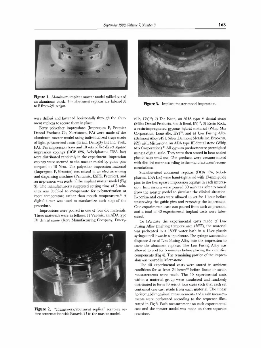
An implant master model was milled out of a solid aluminum block mith five stainless-steel abutment replicas (DC-4 174, Nobelpharma USA Inc, Chicago, IL) prcss- fittcd into the model (Fig 1). The master framework was waxed and cast in a high-pdlladium alloy (Porcelain 76, W.E. Mowrey Company, St. Paul, MNj. To cnsure a passive fit, the abutmcnt replicas were removed from the master model, secured to the framework by prosthetic retaining screws (DCA 075, Nobelpharma, LX4 Inc), aid torqued to 10 Ncm with a hand torquc driver (DIA 250, Blue -10 Ncm, Nobelpharma US.4, Inc). Holes in the aluminum model were enlarged until the abutment replicas attached to the framework could be positioned passively into the preparcd holes (Fig 2). An adhesive resin cement (T'anavia 21, Dental Adhesives, Kureray Dental J, Morita, Tustin, CA) was uscd according to the manufacturer's instructions to cement the abutment replicas into the prepared holes. The complcx was lcft undisturbed for 1 week. Mter visual confirmation of framework fit, stainless-steel sct screws
Table 1. Experiment Materials anti Batch Piumbers ~
Products Batch Xumbers
Die Keen Impregum Adhesivr Impregum Penta ESPE Low Fusing Alloy Microstone Prosthetic Retaining Screws liesin Kock Strain Gauges (E1A-06-0624P-
Triad Vel-mix
1 2 0 4 p t i o n P)
9508326 049/0047 2862 1 no batch number 072796008 3461 1 05549 6002
S 14.5 153 960828B W% I 002 I 275
September 1998, Volume 7, Number 3 163
Figure 1. Aluminum implant master model milled out of an aluminum block. The abutment replicas are labeledA4 to E from Ltj? to righl.
were drilled and fastened horizontally through the abut- ment replicas to secure them in place.
Forty polyether impressions (Impregum F, Premier Dental Products Go, Norristown, PA) were made of the aluminum master model using individualized trays made of light-polymerized resin (Triad, Dentsply Int Inc, York, PA). Ten impression tray3 and 10 sets of five direct square impression copings (DCB 026, Nobelpharma USA Inc) were distributed randomly in the experiment. Impression copings were secured to the master model by guidc pins torqued to 10 Ncm. The polyether impression material (Impregum F, Premier) was mixed in an electric mixing and dispensing machine (Pentamix, ESPE, Premier), and an impression was made of the implant master model (Fig 3). The manufacturer’s suggested setting time of 6 min- utes was doubled to compensate for polymerization at room temperature rather than mouth temperature.“” ,4 digital timer was used to standardize each step of the procedure.
Imprcssions were poured in one of four dic materials. These materials were as follows: 1) Vel-mix, an ADA type IV dental stone (Kerr Manufacturing Company, Emery-
Figure 2. “Framcworlg‘abutment rrplica” complex be- fore cementation with Panavia 2 1 to the master model.
Figure 3. Implant master model impression.
ville, C A ) I 3 ; 2) Die Kccn, an ADA type V dental stone (Miles Dental Products, South Bend, IN)’3; 3 ) Resin Rock, a resin-impregnated gypsum hybrid matcrial (Whip Mix Corporation, Louisville, KY)’O; and 4) Low Fusing Alloy (Belmont Alloy 2491, Silver, Belmont Metals Inc, Brooklyn, NY) with Microstone, an ADA type ILI dental stone (Whip Mix Corporation)?l All gypsum products were preweighed using a digital scale. They were thcn stored in heat-sealed plastic bags until use. The products were vacuum-mixed with distilled water according to the manufacturers’ recom- mendations.
Stainless-steel abutment replicas (DC4 174, Nobel- pharma USA Inc) were hand-tightened with 15-mm guide pins to the five square impression copings in each impres- sion. Impressions were poured 30 minutes after removal from the master model to simulate the clinical situation. Experimental casts were allowed to set for 1 hour before unscrewing the <guide pins and removing the impression. One experimental cast was poured from each impression, and a total of 40 experimental implant casts were fabri- cated.
To fabricate the cxperimcntal casts made of Low Fusing Alloy (melting temperature: 136”F), the material was preheated in a 150°F water bath in a 12-cc plastic syringc until it was in a liquid statc. The syringe was used to dispense 5 cc of Low Fusing Alloy into the impression to cover the abutment replicas. The 1,ow Fusing Alloy was allowed to c t ~ l for 5 minutes before placing the retentive components (Fig 4). Thc remaining portion of the imprcs- sion was poured in Microstone.
‘l’he 40 experimental casts were storcd in ambient conditions for at least 24 hours42 before linear or strain measurements were made. ‘I’he 10 experimental casts within a material group were numbered and randomly distributed to form 10 sets of four casts such that each set contained one cast made from each material. The linear horizontal dimensional measurements and strain measure- ments were performed according to the sequence illus- trated in Fig 5. Each measurement on cach experimental cast and the master model was made on three separate occasions.

164 Accuracy ofSolid Implant Cmts Wee et a1
Figure 4. Implant impression intaglio surface after being poured with Low Fusing Alloy.
During the pilot study, the precision of the digital veneer caliper was found to be 0.02 mm, and the precision of the strain measurements was found to be 20 pe. Subsequently, if any of the three repeated readings for the linear dimensional change or strain measurements were not within the calculated precision range, the readings were made again until three recordings for that particular cast or strain gauge fell within the range.
A digital veneer caliper (Digimatic Caliper, model CD-6 BS, Mitutuyo Corporation, Tokyo, Japan) was posi- tioned in a repeatable fashion on each experimental cast and the master model with a four-point contact on the two most distal abutment replicas. The distance between the most distal abutment replicas was measured and recorded (Fig 6).
Four general-purpose, unidirectional strain gauges with preattached lead wires (EA-06-06”-120 with Option P, Micro-measurements Division, Measurement Group Inc, Raleigh, NC) were bonded to the occlusal aspect of the master framework with the strain gauge axis oriented mesiodistally. One strain gauge was bonded between each of the five gold cylinders (DCA 075, Nobelpharma USA
/ START 4
, Measurement instrument was zeroed. + + Readings were taken on the master cast. i
- C (10times1
411 ten % e o of four implant cast5 Here measured (\=a).
Whole sequence was repeated two additional times on separate occasions, resulting in three repeated measures for each implant cast.
4 END
Measurement instrument was zeroed.
Readings were taken on one cast from the four included in a set.
Each cast in theset was fabricated from one ofthe four different
tested materials.
1 One set offour experimental casts was measured.
Figure 5. Measurement sequence for experimental im- plant casts.
Inc) (Fig 7). The strain gauge jumper wircs were connected to the appropriately numbered, color-coded binding post of a Companion Switch and Balance Unit (Model SB-10, Instruments Division, Measurement Group Inc). The bal- ancing unit was then connected to the Model P-3500 Strain Indicator (Instruments Division, Measurement Group Inc) to create a quarter bridge, 120-0hm configuration (Fig 8). Each of the four indibidual strain gauges was balanced to 50000 strain with no load on the framework before measurements were taken. The framework was secured to the various experimental casts using prosthetic retaining screws torqued to 10 Ncm with a hand torque driver in a standardized sequence. When it was activated, the strain indicator displayed the reading for the appropriate strain gauge. A dfferent set of prosthetic retaining screws was used for each of the three repeated strain measurements.
The absolute strain value used in the analysis for an example strain gauge (SG 01) was calculated using the formula (A - B = [C]), where A was the mean of the three repeated strain values of SG 01 on an experimental implant cast, B was the mean of 30 repeated strain values of SG 01 on the aluminum implant master model, and C was the actual strain value. For A and B, positive and negative values were used to calculate the means. Only the positive values of C were used for statistical analysis. Thus, C was the absolute strainvalue.
Statistical analyses were performed using the SAS statistical program?3 A one-way ANOVA (a = 0.05) was used to evaluate the statistical significance oflinear horizon- tal dimensional change among the four material groups. Thereafter, a post-hoc Duncan’s multiple-range test was used to rank the means of the experimental groups. A MANOVA (a = 0.05) using the Wilks’ Lambda test was used to evaluate the statistical significance of the mean absolute strain values of the four strain gauges among and ihithin the four material groups. The two factors for the strain data were: 1) Material, the “between-subjects” fixed effect; and 2) Position, the “within-subject” or repeated fixed effect. Thereafter, a post-hoc Duncan’s multiple- range test was used to compare mean strain values among die material groups at each strain gauge position. Finally, for each material, a Pearson’s correlation coefficient (r) was used to determine the relationship between the mean horizontal linear dimensional change for each cast and the total absolute strain recorded by the four strain gauges on the framework.
Results Linear Horizontal Measurements
The results of the linear horizontal measurements are reported in Table 2. Values represent the mean difference of the distance between the terminal

Sebtember 1998, Volume 7, Number3 165
Figure 6. Digital veneer cali- per used to measure the most distal abutments of the casts.
abutments on the implant master model (43.86 + 0.007 mm) and each of the experimental groups. The one-way ANOVA (p = .0001) revealed a statistically significant difference among the experimental casts based on die material type (Table 3), and the Dun- can’s multiple-range test (Table 4) showed no diffcr- ence in linear measurement betwccn Resin Rock and Vel-mix groups. Nevertheless, Die Keen casts had significantly greater horizontal dimensional change than the other groups, and Low Fusing Alloy had significantly less dimensional change. The mean horizontal linear measurement from Low Fusing Alloy experimental casts did not diffcr from thc master model, but the coefficient of variance was 20 to 70 times greater than the other groups (Table 2).
Strain Gauge Values on the Framaomk
A significant effect was found based on an interaction between the die material type and the strain gauge position (Table 5). Table 6 illustrates the mean absolute strain for each strain gauge among the four die material groups. For three of the lour strain gauge positions, casts madc of Resin Rock induced the least amount of strain on the framework. In addition, no statisticdly significant difference in mean absolute strain was found among groups from SG 03 and SG 04. Nevertheless, statistically signifi- cant differences in mean absolute strain were identi- fied, and implant casts of Resin Rock induced signifi- cantly less strain on the framework compared with
Figure 7. Four strain gauges bonded to thc master frame- work.

166 Accuray of Solid Implant Casts Wee et al
casts of Vel-mix at SG 01 and Low Fusing Alloy at SG 02.
Correlation of the Linear Measurements and Strain Vdues
Pearsonian correlation coefficients ( r ) were calcu- lated, and negligible correlation was found between the total absolute strain on the framework and the mean horizontal linear dimensional change. The r2 values comparing linear measurements and strain values for the different experimental groups were as follows: Vel-mix = 0.09, Die Keen = -0.12, Resin Rock = -0.01, and Low Fusing Alloy = 0.14. There- fore, linear dimensional change was not an accurate predictor of strain within the framework.
Discussion The results of this study agree with Tan et aI,@ who stated that the magnitude of linear distortion mea- sured in most studies is not directly related to the actual stress induced within the implant system concerned. Negligible correlation between linear hori- zontal dimensional change measurements at the
Figure 8. Strain measure- ment system with strain indi- cator, balancing unit, and strain gauge on the master framework.
terminal abutment and total absolute strain measure- ments on the framework shows that linear dimen- sional change does not adequately predict the strain placed on the secured implant framework in the mesiodistal direction. Therefore, in distortion analy- sis, it is important to target measurements of three- dimensional distortion or a clinically relevant mani- fcstation of distortion, such as stress within the prosthesis-implant-bone complex, to derive a rel- evant conclusion.
The standard deliation of the mean for the three repeated measurements was acceptable for both the linear horizontal dimensional change (0.01 mm) and strain measurements (8 ~ L E ) The standard deviation of repcated measurements for individual strain gauges in this study was similar to those reported by Assif et aP4 (7 p), in which similar methodology was used. Although every attempt was made to standard- ize thc multiple variablcs in thc expcriment, possible explanations for the variability among the material groups (Table 6) include: 1) the four materials have their own range of expansion; 2 ) polyether may interact differently with each of the four materials used; 3 ) the expansion in the three dimensions may differ for each of the four materials; 4) the machining
Table 2. Linear Horizontal Dimensional Charige of Experimental Casts
Mean SD Range % hfference CoeJ%ent Malerial N (mm) (mm) SEA4 immi From iMaster Cast of Variance
Vel-mix 10 0.02 0.01 0.05 0.00-0.04 0.04 88 Die Keen 10 0.04 0.01 0.04 0.02-0.06 0.10 28 Kesin Kock 10 0.02 0.02 0.05 -0.01-0.04 0.04 I00 Low Fusing Alloy 10 0.00 0.02 0.06 -0.02-0.04 0.00 1960
K'ote. Means were calculated using the mean of thc three rcpeated rcadmgs from each cast

September 1998, Volume 7, iVumber 3 167
Table 3. One-way ANOVA @ < .05) for linear Horizontal Dimensional Change Measurements
Table 5. MANOVA ci, < .05) for Mean Absolute Strain on the Secured Mastcr Framework
Sum of df Squares F Value P
~~~~~
Model 3 0.01004 12.60 .om1 Error 36 0.00956
tolerances of the implant components varied4’; and 5 ) the use of only three sets of prosthetic retaining screws may have resulted in deformation of the screws during the study.
The variability of Low Fusing Alloy dimensional measurements could also be a result of its partial eutectic microstructure and multiple alloy composi- tion. Flow or creep may have occurred at room temperature, because the recrystallization tempera- ture of the matrix metal, lead, is very In this experimental design, three repeated measurements werc made at differcnt times, and flow or creep could have occurred bctwecn measurements. Nevertheless, Low Fusing Alloy had significantly greater mean absolute strain values only at the SG 02 position. If greater strain occurred at other positions, it may not have been detected because the gauges measured strain in only one dimension.
Although the framework fit to the aluminum implant master model was visually acceptable, the four strain gauges detected strain on thc framework when the implant framework was secured to the model. This was taken into consideration for data analysis through the use of absolute strain values. The sign in front of the strainvalue is an indication of the “direction” of strain, not the “amount” of strain. In strain gauge technology, thc “negative” sign indi- cates compression, and the “positive” sign indicates tension. A negative strain value does not imply less strain than a positive strain value. If the absolute values were used to calculate A (the mean of the strain measurements on the experimental casts) and B (the mean of the strain measurements on the
Table 4. Duncan’s Multiple-Rangc Tcst ci, < .05) for Linear Horizontal Dimensional Change
Mean Duncan? Material N fmml Grou$ing*
Die Keen 10 0.04 mm A Vel-mix 10 0.02 mm B Resin Rock 10 0.02 mm B h w Fusing Alloy 10 0.00 mm c
*Identical letters in the same column reprerent means that are not significantly dillerent.
Value F Value df p
Wilks’ Lambda 0.561 2.47 9 .015 82.9
aluminum model), then C (the actual strain) would not be a true representation of actual strain. The mean actual strain would therefore not represent the spectrum of both compression and tension readings, and inappropriately identified significant differences could be found during statistical analysis. Therefore, the absolute value of C was appropriate to use for subsequent analysis.
The positions of the strain gauges were arbitrarily determined on the occlusal surface of the implant framework. Studies that evaluate implant cast accu- ra~y’1~;~’ have shown that the horizontal dimensional change is more significant than vertical change. Therefore, the strain gauges were placed in the rnesiodistal direction, and implant cast horizontal dimcnsional change measurements were made. In the future, photoclastic stress analysis during a pilot study could bc used to locate areas on the framework where a hlgh degree of strain occurs. Strain gauges could then be selectively bonded in the mesiodistal dircction in these areas on the implant framework.
A more relevant position to place strain gauges is around the implant abutments to form a load cell, as reported byJemt.q7 The level of strain at the implant abutment would be clinically important, because most implant complications occur within the pros- the tic retaining scre\v/implant abutment/abutment screw c o m p l e ~ . ~ ~ ~ ~ ~ - ~ When components are stressed beyond their long-term fatigue capacity, delayed component failure results. The implant abutment could be calibrated, and with the known modulus of elasticity, stress induced in the abutment replica could be calculated. If the resultant distortion were measured using a three-dimensional analysis? bend- ing moments could also be calculated. This could not be accomplished with the present experimental model.
An alternative method to measure stress on the implant framework would be to use photoelastic stress analysis as reported by Uludamar and Leung.48 A photoelastic plastic coating could be bonded onto the superior surface of the implant framework, and a reflection polariscope would be used to view the fringe order on the secured framework. Greater

168 Accuracy of Solid Implant Casts Wee et a1
Table 6. Duncan’s Multiple-Range Test for Mean Absolute Strain @) for Each Strain Gauge on the Secured Master Framework
Strain Gauge 01 Strain Gauge 02 Strain Gauge 0.7 Strain Gauge 04
Material Mean SD SEM Croups* itlean SD SEM Groups* Mean SD SEM Groups* Mean SD SEM Groups*
Vel-mix 47.30 54.25 17.16 A 35.20 26.22 8.29 A B 25.00 27.97 8.84 A 21.20 24.18 7.55 4 DieKeen 25.40 15.02 4.75 A B 26.00 17.19 5.44 B 37.10 27.47 8.69 A 25.80 18.20 5.76 A Low Fusing
Alloy. 17.80 12.63 3.99 B 44.60 13.73 4.97 A 16.60 17.86 5.65 A 17.00 13.82 4.37 A ResinRock 18.50 9.76 3.08 I3 22.60 16.95 5.36 €3 16.00 12.33 3.90 A 11.50 11.55 3.65 A
*Duncan’s groupings following MANOVA (Multivariate Wilks’ Lambda) using ranked data. Identical letters in the same column represent means that are not significantlydiffererit
fringe ordcr is correlated with greater stress on the framework.
Clinical Significance Compared to Vel-mix, Die Keen or Resin Rock, Low Fusing Alloy used in this experiment produced the least change in linear dimension for a five-implant model when it was poured in a polyether impression. However, because of the exceptionally high variance of Low Fusing Alloy measurements and its more complex technique, it may not be clinically predict- able. Resin Rock produced the least mean absolute strain on the framework in three of the four strain gauges. Therefore, frameworks fabricated on a solid implant cast made of Resin Rock may produce less strain on the implant framework in the mesiodistal direction compared with casts made of Vel-mix, Die Keen, and Low Fusing Alloy. Use of Resin Rock may reduce the amount of stress in the prosthesis-implant- bone complex. The upper limit of the mean strain value range for Resin Rock was found to be 22.6 p ~ . Using Hook’s law, if the high-palladium implant framework’s Young’s modulus were estimated at 95 b P a X lo3, the stress gcneratcd would be 2.15 ma. Although this amount of stress may be minimal, its clinical relevancc has yet to be determined.
Conclusion The accuracy of solid implant casts can be influenced by the type of materials used to fabricate them. Statistically significant differences both in linear horizontal dimensional change and strain on the framework were found among the four materials tested. Resin Rock produced the second-most dimen- sionally accurate solid implant casts and the least amount of strain on the implant framework in this study. Therefore, Resin Rock may be a practical alternative to fabricate solid implant casts.
Acknowledgment The authors thank Dr. Clark Standford for his review of the protocol, Dr. ’lhomas Southard for his insight on the use of strain gauges, and Dr. Supanee Buranadham for her constant support and input during the course of this project. ’They also thank Mrs. .Jane Jacobsen and Dr. William Johnston (The Ohio State University) for their statistical support during the analysis of the data.
References Albrektsson T A multicenter report on osseointegrated oral implants. J Prosthet Dent 1988;60:75-84 ,4dell R, Eriksson B, Lekholm C , ct a1 A long term follow up study of osseointegrated implants in the treatment of totally edentulous jaws. Int .J Oral hlaxillofac Implants 1990;5:347- 359 Zarb GA, Schmitt A The longitudinal clinical effectiveness of osseointegrated dental implants. The Toronto study. Part 11: The prosthetic results. J Prosthet Dent 1990a;6453-51 AdeU R, Lekholm U? Rockler B, et al: A 15-year study of osseointegrated implants in the treatment of the edentulous jaw. IntJOralSurg 1981;10:387-416
5. Johansson G, Palmcpist S: Complications, supplementary treatment and maintenance in edentulous arches with im- plant supported futed prostheses. Int J Prosthodont 1990;3:
6. Jemt T Failures and complications in 391 consecutively inserted fmed prostheses supported byBr%nemai-k implants in edentulous jaws: A study of treatment from the time of prosthesis placement to the first annual checkup. Int J Oral Maxillofac Implants 1991;6:270-276
7. Naert I, Quiqnm hf, Van Steenberghe D, et al: A study of 589 consecutive implants supporting complete fixed prostheses. Part I1 Prosthetic aspects..J Prosthet Dent 1992;68:949-956
8. Tolman L)E, Laney WIZ: Tissue-integrated prosthesis compli- cations. Int J Oral Maxillofac Implants 1992;7:477-484
9. Carlson B; Carlsson GE: Prosthodontic complications in ossee integrated dental implant treatment. Int J Oral Maxillofac Implants 1994;990-94
10. CollinsJW, Rigsby DF, Dixon DL, et al: Accuracy of working casts Tor an implant supported restoration (abstr). J Dent Res 19Y6;7j: I6 1
1 I . Skalak R Biomechanical considerations in osseointegrated prostheses. J Prosthet Dent 1983;49:843-848
89-92

September 1998, Volume 7, Number 3 169
12. Kallus T, Bessing C: Loose gold screws frequently occur in full-arch fEed prostheses supported by osseointegrated im- plantsafter 5years.IntJOralh.ZaxillofacImplants 1994;9169- I78
13. Zarb GA, Jansson TP: Prosthodontic procedures and labora- tory procedures and protocol, in Brhemark PI, Zarb G& Alberktsson I, (eds): Tissue Integrated Prostheses. Chicago, IL: Quintessence, 1985, pp 241-282,293-315
14. Humphries RM, Yaman P, Bloem TJ: The accuracy of implant master casts constructed from transfer impressions. Int J Oral Maxillo Implants 1990;5:331-336
15. Spector M, Donovan TE, NichollsJI: An evaluation of imptes- sion techniques for osseointegrated implants. J Prosthet Dent 1990;63:444-447
16. Carr AB: A comparison of impression techniques for a five-implant mandibular model. Int J Oral Maxillofac lm- plants 1991;6:448-455
17. Carr AB: Comparison of impression techniques for a two- implant 15 degree divergent model. Int J Oral Maxillofac Implants 1992;7:468-475
18. AssXD, Fenton AH, Zarb GA, et al: Comparative accuracyof implant impression procedures. Int .J Periodont Kest Dent 1992;lZ: 1 13-12 1
19. Barrett MG, de Rijk WG, BurgessJO The accuracy of six impression techniques for osseointegrated implants. J Prosthod 1993;2:75-82
20. Inturregui JA, Aquilino SA, Ryther JS, et al: Evaluation of three impression techniques for osseointegrated oral im- plants. J Prosthet Dent 1993;69:503-509
21. Liou AD, NichollsJ, Yuodelis RA, et al: Accuracy of replacing three tapered transfer impression copings into two elasto- meric impression materials. Int J Prosthodont 1993;6:377-383
22. Phillips KM, NichollsJI, Ma T, et al: The accuracy nf three implant impression techniques: A three-dimensioinal analysis. Int J Oral Maxillofac Implants 1994;9:533-540
23. Carr AB, MasterJ: The accuracy of implant verification casts compared with casts produced from a rigid transfer coping technique. J Prosthod 1996;5:248-252
24. Assif' D, Marshak B, Schmidt A Accuracy of implant impres- sion techniques. Int J Oral Maxillofac Implants 1996;11:216- 222
25. Hsu CC, Millstein PL, Stein RS: A comparative analyTis of the accuracy of implant transfer techniques. J Prosthet Dent
26. Hussaini S, Wong T One dinical visit for a multiple implant restoration master cast fabrication. J Prosthet Dent 1997;78: 550-553
27. Vigolo P, Millstein PL: Evaluation of master cast techniques for multiple abntment implant prostheses. Int J Oral hhil lo- fac Implants 1993;8:439-445
28. Alwazzan K, Ziebert G, Balthazar Y The accuracy of a removable die system for implant frameworks (abstr). J Dent Res 1994;73:232
29. Rodney J, Johansen R> Harris W: Dimensional accuracy of two implant impression copings (abstr). J Dent Res 1991; 70(special issue):385
1993;69:588-593
30. Ness EM, Nicholls JI, Rubenstein JE, et al: Accuracy of the acrylic rcain pattern for the implant retained prosthesis. Int J Prosthcdont 1992;5:542-549
31. Tan KB, RubensteinJE, NichollsJE, et al: Three dimensional analysis of the casting accuracy of one-piece, osseointegrated implant retained prostheses. Int J Prosthodont 1993;6:346-363
32. ,Jemt T: In vivo measurements of precision of fit involving
33.
34.
35.
36.
37.
38.
39.
49.
41.
42.
43.
44.
45.
46.
47. on osseointegrated implants supporting fured or removable prostheses: A comparative pilot study. lnt J Oral blaxillofac Implants 1991;6:413417
48. Uludamar .4, Leung T Inaccurate fit n f implant superstruc- tures. Part IL Efticacy of the precidisc system for the correc- tion or errors. IntJProsthodont 1996;9:16-20
implant-supported prostheses in the edentulous jaw. Int J Oral Maxillfac Implants 1996;11:151-158 Cheshire PD, Hobkirk.JA An in vivo quantitative analysis of the lit of' Nobel Biocare implant superstructures. J Oral Kehabil 1996;23:782-789 May KB, Edge MJ, Lang BR, et al: The periotest method: Implant-supported framework precision of fit evaluation. J Prosthod 1996;5:206-2 13 Wicks RA, de Rijk WG, Windeler AS: An evaluation of fit in osseointegrated implant components using torquehrn analy- sis. J Prosthod 1994;3:206-212 Carr AB, Gerard DA, Larsen PE: The response of bone in primates arourd unloaded dental implants supporting prosthe- ses with different levels offit. J Prosthet Dent 1996;76:500-509 Carr AB, Stewart RB: Full-arch implant framework casting accuracy. Preliminary in vitro observation for in viva testing. J Prosthod 1993;2:2-8 Clelland NL, Can AB, Gilat A Comparison of strains trans- ferred to a bone simulant between =-cast and postsoldered implant frameworks for a five-implant-supported fixed prosthe- sis. JProsthod 1996;5:193-200 Clelland NL, Van Putten MC: Comparison of strains pro- duced in a bone simulant between conventional cast and resin-luted implant frameworks. Int J Oral Maxillofac Im- plants 1997;12:793-799 American Dental Association: Revised American Dental Assc- ciation specification no. 19 for non-aqueous, elastomeric den- tal impression materiltls. JAm Dent Assoc 1977;94:733-741 Schneider RL, Wee AG: Fabricating of low fusing metal casts for more accurate implant prosthodontics. J Prosthod 1996;5: 301-303 Arlo K Evaluation of the Vident die and model system. USAF Dental Investigation Services, 1991 SAS Institute I: SAS User's Guide: Basic (5th ed). Cray, NC, SAS Institute Inc, 1985 Tan KB: The clinical significance of distortion in implant prosthodontics: Is there such a thing as passive fit? Ann Acad Med 1995;24: 138-157 Binon PI? The effect of implant/abutment hexagonal misfit on screwjoint stability. Int J Prosthodont 1996;9:149-160 Anusavice JK: Phillip's Science of Dental Materials (10th ed). Philadelphia, PA, Saunders, 1996 Jemt T, Chrlsson L, Boss A, et al: In vivo load measurements