Embed Size (px)
Citation preview

��������
��� � � �� �� � � � � ����

Frequency Modulation (FM)
The frequency of the carrier signal is varied with the amplitude of the
modulating (baseband) signal.
Frequency of FM signal
fsig ( t ) = fc ( 1 + k em )t
where fsig ( t ) = signal frequency as a function of timefc = un modulated carrier frequencyk = proportionality constant
em ( t ) = modulating voltage as a function of time
Substituting for em(t),
fsig ( t ) = fc ( 1 + k Em sin wm t)

http://www.google.com.om/imgres?imgurl=http://www.moz.ac.at/sem/lehre/lib/ks/lib/fm/frequency-modulation-Dateien/_FMMOD.GIF&imgrefurl=http://www.moz.ac.at/sem/lehre/lib/ks/lib/fm/frequency-modulation.h

Frequency Deviation (δδδδ)
Modulation will cause the signal frequency to vary, or deviate, from its
resting value. This deviation will be proportional to the amplitude of the
modulating signal.
Substituting for em(t),
fsig ( t ) = fc ( 1 + k Em sin wm t)
The peak frequency deviation is given by the symbol �,
� = k fc Em = kf Em
where � = peak frequency deviation in hertzEm =peak value of the modulating signal in voltskf = modulator sensitivity in hertz per volt
Thus,fsig ( t ) = fc + � sin �m t

carrier swing
Thus,fsig ( t ) = fc + � sin wm t
Lowest carrier frequency = fc - �
Highest carrier frequency = fc + �
Therefore, the carrier swing = fc + � – ( fc - �) = 2 �
Frequency Modulation Index
No theoretical limits on mf and it can exceed one.

Resting FrequencyIt is the frequency of FM signal when there is no modulation
Maximum Frequency DeviationIt is the maximum frequency shift of the FM signal from the resting frequency.
Carrier SwingIt is the difference between highest and lowest frequency of FM signal.
Modulation IndexIt is the amount by which the carrier signal is frequency modulated by the message signal.

FM signal
Equation for Instantaneous value of FM signal is
eFM(t) = Ec sin (ωct+ mf sin ωmt)Where mf=� �/fm
Frequency spectrum of FM (Solved by Bessel function)
eFM(t) = Ec sin (ωct+ mf sin ωmt)
eFM(t) = Ec{ Jo(mf) sin wct
+J1(mf) [sin (wc + wm)t - sin (wc - wm)t]
+ J2(mf) [sin (wc + 2wm)t- sin (wc – 2wm)t]
+J3(mf) [sin (wc + 3wm)t - sin (wc – 3wm)t]
+ J4(mf) [sin (wc + 4wm)t - sin (wc – 4wm)t] . . . }

http://web.sunybroome.edu/~eet_dept/252/bessell.htm

Plot of Bessel functions
http://www.efunda.com/math/bessel/besselJYPlot.cfm
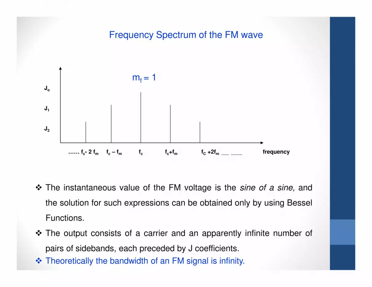
…… fc- 2 fm fc – fm fc fc+fm fC +2fm …… ……… frequency
Frequency Spectrum of the FM wave
mf = 1
� The instantaneous value of the FM voltage is the sine of a sine, and
the solution for such expressions can be obtained only by using Bessel
Functions.
� The output consists of a carrier and an apparently infinite number of
pairs of sidebands, each preceded by J coefficients.� Theoretically the bandwidth of an FM signal is infinity.
Jo
J1
J2

Bandwidth of FM
Bandwidth for FM is theoretically infinity.
But an approximate bandwidth is given by Carson’s rule.
Carson’s Rule
The bandwidth required to pass an FM wave is twice the sum of the
maximum deviation and the highest modulating frequency.
BW = 2 (δ + fm )

)sinsin( tmtEe mfCCFM ωω +=
mf E
Kδ=
δ2. minmax =−= ffsc
δ+= Cffmax
δ−= Cffmin
Formula
mf = δ /fm
(BW )FM= 2 (δ + fm)

Advantages of FM over AM
FM AM
Amplitude is constant and is
independent of mf
All transmitted power is useful in
FM
Amplitude depends on modulation
index(m)
Transmitted power is wasted in
carrier in AM.
FM receivers have amplitude
limiters to remove noise
Noise cannot be removed
Reduce noise by increasing
deviation
Modulation index cannot be
increased above 100% without
causing distortion.

Disadvantages of FM over AM
FM AM
Bandwidth is large for FM, so
wider channel is required
Bandwidth is small
Transmitters and receivers are
complex
Circuits are not complicated
The area of reception is less,
limited to line of sight
The area of reception is more.

Pre-emphasis and De-emphasis
Need for Pre-emphasis and De-emphasis in FM
In FM, noise has a greater effect on the higher modulating frequencies
than on the lower ones. Thus, if the higher frequencies were artificially
boosted at the transmitter and correspondingly cut at the receiver, an
improvement in noise immunity could be expected.
Pre-emphasis
Boosting of higher modulating frequencies in accordance with a pre
arranged curve before modulation.
De-emphasis
Reducing the higher modulating frequency amplitudes, in accordance
with a pre arranged curve after modulation.

75-µs emphasis curves
emphasis curves

Pre-emphasis Circuit
Output signal amplitude depends on input signal frequency. As
frequency increases output voltage increases, which in turn increase
the gain. The time constant (L/R) of the circuit is 75-µs.

De-emphasis
Higher frequencies are attenuated by the low pass filter. So their
amplitude decreases which in turn decrease the gain. The time
constant (RC) of the circuit is 75-µs.


