Embed Size (px)
Citation preview
General Catalogue
D946E173
Quality made in

D946E 1
IndexIndexIndexIndexIndex Page
Contactors, Motor-Starter (D677E)Contactors, Motor-Starter (D677E)Contactors, Motor-Starter (D677E)Contactors, Motor-Starter (D677E)Contactors, Motor-Starter (D677E) 3Micro Contactors 9Mini Contactors 19Contactor Relays 33Contactors 39Starters 85D.O.L. Starters 105Overload Relays 113Modular Contactors 127Contactors for DC-Switching (D911E) 135Contactors RAST 5 (D778E) 139
Circuirt Breakers (D795E)Circuirt Breakers (D795E)Circuirt Breakers (D795E)Circuirt Breakers (D795E)Circuirt Breakers (D795E) 159Circuit-Breakers M4 for motor protection 160Auxiliary contacts, Signalling switch, Auxiliary releases 161Insulated 3-pole busbar system, Terminal block 162DIN-rail adapters, Busbar adapters 163Link modules, Contactors for Circuit-Breakers M4 163
Manual Motor-Starters (D509E)Manual Motor-Starters (D509E)Manual Motor-Starters (D509E)Manual Motor-Starters (D509E)Manual Motor-Starters (D509E) 181Manual Motor-Starters, Auxiliary Contact Blocks 182Trip Alarm Aux. Switch, Shunt Release 182Under-voltage Release, Accessories 183Busbar Connectors, Enclosures 183
Switches (D371E)Switches (D371E)Switches (D371E)Switches (D371E)Switches (D371E) 187Cam Switches 192Mini-Cam Switches 230Load switches 234Handles and plates 236Optional Extras 243Special Switches 251
AC-Main Switches (D656E)AC-Main Switches (D656E)AC-Main Switches (D656E)AC-Main Switches (D656E)AC-Main Switches (D656E) 271Main Switches for Panel Mounting 274Main Switches for Base Mounting with Door Clutch 276Main Switches-Emergency-Stop for Panel Mounting 280Main Switches-Emergency-Stop for Single Hole Mounting 281Main Switches-Emergency-Stop for Base Mounting with Door Clutch 282Main Switches-Emergency-Stop for Distribution Boards 284Maintenance and Safety Switches, in Plastic Enclosures 284Switch Disconnectors for Panel Mounting 286Switch Disconnectors for Distribution Boards 289Switch Disconnectors in Plastic Enclosures 290Add-on modules 291
DC DC DC DC DC Switch DisconnectorsSwitch DisconnectorsSwitch DisconnectorsSwitch DisconnectorsSwitch Disconnectors for Photovoltaic (D911E) for Photovoltaic (D911E) for Photovoltaic (D911E) for Photovoltaic (D911E) for Photovoltaic (D911E) 297ON-OFF Switches for Panel Mounting 300ON-OFF Switches for Single Hole Mounting 301ON-OFF Switches for Base Mounting with Door Clutch 302ON-OFF Switches for Distribution Boards 303Main Switches for Panel Mounting 304Main Switches for Single Hole Mounting 305Main Switches for Base Mounting with Door Clutch 306Main Switches for Distribution Boards 307Main Switches in Plastic Enclosure 307
Technical data, dimension sketches, illustration and weights given in our list and printed matter, are subject to changed without notice.
2 D946E
IndexIndexIndexIndexIndex Page
Push Buttons (D580E)Push Buttons (D580E)Push Buttons (D580E)Push Buttons (D580E)Push Buttons (D580E) 321Program B3 322Push Buttons 323EMERGENCY STOP Button 324Key Operated Rotary Switches 324Rotary Knobs and Swing Knobs 325Illuminated Rotary Knobs and Swing Knobs 325Illuminated Push Buttons 326Double Push Buttons 326Lens Caps 326Monoblock-Multi-LED 327Push Button-Sets 328Illuminated Push Button-Sets 328Pilot Lights 328Connectors 330Actuator inserts 330Contact Blocks and Lamp Holders 330Lamps, LED Lamps 331Accessories 331Label Holder, Legend Plates, Actuator Caps 332Program B5 334Push Buttons 335Rotary Knobs and Swing Knobs 336Key Operaed Rotary Switches 337Illuminated Push Button 337Lens Caps 337Connectors 338Contact Blocks and Lamp Holders 338Lamps, Accessories 339Units for Surface Mounting 341Assembled Units IP65 341Enclosures BG. 342Contact Blocks and Lamp Holders for Enclosures BG.. 342Push Buttons for Enclosures 343Extensions for Push Buttons 343
Representatives and SuppliersRepresentatives and SuppliersRepresentatives and SuppliersRepresentatives and SuppliersRepresentatives and Suppliers 353
Technical data, dimension sketches, illustrations and weights given in our list and printed matter are subject to change without notice.
D946E 3
Technical data, dimension sketches, illustrations and weights given in our list and printed matter are subject to change without notice.
IndexIndexIndexIndexIndex PageGeneralGeneralGeneralGeneralGeneral 4
Approvals 5Technical Information 7Mounting Information 8
Micro ContactorsMicro ContactorsMicro ContactorsMicro ContactorsMicro Contactors 9Micro Contactors 10Micro Contactor Relays 11Micro Reversing Contactors 13Technical Information 14Dimensions 18
Mini ContactorsMini ContactorsMini ContactorsMini ContactorsMini Contactors 19Mini Contactors 20Interface Contactors 20Micro Reversing Contactors 26Technical Information 27Dimensions 32
Contactor RelaysContactor RelaysContactor RelaysContactor RelaysContactor Relays 33Contactor Relays 35Technical Information 36Dimensions 38
ContactorsContactorsContactorsContactorsContactors 39Contactors Overview 40Contactors, 3-pole 42Contactors, 4-pole 44Capacitor Switching Contactors 45Accessories 46Technical Information 56Dimensions 76
StartersStartersStartersStartersStarters 85Star-Delta Starters 86Reversing Contactors 90Pole Changing Starters 92Technical Information 94Dimensions 101
D.O.L. StartersD.O.L. StartersD.O.L. StartersD.O.L. StartersD.O.L. Starters 105D.O.L. Starters 106Enclosures 107Accessories 107Technical Information 108Dimensions 110
Overload RelaysOverload RelaysOverload RelaysOverload RelaysOverload Relays 113Thermal Overload Relays 114Accessories 115Technical Information 118Dimensions 123
Modular ContactorsModular ContactorsModular ContactorsModular ContactorsModular Contactors 127Contactors 128Accessories 129Technical Information 130Dimensions 134
Contactors for DC-SwitchingContactors for DC-SwitchingContactors for DC-SwitchingContactors for DC-SwitchingContactors for DC-Switching 135Contactors RAST 5Contactors RAST 5Contactors RAST 5Contactors RAST 5Contactors RAST 5 139
4 D946E
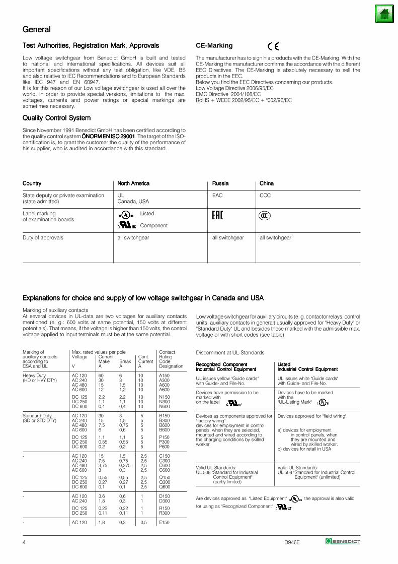
Marking of auxiliary contactsAt several devices in UL-data are two voltages for auxiliary contactsmentioned (e. g.: 600 volts at same potential, 150 volts at differentpotentials). That means, if the voltage is higher than 150 volts, the controlvoltage applied to input terminals must be at the same potential.
Marking of Max. rated values per pole Contactauxiliary contacts Voltage Current Cont. Ratingaccording to Make Break Current CodeCSA and UL V A A A Designation
Heavy Duty AC 120 60 6 10 A150(HD or HVY DTY) AC 240 30 3 10 A300
AC 480 15 1,5 10 A600AC 600 12 1,2 10 A600
DC 125 2,2 2,2 10 N150DC 250 1,1 1,1 10 N300DC 600 0,4 0,4 10 N600
Standard Duty AC 120 30 3 5 B150(SD or STD DTY) AC 240 15 1,5 5 B300
AC 480 7,5 0,75 5 B600AC 600 6 0,6 5 B600
DC 125 1,1 1,1 5 P150DC 250 0,55 0,55 5 P300DC 600 0,2 0,2 5 P600
- AC 120 15 1,5 2,5 C150AC 240 7,5 0,75 2,5 C300AC 480 3,75 0,375 2,5 C600AC 600 3 0,3 2,5 C600
DC 125 0,55 0,55 2,5 Q150DC 250 0,27 0,27 2,5 Q300DC 600 0,1 0,1 2,5 Q600
- AC 120 3,6 0,6 1 D150AC 240 1,8 0,3 1 D300
DC 125 0,22 0,22 1 R150DC 250 0,11 0,11 1 R300
- AC 120 1,8 0,3 0,5 E150
Low voltage switchgear for auxiliary circuits (e. g. contactor relays, controlunits, auxiliary contacts in general) usually approved for "Heavy Duty" or"Standard Duty" UL and besides these marked with the admissible max.voltage or with short codes (see table).
Discernment at UL-Standards
Recognized ComponentRecognized ComponentRecognized ComponentRecognized ComponentRecognized Component ListedListedListedListedListedIndustrial Control EquipmentIndustrial Control EquipmentIndustrial Control EquipmentIndustrial Control EquipmentIndustrial Control Equipment Industrial Control EquipmentIndustrial Control EquipmentIndustrial Control EquipmentIndustrial Control EquipmentIndustrial Control Equipment
UL issues yellow "Guide cards" UL issues white "Guide cards"with Guide- and File-No. with Guide- and File-No.
Devices have permission to be Devices have to be markedmarked with with theon the label "UL-Listing Mark"
Devices as components approved for Devices approved for "field wiring","factory wiring":devices for employment in controlpanels, when they are selected, a) devices for employmentmounted and wired according to in control panels, whenthe charging conditions by skilled they are mounted andworker. wired by skilled worker.
b) devices for retail in USA
Valid UL-Standards: Valid UL-Standards:UL 508 "Standard for Industrial UL 508 "Standard for Industrial Control
Control Equipment" Equipment" (unlimited)(partly limited)
Are devices approved as "Listed Equipment" the approval is also valid
for using as "Recognized Component" .
GeneralGeneralGeneralGeneralGeneral
CE-Marking
The manufacturer has to sign his products with the CE-Marking. With theCE-Marking the manufacturer confirms the accordance with the differentEEC Directives. The CE-Marking is absolutely necessary to sell theproducts in the EEC.Below you find the EEC Directives concerning our products.Low Voltage Directive 2006/95/ECEMC Directive 2004/108/ECRoHS + WEEE 2002/95/EC + "002/96/EC
Test Authorities, Registration Mark, ApprovalsTest Authorities, Registration Mark, ApprovalsTest Authorities, Registration Mark, ApprovalsTest Authorities, Registration Mark, ApprovalsTest Authorities, Registration Mark, Approvals
Low voltage switchgear from Benedict GmbH is built and testedto national and international specifications. All devices suit allimportant specifications without any test obligation, like VDE, BSand also relative to IEC Recommendations and to European Standardslike IEC 947 and EN 60947.It is for this reason of our Low voltage switchgear is used all over theworld. In order to provide special versions, limitations to the max.voltages, currents and power ratings or special markings aresometimes necessary.
Quality Control SystemQuality Control SystemQuality Control SystemQuality Control SystemQuality Control System
Since November 1991 Benedict GmbH has been certified according tothe quality control system ÖNORM EN ISO 29001ÖNORM EN ISO 29001ÖNORM EN ISO 29001ÖNORM EN ISO 29001ÖNORM EN ISO 29001. The target of the ISO-certification is, to grant the customer the quality of the performance ofhis supplier, who is audited in accordance with this standard.
CountryCountryCountryCountryCountry North AmericaNorth AmericaNorth AmericaNorth AmericaNorth America RussiaRussiaRussiaRussiaRussia ChinaChinaChinaChinaChina
State deputy or private examination UL EAC CCC(state admitted) Canada, USA
Label marking Listedof examination boards
Component
Duty of approvals all switchgear all switchgear all switchgear
Explanations for choice and supply of low voltage switchgear in Canada and USAExplanations for choice and supply of low voltage switchgear in Canada and USAExplanations for choice and supply of low voltage switchgear in Canada and USAExplanations for choice and supply of low voltage switchgear in Canada and USAExplanations for choice and supply of low voltage switchgear in Canada and USA
D946E 5
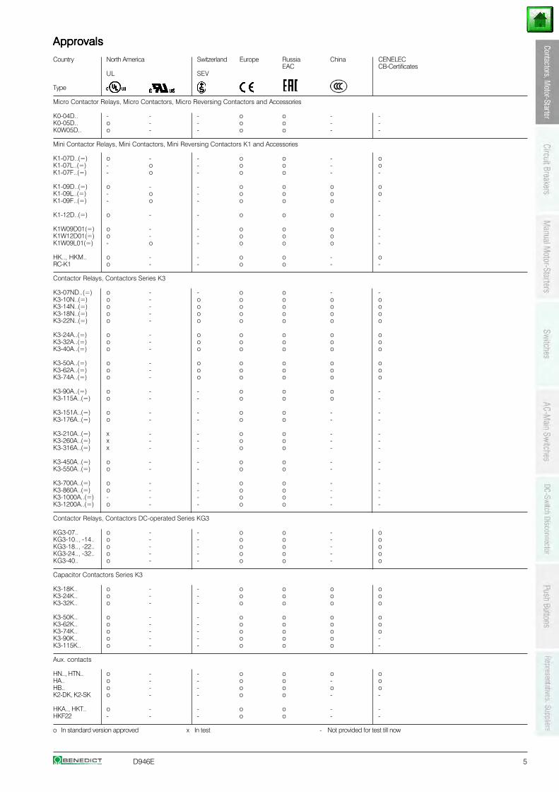
ApprovalsApprovalsApprovalsApprovalsApprovalsCountry North America Switzerland Europe Russia China CENELEC
EAC CB-CertificatesUL SEV
Type
Micro Contactor Relays, Micro Contactors, Micro Reversing Contactors and Accessories
K0-04D.. - - - o o - -K0-05D.. o - - o o - -K0W05D.. o - - o o - -
Mini Contactor Relays, Mini Contactors, Mini Reversing Contactors K1 and Accessories
K1-07D..(=) o - - o o - oK1-07L..(=) - o - o o - oK1-07F..(=) - o - o o - -
K1-09D..(=) o - - o o o oK1-09L..(=) - o - o o o oK1-09F..(=) - o - o o o -
K1-12D..(=) o - - o o o -
K1W09D01(=) o - - o o o -K1W12D01(=) o - - o o o -K1W09L01(=) - o - o o o -
HK.., HKM.. o - - o o - oRC-K1 o - - o o - -
Contactor Relays, Contactors Series K3
K3-07ND..(=) o - - o o - -K3-10N..(=) o - o o o o oK3-14N..(=) o - o o o o oK3-18N..(=) o - o o o o oK3-22N..(=) o - o o o o o
K3-24A..(=) o - o o o o oK3-32A..(=) o - o o o o oK3-40A..(=) o - o o o o o
K3-50A..(=) o - o o o o oK3-62A..(=) o - o o o o oK3-74A..(=) o - o o o o o
K3-90A..(=) o - - o o o -K3-115A..(=) o - - o o o -
K3-151A..(=) o - - o o - -K3-176A..(=) o - - o o - -
K3-210A..(=) x - - o o - -K3-260A..(=) x - - o o - -K3-316A..(=) x - - o o - -
K3-450A..(=) o - - o o - -K3-550A..(=) o - - o o - -
K3-700A..(=) o - - o o - -K3-860A..(=) o - - o o - -K3-1000A..(=) - - - o o - -K3-1200A..(=) o - - o o - -
Contactor Relays, Contactors DC-operated Series KG3
KG3-07.. o - - o o - oKG3-10.., -14.. o - - o o - oKG3-18.., -22.. o - - o o - oKG3-24.., -32.. o - - o o - oKG3-40.. o - - o o - o
Capacitor Contactors Series K3
K3-18K.. o - - o o o oK3-24K.. o - - o o o oK3-32K.. o - - o o o o
K3-50K.. o - - o o o oK3-62K.. o - - o o o oK3-74K.. o - - o o o oK3-90K.. o - - o o o -K3-115K.. o - - o o o -
Aux. contacts
HN.., HTN.. o - - o o o oHA.. o - - o o - oHB.. o - - o o o oK2-DK, K2-SK o - - o o - -
HKA.., HKT.. o - - o o - -HKF22 - - - o o - -
o In standard version approved x In test - Not provided for test till now
6 D946E
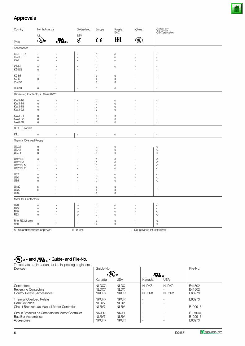
- and - and - and - and - and - Guide- and File-No.- Guide- and File-No.- Guide- and File-No.- Guide- and File-No.- Guide- and File-No.These data are important for UL-inspecting engineers.Devices Guide-No. File-No.
Kanada USA Kanada USA
Contactors NLDX7 NLDX NLDX8 NLDX2 E41502Reversing Contactors NLDX7 NLDX - - E41502Control Relays, Accessories NKCR7 NKCR NKCR8 NKCR2 E66273
Thermal Overload Relays NKCR7 NKCR - - E66273Cam Switches NLRV7 NLRV - -Circuit Breakers as Manual Motor Controller NLRV7 NLRV - - E129916
Circuit Breakers as Combination Motor Controller NKJH7 NKJH - - E197641Bus Bar Assemblies NLRV7 NLRV - - E129916Accessories NKCR7 NKCR - - E66273
ApprovalsApprovalsApprovalsApprovalsApprovals
Country North America Switzerland Europe Russia China CENELECEAC CB-Certificates
UL SEV
Type
Accessories
K2-T..E, -A - - - o o - -K2-TP o - - o o - -K2-L o - - o o - -
K2-IN. o - - o o - -K2-UN. o - - o - -
K2-IM - - - o o - -K2-E o - - o o - -VG-K2 - - - o o - -
RC-K3 o - - o o - -
Reversing Contactors , Serie KW3
KW3-10 o - - o o - -KW3-14 o - - o o - -KW3-18 o - - o o - -KW3-22 o - - o o - -
KW3-24 o - - o o - -KW3-32 o - - o o - -KW3-40 o - - o o - -
D.O.L. Starters
P1.. o - - o o - -
Thermal Overload Relays
U3/32 o - - o o - oU3/42 o - - o o - oU3/74 o - - o o - o
U12/16E o - - o o - oU12/16A - - - o o - oU12/16EM - - - o o - oU12/16EQ - - - o o - o
U32 o - - o o - oU60 o - - o o - oU85 o - - o o - o
U180 x - - o o - -U320 x - - o o - -U800 - - - o o - -
Modular Contactors
R20 o - o o o - oR25 o - o o o - oR40 o - o o o - oR63 o - o o o - o
R40, R63 2-pole - - - o o - oRH11 o - - o o - o
o In standard version approved x In test - Not provided for test till now
D946E 7
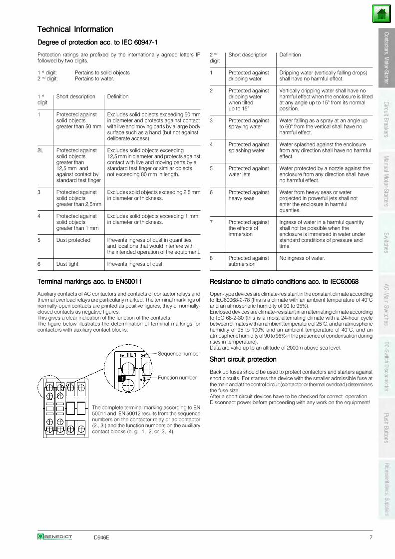
Technical InformationTechnical InformationTechnical InformationTechnical InformationTechnical Information
Degree of protection acc. to IEC 60947-1Degree of protection acc. to IEC 60947-1Degree of protection acc. to IEC 60947-1Degree of protection acc. to IEC 60947-1Degree of protection acc. to IEC 60947-1
Protection ratings are prefixed by the internationally agreed letters IPfollowed by two digits.
1 st digit: Pertains to solid objects2 nd digit: Pertains to water.
1 st Short description Definitiondigit
1 Protected against Excludes solid objects exceeding 50 mmsolid objects in diameter and protects against contactgreater than 50 mm with live and moving parts by a large body
surface such as a hand (but not againstdeliberate access).
2L Protected against Excludes solid objects exceedingsolid objects 12,5 mm in diameter and protects againstgreater than contact with live and moving parts by a12,5 mm and standard test finger or similar objectsagainst contact by not exceeding 80 mm in length.standard test finger
3 Protected against Excludes solid objects exceeding 2,5 mmsolid objects in diameter or thickness.greater than 2,5mm
4 Protected against Excludes solid objects exceeding 1 mmsolid objects in diameter or thickness.greater than 1 mm
5 Dust protected Prevents ingress of dust in quantitiesand locations that would interfere withthe intended operation of the equipment.
6 Dust tight Prevents ingress of dust.
Terminal markings acc. to EN50011Terminal markings acc. to EN50011Terminal markings acc. to EN50011Terminal markings acc. to EN50011Terminal markings acc. to EN50011
Auxiliary contacts of AC contactors and contacts of contactor relays andthermal overload relays are particularly marked. The terminal markings ofnormally-open contacts are printed as positive figures, they of normally-closed contacts as negative figures.This gives a clear indication of the function of the contacts.The figure below illustrates the determination of terminal markings forcontactors with auxiliary contact blocks.
Sequence number
Function number
The complete terminal marking according to EN50011 and EN 50012 results from the sequencenumbers on the contactor relay or ac contactor(2., 3.) and the function numbers on the auxiliarycontact blocks (e. g. .1, .2, or .3, .4).
2 nd Short description Definitiondigit
1 Protected against Dripping water (vertically falling drops)dripping water shall have no harmful effect.
2 Protected against Vertically dripping water shall have nodripping water harmful effect when the enclosure is tiltedwhen tilted at any angle up to 15° from its normalup to 15° position.
3 Protected against Water falling as a spray at an angle upspraying water to 60° from the vertical shall have no
harmful effect.
4 Protected against Water splashed against the enclosuresplashing water from any direction shall have no harmful
effect.
5 Protected against Water protected by a nozzle against thewater jets enclosure from any direction shall have
no harmful effect.
6 Protected against Water from heavy seas or waterheavy seas projected in powerful jets shall not
enter the enclosure in harmfulquanties.
7 Protected against Ingress of water in a harmful quantitythe effects of shall not be possible when theimmersion enclosure is immersed in water under
standard conditions of pressure andtime.
8 Protected against No ingress of water.submersion
Resistance to climatic conditions acc. to IEC60068Resistance to climatic conditions acc. to IEC60068Resistance to climatic conditions acc. to IEC60068Resistance to climatic conditions acc. to IEC60068Resistance to climatic conditions acc. to IEC60068
Open-type devices are climate-resistant in the constant climate accordingto IEC60068-2-78 (this is a climate with an ambient temperature of 40°Cand an atmospheric humidity of 90 to 95%).Enclosed devices are climate-resistant in an alternating climate accordingto IEC 68-2-30 (this is a moist alternating climate with a 24-hour cyclebetween climates with an ambient temperature of 25°C, and an atmospherichumidity of 95 to 100% and an ambient temperature of 40°C, and anatmospheric humidity of 90 to 96% in the presence of condensation duringrises in temperature).Data are valid up to an altitude of 2000m above sea level.
Short circuit protectionShort circuit protectionShort circuit protectionShort circuit protectionShort circuit protection
Back up fuses should be used to protect contactors and starters againstshort circuits. For starters the device with the smaller admissible fuse atthe main and at the control circuit (contactor or thermal overload) determinesthe fuse size.After a short circuit devices have to be checked for correct operation.Disconnect power before proceeding with any work on the equipment!
8 D946E
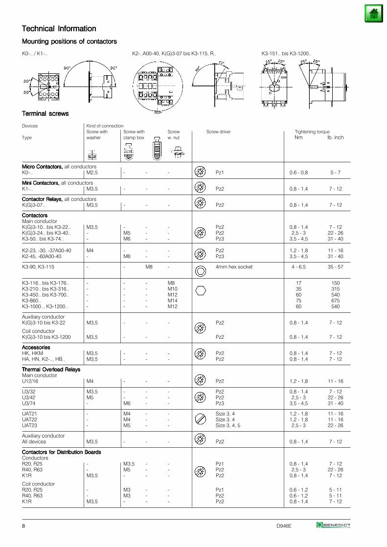
Technical InformationTechnical InformationTechnical InformationTechnical InformationTechnical Information
Mounting positions of contactorsMounting positions of contactorsMounting positions of contactorsMounting positions of contactorsMounting positions of contactors
K0-.. / K1-.. K2-..A00-40, K(G)3-07 bis K3-115, R.. K3-151.. bis K3-1200..
Terminal screwsTerminal screwsTerminal screwsTerminal screwsTerminal screws
Devices Kind of connectionScrew with Screw with Screw Screw driver Tightening torque
Type washer clamp box w. nut Nm lb. inch
Micro Contactors, Micro Contactors, Micro Contactors, Micro Contactors, Micro Contactors, all conductorsK0-.. M2,5 - - - Pz1 0.6 - 0,8 5 - 7
Mini Contactors, Mini Contactors, Mini Contactors, Mini Contactors, Mini Contactors, all conductorsK1-.. M3,5 - - - Pz2 0,8 - 1,4 7 - 12
Contactor Relays,Contactor Relays,Contactor Relays,Contactor Relays,Contactor Relays, all conductorsK(G)3-07.. M3,5 - - - Pz2 0,8 - 1,4 7 - 12
ContactorsContactorsContactorsContactorsContactorsMain conductorK(G)3-10.. bis K3-22.. M3,5 - - - Pz2 0,8 - 1,4 7 - 12K(G)3-24.. bis K3-40.. - M5 - - Pz2 2,5 - 3 22 - 26K3-50.. bis K3-74.. - M6 - - Pz3 3,5 - 4,5 31 - 40
K2-23, -30, -37A00-40 M4 - - - Pz2 1,2 - 1,8 11 - 16K2-45, -60A00-40 - M6 - - Pz3 3,5 - 4,5 31 - 40
K3-90, K3-115 - - M8 - 4mm hex socket 4 - 6,5 35 - 57
K3-116.. bis K3-176.. - - - M8 17 150K3-210.. bis K3-316.. - - - M10 35 315K3-450.. bis K3-700.. - - - M12 60 540K3-860.. - - - M14 75 675K3-1000.., K3-1200.. - - - M12 60 540
Auxiliary conductorK(G)3-10 bis K3-22 M3,5 - - - Pz2 0,8 - 1,4 7 - 12
Coil conductorK(G)3-10 bis K3-1200 M3,5 - - - Pz2 0,8 - 1,4 7 - 12
AccessoriesAccessoriesAccessoriesAccessoriesAccessoriesHK, HKM M3,5 - - - Pz2 0,8 - 1,4 7 - 12HA, HN, K2-.., HB.. M3,5 - - - Pz2 0,8 - 1,4 7 - 12
Thermal Overload RelaysThermal Overload RelaysThermal Overload RelaysThermal Overload RelaysThermal Overload RelaysMain conductorU12/16 M4 - - - Pz2 1,2 - 1,8 11 - 16
U3/32 M3,5 - - - Pz2 0,8 - 1,4 7 - 12U3/42 M5 - - - Pz2 2,5 - 3 22 - 26U3/74 - M6 - - Pz3 3,5 - 4,5 31 - 40
UAT21 - M4 - - Size 3, 4 1,2 - 1,8 11 - 16UAT22 - M4 - - Size 3, 4 1,2 - 1,8 11 - 16UAT23 - M5 - - Size 3, 4, 5 2,5 - 3 22 - 26
Auxiliary conductorAll devices M3,5 - - - Pz2 0,8 - 1,4 7 - 12
Contactors for Distribution BoardsContactors for Distribution BoardsContactors for Distribution BoardsContactors for Distribution BoardsContactors for Distribution BoardsConductorsR20, R25 - M3,5 - - Pz1 0,8 - 1,4 7 - 12R40, R63 - M5 - - Pz2 2,5 - 3 22 - 26K1R M3,5 - - - Pz2 0,8 - 1,4 7 - 12
Coil conductorR20, R25 - M3 - - Pz1 0,6 - 1,2 5 - 11R40, R63 - M3 - - Pz2 0,6 - 1,2 5 - 11K1R M3,5 - - - Pz2 0,8 - 1,4 7 - 12
D946E 9
Micro ContactorsMicro ContactorsMicro ContactorsMicro ContactorsMicro Contactors
Micro Contactor Relays AC or DC operated 10
Micro Contactors AC or DC operated 11
12Micro Contactors With Solder Pins AC or DC operated
Coil voltages 12
Micro Reversing Contactors AC or DC operated 13
Technical Data 14
Dimensions 18
10 D946E
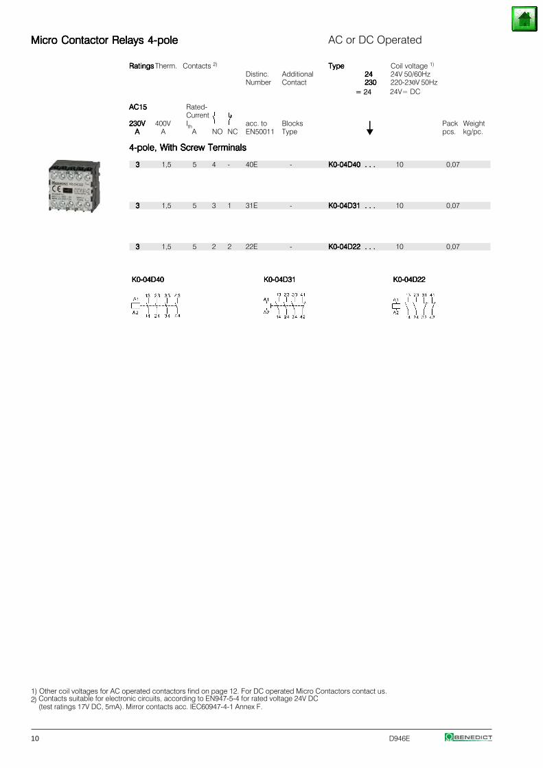
Micro Contactor Relays 4-poleMicro Contactor Relays 4-poleMicro Contactor Relays 4-poleMicro Contactor Relays 4-poleMicro Contactor Relays 4-pole AC or DC Operated
RatingsRatingsRatingsRatingsRatings Therm. Contacts 2) TypeTypeTypeTypeTypeDistinc. Additional 2424242424Number Contact 230230230230230
Coil voltage 1)
24V 50/60Hz220-230V 50Hz
AC15AC15AC15AC15AC15 Rated-Current
230V230V230V230V230V 400V Ith acc. to Blocks ⏐⏐⏐⏐⏐ Pack WeightAAAAA A A NO NC EN50011 Type pcs. kg/pc.
4-pole, With Screw Terminals4-pole, With Screw Terminals4-pole, With Screw Terminals4-pole, With Screw Terminals4-pole, With Screw Terminals
33333 1,5 5 4 - 40E - K0-04D40 . . .K0-04D40 . . .K0-04D40 . . .K0-04D40 . . .K0-04D40 . . . 10 0,07
33333 1,5 5 3 1 31E - K0-04D31 . . .K0-04D31 . . .K0-04D31 . . .K0-04D31 . . .K0-04D31 . . . 10 0,07
33333 1,5 5 2 2 22E - K0-04D22 . . .K0-04D22 . . .K0-04D22 . . .K0-04D22 . . .K0-04D22 . . . 10 0,07
K0-04D40K0-04D40K0-04D40K0-04D40K0-04D40 K0-04D31K0-04D31K0-04D31K0-04D31K0-04D31 K0-04D22K0-04D22K0-04D22K0-04D22K0-04D22
1)2) Contacts suitable for electronic circuits, according to EN947-5-4 for rated voltage 24V DC
(test ratings 17V DC, 5mA). Mirror contacts acc. IEC60947-4-1 Annex F.
= 24 24V= DC
Other coil voltages for AC operated contactors find on page 12. For DC operated Micro Contactors contact us.
D946E 11
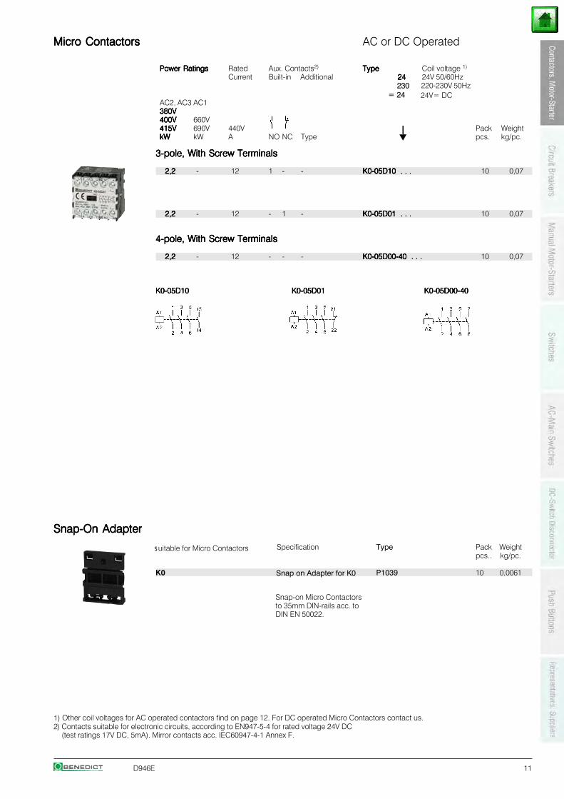
Micro ContactorsMicro ContactorsMicro ContactorsMicro ContactorsMicro Contactors AC or DC Operated
Power RatingsPower RatingsPower RatingsPower RatingsPower Ratings Rated Aux. Contacts2) TypeTypeTypeTypeType Coil voltage 1)
Current Built-in Additional 2424242424 24V 50/60Hz
AC2, AC3 AC1380V380V380V380V380V400V400V400V400V400V 660V415V415V415V415V415V 690V 440V ⏐⏐⏐⏐⏐ Pack WeightkWkWkWkWkW kW A NO NC Type pcs. kg/pc.
3-pole, With Screw Terminals3-pole, With Screw Terminals3-pole, With Screw Terminals3-pole, With Screw Terminals3-pole, With Screw Terminals
2,22,22,22,22,2 - 12 1 - - K0-05D10 . . .K0-05D10 . . .K0-05D10 . . .K0-05D10 . . .K0-05D10 . . . 10 0,07
2,22,22,22,22,2 - 12 - 1 - K0-05D01 . . .K0-05D01 . . .K0-05D01 . . .K0-05D01 . . .K0-05D01 . . . 10 0,07
4-pole, With Screw Terminals4-pole, With Screw Terminals4-pole, With Screw Terminals4-pole, With Screw Terminals4-pole, With Screw Terminals
2,22,22,22,22,2 - 12 - - - K0-05D00-40 . . .K0-05D00-40 . . .K0-05D00-40 . . .K0-05D00-40 . . .K0-05D00-40 . . . 10 0,07
K0-05D10K0-05D10K0-05D10K0-05D10K0-05D10 K0-05D01K0-05D01K0-05D01K0-05D01K0-05D01 K0-05D00-40K0-05D00-40K0-05D00-40K0-05D00-40K0-05D00-40
Snap-On AdapterSnap-On AdapterSnap-On AdapterSnap-On AdapterSnap-On Adapter
Specification Type Pack Weightpcs.. kg/pc.
K0 P1039 10 0,0061
1)2) Contacts suitable for electronic circuits, according to EN947-5-4 for rated voltage 24V DC
(test ratings 17V DC, 5mA). Mirror contacts acc. IEC60947-4-1 Annex F.
230 220-230V 50Hz = 24 24V= DC
suitable for Micro Contactors
Snap on Adapter for K0
Snap-on Micro Contactors to 35mm DIN-rails acc. to DIN EN 50022.
Other coil voltages for AC operated contactors find on page 12. For DC operated Micro Contactors contact us.
12 D946E
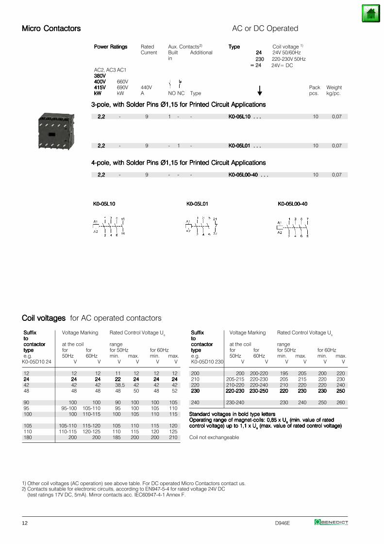
Micro ContactorsMicro ContactorsMicro ContactorsMicro ContactorsMicro Contactors AC or DC Operated
Power RatingsPower RatingsPower RatingsPower RatingsPower Ratings Rated Aux. Contacts2) TypeTypeTypeTypeType Coil voltage 1)
Current Built Additional 2424242424 24V 50/60Hzin
AC2, AC3 AC1380V380V380V380V380V400V400V400V400V400V 660V415V415V415V415V415V 690V 440V ⏐⏐⏐⏐⏐ Pack WeightkWkWkWkWkW kW A NO NC Type pcs. kg/pc.
3-pole, with Solder Pins Ø1,15 for Printed Circuit Applications3-pole, with Solder Pins Ø1,15 for Printed Circuit Applications3-pole, with Solder Pins Ø1,15 for Printed Circuit Applications3-pole, with Solder Pins Ø1,15 for Printed Circuit Applications3-pole, with Solder Pins Ø1,15 for Printed Circuit Applications
2,22,22,22,22,2 - 9 1 - - K0-05L10 . . .K0-05L10 . . .K0-05L10 . . .K0-05L10 . . .K0-05L10 . . . 10 0,07
2,22,22,22,22,2 - 9 - 1 - K0-05L01 . . .K0-05L01 . . .K0-05L01 . . .K0-05L01 . . .K0-05L01 . . . 10 0,07
4-pole, with Solder Pins Ø1,15 for Printed Circuit Applications4-pole, with Solder Pins Ø1,15 for Printed Circuit Applications4-pole, with Solder Pins Ø1,15 for Printed Circuit Applications4-pole, with Solder Pins Ø1,15 for Printed Circuit Applications4-pole, with Solder Pins Ø1,15 for Printed Circuit Applications
2,22,22,22,22,2 - 9 - - - K0-05L00-40 . . .K0-05L00-40 . . .K0-05L00-40 . . .K0-05L00-40 . . .K0-05L00-40 . . . 10 0,07
K0-05L10K0-05L10K0-05L10K0-05L10K0-05L10 K0-05L01K0-05L01K0-05L01K0-05L01K0-05L01 K0-05L00-40K0-05L00-40K0-05L00-40K0-05L00-40K0-05L00-40
1)2) Contacts suitable for electronic circuits, according to EN947-5-4 for rated voltage 24V DC
(test ratings 17V DC, 5mA). Mirror contacts acc. IEC60947-4-1 Annex F.
SuffixSuffixSuffixSuffixSuffix Voltage Marking Rated Control Voltage Ustototototocontactorcontactorcontactorcontactorcontactor at the coil rangetypetypetypetypetype for for for 50Hz for 60Hze.g. 50Hz 60Hz min. max. min. max.K0-05D10 230 V V V V V V
200 200 200-220 195 205 200 220210 205-215 220-230 205 215 220 230220 210-220 220-240 210 220 220 240230230230230230 220-230220-230220-230220-230220-230 230-250230-250230-250230-250230-250 220220220220220 230230230230230 230230230230230 250250250250250
240 230-240 230 240 250 260
Standard voltages in bold type lettersStandard voltages in bold type lettersStandard voltages in bold type lettersStandard voltages in bold type lettersStandard voltages in bold type lettersOperating range of magnet-coils: 0,85 x UOperating range of magnet-coils: 0,85 x UOperating range of magnet-coils: 0,85 x UOperating range of magnet-coils: 0,85 x UOperating range of magnet-coils: 0,85 x Usssss (min. value of rated (min. value of rated (min. value of rated (min. value of rated (min. value of ratedcontrol voltage) up to 1,1 x Ucontrol voltage) up to 1,1 x Ucontrol voltage) up to 1,1 x Ucontrol voltage) up to 1,1 x Ucontrol voltage) up to 1,1 x Usssss (max. value of rated control voltage) (max. value of rated control voltage) (max. value of rated control voltage) (max. value of rated control voltage) (max. value of rated control voltage)
Coil not exchangeable
SuffixSuffixSuffixSuffixSuffix Voltage Marking Rated Control Voltage Ustototototocontactorcontactorcontactorcontactorcontactor at the coil rangetypetypetypetypetype for for for 50Hz for 60Hze.g. 50Hz 60Hz min. max. min. max.
K0-05D10 24 V V V V V V
12 12 12 11 12 12 122424242424 2424242424 2424242424 2222222222 2424242424 2424242424 242424242442 42 42 38,5 42 42 4248 48 48 48 50 48 52
90 100 100 90 100 100 10595 95-100 105-110 95 100 105 110100 100 110-115 100 105 110 115
105 105-110 115-120 105 110 115 120110 110-115 120-125 110 115 120 125180 200 200 185 200 200 210
Coil voltages Coil voltages Coil voltages Coil voltages Coil voltages for AC operated contactors
230 220-230V 50Hz = 24 24V= DC
Other coil voltages (AC operation) see above table. For DC operated Micro Contactors contact us.
D946E 13
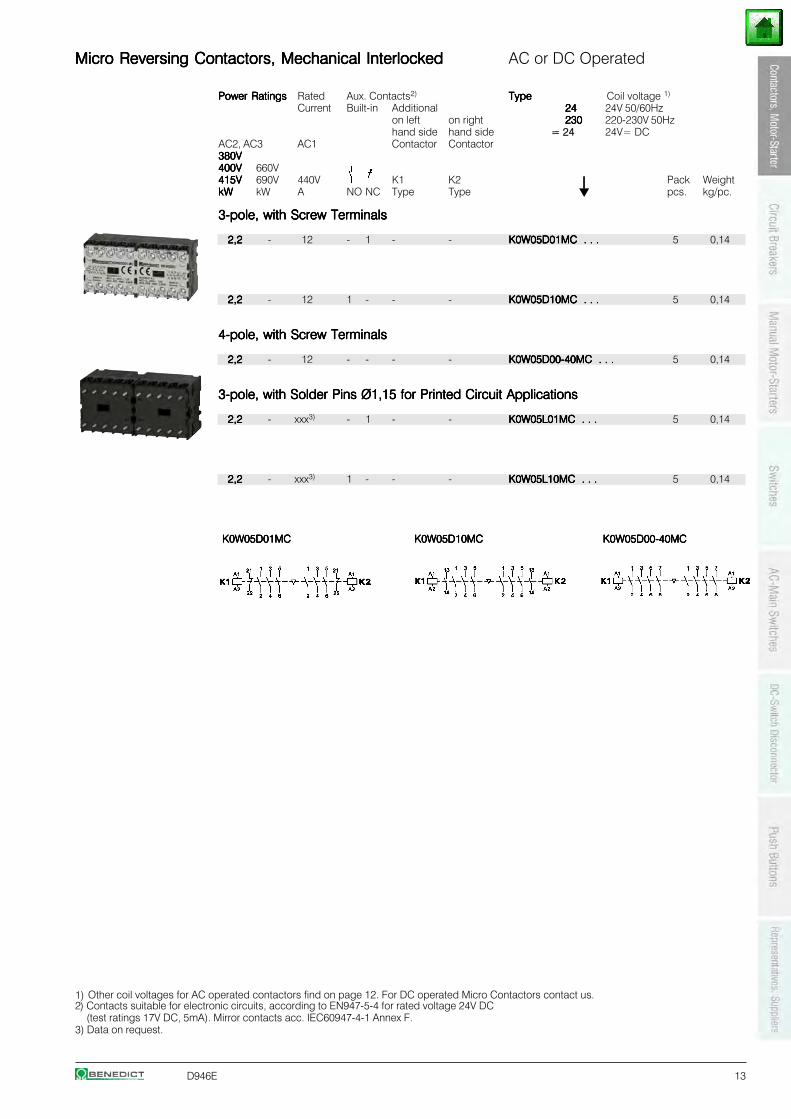
Micro Reversing Contactors, Mechanical InterlockedMicro Reversing Contactors, Mechanical InterlockedMicro Reversing Contactors, Mechanical InterlockedMicro Reversing Contactors, Mechanical InterlockedMicro Reversing Contactors, Mechanical Interlocked AC or DC Operated
Power RatingsPower RatingsPower RatingsPower RatingsPower Ratings Rated Aux. Contacts2) TypeTypeTypeTypeTypeCurrent Built-in Additional 2424242424
on left on right 230230230230230hand side hand side
AC2, AC3 AC1 Contactor Contactor380V380V380V380V380V400V400V400V400V400V 660V415V415V415V415V415V 690V 440V K1 K2 ⏐⏐⏐⏐⏐ Pack WeightkWkWkWkWkW kW A NO NC Type Type pcs. kg/pc.
3-pole, with Screw Terminals3-pole, with Screw Terminals3-pole, with Screw Terminals3-pole, with Screw Terminals3-pole, with Screw Terminals
2,22,22,22,22,2 - 12 - 1 - - K0W05D01MC . . .K0W05D01MC . . .K0W05D01MC . . .K0W05D01MC . . .K0W05D01MC . . . 5 0,14
2,22,22,22,22,2 - 12 1 - - - K0W05D10MC . . .K0W05D10MC . . .K0W05D10MC . . .K0W05D10MC . . .K0W05D10MC . . . 5 0,14
4-pole, with Screw Terminals4-pole, with Screw Terminals4-pole, with Screw Terminals4-pole, with Screw Terminals4-pole, with Screw Terminals
2,22,22,22,22,2 - 12 - - - - K0W05D00-40MC . . .K0W05D00-40MC . . .K0W05D00-40MC . . .K0W05D00-40MC . . .K0W05D00-40MC . . . 5 0,14
3-pole, with Solder Pins Ø1,15 for Printed Circuit Applications3-pole, with Solder Pins Ø1,15 for Printed Circuit Applications3-pole, with Solder Pins Ø1,15 for Printed Circuit Applications3-pole, with Solder Pins Ø1,15 for Printed Circuit Applications3-pole, with Solder Pins Ø1,15 for Printed Circuit Applications
2,22,22,22,22,2 - xxx3) - 1 - - K0W05L01MC . . .K0W05L01MC . . .K0W05L01MC . . .K0W05L01MC . . .K0W05L01MC . . . 5 0,14
2,22,22,22,22,2 - xxx3) 1 - - - K0W05L10MC . . .K0W05L10MC . . .K0W05L10MC . . .K0W05L10MC . . .K0W05L10MC . . . 5 0,14
K0W05D01MCK0W05D01MCK0W05D01MCK0W05D01MCK0W05D01MC K0W05D10MCK0W05D10MCK0W05D10MCK0W05D10MCK0W05D10MC K0W05D00-40MCK0W05D00-40MCK0W05D00-40MCK0W05D00-40MCK0W05D00-40MC
1)2) Contacts suitable for electronic circuits, according to EN947-5-4 for rated voltage 24V DC
(test ratings 17V DC, 5mA). Mirror contacts acc. IEC60947-4-1 Annex F.3) Data on request.
= 24
Coil voltage 1)
24V 50/60Hz220-230V 50Hz24V= DC
Other coil voltages for AC operated contactors find on page 12. For DC operated Micro Contactors contact us.
14 D946E
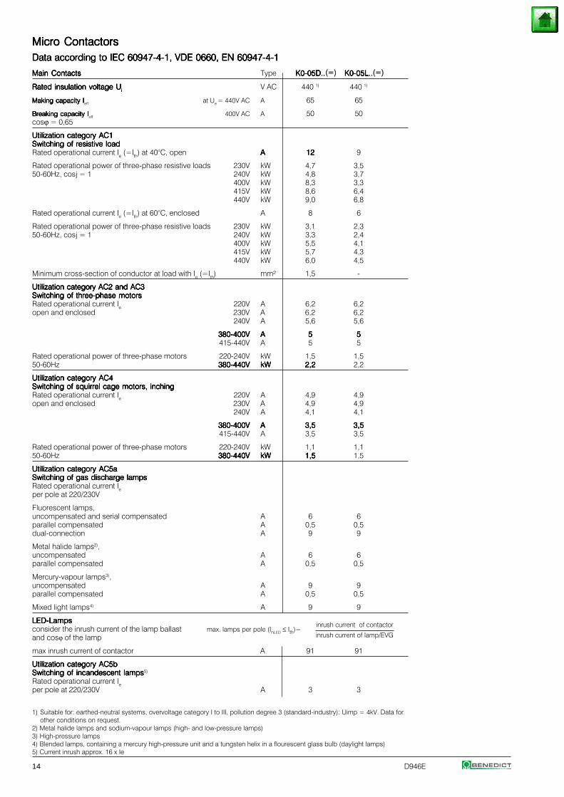
Micro ContactorsMicro ContactorsMicro ContactorsMicro ContactorsMicro ContactorsData according to IEC 60947-4-1, VDE 0660, EN 60947-4-1Data according to IEC 60947-4-1, VDE 0660, EN 60947-4-1Data according to IEC 60947-4-1, VDE 0660, EN 60947-4-1Data according to IEC 60947-4-1, VDE 0660, EN 60947-4-1Data according to IEC 60947-4-1, VDE 0660, EN 60947-4-1
Main ContactsMain ContactsMain ContactsMain ContactsMain Contacts Type K0-05D..K0-05D..K0-05D..K0-05D..K0-05D.. K0-05L..K0-05L..K0-05L..K0-05L..K0-05L..
Rated insulation voltage URated insulation voltage URated insulation voltage URated insulation voltage URated insulation voltage Uiiiii V AC 440 1) 440 1)
Making capacity IMaking capacity IMaking capacity IMaking capacity IMaking capacity Ieff at Ue = 440V AC A 65 65
Breaking capacity IBreaking capacity IBreaking capacity IBreaking capacity IBreaking capacity Ieff 400V AC A 50 50cosϕ = 0,65
Utilization category AC1Utilization category AC1Utilization category AC1Utilization category AC1Utilization category AC1Switching of resistive loadSwitching of resistive loadSwitching of resistive loadSwitching of resistive loadSwitching of resistive loadRated operational current Ie (=Ith) at 40°C, open AAAAA 1212121212 9
Rated operational power of three-phase resistive loads 230V kW 4,7 3,550-60Hz, cosj = 1 240V kW 4,8 3,7
400V kW 8,3 3,3415V kW 8,6 6,4440V kW 9,0 6,8
Rated operational current Ie (=Ith) at 60°C, enclosed A 8 6
Rated operational power of three-phase resistive loads 230V kW 3,1 2,350-60Hz, cosj = 1 240V kW 3,3 2,4
400V kW 5,5 4,1415V kW 5,7 4,3440V kW 6,0 4,5
Minimum cross-section of conductor at load with Ie (=Ith) mm² 1,5 -
Utilization category AC2 and AC3Utilization category AC2 and AC3Utilization category AC2 and AC3Utilization category AC2 and AC3Utilization category AC2 and AC3Switching of three-phase motorsSwitching of three-phase motorsSwitching of three-phase motorsSwitching of three-phase motorsSwitching of three-phase motorsRated operational current Ie 220V A 6,2 6,2open and enclosed 230V A 6,2 6,2
240V A 5,6 5,6
380-400V380-400V380-400V380-400V380-400V AAAAA 55555 55555415-440V A 5 5
Rated operational power of three-phase motors 220-240V kW 1,5 1,550-60Hz 380-440V380-440V380-440V380-440V380-440V kWkWkWkWkW 2,22,22,22,22,2 2,2
Utilization category AC4Utilization category AC4Utilization category AC4Utilization category AC4Utilization category AC4Switching of squirrel cage motors, inchingSwitching of squirrel cage motors, inchingSwitching of squirrel cage motors, inchingSwitching of squirrel cage motors, inchingSwitching of squirrel cage motors, inchingRated operational current Ie 220V A 4,9 4,9open and enclosed 230V A 4,9 4,9
240V A 4,1 4,1
380-400V380-400V380-400V380-400V380-400V AAAAA 3,53,53,53,53,5 3,53,53,53,53,5415-440V A 3,5 3,5
Rated operational power of three-phase motors 220-240V kW 1,1 1,150-60Hz 380-440V380-440V380-440V380-440V380-440V kWkWkWkWkW 1,51,51,51,51,5 1,5
Utilization category AC5aUtilization category AC5aUtilization category AC5aUtilization category AC5aUtilization category AC5aSwitching of gas discharge lampsSwitching of gas discharge lampsSwitching of gas discharge lampsSwitching of gas discharge lampsSwitching of gas discharge lampsRated operational current Ieper pole at 220/230V
Fluorescent lamps,uncompensated and serial compensated A 6 6parallel compensated A 0,5 0,5dual-connection A 9 9
Metal halide lamps2),uncompensated A 6 6parallel compensated A 0,5 0,5
Mercury-vapour lamps3),uncompensated A 9 9parallel compensated A 0,5 0,5
Mixed light lamps4) A 9 9
LED-LampsLED-LampsLED-LampsLED-LampsLED-Lampsinrush current of contactor
consider the inrush current of the lamp ballast max. lamps per pole (InLED ≤ Ith)=and cosϕ of the lamp inrush current of lamp/EVG
max inrush current of contactor A 91 91
Utilization category AC5bUtilization category AC5bUtilization category AC5bUtilization category AC5bUtilization category AC5bSwitching of incandescent lampsSwitching of incandescent lampsSwitching of incandescent lampsSwitching of incandescent lampsSwitching of incandescent lamps5)
Rated operational current Ieper pole at 220/230V A 3 3
1) Suitable for: earthed-neutral systems, overvoltage category I to III, pollution degree 3 (standard-industry): Uimp = 4kV. Data for other conditions on request.
2) Metal halide lamps and sodium-vapour lamps (high- and low-pressure lamps)3) High-pressure lamps4) Blended lamps, containing a mercury high-pressure unit and a tungsten helix in a flourescent glass bulb (daylight lamps)5) Current inrush approx. 16 x Ie
(=)(=)
D946E 15
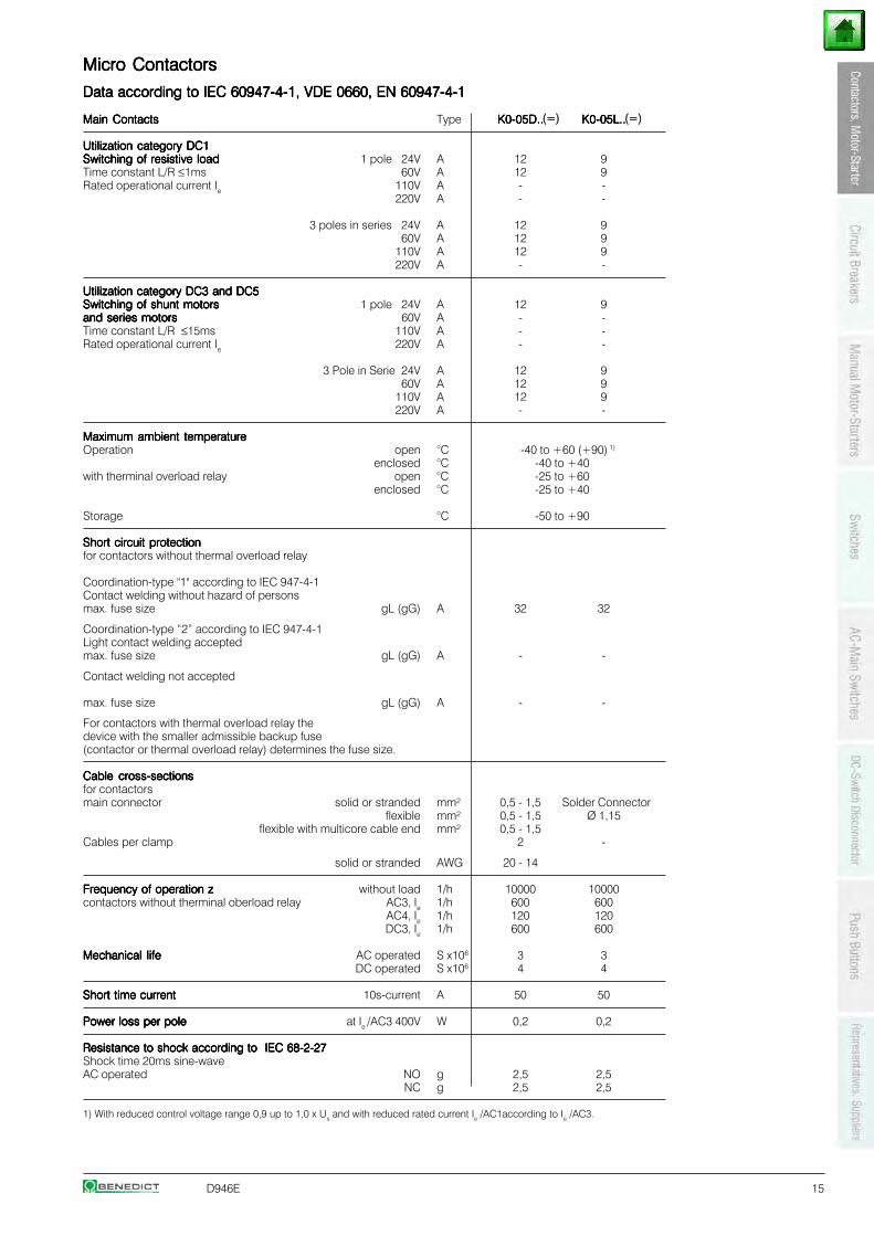
Micro ContactorsMicro ContactorsMicro ContactorsMicro ContactorsMicro Contactors
Data according to IEC 60947-4-1, VDE 0660, EN 60947-4-1Data according to IEC 60947-4-1, VDE 0660, EN 60947-4-1Data according to IEC 60947-4-1, VDE 0660, EN 60947-4-1Data according to IEC 60947-4-1, VDE 0660, EN 60947-4-1Data according to IEC 60947-4-1, VDE 0660, EN 60947-4-1
Main ContactsMain ContactsMain ContactsMain ContactsMain Contacts Type K0-05D..K0-05D..K0-05D..K0-05D..K0-05D.. K0-05L..K0-05L..K0-05L..K0-05L..K0-05L..
Utilization category DC1Utilization category DC1Utilization category DC1Utilization category DC1Utilization category DC1Switching of resistive loadSwitching of resistive loadSwitching of resistive loadSwitching of resistive loadSwitching of resistive load 1 pole 24V A 12 9Time constant L/R ≤1ms 60V A 12 9Rated operational current Ie 110V A - -
220V A - -
3 poles in series 24V A 12 9 60V A 12 9110V A 12 9220V A - -
Utilization category DC3 and DC5Utilization category DC3 and DC5Utilization category DC3 and DC5Utilization category DC3 and DC5Utilization category DC3 and DC5Switching of shunt motorsSwitching of shunt motorsSwitching of shunt motorsSwitching of shunt motorsSwitching of shunt motors 1 pole 24V A 12 9and series motorsand series motorsand series motorsand series motorsand series motors 60V A - -Time constant L/R ≤15ms 110V A - -Rated operational current Ie 220V A - -
3 Pole in Serie 24V A 12 9 60V A 12 9110V A 12 9220V A - -
Maximum ambient temperatureMaximum ambient temperatureMaximum ambient temperatureMaximum ambient temperatureMaximum ambient temperatureOperation open °C -40 to +60 (+90) 1)
enclosed °C -40 to +40with therminal overload relay open °C -25 to +60
enclosed °C -25 to +40
Storage °C -50 to +90
Short circuit protectionShort circuit protectionShort circuit protectionShort circuit protectionShort circuit protectionfor contactors without thermal overload relay
Coordination-type "1" according to IEC 947-4-1Contact welding without hazard of personsmax. fuse size gL (gG) A 32 32
Coordination-type “2” according to IEC 947-4-1Light contact welding acceptedmax. fuse size gL (gG) A - -
Contact welding not accepted
max. fuse size gL (gG) A - -
For contactors with thermal overload relay thedevice with the smaller admissible backup fuse(contactor or thermal overload relay) determines the fuse size.
Cable cross-sectionsCable cross-sectionsCable cross-sectionsCable cross-sectionsCable cross-sectionsfor contactorsmain connector solid or stranded mm² 0,5 - 1,5 Solder Connector
flexible mm² 0,5 - 1,5 Ø 1,15flexible with multicore cable end mm² 0,5 - 1,5
Cables per clamp 2 -
solid or stranded AWG 20 - 14
Frequency of operation zFrequency of operation zFrequency of operation zFrequency of operation zFrequency of operation z without load 1/h 10000 10000contactors without therminal oberload relay AC3, Ie 1/h 600 600
AC4, Ie 1/h 120 120DC3, Ie 1/h 600 600
Mechanical lifeMechanical lifeMechanical lifeMechanical lifeMechanical life AC operated S x106 3 3DC operated S x106 4 4
Short time currentShort time currentShort time currentShort time currentShort time current 10s-current A 50 50
Power loss per polePower loss per polePower loss per polePower loss per polePower loss per pole at Ie /AC3 400V W 0,2 0,2
Resistance to shock according to IEC 68-2-27Resistance to shock according to IEC 68-2-27Resistance to shock according to IEC 68-2-27Resistance to shock according to IEC 68-2-27Resistance to shock according to IEC 68-2-27Shock time 20ms sine-waveAC operated NO g 2,5 2,5
NC g 2,5 2,5
1) With reduced control voltage range 0,9 up to 1,0 x Us and with reduced rated current Ie /AC1according to Ie /AC3.
(=) (=)
16 D946E
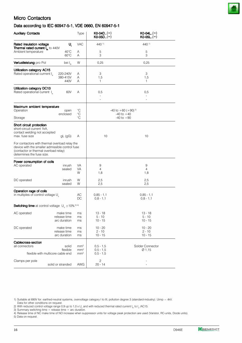
Micro ContactorsMicro ContactorsMicro ContactorsMicro ContactorsMicro Contactors
Data according to IEC 60947-5-1, VDE 0660, EN 60947-5-1Data according to IEC 60947-5-1, VDE 0660, EN 60947-5-1Data according to IEC 60947-5-1, VDE 0660, EN 60947-5-1Data according to IEC 60947-5-1, VDE 0660, EN 60947-5-1Data according to IEC 60947-5-1, VDE 0660, EN 60947-5-1
Auxiliary ContactsAuxiliary ContactsAuxiliary ContactsAuxiliary ContactsAuxiliary Contacts Type K0-04D..K0-04D..K0-04D..K0-04D..K0-04D.. K0-04L..K0-04L..K0-04L..K0-04L..K0-04L..K0-05D..K0-05D..K0-05D..K0-05D..K0-05D.. K0-05L..K0-05L..K0-05L..K0-05L..K0-05L..
Rated insulation voltageRated insulation voltageRated insulation voltageRated insulation voltageRated insulation voltage UUUUUiiiiiVAC 440 1) 440 1)
Thermal rated current IThermal rated current IThermal rated current IThermal rated current IThermal rated current Iththththth to 440V
Ambient temperature 40°C A 5 560°C A 3 3
Verlustleistung Verlustleistung Verlustleistung Verlustleistung Verlustleistung pro Pol bei Ith W 0,25 0,25
Utilization category AC15Utilization category AC15Utilization category AC15Utilization category AC15Utilization category AC15Rated operational currrent Ie 220-240V A 3 3
380-415V A 1,5 1,5440V A 1 1
Utilization category DC13Utilization category DC13Utilization category DC13Utilization category DC13Utilization category DC13Rated operational current Ie 60V A 0,5 0,5
- -- -
Maximum ambient temperatureMaximum ambient temperatureMaximum ambient temperatureMaximum ambient temperatureMaximum ambient temperatureOperation open °C -40 to +60 (+90) 2)
enclosed °C -40 to +40Storage °C -40 to +90
Short circuit protectionShort circuit protectionShort circuit protectionShort circuit protectionShort circuit protectionshort-circuit current 1kA,contact welding not acceptedmax. fuse size gL (gG) A 10 10
For contactors with thermal overload relay thedevice with the smaller admissible control fuse(contactor or thermal overload relay)determines the fuse size.
Power consumption of coilsPower consumption of coilsPower consumption of coilsPower consumption of coilsPower consumption of coilsAC operated inrush VA 9 9
sealed VA 4 4W 1,8 1,8
DC operated inrush W 2,5 2,5sealed W 2,5 2,5
Operation rage of coilsOperation rage of coilsOperation rage of coilsOperation rage of coilsOperation rage of coilsin multiples of control voltage Us AC 0,85 - 1,1 0,85 - 1,1
DC 0,8 - 1,1 0,8 - 1,1
Switching time Switching time Switching time Switching time Switching time at control voltage Us ±10% 3) 4)
AC operated make time ms 13 - 18 13 - 18release time ms 5 - 10 5 - 10arc duration ms 10 - 15 10 - 15
DC operated make time ms 10 - 20 10 - 20release time ms 2 - 10 2 - 10arc duration ms 10 - 15 10 - 15
Cablecross-sectionCablecross-sectionCablecross-sectionCablecross-sectionCablecross-sectionall connectors solid mm2 0,5 - 1,5 Solder Connector
flexible mm² 0,5 - 1,5 Ø 1,15flexible with multicore cable end mm2 0,5 - 1,5
Clamps per pole 2 -solid or stranded AWG 20 - 14 -
1) Suitable at 690V for: earthed-neutral systems, overvoltage category I to III, pollution degree 3 (standard-industry): Uimp = 4kV.Data for other conditions on request.
2) With reduced control voltage range 0,9 up to 1,0 x Us and with reduced thermal rated current Ith to Ie /AC15.3) Summary switching time = release time + arc duration.4) Release time of NC make time of NO increase when suppressor units for voltage peak protection are used (Varistor, RC-units, Diode units).5) Data on request.
(=)(=)
(=)(=)
D946E 17
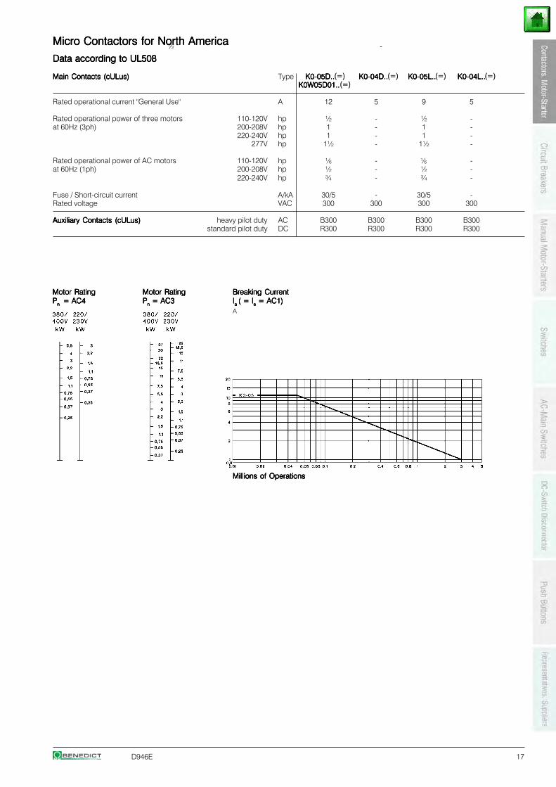
Micro Contactors for North AmericaMicro Contactors for North AmericaMicro Contactors for North AmericaMicro Contactors for North AmericaMicro Contactors for North America
Data according to UL508Data according to UL508Data according to UL508Data according to UL508Data according to UL508
Main Contacts (cULus)Main Contacts (cULus)Main Contacts (cULus)Main Contacts (cULus)Main Contacts (cULus) Type K0-05D..K0-05D..K0-05D..K0-05D..K0-05D.. K0-04D..K0-04D..K0-04D..K0-04D..K0-04D.. K0-05L..K0-05L..K0-05L..K0-05L..K0-05L.. K0-04L..K0-04L..K0-04L..K0-04L..K0-04L..K0W05D01..K0W05D01..K0W05D01..K0W05D01..K0W05D01..
Rated operational current "General Use" A 12 5 9 5
Rated operational power of three motors 110-120V hp ½ - ½ -at 60Hz (3ph) 200-208V hp 1 - 1 -
220-240V hp 1 - 1 -277V hp 1½ - 1½ -
Rated operational power of AC motors 110-120V hp - -at 60Hz (1ph) 200-208V hp ½ - ½ -
220-240V hp ¾ - ¾ -
Fuse / Short-circuit current A/kA 30/5 - 30/5 -Rated voltage VAC 300 300 300 300
Auxiliary Contacts (cULus)Auxiliary Contacts (cULus)Auxiliary Contacts (cULus)Auxiliary Contacts (cULus)Auxiliary Contacts (cULus) heavy pilot duty AC B300 B300 B300 B300standard pilot duty DC R300 R300 R300 R300
Motor RatingMotor RatingMotor RatingMotor RatingMotor Rating Motor RatingMotor RatingMotor RatingMotor RatingMotor Rating Breaking CurrentBreaking CurrentBreaking CurrentBreaking CurrentBreaking CurrentPPPPPn n n n n = AC4 = AC4 = AC4 = AC4 = AC4 PPPPPnnnnn = AC3 = AC3 = AC3 = AC3 = AC3 IIIIIa a a a a ( = I( = I( = I( = I( = Ieeeee = AC1) = AC1) = AC1) = AC1) = AC1)
A
Millions of OperationsMillions of OperationsMillions of OperationsMillions of OperationsMillions of Operations
½6
½ -
½6
(=)(=)(=) (=) (=)
18 D946E
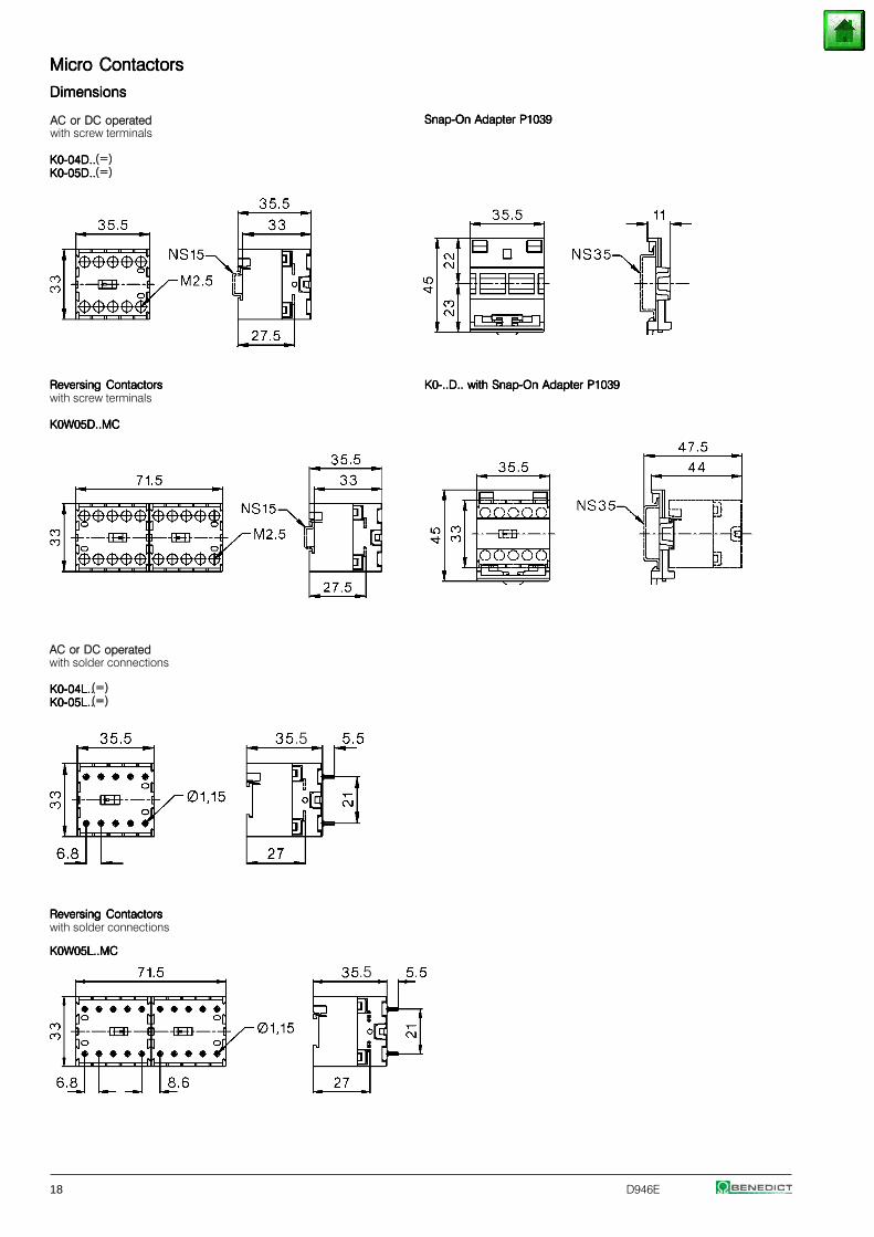
Micro ContactorsMicro ContactorsMicro ContactorsMicro ContactorsMicro Contactors
DimensionsDimensionsDimensionsDimensionsDimensions
Snap-On Adapter P1039Snap-On Adapter P1039Snap-On Adapter P1039Snap-On Adapter P1039Snap-On Adapter P1039
K0-04D..K0-04D..K0-04D..K0-04D..K0-04D..K0-05D..K0-05D..K0-05D..K0-05D..K0-05D..
Reversing ContactorsReversing ContactorsReversing ContactorsReversing ContactorsReversing Contactors K0-..D.. with Snap-On Adapter P1039K0-..D.. with Snap-On Adapter P1039K0-..D.. with Snap-On Adapter P1039K0-..D.. with Snap-On Adapter P1039K0-..D.. with Snap-On Adapter P1039with screw terminals
K0W05D..MCK0W05D..MCK0W05D..MCK0W05D..MCK0W05D..MC
AC or DC operatedwith solder connections
K0-04L..K0-04L..K0-04L..K0-04L..K0-04L..K0-05L..K0-05L..K0-05L..K0-05L..K0-05L..
Reversing ContactorsReversing ContactorsReversing ContactorsReversing ContactorsReversing Contactorswith solder connections
K0W05L..MCK0W05L..MCK0W05L..MCK0W05L..MCK0W05L..MC
AC or DC operatedwith screw terminals
(=)(=)
(=)(=)
.5
.5
D946E 19
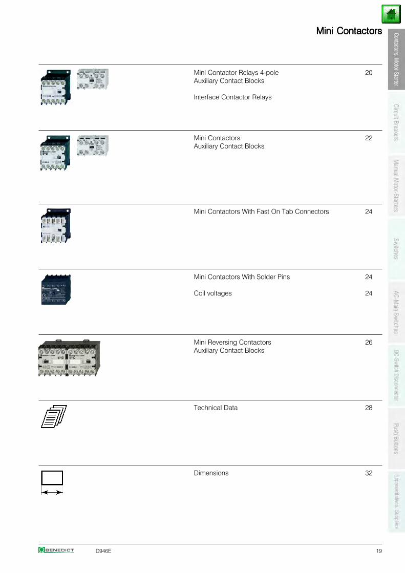
Mini ContactorsMini ContactorsMini ContactorsMini ContactorsMini Contactors
Mini Contactor Relays 4-pole 20Auxiliary Contact Blocks
Interface Contactor Relays
Mini Contactors 22Auxiliary Contact Blocks
Mini Contactors With Fast On Tab Connectors 24
Mini Contactors With Solder Pins 24
Coil voltages 24
Mini Reversing Contactors 26Auxiliary Contact Blocks
Technical Data 28
Dimensions 32
20 D946E
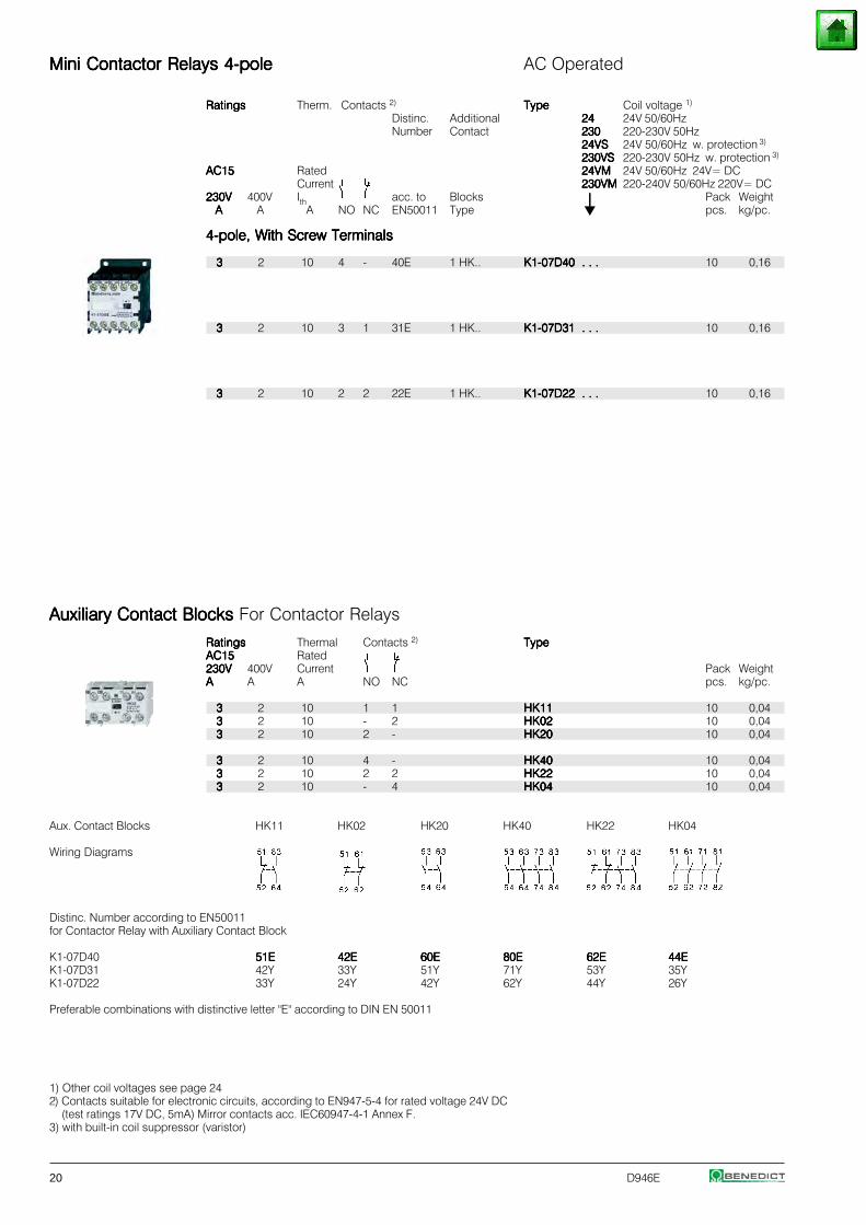
Mini Contactor Relays 4-poleMini Contactor Relays 4-poleMini Contactor Relays 4-poleMini Contactor Relays 4-poleMini Contactor Relays 4-pole AC Operated
RatingsRatingsRatingsRatingsRatings Therm. Contacts 2) TypeTypeTypeTypeType Coil voltage 1)
Distinc. Additional 2424242424 24V 50/60HzNumber Contact 230230230230230 220-230V 50Hz
24VS24VS24VS24VS24VS 24V 50/60Hz w. protection 3)
230VS230VS230VS230VS230VS 220-230V 50Hz w. protection 3)
AC15AC15AC15AC15AC15 Rated 24VM24VM24VM24VM24VM 24V 50/60Hz 24V= DCCurrent 230VM230VM230VM230VM230VM 220-240V 50/60Hz 220V= DC
230V230V230V230V230V 400V Ith acc. to Blocks ⏐⏐⏐⏐⏐ Pack WeightAAAAA A A NO NC EN50011 Type pcs. kg/pc.
4-pole, With Screw Terminals4-pole, With Screw Terminals4-pole, With Screw Terminals4-pole, With Screw Terminals4-pole, With Screw Terminals
33333 2 10 4 - 40E 1 HK.. K1-07D40 . . .K1-07D40 . . .K1-07D40 . . .K1-07D40 . . .K1-07D40 . . . 10 0,16
33333 2 10 3 1 31E 1 HK.. K1-07D31 . . .K1-07D31 . . .K1-07D31 . . .K1-07D31 . . .K1-07D31 . . . 10 0,16
33333 2 10 2 2 22E 1 HK.. K1-07D22 . . .K1-07D22 . . .K1-07D22 . . .K1-07D22 . . .K1-07D22 . . . 10 0,16
Auxiliary Contact Blocks Auxiliary Contact Blocks Auxiliary Contact Blocks Auxiliary Contact Blocks Auxiliary Contact Blocks For Contactor Relays
RatingsRatingsRatingsRatingsRatings Thermal Contacts 2) TypeTypeTypeTypeTypeAC15AC15AC15AC15AC15 Rated230V230V230V230V230V 400V Current Pack WeightAAAAA A A NO NC pcs. kg/pc.
33333 2 10 1 1 HK11HK11HK11HK11HK11 10 0,0433333 2 10 - 2 HK02HK02HK02HK02HK02 10 0,0433333 2 10 2 - HK20HK20HK20HK20HK20 10 0,04
33333 2 10 4 - HK40HK40HK40HK40HK40 10 0,0433333 2 10 2 2 HK22HK22HK22HK22HK22 10 0,0433333 2 10 - 4 HK04HK04HK04HK04HK04 10 0,04
Aux. Contact Blocks HK11 HK02 HK20 HK40 HK22 HK04
Wiring Diagrams
Distinc. Number according to EN50011for Contactor Relay with Auxiliary Contact Block
K1-07D40 51E51E51E51E51E 42E42E42E42E42E 60E60E60E60E60E 80E80E80E80E80E 62E62E62E62E62E 44E44E44E44E44EK1-07D31 42Y 33Y 51Y 71Y 53Y 35YK1-07D22 33Y 24Y 42Y 62Y 44Y 26Y
Preferable combinations with distinctive letter "E" according to DIN EN 50011
1) Other coil voltages see page 242) Contacts suitable for electronic circuits, according to EN947-5-4 for rated voltage 24V DC
(test ratings 17V DC, 5mA) Mirror contacts acc. IEC60947-4-1 Annex F.3) with built-in coil suppressor (varistor)
D946E 21
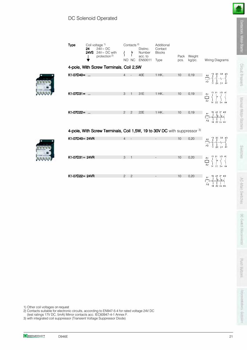
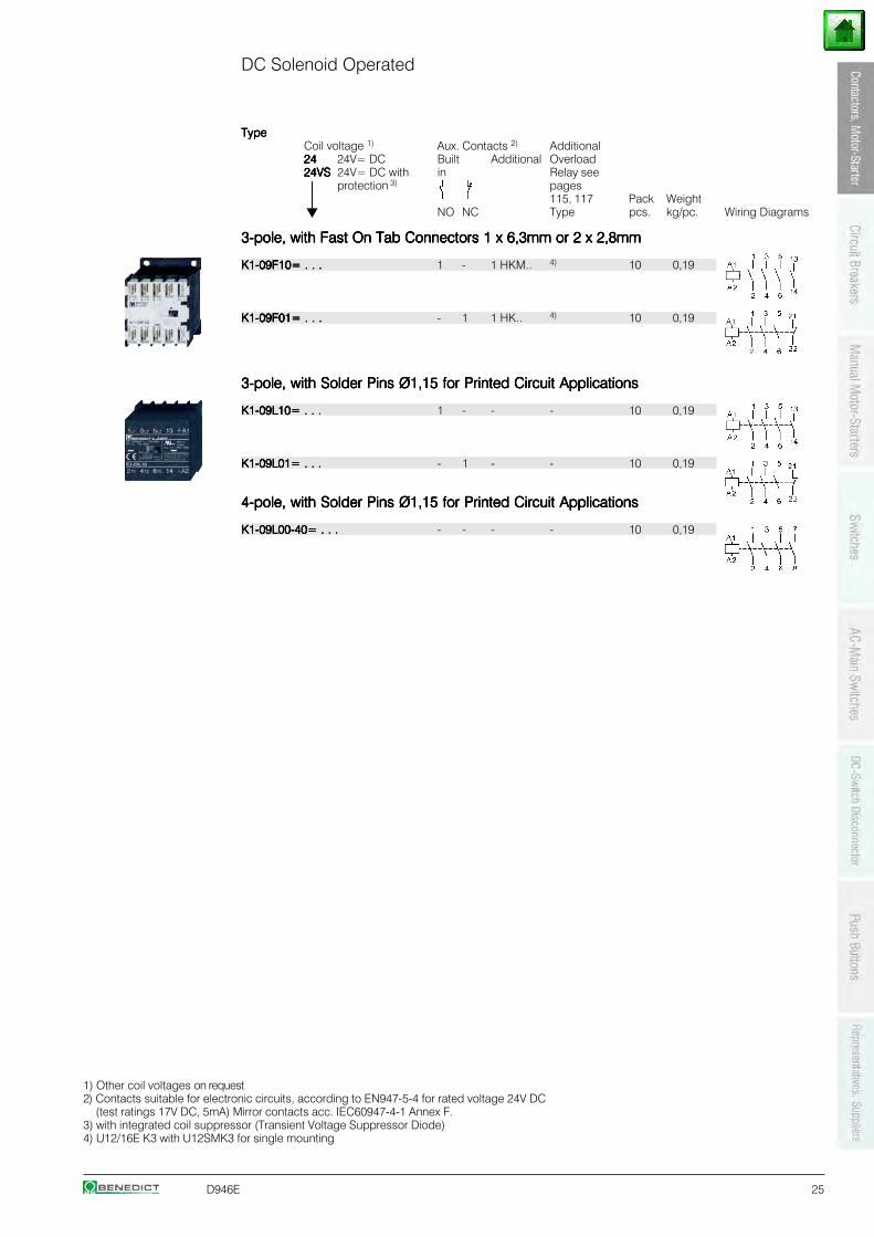
DC Solenoid Operated
TypeTypeTypeTypeType Coil voltage 1) Contacts 2) Additional2424242424 24V= DC Distinc. Contact24VS24VS24VS24VS24VS 24V= DC with Number Blocks
⏐⏐⏐⏐⏐ protection 2) acc. to Pack WeightNO NC EN50011 Type pcs. kg/pc. Wiring Diagrams
4-pole, With Screw Terminals, Coil 2,5W4-pole, With Screw Terminals, Coil 2,5W4-pole, With Screw Terminals, Coil 2,5W4-pole, With Screw Terminals, Coil 2,5W4-pole, With Screw Terminals, Coil 2,5W
K1-07D40= ...K1-07D40= ...K1-07D40= ...K1-07D40= ...K1-07D40= ... 4 - 40E 1 HK.. 10 0,19
K1-07D31= ...K1-07D31= ...K1-07D31= ...K1-07D31= ...K1-07D31= ... 3 1 31E 1 HK.. 10 0,19
K1-07D22= ...K1-07D22= ...K1-07D22= ...K1-07D22= ...K1-07D22= ... 2 2 22E 1 HK.. 10 0,19
4-pole, With Screw Terminals, Coil 1,5W, 19 to 30V DC4-pole, With Screw Terminals, Coil 1,5W, 19 to 30V DC4-pole, With Screw Terminals, Coil 1,5W, 19 to 30V DC4-pole, With Screw Terminals, Coil 1,5W, 19 to 30V DC4-pole, With Screw Terminals, Coil 1,5W, 19 to 30V DC with suppressor 3)
K1-07D40= 24VRK1-07D40= 24VRK1-07D40= 24VRK1-07D40= 24VRK1-07D40= 24VR 4 - - 10 0,20
K1-07D31= 24VRK1-07D31= 24VRK1-07D31= 24VRK1-07D31= 24VRK1-07D31= 24VR 3 1 - 10 0,20
K1-07D22= 24VRK1-07D22= 24VRK1-07D22= 24VRK1-07D22= 24VRK1-07D22= 24VR 2 2 - 10 0,20
1) Other coil voltages on request2) Contacts suitable for electronic circuits, according to EN947-5-4 for rated voltage 24V DC
(test ratings 17V DC, 5mA) Mirror contacts acc. IEC60947-4-1 Annex F.3) with integrated coil suppressor (Transient Voltage Suppressor Diode)
22 D946E
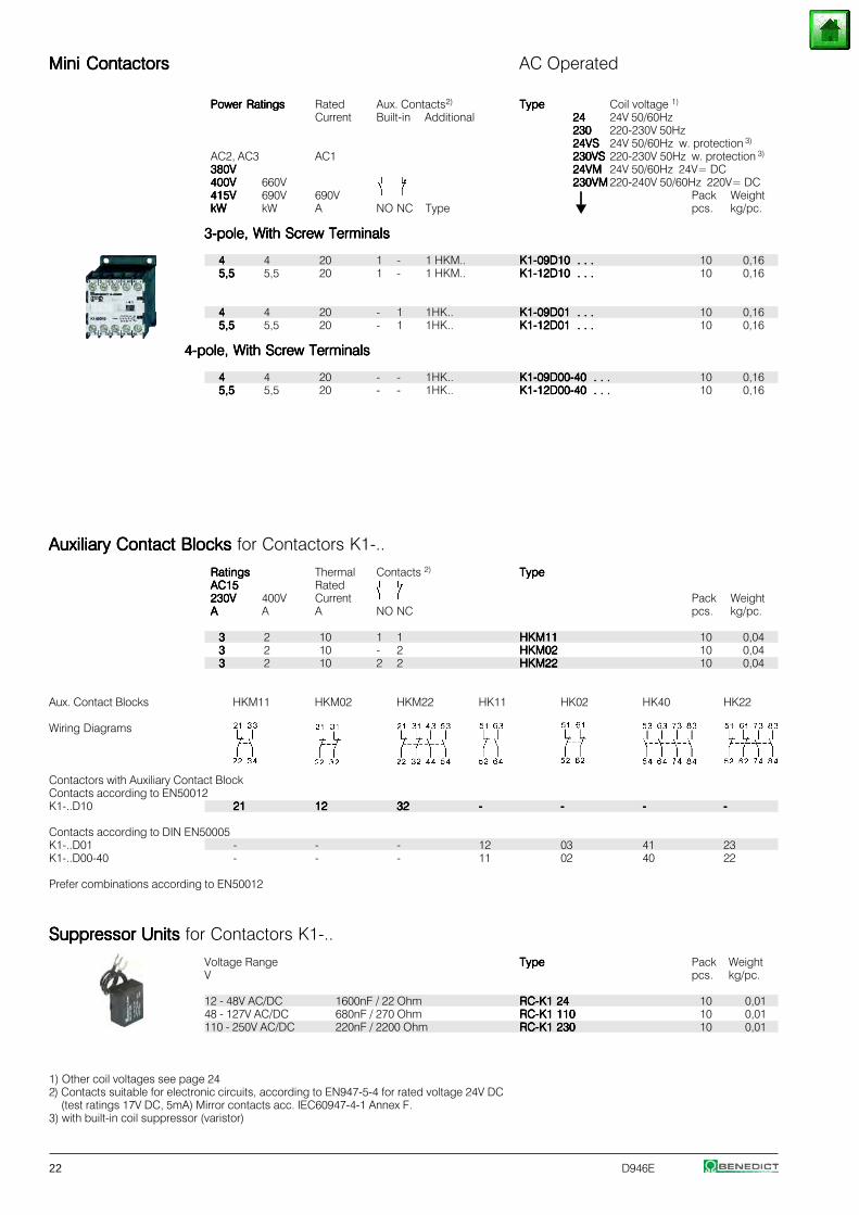
Mini ContactorsMini ContactorsMini ContactorsMini ContactorsMini Contactors AC Operated
Power RatingsPower RatingsPower RatingsPower RatingsPower Ratings Rated Aux. Contacts2) TypeTypeTypeTypeType Coil voltage 1)
Current Built-in Additional 2424242424 24V 50/60Hz230230230230230 220-230V 50Hz24VS24VS24VS24VS24VS 24V 50/60Hz w. protection 3)
AC2, AC3 AC1 230VS230VS230VS230VS230VS 220-230V 50Hz w. protection 3)
380V380V380V380V380V 24VM24VM24VM24VM24VM 24V 50/60Hz 24V= DC400V400V400V400V400V 660V 230VM230VM230VM230VM230VM 220-240V 50/60Hz 220V= DC415V415V415V415V415V 690V 690V ⏐⏐⏐⏐⏐ Pack WeightkWkWkWkWkW kW A NO NC Type pcs. kg/pc.
3-pole, With Screw Terminals3-pole, With Screw Terminals3-pole, With Screw Terminals3-pole, With Screw Terminals3-pole, With Screw Terminals
44444 4 20 1 - 1 HKM.. K1-09D10 . . .K1-09D10 . . .K1-09D10 . . .K1-09D10 . . .K1-09D10 . . . 10 0,165,55,55,55,55,5 5,5 20 1 - 1 HKM.. K1-12D10 . . .K1-12D10 . . .K1-12D10 . . .K1-12D10 . . .K1-12D10 . . . 10 0,16
44444 4 20 - 1 1HK.. K1-09D01 . . .K1-09D01 . . .K1-09D01 . . .K1-09D01 . . .K1-09D01 . . . 10 0,165,55,55,55,55,5 5,5 20 - 1 1HK.. K1-12D01 . . .K1-12D01 . . .K1-12D01 . . .K1-12D01 . . .K1-12D01 . . . 10 0,16
4-pole, With Screw Terminals4-pole, With Screw Terminals4-pole, With Screw Terminals4-pole, With Screw Terminals4-pole, With Screw Terminals
44444 4 20 - - 1HK.. K1-09D00-40 . . .K1-09D00-40 . . .K1-09D00-40 . . .K1-09D00-40 . . .K1-09D00-40 . . . 10 0,165,55,55,55,55,5 5,5 20 - - 1HK.. K1-12D00-40 . . .K1-12D00-40 . . .K1-12D00-40 . . .K1-12D00-40 . . .K1-12D00-40 . . . 10 0,16
Auxiliary Contact Blocks Auxiliary Contact Blocks Auxiliary Contact Blocks Auxiliary Contact Blocks Auxiliary Contact Blocks for Contactors K1-..
RatingsRatingsRatingsRatingsRatings Thermal Contacts 2) TypeTypeTypeTypeTypeAC15AC15AC15AC15AC15 Rated230V230V230V230V230V 400V Current Pack WeightAAAAA A A NO NC pcs. kg/pc.
33333 2 10 1 1 HKM11HKM11HKM11HKM11HKM11 10 0,0433333 2 10 - 2 HKM02HKM02HKM02HKM02HKM02 10 0,0433333 2 10 2 2 HKM22HKM22HKM22HKM22HKM22 10 0,04
Aux. Contact Blocks HKM11 HKM02 HKM22 HK11 HK02 HK40 HK22
Wiring Diagrams
Contactors with Auxiliary Contact BlockContacts according to EN50012K1-..D10 2121212121 1212121212 3232323232 ----- ----- ----- -----
Contacts according to DIN EN50005K1-..D01 - - - 12 03 41 23K1-..D00-40 - - - 11 02 40 22
Prefer combinations according to EN50012
Suppressor Units Suppressor Units Suppressor Units Suppressor Units Suppressor Units for Contactors K1-..
Voltage Range TypeTypeTypeTypeType Pack WeightV pcs. kg/pc.
12 - 48V AC/DC 1600nF / 22 Ohm RC-K1 24RC-K1 24RC-K1 24RC-K1 24RC-K1 24 10 0,0148 - 127V AC/DC 680nF / 270 Ohm RC-K1 110RC-K1 110RC-K1 110RC-K1 110RC-K1 110 10 0,01110 - 250V AC/DC 220nF / 2200 Ohm RC-K1 230RC-K1 230RC-K1 230RC-K1 230RC-K1 230 10 0,01
1) Other coil voltages see page 242) Contacts suitable for electronic circuits, according to EN947-5-4 for rated voltage 24V DC
(test ratings 17V DC, 5mA) Mirror contacts acc. IEC60947-4-1 Annex F.3) with built-in coil suppressor (varistor)
D946E 23
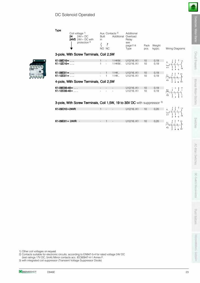
DC Solenoid Operated
TypeTypeTypeTypeTypeCoil voltage 1) Aux. Contacts 2) Additional2424242424 24V= DC Built Additional Overload24VS24VS24VS24VS24VS 24V= DC with in Relay
⏐⏐⏐⏐⏐ protection 3) see
⏐⏐⏐⏐⏐ page114 Pack WeightNO NC Type pcs. kg/pc. Wiring Diagrams
3-pole, With Screw Terminals, Coil 2,5W3-pole, With Screw Terminals, Coil 2,5W3-pole, With Screw Terminals, Coil 2,5W3-pole, With Screw Terminals, Coil 2,5W3-pole, With Screw Terminals, Coil 2,5W
K1-09D10= . . .K1-09D10= . . .K1-09D10= . . .K1-09D10= . . .K1-09D10= . . . 1 - 1 HKM.. U12/16..K1 10 0,19K1-12D10= . . .K1-12D10= . . .K1-12D10= . . .K1-12D10= . . .K1-12D10= . . . 1 - 1 HKM.. U12/16..K1 10 0,19
K1-09D01= . . .K1-09D01= . . .K1-09D01= . . .K1-09D01= . . .K1-09D01= . . . - 1 1 HK.. U12/16..K1 10 0,19K1-12D01= . . .K1-12D01= . . .K1-12D01= . . .K1-12D01= . . .K1-12D01= . . . - 1 1 HK.. U12/16..K1 10 0,19
4-pole, With Screw Terminals, Coil 2,5W4-pole, With Screw Terminals, Coil 2,5W4-pole, With Screw Terminals, Coil 2,5W4-pole, With Screw Terminals, Coil 2,5W4-pole, With Screw Terminals, Coil 2,5W
K1-09D00-40= . . .K1-09D00-40= . . .K1-09D00-40= . . .K1-09D00-40= . . .K1-09D00-40= . . . - - - U12/16..K1 10 0,19K1-12D00-40= . . .K1-12D00-40= . . .K1-12D00-40= . . .K1-12D00-40= . . .K1-12D00-40= . . . - - - U12/16..K1 10 0,19
3-pole, With Screw Terminals, Coil 1,5W, 19 to 30V DC3-pole, With Screw Terminals, Coil 1,5W, 19 to 30V DC3-pole, With Screw Terminals, Coil 1,5W, 19 to 30V DC3-pole, With Screw Terminals, Coil 1,5W, 19 to 30V DC3-pole, With Screw Terminals, Coil 1,5W, 19 to 30V DC with suppressor 3)
K1-09D10=24VRK1-09D10=24VRK1-09D10=24VRK1-09D10=24VRK1-09D10=24VR 1 - - U12/16..K1 10 0,20
K1-09D01= 24VRK1-09D01= 24VRK1-09D01= 24VRK1-09D01= 24VRK1-09D01= 24VR - - 1 - U12/16..K1 10 0,20
1) Other coil voltages on request2) Contacts suitable for electronic circuits, according to EN947-5-4 for rated voltage 24V DC
(test ratings 17V DC, 5mA) Mirror contacts acc. IEC60947-4-1 Annex F.3) with integrated coil suppressor (Transient Voltage Suppressor Diode)
24 D946E
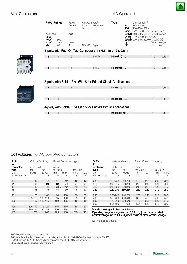
Mini ContactorsMini ContactorsMini ContactorsMini ContactorsMini Contactors AC Operated
Power RatingsPower RatingsPower RatingsPower RatingsPower Ratings Rated Aux. Contacts2) TypeTypeTypeTypeType Coil voltage 1)
Current Built Additional 2424242424 24V 50/60Hzin 230230230230230 220-230V 50Hz
24VS24VS24VS24VS24VS 24V 50/60Hz w. protection 2)
AC2, AC3 AC1 230VS230VS230VS230VS230VS 220-230V 50Hz w. protection 2)
380V380V380V380V380V 24VM24VM24VM24VM24VM 24V 50/60Hz 24V DC400V400V400V400V400V 660V 230VM230VM230VM230VM230VM 220-240V 50/60Hz 220V DC415V415V415V415V415V 690V 690V ⏐⏐⏐⏐⏐ Pack WeightkWkWkWkWkW kW A NO NC Type pcs. kg/pc.
3-pole, with Fast On Tab Connectors 1 x 6,3mm or 2 x 2,8mm3-pole, with Fast On Tab Connectors 1 x 6,3mm or 2 x 2,8mm3-pole, with Fast On Tab Connectors 1 x 6,3mm or 2 x 2,8mm3-pole, with Fast On Tab Connectors 1 x 6,3mm or 2 x 2,8mm3-pole, with Fast On Tab Connectors 1 x 6,3mm or 2 x 2,8mm
44444 4 16 1 - 1 HKM.. K1-09F10 . . .K1-09F10 . . .K1-09F10 . . .K1-09F10 . . .K1-09F10 . . . 10 0,16
44444 4 16 - 1 1 HK.. K1-09F01 . . .K1-09F01 . . .K1-09F01 . . .K1-09F01 . . .K1-09F01 . . . 10 0,16
3-pole, with Solder Pins Ø1,15 for Printed Circuit Applications3-pole, with Solder Pins Ø1,15 for Printed Circuit Applications3-pole, with Solder Pins Ø1,15 for Printed Circuit Applications3-pole, with Solder Pins Ø1,15 for Printed Circuit Applications3-pole, with Solder Pins Ø1,15 for Printed Circuit Applications
44444 4 16 1 - - K1-09L10 . . .K1-09L10 . . .K1-09L10 . . .K1-09L10 . . .K1-09L10 . . . 10 0,16
44444 4 16 - 1 - K1-09L01 . . .K1-09L01 . . .K1-09L01 . . .K1-09L01 . . .K1-09L01 . . . 10 0,16
4-pole, with Solder Pins Ø1,15 for Printed Circuit Applications4-pole, with Solder Pins Ø1,15 for Printed Circuit Applications4-pole, with Solder Pins Ø1,15 for Printed Circuit Applications4-pole, with Solder Pins Ø1,15 for Printed Circuit Applications4-pole, with Solder Pins Ø1,15 for Printed Circuit Applications
44444 4 16 - - - K1-09L00-40 . . .K1-09L00-40 . . .K1-09L00-40 . . .K1-09L00-40 . . .K1-09L00-40 . . . 10 0,16
1) Other coil voltages see page 242) Contacts suitable for electronic circuits, according to EN947-5-4 for rated voltage 24V DC
(test ratings 17V DC, 5mA) Mirror contacts acc. IEC60947-4-1 Annex F.3) with built-in coil suppressor (varistor)
SuffixSuffixSuffixSuffixSuffix Voltage Marking Rated Control Voltage Ustototototocontactorcontactorcontactorcontactorcontactor at the coil rangetypetypetypetypetype for for for 50Hz for 60Hze.g. 50Hz 60Hz min. max. min. max.K1-09D10 230 V V V V V V
200 200 200-220 195 205 200 220210 205-215 220-230 205 215 220 230220 210-220 220-240 210 220 220 240230230230230230 220-230220-230220-230220-230220-230 230-250230-250230-250230-250230-250 220220220220220 230230230230230 230230230230230 250250250250250
240 230-240 240-260 230 240 240 260400 380-400 400-440 380 400 400 440500 475-500 520-545 475 500 520 545550 525-550 600 525 550 570 600
Standard voltages in bold type lettersStandard voltages in bold type lettersStandard voltages in bold type lettersStandard voltages in bold type lettersStandard voltages in bold type lettersOperating range of magnet-coils: 0,85 x UOperating range of magnet-coils: 0,85 x UOperating range of magnet-coils: 0,85 x UOperating range of magnet-coils: 0,85 x UOperating range of magnet-coils: 0,85 x Usssss (min. value of rated (min. value of rated (min. value of rated (min. value of rated (min. value of ratedcontrol voltage) up to 1,1 x Ucontrol voltage) up to 1,1 x Ucontrol voltage) up to 1,1 x Ucontrol voltage) up to 1,1 x Ucontrol voltage) up to 1,1 x Usssss (max. value of rated control voltage) (max. value of rated control voltage) (max. value of rated control voltage) (max. value of rated control voltage) (max. value of rated control voltage)
Coil not exchangeable
SuffixSuffixSuffixSuffixSuffix Voltage Marking Rated Control Voltage Ustototototocontactorcontactorcontactorcontactorcontactor at the coil rangetypetypetypetypetype for for for 50Hz for 60Hze.g. 50Hz 60Hz min. max. min. max.K1-09D10 24 V V V V V V
12 12 12 11 12 12 122424242424 2424242424 2424242424 2222222222 2424242424 2424242424 242424242442 42 42 38,5 42 42 4248 48 48 48 50 48 52
90 100 100 90 100 100 10595 95-100 105-110 95 100 105 110100 100 110-115 100 105 110 115
105 105-110 115-120 105 110 115 120110 110-115 120-125 110 115 120 125180 200 200 185 200 200 210
Coil voltages Coil voltages Coil voltages Coil voltages Coil voltages for AC operated contactors
D946E 25
DC Solenoid Operated
TypeTypeTypeTypeTypeCoil voltage 1) Aux. Contacts 2) Additional2424242424 24V= DC Built Additional Overload24VS24VS24VS24VS24VS 24V= DC with in Relay see
⏐⏐⏐⏐⏐ protection 3) pages
⏐⏐⏐⏐⏐ 115, 117 Pack WeightNO NC Type pcs. kg/pc. Wiring Diagrams
3-pole, with Fast On Tab Connectors 1 x 6,3mm or 2 x 2,8mm3-pole, with Fast On Tab Connectors 1 x 6,3mm or 2 x 2,8mm3-pole, with Fast On Tab Connectors 1 x 6,3mm or 2 x 2,8mm3-pole, with Fast On Tab Connectors 1 x 6,3mm or 2 x 2,8mm3-pole, with Fast On Tab Connectors 1 x 6,3mm or 2 x 2,8mm
K1-09F10= . . .K1-09F10= . . .K1-09F10= . . .K1-09F10= . . .K1-09F10= . . . 1 - 1 HKM.. 4) 10 0,19
K1-09F01= . . .K1-09F01= . . .K1-09F01= . . .K1-09F01= . . .K1-09F01= . . . - 1 1 HK.. 4) 10 0,19
3-pole, with Solder Pins Ø1,15 for Printed Circuit Applications3-pole, with Solder Pins Ø1,15 for Printed Circuit Applications3-pole, with Solder Pins Ø1,15 for Printed Circuit Applications3-pole, with Solder Pins Ø1,15 for Printed Circuit Applications3-pole, with Solder Pins Ø1,15 for Printed Circuit Applications
K1-09L10= . . .K1-09L10= . . .K1-09L10= . . .K1-09L10= . . .K1-09L10= . . . 1 - - - 10 0,19
K1-09L01= . . .K1-09L01= . . .K1-09L01= . . .K1-09L01= . . .K1-09L01= . . . - 1 - - 10 0,19
4-pole, with Solder Pins Ø1,15 for Printed Circuit Applications4-pole, with Solder Pins Ø1,15 for Printed Circuit Applications4-pole, with Solder Pins Ø1,15 for Printed Circuit Applications4-pole, with Solder Pins Ø1,15 for Printed Circuit Applications4-pole, with Solder Pins Ø1,15 for Printed Circuit Applications
K1-09L00-40= . . .K1-09L00-40= . . .K1-09L00-40= . . .K1-09L00-40= . . .K1-09L00-40= . . . - - - - 10 0,19
1) Other coil voltages on request2) Contacts suitable for electronic circuits, according to EN947-5-4 for rated voltage 24V DC
(test ratings 17V DC, 5mA) Mirror contacts acc. IEC60947-4-1 Annex F.3) with integrated coil suppressor (Transient Voltage Suppressor Diode)4) U12/16E K3 with U12SMK3 for single mounting
26 D946E
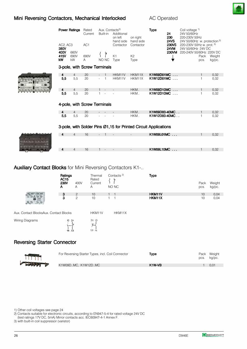
Mini Reversing Contactors, Mechanical InterlockedMini Reversing Contactors, Mechanical InterlockedMini Reversing Contactors, Mechanical InterlockedMini Reversing Contactors, Mechanical InterlockedMini Reversing Contactors, Mechanical Interlocked AC Operated
Power RatingsPower RatingsPower RatingsPower RatingsPower Ratings Rated Aux. Contacts2) TypeTypeTypeTypeType Coil voltage 1)
Current Built-in Additional 2424242424 24V 50/60Hzon left on right 230230230230230 220-230V 50Hzhand side hand side 24VS24VS24VS24VS24VS 24V 50/60Hz w. protection 3)
AC2, AC3 AC1 Contactor Contactor 230VS230VS230VS230VS230VS 220-230V 50Hz w. prot. 3)
380V380V380V380V380V 24VM24VM24VM24VM24VM 24V 50/60Hz 24V DC400V400V400V400V400V 660V 230VM230VM230VM230VM230VM 220-240V 50/60Hz 220V DC415V415V415V415V415V 690V 690V K1 K2 ⏐⏐⏐⏐⏐ Pack WeightkWkWkWkWkW kW A NO NC Type Type pcs. kg/pc.
3-pole, with Screw Terminals3-pole, with Screw Terminals3-pole, with Screw Terminals3-pole, with Screw Terminals3-pole, with Screw Terminals
44444 4 20 - 1 HKM11V HKM11X K1W09D01MC . . .K1W09D01MC . . .K1W09D01MC . . .K1W09D01MC . . .K1W09D01MC . . . 1 0,325,55,55,55,55,5 5,5 20 - 1 HKM11V HKM11X K1W12D01MC . . .K1W12D01MC . . .K1W12D01MC . . .K1W12D01MC . . .K1W12D01MC . . . 1 0,32
44444 4 20 1 - - HKM.. K1W09D10MC . . .K1W09D10MC . . .K1W09D10MC . . .K1W09D10MC . . .K1W09D10MC . . . 1 0,325,55,55,55,55,5 5,5 20 1 - - HKM.. K1W12D10MC . . .K1W12D10MC . . .K1W12D10MC . . .K1W12D10MC . . .K1W12D10MC . . . 1 0,32
4-pole, with Screw Terminals4-pole, with Screw Terminals4-pole, with Screw Terminals4-pole, with Screw Terminals4-pole, with Screw Terminals
44444 4 20 - - - HKM.. K1W09D00-40MC . .K1W09D00-40MC . .K1W09D00-40MC . .K1W09D00-40MC . .K1W09D00-40MC . . 1 0,325,55,55,55,55,5 5,5 20 - - - HKM.. K1W12D00-40MC . .K1W12D00-40MC . .K1W12D00-40MC . .K1W12D00-40MC . .K1W12D00-40MC . . 1 0,32
3-pole, with Solder Pins Ø1,15 for Printed Circuit Applications3-pole, with Solder Pins Ø1,15 for Printed Circuit Applications3-pole, with Solder Pins Ø1,15 for Printed Circuit Applications3-pole, with Solder Pins Ø1,15 for Printed Circuit Applications3-pole, with Solder Pins Ø1,15 for Printed Circuit Applications
44444 4 16 - 1 - - K1W09L01MC . . .K1W09L01MC . . .K1W09L01MC . . .K1W09L01MC . . .K1W09L01MC . . . 1 0,32
44444 4 16 1 - - - K1W09L10MC . . .K1W09L10MC . . .K1W09L10MC . . .K1W09L10MC . . .K1W09L10MC . . . 1 0,32
Auxiliary Contact Blocks Auxiliary Contact Blocks Auxiliary Contact Blocks Auxiliary Contact Blocks Auxiliary Contact Blocks for Mini Reversing Contactors K1-..
RatingsRatingsRatingsRatingsRatings Thermal Contacts 2) TypeTypeTypeTypeTypeAC15AC15AC15AC15AC15 Rated230V230V230V230V230V 400V Current Pack WeightAAAAA A A NO NC pcs. kg/pc.
33333 2 10 1 1 HKM11VHKM11VHKM11VHKM11VHKM11V 10 0,0433333 2 10 1 1 HKM11XHKM11XHKM11XHKM11XHKM11X 10 0,04
Aux. Contact BlocksAux. Contact Blocks HKM11V HKM11X
Wiring Diagrams
Reversing Starter ConnectorReversing Starter ConnectorReversing Starter ConnectorReversing Starter ConnectorReversing Starter Connector
For Reversing Starter Types, incl. Coil Connector TypeTypeTypeTypeType Pack Weightpcs. kg/pc.
K1W09D..MC, K1W12D..MC K1W-VBK1W-VBK1W-VBK1W-VBK1W-VB 1 0,01
1) Other coil voltages see page 242) Contacts suitable for electronic circuits, according to EN947-5-4 for rated voltage 24V DC
(test ratings 17V DC, 5mA) Mirror contacts acc. IEC60947-4-1 Annex F.3) with built-in coil suppressor (varistor)
D946E 27
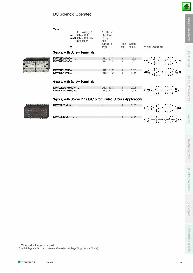
DC Solenoid Operated
TypeTypeTypeTypeTypeCoil voltage 1) Additional
2424242424 24V= DC Overload24VS24VS24VS24VS24VS 24V= DC with Relay
⏐⏐⏐⏐⏐ protection 2) see
⏐⏐⏐⏐⏐ page114 Pack WeightType pcs. kg/pc. Wiring Diagrams
3-pole, with Screw Terminals3-pole, with Screw Terminals3-pole, with Screw Terminals3-pole, with Screw Terminals3-pole, with Screw Terminals
K1W09D01MC= . . .K1W09D01MC= . . .K1W09D01MC= . . .K1W09D01MC= . . .K1W09D01MC= . . . U12/16..K1 1 0,32K1W12D01MC= . . .K1W12D01MC= . . .K1W12D01MC= . . .K1W12D01MC= . . .K1W12D01MC= . . . U12/16..K1 1 0,32
K1W09D10MC= . . .K1W09D10MC= . . .K1W09D10MC= . . .K1W09D10MC= . . .K1W09D10MC= . . . U12/16..K1 1 0,32K1W12D10MC= . . .K1W12D10MC= . . .K1W12D10MC= . . .K1W12D10MC= . . .K1W12D10MC= . . . U12/16..K1 1 0,32
4-pole, with Screw Terminals4-pole, with Screw Terminals4-pole, with Screw Terminals4-pole, with Screw Terminals4-pole, with Screw Terminals
K1W09D00-40MC= . .K1W09D00-40MC= . .K1W09D00-40MC= . .K1W09D00-40MC= . .K1W09D00-40MC= . . U12/16..K1 1 0,32K1W12D00-40MC= . .K1W12D00-40MC= . .K1W12D00-40MC= . .K1W12D00-40MC= . .K1W12D00-40MC= . . U12/16..K1 1 0,32
3-pole, with Solder Pins Ø1,15 for Printed Circuits Applications3-pole, with Solder Pins Ø1,15 for Printed Circuits Applications3-pole, with Solder Pins Ø1,15 for Printed Circuits Applications3-pole, with Solder Pins Ø1,15 for Printed Circuits Applications3-pole, with Solder Pins Ø1,15 for Printed Circuits Applications
K1W09L01MC= . . .K1W09L01MC= . . .K1W09L01MC= . . .K1W09L01MC= . . .K1W09L01MC= . . . - 1 0,32
K1W09L10MC= . . .K1W09L10MC= . . .K1W09L10MC= . . .K1W09L10MC= . . .K1W09L10MC= . . . - 1 0,32
1) Other coil voltages on request2) with integrated coil suppressor (Transient Voltage Suppressor Diode)
28 D946E
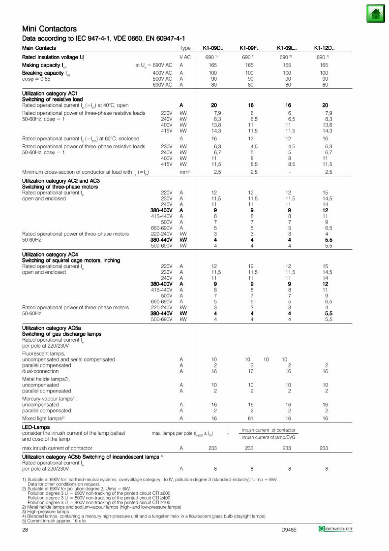
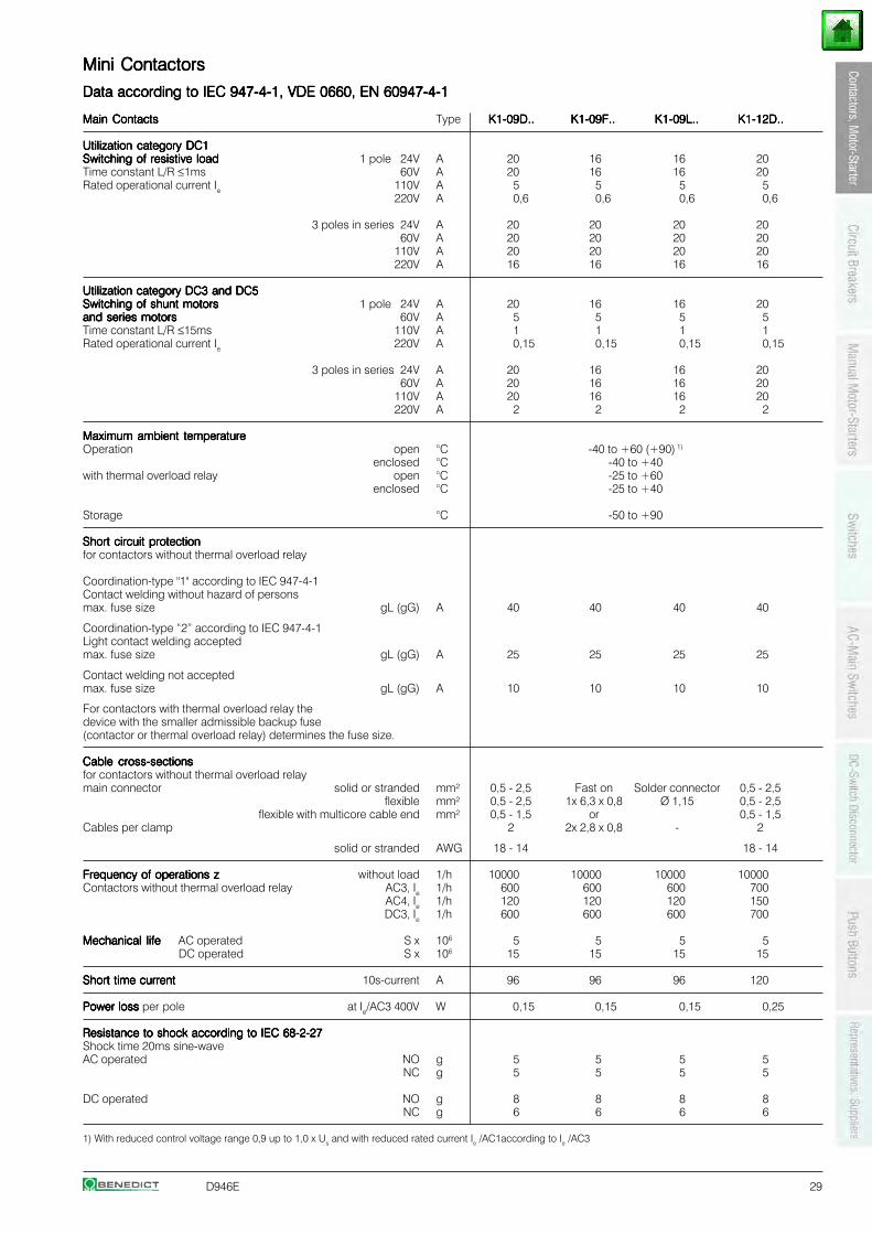
Mini ContactorsMini ContactorsMini ContactorsMini ContactorsMini ContactorsData according to IEC 947-4-1, VDE 0660, EN 60947-4-1Data according to IEC 947-4-1, VDE 0660, EN 60947-4-1Data according to IEC 947-4-1, VDE 0660, EN 60947-4-1Data according to IEC 947-4-1, VDE 0660, EN 60947-4-1Data according to IEC 947-4-1, VDE 0660, EN 60947-4-1Main ContactsMain ContactsMain ContactsMain ContactsMain Contacts Type K1-09D..K1-09D..K1-09D..K1-09D..K1-09D.. K1-09F..K1-09F..K1-09F..K1-09F..K1-09F.. K1-09L..K1-09L..K1-09L..K1-09L..K1-09L.. K1-12D..K1-12D..K1-12D..K1-12D..K1-12D..
Rated insulation voltage URated insulation voltage URated insulation voltage URated insulation voltage URated insulation voltage Uiiiii V AC 690 1) 690 1) 690 2) 690 1)
Making capacity IMaking capacity IMaking capacity IMaking capacity IMaking capacity Ieff at Ue = 690V AC A 165 165 165 165
Breaking capacity IBreaking capacity IBreaking capacity IBreaking capacity IBreaking capacity Ieff 400V AC A 100 100 100 100cosϕ = 0,65 500V AC A 90 90 90 90
690V AC A 80 80 80 80
Utilization category AC1Utilization category AC1Utilization category AC1Utilization category AC1Utilization category AC1Switching of resistive loadSwitching of resistive loadSwitching of resistive loadSwitching of resistive loadSwitching of resistive loadRated operational current Ie (=Ith) at 40°C, open AAAAA 2020202020 1616161616 1616161616 2020202020
Rated operational power of three-phase resistive loads 230V kW 7,9 6 6 7,950-60Hz, cosϕ = 1 240V kW 8,3 6,5 6,5 8,3
400V kW 13,8 11 11 13,8415V kW 14,3 11,5 11,5 14,3
Rated operational current Ie (=Ithe) at 60°C, enclosed A 16 12 12 16
Rated operational power of three-phase resistive loads 230V kW 6,3 4,5 4,5 6,350-60Hz, cosϕ = 1 240V kW 6,7 5 5 6,7
400V kW 11 8 8 11415V kW 11,5 8,5 8,5 11,5
Minimum cross-section of conductor at load with Ie (=Ith) mm² 2,5 2,5 - 2,5
Utilization category AC2 and AC3Utilization category AC2 and AC3Utilization category AC2 and AC3Utilization category AC2 and AC3Utilization category AC2 and AC3Switching of three-phase motorsSwitching of three-phase motorsSwitching of three-phase motorsSwitching of three-phase motorsSwitching of three-phase motorsRated operational current Ie 220V A 12 12 12 15open and enclosed 230V A 11,5 11,5 11,5 14,5
240V A 11 11 11 14380-400V380-400V380-400V380-400V380-400V AAAAA 99999 99999 99999 1212121212415-440V A 8 8 8 11
500V A 7 7 7 9660-690V A 5 5 5 6,5
Rated operational power of three-phase motors 220-240V kW 3 3 3 450-60Hz 380-440V380-440V380-440V380-440V380-440V kWkWkWkWkW 44444 44444 44444 5,55,55,55,55,5
500-690V kW 4 4 4 5,5
Utilization category AC4Utilization category AC4Utilization category AC4Utilization category AC4Utilization category AC4Switching of squirrel cage motors, inchingSwitching of squirrel cage motors, inchingSwitching of squirrel cage motors, inchingSwitching of squirrel cage motors, inchingSwitching of squirrel cage motors, inchingRated operational current Ie 220V A 12 12 12 15open and enclosed 230V A 11,5 11,5 11,5 14,5
240V A 11 11 11 14380-400V380-400V380-400V380-400V380-400V AAAAA 99999 99999 99999 1212121212415-440V A 8 8 8 11
500V A 7 7 7 9660-690V A 5 5 5 6,5
Rated operational power of three-phase motors 220-240V kW 3 3 3 450-60Hz 380-440V380-440V380-440V380-440V380-440V kWkWkWkWkW 44444 44444 44444 5,55,55,55,55,5
500-690V kW 4 4 4 5,5
Utilization category AC5aUtilization category AC5aUtilization category AC5aUtilization category AC5aUtilization category AC5aSwitching of gas discharge lampsSwitching of gas discharge lampsSwitching of gas discharge lampsSwitching of gas discharge lampsSwitching of gas discharge lampsRated operational current Ieper pole at 220/230V
Fluorescent lamps,uncompensated and serial compensated A 10 10 10 10parallel compensated A 2 2 2 2dual-connection A 16 16 16 16
Metal halide lamps3),uncompensated A 10 10 10 10parallel compensated A 2 2 2 2
Mercury-vapour lamps4),uncompensated A 16 16 16 16parallel compensated A 2 2 2 2
Mixed light lamps5) A 16 61 16 16
LED-LampsLED-LampsLED-LampsLED-LampsLED-Lampsinrush current of contactor
consider the inrush current of the lamp ballast max. lamps per pole (InLED ≤ Ith) =and cosϕ of the lamp inrush current of lamp/EVG
max inrush current of contactor A 233 233 233 233
Utilization category AC5b Switching of incandescent lampsUtilization category AC5b Switching of incandescent lampsUtilization category AC5b Switching of incandescent lampsUtilization category AC5b Switching of incandescent lampsUtilization category AC5b Switching of incandescent lamps 6)
Rated operational current Ieper pole at 220/230V A 8 8 8 8
1) Suitable at 690V for: earthed-neutral systems, overvoltage category I to IV, pollution degree 3 (standard-industry): Uimp = 8kV.Data for other conditions on request.
2) Suitable at 690V for pollution degree 2, Uimp = 6kV.Pollution degree 3 Ui = 690V non-tracking of the printed circuit CTI ≥600Pollution degree 3 Ui = 500V non-tracking of the printed circuit CTI ≥400Pollution degree 3 Ui = 400V non-tracking of the printed circuit CTI ≥100
2) Metal halide lamps and sodium-vapour lamps (high- and low-pressure lamps)3) High-pressure lamps4) Blended lamps, containing a mercury high-pressure unit and a tungsten helix in a flourescent glass bulb (daylight lamps)5) Current inrush approx. 16 x Ie
D946E 29
Mini ContactorsMini ContactorsMini ContactorsMini ContactorsMini Contactors
Data according to IEC 947-4-1, VDE 0660, EN 60947-4-1Data according to IEC 947-4-1, VDE 0660, EN 60947-4-1Data according to IEC 947-4-1, VDE 0660, EN 60947-4-1Data according to IEC 947-4-1, VDE 0660, EN 60947-4-1Data according to IEC 947-4-1, VDE 0660, EN 60947-4-1
Main ContactsMain ContactsMain ContactsMain ContactsMain Contacts Type K1-09D..K1-09D..K1-09D..K1-09D..K1-09D.. K1-09F..K1-09F..K1-09F..K1-09F..K1-09F.. K1-09L..K1-09L..K1-09L..K1-09L..K1-09L.. K1-12D..K1-12D..K1-12D..K1-12D..K1-12D..
Utilization category DC1Utilization category DC1Utilization category DC1Utilization category DC1Utilization category DC1Switching of resistive loadSwitching of resistive loadSwitching of resistive loadSwitching of resistive loadSwitching of resistive load 1 pole 24V A 20 16 16 20Time constant L/R ≤1ms 60V A 20 16 16 20Rated operational current Ie 110V A 5 5 5 5
220V A 0,6 0,6 0,6 0,6
3 poles in series 24V A 20 20 20 20 60V A 20 20 20 20110V A 20 20 20 20220V A 16 16 16 16
Utilization category DC3 and DC5Utilization category DC3 and DC5Utilization category DC3 and DC5Utilization category DC3 and DC5Utilization category DC3 and DC5Switching of shunt motorsSwitching of shunt motorsSwitching of shunt motorsSwitching of shunt motorsSwitching of shunt motors 1 pole 24V A 20 16 16 20and series motorsand series motorsand series motorsand series motorsand series motors 60V A 5 5 5 5Time constant L/R ≤15ms 110V A 1 1 1 1Rated operational current Ie 220V A 0,15 0,15 0,15 0,15
3 poles in series 24V A 20 16 16 20 60V A 20 16 16 20110V A 20 16 16 20220V A 2 2 2 2
Maximum ambient temperatureMaximum ambient temperatureMaximum ambient temperatureMaximum ambient temperatureMaximum ambient temperatureOperation open °C -40 to +60 (+90) 1)
enclosed °C -40 to +40with thermal overload relay open °C -25 to +60
enclosed °C -25 to +40
Storage °C -50 to +90
Short circuit protectionShort circuit protectionShort circuit protectionShort circuit protectionShort circuit protectionfor contactors without thermal overload relay
Coordination-type "1" according to IEC 947-4-1Contact welding without hazard of personsmax. fuse size gL (gG) A 40 40 40 40
Coordination-type “2” according to IEC 947-4-1Light contact welding acceptedmax. fuse size gL (gG) A 25 25 25 25
Contact welding not acceptedmax. fuse size gL (gG) A 10 10 10 10
For contactors with thermal overload relay thedevice with the smaller admissible backup fuse(contactor or thermal overload relay) determines the fuse size.
Cable cross-sectionsCable cross-sectionsCable cross-sectionsCable cross-sectionsCable cross-sectionsfor contactors without thermal overload relaymain connector solid or stranded mm² 0,5 - 2,5 Fast on Solder connector 0,5 - 2,5
flexible mm² 0,5 - 2,5 1x 6,3 x 0,8 Ø 1,15 0,5 - 2,5flexible with multicore cable end mm² 0,5 - 1,5 or 0,5 - 1,5
Cables per clamp 2 2x 2,8 x 0,8 - 2
solid or stranded AWG 18 - 14 18 - 14
Frequency of operations zFrequency of operations zFrequency of operations zFrequency of operations zFrequency of operations z without load 1/h 10000 10000 10000 10000Contactors without thermal overload relay AC3, Ie 1/h 600 600 600 700
AC4, Ie 1/h 120 120 120 150DC3, Ie 1/h 600 600 600 700
Mechanical lifeMechanical lifeMechanical lifeMechanical lifeMechanical life AC operated S x 106 5 5 5 5DC operated S x 106 15 15 15 15
Short time currentShort time currentShort time currentShort time currentShort time current 10s-current A 96 96 96 120
Power loss Power loss Power loss Power loss Power loss per pole at Ie/AC3 400V W 0,15 0,15 0,15 0,25
Resistance to shock according to IEC 68-2-27Resistance to shock according to IEC 68-2-27Resistance to shock according to IEC 68-2-27Resistance to shock according to IEC 68-2-27Resistance to shock according to IEC 68-2-27Shock time 20ms sine-waveAC operated NO g 5 5 5 5
NC g 5 5 5 5
DC operated NO g 8 8 8 8NC g 6 6 6 6
1) With reduced control voltage range 0,9 up to 1,0 x Us and with reduced rated current Ie /AC1according to Ie /AC3
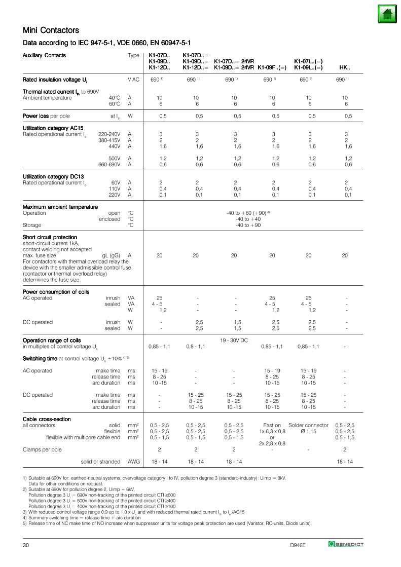
30 D946E
Mini ContactorsMini ContactorsMini ContactorsMini ContactorsMini Contactors
Data according to IEC 947-5-1, VDE 0660, EN 60947-5-1Data according to IEC 947-5-1, VDE 0660, EN 60947-5-1Data according to IEC 947-5-1, VDE 0660, EN 60947-5-1Data according to IEC 947-5-1, VDE 0660, EN 60947-5-1Data according to IEC 947-5-1, VDE 0660, EN 60947-5-1
Auxiliary ContactsAuxiliary ContactsAuxiliary ContactsAuxiliary ContactsAuxiliary Contacts Type K1-07D..K1-07D..K1-07D..K1-07D..K1-07D.. K1-07D..=K1-07D..=K1-07D..=K1-07D..=K1-07D..=K1-09D..K1-09D..K1-09D..K1-09D..K1-09D.. K1-09D..=K1-09D..=K1-09D..=K1-09D..=K1-09D..= K1-07D..= 24VRK1-07D..= 24VRK1-07D..= 24VRK1-07D..= 24VRK1-07D..= 24VR K1-07L..(=)K1-07L..(=)K1-07L..(=)K1-07L..(=)K1-07L..(=)K1-12D..K1-12D..K1-12D..K1-12D..K1-12D.. K1-12D..=K1-12D..=K1-12D..=K1-12D..=K1-12D..= K1-09D..= 24VRK1-09D..= 24VRK1-09D..= 24VRK1-09D..= 24VRK1-09D..= 24VR K1-09F..(=)K1-09F..(=)K1-09F..(=)K1-09F..(=)K1-09F..(=) K1-09L..(=)K1-09L..(=)K1-09L..(=)K1-09L..(=)K1-09L..(=) HK..HK..HK..HK..HK..
Rated insulation voltage URated insulation voltage URated insulation voltage URated insulation voltage URated insulation voltage Uiiiii V AC 690 1) 690 1) 690 1) 690 1) 690 2) 690 1)
Thermal rated current IThermal rated current IThermal rated current IThermal rated current IThermal rated current Iththththth to 690VAmbient temperature 40°C A 10 10 10 10 10 10
60°C A 6 6 6 6 6 6
Power loss Power loss Power loss Power loss Power loss per pole at Ith W 0,5 0,5 0,5 0,5 0,5 0,5
Utilization category AC15Utilization category AC15Utilization category AC15Utilization category AC15Utilization category AC15Rated operational current Ie 220-240V A 3 3 3 3 3 3
380-415V A 2 2 2 2 2 2440V A 1,6 1,6 1,6 1,6 1,6 1,6
500V A 1,2 1,2 1,2 1,2 1,2 1,2660-690V A 0,6 0,6 0,6 0,6 0,6 0,6
Utilization category DC13Utilization category DC13Utilization category DC13Utilization category DC13Utilization category DC13Rated operational current Ie 60V A 2 2 2 2 2 2
110V A 0,4 0,4 0,4 0,4 0,4 0,4220V A 0,1 0,1 0,1 0,1 0,1 0,1
Maximum ambient temperatureMaximum ambient temperatureMaximum ambient temperatureMaximum ambient temperatureMaximum ambient temperatureOperation open °C -40 to +60 (+90) 3)
enclosed °C -40 to +40Storage °C -40 to +90
Short circuit protectionShort circuit protectionShort circuit protectionShort circuit protectionShort circuit protectionshort-circuit current 1kA,contact welding not acceptedmax. fuse size gL (gG) A 20 20 20 20 20 20For contactors with thermal overload relay thedevice with the smaller admissible control fuse(contactor or thermal overload relay)determines the fuse size.
Power consumption of coilsPower consumption of coilsPower consumption of coilsPower consumption of coilsPower consumption of coilsAC operated inrush VA 25 - - 25 25 -
sealed VA 4 - 5 - - 4 - 5 4 - 5 -W 1,2 - - 1,2 1,2 -
DC operated inrush W - 2,5 1,5 2,5 2,5 -sealed W - 2,5 1,5 2,5 2,5 -
Operation range of coilsOperation range of coilsOperation range of coilsOperation range of coilsOperation range of coils 19 - 30V DCin multiples of control voltage Us 0,85 - 1,1 0,8 - 1,1 0,85 - 1,1 0,85 - 1,1 -
Switching time Switching time Switching time Switching time Switching time at control voltage Us ±10% 4) 5)
AC operated make time ms 15 - 19 - - 15 - 19 15 - 19 -release time ms 8 - 25 - - 8 - 25 8 - 25 -arc duration ms 10 -15 - - 10 -15 10 -15 -
DC operated make time ms - 15 - 25 15 - 25 15 - 25 15 - 25 -release time ms - 8 - 25 8 - 25 8 - 25 8 - 25 -arc duration ms - 10 -15 10 -15 10 -15 10 -15 -
Cable cross-sectionCable cross-sectionCable cross-sectionCable cross-sectionCable cross-sectionall connectors solid mm2 0,5 - 2,5 0,5 - 2,5 0,5 - 2,5 Fast on Solder connector 0,5 - 2,5
flexible mm2 0,5 - 2,5 0,5 - 2,5 0,5 - 2,5 1x 6,3 x 0,8 Ø 1,15 0,5 - 2,5flexible with multicore cable end mm2 0,5 - 1,5 0,5 - 1,5 0,5 - 1,5 or 0,5 - 1,5
2x 2,8 x 0,8Clamps per pole 2 2 2 - - 2
solid or stranded AWG 18 - 14 18 - 14 18 - 14 18 - 14
1) Suitable at 690V for: earthed-neutral systems, overvoltage category I to IV, pollution degree 3 (standard-industry): Uimp = 8kV.Data for other conditions on request.
2) Suitable at 690V for pollution degree 2, Uimp = 6kV.Pollution degree 3 Ui = 690V non-tracking of the printed circuit CTI ≥600Pollution degree 3 Ui = 500V non-tracking of the printed circuit CTI ≥400Pollution degree 3 Ui = 400V non-tracking of the printed circuit CTI ≥100
3) With reduced control voltage range 0,9 up to 1,0 x Us and with reduced thermal rated current Ith to Ie /AC154) Summary switching time = release time + arc duration5) Release time of NC make time of NO increase when suppressor units for voltage peak protection are used (Varistor, RC-units, Diode units).
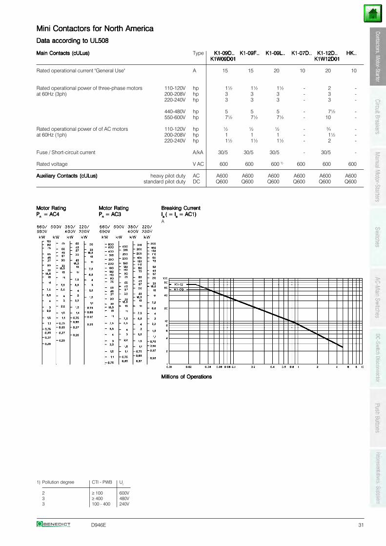
D946E 31
Mini Contactors for North AmericaMini Contactors for North AmericaMini Contactors for North AmericaMini Contactors for North AmericaMini Contactors for North America
Data according to UL508Data according to UL508Data according to UL508Data according to UL508Data according to UL508
Main Contacts (cULus)Main Contacts (cULus)Main Contacts (cULus)Main Contacts (cULus)Main Contacts (cULus) Type K1-09D..K1-09D..K1-09D..K1-09D..K1-09D.. K1-09F..K1-09F..K1-09F..K1-09F..K1-09F.. K1-09L..K1-09L..K1-09L..K1-09L..K1-09L.. K1-07D..K1-07D..K1-07D..K1-07D..K1-07D.. K1-12D..K1-12D..K1-12D..K1-12D..K1-12D.. HK..HK..HK..HK..HK..K1W09D01K1W09D01K1W09D01K1W09D01K1W09D01 K1W12D01K1W12D01K1W12D01K1W12D01K1W12D01
Rated operational current "General Use" A 15 15 20 10 20 10
Rated operational power of three-phase motors 110-120V hp 1½ 1½ 1½ - 2 -at 60Hz (3ph) 200-208V hp 3 3 3 - 3 -
220-240V hp 3 3 3 - 3 -
440-480V hp 5 5 5 - 7½ -550-600V hp 7½ 7½ 7½ - 10 -
Rated operational power of of AC motors 110-120V hp ½ ½ ½ - ¾ -at 60Hz (1ph) 200-208V hp 1 1 1 - 1½ -
220-240V hp 1½ 1½ 1½ - 2 -
Fuse / Short-circuit current A/kA 30/5 30/5 30/5 - 30/5 -
Rated voltage V AC 600 600 600 1) 600 600 600
Auxiliary Contacts (cULus)Auxiliary Contacts (cULus)Auxiliary Contacts (cULus)Auxiliary Contacts (cULus)Auxiliary Contacts (cULus) heavy pilot duty AC A600 A600 A600 A600 A600 A600standard pilot duty DC Q600 Q600 Q600 Q600 Q600 Q600
1) Pollution degree CTI - PWB Ui
2 ≥ 100 600V3 ≥ 400 480V3 100 - 400 240V
Motor RatingMotor RatingMotor RatingMotor RatingMotor Rating Motor RatingMotor RatingMotor RatingMotor RatingMotor Rating Breaking CurrentBreaking CurrentBreaking CurrentBreaking CurrentBreaking CurrentPPPPPn n n n n = AC4 = AC4 = AC4 = AC4 = AC4 PPPPPnnnnn = AC3 = AC3 = AC3 = AC3 = AC3 IIIIIa a a a a ( = I( = I( = I( = I( = Ieeeee = AC1) = AC1) = AC1) = AC1) = AC1)
A
Millions of OperationsMillions of OperationsMillions of OperationsMillions of OperationsMillions of Operations
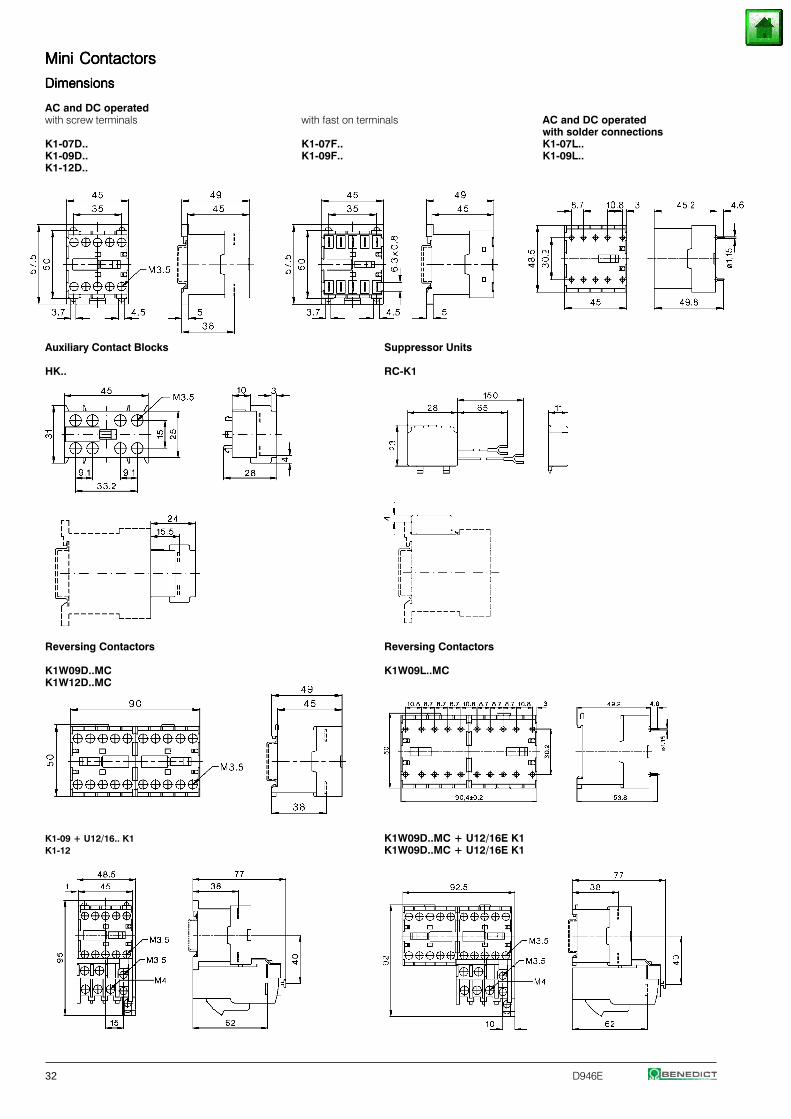
32 D946E
Mini ContactorsMini ContactorsMini ContactorsMini ContactorsMini Contactors
DimensionsDimensionsDimensionsDimensionsDimensions
AC and DC operatedwith screw terminals with fast on terminals AC and DC operated
with solder connectionsK1-07D.. K1-07F.. K1-07L..K1-09D.. K1-09F.. K1-09L..K1-12D..
Auxiliary Contact Blocks Suppressor Units
HK.. RC-K1
Reversing Contactors Reversing Contactors
K1W09D..MC K1W09L..MCK1W12D..MC
K1-09 + U12/16.. K1 K1W09D..MC + U12/16E K1K1-12 K1W09D..MC + U12/16E K1
D946E 33
Contactor RelaysContactor RelaysContactor RelaysContactor RelaysContactor Relays
Contactor Relays 4-pole, AC Operated 34
Auxiliary Contact Blocks 1-pole 34
Contactor Relays 4-pole, DC Operated 35
Technical Data 36
Dimensions 38
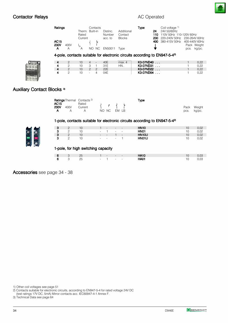
34 D946E
Contactor RelaysContactor RelaysContactor RelaysContactor RelaysContactor Relays AC Operated
RatingsRatingsRatingsRatingsRatings Contacts TypeTypeTypeTypeType Coil voltage 1)
Therm. Built-in Distinc. Additional 2424242424 24V 50/60HzRated Number Contact 110110110110110 110V 50Hz 110-120V 60HzCurrent acc. to Blocks 230230230230230 220-240V 50Hz 230-264V 60Hz
AC15AC15AC15AC15AC15 400400400400400 380-415V 50Hz 400-440V 60Hz230V230V230V230V230V 400V Ith ⏐⏐⏐⏐⏐ Pack Weight
AAAAA A A NO NC EN50011 Type pcs. kg/pc.
4-pole, contacts suitable for electronic circuits according to EN947-5-44-pole, contacts suitable for electronic circuits according to EN947-5-44-pole, contacts suitable for electronic circuits according to EN947-5-44-pole, contacts suitable for electronic circuits according to EN947-5-44-pole, contacts suitable for electronic circuits according to EN947-5-42)2)2)2)2)
44444 2 10 4 - 40E max. 4 K3-07ND40 . . .K3-07ND40 . . .K3-07ND40 . . .K3-07ND40 . . .K3-07ND40 . . . 1 0,2244444 2 10 3 1 31E HN.. K3-07ND31 . . .K3-07ND31 . . .K3-07ND31 . . .K3-07ND31 . . .K3-07ND31 . . . 1 0,2244444 2 10 2 2 22E K3-07ND22 . . .K3-07ND22 . . .K3-07ND22 . . .K3-07ND22 . . .K3-07ND22 . . . 1 0,2244444 2 10 - 4 04E K3-07ND04 . . .K3-07ND04 . . .K3-07ND04 . . .K3-07ND04 . . .K3-07ND04 . . . 1 0,22
Auxiliary Contact Blocks Auxiliary Contact Blocks Auxiliary Contact Blocks Auxiliary Contact Blocks Auxiliary Contact Blocks 3)3)3)3)3)
RatingsRatingsRatingsRatingsRatings Thermal Contacts 2) TypeTypeTypeTypeTypeAC15AC15AC15AC15AC15 Rated230V230V230V230V230V 400V Current Pack Weight
AAAAA A A NO NC EM LB pcs. kg/pc.
1-pole, contacts suitable for electronic circuits according to EN947-5-41-pole, contacts suitable for electronic circuits according to EN947-5-41-pole, contacts suitable for electronic circuits according to EN947-5-41-pole, contacts suitable for electronic circuits according to EN947-5-41-pole, contacts suitable for electronic circuits according to EN947-5-42)2)2)2)2)
33333 2 10 1 - - - HN10HN10HN10HN10HN10 10 0,0233333 2 10 - 1 - - HN01HN01HN01HN01HN01 10 0,0233333 2 10 - - 1 - HN10UHN10UHN10UHN10UHN10U 10 0,0233333 2 10 - - - 1 HN01UHN01UHN01UHN01UHN01U 10 0,02
1-pole, for high switching capacity1-pole, for high switching capacity1-pole, for high switching capacity1-pole, for high switching capacity1-pole, for high switching capacity
66666 3 25 1 - - - HA10HA10HA10HA10HA10 10 0,0366666 3 25 - 1 - - HA01HA01HA01HA01HA01 10 0,03
Accessories Accessories Accessories Accessories Accessories see page 34 - 38
1) Other coil voltages see page 512) Contacts suitable for electronic circuits, according to EN947-5-4 for rated voltage 24V DC
(test ratings 17V DC, 5mA) Mirror contacts acc. IEC60947-4-1 Annex F.3) Technical Data see page 64
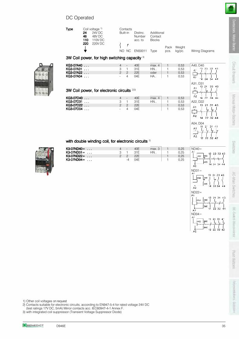
D946E 35
DC Operated
TypeTypeTypeTypeType Coil voltage 1) Contacts2424242424 24V DC Built-in Distinc. Additional4848484848 48V DC Number Contact110110110110110 110V DC acc. to Blocks220220220220220 220V DC
⏐⏐⏐⏐⏐ Pack WeightNO NC EN50011 Type pcs. kg/pc. Wiring Diagrams
3W Coil power, for high switching capacity3W Coil power, for high switching capacity3W Coil power, for high switching capacity3W Coil power, for high switching capacity3W Coil power, for high switching capacity 3)
KG3-07A40 . . .KG3-07A40 . . .KG3-07A40 . . .KG3-07A40 . . .KG3-07A40 . . . 4 - 40E max. 4 1 0,53 A40, D40KG3-07A31 . . .KG3-07A31 . . .KG3-07A31 . . .KG3-07A31 . . .KG3-07A31 . . . 3 1 31E HN.. 1 0,53KG3-07A22 . . .KG3-07A22 . . .KG3-07A22 . . .KG3-07A22 . . .KG3-07A22 . . . 2 2 22E oder 1 0,53KG3-07A04 . . .KG3-07A04 . . .KG3-07A04 . . .KG3-07A04 . . .KG3-07A04 . . . - 4 04E HA.. 1 0,53
A31, D31
3W Coil power, for electronic circuits 3W Coil power, for electronic circuits 3W Coil power, for electronic circuits 3W Coil power, for electronic circuits 3W Coil power, for electronic circuits 2)3)
KG3-07D40 . . .KG3-07D40 . . .KG3-07D40 . . .KG3-07D40 . . .KG3-07D40 . . . 4 - 40E max. 4 1 0,53KG3-07D31 . . .KG3-07D31 . . .KG3-07D31 . . .KG3-07D31 . . .KG3-07D31 . . . 3 1 31E HN.. 1 0,53 A22, D22KG3-07D22 . . .KG3-07D22 . . .KG3-07D22 . . .KG3-07D22 . . .KG3-07D22 . . . 2 2 22E 1 0,53KG3-07D04 . . .KG3-07D04 . . .KG3-07D04 . . .KG3-07D04 . . .KG3-07D04 . . . - 4 04E 1 0,53
A04, D04
with double winding coil, for electronic circuits with double winding coil, for electronic circuits with double winding coil, for electronic circuits with double winding coil, for electronic circuits with double winding coil, for electronic circuits 2)
K3-07ND40= . . .K3-07ND40= . . .K3-07ND40= . . .K3-07ND40= . . .K3-07ND40= . . . 4 - 40E max. 3 1 0,25 ND40=K3-07ND31= . . .K3-07ND31= . . .K3-07ND31= . . .K3-07ND31= . . .K3-07ND31= . . . 3 1 31E HN.. 1 0,25K3-07ND22= . . .K3-07ND22= . . .K3-07ND22= . . .K3-07ND22= . . .K3-07ND22= . . . 2 2 22E 1 0,25K3-07ND04= . . .K3-07ND04= . . .K3-07ND04= . . .K3-07ND04= . . .K3-07ND04= . . . -4 04E 1 0,25
ND31=
ND22=
ND04=
1) Other coil voltages on request2) Contacts suitable for electronic circuits, according to EN947-5-4 for rated voltage 24V DC
(test ratings 17V DC, 5mA) Mirror contacts acc. IEC60947-4-1 Annex F.3) with integrated coil suppressor (Transient Voltage Suppressor Diode)
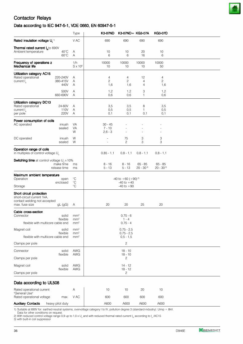
36 D946E
1) Suitable at 690V for: earthed-neutral systems, overvoltage category I to IV, pollution degree 3 (standard-industry): Uimp = 8kV.Data for other conditions on request.
2) With reduced control voltage range 0,9 up to 1,0 x Us and with reduced thermal rated current Ith according to Ie /AC153) with built-in coil suppressor
Contactor RelaysContactor RelaysContactor RelaysContactor RelaysContactor Relays
Data according to IEC 947-5-1, VDE 0660, EN 60947-5-1Data according to IEC 947-5-1, VDE 0660, EN 60947-5-1Data according to IEC 947-5-1, VDE 0660, EN 60947-5-1Data according to IEC 947-5-1, VDE 0660, EN 60947-5-1Data according to IEC 947-5-1, VDE 0660, EN 60947-5-1
Type K3-07NDK3-07NDK3-07NDK3-07NDK3-07ND K3-07ND=K3-07ND=K3-07ND=K3-07ND=K3-07ND= KG3-07AKG3-07AKG3-07AKG3-07AKG3-07A KG3-07DKG3-07DKG3-07DKG3-07DKG3-07D
Rated insulation voltage URated insulation voltage URated insulation voltage URated insulation voltage URated insulation voltage Ui i i i i 1) V AC 690 690 690 690
Thermal rated current IThermal rated current IThermal rated current IThermal rated current IThermal rated current Ithththththto 690VAmbient temperature 40°C A 10 10 20 10
60°C A 6 6 16 6
Frequency of operations zFrequency of operations zFrequency of operations zFrequency of operations zFrequency of operations z 1/h 10000 10000 10000 10000Mechanical lifeMechanical lifeMechanical lifeMechanical lifeMechanical life S x 106 10 10 10 50
Utilization category AC15Utilization category AC15Utilization category AC15Utilization category AC15Utilization category AC15Rated operational 220-240V A 4 4 12 4current Ie 380-415V A 2 2 4 2
440V A 1,6 1,6 4 1,6
500V A 1,2 1,2 3 1,2660-690V A 0,6 0,6 1 0,6
Utilization category DC13Utilization category DC13Utilization category DC13Utilization category DC13Utilization category DC13Rated operational 24-60V A 3,5 3,5 8 3,5current Ie 110V A 0,5 0,5 1 0,5per pole 220V A 0,1 0,1 0,1 0,1
Power consumption of coilsPower consumption of coilsPower consumption of coilsPower consumption of coilsPower consumption of coilsAC operated inrush VA 30 - 45 - - -
sealed VA 7 - 10 - - -W 2,6 - 3 - - -
DC operated inrush W - 75 3 3sealed W - 2 3 3
Operation range of coilsOperation range of coilsOperation range of coilsOperation range of coilsOperation range of coilsin multiples of control voltage Us 0,85 - 1,1 0,8 - 1,1 0,8 - 1,1 0,8 - 1,1
Switching time Switching time Switching time Switching time Switching time at control voltage Us±10%make time ms 8 - 16 8 - 16 65 - 85 65 - 85
release time ms 5 - 13 5 - 13 20 - 30 3) 20 - 30 3)
Maximum ambient temperatureMaximum ambient temperatureMaximum ambient temperatureMaximum ambient temperatureMaximum ambient temperatureOperation open °C -40 to +60 (+90) 2)
enclosed °C -40 to +40Storage °C -40 to +90
Short circuit protectionShort circuit protectionShort circuit protectionShort circuit protectionShort circuit protectionshort-circuit current 1kA,contact welding not acceptedmax. fuse size gL (gG) A 20 20 25 20
Cable cross-sectionCable cross-sectionCable cross-sectionCable cross-sectionCable cross-sectionConnector solid mm2 0,75 - 6
flexible mm2 1 - 4flexible with multicore cable end mm2 0,75 - 4
Magnet coil solid mm2 0,75 - 2,5flexible mm2 0,75 - 2,5
flexible with multicore cable end mm2 0,5 - 1,5
Clamps per pole 2
Connector solid AWG 18 - 10flexible AWG 18 - 10
Clamps per pole 2
Magnet coil solid AWG 14 - 12flexible AWG 18 - 12
Clamps per pole 2
Data according to UL508Data according to UL508Data according to UL508Data according to UL508Data according to UL508
Rated operational current A 10 10 20 10"General Use"Rated operational voltage max. V AC 600 600 600 600
Auxiliary ContactsAuxiliary ContactsAuxiliary ContactsAuxiliary ContactsAuxiliary Contacts heavy pilot duty A600 A600 A600 A600
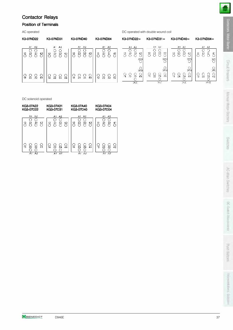
D946E 37
Contactor RelaysContactor RelaysContactor RelaysContactor RelaysContactor Relays
Position of TerminalsPosition of TerminalsPosition of TerminalsPosition of TerminalsPosition of Terminals
AC operated DC operated with double wound coil
K3-07ND22K3-07ND22K3-07ND22K3-07ND22K3-07ND22 K3-07ND31K3-07ND31K3-07ND31K3-07ND31K3-07ND31 K3-07ND40K3-07ND40K3-07ND40K3-07ND40K3-07ND40 K3-07ND04K3-07ND04K3-07ND04K3-07ND04K3-07ND04 K3-07ND22=K3-07ND22=K3-07ND22=K3-07ND22=K3-07ND22= K3-07ND31=K3-07ND31=K3-07ND31=K3-07ND31=K3-07ND31= K3-07ND40=K3-07ND40=K3-07ND40=K3-07ND40=K3-07ND40= K3-07ND04=K3-07ND04=K3-07ND04=K3-07ND04=K3-07ND04=
DC solenoid operated
KG3-07A22KG3-07A22KG3-07A22KG3-07A22KG3-07A22 KG3-07A31KG3-07A31KG3-07A31KG3-07A31KG3-07A31 KG3-07A40KG3-07A40KG3-07A40KG3-07A40KG3-07A40 KG3-07A04KG3-07A04KG3-07A04KG3-07A04KG3-07A04KG3-07D22KG3-07D22KG3-07D22KG3-07D22KG3-07D22 KG3-07D31KG3-07D31KG3-07D31KG3-07D31KG3-07D31 KG3-07D40KG3-07D40KG3-07D40KG3-07D40KG3-07D40 KG3-07D04KG3-07D04KG3-07D04KG3-07D04KG3-07D04
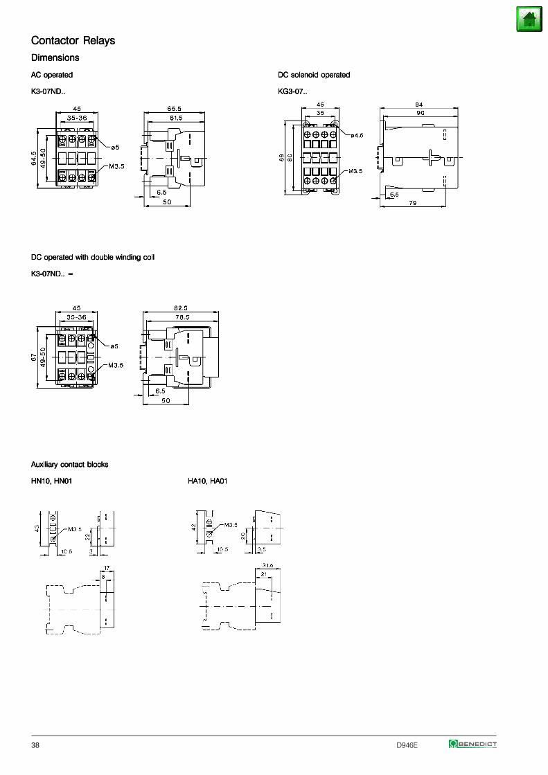
38 D946E
Contactor RelaysContactor RelaysContactor RelaysContactor RelaysContactor Relays
DimensionsDimensionsDimensionsDimensionsDimensions
AC operatedAC operatedAC operatedAC operatedAC operated DC solenoid operatedDC solenoid operatedDC solenoid operatedDC solenoid operatedDC solenoid operated
K3-07ND..K3-07ND..K3-07ND..K3-07ND..K3-07ND.. KG3-07..KG3-07..KG3-07..KG3-07..KG3-07..
DC operated with double winding coilDC operated with double winding coilDC operated with double winding coilDC operated with double winding coilDC operated with double winding coil
K3-07ND.. =K3-07ND.. =K3-07ND.. =K3-07ND.. =K3-07ND.. =
Auxiliary contact blocksAuxiliary contact blocksAuxiliary contact blocksAuxiliary contact blocksAuxiliary contact blocks
HN10, HN01HN10, HN01HN10, HN01HN10, HN01HN10, HN01 HA10, HA01HA10, HA01HA10, HA01HA10, HA01HA10, HA01
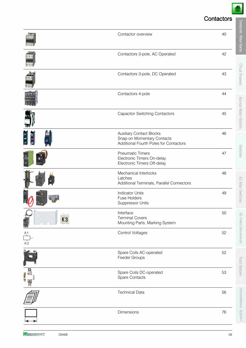
D946E 39
ContactorsContactorsContactorsContactorsContactors
Contactor overview 40
Contactors 3-pole, AC Operated 42
Contactors 3-pole, DC Operated 43
Contactors 4-pole 44
Capacitor Switching Contactors 45
Auxiliary Contact Blocks 46Snap-on Momentary ContactsAdditional Fourth Poles for Contactors
Pneumatic Timers 47Electronic Timers On-delayElectronic Timers Off-delay
Mechanical Interlocks 48LatchesAdditional Terminals, Parallel Connectors
Indicator Units 49Fuse HoldersSuppressor Units
Interface 50Terminal CoversMounting Parts, Marking System
Control Voltages 52
Spare Coils AC-operated 52Feeder Groups
Spare Coils DC-operated 53Spare Contacts
Technical Data 56
Dimensions 76
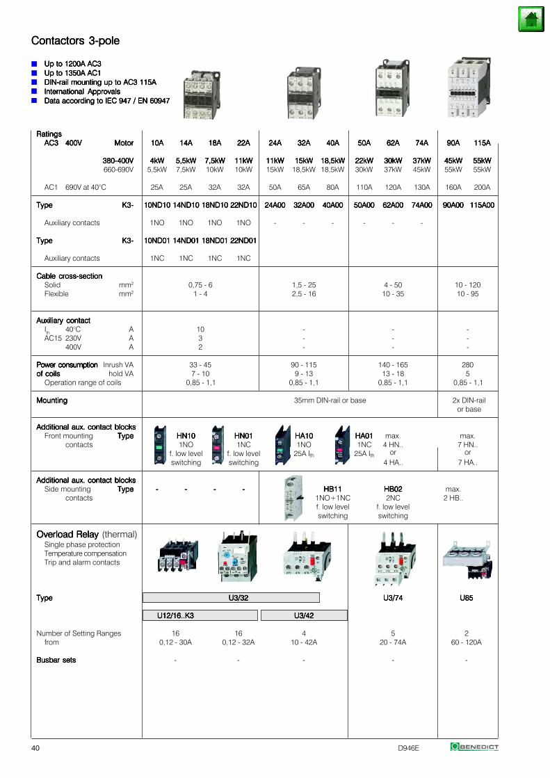
40 D946E
Contactors 3-poleContactors 3-poleContactors 3-poleContactors 3-poleContactors 3-pole
Up to 1200A AC3Up to 1200A AC3Up to 1200A AC3Up to 1200A AC3Up to 1200A AC3Up to 1350A AC1Up to 1350A AC1Up to 1350A AC1Up to 1350A AC1Up to 1350A AC1DIN-rail mounting up to AC3 115ADIN-rail mounting up to AC3 115ADIN-rail mounting up to AC3 115ADIN-rail mounting up to AC3 115ADIN-rail mounting up to AC3 115AInternational ApprovalsInternational ApprovalsInternational ApprovalsInternational ApprovalsInternational ApprovalsData according to IEC 947 / EN 60947Data according to IEC 947 / EN 60947Data according to IEC 947 / EN 60947Data according to IEC 947 / EN 60947Data according to IEC 947 / EN 60947
RatingsRatingsRatingsRatingsRatingsAC3AC3AC3AC3AC3 400V400V400V400V400V MotorMotorMotorMotorMotor 10A10A10A10A10A 14A14A14A14A14A 18A18A18A18A18A 22A22A22A22A22A 24A24A24A24A24A 32A32A32A32A32A 40A40A40A40A40A 50A50A50A50A50A 62A62A62A62A62A 74A74A74A74A74A 90A90A90A90A90A 115A115A115A115A115A
380-400V380-400V380-400V380-400V380-400V 4kW4kW4kW4kW4kW 5,5kW5,5kW5,5kW5,5kW5,5kW 7,5kW7,5kW7,5kW7,5kW7,5kW 11kW11kW11kW11kW11kW 11kW11kW11kW11kW11kW 15kW15kW15kW15kW15kW 18,5kW18,5kW18,5kW18,5kW18,5kW 22kW22kW22kW22kW22kW 30kW30kW30kW30kW30kW 37kW37kW37kW37kW37kW 45kW45kW45kW45kW45kW 55kW55kW55kW55kW55kW660-690V 5,5kW 7,5kW 10kW 10kW 15kW 18,5kW 18,5kW 30kW 37kW 45kW 55kW 55kW
AC1 690V at 40°C 25A 25A 32A 32A 50A 65A 80A 110A 120A 130A 160A 200A
TypeTypeTypeTypeType K3-K3-K3-K3-K3- 10ND1010ND1010ND1010ND1010ND10 14ND1014ND1014ND1014ND1014ND10 18ND1018ND1018ND1018ND1018ND10 22ND1022ND1022ND1022ND1022ND10 24A0024A0024A0024A0024A00 32A0032A0032A0032A0032A00 40A0040A0040A0040A0040A00 50A0050A0050A0050A0050A00 62A0062A0062A0062A0062A00 74A0074A0074A0074A0074A00 90A0090A0090A0090A0090A00 115A00115A00115A00115A00115A00
Auxiliary contacts 1NO 1NO 1NO 1NO - - - - - -
TypeTypeTypeTypeType K3-K3-K3-K3-K3- 10ND0110ND0110ND0110ND0110ND01 14ND0114ND0114ND0114ND0114ND01 18ND0118ND0118ND0118ND0118ND01 22ND0122ND0122ND0122ND0122ND01
Auxiliary contacts 1NC 1NC 1NC 1NC
Cable cross-sectionCable cross-sectionCable cross-sectionCable cross-sectionCable cross-sectionSolid mm2 0,75 - 6 1,5 - 25 4 - 50 10 - 120Flexible mm2 1 - 4 2,5 - 16 10 - 35 10 - 95
Auxiliary contactAuxiliary contactAuxiliary contactAuxiliary contactAuxiliary contactIth 40°C A 10 - - -AC15 230V A 3 - - -
400V A 2 - - -
Power consumptionPower consumptionPower consumptionPower consumptionPower consumption Inrush VA 33 - 45 90 - 115 140 - 165 280of coilsof coilsof coilsof coilsof coils hold VA 7 - 10 9 - 13 13 - 18 5
Operation range of coils 0,85 - 1,1 0,85 - 1,1 0,85 - 1,1 0,85 - 1,1
MountingMountingMountingMountingMounting 35mm DIN-rail or base 2x DIN-railor base
Additional aux. contact blocksAdditional aux. contact blocksAdditional aux. contact blocksAdditional aux. contact blocksAdditional aux. contact blocksFront mounting TypeTypeTypeTypeType HN10HN10HN10HN10HN10 HN01HN01HN01HN01HN01 HA10HA10HA10HA10HA10 HA01HA01HA01HA01HA01 max. max.
contacts 1NO 1NC 1NO 1NC 4 HN.. 7 HN..f. low level f. low level 25A Ith 25A Ith or orswitching switching 4 HA.. 7 HA..
Additional aux. contact blocksAdditional aux. contact blocksAdditional aux. contact blocksAdditional aux. contact blocksAdditional aux. contact blocksSide mounting TypeTypeTypeTypeType ----- ----- ----- ----- HB11HB11HB11HB11HB11 HB02HB02HB02HB02HB02 max.
contacts 1NO+1NC 2NC 2 HB..f. low level f. low levelswitching switching
Overload Relay Overload Relay Overload Relay Overload Relay Overload Relay (thermal)Single phase protectionTemperature compensationTrip and alarm contacts
TypeTypeTypeTypeType U3/32U3/32U3/32U3/32U3/32 U3/74U3/74U3/74U3/74U3/74 U85U85U85U85U85
U12/16..K3U12/16..K3U12/16..K3U12/16..K3U12/16..K3 U3/42U3/42U3/42U3/42U3/42
Number of Setting Ranges 16 16 4 5 2from 0,12 - 30A 0,12 - 32A 10 - 42A 20 - 74A 60 - 120A
Busbar setsBusbar setsBusbar setsBusbar setsBusbar sets - - - - -
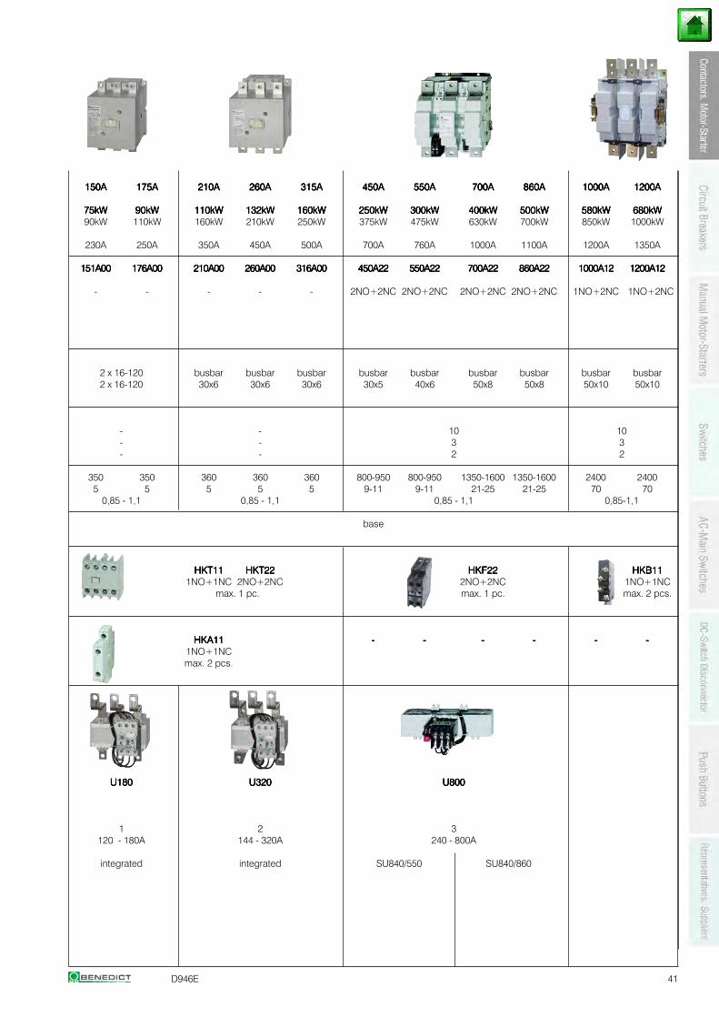
D946E 41
150A150A150A150A150A 175A175A175A175A175A 210A210A210A210A210A 260A260A260A260A260A 315A315A315A315A315A 450A450A450A450A450A 550A550A550A550A550A 700A700A700A700A700A 860A860A860A860A860A 1000A1000A1000A1000A1000A 1200A1200A1200A1200A1200A
75kW75kW75kW75kW75kW 90kW90kW90kW90kW90kW 110kW110kW110kW110kW110kW 132kW132kW132kW132kW132kW 160kW160kW160kW160kW160kW 250kW250kW250kW250kW250kW 300kW300kW300kW300kW300kW 400kW400kW400kW400kW400kW 500kW500kW500kW500kW500kW 580kW580kW580kW580kW580kW 680kW680kW680kW680kW680kW90kW 110kW 160kW 210kW 250kW 375kW 475kW 630kW 700kW 850kW 1000kW
230A 250A 350A 450A 500A 700A 760A 1000A 1100A 1200A 1350A
151A00151A00151A00151A00151A00 176A00176A00176A00176A00176A00 210A00210A00210A00210A00210A00 260A00260A00260A00260A00260A00 316A00316A00316A00316A00316A00 450A22450A22450A22450A22450A22 550A22550A22550A22550A22550A22 700A22700A22700A22700A22700A22 860A22860A22860A22860A22860A22 1000A121000A121000A121000A121000A12 1200A121200A121200A121200A121200A12
- - - - - 2NO+2NC 2NO+2NC 2NO+2NC 2NO+2NC 1NO+2NC 1NO+2NC
2 x 16-120 busbar busbar busbar busbar busbar busbar busbar busbar busbar2 x 16-120 30x6 30x6 30x6 30x5 40x6 50x8 50x8 50x10 50x10
- - 10 10- - 3 3- - 2 2
350 350 360 360 360 800-950 800-950 1350-1600 1350-1600 2400 24005 5 5 5 5 9-11 9-11 21-25 21-25 70 70
0,85 - 1,1 0,85 - 1,1 0,85 - 1,1 0,85-1,1
base
HKT11HKT11HKT11HKT11HKT11 HKT22HKT22HKT22HKT22HKT22 HKF22HKF22HKF22HKF22HKF22 HKB11HKB11HKB11HKB11HKB111NO+1NC 2NO+2NC 2NO+2NC 1NO+1NC
max. 1 pc. max. 1 pc. max. 2 pcs.
HKA11HKA11HKA11HKA11HKA11 ----- ----- ----- ----- ----- -----1NO+1NCmax. 2 pcs.
U180U180U180U180U180 U320U320U320U320U320 U800U800U800U800U800
1 2 3120 - 180A 144 - 320A 240 - 800A
integrated integrated SU840/550 SU840/860
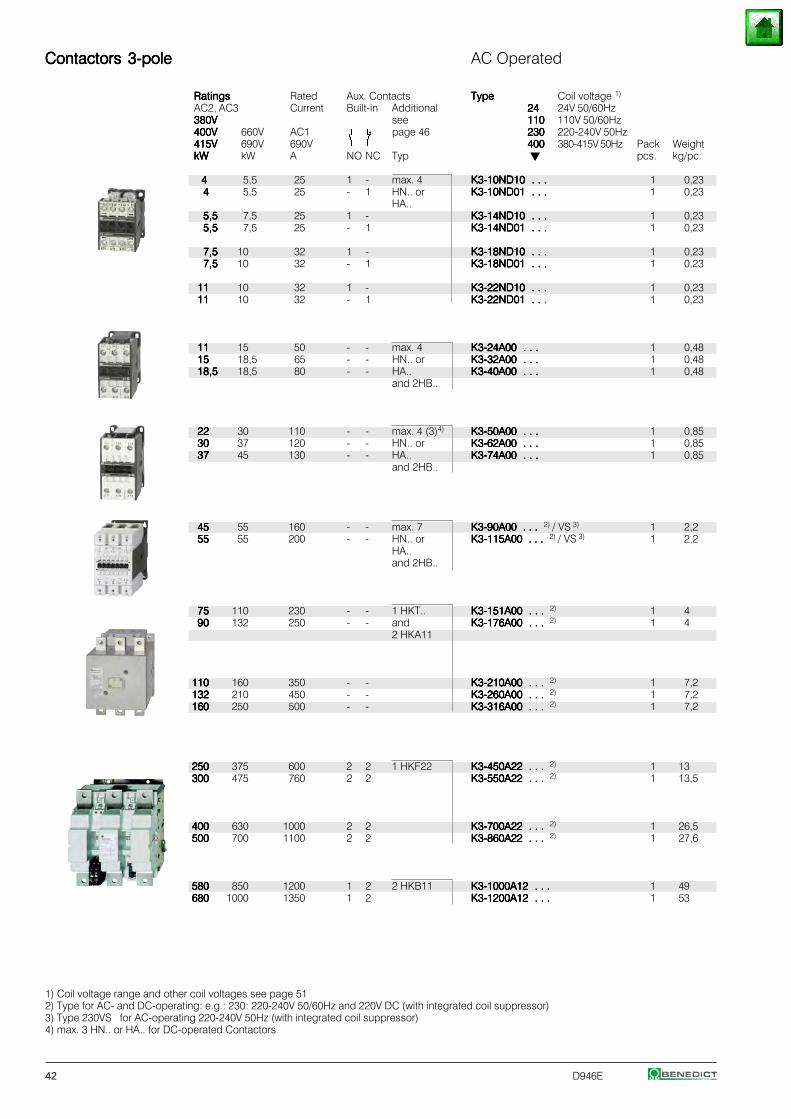
42 D946E
Contactors 3-poleContactors 3-poleContactors 3-poleContactors 3-poleContactors 3-pole AC Operated
RatingsRatingsRatingsRatingsRatings Rated Aux. Contacts TypeTypeTypeTypeType Coil voltage 1)
AC2, AC3 Current Built-in Additional 2424242424 24V 50/60Hz380V380V380V380V380V see 110110110110110 110V 50/60Hz400V400V400V400V400V 660V AC1 page 46 230230230230230 220-240V 50Hz415V415V415V415V415V 690V 690V 400400400400400 380-415V 50Hz Pack WeightkWkWkWkWkW kW A NO NC Typ pcs. kg/pc.
44444 5,5 25 1 - max. 4 K3-10ND10 . . .K3-10ND10 . . .K3-10ND10 . . .K3-10ND10 . . .K3-10ND10 . . . 1 0,2344444 5,5 25 - 1 HN.. or K3-10ND01 . . .K3-10ND01 . . .K3-10ND01 . . .K3-10ND01 . . .K3-10ND01 . . . 1 0,23
HA..5,55,55,55,55,5 7,5 25 1 - K3-14ND10 . . .K3-14ND10 . . .K3-14ND10 . . .K3-14ND10 . . .K3-14ND10 . . . 1 0,235,55,55,55,55,5 7,5 25 - 1 K3-14ND01 . . .K3-14ND01 . . .K3-14ND01 . . .K3-14ND01 . . .K3-14ND01 . . . 1 0,23
7,57,57,57,57,5 10 32 1 - K3-18ND10 . . .K3-18ND10 . . .K3-18ND10 . . .K3-18ND10 . . .K3-18ND10 . . . 1 0,237,57,57,57,57,5 10 32 - 1 K3-18ND01 . . .K3-18ND01 . . .K3-18ND01 . . .K3-18ND01 . . .K3-18ND01 . . . 1 0,23
1111111111 10 32 1 - K3-22ND10 . . .K3-22ND10 . . .K3-22ND10 . . .K3-22ND10 . . .K3-22ND10 . . . 1 0,231111111111 10 32 - 1 K3-22ND01 . . .K3-22ND01 . . .K3-22ND01 . . .K3-22ND01 . . .K3-22ND01 . . . 1 0,23
1111111111 15 50 - - max. 4 K3-24A00 . . .K3-24A00 . . .K3-24A00 . . .K3-24A00 . . .K3-24A00 . . . 1 0,481515151515 18,5 65 - - HN.. or K3-32A00 . . .K3-32A00 . . .K3-32A00 . . .K3-32A00 . . .K3-32A00 . . . 1 0,4818,518,518,518,518,5 18,5 80 - - HA.. K3-40A00 . . .K3-40A00 . . .K3-40A00 . . .K3-40A00 . . .K3-40A00 . . . 1 0,48
and 2HB..
2222222222 30 110 - - max. 4 (3)4) K3-50A00 . . .K3-50A00 . . .K3-50A00 . . .K3-50A00 . . .K3-50A00 . . . 1 0,853030303030 37 120 - - HN.. or K3-62A00 . . .K3-62A00 . . .K3-62A00 . . .K3-62A00 . . .K3-62A00 . . . 1 0,853737373737 45 130 - - HA.. K3-74A00 . . .K3-74A00 . . .K3-74A00 . . .K3-74A00 . . .K3-74A00 . . . 1 0,85
and 2HB..
4545454545 55 160 - - max. 7 K3-90A00 . . .K3-90A00 . . .K3-90A00 . . .K3-90A00 . . .K3-90A00 . . . 2) / VS 3) 1 2,25555555555 55 200 - - HN.. or K3-115A00 . . .K3-115A00 . . .K3-115A00 . . .K3-115A00 . . .K3-115A00 . . . 2) / VS 3) 1 2,2
HA..and 2HB..
7575757575 110 230 - - 1 HKT.. K3-151A00 . . .K3-151A00 . . .K3-151A00 . . .K3-151A00 . . .K3-151A00 . . . 2) 1 49090909090 132 250 - - and K3-176A00 . . .K3-176A00 . . .K3-176A00 . . .K3-176A00 . . .K3-176A00 . . . 2) 1 4
2 HKA11
110110110110110 160 350 - - K3-210A00 . . .K3-210A00 . . .K3-210A00 . . .K3-210A00 . . .K3-210A00 . . . 2) 1 7,2132132132132132 210 450 - - K3-260A00 . . .K3-260A00 . . .K3-260A00 . . .K3-260A00 . . .K3-260A00 . . . 2) 1 7,2160160160160160 250 500 - - K3-316A00 . . .K3-316A00 . . .K3-316A00 . . .K3-316A00 . . .K3-316A00 . . . 2) 1 7,2
250250250250250 375 600 2 2 1 HKF22 K3-450A22 . . .K3-450A22 . . .K3-450A22 . . .K3-450A22 . . .K3-450A22 . . . 2) 1 13300300300300300 475 760 2 2 K3-550A22 . . .K3-550A22 . . .K3-550A22 . . .K3-550A22 . . .K3-550A22 . . . 2) 1 13,5
400400400400400 630 1000 2 2 K3-700A22 . . .K3-700A22 . . .K3-700A22 . . .K3-700A22 . . .K3-700A22 . . . 2) 1 26,5500500500500500 700 1100 2 2 K3-860A22 . . .K3-860A22 . . .K3-860A22 . . .K3-860A22 . . .K3-860A22 . . . 2) 1 27,6
580580580580580 850 1200 1 2 2 HKB11 K3-1000A12 . . .K3-1000A12 . . .K3-1000A12 . . .K3-1000A12 . . .K3-1000A12 . . . 1 49680680680680680 1000 1350 1 2 K3-1200A12 . . .K3-1200A12 . . .K3-1200A12 . . .K3-1200A12 . . .K3-1200A12 . . . 1 53
1) Coil voltage range and other coil voltages see page 512) Type for AC- and DC-operating: e.g.: 230: 220-240V 50/60Hz and 220V DC (with integrated coil suppressor)3) Type 230VS for AC-operating 220-240V 50Hz (with integrated coil suppressor)4) max. 3 HN.. or HA.. for DC-operated Contactors
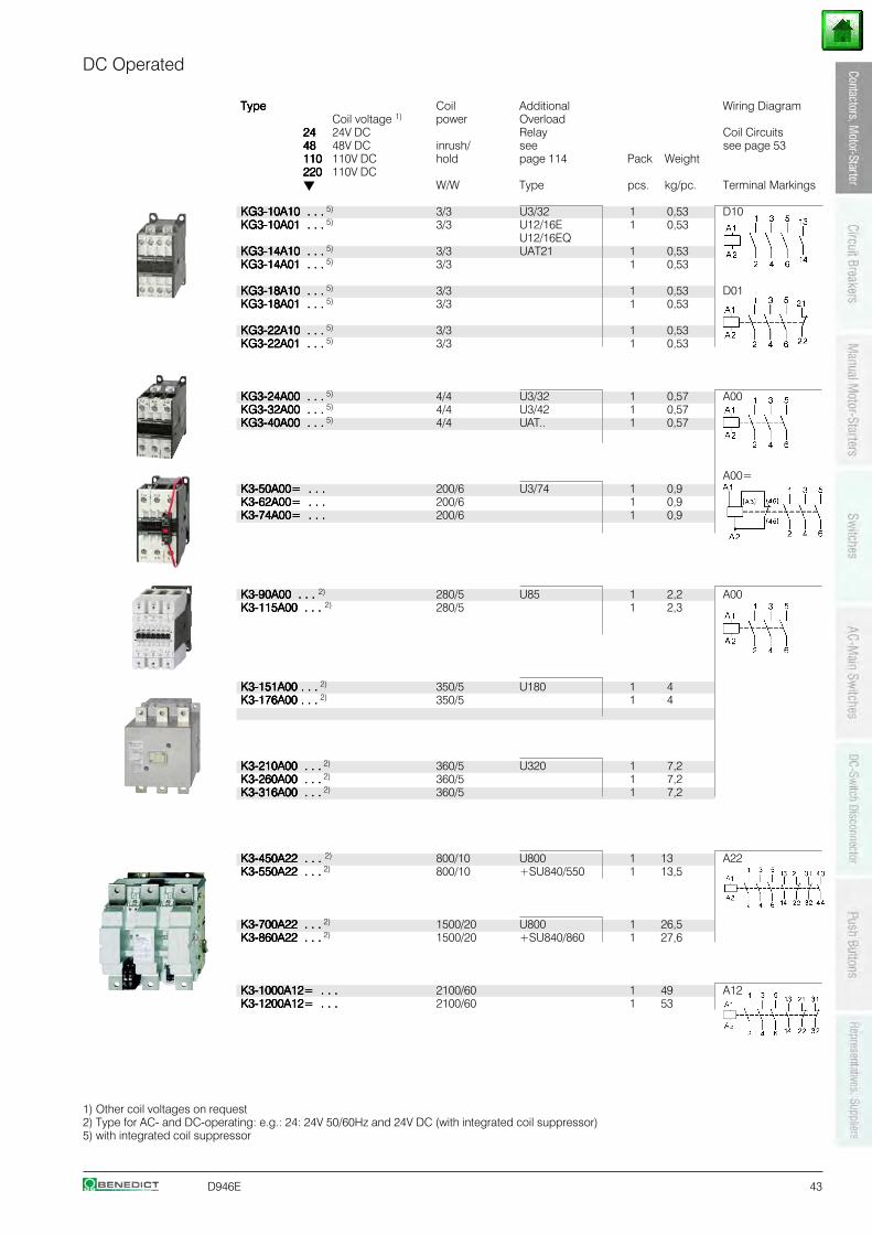
D946E 43
DC Operated
TypeTypeTypeTypeType Coil Additional Wiring DiagramCoil voltage 1) power Overload
2424242424 24V DC Relay Coil Circuits4848484848 48V DC inrush/ see see page 53110110110110110 110V DC hold page 114 Pack Weight220220220220220 110V DC
W/W Type pcs. kg/pc. Terminal Markings
KG3-10A10 . . .KG3-10A10 . . .KG3-10A10 . . .KG3-10A10 . . .KG3-10A10 . . . 5) 3/3 U3/32 1 0,53 D10KG3-10A01 . . .KG3-10A01 . . .KG3-10A01 . . .KG3-10A01 . . .KG3-10A01 . . . 5) 3/3 U12/16E 1 0,53
U12/16EQKG3-14A10 . . .KG3-14A10 . . .KG3-14A10 . . .KG3-14A10 . . .KG3-14A10 . . . 5) 3/3 UAT21 1 0,53KG3-14A01 . . .KG3-14A01 . . .KG3-14A01 . . .KG3-14A01 . . .KG3-14A01 . . . 5) 3/3 1 0,53
KG3-18A10 . . .KG3-18A10 . . .KG3-18A10 . . .KG3-18A10 . . .KG3-18A10 . . . 5) 3/3 1 0,53 D01KG3-18A01 . . .KG3-18A01 . . .KG3-18A01 . . .KG3-18A01 . . .KG3-18A01 . . . 5) 3/3 1 0,53
KG3-22A10 . . .KG3-22A10 . . .KG3-22A10 . . .KG3-22A10 . . .KG3-22A10 . . . 5) 3/3 1 0,53KG3-22A01 . . .KG3-22A01 . . .KG3-22A01 . . .KG3-22A01 . . .KG3-22A01 . . . 5) 3/3 1 0,53
KG3-24A00 . . .KG3-24A00 . . .KG3-24A00 . . .KG3-24A00 . . .KG3-24A00 . . . 5) 4/4 U3/32 1 0,57 A00KG3-32A00 . . .KG3-32A00 . . .KG3-32A00 . . .KG3-32A00 . . .KG3-32A00 . . . 5) 4/4 U3/42 1 0,57KG3-40A00 . . .KG3-40A00 . . .KG3-40A00 . . .KG3-40A00 . . .KG3-40A00 . . . 5) 4/4 UAT.. 1 0,57
A00=K3-50A00= . . .K3-50A00= . . .K3-50A00= . . .K3-50A00= . . .K3-50A00= . . . 200/6 U3/74 1 0,9K3-62A00= . . .K3-62A00= . . .K3-62A00= . . .K3-62A00= . . .K3-62A00= . . . 200/6 1 0,9K3-74A00= . . .K3-74A00= . . .K3-74A00= . . .K3-74A00= . . .K3-74A00= . . . 200/6 1 0,9
K3-90A00 . . .K3-90A00 . . .K3-90A00 . . .K3-90A00 . . .K3-90A00 . . . 2) 280/5 U85 1 2,2 A00K3-115A00 . . .K3-115A00 . . .K3-115A00 . . .K3-115A00 . . .K3-115A00 . . . 2) 280/5 1 2,3
K3-151A00 . . .K3-151A00 . . .K3-151A00 . . .K3-151A00 . . .K3-151A00 . . . 2) 350/5 U180 1 4K3-176A00 . . .K3-176A00 . . .K3-176A00 . . .K3-176A00 . . .K3-176A00 . . . 2) 350/5 1 4
K3-210A00 . . .K3-210A00 . . .K3-210A00 . . .K3-210A00 . . .K3-210A00 . . . 2) 360/5 U320 1 7,2K3-260A00 . . .K3-260A00 . . .K3-260A00 . . .K3-260A00 . . .K3-260A00 . . . 2) 360/5 1 7,2K3-316A00 . . .K3-316A00 . . .K3-316A00 . . .K3-316A00 . . .K3-316A00 . . . 2) 360/5 1 7,2
K3-450A22 . . . K3-450A22 . . . K3-450A22 . . . K3-450A22 . . . K3-450A22 . . . 2) 800/10 U800 1 13 A22K3-550A22 . . .K3-550A22 . . .K3-550A22 . . .K3-550A22 . . .K3-550A22 . . . 2) 800/10 +SU840/550 1 13,5
K3-700A22 . . .K3-700A22 . . .K3-700A22 . . .K3-700A22 . . .K3-700A22 . . . 2) 1500/20 U800 1 26,5K3-860A22 . . .K3-860A22 . . .K3-860A22 . . .K3-860A22 . . .K3-860A22 . . . 2) 1500/20 +SU840/860 1 27,6
K3-1000A12= . . .K3-1000A12= . . .K3-1000A12= . . .K3-1000A12= . . .K3-1000A12= . . . 2100/60 1 49 A12K3-1200A12= . . .K3-1200A12= . . .K3-1200A12= . . .K3-1200A12= . . .K3-1200A12= . . . 2100/60 1 53
1) Other coil voltages on request2) Type for AC- and DC-operating: e.g.: 24: 24V 50/60Hz and 24V DC (with integrated coil suppressor)5) with integrated coil suppressor
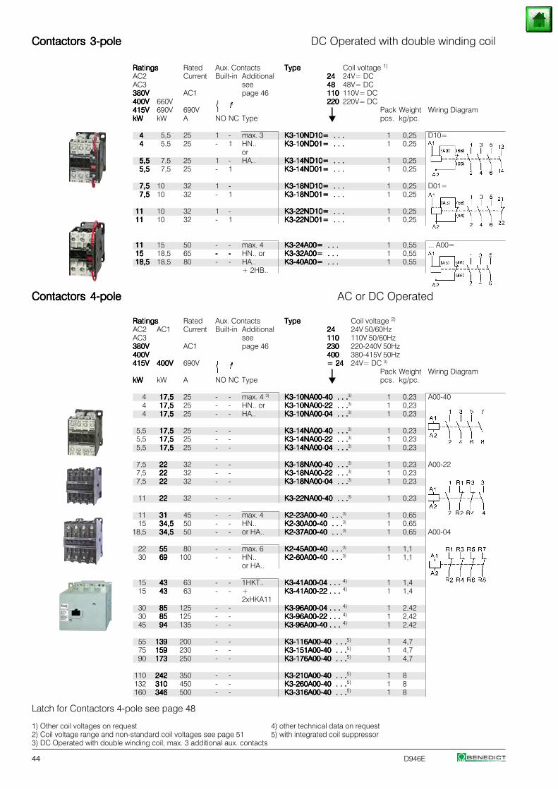
44 D946E
Contactors 3-poleContactors 3-poleContactors 3-poleContactors 3-poleContactors 3-pole DC Operated with double winding coil
RatingsRatingsRatingsRatingsRatings Rated Aux. Contacts TypeTypeTypeTypeType Coil voltage 1)
AC2 Current Built-in Additional 2424242424 24V= DCAC3 see 4848484848 48V= DC380V380V380V380V380V AC1 page 46 110110110110110 110V= DC400V400V400V400V400V 660V 220220220220220 220V= DC415V415V415V415V415V 690V 690V ⏐⏐⏐⏐⏐ Pack Weight Wiring DiagramkWkWkWkWkW kW A NO NC Type pcs. kg/pc.
44444 5,5 25 1 - max. 3 K3-10ND10= . . .K3-10ND10= . . .K3-10ND10= . . .K3-10ND10= . . .K3-10ND10= . . . 1 0,25 D10=44444 5,5 25 - 1 HN.. K3-10ND01= . . .K3-10ND01= . . .K3-10ND01= . . .K3-10ND01= . . .K3-10ND01= . . . 1 0,25
or5,55,55,55,55,5 7,5 25 1 - HA.. K3-14ND10= . . .K3-14ND10= . . .K3-14ND10= . . .K3-14ND10= . . .K3-14ND10= . . . 1 0,255,55,55,55,55,5 7,5 25 - 1 K3-14ND01= . . .K3-14ND01= . . .K3-14ND01= . . .K3-14ND01= . . .K3-14ND01= . . . 1 0,25
7,57,57,57,57,5 10 32 1 - K3-18ND10= . . .K3-18ND10= . . .K3-18ND10= . . .K3-18ND10= . . .K3-18ND10= . . . 1 0,25 D01=7,57,57,57,57,5 10 32 - 1 K3-18ND01= . . .K3-18ND01= . . .K3-18ND01= . . .K3-18ND01= . . .K3-18ND01= . . . 1 0,25
1111111111 10 32 1 - K3-22ND10= . . .K3-22ND10= . . .K3-22ND10= . . .K3-22ND10= . . .K3-22ND10= . . . 1 0,251111111111 10 32 - 1 K3-22ND01= . . .K3-22ND01= . . .K3-22ND01= . . .K3-22ND01= . . .K3-22ND01= . . . 1 0,25
1111111111 15 50 - - max. 4 K3-24A00= . . .K3-24A00= . . .K3-24A00= . . .K3-24A00= . . .K3-24A00= . . . 1 0,55 ... A00=1515151515 18,5 65 ----- ----- HN.. or K3-32A00= . . .K3-32A00= . . .K3-32A00= . . .K3-32A00= . . .K3-32A00= . . . 1 0,5518,518,518,518,518,5 18,5 80 - - HA.. K3-40A00= . . .K3-40A00= . . .K3-40A00= . . .K3-40A00= . . .K3-40A00= . . . 1 0,55
+ 2HB..
Contactors 4-poleContactors 4-poleContactors 4-poleContactors 4-poleContactors 4-pole AC or DC Operated
RatingsRatingsRatingsRatingsRatings Rated Aux. Contacts TypeTypeTypeTypeType Coil voltage 2)
AC2 AC1 Current Built-in Additional 2424242424 24V 50/60HzAC3 see 110110110110110 110V 50/60Hz380V380V380V380V380V AC1 page 46 230230230230230 220-240V 50Hz400V400V400V400V400V 400400400400400 380-415V 50Hz415V415V415V415V415V 400V400V400V400V400V 690V = 24= 24= 24= 24= 24 24V= DC 3)
⏐⏐⏐⏐⏐ Pack Weight Wiring DiagramkWkWkWkWkW kW A NO NC Type pcs. kg/pc.
4 17,517,517,517,517,5 25 - - max. 4 3) K3-10NA00-40 . . .K3-10NA00-40 . . .K3-10NA00-40 . . .K3-10NA00-40 . . .K3-10NA00-40 . . .3) 1 0,23 A00-404 17,517,517,517,517,5 25 - - HN.. or K3-10NA00-22 . . .K3-10NA00-22 . . .K3-10NA00-22 . . .K3-10NA00-22 . . .K3-10NA00-22 . . .3) 1 0,234 17,517,517,517,517,5 25 - - HA.. K3-10NA00-04 . . .K3-10NA00-04 . . .K3-10NA00-04 . . .K3-10NA00-04 . . .K3-10NA00-04 . . .3) 1 0,23
5,5 17,517,517,517,517,5 25 - - K3-14NA00-40 . . .K3-14NA00-40 . . .K3-14NA00-40 . . .K3-14NA00-40 . . .K3-14NA00-40 . . .3) 1 0,235,5 17,517,517,517,517,5 25 - - K3-14NA00-22 . . .K3-14NA00-22 . . .K3-14NA00-22 . . .K3-14NA00-22 . . .K3-14NA00-22 . . .3) 1 0,235,5 17,517,517,517,517,5 25 - - K3-14NA00-04 . . .K3-14NA00-04 . . .K3-14NA00-04 . . .K3-14NA00-04 . . .K3-14NA00-04 . . .3) 1 0,23
7,5 2222222222 32 - - K3-18NA00-40 . . .K3-18NA00-40 . . .K3-18NA00-40 . . .K3-18NA00-40 . . .K3-18NA00-40 . . .3) 1 0,23 A00-227,5 2222222222 32 - - K3-18NA00-22 . . .K3-18NA00-22 . . .K3-18NA00-22 . . .K3-18NA00-22 . . .K3-18NA00-22 . . .3) 1 0,237,5 2222222222 32 - - K3-18NA00-04 . . .K3-18NA00-04 . . .K3-18NA00-04 . . .K3-18NA00-04 . . .K3-18NA00-04 . . .3) 1 0,23
11 2222222222 32 - - K3-22NA00-40 . . .K3-22NA00-40 . . .K3-22NA00-40 . . .K3-22NA00-40 . . .K3-22NA00-40 . . .3) 1 0,23
11 3131313131 45 - - max. 4 K2-23A00-40 . . .K2-23A00-40 . . .K2-23A00-40 . . .K2-23A00-40 . . .K2-23A00-40 . . .3) 1 0,6515 34,534,534,534,534,5 50 - - HN.. K2-30A00-40 . . .K2-30A00-40 . . .K2-30A00-40 . . .K2-30A00-40 . . .K2-30A00-40 . . .3) 1 0,65
18,5 34,534,534,534,534,5 50 - - or HA.. K2-37A00-40 . . .K2-37A00-40 . . .K2-37A00-40 . . .K2-37A00-40 . . .K2-37A00-40 . . .3) 1 0,65 A00-04
22 5555555555 80 - - max. 6 K2-45A00-40 . . .K2-45A00-40 . . .K2-45A00-40 . . .K2-45A00-40 . . .K2-45A00-40 . . .3) 1 1,130 6969696969 100 - - HN.. K2-60A00-40 . . .K2-60A00-40 . . .K2-60A00-40 . . .K2-60A00-40 . . .K2-60A00-40 . . .3) 1 1,1
or HA..
15 4343434343 63 - - 1HKT.. K3-41A00-04 . . . K3-41A00-04 . . . K3-41A00-04 . . . K3-41A00-04 . . . K3-41A00-04 . . . 4) 1 1,415 4343434343 63 - - + K3-41A00-22 . . . K3-41A00-22 . . . K3-41A00-22 . . . K3-41A00-22 . . . K3-41A00-22 . . . 4) 1 1,4
2xHKA1130 8585858585 125 - - K3-96A00-04 . . . K3-96A00-04 . . . K3-96A00-04 . . . K3-96A00-04 . . . K3-96A00-04 . . . 4) 1 2,4230 8585858585 125 - - K3-96A00-22 . . . K3-96A00-22 . . . K3-96A00-22 . . . K3-96A00-22 . . . K3-96A00-22 . . . 4) 1 2,4245 9494949494 135 - - K3-96A00-40 . . . K3-96A00-40 . . . K3-96A00-40 . . . K3-96A00-40 . . . K3-96A00-40 . . . 4) 1 2,42
55 139139139139139 200 - - K3-116A00-40 . . .K3-116A00-40 . . .K3-116A00-40 . . .K3-116A00-40 . . .K3-116A00-40 . . .5) 1 4,775 159159159159159 230 - - K3-151A00-40 . . .K3-151A00-40 . . .K3-151A00-40 . . .K3-151A00-40 . . .K3-151A00-40 . . .5) 1 4,790 173173173173173 250 - - K3-176A00-40 . . .K3-176A00-40 . . .K3-176A00-40 . . .K3-176A00-40 . . .K3-176A00-40 . . .5) 1 4,7
110 242242242242242 350 - - K3-210A00-40 . . .K3-210A00-40 . . .K3-210A00-40 . . .K3-210A00-40 . . .K3-210A00-40 . . .5) 1 8132 310310310310310 450 - - K3-260A00-40 . . .K3-260A00-40 . . .K3-260A00-40 . . .K3-260A00-40 . . .K3-260A00-40 . . .5) 1 8160 346346346346346 500 - - K3-316A00-40 . . .K3-316A00-40 . . .K3-316A00-40 . . .K3-316A00-40 . . .K3-316A00-40 . . .5) 1 8
Latch for Contactors 4-pole see page 48
1) Other coil voltages on request 4) other technical data on request2) Coil voltage range and non-standard coil voltages see page 51 5) with integrated coil suppressor3) DC Operated with double winding coil, max. 3 additional aux. contacts
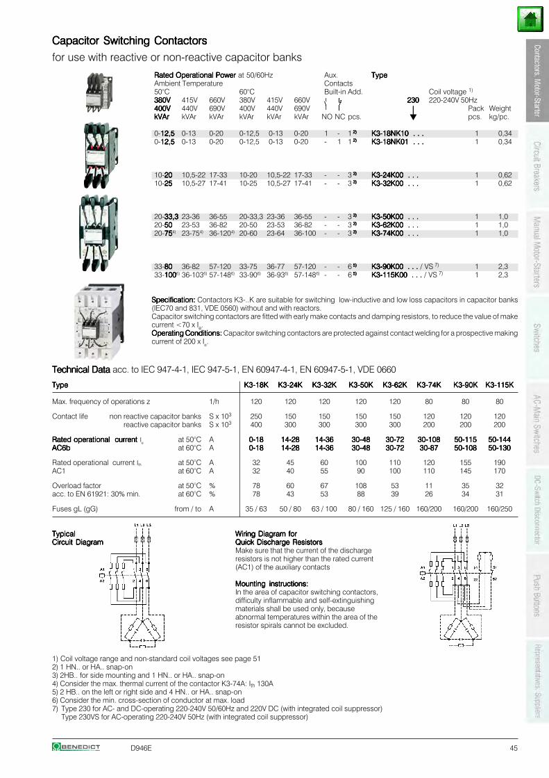
D946E 45
Capacitor Switching ContactorsCapacitor Switching ContactorsCapacitor Switching ContactorsCapacitor Switching ContactorsCapacitor Switching Contactors
for use with reactive or non-reactive capacitor banks
Rated Operational Power Rated Operational Power Rated Operational Power Rated Operational Power Rated Operational Power at 50/60Hz Aux. TypeTypeTypeTypeTypeAmbient Temperature Contacts50°C 60°C Built-in Add. Coil voltage 1)
380V380V380V380V380V 415V 660V 380V 415V 660V 230230230230230 220-240V 50Hz400V400V400V400V400V 440V 690V 400V 440V 690V ⏐⏐⏐⏐⏐ Pack WeightkVArkVArkVArkVArkVAr kVAr kVAr kVAr kVAr kVAr NO NC pcs. pcs. kg/pc.
0-12,512,512,512,512,5 0-13 0-20 0-12,5 0-13 0-20 1 - 1 2) 2) 2) 2) 2) K3-18NK10 . . .K3-18NK10 . . .K3-18NK10 . . .K3-18NK10 . . .K3-18NK10 . . . 1 0,340-12,512,512,512,512,5 0-13 0-20 0-12,5 0-13 0-20 - 1 1 2) 2) 2) 2) 2) K3-18NK01 . . .K3-18NK01 . . .K3-18NK01 . . .K3-18NK01 . . .K3-18NK01 . . . 1 0,34
10-2020202020 10,5-22 17-33 10-20 10,5-22 17-33 - - 3 3) 3) 3) 3) 3) K3-24K00 . . .K3-24K00 . . .K3-24K00 . . .K3-24K00 . . .K3-24K00 . . . 1 0,6210-2525252525 10,5-27 17-41 10-25 10,5-27 17-41 - - 3 3) 3) 3) 3) 3) K3-32K00 . . .K3-32K00 . . .K3-32K00 . . .K3-32K00 . . .K3-32K00 . . . 1 0,62
20-33,333,333,333,333,3 23-36 36-55 20-33,3 23-36 36-55 - - 3 3) 3) 3) 3) 3) K3-50K00 . . .K3-50K00 . . .K3-50K00 . . .K3-50K00 . . .K3-50K00 . . . 1 1,020-5050505050 23-53 36-82 20-50 23-53 36-82 - - 3 3) 3) 3) 3) 3) K3-62K00 . . .K3-62K00 . . .K3-62K00 . . .K3-62K00 . . .K3-62K00 . . . 1 1,020-75757575754) 23-754) 36-1204) 20-60 23-64 36-100 - - 3 3) 3) 3) 3) 3) K3-74K00 . . .K3-74K00 . . .K3-74K00 . . .K3-74K00 . . .K3-74K00 . . . 1 1,0
33-8080808080 36-82 57-120 33-75 36-77 57-120 - - 6 5) 5) 5) 5) 5) K3-90K00 . . . K3-90K00 . . . K3-90K00 . . . K3-90K00 . . . K3-90K00 . . . / VS 7) 1 2,333-1001001001001006) 36-1036) 57-1486) 33-906) 36-936) 57-1486) - - 6 5) 5) 5) 5) 5) K3-115K00 . . . K3-115K00 . . . K3-115K00 . . . K3-115K00 . . . K3-115K00 . . . / VS 7) 1 2,3
Specification:Specification:Specification:Specification:Specification: Contactors K3-..K are suitable for switching low-inductive and low loss capacitors in capacitor banks(IEC70 and 831, VDE 0560) without and with reactors.Capacitor switching contactors are fitted with early make contacts and damping resistors, to reduce the value of makecurrent <70 x Ie.Operating Conditions:Operating Conditions:Operating Conditions:Operating Conditions:Operating Conditions: Capacitor switching contactors are protected against contact welding for a prospective makingcurrent of 200 x Ie.
Technical Data Technical Data Technical Data Technical Data Technical Data acc. to IEC 947-4-1, IEC 947-5-1, EN 60947-4-1, EN 60947-5-1, VDE 0660
TypeTypeTypeTypeType K3-18KK3-18KK3-18KK3-18KK3-18K K3-24KK3-24KK3-24KK3-24KK3-24K K3-32KK3-32KK3-32KK3-32KK3-32K K3-50KK3-50KK3-50KK3-50KK3-50K K3-62KK3-62KK3-62KK3-62KK3-62K K3-74KK3-74KK3-74KK3-74KK3-74K K3-90KK3-90KK3-90KK3-90KK3-90K K3-115KK3-115KK3-115KK3-115KK3-115K
Max. frequency of operations z 1/h 120 120 120 120 120 80 80 80
Contact life non reactive capacitor banks S x 103 250 150 150 150 150 120 120 120reactive capacitor banks S x 103 400 300 300 300 300 200 200 200
Rated operational current Rated operational current Rated operational current Rated operational current Rated operational current Ie at 50°C A 0-180-180-180-180-18 14-2814-2814-2814-2814-28 14-3614-3614-3614-3614-36 30-4830-4830-4830-4830-48 30-7230-7230-7230-7230-72 30-10830-10830-10830-10830-108 50-11550-11550-11550-11550-115 50-14450-14450-14450-14450-144AC6bAC6bAC6bAC6bAC6b at 60°C A 0-180-180-180-180-18 14-2814-2814-2814-2814-28 14-3614-3614-3614-3614-36 30-4830-4830-4830-4830-48 30-7230-7230-7230-7230-72 30-8730-8730-8730-8730-87 50-10850-10850-10850-10850-108 50-13050-13050-13050-13050-130
Rated operational current Ith at 50°C A 32 45 60 100 110 120 155 190AC1 at 60°C A 32 40 55 90 100 110 145 170
Overload factor at 50°C % 78 60 67 108 53 11 35 32acc. to EN 61921: 30% min. at 60°C % 78 43 53 88 39 26 34 31
Fuses gL (gG) from / to A 35 / 63 50 / 80 63 / 100 80 / 160 125 / 160 160/200 160/200 160/250
TypicalTypicalTypicalTypicalTypical Wiring Diagram forWiring Diagram forWiring Diagram forWiring Diagram forWiring Diagram forCircuit DiagramCircuit DiagramCircuit DiagramCircuit DiagramCircuit Diagram Quick Discharge ResistorsQuick Discharge ResistorsQuick Discharge ResistorsQuick Discharge ResistorsQuick Discharge Resistors
Make sure that the current of the dischargeresistors is not higher than the rated current(AC1) of the auxiliary contacts
Mounting instructions:Mounting instructions:Mounting instructions:Mounting instructions:Mounting instructions:In the area of capacitor switching contactors,difficulty inflammable and self-extinguishingmaterials shall be used only, becauseabnormal temperatures within the area of theresistor spirals cannot be excluded.
1) Coil voltage range and non-standard coil voltages see page 512) 1 HN.. or HA.. snap-on3) 2HB.. for side mounting and 1 HN.. or HA.. snap-on4) Consider the max. thermal current of the contactor K3-74A: Ith 130A5) 2 HB.. on the left or right side and 4 HN.. or HA.. snap-on6) Consider the min. cross-section of conductor at max. load7) Type 230 for AC- and DC-operating 220-240V 50/60Hz and 220V DC (with integrated coil suppressor)
Type 230VS for AC-operating 220-240V 50Hz (with integrated coil suppressor)
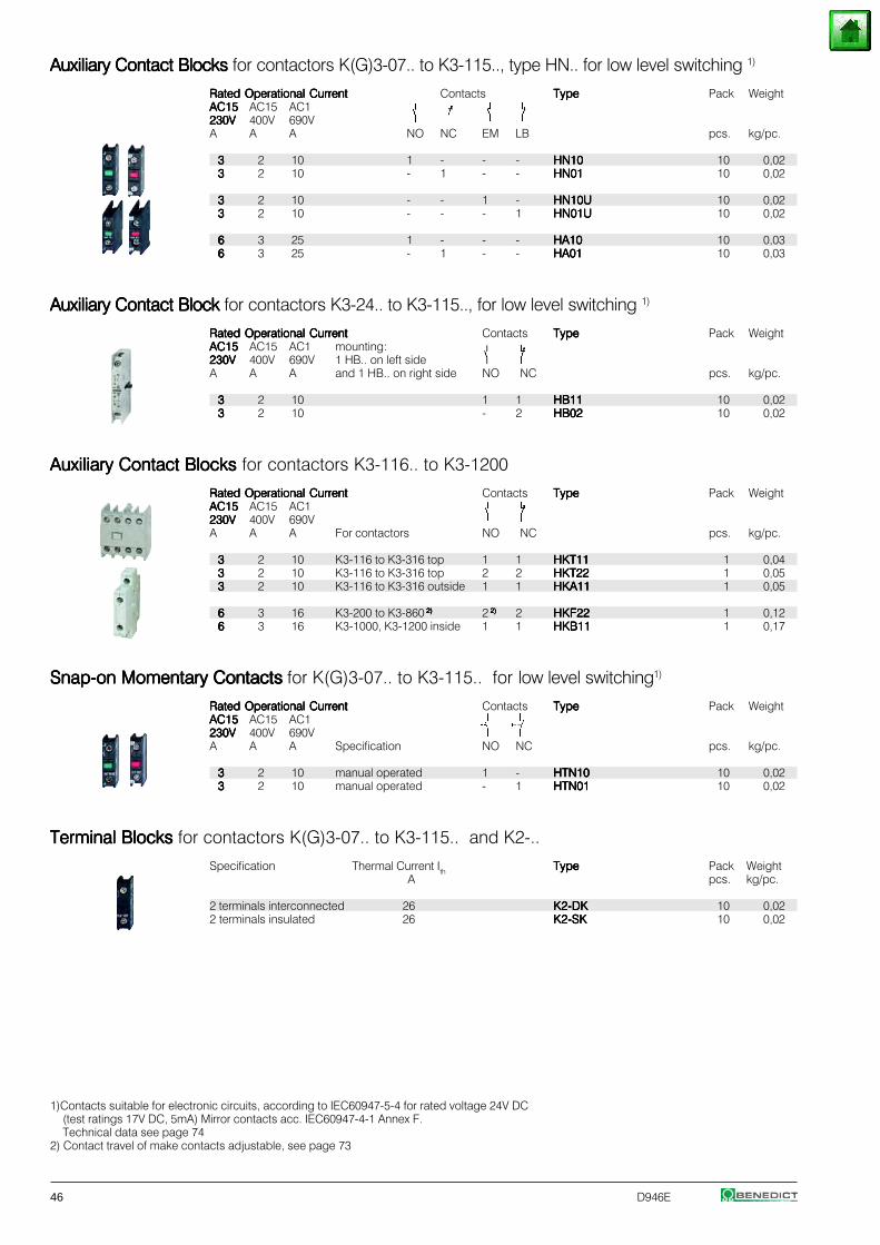
46 D946E
Auxiliary Contact Blocks Auxiliary Contact Blocks Auxiliary Contact Blocks Auxiliary Contact Blocks Auxiliary Contact Blocks for contactors K(G)3-07.. to K3-115.., type HN.. for low level switching 1)
Rated Operational CurrentRated Operational CurrentRated Operational CurrentRated Operational CurrentRated Operational Current Contacts TypeTypeTypeTypeType Pack WeightAC15AC15AC15AC15AC15 AC15 AC1230V230V230V230V230V 400V 690VA A A NO NC EM LB pcs. kg/pc.
33333 2 10 1 - - - HN10HN10HN10HN10HN10 10 0,0233333 2 10 - 1 - - HN01HN01HN01HN01HN01 10 0,02
33333 2 10 - - 1 - HN10UHN10UHN10UHN10UHN10U 10 0,0233333 2 10 - - - 1 HN01UHN01UHN01UHN01UHN01U 10 0,02
66666 3 25 1 - - - HA10HA10HA10HA10HA10 10 0,0366666 3 25 - 1 - - HA01HA01HA01HA01HA01 10 0,03
Auxiliary Contact Block Auxiliary Contact Block Auxiliary Contact Block Auxiliary Contact Block Auxiliary Contact Block for contactors K3-24.. to K3-115.., for low level switching 1)
Rated Operational CurrentRated Operational CurrentRated Operational CurrentRated Operational CurrentRated Operational Current Contacts TypeTypeTypeTypeType Pack WeightAC15AC15AC15AC15AC15 AC15 AC1 mounting:230V230V230V230V230V 400V 690V 1 HB.. on left sideA A A and 1 HB.. on right side NO NC pcs. kg/pc.
33333 2 10 1 1 HB11HB11HB11HB11HB11 10 0,0233333 2 10 - 2 HB02HB02HB02HB02HB02 10 0,02
Auxiliary Contact Blocks Auxiliary Contact Blocks Auxiliary Contact Blocks Auxiliary Contact Blocks Auxiliary Contact Blocks for contactors K3-116.. to K3-1200
Rated Operational CurrentRated Operational CurrentRated Operational CurrentRated Operational CurrentRated Operational Current Contacts TypeTypeTypeTypeType Pack WeightAC15AC15AC15AC15AC15 AC15 AC1230V230V230V230V230V 400V 690VA A A For contactors NO NC pcs. kg/pc.
33333 2 10 K3-116 to K3-316 top 1 1 HKT11HKT11HKT11HKT11HKT11 1 0,0433333 2 10 K3-116 to K3-316 top 2 2 HKT22HKT22HKT22HKT22HKT22 1 0,0533333 2 10 K3-116 to K3-316 outside 1 1 HKA11HKA11HKA11HKA11HKA11 1 0,05
66666 3 16 K3-200 to K3-860 2) 2) 2) 2) 2) 2 2) 2) 2) 2) 2) 2 HKF22HKF22HKF22HKF22HKF22 1 0,1266666 3 16 K3-1000, K3-1200 inside 1 1 HKB11HKB11HKB11HKB11HKB11 1 0,17
Snap-on Momentary Contacts Snap-on Momentary Contacts Snap-on Momentary Contacts Snap-on Momentary Contacts Snap-on Momentary Contacts for K(G)3-07.. to K3-115.. for low level switching1)
Rated Operational CurrentRated Operational CurrentRated Operational CurrentRated Operational CurrentRated Operational Current Contacts TypeTypeTypeTypeType Pack WeightAC15AC15AC15AC15AC15 AC15 AC1230V230V230V230V230V 400V 690VA A A Specification NO NC pcs. kg/pc.
33333 2 10 manual operated 1 - HTN10HTN10HTN10HTN10HTN10 10 0,0233333 2 10 manual operated - 1 HTN01HTN01HTN01HTN01HTN01 10 0,02
Terminal Blocks Terminal Blocks Terminal Blocks Terminal Blocks Terminal Blocks for contactors K(G)3-07.. to K3-115.. and K2-..
Specification Thermal Current Ith TypeTypeTypeTypeType Pack WeightA pcs. kg/pc.
2 terminals interconnected 26 K2-DKK2-DKK2-DKK2-DKK2-DK 10 0,022 terminals insulated 26 K2-SKK2-SKK2-SKK2-SKK2-SK 10 0,02
1)Contacts suitable for electronic circuits, according to IEC60947-5-4 for rated voltage 24V DC(test ratings 17V DC, 5mA) Mirror contacts acc. IEC60947-4-1 Annex F.Technical data see page 74
2) Contact travel of make contacts adjustable, see page 73
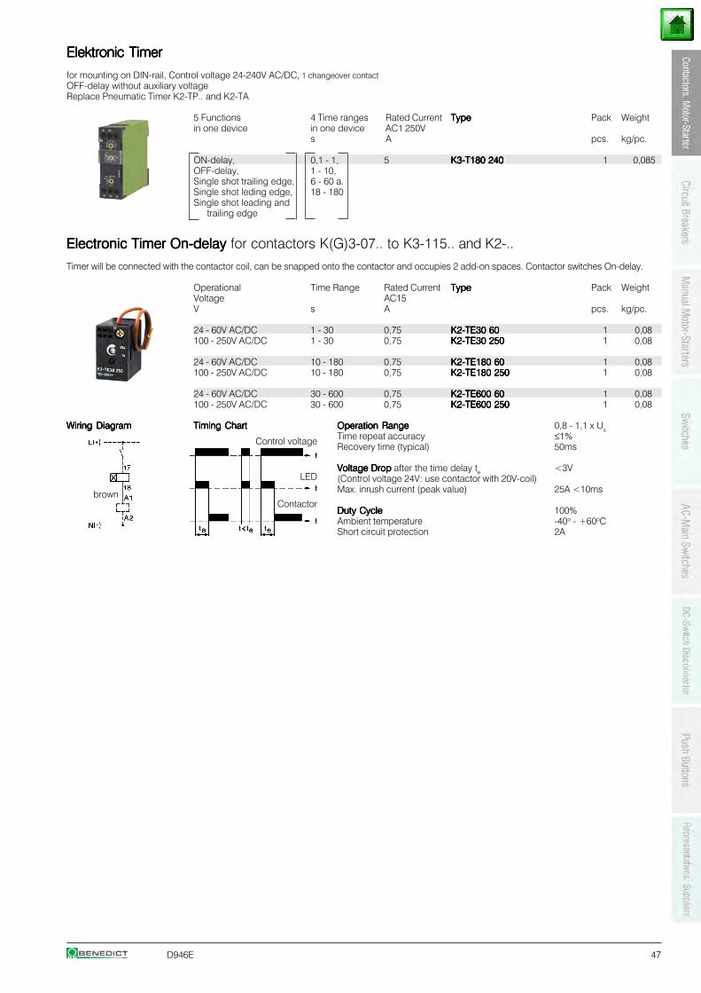
D946E 47
Elektronic TimerElektronic TimerElektronic TimerElektronic TimerElektronic Timer
for mounting on DIN-rail, Control voltage 24-240V AC/DC, 1 changeover contactOFF-delay without auxiliary voltageReplace Pneumatic Timer K2-TP.. and K2-TA
5 Functions 4 Time ranges Rated Current TypeTypeTypeTypeType Pack Weightin one device in one device AC1 250V
s A pcs. kg/pc.
ON-delay, 0,1 - 1, 5 K3-T180 240K3-T180 240K3-T180 240K3-T180 240K3-T180 240 1 0,085OFF-delay, 1 - 10,Single shot trailing edge, 6 - 60 a.Single shot leding edge, 18 - 180Single shot leading and
trailing edge
Electronic Timer On-delay Electronic Timer On-delay Electronic Timer On-delay Electronic Timer On-delay Electronic Timer On-delay for contactors K(G)3-07.. to K3-115.. and K2-..
Timer will be connected with the contactor coil, can be snapped onto the contactor and occupies 2 add-on spaces. Contactor switches On-delay.
Operational Time Range Rated Current TypeTypeTypeTypeType Pack WeightVoltage AC15V s A pcs. kg/pc.
24 - 60V AC/DC 1 - 30 0,75 K2-TE30 60K2-TE30 60K2-TE30 60K2-TE30 60K2-TE30 60 1 0,08100 - 250V AC/DC 1 - 30 0,75 K2-TE30 250K2-TE30 250K2-TE30 250K2-TE30 250K2-TE30 250 1 0,08
24 - 60V AC/DC 10 - 180 0,75 K2-TE180 60K2-TE180 60K2-TE180 60K2-TE180 60K2-TE180 60 1 0,08100 - 250V AC/DC 10 - 180 0,75 K2-TE180 250K2-TE180 250K2-TE180 250K2-TE180 250K2-TE180 250 1 0,08
24 - 60V AC/DC 30 - 600 0,75 K2-TE600 60K2-TE600 60K2-TE600 60K2-TE600 60K2-TE600 60 1 0,08100 - 250V AC/DC 30 - 600 0,75 K2-TE600 250K2-TE600 250K2-TE600 250K2-TE600 250K2-TE600 250 1 0,08
Operation RangeOperation RangeOperation RangeOperation RangeOperation Range 0,8 - 1,1 x UsTime repeat accuracy ≤1%Recovery time (typical) 50ms
Voltage Drop Voltage Drop Voltage Drop Voltage Drop Voltage Drop after the time delay te <3V(Control voltage 24V: use contactor with 20V-coil)Max. inrush current (peak value) 25A <10ms
Duty CycleDuty CycleDuty CycleDuty CycleDuty Cycle 100%Ambient temperature -40o - +60oCShort circuit protection 2A
Wiring DiagramWiring DiagramWiring DiagramWiring DiagramWiring Diagram Timing ChartTiming ChartTiming ChartTiming ChartTiming Chart
Control voltage
LED
brownContactor
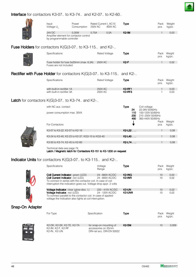
48 D946E
InterfaceInterfaceInterfaceInterfaceInterface for contactors K3-07.. to K3-74.. and K2-07.. to K2-60..
Input Power Rated Current Ie AC15 TypeTypeTypeTypeType Pack WeightVoltage Ue Consumption 250V AC 400V AC pcs. kg/pc.
24V DC 0,35W 0,75A 0,5A K2-IMK2-IMK2-IMK2-IMK2-IM 1 0,03Amplifier element for contactor controlby programmable controller
Fuse Holders Fuse Holders Fuse Holders Fuse Holders Fuse Holders for contactors K(G)3-07.. to K3-115.. and K2-..
Specifications Rated Voltage TypeTypeTypeTypeType Pack Weightpcs. kg/pc.
Fuse holder for fuse 5x20mm (max. 6,3A) 250V AC K2-FK2-FK2-FK2-FK2-F 1 0,02Fuses are not included.
Rectifier with Fuse Holder Rectifier with Fuse Holder Rectifier with Fuse Holder Rectifier with Fuse Holder Rectifier with Fuse Holder for contactors K(G)3-07.. to K3-115.. and K2-..
Specifications Rated Voltage TypeTypeTypeTypeType Pack Weightpcs. kg/pc.
with built-in rectifier 1A 250V AC K2-RF1K2-RF1K2-RF1K2-RF1K2-RF1 1 0,03with built-in rectifier 3A 250V AC K2-RF3K2-RF3K2-RF3K2-RF3K2-RF3 1 0,03
Latch Latch Latch Latch Latch for contactors K(G)3-07.. to K3-74.. and K2-..
with NC aux. contact TypeTypeTypeTypeType Coil voltage2424242424 22-26V 50/60Hz
power consumption max. 30VA 110110110110110 100-120V 50/60Hz230230230230230 210 -250V 50/60Hz400400400400400 360-440V 50/60Hz
⏐⏐⏐⏐⏐ Pack WeightFor Contactors pcs. kg/pc.
K3-07 to K3-22, K2-07 to K2-16 K2-L22 . . .K2-L22 . . .K2-L22 . . .K2-L22 . . .K2-L22 . . . 1 0,08
K3-24 to K3-40, K2-23 to K2-37, KG3-10 to KG3-40 K2-L40 . . .K2-L40 . . .K2-L40 . . .K2-L40 . . .K2-L40 . . . 1 0,08
K3-50 to K3-74, K2-45 to K2-60 K2-L74 . . .K2-L74 . . .K2-L74 . . .K2-L74 . . .K2-L74 . . . 1 0,08
Technical data see page 74Latch / Magnetic latch for Contactors K3-151 to K3-1200 on requestLatch / Magnetic latch for Contactors K3-151 to K3-1200 on requestLatch / Magnetic latch for Contactors K3-151 to K3-1200 on requestLatch / Magnetic latch for Contactors K3-151 to K3-1200 on requestLatch / Magnetic latch for Contactors K3-151 to K3-1200 on request
Indicator Units Indicator Units Indicator Units Indicator Units Indicator Units for contactors K(G)3-07.. to K3-115.. and K2-..
Specifications Voltage TypeTypeTypeTypeType Pack WeightRange pcs. kg/pc.
Coil Current IndicatorCoil Current IndicatorCoil Current IndicatorCoil Current IndicatorCoil Current Indicator, green (LED) 24 - 660V AC/DC K2-INGK2-INGK2-INGK2-INGK2-ING 10 0,02Coil Current IndicatorCoil Current IndicatorCoil Current IndicatorCoil Current IndicatorCoil Current Indicator, red (LED) 24 - 660V AC/DC K2-INRK2-INRK2-INRK2-INRK2-INR 10 0,02To connect in series with the contactor coil. In case of coilinterruption the indication goes out. Voltage drop appr. 2 volts
Voltage IndicatorVoltage IndicatorVoltage IndicatorVoltage IndicatorVoltage Indicator, clear (glow-disc. l.) 220 - 415V AC/DC K2-UNK2-UNK2-UNK2-UNK2-UN 10 0,02Voltage IndicatorVoltage IndicatorVoltage IndicatorVoltage IndicatorVoltage Indicator, red (LED) 24 - 120V AC/DC K2-UNRK2-UNRK2-UNRK2-UNRK2-UNR 10 0,02To connect parallel to the contactor coil. In case of appliedvoltage the indication also lights at coil interruption.
Snap-On AdapterSnap-On AdapterSnap-On AdapterSnap-On AdapterSnap-On Adapter
For Type Specification TypeTypeTypeTypeType Pack Weightpcs. kg/pc.
K2-DK, K2-SK, K2-TE, K2-TA for snap-on mounting of K2-SMK2-SMK2-SMK2-SMK2-SM 10 0,009K2-IM, K2-F, K2-RF accessories on 35mmK2-IN., K2-UN. DIN-rail acc. DIN EN 50022
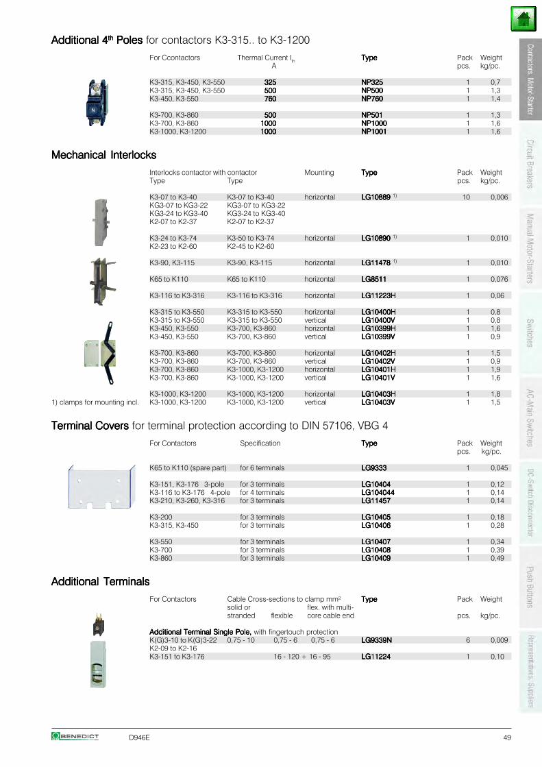
D946E 49
Additional 4Additional 4Additional 4Additional 4Additional 4ththththth Poles Poles Poles Poles Poles for contactors K3-315.. to K3-1200
For Ccontactors Thermal Current Ith TypeTypeTypeTypeType Pack WeightA pcs. kg/pc.
K3-315, K3-450, K3-550 325325325325325 NP325NP325NP325NP325NP325 1 0,7K3-315, K3-450, K3-550 500500500500500 NP500NP500NP500NP500NP500 1 1,3K3-450, K3-550 760760760760760 NP760NP760NP760NP760NP760 1 1,4
K3-700, K3-860 500500500500500 NP501NP501NP501NP501NP501 1 1,3K3-700, K3-860 10001000100010001000 NP1000NP1000NP1000NP1000NP1000 1 1,6K3-1000, K3-1200 10001000100010001000 NP1001NP1001NP1001NP1001NP1001 1 1,6
Mechanical InterlocksMechanical InterlocksMechanical InterlocksMechanical InterlocksMechanical Interlocks
Interlocks contactor with contactor Mounting TypeTypeTypeTypeType Pack WeightType Type pcs. kg/pc.
K3-07 to K3-40 K3-07 to K3-40 horizontal LG10889 LG10889 LG10889 LG10889 LG10889 1) 10 0,006KG3-07 to KG3-22 KG3-07 to KG3-22KG3-24 to KG3-40 KG3-24 to KG3-40K2-07 to K2-37 K2-07 to K2-37
K3-24 to K3-74 K3-50 to K3-74 horizontal LG10890 LG10890 LG10890 LG10890 LG10890 1) 1 0,010K2-23 to K2-60 K2-45 to K2-60
K3-90, K3-115 K3-90, K3-115 horizontal LG11478 LG11478 LG11478 LG11478 LG11478 1) 1 0,010
K65 to K110 K65 to K110 horizontal LG8511LG8511LG8511LG8511LG8511 1 0,076
K3-116 to K3-316 K3-116 to K3-316 horizontal LG11223HLG11223HLG11223HLG11223HLG11223H 1 0,06
K3-315 to K3-550 K3-315 to K3-550 horizontal LG10400HLG10400HLG10400HLG10400HLG10400H 1 0,8K3-315 to K3-550 K3-315 to K3-550 vertical LG10400VLG10400VLG10400VLG10400VLG10400V 1 0,8K3-450, K3-550 K3-700, K3-860 horizontal LG10399HLG10399HLG10399HLG10399HLG10399H 1 1,6K3-450, K3-550 K3-700, K3-860 vertical LG10399VLG10399VLG10399VLG10399VLG10399V 1 0,9
K3-700, K3-860 K3-700, K3-860 horizontal LG10402HLG10402HLG10402HLG10402HLG10402H 1 1,5K3-700, K3-860 K3-700, K3-860 vertical LG10402VLG10402VLG10402VLG10402VLG10402V 1 0,9K3-700, K3-860 K3-1000, K3-1200 horizontal LG10401HLG10401HLG10401HLG10401HLG10401H 1 1,9K3-700, K3-860 K3-1000, K3-1200 vertical LG10401VLG10401VLG10401VLG10401VLG10401V 1 1,6
K3-1000, K3-1200 K3-1000, K3-1200 horizontal LG10403HLG10403HLG10403HLG10403HLG10403H 1 1,81) clamps for mounting incl. K3-1000, K3-1200 K3-1000, K3-1200 vertical LG10403VLG10403VLG10403VLG10403VLG10403V 1 1,5
Terminal Covers Terminal Covers Terminal Covers Terminal Covers Terminal Covers for terminal protection according to DIN 57106, VBG 4
For Contactors Specification TypeTypeTypeTypeType Pack Weightpcs. kg/pc.
K65 to K110 (spare part) for 6 terminals LG9333LG9333LG9333LG9333LG9333 1 0,045
K3-151, K3-176 3-pole for 3 terminals LG10404LG10404LG10404LG10404LG10404 1 0,12K3-116 to K3-176 4-pole for 4 terminals LG104044LG104044LG104044LG104044LG104044 1 0,14K3-210, K3-260, K3-316 for 3 terminals LG11457LG11457LG11457LG11457LG11457 1 0,14
K3-200 for 3 terminals LG10405LG10405LG10405LG10405LG10405 1 0,18K3-315, K3-450 for 3 terminals LG10406LG10406LG10406LG10406LG10406 1 0,28
K3-550 for 3 terminals LG10407LG10407LG10407LG10407LG10407 1 0,34K3-700 for 3 terminals LG10408LG10408LG10408LG10408LG10408 1 0,39K3-860 for 3 terminals LG10409LG10409LG10409LG10409LG10409 1 0,49
Additional TerminalsAdditional TerminalsAdditional TerminalsAdditional TerminalsAdditional Terminals
For Contactors Cable Cross-sections to clamp mm² TypeTypeTypeTypeType Pack Weightsolid or flex. with multi-stranded flexible core cable end pcs. kg/pc.
Additional Terminal Single Pole, Additional Terminal Single Pole, Additional Terminal Single Pole, Additional Terminal Single Pole, Additional Terminal Single Pole, with fingertouch protectionK(G)3-10 to K(G)3-22 0,75 - 10 0,75 - 6 0,75 - 6 LG9339NLG9339NLG9339NLG9339NLG9339N 6 0,009K2-09 to K2-16K3-151 to K3-176 16 - 120 + 16 - 95 LG11224LG11224LG11224LG11224LG11224 1 0,10
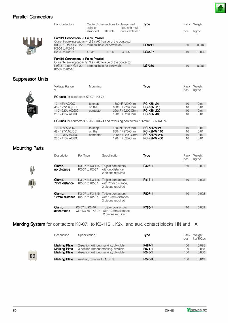
50 D946E
Parallel ConnectorsParallel ConnectorsParallel ConnectorsParallel ConnectorsParallel Connectors
For Contactors Cable Cross-sections to clamp mm² TypeTypeTypeTypeType Pack Weightsolid or flex. with multi-stranded flexible core cable end pcs. kg/pc.
Parallel Connectors, 3 Poles ParallelParallel Connectors, 3 Poles ParallelParallel Connectors, 3 Poles ParallelParallel Connectors, 3 Poles ParallelParallel Connectors, 3 Poles ParallelCurrent-carrying capacity: 2,5 x AC1-value of the contactorK(G)3-10 to K(G)3-22 terminal hole for screw M5 LG9241LG9241LG9241LG9241LG9241 50 0,004K2-09 to K2-16K2-23 to K2-37 4 - 35 6 - 25 4 - 25 LG5587LG5587LG5587LG5587LG5587 10 0,022
Parallel Connectors, 4 Poles ParallelParallel Connectors, 4 Poles ParallelParallel Connectors, 4 Poles ParallelParallel Connectors, 4 Poles ParallelParallel Connectors, 4 Poles ParallelCurrent-carrying capacity: 3,2 x AC1-value of the contactorK(G)3-10 to K(G)3-22 terminal hole for screw M5 LG7360LG7360LG7360LG7360LG7360 10 0,006K2-09 to K2-16
Suppressor UnitsSuppressor UnitsSuppressor UnitsSuppressor UnitsSuppressor Units
Voltage Range Mounting TypeTypeTypeTypeType Pack WeightV pcs. kg/pc.
RC-units RC-units RC-units RC-units RC-units for contactors K3-07 - K3-74
12 - 48V AC/DC to snap 1600nF / 22 Ohm RC-K3N 24RC-K3N 24RC-K3N 24RC-K3N 24RC-K3N 24 10 0,0148 - 127V AC/DC on the 680nF / 270 Ohm RC-K3N 110RC-K3N 110RC-K3N 110RC-K3N 110RC-K3N 110 10 0,01110 - 230V AC/DC contactor 220nF / 2200 Ohm RC-K3N 230RC-K3N 230RC-K3N 230RC-K3N 230RC-K3N 230 10 0,01230 - 415V AC/DC 120nF / 620 Ohm RC-K3N 400RC-K3N 400RC-K3N 400RC-K3N 400RC-K3N 400 10 0,01
RC-units RC-units RC-units RC-units RC-units for contactors K3-07 - K3-74 and reversing contactors K3NWU10 - K3WU74
12 - 48V AC/DC to snap 1600nF / 22 Ohm RC-K3NW 24RC-K3NW 24RC-K3NW 24RC-K3NW 24RC-K3NW 24 10 0,0148 - 127V AC/DC on the 680nF / 270 Ohm RC-K3NW 110RC-K3NW 110RC-K3NW 110RC-K3NW 110RC-K3NW 110 10 0,01110 - 230V AC/DC contactor 220nF / 2200 Ohm RC-K3NW 230RC-K3NW 230RC-K3NW 230RC-K3NW 230RC-K3NW 230 10 0,01230 - 415V AC/DC 120nF / 620 Ohm RC-K3NW 400RC-K3NW 400RC-K3NW 400RC-K3NW 400RC-K3NW 400 10 0,01
Mounting PartsMounting PartsMounting PartsMounting PartsMounting Parts
Description For Type Specification TypeTypeTypeTypeType Pack Weightpcs. kg/pc.
Clamp,Clamp,Clamp,Clamp,Clamp, K3-07 to K3-115 To join contactors P426-1P426-1P426-1P426-1P426-1 50 0,001no distanceno distanceno distanceno distanceno distance K2-07 to K2-37 without distance,
2 pieces required
Clamp,Clamp,Clamp,Clamp,Clamp, K3-07 to K3-115 To join contactors P418-1P418-1P418-1P418-1P418-1 10 0,0027mm distance7mm distance7mm distance7mm distance7mm distance K2-07 to K2-37 with 7mm distance,
2 pieces required
Clamp,Clamp,Clamp,Clamp,Clamp, K3-07 to K3-115 To join contactors P807-1P807-1P807-1P807-1P807-1 10 0,00212mm distance12mm distance12mm distance12mm distance12mm distance K2-07 to K2-37 with 12mm distance,
2 pieces required
ClampClampClampClampClamp K3-07 to K3-40 To join contactors P785-1P785-1P785-1P785-1P785-1 10 0,002asymmetricasymmetricasymmetricasymmetricasymmetric with K3-50 - K3-74 with 12mm distance,
2 pieces required
Marking System Marking System Marking System Marking System Marking System for contactors K3-07.. to K3-115.., K2-.. and aux. contact blocks HN and HA
Description Specification TypeTypeTypeTypeType Pack Weightpcs. kg/100pc
Marking PlateMarking PlateMarking PlateMarking PlateMarking Plate 2-section without marking, divisible P487-1P487-1P487-1P487-1P487-1 100 0,025Marking PlateMarking PlateMarking PlateMarking PlateMarking Plate 3-section without marking, divisible P971-1P971-1P971-1P971-1P971-1 100 0,038Marking PlateMarking PlateMarking PlateMarking PlateMarking Plate 4-section without marking, divisible P245-1P245-1P245-1P245-1P245-1 100 0,050
Marking PlateMarking PlateMarking PlateMarking PlateMarking Plate marked, choice of K1...K32 P245-K..P245-K..P245-K..P245-K..P245-K.. 100 0,013
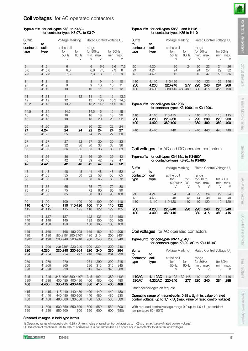
D946E 51
Coil voltages Coil voltages Coil voltages Coil voltages Coil voltages for AC operated contactors
Type-suffixType-suffixType-suffixType-suffixType-suffix for coil-types K6/.. to K45/...for coil-types K6/.. to K45/...for coil-types K6/.. to K45/...for coil-types K6/.. to K45/...for coil-types K6/.. to K45/...for contactor-types K3-07.. to K3-74for contactor-types K3-07.. to K3-74for contactor-types K3-07.. to K3-74for contactor-types K3-07.. to K3-74for contactor-types K3-07.. to K3-74
SuffixSuffixSuffixSuffixSuffix Voltage Marking Rated Control Voltage Ustototototo tototototocontactorcontactorcontactorcontactorcontactor coilcoilcoilcoilcoil at the coil rangetypetypetypetypetype typetypetypetypetype for for for 50Hz for 60Hz
50Hz 60Hz min. max. min. max.V V V V V V
6 41.6 6 6 6,6 6,6 7,36,6 41.6,6 6,6 6,6 7,3 7,3 87,3 41.7,3 7,3 7,3 8 8 9
8 41.8 8 8 9 9 109 41.9 9 9 10 10 1110 41.10 10 10 11 11 12
11 41.11 11 12 11 12 12 13,212 41.12 12 12 13,2 13,2 14,513,2 41.13 13,2 13,2 14,5 14,5 16
14,5 41.14 14,5 14,5 16 16 1816 41.16 16 16 18 18 2018 41.18 18 18 20 20 22
20 41.20 20 20 22 22 242424242424 4.244.244.244.244.24 2424242424 2424242424 2222222222 2424242424 2424242424 272727272725 41.25 25 24 27 27 30
27 41.27 27 32 27 30 30 3332 41.32 32 36 30 33 33 3633 41.33 36 36 33 36 36 39
36 41.36 36 42 36 39 39 4240 41.40 42 42 39 42 42 474242424242 4.424.424.424.424.42 4242424242 4848484848 4242424242 4747474747 4747474747 5252525252
48 41.48 48 48 44 48 48 5255 41.55 55 60 52 58 58 6560 41.60 60 58 65 65 72
65 41.65 65 65 72 72 8075 41.75 75 72 80 80 9085 41.85 85 80 90 90 100
90 41.90 100 100 90 100 100 110110110110110110 4.1104.1104.1104.1104.110 110110110110110 110-120110-120110-120110-120110-120 100100100100100 110110110110110 110110110110110 122122122122122115 41.115 115 125 110 122 122 135
127 41.127 127 122 135 135 150140 41.140 140 135 150 150 165150 41.150 150 150 165 165 180
165 41.165 165 180-208 165 180 180 208180 41.180 180-2101) 200-2401) 180 2101) 200 2401)
1902) 41.190 200-240 200-240 200 240 200 240
200 41.200 200-2301) 220-240 200 2301) 220 240230230230230230 4.2304.2304.2304.2304.230 220-240220-240220-240220-240220-240 230-264230-264230-264230-264230-264 220220220220220 240240240240240 230230230230230 264264264264264254 41.254 254 277 240 264 264 290
270 41.270 270 264 290 290 315300 41.300 300 290 315 315 345320 41.320 320 315 345 345 380
345 41.345 345-4001) 380-4401) 345 4001) 380 4401)
3902) 41.390 400-480 400-480 400 480 400 480400400400400400 4.4004.4004.4004.4004.400 380-415380-415380-415380-415380-415 400-440400-440400-440400-440400-440 380380380380380 415415415415415 400400400400400 460460460460460
415 41.415 415-440 440-480 400 440 440 480440 41.440 440-480 480-500 440 480 480 530480 41.480 480-500 530-580 480 530 530 580
500 41.500 500-550 550-600 500 550 550 600550 41.550 550-600 600 550 600 600 (650)
Standard voltages in bold type lettersStandard voltages in bold type lettersStandard voltages in bold type lettersStandard voltages in bold type lettersStandard voltages in bold type letters
Type-suffixType-suffixType-suffixType-suffixType-suffix for coil-types K85/... and K110/...for coil-types K85/... and K110/...for coil-types K85/... and K110/...for coil-types K85/... and K110/...for coil-types K85/... and K110/...for contactor-types K85 to K110for contactor-types K85 to K110for contactor-types K85 to K110for contactor-types K85 to K110for contactor-types K85 to K110
SuffixSuffixSuffixSuffixSuffix Voltage Marking Rated Control Voltage Ustototototo tototototocontactorcontactorcontactorcontactorcontactor coilcoilcoilcoilcoil at the coil rangetypetypetypetypetype typetypetypetypetype for for for 50Hz for 60Hz
50Hz 60Hz min. max. min. max.V V V V V V
20 4.20 20 24 20 22 24 2624 4.24 24 24 27 29 3242 4.42 42 42 47 50 56
110 4.110 110-120 110 122 132 146230230230230230 4.2304.2304.2304.2304.230 220-240220-240220-240220-240220-240 277277277277277 220220220220220 240240240240240 264264264264264 288288288288288400 4.400 380-415 460-480 380 415 455 498
Type-suffixType-suffixType-suffixType-suffixType-suffix for coil-types K3-1200/..for coil-types K3-1200/..for coil-types K3-1200/..for coil-types K3-1200/..for coil-types K3-1200/..for contactor-types K3-1000.. to K3-1200..for contactor-types K3-1000.. to K3-1200..for contactor-types K3-1000.. to K3-1200..for contactor-types K3-1000.. to K3-1200..for contactor-types K3-1000.. to K3-1200..
110 4.110 110-115 - 110 115 110 115230230230230230 4.2304.2304.2304.2304.230 220-230220-230220-230220-230220-230 ----- 220220220220220 230230230230230 220220220220220 230230230230230400400400400400 4.4004.4004.4004.4004.400 380-400380-400380-400380-400380-400 ----- 380380380380380 400400400400400 380380380380380 400400400400400
440 4.440 440 - 440 440 440 440
Coil voltages Coil voltages Coil voltages Coil voltages Coil voltages for AC and DC operated contactors
Type-suffixType-suffixType-suffixType-suffixType-suffix for coil-types K3-115/.. to K3-860/..for coil-types K3-115/.. to K3-860/..for coil-types K3-115/.. to K3-860/..for coil-types K3-115/.. to K3-860/..for coil-types K3-115/.. to K3-860/..for contactor-types K3-90.. to K3-860..for contactor-types K3-90.. to K3-860..for contactor-types K3-90.. to K3-860..for contactor-types K3-90.. to K3-860..for contactor-types K3-90.. to K3-860..
SuffixSuffixSuffixSuffixSuffix Voltage Marking Rated Control Voltage Ustototototo tototototocontactorcontactorcontactorcontactorcontactor coilcoilcoilcoilcoil at the coil rangetypetypetypetypetype typetypetypetypetype for for for 50Hz for 60Hz
50/60Hz DC min. max. min. max.V V V V V V
24 4.24 24 24 22 24 22 2448 4.48 48 48 44 48 44 48110 4.110 110-120 110 110 120 110 120
230230230230230 4.2304.2304.2304.2304.230 220-240220-240220-240220-240220-240 220220220220220 220220220220220 240240240240240 220220220220220 240240240240240400400400400400 4.4004.4004.4004.4004.400 380-415380-415380-415380-415380-415 ----- 380380380380380 415415415415415 380380380380380 415415415415415
Coil voltages Coil voltages Coil voltages Coil voltages Coil voltages for AC operated contactors
Type-suffixType-suffixType-suffixType-suffixType-suffix for coil-types K3-115/..ACfor coil-types K3-115/..ACfor coil-types K3-115/..ACfor coil-types K3-115/..ACfor coil-types K3-115/..ACfor contactor-types K3-90..AC to K3-115..ACfor contactor-types K3-90..AC to K3-115..ACfor contactor-types K3-90..AC to K3-115..ACfor contactor-types K3-90..AC to K3-115..ACfor contactor-types K3-90..AC to K3-115..AC
SuffixSuffixSuffixSuffixSuffix Voltage Marking Rated Control Voltage Ustototototo tototototocontactorcontactorcontactorcontactorcontactor coilcoilcoilcoilcoil at the coil rangetypetypetypetypetype typetypetypetypetype for for for 50Hz for 60Hz
50Hz 60Hz min. max. min. max.V V V V V V
110AC110AC110AC110AC110AC 4.110AC4.110AC4.110AC4.110AC4.110AC 110-122 132-146 110 122 132 146230AC230AC230AC230AC230AC 4.230AC4.230AC4.230AC4.230AC4.230AC 220-240220-240220-240220-240220-240 277277277277277 220220220220220 240240240240240 264264264264264 288288288288288
Other coil voltages on request
Operating range of magnet-coils: 0,85 x UOperating range of magnet-coils: 0,85 x UOperating range of magnet-coils: 0,85 x UOperating range of magnet-coils: 0,85 x UOperating range of magnet-coils: 0,85 x Usssss (min. value of rated (min. value of rated (min. value of rated (min. value of rated (min. value of ratedcontrol voltage) up to 1,1 x Ucontrol voltage) up to 1,1 x Ucontrol voltage) up to 1,1 x Ucontrol voltage) up to 1,1 x Ucontrol voltage) up to 1,1 x Usssss (max. value of rated control voltage) (max. value of rated control voltage) (max. value of rated control voltage) (max. value of rated control voltage) (max. value of rated control voltage)
With reduced control voltage range 0,9 up to 1,0 x Us at ambienttemperature 60 - 90°C
1) Operating range of magnet-coils: 0,85 x Us (min. value of rated control voltage) up to 1,05 x Us (max. value of rated control voltage)2) Reduction of mechanical life to 10% of normal life. It is not admissible as a spare coil in a contactor for different coil voltages.
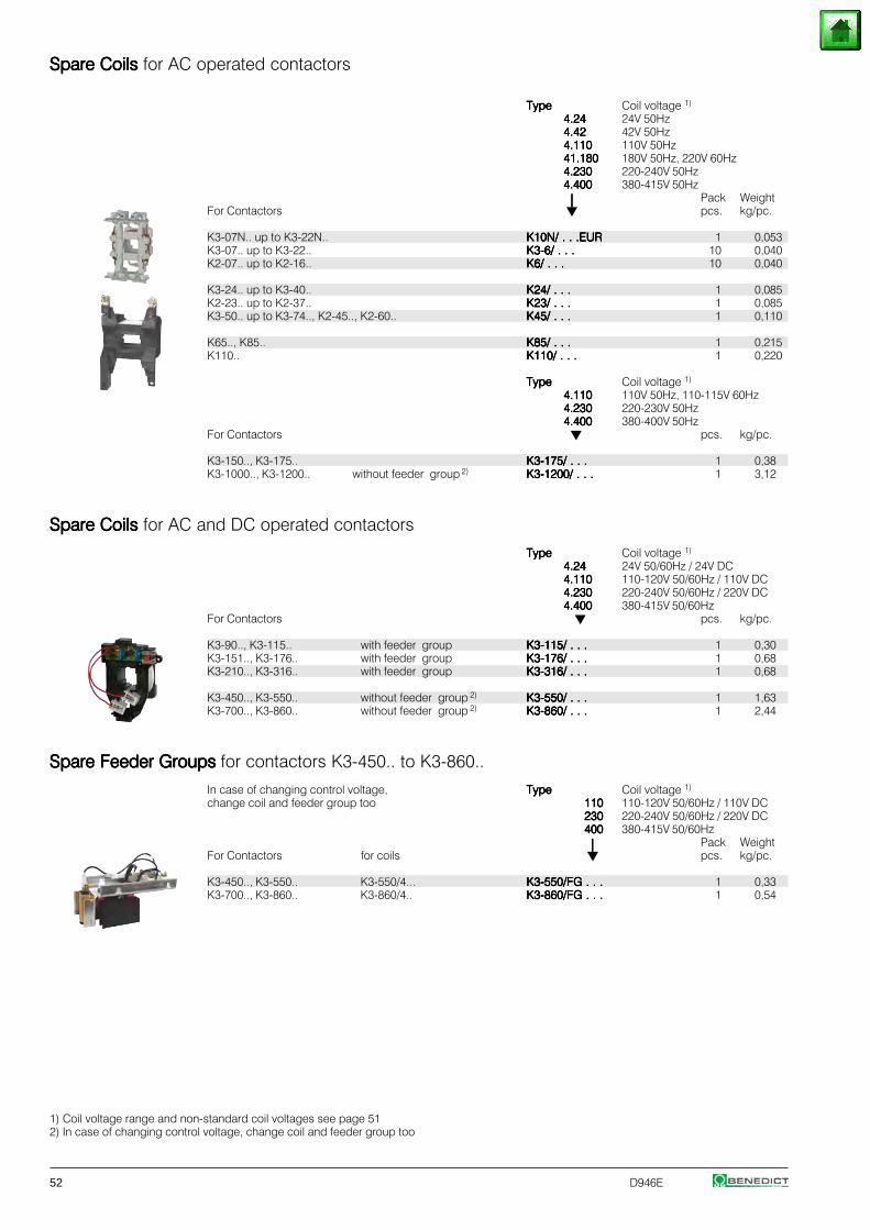
52 D946E
Spare Coils Spare Coils Spare Coils Spare Coils Spare Coils for AC operated contactors
TypeTypeTypeTypeType Coil voltage 1)
4.244.244.244.244.24 24V 50Hz4.424.424.424.424.42 42V 50Hz4.1104.1104.1104.1104.110 110V 50Hz41.18041.18041.18041.18041.180 180V 50Hz, 220V 60Hz4.2304.2304.2304.2304.230 220-240V 50Hz4.4004.4004.4004.4004.400 380-415V 50Hz
⏐⏐⏐⏐⏐ Pack WeightFor Contactors pcs. kg/pc.
K3-07N.. up to K3-22N.. K10N/ . . .EURK10N/ . . .EURK10N/ . . .EURK10N/ . . .EURK10N/ . . .EUR 1 0,053K3-07.. up to K3-22.. K3-6/ . . .K3-6/ . . .K3-6/ . . .K3-6/ . . .K3-6/ . . . 10 0,040K2-07.. up to K2-16.. K6/ . . .K6/ . . .K6/ . . .K6/ . . .K6/ . . . 10 0,040
K3-24.. up to K3-40.. K24/ . . .K24/ . . .K24/ . . .K24/ . . .K24/ . . . 1 0,085K2-23.. up to K2-37.. K23/ . . .K23/ . . .K23/ . . .K23/ . . .K23/ . . . 1 0,085K3-50.. up to K3-74.., K2-45.., K2-60.. K45/ . . .K45/ . . .K45/ . . .K45/ . . .K45/ . . . 1 0,110
K65.., K85.. K85/ . . .K85/ . . .K85/ . . .K85/ . . .K85/ . . . 1 0,215K110.. K110/ . . .K110/ . . .K110/ . . .K110/ . . .K110/ . . . 1 0,220
TypeTypeTypeTypeType Coil voltage 1)
4.1104.1104.1104.1104.110 110V 50Hz, 110-115V 60Hz4.2304.2304.2304.2304.230 220-230V 50Hz4.4004.4004.4004.4004.400 380-400V 50Hz
For Contactors pcs. kg/pc.
K3-150.., K3-175.. K3-175/ . . .K3-175/ . . .K3-175/ . . .K3-175/ . . .K3-175/ . . . 1 0,38K3-1000.., K3-1200.. without feeder group 2) K3-1200/ . . .K3-1200/ . . .K3-1200/ . . .K3-1200/ . . .K3-1200/ . . . 1 3,12
Spare Coils Spare Coils Spare Coils Spare Coils Spare Coils for AC and DC operated contactors
TypeTypeTypeTypeType Coil voltage 1)
4.244.244.244.244.24 24V 50/60Hz / 24V DC4.1104.1104.1104.1104.110 110-120V 50/60Hz / 110V DC4.2304.2304.2304.2304.230 220-240V 50/60Hz / 220V DC4.4004.4004.4004.4004.400 380-415V 50/60Hz
For Contactors pcs. kg/pc.
K3-90.., K3-115.. with feeder group K3-115/ . . .K3-115/ . . .K3-115/ . . .K3-115/ . . .K3-115/ . . . 1 0,30K3-151.., K3-176.. with feeder group K3-176/ . . .K3-176/ . . .K3-176/ . . .K3-176/ . . .K3-176/ . . . 1 0,68K3-210.., K3-316.. with feeder group K3-316/ . . .K3-316/ . . .K3-316/ . . .K3-316/ . . .K3-316/ . . . 1 0,68
K3-450.., K3-550.. without feeder group 2) K3-550/ . . .K3-550/ . . .K3-550/ . . .K3-550/ . . .K3-550/ . . . 1 1,63K3-700.., K3-860.. without feeder group 2) K3-860/ . . .K3-860/ . . .K3-860/ . . .K3-860/ . . .K3-860/ . . . 1 2,44
Spare Feeder Groups Spare Feeder Groups Spare Feeder Groups Spare Feeder Groups Spare Feeder Groups for contactors K3-450.. to K3-860..
In case of changing control voltage, TypeTypeTypeTypeType Coil voltage 1)
change coil and feeder group too 110110110110110 110-120V 50/60Hz / 110V DC230230230230230 220-240V 50/60Hz / 220V DC400400400400400 380-415V 50/60Hz
⏐⏐⏐⏐⏐ Pack WeightFor Contactors for coils pcs. kg/pc.
K3-450.., K3-550.. K3-550/4... K3-550/FG . . .K3-550/FG . . .K3-550/FG . . .K3-550/FG . . .K3-550/FG . . . 1 0,33K3-700.., K3-860.. K3-860/4.. K3-860/FG . . .K3-860/FG . . .K3-860/FG . . .K3-860/FG . . .K3-860/FG . . . 1 0,54
1) Coil voltage range and non-standard coil voltages see page 512) In case of changing control voltage, change coil and feeder group too
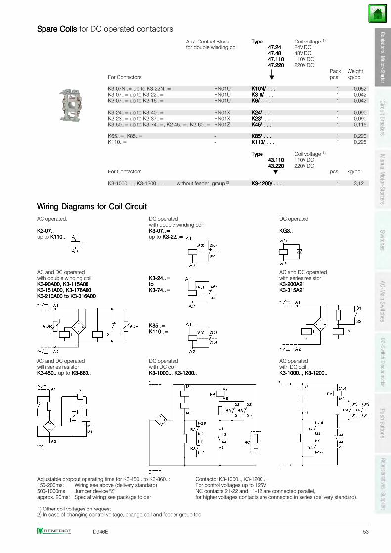
D946E 53
Spare Coils Spare Coils Spare Coils Spare Coils Spare Coils for DC operated contactors
Aux. Contact Block TypeTypeTypeTypeType Coil voltage 1)
for double winding coil 47.2447.2447.2447.2447.24 24V DC47.4847.4847.4847.4847.48 48V DC47.11047.11047.11047.11047.110 110V DC47.22047.22047.22047.22047.220 220V DC
⏐⏐⏐⏐⏐ Pack WeightFor Contactors pcs. kg/pc.
K3-07N..= up to K3-22N..= HN01U K10N/ . . .K10N/ . . .K10N/ . . .K10N/ . . .K10N/ . . . 1 0,052K3-07..= up to K3-22..= HN01U K3-6/ . . .K3-6/ . . .K3-6/ . . .K3-6/ . . .K3-6/ . . . 1 0,042K2-07..= up to K2-16..= HN01U K6/ . . .K6/ . . .K6/ . . .K6/ . . .K6/ . . . 1 0,042
K3-24..= up to K3-40..= HN01X K24/ . . .K24/ . . .K24/ . . .K24/ . . .K24/ . . . 1 0,090K2-23..= up to K2-37..= HN01X K23/ . . .K23/ . . .K23/ . . .K23/ . . .K23/ . . . 1 0,090K3-50..= up to K3-74..=, K2-45..=, K2-60..= HN01Z K45/ . . .K45/ . . .K45/ . . .K45/ . . .K45/ . . . 1 0,115
K65..=, K85..= - K85/ . . .K85/ . . .K85/ . . .K85/ . . .K85/ . . . 1 0,220K110..= - K110/ . . .K110/ . . .K110/ . . .K110/ . . .K110/ . . . 1 0,225
TypeTypeTypeTypeType Coil voltage 1)
43.11043.11043.11043.11043.110 110V DC43.22043.22043.22043.22043.220 220V DC
For Contactors pcs. kg/pc.
K3-1000..=, K3-1200..= without feeder group 2) K3-1200/ . . .K3-1200/ . . .K3-1200/ . . .K3-1200/ . . .K3-1200/ . . . 1 3,12
Wiring Diagrams for Coil CircuitWiring Diagrams for Coil CircuitWiring Diagrams for Coil CircuitWiring Diagrams for Coil CircuitWiring Diagrams for Coil Circuit
AC operated, DC operated DC operatedwith double winding coil
K3-07..K3-07..K3-07..K3-07..K3-07.. K3-07..=K3-07..=K3-07..=K3-07..=K3-07..= KG3..KG3..KG3..KG3..KG3..up to K110..K110..K110..K110..K110.. up to K3-22..=K3-22..=K3-22..=K3-22..=K3-22..=
AC and DC operated AC and DC operatedwith double winding coil K3-24..=K3-24..=K3-24..=K3-24..=K3-24..= with series resistorK3-90A00, K3-115A00K3-90A00, K3-115A00K3-90A00, K3-115A00K3-90A00, K3-115A00K3-90A00, K3-115A00 tototototo K3-200A21K3-200A21K3-200A21K3-200A21K3-200A21K3-151A00, K3-176A00K3-151A00, K3-176A00K3-151A00, K3-176A00K3-151A00, K3-176A00K3-151A00, K3-176A00 K3-74..=K3-74..=K3-74..=K3-74..=K3-74..= K3-315A21K3-315A21K3-315A21K3-315A21K3-315A21K3-210A00 to K3-316A00K3-210A00 to K3-316A00K3-210A00 to K3-316A00K3-210A00 to K3-316A00K3-210A00 to K3-316A00
K85..=K85..=K85..=K85..=K85..=K110..=K110..=K110..=K110..=K110..=
AC and DC operated DC operated AC operatedwith series resistor with DC coil with DC coilK3-450.. K3-450.. K3-450.. K3-450.. K3-450.. up to K3-860..K3-860..K3-860..K3-860..K3-860.. K3-1000.., K3-1200..K3-1000.., K3-1200..K3-1000.., K3-1200..K3-1000.., K3-1200..K3-1000.., K3-1200.. K3-1000.., K3-1200..K3-1000.., K3-1200..K3-1000.., K3-1200..K3-1000.., K3-1200..K3-1000.., K3-1200..
Adjustable dropout operating time for K3-450.. to K3-860..: Contactor K3-1000.., K3-1200..:150-200ms: Wiring see above (delivery standard) For control voltages up to 125V500-1000ms: Jumper device "Z" NC contacts 21-22 and 11-12 are connected parallel,approx. 20ms: Special wiring see package folder for higher voltages contacts are connected in series (delivery standard).
1) Other coil voltages on request2) In case of changing control voltage, change coil and feeder group too
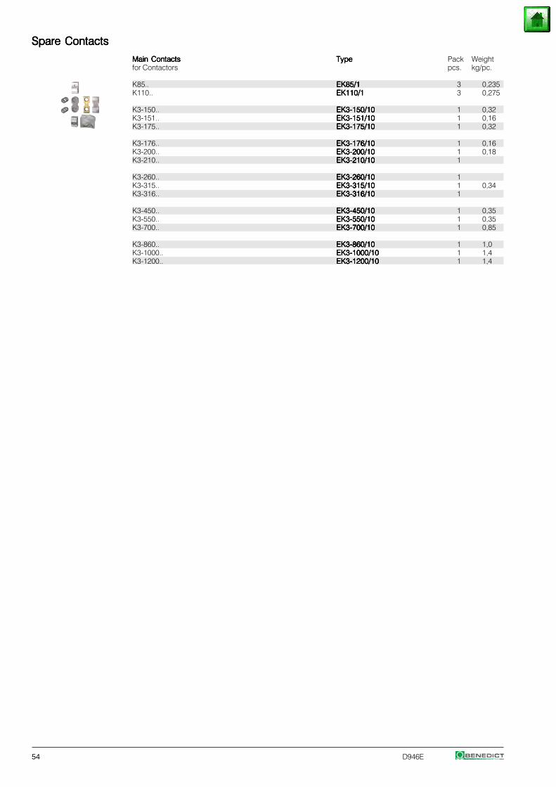
54 D946E
Spare ContactsSpare ContactsSpare ContactsSpare ContactsSpare Contacts
Main ContactsMain ContactsMain ContactsMain ContactsMain Contacts TypeTypeTypeTypeType Pack Weightfor Contactors pcs. kg/pc.
K85.. EK85/1EK85/1EK85/1EK85/1EK85/1 3 0,235K110.. EK110/1EK110/1EK110/1EK110/1EK110/1 3 0,275
K3-150.. EK3-150/10EK3-150/10EK3-150/10EK3-150/10EK3-150/10 1 0,32K3-151.. EK3-151/10EK3-151/10EK3-151/10EK3-151/10EK3-151/10 1 0,16K3-175.. EK3-175/10EK3-175/10EK3-175/10EK3-175/10EK3-175/10 1 0,32
K3-176.. EK3-176/10EK3-176/10EK3-176/10EK3-176/10EK3-176/10 1 0,16K3-200.. EK3-200/10EK3-200/10EK3-200/10EK3-200/10EK3-200/10 1 0,18K3-210.. EK3-210/10EK3-210/10EK3-210/10EK3-210/10EK3-210/10 1
K3-260.. EK3-260/10EK3-260/10EK3-260/10EK3-260/10EK3-260/10 1K3-315.. EK3-315/10EK3-315/10EK3-315/10EK3-315/10EK3-315/10 1 0,34K3-316.. EK3-316/10EK3-316/10EK3-316/10EK3-316/10EK3-316/10 1
K3-450.. EK3-450/10EK3-450/10EK3-450/10EK3-450/10EK3-450/10 1 0,35K3-550.. EK3-550/10EK3-550/10EK3-550/10EK3-550/10EK3-550/10 1 0,35K3-700.. EK3-700/10EK3-700/10EK3-700/10EK3-700/10EK3-700/10 1 0,85
K3-860.. EK3-860/10EK3-860/10EK3-860/10EK3-860/10EK3-860/10 1 1,0K3-1000.. EK3-1000/10EK3-1000/10EK3-1000/10EK3-1000/10EK3-1000/10 1 1,4K3-1200.. EK3-1200/10EK3-1200/10EK3-1200/10EK3-1200/10EK3-1200/10 1 1,4
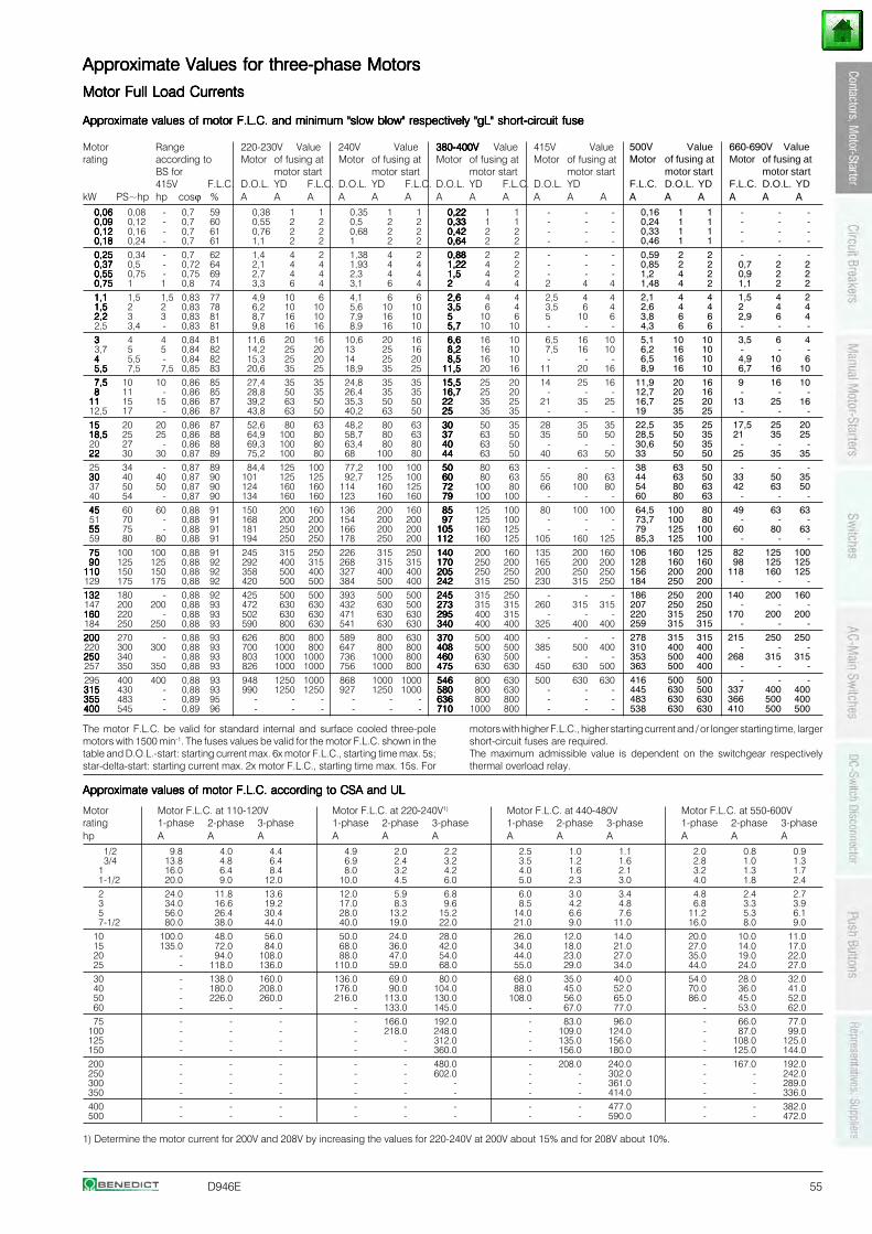
D946E 55
1) Determine the motor current for 200V and 208V by increasing the values for 220-240V at 200V about 15% and for 208V about 10%.
Approximate Values for three-phase MotorsApproximate Values for three-phase MotorsApproximate Values for three-phase MotorsApproximate Values for three-phase MotorsApproximate Values for three-phase Motors
Motor Full Load CurrentsMotor Full Load CurrentsMotor Full Load CurrentsMotor Full Load CurrentsMotor Full Load Currents
Approximate values of motor F.L.C. and minimum "slow blow" respectively "gL" short-circuit fuseApproximate values of motor F.L.C. and minimum "slow blow" respectively "gL" short-circuit fuseApproximate values of motor F.L.C. and minimum "slow blow" respectively "gL" short-circuit fuseApproximate values of motor F.L.C. and minimum "slow blow" respectively "gL" short-circuit fuseApproximate values of motor F.L.C. and minimum "slow blow" respectively "gL" short-circuit fuse
Motor Range 220-230V Value 240V Value 380-400V380-400V380-400V380-400V380-400V Value 415V Valuerating according to Motor of fusing at Motor of fusing at Motor of fusing at Motor of fusing at
BS for motor start motor start motor start motor start415V F.L.C. D.O.L. YD F.L.C. D.O.L. YD F.L.C. D.O.L. YD F.L.C. D.O.L. YD
kW PS~hp hp cosϕ % A A A A A A A A A A A A0,060,060,060,060,06 0,08 - 0,7 59 0,38 1 1 0,35 1 1 0,220,220,220,220,22 1 1 - - -0,090,090,090,090,09 0,12 - 0,7 60 0,55 2 2 0,5 2 2 0,330,330,330,330,33 1 1 - - -0,120,120,120,120,12 0,16 - 0,7 61 0,76 2 2 0,68 2 2 0,420,420,420,420,42 2 2 - - -0,180,180,180,180,18 0,24 - 0,7 61 1,1 2 2 1 2 2 0,640,640,640,640,64 2 2 - - -0,250,250,250,250,25 0,34 - 0,7 62 1,4 4 2 1,38 4 2 0,880,880,880,880,88 2 2 - - -0,370,370,370,370,37 0,5 - 0,72 64 2,1 4 4 1,93 4 4 1,221,221,221,221,22 4 2 - - -0,550,550,550,550,55 0,75 - 0,75 69 2,7 4 4 2,3 4 4 1,51,51,51,51,5 4 2 - - -0,750,750,750,750,75 1 1 0,8 74 3,3 6 4 3,1 6 4 22222 4 4 2 4 41,11,11,11,11,1 1,5 1,5 0,83 77 4,9 10 6 4,1 6 6 2,62,62,62,62,6 4 4 2,5 4 41,51,51,51,51,5 2 2 0,83 78 6,2 10 10 5,6 10 10 3,53,53,53,53,5 6 4 3,5 6 42,22,22,22,22,2 3 3 0,83 81 8,7 16 10 7,9 16 10 55555 10 6 5 10 62,5 3,4 - 0,83 81 9,8 16 16 8,9 16 10 5,75,75,75,75,7 10 10 - - -33333 4 4 0,84 81 11,6 20 16 10,6 20 16 6,66,66,66,66,6 16 10 6,5 16 103,7 5 5 0,84 82 14,2 25 20 13 25 16 8,28,28,28,28,2 16 10 7,5 16 1044444 5,5 - 0,84 82 15,3 25 20 14 25 20 8,58,58,58,58,5 16 10 - - -5,55,55,55,55,5 7,5 7,5 0,85 83 20,6 35 25 18,9 35 25 11,511,511,511,511,5 20 16 11 20 167,57,57,57,57,5 10 10 0,86 85 27,4 35 35 24,8 35 35 15,515,515,515,515,5 25 20 14 25 1688888 11 - 0,86 85 28,8 50 35 26,4 35 35 16,716,716,716,716,7 25 20 - - -
1111111111 15 15 0,86 87 39,2 63 50 35,3 50 50 2222222222 35 25 21 35 2512,5 17 - 0,86 87 43,8 63 50 40,2 63 50 2525252525 35 35 - - -1515151515 20 20 0,86 87 52,6 80 63 48,2 80 63 3030303030 50 35 28 35 3518,518,518,518,518,5 25 25 0,86 88 64,9 100 80 58,7 80 63 3737373737 63 50 35 50 5020 27 - 0,86 88 69,3 100 80 63,4 80 80 4040404040 63 50 - - -2222222222 30 30 0,87 89 75,2 100 80 68 100 80 4444444444 63 50 40 63 5025 34 - 0,87 89 84,4 125 100 77,2 100 100 5050505050 80 63 - - -3030303030 40 40 0,87 90 101 125 125 92,7 125 100 6060606060 80 63 55 80 6337 50 50 0,87 90 124 160 160 114 160 125 7272727272 100 80 66 100 8040 54 - 0,87 90 134 160 160 123 160 160 7979797979 100 100 - - -4545454545 60 60 0,88 91 150 200 160 136 200 160 8585858585 125 100 80 100 10051 70 - 0,88 91 168 200 200 154 200 200 9797979797 125 100 - - -5555555555 75 - 0,88 91 181 250 200 166 200 200 105105105105105 160 125 - - -59 80 80 0,88 91 194 250 250 178 250 200 112112112112112 160 125 105 160 1257575757575 100 100 0,88 91 245 315 250 226 315 250 140140140140140 200 160 135 200 1609090909090 125 125 0,88 92 292 400 315 268 315 315 170170170170170 250 200 165 200 200
110110110110110 150 150 0,88 92 358 500 400 327 400 400 205205205205205 250 250 200 250 250129 175 175 0,88 92 420 500 500 384 500 400 242242242242242 315 250 230 315 250132132132132132 180 - 0,88 92 425 500 500 393 500 500 245245245245245 315 250 - - -147 200 200 0,88 93 472 630 630 432 630 500 273273273273273 315 315 260 315 315160160160160160 220 - 0,88 93 502 630 630 471 630 630 295295295295295 400 315 - - -184 250 250 0,88 93 590 800 630 541 630 630 340340340340340 400 400 325 400 400200200200200200 270 - 0,88 93 626 800 800 589 800 630 370370370370370 500 400 - - -220 300 300 0,88 93 700 1000 800 647 800 800 408408408408408 500 500 385 500 400250250250250250 340 - 0,88 93 803 1000 1000 736 1000 800 460460460460460 630 500 - - -257 350 350 0,88 93 826 1000 1000 756 1000 800 475475475475475 630 630 450 630 500295 400 400 0,88 93 948 1250 1000 868 1000 1000 546546546546546 800 630 500 630 630315315315315315 430 - 0,88 93 990 1250 1250 927 1250 1000 580580580580580 800 630 - - -355355355355355 483 - 0,89 95 - - - - - - 636636636636636 800 800 - - -400400400400400 545 - 0,89 96 - - - - - - 710710710710710 1000 800 - - -
Approximate values of motor F.L.C. according to CSA and ULApproximate values of motor F.L.C. according to CSA and ULApproximate values of motor F.L.C. according to CSA and ULApproximate values of motor F.L.C. according to CSA and ULApproximate values of motor F.L.C. according to CSA and UL
Motor Motor F.L.C. at 110-120V Motor F.L.C. at 220-240V1) Motor F.L.C. at 440-480V Motor F.L.C. at 550-600Vrating 1-phase 2-phase 3-phase 1-phase 2-phase 3-phase 1-phase 2-phase 3-phase 1-phase 2-phase 3-phasehp A A A A A A A A A A A A
1/2 9.8 4.0 4.4 4.9 2.0 2.2 2.5 1.0 1.1 2.0 0.8 0.93/4 13.8 4.8 6.4 6.9 2.4 3.2 3.5 1.2 1.6 2.8 1.0 1.3
1 16.0 6.4 8.4 8.0 3.2 4.2 4.0 1.6 2.1 3.2 1.3 1.71-1/2 20.0 9.0 12.0 10.0 4.5 6.0 5.0 2.3 3.0 4.0 1.8 2.42 24.0 11.8 13.6 12.0 5.9 6.8 6.0 3.0 3.4 4.8 2.4 2.73 34.0 16.6 19.2 17.0 8.3 9.6 8.5 4.2 4.8 6.8 3.3 3.95 56.0 26.4 30.4 28.0 13.2 15.2 14.0 6.6 7.6 11.2 5.3 6.17-1/2 80.0 38.0 44.0 40.0 19.0 22.0 21.0 9.0 11.0 16.0 8.0 9.0
10 100.0 48.0 56.0 50.0 24.0 28.0 26.0 12.0 14.0 20.0 10.0 11.015 135.0 72.0 84.0 68.0 36.0 42.0 34.0 18.0 21.0 27.0 14.0 17.020 - 94.0 108.0 88.0 47.0 54.0 44.0 23.0 27.0 35.0 19.0 22.025 - 118.0 136.0 110.0 59.0 68.0 55.0 29.0 34.0 44.0 24.0 27.030 - 138.0 160.0 136.0 69.0 80.0 68.0 35.0 40.0 54.0 28.0 32.040 - 180.0 208.0 176.0 90.0 104.0 88.0 45.0 52.0 70.0 36.0 41.050 - 226.0 260.0 216.0 113.0 130.0 108.0 56.0 65.0 86.0 45.0 52.060 - - - - 133.0 145.0 - 67.0 77.0 - 53.0 62.075 - - - - 166.0 192.0 - 83.0 96.0 - 66.0 77.0
100 - - - - 218.0 248.0 - 109.0 124.0 - 87.0 99.0125 - - - - - 312.0 - 135.0 156.0 - 108.0 125.0150 - - - - - 360.0 - 156.0 180.0 - 125.0 144.0200 - - - - - 480.0 - 208.0 240.0 - 167.0 192.0250 - - - - - 602.0 - - 302.0 - - 242.0300 - - - - - - - - 361.0 - - 289.0350 - - - - - - - - 414.0 - - 336.0400 - - - - - - - - 477.0 - - 382.0500 - - - - - - - - 590.0 - - 472.0
The motor F.L.C. be valid for standard internal and surface cooled three-polemotors with 1500 min-1. The fuses values be valid for the motor F.L.C. shown in thetable and D.O.L.-start: starting current max. 6x motor F.L.C., starting time max. 5s;star-delta-start: starting current max. 2x motor F.L.C., starting time max. 15s. For
500V Value 660-690V ValueMotor of fusing at Motor of fusing at
motor start motor startF.L.C. D.O.L. YD F.L.C. D.O.L. YDA A A A A A
0,16 1 1 - - -0,24 1 1 - - -0,33 1 1 - - -0,46 1 1 - - -0,59 2 2 - - -0,85 2 2 0,7 2 21,2 4 2 0,9 2 21,48 4 2 1,1 2 22,1 4 4 1,5 4 22,6 4 4 2 4 43,8 6 6 2,9 6 44,3 6 6 - - -5,1 10 10 3,5 6 46,2 16 10 - - -6,5 16 10 4,9 10 68,9 16 10 6,7 16 10
11,9 20 16 9 16 1012,7 20 16 - - -16,7 25 20 13 25 1619 35 25 - - -22,5 35 25 17,5 25 2028,5 50 35 21 35 2530,6 50 35 - - -33 50 50 25 35 3538 63 50 - - -44 63 50 33 50 3554 80 63 42 63 5060 80 63 - - -64,5 100 80 49 63 6373,7 100 80 - - -79 125 100 60 80 6385,3 125 100 - - -
106 160 125 82 125 100128 160 160 98 125 125156 200 200 118 160 125184 250 200 - - -186 250 200 140 200 160207 250 250 - - -220 315 250 170 200 200259 315 315 - - -278 315 315 215 250 250310 400 400 - - -353 500 400 268 315 315363 500 400 - - -416 500 500 - - -445 630 500 337 400 400483 630 630 366 500 400538 630 630 410 500 500
motors with higher F.L.C., higher starting current and / or longer starting time, largershort-circuit fuses are required.The maximum admissible value is dependent on the switchgear respectivelythermal overload relay.
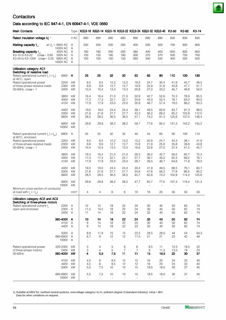
56 D946E
1) Suitable at 690V for: earthed-neutral systems, overvoltage category I to IV, pollution degree 3 (standard-industry): Uimp = 8kV.Data for other conditions on request.
ContactorsContactorsContactorsContactorsContactors
Data according to IEC 947-4-1, EN 60947-4-1, VDE 0660Data according to IEC 947-4-1, EN 60947-4-1, VDE 0660Data according to IEC 947-4-1, EN 60947-4-1, VDE 0660Data according to IEC 947-4-1, EN 60947-4-1, VDE 0660Data according to IEC 947-4-1, EN 60947-4-1, VDE 0660
Main ContactsMain ContactsMain ContactsMain ContactsMain Contacts Type K(G)3-10K(G)3-10K(G)3-10K(G)3-10K(G)3-10 K(G)3-14K(G)3-14K(G)3-14K(G)3-14K(G)3-14 K(G)3-18K(G)3-18K(G)3-18K(G)3-18K(G)3-18 K(G)3-22K(G)3-22K(G)3-22K(G)3-22K(G)3-22 K(G)3-24K(G)3-24K(G)3-24K(G)3-24K(G)3-24 K(G)3-32K(G)3-32K(G)3-32K(G)3-32K(G)3-32 K(G)3-40K(G)3-40K(G)3-40K(G)3-40K(G)3-40 K3-50K3-50K3-50K3-50K3-50 K3-62K3-62K3-62K3-62K3-62 K3-74K3-74K3-74K3-74K3-74
Rated insulation voltage URated insulation voltage URated insulation voltage URated insulation voltage URated insulation voltage Uiiiii 1) V AC 690 690 690 690 690 690 690 830 830 830
Making capacity IMaking capacity IMaking capacity IMaking capacity IMaking capacity Ieff at Ue = 690V AC A 200 200 200 200 400 500 500 700 900 9001000V AC A - - - - - - - - - -
Breaking capacity IBreaking capacity IBreaking capacity IBreaking capacity IBreaking capacity Ieff 400V AC A 180 180 200 200 380 400 400 600 800 800K3-10 to K3-22 cosϕ= 0,65 500V AC A 150 150 180 180 300 370 370 500 700 700K3-24 to K3-1200 cosϕ= 0,35 690V AC A 100 100 150 150 260 340 340 400 500 500
1000V AC A - - - - - - - - - -
Utilization category AC1Utilization category AC1Utilization category AC1Utilization category AC1Utilization category AC1Switching of resistive loadSwitching of resistive loadSwitching of resistive loadSwitching of resistive loadSwitching of resistive loadRated operational current Ie (=Ith) 690V AAAAA 2525252525 2525252525 3232323232 3232323232 5050505050 6565656565 8080808080 110110110110110 120120120120120 130130130130130at 40°C, openRated operational power 220V kW 9,5 9,5 12,2 12,2 19,0 24,7 30,4 41,9 45,7 49,5of three-phase resistive loads 230V kW 9,9 9,9 12,7 12,7 19,9 25,9 31,8 43,8 47,7 51,750-60Hz, cosϕ= 1 240V kW 10,4 10,4 13,3 13,3 20,8 27,0 33,2 45,7 49,8 54,0
380V kW 16,4 16,4 21,0 21,0 32,9 42,7 52,6 72,3 78,9 85,5400V kW 17,3 17,3 22,1 22,1 34,6 45,0 55,4 76,1 83,0 90,0415V kW 17,9 17,9 23,0 23,0 35,9 46,7 57,4 79,0 86,2 93,3
440V kW 19,0 19,0 24,4 24,4 38,1 49,5 60,9 83,7 91,3 99,0500V kW 21,6 21,6 27,7 27,7 43,3 56,2 69,2 95,2 103,8 112,5660V kW 28,5 28,5 36,5 36,5 57,1 74,2 91,3 125,6 137,0 148,4
690V kW 29,8 29,8 38,2 38,2 59,7 77,6 95,5 131,3 143,2 155,21000V kW - - - - - - - - -
Rated operational current Ie (=Ithe) 690V A 25 25 32 32 40 55 65 90 100 110at 60°C, enclosedRated operational power 220V kW 9,5 9,5 12,2 12,2 15,2 20,9 24,7 34,3 38,1 41,9of three-phase resistive loads 230V kW 9,9 9,9 12,7 12,7 15,9 21,9 25,9 35,8 39,8 43,850-60Hz, cosϕ= 1 240V kW 10,4 10,4 13,3 13,3 16,6 22,8 27,0 37,4 41,5 45,7
380V kW 16,4 16,4 21,0 21,0 26,3 36,2 42,7 59,2 65,7 72,3400V kW 17,3 17,3 22,1 22,1 27,7 38,1 45,0 62,3 69,2 76,1415V kW 17,9 17,9 23,0 23,0 28,7 39,5 46,7 64,6 71,8 79,0
440V kW 19,0 19,0 24,4 24,4 30,4 41,9 49,5 68,5 76,1 83,7500V kW 21,6 21,6 27,7 27,7 34,6 47,6 56,2 77,9 86,5 95,2660V kW 28,5 28,5 36,5 36,5 45,7 62,8 74,2 102,8 114,2 125,6
690V kW 29,8 29,8 38,2 38,2 47,7 65,7 77,6 107,4 119,4 131,31000V kW - - - - - - - - -
Minimum cross-section of conductorat load with Ie (=Ith) mm² 4 4 6 6 10 16 25 35 50 50
Utilization category AC2 and AC3Utilization category AC2 and AC3Utilization category AC2 and AC3Utilization category AC2 and AC3Utilization category AC2 and AC3Switching of three-phase motorsSwitching of three-phase motorsSwitching of three-phase motorsSwitching of three-phase motorsSwitching of three-phase motorsRated operational current Ie 220V A 12 15 18 22 24 30 40 50 63 74open and enclosed 230V A 11,5 14,5 18 22 24 30 40 50 62 74
240V A 11 14 18 22 24 32 40 50 62 74
380-400V380-400V380-400V380-400V380-400V AAAAA 1010101010 1414141414 1818181818 2222222222 2424242424 3232323232 4040404040 5050505050 6262626262 7474747474415V A 9 14 18 22 23 30 40 50 62 74440V A 9 14 18 22 23 30 40 50 62 74
500V A 8,9 11,9 15 15 22,5 28,5 28,5 44 54 64,5660-690V A 6,7 9 12 12 17,5 21 21 33 42 49
1000V A - - - - - - - - -
Rated operational power 220-230V kW 3 4 5 6 6 8,5 11 12,5 18,5 22of three-phase motors 240V kW 3 4 5 7 7 9 11,5 13,5 19 2350-60Hz 380-400V380-400V380-400V380-400V380-400V kWkWkWkWkW 44444 5,55,55,55,55,5 7,57,57,57,57,5 1111111111 1111111111 1515151515 18,518,518,518,518,5 2222222222 3030303030 3737373737
415V kW 4,5 6 8,5 12 12 16 20 24 33 40440V kW 4,5 6 8,5 12 12 16 20 24 33 40500V kW 5,5 7,5 10 10 15 18,5 18,5 30 37 45
660-690V kW 5,5 7,5 10 10 15 18,5 18,5 30 37 451000V kW - - - - - - - - - -
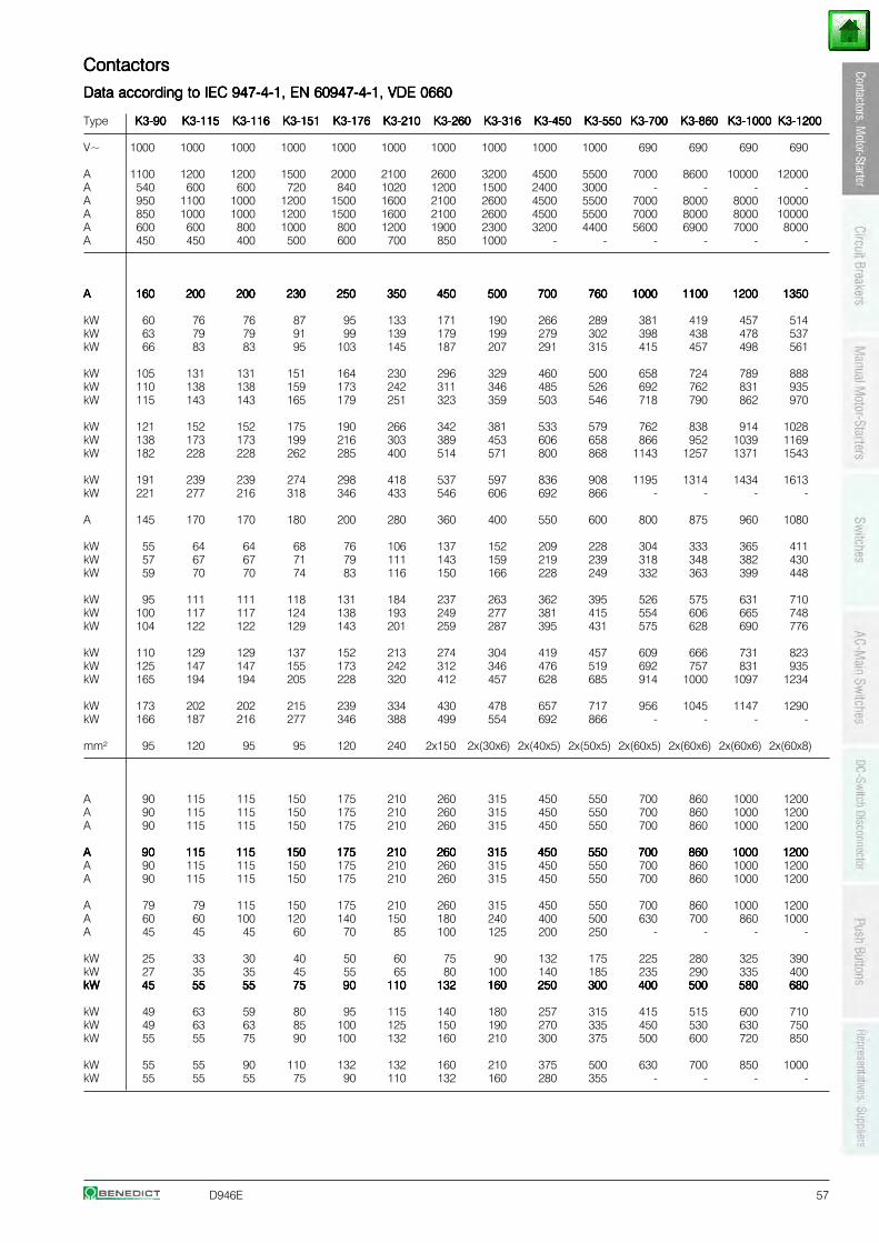
D946E 57
ContactorsContactorsContactorsContactorsContactors
Data according to IEC 947-4-1, EN 60947-4-1, VDE 0660Data according to IEC 947-4-1, EN 60947-4-1, VDE 0660Data according to IEC 947-4-1, EN 60947-4-1, VDE 0660Data according to IEC 947-4-1, EN 60947-4-1, VDE 0660Data according to IEC 947-4-1, EN 60947-4-1, VDE 0660
Type K3-90K3-90K3-90K3-90K3-90 K3-115K3-115K3-115K3-115K3-115 K3-116K3-116K3-116K3-116K3-116 K3-151K3-151K3-151K3-151K3-151 K3-176K3-176K3-176K3-176K3-176 K3-210K3-210K3-210K3-210K3-210 K3-260K3-260K3-260K3-260K3-260 K3-316K3-316K3-316K3-316K3-316 K3-450K3-450K3-450K3-450K3-450 K3-550K3-550K3-550K3-550K3-550 K3-700K3-700K3-700K3-700K3-700 K3-860K3-860K3-860K3-860K3-860 K3-1000K3-1000K3-1000K3-1000K3-1000 K3-1200K3-1200K3-1200K3-1200K3-1200
V~ 1000 1000 1000 1000 1000 1000 1000 1000 1000 1000 690 690 690 690
A 1100 1200 1200 1500 2000 2100 2600 3200 4500 5500 7000 8600 10000 12000A 540 600 600 720 840 1020 1200 1500 2400 3000 - - - -A 950 1100 1000 1200 1500 1600 2100 2600 4500 5500 7000 8000 8000 10000A 850 1000 1000 1200 1500 1600 2100 2600 4500 5500 7000 8000 8000 10000A 600 600 800 1000 800 1200 1900 2300 3200 4400 5600 6900 7000 8000A 450 450 400 500 600 700 850 1000 - - - - - -
AAAAA 160160160160160 200200200200200 200200200200200 230230230230230 250250250250250 350350350350350 450450450450450 500500500500500 700700700700700 760760760760760 10001000100010001000 11001100110011001100 12001200120012001200 13501350135013501350
kW 60 76 76 87 95 133 171 190 266 289 381 419 457 514kW 63 79 79 91 99 139 179 199 279 302 398 438 478 537kW 66 83 83 95 103 145 187 207 291 315 415 457 498 561
kW 105 131 131 151 164 230 296 329 460 500 658 724 789 888kW 110 138 138 159 173 242 311 346 485 526 692 762 831 935kW 115 143 143 165 179 251 323 359 503 546 718 790 862 970
kW 121 152 152 175 190 266 342 381 533 579 762 838 914 1028kW 138 173 173 199 216 303 389 453 606 658 866 952 1039 1169kW 182 228 228 262 285 400 514 571 800 868 1143 1257 1371 1543
kW 191 239 239 274 298 418 537 597 836 908 1195 1314 1434 1613kW 221 277 216 318 346 433 546 606 692 866 - - - -
A 145 170 170 180 200 280 360 400 550 600 800 875 960 1080
kW 55 64 64 68 76 106 137 152 209 228 304 333 365 411kW 57 67 67 71 79 111 143 159 219 239 318 348 382 430kW 59 70 70 74 83 116 150 166 228 249 332 363 399 448
kW 95 111 111 118 131 184 237 263 362 395 526 575 631 710kW 100 117 117 124 138 193 249 277 381 415 554 606 665 748kW 104 122 122 129 143 201 259 287 395 431 575 628 690 776
kW 110 129 129 137 152 213 274 304 419 457 609 666 731 823kW 125 147 147 155 173 242 312 346 476 519 692 757 831 935kW 165 194 194 205 228 320 412 457 628 685 914 1000 1097 1234
kW 173 202 202 215 239 334 430 478 657 717 956 1045 1147 1290kW 166 187 216 277 346 388 499 554 692 866 - - - -
mm² 95 120 95 95 120 240 2x150 2x(30x6) 2x(40x5) 2x(50x5) 2x(60x5) 2x(60x6) 2x(60x6) 2x(60x8)
A 90 115 115 150 175 210 260 315 450 550 700 860 1000 1200A 90 115 115 150 175 210 260 315 450 550 700 860 1000 1200A 90 115 115 150 175 210 260 315 450 550 700 860 1000 1200
AAAAA 9090909090 115115115115115 115115115115115 150150150150150 175175175175175 210210210210210 260260260260260 315315315315315 450450450450450 550550550550550 700700700700700 860860860860860 10001000100010001000 12001200120012001200A 90 115 115 150 175 210 260 315 450 550 700 860 1000 1200A 90 115 115 150 175 210 260 315 450 550 700 860 1000 1200
A 79 79 115 150 175 210 260 315 450 550 700 860 1000 1200A 60 60 100 120 140 150 180 240 400 500 630 700 860 1000A 45 45 45 60 70 85 100 125 200 250 - - - -
kW 25 33 30 40 50 60 75 90 132 175 225 280 325 390kW 27 35 35 45 55 65 80 100 140 185 235 290 335 400kWkWkWkWkW 4545454545 5555555555 5555555555 7575757575 9090909090 110110110110110 132132132132132 160160160160160 250250250250250 300300300300300 400400400400400 500500500500500 580580580580580 680680680680680
kW 49 63 59 80 95 115 140 180 257 315 415 515 600 710kW 49 63 63 85 100 125 150 190 270 335 450 530 630 750kW 55 55 75 90 100 132 160 210 300 375 500 600 720 850
kW 55 55 90 110 132 132 160 210 375 500 630 700 850 1000kW 55 55 55 75 90 110 132 160 280 355 - - - -
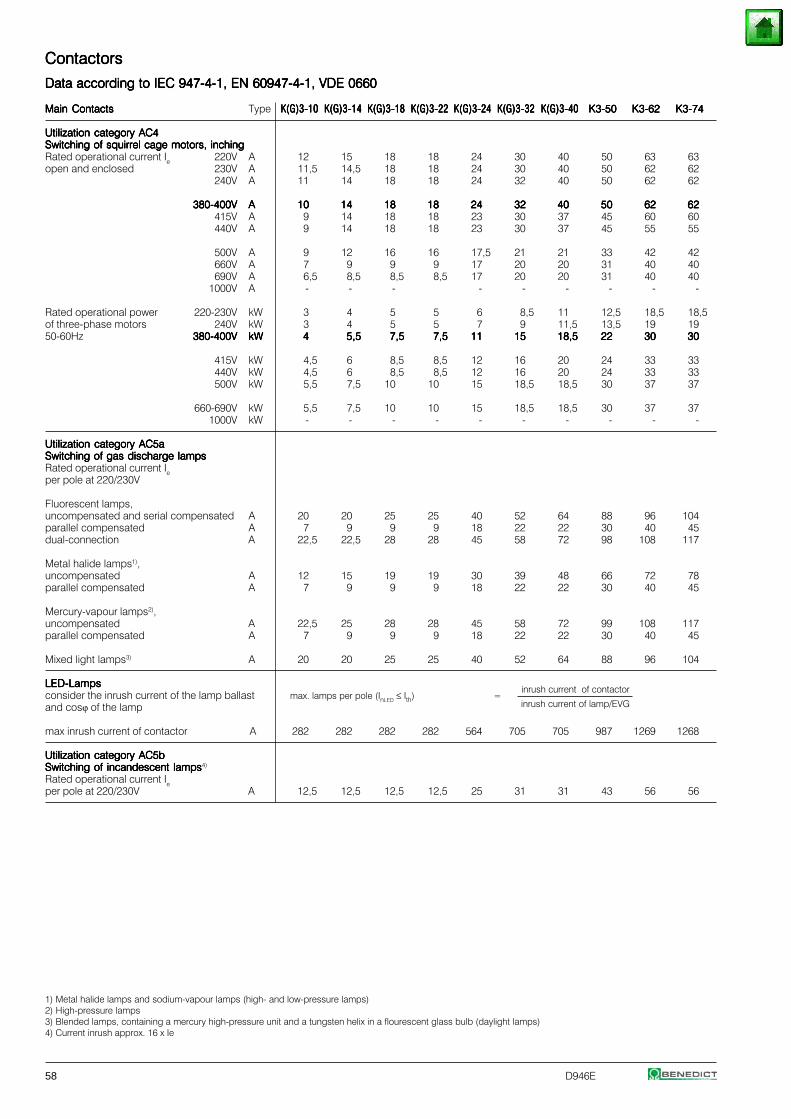
58 D946E
1) Metal halide lamps and sodium-vapour lamps (high- and low-pressure lamps)2) High-pressure lamps3) Blended lamps, containing a mercury high-pressure unit and a tungsten helix in a flourescent glass bulb (daylight lamps)4) Current inrush approx. 16 x Ie
ContactorsContactorsContactorsContactorsContactors
Data according to IEC 947-4-1, EN 60947-4-1, VDE 0660Data according to IEC 947-4-1, EN 60947-4-1, VDE 0660Data according to IEC 947-4-1, EN 60947-4-1, VDE 0660Data according to IEC 947-4-1, EN 60947-4-1, VDE 0660Data according to IEC 947-4-1, EN 60947-4-1, VDE 0660
Main ContactsMain ContactsMain ContactsMain ContactsMain Contacts Type K(G)3-10K(G)3-10K(G)3-10K(G)3-10K(G)3-10 K(G)3-14K(G)3-14K(G)3-14K(G)3-14K(G)3-14 K(G)3-18K(G)3-18K(G)3-18K(G)3-18K(G)3-18 K(G)3-22K(G)3-22K(G)3-22K(G)3-22K(G)3-22 K(G)3-24K(G)3-24K(G)3-24K(G)3-24K(G)3-24 K(G)3-32K(G)3-32K(G)3-32K(G)3-32K(G)3-32 K(G)3-40K(G)3-40K(G)3-40K(G)3-40K(G)3-40 K3-50K3-50K3-50K3-50K3-50 K3-62K3-62K3-62K3-62K3-62 K3-74K3-74K3-74K3-74K3-74
Utilization category AC4Utilization category AC4Utilization category AC4Utilization category AC4Utilization category AC4Switching of squirrel cage motors, inchingSwitching of squirrel cage motors, inchingSwitching of squirrel cage motors, inchingSwitching of squirrel cage motors, inchingSwitching of squirrel cage motors, inchingRated operational current Ie 220V A 12 15 18 18 24 30 40 50 63 63open and enclosed 230V A 11,5 14,5 18 18 24 30 40 50 62 62
240V A 11 14 18 18 24 32 40 50 62 62
380-400V380-400V380-400V380-400V380-400V AAAAA 1010101010 1414141414 1818181818 1818181818 2424242424 3232323232 4040404040 5050505050 6262626262 6262626262415V A 9 14 18 18 23 30 37 45 60 60440V A 9 14 18 18 23 30 37 45 55 55
500V A 9 12 16 16 17,5 21 21 33 42 42660V A 7 9 9 9 17 20 20 31 40 40690V A 6,5 8,5 8,5 8,5 17 20 20 31 40 40
1000V A - - - - - - - - -
Rated operational power 220-230V kW 3 4 5 5 6 8,5 11 12,5 18,5 18,5of three-phase motors 240V kW 3 4 5 5 7 9 11,5 13,5 19 1950-60Hz 380-400V380-400V380-400V380-400V380-400V kWkWkWkWkW 44444 5,55,55,55,55,5 7,57,57,57,57,5 7,57,57,57,57,5 1111111111 1515151515 18,518,518,518,518,5 2222222222 3030303030 3030303030
415V kW 4,5 6 8,5 8,5 12 16 20 24 33 33440V kW 4,5 6 8,5 8,5 12 16 20 24 33 33500V kW 5,5 7,5 10 10 15 18,5 18,5 30 37 37
660-690V kW 5,5 7,5 10 10 15 18,5 18,5 30 37 371000V kW - - - - - - - - - -
Utilization category AC5aUtilization category AC5aUtilization category AC5aUtilization category AC5aUtilization category AC5aSwitching of gas discharge lampsSwitching of gas discharge lampsSwitching of gas discharge lampsSwitching of gas discharge lampsSwitching of gas discharge lampsRated operational current Ieper pole at 220/230V
Fluorescent lamps,uncompensated and serial compensated A 20 20 25 25 40 52 64 88 96 104parallel compensated A 7 9 9 9 18 22 22 30 40 45dual-connection A 22,5 22,5 28 28 45 58 72 98 108 117
Metal halide lamps1),uncompensated A 12 15 19 19 30 39 48 66 72 78parallel compensated A 7 9 9 9 18 22 22 30 40 45
Mercury-vapour lamps2),uncompensated A 22,5 25 28 28 45 58 72 99 108 117parallel compensated A 7 9 9 9 18 22 22 30 40 45
Mixed light lamps3) A 20 20 25 25 40 52 64 88 96 104
LED-LampsLED-LampsLED-LampsLED-LampsLED-Lampsinrush current of contactor
consider the inrush current of the lamp ballast max. lamps per pole (InLED ≤ Ith) =and cosϕ of the lamp inrush current of lamp/EVG
max inrush current of contactor A 282 282 282 282 564 705 705 987 1269 1268
Utilization category AC5bUtilization category AC5bUtilization category AC5bUtilization category AC5bUtilization category AC5bSwitching of incandescent lampsSwitching of incandescent lampsSwitching of incandescent lampsSwitching of incandescent lampsSwitching of incandescent lamps4)
Rated operational current Ieper pole at 220/230V A 12,5 12,5 12,5 12,5 25 31 31 43 56 56
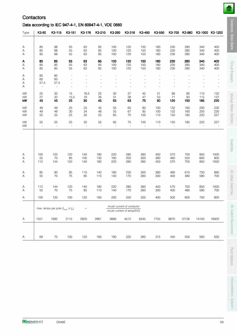
D946E 59
ContactorsContactorsContactorsContactorsContactors
Data according to IEC 947-4-1, EN 60947-4-1, VDE 0660Data according to IEC 947-4-1, EN 60947-4-1, VDE 0660Data according to IEC 947-4-1, EN 60947-4-1, VDE 0660Data according to IEC 947-4-1, EN 60947-4-1, VDE 0660Data according to IEC 947-4-1, EN 60947-4-1, VDE 0660
Type K3-90K3-90K3-90K3-90K3-90 K3-115K3-115K3-115K3-115K3-115 K3-151K3-151K3-151K3-151K3-151 K3-176K3-176K3-176K3-176K3-176 K3-210K3-210K3-210K3-210K3-210 K3-260K3-260K3-260K3-260K3-260 K3-316K3-316K3-316K3-316K3-316 K3-450K3-450K3-450K3-450K3-450 K3-550K3-550K3-550K3-550K3-550 K3-700K3-700K3-700K3-700K3-700 K3-860K3-860K3-860K3-860K3-860 K3-1000K3-1000K3-1000K3-1000K3-1000 K3-1200K3-1200K3-1200K3-1200K3-1200
A 85 98 55 63 85 100 120 150 180 230 280 340 400A 85 98 55 63 85 100 120 150 180 230 280 340 400A 85 98 55 63 85 100 120 150 180 230 280 340 400
AAAAA 8585858585 8585858585 5555555555 6363636363 8585858585 100100100100100 120120120120120 150150150150150 180180180180180 230230230230230 280280280280280 340340340340340 400400400400400A 85 85 55 63 85 100 120 150 180 230 280 340 400A 85 85 55 63 85 100 120 150 180 230 280 340 400
A 85 85 - - - - - - - - - - -A 60 60 - - - - - - - - - - -A 57,5 57,5 - - - - - - - - - - -A - - - - - - - - - - - - -
kW 25 30 15 18,5 25 30 37 45 51 68 80 110 132kW 27 32 15,5 19 26 31 38 47 53 71 83 115 137kWkWkWkWkW 4545454545 4545454545 2525252525 3030303030 4545454545 5555555555 6363636363 7575757575 9090909090 120120120120120 150150150150150 185185185185185 220220220220220
kW 49 49 25 33 45 55 65 80 100 132 160 200 230kW 49 49 30 34 48 55 67 85 100 132 160 200 230kW 55 55 25 30 55 65 75 100 110 150 185 220 257
kW 55 55 25 30 55 65 75 100 110 150 185 220 257kW - - - - - - - - - - - - -
A 100 120 120 140 180 220 280 360 450 570 700 850 1000A 55 70 85 100 130 160 200 300 360 460 550 660 800A 112 144 120 140 180 220 280 360 450 570 700 850 1000
A 85 90 95 110 140 180 230 300 380 490 610 750 890A 55 70 75 85 110 140 170 260 300 400 480 580 700
A 112 144 120 140 180 220 280 360 450 570 700 850 1000A 55 70 75 85 110 140 170 260 300 400 480 580 700
A 100 120 100 120 160 200 250 320 400 500 600 700 800
inrush current of contactormax. lamps per pole (InLED ≤ Ith) =
inrush current of lamp/EVG
A 1551 1692 2115 2820 2961 3666 4512 6345 7755 9870 12126 14100 16920
A 69 75 100 120 160 190 220 260 315 440 500 560 630
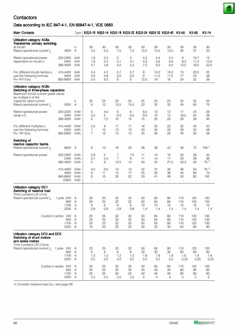
60 D946E
ContactorsContactorsContactorsContactorsContactors
Data according to IEC 947-4-1, EN 60947-4-1, VDE 0660Data according to IEC 947-4-1, EN 60947-4-1, VDE 0660Data according to IEC 947-4-1, EN 60947-4-1, VDE 0660Data according to IEC 947-4-1, EN 60947-4-1, VDE 0660Data according to IEC 947-4-1, EN 60947-4-1, VDE 0660
Main ContactsMain ContactsMain ContactsMain ContactsMain Contacts Type K(G)3-10K(G)3-10K(G)3-10K(G)3-10K(G)3-10 K(G)3-14K(G)3-14K(G)3-14K(G)3-14K(G)3-14 K(G)3-18K(G)3-18K(G)3-18K(G)3-18K(G)3-18 K(G)3-22K(G)3-22K(G)3-22K(G)3-22K(G)3-22 K(G)3-24K(G)3-24K(G)3-24K(G)3-24K(G)3-24 K(G)3-32K(G)3-32K(G)3-32K(G)3-32K(G)3-32 K(G)3-40K(G)3-40K(G)3-40K(G)3-40K(G)3-40 K3-50K3-50K3-50K3-50K3-50 K3-62K3-62K3-62K3-62K3-62 K3-74K3-74K3-74K3-74K3-74
Utilization category AC6aUtilization category AC6aUtilization category AC6aUtilization category AC6aUtilization category AC6aTransformer primary switchingTransformer primary switchingTransformer primary switchingTransformer primary switchingTransformer primary switchingat inrush n 30 30 30 30 30 30 30 30 30 30Rated operational current Ie 400V A 4,5 5,5 7,5 7,5 10,5 13,5 13,5 20 27 33
Rated operational power 220-230V kVA 1,8 2,2 3 3 4,2 5,4 5,4 8 10,7 13dependent on inrush n 240V kVA 1,9 2,3 3,1 3,1 4,3 5,6 5,6 8,3 11,2 13,5
380-400V kVA 3,1 3,8 5,2 5,2 7,3 9,3 9,3 13,5 18,5 22,5
For different inrush-factors x 415-440V kVA 3,4 4,2 5,7 5,7 8 10,2 10,2 15 20,5 25use the following formula: 500V kVA 3,9 4,8 6,5 6,5 9 11,5 11,5 17 23 28Px=Pn*(n/x) 660-690V kVA 5,4 6,5 9 9 12,5 16 16 24 32 39
Utilization category AC6bUtilization category AC6bUtilization category AC6bUtilization category AC6bUtilization category AC6bSwitching of three-phase capacitorsSwitching of three-phase capacitorsSwitching of three-phase capacitorsSwitching of three-phase capacitorsSwitching of three-phase capacitorsMaximum inrush current (peak value)as multiple k of thecapacitor rated current k 35 25 20 20 25 25 25 25 25 20Rated operational current Ie 500V A 8 12 15,5 15,5 23 32 32 45 60 70
Rated operational power 220-230V kVAr 3 4,5 6 6 8,5 12 12 17 24 28(sinϕ→1) 240V kVAr 3,5 5 6,5 6,5 9,5 13 13 18,5 25 29
380-400V kVAr 5 7,5 10 10 15 20 20 29 39 46
For different multiples x 415-440V kVAr 5,5 8 11 11 16 22 22 32 43 50use the following formula: 500V kVAr 7 10 13 13 20 26 26 39 50 58Px=Pk*(k/x) 660-690V kVAr 7 10 13 13 20 26 26 40 50 58
Switching ofSwitching ofSwitching ofSwitching ofSwitching ofreactive capacitor banksreactive capacitor banksreactive capacitor banksreactive capacitor banksreactive capacitor banksRated operational current Ie 690V A 8 13 18 20 28 36 42 48 72 108 1)
Rated operational power 220-230V kVAr 2,9 5 7 7,5 11 14 16 20 28 33240V kVAr 3,1 5,4 7 8 11 14 17 20 28 36
380-400V kVAr 5 9 12,5 13 20 25 27,5 33,3 50 75 1)
415-440V kVAr 5,5 9,5 13 14 22 27 30 36 53 75 1)
500V kVAr 6 11 15 17 25 30 36 40 60 75660-690V kVAr 8 15 20 22 33 41 48 55 82 100
1000V kVAr - - - - - - - - - -
Utilization category DC1Utilization category DC1Utilization category DC1Utilization category DC1Utilization category DC1Switching of resistive loadSwitching of resistive loadSwitching of resistive loadSwitching of resistive loadSwitching of resistive loadTime constant L/R ≤1msRated operational current Ie 1 pole 24V A 20 25 32 32 50 65 80 110 120 130
60V A 20 25 32 32 50 65 80 110 120 130110V A 6 6 6 6 10 10 10 12 12 12220V A 0,8 0,8 0,8 0,8 1,4 1,4 1,4 1,4 1,4 1,4
3 poles in series 24V A 20 25 32 32 50 65 80 110 120 130 60V A 20 25 32 32 50 65 80 110 120 130110V A 20 25 32 32 50 65 80 110 120 130220V A 16 20 20 20 30 35 35 63 80 80
Utilization category DC3 and DC5Utilization category DC3 and DC5Utilization category DC3 and DC5Utilization category DC3 and DC5Utilization category DC3 and DC5Switching of shunt motorsSwitching of shunt motorsSwitching of shunt motorsSwitching of shunt motorsSwitching of shunt motorsand series motorsand series motorsand series motorsand series motorsand series motorsTime constant L/R ≤15msRated operational current Ie 1 pole 24V A 20 25 32 32 50 65 80 110 120 130
60V A 6 6 6 6 30 30 30 60 60 60110V A 1,2 1,2 1,2 1,2 1,8 1,8 1,8 1,8 1,8 1,8
220V A 0,2 0,2 0,2 0,2 0,2 0,2 0,2 0,25 0,25 0,25
3 poles in series 24V A 20 25 32 32 50 65 80 110 120 130 60V A 20 25 32 32 40 40 40 80 80 80110V A 20 20 20 20 40 40 40 80 80 80220V A 2,5 2,5 2,5 2,5 4 4 4 5 5 5
1) Consider resistive load (Ith). see page 56
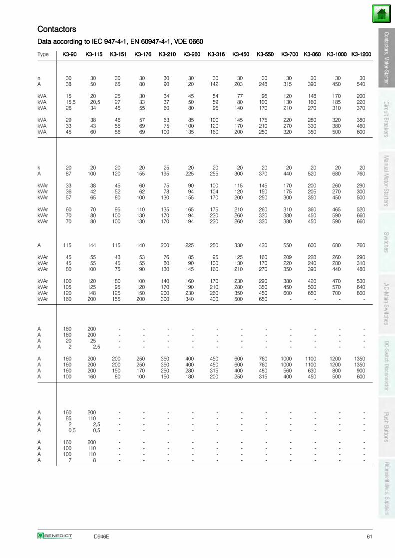
D946E 61
ContactorsContactorsContactorsContactorsContactors
Data according to IEC 947-4-1, EN 60947-4-1, VDE 0660Data according to IEC 947-4-1, EN 60947-4-1, VDE 0660Data according to IEC 947-4-1, EN 60947-4-1, VDE 0660Data according to IEC 947-4-1, EN 60947-4-1, VDE 0660Data according to IEC 947-4-1, EN 60947-4-1, VDE 0660
Type K3-90K3-90K3-90K3-90K3-90 K3-115K3-115K3-115K3-115K3-115 K3-151K3-151K3-151K3-151K3-151 K3-176K3-176K3-176K3-176K3-176 K3-210K3-210K3-210K3-210K3-210 K3-260K3-260K3-260K3-260K3-260 K3-316K3-316K3-316K3-316K3-316 K3-450K3-450K3-450K3-450K3-450 K3-550K3-550K3-550K3-550K3-550 K3-700K3-700K3-700K3-700K3-700 K3-860K3-860K3-860K3-860K3-860 K3-1000K3-1000K3-1000K3-1000K3-1000 K3-1200K3-1200K3-1200K3-1200K3-1200
n 30 30 30 30 30 30 30 30 30 30 30 30 30A 38 50 65 80 90 120 142 203 248 315 390 450 540
kVA 15 20 25 30 34 45 54 77 95 120 148 170 200kVA 15,5 20,5 27 33 37 50 59 80 100 130 160 185 220kVA 26 34 45 55 60 80 95 140 170 210 270 310 370
kVA 29 38 46 57 63 85 100 145 175 220 280 320 380kVA 33 43 55 69 75 100 120 170 210 270 330 380 460kVA 45 60 56 69 100 135 160 200 250 320 350 500 600
k 20 20 20 20 25 20 20 20 20 20 20 20 20A 87 100 120 155 195 225 255 300 370 440 520 680 760
kVAr 33 38 45 60 75 90 100 115 145 170 200 260 290kVAr 36 42 52 62 78 94 104 120 150 175 205 270 300kVAr 57 65 80 100 130 155 170 200 250 300 350 450 500
kVAr 60 70 95 110 135 165 175 210 260 310 360 465 520kVAr 70 80 100 130 170 194 220 260 320 380 450 590 660kVAr 70 80 100 130 170 194 220 260 320 380 450 590 660
A 115 144 115 140 200 225 250 330 420 550 600 680 760
kVAr 45 55 43 53 76 85 95 125 160 209 228 260 290kVAr 45 55 45 55 80 90 100 130 170 220 240 280 310kVAr 80 100 75 90 130 145 160 210 270 350 390 440 480
kVAr 100 120 80 100 140 160 170 230 290 380 420 470 530kVAr 105 125 95 120 170 190 210 280 350 450 500 570 640kVAr 120 148 125 150 200 230 260 350 450 600 650 700 800kVAr 160 200 155 200 300 340 400 500 650 - - - -
A 160 200 - - - - - - - - - - -A 160 200 - - - - - - - - - - -A 20 25 - - - - - - - - - - -A 2 2,5 - - - - - - - - - - -
A 160 200 200 250 350 400 450 600 760 1000 1100 1200 1350A 160 200 200 250 350 400 450 600 760 1000 1100 1200 1350A 160 200 150 170 250 280 315 400 480 560 630 800 900A 100 160 80 100 150 180 200 250 315 400 450 500 600
A 160 200 - - - - - - - - - - -A 85 110 - - - - - - - - - - -A 2 2,5 - - - - - - - - - - -A 0,5 0,5 - - - - - - - - - - -
A 160 200 - - - - - - - - - - -A 100 110 - - - - - - - - - - -A 100 110 - - - - - - - - - - -A 7 8 - - - - - - - - - - -
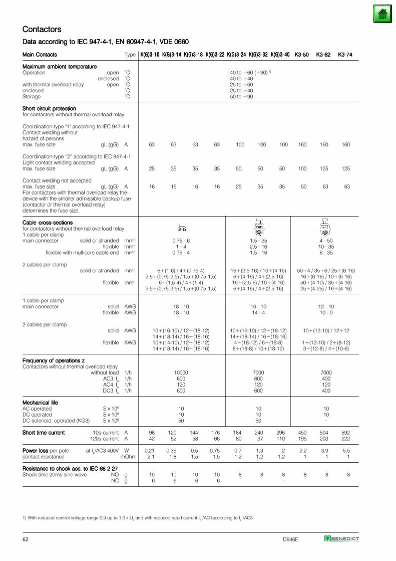
62 D946E
1) With reduced control voltage range 0,9 up to 1,0 x Us and with reduced rated current Ie /AC1according to Ie /AC3
ContactorsContactorsContactorsContactorsContactors
Data according to IEC 947-4-1, EN 60947-4-1, VDE 0660Data according to IEC 947-4-1, EN 60947-4-1, VDE 0660Data according to IEC 947-4-1, EN 60947-4-1, VDE 0660Data according to IEC 947-4-1, EN 60947-4-1, VDE 0660Data according to IEC 947-4-1, EN 60947-4-1, VDE 0660
Main ContactsMain ContactsMain ContactsMain ContactsMain Contacts Type K(G)3-10K(G)3-10K(G)3-10K(G)3-10K(G)3-10 K(G)3-14K(G)3-14K(G)3-14K(G)3-14K(G)3-14 K(G)3-18K(G)3-18K(G)3-18K(G)3-18K(G)3-18 K(G)3-22K(G)3-22K(G)3-22K(G)3-22K(G)3-22 K(G)3-24K(G)3-24K(G)3-24K(G)3-24K(G)3-24 K(G)3-32K(G)3-32K(G)3-32K(G)3-32K(G)3-32 K(G)3-40K(G)3-40K(G)3-40K(G)3-40K(G)3-40 K3-50K3-50K3-50K3-50K3-50 K3-62K3-62K3-62K3-62K3-62 K3-74K3-74K3-74K3-74K3-74
Maximum ambient temperatureMaximum ambient temperatureMaximum ambient temperatureMaximum ambient temperatureMaximum ambient temperatureOperation open °C -40 to +60 (+90) 1)
enclosed °C -40 to +40with thermal overload relay open °C -25 to +60enclosed °C -25 to +40Storage °C -50 to +90
Short circuit protectionShort circuit protectionShort circuit protectionShort circuit protectionShort circuit protectionfor contactors without thermal overload relay
Coordination-type "1" according to IEC 947-4-1Contact welding withouthazard of personsmax. fuse size gL (gG) A 63 63 63 63 100 100 100 160 160 160
Coordination-type “2” according to IEC 947-4-1Light contact welding acceptedmax. fuse size gL (gG) A 25 35 35 35 50 50 50 100 125 125
Contact welding not acceptedmax. fuse size gL (gG) A 16 16 16 16 25 35 35 50 63 63For contactors with thermal overload relay thedevice with the smaller admissible backup fuse(contactor or thermal overload relay)determines the fuse size.
Cable cross-sectionsCable cross-sectionsCable cross-sectionsCable cross-sectionsCable cross-sectionsfor contactors without thermal overload relay1 cable per clampmain connector solid or stranded mm² 0,75 - 6 1,5 - 25 4 - 50
flexible mm² 1 - 4 2,5 - 16 10 - 35flexible with multicore cable end mm² 0,75 - 4 1,5 - 16 6 - 35
2 cables per clampsolid or stranded mm² 6+(1-6) / 4+(0,75-4) 16+(2,5-16) / 10+(4-16) 50+4 / 35+6 / 25+(6-16)
2,5+(0,75-2,5) / 1,5+(0,75-1,5) 6+(4-16) / 4+(2,5-16) 16+(6-16) / 10+(6-16)flexible mm² 6+(1,5-4) / 4+(1-4) 16+(2,5-6) / 10+(4-10) 50+(4-10) / 35+(4-16)
2,5+(0,75-2,5) / 1,5+(0,75-1,5) 6+(4-16) / 4+(2,5-16) 25+(4-25) / 16+(4-16)
1 cable per clampmain connector solid AWG 18 - 10 16 - 10 12 - 10
flexible AWG 18 - 10 14 - 4 10 - 0
2 cables per clampsolid AWG 10+(16-10) / 12+(18-12) 10+(16-10) / 12+(18-12) 10+(12-10) / 12+12
14+(18-14) / 16+(18-16) 14+(18-14) / 16+(18-16)flexible AWG 10+(14-10) / 12+(18-12) 4+(18-12) / 6+(18-8) 1+(12-10) / 2+(8-12)
14+(18-14) / 16+(18-16) 8+(18-8) / 10+(18-12) 3+(12-8) / 4+(10-6)
Frequency of operations zFrequency of operations zFrequency of operations zFrequency of operations zFrequency of operations zContactors without thermal overload relay
without load 1/h 10000 7000 7000AC3, Ie 1/h 600 600 400AC4, Ie 1/h 120 120 120DC3, Ie 1/h 600 600 400
Mechanical lifeMechanical lifeMechanical lifeMechanical lifeMechanical lifeAC operated S x 106 10 10 10DC operated S x 106 10 10 10DC-solenoid operated (KG3) S x 106 50 50 -
Short time currentShort time currentShort time currentShort time currentShort time current 10s-current A 96 120 144 176 184 240 296 450 504 592120s-current A 42 52 58 66 80 97 110 195 203 222
Power loss Power loss Power loss Power loss Power loss per pole at Ie/AC3 400V W 0,21 0,35 0,5 0,75 0,7 1,3 2 2,2 3,9 5,5contact resistance mOhm 2,1 1,8 1,5 1,5 1,2 1,2 1,2 1 1 1
Resistance to shock acc. to IEC 68-2-27Resistance to shock acc. to IEC 68-2-27Resistance to shock acc. to IEC 68-2-27Resistance to shock acc. to IEC 68-2-27Resistance to shock acc. to IEC 68-2-27Shock time 20ms sine-wave NO g 10 10 10 10 8 8 8 8 8 8
NC g 6 6 6 6 - - - - - -
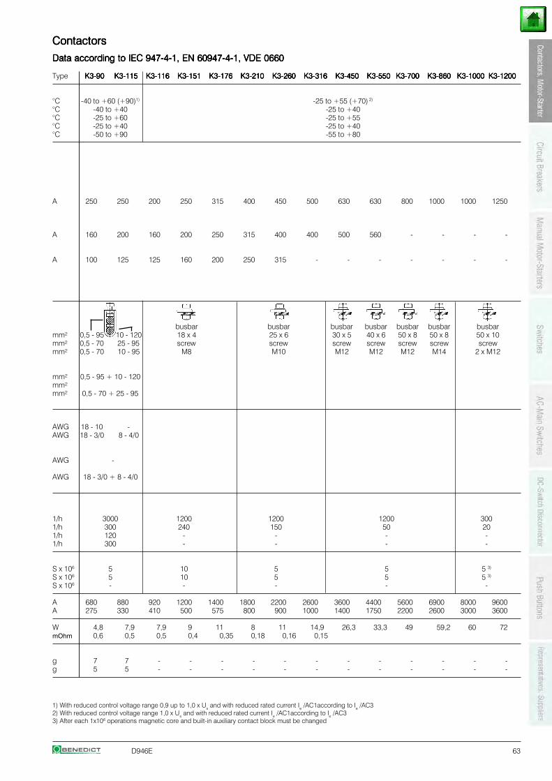
D946E 63
1) With reduced control voltage range 0,9 up to 1,0 x Us and with reduced rated current Ie /AC1according to Ie /AC32) With reduced control voltage range 1,0 x Us and with reduced rated current Ie /AC1according to Ie /AC33) After each 1x10⁶ operations magnetic core and built-in auxiliary contact block must be changed
ContactorsContactorsContactorsContactorsContactors
Data according to IEC 947-4-1, EN 60947-4-1, VDE 0660Data according to IEC 947-4-1, EN 60947-4-1, VDE 0660Data according to IEC 947-4-1, EN 60947-4-1, VDE 0660Data according to IEC 947-4-1, EN 60947-4-1, VDE 0660Data according to IEC 947-4-1, EN 60947-4-1, VDE 0660
Type K3-90K3-90K3-90K3-90K3-90 K3-115K3-115K3-115K3-115K3-115 K3-116K3-116K3-116K3-116K3-116 K3-151K3-151K3-151K3-151K3-151 K3-176K3-176K3-176K3-176K3-176 K3-210K3-210K3-210K3-210K3-210 K3-260K3-260K3-260K3-260K3-260 K3-316K3-316K3-316K3-316K3-316 K3-450K3-450K3-450K3-450K3-450 K3-550K3-550K3-550K3-550K3-550 K3-700K3-700K3-700K3-700K3-700 K3-860K3-860K3-860K3-860K3-860 K3-1000K3-1000K3-1000K3-1000K3-1000 K3-1200K3-1200K3-1200K3-1200K3-1200
°C -40 to +60 (+90)1) -25 to +55 (+70) 2)
°C -40 to +40 -25 to +40°C -25 to +60 -25 to +55°C -25 to +40 -25 to +40°C -50 to +90 -55 to +80
A 250 250 200 250 315 400 450 500 630 630 800 1000 1000 1250
A 160 200 160 200 250 315 400 400 500 560 - - - -
A 100 125 125 160 200 250 315 - - - - - - -
busbar busbar busbar busbar busbar busbar busbarmm² 0,5 - 95 10 - 120 18 x 4 25 x 6 30 x 5 40 x 6 50 x 8 50 x 8 50 x 10mm² 0,5 - 70 25 - 95 screw screw screw screw screw screw screwmm² 0,5 - 70 10 - 95 M8 M10 M12 M12 M12 M14 2 x M12
mm² 0,5 - 95 + 10 - 120mm²mm² 0,5 - 70 + 25 - 95
AWG 18 - 10 -AWG 18 - 3/0 8 - 4/0
AWG -
AWG 18 - 3/0 + 8 - 4/0
1/h 3000 1200 1200 1200 3001/h 300 240 150 50 201/h 120 - - - -1/h 300 - - - -
S x 106 5 10 5 5 5 3)
S x 106 5 10 5 5 5 3)
S x 106 - - - - -
A 680 880 920 1200 1400 1800 2200 2600 3600 4400 5600 6900 8000 9600A 275 330 410 500 575 800 900 1000 1400 1750 2200 2600 3000 3600
W 4,8 7,9 7,9 9 11 8 11 14,9 26,3 33,3 49 59,2 60 72mOhm 0,6 0,5 0,5 0,4 0,35 0,18 0,16 0,15
g 7 7 - - - - - - - - - - - -g 5 5 - - - - - - - - - - - -
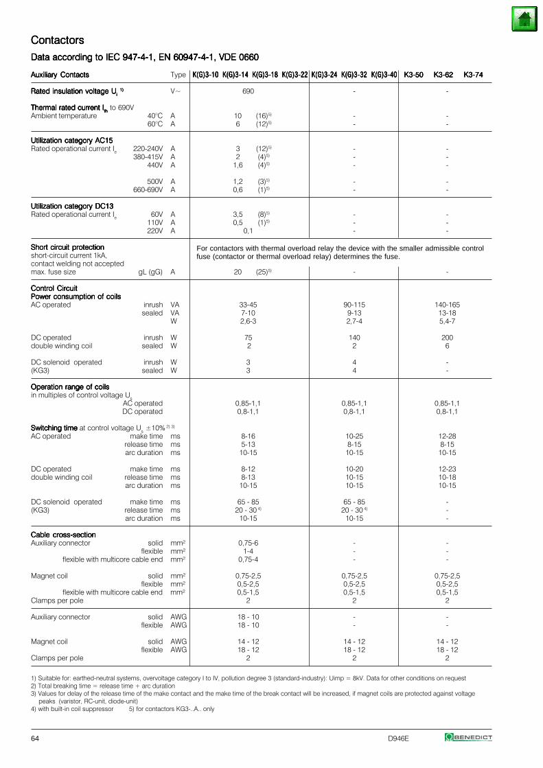
64 D946E
1) Suitable for: earthed-neutral systems, overvoltage category I to IV, pollution degree 3 (standard-industry): Uimp = 8kV. Data for other conditions on request2) Total breaking time = release time + arc duration3) Values for delay of the release time of the make contact and the make time of the break contact will be increased, if magnet coils are protected against voltage
peaks (varistor, RC-unit, diode-unit)4) with built-in coil suppressor 5) for contactors KG3-..A.. only
ContactorsContactorsContactorsContactorsContactors
Data according to IEC 947-4-1, EN 60947-4-1, VDE 0660Data according to IEC 947-4-1, EN 60947-4-1, VDE 0660Data according to IEC 947-4-1, EN 60947-4-1, VDE 0660Data according to IEC 947-4-1, EN 60947-4-1, VDE 0660Data according to IEC 947-4-1, EN 60947-4-1, VDE 0660
Auxiliary ContactsAuxiliary ContactsAuxiliary ContactsAuxiliary ContactsAuxiliary Contacts Type K(G)3-10K(G)3-10K(G)3-10K(G)3-10K(G)3-10 K(G)3-14K(G)3-14K(G)3-14K(G)3-14K(G)3-14 K(G)3-18K(G)3-18K(G)3-18K(G)3-18K(G)3-18 K(G)3-22K(G)3-22K(G)3-22K(G)3-22K(G)3-22 K(G)3-24K(G)3-24K(G)3-24K(G)3-24K(G)3-24 K(G)3-32K(G)3-32K(G)3-32K(G)3-32K(G)3-32 K(G)3-40K(G)3-40K(G)3-40K(G)3-40K(G)3-40 K3-50K3-50K3-50K3-50K3-50 K3-62K3-62K3-62K3-62K3-62 K3-74K3-74K3-74K3-74K3-74
Rated insulation voltage URated insulation voltage URated insulation voltage URated insulation voltage URated insulation voltage Uiiiii 1)1)1)1)1) V~ 690 - -
Thermal rated current IThermal rated current IThermal rated current IThermal rated current IThermal rated current Iththththth to 690VAmbient temperature 40°C A 10 (16)5) - -
60°C A 6 (12)5) - -
Utilization category AC15Utilization category AC15Utilization category AC15Utilization category AC15Utilization category AC15Rated operational current Ie 220-240V A 3 (12)5) - -
380-415V A 2 (4)5) - -440V A 1,6 (4)5) - -
500V A 1,2 (3)5) - -660-690V A 0,6 (1)5) - -
Utilization category DC13Utilization category DC13Utilization category DC13Utilization category DC13Utilization category DC13Rated operational current Ie 60V A 3,5 (8)5) - -
110V A 0,5 (1)5) - -220V A 0,1 - -
Short circuit protectionShort circuit protectionShort circuit protectionShort circuit protectionShort circuit protectionshort-circuit current 1kA,contact welding not acceptedmax. fuse size gL (gG) A 20 (25)5) - -
Control CircuitControl CircuitControl CircuitControl CircuitControl CircuitPower consumption of coilsPower consumption of coilsPower consumption of coilsPower consumption of coilsPower consumption of coilsAC operated inrush VA 33-45 90-115 140-165
sealed VA 7-10 9-13 13-18W 2,6-3 2,7-4 5,4-7
DC operated inrush W 75 140 200double winding coil sealed W 2 2 6
DC solenoid operated inrush W 3 4 -(KG3) sealed W 3 4 -
Operation range of coilsOperation range of coilsOperation range of coilsOperation range of coilsOperation range of coilsin multiples of control voltage Us
AC operated 0,85-1,1 0,85-1,1 0,85-1,1DC operated 0,8-1,1 0,8-1,1 0,8-1,1
Switching time Switching time Switching time Switching time Switching time at control voltage Us ±10% 2) 3)
AC operated make time ms 8-16 10-25 12-28release time ms 5-13 8-15 8-15arc duration ms 10-15 10-15 10-15
DC operated make time ms 8-12 10-20 12-23double winding coil release time ms 8-13 10-15 10-18
arc duration ms 10-15 10-15 10-15
DC solenoid operated make time ms 65 - 85 65 - 85 -(KG3) release time ms 20 - 30 4) 20 - 30 4) -
arc duration ms 10-15 10-15 -
Cable cross-sectionCable cross-sectionCable cross-sectionCable cross-sectionCable cross-sectionAuxiliary connector solid mm² 0,75-6 - -
flexible mm² 1-4 - -flexible with multicore cable end mm² 0,75-4 - -
Magnet coil solid mm² 0,75-2,5 0,75-2,5 0,75-2,5flexible mm² 0,5-2,5 0,5-2,5 0,5-2,5
flexible with multicore cable end mm² 0,5-1,5 0,5-1,5 0,5-1,5Clamps per pole 2 2 2
Auxiliary connector solid AWG 18 - 10 - -flexible AWG 18 - 10 - -
Magnet coil solid AWG 14 - 12 14 - 12 14 - 12flexible AWG 18 - 12 18 - 12 18 - 12
Clamps per pole 2 2 2
For contactors with thermal overload relay the device with the smaller admissible controlfuse (contactor or thermal overload relay) determines the fuse.
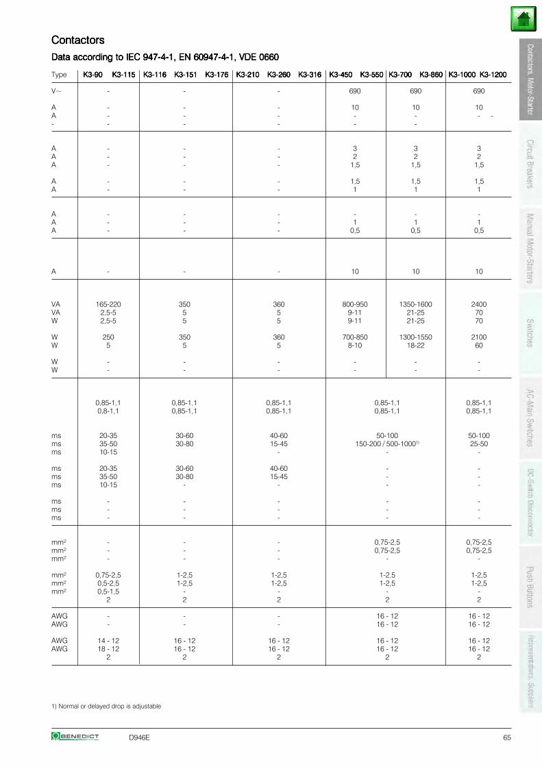
D946E 65
ContactorsContactorsContactorsContactorsContactors
Data according to IEC 947-4-1, EN 60947-4-1, VDE 0660Data according to IEC 947-4-1, EN 60947-4-1, VDE 0660Data according to IEC 947-4-1, EN 60947-4-1, VDE 0660Data according to IEC 947-4-1, EN 60947-4-1, VDE 0660Data according to IEC 947-4-1, EN 60947-4-1, VDE 0660
Type K3-90K3-90K3-90K3-90K3-90 K3-115K3-115K3-115K3-115K3-115 K3-116K3-116K3-116K3-116K3-116 K3-151K3-151K3-151K3-151K3-151 K3-176K3-176K3-176K3-176K3-176 K3-210K3-210K3-210K3-210K3-210 K3-260K3-260K3-260K3-260K3-260 K3-316K3-316K3-316K3-316K3-316 K3-450K3-450K3-450K3-450K3-450 K3-550K3-550K3-550K3-550K3-550 K3-700K3-700K3-700K3-700K3-700 K3-860K3-860K3-860K3-860K3-860 K3-1000K3-1000K3-1000K3-1000K3-1000 K3-1200K3-1200K3-1200K3-1200K3-1200
V~ - - - 690 690 690
A - - - 10 10 10A - - - - - - -- - - - - -
A - - - 3 3 3A - - - 2 2 2A - - - 1,5 1,5 1,5
A - - - 1,5 1,5 1,5A - - - 1 1 1
A - - - - - -A - - - 1 1 1A - - - 0,5 0,5 0,5
A - - - 10 10 10
VA 165-220 350 360 800-950 1350-1600 2400VA 2,5-5 5 5 9-11 21-25 70W 2,5-5 5 5 9-11 21-25 70
W 250 350 360 700-850 1300-1550 2100W 5 5 5 8-10 18-22 60
W - - - - - -W - - - - - -
0,85-1,1 0,85-1,1 0,85-1,1 0,85-1,1 0,85-1,10,8-1,1 0,85-1,1 0,85-1,1 0,85-1,1 0,85-1,1
ms 20-35 30-60 40-60 50-100 50-100ms 35-50 30-80 15-45 150-200 / 500-10001) 25-50ms 10-15 - - -
ms 20-35 30-60 40-60 - -ms 35-50 30-80 15-45 - -ms 10-15 - - - -
ms - - - - -ms - - - - -ms - - - - -
mm² - - - 0,75-2,5 0,75-2,5mm² - - - 0,75-2,5 0,75-2,5mm² - - - - -
mm² 0,75-2,5 1-2,5 1-2,5 1-2,5 1-2,5mm² 0,5-2,5 1-2,5 1-2,5 1-2,5 1-2,5mm² 0,5-1,5 - - - -
2 2 2 2 2
AWG - - - 16 - 12 16 - 12AWG - - - 16 - 12 16 - 12
AWG 14 - 12 16 - 12 16 - 12 16 - 12 16 - 12AWG 18 - 12 16 - 12 16 - 12 16 - 12 16 - 12
2 2 2 2 2
1) Normal or delayed drop is adjustable
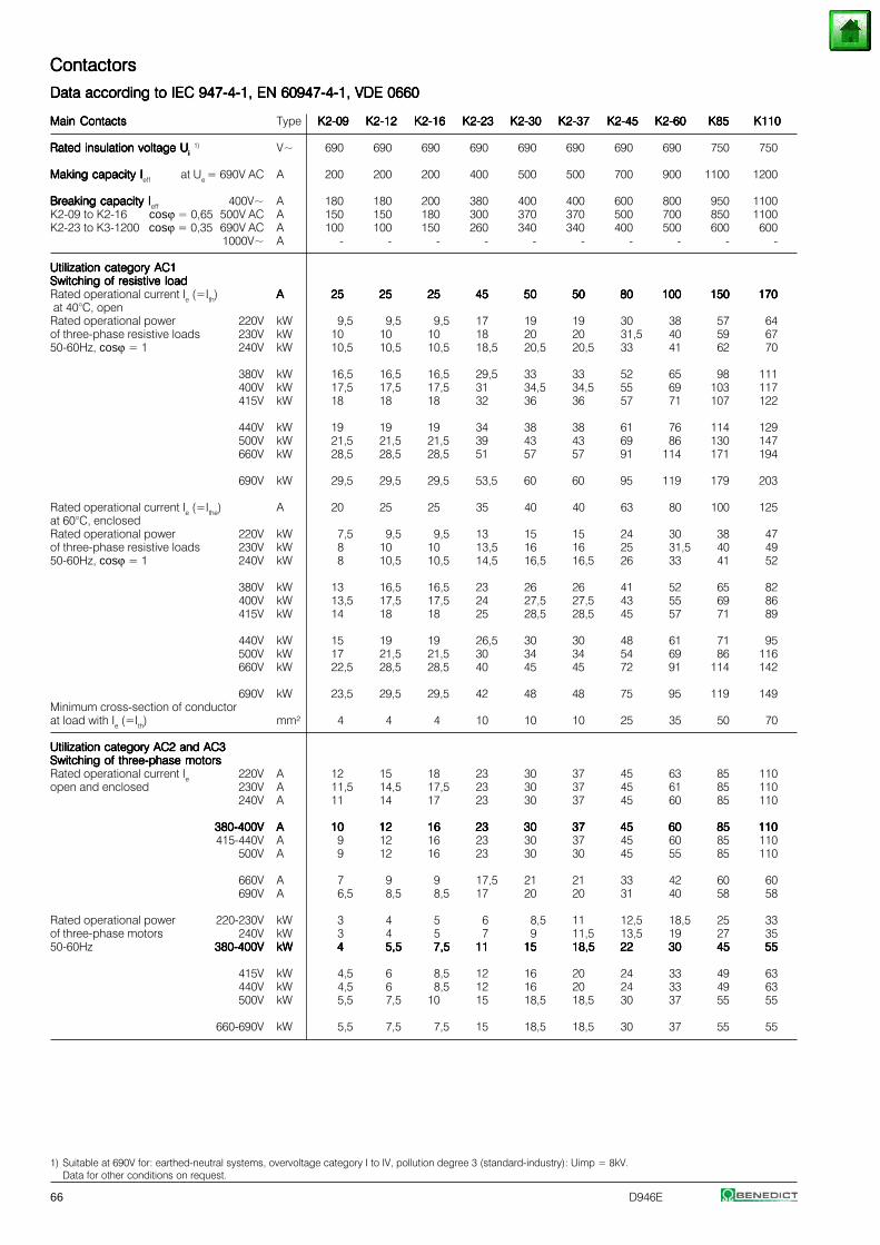
66 D946E
1) Suitable at 690V for: earthed-neutral systems, overvoltage category I to IV, pollution degree 3 (standard-industry): Uimp = 8kV.Data for other conditions on request.
ContactorsContactorsContactorsContactorsContactors
Data according to IEC 947-4-1, EN 60947-4-1, VDE 0660Data according to IEC 947-4-1, EN 60947-4-1, VDE 0660Data according to IEC 947-4-1, EN 60947-4-1, VDE 0660Data according to IEC 947-4-1, EN 60947-4-1, VDE 0660Data according to IEC 947-4-1, EN 60947-4-1, VDE 0660
Main ContactsMain ContactsMain ContactsMain ContactsMain Contacts Type K2-09K2-09K2-09K2-09K2-09 K2-12K2-12K2-12K2-12K2-12 K2-16K2-16K2-16K2-16K2-16 K2-23K2-23K2-23K2-23K2-23 K2-30K2-30K2-30K2-30K2-30 K2-37K2-37K2-37K2-37K2-37 K2-45K2-45K2-45K2-45K2-45 K2-60K2-60K2-60K2-60K2-60 K85K85K85K85K85 K110K110K110K110K110
Rated insulation voltage URated insulation voltage URated insulation voltage URated insulation voltage URated insulation voltage Uiiiii 1) V~ 690 690 690 690 690 690 690 690 750 750
Making capacity IMaking capacity IMaking capacity IMaking capacity IMaking capacity Ieff at Ue = 690V AC A 200 200 200 400 500 500 700 900 1100 1200
Breaking capacity IBreaking capacity IBreaking capacity IBreaking capacity IBreaking capacity Ieff 400V~ A 180 180 200 380 400 400 600 800 950 1100K2-09 to K2-16 cosϕ = 0,65 500V AC A 150 150 180 300 370 370 500 700 850 1100K2-23 to K3-1200 cosϕ = 0,35 690V AC A 100 100 150 260 340 340 400 500 600 600
1000V~ A - - - - - - - - - -
Utilization category AC1Utilization category AC1Utilization category AC1Utilization category AC1Utilization category AC1Switching of resistive loadSwitching of resistive loadSwitching of resistive loadSwitching of resistive loadSwitching of resistive loadRated operational current Ie (=Ith) AAAAA 2525252525 2525252525 2525252525 4545454545 5050505050 5050505050 8080808080 100100100100100 150150150150150 170170170170170 at 40°C, openRated operational power 220V kW 9,5 9,5 9,5 17 19 19 30 38 57 64of three-phase resistive loads 230V kW 10 10 10 18 20 20 31,5 40 59 6750-60Hz, cosϕ = 1 240V kW 10,5 10,5 10,5 18,5 20,5 20,5 33 41 62 70
380V kW 16,5 16,5 16,5 29,5 33 33 52 65 98 111400V kW 17,5 17,5 17,5 31 34,5 34,5 55 69 103 117415V kW 18 18 18 32 36 36 57 71 107 122
440V kW 19 19 19 34 38 38 61 76 114 129500V kW 21,5 21,5 21,5 39 43 43 69 86 130 147660V kW 28,5 28,5 28,5 51 57 57 91 114 171 194
690V kW 29,5 29,5 29,5 53,5 60 60 95 119 179 203
Rated operational current Ie (=Ithe) A 20 25 25 35 40 40 63 80 100 125at 60°C, enclosedRated operational power 220V kW 7,5 9,5 9,5 13 15 15 24 30 38 47of three-phase resistive loads 230V kW 8 10 10 13,5 16 16 25 31,5 40 4950-60Hz, cosϕ = 1 240V kW 8 10,5 10,5 14,5 16,5 16,5 26 33 41 52
380V kW 13 16,5 16,5 23 26 26 41 52 65 82400V kW 13,5 17,5 17,5 24 27,5 27,5 43 55 69 86415V kW 14 18 18 25 28,5 28,5 45 57 71 89
440V kW 15 19 19 26,5 30 30 48 61 71 95500V kW 17 21,5 21,5 30 34 34 54 69 86 116660V kW 22,5 28,5 28,5 40 45 45 72 91 114 142
690V kW 23,5 29,5 29,5 42 48 48 75 95 119 149Minimum cross-section of conductorat load with Ie (=Ith) mm² 4 4 4 10 10 10 25 35 50 70
Utilization category AC2 and AC3Utilization category AC2 and AC3Utilization category AC2 and AC3Utilization category AC2 and AC3Utilization category AC2 and AC3Switching of three-phase motorsSwitching of three-phase motorsSwitching of three-phase motorsSwitching of three-phase motorsSwitching of three-phase motorsRated operational current Ie 220V A 12 15 18 23 30 37 45 63 85 110open and enclosed 230V A 11,5 14,5 17,5 23 30 37 45 61 85 110
240V A 11 14 17 23 30 37 45 60 85 110
380-400V380-400V380-400V380-400V380-400V AAAAA 1010101010 1212121212 1616161616 2323232323 3030303030 3737373737 4545454545 6060606060 8585858585 110110110110110415-440V A 9 12 16 23 30 37 45 60 85 110
500V A 9 12 16 23 30 30 45 55 85 110
660V A 7 9 9 17,5 21 21 33 42 60 60690V A 6,5 8,5 8,5 17 20 20 31 40 58 58
Rated operational power 220-230V kW 3 4 5 6 8,5 11 12,5 18,5 25 33of three-phase motors 240V kW 3 4 5 7 9 11,5 13,5 19 27 3550-60Hz 380-400V380-400V380-400V380-400V380-400V kWkWkWkWkW 44444 5,55,55,55,55,5 7,57,57,57,57,5 1111111111 1515151515 18,518,518,518,518,5 2222222222 3030303030 4545454545 5555555555
415V kW 4,5 6 8,5 12 16 20 24 33 49 63440V kW 4,5 6 8,5 12 16 20 24 33 49 63500V kW 5,5 7,5 10 15 18,5 18,5 30 37 55 55
660-690V kW 5,5 7,5 7,5 15 18,5 18,5 30 37 55 55
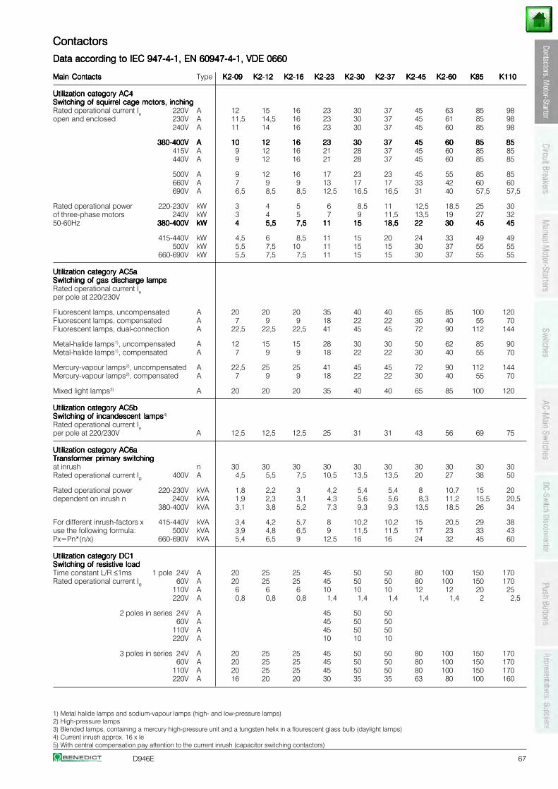
D946E 67
1) Metal halide lamps and sodium-vapour lamps (high- and low-pressure lamps)2) High-pressure lamps3) Blended lamps, containing a mercury high-pressure unit and a tungsten helix in a flourescent glass bulb (daylight lamps)4) Current inrush approx. 16 x Ie5) With central compensation pay attention to the current inrush (capacitor switching contactors)
ContactorsContactorsContactorsContactorsContactors
Data according to IEC 947-4-1, EN 60947-4-1, VDE 0660Data according to IEC 947-4-1, EN 60947-4-1, VDE 0660Data according to IEC 947-4-1, EN 60947-4-1, VDE 0660Data according to IEC 947-4-1, EN 60947-4-1, VDE 0660Data according to IEC 947-4-1, EN 60947-4-1, VDE 0660
Main ContactsMain ContactsMain ContactsMain ContactsMain Contacts Type K2-09K2-09K2-09K2-09K2-09 K2-12K2-12K2-12K2-12K2-12 K2-16K2-16K2-16K2-16K2-16 K2-23K2-23K2-23K2-23K2-23 K2-30K2-30K2-30K2-30K2-30 K2-37K2-37K2-37K2-37K2-37 K2-45K2-45K2-45K2-45K2-45 K2-60K2-60K2-60K2-60K2-60 K85K85K85K85K85 K110K110K110K110K110
Utilization category AC4Utilization category AC4Utilization category AC4Utilization category AC4Utilization category AC4Switching of squirrel cage motors, inchingSwitching of squirrel cage motors, inchingSwitching of squirrel cage motors, inchingSwitching of squirrel cage motors, inchingSwitching of squirrel cage motors, inchingRated operational current Ie 220V A 12 15 16 23 30 37 45 63 85 98open and enclosed 230V A 11,5 14,5 16 23 30 37 45 61 85 98
240V A 11 14 16 23 30 37 45 60 85 98
380-400V380-400V380-400V380-400V380-400V AAAAA 1010101010 1212121212 1616161616 2323232323 3030303030 3737373737 4545454545 6060606060 8585858585 8585858585415V A 9 12 16 21 28 37 45 60 85 85440V A 9 12 16 21 28 37 45 60 85 85
500V A 9 12 16 17 23 23 45 55 85 85660V A 7 9 9 13 17 17 33 42 60 60690V A 6,5 8,5 8,5 12,5 16,5 16,5 31 40 57,5 57,5
Rated operational power 220-230V kW 3 4 5 6 8,5 11 12,5 18,5 25 30of three-phase motors 240V kW 3 4 5 7 9 11,5 13,5 19 27 3250-60Hz 380-400V380-400V380-400V380-400V380-400V kWkWkWkWkW 44444 5,55,55,55,55,5 7,57,57,57,57,5 1111111111 1515151515 18,518,518,518,518,5 2222222222 3030303030 4545454545 4545454545
415-440V kW 4,5 6 8,5 11 15 20 24 33 49 49500V kW 5,5 7,5 10 11 15 15 30 37 55 55
660-690V kW 5,5 7,5 7,5 11 15 15 30 37 55 55
Utilization category AC5aUtilization category AC5aUtilization category AC5aUtilization category AC5aUtilization category AC5aSwitching of gas discharge lampsSwitching of gas discharge lampsSwitching of gas discharge lampsSwitching of gas discharge lampsSwitching of gas discharge lampsRated operational current Ieper pole at 220/230V
Fluorescent lamps, uncompensated A 20 20 20 35 40 40 65 85 100 120Fluorescent lamps, compensated A 7 9 9 18 22 22 30 40 55 70Fluorescent lamps, dual-connection A 22,5 22,5 22,5 41 45 45 72 90 112 144
Metal-halide lamps1), uncompensated A 12 15 15 28 30 30 50 62 85 90Metal-halide lamps1), compensated A 7 9 9 18 22 22 30 40 55 70
Mercury-vapour lamps2), uncompensated A 22,5 25 25 41 45 45 72 90 112 144Mercury-vapour lamps2), compensated A 7 9 9 18 22 22 30 40 55 70
Mixed light lamps3) A 20 20 20 35 40 40 65 85 100 120
Utilization category AC5bUtilization category AC5bUtilization category AC5bUtilization category AC5bUtilization category AC5bSwitching of incandescent lampsSwitching of incandescent lampsSwitching of incandescent lampsSwitching of incandescent lampsSwitching of incandescent lamps4)
Rated operational current Ieper pole at 220/230V A 12,5 12,5 12,5 25 31 31 43 56 69 75
Utilization category AC6aUtilization category AC6aUtilization category AC6aUtilization category AC6aUtilization category AC6aTransformer primary switchingTransformer primary switchingTransformer primary switchingTransformer primary switchingTransformer primary switchingat inrush n 30 30 30 30 30 30 30 30 30 30Rated operational current Ie 400V A 4,5 5,5 7,5 10,5 13,5 13,5 20 27 38 50
Rated operational power 220-230V kVA 1,8 2,2 3 4,2 5,4 5,4 8 10,7 15 20dependent on inrush n 240V kVA 1,9 2,3 3,1 4,3 5,6 5,6 8,3 11,2 15,5 20,5
380-400V kVA 3,1 3,8 5,2 7,3 9,3 9,3 13,5 18,5 26 34
For different inrush-factors x 415-440V kVA 3,4 4,2 5,7 8 10,2 10,2 15 20,5 29 38use the following formula: 500V kVA 3,9 4,8 6,5 9 11,5 11,5 17 23 33 43Px=Pn*(n/x) 660-690V kVA 5,4 6,5 9 12,5 16 16 24 32 45 60
Utilization category DC1Utilization category DC1Utilization category DC1Utilization category DC1Utilization category DC1Switching of resistive loadSwitching of resistive loadSwitching of resistive loadSwitching of resistive loadSwitching of resistive loadTime constant L/R ≤1ms 1 pole 24V A 20 25 25 45 50 50 80 100 150 170Rated operational current Ie 60V A 20 25 25 45 50 50 80 100 150 170
110V A 6 6 6 10 10 10 12 12 20 25220V A 0,8 0,8 0,8 1,4 1,4 1,4 1,4 1,4 2 2,5
2 poles in series 24V A 45 50 50 60V A 45 50 50110V A 45 50 50220V A 10 10 10
3 poles in series 24V A 20 25 25 45 50 50 80 100 150 170 60V A 20 25 25 45 50 50 80 100 150 170110V A 20 25 25 45 50 50 80 100 150 170220V A 16 20 20 30 35 35 63 80 100 160
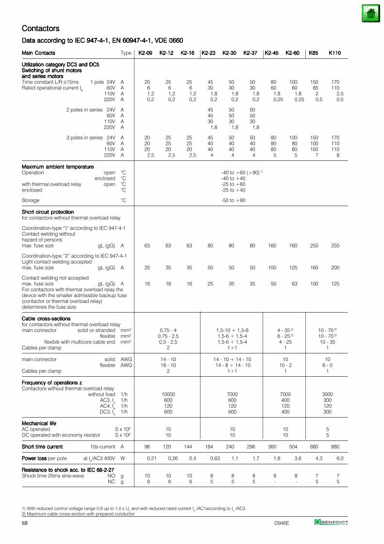
68 D946E
1) With reduced control voltage range 0,9 up to 1,0 x Us and with reduced rated current Ie /AC1according to Ie /AC32) Maximum cable cross-section with prepared conductor
ContactorsContactorsContactorsContactorsContactors
Data according to IEC 947-4-1, EN 60947-4-1, VDE 0660Data according to IEC 947-4-1, EN 60947-4-1, VDE 0660Data according to IEC 947-4-1, EN 60947-4-1, VDE 0660Data according to IEC 947-4-1, EN 60947-4-1, VDE 0660Data according to IEC 947-4-1, EN 60947-4-1, VDE 0660
Main ContactsMain ContactsMain ContactsMain ContactsMain Contacts Type K2-09K2-09K2-09K2-09K2-09 K2-12K2-12K2-12K2-12K2-12 K2-16K2-16K2-16K2-16K2-16 K2-23K2-23K2-23K2-23K2-23 K2-30K2-30K2-30K2-30K2-30 K2-37K2-37K2-37K2-37K2-37 K2-45K2-45K2-45K2-45K2-45 K2-60K2-60K2-60K2-60K2-60 K85K85K85K85K85 K110K110K110K110K110
Utilization category DC3 and DC5Utilization category DC3 and DC5Utilization category DC3 and DC5Utilization category DC3 and DC5Utilization category DC3 and DC5Switching of shunt motorsSwitching of shunt motorsSwitching of shunt motorsSwitching of shunt motorsSwitching of shunt motorsand series motorsand series motorsand series motorsand series motorsand series motorsTime constant L/R ≤15ms 1 pole 24V A 20 25 25 45 50 50 80 100 150 170Rated operational current Ie 60V A 6 6 6 30 30 30 60 60 85 110
110V A 1,2 1,2 1,2 1,8 1,8 1,8 1,8 1,8 2 2,5 220V A 0,2 0,2 0,2 0,2 0,2 0,2 0,25 0,25 0,5 0,5
2 poles in series 24V A 45 50 50 60V A 45 50 50110V A 30 30 30
220V A 1,8 1,8 1,8
3 poles in series 24V A 20 25 25 45 50 50 80 100 150 170 60V A 20 25 25 40 40 40 80 80 100 110110V A 20 20 20 40 40 40 80 80 100 110220V A 2,5 2,5 2,5 4 4 4 5 5 7 8
Maximum ambient temperatureMaximum ambient temperatureMaximum ambient temperatureMaximum ambient temperatureMaximum ambient temperatureOperation open °C -40 to +60 (+90) 1)
enclosed °C -40 to +40with thermal overload relay open °C -25 to +60enclosed °C -25 to +40
Storage °C -50 to +90
Short circuit protectionShort circuit protectionShort circuit protectionShort circuit protectionShort circuit protectionfor contactors without thermal overload relay
Coordination-type "1" according to IEC 947-4-1Contact welding withouthazard of personsmax. fuse size gL (gG) A 63 63 63 80 80 80 160 160 250 250
Coordination-type “2” according to IEC 947-4-1Light contact welding acceptedmax. fuse size gL (gG) A 25 35 35 50 50 50 100 125 160 200
Contact welding not acceptedmax. fuse size gL (gG) A 16 16 16 25 35 35 50 63 100 125For contactors with thermal overload relay thedevice with the smaller admissible backup fuse(contactor or thermal overload relay)determines the fuse size.
Cable cross-sectionsCable cross-sectionsCable cross-sectionsCable cross-sectionsCable cross-sectionsfor contactors without thermal overload relaymain connector solid or stranded mm² 0,75 - 4 1,5-10 + 1,5-6 4 - 35 2) 10 - 70 2)
flexible mm² 0,75 - 2,5 1,5-6 + 1,5-4 6 - 25 2) 10 - 70 2)
flexible with multicore cable end mm² 0,5 - 2,5 1,5-6 + 1,5-4 4 - 25 10 - 35Cables per clamp 2 1+1 1 1
main connector solid AWG 14 - 10 14 - 10 + 14 - 10 10 10flexible AWG 18 - 10 14 - 8 + 14 - 10 10 - 2 6 - 0
Cables per clamp 2 1+1 1 1
Frequency of operations zFrequency of operations zFrequency of operations zFrequency of operations zFrequency of operations zContactors without thermal overload relay
without load 1/h 10000 7000 7000 3000AC3, Ie 1/h 600 600 400 300AC4, Ie 1/h 120 120 120 120DC3, Ie 1/h 600 600 400 300
Mechanical lifeMechanical lifeMechanical lifeMechanical lifeMechanical lifeAC operated S x 106 10 10 10 5DC operated with economy resistor S x 106 10 10 10 5
Short time currentShort time currentShort time currentShort time currentShort time current 10s-current A 96 120 144 184 240 296 360 504 680 880
Power loss Power loss Power loss Power loss Power loss per pole at Ie/AC3 400V W 0,21 0,26 0,4 0,63 1,1 1,7 1,8 3,6 4,3 6,0
Resistance to shock acc. to IEC 68-2-27Resistance to shock acc. to IEC 68-2-27Resistance to shock acc. to IEC 68-2-27Resistance to shock acc. to IEC 68-2-27Resistance to shock acc. to IEC 68-2-27Shock time 20ms sine-wave NO g 10 10 10 8 8 8 8 8 7 7
NC g 6 6 6 5 5 5 - - 5 5
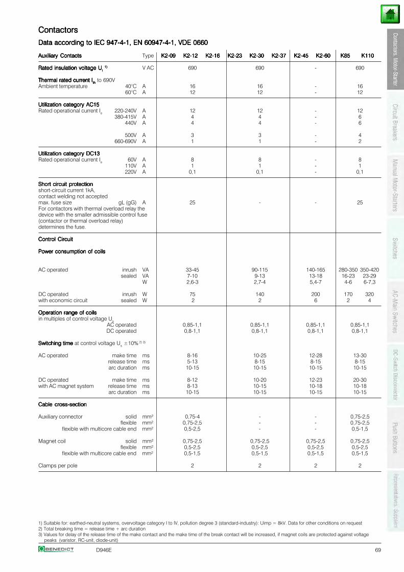
D946E 69
1) Suitable for: earthed-neutral systems, overvoltage category I to IV, pollution degree 3 (standard-industry): Uimp = 8kV. Data for other conditions on request2) Total breaking time = release time + arc duration3) Values for delay of the release time of the make contact and the make time of the break contact will be increased, if magnet coils are protected against voltage
peaks (varistor, RC-unit, diode-unit)
ContactorsContactorsContactorsContactorsContactors
Data according to IEC 947-4-1, EN 60947-4-1, VDE 0660Data according to IEC 947-4-1, EN 60947-4-1, VDE 0660Data according to IEC 947-4-1, EN 60947-4-1, VDE 0660Data according to IEC 947-4-1, EN 60947-4-1, VDE 0660Data according to IEC 947-4-1, EN 60947-4-1, VDE 0660
Auxiliary ContactsAuxiliary ContactsAuxiliary ContactsAuxiliary ContactsAuxiliary Contacts Type K2-09K2-09K2-09K2-09K2-09 K2-12K2-12K2-12K2-12K2-12 K2-16K2-16K2-16K2-16K2-16 K2-23K2-23K2-23K2-23K2-23 K2-30K2-30K2-30K2-30K2-30 K2-37K2-37K2-37K2-37K2-37 K2-45K2-45K2-45K2-45K2-45 K2-60K2-60K2-60K2-60K2-60 K85K85K85K85K85 K110K110K110K110K110
Rated insulation voltage URated insulation voltage URated insulation voltage URated insulation voltage URated insulation voltage Uiiiii 1)1)1)1)1) V AC 690 690 - 690
Thermal rated current IThermal rated current IThermal rated current IThermal rated current IThermal rated current Iththththth to 690VAmbient temperature 40°C A 16 16 - 16
60°C A 12 12 - 12
Utilization category AC15Utilization category AC15Utilization category AC15Utilization category AC15Utilization category AC15Rated operational current Ie 220-240V A 12 12 - 12
380-415V A 4 4 - 6440V A 4 4 - 6
500V A 3 3 - 4660-690V A 1 1 - 2
Utilization category DC13Utilization category DC13Utilization category DC13Utilization category DC13Utilization category DC13Rated operational current Ie 60V A 8 8 - 8
110V A 1 1 - 1220V A 0,1 0,1 - 0,1
Short circuit protectionShort circuit protectionShort circuit protectionShort circuit protectionShort circuit protectionshort-circuit current 1kA,contact welding not acceptedmax. fuse size gL (gG) A 25 - - 25For contactors with thermal overload relay thedevice with the smaller admissible control fuse(contactor or thermal overload relay)determines the fuse.
Control CircuitControl CircuitControl CircuitControl CircuitControl Circuit
Power consumption of coilsPower consumption of coilsPower consumption of coilsPower consumption of coilsPower consumption of coils
AC operated inrush VA 33-45 90-115 140-165 280-350 350-420sealed VA 7-10 9-13 13-18 16-23 23-29
W 2,6-3 2,7-4 5,4-7 4-6 6-7,3
DC operated inrush W 75 140 200 170 320with economic circuit sealed W 2 2 6 2 4
Operation range of coilsOperation range of coilsOperation range of coilsOperation range of coilsOperation range of coilsin multiples of control voltage Us
AC operated 0,85-1,1 0,85-1,1 0,85-1,1 0,85-1,1DC operated 0,8-1,1 0,8-1,1 0,8-1,1 0,8-1,1
Switching time Switching time Switching time Switching time Switching time at control voltage Us ±10% 2) 3)
AC operated make time ms 8-16 10-25 12-28 13-30release time ms 5-13 8-15 8-15 8-15arc duration ms 10-15 10-15 10-15 10-15
DC operated make time ms 8-12 10-20 12-23 20-30with AC magnet system release time ms 8-13 10-15 10-18 10-18
arc duration ms 10-15 10-15 10-15 10-15
Cable cross-sectionCable cross-sectionCable cross-sectionCable cross-sectionCable cross-section
Auxiliary connector solid mm² 0,75-4 - - 0,75-2,5flexible mm² 0,75-2,5 - - 0,75-2,5
flexible with multicore cable end mm² 0,5-2,5 - - 0,5-1,5
Magnet coil solid mm² 0,75-2,5 0,75-2,5 0,75-2,5 0,75-2,5flexible mm² 0,5-2,5 0,5-2,5 0,5-2,5 0,5-2,5
flexible with multicore cable end mm² 0,5-1,5 0,5-1,5 0,5-1,5 0,5-1,5
Clamps per pole 2 2 2 2
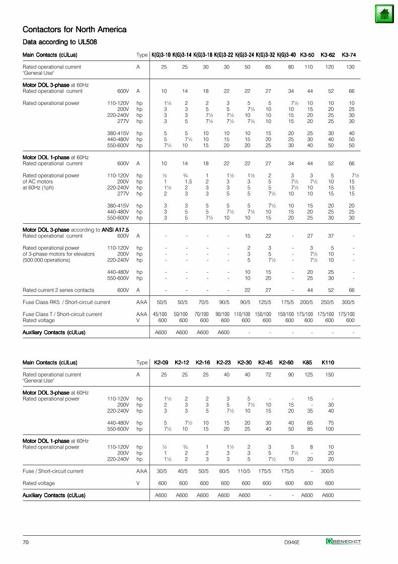
70 D946E
Contactors for North AmericaContactors for North AmericaContactors for North AmericaContactors for North AmericaContactors for North America
Data according to UL508Data according to UL508Data according to UL508Data according to UL508Data according to UL508
Main Contacts (cULus)Main Contacts (cULus)Main Contacts (cULus)Main Contacts (cULus)Main Contacts (cULus) Type K(G)3-10K(G)3-10K(G)3-10K(G)3-10K(G)3-10 K(G)3-14K(G)3-14K(G)3-14K(G)3-14K(G)3-14 K(G)3-18K(G)3-18K(G)3-18K(G)3-18K(G)3-18 K(G)3-22K(G)3-22K(G)3-22K(G)3-22K(G)3-22 K(G)3-24K(G)3-24K(G)3-24K(G)3-24K(G)3-24 K(G)3-32K(G)3-32K(G)3-32K(G)3-32K(G)3-32 K(G)3-40K(G)3-40K(G)3-40K(G)3-40K(G)3-40 K3-50K3-50K3-50K3-50K3-50 K3-62K3-62K3-62K3-62K3-62 K3-74K3-74K3-74K3-74K3-74
Rated operational current A 25 25 30 30 50 65 80 110 120 130"General Use"
Motor DOL 3-phaseMotor DOL 3-phaseMotor DOL 3-phaseMotor DOL 3-phaseMotor DOL 3-phase at 60HzRated operational current 600V A 10 14 18 22 22 27 34 44 52 66
Rated operational power 110-120V hp 1½ 2 2 3 5 5 7½ 10 10 10200V hp 3 3 5 5 7½ 10 10 15 20 25
220-240V hp 3 3 7½ 7½ 10 10 15 20 25 30277V hp 3 5 7½ 7½ 7½ 10 15 20 25 30
380-415V hp 5 5 10 10 10 15 20 25 30 40440-480V hp 5 7½ 10 15 15 20 25 30 40 50550-600V hp 7½ 10 15 20 20 25 30 40 50 50
Motor DOL 1-phaseMotor DOL 1-phaseMotor DOL 1-phaseMotor DOL 1-phaseMotor DOL 1-phase at 60HzRated operational current 600V A 10 14 18 22 22 27 34 44 52 66
Rated operational power 110-120V hp ½ ¾ 1 1½ 1½ 2 3 3 5 7½of AC motors 200V hp 1 1,5 2 3 3 5 7½ 7½ 10 15at 60Hz (1ph) 220-240V hp 1½ 2 3 3 5 5 7½ 10 15 15
277V hp 2 3 3 5 5 7½ 10 10 15 15
380-415V hp 3 3 5 5 5 7½ 10 15 20 20440-480V hp 3 5 5 7½ 7½ 10 15 20 25 25550-600V hp 3 5 7½ 10 10 15 20 25 30 30
Motor DOL 3-phaseMotor DOL 3-phaseMotor DOL 3-phaseMotor DOL 3-phaseMotor DOL 3-phase according to ANSI A17.5 ANSI A17.5 ANSI A17.5 ANSI A17.5 ANSI A17.5Rated operational current 600V A - - - - 15 22 - 27 37 -
Rated operational power 110-120V hp - - - - 2 3 - 3 5 -of 3-phase motors for elevators 200V hp - - - - 3 5 - 7½ 10 -(500.000 operations) 220-240V hp - - - - 5 7½ - 7½ 10 -
440-480V hp - - - - 10 15 - 20 25 -550-600V hp - - - - 10 20 - 25 30 -
Rated current 2 series contacts 600V A - - - - 22 27 - 44 52 66
Fuse Class RK5 / Short-circuit current A/kA 50/5 50/5 70/5 90/5 90/5 125/5 175/5 200/5 250/5 300/5
Fuse Class T / Short-circuit current A/kA 45/100 50/100 70/100 90/100 110/100 150/100 150/100 175/100 175/100 175/100Rated voltage V 600 600 600 600 600 600 600 600 600 600
Auxiliary Contacts (cULus)Auxiliary Contacts (cULus)Auxiliary Contacts (cULus)Auxiliary Contacts (cULus)Auxiliary Contacts (cULus) A600 A600 A600 A600 - - - - - -
Main Contacts (cULus)Main Contacts (cULus)Main Contacts (cULus)Main Contacts (cULus)Main Contacts (cULus) Type K2-09K2-09K2-09K2-09K2-09 K2-12K2-12K2-12K2-12K2-12 K2-16K2-16K2-16K2-16K2-16 K2-23K2-23K2-23K2-23K2-23 K2-30K2-30K2-30K2-30K2-30 K2-45K2-45K2-45K2-45K2-45 K2-60K2-60K2-60K2-60K2-60 K85K85K85K85K85 K110K110K110K110K110
Rated operational current A 25 25 25 40 40 72 90 125 150"General Use"
Motor DOL 3-phaseMotor DOL 3-phaseMotor DOL 3-phaseMotor DOL 3-phaseMotor DOL 3-phase at 60HzRated operational power 110-120V hp 1½ 2 2 3 5 - - 15 -
200V hp 2 3 3 5 7½ 10 15 - 30220-240V hp 3 3 5 7½ 10 15 20 35 40
440-480V hp 5 7½ 10 15 20 30 40 65 75550-600V hp 7½ 10 15 20 25 40 50 85 100
Motor DOL 1-phaseMotor DOL 1-phaseMotor DOL 1-phaseMotor DOL 1-phaseMotor DOL 1-phase at 60HzRated operational power 110-120V hp ½ ¾ 1 1½ 2 3 5 8 10
200V hp 1 2 2 3 3 5 7½ - 20220-240V hp 1½ 2 3 3 5 7½ 10 20 20
Fuse / Short-circuit current A/kA 30/5 40/5 50/5 60/5 110/5 175/5 175/5 - 300/5
Rated voltage V 600 600 600 600 600 600 600 600 600
Auxiliary Contacts (cULus)Auxiliary Contacts (cULus)Auxiliary Contacts (cULus)Auxiliary Contacts (cULus)Auxiliary Contacts (cULus) A600 A600 A600 A600 A600 - - A600 A600
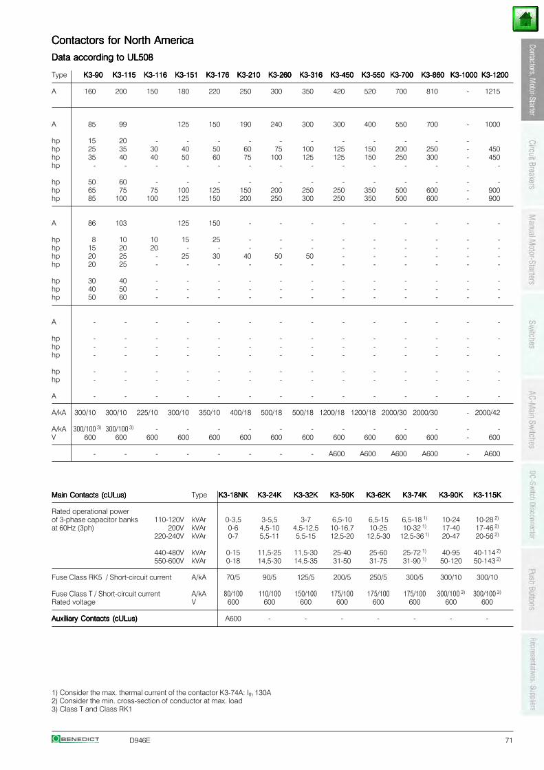
D946E 71
Contactors for North AmericaContactors for North AmericaContactors for North AmericaContactors for North AmericaContactors for North America
Data according to UL508Data according to UL508Data according to UL508Data according to UL508Data according to UL508
Type K3-90K3-90K3-90K3-90K3-90 K3-115K3-115K3-115K3-115K3-115 K3-116K3-116K3-116K3-116K3-116 K3-151K3-151K3-151K3-151K3-151 K3-176K3-176K3-176K3-176K3-176 K3-210K3-210K3-210K3-210K3-210 K3-260K3-260K3-260K3-260K3-260 K3-316K3-316K3-316K3-316K3-316 K3-450K3-450K3-450K3-450K3-450 K3-550K3-550K3-550K3-550K3-550 K3-700K3-700K3-700K3-700K3-700 K3-860K3-860K3-860K3-860K3-860 K3-1000K3-1000K3-1000K3-1000K3-1000 K3-1200K3-1200K3-1200K3-1200K3-1200
A 160 200 150 180 220 250 300 350 420 520 700 810 - 1215
A 85 99 125 150 190 240 300 300 400 550 700 - 1000
hp 15 20 - - - - - - - - - - -hp 25 35 30 40 50 60 75 100 125 150 200 250 - 450hp 35 40 40 50 60 75 100 125 125 150 250 300 - 450hp - - - - - - - - - - - - - -
hp 50 60 - - - - - - - - - - - -hp 65 75 75 100 125 150 200 250 250 350 500 600 - 900hp 85 100 100 125 150 200 250 300 250 350 500 600 - 900
A 86 103 125 150 - - - - - - - - -
hp 8 10 10 15 25 - - - - - - - - -hp 15 20 20 - - - - - - - - - - -hp 20 25 - 25 30 40 50 50 - - - - - -hp 20 25 - - - - - - - - - - - -
hp 30 40 - - - - - - - - - - - -hp 40 50 - - - - - - - - - - - -hp 50 60 - - - - - - - - - - - -
A - - - - - - - - - - - - - -
hp - - - - - - - - - - - - - -hp - - - - - - - - - - - - -hp - - - - - - - - - - - - - -
hp - - - - - - - - - - - - - -hp - - - - - - - - - - - - - -
A - - - - - - - - - - - - - -
A/kA 300/10 300/10 225/10 300/10 350/10 400/18 500/18 500/18 1200/18 1200/18 2000/30 2000/30 - 2000/42
A/kA 300/100 3) 300/100 3) - - - - - - - - - - - -V 600 600 600 600 600 600 600 600 600 600 600 600 - 600
- - - - - - - - A600 A600 A600 A600 - A600
Main Contacts (cULus)Main Contacts (cULus)Main Contacts (cULus)Main Contacts (cULus)Main Contacts (cULus) Type K3-18NKK3-18NKK3-18NKK3-18NKK3-18NK K3-24KK3-24KK3-24KK3-24KK3-24K K3-32KK3-32KK3-32KK3-32KK3-32K K3-50KK3-50KK3-50KK3-50KK3-50K K3-62KK3-62KK3-62KK3-62KK3-62K K3-74KK3-74KK3-74KK3-74KK3-74K K3-90KK3-90KK3-90KK3-90KK3-90K K3-115KK3-115KK3-115KK3-115KK3-115K
Rated operational powerof 3-phase capacitor banks 110-120V kVAr 0-3,5 3-5,5 3-7 6,5-10 6,5-15 6,5-18 1) 10-24 10-28 2)
at 60Hz (3ph) 200V kVAr 0-6 4,5-10 4,5-12,5 10-16,7 10-25 10-32 1) 17-40 17-46 2)
220-240V kVAr 0-7 5,5-11 5,5-15 12,5-20 12,5-30 12,5-36 1) 20-47 20-56 2)
440-480V kVAr 0-15 11,5-25 11,5-30 25-40 25-60 25-72 1) 40-95 40-114 2)
550-600V kVAr 0-18 14,5-30 14,5-35 31-50 31-75 31-90 1) 50-120 50-143 2)
Fuse Class RK5 / Short-circuit current A/kA 70/5 90/5 125/5 200/5 250/5 300/5 300/10 300/10
Fuse Class T / Short-circuit current A/kA 80/100 110/100 150/100 175/100 175/100 175/100 300/100 3) 300/100 3)
Rated voltage V 600 600 600 600 600 600 600 600
Auxiliary Contacts (cULus)Auxiliary Contacts (cULus)Auxiliary Contacts (cULus)Auxiliary Contacts (cULus)Auxiliary Contacts (cULus) A600 - - - - - - -
1) Consider the max. thermal current of the contactor K3-74A: Ith 130A2) Consider the min. cross-section of conductor at max. load3) Class T and Class RK1
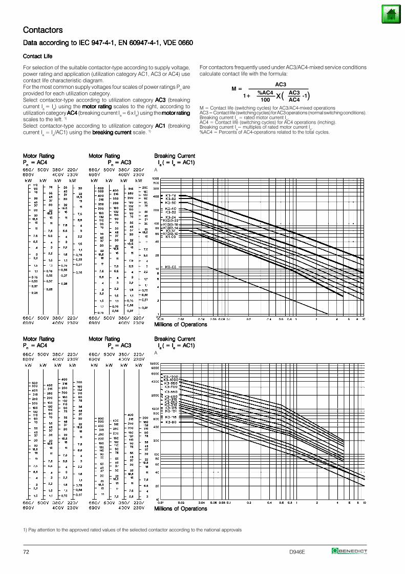
72 D946E
For contactors frequently used under AC3/AC4-mixed service conditionscalculate contact life with the formula:
M = Contact life (switching cycles) for AC3/AC4-mixed operationsAC3 = Contact life (switching cycles) for AC3 operations (normal switching conditions).Breaking current Ia = rated motor current In.AC4 = Contact life (switching cycles) for AC4 operations (inching).Breaking current Ia= multiples of rated motor current In.%AC4 = Percents of AC4-operations related to the total cycles.
Contact LifeContact LifeContact LifeContact LifeContact Life
For selection of the suitable contactor-type according to supply voltage,power rating and application (utilization category AC1, AC3 or AC4) usecontact life characteristic diagram.For the most common supply voltages four scales of power ratings Pn areprovided for each utilization category.Select contactor-type according to utilization category AC3 AC3 AC3 AC3 AC3 (breakingcurrent Ia = Ie) using the motor ratingmotor ratingmotor ratingmotor ratingmotor rating scales to the right, according toutilization category AC4 AC4 AC4 AC4 AC4 (breaking current Ia = 6 x Ie) using the motor ratingmotor ratingmotor ratingmotor ratingmotor ratingscales to the left. 1)
Select contactor-type according to utilization category AC1 AC1 AC1 AC1 AC1 (breakingcurrent Ia = Ie/AC1) using the breaking currentbreaking currentbreaking currentbreaking currentbreaking current scale. 1)
M =1+ -1x( )
Motor RatingMotor RatingMotor RatingMotor RatingMotor Rating Motor RatingMotor RatingMotor RatingMotor RatingMotor Rating Breaking CurrentBreaking CurrentBreaking CurrentBreaking CurrentBreaking CurrentPPPPPn n n n n = AC4 = AC4 = AC4 = AC4 = AC4 PPPPPnnnnn = AC3 = AC3 = AC3 = AC3 = AC3 IIIIIa a a a a ( = I( = I( = I( = I( = Ieeeee = AC1) = AC1) = AC1) = AC1) = AC1)
A
Millions of OperationsMillions of OperationsMillions of OperationsMillions of OperationsMillions of Operations
AC3
%AC4 AC3100 AC4
1) Pay attention to the approved rated values of the selected contactor according to the national approvals
ContactorsContactorsContactorsContactorsContactors
Data according to IEC 947-4-1, EN 60947-4-1, VDE 0660Data according to IEC 947-4-1, EN 60947-4-1, VDE 0660Data according to IEC 947-4-1, EN 60947-4-1, VDE 0660Data according to IEC 947-4-1, EN 60947-4-1, VDE 0660Data according to IEC 947-4-1, EN 60947-4-1, VDE 0660
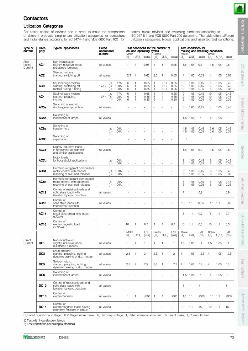
D946E 73
ContactorsContactorsContactorsContactorsContactors
Utilization CategoriesUtilization CategoriesUtilization CategoriesUtilization CategoriesUtilization Categories
Type ofType ofType ofType ofType of Cate-Cate-Cate-Cate-Cate- Typical applicationsTypical applicationsTypical applicationsTypical applicationsTypical applications RatedRatedRatedRatedRated Test conditions for the number ofTest conditions for the number ofTest conditions for the number ofTest conditions for the number ofTest conditions for the number of Test conditions forTest conditions forTest conditions forTest conditions forTest conditions forcurrentcurrentcurrentcurrentcurrent gorygorygorygorygory operationaloperationaloperationaloperationaloperational on-load operating cycleson-load operating cycleson-load operating cycleson-load operating cycleson-load operating cycles making and breaking capacitiesmaking and breaking capacitiesmaking and breaking capacitiesmaking and breaking capacitiesmaking and breaking capacities
currentcurrentcurrentcurrentcurrent Make Break Make BreakI/Ie U/Ue cosϕ Ic/Ie Ur/Ue cosϕ I/Ie U/Ue cosϕ Ic/Ie Ur/Ue cosϕ
Alter- Non-inductive ornating AC1AC1AC1AC1AC1 slightly inductive loads all values 1 1 0,95 1 1 0,95 1,5 1,05 0,8 1,5 1,05 0,8Current resistance furnaces
Slip-ring motors:AC2AC2AC2AC2AC2 starting, switching off all values 2,5 1 0,65 2,5 1 0,65 4 1,05 0,65 4 1,05 0,65
Squirrel-cage motors: Ie≤ 17A 6 1 0,65 1 0,17 0,65 10 1,05 0,45 8 1,05 0,45AC3AC3AC3AC3AC3 starting, switching off 17A< Ie≤ 100A 6 1 0,35 1 0,17 0,35 10 1,05 0,45 8 1,05 0,45
motors during running Ie> 100A 6 1 0,35 1 0,17 0,35 10 1,05 0,35 8 1,05 0,35
Squirrel-cage motors: Ie≤ 17A 6 1 0,65 6 1 0,65 12 1,05 0,45 10 1,05 0,45AC4AC4AC4AC4AC4 starting, plugging, 17A< Ie≤ 100A 6 1 0,35 6 1 0,35 12 1,05 0,45 10 1,05 0,45
inching Ie> 100A 6 1 0,35 6 1 0,35 12 1,05 0,35 10 1,05 0,35
Switching of electricAC5aAC5aAC5aAC5aAC5a discharge lamp controls all values - - - - - - 3 1,05 0,45 3 1,05 0,45
Switching ofAC5bAC5bAC5bAC5bAC5b incandescent lamps all values - - - - - - 1,5 1,05 1) 4 1,05 1)
Switching ofAC6aAC6aAC6aAC6aAC6a transformers Ie≤ 100A - - - - - - 4,5 1,05 0,45 3,6 1,05 0,45
Ie> 100A - - - - - - 4,5 1,05 0,35 3,6 1,05 0,35
Switching ofAC6bAC6bAC6bAC6bAC6b capacitors - - - - - - - 2) 2)
Slightly inductive loadsAC7aAC7aAC7aAC7aAC7a in household appliances all values - - - - - - 1,5 1,05 0,8 1,5 1,05 0,8
and similar applications
Motor loadsAC7bAC7bAC7bAC7bAC7b for household applications Ie≤ 100A - - - - - - 8 1,05 0,45 6 1,05 0,45
Ie> 100A - - - - - - 8 1,05 0,35 6 1,05 0,35
Hermetic refrigerant compressorAC8aAC8aAC8aAC8aAC8a motor control with manual Ie≤ 100A - - - - - - 6 1,05 0,45 6 1,05 0,45
resetting of overload releases Ie> 100A - - - - - - 6 1,05 0,35 6 1,05 0,35
Hermetic refrigerant compressorAC8bAC8bAC8bAC8bAC8b motor control with automatic Ie≤ 100A - - - - - - 6 1,05 0,45 6 1,05 0,45
resetting of overload releases Ie> 100A - - - - - - 6 1,05 0,35 6 1,05 0,35
Control of resistive loads andAC12AC12AC12AC12AC12 solid state loads with all values - - - - - - 1 1 0,9 1 1 0.9
isolation by opto couplers
Control ofAC13AC13AC13AC13AC13 solid state loads with all values - - - - - - 10 1,1 0,65 1,1 1,1 0,65
transformer isolation
Control ofAC14AC14AC14AC14AC14 small electromagnetic loads - - - - - - - 6 1,1 0,7 6 1,1 0,7
(≤72VA)
Control ofAC15AC15AC15AC15AC15 electromagnetic load - 10 1 0,7 1 1 0,4 10 1,1 0,3 10 1,1 0,3
(>72VA)
Make L/R Break L/R Make L/R Break L/RI/Ie U/Ue [ms] Ic/Ie Ur/Ue [ms] I/Ie U/Ue [ms] Ic/Ie Ur/Ue [ms]
Direct Non-inductive orCurrent DC1DC1DC1DC1DC1 slightly inductive loads all values 1 1 1 1 1 1 1,5 1,05 1 1,5 1,05 1
resistance furnaces
Shunt-motors:DC3DC3DC3DC3DC3 starting, plugging, inching all values 2,5 1 2 2,5 1 2 4 1,05 2,5 4 1,05 2,5
dynamic braking of d.c. motors
Series-motors:DC5DC5DC5DC5DC5 starting, plugging, inching all values 2,5 1 7,5 2,5 1 7,5 4 1,05 15 4 1,05 15
dynamic braking of d.c. motors
Switching ofDC6DC6DC6DC6DC6 incandescent lamps all values - - - - - - 1,5 1,05 1) 4 1,05 1)
Control of resistive loads andDC12DC12DC12DC12DC12 solid state loads with all values - - - - - - 1 1 1 1 1 1
isolation by opto couplers
Control ofDC13DC13DC13DC13DC13 electromagnets all values 1 1 ≤300 1 1 ≤300 1,1 1,1 ≤300 1,1 1,1 ≤300
Control ofDC14DC14DC14DC14DC14 electromagnetic loads having all values - - - - - - 10 1,1 15 10 1,1 15
economy resistors in circuit
Ue Rated operational voltage, U Voltage before make, Ur Recovery voltage, Ie Rated operational current, I Current make, Ic Current broken
1) Test with incandescent lamps2) Test conditions according to standard
For easier choice of devices and in order to make the comparisonof different products simplier are utilization categories for contactorsand motor-starters according to IEC 947-4-1 and VDE 0660 Part 102, for
control circuit devices and switching elements according toIEC 947-5-1 and VDE 0660 Part 200 determind. The table offers differentutilization categories, typical applications and assorted test conditions.
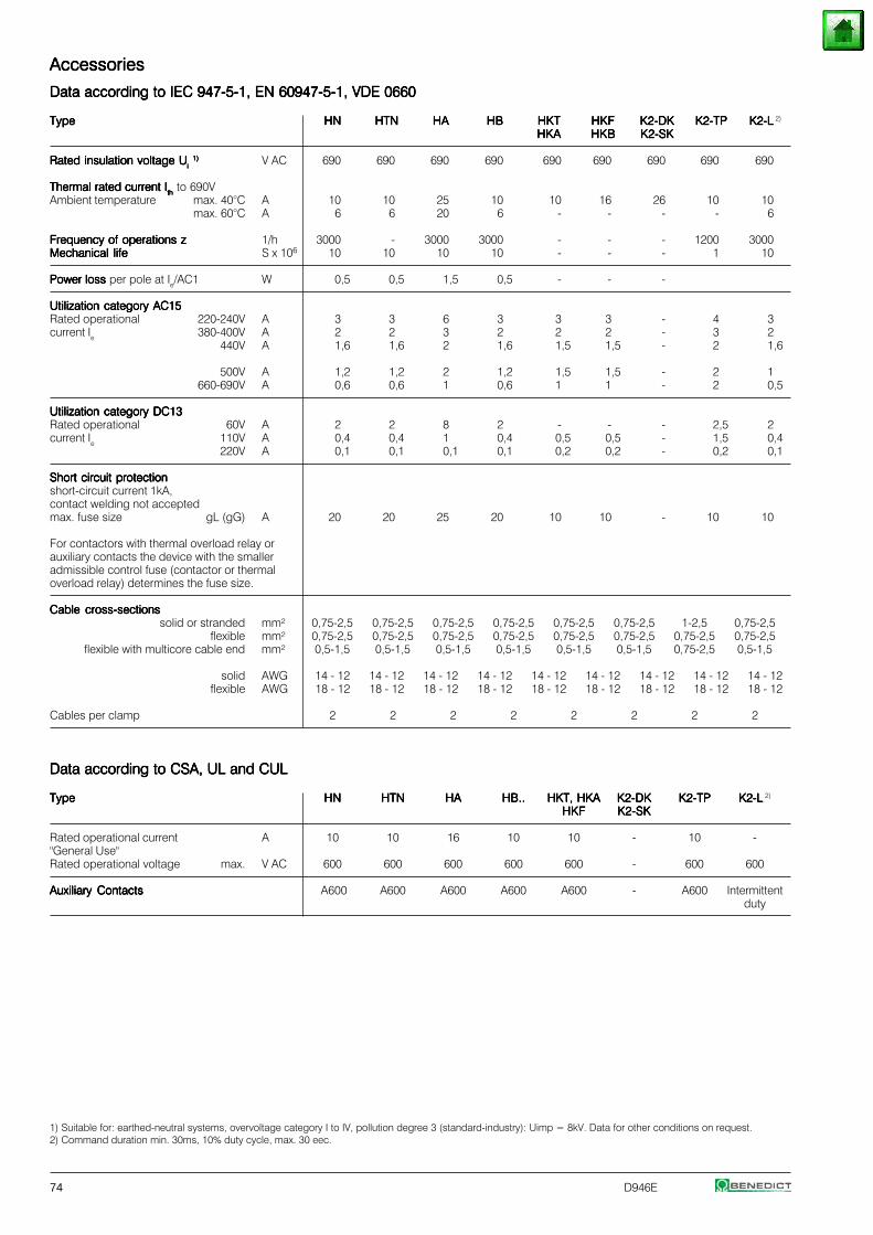
74 D946E
AccessoriesAccessoriesAccessoriesAccessoriesAccessories
Data according to IEC 947-5-1, EN 60947-5-1, VDE 0660Data according to IEC 947-5-1, EN 60947-5-1, VDE 0660Data according to IEC 947-5-1, EN 60947-5-1, VDE 0660Data according to IEC 947-5-1, EN 60947-5-1, VDE 0660Data according to IEC 947-5-1, EN 60947-5-1, VDE 0660
TypeTypeTypeTypeType HNHNHNHNHN HTNHTNHTNHTNHTN HAHAHAHAHA HBHBHBHBHB HKTHKTHKTHKTHKT HKFHKFHKFHKFHKF K2-DKK2-DKK2-DKK2-DKK2-DK K2-TPK2-TPK2-TPK2-TPK2-TP K2-LK2-LK2-LK2-LK2-L 2)
HKAHKAHKAHKAHKA HKBHKBHKBHKBHKB K2-SKK2-SKK2-SKK2-SKK2-SK
Rated insulation voltage URated insulation voltage URated insulation voltage URated insulation voltage URated insulation voltage Uiiiii
1)1)1)1)1) V AC 690 690 690 690 690 690 690 690 690
Thermal rated current IThermal rated current IThermal rated current IThermal rated current IThermal rated current Iththththth to 690V
Ambient temperature max. 40°C A 10 10 25 10 10 16 26 10 10max. 60°C A 6 6 20 6 - - - - 6
Frequency of operations zFrequency of operations zFrequency of operations zFrequency of operations zFrequency of operations z 1/h 3000 - 3000 3000 - - - 1200 3000Mechanical lifeMechanical lifeMechanical lifeMechanical lifeMechanical life S x 106 10 10 10 10 - - - 1 10
Power loss Power loss Power loss Power loss Power loss per pole at Ie/AC1 W 0,5 0,5 1,5 0,5 - - -
Utilization category AC15Utilization category AC15Utilization category AC15Utilization category AC15Utilization category AC15Rated operational 220-240V A 3 3 6 3 3 3 - 4 3current Ie 380-400V A 2 2 3 2 2 2 - 3 2
440V A 1,6 1,6 2 1,6 1,5 1,5 - 2 1,6
500V A 1,2 1,2 2 1,2 1,5 1,5 - 2 1660-690V A 0,6 0,6 1 0,6 1 1 - 2 0,5
Utilization category DC13Utilization category DC13Utilization category DC13Utilization category DC13Utilization category DC13Rated operational 60V A 2 2 8 2 - - - 2,5 2current Ie 110V A 0,4 0,4 1 0,4 0,5 0,5 - 1,5 0,4
220V A 0,1 0,1 0,1 0,1 0,2 0,2 - 0,2 0,1
Short circuit protectionShort circuit protectionShort circuit protectionShort circuit protectionShort circuit protectionshort-circuit current 1kA,contact welding not acceptedmax. fuse size gL (gG) A 20 20 25 20 10 10 - 10 10
For contactors with thermal overload relay orauxiliary contacts the device with the smalleradmissible control fuse (contactor or thermaloverload relay) determines the fuse size.
Cable cross-sectionsCable cross-sectionsCable cross-sectionsCable cross-sectionsCable cross-sectionssolid or stranded mm² 0,75-2,5 0,75-2,5 0,75-2,5 0,75-2,5 0,75-2,5 0,75-2,5 1-2,5 0,75-2,5
flexible mm² 0,75-2,5 0,75-2,5 0,75-2,5 0,75-2,5 0,75-2,5 0,75-2,5 0,75-2,5 0,75-2,5flexible with multicore cable end mm² 0,5-1,5 0,5-1,5 0,5-1,5 0,5-1,5 0,5-1,5 0,5-1,5 0,75-2,5 0,5-1,5
solid AWG 14 - 12 14 - 12 14 - 12 14 - 12 14 - 12 14 - 12 14 - 12 14 - 12 14 - 12flexible AWG 18 - 12 18 - 12 18 - 12 18 - 12 18 - 12 18 - 12 18 - 12 18 - 12 18 - 12
Cables per clamp 2 2 2 2 2 2 2 2
Data according to CSA, UL and CULData according to CSA, UL and CULData according to CSA, UL and CULData according to CSA, UL and CULData according to CSA, UL and CUL
TypeTypeTypeTypeType HNHNHNHNHN HTNHTNHTNHTNHTN HAHAHAHAHA HB..HB..HB..HB..HB.. HKT, HKAHKT, HKAHKT, HKAHKT, HKAHKT, HKA K2-DKK2-DKK2-DKK2-DKK2-DK K2-TPK2-TPK2-TPK2-TPK2-TP K2-LK2-LK2-LK2-LK2-L 2)
HKFHKFHKFHKFHKF K2-SKK2-SKK2-SKK2-SKK2-SK
Rated operational current A 10 10 16 10 10 - 10 -"General Use"Rated operational voltage max. V AC 600 600 600 600 600 - 600 600
Auxiliary ContactsAuxiliary ContactsAuxiliary ContactsAuxiliary ContactsAuxiliary Contacts A600 A600 A600 A600 A600 - A600 Intermittentduty
1) Suitable for: earthed-neutral systems, overvoltage category I to IV, pollution degree 3 (standard-industry): Uimp = 8kV. Data for other conditions on request.2) Command duration min. 30ms, 10% duty cycle, max. 30 eec.
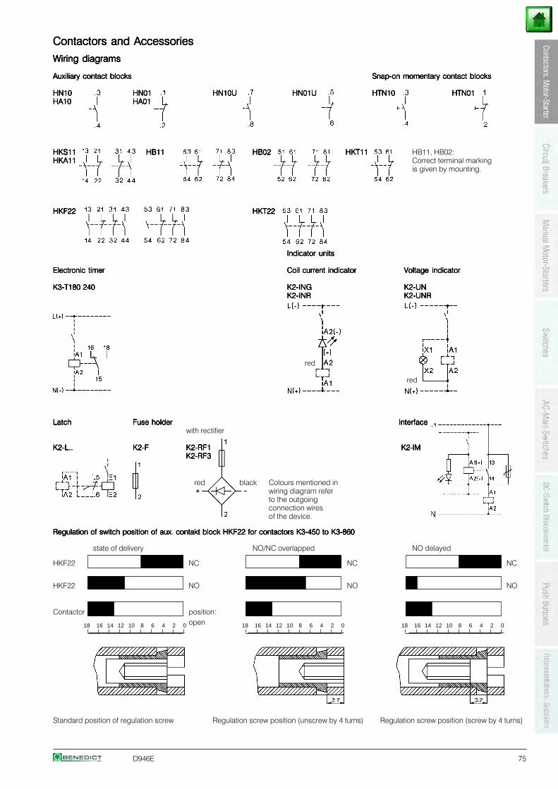
D946E 75
Contactors and AccessoriesContactors and AccessoriesContactors and AccessoriesContactors and AccessoriesContactors and Accessories
Wiring diagramsWiring diagramsWiring diagramsWiring diagramsWiring diagrams
Auxiliary contact blocksAuxiliary contact blocksAuxiliary contact blocksAuxiliary contact blocksAuxiliary contact blocks Snap-on momentary contact blocksSnap-on momentary contact blocksSnap-on momentary contact blocksSnap-on momentary contact blocksSnap-on momentary contact blocks
HN10HN10HN10HN10HN10 HN01HN01HN01HN01HN01 HN10UHN10UHN10UHN10UHN10U HN01UHN01UHN01UHN01UHN01U HTN10HTN10HTN10HTN10HTN10 HTN01HTN01HTN01HTN01HTN01HA10HA10HA10HA10HA10 HA01HA01HA01HA01HA01
HKS11HKS11HKS11HKS11HKS11 HB11HB11HB11HB11HB11 HB02HB02HB02HB02HB02 HKT11HKT11HKT11HKT11HKT11 HB11, HB02:HKA11HKA11HKA11HKA11HKA11 Correct terminal marking
is given by mounting.
HKF22HKF22HKF22HKF22HKF22 HKT22HKT22HKT22HKT22HKT22
Indicator unitsIndicator unitsIndicator unitsIndicator unitsIndicator units
Electronic timerElectronic timerElectronic timerElectronic timerElectronic timer Coil current indicatorCoil current indicatorCoil current indicatorCoil current indicatorCoil current indicator Voltage indicatorVoltage indicatorVoltage indicatorVoltage indicatorVoltage indicator
K3-T180 240K3-T180 240K3-T180 240K3-T180 240K3-T180 240 K2-INGK2-INGK2-INGK2-INGK2-ING K2-UNK2-UNK2-UNK2-UNK2-UNK2-INRK2-INRK2-INRK2-INRK2-INR K2-UNRK2-UNRK2-UNRK2-UNRK2-UNR
red
red
LatchLatchLatchLatchLatch Fuse holderFuse holderFuse holderFuse holderFuse holder InterfaceInterfaceInterfaceInterfaceInterfacewith rectifier
K2-L..K2-L..K2-L..K2-L..K2-L.. K2-FK2-FK2-FK2-FK2-F K2-RF1K2-RF1K2-RF1K2-RF1K2-RF1 K2-IM K2-IM K2-IM K2-IM K2-IMK2-RF3K2-RF3K2-RF3K2-RF3K2-RF3
Regulation of switch position of aux. contakt block HKF22 for contactors K3-450 to K3-860Regulation of switch position of aux. contakt block HKF22 for contactors K3-450 to K3-860Regulation of switch position of aux. contakt block HKF22 for contactors K3-450 to K3-860Regulation of switch position of aux. contakt block HKF22 for contactors K3-450 to K3-860Regulation of switch position of aux. contakt block HKF22 for contactors K3-450 to K3-860
state of delivery NO/NC overlapped NO delayed
HKF22 NC NC NC
HKF22 NO NO NO
Contactor position:open
Standard position of regulation screw Regulation screw position (unscrew by 4 turns) Regulation screw position (screw by 4 turns)
red black Colours mentioned inwiring diagram referto the outgoingconnection wiresof the device.
18 16 14 12 10 8 6 4 2 0 18 16 14 12 10 8 6 4 2 0 18 16 14 12 10 8 6 4 2 0
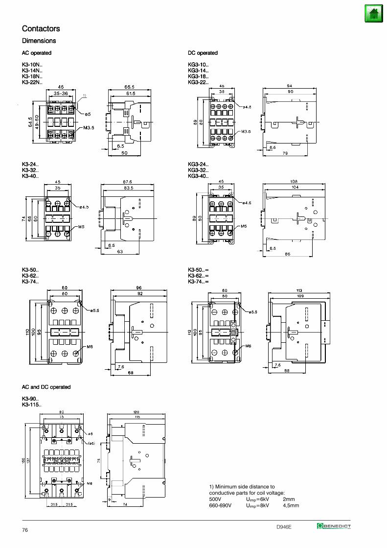
76D946E
ContactorsContactorsContactorsContactorsContactors
DimensionsDimensionsDimensionsDimensionsDimensions
AC operatedAC operatedAC operatedAC operatedAC operated DC operatedDC operatedDC operatedDC operatedDC operated
K3-10N..K3-10N..K3-10N..K3-10N..K3-10N.. KG3-10..KG3-10..KG3-10..KG3-10..KG3-10..K3-14N..K3-14N..K3-14N..K3-14N..K3-14N.. KG3-14..KG3-14..KG3-14..KG3-14..KG3-14..K3-18N..K3-18N..K3-18N..K3-18N..K3-18N.. KG3-18..KG3-18..KG3-18..KG3-18..KG3-18..K3-22N..K3-22N..K3-22N..K3-22N..K3-22N.. KG3-22..KG3-22..KG3-22..KG3-22..KG3-22..
K3-24..K3-24..K3-24..K3-24..K3-24.. KG3-24..KG3-24..KG3-24..KG3-24..KG3-24..K3-32..K3-32..K3-32..K3-32..K3-32.. KG3-32..KG3-32..KG3-32..KG3-32..KG3-32..K3-40..K3-40..K3-40..K3-40..K3-40.. KG3-40..KG3-40..KG3-40..KG3-40..KG3-40..
K3-50..K3-50..K3-50..K3-50..K3-50.. K3-50..=K3-50..=K3-50..=K3-50..=K3-50..=K3-62..K3-62..K3-62..K3-62..K3-62.. K3-62..=K3-62..=K3-62..=K3-62..=K3-62..=K3-74..K3-74..K3-74..K3-74..K3-74.. K3-74..=K3-74..=K3-74..=K3-74..=K3-74..=
AC and DC operatedAC and DC operatedAC and DC operatedAC and DC operatedAC and DC operated
K3-90..K3-90..K3-90..K3-90..K3-90..K3-115..K3-115..K3-115..K3-115..K3-115..
1)
1) Minimum side distance toconductive parts for coil voltage:500V Uimp=6kV 2mm660-690V Uimp=8kV 4,5mm
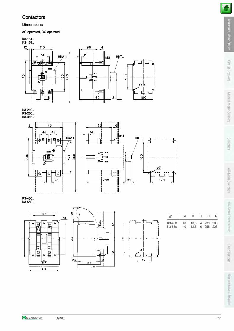
D946E 77
ContactorsContactorsContactorsContactorsContactors
DimensionsDimensionsDimensionsDimensionsDimensions
AC operated, DC operatedAC operated, DC operatedAC operated, DC operatedAC operated, DC operatedAC operated, DC operated
K3-151..K3-151..K3-151..K3-151..K3-151..K3-176..K3-176..K3-176..K3-176..K3-176..
HKA11HKA11HKA11HKA11HKA11 HKT..HKT..HKT..HKT..HKT..
K3-210..K3-210..K3-210..K3-210..K3-210..K3-260..K3-260..K3-260..K3-260..K3-260..K3-316..K3-316..K3-316..K3-316..K3-316..
HKA11HKA11HKA11HKA11HKA11 HKT..HKT..HKT..HKT..HKT..
K3-450..K3-450..K3-450..K3-450..K3-450..K3-550..K3-550..K3-550..K3-550..K3-550..
Typ A B C H N
K3-450 40 10,5 4 233 206K3-550 40 12,5 6 258 228
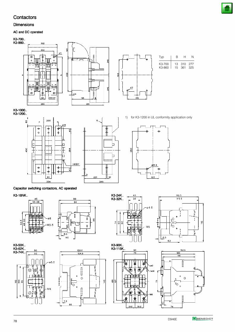
78D946E
ContactorsContactorsContactorsContactorsContactors
DimensionsDimensionsDimensionsDimensionsDimensions
AC and DC operatedAC and DC operatedAC and DC operatedAC and DC operatedAC and DC operated
K3-700..K3-700..K3-700..K3-700..K3-700..K3-860..K3-860..K3-860..K3-860..K3-860..
Typ B H N
K3-700 13 310 277K3-860 15 361 325
K3-1000..K3-1000..K3-1000..K3-1000..K3-1000..K3-1200..K3-1200..K3-1200..K3-1200..K3-1200..
1) for K3-1200 in UL conformity application only
Capacitor switching contactors, AC operatedCapacitor switching contactors, AC operatedCapacitor switching contactors, AC operatedCapacitor switching contactors, AC operatedCapacitor switching contactors, AC operated
K3-18NK..K3-18NK..K3-18NK..K3-18NK..K3-18NK.. K3-24K..K3-24K..K3-24K..K3-24K..K3-24K..K3-32K..K3-32K..K3-32K..K3-32K..K3-32K..
K3-50K..K3-50K..K3-50K..K3-50K..K3-50K.. K3-90K..K3-90K..K3-90K..K3-90K..K3-90K..K3-62K..K3-62K..K3-62K..K3-62K..K3-62K.. K3-115K..K3-115K..K3-115K..K3-115K..K3-115K..K3-74K..K3-74K..K3-74K..K3-74K..K3-74K..
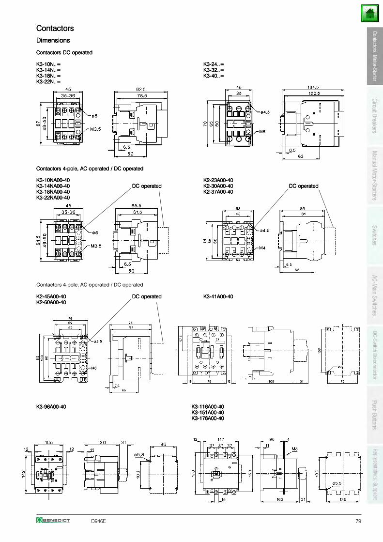
D946E 79
ContactorsContactorsContactorsContactorsContactors
DimensionsDimensionsDimensionsDimensionsDimensions
Contactors DC operatedContactors DC operatedContactors DC operatedContactors DC operatedContactors DC operated
K3-10N..=K3-10N..=K3-10N..=K3-10N..=K3-10N..= K3-24..=K3-24..=K3-24..=K3-24..=K3-24..=K3-14N..=K3-14N..=K3-14N..=K3-14N..=K3-14N..= K3-32..=K3-32..=K3-32..=K3-32..=K3-32..=K3-18N..=K3-18N..=K3-18N..=K3-18N..=K3-18N..= K3-40..=K3-40..=K3-40..=K3-40..=K3-40..=K3-22N..=K3-22N..=K3-22N..=K3-22N..=K3-22N..=
Contactors 4-pole, AC operated / DC operatedContactors 4-pole, AC operated / DC operatedContactors 4-pole, AC operated / DC operatedContactors 4-pole, AC operated / DC operatedContactors 4-pole, AC operated / DC operated
K3-10NA00-40K3-10NA00-40K3-10NA00-40K3-10NA00-40K3-10NA00-40 K2-23A00-40K2-23A00-40K2-23A00-40K2-23A00-40K2-23A00-40K3-14NA00-40K3-14NA00-40K3-14NA00-40K3-14NA00-40K3-14NA00-40 DC operatedDC operatedDC operatedDC operatedDC operated K2-30A00-40K2-30A00-40K2-30A00-40K2-30A00-40K2-30A00-40 DC operatedDC operatedDC operatedDC operatedDC operatedK3-18NA00-40K3-18NA00-40K3-18NA00-40K3-18NA00-40K3-18NA00-40 K2-37A00-40K2-37A00-40K2-37A00-40K2-37A00-40K2-37A00-40K3-22NA00-40K3-22NA00-40K3-22NA00-40K3-22NA00-40K3-22NA00-40
Contactors 4-pole, AC operated / DC operated
K2-45A00-40K2-45A00-40K2-45A00-40K2-45A00-40K2-45A00-40 DC operatedDC operatedDC operatedDC operatedDC operated K3-41A00-40K3-41A00-40K3-41A00-40K3-41A00-40K3-41A00-40K2-60A00-40K2-60A00-40K2-60A00-40K2-60A00-40K2-60A00-40
K3-96A00-40K3-96A00-40K3-96A00-40K3-96A00-40K3-96A00-40 K3-116A00-40K3-116A00-40K3-116A00-40K3-116A00-40K3-116A00-40K3-151A00-40K3-151A00-40K3-151A00-40K3-151A00-40K3-151A00-40K3-176A00-40K3-176A00-40K3-176A00-40K3-176A00-40K3-176A00-40
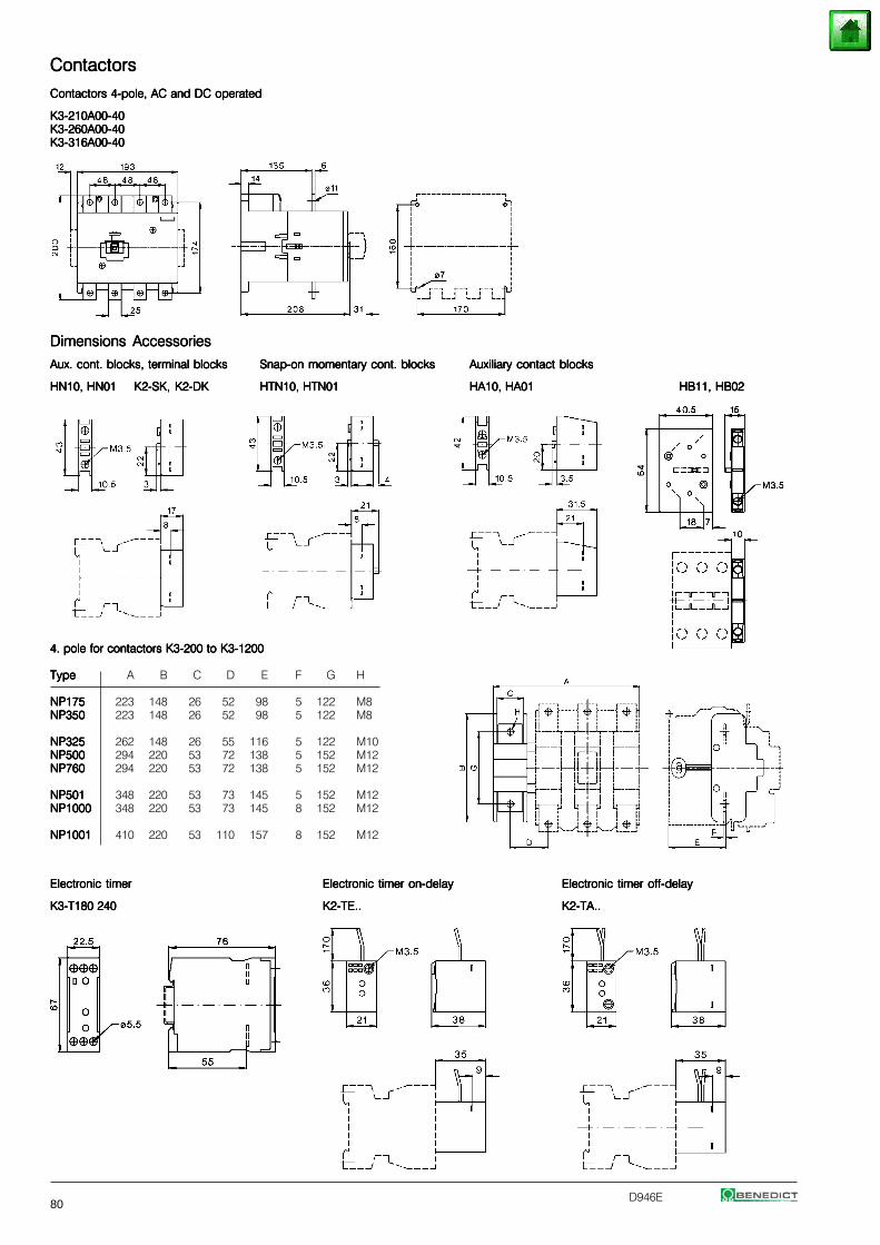
80D946E
ContactorsContactorsContactorsContactorsContactors
Contactors 4-pole, AC and DC operatedContactors 4-pole, AC and DC operatedContactors 4-pole, AC and DC operatedContactors 4-pole, AC and DC operatedContactors 4-pole, AC and DC operated
K3-210A00-40K3-210A00-40K3-210A00-40K3-210A00-40K3-210A00-40K3-260A00-40K3-260A00-40K3-260A00-40K3-260A00-40K3-260A00-40K3-316A00-40K3-316A00-40K3-316A00-40K3-316A00-40K3-316A00-40
Dimensions AccessoriesDimensions AccessoriesDimensions AccessoriesDimensions AccessoriesDimensions Accessories
Aux. cont. blocks, terminal blocksAux. cont. blocks, terminal blocksAux. cont. blocks, terminal blocksAux. cont. blocks, terminal blocksAux. cont. blocks, terminal blocks Snap-on momentary cont. blocksSnap-on momentary cont. blocksSnap-on momentary cont. blocksSnap-on momentary cont. blocksSnap-on momentary cont. blocks Auxiliary contact blocksAuxiliary contact blocksAuxiliary contact blocksAuxiliary contact blocksAuxiliary contact blocks
HN10, HN01HN10, HN01HN10, HN01HN10, HN01HN10, HN01 K2-SK, K2-DKK2-SK, K2-DKK2-SK, K2-DKK2-SK, K2-DKK2-SK, K2-DK HTN10, HTN01HTN10, HTN01HTN10, HTN01HTN10, HTN01HTN10, HTN01 HA10, HA01HA10, HA01HA10, HA01HA10, HA01HA10, HA01 HB11, HB02HB11, HB02HB11, HB02HB11, HB02HB11, HB02
4. pole for contactors K3-200 to K3-12004. pole for contactors K3-200 to K3-12004. pole for contactors K3-200 to K3-12004. pole for contactors K3-200 to K3-12004. pole for contactors K3-200 to K3-1200
TypeTypeTypeTypeType A B C D E F G H
NP175NP175NP175NP175NP175 223 148 26 52 98 5 122 M8NP350NP350NP350NP350NP350 223 148 26 52 98 5 122 M8
NP325NP325NP325NP325NP325 262 148 26 55 116 5 122 M10NP500NP500NP500NP500NP500 294 220 53 72 138 5 152 M12NP760NP760NP760NP760NP760 294 220 53 72 138 5 152 M12
NP501NP501NP501NP501NP501 348 220 53 73 145 5 152 M12NP1000NP1000NP1000NP1000NP1000 348 220 53 73 145 8 152 M12
NP1001NP1001NP1001NP1001NP1001 410 220 53 110 157 8 152 M12
Electronic timerElectronic timerElectronic timerElectronic timerElectronic timer Electronic timer on-delayElectronic timer on-delayElectronic timer on-delayElectronic timer on-delayElectronic timer on-delay Electronic timer off-delayElectronic timer off-delayElectronic timer off-delayElectronic timer off-delayElectronic timer off-delay
K3-T180 240K3-T180 240K3-T180 240K3-T180 240K3-T180 240 K2-TE..K2-TE..K2-TE..K2-TE..K2-TE.. K2-TA..K2-TA..K2-TA..K2-TA..K2-TA..
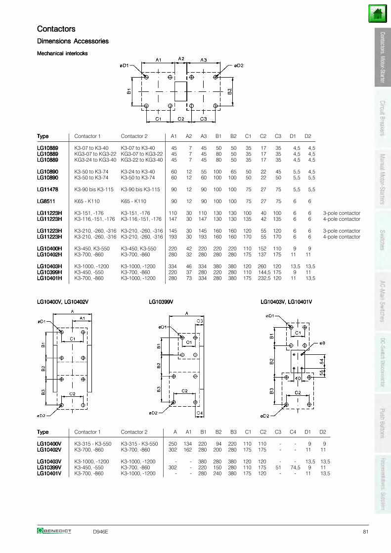
D946E 81
ContactorsContactorsContactorsContactorsContactors
Dimensions AccessoriesDimensions AccessoriesDimensions AccessoriesDimensions AccessoriesDimensions Accessories
Mechanical interlocksMechanical interlocksMechanical interlocksMechanical interlocksMechanical interlocks
TypeTypeTypeTypeType Contactor 1 Contactor 2 A1 A2 A3 B1 B2 C1 C2 C3 D1 D2
LG10889LG10889LG10889LG10889LG10889 K3-07 to K3-40 K3-07 to K3-40 45 7 45 50 50 35 17 35 4,5 4,5LG10889LG10889LG10889LG10889LG10889 KG3-07 to KG3-22 KG3-07 to KG3-22 45 7 45 80 50 35 17 35 4,5 4,5LG10889LG10889LG10889LG10889LG10889 KG3-24 to KG3-40 KG3-22 to KG3-40 45 7 45 80 50 35 17 35 4,5 4,5
LG10890LG10890LG10890LG10890LG10890 K3-50 to K3-74 K3-24 to K3-40 60 12 55 100 65 50 22 45 5,5 4,5LG10890LG10890LG10890LG10890LG10890 K3-50 to K3-74 K3-50 to K3-74 60 12 60 100 100 50 22 50 5,5 5,5
LG11478LG11478LG11478LG11478LG11478 K3-90 bis K3-115 K3-90 bis K3-115 90 12 90 100 100 75 27 75 5,5 5,5
LG8511LG8511LG8511LG8511LG8511 K65 - K110 K65 - K110 90 12 90 100 100 75 27 75 6 6
LG11223HLG11223HLG11223HLG11223HLG11223H K3-151, -176 K3-151, -176 110 30 110 130 130 100 40 100 6 6 3-pole contactorLG11223HLG11223HLG11223HLG11223HLG11223H K3-116,-151, -176 K3-116,-151, -176 147 30 147 130 130 135 42 135 6 6 4-pole contactor
LG11223HLG11223HLG11223HLG11223HLG11223H K3-210, -260, -316 K3-210, -260, -316 145 30 145 160 160 120 55 120 6 6 3-pole contactorLG11223HLG11223HLG11223HLG11223HLG11223H K3-210, -260, -316 K3-210, -260, -316 193 30 193 160 160 170 55 170 6 6 4-pole contactor
LG10400HLG10400HLG10400HLG10400HLG10400H K3-450, K3-550 K3-450, K3-550 220 42 220 220 220 110 152 110 9 9LG10402HLG10402HLG10402HLG10402HLG10402H K3-700, -860 K3-700, -860 280 32 280 280 280 175 137 175 11 11
LG10403HLG10403HLG10403HLG10403HLG10403H K3-1000, -1200 K3-1000, -1200 334 46 334 380 380 120 260 120 13,5 13,5LG10399HLG10399HLG10399HLG10399HLG10399H K3-450, -550 K3-700, -860 220 37 280 220 280 110 144,5 175 9 11LG10401HLG10401HLG10401HLG10401HLG10401H K3-700, -860 K3-1000, -1200 280 73 334 280 380 175 232,5 120 11 13,5
LG10400V, LG10402VLG10400V, LG10402VLG10400V, LG10402VLG10400V, LG10402VLG10400V, LG10402V LG10399VLG10399VLG10399VLG10399VLG10399V LG10403V, LG10401VLG10403V, LG10401VLG10403V, LG10401VLG10403V, LG10401VLG10403V, LG10401V
TypeTypeTypeTypeType Contactor 1 Contactor 2 A A1 B1 B2 B3 C1 C2 C3 C4 D1 D2
LG10400VLG10400VLG10400VLG10400VLG10400V K3-315 - K3-550 K3-315 - K3-550 250 134 220 94 220 110 110 - - 9 9LG10402VLG10402VLG10402VLG10402VLG10402V K3-700, -860 K3-700, -860 302 162 280 200 280 175 175 - - 11 11
LG10403VLG10403VLG10403VLG10403VLG10403V K3-1000, -1200 K3-1000, -1200 - - 380 280 380 120 120 - - 13,5 13,5LG10399VLG10399VLG10399VLG10399VLG10399V K3-450, -550 K3-700, -860 302 - 220 150 280 110 175 51 74,5 9 11LG10401VLG10401VLG10401VLG10401VLG10401V K3-700, -860 K3-1000, -1200 - - 280 240 380 175 120 - - 11 13,5
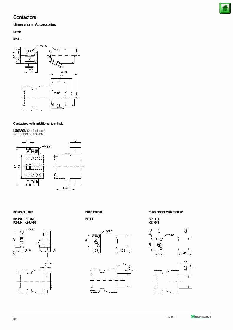
82D946E
ContactorsContactorsContactorsContactorsContactors
Dimensions AccessoriesDimensions AccessoriesDimensions AccessoriesDimensions AccessoriesDimensions Accessories
LatchLatchLatchLatchLatch
K2-L..K2-L..K2-L..K2-L..K2-L..
Contactors with additional terminalsContactors with additional terminalsContactors with additional terminalsContactors with additional terminalsContactors with additional terminals
LG9339NLG9339NLG9339NLG9339NLG9339N (2 x 3 pieces)for K3-10N. to K3-22N.
Indicator unitsIndicator unitsIndicator unitsIndicator unitsIndicator units Fuse holderFuse holderFuse holderFuse holderFuse holder Fuse holder with rectifierFuse holder with rectifierFuse holder with rectifierFuse holder with rectifierFuse holder with rectifier
K2-ING, K2-INRK2-ING, K2-INRK2-ING, K2-INRK2-ING, K2-INRK2-ING, K2-INR K2-RFK2-RFK2-RFK2-RFK2-RF K2-RF1K2-RF1K2-RF1K2-RF1K2-RF1K2-UN, K2-UNRK2-UN, K2-UNRK2-UN, K2-UNRK2-UN, K2-UNRK2-UN, K2-UNR K2-RF3K2-RF3K2-RF3K2-RF3K2-RF3
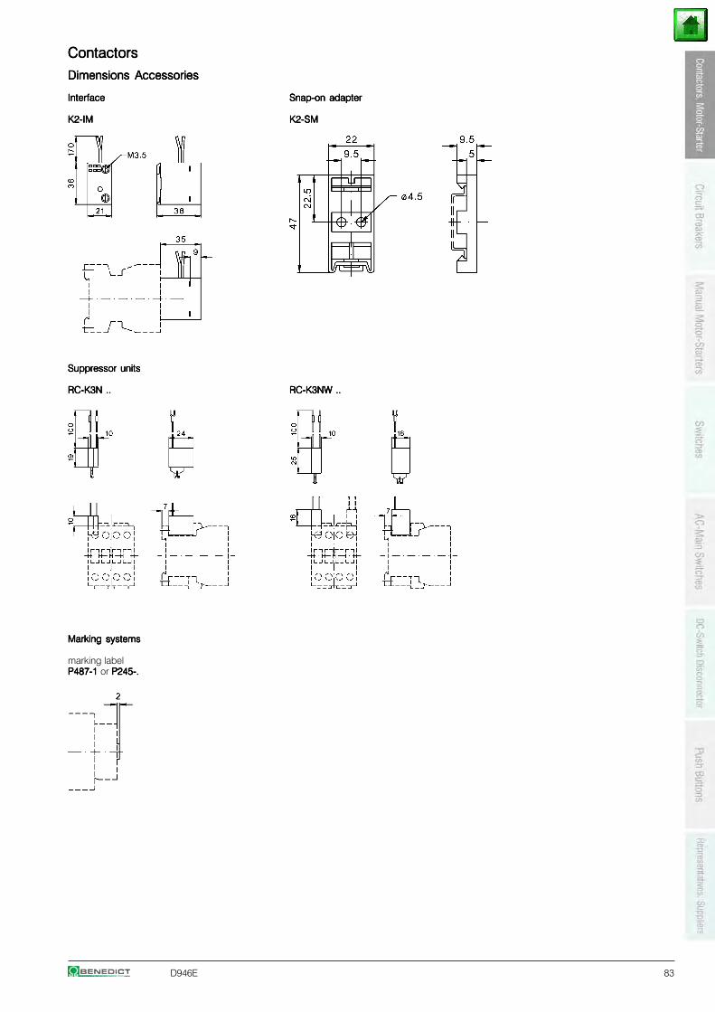
D946E 83
ContactorsContactorsContactorsContactorsContactors
Dimensions AccessoriesDimensions AccessoriesDimensions AccessoriesDimensions AccessoriesDimensions Accessories
InterfaceInterfaceInterfaceInterfaceInterface Snap-on adapterSnap-on adapterSnap-on adapterSnap-on adapterSnap-on adapter
K2-IMK2-IMK2-IMK2-IMK2-IM K2-SMK2-SMK2-SMK2-SMK2-SM
Suppressor unitsSuppressor unitsSuppressor unitsSuppressor unitsSuppressor units
RC-K3N ..RC-K3N ..RC-K3N ..RC-K3N ..RC-K3N .. RC-K3NW ..RC-K3NW ..RC-K3NW ..RC-K3NW ..RC-K3NW ..
Marking systemsMarking systemsMarking systemsMarking systemsMarking systems
marking labelP487-1 P487-1 P487-1 P487-1 P487-1 or P245-.P245-.P245-.P245-.P245-.
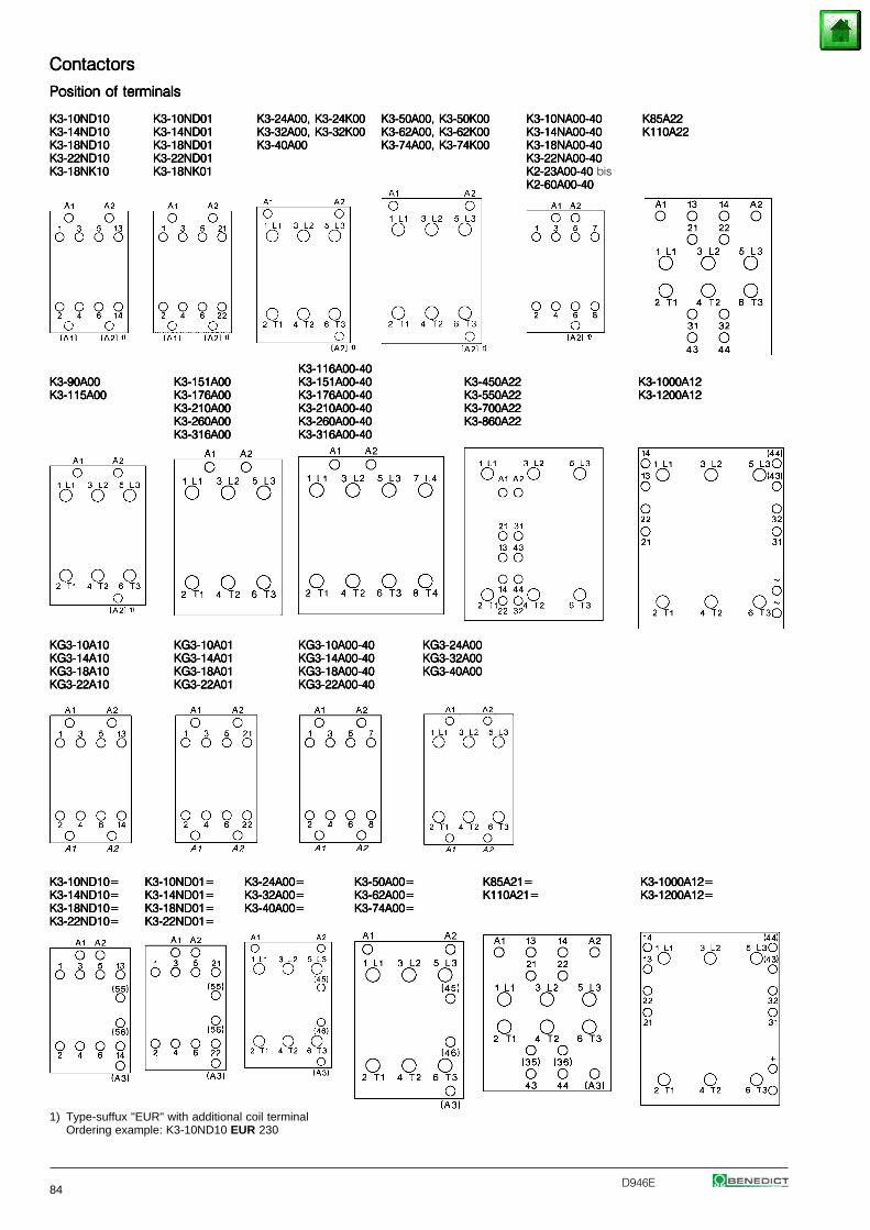
84D946E
ContactorsContactorsContactorsContactorsContactors
Position of terminalsPosition of terminalsPosition of terminalsPosition of terminalsPosition of terminals
K3-10ND10K3-10ND10K3-10ND10K3-10ND10K3-10ND10 K3-10ND01K3-10ND01K3-10ND01K3-10ND01K3-10ND01 K3-24A00, K3-24K00K3-24A00, K3-24K00K3-24A00, K3-24K00K3-24A00, K3-24K00K3-24A00, K3-24K00 K3-50A00, K3-50K00K3-50A00, K3-50K00K3-50A00, K3-50K00K3-50A00, K3-50K00K3-50A00, K3-50K00 K3-10NA00-40K3-10NA00-40K3-10NA00-40K3-10NA00-40K3-10NA00-40 K85A22K85A22K85A22K85A22K85A22K3-14ND10K3-14ND10K3-14ND10K3-14ND10K3-14ND10 K3-14ND01K3-14ND01K3-14ND01K3-14ND01K3-14ND01 K3-32A00, K3-32K00K3-32A00, K3-32K00K3-32A00, K3-32K00K3-32A00, K3-32K00K3-32A00, K3-32K00 K3-62A00, K3-62K00K3-62A00, K3-62K00K3-62A00, K3-62K00K3-62A00, K3-62K00K3-62A00, K3-62K00 K3-14NA00-40K3-14NA00-40K3-14NA00-40K3-14NA00-40K3-14NA00-40 K110A22K110A22K110A22K110A22K110A22K3-18ND10K3-18ND10K3-18ND10K3-18ND10K3-18ND10 K3-18ND01K3-18ND01K3-18ND01K3-18ND01K3-18ND01 K3-40A00K3-40A00K3-40A00K3-40A00K3-40A00 K3-74A00, K3-74K00K3-74A00, K3-74K00K3-74A00, K3-74K00K3-74A00, K3-74K00K3-74A00, K3-74K00 K3-18NA00-40K3-18NA00-40K3-18NA00-40K3-18NA00-40K3-18NA00-40K3-22ND10K3-22ND10K3-22ND10K3-22ND10K3-22ND10 K3-22ND01K3-22ND01K3-22ND01K3-22ND01K3-22ND01 K3-22NA00-40K3-22NA00-40K3-22NA00-40K3-22NA00-40K3-22NA00-40K3-18NK10K3-18NK10K3-18NK10K3-18NK10K3-18NK10 K3-18NK01K3-18NK01K3-18NK01K3-18NK01K3-18NK01 K2-23A00-40 K2-23A00-40 K2-23A00-40 K2-23A00-40 K2-23A00-40 bis
K2-60A00-40K2-60A00-40K2-60A00-40K2-60A00-40K2-60A00-40
K3-116A00-40K3-116A00-40K3-116A00-40K3-116A00-40K3-116A00-40K3-90A00K3-90A00K3-90A00K3-90A00K3-90A00 K3-151A00K3-151A00K3-151A00K3-151A00K3-151A00 K3-151A00-40K3-151A00-40K3-151A00-40K3-151A00-40K3-151A00-40 K3-450A22K3-450A22K3-450A22K3-450A22K3-450A22 K3-1000A12K3-1000A12K3-1000A12K3-1000A12K3-1000A12K3-115A00K3-115A00K3-115A00K3-115A00K3-115A00 K3-176A00K3-176A00K3-176A00K3-176A00K3-176A00 K3-176A00-40K3-176A00-40K3-176A00-40K3-176A00-40K3-176A00-40 K3-550A22K3-550A22K3-550A22K3-550A22K3-550A22 K3-1200A12K3-1200A12K3-1200A12K3-1200A12K3-1200A12
K3-210A00K3-210A00K3-210A00K3-210A00K3-210A00 K3-210A00-40K3-210A00-40K3-210A00-40K3-210A00-40K3-210A00-40 K3-700A22K3-700A22K3-700A22K3-700A22K3-700A22K3-260A00K3-260A00K3-260A00K3-260A00K3-260A00 K3-260A00-40K3-260A00-40K3-260A00-40K3-260A00-40K3-260A00-40 K3-860A22K3-860A22K3-860A22K3-860A22K3-860A22K3-316A00K3-316A00K3-316A00K3-316A00K3-316A00 K3-316A00-40K3-316A00-40K3-316A00-40K3-316A00-40K3-316A00-40
KG3-10A10KG3-10A10KG3-10A10KG3-10A10KG3-10A10 KG3-10A01KG3-10A01KG3-10A01KG3-10A01KG3-10A01 KG3-10A00-40KG3-10A00-40KG3-10A00-40KG3-10A00-40KG3-10A00-40 KG3-24A00KG3-24A00KG3-24A00KG3-24A00KG3-24A00KG3-14A10KG3-14A10KG3-14A10KG3-14A10KG3-14A10 KG3-14A01KG3-14A01KG3-14A01KG3-14A01KG3-14A01 KG3-14A00-40KG3-14A00-40KG3-14A00-40KG3-14A00-40KG3-14A00-40 KG3-32A00KG3-32A00KG3-32A00KG3-32A00KG3-32A00KG3-18A10KG3-18A10KG3-18A10KG3-18A10KG3-18A10 KG3-18A01KG3-18A01KG3-18A01KG3-18A01KG3-18A01 KG3-18A00-40KG3-18A00-40KG3-18A00-40KG3-18A00-40KG3-18A00-40 KG3-40A00KG3-40A00KG3-40A00KG3-40A00KG3-40A00KG3-22A10KG3-22A10KG3-22A10KG3-22A10KG3-22A10 KG3-22A01KG3-22A01KG3-22A01KG3-22A01KG3-22A01 KG3-22A00-40KG3-22A00-40KG3-22A00-40KG3-22A00-40KG3-22A00-40
K3-10ND10=K3-10ND10=K3-10ND10=K3-10ND10=K3-10ND10= K3-10ND01=K3-10ND01=K3-10ND01=K3-10ND01=K3-10ND01= K3-24A00=K3-24A00=K3-24A00=K3-24A00=K3-24A00= K3-50A00=K3-50A00=K3-50A00=K3-50A00=K3-50A00= K85A21=K85A21=K85A21=K85A21=K85A21= K3-1000A12=K3-1000A12=K3-1000A12=K3-1000A12=K3-1000A12=K3-14ND10=K3-14ND10=K3-14ND10=K3-14ND10=K3-14ND10= K3-14ND01=K3-14ND01=K3-14ND01=K3-14ND01=K3-14ND01= K3-32A00=K3-32A00=K3-32A00=K3-32A00=K3-32A00= K3-62A00=K3-62A00=K3-62A00=K3-62A00=K3-62A00= K110A21=K110A21=K110A21=K110A21=K110A21= K3-1200A12=K3-1200A12=K3-1200A12=K3-1200A12=K3-1200A12=K3-18ND10=K3-18ND10=K3-18ND10=K3-18ND10=K3-18ND10= K3-18ND01=K3-18ND01=K3-18ND01=K3-18ND01=K3-18ND01= K3-40A00=K3-40A00=K3-40A00=K3-40A00=K3-40A00= K3-74A00=K3-74A00=K3-74A00=K3-74A00=K3-74A00=K3-22ND10=K3-22ND10=K3-22ND10=K3-22ND10=K3-22ND10= K3-22ND01=K3-22ND01=K3-22ND01=K3-22ND01=K3-22ND01=
1) Type-suffux "EUR" with additional coil terminalOrdering example: K3-10ND10 EUR 230
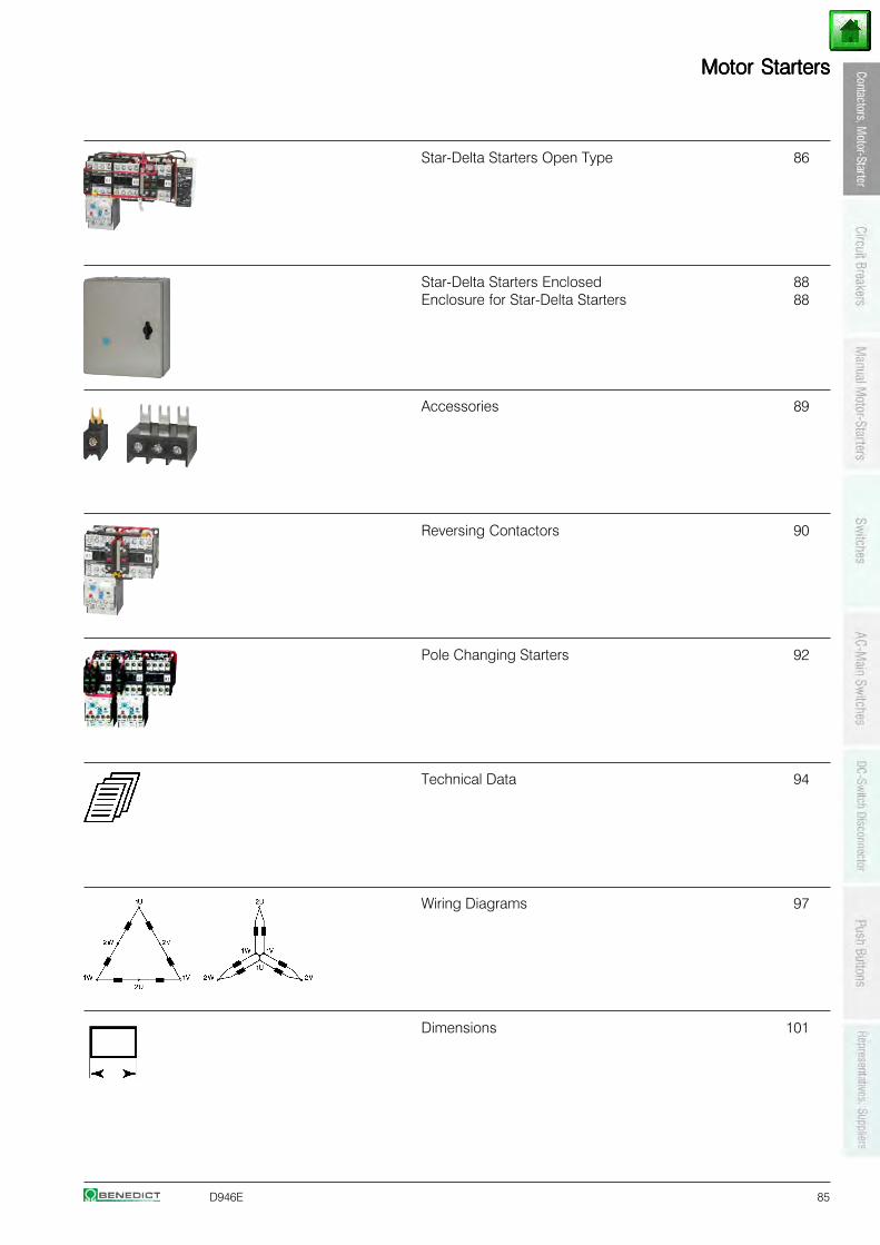
D946E 85
Motor StartersMotor StartersMotor StartersMotor StartersMotor Starters
Star-Delta Starters Open Type 86
Star-Delta Starters Enclosed 88Enclosure for Star-Delta Starters 88
Accessories 89
Reversing Contactors 90
Pole Changing Starters 92
Technical Data 94
Wiring Diagrams 97
Dimensions 101
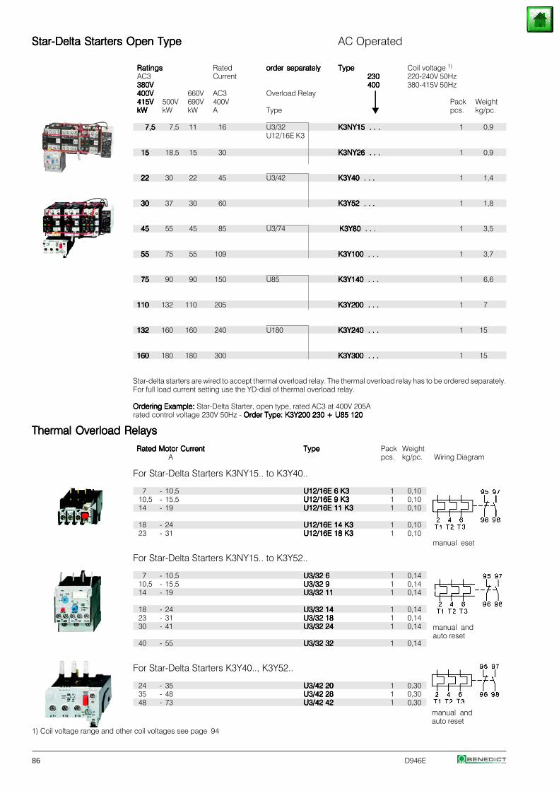
86 D946E
Star-Delta Starters Open TypeStar-Delta Starters Open TypeStar-Delta Starters Open TypeStar-Delta Starters Open TypeStar-Delta Starters Open Type AC Operated
RatingsRatingsRatingsRatingsRatings Rated order separatelyorder separatelyorder separatelyorder separatelyorder separately TypeTypeTypeTypeType Coil voltage 1)
AC3 Current 230230230230230 220-240V 50Hz380V380V380V380V380V 400400400400400 380-415V 50Hz400V400V400V400V400V 660V AC3 Overload Relay ⏐⏐⏐⏐⏐415V415V415V415V415V 500V 690V 400V ⏐⏐⏐⏐⏐ Pack WeightkWkWkWkWkW kW kW A Type pcs. kg/pc.
7,57,57,57,57,5 7,5 11 16 U3/32 K3NY15 . . .K3NY15 . . .K3NY15 . . .K3NY15 . . .K3NY15 . . . 1 0,9U12/16E K3
1515151515 18,5 15 30 K3NY26 . . .K3NY26 . . .K3NY26 . . .K3NY26 . . .K3NY26 . . . 1 0,9
2222222222 30 22 45 U3/42 K3Y40 . . .K3Y40 . . .K3Y40 . . .K3Y40 . . .K3Y40 . . . 1 1,4
3030303030 37 30 60 K3Y52 . . .K3Y52 . . .K3Y52 . . .K3Y52 . . .K3Y52 . . . 1 1,8
4545454545 55 45 85 U3/74 K3Y80 . . .K3Y80 . . .K3Y80 . . .K3Y80 . . .K3Y80 . . . 1 3,5
5555555555 75 55 109 K3Y100 . . .K3Y100 . . .K3Y100 . . .K3Y100 . . .K3Y100 . . . 1 3,7
7575757575 90 90 150 U85 K3Y140 . . .K3Y140 . . .K3Y140 . . .K3Y140 . . .K3Y140 . . . 1 6,6
110110110110110 132 110 205 K3Y200 . . .K3Y200 . . .K3Y200 . . .K3Y200 . . .K3Y200 . . . 1 7
132132132132132 160 160 240 U180 K3Y240 . . .K3Y240 . . .K3Y240 . . .K3Y240 . . .K3Y240 . . . 1 15
160160160160160 180 180 300 K3Y300 . . .K3Y300 . . .K3Y300 . . .K3Y300 . . .K3Y300 . . . 1 15
Star-delta starters are wired to accept thermal overload relay. The thermal overload relay has to be ordered separately.For full load current setting use the YD-dial of thermal overload relay.
Ordering Example:Ordering Example:Ordering Example:Ordering Example:Ordering Example: Star-Delta Starter, open type, rated AC3 at 400V 205Arated control voltage 230V 50Hz - Order Type: K3Y200 230 + U85 120Order Type: K3Y200 230 + U85 120Order Type: K3Y200 230 + U85 120Order Type: K3Y200 230 + U85 120Order Type: K3Y200 230 + U85 120
Thermal Overload RelaysThermal Overload RelaysThermal Overload RelaysThermal Overload RelaysThermal Overload Relays
Rated Motor CurrentRated Motor CurrentRated Motor CurrentRated Motor CurrentRated Motor Current TypeTypeTypeTypeType Pack WeightA pcs. kg/pc. Wiring Diagram
For Star-Delta Starters K3NY15.. to K3Y40..
7 - 10,5 U12/16E 6 K3U12/16E 6 K3U12/16E 6 K3U12/16E 6 K3U12/16E 6 K3 1 0,1010,5 - 15,5 U12/16E 9 K3U12/16E 9 K3U12/16E 9 K3U12/16E 9 K3U12/16E 9 K3 1 0,1014 - 19 U12/16E 11 K3U12/16E 11 K3U12/16E 11 K3U12/16E 11 K3U12/16E 11 K3 1 0,10
18 - 24 U12/16E 14 K3U12/16E 14 K3U12/16E 14 K3U12/16E 14 K3U12/16E 14 K3 1 0,1023 - 31 U12/16E 18 K3U12/16E 18 K3U12/16E 18 K3U12/16E 18 K3U12/16E 18 K3 1 0,10
For Star-Delta Starters K3NY15.. to K3Y52..
7 - 10,5 U3/32 6U3/32 6U3/32 6U3/32 6U3/32 6 1 0,1410,5 - 15,5 U3/32 9U3/32 9U3/32 9U3/32 9U3/32 9 1 0,1414 - 19 U3/32 11U3/32 11U3/32 11U3/32 11U3/32 11 1 0,14
18 - 24 U3/32 14U3/32 14U3/32 14U3/32 14U3/32 14 1 0,1423 - 31 U3/32 18U3/32 18U3/32 18U3/32 18U3/32 18 1 0,1430 - 41 U3/32 24U3/32 24U3/32 24U3/32 24U3/32 24 1 0,14
40 - 55 U3/32 32U3/32 32U3/32 32U3/32 32U3/32 32 1 0,14
For Star-Delta Starters K3Y40.., K3Y52..
24 - 35 U3/42 20U3/42 20U3/42 20U3/42 20U3/42 20 1 0,3035 - 48 U3/42 28U3/42 28U3/42 28U3/42 28U3/42 28 1 0,3048 - 73 U3/42 42U3/42 42U3/42 42U3/42 42U3/42 42 1 0,30
1) Coil voltage range and other coil voltages see page 94
manual andauto reset
manual andauto reset
manual eset
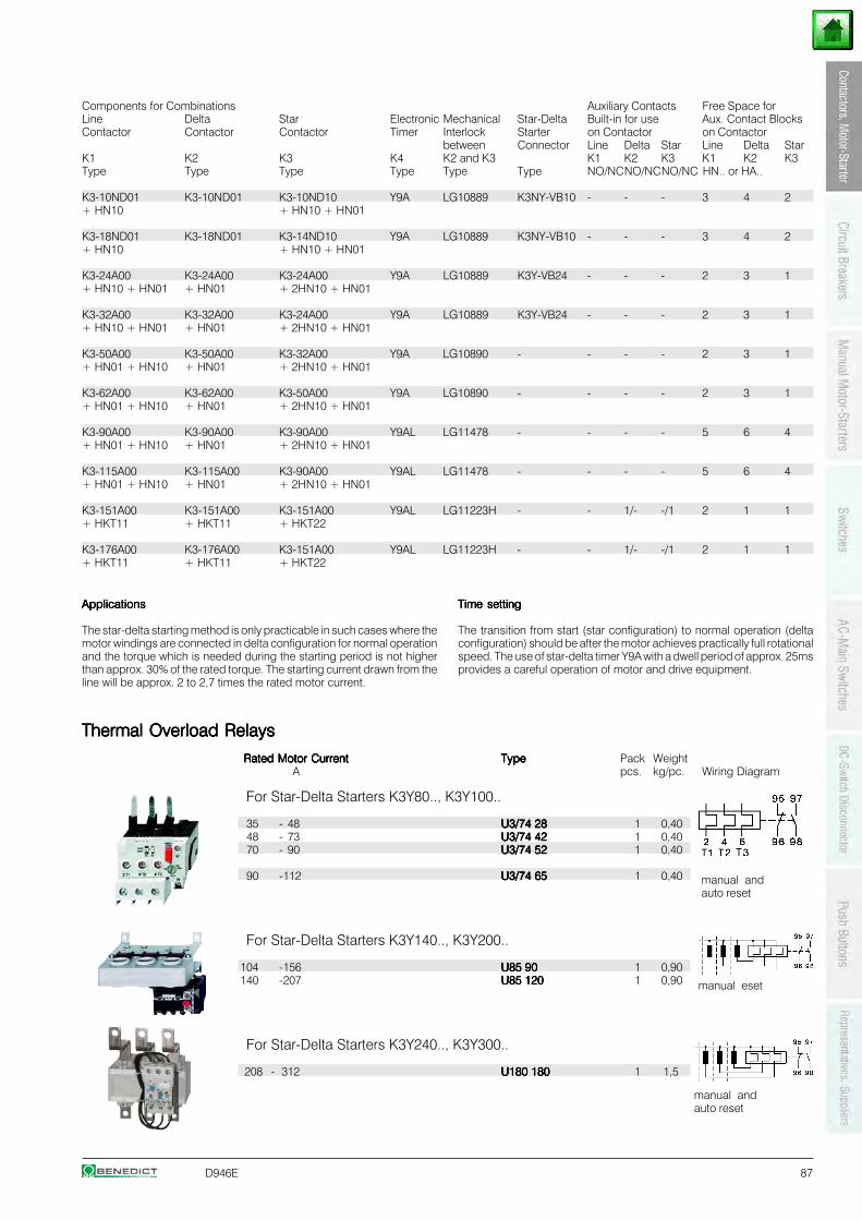
D946E 87
Components for Combinations Auxiliary Contacts Free Space forLine Delta Star Electronic Mechanical Star-Delta Built-in for use Aux. Contact BlocksContactor Contactor Contactor Timer Interlock Starter on Contactor on Contactor
between Connector Line Delta Star Line Delta StarK1 K2 K3 K4 K2 and K3 K1 K2 K3 K1 K2 K3Type Type Type Type Type Type NO/NCNO/NCNO/NC HN.. or HA..
K3-10ND01 K3-10ND01 K3-10ND10 Y9A LG10889 K3NY-VB10 - - - 3 4 2+ HN10 + HN10 + HN01
K3-18ND01 K3-18ND01 K3-14ND10 Y9A LG10889 K3NY-VB10 - - - 3 4 2+ HN10 + HN10 + HN01
K3-24A00 K3-24A00 K3-24A00 Y9A LG10889 K3Y-VB24 - - - 2 3 1+ HN10 + HN01 + HN01 + 2HN10 + HN01
K3-32A00 K3-32A00 K3-24A00 Y9A LG10889 K3Y-VB24 - - - 2 3 1+ HN10 + HN01 + HN01 + 2HN10 + HN01
K3-50A00 K3-50A00 K3-32A00 Y9A LG10890 - - - - 2 3 1+ HN01 + HN10 + HN01 + 2HN10 + HN01
K3-62A00 K3-62A00 K3-50A00 Y9A LG10890 - - - - 2 3 1+ HN01 + HN10 + HN01 + 2HN10 + HN01
K3-90A00 K3-90A00 K3-90A00 Y9AL LG11478 - - - - 5 6 4+ HN01 + HN10 + HN01 + 2HN10 + HN01
K3-115A00 K3-115A00 K3-90A00 Y9AL LG11478 - - - - 5 6 4+ HN01 + HN10 + HN01 + 2HN10 + HN01
K3-151A00 K3-151A00 K3-151A00 Y9AL LG11223H - - 1/- -/1 2 1 1+ HKT11 + HKT11 + HKT22
K3-176A00 K3-176A00 K3-151A00 Y9AL LG11223H - - 1/- -/1 2 1 1+ HKT11 + HKT11 + HKT22
Thermal Overload RelaysThermal Overload RelaysThermal Overload RelaysThermal Overload RelaysThermal Overload Relays
Rated Motor CurrentRated Motor CurrentRated Motor CurrentRated Motor CurrentRated Motor Current TypeTypeTypeTypeType Pack WeightA pcs. kg/pc. Wiring Diagram
For Star-Delta Starters K3Y80.., K3Y100..
35 - 48 U3/74 28U3/74 28U3/74 28U3/74 28U3/74 28 1 0,4048 - 73 U3/74 42U3/74 42U3/74 42U3/74 42U3/74 42 1 0,4070 - 90 U3/74 52U3/74 52U3/74 52U3/74 52U3/74 52 1 0,40
90 -112 U3/74 65U3/74 65U3/74 65U3/74 65U3/74 65 1 0,40
For Star-Delta Starters K3Y140.., K3Y200..
104 -156 U85 90U85 90U85 90U85 90U85 90 1 0,90140 -207 U85 120U85 120U85 120U85 120U85 120 1 0,90
For Star-Delta Starters K3Y240.., K3Y300..
208 - 312 U180 180U180 180U180 180U180 180U180 180 1 1,5
ApplicationsApplicationsApplicationsApplicationsApplications
The star-delta starting method is only practicable in such cases where themotor windings are connected in delta configuration for normal operationand the torque which is needed during the starting period is not higherthan approx. 30% of the rated torque. The starting current drawn from theline will be approx. 2 to 2,7 times the rated motor current.
Time settingTime settingTime settingTime settingTime setting
The transition from start (star configuration) to normal operation (deltaconfiguration) should be after the motor achieves practically full rotationalspeed. The use of star-delta timer Y9A with a dwell period of approx. 25msprovides a careful operation of motor and drive equipment.
manual andauto reset
manual eset
manual andauto reset
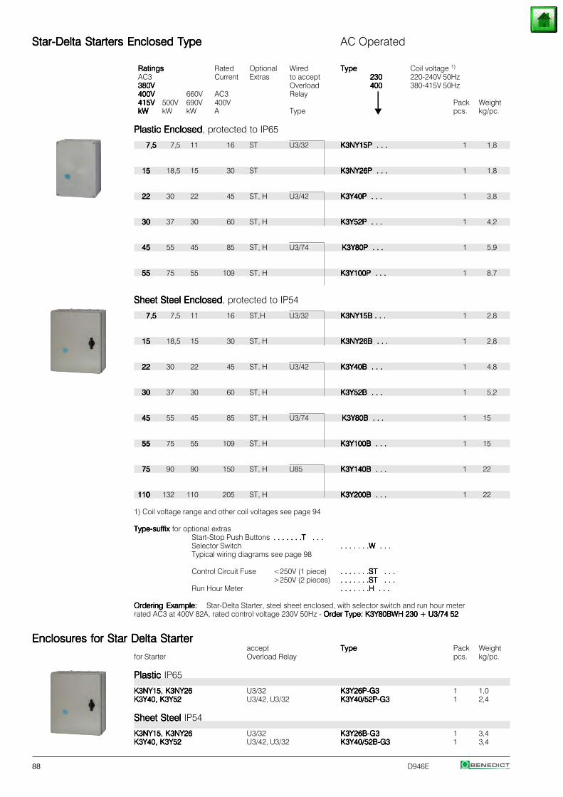
88 D946E
Star-Delta Starters Enclosed TypeStar-Delta Starters Enclosed TypeStar-Delta Starters Enclosed TypeStar-Delta Starters Enclosed TypeStar-Delta Starters Enclosed Type AC Operated
RatingsRatingsRatingsRatingsRatings Rated Optional Wired TypeTypeTypeTypeType Coil voltage 1)
AC3 Current Extras to accept 230230230230230 220-240V 50Hz380V380V380V380V380V Overload 400400400400400 380-415V 50Hz400V400V400V400V400V 660V AC3 Relay ⏐⏐⏐⏐⏐415V415V415V415V415V 500V 690V 400V ⏐⏐⏐⏐⏐ Pack WeightkWkWkWkWkW kW kW A Type pcs. kg/pc.
Plastic EnclosedPlastic EnclosedPlastic EnclosedPlastic EnclosedPlastic Enclosed, protected to IP65
7,57,57,57,57,5 7,5 11 16 ST U3/32 K3NY15P . . .K3NY15P . . .K3NY15P . . .K3NY15P . . .K3NY15P . . . 1 1,8
1515151515 18,5 15 30 ST K3NY26P . . .K3NY26P . . .K3NY26P . . .K3NY26P . . .K3NY26P . . . 1 1,8
2222222222 30 22 45 ST, H U3/42 K3Y40P . . .K3Y40P . . .K3Y40P . . .K3Y40P . . .K3Y40P . . . 1 3,8
3030303030 37 30 60 ST, H K3Y52P . . .K3Y52P . . .K3Y52P . . .K3Y52P . . .K3Y52P . . . 1 4,2
4545454545 55 45 85 ST, H U3/74 K3Y80P . . .K3Y80P . . .K3Y80P . . .K3Y80P . . .K3Y80P . . . 1 5,9
5555555555 75 55 109 ST, H K3Y100P . . .K3Y100P . . .K3Y100P . . .K3Y100P . . .K3Y100P . . . 1 8,7
Sheet Steel EnclosedSheet Steel EnclosedSheet Steel EnclosedSheet Steel EnclosedSheet Steel Enclosed, protected to IP54
7,57,57,57,57,5 7,5 11 16 ST,H U3/32 K3NY15B . . .K3NY15B . . .K3NY15B . . .K3NY15B . . .K3NY15B . . . 1 2,8
1515151515 18,5 15 30 ST, H K3NY26B . . .K3NY26B . . .K3NY26B . . .K3NY26B . . .K3NY26B . . . 1 2,8
2222222222 30 22 45 ST, H U3/42 K3Y40B . . .K3Y40B . . .K3Y40B . . .K3Y40B . . .K3Y40B . . . 1 4,8
3030303030 37 30 60 ST, H K3Y52B . . .K3Y52B . . .K3Y52B . . .K3Y52B . . .K3Y52B . . . 1 5,2
4545454545 55 45 85 ST, H U3/74 K3Y80B . . .K3Y80B . . .K3Y80B . . .K3Y80B . . .K3Y80B . . . 1 15
5555555555 75 55 109 ST, H K3Y100B . . .K3Y100B . . .K3Y100B . . .K3Y100B . . .K3Y100B . . . 1 15
7575757575 90 90 150 ST, H U85 K3Y140B . . .K3Y140B . . .K3Y140B . . .K3Y140B . . .K3Y140B . . . 1 22
110110110110110 132 110 205 ST, H K3Y200B . . .K3Y200B . . .K3Y200B . . .K3Y200B . . .K3Y200B . . . 1 22
1) Coil voltage range and other coil voltages see page 94
Type-suffix Type-suffix Type-suffix Type-suffix Type-suffix for optional extrasStart-Stop Push Buttons . . . . . . .T . . .. . . . . . .T . . .. . . . . . .T . . .. . . . . . .T . . .. . . . . . .T . . .Selector Switch . . . . . . .W . . .. . . . . . .W . . .. . . . . . .W . . .. . . . . . .W . . .. . . . . . .W . . .Typical wiring diagrams see page 98
Control Circuit Fuse <250V (1 piece) . . . . . . .ST . . .. . . . . . .ST . . .. . . . . . .ST . . .. . . . . . .ST . . .. . . . . . .ST . . .>250V (2 pieces) . . . . . . .ST . . .. . . . . . .ST . . .. . . . . . .ST . . .. . . . . . .ST . . .. . . . . . .ST . . .
Run Hour Meter . . . . . . .H . . .. . . . . . .H . . .. . . . . . .H . . .. . . . . . .H . . .. . . . . . .H . . .
Ordering Example:Ordering Example:Ordering Example:Ordering Example:Ordering Example: Star-Delta Starter, steel sheet enclosed, with selector switch and run hour meterrated AC3 at 400V 82A, rated control voltage 230V 50Hz - Order Type: K3Y80BWH 230 + U3/74 52Order Type: K3Y80BWH 230 + U3/74 52Order Type: K3Y80BWH 230 + U3/74 52Order Type: K3Y80BWH 230 + U3/74 52Order Type: K3Y80BWH 230 + U3/74 52
Enclosures for Star Delta StarterEnclosures for Star Delta StarterEnclosures for Star Delta StarterEnclosures for Star Delta StarterEnclosures for Star Delta Starteraccept TypeTypeTypeTypeType Pack Weight
for Starter Overload Relay pcs. kg/pc.
Plastic Plastic Plastic Plastic Plastic IP65
K3NY15, K3NY26K3NY15, K3NY26K3NY15, K3NY26K3NY15, K3NY26K3NY15, K3NY26 U3/32 K3Y26P-G3K3Y26P-G3K3Y26P-G3K3Y26P-G3K3Y26P-G3 1 1,0K3Y40, K3Y52K3Y40, K3Y52K3Y40, K3Y52K3Y40, K3Y52K3Y40, K3Y52 U3/42, U3/32 K3Y40/52P-G3K3Y40/52P-G3K3Y40/52P-G3K3Y40/52P-G3K3Y40/52P-G3 1 2,4
Sheet Steel Sheet Steel Sheet Steel Sheet Steel Sheet Steel IP54
K3NY15, K3NY26K3NY15, K3NY26K3NY15, K3NY26K3NY15, K3NY26K3NY15, K3NY26 U3/32 K3Y26B-G3K3Y26B-G3K3Y26B-G3K3Y26B-G3K3Y26B-G3 1 3,4K3Y40, K3Y52K3Y40, K3Y52K3Y40, K3Y52K3Y40, K3Y52K3Y40, K3Y52 U3/42, U3/32 K3Y40/52B-G3K3Y40/52B-G3K3Y40/52B-G3K3Y40/52B-G3K3Y40/52B-G3 1 3,4
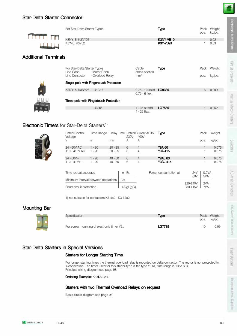
D946E 89
Star-Delta Starter ConnectorStar-Delta Starter ConnectorStar-Delta Starter ConnectorStar-Delta Starter ConnectorStar-Delta Starter Connector
For Star-Delta Starter Types TypeTypeTypeTypeType Pack Weightpcs. kg/pc.
K3NY15, K3NY26 K3NY-VB10K3NY-VB10K3NY-VB10K3NY-VB10K3NY-VB10 1 0,02K3Y40, K3Y52 K3Y-VB24K3Y-VB24K3Y-VB24K3Y-VB24K3Y-VB24 1 0,03
Additional TerminalsAdditional TerminalsAdditional TerminalsAdditional TerminalsAdditional Terminals
For Star-Delta Starter Types Cable TypeTypeTypeTypeType Pack WeightLine Conn. Motor Conn. cross-sectionLine Contactor Overload Relay mm² pcs. kg/pc.
Single pole with Fingertouch ProtectionSingle pole with Fingertouch ProtectionSingle pole with Fingertouch ProtectionSingle pole with Fingertouch ProtectionSingle pole with Fingertouch Protection
K3NY15, K3NY26 U12/16 0,75 - 10 solid LG9339LG9339LG9339LG9339LG9339 6 0,0090,75 - 6 flex.
Three-pole with Fingertouch ProtectionThree-pole with Fingertouch ProtectionThree-pole with Fingertouch ProtectionThree-pole with Fingertouch ProtectionThree-pole with Fingertouch Protection
U3/42 4 - 35 strand. LG7559LG7559LG7559LG7559LG7559 1 0,0524 - 25 flex.
Electronic Timers Electronic Timers Electronic Timers Electronic Timers Electronic Timers for Star-Delta Starters1)
Rated Control Time Range Delay Time Rated Current AC15 TypeTypeTypeTypeType Pack WeightVoltage 230V 400VV s ms A A pcs. kg/pc.
24 - 60V AC 1 - 20 20 - 25 6 4 Y9A 60Y9A 60Y9A 60Y9A 60Y9A 60 1 0,075110 - 415V AC 1 - 20 20 - 25 6 4 Y9A 415Y9A 415Y9A 415Y9A 415Y9A 415 1 0,075
24 - 60V~ 1 - 20 40 - 80 6 4 Y9AL 60Y9AL 60Y9AL 60Y9AL 60Y9AL 60 1 0,075110 - 415V~ 1 - 20 40 - 80 6 4 Y9AL 415Y9AL 415Y9AL 415Y9AL 415Y9AL 415 1 0,075
Time repeat accuracy ± 1% Power consumption at 24V 0,2VA60V 5VA
Minimum interval between operations 2s220-240V 2VA
Short circuit protection 4A gl (gG) 380-415V 7VA
1) not suitable for contactors K3-450 - K3-1200
Mounting BarMounting BarMounting BarMounting BarMounting Bar
Specification TypeTypeTypeTypeType Pack Weightpcs. kg/pc.
For screw mounting of electronic timer Y9.. LG7735LG7735LG7735LG7735LG7735 10 0,09
Star-Delta Starters in Special VersionsStar-Delta Starters in Special VersionsStar-Delta Starters in Special VersionsStar-Delta Starters in Special VersionsStar-Delta Starters in Special Versions
Starters for Longer Starting TimeStarters for Longer Starting TimeStarters for Longer Starting TimeStarters for Longer Starting TimeStarters for Longer Starting Time
For longer starting times the thermal overload relay is mounted on delta-contactor. The motor is not protected inY-connection. The timer used for this starter-type is the type Y91A, time range is 10 to 60s.Principal wiring diagram see page 98.
Ordering Example:Ordering Example:Ordering Example:Ordering Example:Ordering Example: K3YLLLLL52 230
Starters with two Thermal Overload Relays on requestStarters with two Thermal Overload Relays on requestStarters with two Thermal Overload Relays on requestStarters with two Thermal Overload Relays on requestStarters with two Thermal Overload Relays on request
Basic circuit diagram see page 98
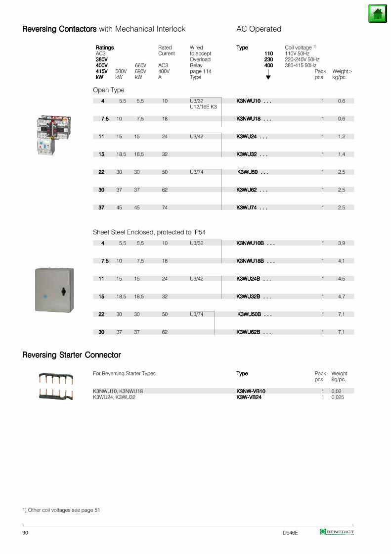
90 D946E
Reversing Contactors Reversing Contactors Reversing Contactors Reversing Contactors Reversing Contactors with Mechanical Interlock AC Operated
RatingsRatingsRatingsRatingsRatings Rated Wired TypeTypeTypeTypeType Coil voltage 1)
AC3 Current to accept 110110110110110 110V 50Hz380V380V380V380V380V Overload 230230230230230 220-240V 50Hz400V400V400V400V400V 660V AC3 Relay 400400400400400 380-415 50Hz415V415V415V415V415V 500V 690V 400V page 114 ⏐⏐⏐⏐⏐ Pack Weight>kWkWkWkWkW kW kW A Type pcs. kg/pc.
Open Type
44444 5,5 5,5 10 U3/32 K3NWU10 . . .K3NWU10 . . .K3NWU10 . . .K3NWU10 . . .K3NWU10 . . . 1 0,6U12/16E K3
7,57,57,57,57,5 10 7,5 18 K3NWU18 . . .K3NWU18 . . .K3NWU18 . . .K3NWU18 . . .K3NWU18 . . . 1 0,6
1111111111 15 15 24 U3/42 K3WU24 . . .K3WU24 . . .K3WU24 . . .K3WU24 . . .K3WU24 . . . 1 1,2
1515151515 18,5 18,5 32 K3WU32 . . .K3WU32 . . .K3WU32 . . .K3WU32 . . .K3WU32 . . . 1 1,4
2222222222 30 30 50 U3/74 K3WU50 . . .K3WU50 . . .K3WU50 . . .K3WU50 . . .K3WU50 . . . 1 2,5
3030303030 37 37 62 K3WU62 . . .K3WU62 . . .K3WU62 . . .K3WU62 . . .K3WU62 . . . 1 2,5
3737373737 45 45 74 K3WU74 . . .K3WU74 . . .K3WU74 . . .K3WU74 . . .K3WU74 . . . 1 2,5
Sheet Steel Enclosed, protected to IP54
44444 5,5 5,5 10 U3/32 K3NWU10B . . .K3NWU10B . . .K3NWU10B . . .K3NWU10B . . .K3NWU10B . . . 1 3,9
7,57,57,57,57,5 10 7,5 18 K3NWU18B . . .K3NWU18B . . .K3NWU18B . . .K3NWU18B . . .K3NWU18B . . . 1 4,1
1111111111 15 15 24 U3/42 K3WU24B . . .K3WU24B . . .K3WU24B . . .K3WU24B . . .K3WU24B . . . 1 4,5
1515151515 18,5 18,5 32 K3WU32B . . .K3WU32B . . .K3WU32B . . .K3WU32B . . .K3WU32B . . . 1 4,7
2222222222 30 30 50 U3/74 K3WU50B . . .K3WU50B . . .K3WU50B . . .K3WU50B . . .K3WU50B . . . 1 7,1
3030303030 37 37 62 K3WU62B . . .K3WU62B . . .K3WU62B . . .K3WU62B . . .K3WU62B . . . 1 7,1
Reversing Starter ConnectorReversing Starter ConnectorReversing Starter ConnectorReversing Starter ConnectorReversing Starter Connector
For Reversing Starter Types TypeTypeTypeTypeType Pack Weightpcs. kg/pc.
K3NWU10, K3NWU18 K3NW-VB10K3NW-VB10K3NW-VB10K3NW-VB10K3NW-VB10 1 0,02K3WU24, K3WU32 K3W-VB24K3W-VB24K3W-VB24K3W-VB24K3W-VB24 1 0,025
1) Other coil voltages see page 51
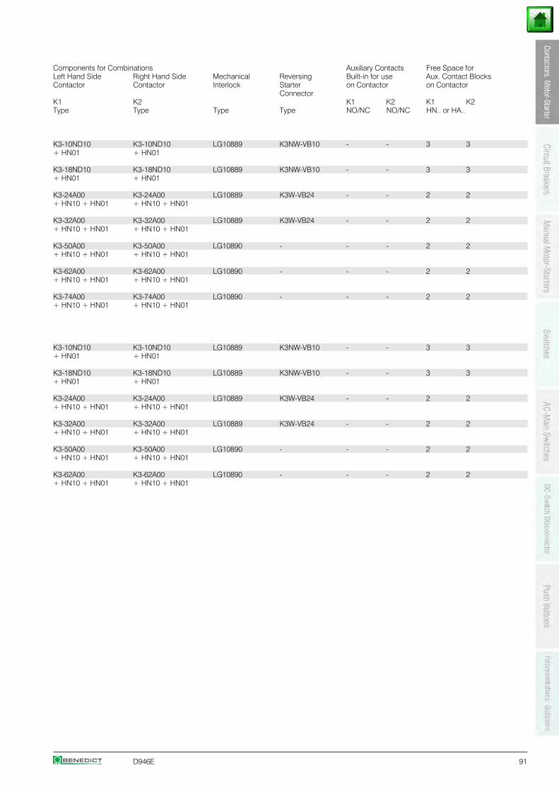
D946E 91
Components for Combinations Auxiliary Contacts Free Space forLeft Hand Side Right Hand Side Mechanical Reversing Built-in for use Aux. Contact BlocksContactor Contactor Interlock Starter on Contactor on Contactor
ConnectorK1 K2 K1 K2 K1 K2Type Type Type Type NO/NC NO/NC HN.. or HA..
K3-10ND10 K3-10ND10 LG10889 K3NW-VB10 - - 3 3+ HN01 + HN01
K3-18ND10 K3-18ND10 LG10889 K3NW-VB10 - - 3 3+ HN01 + HN01
K3-24A00 K3-24A00 LG10889 K3W-VB24 - - 2 2+ HN10 + HN01 + HN10 + HN01
K3-32A00 K3-32A00 LG10889 K3W-VB24 - - 2 2+ HN10 + HN01 + HN10 + HN01
K3-50A00 K3-50A00 LG10890 - - - 2 2+ HN10 + HN01 + HN10 + HN01
K3-62A00 K3-62A00 LG10890 - - - 2 2+ HN10 + HN01 + HN10 + HN01
K3-74A00 K3-74A00 LG10890 - - - 2 2+ HN10 + HN01 + HN10 + HN01
K3-10ND10 K3-10ND10 LG10889 K3NW-VB10 - - 3 3+ HN01 + HN01
K3-18ND10 K3-18ND10 LG10889 K3NW-VB10 - - 3 3+ HN01 + HN01
K3-24A00 K3-24A00 LG10889 K3W-VB24 - - 2 2+ HN10 + HN01 + HN10 + HN01
K3-32A00 K3-32A00 LG10889 K3W-VB24 - - 2 2+ HN10 + HN01 + HN10 + HN01
K3-50A00 K3-50A00 LG10890 - - - 2 2+ HN10 + HN01 + HN10 + HN01
K3-62A00 K3-62A00 LG10890 - - - 2 2+ HN10 + HN01 + HN10 + HN01
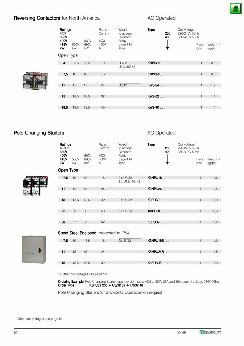
92 D946E
Reversing Contactors Reversing Contactors Reversing Contactors Reversing Contactors Reversing Contactors for North America AC Operated
RatingsRatingsRatingsRatingsRatings Rated Wired TypeTypeTypeTypeType Coil voltage 1)
AC3 Current to accept 230230230230230 220-240V 50Hz380V380V380V380V380V Overload 400400400400400 380-415V 50Hz400V400V400V400V400V 660V AC3 Relay ⏐⏐⏐⏐⏐415V415V415V415V415V 500V 690V 400V page 114 ⏐⏐⏐⏐⏐ Pack Weight>kWkWkWkWkW kW kW A Type pcs. kg/pc.
Open Type
44444 5,5 5,5 10 U3/32 KNW3-10 . . .KNW3-10 . . .KNW3-10 . . .KNW3-10 . . .KNW3-10 . . . 1 0,6U12/16E K3
7,57,57,57,57,5 10 10 18 KNW3-18 . . .KNW3-18 . . .KNW3-18 . . .KNW3-18 . . .KNW3-18 . . . 1 0,6
1111111111 15 15 24 U3/42 KW3-24 . . .KW3-24 . . .KW3-24 . . .KW3-24 . . .KW3-24 . . . 1 1,2
1515151515 18,5 18,5 32 KW3-32 . . .KW3-32 . . .KW3-32 . . .KW3-32 . . .KW3-32 . . . 1 1,4
18,518,518,518,518,5 18,5 18,5 40 KW3-40 . . .KW3-40 . . .KW3-40 . . .KW3-40 . . .KW3-40 . . . 1 1,4
Pole Changing StartersPole Changing StartersPole Changing StartersPole Changing StartersPole Changing Starters AC Operated
RatingsRatingsRatingsRatingsRatings Rated Wired TypeTypeTypeTypeType Coil voltage 1)
AC3 at Current to accept 230230230230230 220-240V 50Hz380V380V380V380V380V Overload 400400400400400 380-415V 50Hz400V400V400V400V400V 660V AC3 Relay ⏐⏐⏐⏐⏐415V415V415V415V415V 500V 690V 400V page 114 ⏐⏐⏐⏐⏐ Pack Weight>kWkWkWkWkW kW kW A Type pcs. kg/pc.
Open TypeOpen TypeOpen TypeOpen TypeOpen Type
7,57,57,57,57,5 10 10 18 2 x U3/32 K3NPU18 . . .K3NPU18 . . .K3NPU18 . . .K3NPU18 . . .K3NPU18 . . . 1 1,02 x U12/16E K3
1111111111 15 15 24 K3NPU24 . . .K3NPU24 . . .K3NPU24 . . .K3NPU24 . . .K3NPU24 . . . 1 1,5
1515151515 18,5 18,5 32 2 x U3/32 K3PU32 . . .K3PU32 . . .K3PU32 . . .K3PU32 . . .K3PU32 . . . 1 1,9
2222222222 30 30 50 2 x U3/74 K3PU50 . . .K3PU50 . . .K3PU50 . . .K3PU50 . . .K3PU50 . . . 1 3,9
3030303030 37 37 62 K3PU62 . . .K3PU62 . . .K3PU62 . . .K3PU62 . . .K3PU62 . . . 1 3,9
Sheet Steel EnclosedSheet Steel EnclosedSheet Steel EnclosedSheet Steel EnclosedSheet Steel Enclosed, protected to IP54
7,57,57,57,57,5 10 7,5 18 2x U3/32 K3NPU18B . . .K3NPU18B . . .K3NPU18B . . .K3NPU18B . . .K3NPU18B . . . 1 1,0
1111111111 15 15 24 K3NPU24B . . .K3NPU24B . . .K3NPU24B . . .K3NPU24B . . .K3NPU24B . . . 1 1,5
1515151515 18,5 18,5 32 K3PU32B . . .K3PU32B . . .K3PU32B . . .K3PU32B . . .K3PU32B . . . 1 1,9
1) Other coil voltages see page 50
Ordering Example: Ordering Example: Ordering Example: Ordering Example: Ordering Example: Pole Changing Starter, open version, rated AC3 at 400V 28A and 15A, control voltage 230V 50HzOrder Type:Order Type:Order Type:Order Type:Order Type: K3PU32 230 + U3/32 32 + U3/32 18K3PU32 230 + U3/32 32 + U3/32 18K3PU32 230 + U3/32 32 + U3/32 18K3PU32 230 + U3/32 32 + U3/32 18K3PU32 230 + U3/32 32 + U3/32 18
Pole Changing Starters for Star-Delta Operation on request
1) Other coil voltages see page 51
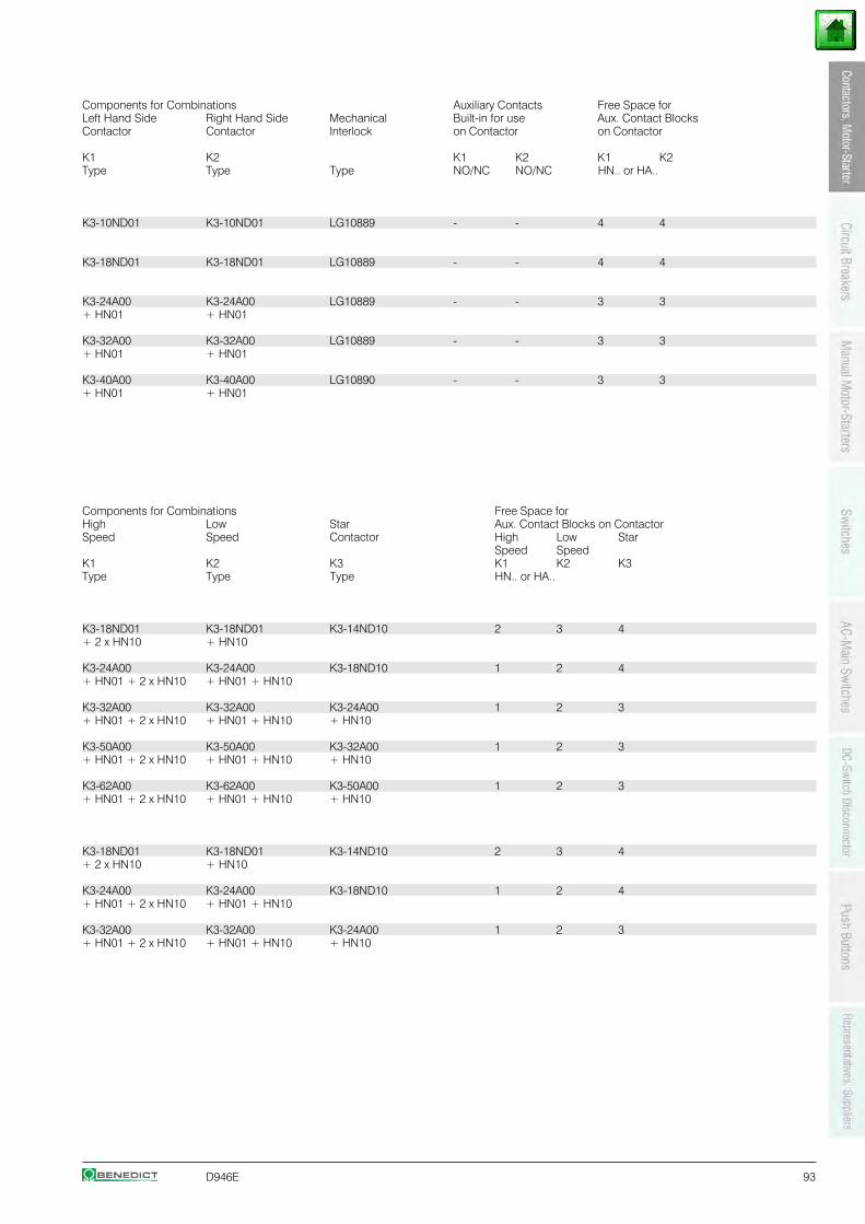
D946E 93
Components for Combinations Auxiliary Contacts Free Space forLeft Hand Side Right Hand Side Mechanical Built-in for use Aux. Contact BlocksContactor Contactor Interlock on Contactor on Contactor
K1 K2 K1 K2 K1 K2Type Type Type NO/NC NO/NC HN.. or HA..
K3-10ND01 K3-10ND01 LG10889 - - 4 4
K3-18ND01 K3-18ND01 LG10889 - - 4 4
K3-24A00 K3-24A00 LG10889 - - 3 3+ HN01 + HN01
K3-32A00 K3-32A00 LG10889 - - 3 3+ HN01 + HN01
K3-40A00 K3-40A00 LG10890 - - 3 3+ HN01 + HN01
Components for Combinations Free Space forHigh Low Star Aux. Contact Blocks on ContactorSpeed Speed Contactor High Low Star
Speed SpeedK1 K2 K3 K1 K2 K3Type Type Type HN.. or HA..
K3-18ND01 K3-18ND01 K3-14ND10 2 3 4+ 2 x HN10 + HN10
K3-24A00 K3-24A00 K3-18ND10 1 2 4+ HN01 + 2 x HN10 + HN01 + HN10
K3-32A00 K3-32A00 K3-24A00 1 2 3+ HN01 + 2 x HN10 + HN01 + HN10 + HN10
K3-50A00 K3-50A00 K3-32A00 1 2 3+ HN01 + 2 x HN10 + HN01 + HN10 + HN10
K3-62A00 K3-62A00 K3-50A00 1 2 3+ HN01 + 2 x HN10 + HN01 + HN10 + HN10
K3-18ND01 K3-18ND01 K3-14ND10 2 3 4+ 2 x HN10 + HN10
K3-24A00 K3-24A00 K3-18ND10 1 2 4+ HN01 + 2 x HN10 + HN01 + HN10
K3-32A00 K3-32A00 K3-24A00 1 2 3+ HN01 + 2 x HN10 + HN01 + HN10 + HN10
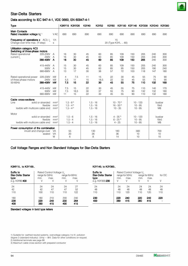
94 D946E
Star-Delta StartersStar-Delta StartersStar-Delta StartersStar-Delta StartersStar-Delta Starters
Data according to IEC 947-4-1, VDE 0660, EN 60947-4-1Data according to IEC 947-4-1, VDE 0660, EN 60947-4-1Data according to IEC 947-4-1, VDE 0660, EN 60947-4-1Data according to IEC 947-4-1, VDE 0660, EN 60947-4-1Data according to IEC 947-4-1, VDE 0660, EN 60947-4-1
TypeTypeTypeTypeType K3NY15K3NY15K3NY15K3NY15K3NY15 K3NY26K3NY26K3NY26K3NY26K3NY26 K3Y40K3Y40K3Y40K3Y40K3Y40 K3Y52K3Y52K3Y52K3Y52K3Y52 K3Y80K3Y80K3Y80K3Y80K3Y80 K3Y100K3Y100K3Y100K3Y100K3Y100 K3Y140K3Y140K3Y140K3Y140K3Y140 K3Y200K3Y200K3Y200K3Y200K3Y200 K3Y240K3Y240K3Y240K3Y240K3Y240 K3Y300K3Y300K3Y300K3Y300K3Y300
Main ContactsMain ContactsMain ContactsMain ContactsMain ContactsRated insulation voltage URated insulation voltage URated insulation voltage URated insulation voltage URated insulation voltage Uiiiii
1) V AC 690 690 690 690 690 690 690 690 690 690
Frequency of operations zFrequency of operations zFrequency of operations zFrequency of operations zFrequency of operations z AC3, Ie 1/h 15Change-over time max. (Y-step) s 20 (Type K3YL ... 60)
Utilization category AC3Utilization category AC3Utilization category AC3Utilization category AC3Utilization category AC3Switching of three-phase motorsSwitching of three-phase motorsSwitching of three-phase motorsSwitching of three-phase motorsSwitching of three-phase motorsRated operational 220-230V A 16 30 45 60 85 109 150 205 240 300current Ie 240V A 16 30 45 60 85 109 150 205 240 300
380-400V380-400V380-400V380-400V380-400V AAAAA 1616161616 3030303030 4545454545 6060606060 8585858585 109109109109109 150150150150150 205205205205205 240 300
415-440V A 15 30 45 60 85 109 150 205 240 300500V A 15 30 45 60 85 95 150 205 190 240
660-690V A 13 17 30 36 57 72 103 118 147 180
Rated operational power 220-230V kW 4 7,5 11 15 22 30 45 55 75 90of three-phase motors 240V kW 5,5 11 15 18,5 22 30 45 55 75 9050-60Hz 380-400V380-400V380-400V380-400V380-400V kWkWkWkWkW 7,57,57,57,57,5 1515151515 2222222222 3030303030 4545454545 5555555555 7575757575 110110110110110 132132132132132 160160160160160
415-440V kW 7,5 15 22 30 45 55 75 110 140 170500V kW 7,5 18,5 30 37 55 75 90 132 132 180
660-690V kW 11 15 22 30 45 55 90 110 132 180
Cable cross-sectionsCable cross-sectionsCable cross-sectionsCable cross-sectionsCable cross-sectionsLine solid or stranded mm² 1,5 - 6 2) 1,5 - 16 10 - 70 3) 10 - 120 busbar
flexible mm² 1,5 - 4 2) 1,5 - 16 16 - 50 3) 10 - 95 18x5lexible with multicore cable end mm² 1,5 - 4 2) 1,5 - 16 10 - 35 10 - 95 M8
Motorsolid or stranded mm² 1,5 - 6 1,5 - 16 4 - 35 3) 10 - 120 busbar
flexible mm² 1,5 - 4 1,5 - 16 6 - 25 3) 10 - 95 18x5lexible with multicore cable end mm² 1,5 - 4 1,5 - 16 4 - 25 10 - 95 M8
Power consumption of the combinationPower consumption of the combinationPower consumption of the combinationPower consumption of the combinationPower consumption of the combinationinrush and change-over VA 55 130 183 560 700
sealed VA 20 26 36 10 10W 6 8 14 10 10
Coil Voltage Ranges and Non Standard Voltages for Star-Delta StartersCoil Voltage Ranges and Non Standard Voltages for Star-Delta StartersCoil Voltage Ranges and Non Standard Voltages for Star-Delta StartersCoil Voltage Ranges and Non Standard Voltages for Star-Delta StartersCoil Voltage Ranges and Non Standard Voltages for Star-Delta Starters
K3NY15.. to K3Y100..K3NY15.. to K3Y100..K3NY15.. to K3Y100..K3NY15.. to K3Y100..K3NY15.. to K3Y100..
Suffix toSuffix toSuffix toSuffix toSuffix to Rated Control Voltage UsStar-Delta StarterStar-Delta StarterStar-Delta StarterStar-Delta StarterStar-Delta Starter range for 50Hz range for 60Hztypetypetypetypetype min. max. min. max.e.g. K3Y80 400400400400400 V V V V
24 24 24 24 2742 42 47 47 52110 100 110 110 122
180 180 210 200 240230230230230230 220220220220220 240240240240240 230230230230230 264264264264264400400400400400 380380380380380 415415415415415 400400400400400 415415415415415
Standard voltages in bold type lettersStandard voltages in bold type lettersStandard voltages in bold type lettersStandard voltages in bold type lettersStandard voltages in bold type letters
1) Suitable for: earthed-neutral systems, overvoltage category I to IV, pollutiondegree 3 (standard-industry): Uimp = 8kV. Data for other conditions on request.2) Additional terminals see page 893) Maximum cable cross-section with prepared conductor
K3Y140, to K3Y300..K3Y140, to K3Y300..K3Y140, to K3Y300..K3Y140, to K3Y300..K3Y140, to K3Y300..
Suffix toSuffix toSuffix toSuffix toSuffix to Rated Control Voltage UsStar-Delta StarterStar-Delta StarterStar-Delta StarterStar-Delta StarterStar-Delta Starter range for 50Hz range for 60Hz for DCtypetypetypetypetype min. max. min. max.e.g. K3Y300 230230230230230 V V V V V
24 24 24 24 24 2448 48 48 48 48 48
110 110 120 110 120 110
230230230230230 220220220220220 240240240240240 220220220220220 240240240240240 220220220220220400400400400400 380380380380380 415415415415415 380380380380380 415415415415415 -----
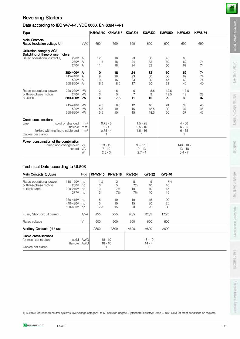
D946E 95
Reversing StartersReversing StartersReversing StartersReversing StartersReversing Starters
Data according to IEC 947-4-1, VDE 0660, EN 60947-4-1Data according to IEC 947-4-1, VDE 0660, EN 60947-4-1Data according to IEC 947-4-1, VDE 0660, EN 60947-4-1Data according to IEC 947-4-1, VDE 0660, EN 60947-4-1Data according to IEC 947-4-1, VDE 0660, EN 60947-4-1
TypeTypeTypeTypeType K3NWU10K3NWU10K3NWU10K3NWU10K3NWU10 K3NWU18K3NWU18K3NWU18K3NWU18K3NWU18 K3WU24K3WU24K3WU24K3WU24K3WU24 K3WU32K3WU32K3WU32K3WU32K3WU32 K3WU50K3WU50K3WU50K3WU50K3WU50 K3WU62K3WU62K3WU62K3WU62K3WU62 K3WU74K3WU74K3WU74K3WU74K3WU74
Main ContactsMain ContactsMain ContactsMain ContactsMain ContactsRated insulation voltage URated insulation voltage URated insulation voltage URated insulation voltage URated insulation voltage Uiiiii
1) V AC 690 690 690 690 690 690 690
Utilization category AC3Utilization category AC3Utilization category AC3Utilization category AC3Utilization category AC3Switching of three-phase motorsSwitching of three-phase motorsSwitching of three-phase motorsSwitching of three-phase motorsSwitching of three-phase motorsRated operational current Ie 220V A 12 18 23 30 45 63
230V A 11,5 18 24 32 50 62 74240V A 11 18 24 32 50 62 74
380-400V380-400V380-400V380-400V380-400V AAAAA 1010101010 1818181818 2424242424 3232323232 5050505050 6262626262 7474747474415-440V A 9 18 23 30 50 62 74
500V A 9 16 23 30 45 60 74660-690V A 6,5 8,5 17 20 31 40 40
Rated operational power 220-230V kW 3 5 6 8,5 12,5 18,5of three-phase motors 240V kW 3 5 7 9 13,5 19 2350-60Hz 380-400V380-400V380-400V380-400V380-400V kWkWkWkWkW 44444 7,57,57,57,57,5 1111111111 1515151515 2222222222 3030303030 3737373737
415-440V kW 4,5 8,5 12 16 24 33 40500V kW 5,5 10 15 18,5 30 37 45
660-690V kW 5,5 10 15 18,5 30 37 45
Cable cross-sectionsCable cross-sectionsCable cross-sectionsCable cross-sectionsCable cross-sectionsLine solid or stranded mm² 0,75 - 6 1,5 - 25 4 - 50
flexible mm² 1 - 4 2,5 - 16 6 - 35flexible with multicore cable end mm² 0,75 - 4 1,5 - 16 6 - 35
Cables per clamp 1 1 1
Power consumption of the combinationPower consumption of the combinationPower consumption of the combinationPower consumption of the combinationPower consumption of the combinationinrush and change-over VA 33 - 45 90 - 115 140 - 185
sealed VA 7 - 10 9 - 13 13 - 18W 2,6 - 3 2,7 - 4 5,4 - 7
Technical Data according to UL508Technical Data according to UL508Technical Data according to UL508Technical Data according to UL508Technical Data according to UL508
Main Contacts (cULus)Main Contacts (cULus)Main Contacts (cULus)Main Contacts (cULus)Main Contacts (cULus) Type KNW3-10KNW3-10KNW3-10KNW3-10KNW3-10 KNW3-18KNW3-18KNW3-18KNW3-18KNW3-18 KW3-24KW3-24KW3-24KW3-24KW3-24 KW3-32KW3-32KW3-32KW3-32KW3-32 KW3-40KW3-40KW3-40KW3-40KW3-40
Rated operational power 110-120V hp 1½ 2 5 5 7½of three-phase motors 200V hp 3 5 7½ 10 10at 60Hz (3ph) 220-240V hp 3 7½ 10 10 15
277V hp 3 7½ 7½ 10 15
380-415V hp 5 10 10 15 20440-480V hp 5 10 15 20 25550-600V hp 7½ 15 20 25 30
Fuse / Short-circuit current A/kA 30/5 50/5 90/5 125/5 175/5
Rated voltage V 600 600 600 600 600
Auxiliary Contacts (cULus)Auxiliary Contacts (cULus)Auxiliary Contacts (cULus)Auxiliary Contacts (cULus)Auxiliary Contacts (cULus) A600 A600 A600 A600 A600
Cable cross-sectionsCable cross-sectionsCable cross-sectionsCable cross-sectionsCable cross-sectionsfor main connectors solid AWG 18 - 10 16 - 10
flexible AWG 18 - 10 14 - 4Cables per clamp 1 1
1) Suitable for: earthed-neutral systems, overvoltage category I to IV, pollution degree 3 (standard-industry): Uimp = 8kV. Data for other conditions on request.
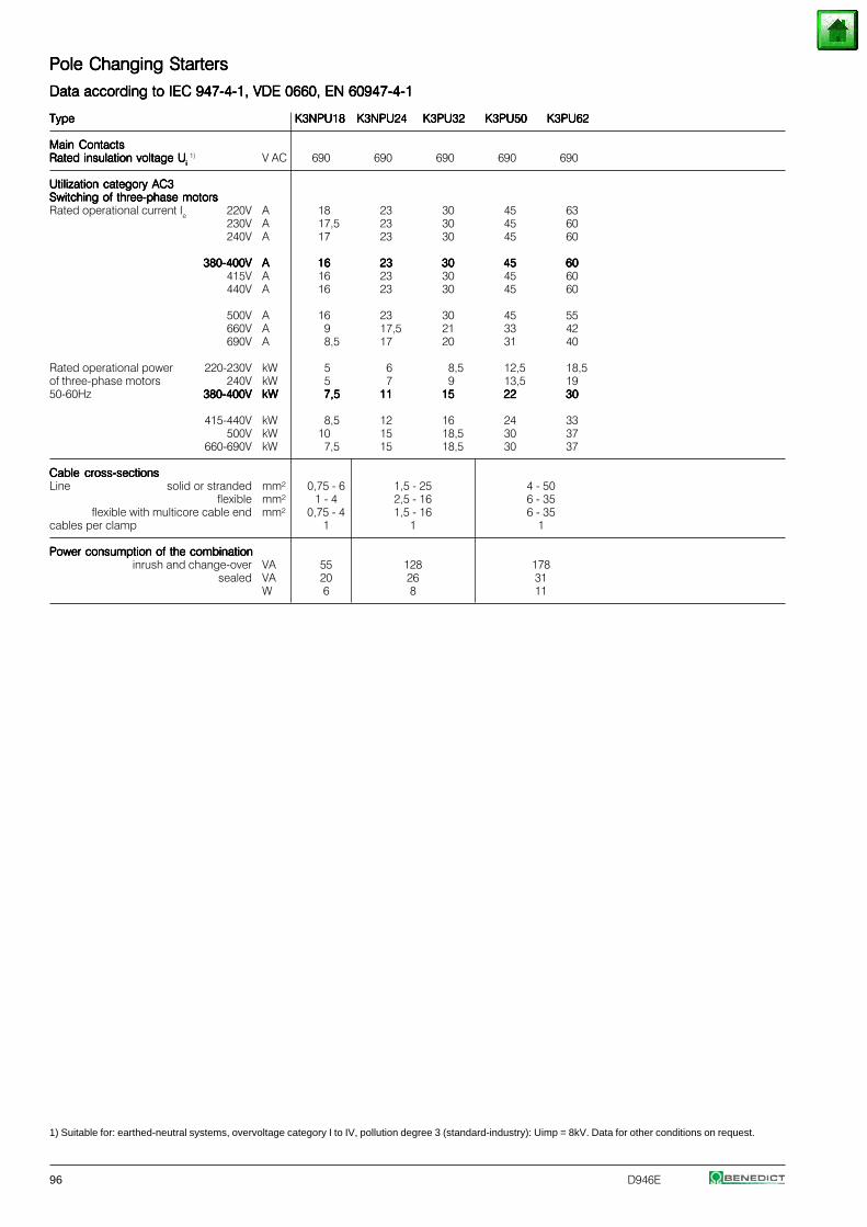
96 D946E
Pole Changing StartersPole Changing StartersPole Changing StartersPole Changing StartersPole Changing Starters
Data according to IEC 947-4-1, VDE 0660, EN 60947-4-1Data according to IEC 947-4-1, VDE 0660, EN 60947-4-1Data according to IEC 947-4-1, VDE 0660, EN 60947-4-1Data according to IEC 947-4-1, VDE 0660, EN 60947-4-1Data according to IEC 947-4-1, VDE 0660, EN 60947-4-1
TypeTypeTypeTypeType K3NPU18K3NPU18K3NPU18K3NPU18K3NPU18 K3NPU24K3NPU24K3NPU24K3NPU24K3NPU24 K3PU32K3PU32K3PU32K3PU32K3PU32 K3PU50K3PU50K3PU50K3PU50K3PU50 K3PU62K3PU62K3PU62K3PU62K3PU62
Main ContactsMain ContactsMain ContactsMain ContactsMain ContactsRated insulation voltage URated insulation voltage URated insulation voltage URated insulation voltage URated insulation voltage Uiiiii
1) V AC 690 690 690 690 690
Utilization category AC3Utilization category AC3Utilization category AC3Utilization category AC3Utilization category AC3Switching of three-phase motorsSwitching of three-phase motorsSwitching of three-phase motorsSwitching of three-phase motorsSwitching of three-phase motorsRated operational current Ie 220V A 18 23 30 45 63
230V A 17,5 23 30 45 60240V A 17 23 30 45 60
380-400V380-400V380-400V380-400V380-400V AAAAA 1616161616 2323232323 3030303030 4545454545 6060606060415V A 16 23 30 45 60440V A 16 23 30 45 60
500V A 16 23 30 45 55660V A 9 17,5 21 33 42690V A 8,5 17 20 31 40
Rated operational power 220-230V kW 5 6 8,5 12,5 18,5of three-phase motors 240V kW 5 7 9 13,5 1950-60Hz 380-400V380-400V380-400V380-400V380-400V kWkWkWkWkW 7,57,57,57,57,5 1111111111 1515151515 2222222222 3030303030
415-440V kW 8,5 12 16 24 33500V kW 10 15 18,5 30 37
660-690V kW 7,5 15 18,5 30 37
Cable cross-sectionsCable cross-sectionsCable cross-sectionsCable cross-sectionsCable cross-sectionsLine solid or stranded mm² 0,75 - 6 1,5 - 25 4 - 50
flexible mm² 1 - 4 2,5 - 16 6 - 35flexible with multicore cable end mm² 0,75 - 4 1,5 - 16 6 - 35
cables per clamp 1 1 1
Power consumption of the combinationPower consumption of the combinationPower consumption of the combinationPower consumption of the combinationPower consumption of the combinationinrush and change-over VA 55 128 178
sealed VA 20 26 31W 6 8 11
1) Suitable for: earthed-neutral systems, overvoltage category I to IV, pollution degree 3 (standard-industry): Uimp = 8kV. Data for other conditions on request.
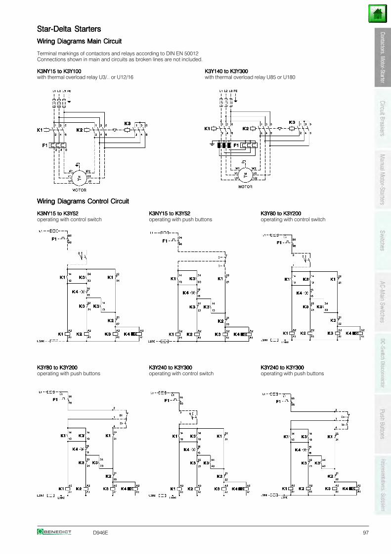
D946E 97
Star-Delta StartersStar-Delta StartersStar-Delta StartersStar-Delta StartersStar-Delta Starters
Wiring Diagrams Main CircuitWiring Diagrams Main CircuitWiring Diagrams Main CircuitWiring Diagrams Main CircuitWiring Diagrams Main Circuit
Terminal markings of contactors and relays according to DIN EN 50012Connections shown in main and circuits as broken lines are not included.
K3NY15 to K3Y100K3NY15 to K3Y100K3NY15 to K3Y100K3NY15 to K3Y100K3NY15 to K3Y100 K3Y140 to K3Y300K3Y140 to K3Y300K3Y140 to K3Y300K3Y140 to K3Y300K3Y140 to K3Y300with thermal overload relay U3/.. or U12/16 with thermal overload relay U85 or U180
Wiring Diagrams Control CircuitWiring Diagrams Control CircuitWiring Diagrams Control CircuitWiring Diagrams Control CircuitWiring Diagrams Control Circuit
K3NY15 to K3Y52K3NY15 to K3Y52K3NY15 to K3Y52K3NY15 to K3Y52K3NY15 to K3Y52 K3NY15 to K3Y52K3NY15 to K3Y52K3NY15 to K3Y52K3NY15 to K3Y52K3NY15 to K3Y52 K3Y80 to K3Y200K3Y80 to K3Y200K3Y80 to K3Y200K3Y80 to K3Y200K3Y80 to K3Y200operating with control switch operating with push buttons operating with control switch
K3Y80 to K3Y200K3Y80 to K3Y200K3Y80 to K3Y200K3Y80 to K3Y200K3Y80 to K3Y200 K3Y240 to K3Y300K3Y240 to K3Y300K3Y240 to K3Y300K3Y240 to K3Y300K3Y240 to K3Y300 K3Y240 to K3Y300K3Y240 to K3Y300K3Y240 to K3Y300K3Y240 to K3Y300K3Y240 to K3Y300operating with push buttons operating with control switch operating with push buttons
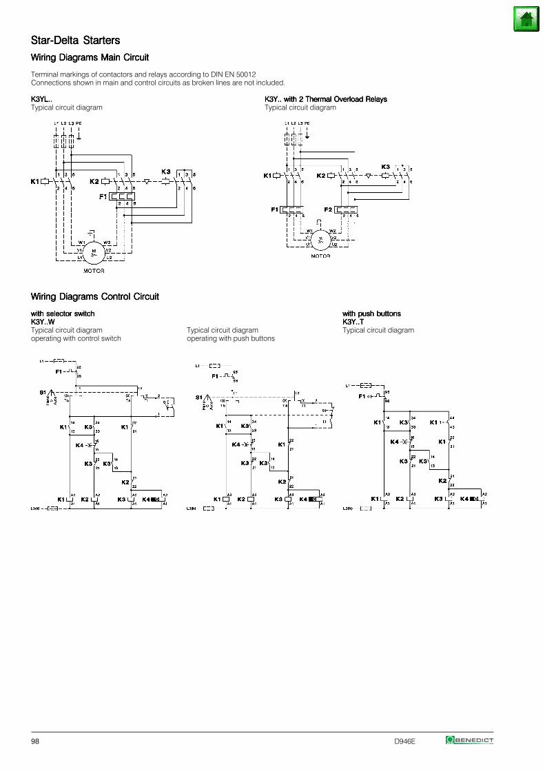
98 D946E
Star-Delta StartersStar-Delta StartersStar-Delta StartersStar-Delta StartersStar-Delta Starters
Wiring Diagrams Main CircuitWiring Diagrams Main CircuitWiring Diagrams Main CircuitWiring Diagrams Main CircuitWiring Diagrams Main Circuit
Terminal markings of contactors and relays according to DIN EN 50012Connections shown in main and control circuits as broken lines are not included.
K3YL..K3YL..K3YL..K3YL..K3YL.. K3Y.. with 2 Thermal Overload RelaysK3Y.. with 2 Thermal Overload RelaysK3Y.. with 2 Thermal Overload RelaysK3Y.. with 2 Thermal Overload RelaysK3Y.. with 2 Thermal Overload RelaysTypical circuit diagram Typical circuit diagram
Wiring Diagrams Control CircuitWiring Diagrams Control CircuitWiring Diagrams Control CircuitWiring Diagrams Control CircuitWiring Diagrams Control Circuit
with selector switchwith selector switchwith selector switchwith selector switchwith selector switch with push buttonswith push buttonswith push buttonswith push buttonswith push buttonsK3Y..WK3Y..WK3Y..WK3Y..WK3Y..W K3Y..TK3Y..TK3Y..TK3Y..TK3Y..TTypical circuit diagram Typical circuit diagram Typical circuit diagramoperating with control switch operating with push buttons
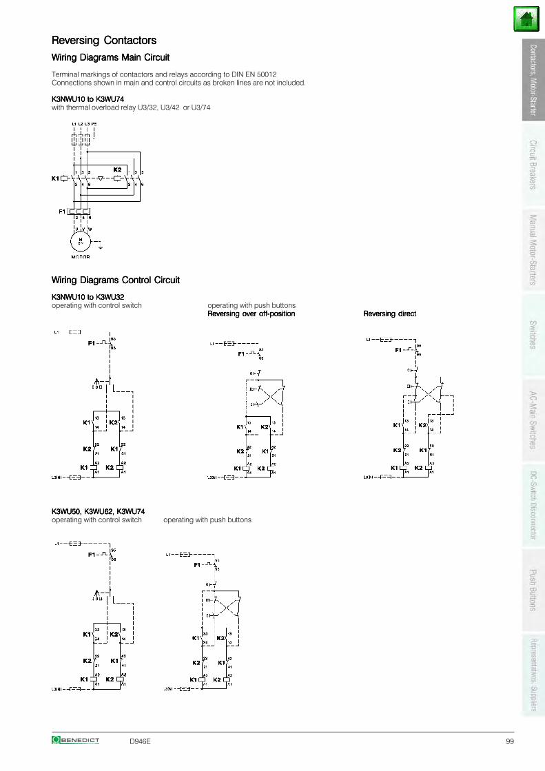
D946E 99
Reversing ContactorsReversing ContactorsReversing ContactorsReversing ContactorsReversing Contactors
Wiring Diagrams Main CircuitWiring Diagrams Main CircuitWiring Diagrams Main CircuitWiring Diagrams Main CircuitWiring Diagrams Main Circuit
Terminal markings of contactors and relays according to DIN EN 50012Connections shown in main and control circuits as broken lines are not included.
K3NWU10 to K3WU74K3NWU10 to K3WU74K3NWU10 to K3WU74K3NWU10 to K3WU74K3NWU10 to K3WU74with thermal overload relay U3/32, U3/42 or U3/74
Wiring Diagrams Control CircuitWiring Diagrams Control CircuitWiring Diagrams Control CircuitWiring Diagrams Control CircuitWiring Diagrams Control Circuit
K3NWU10 to K3WU32K3NWU10 to K3WU32K3NWU10 to K3WU32K3NWU10 to K3WU32K3NWU10 to K3WU32operating with control switch operating with push buttons
Reversing over off-positionReversing over off-positionReversing over off-positionReversing over off-positionReversing over off-position Reversing directReversing directReversing directReversing directReversing direct
K3WU50, K3WU62, K3WU74K3WU50, K3WU62, K3WU74K3WU50, K3WU62, K3WU74K3WU50, K3WU62, K3WU74K3WU50, K3WU62, K3WU74operating with control switch operating with push buttons
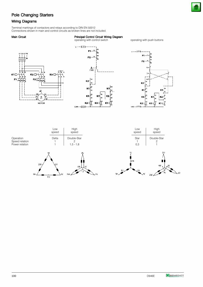
100 D946E
Pole Changing StartersPole Changing StartersPole Changing StartersPole Changing StartersPole Changing Starters
Wiring DiagramsWiring DiagramsWiring DiagramsWiring DiagramsWiring Diagrams
Terminal markings of contactors and relays according to DIN EN 50012Connections shown in main and control circuits as broken lines are not included.
Main CircuitMain CircuitMain CircuitMain CircuitMain Circuit Principal Control Circuit Wiring DiagramPrincipal Control Circuit Wiring DiagramPrincipal Control Circuit Wiring DiagramPrincipal Control Circuit Wiring DiagramPrincipal Control Circuit Wiring Diagramoperating with control switch operating with push buttons
Low High Low Highspeed speed speed speed
Operation Delta Double-Star Star Double-StarSpeed relation 1 2 1 2Power relation 1 1,5 - 1,8 0,3 1
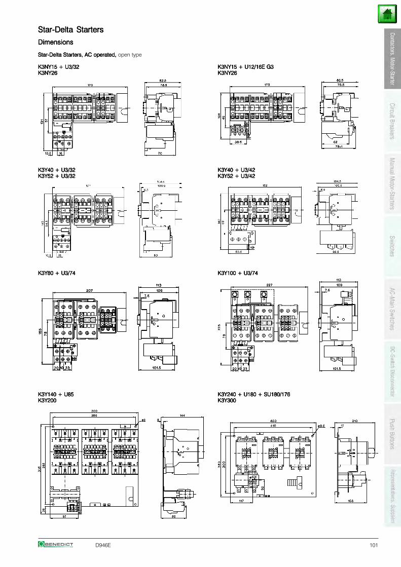
D946E 101
Star-Delta StartersStar-Delta StartersStar-Delta StartersStar-Delta StartersStar-Delta Starters
DimensionsDimensionsDimensionsDimensionsDimensions
Star-Delta Starters, AC operated,Star-Delta Starters, AC operated,Star-Delta Starters, AC operated,Star-Delta Starters, AC operated,Star-Delta Starters, AC operated, open type
K3NY15 + U3/32K3NY15 + U3/32K3NY15 + U3/32K3NY15 + U3/32K3NY15 + U3/32 K3NY15 + U12/16E G3K3NY15 + U12/16E G3K3NY15 + U12/16E G3K3NY15 + U12/16E G3K3NY15 + U12/16E G3K3NY26K3NY26K3NY26K3NY26K3NY26 K3NY26K3NY26K3NY26K3NY26K3NY26
K3Y40 + U3/32K3Y40 + U3/32K3Y40 + U3/32K3Y40 + U3/32K3Y40 + U3/32 K3Y40 + U3/42K3Y40 + U3/42K3Y40 + U3/42K3Y40 + U3/42K3Y40 + U3/42K3Y52 + U3/32K3Y52 + U3/32K3Y52 + U3/32K3Y52 + U3/32K3Y52 + U3/32 K3Y52 + U3/42K3Y52 + U3/42K3Y52 + U3/42K3Y52 + U3/42K3Y52 + U3/42
K3Y80 + U3/74K3Y80 + U3/74K3Y80 + U3/74K3Y80 + U3/74K3Y80 + U3/74 K3Y100 + U3/74K3Y100 + U3/74K3Y100 + U3/74K3Y100 + U3/74K3Y100 + U3/74
K3Y140 + U85K3Y140 + U85K3Y140 + U85K3Y140 + U85K3Y140 + U85 K3Y240 + U180 + SU180/176K3Y240 + U180 + SU180/176K3Y240 + U180 + SU180/176K3Y240 + U180 + SU180/176K3Y240 + U180 + SU180/176K3Y200K3Y200K3Y200K3Y200K3Y200 K3Y300K3Y300K3Y300K3Y300K3Y300
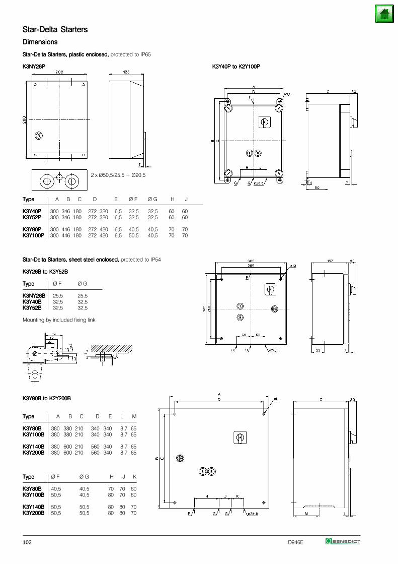
102 D946E
Star-Delta StartersStar-Delta StartersStar-Delta StartersStar-Delta StartersStar-Delta Starters
DimensionsDimensionsDimensionsDimensionsDimensions
Star-Delta Starters, plastic enclosed, Star-Delta Starters, plastic enclosed, Star-Delta Starters, plastic enclosed, Star-Delta Starters, plastic enclosed, Star-Delta Starters, plastic enclosed, protected to IP65
K3NY26PK3NY26PK3NY26PK3NY26PK3NY26P K3Y40P to K2Y100PK3Y40P to K2Y100PK3Y40P to K2Y100PK3Y40P to K2Y100PK3Y40P to K2Y100P
2 x Ø50,5/25,5 + Ø20,5
TypeTypeTypeTypeType A B C D E Ø F Ø G H J
K3Y40PK3Y40PK3Y40PK3Y40PK3Y40P 300 346 180 272 320 6,5 32,5 32,5 60 60K3Y52PK3Y52PK3Y52PK3Y52PK3Y52P 300 346 180 272 320 6,5 32,5 32,5 60 60
K3Y80PK3Y80PK3Y80PK3Y80PK3Y80P 300 446 180 272 420 6,5 40,5 40,5 70 70K3Y100PK3Y100PK3Y100PK3Y100PK3Y100P 300 446 180 272 420 6,5 50,5 40,5 70 70
Star-Delta Starters, sheet steel enclosed, Star-Delta Starters, sheet steel enclosed, Star-Delta Starters, sheet steel enclosed, Star-Delta Starters, sheet steel enclosed, Star-Delta Starters, sheet steel enclosed, protected to IP54
K3Y26B to K3Y52BK3Y26B to K3Y52BK3Y26B to K3Y52BK3Y26B to K3Y52BK3Y26B to K3Y52B
TypeTypeTypeTypeType Ø F Ø G
K3NY26BK3NY26BK3NY26BK3NY26BK3NY26B 25,5 25,5K3Y40BK3Y40BK3Y40BK3Y40BK3Y40B 32,5 32,5K3Y52BK3Y52BK3Y52BK3Y52BK3Y52B 32,5 32,5
Mounting by included fixing link
K3Y80B to K2Y200BK3Y80B to K2Y200BK3Y80B to K2Y200BK3Y80B to K2Y200BK3Y80B to K2Y200B
TypeTypeTypeTypeType A B C D E L M
K3Y80BK3Y80BK3Y80BK3Y80BK3Y80B 380 380 210 340 340 8,7 65K3Y100BK3Y100BK3Y100BK3Y100BK3Y100B 380 380 210 340 340 8,7 65
K3Y140BK3Y140BK3Y140BK3Y140BK3Y140B 380 600 210 560 340 8,7 65K3Y200BK3Y200BK3Y200BK3Y200BK3Y200B 380 600 210 560 340 8,7 65
TypeTypeTypeTypeType Ø F Ø G H J K
K3Y80BK3Y80BK3Y80BK3Y80BK3Y80B 40,5 40,5 70 70 60K3Y100BK3Y100BK3Y100BK3Y100BK3Y100B 50,5 40,5 80 70 60
K3Y140BK3Y140BK3Y140BK3Y140BK3Y140B 50,5 50,5 80 80 70K3Y200BK3Y200BK3Y200BK3Y200BK3Y200B 50,5 50,5 80 80 70
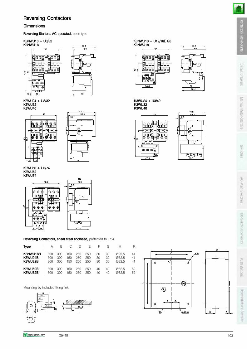
D946E 103
Reversing ContactorsReversing ContactorsReversing ContactorsReversing ContactorsReversing Contactors
DimensionsDimensionsDimensionsDimensionsDimensions
Reversing Starters, AC operated,Reversing Starters, AC operated,Reversing Starters, AC operated,Reversing Starters, AC operated,Reversing Starters, AC operated, open type
K3NWU10 + U3/32K3NWU10 + U3/32K3NWU10 + U3/32K3NWU10 + U3/32K3NWU10 + U3/32 K3NWU10 + U12/16E G3K3NWU10 + U12/16E G3K3NWU10 + U12/16E G3K3NWU10 + U12/16E G3K3NWU10 + U12/16E G3K3NWU18K3NWU18K3NWU18K3NWU18K3NWU18 K3NWU18K3NWU18K3NWU18K3NWU18K3NWU18
K3WU24 + U3/32K3WU24 + U3/32K3WU24 + U3/32K3WU24 + U3/32K3WU24 + U3/32 K3WU24 + U3/42K3WU24 + U3/42K3WU24 + U3/42K3WU24 + U3/42K3WU24 + U3/42K3WU32K3WU32K3WU32K3WU32K3WU32 K3WU32K3WU32K3WU32K3WU32K3WU32K3WU40K3WU40K3WU40K3WU40K3WU40 K3WU40K3WU40K3WU40K3WU40K3WU40
K3WU50 + U3/74K3WU50 + U3/74K3WU50 + U3/74K3WU50 + U3/74K3WU50 + U3/74K3WU62K3WU62K3WU62K3WU62K3WU62K3WU74K3WU74K3WU74K3WU74K3WU74
Reversing Contactors, sheet steel enclosed, Reversing Contactors, sheet steel enclosed, Reversing Contactors, sheet steel enclosed, Reversing Contactors, sheet steel enclosed, Reversing Contactors, sheet steel enclosed, protected to IP54
TypeTypeTypeTypeType A B C D E F G H K
K3NWU18BK3NWU18BK3NWU18BK3NWU18BK3NWU18B 300 300 150 250 250 30 30 Ø25,5 41K3WU24BK3WU24BK3WU24BK3WU24BK3WU24B 300 300 150 250 250 30 30 Ø32,5 41K3WU32BK3WU32BK3WU32BK3WU32BK3WU32B 300 300 150 250 250 30 30 Ø32,5 41
K3WU50BK3WU50BK3WU50BK3WU50BK3WU50B 300 300 150 250 250 40 40 Ø32,5 59K3WU62BK3WU62BK3WU62BK3WU62BK3WU62B 300 300 150 250 250 40 40 Ø32,5 59
Mounting by included fixing link
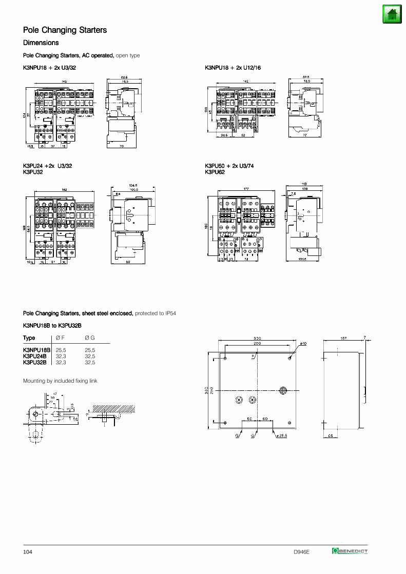
104 D946E
Pole Changing StartersPole Changing StartersPole Changing StartersPole Changing StartersPole Changing Starters
DimensionsDimensionsDimensionsDimensionsDimensions
Pole Changing Starters, AC operated, Pole Changing Starters, AC operated, Pole Changing Starters, AC operated, Pole Changing Starters, AC operated, Pole Changing Starters, AC operated, open type
K3NPU18 + 2x U3/32K3NPU18 + 2x U3/32K3NPU18 + 2x U3/32K3NPU18 + 2x U3/32K3NPU18 + 2x U3/32 K3NPU18 + 2x U12/16K3NPU18 + 2x U12/16K3NPU18 + 2x U12/16K3NPU18 + 2x U12/16K3NPU18 + 2x U12/16
K3PU24 +2x U3/32K3PU24 +2x U3/32K3PU24 +2x U3/32K3PU24 +2x U3/32K3PU24 +2x U3/32 K3PU50 + 2x U3/74K3PU50 + 2x U3/74K3PU50 + 2x U3/74K3PU50 + 2x U3/74K3PU50 + 2x U3/74K3PU32K3PU32K3PU32K3PU32K3PU32 K3PU62K3PU62K3PU62K3PU62K3PU62
Pole Changing Starters, sheet steel enclosed, Pole Changing Starters, sheet steel enclosed, Pole Changing Starters, sheet steel enclosed, Pole Changing Starters, sheet steel enclosed, Pole Changing Starters, sheet steel enclosed, protected to IP54
K3NPU18B to K3PU32BK3NPU18B to K3PU32BK3NPU18B to K3PU32BK3NPU18B to K3PU32BK3NPU18B to K3PU32B
TypeTypeTypeTypeType Ø F Ø G
K3NPU18BK3NPU18BK3NPU18BK3NPU18BK3NPU18B 25,5 25,5K3PU24BK3PU24BK3PU24BK3PU24BK3PU24B 32,3 32,5K3PU32BK3PU32BK3PU32BK3PU32BK3PU32B 32,3 32,5
Mounting by included fixing link
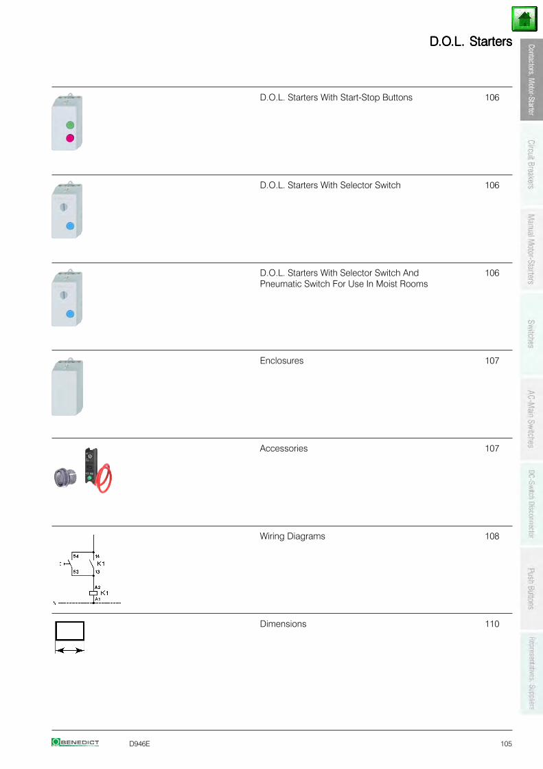
D946E 105
DDDDD.O.O.O.O.O.L.L.L.L.L. Starters. Starters. Starters. Starters. Starters
D.O.L. Starters With Start-Stop Buttons 106
D.O.L. Starters With Selector Switch 106
D.O.L. Starters With Selector Switch And 106Pneumatic Switch For Use In Moist Rooms
Enclosures 107
Accessories 107
Wiring Diagrams 108
Dimensions 110
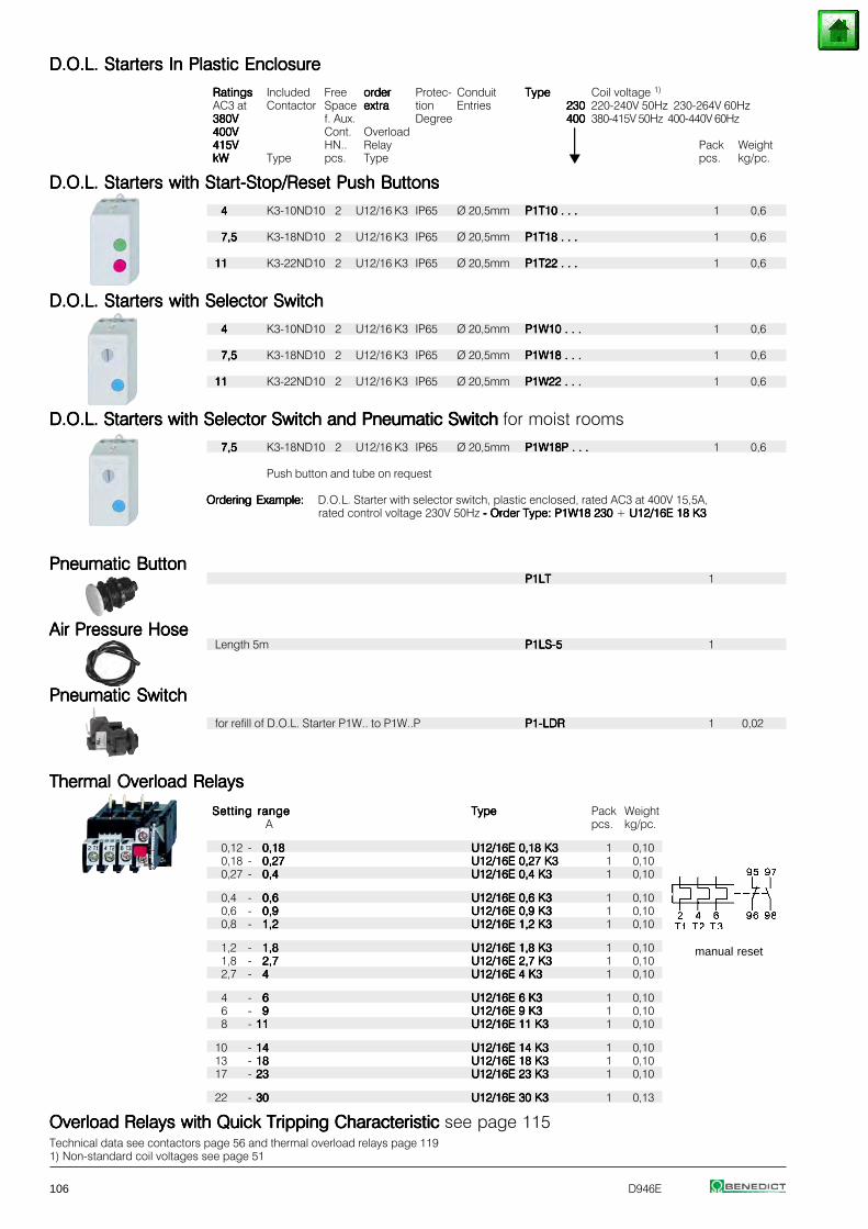
106 D946E
D.O.L. Starters D.O.L. Starters D.O.L. Starters D.O.L. Starters D.O.L. Starters In Plastic EnclosureIn Plastic EnclosureIn Plastic EnclosureIn Plastic EnclosureIn Plastic Enclosure
RatingsRatingsRatingsRatingsRatings Included Free orderorderorderorderorder Protec- Conduit TypeTypeTypeTypeType Coil voltage 1)
AC3 at Contactor Space extraextraextraextraextra tion Entries 230230230230230 220-240V 50Hz 230-264V 60Hz380V380V380V380V380V f. Aux. Degree 400400400400400 380-415V 50Hz 400-440V 60Hz400V400V400V400V400V Cont. Overload ⏐⏐⏐⏐⏐415V415V415V415V415V HN.. Relay ⏐⏐⏐⏐⏐ Pack WeightkWkWkWkWkW Type pcs. Type pcs. kg/pc.
D.O.L. Starters with Start-Stop/Reset Push ButtonsD.O.L. Starters with Start-Stop/Reset Push ButtonsD.O.L. Starters with Start-Stop/Reset Push ButtonsD.O.L. Starters with Start-Stop/Reset Push ButtonsD.O.L. Starters with Start-Stop/Reset Push Buttons
44444 K3-10ND10 2 U12/16 K3 IP65 Ø 20,5mm P1T10 . . .P1T10 . . .P1T10 . . .P1T10 . . .P1T10 . . . 1 0,6
7,57,57,57,57,5 K3-18ND10 2 U12/16 K3 IP65 Ø 20,5mm P1T18 . . .P1T18 . . .P1T18 . . .P1T18 . . .P1T18 . . . 1 0,6
1111111111 K3-22ND10 2 U12/16 K3 IP65 Ø 20,5mm P1T22 . . .P1T22 . . .P1T22 . . .P1T22 . . .P1T22 . . . 1 0,6
D.O.L. Starters with Selector SwitchD.O.L. Starters with Selector SwitchD.O.L. Starters with Selector SwitchD.O.L. Starters with Selector SwitchD.O.L. Starters with Selector Switch
44444 K3-10ND10 2 U12/16 K3 IP65 Ø 20,5mm P1W10 . . .P1W10 . . .P1W10 . . .P1W10 . . .P1W10 . . . 1 0,6
7,57,57,57,57,5 K3-18ND10 2 U12/16 K3 IP65 Ø 20,5mm P1W18 . . .P1W18 . . .P1W18 . . .P1W18 . . .P1W18 . . . 1 0,6
1111111111 K3-22ND10 2 U12/16 K3 IP65 Ø 20,5mm P1W22 . . .P1W22 . . .P1W22 . . .P1W22 . . .P1W22 . . . 1 0,6
D.O.L. Starters with Selector Switch and Pneumatic Switch D.O.L. Starters with Selector Switch and Pneumatic Switch D.O.L. Starters with Selector Switch and Pneumatic Switch D.O.L. Starters with Selector Switch and Pneumatic Switch D.O.L. Starters with Selector Switch and Pneumatic Switch for moist rooms
7,57,57,57,57,5 K3-18ND10 2 U12/16 K3 IP65 Ø 20,5mm P1W18P . . .P1W18P . . .P1W18P . . .P1W18P . . .P1W18P . . . 1 0,6
Push button and tube on request
Ordering Example:Ordering Example:Ordering Example:Ordering Example:Ordering Example: D.O.L. Starter with selector switch, plastic enclosed, rated AC3 at 400V 15,5A,rated control voltage 230V 50Hz - Order Type: P1W18 230 - Order Type: P1W18 230 - Order Type: P1W18 230 - Order Type: P1W18 230 - Order Type: P1W18 230 + U12/16E 18 K3 U12/16E 18 K3 U12/16E 18 K3 U12/16E 18 K3 U12/16E 18 K3
Pneumatic ButtonPneumatic ButtonPneumatic ButtonPneumatic ButtonPneumatic ButtonP1LTP1LTP1LTP1LTP1LT 1
Air Pressure HoseAir Pressure HoseAir Pressure HoseAir Pressure HoseAir Pressure HoseLength 5m P1LS-5P1LS-5P1LS-5P1LS-5P1LS-5 1
Pneumatic SwitchPneumatic SwitchPneumatic SwitchPneumatic SwitchPneumatic Switch
for refill of D.O.L. Starter P1W.. to P1W..P P1-LDRP1-LDRP1-LDRP1-LDRP1-LDR 1 0,02
Thermal Overload RelaysThermal Overload RelaysThermal Overload RelaysThermal Overload RelaysThermal Overload Relays
Setting rangeSetting rangeSetting rangeSetting rangeSetting range TypeTypeTypeTypeType Pack WeightA pcs. kg/pc.
0,12 - 0,180,180,180,180,18 U12/16E 0,18 K3U12/16E 0,18 K3U12/16E 0,18 K3U12/16E 0,18 K3U12/16E 0,18 K3 1 0,100,18 - 0,270,270,270,270,27 U12/16E 0,27 K3U12/16E 0,27 K3U12/16E 0,27 K3U12/16E 0,27 K3U12/16E 0,27 K3 1 0,100,27 - 0,40,40,40,40,4 U12/16E 0,4 K3U12/16E 0,4 K3U12/16E 0,4 K3U12/16E 0,4 K3U12/16E 0,4 K3 1 0,10
0,4 - 0,60,60,60,60,6 U12/16E 0,6 K3U12/16E 0,6 K3U12/16E 0,6 K3U12/16E 0,6 K3U12/16E 0,6 K3 1 0,100,6 - 0,90,90,90,90,9 U12/16E 0,9 K3U12/16E 0,9 K3U12/16E 0,9 K3U12/16E 0,9 K3U12/16E 0,9 K3 1 0,100,8 - 1,21,21,21,21,2 U12/16E 1,2 K3U12/16E 1,2 K3U12/16E 1,2 K3U12/16E 1,2 K3U12/16E 1,2 K3 1 0,10
1,2 - 1,81,81,81,81,8 U12/16E 1,8 K3U12/16E 1,8 K3U12/16E 1,8 K3U12/16E 1,8 K3U12/16E 1,8 K3 1 0,101,8 - 2,72,72,72,72,7 U12/16E 2,7 K3U12/16E 2,7 K3U12/16E 2,7 K3U12/16E 2,7 K3U12/16E 2,7 K3 1 0,102,7 - 44444 U12/16E 4 K3U12/16E 4 K3U12/16E 4 K3U12/16E 4 K3U12/16E 4 K3 1 0,10
4 - 66666 U12/16E 6 K3U12/16E 6 K3U12/16E 6 K3U12/16E 6 K3U12/16E 6 K3 1 0,106 - 99999 U12/16E 9 K3U12/16E 9 K3U12/16E 9 K3U12/16E 9 K3U12/16E 9 K3 1 0,108 - 1111111111 U12/16E 11 K3U12/16E 11 K3U12/16E 11 K3U12/16E 11 K3U12/16E 11 K3 1 0,10
10 - 1414141414 U12/16E 14 K3U12/16E 14 K3U12/16E 14 K3U12/16E 14 K3U12/16E 14 K3 1 0,1013 - 1818181818 U12/16E 18 K3U12/16E 18 K3U12/16E 18 K3U12/16E 18 K3U12/16E 18 K3 1 0,1017 - 2323232323 U12/16E 23 K3U12/16E 23 K3U12/16E 23 K3U12/16E 23 K3U12/16E 23 K3 1 0,10
22 - 3030303030 U12/16E 30 K3U12/16E 30 K3U12/16E 30 K3U12/16E 30 K3U12/16E 30 K3 1 0,13
Overload Relays with Quick Tripping Characteristic Overload Relays with Quick Tripping Characteristic Overload Relays with Quick Tripping Characteristic Overload Relays with Quick Tripping Characteristic Overload Relays with Quick Tripping Characteristic see page 115Technical data see contactors page 56 and thermal overload relays page 1191) Non-standard coil voltages see page 51
manual reset
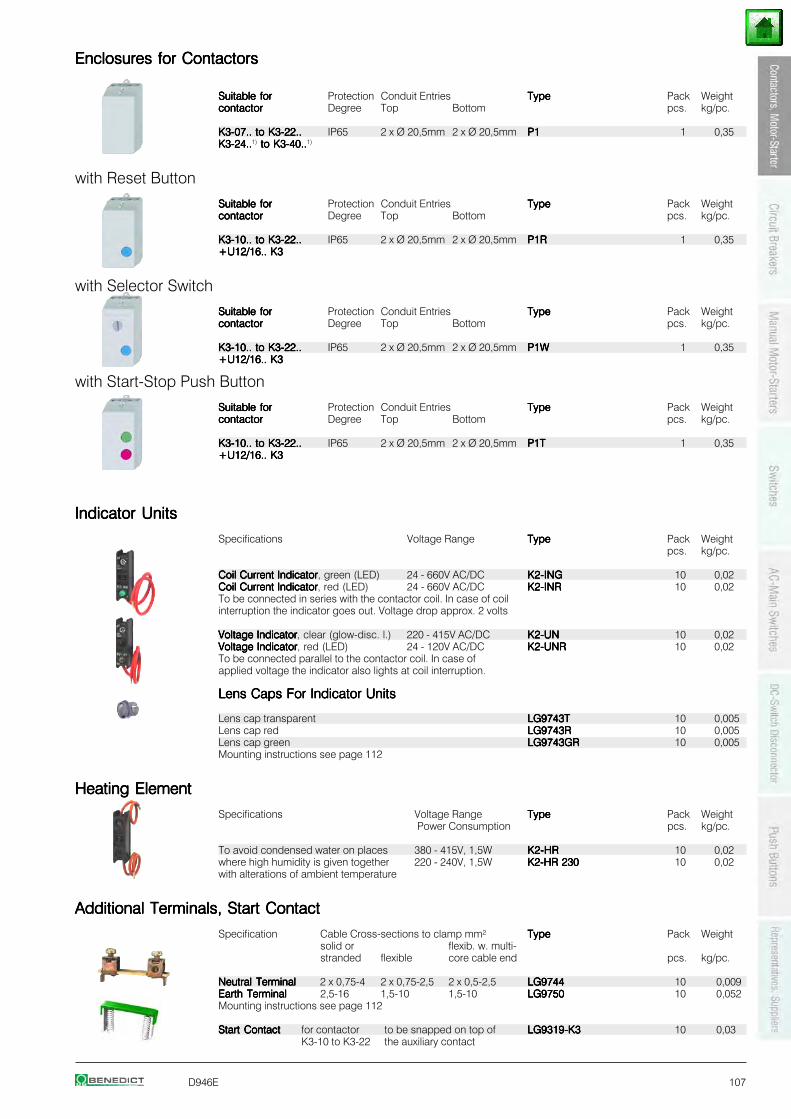
D946E 107
Enclosures for ContactorsEnclosures for ContactorsEnclosures for ContactorsEnclosures for ContactorsEnclosures for Contactors
Suitable forSuitable forSuitable forSuitable forSuitable for Protection Conduit Entries TypeTypeTypeTypeType Pack Weightcontactorcontactorcontactorcontactorcontactor Degree Top Bottom pcs. kg/pc.
K3-07.. to K3-22..K3-07.. to K3-22..K3-07.. to K3-22..K3-07.. to K3-22..K3-07.. to K3-22.. IP65 2 x Ø 20,5mm 2 x Ø 20,5mm P1P1P1P1P1 1 0,35K3-24..K3-24..K3-24..K3-24..K3-24..1) to K3-40.. to K3-40.. to K3-40.. to K3-40.. to K3-40..1)
with Reset Button
Suitable forSuitable forSuitable forSuitable forSuitable for Protection Conduit Entries TypeTypeTypeTypeType Pack Weightcontactorcontactorcontactorcontactorcontactor Degree Top Bottom pcs. kg/pc.
K3-10.. to K3-22..K3-10.. to K3-22..K3-10.. to K3-22..K3-10.. to K3-22..K3-10.. to K3-22.. IP65 2 x Ø 20,5mm 2 x Ø 20,5mm P1RP1RP1RP1RP1R 1 0,35+U12/16.. K3+U12/16.. K3+U12/16.. K3+U12/16.. K3+U12/16.. K3
with Selector Switch
Suitable forSuitable forSuitable forSuitable forSuitable for Protection Conduit Entries TypeTypeTypeTypeType Pack Weightcontactorcontactorcontactorcontactorcontactor Degree Top Bottom pcs. kg/pc.
K3-10.. to K3-22..K3-10.. to K3-22..K3-10.. to K3-22..K3-10.. to K3-22..K3-10.. to K3-22.. IP65 2 x Ø 20,5mm 2 x Ø 20,5mm P1WP1WP1WP1WP1W 1 0,35+U12/16.. K3+U12/16.. K3+U12/16.. K3+U12/16.. K3+U12/16.. K3
with Start-Stop Push Button
Suitable forSuitable forSuitable forSuitable forSuitable for Protection Conduit Entries TypeTypeTypeTypeType Pack Weightcontactorcontactorcontactorcontactorcontactor Degree Top Bottom pcs. kg/pc.
K3-10.. to K3-22..K3-10.. to K3-22..K3-10.. to K3-22..K3-10.. to K3-22..K3-10.. to K3-22.. IP65 2 x Ø 20,5mm 2 x Ø 20,5mm P1TP1TP1TP1TP1T 1 0,35+U12/16.. K3+U12/16.. K3+U12/16.. K3+U12/16.. K3+U12/16.. K3
Indicator UnitsIndicator UnitsIndicator UnitsIndicator UnitsIndicator Units
Specifications Voltage Range TypeTypeTypeTypeType Pack Weightpcs. kg/pc.
Coil Current IndicatorCoil Current IndicatorCoil Current IndicatorCoil Current IndicatorCoil Current Indicator, green (LED) 24 - 660V AC/DC K2-INGK2-INGK2-INGK2-INGK2-ING 10 0,02Coil Current IndicatorCoil Current IndicatorCoil Current IndicatorCoil Current IndicatorCoil Current Indicator, red (LED) 24 - 660V AC/DC K2-INRK2-INRK2-INRK2-INRK2-INR 10 0,02To be connected in series with the contactor coil. In case of coilinterruption the indicator goes out. Voltage drop approx. 2 volts
Voltage IndicatorVoltage IndicatorVoltage IndicatorVoltage IndicatorVoltage Indicator, clear (glow-disc. l.) 220 - 415V AC/DC K2-UNK2-UNK2-UNK2-UNK2-UN 10 0,02Voltage IndicatorVoltage IndicatorVoltage IndicatorVoltage IndicatorVoltage Indicator, red (LED) 24 - 120V AC/DC K2-UNRK2-UNRK2-UNRK2-UNRK2-UNR 10 0,02To be connected parallel to the contactor coil. In case ofapplied voltage the indicator also lights at coil interruption.
Lens Caps For Indicator UnitsLens Caps For Indicator UnitsLens Caps For Indicator UnitsLens Caps For Indicator UnitsLens Caps For Indicator Units
Lens cap transparent LG9743TLG9743TLG9743TLG9743TLG9743T 10 0,005Lens cap red LG9743RLG9743RLG9743RLG9743RLG9743R 10 0,005Lens cap green LG9743GRLG9743GRLG9743GRLG9743GRLG9743GR 10 0,005Mounting instructions see page 112
Heating ElementHeating ElementHeating ElementHeating ElementHeating Element
Specifications Voltage Range TypeTypeTypeTypeType Pack Weight Power Consumption pcs. kg/pc.
To avoid condensed water on places 380 - 415V, 1,5W K2-HRK2-HRK2-HRK2-HRK2-HR 10 0,02where high humidity is given together 220 - 240V, 1,5W K2-HR 230K2-HR 230K2-HR 230K2-HR 230K2-HR 230 10 0,02with alterations of ambient temperature
Additional Terminals, Start ContactAdditional Terminals, Start ContactAdditional Terminals, Start ContactAdditional Terminals, Start ContactAdditional Terminals, Start Contact
Specification Cable Cross-sections to clamp mm² TypeTypeTypeTypeType Pack Weightsolid or flexib. w. multi-stranded flexible core cable end pcs. kg/pc.
Neutral TerminalNeutral TerminalNeutral TerminalNeutral TerminalNeutral Terminal 2 x 0,75-4 2 x 0,75-2,5 2 x 0,5-2,5 LG9744LG9744LG9744LG9744LG9744 10 0,009Earth TerminalEarth TerminalEarth TerminalEarth TerminalEarth Terminal 2,5-16 1,5-10 1,5-10 LG9750LG9750LG9750LG9750LG9750 10 0,052Mounting instructions see page 112
Start ContactStart ContactStart ContactStart ContactStart Contact for contactor to be snapped on top of LG9319-K3LG9319-K3LG9319-K3LG9319-K3LG9319-K3 10 0,03K3-10 to K3-22 the auxiliary contact
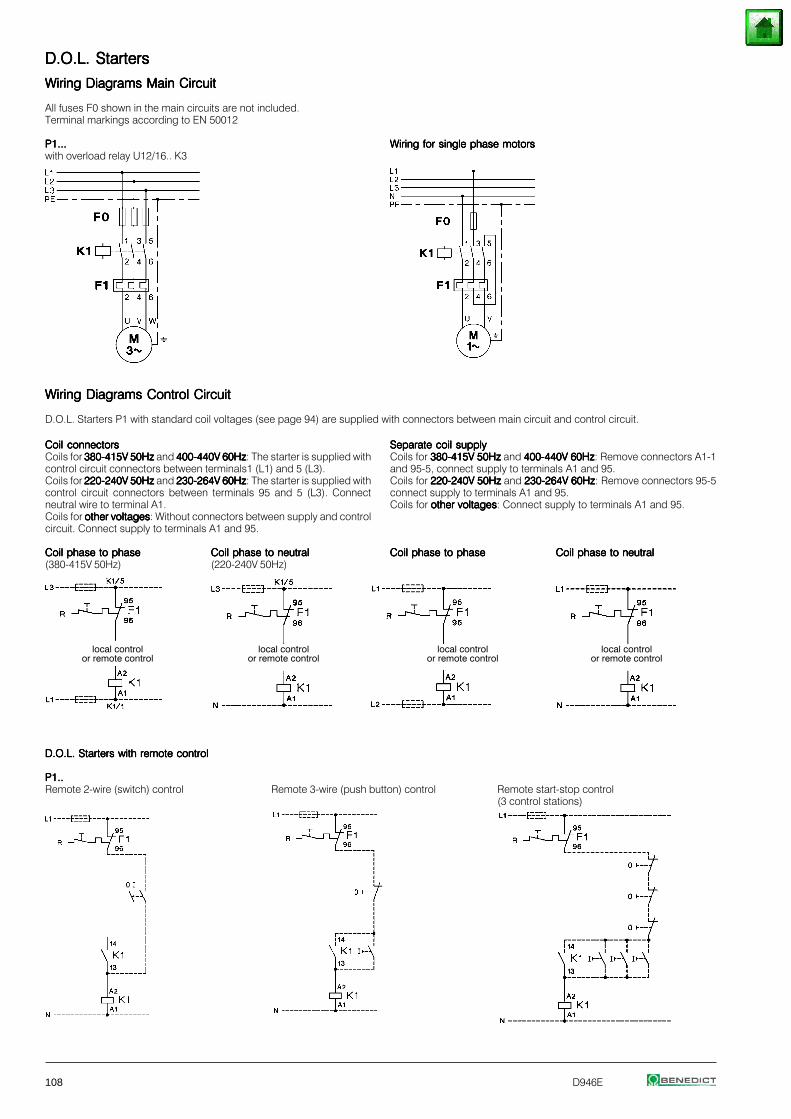
108 D946E
D.O.L. StartersD.O.L. StartersD.O.L. StartersD.O.L. StartersD.O.L. Starters
Wiring Diagrams Main CircuitWiring Diagrams Main CircuitWiring Diagrams Main CircuitWiring Diagrams Main CircuitWiring Diagrams Main Circuit
All fuses F0 shown in the main circuits are not included.Terminal markings according to EN 50012
P1...P1...P1...P1...P1... Wiring for single phase motorsWiring for single phase motorsWiring for single phase motorsWiring for single phase motorsWiring for single phase motorswith overload relay U12/16.. K3
Wiring Diagrams Control CircuitWiring Diagrams Control CircuitWiring Diagrams Control CircuitWiring Diagrams Control CircuitWiring Diagrams Control Circuit
D.O.L. Starters P1 with standard coil voltages (see page 94) are supplied with connectors between main circuit and control circuit.
Coil connectorsCoil connectorsCoil connectorsCoil connectorsCoil connectorsCoils for 380-415V 50Hz380-415V 50Hz380-415V 50Hz380-415V 50Hz380-415V 50Hz and 400-440V 60Hz400-440V 60Hz400-440V 60Hz400-440V 60Hz400-440V 60Hz: The starter is supplied withcontrol circuit connectors between terminals1 (L1) and 5 (L3).Coils for 220-240V 50Hz220-240V 50Hz220-240V 50Hz220-240V 50Hz220-240V 50Hz and 230-264V 60Hz230-264V 60Hz230-264V 60Hz230-264V 60Hz230-264V 60Hz: The starter is supplied withcontrol circuit connectors between terminals 95 and 5 (L3). Connectneutral wire to terminal A1.Coils for other voltagesother voltagesother voltagesother voltagesother voltages: Without connectors between supply and controlcircuit. Connect supply to terminals A1 and 95.
Coil phase to phaseCoil phase to phaseCoil phase to phaseCoil phase to phaseCoil phase to phase Coil phase to neutralCoil phase to neutralCoil phase to neutralCoil phase to neutralCoil phase to neutral(380-415V 50Hz) (220-240V 50Hz)
Separate coil supplySeparate coil supplySeparate coil supplySeparate coil supplySeparate coil supplyCoils for 380-415V 50Hz380-415V 50Hz380-415V 50Hz380-415V 50Hz380-415V 50Hz and 400-440V 60Hz400-440V 60Hz400-440V 60Hz400-440V 60Hz400-440V 60Hz: Remove connectors A1-1and 95-5, connect supply to terminals A1 and 95.Coils for 220-240V 50Hz220-240V 50Hz220-240V 50Hz220-240V 50Hz220-240V 50Hz and 230-264V 60Hz230-264V 60Hz230-264V 60Hz230-264V 60Hz230-264V 60Hz: Remove connectors 95-5connect supply to terminals A1 and 95.Coils for other voltagesother voltagesother voltagesother voltagesother voltages: Connect supply to terminals A1 and 95.
Coil phase to phaseCoil phase to phaseCoil phase to phaseCoil phase to phaseCoil phase to phase Coil phase to neutralCoil phase to neutralCoil phase to neutralCoil phase to neutralCoil phase to neutral
local controlor remote control
local controlor remote control
local controlor remote control
local controlor remote control
D.O.L. Starters with remote controlD.O.L. Starters with remote controlD.O.L. Starters with remote controlD.O.L. Starters with remote controlD.O.L. Starters with remote control
P1..P1..P1..P1..P1..Remote 2-wire (switch) control Remote 3-wire (push button) control Remote start-stop control
(3 control stations)
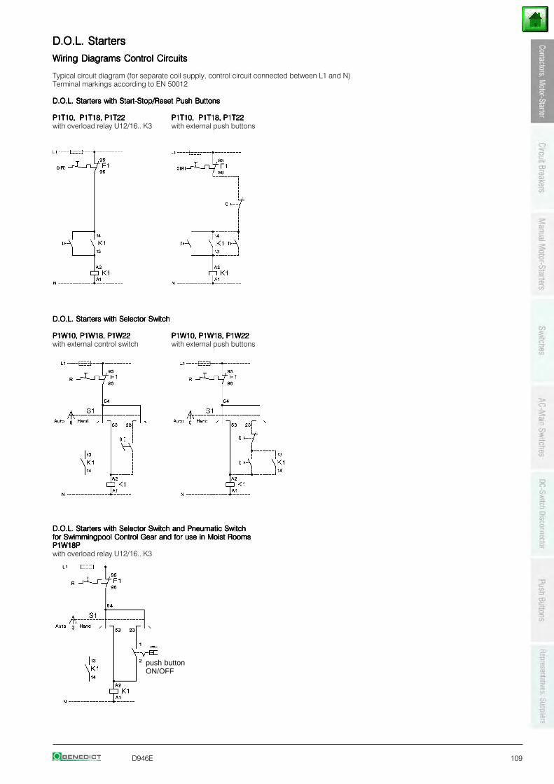
D946E 109
D.O.L. StartersD.O.L. StartersD.O.L. StartersD.O.L. StartersD.O.L. Starters
Wiring Diagrams Control CircuitsWiring Diagrams Control CircuitsWiring Diagrams Control CircuitsWiring Diagrams Control CircuitsWiring Diagrams Control Circuits
Typical circuit diagram (for separate coil supply, control circuit connected between L1 and N)Terminal markings according to EN 50012
D.O.L. Starters with Start-Stop/Reset Push ButtonsD.O.L. Starters with Start-Stop/Reset Push ButtonsD.O.L. Starters with Start-Stop/Reset Push ButtonsD.O.L. Starters with Start-Stop/Reset Push ButtonsD.O.L. Starters with Start-Stop/Reset Push Buttons
P1T10, P1T18, P1T22P1T10, P1T18, P1T22P1T10, P1T18, P1T22P1T10, P1T18, P1T22P1T10, P1T18, P1T22 P1T10, P1T18, P1T22P1T10, P1T18, P1T22P1T10, P1T18, P1T22P1T10, P1T18, P1T22P1T10, P1T18, P1T22with overload relay U12/16.. K3 with external push buttons
D.O.L. Starters with Selector SwitchD.O.L. Starters with Selector SwitchD.O.L. Starters with Selector SwitchD.O.L. Starters with Selector SwitchD.O.L. Starters with Selector Switch
P1W10, P1W18, P1W22P1W10, P1W18, P1W22P1W10, P1W18, P1W22P1W10, P1W18, P1W22P1W10, P1W18, P1W22 P1W10, P1W18, P1W22P1W10, P1W18, P1W22P1W10, P1W18, P1W22P1W10, P1W18, P1W22P1W10, P1W18, P1W22with external control switch with external push buttons
D.O.L. Starters with Selector Switch and Pneumatic SwitchD.O.L. Starters with Selector Switch and Pneumatic SwitchD.O.L. Starters with Selector Switch and Pneumatic SwitchD.O.L. Starters with Selector Switch and Pneumatic SwitchD.O.L. Starters with Selector Switch and Pneumatic Switchfor Swimmingpool Control Gear and for use in Moist Roomsfor Swimmingpool Control Gear and for use in Moist Roomsfor Swimmingpool Control Gear and for use in Moist Roomsfor Swimmingpool Control Gear and for use in Moist Roomsfor Swimmingpool Control Gear and for use in Moist RoomsP1W18PP1W18PP1W18PP1W18PP1W18Pwith overload relay U12/16.. K3
push buttonON/OFF
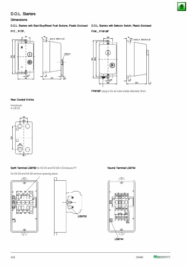
110 D946E
D.O.L. StartersD.O.L. StartersD.O.L. StartersD.O.L. StartersD.O.L. Starters
DimensionsDimensionsDimensionsDimensionsDimensions
D.O.L. Starters with Start-Stop/Reset Push Buttons, Plastic EnclosedD.O.L. Starters with Start-Stop/Reset Push Buttons, Plastic EnclosedD.O.L. Starters with Start-Stop/Reset Push Buttons, Plastic EnclosedD.O.L. Starters with Start-Stop/Reset Push Buttons, Plastic EnclosedD.O.L. Starters with Start-Stop/Reset Push Buttons, Plastic Enclosed D.O.L. Starters with Selector Switch, Plastic EnclosedD.O.L. Starters with Selector Switch, Plastic EnclosedD.O.L. Starters with Selector Switch, Plastic EnclosedD.O.L. Starters with Selector Switch, Plastic EnclosedD.O.L. Starters with Selector Switch, Plastic Enclosed
P1T.., P1TP..P1T.., P1TP..P1T.., P1TP..P1T.., P1TP..P1T.., P1TP.. P1W.., P1W18PP1W.., P1W18PP1W.., P1W18PP1W.., P1W18PP1W.., P1W18P
P1W18P:P1W18P:P1W18P:P1W18P:P1W18P: plug-in for air tube inside diameter 3mm
Rear Conduit EntriesRear Conduit EntriesRear Conduit EntriesRear Conduit EntriesRear Conduit Entries
knockouts4 x Ø 23
Earth Terminal LG9750Earth Terminal LG9750Earth Terminal LG9750Earth Terminal LG9750Earth Terminal LG9750 for K2-23 and K2-30 in Enclosure P1 Neutral Terminal LG9744Neutral Terminal LG9744Neutral Terminal LG9744Neutral Terminal LG9744Neutral Terminal LG9744
for K2-23 and K2-30 remove spacing piece
LG9750LG9750LG9750LG9750LG9750
LG9744LG9744LG9744LG9744LG9744
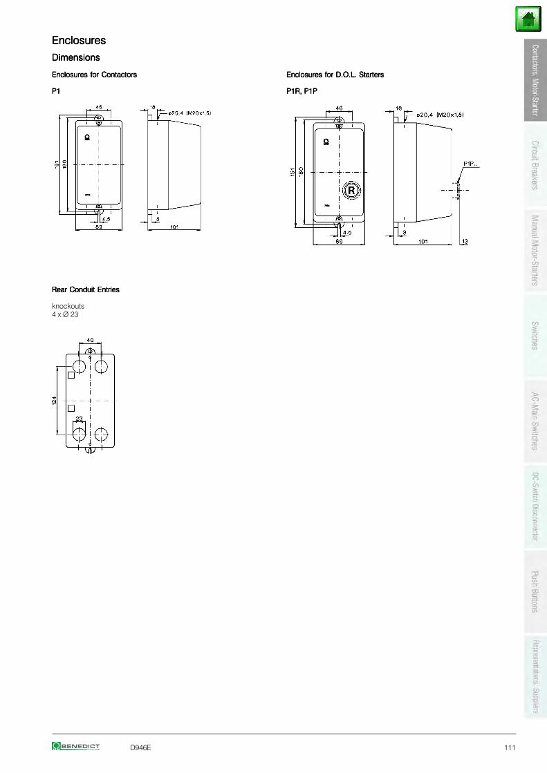
D946E 111
EnclosuresEnclosuresEnclosuresEnclosuresEnclosures
DimensionsDimensionsDimensionsDimensionsDimensions
Enclosures for ContactorsEnclosures for ContactorsEnclosures for ContactorsEnclosures for ContactorsEnclosures for Contactors Enclosures for D.O.L. StartersEnclosures for D.O.L. StartersEnclosures for D.O.L. StartersEnclosures for D.O.L. StartersEnclosures for D.O.L. Starters
P1P1P1P1P1 P1R, P1PP1R, P1PP1R, P1PP1R, P1PP1R, P1P
Rear Conduit EntriesRear Conduit EntriesRear Conduit EntriesRear Conduit EntriesRear Conduit Entries
knockouts4 x Ø 23
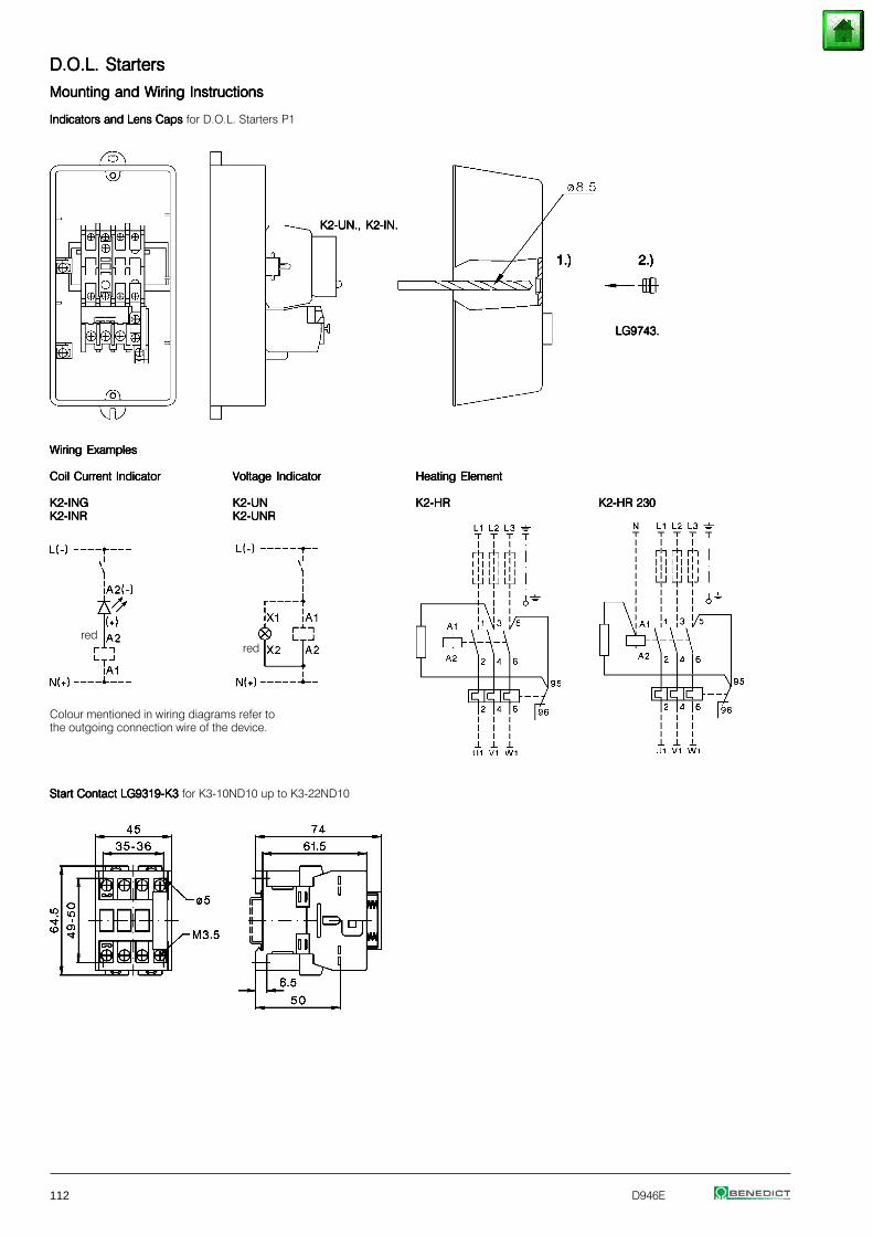
112 D946E
D.O.L. StartersD.O.L. StartersD.O.L. StartersD.O.L. StartersD.O.L. Starters
Mounting and Wiring InstructionsMounting and Wiring InstructionsMounting and Wiring InstructionsMounting and Wiring InstructionsMounting and Wiring Instructions
Indicators and Lens Caps Indicators and Lens Caps Indicators and Lens Caps Indicators and Lens Caps Indicators and Lens Caps for D.O.L. Starters P1
K2-UN., K2-IN.K2-UN., K2-IN.K2-UN., K2-IN.K2-UN., K2-IN.K2-UN., K2-IN.
LG9743.LG9743.LG9743.LG9743.LG9743.
Wiring ExamplesWiring ExamplesWiring ExamplesWiring ExamplesWiring Examples
Coil Current IndicatorCoil Current IndicatorCoil Current IndicatorCoil Current IndicatorCoil Current Indicator Voltage IndicatorVoltage IndicatorVoltage IndicatorVoltage IndicatorVoltage Indicator Heating ElementHeating ElementHeating ElementHeating ElementHeating Element
K2-INGK2-INGK2-INGK2-INGK2-ING K2-UNK2-UNK2-UNK2-UNK2-UN K2-HRK2-HRK2-HRK2-HRK2-HR K2-HR 230K2-HR 230K2-HR 230K2-HR 230K2-HR 230K2-INRK2-INRK2-INRK2-INRK2-INR K2-UNRK2-UNRK2-UNRK2-UNRK2-UNR
redred
Colour mentioned in wiring diagrams refer tothe outgoing connection wire of the device.
Start Contact LG9319-K3 Start Contact LG9319-K3 Start Contact LG9319-K3 Start Contact LG9319-K3 Start Contact LG9319-K3 for K3-10ND10 up to K3-22ND10
D946E 113
Thermal Overload RelaysThermal Overload RelaysThermal Overload RelaysThermal Overload RelaysThermal Overload Relays
Thermal Overload Relays for Direct Mounting 114
Thermal Overload Relays for Separate Mounting 116
Accessories 117
Technical Data 118
Dimensions 123
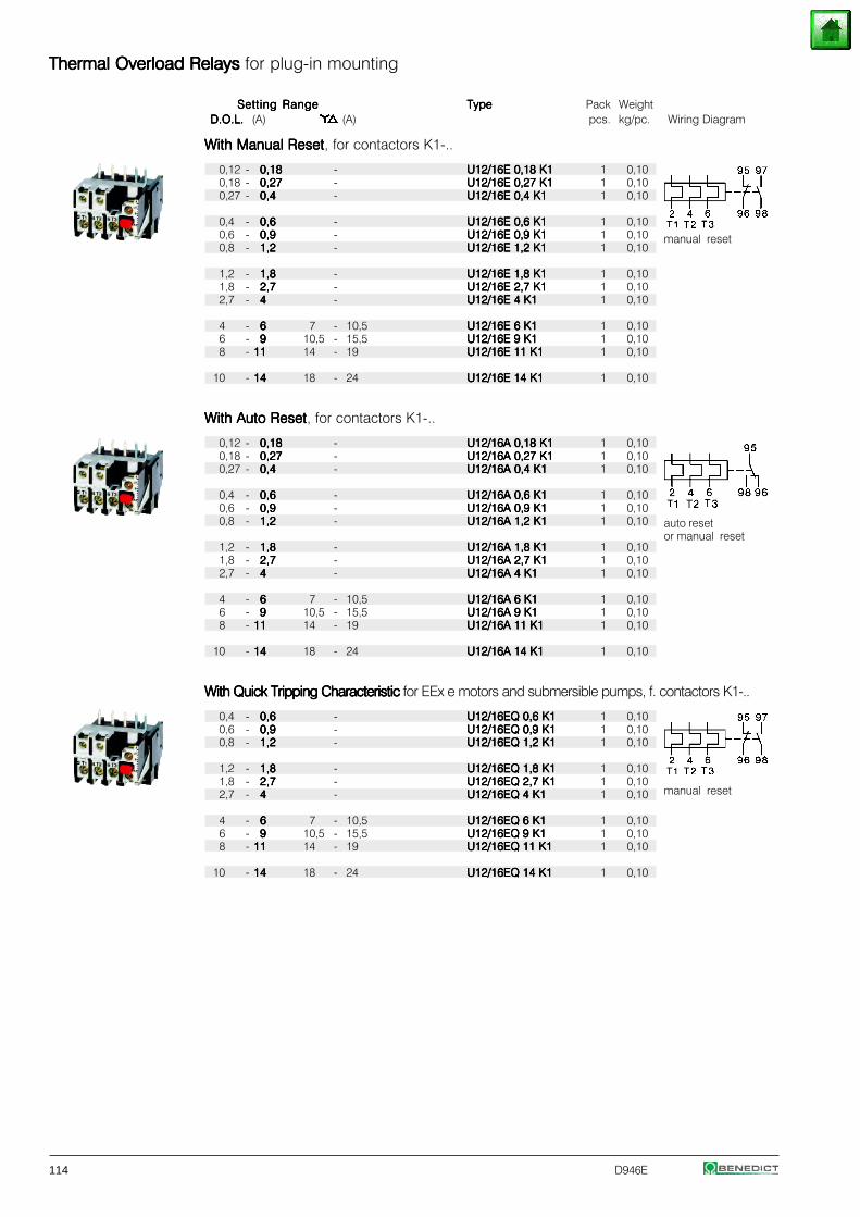
114 D946E
Thermal Overload Relays Thermal Overload Relays Thermal Overload Relays Thermal Overload Relays Thermal Overload Relays for plug-in mounting
Setting RangeSetting RangeSetting RangeSetting RangeSetting Range TypeTypeTypeTypeType Pack WeightD.O.L.D.O.L.D.O.L.D.O.L.D.O.L. (A) (A) pcs. kg/pc. Wiring Diagram
With Manual ResetWith Manual ResetWith Manual ResetWith Manual ResetWith Manual Reset, for contactors K1-..
0,12 - 0,180,180,180,180,18 - U12/16E 0,18 K1U12/16E 0,18 K1U12/16E 0,18 K1U12/16E 0,18 K1U12/16E 0,18 K1 1 0,100,18 - 0,270,270,270,270,27 - U12/16E 0,27 K1U12/16E 0,27 K1U12/16E 0,27 K1U12/16E 0,27 K1U12/16E 0,27 K1 1 0,100,27 - 0,40,40,40,40,4 - U12/16E 0,4 K1U12/16E 0,4 K1U12/16E 0,4 K1U12/16E 0,4 K1U12/16E 0,4 K1 1 0,10
0,4 - 0,60,60,60,60,6 - U12/16E 0,6 K1U12/16E 0,6 K1U12/16E 0,6 K1U12/16E 0,6 K1U12/16E 0,6 K1 1 0,100,6 - 0,90,90,90,90,9 - U12/16E 0,9 K1U12/16E 0,9 K1U12/16E 0,9 K1U12/16E 0,9 K1U12/16E 0,9 K1 1 0,100,8 - 1,21,21,21,21,2 - U12/16E 1,2 K1U12/16E 1,2 K1U12/16E 1,2 K1U12/16E 1,2 K1U12/16E 1,2 K1 1 0,10
1,2 - 1,81,81,81,81,8 - U12/16E 1,8 K1U12/16E 1,8 K1U12/16E 1,8 K1U12/16E 1,8 K1U12/16E 1,8 K1 1 0,101,8 - 2,72,72,72,72,7 - U12/16E 2,7 K1U12/16E 2,7 K1U12/16E 2,7 K1U12/16E 2,7 K1U12/16E 2,7 K1 1 0,102,7 - 44444 - U12/16E 4 K1U12/16E 4 K1U12/16E 4 K1U12/16E 4 K1U12/16E 4 K1 1 0,10
4 - 66666 7 - 10,5 U12/16E 6 K1U12/16E 6 K1U12/16E 6 K1U12/16E 6 K1U12/16E 6 K1 1 0,106 - 99999 10,5 - 15,5 U12/16E 9 K1U12/16E 9 K1U12/16E 9 K1U12/16E 9 K1U12/16E 9 K1 1 0,108 - 1111111111 14 - 19 U12/16E 11 K1U12/16E 11 K1U12/16E 11 K1U12/16E 11 K1U12/16E 11 K1 1 0,10
10 - 1414141414 18 - 24 U12/16E 14 K1U12/16E 14 K1U12/16E 14 K1U12/16E 14 K1U12/16E 14 K1 1 0,10
With Auto ResetWith Auto ResetWith Auto ResetWith Auto ResetWith Auto Reset, for contactors K1-..
0,12 - 0,180,180,180,180,18 - U12/16A 0,18 K1U12/16A 0,18 K1U12/16A 0,18 K1U12/16A 0,18 K1U12/16A 0,18 K1 1 0,100,18 - 0,270,270,270,270,27 - U12/16A 0,27 K1U12/16A 0,27 K1U12/16A 0,27 K1U12/16A 0,27 K1U12/16A 0,27 K1 1 0,100,27 - 0,40,40,40,40,4 - U12/16A 0,4 K1U12/16A 0,4 K1U12/16A 0,4 K1U12/16A 0,4 K1U12/16A 0,4 K1 1 0,10
0,4 - 0,60,60,60,60,6 - U12/16A 0,6 K1U12/16A 0,6 K1U12/16A 0,6 K1U12/16A 0,6 K1U12/16A 0,6 K1 1 0,100,6 - 0,90,90,90,90,9 - U12/16A 0,9 K1U12/16A 0,9 K1U12/16A 0,9 K1U12/16A 0,9 K1U12/16A 0,9 K1 1 0,100,8 - 1,21,21,21,21,2 - U12/16A 1,2 K1U12/16A 1,2 K1U12/16A 1,2 K1U12/16A 1,2 K1U12/16A 1,2 K1 1 0,10
1,2 - 1,81,81,81,81,8 - U12/16A 1,8 K1U12/16A 1,8 K1U12/16A 1,8 K1U12/16A 1,8 K1U12/16A 1,8 K1 1 0,101,8 - 2,72,72,72,72,7 - U12/16A 2,7 K1U12/16A 2,7 K1U12/16A 2,7 K1U12/16A 2,7 K1U12/16A 2,7 K1 1 0,102,7 - 44444 - U12/16A 4 K1U12/16A 4 K1U12/16A 4 K1U12/16A 4 K1U12/16A 4 K1 1 0,10
4 - 66666 7 - 10,5 U12/16A 6 K1U12/16A 6 K1U12/16A 6 K1U12/16A 6 K1U12/16A 6 K1 1 0,106 - 99999 10,5 - 15,5 U12/16A 9 K1U12/16A 9 K1U12/16A 9 K1U12/16A 9 K1U12/16A 9 K1 1 0,108 - 1111111111 14 - 19 U12/16A 11 K1U12/16A 11 K1U12/16A 11 K1U12/16A 11 K1U12/16A 11 K1 1 0,10
10 - 1414141414 18 - 24 U12/16A 14 K1U12/16A 14 K1U12/16A 14 K1U12/16A 14 K1U12/16A 14 K1 1 0,10
With Quick Tripping Characteristic With Quick Tripping Characteristic With Quick Tripping Characteristic With Quick Tripping Characteristic With Quick Tripping Characteristic for EEx e motors and submersible pumps, f. contactors K1-..
0,4 - 0,60,60,60,60,6 - U12/16EQ 0,6 K1U12/16EQ 0,6 K1U12/16EQ 0,6 K1U12/16EQ 0,6 K1U12/16EQ 0,6 K1 1 0,100,6 - 0,90,90,90,90,9 - U12/16EQ 0,9 K1U12/16EQ 0,9 K1U12/16EQ 0,9 K1U12/16EQ 0,9 K1U12/16EQ 0,9 K1 1 0,100,8 - 1,21,21,21,21,2 - U12/16EQ 1,2 K1U12/16EQ 1,2 K1U12/16EQ 1,2 K1U12/16EQ 1,2 K1U12/16EQ 1,2 K1 1 0,10
1,2 - 1,81,81,81,81,8 - U12/16EQ 1,8 K1U12/16EQ 1,8 K1U12/16EQ 1,8 K1U12/16EQ 1,8 K1U12/16EQ 1,8 K1 1 0,101,8 - 2,72,72,72,72,7 - U12/16EQ 2,7 K1U12/16EQ 2,7 K1U12/16EQ 2,7 K1U12/16EQ 2,7 K1U12/16EQ 2,7 K1 1 0,102,7 - 44444 - U12/16EQ 4 K1U12/16EQ 4 K1U12/16EQ 4 K1U12/16EQ 4 K1U12/16EQ 4 K1 1 0,10
4 - 66666 7 - 10,5 U12/16EQ 6 K1U12/16EQ 6 K1U12/16EQ 6 K1U12/16EQ 6 K1U12/16EQ 6 K1 1 0,106 - 99999 10,5 - 15,5 U12/16EQ 9 K1U12/16EQ 9 K1U12/16EQ 9 K1U12/16EQ 9 K1U12/16EQ 9 K1 1 0,108 - 1111111111 14 - 19 U12/16EQ 11 K1U12/16EQ 11 K1U12/16EQ 11 K1U12/16EQ 11 K1U12/16EQ 11 K1 1 0,10
10 - 1414141414 18 - 24 U12/16EQ 14 K1U12/16EQ 14 K1U12/16EQ 14 K1U12/16EQ 14 K1U12/16EQ 14 K1 1 0,10
manual reset
manual reset
auto resetor manual reset
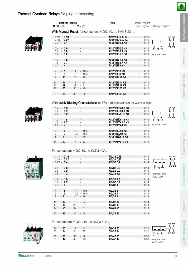
D946E 115
Thermal Overload Relays Thermal Overload Relays Thermal Overload Relays Thermal Overload Relays Thermal Overload Relays for plug-in mounting
Setting RangeSetting RangeSetting RangeSetting RangeSetting Range TypeTypeTypeTypeType Pack WeightD.O.L.D.O.L.D.O.L.D.O.L.D.O.L. (A) (A) pcs. kg/pc. Wiring Diagram
With Manual ResetWith Manual ResetWith Manual ResetWith Manual ResetWith Manual Reset, for contactors K(G)3-10.. to K(G)3-22.. ..
0,12 - 0,180,180,180,180,18 - U12/16E 0,18 K3U12/16E 0,18 K3U12/16E 0,18 K3U12/16E 0,18 K3U12/16E 0,18 K3 1 0,100,18 - 0,270,270,270,270,27 - U12/16E 0,27 K3U12/16E 0,27 K3U12/16E 0,27 K3U12/16E 0,27 K3U12/16E 0,27 K3 1 0,100,27 - 0,40,40,40,40,4 - U12/16E 0,4 K3U12/16E 0,4 K3U12/16E 0,4 K3U12/16E 0,4 K3U12/16E 0,4 K3 1 0,10
0,4 - 0,60,60,60,60,6 - U12/16E 0,6 K3U12/16E 0,6 K3U12/16E 0,6 K3U12/16E 0,6 K3U12/16E 0,6 K3 1 0,100,6 - 0,90,90,90,90,9 - U12/16E 0,9 K3U12/16E 0,9 K3U12/16E 0,9 K3U12/16E 0,9 K3U12/16E 0,9 K3 1 0,100,8 - 1,21,21,21,21,2 - U12/16E 1,2 K3U12/16E 1,2 K3U12/16E 1,2 K3U12/16E 1,2 K3U12/16E 1,2 K3 1 0,10
1,2 - 1,81,81,81,81,8 - U12/16E 1,8 K3U12/16E 1,8 K3U12/16E 1,8 K3U12/16E 1,8 K3U12/16E 1,8 K3 1 0,101,8 - 2,72,72,72,72,7 - U12/16E 2,7 K3U12/16E 2,7 K3U12/16E 2,7 K3U12/16E 2,7 K3U12/16E 2,7 K3 1 0,102,7 - 44444 - U12/16E 4 K3U12/16E 4 K3U12/16E 4 K3U12/16E 4 K3U12/16E 4 K3 1 0,10
4 - 66666 7 - 10,5 U12/16E 6 K3U12/16E 6 K3U12/16E 6 K3U12/16E 6 K3U12/16E 6 K3 1 0,106 - 99999 10,5 - 15,5 U12/16E 9 K3U12/16E 9 K3U12/16E 9 K3U12/16E 9 K3U12/16E 9 K3 1 0,108 - 1111111111 14 - 19 U12/16E 11 K3U12/16E 11 K3U12/16E 11 K3U12/16E 11 K3U12/16E 11 K3 1 0,10
10 - 1414141414 18 - 24 U12/16E 14 K3U12/16E 14 K3U12/16E 14 K3U12/16E 14 K3U12/16E 14 K3 1 0,1013 - 1818181818 23 - 31 U12/16E 18 K3U12/16E 18 K3U12/16E 18 K3U12/16E 18 K3U12/16E 18 K3 1 0,1017 - 2323232323 30 - 40 U12/16E 23 K3U12/16E 23 K3U12/16E 23 K3U12/16E 23 K3U12/16E 23 K3 1 0,10
22 - 3030303030 38 - 52 U12/16E 30 K3U12/16E 30 K3U12/16E 30 K3U12/16E 30 K3U12/16E 30 K3 1 0,13
With quick Tripping Characteristic quick Tripping Characteristic quick Tripping Characteristic quick Tripping Characteristic quick Tripping Characteristic for EEx e motors and under water pumps
0,4 - 0,60,60,60,60,6 - U12/16EQ 0,6 K3U12/16EQ 0,6 K3U12/16EQ 0,6 K3U12/16EQ 0,6 K3U12/16EQ 0,6 K3 1 0,100,6 - 0,90,90,90,90,9 - U12/16EQ 0,9 K3U12/16EQ 0,9 K3U12/16EQ 0,9 K3U12/16EQ 0,9 K3U12/16EQ 0,9 K3 1 0,100,8 - 1,21,21,21,21,2 - U12/16EQ 1,2 K3U12/16EQ 1,2 K3U12/16EQ 1,2 K3U12/16EQ 1,2 K3U12/16EQ 1,2 K3 1 0,10
1,2 - 1,81,81,81,81,8 - U12/16EQ 1,8 K3U12/16EQ 1,8 K3U12/16EQ 1,8 K3U12/16EQ 1,8 K3U12/16EQ 1,8 K3 1 0,101,8 - 2,72,72,72,72,7 - U12/16EQ 2,7 K3U12/16EQ 2,7 K3U12/16EQ 2,7 K3U12/16EQ 2,7 K3U12/16EQ 2,7 K3 1 0,102,7 - 44444 - U12/16EQ 4 K3U12/16EQ 4 K3U12/16EQ 4 K3U12/16EQ 4 K3U12/16EQ 4 K3 1 0,10
4 - 66666 7 - 10,5 U12/16EQ 6 K3U12/16EQ 6 K3U12/16EQ 6 K3U12/16EQ 6 K3U12/16EQ 6 K3 1 0,106 - 99999 10,5 - 15,5 U12/16EQ 9 K3U12/16EQ 9 K3U12/16EQ 9 K3U12/16EQ 9 K3U12/16EQ 9 K3 1 0,108 - 1111111111 14 - 19 U12/16EQ 11 K3U12/16EQ 11 K3U12/16EQ 11 K3U12/16EQ 11 K3U12/16EQ 11 K3 1 0,10
10 - 1414141414 18 - 24 U12/16EQ 14 K3U12/16EQ 14 K3U12/16EQ 14 K3U12/16EQ 14 K3U12/16EQ 14 K3 1 0,10
For contactors K(G)3-10.. to K(G)3-40A..
0,12 - 0,180,180,180,180,18 - U3/32 0,18U3/32 0,18U3/32 0,18U3/32 0,18U3/32 0,18 1 0,140,18 - 0,270,270,270,270,27 - U3/32 0,27U3/32 0,27U3/32 0,27U3/32 0,27U3/32 0,27 1 0,140,27 - 0,40,40,40,40,4 - U3/32 0,4U3/32 0,4U3/32 0,4U3/32 0,4U3/32 0,4 1 0,14
0,4 - 0,60,60,60,60,6 - U3/32 0,6U3/32 0,6U3/32 0,6U3/32 0,6U3/32 0,6 1 0,140,6 - 0,90,90,90,90,9 - U3/32 0,9U3/32 0,9U3/32 0,9U3/32 0,9U3/32 0,9 1 0,140,8 - 1,21,21,21,21,2 - U3/32 1,2U3/32 1,2U3/32 1,2U3/32 1,2U3/32 1,2 1 0,14
1,2 - 1,81,81,81,81,8 - U3/32 1,8U3/32 1,8U3/32 1,8U3/32 1,8U3/32 1,8 1 0,141,8 - 2,72,72,72,72,7 - U3/32 2,7U3/32 2,7U3/32 2,7U3/32 2,7U3/32 2,7 1 0,142,7 - 44444 - U3/32 4U3/32 4U3/32 4U3/32 4U3/32 4 1 0,14
4 - 66666 7 - 10,5 U3/32 6U3/32 6U3/32 6U3/32 6U3/32 6 1 0,146 - 99999 10,5 - 15,5 U3/32 9U3/32 9U3/32 9U3/32 9U3/32 9 1 0,148 - 1111111111 14 - 19 U3/32 11U3/32 11U3/32 11U3/32 11U3/32 11 1 0,14
10 - 1414141414 18 - 24 U3/32 14U3/32 14U3/32 14U3/32 14U3/32 14 1 0,1413 - 1818181818 23 - 31 U3/32 18U3/32 18U3/32 18U3/32 18U3/32 18 1 0,1417 - 2424242424 30 - 41 U3/32 24U3/32 24U3/32 24U3/32 24U3/32 24 1 0,14
23 - 3232323232 40 - 55 U3/32 32U3/32 32U3/32 32U3/32 32U3/32 32 1 0,14
For contactors K(G)3-24A.. to K(G)3-40A ..
10 - 1414141414 18 - 24 U3/42 14U3/42 14U3/42 14U3/42 14U3/42 14 1 0,3014 - 2020202020 24 - 35 U3/42 20U3/42 20U3/42 20U3/42 20U3/42 20 1 0,30
20 - 2828282828 35 - 48 U3/42 28U3/42 28U3/42 28U3/42 28U3/42 28 1 0,3028 - 4242424242 48 - 73 U3/42 42U3/42 42U3/42 42U3/42 42U3/42 42 1 0,30
manual reset
manual andauto reset
manual andauto reset
manual reset
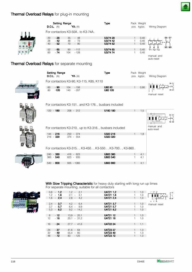
116 D946E
Thermal Overload Relays Thermal Overload Relays Thermal Overload Relays Thermal Overload Relays Thermal Overload Relays for plug-in mounting
Setting RangeSetting RangeSetting RangeSetting RangeSetting Range TypeTypeTypeTypeType Pack WeightD.O.L.D.O.L.D.O.L.D.O.L.D.O.L. (A) (A) pcs. kg/pc. Wiring Diagram
For contactors K3-50A.. to K3-74A..
20 - 2828282828 35 - 48 U3/74 28U3/74 28U3/74 28U3/74 28U3/74 28 1 0,4028 - 4242424242 48 - 73 U3/74 42U3/74 42U3/74 42U3/74 42U3/74 42 1 0,4040 - 5252525252 70 - 90 U3/74 52U3/74 52U3/74 52U3/74 52U3/74 52 1 0,40
52 - 6565656565 90 - 112 U3/74 65U3/74 65U3/74 65U3/74 65U3/74 65 1 0,4060 - 7474747474 104 - 128 U3/74 74U3/74 74U3/74 74U3/74 74U3/74 74 1 0,40
Thermal Overload Relays Thermal Overload Relays Thermal Overload Relays Thermal Overload Relays Thermal Overload Relays for separate mounting
Setting RangeSetting RangeSetting RangeSetting RangeSetting Range TypeTypeTypeTypeType Pack WeightD.O.L.D.O.L.D.O.L.D.O.L.D.O.L. (A) (A) pcs. kg/pc. Wiring Diagram
For contactors K3-90, K3-115, K85, K110
60 - 9090909090 104 - 156 U85 90U85 90U85 90U85 90U85 90 1 0,9080 -120120120120120 140 - 207 U85 120U85 120U85 120U85 120U85 120
For contactors K3-151.. and K3-176.., busbars included
120 - 180180180180180 208 - 312 U180 180U180 180U180 180U180 180U180 180 1 1,5
For contactors K3-210.. up to K3-316.., busbars included
144 - 216216216216216 250 - 374 U320 216U320 216U320 216U320 216U320 216 1 1,8216 - 320320320320320 374 - 554 U320 320U320 320U320 320U320 320U320 320
For contactors K3-315.. , K3-450.. , K3-550.. , K3-700.. , K3-860..
240 - 360360360360360 416 - 623 U800 360U800 360U800 360U800 360U800 360 1 4,1360 - 540540540540540 623 - 935 U800 540U800 540U800 540U800 540U800 540 1 4,1
540 - 800800800800800 935 - 1385 U800 800U800 800U800 800U800 800U800 800 1 4,1
With Slow Tripping Characteristic With Slow Tripping Characteristic With Slow Tripping Characteristic With Slow Tripping Characteristic With Slow Tripping Characteristic for heavy duty starting with long run up timesFor separate mounting, suitable for all contactors
0,8 - 1,21,21,21,21,2 1,2 - 2,1 UAT21 1,2UAT21 1,2UAT21 1,2UAT21 1,2UAT21 1,2 1 1,01,2 - 1,81,81,81,81,8 2,1 - 3,1 UAT21 1,8UAT21 1,8UAT21 1,8UAT21 1,8UAT21 1,8 1 1,01,6 - 2,42,42,42,42,4 2,8 - 4,2 UAT21 2,4UAT21 2,4UAT21 2,4UAT21 2,4UAT21 2,4 1 1,0
2,4 - 3,73,73,73,73,7 4,2 - 6,4 UAT21 3,7UAT21 3,7UAT21 3,7UAT21 3,7UAT21 3,7 1 1,03,7 - 5,75,75,75,75,7 6,4 - 9,9 UAT21 5,7UAT21 5,7UAT21 5,7UAT21 5,7UAT21 5,7 1 1,05,3 - 8,28,28,28,28,2 9,2 - 14,2 UAT21 8,2UAT21 8,2UAT21 8,2UAT21 8,2UAT21 8,2 1 1,0
8 - 1212121212 13,9 - 20,1 UAT21 12UAT21 12UAT21 12UAT21 12UAT21 12 1 1,012 - 1818181818 20,1 - 31,2 UAT21 18UAT21 18UAT21 18UAT21 18UAT21 18 1 1,0
16 - 2424242424 27,7 - 41,6 UAT22 24UAT22 24UAT22 24UAT22 24UAT22 24 1 1,1
24 - 3737373737 41,6 - 64 UAT23 37UAT23 37UAT23 37UAT23 37UAT23 37 1 1,332 - 4949494949 55,4 - 85 UAT23 49UAT23 49UAT23 49UAT23 49UAT23 49 1 1,348 - 7272727272 83 - 125 UAT23 72UAT23 72UAT23 72UAT23 72UAT23 72 1 1,3
manual reset
manual andauto reset
manual reset
manual andauto reset
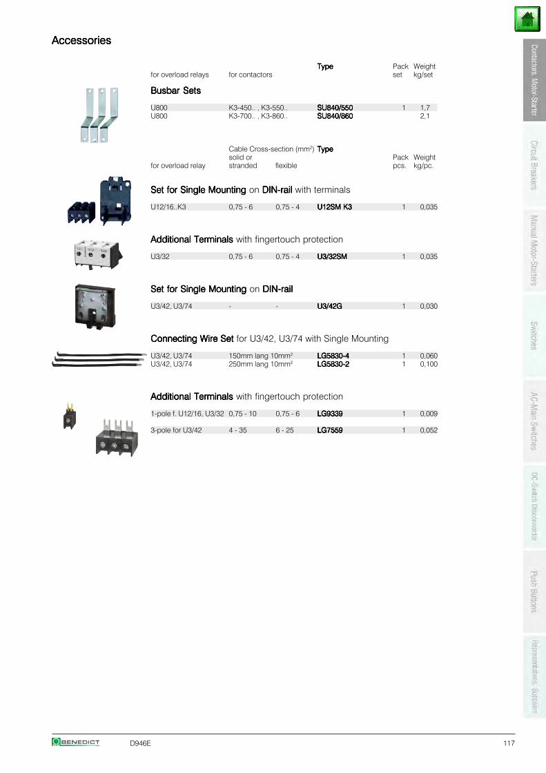
D946E 117
AccessoriesAccessoriesAccessoriesAccessoriesAccessories
TypeTypeTypeTypeType Pack Weightfor overload relays for contactors set kg/set
Busbar SetsBusbar SetsBusbar SetsBusbar SetsBusbar Sets
U800 K3-450.. , K3-550.. SU840/550SU840/550SU840/550SU840/550SU840/550 1 1,7U800 K3-700.. , K3-860.. SU840/860SU840/860SU840/860SU840/860SU840/860 2,1
Cable Cross-section (mm2) TypeTypeTypeTypeTypesolid or Pack Weight
for overload relay stranded flexible pcs. kg/pc.
Set for Single Mounting Set for Single Mounting Set for Single Mounting Set for Single Mounting Set for Single Mounting on DIN-rail DIN-rail DIN-rail DIN-rail DIN-rail with terminals
U12/16..K3 0,75 - 6 0,75 - 4 U12SM K3U12SM K3U12SM K3U12SM K3U12SM K3 1 0,035
Additional TerminalsAdditional TerminalsAdditional TerminalsAdditional TerminalsAdditional Terminals with fingertouch protection
U3/32 0,75 - 6 0,75 - 4 U3/32SMU3/32SMU3/32SMU3/32SMU3/32SM 1 0,035
Set for Single Mounting Set for Single Mounting Set for Single Mounting Set for Single Mounting Set for Single Mounting on DIN-railDIN-railDIN-railDIN-railDIN-rail
U3/42, U3/74 - - U3/42GU3/42GU3/42GU3/42GU3/42G 1 0,030
Connecting Wire SetConnecting Wire SetConnecting Wire SetConnecting Wire SetConnecting Wire Set for U3/42, U3/74 with Single Mounting
U3/42, U3/74 150mm lang 10mm2 LG5830-4LG5830-4LG5830-4LG5830-4LG5830-4 1 0,060U3/42, U3/74 250mm lang 10mm2 LG5830-2LG5830-2LG5830-2LG5830-2LG5830-2 1 0,100
Additional TerminalsAdditional TerminalsAdditional TerminalsAdditional TerminalsAdditional Terminals with fingertouch protection
1-pole f. U12/16, U3/32 0,75 - 10 0,75 - 6 LG9339LG9339LG9339LG9339LG9339 1 0,009
3-pole for U3/42 4 - 35 6 - 25 LG7559LG7559LG7559LG7559LG7559 1 0,052
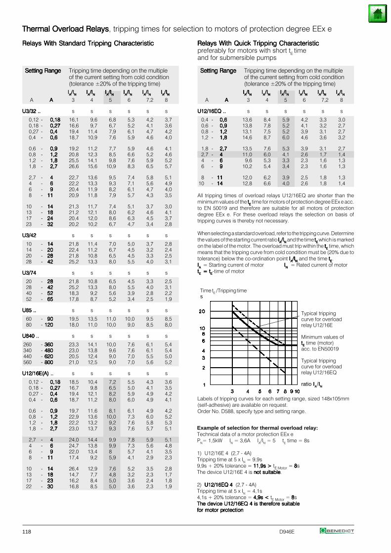
118 D946E
Thermal Overload RelaysThermal Overload RelaysThermal Overload RelaysThermal Overload RelaysThermal Overload Relays, tripping times for selection to motors of protection degree EEx e
Relays With Standard Tripping CharacteristicRelays With Standard Tripping CharacteristicRelays With Standard Tripping CharacteristicRelays With Standard Tripping CharacteristicRelays With Standard Tripping Characteristic
Setting RangeSetting RangeSetting RangeSetting RangeSetting Range Tripping time depending on the multipleof the current setting from cold condition(tolerance ±20% of the tripping time)IIIIIAAAAA/I/I/I/I/INNNNN IIIIIAAAAA/I/I/I/I/INNNNN IIIIIAAAAA/I/I/I/I/INNNNN IIIIIAAAAA/I/I/I/I/INNNNN IIIIIAAAAA/I/I/I/I/INNNNN IIIIIAAAAA/I/I/I/I/INNNNN
A AAAAA 3 4 5 6 7,2 8
U3/32 ..U3/32 ..U3/32 ..U3/32 ..U3/32 .. s s s s s s
0,12 - 0,180,180,180,180,18 16,1 9,6 6,8 5,3 4,2 3,70,18 - 0,270,270,270,270,27 16,6 9,7 6,7 5,2 4,1 3,60,27 - 0,40,40,40,40,4 19,4 11,4 7,9 6,1 4,7 4,20,4 - 0,60,60,60,60,6 18,7 10,9 7,6 5,9 4,6 4,0
0,6 - 0,90,90,90,90,9 19,2 11,2 7,7 5,9 4,6 4,10,8 - 1,21,21,21,21,2 20,8 12,3 8,5 6,6 5,2 4,61,2 - 1,81,81,81,81,8 25,5 14,1 9,8 7,6 5,9 5,21,8 - 2,72,72,72,72,7 26,6 15,6 10,9 8,3 6,5 5,7
2,7 - 44444 22,7 13,6 9,5 7,4 5,8 5,14 - 66666 22,2 13,3 9,3 7,1 5,6 4,96 - 99999 20,4 11,9 8,2 6,1 4,7 4,08 - 1111111111 20,9 11,8 7,9 5,7 4,3 3,5
10 - 1414141414 21,3 11,7 7,4 5,1 3,7 3,013 - 1818181818 21,2 12,1 8,0 6,2 4,6 4,117 - 2424242424 20,4 12,0 8,6 6,3 4,5 3,723 - 3232323232 20,2 10,2 6,7 4,7 3,4 2,8
U3/42U3/42U3/42U3/42U3/42 s s s s s s
10 - 1414141414 21,8 11,4 7,0 5,0 3,7 2,814 - 2020202020 22,4 11,2 6,7 4,5 3,2 2,420 - 2828282828 21,8 10,8 6,5 4,5 3,3 2,528 - 4242424242 25,2 13,3 8,0 5,5 4,0 3,1
U3/74U3/74U3/74U3/74U3/74 s s s s s s
20 - 2828282828 21,8 10,8 6,5 4,5 3,3 2,528 - 4242424242 25,2 13,3 8,0 5,5 4,0 3,140 - 5252525252 18,3 9,2 5,6 3,9 2,8 2,252 - 6565656565 17,8 8,7 5,2 3,4 2,5 1,9
U85 ..U85 ..U85 ..U85 ..U85 .. s s s s s s
60 - 9090909090 19,5 13,5 11,0 10,0 9,5 8,580 - 120120120120120 18,0 11,0 10,0 9,0 8,5 8,0
U840 ..U840 ..U840 ..U840 ..U840 .. s s s s s s
260 - 360360360360360 23,3 14,1 10,0 7,6 6,1 5,4340 - 480480480480480 23,0 13,8 9,6 7,6 6,1 5,4440 - 620620620620620 20,5 12,4 9,0 7,0 5,5 5,0560 - 800800800800800 21,0 12,5 9,0 7,0 5,6 5,2
U12/16E(A) ..U12/16E(A) ..U12/16E(A) ..U12/16E(A) ..U12/16E(A) .. s s s s s s
0,12 - 0,180,180,180,180,18 18,5 10,4 7,2 5,5 4,3 3,60,18 - 0,270,270,270,270,27 16,7 9,8 6,5 5,0 4,1 3,50,27 - 0,40,40,40,40,4 19,4 12,1 8,2 5,9 4,9 4,20,4 - 0,60,60,60,60,6 18,7 11,2 8,0 6,0 4,9 4,1
0,6 - 0,90,90,90,90,9 19,7 11,6 8,1 6,1 4,9 4,20,8 - 1,21,21,21,21,2 22,9 13,6 10,0 7,3 6,0 5,21,2 - 1,81,81,81,81,8 22,2 13,2 9,2 7,6 5,8 5,31,8 - 2,72,72,72,72,7 23,0 13,7 9,3 7,6 5,7 5,1
2,7 - 44444 24,0 14,4 9,9 7,8 5,9 5,14 - 66666 24,7 13,8 9,9 7,3 5,6 4,86 - 99999 22,0 13,4 8 5,7 4,1 3,58 - 1111111111 17,4 9,2 5,9 4,1 2,9 2,3
10 - 1414141414 26,4 12,9 7,6 5,2 3,5 2,813 - 1818181818 14,7 7,7 4,8 3,2 2,3 1,717 - 2323232323 16,2 8,4 5,0 3,6 2,4 1,822 - 3030303030 16,8 8,5 5,0 3,6 2,3 1,9
Relays With Quick Tripping CharacteristicRelays With Quick Tripping CharacteristicRelays With Quick Tripping CharacteristicRelays With Quick Tripping CharacteristicRelays With Quick Tripping Characteristicpreferably for motors with short tE timeand for submersible pumps
Setting RangeSetting RangeSetting RangeSetting RangeSetting Range Tripping time depending on the multipleof the current setting from cold condition(tolerance ±20% of the tripping time)IIIIIAAAAA/I/I/I/I/INNNNN IIIIIAAAAA/I/I/I/I/INNNNN IIIIIAAAAA/I/I/I/I/INNNNN IIIIIAAAAA/I/I/I/I/INNNNN IIIIIAAAAA/I/I/I/I/INNNNN IIIIIAAAAA/I/I/I/I/INNNNN
A AAAAA 3 4 5 6 7,2 8
U12/16EQ ..U12/16EQ ..U12/16EQ ..U12/16EQ ..U12/16EQ .. s s s s s s
0,4 - 0,60,60,60,60,6 13,6 8,4 5,9 4,2 3,3 3,00,6 - 0,90,90,90,90,9 13,8 7,8 5,2 4,1 3,2 2,70,8 - 1,21,21,21,21,2 13,1 7,5 5,2 3,9 3,1 2,71,2 - 1,81,81,81,81,8 14,6 8,7 6,0 4,6 3,6 3,2
1,8 - 2,72,72,72,72,7 13,5 7,6 5,3 3,9 3,1 2,72,7 - 44444 11,0 6,0 4,1 2,6 1,7 1,44 - 66666 9,6 5,3 3,3 2,3 1,6 1,36 - 99999 10,2 5,4 3,4 2,3 1,6 1,3
8 - 1111111111 12,0 6,2 3,9 2,5 1,8 1,310 - 1414141414 12,8 6,6 4,0 2,6 1,8 1,4
All tripping times of overload relays U12/16EQ are shorter than theminimum values of the tttttEEEEE time for motors of protection degree EEx e acc.to EN 50019 and therefore are suitable for all motors of protectiondegree EEx e. For these overload relays the selection on basis oftripping curves is thereby not necessary.
When selecting a standard overload, refer to the tripping curve. Determinethe values of the starting current ratio IIIIIAAAAA/I/I/I/I/INNNNN and the time tttttEEEEE which is markedon the label of the motor. The overload must trip within the tttttEEEEE time, whichmeans that the tripping curve from cold condition must be (20% due totolerance) below the co-ordination point IIIIIAAAAA/I/I/I/I/INNNNN and the time tttttEEEEE.IIIIIAAAAA = Starting current of motor IIIIINNNNN = Rated current of motortttttEEEEE = t= t= t= t= tEEEEE-time of motor
Labels of tripping curves for each setting range, sized 148x105mm(self-adhesive) are available on request.Order No. D588, specify type and setting range.
ratio IA/IN
Time tE /Tripping times
Example of selection for thermal overload relay:Technical data of a motor protection EEx ePN= 1,5kW IN = 3,6A IA/IN = 5 tE time = 8s
1) U12/16E 4 (2,7 - 4A)Tripping time at 5 x IN = 9,9s9,9s + 20% tolerance = 11,9s11,9s11,9s11,9s11,9s >>>>> tE Motor = 88888sThe device U12/16E 4 is not suitablenot suitablenot suitablenot suitablenot suitable.
2) U12/16EQ 4 U12/16EQ 4 U12/16EQ 4 U12/16EQ 4 U12/16EQ 4 (2,7 - 4A)Tripping time at 5 x IN = 4,1s4,1s + 20% tolerance = 4,9s <4,9s <4,9s <4,9s <4,9s < tE Motor = 88888sThe device U12/16EQ 4 is therefore suitableThe device U12/16EQ 4 is therefore suitableThe device U12/16EQ 4 is therefore suitableThe device U12/16EQ 4 is therefore suitableThe device U12/16EQ 4 is therefore suitablefor motor protectionfor motor protectionfor motor protectionfor motor protectionfor motor protection
Typical trippingcurve for overloadrelay U12/16E
Minimum values oftttttEEEEE time (motor)acc. to EN50019
Typical trippingcurve for overloadrelay U12/16EQ
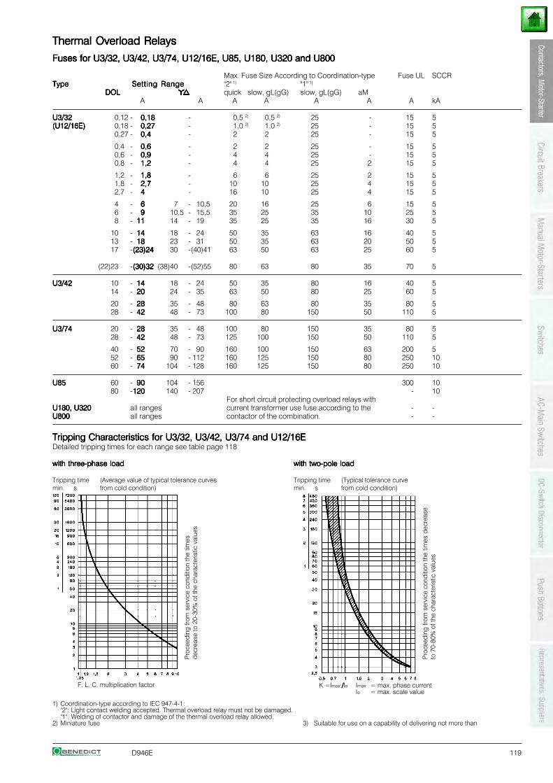
D946E 119
Thermal Overload RelaysThermal Overload RelaysThermal Overload RelaysThermal Overload RelaysThermal Overload Relays
Fuses for U3/32, U3/42, U3/74, U12/16E, U85, U180, U320 and U800Fuses for U3/32, U3/42, U3/74, U12/16E, U85, U180, U320 and U800Fuses for U3/32, U3/42, U3/74, U12/16E, U85, U180, U320 and U800Fuses for U3/32, U3/42, U3/74, U12/16E, U85, U180, U320 and U800Fuses for U3/32, U3/42, U3/74, U12/16E, U85, U180, U320 and U800
Max. Fuse Size According to Coordination-type Fuse UL SCCRTypeTypeTypeTypeType Setting RangeSetting RangeSetting RangeSetting RangeSetting Range "2" 1) "1" 1)
DOLDOLDOLDOLDOL quick slow, gL(gG) slow, gL(gG) aMA A A A A A A kA
U3/32U3/32U3/32U3/32U3/32 0,12 - 0,180,180,180,180,18 - 0,5 2) 0,5 2) 25 - 15 5(U12/16E)(U12/16E)(U12/16E)(U12/16E)(U12/16E) 0,18 - 0,270,270,270,270,27 - 1,0 2) 1,0 2) 25 - 15 5
0,27 - 0,40,40,40,40,4 - 2 2 25 - 15 5
0,4 - 0,60,60,60,60,6 - 2 2 25 - 15 50,6 - 0,90,90,90,90,9 - 4 4 25 - 15 50,8 - 1,21,21,21,21,2 - 4 4 25 2 15 5
1,2 - 1,81,81,81,81,8 - 6 6 25 2 15 51,8 - 2,72,72,72,72,7 - 10 10 25 4 15 52,7 - 44444 - 16 10 25 4 15 5
4 - 66666 7 - 10,5 20 16 25 6 15 56 - 99999 10,5 - 15,5 35 25 35 10 25 58 - 1111111111 14 - 19 35 25 35 16 30 5
10 - 1414141414 18 - 24 50 35 63 16 40 513 - 1818181818 23 - 31 50 35 63 20 50 517 -(23)24(23)24(23)24(23)24(23)24 30 -(40)41 63 50 63 25 60 5
(22)23 -(30)32(30)32(30)32(30)32(30)32 (38)40 -(52)55 80 63 80 35 70 5
U3/42U3/42U3/42U3/42U3/42 10 - 1414141414 18 - 24 50 35 80 16 40 514 - 2020202020 24 - 35 63 50 80 25 60 5
20 - 2828282828 35 - 48 80 63 80 35 80 528 - 4242424242 48 - 73 100 80 150 50 110 5
U3/74U3/74U3/74U3/74U3/74 20 - 2828282828 35 - 48 100 80 150 35 80 528 - 4242424242 48 - 73 125 100 150 50 110 5
40 - 5252525252 70 - 90 160 100 150 63 200 552 - 6565656565 90 - 112 160 125 150 80 250 1060 - 7474747474 104 - 128 160 125 150 80 250 10
U85U85U85U85U85 60 - 9090909090 104 - 156 300 1080 -120120120120120 140 - 207 - 10
For short circuit protecting overload relays withU180, U320U180, U320U180, U320U180, U320U180, U320 all ranges current transformer use fuse according to the - -U800U800U800U800U800 all ranges contactor of the combination. - -
1) Coordination-type according to IEC 947-4-1:"2": Light contact welding accepted. Thermal overload relay must not be damaged."1": Welding of contactor and damage of the thermal overload relay allowed.
2) Miniature fuse 3) Suitable for use on a capability of delivering not more than
with two-pole loadwith two-pole loadwith two-pole loadwith two-pole loadwith two-pole load
Tripping time (Typical tolerance curvemin. s from cold condition)
Pro
ceed
ing
from
ser
vice
con
ditio
n th
e tim
es d
ecre
ase
to 7
0-80
% o
f the
cha
ract
eris
tic v
alue
sTripping Characteristics for U3/32, U3/42, U3/74 and U12/16ETripping Characteristics for U3/32, U3/42, U3/74 and U12/16ETripping Characteristics for U3/32, U3/42, U3/74 and U12/16ETripping Characteristics for U3/32, U3/42, U3/74 and U12/16ETripping Characteristics for U3/32, U3/42, U3/74 and U12/16EDetailed tripping times for each range see table page 118
with three-phase loadwith three-phase loadwith three-phase loadwith three-phase loadwith three-phase load
Tripping time (Average value of typical tolerance curvesmin. s from cold condition)
K =Imax /////Ie Imax = max. phase currentIe = max. scale value
F. L. C. multiplication factor
Pro
ceed
ing
from
ser
vice
con
ditio
n th
e tim
esde
crea
se to
20-
30%
of t
he c
hara
cter
istic
val
ues
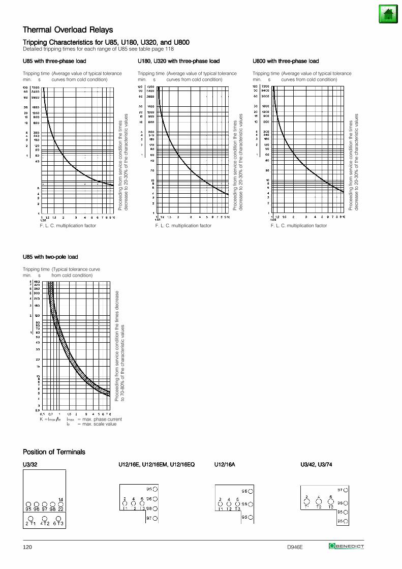
120 D946E
Thermal Overload RelaysThermal Overload RelaysThermal Overload RelaysThermal Overload RelaysThermal Overload Relays
Tripping Characteristics for U85, U180, U320, and U800Tripping Characteristics for U85, U180, U320, and U800Tripping Characteristics for U85, U180, U320, and U800Tripping Characteristics for U85, U180, U320, and U800Tripping Characteristics for U85, U180, U320, and U800Detailed tripping times for each range of U85 see table page 118
U85 with three-phase loadU85 with three-phase loadU85 with three-phase loadU85 with three-phase loadU85 with three-phase load U180, U320 with three-phase loadU180, U320 with three-phase loadU180, U320 with three-phase loadU180, U320 with three-phase loadU180, U320 with three-phase load U800 with three-phase loadU800 with three-phase loadU800 with three-phase loadU800 with three-phase loadU800 with three-phase load
Tripping time (Average value of typical tolerance Tripping time (Average value of typical tolerance Tripping time (Average value of typical tolerancemin. s curves from cold condition) min. s curves from cold condition) min. s curves from cold condition)
U85 with two-pole loadU85 with two-pole loadU85 with two-pole loadU85 with two-pole loadU85 with two-pole load
Tripping time (Typical tolerance curvemin. s from cold condition)
Position of TerminalsPosition of TerminalsPosition of TerminalsPosition of TerminalsPosition of Terminals
U3/32U3/32U3/32U3/32U3/32 U12/16E, U12/16EM, U12/16EQU12/16E, U12/16EM, U12/16EQU12/16E, U12/16EM, U12/16EQU12/16E, U12/16EM, U12/16EQU12/16E, U12/16EM, U12/16EQ U12/16AU12/16AU12/16AU12/16AU12/16A U3/42, U3/74U3/42, U3/74U3/42, U3/74U3/42, U3/74U3/42, U3/74
Pro
ceed
ing
from
ser
vice
con
ditio
n th
e tim
es d
ecre
ase
to 7
0-80
% o
f the
cha
ract
eris
tic v
alue
s
F. L. C. multiplication factor F. L. C. multiplication factor
Pro
ceed
ing
from
ser
vice
con
ditio
n th
e tim
esde
crea
se to
20-
30%
of t
he c
hara
cter
istic
val
ues
Pro
ceed
ing
from
ser
vice
con
ditio
n th
e tim
esde
crea
se to
20-
30%
of t
he c
hara
cter
istic
val
ues
K =Imax /////Ie Imax = max. phase currentIe = max. scale value
Pro
ceed
ing
from
ser
vice
con
ditio
n th
e tim
esde
crea
se to
20-
30%
of t
he c
hara
cter
istic
val
ues
F. L. C. multiplication factor
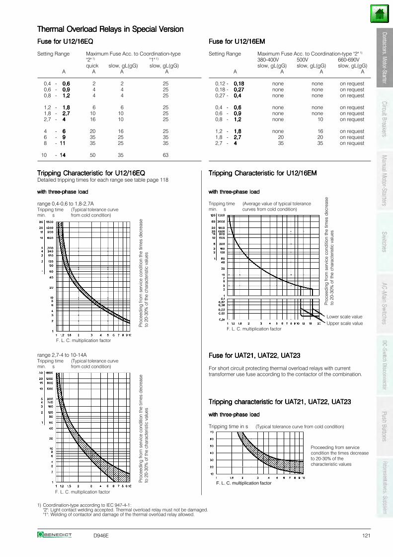
D946E 121
Thermal Overload Relays in Special VersionThermal Overload Relays in Special VersionThermal Overload Relays in Special VersionThermal Overload Relays in Special VersionThermal Overload Relays in Special Version
Fuse for U12/16EQFuse for U12/16EQFuse for U12/16EQFuse for U12/16EQFuse for U12/16EQ
Setting Range Maximum Fuse Acc. to Coordination-type"2" 1) "1" 1)
quick slow, gL(gG) slow, gL(gG)A A A A
0,4 - 0,60,60,60,60,6 2 2 250,6 - 0,90,90,90,90,9 4 4 250,8 - 1,21,21,21,21,2 4 4 25
1,2 - 1,81,81,81,81,8 6 6 251,8 - 2,72,72,72,72,7 10 10 252,7 - 44444 16 10 25
4 - 66666 20 16 256 - 99999 35 25 358 - 1111111111 35 25 35
10 - 1414141414 50 35 63
1) Coordination-type according to IEC 947-4-1:"2": Light contact welding accepted. Thermal overload relay must not be damaged."1": Welding of contactor and damage of the thermal overload relay allowed.
Fuse for U12/16EMFuse for U12/16EMFuse for U12/16EMFuse for U12/16EMFuse for U12/16EM
Setting Range Maximum Fuse Acc. to Coordination-type "2" 1)
380-400V 500V 660-690Vslow, gL(gG) slow, gL(gG) slow, gL(gG)
A A A A
0,12 - 0,180,180,180,180,18 none none on request0,18 - 0,270,270,270,270,27 none none on request0,27 - 0,40,40,40,40,4 none none on request
0,4 - 0,60,60,60,60,6 none none on request0,6 - 0,90,90,90,90,9 none none on request0,8 - 1,21,21,21,21,2 none 10 on request
1,2 - 1,81,81,81,81,8 none 16 on request1,8 - 2,72,72,72,72,7 20 20 on request2,7 - 44444 35 35 on request
Tripping Characteristic Tripping Characteristic Tripping Characteristic Tripping Characteristic Tripping Characteristic for U12/16EQfor U12/16EQfor U12/16EQfor U12/16EQfor U12/16EQDetailed tripping times for each range see table page 118
with three-phase loadwith three-phase loadwith three-phase loadwith three-phase loadwith three-phase load
range 0,4-0,6 to 1,8-2,7ATripping time (Typical tolerance curvemin. s from cold condition)
Tripping Characteristic Tripping Characteristic Tripping Characteristic Tripping Characteristic Tripping Characteristic for U12/16EMfor U12/16EMfor U12/16EMfor U12/16EMfor U12/16EM
with three-phase loadwith three-phase loadwith three-phase loadwith three-phase loadwith three-phase load
Tripping time (Average value of typical tolerancemin. s curves from cold condition)
range 2,7-4 to 10-14ATripping time (Typical tolerance curvemin. s from cold condition)
Fuse for Fuse for Fuse for Fuse for Fuse for UAT21, UAT22, UAT23UAT21, UAT22, UAT23UAT21, UAT22, UAT23UAT21, UAT22, UAT23UAT21, UAT22, UAT23
For short circuit protecting thermal overload relays with currenttransformer use fuse according to the contactor of the combination.
Lower scale valueUpper scale value
Tripping characteristic Tripping characteristic Tripping characteristic Tripping characteristic Tripping characteristic for UAT21, UAT22, UAT23for UAT21, UAT22, UAT23for UAT21, UAT22, UAT23for UAT21, UAT22, UAT23for UAT21, UAT22, UAT23
with three-phase loadwith three-phase loadwith three-phase loadwith three-phase loadwith three-phase load
Tripping time in s (Typical tolerance curve from cold condition)
F. L. C. multiplication factor
F. L. C. multiplication factor
Pro
ceed
ing
from
ser
vice
con
ditio
n th
e tim
es d
ecre
ase
to 2
0-30
% o
f the
cha
ract
eris
tic v
alue
sP
roce
edin
g fro
m s
ervi
ce c
ondi
tion
the
times
dec
reas
eto
20-
30%
of t
he c
hara
cter
istic
val
ues
Pro
ceed
ing
from
ser
vice
con
ditio
n th
e tim
es d
ecre
ase
to 2
0-30
% o
f the
cha
ract
eris
tic v
alue
s
Proceeding from servicecondition the times decreaseto 20-30% of thecharacteristic values
F. L. C. multiplication factor
F. L. C. multiplication factor
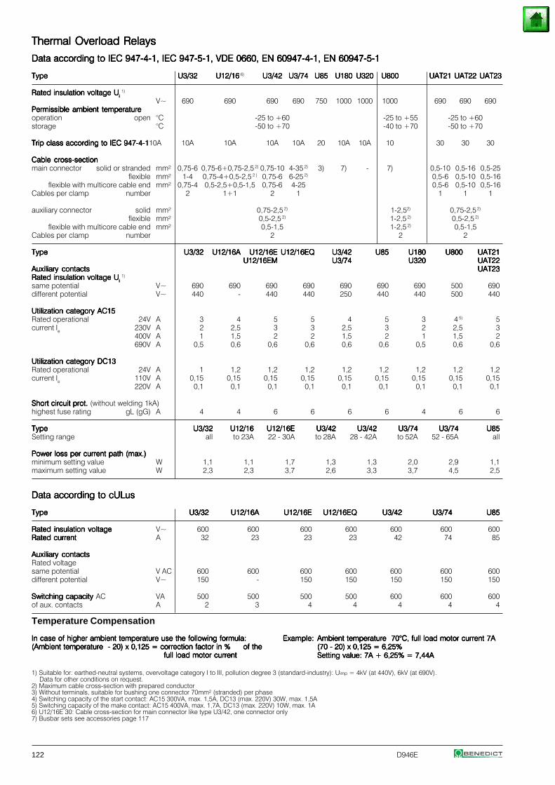
122 D946E
Thermal Overload RelaysThermal Overload RelaysThermal Overload RelaysThermal Overload RelaysThermal Overload Relays
Data according to IEC 947-4-1, IEC 947-5-1, VDE 0660, EN 60947-4-1, EN 60947-5-1Data according to IEC 947-4-1, IEC 947-5-1, VDE 0660, EN 60947-4-1, EN 60947-5-1Data according to IEC 947-4-1, IEC 947-5-1, VDE 0660, EN 60947-4-1, EN 60947-5-1Data according to IEC 947-4-1, IEC 947-5-1, VDE 0660, EN 60947-4-1, EN 60947-5-1Data according to IEC 947-4-1, IEC 947-5-1, VDE 0660, EN 60947-4-1, EN 60947-5-1
TypeTypeTypeTypeType U3/32U3/32U3/32U3/32U3/32 U12/16U12/16U12/16U12/16U12/16 6) U3/42U3/42U3/42U3/42U3/42 U3/74U3/74U3/74U3/74U3/74 U85U85U85U85U85 U180U180U180U180U180 U320U320U320U320U320 U800U800U800U800U800 UAT21UAT21UAT21UAT21UAT21 UAT22UAT22UAT22UAT22UAT22 UAT23UAT23UAT23UAT23UAT23
Rated insulation voltage URated insulation voltage URated insulation voltage URated insulation voltage URated insulation voltage Ui i i i i 1)
V~ 690 690 690 690 750 1000 1000 1000 690 690 690Permissible ambient temperaturePermissible ambient temperaturePermissible ambient temperaturePermissible ambient temperaturePermissible ambient temperatureoperation open °C -25 to +60 -25 to +55 -25 to +60storage °C -50 to +70 -40 to +70 -50 to +70
Trip class according to IEC 947-4-1Trip class according to IEC 947-4-1Trip class according to IEC 947-4-1Trip class according to IEC 947-4-1Trip class according to IEC 947-4-110A 10A 10A 10A 10A 20 10A 10A 10 30 30 30
Cable cross-sectionCable cross-sectionCable cross-sectionCable cross-sectionCable cross-sectionmain connector solid or stranded mm² 0,75-6 0,75-6+0,75-2,5 2) 0,75-10 4-35 2) 3) 7) - 7) 0,5-10 0,5-16 0,5-25
flexible mm² 1-4 0,75-4+0,5-2,5 2 ) 0,75-6 6-25 2) 0,5-6 0,5-10 0,5-16flexible with multicore cable end mm² 0,75-4 0,5-2,5+0,5-1,5 0,75-6 4-25 0,5-6 0,5-10 0,5-16
Cables per clamp number 2 1+1 2 1 1 1 1
auxiliary connector solid mm² 0,75-2,5 2) 1-2,52) 0,75-2,5 2)
flexible mm² 0,5-2,5 2) 1-2,5 2) 0,5-2,5 2)
flexible with multicore cable end mm² 0,5-1,5 1-2,5 2) 0,5-1,5Cables per clamp number 2 2 2
TypeTypeTypeTypeType U3/32U3/32U3/32U3/32U3/32 U12/16AU12/16AU12/16AU12/16AU12/16A U12/16EU12/16EU12/16EU12/16EU12/16E U12/16EQU12/16EQU12/16EQU12/16EQU12/16EQ U3/42U3/42U3/42U3/42U3/42 U85U85U85U85U85 U180U180U180U180U180 U800U800U800U800U800 UAT21UAT21UAT21UAT21UAT21U12/16EMU12/16EMU12/16EMU12/16EMU12/16EM U3/74U3/74U3/74U3/74U3/74 U320U320U320U320U320 UAT22UAT22UAT22UAT22UAT22
Auxiliary contactsAuxiliary contactsAuxiliary contactsAuxiliary contactsAuxiliary contacts UAT23UAT23UAT23UAT23UAT23Rated insulation voltage URated insulation voltage URated insulation voltage URated insulation voltage URated insulation voltage Ui i i i i
1)
same potential V~ 690 690 690 690 690 690 690 500 690different potential V~ 440 - 440 440 250 440 440 500 440
Utilization category AC15Utilization category AC15Utilization category AC15Utilization category AC15Utilization category AC15Rated operational 24V A 3 4 5 5 4 5 3 4 5) 5current Ie 230V A 2 2,5 3 3 2,5 3 2 2,5 3
400V A 1 1,5 2 2 1,5 2 1 1,5 2690V A 0,5 0,6 0,6 0,6 0,6 0,6 0,5 0,6 0,6
Utilization category DC13Utilization category DC13Utilization category DC13Utilization category DC13Utilization category DC13Rated operational 24V A 1 1,2 1,2 1,2 1,2 1,2 1,2 1,2 1,2current Ie 110V A 0,15 0,15 0,15 0,15 0,15 0,15 0,15 0,15 0,15
220V A 0,1 0,1 0,1 0,1 0,1 0,1 0,1 0,1 0,1
Short circuit prot. Short circuit prot. Short circuit prot. Short circuit prot. Short circuit prot. (without welding 1kA)highest fuse rating gL (gG) A 4 4 6 6 6 6 4 6 6
TypeTypeTypeTypeType U3/32U3/32U3/32U3/32U3/32 U12/16U12/16U12/16U12/16U12/16 U12/16EU12/16EU12/16EU12/16EU12/16E U3/42U3/42U3/42U3/42U3/42 U3/42U3/42U3/42U3/42U3/42 U3/74U3/74U3/74U3/74U3/74 U3/74U3/74U3/74U3/74U3/74 U85U85U85U85U85Setting range all to 23A 22 - 30A to 28A 28 - 42A to 52A 52 - 65A all
Power loss per current path (max.)Power loss per current path (max.)Power loss per current path (max.)Power loss per current path (max.)Power loss per current path (max.)minimum setting value W 1,1 1,1 1,7 1,3 1,3 2,0 2,9 1,1maximum setting value W 2,3 2,3 3,7 2,6 3,3 3,7 4,5 2,5
Data according to cULusData according to cULusData according to cULusData according to cULusData according to cULus
TypeTypeTypeTypeType U3/32U3/32U3/32U3/32U3/32 U12/16AU12/16AU12/16AU12/16AU12/16A U12/16EU12/16EU12/16EU12/16EU12/16E U12/16EQU12/16EQU12/16EQU12/16EQU12/16EQ U3/42U3/42U3/42U3/42U3/42 U3/74U3/74U3/74U3/74U3/74 U85U85U85U85U85
Rated insulation voltageRated insulation voltageRated insulation voltageRated insulation voltageRated insulation voltage V~ 600 600 600 600 600 600 600Rated currentRated currentRated currentRated currentRated current A 32 23 23 23 42 74 85
Auxiliary contactsAuxiliary contactsAuxiliary contactsAuxiliary contactsAuxiliary contactsRated voltagesame potential V AC 600 600 600 600 600 600 600different potential V~ 150 - 150 150 150 150 150
Switching capacity Switching capacity Switching capacity Switching capacity Switching capacity AC VA 500 500 500 500 600 600 600of aux. contacts A 2 3 4 4 4 4 4
Example:Example:Example:Example:Example: Ambient temperature 70°C, full load motor current 7AAmbient temperature 70°C, full load motor current 7AAmbient temperature 70°C, full load motor current 7AAmbient temperature 70°C, full load motor current 7AAmbient temperature 70°C, full load motor current 7A(70 - 20) x 0,125 = 6,25%(70 - 20) x 0,125 = 6,25%(70 - 20) x 0,125 = 6,25%(70 - 20) x 0,125 = 6,25%(70 - 20) x 0,125 = 6,25%Setting value: 7A + 6,25% = 7,44ASetting value: 7A + 6,25% = 7,44ASetting value: 7A + 6,25% = 7,44ASetting value: 7A + 6,25% = 7,44ASetting value: 7A + 6,25% = 7,44A
Temperature Compensation
In case of higher ambient temperature use the following formula:In case of higher ambient temperature use the following formula:In case of higher ambient temperature use the following formula:In case of higher ambient temperature use the following formula:In case of higher ambient temperature use the following formula:(Ambient temperature - 20) x 0,125 = correction factor in %(Ambient temperature - 20) x 0,125 = correction factor in %(Ambient temperature - 20) x 0,125 = correction factor in %(Ambient temperature - 20) x 0,125 = correction factor in %(Ambient temperature - 20) x 0,125 = correction factor in % of theof theof theof theof the
full load motor currentfull load motor currentfull load motor currentfull load motor currentfull load motor current
1) Suitable for: earthed-neutral systems, overvoltage category I to III, pollution degree 3 (standard-industry): Uimp = 4kV (at 440V), 6kV (at 690V).Data for other conditions on request.
2) Maximum cable cross-section with prepared conductor3) Without terminals, suitable for bushing one connector 70mm² (stranded) per phase4) Switching capacity of the start contact: AC15 300VA, max. 1,5A, DC13 (max. 220V) 30W, max. 1,5A5) Switching capacity of the make contact: AC15 400VA, max. 1,7A, DC13 (max. 220V) 10W, max. 1A6) U12/16E 30: Cable cross-section for main connector like type U3/42, one connector only7) Busbar sets see accessories page 117
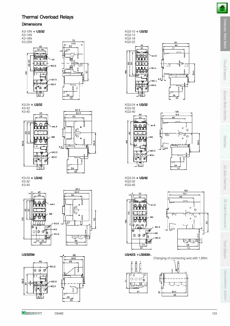
D946E 123
Thermal Overload RelaysThermal Overload RelaysThermal Overload RelaysThermal Overload RelaysThermal Overload Relays
DimensionsDimensionsDimensionsDimensionsDimensions
K3-10N + U3/32+ U3/32+ U3/32+ U3/32+ U3/32 KG3-10 + U3/32 + U3/32 + U3/32 + U3/32 + U3/32K3-14N KG3-14K3-18N KG3-18K3-22N KG3-22
K3-24 + U3/32+ U3/32+ U3/32+ U3/32+ U3/32 KG3-24 + U3/32+ U3/32+ U3/32+ U3/32+ U3/32K3-32 KG3-32K3-40 KG3-40
K3-24 + U3/42+ U3/42+ U3/42+ U3/42+ U3/42 KG3-24 + U3/42+ U3/42+ U3/42+ U3/42+ U3/42K3-32 KG3-32K3-40 KG3-40
U3/32SMU3/32SMU3/32SMU3/32SMU3/32SM U3/42G +LG5830-.U3/42G +LG5830-.U3/42G +LG5830-.U3/42G +LG5830-.U3/42G +LG5830-.Changing of connecting wire with 1,8Nm
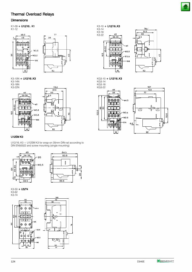
124 D946E
Thermal Overload RelaysThermal Overload RelaysThermal Overload RelaysThermal Overload RelaysThermal Overload Relays
DimensionsDimensionsDimensionsDimensionsDimensions
K1-09 + U12/16.. K1+ U12/16.. K1+ U12/16.. K1+ U12/16.. K1+ U12/16.. K1 K3-10 + U12/16..K3 + U12/16..K3 + U12/16..K3 + U12/16..K3 + U12/16..K3K1-12 K3-14
K3-18K3-22
K3-10N + U12/16..K3 + U12/16..K3 + U12/16..K3 + U12/16..K3 + U12/16..K3 KG3-10 + U12/16..K3 + U12/16..K3 + U12/16..K3 + U12/16..K3 + U12/16..K3K3-14N KG3-14K3-18N KG3-18K3-22N KG3-22
U12SM K3U12SM K3U12SM K3U12SM K3U12SM K3
U12/16..K3 + U12SM K3 for snap-on 35mm DIN-rail according toDIN EN50022 and screw mounting (single mounting)
K3-50 + U3/74 + U3/74 + U3/74 + U3/74 + U3/74K3-62K3-74
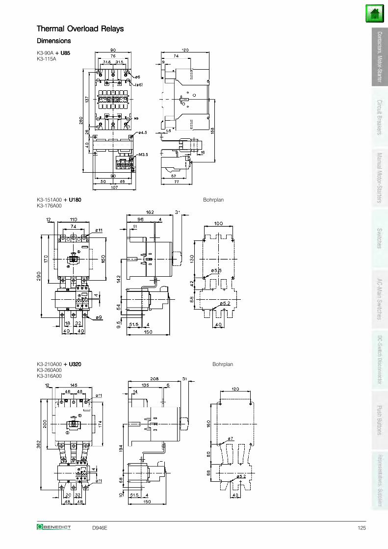
D946E 125
Thermal Overload RelaysThermal Overload RelaysThermal Overload RelaysThermal Overload RelaysThermal Overload Relays
DimensionsDimensionsDimensionsDimensionsDimensions
K3-90A + U85+ U85+ U85+ U85+ U85K3-115A
K3-151A00 + U180 + U180 + U180 + U180 + U180 BohrplanK3-176A00
K3-210A00 + U320 + U320 + U320 + U320 + U320 BohrplanK3-260A00K3-316A00
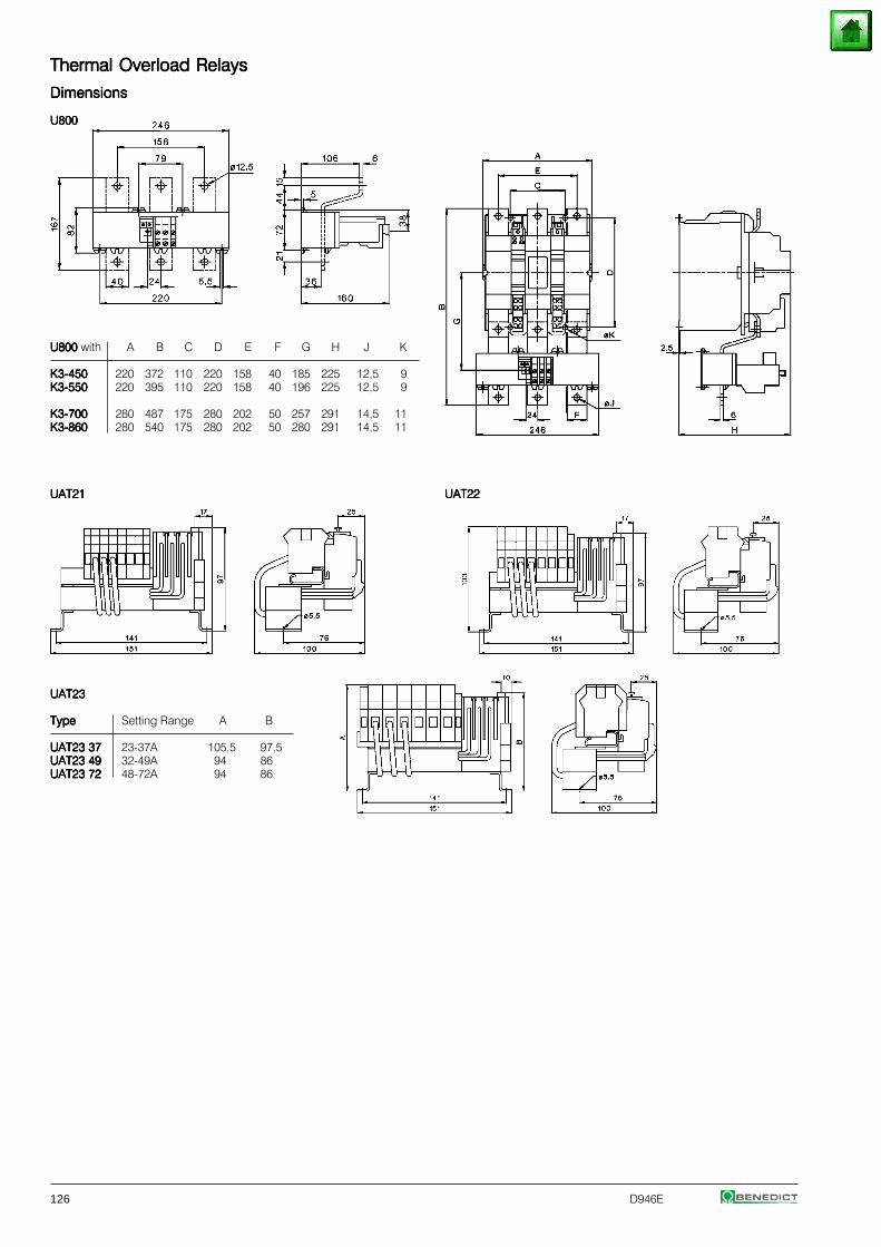
126 D946E
Thermal Overload RelaysThermal Overload RelaysThermal Overload RelaysThermal Overload RelaysThermal Overload Relays
DimensionsDimensionsDimensionsDimensionsDimensions
U800U800U800U800U800
U800 U800 U800 U800 U800 with A B C D E F G H J K
K3-450K3-450K3-450K3-450K3-450 220 372 110 220 158 40 185 225 12,5 9K3-550K3-550K3-550K3-550K3-550 220 395 110 220 158 40 196 225 12,5 9
K3-700K3-700K3-700K3-700K3-700 280 487 175 280 202 50 257 291 14,5 11K3-860K3-860K3-860K3-860K3-860 280 540 175 280 202 50 280 291 14,5 11
UAT21UAT21UAT21UAT21UAT21 UAT22UAT22UAT22UAT22UAT22
UAT23UAT23UAT23UAT23UAT23
TypeTypeTypeTypeType Setting Range A B
UAT23 37UAT23 37UAT23 37UAT23 37UAT23 37 23-37A 105,5 97,5UAT23 49UAT23 49UAT23 49UAT23 49UAT23 49 32-49A 94 86UAT23 72UAT23 72UAT23 72UAT23 72UAT23 72 48-72A 94 86
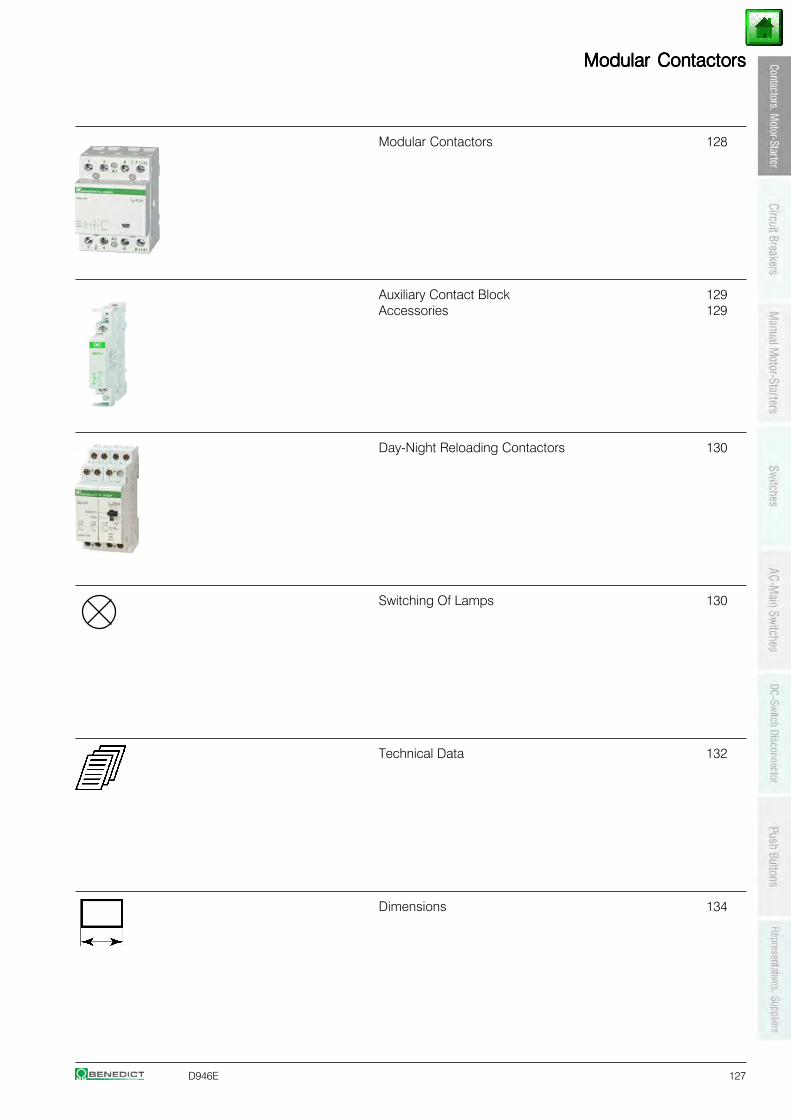
D946E 127
Modular ContactorsModular ContactorsModular ContactorsModular ContactorsModular Contactors
Modular Contactors 128
Auxiliary Contact Block 129Accessories 129
Day-Night Reloading Contactors 130
Switching Of Lamps 130
Technical Data 132
Dimensions 134
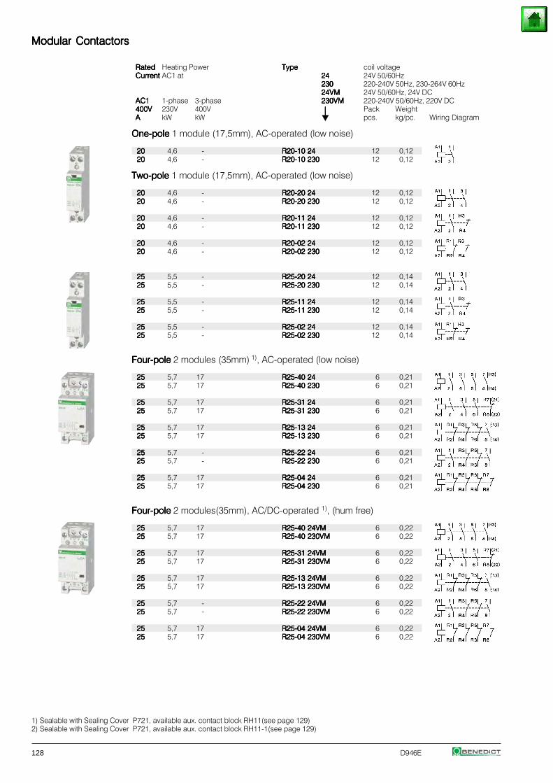
128 D946E
Modular ContactorsModular ContactorsModular ContactorsModular ContactorsModular Contactors
RatedRatedRatedRatedRated Heating Power TypeTypeTypeTypeType coil voltageCurrentCurrentCurrentCurrentCurrent AC1 at 2424242424 24V 50/60Hz
230230230230230 220-240V 50Hz, 230-264V 60Hz24VM24VM24VM24VM24VM 24V 50/60Hz, 24V DC
AC1AC1AC1AC1AC1 1-phase 3-phase 230VM230VM230VM230VM230VM 220-240V 50/60Hz, 220V DC400V400V400V400V400V 230V 400V ⏐⏐⏐⏐⏐ Pack WeightAAAAA kW kW pcs. kg/pc. Wiring Diagram
One-poleOne-poleOne-poleOne-poleOne-pole 1 module (17,5mm), AC-operated (low noise)
2020202020 4,6 - R20-10 24R20-10 24R20-10 24R20-10 24R20-10 24 12 0,122020202020 4,6 - R20-10 230R20-10 230R20-10 230R20-10 230R20-10 230 12 0,12
Two-poleTwo-poleTwo-poleTwo-poleTwo-pole 1 module (17,5mm), AC-operated (low noise)
2020202020 4,6 - R20-20 24R20-20 24R20-20 24R20-20 24R20-20 24 12 0,122020202020 4,6 - R20-20 230R20-20 230R20-20 230R20-20 230R20-20 230 12 0,12
2020202020 4,6 - R20-11 24R20-11 24R20-11 24R20-11 24R20-11 24 12 0,122020202020 4,6 - R20-11 230R20-11 230R20-11 230R20-11 230R20-11 230 12 0,12
2020202020 4,6 - R20-02 24R20-02 24R20-02 24R20-02 24R20-02 24 12 0,122020202020 4,6 - R20-02 230R20-02 230R20-02 230R20-02 230R20-02 230 12 0,12
2525252525 5,5 - R25-20 24R25-20 24R25-20 24R25-20 24R25-20 24 12 0,142525252525 5,5 - R25-20 230R25-20 230R25-20 230R25-20 230R25-20 230 12 0,14
2525252525 5,5 - R25-11 24R25-11 24R25-11 24R25-11 24R25-11 24 12 0,142525252525 5,5 - R25-11 230R25-11 230R25-11 230R25-11 230R25-11 230 12 0,14
2525252525 5,5 - R25-02 24R25-02 24R25-02 24R25-02 24R25-02 24 12 0,142525252525 5,5 - R25-02 230R25-02 230R25-02 230R25-02 230R25-02 230 12 0,14
Four-poleFour-poleFour-poleFour-poleFour-pole 2 modules (35mm) 1), AC-operated (low noise)
2525252525 5,7 17 R25-40 24R25-40 24R25-40 24R25-40 24R25-40 24 6 0,212525252525 5,7 17 R25-40 230R25-40 230R25-40 230R25-40 230R25-40 230 6 0,21
2525252525 5,7 17 R25-31 24R25-31 24R25-31 24R25-31 24R25-31 24 6 0,212525252525 5,7 17 R25-31 230R25-31 230R25-31 230R25-31 230R25-31 230 6 0,21
2525252525 5,7 17 R25-13 24R25-13 24R25-13 24R25-13 24R25-13 24 6 0,212525252525 5,7 17 R25-13 230R25-13 230R25-13 230R25-13 230R25-13 230 6 0,21
2525252525 5,7 - R25-22 24R25-22 24R25-22 24R25-22 24R25-22 24 6 0,212525252525 5,7 - R25-22 230R25-22 230R25-22 230R25-22 230R25-22 230 6 0,21
2525252525 5,7 17 R25-04 24R25-04 24R25-04 24R25-04 24R25-04 24 6 0,212525252525 5,7 17 R25-04 230R25-04 230R25-04 230R25-04 230R25-04 230 6 0,21
Four-poleFour-poleFour-poleFour-poleFour-pole 2 modules(35mm), AC/DC-operated 1), (hum free)
2525252525 5,7 17 R25-40 24VMR25-40 24VMR25-40 24VMR25-40 24VMR25-40 24VM 6 0,222525252525 5,7 17 R25-40 230VMR25-40 230VMR25-40 230VMR25-40 230VMR25-40 230VM 6 0,22
2525252525 5,7 17 R25-31 24VMR25-31 24VMR25-31 24VMR25-31 24VMR25-31 24VM 6 0,222525252525 5,7 17 R25-31 230VMR25-31 230VMR25-31 230VMR25-31 230VMR25-31 230VM 6 0,22
2525252525 5,7 17 R25-13 24VMR25-13 24VMR25-13 24VMR25-13 24VMR25-13 24VM 6 0,222525252525 5,7 17 R25-13 230VMR25-13 230VMR25-13 230VMR25-13 230VMR25-13 230VM 6 0,22
2525252525 5,7 - R25-22 24VMR25-22 24VMR25-22 24VMR25-22 24VMR25-22 24VM 6 0,222525252525 5,7 - R25-22 230VMR25-22 230VMR25-22 230VMR25-22 230VMR25-22 230VM 6 0,22
2525252525 5,7 17 R25-04 24VMR25-04 24VMR25-04 24VMR25-04 24VMR25-04 24VM 6 0,222525252525 5,7 17 R25-04 230VMR25-04 230VMR25-04 230VMR25-04 230VMR25-04 230VM 6 0,22
1) Sealable with Sealing Cover P721, available aux. contact block RH11(see page 129)2) Sealable with Sealing Cover P721, available aux. contact block RH11-1(see page 129)
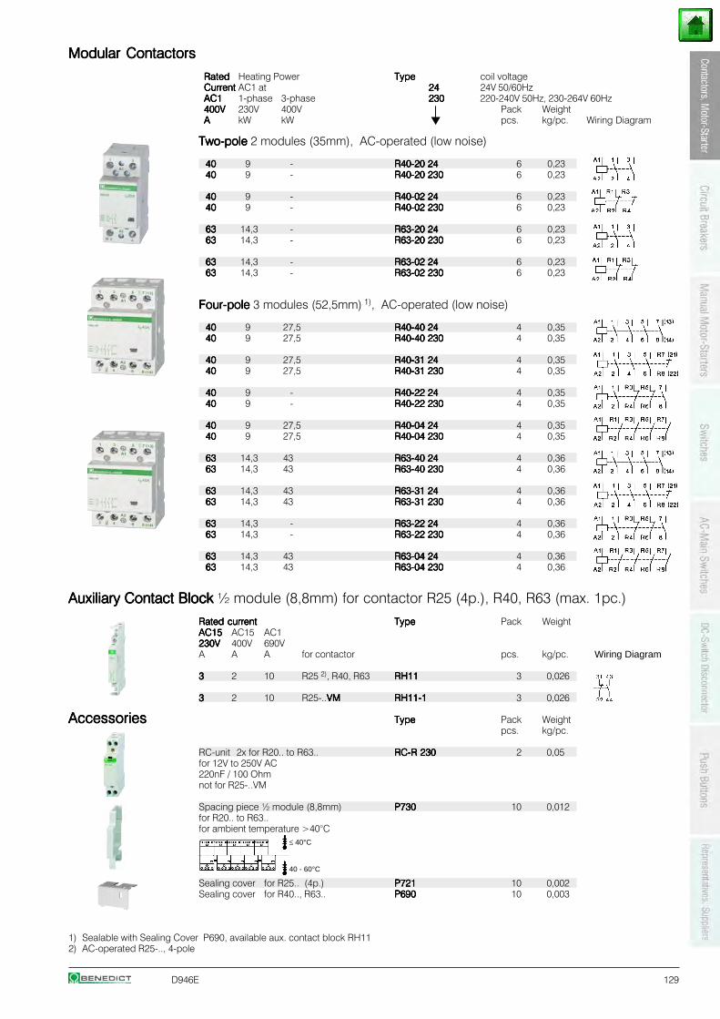
D946E 129
Modular ContactorsModular ContactorsModular ContactorsModular ContactorsModular Contactors
RatedRatedRatedRatedRated Heating Power TypeTypeTypeTypeType coil voltageCurrentCurrentCurrentCurrentCurrent AC1 at 2424242424 24V 50/60HzAC1AC1AC1AC1AC1 1-phase 3-phase 230230230230230 220-240V 50Hz, 230-264V 60Hz400V400V400V400V400V 230V 400V ⏐⏐⏐⏐⏐ Pack WeightAAAAA kW kW pcs. kg/pc. Wiring Diagram
Two-poleTwo-poleTwo-poleTwo-poleTwo-pole 2 modules (35mm), AC-operated (low noise)
4040404040 9 - R40-20 24R40-20 24R40-20 24R40-20 24R40-20 24 6 0,234040404040 9 - R40-20 230R40-20 230R40-20 230R40-20 230R40-20 230 6 0,23
4040404040 9 - R40-02 24R40-02 24R40-02 24R40-02 24R40-02 24 6 0,234040404040 9 - R40-02 230R40-02 230R40-02 230R40-02 230R40-02 230 6 0,23
6363636363 14,3 - R63-20 24R63-20 24R63-20 24R63-20 24R63-20 24 6 0,236363636363 14,3 - R63-20 230R63-20 230R63-20 230R63-20 230R63-20 230 6 0,23
6363636363 14,3 - R63-02 24R63-02 24R63-02 24R63-02 24R63-02 24 6 0,236363636363 14,3 - R63-02 230R63-02 230R63-02 230R63-02 230R63-02 230 6 0,23
Four-poleFour-poleFour-poleFour-poleFour-pole 3 modules (52,5mm) 1), AC-operated (low noise)
4040404040 9 27,5 R40-40 24R40-40 24R40-40 24R40-40 24R40-40 24 4 0,354040404040 9 27,5 R40-40 230R40-40 230R40-40 230R40-40 230R40-40 230 4 0,35
4040404040 9 27,5 R40-31 24R40-31 24R40-31 24R40-31 24R40-31 24 4 0,354040404040 9 27,5 R40-31 230R40-31 230R40-31 230R40-31 230R40-31 230 4 0,35
4040404040 9 - R40-22 24R40-22 24R40-22 24R40-22 24R40-22 24 4 0,354040404040 9 - R40-22 230R40-22 230R40-22 230R40-22 230R40-22 230 4 0,35
4040404040 9 27,5 R40-04 24R40-04 24R40-04 24R40-04 24R40-04 24 4 0,354040404040 9 27,5 R40-04 230R40-04 230R40-04 230R40-04 230R40-04 230 4 0,35
6363636363 14,3 43 R63-40 24R63-40 24R63-40 24R63-40 24R63-40 24 4 0,366363636363 14,3 43 R63-40 230R63-40 230R63-40 230R63-40 230R63-40 230 4 0,36
6363636363 14,3 43 R63-31 24R63-31 24R63-31 24R63-31 24R63-31 24 4 0,366363636363 14,3 43 R63-31 230R63-31 230R63-31 230R63-31 230R63-31 230 4 0,36
6363636363 14,3 - R63-22 24R63-22 24R63-22 24R63-22 24R63-22 24 4 0,366363636363 14,3 - R63-22 230R63-22 230R63-22 230R63-22 230R63-22 230 4 0,36
6363636363 14,3 43 R63-04 24R63-04 24R63-04 24R63-04 24R63-04 24 4 0,366363636363 14,3 43 R63-04 230R63-04 230R63-04 230R63-04 230R63-04 230 4 0,36
Auxiliary Contact Block Auxiliary Contact Block Auxiliary Contact Block Auxiliary Contact Block Auxiliary Contact Block ½ module (8,8mm) for contactor R25 (4p.), R40, R63 (max. 1pc.)
Rated currentRated currentRated currentRated currentRated current TypeTypeTypeTypeType Pack WeightAC15AC15AC15AC15AC15 AC15 AC1230V230V230V230V230V 400V 690VA A A for contactor pcs. kg/pc. Wiring Diagram
33333 2 10 R25 2), R40, R63 RH11RH11RH11RH11RH11 3 0,026
33333 2 10 R25-..VMVMVMVMVM RH11-1RH11-1RH11-1RH11-1RH11-1 3 0,026
AccessoriesAccessoriesAccessoriesAccessoriesAccessories TypeTypeTypeTypeType Pack Weightpcs. kg/pc.
RC-unit 2x for R20.. to R63.. RC-R 230RC-R 230RC-R 230RC-R 230RC-R 230 2 0,05for 12V to 250V AC220nF / 100 Ohmnot for R25-..VM
Spacing piece ½ module (8,8mm) P730P730P730P730P730 10 0,012for R20.. to R63..for ambient temperature >40°C
Sealing cover for R25.. (4p.) P721P721P721P721P721 10 0,002Sealing cover for R40.., R63.. P690P690P690P690P690 10 0,003
1) Sealable with Sealing Cover P690, available aux. contact block RH112) AC-operated R25-.., 4-pole
≤ 40°C
40 - 60°C
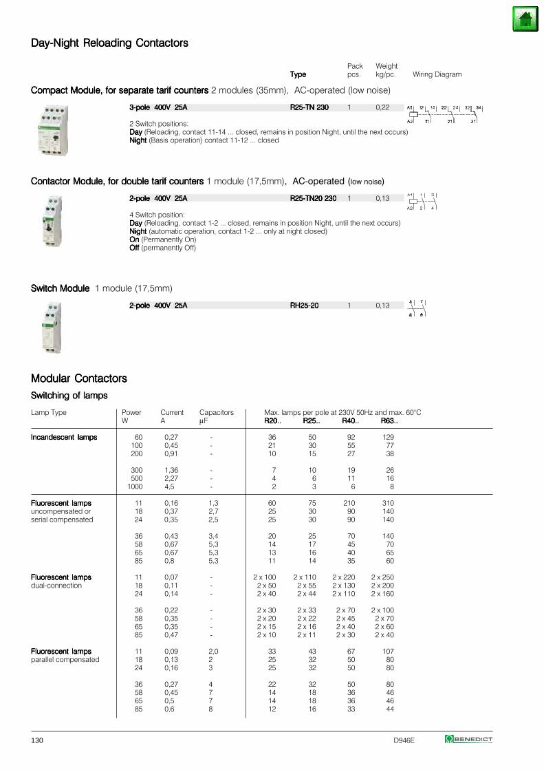
130 D946E
Day-Night Reloading ContactorsDay-Night Reloading ContactorsDay-Night Reloading ContactorsDay-Night Reloading ContactorsDay-Night Reloading Contactors
Pack WeightTypeTypeTypeTypeType pcs. kg/pc. Wiring Diagram
Compact Module, for separate tarif counters Compact Module, for separate tarif counters Compact Module, for separate tarif counters Compact Module, for separate tarif counters Compact Module, for separate tarif counters 2 modules (35mm), AC-operated (low noise)
3-pole 400V 25A3-pole 400V 25A3-pole 400V 25A3-pole 400V 25A3-pole 400V 25A R25-TN 230R25-TN 230R25-TN 230R25-TN 230R25-TN 230 1 0,22
2 Switch positions:DayDayDayDayDay (Reloading, contact 11-14 ... closed, remains in position Night, until the next occurs)Night Night Night Night Night (Basis operation) contact 11-12 ... closed
Contactor Module, for double tarif counters Contactor Module, for double tarif counters Contactor Module, for double tarif counters Contactor Module, for double tarif counters Contactor Module, for double tarif counters 1 module (17,5mm), AC-operated (low noise)
2-pole 400V 25A2-pole 400V 25A2-pole 400V 25A2-pole 400V 25A2-pole 400V 25A R25-TN20 230R25-TN20 230R25-TN20 230R25-TN20 230R25-TN20 230 1 0,13
4 Switch position:Day Day Day Day Day (Reloading, contact 1-2 ... closed, remains in position Night, until the next occurs)Night Night Night Night Night (automatic operation, contact 1-2 ... only at night closed)On On On On On (Permanently On)OffOffOffOffOff (permanently Off)
Switch ModuleSwitch ModuleSwitch ModuleSwitch ModuleSwitch Module 1 module (17,5mm)
2-pole 400V 25A2-pole 400V 25A2-pole 400V 25A2-pole 400V 25A2-pole 400V 25A RH25-20RH25-20RH25-20RH25-20RH25-20 1 0,13
Modular ContactorsModular ContactorsModular ContactorsModular ContactorsModular Contactors
Switching of lampsSwitching of lampsSwitching of lampsSwitching of lampsSwitching of lamps
Lamp Type Power Current Capacitors Max. lamps per pole at 230V 50Hz and max. 60°CW A μF R20..R20..R20..R20..R20.. R25..R25..R25..R25..R25.. R40..R40..R40..R40..R40.. R63..R63..R63..R63..R63..
Incandescent lampsIncandescent lampsIncandescent lampsIncandescent lampsIncandescent lamps 60 0,27 - 36 50 92 129100 0,45 - 21 30 55 77200 0,91 - 10 15 27 38
300 1,36 - 7 10 19 26500 2,27 - 4 6 11 16
1000 4,5 - 2 3 6 8
Fluorescent lampsFluorescent lampsFluorescent lampsFluorescent lampsFluorescent lamps 11 0,16 1,3 60 75 210 310uncompensated or 18 0,37 2,7 25 30 90 140serial compensated 24 0,35 2,5 25 30 90 140
36 0,43 3,4 20 25 70 14058 0,67 5,3 14 17 45 7065 0,67 5,3 13 16 40 6585 0,8 5,3 11 14 35 60
Fluorescent lampsFluorescent lampsFluorescent lampsFluorescent lampsFluorescent lamps 11 0,07 - 2 x 100 2 x 110 2 x 220 2 x 250dual-connection 18 0,11 - 2 x 50 2 x 55 2 x 130 2 x 200
24 0,14 - 2 x 40 2 x 44 2 x 110 2 x 160
36 0,22 - 2 x 30 2 x 33 2 x 70 2 x 10058 0,35 - 2 x 20 2 x 22 2 x 45 2 x 7065 0,35 - 2 x 15 2 x 16 2 x 40 2 x 6085 0,47 - 2 x 10 2 x 11 2 x 30 2 x 40
Fluorescent lampsFluorescent lampsFluorescent lampsFluorescent lampsFluorescent lamps 11 0,09 2,0 33 43 67 107parallel compensated 18 0,13 2 25 32 50 80
24 0,16 3 25 32 50 80
36 0,27 4 22 32 50 8058 0,45 7 14 18 36 4665 0,5 7 14 18 36 4685 0,6 8 12 16 33 44
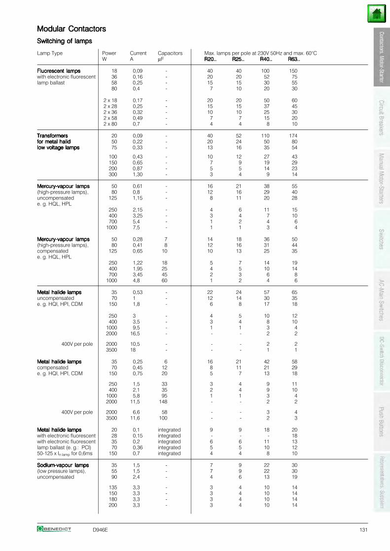
D946E 131
Modular ContactorsModular ContactorsModular ContactorsModular ContactorsModular Contactors
Switching of lampsSwitching of lampsSwitching of lampsSwitching of lampsSwitching of lamps
Lamp Type Power Current Capacitors Max. lamps per pole at 230V 50Hz and max. 60°CW A μF R20..R20..R20..R20..R20.. R25..R25..R25..R25..R25.. R40..R40..R40..R40..R40.. R63..R63..R63..R63..R63..
Fluorescent lampsFluorescent lampsFluorescent lampsFluorescent lampsFluorescent lamps 18 0,09 - 40 40 100 150with electronic fluorescent 36 0,16 - 20 20 52 75lamp ballast 58 0,25 - 15 15 30 55
80 0,4 - 7 10 20 30
2 x 18 0,17 - 20 20 50 602 x 28 0,25 - 15 15 37 452 x 36 0,32 - 10 10 25 302 x 58 0,49 - 7 7 15 202 x 80 0,7 - 4 4 8 10
TransformersTransformersTransformersTransformersTransformers 20 0,09 - 40 52 110 174for metal halidfor metal halidfor metal halidfor metal halidfor metal halid 50 0,22 - 20 24 50 80low voltage lampslow voltage lampslow voltage lampslow voltage lampslow voltage lamps 75 0,33 - 13 16 35 54
100 0,43 - 10 12 27 43150 0,65 - 7 9 19 29200 0,87 - 5 5 14 23300 1,30 - 3 4 9 14
Mercury-vapour lampsMercury-vapour lampsMercury-vapour lampsMercury-vapour lampsMercury-vapour lamps 50 0,61 - 16 21 38 55(high-pressure lamps), 80 0,8 - 12 16 29 40uncompensated 125 1,15 - 8 11 20 28e. g. HQL, HPL
250 2,15 - 4 6 11 15400 3,25 - 3 4 7 10700 5,4 - 1 2 4 6
1000 7,5 - 1 1 3 4
Mercury-vapour lampsMercury-vapour lampsMercury-vapour lampsMercury-vapour lampsMercury-vapour lamps 50 0,28 7 14 18 36 50(high-pressure lamps), 80 0,41 8 12 16 31 44compensated 125 0,65 10 10 13 25 35e. g. HQL, HPL
250 1,22 18 5 7 14 19400 1,95 25 4 5 10 14700 3,45 45 2 3 6 8
1000 4,8 60 1 2 4 6
Metal halide lampsMetal halide lampsMetal halide lampsMetal halide lampsMetal halide lamps 35 0,53 - 22 24 57 65uncompensated 70 1 - 12 14 30 35e. g. HQI, HPI, CDM 150 1,8 - 6 8 17 18
250 3 - 4 5 10 12400 3,5 - 3 4 8 10
1000 9,5 - 1 1 3 42000 16,5 - - - 2 2
400V per pole 2000 10,5 - - - 2 23500 18 - - - 1 1
Metal halide lampsMetal halide lampsMetal halide lampsMetal halide lampsMetal halide lamps 35 0,25 6 16 21 42 58compensated 70 0,45 12 8 11 21 29e. g. HQI, HPI, CDM 150 0,75 20 5 7 13 18
250 1,5 33 3 4 9 11400 2,1 35 2 4 9 10
1000 5,8 95 1 1 3 42000 11,5 148 - - 2 2
400V per pole 2000 6,6 58 - - 3 43500 11,6 100 - - 2 3
Metal halide lampsMetal halide lampsMetal halide lampsMetal halide lampsMetal halide lamps 20 0,1 integrated 9 9 18 20with electronic fluorescent 28 0,15 integrated - - - 18with electronic fluorescent 35 0,2 integrated 6 6 11 13lamp ballast (e. g.: PCI) 70 0,36 integrated 5 5 10 1250-125 x In lamp for 0,6ms 150 0,7 integrated 4 4 8 10
Sodium-vapour lampsSodium-vapour lampsSodium-vapour lampsSodium-vapour lampsSodium-vapour lamps 35 1,5 - 7 9 22 30(low pressure lamps), 55 1,5 - 7 9 22 30uncompensated 90 2,4 - 4 6 13 19
135 3,3 - 3 4 10 14150 3,3 - 3 4 10 14180 3,3 - 3 4 10 14200 3,3 - 3 4 10 14
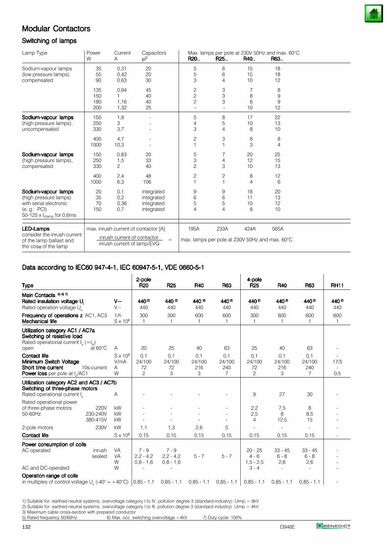
132 D946E
Modular ContactorsModular ContactorsModular ContactorsModular ContactorsModular Contactors
Switching of lampsSwitching of lampsSwitching of lampsSwitching of lampsSwitching of lamps
Lamp Type Power Current Capacitors Max. lamps per pole at 230V 50Hz and max. 60°CW A μF R20..R20..R20..R20..R20.. R25..R25..R25..R25..R25.. R40..R40..R40..R40..R40.. R63..R63..R63..R63..R63..
Sodium-vapour lamps 35 0,31 20 5 6 15 18(low pressure lamps), 55 0,42 20 5 6 15 18compensated 90 0,63 30 3 4 10 12
135 0,94 45 2 3 7 8150 1 40 2 3 8 9180 1,16 40 2 3 8 9200 1,32 25 - - 10 12
Sodium-vapour lampsSodium-vapour lampsSodium-vapour lampsSodium-vapour lampsSodium-vapour lamps 150 1,8 - 5 8 17 22(high pressure lamps), 250 3 - 4 5 10 13uncompensated 330 3,7 - 3 4 8 10
400 4,7 - 2 3 6 81000 10,3 - 1 1 3 4
Sodium-vapour lampsSodium-vapour lampsSodium-vapour lampsSodium-vapour lampsSodium-vapour lamps 150 0,83 20 5 7 20 25(high pressure lamps), 250 1,5 33 3 4 12 15compensated 330 2 40 2 3 10 13
400 2,4 48 2 2 8 121000 6,3 106 1 1 4 6
Sodium-vapour lampsSodium-vapour lampsSodium-vapour lampsSodium-vapour lampsSodium-vapour lamps 20 0,1 integrated 9 9 18 20(high pressure lamps) 35 0,2 integrated 6 6 11 13with serial electronic 70 0,36 integrated 5 5 10 12(e. g.: PCI) 150 0,7 integrated 4 4 8 1050-125 x Inlamp for 0,6ms
LED-LampsLED-LampsLED-LampsLED-LampsLED-Lamps max. inrush current of contactor [A] 195A 233A 424A 565Aconsider the inrush current inrush current of contactorof the lamp ballast and = max. lamps per pole at 230V 50Hz and max. 60°Cthe cosϕ of the lamp inrush current of lamp/EVG
Data according to IEC60 947-4-1, IEC 60947-5-1, VDE 0660-5-1Data according to IEC60 947-4-1, IEC 60947-5-1, VDE 0660-5-1Data according to IEC60 947-4-1, IEC 60947-5-1, VDE 0660-5-1Data according to IEC60 947-4-1, IEC 60947-5-1, VDE 0660-5-1Data according to IEC60 947-4-1, IEC 60947-5-1, VDE 0660-5-1
2-pole2-pole2-pole2-pole2-pole 4-pole4-pole4-pole4-pole4-poleTypeTypeTypeTypeType R20R20R20R20R20 R25R25R25R25R25 R40R40R40R40R40 R63R63R63R63R63 R25R25R25R25R25 R40R40R40R40R40 R63R63R63R63R63 RH11RH11RH11RH11RH11
Main Contacts Main Contacts Main Contacts Main Contacts Main Contacts 5) 6) 7) 5) 6) 7) 5) 6) 7) 5) 6) 7) 5) 6) 7)
Rated insulation voltage Rated insulation voltage Rated insulation voltage Rated insulation voltage Rated insulation voltage UUUUUiiiii V~V~V~V~V~ 440440440440440 2) 2) 2) 2) 2) 440 440 440 440 440 2)2)2)2)2) 440 440 440 440 440 2)2)2)2)2) 440440440440440 2) 2) 2) 2) 2) 440440440440440 2) 2) 2) 2) 2) 440440440440440 2) 2) 2) 2) 2) 440440440440440 2) 2) 2) 2) 2) 440440440440440 2) 2) 2) 2) 2)
Rated operation voltage Ue V~ 440 440 440 440 440 440 440 440
Frequency of operations zFrequency of operations zFrequency of operations zFrequency of operations zFrequency of operations z AC1, AC3 1/h 300 300 600 600 300 600 600 600Mechanical lifeMechanical lifeMechanical lifeMechanical lifeMechanical life S x 106 1 1 1 1 1 1 1 1
Utilization category AC1 / AC7aUtilization category AC1 / AC7aUtilization category AC1 / AC7aUtilization category AC1 / AC7aUtilization category AC1 / AC7aSwitching of resistive loadSwitching of resistive loadSwitching of resistive loadSwitching of resistive loadSwitching of resistive loadRated operational current Ie (=Ith)open at 60°C A 20 25 40 63 25 40 63 -
Contact lifeContact lifeContact lifeContact lifeContact life S x 106 0,1 0,1 0,1 0,1 0,1 0,1 0,1 -Minimum Switch VoltageMinimum Switch VoltageMinimum Switch VoltageMinimum Switch VoltageMinimum Switch Voltage V/mA 24/100 24/100 24/100 24/100 24/100 24/100 24/100 17/5Short time currentShort time currentShort time currentShort time currentShort time current 10s-current A 72 72 216 240 72 216 240 -Power loss Power loss Power loss Power loss Power loss per pole at Ie/AC1 W 2 3 3 7 2 3 7 0,5
Utilization category AC2 and AC3 / AC7bUtilization category AC2 and AC3 / AC7bUtilization category AC2 and AC3 / AC7bUtilization category AC2 and AC3 / AC7bUtilization category AC2 and AC3 / AC7bSwitching of three-phase motorsSwitching of three-phase motorsSwitching of three-phase motorsSwitching of three-phase motorsSwitching of three-phase motorsRated operational current Ie A - - - - 9 27 30 -
Rated operational powerof three-phase motors 220V kW - - - - 2,2 7,5 8 -50-60Hz 230-240V kW - - - - 2,5 8 8,5 -
380-415V kW - - - - 4 12,5 15 -
2-pole motors 230V kW 1,1 1,3 2,6 5 - - - -
Contact lifeContact lifeContact lifeContact lifeContact life S x 106 0,15 0,15 0,15 0,15 0,15 0,15 0,15 -
Power consumption of coilsPower consumption of coilsPower consumption of coilsPower consumption of coilsPower consumption of coilsAC operated inrush VA 7 - 9 7 - 9 20 - 25 33 - 45 33 - 45 -
sealed VA 2,2 - 4,2 2,2 - 4,2 5 - 7 5 - 7 4 - 6 6 - 8 6 - 8 -W 0,8 - 1,6 0,8 - 1,6 1,5 - 2,5 2,6 2,6 -
AC and DC-operated W - - 3 - 4 - - -
Operation range of coilsOperation range of coilsOperation range of coilsOperation range of coilsOperation range of coilsin multiples of control voltage Us (-40° – – – – – +40°C) 0,85 - 1,1 0,85 - 1,1 0,85 - 1,1 0,85 - 1,1 0,85 - 1,1 0,85 - 1,1 0,85 - 1,1 -
1) Suitable for: earthed-neutral systems, overvoltage category I to IV, pollution degree 3 (standard-industry): Uimp = 8kV.2) Suitable for: earthed-neutral systems, overvoltage category I to III, pollution degree 3 (standard-industry): Uimp = 4kV.3) Maximum cable cross-section with prepared conductor5) Rated frequency 50/60Hz 6) Max. occ. switching overvoltage <4kV 7) Duty cycle: 100%
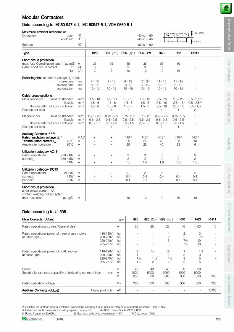
D946E 133
Modular ContactorsModular ContactorsModular ContactorsModular ContactorsModular Contactors
Data according to IEC60 947-4-1, IEC 60947-5-1, VDE 0660-5-1Data according to IEC60 947-4-1, IEC 60947-5-1, VDE 0660-5-1Data according to IEC60 947-4-1, IEC 60947-5-1, VDE 0660-5-1Data according to IEC60 947-4-1, IEC 60947-5-1, VDE 0660-5-1Data according to IEC60 947-4-1, IEC 60947-5-1, VDE 0660-5-1
Maximum ambient temperatureMaximum ambient temperatureMaximum ambient temperatureMaximum ambient temperatureMaximum ambient temperatureOperation open °C -40 to + 60
enclosed °C -40 to + 40
Storage °C -50 to + 90
TypeTypeTypeTypeType R20R20R20R20R20 R25 R25 R25 R25 R25 (2p.) R25 R25 R25 R25 R25 (4p.) R25-..VMR25-..VMR25-..VMR25-..VMR25-..VM R40R40R40R40R40 R63R63R63R63R63 RH11RH11RH11RH11RH11
Short circuit protectionShort circuit protectionShort circuit protectionShort circuit protectionShort circuit protectionmax. fuse Coordination-type "1"gL (gG) A 35 35 35 35 63 80 -Rated short circuit current "r" kA 3 3 3 3 3 3 -
"Iq" kA 3 3 10 10 10 10 -
Switching time Switching time Switching time Switching time Switching time at control voltage Us ±10%make time ms 7 - 16 7 - 16 9 - 15 17 - 24 11 - 15 11 - 15 -
release time ms 6 - 12 6 - 12 4 - 8 17 - 23 6 - 13 6 - 13 -arc duration ms 10 - 15 10 - 15 10 - 15 10 - 15 10 - 15 10 - 15 -
Cable cross-sectionsCable cross-sectionsCable cross-sectionsCable cross-sectionsCable cross-sectionsMain connector solid or stranded mm² 1,5 - 10 1,5 - 10 1,5 - 10 1,5 - 10 2,5 - 25 2,5 - 25 0,5 - 2,5 3)
flexible mm² 1,5 - 6 1,5 - 6 1,5 - 6 1,5 - 6 2,5 - 16 2,5 - 16 0,5 - 2,5 3)
flexible with multicore cable end mm² 1,5 - 6 1,5 - 6 1,5 - 6 1,5 - 6 2,5 - 16 2,5 - 16 0,5 - 1,5Clamps per pole 1 1 1 1 1 1 2
Magnetic coil solid or stranded mm² 0,75 - 2,5 0,75 - 2,5 0,75 - 2,5 0,75 - 2,5 0,75 - 2,5 0,75 - 2,5 -flexible mm² 0,5 - 2,5 0,5 - 2,5 0,5 - 2,5 0,5 - 2,5 0,5 - 2,5 0,5 - 2,5 -
flexible with multicore cable end mm² 0,5 - 1,5 0,5 - 2,5 0,5 - 1,5 0,5 - 1,5 0,5 - 1,5 0,5 - 1,5 -Clamps per pole 1 1 1 1 1 1 -
Auxiliary Contacts Auxiliary Contacts Auxiliary Contacts Auxiliary Contacts Auxiliary Contacts 5) 6) 7) 5) 6) 7) 5) 6) 7) 5) 6) 7) 5) 6) 7)
Rated insulation voltage URated insulation voltage URated insulation voltage URated insulation voltage URated insulation voltage Ui i i i i 1) V AC ----- ----- 440 2) 440 2) 440 2) 440 2) 440 2)
Thermal rated current IThermal rated current IThermal rated current IThermal rated current IThermal rated current Iththththth 40°C A ----- ----- 25 25 40 63 10Ambient temperature 60°C A ----- ----- 25 25 40 63 6
Utilization category AC15Utilization category AC15Utilization category AC15Utilization category AC15Utilization category AC15Rated operational 220-240V A ----- ----- 3 3 3 3 3current Ie 380-415V A ----- ----- 2 2 2 2 2
440V A ----- ----- 1,6 1,6 1,6 1,6 1,6
Utilization category DC13Utilization category DC13Utilization category DC13Utilization category DC13Utilization category DC13Rated operational 24-60V A ----- ----- 2 2 2 2 2current Ie 110V A ----- ----- 0,4 0,4 0,4 0,4 0,4per pole 220V A ----- ----- 0,1 0,1 0,1 0,1 0,1
Short circuit protectionShort circuit protectionShort circuit protectionShort circuit protectionShort circuit protectionshort-circuit current 1kA,contact welding not acceptedmax. fuse size gL (gG) A ----- ----- 10 10 10 10 10
Data according to UL508Data according to UL508Data according to UL508Data according to UL508Data according to UL508
Main Contacts (cULus)Main Contacts (cULus)Main Contacts (cULus)Main Contacts (cULus)Main Contacts (cULus) Type R20R20R20R20R20 R25 R25 R25 R25 R25 (2p.) R25 R25 R25 R25 R25 (4p.) R40R40R40R40R40 R63R63R63R63R63 RH11RH11RH11RH11RH11
Rated operational current "General Use" A 20 25 25 40 63 10
Rated operational power of three-phase motors 110-120V hp - - 1 2 3 -at 60Hz (3ph) 200-208V hp - - 2 5 7½ -
220-240V hp - - 3 7½ 10 -265-277V hp - - 3 7½ 10 -
Rated operational power of of AC motors 110-120V hp ½ ½ ½ 1 1½ -at 60Hz (1ph) 200-208V hp 1 1 1 2 3 -
220-240V hp 1½ 1 ½ 1½ 3 5 -265-277V hp 1½ 2 2 3 5 -
Fuses A 40 40 40 80 80 -Suitable for use on a capability of delivering not more than rms A 5000 5000 5000 5000 5000 -
V 300 300 300 300 300 300
Rated operation voltage V~ 300 300 300 300 300 300
Auxiliary Contacts (cULus)Auxiliary Contacts (cULus)Auxiliary Contacts (cULus)Auxiliary Contacts (cULus)Auxiliary Contacts (cULus) heavy pilot duty AC - - - - - C300
2) Suitable for: earthed-neutral systems, overvoltage category I to III, pollution degree 3 (standard-industry): Uimp = 4kV.3) Maximum cable cross-section with prepared conductor 4) AC7b motor 2-pole 230V 1,1kW5) Rated frequency 50/60Hz 6) Max. occ. switching overvoltage <4kV 7) Duty cycle: 100%
40 - 60°C
≤ 40°C
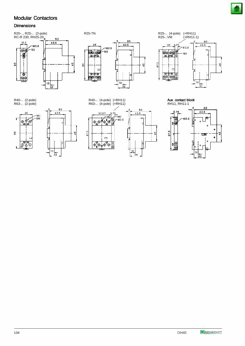
134 D946E
Modular ContactorsModular ContactorsModular ContactorsModular ContactorsModular Contactors
DimensionsDimensionsDimensionsDimensionsDimensions
R20-.., R25-.. (2-pole) R25-TN R25-.. (4-pole) (+RH11)RC-R 230, RH25-20 R25-..VM (+RH11-1)
R40-.. (2-pole) R40-.. (4-pole) (+RH11) Aux. contact blockAux. contact blockAux. contact blockAux. contact blockAux. contact blockR63-.. (2-pole) R63-.. (4-pole) (+RH11) RH11, RH11-1
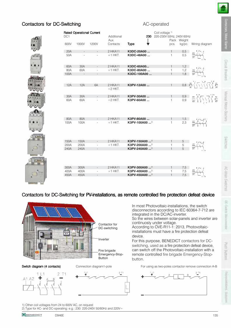
D946E 135
Contactors for DC-SwitchingContactors for DC-SwitchingContactors for DC-SwitchingContactors for DC-SwitchingContactors for DC-Switching AC-operated
Rated Operational CurrentRated Operational CurrentRated Operational CurrentRated Operational CurrentRated Operational Current Coil voltage 1)
DC1 Additional 230230230230230 220-230V 50Hz, 240V 60HzAux. Pack Weight
600V 1000V 1200V Contacts TypeTypeTypeTypeType pcs. kg/pc. Wiring diagram
20A - - 2 HKA11 K3DC-20A00 ... 1 0,550A - - +1 HKT. K3DC-48A00 ... 1 0,5
60A 30A - 2 HKA11 K3DC-60A00... 1 1,280A 60A - +1 HKT. K3DC-80A00 ... 1 1,2
100A - - K3DC-100A00 ... 1 1,8
12A 12A 6A 2 HKA11 K3PV-12A00 ... 1 0,8+2 HKT.
30A 30A - 2 HKA11 K3PV-30A00 ... 1 0,960A 60A - +2 HKT. K3PV-60A00 ... 1 0,9
80A 80A - 2 HKA11 K3PV-80A00 ... 1 1,5100A 100A - +1 HKT. K3PV-100A00 ...2) 1 2,3
150A 150A - 2 HKA11 K3PV-150A00 ...2) 1 5200A 200A - +1 HKT. K3PV-200A00 ...2) 1 5240A 240A - K3PV-240A00 ...2) 1 5
300A 300A - 2 HKA11 K3PV-300A00 ...2) 1 7,5400A 400A - +1 HKT. K3PV-400A00 ...2) 1 7,5450A 450A - K3PV-450A00 ...2) 1 7,5
1) Other coil voltages from 24 to 600V AC, on request2) Type for AC- and DC-operating: e.g.: 230: 220-240V 50/60Hz and 220V=
Contactors for DCContactors for DCContactors for DCContactors for DCContactors for DC-Switching -Switching -Switching -Switching -Switching for PVfor PVfor PVfor PVfor PV-installations, as remote controlled fire protection defeat device-installations, as remote controlled fire protection defeat device-installations, as remote controlled fire protection defeat device-installations, as remote controlled fire protection defeat device-installations, as remote controlled fire protection defeat device
In most Photovoltaic-installations, the switchdisconnectors according to IEC 60364-7-712 areintegrated in the DC/AC-inverter.So the wires between solar-panels and inverter arecontinuosly under voltage.According to ÖVE-R11-1: 2013, Photovoltaic-installations must have a fire protection defeatdevice.For this purpose, BENEDICT contactors for DC-switching, used as a fire protection defeat device,can switch off the Photovoltaic-installation with aremote controlled fire brigade Emergency-Stop-button.
Contactor forDC-switching
Inverter
Fire brigadeEmergency-Stop-Button
Switch diagram (4 contacts)Switch diagram (4 contacts)Switch diagram (4 contacts)Switch diagram (4 contacts)Switch diagram (4 contacts) Connection diagram1-pole For using as two-poles contactor remove connection A-B
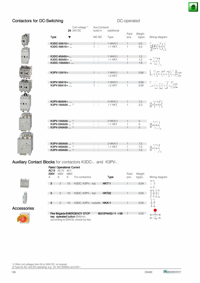
136 D946E
1) Other coil voltages from 24 to 250V DC, on request2) Type for AC- and DC-operating: e.g.: 24: 24V 50/60Hz and 24V=
Contactors for DC-SwitchingContactors for DC-SwitchingContactors for DC-SwitchingContactors for DC-SwitchingContactors for DC-Switching DC-operated
Coil voltage 1) Aux.Contacts2424242424 24V DC build in additional
Pack WeightTypeTypeTypeTypeType NO NC Type pcs. kg/pc. Wiring diagram
K3DC-20A10= ... 1 - 1 HKA11 1 0,5K3DC-48A10= ... 1 - +1 HKT. 1 0,5
K3DC-60A00=... - - 1 HKA11 1 1,2K3DC-80A00= ... - - +1 HKT. 1 1,2K3DC-100A00= ... - - 1 1,8
K3PV-12A10= 1 - 1 HKA11 1 0,85+2 HKT.
K3PV-30A10= ... 1 - 1 HKA11 1 0,95K3PV-60A10= ... 1 - +2 HKT. 1 0,95
K3PV-80A00= ... - - 2 HKA11 1 1,5K3PV-100A00 ... 2) - - +1 HKT. 1 2,3
K3PV-150A00 ... 2) - - 2 HKA11 1 5K3PV-200A00 ... 2) - - +1 HKT. 1 5K3PV-240A00 ... 2) - - 1 5
K3PV-300A00 ... 2) - - 2 HKA11 1 7,5K3PV-400A00 ... 2) - - +1 HKT. 1 7,5K3PV-450A00 ... 2) - - 1 7,5
Auxiliary Contact Blocks Auxiliary Contact Blocks Auxiliary Contact Blocks Auxiliary Contact Blocks Auxiliary Contact Blocks for contactors K3DC-.. and K3PV-..Rated Operational CurrentRated Operational CurrentRated Operational CurrentRated Operational CurrentRated Operational CurrentAC15AC15AC15AC15AC15 AC15 AC1230V230V230V230V230V 400V 690V Pack WeightA A A For contactors TypeTypeTypeTypeType pcs. kg/pc. Wiring diagram
33333 2 10 K3DC, K3PV-.. top HKT11HKT11HKT11HKT11HKT11 1 0,04
33333 2 10 K3DC, K3PV-.. top HKT22HKT22HKT22HKT22HKT22 1 0,05
33333 2 10 K3DC, K3PV-.. outside HKA11HKA11HKA11HKA11HKA11 1 0,05
AccessoriesAccessoriesAccessoriesAccessoriesAccessoriesFire Brigade-EMERGENCY STOPFire Brigade-EMERGENCY STOPFire Brigade-EMERGENCY STOPFire Brigade-EMERGENCY STOPFire Brigade-EMERGENCY STOP BG10P44S3-11 +SKBG10P44S3-11 +SKBG10P44S3-11 +SKBG10P44S3-11 +SKBG10P44S3-11 +SK 1 0,22key key key key key operated buttonoperated buttonoperated buttonoperated buttonoperated button Ø40mm,according to EN418, unlock by key
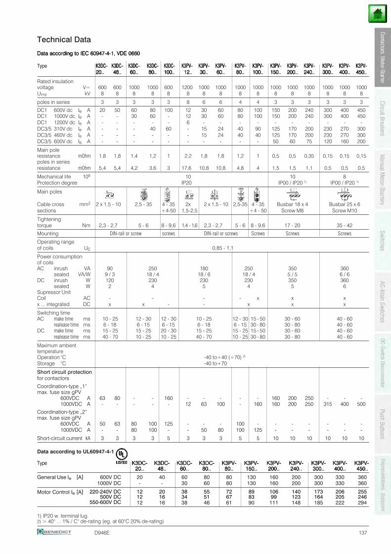
D946E 137
Technical Data
Data according to IEC 60947-4-1, VDE 0660Data according to IEC 60947-4-1, VDE 0660Data according to IEC 60947-4-1, VDE 0660Data according to IEC 60947-4-1, VDE 0660Data according to IEC 60947-4-1, VDE 0660
Type K3DC-K3DC-K3DC-K3DC-K3DC- K3DC-K3DC-K3DC-K3DC-K3DC- K3DC-K3DC-K3DC-K3DC-K3DC- K3DC-K3DC-K3DC-K3DC-K3DC- K3DC- K3DC- K3DC- K3DC- K3DC- K3PV-K3PV-K3PV-K3PV-K3PV- K3PV-K3PV-K3PV-K3PV-K3PV- K3PV-K3PV-K3PV-K3PV-K3PV- K3PV-K3PV-K3PV-K3PV-K3PV- K3PV-K3PV-K3PV-K3PV-K3PV- K3PV-K3PV-K3PV-K3PV-K3PV- K3PV-K3PV-K3PV-K3PV-K3PV- K3PV-K3PV-K3PV-K3PV-K3PV- K3PV-K3PV-K3PV-K3PV-K3PV- K3PV-K3PV-K3PV-K3PV-K3PV- K3PV-K3PV-K3PV-K3PV-K3PV-20..20..20..20..20.. 48..48..48..48..48.. 60..60..60..60..60.. 80..80..80..80..80.. 100.. 100.. 100.. 100.. 100.. 12..12..12..12..12.. 30..30..30..30..30.. 60..60..60..60..60.. 80..80..80..80..80.. 100..100..100..100..100.. 150..150..150..150..150.. 200..200..200..200..200.. 240..240..240..240..240.. 300..300..300..300..300.. 400..400..400..400..400.. 450..450..450..450..450..
Rated insulationvoltage V= 600 600 1000 1000 600 1200 1000 1000 1000 1000 1000 1000 1000 1000 1000 1000Uimp kV 8 8 8 8 8 8 8 8 8 8 8 8 8 8 8 8
poles in series 3 3 3 3 3 8 6 6 4 4 3 3 3 3 3 3
DC1 600V dc Ie A 20 50 60 80 100 12 30 60 80 100 150 200 240 300 400 450DC1 1000V dc Ie A - - 30 60 - 12 30 60 80 100 150 200 240 300 400 450DC1 1200V dc Ie A - - - - - 6 - - - - - - - - - -DC3/5 310V dc Ie A - - - 40 60 - 15 24 40 90 125 170 200 230 270 300DC3/5 460V dc Ie A - - - - - - 15 24 40 40 125 170 200 230 270 300DC3/5 600V dc Ie A - - - - - - - - - - 50 60 75 120 160 200
Main poleresistance mOhm 1,8 1,8 1,4 1,2 1 2,2 1,8 1,8 1,2 1 0,5 0,5 0,35 0,15 0,15 0,15poles in seriesresistance mOhm 5,4 5,4 4,2 3,6 3 17,6 10,8 10,8 4,8 4 1,5 1,5 1,1 0,5 0,5 0,5
Mechanical life 106 10 10 8Protection degree IP20 IP00 / IP20 1) IP00 / IP20 1)
Main poles
Cable cross mm2 2 x 1,5 - 10 2,5 - 35 4 - 35 2x 2 x 1,5 - 10 2,5-35 4 - 35 Busbar 18 x 4 Busbar 25 x 6sections +4-50 1,5-2,5 +4 - 50 Screw M8 Screw M10
Tighteningtorque Nm 2,3 - 2,7 5 - 6 8 - 9,6 1,4 - 1,6 2,3 - 2,7 5 - 6 8 - 9,6 17 - 20 35 - 42
Mounting DIN-rail or screw screws DIN-rail or screws Screws Screws Screws
Operating rangeof coils Uc 0,85 - 1,1
Power consumptionof coilsAC inrush VA 90 250 180 250 350 360
sealed VA/W 9 / 3 18 / 4 18 / 6 18 / 4 5 / 5 6 / 6DC inrush W 120 230 230 230 350 360
sealed W 2 4 5 4 5 6Supressor UnitCoil AC - - - - x x xx ... integrated DC x x - - x x x
Switching timeAC make time ms 10 - 25 12 - 30 12 - 30 10 - 25 12 - 30 15 - 50 30 - 60 40 - 60
realease time ms 6 - 18 6 - 15 6 - 15 6 - 18 6 - 15 30 - 80 30 - 80 40 - 60DC make time ms 15 - 25 15 - 25 20 - 30 15 - 25 15 - 25 15 - 50 30 - 60 40 - 60
realease time ms 40 - 70 10 - 25 10 - 25 40 - 70 10 - 25 30 - 80 30 - 80 40 - 60
Maximum ambienttemperatureOperation °C -40 to+40 (+70) 2)
Storage °C -40 to+70
Short circuit protectionfor contactors
Coordination-type „1“max. fuse size gPV
600VDC A 63 80 - - 160 - - - - - 160 200 250 - - -1000VDC A - - - - - 12 63 100 - 160 160 200 250 315 400 500
Coordination-type „2“max. fuse size gPV
600VDC A 50 63 80 100 125 - - - 100 - - - - - - -1000VDC A - - 80 100 - - 50 80 100 125 - - - - - -
Short-circuit current kA 3 3 3 3 5 3 3 3 5 5 10 10 10 10 10 10
1) IP20 w. terminal lug.2) > 40° ... 1% / C° de-rating (eg. at 60°C 20% de-rating)
Data according to UL60947-4-1
Type K3DC-K3DC-K3DC-K3DC-K3DC- K3DC-K3DC-K3DC-K3DC-K3DC- K3DC-K3DC-K3DC-K3DC-K3DC- K3DC-K3DC-K3DC-K3DC-K3DC- K3PV-K3PV-K3PV-K3PV-K3PV- K3PV-K3PV-K3PV-K3PV-K3PV- K3PV-K3PV-K3PV-K3PV-K3PV- K3PV-K3PV-K3PV-K3PV-K3PV- K3PV-K3PV-K3PV-K3PV-K3PV- K3PV-K3PV-K3PV-K3PV-K3PV- K3PV-K3PV-K3PV-K3PV-K3PV-20..20..20..20..20.. 48..48..48..48..48.. 60..60..60..60..60.. 80..80..80..80..80.. 80..80..80..80..80.. 150..150..150..150..150.. 200..200..200..200..200.. 240..240..240..240..240.. 300..300..300..300..300.. 400..400..400..400..400.. 450..450..450..450..450..
General Use Ie [A] 600V DC 20 40 60 80 80 130 160 200 300 330 3601000V DC - - 30 60 80 130 160 200 300 330 360
Motor Control Ie [A] 220-240V DC 12 20 38 55 72 89 106 140 173 206 255500V DC 12 16 34 51 67 83 99 123 164 205 246
550-600V DC 12 16 38 46 61 90 111 148 185 222 294
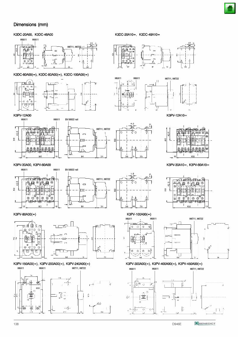
HKT11, HKT22
HKA11 HKA11
HKT11, HKT22
Dimensions (mm)Dimensions (mm)Dimensions (mm)Dimensions (mm)Dimensions (mm)
K3DC-20A00, K3DC-48A00K3DC-20A00, K3DC-48A00K3DC-20A00, K3DC-48A00K3DC-20A00, K3DC-48A00K3DC-20A00, K3DC-48A00 K3DC-20A10=, K3DC-48A10=K3DC-20A10=, K3DC-48A10=K3DC-20A10=, K3DC-48A10=K3DC-20A10=, K3DC-48A10=K3DC-20A10=, K3DC-48A10=
K3DC-60A00(=), K3DC-80A00(=), K3DC-100A00(=)K3DC-60A00(=), K3DC-80A00(=), K3DC-100A00(=)K3DC-60A00(=), K3DC-80A00(=), K3DC-100A00(=)K3DC-60A00(=), K3DC-80A00(=), K3DC-100A00(=)K3DC-60A00(=), K3DC-80A00(=), K3DC-100A00(=)
K3PV-12A00K3PV-12A00K3PV-12A00K3PV-12A00K3PV-12A00 K3PV-12A10=K3PV-12A10=K3PV-12A10=K3PV-12A10=K3PV-12A10=
K3PV-30A00, K3PV-60A00K3PV-30A00, K3PV-60A00K3PV-30A00, K3PV-60A00K3PV-30A00, K3PV-60A00K3PV-30A00, K3PV-60A00 K3PV-30A10=, K3PV-60A10=K3PV-30A10=, K3PV-60A10=K3PV-30A10=, K3PV-60A10=K3PV-30A10=, K3PV-60A10=K3PV-30A10=, K3PV-60A10=
K3PV-80A00(=)K3PV-80A00(=)K3PV-80A00(=)K3PV-80A00(=)K3PV-80A00(=) K3PV-100A00(=)K3PV-100A00(=)K3PV-100A00(=)K3PV-100A00(=)K3PV-100A00(=)
K3PV-150A00(=), K3PV-200A00(=), K3PV-240A00(=)K3PV-150A00(=), K3PV-200A00(=), K3PV-240A00(=)K3PV-150A00(=), K3PV-200A00(=), K3PV-240A00(=)K3PV-150A00(=), K3PV-200A00(=), K3PV-240A00(=)K3PV-150A00(=), K3PV-200A00(=), K3PV-240A00(=) K3PV-300A00(=), K3PV-400A00(=), K3PV-450A00(=)K3PV-300A00(=), K3PV-400A00(=), K3PV-450A00(=)K3PV-300A00(=), K3PV-400A00(=), K3PV-450A00(=)K3PV-300A00(=), K3PV-400A00(=), K3PV-450A00(=)K3PV-300A00(=), K3PV-400A00(=), K3PV-450A00(=)
138 D946E
EN 50022 rail
HKA11 HKA11 EN 50022 rail
HKA11 HKA11 HKT11, HKT22
HKA11 HKA11 HKT11, HKT22 HKA11 HKA11 HKT11, HKT22
HKA11 HKA11 HKT11, HKT22
HKT11, HKT22
HKA11 HKA11
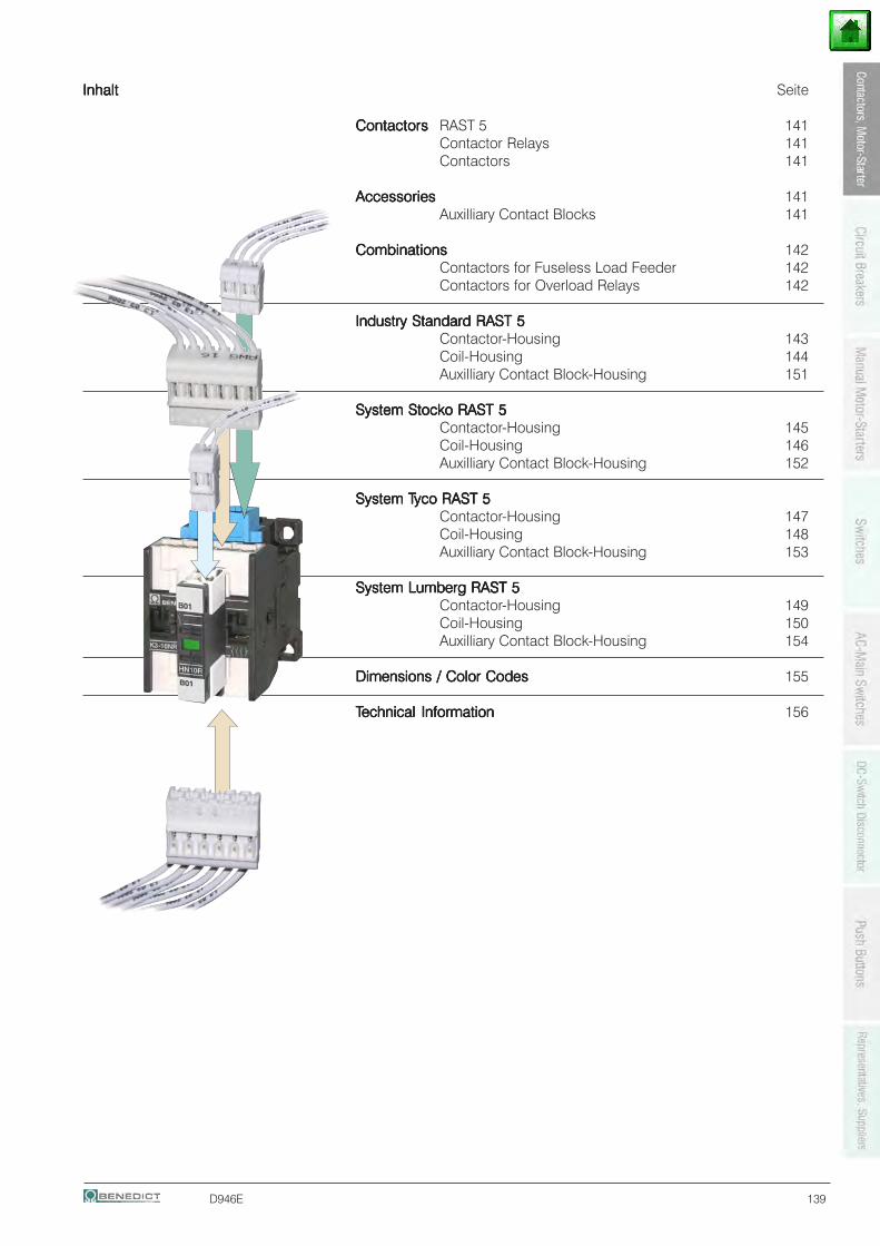
D946E 139
InhaltInhaltInhaltInhaltInhalt Seite
ContactorsContactorsContactorsContactorsContactors RAST 5 141Contactor Relays 141Contactors 141
AccessoriesAccessoriesAccessoriesAccessoriesAccessories 141Auxilliary Contact Blocks 141
CombinationsCombinationsCombinationsCombinationsCombinations 142Contactors for Fuseless Load Feeder 142Contactors for Overload Relays 142
Industry Standard RAST 5Industry Standard RAST 5Industry Standard RAST 5Industry Standard RAST 5Industry Standard RAST 5Contactor-Housing 143Coil-Housing 144Auxilliary Contact Block-Housing 151
System Stocko RAST 5System Stocko RAST 5System Stocko RAST 5System Stocko RAST 5System Stocko RAST 5Contactor-Housing 145Coil-Housing 146Auxilliary Contact Block-Housing 152
System TSystem TSystem TSystem TSystem Tyco RAST 5yco RAST 5yco RAST 5yco RAST 5yco RAST 5Contactor-Housing 147Coil-Housing 148Auxilliary Contact Block-Housing 153
System Lumberg RAST 5System Lumberg RAST 5System Lumberg RAST 5System Lumberg RAST 5System Lumberg RAST 5Contactor-Housing 149Coil-Housing 150Auxilliary Contact Block-Housing 154
Dimensions / Color CodesDimensions / Color CodesDimensions / Color CodesDimensions / Color CodesDimensions / Color Codes 155
TTTTTechnical Informationechnical Informationechnical Informationechnical Informationechnical Information 156
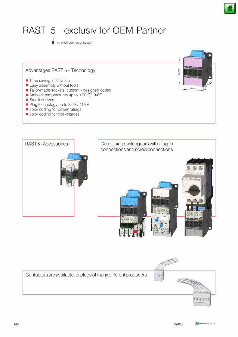
140 D946E
RAST 5 - exclusiv for OEM-Partner5 5 5 5 5 mm pitch connector system
Contactors are available for plugs of many different producers
65,5
mm
45 mm
59 m
m
Combining switchgears with plug-inconnections and screw connections
RAST 5 - Accessories
Advantages RAST 5 - Technology
Time saving installation Easy assembly without tools Tailor-made sockets, custom - designed codes Ambient temperatures up to +90°C/194°F Smallest sizes Plug technology up to 32 A / 415 V color coding for power ratings color coding for coil voltages
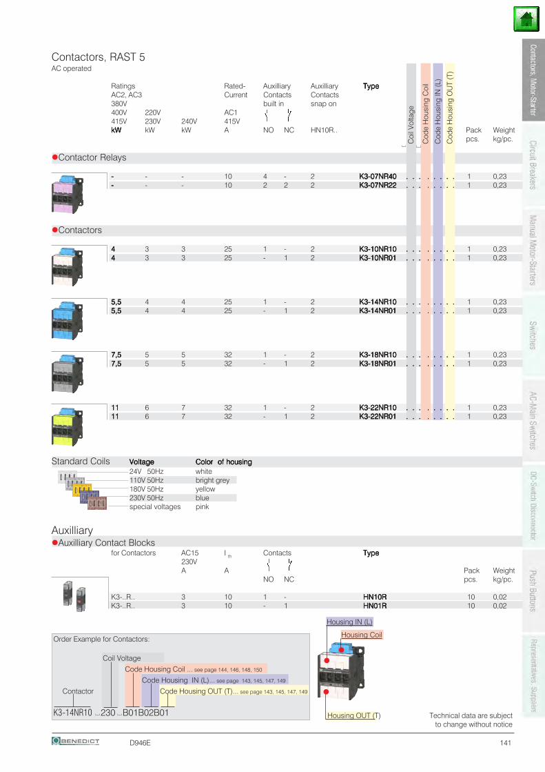
D946E 141
Contactors, RAST 5AC operated
Ratings Rated- Auxilliary Auxilliary TypeTypeTypeTypeTypeAC2, AC3 Current Contacts Contacts380V built in snap on400V 220V AC1415V 230V 240V 415VkWkWkWkWkW kW kW A NO NC HN10R.. Pack Weight
pcs. kg/pc.
Contactor Relays
----- - - 10 4 - 2 K3-07NR40K3-07NR40K3-07NR40K3-07NR40K3-07NR40 . . . . . . . .. . . . . . . .. . . . . . . .. . . . . . . .. . . . . . . . 1 0,23----- - - 10 2 2 2 K3-07NR22K3-07NR22K3-07NR22K3-07NR22K3-07NR22 . . . . . . . .. . . . . . . .. . . . . . . .. . . . . . . .. . . . . . . . 1 0,23
Contactors
44444 3 3 25 1 - 2 K3-10NR10K3-10NR10K3-10NR10K3-10NR10K3-10NR10 . . . . . . . .. . . . . . . .. . . . . . . .. . . . . . . .. . . . . . . . 1 0,2344444 3 3 25 - 1 2 K3-10NR01K3-10NR01K3-10NR01K3-10NR01K3-10NR01 . . . . . . . .. . . . . . . .. . . . . . . .. . . . . . . .. . . . . . . . 1 0,23
5,55,55,55,55,5 4 4 25 1 - 2 K3-14NR10K3-14NR10K3-14NR10K3-14NR10K3-14NR10 . . . . . . . .. . . . . . . .. . . . . . . .. . . . . . . .. . . . . . . . 1 0,235,55,55,55,55,5 4 4 25 - 1 2 K3-14NR01K3-14NR01K3-14NR01K3-14NR01K3-14NR01 . . . . . . . .. . . . . . . .. . . . . . . .. . . . . . . .. . . . . . . . 1 0,23
7,57,57,57,57,5 5 5 32 1 - 2 K3-18NR10K3-18NR10K3-18NR10K3-18NR10K3-18NR10 . . . . . . . .. . . . . . . .. . . . . . . .. . . . . . . .. . . . . . . . 1 0,237,57,57,57,57,5 5 5 32 - 1 2 K3-18NR01K3-18NR01K3-18NR01K3-18NR01K3-18NR01 . . . . . . . .. . . . . . . .. . . . . . . .. . . . . . . .. . . . . . . . 1 0,23
1111111111 6 7 32 1 - 2 K3-22NR10K3-22NR10K3-22NR10K3-22NR10K3-22NR10 . . . . . . . .. . . . . . . .. . . . . . . .. . . . . . . .. . . . . . . . 1 0,231111111111 6 7 32 - 1 2 K3-22NR01K3-22NR01K3-22NR01K3-22NR01K3-22NR01 . . . . . . . .. . . . . . . .. . . . . . . .. . . . . . . .. . . . . . . . 1 0,23
Standard Coils VoltageVoltageVoltageVoltageVoltage Color of housingColor of housingColor of housingColor of housingColor of housing24V 50Hz white110V 50Hz bright grey180V 50Hz yellow230V 50Hz bluespecial voltages pink
AuxilliaryAuxilliary Contact Blocks
for Contactors AC15 I th Contacts TypeTypeTypeTypeType230VA A Pack Weight
NO NC pcs. kg/pc.
K3-..R.. 3 10 1 - HN10RHN10RHN10RHN10RHN10R 10 0,02K3-..R.. 3 10 - 1 HN01RHN01RHN01RHN01RHN01R 10 0,02
Coi
l Vol
tage
Cod
e H
ousi
ng C
oil
Cod
e H
ousi
ng O
UT
(T)
Cod
e H
ousi
ng IN
(L)
Technical data are subjectto change without notice
Housing IN (L)
Housing OUT (T)
Housing CoilOrder Example for Contactors:
Coil Voltage
Code Housing Coil ... see page 144, 146, 148, 150
Code Housing IN (L)... see page 143, 145, 147, 149
Contactor Code Housing OUT (T)... see page 143, 145, 147, 149
K3-14NR10 230 B01B02B01
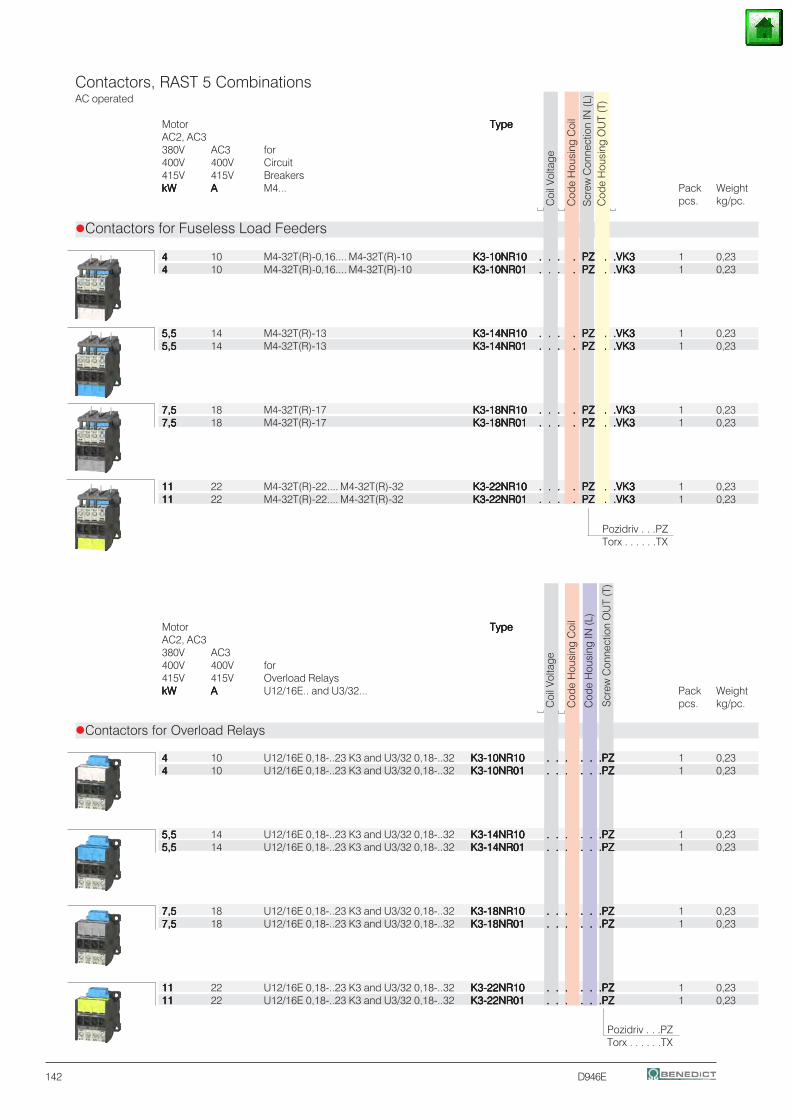
142 D946E
Contactors, RAST 5 CombinationsAC operated
Motor TypeTypeTypeTypeTypeAC2, AC3380V AC3 for400V 400V Circuit415V 415V BreakerskWkWkWkWkW AAAAA M4... Pack Weight
pcs. kg/pc.
Contactors for Fuseless Load Feeders
44444 10 M4-32T(R)-0,16.... M4-32T(R)-10 K3-10NR10K3-10NR10K3-10NR10K3-10NR10K3-10NR10 . . . . PZ . .VK3. . . . PZ . .VK3. . . . PZ . .VK3. . . . PZ . .VK3. . . . PZ . .VK3 1 0,2344444 10 M4-32T(R)-0,16.... M4-32T(R)-10 K3-10NR01K3-10NR01K3-10NR01K3-10NR01K3-10NR01 . . . . PZ . .VK3. . . . PZ . .VK3. . . . PZ . .VK3. . . . PZ . .VK3. . . . PZ . .VK3 1 0,23
5,55,55,55,55,5 14 M4-32T(R)-13 K3-14NR10K3-14NR10K3-14NR10K3-14NR10K3-14NR10 . . . . PZ . .VK3. . . . PZ . .VK3. . . . PZ . .VK3. . . . PZ . .VK3. . . . PZ . .VK3 1 0,235,55,55,55,55,5 14 M4-32T(R)-13 K3-14NR01K3-14NR01K3-14NR01K3-14NR01K3-14NR01 . . . . PZ . .VK3. . . . PZ . .VK3. . . . PZ . .VK3. . . . PZ . .VK3. . . . PZ . .VK3 1 0,23
7,57,57,57,57,5 18 M4-32T(R)-17 K3-18NR10K3-18NR10K3-18NR10K3-18NR10K3-18NR10 . . . . PZ . .VK3. . . . PZ . .VK3. . . . PZ . .VK3. . . . PZ . .VK3. . . . PZ . .VK3 1 0,237,57,57,57,57,5 18 M4-32T(R)-17 K3-18NR01K3-18NR01K3-18NR01K3-18NR01K3-18NR01 . . . . PZ . .VK3. . . . PZ . .VK3. . . . PZ . .VK3. . . . PZ . .VK3. . . . PZ . .VK3 1 0,23
1111111111 22 M4-32T(R)-22.... M4-32T(R)-32 K3-22NR10K3-22NR10K3-22NR10K3-22NR10K3-22NR10 . . . . PZ . .VK3. . . . PZ . .VK3. . . . PZ . .VK3. . . . PZ . .VK3. . . . PZ . .VK3 1 0,231111111111 22 M4-32T(R)-22.... M4-32T(R)-32 K3-22NR01K3-22NR01K3-22NR01K3-22NR01K3-22NR01 . . . . PZ . .VK3. . . . PZ . .VK3. . . . PZ . .VK3. . . . PZ . .VK3. . . . PZ . .VK3 1 0,23
Motor TypeTypeTypeTypeTypeAC2, AC3380V AC3400V 400V for415V 415V Overload RelayskWkWkWkWkW AAAAA U12/16E.. and U3/32... Pack Weight
pcs. kg/pc.
Contactors for Overload Relays
44444 10 U12/16E 0,18-..23 K3 and U3/32 0,18-..32 K3-10NR10K3-10NR10K3-10NR10K3-10NR10K3-10NR10 . . . . . .PZ. . . . . .PZ. . . . . .PZ. . . . . .PZ. . . . . .PZ 1 0,2344444 10 U12/16E 0,18-..23 K3 and U3/32 0,18-..32 K3-10NR01K3-10NR01K3-10NR01K3-10NR01K3-10NR01 . . . . . .PZ. . . . . .PZ. . . . . .PZ. . . . . .PZ. . . . . .PZ 1 0,23
5,55,55,55,55,5 14 U12/16E 0,18-..23 K3 and U3/32 0,18-..32 K3-14NR10K3-14NR10K3-14NR10K3-14NR10K3-14NR10 . . . . . .PZ. . . . . .PZ. . . . . .PZ. . . . . .PZ. . . . . .PZ 1 0,235,55,55,55,55,5 14 U12/16E 0,18-..23 K3 and U3/32 0,18-..32 K3-14NR01K3-14NR01K3-14NR01K3-14NR01K3-14NR01 . . . . . .PZ. . . . . .PZ. . . . . .PZ. . . . . .PZ. . . . . .PZ 1 0,23
7,57,57,57,57,5 18 U12/16E 0,18-..23 K3 and U3/32 0,18-..32 K3-18NR10K3-18NR10K3-18NR10K3-18NR10K3-18NR10 . . . . . .PZ. . . . . .PZ. . . . . .PZ. . . . . .PZ. . . . . .PZ 1 0,237,57,57,57,57,5 18 U12/16E 0,18-..23 K3 and U3/32 0,18-..32 K3-18NR01K3-18NR01K3-18NR01K3-18NR01K3-18NR01 . . . . . .PZ. . . . . .PZ. . . . . .PZ. . . . . .PZ. . . . . .PZ 1 0,23
1111111111 22 U12/16E 0,18-..23 K3 and U3/32 0,18-..32 K3-22NR10K3-22NR10K3-22NR10K3-22NR10K3-22NR10 . . . . . .PZ. . . . . .PZ. . . . . .PZ. . . . . .PZ. . . . . .PZ 1 0,231111111111 22 U12/16E 0,18-..23 K3 and U3/32 0,18-..32 K3-22NR01K3-22NR01K3-22NR01K3-22NR01K3-22NR01 . . . . . .PZ. . . . . .PZ. . . . . .PZ. . . . . .PZ. . . . . .PZ 1 0,23
Coi
l Vol
tage
Cod
e H
ousi
ng C
oil
Cod
e H
ousi
ng O
UT
(T)
Scr
ew C
onne
ctio
n IN
(L)
Pozidriv . . .PZTorx . . . . . .TX
Coi
l Vol
tage
Cod
e H
ousi
ng C
oil
Cod
e H
ousi
ng IN
(L)
Scr
ew C
onne
ctio
n O
UT
(T)
Pozidriv . . .PZTorx . . . . . .TX
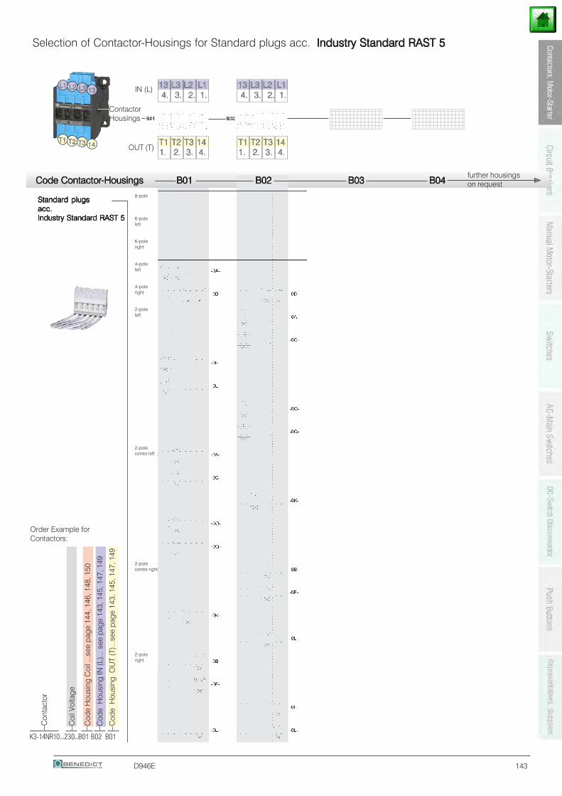
D946E 143
Code ContactorCode ContactorCode ContactorCode ContactorCode Contactor-Housings B01-Housings B01-Housings B01-Housings B01-Housings B01 B02 B02 B02 B02 B02 B03 B03 B03 B03 B03 B04 B04 B04 B04 B04
Standard plugsStandard plugsStandard plugsStandard plugsStandard plugsacc.acc.acc.acc.acc.Industry Standard RAST 5Industry Standard RAST 5Industry Standard RAST 5Industry Standard RAST 5Industry Standard RAST 5
1234567890123456123456789012345612345678901234561234567890123456123456789012345612345678901234561234567890123456
123456789012345612345678901234561234567890123456123456789012345612345678901234561234567890123456
Selection of Contactor-Housings for Standard plugs acc. Industry Standard RAST 5Industry Standard RAST 5Industry Standard RAST 5Industry Standard RAST 5Industry Standard RAST 5
T1T1T1T1T1 T2T2T2T2T2 T3T3T3T3T3 1414141414
L2L2L2L2L2L1L1L1L1L1 L3L3L3L3L3 1313131313
T1T1T1T1T1 T2T2T2T2T2 T3T3T3T3T3 14141414141. 1. 1. 1. 1. 2. 2. 2. 2. 2. 3. 3. 3. 3. 3. 4.4.4.4.4.
4.4.4.4.4. 3.3.3.3.3. 2.2.2.2.2. 1.1.1.1.1.1313131313 L3L3L3L3L3 L2L2L2L2L2 L1L1L1L1L1
T1T1T1T1T1 T2T2T2T2T2 T3T3T3T3T3 14141414141. 1. 1. 1. 1. 2. 2. 2. 2. 2. 3. 3. 3. 3. 3. 4.4.4.4.4.
4.4.4.4.4. 3.3.3.3.3. 2.2.2.2.2. 1.1.1.1.1.1313131313 L3L3L3L3L3 L2L2L2L2L2 L1L1L1L1L1
ContactorHousings
IN (L)
OUT (T)
Coi
l Vol
tage
Cod
e H
ousi
ng C
oil .
..see
pag
e 14
4, 1
46, 1
48, 1
50
Cod
e H
ousi
ng IN
(L)..
. see
pag
e 14
3, 1
45, 1
47, 1
49
Cod
e H
ousi
ng O
UT
(T)..
.see
pag
e 14
3, 1
45, 1
47, 1
49
K3-14NR10 230 B01 B02 B01
Con
tact
or
Order Example forContactors:
further housingson request
8-pole
6-poleleft
6-poleright
4-poleleft
4-poleright
2-poleleft
2-polecenter left
2-polecenter right
2-poleright
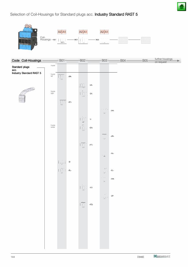
144 D946E
Standard plugsStandard plugsStandard plugsStandard plugsStandard plugsacc.acc.acc.acc.acc.Industry Standard RAST 5Industry Standard RAST 5Industry Standard RAST 5Industry Standard RAST 5Industry Standard RAST 5
Selection of Coil-Housings for Standard plugs acc. Industry Standard RAST 5Industry Standard RAST 5Industry Standard RAST 5Industry Standard RAST 5Industry Standard RAST 5
Code Coil-HousingsCode Coil-HousingsCode Coil-HousingsCode Coil-HousingsCode Coil-Housings B01 B02 B03 B04 B05
123456789123456789123456789123456789123456789123456789
A1A1A1A1A1 A2A2A2A2A2
A2A2A2A2A2 A1A1A1A1A1 A2A2A2A2A2 A1A1A1A1A1 A2A2A2A2A2 A1A1A1A1A1123456781234567812345678123456781234567812345678
Coil-Housings
further housingson request
4-pole
3-poleleft
3-poleright
2-polecenter
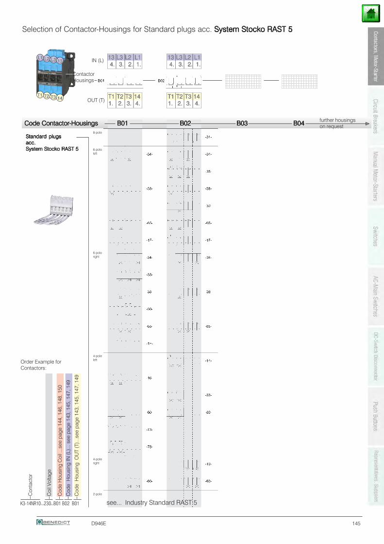
D946E 145
Code ContactorCode ContactorCode ContactorCode ContactorCode Contactor-Housings B01-Housings B01-Housings B01-Housings B01-Housings B01 B02 B02 B02 B02 B02 B03 B03 B03 B03 B03 B04 B04 B04 B04 B04
Standard plugsStandard plugsStandard plugsStandard plugsStandard plugsacc.acc.acc.acc.acc.System Stocko RAST 5System Stocko RAST 5System Stocko RAST 5System Stocko RAST 5System Stocko RAST 5
1234567890123456123456789012345612345678901234561234567890123456123456789012345612345678901234561234567890123456
123456789012345612345678901234561234567890123456123456789012345612345678901234561234567890123456
Selection of Contactor-Housings for Standard plugs acc. System Stocko RAST 5System Stocko RAST 5System Stocko RAST 5System Stocko RAST 5System Stocko RAST 5
see... Industry Standard RAST 5
T1T1T1T1T1 T2T2T2T2T2 T3T3T3T3T3 1414141414
L2L2L2L2L2L1L1L1L1L1 L3L3L3L3L3 1313131313
T1T1T1T1T1 T2T2T2T2T2 T3T3T3T3T3 14141414141. 1. 1. 1. 1. 2. 2. 2. 2. 2. 3. 3. 3. 3. 3. 4.4.4.4.4.
4.4.4.4.4. 3.3.3.3.3. 2.2.2.2.2. 1.1.1.1.1.1313131313 L3L3L3L3L3 L2L2L2L2L2 L1L1L1L1L1
T1T1T1T1T1 T2T2T2T2T2 T3T3T3T3T3 14141414141. 1. 1. 1. 1. 2. 2. 2. 2. 2. 3. 3. 3. 3. 3. 4.4.4.4.4.
4.4.4.4.4. 3.3.3.3.3. 2.2.2.2.2. 1.1.1.1.1.1313131313 L3L3L3L3L3 L2L2L2L2L2 L1L1L1L1L1
ContactorHousings
IN (L)
OUT (T)
further housingson request
Coi
l Vol
tage
Cod
e H
ousi
ng C
oil .
..see
pag
e 14
4, 1
46, 1
48, 1
50
Cod
e H
ousi
ng IN
(L)..
. see
pag
e 14
3, 1
45, 1
47, 1
49
Cod
e H
ousi
ng O
UT
(T)..
.see
pag
e 14
3, 1
45, 1
47, 1
49
K3-14NR10 230 B01 B02 B01
Con
tact
or
Order Example forContactors:
8-pole
6-poleleft
6-poleright
4-poleleft
4-poleright
2-pole
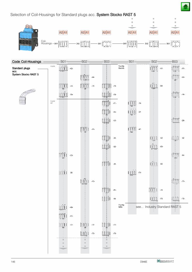
146 D946E
Standard plugsStandard plugsStandard plugsStandard plugsStandard plugsacc.acc.acc.acc.acc.System Stocko RAST 5System Stocko RAST 5System Stocko RAST 5System Stocko RAST 5System Stocko RAST 5
Selection of Coil-Housings for Standard plugs acc. System Stocko RAST 5System Stocko RAST 5System Stocko RAST 5System Stocko RAST 5System Stocko RAST 5
A1A1A1A1A1 A2A2A2A2A2
A2A2A2A2A2 A1A1A1A1A1 A2A2A2A2A2 A1A1A1A1A1 A2A2A2A2A2 A1A1A1A1A1 A2A2A2A2A2 A1A1A1A1A1A2A2A2A2A2 A1A1A1A1A1 A2A2A2A2A2 A1A1A1A1A1
Code Coil-HousingsCode Coil-HousingsCode Coil-HousingsCode Coil-HousingsCode Coil-Housings B01 B02 B03 B01 B02 B03
Coil-Housings
see... Industry Standard RAST 5
4-pole
3-poleleft
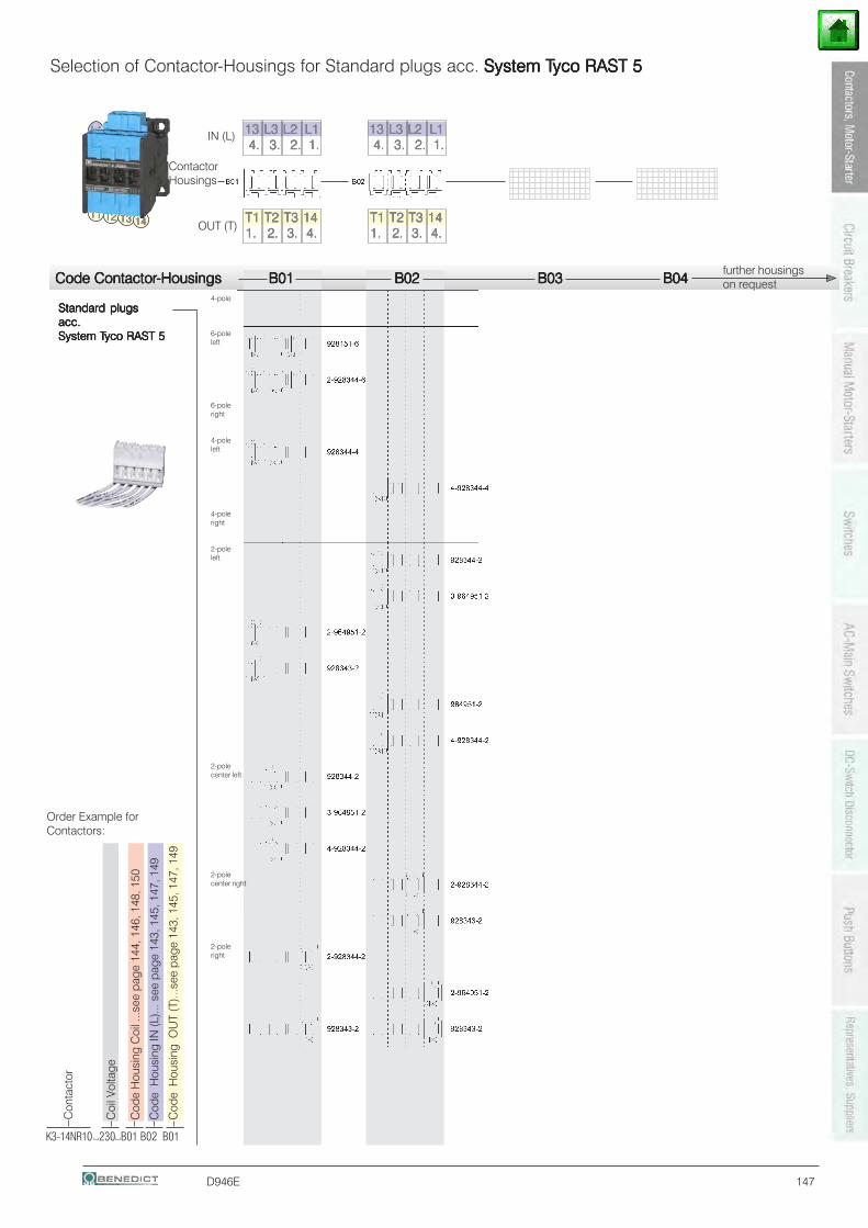
D946E 147
Code ContactorCode ContactorCode ContactorCode ContactorCode Contactor-Housings B01-Housings B01-Housings B01-Housings B01-Housings B01 B02 B02 B02 B02 B02 B03 B03 B03 B03 B03 B04 B04 B04 B04 B04
Standard plugsStandard plugsStandard plugsStandard plugsStandard plugsacc.acc.acc.acc.acc.System TSystem TSystem TSystem TSystem Tyco RAST 5yco RAST 5yco RAST 5yco RAST 5yco RAST 5
1234567890123456123456789012345612345678901234561234567890123456123456789012345612345678901234561234567890123456
123456789012345612345678901234561234567890123456123456789012345612345678901234561234567890123456
Selection of Contactor-Housings for Standard plugs acc. System TSystem TSystem TSystem TSystem Tyco RAST 5yco RAST 5yco RAST 5yco RAST 5yco RAST 5
T1T1T1T1T1 T2T2T2T2T2 T3T3T3T3T3 1414141414
L2L2L2L2L2L1L1L1L1L1 L3L3L3L3L3 1313131313
T1T1T1T1T1 T2T2T2T2T2 T3T3T3T3T3 14141414141. 1. 1. 1. 1. 2. 2. 2. 2. 2. 3. 3. 3. 3. 3. 4.4.4.4.4.
4.4.4.4.4. 3.3.3.3.3. 2.2.2.2.2. 1.1.1.1.1.1313131313 L3L3L3L3L3 L2L2L2L2L2 L1L1L1L1L1
T1T1T1T1T1 T2T2T2T2T2 T3T3T3T3T3 14141414141. 1. 1. 1. 1. 2. 2. 2. 2. 2. 3. 3. 3. 3. 3. 4.4.4.4.4.
4.4.4.4.4. 3.3.3.3.3. 2.2.2.2.2. 1.1.1.1.1.1313131313 L3L3L3L3L3 L2L2L2L2L2 L1L1L1L1L1
ContactorHousings
IN (L)
OUT (T)
further housingson request
Coi
l Vol
tage
Cod
e H
ousi
ng C
oil .
..see
pag
e 14
4, 1
46, 1
48, 1
50
Cod
e H
ousi
ng IN
(L)..
. see
pag
e 14
3, 1
45, 1
47, 1
49
Cod
e H
ousi
ng O
UT
(T)..
.see
pag
e 14
3, 1
45, 1
47, 1
49
K3-14NR10 230 B01 B02 B01
Con
tact
or
Order Example forContactors:
4-pole
6-poleleft
6-poleright
4-poleleft
4-poleright
2-poleleft
2-polecenter left
2-polecenter right
2-poleright
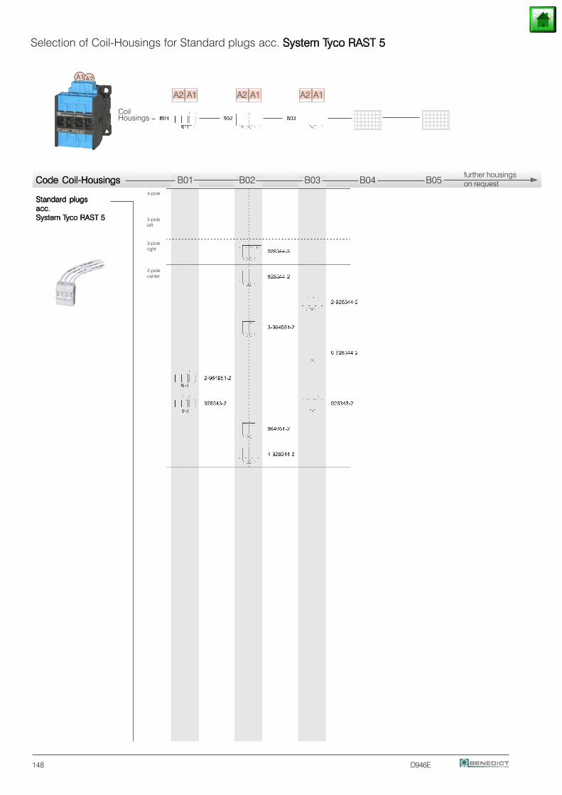
148 D946E
Standard plugsStandard plugsStandard plugsStandard plugsStandard plugsacc.acc.acc.acc.acc.System TSystem TSystem TSystem TSystem Tyco RAST 5yco RAST 5yco RAST 5yco RAST 5yco RAST 5
Selection of Coil-Housings for Standard plugs acc. System TSystem TSystem TSystem TSystem Tyco RAST 5yco RAST 5yco RAST 5yco RAST 5yco RAST 5
Code Coil-HousingsCode Coil-HousingsCode Coil-HousingsCode Coil-HousingsCode Coil-Housings B01 B02 B03 B04 B05
123456789123456789123456789123456789123456789123456789
A1A1A1A1A1 A2A2A2A2A2
A2A2A2A2A2 A1A1A1A1A1 A2A2A2A2A2 A1A1A1A1A1 A2A2A2A2A2 A1A1A1A1A1123456781234567812345678123456781234567812345678
CoilHousings
further housingson request
4-pole
3-poleleft
3-poleright
2-polecenter

D946E 149
Code ContactorCode ContactorCode ContactorCode ContactorCode Contactor-Housings-Housings-Housings-Housings-Housings B01 B01 B01 B01 B01 B02 B02 B02 B02 B02 B03 B03 B03 B03 B03 B04 B04 B04 B04 B04
Standard plugsStandard plugsStandard plugsStandard plugsStandard plugsacc.acc.acc.acc.acc.System Lumberg RAST 5System Lumberg RAST 5System Lumberg RAST 5System Lumberg RAST 5System Lumberg RAST 5
1234567890123456123456789012345612345678901234561234567890123456123456789012345612345678901234561234567890123456
1234567890123456123456789012345612345678901234561234567890123456123456789012345612345678901234561234567890123456
Selection of Contactor-Housings for Standard plugs acc. System Lumberg RAST 5System Lumberg RAST 5System Lumberg RAST 5System Lumberg RAST 5System Lumberg RAST 5
T1T1T1T1T1 T2T2T2T2T2 T3T3T3T3T3 1414141414
L2L2L2L2L2L1L1L1L1L1 L3L3L3L3L3 1313131313
T1T1T1T1T1 T2T2T2T2T2 T3T3T3T3T3 14141414141. 1. 1. 1. 1. 2. 2. 2. 2. 2. 3. 3. 3. 3. 3. 4.4.4.4.4.
4.4.4.4.4. 3.3.3.3.3. 2.2.2.2.2. 1.1.1.1.1.1313131313 L3L3L3L3L3 L2L2L2L2L2 L1L1L1L1L1
T1T1T1T1T1 T2T2T2T2T2 T3T3T3T3T3 14141414141. 1. 1. 1. 1. 2. 2. 2. 2. 2. 3. 3. 3. 3. 3. 4.4.4.4.4.
4.4.4.4.4. 3.3.3.3.3. 2.2.2.2.2. 1.1.1.1.1.1313131313 L3L3L3L3L3 L2L2L2L2L2 L1L1L1L1L1
ContactorHousings
IN (L)
OUT (T)
further housingson request
Coi
l Vol
tage
Cod
e H
ousi
ng C
oil .
..see
pag
e 14
4, 1
46, 1
48, 1
50
Cod
e H
ousi
ng IN
(L)..
. see
pag
e 14
3, 1
45, 1
47, 1
49
Cod
e H
ousi
ng O
UT
(T)..
.see
pag
e 14
3, 1
45, 1
47, 1
49
K3-14NR10 230 B01 B02 B01
Con
tact
or
Order Example forContactors:
8-pole
6-poleleft
6-poleright
4-poleleft
4-poleright
2-poleleft
2-polecenter left
2-polecenter right
2-poleright
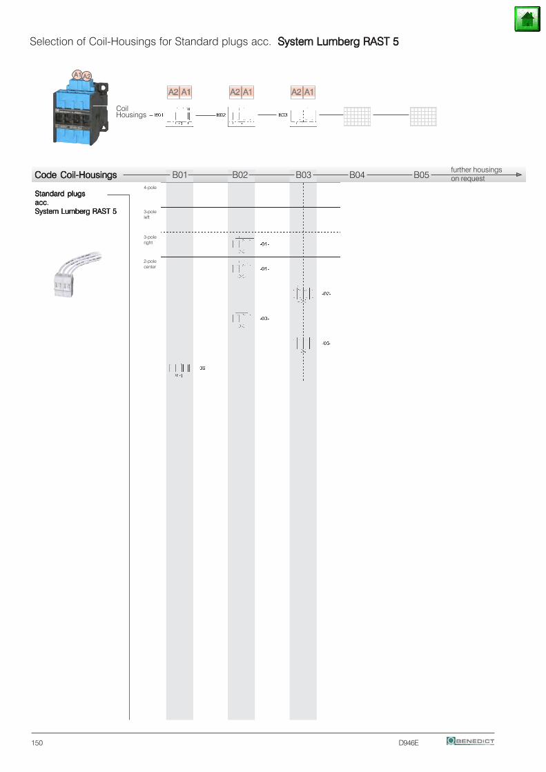
150 D946E
Standard plugsStandard plugsStandard plugsStandard plugsStandard plugsacc.acc.acc.acc.acc.System Lumberg RAST 5System Lumberg RAST 5System Lumberg RAST 5System Lumberg RAST 5System Lumberg RAST 5
Selection of Coil-Housings for Standard plugs acc. System Lumberg RAST 5System Lumberg RAST 5System Lumberg RAST 5System Lumberg RAST 5System Lumberg RAST 5
Code Coil-HousingsCode Coil-HousingsCode Coil-HousingsCode Coil-HousingsCode Coil-Housings B01 B02 B03 B04 B05
123456789123456789123456789123456789123456789123456789
A1A1A1A1A1 A2A2A2A2A2
A2A2A2A2A2 A1A1A1A1A1 A2A2A2A2A2 A1A1A1A1A1 A2A2A2A2A2 A1A1A1A1A1123456781234567812345678123456781234567812345678
CoilHousings
further housingson request
4-pole
3-poleleft
3-poleright
2-polecenter
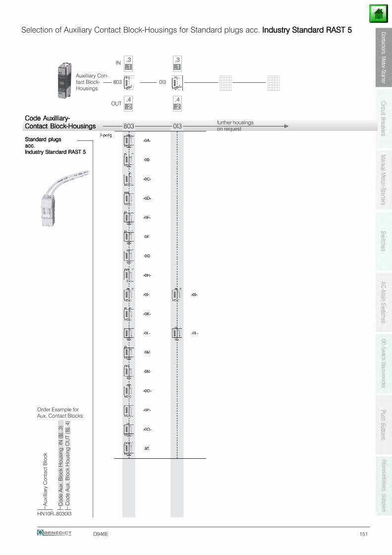
D946E 151
Standard plugsStandard plugsStandard plugsStandard plugsStandard plugsacc.acc.acc.acc.acc.Industry Standard RAST 5Industry Standard RAST 5Industry Standard RAST 5Industry Standard RAST 5Industry Standard RAST 5
Selection of Auxiliary Contact Block-Housings for Standard plugs acc. Industry Standard RAST 5Industry Standard RAST 5Industry Standard RAST 5Industry Standard RAST 5Industry Standard RAST 5
Code AuxilliaryCode AuxilliaryCode AuxilliaryCode AuxilliaryCode Auxilliary-----Contact BlockContact BlockContact BlockContact BlockContact Block-Housings-Housings-Housings-Housings-Housings 803 0I3
123456123456123456123456123456123456123456
123456123456123456123456123456123456123456
Auxilliary Con-tact Block- 803 0I3Housings
.3.3.3.3.3
.2.2.2.2.2
.4.4.4.4.4
.1.1.1.1.1.3.3.3.3.3
.2.2.2.2.2
.4.4.4.4.4
.1.1.1.1.1IN
OUT
further housingson request
HN10R 8030I3
Aux
illia
ry C
onta
ct B
lock
Cod
e A
ux. B
lock
Hou
sing
IN
(.1,
.3)
Order Example forAux. Contact Blocks:
Cod
e A
ux. B
lock
Hou
sing
OU
T (.2
,.4)
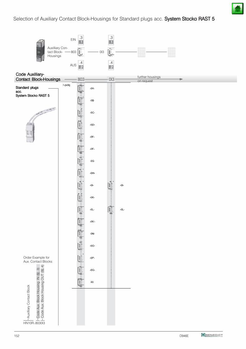
152 D946E
Standard plugsStandard plugsStandard plugsStandard plugsStandard plugsacc.acc.acc.acc.acc.System Stocko RAST 5System Stocko RAST 5System Stocko RAST 5System Stocko RAST 5System Stocko RAST 5
Selection of Auxiliary Contact Block-Housings for Standard plugs acc. System Stocko RAST 5System Stocko RAST 5System Stocko RAST 5System Stocko RAST 5System Stocko RAST 5
123456123456123456123456123456123456123456
123456123456123456123456123456123456123456
.3.3.3.3.3
.2.2.2.2.2
.4.4.4.4.4
.1.1.1.1.1.3.3.3.3.3
.2.2.2.2.2
.4.4.4.4.4
.1.1.1.1.1EIN
AUS
Auxilliary Con-tact Block- 803 0I3Housings
Code AuxilliaryCode AuxilliaryCode AuxilliaryCode AuxilliaryCode Auxilliary-----Contact BlockContact BlockContact BlockContact BlockContact Block-Housings-Housings-Housings-Housings-Housings 803 0I3
further housingson request
HN10R 8030I3
Aux
illia
ry C
onta
ct B
lock
Cod
e A
ux. B
lock
Hou
sing
IN
(.1,
.3)
Order Example forAux. Contact Blocks:
Cod
e A
ux. B
lock
Hou
sing
OU
T (.2
,.4)
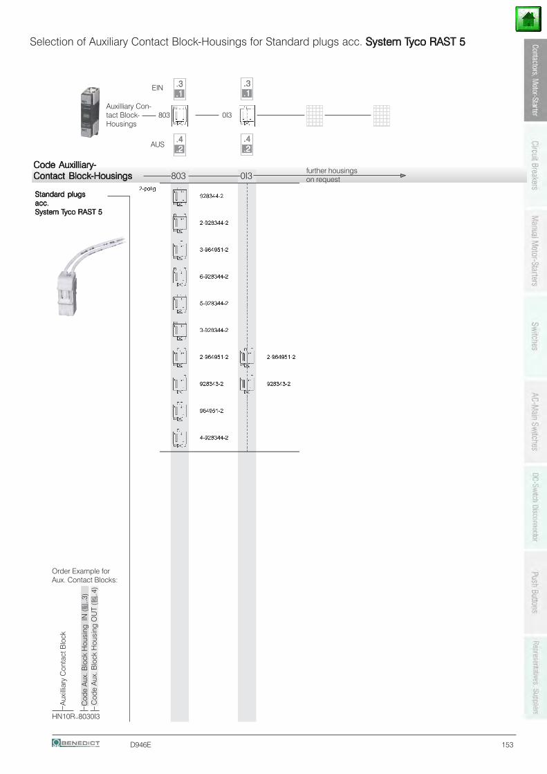
D946E 153
Standard plugsStandard plugsStandard plugsStandard plugsStandard plugsacc.acc.acc.acc.acc.System TSystem TSystem TSystem TSystem Tyco RAST 5yco RAST 5yco RAST 5yco RAST 5yco RAST 5
Selection of Auxiliary Contact Block-Housings for Standard plugs acc. System TSystem TSystem TSystem TSystem Tyco RAST 5yco RAST 5yco RAST 5yco RAST 5yco RAST 5
123456123456123456123456123456123456123456
123456123456123456123456123456123456123456
EIN
AUS
.3.3.3.3.3
.2.2.2.2.2
.4.4.4.4.4
.1.1.1.1.1.3.3.3.3.3
.2.2.2.2.2
.4.4.4.4.4
.1.1.1.1.1
Auxilliary Con-tact Block- 803 0I3Housings
Code AuxilliaryCode AuxilliaryCode AuxilliaryCode AuxilliaryCode Auxilliary-----Contact BlockContact BlockContact BlockContact BlockContact Block-Housings-Housings-Housings-Housings-Housings 803 0I3
further housingson request
HN10R 8030I3
Aux
illia
ry C
onta
ct B
lock
Cod
e A
ux. B
lock
Hou
sing
IN
(.1,
.3)
Order Example forAux. Contact Blocks:
Cod
e A
ux. B
lock
Hou
sing
OU
T (.2
,.4)
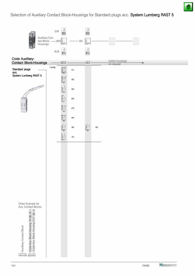
154 D946E
Standard plugsStandard plugsStandard plugsStandard plugsStandard plugsacc.acc.acc.acc.acc.System Lumberg RAST 5System Lumberg RAST 5System Lumberg RAST 5System Lumberg RAST 5System Lumberg RAST 5
Selection of Auxiliary Contact Block-Housings for Standard plugs acc. System Lumberg RAST 5System Lumberg RAST 5System Lumberg RAST 5System Lumberg RAST 5System Lumberg RAST 5
123456123456123456123456123456123456123456
123456123456123456123456123456123456123456
EIN
AUS
.3.3.3.3.3
.2.2.2.2.2
.4.4.4.4.4
.1.1.1.1.1.3.3.3.3.3
.2.2.2.2.2
.4.4.4.4.4
.1.1.1.1.1Auxilliary Con-tact Block- 803 0I3Housings
Code AuxilliaryCode AuxilliaryCode AuxilliaryCode AuxilliaryCode Auxilliary-----Contact BlockContact BlockContact BlockContact BlockContact Block-Housings-Housings-Housings-Housings-Housings 803 0I3
further housingson request
HN10R 8030I3
Aux
illia
ry C
onta
ct B
lock
Cod
e A
ux. B
lock
Hou
sing
IN
(.1,
.3)
Order Example forAux. Contact Blocks:
Cod
e A
ux. B
lock
Hou
sing
OU
T (.2
,.4)
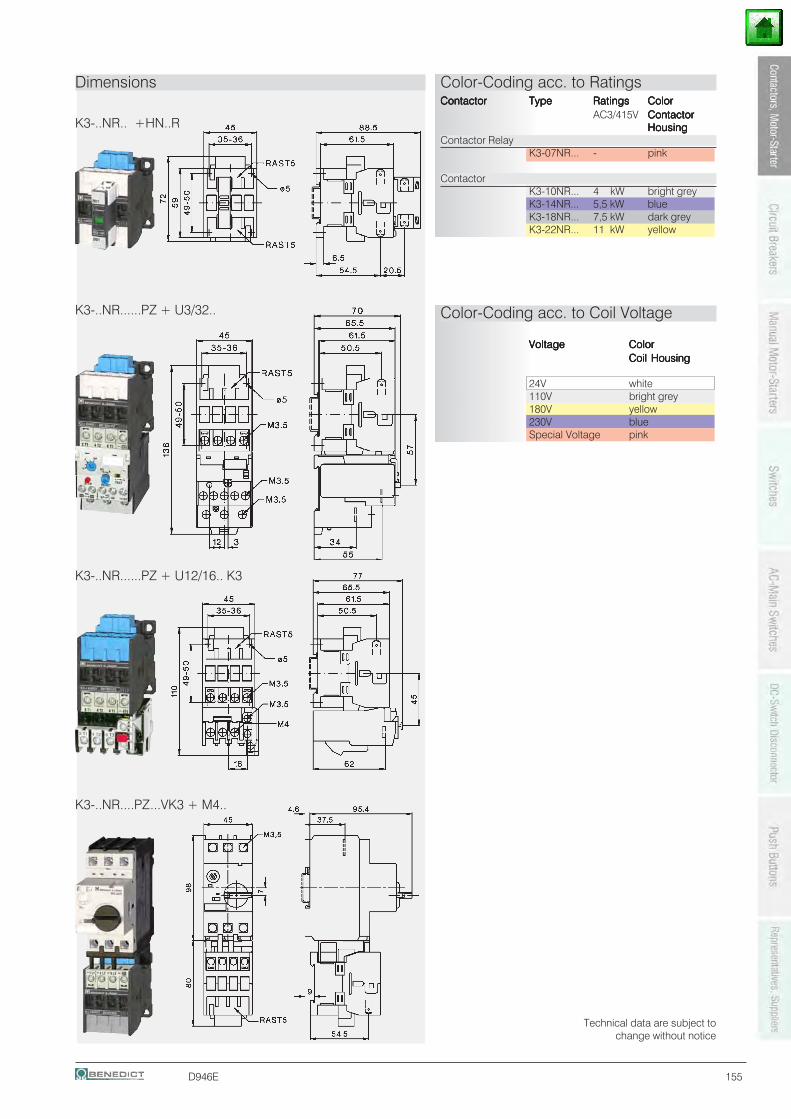
D946E 155
K3-..NR.. +HN..R
K3-..NR......PZ + U3/32..
K3-..NR......PZ + U12/16.. K3
Dimensions Color-Coding acc. to RatingsContactorContactorContactorContactorContactor TypeTypeTypeTypeType RatingsRatingsRatingsRatingsRatings ColorColorColorColorColor
AC3/415V ContactorContactorContactorContactorContactorHousingHousingHousingHousingHousing
Contactor RelayK3-07NR... - pink
ContactorK3-10NR... 4 kW bright greyK3-14NR... 5,5 kW blueK3-18NR... 7,5 kW dark greyK3-22NR... 11 kW yellow
Color-Coding acc. to Coil Voltage
VoltageVoltageVoltageVoltageVoltage ColorColorColorColorColorCoil HousingCoil HousingCoil HousingCoil HousingCoil Housing
24V white110V bright grey180V yellow230V blueSpecial Voltage pink
Technical data are subject tochange without notice
K3-..NR....PZ...VK3 + M4..
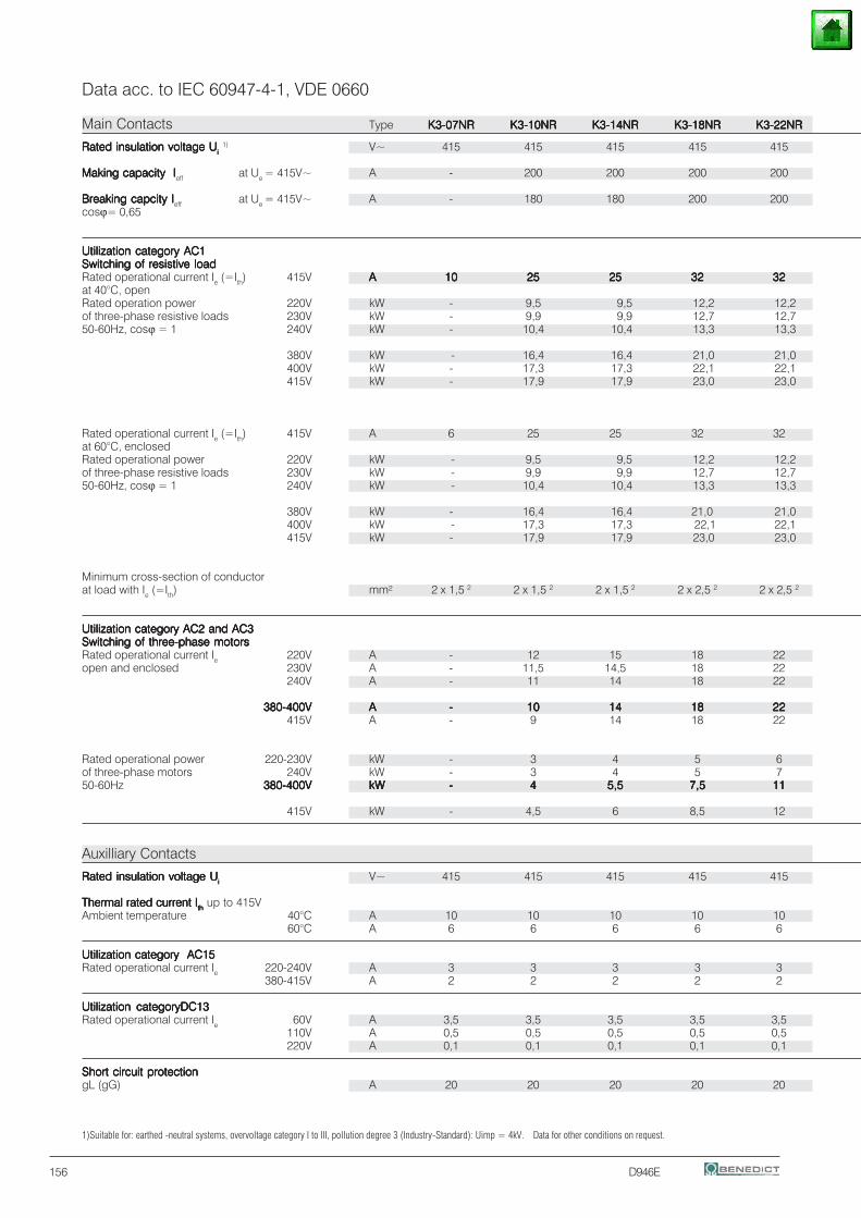
156 D946E
Data acc. to IEC 60947-4-1, VDE 0660
Main Contacts Type K3-07NRK3-07NRK3-07NRK3-07NRK3-07NR K3-10NRK3-10NRK3-10NRK3-10NRK3-10NR K3-14NRK3-14NRK3-14NRK3-14NRK3-14NR K3-18NRK3-18NRK3-18NRK3-18NRK3-18NR K3-22NRK3-22NRK3-22NRK3-22NRK3-22NR
Rated insulation voltage URated insulation voltage URated insulation voltage URated insulation voltage URated insulation voltage Uiiiii 1) V~ 415 415 415 415 415
Making capacity IMaking capacity IMaking capacity IMaking capacity IMaking capacity Ieff at Ue = 415V~ A - 200 200 200 200
Breaking capcity IBreaking capcity IBreaking capcity IBreaking capcity IBreaking capcity Ieff at Ue = 415V~ A - 180 180 200 200cosϕ= 0,65
Utilization category AC1Utilization category AC1Utilization category AC1Utilization category AC1Utilization category AC1Switching of resistive loadSwitching of resistive loadSwitching of resistive loadSwitching of resistive loadSwitching of resistive loadRated operational current Ie (=Ith) 415V AAAAA 1010101010 2525252525 2525252525 3232323232 3232323232at 40°C, openRated operation power 220V kW - 9,5 9,5 12,2 12,2of three-phase resistive loads 230V kW - 9,9 9,9 12,7 12,750-60Hz, cosϕ = 1 240V kW - 10,4 10,4 13,3 13,3
380V kW - 16,4 16,4 21,0 21,0400V kW - 17,3 17,3 22,1 22,1415V kW - 17,9 17,9 23,0 23,0
Rated operational current Ie (=Ith) 415V A 6 25 25 32 32at 60°C, enclosedRated operational power 220V kW - 9,5 9,5 12,2 12,2of three-phase resistive loads 230V kW - 9,9 9,9 12,7 12,750-60Hz, cosϕ = 1 240V kW - 10,4 10,4 13,3 13,3
380V kW - 16,4 16,4 21,0 21,0400V kW - 17,3 17,3 22,1 22,1415V kW - 17,9 17,9 23,0 23,0
Minimum cross-section of conductorat load with Ie (=Ith) mm² 2 x 1,5 2 2 x 1,5 2 2 x 1,5 2 2 x 2,5 2 2 x 2,5 2
Utilization category AC2 and AC3Utilization category AC2 and AC3Utilization category AC2 and AC3Utilization category AC2 and AC3Utilization category AC2 and AC3Switching of three-phase motorsSwitching of three-phase motorsSwitching of three-phase motorsSwitching of three-phase motorsSwitching of three-phase motorsRated operational current Ie 220V A - 12 15 18 22open and enclosed 230V A - 11,5 14,5 18 22
240V A - 11 14 18 22
380-400V380-400V380-400V380-400V380-400V AAAAA ----- 1010101010 1414141414 1818181818 2222222222415V A - 9 14 18 22
Rated operational power 220-230V kW - 3 4 5 6of three-phase motors 240V kW - 3 4 5 750-60Hz 380-400V380-400V380-400V380-400V380-400V kWkWkWkWkW ----- 44444 5,55,55,55,55,5 7,57,57,57,57,5 1111111111
415V kW - 4,5 6 8,5 12
Auxilliary Contacts
Rated insulation voltage URated insulation voltage URated insulation voltage URated insulation voltage URated insulation voltage Uiiiii V~ 415 415 415 415 415
Thermal rated current IThermal rated current IThermal rated current IThermal rated current IThermal rated current Iththththth up to 415VAmbient temperature 40°C A 10 10 10 10 10
60°C A 6 6 6 6 6
Utilization category AC15Utilization category AC15Utilization category AC15Utilization category AC15Utilization category AC15Rated operational current Ie 220-240V A 3 3 3 3 3
380-415V A 2 2 2 2 2
Utilization categoryDC13Utilization categoryDC13Utilization categoryDC13Utilization categoryDC13Utilization categoryDC13Rated operational current Ie 60V A 3,5 3,5 3,5 3,5 3,5
110V A 0,5 0,5 0,5 0,5 0,5220V A 0,1 0,1 0,1 0,1 0,1
Short circuit protectionShort circuit protectionShort circuit protectionShort circuit protectionShort circuit protectiongL (gG) A 20 20 20 20 20
1)Suitable for: earthed -neutral systems, overvoltage category I to III, pollution degree 3 (Industry-Standard): Uimp = 4kV. Data for other conditions on request.
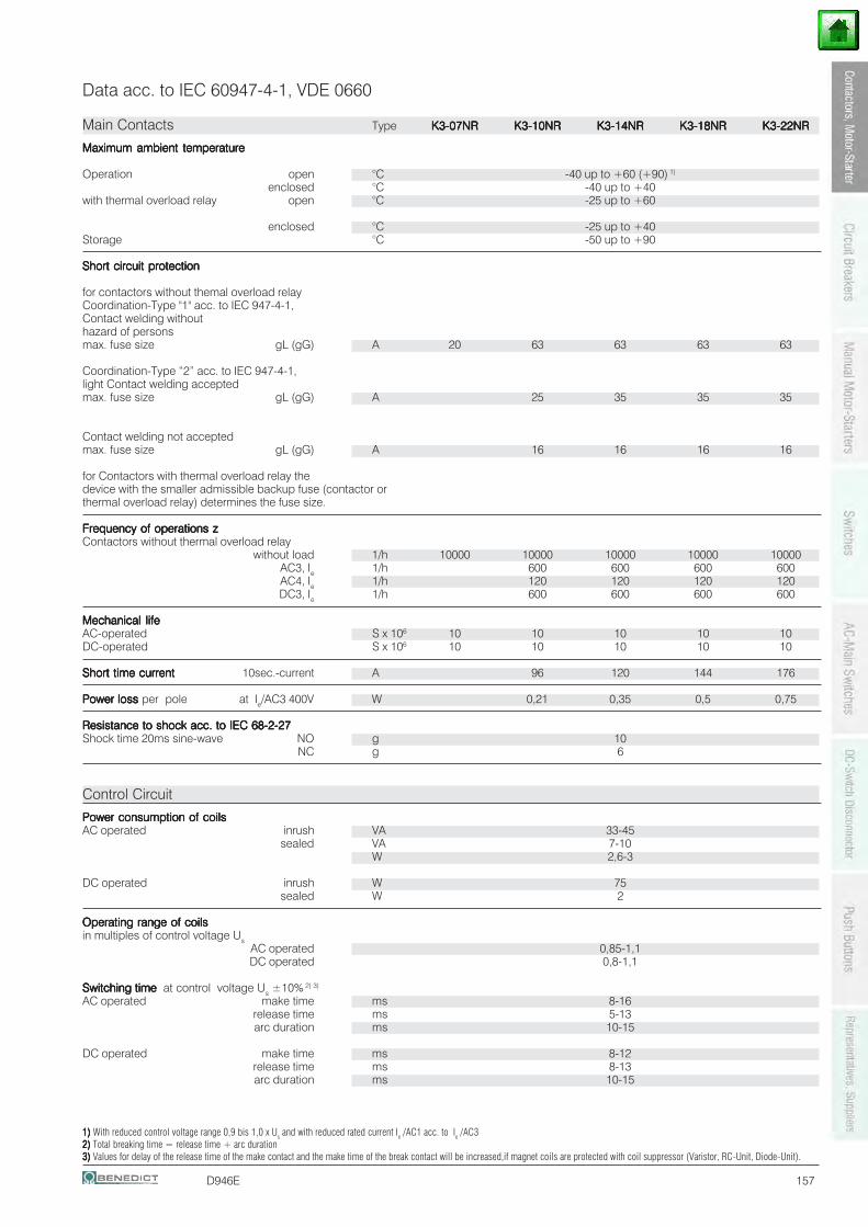
D946E 157
Data acc. to IEC 60947-4-1, VDE 0660
Main Contacts Type K3-07NRK3-07NRK3-07NRK3-07NRK3-07NR K3-10NRK3-10NRK3-10NRK3-10NRK3-10NR K3-14NRK3-14NRK3-14NRK3-14NRK3-14NR K3-18NRK3-18NRK3-18NRK3-18NRK3-18NR K3-22NRK3-22NRK3-22NRK3-22NRK3-22NR
Maximum ambient temperatureMaximum ambient temperatureMaximum ambient temperatureMaximum ambient temperatureMaximum ambient temperature
Operation open °C -40 up to +60 (+90) 1)
enclosed °C -40 up to +40with thermal overload relay open °C -25 up to +60
enclosed °C -25 up to +40Storage °C -50 up to +90
Short circuit protectionShort circuit protectionShort circuit protectionShort circuit protectionShort circuit protection
for contactors without themal overload relayCoordination-Type "1" acc. to IEC 947-4-1,Contact welding withouthazard of personsmax. fuse size gL (gG) A 20 63 63 63 63
Coordination-Type “2” acc. to IEC 947-4-1,light Contact welding acceptedmax. fuse size gL (gG) A 25 35 35 35
Contact welding not acceptedmax. fuse size gL (gG) A 16 16 16 16
for Contactors with thermal overload relay thedevice with the smaller admissible backup fuse (contactor orthermal overload relay) determines the fuse size.
Frequency of operations zFrequency of operations zFrequency of operations zFrequency of operations zFrequency of operations zContactors without thermal overload relay
without load 1/h 10000 10000 10000 10000 10000AC3, Ie 1/h 600 600 600 600AC4, Ie 1/h 120 120 120 120DC3, Ie 1/h 600 600 600 600
Mechanical lifeMechanical lifeMechanical lifeMechanical lifeMechanical lifeAC-operated S x 106 10 10 10 10 10DC-operated S x 106 10 10 10 10 10
Short time currentShort time currentShort time currentShort time currentShort time current 10sec.-current A 96 120 144 176
Power loss Power loss Power loss Power loss Power loss per pole at Ie/AC3 400V W 0,21 0,35 0,5 0,75
Resistance to shock acc. to IEC 68-2-27Resistance to shock acc. to IEC 68-2-27Resistance to shock acc. to IEC 68-2-27Resistance to shock acc. to IEC 68-2-27Resistance to shock acc. to IEC 68-2-27Shock time 20ms sine-wave NO g 10
NC g 6
Control Circuit
Power consumption of coilsPower consumption of coilsPower consumption of coilsPower consumption of coilsPower consumption of coilsAC operated inrush VA 33-45
sealed VA 7-10W 2,6-3
DC operated inrush W 75sealed W 2
Operating range of coilsOperating range of coilsOperating range of coilsOperating range of coilsOperating range of coilsin multiples of control voltage Us
AC operated 0,85-1,1DC operated 0,8-1,1
Switching time Switching time Switching time Switching time Switching time at control voltage Us ±10% 2) 3)
AC operated make time ms 8-16release time ms 5-13arc duration ms 10-15
DC operated make time ms 8-12release time ms 8-13arc duration ms 10-15
1)1)1)1)1) With reduced control voltage range 0,9 bis 1,0 x Us and with reduced rated current Ie /AC1 acc. to Ie /AC32)2)2)2)2) Total breaking time = release time + arc duration3) 3) 3) 3) 3) Values for delay of the release time of the make contact and the make time of the break contact will be increased,if magnet coils are protected with coil suppressor (Varistor, RC-Unit, Diode-Unit).
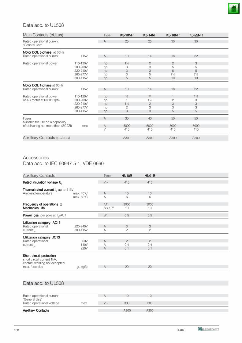
158 D946E
AccessoriesData acc. to IEC 60947-5-1, VDE 0660
Auxilliary Contacts Type HN10RHN10RHN10RHN10RHN10R HN01RHN01RHN01RHN01RHN01R
Rated insulation voltage URated insulation voltage URated insulation voltage URated insulation voltage URated insulation voltage Uiiiii V~ 415 415
Thermal rated current IThermal rated current IThermal rated current IThermal rated current IThermal rated current Iththththth up to 415VAmbient temperature max. 40°C A 10 10
max. 60°C A 6 6
Frequency of operations zFrequency of operations zFrequency of operations zFrequency of operations zFrequency of operations z 1/h 3000 3000Mechanical lifeMechanical lifeMechanical lifeMechanical lifeMechanical life S x 106 10 10
Power loss Power loss Power loss Power loss Power loss per pole at Ie/AC1 W 0,5 0,5
Utilization category AC15Utilization category AC15Utilization category AC15Utilization category AC15Utilization category AC15Rated operational 220-240V A 3 3current Ie 380-415V A 2 2
Utilization category DC13Utilization category DC13Utilization category DC13Utilization category DC13Utilization category DC13Rated operational 60V A 2 2current Ie 110V A 0,4 0,4
220V A 0,1 0,1
Short circuit protectionShort circuit protectionShort circuit protectionShort circuit protectionShort circuit protectionshort circuit current 1kA,contact welding not acceptedmax. fuse size gL (gG) A 20 20
Data acc. to UL508
Rated operational current A 10 10"General Use"Rated operational voltage max. V~ 300 300
Auxiliary ContactsAuxiliary ContactsAuxiliary ContactsAuxiliary ContactsAuxiliary Contacts A300 A300
Data acc. to UL508
Main Contacts (cULus) Type K3-10NRK3-10NRK3-10NRK3-10NRK3-10NR K3-14NRK3-14NRK3-14NRK3-14NRK3-14NR K3-18NRK3-18NRK3-18NRK3-18NRK3-18NR K3-22NRK3-22NRK3-22NRK3-22NRK3-22NR
Rated operational current A 25 25 30 30"General Use"
Motor DOL 3-phase Motor DOL 3-phase Motor DOL 3-phase Motor DOL 3-phase Motor DOL 3-phase at 60HzRated operational current 415V A 10 14 18 22
Rated operational power 110-120V hp 1½ 2 2 3200-208V hp 3 3 5 5220-240V hp 3 3 5 5265-277V hp 3 5 7½ 7½380-415V hp 5 5 10 10
Motor DOL 1-phaseMotor DOL 1-phaseMotor DOL 1-phaseMotor DOL 1-phaseMotor DOL 1-phase at 60HzRated operational current 415V A 10 14 18 22
Rated operational power 110-120V hp ½ ¾ 1 1½of AC motor at 60Hz (1ph) 200-208V hp 1 1½ 2 3
220-240V hp 1½ 2 3 3265-277V hp 2 3 3 3380-415V hp 3 3 5 5
Fuses A 30 40 50 50Suitable for use on a capabilityof delivering not more than (SCCR) rms A 5000 5000 5000 5000
V 415 415 415 415
Auxilliary Contacts (cULus) A300 A300 A300 A300
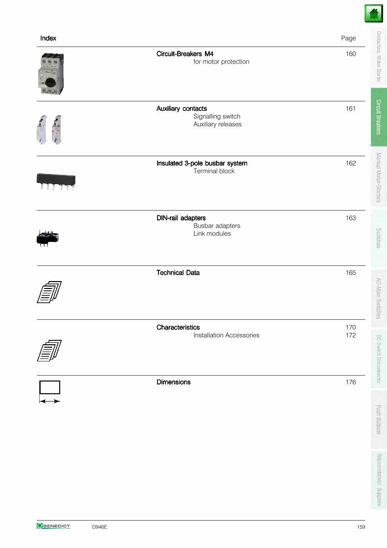
D946E 159
IndexIndexIndexIndexIndex Page
Circuit-Breakers M4Circuit-Breakers M4Circuit-Breakers M4Circuit-Breakers M4Circuit-Breakers M4 160for motor protection
Auxiliary contactsAuxiliary contactsAuxiliary contactsAuxiliary contactsAuxiliary contacts 161Signalling switchAuxiliary releases
Insulated 3-pole busbar systemInsulated 3-pole busbar systemInsulated 3-pole busbar systemInsulated 3-pole busbar systemInsulated 3-pole busbar system 162Terminal block
DIN-rail adaptersDIN-rail adaptersDIN-rail adaptersDIN-rail adaptersDIN-rail adapters 163Busbar adaptersLink modules
Technical DataTechnical DataTechnical DataTechnical DataTechnical Data 165
CharacteristicsCharacteristicsCharacteristicsCharacteristicsCharacteristics 170Installation Accessories 172
DimensionsDimensionsDimensionsDimensionsDimensions 176
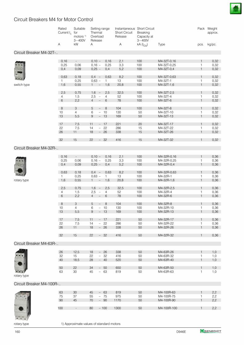
160 D946E
Circuit Breakers M4 for Motor Control
Rated Suitable Setting range Instantaneous Short Circuit Pack WeightCurrent In for Thermal Short Circuit Breaking approx.
motors 1) Overload Release Capacity at3~400V Release 3~400V
A kW A A kA (Icu) Type pcs. kg/pc.
Circuit Breaker M4-32T-..
0,16 - 0,10 – 0,16 2,1 100 M4-32T-0,16 1 0,32 0,25 0,06 0,16 – 0,25 3,3 100 M4-32T-0,25 1 0,320,4 0,09 0,25 – 0,4 5,2 100 M4-32T-0,4 1 0,32
0,63 0,18 0,4 – 0,63 8,2 100 M4-32T-0,63 1 0,32 1 0,25 0,63 – 1 13 100 M4-32T-1 1 0,32
switch type 1,6 0,55 1 – 1,6 20,8 100 M4-32T-1,6 1 0,32
2,5 0,75 1,6 – 2,5 32,5 100 M4-32T-2,5 1 0,324 1,5 2,5 – 4 52 100 M4-32T-4 1 0,326 2,2 4 – 6 78 100 M4-32T-6 1 0,32
8 3 5 – 8 104 100 M4-32T-8 1 0,3210 4 6 – 10 130 50 M4-32T-10 1 0,3213 5,5 9 – 13 169 50 M4-32T-13 1 0,32
17 7,5 11 – 17 221 20 M4-32T-17 1 0,3222 7,5 14 – 22 286 15 M4-32T-22 1 0,3226 11 18 – 26 338 15 M4-32T-26 1 0,32
32 15 22 – 32 416 15 M4-32T-32 1 0,32
Circuit Breaker M4-32R-..
0,16 - 0,10 – 0,16 2,1 100 M4-32R-0,16 1 0,36 0,25 0,06 0,16 – 0,25 3,3 100 M4-32R-0,25 1 0,360,4 0,09 0,25 – 0,4 5,2 100 M4-32R-0,4 1 0,36
0,63 0,18 0,4 – 0,63 8,2 100 M4-32R-0,63 1 0,36 1 0,25 0,63 – 1 13 100 M4-32R-1 1 0,36
rotary type 1,6 0,55 1 – 1,6 20,8 100 M4-32R-1,6 1 0,36
2,5 0,75 1,6 – 2,5 32,5 100 M4-32R-2,5 1 0,364 1,5 2,5 – 4 52 100 M4-32R-4 1 0,366 2,2 4 – 6 78 100 M4-32R-6 1 0,36
8 3 5 – 8 104 100 M4-32R-8 1 0,3610 4 6 – 10 130 100 M4-32R-10 1 0,3613 5,5 9 – 13 169 100 M4-32R-13 1 0,36
17 7,5 11 – 17 221 50 M4-32R-17 1 0,3622 7,5 14 – 22 286 50 M4-32R-22 1 0,3626 11 18 – 26 338 50 M4-32R-26 1 0,36
32 15 22 – 32 416 50 M4-32R-32 1 0,36
Circuit Breaker M4-63R-..
26 12,5 18 – 26 338 50 M4-63R-26 1 1,032 15 22 – 32 416 50 M4-63R-32 1 1,040 18,5 28 – 40 520 50 M4-63R-40 1 1,0
50 22 34 – 50 650 50 M4-63R-50 1 1,063 30 45 – 63 819 50 M4-63R-63 1 1,0
rotary type
Circuit Breaker M4-100R-..
63 30 45 – 63 819 50 M4-100R-63 1 2,2 75 37 55 – 75 975 50 M4-100R-75 1 2,290 45 70 – 90 1170 50 M4-100R-90 1 2,2
100 - 80 – 100 1300 50 M4-100R-100 1 2,2
rotary type 1) Approximate values of standard motors
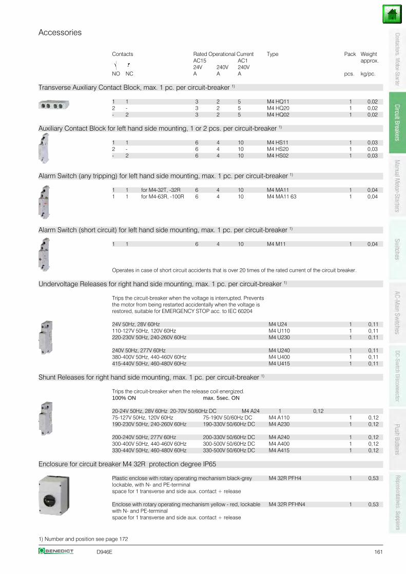
D946E 161
Accessories
Contacts Rated Operational Current Type Pack WeightAC15 AC1 approx.24V 240V 240V
NO NC A A A pcs. kg/pc.
Transverse Auxiliary Contact Block, max. 1 pc. per circuit-breaker 1)
1 1 3 2 5 M4 HQ11 1 0,022 - 3 2 5 M4 HQ20 1 0,02- 2 3 2 5 M4 HQ02 1 0,02
Auxiliary Contact Block for left hand side mounting, 1 or 2 pcs. per circuit-breaker 1)
1 1 6 4 10 M4 HS11 1 0,032 - 6 4 10 M4 HS20 1 0,03- 2 6 4 10 M4 HS02 1 0,03
Alarm Switch (any tripping) for left hand side mounting, max. 1 pc. per circuit-breaker 1)
1 1 for M4-32T, -32R 6 4 10 M4 MA11 1 0,041 1 for M4-63R, -100R 6 4 10 M4 MA11 63 1 0,04
Alarm Switch (short circuit) for left hand side mounting, max. 1 pc. per circuit-breaker 1)
1 1 6 4 10 M4 M11 1 0,04
Operates in case of short circuit accidents that is over 20 times of the rated current of the circuit breaker.
Undervoltage Releases for right hand side mounting, max. 1 pc. per circuit-breaker 1)
Trips the circuit-breaker when the voltage is interrupted. Preventsthe motor from being restarted accidentally when the voltage isrestored, suitable for EMERGENCY STOP acc. to IEC 60204
24V 50Hz, 28V 60Hz M4 U24 1 0,11110-127V 50Hz, 120V 60Hz M4 U110 1 0,11220-230V 50Hz, 240-260V 60Hz M4 U230 1 0,11
240V 50Hz, 277V 60Hz M4 U240 1 0,11380-400V 50Hz, 440-460V 60Hz M4 U400 1 0,11415-440V 50Hz, 460-480V 60Hz M4 U415 1 0,11
Shunt Releases for right hand side mounting, max. 1 pc. per circuit-breaker 1)
Trips the circuit-breaker when the release coil energized.100% ON max. 5sec. ON
20-24V 50Hz, 28V 60Hz 20-70V 50/60Hz DC M4 A24 1 0,1275-127V 50Hz, 120V 60Hz 75-190V 50/60Hz DC M4 A110 1 0,12190-230V 50Hz, 240-260V 60Hz 190-330V 50/60Hz DC M4 A230 1 0,12
200-240V 50Hz, 277V 60Hz 200-330V 50/60Hz DC M4 A240 1 0,12300-400V 50Hz, 440-460V 60Hz 300-500V 50/60Hz DC M4 A400 1 0,12330-440V 50Hz, 460-480V 60Hz 330-500V 50/60Hz DC M4 A415 1 0,12
Enclosure for circuit breaker M4 32R protection degree IP65
Plastic enclose with rotary operating mechanism black-grey M4 32R PFH4 1 0,53lockable, with N- and PE-terminalspace for 1 transverse and side aux. contact + release
Enclose with rotary operating mechanism yellow - red, lockable M4 32R PFHN4 1 0,53with N- and PE-terminalspace for 1 transverse and side aux. contact + release
1) Number and position see page 172
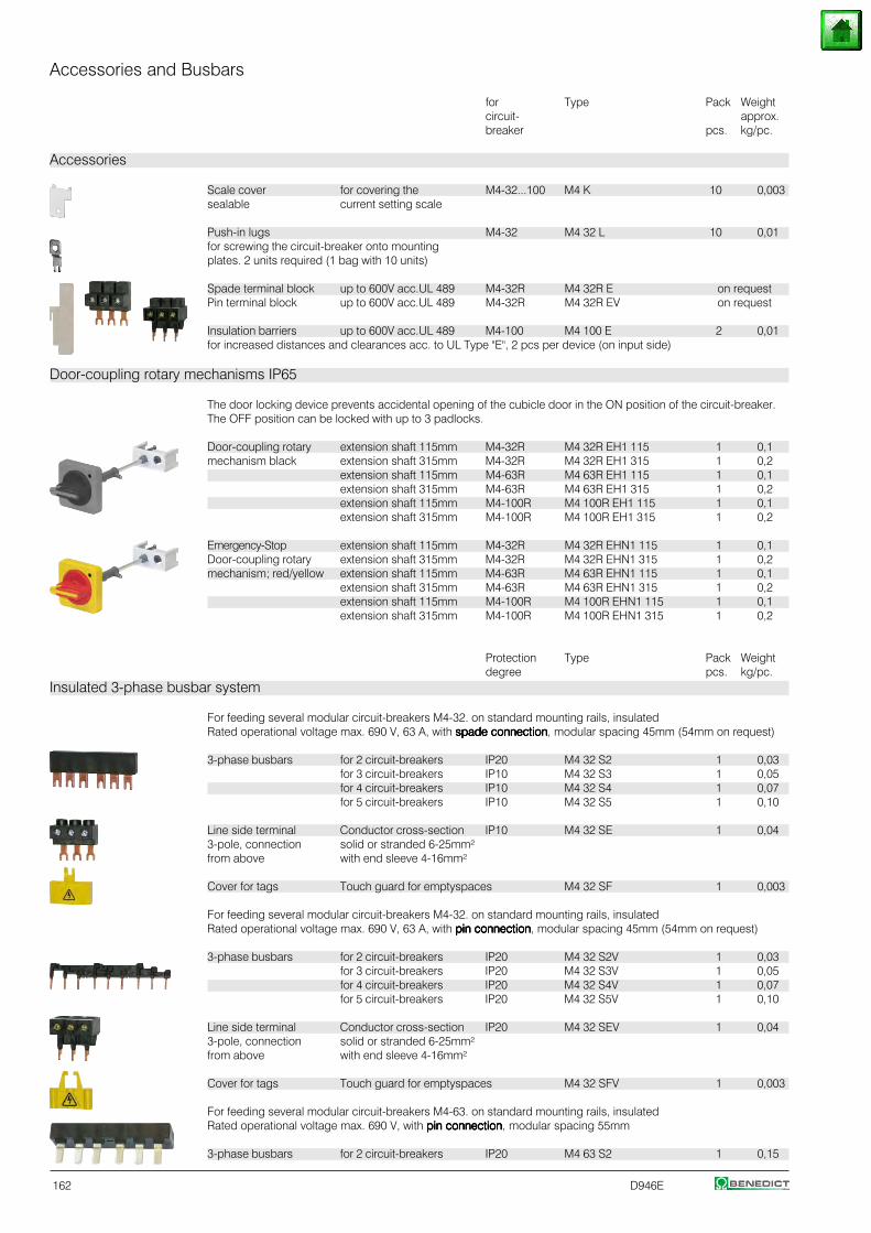
162 D946E
Accessories and Busbars
for Type Pack Weightcircuit- approx.breaker pcs. kg/pc.
Accessories
Scale cover for covering the M4-32...100 M4 K 10 0,003sealable current setting scale
Push-in lugs M4-32 M4 32 L 10 0,01for screwing the circuit-breaker onto mountingplates. 2 units required (1 bag with 10 units)
Spade terminal block up to 600V acc.UL 489 M4-32R M4 32R E on requestPin terminal block up to 600V acc.UL 489 M4-32R M4 32R EV on request
Insulation barriers up to 600V acc.UL 489 M4-100 M4 100 E 2 0,01for increased distances and clearances acc. to UL Type "E", 2 pcs per device (on input side)
Door-coupling rotary mechanisms IP65
The door locking device prevents accidental opening of the cubicle door in the ON position of the circuit-breaker.The OFF position can be locked with up to 3 padlocks.
Door-coupling rotary extension shaft 115mm M4-32R M4 32R EH1 115 1 0,1mechanism black extension shaft 315mm M4-32R M4 32R EH1 315 1 0,2
extension shaft 115mm M4-63R M4 63R EH1 115 1 0,1extension shaft 315mm M4-63R M4 63R EH1 315 1 0,2extension shaft 115mm M4-100R M4 100R EH1 115 1 0,1extension shaft 315mm M4-100R M4 100R EH1 315 1 0,2
Emergency-Stop extension shaft 115mm M4-32R M4 32R EHN1 115 1 0,1Door-coupling rotary extension shaft 315mm M4-32R M4 32R EHN1 315 1 0,2mechanism; red/yellow extension shaft 115mm M4-63R M4 63R EHN1 115 1 0,1
extension shaft 315mm M4-63R M4 63R EHN1 315 1 0,2extension shaft 115mm M4-100R M4 100R EHN1 115 1 0,1extension shaft 315mm M4-100R M4 100R EHN1 315 1 0,2
Protection Type Pack Weightdegree pcs. kg/pc.
Insulated 3-phase busbar system
For feeding several modular circuit-breakers M4-32. on standard mounting rails, insulatedRated operational voltage max. 690 V, 63 A, with spade connectionspade connectionspade connectionspade connectionspade connection, modular spacing 45mm (54mm on request)
3-phase busbars for 2 circuit-breakers IP20 M4 32 S2 1 0,03for 3 circuit-breakers IP10 M4 32 S3 1 0,05for 4 circuit-breakers IP10 M4 32 S4 1 0,07for 5 circuit-breakers IP10 M4 32 S5 1 0,10
Line side terminal Conductor cross-section IP10 M4 32 SE 1 0,043-pole, connection solid or stranded 6-25mm²from above with end sleeve 4-16mm²
Cover for tags Touch guard for emptyspaces M4 32 SF 1 0,003
For feeding several modular circuit-breakers M4-32. on standard mounting rails, insulatedRated operational voltage max. 690 V, 63 A, with pin connectionpin connectionpin connectionpin connectionpin connection, modular spacing 45mm (54mm on request)
3-phase busbars for 2 circuit-breakers IP20 M4 32 S2V 1 0,03for 3 circuit-breakers IP20 M4 32 S3V 1 0,05for 4 circuit-breakers IP20 M4 32 S4V 1 0,07for 5 circuit-breakers IP20 M4 32 S5V 1 0,10
Line side terminal Conductor cross-section IP20 M4 32 SEV 1 0,043-pole, connection solid or stranded 6-25mm²from above with end sleeve 4-16mm²
Cover for tags Touch guard for emptyspaces M4 32 SFV 1 0,003
For feeding several modular circuit-breakers M4-63. on standard mounting rails, insulatedRated operational voltage max. 690 V, with pin connectionpin connectionpin connectionpin connectionpin connection, modular spacing 55mm
3-phase busbars for 2 circuit-breakers IP20 M4 63 S2 1 0,15
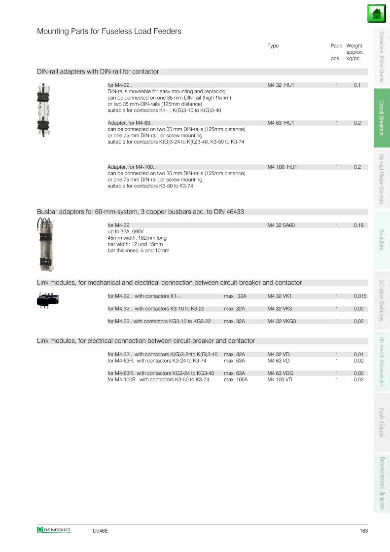
D946E 163
Mounting Parts for Fuseless Load Feeders
Type Pack Weightapprox.
pcs. kg/pc.
DIN-rail adapters with DIN-rail for contactor
for M4-32.. M4 32 HU1 1 0,1DIN-rails moveable for easy mounting and replacingcan be connected on one 35 mm DIN-rail (high 15mm)or two 35 mm-DIN-rails (125mm distance)suitable for contactors K1-.., K(G)3-10 to K(G)3-40
Adapter, for M4-63.. M4 63 HU1 1 0,2can be connected on two 35 mm DIN-rails (125mm distance)or one 75 mm DIN-rail, or screw mountingsuitable for contactors K(G)3-24 to K(G)3-40, K3-50 to K3-74
Adapter, for M4-100.. M4 100 HU1 1 0,2can be connected on two 35 mm DIN-rails (125mm distance)or one 75 mm DIN-rail, or screw mountingsuitable for contactors K3-50 to K3-74
Busbar adapters for 60-mm-system, 3 copper busbars acc. to DIN 46433
for M4-32 M4 32 SA60 1 0,18up to 32A, 690V45mm width, 182mm longbar width: 12 und 15mmbar thickness: 5 and 10mm
Link modules, for mechanical and electrical connection between circuit-breaker and contactor
for M4-32.. with contactors K1-.. max. 32A M4 32 VK1 1 0,015
for M4-32.. with contactors K3-10 to K3-22 max. 32A M4 32 VK3 1 0,02
for M4-32.. with contactors KG3-10 to KG3-22 max. 32A M4 32 VKG3 1 0,02
Link modules, for electrical connection between circuit-breaker and contactor
for M4-32.. with contactors K(G)3-24to K(G)3-40 max. 32A M4 32 VD 1 0,01for M4-63R. with contactors K3-24 to K3-74 max. 63A M4 63 VD 1 0,02
for M4-63R. with contactors KG3-24 to KG3-40 max. 63A M4 63 VDG 1 0,02for M4-100R. with contactors K3-50 to K3-74 max. 100A M4 100 VD 1 0,02
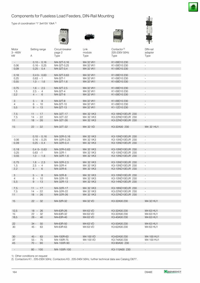
164 D946E
Components for Fuseless Load Feeders, DIN-Rail Mounting
Type of coordination "1" 3x415V 10kA 1)
Motor Setting range Circuit-breaker Link Contactor 2) DIN-rail3~400V page 2 module 220-230V 50Hz adapterkW A Type Type Type Type
- 0,10 – 0,16 M4-32T-0,16 M4 32 VK1 K1-09D10 230 - 0,06 0,16 – 0,25 M4-32T-0,25 M4 32 VK1 K1-09D10 230 -0,09 0,25 – 0,4 M4-32T-0,4 M4 32 VK1 K1-09D10 230 -
0,18 0,4 0– 0,63 M4-32T-0,63 M4 32 VK1 K1-09D10 230 - 0,25 0,63 – 1 M4-32T-1 M4 32 VK1 K1-09D10 230 - 0,55 1,0 – 1,6 M4-32T-1,6 M4 32 VK1 K1-09D10 230 -
0,75 1,6 – 2,5 M4-32T-2,5 M4 32 VK1 K1-09D10 230 -1,5 2,5 – 4 M4-32T-4 M4 32 VK1 K1-09D10 230 -2,2 4 – 6 M4-32T-6 M4 32 VK1 K1-09D10 230 -
3 5 – 8 M4-32T-8 M4 32 VK1 K1-09D10 230 -4 6 – 10 M4-32T-10 M4 32 VK1 K1-09D10 230 -5,5 9 – 13 M4-32T-13 M4 32 VK1 K1-12D10 230 -
7,5 11 – 17 M4-32T-17 M4 32 VK3 K3-18ND10EUR 230 -7,5 14 – 22 M4-32T-22 M4 32 VK3 K3-22ND10EUR 230 -
11 18 – 26 M4-32T-26 M4 32 VK3 K3-22ND10EUR 230 -
15 22 – 32 M4-32T-32 M4 32 VD K3-32A00 230 M4 32 HU1
- 0,10 – 0,16 M4-32R-0,16 M4 32 VK3 K3-10ND10EUR 230 - 0,06 0,16 – 0,25 M4-32R-0,25 M4 32 VK3 K3-10ND10EUR 230 -0,09 0,25 – 0,4 M4-32R-0,4 M4 32 VK3 K3-10ND10EUR 230 -
0,18 0,4 0– 0,63 M4-32R-0,63 M4 32 VK3 K3-10ND10EUR 230 - 0,25 0,63 –1 M4-32R-1 M4 32 VK3 K3-10ND10EUR 230 - 0,55 1,0 – 1,6 M4-32R-1,6 M4 32 VK3 K3-10ND10EUR 230 -
0,75 1,6 – 2,5 M4-32R-2,5 M4 32 VK3 K3-10ND10EUR 230 -1,5 2,5 – 4 M4-32R-4 M4 32 VK3 K3-10ND10EUR 230 -2,2 4 – 6 M4-32R-6 M4 32 VK3 K3-10ND10EUR 230 -
3 5 – 8 M4-32R-8 M4 32 VK3 K3-10ND10EUR 230 - 4 6 – 10 M4-32R-10 M4 32 VK3 K3-10ND10EUR 230 -5,5 9 – 13 M4-32R-13 M4 32 VK3 K3-14ND10EUR 230 -
7,5 11 – 17 M4-32R-17 M4 32 VK3 K3-18ND10EUR 230 -7,5 14 – 22 M4-32R-22 M4 32 VK3 K3-22ND10EUR 230 -
11 18 – 26 M4-32R-26 M4 32 VK3 K3-22ND10EUR 230 -
15 22 – 32 M4-32R-32 M4 32 VD K3-32A00 230 M4 32 HU1
12,5 18 – 26 M4-63R-26 M4 63 VD K3-32A00 230 M4 63 HU115 22 – 32 M4-63R-32 M4 63 VD K3-32A00 230 M4 63 HU118,5 28 – 40 M4-63R-40 M4 63 VD K3-40A00 230 M4 63 HU1
22 34 – 50 M4-63R-50 M4 63 VD K3-50A00 230 M4 63 HU130 45 – 63 M4-63R-63 M4 63 VD K3-62A00 230 M4 63 HU1
30 45 – 63 M4-100R-63 M4 100 VD K3-62A00 230 M4 100 HU1 37 55 – 75 M4-100R-75 M4 100 VD K3-74A00 230 M4 100 HU145 70 – 90 M4-100R-90 - K3-90A00 230 -
- 80 – 100 M4-100R-100 - K3-115A00 230 -
1) Other conditions on request2) Contactors K1.. 220-230V 50Hz, Contactors K3.. 220-240V 50Hz, further technical data see Catalog D677..
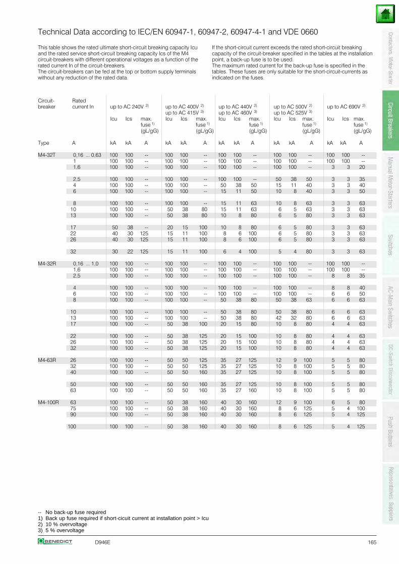
D946E 165
Technical Data according to IEC/EN 60947-1, 60947-2, 60947-4-1 and VDE 0660
Circuit- Ratedbreaker current In up to AC 240V 2) up to AC 400V 2) up to AC 440V 2) up to AC 500V 2) up to AC 690V 2)
up to AC 415V 3) up to AC 460V 3) up to AC 525V 3)
Icu Ics max. Icu Ics max. Icu Ics max. Icu Ics max. Icu Ics max.fuse 1) fuse 1) fuse 1) fuse 1) fuse 1)
(gL/gG) (gL/gG) (gL/gG) (gL/gG) (gL/gG)
Type A kA kA A kA kA A kA kA A kA kA A kA kA A
M4-32T 0,16 ... 0,63 100 100 -- 100 100 -- 100 100 -- 100 100 -- 100 100 -- 1 100 100 -- 100 100 -- 100 100 -- 100 100 -- 100 100 -- 1,6 100 100 -- 100 100 -- 100 100 -- 100 100 -- 3 3 20
2,5 100 100 -- 100 100 -- 100 100 -- 50 38 50 3 3 35 4 100 100 -- 100 100 -- 50 38 50 15 11 40 3 3 40 6 100 100 -- 100 100 -- 15 11 50 10 8 40 3 3 50
8 100 100 -- 100 100 -- 15 11 63 10 8 63 3 3 63 10 100 100 -- 50 38 80 15 11 63 6 5 63 3 3 63 13 100 100 -- 50 38 80 10 8 80 6 5 80 3 3 63
17 50 38 -- 20 15 100 10 8 80 6 5 80 3 3 63 22 40 30 125 15 11 100 8 6 100 6 5 80 3 3 63 26 40 30 125 15 11 100 8 6 100 6 5 80 3 3 63
32 30 22 125 15 11 100 6 4 100 5 4 80 3 3 63
M4-32R 0,16 ... 1,0 100 100 -- 100 100 -- 100 100 -- 100 100 -- 100 100 -- 1,6 100 100 -- 100 100 -- 100 100 -- 100 100 -- 100 100 -- 2,5 100 100 -- 100 100 -- 100 100 -- 100 100 -- 8 8 35
4 100 100 -- 100 100 -- 100 100 -- 100 100 -- 8 8 40 6 100 100 -- 100 100 -- 100 100 -- 100 100 -- 6 6 50 8 100 100 -- 100 100 -- 50 38 80 50 38 63 6 6 63
10 100 100 -- 100 100 -- 50 38 80 50 38 80 6 6 63 13 100 100 -- 100 100 -- 50 38 80 42 32 80 6 6 63 17 100 100 -- 50 38 100 20 15 80 10 8 80 4 4 63
22 100 100 -- 50 38 125 20 15 100 10 8 80 4 4 63 26 100 100 -- 50 38 125 20 15 100 10 8 80 4 4 63 32 100 100 -- 50 38 125 20 15 100 10 8 80 4 4 63
M4-63R 26 100 100 -- 50 50 125 35 27 125 12 9 100 5 5 80 32 100 100 -- 50 50 125 35 27 125 10 8 100 5 5 80 40 100 100 -- 50 50 160 35 27 125 10 8 100 5 5 80
50 100 100 -- 50 50 160 35 27 125 10 8 100 5 5 80 63 100 100 -- 50 50 160 35 27 160 10 8 100 5 5 80
M4-100R 63 100 100 -- 50 38 160 40 30 160 12 9 100 6 5 80 75 100 100 -- 50 38 160 40 30 160 8 6 125 5 4 100 90 100 100 -- 50 38 160 40 30 160 8 6 125 5 4 125
100 100 100 -- 50 38 160 40 30 160 8 6 125 5 4 125
This table shows the rated ultimate short-circuit breaking capacity Icuand the rated service short-circuit breaking capacity Ics of the M4circuit-breakers with different operational voltages as a function of therated current In of the circuit-breakers.The circuit-breakers can be fed at the top or bottom supply terminalswithout any reduction of the rated data.
If the short-circuit current exceeds the rated short-circuit breakingcapacity of the circuit-breaker specified in the tables at the installationpoint, a back-up fuse is to be used.The maximum rated current for the back-up fuse is specified in thetables. These fuses are only suitable for the short-circuit-currents asindicated on the fuses.
-- No back-up fuse required1) Back up fuse required if short-cicuit current at installation point > Icu2) 10 % overvoltage3) 5 % overvoltage
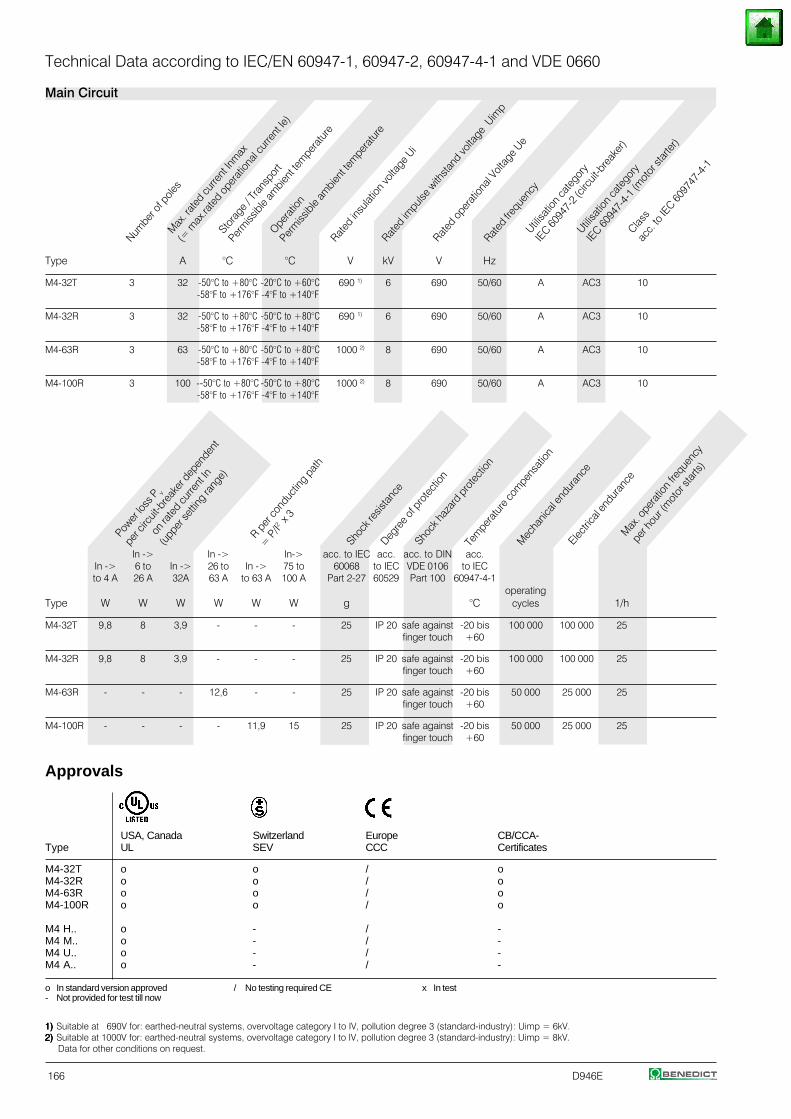
166 D946E
Numbe
r of p
oles
Max
. rat
ed cu
rrent
Inm
ax
(= m
ax.ra
ted
oper
ation
al cu
rrent
Ie)
Stora
ge / T
rans
port
Perm
issibl
e am
bient
tem
pera
ture
Opera
tion
Perm
issibl
e am
bient
tem
pera
ture
Rated
insu
lation
volta
ge U
i
Rated
impu
lse w
ithsta
nd vo
ltage
Uim
p
Rated
ope
ratio
nal V
oltag
e Ue
Rated
freq
uenc
yUtili
satio
n ca
tego
ry
IEC 60
947-
2 (cir
cuit-
brea
ker)
Utilisa
tion
cate
gory
IEC 60
947-
4-1 (
mot
or st
arte
r)
Class
acc.
to IE
C 6097
47-4
-1
Power
loss
P v
per c
ircuit
-bre
aker
dep
ende
nt
on r
ated
curre
nt In
(upp
er se
tting
rang
e)
R per
cond
uctin
g pa
th
= P
/I2 x
3
Shock
resis
tanc
eDeg
ree o
f pro
tecti
on
Shock
haza
rd p
rote
ction
Tem
pera
ture
com
pens
ation
Mec
hanic
al en
dura
nce
Electric
al en
dura
nce
Max
. ope
ratio
n fre
quen
cy
per
hour
(mot
or st
arts)
1)1)1)1)1) Suitable at 690V for: earthed-neutral systems, overvoltage category I to IV, pollution degree 3 (standard-industry): Uimp = 6kV.2)2)2)2)2) Suitable at 1000V for: earthed-neutral systems, overvoltage category I to IV, pollution degree 3 (standard-industry): Uimp = 8kV. Data for other conditions on request.
Approvals
USA, Canada Switzerland Europe CB/CCA-Type UL SEV CCC Certificates
M4-32T o o / oM4-32R o o / oM4-63R o o / oM4-100R o o / o
M4 H.. o - / -M4 M.. o - / -M4 U.. o - / -M4 A.. o - / -
o In standard version approved / No testing required CE x In test- Not provided for test till now
Technical Data according to IEC/EN 60947-1, 60947-2, 60947-4-1 and VDE 0660
Main Circuit
Type A °C °C V kV V Hz
M4-32T 3 32 -50°C to +80°C -20°C to +60°C 690 1) 6 690 50/60 A AC3 10-58°F to +176°F -4°F to +140°F
M4-32R 3 32 -50°C to +80°C -50°C to +80°C 690 1) 6 690 50/60 A AC3 10-58°F to +176°F -4°F to +140°F
M4-63R 3 63 -50°C to +80°C -50°C to +80°C 1000 2) 8 690 50/60 A AC3 10-58°F to +176°F -4°F to +140°F
M4-100R 3 100 --50°C to +80°C -50°C to +80°C 1000 2) 8 690 50/60 A AC3 10-58°F to +176°F -4°F to +140°F
In -> In -> In-> acc. to IEC acc. acc. to DIN acc.In -> 6 to In -> 26 to In -> 75 to 60068 to IEC VDE 0106 to IECto 4 A 26 A 32A 63 A to 63 A 100 A Part 2-27 60529 Part 100 60947-4-1
operatingType W W W W W W g °C cycles 1/h
M4-32T 9,8 8 3,9 - - - 25 IP 20 safe against -20 bis 100 000 100 000 25finger touch +60
M4-32R 9,8 8 3,9 - - - 25 IP 20 safe against -20 bis 100 000 100 000 25finger touch +60
M4-63R - - - 12,6 - - 25 IP 20 safe against -20 bis 50 000 25 000 25finger touch +60
M4-100R - - - - 11,9 15 25 IP 20 safe against -20 bis 50 000 25 000 25finger touch +60
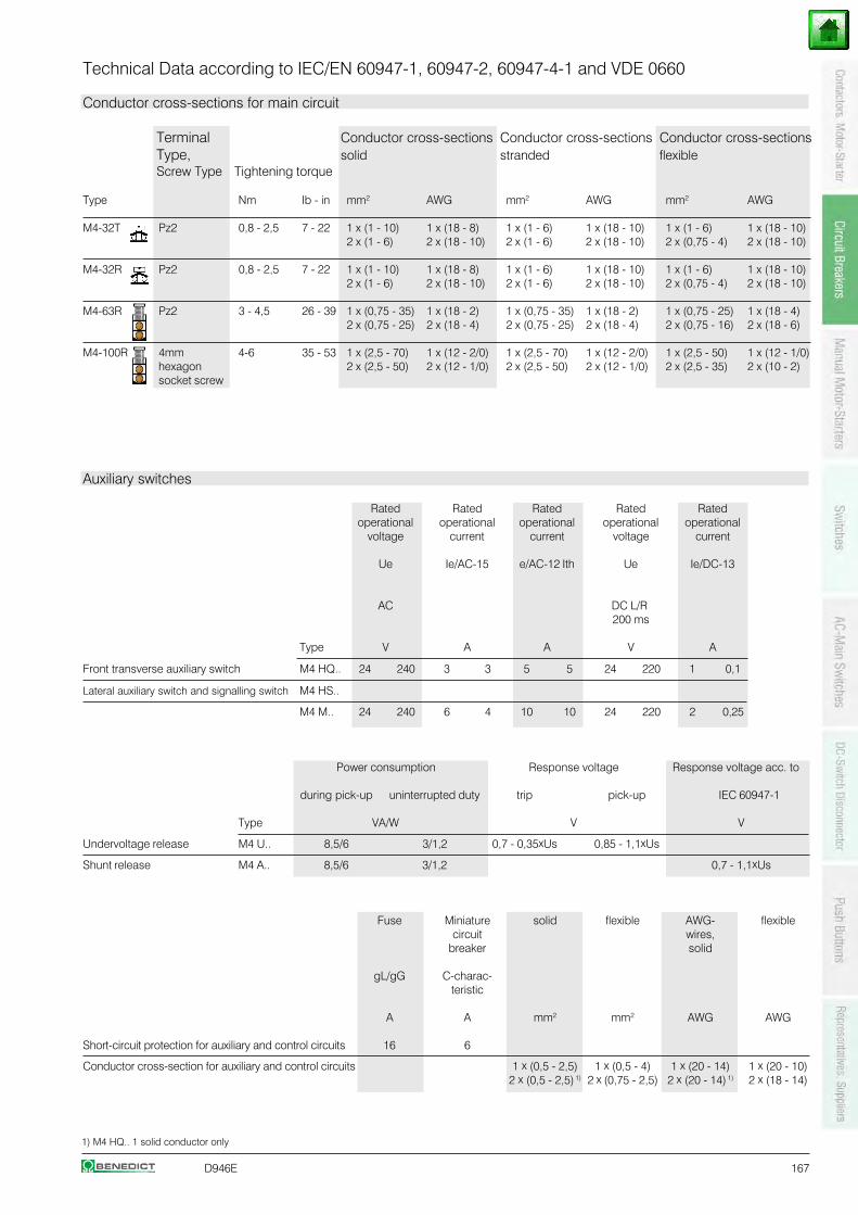
D946E 167
1) M4 HQ.. 1 solid conductor only
Technical Data according to IEC/EN 60947-1, 60947-2, 60947-4-1 and VDE 0660
Conductor cross-sections for main circuit
Terminal Conductor cross-sections Conductor cross-sections Conductor cross-sectionsType, solid stranded flexibleScrew Type Tightening torque
Type Nm Ib - in mm2 AWG mm2 AWG mm2 AWG
M4-32T Pz2 0,8 - 2,5 7 - 22 1 x (1 - 10) 1 x (18 - 8) 1 x (1 - 6) 1 x (18 - 10) 1 x (1 - 6) 1 x (18 - 10)2 x (1 - 6) 2 x (18 - 10) 2 x (1 - 6) 2 x (18 - 10) 2 x (0,75 - 4) 2 x (18 - 10)
M4-32R Pz2 0,8 - 2,5 7 - 22 1 x (1 - 10) 1 x (18 - 8) 1 x (1 - 6) 1 x (18 - 10) 1 x (1 - 6) 1 x (18 - 10)2 x (1 - 6) 2 x (18 - 10) 2 x (1 - 6) 2 x (18 - 10) 2 x (0,75 - 4) 2 x (18 - 10)
M4-63R Pz2 3 - 4,5 26 - 39 1 x (0,75 - 35) 1 x (18 - 2) 1 x (0,75 - 35) 1 x (18 - 2) 1 x (0,75 - 25) 1 x (18 - 4)2 x (0,75 - 25) 2 x (18 - 4) 2 x (0,75 - 25) 2 x (18 - 4) 2 x (0,75 - 16) 2 x (18 - 6)
M4-100R 4mm 4-6 35 - 53 1 x (2,5 - 70) 1 x (12 - 2/0) 1 x (2,5 - 70) 1 x (12 - 2/0) 1 x (2,5 - 50) 1 x (12 - 1/0)hexagon 2 x (2,5 - 50) 2 x (12 - 1/0) 2 x (2,5 - 50) 2 x (12 - 1/0) 2 x (2,5 - 35) 2 x (10 - 2)socket screw
Auxiliary switches
Rated Rated Rated Rated Ratedoperational operational operational operational operational
voltage current current voltage current
Ue Ie/AC-15 e/AC-12 Ith Ue Ie/DC-13
AC DC L/R200 ms
Type V A A V A
Front transverse auxiliary switch M4 HQ.. 24 240 3 3 5 5 24 220 1 0,1
Lateral auxiliary switch and signalling switch M4 HS..
M4 M.. 24 240 6 4 10 10 24 220 2 0,25
Power consumption Response voltage Response voltage acc. to
during pick-up uninterrupted duty trip pick-up IEC 60947-1
Type VA/W V V
Undervoltage release M4 U.. 8,5/6 3/1,2 0,7 - 0,35xUs 0,85 - 1,1xUs
Shunt release M4 A.. 8,5/6 3/1,2 0,7 - 1,1xUs
Fuse Miniature solid flexible AWG- flexiblecircuit wires,
breaker solid
gL/gG C-charac-teristic
A A mm2 mm2 AWG AWG
Short-circuit protection for auxiliary and control circuits 16 6
Conductor cross-section for auxiliary and control circuits 1 x (0,5 - 2,5) 1 x (0,5 - 4) 1 x (20 - 14) 1 x (20 - 10)2 x (0,5 - 2,5) 1) 2 x (0,75 - 2,5) 2 x (20 - 14) 1) 2 x (18 - 14)
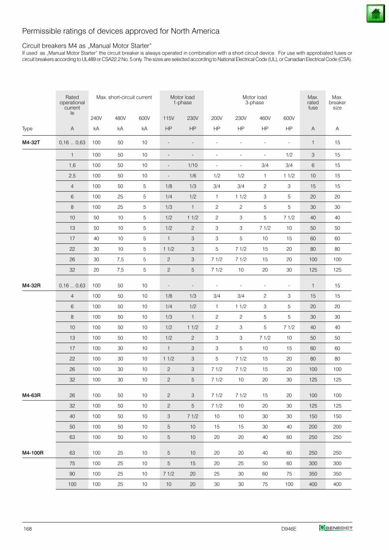
168 D946E
Permissible ratings of devices approved for North America
Circuit breakers M4 as „Manual Motor Starter“If used as „Manual Motor Starter“ the circuit breaker is always operated in combination with a short circuit device. For use with approbated fuses orcircuit breakers according to UL489 or CSA22.2 No. 5 only. The sizes are selected according to National Electrical Code (UL), or Canadian Electrical Code (CSA).
Rated Max. short-circuit current Motor load Motor load Max. Max.operational 1-phase 3-phase rated breaker
current fuse sizeIe
240V 480V 600V 115V 230V 200V 230V 460V 600V
Type A kA kA kA HP HP HP HP HP HP A A
M4-32T 0,16 ... 0,63 100 50 10 - - - - - - 1 15
1 100 50 10 - - - - - 1/2 3 15
1,6 100 50 10 - 1/10 - - 3/4 3/4 6 15
2,5 100 50 10 - 1/6 1/2 1/2 1 1 1/2 10 15
4 100 50 5 1/8 1/3 3/4 3/4 2 3 15 15
6 100 25 5 1/4 1/2 1 1 1/2 3 5 20 20
8 100 25 5 1/3 1 2 2 5 5 30 30
10 50 10 5 1/2 1 1/2 2 3 5 7 1/2 40 40
13 50 10 5 1/2 2 3 3 7 1/2 10 50 50
17 40 10 5 1 3 3 5 10 15 60 60
22 30 10 5 1 1/2 3 5 7 1/2 15 20 80 80
26 30 7,5 5 2 3 7 1/2 7 1/2 15 20 100 100
32 20 7,5 5 2 5 7 1/2 10 20 30 125 125
M4-32R 0,16 ... 0,63 100 50 10 - - - - - - 1 15
4 100 50 10 1/8 1/3 3/4 3/4 2 3 15 15
6 100 50 10 1/4 1/2 1 1 1/2 3 5 20 20
8 100 50 10 1/3 1 2 2 5 5 30 30
10 100 50 10 1/2 1 1/2 2 3 5 7 1/2 40 40
13 100 50 10 1/2 2 3 3 7 1/2 10 50 50
17 100 30 10 1 3 3 5 10 15 60 60
22 100 30 10 1 1/2 3 5 7 1/2 15 20 80 80
26 100 30 10 2 3 7 1/2 7 1/2 15 20 100 100
32 100 30 10 2 5 7 1/2 10 20 30 125 125
M4-63R 26 100 50 10 2 3 7 1/2 7 1/2 15 20 100 100
32 100 50 10 2 5 7 1/2 10 20 30 125 125
40 100 50 10 3 7 1/2 10 10 30 30 150 150
50 100 50 10 5 10 15 15 30 40 200 200
63 100 50 10 5 10 20 20 40 60 250 250
M4-100R 63 100 25 10 5 10 20 20 40 60 250 250
75 100 25 10 5 15 20 25 50 60 300 300
90 100 25 10 7 1/2 20 25 30 60 75 350 350
100 100 25 10 10 20 30 30 75 100 400 400
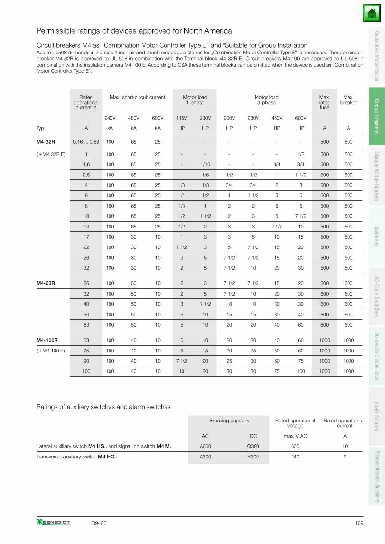
D946E 169
Permissible ratings of devices approved for North America
Circuit breakers M4 as „Combination Motor Controller Type E“ and "Suitable for Group Installation"Acc to UL508 demands a line-side 1 inch air and 2 inch creepage distance for „Combination Motor Controller Type E“ is necessary. Therefor circuit-breaker M4-32R is approved to UL 508 in combination with the Terminal block M4 32R E. Circuit-breakers M4-100 are approved to UL 508 incombination with the insulation barriers M4 100 E. According to CSA these terminal blocks can be omitted when the device is used as „CombinationMotor Controller Type E“.
Rated Max. short-circuit current Motor load Motor load Max. Max.operational 1-phase 3-phase rated breakercurrent Ie fuse
240V 480V 600V 115V 230V 200V 230V 460V 600V
Typ A kA kA kA HP HP HP HP HP HP A A
M4-32R 0,16 ... 0,63 100 65 25 - - - - - - 500 500
(+M4 32R E) 1 100 65 25 - - - - - 1/2 500 500
1,6 100 65 25 - 1/10 - - 3/4 3/4 500 500
2,5 100 65 25 - 1/6 1/2 1/2 1 1 1/2 500 500
4 100 65 25 1/8 1/3 3/4 3/4 2 3 500 500
6 100 65 25 1/4 1/2 1 1 1/2 3 5 500 500
8 100 65 25 1/3 1 2 2 5 5 500 500
10 100 65 25 1/2 1 1/2 2 3 5 7 1/2 500 500
13 100 65 25 1/2 2 3 3 7 1/2 10 500 500
17 100 30 10 1 3 3 5 10 15 500 500
22 100 30 10 1 1/2 3 5 7 1/2 15 20 500 500
26 100 30 10 2 5 7 1/2 7 1/2 15 20 500 500
32 100 30 10 2 5 7 1/2 10 20 30 500 500
M4-63R 26 100 50 10 2 3 7 1/2 7 1/2 15 20 600 600
32 100 50 10 2 5 7 1/2 10 20 30 600 600
40 100 50 10 3 7 1/2 10 10 30 30 600 600
50 100 50 10 5 10 15 15 30 40 600 600
63 100 50 10 5 10 20 20 40 60 600 600
M4-100R 63 100 40 10 5 10 20 20 40 60 1000 1000
(+M4 100 E) 75 100 40 10 5 15 20 25 50 60 1000 1000
90 100 40 10 7 1/2 20 25 30 60 75 1000 1000
100 100 40 10 10 20 30 30 75 100 1000 1000
Ratings of auxiliary switches and alarm switches
Breaking capacity Rated operational Rated operationalvoltage current
AC DC max. V AC A
Lateral auxiliary switch M4 HS.. and signalling switch M4 M.. A600 Q300 600 10
Transversal auxiliary switch M4 HQ.. A300 R300 240 5
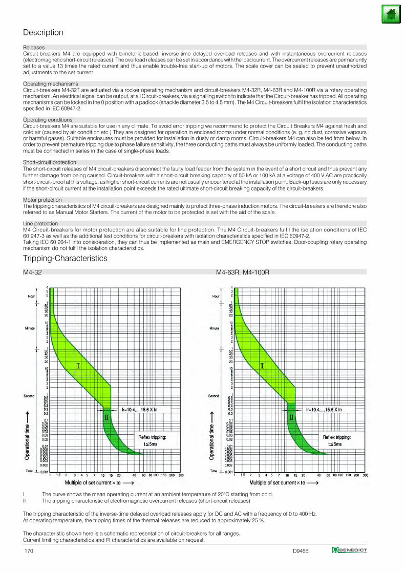
170 D946E
Description
ReleasesCircuit-breakers M4 are equipped with bimetallic-based, inverse-time delayed overload releases and with instantaneous overcurrent releases(electromagnetic short-circuit releases). The overload releases can be set in accordance with the load current. The overcurrent releases are permanentlyset to a value 13 times the rated current and thus enable trouble-free start-up of motors. The scale cover can be sealed to prevent unauthorizedadjustments to the set current.
Operating mechanismsCircuit-breakers M4-32T are actuated via a rocker operating mechanism and circuit-breakers M4-32R, M4-63R and M4-100R via a rotary operatingmechanism. An electrical signal can be output, at all Circuit-breakers, via a signalling switch to indicate that the Circuit-breaker has tripped. All operatingmechanisms can be locked in the 0 position with a padlock (shackle diameter 3.5 to 4.5 mm). The M4 Circuit-breakers fulfil the isolation characteristicsspecified in IEC 60947-2.
Operating conditionsCircuit-breakers M4 are suitable for use in any climate. To avoid error tripping we recommend to protect the Circuit Breakers M4 against fresh andcold air (caused by air condition etc.) They are designed for operation in enclosed rooms under normal conditions (e. g. no dust, corrosive vapoursor harmful gases). Suitable enclosures must be provided for installation in dusty or damp rooms. Circuit-breakers M4 can also be fed from below. Inorder to prevent premature tripping due to phase failure sensitivity, the three conducting paths must always be uniformly loaded. The conducting pathsmust be connected in series in the case of single-phase loads.
Short-circuit protectionThe short-circuit releases of M4 circuit-breakers disconnect the faulty load feeder from the system in the event of a short circuit and thus prevent anyfurther damage from being caused. Circuit-breakers with a short-circuit breaking capacity of 50 kA or 100 kA at a voltage of 400 V AC are practicallyshort-circuit-proof at this voltage, as higher short-circuit currents are not usually encountered at the installation point. Back-up fuses are only necessaryif the short-circuit current at the installation point exceeds the rated ultimate short-circuit breaking capacity of the circuit-breakers.
Motor protectionThe tripping characteristics of M4 circuit-breakers are designed mainly to protect three-phase induction motors. The circuit-breakers are therefore alsoreferred to as Manual Motor Starters. The current of the motor to be protected is set with the aid of the scale.
Line protectionM4 Circuit-breakers for motor protection are also suitable for line protection. The M4 Circuit-breakers fulfil the isolation conditions of IEC60 947-3 as well as the additional test conditions for circuit-breakers with isolation characteristics specified in IEC 60947-2.Taking IEC 60 204-1 into consideration, they can thus be implemented as main and EMERGENCY STOP switches. Door-coupling rotary operatingmechanism do not fulfil the isolation characteristics.
Tripping-Characteristics
M4-32 M4-63R, M4-100R
I The curve shows the mean operating current at an ambient temperature of 20°C starting from cold.II The tripping characteristic of electromagnetic overcurrent releases (short-circuit releases)
The tripping characteristic of the inverse-time delayed overload releases apply for DC and AC with a frequency of 0 to 400 Hz.At operating temperature, the tripping times of the thermal releases are reduced to approximately 25 %.
The characteristic shown here is a schematic representation of circuit-breakers for all ranges.Current limiting characteristics and I²t characteristics are available on request.
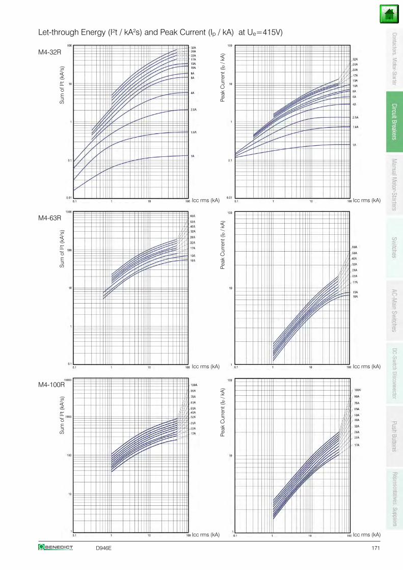
D946E 171
Icc rms (kA) Icc rms (kA)
Sum
of I
²t (k
A²s
)
Let-through Energy (I²t / kA2s) and Peak Current (Ip / kA) at Ue=415V)
M4-32R
M4-63R
M4-100R
Sum
of I
²t (k
A²s
)
Peak
Cur
rent
(Ip
/ kA
)
Sum
of I
²t (k
A²s
)
Peak
Cur
rent
(Ip
/ kA
)Pe
ak C
urre
nt (I
p / k
A)
Icc rms (kA) Icc rms (kA)
Icc rms (kA) Icc rms (kA)
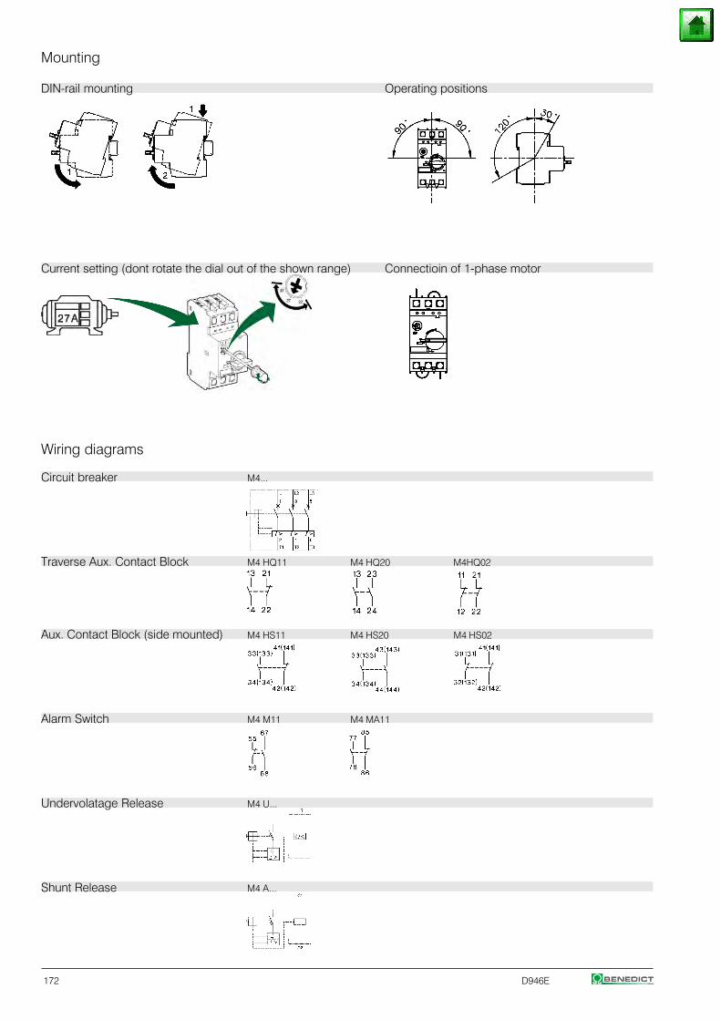
172 D946E
Mounting
DIN-rail mounting Operating positions
Wiring diagrams
Circuit breaker M4...
Traverse Aux. Contact Block M4 HQ11 M4 HQ20 M4HQ02
Aux. Contact Block (side mounted) M4 HS11 M4 HS20 M4 HS02
Alarm Switch M4 M11 M4 MA11
Undervolatage Release M4 U...
Shunt Release M4 A...
Current setting (dont rotate the dial out of the shown range) Connectioin of 1-phase motor
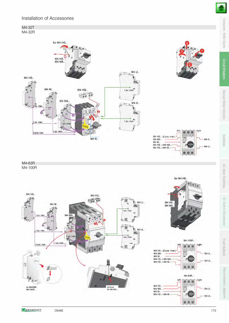
D946E 173
Installation of Accessories
M4-32TM4-32R
M4-63RM4-100R
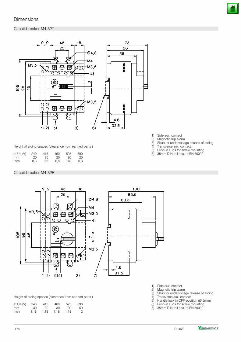
174 D946E
Dimensions
Circuit-breaker M4-32T
1) Side aux. contact2) Magnetic trip alarm3) Shunt or undervoltage release of arcing
Height of arcing spaces (clearance from earthed parts ) 4) Transverse aux. contact5) Push-in Lugs for screw mounting
at Ue (V) 240 415 460 525 690 6) 35mm DIN-rail acc. to EN 50022mm 20 20 20 20 20inch 0,8 0,8 0,8 0,8 0,8
Circuit-breaker M4-32R
1) Side aux. contact2) Magnetic trip alarm3) Shunt or undervoltage release of arcing
Height of arcing spaces (clearance from earthed parts ) 4) Transverse aux. contact5) Handle lock in OFF-position (Ø 5mm)
at Ue (V) 240 415 460 525 690 6) Push-in Lugs for screw mountingmm 30 30 30 30 50 7) 35mm DIN-rail acc. to EN 50022inch 1,18 1,18 1,18 1,18 2
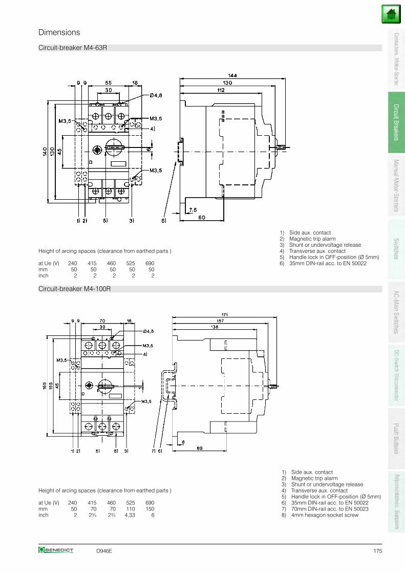
D946E 175
Dimensions
Circuit-breaker M4-63R
1) Side aux. contact2) Magnetic trip alarm3) Shunt or undervoltage release
Height of arcing spaces (clearance from earthed parts ) 4) Transverse aux. contact5) Handle lock in OFF-position (Ø 5mm)
at Ue (V) 240 415 460 525 690 6) 35mm DIN-rail acc. to EN 50022mm 50 50 50 50 50inch 2 2 2 2 2
Circuit-breaker M4-100R
1) Side aux. contact2) Magnetic trip alarm3) Shunt or undervoltage release
Height of arcing spaces (clearance from earthed parts ) 4) Transverse aux. contact5) Handle lock in OFF-position (Ø 5mm)
at Ue (V) 240 415 460 525 690 6) 35mm DIN-rail acc. to EN 50022mm 50 70 70 110 150 7) 70mm DIN-rail acc. to EN 50023inch 2 2¾ 2¾ 4,33 6 8) 4mm hexagon socket screw
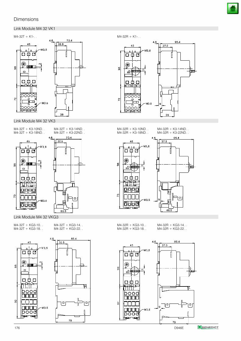
176 D946E
Dimensions
Link Module M4 32 VK1
M4-32T + K1-. . M4-32R + K1-. .
Link Module M4 32 VK3
M4-32T + K3-10ND. . M4-32T + K3-14ND. . M4-32R + K3-10ND. . M4-32R + K3-14ND. .M4-32T + K3-18ND. . M4-32T + K3-22ND. . M4-32R + K3-18ND. . M4-32R + K3-22ND. .
Link Module M4 32 VKG3
M4-32T + KG3-10. . M4-32T + KG3-14. . M4-32R + KG3-10. . M4-32R + KG3-14. .M4-32T + KG3-18. . M4-32T + KG3-22. . M4-32R + KG3-18. . M4-32R + KG3-22. .
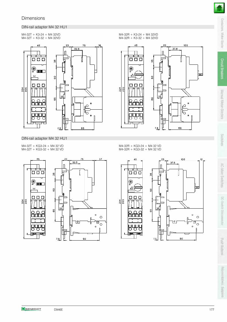
D946E 177
Dimensions
DIN-rail adapter M4 32 HU1
M4-32T + K3-24 + M4 32VD M4-32R + K3-24 + M4 32VDM4-32T + K3-32 + M4 32VD M4-32R + K3-32 + M4 32VD
DIN-rail adapter M4 32 HU1
M4-32T + KG3-24 + M4 32 VD M4-32R + KG3-24 + M4 32 VDM4-32T + KG3-32 + M4 32 VD M4-32R + KG3-32 + M4 32 VD
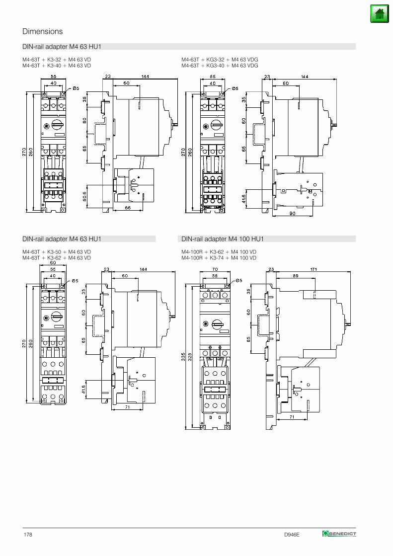
178 D946E
Dimensions
DIN-rail adapter M4 63 HU1
M4-63T + K3-32 + M4 63 VD M4-63T + KG3-32 + M4 63 VDGM4-63T + K3-40 + M4 63 VD M4-63T + KG3-40 + M4 63 VDG
DIN-rail adapter M4 63 HU1 DIN-rail adapter M4 100 HU1
M4-63T + K3-50 + M4 63 VD M4-100R + K3-62 + M4 100 VDM4-63T + K3-62 + M4 63 VD M4-100R + K3-74 + M4 100 VD
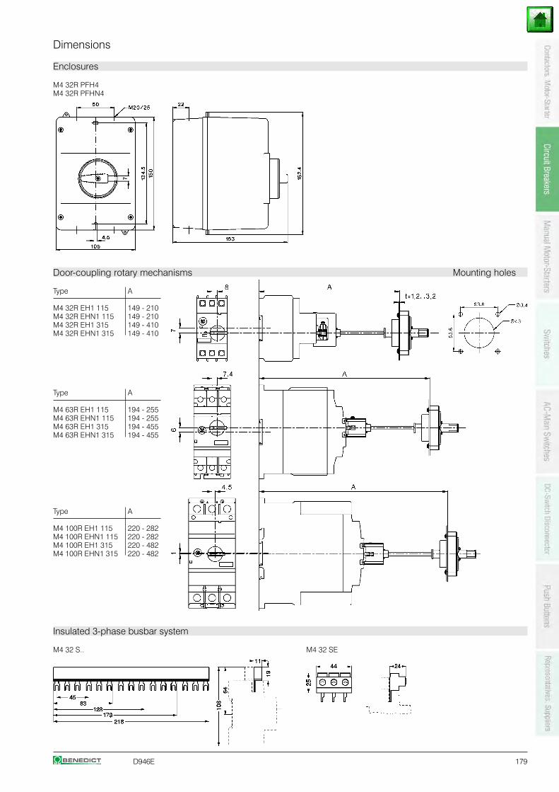
D946E 179
Dimensions
Enclosures
M4 32R PFH4M4 32R PFHN4
Door-coupling rotary mechanisms Mounting holes
Type A
M4 32R EH1 115 149 - 210M4 32R EHN1 115 149 - 210M4 32R EH1 315 149 - 410M4 32R EHN1 315 149 - 410
Type A
M4 63R EH1 115 194 - 255M4 63R EHN1 115 194 - 255M4 63R EH1 315 194 - 455M4 63R EHN1 315 194 - 455
Type A
M4 100R EH1 115 220 - 282M4 100R EHN1 115 220 - 282M4 100R EH1 315 220 - 482M4 100R EHN1 315 220 - 482
Insulated 3-phase busbar system
M4 32 S.. M4 32 SE
180 D946E
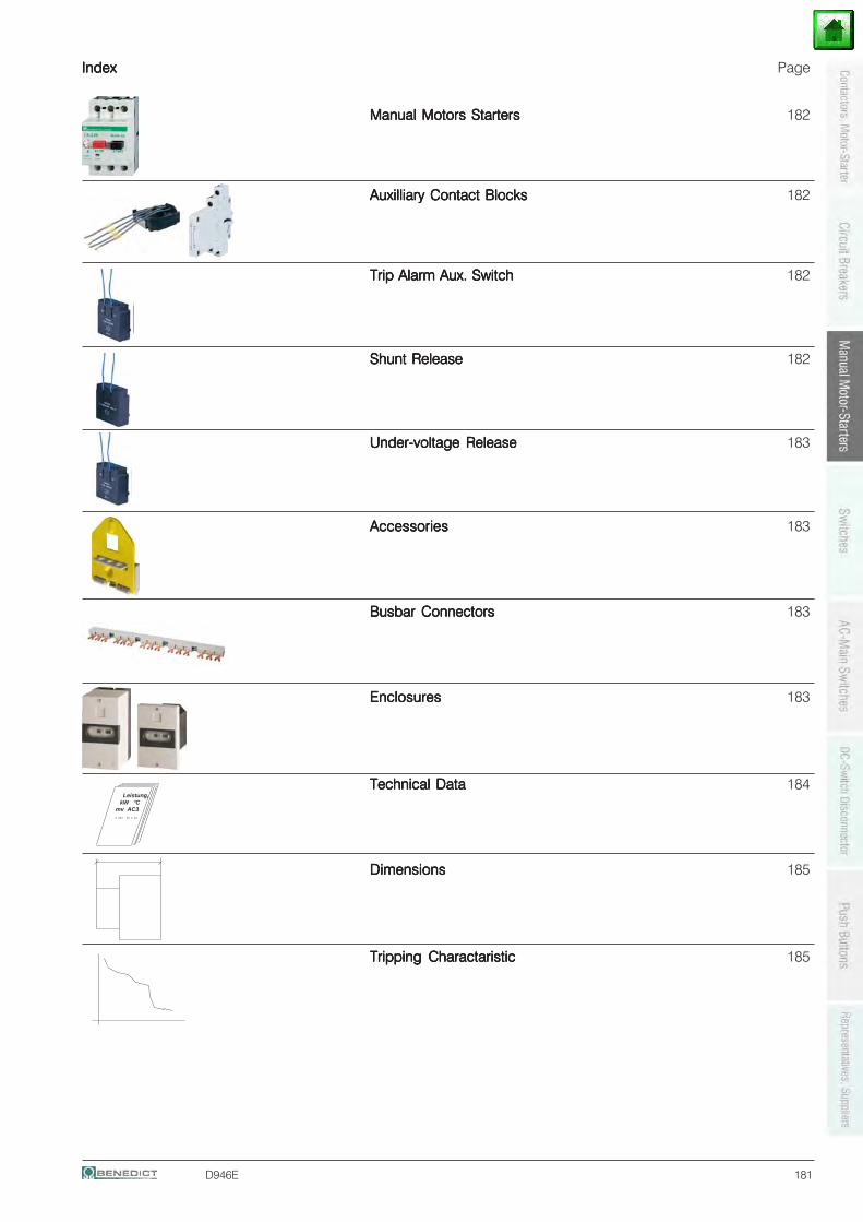
D946E
IndexIndexIndexIndexIndex Page
Manual Motors StartersManual Motors StartersManual Motors StartersManual Motors StartersManual Motors Starters 182
Auxilliary Contact BlocksAuxilliary Contact BlocksAuxilliary Contact BlocksAuxilliary Contact BlocksAuxilliary Contact Blocks 182
Trip Alarm Aux. SwitchTrip Alarm Aux. SwitchTrip Alarm Aux. SwitchTrip Alarm Aux. SwitchTrip Alarm Aux. Switch 182
Shunt ReleaseShunt ReleaseShunt ReleaseShunt ReleaseShunt Release 182
Under-voltage ReleaseUnder-voltage ReleaseUnder-voltage ReleaseUnder-voltage ReleaseUnder-voltage Release 183
AccessoriesAccessoriesAccessoriesAccessoriesAccessories 183
Busbar ConnectorsBusbar ConnectorsBusbar ConnectorsBusbar ConnectorsBusbar Connectors 183
EnclosuresEnclosuresEnclosuresEnclosuresEnclosures 183
Technical DataTechnical DataTechnical DataTechnical DataTechnical Data 184
DimensionsDimensionsDimensionsDimensionsDimensions 185
Tripping CharactaristicTripping CharactaristicTripping CharactaristicTripping CharactaristicTripping Charactaristic 185
Leistung, kW °C mv AC3 . ... .. . ..
181
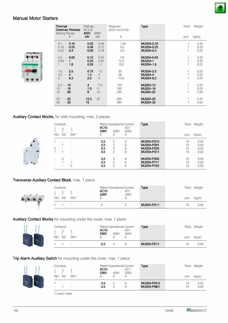
D946E
Manual Motor StartersManual Motor StartersManual Motor StartersManual Motor StartersManual Motor Starters
ThermalThermalThermalThermalThermal Ratings Magnetic TypeTypeTypeTypeType Pack WeightOverload ReleaseOverload ReleaseOverload ReleaseOverload ReleaseOverload Release AC3 at short circuit tripSetting Range 400V400V400V400V400V 690V
A kWkWkWkWkW kW A pcs. kg/pc.
0,1 - 0,160,160,160,160,16 0,020,020,020,020,02 0,06 1,92 MU25A-0,16MU25A-0,16MU25A-0,16MU25A-0,16MU25A-0,16 1 0,250,16 - 0,250,250,250,250,25 0,060,060,060,060,06 0,12 3,0 MU25A-0,25MU25A-0,25MU25A-0,25MU25A-0,25MU25A-0,25 1 0,250,25 - 0,40,40,40,40,4 0,090,090,090,090,09 0,18 4,8 MU25A-0,4MU25A-0,4MU25A-0,4MU25A-0,4MU25A-0,4 1 0,25
0,4 - 0,630,630,630,630,63 0,120,120,120,120,12 0,25 7,6 MU25A-0,63MU25A-0,63MU25A-0,63MU25A-0,63MU25A-0,63 1 0,250,63 - 11111 0,250,250,250,250,25 0,55 12,0 MU25A-1MU25A-1MU25A-1MU25A-1MU25A-1 1 0,251 - 1,61,61,61,61,6 0,550,550,550,550,55 1,1 19,2 MU25A-1,6MU25A-1,6MU25A-1,6MU25A-1,6MU25A-1,6 1 0,25
1,6 - 2,52,52,52,52,5 0,750,750,750,750,75 1,5 30 MU25A-2,5MU25A-2,5MU25A-2,5MU25A-2,5MU25A-2,5 1 0,252,5 - 44444 1,51,51,51,51,5 3 48 MU25A-4MU25A-4MU25A-4MU25A-4MU25A-4 1 0,254 - 6,36,36,36,36,3 2,52,52,52,52,5 4 75,6 MU25A-6,3MU25A-6,3MU25A-6,3MU25A-6,3MU25A-6,3 1 0,25
6,3 - 1010101010 44444 7,5 120 MU25A-10MU25A-10MU25A-10MU25A-10MU25A-10 1 0,2510 - 1616161616 7,57,57,57,57,5 11 192 MU25A-16MU25A-16MU25A-16MU25A-16MU25A-16 1 0,2516 - 2020202020 99999 12 240 MU25A-20MU25A-20MU25A-20MU25A-20MU25A-20 1 0,25
20 - 2525252525 12,512,512,512,512,5 22 300 MU25A-25MU25A-25MU25A-25MU25A-25MU25A-25 1 0,2525 - 3232323232 1515151515 384 MU25A-32MU25A-32MU25A-32MU25A-32MU25A-32 1 0,25
Auxiliary Contact Blocks, Auxiliary Contact Blocks, Auxiliary Contact Blocks, Auxiliary Contact Blocks, Auxiliary Contact Blocks, for side mounting, max. 2 pieces
Contacts Rated Operational Current TypeTypeTypeTypeType Pack WeightAC15AC15AC15AC15AC15 AC1230V230V230V230V230V 400V 500V
NO NC EM 1) A A A pcs. kg/pc.
1 - - 3,53,53,53,53,5 2 6 MU25A-PS10MU25A-PS10MU25A-PS10MU25A-PS10MU25A-PS10 10 0,03- 1 - 3,53,53,53,53,5 2 6 MU25A-PS01MU25A-PS01MU25A-PS01MU25A-PS01MU25A-PS01 10 0,032 - - 3,53,53,53,53,5 2 6 MU25A-PS20MU25A-PS20MU25A-PS20MU25A-PS20MU25A-PS20 10 0,031 1 - 3,53,53,53,53,5 2 6 MU25A-PS11MU25A-PS11MU25A-PS11MU25A-PS11MU25A-PS11 10 0,03
- 2 - 3,53,53,53,53,5 2 6 MU25A-PS02MU25A-PS02MU25A-PS02MU25A-PS02MU25A-PS02 10 0,03- 1 1 3,53,53,53,53,5 2 6 MU25A-PV11MU25A-PV11MU25A-PV11MU25A-PV11MU25A-PV11 10 0,03- - 2 3,53,53,53,53,5 2 6 MU25A-PV20MU25A-PV20MU25A-PV20MU25A-PV20MU25A-PV20 10 0,03
Transverse Auxiliary Contact BlockTransverse Auxiliary Contact BlockTransverse Auxiliary Contact BlockTransverse Auxiliary Contact BlockTransverse Auxiliary Contact Block, max. 1 piece
Contacts Rated Operational Current TypeTypeTypeTypeType Pack WeightAC15AC15AC15AC15AC15 AC1230V230V230V230V230V 230V
NO NC EM 1) A A pcs. kg/pc.
1 1 - 11111 5 MU25A-PA11MU25A-PA11MU25A-PA11MU25A-PA11MU25A-PA11 10 0,02
Auxiliary Contact Blocks Auxiliary Contact Blocks Auxiliary Contact Blocks Auxiliary Contact Blocks Auxiliary Contact Blocks for mounting under the cover, max. 1 piece
Contacts Rated Operational Current TypeTypeTypeTypeType Pack WeightAC15AC15AC15AC15AC15 AC1230V230V230V230V230V 400V 500V
NO NC EM 1) A A A pcs. kg/pc.
1 1 - 3,53,53,53,53,5 2 6 MU25A-PE11MU25A-PE11MU25A-PE11MU25A-PE11MU25A-PE11 10 0,02
Trip Alarm Auxiliary Switch Trip Alarm Auxiliary Switch Trip Alarm Auxiliary Switch Trip Alarm Auxiliary Switch Trip Alarm Auxiliary Switch for mounting under the cover, max. 1 piece
Contacts Rated Operational Current TypeTypeTypeTypeType Pack WeightAC15AC15AC15AC15AC15 AC1230V230V230V230V230V 400V 500V
NO NC EM 1) A A A pcs. kg/pc.
1 - - 3,53,53,53,53,5 2 6 MU25A-PM10MU25A-PM10MU25A-PM10MU25A-PM10MU25A-PM10 10 0,02- 1 - 3,53,53,53,53,5 2 6 MU25A-PM01MU25A-PM01MU25A-PM01MU25A-PM01MU25A-PM01 10 0,02
1) early make
182
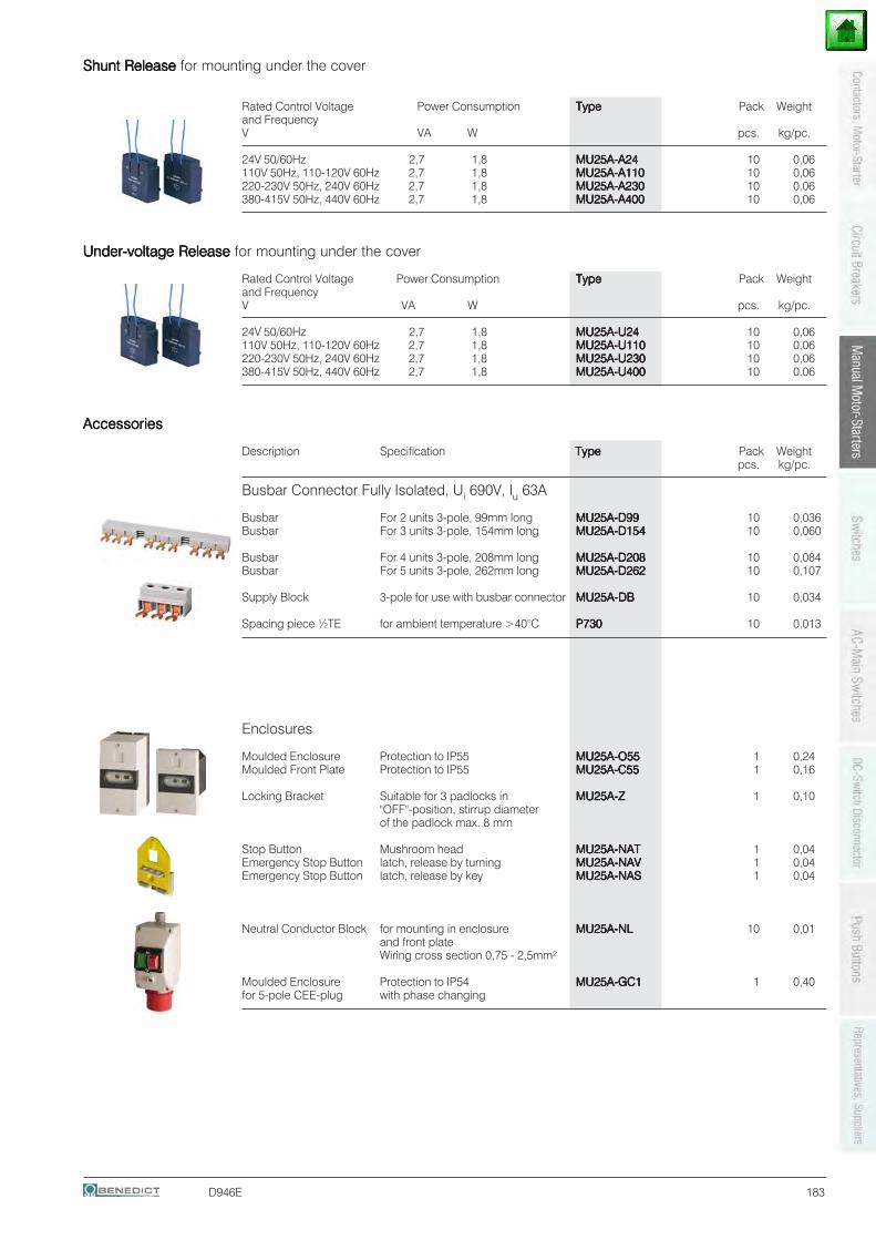
D946E
Shunt Release Shunt Release Shunt Release Shunt Release Shunt Release for mounting under the cover
Rated Control Voltage Power Consumption TypeTypeTypeTypeType Pack Weightand FrequencyV VA W pcs. kg/pc.
24V 50/60Hz 2,7 1,8 MU25A-A24MU25A-A24MU25A-A24MU25A-A24MU25A-A24 10 0,06110V 50Hz, 110-120V 60Hz 2,7 1,8 MU25A-A110MU25A-A110MU25A-A110MU25A-A110MU25A-A110 10 0,06220-230V 50Hz, 240V 60Hz 2,7 1,8 MU25A-A230MU25A-A230MU25A-A230MU25A-A230MU25A-A230 10 0,06380-415V 50Hz, 440V 60Hz 2,7 1,8 MU25A-A400MU25A-A400MU25A-A400MU25A-A400MU25A-A400 10 0,06
Under-voltage Release Under-voltage Release Under-voltage Release Under-voltage Release Under-voltage Release for mounting under the cover
Rated Control Voltage Power Consumption TypeTypeTypeTypeType Pack Weightand FrequencyV VA W pcs. kg/pc.
24V 50/60Hz 2,7 1,8 MU25A-U24MU25A-U24MU25A-U24MU25A-U24MU25A-U24 10 0,06110V 50Hz, 110-120V 60Hz 2,7 1,8 MU25A-U110MU25A-U110MU25A-U110MU25A-U110MU25A-U110 10 0,06220-230V 50Hz, 240V 60Hz 2,7 1,8 MU25A-U230MU25A-U230MU25A-U230MU25A-U230MU25A-U230 10 0,06380-415V 50Hz, 440V 60Hz 2,7 1,8 MU25A-U400MU25A-U400MU25A-U400MU25A-U400MU25A-U400 10 0,06
AccessoriesAccessoriesAccessoriesAccessoriesAccessories
Description Specification TypeTypeTypeTypeType Pack Weightpcs. kg/pc.
Busbar Connector Fully Isolated, Ui 690V, Iu 63A
Busbar For 2 units 3-pole, 99mm long MU25A-D99MU25A-D99MU25A-D99MU25A-D99MU25A-D99 10 0,036Busbar For 3 units 3-pole, 154mm long MU25A-D154MU25A-D154MU25A-D154MU25A-D154MU25A-D154 10 0,060
Busbar For 4 units 3-pole, 208mm long MU25A-D208MU25A-D208MU25A-D208MU25A-D208MU25A-D208 10 0,084Busbar For 5 units 3-pole, 262mm long MU25A-D262MU25A-D262MU25A-D262MU25A-D262MU25A-D262 10 0,107
Supply Block 3-pole for use with busbar connector MU25A-DBMU25A-DBMU25A-DBMU25A-DBMU25A-DB 10 0,034
Spacing piece ½TE for ambient temperature >40°C P730P730P730P730P730 10 0,013
Enclosures
Moulded Enclosure Protection to IP55 MU25A-O55MU25A-O55MU25A-O55MU25A-O55MU25A-O55 1 0,24Moulded Front Plate Protection to IP55 MU25A-C55MU25A-C55MU25A-C55MU25A-C55MU25A-C55 1 0,16
Locking Bracket Suitable for 3 padlocks in MU25A-ZMU25A-ZMU25A-ZMU25A-ZMU25A-Z 1 0,10"OFF"-position, stirrup diameterof the padlock max. 8 mm
Stop Button Mushroom head MU25A-NATMU25A-NATMU25A-NATMU25A-NATMU25A-NAT 1 0,04Emergency Stop Button latch, release by turning MU25A-NAVMU25A-NAVMU25A-NAVMU25A-NAVMU25A-NAV 1 0,04Emergency Stop Button latch, release by key MU25A-NASMU25A-NASMU25A-NASMU25A-NASMU25A-NAS 1 0,04
Neutral Conductor Block for mounting in enclosure MU25A-NLMU25A-NLMU25A-NLMU25A-NLMU25A-NL 10 0,01and front plateWiring cross section 0,75 - 2,5mm²
Moulded Enclosure Protection to IP54 MU25A-GC1MU25A-GC1MU25A-GC1MU25A-GC1MU25A-GC1 1 0,40for 5-pole CEE-plug with phase changing
183
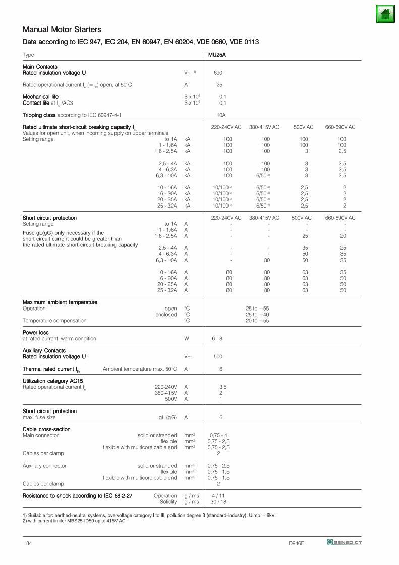
D946E
Manual Motor StartersManual Motor StartersManual Motor StartersManual Motor StartersManual Motor Starters
Data according to IEC 947, IEC 204, EN 60947, EN 60204, VDE 0660, VDE 0113Data according to IEC 947, IEC 204, EN 60947, EN 60204, VDE 0660, VDE 0113Data according to IEC 947, IEC 204, EN 60947, EN 60204, VDE 0660, VDE 0113Data according to IEC 947, IEC 204, EN 60947, EN 60204, VDE 0660, VDE 0113Data according to IEC 947, IEC 204, EN 60947, EN 60204, VDE 0660, VDE 0113
Type MU25AMU25AMU25AMU25AMU25A
Main ContactsMain ContactsMain ContactsMain ContactsMain ContactsRated insulation voltage URated insulation voltage URated insulation voltage URated insulation voltage URated insulation voltage Uiiiii V~ 1) 690
Rated operational current Ie (=Ith) open, at 50°C A 25
Mechanical lifeMechanical lifeMechanical lifeMechanical lifeMechanical life S x 106 0,1Contact life Contact life Contact life Contact life Contact life at Ie /AC3 S x 106 0,1
Tripping class Tripping class Tripping class Tripping class Tripping class according to IEC 60947-4-1 10A
Rated ultimate short-circuit breaking capacity IRated ultimate short-circuit breaking capacity IRated ultimate short-circuit breaking capacity IRated ultimate short-circuit breaking capacity IRated ultimate short-circuit breaking capacity Icu 220-240V AC 380-415V AC 500V AC 660-690V ACValues for open unit, when incoming supply on upper terminalsSetting range to 1A kA 100 100 100 100
1 - 1,6A kA 100 100 100 1001,6 - 2,5A kA 100 100 3 2,5
2,5 - 4A kA 100 100 3 2,54 - 6,3A kA 100 100 3 2,5
6,3 - 10A kA 100 6/50 2) 3 2,5
10 - 16A kA 10/100 2) 6/50 2) 2,5 216 - 20A kA 10/100 2) 6/50 2) 2,5 220 - 25A kA 10/100 2) 6/50 2) 2,5 225 - 32A kA 10/100 2) 6/50 2) 2,5 2
Short circuit protectionShort circuit protectionShort circuit protectionShort circuit protectionShort circuit protection 220-240V AC 380-415V AC 500V AC 660-690V ACSetting range to 1A A - - - -
1 - 1,6A A - - - -1,6 - 2,5A A - - 25 20
2,5 - 4A A - - 35 254 - 6,3A A - - 50 35
6,3 - 10A A - 80 50 35
10 - 16A A 80 80 63 3516 - 20A A 80 80 63 5020 - 25A A 80 80 63 5025 - 32A A 80 80 63 50
Maximum ambient temperatureMaximum ambient temperatureMaximum ambient temperatureMaximum ambient temperatureMaximum ambient temperatureOperation open °C -25 to +55
enclosed °C -25 to +40Temperature compensation °C -20 to +55
Power lossPower lossPower lossPower lossPower lossat rated current, warm condition W 6 - 8
Auxiliary ContactsAuxiliary ContactsAuxiliary ContactsAuxiliary ContactsAuxiliary ContactsRated insulation voltage URated insulation voltage URated insulation voltage URated insulation voltage URated insulation voltage Uiiiii V~ 500
Thermal rated current IThermal rated current IThermal rated current IThermal rated current IThermal rated current Iththththth Ambient temperature max. 50°C A 6
Utilization category AC15Utilization category AC15Utilization category AC15Utilization category AC15Utilization category AC15Rated operational current Ie 220-240V A 3,5
380-415V A 2500V A 1
Short circuit protectionShort circuit protectionShort circuit protectionShort circuit protectionShort circuit protectionmax. fuse size gL (gG) A 6
Cable cross-sectionCable cross-sectionCable cross-sectionCable cross-sectionCable cross-sectionMain connector solid or stranded mm² 0,75 - 4
flexible mm² 0,75 - 2,5flexible with multicore cable end mm² 0,75 - 2,5
Cables per clamp 2
Auxiliary connector solid or stranded mm² 0,75 - 2,5flexible mm² 0,75 - 1,5
flexible with multicore cable end mm² 0,75 - 1,5Cables per clamp 2
Resistance to shock according to IEC 68-2-27Resistance to shock according to IEC 68-2-27Resistance to shock according to IEC 68-2-27Resistance to shock according to IEC 68-2-27Resistance to shock according to IEC 68-2-27 Operation g / ms 4 / 11Solidity g / ms 30 / 18
1) Suitable for: earthed-neutral systems, overvoltage category I to III, pollution degree 3 (standard-industry): Uimp = 6kV.2) with current limiter MBS25-ID50 up to 415V AC
Fuse gL(gG) only necessary if theshort circuit current could be greater thanthe rated ultimate short-circuit breaking capacity
184
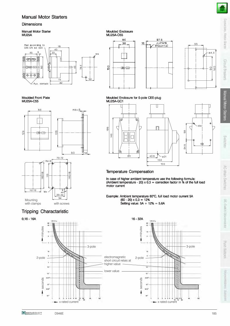
D946E
Tripping CharactaristicTripping CharactaristicTripping CharactaristicTripping CharactaristicTripping Charactaristic
0,16 - 16A0,16 - 16A0,16 - 16A0,16 - 16A0,16 - 16A 16 - 32A16 - 32A16 - 32A16 - 32A16 - 32A
Manual Motor StartersManual Motor StartersManual Motor StartersManual Motor StartersManual Motor Starters
DimensionsDimensionsDimensionsDimensionsDimensions
Manual Motor StarterManual Motor StarterManual Motor StarterManual Motor StarterManual Motor Starter Moulded EnclosureMoulded EnclosureMoulded EnclosureMoulded EnclosureMoulded EnclosureMU25AMU25AMU25AMU25AMU25A MU25A-O55MU25A-O55MU25A-O55MU25A-O55MU25A-O55
Moulded Front PlateMoulded Front PlateMoulded Front PlateMoulded Front PlateMoulded Front Plate Moulded Enclosure for 5-pole CEE-plugMoulded Enclosure for 5-pole CEE-plugMoulded Enclosure for 5-pole CEE-plugMoulded Enclosure for 5-pole CEE-plugMoulded Enclosure for 5-pole CEE-plugMU25A-C55MU25A-C55MU25A-C55MU25A-C55MU25A-C55 MU25A-GC1MU25A-GC1MU25A-GC1MU25A-GC1MU25A-GC1
Mountingwith clamps with screws
TTTTTemperature Compensationemperature Compensationemperature Compensationemperature Compensationemperature Compensation
In case of higher ambient temperature use the following formula:In case of higher ambient temperature use the following formula:In case of higher ambient temperature use the following formula:In case of higher ambient temperature use the following formula:In case of higher ambient temperature use the following formula:(Ambient temperature - 20) x 0,3 = correction factor in % of the full load(Ambient temperature - 20) x 0,3 = correction factor in % of the full load(Ambient temperature - 20) x 0,3 = correction factor in % of the full load(Ambient temperature - 20) x 0,3 = correction factor in % of the full load(Ambient temperature - 20) x 0,3 = correction factor in % of the full loadmotor currentmotor currentmotor currentmotor currentmotor current
Example: Ambient temperature 60°C, full load motor current 5AExample: Ambient temperature 60°C, full load motor current 5AExample: Ambient temperature 60°C, full load motor current 5AExample: Ambient temperature 60°C, full load motor current 5AExample: Ambient temperature 60°C, full load motor current 5A(60 - 20) x 0,3 = 12%(60 - 20) x 0,3 = 12%(60 - 20) x 0,3 = 12%(60 - 20) x 0,3 = 12%(60 - 20) x 0,3 = 12%Setting value: 5A + 12% = 5,6ASetting value: 5A + 12% = 5,6ASetting value: 5A + 12% = 5,6ASetting value: 5A + 12% = 5,6ASetting value: 5A + 12% = 5,6A
3-pole
2-pole electromagneticshort circuit relais athigher value
lower value
x rated current
seco
nds
min
utes
3-pole
2-pole
x rated current
seco
nds
min
utes
185
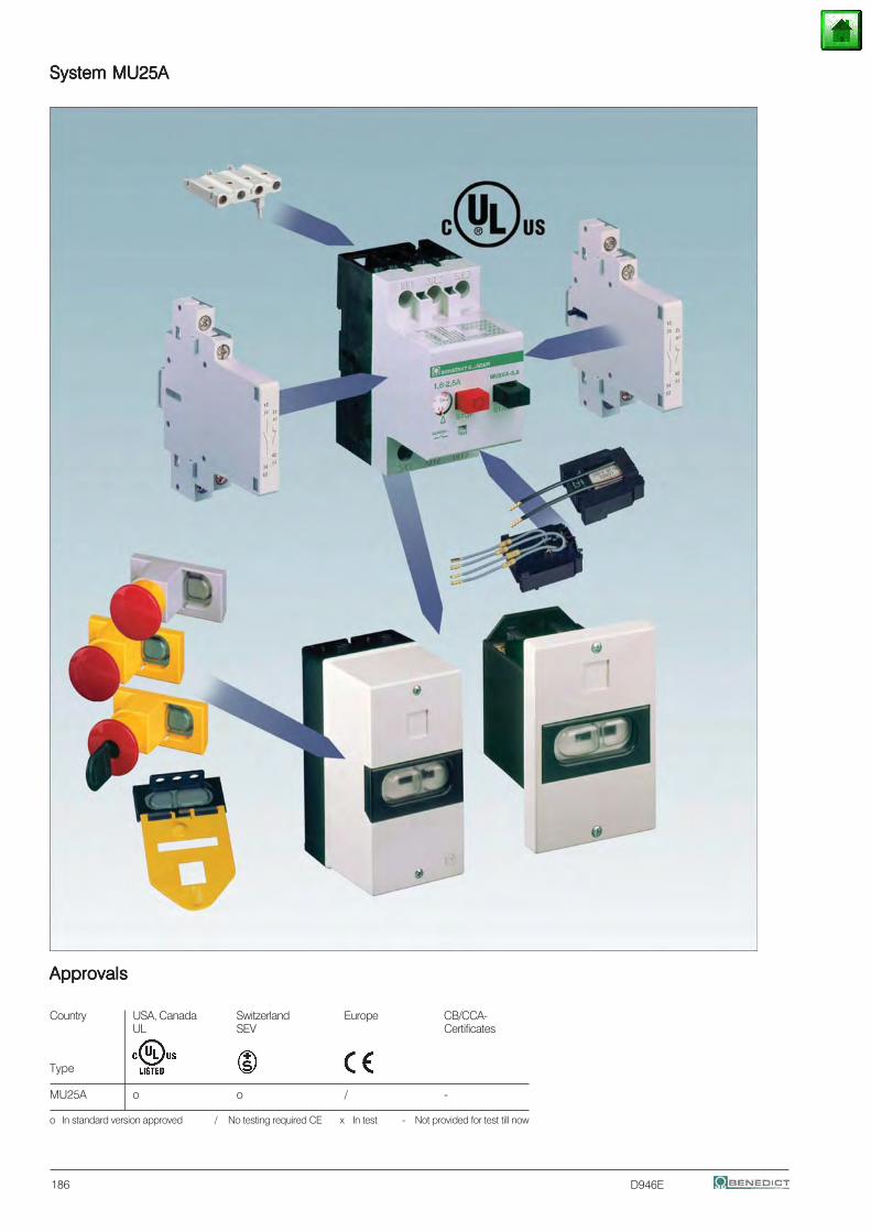
D946E
System MU25ASystem MU25ASystem MU25ASystem MU25ASystem MU25A
ApprovalsApprovalsApprovalsApprovalsApprovals
Country USA, Canada Switzerland Europe CB/CCA-UL SEV Certificates
Type
MU25A o o / -
o In standard version approved / No testing required CE x In test - Not provided for test till now
186
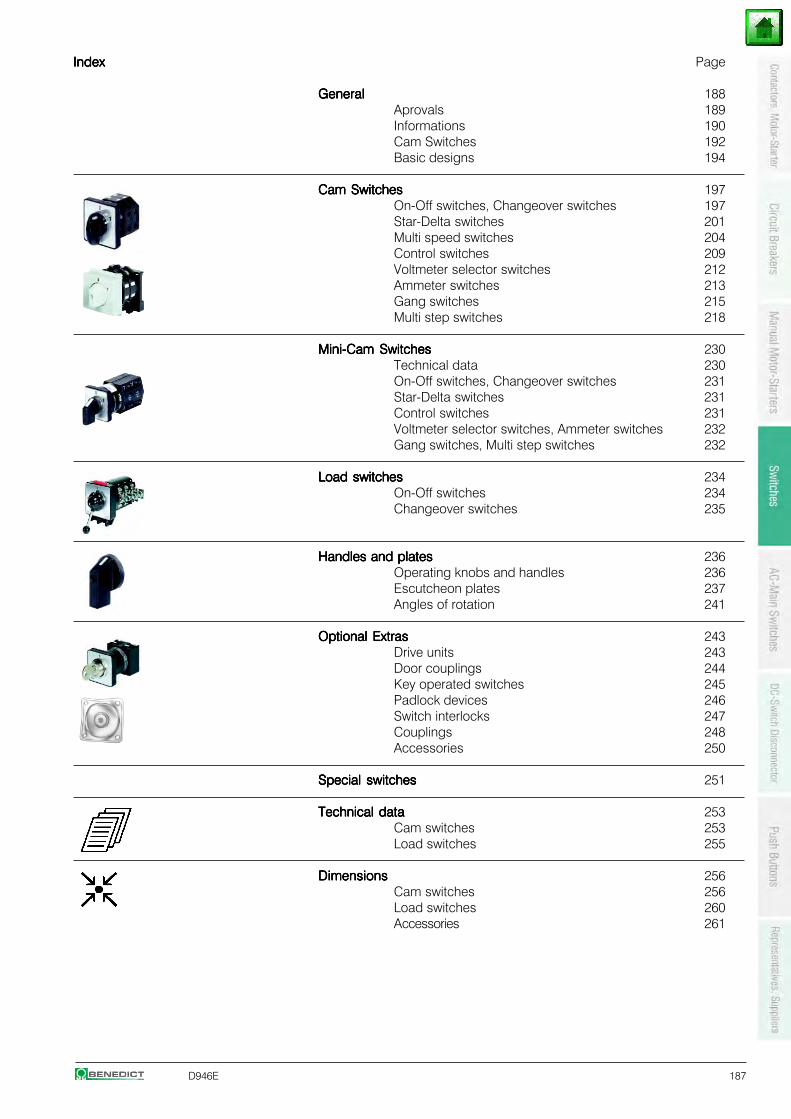
D946E 187
IndexIndexIndexIndexIndex Page
GeneralGeneralGeneralGeneralGeneral 188Aprovals 189Informations 190Cam Switches 192Basic designs 194
Cam SwitchesCam SwitchesCam SwitchesCam SwitchesCam Switches 197On-Off switches, Changeover switches 197Star-Delta switches 201Multi speed switches 204Control switches 209Voltmeter selector switches 212Ammeter switches 213Gang switches 215Multi step switches 218
Mini-Cam SwitchesMini-Cam SwitchesMini-Cam SwitchesMini-Cam SwitchesMini-Cam Switches 230Technical data 230On-Off switches, Changeover switches 231Star-Delta switches 231Control switches 231Voltmeter selector switches, Ammeter switches 232Gang switches, Multi step switches 232
Load switchesLoad switchesLoad switchesLoad switchesLoad switches 234On-Off switches 234Changeover switches 235
Handles and platesHandles and platesHandles and platesHandles and platesHandles and plates 236Operating knobs and handles 236Escutcheon plates 237Angles of rotation 241
Optional ExtrasOptional ExtrasOptional ExtrasOptional ExtrasOptional Extras 243Drive units 243Door couplings 244Key operated switches 245Padlock devices 246Switch interlocks 247Couplings 248Accessories 250
Special switchesSpecial switchesSpecial switchesSpecial switchesSpecial switches 251
Technical dataTechnical dataTechnical dataTechnical dataTechnical data 253Cam switches 253Load switches 255
DimensionsDimensionsDimensionsDimensionsDimensions 256Cam switches 256Load switches 260Accessories 261
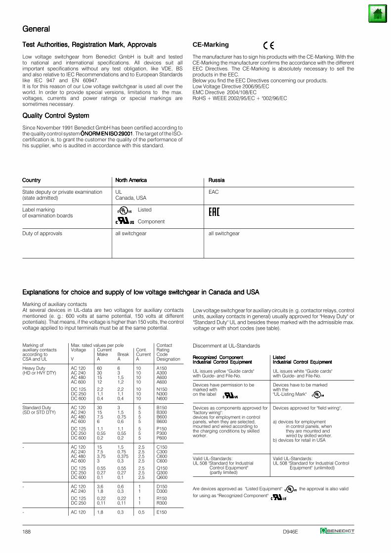
188 D946E
Marking of auxiliary contactsAt several devices in UL-data are two voltages for auxiliary contactsmentioned (e. g.: 600 volts at same potential, 150 volts at differentpotentials). That means, if the voltage is higher than 150 volts, the controlvoltage applied to input terminals must be at the same potential.
Marking of Max. rated values per pole Contactauxiliary contacts Voltage Current Cont. Ratingaccording to Make Break Current CodeCSA and UL V A A A Designation
Heavy Duty AC 120 60 6 10 A150(HD or HVY DTY) AC 240 30 3 10 A300
AC 480 15 1,5 10 A600AC 600 12 1,2 10 A600
DC 125 2,2 2,2 10 N150DC 250 1,1 1,1 10 N300DC 600 0,4 0,4 10 N600
Standard Duty AC 120 30 3 5 B150(SD or STD DTY) AC 240 15 1,5 5 B300
AC 480 7,5 0,75 5 B600AC 600 6 0,6 5 B600
DC 125 1,1 1,1 5 P150DC 250 0,55 0,55 5 P300DC 600 0,2 0,2 5 P600
- AC 120 15 1,5 2,5 C150AC 240 7,5 0,75 2,5 C300AC 480 3,75 0,375 2,5 C600AC 600 3 0,3 2,5 C600
DC 125 0,55 0,55 2,5 Q150DC 250 0,27 0,27 2,5 Q300DC 600 0,1 0,1 2,5 Q600
- AC 120 3,6 0,6 1 D150AC 240 1,8 0,3 1 D300
DC 125 0,22 0,22 1 R150DC 250 0,11 0,11 1 R300
- AC 120 1,8 0,3 0,5 E150
Low voltage switchgear for auxiliary circuits (e. g. contactor relays, controlunits, auxiliary contacts in general) usually approved for "Heavy Duty" or"Standard Duty" UL and besides these marked with the admissible max.voltage or with short codes (see table).
Discernment at UL-Standards
Recognized ComponentRecognized ComponentRecognized ComponentRecognized ComponentRecognized Component ListedListedListedListedListedIndustrial Control EquipmentIndustrial Control EquipmentIndustrial Control EquipmentIndustrial Control EquipmentIndustrial Control Equipment Industrial Control EquipmentIndustrial Control EquipmentIndustrial Control EquipmentIndustrial Control EquipmentIndustrial Control Equipment
UL issues yellow "Guide cards" UL issues white "Guide cards"with Guide- and File-No. with Guide- and File-No.
Devices have permission to be Devices have to be markedmarked with with theon the label "UL-Listing Mark"
Devices as components approved for Devices approved for "field wiring","factory wiring":devices for employment in controlpanels, when they are selected, a) devices for employmentmounted and wired according to in control panels, whenthe charging conditions by skilled they are mounted andworker. wired by skilled worker.
b) devices for retail in USA
Valid UL-Standards: Valid UL-Standards:UL 508 "Standard for Industrial UL 508 "Standard for Industrial Control
Control Equipment" Equipment" (unlimited)(partly limited)
Are devices approved as "Listed Equipment" the approval is also validfor using as "Recognized Component" .
GeneralGeneralGeneralGeneralGeneral
CE-Marking
The manufacturer has to sign his products with the CE-Marking. With theCE-Marking the manufacturer confirms the accordance with the differentEEC Directives. The CE-Marking is absolutely necessary to sell theproducts in the EEC.Below you find the EEC Directives concerning our products.Low Voltage Directive 2006/95/ECEMC Directive 2004/108/ECRoHS + WEEE 2002/95/EC + "002/96/EC
Test Authorities, Registration Mark, ApprovalsTest Authorities, Registration Mark, ApprovalsTest Authorities, Registration Mark, ApprovalsTest Authorities, Registration Mark, ApprovalsTest Authorities, Registration Mark, Approvals
Low voltage switchgear from Benedict GmbH is built and testedto national and international specifications. All devices suit allimportant specifications without any test obligation, like VDE, BSand also relative to IEC Recommendations and to European Standardslike IEC 947 and EN 60947.It is for this reason of our Low voltage switchgear is used all over theworld. In order to provide special versions, limitations to the max.voltages, currents and power ratings or special markings aresometimes necessary.
Quality Control SystemQuality Control SystemQuality Control SystemQuality Control SystemQuality Control System
Since November 1991 Benedict GmbH has been certified according tothe quality control system ÖNORM EN ISO 29001ÖNORM EN ISO 29001ÖNORM EN ISO 29001ÖNORM EN ISO 29001ÖNORM EN ISO 29001. The target of the ISO-certification is, to grant the customer the quality of the performance ofhis supplier, who is audited in accordance with this standard.
CountryCountryCountryCountryCountry North AmericaNorth AmericaNorth AmericaNorth AmericaNorth America RussiaRussiaRussiaRussiaRussia
State deputy or private examination UL EAC(state admitted) Canada, USA
Label marking Listedof examination boards
Component
Duty of approvals all switchgear all switchgear
Explanations for choice and supply of low voltage switchgear in Canada and USAExplanations for choice and supply of low voltage switchgear in Canada and USAExplanations for choice and supply of low voltage switchgear in Canada and USAExplanations for choice and supply of low voltage switchgear in Canada and USAExplanations for choice and supply of low voltage switchgear in Canada and USA
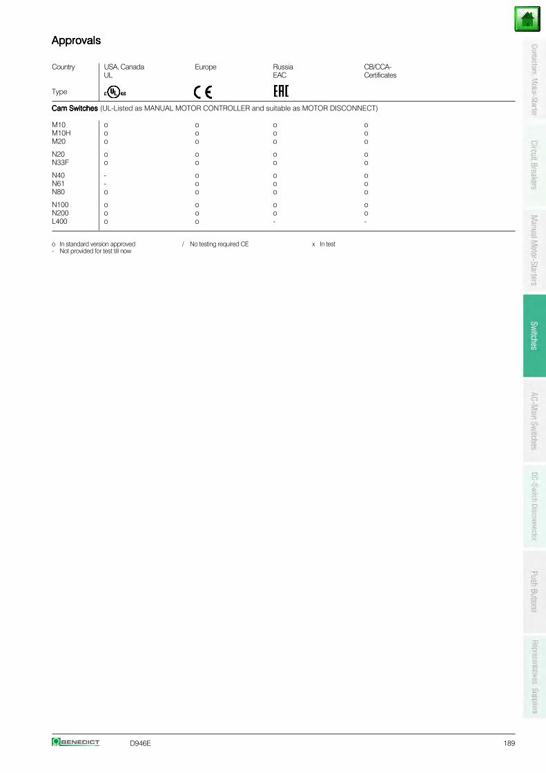
D946E 189
ApprovalsApprovalsApprovalsApprovalsApprovals
Country USA, Canada Europe Russia CB/CCA-UL EAC Certificates
Type
Cam Switches Cam Switches Cam Switches Cam Switches Cam Switches (UL-Listed as MANUAL MOTOR CONTROLLER and suitable as MOTOR DISCONNECT)
M10 o o o oM10H o o o oM20 o o o o
N20 o o o oN33F o o o o
N40 - o o oN61 - o o oN80 o o o o
N100 o o o oN200 o o o oL400 o o - -
o In standard version approved / No testing required CE x In test- Not provided for test till now
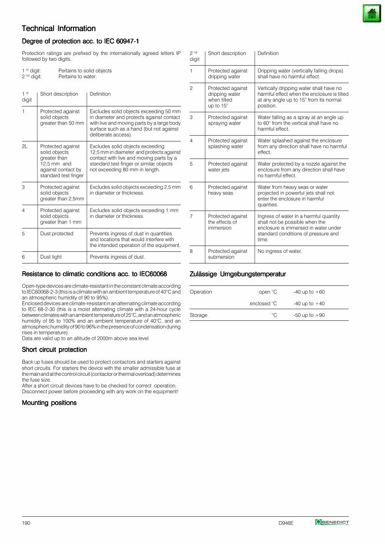
190 D946E
Technical InformationTechnical InformationTechnical InformationTechnical InformationTechnical Information
Degree of protection acc. to IEC 60947-1Degree of protection acc. to IEC 60947-1Degree of protection acc. to IEC 60947-1Degree of protection acc. to IEC 60947-1Degree of protection acc. to IEC 60947-1
Protection ratings are prefixed by the internationally agreed letters IPfollowed by two digits.
1 st digit: Pertains to solid objects2 nd digit: Pertains to water.
1 st Short description Definitiondigit
1 Protected against Excludes solid objects exceeding 50 mmsolid objects in diameter and protects against contactgreater than 50 mm with live and moving parts by a large body
surface such as a hand (but not againstdeliberate access).
2L Protected against Excludes solid objects exceedingsolid objects 12,5 mm in diameter and protects againstgreater than contact with live and moving parts by a12,5 mm and standard test finger or similar objectsagainst contact by not exceeding 80 mm in length.standard test finger
3 Protected against Excludes solid objects exceeding 2,5 mmsolid objects in diameter or thickness.greater than 2,5mm
4 Protected against Excludes solid objects exceeding 1 mmsolid objects in diameter or thickness.greater than 1 mm
5 Dust protected Prevents ingress of dust in quantitiesand locations that would interfere withthe intended operation of the equipment.
6 Dust tight Prevents ingress of dust.
Resistance to climatic conditions acc. to IEC60068Resistance to climatic conditions acc. to IEC60068Resistance to climatic conditions acc. to IEC60068Resistance to climatic conditions acc. to IEC60068Resistance to climatic conditions acc. to IEC60068
Open-type devices are climate-resistant in the constant climate accordingto IEC60068-2-3 (this is a climate with an ambient temperature of 40°C andan atmospheric humidity of 90 to 95%).Enclosed devices are climate-resistant in an alternating climate accordingto IEC 68-2-30 (this is a moist alternating climate with a 24-hour cyclebetween climates with an ambient temperature of 25°C, and an atmospherichumidity of 95 to 100% and an ambient temperature of 40°C, and anatmospheric humidity of 90 to 96% in the presence of condensation duringrises in temperature).Data are valid up to an altitude of 2000m above sea level.
Short circuit protectionShort circuit protectionShort circuit protectionShort circuit protectionShort circuit protection
Back up fuses should be used to protect contactors and starters againstshort circuits. For starters the device with the smaller admissible fuse atthe main and at the control circuit (contactor or thermal overload) determinesthe fuse size.After a short circuit devices have to be checked for correct operation.Disconnect power before proceeding with any work on the equipment!
Mounting positionsMounting positionsMounting positionsMounting positionsMounting positions
2 nd Short description Definitiondigit
1 Protected against Dripping water (vertically falling drops)dripping water shall have no harmful effect.
2 Protected against Vertically dripping water shall have nodripping water harmful effect when the enclosure is tiltedwhen tilted at any angle up to 15° from its normalup to 15° position.
3 Protected against Water falling as a spray at an angle upspraying water to 60° from the vertical shall have no
harmful effect.
4 Protected against Water splashed against the enclosuresplashing water from any direction shall have no harmful
effect.
5 Protected against Water protected by a nozzle against thewater jets enclosure from any direction shall have
no harmful effect.
6 Protected against Water from heavy seas or waterheavy seas projected in powerful jets shall not
enter the enclosure in harmfulquanties.
7 Protected against Ingress of water in a harmful quantitythe effects of shall not be possible when theimmersion enclosure is immersed in water under
standard conditions of pressure andtime.
8 Protected against No ingress of water.submersion
Zulässige UmgebungstemperaturZulässige UmgebungstemperaturZulässige UmgebungstemperaturZulässige UmgebungstemperaturZulässige Umgebungstemperatur
Operation open °C -40 up to +60
enclosed °C -40 up to +40
Storage °C -50 up to +90
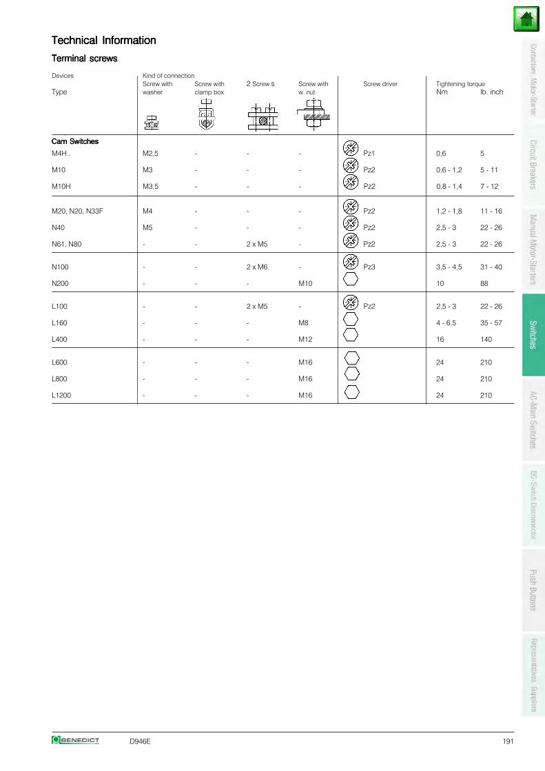
D946E 191
Technical InformationTechnical InformationTechnical InformationTechnical InformationTechnical Information
Terminal screwsTerminal screwsTerminal screwsTerminal screwsTerminal screws
Devices Kind of connectionScrew with Screw with 2 Screw s Screw with Screw driver Tightening torque
Type washer clamp box w. nut Nm lb. inch
Cam SwitchesCam SwitchesCam SwitchesCam SwitchesCam Switches
M4H.. M2,5 - - - Pz1 0,6 5
M10 M3 - - - Pz2 0,6 - 1,2 5 - 11
M10H M3,5 - - - Pz2 0,8 - 1,4 7 - 12
M20, N20, N33F M4 - - - Pz2 1,2 - 1,8 11 - 16
N40 M5 - - - Pz2 2,5 - 3 22 - 26
N61, N80 - - 2 x M5 - Pz2 2,5 - 3 22 - 26
N100 - - 2 x M6 - Pz3 3,5 - 4,5 31 - 40
N200 - - - M10 10 88
L100 - - 2 x M5 - Pz2 2,5 - 3 22 - 26
L160 - - - M8 4 - 6,5 35 - 57
L400 - - - M12 16 140
L600 - - - M16 24 210
L800 - - - M16 24 210
L1200 - - - M16 24 210
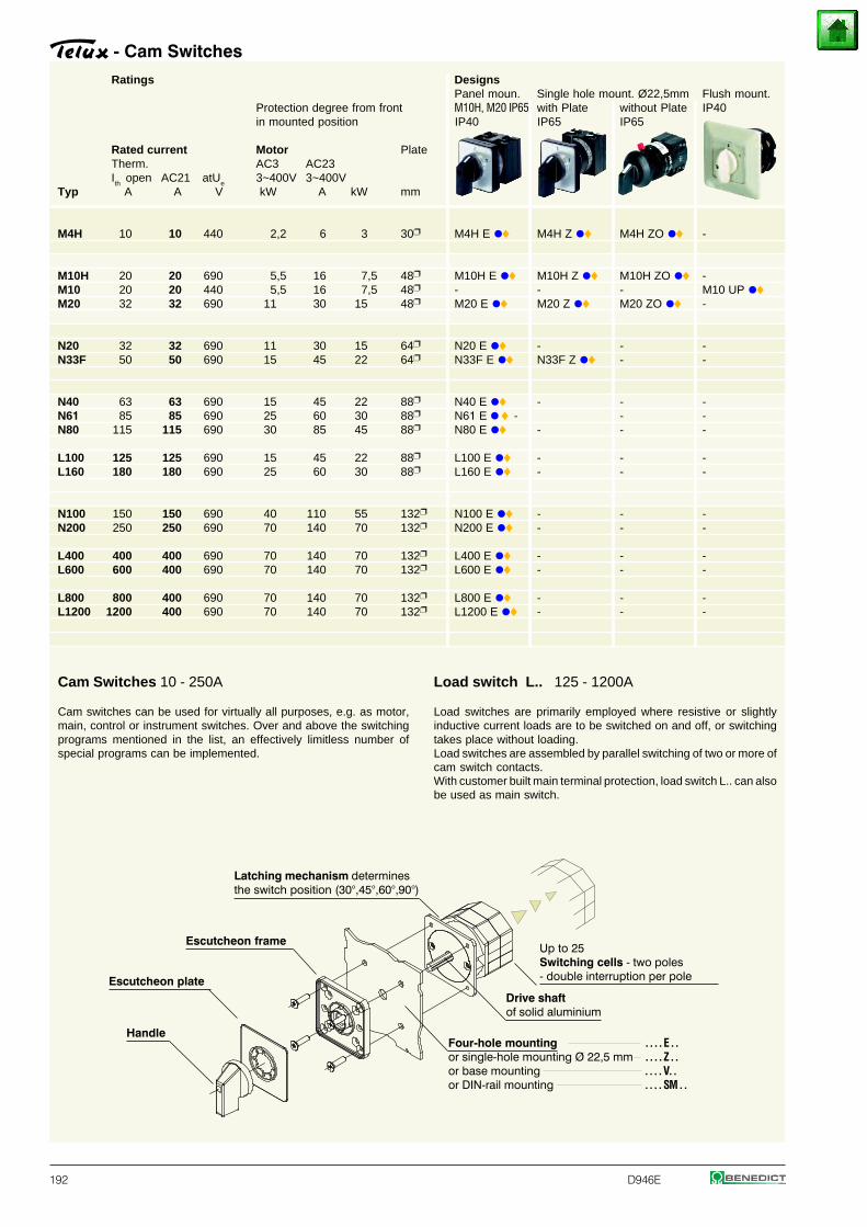
192 D946E
Ratings DesignsPanel moun. Single hole mount. Ø22,5mm Flush mount.
Protection degree from front M10H, M20 IP65 with Plate without Plate IP40in mounted position IP40 IP65 IP65
Rated current Motor PlateTherm. AC3 AC23Ith
open AC21 atUe
3~400V 3~400VTyp A A V kW A kW mm
M4H 10 10 440 2,2 6 3 30 M4H E •♦ M4H Z •♦ M4H ZO •♦ -
M10H 20 20 690 5,5 16 7,5 48 M10H E •♦ M10H Z •♦ M10H ZO •♦ -M10 20 20 440 5,5 16 7,5 48 - - - M10 UP •♦M20 32 32 690 11 30 15 48 M20 E •♦ M20 Z •♦ M20 ZO •♦ -
N20 32 32 690 11 30 15 64 N20 E •♦ - - -N33F 50 50 690 15 45 22 64 N33F E •♦ N33F Z •♦ - -
N40 63 63 690 15 45 22 88 N40 E •♦ - - -N61 85 85 690 25 60 30 88 N61 E •♦ - - -N80 115 115 690 30 85 45 88 N80 E •♦ - - -
L100 125 125 690 15 45 22 88 L100 E •♦ - - -L160 180 180 690 25 60 30 88 L160 E •♦ - - -
N100 150 150 690 40 110 55 132 N100 E •♦ - - -N200 250 250 690 70 140 70 132 N200 E •♦ - - -
L400 400 400 690 70 140 70 132 L400 E •♦ - - -L600 600 400 690 70 140 70 132 L600 E •♦ - - -
L800 800 400 690 70 140 70 132 L800 E •♦ - - -L1200 1200 400 690 70 140 70 132 L1200 E •♦ - - -
Load switch L.. 125 - 1200A
Load switches are primarily employed where resistive or slightlyinductive current loads are to be switched on and off, or switchingtakes place without loading.Load switches are assembled by parallel switching of two or more ofcam switch contacts.With customer built main terminal protection, load switch L.. can alsobe used as main switch.
Four-hole mountingor single-hole mounting Ø 22,5 mmor base mountingor DIN-rail mounting
Escutcheon frame
Handle
Latching mechanism determinesthe switch position (30°,45°,60°,90°)
Up to 25Switching cells - two poles- double interruption per pole
Drive shaftof solid aluminium
Escutcheon plate
. . . . E . . . . . . Z . . . . . . V. . . . . . SM . .
Cam Switches 10 - 250A
Cam switches can be used for virtually all purposes, e.g. as motor,main, control or instrument switches. Over and above the switchingprograms mentioned in the list, an effectively limitless number ofspecial programs can be implemented.
- Cam Switches
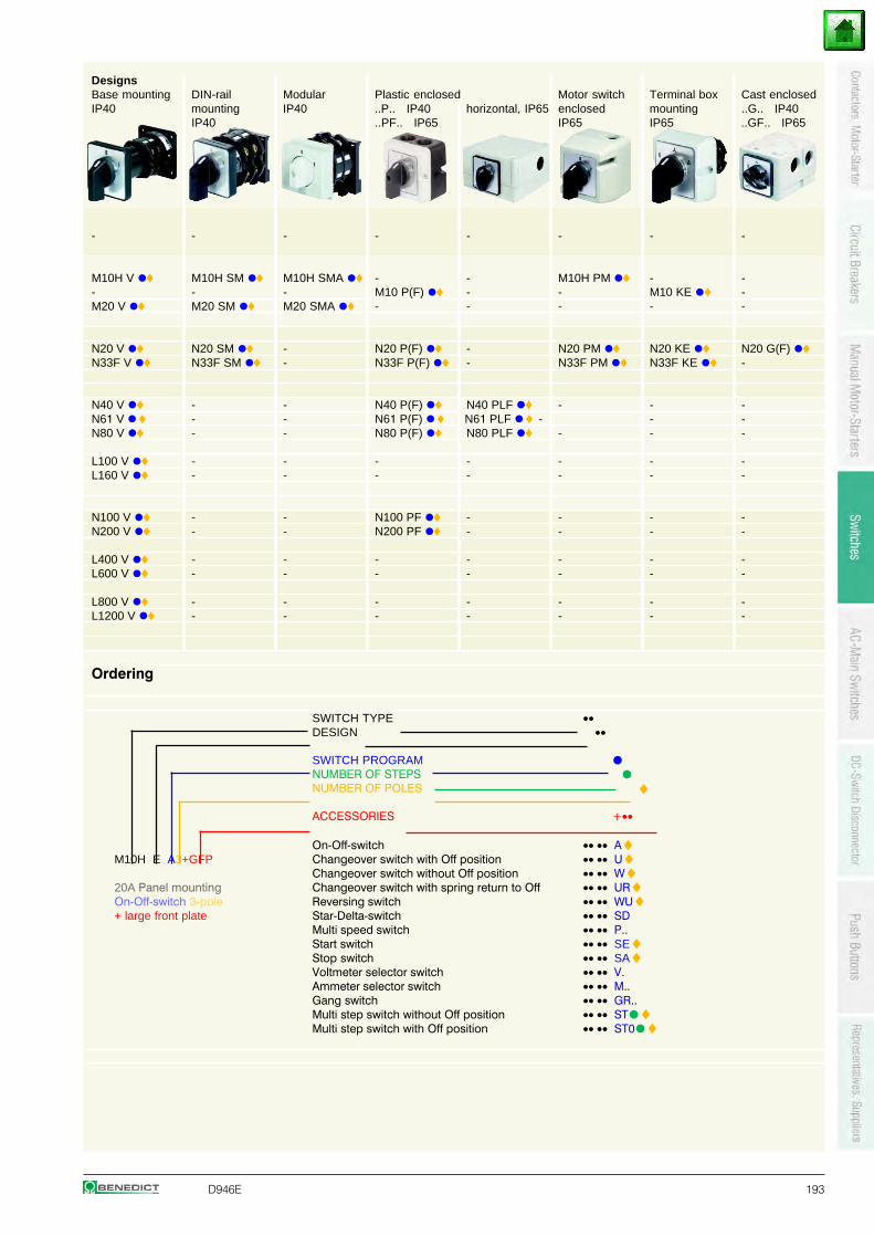
D946E 193
DesignsBase mounting DIN-rail Modular Plastic enclosed Motor switch Terminal box Cast enclosedIP40 mounting IP40 ..P.. IP40 horizontal, IP65 enclosed mounting ..G.. IP40
IP40 ..PF.. IP65 IP65 IP65 ..GF.. IP65
- - - - - - - -
M10H V •♦ M10H SM •♦ M10H SMA •♦ - - M10H PM •♦ - -- - - M10 P(F) •♦ - - M10 KE •♦ -M20 V •♦ M20 SM •♦ M20 SMA •♦ - - - - -
N20 V •♦ N20 SM •♦ - N20 P(F) •♦ - N20 PM •♦ N20 KE •♦ N20 G(F) •♦N33F V •♦ N33F SM •♦ - N33F P(F) •♦ - N33F PM •♦ N33F KE •♦ -
N40 V •♦ - - N40 P(F) •♦ N40 PLF •♦ - - -N61 V •♦ - - N61 P(F) •♦ N61 PLF •♦ - - -N80 V •♦ - - N80 P(F) •♦ N80 PLF •♦ - - -
L100 V •♦ - - - - - - -L160 V •♦ - - - - - - -
N100 V •♦ - - N100 PF •♦ - - - -N200 V •♦ - - N200 PF •♦ - - - -
L400 V •♦ - - - - - - -L600 V •♦ - - - - - - -
L800 V •♦ - - - - - - -L1200 V •♦ - - - - - - -
Ordering
SWITCH TYPE ••DESIGN ••
SWITCH PROGRAM •NUMBER OF STEPS •NUMBER OF POLES ♦ACCESSORIES +••
On-Off-switch •• •• A♦M10H E A3+GFP Changeover switch with Off position •• •• U♦
Changeover switch without Off position •• •• W♦20A Panel mounting Changeover switch with spring return to Off •• •• UR♦On-Off-switch 3-pole Reversing switch •• •• WU♦+ large front plate Star-Delta-switch •• •• SD
Multi speed switch •• •• P..Start switch •• •• SE♦Stop switch •• •• SA♦Voltmeter selector switch •• •• V.Ammeter selector switch •• •• M..Gang switch •• •• GR..Multi step switch without Off position •• •• ST•♦Multi step switch with Off position •• •• ST0•♦
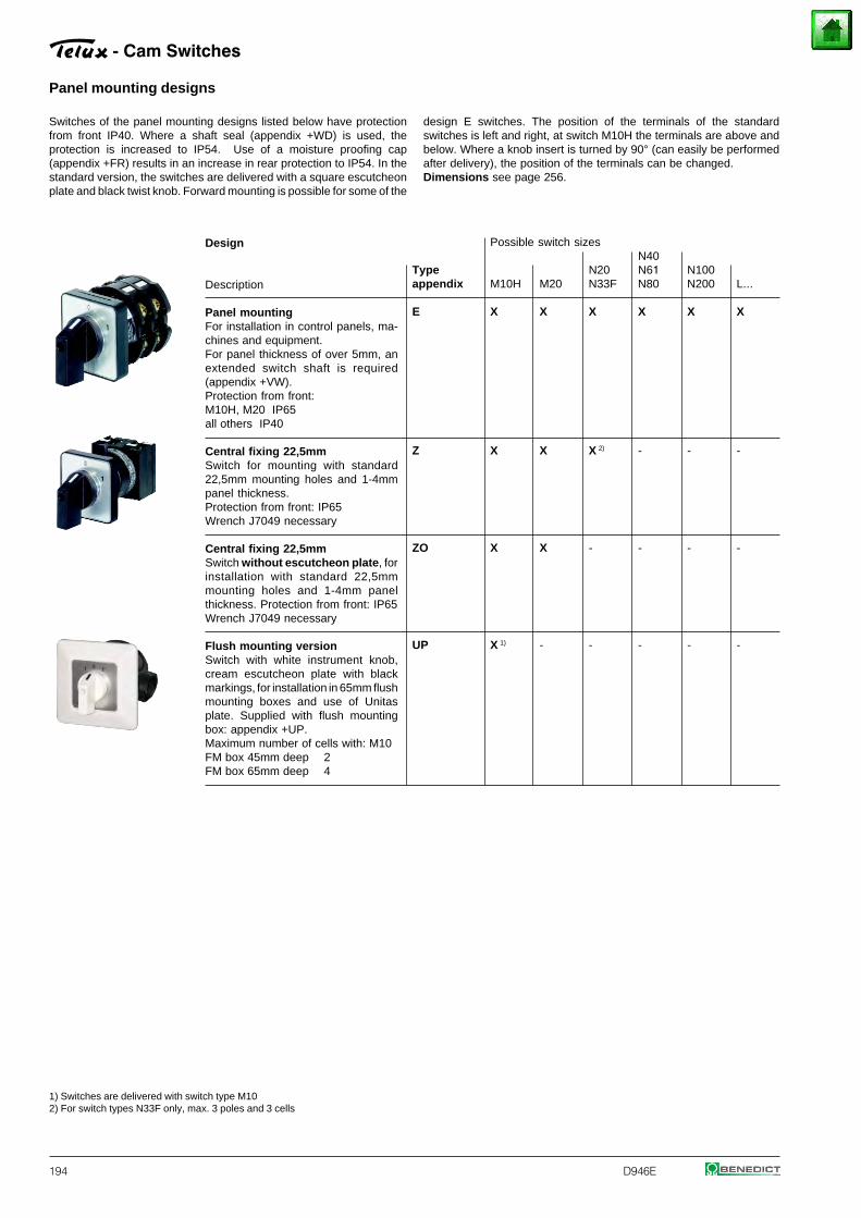
194 D946E
Panel mounting designs
Design
Description
Panel mountingFor installation in control panels, ma-chines and equipment.For panel thickness of over 5mm, anextended switch shaft is required(appendix +VW).Protection from front:M10H, M20 IP65all others IP40
Central fixing 22,5mmSwitch for mounting with standard22,5mm mounting holes and 1-4mmpanel thickness.Protection from front: IP65Wrench J7049 necessary
Central fixing 22,5mmSwitch without escutcheon plate, forinstallation with standard 22,5mmmounting holes and 1-4mm panelthickness. Protection from front: IP65Wrench J7049 necessary
Flush mounting versionSwitch with white instrument knob,cream escutcheon plate with blackmarkings, for installation in 65mm flushmounting boxes and use of Unitasplate. Supplied with flush mountingbox: appendix +UP.Maximum number of cells with: M10FM box 45mm deep 2FM box 65mm deep 4
Possible switch sizesN40
Type N20 N61 N100appendix M10H M20 N33F N80 N200 L...
E X X X X X X
Z X X X 2) - - -
ZO X X - - - -
UP X 1) - - - - -
- Cam Switches
1) Switches are delivered with switch type M102) For switch types N33F only, max. 3 poles and 3 cells
Switches of the panel mounting designs listed below have protectionfrom front IP40. Where a shaft seal (appendix +WD) is used, theprotection is increased to IP54. Use of a moisture proofing cap(appendix +FR) results in an increase in rear protection to IP54. In thestandard version, the switches are delivered with a square escutcheonplate and black twist knob. Forward mounting is possible for some of the
design E switches. The position of the terminals of the standardswitches is left and right, at switch M10H the terminals are above andbelow. Where a knob insert is turned by 90° (can easily be performedafter delivery), the position of the terminals can be changed.Dimensions see page 256.
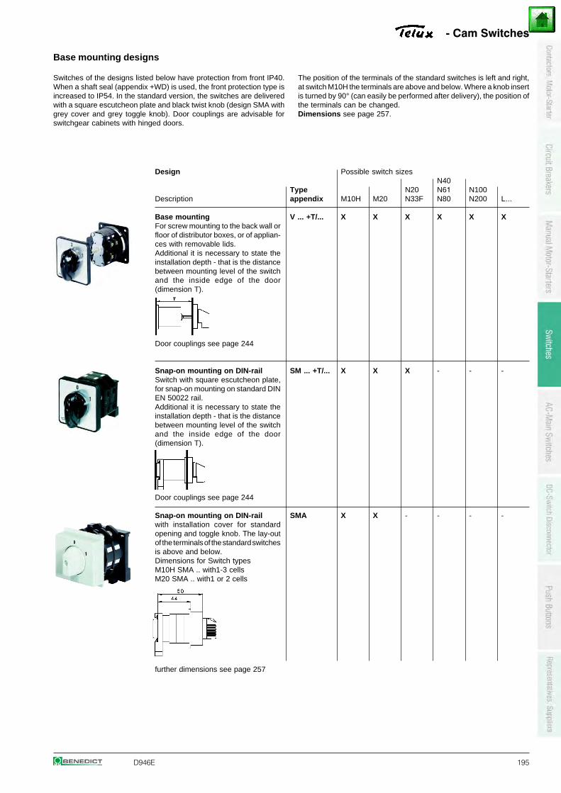
D946E 195
Base mounting designs
Design
Description
Base mountingFor screw mounting to the back wall orfloor of distributor boxes, or of applian-ces with removable lids.Additional it is necessary to state theinstallation depth - that is the distancebetween mounting level of the switchand the inside edge of the door(dimension T).
Door couplings see page 244
Snap-on mounting on DIN-railSwitch with square escutcheon plate,for snap-on mounting on standard DINEN 50022 rail.Additional it is necessary to state theinstallation depth - that is the distancebetween mounting level of the switchand the inside edge of the door(dimension T).
Door couplings see page 244
Snap-on mounting on DIN-railwith installation cover for standardopening and toggle knob. The lay-outof the terminals of the standard switchesis above and below.Dimensions for Switch typesM10H SMA .. with1-3 cellsM20 SMA .. with1 or 2 cells
further dimensions see page 257
- Cam Switches
Possible switch sizesN40
Type N20 N61 N100appendix M10H M20 N33F N80 N200 L...
V ... +T/... X X X X X X
SM ... +T/... X X X - - -
SMA X X - - - -
Switches of the designs listed below have protection from front IP40.When a shaft seal (appendix +WD) is used, the front protection type isincreased to IP54. In the standard version, the switches are deliveredwith a square escutcheon plate and black twist knob (design SMA withgrey cover and grey toggle knob). Door couplings are advisable forswitchgear cabinets with hinged doors.
The position of the terminals of the standard switches is left and right,at switch M10H the terminals are above and below. Where a knob insertis turned by 90° (can easily be performed after delivery), the position ofthe terminals can be changed.Dimensions see page 257.
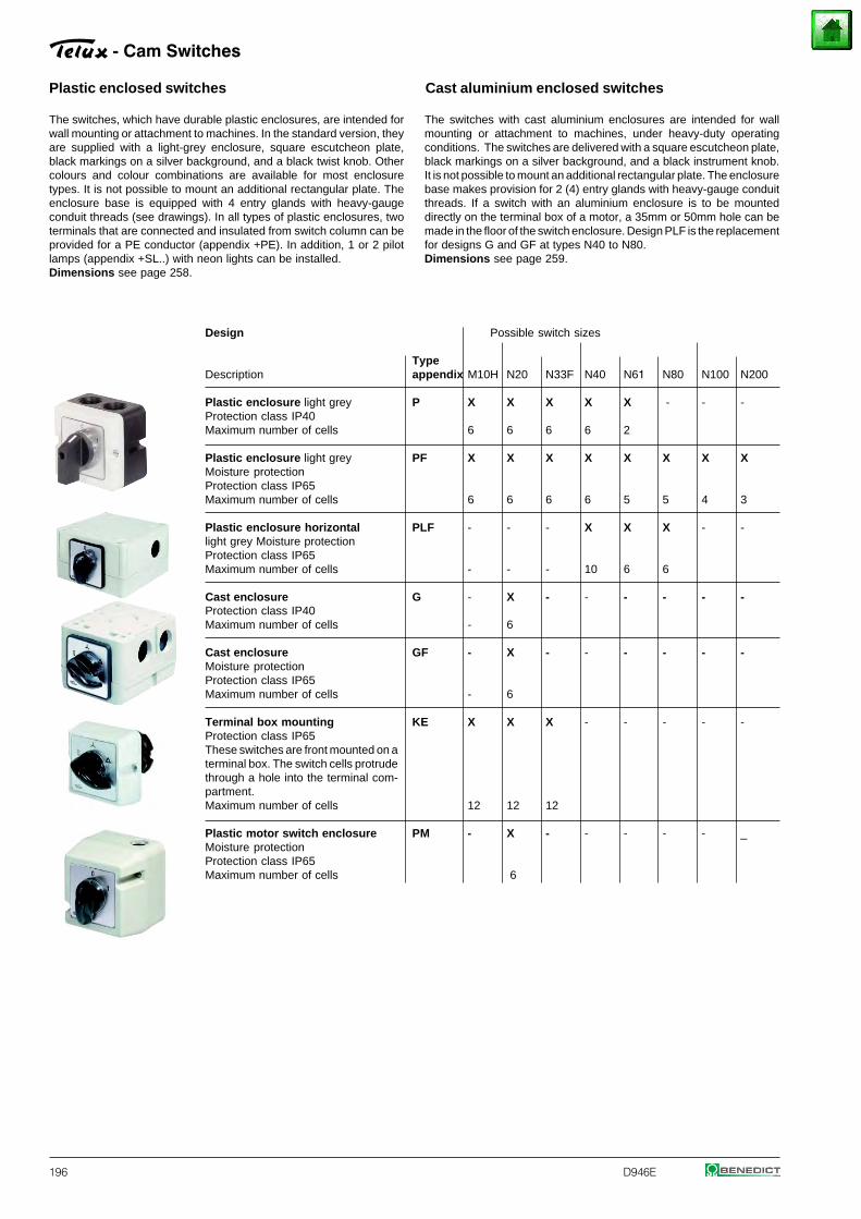
196 D946E
Possible switch sizes
Typeappendix M10H N20 N33F N40 N61 N80 N100 N200
P X X X X X - - -
6 6 6 6 2
PF X X X X X X X X
6 6 6 6 5 5 4 3
PLF - - - X X X - -
- - - 10 6 6
G - X - - - - - -
- 6
GF - X - - - - - -
- 6
KE X X X - - - - -
12 12 12
PM - X - - - - - _
6
Plastic enclosed switches Cast aluminium enclosed switches
Design
Description
Plastic enclosure light greyProtection class IP40Maximum number of cells
Plastic enclosure light greyMoisture protectionProtection class IP65Maximum number of cells
Plastic enclosure horizontallight grey Moisture protectionProtection class IP65Maximum number of cells
Cast enclosureProtection class IP40Maximum number of cells
Cast enclosureMoisture protectionProtection class IP65Maximum number of cells
Terminal box mountingProtection class IP65These switches are front mounted on aterminal box. The switch cells protrudethrough a hole into the terminal com-partment.Maximum number of cells
Plastic motor switch enclosureMoisture protectionProtection class IP65Maximum number of cells
- Cam Switches
The switches, which have durable plastic enclosures, are intended forwall mounting or attachment to machines. In the standard version, theyare supplied with a light-grey enclosure, square escutcheon plate,black markings on a silver background, and a black twist knob. Othercolours and colour combinations are available for most enclosuretypes. It is not possible to mount an additional rectangular plate. Theenclosure base is equipped with 4 entry glands with heavy-gaugeconduit threads (see drawings). In all types of plastic enclosures, twoterminals that are connected and insulated from switch column can beprovided for a PE conductor (appendix +PE). In addition, 1 or 2 pilotlamps (appendix +SL..) with neon lights can be installed.Dimensions see page 258.
The switches with cast aluminium enclosures are intended for wallmounting or attachment to machines, under heavy-duty operatingconditions. The switches are delivered with a square escutcheon plate,black markings on a silver background, and a black instrument knob.It is not possible to mount an additional rectangular plate. The enclosurebase makes provision for 2 (4) entry glands with heavy-gauge conduitthreads. If a switch with an aluminium enclosure is to be mounteddirectly on the terminal box of a motor, a 35mm or 50mm hole can bemade in the floor of the switch enclosure. Design PLF is the replacementfor designs G and GF at types N40 to N80.Dimensions see page 259.
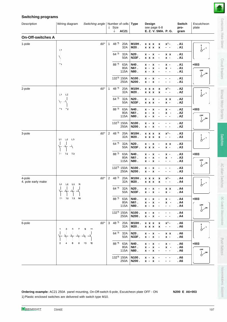
Description Wiring diagram Switching angle Number of cells Type Design Switch Escutcheon↓ Size see page 6-8 pro- plate
↓ AC21 E. Z. V. SMA. P. G. gram
Switching programs
D946E 197
On-Off-switches A
1-pole 60° 1 48 20A M10H . x x x x x1) - . A132A M20 . x x x x - - . A1
64 32A N20 . x - x - x x . A150A N33F . x x x - x - . A1
88 63A N40 . x - x - x - . A1 +00380A N61 . x - x - x - . A1
115A N80 . x - x - - - . A1
132 150A N100 . x - x - - - . A1250A N200 . x - x - - - . A1
2-pole 60° 1 48 20A M10H . x x x x x1) - . A232A M20 . x x x x - - . A2
64 32A N20 . x - x - x x . A250A N33F . x x x - x - . A2
88 63A N40 . x - x - x - . A2 +00380A N61 . x - x - x - . A2
115A N80 . x - x - - - . A2
132 150A N100 . x - x - - - . A2250A N200 . x - x - - - . A2
3-pole 60° 2 48 20A M10H . x x x x x1) - . A332A M20 . x x x x - - . A3
64 32A N20 . x - x - x x . A350A N33F . x x x - x - . A3
88 63A N40 . x - x - x - . A3 +00380A N61 . x - x - x - . A3
115A N80 . x - x - - - . A3
132 150A N100 . x - x - - - . A3250A N200 . x - x - - - . A3
4-pole 60° 2 48 20A M10H . x x x x x1) - . A44. pole early make 32A M20 . x x x x - - . A4
64 32A N20 . x - x - x x . A450A N33F . x - x - x - . A4
88 63A N40 . x - x - x - . A4 +00380A N61 . x - x - x - . A4
115A N80 . x - x - - - . A4
132 150A N100 . x - x - - - . A4250A N200 . x - x - - - . A4
6-pole 60° 3 48 20A M10H . x x x x x1) - . A632A M20 . x x x x - - . A6
64 32A N20 . x - x - x x . A650A N33F . x - x - x - . A6
88 63A N40 . x - x - x - . A6 +00380A N61 . x - x - x - . A6
115A N80 . x - x - - - . A6
132 150A N100 . x - x - - - . A6250A N200 . x - x - - - . A6
Ordering example: AC21 250A panel mounting, On-Off-switch 6-pole, Escutcheon plate OFF - ON N200 E A6+003
1) Plastic enclosed switches are delivered with switch type M10.
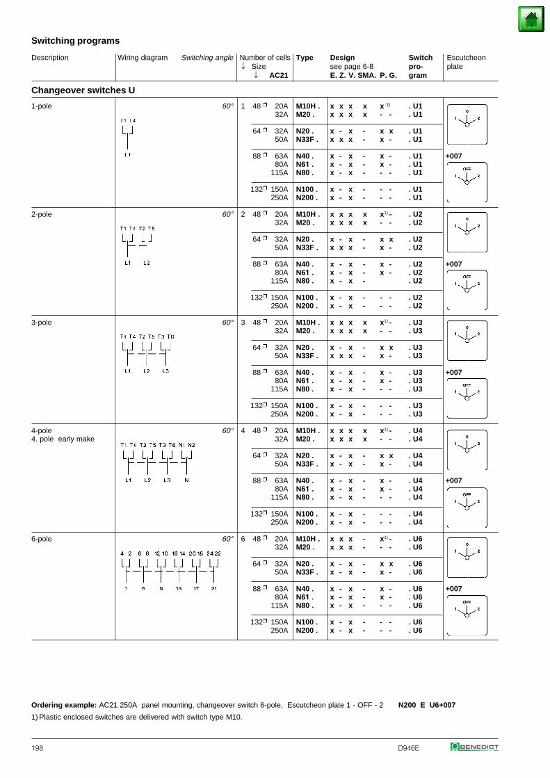
Description Wiring diagram Switching angle Number of cells Type Design Switch Escutcheon↓ Size see page 6-8 pro- plate
↓ AC21 E. Z. V. SMA. P. G. gram
Switching programs
198 D946E
Changeover switches U
1-pole 60° 1 48 20A M10H . x x x x x 1) . U132A M20 . x x x x - - . U1
64 32A N20 . x - x - x x . U150A N33F . x x x - x - . U1
88 63A N40 . x - x - x - . U1 +00780A N61 . x - x - x - . U1
115A N80 . x - x - - - . U1
132 150A N100 . x - x - - - . U1250A N200 . x - x - - - . U1
2-pole 60° 2 48 20A M10H . x x x x x1) - . U232A M20 . x x x x - - . U2
64 32A N20 . x - x - x x . U250A N33F . x x x - x - . U2
88 63A N40 . x - x - x - . U2 +00780A N61 . x - x - x - . U2
115A N80 . x - x - . U2
132 150A N100 . x - x - - - . U2250A N200 . x - x - - - . U2
3-pole 60° 3 48 20A M10H . x x x x x1) - . U332A M20 . x x x x - - . U3
64 32A N20 . x - x - x x . U350A N33F . x x x - x - . U3
88 63A N40 . x - x - x - . U3 +00780A N61 . x - x - x - . U3
115A N80 . x - x - - - . U3
132 150A N100 . x - x - - - . U3250A N200 . x - x - - - . U3
4-pole 60° 4 48 20A M10H . x x x x x1) - . U44. pole early make 32A M20 . x x x x - - . U4
64 32A N20 . x - x - x x . U450A N33F . x - x - x - . U4
88 63A N40 . x - x - x - . U4 +00780A N61 . x - x - x - . U4
115A N80 . x - x - - - . U4
132 150A N100 . x - x - - - . U4250A N200 . x - x - - - . U4
6-pole 60° 6 48 20A M10H . x x x - x1) - . U632A M20 . x x x - - - . U6
64 32A N20 . x - x - x x . U650A N33F . x - x - x - . U6
88 63A N40 . x - x - x - . U6 +00780A N61 . x - x - x - . U6
115A N80 . x - x - - - . U6
132 150A N100 . x - x - - - . U6250A N200 . x - x - - - . U6
Ordering example: AC21 250A panel mounting, changeover switch 6-pole, Escutcheon plate 1 - OFF - 2 N200 E U6+007
1) Plastic enclosed switches are delivered with switch type M10.
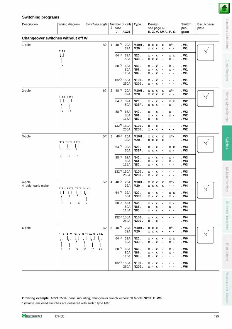
Description Wiring diagram Switching angle Number of cells Type Design Switch Escutcheon↓ Size see page 6-8 pro- plate
↓ AC21 E. Z. V. SMA. P. G. gram
Switching programs
D946E 199
Changeover switches without off W
1-pole 60° 1 48 20A M10H . x x x x x1) - . W132A M20 . x x x x - - . W1
64 32A N20 . x - x - x x . W150A N33F . x x x - x - . W1
88 63A N40 . x - x - x - . W180A N61 . x - x - x - . W1
115A N80 . x - x - - - . W1
132 150A N100 . x - x - - - . W1250A N200 . x - x - - - . W1
2-pole 60° 2 48 20A M10H . x x x x x1) - . W232A M20 . x x x x - - . W2
64 32A N20 . x - x - x x . W250A N33F . x x x - x - . W2
88 63A N40 . x - x - x - . W280A N61 . x - x - x - . W2
115A N80 . x - x - - - . W2
132 150A N100 . x - x - - - . W2250A N200 . x - x - - - . W2
3-pole 60° 3 48 20A M10H . x x x x x1) - . W332A M20 . x x x x - - . W3
64 32A N20 . x - x - x x . W350A N33F . x x x - x - . W3
88 63A N40 . x - x - x - . W380A N61 . x - x - x - . W3
115A N80 . x - x - - - . W3
132 150A N100 . x - x - - - . W3250A N200 . x - x - - - . W3
4-pole 60° 4 48 20A M10H . x x x x x1) - . W44. pole early make 32A M20 . x x x x - - . W4
64 32A N20 . x - x - x x . W450A N33F . x - x - x - . W4
88 63A N40 . x - x - x - . W480A N61 . x - x - x - . W4
115A N80 . x - x - - - . W4
132 150A N100 . x - x - - - . W4250A N200 . x - x - - - . W4
6-pole 60° 6 48 20A M10H . x x x - x1) - . W632A M20 . x x x - - - . W6
64 32A N20 . x - x - x x . W650A N33F . x - x - x - . W6
88 63A N40 . x - x - x - . W680A N61 . x - x - x - . W6
115A N80 . x - x - - - . W6
132 150A N100 . x - x - - - . W6250A N200 . x - x - - - . W6
Ordering example: AC21 250A panel mounting, changeover switch without off 6-pole,N200 E W6
1) Plastic enclosed switches are delivered with switch type M10.
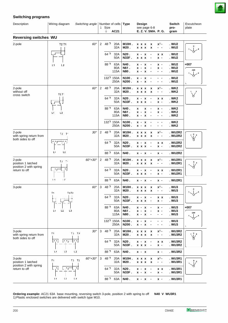
Description Wiring diagram Switching angle Number of cells Type Design Switch Escutcheon↓ Size see page 6-8 pro- plate
↓ AC21 E. Z. V. SMA. P. G. gram
Switching programs
200 D946E
Reversing switches WU
2-pole 60° 2 48 20A M10H . x x x x x1) - . WU232A M20 . x x x x - - . WU2
64 32A N20 . x - x - x x . WU250A N33F . x x x - x - . WU2
88 63A N40 . x - x - x - . WU2 +00780A N61 . x - x - x - . WU2
115A N80 . x - x - - - . WU2
132 150A N100 . x - x - - - . WU2250A N200 . x - x - - - . WU2
2-pole 60° 2 48 20A M10H . x x x x x1) - . WK2without off 32A M20 . x x x x - - . WK2cross switch
64 32A N20 . x - x - x x . WK250A N33F . x x x - x - . WK2
88 63A N40 . x x - x - . WK280A N61 . x - x - x - . WK2
115A N80 . x - x - - - . WK2
132 150A N100 . x - x - - - . WK2250A N200 . x - x - - - . WK2
2-pole 30° 2 48 20A M10H . x x x x x1) - . WU2R2with spring return from 32A M20 . x x x x - - . WU2R2both sides to off
64 32A N20 . x - x - x x . WU2R250A N33F . x x x - x - . WU2R2
88 63A N40 . x - x - x - . WU2R2
2-pole 60°+30° 2 48 20A M10H . x x x x x1) - . WU2R1position 1 latched 32A M20 . x x x x - - . WU2R1position 2 with springreturn to off 64 32A N20 . x - x - x x . WU2R1
50A N33F . x x x - x - . WU2R1
88 63A N40 . x - x - x - . WU2R1
3-pole 60° 3 48 20A M10H . x x x x x1) - . WU332A M20 . x x x x - - . WU3
64 32A N20 . x - x - x x . WU350A N33F . x x x - x - . WU3
88 63A N40 . x - x - x - . WU3 +00780A N61 . x - x - x - . WU3
115A N80 . x - x - - - . WU3
132 150A N100 . x - x - - - . WU3250A N200 . x - x - - - . WU3
3-pole 30° 3 48 20A M10H . x x x x x1) - . WU3R2with spring return from 32A M20 . x x x x - - . WU3R2both sides to off
64 32A N20 . x - x - x x . WU3R250A N33F . x x x - x - . WU3R2
88 63A N40 . x - x x - . WU3R2
3-pole 60°+30° 3 48 20A M10H . x x x x x1) - . WU3R1position 1 latched 32A M20 . x x x x - - . WU3R1position 2 with springreturn to off 64 32A N20 . x - x - x x . WU3R1
50A N33F . x - x - x - . WU3R1
88 63A N40 . x - x - x - . WU3R1
Ordering example: AC21 63A base mounting, reversing switch 3-pole, position 2 with spring to off N40 V WU3R11) Plastic enclosed switches are delivered with switch type M10.
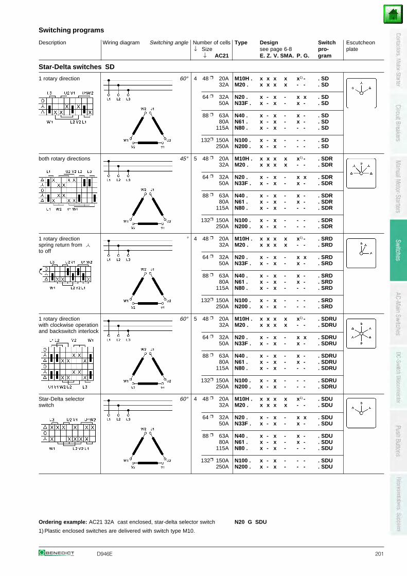
Description Wiring diagram Switching angle Number of cells Type Design Switch Escutcheon↓ Size see page 6-8 pro- plate
↓ AC21 E. Z. V. SMA. P. G. gram
Switching programs
D946E 201
Star-Delta switches SD
1 rotary direction 60° 4 48 20A M10H . x x x x x1) - . SD32A M20 . x x x x - - . SD
64 32A N20 . x - x - x x . SD50A N33F . x - x - x - . SD
88 63A N40 . x - x - x - . SD80A N61 . x - x - x - . SD
115A N80 . x - x - - - . SD
132 150A N100 . x - x - - - . SD250A N200 . x - x - - - . SD
both rotary directions 45° 5 48 20A M10H . x x x x x1) - . SDR32A M20 . x x x x - - . SDR
64 32A N20 . x - x - x x . SDR50A N33F . x - x - x - . SDR
88 63A N40 . x - x - x - . SDR80A N61 . x - x - x - . SDR
115A N80 . x - x - - - . SDR
132 150A N100 . x - x - - - . SDR250A N200 . x - x - - - . SDR
1 rotary direction 30°+60° 4 48 20A M10H . x x x x x1) - . SRDspring return from 32A M20 . x x x x - - . SRDto off
64 32A N20 . x - x - x x . SRD50A N33F . x - x - x - . SRD
88 63A N40 . x - x - x - . SRD80A N61 . x - x - x - . SRD
115A N80 . x - x - - - . SRD
132 150A N100 . x - x - - - . SRD250A N200 . x - x - - - . SRD
1 rotary direction 60° 5 48 20A M10H . x x x x x1) - . SDRUwith clockwise operation 32A M20 . x x x x - - . SDRUand backswitch interlock
64 32A N20 . x - x - x x . SDRU50A N33F . x - x - x - . SDRU
88 63A N40 . x - x - x - . SDRU80A N61 . x - x - x - . SDRU
115A N80 . x - x - - - . SDRU
132 150A N100 . x - x - - - . SDRU250A N200 . x - x - - - . SDRU
Star-Delta selector 60° 4 48 20A M10H . x x x x x1) - . SDUswitch 32A M20 . x x x x - - . SDU
64 32A N20 . x - x - x x . SDU50A N33F . x - x - x - . SDU
88 63A N40 . x - x - x - . SDU80A N61 . x - x - x - . SDU
115A N80 . x - x - - - . SDU
132 150A N100 . x - x - - - . SDU250A N200 . x - x - - - . SDU
Ordering example: AC21 32A cast enclosed, star-delta selector switch N20 G SDU
1) Plastic enclosed switches are delivered with switch type M10.
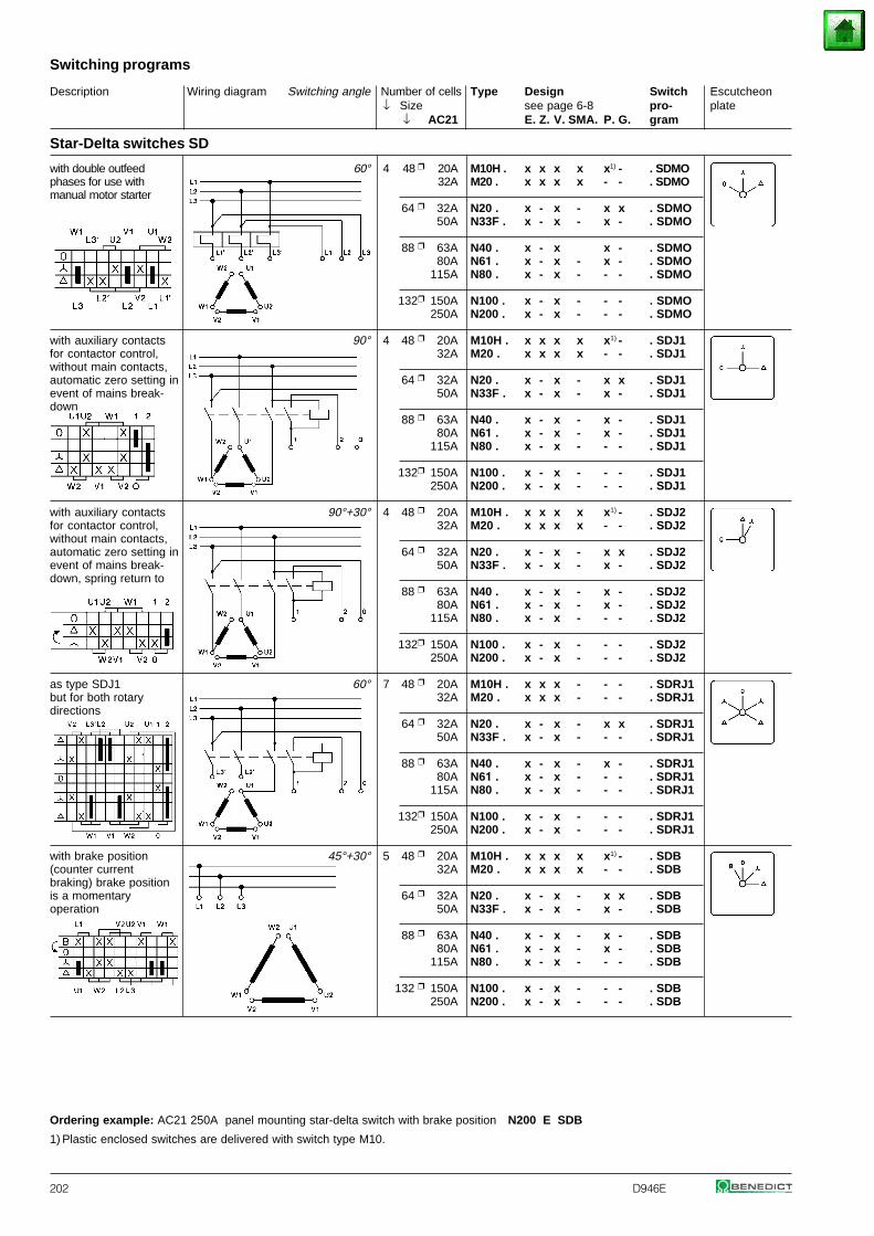
Description Wiring diagram Switching angle Number of cells Type Design Switch Escutcheon↓ Size see page 6-8 pro- plate
↓ AC21 E. Z. V. SMA. P. G. gram
Switching programs
202 D946E
Star-Delta switches SD
with double outfeed 60° 4 48 20A M10H . x x x x x1) - . SDMOphases for use with 32A M20 . x x x x - - . SDMOmanual motor starter
64 32A N20 . x - x - x x . SDMO50A N33F . x - x - x - . SDMO
88 63A N40 . x - x x - . SDMO80A N61 . x - x - x - . SDMO
115A N80 . x - x - - - . SDMO
132 150A N100 . x - x - - - . SDMO250A N200 . x - x - - - . SDMO
with auxiliary contacts 90° 4 48 20A M10H . x x x x x1) - . SDJ1for contactor control, 32A M20 . x x x x - - . SDJ1without main contacts,automatic zero setting in 64 32A N20 . x - x - x x . SDJ1event of mains break- 50A N33F . x - x - x - . SDJ1down
88 63A N40 . x - x - x - . SDJ180A N61 . x - x - x - . SDJ1
115A N80 . x - x - - - . SDJ1
132 150A N100 . x - x - - - . SDJ1250A N200 . x - x - - - . SDJ1
with auxiliary contacts 90°+30° 4 48 20A M10H . x x x x x1) - . SDJ2for contactor control, 32A M20 . x x x x - - . SDJ2without main contacts,automatic zero setting in 64 32A N20 . x - x - x x . SDJ2event of mains break- 50A N33F . x - x - x - . SDJ2down, spring return to
88 63A N40 . x - x - x - . SDJ280A N61 . x - x - x - . SDJ2
115A N80 . x - x - - - . SDJ2
132 150A N100 . x - x - - - . SDJ2250A N200 . x - x - - - . SDJ2
as type SDJ1 60° 7 48 20A M10H . x x x - - - . SDRJ1but for both rotary 32A M20 . x x x - - - . SDRJ1directions
64 32A N20 . x - x - x x . SDRJ150A N33F . x - x - - - . SDRJ1
88 63A N40 . x - x - x - . SDRJ180A N61 . x - x - - - . SDRJ1
115A N80 . x - x - - - . SDRJ1
132 150A N100 . x - x - - - . SDRJ1250A N200 . x - x - - - . SDRJ1
with brake position 45°+30° 5 48 20A M10H . x x x x x1) - . SDB(counter current 32A M20 . x x x x - - . SDBbraking) brake positionis a momentary 64 32A N20 . x - x - x x . SDBoperation 50A N33F . x - x - x - . SDB
88 63A N40 . x - x - x - . SDB80A N61 . x - x - x - . SDB
115A N80 . x - x - - - . SDB
132 150A N100 . x - x - - - . SDB250A N200 . x - x - - - . SDB
Ordering example: AC21 250A panel mounting star-delta switch with brake position N200 E SDB
1) Plastic enclosed switches are delivered with switch type M10.
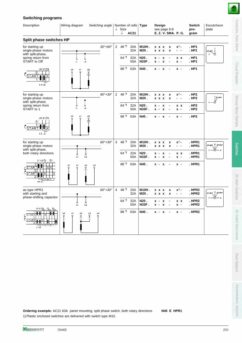
Description Wiring diagram Switching angle Number of cells Type Design Switch Escutcheon↓ Size see page 6-8 pro- plate
↓ AC21 E. Z. V. SMA. P. G. gram
Switching programs
D946E 203
Split phase switches HP
for starting up 30°+60° 2 48 20A M10H . x x x x x1) - . HP1single-phase motors 32A M20 . x x x x - - . HP1with split-phase,spring return from 64 32A N20 . x - x - x x . HP1START to Off 50A N33F . x - x - x - . HP1
88 63A N40 . x - x - x - . HP1
for starting up 90°+30° 2 48 20A M10H . x x x x x1) - . HP2single-phase motors 32A M20 . x x x x - - . HP2with split-phase,spring return from 64 32A N20 . x - x - x x . HP2START to 1 50A N33F . x - x - x - . HP2
88 63A N40 . x - x - x - . HP2
for starting up 60°+30° 3 48 20A M10H . x x x x x1) - . HPR1single-phase motors 32A M20 . x x x x - - . HPR1with split-phase,both rotary directions 64 32A N20 . x - x - x x . HPR1
50A N33F . x - x - x - . HPR1
88 63A N40 . x - x - x - . HPR1
as type HPR1 60°+30° 4 48 20A M10H . x x x x x1) - . HPR2with starting and 32A M20 . x x x x - - . HPR2phase-shifting capacitor
64 32A N20 . x - x - x x . HPR250A N33F . x - x - x - . HPR2
88 63A N40 . x - x - x - . HPR2
Ordering example: AC21 63A panel mounting, split phase switch, both rotary directions N40 E HPR1
1) Plastic enclosed switches are delivered with switch type M10.
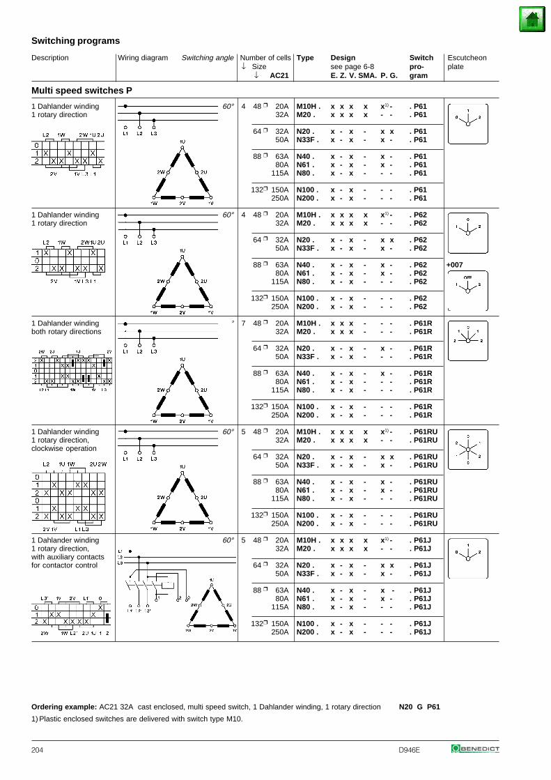
Description Wiring diagram Switching angle Number of cells Type Design Switch Escutcheon↓ Size see page 6-8 pro- plate
↓ AC21 E. Z. V. SMA. P. G. gram
Switching programs
204 D946E
Multi speed switches P
1 Dahlander winding 60° 4 48 20A M10H . x x x x x1) - . P611 rotary direction 32A M20 . x x x x - - . P61
64 32A N20 . x - x - x x . P6150A N33F . x - x - x - . P61
88 63A N40 . x - x - x - . P6180A N61 . x - x - x - . P61
115A N80 . x - x - - - . P61
132 150A N100 . x - x - - - . P61250A N200 . x - x - - - . P61
1 Dahlander winding 60° 4 48 20A M10H . x x x x x1) - . P621 rotary direction 32A M20 . x x x x - - . P62
64 32A N20 . x - x - x x . P6250A N33F . x - x - x - . P62
88 63A N40 . x - x - x - . P62 +00780A N61 . x - x - x - . P62
115A N80 . x - x - - - . P62
132 150A N100 . x - x - - - . P62250A N200 . x - x - - - . P62
1 Dahlander winding 45° 7 48 20A M10H . x x x - - - . P61Rboth rotary directions 32A M20 . x x x - - - . P61R
64 32A N20 . x - x - x - . P61R50A N33F . x - x - - - . P61R
88 63A N40 . x - x - x - . P61R80A N61 . x - x - - - . P61R
115A N80 . x - x - - - . P61R
132 150A N100 . x - x - - - . P61R250A N200 . x - x - - - . P61R
1 Dahlander winding 60° 5 48 20A M10H . x x x x x1) - . P61RU1 rotary direction, 32A M20 . x x x x - - . P61RUclockwise operation
64 32A N20 . x - x - x x . P61RU50A N33F . x - x - x - . P61RU
88 63A N40 . x - x - x - . P61RU80A N61 . x - x - x - . P61RU
115A N80 . x - x - - - . P61RU
132 150A N100 . x - x - - - . P61RU250A N200 . x - x - - - . P61RU
1 Dahlander winding 60° 5 48 20A M10H . x x x x x1) - . P61J1 rotary direction, 32A M20 . x x x x - - . P61Jwith auxiliary contactsfor contactor control 64 32A N20 . x - x - x x . P61J
50A N33F . x - x - x - . P61J
88 63A N40 . x - x - x - . P61J80A N61 . x - x - x - . P61J
115A N80 . x - x - - - . P61J
132 150A N100 . x - x - - - . P61J250A N200 . x - x - - - . P61J
Ordering example: AC21 32A cast enclosed, multi speed switch, 1 Dahlander winding, 1 rotary direction N20 G P61
1) Plastic enclosed switches are delivered with switch type M10.
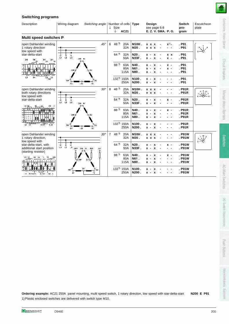
Description Wiring diagram Switching angle Number of cells Type Design Switch Escutcheon↓ Size see page 6-8 pro- plate
↓ AC21 E. Z. V. SMA. P. G. gram
Switching programs
D946E 205
Multi speed switches P
open Dahlander winding 45° 6 48 20A M10H . x x x - x1) - . P911 rotary direction 32A M20 . x x x - - - . P91low speed withstar-delta-start 64 32A N20 . x - x - x x . P91
50A N33F . x - x - x - . P91
88 63A N40 . x - x - x - . P9180A N61 . x - x - x - . P91
115A N80 . x - x - - - . P91
132 150A N100 . x - x - - - . P91250A N200 . x - x - - - . P91
open Dahlander winding 30° 8 48 20A M10H . x x x - - - . P91Rboth rotary directions 32A M20 . x x x - - - . P91Rlow speed withstar-delta-start 64 32A N20 . x - x - x - . P91R
50A N33F . x - x - - - . P91R
88 63A N40 . x - x - x - . P91R80A N61 . x - x - - - . P91R
115A N80 . x - x - - - . P91R
132 150A N100 . x - x - - - . P91R250A N200 . x - x - - - . P91R
open Dahlander winding 30° 7 48 20A M10H . x x x - - - . P91W1 rotary direction, 32A M20 . x x x - - - . P91Wlow speed withstar-delta-start, with 64 32A N20 . x - x - x - . P91Wadditional start position 50A N33F . x - x - - - . P91W(starting resistor)
88 63A N40 . x - x - x - . P91W80A N61 . x - x - - - . P91W
115A N80 . x - x - - - . P91W
132 150A N100 . x - x - - - . P91W250A N200 . x - x - - - . P91W
Ordering example: AC21 250A panel mounting, multi speed switch, 1 rotary direction, low speed with star-delta-start N200 E P91
1) Plastic enclosed switches are delivered with switch type M10.
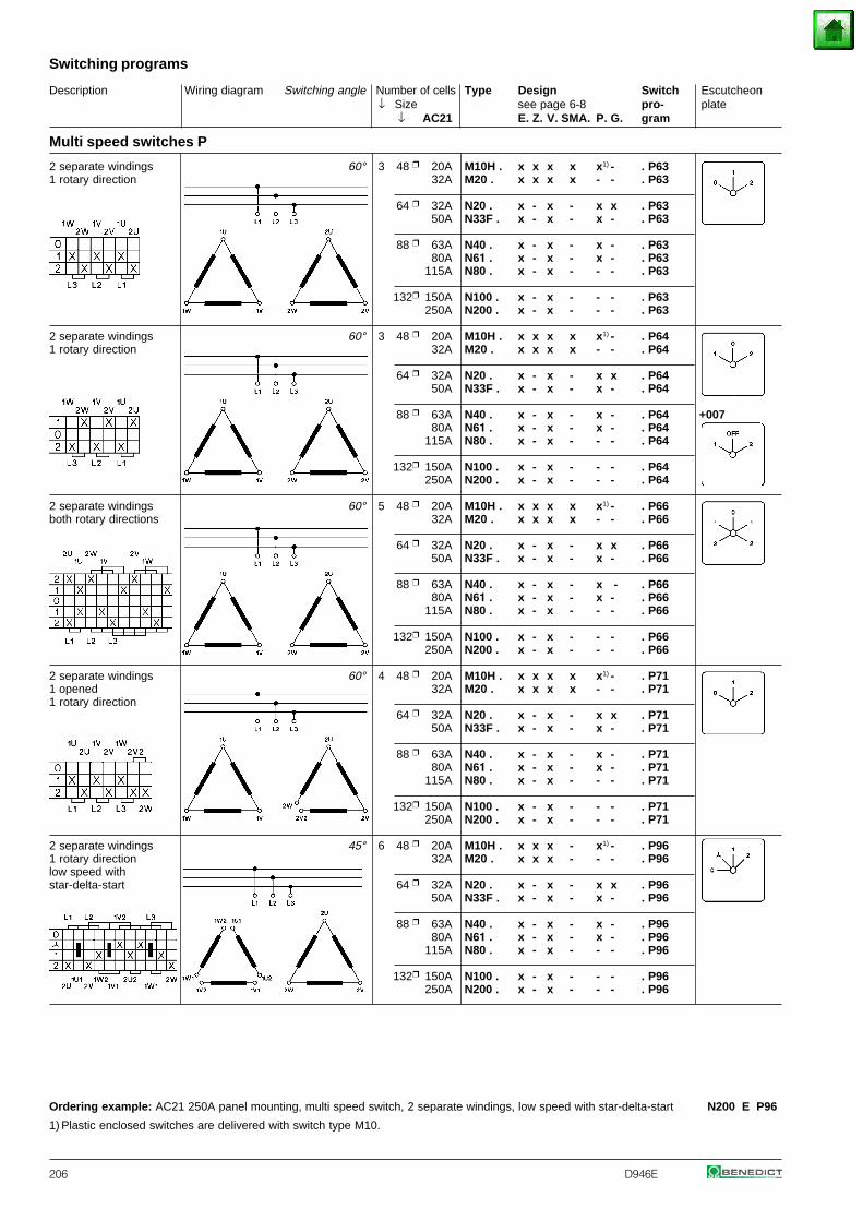
Description Wiring diagram Switching angle Number of cells Type Design Switch Escutcheon↓ Size see page 6-8 pro- plate
↓ AC21 E. Z. V. SMA. P. G. gram
Switching programs
206 D946E
Multi speed switches P
2 separate windings 60° 3 48 20A M10H . x x x x x1) - . P631 rotary direction 32A M20 . x x x x - - . P63
64 32A N20 . x - x - x x . P6350A N33F . x - x - x - . P63
88 63A N40 . x - x - x - . P6380A N61 . x - x - x - . P63
115A N80 . x - x - - - . P63
132 150A N100 . x - x - - - . P63250A N200 . x - x - - - . P63
2 separate windings 60° 3 48 20A M10H . x x x x x1) - . P641 rotary direction 32A M20 . x x x x - - . P64
64 32A N20 . x - x - x x . P6450A N33F . x - x - x - . P64
88 63A N40 . x - x - x - . P64 +00780A N61 . x - x - x - . P64
115A N80 . x - x - - - . P64
132 150A N100 . x - x - - - . P64250A N200 . x - x - - - . P64
2 separate windings 60° 5 48 20A M10H . x x x x x1) - . P66both rotary directions 32A M20 . x x x x - - . P66
64 32A N20 . x - x - x x . P6650A N33F . x - x - x - . P66
88 63A N40 . x - x - x - . P6680A N61 . x - x - x - . P66
115A N80 . x - x - - - . P66
132 150A N100 . x - x - - - . P66250A N200 . x - x - - - . P66
2 separate windings 60° 4 48 20A M10H . x x x x x1) - . P711 opened 32A M20 . x x x x - - . P711 rotary direction
64 32A N20 . x - x - x x . P7150A N33F . x - x - x - . P71
88 63A N40 . x - x - x - . P7180A N61 . x - x - x - . P71
115A N80 . x - x - - - . P71
132 150A N100 . x - x - - - . P71250A N200 . x - x - - - . P71
2 separate windings 45° 6 48 20A M10H . x x x - x1) - . P961 rotary direction 32A M20 . x x x - - - . P96low speed withstar-delta-start 64 32A N20 . x - x - x x . P96
50A N33F . x - x - x - . P96
88 63A N40 . x - x - x - . P9680A N61 . x - x - x - . P96
115A N80 . x - x - - - . P96
132 150A N100 . x - x - - - . P96250A N200 . x - x - - - . P96
Ordering example: AC21 250A panel mounting, multi speed switch, 2 separate windings, low speed with star-delta-start N200 E P96
1) Plastic enclosed switches are delivered with switch type M10.
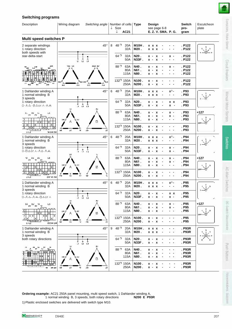
Description Wiring diagram Switching angle Number of cells Type Design Switch Escutcheon↓ Size see page 6-8 pro- plate
↓ AC21 E. Z. V. SMA. P. G. gram
Switching programs
D946E 207
Multi speed switches P
2 separate windings 45° 8 48 20A M10H . x x x - - - . P1221 rotary direction 32A M20 . x x x - - - . P122both speeds withstar-delta-start 64 32A N20 . x - x - x - . P122
50A N33F . x - x - - - . P122
88 63A N40 . x - x - x - . P12280A N61 . x - x - - - . P122
115A N80 . x - x - - - . P122
132 150A N100 . x - x - - - . P122250A N200 . x - x - - - . P122
1 Dahlander winding A 45° 6 48 20A M10H . x x x - x1) - . P931 normal winding B 32A M20 . x x x - - - . P933 speeds1 rotary direction 64 32A N20 . x - x - x x . P93
50A N33F . x - x - x - . P93
88 63A N40 . x - x - x - . P93 +12780A N61. x - x - x - . P93
115A N80 . x - x - - - . P93
132 150A N100 . x - x - - - . P93250A N200 . x - x - - - . P93
1 Dahlander winding A 45° 6 48 20A M10H . x x x - x1) - . P941 normal winding B 32A M20 . x x x - - - . P943 speeds1 rotary direction 64 32A N20 . x - x - x - . P94
50A N33F . x - x - x - . P94
88 63A N40 . x - x - x - . P94 +12780A N61 . x - x - x - . P94
115A N80 . x - x - - - . P94
132 150A N100 . x - x - - - . P94250A N200 . x - x - - - . P94
1 Dahlander winding A 45° 6 48 20A M10H . x x x - x1) - . P951 normal winding B 32A M20 . x x x - - - . P953 speeds1 rotary direction 64 32A N20 . x - x - x x . P95
50A N33F . x - x - x - . P95
88 63A N40 . x - x - x - . P95 +12780A N61 . x - x - x - . P95
115A N80 . x - x - - - . P95
132 150A N100 . x - x - - - . P95250A N200 . x - x - - - . P95
1 Dahlander winding A 45° 9 48 20A M10H . x x x - - - . P93R1 normal winding B 32A M20 . x x x - - - . P93R3 speedsboth rotary directions 64 32A N20 . x - x - - - . P93R
50A N33F . x - x - - - . P93R
88 63A N40 . x - x - - - . P93R80A N61 . x - x - - - . P93R
115A N80 . x - x - - - . P93R
132 150A N100 . x - x - - - . P93R250A N200 . x - x - - - . P93R
Ordering example: AC21 250A panel mounting, multi speed switch, 1 Dahlander winding A,1 normal winding B, 3 speeds, both rotary directions N200 E P93R
1) Plastic enclosed switches are delivered with switch type M10.
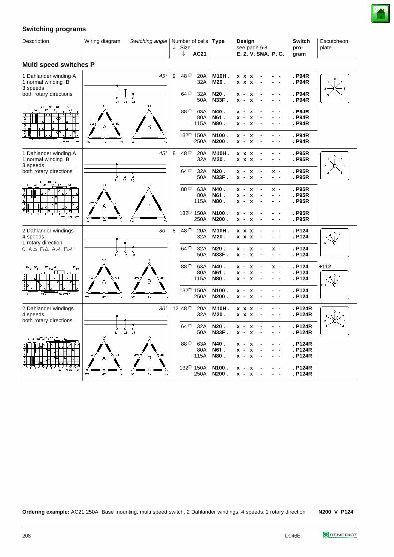
Description Wiring diagram Switching angle Number of cells Type Design Switch Escutcheon↓ Size see page 6-8 pro- plate
↓ AC21 E. Z. V. SMA. P. G. gram
Switching programs
208 D946E
Multi speed switches P
1 Dahlander winding A 45° 9 48 20A M10H . x x x - - - . P94R1 normal winding B 32A M20 . x x x - - - . P94R3 speedsboth rotary directions 64 32A N20 . x - x - - - . P94R
50A N33F . x - x - - - . P94R
88 63A N40 . x - x - - - . P94R80A N61 . x - x - - - . P94R
115A N80 . x - x - - - . P94R
132 150A N100 . x - x - - - . P94R250A N200 . x - x - - - . P94R
1 Dahlander winding A 45° 8 48 20A M10H . x x x - - - . P95R1 normal winding B 32A M20 . x x x - - - . P95R3 speedsboth rotary directions 64 32A N20 . x - x - x - . P95R
50A N33F . x - x - - - . P95R
88 63A N40 . x - x - x - . P95R80A N61 . x - x - - - . P95R
115A N80 . x - x - - - . P95R
132 150A N100 . x - x - - - . P95R250A N200 . x - x - - - . P95R
2 Dahlander windings 30° 8 48 20A M10H . x x x - - - . P1244 speeds 32A M20 . x x x - - - . P1241 rotary direction
64 32A N20 . x - x - x - . P12450A N33F . x - x - - - . P124
88 63A N40 . x - x - x - . P124 +11280A N61 . x - x - - - . P124
115A N80 . x - x - - - . P124
132 150A N100 . x - x - - - . P124250A N200 . x - x - - - . P124
2 Dahlander windings 30° 12 48 20A M10H . x x x - - - . P124R4 speeds 32A M20 . x x x - - - . P124Rboth rotary directions
64 32A N20 . x - x - - - . P124R50A N33F . x - x - - - . P124R
88 63A N40 . x - x - - - . P124R80A N61 . x - x - - - . P124R
115A N80 . x - x - - - . P124R
132 150A N100 . x - x - - - . P124R250A N200 . x - x - - - . P124R
Ordering example: AC21 250A Base mounting, multi speed switch, 2 Dahlander windings, 4 speeds, 1 rotary direction N200 V P124
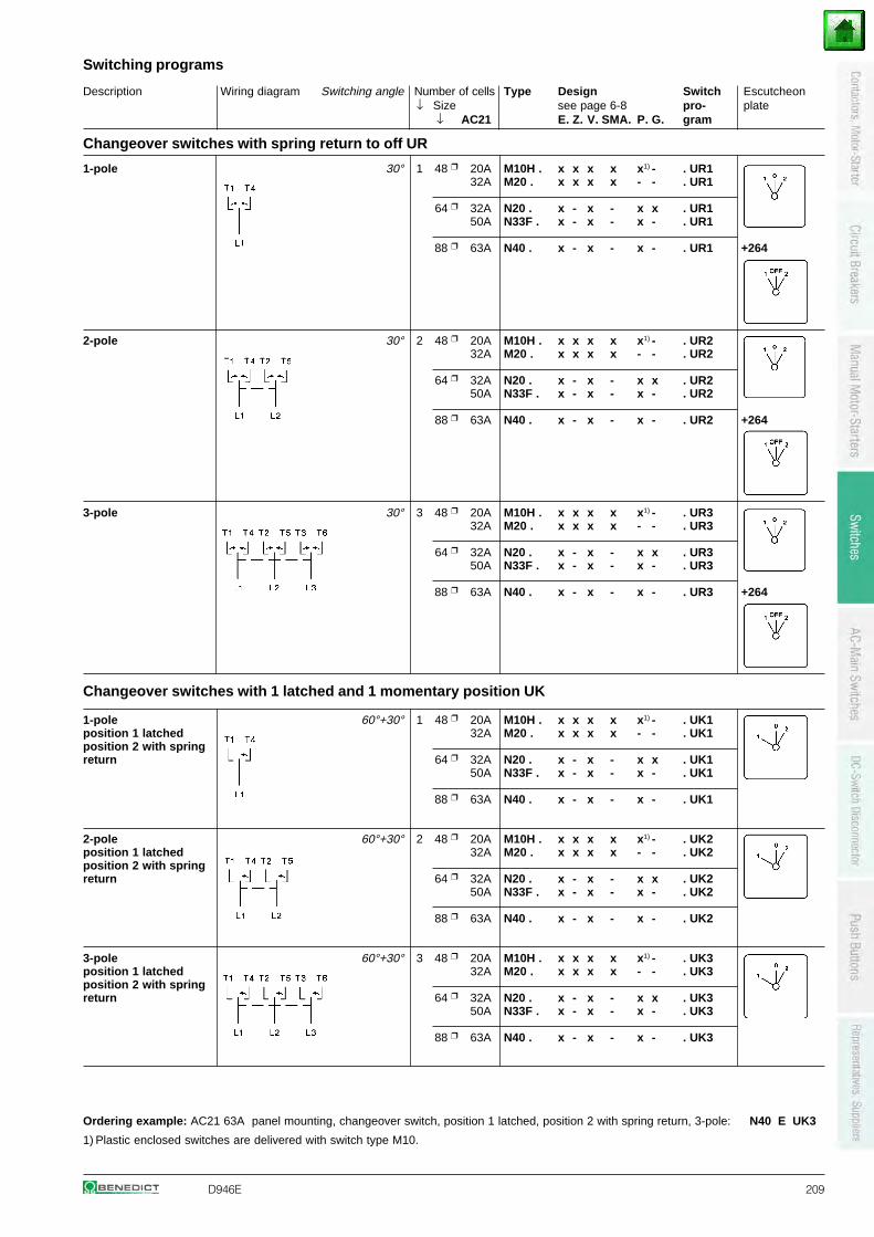
Description Wiring diagram Switching angle Number of cells Type Design Switch Escutcheon↓ Size see page 6-8 pro- plate
↓ AC21 E. Z. V. SMA. P. G. gram
Switching programs
D946E 209
Changeover switches with spring return to off UR
1-pole 30° 1 48 20A M10H . x x x x x1) - . UR132A M20 . x x x x - - . UR1
64 32A N20 . x - x - x x . UR150A N33F . x - x - x - . UR1
88 63A N40 . x - x - x - . UR1 +264
2-pole 30° 2 48 20A M10H . x x x x x1) - . UR232A M20 . x x x x - - . UR2
64 32A N20 . x - x - x x . UR250A N33F . x - x - x - . UR2
88 63A N40 . x - x - x - . UR2 +264
3-pole 30° 3 48 20A M10H . x x x x x1) - . UR332A M20 . x x x x - - . UR3
64 32A N20 . x - x - x x . UR350A N33F . x - x - x - . UR3
88 63A N40 . x - x - x - . UR3 +264
Changeover switches with 1 latched and 1 momentary position UK
1-pole 60°+30° 1 48 20A M10H . x x x x x1) - . UK1position 1 latched 32A M20 . x x x x - - . UK1position 2 with springreturn 64 32A N20 . x - x - x x . UK1
50A N33F . x - x - x - . UK1
88 63A N40 . x - x - x - . UK1
2-pole 60°+30° 2 48 20A M10H . x x x x x1) - . UK2position 1 latched 32A M20 . x x x x - - . UK2position 2 with springreturn 64 32A N20 . x - x - x x . UK2
50A N33F . x - x - x - . UK2
88 63A N40 . x - x - x - . UK2
3-pole 60°+30° 3 48 20A M10H . x x x x x1) - . UK3position 1 latched 32A M20 . x x x x - - . UK3position 2 with springreturn 64 32A N20 . x - x - x x . UK3
50A N33F . x - x - x - . UK3
88 63A N40 . x - x - x - . UK3
Ordering example: AC21 63A panel mounting, changeover switch, position 1 latched, position 2 with spring return, 3-pole: N40 E UK3
1) Plastic enclosed switches are delivered with switch type M10.
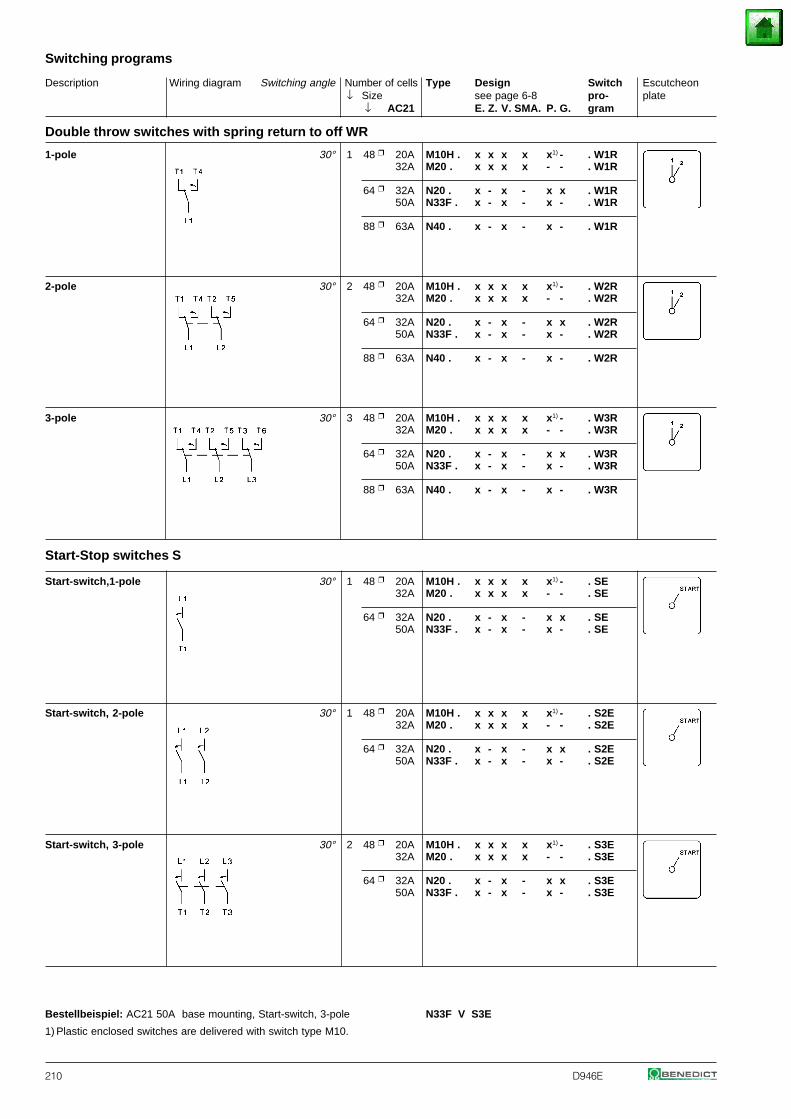
Description Wiring diagram Switching angle Number of cells Type Design Switch Escutcheon↓ Size see page 6-8 pro- plate
↓ AC21 E. Z. V. SMA. P. G. gram
Switching programs
210 D946E
Double throw switches with spring return to off WR
1-pole 30° 1 48 20A M10H . x x x x x1) - . W1R32A M20 . x x x x - - . W1R
64 32A N20 . x - x - x x . W1R50A N33F . x - x - x - . W1R
88 63A N40 . x - x - x - . W1R
2-pole 30° 2 48 20A M10H . x x x x x1) - . W2R32A M20 . x x x x - - . W2R
64 32A N20 . x - x - x x . W2R50A N33F . x - x - x - . W2R
88 63A N40 . x - x - x - . W2R
3-pole 30° 3 48 20A M10H . x x x x x1) - . W3R32A M20 . x x x x - - . W3R
64 32A N20 . x - x - x x . W3R50A N33F . x - x - x - . W3R
88 63A N40 . x - x - x - . W3R
Start-Stop switches S
Start-switch,1-pole 30° 1 48 20A M10H . x x x x x1) - . SE32A M20 . x x x x - - . SE
64 32A N20 . x - x - x x . SE50A N33F . x - x - x - . SE
Start-switch, 2-pole 30° 1 48 20A M10H . x x x x x1) - . S2E32A M20 . x x x x - - . S2E
64 32A N20 . x - x - x x . S2E50A N33F . x - x - x - . S2E
Start-switch, 3-pole 30° 2 48 20A M10H . x x x x x1) - . S3E32A M20 . x x x x - - . S3E
64 32A N20 . x - x - x x . S3E50A N33F . x - x - x - . S3E
Bestellbeispiel: AC21 50A base mounting, Start-switch, 3-pole N33F V S3E
1) Plastic enclosed switches are delivered with switch type M10.
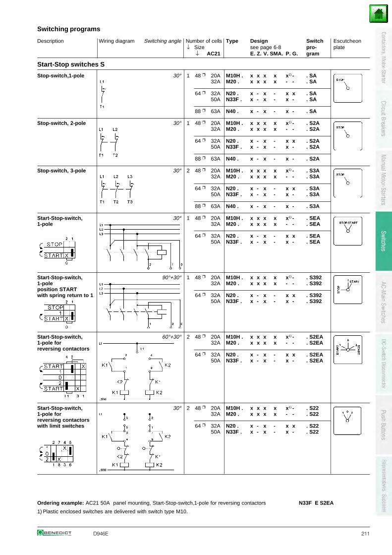
Description Wiring diagram Switching angle Number of cells Type Design Switch Escutcheon↓ Size see page 6-8 pro- plate
↓ AC21 E. Z. V. SMA. P. G. gram
Switching programs
D946E 211
Start-Stop switches S
Stop-switch,1-pole 30° 1 48 20A M10H . x x x x x1) - . SA32A M20 . x x x x - - . SA
64 32A N20 . x - x - x x . SA50A N33F . x - x - x - . SA
88 63A N40 . x - x - x - . SA
Stop-switch, 2-pole 30° 1 48 20A M10H . x x x x x1) - . S2A32A M20 . x x x x - - . S2A
64 32A N20 . x - x - x x . S2A50A N33F . x - x - x - . S2A
88 63A N40 . x - x - x - . S2A
Stop-switch, 3-pole 30° 2 48 20A M10H . x x x x x1) - . S3A32A M20 . x x x x - - . S3A
64 32A N20 . x - x - x x . S3A50A N33F . x - x - x - . S3A
88 63A N40 . x - x - x - . S3A
Start-Stop-switch, 30° 1 48 20A M10H . x x x x x1) - . SEA1-pole 32A M20 . x x x x - - . SEA
64 32A N20 . x - x - x x . SEA50A N33F . x - x - x - . SEA
Start-Stop-switch, 90°+30° 1 48 20A M10H . x x x x x1) - . S3921-pole 32A M20 . x x x x - - . S392position STARTwith spring return to 1 64 32A N20 . x - x - x x . S392
50A N33F . x - x - x - . S392
Start-Stop-switch, 60°+30° 2 48 20A M10H . x x x x x1) - . S2EA1-pole for 32A M20 . x x x x - - . S2EAreversing contactors
64 32A N20 . x - x - x x . S2EA50A N33F . x - x - x - . S2EA
Start-Stop-switch, 30° 2 48 20A M10H . x x x x x1) - . S221-pole for 32A M20 . x x x x - - . S22reversing contactorswith limit switches 64 32A N20 . x - x - x x . S22
50A N33F . x - x - x - . S22
Ordering example: AC21 50A panel mounting, Start-Stop-switch,1-pole for reversing contactors N33F E S2EA
1) Plastic enclosed switches are delivered with switch type M10.
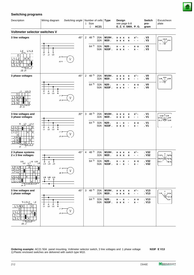
Description Wiring diagram Switching angle Number of cells Type Design Switch Escutcheon↓ Size see page 6-8 pro- plate
↓ AC21 E. Z. V. SMA. P. G. gram
Switching programs
212 D946E
Voltmeter selector switches V
3 line voltages 45° 2 48 20A M10H . x x x x x1) - . V332A M20 . x x x x - - . V3
64 32A N20 . x - x - x x . V350A N33F . x x x - x - . V3
3 phase voltages 45° 2 48 20A M10H . x x x x x1) - . V032A M20 . x x x x - - . V0
64 32A N20 . x - x - x x . V050A N33F . x x x - x - . V0
3 line voltages and 30° 3 48 20A M10H . x x x x x1) - . V13 phase voltages 32A M20 . x x x x - - . V1
64 32A N20 . x - x - x x . V150A N33F . x x x - x - . V1
2 3-phase systems 45° 4 48 20A M10H . x x x x x1) - . V322 x 3 line voltages 32A M20 . x x x x - - . V32
64 32A N20 . x - x - x x . V3250A N33F . x - x - x - . V32
3 line voltages and 45° 3 48 20A M10H . x x x x x1) - . V131 phase voltage 32A M20 . x x x x - - . V13
64 32A N20 . x - x - x x . V1350A N33F . x x x - x - . V13
Ordering example: AC21 50A panel mounting, Voltmeter selector switch, 3 line voltages and 1 phase voltage N33F E V131) Plastic enclosed switches are delivered with switch type M10.
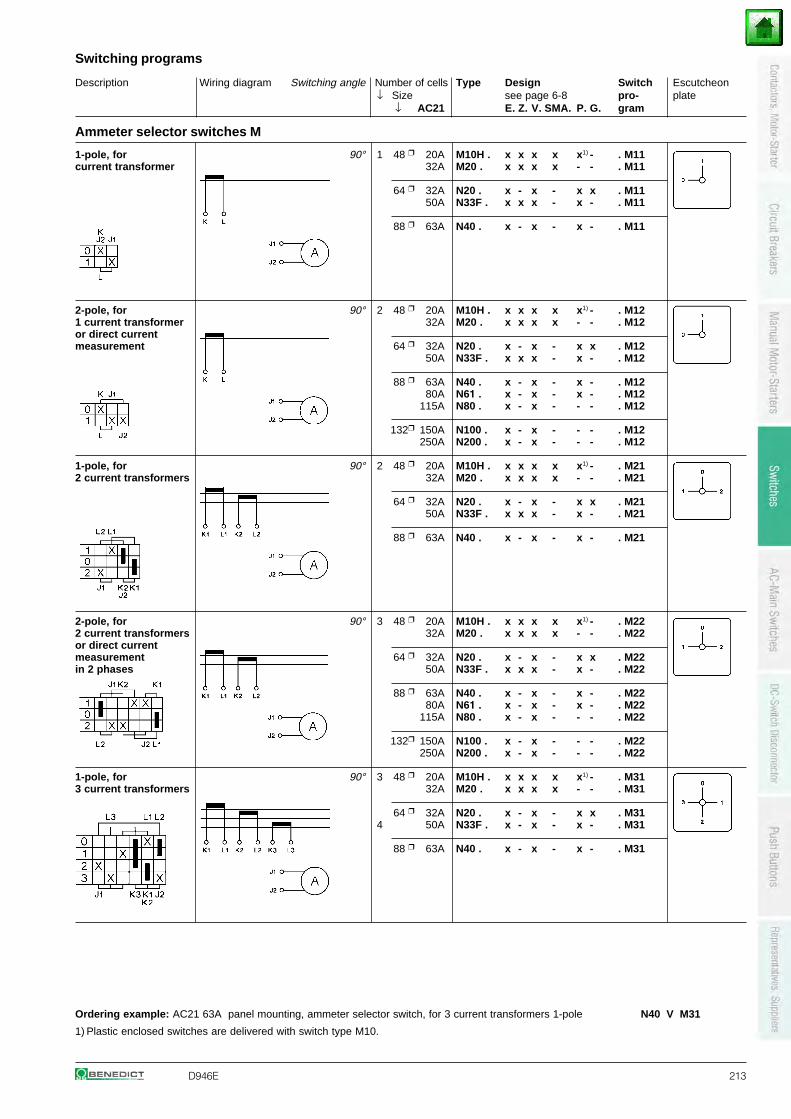
Description Wiring diagram Switching angle Number of cells Type Design Switch Escutcheon↓ Size see page 6-8 pro- plate
↓ AC21 E. Z. V. SMA. P. G. gram
Switching programs
D946E 213
Ammeter selector switches M
1-pole, for 90° 1 48 20A M10H . x x x x x1) - . M11current transformer 32A M20 . x x x x - - . M11
64 32A N20 . x - x - x x . M1150A N33F . x x x - x - . M11
88 63A N40 . x - x - x - . M11
2-pole, for 90° 2 48 20A M10H . x x x x x1) - . M121 current transformer 32A M20 . x x x x - - . M12or direct currentmeasurement 64 32A N20 . x - x - x x . M12
50A N33F . x x x - x - . M12
88 63A N40 . x - x - x - . M1280A N61 . x - x - x - . M12
115A N80 . x - x - - - . M12
132 150A N100 . x - x - - - . M12250A N200 . x - x - - - . M12
1-pole, for 90° 2 48 20A M10H . x x x x x1) - . M212 current transformers 32A M20 . x x x x - - . M21
64 32A N20 . x - x - x x . M2150A N33F . x x x - x - . M21
88 63A N40 . x - x - x - . M21
2-pole, for 90° 3 48 20A M10H . x x x x x1) - . M222 current transformers 32A M20 . x x x x - - . M22or direct currentmeasurement 64 32A N20 . x - x - x x . M22in 2 phases 50A N33F . x x x - x - . M22
88 63A N40 . x - x - x - . M2280A N61 . x - x - x - . M22
115A N80 . x - x - - - . M22
132 150A N100 . x - x - - - . M22250A N200 . x - x - - - . M22
1-pole, for 90° 3 48 20A M10H . x x x x x1) - . M313 current transformers 32A M20 . x x x x - - . M31
64 32A N20 . x - x - x x . M314 50A N33F . x - x - x - . M31
88 63A N40 . x - x - x - . M31
Ordering example: AC21 63A panel mounting, ammeter selector switch, for 3 current transformers 1-pole N40 V M31
1) Plastic enclosed switches are delivered with switch type M10.
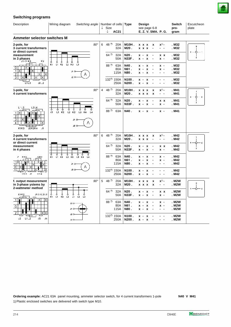
Description Wiring diagram Switching angle Number of cells Type Design Switch Escutcheon↓ Size see page 6-8 pro- plate
↓ AC21 E. Z. V. SMA. P. G. gram
Switching programs
214 D946E
Ammeter selector switches M
2-pole, for 90° 6 48 20A M10H . x x x x x1) - . M323 current transformers 32A M20 . x x x - - - . M32or direct currentmeasurement 64 32A N20 . x - x - x x . M32in 3 phases 50A N33F . x - x - x - . M32
88 63A N40 . x - x - x - . M3280A N61 . x - x - x - . M32
115A N80 . x - x - - - . M32
132 150A N100 . x - x - - - . M32250A N200 . x - x - - - . M32
1-pole, for 90° 4 48 20A M10H . x x x x x1) - . M414 current transformers 32A M20 . x x x x - - . M41
64 32A N20 . x - x - x x . M4150A N33F . x - x - x - . M41
88 63A N40 . x - x - x - . M41
2-pole, for 90° 6 48 20A M10H . x x x x x1) - . M424 current transformers 32A M20 . x x x - - - . M42or direct currentmeasurement 64 32A N20 . x - x - x x . M42in 4 phases 50A N33F . x - x - x - . M42
88 63A N40 . x - x - x - . M4280A N61 . x - x - x - . M42
115A N80 . x - x - - - . M42
132 150A N100 . x - x - - - . M42250A N200 . x - x - - - . M42
f. output measurement 90° 5 48 20A M10H . x x x x x1) - . M2Win 3-phase ystems by 32A M20 . x x x x - - . M2W2-wattmeter method
64 32A N20 . x - x - x x . M2W50A N33F . x - x - x - . M2W
88 63A N40 . x - x - x - . M2W80A N61 . x - x - x - . M2W
115A N80 . x - x - - - . M2W
132 150A N100 . x - x - - - . M2W250A N200 . x - x - - - . M2W
Ordering example: AC21 63A panel mounting, ammeter selector switch, for 4 current transformers 1-pole N40 V M41
1) Plastic enclosed switches are delivered with switch type M10.
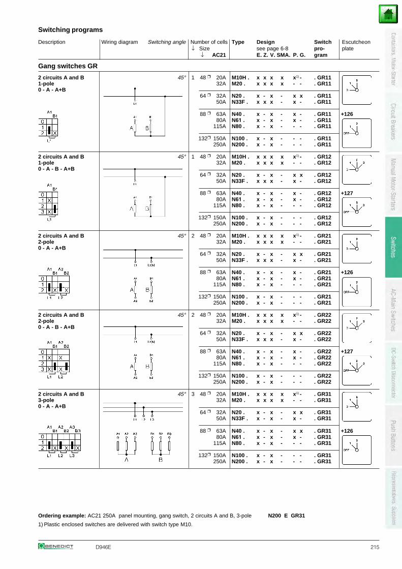
Description Wiring diagram Switching angle Number of cells Type Design Switch Escutcheon↓ Size see page 6-8 pro- plate
↓ AC21 E. Z. V. SMA. P. G. gram
Switching programs
D946E 215
Gang switches GR
2 circuits A and B 45° 1 48 20A M10H . x x x x x1) - . GR111-pole 32A M20 . x x x x - - . GR110 - A - A+B
64 32A N20 . x - x - x x . GR1150A N33F . x x x - x - . GR11
88 63A N40 . x - x - x - . GR11 +12680A N61 . x - x - x - . GR11
115A N80 . x - x - - - . GR11
132 150A N100 . x - x - - - . GR11250A N200 . x - x - - - . GR11
2 circuits A and B 45° 1 48 20A M10H . x x x x x1) - . GR121-pole 32A M20 . x x x x - - . GR120 - A - B - A+B
64 32A N20 . x - x - x x . GR1250A N33F . x x x - x - . GR12
88 63A N40 . x - x - x - . GR12 +12780A N61 . x - x - x - . GR12
115A N80 . x - x - - - . GR12
132 150A N100 . x - x - - - . GR12250A N200 . x - x - - - . GR12
2 circuits A and B 45° 2 48 20A M10H . x x x x x1) - . GR212-pole 32A M20 . x x x x - - . GR210 - A - A+B
64 32A N20 . x - x - x x . GR2150A N33F . x x x - x - . GR21
88 63A N40 . x - x - x - . GR21 +12680A N61 . x - x - x - . GR21
115A N80 . x - x - - - . GR21
132 150A N100 . x - x - - - . GR21250A N200 . x - x - - - . GR21
2 circuits A and B 45° 2 48 20A M10H . x x x x x1) - . GR222-pole 32A M20 . x x x x - - . GR220 - A - B - A+B
64 32A N20 . x - x - x x . GR2250A N33F . x x x - x - . GR22
88 63A N40 . x - x - x - . GR22 +12780A N61 . x - x - x - . GR22
115A N80 . x - x - - - . GR22
132 150A N100 . x - x - - - . GR22250A N200 . x - x - - - . GR22
2 circuits A and B 45° 3 48 20A M10H . x x x x x1) - . GR313-pole 32A M20 . x x x x - - . GR310 - A - A+B
64 32A N20 . x - x - x x . GR3150A N33F . x - x - x - . GR31
88 63A N40 . x - x - x x . GR31 +12680A N61 . x - x - x - . GR31
115A N80 . x - x - - - . GR31
132 150A N100 . x - x - - - . GR31250A N200 . x - x - - - . GR31
Ordering example: AC21 250A panel mounting, gang switch, 2 circuits A and B, 3-pole N200 E GR31
1) Plastic enclosed switches are delivered with switch type M10.
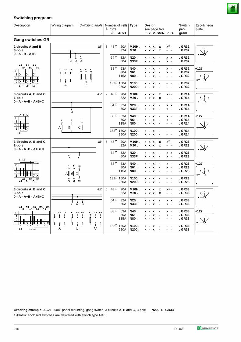
Description Wiring diagram Switching angle Number of cells Type Design Switch Escutcheon↓ Size see page 6-8 pro- plate
↓ AC21 E. Z. V. SMA. P. G. gram
Switching programs
216 D946E
Gang switches GR
2 circuits A and B 45° 3 48 20A M10H . x x x x x1) - . GR323-pole 32A M20 . x x x x - - . GR320 - A - B - A+B
64 32A N20 . x - x - x x . GR3250A N33F . x - x - x - . GR32
88 63A N40 . x - x - x - . GR32 +12780A N61 . x - x - x - . GR32
115A N80 . x - x - - - . GR32
132 150A N100 . x - x - - - . GR32250A N200 . x - x - - - . GR32
3 circuits A, B and C 45° 2 48 20A M10H . x x x x x1) - . GR141-pole 32A M20 . x x x x - - . GR140 - A - A+B - A+B+C
64 32A N20 . x - x - x x . GR1450A N33F . x - x - x - . GR14
88 63A N40 . x - x - x - . GR14 +12780A N61 . x - x - x - . GR14
115A N80 . x - x - - - . GR14
132 150A N100 . x - x - - - . GR14250A N200 . x - x - - - . GR14
3 circuits A, B and C 45° 3 48 20A M10H . x x x x x1) - . GR232-pole 32A M20 . x x x x - - . GR230 - A - A+B - A+B+C
64 32A N20 . x - x - x x . GR2350A N33F . x - x - x - . GR23
88 63A N40 . x - x - x - . GR23 +12780A N61 . x - x - x - . GR23
115A N80 . x - x - - - . GR23
132 150A N100 . x - x - - - . GR23250A N200 . x - x - - - . GR23
3 circuits A, B and C 45° 5 48 20A M10H . x x x x x1) - . GR333-pole 32A M20 . x x x x - - . GR330 - A - A+B - A+B+C
64 32A N20 . x - x - x x . GR3350A N33F . x - x - x - . GR33
88 63A N40 . x - x - x - . GR33 +12780A N61 . x - x - x - . GR33
115A N80 . x - x - - - . GR33
132 150A N100 . x - x - - - . GR33250A N200 . x - x - - - . GR33
Ordering example: AC21 250A panel mounting, gang switch, 3 circuits A, B and C, 3-pole N200 E GR33
1) Plastic enclosed switches are delivered with switch type M10.
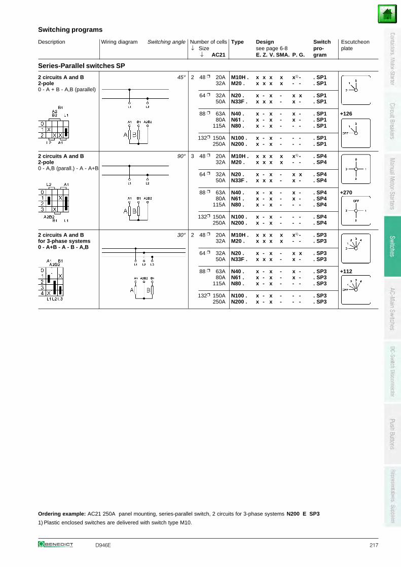
Description Wiring diagram Switching angle Number of cells Type Design Switch Escutcheon↓ Size see page 6-8 pro- plate
↓ AC21 E. Z. V. SMA. P. G. gram
Switching programs
D946E 217
Series-Parallel switches SP
2 circuits A and B 45° 2 48 20A M10H . x x x x x1) - . SP12-pole 32A M20 . x x x x - - . SP10 - A + B - A,B (parallel)
64 32A N20 . x - x - x x . SP150A N33F . x x x - x - . SP1
88 63A N40 . x - x - x - . SP1 +12680A N61 . x - x - x - . SP1
115A N80 . x - x - - - . SP1
132 150A N100 . x - x - - - . SP1250A N200 . x - x - - - . SP1
2 circuits A and B 90° 3 48 20A M10H . x x x x x1) - . SP42-pole 32A M20 . x x x x - - . SP40 - A,B (parall.) - A - A+B
64 32A N20 . x - x - x x . SP450A N33F . x x x - x - . SP4
88 63A N40 . x - x - x - . SP4 +27080A N61 . x - x - x - . SP4
115A N80 . x - x - - - . SP4
132 150A N100 . x - x - - - . SP4250A N200 . x - x - - - . SP4
2 circuits A and B 30° 2 48 20A M10H . x x x x x1) - . SP3for 3-phase systems 32A M20 . x x x x - - . SP30 - A+B - A - B - A,B
64 32A N20 . x - x - x x . SP350A N33F . x x x - x - . SP3
88 63A N40 . x - x - x - . SP3 +11280A N61 . x - x - x - . SP3
115A N80 . x - x - - - . SP3
132 150A N100 . x - x - - - . SP3250A N200 . x - x - - - . SP3
Ordering example: AC21 250A panel mounting, series-parallel switch, 2 circuits for 3-phase systems N200 E SP3
1) Plastic enclosed switches are delivered with switch type M10.
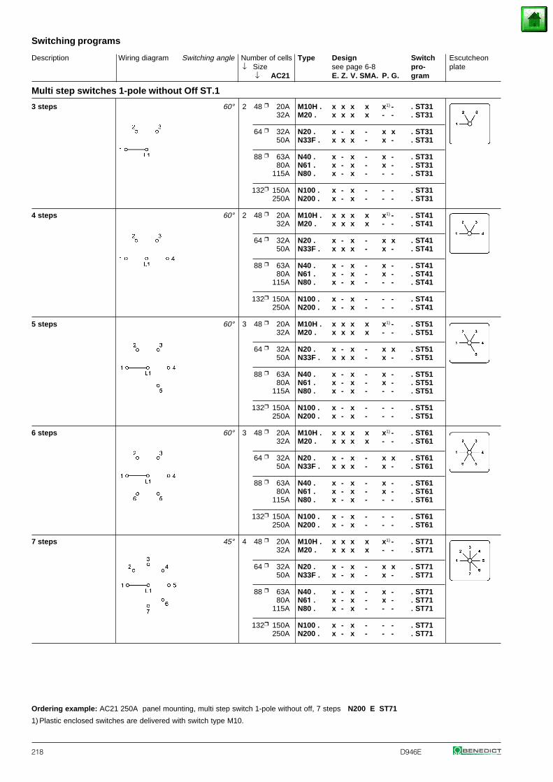
Description Wiring diagram Switching angle Number of cells Type Design Switch Escutcheon↓ Size see page 6-8 pro- plate
↓ AC21 E. Z. V. SMA. P. G. gram
Switching programs
218 D946E
Multi step switches 1-pole without Off ST.1
3 steps 60° 2 48 20A M10H . x x x x x1) - . ST3132A M20 . x x x x - - . ST31
64 32A N20 . x - x - x x . ST3150A N33F . x x x - x - . ST31
88 63A N40 . x - x - x - . ST3180A N61 . x - x - x - . ST31
115A N80 . x - x - - - . ST31
132 150A N100 . x - x - - - . ST31250A N200 . x - x - - - . ST31
4 steps 60° 2 48 20A M10H . x x x x x1) - . ST4132A M20 . x x x x - - . ST41
64 32A N20 . x - x - x x . ST4150A N33F . x x x - x - . ST41
88 63A N40 . x - x - x - . ST4180A N61 . x - x - x - . ST41
115A N80 . x - x - - - . ST41
132 150A N100 . x - x - - - . ST41250A N200 . x - x - - - . ST41
5 steps 60° 3 48 20A M10H . x x x x x1) - . ST5132A M20 . x x x x - - . ST51
64 32A N20 . x - x - x x . ST5150A N33F . x x x - x - . ST51
88 63A N40 . x - x - x - . ST5180A N61 . x - x - x - . ST51
115A N80 . x - x - - - . ST51
132 150A N100 . x - x - - - . ST51250A N200 . x - x - - - . ST51
6 steps 60° 3 48 20A M10H . x x x x x1) - . ST6132A M20 . x x x x - - . ST61
64 32A N20 . x - x - x x . ST6150A N33F . x x x - x - . ST61
88 63A N40 . x - x - x - . ST6180A N61 . x - x - x - . ST61
115A N80 . x - x - - - . ST61
132 150A N100 . x - x - - - . ST61250A N200 . x - x - - - . ST61
7 steps 45° 4 48 20A M10H . x x x x x1) - . ST7132A M20 . x x x x - - . ST71
64 32A N20 . x - x - x x . ST7150A N33F . x - x - x - . ST71
88 63A N40 . x - x - x - . ST7180A N61 . x - x - x - . ST71
115A N80 . x - x - - - . ST71
132 150A N100 . x - x - - - . ST71250A N200 . x - x - - - . ST71
Ordering example: AC21 250A panel mounting, multi step switch 1-pole without off, 7 steps N200 E ST71
1) Plastic enclosed switches are delivered with switch type M10.

Description Wiring diagram Switching angle Number of cells Type Design Switch Escutcheon↓ Size see page 6-8 pro- plate
↓ AC21 E. Z. V. SMA. P. G. gram
Switching programs
D946E 219
Multi step switches 1-pole without Off ST.1
8 steps 45° 4 48 20A M10H . x x x x x1) - . ST8132A M20 . x x x x - - . ST81
64 32A N20 . x - x - x x . ST8150A N33F . x - x - x - . ST81
88 63A N40 . x - x - x - . ST8180A N61 . x - x - x - . ST81
115A N80 . x - x - - - . ST81
132 150A N100 . x - x - - - . ST81250A N200 . x - x - - - . ST81
9 steps 30° 5 48 20A M10H . x x x x x1) - . ST9132A M20 . x x x x - - . ST91
64 32A N20 . x - x - x x . ST9150A N33F . x - x - x - . ST91
88 63A N40 . x - x - x - . ST9180A N61 . x - x - x - . ST91
115A N80 . x - x - - - . ST91
132 150A N100 . x - x - - - . ST91250A N200 . x - x - - - . ST91
10 steps 30° 5 48 20A M10H . x x x x x1) - . ST10132A M20 . x x x x - - . ST101
64 32A N20 . x - x - x x . ST10150A N33F . x - x - x - . ST101
88 63A N40 . x - x - x - . ST10180A N61 . x - x - x - . ST101
115A N80 . x - x - - - . ST101
132 150A N100 . x - x - - - . ST101250A N200 . x - x - - - . ST101
11 steps 30° 6 48 20A M10H . x x x - x1) - . ST11132A M20 . x x x - - - . ST111
64 32A N20 . x - x - x x . ST11150A N33F . x - x - x - . ST111
88 63A N40 . x - x - x - . ST11180A N61 . x - x - x - . ST111
115A N80 . x - x - - - . ST111
132 150A N100 . x - x - - - . ST111250A N200 . x - x - - - . ST111
12 steps 30° 6 48 20A M10H . x x x - x1) - . ST12132A M20 . x x x - - - . ST121
64 32A N20 . x - x - x x . ST12150A N33F . x - x - x - . ST121
88 63A N40 . x - x - x - . ST12180A N61 . x - x - x - . ST121
115A N80 . x - x - - - . ST121
132 150A N100 . x - x - - - . ST121250A N200 . x - x - - - . ST121
Ordering example: AC21 250A panel mounting, multi step switch 1-pole without off, 12 steps N200 E ST121
1) Plastic enclosed switches are delivered with switch type M10.
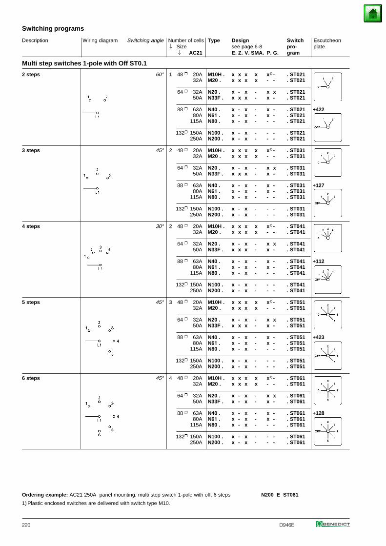
Description Wiring diagram Switching angle Number of cells Type Design Switch Escutcheon↓ Size see page 6-8 pro- plate
↓ AC21 E. Z. V. SMA. P. G. gram
Switching programs
220 D946E
Multi step switches 1-pole with Off ST0.1
2 steps 60° 1 48 20A M10H . x x x x x1) - . ST02132A M20 . x x x x - - . ST021
64 32A N20 . x - x - x x . ST02150A N33F . x x x - x - . ST021
88 63A N40 . x - x - x - . ST021 +42280A N61 . x - x - x - . ST021
115A N80 . x - x - - - . ST021
132 150A N100 . x - x - - - . ST021250A N200 . x - x - - - . ST021
3 steps 45° 2 48 20A M10H . x x x x x1) - . ST03132A M20 . x x x x - - . ST031
64 32A N20 . x - x - x x . ST03150A N33F . x x x - x - . ST031
88 63A N40 . x - x - x - . ST031 +12780A N61 . x - x - x - . ST031
115A N80 . x - x - - - . ST031
132 150A N100 . x - x - - - . ST031250A N200 . x - x - - - . ST031
4 steps 30° 2 48 20A M10H . x x x x x1) - . ST04132A M20 . x x x x - - . ST041
64 32A N20 . x - x - x x . ST04150A N33F . x x x - x - . ST041
88 63A N40 . x - x - x - . ST041 +11280A N61 . x - x - x - . ST041
115A N80 . x - x - - - . ST041
132 150A N100 . x - x - - - . ST041250A N200 . x - x - - - . ST041
5 steps 45° 3 48 20A M10H . x x x x x1) - . ST05132A M20 . x x x x - - . ST051
64 32A N20 . x - x - x x . ST05150A N33F . x x x - x - . ST051
88 63A N40 . x - x - x - . ST051 +42380A N61 . x - x - x - . ST051
115A N80 . x - x - - - . ST051
132 150A N100 . x - x - - - . ST051250A N200 . x - x - - - . ST051
6 steps 45° 4 48 20A M10H . x x x x x1) - . ST06132A M20 . x x x x - - . ST061
64 32A N20 . x - x - x x . ST06150A N33F . x - x - x - . ST061
88 63A N40 . x - x - x - . ST061 +12880A N61 . x - x - x - . ST061
115A N80 . x - x - - - . ST061
132 150A N100 . x - x - - - . ST061250A N200 . x - x - - - . ST061
Ordering example: AC21 250A panel mounting, multi step switch 1-pole with off, 6 steps N200 E ST061
1) Plastic enclosed switches are delivered with switch type M10.
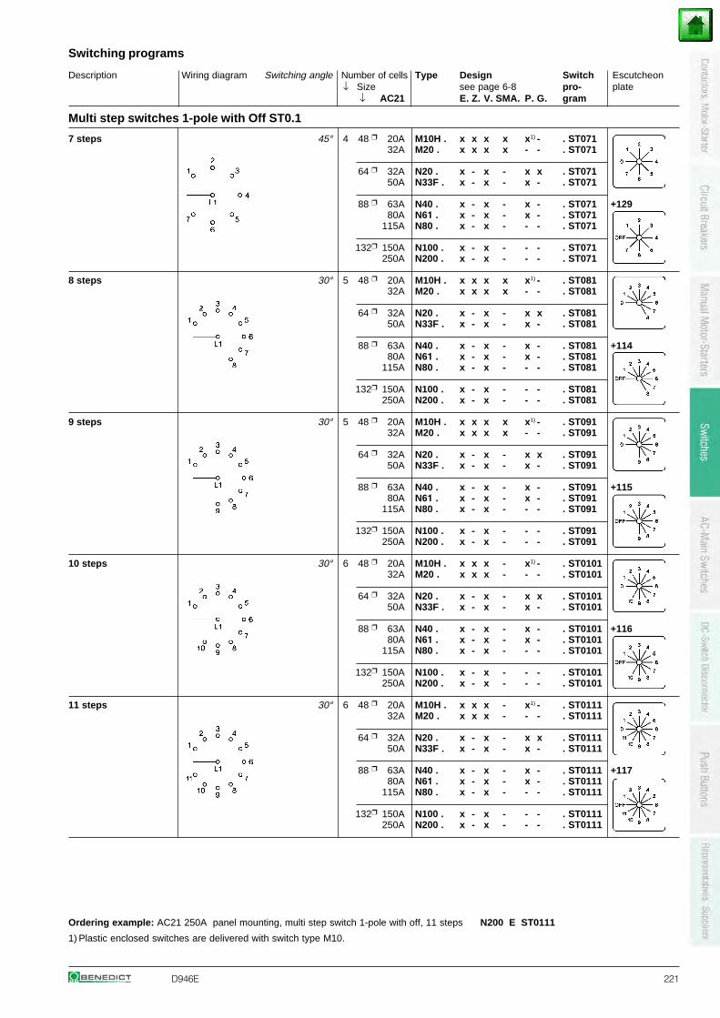
Description Wiring diagram Switching angle Number of cells Type Design Switch Escutcheon↓ Size see page 6-8 pro- plate
↓ AC21 E. Z. V. SMA. P. G. gram
Switching programs
D946E 221
Multi step switches 1-pole with Off ST0.1
7 steps 45° 4 48 20A M10H . x x x x x1) - . ST07132A M20 . x x x x - - . ST071
64 32A N20 . x - x - x x . ST07150A N33F . x - x - x - . ST071
88 63A N40 . x - x - x - . ST071 +12980A N61 . x - x - x - . ST071
115A N80 . x - x - - - . ST071
132 150A N100 . x - x - - - . ST071250A N200 . x - x - - - . ST071
8 steps 30° 5 48 20A M10H . x x x x x1) - . ST08132A M20 . x x x x - - . ST081
64 32A N20 . x - x - x x . ST08150A N33F . x - x - x - . ST081
88 63A N40 . x - x - x - . ST081 +11480A N61 . x - x - x - . ST081
115A N80 . x - x - - - . ST081
132 150A N100 . x - x - - - . ST081250A N200 . x - x - - - . ST081
9 steps 30° 5 48 20A M10H . x x x x x1) - . ST09132A M20 . x x x x - - . ST091
64 32A N20 . x - x - x x . ST09150A N33F . x - x - x - . ST091
88 63A N40 . x - x - x - . ST091 +11580A N61 . x - x - x - . ST091
115A N80 . x - x - - - . ST091
132 150A N100 . x - x - - - . ST091250A N200 . x - x - - - . ST091
10 steps 30° 6 48 20A M10H . x x x - x1) - . ST010132A M20 . x x x - - - . ST0101
64 32A N20 . x - x - x x . ST010150A N33F . x - x - x - . ST0101
88 63A N40 . x - x - x - . ST0101 +11680A N61 . x - x - x - . ST0101
115A N80 . x - x - - - . ST0101
132 150A N100 . x - x - - - . ST0101250A N200 . x - x - - - . ST0101
11 steps 30° 6 48 20A M10H . x x x - x1) - . ST011132A M20 . x x x - - - . ST0111
64 32A N20 . x - x - x x . ST011150A N33F . x - x - x - . ST0111
88 63A N40 . x - x - x - . ST0111 +11780A N61 . x - x - x - . ST0111
115A N80 . x - x - - - . ST0111
132 150A N100 . x - x - - - . ST0111250A N200 . x - x - - - . ST0111
Ordering example: AC21 250A panel mounting, multi step switch 1-pole with off, 11 steps N200 E ST0111
1) Plastic enclosed switches are delivered with switch type M10.

Description Wiring diagram Switching angle Number of cells Type Design Switch Escutcheon↓ Size see page 6-8 pro- plate
↓ AC21 E. Z. V. SMA. P. G. gram
Switching programs
222 D946E
Multi step switches 2-pole without Off ST.2
3 steps 60° 3 48 20A M10H . x x x x x1) - . ST3232A M20 . x x x x - - . ST32
64 32A N20 . x - x - x x . ST3250A N33F . x x x - x - . ST32
88 63A N40 . x - x - x - . ST3280A N61 . x - x - x - . ST32
115A N80 . x - x - - - . ST32
132 150A N100 . x - x - - - . ST32250A N200 . x - x - - - . ST32
4 steps 60° 4 48 20A M10H . x x x x x1) - . ST4232A M20 . x x x x - - . ST42
64 32A N20 . x - x - x x . ST4250A N33F . x - x - x - . ST42
88 63A N40 . x - x - x - . ST4280A N61 . x - x - x - . ST42
115A N80 . x - x - - - . ST42
132 150A N100 . x - x - - - . ST42250A N200 . x - x - - - . ST42
5 steps 60° 5 48 20A M10H . x x x x x1) - . ST5232A M20 . x x x x - - . ST52
64 32A N20 . x - x - x x . ST5250A N33F . x - x - x - . ST52
88 63A N40 . x - x - x - . ST5280A N61 . x - x - x - . ST52
115A N80 . x - x - - - . ST52
132 150A N100 . x - x - - - . ST52250A N200 . x - x - - - . ST52
6 steps 60° 6 48 20A M10H . x x x - x1) - . ST6232A M20 . x x x - - - . ST62
64 32A N20 . x - x - x x . ST6250A N33F . x - x - x - . ST62
88 63A N40 . x - x - x - . ST6280A N61 . x - x - x - . ST62
115A N80 . x - x - - - . ST62
132 150A N100 . x - x - - - . ST62250A N200 . x - x - - - . ST62
7 steps 45° 7 48 20A M10H . x x x - - - . ST7232A M20 . x x x - - - . ST72
64 32A N20 . x - x - x - . ST7250A N33F . x - x - - - . ST72
88 63A N40 . x - x - x - . ST7280A N61 . x - x - - - . ST72
115A N80 . x - x - - - . ST72
132 150A N100 . x - x - - - . ST72250A N200 . x - x - - - . ST72
Ordering example: AC21 250A panel mounting, multi step switch 2-pole without off, 7 steps N200 E ST72
1) Plastic enclosed switches are delivered with switch type M10.

Description Wiring diagram Switching angle Number of cells Type Design Switch Escutcheon↓ Size see page 6-8 pro- plate
↓ AC21 E. Z. V. SMA. P. G. gram
Switching programs
D946E 223
Multi step switches 2-pole without Off ST.2
8 steps 45° 8 48 20A M10H . x x x - - - . ST8232A M20 . x x x - - - . ST82
64 32A N20 . x - x - x - . ST8250A N33F . x - x - - - . ST82
88 63A N40 . x - x - x - . ST8280A N61 . x - x - - - . ST82
115A N80 . x - x - - - . ST82
132 150A N100 . x - x - - - . ST82250A N200 . x - x - - - . ST82
9 steps 30° 9 48 20A M10H . x x x - - - . ST9232A M20 . x x x - - - . ST92
64 32A N20 . x - x - - - . ST9250A N33F . x - x - - - . ST92
88 63A N40 . x - x - - - . ST9280A N61 . x - x - - - . ST92
115A N80 . x - x - - - . ST92
132 150A N100 . x - x - - - . ST92250A N200 . x - x - - - . ST92
10 steps 30° 10 48 20A M10H . x x x - - - . ST10232A M20 . x x x - - - . ST102
64 32A N20 . x - x - - - . ST10250A N33F . x - x - - - . ST102
88 63A N40 . x - x - - - . ST10280A N61 . x - x - - - . ST102
115A N80 . x - x - - - . ST102
132 150A N100 . x - x - - - . ST102250A N200 . x - x - - - . ST102
11 steps 30° 11 48 20A M10H . x x x - - - . ST11232A M20 . x x x - - - . ST112
64 32A N20 . x - x - - - . ST11250A N33F . x - x - - - . ST112
88 63A N40 . x - x - - - . ST11280A N61 . x - x - - - . ST112
115A N80 . x - x - - - . ST112
132 150A N100 . x - x - - - . ST112250A N200 . x - x - - - . ST112
12 steps 30° 12 48 20A M10H . x x x - - - . ST12232A M20 . x x x - - - . ST122
64 32A N20 . x - x - - - . ST12250A N33F . x - x - - - . ST122
88 63A N40 . x - x - - - . ST12280A N61 . x - x - - - . ST122
115A N80 . x - x - - - . ST122
132 150A N100 . x - x - - - . ST122250A N200 . x - x - - - . ST122
Ordering example: AC21 250A panel mounting, multi step switch 2-pole without off, 12 steps N200 E ST122

Description Wiring diagram Switching angle Number of cells Type Design Switch Escutcheon↓ Size see page 6-8 pro- plate
↓ AC21 E. Z. V. SMA. P. G. gram
Switching programs
224 D946E
Multi step switches 2-pole with Off ST0.2
2 steps 60° 2 48 20A M10H . x x x x x1) - . ST02232A M20 . x x x x - - . ST022
64 32A N20 . x - x - x x . ST02250A N33F . x x x - x - . ST022
88 63A N40 . x - x - x - . ST022 +42280A N61 . x - x - x - . ST022
115A N80 . x - x - - - . ST022
132 150A N100 . x - x - - - . ST022250A N200 . x - x - - - . ST022
3 steps 45° 3 48 20A M10H . x x x x x1) - . ST03232A M20 . x x x x - - . ST032
64 32A N20 . x - x - x x . ST03250A N33F . x x x - x - . ST032
88 63A N40 . x - x - x - . ST032 +12780A N61 . x - x - x - . ST032
115A N80 . x - x - - - . ST032
132 150A N100 . x - x - - - . ST032250A N200 . x - x - - - . ST032
4 steps 30° 4 48 20A M10H . x x x x x1) - . ST04232A M20 . x x x x - - . ST042
64 32A N20 . x - x - x x . ST04250A N33F . x - x - x - . ST042
88 63A N40 . x - x - x - . ST042 +11280A N61 . x - x - x - . ST042
115A N80 . x - x - - - . ST042
132 150A N100 . x - x - - - . ST042250A N200 . x - x - - - . ST042
5 steps 45° 6 48 20A M10H . x x x - x1) - . ST05232A M20 . x x x - - - . ST052
64 32A N20 . x - x - x x . ST05250A N33F . x - x - x - . ST052
88 63A N40 . x - x - x - . ST052 +42380A N61 . x - x - x - . ST052
115A N80 . x - x - - - . ST052
132 150A N100 . x - x - - - . ST052250A N200 . x - x - - - . ST052
6 steps 45° 7 48 20A M10H . x x x - x1) - . ST06232A M20 . x x x - - - . ST062
64 32A N20 . x - x - x - . ST06250A N33F . x - x - - - . ST062
88 63A N40 . x - x - x - . ST062 +12880A N61 . x - x - - - . ST062
115A N80 . x - x - - - . ST062
132 150A N100 . x - x - - - . ST062250A N200 . x - x - - - . ST062
Ordering example: AC21 250A panel mounting, multi step switch 2-pole with off, 6 steps N200 E ST062
1) Plastic enclosed switches are delivered with switch type M10.
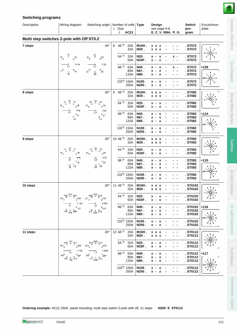
Description Wiring diagram Switching angle Number of cells Type Design Switch Escutcheon↓ Size see page 6-8 pro- plate
↓ AC21 E. Z. V. SMA. P. G. gram
Switching programs
D946E 225
Multi step switches 2-pole with Off ST0.2
7 steps 45° 8 48 20A M10H . x x x - - - . ST07232A M20 . x x x - - - . ST072
64 32A N20 . x - x - x - . ST07250A N33F . x - x - - - . ST072
88 63A N40 . x - x - x - . ST072 +12980A N61 . x - x - - - . ST072
115A N80 . x - x - - - . ST072
132 150A N100 . x - x - - - . ST072250A N200 . x - x - - - . ST072
8 steps 30° 9 48 20A M10H . x x x - - - . ST08232A M20 . x x x - - - . ST082
64 32A N20 . x - x - - - . ST08250A N33F . x - x - - - . ST082
88 63A N40 . x - x - - - . ST082 +11480A N61 . x - x - - - . ST082
115A N80 . x - x - - - . ST082
132 150A N100 . x - x - - - . ST082250A N200 . x - x - - - . ST082
9 steps 30° 10 48 20A M10H . x x x - - - . ST09232A M20 . x x x - - - . ST092
64 32A N20 . x - x - - - . ST09250A N33F . x - x - - - . ST092
88 63A N40 . x - x - - - . ST092 +11580A N61 . x - x - - - . ST092
115A N80 . x - x - - - . ST092
132 150A N100 . x - x - - - . ST092250A N200 . x - x - - - . ST092
10 steps 30° 11 48 20A M10H . x x x - - - . ST010232A M20 . x x x - - - . ST0102
64 32A N20 . x - x - - - . ST010250A N33F . x - x - - - . ST0102
88 63A N40 . x - x - - - . ST0102 +11680A N61 . x - x - - - . ST0102
115A N80 . x - x - - - . ST0102
132 150A N100 . x - x - - - . ST0102250A N200 . x - x - - - . ST0102
11 steps 30° 12 48 20A M10H . x x x - - - . ST011232A M20 . x x x - - - . ST0112
64 32A N20 . x - x - - - . ST011250A N33F . x - x - - - . ST0112
88 63A N40 . x - x - - - . ST0112 +11780A N61 . x - x - - - . ST0112
115A N80 . x - x - - - . ST0112
132 150A N100 . x - x - - - . ST0112250A N200 . x - x - - - . ST0112
Ordering example: AC21 250A panel mounting, multi step switch 2-pole with off, 11 steps N200 E ST0112
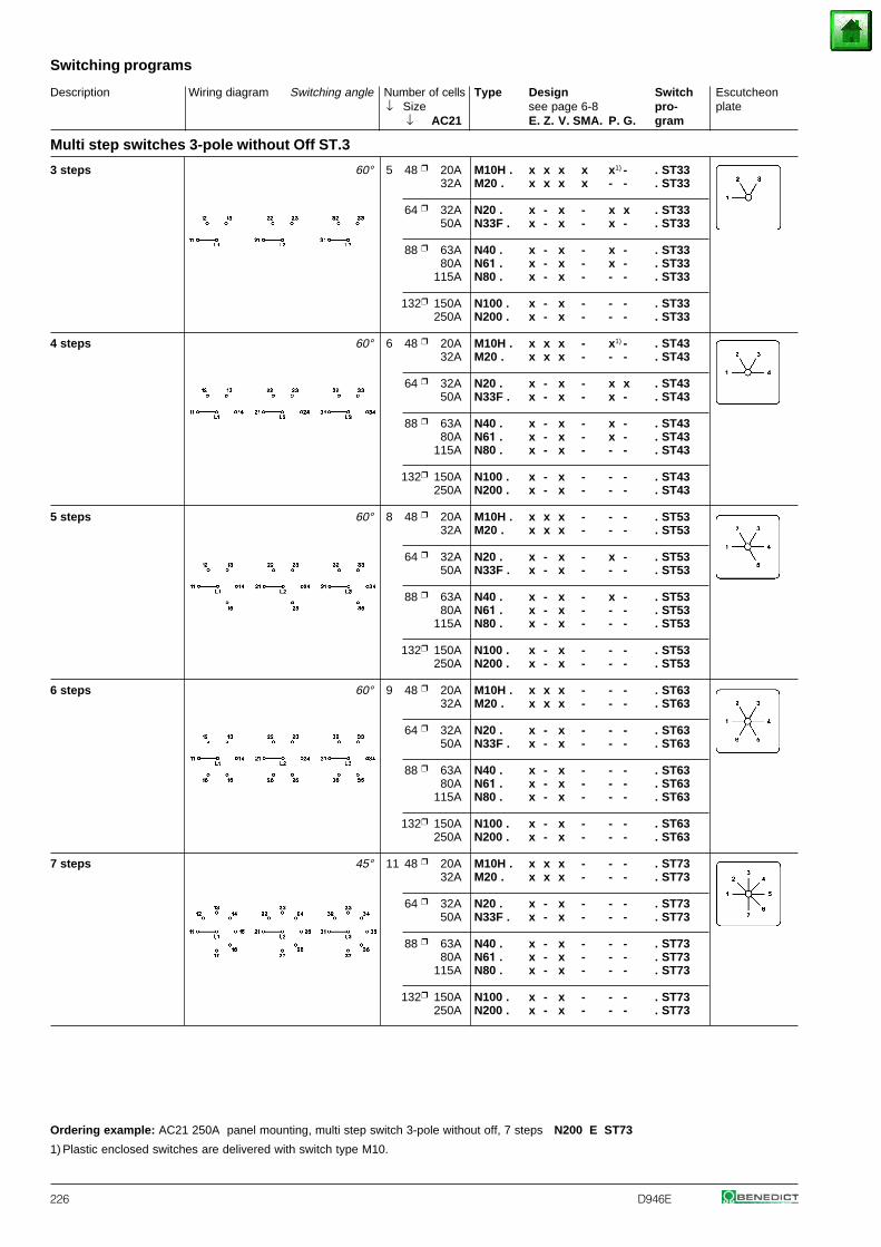
Description Wiring diagram Switching angle Number of cells Type Design Switch Escutcheon↓ Size see page 6-8 pro- plate
↓ AC21 E. Z. V. SMA. P. G. gram
Switching programs
226 D946E
Multi step switches 3-pole without Off ST.3
3 steps 60° 5 48 20A M10H . x x x x x1) - . ST3332A M20 . x x x x - - . ST33
64 32A N20 . x - x - x x . ST3350A N33F . x - x - x - . ST33
88 63A N40 . x - x - x - . ST3380A N61 . x - x - x - . ST33
115A N80 . x - x - - - . ST33
132 150A N100 . x - x - - - . ST33250A N200 . x - x - - - . ST33
4 steps 60° 6 48 20A M10H . x x x - x1) - . ST4332A M20 . x x x - - - . ST43
64 32A N20 . x - x - x x . ST4350A N33F . x - x - x - . ST43
88 63A N40 . x - x - x - . ST4380A N61 . x - x - x - . ST43
115A N80 . x - x - - - . ST43
132 150A N100 . x - x - - - . ST43250A N200 . x - x - - - . ST43
5 steps 60° 8 48 20A M10H . x x x - - - . ST5332A M20 . x x x - - - . ST53
64 32A N20 . x - x - x - . ST5350A N33F . x - x - - - . ST53
88 63A N40 . x - x - x - . ST5380A N61 . x - x - - - . ST53
115A N80 . x - x - - - . ST53
132 150A N100 . x - x - - - . ST53250A N200 . x - x - - - . ST53
6 steps 60° 9 48 20A M10H . x x x - - - . ST6332A M20 . x x x - - - . ST63
64 32A N20 . x - x - - - . ST6350A N33F . x - x - - - . ST63
88 63A N40 . x - x - - - . ST6380A N61 . x - x - - - . ST63
115A N80 . x - x - - - . ST63
132 150A N100 . x - x - - - . ST63250A N200 . x - x - - - . ST63
7 steps 45° 11 48 20A M10H . x x x - - - . ST7332A M20 . x x x - - - . ST73
64 32A N20 . x - x - - - . ST7350A N33F . x - x - - - . ST73
88 63A N40 . x - x - - - . ST7380A N61 . x - x - - - . ST73
115A N80 . x - x - - - . ST73
132 150A N100 . x - x - - - . ST73250A N200 . x - x - - - . ST73
Ordering example: AC21 250A panel mounting, multi step switch 3-pole without off, 7 steps N200 E ST73
1) Plastic enclosed switches are delivered with switch type M10.
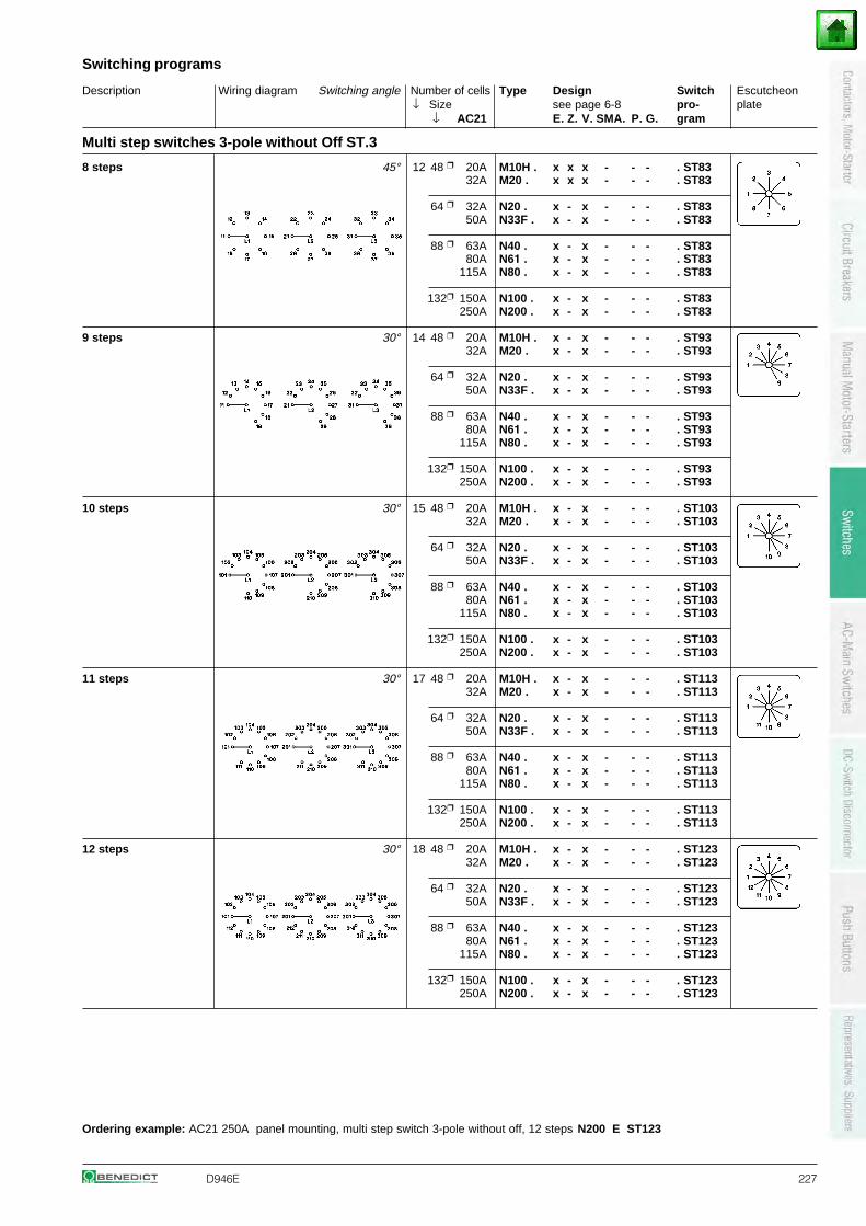
Description Wiring diagram Switching angle Number of cells Type Design Switch Escutcheon↓ Size see page 6-8 pro- plate
↓ AC21 E. Z. V. SMA. P. G. gram
Switching programs
D946E 227
Multi step switches 3-pole without Off ST.3
8 steps 45° 12 48 20A M10H . x x x - - - . ST8332A M20 . x x x - - - . ST83
64 32A N20 . x - x - - - . ST8350A N33F . x - x - - - . ST83
88 63A N40 . x - x - - - . ST8380A N61 . x - x - - - . ST83
115A N80 . x - x - - - . ST83
132 150A N100 . x - x - - - . ST83250A N200 . x - x - - - . ST83
9 steps 30° 14 48 20A M10H . x - x - - - . ST9332A M20 . x - x - - - . ST93
64 32A N20 . x - x - - - . ST9350A N33F . x - x - - - . ST93
88 63A N40 . x - x - - - . ST9380A N61 . x - x - - - . ST93
115A N80 . x - x - - - . ST93
132 150A N100 . x - x - - - . ST93250A N200 . x - x - - - . ST93
10 steps 30° 15 48 20A M10H . x - x - - - . ST10332A M20 . x - x - - - . ST103
64 32A N20 . x - x - - - . ST10350A N33F . x - x - - - . ST103
88 63A N40 . x - x - - - . ST10380A N61 . x - x - - - . ST103
115A N80 . x - x - - - . ST103
132 150A N100 . x - x - - - . ST103250A N200 . x - x - - - . ST103
11 steps 30° 17 48 20A M10H . x - x - - - . ST11332A M20 . x - x - - - . ST113
64 32A N20 . x - x - - - . ST11350A N33F . x - x - - - . ST113
88 63A N40 . x - x - - - . ST11380A N61 . x - x - - - . ST113
115A N80 . x - x - - - . ST113
132 150A N100 . x - x - - - . ST113250A N200 . x - x - - - . ST113
12 steps 30° 18 48 20A M10H . x - x - - - . ST12332A M20 . x - x - - - . ST123
64 32A N20 . x - x - - - . ST12350A N33F . x - x - - - . ST123
88 63A N40 . x - x - - - . ST12380A N61 . x - x - - - . ST123
115A N80 . x - x - - - . ST123
132 150A N100 . x - x - - - . ST123250A N200 . x - x - - - . ST123
Ordering example: AC21 250A panel mounting, multi step switch 3-pole without off, 12 steps N200 E ST123
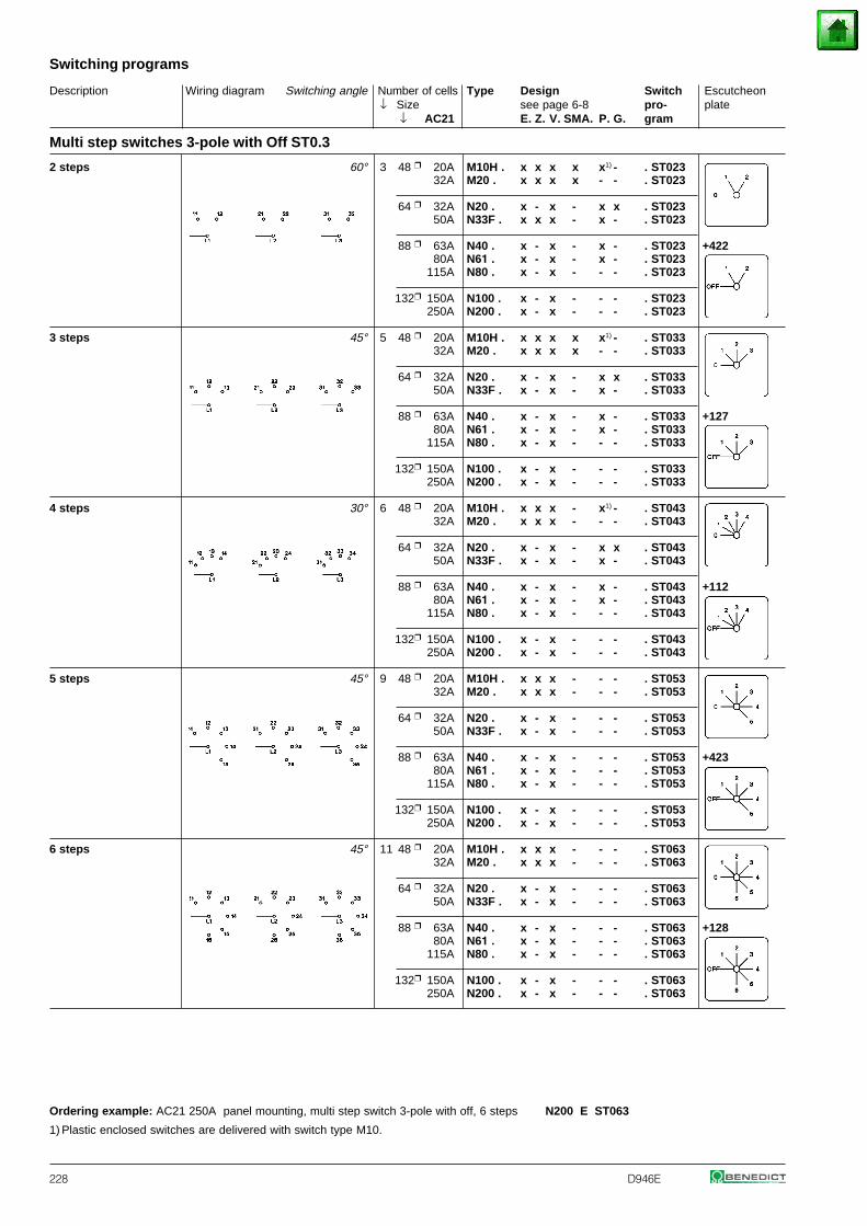
Description Wiring diagram Switching angle Number of cells Type Design Switch Escutcheon↓ Size see page 6-8 pro- plate
↓ AC21 E. Z. V. SMA. P. G. gram
Switching programs
228 D946E
Multi step switches 3-pole with Off ST0.3
2 steps 60° 3 48 20A M10H . x x x x x1) - . ST02332A M20 . x x x x - - . ST023
64 32A N20 . x - x - x x . ST02350A N33F . x x x - x - . ST023
88 63A N40 . x - x - x - . ST023 +42280A N61 . x - x - x - . ST023
115A N80 . x - x - - - . ST023
132 150A N100 . x - x - - - . ST023250A N200 . x - x - - - . ST023
3 steps 45° 5 48 20A M10H . x x x x x1) - . ST03332A M20 . x x x x - - . ST033
64 32A N20 . x - x - x x . ST03350A N33F . x - x - x - . ST033
88 63A N40 . x - x - x - . ST033 +12780A N61 . x - x - x - . ST033
115A N80 . x - x - - - . ST033
132 150A N100 . x - x - - - . ST033250A N200 . x - x - - - . ST033
4 steps 30° 6 48 20A M10H . x x x - x1) - . ST04332A M20 . x x x - - - . ST043
64 32A N20 . x - x - x x . ST04350A N33F . x - x - x - . ST043
88 63A N40 . x - x - x - . ST043 +11280A N61 . x - x - x - . ST043
115A N80 . x - x - - - . ST043
132 150A N100 . x - x - - - . ST043250A N200 . x - x - - - . ST043
5 steps 45° 9 48 20A M10H . x x x - - - . ST05332A M20 . x x x - - - . ST053
64 32A N20 . x - x - - - . ST05350A N33F . x - x - - - . ST053
88 63A N40 . x - x - - - . ST053 +42380A N61 . x - x - - - . ST053
115A N80 . x - x - - - . ST053
132 150A N100 . x - x - - - . ST053250A N200 . x - x - - - . ST053
6 steps 45° 11 48 20A M10H . x x x - - - . ST06332A M20 . x x x - - - . ST063
64 32A N20 . x - x - - - . ST06350A N33F . x - x - - - . ST063
88 63A N40 . x - x - - - . ST063 +12880A N61 . x - x - - - . ST063
115A N80 . x - x - - - . ST063
132 150A N100 . x - x - - - . ST063250A N200 . x - x - - - . ST063
Ordering example: AC21 250A panel mounting, multi step switch 3-pole with off, 6 steps N200 E ST063
1) Plastic enclosed switches are delivered with switch type M10.
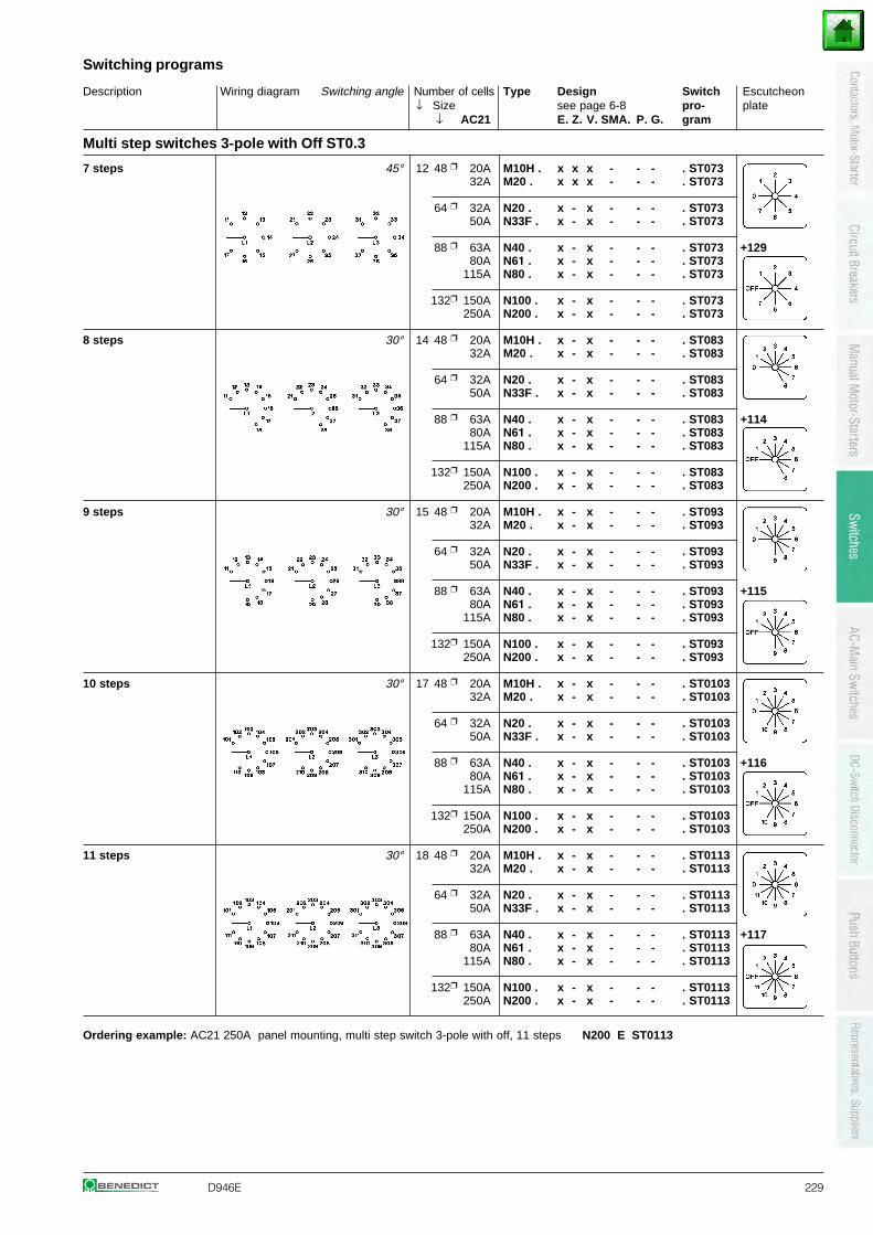
D946E 229
Multi step switches 3-pole with Off ST0.3
7 steps 45° 12 48 20A M10H . x x x - - - . ST07332A M20 . x x x - - - . ST073
64 32A N20 . x - x - - - . ST07350A N33F . x - x - - - . ST073
88 63A N40 . x - x - - - . ST073 +12980A N61 . x - x - - - . ST073
115A N80 . x - x - - - . ST073
132 150A N100 . x - x - - - . ST073250A N200 . x - x - - - . ST073
8 steps 30° 14 48 20A M10H . x - x - - - . ST08332A M20 . x - x - - - . ST083
64 32A N20 . x - x - - - . ST08350A N33F . x - x - - - . ST083
88 63A N40 . x - x - - - . ST083 +11480A N61 . x - x - - - . ST083
115A N80 . x - x - - - . ST083
132 150A N100 . x - x - - - . ST083250A N200 . x - x - - - . ST083
9 steps 30° 15 48 20A M10H . x - x - - - . ST09332A M20 . x - x - - - . ST093
64 32A N20 . x - x - - - . ST09350A N33F . x - x - - - . ST093
88 63A N40 . x - x - - - . ST093 +11580A N61 . x - x - - - . ST093
115A N80 . x - x - - - . ST093
132 150A N100 . x - x - - - . ST093250A N200 . x - x - - - . ST093
10 steps 30° 17 48 20A M10H . x - x - - - . ST010332A M20 . x - x - - - . ST0103
64 32A N20 . x - x - - - . ST010350A N33F . x - x - - - . ST0103
88 63A N40 . x - x - - - . ST0103 +11680A N61 . x - x - - - . ST0103
115A N80 . x - x - - - . ST0103
132 150A N100 . x - x - - - . ST0103250A N200 . x - x - - - . ST0103
11 steps 30° 18 48 20A M10H . x - x - - - . ST011332A M20 . x - x - - - . ST0113
64 32A N20 . x - x - - - . ST011350A N33F . x - x - - - . ST0113
88 63A N40 . x - x - - - . ST0113 +11780A N61 . x - x - - - . ST0113
115A N80 . x - x - - - . ST0113
132 150A N100 . x - x - - - . ST0113250A N200 . x - x - - - . ST0113
Ordering example: AC21 250A panel mounting, multi step switch 3-pole with off, 11 steps N200 E ST0113
Description Wiring diagram Switching angle Number of cells Type Design Switch Escutcheon↓ Size see page 6-8 pro- plate
↓ AC21 E. Z. V. SMA. P. G. gram
Switching programs
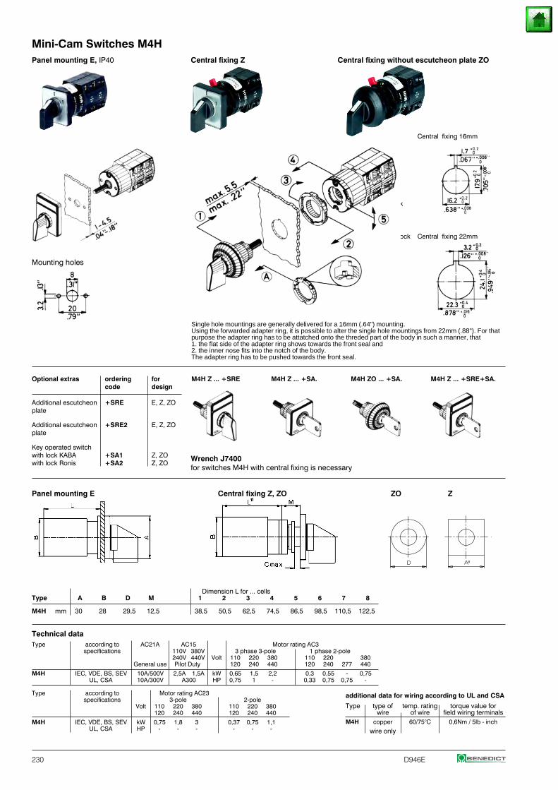
230 D946E
Panel mounting E, IP40 Central fixing Z Central fixing without escutcheon plate ZO
Central fixing 16mm
lock
unlock Central fixing 22mm
Mounting holes
Single hole mountings are generally delivered for a 16mm (.64") mounting.Using the forwarded adapter ring, it is possible to alter the single hole mountings from 22mm (.88"). For thatpurpose the adapter ring has to be attatched onto the threded part of the body in such a manner, that1. the flat side of the adapter ring shows towards the front seal and2. the inner nose fits into the notch of the body.The adapter ring has to be pushed towards the front seal.
Optional extras ordering for M4H Z ... +SRE M4H Z ... +SA. M4H ZO ... +SA. M4H Z ... +SRE+SA.code design
Additional escutcheon +SRE E, Z, ZOplate
Additional escutcheon +SRE2 E, Z, ZOplate
Key operated switchwith lock KABA +SA1 Z, ZOwith lock Ronis +SA2 Z, ZO
Panel mounting E Central fixing Z, ZO ZO Z
Dimension L for ... cellsType A B D M 1 2 3 4 5 6 7 8
M4H mm 30 28 29,5 12,5 38,5 50,5 62,5 74,5 86,5 98,5 110,5 122,5
Technical dataType according to AC21A AC15 Motor rating AC3
specifications 110V 380V 3 phase 3-pole 1 phase 2-pole240V 440V Volt 110 220 380 110 220 380
General use Pilot Duty 120 240 440 120 240 277 440
M4H IEC, VDE, BS, SEV 10A/500V 2,5A 1,5A kW 0,65 1,5 2,2 0,3 0,55 - 0,75UL, CSA 10A/300V A300 HP 0,75 1 - 0,33 0,75 0,75 -
Type according to Motor rating AC23specifications 3-pole 2-pole
Volt 110 220 380 110 220 380120 240 440 120 240 440
M4H IEC, VDE, BS, SEV kW 0,75 1,8 3 0,37 0,75 1,1UL, CSA HP - - - - - -
additional data for wiring according to UL and CSA
Type type of temp. rating torque value forwire of wire field wiring terminals
M4H copper 60/75°C 0,6Nm / 5lb - inch
wire only
Wrench J7400for switches M4H with central fixing is necessary
Mini-Cam Switches M4H
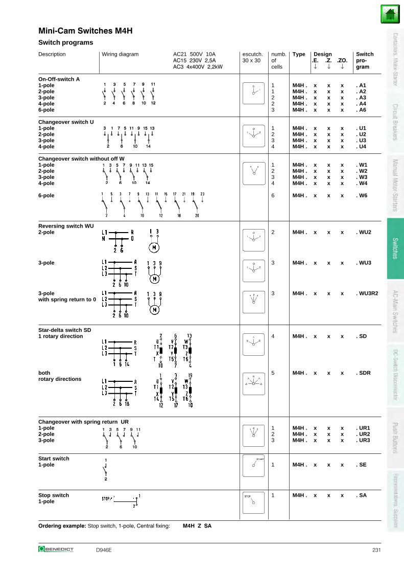
D946E 231
Description Wiring diagram AC21 500V 10A escutch. numb. Type Design SwitchAC15 230V 2,5A 30 x 30 of .E. .Z. .ZO. pro-AC3 4x400V 2,2kW cells ↓ ↓ ↓ gram
On-Off-switch A1-pole 1 M4H . x x x . A12-pole 1 M4H . x x x . A23-pole 2 M4H . x x x . A34-pole 2 M4H . x x x . A46-pole 3 M4H . x x x . A6
Changeover switch U1-pole 1 M4H . x x x . U12-pole 2 M4H . x x x . U23-pole 3 M4H . x x x . U34-pole 4 M4H . x x x . U4
Changeover switch without off W1-pole 1 M4H . x x x . W12-pole 2 M4H . x x x . W23-pole 3 M4H . x x x . W34-pole 4 M4H . x x x . W4
6-pole 6 M4H . x x x . W6
Reversing switch WU2-pole 2 M4H . x x x . WU2
3-pole 3 M4H . x x x . WU3
3-pole 3 M4H . x x x . WU3R2with spring return to 0
Star-delta switch SD1 rotary direction 4 M4H . x x x . SD
both 5 M4H . x x x . SDRrotary directions
Changeover with spring return UR1-pole 1 M4H . x x x . UR12-pole 2 M4H . x x x . UR23-pole 3 M4H . x x x . UR3
Start switch1-pole 1 M4H . x x x . SE
Stop switch 1 M4H . x x x . SA1-pole
Ordering example: Stop switch, 1-pole, Central fixing: M4H Z SA
Switch programs
Mini-Cam Switches M4H
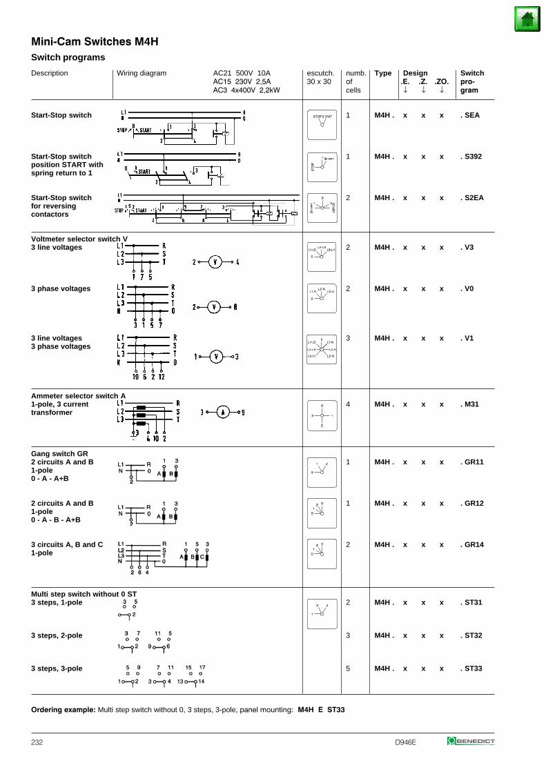
232 D946E
Description Wiring diagram AC21 500V 10A escutch. numb. Type Design SwitchAC15 230V 2,5A 30 x 30 of .E. .Z. .ZO. pro-AC3 4x400V 2,2kW cells ↓ ↓ ↓ gram
Start-Stop switch 1 M4H . x x x . SEA
Start-Stop switch 1 M4H . x x x . S392position START withspring return to 1
Start-Stop switch 2 M4H . x x x . S2EAfor reversingcontactors
Voltmeter selector switch V3 line voltages 2 M4H . x x x . V3
3 phase voltages 2 M4H . x x x . V0
3 line voltages 3 M4H . x x x . V13 phase voltages
Ammeter selector switch A1-pole, 3 current 4 M4H . x x x . M31transformer
Gang switch GR2 circuits A and B 1 M4H . x x x . GR111-pole0 - A - A+B
2 circuits A and B 1 M4H . x x x . GR121-pole0 - A - B - A+B
3 circuits A, B and C 2 M4H . x x x . GR141-pole
Multi step switch without 0 ST3 steps, 1-pole 2 M4H . x x x . ST31
3 steps, 2-pole 3 M4H . x x x . ST32
3 steps, 3-pole 5 M4H . x x x . ST33
Ordering example: Multi step switch without 0, 3 steps, 3-pole, panel mounting: M4H E ST33
Switch programs
Mini-Cam Switches M4H
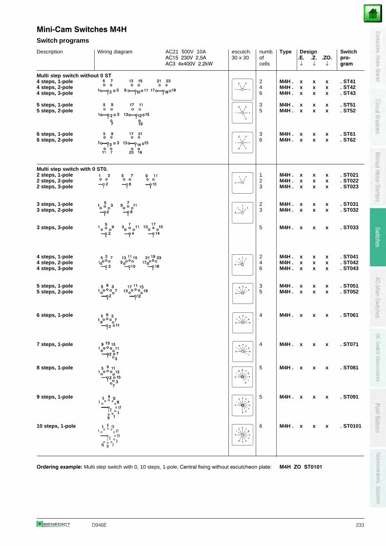
D946E 233
Switch programs
Description Wiring diagram AC21 500V 10A escutch. numb. Type Design SwitchAC15 230V 2,5A 30 x 30 of .E. .Z. .ZO. pro-AC3 4x400V 2,2kW cells ↓ ↓ ↓ gram
Multi step switch without 0 ST4 steps, 1-pole 2 M4H . x x x . ST414 steps, 2-pole 4 M4H . x x x . ST424 steps, 3-pole 6 M4H . x x x . ST43
5 steps, 1-pole 3 M4H . x x x . ST515 steps, 2-pole 5 M4H . x x x . ST52
6 steps, 1-pole 3 M4H . x x x . ST616 steps, 2-pole 6 M4H . x x x . ST62
Multi step switch with 0 ST0.2 steps, 1-pole 1 M4H . x x x . ST0212 steps, 2-pole 2 M4H . x x x . ST0222 steps, 3-pole 3 M4H . x x x . ST023
3 steps, 1-pole 2 M4H . x x x . ST0313 steps, 2-pole 3 M4H . x x x . ST032
3 steps, 3-pole 5 M4H . x x x . ST033
4 steps, 1-pole 2 M4H . x x x . ST0414 steps, 2-pole 4 M4H . x x x . ST0424 steps, 3-pole 6 M4H . x x x . ST043
5 steps, 1-pole 3 M4H . x x x . ST0515 steps, 2-pole 5 M4H . x x x . ST052
6 steps, 1-pole 4 M4H . x x x . ST061
7 steps, 1-pole 4 M4H . x x x . ST071
8 steps, 1-pole 5 M4H . x x x . ST081
9 steps, 1-pole 5 M4H . x x x . ST091
10 steps, 1-pole 6 M4H . x x x . ST0101
Ordering example: Multi step switch with 0, 10 steps, 1-pole, Central fixing without escutcheon plate: M4H ZO ST0101
Mini-Cam Switches M4H
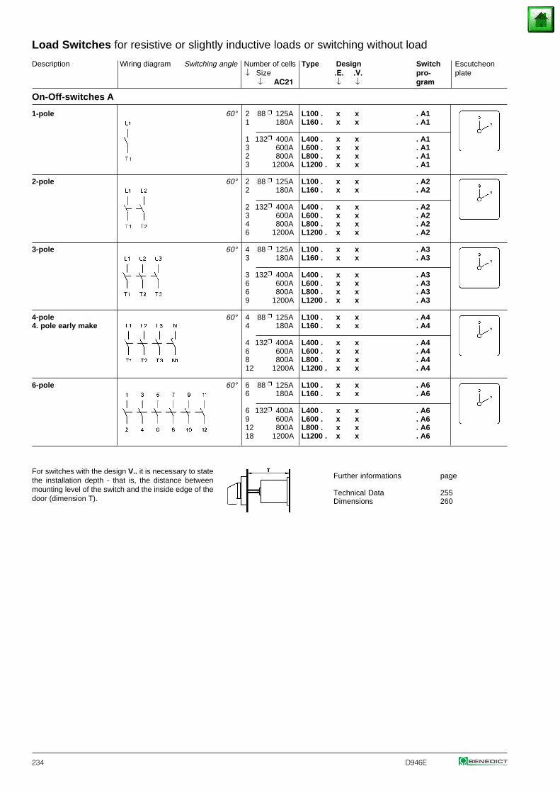
234 D946E
For switches with the design V.. it is necessary to statethe installation depth - that is, the distance betweenmounting level of the switch and the inside edge of thedoor (dimension T).
Further informations page
Technical Data 255Dimensions 260
On-Off-switches A
Description Wiring diagram Switching angle Number of cells Type Design Switch Escutcheon↓ Size .E. .V. pro- plate
↓ AC21 ↓ ↓ gram
Load Switches for resistive or slightly inductive loads or switching without load
1-pole 60° 2 88 125A L100 . x x . A11 180A L160 . x x . A1
1 132 400A L400 . x x . A13 600A L600 . x x . A12 800A L800 . x x . A13 1200A L1200 . x x . A1
2-pole 60° 2 88 125A L100 . x x . A22 180A L160 . x x . A2
2 132 400A L400 . x x . A23 600A L600 . x x . A24 800A L800 . x x . A26 1200A L1200 . x x . A2
3-pole 60° 4 88 125A L100 . x x . A33 180A L160 . x x . A3
3 132 400A L400 . x x . A36 600A L600 . x x . A36 800A L800 . x x . A39 1200A L1200 . x x . A3
4-pole 60° 4 88 125A L100 . x x . A44. pole early make 4 180A L160 . x x . A4
4 132 400A L400 . x x . A46 600A L600 . x x . A48 800A L800 . x x . A412 1200A L1200 . x x . A4
6-pole 60° 6 88 125A L100 . x x . A66 180A L160 . x x . A6
6 132 400A L400 . x x . A69 600A L600 . x x . A612 800A L800 . x x . A618 1200A L1200 . x x . A6
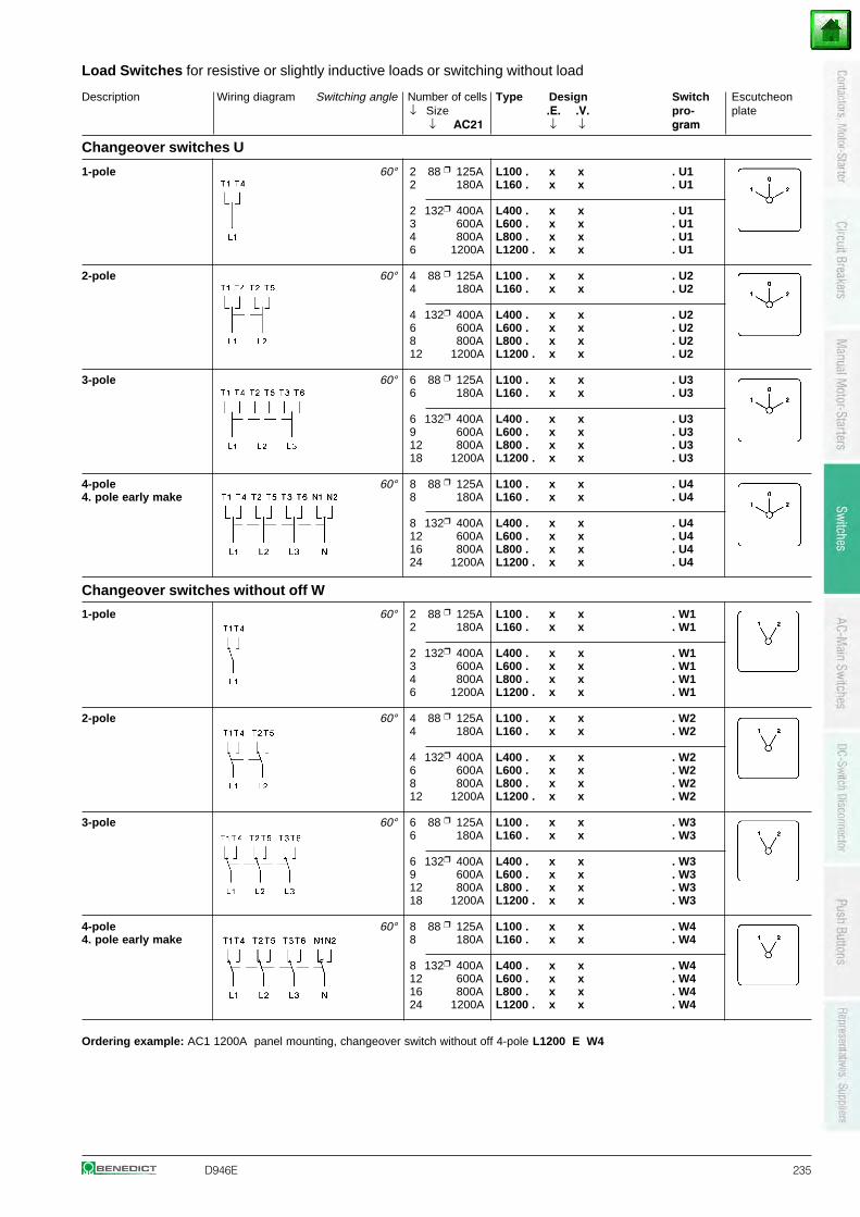
D946E 235
Description Wiring diagram Switching angle Number of cells Type Design Switch Escutcheon↓ Size .E. .V. pro- plate
↓ AC21 ↓ ↓ gram
Load Switches for resistive or slightly inductive loads or switching without load
Changeover switches U
1-pole 60° 2 88 125A L100 . x x . U12 180A L160 . x x . U1
2 132 400A L400 . x x . U13 600A L600 . x x . U14 800A L800 . x x . U16 1200A L1200 . x x . U1
2-pole 60° 4 88 125A L100 . x x . U24 180A L160 . x x . U2
4 132 400A L400 . x x . U26 600A L600 . x x . U28 800A L800 . x x . U212 1200A L1200 . x x . U2
3-pole 60° 6 88 125A L100 . x x . U36 180A L160 . x x . U3
6 132 400A L400 . x x . U39 600A L600 . x x . U312 800A L800 . x x . U318 1200A L1200 . x x . U3
4-pole 60° 8 88 125A L100 . x x . U44. pole early make 8 180A L160 . x x . U4
8 132 400A L400 . x x . U412 600A L600 . x x . U416 800A L800 . x x . U424 1200A L1200 . x x . U4
Changeover switches without off W
Ordering example: AC1 1200A panel mounting, changeover switch without off 4-pole L1200 E W4
1-pole 60° 2 88 125A L100 . x x . W12 180A L160 . x x . W1
2 132 400A L400 . x x . W13 600A L600 . x x . W14 800A L800 . x x . W16 1200A L1200 . x x . W1
2-pole 60° 4 88 125A L100 . x x . W24 180A L160 . x x . W2
4 132 400A L400 . x x . W26 600A L600 . x x . W28 800A L800 . x x . W212 1200A L1200 . x x . W2
3-pole 60° 6 88 125A L100 . x x . W36 180A L160 . x x . W3
6 132 400A L400 . x x . W39 600A L600 . x x . W312 800A L800 . x x . W318 1200A L1200 . x x . W3
4-pole 60° 8 88 125A L100 . x x . W44. pole early make 8 180A L160 . x x . W4
8 132 400A L400 . x x . W412 600A L600 . x x . W416 800A L800 . x x . W424 1200A L1200 . x x . W4
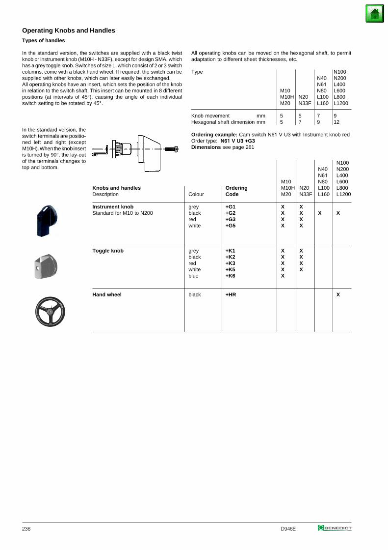
236 D946E
Operating Knobs and Handles
All operating knobs can be moved on the hexagonal shaft, to permitadaptation to different sheet thicknesses, etc.
Type N100N40 N200N61 L400
M10 N80 L600M10H N20 L100 L800M20 N33F L160 L1200
Knob movement mm 5 5 7 9Hexagonal shaft dimension mm 5 7 9 12
Ordering example: Cam switch N61 V U3 with Instrument knob red Order type: N61 V U3 +G3Dimensions see page 261
Types of handles
In the standard version, the switches are supplied with a black twistknob or instrument knob (M10H - N33F), except for design SMA, whichhas a grey toggle knob. Switches of size L, which consist of 2 or 3 switchcolumns, come with a black hand wheel. If required, the switch can besupplied with other knobs, which can later easily be exchanged.All operating knobs have an insert, which sets the position of the knobin relation to the switch shaft. This insert can be mounted in 8 differentpositions (at intervals of 45°), causing the angle of each individualswitch setting to be rotated by 45°.
In the standard version, theswitch terminals are positio-ned left and right (exceptM10H). When the knob insertis turned by 90°, the lay-outof the terminals changes totop and bottom.
N100N40 N200N61 L400
M10 N80 L600Knobs and handles Ordering M10H N20 L100 L800Description Colour Code M20 N33F L160 L1200
Instrument knob grey +G1 X XStandard for M10 to N200 black +G2 X X X X
red +G3 X Xwhite +G5 X X
Toggle knob grey +K1 X Xblack +K2 X Xred +K3 X Xwhite +K5 X Xblue +K6 X
Hand wheel black +HR X
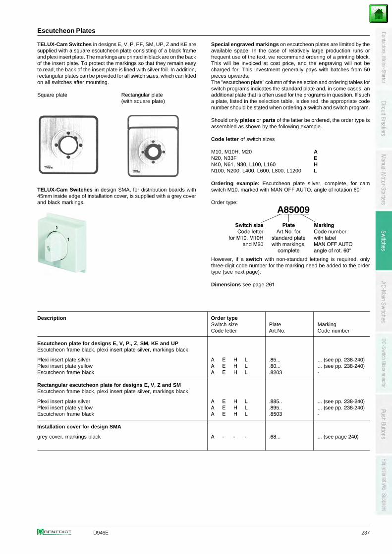
D946E 237
Escutcheon Plates
TELUX-Cam Switches in designs E, V, P, PF, SM, UP, Z and KE aresupplied with a square escutcheon plate consisting of a black frameand plexi insert plate. The markings are printed in black are on the backof the insert plate. To protect the markings so that they remain easyto read, the back of the insert plate is lined with silver foil. In addition,rectangular plates can be provided for all switch sizes, which can fittedon all switches after mounting.
Square plate Rectangular plate(with square plate)
TELUX-Cam Switches in design SMA, for distribution boards with45mm inside edge of installation cover, is supplied with a grey coverand black markings.
Special engraved markings on escutcheon plates are limited by theavailable space. In the case of relatively large production runs orfrequent use of the text, we recommend ordering of a printing block.This will be invoiced at cost price, and the engraving will not becharged for. This investment generally pays with batches from 50pieces upwards.The "escutcheon plate" column of the selection and ordering tables forswitch programs indicates the standard plate and, in some cases, anadditional plate that is often used for the programs in question. If sucha plate, listed in the selection table, is desired, the appropriate codenumber should be stated when ordering a switch and switch program.
Should only plates or parts of the latter be ordered, the order type isassembled as shown by the following example.
Code letter of switch sizes
AEH
M10, M10H, M20N20, N33FN40, N61, N80, L100, L160N100, N200, L400, L600, L800, L1200 L
Ordering example: Escutcheon plate silver, complete, for camswitch M10, marked with MAN OFF AUTO, angle of rotation 60°
Order type:
However, if a switch with non-standard lettering is required, onlythree-digit code number for the marking need be added to the ordertype (see next page).
Dimensions see page 261
Description Order typeSwitch size Plate MarkingCode letter Art.No. Code number
Escutcheon plate for designs E, V, P., Z, SM, KE and UPEscutcheon frame black, plexi insert plate silver, markings black
Plexi insert plate silver A E H L .85... ... (see pp. 238-240)Plexi insert plate yellow A E H L .80... ... (see pp. 238-240)Escutcheon frame black A E H L .8203 -
Rectangular escutcheon plate for designs E, V, Z and SMEscutcheon frame black, plexi insert plate silver, markings black
Plexi insert plate silver A E H L .885.. ... (see pp. 238-240)Plexi insert plate yellow A E H L .895.. ... (see pp. 238-240)Escutcheon frame black A E H L .8503 -
Installation cover for design SMA
grey cover, markings black A - - - .68... ... (see page 240)
A85009
Switch size Plate MarkingCode letter Art.No. for Code number
for M10, M10H standard plate with labeland M20 with markings, MAN OFF AUTO
complete angle of rot. 60°
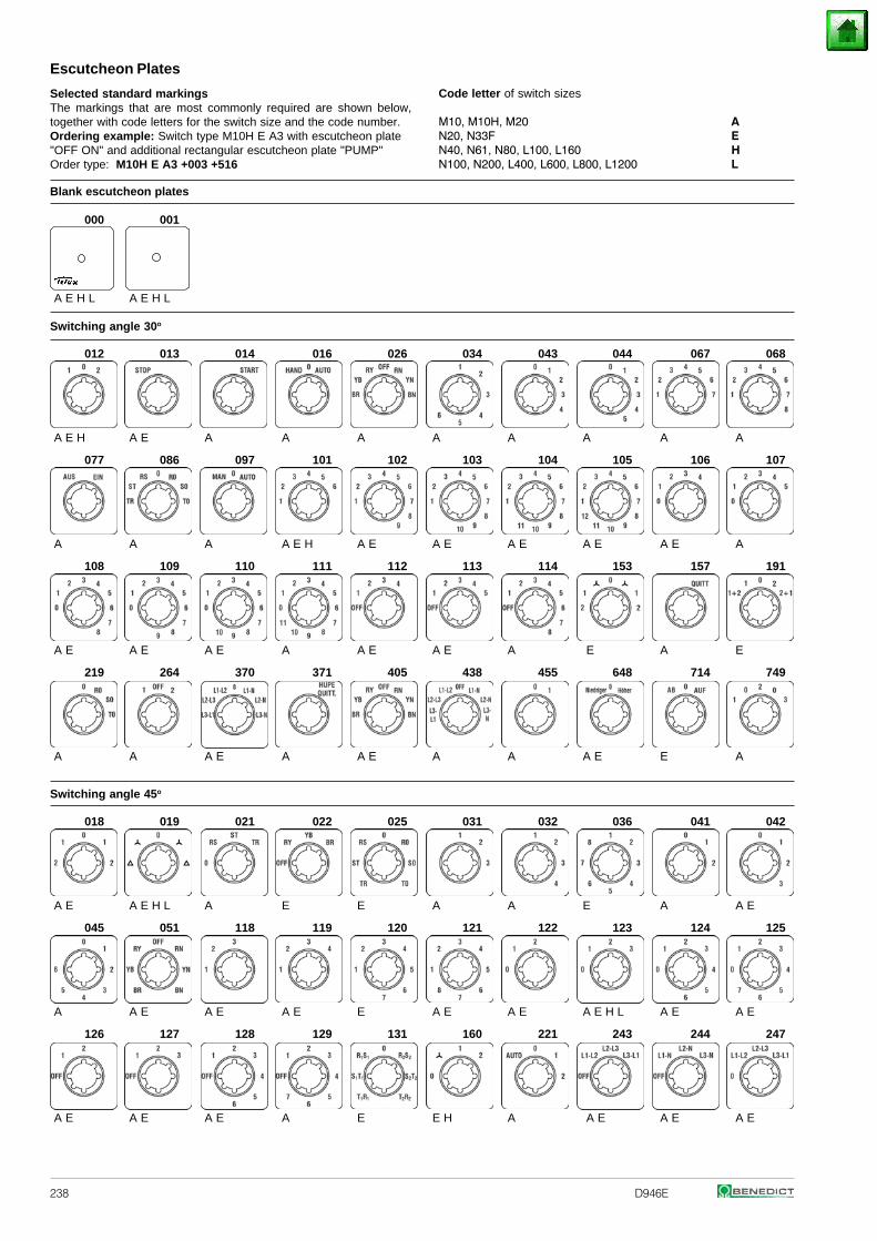
238 D946E
Escutcheon Plates
Code letter of switch sizes
AEH
M10, M10H, M20N20, N33FN40, N61, N80, L100, L160N100, N200, L400, L600, L800, L1200 L
Selected standard markingsThe markings that are most commonly required are shown below,together with code letters for the switch size and the code number.Ordering example: Switch type M10H E A3 with escutcheon plate"OFF ON" and additional rectangular escutcheon plate "PUMP"Order type: M10H E A3 +003 +516
Blank escutcheon plates
000 001
A E H L A E H L
Switching angle 30o
012 013 014 016 026 034 043 044 067 068
A E H A E A A A A A A A A
077 086 097 101 102 103 104 105 106 107
A A A A E H A E A E A E A E A E A
108 109 110 111 112 113 114 153 157 191
A E A E A E A A E A E A E A E
219 264 370 371 405 438 455 648 714 749
A A A E A A E A A A E E A
Switching angle 45o
018 019 021 022 025 031 032 036 041 042
A E A E H L A E E A A E A A E
045 051 118 119 120 121 122 123 124 125
A A E A E A E E A E A E A E H L A E A E
126 127 128 129 131 160 221 243 244 247
A E A E A E A E E H A A E A E A E
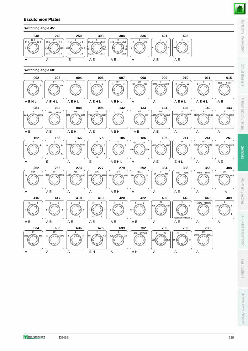
D946E 239
Escutcheon Plates
Switching angle 45o
248 249 250 303 304 336 421 423
A A E A E A E A A E A E
Switching angle 60o
002 003 004 006 007 008 009 010 011 015
A E H L A E H L A E H L A E H L A E H L A A A E H L A E H L A E
081 082 088 095 132 133 134 136 140 143
A E A E A E H A E A E H A E A E A A A
162 163 166 175 185 186 195 211 241 251
A E A E A E H L A A E E H L A A E
252 266 273 277 279 292 334 338 355 408
A A E A A A E H A A A E A A
416 417 418 419 420 422 439 446 448 489
A E A E A E A E A E A E A A E A A
634 635 636 675 699 702 706 739 798
A A A E H A A H A A A
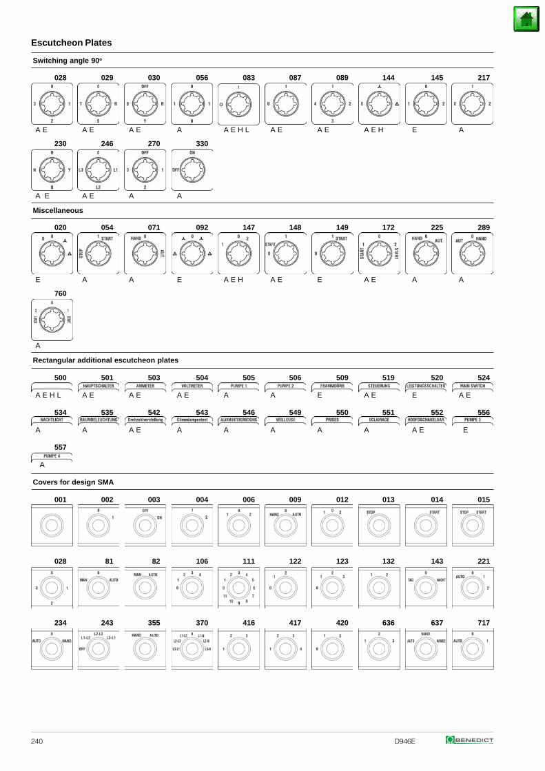
240 D946E
Escutcheon Plates
Switching angle 90o
028 029 030 056 083 087 089 144 145 217
A E A E A E A A E H L A E A E A E H E A
230 246 270 330
A E A E A A
Miscellaneous
020 054 071 092 147 148 149 172 225 289
E A A E A E H A E E A E A A
760
A
Rectangular additional escutcheon plates
500 501 503 504 505 506 509 519 520 524
A E H L A E A E A E A A E A E E A E
534 535 542 543 546 549 550 551 552 556
A A A E A A A A A A E E
557
A
Covers for design SMA
001 002 003 004 006 009 012 013 014 015
028 81 82 106 111 122 123 132 143 221
234 243 355 370 416 417 420 636 637 717
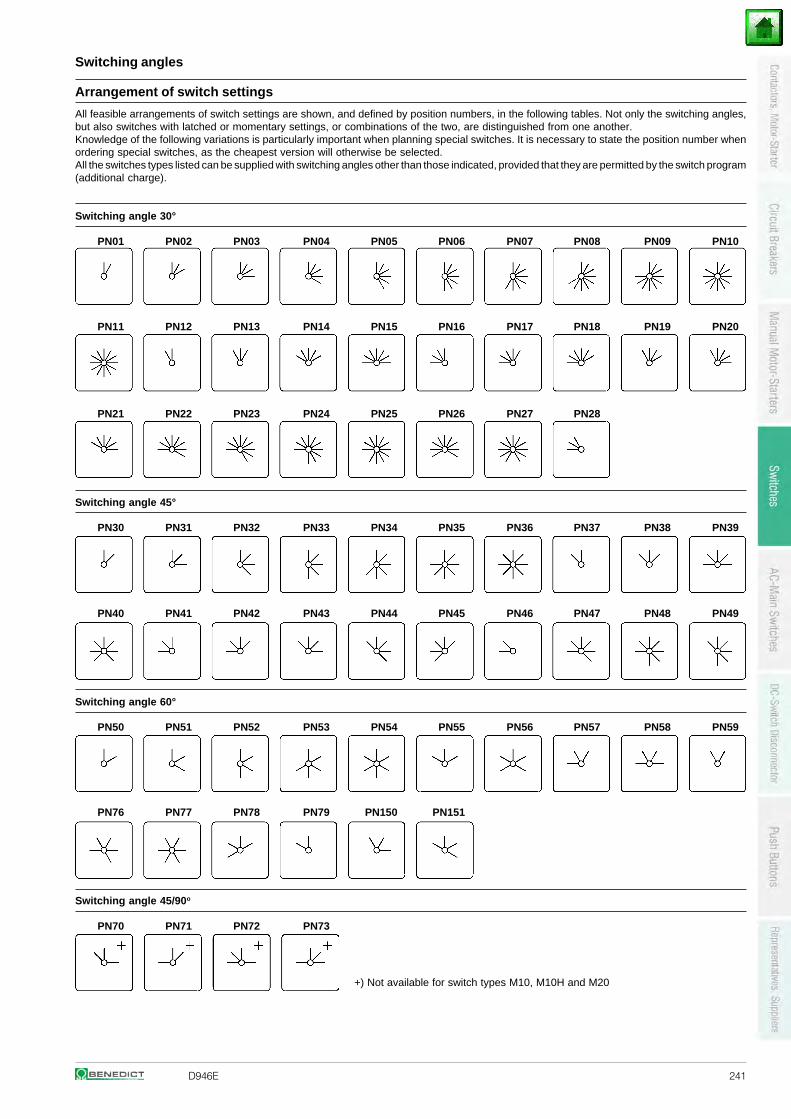
D946E 241
Switching angles
Arrangement of switch settings
All feasible arrangements of switch settings are shown, and defined by position numbers, in the following tables. Not only the switching angles,but also switches with latched or momentary settings, or combinations of the two, are distinguished from one another.Knowledge of the following variations is particularly important when planning special switches. It is necessary to state the position number whenordering special switches, as the cheapest version will otherwise be selected.All the switches types listed can be supplied with switching angles other than those indicated, provided that they are permitted by the switch program(additional charge).
Switching angle 30°
PN01 PN02 PN03 PN04 PN05 PN06 PN07 PN08 PN09 PN10
PN11 PN12 PN13 PN14 PN15 PN16 PN17 PN18 PN19 PN20
PN21 PN22 PN23 PN24 PN25 PN26 PN27 PN28
Switching angle 45°
PN30 PN31 PN32 PN33 PN34 PN35 PN36 PN37 PN38 PN39
PN40 PN41 PN42 PN43 PN44 PN45 PN46 PN47 PN48 PN49
Switching angle 60°
PN50 PN51 PN52 PN53 PN54 PN55 PN56 PN57 PN58 PN59
PN76 PN77 PN78 PN79 PN150 PN151
Switching angle 45/90o
PN70 PN71 PN72 PN73
+) Not available for switch types M10, M10H and M20
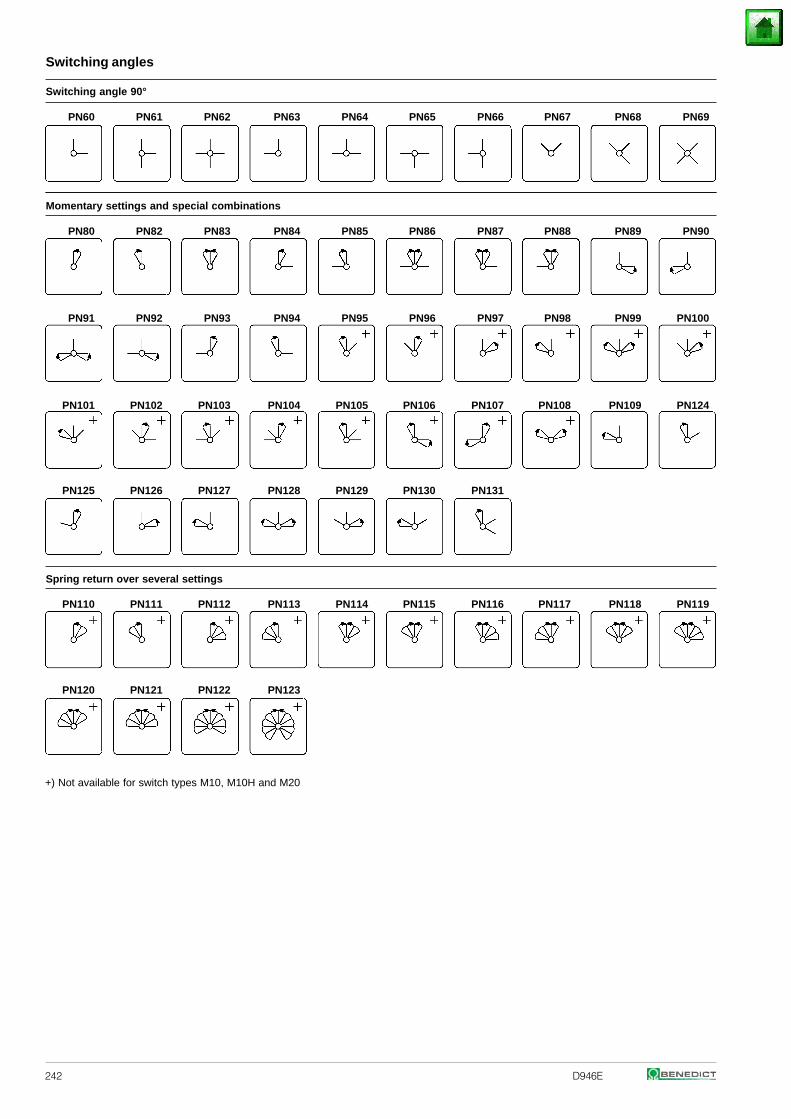
242 D946E
Switching angles
+) Not available for switch types M10, M10H and M20
Switching angle 90°
PN60 PN61 PN62 PN63 PN64 PN65 PN66 PN67 PN68 PN69
Momentary settings and special combinations
PN80 PN82 PN83 PN84 PN85 PN86 PN87 PN88 PN89 PN90
PN91 PN92 PN93 PN94 PN95 PN96 PN97 PN98 PN99 PN100
PN101 PN102 PN103 PN104 PN105 PN106 PN107 PN108 PN109 PN124
PN125 PN126 PN127 PN128 PN129 PN130 PN131
Spring return over several settings
PN110 PN111 PN112 PN113 PN114 PN115 PN116 PN117 PN118 PN119
PN120 PN121 PN122 PN123
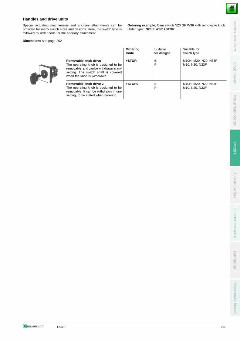
D946E 243
Handles and drive unitsSpecial actuating mechanisms and ancillary attachments can beprovided for many switch sizes and designs. Here, the switch type isfollowed by order code for the ancillary attachment.
Dimensions see page 262
Removable knob driveThe operating knob is designed to beremovable, and can be withdrawn in anysetting. The switch shaft is coveredwhen the knob is withdrawn.
Removable knob drive 2The operating knob is designed to beremovable. It can be withdrawn in onesetting, to be stated when ordering.
Ordering Suitable Suitable forCode for designs switch type
+STGR E M10H, M20, N20, N33FP M10, N20, N33F
+STGR2 E M10H, M20, N20, N33FP M10, N20, N33F
Ordering example: Cam switch N20 GF W3R with removable knobOrder type: N20 E W3R +STGR
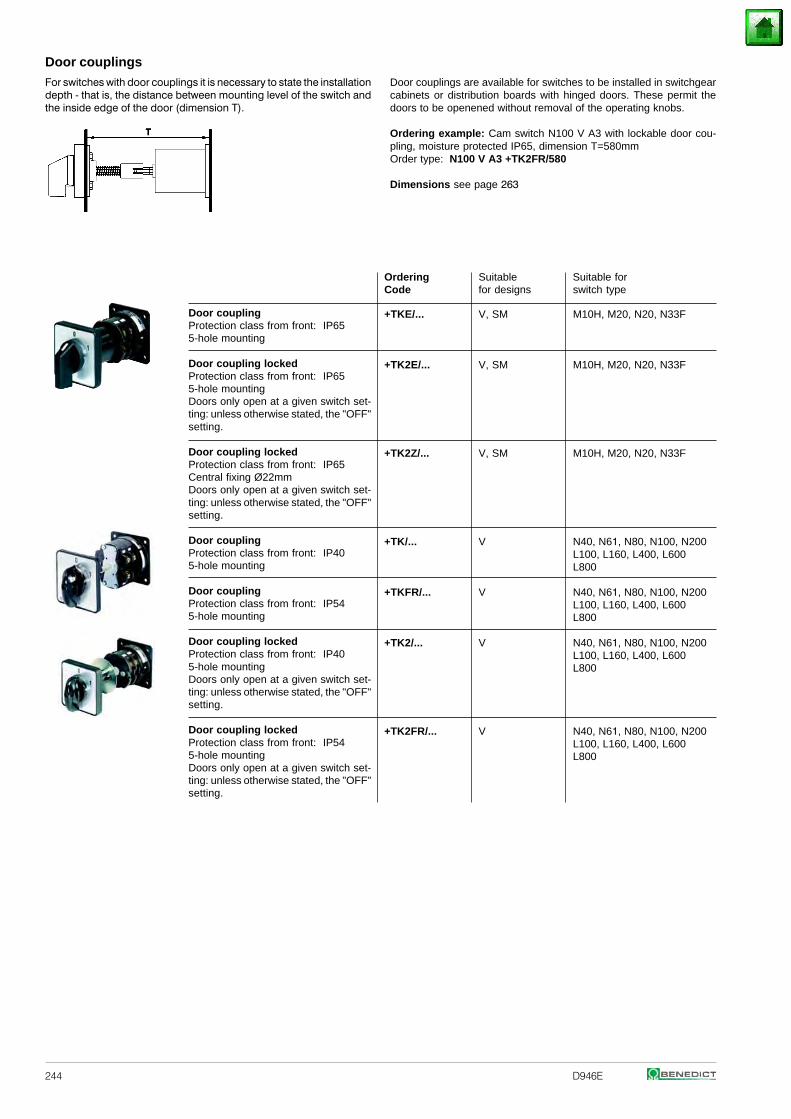
244 D946E
Door couplingsDoor couplings are available for switches to be installed in switchgearcabinets or distribution boards with hinged doors. These permit thedoors to be openened without removal of the operating knobs.
Ordering example: Cam switch N100 V A3 with lockable door cou-pling, moisture protected IP65, dimension T=580mmOrder type: N100 V A3 +TK2FR/580
Dimensions see page 263
For switches with door couplings it is necessary to state the installationdepth - that is, the distance between mounting level of the switch andthe inside edge of the door (dimension T).
Ordering Suitable Suitable forCode for designs switch type
+TKE/... V, SM M10H, M20, N20, N33F
+TK2E/... V, SM M10H, M20, N20, N33F
+TK2Z/... V, SM M10H, M20, N20, N33F
+TK/... V N40, N61, N80, N100, N200 L100, L160, L400, L600 L800
+TKFR/... V N40, N61, N80, N100, N200 L100, L160, L400, L600 L800
+TK2/... V N40, N61, N80, N100, N200 L100, L160, L400, L600 L800
+TK2FR/... V N40, N61, N80, N100, N200 L100, L160, L400, L600 L800
Door couplingProtection class from front: IP655-hole mounting
Door coupling lockedProtection class from front: IP655-hole mountingDoors only open at a given switch set-ting: unless otherwise stated, the "OFF"setting.
Door coupling lockedProtection class from front: IP65Central fixing Ø22mmDoors only open at a given switch set-ting: unless otherwise stated, the "OFF"setting.
Door couplingProtection class from front: IP405-hole mounting
Door couplingProtection class from front: IP545-hole mounting
Door coupling lockedProtection class from front: IP405-hole mountingDoors only open at a given switch set-ting: unless otherwise stated, the "OFF"setting.
Door coupling lockedProtection class from front: IP545-hole mountingDoors only open at a given switch set-ting: unless otherwise stated, the "OFF"setting.
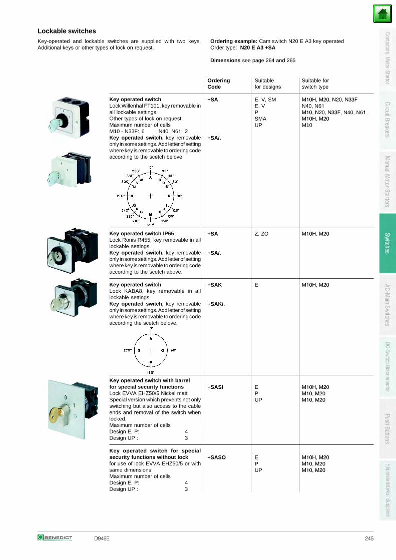
D946E 245
Lockable switchesOrdering example: Cam switch N20 E A3 key operatedOrder type: N20 E A3 +SA
Dimensions see page 264 and 265
Key-operated and lockable switches are supplied with two keys.Additional keys or other types of lock on request.
Ordering Suitable Suitable forCode for designs switch type
+SA E, V, SME, VPSMAUP
M10H, M20, N20, N33F N40, N61M10, N20, N33F, N40, N61 M10H, M20M10
+SA/.
+SA Z, ZO M10H, M20
+SA/.
+SAK E M10H, M20
+SAK/.
+SASI E M10H, M20P M10, M20UP M10, M20
+SASO E M10H, M20P M10, M20UP M10, M20
Key operated switchLock Willenhal FT101, key removable in all lockable settings.Other types of lock on request. Maximum number of cellsM10 - N33F: 6 N40, N61: 2 Key operated switch, key removable only in some settings. Add letter of setting where key is removable to ordering code according to the scetch belove.
Key operated switch IP65Lock Ronis R455, key removable in alllockable settings.Key operated switch, key removableonly in some settings. Add letter of settingwhere key is removable to ordering codeaccording to the scetch above.
Key operated switchLock KABA8, key removable in alllockable settings.Key operated switch, key removableonly in some settings. Add letter of settingwhere key is removable to ordering codeaccording the scetch belove.
Key operated switch with barrelfor special security functionsLock EVVA EHZ50/5 Nickel mattSpecial version which prevents not onlyswitching but also access to the cableends and removal of the switch whenlocked.Maximum number of cellsDesign E, P: 4Design UP : 3
Key operated switch for specialsecurity functions without lockfor use of lock EVVA EHZ50/5 or withsame dimensionsMaximum number of cellsDesign E, P: 4Design UP : 3
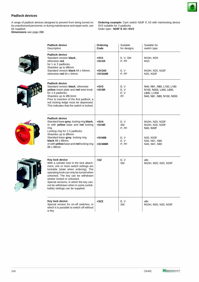
246 D946E
Padlock devices
A range of padlock devices designed to prevent from being turned onby unauthorized personnel, or during maintenance and repair work, canbe supplied.Dimensions see page 266
Ordering example: Cam switch N33F E A3 with interlocking deviceSV3 suitable for 3 padlocksOrder type: N33F E A3 +SV3
Padlock deviceDescription
Padlock deviceStandard version black,otherwise red,for 1 or 2 padlocks.Shackles up to Ø6mmStandard version black 64 x 64mm,otherwise red 64 x 64mm
Padlock deviceStandard version black, otherwiseyellow insert plate and red twist knobfor 1-3 padlocks.Shackles up to Ø8,5mmPrior to insertion of the first padlock, ared locking ledge must be depressed.This indicates that the switch is locked.
Padlock deviceStandard base grey, locking ring black,or with yellow base and red lockingring.Locking ring for 1-3 padlocks.Shackles up to Ø6mmStandard base grey, locking ringblack 88 x 88mm,or with yellow base and red locking ring88 x 88mm
Key lock deviceWith a cylinder lock in the lock attach-ment, one or more switch settings arelockable (state when ordering). Theoperating knob can only be turned whenunlocked. The key can be withdrawnwheter locked or unlocked.Special versions, in which the key can-not be withdrawn when in some (unlok-kable) settings can be supplied.
Key lock deviceSpecial version for on-off switches, inwhich it is possible to switch off withouta key.
Ordering Suitable Suitable forCode for designs switch type
+SV1 E, V, SM M10H, M20+SV1R P, PF M10
+SV164 E, V M10H, N20, N33F+SV164R P, PF N20, N33F
+SV3 E, V+SV3R E, V
E, VPF
N40, N61, N80, L100, L160 N100, N200, L400, L600, L800, L1200N40, N61, N80, N100, N200
+SV4 E, V M10H, N20, N33F+SV4R SM M10H, N20, N33F
P, PF N20, N33F
+SV488 E, V N20, N33FE, V N40, N61, N80
+SV488R P, PF N40, N61, N80
+SZ E, V alleSM M10H, M20, N20, N33F
+SZ2 E, V alleSM M10H, M20, N20, N33F
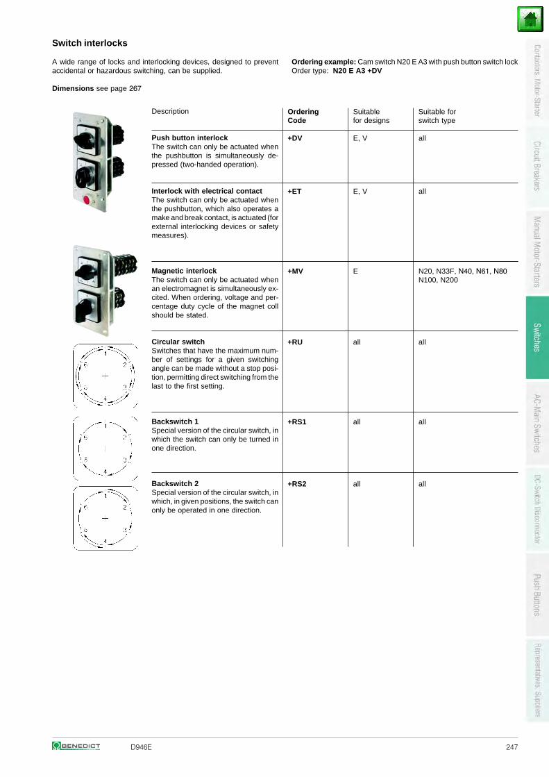
D946E 247
Switch interlocks
A wide range of locks and interlocking devices, designed to preventaccidental or hazardous switching, can be supplied.
Dimensions see page 267
Ordering example: Cam switch N20 E A3 with push button switch lockOrder type: N20 E A3 +DV
Description
Push button interlockThe switch can only be actuated whenthe pushbutton is simultaneously de-pressed (two-handed operation).
Interlock with electrical contactThe switch can only be actuated whenthe pushbutton, which also operates amake and break contact, is actuated (forexternal interlocking devices or safetymeasures).
Magnetic interlockThe switch can only be actuated whenan electromagnet is simultaneously ex-cited. When ordering, voltage and per-centage duty cycle of the magnet collshould be stated.
Circular switchSwitches that have the maximum num-ber of settings for a given switchingangle can be made without a stop posi-tion, permitting direct switching from thelast to the first setting.
Backswitch 1Special version of the circular switch, inwhich the switch can only be turned inone direction.
Backswitch 2Special version of the circular switch, inwhich, in given positions, the switch canonly be operated in one direction.
Ordering Suitable Suitable forCode for designs switch type
+DV E, V all
+ET E, V all
+MV E N20, N33F, N40, N61, N80 N100, N200
+RU all all
+RS1 all all
+RS2 all all
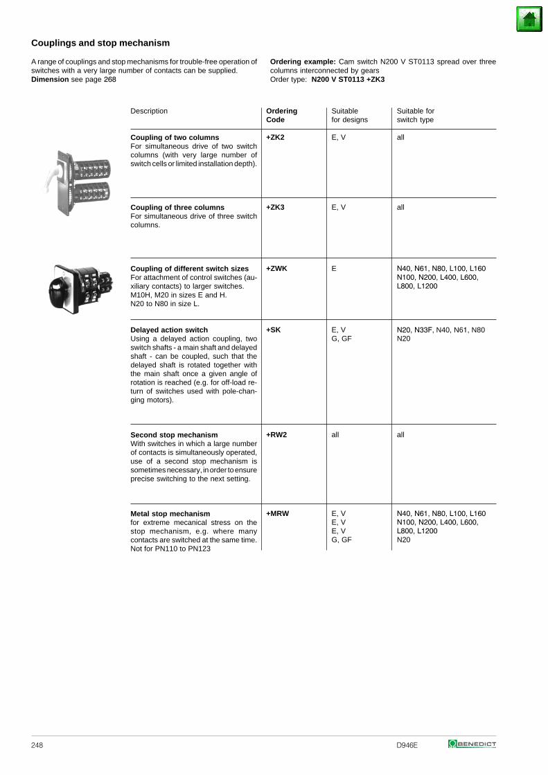
248 D946E
Couplings and stop mechanism
Description
Coupling of two columnsFor simultaneous drive of two switchcolumns (with very large number ofswitch cells or limited installation depth).
Coupling of three columnsFor simultaneous drive of three switchcolumns.
Coupling of different switch sizesFor attachment of control switches (au-xiliary contacts) to larger switches.M10H, M20 in sizes E and H.N20 to N80 in size L.
Delayed action switchUsing a delayed action coupling, twoswitch shafts - a main shaft and delayedshaft - can be coupled, such that thedelayed shaft is rotated together withthe main shaft once a given angle ofrotation is reached (e.g. for off-load re-turn of switches used with pole-chan-ging motors).
Second stop mechanismWith switches in which a large numberof contacts is simultaneously operated,use of a second stop mechanism issometimes necessary, in order to ensureprecise switching to the next setting.
Metal stop mechanismfor extreme mecanical stress on thestop mechanism, e.g. where manycontacts are switched at the same time.Not for PN110 to PN123
Ordering Suitable Suitable forCode for designs switch type
+ZK2 E, V all
+ZK3 E, V all
+ZWK E N40, N61, N80, L100, L160 N100, N200, L400, L600, L800, L1200
+SK E, VG, GF
N20, N33F, N40, N61, N80 N20
+RW2 all all
+MRW E, VE, VE, VG, GF
N40, N61, N80, L100, L160 N100, N200, L400, L600, L800, L1200N20
A range of couplings and stop mechanisms for trouble-free operation ofswitches with a very large number of contacts can be supplied.Dimension see page 268
Ordering example: Cam switch N200 V ST0113 spread over threecolumns interconnected by gearsOrder type: N200 V ST0113 +ZK3
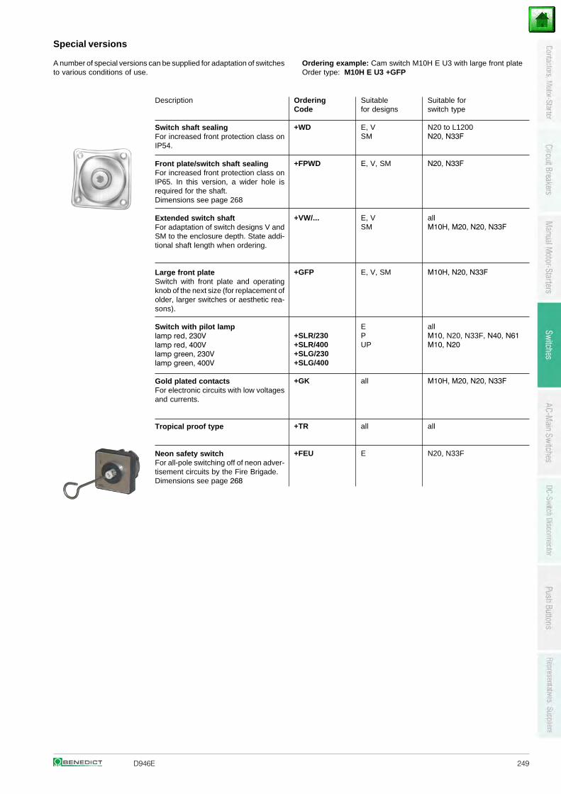
D946E 249
Special versions
A number of special versions can be supplied for adaptation of switchesto various conditions of use.
Ordering example: Cam switch M10H E U3 with large front plateOrder type: M10H E U3 +GFP
Ordering Suitable Suitable forCode for designs switch type
+WD E, V N20 to L1200SM N20, N33F
+FPWD E, V, SM N20, N33F
+VW/... E, V allSM M10H, M20, N20, N33F
+GFP E, V, SM M10H, N20, N33F
E+SLR/230 P+SLR/400 UP
allM10, N20, N33F, N40, N61 M10, N20
+SLG/230+SLG/400
+GK all M10H, M20, N20, N33F
+TR all all
+FEU E N20, N33F
Description
Switch shaft sealingFor increased front protection class onIP54.
Front plate/switch shaft sealingFor increased front protection class onIP65. In this version, a wider hole isrequired for the shaft.Dimensions see page 268
Extended switch shaftFor adaptation of switch designs V andSM to the enclosure depth. State addi-tional shaft length when ordering.
Large front plateSwitch with front plate and operatingknob of the next size (for replacement ofolder, larger switches or aesthetic rea-sons).
Switch with pilot lamplamp red, 230Vlamp red, 400Vlamp green, 230Vlamp green, 400V
Gold plated contactsFor electronic circuits with low voltagesand currents.
Tropical proof type
Neon safety switchFor all-pole switching off of neon adver-tisement circuits by the Fire Brigade.Dimensions see page 268
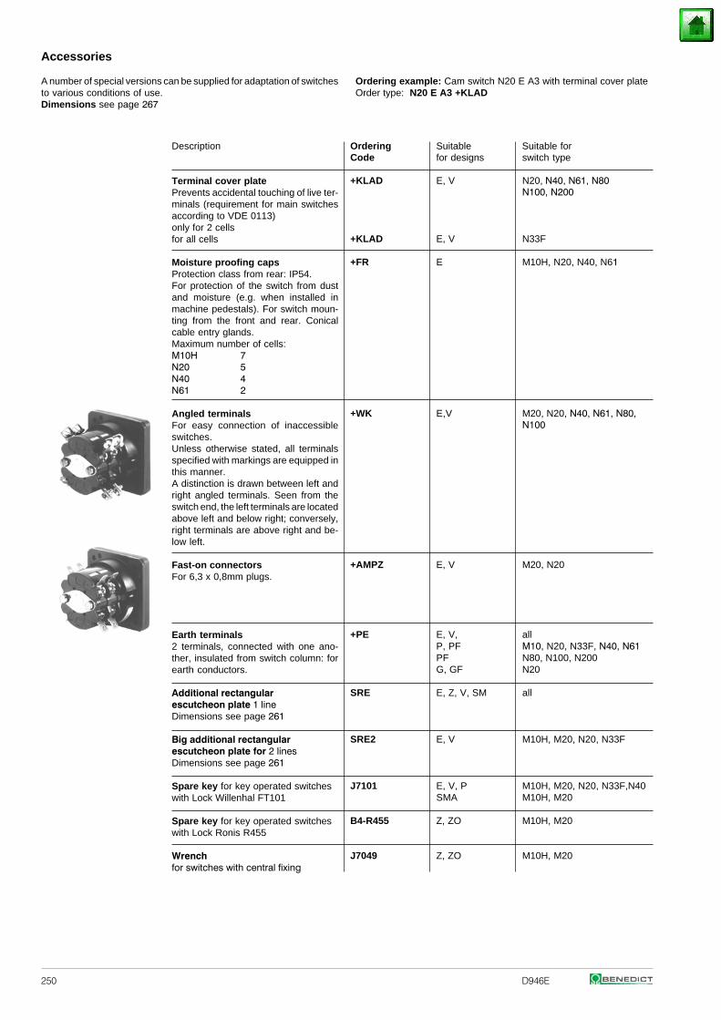
250 D946E
Accessories
Ordering example: Cam switch N20 E A3 with terminal cover plateOrder type: N20 E A3 +KLAD
A number of special versions can be supplied for adaptation of switchesto various conditions of use.Dimensions see page 267
Description
Terminal cover platePrevents accidental touching of live ter-minals (requirement for main switchesaccording to VDE 0113)only for 2 cellsfor all cells
Moisture proofing capsProtection class from rear: IP54.For protection of the switch from dustand moisture (e.g. when installed inmachine pedestals). For switch moun-ting from the front and rear. Conicalcable entry glands.Maximum number of cells:M10H 7
54
N20 N40 N61 2
Angled terminalsFor easy connection of inaccessibleswitches.Unless otherwise stated, all terminalsspecified with markings are equipped inthis manner.A distinction is drawn between left andright angled terminals. Seen from theswitch end, the left terminals are locatedabove left and below right; conversely,right terminals are above right and be-low left.
Fast-on connectorsFor 6,3 x 0,8mm plugs.
Earth terminals2 terminals, connected with one ano-ther, insulated from switch column: forearth conductors.
Additional rectangularescutcheon plate 1 lineDimensions see page 261
Big additional rectangularescutcheon plate for 2 linesDimensions see page 261
Spare key for key operated switcheswith Lock Willenhal FT101
Spare key for key operated switcheswith Lock Ronis R455
Wrenchfor switches with central fixing
Ordering Suitable Suitable forCode for designs switch type
+KLAD E, V N20, N40, N61, N80 N100, N200
+KLAD E, V N33F
+FR E M10H, N20, N40, N61
+WK E,V M20, N20, N40, N61, N80, N100
+AMPZ E, V M20, N20
+PE E, V,P, PFPFG, GF
allM10, N20, N33F, N40, N61 N80, N100, N200N20
SRE E, Z, V, SM all
SRE2 E, V M10H, M20, N20, N33F
J7101 E, V, P M10H, M20, N20, N33F,N40SMA M10H, M20
B4-R455 Z, ZO M10H, M20
J7049 Z, ZO M10H, M20
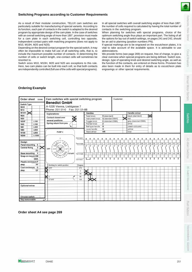
D946E 251
Switching Programs according to Customer Requirements
As a result of their modular construction, TELUX cam switches areparticularly suitable for manufacturing of special variants. According toits function, each pair of contacts in the switch is adapted to the desiredprogram by appropriate design of the cam plate. In the case of switcheswith an overall switching angle of more than 180°, provision must madefor a cam plate in each switching cell, controlling two opposite,independent contact pairs with matching programs (does not apply toM10, M10H, M20 and N20).Depending on the desired contact program for the special switch, it mayoften be impossible to make full use of all switching cells, that is, toinclude the maximum possible number of contacts. In determining thenumber of cells or switch length, one-contact cells will sometimes beresorted to.Switch sizes M10, M10H, M20 and N20 are exceptions to this rule.Here, two cam plates can be built into each cell, so that both contactsare independently controlled (full use of the cells with special programs).
In all special switches with overall switching angles of less than 180°,the number of cells required is calculated by having the total number ofcontacts in the switching program.When planning for switches with special programs, choice of theoptimum switching angle thus plays an important part. The listing of allthe options for lay-out of switch settings, on pages 241 and 242, shouldbe an aid to planning (position numbers PN).If special markings are to be engraved on the escutcheon plates, it isvital to take account of the available space. It is advisable to useabbreviations.We provide forms (see page 269) on request, free of charge, to give aclear overview when special programs are being defined. Switch size,design, type of operating knob and desired switching angle, as well asthe function of the contacts, are entered on these forms. Provision hasalso been made in them for entry of details as to escutcheon plateengravings or other special requirements.
Ordering Example
Order sheet A4 see page 269
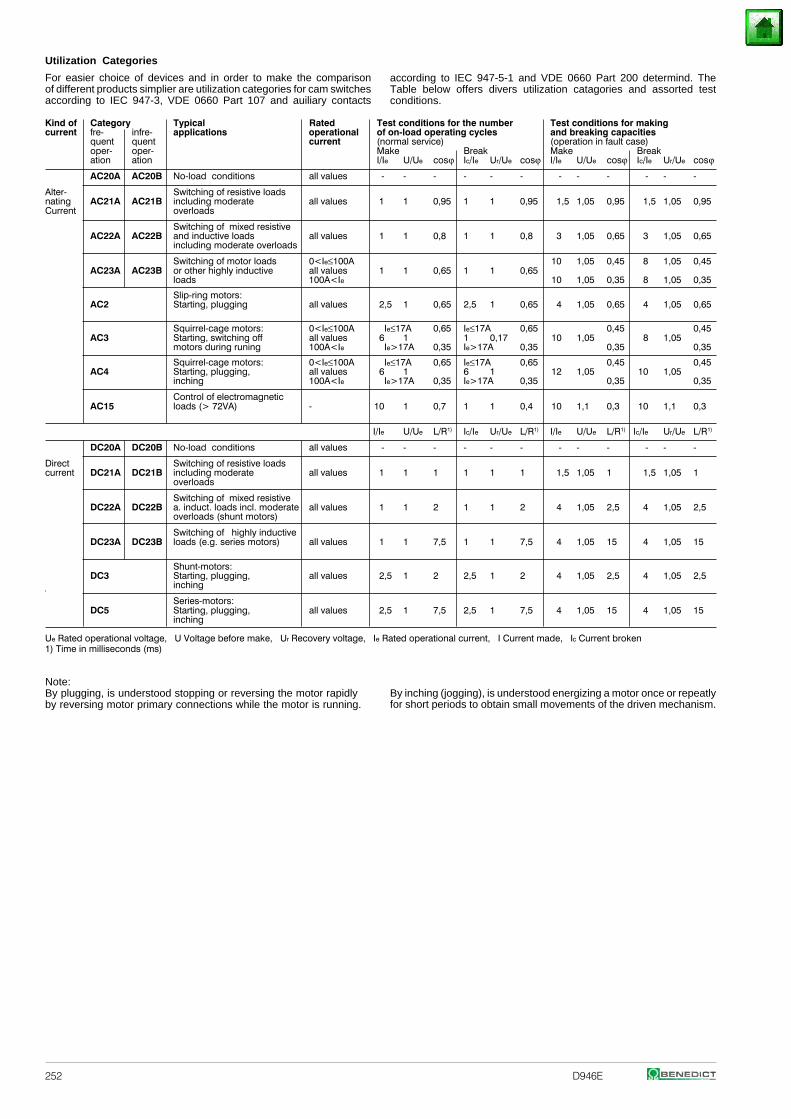
252 D946E
Kind of Category Typical Rated Test conditions for the number Test conditions for makingcurrent fre- infre- applications operational of on-load operating cycles and breaking capacities
quent quent current (normal service) (operation in fault case)oper- oper- Make Break Make Breakation ation I/Ie U/Ue cosϕ Ic/Ie Ur/Ue cosϕ I/Ie U/Ue cosϕ Ic/Ie Ur/Ue cosϕ
AC20A AC20B No-load conditions all values - - - - - - - - - - - -
Alter- Switching of resistive loadsnating AC21A AC21B including moderate all values 1 1 0,95 1 1 0,95 1,5 1,05 0,95 1,5 1,05 0,95Current overloads
Switching of mixed resistiveAC22A AC22B and inductive loads all values 1 1 0,8 1 1 0,8 3 1,05 0,65 3 1,05 0,65
including moderate overloads
Switching of motor loads 0<Ie≤100A 10 1,05 0,45 8 1,05 0,45AC23A AC23B or other highly inductive all values 1 1 0,65 1 1 0,65
loads 100A<Ie 10 1,05 0,35 8 1,05 0,35
Slip-ring motors:AC2 Starting, plugging all values 2,5 1 0,65 2,5 1 0,65 4 1,05 0,65 4 1,05 0,65
Squirrel-cage motors: 0<Ie≤100A Ie≤17A 0,65 Ie≤17A 0,65 0,45 0,45AC3 Starting, switching off all values 6 1 1 0,17 10 1,05 8 1,05
motors during runing 100A<Ie Ie>17A 0,35 Ie>17A 0,35 0,35 0,35
Squirrel-cage motors: 0<Ie≤100A Ie≤17A 0,65 Ie≤17A 0,65 0,45 0,45AC4 Starting, plugging, all values 6 1 6 1 12 1,05 10 1,05
inching 100A<Ie Ie>17A 0,35 Ie>17A 0,35 0,35 0,35
Control of electromagneticAC15 loads (> 72VA) - 10 1 0,7 1 1 0,4 10 1,1 0,3 10 1,1 0,3
I/Ie U/Ue L/R1) Ic/Ie Ur/Ue L/R1) I/Ie U/Ue L/R1) Ic/Ie Ur/Ue L/R1)
DC20A DC20B No-load conditions all values - - - - - - - - - - - -
Direct Switching of resistive loadscurrent DC21A DC21B including moderate all values 1 1 1 1 1 1 1,5 1,05 1 1,5 1,05 1
overloads
Switching of mixed resistiveDC22A DC22B a. induct. loads incl. moderate all values 1 1 2 1 1 2 4 1,05 2,5 4 1,05 2,5
overloads (shunt motors)
Switching of highly inductiveDC23A DC23B loads (e.g. series motors) all values 1 1 7,5 1 1 7,5 4 1,05 15 4 1,05 15
Shunt-motors:DC3 Starting, plugging, all values 2,5 1 2 2,5 1 2 4 1,05 2,5 4 1,05 2,5
inching
Series-motors:DC5 Starting, plugging, all values 2,5 1 7,5 2,5 1 7,5 4 1,05 15 4 1,05 15
inching
Ue Rated operational voltage, U Voltage before make, Ur Recovery voltage, Ie Rated operational current, I Current made, Ic Current broken1) Time in milliseconds (ms)
Note:By plugging, is understood stopping or reversing the motor rapidlyby reversing motor primary connections while the motor is running.
By inching (jogging), is understood energizing a motor once or repeatlyfor short periods to obtain small movements of the driven mechanism.
Utilization Categories
For easier choice of devices and in order to make the comparisonof different products simplier are utilization categories for cam switchesaccording to IEC 947-3, VDE 0660 Part 107 and auiliary contacts
according to IEC 947-5-1 and VDE 0660 Part 200 determind. TheTable below offers divers utilization catagories and assorted testconditions.
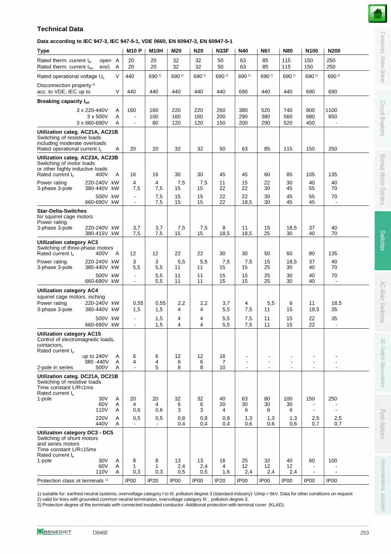
D946E 253
Technical Data
Data according to IEC 947-3, IEC 947-5-1, VDE 0660, EN 60947-3, EN 60947-5-1
Type M10 P M10H M20 N20 N33F N40 N61 N80 N100 N200
Rated therm. current Ith open A 20 20 32 32 50 63 85 115 150 250Rated therm. current Ithe encl. A 20 20 32 32 50 63 85 115 150 250
Rated operational voltage Ue V 440 690 1) 690 1) 690 1) 690 1) 690 1) 690 1) 690 1) 690 1) 690 1)
Disconnection property 2)
acc. to VDE, IEC up to V 440 440 440 440 440 690 440 440 690 690
Breaking capacity Ieff
3 x 220-440V A 160 160 220 220 260 380 520 740 900 11003 x 500V A - 100 160 160 200 290 380 560 680 850
3 x 660-690V A - 80 120 120 150 200 290 520 450 -
Utilization categ. AC21A, AC21BSwitching of resistive loadsincluding moderate overloadsRated operational current Ie A 20 20 32 32 50 63 85 115 150 250
Utilization categ. AC23A, AC23BSwitching of motor loadsor other highly inductive loadsRated current Ie 400V A 16 16 30 30 45 45 60 85 105 135
Power rating 220-240V kW 4 4 7,5 7,5 11 15 22 30 40 403-phase 3-pole 380-440V kW 7,5 7,5 15 15 22 22 30 45 55 70
500V kW - 7,5 15 15 22 22 30 45 55 70660-690V kW - 7,5 15 15 22 18,5 30 45 45 -
Star-Delta-Switchesfor squirrel cage motorsPower rating3-phase 3-pole 220-240V kW 3,7 3,7 7,5 7,5 8 11 15 18,5 37 40
380-415V kW 7,5 7,5 15 15 18,5 18,5 25 30 40 70
Utilization category AC3Switching of three-phase motorsRated current Ie 400V A 12 12 22 22 30 30 50 60 80 135
Power rating 220-240V kW 3 3 5,5 5,5 7,5 7,5 15 18,5 37 403-phase 3-pole 380-440V kW 5,5 5,5 11 11 15 15 25 30 40 70
500V kW - 5,5 11 11 15 15 25 30 40 70660-690V kW - 5,5 11 11 15 15 25 30 40 -
Utilization category AC4squirrel cage motors, inchingPower rating 220-240V kW 0,55 0,55 2,2 2,2 3,7 4 5,5 6 11 18,53-phase 3-pole 380-440V kW 1,5 1,5 4 4 5,5 7,5 11 15 18,5 35
500V kW - 1,5 4 4 5,5 7,5 11 15 22 35660-690V kW - 1,5 4 4 5,5 7,5 11 15 22 -
Utilization category AC15Control of electromagnetic loads,contactors,Rated current Ie
up to 240V A 6 6 12 12 16 - - - - -380 -440V A 4 4 6 6 7 - - - - -
2-pole in series 500V A - 5 8 8 10 - - - - -
Utilization categ. DC21A, DC21BSwitching of resistive loadsTime constant L/R≤1msRated current Ie
1-pole 30V A 20 20 32 32 40 63 80 100 150 25060V A 4 4 6 6 20 30 30 30 - -
110V A 0,6 0,6 3 3 4 6 6 6 - -
220V A 0,5 0,5 0,8 0,8 0,8 1,3 1,3 1,3 2,5 2,5440V A - - 0,4 0,4 0,4 0,6 0,6 0,6 0,7 0,7
Utilization category DC3 - DC5Switching of shunt motorsand series motorsTime constant L/R≤15msRated current Ie
1-pole 30V A 8 8 13 13 16 25 32 40 60 10060V A 1 1 2,4 2,4 4 12 12 12 - -
110V A 0,3 0,3 0,5 0,5 1,6 2,4 2,4 2,4 - -
Protection class ot terminals 1) IP00 IP20 IP00 IP00 IP20 IP00 IP00 IP00 IP00 IP00
1) suitable for: earthed-neutral systems, overvoltage category I to III, pollution degree 3 (standard-industry): Uimp = 6kV. Data for other conditions on request2) valid for lines with grounded common neutral termination, overvoltage category III , pollution degree 3.3) Protection degree of the terminals with connected insulated conductor. Additional protection with terminal cover (KLAD).
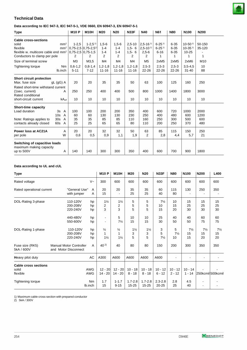
254 D946E
Technical Data
Data according to IEC 947-3, IEC 947-5-1, VDE 0660, EN 60947-3, EN 60947-5-1
Type M10 P M10H M20 N20 N33F N40 N61 N80 N100 N200
Cable cross-sectionssolid mm2 1-2,5 1-2,5 1) 1,5-6 1,5-6 2,5-10 2,5-16 1) 6-25 1) 6-35 10-50 1) 50-150flexible mm2 0,75-2,5 0,75-2,51) 1-4 1-4 1,5- 6 2,5-10 1) 6-25 1) 6-35 10-35 1) 35-120flexible w. multicore cable end mm2 0,75-2,5 0,75-1,5 1-4 1-4 1,5- 6 2,5-6 6-16 6-35 10-25 -Conductors to clamp per pole 2 2 2 2 2 2 1 1 1 1
Size of terminal screw M3 M3,5 M4 M4 M4 M5 2xM5 2xM5 2xM6 M10
Tightening torque Nm 0,6-1,2 0,8-1,4 1,2-1,8 1,2-1,8 1,2-1,8 2,5-3 2,5-3 2,5-3 3,5-4,5 10lb.inch 5-11 7-12 11-16 11-16 11-16 22-26 22-26 22-26 31-40 88
Short circuit protectionMax. fuse size gL (gG) A 20 20 35 35 50 63 100 125 160 250
Rated short-time withstand current(1sec. current) A 250 250 400 400 500 800 1000 1400 1800 3000Rated conditionalshort-circuit current kAeff 10 10 10 10 10 10 10 10 10 10
Short-time capacityLoad duration 3s A 100 100 200 200 350 400 600 720 1000 2000
10s A 60 60 130 130 230 250 400 480 600 1200Note: Ratings applies to 30s A 35 35 85 85 110 160 250 300 500 600contacts already closed 60s A 25 25 65 65 80 110 200 250 370 480
Power loss at AC21A A 20 20 32 32 50 63 85 115 150 250per pole W 0,6 0,5 0,9 1,1 1,9 2 2,8 4,4 5,7 21
Switching of capacitive loadsmaximum making capacityup to 500V A 140 140 300 300 350 400 600 700 900 1800
Data according to UL and cUL
Type M10 P M10H M20 N20 N33F N80 N100 N200 L400
Rated voltage V~ 300 600 600 600 600 600 600 600 600
Rated operational current "General Use" A 20 20 35 35 60 115 130 250 350with jumper A 15 - 25 25 40 80 - - -
DOL-Rating 3-phase 110-120V hp 1½ 1½ 5 5 7½ 10 15 15 15200-208V hp 2 2 5 5 10 15 25 25 25220-240V hp 3 3 5 5 15 20 30 30 30
440-480V hp - 5 10 10 25 40 40 60 60550-600V hp - 7½ 15 15 30 50 50 75 75
DOL-Rating 1-phase 110-120V hp ½ ½ 1½ 1½ 3 5 7½ 7½ 7½200-208V hp 1 1 3 3 5 7½ 15 15 15220-240V hp 1½ 1½ 5 5 7½ 10 15 20 20
Fuse size (RK5) Manual Motor Controller A 40 2) 40 80 80 150 200 300 350 3505kA / 600V and Motor Disconnect
Heavy pilot duty AC A300 A600 A600 A600 A600 - - - -
Cable cross sectionssolid AWG 12 - 20 12 - 20 10 - 18 10 - 18 10 - 12 10 - 12 10 - 14 - -flexible AWG 14 - 20 14 - 20 8 - 18 8 - 18 6 - 12 2 - 12 1 - 14 250kcmil 500kcmil
Tightening torque Nm 1.7 1-1.7 1.7-2.8 1.7-2.8 2.3-2.8 2.8 4.5 - -lb.inch 15 9-15 15-25 15-25 20-25 25 40 - -
1) Maximum cable cross-section with prepared conductor2) 5kA / 300V
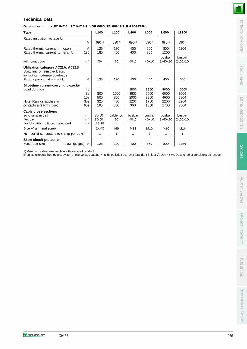
D946E 255
Technical Data
Data according to IEC 947-3, IEC 947-5-1, VDE 0660, EN 60947-3, EN 60947-5-1
Type L100 L160 L400 L600 L800 L1200
Rated insulation voltage Ui
V 690 2) 690 2) 690 2) 690 2) 690 2) 690 2)
Rated thermal current Ith open A 125 180 400 600 800 1200Rated thermal current Ithe encl.A 125 180 400 600 800 1200
busbar busbarwith conductor mm2 50 70 40x5 40x10 2x40x10 2x50x10
Utilization category AC21A, AC21BSwitching of resistive loads,including moderate overloadsRated operational current Ie A 125 180 400 400 400 400
Shot-time current-carrying capacityLoad duration 1s - - 4800 6500 8500 10000
3s 800 1200 3600 5000 6500 800010s 500 800 2000 3200 4000 5800
Note: Ratings applies to 30s 320 480 1200 1700 2200 3200contacts already closed 60s 180 380 960 1300 1700 2300
Cable cross-sectionssolid or stranded mm2 25-50 1) cable lug busbar busbar busbar busbarflexible mm2 25-50 1) 70 40x5 40x10 2x40x10 2x50x10flexible with multicore cable end mm2 25-35 - - - - -
Size of terminal screw 2xM5 M8 M12 M16 M16 M16
Number of conductors to clamp per pole 1 1 1 2 1 1
Short circuit protectionMax. fuse size slow, gL (gG) A 125 200 400 630 800 1250
1) Maximum cable cross-section with prepared conductor2) suitable for: earthed-neutral systems, overvoltage category I to III, pollution degree 3 (standard-industry): Uimp = 6kV. Data for other conditions on request
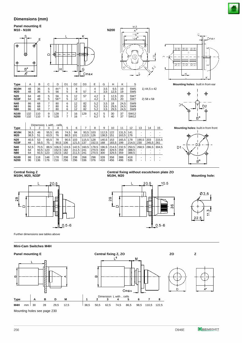
256 D946E
Panel mounting EM10 - N100 N200
Type A B C D D1 D2 D3 E G H K S Mounting holes: built in from ear
M10H 48 36 5 44 1) 5 8 - 4 3,5 9,5 19 SW5 1) 44,5 x 42M20 48 36 5 56 5 8 57 4 3,5 12,5 19 SW5
N20 64 48 5 56 5 12 57 4,2 3 12,5 20 SW7N33F 64 48 5 58 2) 5 12 - 4,2 3 15,5 20 SW7 2) 58 x 58
N40 86 68 7 80 6 12 82 5,2 3,5 18 24,5 SW9N61 86 68 7 80 6 12 82 5,2 3,5 29,5 24,5 SW9N80 86 68 7 80 6 12 82 5,2 3,5 29,5 24,5 SW9
N100 132 110 9 128 7 16 129 6,2 5 30 37 SW12N200 132 110 9 128 7 16 - 6,2 5 40 37 SW12
Dimension L with .. cellsType 1 2 3 4 5 6 7 8 9 10 11 12 13 14 15 Mounting holes: built in from front
M10H 36,5 46 55,5 65 74,5 84 93,5 103 112,5 122 131,5 141 - - -M20 38,5 51 63,5 76 88,5 101 113,5 126 138,5 151 163,5 176 - - -
N20 40,5 53 65,5 78 90,5 103 115,5 128 140,5 153 165,5 178 190,5 203 215,5N33F 44 59,5 75 90,5 106 121,5 137 152,5 168 183,5 199 214,5 230 245,5 261
N40 52,5 70,5 88,5 106,5 124,5 142,5 160,5 178,5 196,5 214,5 232,5 250,5 268,5 286,5 304,5N61 64 93,5 123 152,5 182 211,5 241 270,5 300 329,5 359 388,5 - - -N80 64 93,5 123 152,5 182 211,5 241 270,5 300 329,5 359 388,5 - - -
N100 88 118 148 178 208 238 268 298 328 358 388 418 - - -N200 96 136 176 216 256 296 336 376 416 456 496 536 - - -
Central fixing Z Central fixing without escutcheon plate ZOM10H, M20, N33F M10H, M20 Mounting hole:
Further dimensions see tables above
Mini-Cam Switches M4H
Panel mounting E Central fixing Z, ZO ZO Z
Dimension L with .. cellsType A B D M 1 2 3 4 5 6 7 8
M4H mm 30 28 29,5 12,5 38,5 50,5 62,5 74,5 86,5 98,5 110,5 122,5
Mounting holes see page 230
Dimensions (mm)
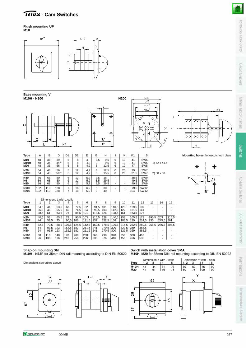
D946E 257
- Cam Switches
Flush mounting UPM10
Base mounting VM10H - N100 N200
Type A B D D1 D2 E G H I K K1 S Mounting holes: for escutcheon plate
M10 48 36 39 5 8 4 3,5 9,5 6 19 41 SW5M10H 48 36 44 1) 5 8 4,2 3 9,5 6 19 41 SW5 1) 42 x 44,5M20 48 36 56 5 8 4,2 3 12,5 6 19 47 SW5
N20 64 48 56 5 12 4,2 3 12,5 0 20 29 SW7N33F 64 48 58 2) 5 12 4,2 3 15,5 0 20 31,5 SW7 2) 58 x 58
N40 86 68 80 6 12 5,2 3,5 18 - - 38,5 SW9N61 86 68 80 6 12 5,2 3,5 29,5 - - 49,5 SW9N80 86 68 80 6 12 5,2 3,5 29,5 - - 49,5 SW9
N100 132 110 128 7 16 6,2 5 30 - - 79,5 SW12N200 132 110 128 7 16 6,2 5 40 - - 104 SW12
Dimensions L with .. cellsType 1 2 3 4 5 6 7 8 9 10 11 12 13 14 15
M10 34,5 44 53,5 63 72,5 82 91,5 101 110,5 120 129,5 139 - - -M10H 36,5 46 55,5 65 74,5 84 93,5 103 112,5 122 131,5 141 - - -M20 38,5 51 63,5 76 88,5 101 113,5 126 138,5 151 163,5 176 - - -
N20 40,5 53 65,5 78 90,5 103 115,5 128 140,5 153 165,5 178 190,5 203 215,5N33F 44 59,5 75 90,5 106 121,5 137 152,5 168 183,5 199 214,5 230 245,5 261
N40 52,5 70,5 88,5 106,5 124,5 142,5 160,5 178,5 196,5 214,5 232,5 250,5 268,5 286,5 304,5N61 64 93,5 123 152,5 182 211,5 241 270,5 300 329,5 359 388,5 - - -N80 64 93,5 123 152,5 182 211,5 241 270,5 300 329,5 359 388,5 - - -
N100 88 118 148 178 208 238 268 298 328 358 388 418 - - -N200 96 136 176 216 256 296 336 376 416 456 496 536 - - -
Snap-on mounting SM Swich with installation cover SMAM10H - N33F for 35mm DIN-rail mounting according to DIN EN 50022 M10H, M20 for 35mm DIN-rail mounting according to DIN EN 50022
Dimension X with .. cells Dimension Y with .. cellsDimensions see tables above Type 1, 2 3 4 5 1, 2 3 4 5
M10H 44 44 61 76 60 60 75 90M20 44 61 76 76 60 75 90 90
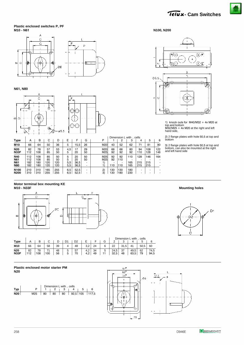
258 D946E
Plastic enclosed switches P, PF M10 - N61 N100, N200
N61, N80
Dimension L with .. cellsType A B C D E F G P 1 2 3 4 5 6
M10 66 64 50 36 5 15,5 26 M20 43 52 62 71 81 90
N20 82 78 57 53 4,5 17 29 M20 66 66 80 94 108 122N33F 112 108 85 50 5 20 50 M25 92 92 92 110 128 146
N40 112 108 85 50 5 20 50 M25 92 92 110 128 146 164N61 112 108 85 50 5 20 50 M25 92 110 - - - -N61 182 180 120 120 5,5 36,5 - 1) - - 165 215 215 -N80 182 180 120 120 5,5 36,5 - 1) 110 110 165 215 215 -
N100 210 310 165 255 6,5 52,5 - 2) 130 130 180 - - -N200 310 310 255 255 6,5 52,5 - 3) 130 180 230 - - -
Motor terminal box mounting KEM10 - N33F Mounting holes
Dimension L with .. cellsType A B C D D1 D2 E F G 2 3 4 5 6
M10 66 64 58 39 4 48 3,2 24 6 22 31,5 41 50,5 60
N20 82 78 71 48 5 57 4,2 34 5 24,5 37 49,5 62 74,5N33F 112 108 100 56 5 70 4,2 49 11 32,5 48 63,5 79 94,5
Plastic enclosed motor starter PMN20
Dimension L with .. cellsTyp P 1 2 3 4 5 6
N20 M25 80 80 80 92,5 105 117,5
- Cam Switches
1) knock outs for M40/M32 + 4x M20 attop and bottomM32/M25 + 4x M20 at the right and lefthand side,
2) 2 flange plates with hole 50,5 at top andbottom
3) 2 flange plates with hole 50,5 at top andbottom, can also be mounted at the rightand left hand side
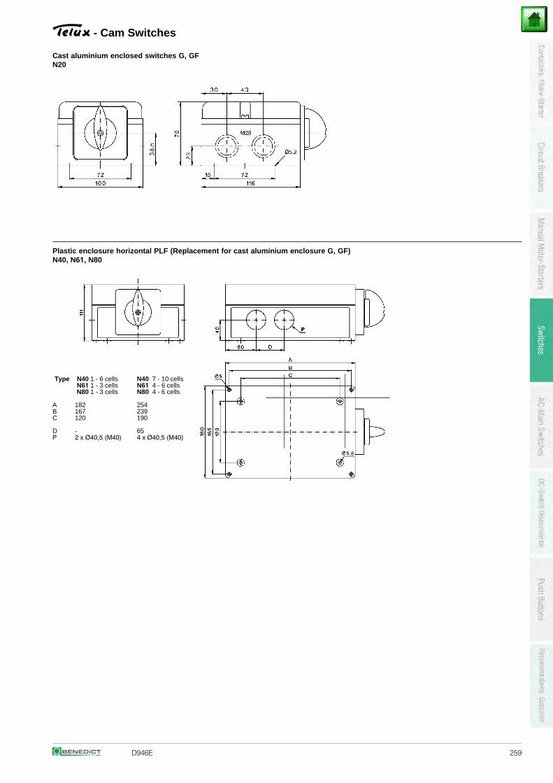
D946E 259
- Cam Switches
Cast aluminium enclosed switches G, GFN20
Plastic enclosure horizontal PLF (Replacement for cast aluminium enclosure G, GF) N40, N61, N80
N40 7 - 10 cellsN61 4 - 6 cells
Type N40 1 - 6 cells N61 1 - 3 cells N80 1 - 3 cells N80 4 - 6 cells
A 182 254B 167 239C 120 190
D - 65P 2 x Ø40,5 (M40) 4 x Ø40,5 (M40)
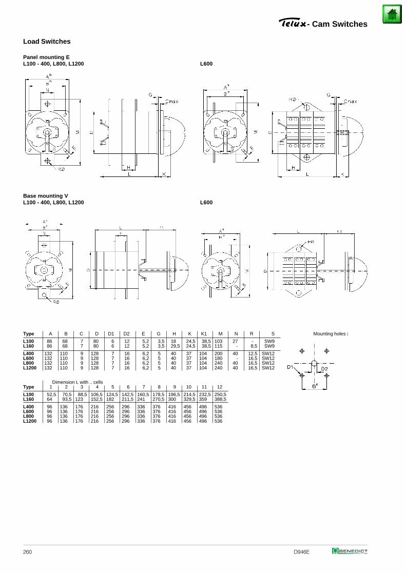
260 D946E
Load Switches
Panel mounting EL100 - 400, L800, L1200 L600
Base mounting VL100 - 400, L800, L1200 L600
Type A B C D D1 D2 E G H K K1 M N R S Mounting holes :
L100 86 68 7 80 6 12 5,2 3,5 18 24,5 38,5 103 27 - SW9L160 86 68 7 80 6 12 5,2 3,5 29,5 24,5 38,5 115 - 8,5 SW9
L400 132 110 9 128 7 16 6,2 5 40 37 104 200 40 12,5 SW12L600 132 110 9 128 7 16 6,2 5 40 37 104 180 - 16,5 SW12L800 132 110 9 128 7 16 6,2 5 40 37 104 240 40 16,5 SW12L1200 132 110 9 128 7 16 6,2 5 40 37 104 240 40 16,5 SW12
Dimension L with .. cellsType 1 2 3 4 5 6 7 8 9 10 11 12
L100 52,5 70,5 88,5 106,5 124,5 142,5 160,5 178,5 196,5 214,5 232,5 250,5L160 64 93,5 123 152,5 182 211,5 241 270,5 300 329,5 359 388,5
L400 96 136 176 216 256 296 336 376 416 456 496 536L600 96 136 176 216 256 296 336 376 416 456 496 536L800 96 136 176 216 256 296 336 376 416 456 496 536L1200 96 136 176 216 256 296 336 376 416 456 496 536
- Cam Switches
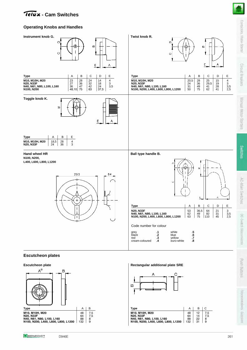
D946E 261
- Cam Switches
Operating Knobs and Handles
Instrument knob G. Twist knob R.
Type A B C D E Type A B C D E
23 28 24 14 4 20,5 28 25 15 427 36 32 18 3 24 36 29,5 19 336 47 42 24 3,5 31 49 41 28 3,5
M10, M10H, M20N20, N33FN40, N61, N80, L100, L160 N100, N200 48,10 75 63 37,5 -
M10, M10H, M20N20, N33FN40, N61, N80, L100, L160N100, N200, L400, L600, L800, L1200 50 75 62 41 2,5
Toggle knob K.
Type A B E
M10, M10H, M20 18,5 28 4N20, N33F 24 36 3
Hand wheel HR Ball type handle B.N100, N200,L400, L600, L800, L1200
Type A B C D E
53 36,5 64 21 3 62 49 82 31 3,5
N20, N33FN40, N61, N80, L100, L160N100, N200, L400, L600, L800, L1200 63 75 110 45 2,5
Code number for colour
grey .1 white .5black .2 blue .6red .3 yellow .7cream-coloured .4 euro-white .8
Escutcheon plates
Escutcheon plate Rectangular additional plate SRE
Type A B Type A B C
48 7,5 48 12 7,564 7,5 64 14 7,5
88 8 88 22 8
M10, M10H, M20N20, N33FN40, N61, N80, L100, L160N100, N200, L400, L600, L800, L1200 132 9
M10, M10H, M20N20, N33FN40, N61, N80, L100, L160N100, N200, L400, L600, L800, L1200 132 31 9
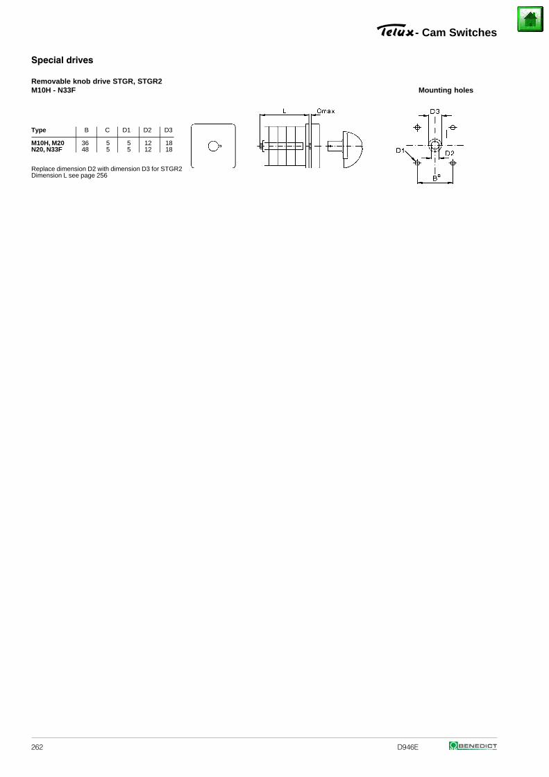
262 D946E
Special drives
Removable knob drive STGR, STGR2M10H - N33F Mounting holes
Type B C D1 D2 D3
M10H, M20 36 5 5 12 18N20, N33F 48 5 5 12 18
Replace dimension D2 with dimension D3 for STGR2Dimension L see page 256
- Cam Switches
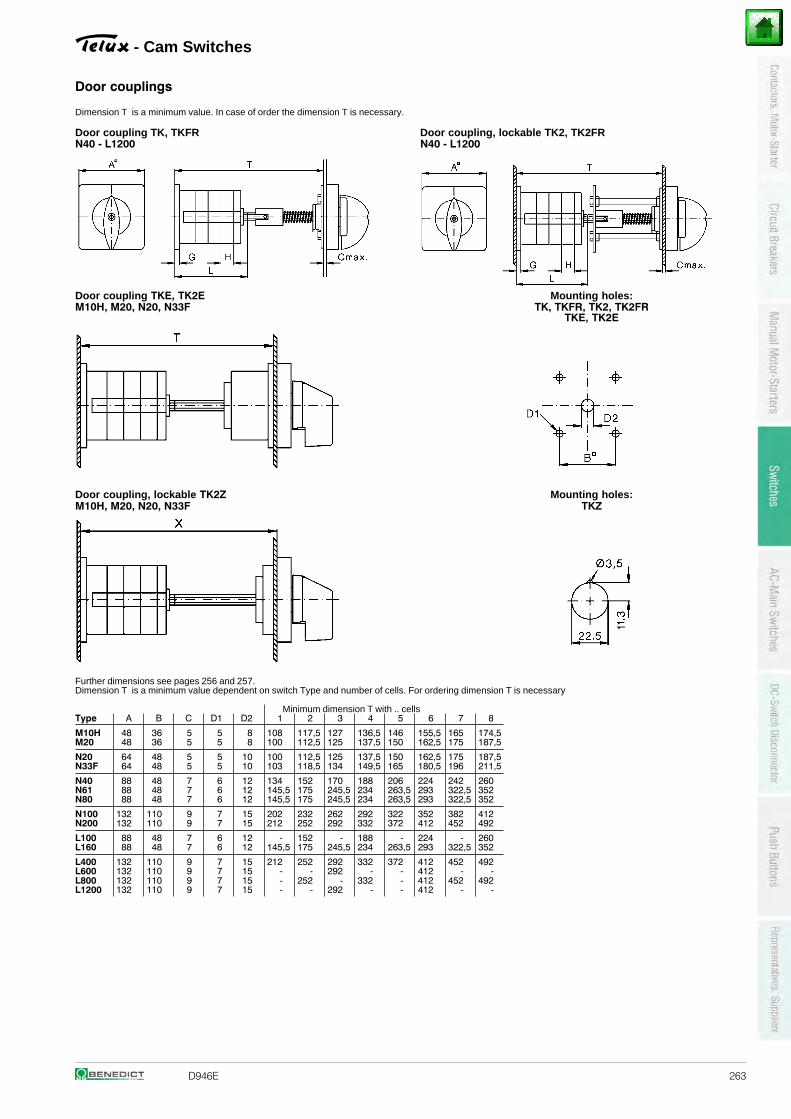
D946E 263
Door couplings
Dimension T is a minimum value. In case of order the dimension T is necessary.
Door coupling TK, TKFR Door coupling, lockable TK2, TK2FRN40 - L1200 N40 - L1200
Door coupling TKE, TK2E Mounting holes:M10H, M20, N20, N33F TK, TKFR, TK2, TK2FR
TKE, TK2E
Door coupling, lockable TK2Z Mounting holes:M10H, M20, N20, N33F TKZ
Further dimensions see pages 256 and 257.Dimension T is a minimum value dependent on switch Type and number of cells. For ordering dimension T is necessary
Minimum dimension T with .. cellsType A B C D1 D2 1 2 3 4 5 6 7 8
M10H 48 36 5 5 8 108 117,5 127 136,5 146 155,5 165 174,5M20 48 36 5 5 8 100 112,5 125 137,5 150 162,5 175 187,5
N20 64 48 5 5 10 100 112,5 125 137,5 150 162,5 175 187,5N33F 64 48 5 5 10 103 118,5 134 149,5 165 180,5 196 211,5
N40 88 48 7 6 12 134 152 170 188 206 224 242 260N61 88 48 7 6 12 145,5 175 245,5 234 263,5 293 322,5 352N80 88 48 7 6 12 145,5 175 245,5 234 263,5 293 322,5 352
N100 132 110 9 7 15 202 232 262 292 322 352 382 412N200 132 110 9 7 15 212 252 292 332 372 412 452 492
L100 88 48 7 6 12 - 152 - 188 - 224 - 260L160 88 48 7 6 12 145,5 175 245,5 234 263,5 293 322,5 352
L400 132 110 9 7 15 212 252 292 332 372 412 452 492L600 132 110 9 7 15 - - 292 - - 412 - -L800 132 110 9 7 15 - 252 - 332 - 412 452 492L1200 132 110 9 7 15 - - 292 - - 412 - -
- Cam Switches
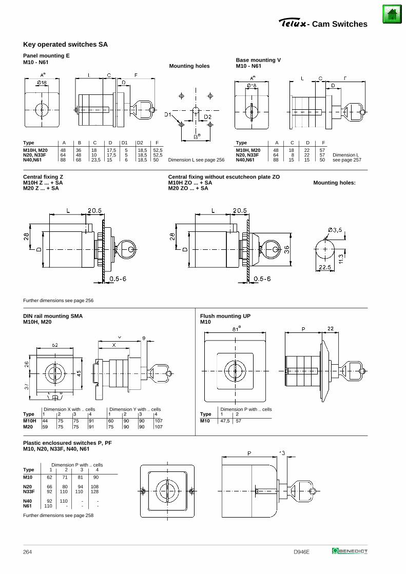
264 D946E
Key operated switches SA
Panel mounting EM10 - N61
Mounting holesBase mounting V M10 - N61
Type A B C D D1 D2 F Type A C D F
M10H, M20 48 36 18 17,5 5 18,5 52,5 M10H, M20 48 18 22 57N20, N33F 64 48 10 17,5 5 18,5 52,5 N20, N33F 64 8 22 57 Dimension LN40,N61 88 68 23,5 15 6 18,5 50 Dimension L see page 256 N40,N61 88 15 15 50 see page 257
Central fixing Z Central fixing without escutcheon plate ZOM10H Z ... + SA M10H ZO ... + SA Mounting holes:M20 Z ... + SA M20 ZO ... + SA
Further dimensions see page 256
DIN rail mounting SMA Flush mounting UPM10H, M20 M10
Dimension X with .. cells Dimension Y with .. cells Dimension P with .. cellsType 1 2 3 4 1 2 3 4 Type 1 2M10H 44 75 75 91 60 90 90 107 M10 47,5 57M20 59 75 75 91 75 90 90 107
Plastic enclosured switches P, PF M10, N20, N33F, N40, N61
Dimension P with .. cellsType 1 2 3 4
M10 62 71 81 90
N20 66 80 94 108N33F 92 110 110 128
N40 92 110 - -N61 110 - - -
Further dimensions see page 258
- Cam Switches
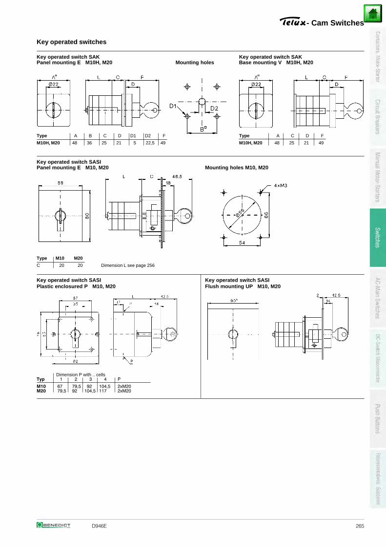
D946E 265
Key operated switches
Key operated switch SAK Key operated switch SAKPanel mounting E M10H, M20 Mounting holes Base mounting V M10H, M20
Type A B C D D1 D2 F Type A C D F
M10H, M20 48 36 25 21 5 22,5 49 M10H, M20 48 25 21 49
Key operated switch SASIPanel mounting E M10, M20 Mounting holes M10, M20
Type M10 M20
C 20 20 Dimension L see page 256
Key operated switch SASI Key operated switch SASIPlastic enclosured P M10, M20 Flush mounting UP M10, M20
Dimension P with .. cellsTyp 1 2 3 4 P
M10 67 79,5 92 104,5 2xM20M20 79,5 92 104,5 117 2xM20
- Cam Switches
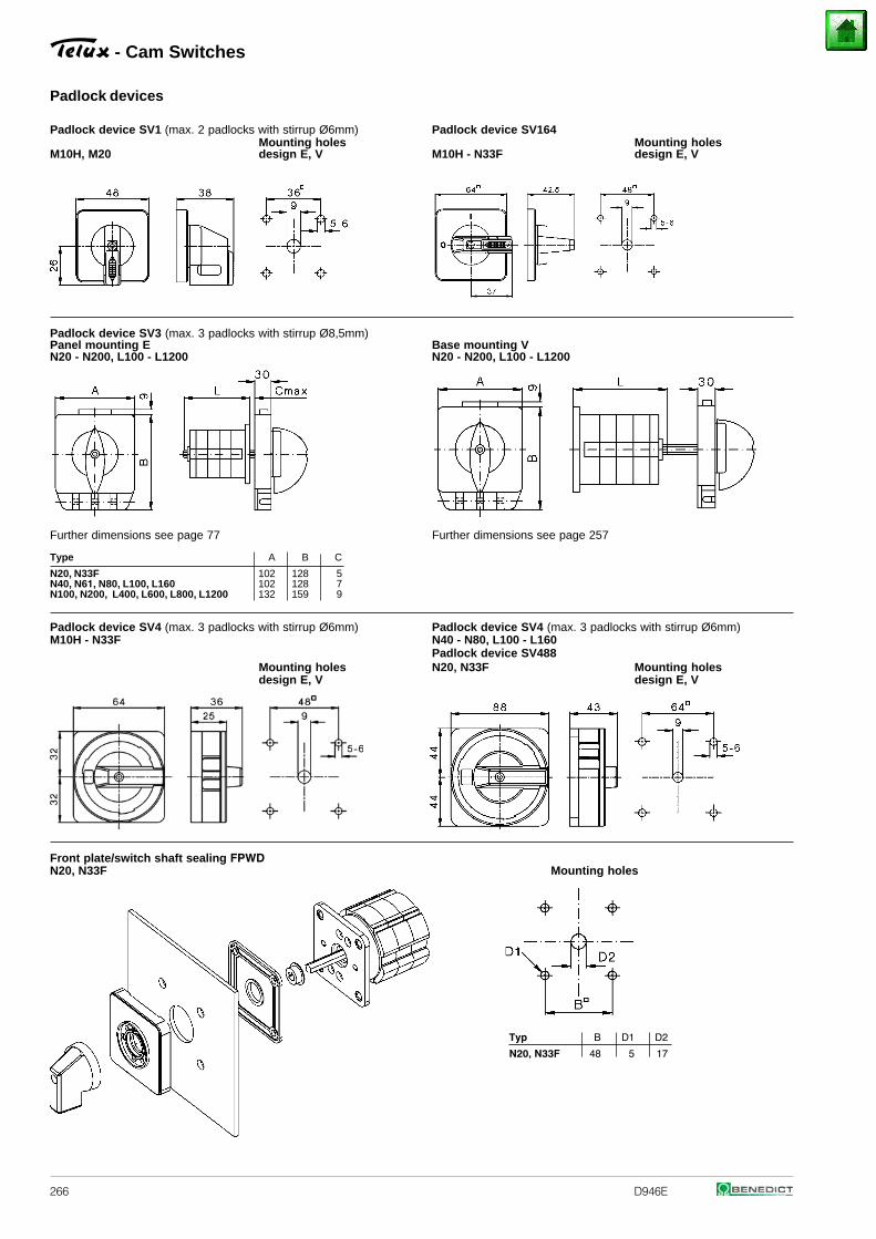
266 D946E
Padlock devices
Padlock device SV1 (max. 2 padlocks with stirrup Ø6mm) Padlock device SV164Mounting holes Mounting holes
M10H, M20 design E, V M10H - N33F design E, V
Padlock device SV3 (max. 3 padlocks with stirrup Ø8,5mm)Panel mounting E Base mounting VN20 - N200, L100 - L1200 N20 - N200, L100 - L1200
Further dimensions see page 77 Further dimensions see page 257
Type A B C
102 128 5102 128 7
N20, N33FN40, N61, N80, L100, L160N100, N200, L400, L600, L800, L1200 132 159 9
Padlock device SV4 (max. 3 padlocks with stirrup Ø6mm) Padlock device SV4 (max. 3 padlocks with stirrup Ø6mm)M10H - N33F N40 - N80, L100 - L160
Padlock device SV488Mounting holes N20, N33F Mounting holesdesign E, V design E, V
Front plate/switch shaft sealing FPWDN20, N33F Mounting holes
Typ B D1 D2
N20, N33F 48 5 17
- Cam Switches
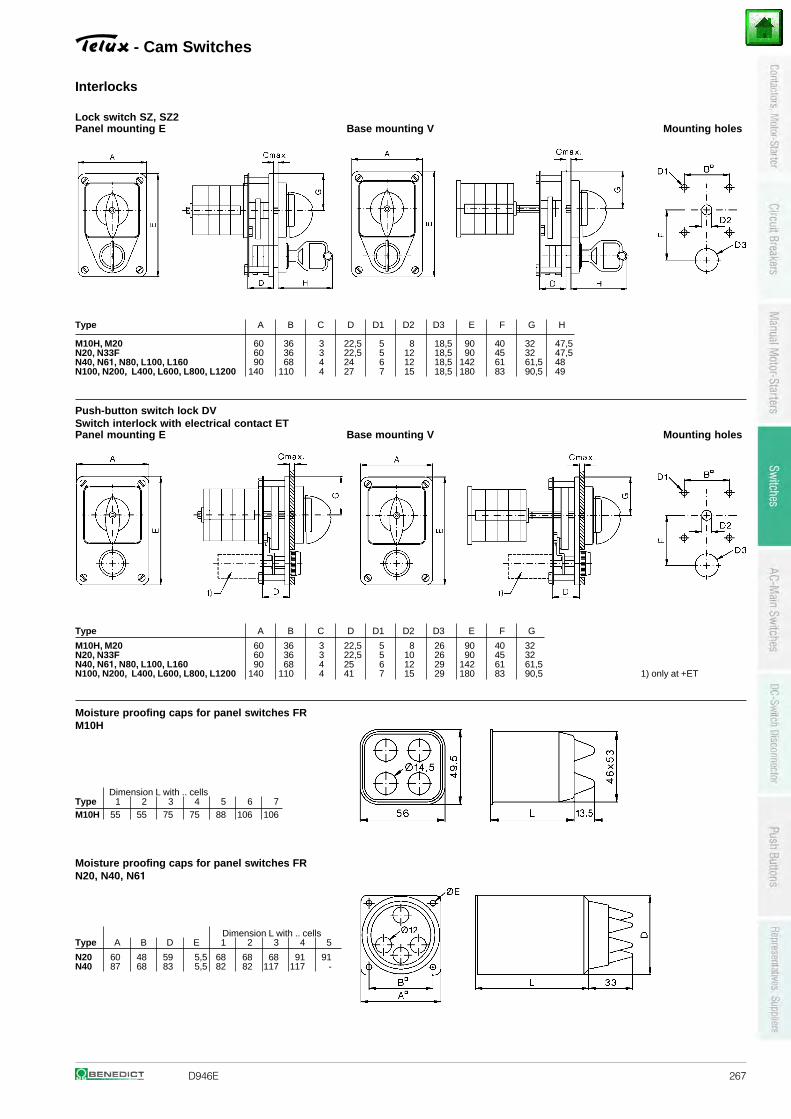
D946E 267
- Cam Switches
Interlocks
Lock switch SZ, SZ2Panel mounting E Base mounting V Mounting holes
Type A B C D D1 D2 D3 E F G H
60 36 3 22,5 5 8 18,5 90 40 32 47,560 36 3 22,5 5 12 18,5 90 45 32 47,590 68 4 24 6 12 18,5 142 61 61,5 48
M10H, M20N20, N33FN40, N61, N80, L100, L160N100, N200, L400, L600, L800, L1200 140 110 4 27 7 15 18,5 180 83 90,5 49
Push-button switch lock DVSwitch interlock with electrical contact ETPanel mounting E Base mounting V Mounting holes
Type A B C D D1 D2 D3 E F G
60 36 3 22,5 5 8 26 90 40 3260 36 3 22,5 5 10 26 90 45 3290 68 4 25 6 12 29 142 61 61,5
M10H, M20N20, N33FN40, N61, N80, L100, L160N100, N200, L400, L600, L800, L1200 140 110 4 41 7 15 29 180 83 90,5 1) only at +ET
Moisture proofing caps for panel switches FRM10H
Dimension L with .. cellsType 1 2 3 4 5 6 7M10H 55 55 75 75 88 106 106
Moisture proofing caps for panel switches FR N20, N40, N61
Dimension L with .. cellsType A B D E 1 2 3 4 5
N20 60 48 59 5,5 68 68 68 91 91N40 87 68 83 5,5 82 82 117 117 -
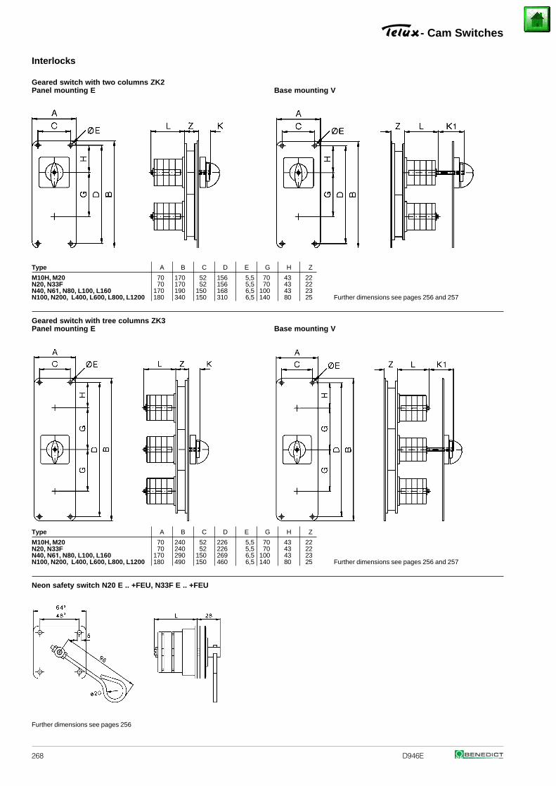
268 D946E
Interlocks
Geared switch with two columns ZK2Panel mounting E Base mounting V
Type A B C D E G H Z
70 170 52 156 5,5 70 43 2270 170 52 156 5,5 70 43 22
170 190 150 168 6,5 100 43 23
M10H, M20N20, N33FN40, N61, N80, L100, L160N100, N200, L400, L600, L800, L1200 180 340 150 310 6,5 140 80 25 Further dimensions see pages 256 and 257
Geared switch with tree columns ZK3Panel mounting E Base mounting V
Type A B C D E G H Z
70 240 52 226 5,5 70 43 2270 240 52 226 5,5 70 43 22
170 290 150 269 6,5 100 43 23
M10H, M20N20, N33FN40, N61, N80, L100, L160N100, N200, L400, L600, L800, L1200 180 490 150 460 6,5 140 80 25 Further dimensions see pages 256 and 257
Neon safety switch N20 E .. +FEU, N33F E .. +FEU
Further dimensions see pages 256
- Cam Switches
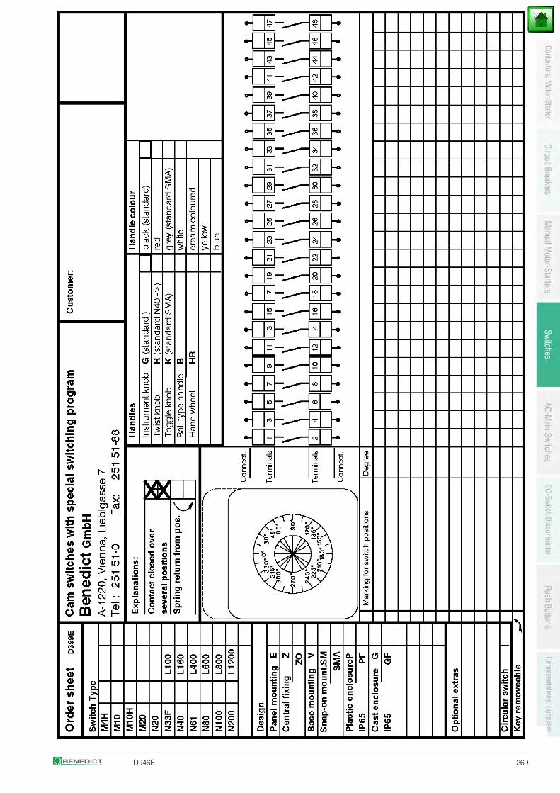
D946E 269
270 D946E
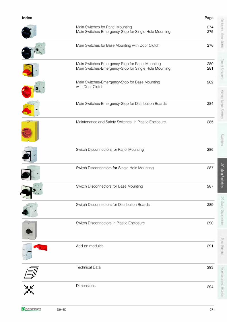
D946D 271
Index Page
Main Switches for Panel Mounting 274Main Switches-Emergency-Stop for Single Hole Mounting 275
Main Switches for Base Mounting with Door Clutch 276
Main Switches-Emergency-Stop for Panel Mounting 280Main Switches-Emergency-Stop for Single Hole Mounting 281
Main Switches-Emergency-Stop for Base Mounting 282with Door Clutch
Main Switches-Emergency-Stop for Distribution Boards 284
Maintenance and Safety Switches, in Plastic Enclosure 285
Switch Disconnectors for Panel Mounting 286
Switch Disconnectors for Single Hole Mounting 287
Switch Disconnectors for Base Mounting 287
Switch Disconnectors for Distribution Boards 289
Switch Disconnectors in Plastic Enclosure 290
Add-on modules 291
Technical Data 293
Dimensions 294
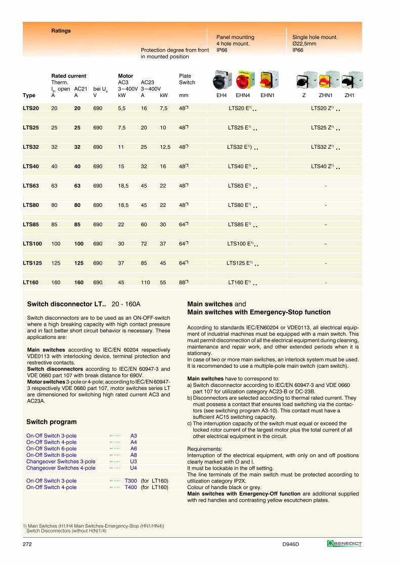
272 D946D
RatingsPanel mounting Single hole mount.4 hole mount. Ø22,5mm
Protection degree from front IP66 IP66in mounted position
Rated current Motor PlateTherm. AC3 AC23 SwitchIth open AC21 bei Ue 3~400V 3~400V
Type A A V kW A kW mm EH4 EHN4 EHN1 Z ZHN1 ZH1
LTS20 20 20 690 5,5 16 7,5 48 LTS20 E1).. LTS20 Z1) ..
LTS25 25 25 690 7,5 20 10 48 LTS25 E1) .. LTS25 Z1) ..
LTS32 32 32 690 11 25 12,5 48 LTS32 E1)) .. LTS32 Z1) ..
LTS40 40 40 690 15 32 16 48 LTS40 E1) .. LTS40 Z1) ..
LTS63 63 63 690 18,5 45 22 48 LTS63 E1) .. -
LTS80 80 80 690 18,5 45 22 48 LTS80 E1) .. -
LTS85 85 85 690 22 60 30 64 LTS85 E1) .. -
LTS100 100 100 690 30 72 37 64 LTS100 E1).. -
LTS125 125 125 690 37 85 45 64 LTS125 E1) .. -
LT160 160 160 690 45 110 55 88 LT160 E1) .. -
Switch disconnector LT.. 20 - 160A
Switch disconnectors are to be used as an ON-OFF-switchwhere a high breaking capacity with high contact pressureand in fact better short circuit behavior is necessary. Theseapplications are:
Main switches according to IEC/EN 60204 respectivelyVDE0113 with interlocking device, terminal protection andrestrective contacts.Switch disconnectors according to IEC/EN 60947-3 andVDE 0660 part 107 with break distance for 690V.Motor switches 3-pole or 4-pole; according to IEC/EN 60947-3 respectively VDE 0660 part 107, motor switches series LTare dimensioned for switching high rated current AC3 andAC23A.
Main switches andMain switches with Emergency-Stop function
According to standards IEC/EN60204 or VDE0113, all electrical equip-ment of industrial machines must be equipped with a main switch. Thismust permit disconnection of all the electrical equipment during cleaning,maintenance and repair work, and other extended periods when it isstationary.In case of two or more main switches, an interlock system must be used.It is recommended to use a multiple-pole main switch (cam switch).
Main switches have to correspond to:a) Switch disconnector according to IEC/EN 60947-3 and VDE 0660
part 107 for utilization category AC23-B or DC-23B.b)Disconnectors are selected according to thermal rated current. They
must possess a contact that ensures load switching via the contac-tors (see switching program A3-10). This contact must have asufficient AC15 switching capacity.
c) The interruption capacity of the switch must equal or exceed thelocked rotor current of the largest motor plus the total current of allother electrical equipment in the circuit.
Requirements:Interruption of the electrical equipment, with only on and off positionsclearly marked with O and I.It must be lockable in the off setting.The line terminals of the main switch must be protected according toutilization category IP2X.Colour of handle black or grey.Main switches with Emergency-Off function are additional suppliedwith red handles and contrasting yellow escutcheon plates.
Switch program
On-Off Switch 3-pole ·· ···· A3On-Off Switch 4-pole ·· ···· A4On-Off Switch 6-pole ·· ···· A6On-Off Switch 8-pole ·· ···· A8Changeover Switches 3-pole ·· ···· U3Changeover Switches 4-pole ·· ···· U4
On-Off Switch 3-pole ·· ···· T300 (for LT160)On-Off Switch 4-pole ·· ···· T400 (for LT160)
1) Main Switches (H1/H4 Main Switches-Emergency-Stop (HN1/HN4)) Switch Disconnectors (without H(N)1/4)
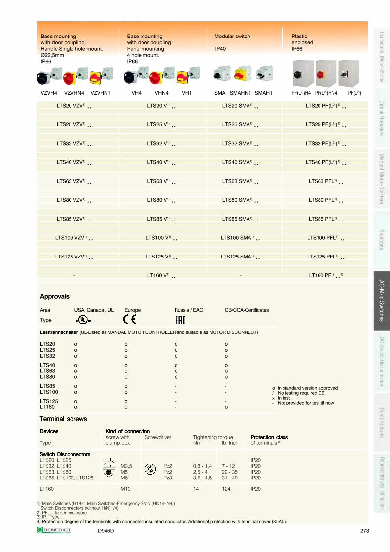
D946D 273
Base mounting Base mounting Modular switch Plasticwith door coupling with door coupling enclosedHandle Single hole mount. Panel mounting IP40 IP66Ø22,5mm 4 hole mount.IP66 IP66
VZVH4 VZVHN4 VZVHN1 VH4 VHN4 VH1 SMA SMAHN1 SMAH1 PF(L2))H4 PF(L2))HN4 PF(L2))
LTS20 VZV1) .. LTS20 V1) .. LTS20 SMA1) .. LTS20 PF(L2))1) ..
LTS25 VZV1) .. LTS25 V1) .. LTS25 SMA1) .. LTS25 PF(L2))1) ..
LTS32 VZV1) .. LTS32 V1) .. LTS32 SMA1) .. LTS32 PF(L2))1) ..
LTS40 VZV1) .. LTS40 V1) .. LTS40 SMA1) .. LTS40 PF(L2))1) ..
LTS63 VZV1) .. LTS63 V1) .. LTS63 SMA1) .. LTS63 PFL1) ..
LTS80 VZV1) .. LTS80 V1) .. LTS80 SMA1) .. LTS80 PFL1) ..
LTS85 VZV1) .. LTS85 V1) .. LTS85 SMA1) .. LTS85 PFL1) ..
LTS100 VZV1) .. LTS100 V1) .. LTS100 SMA1) .. LTS100 PFL1) ..
LTS125 VZV1) .. LTS125 V1) .. LTS125 SMA1) .. LTS125 PFL1) ..
- LT160 V1) .. - LT160 PF1) ..3)
Approvals
Area USA, Canada / UL Europe Russia / EAC CB/CCA-Certificates
Type
Lasttrennschalter (UL-Listed as MANUAL MOTOR CONTROLLER and suitable as MOTOR DISCONNECT)
LTS20 o o o oLTS25 o o o oLTS32 o o o o
LTS40 o o o oLTS63 o o o oLTS80 o o o o
LTS85 o o - -LTS100 o o - -
LTS125 o o - -LT160 o o - o
o in standard version approved/ No testing required CEx in test- Not provided for test til now
Terminal screwsTerminal screwsTerminal screwsTerminal screwsTerminal screws
DevicesDevicesDevicesDevicesDevices Kind of connectionKind of connectionKind of connectionKind of connectionKind of connectionscrew with Screwdriver Tightening torque Protection classProtection classProtection classProtection classProtection class
Type clamp box Nm lb. inch of terminals4)
Switch DisconnectorsSwitch DisconnectorsSwitch DisconnectorsSwitch DisconnectorsSwitch DisconnectorsLTS20, LTS25 IP20LTS32, LTS40 M3,5 Pz2 0,8 - 1,4 7 - 12 IP20LTS63, LTS80 M5 Pz2 2,5 - 4 22 - 35 IP20LTS85, LTS100, LTS125 M6 Pz3 3,5 - 4,5 31 - 40 IP20
LT160 M10 14 124 IP20
1) Main Switches (H1/H4 Main Switches-Emergency-Stop (HN1/HN4)) Switch Disconnectors (without H(N)1/4)2) PFL... larger enclosure3) IP.. Type..4) Protection degree of the terminals with connected insulated conductor. Additional protection with terminal cover (KLAD).
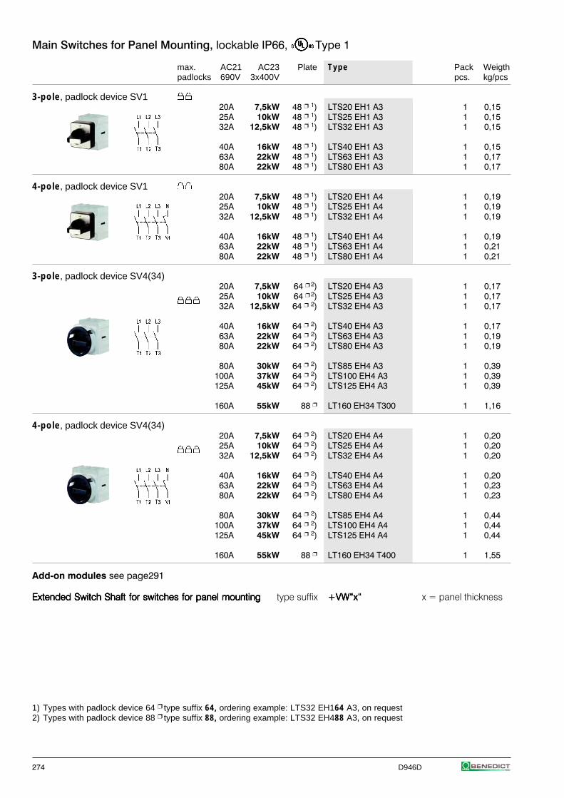
274 D946D
Main Switches for Panel Mounting, lockable IP66, Type 1
max. AC21 AC23 Plate Type Pack Weigthpadlocks 690V 3x400V pcs. kg/pcs
3-pole, padlock device SV120A 7,5kW 48 1) LTS20 EH1 A3 1 0,1525A 10kW 48 1) LTS25 EH1 A3 1 0,1532A 12,5kW 48 1) LTS32 EH1 A3 1 0,15
40A 16kW 48 1) LTS40 EH1 A3 1 0,1563A 22kW 48 1) LTS63 EH1 A3 1 0,1780A 22kW 48 1) LTS80 EH1 A3 1 0,17
4-pole, padlock device SV120A 7,5kW 48 1) LTS20 EH1 A4 1 0,1925A 10kW 48 1) LTS25 EH1 A4 1 0,1932A 12,5kW 48 1) LTS32 EH1 A4 1 0,19
40A 16kW 48 1) LTS40 EH1 A4 1 0,1963A 22kW 48 1) LTS63 EH1 A4 1 0,2180A 22kW 48 1) LTS80 EH1 A4 1 0,21
3-pole, padlock device SV4(34)20A 7,5kW 64 2) LTS20 EH4 A3 1 0,1725A 10kW 64 2) LTS25 EH4 A3 1 0,1732A 12,5kW 64 2) LTS32 EH4 A3 1 0,17
40A 16kW 64 2) LTS40 EH4 A3 1 0,1763A 22kW 64 2) LTS63 EH4 A3 1 0,1980A 22kW 64 2) LTS80 EH4 A3 1 0,19
80A 30kW 64 2) LTS85 EH4 A3 1 0,39100A 37kW 64 2) LTS100 EH4 A3 1 0,39125A 45kW 64 2) LTS125 EH4 A3 1 0,39
160A 55kW 88 LT160 EH34 T300 1 1,16
4-pole, padlock device SV4(34)20A 7,5kW 64 2) LTS20 EH4 A4 1 0,2025A 10kW 64 2) LTS25 EH4 A4 1 0,2032A 12,5kW 64 2) LTS32 EH4 A4 1 0,20
40A 16kW 64 2) LTS40 EH4 A4 1 0,2063A 22kW 64 2) LTS63 EH4 A4 1 0,2380A 22kW 64 2) LTS80 EH4 A4 1 0,23
80A 30kW 64 2) LTS85 EH4 A4 1 0,44100A 37kW 64 2) LTS100 EH4 A4 1 0,44125A 45kW 64 2) LTS125 EH4 A4 1 0,44
160A 55kW 88 LT160 EH34 T400 1 1,55
Add-on modules see page291
Extended Switch Shaft for switches for panel mountingExtended Switch Shaft for switches for panel mountingExtended Switch Shaft for switches for panel mountingExtended Switch Shaft for switches for panel mountingExtended Switch Shaft for switches for panel mounting type suffix +VW“x“+VW“x“+VW“x“+VW“x“+VW“x“ x = panel thickness
1) Types with padlock device 64 type suffix 64, ordering example: LTS32 EH164 A3, on request2) Types with padlock device 88 type suffix 88, ordering example: LTS32 EH488 A3, on request
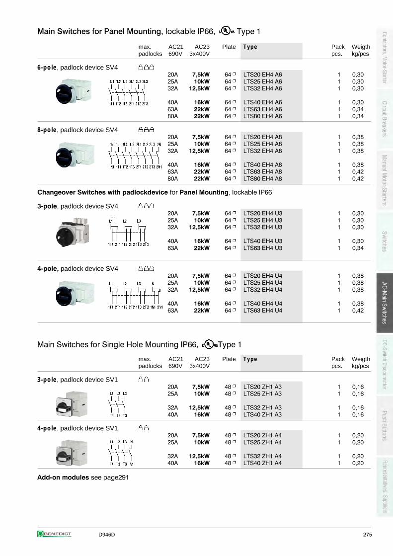
D946D 275
Main Switches for Panel Mounting, lockable IP66, Type 1
max. AC21 AC23 Plate Type Pack Weigthpadlocks 690V 3x400V pcs. kg/pcs
6-pole, padlock device SV420A 7,5kW 64 LTS20 EH4 A6 1 0,3025A 10kW 64 LTS25 EH4 A6 1 0,3032A 12,5kW 64 LTS32 EH4 A6 1 0,30
40A 16kW 64 LTS40 EH4 A6 1 0,3063A 22kW 64 LTS63 EH4 A6 1 0,3480A 22kW 64 LTS80 EH4 A6 1 0,34
8-pole, padlock device SV420A 7,5kW 64 LTS20 EH4 A8 1 0,3825A 10kW 64 LTS25 EH4 A8 1 0,3832A 12,5kW 64 LTS32 EH4 A8 1 0,38
40A 16kW 64 LTS40 EH4 A8 1 0,3863A 22kW 64 LTS63 EH4 A8 1 0,4280A 22kW 64 LTS80 EH4 A8 1 0,42
Changeover Switches with padlockdevice for Panel Mounting, lockable IP66
3-pole, padlock device SV420A 7,5kW 64 LTS20 EH4 U3 1 0,3025A 10kW 64 LTS25 EH4 U3 1 0,3032A 12,5kW 64 LTS32 EH4 U3 1 0,30
40A 16kW 64 LTS40 EH4 U3 1 0,3063A 22kW 64 LTS63 EH4 U3 1 0,34
4-pole, padlock device SV420A 7,5kW 64 LTS20 EH4 U4 1 0,3825A 10kW 64 LTS25 EH4 U4 1 0,3832A 12,5kW 64 LTS32 EH4 U4 1 0,38
40A 16kW 64 LTS40 EH4 U4 1 0,3863A 22kW 64 LTS63 EH4 U4 1 0,42
Main Switches for Single Hole Mounting IP66, Type 1
max. AC21 AC23 Plate Type Pack Weigthpadlocks 690V 3x400V pcs. kg/pcs
3-pole, padlock device SV120A 7,5kW 48 LTS20 ZH1 A3 1 0,1625A 10kW 48 LTS25 ZH1 A3 1 0,16
32A 12,5kW 48 LTS32 ZH1 A3 1 0,1640A 16kW 48 LTS40 ZH1 A3 1 0,16
4-pole, padlock device SV120A 7,5kW 48 LTS20 ZH1 A4 1 0,2025A 10kW 48 LTS25 ZH1 A4 1 0,20
32A 12,5kW 48 LTS32 ZH1 A4 1 0,2040A 16kW 48 LTS40 ZH1 A4 1 0,20
Add-on modules see page291
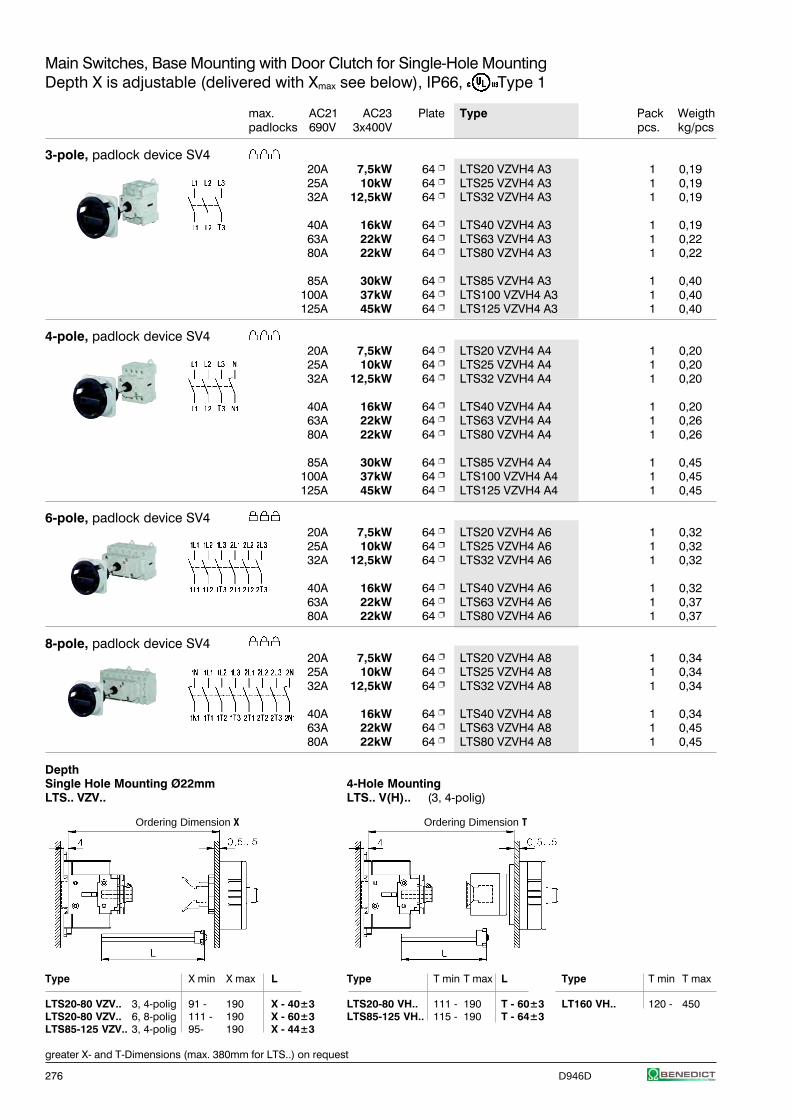
276 D946D
Main Switches, Base Mounting with Door Clutch for Single-Hole MountingDepth X is adjustable (delivered with Xmax see below), IP66, Type 1
max. AC21 AC23 Plate Type Pack Weigthpadlocks 690V 3x400V pcs. kg/pcs
3-pole, padlock device SV420A 7,5kW 64 LTS20 VZVH4 A3 1 0,1925A 10kW 64 LTS25 VZVH4 A3 1 0,1932A 12,5kW 64 LTS32 VZVH4 A3 1 0,19
40A 16kW 64 LTS40 VZVH4 A3 1 0,1963A 22kW 64 LTS63 VZVH4 A3 1 0,2280A 22kW 64 LTS80 VZVH4 A3 1 0,22
85A 30kW 64 LTS85 VZVH4 A3 1 0,40100A 37kW 64 LTS100 VZVH4 A3 1 0,40125A 45kW 64 LTS125 VZVH4 A3 1 0,40
4-pole, padlock device SV420A 7,5kW 64 LTS20 VZVH4 A4 1 0,2025A 10kW 64 LTS25 VZVH4 A4 1 0,2032A 12,5kW 64 LTS32 VZVH4 A4 1 0,20
40A 16kW 64 LTS40 VZVH4 A4 1 0,2063A 22kW 64 LTS63 VZVH4 A4 1 0,2680A 22kW 64 LTS80 VZVH4 A4 1 0,26
85A 30kW 64 LTS85 VZVH4 A4 1 0,45100A 37kW 64 LTS100 VZVH4 A4 1 0,45125A 45kW 64 LTS125 VZVH4 A4 1 0,45
6-pole, padlock device SV420A 7,5kW 64 LTS20 VZVH4 A6 1 0,3225A 10kW 64 LTS25 VZVH4 A6 1 0,3232A 12,5kW 64 LTS32 VZVH4 A6 1 0,32
40A 16kW 64 LTS40 VZVH4 A6 1 0,3263A 22kW 64 LTS63 VZVH4 A6 1 0,3780A 22kW 64 LTS80 VZVH4 A6 1 0,37
8-pole, padlock device SV420A 7,5kW 64 LTS20 VZVH4 A8 1 0,3425A 10kW 64 LTS25 VZVH4 A8 1 0,3432A 12,5kW 64 LTS32 VZVH4 A8 1 0,34
40A 16kW 64 LTS40 VZVH4 A8 1 0,3463A 22kW 64 LTS63 VZVH4 A8 1 0,4580A 22kW 64 LTS80 VZVH4 A8 1 0,45
DepthSingle Hole Mounting Ø22mm 4-Hole MountingLTS.. VZV.. LTS.. V(H).. (3, 4-polig)
Type X min X max L Type T min T max L Type T min T max
LTS20-80 VZV.. 3, 4-polig 91 - 190 X - 40±3 LTS20-80 VH.. 111 - 190 T - 60±3 LT160 VH.. 120 - 450LTS20-80 VZV.. 6, 8-polig 111 - 190 X - 60±3 LTS85-125 VH.. 115 - 190 T - 64±3LTS85-125 VZV.. 3, 4-polig 95- 190 X - 44±3
greater X- and T-Dimensions (max. 380mm for LTS..) on request
Ordering Dimension X Ordering Dimension T
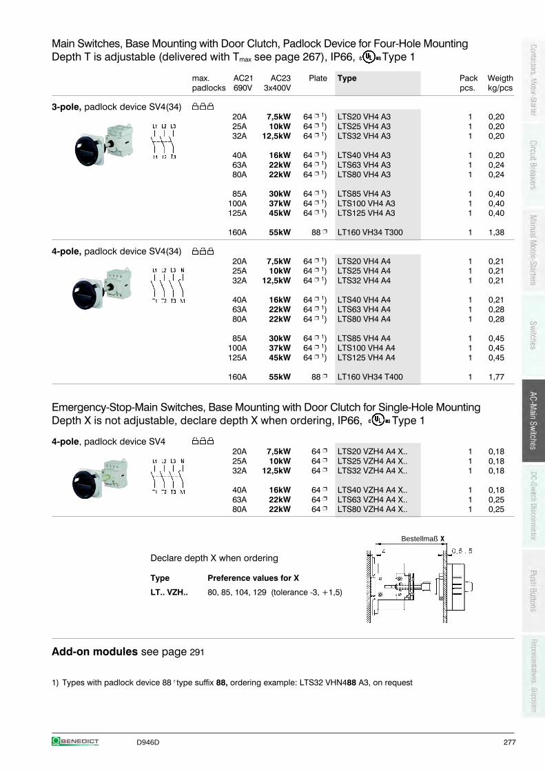
D946D 277
Main Switches, Base Mounting with Door Clutch, Padlock Device for Four-Hole MountingDepth T is adjustable (delivered with Tmax see page 267), IP66, Type 1
max. AC21 AC23 Plate Type Pack Weigthpadlocks 690V 3x400V pcs. kg/pcs
3-pole, padlock device SV4(34)20A 7,5kW 64 1) LTS20 VH4 A3 1 0,2025A 10kW 64 1) LTS25 VH4 A3 1 0,2032A 12,5kW 64 1) LTS32 VH4 A3 1 0,20
40A 16kW 64 1) LTS40 VH4 A3 1 0,2063A 22kW 64 1) LTS63 VH4 A3 1 0,2480A 22kW 64 1) LTS80 VH4 A3 1 0,24
85A 30kW 64 1) LTS85 VH4 A3 1 0,40100A 37kW 64 1) LTS100 VH4 A3 1 0,40125A 45kW 64 1) LTS125 VH4 A3 1 0,40
160A 55kW 88 LT160 VH34 T300 1 1,38
4-pole, padlock device SV4(34)20A 7,5kW 64 1) LTS20 VH4 A4 1 0,2125A 10kW 64 1) LTS25 VH4 A4 1 0,2132A 12,5kW 64 1) LTS32 VH4 A4 1 0,21
40A 16kW 64 1) LTS40 VH4 A4 1 0,2163A 22kW 64 1) LTS63 VH4 A4 1 0,2880A 22kW 64 1) LTS80 VH4 A4 1 0,28
85A 30kW 64 1) LTS85 VH4 A4 1 0,45100A 37kW 64 1) LTS100 VH4 A4 1 0,45125A 45kW 64 1) LTS125 VH4 A4 1 0,45
160A 55kW 88 LT160 VH34 T400 1 1,77
Emergency-Stop-Main Switches, Base Mounting with Door Clutch for Single-Hole MountingDepth X is not adjustable, declare depth X when ordering, IP66, Type 1
4-pole, padlock device SV420A 7,5kW 64 LTS20 VZH4 A4 X.. 1 0,1825A 10kW 64 LTS25 VZH4 A4 X.. 1 0,1832A 12,5kW 64 LTS32 VZH4 A4 X.. 1 0,18
40A 16kW 64 LTS40 VZH4 A4 X.. 1 0,1863A 22kW 64 LTS63 VZH4 A4 X.. 1 0,2580A 22kW 64 LTS80 VZH4 A4 X.. 1 0,25
Declare depth X when ordering
Type Preference values for X
LT.. VZH.. 80, 85, 104, 129 (tolerance -3, +1,5)
Add-on modules see page 291
1) Types with padlock device 88 r type suffix 88, ordering example: LTS32 VHN488 A3, on request
Bestellmaß X
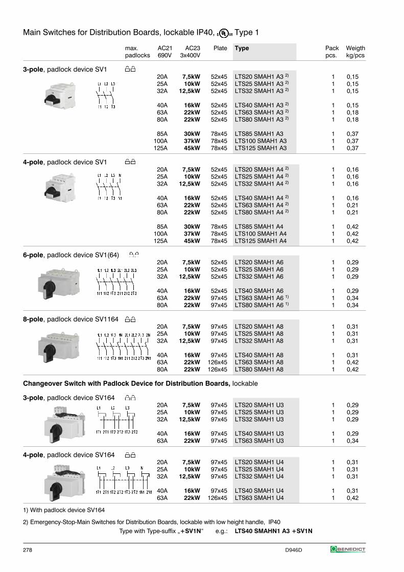
278 D946D
Main Switches for Distribution Boards, lockable IP40, Type 1
max. AC21 AC23 Plate Type Pack Weigthpadlocks 690V 3x400V pcs. kg/pcs
3-pole, padlock device SV120A 7,5kW 52x45 LTS20 SMAH1 A3 2) 1 0,1525A 10kW 52x45 LTS25 SMAH1 A3 2) 1 0,1532A 12,5kW 52x45 LTS32 SMAH1 A3 2) 1 0,15
40A 16kW 52x45 LTS40 SMAH1 A3 2) 1 0,1563A 22kW 52x45 LTS63 SMAH1 A3 2) 1 0,1880A 22kW 52x45 LTS80 SMAH1 A3 2) 1 0,18
85A 30kW 78x45 LTS85 SMAH1 A3 1 0,37100A 37kW 78x45 LTS100 SMAH1 A3 1 0,37125A 45kW 78x45 LTS125 SMAH1 A3 1 0,37
4-pole, padlock device SV120A 7,5kW 52x45 LTS20 SMAH1 A4 2) 1 0,1625A 10kW 52x45 LTS25 SMAH1 A4 2) 1 0,1632A 12,5kW 52x45 LTS32 SMAH1 A4 2) 1 0,16
40A 16kW 52x45 LTS40 SMAH1 A4 2) 1 0,1663A 22kW 52x45 LTS63 SMAH1 A4 2) 1 0,2180A 22kW 52x45 LTS80 SMAH1 A4 2) 1 0,21
85A 30kW 78x45 LTS85 SMAH1 A4 1 0,42100A 37kW 78x45 LTS100 SMAH1 A4 1 0,42125A 45kW 78x45 LTS125 SMAH1 A4 1 0,42
6-pole, padlock device SV1(64)20A 7,5kW 52x45 LTS20 SMAH1 A6 1 0,2925A 10kW 52x45 LTS25 SMAH1 A6 1 0,2932A 12,5kW 52x45 LTS32 SMAH1 A6 1 0,29
40A 16kW 52x45 LTS40 SMAH1 A6 1 0,2963A 22kW 97x45 LTS63 SMAH1 A6 1) 1 0,3480A 22kW 97x45 LTS80 SMAH1 A6 1) 1 0,34
8-pole, padlock device SV116420A 7,5kW 97x45 LTS20 SMAH1 A8 1 0,3125A 10kW 97x45 LTS25 SMAH1 A8 1 0,3132A 12,5kW 97x45 LTS32 SMAH1 A8 1 0,31
40A 16kW 97x45 LTS40 SMAH1 A8 1 0,3163A 22kW 126x45 LTS63 SMAH1 A8 1 0,4280A 22kW 126x45 LTS80 SMAH1 A8 1 0,42
Changeover Switch with Padlock Device for Distribution Boards, lockable
3-pole, padlock device SV16420A 7,5kW 97x45 LTS20 SMAH1 U3 1 0,2925A 10kW 97x45 LTS25 SMAH1 U3 1 0,2932A 12,5kW 97x45 LTS32 SMAH1 U3 1 0,29
40A 16kW 97x45 LTS40 SMAH1 U3 1 0,2963A 22kW 97x45 LTS63 SMAH1 U3 1 0,34
4-pole, padlock device SV16420A 7,5kW 97x45 LTS20 SMAH1 U4 1 0,3125A 10kW 97x45 LTS25 SMAH1 U4 1 0,3132A 12,5kW 97x45 LTS32 SMAH1 U4 1 0,31
40A 16kW 97x45 LTS40 SMAH1 U4 1 0,3163A 22kW 126x45 LTS63 SMAH1 U4 1 0,42
1) With padlock device SV164
2) Emergency-Stop-Main Switches for Distribution Boards, lockable with low height handle, IP40Type with Type-suffix „+SV1N“ e.g.: LTS40 SMAHN1 A3 +SV1N
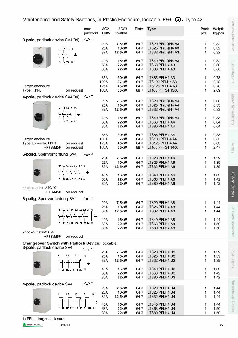
D946D 279
Maintenance and Safety Switches, in Plastic Enclosure, lockable IP66, Type 4X
max. AC21 AC23 Plate Type Pack Weigthpadlocks 690V 3x400V pcs. kg/pcs
3-pole, padlock device SV4(34)20A 7,5kW 64 LTS20 PF(L1))H4 A3 1 0,3225A 10kW 64 LTS25 PF(L1))H4 A3 1 0,3232A 12,5kW 64 LTS32 PF(L1))H4 A3 1 0,32
40A 16kW 64 LTS40 PF(L1))H4 A3 1 0,3263A 22kW 64 LTS63 PFLH4 A3 1 0,6080A 22kW 64 LTS80 PFLH4 A3 1 0,60
85A 30kW 64 LTS85 PFLH4 A3 1 0,78100A 37kW 64 LTS100 PFLH4 A3 1 0,78
Larger enclosure 125A 45kW 64 LTS125 PFLH4 A3 1 0,78Type: ..PFL.. on request 160A 55kW 88 LT160 PFH34 T300 1 2,09
4-pole, padlock device SV4(34)20A 7,5kW 64 LTS20 PF(L1))H4 A4 1 0,3325A 10kW 64 LTS25 PF(L1))H4 A4 1 0,3332A 12,5kW 64 LTS32 PF(L1))H4 A4 1 0,33
40A 16kW 64 LTS40 PF(L1))H4 A4 1 0,3363A 22kW 64 LTS63 PFLH4 A4 1 0,6480A 22kW 64 LTS80 PFLH4 A4 1 0,64
85A 30kW 64 LTS85 PFLH4 A4 1 0,83Larger enclosure 100A 37kW 64 LTS100 PFLH4 A4 1 0,83Type appendix +PF3 on request 125A 45kW 64 LTS125 PFLH4 A4 1 0,83
+PF3/M50 on request 160A 55kW 88 LT160 PFH34 T400 1 2,47
6-polig, Sperrvorrichtung SV420A 7,5kW 64 LTS20 PFLH4 A6 1 1,3925A 10kW 64 LTS25 PFLH4 A6 1 1,3932A 12,5kW 64 LTS32 PFLH4 A6 1 1,39
40A 16kW 64 LTS40 PFLH4 A6 1 1,3963A 22kW 64 LTS63 PFLH4 A6 1 1,4280A 22kW 64 LTS80 PFLH4 A6 1 1,42
knockoutlets M50/40+PF3/M50 on request
8-polig, Sperrvorrichtung SV420A 7,5kW 64 LTS20 PFLH4 A8 1 1,4425A 10kW 64 LTS25 PFLH4 A8 1 1,4432A 12,5kW 64 LTS32 PFLH4 A8 1 1,44
40A 16kW 64 LTS40 PFLH4 A8 1 1,4463A 22kW 64 LTS63 PFLH4 A8 1 1,5080A 22kW 64 LTS80 PFLH4 A8 1 1,50
knockoutletsM50/40+PF3/M50 on request
Changeover Switch with Padlock Device, lockable3-pole, padlock device SV4
20A 7,5kW 64 LTS20 PFLH4 U3 1 1,3925A 10kW 64 LTS25 PFLH4 U3 1 1,3932A 12,5kW 64 LTS32 PFLH4 U3 1 1,39
40A 16kW 64 LTS40 PFLH4 U3 1 1,3963A 22kW 64 LTS63 PFLH4 U3 1 1,4280A 22kW 64 LTS80 PFLH4 U3 1 1,42
4-pole, padlock device SV420A 7,5kW 64 LTS20 PFLH4 U4 1 1,4425A 10kW 64 LTS25 PFLH4 U4 1 1,4432A 12,5kW 64 LTS32 PFLH4 U4 1 1,44
40A 16kW 64 LTS40 PFLH4 U4 1 1,4463A 22kW 64 LTS63 PFLH4 U4 1 1,5080A 22kW 64 LTS80 PFLH4 U4 1 1,50
1) PFL.... larger enclosure
PE
PE
PE
PE
PE
PE
PE
PE
PE
PE
PE
PE
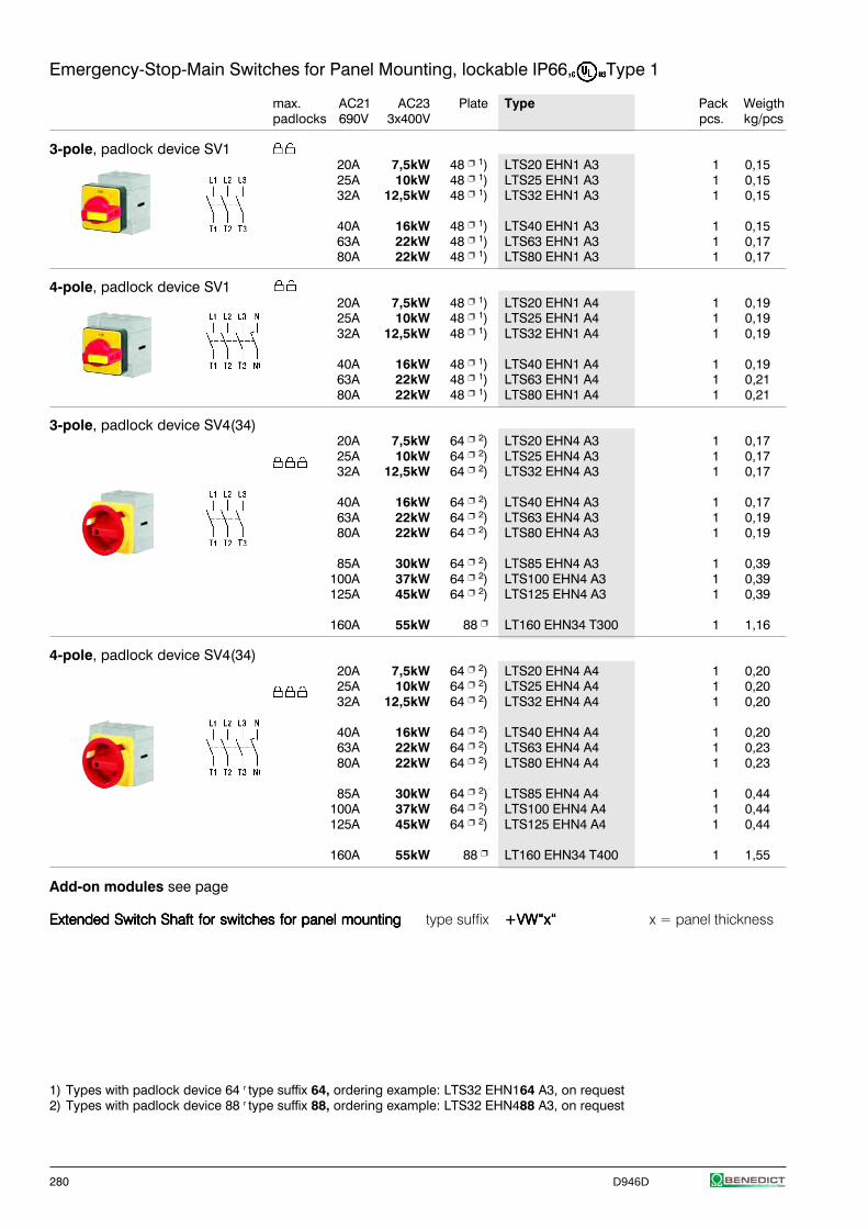
280 D946D
Emergency-Stop-Main Switches for Panel Mounting, lockable IP66, Type 1
max. AC21 AC23 Plate Type Pack Weigthpadlocks 690V 3x400V pcs. kg/pcs
3-pole, padlock device SV120A 7,5kW 48 1) LTS20 EHN1 A3 1 0,1525A 10kW 48 1) LTS25 EHN1 A3 1 0,1532A 12,5kW 48 1) LTS32 EHN1 A3 1 0,15
40A 16kW 48 1) LTS40 EHN1 A3 1 0,1563A 22kW 48 1) LTS63 EHN1 A3 1 0,1780A 22kW 48 1) LTS80 EHN1 A3 1 0,17
4-pole, padlock device SV120A 7,5kW 48 1) LTS20 EHN1 A4 1 0,1925A 10kW 48 1) LTS25 EHN1 A4 1 0,1932A 12,5kW 48 1) LTS32 EHN1 A4 1 0,19
40A 16kW 48 1) LTS40 EHN1 A4 1 0,1963A 22kW 48 1) LTS63 EHN1 A4 1 0,2180A 22kW 48 1) LTS80 EHN1 A4 1 0,21
3-pole, padlock device SV4(34)20A 7,5kW 64 2) LTS20 EHN4 A3 1 0,1725A 10kW 64 2) LTS25 EHN4 A3 1 0,1732A 12,5kW 64 2) LTS32 EHN4 A3 1 0,17
40A 16kW 64 2) LTS40 EHN4 A3 1 0,1763A 22kW 64 2) LTS63 EHN4 A3 1 0,1980A 22kW 64 2) LTS80 EHN4 A3 1 0,19
85A 30kW 64 2) LTS85 EHN4 A3 1 0,39100A 37kW 64 2) LTS100 EHN4 A3 1 0,39125A 45kW 64 2) LTS125 EHN4 A3 1 0,39
160A 55kW 88 LT160 EHN34 T300 1 1,16
4-pole, padlock device SV4(34)20A 7,5kW 64 2) LTS20 EHN4 A4 1 0,2025A 10kW 64 2) LTS25 EHN4 A4 1 0,2032A 12,5kW 64 2) LTS32 EHN4 A4 1 0,20
40A 16kW 64 2) LTS40 EHN4 A4 1 0,2063A 22kW 64 2) LTS63 EHN4 A4 1 0,2380A 22kW 64 2) LTS80 EHN4 A4 1 0,23
85A 30kW 64 2) LTS85 EHN4 A4 1 0,44100A 37kW 64 2) LTS100 EHN4 A4 1 0,44125A 45kW 64 2) LTS125 EHN4 A4 1 0,44
160A 55kW 88 LT160 EHN34 T400 1 1,55
Add-on modules see page
Extended Switch Shaft for switches for panel mountingExtended Switch Shaft for switches for panel mountingExtended Switch Shaft for switches for panel mountingExtended Switch Shaft for switches for panel mountingExtended Switch Shaft for switches for panel mounting type suffix +VW“x“+VW“x“+VW“x“+VW“x“+VW“x“ x = panel thickness
1) Types with padlock device 64 r type suffix 64, ordering example: LTS32 EHN164 A3, on request2) Types with padlock device 88 r type suffix 88, ordering example: LTS32 EHN488 A3, on request
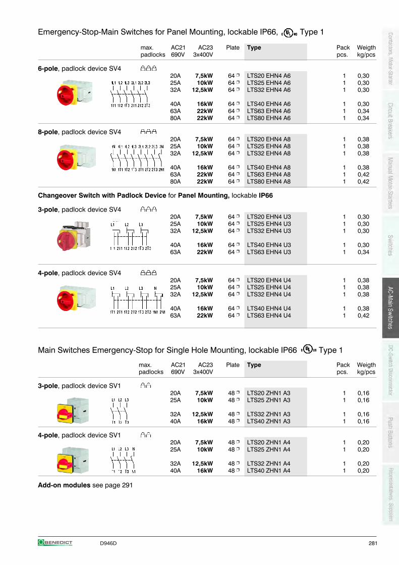
D946D 281
Emergency-Stop-Main Switches for Panel Mounting, lockable IP66, Type 1
max. AC21 AC23 Plate Type Pack Weigthpadlocks 690V 3x400V pcs. kg/pcs
6-pole, padlock device SV420A 7,5kW 64 LTS20 EHN4 A6 1 0,3025A 10kW 64 LTS25 EHN4 A6 1 0,3032A 12,5kW 64 LTS32 EHN4 A6 1 0,30
40A 16kW 64 LTS40 EHN4 A6 1 0,3063A 22kW 64 LTS63 EHN4 A6 1 0,3480A 22kW 64 LTS80 EHN4 A6 1 0,34
8-pole, padlock device SV420A 7,5kW 64 LTS20 EHN4 A8 1 0,3825A 10kW 64 LTS25 EHN4 A8 1 0,3832A 12,5kW 64 LTS32 EHN4 A8 1 0,38
40A 16kW 64 LTS40 EHN4 A8 1 0,3863A 22kW 64 LTS63 EHN4 A8 1 0,4280A 22kW 64 LTS80 EHN4 A8 1 0,42
Changeover Switch with Padlock Device for Panel Mounting, lockable IP66
3-pole, padlock device SV420A 7,5kW 64 LTS20 EHN4 U3 1 0,3025A 10kW 64 LTS25 EHN4 U3 1 0,3032A 12,5kW 64 LTS32 EHN4 U3 1 0,30
40A 16kW 64 LTS40 EHN4 U3 1 0,3063A 22kW 64 LTS63 EHN4 U3 1 0,34
4-pole, padlock device SV420A 7,5kW 64 LTS20 EHN4 U4 1 0,3825A 10kW 64 LTS25 EHN4 U4 1 0,3832A 12,5kW 64 LTS32 EHN4 U4 1 0,38
40A 16kW 64 LTS40 EHN4 U4 1 0,3863A 22kW 64 LTS63 EHN4 U4 1 0,42
Main Switches Emergency-Stop for Single Hole Mounting, lockable IP66 Type 1
max. AC21 AC23 Plate Type Pack Weigthpadlocks 690V 3x400V pcs. kg/pcs
3-pole, padlock device SV120A 7,5kW 48 LTS20 ZHN1 A3 1 0,1625A 10kW 48 LTS25 ZHN1 A3 1 0,16
32A 12,5kW 48 LTS32 ZHN1 A3 1 0,1640A 16kW 48 LTS40 ZHN1 A3 1 0,16
4-pole, padlock device SV120A 7,5kW 48 LTS20 ZHN1 A4 1 0,2025A 10kW 48 LTS25 ZHN1 A4 1 0,20
32A 12,5kW 48 LTS32 ZHN1 A4 1 0,2040A 16kW 48 LTS40 ZHN1 A4 1 0,20
Add-on modules see page 291
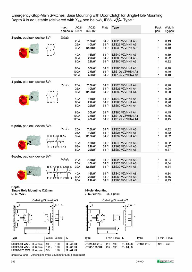
282 D946D
Emergency-Stop-Main Switches, Base Mounting with Door Clutch for Single-Hole MountingDepth X is adjustable (delivered with Xmax see below), IP66, Type 1
max. AC21 AC23 Plate Type Pack Weigthpadlocks 690V 3x400V pcs. kg/pcs
3-pole, padlock device SV420A 7,5kW 64 LTS20 VZVHN4 A3 1 0,1925A 10kW 64 LTS25 VZVHN4 A3 1 0,1932A 12,5kW 64 LTS32 VZVHN4 A3 1 0,19
40A 16kW 64 LTS40 VZVHN4 A3 1 0,1963A 22kW 64 LTS63 VZVHN4 A3 1 0,2280A 22kW 64 LTS80 VZVHN4 A3 1 0,22
85A 30kW 64 LTS85 VZVHN4 A3 1 0,40100A 37kW 64 LTS100 VZVHN4 A3 1 0,40125A 45kW 64 LTS125 VZVHN4 A3 1 0,40
4-pole, padlock device SV420A 7,5kW 64 LTS20 VZVHN4 A4 1 0,2025A 10kW 64 LTS25 VZVHN4 A4 1 0,2032A 12,5kW 64 LTS32 VZVHN4 A4 1 0,20
40A 16kW 64 LTS40 VZVHN4 A4 1 0,2063A 22kW 64 LTS63 VZVHN4 A4 1 0,2680A 22kW 64 LTS80 VZVHN4 A4 1 0,26
85A 30kW 64 LTS85 VZVHN4 A4 1 0,45100A 37kW 64 LTS100 VZVHN4 A4 1 0,45125A 45kW 64 LTS125 VZVHN4 A4 1 0,45
6-pole, padlock device SV420A 7,5kW 64 LTS20 VZVHN4 A6 1 0,3225A 10kW 64 LTS25 VZVHN4 A6 1 0,3232A 12,5kW 64 LTS32 VZVHN4 A6 1 0,32
40A 16kW 64 LTS40 VZVHN4 A6 1 0,3263A 22kW 64 LTS63 VZVHN4 A6 1 0,3780A 22kW 64 LTS80 VZVHN4 A6 1 0,37
8-pole, padlock device SV420A 7,5kW 64 LTS20 VZVHN4 A8 1 0,3425A 10kW 64 LTS25 VZVHN4 A8 1 0,3432A 12,5kW 64 LTS32 VZVHN4 A8 1 0,34
40A 16kW 64 LTS40 VZVHN4 A8 1 0,3463A 22kW 64 LTS63 VZVHN4 A8 1 0,4580A 22kW 64 LTS80 VZVHN4 A8 1 0,45
DepthSingle Hole Mounting Ø22mm 4-Hole MountingLTS.. VZV.. LTS.. V(HN).. (3, 4-pole)
Type X min X max L Type T min T max L Type T min T max
LTS20-80 VZV.. 3, 4-pole 91 - 190 X - 40±3 LTS20-80 VH.. 111 - 190 T - 60±3 LT160 VH.. 120 - 450LTS20-80 VZV.. 6, 8-pole 111 - 190 X - 60±3 LTS85-125 VH.. 115 - 190 T - 64±3LTS85-125 VZV.. 3, 4-pole 95- 190 X - 44±3
greater X- and T-Dimensions (max. 380mm for LTS..) on request
Ordering Dimension X Ordering Dimension T
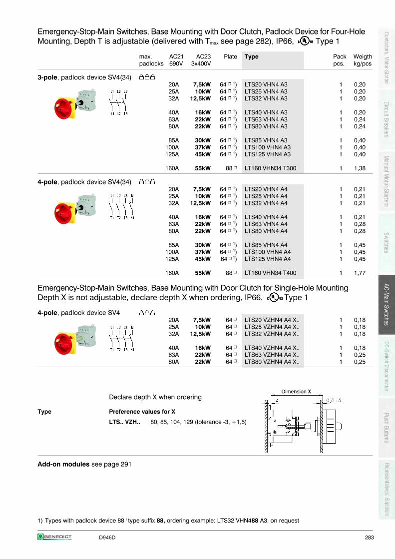
D946D 283
Emergency-Stop-Main Switches, Base Mounting with Door Clutch, Padlock Device for Four-HoleMounting, Depth T is adjustable (delivered with Tmax see page 282), IP66, Type 1
max. AC21 AC23 Plate Type Pack Weigthpadlocks 690V 3x400V pcs. kg/pcs
3-pole, padlock device SV4(34)20A 7,5kW 64 1) LTS20 VHN4 A3 1 0,2025A 10kW 64 1) LTS25 VHN4 A3 1 0,2032A 12,5kW 64 1) LTS32 VHN4 A3 1 0,20
40A 16kW 64 1) LTS40 VHN4 A3 1 0,2063A 22kW 64 1) LTS63 VHN4 A3 1 0,2480A 22kW 64 1) LTS80 VHN4 A3 1 0,24
85A 30kW 64 1) LTS85 VHN4 A3 1 0,40100A 37kW 64 1) LTS100 VHN4 A3 1 0,40125A 45kW 64 1) LTS125 VHN4 A3 1 0,40
160A 55kW 88 LT160 VHN34 T300 1 1,38
4-pole, padlock device SV4(34)20A 7,5kW 64 1) LTS20 VHN4 A4 1 0,2125A 10kW 64 1) LTS25 VHN4 A4 1 0,2132A 12,5kW 64 1) LTS32 VHN4 A4 1 0,21
40A 16kW 64 1) LTS40 VHN4 A4 1 0,2163A 22kW 64 1) LTS63 VHN4 A4 1 0,2880A 22kW 64 1) LTS80 VHN4 A4 1 0,28
85A 30kW 64 1) LTS85 VHN4 A4 1 0,45100A 37kW 64 1) LTS100 VHN4 A4 1 0,45125A 45kW 64 1) LTS125 VHN4 A4 1 0,45
160A 55kW 88 LT160 VHN34 T400 1 1,77
Emergency-Stop-Main Switches, Base Mounting with Door Clutch for Single-Hole MountingDepth X is not adjustable, declare depth X when ordering, IP66, Type 1
4-pole, padlock device SV420A 7,5kW 64 LTS20 VZHN4 A4 X.. 1 0,1825A 10kW 64 LTS25 VZHN4 A4 X.. 1 0,1832A 12,5kW 64 LTS32 VZHN4 A4 X.. 1 0,18
40A 16kW 64 LTS40 VZHN4 A4 X.. 1 0,1863A 22kW 64 LTS63 VZHN4 A4 X.. 1 0,2580A 22kW 64 LTS80 VZHN4 A4 X.. 1 0,25
Declare depth X when ordering
Type Preference values for X
LTS.. VZH.. 80, 85, 104, 129 (tolerance -3, +1,5)
Add-on modules see page 291
1) Types with padlock device 88 r type suffix 88, ordering example: LTS32 VHN488 A3, on request
Dimension X
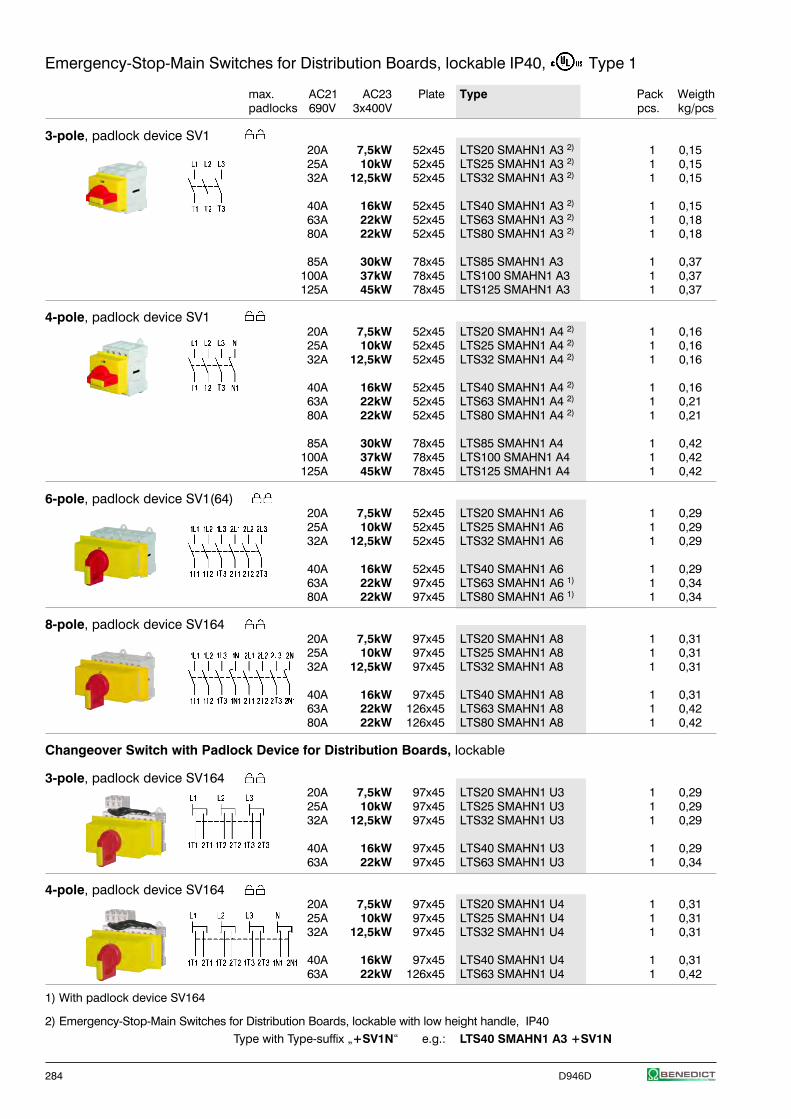
284 D946D
Emergency-Stop-Main Switches for Distribution Boards, lockable IP40, Type 1
max. AC21 AC23 Plate Type Pack Weigthpadlocks 690V 3x400V pcs. kg/pcs
3-pole, padlock device SV120A 7,5kW 52x45 LTS20 SMAHN1 A3 2) 1 0,1525A 10kW 52x45 LTS25 SMAHN1 A3 2) 1 0,1532A 12,5kW 52x45 LTS32 SMAHN1 A3 2) 1 0,15
40A 16kW 52x45 LTS40 SMAHN1 A3 2) 1 0,1563A 22kW 52x45 LTS63 SMAHN1 A3 2) 1 0,1880A 22kW 52x45 LTS80 SMAHN1 A3 2) 1 0,18
85A 30kW 78x45 LTS85 SMAHN1 A3 1 0,37100A 37kW 78x45 LTS100 SMAHN1 A3 1 0,37125A 45kW 78x45 LTS125 SMAHN1 A3 1 0,37
4-pole, padlock device SV120A 7,5kW 52x45 LTS20 SMAHN1 A4 2) 1 0,1625A 10kW 52x45 LTS25 SMAHN1 A4 2) 1 0,1632A 12,5kW 52x45 LTS32 SMAHN1 A4 2) 1 0,16
40A 16kW 52x45 LTS40 SMAHN1 A4 2) 1 0,1663A 22kW 52x45 LTS63 SMAHN1 A4 2) 1 0,2180A 22kW 52x45 LTS80 SMAHN1 A4 2) 1 0,21
85A 30kW 78x45 LTS85 SMAHN1 A4 1 0,42100A 37kW 78x45 LTS100 SMAHN1 A4 1 0,42125A 45kW 78x45 LTS125 SMAHN1 A4 1 0,42
6-pole, padlock device SV1(64)20A 7,5kW 52x45 LTS20 SMAHN1 A6 1 0,2925A 10kW 52x45 LTS25 SMAHN1 A6 1 0,2932A 12,5kW 52x45 LTS32 SMAHN1 A6 1 0,29
40A 16kW 52x45 LTS40 SMAHN1 A6 1 0,2963A 22kW 97x45 LTS63 SMAHN1 A6 1) 1 0,3480A 22kW 97x45 LTS80 SMAHN1 A6 1) 1 0,34
8-pole, padlock device SV16420A 7,5kW 97x45 LTS20 SMAHN1 A8 1 0,3125A 10kW 97x45 LTS25 SMAHN1 A8 1 0,3132A 12,5kW 97x45 LTS32 SMAHN1 A8 1 0,31
40A 16kW 97x45 LTS40 SMAHN1 A8 1 0,3163A 22kW 126x45 LTS63 SMAHN1 A8 1 0,4280A 22kW 126x45 LTS80 SMAHN1 A8 1 0,42
Changeover Switch with Padlock Device for Distribution Boards, lockable
3-pole, padlock device SV16420A 7,5kW 97x45 LTS20 SMAHN1 U3 1 0,2925A 10kW 97x45 LTS25 SMAHN1 U3 1 0,2932A 12,5kW 97x45 LTS32 SMAHN1 U3 1 0,29
40A 16kW 97x45 LTS40 SMAHN1 U3 1 0,2963A 22kW 97x45 LTS63 SMAHN1 U3 1 0,34
4-pole, padlock device SV16420A 7,5kW 97x45 LTS20 SMAHN1 U4 1 0,3125A 10kW 97x45 LTS25 SMAHN1 U4 1 0,3132A 12,5kW 97x45 LTS32 SMAHN1 U4 1 0,31
40A 16kW 97x45 LTS40 SMAHN1 U4 1 0,3163A 22kW 126x45 LTS63 SMAHN1 U4 1 0,42
1) With padlock device SV164
2) Emergency-Stop-Main Switches for Distribution Boards, lockable with low height handle, IP40Type with Type-suffix „+SV1N“ e.g.: LTS40 SMAHN1 A3 +SV1N
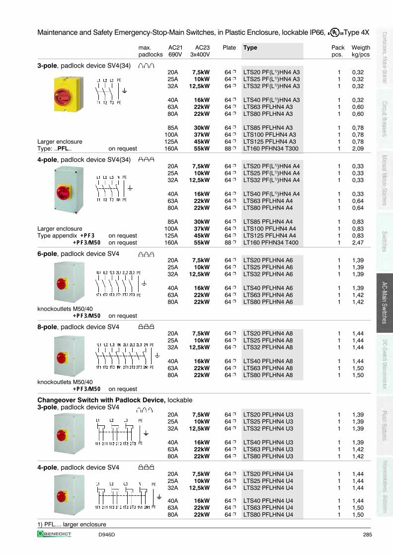
D946D 285
Maintenance and Safety Emergency-Stop-Main Switches, in Plastic Enclosure, lockable IP66, Type 4X
max. AC21 AC23 Plate Type Pack Weigthpadlocks 690V 3x400V pcs. kg/pcs
3-pole, padlock device SV4(34)20A 7,5kW 64 LTS20 PF(L1))HN4 A3 1 0,3225A 10kW 64 LTS25 PF(L1))HN4 A3 1 0,3232A 12,5kW 64 LTS32 PF(L1))HN4 A3 1 0,32
40A 16kW 64 LTS40 PF(L1))HN4 A3 1 0,3263A 22kW 64 LTS63 PFLHN4 A3 1 0,6080A 22kW 64 LTS80 PFLHN4 A3 1 0,60
85A 30kW 64 LTS85 PFLHN4 A3 1 0,78100A 37kW 64 LTS100 PFLHN4 A3 1 0,78
Larger enclosure 125A 45kW 64 LTS125 PFLHN4 A3 1 0,78Type: ..PFL.. on request 160A 55kW 88 LT160 PFHN34 T300 1 2,09
4-pole, padlock device SV4(34)20A 7,5kW 64 LTS20 PF(L1))HN4 A4 1 0,3325A 10kW 64 LTS25 PF(L1))HN4 A4 1 0,3332A 12,5kW 64 LTS32 PF(L1))HN4 A4 1 0,33
40A 16kW 64 LTS40 PF(L1))HN4 A4 1 0,3363A 22kW 64 LTS63 PFLHN4 A4 1 0,6480A 22kW 64 LTS80 PFLHN4 A4 1 0,64
85A 30kW 64 LTS85 PFLHN4 A4 1 0,83Larger enclosure 100A 37kW 64 LTS100 PFLHN4 A4 1 0,83Type appendix +PF3 on request 125A 45kW 64 LTS125 PFLHN4 A4 1 0,83
+PF3/M50 on request 160A 55kW 88 LT160 PFHN34 T400 1 2,47
6-pole, padlock device SV420A 7,5kW 64 LTS20 PFLHN4 A6 1 1,3925A 10kW 64 LTS25 PFLHN4 A6 1 1,3932A 12,5kW 64 LTS32 PFLHN4 A6 1 1,39
40A 16kW 64 LTS40 PFLHN4 A6 1 1,3963A 22kW 64 LTS63 PFLHN4 A6 1 1,4280A 22kW 64 LTS80 PFLHN4 A6 1 1,42
knockoutlets M50/40+PF3/M50 on request
8-pole, padlock device SV420A 7,5kW 64 LTS20 PFLHN4 A8 1 1,4425A 10kW 64 LTS25 PFLHN4 A8 1 1,4432A 12,5kW 64 LTS32 PFLHN4 A8 1 1,44
40A 16kW 64 LTS40 PFLHN4 A8 1 1,4463A 22kW 64 LTS63 PFLHN4 A8 1 1,5080A 22kW 64 LTS80 PFLHN4 A8 1 1,50
knockoutlets M50/40+PF3/M50 on request
Changeover Switch with Padlock Device, lockable3-pole, padlock device SV4
20A 7,5kW 64 LTS20 PFLHN4 U3 1 1,3925A 10kW 64 LTS25 PFLHN4 U3 1 1,3932A 12,5kW 64 LTS32 PFLHN4 U3 1 1,39
40A 16kW 64 LTS40 PFLHN4 U3 1 1,3963A 22kW 64 LTS63 PFLHN4 U3 1 1,4280A 22kW 64 LTS80 PFLHN4 U3 1 1,42
4-pole, padlock device SV420A 7,5kW 64 LTS20 PFLHN4 U4 1 1,4425A 10kW 64 LTS25 PFLHN4 U4 1 1,4432A 12,5kW 64 LTS32 PFLHN4 U4 1 1,44
40A 16kW 64 LTS40 PFLHN4 U4 1 1,4463A 22kW 64 LTS63 PFLHN4 U4 1 1,5080A 22kW 64 LTS80 PFLHN4 U4 1 1,50
1) PFL.... larger enclosure
PE
PE
PE
PE
PE
PE
PE
PE
PE
PE
PE
PE
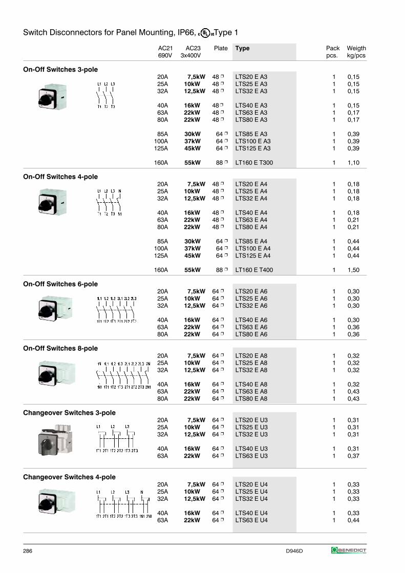
286 D946D
Switch Disconnectors for Panel Mounting, IP66, Type 1
AC21 AC23 Plate Type Pack Weigth690V 3x400V pcs. kg/pcs
On-Off Switches 3-pole20A 7,5kW 48 LTS20 E A3 1 0,1525A 10kW 48 LTS25 E A3 1 0,1532A 12,5kW 48 LTS32 E A3 1 0,15
40A 16kW 48 LTS40 E A3 1 0,1563A 22kW 48 LTS63 E A3 1 0,1780A 22kW 48 LTS80 E A3 1 0,17
85A 30kW 64 LTS85 E A3 1 0,39100A 37kW 64 LTS100 E A3 1 0,39125A 45kW 64 LTS125 E A3 1 0,39
160A 55kW 88 LT160 E T300 1 1,10
On-Off Switches 4-pole20A 7,5kW 48 LTS20 E A4 1 0,1825A 10kW 48 LTS25 E A4 1 0,1832A 12,5kW 48 LTS32 E A4 1 0,18
40A 16kW 48 LTS40 E A4 1 0,1863A 22kW 48 LTS63 E A4 1 0,2180A 22kW 48 LTS80 E A4 1 0,21
85A 30kW 64 LTS85 E A4 1 0,44100A 37kW 64 LTS100 E A4 1 0,44125A 45kW 64 LTS125 E A4 1 0,44
160A 55kW 88 LT160 E T400 1 1,50
On-Off Switches 6-pole20A 7,5kW 64 LTS20 E A6 1 0,3025A 10kW 64 LTS25 E A6 1 0,3032A 12,5kW 64 LTS32 E A6 1 0,30
40A 16kW 64 LTS40 E A6 1 0,3063A 22kW 64 LTS63 E A6 1 0,3680A 22kW 64 LTS80 E A6 1 0,36
On-Off Switches 8-pole20A 7,5kW 64 LTS20 E A8 1 0,3225A 10kW 64 LTS25 E A8 1 0,3232A 12,5kW 64 LTS32 E A8 1 0,32
40A 16kW 64 LTS40 E A8 1 0,3263A 22kW 64 LTS63 E A8 1 0,4380A 22kW 64 LTS80 E A8 1 0,43
Changeover Switches 3-pole20A 7,5kW 64 LTS20 E U3 1 0,3125A 10kW 64 LTS25 E U3 1 0,3132A 12,5kW 64 LTS32 E U3 1 0,31
40A 16kW 64 LTS40 E U3 1 0,3163A 22kW 64 LTS63 E U3 1 0,37
Changeover Switches 4-pole20A 7,5kW 64 LTS20 E U4 1 0,3325A 10kW 64 LTS25 E U4 1 0,3332A 12,5kW 64 LTS32 E U4 1 0,33
40A 16kW 64 LTS40 E U4 1 0,3363A 22kW 64 LTS63 E U4 1 0,44
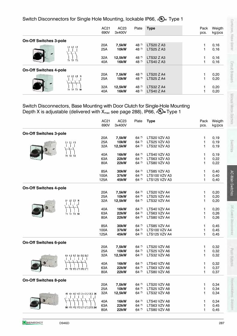
D946D 287
Switch Disconnectors for Single Hole Mounting, lockable IP66, Type 1
AC21 AC23 Plate Type Pack Weigth690V 3x400V pcs. kg/pcs
On-Off Switches 3-pole20A 7,5kW 48 LTS20 Z A3 1 0,1625A 10kW 48 LTS25 Z A3 1 0,16
32A 12,5kW 48 LTS32 Z A3 1 0,1640A 16kW 48 LTS40 Z A3 1 0,16
On-Off Switches 4-pole20A 7,5kW 48 LTS20 Z A4 1 0,2025A 10kW 48 LTS25 Z A4 1 0,20
32A 12,5kW 48 LTS32 Z A4 1 0,2040A 16kW 48 LTS40 Z A4 1 0,20
Switch Disconnectors, Base Mounting with Door Clutch for Single-Hole MountingDepth X is adjustable (delivered with Xmax see page 288), IP66, Type 1
AC21 AC23 Plate Type Pack Weigth690V 3x400V pcs. kg/pcs
On-Off Switches 3-pole20A 7,5kW 64 LTS20 VZV A3 1 0,1925A 10kW 64 LTS25 VZV A3 1 0,1932A 12,5kW 64 LTS32 VZV A3 1 0,19
40A 16kW 64 LTS40 VZV A3 1 0,1963A 22kW 64 LTS63 VZV A3 1 0,2280A 22kW 64 LTS80 VZV A3 1 0,22
85A 30kW 64 LTS85 VZV A3 1 0,40100A 37kW 64 LTS100 VZV A3 1 0,40125A 45kW 64 LTS125 VZV A3 1 0,40
On-Off Switches 4-pole20A 7,5kW 64 LTS20 VZV A4 1 0,2025A 10kW 64 LTS25 VZV A4 1 0,2032A 12,5kW 64 LTS32 VZV A4 1 0,20
40A 16kW 64 LTS40 VZV A4 1 0,2063A 22kW 64 LTS63 VZV A4 1 0,2680A 22kW 64 LTS80 VZV A4 1 0,26
85A 30kW 64 LTS85 VZV A4 1 0,45100A 37kW 64 LTS100 VZV A4 1 0,45125A 45kW 64 LTS125 VZV A4 1 0,45
On-Off Switches 6-pole20A 7,5kW 64 LTS20 VZV A6 1 0,3225A 10kW 64 LTS25 VZV A6 1 0,3232A 12,5kW 64 LTS32 VZV A6 1 0,32
40A 16kW 64 LTS40 VZV A6 1 0,3263A 22kW 64 LTS63 VZV A6 1 0,3780A 22kW 64 LTS80 VZV A6 1 0,37
On-Off Switches 8-pole20A 7,5kW 64 LTS20 VZV A8 1 0,3425A 10kW 64 LTS25 VZV A8 1 0,3432A 12,5kW 64 LTS32 VZV A8 1 0,34
40A 16kW 64 LTS40 VZV A8 1 0,3463A 22kW 64 LTS63 VZV A8 1 0,4580A 22kW 64 LTS80 VZV A8 1 0,45
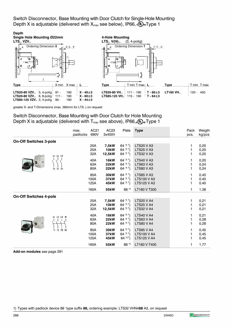
288 D946D
Switch Disconnector, Base Mounting with Door Clutch for Single-Hole MountingDepth X is adjustable (delivered with Xmax see below), IP66, Type 1
DepthSingle Hole Mounting Ø22mm 4-Hole MountingLTS.. VZV.. LTS.. V(H).. (3, 4-polig)
Type X min X max L Type T min T max L Type T min T max
LTS20-80 VZV.. 3, 4-polig 91 - 190 X - 40±3 LTS20-80 VH.. 111 - 190 T - 60±3 LT160 VH.. 120 - 450LTS20-80 VZV.. 6, 8-polig 111 - 190 X - 60±3 LTS85-125 VH.. 115 - 190 T - 64±3LTS85-125 VZV.. 3, 4-polig 95- 190 X - 44±3
greater X- and T-Dimensions (max. 380mm for LTS..) on request
Switch Disconnector, Base Mounting with Door Clutch for Hole MountingDepth X is adjustable (delivered with Tmax see above), IP66, Type 1
max. AC21 AC23 Plate Type Pack Weigthpadlocks 690V 3x400V pcs. kg/pcs
On-Off Switches 3-pole20A 7,5kW 64 1) LTS20 V A3 1 0,2025A 10kW 64 1) LTS25 V A3 1 0,2032A 12,5kW 64 1) LTS32 V A3 1 0,20
40A 16kW 64 1) LTS40 V A3 1 0,2063A 22kW 64 1) LTS63 V A3 1 0,2480A 22kW 64 1) LTS80 V A3 1 0,24
85A 30kW 64 1) LTS85 V A3 1 0,40100A 37kW 64 1) LTS100 V A3 1 0,40125A 45kW 64 1) LTS125 V A3 1 0,40
160A 55kW 88 LT160 V T300 1 1,38
On-Off Switches 4-pole20A 7,5kW 64 1) LTS20 V A4 1 0,2125A 10kW 64 1) LTS25 V A4 1 0,2132A 12,5kW 64 1) LTS32 V A4 1 0,21
40A 16kW 64 1) LTS40 V A4 1 0,2163A 22kW 64 1) LTS63 V A4 1 0,2880A 22kW 64 1) LTS80 V A4 1 0,28
85A 30kW 64 1) LTS85 V A4 1 0,45100A 37kW 64 1) LTS100 V A4 1 0,45125A 45kW 64 1) LTS125 V A4 1 0,45
160A 55kW 88 LT160 V T400 1 1,77
Add-on modules see page 291
1) Types with padlock device 88 r type suffix 88, ordering example: LTS32 VHN488 A3, on request
Ordering Dimension X Ordering Dimension T
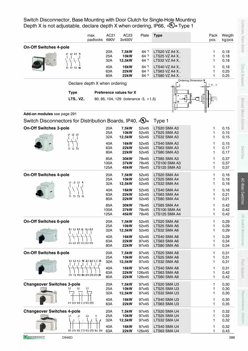
D946D 289
Switch Disconnector, Base Mounting with Door Clutch for Single-Hole MountingDepth X is not adjustable, declare depth X when ordering, IP66, Type 1
max. AC21 AC23 Plate Type Pack Weigthpadlocks 690V 3x400V pcs. kg/pcs
On-Off Switches 4-pole20A 7,5kW 64 LTS20 VZ A4 X.. 1 0,1825A 10kW 64 LTS25 VZ A4 X.. 1 0,1832A 12,5kW 64 LTS32 VZ A4 X.. 1 0,18
40A 16kW 64 LTS40 VZ A4 X.. 1 0,1863A 22kW 64 LTS63 VZ A4 X.. 1 0,2580A 22kW 64 LTS80 VZ A4 X.. 1 0,25
Declare depth X when ordering
Type Preference values for X
LTS.. VZ.. 80, 85, 104, 129 (tolerance -3, +1,5)
Add-on modules see page 291
Switch Disconnectors for Distribution Boards, IP40, Type 1On-Off Switches 3-pole 20A 7,5kW 52x45 LTS20 SMA A3 1 0,15
25A 10kW 52x45 LTS25 SMA A3 1 0,1532A 12,5kW 52x45 LTS32 SMA A3 1 0,15
40A 16kW 52x45 LTS40 SMA A3 1 0,1563A 22kW 52x45 LTS63 SMA A3 1 0,1780A 22kW 52x45 LTS80 SMA A3 1 0,17
85A 30kW 78x45 LTS85 SMA A3 1 0,37100A 37kW 78x45 LTS100 SMA A3 1 0,37125A 45kW 78x45 LTS125 SMA A3 1 0,37
On-Off Switches 4-pole 20A 7,5kW 52x45 LTS20 SMA A4 1 0,1625A 10kW 52x45 LTS25 SMA A4 1 0,1632A 12,5kW 52x45 LTS32 SMA A4 1 0,16
40A 16kW 52x45 LTS40 SMA A4 1 0,1663A 22kW 52x45 LTS63 SMA A4 1 0,2180A 22kW 52x45 LTS80 SMA A4 1 0,21
85A 30kW 78x45 LTS85 SMA A4 1 0,42100A 37kW 78x45 LTS100 SMA A4 1 0,42125A 45kW 78x45 LTS125 SMA A4 1 0,42
On-Off Switches 6-pole 20A 7,5kW 52x45 LTS20 SMA A6 1 0,2925A 10kW 52x45 LTS25 SMA A6 1 0,2932A 12,5kW 52x45 LTS32 SMA A6 1 0,29
40A 16kW 52x45 LTS40 SMA A6 1 0,2963A 22kW 97x45 LTS63 SMA A6 1 0,3480A 22kW 97x45 LTS80 SMA A6 1 0,34
On-Off Switches 8-pole 20A 7,5kW 97x45 LTS20 SMA A8 1 0,3125A 10kW 97x45 LTS25 SMA A8 1 0,3132A 12,5kW 97x45 LTS32 SMA A8 1 0,31
40A 16kW 97x45 LTS40 SMA A8 1 0,3163A 22kW 126x45 LTS63 SMA A8 1 0,4280A 22kW 126x45 LTS80 SMA A8 1 0,42
Changeover Switches 3-pole 20A 7,5kW 97x45 LTS20 SMA U3 1 0,3025A 10kW 97x45 LTS25 SMA U3 1 0,3032A 12,5kW 97x45 LTS32 SMA U3 1 0,30
40A 16kW 97x45 LTS40 SMA U3 1 0,3063A 22kW 97x45 LTS63 SMA U3 1 0,35
Changeover Switches 4-pole 20A 7,5kW 97x45 LTS20 SMA U4 1 0,3225A 10kW 97x45 LTS25 SMA U4 1 0,3232A 12,5kW 97x45 LTS32 SMA U4 1 0,32
40A 16kW 97x45 LTS40 SMA U4 1 0,3263A 22kW 126x45 LTS63 SMA U4 1 0,43
Ordering Dimension X
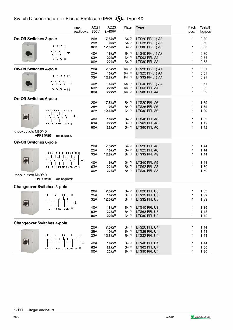
290 D946D
PE
PE
PE
PE
Switch Disconnectors in Plastic Enclosure IP66, Type 4X
max. AC21 AC23 Plate Type Pack Weigthpadlocks 690V 3x400V pcs. kg/pcs
On-Off Switches 3-pole 20A 7,5kW 64 LTS20 PF(L1)) A3 1 0,3025A 10kW 64 LTS25 PF(L1)) A3 1 0,3032A 12,5kW 64 LTS32 PF(L1)) A3 1 0,30
40A 16kW 64 LTS40 PF(L1)) A3 1 0,3063A 22kW 64 LTS63 PFL A3 1 0,5880A 22kW 64 LTS80 PFL A3 1 0,58
On-Off Switches 4-pole 20A 7,5kW 64 LTS20 PF(L1)) A4 1 0,3125A 10kW 64 LTS25 PF(L1)) A4 1 0,3132A 12,5kW 64 LTS32 PF(L1)) A4 1 0,31
40A 16kW 64 LTS40 PF(L1)) A4 1 0,3163A 22kW 64 LTS63 PFL A4 1 0,6280A 22kW 64 LTS80 PFL A4 1 0,62
On-Off Switches 6-pole20A 7,5kW 64 LTS20 PFL A6 1 1,3925A 10kW 64 LTS25 PFL A6 1 1,3932A 12,5kW 64 LTS32 PFL A6 1 1,39
40A 16kW 64 LTS40 PFL A6 1 1,3963A 22kW 64 LTS63 PFL A6 1 1,4280A 22kW 64 LTS80 PFL A6 1 1,42
knockoutlets M50/40+PF3/M50 on request
On-Off Switches 8-pole20A 7,5kW 64 LTS20 PFL A8 1 1,4425A 10kW 64 LTS25 PFL A8 1 1,4432A 12,5kW 64 LTS32 PFL A8 1 1,44
40A 16kW 64 LTS40 PFL A8 1 1,4463A 22kW 64 LTS63 PFL A8 1 1,5080A 22kW 64 LTS80 PFL A8 1 1,50
knockoutlets M50/40+PF3/M50 on request
Changeover Switches 3-pole20A 7,5kW 64 LTS20 PFL U3 1 1,3925A 10kW 64 LTS25 PFL U3 1 1,3932A 12,5kW 64 LTS32 PFL U3 1 1,39
40A 16kW 64 LTS40 PFL U3 1 1,3963A 22kW 64 LTS63 PFL U3 1 1,4280A 22kW 64 LTS80 PFL U3 1 1,42
Changeover Switches 4-pole20A 7,5kW 64 LTS20 PFL U4 1 1,4425A 10kW 64 LTS25 PFL U4 1 1,4432A 12,5kW 64 LTS32 PFL U4 1 1,44
40A 16kW 64 LTS40 PFL U4 1 1,4463A 22kW 64 LTS63 PFL U4 1 1,5080A 22kW 64 LTS80 PFL U4 1 1,50
1) PFL.... larger enclosure
PE
PE
PE
PE
PE
PE
PE
PE
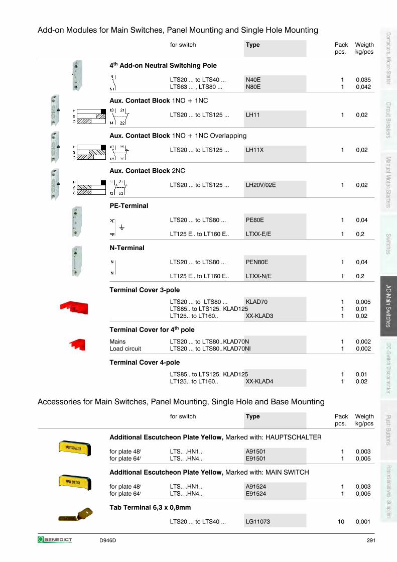
D946D 291
N
N
Add-on Modules for Main Switches, Panel Mounting and Single Hole Mounting
for switch Type Pack Weigthpcs. kg/pcs
4th Add-on Neutral Switching Pole
LTS20 ... to LTS40 ... N40E 1 0,035LTS63 ... , LTS80 ... N80E 1 0,042
Aux. Contact Block 1NO + 1NC
LTS20 ... to LTS125 ... LH11 1 0,02
Aux. Contact Block 1NO + 1NC Overlapping
LTS20 ... to LTS125 ... LH11X 1 0,02
Aux. Contact Block 2NC
LTS20 ... to LTS125 ... LH20V/02E 1 0,02
PE-Terminal
LTS20 ... to LTS80 ... PE80E 1 0,04
LT125 E.. to LT160 E.. LTXX-E/E 1 0,2
N-Terminal
LTS20 ... to LTS80 ... PEN80E 1 0,04
LT125 E.. to LT160 E.. LTXX-N/E 1 0,2
Terminal Cover 3-pole
LTS20 ... to LTS80 ... KLAD70 1 0,005LTS85.. to LTS125. KLAD125 1 0,01LT125.. to LT160.. XX-KLAD3 1 0,02
Terminal Cover for 4th pole
Mains LTS20 ... to LTS80..KLAD70N 1 0,002Load circuit LTS20 ... to LTS80..KLAD70NI 1 0,002
Terminal Cover 4-pole
LTS85.. to LTS125. KLAD125 1 0,01LT125.. to LT160.. XX-KLAD4 1 0,02
Accessories for Main Switches, Panel Mounting, Single Hole and Base Mounting
for switch Type Pack Weigthpcs. kg/pcs
Additional Escutcheon Plate Yellow, Marked with: HAUPTSCHALTER
for plate 48r LTS.. .HN1.. A91501 1 0,003for plate 64r LTS.. .HN4.. E91501 1 0,005
Additional Escutcheon Plate Yellow, Marked with: MAIN SWITCH
for plate 48r LTS.. .HN1.. A91524 1 0,003for plate 64r LTS.. .HN4.. E91524 1 0,005
Tab Terminal 6,3 x 0,8mm
LTS20 ... to LTS40 ... LG11073 10 0,001
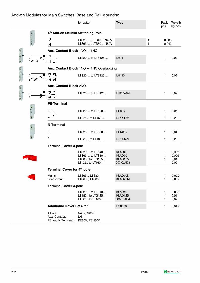
292 D946D
Add-on Modules for Main Switches, Base and Rail Mounting
for switch Type Pack Weigthpcs. kg/pcs
4th Add-on Neutral Switching Pole
LTS20 ... , LTS40 ...N40V 1 0,035LTS63 ... , LTS80 ...N80V 1 0,042
Aux. Contact Block 1NO + 1NC
LTS20 ... to LTS125 ... LH11 1 0,02
Aux. Contact Block 1NO + 1NC Overlapping
LTS20 ... to LTS125 ... LH11X 1 0,02
Aux. Contact Block 2NO
LTS20 ... to LTS125 ... LH20V/02E 1 0,02
PE-Terminal
LTS20 ... to LTS80 ... PE80V 1 0,04
LT125 .. to LT160 .. LTXX-E/V 1 0,2
N-Terminal
LTS20 ... to LTS80 ... PEN80V 1 0,04
LT125 .. to LT160 .. LTXX-N/V 1 0,2
Terminal Cover 3-pole
LTS20 ... to LTS40 ... KLAD40 1 0,005LTS63 ... to LTS80 ... KLAD70 1 0,005LTS85.. to LTS125. KLAD125 1 0,01LT125.. to LT160.. XX-KLAD3 1 0,02
Terminal Cover for 4th pole
Mains LTS63.., LTS80.. KLAD70N 1 0,002Load circuit LTS63.., LTS80.. KLAD70NI 1 0,002
Terminal Cover 4-pole
LTS20 ... to LTS40 ... KLAD40 1 0,005LTS85.. to LTS125. KLAD125 1 0,01LT125.. to LT160.. XX-KLAD4 1 0,02
Additional Cover SMA for LG8628 1 0,047
4.Pole N40V, N80VAux. Contacts LH..PE and N-Terminal PE80V, PEN80V
N
N
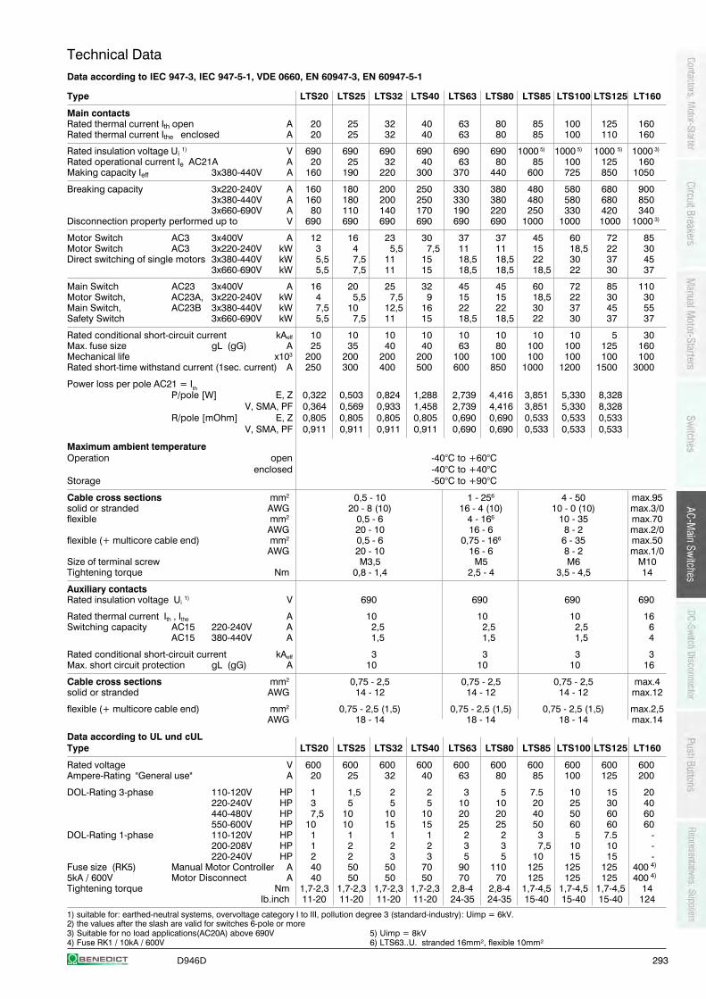
D946D 293
Technical DataData according to IEC 947-3, IEC 947-5-1, VDE 0660, EN 60947-3, EN 60947-5-1
Type LTS20 LTS25 LTS32 LTS40 LTS63 LTS80 LTS85 LTS100 LTS125 LT160
Main contactsRated thermal current Ith open A 20 25 32 40 63 80 85 100 125 160Rated thermal current Ithe enclosed A 20 25 32 40 63 80 85 100 110 160
Rated insulation voltage Ui 1) V 690 690 690 690 690 690 1000 5) 1000 5) 1000 5) 1000 3)
Rated operational current Ie AC21A A 20 25 32 40 63 80 85 100 125 160Making capacity Ieff 3x380-440V A 160 190 220 300 370 440 600 725 850 1050
Breaking capacity 3x220-240V A 160 180 200 250 330 380 480 580 680 9003x380-440V A 160 180 200 250 330 380 480 580 680 8503x660-690V A 80 110 140 170 190 220 250 330 420 340
Disconnection property performed up to V 690 690 690 690 690 690 1000 1000 1000 1000 3)
Motor Switch AC3 3x400V A 12 16 23 30 37 37 45 60 72 85Motor Switch AC3 3x220-240V kW 3 4 5,5 7,5 11 11 15 18,5 22 30Direct switching of single motors 3x380-440V kW 5,5 7,5 11 15 18,5 18,5 22 30 37 45
3x660-690V kW 5,5 7,5 11 15 18,5 18,5 18,5 22 30 37
Main Switch AC23 3x400V A 16 20 25 32 45 45 60 72 85 110Motor Switch, AC23A, 3x220-240V kW 4 5,5 7,5 9 15 15 18,5 22 30 30Main Switch, AC23B 3x380-440V kW 7,5 10 12,5 16 22 22 30 37 45 55Safety Switch 3x660-690V kW 5,5 7,5 11 15 18,5 18,5 22 30 37 37
Rated conditional short-circuit current kAeff 10 10 10 10 10 10 10 10 5 30Max. fuse size gL (gG) A 25 35 40 40 63 80 100 100 125 160Mechanical life x103 200 200 200 200 100 100 100 100 100 100Rated short-time withstand current (1sec. current) A 250 300 400 500 600 850 1000 1200 1500 3000
Power loss per pole AC21 = IthP/pole [W] E, Z 0,322 0,503 0,824 1,288 2,739 4,416 3,851 5,330 8,328
V, SMA, PF 0,364 0,569 0,933 1,458 2,739 4,416 3,851 5,330 8,328R/pole [mOhm] E, Z 0,805 0,805 0,805 0,805 0,690 0,690 0,533 0,533 0,533
V, SMA, PF 0,911 0,911 0,911 0,911 0,690 0,690 0,533 0,533 0,533
Maximum ambient temperatureOperation open -40°C to +60°C
enclosed -40°C to +40°CStorage -50°C to +90°C
Cable cross sections mm2 0,5 - 10 1 - 256 4 - 50 max.95solid or stranded AWG 20 - 8 (10) 16 - 4 (10) 10 - 0 (10) max.3/0flexible mm2 0,5 - 6 4 - 166 10 - 35 max.70
AWG 20 - 10 16 - 6 8 - 2 max.2/0flexible (+ multicore cable end) mm2 0,5 - 6 0,75 - 166 6 - 35 max.50
AWG 20 - 10 16 - 6 8 - 2 max.1/0Size of terminal screw M3,5 M5 M6 M10Tightening torque Nm 0,8 - 1,4 2,5 - 4 3,5 - 4,5 14
Auxiliary contactsRated insulation voltage Ui 1) V 690 690 690 690
Rated thermal current Ith , Ithe A 10 10 10 16Switching capacity AC15 220-240V A 2,5 2,5 2,5 6
AC15 380-440V A 1,5 1,5 1,5 4
Rated conditional short-circuit current kAeff 3 3 3 3Max. short circuit protection gL (gG) A 10 10 10 16
Cable cross sections mm2 0,75 - 2,5 0,75 - 2,5 0,75 - 2,5 max.4solid or stranded AWG 14 - 12 14 - 12 14 - 12 max.12
flexible (+ multicore cable end) mm2 0,75 - 2,5 (1,5) 0,75 - 2,5 (1,5) 0,75 - 2,5 (1,5) max.2,5AWG 18 - 14 18 - 14 18 - 14 max.14
Data according to UL und cULType LTS20 LTS25 LTS32 LTS40 LTS63 LTS80 LTS85 LTS100 LTS125 LT160
Rated voltage V 600 600 600 600 600 600 600 600 600 600Ampere-Rating "General use" A 20 25 32 40 63 80 85 100 125 200
DOL-Rating 3-phase 110-120V HP 1 1,5 2 2 3 5 7.5 10 15 20220-240V HP 3 5 5 5 10 10 20 25 30 40440-480V HP 7,5 10 10 10 20 20 40 50 60 60550-600V HP 10 10 15 15 25 25 50 60 60 60
DOL-Rating 1-phase 110-120V HP 1 1 1 1 2 2 3 5 7.5 -200-208V HP 1 2 2 2 3 3 7,5 10 10 -220-240V HP 2 2 3 3 5 5 10 15 15 -
Fuse size (RK5) Manual Motor Controller A 40 50 50 70 90 110 125 125 125 400 4)
5kA / 600V Motor Disconnect A 40 50 50 50 70 70 125 125 125 400 4)
Tightening torque Nm 1,7-2,3 1,7-2,3 1,7-2,3 1,7-2,3 2,8-4 2,8-4 1,7-4,5 1,7-4,5 1,7-4,5 14lb.inch 11-20 11-20 11-20 11-20 24-35 24-35 15-40 15-40 15-40 124
1) suitable for: earthed-neutral systems, overvoltage category I to III, pollution degree 3 (standard-industry): Uimp = 6kV.2) the values after the slash are valid for switches 6-pole or more3) Suitable for no load applications(AC20A) above 690V 5) Uimp = 8kV4) Fuse RK1 / 10kA / 600V 6) LTS63..U. stranded 16mm², flexible 10mm²
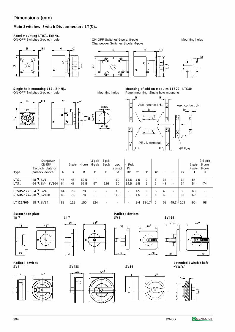
294 D946D
Dimensions (mm)
Main Switches, Switch Disconnectors LT(S)..
Panel mounting LT(S).. E(HN)..ON-OFF Switches 3-pole, 4-pole ON-OFF Switches 6-pole, 8-pole Mounting holes
Changeover Switches 3-pole, 4-pole
Single hole mounting LTS.. Z(HN).. Mounting of add-on modules LTS20 - LTS80ON-OFF Switches 3-pole, 4-pole Mounting holes Panel mounting, Single hole mounting
Changeover 3-pole 4-pole 3,4-poleON-OFF 3-pole 4-pole 6-pole 8-pole aux. 4. Pole 3-pole 6-pole
Escutch. plate or contact PE 4-pole 8-poleType padlock device A B B B B B1 B2 C1 D1 D2 E F G H H
LTS.. 48 , SV1 48 48 62,5 - - 10 14,5 1-5 9 5 36 - 64 54 -LTS.. 64 , SV4, SV164 64 48 62,5 97 126 10 14,5 1-5 9 5 48 - 64 54 74
LTS85-125.. 64 , SV4 64 78 78 - - 10 - 1-5 9 5 48 - 85 60 -LTS85-125.. 88 , SV488 88 78 78 - - 10 - 1-5 9 6 68 - 85 60 -
LT125/160 88 , SV34 88 112 150 224 - - - 1-4 13-17 6 68 49,3 108 96 98
Escutcheon plate Padlock devices48 64 SV1 SV164
Padlock devices Extended Switch ShaftSV4 SV488 SV34 +VW"x"
Aux. contact LH..
4th Pole
PE-, N-terminal
Aux. contact LH..
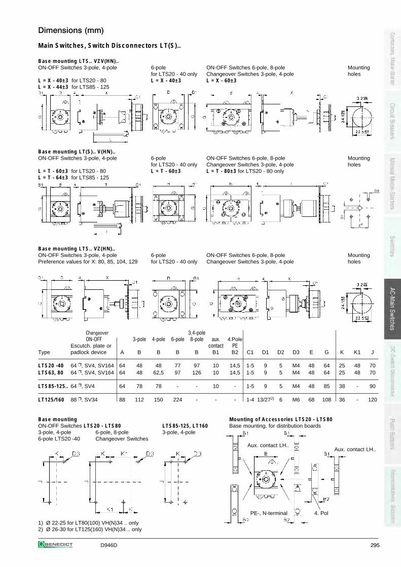
D946D 295
Dimensions (mm)
Main Switches, Switch Disconnectors LT(S)..
Base mounting LTS.. VZV(HN)..ON-OFF Switches 3-pole, 4-pole 6-pole ON-OFF Switches 6-pole, 8-pole Mounting
for LTS20 - 40 only Changeover Switches 3-pole, 4-pole holesL = X - 40±3 for LTS20 - 80 L = X - 40±3 L = X - 60±3L = X - 44±3 for LTS85 - 125
Base mounting LT(S).. V(HN)..ON-OFF Switches 3-pole, 4-pole 6-pole ON-OFF Switches 6-pole, 8-pole Mounting
for LTS20 - 40 only Changeover Switches 3-pole, 4-pole holesL = T - 60±3 for LTS20 - 80 L = T - 60±3 L = T - 80±3 for LTS20 - 80 onlyL = T - 64±3 for LTS85 - 125
Base mounting LTS.. VZ(HN)..ON-OFF Switches 3-pole, 4-pole 6-pole ON-OFF Switches 6-pole, 8-pole MountingPreference values for X: 80, 85, 104, 129 for LTS20 - 40 only Changeover Switches 3-pole, 4-pole holes
Changeover 3,4-poleON-OFF 3-pole 4-pole 6-pole 8-pole aux. 4.Pole
Escutch. plate or contact PEType padlock device A B B B B B1 B2 C1 D1 D2 D3 E G K K1 J
LTS20 -40 64 , SV4, SV164 64 48 48 77 97 10 14,5 1-5 9 5 M4 48 64 25 48 70LTS63, 80 64 , SV4, SV164 64 48 62,5 97 126 10 14,5 1-5 9 5 M4 48 64 25 48 70
LTS85-125.. 64 , SV4 64 78 78 - - 10 - 1-5 9 5 M4 48 85 38 - 90
LT125/160 88 , SV34 88 112 150 224 - - - 1-4 13/272) 6 M6 68 108 36 - 120
Base mounting Mounting of Accessories LTS20 - LTS80ON-OFF Switches LTS20 - LTS80 LTS85-125, LT160 Base mounting, for distribution boards3-pole, 4-pole 6-pole, 8-pole 3-pole, 4-pole6-pole LTS20 -40 Changeover Switches
1) Ø 22-25 for LT80(100) VH(N)34 .. only2) Ø 26-30 for LT125(160) VH(N)34 .. only
Aux. contact LH..
4. PolPE-, N-terminal
Aux. contact LH..
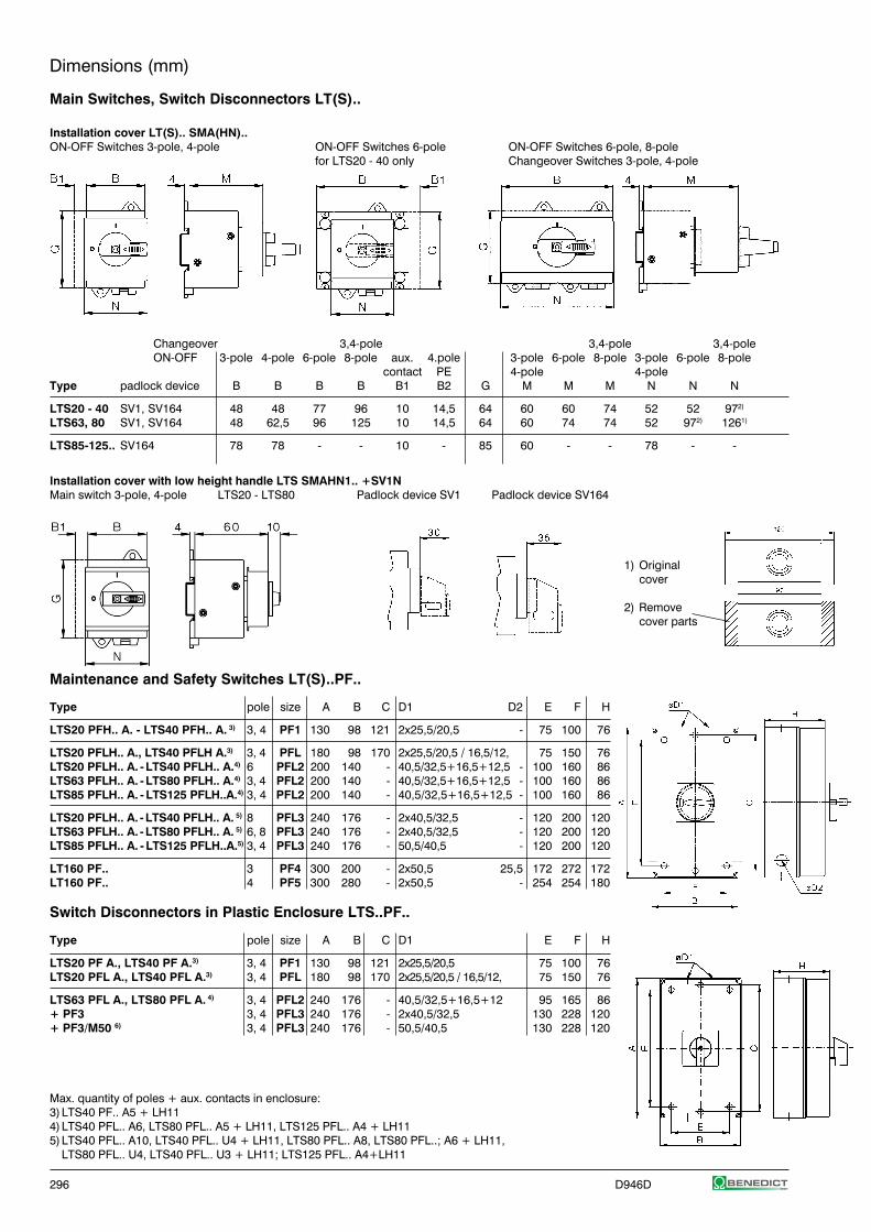
296 D946D
Dimensions (mm)
Main Switches, Switch Disconnectors LT(S)..
Installation cover LT(S).. SMA(HN)..ON-OFF Switches 3-pole, 4-pole ON-OFF Switches 6-pole ON-OFF Switches 6-pole, 8-pole
for LTS20 - 40 only Changeover Switches 3-pole, 4-pole
Changeover 3,4-pole 3,4-pole 3,4-poleON-OFF 3-pole 4-pole 6-pole 8-pole aux. 4.pole 3-pole 6-pole 8-pole 3-pole 6-pole 8-pole
contact PE 4-pole 4-poleType padlock device B B B B B1 B2 G M M M N N N
LTS20 - 40 SV1, SV164 48 48 77 96 10 14,5 64 60 60 74 52 52 972)
LTS63, 80 SV1, SV164 48 62,5 96 125 10 14,5 64 60 74 74 52 972) 1261)
LTS85-125.. SV164 78 78 - - 10 - 85 60 - - 78 - -
Installation cover with low height handle LTS SMAHN1.. +SV1NMain switch 3-pole, 4-pole LTS20 - LTS80 Padlock device SV1 Padlock device SV164
1) Originalcover
2) Removecover parts
Maintenance and Safety Switches LT(S)..PF..
Type pole size A B C D1 D2 E F H
LTS20 PFH.. A. - LTS40 PFH.. A. 3) 3, 4 PF1 130 98 121 2x25,5/20,5 - 75 100 76
LTS20 PFLH.. A., LTS40 PFLH A.3) 3, 4 PFL 180 98 170 2x25,5/20,5 / 16,5/12, 75 150 76LTS20 PFLH.. A. - LTS40 PFLH.. A.4) 6 PFL2 200 140 - 40,5/32,5+16,5+12,5 - 100 160 86LTS63 PFLH.. A. - LTS80 PFLH.. A.4) 3, 4 PFL2 200 140 - 40,5/32,5+16,5+12,5 - 100 160 86LTS85 PFLH.. A. - LTS125 PFLH..A.4) 3, 4 PFL2 200 140 - 40,5/32,5+16,5+12,5 - 100 160 86
LTS20 PFLH.. A. - LTS40 PFLH.. A. 5) 8 PFL3 240 176 - 2x40,5/32,5 - 120 200 120LTS63 PFLH.. A. - LTS80 PFLH.. A. 5) 6, 8 PFL3 240 176 - 2x40,5/32,5 - 120 200 120LTS85 PFLH.. A. - LTS125 PFLH..A.5) 3, 4 PFL3 240 176 - 50,5/40,5 - 120 200 120
LT160 PF.. 3 PF4 300 200 - 2x50,5 25,5 172 272 172LT160 PF.. 4 PF5 300 280 - 2x50,5 - 254 254 180
Switch Disconnectors in Plastic Enclosure LTS..PF..
Type pole size A B C D1 E F H
LTS20 PF A., LTS40 PF A.3) 3, 4 PF1 130 98 121 2x25,5/20,5 75 100 76LTS20 PFL A., LTS40 PFL A.3) 3, 4 PFL 180 98 170 2x25,5/20,5 / 16,5/12, 75 150 76
LTS63 PFL A., LTS80 PFL A. 4) 3, 4 PFL2 240 176 - 40,5/32,5+16,5+12 95 165 86+ PF3 3, 4 PFL3 240 176 - 2x40,5/32,5 130 228 120+ PF3/M50 6) 3, 4 PFL3 240 176 - 50,5/40,5 130 228 120
Max. quantity of poles + aux. contacts in enclosure:3)LTS40 PF.. A5 + LH114)LTS40 PFL.. A6, LTS80 PFL.. A5 + LH11, LTS125 PFL.. A4 + LH115)LTS40 PFL.. A10, LTS40 PFL.. U4 + LH11, LTS80 PFL.. A8, LTS80 PFL..; A6 + LH11,
LTS80 PFL.. U4, LTS40 PFL.. U3 + LH11; LTS125 PFL.. A4+LH11
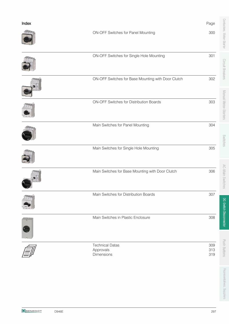
D946E 297
IndexIndexIndexIndexIndex Page
ON-OFF Switches for Panel Mounting 300
ON-OFF Switches for Single Hole Mounting 301
ON-OFF Switches for Base Mounting with Door Clutch 302
ON-OFF Switches for Distribution Boards 303
Main Switches for Panel Mounting 304
Main Switches for Single Hole Mounting 305
Main Switches for Base Mounting with Door Clutch 306
Main Switches for Distribution Boards 307
Main Switches in Plastic Enclosure 308
Technical Datas 309Approvals 313Dimensions 319
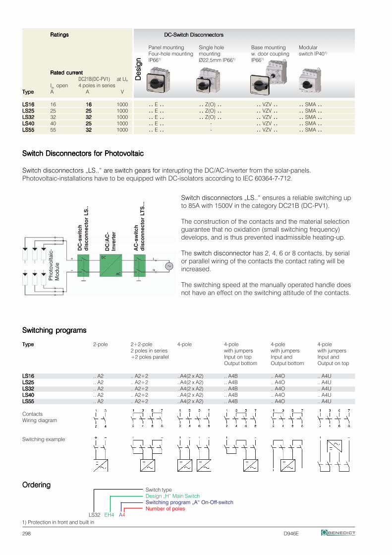
298 D946E
DC-Switch Disconnectors DC-Switch Disconnectors DC-Switch Disconnectors DC-Switch Disconnectors DC-Switch Disconnectors
Panel mounting Single hole Base mounting ModularFour-hole mounting mounting w. door coupling switch IP401)
IP661) Ø22,5mm IP661) IP661)
DC21B(DC-PV1) at Ue
Ith open 4 poles in seriesTypeTypeTypeTypeType A A V
LS16LS16LS16LS16LS16 16 1616161616 1000 .. E .. .. Z(O) .. .. VZV .. .. SMA ..LS25LS25LS25LS25LS25 25 2525252525 1000 .. E .. .. Z(O) .. .. VZV .. .. SMA ..LS32LS32LS32LS32LS32 32 3232323232 1000 .. E .. .. Z(O) .. .. VZV .. .. SMA ..LS40LS40LS40LS40LS40 40 2525252525 1000 .. E .. - .. VZV .. .. SMA ..LS55LS55LS55LS55LS55 55 3232323232 1000 .. E .. - .. VZV .. .. SMA ..
RatingsRatingsRatingsRatingsRatings
Rated currentRated currentRated currentRated currentRated current
Pho
tovo
ltaic
-M
odul
e
DC
-sw
itch
dis
con
nec
tor
LS..
DC
/AC
-In
vert
er
AC
-sw
itch
dis
con
nec
tor
LTS
...
Switch Disconnectors for PhotovoltaicSwitch Disconnectors for PhotovoltaicSwitch Disconnectors for PhotovoltaicSwitch Disconnectors for PhotovoltaicSwitch Disconnectors for Photovoltaic
Switch disconnectors „LS..“ are switch gears for interupting the DC/AC-Inverter from the solar-panels.Photovoltaic-installations have to be equipped with DC-isolators according to IEC 60364-7-712.
Switch disconnectors „LS..“ ensures a reliable switching upto 85A with 1500V in the category DC21B (DC-PV1).
The construction of the contacts and the material selectionguarantee that no oxidation (small switching frequency)develops, and is thus prevented inadmissible heating-up.
The switch disconnector has 2, 4, 6 or 8 contacts, by serialor parallel wiring of the contacts the contact rating will beincreased.
The switching speed at the manually operated handle doesnot have an effect on the switching attitude of the contacts.
Des
ign
Des
ign
Des
ign
Des
ign
Des
ign
Switch typeDesign „H“ Main SwitchSwitching program „A“ On-Off-switchNumber of poles
LS32 EH4 A4
Switching programsSwitching programsSwitching programsSwitching programsSwitching programs
TypeTypeTypeTypeType 2-pole 2+2-pole 4-pole 4-pole 4-pole 4-pole2 poles in series with jumpers with jumpers with jumpers+2 poles parallel Input on top Input and Input and
Output bottom Output bottom Output on top
LS16LS16LS16LS16LS16 .. A2 .. A2+2 ..A4(2 x A2) .. A4B .. A4O .. A4ULS25LS25LS25LS25LS25 .. A2 .. A2+2 ..A4(2 x A2) .. A4B .. A4O .. A4ULS32LS32LS32LS32LS32 .. A2 .. A2+2 ..A4(2 x A2) .. A4B .. A4O .. A4ULS40LS40LS40LS40LS40 .. A2 .. A2+2 ..A4(2 x A2) .. A4B .. A4O .. A4ULS55LS55LS55LS55LS55 .. A2 .. A2+2 ..A4(2 x A2) .. A4B .. A4O .. A4U
ContactsWiring diagram
Switching example
OrderingOrderingOrderingOrderingOrdering
1) Protection in front and built in
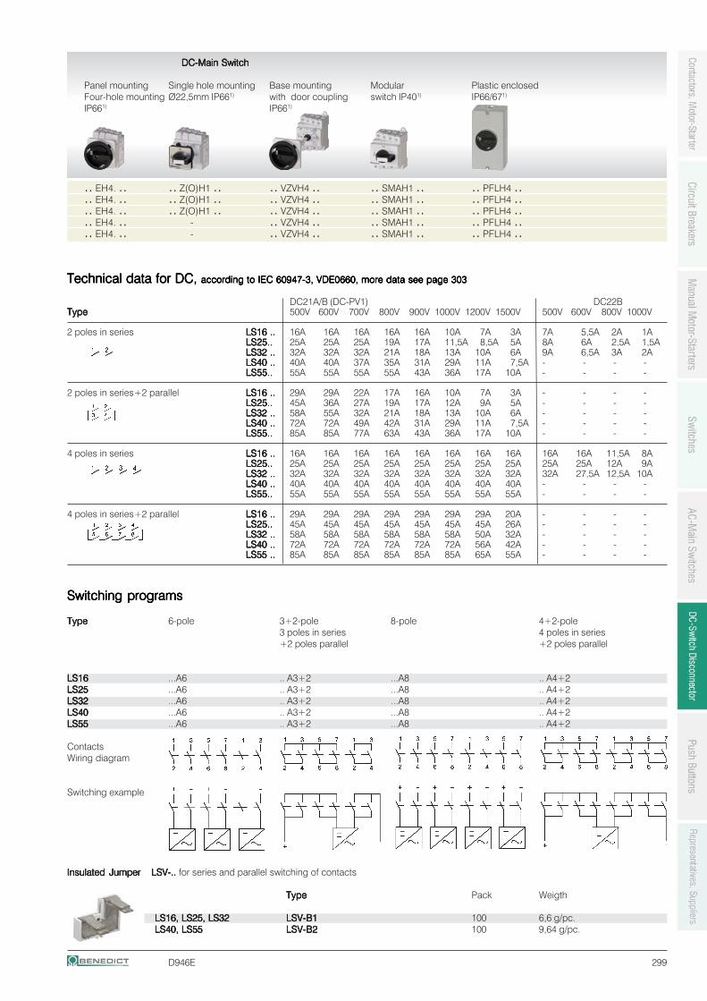
D946E 299
DC-Main Switch DC-Main Switch DC-Main Switch DC-Main Switch DC-Main Switch
Panel mounting Single hole mounting Base mounting Modular Plastic enclosedFour-hole mounting Ø22,5mm IP661) with door coupling switch IP401) IP66/671)
IP661) IP661)
.. EH4. .. .. Z(O)H1 .. .. VZVH4 .. .. SMAH1 .. .. PFLH4 ..
.. EH4. .. .. Z(O)H1 .. .. VZVH4 .. .. SMAH1 .. .. PFLH4 ..
.. EH4. .. .. Z(O)H1 .. .. VZVH4 .. .. SMAH1 .. .. PFLH4 ..
.. EH4. .. - .. VZVH4 .. .. SMAH1 .. .. PFLH4 ..
.. EH4. .. - .. VZVH4 .. .. SMAH1 .. .. PFLH4 ..
Switching programsSwitching programsSwitching programsSwitching programsSwitching programs
TypeTypeTypeTypeType 6-pole 3+2-pole 8-pole 4+2-pole3 poles in series 4 poles in series+2 poles parallel +2 poles parallel
LS16LS16LS16LS16LS16 ...A6 .. A3+2 ...A8 .. A4+2LS25LS25LS25LS25LS25 ...A6 .. A3+2 ...A8 .. A4+2LS32LS32LS32LS32LS32 ...A6 .. A3+2 ...A8 .. A4+2LS40LS40LS40LS40LS40 ...A6 .. A3+2 ...A8 .. A4+2LS55LS55LS55LS55LS55 ...A6 .. A3+2 ...A8 .. A4+2
ContactsWiring diagram
Switching example
Insulated JumperInsulated JumperInsulated JumperInsulated JumperInsulated Jumper LSV-..LSV-..LSV-..LSV-..LSV-.. for series and parallel switching of contacts
TypeTypeTypeTypeType Pack Weigth
LS16, LS25, LS32LS16, LS25, LS32LS16, LS25, LS32LS16, LS25, LS32LS16, LS25, LS32 LSV-B1LSV-B1LSV-B1LSV-B1LSV-B1 100 6,6 g/pc.LS40, LS55LS40, LS55LS40, LS55LS40, LS55LS40, LS55 LSV-B2LSV-B2LSV-B2LSV-B2LSV-B2 100 9,64 g/pc.
Technical data for DC, Technical data for DC, Technical data for DC, Technical data for DC, Technical data for DC, according to IEC 60947-3, VDE0660, more data see page 303according to IEC 60947-3, VDE0660, more data see page 303according to IEC 60947-3, VDE0660, more data see page 303according to IEC 60947-3, VDE0660, more data see page 303according to IEC 60947-3, VDE0660, more data see page 303
DC21A/B (DC-PV1) DC22BTypeTypeTypeTypeType 500V 600V 700V 800V 900V 1000V 1200V 1500V 500V 600V 800V 1000V
2 poles in series LS16 ..LS16 ..LS16 ..LS16 ..LS16 .. 16A 16A 16A 16A 16A 10A 7A 3A 7A 5,5A 2A 1ALS25..LS25..LS25..LS25..LS25.. 25A 25A 25A 19A 17A 11,5A 8,5A 5A 8A 6A 2,5A 1,5ALS32 ..LS32 ..LS32 ..LS32 ..LS32 .. 32A 32A 32A 21A 18A 13A 10A 6A 9A 6,5A 3A 2ALS40 ..LS40 ..LS40 ..LS40 ..LS40 .. 40A 40A 37A 35A 31A 29A 11A 7,5A - - - -LS55..LS55..LS55..LS55..LS55.. 55A 55A 55A 55A 43A 36A 17A 10A - - - -
2 poles in series+2 parallel LS16 ..LS16 ..LS16 ..LS16 ..LS16 .. 29A 29A 22A 17A 16A 10A 7A 3A - - - -LS25..LS25..LS25..LS25..LS25.. 45A 36A 27A 19A 17A 12A 9A 5A - - - -LS32 ..LS32 ..LS32 ..LS32 ..LS32 .. 58A 55A 32A 21A 18A 13A 10A 6A - - - -LS40 ..LS40 ..LS40 ..LS40 ..LS40 .. 72A 72A 49A 42A 31A 29A 11A 7,5A - - - -LS55..LS55..LS55..LS55..LS55.. 85A 85A 77A 63A 43A 36A 17A 10A - - - -
4 poles in series LS16 ..LS16 ..LS16 ..LS16 ..LS16 .. 16A 16A 16A 16A 16A 16A 16A 16A 16A 16A 11,5A 8ALS25..LS25..LS25..LS25..LS25.. 25A 25A 25A 25A 25A 25A 25A 25A 25A 25A 12A 9ALS32 ..LS32 ..LS32 ..LS32 ..LS32 .. 32A 32A 32A 32A 32A 32A 32A 32A 32A 27,5A 12,5A 10ALS40 ..LS40 ..LS40 ..LS40 ..LS40 .. 40A 40A 40A 40A 40A 40A 40A 40A - - - -LS55..LS55..LS55..LS55..LS55.. 55A 55A 55A 55A 55A 55A 55A 55A - - - -
4 poles in series+2 parallel LS16 ..LS16 ..LS16 ..LS16 ..LS16 .. 29A 29A 29A 29A 29A 29A 29A 20A - - - -LS25..LS25..LS25..LS25..LS25.. 45A 45A 45A 45A 45A 45A 45A 26A - - - -LS32 ..LS32 ..LS32 ..LS32 ..LS32 .. 58A 58A 58A 58A 58A 58A 50A 32A - - - -LS40 ..LS40 ..LS40 ..LS40 ..LS40 .. 72A 72A 72A 72A 72A 72A 56A 42A - - - -LS55 ..LS55 ..LS55 ..LS55 ..LS55 .. 85A 85A 85A 85A 85A 85A 65A 55A - - - -
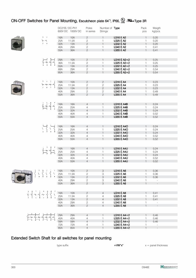
300 D946E
ON-OFF Switches for Panel Mounting,ON-OFF Switches for Panel Mounting,ON-OFF Switches for Panel Mounting,ON-OFF Switches for Panel Mounting,ON-OFF Switches for Panel Mounting, Escutcheon plate 64Escutcheon plate 64Escutcheon plate 64Escutcheon plate 64Escutcheon plate 64 , IP66,, IP66,, IP66,, IP66,, IP66, Type 3RType 3RType 3RType 3RType 3R
DC21B / DC-PV1 Poles Number of TypeTypeTypeTypeType Pack Weigth600V DC 1000V DC in series Strings pcs kg/pcs.
16A 10A 2 1 LS16 E A2LS16 E A2LS16 E A2LS16 E A2LS16 E A2 1 0,2025A 11,5A 2 1 LS25 E A2LS25 E A2LS25 E A2LS25 E A2LS25 E A2 1 0,2032A 13A 2 1 LS32 E A2LS32 E A2LS32 E A2LS32 E A2LS32 E A2 1 0,2040A 29A 2 1 LS40 E A2LS40 E A2LS40 E A2LS40 E A2LS40 E A2 1 0,4155A 36A 2 1 LS55 E A2LS55 E A2LS55 E A2LS55 E A2LS55 E A2 1 0,41
29A 10A 2 1 LS16 E A2+2LS16 E A2+2LS16 E A2+2LS16 E A2+2LS16 E A2+2 1 0,2536A 11,5A 2 1 LS25 E A2+2LS25 E A2+2LS25 E A2+2LS25 E A2+2LS25 E A2+2 1 0,2555A 13A 2 1 LS32 E A2+2LS32 E A2+2LS32 E A2+2LS32 E A2+2LS32 E A2+2 1 0,2568A 29A 2 1 LS40 E A2+2LS40 E A2+2LS40 E A2+2LS40 E A2+2LS40 E A2+2 1 0,5485A 36A 2 1 LS55 E A2+2LS55 E A2+2LS55 E A2+2LS55 E A2+2LS55 E A2+2 1 0,54
16A 10A 2 2 LS16 E A4LS16 E A4LS16 E A4LS16 E A4LS16 E A4 1 0,2325A 11,5A 2 2 LS25 E A4LS25 E A4LS25 E A4LS25 E A4LS25 E A4 1 0,2332A 13A 2 2 LS32 E A4LS32 E A4LS32 E A4LS32 E A4LS32 E A4 1 0,2340A 29A 2 2 LS40 E A4LS40 E A4LS40 E A4LS40 E A4LS40 E A4 1 0,4955A 36A 2 2 LS55 E A4LS55 E A4LS55 E A4LS55 E A4LS55 E A4 1 0,49
16A 16A 4 1 LS16 E A4BLS16 E A4BLS16 E A4BLS16 E A4BLS16 E A4B 1 0,2425A 25A 4 1 LS25 E A4BLS25 E A4BLS25 E A4BLS25 E A4BLS25 E A4B 1 0,2432A 32A 4 1 LS32 E A4BLS32 E A4BLS32 E A4BLS32 E A4BLS32 E A4B 1 0,2440A 40A 4 1 LS40 E A4BLS40 E A4BLS40 E A4BLS40 E A4BLS40 E A4B 1 0,5255A 55A 4 1 LS55 E A4BLS55 E A4BLS55 E A4BLS55 E A4BLS55 E A4B 1 0,52
16A 16A 4 1 LS16 E A4OLS16 E A4OLS16 E A4OLS16 E A4OLS16 E A4O 1 0,2425A 25A 4 1 LS25 E A4OLS25 E A4OLS25 E A4OLS25 E A4OLS25 E A4O 1 0,2432A 32A 4 1 LS32 E A4OLS32 E A4OLS32 E A4OLS32 E A4OLS32 E A4O 1 0,2440A 40A 4 1 LS40 E A4OLS40 E A4OLS40 E A4OLS40 E A4OLS40 E A4O 1 0,5255A 55A 4 1 LS55 E A4OLS55 E A4OLS55 E A4OLS55 E A4OLS55 E A4O 1 0,52
16A 16A 4 1 LS16 E A4ULS16 E A4ULS16 E A4ULS16 E A4ULS16 E A4U 1 0,2425A 25A 4 1 LS25 E A4ULS25 E A4ULS25 E A4ULS25 E A4ULS25 E A4U 1 0,2432A 32A 4 1 LS32 E A4ULS32 E A4ULS32 E A4ULS32 E A4ULS32 E A4U 1 0,2440A 40A 4 1 LS40 E A4ULS40 E A4ULS40 E A4ULS40 E A4ULS40 E A4U 1 0,5255A 55A 4 1 LS55 E A4ULS55 E A4ULS55 E A4ULS55 E A4ULS55 E A4U 1 0,52
16A 10A 2 3 LS16 E A6LS16 E A6LS16 E A6LS16 E A6LS16 E A6 1 0,3625A 11,5A 2 3 LS25 E A6LS25 E A6LS25 E A6LS25 E A6LS25 E A6 1 0,3632A 13A 2 3 LS32 E A6LS32 E A6LS32 E A6LS32 E A6LS32 E A6 1 0,3640A 29A 2 3 LS40 E A6LS40 E A6LS40 E A6LS40 E A6LS40 E A6 1 -55A 36A 2 3 LS55 E A6LS55 E A6LS55 E A6LS55 E A6LS55 E A6 1 -
16A 10A 2 4 LS16 E A8LS16 E A8LS16 E A8LS16 E A8LS16 E A8 1 0,4125A 11,5A 2 4 LS25 E A8LS25 E A8LS25 E A8LS25 E A8LS25 E A8 1 0,4132A 13A 2 4 LS32 E A8LS32 E A8LS32 E A8LS32 E A8LS32 E A8 1 0,4140A 29A 2 4 LS40 E A8LS40 E A8LS40 E A8LS40 E A8LS40 E A8 1 -55A 36A 2 4 LS55 E A8LS55 E A8LS55 E A8LS55 E A8LS55 E A8 1 -
29A 29A 4 1 LS16 E A4+2LS16 E A4+2LS16 E A4+2LS16 E A4+2LS16 E A4+2 1 0,4645A 45A 4 1 LS25 E A4+2LS25 E A4+2LS25 E A4+2LS25 E A4+2LS25 E A4+2 1 0,4658A 58A 4 1 LS32 E A4+2LS32 E A4+2LS32 E A4+2LS32 E A4+2LS32 E A4+2 1 0,4672A 72A 4 1 LS40 E A4+2LS40 E A4+2LS40 E A4+2LS40 E A4+2LS40 E A4+2 1 -85A 85A 4 1 LS55 E A4+2LS55 E A4+2LS55 E A4+2LS55 E A4+2LS55 E A4+2 1 -
Extended Switch Shaft for all switches for panel mountingExtended Switch Shaft for all switches for panel mountingExtended Switch Shaft for all switches for panel mountingExtended Switch Shaft for all switches for panel mountingExtended Switch Shaft for all switches for panel mounting
type suffix +VW“x“+VW“x“+VW“x“+VW“x“+VW“x“ x = panel thickness
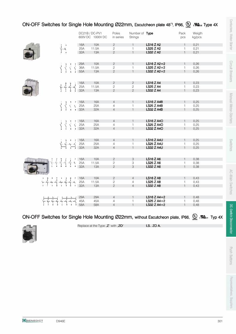
D946E 301
ON-OFF Switches for Single Hole Mounting Ø22mm,ON-OFF Switches for Single Hole Mounting Ø22mm,ON-OFF Switches for Single Hole Mounting Ø22mm,ON-OFF Switches for Single Hole Mounting Ø22mm,ON-OFF Switches for Single Hole Mounting Ø22mm, Escutcheon plate 48Escutcheon plate 48Escutcheon plate 48Escutcheon plate 48Escutcheon plate 48 , IP66,, IP66,, IP66,, IP66,, IP66, Type 4XType 4XType 4XType 4XType 4X
DC21B / DC-PV1 Poles Number of TypeTypeTypeTypeType Pack Weigth600V DC 1000V DC in series Strings pcs kg/pcs.
16A 10A 2 1 LS16 Z A2LS16 Z A2LS16 Z A2LS16 Z A2LS16 Z A2 1 0,2125A 11,5A 2 1 LS25 Z A2LS25 Z A2LS25 Z A2LS25 Z A2LS25 Z A2 1 0,2132A 13A 2 1 LS32 Z A2LS32 Z A2LS32 Z A2LS32 Z A2LS32 Z A2 1 0,21
29A 10A 2 1 LS16 Z A2+2LS16 Z A2+2LS16 Z A2+2LS16 Z A2+2LS16 Z A2+2 1 0,2636A 11,5A 2 1 LS25 Z A2+2LS25 Z A2+2LS25 Z A2+2LS25 Z A2+2LS25 Z A2+2 1 0,2655A 13A 2 1 LS32 Z A2+2LS32 Z A2+2LS32 Z A2+2LS32 Z A2+2LS32 Z A2+2 1 0,26
16A 10A 2 2 LS16 Z A4LS16 Z A4LS16 Z A4LS16 Z A4LS16 Z A4 1 0,2325A 11,5A 2 2 LS25 Z A4LS25 Z A4LS25 Z A4LS25 Z A4LS25 Z A4 1 0,2332A 13A 2 2 LS32 Z A4LS32 Z A4LS32 Z A4LS32 Z A4LS32 Z A4 1 0,23
16A 16A 4 1 LS16 Z A4BLS16 Z A4BLS16 Z A4BLS16 Z A4BLS16 Z A4B 1 0,2525A 25A 4 1 LS25 Z A4BLS25 Z A4BLS25 Z A4BLS25 Z A4BLS25 Z A4B 1 0,2532A 32A 4 1 LS32 Z A4BLS32 Z A4BLS32 Z A4BLS32 Z A4BLS32 Z A4B 1 0,25
16A 16A 4 1 LS16 Z A4OLS16 Z A4OLS16 Z A4OLS16 Z A4OLS16 Z A4O 1 0,2525A 25A 4 1 LS25 Z A4OLS25 Z A4OLS25 Z A4OLS25 Z A4OLS25 Z A4O 1 0,2532A 32A 4 1 LS32 Z A4OLS32 Z A4OLS32 Z A4OLS32 Z A4OLS32 Z A4O 1 0,25
16A 16A 4 1 LS16 Z A4ULS16 Z A4ULS16 Z A4ULS16 Z A4ULS16 Z A4U 1 0,2525A 25A 4 1 LS25 Z A4ULS25 Z A4ULS25 Z A4ULS25 Z A4ULS25 Z A4U 1 0,2532A 32A 4 1 LS32 Z A4ULS32 Z A4ULS32 Z A4ULS32 Z A4ULS32 Z A4U 1 0,25
16A 10A 2 3 LS16 Z A6LS16 Z A6LS16 Z A6LS16 Z A6LS16 Z A6 1 0,3825A 11,5A 2 3 LS25 Z A6LS25 Z A6LS25 Z A6LS25 Z A6LS25 Z A6 1 0,3832A 13A 2 3 LS32 Z A6LS32 Z A6LS32 Z A6LS32 Z A6LS32 Z A6 1 0,38
16A 10A 2 4 LS16 Z A8LS16 Z A8LS16 Z A8LS16 Z A8LS16 Z A8 1 0,4325A 11,5A 2 4 LS25 Z A8LS25 Z A8LS25 Z A8LS25 Z A8LS25 Z A8 1 0,4332A 13A 2 4 LS32 Z A8LS32 Z A8LS32 Z A8LS32 Z A8LS32 Z A8 1 0,43
29A 29A 4 1 LS16 Z A4+2LS16 Z A4+2LS16 Z A4+2LS16 Z A4+2LS16 Z A4+2 1 0,4845A 45A 4 1 LS25 Z A4+2LS25 Z A4+2LS25 Z A4+2LS25 Z A4+2LS25 Z A4+2 1 0,4858A 58A 4 1 LS32 Z A4+2LS32 Z A4+2LS32 Z A4+2LS32 Z A4+2LS32 Z A4+2 1 0,48
ON-OFF Switches for Single Hole Mounting Ø22mm,ON-OFF Switches for Single Hole Mounting Ø22mm,ON-OFF Switches for Single Hole Mounting Ø22mm,ON-OFF Switches for Single Hole Mounting Ø22mm,ON-OFF Switches for Single Hole Mounting Ø22mm, without Escutcheon plate, IP66,without Escutcheon plate, IP66,without Escutcheon plate, IP66,without Escutcheon plate, IP66,without Escutcheon plate, IP66, Typ 4XTyp 4XTyp 4XTyp 4XTyp 4X
Replace at the Type „ZZZZZ“ with „ZOZOZOZOZO“ LS.. ZO A.LS.. ZO A.LS.. ZO A.LS.. ZO A.LS.. ZO A.
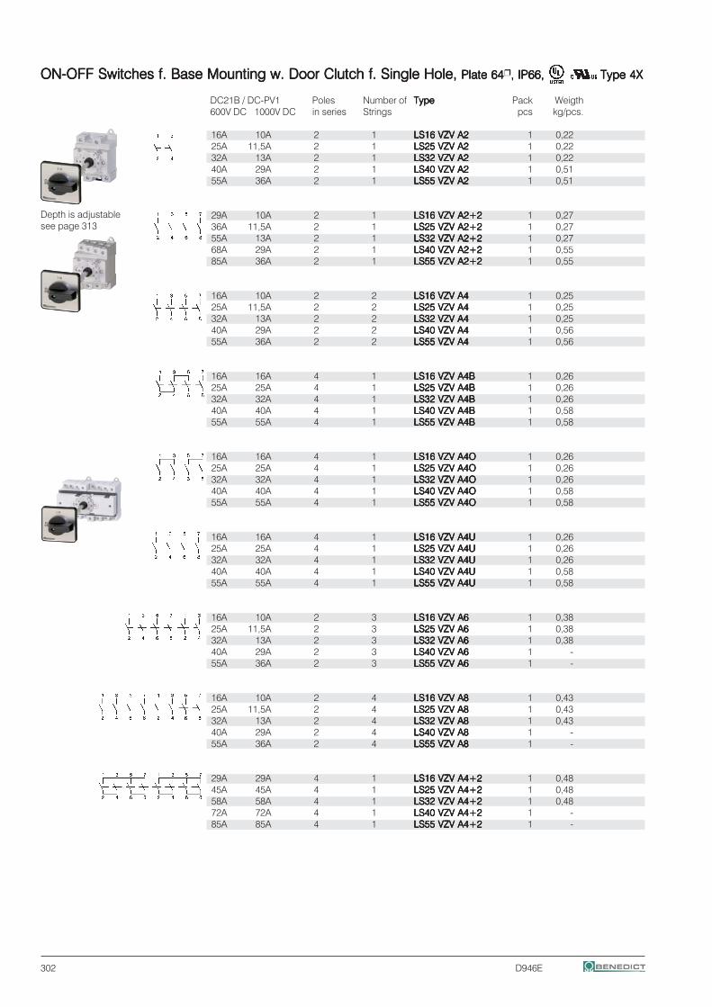
302 D946E
ON-OFF Switches f. Base Mounting w. Door Clutch f. Single Hole,ON-OFF Switches f. Base Mounting w. Door Clutch f. Single Hole,ON-OFF Switches f. Base Mounting w. Door Clutch f. Single Hole,ON-OFF Switches f. Base Mounting w. Door Clutch f. Single Hole,ON-OFF Switches f. Base Mounting w. Door Clutch f. Single Hole, Plate 64Plate 64Plate 64Plate 64Plate 64 , IP66,, IP66,, IP66,, IP66,, IP66, Type 4XType 4XType 4XType 4XType 4X
DC21B / DC-PV1 Poles Number of TypeTypeTypeTypeType Pack Weigth600V DC 1000V DC in series Strings pcs kg/pcs.
16A 10A 2 1 LS16 VZV A2LS16 VZV A2LS16 VZV A2LS16 VZV A2LS16 VZV A2 1 0,2225A 11,5A 2 1 LS25 VZV A2LS25 VZV A2LS25 VZV A2LS25 VZV A2LS25 VZV A2 1 0,2232A 13A 2 1 LS32 VZV A2LS32 VZV A2LS32 VZV A2LS32 VZV A2LS32 VZV A2 1 0,2240A 29A 2 1 LS40 VZV A2LS40 VZV A2LS40 VZV A2LS40 VZV A2LS40 VZV A2 1 0,5155A 36A 2 1 LS55 VZV A2LS55 VZV A2LS55 VZV A2LS55 VZV A2LS55 VZV A2 1 0,51
29A 10A 2 1 LS16 VZV A2+2LS16 VZV A2+2LS16 VZV A2+2LS16 VZV A2+2LS16 VZV A2+2 1 0,2736A 11,5A 2 1 LS25 VZV A2+2LS25 VZV A2+2LS25 VZV A2+2LS25 VZV A2+2LS25 VZV A2+2 1 0,2755A 13A 2 1 LS32 VZV A2+2LS32 VZV A2+2LS32 VZV A2+2LS32 VZV A2+2LS32 VZV A2+2 1 0,2768A 29A 2 1 LS40 VZV A2+2LS40 VZV A2+2LS40 VZV A2+2LS40 VZV A2+2LS40 VZV A2+2 1 0,5585A 36A 2 1 LS55 VZV A2+2LS55 VZV A2+2LS55 VZV A2+2LS55 VZV A2+2LS55 VZV A2+2 1 0,55
16A 10A 2 2 LS16 VZV A4LS16 VZV A4LS16 VZV A4LS16 VZV A4LS16 VZV A4 1 0,2525A 11,5A 2 2 LS25 VZV A4LS25 VZV A4LS25 VZV A4LS25 VZV A4LS25 VZV A4 1 0,2532A 13A 2 2 LS32 VZV A4LS32 VZV A4LS32 VZV A4LS32 VZV A4LS32 VZV A4 1 0,2540A 29A 2 2 LS40 VZV A4LS40 VZV A4LS40 VZV A4LS40 VZV A4LS40 VZV A4 1 0,5655A 36A 2 2 LS55 VZV A4LS55 VZV A4LS55 VZV A4LS55 VZV A4LS55 VZV A4 1 0,56
16A 16A 4 1 LS16 VZV A4BLS16 VZV A4BLS16 VZV A4BLS16 VZV A4BLS16 VZV A4B 1 0,2625A 25A 4 1 LS25 VZV A4BLS25 VZV A4BLS25 VZV A4BLS25 VZV A4BLS25 VZV A4B 1 0,2632A 32A 4 1 LS32 VZV A4BLS32 VZV A4BLS32 VZV A4BLS32 VZV A4BLS32 VZV A4B 1 0,2640A 40A 4 1 LS40 VZV A4BLS40 VZV A4BLS40 VZV A4BLS40 VZV A4BLS40 VZV A4B 1 0,5855A 55A 4 1 LS55 VZV A4BLS55 VZV A4BLS55 VZV A4BLS55 VZV A4BLS55 VZV A4B 1 0,58
16A 16A 4 1 LS16 VZV A4OLS16 VZV A4OLS16 VZV A4OLS16 VZV A4OLS16 VZV A4O 1 0,2625A 25A 4 1 LS25 VZV A4OLS25 VZV A4OLS25 VZV A4OLS25 VZV A4OLS25 VZV A4O 1 0,2632A 32A 4 1 LS32 VZV A4OLS32 VZV A4OLS32 VZV A4OLS32 VZV A4OLS32 VZV A4O 1 0,2640A 40A 4 1 LS40 VZV A4OLS40 VZV A4OLS40 VZV A4OLS40 VZV A4OLS40 VZV A4O 1 0,5855A 55A 4 1 LS55 VZV A4OLS55 VZV A4OLS55 VZV A4OLS55 VZV A4OLS55 VZV A4O 1 0,58
16A 16A 4 1 LS16 VZV A4ULS16 VZV A4ULS16 VZV A4ULS16 VZV A4ULS16 VZV A4U 1 0,2625A 25A 4 1 LS25 VZV A4ULS25 VZV A4ULS25 VZV A4ULS25 VZV A4ULS25 VZV A4U 1 0,2632A 32A 4 1 LS32 VZV A4ULS32 VZV A4ULS32 VZV A4ULS32 VZV A4ULS32 VZV A4U 1 0,2640A 40A 4 1 LS40 VZV A4ULS40 VZV A4ULS40 VZV A4ULS40 VZV A4ULS40 VZV A4U 1 0,5855A 55A 4 1 LS55 VZV A4ULS55 VZV A4ULS55 VZV A4ULS55 VZV A4ULS55 VZV A4U 1 0,58
16A 10A 2 3 LS16 VZV A6LS16 VZV A6LS16 VZV A6LS16 VZV A6LS16 VZV A6 1 0,3825A 11,5A 2 3 LS25 VZV A6LS25 VZV A6LS25 VZV A6LS25 VZV A6LS25 VZV A6 1 0,3832A 13A 2 3 LS32 VZV A6LS32 VZV A6LS32 VZV A6LS32 VZV A6LS32 VZV A6 1 0,3840A 29A 2 3 LS40 VZV A6LS40 VZV A6LS40 VZV A6LS40 VZV A6LS40 VZV A6 1 -55A 36A 2 3 LS55 VZV A6LS55 VZV A6LS55 VZV A6LS55 VZV A6LS55 VZV A6 1 -
16A 10A 2 4 LS16 VZV A8LS16 VZV A8LS16 VZV A8LS16 VZV A8LS16 VZV A8 1 0,4325A 11,5A 2 4 LS25 VZV A8LS25 VZV A8LS25 VZV A8LS25 VZV A8LS25 VZV A8 1 0,4332A 13A 2 4 LS32 VZV A8LS32 VZV A8LS32 VZV A8LS32 VZV A8LS32 VZV A8 1 0,4340A 29A 2 4 LS40 VZV A8LS40 VZV A8LS40 VZV A8LS40 VZV A8LS40 VZV A8 1 -55A 36A 2 4 LS55 VZV A8LS55 VZV A8LS55 VZV A8LS55 VZV A8LS55 VZV A8 1 -
29A 29A 4 1 LS16 VZV A4+2LS16 VZV A4+2LS16 VZV A4+2LS16 VZV A4+2LS16 VZV A4+2 1 0,4845A 45A 4 1 LS25 VZV A4+2LS25 VZV A4+2LS25 VZV A4+2LS25 VZV A4+2LS25 VZV A4+2 1 0,4858A 58A 4 1 LS32 VZV A4+2LS32 VZV A4+2LS32 VZV A4+2LS32 VZV A4+2LS32 VZV A4+2 1 0,4872A 72A 4 1 LS40 VZV A4+2LS40 VZV A4+2LS40 VZV A4+2LS40 VZV A4+2LS40 VZV A4+2 1 -85A 85A 4 1 LS55 VZV A4+2LS55 VZV A4+2LS55 VZV A4+2LS55 VZV A4+2LS55 VZV A4+2 1 -
Depth is adjustablesee page 313
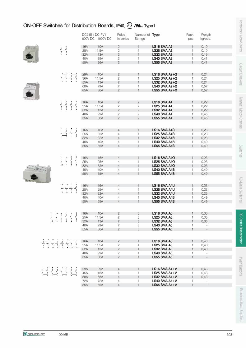
D946E 303
ON-OFF Switches for Distribution Boards,ON-OFF Switches for Distribution Boards,ON-OFF Switches for Distribution Boards,ON-OFF Switches for Distribution Boards,ON-OFF Switches for Distribution Boards, IP40, IP40, IP40, IP40, IP40, Type1Type1Type1Type1Type1
DC21B / DC-PV1 Poles Number of TypeTypeTypeTypeType Pack Weigth600V DC 1000V DC in series Strings pcs kg/pcs.
16A 10A 2 1 LS16 SMA A2LS16 SMA A2LS16 SMA A2LS16 SMA A2LS16 SMA A2 1 0,1925A 11,5A 2 1 LS25 SMA A2LS25 SMA A2LS25 SMA A2LS25 SMA A2LS25 SMA A2 1 0,1932A 13A 2 1 LS32 SMA A2LS32 SMA A2LS32 SMA A2LS32 SMA A2LS32 SMA A2 1 0,1940A 29A 2 1 LS40 SMA A2LS40 SMA A2LS40 SMA A2LS40 SMA A2LS40 SMA A2 1 0,4155A 36A 2 1 LS55 SMA A2LS55 SMA A2LS55 SMA A2LS55 SMA A2LS55 SMA A2 1 0,41
29A 10A 2 1 LS16 SMA A2+2LS16 SMA A2+2LS16 SMA A2+2LS16 SMA A2+2LS16 SMA A2+2 1 0,2436A 11,5A 2 1 LS25 SMA A2+2LS25 SMA A2+2LS25 SMA A2+2LS25 SMA A2+2LS25 SMA A2+2 1 0,2455A 13A 2 1 LS32 SMA A2+2LS32 SMA A2+2LS32 SMA A2+2LS32 SMA A2+2LS32 SMA A2+2 1 0,2468A 29A 2 1 LS40 SMA A2+2LS40 SMA A2+2LS40 SMA A2+2LS40 SMA A2+2LS40 SMA A2+2 1 0,5285A 36A 2 1 LS55 SMA A2+2LS55 SMA A2+2LS55 SMA A2+2LS55 SMA A2+2LS55 SMA A2+2 1 0,52
16A 10A 2 2 LS16 SMA A4LS16 SMA A4LS16 SMA A4LS16 SMA A4LS16 SMA A4 1 0,2225A 11,5A 2 2 LS25 SMA A4LS25 SMA A4LS25 SMA A4LS25 SMA A4LS25 SMA A4 1 0,2232A 13A 2 2 LS32 SMA A4LS32 SMA A4LS32 SMA A4LS32 SMA A4LS32 SMA A4 1 0,2240A 29A 2 2 LS40 SMA A4LS40 SMA A4LS40 SMA A4LS40 SMA A4LS40 SMA A4 1 0,4555A 36A 2 2 LS55 SMA A4LS55 SMA A4LS55 SMA A4LS55 SMA A4LS55 SMA A4 1 0,45
16A 16A 4 1 LS16 SMA A4BLS16 SMA A4BLS16 SMA A4BLS16 SMA A4BLS16 SMA A4B 1 0,2325A 25A 4 1 LS25 SMA A4BLS25 SMA A4BLS25 SMA A4BLS25 SMA A4BLS25 SMA A4B 1 0,2332A 32A 4 1 LS32 SMA A4BLS32 SMA A4BLS32 SMA A4BLS32 SMA A4BLS32 SMA A4B 1 0,2340A 40A 4 1 LS40 SMA A4BLS40 SMA A4BLS40 SMA A4BLS40 SMA A4BLS40 SMA A4B 1 0,4955A 55A 4 1 LS55 SMA A4BLS55 SMA A4BLS55 SMA A4BLS55 SMA A4BLS55 SMA A4B 1 0,49
16A 16A 4 1 LS16 SMA A4OLS16 SMA A4OLS16 SMA A4OLS16 SMA A4OLS16 SMA A4O 1 0,2325A 25A 4 1 LS25 SMA A4OLS25 SMA A4OLS25 SMA A4OLS25 SMA A4OLS25 SMA A4O 1 0,2332A 32A 4 1 LS32 SMA A4OLS32 SMA A4OLS32 SMA A4OLS32 SMA A4OLS32 SMA A4O 1 0,2340A 40A 4 1 LS40 SMA A4BLS40 SMA A4BLS40 SMA A4BLS40 SMA A4BLS40 SMA A4B 1 0,4955A 55A 4 1 LS55 SMA A4BLS55 SMA A4BLS55 SMA A4BLS55 SMA A4BLS55 SMA A4B 1 0,49
16A 16A 4 1 LS16 SMA A4ULS16 SMA A4ULS16 SMA A4ULS16 SMA A4ULS16 SMA A4U 1 0,2325A 25A 4 1 LS25 SMA A4ULS25 SMA A4ULS25 SMA A4ULS25 SMA A4ULS25 SMA A4U 1 0,2332A 32A 4 1 LS32 SMA A4ULS32 SMA A4ULS32 SMA A4ULS32 SMA A4ULS32 SMA A4U 1 0,2340A 40A 4 1 LS40 SMA A4BLS40 SMA A4BLS40 SMA A4BLS40 SMA A4BLS40 SMA A4B 1 0,4955A 55A 4 1 LS55 SMA A4BLS55 SMA A4BLS55 SMA A4BLS55 SMA A4BLS55 SMA A4B 1 0,49
16A 10A 2 3 LS16 SMA A6LS16 SMA A6LS16 SMA A6LS16 SMA A6LS16 SMA A6 1 0,3525A 11,5A 2 3 LS25 SMA A6LS25 SMA A6LS25 SMA A6LS25 SMA A6LS25 SMA A6 1 0,3532A 13A 2 3 LS32 SMA A6LS32 SMA A6LS32 SMA A6LS32 SMA A6LS32 SMA A6 1 0,3540A 29A 2 3 LS40 SMA A6LS40 SMA A6LS40 SMA A6LS40 SMA A6LS40 SMA A6 1 -55A 36A 2 3 LS55 SMA A6LS55 SMA A6LS55 SMA A6LS55 SMA A6LS55 SMA A6 1 -
16A 10A 2 4 LS16 SMA A8LS16 SMA A8LS16 SMA A8LS16 SMA A8LS16 SMA A8 1 0,4025A 11,5A 2 4 LS25 SMA A8LS25 SMA A8LS25 SMA A8LS25 SMA A8LS25 SMA A8 1 0,4032A 13A 2 4 LS32 SMA A8LS32 SMA A8LS32 SMA A8LS32 SMA A8LS32 SMA A8 1 0,4040A 29A 2 4 LS40 SMA A8LS40 SMA A8LS40 SMA A8LS40 SMA A8LS40 SMA A8 1 -55A 36A 2 4 LS55 SMA A8LS55 SMA A8LS55 SMA A8LS55 SMA A8LS55 SMA A8 1 -
29A 29A 4 1 LS16 SMA A4+2LS16 SMA A4+2LS16 SMA A4+2LS16 SMA A4+2LS16 SMA A4+2 1 0,4345A 45A 4 1 LS25 SMA A4+2LS25 SMA A4+2LS25 SMA A4+2LS25 SMA A4+2LS25 SMA A4+2 1 0,4358A 58A 4 1 LS32 SMA A4+2LS32 SMA A4+2LS32 SMA A4+2LS32 SMA A4+2LS32 SMA A4+2 1 0,4372A 72A 4 1 LS40 SMA A4+2LS40 SMA A4+2LS40 SMA A4+2LS40 SMA A4+2LS40 SMA A4+2 1 -85A 85A 4 1 LS55 SMA A4+2LS55 SMA A4+2LS55 SMA A4+2LS55 SMA A4+2LS55 SMA A4+2 1 -
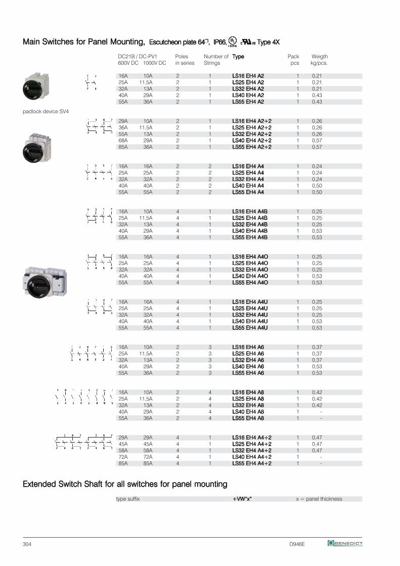
304 D946E
Main Switches for Panel MountingMain Switches for Panel MountingMain Switches for Panel MountingMain Switches for Panel MountingMain Switches for Panel Mounting, , , , , Escutcheon plate 64Escutcheon plate 64Escutcheon plate 64Escutcheon plate 64Escutcheon plate 64 , IP66,, IP66,, IP66,, IP66,, IP66, Type 4XType 4XType 4XType 4XType 4X
DC21B / DC-PV1 Poles Number of TypeTypeTypeTypeType Pack Weigth600V DC 1000V DC in series Strings pcs kg/pcs.
16A 10A 2 1 LS16 EH4 A2LS16 EH4 A2LS16 EH4 A2LS16 EH4 A2LS16 EH4 A2 1 0,2125A 11,5A 2 1 LS25 EH4 A2LS25 EH4 A2LS25 EH4 A2LS25 EH4 A2LS25 EH4 A2 1 0,2132A 13A 2 1 LS32 EH4 A2LS32 EH4 A2LS32 EH4 A2LS32 EH4 A2LS32 EH4 A2 1 0,2140A 29A 2 1 LS40 EH4 A2LS40 EH4 A2LS40 EH4 A2LS40 EH4 A2LS40 EH4 A2 1 0,4355A 36A 2 1 LS55 EH4 A2LS55 EH4 A2LS55 EH4 A2LS55 EH4 A2LS55 EH4 A2 1 0,43
29A 10A 2 1 LS16 EH4 A2+2LS16 EH4 A2+2LS16 EH4 A2+2LS16 EH4 A2+2LS16 EH4 A2+2 1 0,2636A 11,5A 2 1 LS25 EH4 A2+2LS25 EH4 A2+2LS25 EH4 A2+2LS25 EH4 A2+2LS25 EH4 A2+2 1 0,2655A 13A 2 1 LS32 EH4 A2+2LS32 EH4 A2+2LS32 EH4 A2+2LS32 EH4 A2+2LS32 EH4 A2+2 1 0,2668A 29A 2 1 LS40 EH4 A2+2LS40 EH4 A2+2LS40 EH4 A2+2LS40 EH4 A2+2LS40 EH4 A2+2 1 0,5785A 36A 2 1 LS55 EH4 A2+2LS55 EH4 A2+2LS55 EH4 A2+2LS55 EH4 A2+2LS55 EH4 A2+2 1 0,57
16A 16A 2 2 LS16 EH4 A4LS16 EH4 A4LS16 EH4 A4LS16 EH4 A4LS16 EH4 A4 1 0,2425A 25A 2 2 LS25 EH4 A4LS25 EH4 A4LS25 EH4 A4LS25 EH4 A4LS25 EH4 A4 1 0,2432A 32A 2 2 LS32 EH4 A4LS32 EH4 A4LS32 EH4 A4LS32 EH4 A4LS32 EH4 A4 1 0,2440A 40A 2 2 LS40 EH4 A4LS40 EH4 A4LS40 EH4 A4LS40 EH4 A4LS40 EH4 A4 1 0,5055A 55A 2 2 LS55 EH4 A4LS55 EH4 A4LS55 EH4 A4LS55 EH4 A4LS55 EH4 A4 1 0,50
16A 10A 4 1 LS16 EH4 A4BLS16 EH4 A4BLS16 EH4 A4BLS16 EH4 A4BLS16 EH4 A4B 1 0,2525A 11,5A 4 1 LS25 EH4 A4BLS25 EH4 A4BLS25 EH4 A4BLS25 EH4 A4BLS25 EH4 A4B 1 0,2532A 13A 4 1 LS32 EH4 A4BLS32 EH4 A4BLS32 EH4 A4BLS32 EH4 A4BLS32 EH4 A4B 1 0,2540A 29A 4 1 LS40 EH4 A4BLS40 EH4 A4BLS40 EH4 A4BLS40 EH4 A4BLS40 EH4 A4B 1 0,5355A 36A 4 1 LS55 EH4 A4BLS55 EH4 A4BLS55 EH4 A4BLS55 EH4 A4BLS55 EH4 A4B 1 0,53
16A 16A 4 1 LS16 EH4 A4OLS16 EH4 A4OLS16 EH4 A4OLS16 EH4 A4OLS16 EH4 A4O 1 0,2525A 25A 4 1 LS25 EH4 A4OLS25 EH4 A4OLS25 EH4 A4OLS25 EH4 A4OLS25 EH4 A4O 1 0,2532A 32A 4 1 LS32 EH4 A4OLS32 EH4 A4OLS32 EH4 A4OLS32 EH4 A4OLS32 EH4 A4O 1 0,2540A 40A 4 1 LS40 EH4 A4OLS40 EH4 A4OLS40 EH4 A4OLS40 EH4 A4OLS40 EH4 A4O 1 0,5355A 55A 4 1 LS55 EH4 A4OLS55 EH4 A4OLS55 EH4 A4OLS55 EH4 A4OLS55 EH4 A4O 1 0,53
16A 16A 4 1 LS16 EH4 A4ULS16 EH4 A4ULS16 EH4 A4ULS16 EH4 A4ULS16 EH4 A4U 1 0,2525A 25A 4 1 LS25 EH4 A4ULS25 EH4 A4ULS25 EH4 A4ULS25 EH4 A4ULS25 EH4 A4U 1 0,2532A 32A 4 1 LS32 EH4 A4ULS32 EH4 A4ULS32 EH4 A4ULS32 EH4 A4ULS32 EH4 A4U 1 0,2540A 40A 4 1 LS40 EH4 A4ULS40 EH4 A4ULS40 EH4 A4ULS40 EH4 A4ULS40 EH4 A4U 1 0,5355A 55A 4 1 LS55 EH4 A4ULS55 EH4 A4ULS55 EH4 A4ULS55 EH4 A4ULS55 EH4 A4U 1 0,53
16A 10A 2 3 LS16 EH4 A6LS16 EH4 A6LS16 EH4 A6LS16 EH4 A6LS16 EH4 A6 1 0,3725A 11,5A 2 3 LS25 EH4 A6LS25 EH4 A6LS25 EH4 A6LS25 EH4 A6LS25 EH4 A6 1 0,3732A 13A 2 3 LS32 EH4 A6LS32 EH4 A6LS32 EH4 A6LS32 EH4 A6LS32 EH4 A6 1 0,3740A 29A 2 3 LS40 EH4 A6LS40 EH4 A6LS40 EH4 A6LS40 EH4 A6LS40 EH4 A6 1 0,5355A 36A 2 3 LS55 EH4 A6LS55 EH4 A6LS55 EH4 A6LS55 EH4 A6LS55 EH4 A6 1 0,53
16A 10A 2 4 LS16 EH4 A8LS16 EH4 A8LS16 EH4 A8LS16 EH4 A8LS16 EH4 A8 1 0,4225A 11,5A 2 4 LS25 EH4 A8LS25 EH4 A8LS25 EH4 A8LS25 EH4 A8LS25 EH4 A8 1 0,4232A 13A 2 4 LS32 EH4 A8LS32 EH4 A8LS32 EH4 A8LS32 EH4 A8LS32 EH4 A8 1 0,4240A 29A 2 4 LS40 EH4 A8LS40 EH4 A8LS40 EH4 A8LS40 EH4 A8LS40 EH4 A8 1 -55A 36A 2 4 LS55 EH4 A8LS55 EH4 A8LS55 EH4 A8LS55 EH4 A8LS55 EH4 A8 1 -
29A 29A 4 1 LS16 EH4 A4+2LS16 EH4 A4+2LS16 EH4 A4+2LS16 EH4 A4+2LS16 EH4 A4+2 1 0,4745A 45A 4 1 LS25 EH4 A4+2LS25 EH4 A4+2LS25 EH4 A4+2LS25 EH4 A4+2LS25 EH4 A4+2 1 0,4758A 58A 4 1 LS32 EH4 A4+2LS32 EH4 A4+2LS32 EH4 A4+2LS32 EH4 A4+2LS32 EH4 A4+2 1 0,4772A 72A 4 1 LS40 EH4 A4+2LS40 EH4 A4+2LS40 EH4 A4+2LS40 EH4 A4+2LS40 EH4 A4+2 1 -85A 85A 4 1 LS55 EH4 A4+2LS55 EH4 A4+2LS55 EH4 A4+2LS55 EH4 A4+2LS55 EH4 A4+2 1 -
Extended Switch Shaft for all switches for panel mountingExtended Switch Shaft for all switches for panel mountingExtended Switch Shaft for all switches for panel mountingExtended Switch Shaft for all switches for panel mountingExtended Switch Shaft for all switches for panel mounting
type suffix +VW“x“+VW“x“+VW“x“+VW“x“+VW“x“ x = panel thickness
padlock device SV4
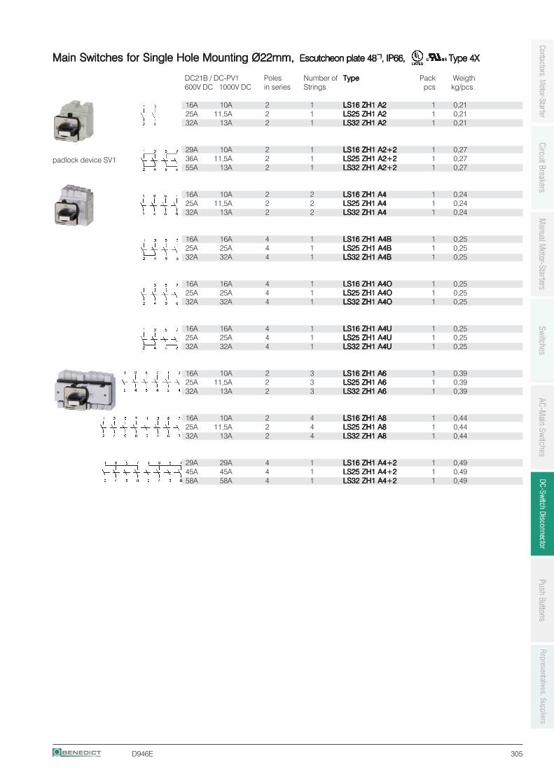
D946E 305
Main Switches for Single Hole Mounting Ø22mmMain Switches for Single Hole Mounting Ø22mmMain Switches for Single Hole Mounting Ø22mmMain Switches for Single Hole Mounting Ø22mmMain Switches for Single Hole Mounting Ø22mm, , , , , Escutcheon plate 48Escutcheon plate 48Escutcheon plate 48Escutcheon plate 48Escutcheon plate 48 , IP66,, IP66,, IP66,, IP66,, IP66, Type 4XType 4XType 4XType 4XType 4X
DC21B / DC-PV1 Poles Number of TypeTypeTypeTypeType Pack Weigth600V DC 1000V DC in series Strings pcs kg/pcs.
16A 10A 2 1 LS16 ZH1 A2LS16 ZH1 A2LS16 ZH1 A2LS16 ZH1 A2LS16 ZH1 A2 1 0,2125A 11,5A 2 1 LS25 ZH1 A2LS25 ZH1 A2LS25 ZH1 A2LS25 ZH1 A2LS25 ZH1 A2 1 0,2132A 13A 2 1 LS32 ZH1 A2LS32 ZH1 A2LS32 ZH1 A2LS32 ZH1 A2LS32 ZH1 A2 1 0,21
29A 10A 2 1 LS16 ZH1 A2+2LS16 ZH1 A2+2LS16 ZH1 A2+2LS16 ZH1 A2+2LS16 ZH1 A2+2 1 0,2736A 11,5A 2 1 LS25 ZH1 A2+2LS25 ZH1 A2+2LS25 ZH1 A2+2LS25 ZH1 A2+2LS25 ZH1 A2+2 1 0,2755A 13A 2 1 LS32 ZH1 A2+2LS32 ZH1 A2+2LS32 ZH1 A2+2LS32 ZH1 A2+2LS32 ZH1 A2+2 1 0,27
16A 10A 2 2 LS16 ZH1 A4LS16 ZH1 A4LS16 ZH1 A4LS16 ZH1 A4LS16 ZH1 A4 1 0,2425A 11,5A 2 2 LS25 ZH1 A4LS25 ZH1 A4LS25 ZH1 A4LS25 ZH1 A4LS25 ZH1 A4 1 0,2432A 13A 2 2 LS32 ZH1 A4LS32 ZH1 A4LS32 ZH1 A4LS32 ZH1 A4LS32 ZH1 A4 1 0,24
16A 16A 4 1 LS16 ZH1 A4BLS16 ZH1 A4BLS16 ZH1 A4BLS16 ZH1 A4BLS16 ZH1 A4B 1 0,2525A 25A 4 1 LS25 ZH1 A4BLS25 ZH1 A4BLS25 ZH1 A4BLS25 ZH1 A4BLS25 ZH1 A4B 1 0,2532A 32A 4 1 LS32 ZH1 A4BLS32 ZH1 A4BLS32 ZH1 A4BLS32 ZH1 A4BLS32 ZH1 A4B 1 0,25
16A 16A 4 1 LS16 ZH1 A4OLS16 ZH1 A4OLS16 ZH1 A4OLS16 ZH1 A4OLS16 ZH1 A4O 1 0,2525A 25A 4 1 LS25 ZH1 A4OLS25 ZH1 A4OLS25 ZH1 A4OLS25 ZH1 A4OLS25 ZH1 A4O 1 0,2532A 32A 4 1 LS32 ZH1 A4OLS32 ZH1 A4OLS32 ZH1 A4OLS32 ZH1 A4OLS32 ZH1 A4O 1 0,25
16A 16A 4 1 LS16 ZH1 A4ULS16 ZH1 A4ULS16 ZH1 A4ULS16 ZH1 A4ULS16 ZH1 A4U 1 0,2525A 25A 4 1 LS25 ZH1 A4ULS25 ZH1 A4ULS25 ZH1 A4ULS25 ZH1 A4ULS25 ZH1 A4U 1 0,2532A 32A 4 1 LS32 ZH1 A4ULS32 ZH1 A4ULS32 ZH1 A4ULS32 ZH1 A4ULS32 ZH1 A4U 1 0,25
16A 10A 2 3 LS16 ZH1 A6LS16 ZH1 A6LS16 ZH1 A6LS16 ZH1 A6LS16 ZH1 A6 1 0,3925A 11,5A 2 3 LS25 ZH1 A6LS25 ZH1 A6LS25 ZH1 A6LS25 ZH1 A6LS25 ZH1 A6 1 0,3932A 13A 2 3 LS32 ZH1 A6LS32 ZH1 A6LS32 ZH1 A6LS32 ZH1 A6LS32 ZH1 A6 1 0,39
16A 10A 2 4 LS16 ZH1 A8LS16 ZH1 A8LS16 ZH1 A8LS16 ZH1 A8LS16 ZH1 A8 1 0,4425A 11,5A 2 4 LS25 ZH1 A8LS25 ZH1 A8LS25 ZH1 A8LS25 ZH1 A8LS25 ZH1 A8 1 0,4432A 13A 2 4 LS32 ZH1 A8LS32 ZH1 A8LS32 ZH1 A8LS32 ZH1 A8LS32 ZH1 A8 1 0,44
29A 29A 4 1 LS16 ZH1 A4+2LS16 ZH1 A4+2LS16 ZH1 A4+2LS16 ZH1 A4+2LS16 ZH1 A4+2 1 0,4945A 45A 4 1 LS25 ZH1 A4+2LS25 ZH1 A4+2LS25 ZH1 A4+2LS25 ZH1 A4+2LS25 ZH1 A4+2 1 0,4958A 58A 4 1 LS32 ZH1 A4+2LS32 ZH1 A4+2LS32 ZH1 A4+2LS32 ZH1 A4+2LS32 ZH1 A4+2 1 0,49
padlock device SV1
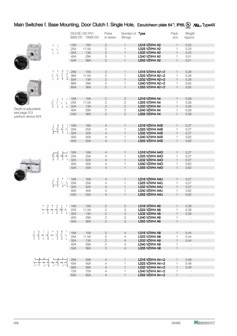
306 D946E
Main Switches f. Base Mounting, Door Clutch f. Single Hole, Main Switches f. Base Mounting, Door Clutch f. Single Hole, Main Switches f. Base Mounting, Door Clutch f. Single Hole, Main Switches f. Base Mounting, Door Clutch f. Single Hole, Main Switches f. Base Mounting, Door Clutch f. Single Hole, Escutcheon plate 64Escutcheon plate 64Escutcheon plate 64Escutcheon plate 64Escutcheon plate 64 , IP66,, IP66,, IP66,, IP66,, IP66, Type4XType4XType4XType4XType4X
DC21B / DC-PV1 Poles Number of TypeTypeTypeTypeType Pack Weigth600V DC 1000V DC in series Strings pcs kg/pcs.
16A 10A 2 1 LS16 VZVH4 A2LS16 VZVH4 A2LS16 VZVH4 A2LS16 VZVH4 A2LS16 VZVH4 A2 1 0,2325A 11,5A 2 1 LS25 VZVH4 A2LS25 VZVH4 A2LS25 VZVH4 A2LS25 VZVH4 A2LS25 VZVH4 A2 1 0,2332A 13A 2 1 LS32 VZVH4 A2LS32 VZVH4 A2LS32 VZVH4 A2LS32 VZVH4 A2LS32 VZVH4 A2 1 0,2340A 29A 2 1 LS40 VZVH4 A2LS40 VZVH4 A2LS40 VZVH4 A2LS40 VZVH4 A2LS40 VZVH4 A2 1 0,5155A 36A 2 1 LS55 VZVH4 A2LS55 VZVH4 A2LS55 VZVH4 A2LS55 VZVH4 A2LS55 VZVH4 A2 1 0,51
29A 10A 2 1 LS16 VZVH4 A2+2LS16 VZVH4 A2+2LS16 VZVH4 A2+2LS16 VZVH4 A2+2LS16 VZVH4 A2+2 1 0,2836A 11,5A 2 1 LS25 VZVH4 A2+2LS25 VZVH4 A2+2LS25 VZVH4 A2+2LS25 VZVH4 A2+2LS25 VZVH4 A2+2 1 0,2855A 13A 2 1 LS32 VZVH4 A2+2LS32 VZVH4 A2+2LS32 VZVH4 A2+2LS32 VZVH4 A2+2LS32 VZVH4 A2+2 1 0,2868A 29A 2 1 LS40 VZVH4 A2+2LS40 VZVH4 A2+2LS40 VZVH4 A2+2LS40 VZVH4 A2+2LS40 VZVH4 A2+2 1 0,6585A 36A 2 1 LS55 VZVH4 A2+2LS55 VZVH4 A2+2LS55 VZVH4 A2+2LS55 VZVH4 A2+2LS55 VZVH4 A2+2 1 0,65
16A 10A 2 2 LS16 VZVH4 A4LS16 VZVH4 A4LS16 VZVH4 A4LS16 VZVH4 A4LS16 VZVH4 A4 1 0,2625A 11,5A 2 2 LS25 VZVH4 A4LS25 VZVH4 A4LS25 VZVH4 A4LS25 VZVH4 A4LS25 VZVH4 A4 1 0,2632A 13A 2 2 LS32 VZVH4 A4LS32 VZVH4 A4LS32 VZVH4 A4LS32 VZVH4 A4LS32 VZVH4 A4 1 0,2640A 29A 2 2 LS40 VZVH4 A4LS40 VZVH4 A4LS40 VZVH4 A4LS40 VZVH4 A4LS40 VZVH4 A4 1 0,5855A 36A 2 2 LS55 VZVH4 A4LS55 VZVH4 A4LS55 VZVH4 A4LS55 VZVH4 A4LS55 VZVH4 A4 1 0,58
16A 16A 4 1 LS16 VZVH4 A4BLS16 VZVH4 A4BLS16 VZVH4 A4BLS16 VZVH4 A4BLS16 VZVH4 A4B 1 0,2725A 25A 4 1 LS25 VZVH4 A4BLS25 VZVH4 A4BLS25 VZVH4 A4BLS25 VZVH4 A4BLS25 VZVH4 A4B 1 0,2732A 32A 4 1 LS32 VZVH4 A4BLS32 VZVH4 A4BLS32 VZVH4 A4BLS32 VZVH4 A4BLS32 VZVH4 A4B 1 0,2740A 40A 4 1 LS40 VZVH4 A4BLS40 VZVH4 A4BLS40 VZVH4 A4BLS40 VZVH4 A4BLS40 VZVH4 A4B 1 0,6255A 55A 4 1 LS55 VZVH4 A4BLS55 VZVH4 A4BLS55 VZVH4 A4BLS55 VZVH4 A4BLS55 VZVH4 A4B 1 0,62
16A 16A 4 1 LS16 VZVH4 A4OLS16 VZVH4 A4OLS16 VZVH4 A4OLS16 VZVH4 A4OLS16 VZVH4 A4O 1 0,2725A 25A 4 1 LS25 VZVH4 A4OLS25 VZVH4 A4OLS25 VZVH4 A4OLS25 VZVH4 A4OLS25 VZVH4 A4O 1 0,2732A 32A 4 1 LS32 VZVH4 A4OLS32 VZVH4 A4OLS32 VZVH4 A4OLS32 VZVH4 A4OLS32 VZVH4 A4O 1 0,2740A 40A 4 1 LS40 VZVH4 A4OLS40 VZVH4 A4OLS40 VZVH4 A4OLS40 VZVH4 A4OLS40 VZVH4 A4O 1 0,6255A 55A 4 1 LS55 VZVH4 A4OLS55 VZVH4 A4OLS55 VZVH4 A4OLS55 VZVH4 A4OLS55 VZVH4 A4O 1 0,62
16A 16A 4 1 LS16 VZVH4 A4ULS16 VZVH4 A4ULS16 VZVH4 A4ULS16 VZVH4 A4ULS16 VZVH4 A4U 1 0,2725A 25A 4 1 LS25 VZVH4 A4ULS25 VZVH4 A4ULS25 VZVH4 A4ULS25 VZVH4 A4ULS25 VZVH4 A4U 1 0,2732A 32A 4 1 LS32 VZVH4 A4ULS32 VZVH4 A4ULS32 VZVH4 A4ULS32 VZVH4 A4ULS32 VZVH4 A4U 1 0,2740A 40A 4 1 LS40 VZVH4 A4ULS40 VZVH4 A4ULS40 VZVH4 A4ULS40 VZVH4 A4ULS40 VZVH4 A4U 1 0,6255A 55A 4 1 LS55 VZVH4 A4ULS55 VZVH4 A4ULS55 VZVH4 A4ULS55 VZVH4 A4ULS55 VZVH4 A4U 1 0,62
16A 10A 2 3 LS16 VZVH4 A6LS16 VZVH4 A6LS16 VZVH4 A6LS16 VZVH4 A6LS16 VZVH4 A6 1 0,3925A 11,5A 2 3 LS25 VZVH4 A6LS25 VZVH4 A6LS25 VZVH4 A6LS25 VZVH4 A6LS25 VZVH4 A6 1 0,3932A 13A 2 3 LS32 VZVH4 A6LS32 VZVH4 A6LS32 VZVH4 A6LS32 VZVH4 A6LS32 VZVH4 A6 1 0,3940A 29A 2 3 LS40 VZVH4 A6LS40 VZVH4 A6LS40 VZVH4 A6LS40 VZVH4 A6LS40 VZVH4 A6 1 -55A 36A 2 3 LS55 VZVH4 A6LS55 VZVH4 A6LS55 VZVH4 A6LS55 VZVH4 A6LS55 VZVH4 A6 1 -
16A 10A 2 4 LS16 VZVH4 A8LS16 VZVH4 A8LS16 VZVH4 A8LS16 VZVH4 A8LS16 VZVH4 A8 1 0,4425A 11,5A 2 4 LS25 VZVH4 A8LS25 VZVH4 A8LS25 VZVH4 A8LS25 VZVH4 A8LS25 VZVH4 A8 1 0,4432A 13A 2 4 LS32 VZVH4 A8LS32 VZVH4 A8LS32 VZVH4 A8LS32 VZVH4 A8LS32 VZVH4 A8 1 0,4440A 29A 2 4 LS40 VZVH4 A8LS40 VZVH4 A8LS40 VZVH4 A8LS40 VZVH4 A8LS40 VZVH4 A8 1 -55A 36A 2 4 LS55 VZVH4 A8LS55 VZVH4 A8LS55 VZVH4 A8LS55 VZVH4 A8LS55 VZVH4 A8 1 -
29A 29A 4 1 LS16 VZVH4 A4+2LS16 VZVH4 A4+2LS16 VZVH4 A4+2LS16 VZVH4 A4+2LS16 VZVH4 A4+2 1 0,4945A 45A 4 1 LS25 VZVH4 A4+2LS25 VZVH4 A4+2LS25 VZVH4 A4+2LS25 VZVH4 A4+2LS25 VZVH4 A4+2 1 0,4958A 58A 4 1 LS32 VZVH4 A4+2LS32 VZVH4 A4+2LS32 VZVH4 A4+2LS32 VZVH4 A4+2LS32 VZVH4 A4+2 1 0,4972A 72A 4 1 LS40 VZVH4 A4+2LS40 VZVH4 A4+2LS40 VZVH4 A4+2LS40 VZVH4 A4+2LS40 VZVH4 A4+2 1 -85A 85A 4 1 LS55 VZVH4 A4+2LS55 VZVH4 A4+2LS55 VZVH4 A4+2LS55 VZVH4 A4+2LS55 VZVH4 A4+2 1 -
Depth is adjustablesee page 313padlock device SV4
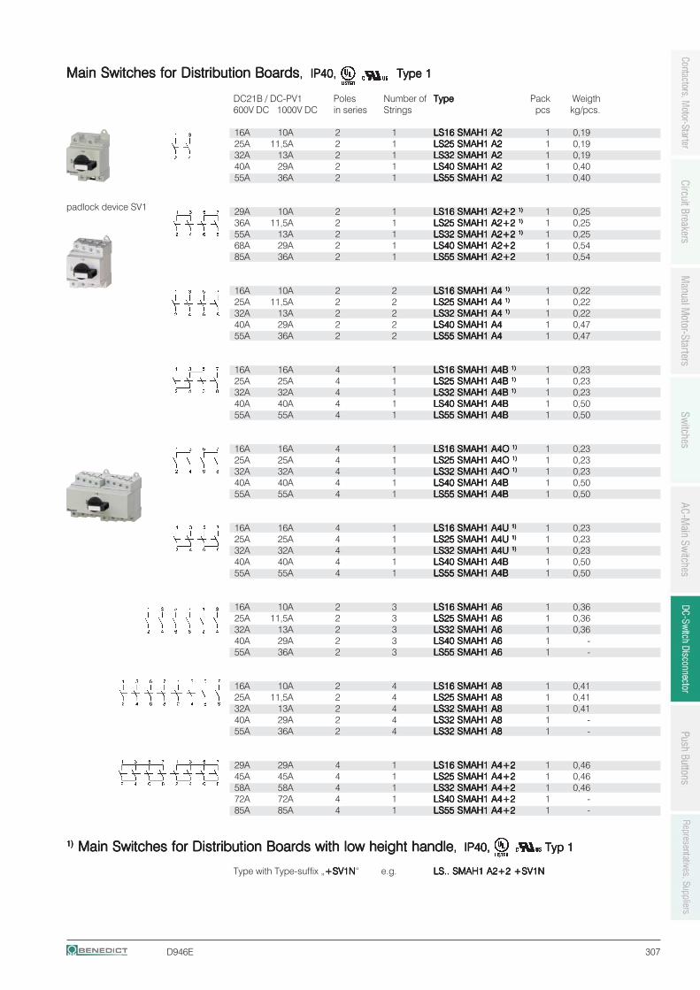
D946E 307
Main Switches for Distribution BoardsMain Switches for Distribution BoardsMain Switches for Distribution BoardsMain Switches for Distribution BoardsMain Switches for Distribution Boards, IP40,, IP40,, IP40,, IP40,, IP40, Type 1Type 1Type 1Type 1Type 1
DC21B / DC-PV1 Poles Number of TypeTypeTypeTypeType Pack Weigth600V DC 1000V DC in series Strings pcs kg/pcs.
16A 10A 2 1 LS16 SMAH1 A2LS16 SMAH1 A2LS16 SMAH1 A2LS16 SMAH1 A2LS16 SMAH1 A2 1 0,1925A 11,5A 2 1 LS25 SMAH1 A2LS25 SMAH1 A2LS25 SMAH1 A2LS25 SMAH1 A2LS25 SMAH1 A2 1 0,1932A 13A 2 1 LS32 SMAH1 A2LS32 SMAH1 A2LS32 SMAH1 A2LS32 SMAH1 A2LS32 SMAH1 A2 1 0,1940A 29A 2 1 LS40 SMAH1 A2LS40 SMAH1 A2LS40 SMAH1 A2LS40 SMAH1 A2LS40 SMAH1 A2 1 0,4055A 36A 2 1 LS55 SMAH1 A2LS55 SMAH1 A2LS55 SMAH1 A2LS55 SMAH1 A2LS55 SMAH1 A2 1 0,40
29A 10A 2 1 LS16 SMAH1 A2+2 LS16 SMAH1 A2+2 LS16 SMAH1 A2+2 LS16 SMAH1 A2+2 LS16 SMAH1 A2+2 1)1)1)1)1) 1 0,2536A 11,5A 2 1 LS25 SMAH1 A2+2 LS25 SMAH1 A2+2 LS25 SMAH1 A2+2 LS25 SMAH1 A2+2 LS25 SMAH1 A2+2 1)1)1)1)1) 1 0,2555A 13A 2 1 LS32 SMAH1 A2+2 LS32 SMAH1 A2+2 LS32 SMAH1 A2+2 LS32 SMAH1 A2+2 LS32 SMAH1 A2+2 1)1)1)1)1) 1 0,2568A 29A 2 1 LS40 SMAH1 A2+2LS40 SMAH1 A2+2LS40 SMAH1 A2+2LS40 SMAH1 A2+2LS40 SMAH1 A2+2 1 0,5485A 36A 2 1 LS55 SMAH1 A2+2LS55 SMAH1 A2+2LS55 SMAH1 A2+2LS55 SMAH1 A2+2LS55 SMAH1 A2+2 1 0,54
16A 10A 2 2 LS16 SMAH1 A4 LS16 SMAH1 A4 LS16 SMAH1 A4 LS16 SMAH1 A4 LS16 SMAH1 A4 1)1)1)1)1) 1 0,2225A 11,5A 2 2 LS25 SMAH1 A4 LS25 SMAH1 A4 LS25 SMAH1 A4 LS25 SMAH1 A4 LS25 SMAH1 A4 1)1)1)1)1) 1 0,2232A 13A 2 2 LS32 SMAH1 A4 LS32 SMAH1 A4 LS32 SMAH1 A4 LS32 SMAH1 A4 LS32 SMAH1 A4 1)1)1)1)1) 1 0,2240A 29A 2 2 LS40 SMAH1 A4LS40 SMAH1 A4LS40 SMAH1 A4LS40 SMAH1 A4LS40 SMAH1 A4 1 0,4755A 36A 2 2 LS55 SMAH1 A4LS55 SMAH1 A4LS55 SMAH1 A4LS55 SMAH1 A4LS55 SMAH1 A4 1 0,47
16A 16A 4 1 LS16 SMAH1 A4B LS16 SMAH1 A4B LS16 SMAH1 A4B LS16 SMAH1 A4B LS16 SMAH1 A4B 1)1)1)1)1) 1 0,2325A 25A 4 1 LS25 SMAH1 A4B LS25 SMAH1 A4B LS25 SMAH1 A4B LS25 SMAH1 A4B LS25 SMAH1 A4B 1)1)1)1)1) 1 0,2332A 32A 4 1 LS32 SMAH1 A4B LS32 SMAH1 A4B LS32 SMAH1 A4B LS32 SMAH1 A4B LS32 SMAH1 A4B 1)1)1)1)1) 1 0,2340A 40A 4 1 LS40 SMAH1 A4BLS40 SMAH1 A4BLS40 SMAH1 A4BLS40 SMAH1 A4BLS40 SMAH1 A4B 1 0,5055A 55A 4 1 LS55 SMAH1 A4BLS55 SMAH1 A4BLS55 SMAH1 A4BLS55 SMAH1 A4BLS55 SMAH1 A4B 1 0,50
16A 16A 4 1 LS16 SMAH1 A4O LS16 SMAH1 A4O LS16 SMAH1 A4O LS16 SMAH1 A4O LS16 SMAH1 A4O 1)1)1)1)1) 1 0,2325A 25A 4 1 LS25 SMAH1 A4O LS25 SMAH1 A4O LS25 SMAH1 A4O LS25 SMAH1 A4O LS25 SMAH1 A4O 1)1)1)1)1) 1 0,2332A 32A 4 1 LS32 SMAH1 A4O LS32 SMAH1 A4O LS32 SMAH1 A4O LS32 SMAH1 A4O LS32 SMAH1 A4O 1)1)1)1)1) 1 0,2340A 40A 4 1 LS40 SMAH1 A4BLS40 SMAH1 A4BLS40 SMAH1 A4BLS40 SMAH1 A4BLS40 SMAH1 A4B 1 0,5055A 55A 4 1 LS55 SMAH1 A4BLS55 SMAH1 A4BLS55 SMAH1 A4BLS55 SMAH1 A4BLS55 SMAH1 A4B 1 0,50
16A 16A 4 1 LS16 SMAH1 A4U LS16 SMAH1 A4U LS16 SMAH1 A4U LS16 SMAH1 A4U LS16 SMAH1 A4U 1)1)1)1)1) 1 0,2325A 25A 4 1 LS25 SMAH1 A4U LS25 SMAH1 A4U LS25 SMAH1 A4U LS25 SMAH1 A4U LS25 SMAH1 A4U 1)1)1)1)1) 1 0,2332A 32A 4 1 LS32 SMAH1 A4U LS32 SMAH1 A4U LS32 SMAH1 A4U LS32 SMAH1 A4U LS32 SMAH1 A4U 1)1)1)1)1) 1 0,2340A 40A 4 1 LS40 SMAH1 A4BLS40 SMAH1 A4BLS40 SMAH1 A4BLS40 SMAH1 A4BLS40 SMAH1 A4B 1 0,5055A 55A 4 1 LS55 SMAH1 A4BLS55 SMAH1 A4BLS55 SMAH1 A4BLS55 SMAH1 A4BLS55 SMAH1 A4B 1 0,50
16A 10A 2 3 LS16 SMAH1 A6LS16 SMAH1 A6LS16 SMAH1 A6LS16 SMAH1 A6LS16 SMAH1 A6 1 0,3625A 11,5A 2 3 LS25 SMAH1 A6LS25 SMAH1 A6LS25 SMAH1 A6LS25 SMAH1 A6LS25 SMAH1 A6 1 0,3632A 13A 2 3 LS32 SMAH1 A6LS32 SMAH1 A6LS32 SMAH1 A6LS32 SMAH1 A6LS32 SMAH1 A6 1 0,3640A 29A 2 3 LS40 SMAH1 A6LS40 SMAH1 A6LS40 SMAH1 A6LS40 SMAH1 A6LS40 SMAH1 A6 1 -55A 36A 2 3 LS55 SMAH1 A6LS55 SMAH1 A6LS55 SMAH1 A6LS55 SMAH1 A6LS55 SMAH1 A6 1 -
16A 10A 2 4 LS16 SMAH1 A8LS16 SMAH1 A8LS16 SMAH1 A8LS16 SMAH1 A8LS16 SMAH1 A8 1 0,4125A 11,5A 2 4 LS25 SMAH1 A8LS25 SMAH1 A8LS25 SMAH1 A8LS25 SMAH1 A8LS25 SMAH1 A8 1 0,4132A 13A 2 4 LS32 SMAH1 A8LS32 SMAH1 A8LS32 SMAH1 A8LS32 SMAH1 A8LS32 SMAH1 A8 1 0,4140A 29A 2 4 LS32 SMAH1 A8LS32 SMAH1 A8LS32 SMAH1 A8LS32 SMAH1 A8LS32 SMAH1 A8 1 -55A 36A 2 4 LS32 SMAH1 A8LS32 SMAH1 A8LS32 SMAH1 A8LS32 SMAH1 A8LS32 SMAH1 A8 1 -
29A 29A 4 1 LS16 SMAH1 A4+2LS16 SMAH1 A4+2LS16 SMAH1 A4+2LS16 SMAH1 A4+2LS16 SMAH1 A4+2 1 0,4645A 45A 4 1 LS25 SMAH1 A4+2LS25 SMAH1 A4+2LS25 SMAH1 A4+2LS25 SMAH1 A4+2LS25 SMAH1 A4+2 1 0,4658A 58A 4 1 LS32 SMAH1 A4+2LS32 SMAH1 A4+2LS32 SMAH1 A4+2LS32 SMAH1 A4+2LS32 SMAH1 A4+2 1 0,4672A 72A 4 1 LS40 SMAH1 A4+2LS40 SMAH1 A4+2LS40 SMAH1 A4+2LS40 SMAH1 A4+2LS40 SMAH1 A4+2 1 -85A 85A 4 1 LS55 SMAH1 A4+2LS55 SMAH1 A4+2LS55 SMAH1 A4+2LS55 SMAH1 A4+2LS55 SMAH1 A4+2 1 -
1)1)1)1)1) Main Switches for Distribution Boards with low height handle Main Switches for Distribution Boards with low height handle Main Switches for Distribution Boards with low height handle Main Switches for Distribution Boards with low height handle Main Switches for Distribution Boards with low height handle, IP40,, IP40,, IP40,, IP40,, IP40, Typ 1Typ 1Typ 1Typ 1Typ 1
Type with Type-suffix „+SV1N+SV1N+SV1N+SV1N+SV1N“ e.g. LS.. SMAH1 A2+2 +SV1NLS.. SMAH1 A2+2 +SV1NLS.. SMAH1 A2+2 +SV1NLS.. SMAH1 A2+2 +SV1NLS.. SMAH1 A2+2 +SV1N
padlock device SV1
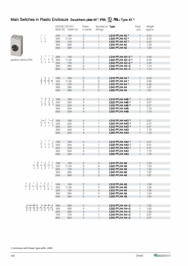
308 D946E
Main Switches in Plastic EnclosureMain Switches in Plastic EnclosureMain Switches in Plastic EnclosureMain Switches in Plastic EnclosureMain Switches in Plastic Enclosure Escutcheon plate 64Escutcheon plate 64Escutcheon plate 64Escutcheon plate 64Escutcheon plate 64 , IP66, IP66, IP66, IP66, IP66,,,,, Type 4X Type 4X Type 4X Type 4X Type 4X 1)1)1)1)1)
DC21B / DC-PV1 Poles Number of TypeTypeTypeTypeType Pack Weigth600V DC 1000V DC in series Strings pcs kg/pcs.
16A 10A 2 1 LS16 PFLH4 A2 LS16 PFLH4 A2 LS16 PFLH4 A2 LS16 PFLH4 A2 LS16 PFLH4 A2 1)1)1)1)1) 1 0,4325A 11,5A 2 1 LS25 PFLH4 A2 LS25 PFLH4 A2 LS25 PFLH4 A2 LS25 PFLH4 A2 LS25 PFLH4 A2 1)1)1)1)1) 1 0,4332A 13A 2 1 LS32 PFLH4 A2 LS32 PFLH4 A2 LS32 PFLH4 A2 LS32 PFLH4 A2 LS32 PFLH4 A2 1)1)1)1)1) 1 0,4340A 29A 2 1 LS40 PFLH4 A2LS40 PFLH4 A2LS40 PFLH4 A2LS40 PFLH4 A2LS40 PFLH4 A2 1 1,5955A 36A 2 1 LS55 PFLH4 A2LS55 PFLH4 A2LS55 PFLH4 A2LS55 PFLH4 A2LS55 PFLH4 A2 1 1,59
29A 10A 2 1 LS16 PFLH4 A2+2 LS16 PFLH4 A2+2 LS16 PFLH4 A2+2 LS16 PFLH4 A2+2 LS16 PFLH4 A2+2 1)1)1)1)1) 1 0,4936A 11,5A 2 1 LS25 PFLH4 A2+2 LS25 PFLH4 A2+2 LS25 PFLH4 A2+2 LS25 PFLH4 A2+2 LS25 PFLH4 A2+2 1)1)1)1)1) 1 0,4955A 13A 2 1 LS32 PFLH4 A2+2 LS32 PFLH4 A2+2 LS32 PFLH4 A2+2 LS32 PFLH4 A2+2 LS32 PFLH4 A2+2 1)1)1)1)1) 1 0,4968A 29A 2 1 LS40 PFLH4 A2+2LS40 PFLH4 A2+2LS40 PFLH4 A2+2LS40 PFLH4 A2+2LS40 PFLH4 A2+2 1 1,7485A 36A 2 1 LS55 PFLH4 A2+2LS55 PFLH4 A2+2LS55 PFLH4 A2+2LS55 PFLH4 A2+2LS55 PFLH4 A2+2 1 1,74
16A 10A 2 2 LS16 PFLH4 A4 LS16 PFLH4 A4 LS16 PFLH4 A4 LS16 PFLH4 A4 LS16 PFLH4 A4 1)1)1)1)1) 1 0,4625A 11,5A 2 2 LS25 PFLH4 A4 LS25 PFLH4 A4 LS25 PFLH4 A4 LS25 PFLH4 A4 LS25 PFLH4 A4 1)1)1)1)1) 1 0,4632A 13A 2 2 LS32 PFLH4 A4 LS32 PFLH4 A4 LS32 PFLH4 A4 LS32 PFLH4 A4 LS32 PFLH4 A4 1)1)1)1)1) 1 0,4640A 29A 2 2 LS40 PFLH4 A4LS40 PFLH4 A4LS40 PFLH4 A4LS40 PFLH4 A4LS40 PFLH4 A4 1 1,6755A 36A 2 2 LS55 PFLH4 A4LS55 PFLH4 A4LS55 PFLH4 A4LS55 PFLH4 A4LS55 PFLH4 A4 1 1,67
16A 16A 4 1 LS16 PFLH4 A4B LS16 PFLH4 A4B LS16 PFLH4 A4B LS16 PFLH4 A4B LS16 PFLH4 A4B 1)1)1)1)1) 1 0,4725A 25A 4 1 LS25 PFLH4 A4B LS25 PFLH4 A4B LS25 PFLH4 A4B LS25 PFLH4 A4B LS25 PFLH4 A4B 1)1)1)1)1) 1 0,4732A 32A 4 1 LS32 PFLH4 A4B LS32 PFLH4 A4B LS32 PFLH4 A4B LS32 PFLH4 A4B LS32 PFLH4 A4B 1)1)1)1)1) 1 0,4740A 40A 4 1 LS40 PFLH4 A4BLS40 PFLH4 A4BLS40 PFLH4 A4BLS40 PFLH4 A4BLS40 PFLH4 A4B 1 1,7055A 55A 4 1 LS55 PFLH4 A4BLS55 PFLH4 A4BLS55 PFLH4 A4BLS55 PFLH4 A4BLS55 PFLH4 A4B 1 1,70
16A 16A 4 1 LS16 PFLH4 A4O LS16 PFLH4 A4O LS16 PFLH4 A4O LS16 PFLH4 A4O LS16 PFLH4 A4O 1)1)1)1)1) 1 0,4725A 25A 4 1 LS25 PFLH4 A4O LS25 PFLH4 A4O LS25 PFLH4 A4O LS25 PFLH4 A4O LS25 PFLH4 A4O 1)1)1)1)1) 1 0,4732A 32A 4 1 LS32 PFLH4 A4O LS32 PFLH4 A4O LS32 PFLH4 A4O LS32 PFLH4 A4O LS32 PFLH4 A4O 1)1)1)1)1) 1 0,4740A 40A 4 1 LS40 PFLH4 A4OLS40 PFLH4 A4OLS40 PFLH4 A4OLS40 PFLH4 A4OLS40 PFLH4 A4O 1 1,7055A 55A 4 1 LS55 PFLH4 A4OLS55 PFLH4 A4OLS55 PFLH4 A4OLS55 PFLH4 A4OLS55 PFLH4 A4O 1 1,70
16A 16A 4 1 LS16 PFLH4 A4U LS16 PFLH4 A4U LS16 PFLH4 A4U LS16 PFLH4 A4U LS16 PFLH4 A4U 1)1)1)1)1) 1 0,4725A 25A 4 1 LS25 PFLH4 A4U LS25 PFLH4 A4U LS25 PFLH4 A4U LS25 PFLH4 A4U LS25 PFLH4 A4U 1)1)1)1)1) 1 0,4732A 32A 4 1 LS32 PFLH4 A4U LS32 PFLH4 A4U LS32 PFLH4 A4U LS32 PFLH4 A4U LS32 PFLH4 A4U 1)1)1)1)1) 1 0,4740A 40A 4 1 LS40 PFLH4 A4ULS40 PFLH4 A4ULS40 PFLH4 A4ULS40 PFLH4 A4ULS40 PFLH4 A4U 1 1,7055A 55A 4 1 LS55 PFLH4 A4ULS55 PFLH4 A4ULS55 PFLH4 A4ULS55 PFLH4 A4ULS55 PFLH4 A4U 1 1,70
16A 10A 2 3 LS16 PFLH4 A6LS16 PFLH4 A6LS16 PFLH4 A6LS16 PFLH4 A6LS16 PFLH4 A6 1 1,5325A 11,5A 2 3 LS25 PFLH4 A6LS25 PFLH4 A6LS25 PFLH4 A6LS25 PFLH4 A6LS25 PFLH4 A6 1 1,5332A 13A 2 3 LS32 PFLH4 A6LS32 PFLH4 A6LS32 PFLH4 A6LS32 PFLH4 A6LS32 PFLH4 A6 1 1,5340A 29A 2 3 LS40 PFLH4 A6LS40 PFLH4 A6LS40 PFLH4 A6LS40 PFLH4 A6LS40 PFLH4 A6 1 1,8755A 36A 2 3 LS55 PFLH4 A6LS55 PFLH4 A6LS55 PFLH4 A6LS55 PFLH4 A6LS55 PFLH4 A6 1 1,87
16A 10A 2 4 LS16 PFLH4 A8LS16 PFLH4 A8LS16 PFLH4 A8LS16 PFLH4 A8LS16 PFLH4 A8 1 1,5825A 11,5A 2 4 LS25 PFLH4 A8LS25 PFLH4 A8LS25 PFLH4 A8LS25 PFLH4 A8LS25 PFLH4 A8 1 1,5832A 13A 2 4 LS32 PFLH4 A8LS32 PFLH4 A8LS32 PFLH4 A8LS32 PFLH4 A8LS32 PFLH4 A8 1 1,5840A 29A 2 4 LS40 PFLH4 A8LS40 PFLH4 A8LS40 PFLH4 A8LS40 PFLH4 A8LS40 PFLH4 A8 1 1,9455A 36A 2 4 LS55 PFLH4 A8LS55 PFLH4 A8LS55 PFLH4 A8LS55 PFLH4 A8LS55 PFLH4 A8 1 1,94
29A 29A 4 1 LS16 PFLH4 A4+2LS16 PFLH4 A4+2LS16 PFLH4 A4+2LS16 PFLH4 A4+2LS16 PFLH4 A4+2 1 1,6345A 45A 4 1 LS25 PFLH4 A4+2LS25 PFLH4 A4+2LS25 PFLH4 A4+2LS25 PFLH4 A4+2LS25 PFLH4 A4+2 1 1,6358A 58A 4 1 LS32 PFLH4 A4+2LS32 PFLH4 A4+2LS32 PFLH4 A4+2LS32 PFLH4 A4+2LS32 PFLH4 A4+2 1 1,6372A 72A 4 1 LS40 PFLH4 A4+2LS40 PFLH4 A4+2LS40 PFLH4 A4+2LS40 PFLH4 A4+2LS40 PFLH4 A4+2 1 2,0785A 85A 4 1 LS55 PFLH4 A4+2LS55 PFLH4 A4+2LS55 PFLH4 A4+2LS55 PFLH4 A4+2LS55 PFLH4 A4+2 1 2,07
padlock device SV4
1) enclosure with thread, type suffix:+M25
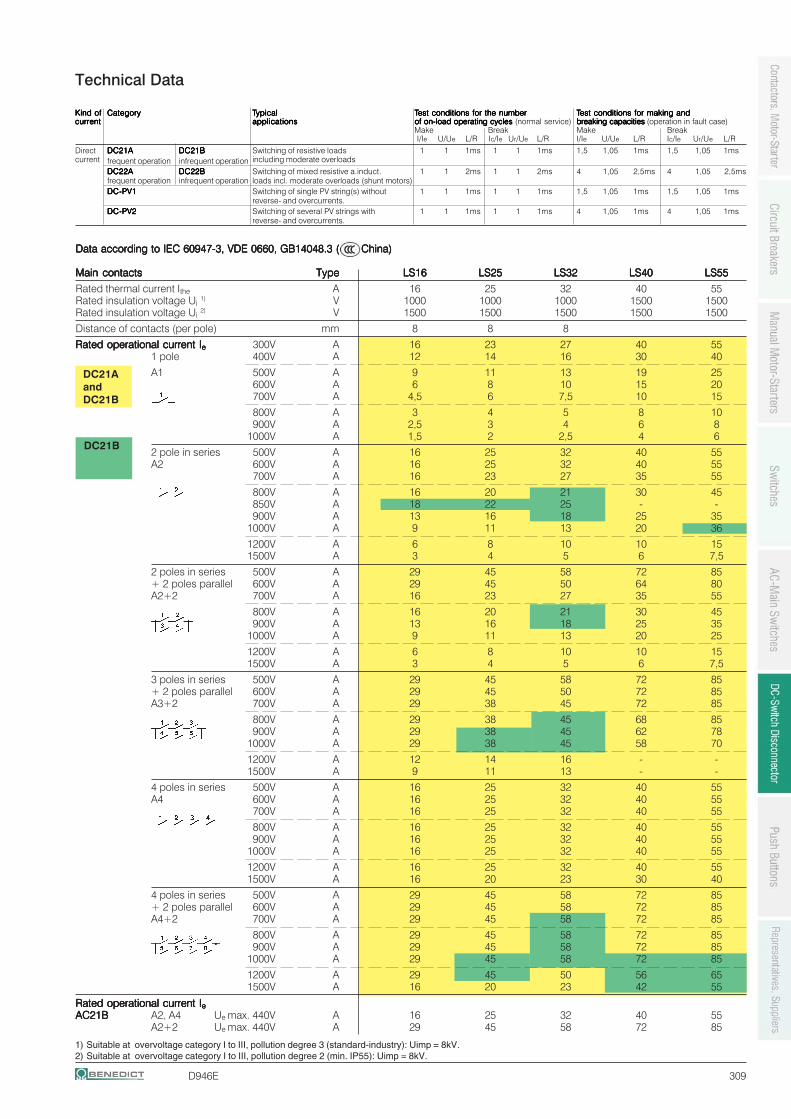
D946E 309
1) Suitable at overvoltage category I to III, pollution degree 3 (standard-industry): Uimp = 8kV.2) Suitable at overvoltage category I to III, pollution degree 2 (min. IP55): Uimp = 8kV.
Kind ofKind ofKind ofKind ofKind of CategoryCategoryCategoryCategoryCategory TTTTTypicalypicalypicalypicalypical TTTTTest conditions for the numberest conditions for the numberest conditions for the numberest conditions for the numberest conditions for the number TTTTTest conditions for making est conditions for making est conditions for making est conditions for making est conditions for making andandandandandcurrentcurrentcurrentcurrentcurrent applicationsapplicationsapplicationsapplicationsapplications of on-load operating cycles of on-load operating cycles of on-load operating cycles of on-load operating cycles of on-load operating cycles (normal service) breakingbreakingbreakingbreakingbreaking capacitiescapacitiescapacitiescapacitiescapacities (operation in fault case)
Make Break Make BreakI/Ie U/Ue L/R Ic/Ie Ur/Ue L/R I/Ie U/Ue L/R Ic/Ie Ur/Ue L/R
Direct DC21ADC21ADC21ADC21ADC21A DC21BDC21BDC21BDC21BDC21B Switching of resistive loads 1 1 1ms 1 1 1ms 1,5 1,05 1ms 1,5 1,05 1mscurrent frequent operation infrequent operation including moderate overloads
DC22ADC22ADC22ADC22ADC22A DC22BDC22BDC22BDC22BDC22B Switching of mixed resistive a.induct. 1 1 2ms 1 1 2ms 4 1,05 2,5ms 4 1,05 2,5msfrequent operation infrequent operation loads incl. moderate overloads (shunt motors)DCDCDCDCDC-PV1-PV1-PV1-PV1-PV1 Switching of single PV string(s) without 1 1 1ms 1 1 1ms 1,5 1,05 1ms 1,5 1,05 1ms
reverse- and overcurrents.DCDCDCDCDC-PV2-PV2-PV2-PV2-PV2 Switching of several PV strings with 1 1 1ms 1 1 1ms 4 1,05 1ms 4 1,05 1ms
reverse- and overcurrents.
Technical Data
DC21B
DC21AandDC21B
Data according to IEC 60947-3, VDE 0660, GB14048.3 (Data according to IEC 60947-3, VDE 0660, GB14048.3 (Data according to IEC 60947-3, VDE 0660, GB14048.3 (Data according to IEC 60947-3, VDE 0660, GB14048.3 (Data according to IEC 60947-3, VDE 0660, GB14048.3 ( China) China) China) China) China)
Main contactsMain contactsMain contactsMain contactsMain contacts TypeTypeTypeTypeType LS16LS16LS16LS16LS16 LS25LS25LS25LS25LS25 LS32LS32LS32LS32LS32 LS40LS40LS40LS40LS40 LS55LS55LS55LS55LS55
Rated thermal current Ithe A 16 25 32 40 55Rated insulation voltage Ui 1) V 1000 1000 1000 1500 1500Rated insulation voltage Ui 2) V 1500 1500 1500 1500 1500
Distance of contacts (per pole) mm 8 8 8
Rated operational current IRated operational current IRated operational current IRated operational current IRated operational current Ieeeee 300V A 16 23 27 40 551 pole 400V A 12 14 16 30 40
A1 500V A 9 11 13 19 25600V A 6 8 10 15 20700V A 4,5 6 7,5 10 15
800V A 3 4 5 8 10900V A 2,5 3 4 6 8
1000V A 1,5 2 2,5 4 6
2 pole in series 500V A 16 25 32 40 55A2 600V A 16 25 32 40 55
700V A 16 23 27 35 55
800V A 16 20 21 30 45850V A 18 22 25 - -900V A 13 16 18 25 35
1000V A 9 11 13 20 36
1200V A 6 8 10 10 151500V A 3 4 5 6 7,5
2 poles in series 500V A 29 45 58 72 85+ 2 poles parallel 600V A 29 45 50 64 80A2+2 700V A 16 23 27 35 55
800V A 16 20 21 30 45900V A 13 16 18 25 35
1000V A 9 11 13 20 25
1200V A 6 8 10 10 151500V A 3 4 5 6 7,5
3 poles in series 500V A 29 45 58 72 85+ 2 poles parallel 600V A 29 45 50 72 85A3+2 700V A 29 38 45 72 85
800V A 29 38 45 68 85900V A 29 38 45 62 78
1000V A 29 38 45 58 70
1200V A 12 14 16 - -1500V A 9 11 13 - -
4 poles in series 500V A 16 25 32 40 55A4 600V A 16 25 32 40 55
700V A 16 25 32 40 55
800V A 16 25 32 40 55900V A 16 25 32 40 55
1000V A 16 25 32 40 55
1200V A 16 25 32 40 551500V A 16 20 23 30 40
4 poles in series 500V A 29 45 58 72 85+ 2 poles parallel 600V A 29 45 58 72 85A4+2 700V A 29 45 58 72 85
800V A 29 45 58 72 85900V A 29 45 58 72 85
1000V A 29 45 58 72 85
1200V A 29 45 50 56 651500V A 16 20 23 42 55
Rated operational current IRated operational current IRated operational current IRated operational current IRated operational current IeeeeeAC21BAC21BAC21BAC21BAC21B A2, A4 Ue max. 440V A 16 25 32 40 55
A2+2 Ue max. 440V A 29 45 58 72 85
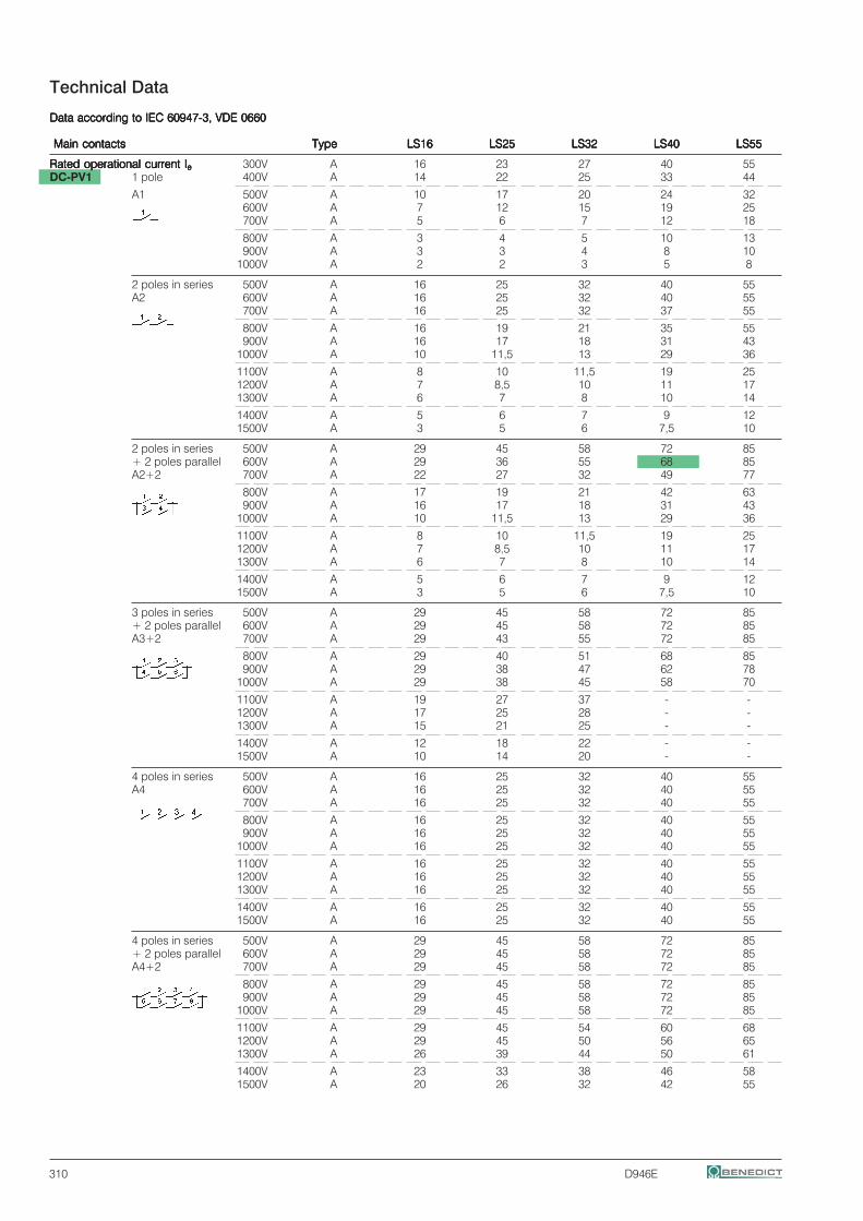
310 D946E
Technical Data
Data according to IEC 60947-3, VDE 0660Data according to IEC 60947-3, VDE 0660Data according to IEC 60947-3, VDE 0660Data according to IEC 60947-3, VDE 0660Data according to IEC 60947-3, VDE 0660
Main contacts Main contacts Main contacts Main contacts Main contacts TypeTypeTypeTypeType LS16LS16LS16LS16LS16 LS25LS25LS25LS25LS25 LS32LS32LS32LS32LS32 LS40LS40LS40LS40LS40 LS55LS55LS55LS55LS55
Rated operational current IRated operational current IRated operational current IRated operational current IRated operational current Ieeeee 300V A 16 23 27 40 55DC-PV1 1 pole 400V A 14 22 25 33 44
A1 500V A 10 17 20 24 32600V A 7 12 15 19 25700V A 5 6 7 12 18
800V A 3 4 5 10 13900V A 3 3 4 8 10
1000V A 2 2 3 5 8
2 poles in series 500V A 16 25 32 40 55A2 600V A 16 25 32 40 55
700V A 16 25 32 37 55
800V A 16 19 21 35 55900V A 16 17 18 31 43
1000V A 10 11,5 13 29 36
1100V A 8 10 11,5 19 251200V A 7 8,5 10 11 171300V A 6 7 8 10 14
1400V A 5 6 7 9 121500V A 3 5 6 7,5 10
2 poles in series 500V A 29 45 58 72 85+ 2 poles parallel 600V A 29 36 55 68 85A2+2 700V A 22 27 32 49 77
800V A 17 19 21 42 63900V A 16 17 18 31 43
1000V A 10 11,5 13 29 36
1100V A 8 10 11,5 19 251200V A 7 8,5 10 11 171300V A 6 7 8 10 14
1400V A 5 6 7 9 121500V A 3 5 6 7,5 10
3 poles in series 500V A 29 45 58 72 85+ 2 poles parallel 600V A 29 45 58 72 85A3+2 700V A 29 43 55 72 85
800V A 29 40 51 68 85900V A 29 38 47 62 78
1000V A 29 38 45 58 70
1100V A 19 27 37 - -1200V A 17 25 28 - -1300V A 15 21 25 - -
1400V A 12 18 22 - -1500V A 10 14 20 - -
4 poles in series 500V A 16 25 32 40 55A4 600V A 16 25 32 40 55
700V A 16 25 32 40 55
800V A 16 25 32 40 55900V A 16 25 32 40 55
1000V A 16 25 32 40 55
1100V A 16 25 32 40 551200V A 16 25 32 40 551300V A 16 25 32 40 55
1400V A 16 25 32 40 551500V A 16 25 32 40 55
4 poles in series 500V A 29 45 58 72 85+ 2 poles parallel 600V A 29 45 58 72 85A4+2 700V A 29 45 58 72 85
800V A 29 45 58 72 85900V A 29 45 58 72 85
1000V A 29 45 58 72 85
1100V A 29 45 54 60 681200V A 29 45 50 56 651300V A 26 39 44 50 61
1400V A 23 33 38 46 581500V A 20 26 32 42 55
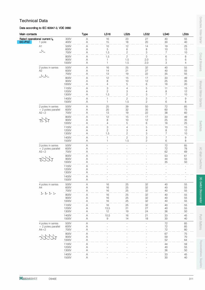
D946E 311
Technical Data
Data according to IEC 60947-3, VDE 0660Data according to IEC 60947-3, VDE 0660Data according to IEC 60947-3, VDE 0660Data according to IEC 60947-3, VDE 0660Data according to IEC 60947-3, VDE 0660
Main contactsMain contactsMain contactsMain contactsMain contacts TypeTypeTypeTypeType LS16LS16LS16LS16LS16 LS25LS25LS25LS25LS25 LS32LS32LS32LS32LS32 LS40LS40LS40LS40LS40 LS55LS55LS55LS55LS55
Rated operational current IRated operational current IRated operational current IRated operational current IRated operational current Ieeeee 300V A 16 23 27 40 55DC-PV2 1 pole 400V A 15 18 20 30 40
A1 500V A 10 12 14 19 25600V A 5 6 8 10 13700V A 1,5 2 3 7 10
800V A 1,5 2 3 6 8900V A 1 1,5 2,0 5 6
1000V A 1 1,5 2,0 3 4
2 poles in series 500V A 16 25 32 40 55A2 600V A 14 21 27 40 55
700V A 13 19 22 35 55
800V A 12 15 17 33 49900V A 8 10 12 25 35
1000V A 4 5 6 16 20
1100V A 3 4 5 11 151200V A 2 3 4 8 121300V A 1,5 2 3 7 10
1400V A 1 2 3 7 91500V A 1 1,5 2 6 8
2 poles in series 500V A 25 39 50 72 85+ 2 poles parallel 600V A 20 32 35 60 75A2+2 700V A 13 19 22 38 60
800V A 12 15 17 33 49900V A 8 10 12 25 35
1000V A 4 5 6 16 25
1100V A 3 4 5 10 151200V A 2 3 4 8 121300V A 1,5 2 3 7 10
1400V A 1 2 3 7 91500V A 1 1,5 2 6 8
3 poles in series 500V A - - - 72 85+ 2 poles parallel 600V A - - - 72 78A3+2 700V A - - - 62 69
800V A - - - 53 61900V A - - - 44 55
1000V A - - - 35 50
1100V A - - - - -1200V A - - - - -1300V A - - - - -
1400V A - - - - -1500V A - - - - -
4 poles in series 500V A 16 25 32 40 55A4 600V A 16 25 32 40 55
700V A 16 25 32 40 55
800V A 16 25 32 40 55900V A 16 25 32 40 55
1000V A 16 25 32 40 55
1100V A 16 25 32 40 551200V A 13,5 21 27 40 551300V A 12 19 24 36 50
1400V A 10,5 16 21 33 451500V A 9 14 18 30 40
4 poles in series 500V A - - - 72 85+ 2 poles parallel 600V A - - - 72 85A4+2 700V A - - - 72 80
800V A - - - 67 75900V A - - - 59 70
1000V A - - - 52 64
1100V A - - - 44 591200V A - - - 40 551300V A - - - 36 50
1400V A - - - 33 451500V A - - - 30 40
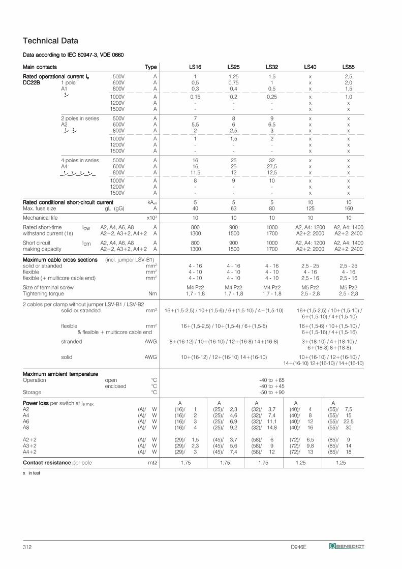
312 D946E
Technical Data
Data according to IEC 60947-3, VDE 0660Data according to IEC 60947-3, VDE 0660Data according to IEC 60947-3, VDE 0660Data according to IEC 60947-3, VDE 0660Data according to IEC 60947-3, VDE 0660
Main contactsMain contactsMain contactsMain contactsMain contacts TypeTypeTypeTypeType LS16LS16LS16LS16LS16 LS25LS25LS25LS25LS25 LS32LS32LS32LS32LS32 LS40LS40LS40LS40LS40 LS55LS55LS55LS55LS55
Rated operational current IRated operational current IRated operational current IRated operational current IRated operational current Ieeeee 500V A 1 1,25 1,5 x 2,5DC22BDC22BDC22BDC22BDC22B 1 pole 600V A 0,5 0,75 1 x 2,0
A1 800V A 0,3 0,4 0,5 x 1,5
1000V A 0,15 0,2 0,25 x 1,01200V A - - - x x1500V A - - - x x
2 poles in series 500V A 7 8 9 x xA2 600V A 5,5 6 6,5 x x
800V A 2 2,5 3 x x
1000V A 1 1,5 2 x x1200V A - - - x x1500V A - - - x x
4 poles in series 500V A 16 25 32 x xA4 600V A 16 25 27,5 x x
800V A 11,5 12 12,5 x x
1000V A 8 9 10 x x1200V A - - - x x1500V A - - - x x
Rated conditional short-circuit currentRated conditional short-circuit currentRated conditional short-circuit currentRated conditional short-circuit currentRated conditional short-circuit current kAeff 5 5 5 10 10Max. fuse size gL (gG) A 40 63 80 125 160
Mechanical life x103 10 10 10 10 10
Rated short-time Icw A2, A4, A6, A8 A 800 900 1000 A2, A4: 1200 A2, A4: 1400withstand current (1s) A2+2, A3+2, A4+2 A 1300 1500 1700 A2+2: 2000 A2+2: 2400
Short circuit Icm A2, A4, A6, A8 A 800 900 1000 A2, A4: 1200 A2, A4: 1400making capacity A2+2, A3+2, A4+2 A 1300 1500 1700 A2+2: 2000 A2+2: 2400
Maximum cable cross sectionsMaximum cable cross sectionsMaximum cable cross sectionsMaximum cable cross sectionsMaximum cable cross sections (incl. jumper LSV-B1)solid or stranded mm2 4 - 16 4 - 16 4 - 16 2,5 - 25 2,5 - 25flexible mm2 4 - 10 4 - 10 4 - 10 4 - 16 4 - 16flexible (+ multicore cable end) mm2 4 - 10 4 - 10 4 - 10 2,5 - 16 2,5 - 16
Size of terminal screw M4 Pz2 M4 Pz2 M4 Pz2 M5 Pz2 M5 Pz2Tightening torque Nm 1,7 - 1,8 1,7 - 1,8 1,7 - 1,8 2,5 - 2,8 2,5 - 2,8
2 cables per clamp without jumper LSV-B1 / LSV-B2solid or stranded mm2 16+(1,5-2,5) / 10+(1,5-6) / 6+(1,5-10) / 4+(1,5-10) 16+(1,5-2,5) / 10+(1,5-10) /
6+(1,5-10) / 4+(1,5-10)
flexible mm2 16+(1,5-2,5) / 10+(1,5-4) / 6+(1,5-6) 16+(1,5-6) / 10+(1,5-10) /& flexible + multicore cable end 6+(1,5-16) / 4+(1,5-16)
stranded AWG 8+(16-12) / 10+(16-10) / 12+(16-8) 14+(16-8) 3+(18-10) / 4+(18-10) /6+(18-8) 8+(18-8)
solid AWG 10+(16-12) / 12+(16-10) 14+(16-10) 10+(16-10) / 12+(16-10) /14+(16-10) 12+(16-10) / 14+(16-10)
Maximum ambient temperatureMaximum ambient temperatureMaximum ambient temperatureMaximum ambient temperatureMaximum ambient temperatureOperation open °C -40 to +65
enclosed °C -40 to +45Storage °C -50 to +90
Power loss Power loss Power loss Power loss Power loss per switch at Ie max. A A A A AA2 (A)/ W (16)/ 1 (25)/ 2,3 (32)/ 3,7 (40)/ 4 (55)/ 7,5A4 (A)/ W (16)/ 2 (25)/ 4,6 (32)/ 7,4 (40)/ 8 (55)/ 15A6 (A)/ W (16)/ 3 (25)/ 6,9 (32)/ 11,1 (40)/ 12 (55)/ 22,5A8 (A)/ W (16)/ 4 (25)/ 9,2 (32)/ 14,8 (40)/ 16 (55)/ 30
A2+2 (A)/ W (29)/ 1,5 (45)/ 3,7 (58)/ 6 (72)/ 6,5 (85)/ 9A3+2 (A)/ W (29)/ 2,3 (45)/ 5,6 (58)/ 9 (72)/ 9,8 (85)/ 14A4+2 (A)/ W (29)/ 3 (45)/ 7,4 (58)/ 12 (72)/ 13 (85)/ 18
Contact resistance per pole mΩ 1,75 1,75 1,75 1,25 1,25
x in test
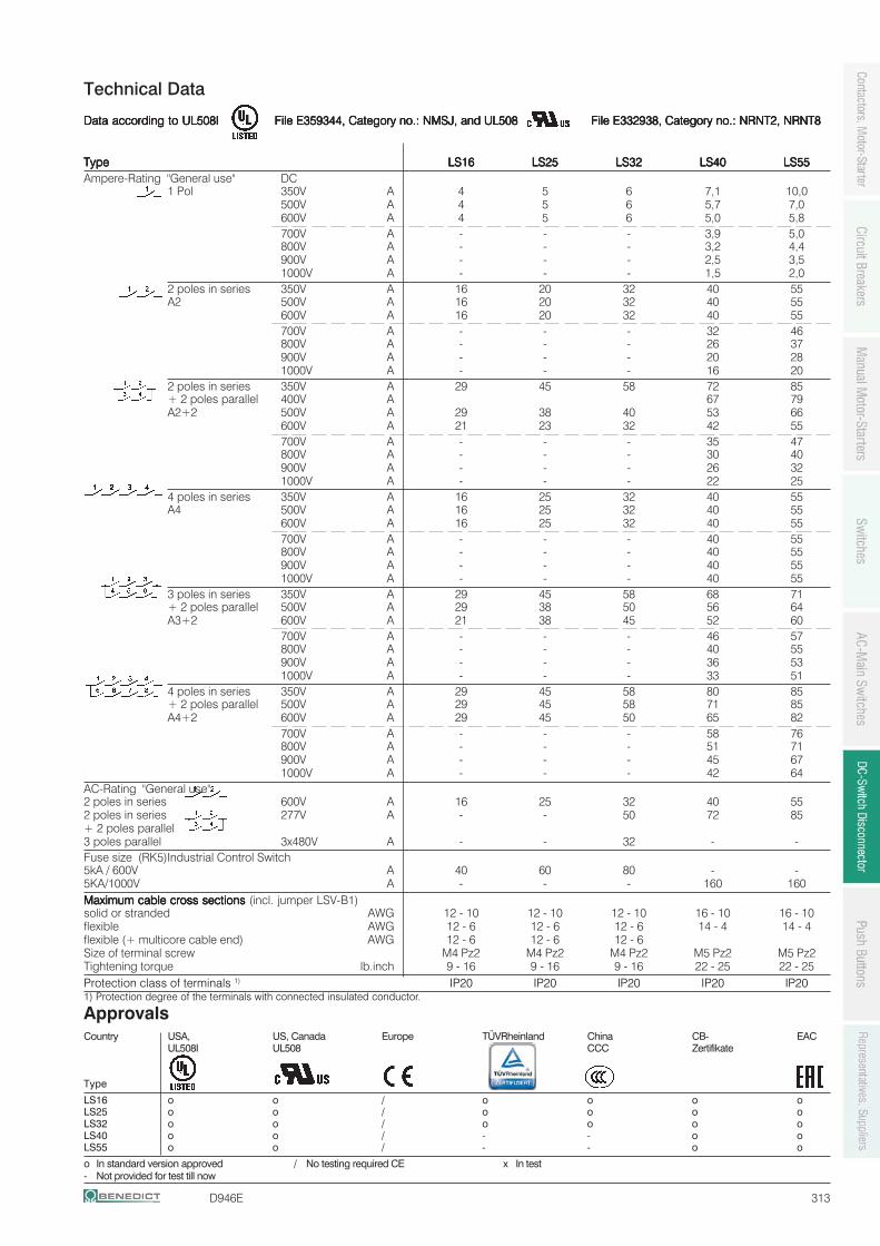
D946E 313
Technical Data
Data according to Data according to Data according to Data according to Data according to UL508IUL508IUL508IUL508IUL508I File E359344, Category no.: NMSJ, and UL508 File E332938, Category no.: NRNT2, NRNT8 File E359344, Category no.: NMSJ, and UL508 File E332938, Category no.: NRNT2, NRNT8 File E359344, Category no.: NMSJ, and UL508 File E332938, Category no.: NRNT2, NRNT8 File E359344, Category no.: NMSJ, and UL508 File E332938, Category no.: NRNT2, NRNT8 File E359344, Category no.: NMSJ, and UL508 File E332938, Category no.: NRNT2, NRNT8
TTTTTypeypeypeypeype LS16LS16LS16LS16LS16 LS25LS25LS25LS25LS25 LS32LS32LS32LS32LS32 LS40LS40LS40LS40LS40 LS55LS55LS55LS55LS55Ampere-Rating "General use" DC
1 Pol 350V A 4 5 6 7,1 10,0500V A 4 5 6 5,7 7,0600V A 4 5 6 5,0 5,8700V A - - - 3,9 5,0800V A - - - 3,2 4,4900V A - - - 2,5 3,51000V A - - - 1,5 2,0
2 poles in series 350V A 16 20 32 40 55A2 500V A 16 20 32 40 55
600V A 16 20 32 40 55700V A - - - 32 46800V A - - - 26 37900V A - - - 20 281000V A - - - 16 20
2 poles in series 350V A 29 45 58 72 85+ 2 poles parallel 400V A 67 79A2+2 500V A 29 38 40 53 66
600V A 21 23 32 42 55700V A - - - 35 47800V A - - - 30 40900V A - - - 26 321000V A - - - 22 25
4 poles in series 350V A 16 25 32 40 55A4 500V A 16 25 32 40 55
600V A 16 25 32 40 55700V A - - - 40 55800V A - - - 40 55900V A - - - 40 551000V A - - - 40 55
3 poles in series 350V A 29 45 58 68 71+ 2 poles parallel 500V A 29 38 50 56 64A3+2 600V A 21 38 45 52 60
700V A - - - 46 57800V A - - - 40 55900V A - - - 36 531000V A - - - 33 51
4 poles in series 350V A 29 45 58 80 85+ 2 poles parallel 500V A 29 45 58 71 85A4+2 600V A 29 45 50 65 82
700V A - - - 58 76800V A - - - 51 71900V A - - - 45 671000V A - - - 42 64
AC-Rating "General use"2 poles in series 600V A 16 25 32 40 552 poles in series 277V A - - 50 72 85+ 2 poles parallel3 poles parallel 3x480V A - - 32 - -Fuse size (RK5)Industrial Control Switch5kA / 600V A 40 60 80 - -5KA/1000V A - - - 160 160Maximum cable cross sections Maximum cable cross sections Maximum cable cross sections Maximum cable cross sections Maximum cable cross sections (incl. jumper LSV-B1)solid or stranded AWG 12 - 10 12 - 10 12 - 10 16 - 10 16 - 10flexible AWG 12 - 6 12 - 6 12 - 6 14 - 4 14 - 4flexible (+ multicore cable end) AWG 12 - 6 12 - 6 12 - 6Size of terminal screw M4 Pz2 M4 Pz2 M4 Pz2 M5 Pz2 M5 Pz2Tightening torque lb.inch 9 - 16 9 - 16 9 - 16 22 - 25 22 - 25Protection class of terminals 1) IP20 IP20 IP20 IP20 IP201) Protection degree of the terminals with connected insulated conductor.
ApprovalsCountry USA, US, Canada Europe TÜVRheinland China CB- EAC
UL508I UL508 CCC Zertifikate
Type
LS16 o o / o o o oLS25 o o / o o o oLS32 o o / o o o oLS40 o o / - - o oLS55 o o / - - o o
o In standard version approved / No testing required CE x In test- Not provided for test till now
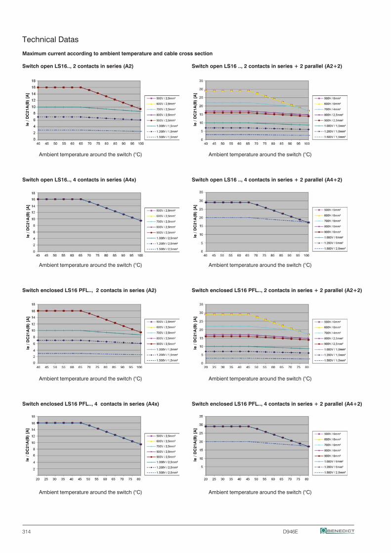
314 D946E
Technical Datas
Maximum current according to ambient temperature and cable cross section
Switch open LS16.., 2 contacts in series (A2) Switch open LS16 .., 2 contacts in series + 2 parallel (A2+2)
Ambient temperature around the switch (°C) Ambient temperature around the switch (°C)
Switch open LS16.., 4 contacts in series (A4x) Switch open LS16 .., 4 contacts in series + 2 parallel (A4+2)
Ambient temperature around the switch (°C) Ambient temperature around the switch (°C)
Switch enclosed LS16 PFL.., 2 contacts in series (A2) Switch enclosed LS16 PFL.., 2 contacts in series + 2 parallel (A2+2)
Ambient temperature around the switch (°C) Ambient temperature around the switch (°C)
Switch enclosed LS16 PFL.., 4 contacts in series (A4x) Switch enclosed LS16 PFL.., 4 contacts in series + 2 parallel (A4+2)
Ambient temperature around the switch (°C) Ambient temperature around the switch (°C)
Ie /
DC
21A
(B)
[A]
Ie /
DC
21A
(B)
[A]
Ie /
DC
21A
(B)
[A]
Ie /
DC
21A
(B)
[A]
Ie /
DC
21A
(B)
[A]
Ie /
DC
21A
(B)
[A]
Ie /
DC
21A
(B)
[A]
Ie /
DC
21A
(B)
[A]
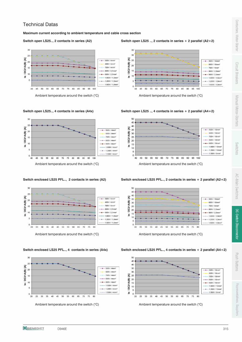
D946E 315
Technical Datas
Maximum current according to ambient temperature and cable cross section
Switch open LS25.., 2 contacts in series (A2) Switch open LS25 .., 2 contacts in series + 2 parallel (A2+2)
Ambient temperature around the switch (°C) Ambient temperature around the switch (°C)
Switch open LS25.., 4 contacts in series (A4x) Switch open LS25 .., 4 contacts in series + 2 parallel (A4+2)
Ambient temperature around the switch (°C) Ambient temperature around the switch (°C)
Switch enclosed LS25 PFL.., 2 contacts in series (A2) Switch enclosed LS25 PFL.., 2 contacts in series + 2 parallel (A2+2)
Ambient temperature around the switch (°C) Ambient temperature around the switch (°C)
Switch enclosed LS25 PFL.., 4 contacts in series (A4x) Switch enclosed LS25 PFL.., 4 contacts in series + 2 parallel (A4+2)
Ambient temperature around the switch (°C) Ambient temperature around the switch (°C)
Ie /
DC
21A
(B)
[A]
Ie /
DC
21A
(B)
[A]
Ie /
DC
21A
(B)
[A]
Ie /
DC
21A
(B)
[A]
Ie /
DC
21A
(B)
[A]
Ie /
DC
21A
(B)
[A]
Ie /
DC
21A
(B)
[A]
Ie /
DC
21A
(B)
[A]
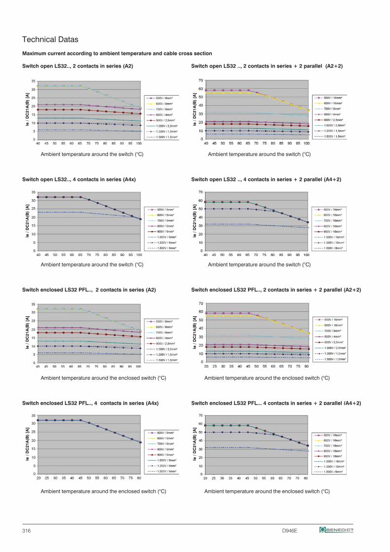
316 D946E
Technical Datas
Maximum current according to ambient temperature and cable cross section
Switch open LS32.., 2 contacts in series (A2) Switch open LS32 .., 2 contacts in series + 2 parallel (A2+2)
Ambient temperature around the switch (°C) Ambient temperature around the switch (°C)
Switch open LS32.., 4 contacts in series (A4x) Switch open LS32 .., 4 contacts in series + 2 parallel (A4+2)
Ambient temperature around the switch (°C) Ambient temperature around the switch (°C)
Switch enclosed LS32 PFL.., 2 contacts in series (A2) Switch enclosed LS32 PFL.., 2 contacts in series + 2 parallel (A2+2)
Ambient temperature around the enclosed switch (°C) Ambient temperature around the enclosed switch (°C)
Switch enclosed LS32 PFL.., 4 contacts in series (A4x) Switch enclosed LS32 PFL.., 4 contacts in series + 2 parallel (A4+2)
Ambient temperature around the enclosed switch (°C) Ambient temperature around the enclosed switch (°C)
Ie /
DC
21A
(B)
[A]
Ie /
DC
21A
(B)
[A]
Ie /
DC
21A
(B)
[A]
Ie /
DC
21A
(B)
[A]
Ie /
DC
21A
(B)
[A]
Ie /
DC
21A
(B)
[A]
Ie /
DC
21A
(B)
[A]
Ie /
DC
21A
(B)
[A]
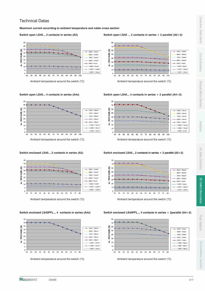
D946E 317
Technical Datas
Maximum current according to ambient temperature and cable cross section
Switch open LS40.., 2 contacts in series (A2) Switch open LS40 .., 2 contacts in series + 2 parallel (A2+2)
Ambient temperature around the switch (°C) Ambient temperature around the switch (°C)
Switch open LS40.., 4 contacts in series (A4x) Switch open LS40.., 4 contacts in series + 2 parallel (A4+2)
Ambient temperature around the switch (°C) Ambient temperature around the switch (°C)
Switch enclosed LS40.., 2 contacts in series (A2) Switch enclosed LS40.., 2 contacts in series + 2 parallel (A2+2)
Ambient temperature around the switch (°C) Ambient temperature around the switch (°C)
Switch enclosed LS40PFL.., 4 contacts in series (A4x) Switch enclosed LS40PFL.., 4 contacts in series + 2parallel (A4+2)
Ambient temperature around the switch (°C) Ambient temperature around the switch (°C)
Ie /
DC
21A
(B)
[A]
Ie /
DC
21A
(B)
[A]
Ie /
DC
21A
(B)
[A]
Ie /
DC
21A
(B)
[A]
Ie /
DC
21A
(B)
[A]
Ie /
DC
21A
(B)
[A]
Ie /
DC
21A
(B)
[A]
Ie /
DC
21A
(B)
[A]
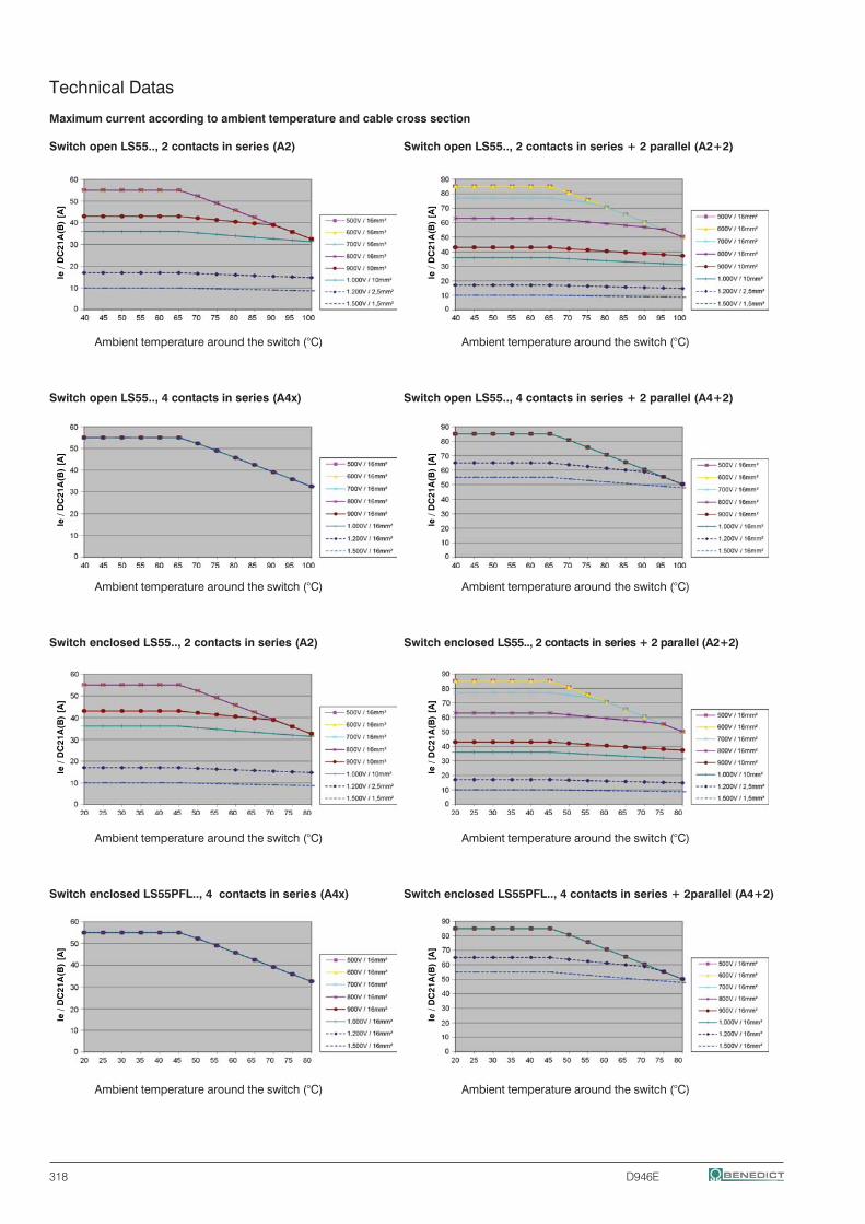
318 D946E
Technical Datas
Maximum current according to ambient temperature and cable cross section
Switch open LS55.., 2 contacts in series (A2) Switch open LS55.., 2 contacts in series + 2 parallel (A2+2)
Ambient temperature around the switch (°C) Ambient temperature around the switch (°C)
Switch open LS55.., 4 contacts in series (A4x) Switch open LS55.., 4 contacts in series + 2 parallel (A4+2)
Ambient temperature around the switch (°C) Ambient temperature around the switch (°C)
Switch enclosed LS55.., 2 contacts in series (A2) Switch enclosed LS55.., 2 contacts in series + 2 parallel (A2+2)
Ambient temperature around the switch (°C) Ambient temperature around the switch (°C)
Switch enclosed LS55PFL.., 4 contacts in series (A4x) Switch enclosed LS55PFL.., 4 contacts in series + 2parallel (A4+2)
Ambient temperature around the switch (°C) Ambient temperature around the switch (°C)
Ie /
DC
21A
(B)
[A]
Ie /
DC
21A
(B)
[A]
Ie /
DC
21A
(B)
[A]
Ie /
DC
21A
(B)
[A]
Ie /
DC
21A
(B)
[A]
Ie /
DC
21A
(B)
[A]
Ie /
DC
21A
(B)
[A]
Ie /
DC
21A
(B)
[A]
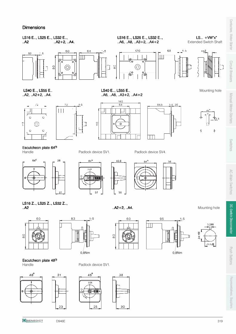
D946E 319
DimensionsDimensionsDimensionsDimensionsDimensions
LS16 ELS16 ELS16 ELS16 ELS16 E.., LS25 E.., LS25 E.., LS25 E.., LS25 E.., LS25 E.., LS32 E.., LS32 E.., LS32 E.., LS32 E.., LS32 E..,..,..,..,.., LS16 ELS16 ELS16 ELS16 ELS16 E.., LS25 E.., LS25 E.., LS25 E.., LS25 E.., LS25 E.., LS32 E.., LS32 E.., LS32 E.., LS32 E.., LS32 E..,..,..,..,.., LS... +VW“x“LS... +VW“x“LS... +VW“x“LS... +VW“x“LS... +VW“x“..A2..A2..A2..A2..A2 ..A2+2, ..A4...A2+2, ..A4...A2+2, ..A4...A2+2, ..A4...A2+2, ..A4. ..A6, ..A8, ..A3+2, ..A4+2..A6, ..A8, ..A3+2, ..A4+2..A6, ..A8, ..A3+2, ..A4+2..A6, ..A8, ..A3+2, ..A4+2..A6, ..A8, ..A3+2, ..A4+2 Extended Switch Shaft
LS40 E LS40 E LS40 E LS40 E LS40 E.., LS55 E.., LS55 E.., LS55 E.., LS55 E.., LS55 E.......... LS40 ELS40 ELS40 ELS40 ELS40 E.., LS55 E.., LS55 E.., LS55 E.., LS55 E.., LS55 E.......... Mounting hole..A2, ..A2+2, ..A4...A2, ..A2+2, ..A4...A2, ..A2+2, ..A4...A2, ..A2+2, ..A4...A2, ..A2+2, ..A4. ..A6, ..A8, ..A3+2, ..A4+2..A6, ..A8, ..A3+2, ..A4+2..A6, ..A8, ..A3+2, ..A4+2..A6, ..A8, ..A3+2, ..A4+2..A6, ..A8, ..A3+2, ..A4+2
Escutcheon plate 64Escutcheon plate 64Escutcheon plate 64Escutcheon plate 64Escutcheon plate 64Handle Padlock device SV1. Padlock device SV4.
LS16 ZLS16 ZLS16 ZLS16 ZLS16 Z.., LS25 Z.., LS25 Z.., LS25 Z.., LS25 Z.., LS25 Z.., LS32 Z.., LS32 Z.., LS32 Z.., LS32 Z.., LS32 Z..,..,..,..,..,..A2..A2..A2..A2..A2 ..A2+2, ..A4...A2+2, ..A4...A2+2, ..A4...A2+2, ..A4...A2+2, ..A4. Mounting hole
Escutcheon plate 48Escutcheon plate 48Escutcheon plate 48Escutcheon plate 48Escutcheon plate 48Handle Padlock device SV1.
0,8Nm0,8Nm
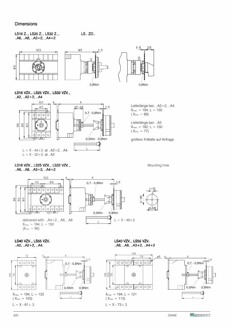
320 D946E
DimensionsDimensionsDimensionsDimensionsDimensions
LS16 ZLS16 ZLS16 ZLS16 ZLS16 Z.., LS25 Z.., LS25 Z.., LS25 Z.., LS25 Z.., LS25 Z.., LS32 Z.., LS32 Z.., LS32 Z.., LS32 Z.., LS32 Z..,..,..,..,.., LS.. ZOLS.. ZOLS.. ZOLS.. ZOLS.. ZO............A6, ..A8, ..A3+2, ..A4+2..A6, ..A8, ..A3+2, ..A4+2..A6, ..A8, ..A3+2, ..A4+2..A6, ..A8, ..A3+2, ..A4+2..A6, ..A8, ..A3+2, ..A4+2
LS16 VZVLS16 VZVLS16 VZVLS16 VZVLS16 VZV.., LS25 VZV.., LS25 VZV.., LS25 VZV.., LS25 VZV.., LS25 VZV.., LS32 VZV.., LS32 VZV.., LS32 VZV.., LS32 VZV.., LS32 VZV..,..,..,..,..,..A2, ..A2+2, ..A4..A2, ..A2+2, ..A4..A2, ..A2+2, ..A4..A2, ..A2+2, ..A4..A2, ..A2+2, ..A4
L = X - 44±3 at ..A2+2, ..A4.L = X - 32±3 at ..A2
LS16 LS16 LS16 LS16 LS16 VZVVZVVZVVZVVZV.., LS25 .., LS25 .., LS25 .., LS25 .., LS25 VZVVZVVZVVZVVZV.., LS32 V.., LS32 V.., LS32 V.., LS32 V.., LS32 VZVZVZVZVZV..,..,..,..,.., Mounting hole..A6, ..A8, ..A3+2, ..A4+2..A6, ..A8, ..A3+2, ..A4+2..A6, ..A8, ..A3+2, ..A4+2..A6, ..A8, ..A3+2, ..A4+2..A6, ..A8, ..A3+2, ..A4+2
delivered with: ..A4+2, ..A6, ..A8 L = X - 49±3Xmax. = 194, L = 150(Xmin. = 95)
LS40 VZVLS40 VZVLS40 VZVLS40 VZVLS40 VZV.., LS55 VZV.., LS55 VZV.., LS55 VZV.., LS55 VZV.., LS55 VZV.......... LS40 VZVLS40 VZVLS40 VZVLS40 VZVLS40 VZV.., LS55 VZV.., LS55 VZV.., LS55 VZV.., LS55 VZV.., LS55 VZV............A2, ..A2+2, ..A4...A2, ..A2+2, ..A4...A2, ..A2+2, ..A4...A2, ..A2+2, ..A4...A2, ..A2+2, ..A4. ..A6, ..A8, ..A3+2, ..A4+2..A6, ..A8, ..A3+2, ..A4+2..A6, ..A8, ..A3+2, ..A4+2..A6, ..A8, ..A3+2, ..A4+2..A6, ..A8, ..A3+2, ..A4+2
Lieferlänge bei: ..A2+2, ..A4.Xmax. = 194, L = 150( Xmin. = 89)
Lieferlänge bei: ..A2Xmax. = 182, L = 150( Xmin. = 77)
größere X-Maße auf Anfrage
Xmax. = 194, L = 133( Xmin. = 103)
L = X - 61± 3
Xmax. = 194, L = 121( Xmin. = 113)
L = X - 73± 3
0,8Nm0,8Nm
0,8Nm0,5Nm
0,8Nm0,5Nm
0,7 - 0,8Nm
0,8Nm0,5Nm
0,7 - 0,8Nm
0,8Nm0,5Nm
0,7 - 0,8Nm
0,7 - 0,8Nm
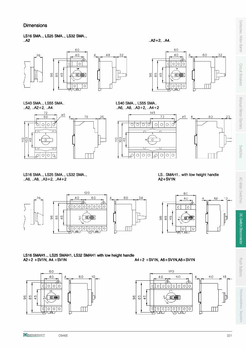
D946E 321
DimensionsDimensionsDimensionsDimensionsDimensions
LS16 SMALS16 SMALS16 SMALS16 SMALS16 SMA.., LS25 SMA.., LS25 SMA.., LS25 SMA.., LS25 SMA.., LS25 SMA.., LS32 SMA.., LS32 SMA.., LS32 SMA.., LS32 SMA.., LS32 SMA..,..,..,..,..,..A2..A2..A2..A2..A2 ..A2+2, ..A4...A2+2, ..A4...A2+2, ..A4...A2+2, ..A4...A2+2, ..A4.
LS40 SMALS40 SMALS40 SMALS40 SMALS40 SMA.., LS55 SMA.., LS55 SMA.., LS55 SMA.., LS55 SMA.., LS55 SMA.......... LS40 SMALS40 SMALS40 SMALS40 SMALS40 SMA.., LS55 SMA.., LS55 SMA.., LS55 SMA.., LS55 SMA.., LS55 SMA............A2, ..A2+2, ..A4...A2, ..A2+2, ..A4...A2, ..A2+2, ..A4...A2, ..A2+2, ..A4...A2, ..A2+2, ..A4. ..A6, ..A8, ..A3+2, ..A4+2..A6, ..A8, ..A3+2, ..A4+2..A6, ..A8, ..A3+2, ..A4+2..A6, ..A8, ..A3+2, ..A4+2..A6, ..A8, ..A3+2, ..A4+2
LLLLLS16 SMAS16 SMAS16 SMAS16 SMAS16 SMA.., LS25 SMA.., LS25 SMA.., LS25 SMA.., LS25 SMA.., LS25 SMA.., LS32 SMA.., LS32 SMA.., LS32 SMA.., LS32 SMA.., LS32 SMA..,..,..,..,.., LS.. SMAH1.. with low height handleLS.. SMAH1.. with low height handleLS.. SMAH1.. with low height handleLS.. SMAH1.. with low height handleLS.. SMAH1.. with low height handle..A6, ..A8, ..A3+2, ..A4+2..A6, ..A8, ..A3+2, ..A4+2..A6, ..A8, ..A3+2, ..A4+2..A6, ..A8, ..A3+2, ..A4+2..A6, ..A8, ..A3+2, ..A4+2 A2+SV1NA2+SV1NA2+SV1NA2+SV1NA2+SV1N
LS16 SMAH1.., LS25 SMAH1, LS32 SMAH1 with low height handleLS16 SMAH1.., LS25 SMAH1, LS32 SMAH1 with low height handleLS16 SMAH1.., LS25 SMAH1, LS32 SMAH1 with low height handleLS16 SMAH1.., LS25 SMAH1, LS32 SMAH1 with low height handleLS16 SMAH1.., LS25 SMAH1, LS32 SMAH1 with low height handleA2+2 +SV1N, A4.+SV1NA2+2 +SV1N, A4.+SV1NA2+2 +SV1N, A4.+SV1NA2+2 +SV1N, A4.+SV1NA2+2 +SV1N, A4.+SV1N A4+2 +SV1N, A6+SV1N,A8+SV1NA4+2 +SV1N, A6+SV1N,A8+SV1NA4+2 +SV1N, A6+SV1N,A8+SV1NA4+2 +SV1N, A6+SV1N,A8+SV1NA4+2 +SV1N, A6+SV1N,A8+SV1N
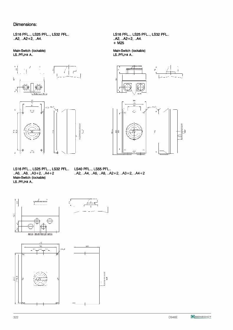
322 D946E
Dimensions:Dimensions:Dimensions:Dimensions:Dimensions:
LS16 PFLLS16 PFLLS16 PFLLS16 PFLLS16 PFL.., LS25 PFL.., LS25 PFL.., LS25 PFL.., LS25 PFL.., LS25 PFL.., LS32 PFL.., LS32 PFL.., LS32 PFL.., LS32 PFL.., LS32 PFL.......... LS16 PFLLS16 PFLLS16 PFLLS16 PFLLS16 PFL.., LS25 PFL.., LS25 PFL.., LS25 PFL.., LS25 PFL.., LS25 PFL.., LS32 PFL.., LS32 PFL.., LS32 PFL.., LS32 PFL.., LS32 PFL............A2, ..A2+2, ..A4...A2, ..A2+2, ..A4...A2, ..A2+2, ..A4...A2, ..A2+2, ..A4...A2, ..A2+2, ..A4. ..A2, ..A2+2, ..A4...A2, ..A2+2, ..A4...A2, ..A2+2, ..A4...A2, ..A2+2, ..A4...A2, ..A2+2, ..A4.
+ M25+ M25+ M25+ M25+ M25
Main-Switch (lockable)Main-Switch (lockable)Main-Switch (lockable)Main-Switch (lockable)Main-Switch (lockable) Main-Switch (lockable)Main-Switch (lockable)Main-Switch (lockable)Main-Switch (lockable)Main-Switch (lockable)LS..PFLH4 ALS..PFLH4 ALS..PFLH4 ALS..PFLH4 ALS..PFLH4 A.......... LS..PFLH4 ALS..PFLH4 ALS..PFLH4 ALS..PFLH4 ALS..PFLH4 A..........
LS16 PFLLS16 PFLLS16 PFLLS16 PFLLS16 PFL.., LS25 PFL.., LS25 PFL.., LS25 PFL.., LS25 PFL.., LS25 PFL.., LS32 PFL.., LS32 PFL.., LS32 PFL.., LS32 PFL.., LS32 PFL.......... LS40 PFLLS40 PFLLS40 PFLLS40 PFLLS40 PFL.., LS55 PFL.., LS55 PFL.., LS55 PFL.., LS55 PFL.., LS55 PFL............A6, ..A8, ..A3+2, ..A4+2..A6, ..A8, ..A3+2, ..A4+2..A6, ..A8, ..A3+2, ..A4+2..A6, ..A8, ..A3+2, ..A4+2..A6, ..A8, ..A3+2, ..A4+2 ..A2, ..A4, ..A6, ..A8, ..A2+2, ..A3+2, ..A4+2..A2, ..A4, ..A6, ..A8, ..A2+2, ..A3+2, ..A4+2..A2, ..A4, ..A6, ..A8, ..A2+2, ..A3+2, ..A4+2..A2, ..A4, ..A6, ..A8, ..A2+2, ..A3+2, ..A4+2..A2, ..A4, ..A6, ..A8, ..A2+2, ..A3+2, ..A4+2Main-Switch (lockable)Main-Switch (lockable)Main-Switch (lockable)Main-Switch (lockable)Main-Switch (lockable)LS..PFLH4 ALS..PFLH4 ALS..PFLH4 ALS..PFLH4 ALS..PFLH4 A..........
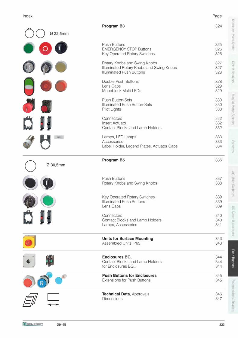
D946E 323
Index Page
Program B3 324
Push Buttons 325 EMERGENCY STOP Buttons 326 Key Operated Rotary Switches 326
Rotary Knobs and Swing Knobs 327 Illuminated Rotary Knobs and Swing Knobs 327 Illuminated Push Buttons 328
Double Push Buttons 328 Lens Caps 329 Monoblock-Multi-LEDs 329
Push Button-Sets 330 Illuminated Push Button-Sets 330 Pilot Lights 330
Connectors 332 Insert Actuato 332 Contact Blocks and Lamp Holders 332
Lamps, LED Lamps 333 Accessories 333 Label Holder, Legend Plates, Actuator Caps 334
Program B5 336
Push Buttons 337 Rotary Knobs and Swing Knobs 338
Key Operated Rotary Switches 339 Illuminated Push Buttons 339 Lens Caps 339
Connectors 340 Contact Blocks and Lamp Holders 340 Lamps, Accessories 341
Units for Surface Mounting 343 Assembled Units IP65 343
Enclosures BG. 344 Contact Blocks and Lamp Holders 344 for Enclosures BG.. 344
Push Buttons for Enclosures 345 Extensions for Push Buttons 345
Technical Data, Approvals 346 Dimensions 347
Ø 22,5mm
Ø 30,5mm
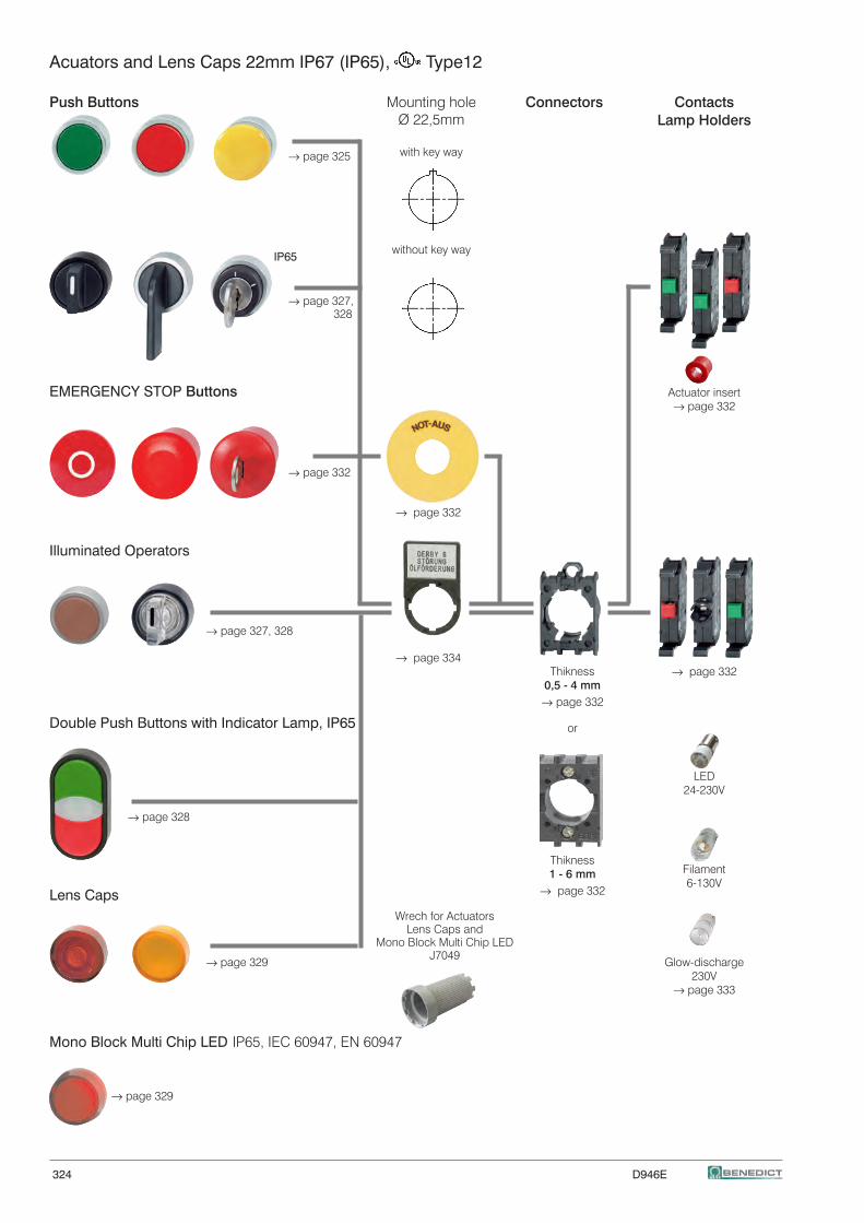
324 D946E
Acuators and Lens Caps 22mm IP67 (IP65), Type12
Push Buttons Connectors Contacts
Lamp Holders
→ page 325
IP65
→ page 327, 328
EMERGENCY STOP Buttons Actuator insert → page 332
→ page 332
→ page 332
Illuminated Operators
→ page 327, 328 → page 334 → page 332
Double Push Buttons with Indicator Lamp, IP65
LED 24-230V
→ page 328
Filament 6-130VLens Caps
→ page 329 Glow-discharge 230V → page 333 Mono Block Multi Chip LED IP65, IEC 60947, EN 60947
→ page 329
Mounting holeØ 22,5mm
with key way
without key way
Wrech for Actuators Lens Caps and
Mono Block Multi Chip LEDJ7049
Thikness1 - 6 mm
→ page 332
Thikness0,5 - 4 mm
→ page 332
or
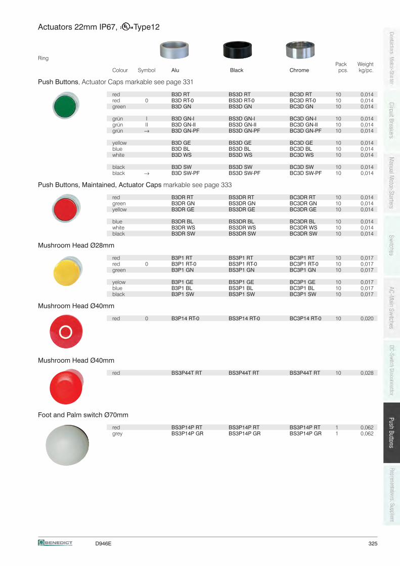
D946E 325
Actuators 22mm IP67, Type12
Ring Pack Weight Colour Symbol Alu Black Chrome pcs. kg/pc.
Push Buttons, Actuator Caps markable see page 331
red B3D RT BS3D RT BC3D RT 10 0,014 red 0 B3D RT-0 BS3D RT-0 BC3D RT-0 10 0,014 green B3D GN BS3D GN BC3D GN 10 0,014
grün I B3D GN-I BS3D GN-I BC3D GN-I 10 0,014 grün II B3D GN-II BS3D GN-II BC3D GN-II 10 0,014 grün → B3D GN-PF BS3D GN-PF BC3D GN-PF 10 0,014
yellow B3D GE BS3D GE BC3D GE 10 0,014 blue B3D BL BS3D BL BC3D BL 10 0,014 white B3D WS BS3D WS BC3D WS 10 0,014
black B3D SW BS3D SW BC3D SW 10 0,014 black → B3D SW-PF BS3D SW-PF BC3D SW-PF 10 0,014
Push Buttons, Maintained, Actuator Caps markable see page 333
red B3DR RT BS3DR RT BC3DR RT 10 0,014 green B3DR GN BS3DR GN BC3DR GN 10 0,014 yellow B3DR GE BS3DR GE BC3DR GE 10 0,014
blue B3DR BL BS3DR BL BC3DR BL 10 0,014 white B3DR WS BS3DR WS BC3DR WS 10 0,014 black B3DR SW BS3DR SW BC3DR SW 10 0,014
Mushroom Head Ø28mm
red B3P1 RT BS3P1 RT BC3P1 RT 10 0,017 red 0 B3P1 RT-0 BS3P1 RT-0 BC3P1 RT-0 10 0,017 green B3P1 GN BS3P1 GN BC3P1 GN 10 0,017
yelow B3P1 GE BS3P1 GE BC3P1 GE 10 0,017 blue B3P1 BL BS3P1 BL BC3P1 BL 10 0,017 black B3P1 SW BS3P1 SW BC3P1 SW 10 0,017
Mushroom Head Ø40mm
red 0 B3P14 RT-0 BS3P14 RT-0 BC3P14 RT-0 10 0,020
Mushroom Head Ø40mm
red BS3P44T RT BS3P44T RT BS3P44T RT 10 0,028
Foot and Palm switch Ø70mm
red BS3P14P RT BS3P14P RT BS3P14P RT 1 0,062 grey BS3P14P GR BS3P14P GR BS3P14P GR 1 0,062
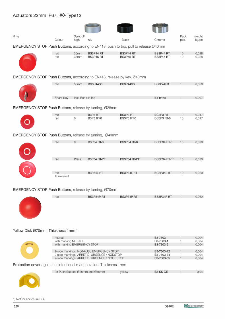
326 D946E
Actuators 22mm IP67, Type12
Ring Symbol/ Pack Weight Colour high Alu Black Chrome pcs. kg/pc EMERGENCY STOP Push Buttons, according to EN418, push to trip, pull to release Ø40mm
red 30mm BS3P44 RT BS3P44 RT BS3P44 RT 10 0,028 red 38mm BS3P45 RT BS3P45 RT BS3P45 RT 10 0,028
EMERGENCY STOP Push Buttons, according to EN418, release by key, Ø40mm
red 38mm BS3P44S3 BS3P44S3 BS3P44S3 1 0,050
Spare Key lock Ronis R455 B4-R455 1 0,007
EMERGENCY STOP Push Buttons, release by turning, Ø28mm
red B3P3 RT BS3P3 RT BC3P3 RT 10 0,017 red 0 B3P3 RT-0 BS3P3 RT-0 BC3P3 RT-0 10 0,017
EMERGENCY STOP Push Buttons, release by turning, Ø40mm
red 0 B3P34 RT-0 BS3P34 RT-0 BC3P34 RT-0 10 0,020
red Pfeile B3P34 RT-PF BS3P34 RT-PF BC3P34 RT-PF 10 0,020
red B3P34L RT BS3P34L RT BC3P34L RT 10 0,020 illuminated
EMERGENCY STOP Push Buttons, release by turning, Ø70mm
red BS3P34P RT BS3P34P RT BS3P34P RT 1 0,062
Yellow Disk Ø70mm, Thickness 1mm 1)
neutral B3-7603 1 0,004 with marking NOT-AUS B3-7603-1 1 0,004 with marking EMERGENCY STOP B3-7603-2 1 0,004
2-side markings: NOT-AUS / EMERGENCY STOP B3-7603-12 1 0,004 2-side markings: ARRET D`URGENCE / NØDSTOP B3-7603-34 1 0,004 2-side markings: ARRET D`URGENCE / NOODSTOP B3-7603-35 1 0,004
Protection cover against unintentional manupulation, Thickness 1mm
for Push Buttons Ø28mm and Ø40mm yellow B3-SK GE 1 0,04
1) Not for enclosure BG..
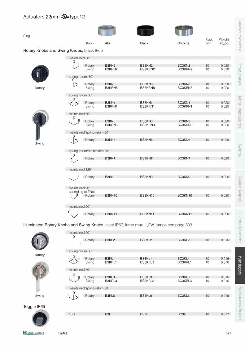
D946E 327
Actuators 22mm Type12
Ring Pack Weight Knob Alu Black Chrome pcs. kg/pc.
Rotary Knobs and Swing Knobs, black IP65
maintained 60°
Rotary B3KN2 BS3KN2 BC3KN2 10 0,020 Swing B3KRN2 BS3KRN2 BC3KRN2 10 0,020
spring return 60°
Rotary B3KN8 BS3KN8 BC3KN8 10 0,020 Swing B3KRN8 BS3KRN8 BC3KRN8 10 0,020
spring return 60°
Rotary B3KN1 BS3KN1 BC3KN1 10 0,020 Swing B3KRN1 BS3KRN1 BC3KRN1 10 0,020
maintained 60°
Rotary B3KN3 BS3KN3 BC3KN3 10 0,020 Swing B3KRN3 BS3KRN3 BC3KRN3 10 0,020
maintained/spring return 60°
Rotary B3KN6 BS3KN6 BC3KN6 10 0,020
spring return/maintained 60°
Rotary B3KN7 BS3KN7 BC3KN7 10 0,020
maintained 120°
Rotary B3KN9 BS3KN9 BC3KN9 10 0,020
maintained 90° according to EN81 Rotary B3KN10 BS3KN10 BC3KN10 10 0,020
maintained 90°
Rotary B3KN11 BS3KN11 BC3KN11 10 0,020
Illuminated Rotary Knobs and Swing Knobs, clear IP67, lamp max. 1,2W, lamps see page 333
maintained 90°
Rotary B3KL2 BS3KL2 BC3KL2 10 0,016
spring return 60°
Rotary B3KL1 BS3KL1 BC3KL1 10 0,016 Swing B3KRL1 BS3KRL1 BC3KRL1 10 0,016
maintained 60°
Rotary B3KL3 BS3KL3 BC3KL3 10 0,016 Swing B3KRL3 BS3KRL3 BC3KRL3 10 0,016
maintained/spring return 60°
Rotary B3KL6 BS3KL6 BC3KL6 10 0,016
Toggle IP65
O - I B3E BS3E BC3E 10 0,017
Swing
Rotary
Swing
Rotary
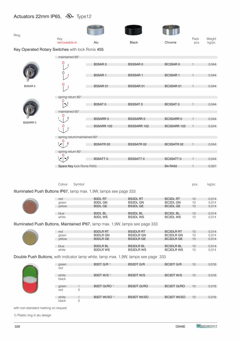
328 D946E
B3SAR 0
B3SARR 0
Actuators 22mm IP65, Type12
RingKey Pack Weightremoveable in Alu Black Chrome pcs. kg/pc.
Key Operated Rotary Switches with lock Ronis 455
maintained 60°
B3SAR 0 BS3SAR 0 BC3SAR 0 1 0,044 B3SAR 1 BS3SAR 1 BC3SAR 1 1 0,044 B3SAR 01 BS3SAR 01 BC3SAR 01 1 0,044
spring return 60°
B3SAT 0 BS3SAT 0 BC3SAT 0 1 0,044
maintained 60°
B3SARR 0 BS3SARR 0 BC3SARR 0 1 0,044 B3SARR 102 BS3SARR 102 BC3SARR 102 1 0,044
spring return/maintained 60°
B3SATR 02 BS3SATR 02 BC3SATR 02 1 0,044
spring return 60°
B3SATT 0 BS3SATT 0 BC3SATT 0 1 0,044
Spare Key lock Ronis R455 B4-R455 1 0,007
Colour Symbol pcs. kg/pc.
Illuminated Push Buttons IP67, lamp max. 1,9W, lamps see page 333
red B3DL RT BS3DL RT BC3DL RT 10 0,014 green B3DL GN BS3DL GN BC3DL GN 10 0,014 yellow B3DL GE BS3DL GE BC3DL GE 10 0,014
blue B3DL BL BS3DL BL BC3DL BL 10 0,014 white B3DL WS BS3DL WS BC3DL WS 10 0,014
Illuminated Push Buttons, Maintained IP67, lamp max. 1,9W, lamps see page 333
red B3DLR RT BS3DLR RT BC3DLR RT 10 0,014 green B3DLR GN BS3DLR GN BC3DLR GN 10 0,014 yellow B3DLR GE BS3DLR GE BC3DLR GE 10 0,014
blue B3DLR BL BS3DLR BL BC3DLR BL 10 0,014 white B3DLR WS BS3DLR WS BC3DLR WS 10 0,014
Double Push Buttons, with indicator lamp white, lamp max. 1,9W, lamps see page 333
green B3DT G/R 1) BS3DT G/R BC3DT G/R 10 0,016 red
white B3DT W/S 1) BS3DT W/S BC3DT W/S 10 0,016 black
green I B3DT GI/RO 1) BS3DT GI/RO BC3DT GI/RO 10 0,016 red 0
white I B3DT WI/SO 1) BS3DT WI/SO BC3DT WI/SO 10 0,016 black 0
with non-standard marking on request 1) Plastic ring in alu design
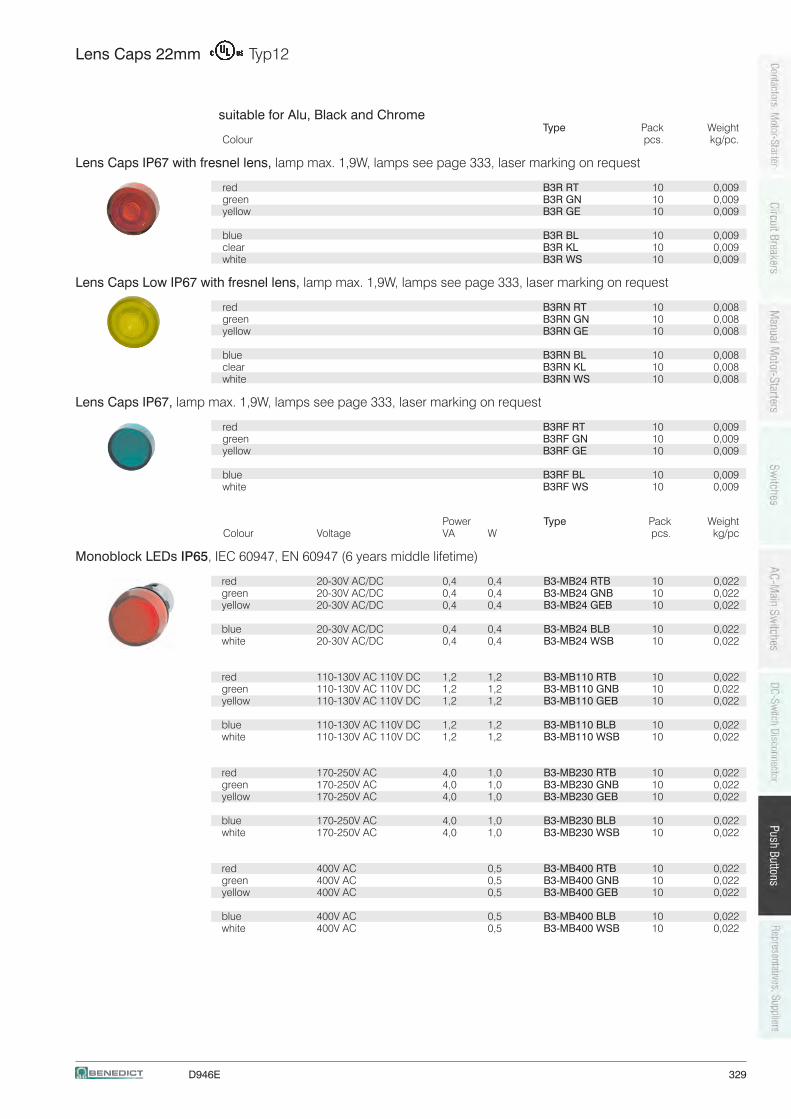
D946E 329
Lens Caps 22mm Typ12
suitable for Alu, Black and Chrome Type Pack Weight Colour pcs. kg/pc.
Lens Caps IP67 with fresnel lens, lamp max. 1,9W, lamps see page 333, laser marking on request red B3R RT 10 0,009 green B3R GN 10 0,009 yellow B3R GE 10 0,009
blue B3R BL 10 0,009 clear B3R KL 10 0,009 white B3R WS 10 0,009
Lens Caps Low IP67 with fresnel lens, lamp max. 1,9W, lamps see page 333, laser marking on request
red B3RN RT 10 0,008 green B3RN GN 10 0,008 yellow B3RN GE 10 0,008
blue B3RN BL 10 0,008 clear B3RN KL 10 0,008 white B3RN WS 10 0,008
Lens Caps IP67, lamp max. 1,9W, lamps see page 333, laser marking on request
red B3RF RT 10 0,009 green B3RF GN 10 0,009 yellow B3RF GE 10 0,009
blue B3RF BL 10 0,009 white B3RF WS 10 0,009
Power Type Pack WeightColour Voltage VA W pcs. kg/pc
Monoblock LEDs IP65, IEC 60947, EN 60947 (6 years middle lifetime)
red 20-30V AC/DC 0,4 0,4 B3-MB24 RTB 10 0,022green 20-30V AC/DC 0,4 0,4 B3-MB24 GNB 10 0,022yellow 20-30V AC/DC 0,4 0,4 B3-MB24 GEB 10 0,022
blue 20-30V AC/DC 0,4 0,4 B3-MB24 BLB 10 0,022white 20-30V AC/DC 0,4 0,4 B3-MB24 WSB 10 0,022
red 110-130V AC 110V DC 1,2 1,2 B3-MB110 RTB 10 0,022green 110-130V AC 110V DC 1,2 1,2 B3-MB110 GNB 10 0,022yellow 110-130V AC 110V DC 1,2 1,2 B3-MB110 GEB 10 0,022
blue 110-130V AC 110V DC 1,2 1,2 B3-MB110 BLB 10 0,022white 110-130V AC 110V DC 1,2 1,2 B3-MB110 WSB 10 0,022
red 170-250V AC 4,0 1,0 B3-MB230 RTB 10 0,022green 170-250V AC 4,0 1,0 B3-MB230 GNB 10 0,022yellow 170-250V AC 4,0 1,0 B3-MB230 GEB 10 0,022
blue 170-250V AC 4,0 1,0 B3-MB230 BLB 10 0,022white 170-250V AC 4,0 1,0 B3-MB230 WSB 10 0,022
red 400V AC 0,5 B3-MB400 RTB 10 0,022green 400V AC 0,5 B3-MB400 GNB 10 0,022yellow 400V AC 0,5 B3-MB400 GEB 10 0,022
blue 400V AC 0,5 B3-MB400 BLB 10 0,022white 400V AC 0,5 B3-MB400 WSB 10 0,022
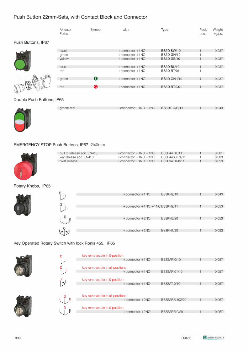
330 D946E
Push Button 22mm-Sets, with Contact Block and Connector
Aktuator Symbol with Type Pack Weight Farbe pcs. kg/pc.
Push Buttons, IP67
black +connector +1NO BS3D SW/10 1 0,037 green +connector +1NO BS3D GN/10 1 yellow +connector +1NO BS3D GE/10 1 0,037
blue +connector +1NO BS3D BL/10 1 0,037 red +connector +1NC BS3D RT/01 1
green +connector +1NO BS3D GN-I/10 1 0,037
red +connector +1NC BS3D RT-0/01 1 0,037
Double Push Buttons, IP65
green/ red +connector +1NO +1NC BS3DT G/R/11 1 0,049
EMERGENCY STOP Push Buttons, IP67 Ø40mm
pull to release acc. EN418 +connector +1NO +1NC BS3P44 RT/11 1 0,061 key release acc. EN418 +connector +1NO +1NC BS3P44S3 RT/11 1 0,083 twist release +connector +1NO +1NC BS3P34 RT-0/11 1 0,053
Rotary Knobs, IP65
+connector +1NO BS3KN2/10 1 0,043
+connector +1NO +1NC BS3KN2/11 1 0,053
+connector +2NO BS3KN3/20 1 0,053
+connector +2NO BS3KN1/20 1 0,053
Key Operated Rotary Switch with lock Ronis 455, IP65
key removeable in 0-position +connector +1NO BS3SAR 0/10 1 0,057
key removeable in all positions +connector +1NO BS3SAR 01/10 1 0,057
key removeable in 0-position +connector +1NO BS3SAT 0/10 1 0,057
key removeable in all positions +connector +2NO BS3SARR 102/20 1 0,067
key removeable in 0-position +connector +2NO BS3SARR 0/20 1 0,067
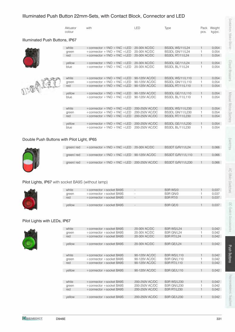
D946E 331
Illuminated Push Button 22mm-Sets, with Contact Block, Connector and LED
Aktuator with LED Type Pack Weightcolour pcs. kg/pc.
Illuminated Push Buttons, IP67
white +connector +1NO +1NC +LED 20-30V AC/DC BS3DL WS/11/L24 1 0,054 green +connector +1NO +1NC +LED 20-30V AC/DC BS3DL GN/11/L24 1 0,054 red +connector +1NO +1NC +LED 20-30V AC/DC BS3DL RT/11/L24 1 0,054
yellow +connector +1NO +1NC +LED 20-30V AC/DC BS3DL GE/11/L24 1 0,054 blue +connector +1NO +1NC +LED 20-30V AC/DC BS3DL BL/11/L24 1 0,054
white +connector +1NO +1NC +LED 90-120V AC/DC BS3DL WS/11/L110 1 0,054 green +connector +1NO +1NC +LED 90-120V AC/DC BS3DL GN/11/L110 1 0,054 red +connector +1NO +1NC +LED 90-120V AC/DC BS3DL RT/11/L110 1 0,054
yellow +connector +1NO +1NC +LED 90-120V AC/DC BS3DL GE/11/L110 1 0,054 blue +connector +1NO +1NC +LED 90-120V AC/DC BS3DL BL/11/L110 1 0,054
white +connector +1NO +1NC +LED 200-250V AC/DC BS3DL WS/11/L230 1 0,054 green +connector +1NO +1NC +LED 200-250V AC/DC BS3DL GN/11/L230 1 0,054 red +connector +1NO +1NC +LED 200-250V AC/DC BS3DL RT/11/L230 1 0,054
yellow +connector +1NO +1NC +LED 200-250V AC/DC BS3DL GE/11/L230 1 0,054 blue +connector +1NO +1NC +LED 200-250V AC/DC BS3DL BL/11/L230 1 0,054
Double Push Buttons with Pilot Light, IP65
green/ red +connector +1NO +1NC +LED 20-30V AC/DC BS3DT G/R/11/L24 1 0,066
green/ red +connector +1NO +1NC +LED 90-120V AC/DC BS3DT G/R/11/L110 1 0,066
green/ red +connector +1NO +1NC +LED 200-250V AC/DC BS3DT G/R/11/L230 1 0,066
Pilot Lights, IP67 with socket BA9S (without lamp)
white +connector +socket BA9S - B3R WS/0 1 0,037 green +connector +socket BA9S - B3R GN/0 1 0,037 red +connector +socket BA9S - B3R RT/0 1 0,037
yellow +connector +socket BA9S - B3R GE/0 1 0,037
Pilot Lights with LEDs, IP67
white +connector +socket BA9S 20-30V AC/DC B3R WS/L24 1 0,042 green +connector +socket BA9S 20-30V AC/DC B3R GN/L24 1 0,042 red +connector +socket BA9S 20-30V AC/DC B3R RT/L24 1 0,042
yellow +connector +socket BA9S 20-30V AC/DC B3R GE/L24 1 0,042
white +connector +socket BA9S 90-120V AC/DC B3R WS/L110 1 0,042 green +connector +socket BA9S 90-120V AC/DC B3R GN/L110 1 0,042 red +connector +socket BA9S 90-120V AC/DC B3R RT/L110 1 0,042
yellow +connector +socket BA9S 90-120V AC/DC B3R GE/L110 1 0,042
white +connector +socket BA9S 200-250V AC/DC B3R WS/L230 1 0,042 green +connector +socket BA9S 200-250V AC/DC B3R GN/L230 1 0,042 red +connector +socket BA9S 200-250V AC/DC B3R RT/L230 1 0,042
yellow +connector +socket BA9S 200-250V AC/DC B3R GE/L230 1 0,042
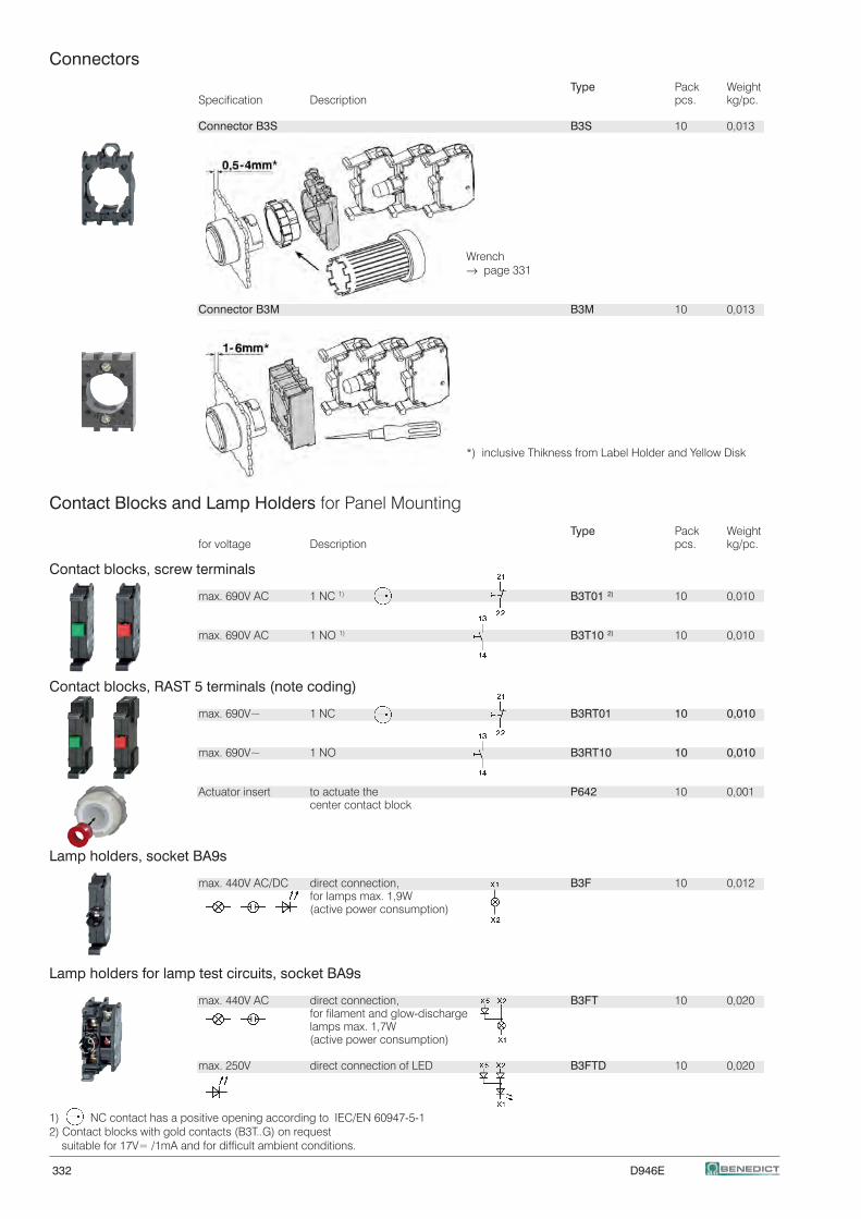
332 D946E
Connectors
Type Pack Weight Specification Description pcs. kg/pc.
Connector B3S B3S 10 0,013
Wrench → page 331
Connector B3M B3M 10 0,013
*) inclusive Thikness from Label Holder and Yellow Disk
Contact Blocks and Lamp Holders for Panel Mounting
Type Pack Weight for voltage Description pcs. kg/pc.
Contact blocks, screw terminals
max. 690V AC 1 NC 1) B3T01 2) 10 0,010
max. 690V AC 1 NO 1) B3T10 2) 10 0,010
Contact blocks, RAST 5 terminals (note coding)
max. 690V~ 1 NC B3RT01 10 0,010
max. 690V~ 1 NO B3RT10 10 0,010
Actuator insert to actuate the P642 10 0,001 center contact block
Lamp holders, socket BA9s
max. 440V AC/DC direct connection, B3F 10 0,012 for lamps max. 1,9W (active power consumption)
Lamp holders for lamp test circuits, socket BA9s
max. 440V AC direct connection, B3FT 10 0,020 for filament and glow-discharge lamps max. 1,7W (active power consumption)
max. 250V direct connection of LED B3FTD 10 0,020
1) NC contact has a positive opening according to IEC/EN 60947-5-12) Contact blocks with gold contacts (B3T..G) on request suitable for 17V= /1mA and for difficult ambient conditions.
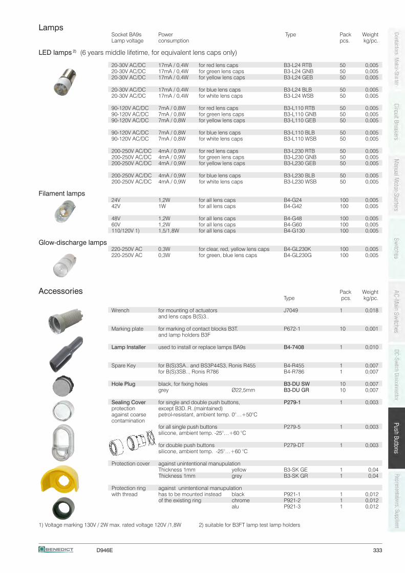
D946E 333
Lamps Socket BA9s Power Type Pack Weight Lamp voltage consumption pcs. kg/pc. LED lamps 2) (6 years middle lifetime, for equivalent lens caps only)
20-30V AC/DC 17mA / 0,4W for red lens caps B3-L24 RTB 50 0,005 20-30V AC/DC 17mA / 0,4W for green lens caps B3-L24 GNB 50 0,005 20-30V AC/DC 17mA / 0,4W for yellow lens caps B3-L24 GEB 50 0,005
20-30V AC/DC 17mA / 0,4W for blue lens caps B3-L24 BLB 50 0,005 20-30V AC/DC 17mA / 0,4W for white lens caps B3-L24 WSB 50 0,005
90-120V AC/DC 7mA / 0,8W for red lens caps B3-L110 RTB 50 0,005 90-120V AC/DC 7mA / 0,8W for green lens caps B3-L110 GNB 50 0,005 90-120V AC/DC 7mA / 0,8W for yellow lens caps B3-L110 GEB 50 0,005
90-120V AC/DC 7mA / 0,8W for blue lens caps B3-L110 BLB 50 0,005 90-120V AC/DC 7mA / 0,8W for white lens caps B3-L110 WSB 50 0,005
200-250V AC/DC 4mA / 0,9W for red lens caps B3-L230 RTB 50 0,005 200-250V AC/DC 4mA / 0,9W for green lens caps B3-L230 GNB 50 0,005 200-250V AC/DC 4mA / 0,9W for yellow lens caps B3-L230 GEB 50 0,005
200-250V AC/DC 4mA / 0,9W for blue lens caps B3-L230 BLB 50 0,005 200-250V AC/DC 4mA / 0,9W for white lens caps B3-L230 WSB 50 0,005
Filament lamps 24V 1,2W for all lens caps B4-G24 100 0,005 42V 1W for all lens caps B4-G42 100 0,005
48V 1,2W for all lens caps B4-G48 100 0,005 60V 1,2W for all lens caps B4-G60 100 0,005 110/120V 1) 1,5/1,8W for all lens caps B4-G130 100 0,005
Glow-discharge lamps 220-250V AC 0,3W for clear, red, yellow lens caps B4-GL230K 100 0,005 220-250V AC 0,3W for green, blue lens caps B4-GL230G 100 0,005
Accessories Pack Weight Type pcs. kg/pc.
Wrench for mounting of actuators J7049 1 0,018 and lens caps B(S)3..
Marking plate for marking of contact blocks B3T. P672-1 10 0,001 and lamp holders B3F
Lamp Installer used to install or replace lamps BA9s B4-7408 1 0,010
Spare Key for B(S)3SA.. and BS3P44S3, Ronis R455 B4-R455 1 0,007 for B(S)3SB.., Ronis R786 B4-R786 1 0,007
Hole Plug black, for fixing holes B3-DU SW 10 0,007 grey Ø22,5mm B3-DU GR 10 0,007
Sealing Cover for single and double push buttons, P279-1 1 0,003 protection except B3D..R..(maintained) against coarse petrol-resistant, ambient temp. 0°…+50°C contamination for all single push buttons P279-5 1 0,003 silicone, ambient temp. -25°…+60 °C
for double push buttons P279-DT 1 0,003 silicone, ambient temp. -25°…+60 °C
Protection cover against unintentional manupulation Thickness 1mm yellow B3-SK GE 1 0,04 Thickness 1mm grey B3-SK GR 1 0,04
Protection ring against unintentional manupulation with thread has to be mounted instead black P921-1 1 0,012 of the existing ring chrome P921-2 1 0,012 alu P921-3 1 0,012
1) Voltage marking 130V / 2W max. rated voltage 120V /1,8W 2) suitable for B3FT lamp test lamp holders
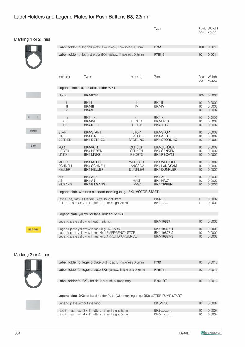
334 D946E
Label Holders and Legend Plates for Push Buttons B3, 22mm
Type Pack Weight pcs. kg/pc.
Marking 1 or 2 lines
Label holder for legend plate BK4, black, Thickness 0,8mm P751 100 0,001
Label holder for legend plate BK4, yellow, Thickness 0,8mm P751-3 10 0,001
marking Type marking Type Pack Weight pcs. kg/pc.
Legend plate alu, for label holder P751
blank BK4-9736 100 0,0002
I BK4-I II BK4-II 10 0,0002 III BK4-III IV BK4-IV 10 0,0002 V BK4-V 10 0,0002
→ BK4---> ← BK4-<-- 10 0,0002 0 I BK4-0-I H 0 A BK4-H 0 A 10 0,0002 0 I BK4-0___I 1 0 2 BK4-1 0 2 10 0,0002
START BK4-START STOP BK4-STOP 10 0,0002 EIN BK4-EIN AUS BK4-AUS 10 0,0002 BETRIEB BK4-BETRIEB STÖRUNG BK4-STÖRUNG 10 0,0002
VOR BK4-VOR ZURÜCK BK4-ZURÜCK 10 0,0002 HEBEN BK4-HEBEN SENKEN BK4-SENKEN 10 0,0002 LINKS BK4-LINKS RECHTS BK4-RECHTS 10 0,0002
MEHR BK4-MEHR WENIGER BK4-WENIGER 10 0,0002 SCHNELL BK4-SCHNELL LANGSAM BK4-LANGSAM 10 0,0002 HELLER BK4-HELLER DUNKLER BK4-DUNKLER 10 0,0002
AUF BK4-AUF ZU BK4-ZU 10 0,0002 AB BK4-AB HALT BK4-HALT 10 0,0002 EILGANG BK4-EILGANG TIPPEN BK4-TIPPEN 10 0,0002
Legend plate with non-standard marking (e. g.: BK4-MOTOR-START)
Text 1 line, max. 11 letters, letter height 3mm BK4-... 1 0,0002 Text 2 lines, max. 2 x 11 letters, letter height 3mm BK4-...-... 1 0,0002
Legend plate yellow, for label holder P751-3
Legend plate yellow without marking BK4-10827 10 0,0002
Legend plate yellow with marking NOT-AUS BK4-10827-1 10 0,0002 Legend plate yellow with marking EMERGENCY STOP BK4-10827-2 10 0,0002 Legend plate yellow with marking ARRET D`URGENCE BK4-10827-3 10 0,0002
Marking 3 or 4 lines
Label holder for legend plate BK8, black, Thickness 0,8mm P761 10 0,0013
Label holder for legend plate BK8, yellow, Thickness 0,8mm P761-3 10 0,0013
Label holder for BK8, for double push buttons only P761-DT 10 0,0013
Legend plate BK8 for label holder P761 (with marking e. g.: BK8-WATER-PUMP-START)
Legend plate without marking BK8-9736 10 0,0004
Text 3 lines, max. 3 x 11 letters, letter height 3mm BK8-...-...-... 10 0,0004 Text 4 lines, max. 4 x 11 letters, letter height 3mm BK8-...-...-... 10 0,0004
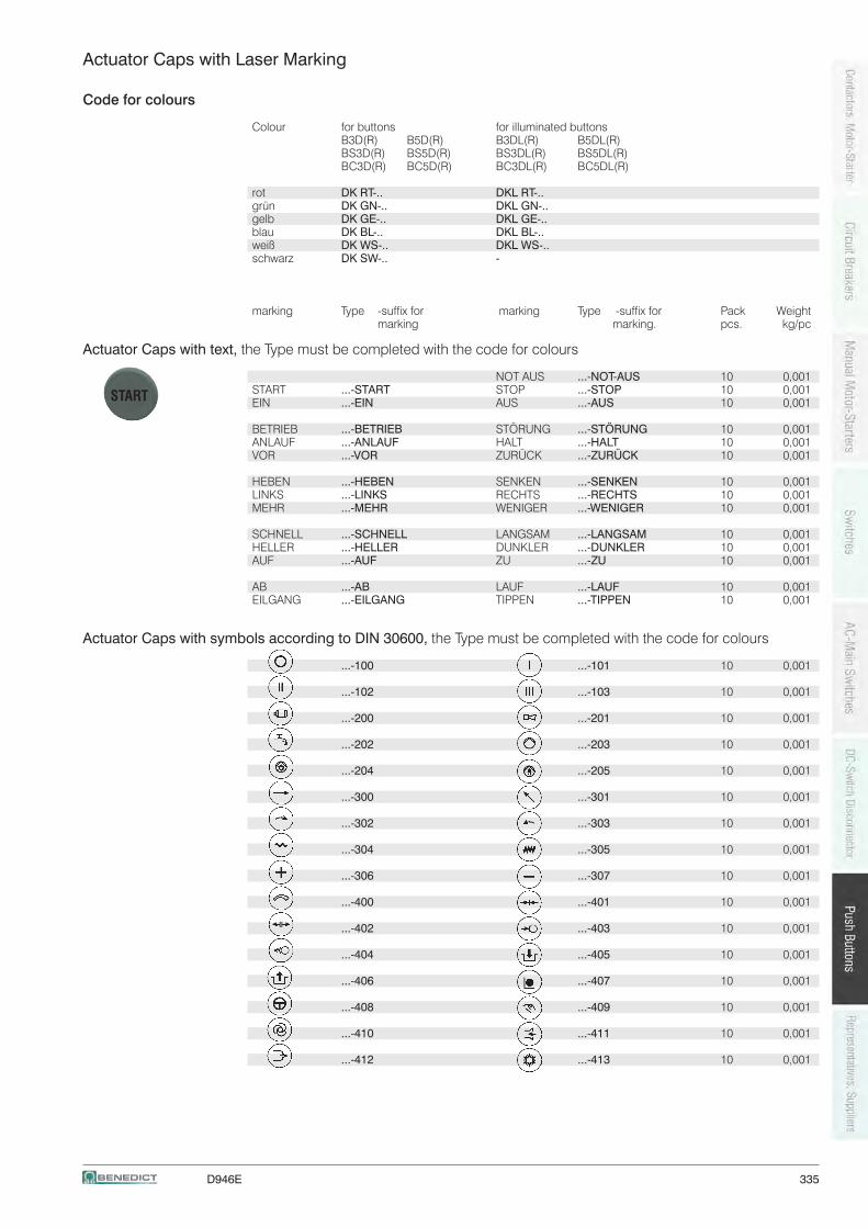
D946E 335
Actuator Caps with Laser Marking
Code for colours
Colour for buttons for illuminated buttons B3D(R) B5D(R) B3DL(R) B5DL(R) BS3D(R) BS5D(R) BS3DL(R) BS5DL(R) BC3D(R) BC5D(R) BC3DL(R) BC5DL(R)
rot DK RT-.. DKL RT-.. grün DK GN-.. DKL GN-.. gelb DK GE-.. DKL GE-.. blau DK BL-.. DKL BL-.. weiß DK WS-.. DKL WS-.. schwarz DK SW-.. -
marking Type -suffix for marking Type -suffix for Pack Weight marking marking. pcs. kg/pc
Actuator Caps with text, the Type must be completed with the code for colours
NOT AUS ...-NOT-AUS 10 0,001 START ...-START STOP ...-STOP 10 0,001 EIN ...-EIN AUS ...-AUS 10 0,001
BETRIEB ...-BETRIEB STÖRUNG ...-STÖRUNG 10 0,001 ANLAUF ...-ANLAUF HALT ...-HALT 10 0,001 VOR ...-VOR ZURÜCK ...-ZURÜCK 10 0,001
HEBEN ...-HEBEN SENKEN ...-SENKEN 10 0,001 LINKS ...-LINKS RECHTS ...-RECHTS 10 0,001 MEHR ...-MEHR WENIGER ...-WENIGER 10 0,001
SCHNELL ...-SCHNELL LANGSAM ...-LANGSAM 10 0,001 HELLER ...-HELLER DUNKLER ...-DUNKLER 10 0,001 AUF ...-AUF ZU ...-ZU 10 0,001
AB ...-AB LAUF ...-LAUF 10 0,001 EILGANG ...-EILGANG TIPPEN ...-TIPPEN 10 0,001
Actuator Caps with symbols according to DIN 30600, the Type must be completed with the code for colours
...-100 ...-101 10 0,001
...-102 ...-103 10 0,001
...-200 ...-201 10 0,001
...-202 ...-203 10 0,001
...-204 ...-205 10 0,001
...-300 ...-301 10 0,001
...-302 ...-303 10 0,001
...-304 ...-305 10 0,001
...-306 ...-307 10 0,001
...-400 ...-401 10 0,001
...-402 ...-403 10 0,001
...-404 ...-405 10 0,001
...-406 ...-407 10 0,001
...-408 ...-409 10 0,001 ...-410 ...-411 10 0,001
...-412 ...-413 10 0,001
START
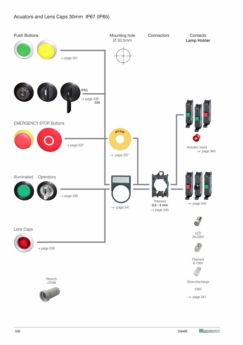
336 D946E
Acuators and Lens Caps 30mm IP67 (IP65)
Push Buttons Connectors Contacts
Lamp Holder
→ page 331
IP65
→ page 338 339 EMERGENCY STOP Buttons
→ page 337
Actuator insert → page 340 → page 337
Illuminated Operators
→ page 339 → page 340 → page 341
Lens Caps LED 24-230V
→ page 339
Filament 6-130V Glow-discharge
230V → page 341
Thikness0,5 - 3 mm
→ page 340
WrenchJ7049
Mounting holeØ 30,5mm
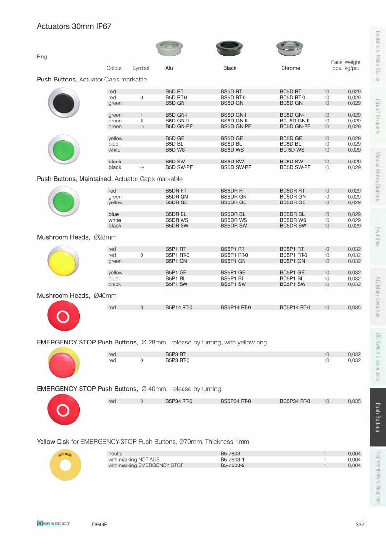
D946E 337
Actuators 30mm IP67
Ring Pack WeightColour Symbol Alu Black Chrome pcs. kg/pc.
Push Buttons, Actuator Caps markable
red B5D RT BS5D RT BC5D RT 10 0,029 red 0 B5D RT-0 BS5D RT-0 BC5D RT-0 10 0,029 green B5D GN BS5D GN BC5D GN 10 0,029
green I B5D GN-I BS5D GN-I BC5D GN-I 10 0,029 green II B5D GN-II BS5D GN-II BC 5D GN-II 10 0,029 green → B5D GN-PF BS5D GN-PF BC5D GN-PF 10 0,029
yellow B5D GE BS5D GE BC5D GE 10 0,029 blue B5D BL BS5D BL BC5D BL 10 0,029 white B5D WS BS5D WS BC 5D WS 10 0,029
black B5D SW BS5D SW BC5D SW 10 0,029 black → B5D SW-PF BS5D SW-PF BC5D SW-PF 10 0,029
Push Buttons, Maintained, Actuator Caps markable
red B5DR RT BS5DR RT BC5DR RT 10 0,029 green B5DR GN BS5DR GN BC5DR GN 10 0,029 yellow B5DR GE BS5DR GE BC5DR GE 10 0,029
blue B5DR BL BS5DR BL BC5DR BL 10 0,029 white B5DR WS BS5DR WS BC5DR WS 10 0,029 black B5DR SW BS5DR SW BC5DR SW 10 0,029
Mushroom Heads, Ø28mm
red B5P1 RT BS5P1 RT BC5P1 RT 10 0,032 red 0 B5P1 RT-0 BS5P1 RT-0 BC5P1 RT-0 10 0,032 green B5P1 GN BS5P1 GN BC5P1 GN 10 0,032
yellow B5P1 GE BS5P1 GE BC5P1 GE 10 0,032 blue B5P1 BL BS5P1 BL BC5P1 BL 10 0,032 black B5P1 SW BS5P1 SW BC5P1 SW 10 0,032
Mushroom Heads, Ø40mm
red 0 B5P14 RT-0 BS5P14 RT-0 BC5P14 RT-0 10 0,035
EMERGENCY STOP Push Buttons, Ø 28mm, release by turning, with yellow ring
red B5P3 RT 10 0,032 red 0 B5P3 RT-0 10 0,032
EMERGENCY STOP Push Buttons, Ø 40mm, release by turning
red 0 B5P34 RT-0 BS5P34 RT-0 BC5P34 RT-0 10 0,035
Yellow Disk for EMERGENCY-STOP Push Buttons, Ø70mm, Thickness 1mm
neutral B5-7603 1 0,004 with marking NOT-AUS B5-7603-1 1 0,004 with marking EMERGENCY STOP B5-7603-2 1 0,004
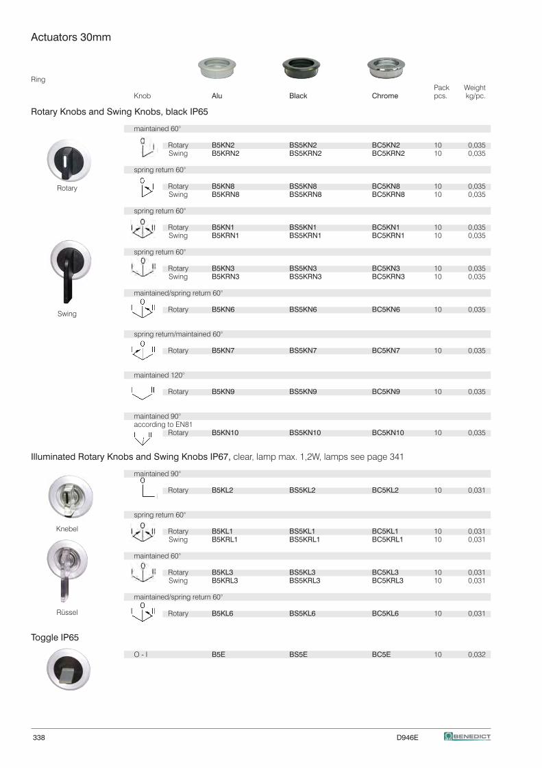
338 D946E
Actuators 30mm
Ring Pack Weight Knob Alu Black Chrome pcs. kg/pc.
Rotary Knobs and Swing Knobs, black IP65
maintained 60°
Rotary B5KN2 BS5KN2 BC5KN2 10 0,035 Swing B5KRN2 BS5KRN2 BC5KRN2 10 0,035
spring return 60°
Rotary B5KN8 BS5KN8 BC5KN8 10 0,035 Swing B5KRN8 BS5KRN8 BC5KRN8 10 0,035
spring return 60°
Rotary B5KN1 BS5KN1 BC5KN1 10 0,035 Swing B5KRN1 BS5KRN1 BC5KRN1 10 0,035
spring return 60°
Rotary B5KN3 BS5KN3 BC5KN3 10 0,035 Swing B5KRN3 BS5KRN3 BC5KRN3 10 0,035
maintained/spring return 60°
Rotary B5KN6 BS5KN6 BC5KN6 10 0,035
spring return/maintained 60°
Rotary B5KN7 BS5KN7 BC5KN7 10 0,035
maintained 120°
Rotary B5KN9 BS5KN9 BC5KN9 10 0,035
maintained 90° according to EN81 Rotary B5KN10 BS5KN10 BC5KN10 10 0,035
Illuminated Rotary Knobs and Swing Knobs IP67, clear, lamp max. 1,2W, lamps see page 341
maintained 90°
Rotary B5KL2 BS5KL2 BC5KL2 10 0,031
spring return 60°
Rotary B5KL1 BS5KL1 BC5KL1 10 0,031 Swing B5KRL1 BS5KRL1 BC5KRL1 10 0,031
maintained 60°
Rotary B5KL3 BS5KL3 BC5KL3 10 0,031 Swing B5KRL3 BS5KRL3 BC5KRL3 10 0,031
maintained/spring return 60°
Rotary B5KL6 BS5KL6 BC5KL6 10 0,031
Toggle IP65
O - I B5E BS5E BC5E 10 0,032
Knebel
Rüssel
Swing
Rotary
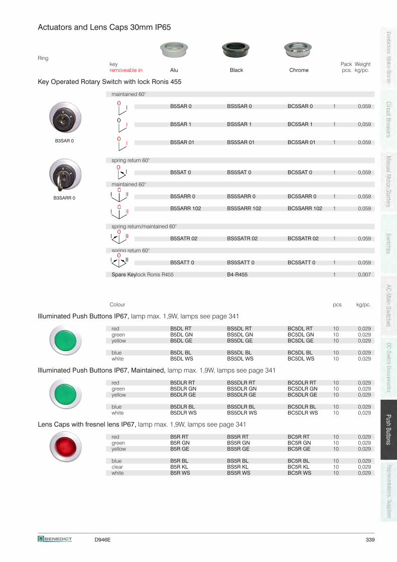
D946E 339
Actuators and Lens Caps 30mm IP65
Ringkey Pack Weightremoveable in Alu Black Chrome pcs. kg/pc.
Key Operated Rotary Switch with lock Ronis 455
maintained 60°
B5SAR 0 BS5SAR 0 BC5SAR 0 1 0,059
B5SAR 1 BS5SAR 1 BC5SAR 1 1 0,059
B5SAR 01 BS5SAR 01 BC5SAR 01 1 0,059
spring return 60° B5SAT 0 BS5SAT 0 BC5SAT 0 1 0,059
maintained 60° B5SARR 0 BS5SARR 0 BC5SARR 0 1 0,059
B5SARR 102 BS5SARR 102 BC5SARR 102 1 0,059
spring return/maintained 60° B5SATR 02 BS5SATR 02 BC5SATR 02 1 0,059
spring return 60°
B5SATT 0 BS5SATT 0 BC5SATT 0 1 0,059
Spare Key lock Ronis R455 B4-R455 1 0,007
Colour pcs. kg/pc.
Illuminated Push Buttons IP67, lamp max. 1,9W, lamps see page 341
red B5DL RT BS5DL RT BC5DL RT 10 0,029 green B5DL GN BS5DL GN BC5DL GN 10 0,029 yellow B5DL GE BS5DL GE BC5DL GE 10 0,029
blue B5DL BL BS5DL BL BC5DL BL 10 0,029 white B5DL WS BS5DL WS BC5DL WS 10 0,029
Illuminated Push Buttons IP67, Maintained, lamp max. 1,9W, lamps see page 341
red B5DLR RT BS5DLR RT BC5DLR RT 10 0,029 green B5DLR GN BS5DLR GN BC5DLR GN 10 0,029 yellow B5DLR GE BS5DLR GE BC5DLR GE 10 0,029
blue B5DLR BL BS5DLR BL BC5DLR BL 10 0,029 white B5DLR WS BS5DLR WS BC5DLR WS 10 0,029
Lens Caps with fresnel lens IP67, lamp max. 1,9W, lamps see page 341
red B5R RT BS5R RT BC5R RT 10 0,029 green B5R GN BS5R GN BC5R GN 10 0,029 yellow B5R GE BS5R GE BC5R GE 10 0,029
blue B5R BL BS5R BL BC5R BL 10 0,029 clear B5R KL BS5R KL BC5R KL 10 0,029 white B5R WS BS5R WS BC5R WS 10 0,029
B3SAR 0
B3SARR 0
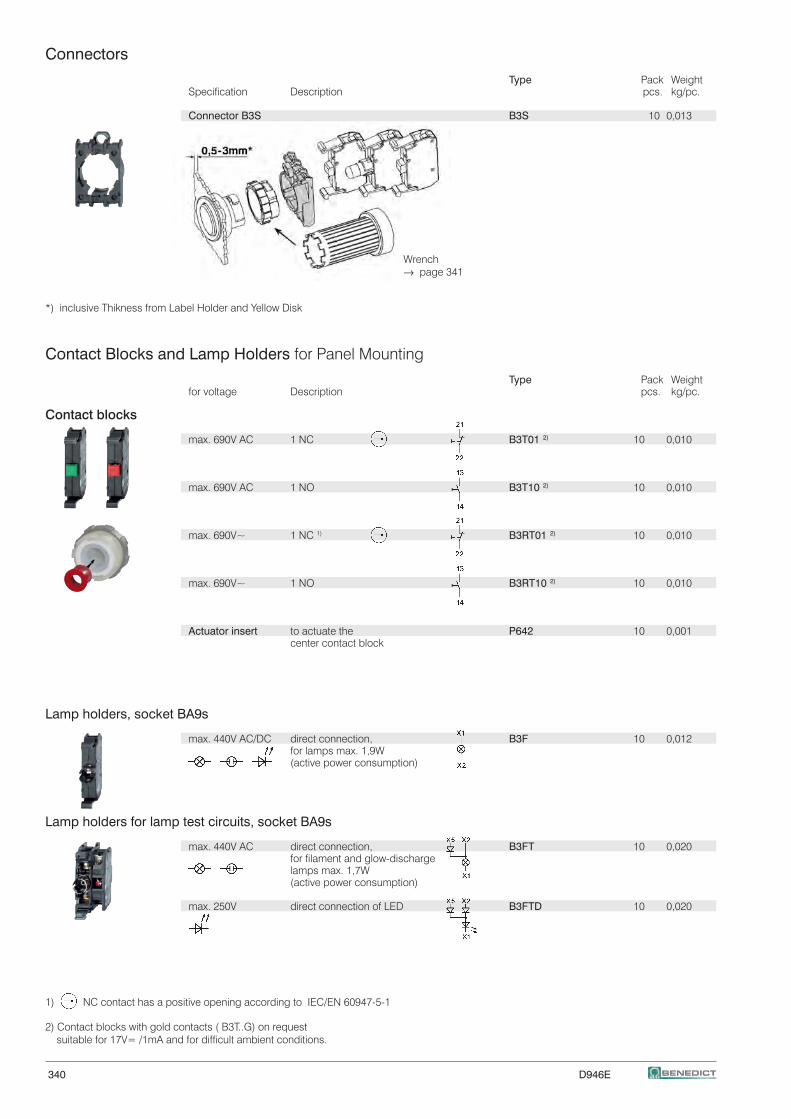
340 D946E
Connectors
Type Pack WeightSpecification Description pcs. kg/pc.
Connector B3S B3S 10 0,013
Wrench → page 341
*) inclusive Thikness from Label Holder and Yellow Disk
Contact Blocks and Lamp Holders for Panel Mounting
Type Pack Weightfor voltage Description pcs. kg/pc.
Contact blocks
max. 690V AC 1 NC B3T01 2) 10 0,010
max. 690V AC 1 NO B3T10 2) 10 0,010
max. 690V~ 1 NC 1) B3RT01 2) 10 0,010
max. 690V~ 1 NO B3RT10 2) 10 0,010
Actuator insert to actuate the P642 10 0,001 center contact block
Lamp holders, socket BA9s
max. 440V AC/DC direct connection, B3F 10 0,012 for lamps max. 1,9W (active power consumption)
Lamp holders for lamp test circuits, socket BA9s
max. 440V AC direct connection, B3FT 10 0,020 for filament and glow-discharge lamps max. 1,7W (active power consumption)
max. 250V direct connection of LED B3FTD 10 0,020
1) NC contact has a positive opening according to IEC/EN 60947-5-1
2) Contact blocks with gold contacts ( B3T..G) on request suitable for 17V= /1mA and for difficult ambient conditions.
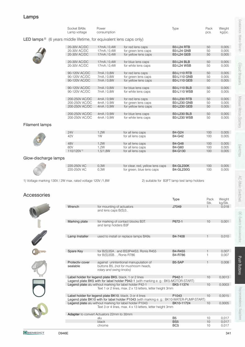
D946E 341
Lamps
Socket BA9s Power Type Pack Weight Lamp voltage consumption pcs. kg/pc.
LED lamps 2) (6 years middle lifetime, for equivalent lens caps only)
20-30V AC/DC 17mA / 0,4W for red lens caps B3-L24 RTB 50 0,00520-30V AC/DC 17mA / 0,4W for green lens caps B3-L24 GNB 50 0,00520-30V AC/DC 17mA / 0,4W for yellow lens caps B3-L24 GEB 50 0,005
20-30V AC/DC 17mA / 0,4W for blue lens caps B3-L24 BLB 50 0,00520-30V AC/DC 17mA / 0,4W for white lens caps B3-L24 WSB 50 0,005
90-120V AC/DC 7mA / 0,8W for red lens caps B3-L110 RTB 50 0,00590-120V AC/DC 7mA / 0,8W for green lens caps B3-L110 GNB 50 0,00590-120V AC/DC 7mA / 0,8W for yellow lens caps B3-L110 GEB 50 0,005
90-120V AC/DC 7mA / 0,8W for blue lens caps B3-L110 BLB 50 0,00590-120V AC/DC 7mA / 0,8W for white lens caps B3-L110 WSB 50 0,005
200-250V AC/DC 4mA / 0,9W for red lens caps B3-L230 RTB 50 0,005200-250V AC/DC 4mA / 0,9W for green lens caps B3-L230 GNB 50 0,005200-250V AC/DC 4mA / 0,9W for yellow lens caps B3-L230 GEB 50 0,005
200-250V AC/DC 4mA / 0,9W for blue lens caps B3-L230 BLB 50 0,005200-250V AC/DC 4mA / 0,9W for white lens caps B3-L230 WSB 50 0,005
Filament lamps
24V 1,2W for all lens caps B4-G24 100 0,00542V 1W for all lens caps B4-G42 100 0,005
48V 1,2W for all lens caps B4-G48 100 0,00560V 1,2W for all lens caps B4-G60 100 0,005110/120V 1) 1,5/1,8W for all lens caps B4-G130 100 0,005
Glow-discharge lamps
220-250V AC 0,3W for clear, red, yellow lens caps B4-GL230K 100 0,005220-250V AC 0,3W for green, blue lens caps B4-GL230G 100 0,005
1) Voltage marking 130V / 2W max. rated voltage 120V /1,8W 2) suitable for B3FT lamp test lamp holders
Accessories Type Pack Weight Stk. kg/Stk.Wrench for mounting of actuators J7049 1 0,018 and lens caps B(S)3..
Marking plate for marking of contact blocks B3T. P672-1 10 0,001 and lamp holders B3F
Lamp Installer used to install or replace lamps BA9s B4-7408 1 0,010
Spare Key for B(S)3SA.. and BS3P44S3, Ronis R455 B4-R455 1 0,007 for B(S)3SB.. , Ronis R786 B4-R786 1 0,007
Protectiv cover against unintentional manupulation of B5-SAP 1 0,008sealable buttons B5, (not for mushroom heads, rotary and swing knobs)
Label holder for legend plate BK5, black, 1 or 2 lines P942-1 10 0,0013Legend plate BK5 with for label holder P942-1 (with marking e. g.: BK5-MOTOR-START)Legend plate alu without marking for label holder P42-1 BK5-11374 10 0,0003 Text 1 or 2 lines, max. 2 x 13 letters, letter height 3mm
Label holder for legend plate BK10, black, 3 or 4 lines P1043 10 0,0015Legend plate BK10 with for label holder P1043 (with marking e. g.: BK10-WATER-PUMP-START)Legend plate alu without marking for label holder P1043 BK10-11724 10 0,0005 Text 3 or 4 lines, max. 4 x 13 letters, letter height 3mm Adapter to convert Actuators 22mm to 30mm alu B5 10 0,017 black BS5 10 0,017 chrome BC5 10 0,017
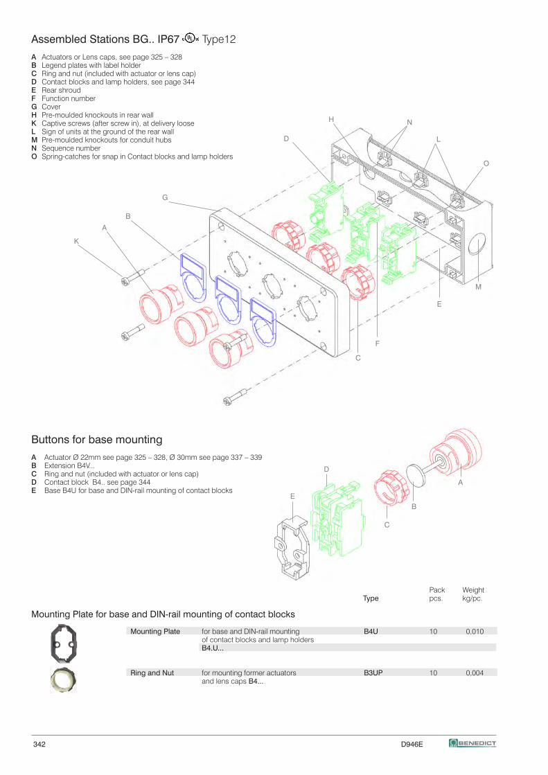
342 D946E
G
B
A
K
E
C
H N
L
O
F
D
Assembled Stations BG.. IP67 Type12
A Actuators or Lens caps, see page 325 – 328B Legend plates with label holderC Ring and nut (included with actuator or lens cap) D Contact blocks and lamp holders, see page 344E Rear shroudF Function numberG CoverH Pre-moulded knockouts in rear wallK Captive screws (after screw in), at delivery looseL Sign of units at the ground of the rear wallM Pre-moulded knockouts for conduit hubsN Sequence numberO Spring-catches for snap in Contact blocks and lamp holders
E
D
C
A
B
M
Buttons for base mounting
A Actuator Ø 22mm see page 325 – 328, Ø 30mm see page 337 – 339B Extension B4V...C Ring and nut (included with actuator or lens cap) D Contact block B4.. see page 344E Base B4U for base and DIN-rail mounting of contact blocks
Pack Weight Type pcs. kg/pc.
Mounting Plate for base and DIN-rail mounting of contact blocks
Mounting Plate for base and DIN-rail mounting B4U 10 0,010 of contact blocks and lamp holders B4.U...
Ring and Nut for mounting former actuators B3UP 10 0,004 and lens caps B4...
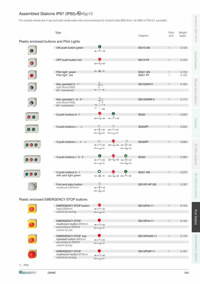
D946E 343
← →
← →
Assembled Stations IP67 (IP65) Typ12
For conduit entries are in top and both small sides only one knockouts for conduit hubs Ø20,5mm, for M20 or PG13,5 provided.
Type Pack Weight Diagram pcs. kg/pc.
Plastic enclosed buttons and Pilot Lights
ON push button green BG10 GN 1 0,135
OFF push button red BG10 RT 1 0,135
Pilot light green BG01 GN 1 0,135 Pilot light red BG01 RT 1 0,135
Key operated 0 - I 1) BG10SAR 0 1 0,165 lock Ronis R455 60° maintained
Key operated I - 0 - II 1) BG10SARR 0 1 0,172 lock Ronis R455 60° maintained
2 push buttons 0 - I BG20 1 0,200
2 push buttons ←→ BG20PF 1 0,200
3 push buttons ← 0 → BG30PF 1 0,283
3 push buttons I - 0 - II BG30 1 0,283
2 push buttons 0 - I BG21 GN 1 0,270 with pilot light green
Foot and palm button BG10P14P GR 1 0,187 mushroom Ø70mm
Plastic enclosed EMERGENCY STOP buttons
EMERGENCY STOP button BG10P34-11 1 0,145 head Ø40mm unlock by turning
EMERGENCY STOP BG10P44-11 1 0,145 mushroom button Ø40mm according to EN418 unlock by pull
EMERGENCY STOP key BG10P44S3-11 1 0,178 operated button Ø40mm according to EN418 unlock by key
EMERGENCY STOP BG10P34P-11 1 0,187 mushroom button Ø70mm unlock by turning
1) IP65
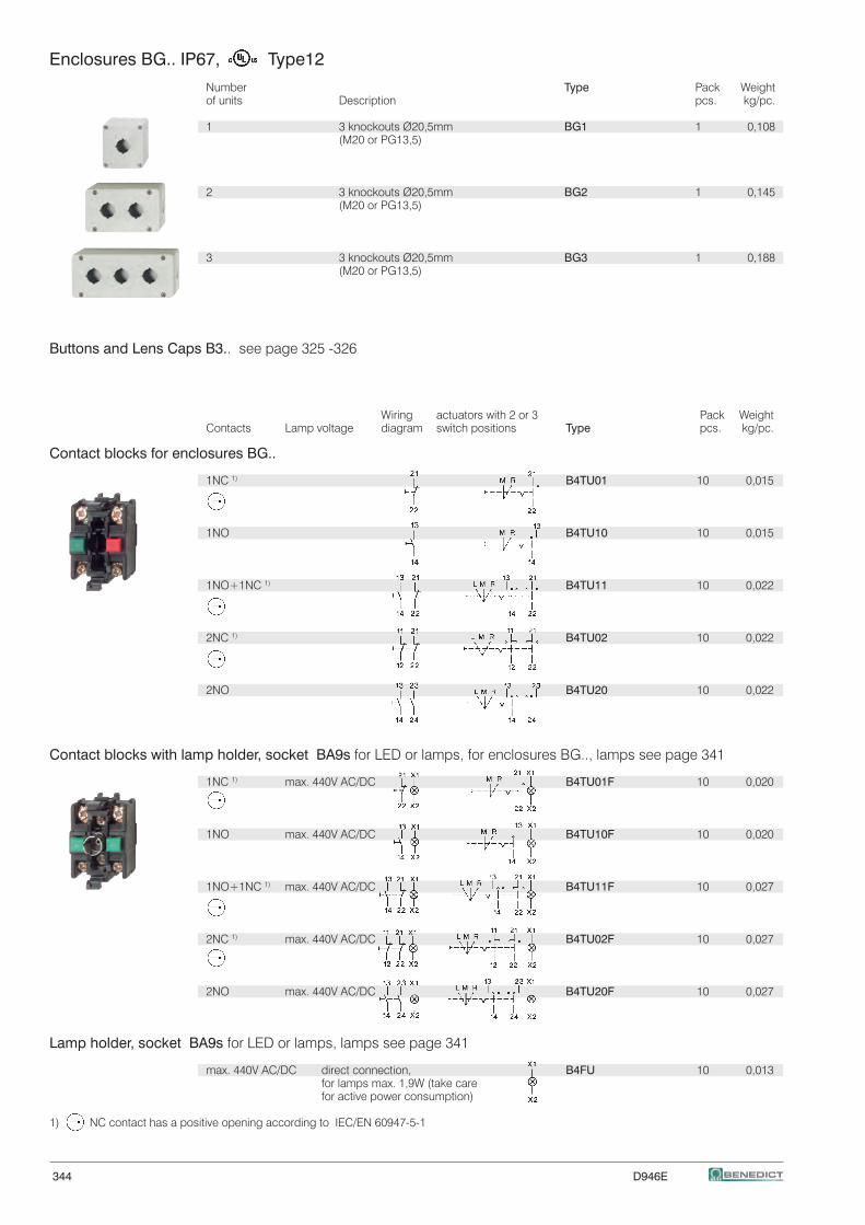
344 D946E
Enclosures BG.. IP67, Type12
Number Type Pack Weightof units Description pcs. kg/pc.
1 3 knockouts Ø20,5mm BG1 1 0,108 (M20 or PG13,5)
2 3 knockouts Ø20,5mm BG2 1 0,145 (M20 or PG13,5)
3 3 knockouts Ø20,5mm BG3 1 0,188 (M20 or PG13,5)
Buttons and Lens Caps B3.. see page 325 -326
Wiring actuators with 2 or 3 Pack WeightContacts Lamp voltage diagram switch positions Type pcs. kg/pc.
Contact blocks for enclosures BG..
1NC 1) B4TU01 10 0,015
1NO B4TU10 10 0,015
1NO+1NC 1) B4TU11 10 0,022
2NC 1) B4TU02 10 0,022
2NO B4TU20 10 0,022
Contact blocks with lamp holder, socket BA9s for LED or lamps, for enclosures BG.., lamps see page 341
1NC 1) max. 440V AC/DC B4TU01F 10 0,020
1NO max. 440V AC/DC B4TU10F 10 0,020
1NO+1NC 1) max. 440V AC/DC B4TU11F 10 0,027
2NC 1) max. 440V AC/DC B4TU02F 10 0,027
2NO max. 440V AC/DC B4TU20F 10 0,027
Lamp holder, socket BA9s for LED or lamps, lamps see page 341
max. 440V AC/DC direct connection, B4FU 10 0,013 for lamps max. 1,9W (take care for active power consumption)
1) NC contact has a positive opening according to IEC/EN 60947-5-1
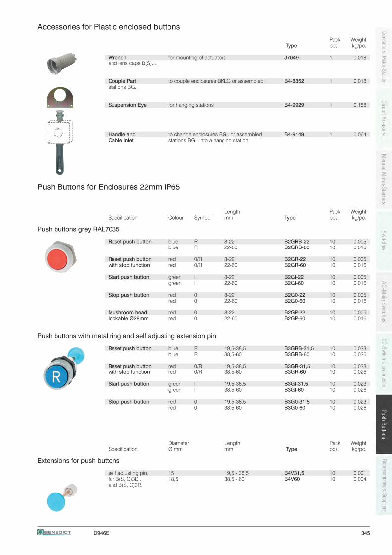
D946E 345
Accessories for Plastic enclosed buttons Pack Weight Type pcs. kg/pc.
Wrench for mounting of actuators J7049 1 0,018and lens caps B(S)3..
Couple Part to couple enclosures BKLG or assembled B4-8852 1 0,018stations BG..
Suspension Eye for hanging stations B4-9929 1 0,188
Handle and to change enclosures BG.. or assembled B4-9149 1 0,064Cable Inlet stations BG.. into a hanging station
Push Buttons for Enclosures 22mm IP65
Length Pack WeightSpecification Colour Symbol mm Type pcs. kg/pc.
Push buttons grey RAL7035
Reset push button blue R 8-22 B2GRB-22 10 0,005 blue R 22-60 B2GRB-60 10 0,016
Reset push button red 0/R 8-22 B2GR-22 10 0,005with stop function red 0/R 22-60 B2GR-60 10 0,016
Start push button green I 8-22 B2GI-22 10 0,005 green I 22-60 B2GI-60 10 0,016
Stop push button red 0 8-22 B2G0-22 10 0,005 red 0 22-60 B2G0-60 10 0,016
Mushroom head red 0 8-22 B2GP-22 10 0,005lockable Ø28mm red 0 22-60 B2GP-60 10 0,016
Push buttons with metal ring and self adjusting extension pin
Reset push button blue R 19,5-38,5 B3GRB-31,5 10 0,023 blue R 38,5-60 B3GRB-60 10 0,026
Reset push button red 0/R 19,5-38,5 B3GR-31,5 10 0,023with stop function red 0/R 38,5-60 B3GR-60 10 0,026
Start push button green I 19,5-38,5 B3GI-31,5 10 0,023 green I 38,5-60 B3GI-60 10 0,026
Stop push button red 0 19,5-38,5 B3G0-31,5 10 0,023 red 0 38,5-60 B3G0-60 10 0,026
Diameter Length Pack WeightSpecification Ø mm mm Type pcs. kg/pc.
Extensions for push buttons
self adjusting pin, 15 19,5 - 38,5 B4V31,5 10 0,001for B(S, C)3D.. 18,5 38,5 - 60 B4V60 10 0,004and B(S, C)3P..
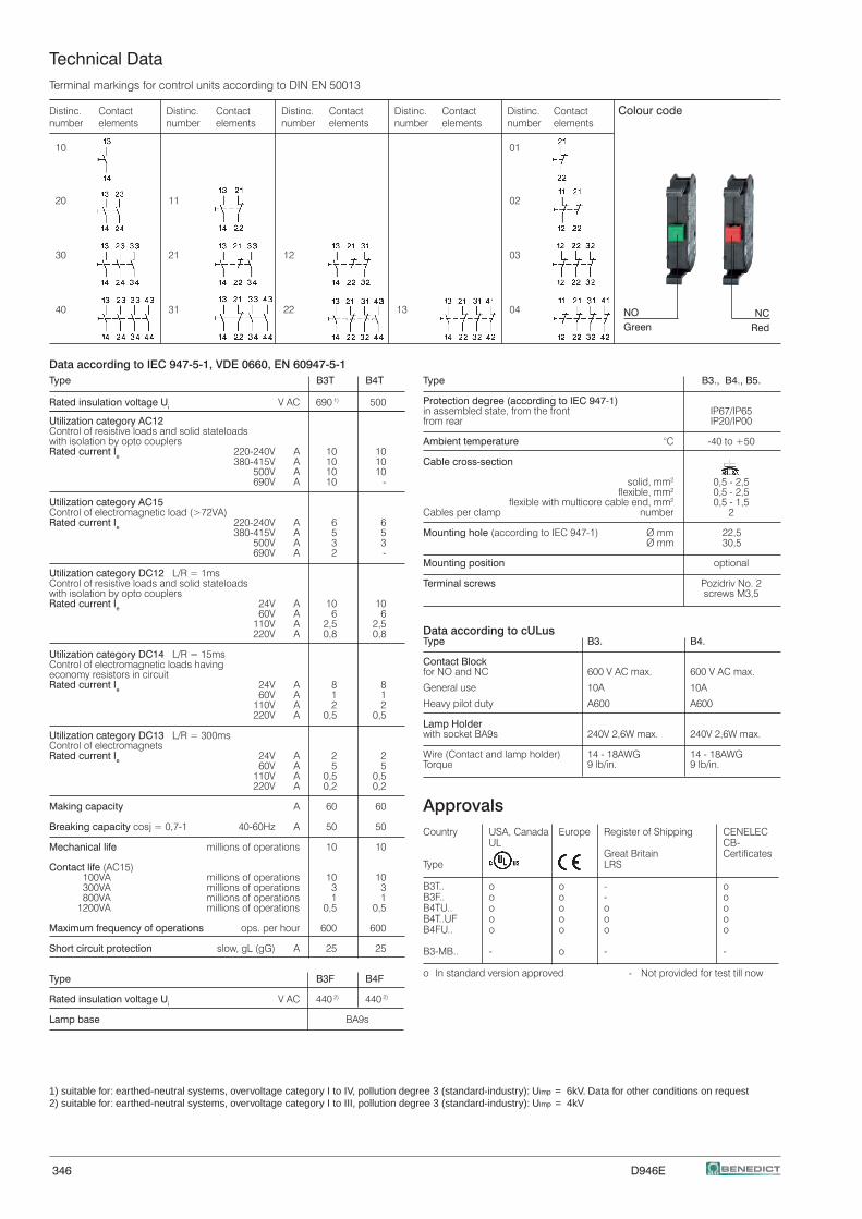
346 D946E
1) suitable for: earthed-neutral systems, overvoltage category I to IV, pollution degree 3 (standard-industry): Uimp = 6kV. Data for other conditions on request2) suitable for: earthed-neutral systems, overvoltage category I to III, pollution degree 3 (standard-industry): Uimp = 4kV
Terminal markings for control units according to DIN EN 50013
Distinc. Contact Distinc. Contact Distinc. Contact Distinc. Contact Distinc. Contact Colour codenumber elements number elements number elements number elements number elements
10 01
20 11 02
30 21 12 03
40 31 22 13 04
Type B3., B4., B5.
Protection degree (according to IEC 947-1)in assembled state, from the front IP67/IP65from rear IP20/IP00
Ambient temperature °C -40 to +50
Cable cross-section
solid, mm2 0,5 - 2,5 flexible, mm2 0,5 - 2,5 flexible with multicore cable end, mm2 0,5 - 1,5Cables per clamp number 2
Mounting hole (according to IEC 947-1) Ø mm 22,5 Ø mm 30,5
Mounting position optional
Terminal screws Pozidriv No. 2 screws M3,5
Data according to cULus Type B3. B4.
Contact Blockfor NO and NC 600 V AC max. 600 V AC max.
General use 10A 10A
Heavy pilot duty A600 A600
Lamp Holderwith socket BA9s 240V 2,6W max. 240V 2,6W max.
Wire (Contact and lamp holder) 14 - 18AWG 14 - 18AWGTorque 9 lb/in. 9 lb/in.
ApprovalsCountry USA, Canada Europe Register of Shipping CENELEC UL CB- Great Britain CertificatesType LRS
B3T.. o o - oB3F.. o o - oB4TU.. o o o oB4T..UF o o o oB4FU.. o o o o
B3-MB.. - o - -
o In standard version approved - Not provided for test till now
Data according to IEC 947-5-1, VDE 0660, EN 60947-5-1Type B3T B4T
Rated insulation voltage Ui V AC 690 1) 500
Utilization category AC12Control of resistive loads and solid stateloadswith isolation by opto couplersRated current Ie 220-240V A 10 10 380-415V A 10 10 500V A 10 10 690V A 10 -
Utilization category AC15Control of electromagnetic load (>72VA)Rated current Ie 220-240V A 6 6 380-415V A 5 5 500V A 3 3 690V A 2 -
Utilization category DC12 L/R = 1msControl of resistive loads and solid stateloadswith isolation by opto couplersRated current Ie 24V A 10 10 60V A 6 6 110V A 2,5 2,5 220V A 0,8 0,8
Utilization category DC14 L/R = 15msControl of electromagnetic loads havingeconomy resistors in circuitRated current Ie 24V A 8 8 60V A 1 1 110V A 2 2 220V A 0,5 0,5
Utilization category DC13 L/R = 300msControl of electromagnetsRated current Ie 24V A 2 2 60V A 5 5 110V A 0,5 0,5 220V A 0,2 0,2
Making capacity A 60 60
Breaking capacity cosj = 0,7-1 40-60Hz A 50 50
Mechanical life millions of operations 10 10
Contact life (AC15) 100VA millions of operations 10 10 300VA millions of operations 3 3 800VA millions of operations 1 1 1200VA millions of operations 0,5 0,5
Maximum frequency of operations ops. per hour 600 600
Short circuit protection slow, gL (gG) A 25 25
Type B3F B4F
Rated insulation voltage Ui V AC 440 2) 440 2)
Lamp base BA9s
Technical Data
NCRed
NOGreen
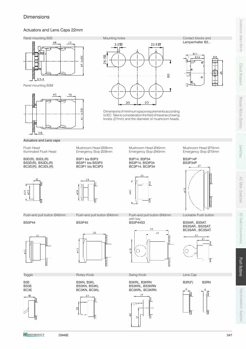
D946E 347
Dimensions
Actuators and Lens Caps 22mm
Panel mounting B3S Mounting holes Contact blocks and Lampenhalter B3...
Panel mounting B3M
Actuators and Lens caps
Flush Head Mushroom Head Ø28mm Mushroom Head Ø40mm Mushroom Head Ø70mmIlluminated Flush Head Emergency Stop Ø28mm Emergency Stop Ø40mm Emergency Stop Ø70mm
B3D(R), B3DL(R) B3P1 bis B3P3 B3P14, B3P34 BS3P14P BS3D(R), BS3DL(R) BS3P1 bis BS3P3 BS3P14, BS3P34 BS3P34PBC3D(R), BC3DL(R) BC3P1 bis BC3P3 BC3P14, BC3P34
Push-and pull button Ø40mm Push-and pull button Ø40mm Push-and pull button Ø40mm Lockable Push button with keyBS3P44 BS3P45 BS3P44S3 B3SAR., B3SAT. BS3SAR., BS3SAT. BC3SAR., BC3SAT.
Toggle Rotary Knob Swing Knob Lens Cap
B3E B3KN, B3KL B3KRL, B3KRN B3R(F) B3RNBS3E BS3KN, BS3KL BS3KRL, BS3KRN BC3E BC3KN, BC3KL BC3KRL, BC3KRN
Dimensions of minimum space requirements according to IEC. Take to consideration the field of traverse of swing knobs (27mm) and the diameter of mushroom heads.
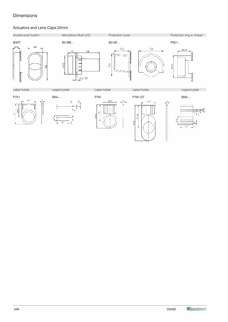
348 D946E
Dimensions
Actuators and Lens Caps 22mm
Double push button Monoblock Multi-LED Protection cover Protection ring w. thread B3DT B3-MB... B3-SK .. P921-.
Label holder Legend plate Label holder Label holder Legend plate
P751 BK4-... P761 P761-DT BK8-...
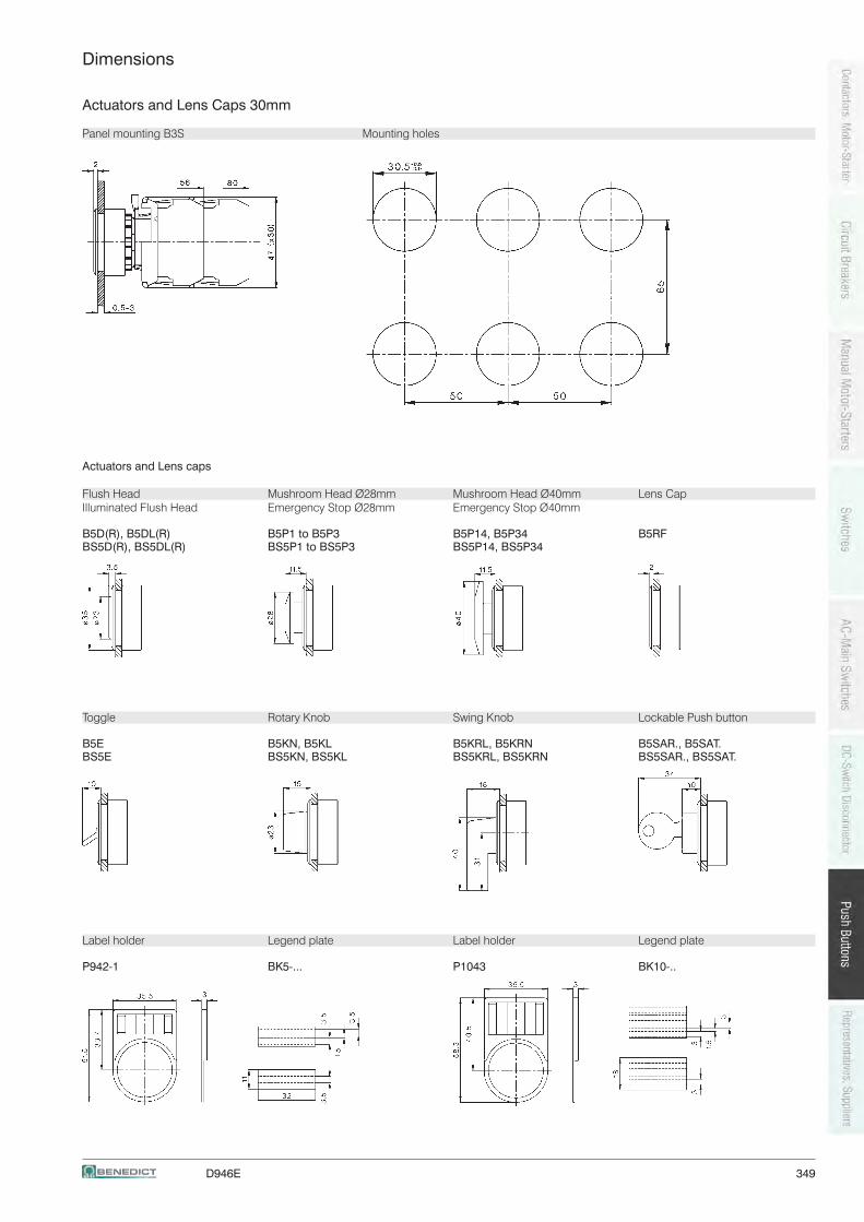
D946E 349
v
Dimensions
Actuators and Lens Caps 30mm
Panel mounting B3S Mounting holes
Actuators and Lens caps
Flush Head Mushroom Head Ø28mm Mushroom Head Ø40mm Lens CapIlluminated Flush Head Emergency Stop Ø28mm Emergency Stop Ø40mm B5D(R), B5DL(R) B5P1 to B5P3 B5P14, B5P34 B5RFBS5D(R), BS5DL(R) BS5P1 to BS5P3 BS5P14, BS5P34
Toggle Rotary Knob Swing Knob Lockable Push button
B5E B5KN, B5KL B5KRL, B5KRN B5SAR., B5SAT.BS5E BS5KN, BS5KL BS5KRL, BS5KRN BS5SAR., BS5SAT.
Label holder Legend plate Label holder Legend plate
P942-1 BK5-... P1043 BK10-..
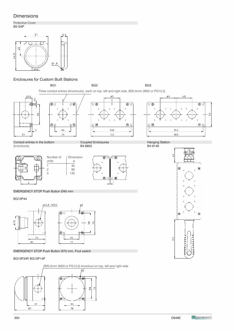
350 D946E
DimensionsProtective CoverB5-SAP
Enclosures for Custom Built Stations BG1 BG2 BG3
Three conduit entries (knockouts), each on top, left and right side, Ø20,5mm (M20 or PG13,5)
Conduit entries in the bottom Coupled Enclosures Hanging Station(knockouts) B4-8852 B4-9149
Number of Dimension units a
1 45 2 90 3 135
EMERGENCY STOP Push Button Ø40 mm
BG10P44
EMERGENCY STOP Push Button Ø70 mm, Foot switch
BG10P34P, BG10P14P
Ø20,5mm (M20 or PG13,5) knockout on top, left and right side
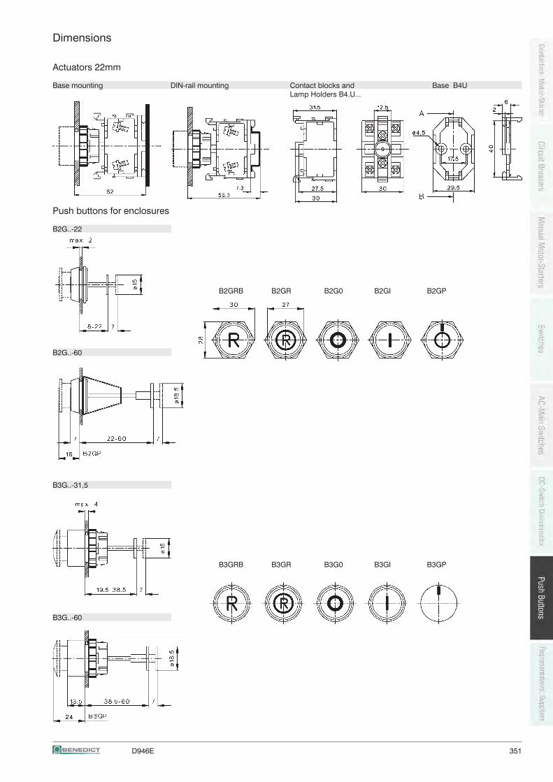
D946E 351
Dimensions
Actuators 22mm
Base mounting DIN-rail mounting Contact blocks and Base B4U Lamp Holders B4.U...
Push buttons for enclosures
B2G..-22
B2GRB B2GR B2G0 B2GI B2GP
B2G..-60
B3G..-31,5
B3GRB B3GR B3G0 B3GI B3GP
B3G..-60
352 D946E
D946E 353
European Representatives and Suppliers
AustriaAustriaAustriaAustriaAustria
Kiechel & Hagleitner GmbH &Co KGKiechel & Hagleitner GmbH &Co KGKiechel & Hagleitner GmbH &Co KGKiechel & Hagleitner GmbH &Co KGKiechel & Hagleitner GmbH &Co KG Tel: +43 / 5574 / 4970-53Quellenstraße 20-22 Fax: +43 / 5574 / 4970-206900 Bregenz [email protected] for Vorarlberg www.kiha.at
Ernst WErnst WErnst WErnst WErnst Wallnöferallnöferallnöferallnöferallnöfer Tel: +43 / 512 / 26 38 38Elektro IndustrievertretungElektro IndustrievertretungElektro IndustrievertretungElektro IndustrievertretungElektro Industrievertretung Fax: +43 / 512 / 26 38 38-26Bundesstrasse 29 [email protected] Rum www.wallnoefer-elektro.atRepresentation for Tirol
Seitner & BittmannSeitner & BittmannSeitner & BittmannSeitner & BittmannSeitner & Bittmann Tel: +43 / 316 / 82 35 62Kossgasse 21 Fax: +43 / 316 / 82 35 658035 Graz [email protected] for Styria www.seitner-bittmann.at
Seitner & BittmannSeitner & BittmannSeitner & BittmannSeitner & BittmannSeitner & Bittmann Tel: +47 / 463 / 38 10 70Kirchengasse 11 Fax: +47 / 463 / 38 10 729020 Klagenfurt [email protected]
www.seitner-bittmann.at
Eichmann Elektrogroßhandel GmbHEichmann Elektrogroßhandel GmbHEichmann Elektrogroßhandel GmbHEichmann Elektrogroßhandel GmbHEichmann Elektrogroßhandel GmbH Tel: +43 / 732 / 669 447Hollaberestraße 7 Fax: +43 / 732 / 669 447-334020 Linz [email protected]
www.eichmann.at
Gebrüder LIMMERT AGGebrüder LIMMERT AGGebrüder LIMMERT AGGebrüder LIMMERT AGGebrüder LIMMERT AG Tel: +43 / 662 / 88933-0Samergasse 30a Fax: +43 / 662 / 881254Postfach 168 [email protected] Salzburg www.limmert.com
GFI ElektrofachgroßhandelGFI ElektrofachgroßhandelGFI ElektrofachgroßhandelGFI ElektrofachgroßhandelGFI Elektrofachgroßhandel Tel: +43 / 1 / 7265200-0Oberlaaer Srtaße 285 Fax: +43 / 1 / 7265200-201230 Wien [email protected]
www.gfi-elektro.at
Hagemeyer Austria GmbHHagemeyer Austria GmbHHagemeyer Austria GmbHHagemeyer Austria GmbHHagemeyer Austria GmbH Tel: +43 / 1 / 291 26-0Prager Strasse 243 Fax: +43 / 1 / 291 26-8351210 Wien www.hagemeyer.at
REGRO Elektro-Grosshandel GmbHREGRO Elektro-Grosshandel GmbHREGRO Elektro-Grosshandel GmbHREGRO Elektro-Grosshandel GmbHREGRO Elektro-Grosshandel GmbH Tel: +43 / 5 / 734 76-0Muthgasse 26/5 Fax: +43 / 5/ 734 76-580821190 Wien www.regro.at
Rexel Austria GmbHRexel Austria GmbHRexel Austria GmbHRexel Austria GmbHRexel Austria GmbH Tel: +43 / 1 / 688 0 388 30Murbangasse 1 [email protected] Wien www.rexel.at
Schäcke Elektrogroßhandels-Schäcke Elektrogroßhandels-Schäcke Elektrogroßhandels-Schäcke Elektrogroßhandels-Schäcke Elektrogroßhandels- Tel: +43 / 5 / 01210 13gesellschaft m.b.H.gesellschaft m.b.H.gesellschaft m.b.H.gesellschaft m.b.H.gesellschaft m.b.H. www.schaecke.atMurbangasse 11100 Wien
Sonepar Österreich GmbHSonepar Österreich GmbHSonepar Österreich GmbHSonepar Österreich GmbHSonepar Österreich GmbH Tel: +43 / 51706-0Großmarktstraße 7b Fax: +43 / 51706-705001230 Wien [email protected]
www.sonepar.at
STSTSTSTSTARA Elektrogroßhandels GmbHARA Elektrogroßhandels GmbHARA Elektrogroßhandels GmbHARA Elektrogroßhandels GmbHARA Elektrogroßhandels GmbH Tel. Linz: +43 / 732 / 380841-0Autokaderstraße 31 Fax Linz: +43 / 732 / 380841-241210 Wien [email protected]. Vienna: +43 / 1 / 6992619-0 [email protected] Vienna: +43 / 1 / 6992619-18 [email protected]
www.stara.at
TEG GmbHTEG GmbHTEG GmbHTEG GmbHTEG GmbH Tel: +43 / 1 / 5 96 36 92Richard-Strauss-Str. 15 Fax: +43 / 1 / 5 96 36 92 921230 Wien [email protected]
www.teg.at
BelgiumBelgiumBelgiumBelgiumBelgium
TeconexTeconexTeconexTeconexTeconex Tel: +32 / 4 / 358 85 75Matérial ElectriqueRue de Magnée 108 [email protected] - 4610 Beyne-Heusay www.teconex.eu
BulgariaBulgariaBulgariaBulgariaBulgaria
Schrabul LtdSchrabul LtdSchrabul LtdSchrabul LtdSchrabul Ltd Tel: +359 / 02 / 958 76 54Yordan Yovkov Str. 8 Fax: +359 / 02 / 958 59 95BG - 1408 Sofia [email protected]
CyprusCyprusCyprusCyprusCyprus
M. Hadjioannou Ltd.M. Hadjioannou Ltd.M. Hadjioannou Ltd.M. Hadjioannou Ltd.M. Hadjioannou Ltd. Tel: +357 / 22 / 348 262Electrotechnical & Lighting Specialists Fax: +357 / 22 / 430 107Aegeos 8c, Pallouriotissa [email protected] - Nicosia
CzechCzechCzechCzechCzech
DNA Energie spol s.rDNA Energie spol s.rDNA Energie spol s.rDNA Energie spol s.rDNA Energie spol s.r.o..o..o..o..o. Tel: +420 / 327 316 339Kmochova 406 Fax: +420 / 327 316 405280 02 Kolin 2 [email protected]
www.dna.cz
DenmarkDenmarkDenmarkDenmarkDenmark
MTO electric a/sMTO electric a/sMTO electric a/sMTO electric a/sMTO electric a/s Tel: +45 / 75 800 310Stiftsvej 14 Fax: +45 / 75 800 320DK - 7100 Vejle [email protected]
www.mto-electric.dk
FinlandFinlandFinlandFinlandFinland
UTU Powel OyUTU Powel OyUTU Powel OyUTU Powel OyUTU Powel Oy Tel: +358 / 9 / 274 64 128Valimotie 26B Fax: +358 / 9 / 274 64 141PL 252 [email protected] - 01531 Vantaa www.utu.eu
FranceFranceFranceFranceFrance
TeconexTeconexTeconexTeconexTeconex Tel: +32 / 4 / 358 85 75Matériel ElectriqueRue de Magnée 108 [email protected] - 4610 Beyne-Heusay www.teconex.eu
GermanyGermanyGermanyGermanyGermany
TVB - ENSYPA GmbHTVB - ENSYPA GmbHTVB - ENSYPA GmbHTVB - ENSYPA GmbHTVB - ENSYPA GmbH Tel: +49 / 40 / 671 021 70Neuer Höltingbaum 36 Fax: +49 / 40 / 671 021 769D - 22143 Hamburg www.tvb-ensypa.com
[email protected] for Schleswig-Holstein, Hamburg, Mecklenburg-Vorpommern, Niedersachsen
ELWATEG Elektrohandel GmbH &Co KGELWATEG Elektrohandel GmbH &Co KGELWATEG Elektrohandel GmbH &Co KGELWATEG Elektrohandel GmbH &Co KGELWATEG Elektrohandel GmbH &Co KGAm Südfeld 7 Tel: +49 / 4441 / 9170 0D - 49377 Vechta Fax: +49 / 4441 / 9170 70
Representation for Niedersachsen: Vechta, Cloppenburg, Diepholz,Osnabrück, Oldenburg, Bremen, Emsland
Messtechnik GmbHMesstechnik GmbHMesstechnik GmbHMesstechnik GmbHMesstechnik GmbH Tel: +49 / 341 / 5 50 16 06Rudolf Kiesewetter Fax: +49 / 341 / 5 50 16 09Prager Straße 34 [email protected] - 04317 Leipzig www.kiesewetter-mt.deRepresentation for Brandenburg, Sachsen-Anhalt, Sachsen, Thüringen
Wagner GmbHWagner GmbHWagner GmbHWagner GmbHWagner GmbH Tel: +49 / 2058 / 782 800-0Elektrotechnische Systemlösungen Fax: +49 / 2058 / 752 800-49Robert-Bosch-Straße 35 [email protected] - 42489 Wülfrath www.wagnergmbh.deRepresentation for Nordrhein-Westfalen, Rheinland-Pfalz, Saarland
Elektro-HandelsvertretungElektro-HandelsvertretungElektro-HandelsvertretungElektro-HandelsvertretungElektro-Handelsvertretung Tel: +49 / 6002 / 9925250Wilhelm Becker Fax: +49 / 6002 / 9925251Elisabethenstraße 4 [email protected] - 61239 Ober-Mörlen www.becker-ehv.deRepresentation for Hessen, Baden-Württemberg
354 D946E
RussiaRussiaRussiaRussiaRussia
PPPPPoligonoligonoligonoligonoligon Tel: +7 / 812 / 335 3665Fax: +7 / 812 / 325 4220www.poligon.info
TsUP ChEAZTsUP ChEAZTsUP ChEAZTsUP ChEAZTsUP ChEAZ Tel: +7 495 6603100(ChEAZ Center for Project Fax: +7 495 6602138Management) [email protected]. Dokukina, 16/1 www.cheaz.ruMoscowRU-129226 Russia
SlowakiaSlowakiaSlowakiaSlowakiaSlowakia
DNA Slovakia s.rDNA Slovakia s.rDNA Slovakia s.rDNA Slovakia s.rDNA Slovakia s.r.o..o..o..o..o. Tel: +35 / 6400 616, 6426 824,Komáròanská cesta 13 6426 825940 43 Nové Zámky Fax: +35 / 6401 907
SloweniaSloweniaSloweniaSloweniaSlowenia
TDR TTDR TTDR TTDR TTDR Tradingradingradingradingrading Tel: +386 / 2 / 22 94 650Cesta k Tamu 8 Fax: +386 / 2 / 46 14 4502000 Maribor [email protected]
www.tdr-trading.si
SpainSpainSpainSpainSpain
CYDESACYDESACYDESACYDESACYDESA Tel: +34 / 93 / 656 59 50Construcciones y Distribuciones, Fax: +34 / 93 / 656 65 59Electricas, S.A. [email protected] Industriel Sant www.cydesa.comAntoni Parcela 2 Nave AE - 08620 Sant Vicenc Dels HortsBarcelona
SwedenSwedenSwedenSwedenSweden
WWWWWallin & Co ABallin & Co ABallin & Co ABallin & Co ABallin & Co AB Tel: +46 / 8 / 860 102Götlundagatan 10 Fax: +46 / 8 / 997 050S - 12471 Bandhagen [email protected]
www.wallin-co.se
SwitzerlandSwitzerlandSwitzerlandSwitzerlandSwitzerland
BENEDICT Swiss AGBENEDICT Swiss AGBENEDICT Swiss AGBENEDICT Swiss AGBENEDICT Swiss AG Tel: +41 / 44 / 213 66 00Grindelstraße 19 Fax: +41 / 44 / 213 66 09CH - 8303 Bassersdorf [email protected]
www.benedict-swiss.ch
Serbia and MontenegroSerbia and MontenegroSerbia and MontenegroSerbia and MontenegroSerbia and Montenegro
TTTTTipteh d.o.o Beogradipteh d.o.o Beogradipteh d.o.o Beogradipteh d.o.o Beogradipteh d.o.o Beograd Tel: +381 / 11 / 289 22 50Ulica Toplice Milana 14a Fax: +381 / 11 / 289 22 50SRB-110500 Belgrade [email protected]
www.tipteh.rs
TürkeyTürkeyTürkeyTürkeyTürkey
ERGUN ELEKTRIK Co Ltd.ERGUN ELEKTRIK Co Ltd.ERGUN ELEKTRIK Co Ltd.ERGUN ELEKTRIK Co Ltd.ERGUN ELEKTRIK Co Ltd. Tel: +90 / 232 462 72 00Kazim Dirik Mahallesi Fax: +90 / 232 462 72 04Sanayi Caddesi No: 66 [email protected], Izmir www.ergunelektrik.com35100 Turkey
SBV - Gawehn GmbHSBV - Gawehn GmbHSBV - Gawehn GmbHSBV - Gawehn GmbHSBV - Gawehn GmbH Tel: +49 / 9101 / 9099-0Industrievertretungen Fax: +49 / 9101 / 9099-30Zollnerstraße 2 [email protected] - 90579 Langenzenn www.gawehn.comRepresentation for Bayern
Great BritainGreat BritainGreat BritainGreat BritainGreat Britain
IMO Precision Controls Ltd.IMO Precision Controls Ltd.IMO Precision Controls Ltd.IMO Precision Controls Ltd.IMO Precision Controls Ltd. Tel:+44 / 20 / 8452 64441000 North Circular Road Fax: +44 / 20 / 8450 2274GB - NW2 7JP London [email protected]
www.imopc.com
GreeceGreeceGreeceGreeceGreece
Geyer Hellas s.a.Geyer Hellas s.a.Geyer Hellas s.a.Geyer Hellas s.a.Geyer Hellas s.a. Tel: +30 / 22210 / 987 11Electrical and Electronic Material Fax: +30 / 22210 / 987 12PO Box 19038 [email protected] - 34100 Drosia-Chalkis www.geyer.gr
HungariaHungariaHungariaHungariaHungaria
Dial-Comp GmbHDial-Comp GmbHDial-Comp GmbHDial-Comp GmbHDial-Comp GmbH Tel: +36 / 1 / 236 0427Keszkeno u. 46/b. Fax: +36 / 1 / 236 0430H - 1131 Budapest [email protected]
www.dialcomp.hu
ItalyItalyItalyItalyItaly
SIF sasSIF sasSIF sasSIF sasSIF sas Tel: +39 / 35 / 592 931Via del Carraccio 104/1 Fax: +39 / 35 / 455 93 58I - 24040 Stezzano [email protected]
NetherlandsNetherlandsNetherlandsNetherlandsNetherlands
Hirsch-Driebergen B.VHirsch-Driebergen B.VHirsch-Driebergen B.VHirsch-Driebergen B.VHirsch-Driebergen B.V..... Tel: +31 / 343 / 51 55 34Postbus 143 Fax: +31 / 343 / 52 03 14NL - 3970 AC Driebergen [email protected]
www.hirsch-driebergen.nl
NorwayNorwayNorwayNorwayNorway
Gylling TGylling TGylling TGylling TGylling Teknikk ASeknikk ASeknikk ASeknikk ASeknikk AS Tel: +47 / 67 / 15 14 00P. O. Box 103 Fax: +47 / 67 / 15 14 01Rudssletta 71 [email protected] - 1351 Rud www.gylling.no
PolandPolandPolandPolandPoland
ASTAT Sp. z o.o.ASTAT Sp. z o.o.ASTAT Sp. z o.o.ASTAT Sp. z o.o.ASTAT Sp. z o.o. Tel: +48 / 61 / 848 88 71ul. Dabrowskiego 441 Fax: +48 / 61 / 848 82 76PL - 60-451 Poznañ [email protected]
www.astat.com.pl
PortugalPortugalPortugalPortugalPortugal
Jayme da CostaJayme da CostaJayme da CostaJayme da CostaJayme da Costa Tel:+351 / 22 / 74 70 250Mecanica e Electricidade, S.A. Fax: +351 / 22 / 76 40 548Rua de Murraceses, 216 [email protected] - 4416 - 901 Pedroso www.jaymedacosta.pt
RomaniaRomaniaRomaniaRomaniaRomania
Megatech Trading & Consulting SRLMegatech Trading & Consulting SRLMegatech Trading & Consulting SRLMegatech Trading & Consulting SRLMegatech Trading & Consulting SRL Tel: +40 / 21 / 317 05 68Str. Buzesti 61, Bl.A6, Sc. 1, Et.6 Fax: +40 / 21 / 317 05 68RO - Bukarest 1 [email protected]
http://www.megatech.ro
D946E 355
Oversea Representatives and Suppliers
AustraliaAustraliaAustraliaAustraliaAustralia
IMO Pacific Pty LtdIMO Pacific Pty LtdIMO Pacific Pty LtdIMO Pacific Pty LtdIMO Pacific Pty Ltd Tel: +61 / 08 / 9302 52461/34 Fallon RoadLandsdale [email protected] 6065 www.imopacific.com.auAustralia
BoliviaBoliviaBoliviaBoliviaBolivia
Agencias Generales S.A.Agencias Generales S.A.Agencias Generales S.A.Agencias Generales S.A.Agencias Generales S.A. Tel: +591 / 04-4251062Calle Bolivar E-520 Fax: +591 / 4-4251062
[email protected] - 0253 Cochabamba www.agsa.com
CanadaCanadaCanadaCanadaCanada
BROOK CROMPTON LTD:BROOK CROMPTON LTD:BROOK CROMPTON LTD:BROOK CROMPTON LTD:BROOK CROMPTON LTD: Tel: +1 / 416 / 675 38 44264 Attwell Drive Fax: +1 /416 / 675 68 85Toronto, ON [email protected] - M9W 5B2 www.brookcromtonna.com
EgyptEgyptEgyptEgyptEgypt
Economic Co.Economic Co.Economic Co.Economic Co.Economic Co. Tel: +20 / 02 / 592 91 80Electrical Commerce & Import Fax: +20 / 02 / 590 78 8244, Naguib El-Rihani St. [email protected] - Kairo
Hong KongHong KongHong KongHong KongHong Kong
Creation Building ServicesCreation Building ServicesCreation Building ServicesCreation Building ServicesCreation Building ServicesMaterials LimitedMaterials LimitedMaterials LimitedMaterials LimitedMaterials Limited Tel: +852 / 2398 2106Unit A & B,15th Floor, Worldwide Centre Fax: +852 / 2191 5808123 Tung Chau Street, Tai Kok Tsui, [email protected] www.creation-trading.comHong Kong - China SAR
KeniaKeniaKeniaKeniaKenia
G.F. Corvin Ltd.G.F. Corvin Ltd.G.F. Corvin Ltd.G.F. Corvin Ltd.G.F. Corvin Ltd. Tel: +254 / 20 / 856 06 08P.O. Box 30747 Fax: +254 / 20 / 856 19 7400100 Nairobi [email protected]
LibanonLibanonLibanonLibanonLibanon
Industrial Technologies. S.A.L. (itec)Industrial Technologies. S.A.L. (itec)Industrial Technologies. S.A.L. (itec)Industrial Technologies. S.A.L. (itec)Industrial Technologies. S.A.L. (itec) Tel: +961 / 1 491 161Afrah PLAZA Center Fax: +961 / 1 491 162Blvd Fouad Chehab, [email protected] El Fil, Beirut www.iteclb.com
MexicoMexicoMexicoMexicoMexico
B&J USA Inc.B&J USA Inc.B&J USA Inc.B&J USA Inc.B&J USA Inc. Tel: +52 / 800 989 73 57120-101 North Tech Drive Fax: +52 / 919 / 553 5565Post Office Box 877 [email protected], N.C. 27528 www.bnj-usa.com
New ZealandNew ZealandNew ZealandNew ZealandNew Zealand
Eurotec Instruments Ltd.Eurotec Instruments Ltd.Eurotec Instruments Ltd.Eurotec Instruments Ltd.Eurotec Instruments Ltd. Tel: +64 / 9 / 579 1990P.O.Box 14-543 Panmure Fax: +64 / 9 /525 3334750 Gt South Rd, Penrose [email protected] - Auckland www.eurotec.co.nz
SingaporeSingaporeSingaporeSingaporeSingapore
Mecomb Singapore Ltd.Mecomb Singapore Ltd.Mecomb Singapore Ltd.Mecomb Singapore Ltd.Mecomb Singapore Ltd. Tel: +65 / 646 / 98 833#04-02 Sime Darby Center Fax: +65 / 646 / 71 905896 Dunearn Road [email protected] - 589472 Singapore
South AfricaSouth AfricaSouth AfricaSouth AfricaSouth Africa
DeebarDeebarDeebarDeebarDeebar Tel: +27 / 21 / 873 43 32Mining & Ind. Supplies Fax: +27 / 21 / 825 69 84P.O. Box 40325 [email protected] - 2022 Cleveland
Electric AssembliesElectric AssembliesElectric AssembliesElectric AssembliesElectric Assemblies Tel: + 27 / 21 / 52 3023Unit 2A Simplex Ind. Park Fax: +27 / 21 / 52 2704Engine Road, [email protected] - 7441 Cape Town
SyriaSyriaSyriaSyriaSyria
T. S. BoyadjianT. S. BoyadjianT. S. BoyadjianT. S. BoyadjianT. S. Boyadjian Tel: +963 / 11 / 221 14 45Electrical Equipments Fax: +963 / 11 / 221 67 45Halbouni Street no. 9 [email protected]. Box 2822SYR - Damaskus
TaiwanTaiwanTaiwanTaiwanTaiwan
VINMAJOR ENTERPRISE Co., LTD.VINMAJOR ENTERPRISE Co., LTD.VINMAJOR ENTERPRISE Co., LTD.VINMAJOR ENTERPRISE Co., LTD.VINMAJOR ENTERPRISE Co., LTD. Tel: +886 / 2 / 2643 61838F-2, No. 306, Section 1, Ta-Tung Road Fax: + 886 / 2 / 8691 6288Hsi-Chih, Taipei Hsien [email protected]. Taiwan
UAEUAEUAEUAEUAE
Doepke International Trading LLCDoepke International Trading LLCDoepke International Trading LLCDoepke International Trading LLCDoepke International Trading LLC Tel: +971 / 4 25 11 123Al Ahbabi Building Fax: +971 / 4 25 11 322Al Quasis - Suite 123 [email protected] 48767 Dubai www.doepke.aeUnited Arab Emirates
USAUSAUSAUSAUSA
B&J USA Inc.B&J USA Inc.B&J USA Inc.B&J USA Inc.B&J USA Inc. Tel: +1 / 800 989 7357120-101 North Tech Drive Fax: +1 / 919/ 553 5565Post Office Box 877 [email protected], N.C. 27528 www.bnj-usa.com
ZimbabweZimbabweZimbabweZimbabweZimbabwe
Star Delta ElectrixStar Delta ElectrixStar Delta ElectrixStar Delta ElectrixStar Delta Electrix Tel: +263 / 9 / 715 24No 2 Bristol Road South Fax: +263 / 9 / 764 75Belmont East [email protected]. Box 3592 www.stardelta.netZW - Bulawayo

356 D946E


![Benedict, Ruth - El Crisantemo y la Espada [1]](https://img.pdfslide.net/doc/110x75/634a063e6bb2dc8f2504f1a9/benedict-ruth-el-crisantemo-y-la-espada-1.jpg)