Embed Size (px)
Citation preview

Group effect on bearing capacities of tripod bucket foundationsin undrained clay
Sung-Ryul Kim a,n, Le Chi Hung a, Myounghak Oh b
a Civil Engineering Department, Dong-A University, 840 Hadan 2-dong, Saha-gu, Busan 604-714, Republic of Koreab Korea Institute of Ocean Science and Technology, 787 Haean-ro, Sangrok-gu, Ansan-si, Gyeonggi-do, Republic of Korea
a r t i c l e i n f o
Article history:Received 18 March 2013Accepted 29 December 2013
Keywords:Bucket foundationGroup effectBearing capacityFinite element analysisNon-uniform clayUndrained shear strength
a b s t r a c t
Tripod bucket foundations are being used as alternative foundations to resist large horizontal andmoment loadings from offshore wind turbines. The bearing capacity of the tripod bucket foundationdiffers particularly from that of the single bucket foundation due to the interaction among individualbuckets of the tripod. This paper investigated the group effect of tripod bucket foundations in clay bythree-dimensional finite element analysis. Parametric studies were performed varying the spacingbetween each bucket foundation, embedded depth of the bucket foundation, and loading directions.Normally consolidated clay under an undrained condition was modeled using a linear elastic-perfectlyplastic model obeying the Tresca failure criterion. The undrained shear strength and Young0s modulus ofclay were assumed to linearly increase with depth. The group efficiency factor, which is the ratio of thebearing capacity of the tripod bucket foundation to that of the single bucket foundation, was evaluatedbased on finite element analysis for vertical, horizontal and moment loadings. Results showed that theefficiency factors were functions of the bucket spacing and embedment depth of the foundations.
& 2014 Elsevier Ltd. All rights reserved.
1. Introduction
Designs of foundations for offshore wind turbines must provideresistance against large horizontal and moment loadings, whichsignificantly increase with water depth. The tripod bucket founda-tion, which combines three single bucket foundations into atriangular shape, is a potential alternative to increase the bearingcapacities of the foundation for offshore wind turbines. This typeof foundation is well suited for offshore sites with water depthranging from 20 to 50 m (Veritas, 2007).
The procedure for installation of the tripod bucket foundationinto the seabed is similar to that of the single bucket foundation.The skirt of the bucket is first penetrated into the seabed by self-weight. Water is then pumped out of the bucket, producingsuction pressure inside the bucket, to allow for further penetra-tion. The penetration stops when the top-plate of the buckettouches with the seabed, and the suction pressure confines the soilplugged within the skirt.
Fig. 1 presents the geometry of the tripod bucket foundation.S is the spacing between each bucket and the wind turbine towerat the center. L is the skirt length and D is the diameter of thebucket. The spacing ratio and the embedment ratio of the tripodbucket are denoted by S/D and L/D, respectively.
The bearing capacity of the tripod bucket foundation would beinfluenced by bucket spacing, embedment depth of the bucket andnon-uniformity of clay. The bearing capacity of the tripod bucketfoundation differs particularly from that of the single bucketfoundation through the interaction among individual buckets ofthe tripod. Numerous studies have focused on the group effect ofdeep pile foundations; however, studies on the group effect of thetripod bucket foundation remain scarce.
Martin and Hazell (2005) applied the plasticity theory toanalyze the group effect between two-dimensional parallel stripfootings under vertical load. The group effects were mainlyinfluenced by the spacing between footings. The effect of thenon-homogeneity of clay was considered negligible except thefootings at close spacing. Hung and Kim (2012) demonstrated thechange in the bearing behavior of the single bucket foundationsunder horizontal loading from pure horizontal sliding to a rota-tional movement with the increase in L/D ratio. This resultsuggests that L/D can influence the group effect of the tripodbucket foundation.
Gourvenec and Steinepreis (2007) performed two-dimensional(2D) finite element (FE) analysis to investigate the undrainedbearing behavior of two-surface footing systems in uniform clay.Vertical, horizontal, and moment capacities were analyzed accord-ing to the spacing between footings.
Gourvenec and Jensen (2009) extended the work of Gourvenecand Steinepreis (2007) and analyzed the group effect of the two-skirted foundation systems with L/D¼0.5 in uniform clay by 2D FE
Contents lists available at ScienceDirect
journal homepage: www.elsevier.com/locate/oceaneng
Ocean Engineering
0029-8018/$ - see front matter & 2014 Elsevier Ltd. All rights reserved.http://dx.doi.org/10.1016/j.oceaneng.2013.12.017
n Corresponding author. Tel.: þ82 51 200 5687; fax: þ82 51 201 1419.E-mail address: [email protected] (S.-R. Kim).
Ocean Engineering 79 (2014) 1–9

analysis. They showed that the group effect in the vertical bearingcapacity was negligible. With the increase in spacing betweenfootings, the horizontal bearing capacity increased significantlyand converged into a constant value, whereas the moment bearingcapacities increased continuously.
Other studies observed the significance of geometry on thebearing behavior of the foundation (Gourvenec and Randolph,2003). Thus, modeling of the tripod bucket foundation in three-dimensional (3D) geometry is essential.
The present study involved a series of 3D FE analyses toinvestigate the group effect of the tripod bucket foundation innon-uniform clay on the undrained bearing behavior. A parametricstudy on the group effect was conducted varying the S/D, L/D, andnon-uniformity of clay. The bearing capacities of single and tripodbucket foundations were then compared, and the group efficiencyfactors were evaluated. The group efficiency factor is the ratio ofthe bearing capacity of the tripod bucket foundation to that of thesingle bucket foundation. The bearing capacity of the tripod bucketis conveniently evaluated by multiplying the group efficiencyfactor and the bearing capacity of the single bucket foundation,which can be determined using the suggested equations in theprevious studies (Zhan and Liu, 2010; Hung and Kim, 2012, 2014).
2. Numerical simulation
2.1. Material properties and FE modeling
Fig. 1 presents the geometry of the tripod bucket foundationand the sign conventions adopted in this study. L/D was varied as0.25, 0.5, 0.75, and 1, and S/D was varied as 1, 1.5, 2, 2.5, and 3.Preliminary analysis confirmed that D had no effect on thenormalized bearing capacities (Hung and Kim, 2012). Thus, Dwas maintained at 10 m for all analyses. The skirt thickness wasfixed at t¼25 mm, which is the common thickness of steel bucketfoundations. Deformation of the bucket in soft clay is difficult tooccur; thus, the bucket foundation was modeled as a rigid body.
The normally consolidated clay under undrained conditions wasmodeled as a linear elastic-perfectly plastic model obeying the Trescafailure criterion. The undrained shear strength su was assumed tovary linearly with depth by the following equation (Houlsby andMartin, 2003):
su ¼ sumþkz ð1Þwhere sum is the undrained shear strength at the ground surface, z isthe depth below the ground surface, and k is the increasing rate ofstrength with depth.
Preliminary analyses were performed to confirm that bearingcapacity factors are dependent not on the individual parameters of
sum or k, but on the normalized non-homogeneity ratio of kD/sum.This observation was also indicated by other previous works (e.g.,Houlsby and Wroth, 1983; Houlsby and Martin, 2003; Martin andHazell, 2005; Bransby and Yun, 2009; Gourvenec and Mana, 2011;Hung and Kim, 2014). Thus, the non-homogeneity of clay wasdefined by the normalized parameter kD/sum. The kD/sum valuewould vary in the range of 0–30 (Houlsby and Wroth, 1983; Martinand Hazell, 2005; Gourvenec and Mana, 2011). The increasing ratek of undrained shear strength would vary from k¼1 kPa/m to2 kPa/m for normally or slightly over-consolidated clays (Randolphand Gourvenec, 2011). For marine clays, the undrained shearstrength has a relationship with the vertical effective stress assu¼0.2s0
v0 to su¼0.4s0v0 (Lambe and Whitman, 1969), or typically
su¼0.22s0v0 (Mesri, 1989). Therefore, k¼1.25 kPa/m was selected
by applying the effective unit weight of γ0 ¼6 kN/m3. The normallyconsolidated clay would have a negligible undrained shearstrength sum at the ground surface (i.e., sumE0). A small value ofsum¼1.25 kPa was chosen to overcome the difficulty of conver-gence in FE simulation as well as to consider the non-homogeneityof clay with kD/sum¼10. The Young0s modulus Eu of soil was set at400su. The Poisson0s ratio ν of soil was fixed at 0.495 to simulatethe constant volume response of clay in undrained conditions(Taiebat and Carter, 2000; Yun and Bransby, 2007a).
All FE analyses were performed using the Abaqus software(Simulia, 2010) with small strain FE analyses. The first-order,eight-node linear brick, reduced integration continuum withhybrid formulation element C3D8RH was used to model the soil,whereas the foundation was simulated using the C3D8R element.The hybrid element is appropriate for simulating the incompres-sible or nearly incompressible clay, which has no volume changeunder undrained condition.
Fig. 2 shows a typical mesh and boundary extensions of the soildomain for the tripod bucket foundation. Half of the entire systemwas modeled by applying symmetric conditions. The vertical andhorizontal displacements at the bottom boundary, as well as thehorizontal displacements at the lateral boundaries, were constrained.The size of the soil elements gradually increased from the bucketfoundation to the domain boundary. Optimummesh sizes were usedto minimize the effect of the mesh size on the results. The totalnumber of elements were dependent on L/D and S/D ratios, andvaried between 20,000 and 27,000 for single bucket foundations, andbetween 40,000 and 75,000 for tripod bucket foundations. Thetypical calculation time was varied about 5 h for the single bucket,and 15 h for the tripod bucket using the Intel(R) Core (TM) i5 CPU.
BV and BH in the Fig. 2 present the vertical and horizontal boundaryextents from the skirt tip and the side of the bucket foundation,respectively. The boundary with BH/DZ4.5 and BV/DZ4.5 is knownto have minimal effect on the bearing capacities for a single bucket(Hung and Kim, 2012). In addition, the analyses for the tripod bucket
Fig. 1. Geometry of tripod bucket foundation and conventions of load and displacements: (a) side view and (b) top view.
S.-R. Kim et al. / Ocean Engineering 79 (2014) 1–92

showed that the boundary with BH/D¼5 and BV/D¼5 had a slight effecton vertical, horizontal and moment load–displacement curves compar-ing with those at BH/D¼10 and BV/D¼10. Therefore, the BH/D¼5 andBV/D¼5 was applied for subsequent analyses.
Clays have low permeability, such that the passive suction forcecould develop inside the clay plugged within the skirt of thefoundation during undrained loading (Bransby and Randolph,1999; Taiebat and Carter, 2000; Rattley et al., 2005; Gourvenecand Jensen, 2009; Bienen et al., 2012). This suction force producesthe tension resistance and prevents the separation of the founda-tion from the soil (Bransby and Randolph, 1999; Gourvenec andJensen, 2009). To consider the effect of the passive suction force,the interface between the foundation and the soil was assumed tobe fully rough and bonded (Bransby and Randolph, 1999; Taiebatand Carter, 2000; Yun and Bransby, 2007a, 2007b; Gourvenec,2008; Bransby and Yun, 2009; Gourvenec and Jensen, 2009; Zhanget al., 2012; Barari and Ibsen, 2012; Bienen et al., 2012).
The validation of the adopted 3D FE analysis with the Trescafailure criterion needs to be verified. However, theoretical solutionsand experimental test results for the tripod bucket foundation in clayare not available. Thus, the validation was performed by using theresults for other types of foundations in clay. Hung and Kim (2014)showed that the adopted 3D FE modeling can appropriately simulatethe undrained bearing capacities of circular surface foundations fromtheoretical solutions (Houlsby and Wroth, 1983), skirted foundationsfrom 100g centrifuge tests (Yun and Bransby, 2007b), and suctionanchors from 1g experimental tests (Coffman et al., 2004). Thus, theadopted 3D FE analysis with the Tresca failure criterion is reliable andacceptable for simulating the undrained bearing behavior of thetripod bucket foundations in clay.
2.2. Determination of bearing capacities
In this study, the connection of the tripod bucket foundationsystem was considered to be rigid, as suggested by previous works(e.g., Murff, 1994; Gourvenec and Steinepreis, 2007; Gourvenec
and Jensen, 2009). To simulate the rigid connection between eachbucket, a reference point (RP) was used. The location of the RP wasselected to be at the top center of the single bucket foundation orthe location of the tower structure of the tripod bucket foundation.The nodes in the top surface of each bucket were then rigidlyconstrained to the RP. The level of the RP was set at the top level ofthe bucket foundations because this level is the joint positionbetween the foundations and the tower structure (Nguyen andHoulsby, 2005). Loading was applied using the displacement-controlled method, which increases the vertical (v), horizontal(h), and rotational (θ) displacements at the RP, as shown in Fig. 1(Bransby and Randolph, 1997; Yun and Bransby, 2007a). Thismethod is suitable for obtaining the failure loads (Bransby andRandolph, 1997).
The vertical (Vo), horizontal (Ho) and moment (Mo) bearingcapacities were determined using the tangent intersection method(Mansur and Kaufman, 1956), as shown in Fig. 3. The method plotstwo tangential lines along the initial and latter portions of theload–displacement curve. The load corresponds to the intersectionpoint of these two lines is considered as the bearing capacity.
Table 1 presents the sign conventions that were modified basedon Gourvenec (2008). Loads and displacements were definedbased on the suggestion of Butterfield et al. (1997). The loaddirection shown in Fig. 1 was defined as the positive sign. Thevertical load (V) and vertical displacement (v) were defined at thevertical direction. The horizontal load (H) and the horizontaldisplacement (h) were defined at the right-handed axes, whereasthe moment (M) and the rotation (θ) were taken in the clockwisedirection. Each of the vertical, horizontal, and moment bearingcapacity factor was defined as the bearing capacity of each, dividedby (cross-sectional area of a bucket foundation, A)� (undrainedshear strength at a specific depth, suo). suo Was considered as theundrained shear strength at a depth D/4 below the skirt tip level,following the suggestion of Byrne and Cassidy (2002). The groupefficiency factor represents the ratio of the bearing capacity of thetripod bucket foundation to that of the single bucket foundation.
Fig. 2. Typical mesh and boundary extension for soil and foundation domain.
S.-R. Kim et al. / Ocean Engineering 79 (2014) 1–9 3
3. Analysis results
3.1. Vertical bearing capacity
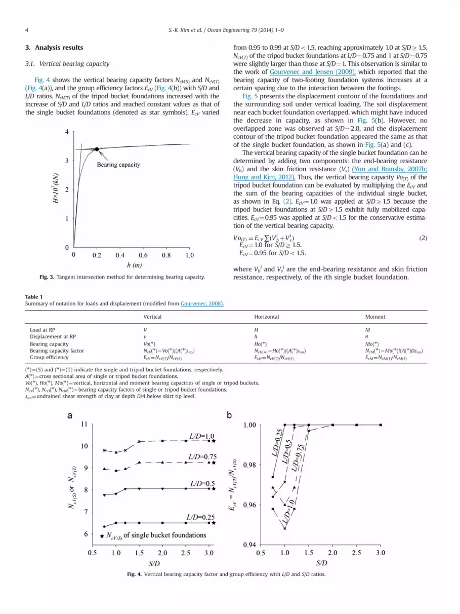
Fig. 4 shows the vertical bearing capacity factors NcV(S) and NcV(T)
(Fig. 4(a)), and the group efficiency factors EcV (Fig. 4(b)) with S/D andL/D ratios. NcV(T) of the tripod bucket foundations increased with theincrease of S/D and L/D ratios and reached constant values as that ofthe single bucket foundations (denoted as star symbols). EcV varied
from 0.95 to 0.99 at S/Do1.5, reaching approximately 1.0 at S/DZ1.5.NcV(T) of the tripod bucket foundations at L/D¼0.75 and 1 at S/D¼0.75were slightly larger than those at S/D¼1. This observation is similar tothe work of Gourvenec and Jensen (2009), which reported that thebearing capacity of two-footing foundation systems increases at acertain spacing due to the interaction between the footings.
Fig. 5 presents the displacement contour of the foundations andthe surrounding soil under vertical loading. The soil displacementnear each bucket foundation overlapped, which might have inducedthe decrease in capacity, as shown in Fig. 5(b). However, nooverlapped zone was observed at S/D¼2.0, and the displacementcontour of the tripod bucket foundation appeared the same as thatof the single bucket foundation, as shown in Fig. 5(a) and (c).
The vertical bearing capacity of the single bucket foundation can bedetermined by adding two components: the end-bearing resistance(Vb) and the skin friction resistance (Vs) (Yun and Bransby, 2007b;Hung and Kim, 2012). Thus, the vertical bearing capacity Vo(T) of thetripod bucket foundation can be evaluated by multiplying the EcV andthe sum of the bearing capacities of the individual single bucket,as shown in Eq. (2). EcV¼1.0 was applied at S/DZ1.5 because thetripod bucket foundations at S/DZ1.5 exhibit fully mobilized capa-cities. EcV¼0.95 was applied at S/Do1.5 for the conservative estima-tion of the vertical bearing capacity.
VoðTÞ ¼ EcV∑ðVibþVi
sÞ ð2ÞEcV¼1.0 for S/DZ1.5.EcV¼0.95 for S/Do1.5.
where Vbi and Vs
i are the end-bearing resistance and skin frictionresistance, respectively, of the ith single bucket foundation.Fig. 3. Tangent intersection method for determining bearing capacity.
Table 1Summary of notation for loads and displacement (modified from Gourvenec, 2008).
Vertical Horizontal Moment
Load at RP V H MDisplacement at RP v h θ
Bearing capacity Vo(n) Ho(n) Mo(n)Bearing capacity factor NcV(n)¼Vo(n)/(A(n)suo) NcH(n)¼Ho(n)/(A(n)suo) NcM(n)¼Mo(n)/(A(n)Dsuo)Group efficiency EcV¼NcV(T)/NcV(S) EcH¼NcH(T)/NcH(S) EcM¼NcM(T)/NcM(S)
(n)¼(S) and (n)¼(T) indicate the single and tripod bucket foundations, respectively.A(n)¼cross sectional area of single or tripod bucket foundations.Vo(n), Ho(n), Mo(n)¼vertical, horizontal and moment bearing capacities of single or tripod buckets.NcV(n), NcH(n), NcM(n)¼bearing capacity factors of single or tripod bucket foundations.suo¼undrained shear strength of clay at depth D/4 below skirt tip level.
Fig. 4. Vertical bearing capacity factor and group efficiency with L/D and S/D ratios.
S.-R. Kim et al. / Ocean Engineering 79 (2014) 1–94

3.2. Horizontal bearing capacity
Fig. 6 shows the horizontal bearing capacity factors NcH(S) andNcH(T) of the single bucket foundations and the tripod bucketfoundation respectively, and the group efficiency factors EcH withS/D and L/D ratios. The values at S/D¼0 indicate the capacity factorsNcH(S) of the single bucket foundations, which were allowed to befreely rotated during loading. The maximum horizontal bearingcapacity of the single bucket foundation under horizontal load canbe numerically obtained by constraining the rotational degree offreedom and indicated as the star symbol for comparison. NcH(T) of
the tripod bucket foundation increased with S/D ratio and stabilizedat a certain value, which was identical to the bearing capacity factorof the single bucket with fixed rotation. EcH also increased with theS/D and L/D ratios, but the factor with higher L/D ratios significantlyincreased with the S/D ratio, as shown in Fig. 6(b).
Fig. 7 presents the displacement contour of the bucket founda-tions at L/D¼1 under horizontal load. The single bucket with freerotation showed the combined horizontal and rotational move-ments, as shown in Fig. 7(a). The tripod bucket foundation atS/D¼2 showed the horizontal movement without any rotation(Fig. 7(c)), which was the same as that of the single bucket
Magnitude (m) Magnitude (m)
Magnitude (m)
Fig. 5. Displacement contours of foundations and soil under vertical loading (L/D¼1): (a) single bucket (kD/sum¼10); (b) tripod bucket (S/D¼1, kD/sum¼10); and (c) tripodbucket (S/D¼2, kD/sum¼10).
Fig. 6. Horizontal bearing capacity factors and group efficiency with L/D and S/D ratios.
S.-R. Kim et al. / Ocean Engineering 79 (2014) 1–9 5

foundation with fixed rotation in Fig. 7(b). These observationssuggested that the horizontal capacity factors of the tripod bucketfoundation at S/DZ2 were similar to that of the horizontalcapacity factors of the single buckets with fixed rotation.
Simple equations for evaluating the horizontal bearing capacityof the tripod bucket foundation were proposed based on the FEresults as shown in Eqs. (3)–(6). The equations were proposedbased on curve fitting techniques and expressed as functions ofS/D and L/D ratios. The horizontal capacity of the tripod bucketfoundation Ho(T) can be calculated by multiplying the efficiencyfactor EcH and the capacity of the single bucket foundation Ho(S).
HoðTÞ ¼ EcHNcHðSÞAðTÞsuo ð3Þ
EcH ¼ 1þα 1�eð�βS=DÞ� �
ð4Þ
α¼ 1:26LD
� �2:4
ð5Þ
β¼ 1:5�0:3LD
� �ð6Þ
where Ho(T) is bearing capacity of the tripod bucket foundation;EcH is the horizontal efficiency factor; NcH(S) is bearing capacityfactor of the single bucket foundation at free rotation; A(T) is thecross-sectional area of the tripod bucket foundation; suo is theundrained shear strength at depth D/4 below the skirt tip level.
Rotation point
Magnitude (m) Magnitude (m)
Magnitude (m)
Fig.7. Displacement contours of foundations and soil under horizontal loading (L/D¼1): (a) single bucket (free rotation, kD/sum¼10); (b) single bucket (fixed rotation,kD/sum¼10); and (c) tripod bucket (S/D¼2, kD/sum¼10).
Fig. 8. Moment bearing capacity factors and group efficiency with L/D and S/D ratios.
S.-R. Kim et al. / Ocean Engineering 79 (2014) 1–96

3.3. Moment bearing capacity
Fig. 8 shows the moment bearing capacity factors NcM(T) andthe efficiency factor EcM with S/D and L/D ratios. Fig. 8(a) indicatesthat the NcM(T) linearly increased with the increasing moment armS because the tripod bucket resisted as a push–pull system of theindividual bucket against the overturning moment (Senders, 2005;Houlsby et al., 2005). EcM in Fig. 8(b) also increased with S/D ratio,although the factor decreased as the L/D ratio increased, whichwas unlike the NcM(T) factor.
Fig. 9 shows the displacement contour of the single and tripodbucket foundations at S/D¼1 and 2.5. The single bucket founda-tion under moment loading exhibited rotational movement, asshown in Fig. 9(a). Notably, the rotation center of the tripod bucketwas located in the downward bucket as shown in Fig. 9(b) and (c).
For clays under undrained conditions, the upward verticalbearing capacities are mobilized by suction pressure developedin the plugged soil and by the skin friction resistance. Thus, theupward pull-out capacity would be similar to the compressioncapacity (Watson and Randolph, 1997). Therefore, the momentcapacity of the tripod bucket foundation Mo(T) can be evaluated bymultiplying the vertical capacity of the single bucket foundationVo(S) and the length of the moment arm, as shown in Eq. (7).The length of the moment arm was determined as 1.5S, asindicated in Fig. 10. The correction factor fM was introduced torelate the theoretical moment capacity to the FE results. fM wasdetermined as 1.1 by back-calculation after applying the Vo(S) fromthe FE results and the corresponding S values.
MoðTÞ ¼ f M jVoðsÞj1:5s ð7Þ
where fM is the correction factor for moment capacity; fM¼1.1 wassuggested in this study.
Alternative equations were proposed to calculate Mo(T). Mo(T)can be calculated by multiplying the Mo(S) and the efficiency factor
EcM. EcM can be expressed as the function of S/D and L/D ratios.
MoðTÞ ¼ EcMNcMðsÞAðTÞDsuo ð8Þ
EcM ¼ 1þλsD
ð9Þ
λ¼ 5:6eð�0:8ðL=DÞÞ ð10Þ
where Mo(T) is moment bearing capacity of the tripod bucketfoundation; EcM is the moment efficiency factor; NcM(S) is bearingcapacity factor of the single bucket.
Rotation point
Magnitude (m)
Magnitude (m)
Rotation point
Rotation point
Magnitude (m)
Fig. 9. Displacement contours of buckets and soil under moment loading (L/D¼1): (a) single bucket (kD/sum¼10); (b) tripod bucket (S/D¼1, kD/sum¼10); and (c) tripodbucket (S/D¼2.5, kD/sum¼10).
Downward bucket
Upward bucket
1.5S
Moment arm
Rotation axis
D
Fig. 10. Definition of moment arm length based on numerical results.
S.-R. Kim et al. / Ocean Engineering 79 (2014) 1–9 7

3.4. Effect of non-homogeneity of clay on group efficiency factor
The group efficiency factor in the study was evaluated at kD/sum¼10, which corresponds to the usual clay condition. To analyzethe effect of non-homogeneity of clay, the efficiency factors atdifferent kD/sum ratios were evaluated. Previous studies indicatedthat the bearing capacity factors of the single bucket foundationsin clay were not significantly varied at kD/sumZ10 (Hung and Kim,2014). Therefore, kD/sum¼2 and 4 were selected for furtheranalysis. The input parameters are given in Table 2.
Fig. 11 shows the comparison of the efficiency factors accordingto kD/sum. The efficiency factors were almost identical regardless ofthe change in kD/sum ratios. The invariability of the efficiency
factor regardless of kD/sum can be explained by the similarity in thesoil displacement at the different kD/sum values for the samefoundations. Thus, the non-homogeneity of clay had a negligibleeffect on the group efficiency factors of the tripod bucketfoundations.
4. Conclusions
The three dimensional finite element analyses were performedto evaluate the bearing capacity of the single and the tripod bucketfoundations in clay. From the finite element analysis, the groupefficiency factors, which are the ratio of the bearing capacitiesof the tripod bucket foundations to that of the single bucketfoundations were evaluated for vertical, horizontal and momentloadings. The following conclusions were drawn:
(1) The vertical bearing capacity factor of the tripod bucketfoundation increased with increasing S/D and L/D ratios.At S/DZ1.5, the factor was almost identical with that of thesingle bucket foundation. The vertical bearing capacity of the
Table 2Input values for analyzing the effect of non-homogeneity of soil.
L/D S/D k (kPa/m) sum (kPa) kD/sum
0.5 0–3 1.3 3.25 41 0–3 1.25 6.25 2
Fig. 11. Comparison of group efficiency factors at various kD/sum ratios: (a) vertical efficiency; (b) horizontal efficiency and (c) moment efficiency.
S.-R. Kim et al. / Ocean Engineering 79 (2014) 1–98

tripod bucket foundation can be calculated by multiplying thesum of the vertical bearing capacity of individual buckets andthe efficiency factor. The vertical efficiency factor was deter-mined as 0.95 at S/Do1.5 and 1.0 at S/DZ1.5
(2) The horizontal capacity factor increased with increasing L/Dand S/D ratios because the tripod bucket foundation was moreinclined to move horizontally than to rotate. The factorreached the maximum value at S/DZ2, which was similar tothat of the single bucket foundation under fixed rotation. Thehorizontal bearing capacity of the tripod bucket founda-tion can be obtained by applying the efficiency factor andthe horizontal bearing capacity factor of the single bucketfoundation.
(3) The single bucket foundation resisted the moment loading by therotational movement, whereas the tripod bucket foundationresisted the moment loading by the vertical pull-out and push-in resistances of individual buckets. Thus, the new equation wasproposed to evaluate the moment capacity of the tripod bucketfoundation by multiplying the vertical bearing capacity of thesingle bucket foundation with the moment arm of 1.5S and thecorrection factor of 1.1. In addition, the moment bearing capacityof the tripod bucket foundation can be evaluated by using theefficiency factor and the moment bearing capacity factor of thesingle bucket foundation.
Acknowledgments
The present research was supported by a grant from the KoreaInstitute of Construction and Transportation Technology Evalua-tion and Planning (KICTTEP) and from the Ministry of Land,Transport, and Maritime Affairs (MLTM) R&D program (2010Construction Technology Innovation Program, 10-CTIP-E04), andby Basic Science Research Program through the National ResearchFoundation of Korea (NRF) funded by the Ministry of Education(NRF-2012R1A1A2A10042889).
References
Barari, A., Ibsen, L.B., 2012. Undrained response of bucket foundations to momentloading. Appl. Ocean Res. 36, 12–21.
Bienen, B., Gaudin, C., Cassidy, M.J., Rausch, L., Purwana, O.A., 2012. Numericalmodelling of a hybrid skirted foundation under combined loading. Comput.Geotech. 45, 127–139.
Bransby, M.F., Randolph, M.F., 1997. Shallow foundation subject to combinedloadings. In: Proceedings of the 9th International Conference on ComputerMethods and Advances in Geomechanics. Wuhan, China, vol. 3, pp. 1947–1956.
Bransby, M.F., Randolph, M.F., 1999. The effect of embedment depth on theundrained response of skirted foundations to combined loading. Soils Found.39 (4), 19–33.
Bransby, M.F., Yun, G., 2009. The undrained capacity of skirted strip foundationunder combined loading. Geotechnique 59 (2), 115–125.
Byrne, B.W., Cassidy, M.J., 2002. Investigating the response of offshore foundationsin soft clay soils. In: Proceedings of the 21st International Conference onOffshore Mechanics and Arctic Engineering OMAE002. Oslo, paper OMAE2002-28057.
Coffman, R.R., El-Sherbiny, R.M., Rauch, A.F., 2004. Measured horizontal capacity ofsuction caissons. In: Proceedings of the Offshore Technology Conference, OTC16161. Houston, Texas, USA, pp. 1–10.
Gourvenec, S., 2008. Effect of embedment on the undrained capacity of shallowfoundations under general loading. Géotechnique 58 (3), 177–185.
Gourvenec, S., Jensen, K., 2009. Effect of embedment and spacing of conjoinedskirted foundation systems on undrained limit states under general loading.Int. J. Geomech. 9 (6), 267–279.
Gourvenec, S., Mana, D.S.D., 2011. Undrained vertical bearing capacity factors forshallow foundations. Géotech. Lett. 1, 101–108.
Gourvenec, S., Steinepreis, M., 2007. Undrained limit states of shallow foundationsacting in consort. Int. J. Geomech. 7 (3), 194–205.
Gourvenec, S., Randolph, M., 2003. Effect of strength non-homogeneity on theshape of failure envelopes for combined loading of strip and circular founda-tions on clay. Géotechnique 53 (6), 575–586.
Houlsby, G.T., Ibsen, L.B., Byrne, W.B., 2005. Suction caissons for wind turbines. In:Gourvenec, Cassidy (Eds.), Frontiers on Offshore Geotechnics (ISFOG 2005).Taylor & Francis Group, London, ISBN: 041539063X, pp. 75–93
Houlsby, G.T., Martin, C.M., 2003. Undrained bearing capacity factors for conicalfooting on clay. Géotechnique 53 (5), 513–520.
Houlsby, G.T., Wroth, C.P., 1983. Calculation of stresses on shallow penetrometersand footings. Proceedings of the IUTAM/IUGG Symposium on SeabedMechanics, Newcastle upon Tyne, pp. 107–112.
Hung, L.C., Kim, S.R., 2012. Evaluation of vertical and horizontal bearing capacitiesof bucket foundations in clay. Ocean Eng. 52, 75–82.
Hung, L.C., Kim, S.R., 2014. Evaluation of undrained bearing capacities of bucketfoundations under combined loads. Mar. Georesour. Geotechnol. 32 (1), 76–92.
Lambe, T.W., Whitman, R.V., 1969. Soil Mechanics, SI Version. John Willey & Sons,New York, USA, 553 pp.
Mansur, C.I., Kaufman, J.M., 1956. Pile tests, low-sill structure, Old River, Louisiana. J.Soil Mech. Found. Div., ASCE 82 (SM5), 1–33.
Martin, C.M., Hazell, E.J., 2005. Bearing capacity of parallel strip footing on non-homogeneous clay. In: Gourvenec, Cassidy (Eds.), Frontiers on Offshore Geo-technics (ISFOG 2005). Taylor & Francis Group, London, ISBN: 041539063X,pp. 427–441
Mesri, G., 1989. A re-evaluation of su(mob)¼0.22s0p using laboratory shear tests. Can.
Geotech. J. 26 (1), 162–164.Murff, J.D., 1994. Limit analysis of multi-footing foundations under eccentric and
inclined loads. In: Proceedings of the 3rd International Conference of SMFE. vol.1, pp. 440–445.
Nguyen, L.S., Houlsby, G.G., 2005. The theoretical modeling of a suction caissonfoundation using hyperplasticity theory. In: Gourvenec, Cassidy (Eds.), Frontierson Offshore Geotechnics (ISFOG 2005). Taylor & Francis Group, London, ISBN:041539063X, pp. 417–423
Randolph, M.F., Gourvenec, S., 2011. Offshore Geotechnical Engineering. Taylor &Francis, Spon Press, UK (528 pp.)
Rattley, M.J., Lehane, B.M., Richards, D.J., Goudin, C., 2005. An experimental andnumerical study of rate effects for plate anchors in clayIn: Gourvenec, Cassidy(Eds.), Frontiers on Offshore Geotechnics (ISFOG 2005). Taylor & Francis Group,London, ISBN: 041539063X197–202
Senders, M., 2005. Tripod with suction caissions as foundations for offshore windturbines on sand. In: Gourvenec, Cassidy (Eds.), Frontiers on Offshore Geotech-nics (ISFOG 2005). Taylor & Francis Group, London, ISBN: 041539063X,pp. 397–410
Simulia, 2010. Abaqus user0s ManualDassault Systèmes Simulia Corp., Providence, RITaiebat, H.A., Carter, J.P., 2000. Numerical studies of the bearing capacity of shallow
foundations on cohesive soil subjected to combined loading. Géotechnique 50(4), 409–418.
Veritas, Det Norske, 2007. Design of offshore wind turbine structures. OffshoreStandard DNV-OS-J101.
Watson, P.G., Randolph, M.F., 1997. Vertical capacity of caisson foundations incalcareous sediments. In: Proceedings of the 7th International Offshore andPolar Engineering Conference. Honolulu, Hawai, USA, pp. 784–790.
Yun, G., Bransby, M.F., 2007a. The horizontal-moment capacity of embeddedfoundations in undrained soil. Can. Geotech. J. 44 (4), 409–427.
Yun, G., Bransby, M.F., 2007b. The undrained vertical bearing capacity of skirtedfoundations in undrained soil. Soils Found. 47 (3), 493–506.
Zhang, Y., Bienen, B., Cassidy, M.J., Gourvenec, S., 2012. Undrained bearing capacityof deeply buried flat circular footings under general loading. ASCE J. Geotech.Geoenviron. Eng. 138 (3), 385–397.
Zhan, Y.G., Liu, F.C., 2010. Numerical analysis of bearing capacity of suction bucketfoundations for offshore wind turbines. Electron. J. Geotech. Eng. 15, 633–644.
S.-R. Kim et al. / Ocean Engineering 79 (2014) 1–9 9


