Embed Size (px)
Citation preview

Heteroepitaxial ZnO nano hexagons on p-type
SiC
Volodymyr Khranovskyy, I Tsiaoussis, Gholamreza Yazdi, Lars Hultman and Rositsa
Yakimova
Linköping University Post Print
N.B.: When citing this work, cite the original article.
Original Publication:
Volodymyr Khranovskyy, I Tsiaoussis, Gholamreza Yazdi, Lars Hultman and Rositsa
Yakimova, Heteroepitaxial ZnO nano hexagons on p-type SiC, 2010, JOURNAL OF
CRYSTAL GROWTH, (312), 2, 327-332.
http://dx.doi.org/10.1016/j.jcrysgro.2009.09.057
Copyright: Elsevier
http://www.elsevier.com/
Postprint available at: Linköping University Electronic Press
http://urn.kb.se/resolve?urn=urn:nbn:se:liu:diva-54065
Heteroepitaxial ZnO nano hexagons on p-type SiC
V Khranovskyy1, I Tsiaoussis
2, G R Yazdi
1, L Hultman
1and R Yakimova
1
1Department of Physics, Chemistry and Biology (IFM), Linköping University, SE-58183
Linköping, Sweden2 Solid State Physics Section, Department of Physics, Aristotle University of Thessaloniki, GR-
54124 Thessaloniki, Greece
Abstract
ZnO single crystal nanohexagons have been grown heteroepitaxially on p-type Si-face 4H-SiC substrates with 8o
miscut from [0001] by catalyst-free atmospheric pressure metalorganic chemical vapor deposition and characterized
by x-ray diffraction, scanning and transmission electron microscopy as well as energy disperse x-ray and
cathodoluminescence analyses. The as-grown ZnO nanohexagons have a pillar shape terminated by a and c plane
facets, and are aligned along the growth direction with the epitaxial relation [0001]ZnO//[0001]4H-SiC and
[101 0]ZnO//[1010]4H-SiC. The ZnO nanohexagons demonstrate intense UV emission ( NBE = 376 nm) and negligible
defect related luminescence.
PACS: 81.16.-c, 81.07.-b, 61.46.Km, 68.37.Lp, 78.67.-n
Keywords: A1. Crystal structure, A1. Nanostructures, A1. Interfaces, A3. Metalorganic chemical
vapor deposition, B3. Light emitting diodes.
*Corresponding author: Volodymyr Khranovskyy, Linkoping University, Department of Physics,
Chemistry and Biology, SE-58183, Linkoping, Sweden Tel.: +4613285776 Fax : +4613142337 E-mail:
Click here to view linked References

1. Introduction
During the last decade ZnO has become interesting as a semiconductor material for device
fabrication. Due to its properties such as wide band gap (3.37 eV at RT), high exciton binding
energy (60 meV at RT), and optical transparency for visible light, ZnO is a prospective material
for micro-, opto- and transparent electronics [1]. Implementations in room temperature
spintronics are also foreseen [1]. Recently promising application of ZnO as UV nanolasers [2],
field effect transistors [3], solar cell electrodes [4] and nanogenerators [5] have been reported.
ZnO exhibits aptitude for nanotechnology, due to its viability to be grown as low-dimensional
nanoscaled structures of various shapes and morphologies. Indeed, ZnO possesses the richest
family of nanostructures being obtained [6]. Additional advantages are the convenience and
simplicity of the growth techniques, in comparison to other wide band gap semiconductors, e.g.
GaN and SiC.
However, it remains a central issue to obtain spectrally monochromatic ZnO material.
Having a band gap of 3.37 eV, ZnO should emit in the range of 366 nm to 380 nm (A-UV
radiation), but commonly the emission spectra of ZnO consist of two luminescence bands. The
narrow peak of the near band edge excitonic emission is typically accompanied by a broad
visible emission, so called “green-
origin of the visible luminescence is still under debate, but it is most probably related to Zn
atoms as interstitials (Zni) and/or oxygen vacancies (Vo) [9]. Recently, we demonstrated that
hydrogen incorporation into ZnO nanostructured films results in a “purification” of the ZnO
emission spectra and an increase of the near band edge (NBE) excitonic emission intensity [10].
Another persistent problem is to obtain p-type material: usually the intrinsic (as-grown) ZnO is
of n-type conductivity, which is difficult to overcome due to a self-compensation effect.

Nevertheless, there are several reports claiming a successful p-type ZnO preparation, e. g., [11-
15]. However, the low hole mobility [12], time instability [13], non-reproducibility [14] and/or
impractical growth techniques [15] of the obtained material brings doubts whether the p-type
problem is as by today confidently solved. While light-emitting diodes based on ZnO p-n
homojunction have been reported [16], the prepared devices demonstrated low optical quality
with defect-related luminescence in the visible range [17] and low emission intensity [18].
An alternative approach may be the heteroepitaxial growth of ZnO on p-type SiC [19]. SiC is
attractive due to the similarity of the crystal structures and small lattice and thermal mismatch
a6H-SiC = 0.308 nm, TEC6H-SiC = 4.3×10⁻⁶/K, while a ZnO = 0.3252 nm, TECZnO = 6.51×10⁻⁶/K [20,
21], giving a misfit in the basal plane 5.4%. Although a high interest in fabrications of ZnO/p-
SiC heterojunctions has been shown in recent years, efficient UV light emitting diodes have not
been proven [9]. Structural/interfacial defects are suggested to be responsible for the
enhancement of the defect emission and the quenching of NBE emission [10]. Since Park and Yi
demonstrated potential applications of ZnO nanorods for ultraviolet light emitting diodes [22],
heterostructures of ZnO nanorods on different substrates have been intensively studied. This far
the nanorods have been considered non-faceted. Decreasing the size of the ZnO functional
elements (nanosized p-n junction) can be a solution toward obtaining monoemission spectra due
to a better structural quality and improved stoichiometry, which is a common problem in II-VI
compounds. The quality of the hetero interface is of primary importance, since it may be an
origin of extended defects acting as non-radiative recombination centers [23]. The influence of
heterointerface roughness on ZnO nanorods growth has been investigated by Park et al. [24].
Atomically abrupt heterojunction of ZnO nanorods on SiC nanowires was recently reported [25].
However, both materials had a developed random morphology, which limits their applications.
Hence, the fabrication of aligned nanosize ZnO/SiC heterojunctions of high structural and

interface quality, capable of monochromatic intense light emission remains a significant
nanotechnological challenge.
In this paper we report epitaxial growth of self-aligned n-type ZnO hexagonal nanorods
(nanohexagons) on p-type 4H-SiC substrates. We demonstrate enhanced UV emission in this as-
prepared ZnO material, consistent with the accomplished improvements in structure and
interface quality.
2. Experimental details
2.1 Sample growth
The ZnO nanostructures were grown by atmospheric pressure metalorganic chemical
vapor deposition (APMOCVD) using Zn acetylacetonate and oxygen as zinc and oxygen
precursors, respectively. The substrate temperature was kept at 500 °C, the flow rates of Ar, as a
buffer gas, and oxygen were 50 and 25 sccm, respectively [26]. The commercial 4H-SiC [0001]
substrates were miscut by 8° off the c- axis to [11 2 0] and then a p-SiC layer was grown by
sublimation epitaxy [27]. The layer thickness and the net acceptor concentrations were
and ~ 5 1016 cm-3, respectively. The off-axis substrate provides conditions for step flow growth
mode of SiC, which typically results in step bunching yielding terraces with different width [28].
We supposed that the steps on such surfaces would favor the nucleation process.
2.2 Characterization
Structural properties of the ZnO samples were investigated by x-ray diffraction (XRD)
- figures using a Siemens D5000 difractometer, utilizing Cu-K radiation
( = 0.1542 nm). Scanning electron microscopy (SEM) was used to characterize microstructure
and elemental mapping was made by Energy Disperse X-ray (EDX) analysis in a Leo 1550
Gemini SEM (at operating voltage ranging from 10 kV to 20 kV and standard aperture value 30
m). The microstructure study of the ZnO nanorods was carried out using conventional and

high-resolution TEM (HRTEM). For the cross-section TEM (XTEM) specimen preparation, two
strips of the specimen were cut and glued face to face, then were mechanically thinned down to
25 µm. Subsequently the specimens were thinned to electron transparency by Ar ion milling with
energy of 4 kV, at a low incident angle of 4o in order to avoid amorphisation artefacts from the
argon ions. For the conventional characterization a TEM JEM 120 CX was used, while for the
HRTEM investigation a JEM 2011 having 0.194 nm point to point resolution was utilized.
Cathodoluminescence (CL) spectra were taken in the Leo 1550 Gemini SEM equipped with a
MonoCL system (Oxford Instruments) using a 10 keV electron beam and 30 m of aperture with
1800 lines mm grating. Panchromatic images of ZnO/SiC samples were taken to trace the
difference in emission intensity.
3. Results and discussion
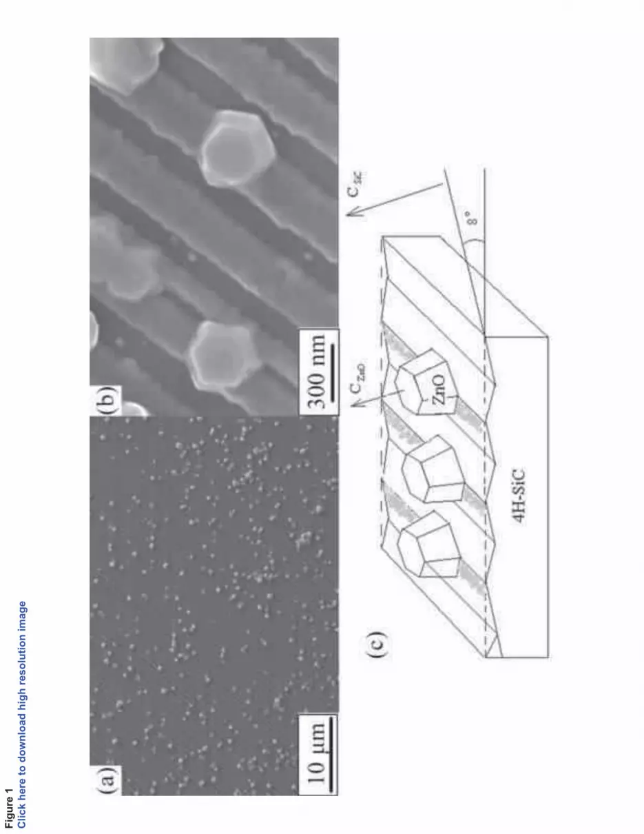
Figure 1(a) and 1(b) present SEM images taken from an as-grown sample. The sample
exhibits surface steps along SiC [11- 2 0] and nano hexagons. Due to anisotropy of growth rate in
wurtzite semiconductors and minimization of the surface energy, vicinal surfaces of SiC show
self-ordering phenomena, resulting in step bunching [29]. In our 8o off 4H-SiC the bunched step
configurations with an integer number (1,2,3,…) of unit cell height are energetically stabilized
where the number depends on the growth conditions [30]. Here, the 4H-SiC utilized has 20 nm
bunched step height. The nanohexagons of alleged ZnO composition in figure 1(a) and (b) have
an a-plane-faceted hexagonal shape (1 2 00) facets with a top c-plane facet reflecting the crystal
symmetry of ZnO and suggesting a single-crystal nature. These hexagons have a characteristic
azimuthal diameter of 200 - 350 nm and height of ~200 nm. Figure 1(c) is a sketch illustrating
the orientation relationship between the ZnO nanohexagons and the SiC substrate. The
nanohexagons are aligned along the ZnO c-axis with an 8° tilt corresponding to the substrate
miscut. It should be mentioned that during the XRD measurements it was possible to identify the
signal from ZnO HEX only after subtraction of 8° from the angle of the incident x-ray beam,
assuming 8° misorientation from the c-axis towards [11 2 0] direction. This is actually the step
flow direction during the growth of the SiC epitaxial layer. This shows that the ZnO
nanohexagons were grown not perpendicularly to the substrate plane, but to the (0001) plane of
SiC, i.e., epitaxially onto the SiC substrate. Figure 2 shows cross-sectional TEM micrographs
from the ZnO/SiC heterointerface taken along the 4H-SiC [11 2 0] zone axis (along the step
edges as an overview and a higher magnification image. While a few crystallites touch each
other, as seen in SEM (Figure. 1a), the apparent proximity between the crystallites in figure 2a is
an artifact because of the projective nature of the TEM technique and sample thickness of about
200 nm. When the cross section specimen is much thinner individual crystallites are evident as
shown in figure 2b. The crystallites have a trapezoidal shape with flat planes on top forming an
angle of 8o with respect of the miscut substrate. This confirms that the growth of ZnO follows
the c-axis of 4H-SiC. The nanocrystallites nucleate at the step edge and expand laterally and
vertically, ultimately overgrowing the step, over the adjacent terraces, as shown by arrows in
Figure 2b. The XTEM image also indicates the presence of a few monolayer-thick ZnO film on
top of the SiC terraces in between the ZnO hexagons. The SEM images from the ZnO-deposited
samples also reveal ~20 nm wide longitudinal stripes along the direction expected for the
terraces of the miscut SiC substrate, however, with a stronger contrast (bright in Figures 1(a, b)
than for the virgin substrate. A schematic representation is depicted in Figure 1c. The EDX and
CL analyses presented below imply that there is a Stranski-Krastanov (3D-island on 2D-layer)
growth mode for the ZnO on SiC. Thus, the origin of the stripes is a decoration of SiC terraces
by ZnO. Indeed, a thin layer was observed by XTEM (Figure 2b).
Figure 3 shows a plan-view TEM image from an as-deposited sample after ion beam
thinning from the substrate side. The image confirms the presence of the thin ZnO layer that
completely covers the SiC terraces as seen by the Moirée pattern. In addition, Fig 3 reveals the

presence of ZnO domains with a mean size of 40 nm, which are slightly misoriented, exhibiting
a mosaic structure. The misorientation of the grains is evident from the distortions of the Moiré
pattern, which are denoted by arrows in Figure 3a. In our case the actual in-plane misorientation
of the nanograins in respect to the SiC matrix is 0.3o. The mosaic structure of the film is also
illustrated by the diffuse diffraction pattern in Figure 3b. In Figure 4, images obtained by
mapping the elements Zn, O and Si, are presented along with the SEM image of the scanned
area. The Zn and O signals are clearly correlated with the nano hexagons, but also with the
stripes, however, of faint contrast consistent with the mosaic structure of the 2D-layer of ZnO
not much thicker than a few atomic layers (about 1 nm). The signal of Si was detected over the
whole area of scanning which is due to a high penetration of the excitation electron beam, thus
probing the SiC substrate. Nevertheless, the area where the ZnO HEX nanorods are located,
displayed a lower intensity of the Si signal.
In order to determine the epitaxial relationship of ZnO nanohexagons and SiC substrate
we performed pole figure XRD measurements ( scan). Pole figures are widely used to examine
the epitaxial relationship or the in-plane orientation of ZnO films [31, 32]. For the {1 1 2 }
family of planes, sixfold peaks are expected, which reflects the hexagonal structure of the unit
cell. Figure 5 shows the scans of the ZnO hexagons {1 1 2 2} family of planes together with
the scan of the {1 1 2 6} family of planes of the SiC substrate. The obvious six-fold
symmetry unambiguously demonstrates that the ZnO hetero structures containing the hexagons
are grown epitaxially - H-SiC heterostructure
exhibits only (0002) and (0004) diffraction peaks characteristic of ZnO, which evidences a good
structural quality. Table 1 presents data on interplanar space, lattice constant, strain and stress
along c-axis obtained by Bragg’s equation [33, 34] and biaxial strain model [35]. Using the
interplanar spacing the stress along the c-axis of the ZnO film can be expressed as [36]:

bulk
bulkfilm
filmc
cc
c
cccc
13
121133132
2
)(2(1)
where filmc and bulkc are the c-lattice parameters of the ZnO thin film and bulk reference,
respectively. The values of the elastic constant of single-crystal ZnO are used, 11c =208.8 GPa,
33c =213.8 GPa, 12c =119.7 GPa and 13c =104.2 GPa. ÅcBulk 2067.5 as obtained from the
ASTM card for bulk ZnO [33-36]. From Table 1 one can conclude that the ZnO/4H-SiC
heterostructures are virtually unstrained, i.e. the ZnO nanohexagons are relaxed. From the TEM
study it also follows that the nanohexagons are in perfect epitaxial relation with the substrate
having the [0001]ZnO//[0001]4H-SiC and the [1010]ZnO//[1010]4H-SiC as shown in the selected area
diffraction (SAD) in figure 6(a), which was taken from a typical crystallite. In the rare case of
coalescence of the nanohexagons, threading dislocations are observed in the resultant larger
hexagon, as shown by an arrow in figure 6(b). Figure 6 (c) is a high-resolution micrograph from
the ZnO/4H-SiC interface. The crystal planes are continuous across the heterointerface to the
ZnO layer on the SiC terraces as well as to the hexagons confirming the epitaxial quality of the
film. Growth of faceted ZnO nanorods on n-type 4H-SiC by using metal catalyst is reported in
Ref. [38]. However, the emission spectra of the prepared material possess strong luminescence in
the visible range, typically assigned to defects. We investigated the luminescence properties of
the fabricated ZnO nanohexagons containing samples by cathodoluminescence measurements at
room temperature in terms of possible optoelectronic applications. The CL spectra of the sample
demonstrated intense peak of ultraviolet emission a
was negligible (Figure 7a). The spectral line of the UV emission is very narrow – the full width
at half maximum is as low as 12 nm. We assign the luminescence observed to the near band edge
(NBE) excitonic emission [10]. Moreover, probing over the sample surface with different
concentration of ZnO nanohexagons displayed different signal intensity, but the characteristic

features of the spectra did not change. In order to differentiate the contribution of the emission
from nanohexagons and the ZnO stripes, we recorded their emission spectra separately. In Figure
7 CL spectra along with the probed regions are shown. Figure 7 (b) represents the panchromatic
image of the sample. Light is emitted by the whole area covered by ZnO, i.e. CL signal is also
observed from the stripes around hexagons, proving their emitting ability and ZnO nature.
However, it is evident that the emission intensity from ZnO stripes on top of the SiC terraces is
significantly lower than that from ZnO hexagons.
The spectra from both areas display the only peak of NBE emission. The absence of
visible emission which is related to point defects in the material suggests a good stoichiometry of
both types of ZnO. At the same time, the difference in the emission intensities may be explained
by a difference in the concentrations of extended structural defects. It has been reported that
structural defects as dislocations are mainly responsible for quenching of the luminescence
intensity [23]. The epitaxial interface followed by high structural quality, is a prerequisite of
obtaining the high light emission efficiency. Since the ZnO nanorods are relaxed heteroepitaxial
structures, misfit dislocations are expected, although they are invisible in the TEM images. We
assume that they do not affect the CL properties since they are confined at the interface.
Conclusions
The fabrication feasibility of high-quality ZnO nano-crystal material by heteroepitaxial
growth on p-type 4H-SiC has been demonstrated. The ZnO nanohexagons form via Stranski-
Krastanow growth mode: a few monolayers of ZnO grow on the SiC terraces on top of which
ZnO nanohexagons evolve. The hexagons are regular in shape with a- and c-plane faceting. A
perfect epitaxial relationship and a high quality interface between the ZnO HEX and the SiC
substrate was observed. The high intensity monochromatic emission demonstrated in the ZnO
nanohexagons is attributed to the single crystal structure, epitaxial relation and high quality

heterointerface. Accounting for the high optical quality and the availability of p-n junctions, the
structures prepared in this study can be considered as a promising key element for nano-
optoelectronics.
Acknowledgments
The financial support from the Swedish Institute, Swedish Research Council and the VINNEX
Centre FunMat is greatly acknowledged. The authors are grateful to Prof. J. Stoemenos for TEM
images and fruitful discussions.

References
[1] vrutin, S.-J. Cho
and H. Morkoç, J. Appl. Phys. 98 (2005) 041301
[2] M. H. Huang, S. Mao, H. Feick, H.Yan, Y. Wu, H. Kind, E. Weber, R. Russo and P.
Yang, Science 292 (2001) 1897
[3] S. Cha, J. Yang. Y. Choi, G. A. Amaratunga, G. W. Ho, M. E. Welland, D. G. Hasko, D.-
J. Kang and J. M. Kim, Appl. Phys. Lett. 89 (2006) 263102
[4] M. Law, L. E. Greene, J. C. Johnson, R. Saykally and P. D. Yang, Nat. Mater. 4 (2005)
455
[5] Z. L. Wang and J. Song, Science 312 (2007) 242
[6] Y. Quin, X. Wang, L. Z. Wang, Nature 451 (2008) 809
[7] K. Vanheusden C. H. Seager, W. L. Warren, D. R. Tallant, J. A. Voigt, Appl. Phys. Lett.
68 (1996) 403
[8] F. Leiter, H. Zhou, F. Henecker, A. Hofstaetter, D. M. Hoffman, B. K. Meyer, Physica B
908 (2001) 308
[9] D.C. Look, J. W. Hemsky, and J. R. Sizelove, Phys. Rev. Lett. 82 (1999) 2552
[10] V. Khranovskyy, G. R. Yazdi, G. Lashkarev, A. Ulyashin and R. Yakimova, Phys. Stat.
Sol. A 205 (2008) 144
[11] M. Joseph, H. Tabata and T. Kawai, Jpn. J. Appl. Phys. 38 (1999) 1205
[12] K. Minegishi, Y. Koiwai, Y. Kikuchi, K. Yano, M. Kasuga and A. Shimizu, Jpn. J. Appl.
Phys 36 (1997) L1453
[13] K. K. Kim, H.-S. Kim, D.-K. Hwang, J.-H. Lim, and S.-J. Park, Appl. Phys. Lett. 83
(2003) 63
[14] D. C. Look, D. C. Reynolds, C. W. Litton, R. L. Jones, D. B. Eason, and G. Cantwell,
Appl. Phys. Lett. 81 (2002) 1830
[15] Y. R. Ryu, T. S. Lee, J. H. Leem, and H. W. White, Appl. Phys. Lett. 83 (2003) 4032
[16] X.-L. Guo, J.-H. Choi, H. Tabata and T. Kawai, Jpn. J. Appl. Phys. 40 (2001) L177
[17] T. Aoki, Y. Hatanaka and D. C. Look, Appl. Phys. Lett. 76 (2000) 3257
[18] G. T. Du, W. F. LiU, J. M. Bian, L. Z. Hu, H. W. Liang, X. S. Wang, A. M. Liu and T. P.
Yang, Appl. Phys. Lett. 89 (2006) 052113
[19] A. Ashrafi, B. Zhang, N. Binh, K. Wakatsuki and Y. Segawa, Jpn. J. Appl. Phys. 43
(2004) 1114
[20] A. Ashrafi, N. Binh, B. Zhang, Y. Segawa, Appl. Phys. Lett. 84 (2004) 2814

[21] S. Hong, H. Ko, Y. Chen, T. Yao, J. Crystal Growth 209 (2000) 537
[22] W. I. Park and G.-C. Yi, Adv. Mater. (Weinheim, Ger.) 16 (2004) 87
[23] A. B. Djurisic and Y. H. Leung, Small 2 (2006) 944
[24] S.-H. Park, S.-Y. Seo, S.-H. Kim, and S.-W. Han, Appl. Phys. Lett. 88 (2006) 251903
[25] J. Y, Y. Ryu and K. Yong, Nanotechnology 16 (2005) 1712
[26] V. Khranovskyy, G. R. Yazdi, A. Larson, S. Hussain, P-O. Holtz, R. Yakimova, J. Opt.
Adv. Mater. 10 (2008) 2629
[27] M. Syväjärvi, R. Yakimova, H. Jacobsson and E. Janzén, J. Appl. Phys. 88 (2000) 1407
[28] M Syväjärvi, R Yakimova, A-L. Hylen and E Janzén, J. Phys.: Condensed Metter 11
(1999) 10019
[29] A. Shuchukin and D. Bimberg, Rev. Mod. Phys. 4 (1999) 71
[30] H. Nakagawa, S. Tanaka, and I. Suemune, Phys. Rev. Lett. 91 (2003) 226107-1
[31] C. Gorla, N. Emanetoglu, S. Liang, W. Mayo, Y. Lu, M. Wraback and H. Shen, J. Appl.
Phys. 85 (1999) 2595
[32] B. Zhang, L. Manh, K. Wakatsuki, T. Ohnishi, M. Lippmaa, N. Usami, M. Kawasaki and
Y. Segawa, Jap. J. Appl. Phys. 42 (2003) 2291
[33] B. Zhu, X. Sun, S. Guo, X. Zhao, J. Wu, R. Wu and J. Liu, J. Journ. Appl. Phys 45
(2006) 7860
[34] J. Hinze. and K. Ellmera, J. Appl. Phys. 88 (2000) 2443
[35] I. Akyuz, S. Kose, F. Atay and V. Bilgin, Semicond. Sci. Technol. 21 (2006) 1620
[36] H. Hsu, C. Cheng, C. Chang, S. Yang, S.-C. Chang and W.-F. Hsieh, Nanotechnology 16
(2005) 297
[37] Powder Diffraction File, Joint Committee on Powder Diffraction Standards, ICDD,
Newtown Square, PA, 2001, Card 36-1451
[38] Q. X. Zhao, P. Klason, M. Willander, Appl. Phys. A 88 (2007) 27

List of figures:
Fig. 1. SEM images of ZnO HEX nanostructures on a stepped SiC surface (a) an overview, (b) a
closer view: the light regions are ZnO, the dark area between the stripes reflects the steps; (c)
schematic representation of ZnO growth on 4H-SiC vicinal surface. The shadowed areas indicate
ZnO film on the SiC terraces, corresponding to the bright area in Figure 1b.
Fig. 2. XTEM images of the ZnO/SiC structure. (a) overview, b) ZnO nano rods and a thin ZnO
layer covering the SiC substrate (indicated by arrows) between the nano rods.
Fig. 3. a) Plan view TEM and b) corresponding selected area electron diffraction pattern from an
area of the sample containing thin ZnO layer covering the SiC substrate (apparent from Moirée
fringes).
Fig. 4. SEM image and corresponding EDX elemental maps of Si, Zn and O from a sample with
ZnO deposited on a SiC substrate.
Fig. 5. scans of the {1 1 2 2} family of planes of the ZnO/4H-SiC heterostructure and with
the scans of the {1 1 2 6} family of planes of the 8° off-cut 4H-SiC substrate.
Fig. 6. XTEM images from the ZnO/SiC heterointerface: (a) selected area diffraction (SAD),
taken from a ZnO crystallite; (b) demonstration of threading dislocation (marked by arrow); (c)
high-resolution (HREM) image of the interface between a ZnO nano hexagon and the 4H-SiC
substrate; respective interplanar distances are indicated.

Fig. 7. (a) RT CL spectra taken from ZnO grown on p-4H-SiC . The corresponding regions are
marked on the panchromatic CL image (b). The spectral range, where a possible defect emission
(DE) could be observed is indicated.
1

Table captions:
(002) – (002) peak position; d - interplanar
space, c – c- – - stress.

Table 1.
Sample (002),° d, Å c, Å -3 Reference
ZnO nano
hexagons
34.43 2.6033 5.2066 -0.08 +0.002 This work
ZnO films 34.51 2.5975 5.1950 -2.24 +0.5195 [26]
ZnO powder 34.42 2.6035 5.207 - - [37]
Fig
ure
1
Cli
ck h
ere
to
do
wn
load
hig
h r
eso
luti
on
im
ag
e

Fig
ure
2
Cli
ck h
ere
to
do
wn
load
hig
h r
eso
luti
on
im
ag
e

Fig
ure
3
Cli
ck h
ere
to
do
wn
load
hig
h r
eso
luti
on
im
ag
e

Fig
ure
4
Cli
ck h
ere
to
do
wn
load
hig
h r
eso
luti
on
im
ag
e

Fig
ure
5
Cli
ck h
ere
to
do
wn
load
hig
h r
eso
luti
on
im
ag
e

Figure 6
Click here to download high resolution image

Fig
ure
7
Cli
ck h
ere
to
do
wn
load
hig
h r
eso
luti
on
im
ag
e


