Embed Size (px)
Citation preview

Laboratory Manual for Practical Courses
M.Sc. Physics
Directorate of Distance and Continuing Education
Manonmaniam Sundaranar University
Tirunelveli – 627012
November 2021

I-year M.Sc. Physics Practical Experiments (DD&CE) 2021
2
Practical I: Electronics (DKPP1)
Contents Page no.
1 Op-amp as Integrator and Differentiator 3
2 Op-amp as Adder and Subtractor 6
3 Half Adder and Full Adder 11
4 Hallf Subtractor and Full Subtractor 14
5 Verification of Demorgan’s Law 17

I-year M.Sc. Physics Practical Experiments (DD&CE) 2021
3
1. OP-AMP AS INTEGRATOR AND DIFFERENTIATOR
AIM
To construct an integrator and differentiator using operational amplifier and trace its
waveform.
APPARATUS REQUIRED
IC741, 10KΩ resistor, 0.01 μ F capacitor, signal generator, trainer kit, connecting wires.
THEORY
Operational amplifier:
Operational amplifiers were used for mathematical operations such as addition, subtraction,
integration and differentiation. An OP-Amp is used to amplify both alternating and direct current
signals at the input. It is fundamentally a voltage amplifying device designed to be used with
external feedback components, resistors and capacitors between its output and input terminals.
An Op-amp is basically a three terminals device which consists of two high impedance
inputs, one is called the inverting input, marked with negative sign and the other one is called non
inverting input marked with positive sign.
Offset Null:
Due to high gain provided by IC741 even slight difference in voltages at the inverting and
non-inverting inputs, caused due to reregulating in manufacturing process or external disturbance
can influence the output. To nullify this effect voltage can be applied at pin 1 and pin 5 using a
10K potentiometer.
Op- Amp integrator:
In an integrator circuit, the output voltage is integral of the signal. The output of an
integrator is given by
At low frequencies the gain becomes infinite, so the capacitor is fully charges and behaves
like an open circuit. The gain of integrator at low frequency can be limited by connecting a resistor
in shunt with capacitor.

I-year M.Sc. Physics Practical Experiments (DD&CE) 2021
4
Operational amplifier - Differentiator:
The circuit which produce the differentiation of the input voltage at its output is called
differentiator. The following circuit diagram, shows the differentiation using op amp. Output
voltage is nothing but time differentiation of the input signal and hence acting as differentiator here
Rc is the time constant of the differentiator.
PROCEDURE
Integrator:
Connect the circuit as shown in circuit diagram. Apply sine wave, square wave and
triangular wave, as the input in the function generator and measure the voltage and time in CRO.
Then study the output waves displayed on CRO, measure its voltage and time in CRO. Trace the
respective input and output waveforms.
Figure 1: Integrator input and output wave forms
I-year M.Sc. Physics Practical Experiments (DD&CE) 2021
5
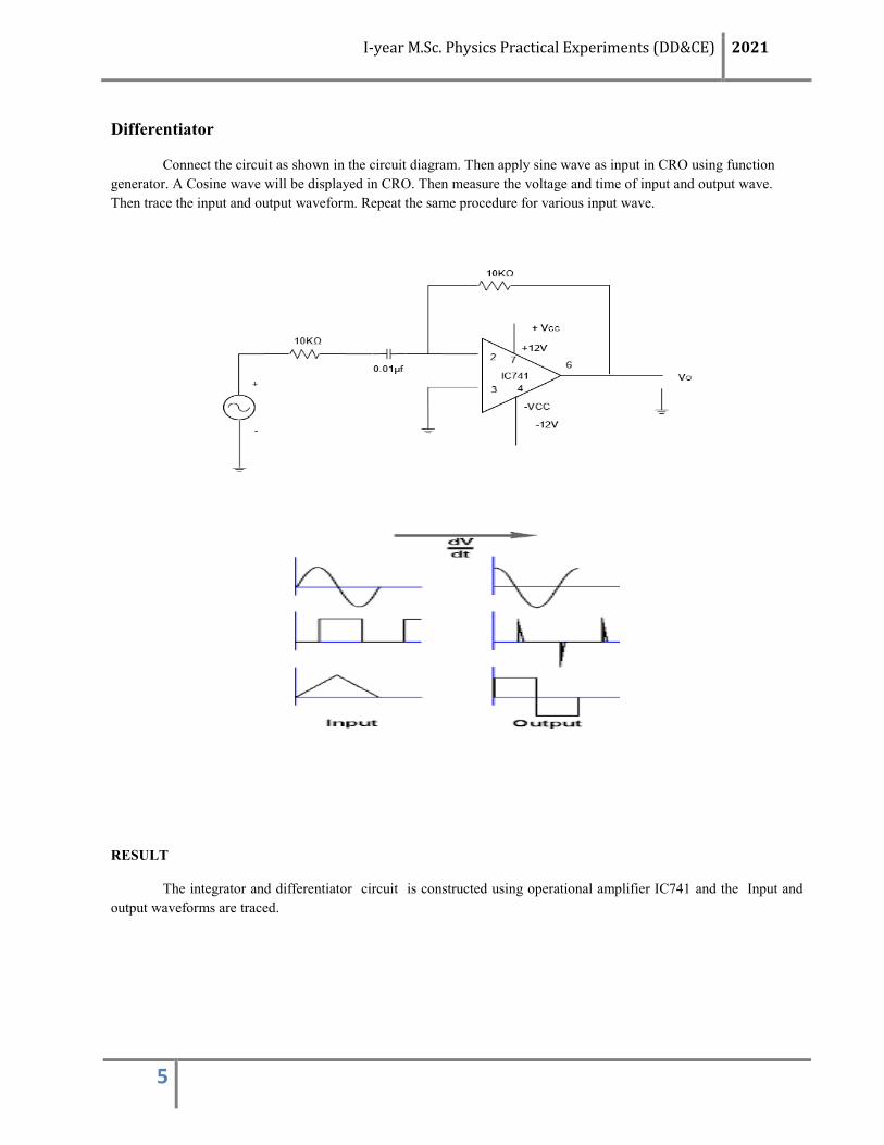
Differentiator
Connect the circuit as shown in the circuit diagram. Then apply sine wave as input in CRO using function
generator. A Cosine wave will be displayed in CRO. Then measure the voltage and time of input and output wave.
Then trace the input and output waveform. Repeat the same procedure for various input wave.
RESULT
The integrator and differentiator circuit is constructed using operational amplifier IC741 and the Input and
output waveforms are traced.

I-year M.Sc. Physics Practical Experiments (DD&CE) 2021
6
2. OP-AMP ADDER AND SUBTRACTOR
AIM
To construct an adder and subtractor using IC741
APPARATUS REQUIRED
IC741, 10KΩ resistor, 0.01 μ F capacitor, signal generator, trainer kit, connecting wires.
FORMULA
Adder
(i) Inverting terminal
Output Vo = - ( V1 + V2)
(ii) Non Inverting terminal
Output Vo = ( V1 + V2)
Subtractor
Output Vo = ( V2 – V1)
V1 , V2 - Two input voltages (volt)
Vo - Output voltages (volt)
Theory
An adder is an electronic circuit that produces an output, which is equal to the sum of the
applied inputs. It is also called as a summing amplifier, since the output is an amplified.The non-
inverting input terminal of the op-amp is connected to ground. That means zero volts is applied at
its non-inverting input terminal
A subtractor is an electronic circuit that produces an output, which is equal to the difference
of the applied inputs. It is also called as a difference amplifier. An op-amp based subtractor
produces an output equal to the difference of the input voltages applied at its inverting and non
inverting terminals.

I-year M.Sc. Physics Practical Experiments (DD&CE) 2021
7
Pin Configuration
1
2
3
4
8
7
6
5
No connection
+ VCC
output
off set null
off set null
Inverting terminal
Non Inverting terminal
- VCC
ICI-741
Fig. 1. Pin Configuration
Fig. 2. Offset null
10 k
10 k
10 k
+ VCC
- VCC
o/p7
2
3
4
56
-
+

I-year M.Sc. Physics Practical Experiments (DD&CE) 2021
8
Procedure
Adder Inverting and Non Inverting Terminal
The adder circuit is constructed as shown in Fig. 3 and Fig. 4. The circuit diagrams shows
a two input inverting summing amplifier. It has two input voltages V1andV2, two input resistors R1,
R2 and a feedback resistor Rf. Set the voltages V1, V2 in the input terminal. Measure the output
voltages at the output terminal ( 6th
pin). Repeat the same procedure and tabulate the values. Find
the percentage error.
10 k
10 k
+ VCC
- VCC
VO
72
3
4
6
-
+10 k
V1
V2
Fig. 3. Adder - Inverting
10 k
+ VCC
- VCC
VO
72
3
4
6
-
+
10 k
V1
V2
10 k
Fig. 4. Adder – Non Inverting

I-year M.Sc. Physics Practical Experiments (DD&CE) 2021
9
Table. 1 Adder - Inverting terminal
S. No V1
(volts)
V2
(volts)
Calculated value
Vo = - ( V1 + V2)
(volts)
Experimental Value
Vo = - ( V1 + V2)
(volts) % Error
Table. 2 Adder – Non Inverting terminal
S. No V1
(volts)
V2
(volts)
Calculated value
Vo = ( V1 + V2)
(volts)
Experimental Value
Vo = ( V1 + V2)
(volts)
% Error
Subtractor
The subtractor circuit is constructed as shown in Fig. 5. the output voltage V0 is equal to the
voltage V1 applied to the non inverting terminal difference voltage V2 applied to inverting terminal.
Set the voltages V1, V2 in the input terminal. Measure the output voltages at the output terminal (
6th
pin). Repeat the same procedure and tabulate the values and find the percentage error.
10 k
10 k
10 k
+ VCC
- VCC
VO
72
3
4
6
-
+
10 k
V1
V2
Fig.5 Subtractor

I-year M.Sc. Physics Practical Experiments (DD&CE) 2021
10
Table. 3 Subtractor
S. No V1
(volts)
V2
(volts)
Calculated value
Vo = ( V2 + V1)
(volts)
Experimental Value
Vo = ( V2 + V1)
(volts) % Error
Result
The adder and subtractor circuit is constructed using IC 741. The calculated and
experimental values are verified.

I-year M.Sc. Physics Practical Experiments (DD&CE) 2021
11
3. HALF ADDER AND FULL ADDER
AIM
To construct half adder and full adder circuits and verify their truth tables.
APPARATUS REQUIRED
IC 7408, IC 7432, IC 7486 and digital trainer kit
Fig. 1. Pin Configuration

I-year M.Sc. Physics Practical Experiments (DD&CE) 2021
12
Procedure :
An half adder is a logic circuit that adds two bits and produces two outputs sum (s)and carry (c). The half-
adder does not take the carry bit from its previous stage into account. This carry bit from its previous stage is called
carry-in bit. A combinational logic circuit that adds two data bits, A and B, and a carry-in bit, Cin, is called a full-
adder. A full adder is useful to add three bits at a time but a half adder cannot.
Fig. 2. HALF ADDER
Table1. Half Adder - Truth Table
A B SUM CARRY
0 0 0 0
0 1 1 0
1 0 1 0
1 1 1 1
Table 2. Half adder - Voltage Table
A
(v)
B
(v)
SUM
(v)
CARRY
(v)

I-year M.Sc. Physics Practical Experiments (DD&CE) 2021
13
Fig. 3. Full Adder
Table3. Half Adder - Truth Table
A B C SUM CARRY
0 0 0 0 0
0 0 1 1 0
0 1 0 1 0
0 1 1 0 1
1 0 0 1 0
1 0 1 0 1
1 1 0 0 1
1 1 1 1 1
Table 4. Half Adder - Voltage Table
A
(v)
B
(v)
C
(v)
SUM
(v)
CARRY
(v)
Ressults
The half adder and full adder circuits are constructed using IC and their truth tables are verified.

I-year M.Sc. Physics Practical Experiments (DD&CE) 2021
14
4. HALF SUBTRACTOR AND FULL SUBTRACTOR
Aim :
To construct half subtractor and full subtractor circuits using logic
gates.
Apparatus required
IC 7408, IC 7432, IC 7486, IC7404 and digital trainer kit
FIG. 1 Half Subtractor
Table. 1 Half Subtractor - Truth Table
A B Difference Borrow
0 0 0 0
0 1 1 0
1 0 1 0
1 1 0 1

I-year M.Sc. Physics Practical Experiments (DD&CE) 2021
15
Table. 2 Half Subtractor – Voltage Table
A
(v)
B
(v)
Difference
(v)
Borrow
(v)
Fig. 1 Full Subtractor
Table. 3 Full Subtractor - Truth Table
A B C Difference Borrow
0 0 0 0 0
0 0 1 1 0
0 1 0 1 0
0 1 1 0 1
1 0 0 1 0
1 0 1 0 1
1 1 0 0 1
1 1 1 1 1

I-year M.Sc. Physics Practical Experiments (DD&CE) 2021
16
Table. 4 Full Subtractor - Voltage Table
A
(v)
B
(v)
C
(v)
Difference
(v)
Borrow
(v)
Results
The half and full subtractor circuits are constructed using IC and their Truth tables and
voltage tables verified.

I-year M.Sc. Physics Practical Experiments (DD&CE) 2021
17
5. Verification of Demorgans law using logic gates.
AIM :
To verify DeMorgans law using Logic gates
Apparatus Required
IC - 7400, 7402, 7404, 7408,7432
Demaorgans Law
De-Morgan's law has two conditions, or two laws called De-Morgan's Laws. We
can often use these laws to reduce expressions
First Law
The compliment of the product of two variables is equal to the sum of the
compliment of each variable
Fig.1. Demorgans First law
Table. 1. Verification of First law
A B ______
BA BA.
0 0
0 1
1 0
1 1

I-year M.Sc. Physics Practical Experiments (DD&CE) 2021
18
Second Law
The compliment of the sum of two variables is equal to the product of the
compliment of each variable.
Fig.2. Demorgans First law
Table. 1. Verification of First law
A B ______
.BA BA
0 0
0 1
1 0
1 1
Results
Demorgan’s Laws are verified using Logic gates.

I-year M.Sc. Physics Practical Experiments (DD&CE) 2021
19
Practical II: C++ Programming (DKPP2)
Contents Page no.
1 Solution of Simultaneous Equation-Gauss Elimination Method 20
2 Curve Fitting Cauchy’s Constant – Least Square Method 23
3 Newton Raphson Method 26
4 Matrix Multiplication 29
5 Euler’s Method- Radio Active Decay Problem 32

I-year M.Sc. Physics Practical Experiments (DD&CE) 2021
20
1. SOLUTION OF SIMULTANEOUS EQUATION-GAUSS ELIMINATION METHOD
Aim:
To write a C++ program to solve the solution of simultaneous equation-gauss elimination
method.
Algorithm:

I-year M.Sc. Physics Practical Experiments (DD&CE) 2021
21
Program:

I-year M.Sc. Physics Practical Experiments (DD&CE) 2021
22
Output:
Result:
The C++ program is written for finding the solution of simultaneous equation by using Gauss –
Elimination method. The program is executed and the values are verified manually.

I-year M.Sc. Physics Practical Experiments (DD&CE) 2021
23
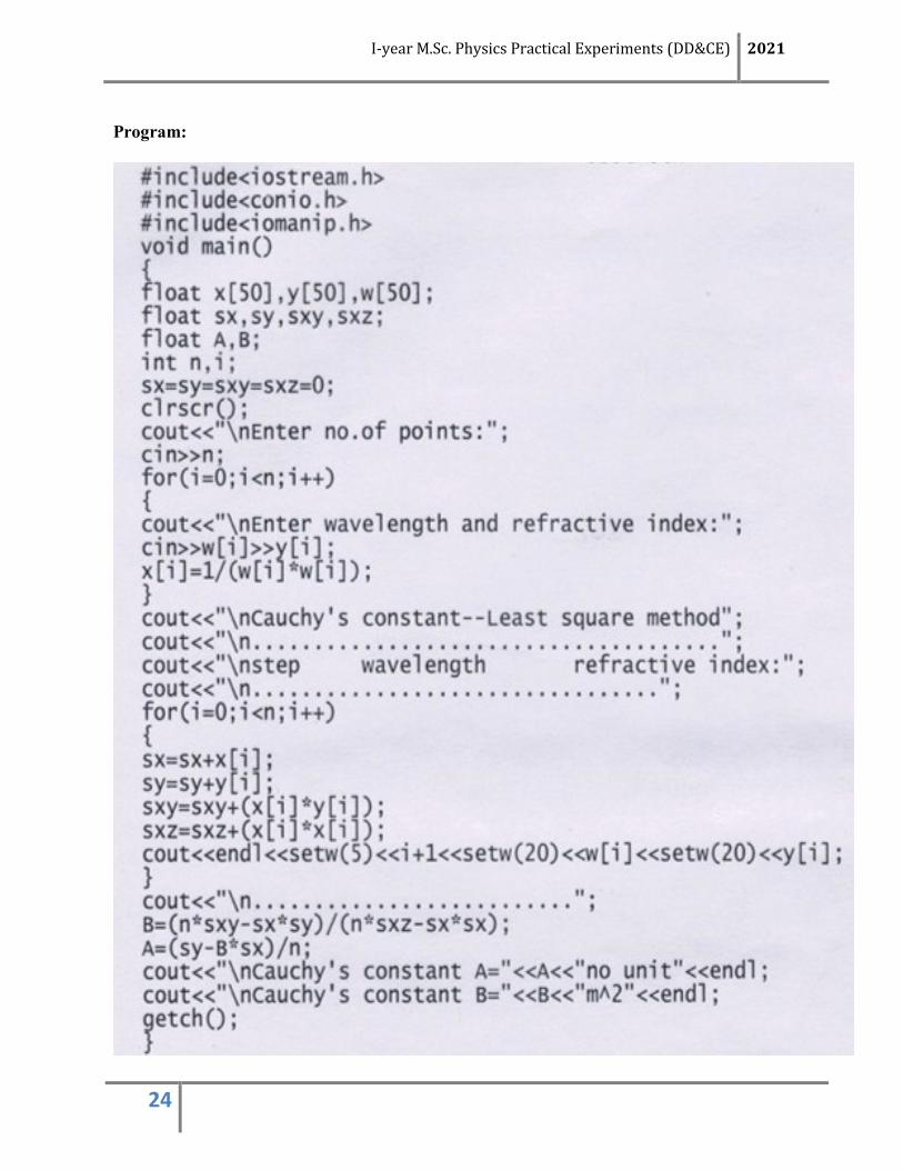
2. CURVE FITTING CAUCHY’S CONSTANT – LEAST SQUARE METHOD
Aim:
To write a C++ program to find the Cauchy’s constants A and B by least square method
Algorithm:
I-year M.Sc. Physics Practical Experiments (DD&CE) 2021
24
Program:

I-year M.Sc. Physics Practical Experiments (DD&CE) 2021
25
Output:
Result:
The C++ program is written for finding the Cauchy’s constant A and B by using least
square method. The program is executed and the values are verified manually.

I-year M.Sc. Physics Practical Experiments (DD&CE) 2021
26
3. NEWTON RAPHSON METHOD
Aim:
To write a C++ program to find the solution using Newton Raphson method and verification
Algorithm:

I-year M.Sc. Physics Practical Experiments (DD&CE) 2021
27
Program:

I-year M.Sc. Physics Practical Experiments (DD&CE) 2021
28
Output:
Result:
The C++ program is written to find the root of on equation by Newton Rapson method. The
program is executed and the values are verified manually.
I-year M.Sc. Physics Practical Experiments (DD&CE) 2021
29
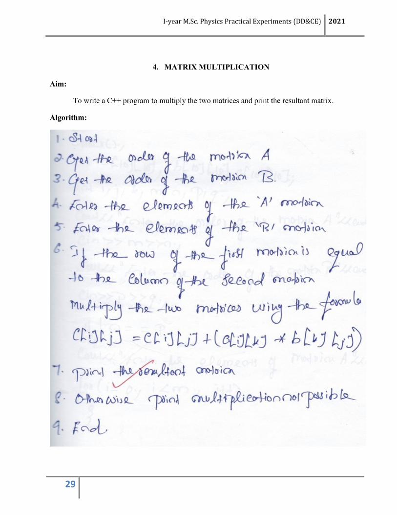
4. MATRIX MULTIPLICATION
Aim:
To write a C++ program to multiply the two matrices and print the resultant matrix.
Algorithm:

I-year M.Sc. Physics Practical Experiments (DD&CE) 2021
30
Program:

I-year M.Sc. Physics Practical Experiments (DD&CE) 2021
31
Output:
Result:
The C++ program is written multiply the two matrices and print the resultant matrix. The
program is executed and the values are verified manually.

I-year M.Sc. Physics Practical Experiments (DD&CE) 2021
32
5. EULER’S METHOD- RADIO ACTIVE DECAY PROBLEM
Aim:
To write a C++ program to solve the radioactive decay problem using Euler’s method.
Algorithm:

I-year M.Sc. Physics Practical Experiments (DD&CE) 2021
33
Program:

I-year M.Sc. Physics Practical Experiments (DD&CE) 2021
34
Output:
Result:
The C++ program is written to solve the radioactive decay problem using Euler’s method. The
program is executed and the values are verified manually.


![[3623]-104 M.Sc. BIOCHEMISTRY P1229](https://img.pdfslide.net/doc/110x75/63280493cedd78c2b50ddd26/3623-104-msc-biochemistry-p1229.jpg)