Embed Size (px)
Citation preview
J. Flow Injection Anal.,Vol.5,No2(1988) -
The Development of a Data Processing System with Personal Computer of MS@ Standard System for Flow Injection Analysis
Daisuke YOSHIZAWA*, Masako TOMODA* , Kazuhide UCHIDA** Kazuaki FUKUSHIMA** and Shin-ichi SAITO*
. . * Department of Natural Sciences, Faculty of Science and
Technology, Sophia University, Kioicho, Tokyo 1 0 2 , * * Department ofAnesthesiology, National Defense Medical
College, Namiki, Tokorozawa, Saitama.359
Abstract
Since one of the merits of flow injection analysis (FIA)
is rapid measurement, the time taken for data processing
reduces the usefulness of the method. In this study, a
personal computer of MSX^ standard system, which has a Z80A-
type chip as CPU and more than 8 Kbyte of RAM, with a data
acquisition system of -our own making, was introduced to
facilitate data processing for FIA; a program written in MSX-
BASIC was also developed. This system was applied to
determination of glucose in control sera, and the results were
compared with those of an analog recorded system. It was found
that our 8 bit system had enough resolution for the FIA data
processing.
Since one of the merits of flow injection analysis (FIR)
is rapid measurement, the time taken for data processing
reduces the usefulness of the method. As the data in FIA may
have many peaks, it becomes hard to measure the peak heights
manually. A data processing system for FIA makes the
processing time shorter, and removes many measurement troubles.
Many data processing systems have been developed by researchers
who took account of these points. However, these systems are
almost all for high performance liquid chromatography. We use
just a few parts of their multiple functions for FIA data
processing in measuring only the peak heights. Their systems 1 are also very expensive. In the previous paper , we have
developed a data processing system that has a simple
configuration and enough resolution for FIA data processing,
and we wish to report details of this work.
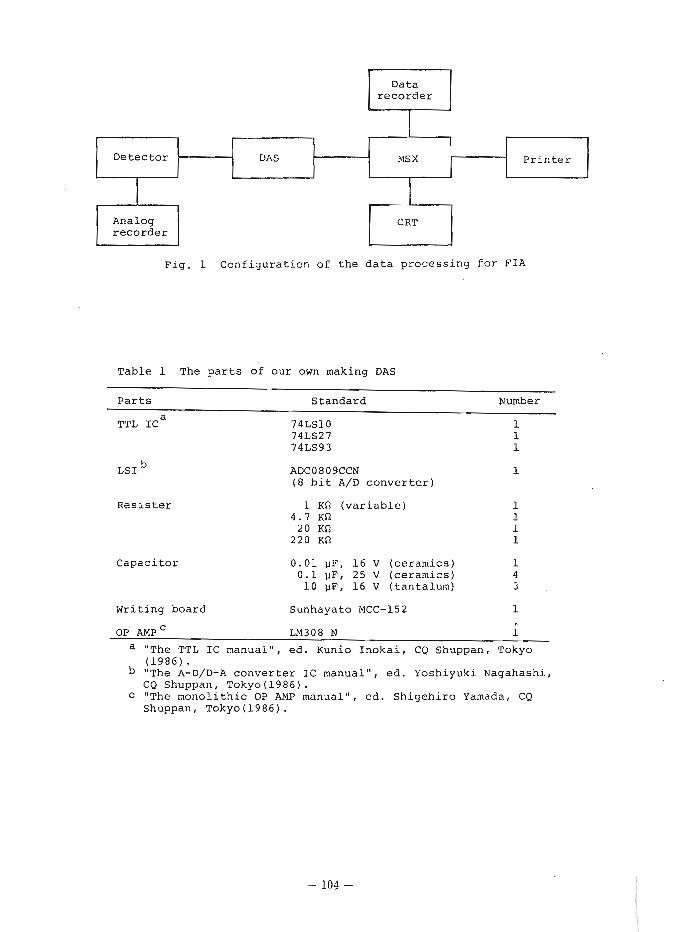
The configuration of our data processing system is shown
in Fig. 1. The signals from the detector are converted by an
A/D converter to digital signals which can be processed by a
micro computer, and the data are typed by a printer. The
personal computer for data processing is MSP standard system
(abbreviated as MSX). MSX has a Z8OA-type chip as CPU and more
than 8 Kbyte of RAM. Some merits of MSX are as follows: 1 ) the
configuration of hardware is simple, 2) the specifications are
opened to the public, 3 ) its hardware and software are widely
compatible, 4) they are low in price, 5) in Japan alone, more
than ten companies deal in them, 6 ) it is easy to develop
programs on an assembler. Recently MSX has been used in
various fields and has become an important part of our 1ifem2l3
When MSX was improved in 1986 to MSX-2, the ability of
functions became wider; thus more applications of MSX are
expected soon.
Experimental
A data acquisition system (abbreviated as DAS) that can
convert the voltage from the detector to digital signals which
can be accepted by MSX was developed. The DAS consists of an
interface circuit, an AID converter LSI, and an amplification
circuit. The AID converter LSI is ADC0809 type. This is a
successive approximation type LSI which has a resolution of 8
bits. Because the LSI functions at +5 V single power source,
the connection to 280 type microprocesser of CPU through the
Input Output (abbreviated as 110) port of MSX, is easy. The
conversion of the LSI is relatively high speed (time ca. 100
us) in spite of its reasonable price and so the sampling
interval can be selected from over a wide range. The way of
interface to Z80A type CPU is based on the so-called
accumulator 110 (110 mapped 1/01 which runs AID converter LSI
by 110 access command operated by BASIC, IN and OUT, or which inputs converted data.
Some programs for FIA data processing were developed.
They were all written in MSX-BASIC. The apparatus used were a
personal computer (Hitachi, MB-H25, RAM: 32 Kbite), a printer
(Brother, M 1009X), and a data recorder [NEC PC-6082 (DR-320)l.
The reproducibility of the peak heights obtained using an
AID converter depends greatly on the intervals at which data
are taken in. In this work, the influence of this interval on
the scatters of peak heights was examined using a basic FIA
system.4 When the intervals at which data were taken in were
50 and 100 ms (sampling rate: 20 and 10 /s), relative standard
deviations were calculated. The intervals were controlled by
the repeat number in the For-Next command loop. The apparatus
and reagents used weresimilarto those described in the
previous report4 except for the spectrophotometer
(Kyowaseimitsu,. KLC-800)
This system was applied to determination of glucose in
control sera, and the results were compared with those from an
analog recorded system. The FIA system used in this work was
similar to the system previously described. 5
Results and discussion
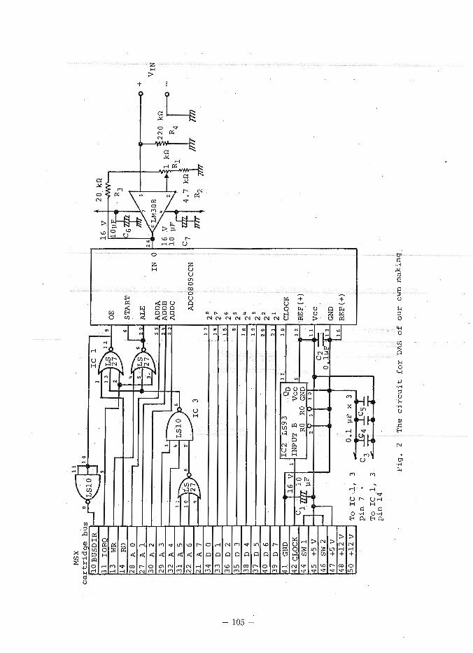
The circuit617 and the parts for DAS of our own making is
shown in Fig. 2 and Table 1. The operation signals provided to
LSI for AID conversion are "START" and "ALE". "ALE" is the
signal in order to select the channel of the analog multiplexer
1 r e c o r d e r 1
Analog r e c o r d e r
F i g . 1 C o n f i g u r a t i o n o f t h e d a t a p r o c e s s i n g f o r F I A
D e t e c t o r
T a b l e 1 The p a r t s o f o u r own making DAS
I I
MS X
P a r t s S t a n d a r d Number
TTL lca 74LS10 1 74LS27 1 74LS93 1
P r i n t e r a
LSI
R e s i s t e r
DAS
C a p a c i t o r
ADC0809CCN 1 ( 8 b i t A/D c o n v e r t e r )
1 KQ ( v a r i a b l e ) 4 . 7 Kc2
20 Kft 2 2 0 KQ
0 . 0 1 pF, 1 6 V ( c e r a m i c s ) 1 0 . 1 p F , 25 V ( c e r a m i c s ) 4
1 0 pF, 1 6 V ( t a n t a l u m ) 3
W r i t i n g b o a r d S u n h a y a t o MCC-152 1
OP AMP LM308 N 1
a "The TTL 1C m a n u a l " , e d . Kunio I n o k a i , CQ Shuppan , Tokyo ( 1 9 8 6 ) . "The A-D/D-A c o n v e r t e r 1C m a n u a l " , e d , Y o s h i y u k i Nagahash i , CQ Shuppan , Tokyo ( 1 9 8 6 ) .
C "The m o n o l i t h i c OP AMP manua l" , e d . S h i g e h i r o Yamada, CQ Shuppan, Tokyo (1986) .
1-1 T
o IC ,l, 3
pin 7
* T
o 1C 1. 3
STA
RT
AL
E
AD
DA
IN 0
AD
DB
A
DD
C
ADC0809CCN
2
CLOCK
vcc
GND
RE
F (+
)
pin
14 '
Fig. 2
The circuit
fo
r DAS
of
ou
r o
wn making
(and channel addresses are input to three pins between ADDA - ADDC). Although only channel 0 was used in this study, it is
possible that some detectors can be connected to MSX without
mechanical operation if only some suitable terminals are
prepared. "START" is the signal in order to start A/D
conversion. The process to select the channel of the analog
multiplexer and the process to start AID conversion are both
carried out at the same time, because of a short circuit
between ALE signal line and START signal one. Since the
voltage range of output from the detector is 0 to 1 V
(correspondence to 0 - 1.000 Abs) and that of input for A/D
converter LSI is 0 - 5 V, the voltage from the detector was
input to A/D converter LSI after the amplification by an
operational amplifier.8 However, the change of the ra-te of
amplification was made to enable adaptation to various
experiments. As the power source for amplification was
supplied from 1/0 port terminals of MSX ( 2 1 2 V), the
amplification was carried out without any other power supply
device. For the purpose of prevention of n ~ i s e ~ ' ~ , the part of
analog circuit (Amplification) and that of digital circuit (AID
conversion and interface) were kept separated by a distance of
25 cm.
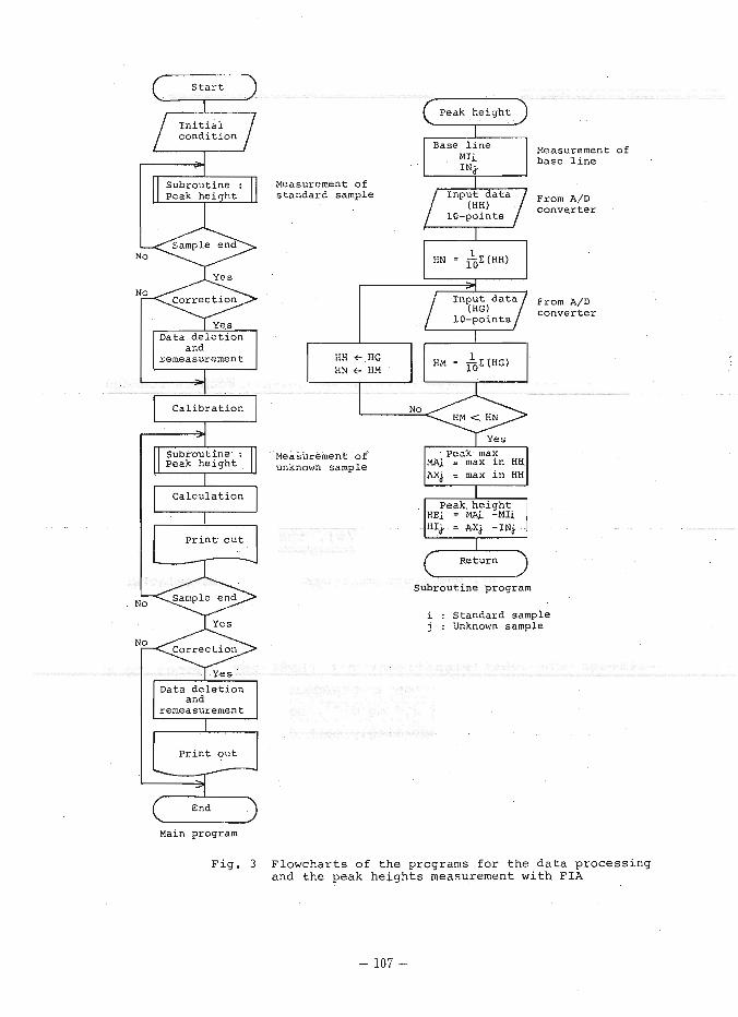
Flowcharts of the program for data processing to FIA are
shown in Fig. 3. The program comprises the main program for
processing data, and the subroutine program for measuring peak
heights. In the main program, the initial conditions
(including date, the concentration and number of standard
samples for calibration) are input. The calibration curve is
calculated with peak heights for each concentration standard
sample by the least square method. Then the peak heights of
the unknown sample are measured, and the concentrations are
calculated from peak heights using a calibration curve. This
program was modified to deal with various measurement
situations, including the trouble of air in the tube,
electrical noise, and artifical mistakes. Accordingly the
S t a r t
I n i t i a l c o n d i t i o n
1 yu Peak h e i h t
remeasurement
C a l i b r a t i o n i='l Subrou t ine : 1 1 peak h e i q h t 1 1
Calcu la t ion la P r i n t o u t a
No Sampleend Q Cor rec t ion +
Data d e l e t i o n
P r i n t o u t -z Main program
Peak h e i g h t Q Base l i n e Measurement o f
base l i n e
Measurement o f s t anda rd sample
/ r n ~ ~ d a t a / From A I D c o n v e r t e r 10 -po in t s
Measurement of unknown sample
I Yes vl AX^ = max i n HH
I
Return ^_____^
Subrout ine program
i : Standard sample j : Unknown sample
Fig. 3 Flowcharts of the programs for the data processing and the peak heights measurement with FIA
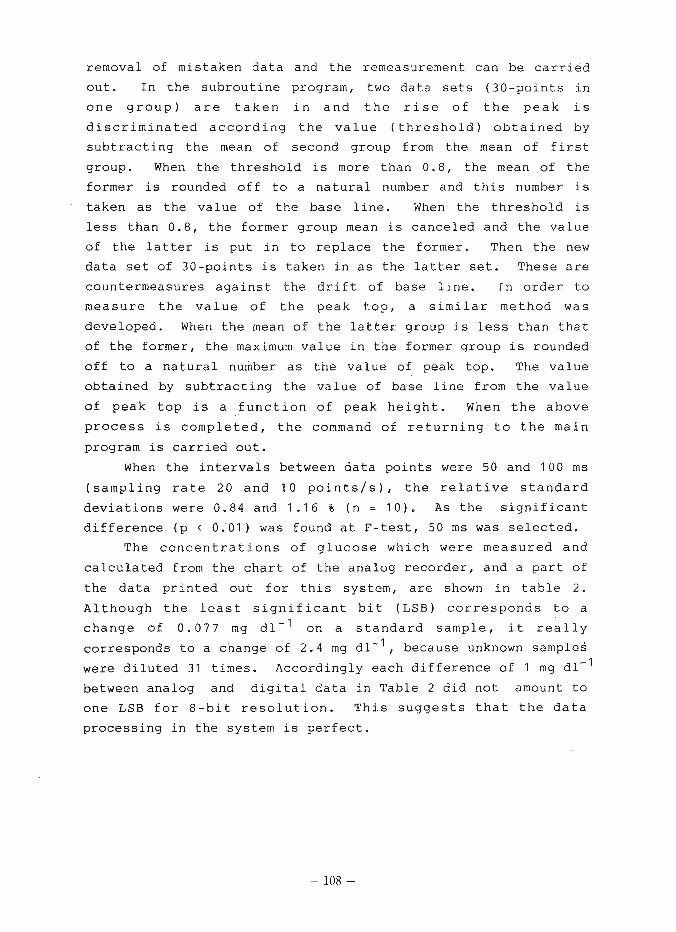
removal of mistaken data and the remeasurement can be carried
out. In the subroutine program, two data sets (30-points in
one group) are taken in and the rise of the peak is
discriminated according the value (threshold) obtained by
subtracting the mean of second group from the mean of first
group. When the threshold is more than 0.8, the mean of the
former is rounded off to a natural number and this number is
taken as the value of the base line. When the threshold is
less than 0.8, the former group mean is canceled and the value
of the latter is put in to replace the former. Then the new
data set of 30-points is taken in as the latter set. These are
countermeasures against the drift of base line. In order to
measure the value of the peak top, a similar method was
developed. When the mean of the latter group is less than that
of the former, the maximum value in the former group is rounded
off to a natural number as the value of peak top. The value
obtained by subtracting the value of base line from the value
of peak top is a function of peak height. When the above
process is completed, the command of returning to the main
program is carried out.
When the intervals between data points were 50 and 100 ms
(sampling rate 20 and 10 points/s), the relative standard
deviations were 0.84 and 1 .I6 % (n = 10). As the significant
difference (p < 0.'01) was found at F-test, 50 ms was selected.
The concentrations of glucose which were measured and
calculated from the chart of the analog recorder, and a part of
the data printed out for this system, are shown in table 2.
Although the least significant bit (LSB) corresponds to a
change of 0.077 m g dl-' on a standard sample, it really
corresponds to a change of 2.4 mg d l 1 , because unknown samples
were diluted 31 times. Accordingly each difference of 1 mg dl-'
between analog and digital data in Table 2 did not amount to
one LSB for 8-bit resolution. This suggests that the data
processing in the system is perfect.
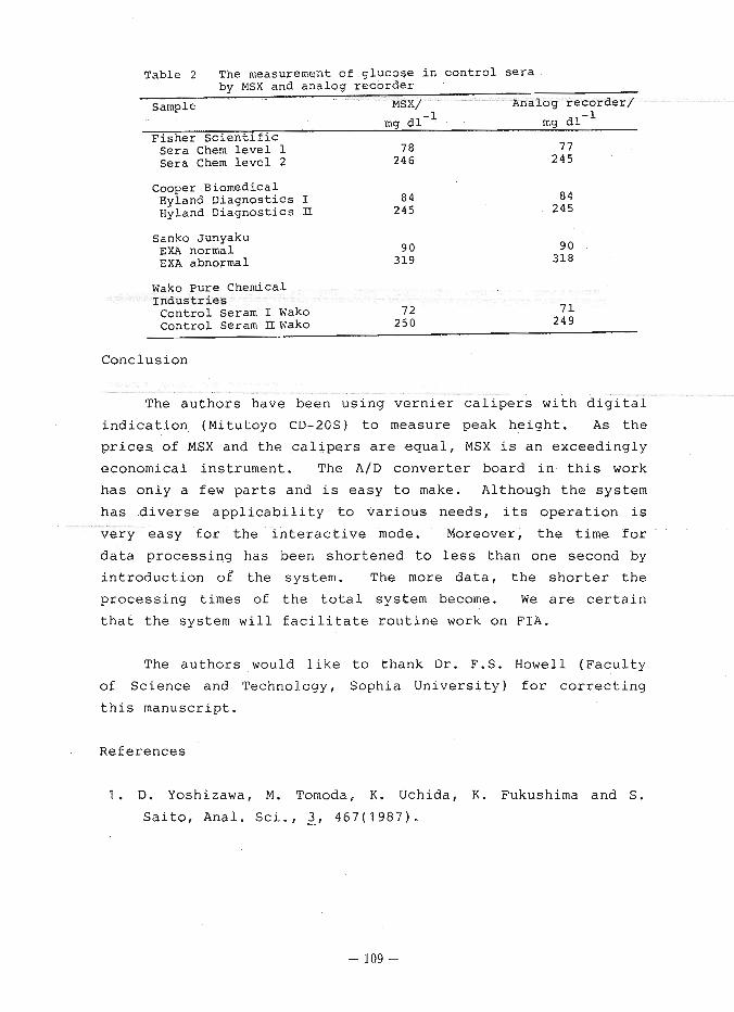
Table 2 The measurement o f g l u c o s e i n c o n t r o l s e r a by MSX and ana log r e c o r d e r
- Sample MSX/- - Analog r e c o r d e r /
mq d l - I ing d l - l F i s h e r S c i e n t i f i c
Se ra Chem l e v e l 1 7 8 7 7 Se ra Chem l e v e l 2 24 6 2 4 5
Cooper Biomedical Hyland D i a g n o s t i c s I 8 4 8 4 Hyland D i a g n o s t i c s It 245 2 4 5
sank0 Junyaku EXA normal EXA abnormal
Wako Pure Chemical I n d u s t r i e s
c o n t r o l Seram I Wako 72 7 1 Cont ro l Seram H ~ a k o 250 2 4 9
Conclusion
The authors have been using vernier calipers with digital
indication (Mitutoyo CD-20s) to measure peak height. As the
prices of MSX and the calipers are equal, MSX is an exceedingly
economical instrument. The AID converter board in this work
has only a few parts and is easy to make. Although the system
has diverse applicability to various needs, its operation is
very easy for the interactive mode. Moreover, the time for
data processing has been shortened to less than one second by
introduction of the system. The more data, the shorter the
processing times of the total system become. We are certain
that the system will facilitate routine work on FIA.
The authors would like t o thank Dr. F.S. Howell (Faculty
of Science and Technology, Sophia University) for correcting
this manuscript.
References
1. D. Yoshizawa, M. Tomoda, K. Uchida, K. Fukushima and S.
Saito, Anal. Sci., 3, 4 6 7 ( 1 9 8 7 ) .

K. Tsukamoto, MSX Magazine, 3, 99(1987). S. Ito, Seikagaku, 59, 154(1987).
K. Uchida, M. Tornoda and S. Saito, J. FLOW Injection
Anal., 2, 143(1985). K. Uchida, D. Yoshizawa, M. Tomoda and S. Saito, Anal.
Sci., 3, 181(1987). S. Kinoshita, Nikkei Byte, ~ ~ 8 ~ , ~ ~ 0 ~ , 125.
K. Sato, "practical technique of interface", CQ shuppan,
Tokyo( 1985 1.
T. Korenaga, h he Personal Computer in the Region of
Chemistry 1 " pp. 111-162, ed. The Association of Personal
Computers for Chemists, Maruzen, Tokyo(1984).
A . Takemoto and H. Inamura, Interfacel x, 205(1986).
(Accepted 25 July 1988)