Embed Size (px)
Citation preview

Levy Nuclear Plant
Units 1 and 2
21-1
21.0 DESIGN CHANGES PROPOSED IN ACCORDANCE WITH ISG-11 This safety evaluation report (SER) chapter contains the staff’s evaluations of five departures from the AP1000 certified design that the applicant included in the Levy Nuclear Plant (LNP) Units 1 and 2 combined license (COL) application. The applicant included the five departures in its COL application because they did not meet the criteria for post-COL deferral, identified in Interim Staff Guidance DC/COL-ISG-011, "Finalizing Licensing-Basis Information." These departures are common to all COL applicants referencing the AP1000 design. Because each of the five departures contains changes to the AP1000 Tier 1 information or technical specifications (TS), exemptions are required, in accordance with Title 10 of the Code of Federal Regulations Part 52, Appendix D, Section VIII, in order for the staff to find the departures acceptable. The applicant included exemption requests in its application, and the staff review of each request also appears in this chapter as part of each technical evaluation. The departures address the following five aspects of the AP1000 certified design:
• Passive core cooling system containment condensate return • Main control room (MCR) dose • MCR Heatup • Hydrogen Vent Inspections, Tests, Analyses, and Acceptance Criteria (ITAAC) • Neutron Flux Logic Operating Bypass
The staff evaluated each of the departures for impact on the probabilistic risk assessment (PRA). None of them have any impact on the quantification of core damage frequency or large release frequency. Only one (the departure relating to the passive core cooling system containment condensate return) resulted in a revision to any PRA-based insight. As discussed in Section 21.1.4 of this SER, this clarification did not alter any staff finding related to the AP1000 certified design. The staff finds that the cumulative risk impact of these design changes and departures is negligible. 21.1 Passive Core Cooling System Containment Condensate Return 21.1.1 Introduction General Design Criteria (GDC) 34 of Appendix A to 10 CFR Part 50, requires that nuclear power plant designs have a system capable of removing residual heat, such that the decay heat does not exceed design limits for the fuel and pressure boundary. Inherent in this requirement is the need to bring the plant to a safe, stable condition following an anticipated transient. The AP1000 design accomplishes this function via the passive core cooling system (PXS). The PXS is designed to perform the following safety-related functions:
• emergency core decay heat removal • reactor coolant system (RCS) emergency makeup and boration • safety injection • containment sump pH control
In order to support long term decay heat removal in a closed loop configuration, the AP1000 passive core cooling system must achieve a sufficient condensate return rate such that inventory in the in-containment refueling water storage tank (IRWST) is maintained in order to

Levy Nuclear Plant
Units 1 and 2
21-2
retain the heat transfer capability of the passive residual heat removal (PRHR) heat exchanger (HX). Water is steamed from the IRWST during transients that require the PRHR HX to remove decay heat from the RCS. The steam that reaches the containment shell condenses and returns to the IRWST through a gutter system. LNP DEP 3.2-1, a departure from the AP1000 design control document (DCD) requested by the applicant and reviewed below, proposes design changes to increase the fraction of condensate return to the IRWST and quantifies the condensate losses associated with the pressurization of the containment atmosphere, condensation on heat sinks within the containment, and from dripping or splashing from structures and components attached to the containment shell. LNP DEP 6.3-1, another departure reviewed below, makes further changes to the final safety analysis report (FSAR) supporting the design change proposed in LNP DEP 3.2-1. 21.1.2 Summary of Application Tier 1 and Tier 2 Departures The applicant proposed the following Tier 1 and Tier 2 departures from the AP1000 DCD:
• LNP DEP 3.2-1 and LNP DEP 6.3-1 In LNP DEP 3.2-1, the applicant proposed a departure from Tier 1 and Tier 2 information related to design changes of the containment condensate return system used to direct water that has condensed on the containment shell to the IRWST during accident scenarios. As described in a request for additional information (RAI) partial response dated June 27, 2014, the proposed Tier 2 departure includes changes to FSAR Chapters 3, 5, 6, 7, 14, 15, 16, and 19 as well as the TS and corresponding Bases appearing in Part 4 of the COL application and cited in FSAR Chapter 16. In addition, the applicant requested an exemption from the incorporation by reference of AP1000 DCD Tier 1 information, specifically Tier 1 Subsection 2.2.3, Tables 2.2.3-1 and 2.2.3-2. The exemption request proposes to revise the list of components in these tables to include additional components of the containment condensate return cooling system of the PXS. These changes were incorporated into Revision 7 of the FSAR, submitted August 28, 2014. In LNP DEP 6.3-1, the applicant proposed changes to FSAR Chapters 5, 6, 7, 9, 15, and 19 to address a departure related to quantifying the duration that the PRHR HX can maintain safe shutdown conditions, changing the description of the duration from indefinite to at least 14 days. These changes, described in a RAI partial response dated June 27, 2014, were incorporated into Revision 7 of the FSAR, submitted August 28, 2014. In letters dated November 17, 2014, May 5, 2015, July 14, 2015, and July 20, 2015, the applicant proposed additional changes to LNP DEP 3.2-1 and LNP DEP 6.3-1. These changes were incorporated into Revision 8 of the FSAR, submitted December 7, 2015. Subsequent to a staff audit of supporting documentation, in letters dated January 14, 2016, and January 26, 2016, the applicant proposed additional changes under LNP DEP 3.2-1 in Chapters 1, 5, 6, 15, and 19 of the FSAR, to be incorporated in a future revision to the FSAR and COL application.

Levy Nuclear Plant
Units 1 and 2
21-3
This exemption request involves a departure from Tier 1 Section 2.2.3, Tables 2.2.3-1 and 2.2.3-2, with Tier 2 involved departures. Therefore, these departures require NRC approval and are evaluated below. 21.1.3 Regulatory Basis In conducting its review of STD COL 6.3-1, the NRC staff used the guidance and staff positions of Regulatory Guide 1.82, Revision 3, “Potential Impact of Debris Blockage on Emergency Recirculation during Design Basis Accidents at Pressurized-Water Reactors,” and NEI 04-07, “Pressurized Water Reactor Sump Performance Evaluation Methodology,” Revision 0, Volume 1, and in the “Safety Evaluation by the Office of Nuclear Reactor Regulation Related to NRC Generic Letter 2004-02,” in NEI 04-07, Revision 0, Volume 2. The changes proposed in LNP DEP 3.2-1 and LNP DEP 6.3.1 are also required to meet the following GDC, which also apply to the AP1000 DCD:
Title 10 of the Code of Federal Regulations (10 CFR) Part 50, Appendix A, GDC 34, “Residual heat removal,” as it applies to the capability of the PRHR HX to perform safety related safe shutdown cooling of the RCS. Additionally, LNP DEP 3.2-1 and LNP DEP 6.3.1 are required to meet GDC 44, “Cooling Water,” as it applies to the ability of the containment systems to transfer heat from the PRHR HX to the ultimate heat sink via the passive containment cooling system.
21.1.4 Technical Evaluation Tier 1 and Tier 2 Departures
• LNP DEP 3.2-1 and LNP DEP 6.3-1
LNP DEP 3.2-1 proposes to change the PXS to increase the fraction of condensate returning to the IRWST when there is steam in the containment building. This change creates intermediate gutters at the top and bottom of the polar crane girder and at the containment shell intermediate ring stiffener. It blocks drain holes that were in these structures and adds dams where needed to collect condensate. It adds downspouts from these gutters to the IRWST. It also modifies the gutter drip lip so that condensate is not lost between the containment wall and the gutter. Condensate that is “lost” does not return to the IRWST, and instead drips off of the shell into various containment holdup volumes, such as the loop compartments or reactor vessel cavity. LNP DEP 6.3-1 proposes additional changes to the FSAR in conjunction with the design changes described in LNP DEP 3.2-1 to clarify the duration of operation of the PRHR HX and separate the description of the safety functions from the non-safety design function of the PXS. The staff reviewed a request for an exemption submitted by the applicant. The request proposed changes to Tier 1 Tables 2.2.3-1 and 2.2.3-2 and generic TS Surveillance Requirement (SR) 3.5.4.7 in the AP1000 DCD. Additionally, the staff reviewed the Tier 2 changes for potential effects on safety functions of the PXS and the associated Chapter 15 safety analyses, the safe-shutdown temperature evaluation in Chapter 19E, the seismic classification in Chapter 3, and the TS and Bases in Chapter 16. The regulatory evaluation of the exemption request appears in Subsection A, below, and the technical evaluation of the exemption request and departure appears in Subsection B, below.

Levy Nuclear Plant
Units 1 and 2
21-4
A. Regulatory Evaluation of Exemption Request
A.1 Summary of Exemption The applicant requested an exemption from the provisions of 10 CFR Part 52, Appendix D, Section III.B, “Design Certification Rule for the AP1000 Design, Scope and Contents,” that require the applicant referencing a certified design to incorporate by reference Tier 1 information. Specifically, the applicant proposed to revise Tier 1 Tables 2.2.3-1 and 2.2.3-2 by adding components to the condensate return design to enable the PXS to more effectively perform its design functions and revised TS SR 3.5.4.7 to address downspout screens.1
A.2 Regulations
• 10 CFR Part 52, Appendix D, Section VIII.A.4 states that exemptions from Tier 1 information are governed by the requirements of 10 CFR 52.63(b) and 10 CFR 52.98(f). It also states that the Commission may deny such a request if the design change causes a significant reduction in plant safety otherwise provided by the design. This subsection of Appendix D also provides that a design change requiring a Tier 1 change shall not result in a significant decrease in the level of safety otherwise provided by the design.
• 10 CFR Part 52, Appendix D, Section VIII.C.4 states that an applicant may request
an exemption from the generic TS or other operational requirements. The Commission may grant such a request only if it determines that the exemption will comply with the requirements of 10 CFR 52.7.
• 10 CFR 52.63(b)(1) allows an applicant or licensee to request NRC approval for an
exemption from one or more elements of the certification information. The Commission may only grant such a request if it complies with the requirements of 10 CFR 52.7 which in turn points to the requirements listed in 10 CFR 50.12 for specific exemptions, and if the special circumstances present outweigh the potential decrease in safety due to reduced standardization. Therefore, any exemption from the Tier 1 information certified by Appendix D to 10 CFR Part 52 must meet the requirements of 10 CFR 50.12, 52.7, and 52.63(b)(1).
A.3 Evaluation of Exemption
As stated in Section VIII.A.4 of Appendix D to 10 CFR Part 52, an exemption from Tier 1 information is governed by the requirements of 10 CFR 52.63(b)(1) and 52.98(f). Additionally, the Commission will deny an exemption request if it finds that the requested change to Tier 1 information will result in a significant decrease in safety. Pursuant to 10 CFR 52.63(b)(1), the Commission may, upon application by an applicant or licensee referencing a certified design, grant exemptions from one or more elements of the certification information, so long as the
1 While the applicant describes the requested exemption as being from Section III.B of 10 CFR Part 52, Appendix D, the entirety of the exemption pertains to proposed departures from Tier 1 information and generic TS in the generic DCD. In the remainder of this evaluation, the NRC will refer to the exemption as an exemption from Tier 1 information and generic TS to match the language of Sections VIII.A.4 and VIII.C.4 of 10 CFR Part 52, Appendix D, which specifically govern the granting of exemptions from Tier 1 information and generic TS.

Levy Nuclear Plant
Units 1 and 2
21-5
criteria given in 10 CFR 50.12 are met and the special circumstances as defined by 10 CFR 50.12 outweigh any potential decrease in safety due to reduced standardization. As stated in Section VIII.C.4 of Appendix D to 10 CFR Part 52, the Commission may grant an exemption from generic TS of the DCD only if it determines that the exemption will comply with the requirements of 10 CFR 52.7. As stated above, Section 52.7 points to 10 CFR 50.12 for specific exemptions. Applicable criteria for when the Commission may grant the requested specific exemption are provided in 10 CFR 50.12(a)(1) and (a)(2). Section 50.12(a)(1) provides that the requested exemption must be authorized by law, not present an undue risk to the public health and safety, and be consistent with the common defense and security. The provisions of 10 CFR 50.12(a)(2) list six special circumstances for which an exemption may be granted. It is necessary for one of these special circumstances to be present in order for NRC to consider granting an exemption request. The applicant stated that the requested exemption meets the special circumstances of 10 CFR 50.12(a)(2)(ii). That subsection defines special circumstances as when “[a]pplication of the regulation in the particular circumstances would not serve the underlying purpose of the rule or is not necessary to achieve the underlying purpose of the rule.” The staff’s analysis of each of these findings is presented below.
A.3.1 Authorized by Law This exemption would allow the applicant to implement approved changes to Tier 1 Tables 2.2.3-1 and 2.2.3-2 and generic TS SR 3.5.4.7. This is a permanent exemption limited in scope to particular Tier 1 information and generic TS, and subsequent changes to this information or any other Tier 1 information or generic TS would be subject to full compliance with the change processes specified in Sections VIII.A.4 and VIII.C.4 of Appendix D to 10 CFR Part 52. As stated above, 10 CFR 52.63(b)(1) allows the NRC to grant exemptions from one or more elements of the certification information, namely, as discussed in this exemption evaluation, the requirements of Tier 1. Moreover, Section VIII.C.4 allows the NRC to grant exemptions from generic TS if the exemption meets the requirements of 10 CFR 52.7 and 50.12. The NRC staff has determined that granting of the applicant’s proposed exemption will not result in a violation of the Atomic Energy Act of 1954, as amended, or the Commission’s regulations. Therefore, as required by 10 CFR 50.12(a)(1), the exemption is authorized by law. A.3.2 No Undue Risk to Public Health and Safety The underlying purpose of AP1000 Tier 1 Tables 2.2.3-1 and 2.2.3-2 and generic TS SR 3.5.4.7 is to ensure that the plant will be constructed and operated with a safe and reliable condensate return system in the event of an accident. Additions to the condensate return portion of the passive core cooling system improve the reliability and effectiveness of the condensate return system; these additions to the system, therefore, support the system’s intended design functions. The plant-specific Tier 1 DCD and TS will continue to reflect the approved licensing basis for the applicant and will maintain a level of detail consistent with that which is currently provided elsewhere in Tier 1 of the plant-specific DCD. The affected design description in the plant-specific Tier 1 DCD will continue to provide the detail necessary to support the performance of the associated ITAAC. The proposed changes to Tier 1 information and generic TS are evaluated and found to be acceptable in Section 6.3 of this safety evaluation. Therefore, the staff finds the exemption presents no undue risk to public health and safety as required by 10 CFR 50.12(a)(1).

Levy Nuclear Plant
Units 1 and 2
21-6
A.3.3 Consistent with Common Defense and Security The proposed exemption would allow the applicant to implement modifications to the Tier 1 information and generic TS requested in the applicant’s submittal. This is a permanent exemption limited in scope to particular Tier 1 information and a specific TS. Subsequent changes to this information or any other Tier 1 information or generic TS would be subject to full compliance with the change processes specified in Sections VIII.A.4 and VIII.C.4 of Appendix D to 10 CFR Part 52. This change is not related to security issues. Therefore, as required by 10 CFR 50.12(a)(1), the staff finds that the exemption is consistent with the common defense and security. A.3.4 Special Circumstances Special circumstances, in accordance with 10 CFR 50.12(a)(2)(ii), are present whenever application of the regulation in the particular circumstances would not serve the underlying purposes of the rule or is not necessary to achieve the underlying purpose of the rule. The underlying purpose of the specific Tier 1 Tables 2.2.3-1 and 2.2.3-2 and TS SR 3.5.4.7 being modified in the exemption request is to identify and conduct surveillances of the components that will be added to the design of the condensate return portion of the passive core cooling system. The additional components and new surveillance requirements for those components are needed so that the passive core cooling system can perform its intended function, that is, to bring the reactor coolant system to safe shutdown conditions during certain non-loss-of-coolant-accident events. Application of the requirements in Tier 1 Tables 2.2.3-1 and 2.2.3-2 and generic TS SR 3.5.4.7 is not necessary to achieve the underlying purpose of those portions of the rule. The proposed additions to the condensate return portion of the passive core cooling system support the system’s intended design functions, as does the addition of a generic TS to conduct surveillances of those additional components. The system and tables listing its components and surveillances, as modified in the requested exemption, will continue to perform their intended functions and will, therefore, meet the underlying purposes of the rule. Accordingly, because application of the requirements in Tier 1 Tables 2.2.3-1 and 2.2.3-2 and the generic TS SR 3.5.4.7 is not necessary to achieve the underlying purpose of the rule, special circumstances are present. Therefore, the staff finds that special circumstances required by 10 CFR 50.12(a)(2)(ii) for the granting of an exemption from the Tier 1 information and generic TS described above. A.3.5 Special Circumstances Outweigh Reduced Standardization This exemption, if granted, would allow the applicant to change certain Tier 1 information incorporated by reference from the AP1000 DCD into the LNP COL application. An exemption from Tier 1 information may only be granted if the special circumstances of the exemption request, required to be present under 10 CFR 52.7 and 10 CFR 50.12, outweigh any reduction in standardization. The proposed exemption would modify the condensate return portion of the passive core cooling system to improve the reliability and effectiveness of the condensate return

Levy Nuclear Plant
Units 1 and 2
21-7
system. The proposed additions to the system support the system’s intended design functions and the key design functions of the passive core cooling system will be maintained.2 As described below in the technical evaluation, the changes to the condensate return system are necessary to (1) ensure the capability of the PRHR HX to maintain the RCS in a safe, stable condition, as described in DCD Chapter 19E, “Shutdown Temperature Evaluation,” and (2) to demonstrate the existing non-loss-of-coolant accident (LOCA) analyses in Chapter 15 that credit the PRHR HX remain valid. Consequently, while there is a small possibility that standardization may be slightly reduced by the granting the exemption from the specified Tier 1 requirements, the proposed exemption modifying the condensate return portion of the passive core cooling system will improve the reliability and effectiveness of the condensate return system, to better allow the system to perform its intended function. For this reason, the staff determined that even if other AP1000 licensees and applicants do not request similar departures, the special circumstances supporting this exemption outweigh the potential decrease in safety due to reduced standardization of the AP1000 design, as required by 10 CFR 52.63(b)(1). A.3.6 No Significant Reduction in Safety The proposed exemption would modify the passive core cooling system from the design presented in the original application. As described below in the technical evaluation, the changes to the condensate return system are necessary to (1) ensure the capability of the PRHR HX to maintain the RCS in a safe, stable condition, as described in DCD Chapter 19E, “Shutdown Temperature Evaluation,” and (2) to demonstrate the existing non-LOCA analyses in Chapter 15 that credit the PRHR HX remain valid. The proposed changes to the PXS design will increase the reliability of the system, maintain its key design functions, and will not adversely affect its function. Therefore, the staff finds that granting the exemption would not result in a significant decrease in the level of safety otherwise provided by the design, as required by 10 CFR Part 52, Appendix D, Section VIII.A.4.
A.4 Conclusion The staff has determined that pursuant to Section VIII.A.4 of Appendix D to 10 CFR Part 52, the exemption: (1) is authorized by law, (2) presents no undue risk to the public health and safety, (3) is consistent with the common defense and security, (4) has special circumstances that outweigh the potential decrease in safety due to reduced standardization, and (5) does not significantly reduce the level of safety at the licensee’s facility. The staff has also determined, pursuant to Section VIII.C.4 of Appendix D to 10 CFR Part 52 , that the generic TS portion of the exemption request: (1) is authorized by law, (2) presents no undue risk to the public health and safety, (3) is consistent with the common defense and security, (4) demonstrates the existence of special circumstances. Therefore, the staff grants the applicant an exemption from the requirements of Tier 1 Tables 2.2.3-1 and 2.2.3-2 and generic TS SR 3.5.4.7 of the generic DCD associated with the LNP Units 1 and 2.
2 Based on the nature of the proposed changes to the generic Tier 1 information in Tables 2.2.3-1 and 2.2.3-2 and TS SR 3.5.4.7, both of which maintain and support the design functions of the passive core cooling system, other AP1000 licensees and applicants may request the same exemption, preserving the intended level of standardization.

Levy Nuclear Plant
Units 1 and 2
21-8
B. Technical Evaluation of Exemption Request and Departure
B.1 Passive Core Cooling System, Accident Analysis, and Shutdown Temperature Evaluation
Letter NPD-NRC-2014-005, submitted by the applicant and dated February 7, 2014, requested the previously described departures from 10 CFR Part 52, Appendix D, Section III.B. A revised submittal, letter NPD-NRC-2015-015, dated May 5, 2015, included two supporting reports as Enclosures 2 and 3: APP-GW-GLR-161, Revision 2 (proprietary) and APP-GW-GLR-607, Revision 2 (non-proprietary), respectively, both titled “Changes to Passive Core Cooling System Condensate Return.” These reports describe the change and the basis for the change. In addition, APP-GW-GLR-161 and APP-GW-GLR-607 references three calculations and a test report further described below. Enclosure 6 provides the applicant’s request for exemption related to this topic. Enclosures 7 and 8 present, respectively, changes to AP1000 DCD Revision 19 and the LNP COLA information that will be included in a future revision to the COLA. Letter NPD-NRC-2014-005 and its enclosures are the subject of the following review by the staff. The applicant indicated that the changes described in LNP DEP 3.2-1 are necessary to (1) ensure the capability of the PRHR HX to maintain the RCS in a safe, stable condition, as described in DCD Chapter 19E, “Shutdown Temperature Evaluation,” and (2) to demonstrate the existing non-LOCA analyses in Chapter 15 that credit the PRHR HX remain valid. The safe shutdown temperature evaluation, presented in DCD Chapter 19E Revision 19, assumes a constant condensate return fraction (the fraction of the water boiled off from the IRWST that will condense on the containment shell and return to the IRWST). Water that does not return to the IRWST can be referred to as condensate losses. The NRC staff understands that the applicant’s analyses showed there are a number of mechanisms for condensate losses that vary with time including: steam to pressurize the containment atmosphere, condensation on passive heat sinks within the containment, and condensate splashing from the containment vessel and its attachments that does not reach to the PXS gutter system. The NRC staff’s review of this departure request indicates some of these losses, such as the steam to pressurize the atmosphere, initially account for the majority of the condensation losses but decrease as the transient progresses, while other losses, such as the splashing from the attachments to the shell, are relatively time-independent and only a function of the amount of condensation on the shell. Condensate return is one of the primary factors influencing the performance of the PRHR HX. Section 5.0, “Design Changes,” of APP-GW-GLR-607 and APP-GW-GLR-161 detail the changes proposed by the applicant for increasing the condensate return rate. Subsection 1 describes the PXS downspout piping network added at the polar crane girder and stiffener, the routing for which is shown in the revised Figure 6.3-1 of the FSAR. Four collection points are located on both the upper portion and the lower flange of the polar crane girder and the stiffener ring that are routed to common lines that empty into two collection points already existing on either side of the IRWST. These downspouts, collection points and connecting piping serve to capture condensate that previously would have been lost, and are sized such that any one line can accommodate the full flow anticipated during a transient to prevent a single failure from impacting the return flow to the IRWST. Subsection 2 describes the screens added to the downspouts and new guttering that is similar to screens existing on the IRWST gutter. These screens are designed to keep larger debris from blocking piping while still allowing condensate flow. The seismic qualifications of the downspouts and screens are further discussed later in

Levy Nuclear Plant
Units 1 and 2
21-9
this section. Subsection 3 explains how fabrication holes are blocked in the polar crane girder and the stiffener. Subsection 4 details the dam added to the polar crane girder to alleviate flow interactions between the containment shell and polar crane girder that contributed to losses. Furthermore, changes to the gutter drip lip and gutter routing were made to reduce losses from the gutter-wall interaction as much as possible. The effect of these changes on the transient analysis is described in detail below. The design changes, which are intended to reduce the condensate losses, prompted review of the analyses associated with transients that rely on condensate return. The effectiveness of the condensate return to the IRWST is captured in a series of proprietary calculations supporting the submittal, which were audited by the staff (Agencywide Documents Access and Management System (ADAMS) Accession Nos. ML14219A200 and ML15187A248) and are described in Section A.2 of APP-GW-GL-161 and APP-GW-GLR-607. The containment response is analyzed in calculation APP-PXS-M3C-071, “Containment Response Analysis for the Long Term PRHR Operation,” via modifying the NRC-approved AP1000 WGOTHIC model used for containment peak pressure calculation that is part of the licensing basis, and provides transient containment pressure, temperature, and condensate holdup volumes input to the other calculations. Condensate losses implemented in WGOTHIC are obtained from a second calculation, APP-PXS-M3C-072, “Condensate Return to IRWST for Long Term PRHR Operation,” which uses the parameters from WGOTHIC in concert with test results to provide a bounding condensate loss fraction from the containment shell. The test data used to calculate the losses are summarized in Section 4 of APP-GW-GL-161 and APP-GW-GLR-607 and described in detail in report TR-SEE-III-12-01, “AP1000 Condensate Return Test Report.” A further calculation, APP-SSAR-GSC-536, “AP1000 Safe Shutdown Temperature Evaluation,” incorporated the containment parameters and condensate behavior from the WGOTHIC analysis into LOFTRAN to calculate the behavior of the RCS and PRHR heat exchanger. This calculation was performed both for a 72-hour design basis case to verify that the assertions in Chapter 6 of the FSAR remain valid for all FSAR Chapter 15 events reliant on the PRHR, and for the 36-hour cooldown case depicted in Chapter 19 of the FSAR. A further calculation, APP-SSAR-GSC-009, “AP1000 Plant Safe Shutdown Duration Evaluation,” justifies the duration of extended operation to 14 days using a LOFTRAN analysis. Further discussion of the analyses is located below in the “Evaluation of Containment Response,” “Safety Design Bases,” and “Non-Safety Design Bases” subsections of this SER section. B.1.1 Evaluation of Containment Response Although the staff audited the calculations referenced in the February 7, 2014 submittal by the applicant (ADAMS Accession Nos. ML14219A200 and ML15187A248), the submittal did not contain sufficient information for the staff to make a safety finding based on the docketed information, and thus the staff issued RAI 7439 in a letter dated March 6, 2014, asking the applicant to summarize the containment response calculation and its relationship with the other calculations. In its response dated May 5, 2014, the applicant provided a summary to address the impact of the cited calculation on the changes in LNP DEP 3.2-1. The staff requested in RAI 7439, Question 6.03-1, that the applicant provide additional detail on the results described in “Containment Response Analysis for the Long Term PRHR Operation” (ADAMS Accession Nos. ML14077A609 and ML14126A702), which describes the WGOTHIC model used to calculate the containment pressure and temperature as well as the steaming rate from the IRWST to the containment atmosphere, heat sinks and the containment shell, to address the technical merits of the changes in LNP DEP 3.2-1. The staff reviewed this response and finds it acceptable, as it provides an accurate summary of the analysis explaining how the containment response

Levy Nuclear Plant
Units 1 and 2
21-10
calculation relates to other calculations, inputs, and key results with sufficient information for the staff to make its finding. Operation of the PRHR HX is affected by the amount of condensate returned to the IRWST. Therefore, in order to bound all events that credit the PRHR HX, the staff considered events requiring operation of the PRHR HX. The applicant identified the loss of normal feedwater coincident with a loss of alternating current (ac) power to the plant auxiliaries as the most limiting transient. The discussion below analyzes this scenario, and the justification for the loss of ac power as the most limiting transient is provided below in the “Safety Design Basis” subsection of this SER. Using WGOTHIC, the applicant modeled the containment behavior during a transient involving the actuation of the PRHR by modifying the containment model used for the peak pressure calculation such that it conservatively captured the phenomena that would challenge the performance of the PRHR HX. This was accomplished by modifying the existing peak pressure calculation model in the following ways: increasing the area of the passive heat sinks as modeled by applying a multiplying factor, creating a volume to capture the condensate losses on the shell, adding a flow path to account for containment leakage, changing the IRWST (including a structure simulating PRHR heat exchanger using boundary conditions from LOFTRAN) to better represent the conditions during a non-LOCA transient, and adding a heat structure in the cavity to represent the vessel, among other minor changes. The net effect of these changes is to minimize the condensation rate on the containment inner shell, maximize the amount of steam and condensate that does not return to the IRWST—such as on passive heat sinks in containment and in the containment atmosphere—and maximize the amount of heat input to the IRWST, all of which are conservatisms for the non-LOCA transients that challenge the PRHR HX. The addition of the heat structure to represent the reactor vessel in the reactor cavity, although used appropriately to capture a physical phenomenon present in the problem, is not the most conservative modeling choice with respect to the calculation of condensate return. Most condensate that is lost from the containment shell eventually reaches the reactor cavity. This water fills the cavity to the point that it reaches the vessel and begins steaming. The vessel is surrounded by metallic insulation material designed to admit water through gaps and release the resultant steam through larger gaps between the insulation and the vessel. Although steaming from the reactor vessel cavity has competing effects on the system performance, as it both cools the reactor vessel and results in additional mixing below the operating deck, it does result in a larger net condensate return fraction to the IRWST. The applicant explored mechanisms that stimulate mixing within containment, but the precise extent of the mixing beneath the operating deck is not fully defined. The applicant states that additional mixing below the operating deck results in more condensate holdup on passive heat sinks, but also that in the long term steaming from the reactor vessel results in additional inventory return to the IRWST. The analysis in WGOTHIC accounts for the heat removal from the reactor vessel by subtracting it from heat that would be removed by the PRHR HX so that the energy balance is maintained. Temperature data from LOFTRAN is extracted and input into one boundary of the WGOTHIC vessel, while the other boundary exposed to the control volume uses a boiling correlation. The amount of heat removed by the boiling from the vessel is stored and subtracted from the PRHR HX heat input. Due to the nature of the modeling of the heat structure in the cavity in WGOTHIC, the entirety of the structure participates in heat transfer to the fluid in the reactor

Levy Nuclear Plant
Units 1 and 2
21-11
cavity. To mitigate against the effects of this, the applicant subtracted the volume in the cavity underneath the vessel and added it to the reactor coolant drain tank room so as to increase the holdup volume that must fill prior to condensate reaching the reactor vessel. This still results in additional boiling from the condensate that reaches the reactor vessel, as a larger area available (at least until the water would have reached the top of the bottom head) results in higher heat transfer. Conversely, in the very long term, the WGOTHIC model does not consider additional area that would participate as the water in the cavity rises above the lower head of the reactor vessel. In “Containment Response Analysis for the Long Term PRHR Operation,” the applicant documents a sensitivity study that explores the effect on IRWST level of no condensate return resulting from reactor vessel steaming. The analysis shows that IRWST level is reduced by as much as 7 inches in the 72-hour period following the transient as a result of not accounting for reactor vessel steaming. This reduction in IRWST inventory does not appreciably impact system performance during the first 72 hours and would not challenge the operability of the system until much later in the transient. The staff performed a confirmatory analysis on the effect of the lower condensate return rate using LOFTRAN, which showed the lack of steaming from the reactor vessel would have less impact than was calculated by the applicant in their sensitivity study. In addition, the staff confirmatory calculation in MELCOR documented below tracks level along the reactor vessel heat structure and uses a conservatively high holdup volume such that steaming from the cavity is not established until almost one day into the transient. The applicant’s design basis calculation bounds the confirmatory analysis performed by the staff. As a result, the staff finds the treatment of steaming from the vessel bottom head acceptable for this analysis. The applicant made additional changes as compared to the approved WGOTHIC model used for peak pressure analyses in the most recent revisions of the calculations referenced in the May 5, 2015, submittal. The elevation of a modeled volume was changed, (resulting in changes to flow paths not representative of pipes but rather a function of the modeling divisions) in the analysis to prevent condensate build up in the control volume from inhibiting air flow between the control volumes to prevent non-physical behavior and better represent real conditions. The condensate return fraction was further modified to be a flat value representative of the loss rate determined by testing at the highest flow rate (discussed further below) plus a margin of 0.7 percent. In addition, the heat structures representing the PRHR HX and reactor vessel receive temperature conditions from iterative runs of the LOFTRAN model discussed later in the “Safety Design Basis” section of this report, rather than bounding values. In the applicant’s supporting analysis, condensation on most of the heat sinks is directly analyzed in WGOTHIC, while condensation holdup on surfaces such as the operating deck floor and other equipment was incorporated into a horizontal film holdup volume assumed proportional to the cross sectional area of containment multiplied by a factor with no provided justification. Therefore, in RAI 7439, Question 6.03-3, the staff requested that the applicant justify the multiplication factor used and the treatment of the horizontal film in the WGOTHIC model. In a response dated June 12, 2014, the applicant determined that the earlier treatment of film may not have been conservative. Thus, the applicant performed a sensitivity study to determine the effect of a different approach. The approach detailed in the response changed the representative area to a value incorporating the total surface area of the heat sinks modeled within containment in WGOTHIC, which are a conservative representation of the total passive heat sink area inside containment, incorporating the fixed components. For direct condensation in WGOTHIC, the applicant further increased this value to bound the total passive heat sink area within containment. Though this value does not directly represent the film holdup area as some heat sinks like the core makeup tanks (CMTs), polar crane girder and stiffener are

Levy Nuclear Plant
Units 1 and 2
21-12
excluded, the use of total surface area rather than horizontal surface area incorporates margin such that this treatment is conservative. In addition, the applicant used a different approach to determine film thickness for condensation on surfaces utilizing a maximum contact angle for wetting in the design basis analyses and a more realistic contact angle for the “conservative, non-bounding” analyses to determine the thickness of the film. Although these changes increase the film holdup by a factor of more than three, there is a negligible effect on the performance of the PRHR HX during the first 72 hours. Initially following a non-LOCA transient, the significantly lower condensate return rates for the first few hours and lack of steaming from the reactor vessel cause the impact of additional holdup resulting from the more conservative film holdup calculation to be lessened and the level in the IRWST to be relatively unchanged. As condensate return increases to its long term value, and steaming from the reactor vessel begins to have a measurable impact on the transient, the submittal shows a minor reduction in the time before the RCS begins to reheat, well after the safety-related 72-hour period. The PRHR is required to remove decay heat following a design basis event for a minimum of 72 hours, in accordance with the revised FSAR Section 6.3.1.1.1, “Emergency Core Decay Heat Removal” in LNP DEP 6.3-1. The staff verified that this calculation was incorporated into “Containment Response Analysis for the Long Term PRHR Operation” calculation in a subsequent audit (ADAMS Accession No. ML15187A248). The amount of condensation held up on surfaces within containment is also an important parameter during containment floodup following a LOCA or automatic depressurization system (ADS) actuation. Because the AP1000 relies on gravity for the driving force for recirculation in the long-term following an accident, the height of water in containment must be sufficient to force flow through the direct vessel injection lines for an opening in the RCS above the floodup level. The NRC staff’s confirmatory analysis applying the revised film holdup to the floodup calculation shows a negligible impact on the containment water level following a LOCA or ADS actuation. Thus, the staff finds the treatment of film holdup on surfaces within containment acceptable because it conservatively accounts for condensation on surfaces using conditions for maximum condensate losses, and does not adversely affect current bounding analyses for other transients. Containment response heavily depends on the initial conditions assumed for the transient of interest. Containment pressure and temperature, IRWST temperature, and the ambient outside temperature (equal to passive containment cooling system (PCS) water temperature) all have an impact. Pressure response can be divided into two phases for this transient, an initial spike up in pressure as the IRWST boils off, followed by a slow levelling off to a peak and decay as passive cooling occurs. Confirmatory analysis performed by the staff using MELCOR for design basis conditions follows a similar trend as the analysis performed by the applicant documented in “Containment Response Analysis for the Long Term PRHR Operation” (ADAMS Accession No. ML14219A200), although the pressure calculated by the applicant bounds the pressure in MELCOR at all points within an hour after steaming begins for the design basis. For best estimate conditions, the staff’s confirmatory analysis shows a peak pressure of approximately 2 pounds per square inch greater than the applicant’s WGOTHIC analysis, while design basis conditions result in confirmatory analysis yielding a pressure approximately 5 pounds per square inch less than the conservative value calculated by the applicant in WGOTHIC; these events, like all events involving PRHR actuation, do not challenge the design pressure. More importantly for this transient, the applicant’s pressure used for the design basis analysis results in a higher saturation pressure for water in containment, which results in additional holdup in the containment atmosphere and higher IRWST temperatures and,

Levy Nuclear Plant
Units 1 and 2
21-13
therefore, reduced heat transfer through the PRHR. As such, the applicant’s modeled pressure response in containment is conservative because it uses bounding inputs into an approved methodology and yields a more conservative value than staff models of the same conditions. In each analysis performed by the applicant, calculations were performed for design basis conditions for Chapter 15 and “non-bounding, conservative” conditions for Chapter 19. Design basis conditions should represent the conservatively bounding set of values for any given transient, and the design basis values for the maximum temperature inside containment is 120 degrees Fahrenheit (°F) (48.9 degrees Celsius (°C)) and outside containment is 115 °F (46.1 °C). The analysis submitted used an in-containment initial temperature of 85 °F (29 °C) (capturing all the heat sinks as well as the IRWST) and an environment temperature of 115 °F (46.1 °C). In RAI 7439, Question 6.03-4, the staff requested the applicant justify the assumption of 85 °F (29 °C) for the initial temperature of containment for the design-basis accident (DBA) analysis. In the response dated July 1, 2014, the applicant explained that the effect of the temperature of the heat sinks outweighed the effect of the IRWST temperature. That is, a lower heat sink temperature results in more condensation on heat sinks and, therefore, more losses when compared with the effect of a change in the initial enthalpy in the IRWST, which affects the time to begin boiling. The NRC staff reviewed analysis supporting this assertion (ADAMS Accession No. ML14219A200), and although the effect is slight, lower heat sink temperatures result in a lower IRWST level as the transient progresses. The choice of 85 °F (29 °C) for in-containment initial temperature was based on the use of an exterior temperature of 115 °F (46.1 °C), the TS maximum for ambient air temperatures for the environment outside containment. The applicant performed a study for a plant located at a site where meteorological data indicates ambient temperatures could reach 115 °F (46.1 °C) and calculated in-containment temperatures for an operating facility with containment coolers running to show that containment temperatures (and therefore the temperatures of the heat sinks and the IRWST) would not reach below 88 °F (31 °C) for an ambient temperature of 115 °F (46.1 °C). The influence of exterior temperatures is more dramatic on PRHR HX performance: while lower temperatures inside containment would result in additional condensation on heat sinks, higher ambient temperatures result in higher initial PCS water temperatures, which result in less heat removal from containment during a transient and thus higher containment pressures and temperatures. The staff agrees that 85 °F (29 °C) for the in containment temperature presents an acceptably conservative value for a transient given a bounding environmental temperature of 115 °F (46.1 °C), due to the large thermal inertia of the heat sinks within containment and the sizable heat load for the operating plant under the steady state conditions leading up to the transient, in addition to the applicant’s justification based on ambient temperatures. Section 6.3.2.1.1 of the revised FSAR, “Emergency Core Decay Heat Removal at High Pressure and Temperature Conditions,” in LNP DEP 6.3-1, addresses the impact of the revised analysis due to the design changes. The revised FSAR discusses the integrated system, including emphasis on the condensate return features, and explicitly describes the mechanics of in-containment condensation as the heat transfer mechanism. In addition, the FSAR now highlights that “[c]ondensation that is not returned to the in-containment refueling water storage tank drains to the containment sump.” This is in accordance with the staff’s understanding of the system as discussed in this subsection, and is acceptable because most water that does not return to the IRWST fills holdup volumes, which must fill to a certain level before overflowing and eventually reaching the lowest point in containment and filling the reactor coolant drain tank room and reactor cavity.

Levy Nuclear Plant
Units 1 and 2
21-14
Section 6.3.2.1.1 also explains the impact of the condensate return rate on the duration of operation of the PRHR HX, and explains that if ac power is not recovered, the PRHR HX can continue to perform for a period of time beyond 72 hours. The plant also retains the ability to transition to open loop cooling via the automatic depressurization system if inventory in the IRWST is insufficient. This agrees with the staff analysis of the performance of the system and is an acceptable change to the FSAR, discussed further in the following section, “Safety Design Basis.” The changes made to Figures 6.3-1 and 6.3-2 in the FSAR appropriately capture the design changes as modeled in the analyses described in the submittal and are acceptable. The components in these figures added to Tier 1 are discussed in the “Classification of Structures, Components, and Systems” subsection below. The applicant stated that the modifications referenced above to the WGOTHIC model, such as those incorporating condensate return to the IRWST, have no effect on the peak containment pressure calculation. Peak containment pressure is reached well before condensate return has a measurable impact on the transient, and any benefits from condensate return at later times are not credited. The addition of downspouts at the polar crane and stiffener have no impact on the current peak pressure analysis because the model already assumes that condensate reaching the polar crane and stiffener makes its way to the reactor coolant drain tank room, which overflows to the reactor cavity region. The assumptions used in these analyses for initial conditions for temperature, humidity, and heat sink area limiting the amount of condensate return are less bounding for the case of peak containment pressure and, therefore, would not be applicable to the peak pressure calculation. The staff finds the peak pressure analysis in the licensing basis is unaffected by the changes implemented in the current analyses. For the analyses supporting LNP DEP 3.2-1, the treatment of the PCS water coverage of the outside of the containment shell is consistent with that used in the peak pressure calculation model previously approved by the staff. That is, an assumed film coverage below the weir of 90 percent (for design basis conditions) at nominal flow rates, decreasing as the level in the PCS water storage tank drops during the 72-hour period (discussed in Section 6.2.1 of NUREG-1273 and Table 6.2.2-1 of the AP1000 DCD). Thus, that treatment is conservative for this analysis, as minimizing shell coverage maximizes the energy within containment, which maximizes the containment pressure and saturation temperature. The calculation, “Containment Response Analysis for the Long Term PRHR Operation,” receives inputs from the “Condensate Return to IRWST for Long Term PRHR Operation” calculation (ADAMS Accession No. ML14219A200), which calculates the effective condensate losses on the inside surface of the containment shell. The NRC staff requested in RAI 7439, Question 6.03-2 that the applicant submit additional detail on the results described in “Condensate Return to IRWST for Long Term PRHR Operation,” which describes the methodology used to calculate losses over the containment shell, including the tests used to determine losses over attachments to the shell. This request was to address deficiencies in the submittal related to insufficient justification of the applicability of the development of the condensate loss model. The applicant summarized the calculation in a response dated June 12, 2014. The NRC staff reviewed the response and found it acceptable because it provides a summary with sufficient information on the calculation for the staff to make its finding.

Levy Nuclear Plant
Units 1 and 2
21-15
Tests for losses over attachments to the shell were performed at lower temperatures than the prototypic conditions on the containment shell during a non-LOCA transient, which could peak in excess of 220 °F (104 °C). Therefore, in RAI 7439, Question 6.03-5, the staff requested the applicant justify the extrapolation from the losses for tested values of condensate losses over attachments to the wall to the values used in the analysis at containment pressure and temperature. In its response to the RAI dated June 27, 2014, the applicant explained that although the losses over wall attachments are extrapolated, the extrapolation is overly conservative and prior research indicates that film thickness should decrease at the same Reynolds number at higher temperatures and thus decrease the condensate losses. In addition, the applicant performed sensitivity studies on the effect of increasing the losses on the performance of the PRHR HX. Those sensitivities indicate that even for a case when losses over attachments are increased by a factor of 1.4 to 1.75, there is a negligible effect on the performance of the system in the first 72 hours and only a minor (approximately 5 percent) reduction in the long term capability of the system. The NRC staff remains unconvinced as to the validity of the applicant’s temperature scaling argument, especially given the relative variance in the test results. However, on the basis of the large degree of conservatism inherent in the extrapolation and the fact that a further 40 percent increase in losses over wall attachments results in an insignificant impact to the system performance, the staff finds the treatment of film losses over attachments to the containment shell acceptable. The analysis described above using WGOTHIC passes a set of inputs to analyses in LOFTRAN (discussed below). The applicant extracts a table including time, condensate return flow, condensate temperature, IRWST steaming rate, containment pressure, and CMT compartment temperature. The data for condensate return flow and condensate temperature are combined to create a recirculation ratio (the fraction of boil off from the IRWST returning as condensate). The recirculation ratio and containment pressure are then used in the LOFTRAN analysis; in the case of the LOFTRAN run using design basis conditions, the recirculation ratio is further reduced and the pressure is increased from the values calculated in WGOTHIC for additional conservatism. On the bases that the modifications to the gutter system are appropriately incorporated into the analyses for events that actuate the PRHR, that the data from tests used to determine the losses on the containment shell conservatively bound realistic losses, and that condensate loss mechanisms have been quantified and captured in the analysis, the staff finds the treatment of containment conditions in calculations supporting LNP DEP 3.2-1 and LNP DEP 6.3-1 acceptable. Therefore, the staff finds the proposed LNP DEP 3.2-1 FSAR revisions related to containment response noted above to be acceptable pending the staff’s confirmation that the proposed FSAR revisions are incorporated in the LNP Units 1 and 2 COL application. The staff is tracking these revisions as LNP Confirmatory Item 21.1-1.
B.1.2 Safety Design Bases The PXS performs the following safety-related functions:
1. Emergency decay heat removal 2. Emergency reactor makeup/boration 3. Safety injection 4. Containment pH control
Levy Nuclear Plant
Units 1 and 2
21-16
The following subsections evaluate the impact of LNP DEP 3.2-1 and LNP DEP 6.3-1 on each safety function of the PXS. B.1.2.1 Emergency Decay Heat Removal
LNP DEP 3.2-1 impacts the condensate return rate to the IRWST and thus impacts the emergency decay heat removal function of the PRHR HX. Under LNP DEP 3.2-1 and LNP DEP 6.3-1, the revised FSAR Section 6.3 states that for non-LOCA events in which a loss of core decay heat removal capability via the steam generators (SGs) occurs, the PRHR HX is designed to perform the following functions:
1. Remove core decay heat following a design basis event. 2. Maintain acceptable reactor coolant system conditions for a minimum of 72 hours
following a non-LOCA event. Applicable post-accident evaluation criteria are specified in Chapter 15.
3. Sufficiently reduce RCS temperature and pressure during an SG tube rupture (SGTR) event to terminate breakflow, without overfilling the SG.
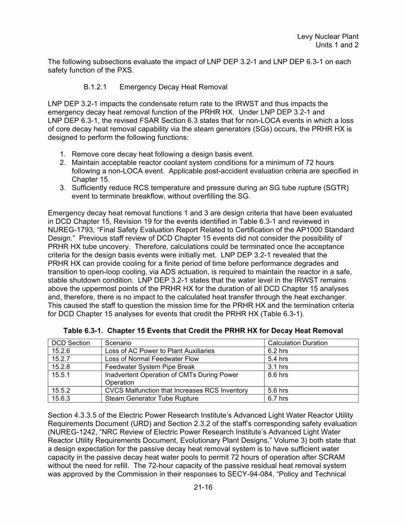
Emergency decay heat removal functions 1 and 3 are design criteria that have been evaluated in DCD Chapter 15, Revision 19 for the events identified in Table 6.3-1 and reviewed in NUREG-1793, “Final Safety Evaluation Report Related to Certification of the AP1000 Standard Design.” Previous staff review of DCD Chapter 15 events did not consider the possibility of PRHR HX tube uncovery. Therefore, calculations could be terminated once the acceptance criteria for the design basis events were initially met. LNP DEP 3.2-1 revealed that the PRHR HX can provide cooling for a finite period of time before performance degrades and transition to open-loop cooling, via ADS actuation, is required to maintain the reactor in a safe, stable shutdown condition. LNP DEP 3.2-1 states that the water level in the IRWST remains above the uppermost points of the PRHR HX for the duration of all DCD Chapter 15 analyses and, therefore, there is no impact to the calculated heat transfer through the heat exchanger. This caused the staff to question the mission time for the PRHR HX and the termination criteria for DCD Chapter 15 analyses for events that credit the PRHR HX (Table 6.3-1).
Table 6.3-1. Chapter 15 Events that Credit the PRHR HX for Decay Heat Removal
DCD Section Scenario Calculation Duration 15.2.6 Loss of AC Power to Plant Auxiliaries 6.2 hrs 15.2.7 Loss of Normal Feedwater Flow 5.4 hrs 15.2.8 Feedwater System Pipe Break 3.1 hrs 15.5.1 Inadvertent Operation of CMTs During Power
Operation 8.6 hrs
15.5.2 CVCS Malfunction that Increases RCS Inventory 5.6 hrs 15.6.3 Steam Generator Tube Rupture 6.7 hrs
Section 4.3.3.5 of the Electric Power Research Institute’s Advanced Light Water Reactor Utility Requirements Document (URD) and Section 2.3.2 of the staff’s corresponding safety evaluation (NUREG-1242, “NRC Review of Electric Power Research Institute’s Advanced Light Water Reactor Utility Requirements Document, Evolutionary Plant Designs,” Volume 3) both state that a design expectation for the passive decay heat removal system is to have sufficient water capacity in the passive decay heat water pools to permit 72 hours of operation after SCRAM without the need for refill. The 72-hour capacity of the passive residual heat removal system was approved by the Commission in their responses to SECY-94-084, “Policy and Technical
Levy Nuclear Plant
Units 1 and 2
21-17
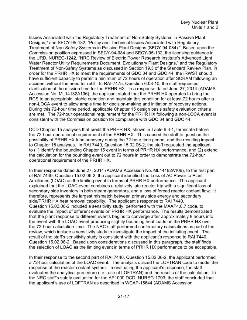
Issues Associated with the Regulatory Treatment of Non-Safety Systems in Passive Plant Designs,” and SECY-95-132, “Policy and Technical Issues Associated with Regulatory Treatment of Non-Safety Systems in Passive Plant Designs (SECY-94-084).” Based upon the Commission position expressed in SECY-94-084 and SECY-95-132, the licensing guidance in the URD, NUREG-1242, “NRC Review of Electric Power Research Institute’s Advanced Light Water Reactor Utility Requirements Document, Evolutionary Plant Designs,” and the Regulatory Treatment of Non-Safety Systems as discussed in Section 19.3 of the Standard Review Plan, in order for the PRHR HX to meet the requirements of GDC 34 and GDC 44, the IRWST should have sufficient capacity to permit a minimum of 72 hours of operation after SCRAM following an accident without the need for refill. In RAI-7475, Question 6.03-10, the staff requested clarification of the mission time for the PRHR HX. In a response dated June 27, 2014 (ADAMS Accession No. ML14182A106), the applicant stated that the PRHR HX operates to bring the RCS to an acceptable, stable condition and maintain this condition for at least 72 hours after a non-LOCA event to allow ample time for decision-making and initiation of recovery actions. During this 72-hour time period, applicable Chapter 15 design basis safety evaluation criteria are met. The 72-hour operational requirement for the PRHR HX following a non-LOCA event is consistent with the Commission position for compliance with GDC 34 and GDC 44. DCD Chapter 15 analyses that credit the PRHR HX, shown in Table 6.3-1, terminate before the 72-hour operational requirement of the PRHR HX. This caused the staff to question the possibility of PRHR HX tube uncovery during the 72-hour time period, and the resulting impact to Chapter 15 analyses. In RAI 7440, Question 15.02.06-2, the staff requested the applicant to (1) identify the bounding Chapter 15 event in terms of PRHR HX performance, and (2) extend the calculation for the bounding event out to 72 hours in order to demonstrate the 72-hour operational requirement of the PRHR HX. In their response dated June 27, 2014 (ADAMS Accession No. ML14182A106), to the first part of RAI 7440, Question 15.02.06-2, the applicant identified the Loss of AC Power to Plant Auxiliaries (LOAC) as the limiting event in terms of PRHR HX performance. The applicant explained that the LOAC event combines a relatively late reactor trip with a significant loss of secondary side inventory in both steam generators, and a loss of forced reactor coolant flow. It therefore, represents the largest mismatch between primary side energy and secondary side/PRHR HX heat removal capability. The applicant’s response to RAI 7440, Question 15.02.06-2 included a sensitivity study, performed with the MAAP4.0.7 code, to evaluate the impact of different events on PRHR HX performance. The results demonstrated that the plant response to different events begins to converge after approximately 8 hours into the event with the LOAC event producing slightly bounding heat loads on the PRHR HX over the 72-hour calculation time. The NRC staff performed confirmatory calculations as part of the review, which include a sensitivity study to investigate the impact of the initiating event. The result of the staff’s sensitivity study is consistent with the applicant’s response to RAI 7440, Question 15.02.06-2. Based upon considerations discussed in this paragraph, the staff finds the selection of LOAC as the limiting event in terms of PRHR HX performance to be acceptable. In their response to the second part of RAI 7440, Question 15.02.06-2, the applicant performed a 72-hour calculation of the LOAC event. The analysis utilized the LOFTRAN code to model the response of the reactor coolant system. In evaluating the applicant’s response, the staff evaluated the analytical procedure (i.e., use of LOFTRAN) and the results of the calculation. In the NRC staff’s safety evaluation for the AP1000 DCD, NUREG-1793, the staff concluded that the applicant’s use of LOFTRAN as described in WCAP-15644 (ADAMS Accession
Levy Nuclear Plant
Units 1 and 2
21-18
No. ML040890663) is acceptable for licensing calculations of the AP1000 subject to the following limitation:
• LOFTRAN is approved to analyze the transients listed in Table 21-2 of NUREG-1793. Use of the code for other analytical purposes will require additional justification.
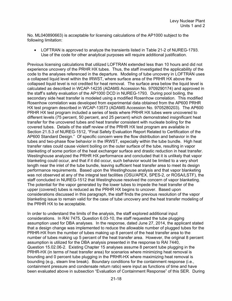
Previous licensing calculations that utilized LOFTRAN extended less than 10 hours and did not experience uncovery of the PRHR HX tubes. Thus, the staff investigated the applicability of the code to the analyses referenced in the departure. Modeling of tube uncovery in LOFTRAN uses a collapsed liquid level within the IRWST, where surface area of the PRHR HX above the collapsed liquid level is not credited for heat removal. The surface area below the liquid level is calculated as described in WCAP-14235 (ADAMS Accession No. 9709290174) and approved in the staff’s safety evaluation of the AP1000 DCD in NUREG-1793. During pool boiling, the secondary side heat transfer is modeled using a modified Rosenhow correlation. This modified Rosenhow correlation was developed from experimental data obtained from the AP600 PRHR HX test program described in WCAP-13573 (ADAMS Accession No. 9705280203). The AP600 PRHR HX test program included a series of tests where PRHR HX tubes were uncovered to different levels (75 percent, 50 percent, and 25 percent) which demonstrated insignificant heat transfer for the uncovered tubes and heat transfer consistent with nucleate boiling for the covered tubes. Details of the staff review of the PRHR HX test program are available in Section 21.5.3 of NUREG-1512, “Final Safety Evaluation Report Related to Certification of the AP600 Standard Design.” Of specific concern were the flow distribution and behavior in the tubes and two-phase flow behavior in the IRWST, especially within the tube bundle. High heat transfer rates could cause violent boiling on the outer surface of the tube, resulting in vapor blanketing of some portion of the heat exchanger surface and drastic reduction in heat transfer. Westinghouse analyzed the PRHR HX performance and concluded that it is unlikely that vapor blanketing could occur, and that if it did occur, such behavior would be limited to a very short length near the inlet of the tube bundle, leaving sufficient heat transfer area to meet its design performance requirements. Based upon the Westinghouse analysis and that vapor blanketing was not observed at any of the integral test facilities (OSU/APEX, SPES-2, or ROSA/LSTF), the staff concluded in NUREG-1512 that Westinghouse resolved the concern of vapor blanketing. The potential for the vapor generated by the lower tubes to impede the heat transfer of the upper (covered) tubes is reduced as the PRHR HX begins to uncover. Based upon considerations discussed in this paragraph, the staff finds the previous resolution of the vapor blanketing issue to remain valid for the case of tube uncovery and the heat transfer modeling of the PRHR HX to be acceptable. In order to understand the limits of the analysis, the staff explored additional input considerations. In RAI 7475, Question 6.03-10, the staff requested the tube plugging assumption used for DBA analyses. In the response, dated June 27, 2014, the applicant stated that a design change was implemented to reduce the allowable number of plugged tubes for the PRHR-HX from the number of tubes making up 8 percent of the heat transfer area to the number of tubes making up 5 percent of the heat transfer area. However, the original 8 percent assumption is utilized for the DBA analysis presented in the response to RAI 7440, Question 15.02.06-2. Existing Chapter 15 analyses assume 8 percent tube plugging in the PRHR-HX (in terms of heat transfer area) for scenarios where minimizing heat removal is bounding and 0 percent tube plugging in the PRHR-HX where maximizing heat removal is bounding (e.g., steam line break). Boundary conditions for the containment response (i.e., containment pressure and condensate return ratio) were input as functions of time and have been evaluated above in subsection “Evaluation of Containment Response” of this SER. During

Levy Nuclear Plant
Units 1 and 2
21-19
an audit, the NRC staff identified that the initial power utilized in the 72 hour analysis accounted for a 1 percent uncertainty. Section 15.0.3.2 of the AP1000 DCD, Revision 19, states that a 1 percent uncertainty is supported by the main feedwater flow measurement instrumentation, but that a bounding value of 2 percent is used in the analysis. The Levy COL FSAR contains COL Information Item STD COL 15.0-1, which identifies the plant operating instrumentation which when properly calibrated will support 1 percent uncertainty in the core power based on flow measurement uncertainty. Additionally, the NRC staff performed a sensitivity study investigating the impact of the reduced core power uncertainty on the 72-hour LOAC event. The results of this study demonstrated that the reduction in core power uncertainty has an insignificant impact on the RCS response and Chapter 15 acceptance criteria. The analysis of the LOAC event submitted by the applicant demonstrates that during the 72-hour period the top horizontal portion of the PRHR HX becomes uncovered. However, the PRHR HX capacity remains sufficient to prevent RCS heatup for a time period greater than 72 hours. The submitted analysis demonstrates that once the Chapter 15 acceptance criteria are satisfied, at approximately 6.2 hours, they remain satisfied for a time period exceeding 72 hours. The NRC staff performed confirmatory calculations as part of the review, which include a 72-hour analysis of the LOAC event. The staff’s confirmatory calculation for the LOAC event is consistent with the applicant’s submitted analysis. Based upon the identification of the LOAC event being the bounding event in terms of PRHR HX operation, the acceptable modeling of the LOAC event, and the result demonstrating the 72-hour operational requirement for the PRHR HX, the staff finds the submitted analysis of the 72-hour LOAC event acceptable. In a letter dated January 14, 2016 (ADAMS Accession No. ML16020A250), the applicant updated their submittal, which included the consideration of ambient heat losses from the RCS during Chapter 15 non-LOCA events. Previous analyses had assumed the RCS to be adiabatic, which would result in the highest required heat removal from the PRHR HX; due to ambient heat losses from the RCS, from the pressurizer in particular, and in the absence of positive pressure control associated with pressurizer heaters, the applicant was concerned that pressure in the RCS could be reduced to the point that subcooled margin is lost. A loss of subcooling was thought to have the potential to inhibit the performance of the PRHR HX. Additional analyses were conducted by the applicant to investigate the impact of ambient heat loss from the RCS. A description of these analyses is provided in APP-GW-GLR-607, Revision 4 “Changes to Passive Core Cooling System Condensate Return,” which is included as an enclosure to the letter of January 14, 2016. The NRC staff audited the supporting calculations (documented in the audit report, ADAMS Accession No. ML16034A034). The audit resulted in a supplemental RAI response, provided in letter dated January 14, 2016 (ADAMS Accession No. ML16020A105), to establish the basis for the ambient heat losses associated with the pressurizer. The RAI response included (1) a description of the ambient heat loss flow paths from the pressurizer and their treatment in transient analyses, and (2) a FSAR update to Section 5.4.5.2.1 to include the average maximum heat transfer rate specification for the metallic reflective insulation installed on the external surfaces of the RCS. The NRC staff found the RAI response identified the applicable heat loss mechanisms from the pressurizer during a DBA. NRC reviewed the details of the heat loss calculation during their audit of the supporting calculations and observed that additional conservatism was included in pressurizer heat loss calculations. Additionally, the NRC staff performed confirmatory calculations for the heat losses from the pressurizer which resulted in values that were consistent with the applicant’s analyses. The conservative modeling of the heat losses from the pressurizer is further supported by data from applicable literature identified in the NRC staff’s audit report. Based upon the information discussed above, the NRC staff finds the treatment of ambient heat losses in the analysis of

Levy Nuclear Plant
Units 1 and 2
21-20
DBAs to be suitably conservative. The applicant performed a DBA analysis that considers ambient heat losses, performed with LOFTRAN, showing that the RCS remains subcooled for a time period exceeding 72 hours. Therefore, the only impact on the DBA analysis was a lower temperature in the RCS due to the increased heat removal. The NRC staff performed confirmatory calculations as part of this review and obtained results that were consistent with the applicant’s analysis. Based on the information in this paragraph, the NRC staff finds that ambient heat losses do not adversely impact DBA analyses for the AP1000. The staff performed confirmatory calculations, which included the Chapter 15 LOAC event, to assist in evaluating the impacts of LNP DEP 3.2-1 to Chapter 15. The calculations caused the staff to question whether containment backpressure effects on PRHR HX performance were accounted for in Chapter 15. During the staff audit of the applicant’s documents related to LNP DEP 3.2-1 and LNP DEP 6.3-1 (ADAMS Accession No. ML14219A200), the staff verified that in Revision 19 of the DCD, Chapter 15 analyses that credit the PRHR HX for decay heat removal do not account for containment backpressure effects on the PRHR HX. Not accounting for containment backpressure on PRHR HX performance introduces a slightly non-conservative boundary condition that affects PRHR HX performance late in the transient. However, the staff verified that this effect does not alter the conclusions of Chapter 15 analyses and thus produces no consequential impact. The change from indefinite operation of the PRHR HX to the 72-hour operational requirement, and subsequent analysis demonstrating the 72-hour operational requirement, are reflected in the applicant’s proposed changes under FSAR Sections 5.4, 6.3, 7.4, and Table 19.59-18 in letter dated June 27, 2014. In the proposed FSAR changes noted above indefinite operation is changed to extended operation at several locations. For consistency among the proposed changes, the staff is interpreting extended operation to be at least 72 hours. Based upon the considerations discussed within this subsection, the staff finds the proposed FSAR revisions noted above to be acceptable pending the staff’s confirmation that the proposed revisions are incorporated in the LNP Units 1 and 2 COL application. The staff is tracking these revisions as LNP Confirmatory Item 21.1-1. Indefinite is still used in the revised FSAR (in Sections 6.3.1.1.4, 6.3.3.3.3, 6.3.3.4.3, and 7.4) when considering the entirety of the passive core cooling system; that is, when ADS is actuated and the system transitions to open-loop cooling with gravity driven injection. At that point, the system is nominally limited by normal containment leakage. This treatment remains unchanged from the system as reviewed by the staff in Revision 19 of the DCD.
B.1.2.2 Emergency Makeup and Boration Emergency makeup and boration for non-LOCA events are functions performed by the CMTs and are not impacted by LNP DEP 3.2-1.
B.1.2.3 Safety Injection LNP DEP 3.2-1 is evaluated to ensure ADS actuation and transition to open loop cooling is retained as a defense-in-depth means of providing emergency core cooling during non-LOCA events. The evaluation includes investigating the impact of IRWST level on the performance of the ADS spargers, the impact of LNP DEP 3.2-1 on the containment floodup level, and the

Levy Nuclear Plant
Units 1 and 2
21-21
availability of the ADS, IRWST injection, and containment recirculation valves during an extended station blackout. In the event that operator action is taken to prolong closed loop mode of PXS operation for an extended period of time, the level in the IRWST can drop below the ADS spargers, causing the staff to question whether ADS actuation can be inhibited by a low IRWST level. In RAI 7440, Question 15.02.06-1, the staff requested information regarding the minimum IRWST level required for ADS actuation. In a letter dated June 19, 2014, the applicant stated that no minimum IRWST level is required for ADS actuation because:
1. ADS spargers do not limit the containment pressure increase for the bounding mass and energy release. The associated mass and energy release attributed to ADS actuation is bounded by the large break LOCA accident or a large main steam line break inside containment.
2. IRWST vents are more than sufficient to vent the amount of steam released if ADS Stages 1-3 are actuated after the spargers are uncovered. The IRWST vents are sized to vent steam relief from ADS stages 1-3 at high system pressures following several hours of PRHR HX operation during which the IRWST has reached saturation pressure.
3. During a long-term non-LOCA event, during which the IRWST level has fallen below the elevation of the ADS spargers, RCS pressure at the time of ADS actuation will be relatively low.
4. Steam relief from uncovered ADS spargers actually improves ADS Stages 1-3 performance due to the lower backpressure provided by the IRWST water. Limitations are imposed on the maximum sparger submergence depth to limit sparger discharge backpressure.
5. No damage is done to spargers, IRWST, or surrounding structures.
The NRC staff identifies the reasons as valid, but requested further justification for the argument that no damage is done to the ADS spargers, IRWST, or surrounding structures. In a supplemental letter dated July 24, 2014, the applicant stated that the ADS spargers are designed to withstand spurious actuation of ADS Stages 1-3 at normal operating conditions. Spurious actuation of ADS Stages 1-3 is bounding in terms of stress on the spargers because it results in bounding mass flows and temperatures experienced by the spargers. Additionally, with the IRWST water level below the spargers, the hydrodynamic loads associated with the initial discharge of air (trapped in the ADS valve discharge lines) or of the subsequent discharge of steam into the water are eliminated. Forces encountered by the IRWST and surrounding structures due to ADS actuation would not be large because the spargers contain a large number of small jets that would interact and dissipate over a relatively short distance. Based upon the considerations mentioned above and the equipment classification of the associated structures and components, the staff finds that ADS actuation is not inhibited by low IRWST level. The NRC staff reviewed the potential changes to containment holdup during floodup following a LOCA or ADS actuation as a result of the changes in LNP DEP 3.2-1. The NRC staff audited the “Containment Floodup Level” calculation (ADAMS Accession No. ML14219A200), and found that steam in the containment atmosphere and film on surfaces was accounted for. Applying the calculation for film condensing on surfaces used in RAI 7439, Question 6.03-3, results in a higher holdup than calculated in the supporting analysis in the form of film, which would reduce the containment level following depressurization of the RCS by less than 2 inches. Given the

Levy Nuclear Plant
Units 1 and 2
21-22
conservatisms inherent in the film holdup analysis in RAI 7439, Question 6.03-3, the staff finds no significant impact to containment floodup level as a result of LNP DEP 3.2-1. An additional consideration is the availability of the ADS, IRWST injection, and containment recirculation valves during an extended station blackout event. The operator action to establish open loop cooling, if required, may occur at a time that exceeds the operating times for the ADS, IRWST injection, and containment recirculation valves specified in Table 3.11-1 of the FSAR. As part of the staff review of submittals from Southern Nuclear Operating Company (SNC) in response to “Order to Modifying Licenses with Regard to Requirements for Mitigation Strategies for Beyond-Design-Basis External Events, Order EA-12-049,” issued on March 12, 2012, for Vogtle Electric Generating Plant Units 3 and 4, which is licensed based on the same AP1000 certified design as the LNP Units 1 and 2 applicant, the NRC staff issued RAI 7741 and RAI 7756 to SNC seeking further justification that the AP1000 can transition to open loop cooling during an extended station blackout. SNC’s response in letters dated December 4, 2014 (ADAMS Accession No. ML14338A658), and February 26, 2015 (ADAMS Accession No. ML15057A590), provided justification regarding (1) equipment qualification of the ADS, IRWST injection, and containment recirculation valves, and (2) diverse actuation capability for the squib valves. SNC demonstrated the equipment qualification envelope for the ADS, IRWST injection, and containment recirculation valves is bounding for an event that utilized the PRHR HX long term. This was done by performing a best estimate calculation for the containment response to an event that utilized the PRHR HX over a 30-day duration. The pressure profile for the qualification envelope was shown to bound the results of the containment response calculation. The temperature profile from the containment response calculation was converted into an equivalent time at 150 °F (65.6 °C) using the Arrhenius method. This equivalent time is bounded by the qualification time specified for the ADS, IRWST injection, and containment recirculation valves. The Arrhenius methodology has been previously reviewed and approved by the NRC staff for modeling the temperature effects in a post-LOCA environment (ADAMS Accession No. ML003701987). Based on the discussion in this paragraph, the NRC staff finds the equipment qualification envelope for the ADS, IRWST injection, and containment recirculation valves bounds the expected containment environment during an extended station blackout for at least 30 days. Additionally, SNC discussed the diverse capability for establishing open loop cooling. The primary means of establishing open loop cooling utilizes the Class 1E dc and uninterruptible power supply system (IDS). SNC’s response included an analysis of the capacity of the IDS batteries. This analysis considered temperature de-rating of the batteries and self-discharge over a month and showed that sufficient margin is available for the batteries to perform their intended function during an extended station blackout. Should the battery supplies become completely exhausted, the ADS Stage 4, IRWST injection, and containment recirculation valves can be actuated via a diverse actuation system power independent device located at the secondary diverse actuation system station. Based upon the considerations in this paragraph, the NRC staff finds reasonable assurance that open loop cooling can be actuated during an extended station blackout event. In a letter dated July 16, 2015 (ADAMS Accession No. ML15201A129), the applicant endorsed the RAI responses of SNC discussed above. Based upon the considerations of the environmental qualification of the ADS, IRWST injection, and containment recirculation valves,
Levy Nuclear Plant
Units 1 and 2
21-23
the containment floodup level, and the diverse actuation for establishing open loop cooling, the NRC staff finds that the safety injection function of the PXS is not impacted by LNP DEP 3.2-1.
B.1.2.4 Containment pH Control Control of the pH in the containment sump post-accident is achieved through the use of pH adjustment baskets containing granulated trisodium phosphate (TSP) and is not impacted by LNP DEP 3.2-1.
B.1.2.5 Safe Shutdown Short term safe shutdown conditions, defined in Section 7.4 of the DCD, include:
• Maintaining the reactor in a subcritical condition • Maintaining RCS average temperature less than or equal to no load temperature • Retaining adequate coolant inventory • Providing adequate core cooling
Establishing short term safe shutdown conditions after an event has been demonstrated through DCD Chapter 15 analyses and reviewed by the staff in NUREG-1793. Through the evaluation of the PXS safety functions, the staff finds that short term safe shutdown is not impacted by LNP DEP 3.2-1. Long term safe shutdown conditions, defined in Section 7.4 of the DCD, are the same as the short term conditions except that the RCS average temperature shall be less than 420 °F. The design requirement of entering a long term safe shutdown condition within 36 hours (i.e., reaching an average RCS temperature less than 420 °F in 36 hours) following an event is established in the URD and SECY-94-084. In Section 6.3 of the DCD, Revision 19, cooling the RCS to 420 °F in 36 hours is identified as part of the design basis for the PRHR HX. The ability of the PRHR HX to satisfy this design requirement is demonstrated in the shutdown temperature evaluation provided in DCD Section 19E.4.10.2. The shutdown temperature evaluation utilizes the same model and evaluates the same event as discussed in subsection “Emergency Decay Heat Removal” of this SER. The analysis in Section 19E.4.10.2 differs in that several model inputs (e.g., containment response pressure, condensate return rate, initial power, and core decay heat) utilize more realistic values. Sections 6.3.3 and 7.4.1.1 of the revised FSAR refer to this analysis as “non-bounding, conservative.” In order to better understand the sources of conservatism in the calculation, the NRC staff issued RAI 7475, Question 6.03-11. The response, provided in letter from the applicant dated June 27, 2014, identified conservatism inherent in the condensate return rate and several modeling choices that were taken to increase the heat load on the PRHR HX and limit the heat removal capability of the PRHR HX. The use of nominal and best-estimate values for reactor power and decay heat remains consistent with the shutdown temperature evaluation supporting the design certification as verified by the staff during an audit of the original calculation (ADAMS Accession No. ML14219A200). The results of the updated analysis demonstrate the RCS average temperature decreases below 420 °F within 36 hours. The staff performed confirmatory calculations as part of the review, which include a shutdown temperature evaluation. The result of the staff’s confirmatory calculation for the shutdown temperature evaluation is consistent with the applicant’s submittal. Based upon the

Levy Nuclear Plant
Units 1 and 2
21-24
considerations within this subsection, and the results of the bounding calculation discussed in subsection “Emergency Decay Heat Removal” of this SER, the staff finds the plant is consistent with SECY-94-084. The updated analysis is reflected in the applicant’s proposed changes to FSAR Section 19E described in a letter from the applicant dated May 5, 2015. In Revision 19 of the AP1000 DCD, the cooldown requirement of reaching an RCS temperature of 420 °F in 36 hours is the only performance criteria listed in Section 6.3.1.1.1 that is not demonstrated by a Chapter 15 analysis. In reading the original DCD, it would be possible to incorrectly conclude that this performance requirement was demonstrated by a Chapter 15 analysis. The applicant’s proposed changes under FSAR Sections 6.3.1.1 in letters dated June 27, 2014, and July 24, 2014, clarify how this design requirement is demonstrated. Based upon considerations within this subsection, the staff finds the proposed FSAR revisions in Sections 6.3.1.1 and 19E, noted above, to be acceptable pending the staff’s confirmation that the proposed revisions are incorporated in the LNP Units 1 and 2 COL application. The staff is tracking these revisions as LNP Confirmatory Item 21.1-1. B.1.3 Non-Safety Design Basis In the proposed FSAR revision under Section 6.3.1.2 the applicant states that the PRHR HX, in conjunction with the IRWST and the condensate return features of the PXS, has the capability to maintain the reactor coolant system in the specified, long-term shutdown condition for 14 days in a closed loop mode of operation. The 14-day operation is also reflected in the applicant’s proposed changes under FSAR Section 19E. The basis for this duration is provided by extending the duration of the non-bounding conservative LOFTRAN calculation that was discussed in subsection “Safe Shutdown” of this SER. The staff verified the results of the analysis in an audit (see ADAMS Accession No. ML15187A248). In an update to the departure provided in a letter dated January 14, 2016 (ADAMS Accession No. ML16020A250), the applicant identified calculations incorporating ambient heat losses performed using RELAP 5, a transient analysis code, as LOFTRAN was not suited for demonstrating two-phase flow through the RCS. The RELAP calculations showed a loss of subcooling in the RCS occurring after 72 hours, but prior to 14 days. The calculations showed that the PRHR HX was capable of performing its function out to 14 days even with the loss of subcooling. The applicant provided test results from the APEX facility to demonstrate the ability of the PRHR HX to perform its function with a saturated RCS. The staff verified the results of the calculation and test results in an audit (ADAMS Accession No. ML16034A034). Operation of the PXS for 14 days in closed loop mode is not required to satisfy Commission regulations. The operational requirements of the PRHR HX have been evaluated in subsection “Safety Design Basis” of this SER. The staff finds the changes made to the operational duration and safety classification of the PRHR HX in LNP DEP 6.3-1 acceptable. B.1.4 Post-72-Hour Actions In DCD Section 6.3.4, it is stated that the only post-72-hour action required is a potential need for containment inventory makeup. This caused the staff to question the post-72-hour actions in the event that closed loop mode of PXS operation is extended following a non-LOCA event. In RAI-7440, Question 15.02.06-3, the staff requested clarification on post-72-hour actions following non-LOCA events. In a response dated June 19, 2014 (ADAMS Accession No. ML14171A453), the applicant stated that containment makeup would be necessary if containment leakage reduces the containment flood-up level, but there is no requirement to provide makeup to the IRWST to maintain PRHR HX operability. The primary post-72-hour

Levy Nuclear Plant
Units 1 and 2
21-25
actions are to provide water makeup to continue passive containment cooling and spent fuel cooling and, in the event that operators extend the closed loop mode of PXS operation, to provide power to the post-accident monitoring cabinets when transition to open loop cooling is required. In RAI 7440, Question 15.06.01, the NRC staff sought clarification on the criteria for operators to actuate ADS and transition to open loop cooling. The applicant’s response provided in letter dated January 15, 2016 (ADAMS Accession No. ML16021A188), stated four criteria associated with reliable indication of core cooling which included (1) power availability to IDS divisions B and C, (2) hot leg and CMT level, (3) core exit thermocouple temperature, and (4) RCS pressure. The NRC staff finds this answer acceptable because it requires operators to check for diverse and reliable indication of adequate core cooling. The impact of post-72-hour actions has been reviewed by the staff in subsection “Safety Design Bases” of this SER.
B.2 Classification of Structures, Components, and Systems Section 6.0, “Impacts to the Licensing Basis,” of APP-GW-GLR-607 and APP-GW-GLR-161, Revision 2 describes the changes impacted to the COL application and provides the additional piping and components to the PXS. Subsection “Tier 1,” states that “The added components of the PXS are integral to providing safety-related core decay heat removal during non-LOCA events. Therefore, it is appropriate to apply inspections, test, analyses and acceptance criteria to the added PXS components to provide reasonable assurance that the facility has been constructed and will be operated in conformity with the applicable design criteria, codes and standards.” It further states that “As required by general design criterion 2 of Appendix A to 10 CFR Part 50, the PXS is designed to withstand the effects of natural phenomena and normal and accident conditions without loss of capability to perform its safety functions.” The PXS containment recirculation downspout screens are identified as follows: PXS-MY-Y81 PXS-MY-Y85 PXS-MY-Y82 PXS-MY-Y86 PXS-MY-Y83 PXS-MY-Y87 PXS-MY-Y84 PXS-MY-Y88 These component numbers will be added to the LNP Units 1 and 2 FSAR to supplement Table 2.2.3-1 of the AP1000 DCD, Revision 19, Tier 1. Mark-ups to Table 2.2.3-1 of the AP1000 DCD, Revision 19, Tier 1 and Table 3.2-3 of the AP1000 DCD, Revision 19, Tier 2, provided in Appendix B of APP-GW-GLR-607 and APP-GW-GLR-161, state that these eight additional downspout screens are not American Society of Mechanical Engineers (ASME) Code Section III components and the principal construction code is manufacturer standard. In Section 6.0 of APP-GW-GLR-607 and APP-GW-GLR-161, under the subheadings “Tier 2,” “Chapter 3: Impacted,” the applicant states that, “The new PXS downspout screens are AP1000 Safety Class C and seismic Category I components. These components meet the quality assurance requirements of 10 CFR 50, Appendix B. Additionally, the screens must be demonstrated to have no functional damage following a seismic ground motion exceeding the one-third of the safe shutdown earthquake ground motion before resuming operations in accordance with 10 CFR Part 50, Appendix S.” Under the subheading “Tier 1,” the applicant further states that ITAAC design requirements will be met for these eight added downspout screens.

Levy Nuclear Plant
Units 1 and 2
21-26
On the basis of the safety and seismic classifications of these eight added downspout screens, their quality assurance requirements, and the fact that SRP 3.2.1, “System Quality Group Classification,” and Regulatory Guide 1.26, “Quality Group Classifications and Standards for Water-, Steam-, and Radioactive-Waste-Containing Components of Nuclear Power Plants,” do not provide specific guidance for the code of construction for non-ASME, non-pressure retaining components that belong to Quality Group C, the staff agrees that the use of manufacturer standards for the design of these downspout screens and the classification of AP1000 Safety Class C and seismic Category I is acceptable. Therefore, the staff finds the proposed FSAR revisions concerning these eight added downspout screens to be acceptable. Section 6.0 of APP-GW-GLR-607 and APP-GW-GLR-161, Subsection “Tier 1,” states that “As required by general design criterion 4 of Appendix A to 10 CFR Part 50, the PXS containment downspout piping would be safety-related and required to withstand normal and seismic design basis loads without losing functional capability.” The following PXS containment downspout piping are the proposed piping to be added to the LNP Units 1 and 2 FSAR to supplement Table 2.2.3-2 of AP1000 DCD, Revision 19, Tier 1: PXS-L301A PXS-L306A PXS-L301B PXS-L306B PXS-L302A PXS-L307A PXS-L302B PXS-L307B PXS-L303A PXS-L308A PXS-L303B PXS-L308B PXS-L304A PXS-L309A PXS-L304B PXS-L309B PXS-L305A PXS-L310A PXS-L305B PXS-L310B Section 5.0, “Design Changes,” Subsection “Polar Crane Girder and Internal Stiffener Modifications,” Sub-subsection “1) PXS Downspout Piping,” of APP-GW-GLR-607 and APP-GW-GLR-161 states that these added downspout piping are classified as AP1000 Safety Class C, seismic Category I. Mark-up of Table 2.2.3-2 to AP1000 DCD, Revision 19, Tier 1, provided in Appendix B of APP-GW-GLR-607 and APP-GW-GLR-161, further states that these added downspout piping are ASME Code Section III piping. According to the AP1000 DCD, Revision 19, Tier 2, Section 3.2.2, “AP1000 Classification System,” Subsection 3.2.2.5, “Equipment Class C,” Class C structures, systems and components are designed to codes and standards consistent with the guidelines for NRC Quality Group C. In addition, 10 CFR 50, Appendix B and ASME Code, Section III, Class 3 apply to pressure retaining components. Section 6.0 of APP-GW-GLR-607 and APP-GW-GLR-161, Subsection “Tier 1,” states that ITAAC design commitments will be met for these added downspout piping. In addition, Table 2.2.3-4 of the AP1000 DCD, Revision 19, Tier 1, provides ITAAC that 1) ensure the piping identified in Table 2.2.3-2 as ASME Code Section III is designed and constructed in accordance with ASME Code Section III requirements; 2) pressure boundary welds in piping identified in Table 2.2.3-2 as ASME Code Section III meet ASME Code Section III requirements; and 3) piping identified in Table 2.2.3-2 as ASME Code Section III retains its pressure boundary integrity at its design pressure. On the bases that these downspout piping are designed to ASME Code Section III, Class 3 and the quality assurance requirements of 10 CFR 50, Appendix B, and that the ITAAC related to piping listed in Table 2.2.3-4 of the AP1000 DCD, Revision 19, Tier 1 apply, the staff finds the classification of this added downspout piping acceptable. Therefore, the staff finds the proposed FSAR revisions noted above to be acceptable.

Levy Nuclear Plant
Units 1 and 2
21-27
B.3 Technical Specifications In a letter dated February 7, 2014, the applicant submitted an exemption request titled “Supplement 3 to Submittal of Exemption Request and Design Change Description for Departure from AP1000 DCD Revision19 to Address Containment Condensate Return Cooling Design,” for LNP Units 1 and 2. As a result of the condensate return testing conducted at the Waltz Mill Test Facility, modifications to the polar crane girder, internal stiffener, and IRWST gutter designs were made. In addition, extensions of the gutter were added above the upper personnel airlock and upper equipment hatch. A downspout system was also added to capture condensation at the polar crane girder and stiffener locations. These modifications result in minor editorial changes in a few sections of the TS and Bases (Chapter 16) in the COL application. In a letter dated November 17, 2014, and titled “Supplement 5 to Submittal of Exemption Request and Design Change Description for Departure from AP1000 DCD Revision19 to Address Containment Condensate Return Cooling Design,” the applicant provided further details on the condensate return issue including other editorial modifications to the TS and Bases. These changes are necessary to ensure that the TS and Bases accurately reflect the updated design and are described below. LCO Section of B3.3.3 (Postaccident Monitoring (PAM) Instrumentation)
On page B3.3.3-4, in the last line of the first paragraph in Section 11, “In-Containment Refueling Water Storage Tank (IRWST) Water Level,” the text “…via a gutter.” is updated to “…via a gutter and downspouts.”
Background Section of B3.5.4 (Passive Residual Heat Removal Heat Exchanger (PRHR HX) – Operating)
On page B3.5.4-1, in the first and second lines of the third paragraph of the Background section, the text “…PRHR HX operation, a gutter is provided…” is updated to “…PRHR HX operation, downspouts and a gutter are provided…” Also in that paragraph, the text in the fourth and fifth line is updated from “…collected by the gutter is directed…” to “...collected by the downspouts or gutter is directed…”
TS and SR Sections for B3.5.4.7
On page 3.5.4-3 of the TS, the text in SR 3.5.4.7 is updated from “…gutter is…” to “…gutter and downspout screens are…” On page B3.5.4-7, the text in the first and second lines of the only paragraph in SR 3.5.4.7 is updated from “…IRWST gutters to verify…” to “…IRWST gutters and downspout screens to verify…” Also in that paragraph, the text in the fourth and fifth lines is updated from “…the gutters could become restricted.” to “…the gutter or downspout screens could become restricted.”

Levy Nuclear Plant
Units 1 and 2
21-28
The staff finds the proposed changes in both Supplement 3 and 5 acceptable because the changes make the TS and Bases consistent with the revised design. Therefore, the staff finds the proposed revisions noted above to be acceptable.
B.4 Risk Results and Insights The proposed departure did not entail any change to the models used for plant-specific PRA. However, FSAR Table 19.59-202, “AP1000 PRA-Based Insights” item 1.e. was clarified to reflect how long the PRHR HX, IRWST, PCS, and condensate return features can now be relied on for core cooling. The plant-specific PRA results and insights have been updated to account for this design change and departure. This is consistent with 10 CFR 52.79(d)(1) and is, therefore, acceptable to the staff. 21.1.5 Post Combined License Activities There are no post-COL activities related to this section. 21.1.6 Conclusion The NRC staff reviewed the application and checked the referenced DCD. The NRC staff’s review confirmed that, pending closure of LNP Confirmatory Item 21.1-1, the applicant addressed the required information relating to the design change of the passive core cooling system, and there is no outstanding information expected to be addressed in the LNP COL FSAR related to this section. In addition, the staff concludes that, pending closure of LNP Confirmatory Item 21.1-1, the relevant information presented in the LNP COL FSAR is acceptable and meets the regulatory requirements and guidance discussed in Section 21.1.3 of this SER. The staff based its conclusion on the following:
• LNP DEP 6.3-1 is acceptable, and LNP DEP 3.2-1 will be acceptable once the applicant’s commitments to revise the FSAR have been included in the COL application, because the described changes permit the applicant to meet the licensing basis within the bounds of the updated licensing document.
21.2 Main Control Room Dose Departure
21.2.1 Introduction At a meeting with the staff on July 23, 2014 (ADAMS Accession Nos. ML14220A110, ML14220A111, and ML14220A113), Westinghouse Electric Company, vendor for the AP1000 design, presented some self-identified discrepancies in underlying calculations supporting the AP1000 DCD, Revision 19, DBA MCR habitability dose analyses. Westinghouse identified the need to update the DBA analyses in order to show compliance with the control room habitability regulatory requirements in 10 CFR Part 50, Appendix A, GDC 19, “Control Room,” because: (1) the analyses did not account for the MCR emergency ventilation system (VES) filter direct dose in the control room, (2) the nuclear island nonradioactive ventilation system (VBS)

Levy Nuclear Plant
Units 1 and 2
21-29
radiation monitor setpoints for control room ventilation system actuation did not account for all DBA release scenarios, and (3) the analyses that estimated the MCR dose contribution from direct radiation and skyshine used methodology that are not up-to-date. Subsequently, the staff issued RAI Letter No. 121, dated September 24, 2014 (ADAMS Accession No. ML14259A094), RAI 7661, to the LNP Units 1 and 2 COL applicant requesting them to address this information from the AP1000 design vendor.
21.2.2 Summary of Application In response to the staff’s RAI Letter No. 121, the applicant determined that a comprehensive change was necessary to correct the errors in the certified design and submitted site-specific departure LNP DEP 6.4-1 by letter dated February 6, 2015, as superseded by submittals dated June 5, 2015, and July 1, 2015 (ADAMS Accession Nos. ML15040A470, ML15161A039, and ML15189A255, respectively). In response to subsequent RAI Letter Nos. 129, 130, and 131, dated July 13, August 7, and September 2, 2015, respectively (ADAMS Accession Nos. ML15194A263, ML15219A536, and ML15245A738, respectively), the applicant submitted responses dated October 13, 2015, November 2, 2015 (two responses), December 22, 2015, and February 9, 2016 (ADAMS Accession Nos. ML15289A228, ML15308A383, ML15308A002, ML15358A013, and ML16042A081, respectively). On December 7, 2015, the applicant submitted Revision 8 to the LNP Units 1 and 2 COL application, which had been updated to incorporate changes proposed by the applicant in submittals from before November 6, 2015. The staff has verified that the FSAR additions and changes that are part of the proposed departure have been incorporated into Revision 8 of the COL application and no confirmatory items are required. Tier 1 and Tier 2 Departure The applicant proposed the following Tier 1 and Tier 2 departure (DEP) from the AP1000 DCD, Revision 19: • LNP DEP 6.4-1 In LNP DEP 6.4-1, the applicant proposed a departure from the AP1000 DCD, Tier 1 and Tier 2 information to reflect revised DBA dose analyses and design changes. As described in the letters referenced above, the proposed Tier 2 departure includes changes to FSAR Chapters 1, 3, 6, 7, 9, 11, 12, 14, and 15 in the LNP Units 1 and 2 COL application, as well as TS and TS Bases appearing in Part 4 of the COL application and cited in FSAR Chapter 16. In addition, the applicant requested an exemption from the incorporation by reference of AP1000 DCD Tier 1 information, specifically Tier 1 Section 2.7.1, to change the VES actuation signal name from “high-high” to “High-2” and to revise Tier 1 Section 2.2.5 and Tables 2.2.5-1 and 2.2.5-5 to add information on ITAAC for added shielding below the VES filter. For the LNP DEP 6.4-1 revisions to FSAR Chapter 15 discussed above, the DBA dose analysis calculations that supported the DCD text are effectively replaced in full by site-specific DBA dose calculations that support departure LNP DEP 6.4-1. All seven of the DBA dose analyses documented in AP1000 DCD Chapter 15 are affected by at least one change to the analysis

Levy Nuclear Plant
Units 1 and 2
21-30
proposed in LNP DEP 6.4-1. The revisions to the DBA dose analyses affect both the MCR and offsite dose results. This exemption request involves departures from Tier 1 Subsection 2.7.1 and the generic TS with other Tier 2 involved departures. Therefore, these departures require NRC approval and are evaluated below.
21.2.3 Regulatory Basis The staff reviewed the departures related to the evaluation of control room habitability systems in accordance with NUREG-0800, “Standard Review Plan for the Review of Safety Analysis Reports for Nuclear Power Plants: LWR Edition” (SRP), Section 6.4, “Control Room Habitability System.” This guidance includes acceptance criteria that have been found acceptable by the staff for meeting the following control room habitability systems requirement: • GDC 19, regarding providing a control room from which actions can be taken to operate
the nuclear power unit safely under normal conditions and to maintain it in a safe condition under accident conditions
The staff used a dose criterion of 0.05 Sievert (Sv) (5 roentgen equivalent man (rem)) total effective dose equivalent (TEDE) for evaluating the control room radiological consequences resulting from DBAs, pursuant to GDC 19 of Appendix A to 10 CFR Part 50. Because the proposed revisions to the DBA dose analyses affected the offsite dose results, the staff also evaluated the radiological consequences of DBAs against the dose criteria specified in 10 CFR 52.79(a)(1)(vi), of 0.25 Sv (25 rem) TEDE at the exclusion area boundary (EAB) for any 2-hour period, following the onset of the postulated fission product release, and 0.25 Sv (25 rem) TEDE at the outer boundary of the low population zone (LPZ) for the duration of exposure to the release cloud. The staff used applicable guidance in SRP Section 6.4, “Control Room Habitability System,” SRP Section 15.0.3, “Design Basis Accident Radiological Consequences Analyses for Advanced Light Water Reactors,” and RG 1.183, “Alternative Radiological Source Terms for Evaluating Design Basis Accidents at Nuclear Power Reactors,” in its review of the revised AP1000 DBA radiological consequence analyses. 21.2.4 Technical Evaluation Tier 1 and Tier 2 Departure • LNP DEP 6.4-1 LNP DEP 6.4-1 proposes to (1) revise the design description of the VBS to reflect the correct name of the actuation signal (high-high to High-2) for isolating the MCR penetrations, (2) reduce the allowable secondary coolant iodine activity to meet GDC 19 requirements for the main steam line break accident, and (3) address a number of other DCD changes based on issues that were identified through the design finalization process that challenge the ability of the AP1000 certified design to satisfy GDC 19.
Levy Nuclear Plant
Units 1 and 2
21-31
LNP DEP 6.4-1 also provides site-specific adoption of generic revisions to the AP1000 DBA dose analyses, including calculation of the MCR dose, and proposes a design change to add radiation shielding to the VES filter. Changes are made to each of the DBA dose analyses evaluated in Chapter 15 of the AP1000 DCD as referenced in the LNP Units 1 and 2 FSAR. Staff review of the specific changes will be discussed below in the technical evaluation of the departure. In addition, the staff reviewed a request for an exemption submitted by the applicant. The request proposed changes to Tier 1 Sections 2.2.5 and 2.7.1, Tier 1 Tables 2.2.5-1 and 2.2.5-4, and generic TS limiting condition for operation (LCO) 3.7.4 and surveillance requirement (SR) 3.7.4.1 and the related TS Bases in the AP1000 DCD. The regulatory evaluation of the exemption request appears in Subsection A, below, and the technical evaluation of the exemption request and departure appears in Subsection B, below. A. Regulatory Evaluation of Exemption Request A.1 Summary of Exemption The applicant requested an exemption from the provisions of 10 CFR Part 52, Appendix D, Section III.B, “Design Certification Rule for the AP1000 Design, Scope and Contents,” that require the applicant referencing a certified design to incorporate by reference Tier 1 information.3 Specifically, the applicant proposed to revise Tier 1 Section 2.2.5 and Tables 2.2.5-1 and 2.2.5-5 to add information on ITAAC related to the radiation shielding below the VES filter. Also, the applicant proposed to revise Tier 1 Section 2.7.1 to reflect a change to the name of the actuation signal for isolating the MCR penetrations and initiating the VES from “high-high” to “High-2”. In addition, the applicant proposed a departure from the AP1000 generic TS, specifically TS LCO 3.7.4 and TS SR 3.7.4.1 to lower the allowable value for secondary coolant iodine activity concentration from 0.1 µCi/gm dose equivalent iodine-131 (DEI-131) to 0.01 µCi/gm DEI-131. A.2 Regulations • 10 CFR Part 52, Appendix D, Section VIII.A.4 states that exemptions from Tier 1
information are governed by the requirements of 10 CFR 52.63(b) and 10 CFR 52.98(f). It also states that the Commission may deny such a request if the design change causes a significant reduction in plant safety otherwise provided by the design. This subsection of Appendix D also provides that a design change requiring a Tier 1 change shall not result in a significant decrease in the level of safety otherwise provided by the design.
• 10 CFR Part 52, Appendix D, Section VIII.C.4 states that an applicant may request an
exemption from the generic TS or other operational requirements. The Commission may grant such a request only if it determines that the exemption will comply with the requirements of 10 CFR 52.7.
3 While the applicant describes the requested exemption as being from Section III.B of 10 CFR Part 52, Appendix D, the entirety of the exemption pertains to proposed departures from Tier 1 information and generic TS in the generic DCD. In the remainder of this evaluation, the NRC will refer to the exemption as an exemption from Tier 1 information and generic TS to match the language of Sections VIII.A.4 and VIII.C.4 of 10 CFR Part 52, Appendix D, which specifically govern the granting of exemptions from Tier 1 information and generic TS.

Levy Nuclear Plant
Units 1 and 2
21-32
• 10 CFR 52.63(b)(1) allows an applicant or licensee to request NRC approval for an exemption from one or more elements of the certification information. The Commission may only grant such a request if it complies with the requirements of 10 CFR 52.7 which in turn points to the requirements listed in 10 CFR 50.12 for specific exemptions, and if the special circumstances present outweigh the potential decrease in safety due to reduced standardization. Therefore, any exemption from the Tier 1 information certified by Appendix D to 10 CFR Part 52 must meet the requirements of 10 CFR 50.12, 52.7, and 52.63(b)(1).
A.3 Evaluation of Exemption As stated in Section VIII.A.4 of Appendix D to 10 CFR Part 52, an exemption from Tier 1 information is governed by the requirements of 10 CFR 52.63(b)(1) and 52.98(f). Additionally, the Commission will deny an exemption request if it finds that the requested change to Tier 1 information will result in a significant decrease in safety. As required by 10 CFR 52.63(b)(1), the Commission may, upon application by an applicant or licensee referencing a certified design, grant exemptions from one or more elements of the certification information, so long as the criteria given in 10 CFR 50.12 are met and the special circumstances as defined by 10 CFR 50.12 outweigh any potential decrease in safety due to reduced standardization. As stated in Section VIII.C.4 of Appendix D to 10 CFR Part 52, the Commission may grant an exemption from generic TS of the DCD only if it determines that the exemption will comply with the requirements of 10 CFR 52.7. As stated above, Section 52.7 points to 10 CFR 50.12 for specific exemptions. Applicable criteria for when the Commission may grant the requested specific exemption are provided in 10 CFR 50.12(a)(1) and (a)(2). Section 50.12(a)(1) provides that the requested exemption must be authorized by law, not present an undue risk to the public health and safety, and be consistent with the common defense and security. The provisions of 10 CFR 50.12(a)(2) list six special circumstances for which an exemption may be granted. It is necessary for one of these special circumstances to be present in order for NRC to consider granting an exemption request. The applicant stated that the requested exemption meets the special circumstances of 10 CFR 50.12(a)(2)(ii). That subsection defines special circumstances as when “[a]pplication of the regulation in the particular circumstances would not serve the underlying purpose of the rule or is not necessary to achieve the underlying purpose of the rule.” The staff’s analysis of each of these findings is presented below. A.3.1 Authorized by Law This exemption would allow the applicant to implement approved changes to Tier 1 Sections 2.2.5 and 2.7.1, Tier 1 Tables 2.2.5-1 and 2.2.5-5 and generic TS LCO 3.7.4 and SR 3.7.4.1. This is a permanent exemption limited in scope to particular Tier 1 information and generic TS, and subsequent changes to this information or any other Tier 1 information or generic TS would be subject to full compliance with the change processes specified in Sections VIII.A.4 and VIII.C.4 of Appendix D to 10 CFR Part 52. As stated above, 10 CFR 52.63(b)(1) allows the NRC to grant exemptions from one or more elements of the certification information, namely, as discussed in this exemption evaluation, the requirements of Tier 1. Moreover, Section VIII.C.4 allows the NRC to grant exemptions from generic TS if the exemption meets the requirements of 10 CFR 52.7 and 50.12. The staff has determined that granting of the applicant’s proposed exemption will not result in a violation of the Atomic Energy

Levy Nuclear Plant
Units 1 and 2
21-33
Act of 1954, as amended, or the NRC’s regulations. Therefore, as required by 10 CFR 50.12(a)(1), the exemption is authorized by law. A.3.2 No Undue Risk to Public Health and Safety The underlying purpose of AP1000 Tier 1 Sections 2.2.5, 2.7.1, Tier 1 Tables 2.2.5-1 and 2.2.5-5 and generic TS LCO 3.7.4 and SR 3.7.4.1 is to ensure that the plant will be constructed and operated with appropriate protection of the public health and safety and provide radiation protection to workers in the event of an accident, including radiation shielding and limitation of radioactive material that could be released to the environment. Addition of radiation shielding below the VES filter improves worker protection from the effects of radiation and ensures that the control room operators can occupy the control room in order to take actions to maintain the plant in a safe condition during accident conditions; this change, therefore, supports the system’s intended design functions. Reducing the allowable iodine activity concentration in the secondary coolant limits the amount of radioactive material that is available for release to the environment during accidents and, therefore, reduces the potential dose to the public from accidents to meet the offsite dose criteria for the plant siting and safety assessment. Changing the name of the VES actuation signal for isolating the MCR penetrations in Tier 1, Section 2.7.1, ensures consistency with Tier 2 design information and does not change the function of the actuation signal. The plant-specific Tier 1 DCD and TS will continue to meet regulatory requirements for protecting public health and safety and will maintain a level of detail consistent with that which is currently provided elsewhere in Tier 1 of the plant-specific DCD. The affected design description in the plant-specific Tier 1 DCD will continue to provide the detail necessary to support the performance of the associated ITAAC. The proposed changes to Tier 1 information and generic TS are evaluated and found to be acceptable in Section 21.2.B of this safety evaluation. Therefore, the staff finds the exemption presents no undue risk to public health and safety as required by 10 CFR 50.12(a)(1). A.3.3 Consistent with Common Defense and Security The proposed exemption would allow the applicant to implement modifications to the Tier 1 information and generic TS requested in the applicant’s submittal. This is a permanent exemption limited in scope to particular Tier 1 information and a specific TS. Subsequent changes to this information or any other Tier 1 information or generic TS would be subject to full compliance with the change processes specified in Sections VIII.A.4 and VIII.C.4 of Appendix D to 10 CFR Part 52. This change is not related to security issues. Therefore, as required by 10 CFR 50.12(a)(1), the staff finds that the exemption is consistent with the common defense and security. A.3.4 Special Circumstances Special circumstances, in accordance with 10 CFR 50.12(a)(2)(ii), are present whenever application of the regulation in the particular circumstances would not serve the underlying purposes of the rule or is not necessary to achieve the underlying purpose of the rule. The underlying purpose of the specific Tier 1 Tables 2.2.5-1 and 2.2.5-5 and TS LCO 3.7.4 and SR 3.7.4.1 being modified in the exemption request is to identify and conduct surveillances of the components that will be added to the design of the VES and also the control of radioactive

Levy Nuclear Plant
Units 1 and 2
21-34
material in the secondary coolant. The additional components and new surveillance requirements for those components are needed so that the MCR can perform its intended functions, that is, to (1) provide a control room from which actions can be taken to operate the nuclear power unit safely under normal conditions, (2) maintain the nuclear power unit in a safe condition under accident conditions, with adequate radiation protection, and (3) permit access and occupancy of the control room under accident conditions without personnel receiving radiation exposure in excess of 0.05 Sv (5 rem) TEDE for the duration of the accident, in accordance with GDC 19. The proposed change to the VES actuation signal name in Tier 1 Section 2.7.1 does not affect the design function of the VBS to isolate the MCR penetrations and ensures consistency with Tier 2 design information. Using the “high-high” name for the VES actuation signal in Tier 1, Section 2.7.1, and application of the requirements in Tier 1, Tables 2.2.5-1 and 2.2.5-5 (related to the VBS and VES design description and ITAAC) and generic TS LCO 3.7.4 and SR 3.7.4.1 (related to the specific activity limit in the secondary coolant), as was previously approved for the AP1000 design certification, is not necessary to achieve the underlying purpose of those portions of the rule, given that the departures proposed by the applicant improve consistency with Tier 2 design information and improve the function of systems designed to limit doses to workers and the public . The proposed additions to the VES filter shielding supports the MCR’s intended design functions, as does the addition of ITAAC for those additional components. Likewise, the changes to the allowable iodine activity concentration in the secondary coolant supports the MCR’s intended design function and compliance with the siting and safety assessment offsite dose requirements. Reducing the TS limit for DEI-131 improves accident consequence margins for DBAs involving secondary coolant release. These changes do not affect the ability of any structures, systems, or components to perform their functions or impair safety and, therefore, meet the underlying purposes of the rule. Accordingly, because application of the requirements in Tier 1 Tables 2.2.5-1 and 2.2.5-5 and the generic TS LCO 3.7.4 and SR 3.7.4.1 is not necessary to achieve the underlying purpose of the rule, special circumstances are present. Therefore, the staff finds that special circumstances required by 10 CFR 50.12(a)(2)(ii) for the granting of an exemption from the Tier 1 information and generic TS described above are present. A.3.5 Special Circumstances Outweigh Reduced Standardization This exemption, if granted, would allow the applicant to change certain Tier 1 information incorporated by reference from the AP1000 DCD into the LNP COL application. An exemption from Tier 1 information may only be granted if the special circumstances of the exemption request, required to be present under 10 CFR 52.7 and 10 CFR 50.12, outweigh any reduction in standardization. The proposed exemption would add shielding under the VES filter and change the name of the VES actuation signal that isolates the MCR. The proposed changes to the VES filter shielding and VES actuation signal name support and maintain the MCR’s intended design functions.4 As described below in the technical evaluation, the changes to the VES filter shielding and the name of the VES actuation signal are necessary to ensure the capability of the safety related VES to maintain habitability in the control room during accidents, as described in DCD
4 Based on the nature of the proposed changes to the plant-specific Tier 1 information in Sections 2.2.5 and 2.7.1, other AP1000 licensees and applicants may request the same exemption, preserving the intended level of standardization.

Levy Nuclear Plant
Units 1 and 2
21-35
Chapter 6.4 “Control Room Habitability Systems,” and meet the dose limit requirements of GDC 19. Consequently, although there is a small possibility that standardization may be slightly reduced by the granting the exemption from the specified Tier 1 requirements, the proposed exemption adding shielding to the VES filter will improve the reliability and effectiveness of the MCR and associated heating, ventilation, and air conditioning (HVAC) systems, to better allow the MCR and the VES to perform their intended functions with respect to radiological habitability. For this reason, the staff determined that even if other AP1000 licensees and applicants do not request similar departures, the special circumstances supporting this exemption outweigh the potential decrease in safety due to reduced standardization of the AP1000 design, as required by 10 CFR 52.63(b)(1). A.3.6 No Significant Reduction in Safety The proposed exemption would add shielding under the VES filter and change the name of the VES actuation signal. As described below in the technical evaluation, these changes are necessary to (1) ensure the design functions for the VES and the MCR are maintained, (2) ensure consistency with Tier 2 design descriptions, and (3) ensure that the requirements of GDC 19 are met for all DBAs. The proposed changes to the VES filter shielding design will maintain the MCR’s key design functions and will not impair the function of the VES or the MCR. The proposed change to the VES actuation signal name does not affect the function of the VBS or VES, and, therefore, does not affect the function of the MCR. Because the proposed changes will ensure that the design functions for the VES and MCR are maintained and that the requirements of GDC 19 are met for all DBAs, there is no reduction in safety. Therefore, the staff finds that granting the exemption would not result in a significant decrease in the level of safety otherwise provided by the design, as required by 10 CFR Part 52, Appendix D, Section VIII.A.4. A.4 Conclusion The staff has determined that pursuant to Section VIII.A.4 of Appendix D to 10 CFR Part 52, the exemption: (1) is authorized by law, (2) presents no undue risk to the public health and safety, (3) is consistent with the common defense and security, (4) has special circumstances that outweigh the potential decrease in safety due to reduced standardization, and (5) does not significantly reduce the level of safety at the applicant’s facility. The staff has also determined, pursuant to Section VIII.C.4 of Appendix D to 10 CFR Part 52 , that the generic TS portion of the exemption request: (1) is authorized by law, (2) presents no undue risk to the public health and safety, (3) is consistent with the common defense and security, and (4) demonstrates the existence of special circumstances. Therefore, the staff grants the applicant an exemption from the requirements of Tier 1 Sections 2.2.5 and 2.7.1, Tables 2.2.5-1 and 2.2.5-5 and generic TS LCO 3.7.4 and generic TS SR 3.7.4. B. Technical Evaluation of Exemption Request and Departure As summarized above in Section 21.2.2 of this safety evaluation, the applicant proposed LNP DEP 6.4-1 to depart from the AP1000 DCD. The applicant’s departure is based on new DBA radiological consequence analyses instead of the generic site analyses that AP1000 DCD Chapter 15 is based on. The remainder of the analysis assumptions, inputs, and methodologies are the same as given in AP1000 DCD that the staff previously evaluated and found acceptable in NUREG-1793, “Final Safety Evaluation Report Related to Certification of the AP1000 Standard Design,” Initial Report, Section 15.3.

Levy Nuclear Plant
Units 1 and 2
21-36
In addition to review of the departure information submitted by letter and incorporated into the FSAR and Parts 2, 4, 7, 9, and 10 of the COL application, the staff performed an audit of the applicant’s proprietary calculation packages and had the opportunity during public meetings to discuss the contents of both the submittals and the audited calculations (ADAMS Accession No. ML15231A003). During the audit, the staff verified that the changes to the DBA dose analyses presented in LNP DEP 6.4-1 and reflected in the provided markups of DCD were included in the supporting DBA dose analysis proprietary calculation packages and that the calculations did not contain additional changes not reflected in LNP DEP 6.4-1. The staff’s review of the proposed design changes and revisions to the DBA radiological consequences analyses, including calculation of the MCR dose, is discussed below in this section. DBAs analyzed for radiological consequences and the corresponding AP1000 DCD sections where the radiological consequences analyses for those DBAs are discussed are given below.
DCD Section Design Basis Accident
15.1.5.4 Main Steam Line Break (MSLB)
15.3.3.3 Reactor Coolant Pump Shaft Seizure (Locked Rotor, LRA)
15.4.8.3 Control Rod Ejection Accident (REA)
15.6.2 Small Line Break
15.6.3.3 Steam Generator Tube Rupture (SGTR)
15.6.5.3 Loss of Coolant Accident (LOCA)
15.7.4.3 Fuel Handling Accident (FHA)
B.1 MCR direct dose analysis revisions At a public meeting with the staff on July 23, 2014, Westinghouse Electric Company presented information about some self-identified discrepancies in underlying calculations supporting the AP1000 DCD DBA MCR habitability dose analyses. Westinghouse identified the need to update the analyses in order to show compliance with GDC 19 because the analyses did not account for the MCR VES filter direct dose in the control room, and the MCR dose contribution from direct radiation and skyshine calculations used a methodology that was not up-to-date. Following this meeting, on September 24, 2014, the staff issued RAI Letter No. 121, RAI 7661 (ADAMS Accession No. ML14259A106). Section 1c of Question 06.04-2 of this RAI specifically asked for additional information regarding intended revisions to the MCR direct radiation and skyshine dose calculations. At a public meeting held on February 26, 2015, the applicant for the LNP Units 1 and 2 COL presented information on the approaches to address three departures from the AP1000 DCD: estimated dose to MCR operators, MCR heatup, and hydrogen vent location ITAAC (ADAMS Accession No. ML15056A091). The purpose of the meeting was to discuss ways for resolving the issues identified in the July 2014 meeting, including RAI 7661, and to discuss the path for conducting the relevant staff reviews. In this meeting, the applicant indicated that it was changing the methods for calculating direct radiation and skyshine doses to MCR operators from those used in AP1000 DCD. Information contained in Tier 2 Sections 6.4, 9.4.1, and 11.5, of the AP1000 DCD Tier 2 describes how the two ventilation systems operate during normal and accident conditions. In

Levy Nuclear Plant
Units 1 and 2
21-37
summary, the VBS system, provides heating, cooling, and air exchange during normal operation. The fans, controls, and air conditioning equipment receive power from non-safety-related alternating current sources. Radiation monitors are located in the outside air inlets to the VBS system. When the safety-related radiation monitors detect a release of radioactive material, non-safety-related signals activate controls to realign non-safety-related dampers that direct airflow through charcoal and high-efficiency particulate air (HEPA) filters. These actions help reduce the amount of activity added to the MCR air and act to reduce the amount of activity already present. If inlet radioactivity levels continue to rise, a safety-related signal (High-2) from the radiation monitors actuates safety-related controls that isolate the MCR from the VBS system and actuate the safety-related VES ventilation system. The VES system uses high-pressure air from compressed air bottles to supply make-up air to the MCR. The air flows through an eductor that recirculates air in the MCR through safety-related HEPA and charcoal filters. The operation of the safety-related radiation monitors, VBS dampers, and VES actuation on a High-2 signal serve to maintain MCR operator doses less than the dose criterion of GDC 19 during accidents. The applicant’s VBS analysis supporting LNP DEP 6.4-1 assumed that the VES system did not actuate when the safety-related High-2 signal actuated. The applicant’s supporting calculation for the total dose resulting from exclusive use of the VBS system without transitioning to the VES system is conservative and unnecessary for the staff to reach a safety finding. On February 24, 2015, the staff began auditing MCR-dose-related calculation packages. The packages reviewed indicated that the direct dose contribution for some portions of the MCR dose analysis were performed using the Monte Carlo N-Particle (MCNP) radiation-transport code, Version 5, developed by Los Alamos National Laboratory. The calculation packages initially reviewed by the staff did not contain listings of the MCNP input or output files used for these calculations. Information provided in the calculation packages indicated that in one area of the plant located adjacent to the MCR, the design used a flexible radiation shielding material to reduce post-loss-of-coolant accident (LOCA) dose rates from Zone IX to Zone VIII. Radiation Zones are defined in AP1000 DCD, Tier 2 Chapter 12, “Radiation Protection,” Section 12.3 “Radiation Protection Design Features,” of the AP1000 DCD (ADAMS Accession No. ML11171A354), Figure 12.3-2 (Sheet 1 of 16,) “Radiation Zones, Post-Accident Legend.” Zone VIII is defined as greater than 100 rem/hr (1 Sv/hr) and less than or equal to 500 rem/hr (5 Sv/hr), and Zone IX as greater than 500 rem/hr (5 Sv/hr). Other portions of the calculation packages indicated that no shielding material is included in penetration models between the Shield Building wall opening and piping or electrical cabling passing through penetrations. The June 5, 2015, response to RAI 7661 contained in Enclosure 1 to NPD-NRC-2015-014 (ADAMS Accession No. ML15161A042), stated that site-specific revisions for direct radiation and skyshine dose would be included in the LNP COL application. These revisions would include updated direct radiation and skyshine dose calculations to account for MCR penetrations shielding differences between the AP1000 and AP600 designs. In the AP1000 DCD, dose contributions from adjacent structure direct and skyshine radiation included in the MCR operator dose results for LOCA are based upon AP600 post-accident dose calculations and assume the presence of shielding that was not included in the AP1000 design. In LNP DEP 6.4-1, the applicant revised the post-accident radiological dose calculations to use updated AP1000 detailed design inputs and analyses for skyshine and direct radiation. The information gathered by the staff during audits and the applicant’s June 5, 2015, response to RAI 7661 led the staff to issue RAI Letter No. 130, RAI 8028, on August 7, 2015. RAI 8028
Levy Nuclear Plant
Units 1 and 2
21-38
contained Questions 12.03-2 through 12.03-9, seeking additional information and clarification regarding the methods, models, and assumptions used to determine the direct and skyshine dose to the MCR operators. The applicant provided the initial response to this RAI in NPD-NRC-2015-042, dated November 2, 2015. The calculation packages reviewed by the staff indicated that all penetrations greater than 6 inches in diameter were included in the applicant’s MCNP model. The calculation packages further stated that contributions from penetrations less than 6 inches in diameter were not included in the MCNP model, but their contribution to the MCR dose was analyzed. The analysis of the contribution to MCR dose from penetrations less than 6 inches in diameter was not included in the set of initial documents reviewed by the staff. It was not clear to the staff how the AP1000 design ensured that the contribution of direct radiation streaming through penetrations in the MCR envelope shield walls would result in MCR operator doses less than the requirements of GDC 19. In RAI 8028 Question 12.03-2, the staff asked the applicant to: (1) identify penetrations to the MCR shielding boundary, (2) identify the radiation protection design features credited for attenuating streaming radiation into the MCR, and (3) describe the direct radiation dose contribution to the MCR operators from MCR shielding penetrations. The applicant’s response stated that Westinghouse had evaluated the control room layout and designed openings to identify penetrations with significant implications for radiation streaming. These penetrations were included in the MCNP model. The applicant excluded smaller penetrations from the model because “. . . previous analyses and informal work (using the Rockwell equations) showing streaming contributions through small penetrations is expected to be insignificant.” “Reactor Shielding Design Manual,” Editor Theodore Rockwell III, McGraw-Hill Book Company, Inc., 1956, available as TID-7004, Chapter 8, “Effects of Irregularities in Shields,” Section 3, “Gammas,” describes the referenced Rockwell equations. Using the referenced Rockwell equations, some penetration sizes representative of those portrayed in the RAI response, and the dose rates referred to in AP1000 DCD, Tier 2 Section 12.3, Figure 12.3-2, the staff performed some scoping calculations to ascertain the potential impact from penetrations on MCR operator dose. Because the Rockwell equations are not directly applicable to the radiation and shielding environment surrounding the MCR shielding envelope, the staff also performed an MCNP-based scoping analysis representing a penetration into the MCR at a right angle to the incident radiation. The analysis performed by the staff indicated that a potential existed for exceeding the requirements of GDC 19 to some MCR operators due to radiation streaming through penetrations under the conditions analyzed in the DCD. From the audit reviews conducted, it was not clear to the staff how the AP1000 design used flexible shielding material to prevent radiation streaming through penetrations into areas located adjacent to the MCR envelope. The staff was concerned because the environmental conditions of some of the locations where this material was located could exceed the design characteristics of the shielding material. It was not clear to the staff to what extent the AP1000 MCR shielding design relied on the use of a flexible shielding material to maintain MCR operator doses less than the requirements of GDC 19. In RAI 8028 Questions 12.03-3 and 12.03-4, the staff asked the applicant to: (1) describe where radiation protection design features such as penetration sealants are credited for attenuating direct radiation entering the MCR, and (2) identify those locations where environmental conditions could limit the serviceability of radiation protection design features such as penetration sealants that are credited for attenuating direct radiation entering the MCR. The applicant’s response dated November 2, 2015, acknowledged that there were inconsistencies in the calculation packages regarding crediting the use of flexible shielding

Levy Nuclear Plant
Units 1 and 2
21-39
material for the MCR dose calculations. The response stated that the MCR dose provided in Enclosure 1 to NPD-NRC-2015-014 and currently certified post-accident radiation zone results do not require penetration sealant materials to be credited, and that the associated dose calculation packages were being revised to clarify this position. Because flexible shielding material is not credited in the MCR post-accident dose analysis used to demonstrate compliance with GDC 19, the staff finds this response acceptable. NPD-NRC-2015-027 Enclosure 3, Figure 9.4.1-1 (Sheet 5 of 7), “Nuclear Island Non-Radioactive Ventilation System,” shows the particulate, iodine, and noble gas airborne radiation monitor sample points upstream of the isolation valves V186 and V187. AP1000 DCD, Tier 2 Figure 7.2-1, Sheet 13 of 21, “Functional Diagram Containment and Other Protection,” shows that the MCR radiation monitors are de-energized and the MCR isolation is actuated on either a High-2 radiation signal or a low battery charger input voltage for greater than 10 minutes. DCD Tier 2 Tables 8.3.2-1 through 8.3.2-4, describing 250V dc Class 1E divisional battery nominal load requirements, do not show any MCR airborne activity radiation monitors or MCR area radiation monitors, nor does it indicate any provisions for power to supply portable airborne activity monitoring equipment. Therefore, in RAI 8028 Question 12.03-7, the staff asked how the applicant would perform the surveys required by 10 CFR 20.1501 needed to ensure that the MCR filtration system was maintaining MCR dose less than the requirements of GDC 19 during post-accident conditions. The applicant’s response stated that results of manual surveys are not credited as part of the AP1000 design. Such actions and the scope for the surveys mentioned in this question would likely fall within an Emergency Planning and Response Program. In addition, the applicant stated that grab samples could be taken using battery-operated equipment or a supply of ac power from a battery-backed control room outlet could be temporarily diverted to sampling equipment to obtain a grab sample of the MCR atmosphere. Because of the limited duration of sampling and the minimal heat load provided by this type of equipment, such activities are expected to have an insignificant impact on temperatures in the MCR. The samples would be analyzed in laboratory space located outside of the MCR envelope. Because this response meets the requirements of 10 CFR 20.1501 for performing surveys, the staff finds this response acceptable. During the audit reviews, the staff identified a number of individually minor differences between information contained within design basis documents, such as the density of concrete specified in DCD, discussions provided in calculation packages and the MCNP input/output files used to calculate MCR dose. Also, AP1000 DCD Tier 1 Table 3.3-1 “Definition of Wall Thicknesses for Nuclear Island Buildings, Turbine Building, and Annex Building,” Footnote 2, states that the wall thicknesses have a tolerance of plus or minus 1 inch. The staff determined that the MCNP input/output files (proprietary) provided by the applicant used to calculate MCR dose calculations specified the nominal wall thicknesses instead of the minimum allowable wall thicknesses (ADAMS Accession Nos. ML15132A101 and ML15148A574). Using Grove Software, MicroShield Version 9.06 and MCNP6, the staff performed some scoping calculations to ascertain the potential effect on MCR operator dose. Based on the results of these calculations, it was not clear to the staff that the AP1000 design ensured that MCR operator doses would be maintained less than the requirements of GDC 19. Therefore, in RAI 8028 Questions 12.03-8 and 12.03-9, the staff asked the applicant to provide sufficient information to demonstrate that the shielding provided for MCR operators would be sufficient to maintain MCR operator doses within the limits of GDC 19, under the conditions analyzed in the DCD. The applicant’s response stated that the AP1000 DCD specified the use of the Westinghouse Quality Program to define how the company meets customer and regulatory requirements. This program was designed to meet the quality requirements of the U.S. nuclear industry including

Levy Nuclear Plant
Units 1 and 2
21-40
10 CFR Part 50 Appendix B and ASME NQA-1. Westinghouse procedures control the use of external computer software applied in safety-related design applications (in this case, the MCNP5 software) acquired from Non-Qualified Suppliers. The inputs to the MCNP5 code were made in accordance with the high-level Westinghouse Policies and Procedures, and the related configuration control procedures in place for design analysis applications. The applicant and Westinghouse further noted that information regarding shield walls and dimensions are noted in Tier 1, Table 3.3-1, of the licensing basis, and that the ITAAC text that introduces this table (Tier 1, Section 3.3, Item 3) states that this information is for “shielding during normal operations.” Therefore, information in this table is not indicative of methods and inputs used in post-accident radiation shielding calculations and is not intended to be used for post-accident MCR operator dose calculations. The applicant and Westinghouse also stated that other conservative assumptions, such as source term assumptions, elemental make up, and concrete density during construction versus concrete density specified within the MCNP input files, provided sufficient margin to ensure that MCR dose remained within the GDC 19 dose criterion. Following staff scoping calculations performed to evaluate the effects on MCR dose from MCR shield wall penetrations and changes in shielding thicknesses and densities, and technical discussions with the applicant during the audit, the applicant made available for audit additional information about MCR penetrations. After reviewing the additional information, the staff continued audit discussions with the applicant and Westinghouse shielding design technical experts. The applicant agreed to provide additional information about: (1) some additional specific penetrations that were being evaluated, (2) treatment of penetrations and embedded piping running through floor shielding, (3) relative value of assumed conservatisms, and (4) a discussion of conservative assumptions that would balance against non-conservatisms (ADAMS Accession No. ML16020A355). The applicant submitted additional information to address these concerns in NPD-NRC-2016-010, dated February 9, 2016 (ADAMS Accession No. ML16042A081). As stated above, in RAI 8028 Question 12.03-2, the staff asked the applicant to provide information about potential dose to MCR operators due to radiation streaming through penetrations in the MCR shield wall envelope. The supplemental response contained in NPD-NRC-2016-010 described a sensitivity study used to ascertain the total effect of all existing penetrations included in the MCNP model to the calculated MCR operator dose. The applicant’s supplemental response provided additional information to address the staff’s concerns. The response stated that these studies showed that the dose resulting from penetrations was a small fraction of the total direct dose to the MCR operators. The response compared the existing modeled penetrations to the penetrations identified during the staff review. Most of the extra penetrations identified by the staff were similar in size and location to already modeled penetrations, so any incremental increase in dose from those penetrations should be small. The response provided information showing that in several cases, such as for horizontal runs of piping through shielding material, the actual dose rates within the areas adjacent to the location of the lines were only a fraction of the maximum dose rate listed for the zone. The staff also used the response to assess treatment of penetrations and embedded piping running through floor shielding. The information contained in DCD Tier 2 Figure 3H.5-9, Sheet 2 of 3,) “Auxiliary Building Finned Floor,” showing the steel plate referenced in the response, in conjunction with the note on Figure 3H.5-9 stating that staff approval is required prior to implementing a change to Figure 3H.5-9, provided confirmation to the staff that other structural components not credited in the MCNP calculations were present in the design. The staff used MicroShield scoping calculations to assess the relative attenuation of an air-filled void

Levy Nuclear Plant
Units 1 and 2
21-41
horizontal drain system pipe combined with the additional steel plate not credited in the applicant’s MCNP calculation to a solid concrete floor without the void and steel plate. The attenuation provided by the void and steel plate appeared to be less than a solid concrete floor. However, by using the information provided in the supplemental response about the localized dose rates in the adjacent rooms, the conservatisms used in the model for the operation of the VBS system, and the directional nature of the radiation in the adjacent rooms, the staff ascertained that any incremental increase in MCR dose resulting from the embedded pipe would be insignificant. The information in supplemental response NPD-NRC-2016-010 also addressed the potential contribution to MCR dose from some staff-identified penetrations in the MCR shield wall into an area of the plant next to the Shield Building. This area contains large penetrations through the Shield Building wall which can result in radiation streaming. The response noted that the radiation zoning for the room is due to the radiation levels next to the Shield Building penetrations. Because of the location of the penetrations in the MCR wall with respect to the Shield Building penetrations, the dose rates near the MCR wall penetrations would be significantly lower than the maximum dose rate associated with the zone designation of the room. The response also noted that because of the directional nature of the radiation streaming through the MCR wall penetrations and the location of the dose receptor point of interest inside of the MCR area, further attenuation would occur. Staff-based MCNP6 scoping calculations to assess the magnitude of the expected attenuation were consistent with the information provided in the supplemental response. The supplemental response contained in NPD-NRC-2016-010, also addressed the staff request to have information demonstrating an understanding of the full extent of penetrations through the MCR shield wall envelope. To help quantify direct dose to operators in the MCR from the existing AP1000 control room penetrations, Westinghouse stated that, based on their analysis, the contribution from the existing penetrations was a small fraction of the total direct dose to the MCR operators. Westinghouse stated that they reviewed archived concrete drawings, reviewed archived penetration drawings, and reviewed completed design change packages, to ensure that that the full scope of penetrations were identified and considered. Through reviews of the AP1000 plant three-dimensional software model, they verified that all penetrations into radiologically significant areas were identified. Because the information provided in the supplemental response contained in NPD-NRC-2016-010 shows that the contribution to MCR operator dose from penetrations through the MCR shielding envelope would not result in exceeding the operator dose requirements of GDC 19, under the conditions analyzed in the DCD, the staff considers the issue identified in RAI 8028 Question 12.03-2 resolved. As stated above in RAI 8028 Questions 12.03-8 and 12.03-9, the staff asked the applicant to provide sufficient information to demonstrate that the shielding provided for MCR operators would be sufficient to maintain MCR operator doses within the limits of GDC 19. The supplemental response contained in NPD-NRC-2016-010 discussed materials and construction details of the Shield Building wall that were not echoed in the applicant’s/Westinghouse’s MCNP shielding model. The staff also performed some scoping calculations using MCNP6 to evaluate the relative effectiveness of regular concrete versus regular concrete with embedded rebar. The staff scoping calculations showed that the degree of radiation attenuation is sensitive to variations in the location, size, or distribution of the rebar material. The level of detail in the DCD regarding location of rebar within walls and rebar size used in various walls of the plant
Levy Nuclear Plant
Units 1 and 2
21-42
does not support the staff performing a reliable evaluation of the relative attenuation effectiveness for generic walls. To address the staff concerns related to the shielding design assumptions, the applicant provided a description of the conservatisms present in other portions of the MCR dose calculation, to show that any realistic non-conservatisms in the shielding design assumptions were well exceeded by the conservatisms present in the airborne activity dose calculations. In the supplemental response contained in NPD-NRC-2016-010, the applicant quantitatively discussed the relative significance of operation of the VBS system below the safety-related High-2 setpoint that would result in the transition from the non-safety-related VBS system to the safety-related VES system. The calculation used by the applicant estimated the total dose resulting from exclusive use of the VBS system without transitioning to the safety-related VES system, even though the VBS inlet airborne radioactivity concentrations would exceed the High-2 setpoints. Because the calculation assumes the non-safety related VBS system continues to operate with inlet airborne radioactivity levels above the safety related High-2 setpoint (the threshold at which the safety-related VES system actuates), this results in over estimating MCR operator dose because of airborne activity concentrations within the MCR. This is a very conservative approach, and unnecessary for the staff to reach a safety finding. As a result, a large margin exists between the 0.05 Sv (5 rem) TEDE criterion used for evaluating the VBS system performance and the total dose estimate derived from operating the VBS system below the High-2 setpoint. Because this margin ensures that the potential additional contribution to MCR operator dose resulting from the use of minimum wall thicknesses would not result in exceeding the operator dose requirements of GDC 19, under the conditions analyzed in the DCD, the staff considers the issue identified in RAI 8028 Question 12.03-8 and 12.03-9 to be resolved. B.2 Control room filter direct dose In its initial response to RAI 7661, dated February 6, 2015, the applicant identified that radiation contributions from MCR HVAC filters were not considered in the MCR dose analyses reported in the AP1000 DCD, Chapters 6.4 and 15. The applicant’s revised DBA dose analyses include the contribution to the total MCR operator dose due to direct radiation from radioactive material estimated to accumulate on the VES and VBS filters during the accident. The staff reviewed applicant-provided information about the direct dose from the VES and VBS filters. Because the VBS filter is located outside of the MCR envelope shielding boundary, the direct radiation dose from the VES filter is more limiting than the direct radiation dose from the VBS filter. Based on this consideration, the staff developed a scoping model using MCNP6 for the VES filter. The scoping model developed by the staff did not indicate the presence of any significant differences between the staff approach and that evidenced in the applicant’s MCNP input and output files for the VES and VBS reviewed by the staff. The applicant’s submittal dated July 1, 2015, states that shielding of the VES filtration unit is accomplished by safety-related metal shielding. The attenuating capability that is required is stated using tungsten as a reference. An equivalent amount of attenuation using stainless steel is also acceptable. However, neither AP1000 DCD Tier 1, Table 3.3-1, “Definition of Wall Thicknesses for Nuclear Island Buildings, Turbine Building, and Annex Building,” nor DCD Tier 1, Section 2.2.5, “Main Control Room Emergency Habitability System,” including Table 2.2.5-5, “Inspections, Tests, Analyses, and Acceptance Criteria,” and Figure 2.2.5-1, “Main Control Room Emergency Habitability System,” describe an ITAAC for verifying the presence, quantity, and the material properties of the VES shielding material. Therefore, in RAI 8028

Levy Nuclear Plant
Units 1 and 2
21-43
Question 12.03-5, the staff asked the applicant whether an ITAAC for verifying the installation of the VES shielding material required to ensure compliance with GDC 19 is necessary. In the response dated November 2, 2015, the applicant revised the proposed departure to identify the VES filter shield in Tier 1, Tables 2.2.5-1 and 2.2.5-5, including a new ITAAC item 7e, which is consistent with modifications to Tier 2 of the licensing basis presented in the proposed FSAR Section 12.3.2.2.7. Because an ITAAC exists to ensure installation of design features needed to meet the regulatory requirements of GCD 19, the staff finds this response acceptable. The staff did not identify any additional issues associated with direct radiation exposure from the VES or VBS filters. Through the addition of the additional shielding at the VES filter and the addition of the related ITAAC, the deficiency in the DCD analysis related to the direct dose contribution from the VES filter identified in the applicant’s revised analysis provided as part of LNP DEP 6.4-1 is resolved. Because additional shielding ensures that the incremental increase to MCR operator dose resulting from the use of the VES filter would not result in exceeding the operator dose requirements of GDC 19, under the conditions analyzed in the DCD. Therefore, the staff finds the proposed changes acceptable. B.3 Radiation monitor setpoint changes As discussed in the response to RAI 7661, dated July 1, 2015, during its re-evaluation of MCR doses to include the direct dose contribution from HVAC filters, the applicant identified that the VBS radiation monitor setpoints in the AP1000 DCD, which were based on LOCA releases, were not selected in a manner that ensures that GDC is met for non-LOCA DBAs. In addition, they determined that the setpoints did not ensure the AP1000 design objective that the non-safety-related VBS supplemental filtration mode would be used when available, instead of initiating the safety-related VES. As stated in item 4 on page 5 of Enclosure 1 to the response to RAI 7661:
For postulated accident conditions involving a reduced source term or release rate other than evaluated for DBAs as part of the certified design, there may not be sufficient radioactivity within the MCR Envelope to prompt actuation of VES, and yet, enough radioactivity could exist that would lead to operator doses in excess of 5 rem [0.05 Sv] without manual actuation. The radiation monitor setpoint values are therefore updated to ensure VBS or VES filtration mode actuation occurs for any radiological release event that could result in MCR operator doses in excess of GDC-19.
Specifically, the applicant stated on page 3 of Enclosure 1 to the response to RAI 7661:
To ensure that GDC-19 is met for all design basis accidents, site-specific revisions to the radiation monitor setpoints will be included in the LNP COL application. These revised setpoints for MCR VES actuation will be based upon concentrations for any particular monitoring channel (particulate or iodine) not exceeding an operator dose of 1 rem [0.01 Sv]—regardless of release or accident scenario. This methodology will allow for airborne radioactivity in the control room to reach concentrations in each of the three channels at the setpoint and maintain compliance with GDC-19.

Levy Nuclear Plant
Units 1 and 2
21-44
The applicant ensured that the postulated radioactive material releases for each DBA were conservatively compared to the setpoints to determine the timing of the initiation of the VES or the non-safety-related VBS supplemental filtration mode used as input to the MCR dose analyses. As the staff verified through audit of the proprietary radiation monitor setpoint calculation, the radiation monitor setpoints are calculated to correspond to a radioactive material concentration at the MCR HVAC intake that results in an MCR operator dose of 0.01 Sv (1 rem) in any channel because of the airborne release. Therefore, although the calculation of the VBS radiation monitor setpoints does not explicitly include the direct dose component of the MCR operator dose, the setpoint radioactive material concentration values provide sufficient margin to accommodate the addition of direct dose in the MCR and ensure that the GDC 19 dose criterion of 0.05 Sv (5 rem) TEDE is met. The staff finds these changes related to the VBS radiation monitor setpoints acceptable because they appropriately reflect the expected MCR HVAC system operation and provide acceptable input assumptions for use in each of the revised DBA dose analyses. B.4 DBA dose analysis changes that affect the MCR airborne dose calculation In addition to making changes to the DBA dose analyses to correct errors in the AP1000 DCD analysis of the direct dose component of the MCR dose as described above, the applicant revised the modeling of the MCR in the calculation of the dose to MCR operators from immersion in and inhalation of the airborne release. The applicant made these changes to the AP1000 DCD Chapter 15 analyses modeling of the MCR to partially offset the increase in MCR operator dose because of the revised direct dose calculations and to reflect general updates to the detailed design. The staff’s review of these DBA dose analysis changes that affect the calculation of MCR airborne dose are discussed in the following B.4 subsections. Although LNP DEP 6.4-1 is a site-specific departure from the AP1000 DCD, the revised DBA dose analyses provided by the applicant are generic analyses in that they use the same short-term (accident) atmospheric dispersion factor (χ/Q) values given as site parameters in AP1000 DCD, Section 2.3.4. For LNP DEP 6.4-1, no changes were made to the LNP site characteristic short-term χ/Qs given in FSAR 2.3.4; therefore, in accordance with the discussion of LNP COL 2.3-4 in Section 15A.4 of this safety evaluation, the LNP site-specific short-term χ/Q values are less than those used in the revised generic analysis supporting LNP DEP 6.4-1. The applicant did not provide site-specific doses at the EAB, LPZ, or MCR for the DBAs referenced in AP1000 DCD, Chapter 15, but instead provided the results of the revised generic DBA dose analysis, which are bounding for the LNP site. The estimated DBA dose calculated for a particular site is affected by the site characteristics through the calculated χ/Q input to the analysis; therefore, the resulting dose would be different than that calculated generically for the AP1000 design in the revised generic analyses. All other inputs and assumptions in the radiological consequences analyses remain the same as in the revised generic analyses. Smaller χ/Q values are associated with greater dilution capability, resulting in lower radiological doses. When comparing a DCD site parameter χ/Q value and a site characteristic χ/Q value, the site is acceptable for the design if the site characteristic χ/Q value is smaller than the site parameter χ/Q value. Such a comparison shows that the site has better dispersion characteristics than that required by the reactor design. For each of the DBAs, the LNP site-specific χ/Q values for each time averaging period are less than the comparable design reference χ/Q values used in the AP1000 DCD and the revised

Levy Nuclear Plant
Units 1 and 2
21-45
DBA dose analyses provided in LNP DEP 6.4-1. Because the result of the radiological consequences analysis for a DBA during any time period of radioactive material release from the plant is directly proportional to the χ/Q for that time period, and because the LNP site-specific χ/Q values are less than the comparable AP1000 design reference χ/Q values for all time periods and all accidents, the LNP site-specific estimated total dose at the EAB, LPZ, and the MCR for each DBA is, therefore, less than the generic revised estimated total dose at the same receptor location for each DBA, as provided in LNP DEP 6.4-1. B.4.1 Increase in VES filter efficiency for organic iodine As discussed in the response to RAI 7661, dated July 1, 2015, the applicant increased the assumed VES charcoal filter efficiency for organic iodine to 90 percent from the 30 percent value used in the AP1000 DCD Chapter 15 DBA dose analyses and the estimation of the DBA dose to the MCR operators as reported in AP1000 DCD Chapter 6.4. The applicant proposed this change to partially offset increases in the total dose to the operators related to the revised consideration of direct dose from VES filter shine and other refinements in the MCR direct dose calculations. The change in the VES filter organic iodine efficiency is noted as a revision to DCD Table 15.6.5-2, Sheet 2 of 3. The change in the assumed organic iodine efficiency for the VES filter is based upon the applicant’s updated evaluation of the relative humidity expected in the MCR during post-accident operation of the VES and upon conformance with the guidance in RG 1.52, Revision 2, “Design, Testing, and Maintenance Criteria for Postaccident Engineered-Safety-Feature Atmosphere Cleanup System Air Filtration and Adsorption Units of Light-Water-Cooled Nuclear Power Plants.” As stated in Section 6.4.2.3 of the DCD incorporated by reference in the LNP COL application, the LNP VES charcoal adsorber is designed in accordance with ASME AG-1, Section FD, and RG 1.52. Each charcoal adsorber is an assembly with 2-inch deep Type II adsorber cells. RG 1.52 specifies the use of a safety factor of at least 2 when determining the appropriate methyl iodide penetration acceptance criterion in the TS for the representative sample of the charcoal adsorber. According to NRC Generic Letter 99-02, “Laboratory Testing of Nuclear-Grade Activated Charcoal,” the following equation is used to determine the appropriate methyl iodide allowable penetration:
penetration = (100% - organic iodide efficiency credited in accident analysis)/safety factor) In AP1000 DCD, Table 15.6.5-2, the charcoal filter efficiency for organic iodine credited in accident analysis has been revised from 30 percent to 90 percent. The efficiencies for elemental iodine, 90 percent, and particulates, 99 percent, remain the same. Section 5.5.13 of the LNP TS requires the laboratory testing of the VES charcoal filters at 30 degrees Celsius (C) (86 degrees Fahrenheit (F)) and 95 percent RH using the American Society for Testing and Materials standard ASTM D3803, “Standard Test Method for Nuclear-Grade Activated Carbon,” with a test penetration of 5 percent. Appling the above equation, the safety factor of two is satisfied. Therefore, the required LNP TS laboratory test will ensure that the DBA dose analysis credited efficiency of 90 percent organic iodine will conservatively be met with margin (i.e. safety factor of 2) which accounts for potential degradation over the 24-month operating cycle.

Levy Nuclear Plant
Units 1 and 2
21-46
B.4.2 Changes to MCR design input assumptions The applicant’s DBA dose analyses included revisions to the analysis input assumptions on MCR and MCR HVAC volume based on updated detailed design data. In addition, the VBS intake and VBS ancillary fan intake flow rates include a 10-percent uncertainty on the nominal flow rates used in the DCD Revision 19 Chapter 15 DBA dose analyses. The staff finds these changes acceptable because they are based on detailed design data and include appropriate consideration of uncertainty. As discussed in the response to RAI 7661, dated July 1, 2015, the applicant determined that the time modeled in the AP1000 DCD, Chapter 15, DBA analyses for the switchover from VBS normal operation to the VBS supplemental filtration mode based on the VBS radiation monitor reaching the non-safety-related High-1 MCR HVAC system setpoint was not bounding for non-LOCA analyses when the updated detailed design information was taken into account. Similarly, the VES initiation time assumed in the DCD non-LOCA DBA analyses was not bounding. To address this concern, the applicant revised the DBA dose analyses using updated detailed design information and included a longer delay interval between the time that the VBS radiation monitor reaches the High-1 setpoint concentration and the time when the non-safety-related VBS supplemental filtration mode is operational. The applicant’s revised DBA dose analyses that show compliance with GDC 19 included consideration of a longer delay interval between the time that the VBS radiation monitor reaches the High-2 setpoint concentration and the time when the safety-related VES is operational, based on updated detailed design information. In RAI Letter No. 129, dated July 13, 2015 (ADAMS Accession No. ML15194A263), RAI 8004 Question 06.04-10, the staff asked for more information on the calculated time after the beginning of the accident that the VBS radiation monitor setpoints are reached and the timing of initiation of the VES or VBS supplemental filtration mode. The applicant’s response, dated October 13, 2015 (ADAMS Accession No. ML15289A228), provided information that listed the calculated times that the radiation monitor setpoints are reached and the times that the VES or VBS supplemental filtration mode begins operation for each of the DBAs based on the calculated radioactive material release for the specific DBA. Additional proprietary information was also provided on the estimated delay time for each event related to system initiation, including the time to detect the radioactive material, time for signal processing, and time to complete damper movement. The staff determined that the more detailed information supports the changes to the assumptions on timing of the VES and VBS systems operation made in the revised DBA dose analyses. The staff also determined that the proposed changes to DBA dose analysis input related to MCR HVAC system operation appropriately address the issue that the applicant identified where the DCD MCR dose analysis would not be bounding for non-LOCA DBAs. Therefore, the staff finds acceptable the proposed changes to the MCR design assumptions used as input to the DBA dose analyses, and RAI 8004, Question 06.04-10, is resolved. B.5 Other DBA dose analysis changes that affect both the MCR dose and the offsite
dose results The applicant made additional changes to selected DBA dose analysis assumptions to reflect general detailed design updates. Because the proposed analysis changes result in a change of the calculated amount of radioactive material that is assumed to be released to the

Levy Nuclear Plant
Units 1 and 2
21-47
environment, the offsite dose results are also affected. The staff’s review of these DBA dose analysis changes are discussed below in the following B.5 subsections. B.5.1 Iodine re-evolution modeling in LOCA dose analysis As discussed in the response to RAI 7661, dated July 1, 2015, to partially offset increases in the MCR operator dose because of addition of the VES filter shine and other analyses changes proposed in LNP DEP 6.4-1, the applicant made changes to the modeling assumptions regarding iodine re-evolution from the IRWST in the DBA LOCA dose analysis. Specifically, the proposed changes involve refining the assumed water/vapor partition factor for elemental iodine to be consistent with guidance in RG 1.183 and using updated AP1000 design information to determine revised timing associated with the conversion of elemental iodine to organic iodine and its availability for release from the IRWST fluid. On page 6 of Enclosure 1 of the July 1, 2015, submittal, the applicant provided the following description of the specific proposed changes:
The iodine source term applied in the LOCA dose analysis supporting DCD Revision 19 is based upon the NUREG-1465 source term described in Regulatory Guide 1.183. The analysis models a staged release of core activity (i.e. gap release and early in-vessel) to the containment atmosphere over the first 2 hours following the start of the event. The chemical form of iodine released is assumed to be 95% particulate, 4.85% elemental, and 0.15% organic, consistent with Regulatory Guide 1.183. Particulate removal via passive processes (i.e., diffusiophoresis, thermophoresis, and sedimentation) and elemental iodine removal via deposition are modeled. Organic iodine removal via processes other than decay or leakage from containment is not modeled. Particulates removed to the containment shell are assumed to be washed off the shell by the flow of water resulting from condensing steam (i.e. condensate flow). The particulates may be either washed into the sump, which is controlled to a pH > 7 post-accident or into the IRWST, which is not pH controlled post-accident. Due to the assumed conditions in the IRWST, the particulate iodine washed into the IRWST may chemically convert to an elemental form and re-evolve, subject to partitioning, as airborne. A portion (3%) of that airborne elemental iodine is then assumed to convert to an organic form. This is consistent with elemental organic split assumed for the initial release from the core (4.85/0.15 = 97/3) and is consistent the Regulatory Guide 1.183 guidance for other events. The calculational approach to account for the iodine that is assumed to re-evolve from the IRWST post-LOCA is overly conservative in the certified design analysis. The certified design analysis applies a water-steam partition factor of 5 for elemental iodine and neglects the time dependent formation of organic iodine from elemental iodine; the organic iodine that would be formed over time is assumed to be present at time zero. NUREG-1465 states that “It is unduly conservative to assume that organic iodine is not removed at all from containment atmosphere, once generated, since such an assumption can result in an overestimate of the long-term doses to the thyroid.” The revised analysis approach applies a conservative water/vapor

Levy Nuclear Plant
Units 1 and 2
21-48
elemental iodine partition factor of 10, selected to conservatively bound the time-dependent partition factors calculated using the NUREG/CR-5950 models and IRWST temperature and pH as a function of time. Additionally, the conversion of elemental iodine to organic iodine is modeled on a time-dependent basis in which 3% of the evolved elemental iodine is assumed to convert to an organic form upon its release to containment. It is noted that this does not impact the percentage of iodine assumed to convert to the organic form.
Although this description of the proposed changes to the modeling of iodine re-evolution from the IRWST fluid during a DBA LOCA was given in Enclosure 1 of the submittal dated July 1, 2015, no markup of DCD text was given to document the site-specific changes in the LNP FSAR. In RAI Letter No. 129, the staff issued RAI 8005 Question 15.00.03-4 asking for additional detail on the revised modeling of iodine re-evolution from the IRWST, including values for the time-dependent pH and partition coefficients for the water in the IRWST. The staff also asked that the applicant document the specifics of this departure from the DCD dose analysis in the LNP FSAR. In the response to RAI 8005 Question 15.00.03-4, dated October 13, 2015, the applicant provided the requested detailed information marked as proprietary information. The staff was able to audit the proprietary LOCA DBA calculation package and verified that the LOCA DBA dose calculation inputs agreed with the information given in the RAI response. The response to Question 15.00.03-4 also provided text to describe the LNP DEP 6.4-1 change to iodine re-evolution modeling, which the staff verified was added to Revision 8 of the LNP FSAR, Section 15.6.5.3.2. The staff finds through review of the description of the departure that the applicant’s revisions to the iodine re-evolution analysis use models and methods that have been previously found acceptable to the staff, as noted in RG 1.183. The staff also determined through review of the proprietary information provided that the applicant’s inputs and assumptions reflect the AP1000 design information and are acceptable. A description of the changes made to the LOCA dose analysis modeling of iodine re-evolution from the IRWST was added to the LNP FSAR. Therefore, the staff finds the proposed changes to the modeling of IRWST iodine re-evolution acceptable and RAI 8005, Question 15.00.03-4, is resolved. B.5.2 Increase in containment elemental iodine deposition removal coefficient In the revised LOCA and REA dose analyses, the applicant increased the passive containment elemental iodine deposition coefficient value to 1.9 hr-1 from the AP1000 DCD value of 1.7 hr-1. The change in the deposition removal coefficient value was calculated based on a larger containment surface area available for deposition, as determined in the AP1000 updated detailed design. Through audit of the revised LOCA and REA dose analyses, the staff verified that the calculations used the increased containment elemental iodine deposition coefficient as input. The staff finds the increased containment elemental iodine deposition coefficient acceptable because the value was calculated using the same method that was found acceptable in review of the DCD, with the only change the incorporation of updated detailed design information as input to the calculation of the deposition coefficient.

Levy Nuclear Plant
Units 1 and 2
21-49
B.5.3 Revised steam release rates for the MSLB dose analysis The applicant calculated revised steam release rates from the secondary coolant system based on calculation of an earlier time for steam generator dry-out, which would be limiting for MCR dose estimation. As stated on page 7 of Enclosure 1 to the response to RAI 7661, dated July 1, 2015:
The AP1000 steam line break accident analysis described in DCD Revision 19 assumes a 10 minute faulted steam generator (SG) blowdown based on a Hot Zero Power (HZP) SG mass released at an average rate. This HZP case is conservative for offsite dose. It was determined, however, that a full power SG mass could lead to SG dry-out occurring at ~200 seconds. Earlier dry-out is more limiting for the purposes of operator post-accident dose calculations. To ensure a conservative dose for both offsite and MCR, the HZP initial mass was retained, a bounding release rate was modeled until 300 seconds, and any remaining activity was released thereafter.
Through audit of the revised MSLB dose analyses, the staff verified that the calculation used revised steam release rates as input. Calculating an earlier time for steam-generator dry-out results in an earlier increase in the estimated release of radioactive material to the environment because of reduced retention in the steam generators. Because there is a delay in the timing of the control room VES initiation, the calculation of the MCR dose is more sensitive to the timing of the increase in the SGTR releases, as compared to the calculation of the offsite doses. The staff finds the revised steam release rates acceptable because the values were calculated using the same method that was found acceptable in review of the DCD, with the only change to the calculation of the mass releases being the use of a more limiting power condition for the estimation of the timing of steam generator dry-out and the subsequent effect on the calculation of the MCR dose. B.5.4 TS secondary coolant iodine activity concentration limit reduced to
0.01 µCi/gm DEI-131 In the revised dose analyses for the MSLB, REA, SGTR and LRA, in order to offset increases in the calculated MCR operator dose due to other changes in the DBA dose analyses, particularly the MSLB steam releases as discussed above in Section B.5.3, the applicant reduced the assumed secondary coolant iodine activity concentration to 0.01 µCi/gm DEI-131. To reflect this change, the applicant also proposed to revise the TS LCO 3.7.4 limit for secondary coolant iodine concentration from the AP1000 generic value of 0.1 µCi/gm DEI-131 to 0.01 µCi/gm DEI-131. The site-specific departure on the TS LCO limit for secondary coolant allowable iodine concentration results in a lower amount than allowed by the AP1000 generic TS of radioactive material available for release during DBAs that include release of the secondary coolant through break flow or through steaming to cool down the RCS). The staff verified that the revised MSLB, REA, SGTR and LRA dose analyses assume that the secondary coolant is at the TS allowable limit at the beginning of the accident in accordance with the guidance in RG 1.183. Therefore, the staff finds that the proposed LNP DEP 6.4-1 change to TS LCO 3.7.4 was appropriately accounted for in the safety analyses provided to support the departure.

Levy Nuclear Plant
Units 1 and 2
21-50
B.5.5 Change in methodology to estimate fuel damage in the REA dose analysis The applicant revised the method to estimate fuel damage for the REA to be based on an updated accepted methodology. As stated on page 8 of Enclosure 1 to the response to RAI 7661, dated July 1, 2015:
The method for performing the REA dose analysis has changed from that applied in DCD Revision 19. As stated in NUREG-1793, the NRC accepted the use of NUREG-0800 Section 4.2 Revision 2 for design certification of the AP1000 plant. However, in NUREG-1793 Supplement 2 it is stated that:
"For COL applicants or licensees who reference the AP1000 or AP600 certified designs, the staff will review any change or departure from the certified design that requires prior NRC approval as specified in Section VIII of Appendices C and D to 10 CFR Part 52, respectively. The staff will evaluate the reactivity-initiated accidents such as rod ejection accidents based on the acceptance criteria in effect 6 months before docketing the amendment request, such as the interim acceptance criteria specified in Appendix B to NUREG-0800 Section 4.2, Revision 3, if a change or departure in fuel design or other aspects is proposed that requires a reevaluation of final safety evaluation report Chapter 4, "Reactor," or Chapter 15, "Transient and Accident Analysis."
Due to the need to incorporate other design changes in the REA MCR operator dose calculations, NUREG-0800, Section 4.2, Revision 3, is used for recalculation of the rod ejection dose analysis, which results in a significant impact to the rod ejection dose analysis. NUREG-0800, Section 4.2, Revision 3, precludes fuel melt, providing a dose benefit, but also connects the source term to the fuel enthalpy increase, which is a significant dose penalty. The dominant contributor to the increased dose is the increase by a factor of more than 5 in alkali metal releases.
The staff evaluated the information provided in the July 1, 2015, response to RAI 7661 and through audit of the proprietary calculation package verified that the revised fuel failure assumptions were reflected in the revised REA dose analysis. The method the applicant used to estimate fuel failure and fission product release during the REA is in conformance with the guidance in SRP, Revision 3, Section 4.2, which the staff stated in NUREG-1793 is an acceptable methodology for this purpose. The staff also determined that the fuel enthalpy input to the calculation of the fuel failure was consistent with the AP1000 design information. Therefore, the staff finds acceptable the proposed changes in LNP DEP 6.4-1 related to the estimation of fuel failure for the REA dose analysis.

Levy Nuclear Plant
Units 1 and 2
21-51
B.5.6 Increase in SG moisture carryover assumptions In the revised dose analyses for the REA, SGTR, and LRA, the assumed full-power moisture carryover from the steam generators was increased from the value of 0.1 percent used in AP1000 DCD to 0.35 percent to be consistent with the updated AP1000 detailed design. In RAI Letter 129, RAI 8005, Question 15.00.03-2, dated July 13, 2015, the staff noted that using the increased full-power moisture carryover from the steam generators of 0.35 percent to model alkali metal releases to the environment in the revised DBA analyses that assume release through the secondary system is consistent with guidance in Appendix E of RG 1.183 (ADAMS Accession No. ML15194A263). However, the staff also noted that the value for the full-power moisture carryover is larger than the maximum weight percent moisture carryover value of 0.25 percent listed in AP1000 DCD Table 5.4-4, “Steam Generator Design Requirements,” and asked that applicant clarify this apparent discrepancy. In its response to RAI 8005, Question 15.00.03-2, dated October 13, 2015, the applicant stated that the value of 0.35 percent for moisture carryover used in the REA, SGTR, and LRA dose analyses was chosen to be a conservative bounding value for analysis purposes, and is considered to be an upper bound for the amount of moisture carryover that could be expected during plant operation and is consistent with the value considered in RCS design (ADAMS Accession No. ML15289A228). The staff agrees that using the larger moisture carryover assumption in the DBA dose analyses is conservative for the design. Therefore, the staff finds that the use of a conservative steam generator moisture carryover assumption in the DBA dose analyses is acceptable, and RAI 8005, Question 15.00.03-2, is resolved. B.5.7 Additional changes to SGTR dose analysis assumptions In addition to changes to the steam generator moisture carryover and the assumed secondary coolant iodine activity concentration in the revised SGTR dose analysis, the applicant proposed to increase the duration of steam releases from the values used in the AP1000 DCD and decrease the initial values assumed for the reactor coolant mass and secondary coolant mass. In RAI Letter 129, RAI 8005, Question 15.00.03-3, the staff requested that the applicant provide the basis for these proposed changes to the SGTR dose analysis. In the response to RAI 129, Question 15.00.03-3, the applicant stated that the changes were conforming changes to reflect the updated AP1000 detailed design and are conservative values to provide additional margin for future design updates. Through audit of the revised SGTR dose analyses, the staff verified that the calculation used the proposed revisions to the duration of steam release and the primary and secondary coolant mass values as input to the analyses. Because the applicant made these changes to reflect the updated detailed design and to provide additional analysis margin, the staff finds the changes acceptable, and RAI 8005, Question 15.00.03-3, is resolved. B.5.8 Change in assumed fuel radial peaking factor to account for advanced first core design In the revised dose analyses for the REA, LRA, and FHA, the applicant changed the fuel radial peaking factor to a value of 1.75, which is higher than the value of 1.65 used in the AP1000 DCD DBA dose analyses. The increase in the fuel radial peaking factor was proposed in order to provide additional analysis margin for future core design changes. This results in a 6 percent increase to the estimated amount of radioactive material released from the fuel.

Levy Nuclear Plant
Units 1 and 2
21-52
Through audit of the revised REA, LRA, and FHA dose analyses, the staff verified that the calculations used the increased fuel radial peaking factor as input to the analyses. Because the applicant proposed the increased fuel radial peaking factor as a conservative multiplying factor to provide additional analysis margin, the staff finds the increased radial peaking factor acceptable. B.5.9 Small line break flashing fraction increased based on updated detailed design The applicant’s revised small line break dose analysis included an increase in the assumed fraction of reactor coolant flashing to steam from the value that was used in AP1000 DCD small line break dose analysis. The flashing fraction is increased from 0.41 to 0.47 based on the updated AP1000 detailed design and the determination that the RCS hot leg temperature should be used to calculate the flashing fraction instead of basing it on the vessel average temperature as was done in the AP1000 DCD small line break dose analysis. Through audit of the revised small line break dose analyses, the staff verified that the calculation used increased flashing fraction as input. The staff finds the revised flashing fraction acceptable because the value was calculated using the same method that was found acceptable in review of the AP1000 DCD, with the only change to the calculation of the flashing fraction being the correction of the coolant temperature, which was based on updated detailed design information. B.6 Comparison of revised DBA doses to regulatory criteria Because the revised generic DBA dose analyses that support LNP DEP 6.4-1 show that the offsite radiological consequences meet the regulatory dose requirements of 10 CFR 52.79(a)(1)(vi), and because, by the reasoning above in Section B.4, the LNP site-specific DBA radiological consequences are estimated to be less than those calculated in the revised generic DBA dose analyses, the applicant has sufficiently shown that the DBA offsite radiological consequences meet the requirements 10 CFR 52.79(a)(1)(vi). Because the revised generic DBA dose analyses that support LNP DEP 6.4-1 show that the DBA MCR radiological consequences meet the regulatory dose requirements of GDC 19, and because, by the reasoning above in Section B.4, the LNP site-specific DBA MCR radiological consequences are estimated to be less than those calculated in the revised generic DBA MCR dose analyses, the applicant has sufficiently shown that the DBA MCR radiological consequences meet the requirements of GDC 19. Based on the technical evaluation discussion above in Section B, the staff finds that LNP DEP 6.4-1 sufficiently addresses the concerns raised in RAI 7661, Question 06.04-2. Therefore, RAI 7661, Question 06.04-2 is resolved. B.7 Risk Results and Insights This design departure does not alter the description of AP1000 design features relevant to human performance in the control room. It does not modify the plant-specific PRA model used for licensing. Consequently, there is no change to the risk profile described in the COL application or the risk insights concerning the control room AP1000 DCD Revision 19, Table 19.59-18, item 20. Instead, the change improves confidence in the validity of the reported

Levy Nuclear Plant
Units 1 and 2
21-53
risk results and insights. Consistent with DC/COL ISG 003, “PRA Information to Support Design Certification and Combined License Applications,” the plant-specific PRA remains acceptable to the staff. 21.2.5 Post Combined License Activities For the reasons discussed in the technical evaluation section above, the staff finds acceptable item 7e proposed to be inserted in DCD Table 2.2.5-5, reproduced below in Table 21.2-1.
Table 21.2-1: DCD ITAAC item 7e from DCD Table 2.2.5-5, as revised by LNP DEP 6.4-1
Design Commitment Inspections, Tests, Analyses Acceptance Criteria7e) Shielding below the VES Filter is capable of providing attenuation that is sufficient to ensure main control room doses are below an acceptable level during VES operation.
Inspection will be performed for the existence of a report verifying that the as-built shielding meets the requirements for functional capability.
A report exists and concludes that the as-built shielding identified in Table 2.2.5-1 meets the functional requirements and exists below the filtration unit, and within its vertical projection.
21.2.6 Conclusion The staff reviewed the application for proposed departure number LNP DEP 6.4-1 and checked the referenced DCD. The staff’s review confirmed that the applicant addressed the required information relating to the departure, including the design change and revised DBA dose analyses related to addressing errors in the AP1000 DCD MCR dose assessment, and there is no outstanding information expected to be addressed in the LNP COL FSAR related to this section. In addition, the staff concludes that the relevant information presented in the LNP COL FSAR is acceptable and meets the regulatory requirements and guidance discussed in Section 21.2.3 of this SER. The staff based its conclusion on the following: • Based on the evaluation discussed above, the staff concludes that the revised DBA dose
departure from the AP1000 design certification rule at the LNP Units 1 and 2 site meets the 10 CFR 52.79(a)(1)(vi) dose criteria and the offsite dose acceptance criteria, as given in SRP 15.0.3 and RG 1.183 for these accidents.
• The staff finds reasonable assurance that the VES, under High-2 radiological conditions
as described in FSAR Section 6.4 and LNP DEP 6.4-1, can mitigate the dose in the MCR following DBAs to meet the dose acceptance criterion specified in GDC 19.
• The staff finds it reasonable that, if available, the non-safety-related VBS as described in
FSAR Sections 6.4 and 9.4.1, and in LNP DEP 6.4-1 can mitigate the dose in the MCR following DBAs to be within 0.05 Sv (5 rem) TEDE.

Levy Nuclear Plant
Units 1 and 2
21-54
21.3 Main Control Room Heat Load 21.3.1 Introduction The AP1000 DCD Tier 2, Section 6.4.3.2, describes how the temperature and humidity in the MCR pressure boundary remain within limits for reliable human performance over a 72-hour period. At a public meeting held on July 23, 2014 (ADAMS Accession Nos. ML14192A803 and ML14220A113), with Westinghouse, the staff received information that a more limiting transient had been identified and that additional heat sources exist in the control room that were not accounted for in the original analysis that may challenge the ability of the plant to meet control room habitability requirements and equipment qualification limits. The AP1000 design normally uses the non-safety related nuclear island nonradioactive ventilation system (VBS) to provide heating, ventilation, cooling, and filtration to the MCR when power is available. During events where VBS is unavailable, however, the MCR emergency habitability system (VES) uses a combination of bottled air and passive heat sinks to maintain the MCR in a habitable state. As a result of development of the detailed AP1000 design, the applicant identified that the VES is not capable of maintaining the MCR in an acceptable condition for human performance during certain transients. Acceptability, in the certified design, is defined as an MCR effective temperature of 85 °F (29 °C), which corresponds to a dry bulb temperature of 95 °F (35 °C) with a relative humidity (RH) of 50 percent. During events where the MCR is isolated (e.g., because of radiological conditions exceeding the VES actuation setpoint or both trains of VBS are unavailable) and VES is actuated, but offsite power is available to power other plant equipment, the heat loads in the MCR further exceed those set forth in the certified design. Considering the above, by letter dated October 10, 2014 (ADAMS Accession No. ML14283A522), the staff requested a description of how the LNP plant, taking into account the new limiting transient and the additional heat sources, will remain within the bounds of the licensing basis. In an RAI response dated March 26, 2015, and supplemented on July 1, November 12, December 11, and December 22, 2015, the applicant stated that the heat sources in the MCR exceeded those assumed in the DCD, and an event that results in MCR isolation with offsite power available would result in significantly higher heat loads than described in the DCD, and thus a revised approach to evaluate the heat load in the MCR was required. The applicant proposed a design change to add a load shedding arrangement to some of the MCR heat loads, changed the acceptance criteria for the MCR temperature for human performance to a wet bulb globe temperature of 90 °F (32 °C) (consistent with NUREG-0700, Revision 2, “Human-System Interface Design Review Guidelines” for an unlimited stay time), revised the curve defining equipment qualification limits, revised the analysis supporting the habitability of the MCR to incorporate the new heat loads and other analysis changes, and changed the classification of a set of valves in the VES from inactive to active.

Levy Nuclear Plant
Units 1 and 2
21-55
21.3.2 Summary of Application Tier 1 and Tier 2 Departure The applicant proposed the following Tier 1 and Tier 2 departure from the AP1000 DCD:
• LNP DEP 6.4-2
AP1000 DCD, Revision 19, Tier 2 Section 6.4.3.2, describes how the temperature and humidity in the MCR are maintained within the limits for reliable human performance. By letters dated March 26 and November 12, 2015, the applicant requested an exemption and site specific departure LNP DEP 6.4-2 from the AP1000 DCD, Revision 19, for the LNP Units 1 and 2 COL application to address newly identified limiting transients and heat sources in the MCR. The initial submittal, dated March 26, 2015 (ADAMS Accession No. ML15089A193), which contains changes to DCD Tier 1 design descriptions, TS, and design information in DCD Tier 2, requests, in part:
• the addition of an automatic and manual class 1E electric load shed of certain non-safety-related equipment, and accompanying TS changes
• revision of the heat loads in the MCR and associated equipment rooms to reflect the revised analysis, including temperature controls for rooms surrounding the MCR
• reclassification of safety-related 1-inch manual globe valves VES-PL-018 (Temporary Instrument Isolation Valve A) and VES-PL-019 (Temporary Instrument Isolation Valve B) from “non-active valves” with a pressure boundary safety function to “active valves” with pressure-boundary and transfer-open safety functions (After 72 hours following a DBA, a non-safety-related breathable air supply will be connected to the test connections upstream of valves VES-PL-V018 and VES-PL-V019, and the valves will be manually operated to the open position to provide breathable air to the MCR.)
This submittal was supplemented on July 1, 2015 (ADAMS Accession No. ML15187A039), with a more detailed description of the load shed and the list of loads to be shed. FSAR changes proposed in the March 26, 2015, submittal were incorporated into Revision 8 of the FSAR, which the applicant submitted on December 7, 2015. The departure was further supplemented on November 12, 2015 (ADAMS Accession Nos. ML15320A025, ML15320A028, and ML15322A009), with the applicant’s response to staff RAIs prompting a subsequent revision to the MCR heat-up analysis and acceptance criteria and additional proposed changes to the FSAR. A December 11, 2015, letter from the applicant (ADAMS Accession No. ML15349A962) corrects errors in one of the November 12, 2015 submittals. Specific RAI responses are discussed below in the applicable portion of the Technical Evaluation section.

Levy Nuclear Plant
Units 1 and 2
21-56
This exemption request proposes changes to plant-specific DCD Tier 1 information and generic TS with other Tier 2 involved departures. Therefore, these departures require NRC approval and are evaluated below. 21.3.3 Regulatory Basis The acceptance criteria for the staff review of the design and qualification of the main control room habitability system include the following:
• 10 CFR Part 50, Appendix A, GDC 2 requires that safety-related portions of the control room ventilation system be designed to withstand the effects of natural phenomena. Meeting the requirements associated with GDC 2 provides assurance that the habitability of the control room area will be maintained and that equipment in the control room will operate as designed, thereby minimizing the potential for loss of function.
• GDC 4 requires that SSCs important to safety be designed to accommodate the effects of environmental conditions of normal operation, maintenance, testing, and postulated accidents. Meeting the requirements associated with GDC 4 provides assurance that control room ventilation system will support the functioning of systems and components important to safety by maintaining suitable environmental conditions for performance of safety functions.
• GDC 19 requires that the control room remain functional to the degree that actions can be taken to operate the nuclear power unit safely under normal conditions and to maintain the plant in a safe condition under accident conditions. This is accomplished by providing adequate protection to equipment and operators to permit access to and occupy the control room under accident conditions.
The acceptance criteria associated with the human factors review include the following:
• 10 CFR 50.34(f)(2)(iii), which requires a control room design that reflects state-of-the-art human factor principles. Guidance applicable to design-related human factors principles is set out in NUREG-0700.
The acceptance criteria for the staff review of the design and qualification of the instrumentation and controls include the following:
• 10 CFR 50.55a(h)(3), “Protection and Safety Systems,” requires compliance with Institute of Electrical and Electronics Engineers (IEEE) Std. 603-1991, “IEEE Standard Criteria for Safety Systems for Nuclear Power Generating Stations,” and the correction sheet dated January 30, 1995. Clause 5.1 of IEEE Std. 603-1991, “Single Failure Criterion,” requires, in part, that safety systems shall perform all safety functions required for a design-basis event in the presence of (1) any single detectable failure within the safety systems concurrent with all identifiable but non-detectable failures, (2) all failures caused by the single failure, and (3) all failures and spurious system actuations that cause or are caused by the design-basis event requiring the safety functions. Clause 5.6.3 of IEEE Std. 603-1991, “Between Safety Systems and Other Systems,” requires, in part, that the safety system design shall be such that credible failures in and consequential actions by other systems, as documented in Clause 4.8 of the design

Levy Nuclear Plant
Units 1 and 2
21-57
basis, shall not prevent the safety systems from meeting the requirements of this standard.
• GDC 13, “Instrumentation and Control,” requires, in part, that instrumentation shall be provided to monitor variables and systems over their anticipated ranges for normal operation, for anticipated operational occurrences, and for accident conditions as appropriate to assure adequate safety.
• Clause 5.4 of IEEE Std. 603-1991, “Equipment Qualification,” requires safety system equipment be qualified by type test, previous operating experience, or analysis, or any combination of these three methods, to substantiate that it will be capable of meeting, on a continuing basis, the performance requirements as specified in the design basis.
The acceptance criteria for the staff review of the design, qualification (functional, seismic, and environmental), and inservice testing (IST) programs for safety-related valves include the following:
• GDC 1 requires that valves important to safety be designed, fabricated, erected, and tested to quality standards commensurate with the importance of the safety functions to be performed. Meeting the requirements of GDC 1 provides assurance that valves important to safety are capable of performing their intended safety functions.
• GDC 2 requires that components important to safety be designed to withstand the
effects of expected natural phenomena, combined with appropriate effects of normal and accident conditions, without loss of capability to perform their safety functions. Meeting the requirements of GDC 2 provides assurance that valves important to safety are capable of withstanding the effects of expected natural phenomena while performing their safety functions during and after the occurrence of those phenomena, as applicable.
• GDC 4 requires that components important to safety be designed to accommodate the effects of, and be compatible with, the environmental conditions associated with normal operation, maintenance, testing, and postulated accidents. Meeting the requirements of GDC 4 provides assurance that the components can withstand those effects and perform their intended safety functions.
• 10 CFR 50.55a(f) requires that applicable valves whose function is required for safety be
assessed for operational readiness in accordance with the applicable revision to the ASME Code for Operation and Maintenance of Nuclear Power Plants (OM Code). Meeting the requirements of 10 CFR 50.55a(f) provides assurance that applicable valves important to safety are capable of performing their intended safety function.

Levy Nuclear Plant
Units 1 and 2
21-58
21.3.4 Technical Evaluation Tier 1 and Tier 2 Departures
• LNP DEP 6.4-2
LNP DEP 6.4-2 proposes to change the safety-related MCR VES to control the heat-up of the MCR envelope (MCRE) following VES actuation to meet the licensing basis requirements for equipment qualification and human factors engineering, described in DCD Tier 1 Subsection 2.2.5 and would also add generic TS to conduct surveillances of the revised components of the VES. The proposed changes do not change the VES safety-related design requirements and design functions. The staff reviewed a request for an exemption submitted by the applicant. The request proposed changes to Tier 1 Tables 2.5.2-3, 2.5.2-4, 2.2.5-4, and 2.2.5-1 in the AP1000 DCD and generic TS 3.3.2, TS Table 3.3.2-1, TS 3.7.6, and TS surveillances (SRs) 3.7.6.3, 3.7.6.8, and 3.7.6.12. Additionally, the staff reviewed the associated changes to Tier 2 information for potential effects on safety functions of the MCR VES and the associated TS Bases in Chapter 16. The regulatory evaluation of the exemption request appears in Subsection A, below, and the technical evaluation of the exemption request and departure appears in Subsection B, below. A. Regulatory Evaluation of Exemption Request
A.1 Summary of Exemption
The applicant requested an exemption from the provisions of 10 CFR Part 52, Appendix D, Section III.B, “Design Certification Rule for the AP1000 Design, Scope and Contents,” that require the applicant referencing a certified design to incorporate by reference Tier 1 information. Specifically, the applicant proposed to revise Tier 1 Tables 2.5.2-3, 2.5.2-4, 2.2.5-4, and 2.2.5-1 (1) to ensure the VES design functions to maintain heat loads inside the MCRE within design-basis assumptions to limit the heat-up of the room, (2) to ensure a 72-hour supply of breathable-quality air for the occupants of the MCRE, (3) to maintain the MCRE pressure boundary at a positive pressure with respect to the surrounding areas, and (4) to provide a passive recirculation flow of MCRE air to maintain MCR dose rates below an acceptable level during VES operation.5
A.2 Regulations
• 10 CFR Part 52, Appendix D, Section VIII.A.4 states that exemptions from Tier 1 information are governed by the requirements of 10 CFR 52.63(b)(1) and 10 CFR 52.98(f). It also states that the Commission will deny such a request if the design change causes a significant reduction in plant safety otherwise provided by the design. This subsection of Appendix D also provides that a design change requiring a
5 Although the applicant describes the requested exemption as being from Section III.B of 10 CFR Part 52, Appendix D, the entirety of the exemption pertains to proposed departures from Tier 1 information and generic TS in the generic DCD. In the remainder of this evaluation, the NRC will refer to the exemption as an exemption from Tier 1 information and generic TS to match the language of Sections VIII.A.4 and VIII.C.4 of 10 CFR Part 52, Appendix D, which specifically govern the granting of exemptions from Tier 1 information and generic TS.
Levy Nuclear Plant
Units 1 and 2
21-59
Tier 1 change shall not result in a significant decrease in the level of safety otherwise provided by the design.
• 10 CFR Part 52, Appendix D, Section VIII.C.4 states that an applicant may request an
exemption from the generic TS or other operational requirements. The Commission may grant such a request only if it determines that the exemption will comply with the requirements of 10 CFR 52.7.
• 10 CFR 52.63(b)(1) allows an applicant or licensee to request NRC approval for an
exemption from one or more elements of the certification information. The Commission may only grant such a request if it complies with the requirements of 10 CFR 52.7, which in turn points to the requirements listed in 10 CFR 50.12 for specific exemptions, and if the special circumstances present outweigh the potential decrease in safety due to reduced standardization. Therefore, any exemption from the Tier 1 information certified by Appendix D to 10 CFR Part 52 must meet the requirements of 10 CFR 50.12, 52.7, and 52.63(b)(1).
A.3 Evaluation of Exemption
As stated in Section VIII.A.4 of Appendix D to 10 CFR Part 52, an exemption from Tier 1 information is governed by the requirements of 10 CFR 52.63(b)(1) and 52.98(f). Additionally, the Commission will deny an exemption request if it finds that the requested change to Tier 1 information will result in a significant decrease in safety. Pursuant to 10 CFR 52.63(b)(1), the Commission may, upon application by an applicant or licensee referencing a certified design, grant exemptions from one or more elements of the certification information, so long as the criteria given in 10 CFR 50.12 are met and the special circumstances as defined by 10 CFR 50.12 outweigh any potential decrease in safety due to reduced standardization. As stated in Section VIII.C.4 of Appendix D to 10 CFR Part 52, the Commission may grant an exemption from generic TS of the DCD only if it determines that the exemption will comply with the requirements of 10 CFR 52.7. As stated above, Section 52.7 points to 10 CFR 50.12 for specific exemptions. Applicable criteria for when the Commission may grant the requested specific exemption are provided in 10 CFR 50.12(a)(1) and (a)(2). Section 50.12(a)(1) provides that the requested exemption must be authorized by law, not present an undue risk to the public health and safety, and be consistent with the common defense and security. The provisions of 10 CFR 50.12(a)(2) list six special circumstances for which an exemption may be granted. It is necessary for one of these special circumstances to be present in order for NRC to consider granting an exemption request. The applicant stated that the requested exemption meets the special circumstances of 10 CFR 50.12(a)(2)(ii). That subsection defines special circumstances as when “[a]pplication of the regulation in the particular circumstances would not serve the underlying purpose of the rule or is not necessary to achieve the underlying purpose of the rule.” The staff’s analysis of each of these findings is presented below. A.3.1 Authorized by Law This exemption would allow the applicant to implement approved changes to Tier 1 Tables 2.5.2-3, 2.5.2-4, 2.2.5-4, and 2.2.5-1 and generic TS 3.3.2, TS Table 3.3.2-1, TS 3.7.6,

Levy Nuclear Plant
Units 1 and 2
21-60
and TS SRs 3.7.6.3, 3.7.6.8, and 3.7.6.12. This is a permanent exemption limited in scope to particular Tier 1 information and generic TS, and subsequent changes to this information or any other Tier 1 information or generic TS would be subject to full compliance with the change processes specified in Sections VIII.A.4 and VIII.C.4 of Appendix D to 10 CFR Part 52. As stated above, 10 CFR 52.63(b)(1) allows the NRC to grant exemptions from one or more elements of the certification information, namely, as discussed in this exemption evaluation, the requirements of Tier 1. Moreover, Section VIII.C.4 allows the NRC to grant exemptions from generic TS if the exemption meets the requirements of 10 CFR 52.7 and 50.12. The staff has determined that granting of the applicant’s proposed exemption will not result in a violation of the Atomic Energy Act of 1954, as amended, or the NRC’s regulations. Therefore, as required by 10 CFR 50.12(a)(1), the exemption is authorized by law. A.3.2 No Undue Risk to Public Health and Safety The underlying purpose of AP1000 Tier 1 Tables 2.5.2-3, 2.5.2-4, 2.2.5-4, and 2.2.5-1 and generic TS 3.3.2, TS Table 3.3.2-1, TS 3.7.6, and TS SRs 3.7.6.3, 3.7.6.8, and 3.7.6.12 is to ensure that the plant will be constructed and operated with a safe and reliable VES in the event of an accident. The changes to the VES system description and associated TS (1) ensure the VES design functions to maintain heat loads inside the MCRE within design-basis assumptions to limit the heat-up of the room, (2) ensure a 72-hour supply of breathable-quality air for the occupants of the MCRE, (3) maintain the MCRE pressure boundary at a positive pressure with respect to the surrounding areas, and (4) provide a passive recirculation flow of MCRE air to maintain MCR dose rates below an acceptable level during VES operation. The changes to the VES system therefore support the system’s intended design functions. The plant-specific Tier 1 DCD and TS will continue to meet regulatory requirements for protecting public health and safety and will maintain a level of detail consistent with what is provided elsewhere in Tier 1 of the plant-specific DCD. The affected design description in the plant-specific Tier 1 DCD will continue to provide the detail necessary to support the performance of the associated ITAAC. The proposed changes to Tier 1 information and generic TS are evaluated and found to be acceptable in Section 21.3 of this safety evaluation. Therefore, the staff finds the exemption presents no undue risk to public health and safety as required by 10 CFR 50.12(a)(1). A.3.3 Consistent with Common Defense and Security The proposed exemption would allow the applicant to implement modifications to the Tier 1 information and generic TS requested in the applicant’s submittal. This is a permanent exemption limited in scope to particular Tier 1 information and a specific TS. Subsequent changes to this information or any other Tier 1 information or generic TS would be subject to full compliance with the change processes specified in Sections VIII.A.4 and VIII.C.4 of Appendix D to 10 CFR Part 52. This change is not related to security issues. Therefore, as required by 10 CFR 50.12(a)(1), the staff finds that the exemption is consistent with the common defense and security. A.3.4 Special Circumstances Special circumstances, in accordance with 10 CFR 50.12(a)(2)(ii), are present whenever application of the regulation in the particular circumstances would not serve the underlying purposes of the rule or is not necessary to achieve the underlying purpose of the rule. The

Levy Nuclear Plant
Units 1 and 2
21-61
underlying purposes of the specific Tier 1 Tables 2.5.2-3, 2.5.2-4, 2.2.5-4, and 2.2.5-1 modified in the exemption request is (1) to ensure the VES design functions to maintain heat loads inside the MCRE within design-basis assumptions to limit the heat-up of the room, (2) to ensure a 72-hour supply of breathable-quality air for the occupants of the MCRE, (3) to maintain the MCRE pressure boundary at a positive pressure with respect to the surrounding areas, and (4) to provide a passive recirculation flow of MCRE air to maintain MCR dose rates below an acceptable level during VES operation. The underlying purposes of the specific generic TS 3.3.2, TS Table 3.3.2-1, TS 3.7.6, and TS SRs 3.7.6.3, 3.7.6.8, and 3.7.6.12 modified in the exemption request is to identify and conduct surveillances of the components that will be revised in the design of the VES. The revised components and new surveillance requirements for those components ensure that the VES can perform its intended function. Application of the requirements in Tier 1 Tables 2.5.2-3, 2.5.2-4, 2.2.5-4, and 2.2.5-1 and generic TS 3.3.2, TS Table 3.3.2-1, TS 3.7.6, and TS SRs 3.7.6.3, 3.7.6.8, and 3.7.6.12 is not necessary to achieve the underlying purpose of those portions of the rule. The proposed revisions to the VES support the system’s intended design functions, as does the addition of generic TS to conduct surveillances of those revised components. The system and tables listing its components and surveillances, as modified in the requested exemption, will continue to perform its intended function and will, therefore, meet the underlying purpose of the rule. Accordingly, because application of the requirements in Tier 1 Tables 2.5.2-3, 2.5.2-4, 2.2.5-4, and 2.2.5-1 and generic TS 3.3.2, TS Table 3.3.2-1, TS 3.7.6, and TS SRs 3.7.6.3, 3.7.6.8, and 3.7.6.12 is not necessary to achieve the underlying purpose of the rule, special circumstances are present. Therefore, the staff finds that special circumstances required by 10 CFR 50.12(a)(2)(ii) for the granting of an exemption from the Tier 1 information and generic TS described above. A.3.5 Special Circumstances Outweigh Reduced Standardization This exemption, if granted, would allow the applicant to change certain Tier 1 information incorporated by reference from the AP1000 DCD into the LNP COL application. An exemption from Tier 1 information may only be granted if the special circumstances of the exemption request, required to be present under 10 CFR 52.7 and 10 CFR 50.12, outweigh any reduction in standardization. The proposed exemption would modify the VES to support the system’s intended design functions. The proposed additions to the system support the system’s intended design functions and the key design functions of the VES will be maintained.6 As described below in the technical evaluation, the changes to the VES are necessary to (1) maintain heat loads inside the MCRE within design-basis assumptions to limit the heat-up of the room, (2) ensure a 72-hour supply of breathable-quality air for the occupants of the MCRE, (3) maintain the MCRE pressure boundary at a positive pressure with respect to the surrounding areas, and (4) provide a passive recirculation flow of MCRE air to maintain MCR dose rates below an acceptable level during VES operation. While there is a small possibility that standardization may be slightly reduced by granting the exemption from the specified Tier 1 requirements, the proposed exemption modifying the VES will result in no reduction in the level of safety. For this reason, the staff determined that, even if other AP1000 licensees and applicants do not request similar departures, the special circumstances supporting this
6 Based on the nature of the proposed changes to the generic Tier 1 information in Tables 2.5.2-3, 2.5.2-4, 2.2.5-4, and 2.2.5-1, which maintain and support the design functions of the VES, other AP1000 licensees and applicants may request the same exemption, preserving the intended level of standardization.

Levy Nuclear Plant
Units 1 and 2
21-62
exemption outweigh the potential decrease in safety because of reduced standardization of the AP1000 design, as required by 10 CFR 52.63(b)(1). A.3.6 No Significant Reduction in Safety The proposed exemption would modify the VES from the design presented in the original application. As described below in the technical evaluation, the changes to the VES (1) maintain heat loads inside the MCRE within design-basis assumptions to limit the heat-up of the room, (2) ensure a 72-hour supply of breathable-quality air for the occupants of the MCRE, (3) maintain the MCRE pressure boundary at a positive pressure with respect to the surrounding areas, and (4) provide a passive recirculation flow of MCRE air to maintain MCR dose rates below an acceptable level during VES operation. Because the proposed changes will ensure that the VES design will support the system’s intended design functions and will not adversely affect its function, there is no reduction in the level of safety. Therefore, the staff finds that granting the exemption would not result in a significant decrease in the level of safety otherwise provided by the design, as required by 10 CFR Part 52, Appendix D, Section VIII.A.4.
A.4 Conclusion
The staff has determined that, as required by Section VIII.A.4 of Appendix D to 10 CFR Part 52, the exemption: (1) is authorized by law, (2) presents no undue risk to the public health and safety, (3) is consistent with the common defense and security, (4) has special circumstances that outweigh the potential decrease in safety because of reduced standardization, and (5) does not significantly reduce the level of safety at the applicant’s facility. The staff has also determined, pursuant to Section VIII.C.4 of Appendix D to 10 CFR Part 52 , that the generic TS portion of the exemption request: (1) is authorized by law, (2) presents no undue risk to the public health and safety, (3) is consistent with the common defense and security, and (4) demonstrates the existence of special circumstances. Therefore, the staff grants the applicant an exemption from the requirements of Tier 1 Tables 2.5.2-3, 2.5.2-4, 2.2.5-4, and 2.2.5-1 and generic TS 3.3.2, TS Table 3.3.2-1, TS 3.7.6, and TS SRs 3.7.6.3, 3.7.6.8, and 3.7.6.12. B. Technical Evaluation of Exemption Request and Departure
B.1 Main Control Room Temperature and Humidity
To maintain conditions in the control room within limits for reliable human performance and maintain equipment within qualified limits, the applicant proposed changes to the calculated heat loads, as well as changes to the acceptance criteria for conditions resulting in no restrictions to stay times for operators. Because in events where the MCR is isolated—for instance, because of radiological conditions exceeding the VES actuation setpoint or having both trains of VBS out of service at the onset of an accident—and VES is actuated, but offsite power is available to power other plant equipment, the heat loads in the MCR exceed those set forth in the certified design. The applicant’s proposed changes to rectify this issue are evaluated below. FSAR Tier 1 Departure FSAR Tier 1, Section 2.2.5, “Main Control Room Habitability System,” provides a functional description of the MCR VES. This includes a limit on the heat-up of the MCR, instrumentation

Levy Nuclear Plant
Units 1 and 2
21-63
and control (I&C) equipment rooms, and dc equipment rooms to provide assurance that acceptance criteria for reliable human performance and equipment qualification are not exceeded. This is accomplished by limiting the heat loads in these rooms to values specified in FSAR Tier 1, Table 2.2.5-4. The proposed departure includes changes to the table for the values in the control room based on the new load shedding scheme and expectation of the as-installed heat loads, including operators. The staff finds this change acceptable, given that the proposed limiting heat loads are reflected in the GOTHIC analysis (discussed further below) and that the values in Table 2.2.5-4 will be confirmed as limiting in the as-built design by ITAAC 7.c in Table 2.2.5-5. In addition, these values correspond with the changes to FSAR Tier 2, Table 6.4-3. FSAR Tier 2 Departure In a letter dated November 12, 2015, the applicant proposed to change the acceptance criteria for acceptable conditions for control room habitability from the effective temperature of 85 °F (29 °C) in the certified AP1000 design to a wet bulb globe temperature of less than 90 °F (32 °C) in the LNP FSAR. The wet bulb globe temperature (WBGT) is defined as 0.7 times the natural wet bulb temperature of the air plus 0.3 times the dry bulb temperature of the air. The WBGT stay-time criteria, defined in NUREG-0700, was referenced by the applicant. The staff considered that, according to NUREG-0700, Table 12.6, at less than 90 °F (32 °C) WBGT, there is no stay time limit if workers are performing low-metabolism work. The temperature ranges in Table 12.6 are intended to minimize performance decrements and potential harm to workers because of excessive heat. These temperature ranges are ceiling values (i.e., they assume that protective practices, such as acclimatization, training, and a cool place to rest, are in place). Further discussion related to this topic is located in the “Impact of control room habitability changes on operator performance” subsection presented below. The staff views an unlimited stay time as an appropriate method for meeting the GDC 19 requirement to permit operators to occupy the control room under accident conditions. The other aspect required by GDC 19, adequate protection for equipment, is addressed via maintaining MCR conditions under those specified in revised FSAR Figure 3D-201, “Typical Abnormal Environmental Test Profile: Main Control Room (Sheet 1 of 3),” which the applicant identified as a departure from AP1000 DCD Figure 3D.5-1, Sheet 1 of 3. The staff’s review of the applicant’s analysis justifying that limits for reliable human performance and equipment qualification, following the limiting DBA conditions, is below, and is divided into two parts: the first 72 hours, during which the VES system operates to provide air to the main control room, and post-72 hours, when ancillary fan(s) are placed in operation to ventilate the MCRE. First 72 hours As discussed earlier, the heat loading values in FSAR Tier 2, Table 6.4-3, have been changed to correspond with the new load shedding design and revised LNP FSAR heat loads expected in the MCR for the limiting DBA with ac power still available. The staff reviewed the GOTHIC calculations supporting the temperature evaluation, and the revised heat loads including the new timing resulting from the load shed are reflected in the GOTHIC analyses. The applicant’s GOTHIC heat load analyses calculated MCR and I&C equipment room temperatures during a DBA. The temperature and RH values calculated during the 72 hours following a DBA with ac power available equate to a maximum average WBGT index for the control room of less than 90 °F (32 °C). The 90 °F (32 °C) WBGT index is the design limit for

Levy Nuclear Plant
Units 1 and 2
21-64
minimizing performance decrements and potential harm, and preserving well-being and effectiveness of the control room staff for an unlimited duration. Under the load shed, non-1E MCR heat loads are de-energized by automatic actions of the protection and safety monitoring system (PMS) within 3 hours after VES is actuated, and the 24-hour battery heat loads are terminated or exhausted at 24 hours to maintain the assumed heat load values, which then maintain the occupied zone of the MCR and the zones containing qualified safety-related equipment within the temperature constraints at 72 hours following VES actuation. The occupied zone is considered to be the area between the raised floor and 7 ft (2.13 m) above the floor, which encompasses the reactor operators and senior reactor operator consoles. In the event that power to the VBS is unavailable for more than 72 hours, MCR habitability is maintained by operating one of the two MCR ancillary fans to supply outside air to the MCR. Discussion of the post-72-hour conditions can be found below in the “Post 72 hours” subsection below. These conditions are reflected in the GOTHIC model, which was audited by the staff. The GOTHIC calculation used the following conservatisms:
• Finned surfaces areas are conservatively reduced to account for construction tolerances and embedments in the as-built design that could inhibit the heat transfer from the fins
• Heat transfer is conservatively calculated to account for thermal resistances associated with coatings and fouling (minimal fouling is expected over the life of the plant)
• Initial room temperatures are conservatively initialized above expected conditions Related to the above, the applicant revised the FSAR to include new TS surveillance requirements (and changes to the associated TS Bases) for the rooms surrounding the MCR, as well as the I&C and dc equipment rooms, to verify the average temperature is less than 85 °F (29 °C). This is conservative with respect to the value used in the applicant’s analysis and therefore is acceptable to the staff, as provisions to ensure that the initial values are bounded, in concert with limits on the design heat loads, are necessary to meet GDC 4 (specifically, the aspect of maintaining operation under the environmental conditions associated with both normal operations and following a postulated accident). The applicant proposed to revise LNP FSAR Subsection 6.4.3.2 to state that the bounding initial values of temperature and RH in the MCR are 75 °F (24 °C)/60 percent. The temperature and RH values calculated during the 72 hours following a DBA equate to a maximum average WBGT Index for the control room of less than 90 °F (32 °C). The humidity of the air in the MCR also represents an important parameter in the acceptance criteria of the WBGT and is not calculated in the applicant’s GOTHIC analysis. The applicant instead calculated the moisture content in the MCR in a separate spreadsheet calculation. During the first 72 hours, the safety-related VES system supplies air to the MCR. During the first 72 hours, the RH in the control room (and therefore the wet bulb temperature) is a function of the initial moisture in the room, any moisture input from heat loads in the room (e.g., the operators), and any moisture stored in the VES bottles. Uncertainty regarding the allowed level of moisture in the VES bottles led staff to ask RAI 09.04.01-1, as the DCD did not specify a moisture specification for the air stored in the VES bottles. This lack of a moisture

Levy Nuclear Plant
Units 1 and 2
21-65
specification had potential effects on both the MCR analysis for human performance limits and operability of the VES system under conditions that could lead to freezing of the VES regulator. In the certified design, given a potential scenario where the VES moisture content was sufficiently high, the potential existed to cause freezing at the VES regulator because of the Joule-Thomson effect. The air stored in the VES bottles is at high pressure. It is expanded through a pressure regulator before being supplied to the main control room. During the expansion process, the air cools below the freezing point for water. At higher moisture contents (a higher dew point or wet bulb temperature), moisture could condense out of the air and form ice on the regulator, potentially inhibiting the expected flow of air from the VES system to the MCR. In addition, a higher moisture content input from the VES bottled air could result in humidity values in the MCR that may challenge the human performance acceptance criteria outlined above. In a letter dated December 22, 2015, the applicant submitted a revised RAI response proposing revisions to the FSAR and the TS. The proposed changes to FSAR Sections 6.4.5.3 and 9.3.1.1.2, TS Surveillance 3.7.6.8, and the associated TS bases state that the air in the VES bottles will be supplied as ANSI/CGA-7.1 Quality Level E with a pressure dew point temperature not to exceed 40 °F at 3,400 psig (4.4 °C at 23.5 MPa) or greater. Adding a VES moisture specification to the licensing basis that requires a relatively low-pressure dew point (i.e., dry air) in VES prevents moisture from affecting proper operation of VES components, such as the pressure regulator, given that the VES temperatures are maintained in a temperature range of 60–80 °F (16–27 °C) (from TS Bases Figure B3.7.6-2, “VES Operability Requirements”) and the VES has insulated piping and components. In addition, the applicant states that the moisture specification is conservative with respect to maintaining acceptable conditions for habitability in the MCR during the first 72 hours following a transient even with maximum occupancy in the MCR. The staff audited the calculation supporting the RH in the MCR with maximum occupancy. The applicant calculated the humidity content of the control room under limiting conditions with 11 operators and initial values of 75 °F (24 °C) and 60 percent RH, and found that humidity conditions in the control room asymptotically approach a roughly steady-state condition because control room air is exhausted at the same rate it enters the control room not long into the transient (as the control room does not continually increase in pressure). The staff audited the applicant’s calculation, which showed the control room reached a limiting humidity content of approximately 78 °F (26 °C) wet bulb. Because the TS do not impose a limit on the humidity in the control room, the staff performed confirmatory calculations using initial values of 75 °F (24 °C), 100 percent RH with the limiting moisture content added by 11 operators to determine the effect of adding the small amount of moisture present in the bottles using a 40 °F (4.4 °C) pressure dew point at 3,400 psig (4.4 °C at 23.5 MPa). The staff calculated a dew point in the control room of approximately 79 °F (26 °C) wet bulb at 72 hours, less than the value of 80.1 °F (26.7 °C) assumed by the applicant in the submittal. Given the above discussion, staff finds the proposed changes to the air quality acceptable. The staff is tracking the revisions discussed above to the FSAR as LNP Confirmatory Item 21.3-1. Post 72 hours After 72 hours, the bottled air in the VES system has been depleted. If no non-safety system recovery has taken place, one of two ancillary fans is placed in operation to blow approximately 1,500 cfm (42,475 lpm) of outside air through the MCR envelope such that the maximum
Levy Nuclear Plant
Units 1 and 2
21-66
average WBGT index for the control room is less than 90 °F (32 °C). Likewise, outside air is supplied to Division B and C I&C rooms in order to maintain the ambient temperature below the qualification temperature of the equipment. In an RAI response dated July 17, 2015 (ADAMS Accession No. ML15201A540), the applicant stated that beyond 7 days, if VBS is still not operable, offsite support is available to extend habitability system operations. As such, the post-72-hour analyses are performed for a four-day period beginning at 72 hours and ending at 7 days after the onset of the transient. Operation of the ancillary fans results in conditions in the MCR closely resembling ambient outdoor air conditions. In a November 12, 2015, RAI response (ADAMS Accession No. ML15322A009), the applicant performed an MCR habitability analysis in GOTHIC using a diurnal outdoor air input, with a maximum of 101 °F (38.3 °C) and a minimum of 86 °F (30 °C) for the dry bulb temperature. The corresponding wet bulb temperature in the analysis was assumed to be a constant 82.4 °F (28.0 °C) for 4 days. The applicant stated 101 °F (38.3 °C) is the maximum normal temperature for the certified design (FSAR Tier 2, Table 2-1); this value corresponds to the 1 percent seasonal exceedance temperature (or 0.4 percent annual exceedance temperature) for sites referencing the AP1000. The staff has evaluated the applicability of these values to the LNP site and found them acceptable, and further discussion of the staff evaluation is located in Section 2.3 of this SER. The constant 82.4 °F (28.0 °C) wet bulb temperature is a bounding assumption with respect to the value of 80.1 °F (26.7 °C) corresponding wet bulb coincident with the maximum normal dry bulb temperature as reflected in FSAR Tier 2, Table 2-1. FSAR Tier 2, Sections 6.4.2, 9.4.1.1.2, and 9.4.1.2.3.1 have been revised to reflect that, post-72 hours, the ventilation system is designed to maintain the MCR below the limits associated with reliable human performance, as defined in the “Impact of Control Room Habitability Changes on Operator Performance,” section of this SER, below, and the equipment qualification limits in DCD Figure 3D.5-1, Sheet 2 of 3, based on operation at the maximum normal site ambient temperature. Using the temperature data discussed above, the applicant’s analysis demonstrated that the MCR remained below a WBGT index of 90 °F (32 °C) during the 4-day period between 72 hours and 7 days. The staff reviewed the temperature input values and assumptions in the applicant’s analysis and performed its own analysis to confirm the acceptability of the temperature inputs. The staff analysis consisted of reviewing data from National Weather Service stations near the Levy site. As part of its review, the staff identified the worst consecutive 4-day period with respect to the WBGT index, and compared this data set to the applicant’s inputs and assumptions. The staff found that the applicant’s analysis conservatively bounds the staff calculated WBGT index recorded near the site. In addition, in the staff’s analysis, the staff found that the dry and wet bulb temperatures for the entirety of the 4-day period that resulted in the worst WBGT index were bounded by the applicant’s assumption of a daytime peak of 101 °F (38.3 °C) with an 15 °F (8.3 °C) diurnal swing and a wet bulb temperature of 82.4 °F (28.0 °C). In addition, the staff also identified the worst 1-hour period with respect to the WBGT index that was recorded at National Weather Service stations near the Levy site. The staff compared this data to the applicant’s MCR habitability inputs and assumptions. Using the worst 1-hour data, the staff found that the applicant’s peak conditions bound the staff calculated peak WBGT index recorded near the site. The staff recognizes that the use of a WBGT index as an appropriate metric to assess MCR habitability consists of a calculation that combines the dry bulb and wet bulb temperatures using appropriate scaling factors. In the staff’s review of the worst recorded 1-hour WBGT index, an

Levy Nuclear Plant
Units 1 and 2
21-67
individual temperature input that contributed to calculating the WBGT index (i.e., wet bulb temperature) exceeded the assumed value in the applicant’s analysis. However, when the wet bulb temperature was combined with the coincident dry bulb temperature to form the calculated WBGT index, the staff found that the WBGT index was bounded by the applicant’s analysis. Humidity in the control room after 72 hours is primarily a function of the initial humidity of the control room at 72 hours combined with the moisture content of the outside ambient air, as an ancillary fan operates to blow approximately 1500 cfm of air through the MCR and Division B and C I&C rooms. The FSAR was revised to state the fans are expected to maintain the environment in the MCR near the daily average outdoor air temperature. Operators inside the control room represent a substantially smaller contribution to the ambient humidity as compared to the case prior to 72 hours, given the flow rate through the MCR from the fans. As stated earlier, the applicant uses conservative values for the temperature and moisture content of the air. Finally, the applicant revised FSAR Figure 3D-201 to reflect the post-72-hour limits for equipment qualification to 110 °F (43.3 °C) with 35 percent RH at this temperature. This change results in different acceptance criteria for equipment qualification and human performance after 72 hours. Substantial margin (more than 9 °F, or 6 °C) exists between the analysis and FSAR Figure 3D-201, so no effect to the equipment qualification limits is expected. In addition, staff audited an analysis performed by the applicant demonstrating that even in conditions where 101 °F (38.3 °C) outside air was input to the control room for the entirety of the period between 72 hours and 7 days, the limits in FSAR Figure 3D-201 were not exceeded. As such, based on the above discussion, staff finds the proposed change to the FSAR acceptable, as the applicant’s analysis provides reasonable assurance that the requirements associated with GDC 2 (with respect to natural phenomena, including ambient conditions) and GDC 4 are met. The applicant’s calculation showed that the WBGT remains below the 90-degree F (32.2-degree C) index associated with unlimited stay times for the operators. Additionally, the temperatures remain within the bounds for equipment qualification specified in DCD Figure 3D.5-1, Sheet 2 of 3. Based on the above review, the conservatism used by the applicant, and the staff’s confirmatory analysis, the staff believes that the applicant’s control room temperature calculation is acceptable, and therefore meets NRC regulations as specified in GDC 2, GDC 4, and GDC 19.
B.2 Impact of Control Room Habitability Changes on Operator Performance
In response to an RAI on control room habitability dated October 10, 2014 (ADAMS Accession No. ML14283A522), the applicant submitted a response dated March 26, 2015 (ADAMS Accession No. ML15089A193) stating that: The MCRE temperature profile contained in the DCD is incorrect because of the following errors: (1) MCRE heat loads during operation with or without normal ac power sources exceed the
values documented in the DCD.
(2) Analyses that were performed to support the DCD were non-conservative because these analyses assumed that:

Levy Nuclear Plant
Units 1 and 2
21-68
• VES actuation is always coincident with station blackout (SBO); however, MCRE heat load challenge is most severe during events that result in isolation of the control room with offsite power available.
• EDS batteries are exhausted at exactly 1 hour beyond minimum mission time when there is a high probability that these batteries would last considerably longer.
These errors could result in the MCR becoming a limited tolerance hot zone according to the referenced licensing basis standard, MIL-STD-1472E. This results in a 2- to 4-hour stay time for control room personnel, as stated in the applicant’s RAI response dated July 17, 2015 (ADAMS Accession No. ML15201A540). In the applicant’s RAI responses dated November 12, 2015 (ADAMS Accession Nos. ML15320A025, ML15320A028, and ML15322A009), the applicant proposed to change the acceptance criteria for control room habitability from the effective temperature of 85 °F (29 °C) in the certified AP1000 design to a WBGT of less than 90 °F (32 °C) in the LNP FSAR. NUREG-0700, Table 12.6, “Ranges of WBGT for Different Ranges of Stay Times,” was used by the applicant as the basis for stay time limits. In accordance with NUREG-0700, Table 12.6, at 90 °F (32 °C) WBGT or less under control room working conditions (low-activity levels, normal work clothing), there is no stay time limit. The temperature ranges in Table 12.6 are intended to minimize performance decrements and potential harm to workers because of excessive heat. These temperature ranges are ceiling values (i.e., they assume that protective practices, such as acclimatization, training, and a cool place to rest, are in place). The staff finds the change in licensing basis from MIL-STD-1472E to NUREG-0700 to be acceptable. Both documents establish stay time limits above 90-degree F (32.2-degree C) WBGT with NUREG-0700 providing a more detailed set of limitations based on temperature, clothing, and work activity. NUREG-0700 is also the established NRC-approved standard for human factors guidance. The staff finds the change of acceptance criteria for control room habitability from the effective temperature of 85 °F (29 °C) in the certified AP1000 design to a WBGT of less than 90 °F (32 °C) in the LNP FSAR to be acceptable. The new limit, as did the old limit, maintains an unlimited stay time in the control room and provides reasonable assurance that operator performance will not be affected by the control room environment.
B.3 Addition of Load Shed
The safety-related PMS and post-accident monitoring (PAM) system in the certified AP1000 DCD, Revision 19, as modified by LNP DEP 6.4-2, were reviewed to meet the above regulatory requirements. Chapter 7 of AP1000 DCD, Revision 19, as incorporated by reference in the LNP COL application includes the certified PMS and PAM systems. However, in response to RAI Question 06.04-4 on the MCR heat-up concern, dated October 10, 2014, the LNP COL applicant proposed in a submittal dated March 26, 2015, two new safety-related load shedding panels with associated other components to receive commands from the PMS to de-energize some non-safety-related electrical loads in the MCR (ADAMS Accession Nos. ML14283A522 and ML15089A193). In the RAI response, the applicant also stated that the PAM system would be revised to include some status signals. The above design changes were assessed below by the staff to ensure the regulatory requirements in Section 21.3.3 of this SER are still met. In addition, in response to RAI Question 06.04-4 on the MCR heat-up issue, the applicant stated the environmental conditions in the MCR after a design-basis event are changed from the

Levy Nuclear Plant
Units 1 and 2
21-69
certified, original conditions of 95 °F (35 °C) and 70 percent RH to 115 °F (46.1 °C) and 35 percent RH for an extended time duration of 4 days. The above changes to the environmental conditions in the MCR were also evaluated below by the staff to ensure the related regulatory requirement on equipment qualification in Section 21.3.3 of this SER is still met for the safety-related I&C equipment located in the MCR. In order for the safety-related main control room VES to maintain heat loads for the MCRE within design-basis assumptions to limit the heat-up of the MCR, the applicant stated in response to NRC RAI Question 06.04-4 that two safety-related MCR load shedding panels containing Class 1E equipment will be added to automatically or manually de-energize some non-safety-related electrical loads in the MCR. The applicant also stated in response to NRC RAI Question 06.04-4 that automatic actuation of the two new MCR load shedding panels is added to the existing PMS VES system actuation signal for VES MCRE isolation, pressurization, and filtration on a high iodine or particulate MCRE air supply radioactivity signal or a loss of all ac power for longer than 10 minutes signal by the low Class 1E battery charger input voltage parameter. In addition, the existing manual actuation signal for VES MCRE isolation, pressurization, and filtration is added to the two new MCR load shedding panels. De-energized, non-safety-related electrical loads are separated into two stages (Stage 1 and Stage 2 ) to maximize the availability of some non-safety-related wall panel information system, which is de-energized with other Stage 2 loads. Timers controlling the de-energization of electrical loads in both Stage 1 and Stage 2 are internal to each MCR load shedding panel and actuate relays to de-energize the associated loads. Stage 1 loads are de-energized by both panels immediately after the timers in each load shedding panel receive the PMS VES system actuation signal. Stage 2 loads are de-energized by both load shedding panels within 180 minutes after the timers in each load shedding panel receive the PMS VES system actuation signal. Component Interface Modules (CIMs) in PMS Divisions A and C are provided to de-energize non-safety-related electrical loads powered by the two MCR load shedding panels. In the staff’s evaluation, it was not clear in the response to NRC RAI Question 06.04-4 how the above proposed design changes meet the regulatory requirement for the single failure criterion, as required in Clause 5.1 of IEEE Std. 603-1991, for the two new load shedding panels. Hence, the staff issued RAI Question 07.03-1 requesting the applicant to provide design information to demonstrate its compliance with the single failure criterion. In the response to RAI Question 07.03-1, the applicant stated that either PMS Division A or C is capable of de-energizing the two new MCR load shedding panels. Each load shedding panel de-energizes separate, non-essential, non-safety-related electrical loads from both Stage 1 and Stage 2. Each MCR load shedding panel contains redundant load shedding relays and timers that are actuated by both PMS Divisions A and C; therefore, actuation of either PMS Division A or C de-energizes all required non-safety-related electrical loads. The staff found that the additional information submitted in the RAI response demonstrated the compliance with Clause 5.1 of IEEE Std. 603-1991 for the single failure protection. During the staff’s evaluation, it was not clear in the response to NRC RAI Question 06.04-4 how physical separation and electrical isolation were achieved between the two safety-related MCR load shedding panels and non-safety electrical loads controlled by them. In addition, the description on how the non-safety-related electrical loads will be controlled by the two new MCR load shedding panels was not clear in the response to RAI Question 06.04-4. For example, in Section 3.0 of Enclosure 2 in its response to RAI Question 06.04-4, the applicant states that two redundant MCR load shedding panels are added. However, later it states that each panel de-energizes separate nonessential non-safety-related electrical loads. Therefore, in RAI

Levy Nuclear Plant
Units 1 and 2
21-70
Question 07.03-1 dated May 20, 2015, the staff requested the applicant to demonstrate clearly how the proposed changes meet the regulatory requirements for separation and isolation between safety systems and other systems, as required in Clause 5.6.3 of IEEE Std. 603-1991 (ADAMS Accession No. ML15140A475). In its response dated July 16, 2015, the applicant stated that each of the two load shedding panels contains two independent, isolated, in-series sets of relay contacts, one controlled by PMS Division A and the other controlled by PMS Division C (ADAMS Accession No. ML15201A542). In the RAI response, the applicant also provided schematic diagrams showing how the control and feedback signals are designed. Power for the non-safety-related loads, which may be de-energized, passes through both sets of relay contacts in one of the two new load shedding panels. Spatial separation between PMS Division A and Division C within the panel and between Class 1E and non-Class 1E circuits on the two load shedding panels is also provided to meet the requirements of IEEE Std. 384 and Regulatory Guide 1.75, “Criteria for Independence of Electrical Safety Systems,” in accordance with the certified AP1000 commitments and exceptions. The applicant also stated in its response that the non-Class 1E loads to be shed by the two MCR load shedding panels are isolated from each of the Class 1E PMS Divisions A and C through the use of two fuses in series. These fuses provide Class 1E to non-Class 1E isolation and PMS Division to Division isolation. The staff found that the additional design information and schematic diagrams provided by the applicant in its response to RAI Question 07.03-1 demonstrated compliance with the regulatory requirements in Clause 5.6.3 of IEEE Std. 603-1991 regarding separation and isolation between safety systems and other systems. In response to NRC RAI Question 06.04-4, the applicant stated the PAM system will be revised to include the status of the two new MCR load shedding panels. However, the revised Table 7.5-1 provided in the response only identified the MCR electrical load status, which would be added as PAM parameters. The staff found there is an inconsistency in the above description on what new parameters will be added to the PAM system. Therefore, the staff issued RAI Question 07.03-1 requesting the application to clarify what parameters will be added to the existing PAM system. In its response dated July 16, 2015, the applicant stated that each load shedding panel provides feedback to the PMS through individual digital input and output for affirmative display of de-energization of non-safety MCR electrical load status on the primary dedicated safety panel. Two Stage 1 feedbacks and two Stage 2 feedbacks per Division (a total of eight signals) are provided. Each MCR electrical load status signal is reported as closed when the contactor is closed (and MCR loads are energized). When the contactor input is open, the PMS inverts the signal to report that the contactor is open (and MCR loads are de-energized). The staff found that the above additional design information clarified which new parameters will be added to the existing PAM system. Therefore, the staff found that the response to RAI Question 07.03-1 is acceptable to meet the regulatory requirements in GDC 13 for variables to be monitored. The staff found that electrical loads to be shed includes non-safety-related electrical equipment, such as wall panel information system displays, office equipment, water heater, kitchen appliances, and non-emergency lighting. However, it does not include the non-safety-related, but important to safety diverse actuation system equipment. Therefore, the staff found that the proposed changes do not affect the certified design in the AP1000 DCD, Revision 19, approach to diversity and defense-in-depth. Safety-related I&C equipment located in the MCR must meet the regulatory requirements on equipment qualification as entailed in Clause 5.4 of IEEE Std. 603-1991. Chapter 7 of AP1000 DCD, Revision 19, as incorporated by reference in the LNP COL application, includes

Levy Nuclear Plant
Units 1 and 2
21-71
description of the PMS hardware, which will use the approved Common Qualified (Common-Q) platform, as described in Topical Report WCAP-16097-P-A, Revision 2, “Common Qualified Platform Topical Report.” Table 7-1 in Topical Report WCAP-16097-P-A identifies the environmental design requirements for the Common-Q equipment, which includes a maximum temperature at 120 °F (48.9 °C) and 95 percent RH, and a minimum temperature of 40 °F (4.4 °C) and 20 percent RH for a time duration of 12 hours. In response to NRC RAI Question 06.04-4, the applicant stated the potential environmental conditions in the MCR after a design-basis event need to be revised from 95 °F (35 °C) and 70 percent RH, to 115 °F (46.1 °C) and 35 percent RH for an extended time duration of 4 days (between 4th and 7th day after a design-basis event).7 However, the response to NRC RAI Question 06.04-4, lacked discussion on how the safety-related Common-Q equipment, such as flat display panels, node boxes, AP1000 modems and their processors located in the MCR, is qualified for the changed environmental conditions and time duration. It was not stated in the response to NRC RAI Question 06.04-4 whether the qualification already conducted for the Common-Q platform equipment was to be credited for the COL application. Therefore, the staff issued RAI Question 07.01-1, dated October 1, 2015, requesting the applicant to demonstrate how the safety-related Common-Q equipment is qualified for the revised higher temperature with an extended time duration after a design-basis event (ADAMS Accession No. ML15275A000). The staff also requested the applicant to clarify whether the qualification conducted for the Common-Q equipment is credited for the LNP COL application, or if additional testing needs to be performed on safety-related Common-Q equipment in the MCR. In its response to RAI Question 07.01-1 dated November 12, 2015, the applicant stated that qualification performed with the Common-Q platform is not utilized as the only basis for the environmental qualification for the AP1000 safety-related Common-Q equipment in the MCR (ADAMS Accession No. ML15320A022). Topical Report WCAP-16097-P-A provides a qualification basis for the Common-Q system as a whole, but is not specific to the MCR installation of the Common-Q equipment. The MCR safety-related I&C equipment is listed in Table 3.11-1 of the AP1000 DCD, Revision 19. According to AP1000 DCD Tier 2 Appendix 3D, “Methodology for Qualifying AP1000 Safety-Related Electrical and Mechanical Equipment,” the safety I&C equipment in the MCR requires an equipment qualification data package to demonstrate environmental qualification. After the proposed changes in potential environmental conditions to 115 °F (46.1 °C) and 35 percent RH post-72 hours, various test programs that environmentally qualified similar safety-related equipment were used to show the safety Common-Q equipment is qualified for the changed environmental conditions. No further additional testing is expected because these safety-related I&C components have been qualified in other test programs. The equipment qualification data package for the Common-Q equipment in the MCR, which are lower-level design documents, is being updated to reflect the revised environmental conditions in the MCR and reference the evaluation performed to ensure the Common-Q equipment in the MCR remains qualified for the changed environmental conditions with an extended time duration. The staff found the additional design information provided by the applicant demonstrated compliance with Clause 5.4 of IEEE Std. 603-1991. Based on the evaluation above on meeting regulatory requirements for protection and safety systems, the staff finds the design changes meet the requirements identified in 10 CFR 50.55a(h)(3) and GDC 13.
7 Subsequent to the RAI response discussed here, the applicant decreased the proposed limit for the environmental conditions during the period between 72 hours and 7 days from 115 °F (46.1 °C) to 110 °F (43.3 °C).

Levy Nuclear Plant
Units 1 and 2
21-72
B.4 Impact of Load Shed on Operator Performance
To limit control room maximum temperature during VES operation, a two-stage load shed of selected MCR equipment is automatically initiated on a high iodine or particulate MCRE air supply radioactivity signal or a loss of all ac power for greater than 10 minutes. Select, non-safety loads are de-energized by the Stage 1 load shed, which occurs coincident with VES actuation. Consisting primarily of office equipment and non-battery-backed lighting, specific loads include:
• large screen displays used for weather or plan of the day information • water heater • coffee machine • refrigerator • microwave • dishwasher • drinking fountain/icemaker • site-supplied desktop computer, monitors, copy machine, printers • normal ELS lighting (i.e., not battery-backed) • convection heater (2) • non-safety-related MCR area radiation monitor
Additional non-safety-related loads de-energized by the Stage 2 load shed include the
• local area network consoles • wall panel information system (WPIS) Displays.
This occurs 3 hours after the Stage 1 load shed. The staff confirmed that the Stage 1 load shed, with the exception of normal lighting, does not affect operational decision making or plant control. The applicant stated in the July 1, 2015, supplement (ADAMS Accession No. ML15187A039) that the plant lighting system (ELS) in the control area will continue to be available throughout the event using Class 1E battery-backed power. This battery-backed lighting provides the necessary illumination for safe operation. With battery-backed lighting available, the staff concludes the Stage 1 load shed does not affect operator performance. The staff identified two concerns with the proposed Stage 2 load shed: (1) The WPIS is credited with supporting teamwork, situational awareness, and command
and control as part of the “control room design that reflects state-of-the-art human factor principles” required by 10 CFR 50.34(f)(2)(iii).
(2) It is not clear whether the plant would remain at power and for how long it would stay at
power following the initiation of VES followed by the subsequent load shed.

Levy Nuclear Plant
Units 1 and 2
21-73
The staff requested additional information on how the load shed affected these issues in RAI Letter No. 128, issued June 29, 2015 (ADAMS Accession No. ML15180A275). The applicant provided additional information addressing these issues in their RAI response dated August 5, 2015 (ADAMS Accession No. ML15219A202). The July 1, 2015, supplement states that the Two-Stage Automatic Load Shed does not de-energize all non-safety equipment and that although the WPIS displays are de-energized, the information shown on these panels can be readily retrieved and displayed on any available console that is not de-energized. The consoles that are not de-energized are identified as:
• shift manager office console • senior reactor operator console • reactor operator consoles (excluding business LAN)
The staff concludes that the command and control and situational awareness functions are not significantly affected because the WPIS information is available to the control room personnel at their normal work station consoles, which are not de-energized. The information available on the WPIS is high-level, fundamental safety information that is available on the work station consoles typically at the first or second information level so information accessibility remains reasonably quick and simple. Also the safety-related consoles display the minimum inventory parameters that are used to monitor the status of critical safety functions and to manually actuate the safety-related systems that achieve these critical safety functions. While the loss of the WPIS places additional emphasis on communications between operators, the staff concludes the control room communications are also not significantly affected. The normal conduct of operations for MCR communications includes repeat backs, status announcements, and independent verifications to minimize human error and are used for normal and abnormal operations. During normal operations these communication practices reinforce information made readily available to the control room team via WPIS. During abnormal operations, the same practices would supplement the information each operator has available at his control station and compensate for loss of the centralized information on WPIS. Although the control room design is sufficiently diverse to compensate for loss of the WPIS information, the reduction in defense-in-depth strategy within the control room human factors design caused by the removal of common indications, instantly and simultaneously available to all control room personnel that supports analysis and decision making warrants a better understanding of the conditions under which the loss of WPIS would occur. The staff prepared the following table based on the August 5, 2015, RAI response.

Levy Nuclear Plant
Units 1 and 2
21-74
Table 21.3-1. VBS/VES Functionality
Scenario Response Standby Diesel Generator (DG) Functionality
VBS Functionality
1 Station blackout
Rx trip; VES actuates 10 min after power loss; WPIS is de-energized 2 hours after power loss because of battery limit or immediately if non-safety EDS batteries are not functioning
None—Cannot be credited under definition of station blackout
VBS not functional, but after 72 hours, operators may be able to align the ancillary DG to the VBS fans
2
Loss of switchyard only (offsite power) with runback (rapid power reduction)
Rx power reduced to meet plant loads. VBS continues to operate.
Available but not needed
Fully functional
3 Loss of switchyard and turbine generator trip
Rx trip; VES 10-minute timer starts on loss of battery charger input voltage. If DGs not functional then plant is in a station blackout condition
Standby DG starts and provides power to VBS system
Fully functional on power from standby DG.
4 Spurious VES actuation because of component failures.
Simultaneous, independent failures actuate VES and isolate VBS. If repairs unsuccessful WPIS de-energized by auto load shed at 3 hours. Mode 3 required by TS about 26 hours from VES actuation. Exact time to shutdown is dependent on component(s) which failed.
No impact, failures assumed to be independent of power supply
After verification of plant condition, operators override VBS isolation and return system to service.
5
VBS isolation occurs because of simultaneous, independent component failures
Operator manually initiates VES. If VBS repairs unsuccessful, WPIS de-energized by auto load shed at 3 hours. Mode 3 required by TS about 26 hours from VES actuation.
No impact; failures assumed to be independent of power supply
System is unavailable
6
LOCA with fuel failure and leakage from containment. Offsite ac available.
Rx trip; High-1 setpoint shifts VBS to recirc mode. VBS designed to maintain MCR doses below GDC 19 limits during design-basis events.
Available but not needed
Fully functional

Levy Nuclear Plant
Units 1 and 2
21-75
Scenario Response Standby Diesel Generator (DG) Functionality
VBS Functionality
7
LOCA with fuel failure and leakage from containment. Offsite ac not available.
Rx trip; VES 10-minute timer starts. If DG not credited then plant is in a station blackout condition with LOCA.
Standby DG starts and provides power to VBS system; High-1 shifts system to recirc
Fully functional on power from standby DG.
8
LOCA with fuel failure and leakage from containment from adjacent plant.
High-1 setpoint shifts VBS to recirc mode. VBS designed to maintain MCR doses below GDC 19 limits during design-basis events.
Available but not needed
Fully functional
9
LOCA with fuel failure and leakage from containment from adjacent plant with concurrent, simultaneous, independent failure of two VBS recirculation trains on intact unit
High-2 actuates VES on intact unit. WPIS de-energized by auto load shed at 3 hours. Mode 3 required by TS about 26 hours from VES actuation.
No impact; failures assumed to be independent of power supply
System is unavailable
In summary: (1) If the VES actuation occurs from a loss of power the plant is in a station blackout
condition and the WPIS would not be available regardless of the load shed feature. This condition was accepted as part of the AP1000 design certification. If power is available either from offsite or the ancillary diesel generator, then the VBS system remains functional and VES actuation is unnecessary. The VBS system is designed to maintain MCR doses below GDC 19 limits.
(2) If the VES actuation occurred because of spurious component failures or a valid High-2 actuation signal, then TS associated with room temperature limits would require a plant shutdown within 26 hours. These scenarios require multiple independent system or component failures to cause VES actuation.
Scenarios 4, 5, and 9 would be most limiting in that the unit continues at power for up to 26 hours followed by a plant shutdown. However, these scenarios assume multiple, independent failures occur. The incorporation of independent systems and components into a design is a defense-in-depth strategy credited to effectively minimize the scenarios being postulated. Therefore the staff concludes that there is reasonable assurance that Scenarios 4, 5, and 9 will not occur because of the low probability of concurrent independent failures. If they should occur, the MCR operating staff still has the information necessary to evaluate and diagnose plant condition and implement the necessary actions to place the plant in a safe condition. It should be noted that many of the scenarios evaluated above are beyond design requirements. They are being used to illustrate intersystem functionality and the defense-in-depth provided by the design and are not part of the applicant’s design basis.

Levy Nuclear Plant
Units 1 and 2
21-76
The combination of failures and/or events that would cause VES actuation are either beyond the design basis and already addressed in the station blackout regulation or require failure combinations that are beyond what regulation addresses because of their low probability of occurrence. Regardless, should such a combination of events occur, the defense-in-depth strategy inherent to the control room design would be reduced. Given the limited time at power at which the condition exists, the fact that that time is governed by technical specifications, and that redundant information is readily available on each of the operator consoles the staff concludes there is reasonable assurance that the operators could complete the actions necessary to maintain plant safety. Accordingly, the staff finds that, given the low probability of events resulting in WPIS load shed and the availability of alternate indications, the WPIS load shed does not undermine the acceptability of the WPIS system under 10 CFR 52.34(f)(2).
B.5 Reclassification of VES-PL-V018 and VES-PL-V019 as Active Safety-Related Valves This section evaluates provisions for the functional design, qualification (functional, seismic, and environmental), and IST for safety-related valves identified in the LNP Units 1 and 2 request for exemption regarding MCR heat load. The staff reviewed the following proposed departures from DCD Revision 19 to verify that the appropriate provisions are specified for the design, qualification, and IST of valves VES-PL-V018 and VES-PL-V019. FSAR Tier 1 Departures DCD Tier 1, Section 2.2.5, “Main Control Room Habitability System,” describes the design-related information for valves VES-PL-V018 and VES-PL-V019. The applicant proposed a departure from DCD Tier 1, Table 2.2.5-1, to add valves VES-PL-V018 and VES-PL-V019, and identified the design requirements as ASME Boiler & Pressure Vessel Code (BPV Code), Section III, and seismic Category I, with an active function as “Transfer Open.” The proposed departure to DCD Tier 1, Table 2.2.5-1 also specifies that the valve design does not include remote operators, safety-related displays, or PMS controls. DCD Tier 2, Section 3.9.3, “ASME Code Classes 1, 2, and 3 Components, Component Supports, and Core Support Structures,” states that pressure retaining components classified as Class 1, 2, or 3, are constructed according to the rules of ASME BPV Code, Section III, Division 1. Also, DCD Tier 2, Section 3.10, “Seismic and Dynamic Qualification of Seismic Category I Mechanical and Electrical Equipment,” describes seismic qualification requirements for seismic Category I valves. The staff finds the applicant’s proposal to add valves VES-PL-V018 and VES-PL-V019 to DCD Tier 1, Table 2.2.5-1, to be acceptable because it includes the correct identification of the design criteria for the valves. The valves are designed and constructed in accordance with ASME BPV Code, Section III, requirements to withstand seismic design-basis loads without a loss of safety function to transfer open. Therefore, provisions are specified to meet the design and construction requirements of GDC 1 and the design requirements to withstand the effects of natural phenomena requirements of GDC 2. The valves are located in Environmental Zone 7 of the auxiliary building (not in the MCR itself), and are accessible for manual operation during

Levy Nuclear Plant
Units 1 and 2
21-77
normal, abnormal, and accident conditions as identified in Tables 3D.5-1, 3D.5-4, and 3D.5-5 of DCD Tier 2, and therefore do not require manual operators. FSAR Tier 2 Departures The capability provisions for valves VES-PL-V018 and VES-PL-V019 are specified in DCD Tier 2, Section 3.9.3.2.2, “Valve Operability.” DCD Tier 2, Section 3.9.3.2.2 states that prior to installation, qualification of the functional capability of active valve assemblies is performed in accordance with the requirements of ASME Standard QME-1-2007, “Qualification of Active Mechanical Equipment Used in Nuclear Power Plants,” and that Tier 2, Table 3.9-12, “List of ASME Class 1, 2, and 3 Active Valves,” identifies the active valves in the AP1000 design. The applicant proposed a departure to add valves VES-PL-V018 and VES-PL-V019 to FSAR Tier 2, Table 3.9-12, and to classify the valve function as active. The staff finds the applicant’s proposal to reclassify the function of valves VES-PL-V018 and VES-PL-V019 in DCD Tier 2, Table 3.9-12, from inactive valves to “active valves” to be acceptable because it is consistent with the active safety-related function of the valves, and provides identification of the functional qualification requirements in accordance with the provisions of ASME QME-1-2007 where implemented as accepted in NRC Regulatory Guide 1.100, “Seismic Qualification of Electrical and Active Mechanical Equipment and Functional Qualification of Active Mechanical Equipment for Nuclear Power Plants” (Revision 3). The IST (including preservice testing) provisions for valves VES-PL-V018 and VES-PL-V019 are described in DCD Tier 2, Section 3.9.6, “Inservice Testing of Pumps and Valves.” DCD Tier 2, Section 3.9.6, specifies that inservice testing of ASME BPV Code, Section III, Class 1, 2, and 3 valves is performed in accordance with the ASME OM Code as required by 10 CFR 50.55a(f), and that DCD Tier 2, Table 3.9-16, “Valve Inservice Test Requirement,” identifies components subject to the IST program. Table 3.9.6 also identifies the method and frequency of inservice testing for each valve. The applicant proposed a departure from DCD Tier 2, Table 3.9-16, to add valves VES-PL-V018 and VES-PL-V019, and identified the following test requirements: (1) the valves are active manual valves with a safety-related mission to maintain closed, transfer open, and maintain open, (2) the valves are ASME BPV Code, Class 3 and ASME OM Code, IST Category B, and (3) the IST type is full stroke and the test frequency is 2 years. The staff finds the applicant’s proposal to be acceptable because the IST provisions are consistent with the requirements specified in ASME OM Code, Subsection ISTC, “Inservice Testing of Valves in Light-Water Reactor Nuclear Power Plants.” The staff notes that leak testing and position indication testing per ASME OM Code, Subsection ISTC are not required because these valves are classified as Category B and do not have remote position indication. The environmental qualification provisions for valves VES-PL-V018 and VES-PL-V019 are specified in DCD Tier 2, Section 3.11, “Environmental Qualification of Mechanical and Electrical Equipment.” Section 3.11 states that mechanical components identified in DCD Tier 2, Table 3.11-1, “Environmentally Qualified Electrical and Mechanical Equipment,” are qualified to perform their required functions under the appropriate environmental effects of normal, abnormal, accident, and post-accident conditions. For mechanical equipment, DCD Tier 2, Section 3.11, specifies two categories of components: (1) active equipment that performs a mechanical motion as part of its safety-related function, and (2) non-active equipment whose only safety function is to maintain its structural integrity. For active components, the

Levy Nuclear Plant
Units 1 and 2
21-78
environmental qualification program is based on a combination of design, test, and analysis of critical sub-components, which is supported by maintenance and surveillance programs. For non-active equipment, the only safety-related function is to maintain the structural integrity according to the ASME BPV Code, Section III. The applicant proposed a departure from DCD Tier 2, Table 3.11-1, to reclassify the function of valves VES-PL-V018 and VES-PL-V019 from “non-active valves” to “active valves.” The staff finds the applicant’s proposal to be acceptable because reclassification of the valves VES-PL-V018 and VES-PL-V019 in DCD Tier 2, Table 3.11-1, from ”non-active valves” to “active valves” is consistent with the active safety-related function of the valves, and provides identification of the environmental qualification requirements associated with active valves. Therefore, provisions are specified to meet the environmental requirements of GDC 4. Valves VES-PL-V018 and VES-PL-V019 are located in Environmental Zone 7 (auxiliary room). In addition, other mechanical equipment listed in DCD Tier 2, Table 3.11-1, and located in Environmental Zone 3 (MCR) is required to be environmentally qualified to the revised test profile identified in FSAR Figure 3D-201. Use of this revised test profile for environmental qualification is acceptable to the staff because it is consistent with the environmental assumptions for the location. DCD Tier 2, Appendix 3I, “Evaluation for High Frequency Seismic Input,” states that the seismic analysis and design of the AP1000 plant is based on the Certified Seismic Design Response Spectra (CSDRS). Ground Motion Response Spectra (GMRS) for some Central and Eastern United States rock sites show higher amplitude at high frequency than the CSDRS. Appendix 3I describes the methodology and criteria to evaluate equipment that might be sensitive to the high-frequency input. Equipment that is not sensitive to high frequency input is listed in DCD Tier 2, Table 3I.6-3, “List of AP1000 Safety-Related Electrical and Mechanical Equipment Not High Frequency Sensitive,” and does not require high frequency evaluation per Appendix 3I. The applicant proposed a departure to classify valves VES-PL-V018 and VES-PL-V019 as being “not high frequency sensitive,” and added the valves to FSAR Tier 2, Table 3I.6-3. The staff finds the applicant’s proposal to classify valves VES-PL-V018 and VES-PL-V019 as “not high frequency sensitive,” and add the valves to Tier 2, Table 3I.6-3, to be acceptable because the valves are not within the high frequency sensitive criteria listed in Tier 2, Table 3I.6-1, “Potential High Frequency Sensitive Equipment List.” The criteria include attributes such as: (1) equipment or components with moving parts that are required to perform a switching function during the seismic event, and (2) components with moving parts that may bounce or chatter, such as relays and actuation devices. The staff concludes that the LNP proposed departure to DCD, Revision 19, to reclassify valves VES-PL-018 and VES-PL-019 from non-active valves to active valves is acceptable because the applicant specified appropriate provisions for the design, qualification, and IST of valves VES-PL-V018 and VES-PL-V019 and meets NRC regulations as specified in GDC 1, GDC 2, GDC 4, and 10 CFR 50.55a(f).
B.6 Technical Specifications
In a letter dated March 26, 2015, the applicant submitted its response to RAI Letter 122, Question 06.04-4, related to a revised Auxiliary Building heat-up analysis to adequately support the safety function of the VES. This revised analysis results in modification of the VES design to add two new safety-related load-shed panels to allow automatic shutting off of various

Levy Nuclear Plant
Units 1 and 2
21-79
non-safety electrical loads during certain design-basis events, and a need to monitor the initial air temperatures in the MCRE as well as in selected adjacent rooms around the MCRE. These modifications result in changes in a few sections of the TS and TS Bases (Chapter 16) in the COL application. In letters dated July 17 and November 12, 2015, the applicant submitted its responses to follow-up RAI Letter 126, Question 16-3, and RAI Letter 134, Question 16-4, to address the staff’s concerns related to proposed TS requirements and insufficient level of details provided in the TS Bases. Also, in its response letter dated December 22, 2015, to RAI Letter 132, Question 09.04.01-1, regarding the freezing issue in the VES air distribution lines, the applicant proposed changes to existing SR 3.7.6.5 (renumbered as SR 3.7.6.8) to address the potential high-moisture content of the air stored in the VES storage tanks. These changes are necessary to ensure that the TS and TS Bases accurately reflect the updated design and are described below, with deleted text lined out and added text underlined.
• LCO 3.3.2 (engineered safety features actuation system (ESFAS) Instrumentation)
Required Action F.2.2 and Function 20 in Table 3.3.2-1 are revised to include the actuation of the new MCR Load Shed function as follows (with added text underlined):
The description of Function 20 is revised to read “Main Control Room Isolation, Air Supply Initiation, and Electrical Load De-energization” including a minor editorial correction for the input sensor description to read “a. Main Control Room Air Supply Radiation – High-2”
Required Action F.2.2 is revised to read “[V]erify main control room isolation, air supply initiation and electrical load de-energization manual controls are OPERABLE”
• Applicable Safety Analyses, LCOs, and Applicability (ASA) Section of TS Bases B3.3.2
(ESFAS Instrumentation)
On page B3.3.2-45, the discussion of Function 20 is revised as follows (with deleted text lined out and added text underlined):
“Main Control Room Isolation, Air Supply Initiation, and Electrical Load De-energization Isolation of the main control room and initiation of the VES air supply provides a protected environment from which operators can control the plant following an uncontrolled release of radioactivity breathable air supply for the operators following an uncontrolled release of radiation. De-energizing non-essential main control room electrical loads maintains the room temperature within habitable limits. This Function is required to be OPERABLE in MODES 1, 2, 3, and 4, and during movement of irradiated fuel because of the potential for a fission product release following a fuel handling accident, or other DBA. 20.a. Main Control Room Air Supply Radiation – High 2”

Levy Nuclear Plant
Units 1 and 2
21-80
• Actions Section of TS Bases B3.3.2 (ESFAS Instrumentation)
On pages B3.3.2-55 and 57, in the first and second paragraphs under Actions F.1, F.2.1, and F.2.1 and in the second paragraph under Action K.1, the phrase “main control room isolation and air supply initiation” is revised as follows (with deleted text lined out and added text underlined):
“Condition F is applicable to the Main Control Room (MCR) isolation, and air supply initiation and electrical load de-energization function which has only two channels of the initiating process variable …”
“Alternatively, radiation monitor(s) which provide equivalent information and main control room isolation, and air supply initiation and electrical load de-energization manual controls may be verified to be OPERABLE ...”
“Condition K is applicable to the Main Control Room Isolation, and Air Supply Initiation, and Electrical Load De-energization (Function 20), during movement of irradiated fuel assemblies ...”
The staff finds the above proposed changes to TS LCO 3.3.2 and its associated bases acceptable because they reflect the change in the VES actuation logics described in FSAR Chapter 7.
• LCO 3.7.6 (VES)
A new condition, required action, and its associated completion time are added to address failure of the MCR load-shed panels to perform their safety function, as follows:
Condition B which reads “One PMS division inoperable in MCR load shed panel(s)” Required Action B.1 which reads “Restore MCR load shed panel(s) to OPERABLE status” with a Completion Time of “7 days”
A new condition, required action, and its associated completion time are added to address nonconformance issues with monitored air temperature in adjacent rooms around the MCRE, as follows:
Condition D which reads “Air temperature in one or more required rooms not within limit” Required Action D.1 which reads “Restore air temperature of required room(s) to within limit” with a Completion Time of “24 hours”
A new surveillance requirement is added to monitor the air temperature in the adjacent rooms around the MCRE, as follows:
Levy Nuclear Plant
Units 1 and 2
21-81
SR 3.7.6 3 which reads “[V]erify the air temperatures of required rooms are ≤ 85°F” with a Frequency of “24 hours”
A new surveillance requirement is added to verify the automatic response of the electrical load shed function, as follows:
SR 3.7.6.12 which reads “[V]erify the MCR load shed function actuates upon receipt of an actual or simulated actuation signal” with a Frequency of “24 months”
The existing SR 3.7.6.5 for the verification of air quality in the VES high-pressure storage tanks is revised to address the freezing of air distribution lines because of high relative humidity condition of air in the tanks, as follows:
“Verify that the air quality of the air storage tanks meets the requirements of Appendix C, Table C-1 of ASHRAE Standard 62 with a pressure dew point of 40°F or lower at 3400 psig or greater.”
In addition, the order of all SRs is changed such that the one with the shorter Frequency would come first, and the one with the longer Frequency would come last to be consistent with the convention used in the STS.
• Background Section of TS Bases B3.7.6
On page B3.7.6-1, in the first paragraph, the last line is revised as follows (with added text underlined):
“… functional during an accident, via de-energizing (load shedding) non-essential, non-safety main control room (MCR) electrical equipment (e.g., wall panel information system displays, office equipment, water heater, kitchen appliances, and non-emergency lighting) and the heat absorption of passive heat sinks. The VES limits the maximum temperature in DC Equipment Rooms (12201, 12202, 12203, 12204, 12205, and 12207), I&C rooms (12301, 12302, 12304, and 12305), as well as the MCRE.
On page B3.7.6-2, the fourth paragraph is revised as follows (with deleted text lined out and added text underlined):
“Sufficient thermal mass exists in the surrounding concrete structure (including walls, ceiling and floors) to absorb the heat generated inside the MCRE, which is initially at or below 75°F The VES also provides emergency passive heat sinks for the main control room (Room 12401), instrumentation and control rooms (Rooms 12301, 12302, 12304, and 12305), and dc equipment rooms (Rooms 12201, 12202, 12203, 12204, 12205, and 12207). Provided air temperatures in the rooms requiring monitoring are within their Surveillance Requirement limits, the VES passive heat sinks limit the temperature rise inside each room during the 72-hour period following VES actuation. Heat sources inside the MCRE include operator workstations, emergency lighting and occupants.

Levy Nuclear Plant
Units 1 and 2
21-82
Sufficient insulation is provided surrounding the MCRE pressure boundary to preserve the minimum required thermal capacity of the heat sink. The insulation also limits the heat gain from the adjoining areas following the loss of VBS cooling.”
On page B3.7.6-2, new 5th through 13th paragraphs are added as follows:
“During normal operation, temperatures in the main control room, instrumentation and control rooms, dc equipment rooms, Class 1E electrical penetration rooms, and adjacent rooms are maintained within a specified range by the VBS. As described in Section 9.4.1.2, the VBS consists of independent subsystems, including the main control room / control support area HVAC subsystem and the Class 1E Electrical Room HVAC subsystem. The Class 1E Electrical room HVAC subsystem is further divided into two independent subsystems, with one serving the Division A & C Class 1E electrical division rooms and the other serving Division B & D Class 1E electrical division rooms. Each independent subsystem serves its associated rooms with two redundant, 100 percent capacity equipment trains, maintaining temperatures within the specified range.
Surveillance limits are required for rooms which have limits on allowable temperature increase, and conservatively established for some adjacent rooms of the VES passive heat sinks. Monitoring the air temperature is required for the rooms with the following numerical designators: 12201, 12202, 12203, 12204, 12205, 12207, 12300, 12301, 12302, 12303, 12304, 12305, 12313, 12401, 12412, and 12501.
Initial temperatures assumed for remaining rooms modeled in the VES passive heat sinks analysis are selected to maximize operational flexibility in responding to abnormal conditions or equipment failures, while still maintaining sufficient margin below safety analysis limits.
Access corridors, stairwells, rooms separated by an air gap, and other rooms without significant heat loads are not monitored because these areas do not contain significant heat sources and their temperatures are assumed to match the connected spaces. The numerical designators for these unmonitored rooms are 12211, 12311, 12400, 12405, 12411, 21480, 40400, and Stairwells.
Initial temperatures assumed for remaining rooms are conservatively selected to match the outdoor ambient or do not have an appreciable impact on the analyses. The numerical designators of these unmonitored rooms are 12212, 12213, 12306, 12312, 12404, 12406, 12504, 12505, 12506, and Level 1 rooms.
Non-essential, non-safety MCR heat loads are de-energized by the PMS VES actuation signal, which is generated by the “Main Control Room Isolation, Air Supply Initiation and Electrical Load De-energization”

Levy Nuclear Plant
Units 1 and 2
21-83
ESFAS function, to maintain the MCRE within habitable limits for 72 hours.
Upon receipt of a “Main Control Room Isolation, Air Supply Initiation and Electrical Load De-energization” ESFAS signal, PMS Divisions A and C energize associated redundant relays in each of the two safety-related electrical panels (VES-EP-01 and VES-EP-02). Energizing one set of relays in each panel disconnects non-safety related electrical power to the non-safety electrical loads in the MCRE. Energizing just one set of relays in one panel de-energizes non-safety loads associated only with that panel.
De-energized non-safety loads are separated into stage 1 and stage 2 to maximize the availability of the non-safety related wall panel information system which is deenergized with stage 2 loads. Timers and associated relays, which actuate to deenergize the stage 1 and stage 2 non-safety loads, are internal to each safety-related load shed panel. Stage 1 loads are de-energized by both panels immediately after the timers in each panel receive the PMS VES system actuation signal. Stage 2 loads are de-energized by both panels within 180 minutes after the timers in each panel receive the “Main Control Room Isolation, Air Supply Initiation, and Electrical Load Deenergization” ESFAS signal.
OPERABILITY of two redundant divisions of MCR Class 1E load-shed relays and timers located in two safety-related panels is required to meet the single failure criteria. Each panel contains redundant load-shed relays and timers actuated by the two PMS divisions, such that actuation of either division de-energizes all required loads.”
• LCO Section of TS Bases B3.7.6
On page B3.7.6-3, in the third paragraph, the phrase “[T]his includes components listed in SR 3.7.6.3 through 3.7.6.10” is changed to read “[T]his includes components monitored under surveillance requirements” to accommodate the renumbering of all SRs as mentioned above. On page B3.7.6-3, a new paragraph is added after the fourth paragraph as follows:
“The initial MCRE temperature (75°F), DC Equipment and I&C Rooms, and required room temperatures (≤85°F) are initial conditions required to both meet the maximum MCRE temperature limit 72 hours after VES actuation, and to maintain DC Equipment and I&C rooms below the equipment qualification temperature limit throughout the duration of the postulated accidents.”
On page B3.7.6-4, a new paragraph is added at the end of the LCO Section as follows:
“All PMS divisions in the two safety-related electrical panels are required to be OPERABLE, so that non-safety stage 1 and stage 2 MCR heat loads can be de-energized by the VES system actuation signal within the

Levy Nuclear Plant
Units 1 and 2
21-84
required time. This maintains the MCR temperature within habitable limits.”
• Actions Section of TS Bases B3.7.6
On page B3.7.6-4, a discussion of the new Action B.1 is added as follows:
“If one division of MCR load shed panel(s) is inoperable, all divisions of both MCR load shed panels must be restored to OPERABLE status within 7 days. In this condition, the OPERABLE unaffected division of the panels is capable of providing 100% of the load shed function.
A Completion Time of 7 days is permitted to restore the inoperable division of MCR load shed panel(s) to OPERABLE status before action must be taken to reduce power. The Completion Time of 7 days is based on engineering judgment, considering the low probability of an accident that would require VES actuation, and that the remaining panel division can provide the required load shed function.
As described in Subsection 6.4.2.3 of Ref.1, any component failure in a PMS division of the load shed panel(s) renders that division inoperable. If this failure affects only one PMS division, leaving the remaining division of PMS unaffected, including the associated power and control circuit, it renders the panel(s) inoperable, while still maintaining the full load shed function.
An event or action that impacts both PMS divisions in either panel does not maintain the full load shed function, and Condition G or H of LCO 3.7.6 would apply.”
On page B3.7.6-5, a discussion of the new Action D.1 is added as follows:
“When the air temperature in one or more of the rooms requiring temperature monitoring is not within the required limit, action is required to restore it to within the limit. A Completion Time of 24 hours is based on engineering judgment, considering the low probability of an accident that would require VES actuation under the worst case temperature conditions. It is judged to be a sufficient amount of time allotted to correct the deficiency in the non-safety ventilation system before shutting down.”
On pages B3.7.6-6 and 7, in the discussions of Actions E.1, E.2, and F.1 (renumbered G.1, G.2, and H.1), editorial corrections are made to reflect the renumbered applicable Conditions which use the specified action to exit the Modes of Applicability.
• Surveillance Requirements Section of TS Bases B3.7.6
On page B3.7.6-7, the discussion of SR 3.7.6.1 is revised to clarify that temperature of air in the return air duct can be used for the performance of this surveillance.

Levy Nuclear Plant
Units 1 and 2
21-85
On page B3.7.6-7, a discussion of the new SR 3.7.6.3 (for monitoring of air temperature in the required adjacent rooms around the MCRE) is added as follows:
“Using indication from temperature elements in each room, the air temperatures in the following rooms are checked at a Frequency of 24 hours: 12202, 12204, 12300, 12303, 12313, 12412, and 12501.
Using indication from temperature elements located in shared return air ducting, the air temperatures in the following rooms are checked at a Frequency of 24 hours: 12201/12301, 12203/12302, 12205/12305, and 12207/12304.
This is done to verify that the VBS is performing as required to maintain the initial conditions assumed in the safety analyses, and to show that the VES heat sinks provide adequate thermal capacity to limit the temperature increase in the MCRE, DC Equipment Rooms, and I&C Rooms from exceeding the allowable limits after VES actuation. The surveillance limit of 85°F is below the initial temperature assumed in the analysis.
The 24 hour Frequency is acceptable based on the availability of automatic VBS temperature controls, alarms and indication in the MCRE. Air temperatures may also be verified using local measurement.”
On page B3.7.6-10, a discussion of SR 3.7.6.5 (renumbered as SR 3.7.6.8) is revised as follows:
”Verification that the air quality of the air storage tanks meets the requirements of Appendix C, Table C-1 of ASHRAE Standard 62 with a pressure dew point of 40°F or lower at 3400 psig or greater, is required every 92 days. If air has not been added to the air storage tanks since the previous verification, verification may be accomplished by confirmation of the acceptability of the previous surveillance results along with examination of the documented record of air makeup. The purpose of ASHRAE Standard 62 states: “This standard specifies minimum ventilation rates and indoor air quality that will be acceptable to human occupants and are intended to minimize the potential for adverse health effects.” Verification of the initial air quality (in combination with the other surveillances) ensures that breathable air is available for 11 MCRE occupants for at least 72 hours. Verification of the pressure dew point ensures that no water will form in the line, eliminating the potential for freezing at the pressure regulating valve during VES operation. In addition, the dry air ensures the MCRE will remain below the maximum relative humidity to support the 90°F WBGT required for human factors performance.”
On page B3.7.6-10, a discussion of the new SR 3.7.6.12 (for automatic response of the new MCR load shed panels) is added as follows:

Levy Nuclear Plant
Units 1 and 2
21-86
“Verification that the MCR load shed function actuates on an actual or simulated signal from each PMS Division is required every 24 months to ensure that the non-safety stage 1 and stage 2 MCR heat loads can be de-energized by the VES system actuation signal within the required time. The 24 month Frequency is based on the need to perform this Surveillance under the conditions that apply during a plant outage, to minimize the potential for adversely affecting MCR operations.”
The staff finds the above proposed changes to TS LCO 3.7.6 and its associated Bases acceptable because the newly established TS requirements are consistent with guidance in the STS with regards to format and content, the specified completion times and SR frequencies are consistent with those in similar LCOs in the AP1000 TS that are specifically relevant to this modified VES design, and these revised and new TS requirements also reflect the modified VES design described in FSAR Sections 6.4 and 9.4.1. Based on the above evaluation, and pending the staff’s confirmation that the proposed revisions are incorporated in Part 4 of the LNP Units 1 and 2 COL application, the staff finds the proposed TS and Bases revisions meet the requirements of 10 CFR 50.36, “Technical specifications.” The staff is tracking these revisions as LNP Confirmatory Item 21.3-1.
B.7 Risk Results and Insights This design departure does not alter the description of AP1000 design features relevant to human performance in the control room. It does not modify the plant-specific probabilistic risk assessment (PRA) model used for licensing. Consequently, there is no change to the risk profile described in the COL application or the risk insights concerning the control room AP1000 DCD Table 19.59-18, item 20. Instead, the change improves confidence in the validity of the reported risk results and insights. Consistent with DC/COL-ISG-3, “PRA Information to Support Design Certification and Combined License Applications,” the plant-specific PRA remains acceptable to the staff. 21.3.5 Post Combined License Activities There are no post-COL activities related to this section. 21.3.6 Conclusion The staff reviewed the application and checked the referenced DCD. The staff’s review confirmed that, pending closure of LNP Confirmatory Item 21.3-1, the applicant addressed the required information relating to the design change of the VES, and there is no outstanding information expected to be addressed in the LNP COL FSAR related to this section. As discussed above in the technical evaluation section, the staff finds the departure acceptable, as it meets the requirements associated with GDCs 1, 2, 4, 13, and 19, 10 CFR 50.34(f)(2)(iii); 10 CFR 50.55a(h)(3); and 10 CFR 50.55a(f). In addition, the staff concludes that, pending closure of LNP Confirmatory Item 21.3-1, the relevant information presented in the LNP COL FSAR is acceptable and meets the regulatory requirements and guidance discussed in Section 21.3.3 of this SER. The staff based its conclusion on the following:

Levy Nuclear Plant
Units 1 and 2
21-87
• LNP DEP 6.4-2 will be acceptable once the applicant’s commitments to revise the FSAR and TS have been included in the COL application because the described changes permit the applicant to meet the licensing basis within the bounds of the updated licensing document.
21.4 Hydrogen Vent ITAAC 21.4.1 Introduction The applicant requests a change to the AP1000 DCD Revision 19 information. The LNP COL application incorporates the AP1000 DCD by reference. The change involves a departure from DCD Tier 1 ITAAC as well as an associated DCD Tier 2 departure. The applicant determined that the ITAAC described in Tier 1 Table 2.3.9-3 cannot be met by the certified design. Instead, the applicant requested to revise the ITAAC described in Tier 1 Table 2.3.9-3, Item 3, Acceptance Criterion iii. This ITAAC requires that 98 percent of the primary openings through the ceilings of the passive core cooling system (PXS) valve/accumulator rooms in containment must be at least 19 feet (5.8 meters) away from the containment shell and all other openings must be at least 3 feet (0.9 meters) away. The applicant also proposes to depart from Tier 2, Section 6.2.4.5.1, “Preoperational Inspection and Testing, Hydrogen Ignition Subsystem,” and Tier 2, section 19.41.7, “Diffusion Flame Analysis”. 21.4.2 Summary of Application Tier 1 and Tier 2 Departure The applicant proposed the following Tier 1 and Tier 2 departure from the AP1000 DCD:
• LNP DEP 6.2-1
LNP DEP 6.2-1 proposes to change the acceptance criteria to be applied to a specific ITAAC design commitment and associated inspection, test, or analysis in Tier 1 Table 2.3.9-3, Item 3 to establish consistency with the current detailed design of the plant. The ITAAC currently contained in the AP1000 DCD, Tier 1 Table 2.3.9-3, Item 3, for control of containment hydrogen concentration for beyond-design-basis accidents, was based on the original AP600 and AP1000 design. The applicant determined that changes during the development of the current detailed design have resulted in inconsistencies between the design and the ITAAC acceptance criteria for (1) the primary vent paths through the ceilings of the PXS valve/accumulator rooms and (2) the proximity of these paths to the containment shell. The applicant submitted an exemption request and departure on June 30, 2016 (ADAMS Accession No. ML15187A049) and incorporated the information in Revision 8 of the LNP Units 1 and 2 COL application dated December 7, 2016. The information was superseded by an updated submittal dated January 6, 2016 (ADAMS Accession No. ML16008A082). The staff reviewed the applicant’s request for an exemption. The request proposed changes to Tier 1 Table 2.3.9-3, Item 3. Additionally, the staff reviewed the Tier 2 changes for potential

Levy Nuclear Plant
Units 1 and 2
21-88
effects on safety functions and design criteria of the PXS valve/accumulator room vents as described in DCD Sections 6.2.4.5.1 and 19.41.7. Subsection A of this SER (below) shows the staff’s regulatory evaluation of the exemption. Subsection B of this SER (below) shows the staff’s technical evaluation of the exemption request and departure. Below are the specific ITAAC and DCD changes the applicant proposed under LNP DEP 6.2-1 in the submittal dated January 6, 2016.
• Tier 1, Table 2.3.9-3, Item 3, Acceptance Criteria iii, be revised to state:
“The equipment access opening and CMT-A opening constitute at least 98% of vent paths within Room 11206 that vent to Room 11300. The minimum distance between the equipment access opening and containment shell is at least 24.3 feet. The minimum distance between the CMT-A opening and the containment shell is at least 9.4 feet. The CMT-B opening constitutes at least 98% of vent paths within Room 11207 that vent to Room 11300 and is a minimum distance of 24.6 feet away from the containment shell. Other openings through the ceilings of these rooms must be at least 3 feet from the containment shell.”
• Tier 2, chapter 6.2.4.5.1 Preoperational Inspection and Testing, Hydrogen Ignition
Subsystem, second paragraph be revised to read:
“Pre-operational inspection is performed to verify the location of openings through the ceilings of the passive core cooling system valve/accumulator rooms with respect to the containment pressure boundary. The primary openings are those that constitute 98% of the opening area. The primary openings in Room 11206 that vent to Room 11300 are the equipment access opening and CMT-A opening. These openings are verified to be a minimum distance of 24.3 feet and 9.4 feet, respectively, from the containment shell. The primary opening in Room 11207 that vents to Room 11300 is the CMT-B opening, which is verified to be a minimum distance of 24.6 feet away from the containment shell. Other openings through the ceilings of these rooms are verified to be at least 3 feet from the containment shell.”
• Tier 2, chapter 19.41.7, “Diffusion Flame Analysis” the last two paragraphs should be revised to read:
“In the event that ADS stage 4 fails to adequately direct hydrogen away from combined compartments, the compartment vents are designed to release the hydrogen at locations where it burns, but does not challenge the containment shell integrity. Vents from the PXS and CVS compartments to the CMT room are located away from the containment shell and containment penetrations. Access hatches to the subcompartments that are near the containment shell are covered and secured closed such that they will not open as a result of a pipe break inside the compartment. Therefore, hydrogen releases to the CMT room from the subcompartments have been shown to not challenge the containment integrity.”
This exemption request involves a departure from Tier 1 Table 2.3.9-3, with a Tier 2 involved departure. Therefore, these departures require NRC approval and are evaluated below.

Levy Nuclear Plant
Units 1 and 2
21-89
21.4.3 Regulatory Basis The regulatory basis for evaluating the requested departures is provided by the applicable change processes in the AP1000 design certification rule. Departures from Tier 1 and Tier 2 requirements shall comply with Appendix D to Part 52, Design Certification Rule for the AP1000 Design, Section VIII, “Processes for Changes and Departures.” Specifically, the Tier 1 departure shall comply with the requirements for exemptions from Tier 1 information, which are governed by the applicable requirements in 10 CFR 52.63(b)(1) and 52.98(f). The Commission will deny a request for an exemption from Tier 1 if it finds that the design change will result in a significant decrease in the level of safety otherwise provided by the design. An applicant may depart from Tier 2 information without prior NRC approval, subject to the conditions of 10 CFR Part 52, Appendix D, Section VIII.B.5. The regulatory guidance applicable for this technical evaluation is found in SECY-93-087, “Policy, Technical, and Licensing Issues Pertaining to Evolutionary and Advanced Light-Water Reactor Designs,” issued April 2, 1993, and the corresponding SRM, issued July 21, 1993, Section I.J, “Containment Performance,” which states that the containment should maintain its role as a reliable, leak-tight barrier by ensuring that containment stresses do not exceed ASME Service Level C limits for a minimum period of 24 hours following the onset of core damage, and that following this 24-hour period the containment should continue to provide a barrier against the uncontrolled release of fission products. 21.4.4 Technical Evaluation A. Regulatory Evaluation of Exemption Request A.1 Summary of Exemption The applicant requested an exemption from the provisions of 10 CFR Part 52, Appendix D, Section III.B that require the applicant referencing a certified design to incorporate by reference Tier 1 information. Specifically, the applicant proposed to revise Tier 1 Table 2.3.9-3, Item 3, Acceptance Criteria iii, to make it consistent with the current detailed design of the plant.8 A.2 Regulations
• 10 CFR Part 52, Appendix D, Section VIII.A.4 states that exemptions from Tier 1 information are governed by the requirements of 10 CFR 52.63(b) and 10 CFR 52.98(f). It also states that the Commission may deny such a request if the design change causes a significant reduction in plant safety otherwise provided by the design. This subsection of 10 CFR Part 52 Appendix D also provides that a design change requiring a Tier 1 change shall not result in a significant decrease in the level of safety otherwise provided by the design.
8 While the applicant describes the requested exemption as being from Section III.B of 10 CFR Part 52, Appendix D, the entirety of the exemption pertains to proposed departures from Tier 1 information in the generic DCD. In the remainder of this evaluation, the NRC will refer to the exemption as an exemption from Tier 1 information to match the language of Section VIII.A.4 of 10 CFR Part 52, Appendix D, which specifically governs the granting of exemptions from Tier 1 information.

Levy Nuclear Plant
Units 1 and 2
21-90
• 10 CFR 52.63(b)(1) allows an applicant or licensee to request NRC approval for an exemption from one or more elements of the certification information. The Commission may only grant such a request if it complies with the requirements of 10 CFR 52.7, “Specific Exemptions,” which in turn points to the requirements listed in 10 CFR 50.12, “Specific Exemptions,” for specific exemptions. In addition, the special circumstances present outweigh the potential decrease in safety due to reduced standardization. Therefore, any exemption from the Tier 1 information certified by Appendix D to 10 CFR Part 52 must meet the requirements of 10 CFR 50.12, 10 CFR 52.7, and 10 CFR 52.63(b)(1).
A.3 Evaluation of Exemption
As stated in Section VIII.A.4 of Appendix D to 10 CFR Part 52, an exemption from Tier 1 information is governed by the requirements of 10 CFR 52.63(b)(1) and 10 CFR 52.98(f). Additionally, the Commission will deny an exemption request if it finds that the requested change to Tier 1 information will result in a significant decrease in safety. Pursuant to 10 CFR 52.63(b)(1), the Commission may, upon application by an applicant or licensee referencing a certified design, grant exemptions from one or more elements of the certification information, so long as the criteria given in 10 CFR 50.12 are met and the special circumstances as defined by 10 CFR 50.12 outweigh any potential decrease in safety due to reduced standardization. The guidance of 10 CFR 50.12(a)(1) and 10 CFR 50.12(a)(2) provide the applicable criteria for when the Commission may grant the requested specific exemption. Section 50.12(a)(1) provides that the requested exemption must be authorized by law, not present an undue risk to the public health and safety, and be consistent with the common defense and security. The provisions of 10 CFR 50.12(a)(2) list six special circumstances for which an exemption may be granted. In order for NRC to consider granting an exemption request, at least one of these six special circumstances must be present. The applicant stated that the requested exemption meets the special circumstances of 10 CFR 50.12(a)(2)(ii). That subsection defines special circumstances as when “[a]pplication of the regulation in the particular circumstances would not serve the underlying purpose of the rule or is not necessary to achieve the underlying purpose of the rule.” The staff’s analysis of each of these findings is presented below. A.3.1 Authorized by Law This exemption would allow the applicant to implement approved changes to Tier 1 Table 2.3.9-3, Item 3. This is a permanent exemption limited in scope to particular Tier 1 information; subsequent changes to this information or any other Tier 1 information would be subject to full compliance with the change processes specified in Section VIII.A.4 of Appendix D to 10 CFR Part 52. As stated above, 10 CFR 52.63(b)(1) allows the NRC to grant exemptions from one or more elements of the certification information, namely, as discussed in this exemption evaluation, the requirements of Tier 1. The NRC staff has determined that granting the applicant’s proposed exemption will not result in a violation of the Atomic Energy Act of 1954, as amended, or the Commission’s regulations. Therefore, as required by 10 CFR 50.12(a)(1), the exemption is authorized by law.

Levy Nuclear Plant
Units 1 and 2
21-91
A.3.2 No Undue Risk to Public Health and Safety The underlying purpose of AP1000 Tier 1 Table 2.3.9-3, Item 3 is to ensure that in the postulated beyond-design-basis accident scenarios discussed in DCD Subsections 19.34 and 19.41, hydrogen generated as a result of the accident which migrates to the PXS compartments is vented through large openings in the ceilings of these rooms such that, in the event of ignition of the hydrogen plume, the containment shell will not fail. A change to Tier 1 Table 2.3.9-3, Item 3, Acceptance Criteria iii, is necessary to establish consistency with the current detailed design of the plant by changing the ITAAC acceptance criteria for the primary ventilation paths through the ceilings of the PXS valve/accumulator rooms and the proximity of the paths to the containment shell. This change maintains the design margins of the Containment Hydrogen Control System; therefore, the change supports the intended design functions. The plant-specific Tier 1 DCD will continue to protect public health and safety and will maintain a level of detail consistent with that which is currently provided elsewhere in Tier 1 of the plant-specific DCD. The affected design description in the plant-specific Tier 1 DCD will continue to provide the detail necessary to support the performance of the associated ITAAC. In Section 21.4.4 of this safety evaluation, the NRC staff evaluates the proposed changes to Tier 1 information and finds them to be acceptable. Therefore, the staff finds the exemption presents no undue risk to public health and safety as required by 10 CFR 50.12(a)(1). A.3.3 Consistent with Common Defense and Security The proposed exemption would allow the applicant to implement modifications to the Tier 1 information requested in the applicant’s submittal. This is a permanent exemption limited in scope to particular Tier 1 information. Subsequent changes to this information or any other Tier 1 information would be subject to full compliance with the change processes specified in Section VIII.A.4 of Appendix D to 10 CFR Part 52. This change is not related to security issues. Therefore, as required by 10 CFR 50.12(a)(1), the staff finds that the exemption is consistent with the common defense and security. A.3.4 Special Circumstances Special circumstances, in accordance with 10 CFR 50.12(a)(2)(ii), are present whenever application of the regulation in the particular circumstances would not serve the underlying purposes of the rule or is not necessary to achieve the underlying purpose of the rule. The underlying purpose of the specific Tier 1 Table 2.3.9-3, Item 3, Acceptance Criteria iii, modified in the exemption request, is to ensure that, in the postulated beyond-design-basis accident scenarios discussed in DCD Subsections 19.34 and 19.41, the following will happen: hydrogen generated as a result of the accident which migrates to the PXS compartments is vented through large openings in the ceilings of these rooms such that, in the event of ignition of the hydrogen plume, the containment shell will not fail. A change to the ITAAC acceptance criteria is necessary to establish consistency with the current detailed design of the plant. Application of the requirements in Tier 1 Table 2.3.9-3, Item 3, Acceptance Criteria iii, as stated in the certified design, is not necessary to achieve the underlying purpose of those portions of the rule. The proposed change to the ITAAC acceptance criteria maintains the design margins of the Containment Hydrogen Control System, therefore supporting the intended design functions. This change does not impact the ability of any structures, systems, or components to

Levy Nuclear Plant
Units 1 and 2
21-92
perform their functions or negatively impact safety; therefore, the change meets the underlying purposes of the rule. Because application of the current requirements in Tier 1 Table 2.3.9-3, Item 3 is not necessary to achieve the underlying purpose of the rule, special circumstances are present. Therefore, the staff finds that special circumstances exist, as required by 10 CFR 50.12(a)(2)(ii) for the granting of an exemption from the Tier 1 information described above. A.3.5 Special Circumstances Outweigh Reduced Standardization This exemption, if granted, would allow the applicant to change certain Tier 1 information incorporated by reference from the AP1000 DCD into the LNP COL application. An exemption from Tier 1 information may only be granted if the special circumstances of the exemption request, required to be present under 10 CFR 52.7 and 10 CFR 50.12, outweigh any reduction in standardization. The proposed exemption would modify the ITAAC acceptance criteria for the primary ventilation paths through the ceilings of the PXS valve/accumulator rooms and the proximity of the paths to the containment shell. The proposed changes to the ITAAC acceptance criteria maintain the design margins of the Containment Hydrogen Control System, therefore supporting the intended design functions.9 As described below in the technical evaluation, the change to the ITAAC acceptance criteria for the primary ventilation paths through the ceilings of the PXS valve/accumulator rooms and the proximity of the paths to the containment shell is necessary to establish consistency with the description of the hydrogen ventilation paths in the current detailed design of the plant. While there is a small possibility that standardization may be slightly reduced by granting the exemption from the ITAAC acceptance criteria in Tier 1 Table 2.3.9-3, Item 3, the proposed exemption modifying the ITAAC acceptance criteria for combustible gas control will allow for application of acceptance criteria that are appropriate to evaluate a plant built according to the current detailed design. The proposed exemption modifying the ITAAC acceptance criteria for combustible gas control does not reduce the design margins of the Containment Hydrogen Control System and will result in no reduction in the level of safety. For this reason, the staff determined that even if other AP1000 licensees and applicants do not request similar departures, the special circumstances supporting this exemption outweigh the potential decrease in safety due to reduced standardization of the AP1000 design, as required by 10 CFR 52.63(b)(1). A.3.6 No Significant Reduction in Safety The proposed exemption would modify the ITAAC acceptance criteria for combustible gas control presented in the original application. As described below in the technical evaluation, the change to the ITAAC acceptance criteria for the primary ventilation paths through the ceilings of the PXS valve/accumulator rooms and the proximity of the paths to the containment shell is necessary to establish consistency with the current detailed design of the plant. Because the proposed change does not reduce the design margins of the Containment Hydrogen Control System, there is no reduction in the level of safety. Therefore, the staff finds that granting the
9 Based on the nature of the proposed change to the Tier 1 Table 2.3.9-3, Item 3, Acceptance Criteria iii, and the understanding that this change is necessary to establish consistency with the current detailed design of the plant and does not impact the design function of the Containment Hydrogen Control System, other AP1000 licensees and applicants may request the same exemption, preserving the intended level of standardization.

Levy Nuclear Plant
Units 1 and 2
21-93
exemption would not result in a significant decrease in the level of safety otherwise provided by the design, as required by 10 CFR Part 52, Appendix D, Section VIII.A.4.
A.4 Conclusion The staff has determined that pursuant to Section VIII.A.4 of Appendix D to 10 CFR Part 52, the exemption: (1) is authorized by law, (2) presents no undue risk to the public health and safety, (3) is consistent with the common defense and security, (4) has special circumstances that outweigh the potential decrease in safety due to reduced standardization, and (5) does not significantly reduce the level of safety at the licensee’s facility. Therefore, the staff grants the applicant an exemption from the requirements of Tier 1 Table 2.3.9-3, Item 3, Acceptance Criteria iii. B. Technical Evaluation of Exemption Request and Departure As discussed in Section 21.4.3 of this report, SECY-93-087 states that the containment should maintain its role as a reliable, leak-tight barrier by ensuring that containment stresses do not exceed ASME Service Level C limits for a minimum period of 24 hours following the onset of core damage, and that following this 24-hour period the containment should continue to provide a barrier against the uncontrolled release of fission products. The purpose of the ITAAC in Tier 1 Table 2.3.9-3, Item 3 is to keep postulated diffusion flame sources away from the containment pressure boundary to mitigate potential for over temperature leading to failure of the containment shell, hatches, and penetrations. The applicant’s review of the assessment of the hydrogen diffusion flame locations and zones of influence for equipment survivability showed that a burning hydrogen plume from the passive core cooling system (PXS)-A compartment (Room 11206) to the core makeup tank (CMT)-A Room 11300 in the current detailed design could potentially challenge containment thermal limits. The staff’s technical evaluation is largely based on the following Westinghouse documents, which were reviewed during an audit conducted by the staff (ADAMS Accession No. ML15156B062).
• WEC Document No. APP-VLS-M3C-008, Revision 0, “Hydrogen Diffusion Flame and Containment Integrity Analysis,” dated October 15, 2015.
• WEC Engineering & Design Coordination Report No. APP-VLS-GEF-017, Revision 0,
“Containment Structural Assessment for Hydrogen Venting,” which includes Appendix A, “Structural Assessment for Equipment Survivability of the Containment Pressure Boundary during Diffusion Flame in CMT Compartment.” Appendix A will be added to the APP-VLS-M3C-008 calculation.
• WEC Document No. APP-VLS-M3C-008, Appendix A, which calculates temperature
distributions on the containment pressure boundary near the lower equipment hatch for a hydrogen diffusion flame from the PXS-A room vent exit to the CMT-A room. The temperature distribution will be input to a containment structural model to assess the containment pressure boundary severe accident survivability under the heat load of a hydrogen diffusion flame.

Levy Nuclear Plant
Units 1 and 2
21-94
• WEC Document No. APP-VLS-M3C-007, Revision 0, “Thermal Analysis of Hydrogen
Venting and Burning from the PXS-A compartment.” This document describes a computational fluid dynamics (CFD) analysis which models a hydrogen diffusion flame in the CMT-A room that creates a containment wall temperature response. The CFD analysis, which models the hydrogen plumes exiting both the CMT-A opening and the floor hatch opening, shows that plume behavior is affected by the cutout for the equipment hatch in the CMT-A compartment ceiling. The hot plume is drawn toward the containment wall at the location of the lower equipment hatch, creating a hot spot. The applicant used the CFD analysis only as a sensitivity analysis and to identify non-conservative assumptions.
B.1 Hydrogen Diffusion Flame and Temperature Distribution Evaluation
The applicant first performed a computational fluid dynamics (CFD) sensitivity analysis to evaluate location of hot spots and any flow split variation effects from the PXS-A room below. Using the insights gained from the CFD analysis, the applicant then performed a one-dimensional (1D) analysis to calculate temperature distributions on the containment pressure boundary in the CMT-A area near the lower equipment hatch for a hydrogen diffusion flame from the PXS-A room vents following a beyond design basis accident. This 1D calculation was based on first principle heat transfer and thermodynamic correlations. A conservative hydrogen plume temperature is calculated and the radiation and convection heat transfer is assessed to calculate a maximum containment wall temperature. The temperature distribution was then used as input to a containment structural model to assess the containment pressure boundary severe accident survivability under the heat load from a hydrogen diffusion flame. The hydrogen venting scenario from the PXS-A room is for a beyond-design-basis event involving significant core damage and hydrogen generation due to fuel cladding oxidation. The scenario pertains to only one specific initiating event, a direct vessel injection (DVI) double-ended or large-line break which spills into the PXS-A compartment below the CMT room floor. The break must be large enough to defeat injection through the DVI line for the accident to progress to core damage. The PXS-B line must also fail to inject. Multiple failures of the ADS-4 valves must occur for the hydrogen generated in the core to reach the DVI line break and be released into the PXS-A compartment. This potential challenge applies only to a small subset of severe accident scenarios by frequency. The cut set frequency for this scenario, from the AP1000 probabilistic risk assessment (APP-GW-GL-022, Revision 8) is 6.4E-09/reactor-year. The purpose of calculation APP-VLS-M3C-008 was to perform a simple heat transfer calculation independent of the CFD analysis, to calculate potential pressure boundary transients during a diffusion flame hydrogen burn in the CMT-A compartment for the bounding hydrogen release scenario described above. The source term for the hydrogen and steam from the PXS-A vents are from a Modular Accident Analysis Program (MAAP) analysis, referenced in APP-VLS-M3C-007. The diffusion flame hydrogen temperature is calculated from the heat balance on the plume, which is modeled as a cylinder. The area for heat transfer to the containment wall is based on the hydraulic radius of the source, the distance from the source to the wall, and the height of the CMT-A compartment. The calculation assumed that the hydrogen igniters are operable and preventing global hydrogen combustion. The temperature distributions are based on the peak

Levy Nuclear Plant
Units 1 and 2
21-95
temperatures assuming that 100 percent of the hydrogen release is from the equipment access floor hatch. Sensitivity analyses in the CFD calculation showed that the hydrogen release from the floor hatch only produced the most challenging temperature results. The APP-VLS-M3C-008, Appendix A, analysis creates two temperature distributions on the containment pressure boundary based on insights from the CFD analysis and identifies the location of maximum temperature, referred to as the hot spot. The first distribution, Temperature Distribution No. 1, assumes the plume creates a hot spot that spans the lower containment equipment hatch cover, the hatch barrel, the insert plate, and the containment shell. The second distribution, Temperature Distribution No. 2, locates the hot spot on the containment shell at the vent exit (opening in ceiling above the lower equipment hatch). The hot spot is the local area where the hot plume impacts the containment pressure boundary. Heat transfer to the hot spot consists of radiation and convection from the hydrogen diffusion flame. Heat transfer to the containment shell away from the hot spot consists of radiation from the hydrogen diffusion flame. For the structural analysis, the allowable surface temperatures within the hot spot are assumed to be the bounding temperature limits of the containment shell and the hatch door cover. For the hatch barrel hot spot temperature, where the hatch seals are located, the allowable average wall temperature is assumed to be the temperature limit of the ethylene propylene diene monomer (EPDM) rubber, and the corresponding surface temperature is reported. Zone 1 is the area of the containment pressure boundary above the hot spot in contact with the plume flow up the containment wall. The heat transfer consists of radiation and flat plate in parallel flow convection. Zone 2 is the area of the containment pressure boundary below the hot spot where the containment shell is not in contact with the plume flow but is receiving radiation from the plume. Temperatures outside of Zones 1 and 2 are assumed unaffected and remain at 200 °F (93 °C). The calculations are performed to capture the maximum temperature on the inside surface of the heat sink in each region. The average temperatures in each region are also reported because the structural analysis uses the average through-wall temperatures for assessing integrity. The peak surface and average temperatures from the limiting scenario identified by the sensitivity analysis for each of the zones are shown in the table below. The peak average through wall temperatures are assigned to the structural model. For Temperature Distribution No. 1, the temperatures were assigned as both a gradient from the hot spot outward to the base shell temperature and also as a constant value over the zone. Temperature Distribution No. 2 used the worst case from Temperature Distribution No. 1. The component surface temperatures within each zone are calculated from these distributions. Table 21.4-1 provides the results of the applicant’s heat transfer calculations for Zone 1 and Zone 2 and compares them to the applicant’s maximum allowable temperature for the hot spot. The results show that the applicant’s calculated peak surface temperatures and peak average wall temperatures are below the allowable limits. The acceptability of the applicant’s maximum allowable temperatures is discussed in Subsection B.2, below.

Levy Nuclear Plant
Units 1 and 2
21-96
Table 21.4-1. Summary of Peak Temperature Results
Peak Surface Temperature (°F (°C))
Component Hot Spot
Allowables Zone 1=Radiation and
Convection Zone 2=Radiation only
CTMT shell 650* (343) 470 (243) 436 (224) Insert Plate/Barrel
488** (253) 366 (186) 344 (173)
Hatch Cover 800 (427) 591 (310) 543 (284)
Peak Average Wall Temperature (°F (°C))
Component Hot Spot
Allowables Zone 1=Radiation and
Convection Zone 2=Radiation Only
CTMT Shell 607 (319) 442 (228) 411 (210) Insert Plate/Barrel
390** (199) 308 (153) 293 (145)
Hatch Cover 780 (416) 577 (303) 530 (277) * Allowable maximum temperature limit from ASME Code Service Level C for
SA 738 Grade B. ** Allowable maximum temperature limit for insert plate/barrel corresponds to acceptance
criterion for ethylene propylene diene monomer (EPDM) rubber. The staff concludes that the methodology and assumptions in the analysis for determining the temperature source terms from the hydrogen burns are appropriately conservative, and the results are acceptable to be used as input to the structural analysis. The staff is tracking the proposed FSAR and ITAAC revisions proposed in the applicant’s January 6, 2016, submittal, to be included in a future revision of the COL application, as LNP Confirmatory Item 21.4-1.
B.2 Containment Structural Evaluation of Hydrogen Venting The NRC staff considered FSAR, Revision 8, Section 3.8, “Design of Category I Structures” to perform the technical evaluation. The staff also considered portions of NUREG–1793, Supplement 2, “Final Safety Evaluation Report Related to Certification of the AP1000 Standard Plant Design” (ADAMS Accession No. ML112061231). The applicant’s January 6, 2016, submission identifies the actual design distances between the PXS vents and the containment shell, including consideration of construction tolerances that pertain to the ITAAC in AP1000 DCD Tier 1 Table 2.3.9-3, Item 3. This submittal also contains proposed changes to AP1000 DCD Tier 2, Section 6.2.4.5.1, “Preoperational Inspection and Testing for the Hydrogen Ignition Subsystem,” and Tier 2 Section 19.41, “Diffusion Flame Analysis.” This section of the SER evaluates containment survivability and confirms that containment integrity is not challenged due to diffusion flame hydrogen burn in the containment compartments. In the letter dated January 6, 2016, the applicant discussed changes in the analytical approach for the heat transfer calculation and the analysis to confirm that the containment integrity was not challenged due to a diffusion flame hydrogen burn in the containment compartments. In the applicant’s supporting analysis audited by the staff, the maximum allowable temperature of the

Levy Nuclear Plant
Units 1 and 2
21-97
local area at the lower equipment hatch cover (approximately 780 °F (416 °C)) exceeded the ASME NE-3000 maximum service temperature limit of 650 °F (343 °C). The applicant’s supporting information audited by the staff provided further explanation of why the higher limit was acceptable. The temperature exceedance occurs at low containment pressure on order of 1.5 to 2.0 bar absolute. In order to assess the containment survivability of the hydrogen burning in the PXS-A compartment, the staff conducted an audit of the structural calculation (Westinghouse Document No. APP-VLS-GEF-017, Revision 0). As discussed above, the applicant’s calculation developed two temperature distributions, each of which identified the location of a hot spot and two zones relative to the location of features on the containment shell. The calculation also performed sensitivity cases of the structural analysis. The applicant’s results show Zone 1 and 2 are not affected by the hydrogen burn and remain below the service temperature limits. The hot spot area is a local area where burning plume flow impacts the containment pressure boundary. The hot spot area is about 2 meters in diameter and located on the equipment hatch at the top and covers the hatch barrel. For this hot spot, within the hatch barrel where the hatch seal is located, the peak allowable average wall temperature of 390 °F (199 °C) is based on the temperature limit of the EPDM rubber seal located within the hatch. The EPDM rubber is behind the 4-inch (10-cm) -thick lip of the hatch cover and, therefore, it is exposed to lesser temperature than the surrounding area of the hatch door. As shown in Table 21.4-1, above, the maximum average wall temperatures in Zone 1 and Zone 2 for the insert plate/barrel component are well below the applicant’s 390 °F (199 °C) allowable limit. Table 21.4-2, below, shows the applicant’s calculation results of the stress analysis following ASME NE-3000, Service Level C code requirements for the containment vessel and hatch, which are fabricated from SA 738 Grade B steel.
Table 21.4-2. ASME Service Level C Limits
Location and Corresponding Maximum Allowable
Temperature
ASME Section 2, Part D Yield strength (Sy) for SA 738 Grade B
ASME Service Level C Allowable
for SA 738 Grade B 780 °F (416 °C)– Hot spot on equipment hatch
42.4 ksi (292 MPa) 63.6 ksi (438 MPa)
607 °F (319 °C)– Hot spot on containment shell
46.3 ksi (319 MPa) 69.45 ksi (478.8 MPa)
The applicant used an ANSYS finite element analysis (using software from ANSYS, Inc.) to calculate the maximum resultant stress intensity that would be experienced at the hot spot locations on the equipment hatch and containment shell. From the ANSYS stress analysis, the calculated maximum resultant stress intensity of 15.25 thousand pounds per square inch (ksi) (105.1 Megapascal (MPa) is less than ASME Service Level C allowable of 63.6 ksi (438 MPa). Therefore, based on the presented results, the staff concluded that the applicant meets the Service Level C requirements of ASME Code, Section III, Division 1, Subsection NE-3230. Further, during the staff audit, the staff discussed the containment metal creep values at peak average wall temperature with the applicant. The applicant presented to the staff results of the creep calculation that was based on EGG-EA-7431, “Creep Rupture Failure of Three Components of the Reactor Primary Coolant System during the TMLB Accident,” published November 1986. Based on the creep calculation results, the time required to rupture at 800 °F

Levy Nuclear Plant
Units 1 and 2
21-98
(427 °C) is 6.3 E+07 hours and temperature required to rupture at stress level of 15.25 ksi (105.1 MPa) is 1291 °F (699 °C) for a 1-hour duration. Since the time at the elevated temperature exposed for the containment shell and hatch cover is short (less than 10 minutes) the staff concluded that the creep is not significant factor for the containment to rupture for the hydrogen burn event. According to Regulatory Guide 1.216, “Containment Structural Integrity Evaluation for Internal Pressure Loadings Above Design Bases Pressure,” regulatory position 2(b), an instability (buckling) calculation is not required for the steel containments. Therefore, buckling is not an issue for the hydrogen burn event. Based on the staff’s evaluation of containment survivability, discussed above, the staff finds that containment integrity is not challenged due to diffusion flame hydrogen burn in the containment CMT-A compartment from the PXS-A compartment because the containment meets the Service Level C requirements of ASME Code, Section III, Division 1 Subsection NE-3230 and Regulatory Guide 1.216. Therefore, the staff finds that applicant’s FSAR and ITAAC revisions proposed in the January 6, 2016 submittal are acceptable. The staff is tracking these proposed FSAR and ITAAC revisions, to be included in a future revision of the COL application, as LNP Confirmatory Item 21.4-1.
B.3 Risk Results and Insights This design departure does not materially alter the description of AP1000 design features that reduce the risk associated with generation of combustible gases. It does not modify the plant-specific probabilistic risk assessment model used for licensing. Consequently, there is no change to the risk profile described in the COL application or the risk insights concerning hydrogen control in AP1000 DCD Revision 19, Table 19.59-18, Item 31. Consistent with DC/COL-ISG-003, “PRA Information to Support Design Certification and Combined License Applications,” the plant-specific PRA remains acceptable to the staff. 21.4.5 Post Combined License Activities For the reasons discussed in the technical evaluation section above, the staff finds acceptable revised Acceptance Criteria iii, as part of DCD ITAAC Item 3 in DCD Table 2.3.9-3, reproduced below in Table 21.4-3.

Levy Nuclear Plant
Units 1 and 2
21-99
Table 21.4-3. DCD ITAAC Item 3 from DCD Table 2.3.9-3, as revised by LNP DEP 6.2-1.
Design Commitment Inspections, Tests, Analyses Acceptance Criteria 3. The VLS provides the nonsafety-related function to control the containment hydrogen concentration for beyond design basis accidents.
i) Inspection for the number of igniters will be performed. ii) Operability testing will be performed on the igniters. iii) An inspection of the as-built containment internal structures will be performed. iv) An inspection will be performed of the as-built IRWST vents that are located in the roof of the IRWST along the side of the IRWST next to the containment shell.
i) At least 64 hydrogen igniters are provided inside containment at the locations specified in Table 2.3.9-2. ii) The surface temperature of the igniter exceeds 1700°F. iii) The equipment access opening and CMT-A opening constitute at least 98% of vent paths within Room 11206 that vent to Room 11300. The minimum distance between the equipment access opening and containment shell is at least 24.3 feet. The minimum distance between the CMT-A opening and the containment shell is at least 9.4 feet. The CMT-B opening constitutes at least 98% of vent paths within Room 11207 that vent to Room 11300 and is a minimum distance of 24.6 feet away from the containment shell. Other openings through the ceilings of these rooms must be at least 3 feet from the containment shell. iv) The discharge from each of these IRWST vents is oriented generally away from the containment shell.
21.4.6 Conclusion The NRC staff reviewed the application and checked the referenced DCD, including the applicant’s proposed changes in LNP DEP 6.2-1. The NRC staff’s review confirmed that the applicant addressed the required information relating to the ITAAC and FSAR changes to be in conformance with the current detailed design while continuing to preserve the containment integrity. The staff concluded that the AP1000 containment will continue to maintain its role as a reliable leak-tight barrier in accordance with the containment performance regulatory guidance of SECY 93-087. Based on the staff’s technical evaluation documented above, the staff finds that, pending revision of the COL application to close LNP Confirmatory Item 21.4-1, the proposed change to allow short duration of the hydrogen burn temperature and pressure effect on the containment shell and equipment hatch with verification of the ITAAC distances from the containment shell is acceptable. The staff based its conclusion on the following:

Levy Nuclear Plant
Units 1 and 2
21-100
• The methodology and assumptions used in the applicant’s analysis for determining the temperature source terms from the hydrogen burns are appropriately conservative, and the result are acceptable to be used as input to the structural analysis.
• The containment meets the Service Level C requirements of ASME Code, Section III,
Division 1 Subsection NE-3230 and Regulatory Guide 1.216, and the staff confirmed that the containment integrity is not challenged due to diffusion flame hydrogen burn in the containment compartment.
21.5 Source Range Neutron Flux Doubling Logic Operating Bypass 21.5.1 Introduction The regulations in 10 CFR Part 50, Section 50.55a, “Codes and standards,” cites certain standards published by the IEEE. According to 10 CFR 50.55a(h)(3), “Safety Systems,” applicants for a COL must comply with IEEE Std. 603–1991, “IEEE Standard Criteria for Safety Systems for Nuclear Power Generating Stations,” and the associated correction sheet dated January 30, 1995. Operating bypasses are addressed in Clause 6.6 of the standard. Under certain conditions, it may be acceptable to bypass a safety function. All of the conditions that permit bypassing the function must exist before the bypass is activated. If an operating bypass has been activated and plant conditions change so that the bypass is no longer permissible, the safety system must automatically do one of three things: restore plant conditions so that bypass is permissible, remove the active bypass, or initiate the safety function. In the AP1000 certified design, safety functions are initiated by the PMS. Revision 19 of the AP1000 DCD states in Chapter 7 that, with one exception, all safety functions initiated by the PMS comply with IEEE Std. 603-1991, Clause 6.6, “Operating Bypasses.” The exception is the manually activated operating bypass of the safety function called the boron dilution block from the source range neutron flux doubling logic. The boron dilution blocking function is normally activated when neutron flux doubles too quickly while reactor power is in the source range. Boron dilution cannot lead to inadvertent criticality above a certain temperature, a plant condition that permits bypassing the block. The AP1000 design of the PMS flux doubling logic for the boron dilution block did not meet the operating bypass requirements of IEEE Std. 603-1991 because no permissive conditions, as required, were programmed into the PMS to permit the block of the flux doubling logic. 21.5.2 Summary of Application Tier 2 Departure The applicant proposed the following Tier 2 departure from the AP1000 DCD:
• LNP DEP 7.3-1 In a letter dated September 1, 2015, the applicant submitted LNP DEP 7.3-1, which proposes to make required changes for the PMS source range neutron flux doubling logic to comply with the

Levy Nuclear Plant
Units 1 and 2
21-101
requirements of IEEE Std. 603-1991, Clause 6.6 (ADAMS Accession No. ML15247A153). The departure included changes to the FSAR and TS. The applicant submitted Revision 8 of the LNP COL application on December 7, 2015. The staff verified that the proposed changes in the September 1, 2015, submittal were incorporated into Parts 2, 7, and 10 of the updated COL application. In a letter dated December 23, 2015, the applicant proposed additional changes to the FSAR and TS under LNP DEP 7.3-1. This exemption request involves a departure from the generic TS Table 3.3.2-1, and Tier 2 involved departures. Therefore, these departures require NRC approval and are evaluated below. 21.5.3 Regulatory Basis The regulations in 10 CFR 50.55a(h)(3) require compliance with IEEE Std. 603-1991, and the correction sheet dated January 30, 1995. Clause 5.1 of IEEE Std. 603-1991, “Single Failure Criterion,” requires, in part, that safety systems shall perform all safety functions required for a DBE in the presence of (1) any single detectable failure within the safety systems concurrent with all identifiable but nondetectable failures, (2) all failures caused by the single failure, and (3) all failures and spurious system actuations that cause or are caused by the DBE requiring the safety functions. Clause 6.6 of IEEE Std. 603-1991, requires that, whenever the applicable permissive conditions are not met, a safety system shall automatically prevent the activation of an operating bypass or initiate the appropriate safety function(s). If plant conditions change so that an activated operating bypass is no longer permissible, the safety system shall automatically accomplish one of the following actions: (1) remove the appropriate active operating bypass(es), (2) restore plant conditions so that permissive conditions once again exist, or (3) initiate the appropriate safety function(s). The regulations in 10 CFR 52.79(a)(2) require, in part, that the description of the structures, systems, and components shall be sufficient to permit understanding of the system designs and their relationship to the safety evaluations. The guidance of SRP Appendix 7.1-C, “Guidance for Evaluation of Conformance to IEEE Std. 603,” Section 4, “Safety System Designation,” states that the information provided for the design-basis items, taken alone and in combination, should have one and only one interpretation. 21.5.4 Technical Evaluation Tier 2 Departure
• LNP DEP 7.3-1
LNP DEP 7.3-1 proposes to make changes for the PMS source range neutron flux doubling logic to comply with the requirements of IEEE Std. 603-1991, Clause 6.6 (Operating Bypasses). The manual block of the source range flux doubling logic portion of the boron dilution block logic in the AP1000 DCD, Revision 19, does not comply with the requirements contained in Clause 6.6 of IEEE Std. 603-1991, which require the PMS to accomplish one of the following

Levy Nuclear Plant
Units 1 and 2
21-102
actions if plant conditions change so that an activated operating bypass is no longer permissible: (1) automatically remove the appropriate active operational bypass(es), (2) automatically restore plant conditions so that permissive conditions once again exist, or (3) automatically initiate the appropriate safety functions. The staff reviewed a request for an exemption submitted by the applicant. The request proposed changes to generic TS Table 3.3.2-1. Additionally, the staff reviewed the associated changes to Tier 2 information, including DCD Chapters 7, 9, 14, 16, and 19. The regulatory evaluation of the exemption request appears in Subsection A, below, and the technical evaluation of the exemption request and departure appears in Subsection B, below. C. Regulatory Evaluation of Exemption Request
A.1 Summary of Exemption The applicant requested an exemption from the provisions of 10 CFR Part 52, Appendix D, Section III.B, “Design Certification Rule for the AP1000 Design, Scope and Contents,” that require the applicant referencing a certified design to incorporate by reference generic TS. Specifically, the applicant proposed to revise TS Table 3.3.2-1 by adding a P-8 permissive to the TS Table 3.3.2-1 for the ESFAS to provide reasonable assurance that the facility will be constructed and operated in conformity with the applicable design criteria, codes and standards.10
A.2 Regulations 10 CFR Part 52, Appendix D, Section VIII.C.4 states that an applicant may request an exemption from the generic TS or other operational requirements. The Commission may grant such a request only if it determines that the exemption will comply with the requirements of 10 CFR 52.7, “Specific Exemptions.”
A.3 Evaluation of Exemption As stated in Section VIII.C.4 of Appendix D to 10 CFR Part 52, the Commission may grant an exemption from generic TS of the DCD only if it determines that the exemption will comply with the requirements of 10 CFR 52.7. As stated above, Section 52.7 points to 10 CFR 50.12 for specific exemptions. Applicable criteria for when the Commission may grant the requested specific exemption are provided in 10 CFR 50.12(a)(1) and (a)(2). Section 50.12(a)(1) provides that the requested exemption must be authorized by law, not present an undue risk to the public health and safety, and be consistent with the common defense and security. The provisions of 10 CFR 50.12(a)(2) list six special circumstances for which an exemption may be granted. It is necessary for one of these special circumstances to be present in order for NRC to consider granting an exemption request. The applicant stated that the requested exemption meets the
10 Although the applicant describes the requested exemption as being from Section III.B of 10 CFR Part 52, Appendix D, the entirety of the exemption pertains to proposed departures from generic TS in the generic DCD. In the remainder of this evaluation, the staff will refer to the exemption as an exemption from generic TS to match the language of Section VIII.C.4 of 10 CFR Part 52, Appendix D, which specifically governs the granting of exemptions from generic TS.

Levy Nuclear Plant
Units 1 and 2
21-103
special circumstances of 10 CFR 50.12(a)(2)(ii). That subsection defines special circumstances as when “[a]pplication of the regulation in the particular circumstances would not serve the underlying purpose of the rule or is not necessary to achieve the underlying purpose of the rule.” The staff’s analysis of each of these findings is presented below.
A.3.1 Authorized by Law This exemption would allow the applicant to implement approved changes to TS Table 3.3.2-1. This is a permanent exemption limited in scope to particular generic TS, and subsequent changes to this information or any other generic TS would be subject to full compliance with the change processes specified in Section VIII.C.4 of Appendix D to 10 CFR Part 52. Section VIII.C.4 allows the NRC to grant exemptions from generic TS if the exemption meets the requirements of 10 CFR 52.7 and 50.12. The staff has determined that granting of the applicant’s proposed exemption will not result in a violation of the Atomic Energy Act of 1954, as amended, or the NRC’s regulations. Therefore, as required by 10 CFR 50.12(a)(1), the exemption is authorized by law. A.3.2 No Undue Risk to Public Health and Safety Design changes are required for the PMS source range neutron flux doubling logic to comply with the requirements of IEEE Std. 603-1991, Clause 6.6 on operating bypasses; these changes to the source range flux doubling logic therefore support the system’s intended design functions. The change will enable the plant-specific TS to meet the requirements of IEEE Std. 603-1991 and therefore the TS will continue to protect public health and safety and will maintain a level of detail consistent with that which is currently provided elsewhere in the plant-specific TS of the plant-specific DCD. The proposed changes to generic TS are evaluated and found to be acceptable in Section 21.5.4 of this safety evaluation. Therefore, the staff finds the exemption presents no undue risk to public health and safety as required by 10 CFR 50.12(a)(1). A.3.3 Consistent with Common Defense and Security The proposed exemption would allow the applicant to implement modifications to generic TS requested in the applicant’s submittal. This is a permanent exemption limited in scope to a specific TS. Subsequent changes to this information or any other generic TS would be subject to full compliance with the change processes specified in Section VIII.C.4 of Appendix D to 10 CFR Part 52. This change is not related to security issues. Therefore, as required by 10 CFR 50.12(a)(1), the staff finds that the exemption is consistent with the common defense and security. A.3.4 Special Circumstances Special circumstances, in accordance with 10 CFR 50.12(a)(2)(ii), are present whenever application of the regulation in the particular circumstances would not serve the underlying purposes of the rule or is not necessary to achieve the underlying purpose of the rule. The underlying purpose of TS Table 3.3.2-1 is to ensure compliance with the requirements of IEEE Std. 603-1991, Clause 6.6. Because TS Table 3.3.2-1 does not include the missing elements as described in the PMS source range flux doubling logic, the proposed addition is needed to ensure that the plant-specific TS reflect the actual PMS design which meets the applicable requirements in the IEEE Std. The additional TS requirements are needed so that

Levy Nuclear Plant
Units 1 and 2
21-104
the PMS source range flux doubling logic maintains the design margins of reactor startup protection. Application of the requirements in TS Table 3.3.2-1 is not necessary to achieve the underlying purpose of those portions of the rule. The proposed changes to the PMS source range neutron flux doubling logic support the system’s intended design functions, as does the proposed changes to the TS requirements. The system as modified in the requested exemption will continue to perform its intended functions and will, therefore, meet the underlying purposes of the rule. Accordingly, because application of the requirements in generic TS Table 3.3.2-1 is not necessary to achieve the underlying purpose of the rule, special circumstances are present. Therefore, the staff finds that special circumstances exist, as required by 10 CFR 50.12(a)(2)(ii), for the granting of an exemption from generic TS described above.
A.4 Conclusion The staff has determined that, as required by Section VIII.C.4 of Appendix D to 10 CFR Part 52, the exemption: (1) is authorized by law, (2) presents no undue risk to the public health and safety, (3) is consistent with the common defense and security, and (4) has special circumstances. Therefore, the staff grants the applicant an exemption from the requirements of TS Table 3.3.2-1. B. Technical Evaluation of Exemption Request and Departure
B.1 Operating Bypasses Operating bypasses are usually included in the reactor safety I&C system design to permit some safety functions to be bypassed, so that normal plant operations can occur without actuating safety systems unnecessarily. The implementation of operating bypasses for safety functions are required to meet the requirements in Clause 6.6 of IEEE Std. 603-1991, which is required by regulation in accordance with 10 CFR 50.55a(h)(3). The applicant has incorporated the AP1000 DCD for the LNP COL application. However, the applicant proposed this design change because it found that the design in the safety-related PMS for bypassing the source range neutron flux doubling logic input to the boron dilution block, which is a safety function as shown in Figure 7.2-1 (Sheet 3 of 21) in the AP1000 DCD, did not meet the criteria in Clause 6.6 of IEEE Std. 603-1991. Hence, the applicant submitted the exemption request from generic TS and design change description, dated September 1, 2015, for a Tier 2 departure from the AP1000 DCD in which the applicant proposed the following design changes to ensure that the regulatory criteria on operating bypasses for safety functions are met in the LNP COL application: (1) Add a new permissive, P-8, to permit blocking the flux doubling logic during reactor
startup (P-8 provides the logical permissive input to the PMS. P-8 is set to 551 degrees Fahrenheit (°F) (288 degrees Celsius (°C)) RCS temperature, the minimum temperature for criticality).
(2) Add logic that will cause the PMS to force chemical and volume CVS Valves 136A and 136B closed if the flux doubling logic is blocked when reactor temperature is less than P-8. This ensures a permissible condition exists before flux doubling is bypassed below

Levy Nuclear Plant
Units 1 and 2
21-105
P-8, which is one option from IEEE Std. 603-1991, the other being to perform the appropriate safety functions.
(3) When RCS temperature is below P-8 with the flux doubling signal block control logic actuated to block, reset of the flux doubling logic is required to open CVS Valves 136A and 136B.
(4) Add an additional reset of source range flux doubling logic when RCS temperature falls below P-8. Existing PMS design resets flux doubling logic when neutron flux decreases below P-6.
(5) Include new permissive and actuation in TS, and describe the changes in Tier 2 information.
In its submitted exemption request and design change description, the applicant also included revised logic Figure 7.2-1, Sheet 3 of 21, to show the incorporation of the above proposed design changes, which are evaluated below in this section of the safety evaluation. In the AP1000-certified design, without this departure, when the reactor is shut down from power operations, the PMS design for the block of the flux doubling logic safety function met the criteria in Clause 6.6 of IEEE Std. 603-1991 regarding to the operating bypass because the flux doubling logic safety function will be automatically reset to remove its block when the neutron flux falls below the existing Permissive P-6 setpoint. However, when the reactor starts up, the certified design of the PMS did not meet the regulatory requirement to impose permissive conditions for the manual block of the flux doubling logic safety function at any time because there were no permissive conditions implemented in the PMS design for the manual block of the flux doubling logic safety function for the boron dilution block. In addition, for the flux doubling logic safety function the PMS design in the certified AP1000 DCD did not include control logic to reinstate permissive conditions or initiate appropriate safety function when the permissive conditions do not exist. To address the above design deviations from the regulatory requirement on operating bypasses, the applicant proposed to create a new permissive, P-8, by using the RCS temperature to permit blocking the flux doubling logic during reactor startup. The setpoint for the new Permissive P-8 is selected to be at 551 °F (288.3 °C) for the RCS temperature, which is the minimum temperature for criticality for the AP1000 standard design. The staff found that this proposed design change will provide the necessary permissive condition to allow manual bypass of the flux doubling logic safety function during the plant startup. The applicant also proposed to add an additional reset of source range flux doubling logic when the RCS temperature falls below the setpoint for the new Permissive P-8. The staff found that this proposed design change will address the lack of the control logic in the current PMS design to reinstate permissive conditions to manually block the flux doubling logic safety function. When the RCS temperature falls below the setpoint for the new P-8 permissive, the applicant proposed to add logic in the PMS to force CVS Valves 136A and 136B closed. The CVS in the AP1000 DCD is designed to avoid or terminate boron dilution events by isolating sources of unborated water to the RCS during all modes of operation when signaled to do so by the PMS. Valves 136A and 136B are installed on the demineralized water supply line for isolating the unborated demineralized water to the CVS system. The staff found that this proposed change could prevent and/or terminate a boron dilution event from happening when the RCS temperature is below the new P-8 permissive setpoint if the flux doubling logic safety function is blocked.

Levy Nuclear Plant
Units 1 and 2
21-106
In the revised logic Figure 7.2-1, Sheet 3 of 21, included in the submittal dated September 1, 2015, the staff noticed that there is a RESET/BLOCK momentary command for each applicable division for the “FLUX DOUBLING BLOCK CONTROL.” This momentary command is used for the newly created function to close demineralized water system (DWS) isolation valves. However, the staff found that there is not a coincident voting logic used for this divisionized command. Therefore, the staff issued RAI 8404, Question 07.02-1, requesting the applicant to clarify how the single failure criterion, as required in Clause 5.1 of IEEE Std. 603-1991, is met for this newly added actuation signal sent to “CLOSE DWS ISOLATION VALVES.” In its response, dated December 23, 2015, the applicant described how the DWS isolation valves are controlled by the PMS Division A for isolation Valve V136A and Division C for isolation Valve 136B, respectively. When the flux doubling block control is actuated for each division, the respective isolation valve is closed. Because the isolation valves are in series on the demineralized water supply connecting the DWS to the CVS system, the isolation function complies with the single failure criterion. In addition, this new function block to “CLOSE DWS ISOLATION VALVES” is added to prevent a boron dilution from happening if the flux doubling logic is blocked when the RCS temperature falls below the P-8 setpoint. Because this new function is not required to mitigate any DBE, it is not added as an engineered safety feature actuation function. The staff found that the response from the applicant to the above question in the RAI is appropriate and acceptable because it clarified how the design change meets the single failure criterion. The applicant initially proposed to add logic to reset the flux doubling logic if CVS isolation Valves 136A and 136B are opened when RCS temperature is below the setpoint for the new P-8 permissive. However, the staff found that this proposed change was not consistent with the revised logic Figure 7.2-1, Sheet 3 of 21. Hence, the staff issued RAI 8404, Question 07.02-1 requesting the applicant to explain how the proposed logic change would be implemented to match with the revised logic diagram (ADAMS Accession No. ML15329A055). In its response dated December 23, 2015, the applicant provided additional information stating that the information initially submitted is incorrect for this change, which should be changed as follows: When the RCS temperature is below the setpoint for the new P-8 permissive with the flux doubling signal block control logic actuated to block, the reset of the flux doubling block control logic is required to open CVS isolation Valves 136A and 136B (ADAMS Accession No. ML15329A055). The staff found that this modified description matches the revised logic Figure 7.2-1, Sheet 3 of 21. Overall, the staff found that the changes to the PMS design comply with criteria in Clauses 5.1 and 6.6 of IEEE Std. 603-1991. Therefore, the staff found that the design changes proposed by the applicant are acceptable.
B.2 Boron Dilution Analysis The staff reviewed the design change descriptions presented in the departure and exemption request (letter NPD-NRC-2015-038, dated November 12, 2015) with respect to the boron dilution analysis presented in AP1000 DCD Revision 19 Section 15.4.6. The design changes include adding a P-8 permissive which limits the ability to manually block the flux doubling calculation during plant startup and logic to force applicable CVS valves closed if the flux doubling logic is blocked. The inclusion of the new permissive, P-8, does not change the approach and underlying assumptions used in the analysis for boron dilution as presented in Section 15.4.6. The logic

Levy Nuclear Plant
Units 1 and 2
21-107
presented in the exemption includes the automatic closure of the CVS valves if a manual block of the flux doubling logic is implemented below the P-8 permissive. This would block the potential source of unborated water and would be consistent with the termination method for a boron dilution event for modes 1 through 4 as discussed in DCD Section 15.4.6.2. When above the P-8 permissive, the manual block of the flux doubling logic may be permitted to allow for plant startup. The logic associated with the new P-8 permissive is also consistent with the description of dilution during startup (mode 2) as described in DCD Section 15.4.6.2.5. Based on the staff’s review of the new permissive and associated logic, the staff concludes that the boron dilution analysis presented in DCD Section 15.4.6 remains applicable given the changed descriptions presented in exemption request NPD-NRC-2015-038.
B.3 Technical Specifications The design changes proposed by the applicant correspond to proposed changes in Section 3.3 of the TS and TS Bases (FSAR Chapter 16) in the COL application. These changes, which appear in the September 1, 2015, submittal and have been incorporated into Part 4 of, Revision 8 of the COL application, submitted on December 7, 2015, are necessary to ensure that the TS and TS Bases accurately reflect the updated design and are described below. Additionally, in a letter dated December 23, 2015, the applicant submitted its response to RAI Letter No. 135, Question 16-5, to address the staff’s concerns related to proposed TS changes and insufficient level of details provided in the TS Bases. These changes, to be included in a future revision of the COL application, are among those described below and are being tracked by the staff as LNP Confirmatory Item 21.5-1. • LCO 3.3.2 (ESFAS Instrumentation)
In Table 3.3.2-1 (Page 9 of 13), the Mode 3 Applicability of Function 15.a, “Source Range Neutron Flux Doubling” is revised to indicate that this Function is “not applicable for valve isolation Functions whose associated flow path is isolated” (i.e., by applying Footnote (e) to the listed Mode 3). In Table 3.3.2-1 (Page 10 of 13), a new Function 18.d, “Reactor Coolant Average Temperature, P-8” is added, with its associated requirements in columns for Applicable Modes or Other Specified Conditions, Required Channels, Conditions, and Surveillance Requirements, as follows (with added text underlined) :
Applicable Modes or Other Specified
Conditions
Required Channels
Conditions Surveillance
Requirements
2, 3(e), 4(e) 4 J, T SR 3.3.2.1 SR 3.3.2.4 SR 3.3.2.5
5(e) 4 J, P SR 3.3.2.1 SR 3.3.2.4 SR 3.3.2.5

Levy Nuclear Plant
Units 1 and 2
21-108
• Applicable Safety Analyses, LCOs, and Applicability (ASA) Section of TS Bases B3.3.2 (ESFAS Instrumentation) On Page B3.3.2-37, the discussion of Function 15 is revised as follows (with deleted text lined out and added text underlined) to accurately reflect the logics shown in DCD Figure 7.2-1 (Sheet 3 of 21):
“The block of boron dilution is accomplished by closing the CVS makeup line isolation suction valves or closing the demineralized water system isolation storage tanks valves to CVS, and aligning the boric acid tank to the CVS makeup pumps. This Function is actuated by Source Range Neutron Flux Doubling and Reactor Trip.”
On Page B3.3.2-37, the discussion of Function 15.a is revised as follows (with added text underlined) to reflect the revised logics:
“A signal to block boron dilution in MODES 2 or 3, when not critical or during an intentional approach to criticality, and MODES 4 or 5 is derived from source range neutron flow increasing at an excessive rate (source range flux doubling). This Function is not applicable in MODES 3, 4 and 5 if the demineralized water makeup flow path is isolated. The source range neutron detectors are used for this Function. The LCO requires four divisions to be OPERABLE. There are four divisions and two-out-of-four logic is used. On a coincidence of excessively increasing source range neutron flux in two of the four divisions, demineralized water is isolated (CVS demineralized water system isolation valves closed) from the makeup pumps and reactor coolant makeup is isolated (CVS makeup line isolation valves closed) from the reactor coolant system to preclude a boron dilution event. In MODE 6, a dilution event is precluded by the requirement in LCO 3.9.2 to close, lock and secure at least one valve in each unborated water source flow path.”
On Page B3.3.2-37, the discussion of Function 15.b is revised, in part, as follows (with deleted text lined out and added text underlined) to clarify the specific components actuated by the permissive P-4:
“A P-4 signal initiates isolation of RCS makeup from the CVS Demineralized Water Makeup is also isolated by closing the demineralized water system isolation valves, and aligned to the CVS makeup pumps) aligning the CVS makeup pump suction to the boric acid tank. Unborated water source makeup isolation is initiated by all the Functions that initiate a Reactor Trip.”
On Page B3.3.2-41, the discussion of Function 18.c, “Intermediate Range Neutron Flux, P-6,” is revised as follows (with deleted text lined out and added text underlined) to reflect the revised logics:
“The Intermediate Range Neutron Flux, P-6 interlock is actuated when the respective NIS intermediate range channel increases to approximately one decade above the channel lower range limit. Above the setpoint, the P-6 interlock allows manual block of the source range neutron flux reactor trip. Below the setpoint, the P-6 interlock automatically energizes the source range detectors

Levy Nuclear Plant
Units 1 and 2
21-109
and unblocks the source range neutron flux reactor trip. As intermediate range flux decreases from above the setpoint to below the setpoint, the P-6 interlock automatically resets the flux doubling block function ensuring unblocks the source range neutron flux doubling function is enabled, permitting the block of boron dilution. Normally, the source range neutron flux doubling f this Function is blocked by the main control room operator during reactor startup. This Function is required to be OPERABLE in MODE 2.”
On Page B3.3.2-42, the discussion of the new Function 18.d is added as follows to reflect the revised logics:
“The P-8 interlock is provided to permit a manual block of or to reset a manual block of the automatic Source Range Neutron Flux Doubling actuation of the Boron Dilution Block (Function 15.a). The automatic Source Range Neutron Flux Doubling actuation of the Boron Dilution Block Function may be manually blocked (disabled) to permit plant startup and normal power operation when above the P-8 reactor coolant average temperature setpoint. The manual block to disable the automatic Source Range Neutron Flux Doubling actuation of the Boron Dilution Block Function is automatically reset upon decreasing reactor coolant average temperature to below the P-8 setpoint. Once reactor coolant average temperature is below the P-8 setpoint, the Source Range Neutron Flux Doubling actuation of the Boron Dilution Block Function may also be manually blocked to prevent inadvertent actuation during refueling operations and post-refueling control rod testing. When the Source Range Neutron Flux Doubling actuation of the Boron Dilution Block is manually blocked below P-8 during shutdown conditions, the CVS demineralized water system isolation valves will automatically close to prevent inadvertent boron dilution. The P-8 interlock is required to be OPERABLE in MODES 2, 3, 4 and 5. This Function is not applicable in MODES 3, 4 and 5, if the demineralized water makeup flow path is isolated. In MODE 6 a dilution event is precluded by the requirement in LCO 3.9.2 to close, lock and secure at least one valve in each unborated water source flow path.”
• Applicable Safety Analyses, LCOs, and Applicability (ASA) Section of TS Bases B3.3.1 (Reactor Trip System (RTS) Instrumentation) In addition, unrelated to the revised logics in the ESFAS, on Page B3.3.1-23, in the discussion of the permissive P-6, Item a(3) is revised as follows (with deleted text lined out and added text underlined) to reflect relevant information regarding the permissive P-6:
“(3) on decreasing increasing power, the P-6 interlock automatically resets the flux doubling block control ensuring provides a backup block signal to the source

Levy Nuclear Plant
Units 1 and 2
21-110
range neutron flux doubling circuit is enabled. Normally, the source range neutron flux doubling circuit this Function is manually blocked by the main control room operator during the reactor startup.”
• Actions Section of TS Bases B3.3.2 (ESFAS Instrumentation)
On Page B3.3.2-57, in the discussion of Actions J.1 and J.2, the first paragraph is revised to read, in part, “[C]ondition J applies to P-6, P-8, P-11, P-12, and P-19 interlocks ...” to reflect the addition of the permissive P-8.
The staff finds the above proposed changes to TS LCO 3.3.2 and its associated bases acceptable because they reflect the revised logic for the source range neutron flux doubling function of the AP1000 ESFAS as described in DCD Section 7.3. Based on the above evaluation, the staff finds the proposed TS and Bases revisions meet the requirements of 10 CFR 50.36.
B.4 Risk Results and Insights
This design departure does not affect the description of AP1000 design features that reduce the risk of boron dilution events. It does not modify the plant-specific probabilistic risk assessment model used for licensing. Consequently, there is no change to the risk profile described in the COL application or the risk insights concerning boron dilution in AP1000 DCD Revision 19, Table 19.59-18 (Item 9). Instead, the change improves confidence in the validity of the reported risk results and insights. Consistent with DC/COL-ISG 003, “PRA Information to Support Design Certification and Combined License Applications,” the plant-specific probabilistic risk assessment remains acceptable to the staff. 21.5.5 Post Combined License Activities There are no post-COL activities related to this section. 21.5.6 Conclusion The staff reviewed the application for proposed departure number LNP DEP 7.3-1 and checked the referenced DCD. The staff’s review confirmed that the applicant addressed the required information relating to the departures, pending the staff’s confirmation that the applicant’s proposed revisions to the TS are included in the COL application as noted in LNP Confirmatory Item 21.5-1 in the technical evaluation provided above, and there is no outstanding information expected to be addressed in the LNP COL FSAR and TS related to this departure. In addition, the staff concludes that, pending resolution of LNP Confirmatory Item 21.5-1, the relevant information presented in the LNP COL FSAR TS is acceptable and meets the regulatory requirements and guidance discussed in Section 21.4.3 of this SER. The staff based its conclusion on the following: Based on the evaluation discussed above, the staff concludes that the changes to the PMS design and the RAI responses for bypassing the source range neutron flux doubling logic input to the boron dilution block comply with 10 CFR 50.55a(h)(3) because they meet the criteria in

Levy Nuclear Plant
Units 1 and 2
21-111
Clauses 5.1 and 6.6 of IEEE Std. 603-1991. The staff therefore finds the design changes proposed by the applicant acceptable.