Embed Size (px)
Citation preview
International Journal of Computer Networks & Communications (IJCNC) Vol.8, No.3, May 2016
DOI: 10.5121/ijcnc.2016.8302 21
LIGHT FIDELITY (LI-FI) BASED INDOOR
COMMUNICATION SYSTEM
Farooq Aftab, Muhammad Nafees Ulfat khan,Shahzad Ali
School of Computer and Communication Engineering,University of Science and
Technology Beijing china (USTB)
ABSTRACT
Indoor wireless communication is an essential part of next generation wireless communication system.For
an indoor communication number of users and their device are increasing very rapidly so as a result
capacity of frequency spectrum to accommodate further users in future is limited and also it would be
difficult for service providers to provide more user reliable and high speed communication so this short
come can be solve in future by using Li-Fi based indoor communication system. Li-Fi which is an emerging
branch of optical wireless communication can be useful in future as a replacement and backup of Wireless
Fidelity (Wi-Fi)for indoor communication because it can provide high data rate of transmission along with
high capacity to utilize more users as its spectrum bandwidth is much broader than the radio spectrum. In
this paper we will look at the different aspects of the Li-Fi based indoor communication system,summarizes
some of the research conducted so far andwe will also proposed a Li-Fi based communication model
keeping in mind coverage area for multiple user and evaluate its performance under different scenarios .
KEYWORDS
LightFidelity,Indoor communication, Visible light communications, Wi-Fi.
1. INTRODUCTION Light Fidelity (Li-Fi) is a new paradigm of revolution which is a continuation of the trend to
move toward higher frequency spectrum[2] in the field of indoor wireless communication. If we
talk about high speed indoor wireless communication, Li-Fi can bring new dimension in term of
data communication speed by utilizing visible light spectrum. The concept behind this technology
is that the data can be transmitted with the help of light emitting diode (LED) bulbs and
transmission rate can be control by using intensity of LED bulb which can be varies even faster
than light intensity human eye can observe [1]. Keeping in mind number of users increase day by
day and heavy traffic of data, Li-Fi technology can be used as a solution to provide users an
environment of high speed data transmission.
Li-Fi system is a bi-directional multiuser communication system and it could be classified as
nanometer-wave communication system [2]. Li-Fi based communication system is different from
Visible light communication (VLC) system[2] because VLC is only a point to point
communication system while Li-Fi is a proper wireless based networking system which supports
point to multipoint communication.In Li-Fi system, data rate can be related with LEDs so LEDs
selection plays a vital role. Parameters like LEDs size, ON-OFF speed and number of LEDs can
affect data rate of the communication model. Data rate is inversely proportional to the Size of
LEDs which means smaller the size of LED more will be the data rate. If ON-OFF speed of LED
is faster than we can transmit data at higher rates in the form of 1’s and 0’s. Higher the number of
International Journal of Computer Networks & Communications (IJCNC) Vol.8, No.3, May 2016
22
LED’s in a system results in more transmission of data. In Li-Fi based system LED Panel (LP) is
a Light source which can perform the function of illumination and data communication at a same
time. Depending upon the situation and requirement of indoor communication model a Single
LED bulb can also act as a LP and it is also possible that multiple LEDs bulb are combined
together to form a single LP . Number of LEDs in a single LP depends upon the size of room and
number of users to accommodate at a specific time. LED Placement approach (LPA) plays an
important role in Li-Fi based indoor communication system because it can limit data rate and
affect the communication. The placement of LP in indoor environment must be adjusted in such a
way that every Li-Fi user can achieve high intensity of light.
Significant research effort is being directed toward the development of Li-Fi indoor system. For
an indoor system the LED is declared as most power efficient illuminating device for future
indoor lighting system [3]. In [4] researchers investigate how the distance between LEDs can
change the behavior of indoor communication system. The impact of multipath reflections on a
two-dimensional in door positioning is investigated in [5] .In current indoor visible light
positioning systems, several algorithms are proposed to calculate the receiver position as in [6]
researchers propose a novel architecture system that can be used for both indoor positioning and
communications. In [7] light positioning architecture for a typical room has been investigated by
considering different performance related parameters. In [8] researcher designed an optimal
constellation for Indoor 2×2 MIMO based Communication system under arbitrary channel
correlation. Keeping in mind all the research conducted by different researchers until now this
Paper is organized as follow In Section II, we have discussed theoverview of Li-Fi based indoor
communication system which is consists of detail regarding key elements that Indoor
communication system must possess in order to satisfy the demand of implementation of
Wireless communication system. In Section IIIwe have described Scenario based indoor Li-Fi
architecture design in which we have proposeddifferent types of LP in term of coverage area and
Section IV is consists of performance evaluation of proposed designed system followed by
conclusion.
2. LI-FI BASED INDOOR COMMUNICATION SYSTEM OVERVIEW
2.1.LI-FI TRANSMITTER AND RECEIVER
The transmitter in an indoor Li-Fi system is an LED bulb. The most likely candidate for front-end
transmitter devices is incoherent solid-state lighting LEDs due to their low cost. Due to the
physical properties of these components, information can only be encoded by using the intensity
of the emitted light. Different LED’s of different color like red, blue, orange, yellow can be used
in Li-Fi Communication System. But if we talk about high data rates, 1 Giga bits per second has
been reported using phosphor-coated white LEDs [9] and 3.4 Giga bits per second has been red-
green-blue (RGB) LEDs [10], the highest speed that has ever been reported from a single color
incoherent LEDs is 3.5 Giga bits per second.
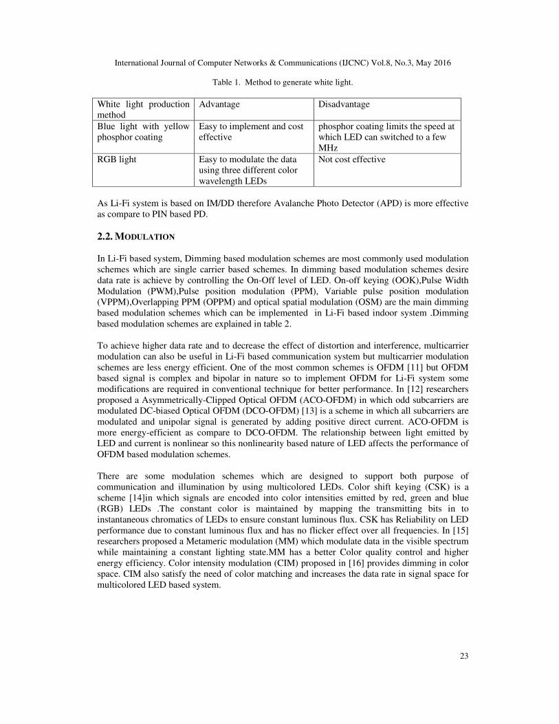
LED luminaire commonly use white light to perform both the function of illumination and
communication. One way of producing white light is to use blue LED with yellow phosphor
coating. When a beam of blue light passes through yellow phosphor coating layer it becomes
white light. Another way is to use a combination of red, green and blue (RGB) LEDs .when red,
green and blue light properly mixed together it becomes white light.As the light emitted by LEDs
are incoherent in nature so therefore there is a need of Intensity Modulation (IM). In IM signal is
modulated in to optical signal of instantaneous power. This signal is received at a receiver by
using Direct Detection (DD) method. In Direct Detection (DD) a photodiode is used to convert
the optical signal power into a proportional current.
International Journal of Computer Networks & Communications (IJCNC) Vol.8, No.3, May 2016
23
Table 1. Method to generate white light.
White light production
method
Advantage Disadvantage
Blue light with yellow
phosphor coating
Easy to implement and cost
effective
phosphor coating limits the speed at
which LED can switched to a few
MHz
RGB light Easy to modulate the data
using three different color
wavelength LEDs
Not cost effective
As Li-Fi system is based on IM/DD therefore Avalanche Photo Detector (APD) is more effective
as compare to PIN based PD.
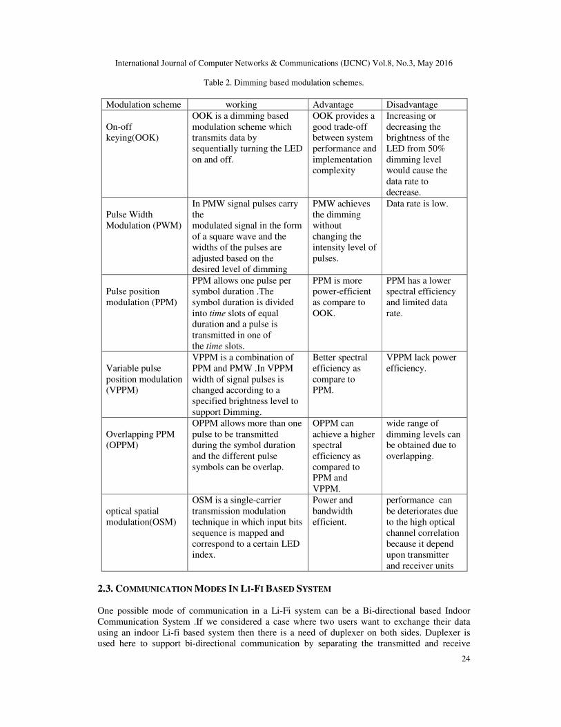
2.2. MODULATION
In Li-Fi based system, Dimming based modulation schemes are most commonly used modulation
schemes which are single carrier based schemes. In dimming based modulation schemes desire
data rate is achieve by controlling the On-Off level of LED. On-off keying (OOK),Pulse Width
Modulation (PWM),Pulse position modulation (PPM), Variable pulse position modulation
(VPPM),Overlapping PPM (OPPM) and optical spatial modulation (OSM) are the main dimming
based modulation schemes which can be implemented in Li-Fi based indoor system .Dimming
based modulation schemes are explained in table 2.
To achieve higher data rate and to decrease the effect of distortion and interference, multicarrier
modulation can also be useful in Li-Fi based communication system but multicarrier modulation
schemes are less energy efficient. One of the most common schemes is OFDM [11] but OFDM
based signal is complex and bipolar in nature so to implement OFDM for Li-Fi system some
modifications are required in conventional technique for better performance. In [12] researchers
proposed a Asymmetrically-Clipped Optical OFDM (ACO-OFDM) in which odd subcarriers are
modulated DC-biased Optical OFDM (DCO-OFDM) [13] is a scheme in which all subcarriers are
modulated and unipolar signal is generated by adding positive direct current. ACO-OFDM is
more energy-efficient as compare to DCO-OFDM. The relationship between light emitted by
LED and current is nonlinear so this nonlinearity based nature of LED affects the performance of
OFDM based modulation schemes.
There are some modulation schemes which are designed to support both purpose of
communication and illumination by using multicolored LEDs. Color shift keying (CSK) is a
scheme [14]in which signals are encoded into color intensities emitted by red, green and blue
(RGB) LEDs .The constant color is maintained by mapping the transmitting bits in to
instantaneous chromatics of LEDs to ensure constant luminous flux. CSK has Reliability on LED
performance due to constant luminous flux and has no flicker effect over all frequencies. In [15]
researchers proposed a Metameric modulation (MM) which modulate data in the visible spectrum
while maintaining a constant lighting state.MM has a better Color quality control and higher
energy efficiency. Color intensity modulation (CIM) proposed in [16] provides dimming in color
space. CIM also satisfy the need of color matching and increases the data rate in signal space for
multicolored LED based system.
International Journal of Computer Networks & Communications (IJCNC) Vol.8, No.3, May 2016
24
Table 2. Dimming based modulation schemes.
Modulation scheme working Advantage Disadvantage
On-off
keying(OOK)
OOK is a dimming based
modulation scheme which
transmits data by
sequentially turning the LED
on and off.
OOK provides a
good trade-off
between system
performance and
implementation
complexity
Increasing or
decreasing the
brightness of the
LED from 50%
dimming level
would cause the
data rate to
decrease.
Pulse Width
Modulation (PWM)
In PMW signal pulses carry
the
modulated signal in the form
of a square wave and the
widths of the pulses are
adjusted based on the
desired level of dimming
PMW achieves
the dimming
without
changing the
intensity level of
pulses.
Data rate is low.
Pulse position
modulation (PPM)
PPM allows one pulse per
symbol duration .The
symbol duration is divided
into time slots of equal
duration and a pulse is
transmitted in one of
the time slots.
PPM is more
power-efficient
as compare to
OOK.
PPM has a lower
spectral efficiency
and limited data
rate.
Variable pulse
position modulation
(VPPM)
VPPM is a combination of
PPM and PMW .In VPPM
width of signal pulses is
changed according to a
specified brightness level to
support Dimming.
Better spectral
efficiency as
compare to
PPM.
VPPM lack power
efficiency.
Overlapping PPM
(OPPM)
OPPM allows more than one
pulse to be transmitted
during the symbol duration
and the different pulse
symbols can be overlap.
OPPM can
achieve a higher
spectral
efficiency as
compared to
PPM and
VPPM.
wide range of
dimming levels can
be obtained due to
overlapping.
optical spatial
modulation(OSM)
OSM is a single-carrier
transmission modulation
technique in which input bits
sequence is mapped and
correspond to a certain LED
index.
Power and
bandwidth
efficient.
performance can
be deteriorates due
to the high optical
channel correlation
because it depend
upon transmitter
and receiver units
2.3. COMMUNICATION MODES IN LI-FI BASED SYSTEM
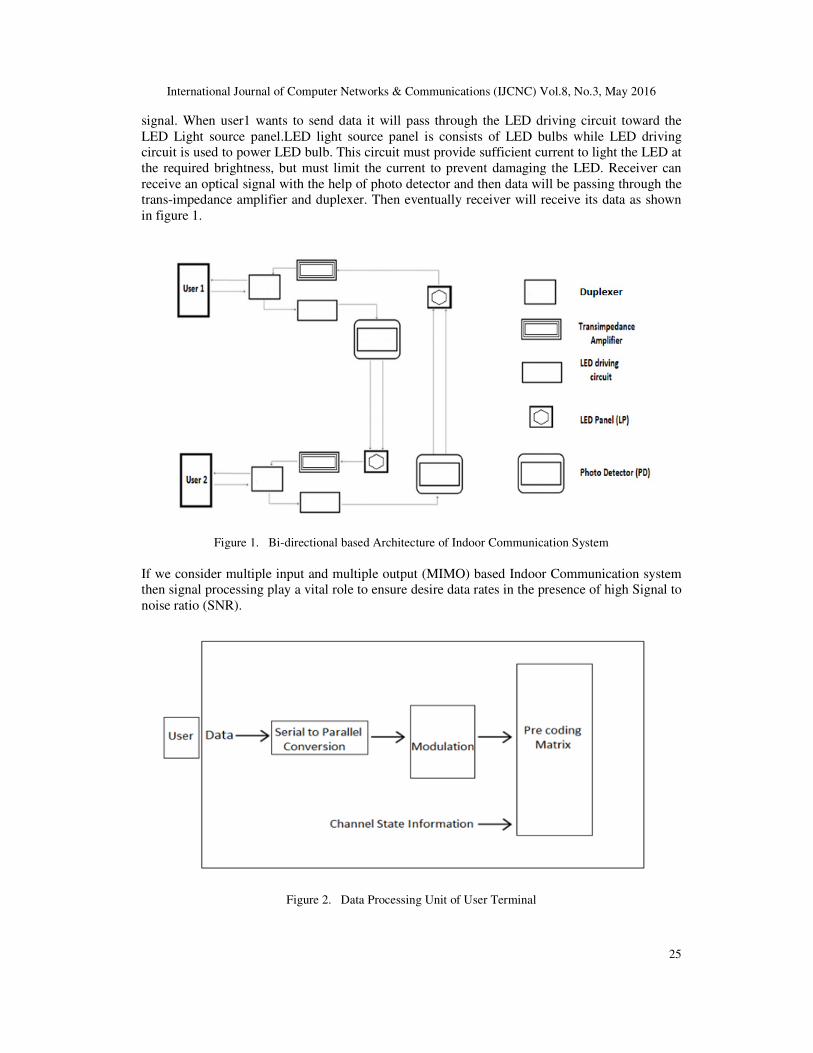
One possible mode of communication in a Li-Fi system can be a Bi-directional based Indoor
Communication System .If we considered a case where two users want to exchange their data
using an indoor Li-fi based system then there is a need of duplexer on both sides. Duplexer is
used here to support bi-directional communication by separating the transmitted and receive
International Journal of Computer Networks & Communications (IJCNC) Vol.8, No.3, May 2016
25
signal. When user1 wants to send data it will pass through the LED driving circuit toward the
LED Light source panel.LED light source panel is consists of LED bulbs while LED driving
circuit is used to power LED bulb. This circuit must provide sufficient current to light the LED at
the required brightness, but must limit the current to prevent damaging the LED. Receiver can
receive an optical signal with the help of photo detector and then data will be passing through the
trans-impedance amplifier and duplexer. Then eventually receiver will receive its data as shown
in figure 1.
Figure 1. Bi-directional based Architecture of Indoor Communication System
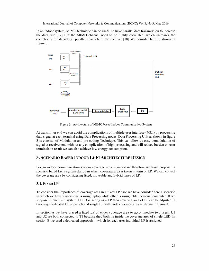
If we consider multiple input and multiple output (MIMO) based Indoor Communication system
then signal processing play a vital role to ensure desire data rates in the presence of high Signal to
noise ratio (SNR).
Figure 2. Data Processing Unit of User Terminal
International Journal of Computer Networks & Communications (IJCNC) Vol.8, No.3, May 2016
26
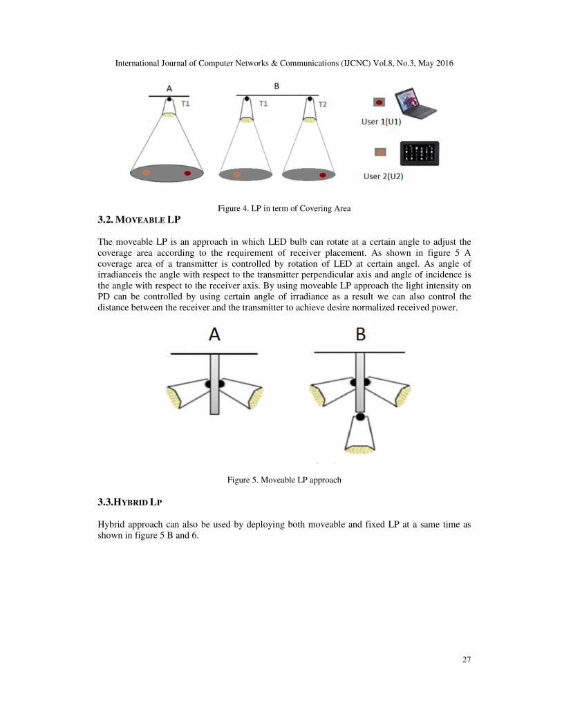
In an indoor system, MIMO technique can be useful to have parallel data transmission to increase
the data rate [17] But the MIMO channel need to be highly correlated, which increases the
complexity of decoding parallel channels in the receiver [18] We consider here as shown in
figure 3.
Figure 3. Architecture of MIMO based Indoor Communication System
At transmitter end we can avoid the complications of multiple user interface (MUI) by processing
data signal at each terminal using Data Processing nodes. Data Processing Unit as shown in figure
3 is consists of Modulation and pre-coding Technique. This can allow us easy demodulation of
signal at receiver end without any complication of high processing and will reduce burden on user
terminals in result we can also achieve low energy consumption.
3. SCENARIO BASED INDOOR LI-FI ARCHITECTURE DESIGN
For an indoor communication system coverage area is important therefore we have proposed a
scenario based Li-Fi system design in which coverage area is taken in term of LP. We can control
the coverage area by considering fixed, moveable and hybrid types of LP.
3.1. FIXED LP
To consider the importance of coverage area in a fixed LP case we have consider here a scenario
in which we have 2 users one is using laptop while other is using tablet personal computer .If we
suppose in our Li-Fi system 1 LED is acting as a LP then covering area of LP can be adjusted in
two ways dedicated LP approach and single LP with wide coverage area as shown in figure 4.
In section A we have placed a fixed LP of wider coverage area to accommodate two users. U1
and U2 are both connected to T1 because they both lie inside the coverage area of single LED. In
section B we used a dedicated approach in which for each user individual LP is assigned.
International Journal of Computer Networks & Communications (IJCNC) Vol.8, No.3, May 2016
27
Figure 4. LP in term of Covering Area
3.2. MOVEABLE LP
The moveable LP is an approach in which LED bulb can rotate at a certain angle to adjust the
coverage area according to the requirement of receiver placement. As shown in figure 5 A
coverage area of a transmitter is controlled by rotation of LED at certain angel. As angle of
irradianceis the angle with respect to the transmitter perpendicular axis and angle of incidence is
the angle with respect to the receiver axis. By using moveable LP approach the light intensity on
PD can be controlled by using certain angle of irradiance as a result we can also control the
distance between the receiver and the transmitter to achieve desire normalized received power.
Figure 5. Moveable LP approach
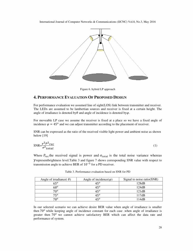
3.3.HYBRID LP
Hybrid approach can also be used by deploying both moveable and fixed LP at a same time as
shown in figure 5 B and 6.
International Journal of Computer Networks & Communications (IJCNC) Vol.8, No.3, May 2016
28
Figure 6. hybrid LP approach
4. PERFORMANCE EVALUATION OF PROPOSED DESIGN
For performance evaluation we assumed line of sight(LOS) link between transmitter and receiver.
The LEDs are assumed to be lambertian sources and receiver is fixed at a certain height. The
angle of irradiance is denoted by� and angle of incidence is denoted by�.
For moveable LP case we assume the receiver is fixed at a place so we have a fixed angle of
incidence � = 45� and we can adjust transmitter according to the placement of receiver.
SNR can be expressed as the ratio of the received visible light power and ambient noise as shown
below [19]
SNR=�����
������(1)
Where ���� the received signal is power and ������ is the total noise variance whereas
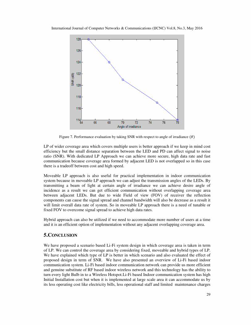
�representbrightness level.Table 3 and figure 7 shows corresponding SNR value with respect to
transmission angle to achieve BER of 10�� for a PD receiver.
Table 3. Performance evaluation based on SNR for PD
Angle of irradiance( �) Angle of incidence(�) Signal to noise ratio(SNR)
65� 45� 128dB
68� 45� 124dB
70� 45� 121dB
75� 45� 117dB
78� 45� 114dB
In our selected scenario we can achieve desire BER value when angle of irradiance is smaller
then 70� while keeping angle of incidence constant for each case .when angle of irradiance is
greater then 70� we cannot achieve satisfactory BER which can affect the data rate and
performance of system.
International Journal of Computer Networks & Communications (IJCNC) Vol.8, No.3, May 2016
29
Figure 7. Performance evaluation by taking SNR with respect to angle of irradiance (�)
LP of wider coverage area which covers multiple users is better approach if we keep in mind cost
efficiency but the small distance separation between the LED and PD can affect signal to noise
ratio (SNR). With dedicated LP Approach we can achieve more secure, high data rate and fast
communication because coverage area formed by adjacent LED is not overlapped so in this case
there is a tradeoff between cost and high speed.
Moveable LP approach is also useful for practical implementation in indoor communication
system because in moveable LP approach we can adjust the transmission angles of the LEDs. By
transmitting a beam of light at certain angle of irradiance we can achieve desire angle of
incidence as a result we can get efficient communication without overlapping coverage area
between adjacent LEDs. But due to wide Field of view (FOV) of receiver the reflection
components can cause the signal spread and channel bandwidth will also be decrease as a result it
will limit overall data rate of system. So in moveable LP approach there is a need of tunable or
fixed FOV to overcome signal spread to achieve high data rates.
Hybrid approach can also be utilized if we need to accommodate more number of users at a time
and it is an efficient option of implementation without any adjacent overlapping coverage area.
5.CONCLUSION
We have proposed a scenario based Li-Fi system design in which coverage area is taken in term
of LP. We can control the coverage area by considering fixed, moveable and hybrid types of LP.
We have explained which type of LP is better in which scenario and also evaluated the effect of
proposed design in term of SNR. We have also presented an overview of Li-Fi based indoor
communication system. Li-Fi based indoor communication network can provide us more efficient
and genuine substitute of RF based indoor wireless network and this technology has the ability to
turn every light Bulb in to a Wireless Hotspot.Li-Fi based Indoor communication system has high
Initial Installation cost but when it is implemented at large scale area it can accommodate us by
its less operating cost like electricity bills, less operational staff and limited maintenance charges
International Journal of Computer Networks & Communications (IJCNC) Vol.8, No.3, May 2016
30
as compare to RF system. Li-Fi communication user always need line of sight connectivity with
its light source therefore some advance research work is required to overcome this limitation to
implement this technology in practical use. Service Providers while providing Li-Fi Indoor
services has to consider major issues like reliability and availability of system and companies also
need to consider how to maintain network for better performance.
REFERENCES
[1] Taner Cevik and Serdar Yilmaz “An overview of visible light communication system” International
Journal of Computer Networks & Communications (IJCNC) Vol.7, No.6, November 2015.
[2] Harald Haas, Member, IEEE, Liang Yin, Student Member, IEEE, Yunlu Wang, Student Member,and
Cheng Chen, Student Member, IEEE, ”what is LiFi?”Journal of Light wave, vol. 34, no. 6, MARCH
15, 2016.
[3] T.Komine and M. Nakagawa,“Fundamental analysis for visible light communication system using
LED lights,” IEEE Trans.consumerElectron., vol. 50, no. 1, pp. 100–107, Feb. 2004.
[4] J.Ding, K. Wang, and Z. Xu, “Impact of different LED-spacing in arrayed LED transmitter on VLC
channel modeling,” in Proc. 6th Int. Conf. Wireless Commun. Signal Process. (WCSP) , Oct. 2014,
pp. 1–6.
[5] Indoor Visible Light Positioning System with Multipath Reflection Analysis Wenjun Gu, Student
Member, IEEE, Mohammadreza Aminikashani, Student Member, IEEE, and Mohsen Kavehrad,
Fellow, IEEE, 2016 IEEE International Conference on Consumer Electronics (ICCE).
[6] Indoor Positioning with OFDM Visible Light Communications, Mohammadreza Aminikashani,
Wenjun Gu, and Mohsen Kavehrad, 2016 13th IEEE Annual Consumer Communications &
Networking Conference (CCNC).
[7] Impact of Multipath Reflections on the Performance of Indoor Visible Light Positioning Systems
Wenjun Gu, Student Member, IEEE , Mohammadreza Aminikashani , Student Member, IEEE, Peng
Deng, and Mohsen Kavehrad , Fellow, IEEEJOURNAL OF LIGHTWAVE TECHNOLOGY, VOL.
34, NO. 10, MAY 15, 2016.
[8] Optimal Constellation Design for Indoor 2×2 MIMO Visible Light Communications ,Heng-Bin Cai,
Jian Zhang, Yi-Jun Zhu,Member, IEEE, Jian-Kang Zhang,Senior Member, IEEE,and XinYang, IEEE
COMMUNICATIONS LETTERS, VOL. 20, NO. 2, FEBRUARY 2016.
[9] Khalid, A. M., Cossu, G., Corsini, R., Choudhury, P and Ciaramella, E “1-Gb/s Transmission Over a
Phosphorescent White LED by Using Rate-Adaptive Discrete Multitone Modulation,” IEEE
Photonics Journal 4, 1465–1473 (Oct. 2012).
[10] Cossu, G., Khalid, A. M., Choudhury, P., Corsini, R., and Ciaramella, E., “3.4 Gbit/s Visible Optical
Wireless Transmission Based on RGB LED,” Optics Express 20, B501–B506 2012.
[11] M.Z.Afgani, H. Haas, H. Elgala, and D. Knipp, “Visible light communication using OFDM,” in Proc.
2nd Int. Conf. Testbeds Res.Infrastruct. Develop. Netw. Commun., 2006, p. 134, doi: 10.1109/
TRIDNT.2006.1649137.
[12] J.Armstrong and A. Lowery, “Power efficient optical OFDM,” Electron.Lett., vol. 42, no. 6, pp. 370–
372, Mar. 2006.
[13] H.Elgala, R. Mesleh, H. Haas, and B. Pricope, “OFDM visible light wireless communication based on
whiteLEDs,” in Proc. IEEE 65th VTC-Spring, Apr. 2007, pp. 2185–2189.
[14] IEEE Std. 802.15.7-2011, IEEE Standard for Local and Metropolitan Area Networks, Part 15.7:
Short-Range Wireless Optical Communication Using Visible Light, IEEE Std., 2011.
[15] P.M.Butala, J. C. Chau, and T. D. C. Little, “Metameric modulation for diffuse visible light
communications with constant ambient lighting,” in Proc. Int. Workshop Opt. Wireless
Communication., Pisa, Italy, Oct. 2012,pp. 1–3.
[16] K.-I.Ahn and J. K. Kwon,“Color intensity modulation for multicolored visible light communication”,
IEEE Photon. Technol. Lett., vol. 24, no. 24, pp. 2254–2257, Dec. 2012.
[17] D.Tsonev, S. Sinanovic, and H. Haas, “Practical MIMO capacity for indoor optical wireless
communication with white LEDs,” in Proc. IEEE VTC—Spring, 2013, pp. 1–5.
[18] F.Bohagen, P. Orten, and G. Oien, “Design of optimal high-rank line of-sight MIMO channels,” IEEE
Trans. Wireless Commun., vol. 6, no. 4,pp. 1420–1425, Apr. 2007.
[19] Seok-Ju Lee and Sung-Yoon Jung “A SNR Analysis of the Visible Light channel Environment for
Visible Light Communication” IEEE APCC 2012.

International Journal of Computer Networks & Communications (IJCNC) Vol.8, No.3, May 2016
31
AUTHORS
Farooq Aftab received his BS Telecommunication Engineering degree in 2013 from
Foundation University, Islamabad, Pakistan. Currently he is pursuing master degree in
Information and Communication Engineering from University of Science and
Technology Beijing, China. His research area is Mobile adhoc network (Manets), Light
fidelity (Li-Fi) and Network coding.
Muhammad Nafees Ulfat khan received his degree ofBachelor of Science in
Electronics and Communication in 2013 from University of Lahore, Pakistan. Currently
he is pursuing master degree in Information and Communication Engineering from
University of Science and Technology Beijing, China. His research area is Light fidelity
(Li-Fi) and visible light communication (VLC).
Shahzad Ali received his degree of M.Sc computer Science in 2013 from Abdul wali
khan Mardan, Pakistan. Currently he is pursuing master degree in Information and
Communication Engineering from University of Science and Technology Beijing,
China. His research area is Wireless Communication.


