Embed Size (px)
Citation preview

N94-14989
Measurement of Birefringence for Optical Recording Disk Substrates
Hong Fu, S. Sugaya t, J.K. Erwin, T. Goodman, Z. Yan, W.J. Tang and
M. Mansuripur
Optical Sciences Center
University of Arizona
Tucson, Arizona 85721
Abstract
The birefringence of bare and coated substrates for magneto-optical recording is experimentally
investigated using ellipsometry at the wavelengths of 632.8 nm and 780 nm. We measure the
rotation and ellipticity of the polarization state of the reflected or transmitted light for different
incident angles and different orientations of the incident linear polarization. The measured data
is then fitted by a computer program which solves the Maxwell equations for the plane-wave
propagation in a multilayer structure and minimizes the error between the measured and
calculated data by adjusting the unknown parameters of the multilayer. This approach enables
us m determine orientations of the three principal axes in the substrate and the corresponding
refractive indices. A special feature of our ellipsometers is that a glass hemisphere is placed in
contact with the substrate, which eliminates the refraction of the incident light and enables a
maximum propagation angle of 70* (with respect to the normal) in the substrate. This increases
the sensitivity of the measurement. Certain anomalies have been observed, which we believe axe
associated with the presence of grooves on these substrates.
? Visiting scientist from Functional Devices Research Laboratories, NEC Corporation, Japan.
37
I:_R1ECEDING PAGE BLAr4K NOT FPLMED

I. INTRODUCTION
Birefringence is a phenomenon observed in optically anisotropic media in which the refractive
indices depend on the polarization direction. The polarization-dependent phase-shifts due to
birefringence of the plastic substrates of magneto-optical (MO) disks can easily degrade the
performance of MO readout systems [1-7]. As the MO data storage systems progress towards
high resolution and ultrafast speeds, the birefdngence has become an increasingly important
prot/lem.
Birefringence in plastic substrates is due to preferential molecular orientation and internal
stresses. The refractive index is higher when the electric field of the light beam is parallel to the
molecular chain direction. For injection-molded polycarbonate substrate the fluid shear during
the injection molding p_ss acts to align the polycarbonate chains in the plane of the disk.
Therefore, the refractive indices n_ and n2 for the in-plane electric field components E_ and F_q
of light are much larger than n3 for the perpendicular component E3. The characterization of
substrate birefringence has been the subject of several papers [6,8-11], which confirmed the
above picture and found that n_ - n3 is on the order of 10_, while In_ - n21 is on the order of
10"5. However, the previous work is limited in the following aspects: First, the formula [8,11]
by which the experimental data were processed applies only to transparent single-layer media
under the assumption that the principal axes of the index ellipsoid are fixed in the radial, track
and perpendicular directions. The phase-shifts due to the multilayers and due to the tilt of the
index ellipsoid could not be taken into account. Second, due to refraction at the interface
between air and substrate, the propagation angle of the light in the substrate is usually small. For
58

example, 70 ° incident angle in air corresponds to 36.5 ° propagation angle in the polycarbonate
substrate (n - 1.58). So the beam possesses only a small E3 component and the experimental
sensitivity to n3 is limited.
The present paper describes measurements of the substrate birefringence using one ellipsometer
with wavelength X = 632.8 nm and another with X - 780 nm. We remove the first restriction
of the previous work by using a computer program which solves the Maxwell equations for a
plane-wave propagating in a multilayer structure including the substrate [12]. This approach
enables us to determine the three principal axes of the substrate and the corresponding refractive
indices. To overcome the second limitation, we have placed a hemispherical glass lens atop the
substrate to eliminate refraction. A maximum propagation angle of 70 ° in the substrate has thus
been achieved. We measured the rotation angle and ellipticity of the polarization state of the
reflected and/or transmitted light as functions of the incident angle for linearly polarized incident
beam. The investigated substrate materials include glass, polycarbonate plastic (bare and coated),
and amorphous polyolephin plastic (bare). Measurements were performed on regions with or
without grooves. For the former case, the grooves were either fdled with index-matching fluid
or left empty. Different angles between the plane of incidence and the direction of grooves were
used in the measurements. This paper is organized as follows. The two ellipsometer systems and
measurement procedures are described in Sec. II, along with a description of the data analysis
procedure using the multilayer program. The measurement results are described in Sec. III. Sec.
IV contains some concluding remarks.
39

II. ELLI_OMETER SYSTEMS AND THE MEASUREMENT METHOD
II.l The VAE633 System
Figure 1 shows the experimental setup. The light source is a HeNe laser with )_ = 632.8 nm.
As the beam first passes through the polarizer and the quarter-wave plate (QWP), whose fast
axis is at 45 ° to the transmission axis of the poladzerl it becomes circularly polarized. The
second polarizer selects the linear polarization direction of the incident beam. A hemispherical
glass lens is placed in contact (using index-matching fluid) with the surface of the sample. This
hemisphere is actually slightly less than one half of a sphere, and is mounted in such a way that
the geometric center of the spherical surface is on the back side of the substrate. The light enters
normally into the hemisphere, goes through the substrate, and is reflected from the back side of
the substrate. After reflection, the beam passes through another QWP with an adjustable fast-axis
orientation. The beam then goes through a Wollaston prism which can be rotated about the
beam. Finally, the two beams of mutually perpendicular polarization are detected by the
photodetectors.
The hemispherical lens eliminates refraction at the air-substrate interface, thus producing a larger
propagation angle within the substrate. For example, in polycarbonate substrate with n = 1.58,
without the glass hemisphere one can reach a maximum angle of 39 ° at grazing incidence (i.e.
O_ = 90°), while with the hemisphere in place (rh¢_ = 1.52), the propagation angle inside
the substrates is 64 ° at OK = 70 °.
11.2 The VAE780 System
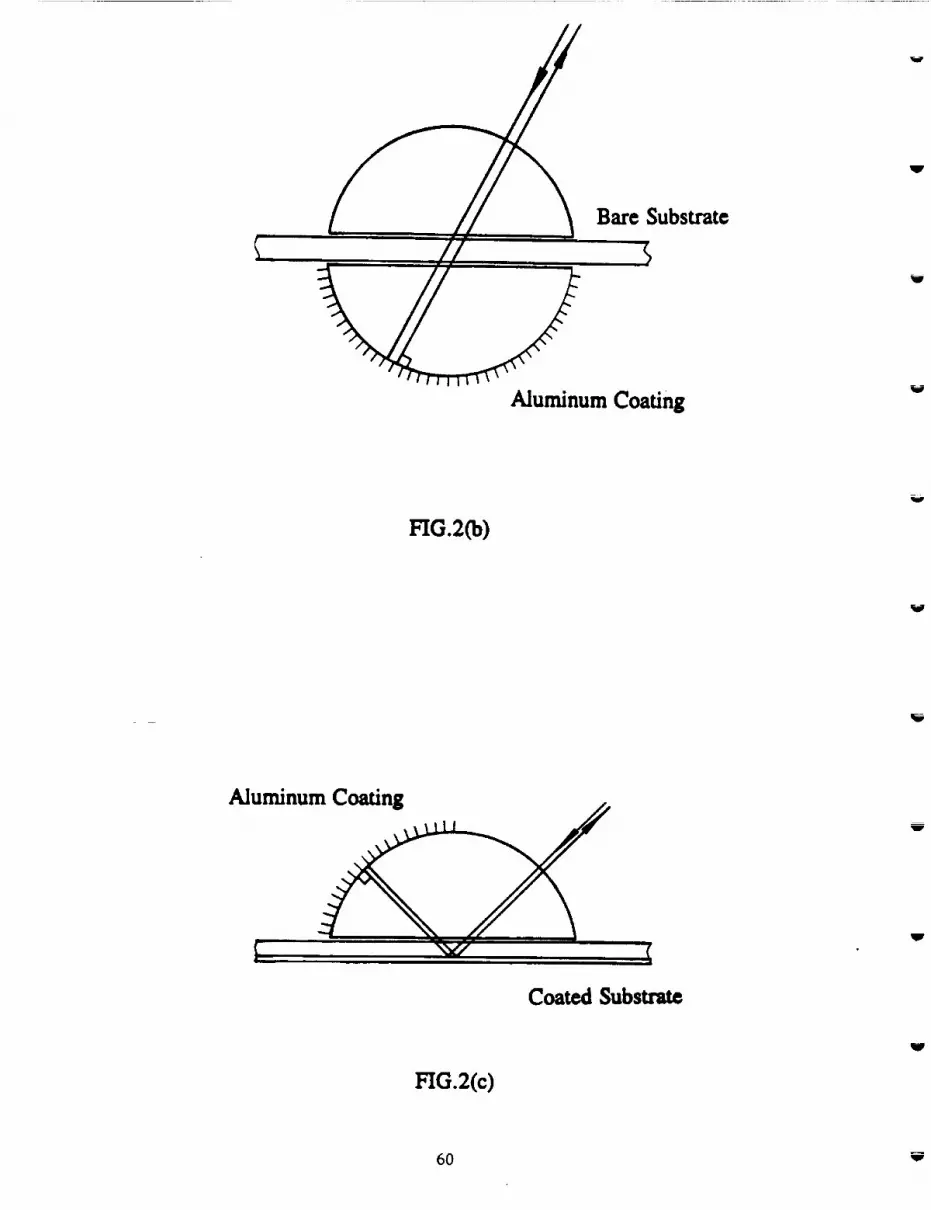
4o

The setup is schematically shown in Fig.2 (a). The operation principle is similar to the VAE633
system. One of the main differences is that all the moving parts are mounted in one arm, which
can be rotated in both polar and azimuthal directions. The alignment of the system is thus easier
to maintain. The freedom of two-dimensional rotation is particularly valuable to measure the
effect of grooves, which are found to be sensitive to both polar incident angle O_ and the
azimuthal incident angle ,l,ffi relative to the radial direction. The linearly polarized light from
the laser diode (k - 780 nm) passes through the beam splitter and enters normally through the
hemisphere before it reaches the sample. The direction of incident polarization is controlled by
rotating the laser in its socket. The hemisphere is used in different ways, depending on whether
the sample is transparent or reflective. For transparent samples, two hemispheres are used, see
Fig.2 Ca). The one on the top is transparent and is used to eliminate refraction. The one at the
bottom is coated with aluminum and reflects the beam normally so that the light goes back along
the incident path. In this configuration the light passes twice through the substrate. For coated
samples, we only need the top hemisphere, see Fig.2 (c). Half of this hemisphere is coated with
aluminum. The beam enters from the uncoated side, gets reflected from the bottom of the
sample, bounces off the coated side of the hemisphere, and retraces its path. Thus the beam
passes four times through the substrate. In both transmission and reflection modes, the use of
hemisphere(s) does not introduce phase shift or relative amplitude change between p and s
components upon entering and exiting the substrate. Therefore, the measured values of rotation
and ellipticity are solely determined by the properties of the sample. As the light beam returns,
it is routed by the beam splitter into the detector channel, where its polarization state is
determined by the use of the QWP, a Wollaston prism and two detectors.
41

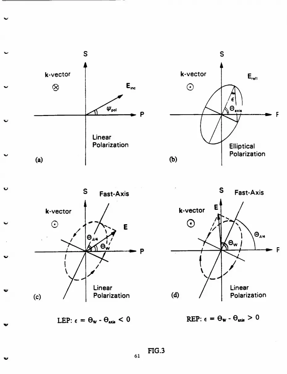
H.3 The Measurement Principle
The measured quantifies axe the rotation angle 0 and ellipticity angle e of the reflected beam.
The definitions of 0 and t and the corresponding measurement procedures are described below.
The p- and s-polarization directions for incident and reflected beams in VAE630 and VAE780
systems axe defined in Fig. 1 and Fig.2 (a), respectively. The polarization angle _bpoj of the
incident beam is measured from the p-direction, Fig.3 (a), and can be read from the setting of
the polarizer in VAE633 and the laser diode in VAE780. In general, due to phase retardation
between the p- and s-components, the reflected beam is either left- or right-handed elliptically
polarized (LEP or REP). Figure 3 Co) shows that the ellipse can be characterized by the
orientation of its major axis, 0m,, and the ellipticity angle e. By definition J tan e J is the ratio
of the minor to major axis, and e < 0 for LEP and e > 0 for REP. Thus, -45 ° < e < 45 °.
In particular, e = -45 ° (or +45 °) corresponds to LCP (or RCP), and e ffi 0 corresponds to
linearly polarized light. When the fast-axis of the QWP is parallel to the major axis of the
ellipse, the beam passing through it becomes linearly polarized. Its polarization angle 0w can be
smaller or greater than 0._, depending on whether the beam before the QWP is LEP or REP.
These two cases axe shown in Figs.3 (c) and (d). 0uz, and 0w can be measured simultaneously
by adjusting the orientations of QWP and the WoUaston prism, until one of the detectors
receives no light. Once extinction is achieved, the orientation of the fast-axis of the QWP gives
0,_,, while the Wollaston orientation gives 0w. The rotation and ellipticity angles of the reflected
beam are then given by:
In practice, the error for the measured value of e is less than 1 °, as estimated from repeated
42

measurements. The error for 0 depends on the value of e. For [ e [ < 40 °, error of less than
1° can be achieved. For ] e] > 40 °, the ellipse is close to a circle and the orientation of the
major axis is hard to measure. The repeatability of 0 in such cases is within several degrees.
II.4 Data FiRing with the MultUayer Program
The first part of the multilayer program [12] solves the Maxwell equations for a plane wave
obli_tuely incident upon a multilayer structure consisting of a given number of layers. Each layer
is characterized by its dielectric tensor and thickness. With adequate restrictions on the tensor
elements, different types of media (isotropic, birefringent, magneto-optic, etc.) can be described.
Figure 4(a) shows the quadrilayer structure of a typical MO disk. This structure is used in data
fitting for coated substrates. For bare substrates, we consider the substrate alone without
additional layers. The hemisphere material (n,_=,, - 1.52) and the index-matching fluid (n_ -
1.52) are treated as the medium of incidence. Since the optical paths in VAE633 and that in the
transmission and reflection modes of VAE780 are different, three versions of the multilayer
program were used in the data _alysis. The second part of the program searches the best values
of unknown parameters by minimizing the error, defined below, between the measured and the
calculated data:
In this equation, the superscript "exp" stands for experimental data, and "ca]" for calculated
data, N is the total number of the measurements on a given sample. The unknown parameters
are the refractive indices, the orientation angles of the principal axes of the ellipsoid of
43

birefringence and the structure parameters of the multilayer. In our Convex computer system,
it takes only a few minutes to search for 10 unknown parameters in fitting 120 data points.
In Fig.4 (a) X and Y denote the in-plane radial and track directions of an optical disk, and Z the
normal direction. In addition to the incident angle Ok, we use ,I,_ to specify the azimuth of the
incident k-vector. For all the samples, we found that one principal axis (3) is always along the
perpendicular direction, but the in-plane axes (1 and 2) may be rotated in the X-Y plane, see
Fig.4 (b). To be specific, we let 1 be the in-plane axis with the larger refractive index, and use
_b_,.pt_ to denote the in-plane rotation of axis 1 from the radial direction.
There are two aspects of the actual systems that are not taken into account in the multilayer
program. One is that the beam is not a plane wave, but a focused beam with 0.5 mm diameter
that converges to a 50_,m spot at the bottom of the substrate. For thick samples, the two
reflected beams from the front and back surfaces are spatially separate and do not interfere with
each other, while in the program the two beams overlap. However, since the reflection at the
interface between the hemisphere and the substrate is weak, the interference only causes small
fluctuation in the calculated curves. Therefore, the plane wave approximation is acceptable.
Another aspect is the structure of the grooves on the surface of the substrate, which are usually
0.5/_m wide, 70 nm deep, and have a periodicity of 1.6 _tm. The effect of the grooves on
polarized light has not been fully investigated. We found that, for bare substrates, the data
measured at q,_,, - 0* can be matched very well, while for coated substrates, good match can
be obtained for 6_ = 90 °. For other values of 6_, there is usually mismatch between the
44

measured data and theory. In these occasions we are probably witnessing anomalous behavior
caused by the grooves.
HI. RESULTS
The measured samples include a glass microscope slide, two 3.5" bare polycarbonata substrates
(PC3.5B01_ and PC3.5B02), two 5.25" polycarbonatcbare substrates(PCS.25B01 and
PC5.25B02), one 5.25" amorphous polyolephinsubstrata(APO5.25BOl), two 3.5" MO disks
(PC3.5C01 and PC3.5C02), three5.25"MO disks(PC5.25C01, PC5.25C02, PC5.25C03). All
coateddisksubstratesare polycarbonataplastic.The main resultsof thesemeasurements are
summarized inTable I.
m.l The Glass Sample
To check the VAE633 system, we measured a glass microscope slide with thickness d - 1.2
mm. Glass is believed to be isotropic with a refractive index close to that of the hemisphere and
index-matching fluid. So the optical path is simple (e.g. no multiple reflections) and the problem
should be well described by the well-known formulas for reflectivity at a single interface
[13,14].
Fig.5 shows 0 and e as functions of the incident angle in the range 10° < O,_ <- 70 ° for ¢_
= 45 °. The measured data in (a) and (b) are same. The caiculatad curves in (a) are obtained by
1In this notation PC stands for polycarbonate (APO stands for amorphous polyolephin), the number3.5 for the disk diameter in inches, B for bare substrate (C for coated substrate), and 01 is the serial
number.
45

assuming that the glass is isotropic. The match gives ns,.. , = 1.54. We see that the rotation
angles can be matched very well, but the non-zero ellipticity for O_ < 41 ° (critical angle of
total internal reflection) cannot be matched. The average fitting error is 1.9 °. To obtain a better
match, we allowed the glass to have a small amount of birefringence. The curves in Fig. 5(b)
show the best match with an average error of 0.8 °. The fitted refractive indices are nl = 1.54,
(nl - n_) = 6x 10 6, (nl - n3) = -1 x 10 -_ and _km.p_ = -9.2 °. In this particular case where the
sample has no grooves, X and Y stand for in-plane directions along the two rectangular sides
of the microscope slide.
The basic features of the plots of 0 and e versus O_ can be understood using the reflectivities
for F_,pand E, for dielectric interface [13,14]. Below the critical angle for the total internal
reflection (O_ < 41°), the reflectivities are real and non-equal, i.e. the values of I Evl and
I E, I will change after reflection but the phase difference should remain zero. Therefore, the
reflected beam is still linearly polarized (e = 0) but in a different direction (0 _ 0). The
measured non-zero e indicates that there exists a small amount of birefringence. At the critical
angle the behavior of 0 and e changes drastically. We mention in passing that the total reflection
occurs at the interface between the glass sample and air, but the critical incident angle is
determined by the refractive index of the hemisphere, as can be readily seen from Snell's law.
In VAE 633, we found that the critical angle is 41.3 °, which is in agreement with n_,u_ = 1.52.
Above Om = 42 °, both Ep and E, are totally reflected and acquire different phase shift, i.e.
I = IE, I, 6p 6.. So we have e g 0.
46

111.2 Sample PC3.SB01 and PC3.SB02
The measured point is located at about 3 cm from the center of the disk and at the center of a
sector with grooves. To reduce diffraction effects, the groove side of the substrate was placed
in contact to the hemisphere and the grooves were thus filled with index matching fluid. The in-
plane projection of the plane of incidence is perpendicular to the track direction (4,_,, = 0").
Figures 7 (a) and 03) show the measurement results and the matched curves for sample
PC3.5B01 with ff_ -- 30* and 60", respectively. The best fit for the data set with ff_ = 30*
gives nl = 1.58, (nt- n2) = 1.5x10 "s, (nt- n3) - 5.87x 10⁴ and ff.,-pt,_ -- -0.3*. The fitting
error is 2.9*. The parameters found for ff_ = 60* are: nl -- 1.58, (nl - n2) - 1.3 x 10-s, (nl-n3)
-- 5.87x 10⁴, and ¢,_,_ -- -5.3*. The average error for ff_ -- 60* is 1.7", smaller than that
for ff_ ----30*. We see that the two sets of fitted parameters are nearly identical. Ingnoring the
small values of _,_, one can assert that the principal axes are in fact along the radial, track
and perpendicular directions.
Some of the features shown in Fig.6 are common to all the substrates and can be easily
explained. First, the absolute values of O and e are small at small O_. The reason is that the
beam close to normal incidence only experiences the small in-plane birefringence, but not the
larger vertical birefringence. The second feature is that the oscillation interval, i.e. the
difference between incident angles corresponding to two adjacent peaks, decreases with
increasing O_. For example, the peaks ofe in (a) appear at Om= 22 °, 37", 49", 60* and 68*.
The corresponding intervals are 150, 12", 11 * and 8", and decrease monotonically. This feature
47

could be understood as the change of optical path length per incident angle increases with O_.
Another feature is that 0 always shows a 90 ° jump when e = 45 °, see the data points at O_,o =
22" in (a). What happens here is that the polarization ellipse is very close to a circle. A slight
decrease in the major-axis or increase in the minor-axis causes exchange of the axes and lead
to a 90 ° jump. This transition is shown in Fig.7.
Sample PC3.5B02 is another substrate in the same series of product as PC3.5B01. We measured
the same position (3 cm from the center of the disk and center of a sector with grooves) in both
VAE633 and VAE780 for _mo = 0 ° and ff_ = 60 °. The data taken with VAE633 has a shape
similar to that shown in Fig.6 (b). However, the best fit gives ff_t_ = -50.3*. In comparison
with PC3.5B01, the in-plane birefringence is three times smaller: (n_ - nz) = 0.5x10 5 and
vertical birefringence is somewhat larger (nl - n3) = 6.26 x 10 -4. PC3.5B02 was also measured
with VAE780 in the transmission mode. Figure 8 shows the measured data and the best fit. The
best match gives ffm-pt_ = 56.7 °. The fitted parameters are: nl = 1.58, (nt - n2) = 1.9xl0 5,
and (n_ - n3) = 5.83 x 10 -4.
II1.3 Sample APOS.25B01
The measured position is located 5 cm from the center of the disk and in the middle of a sector
with grooves. The groove side is in contact with the hemisphere. The sample was measured with
VAE633 at _mo = 0 ° for ff_ = 60 °. The measured data and the best fit are shown in Fig. 9.
Both in-plane and vertical birefringence are small: n_ = 1.50, (nt - nz) = 0.4 x 10 -5, (n_ - n3) =
1.3 x l0 -5 and _km.pt_ = -72.5 °.
48

m.4 Sample PCS.25B01 and PC5.25B02
These two samples are from the same series of product. The measured point on smaple
PC5.25B01 was located 5 cm from the disk center and in the middle of a sector with grooves.
The groove side was faced to the hemisphere and filled with index matching fluid. The
measurement was performed with 4'_ = 0 ° and _b_ = 60 ° with VAE780. The measured data
and the match are shown in Fig. 10. The fitted parameters are: n_ = 1.58, (n_ - n2) = 1.3 x 10-s,
(hi - n3) = 6.22 x 10⁴ and _bi_.p_,_= 66 °.
For Sample PC5.25B02 we measured the region without grooves: a point located 2.5 cm from
the center of the disk with VAE633 for _b_ = 30 °, 45 °, 60 ° and 4,,.. = 90 °. Figure 11 (a)-(c)
show the measured data and the fits. No match has been found for Ow > 54 ° (not plotted). The
fitted parameters based on data taken for 10 ° < O_. _< 53 ° with _b_ ffi 30 °, 45 ° and 60 ° are:
nl = 1.58, (nl -n2) ffi 2.2x10 -5, (hi- n3) = 5.83x10 "4and _.._ ffi 1.6 °. We also measured
a point in the region with grooves. This time we found that, for Offi > 25 °, the measured
curves cannot be matched. The measurement was repeated for the same point, but with the side
of grooves facing backward, so that the grooves were not filled with the index-matching fluid.
In this case there were a series of diffracted beams and we measured the one corresponding to
the zeroth order pattern. The measured values for 0 and e in the range of 10 ° < Offi _< 60 °
were the same as those with the fiUed grooves.
nl.5 Sample PC3.5C01 and PC3.5C02
These two MO disks are from the same series of product with quadrilayer structure. The
49

measured point was located 3 cm from the disk center and in the middle of a sector with
grooves. The data were taken with ¢I,_ = 90 ° and _ = 60 °. The measured data and the best
fit are shown in Fig. 12. The fitted parameters are: n_ = 1.58, (nt - n2) = 2.3 x 10 -5, (n_ - n3)
= 5.34×10 "4, and _b,..p,... = -2.9 °. The principal axes are in fact along the radial and track
directions. To obtain the best fit, the quadrilayer sti'ucture must be used and adjusted in the
calculation. We found that the searched structure parameters were not unique. However, the
searched birefringent parameters were always the same and hence are reliable. The reason is that
the measured 0 and e contain information about the phase shift contributed by the birefringence,
but not much information about the absolute reflectivities which are signatures of the
quadrilayer. The same measurement was performed for PC3.5C02. The fitted parameters are:
nl = 1.58, (hi - nz) = 2×10 "5, (ni - n3) = 5.51 ×10 "4, and ¢'l-pi,_ -- -6.5 °. Compared with the
bare substrates PC3.SB01 and PC3.SB02, we see that the coated substrates have larger in-plane
birefringence but smaller vertical birefringence. The decrease of vertical birefringence due to
coating was also reported in [11].
III.6 Sample PC5.25C01
The sample is a small section of coated substrate with grooves cut from a 5.25" MO disk. The
data were taken_ with VAE633 at ¢I,_. = 90 ° for _b_ = 45 ° and 60 ° As Shown in Fig. 13, both
measured curves can be fitted very well with a fitting error of 1.65 °, using the set of
parameters: nl = 1.58, (n I - nz) = 0.9×10 5, and (hi - n3) = 4.61 ×10 "4 and ¢,,,.p_ = 8 °.
5o

111.7 Sample PC5.25C02 and PC5.25C03
These two samples are from the same series of product. For PC5.25C02 we measured 4 points,
each located at the same radial position (5 cm from the disk center) but in the middle of different
sectors. _E = 90° and _b0o_ = 60 ° were fixed. The measured data were nearly identical for the
4 points, see Fig. 14, indicating that the birefringence ' property is uniform along the track. The
best match for one of the measured points (solid lines in Fig. 14) gives: n_ = 1.58, (nl - n2) =
0.7x 10⁻⁵, and (nt - n3) = 3.37x 10⁴ and _b_,.p_ = -18".
For PC5.25C03 we measured one point at 5 cm from the center of the disk and in the middle
of a grooved sector. The fitted parameters are: n_ = 1.58, (n_ - n_) = 1.9 x 10 -5, (n_ - n3) =
3.47x10 -4 and ¢'_,t_ = 11.5 °. Figure 15 shows the measured data for both PC5.25C02 and
PC5.25C03 with ff_ = 60 °, emphasizing the similarity of the two disks.
IV. CONCLUDING REMARKS
In this paper we have described an approach to measuring the birefringence for optical disk
substrates using ellipsometry. The procedure consists of measurement of the rotation and
ellipticity, and data fitting using a computer program. Using this method we have measured a
number of bare and coated substrates. One of the main differences between our method and the
previous ones is that we can measure the orientation of the principal axes of the index ellipsoid.
Our results confirm that the disk normal direction is always a principal axis (e.g. tilted angle of
less than 0.1 ° was found for all the measured samples). However, rotation of the in-plane axes
was found to occur frequently. This rotation has been mentioned previously [9], but our work
51

gives the first quantitative results. Another advantage is due to the use of the glass hemisphere
which makes large propagation angles. We found that the grooves in bare (even when filled with
index-matching fluid) and coated substrates have different effects on the polarization state of the
beam. For bare substrates, the measured data can be matched very well when the plane of
incidence is perpendicular to the grooves (_B: -- 0°). The opposite is true for coated substrates,
i.e., ¢I,_ = 90 ° gives the best match. For other values of ¢I,_ the match is usually poor,
especially for data measured at large O_. This dependence on ¢I,_ shows that the grooves can
cause a phase shift, thus producing errors in birefringence measurement. The fact that we can
get good match for data taken at ¢I,m -- 0 ° for bare substrates and _ - 90 ° for coated
substrates may suggest that at these particular angles the grooves have no effect on the beam,
and thus the measured birefringence data are more accurate.
REFERENCES
[1] D. Treves and D. S. Bloomberg, "Effect of birefringence on optical memory systems," in
Optical Mass Data Storage 1I, R. P. Freese, A. A. lamberdino and M. de Haan, eds. Proc. Soc.
Photo-Opt. Instrum. Eng. 262-269 (1986).
[2] A. B. Marchant, "Retardation effects in magneto-optic readout," in Optical Mass Data
Storage II, R. P. Freese, A. A. Jamberdino and M. de Haan, eds. Proc. Soc. Photo-Opt.
Instrum. Eng. 270-276 (1986).
[3] W. A. ChaUener and T. A. Rinehart, "Jones matrix analysis of magneto-optical media and
read-back systems," Appl. Opt. 26, 3974-3980 (1987).
[4] T. Toda, K. Shigematsu, M. Ojima and M. Yoshihiro, "Analysis of signal-to-noise ratio in
52

magneto-opticaldisk using a polarization simulator," Electron. Commun. Jpn. Part 2, 72, 49-57
(1989).
[5] A. Yoshizawa and N. Matsubayashi, "Analysis of optical anisotropy of PC substrate for M-O
disks and its effect on CNR," in Optical Mass Data Storage II, R. P. Freese, A. A. Jamberdino
and M. de Haan, eds. Proc. Soc. Photo-Opt. Instrum. Eng. 91-98 (1986).
[6] W. Siebourg, H. Schmid, F. M. Rateike, S. Abders and U. Grigo, "Birefringence -- an
important property of plastic substrates for magneto-optical storage disks," Polym. Eng. Sci. 30,
11133-1139 (1990).
[7] Ivan Prikryl, "Effect of disk birefringence on a differential magneto-optic readout," Appl.
Opt. 31, 1853-1862 (1992).
[8] A. Takahashi, M. Mieda, Y. Murakami, K. Ohta and H. Yamaoka, "Influence of
birefringence on the signal quality of magneto-optical disks using polycarbonate substrates,"
Appl. Opt. 27, 2863-2866.
[9] S. Shirouzu, K. Shigematsu, S. Sakamoto, T. Nakagawa and S. Tagami, _Refractive index
ellipsiods of a polycarbonate magneto-optical memory disk substrate," Jpn. J. Appl. Phys. 28,
797-800 (1989).
[10] J. E. Hayden and S. D. Jacobs, "Automated spatially scanning ellipsometer for retardation
measurements of transparent materials," to appear in Appl. Opt. (1993).
[11] A. Skamanich, "Substrate birefringence in coated optical storage disks," to appear in J.
Magn. Soc. Jpn. 17, $1 (1993).
[12] M. Mansuripur, "Analysis of multilayer thin-film structures containing magneto-optic and
anisotropic media at oblique incidence using 2 x 2 matrices," J. Appl. Phys. 67, 6466-6475
53

[13] J.D. Jackson, Classical Electrodynamics, 2rid Eel., John Wiley & Sins, New York (1975),
p.281.
[14] M.V. Klein and T.E. Furtak, Optics, 2nd Ed., John Wiley & Sons, New York, (1986),
p.84.
FIGURE CAPTIONS
FIG. 1 The system setup for the variational-angle ellipsometer with wavelength k = 632.8 nm
(The VAE633 system).
FIG.2 (a) The system setup for the variation-angle ellipsometer with wavelength k = 780 nm
(The VAE780 system). Co) The hemisphere setup in transmission mode. (c) The hemisphere
setup in reflection mode.
FIG.3 (a) Definition of the incident polarization angle _. Ca) The polarization ellipse of the
reflected beam is characterized by 0.,,. and e. The sign of e is "-" for LEP and "+" for PEP.
(c) and (d): Polarization state of the beam after the QWP when the fast axis is aligned with the
major axis.
FIG.4 (a) The quadrilayer structure of MO disk is used in fitting the data for coated substrate.
Co) The in-plane principal axes are found rotated for some substrates, but the third one is always
perpendicular.
FIG.5 The best fit for glass sample. (a) The medium is forced to be isotropic. Ca) Birefringence
is allowed. Data were taken with VAE633. The small fluctuations appearing in the calculated
curves are due to the interference of beams reflected at the front and the back surfaces of the
54

sample.
FIG.6 The best fit for sample PC3.5B01 measured with (a) ff_ = 30 °, CO)ff_ --- 60*. The
discontinuity at O_ = 22* in (a) is explained in the text. The jumps at OE = 27* and 39* are
not physical, since 5:90* stand for the same polarization plane. Data were taken with VAE633.
To obtain good match for bare substrates, we found the incident plane must be perpendicular to
the track direction (q,_ = 0").
FIG.7 The exchange of major axis and minor axis causes a discontinuity of 90* in 0 when e =
45*.
FIG.8 Measured data and the best fit for Sample PC3.5B02. Data were measured with VAE780
in the transmission mode.
FIG.9 Measured data and the best fit for Sample APO5.25B01. Data was taken with VAE633.
The fluctuations of the calculated curves are due to the interference between beams reflected
from the front and back surfaces of the substrate.
Fig.10 Measured data and the best fit for Sample PC5.25B01. Data were measured with
VAE780 in the transmission mode.
FIG. 11 Measured data and the best fit for Sample PC5.25B02. The measured point locates in
a region without grooves. The polarization angle is (a) ff_ -- 30 °, Co) ff_ = 45", (c) ff_ --
60 °. No match has been found for O_. > 54* (not shown).
FIG. 12 Measured data and the best fit for Sample PC3.5C01. The data were measured at _,,
= 90 ° and ff_ -- 60 ° with VAE633. In contrast to bare substrate, we found that, for coated
substrates, good match can only be achieved with _ -- 90*.
FIG. 13 Measured data and the best fit for Sample PC5.25C01. The data were measured at _
55

-- 90 ° with VAE633. (a) _k_ = 45°, (b) _k_ = 60 °.
FIG. 14 Comparison of measured data for 4 points at different sectors of Sample PC5.25C02.
Solid curves are for sector 1; dashed for sector 2; dotted for sector 3 and dash-dotted for sector
4. The data were taken with VAE633 at (I)_ = 90* and ¢,_ = 60 °. (a) Rotation angle O, (b)
Ellipticity 8.
FIG. 15 Comparison of measured data for the same position at PC5.25C02 (solid lines) and
PC5.25C03 (dashed lines). The data are almost the same for O_ < 45*. This shows the
birefringent property in the two samples is very close.
56

mm
r_ c_
57

The VAE633 System
Substrate
h/4 Plate
$
P
E)inc
Hemi -
sphere
S
P
PBS
Wollaston Prismh/4 Plate
Polarizer
Detectors
w
HeNe Last
FIG.1
58

J
o
,, //_
59
Bare Substrate
AluminumCoating
HG.2(b)
Al minu " !
Coated Substrata
HG.2(c)
6O
(a)
k-vector
®
S S
k-vector L_ E,,f_E,.= Q
Linear l /
Polarization _ EllipticalPolarization
Co)
S Fast-Axis S Fast-Axis
k-vector l / k-vector E_t. /
i eAi4 I /p . F
/ I Linear / Linear
(c) / I Polarization (d) / Polarization
LEP:e =ew-e,=< 0 PEP:e =ew-e,_,> o
HG.361

Hemisphere
Z
\\
Y
Track Direction
Substrate
Dielectric
Magneto-optic
Direlectric
Reflector
X Radial Direction
FIG.4 (a)
62

X
Z,3
1
2
Y
FIG.4 Co)
63

10
0
_m -10
i -20
-30
-4O
-50-60
-70
-80
INCIDENT ANGLE (DEGREE)
I0,-, ' ' '45 DEG. INCIDENT POLARIZATION
_, _ k3 ELLIPTICITY . ,.,_¢_
-7o- \(b) \
-80 ,- . _, ' ......._.0. , , ,I_o°°°°_. °°°°°.. :° ooo_______"Vl0 20 30 40 50 60 70
INCIDENT ANGLE (DEGREE)
V
64H_.5

_CIDENT ANOLE (DEGREE)
7O
T I
60 DEG. INCIDENT POLARIZATION
EILIFllCITY
ROTATION
.0 20 30 40 50 60 70
INCIDENT ANGLE (DEGREE)

_ ._
_J
°wmmR
t
LIC_ c_om

6O60 DEG. INCIDENT POLARIZATION
!" 5o
_ ?o
_ oEIIIPTICTI_
| .... 1
30 40I ,
5O
mc_F.2cr INGLE _EGRF.E)
!
7O
FIG.8
67

10
60 DEG. INCIDENT POLARIZATION
INCIDENT ANGLE (DEGREE)
FIG.9
68 w

6O
50
ELLIPTICITY
6oD_OXNCIDENTPOL_ZATXON2'O 3'0 40
INCIDENT ANGLE (DEGREE)
7O
HG.10
69

00 t i
_, '30 DEG'. INCIDENT POLARIZATION
_ 40j __" 201__oO60................. ""''_" I ' .... _ \_ o__//.__°°°°° \
.201..................................................._j._,. ............j._/ ..............._•o ........ i .................I.i...................... i:. "
x,. I :
ROTATION
-1 15 20 25 30 35 40 45 5'0 55
INCIDENT ANGLE (DEGREE)
45 DEG. INCIDENT POLARIZATION
i
55

40 45 50 55
INCIDENT ANGLE (DEGREE)
FIG,11
71

V
lit
ol 60 DEG. INCIDENT POLARIZATION
ELLIPTICITY
........ ROTATION .....
20 30 40 50
_ENT _OLE (OEOI_..E)
O O
O
7O
FIG.12
72

J- .
0
60 DEG. INCIDENT POLARIZATION
ELLIPTICITY
ROTATION
I i20 /5 30 3_ L I
40 45
x_cn)_¢r ANGLE(DEGREE)
i °
5'0 5'5 6O
ROTATION
45 DEG. INCIDENT POLARIZATION
20 25 30 35 40 45 50 55 60
INCIDENT ANGLE (DEGREE)
FIG.13
73

0
60 DEG. INCIDENT POLARIZATION:?
\
\
"601t) i5 20 25 30 35 40 4'5
I
5'0 55
INCrDENTANOLE O)EOREE)
60 DEG. INCIDENT POI..ARIZATION
30 ......................................................... E':_".............
.....................-:,:_ y_20 .... ,f:_ ...... ":'I.',_,..................................................:// ........"_,\.........
._-'-_..:/" ':::,.X il '_,
X ..........'/_ -10 ................-..... ........ ...........
-20 _ _ i:"
0_)
"30110 15 2'0 25 3() 35 40 4'5 5{) 55 60
INCIDENT ANGLE (DEGREE)
FIG. 14
74

4O
20
!-°411
ELLIPTICITY
60 DEG. INCIDENT POLARIZATION
20 3'0 40 5'0 60
INCIDENT ANGLE (DEGREE)
7O
FIG.15
75

Y

APPENDIX B
I::_RE_D'tNG PAGE BLAr_K NOT FILMED
7"/

v


