Embed Size (px)
Citation preview
User’s Manual 1
Measuring transducers: Power Transducer iMT510
Power Transducer & Recorder iMT511
Voltage Transducer iMT516
Current Transducer iMT518
July 2021 • Version 1.00
ii User’s Manual
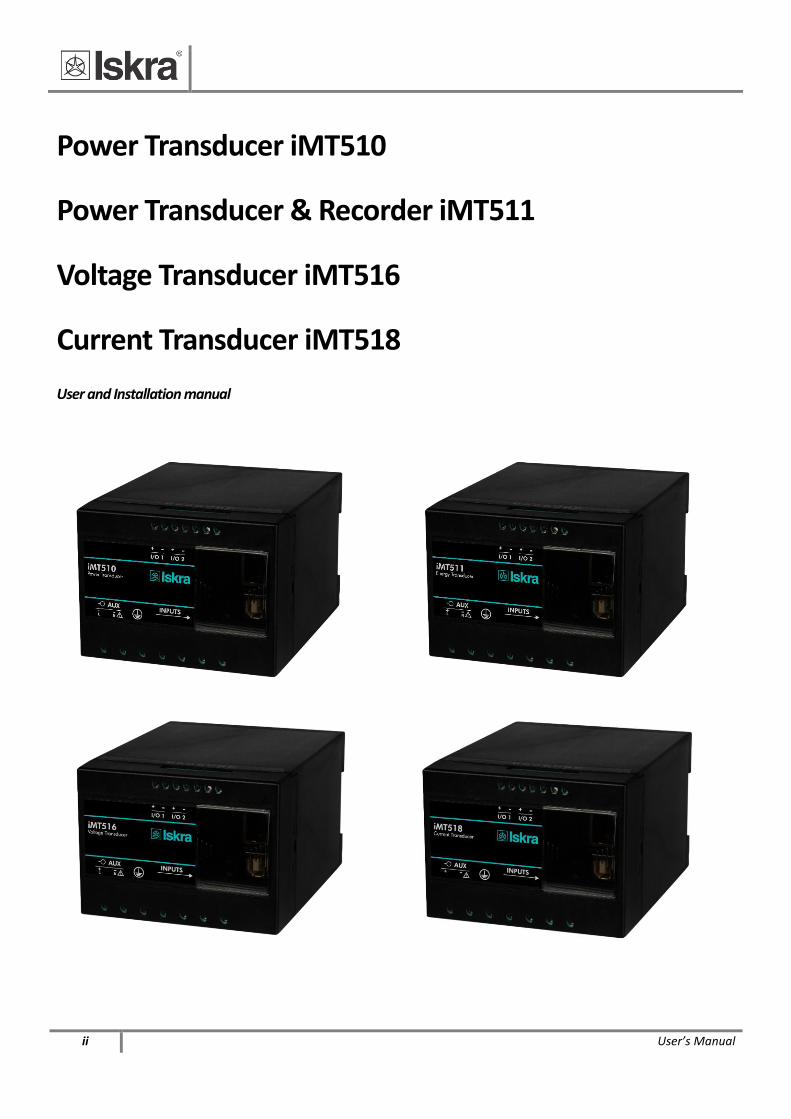
Power Transducer iMT510
Power Transducer & Recorder iMT511
Voltage Transducer iMT516
Current Transducer iMT518
User and Installation manual
User’s Manual iii
Security Advices and Warnings
Please read this chapter carefully and examine the equipment carefully for potential damages which might
arise during transport and to become familiar with it before continue to install, energize and work with a
measuring transducers iMT510, iMT511, iMT516, and iMT518.
This chapter deals with important information and warnings that should be considered for safe installation
and handling with a device in order to assure its correct use and continuous operation.
Everyone using the product should become familiar with the contents of chapter »Security Advices and
Warnings«.
If equipment is used in a manner not specified by the manufacturer, the protection provided by the
equipment may be impaired.
PLEASE NOTE
This booklet contains instructions for installation and use of measuring transducer. Installation
and use of a device also includes handling with dangerous currents and voltages therefore
should be installed, operated, serviced and maintained by qualified personnel only. ISKRA d.o.o.
assumes no responsibility in connection with installation and use of the product. If there is any
doubt regarding installation and use of the system in which the device is used for measuring or
supervision, please contact a person who is responsible for installation of such system.
Before switching the device ON
Check the following before switching on the device:
Nominal voltage.
Proper connection of auxiliary supply.
Nominal frequency.
Voltage ratio and phase sequence.
Current transformer ratio and terminals integrity.
Protection fuse - recommended maximal external fuse size is 6 A.
Integrity and proper connection of earth protective terminals (where necessary).
Important: A current transformer secondary should be short circuited before connecting the meter.
iv User’s Manual
Used symbols on devices’ housing
and labels
SYMBOL EXPLANATION
WARNING
Indicates situations where careful reading of this manual is required and following
requested steps to avoid potential injury is advised.
Double insulation in compliance with the SIST EN 61010−1 standard.
Protective conductor terminal. Terminal which is bonded to conductive parts of an
instrument for safety purposes and is intended to be connected to an external
protective earthing system.
Functional ground potential.
Note: This symbol is also used for marking a terminal for protective ground
potential if it is used as a part of connection terminal or auxiliary supply terminals.
Compliance of the product with directive 2002/96/EC, as first priority, the
prevention of waste electrical and electronic equipment (WEEE), and in addition,
the reuse, recycling and other forms of recovery of such wastes so as to reduce
the disposal of waste. It also seeks to improve the environmental performance of
all operators involved in the life cycle of electrical and electronic equipment.
Compliance of the product with European CE directives.
Important: A current transformer secondary should be short circuited before connecting the
transducer.
Battery replacement
Some instruments are equipped with a built-in battery. When empty, replace with a corresponding
type (Varta, type 6032 CR2032 SLF or equivalent). A battery shall be replaced by an authorized service.
The battery lifetime is approx. 6 years. Instruction on battery replacement is given in chapter 5:
Battery replacement.
Disposal
It is strongly recommended that electrical and electronic equipment (WEEE) is not deposit as
municipal waste. The manufacturer or provider shall take waste electrical and electronic equipment
free of charge. The complete procedure after lifetime should comply with the Directive 2002/96/EC
about restriction on the use of certain hazardous substances in electrical and electronic equipment.
BASIC DESCRIPTION AND OPERATION
User’s Manual v
Table of contents
1 BASIC DESCRIPTION AND OPERATION 1
INTRODUCTION 2 DESCRIPTION OF THE DEVICE 3 PURPOSE AND USE OF DIFFERENT TYPES OF MEASURING TRANSDUCERS 4 TYPE DIFFERENCES 5
2 CONNECTION 6
INTRODUCTION 7 MOUNTING 7 ELECTRICAL CONNECTION 8 CONNECTION OF INPUT/OUTPUT MODULES 9 COMMUNICATION CONNECTION 10 CONNECTION OF AUXILIARY POWER SUPPLY 13
3 SETTINGS 14
INTRODUCTION 15 MIQEN SOFTWARE 15 SETTING PROCEDURE 17
GENERAL SETTINGS 17 CONNECTION 18
SERIAL COMMUNICATION (COM1) 19 SECURITY 19
ENERGY 21 INPUTS AND OUTPUTS 22 ALARMS 25 MEMORY 26 RESET OPERATIONS 26
4 MEASUREMENTS 27
SUPPORTED MEASUREMENTS 28 EXPLANATION OF BASIC CONCEPTS 28 CALCULATION AND DISPLAY OF MEASUREMENTS 29
PRESENT VALUES 29 ALARMS 30 WEB INTERFACE 31
5 BATTERY REPLACEMENT 33
INSTRUCTIONS FOR REPLACEMENT 33
BASIC DESCRIPTION AND OPERATION
vi User’s Manual
6 TECHNICAL DATA 34
ACCURACY 35 MECHANICAL CHARACTERISTICS OF INPUT 36 ELECTRICAL CHARACTERISTICS OF INPUT 36 I/O MODULES 37 ANALOGUE OUTPUT 37
COMMUNICATION 38 ELECTRONIC FEATURES 38 SAFETY FEATURES 39 DIMENSIONS 40
7 ABBREVIATION/GLOSSARY 41
8 APPENDICES 42
APPENDIX A: MODBUS COMMUNICATION PROTOCOL 42
APPENDIX C: CALCULATIONS & EQUATIONS 49
BASIC DESCRIPTION AND OPERATION
User’s Manual 1
1 BASIC DESCRIPTION AND OPERATION
The following chapter presents basic information about multifunction transducers required to
understand its purpose, applicability and basic features connected to its operation.
In this chapter you will find:
1.1 INTRODUCTION 2 1.2 DESCRIPTION OF THE DEVICE 3 1.3 PURPOSE AND USE OF DIFFERENT TYPES OF MEASURING TRANSDUCERS 4 1.4T YPE DIFFERENCES 5
BASIC DESCRIPTION AND OPERATION
2 User’s Manual
Introduction Regarding the type of measuring transducer different chapters should be considered since the types
differ in functionality and design. More detailed description of device functions is given in chapter
Type differences. Al types of measuring transducers are available in DIN or ANSI housing. Instruments
in DIN housing are marked as types iMT5xx; instruments in ANSI housing are marked as types
iUMT5xx. Specifications of housing for both types are specified in chapter Dimensions.
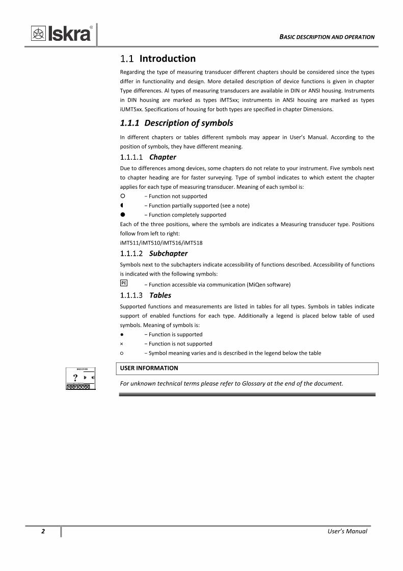
1.1.1 Description of symbols
In different chapters or tables different symbols may appear in User’s Manual. According to the
position of symbols, they have different meaning.
Chapter
Due to differences among devices, some chapters do not relate to your instrument. Five symbols next
to chapter heading are for faster surveying. Type of symbol indicates to which extent the chapter
applies for each type of measuring transducer. Meaning of each symbol is:
− Function not supported
− Function partially supported (see a note)
− Function completely supported
Each of the three positions, where the symbols are indicates a Measuring transducer type. Positions
follow from left to right:
iMT511/iMT510/iMT516/iMT518
Subchapter
Symbols next to the subchapters indicate accessibility of functions described. Accessibility of functions
is indicated with the following symbols:
− Function accessible via communication (MiQen software)
Tables
Supported functions and measurements are listed in tables for all types. Symbols in tables indicate
support of enabled functions for each type. Additionally a legend is placed below table of used
symbols. Meaning of symbols is:
− Function is supported
× − Function is not supported
− Symbol meaning varies and is described in the legend below the table
USER INFORMATION
For unknown technical terms please refer to Glossary at the end of the document.
BASIC DESCRIPTION AND OPERATION
User’s Manual 3
Description of the device Measuring transducer is intended for measuring, analyzing and monitoring single-phase electrical
power network. It measures true RMS values by means of fast sampling of voltage and current signals,
which makes instrument suitable for acquisition of transient events. A built-in microcontroller
calculates measurements (voltage, current, frequency, energy, power, power factor, THD, phase
angles, MD) from the measured signals.
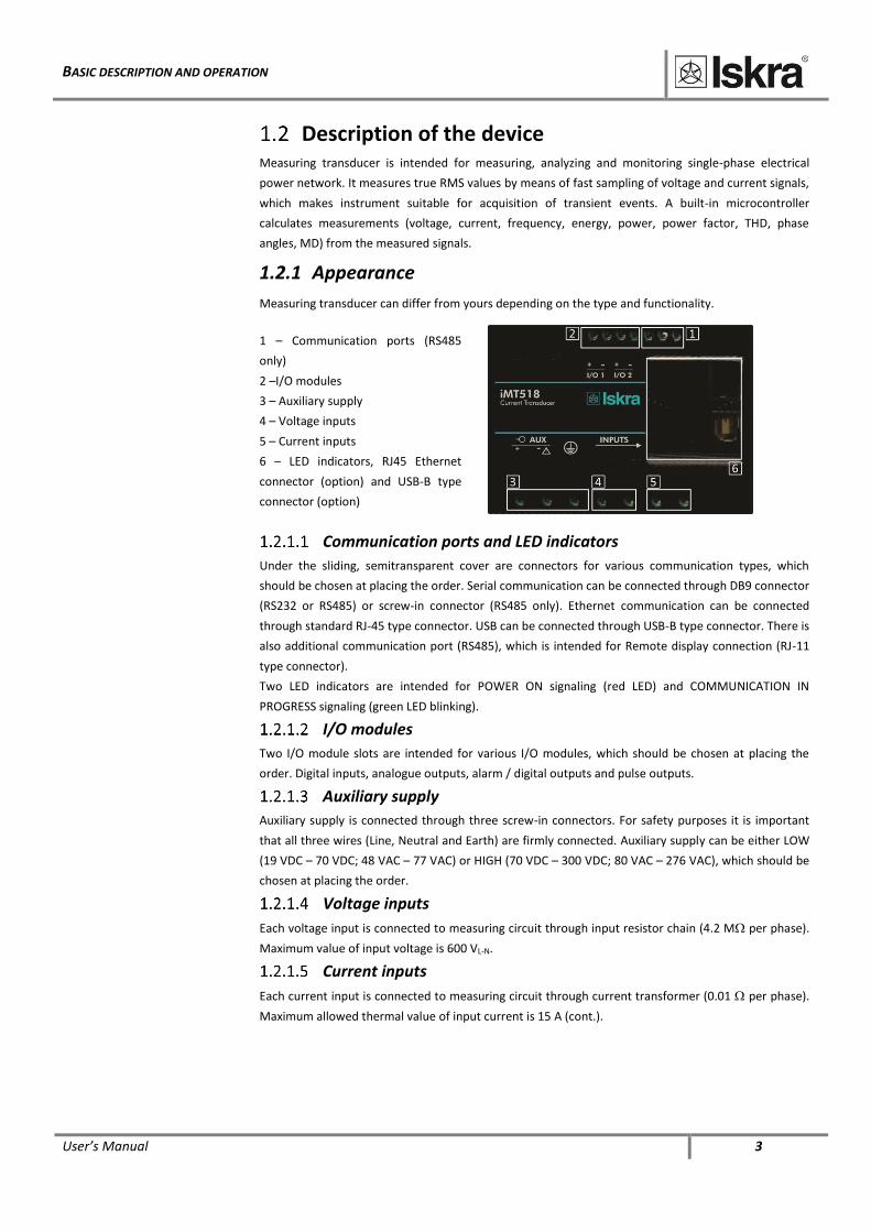
1.2.1 Appearance
Measuring transducer can differ from yours depending on the type and functionality.
1 – Communication ports (RS485
only)
2 –I/O modules
3 – Auxiliary supply
4 – Voltage inputs
5 – Current inputs
6 – LED indicators, RJ45 Ethernet
connector (option) and USB-B type
connector (option)
Communication ports and LED indicators
Under the sliding, semitransparent cover are connectors for various communication types, which
should be chosen at placing the order. Serial communication can be connected through DB9 connector
(RS232 or RS485) or screw-in connector (RS485 only). Ethernet communication can be connected
through standard RJ-45 type connector. USB can be connected through USB-B type connector. There is
also additional communication port (RS485), which is intended for Remote display connection (RJ-11
type connector).
Two LED indicators are intended for POWER ON signaling (red LED) and COMMUNICATION IN
PROGRESS signaling (green LED blinking).
I/O modules
Two I/O module slots are intended for various I/O modules, which should be chosen at placing the
order. Digital inputs, analogue outputs, alarm / digital outputs and pulse outputs.
Auxiliary supply
Auxiliary supply is connected through three screw-in connectors. For safety purposes it is important
that all three wires (Line, Neutral and Earth) are firmly connected. Auxiliary supply can be either LOW
(19 VDC – 70 VDC; 48 VAC – 77 VAC) or HIGH (70 VDC – 300 VDC; 80 VAC – 276 VAC), which should be
chosen at placing the order.
Voltage inputs
Each voltage input is connected to measuring circuit through input resistor chain (4.2 M per phase).
Maximum value of input voltage is 600 VL-N.
Current inputs
Each current input is connected to measuring circuit through current transformer (0.01 per phase).
Maximum allowed thermal value of input current is 15 A (cont.).
BASIC DESCRIPTION AND OPERATION
4 User’s Manual
Purpose and use of different types of measuring
transducers
1.3.1 Voltage transducer iMT516
iMT516 is intended for measuring and monitoring single-phase electrical power network. Voltage
input is electrically isolated from the system by means of high resistive input chain. It measures true
RMS voltage value by means of fast sampling of voltage signals, which makes instruments suitable for
acquisition of transient events. A built-in microcontroller calculates measurands (voltage, frequency)
from the measured signals. Measurands can be then converted into load independent DC current or
voltage which is proportional to the true RMS measured value for the purpose of regulation of
analogue and/or digital devices.
1.3.2 Current transducer iMT518
iMT518 is intended for measuring and monitoring single-phase electrical power network. Input
current is electrically isolated from the system by means of current transformer. iMT518 measures
true RMS current value by means of fast sampling of current signals, which makes instruments
suitable for acquisition of transient events. A built-in microcontroller calculates measurands (current,
frequency) from the measured signals. Measurands can be then converted into load independent DC
current or voltage which is proportional to the true RMS measured value for the purpose of regulation
of analogue and/or digital devices.
1.3.3 Power transducer iMT510
iMT510 is intended for measuring and monitoring single-phase electrical power network. Input
voltage and input current are electrically isolated from the system by means of high resistive input
chain and current transformer respectively. It measures true RMS values by means of fast sampling of
voltage and current signals, which makes instruments suitable for acquisition of transient events. A
built-in microcontroller calculates measurands (voltage, current, frequency, energy, power, power
factor, THD phase angles, etc.) from the measured signals.
1.3.4 Power transducer & recorder iMT511
iMT511 measures all parameters like iMT510 and additionally it records the readings and alarms in the
internal memory for the period of three years or more. Internal battery powered real time clock
enables also energy measurement as well as recording of time – stamped events (alarms) in the
internal memory.
Wide range of various I/O modules makes iMT51x family of trnasducers a perfect choice for numerous
applications. iMT51x can be delivered pre-configured to the required measuring set-up and output
characteristic or they can be delivered un-configured for customer configuration with user friendly
setting software MiQen. They support a wide range of communication interfaces. Standard serial
RS232/485 with speed up to 115200 baud is perfect for simple applications and serial bus interfacing.
Ethernet 10/100 is ideal for a long distance monitoring and configuration of numerous transducers.
USB 2.0 can be used for a fast set-up or memory acquisition.
BASIC DESCRIPTION AND OPERATION
User’s Manual 5
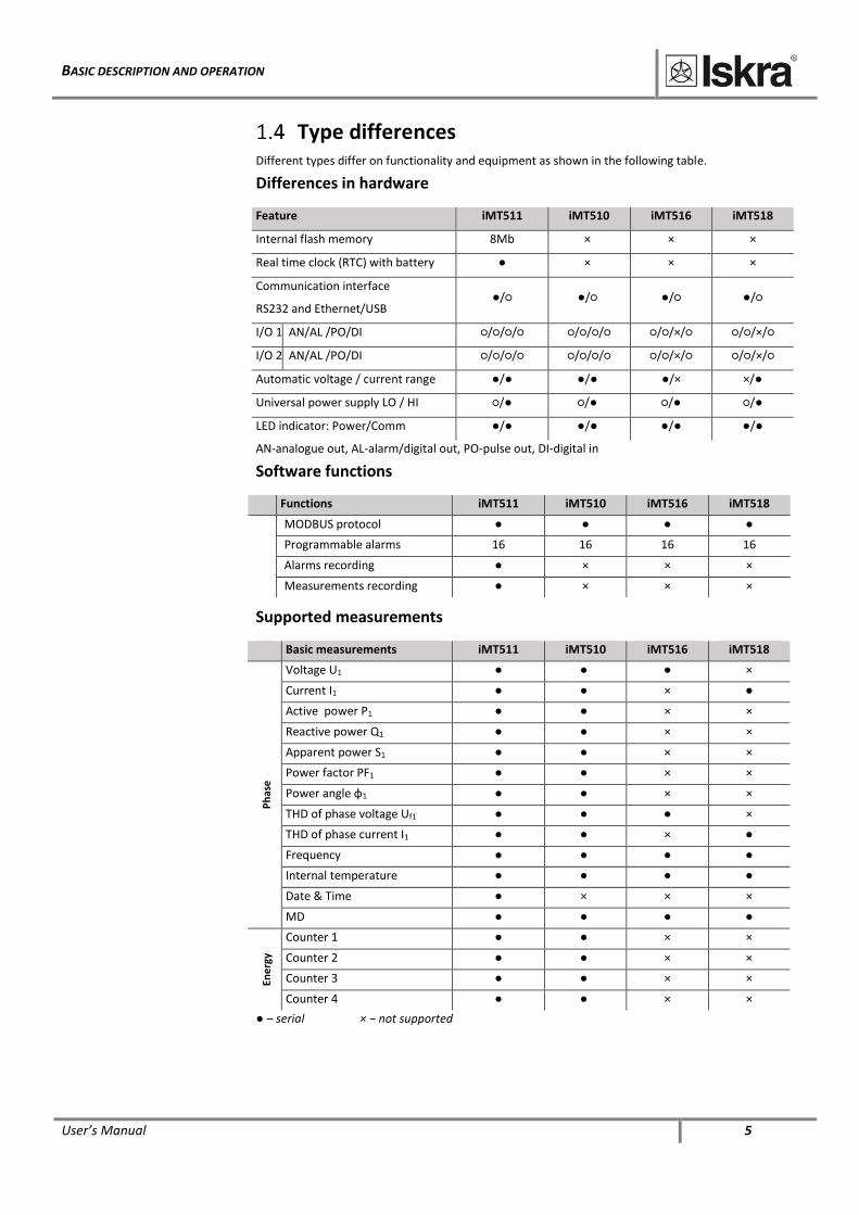
Type differences Different types differ on functionality and equipment as shown in the following table.
Differences in hardware
Feature iMT511 iMT510 iMT516 iMT518
Internal flash memory 8Mb × × ×
Real time clock (RTC) with battery × × ×
Communication interface
RS232 and Ethernet/USB / / / /
I/O 1 AN/AL /PO/DI /// /// //×/ //×/
I/O 2 AN/AL /PO/DI /// /// //×/ //×/
Automatic voltage / current range / / /× ×/
Universal power supply LO / HI / / / /
LED indicator: Power/Comm / / / /
AN-analogue out, AL-alarm/digital out, PO-pulse out, DI-digital in
Software functions
Functions iMT511 iMT510 iMT516 iMT518
MODBUS protocol
Programmable alarms 16 16 16 16
Alarms recording × × ×
Measurements recording × × ×
Supported measurements
Basic measurements iMT511 iMT510 iMT516 iMT518
Ph
ase
Voltage U1 ×
Current I1 ×
Active power P1 × ×
Reactive power Q1 × ×
Apparent power S1 × ×
Power factor PF1 × ×
Power angle φ1 × ×
THD of phase voltage Uf1 ×
THD of phase current I1 ×
Frequency
Internal temperature
Date & Time × × ×
MD
Ene
rgy
Counter 1 × ×
Counter 2 × ×
Counter 3 × ×
Counter 4 × ×
– serial × − not supported
CONNECTION
6 User’s Manual
2 CONNECTION
This chapter deals with the instructions for measuring transducer connection. Both the use and
connection of the device includes handling with dangerous currents and voltages. Only a qualified
person shall therefore perform connection. Iskra d.o.o. does not take any responsibility regarding the
use and connection. If any doubt occurs regarding connection and use in the system, which device is
intended for, please contact a person who is responsible for such installations.
In this chapter you will find:
INTRODUCTION 7 MOUNTING 7 ELECTRICAL CONNECTION 8
CONNECTION OF INPUT/OUTPUT MODULES 9 COMMUNICATION CONNECTION 10 CONNECTION OF AUXILIARY POWER SUPPLY 13
CONNECTION
User’s Manual 7
Introduction Before use: Check voltages, supply voltage and nominal frequency.
Check protective fuse rating (the recommended maximum rating of the external protective fuse for
this equipment is 6 A - Red Spot type or equivalent).
WARNING!
Wrong or incomplete connection of voltage, protective ground or other terminals can cause
malfunction or damage the device.
PLEASE NOTE
After connection, settings have to be performed via communication or remote display
(connection mode, current and voltage transformers ratio …).
Mounting iMT51x measuring transducer is designed for panel mounting. It should be mounted on a 35 mm DIN
rail by means of three plastic fasteners. Before installation fasteners should be in open position
(pulled). After device is on place, fasteners are locked (pushed) to close position.
CONNECTION
8 User’s Manual
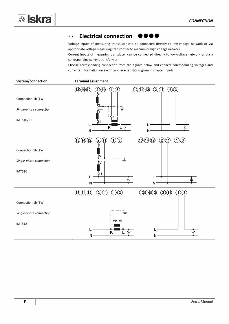
Electrical connection
Voltage inputs of measuring transducer can be connected directly to low-voltage network or via
appropriate voltage measuring transformer to medium or high voltage network.
Current inputs of measuring transducer can be connected directly to low-voltage network or via a
corresponding current transformer.
Choose corresponding connection from the figures below and connect corresponding voltages and
currents. Information on electrical characteristics is given in chapter Inputs.
System/connection Terminal assignment
Connection 1b (1W)
Single-phase connection
iMT510/511
Connection 1b (1W)
Single-phase connection
iMT516
Connection 1b (1W)
Single-phase connection
iMT518
CONNECTION
User’s Manual 9
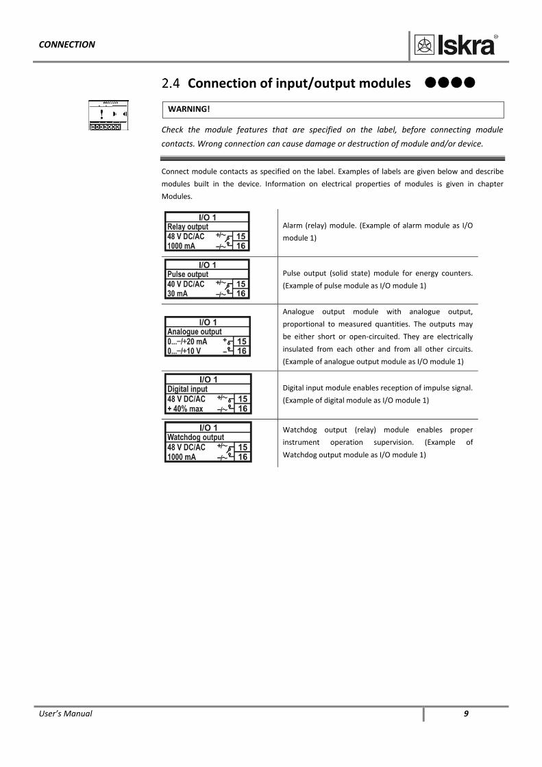
Connection of input/output modules
WARNING!
Check the module features that are specified on the label, before connecting module
contacts. Wrong connection can cause damage or destruction of module and/or device.
Connect module contacts as specified on the label. Examples of labels are given below and describe
modules built in the device. Information on electrical properties of modules is given in chapter
Modules.
Alarm (relay) module. (Example of alarm module as I/O
module 1)
Pulse output (solid state) module for energy counters.
(Example of pulse module as I/O module 1)
Analogue output module with analogue output,
proportional to measured quantities. The outputs may
be either short or open-circuited. They are electrically
insulated from each other and from all other circuits.
(Example of analogue output module as I/O module 1)
Digital input module enables reception of impulse signal.
(Example of digital module as I/O module 1)
Watchdog output (relay) module enables proper
instrument operation supervision. (Example of
Watchdog output module as I/O module 1)
CONNECTION
10 User’s Manual
Communication connection
iMT51x has a wide variety of communication possibilities to suit specific demands. In the case of
simultaneous use of Ethernet and USB communication, the standard port (COM1) is shared by two
communication channels: COM1A (Ethernet) and COM1B (USB). This allows different users to access
data from iMT51x simultaneously and by using Ethernet communication, data can be accessed
worldwide.
Different configurations are possible (to be specified with an order):
Configuration COM1A COM1B
1 RS232/485(1) /
2 Ethernet USB
(1) RS485 communication is available through DB9 or screw-in terminals, while RS232 is available only through DB9
WARNING!
When connecting a DB9 communication connector it is necessary to assure that only RS232
or RS485 communication is used. Terminals of a DB9 connector that are not necessary for
the used communication should remain unconnected, otherwise the communication module
and/or device can be damaged or destroyed. See connection diagrams below.
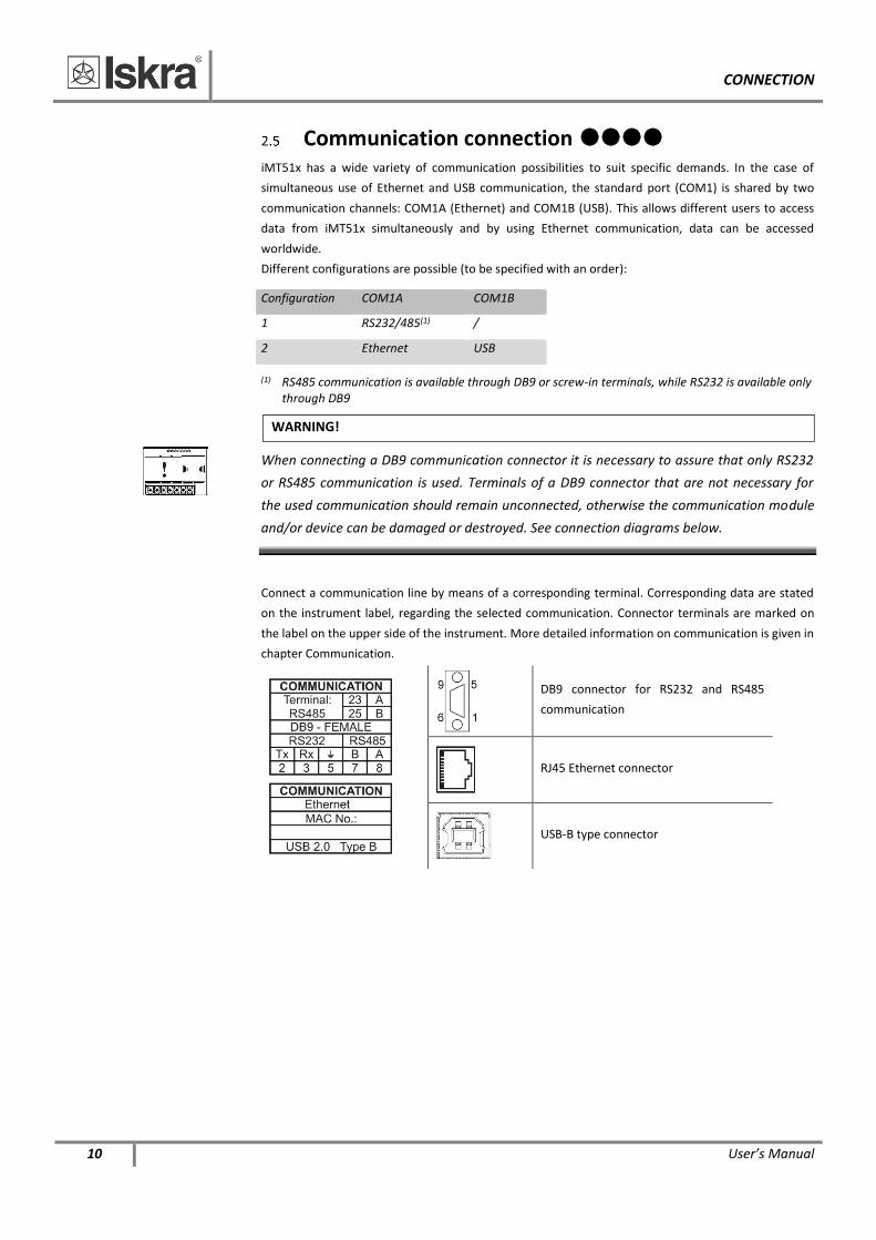
Connect a communication line by means of a corresponding terminal. Corresponding data are stated
on the instrument label, regarding the selected communication. Connector terminals are marked on
the label on the upper side of the instrument. More detailed information on communication is given in
chapter Communication.
DB9 connector for RS232 and RS485
communication
RJ45 Ethernet connector
USB-B type connector
CONNECTION
User’s Manual 11
2.5.2 RS232
RS232 communication is intended for direct connection of the measuring transducer to the personal
computer. It is necessary to assure the corresponding connection of individual terminals of the DB9
connector (see a table on the next page).
2.5.3 RS485
RS485 communication is intended for connection of devices to network where several instruments
with RS485 communication are connected to a common communication interface. We recommend
the use of Iskra d.o.o. communication interfaces for best compatibility!
Correct connection of individual terminals of the DB9 connector shall be provided (see a table on the
next page).
2.5.4 Ethernet
Ethernet communication allows for integration of the device into global Ethernet-based networks. The
device supports fast Ethernet (10/100 Mbps). For proper operation, standard IEEE 802.3 compliant
100BASE-T CAT5 Ethernet cable is recommended. The device is supplied with a unique MAC address
for identification. The MAC address is printed on the label, positioned on the upper side of the
instrument.
2.5.5 USB
USB communication serves as a fast peer-to-terminal data link. The instrument is detected by host as
a USB 2.0 compatible device. The USB connection is provided through a USB standard Type B
connector.
PLEASE NOTE
When iMT51x is connected to a PC through USB communication for the first time, a user is
prompted to install a driver. The driver is provided on the CD, enclosed in the original
shipment package, or can be downloaded from the Iskra d.o.o. web page
https://www.iskra.eu/en/. With this driver installed, USB is redirected to a serial port, which
should be selected when using MiQen software.
CONNECTION
12 User’s Manual
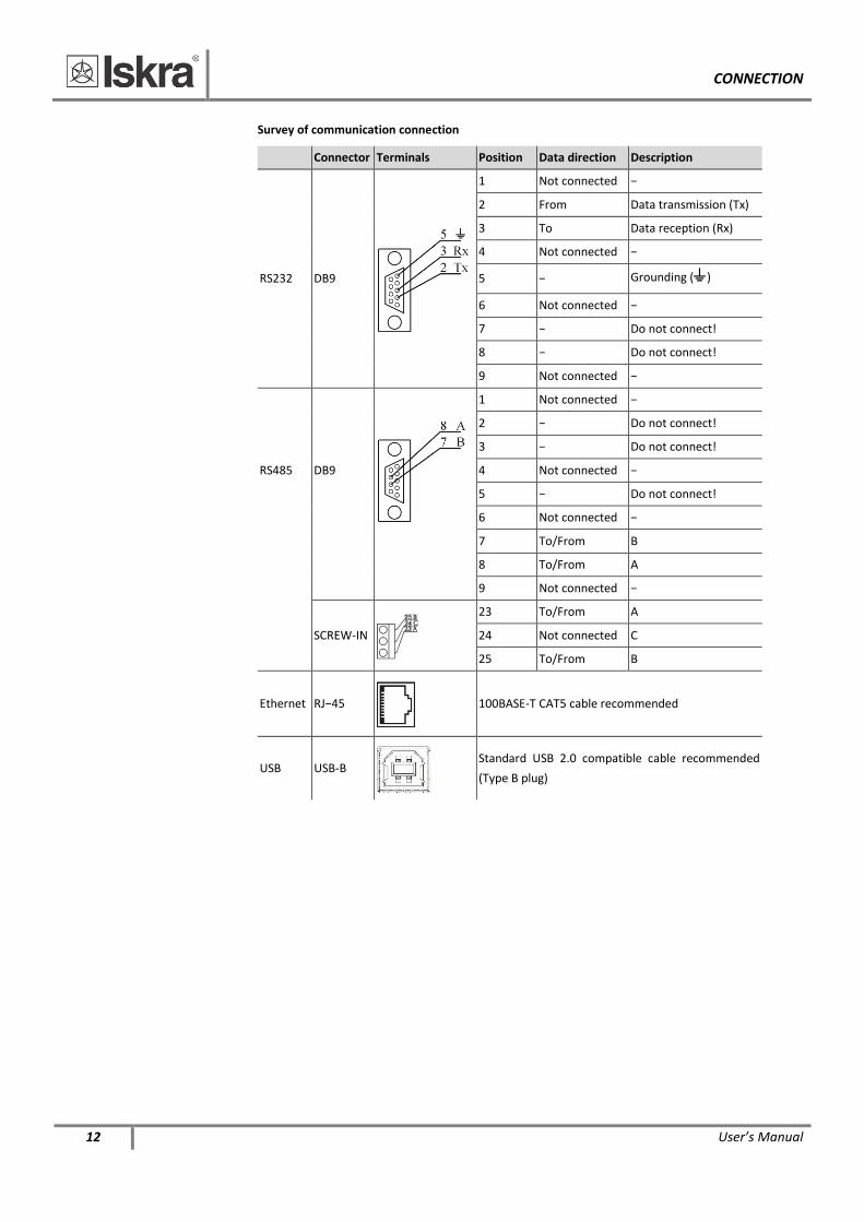
Survey of communication connection
Connector Terminals Position Data direction Description
RS232 DB9
1 Not connected −
2 From Data transmission (Tx)
3 To Data reception (Rx)
4 Not connected −
5 − Grounding ()
6 Not connected −
7 − Do not connect!
8 − Do not connect!
9 Not connected −
RS485 DB9
1 Not connected −
2 − Do not connect!
3 − Do not connect!
4 Not connected −
5 − Do not connect!
6 Not connected −
7 To/From B
8 To/From A
9 Not connected −
SCREW-IN
23 To/From A
24 Not connected C
25 To/From B
Ethernet RJ−45
100BASE-T CAT5 cable recommended
USB USB-B
Standard USB 2.0 compatible cable recommended
(Type B plug)
CONNECTION
User’s Manual 13
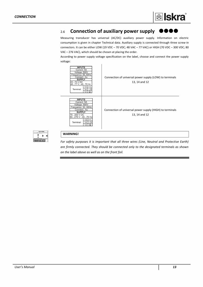
Connection of auxiliary power supply
Measuring transducer has universal (AC/DC) auxiliary power supply. Information on electric
consumption is given in chapter Technical data. Auxiliary supply is connected through three screw-in
connectors. It can be either LOW (19 VDC – 70 VDC; 48 VAC – 77 VAC) or HIGH (70 VDC – 300 VDC; 80
VAC – 276 VAC), which should be chosen at placing the order.
According to power supply voltage specification on the label, choose and connect the power supply
voltage:
Connection of universal power supply (LOW) to terminals
13, 14 and 12
Connection of universal power supply (HIGH) to terminals
13, 14 and 12
WARNING!
For safety purposes it is important that all three wires (Line, Neutral and Protective Earth)
are firmly connected. They should be connected only to the designated terminals as shown
on the label above as well as on the front foil.
SETTINGS
14 User’s Manual
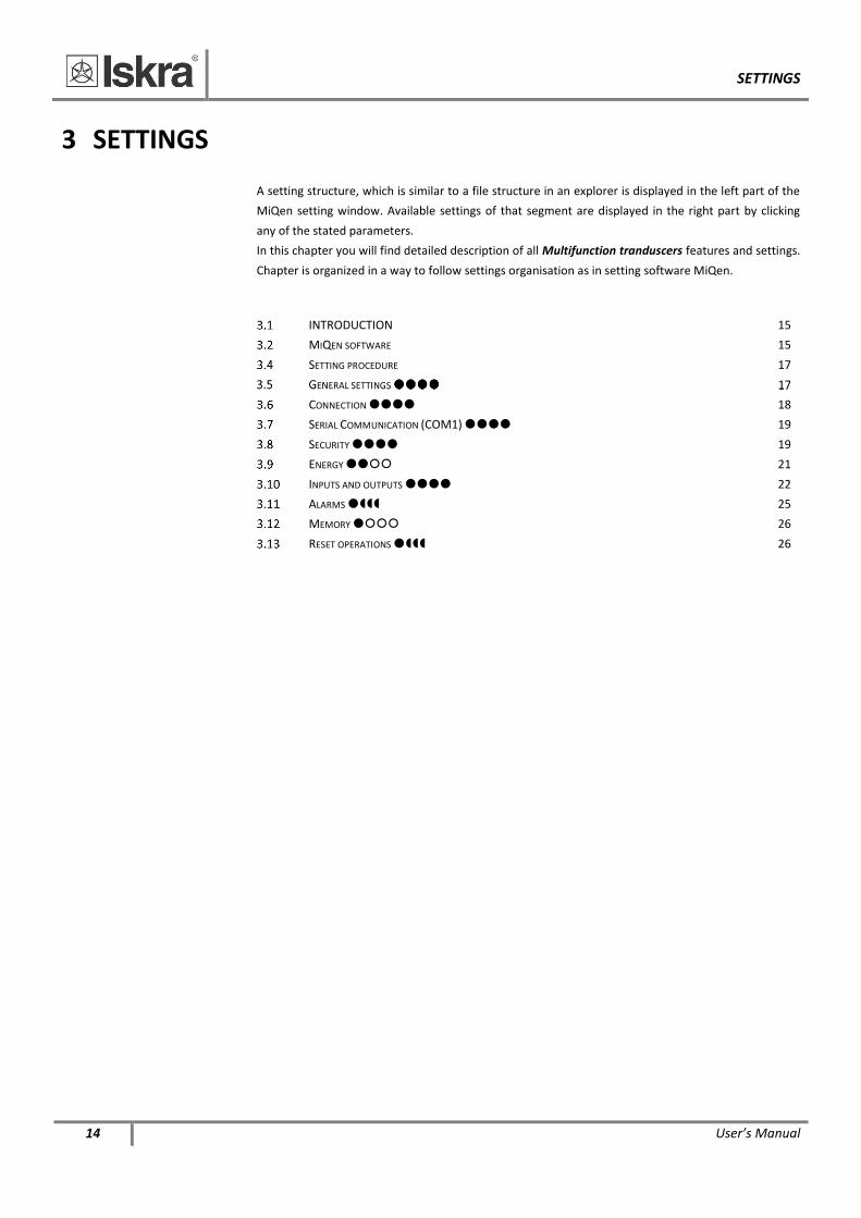
3 SETTINGS
A setting structure, which is similar to a file structure in an explorer is displayed in the left part of the
MiQen setting window. Available settings of that segment are displayed in the right part by clicking
any of the stated parameters.
In this chapter you will find detailed description of all Multifunction tranduscers features and settings.
Chapter is organized in a way to follow settings organisation as in setting software MiQen.
INTRODUCTION 15 MIQEN SOFTWARE 15 SETTING PROCEDURE 17
CONNECTION 18 SERIAL COMMUNICATION (COM1) 19 SECURITY 19 ENERGY 21
INPUTS AND OUTPUTS 22 ALARMS 25 MEMORY 26 RESET OPERATIONS 26
SETTINGS
User’s Manual 15
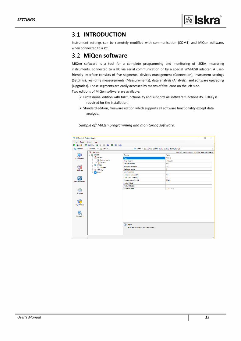
INTRODUCTION Instrument settings can be remotely modified with communication (COM1) and MiQen software,
when connected to a PC.
MiQen software MiQen software is a tool for a complete programming and monitoring of ISKRA measuring
instruments, connected to a PC via serial communication or by a special WM-USB adapter. A user-
friendly interface consists of five segments: devices management (Connection), instrument settings
(Settings), real-time measurements (Measurements), data analysis (Analysis), and software upgrading
(Upgrades). These segments are easily accessed by means of five icons on the left side.
Two editions of MiQen software are available:
Professional edition with full functionality and supports all software functionality. CDKey is
required for the installation.
Standard edition, freeware edition which supports all software functionality except data
analysis.
Sample off MiQen programming and monitoring software:
SETTINGS
16 User’s Manual
MiQen version 2.1 or higher is required for programming and monitoring Multifunction tranduscers.
Software installation is stored on a CD as a part of consignment or it can be downloaded from
https://www.iskra.eu/en/Iskra-Software/MiQen-Settings-Studio/
PLEASE NOTE
MiQen has very intuitive help system. All functions and settings are described in Info window
on the bottom of MiQen window.
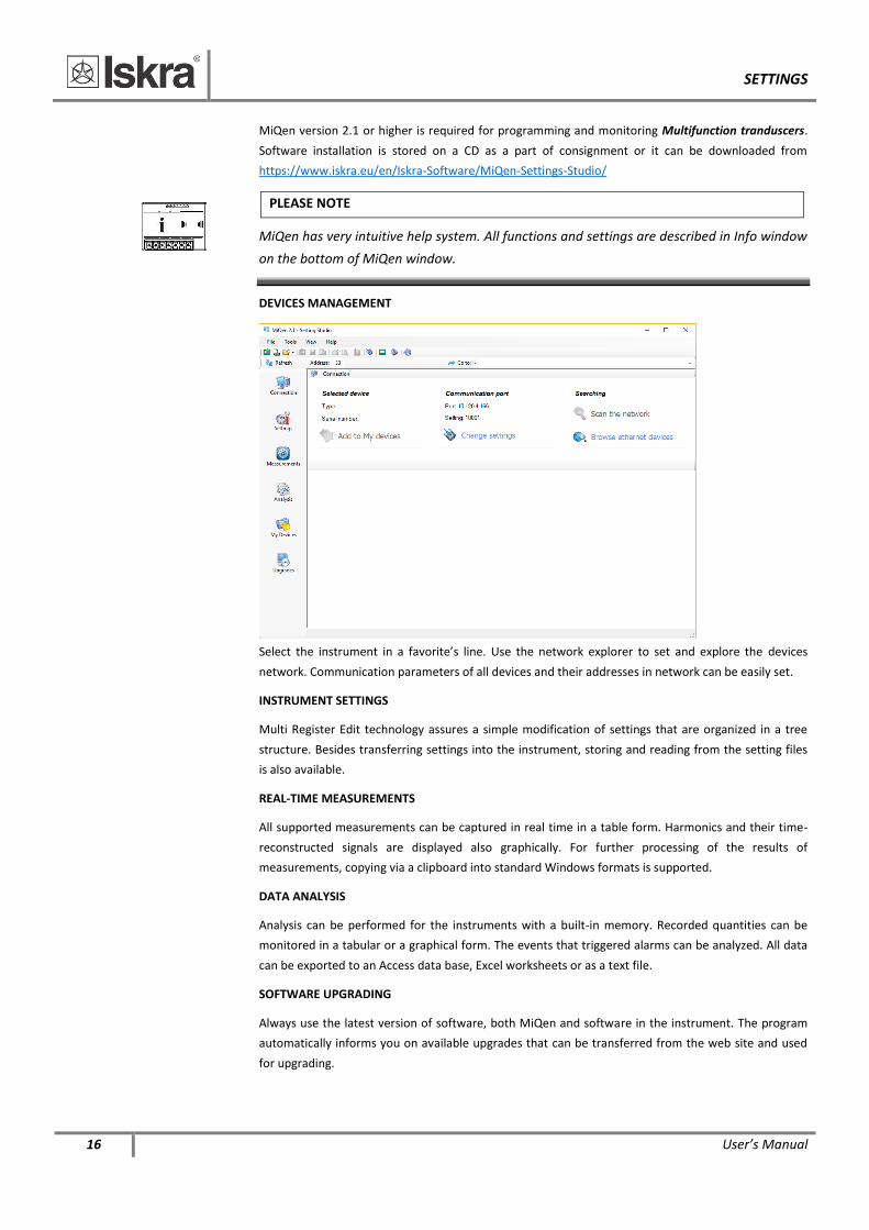
DEVICES MANAGEMENT
Select the instrument in a favorite’s line. Use the network explorer to set and explore the devices
network. Communication parameters of all devices and their addresses in network can be easily set.
INSTRUMENT SETTINGS
Multi Register Edit technology assures a simple modification of settings that are organized in a tree
structure. Besides transferring settings into the instrument, storing and reading from the setting files
is also available.
REAL-TIME MEASUREMENTS
All supported measurements can be captured in real time in a table form. Harmonics and their time-
reconstructed signals are displayed also graphically. For further processing of the results of
measurements, copying via a clipboard into standard Windows formats is supported.
DATA ANALYSIS
Analysis can be performed for the instruments with a built-in memory. Recorded quantities can be
monitored in a tabular or a graphical form. The events that triggered alarms can be analyzed. All data
can be exported to an Access data base, Excel worksheets or as a text file.
SOFTWARE UPGRADING
Always use the latest version of software, both MiQen and software in the instrument. The program
automatically informs you on available upgrades that can be transferred from the web site and used
for upgrading.
SETTINGS
User’s Manual 17
Setting procedure
In order to modify instrument settings with MiQen, current parameters must be loaded first.
Instrument settings can be acquired via a communication link (serial or TCP/IP) or can be loaded off-
line from a file on a local disk. Settings are displayed in the MiQen Setting Window - the left part
displays a hierarchical tree structure of settings, the right part displays parameter values of the chosen
setting group.
PLEASE NOTE
Supported settings and functions depend on the type of device. For a survey of supported
measurements and functions see chapter Type differences.
General settings General settings are essential for measuring transducer. They are divided into four additional
sublevels (Connection, Communication and Security).
3.5.1 Description and Location
Two parameters that are intended for easier recognition of a certain unit. They are especially used for
identification of the device or location on which measurements are performed.
3.5.2 Average interval
The averaging interval defines the refresh rate of measurements on communication.
3.5.3 Date and time
Set date and time of the meter. Setting is important for correct memory operation, maximal values
(MD).
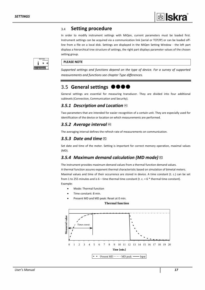
3.5.4 Maximum demand calculation (MD mode)
The instrument provides maximum demand values from a thermal function demand values.
A thermal function assures exponent thermal characteristic based on simulation of bimetal meters.
Maximal values and time of their occurrence are stored in device. A time constant (t. c.) can be set
from 1 to 255 minutes and is 6 − time thermal time constant (t. c. = 6 * thermal time constant).
Example:
Mode: Thermal function
Time constant: 8 min.
Present MD and MD peak: Reset at 0 min.
Thermal function
0 1 2 3 4 5 6 7 8 9 10 11 12 13 14 15 16 17 18 19 20
Time [min.]
Mea
sure
d v
alu
e
Present MD MD peak Input
Time const.
SETTINGS
18 User’s Manual
3.5.5 Starting current for PF and PA (mA)
At all measuring inputs noise is usually present. It is constant and its influence on the accuracy is
increased by decreasing measuring signals. It is present also when measuring signals are not
connected and it occurs at all further calculations as very sporadic measurements. By setting a
common starting current, a limit of input signal is defined where measurements and all other
calculations are still performed.
3.5.6 Starting current for all powers (mA)
Noise is limited with a starting current also at measurements and calculations of powers.
3.5.7 Starting voltage for SYNC (V)
This parameter sets a voltage threshold for measurement synchronization. If voltage signal is below
this threshold or there is no voltage signal, current synchronization is used. If also current is below
starting current value, fixed (default) frequency value is used for synchronization. This value is set
under General/connection/Frequency nominal value(Hz). This value should be set to 50/60Hz
according to power frequency used.
Connection
PLEASE NOTE
Settings of connections shall reflect actual state otherwise measurements are not valid.
3.6.1 Connection
When connection is selected, load connection and the supported measurements are defined (see
chapter Survey of supported measurements regarding connection mode).
3.6.2 Setting of current and voltage ratios
Before setting current and voltage ratios it is necessary to be familiar with the conditions in which
device will be used. All other measurements and calculations depend on these settings. Up to five
decimal places can be set. To set decimal point and prefix on remote display position the cursor (left
/right) to last (empty) place or the decimal point.
Settings range VT primary VT secondary CT primary CT secondary
Maximal value 1638.3 kV 13383 V 1638.3 kA 13383 A
Minimal value 0.1 V 1 mV 0.1 A 1 mA
3.6.3 Used voltage and current range
Setting of the range is connected with all settings of alarms, analogue outputs and a display
(calculation) of energy and measurements recording, where 100% represents 500 V 5A. In case of
subsequent change of the range, alarms settings shall be correspondingly changed, as well.
3.6.4 Nominal frequency
A valid frequency measurement is within the range of nominal frequency ±32 Hz. This setting is used
for alarms and recorders only.
SETTINGS
User’s Manual 19
Serial Communication (COM1)
3.7.1 Communication parameters
They define parameters that are important for the operation in RS485 network or connections with PC
via RS232 communication. Factory settings of communication are #33\115200,n,8,2 (address 1 to
247\rate 2400 to 115200 b/s, parity, data bits, stop bit).
3.7.2 USB Communication
For description of all settings see Serial Communication (COM1).
3.7.3 Ethernet communication
IP address
Communication interface should have a unique IP address in the Ethernet network. Two modes for
assigning IP are described:
Fixed IP address: In most installations a fixed IP address is required. A system provider
usually defines IP addresses. An IP address should be within a valid IP range, unique for your
network and in the same subnetwork as your PC.
DHCP: Automatic method of assigning IP addressed (DHCP) is used in most networks. If you
are not sure if DHPC is used in your network, check it at your system provider.
Local Port
The physical connector on a device enabling the connection to be made. Use a non reserved port
number from 1025 to 65535. If using Redirector software, the port number should be between 14000
and 14009.
Port numbers Function
1 – 1024, 9999, 30718, 33333 Reserved numbers
14000 – 14009 Reserved for Redirector
Factory settings of Ethernet communication are:
IP Address DHCP (automatically)
TCP Port 10001
Subnet Mask 255.255.255.0
Security Settings parameters are divided into four groups regarding security level:
1. At the first level (PL1), settings of a real time clock can be changed, and energy meters and
MD can be reset.
2. At the second level (PL2), the access to all data that are protected with the first level (PL1)
and setting of all other parameters in the »SETTINGS« menu are available.
3. A backup password (BP) is used if passwords at levels 1 (PL1) and 2 (PL2) have been
forgotten, and it is different for each device (depending on a serial number of the meter).
The BP password is available in the user support department in ISKRA d.o.o., and is entered
instead of the password PL1 or/and PL2. Do not forget to state the meter serial meter when
contacting the personnel in Iskra d.o.o..
PLEASE NOTE
A serial number of device is stated on the label and also accessible with MiQen software.
SETTINGS
20 User’s Manual
3.8.1 Password setting
A password consists of four letters taken from the British alphabet from A to Z. When setting a
password, only the letter being set is visible while the others are covered with *.
Two passwords (PL1, PL2) and the time of automatic activation could be set.
Password modification
A password can be modified; however, only that password can be modified to which the access is
unlocked at the moment.
Password disabling
A password is disabled by setting the "AAAA" password.
PLEASE NOTE
A factory set password is "AAAA" at both access levels (L1 and L2). This password does not
limit access.
Password and language
Language change is possible without password input. When language is changed from or to Russian,
character transformation has to be taken in to account. Character transformation table (English or
Russian alphabet) is stated below.
English A B C D E F G H I J K L M N O P Q R S T U V W X Y Z
Russian А Б В Г Д Е Ж З И Й К Л М Н O П P С Т У Ф Х Ц Ч Ш Щ
SETTINGS
User’s Manual 21
Energy
WARNING!
After modification of energy parameters, the energy meters must be reset otherwise all
further energy measurements could be incorrect.
3.9.1 Common energy exponent
Common energy exponent defines minimal energy that can be displayed on the energy counter. On
the basis of this and a counter divider, a basic calculation prefix for energy is defined (−3 is 10−3Wh =
mWh, 4 is 104Wh = 10 kWh). A common energy exponent also influences in setting a number of
impulses for energy of pulse output or alarm output functioning as an energy meter.
Define common energy exponent as recommended in table below, where counter divider is at default
value 10. Values of primary voltage and current determine proper Common energy exponent.
exponent.
Current
Voltage 1 A 5 A 50 A 100 A 1000 A
110 V −1 0 1 1 2
230 V 0 0 1 2 3
1000 V 0 1 2 3 4
30 kV 2 2 3 4 4*
* − Counter divider should be at least 100
3.9.2 Counter divider
The counter divider additionally defines precision of a certain counter, according to settings of
common energy exponent.
An example for 12.345kWh of consumed active energy:
Common energy exponent 0 2 2
Counter divider 1 1 100
Example of result, display 12.345 kWh 12.3 kWh 0.01 MWh
SETTINGS
22 User’s Manual
Inputs and outputs
Module settings depend on built-in modules.
3.10.1 Analogue output module
Each of up to four analogue outputs is fully programmable and can be set to any of 6 ranges.
Output parameter
Set the measured parameter to be transformed onto the analogue output.
Output range
Defines analogue output full-scale ranges:
DC current output DC voltage output
-1…0…1 mA -1…0…1 V
-5…0…5 mA
-10...0...10 mA -10…0…10 V
-20...0...20 mA
Output signal
Defines the shape and up to 5 break points of an analogue output. For intrinsic-error for analogue
outputs with bent or linear zoom characteristic multiply accuracy class with correction factor (c).
Correction factor c (the highest value applies):
Linear characteristic Bent characteristic
1
1
1
0
0
cor
x
x
y
y
c
e
e bb xxx 1 b – number of break points (1 to 5)
11
1
cory
x
xx
yyc
e
e
bb
bb

SETTINGS
User’s Manual 23
Example of settings with linear and bent characteristic:
Average interval for analogue output
Defines the average interval for measurements on the analogue output. Available settings are from 1
period (0.02 sec by 50 Hz) up to 256 periods (5.12 sec by 50 Hz).
3.10.2 Alarm/Digital output module
Alarm groups that are connected with an alarm module and a signal shape are defined.
An alarm module can also function as a pulse output with limited pulse length (min. 10 ms) or general
purpose digital output. Other parameters are defined in the same way as at a pulse module. A parallel
RC filter with time constant of at least 250 μs (R·C ≥ 250 μs) should be used in case of a sensitive pulse
counter. RC filter attenuates relay transient signals.
Signal shape:
Normal − A relay is closed until condition for the alarm is fulfilled.
Normal inverse − A relay is open until condition for the alarm is fulfilled.
Holds − A relay is closed when condition for the alarm is fulfilled, and remains closed until it
is reset via communication.
Pulse − an impulse of the set length is sent always when condition for the alarm is fulfilled.
Always switched on / off (permanent) – A relay is permanently switched on or off
irrespective of the condition for the alarm.
USER INFORMATION
Digital output functionality. Permanent alarm setting enables remote control via
communication.
SETTINGS
24 User’s Manual
3.10.3 Pulse output module
A corresponding energy counter can be assigned to a pulse output. A number of pulses per energy
unit, pulse length, and a tariff in which output is active are set.
WARNING!
Pulse parameters are defined by SIST EN 62053−31 standard. In chapter Calculation of
recommended pulse parameters, below a simplified rule is described to assist you in setting
the pulse output parameters.
The pulse module can also function as an alarm output with limited current load (max. 20 mA).
Calculation of recommended pulse parameters
Number of pulses per energy unit should be in certain limits according to expected power. If not so
the measurement from pulse output can be incorrect. Settings of current and voltage transformers
can help in estimation of expected power.
Principle described below for pulse setting, where e is prefix, satisfies SIST EN 62053−31: 2001
standards pulse specifications:
eWh1p100eW155,1
Examples:
Expected power Pulse output settings
150 − 1500 kW 1 p/1 kWh
1.5 − 15 MW 100 p/1 MWh
15 − 150 MW 10 p/1 MWh
150 − 1500 MW 1 p/1 MWh
3.10.4 Digital input module
No setting. General purpose digital input can be used for various alarms function.
3.10.5 Watchdog output module
The purpose is to detect potential malfunction of transducer or auxiliary power supply failure. This
module can be set for normal operation (relay in close position) or for test purposes to open position
(manual activation). After test module should be set back to normal operation.
SETTINGS
User’s Manual 25
Alarms Alarms are used for alarming exceeded set values of the measured quantities.
− iMT510/516/518 do not support alarms recording into memory.
3.11.1 Alarms setting
Measuring transducer supports recording and storing of 16 alarms in 2 groups. For each group of
alarms a delay time and alarm deactivation hysteresis can be defined.
Quantity, value and a condition for alarm switch-on are defined for every individual alarm.
WARNING!
New values of alarms are calculated in percentage at modification of connection settings.
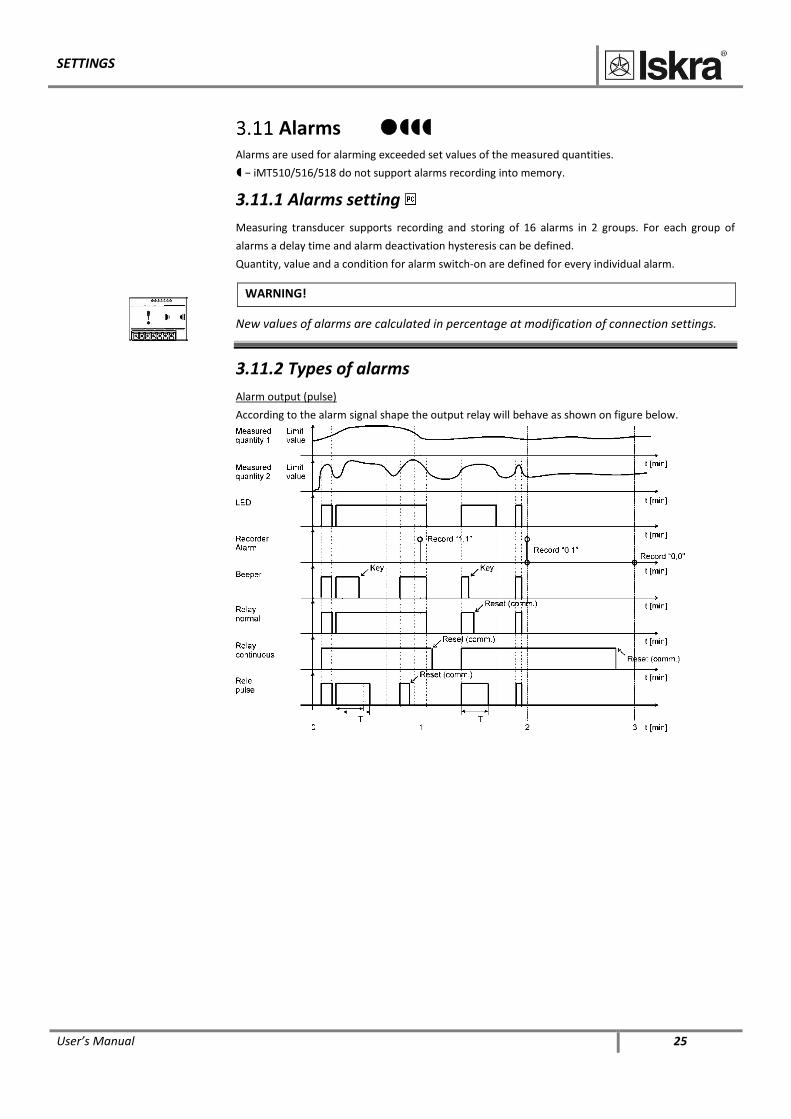
3.11.2 Types of alarms
Alarm output (pulse)
According to the alarm signal shape the output relay will behave as shown on figure below.
SETTINGS
26 User’s Manual
Memory Measurements, alarms, reports and details of supply voltage quality are stored in a built in memory in
the iMT511 - 8MB flash. All records stored in memory are accessible via communication with MiQen
software.
− iMT510/516/518 have no memory
3.12.1 Memory division
Memory is divided into 3 partitions which size is defined by the user. The A and B recorders are
intended for recording measurements, while all alarms that occurred are recorded in an alarm
partition.
Memory operation
Memory functions in a cyclic mode in compliance with the FIFO method. This means that only the
latest records are stored in the memory that will replace the oldest ones. A number of stored data or a
storing period depends on selected partition size, a number of recorded quantities and time of
division sampling.
Memory clearing
There is usually no need to clear the memory, because it works in cyclic mode. If you want to clear
memory data anyway, the data storing must be stopped first. Read the instrument settings with
MiQen and set “Recorder state” in Memory setting group to “stopped”. Download changes to the
device and open Memory info form and then click on Clear memory button. Select memory partitions
to be cleared on Memory clearing form and click on OK button. Set “Recorder state” setting back to
“active”.
Reset operations − iMT510/516/518 do not support some measurements for reset.
3.13.1 Reset energy counters (E1, E2, E3, E4)
All or individual energy meters are reset.
3.13.2 Reset maximal MD values
Current and stored MDs are reset.
3.13.3 Reset the last MD period
Current MD value is reset.
3.13.4 Reset alarm output
All alarms are reset.
MEASUREMENTS
User’s Manual 27
4 MEASUREMENTS
In the following chapters the device operation is explained more in detail.
4.1 SUPPORTED MEASUREMENTS 28 4.2 EXPLANATION OF BASIC CONCEPTS 28 4.4 CALCULATION AND DISPLAY OF MEASUREMENTS 29 4.5 PRESENT VALUES 29 4.6 ALARMS 30
4.7 WEB INTERFACE 31
MEASUREMENTS
28 User’s Manual
Supported measurements Measurements support regarding the device type is described in chapter Type differences, page 5.
Selection of supported measurements of individual instrument type is changed with the connection
settings. All supported measurements could be read via communication (MiQen).
Explanation of basic concepts
4.2.1 Sample factor − MV
A meter measures all primary quantities with the sample frequency of 6.991 kHz. The minimum of 107
samples must be in the calculation period. Based on these limitations (65Hz·107 samples) a sample
factor is calculated. A sample factor (MV), depending on frequency of a measured signal, defines a
number of periods for a measurement calculation and thus a number of harmonics considered in
calculations.
4.2.2 Average interval − MP
Due to readability of measurements from communication, an Average interval (MP) is calculated with
regard to the measured signal frequency. The Average interval (see chapter Average interval) defines
refresh rate of displayed measurements based on a sampling factor.
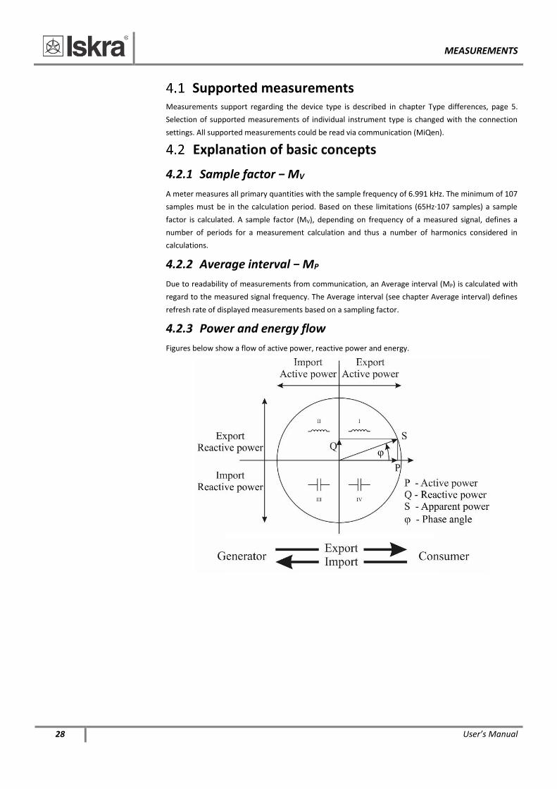
4.2.3 Power and energy flow
Figures below show a flow of active power, reactive power and energy.
MEASUREMENTS
User’s Manual 29
Calculation and display of measurements This chapter deals with capture, calculation and display of all supported quantities of measurement.
Only the most important equations are described; however, all of them are shown in chapter
Equations with additional descriptions and explanations.
− iMT516/518 do not have all described measurements supported (see chapter Type differences).
PLEASE NOTE
Calculation and display of measurements depend on the device type. For more detailed
information see chapter Type differences.
Present values
4.5.1 Voltage
Instrument measures real effective (rms) value of phase voltage (U1), connected to the meter.
Voltage measurement is available via communication.
4.5.2 Current
Instrument measures real effective (rms) value of phase currents, connected to current input.
Current measurement is available via communication.
4.5.3 Active, reactive and apparent power
Active power is calculated from instantaneous phase voltages and currents. All measurements are
seen via communication or are displayed on remote display. For more detailed information about
calculation see chapter Equations.
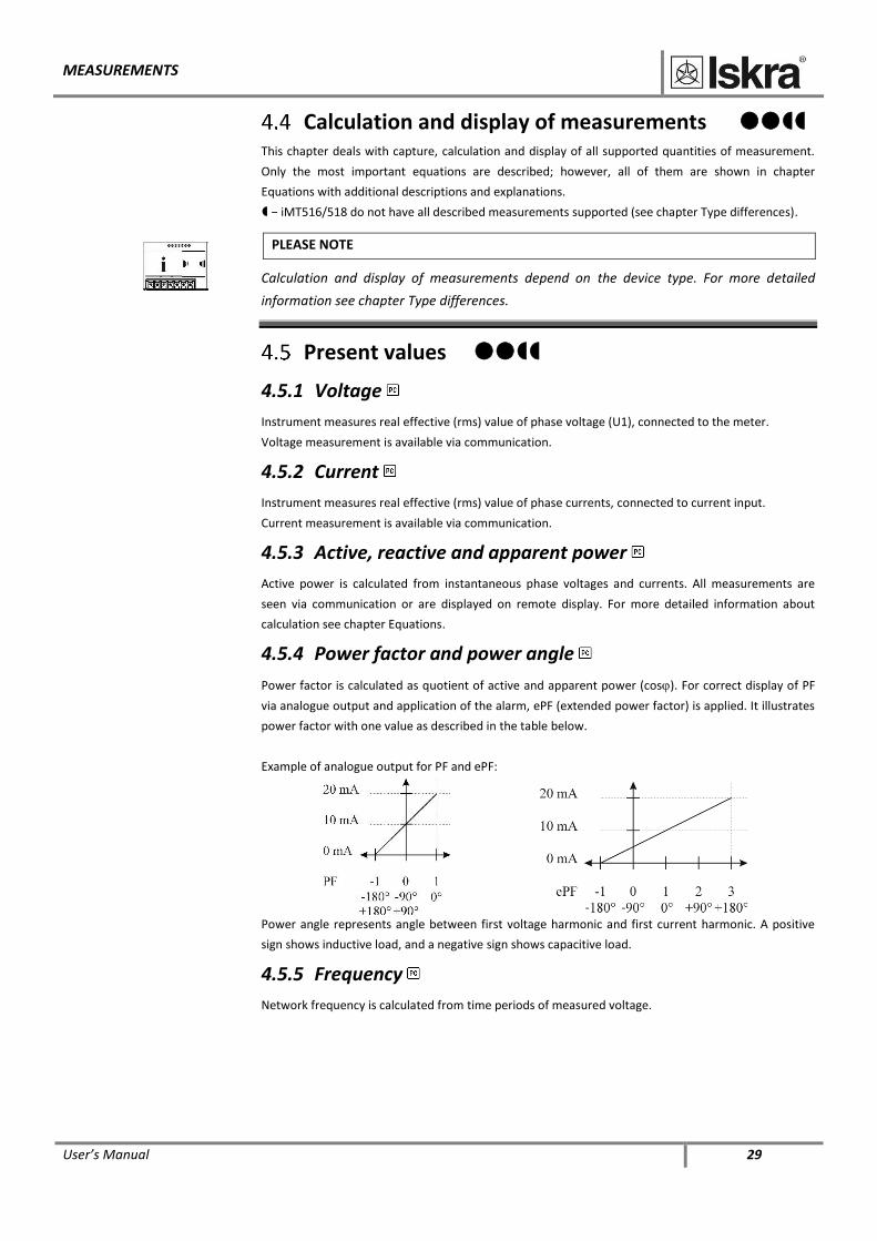
4.5.4 Power factor and power angle
Power factor is calculated as quotient of active and apparent power (cos). For correct display of PF
via analogue output and application of the alarm, ePF (extended power factor) is applied. It illustrates
power factor with one value as described in the table below.
Example of analogue output for PF and ePF:
Power angle represents angle between first voltage harmonic and first current harmonic. A positive
sign shows inductive load, and a negative sign shows capacitive load.
4.5.5 Frequency
Network frequency is calculated from time periods of measured voltage.
MEASUREMENTS
30 User’s Manual
4.5.6 Energy
Four individual counters of energy measurements are available.
4.5.7 MD values
Measurements of MD values.
4.5.8 THD − Total harmonic distortion
THD is calculated for phase currents, phase voltages and is expressed as percent of high harmonic
components relative to first harmonic.
Instrument uses measuring technique of real effective (rms) value that assures exact measurements
with the presence of high harmonics up to 53rd harmonic.
Alarms Two groups of 8 alarms with alarm conditions are measured.
required, yearly reports have to reset manually.
In order to reset reports choose setting Power supply quality / Monitoring mode and change the
value to “No monitoring”. Download settings to instrument. Then choose the same setting in change
the value back to “EN50160”. Again download settings to instrument. Now all yearly reports (anomaly
counters) are reset.
MEASUREMENTS
User’s Manual 31
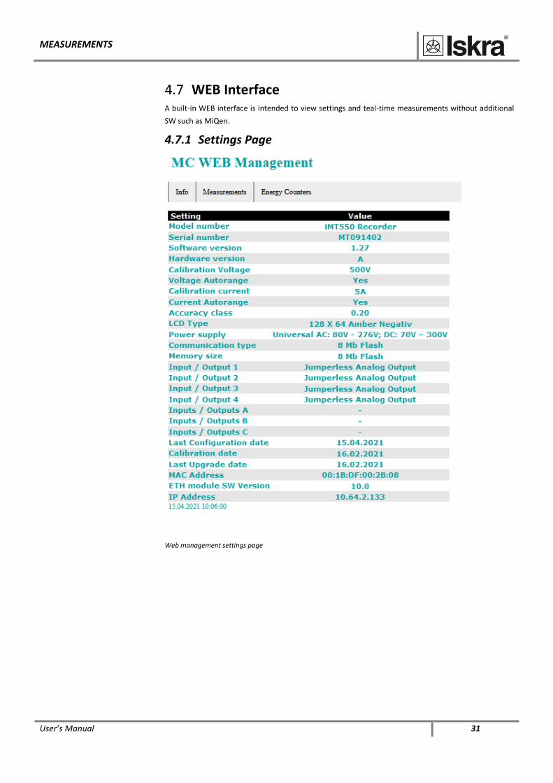
WEB Interface A built-in WEB interface is intended to view settings and teal-time measurements without additional
SW such as MiQen.
4.7.1 Settings Page
Web management settings page
MEASUREMENTS
32 User’s Manual
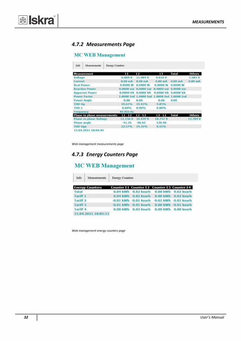
4.7.2 Measurements Page
Web management measurements page
4.7.3 Energy Counters Page
Web management energy counters page

BATTERY REPLACEMENT
User’s Manual 33
5 BATTERY REPLACEMENT
The Measuring transducer contains a lithium battery. It is used to preserve data (date and time) in the
device memory when if the power supply is off. Life time of battery is app.6 years (typical). High
temperature and humidity shortens the battery's functionality. Battery has no effect on other
functionality of the device, except date and time.
It is recommended that the instrument is sent back in the factory for battery replacement. Although it
is possible that replacement is made by the qualified person, but in this case Iskra d.o.o. does not take
on responsibility for any injuries, dysfunction of the instrument or mechanical damage.
Instructions for replacement 1 Disconnect the instrument from measuring grid and power supply (read the safety section)
and take it out of the mounting rail.
2 With flat screwdriver remove the cover [3] from instrument [1] (see picture below).
3 Pull out printed circuit board (PCB) assembly [2].
4 Remove the battery from its holder on the PCB and replace it with the same model (Varta,
type 6032 CR2032 SLF).
5 To put the instrument together replay steps from 2 to 3 in inverse order.
WARNING
You should set device date and time again after replacing the battery.
TECHNICAL DATA
34 User’s Manual
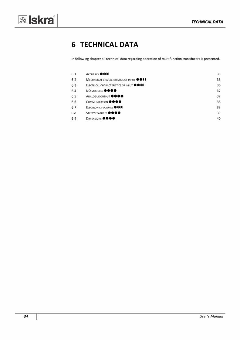
6 TECHNICAL DATA
In following chapter all technical data regarding operation of multifunction transducers is presented.
ACCURACY 35 MECHANICAL CHARACTERISTICS OF INPUT 36
ELECTRICAL CHARACTERISTICS OF INPUT 36 I/O MODULES 37 ANALOGUE OUTPUT 37 COMMUNICATION 38 ELECTRONIC FEATURES 38
SAFETY FEATURES 39 DIMENSIONS 40
TECHNICAL DATA
User’s Manual 35
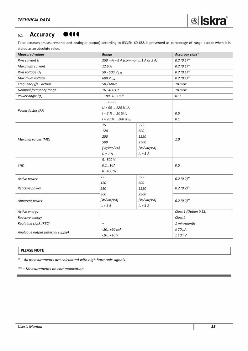
Accuracy
Total accuracy (measurements and analogue output) according to IEC/EN 60 688 is presented as percentage of range except when it is
stated as an absolute value.
Measured values Range Accuracy class*
Rms current I1 250 mA – 6 A (common In 1 A or 5 A) 0.2 (0.1)**
Maximum current 12.5 A 0.2 (0.1)**
Rms voltage U1 50 - 500 V L-N 0.2 (0.1)**
Maximum voltage 600 V L-N 0.2 (0.1)**
Frequency (f) − actual 50 / 60Hz 10 mHz
Nominal frequency range 16…400 Hz 10 mHz
Power angle (φ) −180…0…180° 0.1°
Power factor (PF)
−1…0…+1
U = 50 … 120 % Un
I = 2 % … 20 % In
I = 20 % … 200 % In
0.5
0.1
Maximal values (MD)
75
120
250
500
[W/var/VA]
In = 1 A
375
600
1250
2500
[W/var/VA]
In = 5 A
1.0
THD
5…500 V
0.1…10A
0…400 %
0.5
Active power 75
120
250
500
[W/var/VA]
In = 1 A
375
600
1250
2500
[W/var/VA]
In = 5 A
0.2 (0.2)**
Reactive power 0.2 (0.2)**
Apparent power 0.2 (0.2)**
Active energy Class 1 (Option 0.5S)
Reactive energy Class 2
Real time clock (RTC) − 1 min/month
Analogue output (internal supply) -20…+20 mA
-10…+10 V
± 20 μA
± 10mV
PLEASE NOTE
* − All measurements are calculated with high harmonic signals.
** − Measurements on communication.
TECHNICAL DATA
36 User’s Manual
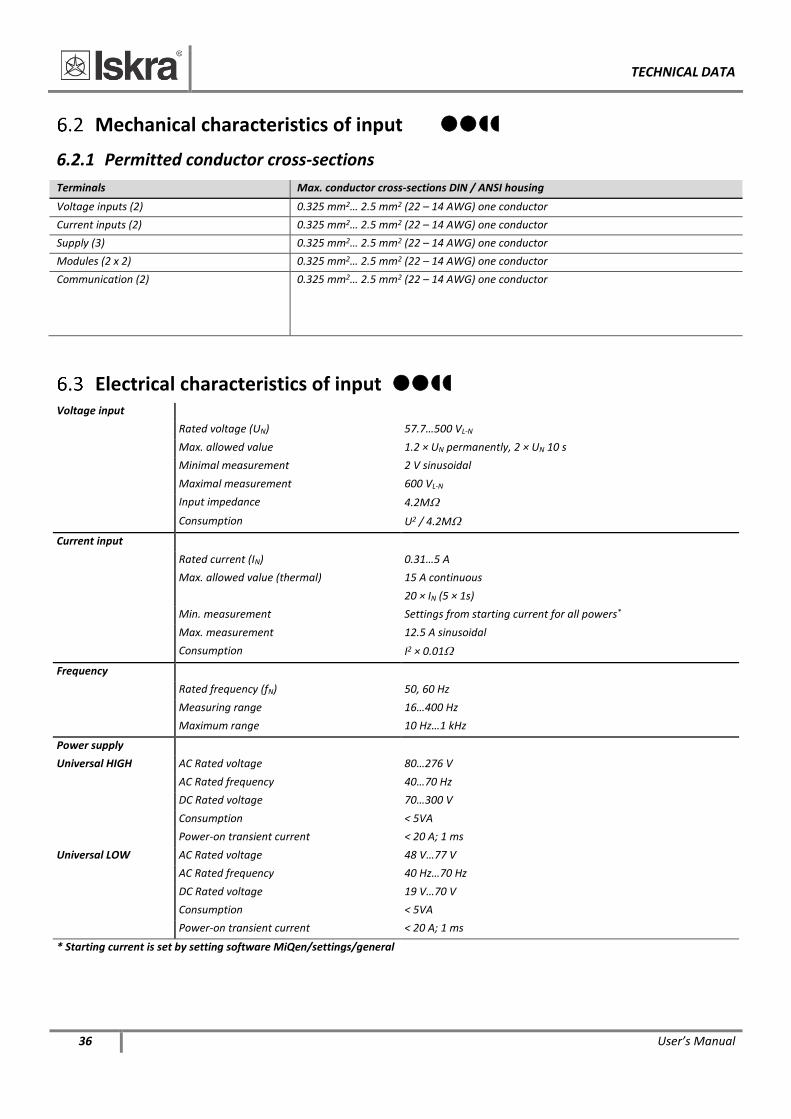
Mechanical characteristics of input
6.2.1 Permitted conductor cross-sections
Terminals Max. conductor cross-sections DIN / ANSI housing
Voltage inputs (2) 0.325 mm2… 2.5 mm2 (22 – 14 AWG) one conductor
Current inputs (2) 0.325 mm2… 2.5 mm2 (22 – 14 AWG) one conductor
Supply (3) 0.325 mm2… 2.5 mm2 (22 – 14 AWG) one conductor
Modules (2 x 2) 0.325 mm2… 2.5 mm2 (22 – 14 AWG) one conductor
Communication (2) 0.325 mm2… 2.5 mm2 (22 – 14 AWG) one conductor
Electrical characteristics of input Voltage input
Rated voltage (UN) 57.7…500 VL-N
Max. allowed value 1.2 × UN permanently, 2 × UN 10 s
Minimal measurement 2 V sinusoidal
Maximal measurement 600 VL-N
Input impedance 4.2M
Consumption U2 / 4.2M
Current input
Rated current (IN) 0.31…5 A
Max. allowed value (thermal) 15 A continuous
20 × IN (5 × 1s)
Min. measurement Settings from starting current for all powers*
Max. measurement 12.5 A sinusoidal
Consumption I2 × 0.01
Frequency
Rated frequency (fN) 50, 60 Hz
Measuring range 16…400 Hz
Maximum range 10 Hz…1 kHz
Power supply
Universal HIGH AC Rated voltage 80…276 V
AC Rated frequency 40…70 Hz
DC Rated voltage 70…300 V
Consumption < 5VA
Power-on transient current < 20 A; 1 ms
Universal LOW AC Rated voltage 48 V…77 V
AC Rated frequency 40 Hz…70 Hz
DC Rated voltage 19 V…70 V
Consumption < 5VA
Power-on transient current < 20 A; 1 ms
* Starting current is set by setting software MiQen/settings/general
TECHNICAL DATA
User’s Manual 37
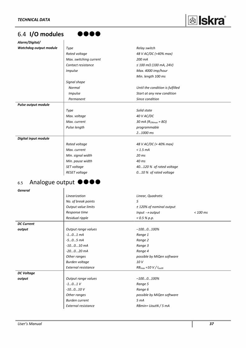
I/O modules Alarm/Digital/
Watchdog output module
Type Relay switch
Rated voltage 48 V AC/DC (+40% max)
Max. switching current 200 mA
Contact resistance ≤ 100 mΩ (100 mA, 24V)
Impulse Max. 4000 imp/hour
Min. length 100 ms
Signal shape
Normal Until the condition is fulfilled
Impulse Start at any new condition
Permanent Since condition
Pulse output module
Type Solid state
Max. voltage 40 V AC/DC
Max. current 30 mA (RONmax = 8Ω)
Pulse length programmable
2…1000 ms
Digital input module
Rated voltage 48 V AC/DC (+ 40% max)
Max. current < 1.5 mA
Min. signal width 20 ms
Min. pause width 40 ms
SET voltage 40...120 % of rated voltage
RESET voltage 0...10 % of rated voltage
Analogue output
General
Linearization Linear, Quadratic
No. of break points 5
Output value limits ± 120% of nominal output
Response time Input output < 100 ms
Residual ripple < 0.5 % p.p.
DC Current
output Output range values –100…0…100%
-1…0…1 mA Range 1
-5…0…5 mA Range 2
-10...0...10 mA Range 3
-20...0...20 mA Range 4
Other ranges possible by MiQen software
Burden voltage 10 V
External resistance RBmax =10 V / IoutN
DC Voltage
output Output range values –100…0…100%
-1…0…1 V Range 5
-10…0…10 V Range 6
Other ranges possible by MiQen software
Burden current 5 mA
External resistance RBmin= UoutN / 5 mA
TECHNICAL DATA
38 User’s Manual
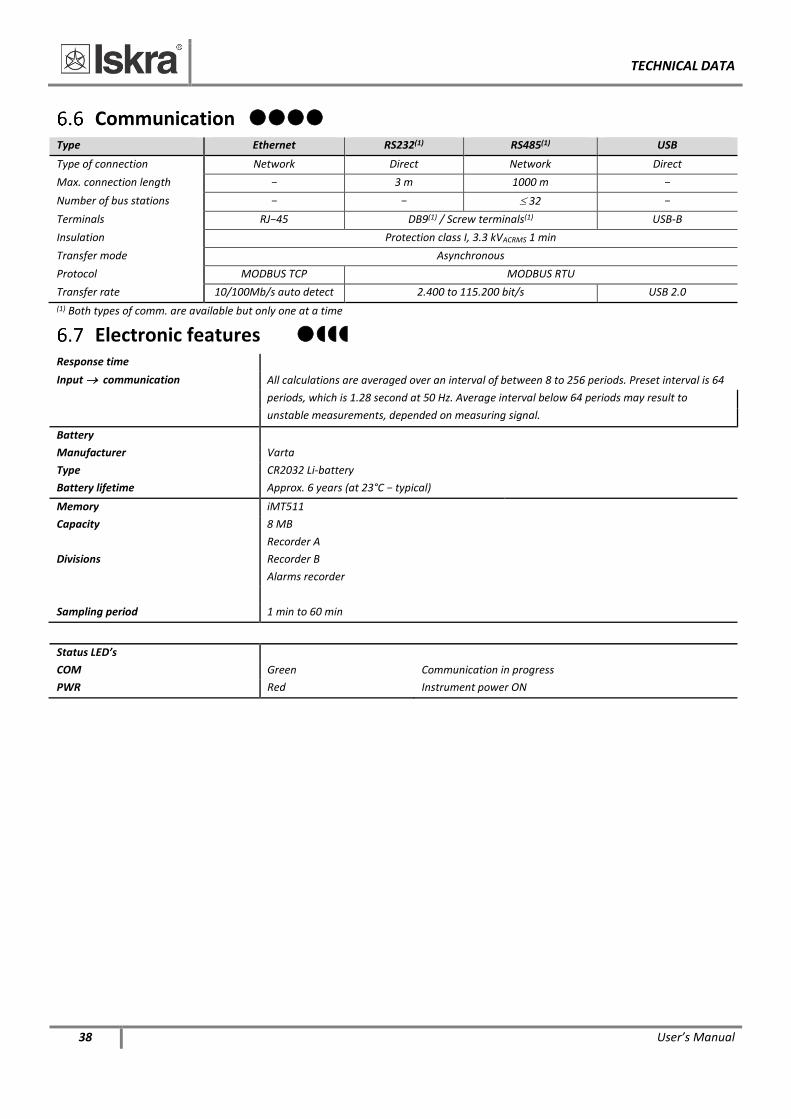
Communication Type Ethernet RS232(1) RS485(1) USB
Type of connection Network Direct Network Direct
Max. connection length − 3 m 1000 m −
Number of bus stations − − 32 −
Terminals RJ−45 DB9(1) / Screw terminals(1) USB-B
Insulation Protection class I, 3.3 kVACRMS 1 min
Transfer mode Asynchronous
Protocol MODBUS TCP MODBUS RTU
Transfer rate 10/100Mb/s auto detect 2.400 to 115.200 bit/s USB 2.0
(1) Both types of comm. are available but only one at a time
Electronic features Response time
Input communication All calculations are averaged over an interval of between 8 to 256 periods. Preset interval is 64
periods, which is 1.28 second at 50 Hz. Average interval below 64 periods may result to
unstable measurements, depended on measuring signal.
Battery
Manufacturer Varta
Type CR2032 Li-battery
Battery lifetime Approx. 6 years (at 23°C − typical)
Memory iMT511
Capacity 8 MB
Divisions
Recorder A
Recorder B
Alarms recorder
Sampling period 1 min to 60 min
Status LED’s
COM Green Communication in progress
PWR Red Instrument power ON
TECHNICAL DATA
User’s Manual 39
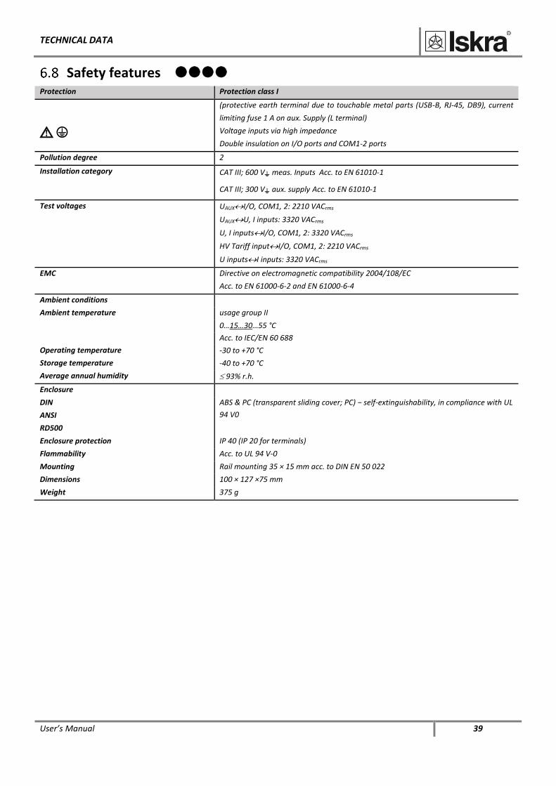
Safety features Protection Protection class I
(protective earth terminal due to touchable metal parts (USB-B, RJ-45, DB9), current
limiting fuse 1 A on aux. Supply (L terminal)
Voltage inputs via high impedance
Double insulation on I/O ports and COM1-2 ports
Pollution degree 2
Installation category CAT III; 600 V meas. Inputs Acc. to EN 61010-1
CAT III; 300 V aux. supply Acc. to EN 61010-1
Test voltages UAUXI/O, COM1, 2: 2210 VACrms
UAUXU, I inputs: 3320 VACrms
U, I inputsI/O, COM1, 2: 3320 VACrms
HV Tariff inputI/O, COM1, 2: 2210 VACrms
U inputsI inputs: 3320 VACrms
EMC Directive on electromagnetic compatibility 2004/108/EC
Acc. to EN 61000-6-2 and EN 61000-6-4
Ambient conditions
Ambient temperature usage group II
0…15…30…55 °C
Acc. to IEC/EN 60 688
Operating temperature -30 to +70 °C
Storage temperature -40 to +70 °C
Average annual humidity 93% r.h.
Enclosure
DIN
ANSI
RD500
ABS & PC (transparent sliding cover; PC) − self-extinguishability, in compliance with UL
94 V0
Enclosure protection IP 40 (IP 20 for terminals)
Flammability Acc. to UL 94 V-0
Mounting Rail mounting 35 × 15 mm acc. to DIN EN 50 022
Dimensions 100 × 127 ×75 mm
Weight 375 g
TECHNICAL DATA
40 User’s Manual
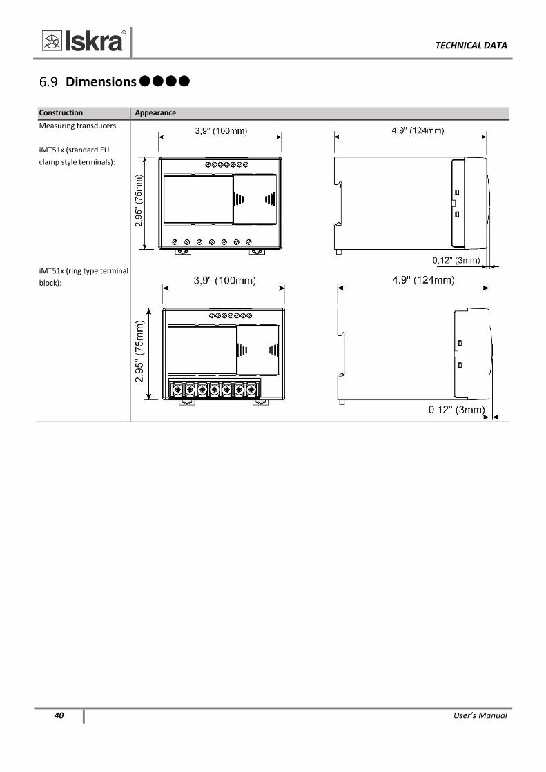
Dimensions
Construction Appearance
Measuring transducers
iMT51x (standard EU
clamp style terminals):
iMT51x (ring type terminal
block):
ABBREVIATION/GLOSSARY
User’s Manual 41
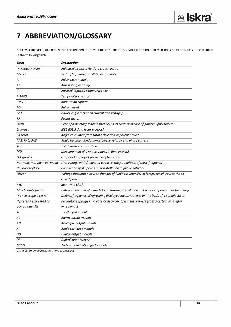
7 ABBREVIATION/GLOSSARY
Abbreviations are explained within the text where they appear the first time. Most common abbreviations and expressions are explained
in the following table:
Term Explanation
MODBUS / DNP3 Industrial protocol for data transmission
MiQen Setting Software for ISKRA instruments
PI Pulse input module
AC Alternating quantity
IR Infrared (optical) communication
Pt1000 Temperature sensor
RMS Root Mean Square
PO Pulse output
PA1 Power angle (between current and voltage)
PF Power factor
Flash Type of a memory module that keeps its content in case of power supply failure
Ethernet IEEE 802.3 data layer protocol
PA total Angle calculated from total active and apparent power
PA1, PA2, PA3 Angle between fundamental phase voltage and phase current
THD Total harmonic distortion
MD Measurement of average values in time interval
FFT graphs Graphical display of presence of harmonics
Harmonic voltage – harmonic Sine voltage with frequency equal to integer multiple of basic frequency
Hand-over place Connection spot of consumer installation in public network
Flicker Voltage fluctuation causes changes of luminous intensity of lamps, which causes the so-
called flicker
RTC Real Time Clock
Mv − Sample factor Defines a number of periods for measuring calculation on the basis of measured frequency
Mp − Average interval Defines frequency of refreshing displayed measurements on the basis of a Sample factor
Hysteresis expressed as
percentage [%]
Percentage specifies increase or decrease of a measurement from a certain limit after
exceeding it
TI Tariff input module
AL Alarm output module
AN Analogue output module
AI Analogue input module
DO Digital output module
DI Digital input module
COM2 2nd communication port module
List of common abbreviations and expressions
APPENDICES
42 User’s Manual
8 APPENDICES
In this chapter you will find
8.1 APPENDIX A: MODBUS COMMUNICATION PROTOCOL 42 8.2 APPENDIX C: CALCULATIONS & EQUATIONS 49
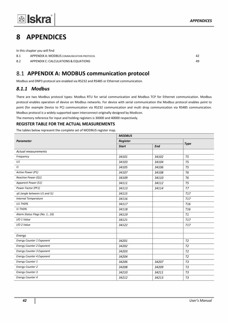
APPENDIX A: MODBUS communication protocol Modbus and DNP3 protocol are enabled via RS232 and RS485 or Ethernet communication.
8.1.1 Modbus
There are two Modbus protocol types: Modbus RTU for serial communication and Modbus TCP for Ethernet communication. Modbus
protocol enables operation of device on Modbus networks. For device with serial communication the Modbus protocol enables point to
point (for example Device to PC) communication via RS232 communication and multi drop communication via RS485 communication.
Modbus protocol is a widely supported open interconnect originally designed by Modicon.
The memory reference for input and holding registers is 30000 and 40000 respectively.
REGISTER TABLE FOR THE ACTUAL MEASUREMENTS
The tables below represent the complete set of MODBUS register map.
Parameter
MODBUS
Register Type
Start End
Actual measurements
Frequency 34101 34102 T5
U1 34103 34104 T5
I1 34105 34106 T5
Active Power (P1) 34107 34108 T6
Reactive Power (Q1) 34109 34110 T6
Apparent Power (S1) 34111 34112 T5
Power Factor (PF1) 34113 34114 T7
1 (angle between U1 and I1) 34115 T17
Internal Temperature 34116 T17
U1 THD% 34117 T16
I1 THD% 34118 T16
Alarm Status Flags (No. 1…16) 34119 T1
I/O 1 Value 34121 T17
I/O 2 Value 34122 T17
Energy
Energy Counter 1 Exponent 34201 T2
Energy Counter 2 Exponent 34202 T2
Energy Counter 3 Exponent 34203 T2
Energy Counter 4 Exponent 34204 T2
Energy Counter 1 34206 34207 T3
Energy Counter 2 34208 34209 T3
Energy Counter 3 34210 34211 T3
Energy Counter 4 34212 34213 T3
APPENDICES
User’s Manual 43
Parameter
MODBUS
Register Type
Start End
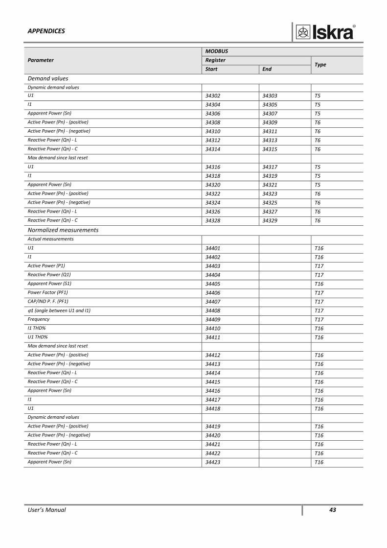
Demand values
Dynamic demand values
U1 34302 34303 T5
I1 34304 34305 T5
Apparent Power (Sn) 34306 34307 T5
Active Power (Pn) - (positive) 34308 34309 T6
Active Power (Pn) - (negative) 34310 34311 T6
Reactive Power (Qn) - L 34312 34313 T6
Reactive Power (Qn) - C 34314 34315 T6
Max demand since last reset
U1 34316 34317 T5
I1 34318 34319 T5
Apparent Power (Sn) 34320 34321 T5
Active Power (Pn) - (positive) 34322 34323 T6
Active Power (Pn) - (negative) 34324 34325 T6
Reactive Power (Qn) - L 34326 34327 T6
Reactive Power (Qn) - C 34328 34329 T6
Normalized measurements
Actual measurements
U1 34401 T16
I1 34402 T16
Active Power (P1) 34403 T17
Reactive Power (Q1) 34404 T17
Apparent Power (S1) 34405 T16
Power Factor (PF1) 34406 T17
CAP/IND P. F. (PF1) 34407 T17
1 (angle between U1 and I1) 34408 T17
Frequency 34409 T17
I1 THD% 34410 T16
U1 THD% 34411 T16
Max demand since last reset
Active Power (Pn) - (positive) 34412 T16
Active Power (Pn) - (negative) 34413 T16
Reactive Power (Qn) - L 34414 T16
Reactive Power (Qn) - C 34415 T16
Apparent Power (Sn) 34416 T16
I1 34417 T16
U1 34418 T16
Dynamic demand values
Active Power (Pn) - (positive) 34419 T16
Active Power (Pn) - (negative) 34420 T16
Reactive Power (Qn) - L 34421 T16
Reactive Power (Qn) - C 34422 T16
Apparent Power (Sn) 34423 T16
APPENDICES
44 User’s Manual
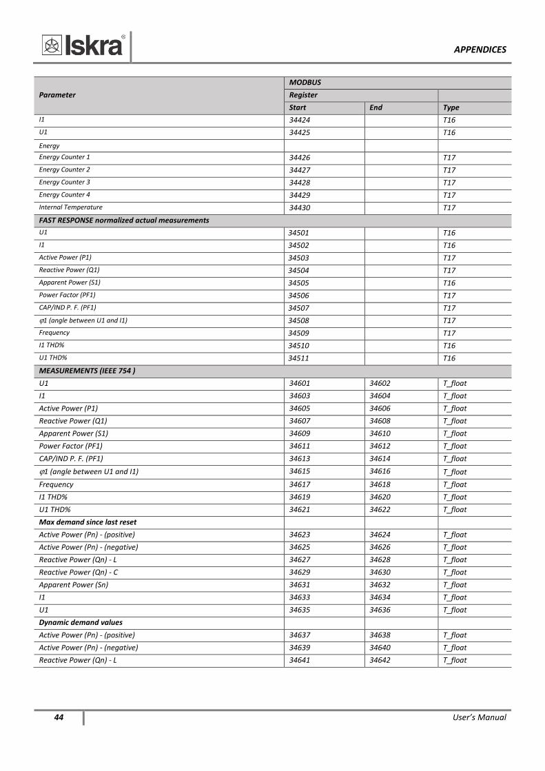
Parameter
MODBUS
Register
Start End Type
I1 34424 T16
U1 34425 T16
Energy
Energy Counter 1 34426 T17
Energy Counter 2 34427 T17
Energy Counter 3 34428 T17
Energy Counter 4 34429 T17
Internal Temperature 34430 T17
FAST RESPONSE normalized actual measurements
U1 34501 T16
I1 34502 T16
Active Power (P1) 34503 T17
Reactive Power (Q1) 34504 T17
Apparent Power (S1) 34505 T16
Power Factor (PF1) 34506 T17
CAP/IND P. F. (PF1) 34507 T17
1 (angle between U1 and I1) 34508 T17
Frequency 34509 T17
I1 THD% 34510 T16
U1 THD% 34511 T16
MEASUREMENTS (IEEE 754 )
U1 34601 34602 T_float
I1 34603 34604 T_float
Active Power (P1) 34605 34606 T_float
Reactive Power (Q1) 34607 34608 T_float
Apparent Power (S1) 34609 34610 T_float
Power Factor (PF1) 34611 34612 T_float
CAP/IND P. F. (PF1) 34613 34614 T_float
1 (angle between U1 and I1) 34615 34616 T_float
Frequency 34617 34618 T_float
I1 THD% 34619 34620 T_float
U1 THD% 34621 34622 T_float
Max demand since last reset
Active Power (Pn) - (positive) 34623 34624 T_float
Active Power (Pn) - (negative) 34625 34626 T_float
Reactive Power (Qn) - L 34627 34628 T_float
Reactive Power (Qn) - C 34629 34630 T_float
Apparent Power (Sn) 34631 34632 T_float
I1 34633 34634 T_float
U1 34635 34636 T_float
Dynamic demand values
Active Power (Pn) - (positive) 34637 34638 T_float
Active Power (Pn) - (negative) 34639 34640 T_float
Reactive Power (Qn) - L 34641 34642 T_float
APPENDICES
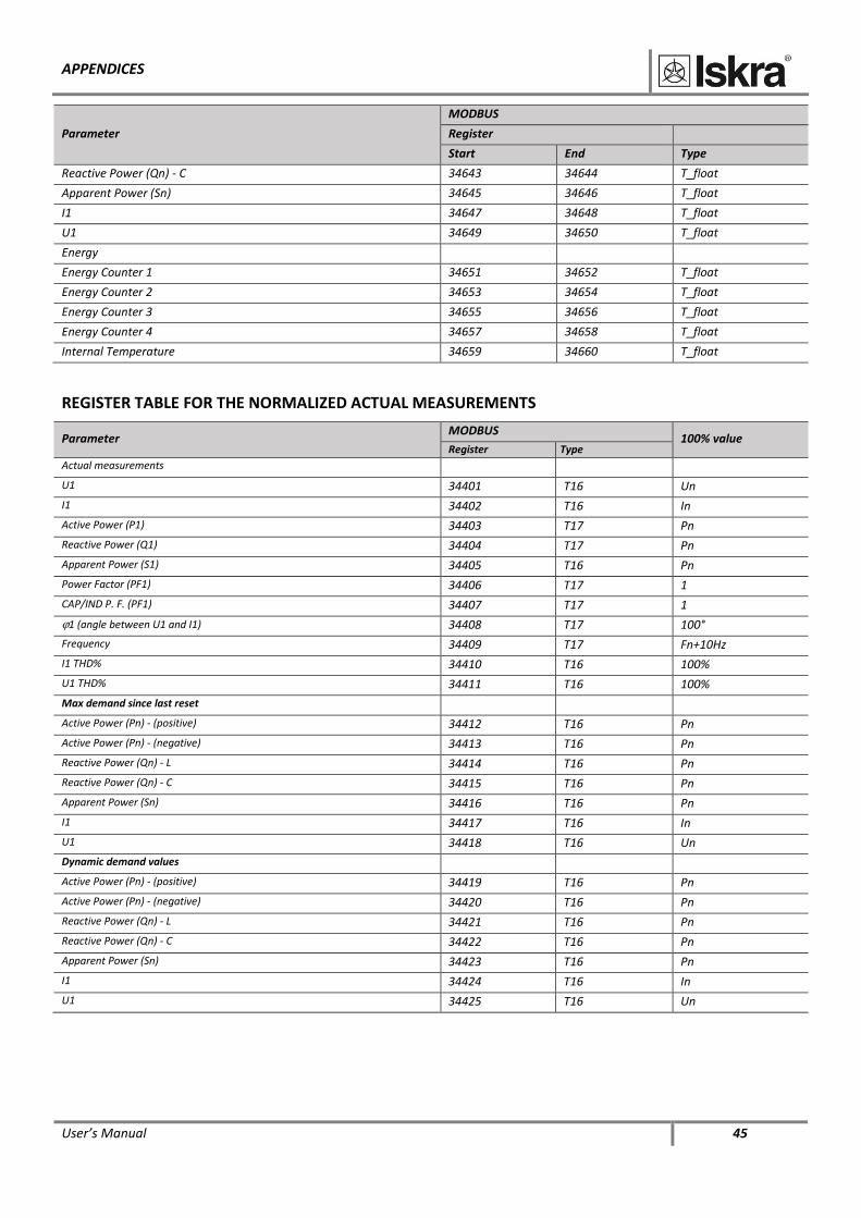
User’s Manual 45
Parameter
MODBUS
Register
Start End Type
Reactive Power (Qn) - C 34643 34644 T_float
Apparent Power (Sn) 34645 34646 T_float
I1 34647 34648 T_float
U1 34649 34650 T_float
Energy
Energy Counter 1 34651 34652 T_float
Energy Counter 2 34653 34654 T_float
Energy Counter 3 34655 34656 T_float
Energy Counter 4 34657 34658 T_float
Internal Temperature 34659 34660 T_float
REGISTER TABLE FOR THE NORMALIZED ACTUAL MEASUREMENTS
Parameter MODBUS
100% value Register Type
Actual measurements
U1 34401 T16 Un
I1 34402 T16 In
Active Power (P1) 34403 T17 Pn
Reactive Power (Q1) 34404 T17 Pn
Apparent Power (S1) 34405 T16 Pn
Power Factor (PF1) 34406 T17 1
CAP/IND P. F. (PF1) 34407 T17 1
1 (angle between U1 and I1) 34408 T17 100°
Frequency 34409 T17 Fn+10Hz
I1 THD% 34410 T16 100%
U1 THD% 34411 T16 100%
Max demand since last reset
Active Power (Pn) - (positive) 34412 T16 Pn
Active Power (Pn) - (negative) 34413 T16 Pn
Reactive Power (Qn) - L 34414 T16 Pn
Reactive Power (Qn) - C 34415 T16 Pn
Apparent Power (Sn) 34416 T16 Pn
I1 34417 T16 In
U1 34418 T16 Un
Dynamic demand values
Active Power (Pn) - (positive) 34419 T16 Pn
Active Power (Pn) - (negative) 34420 T16 Pn
Reactive Power (Qn) - L 34421 T16 Pn
Reactive Power (Qn) - C 34422 T16 Pn
Apparent Power (Sn) 34423 T16 Pn
I1 34424 T16 In
U1 34425 T16 Un
APPENDICES
46 User’s Manual
Parameter MODBUS
100% value Register Type
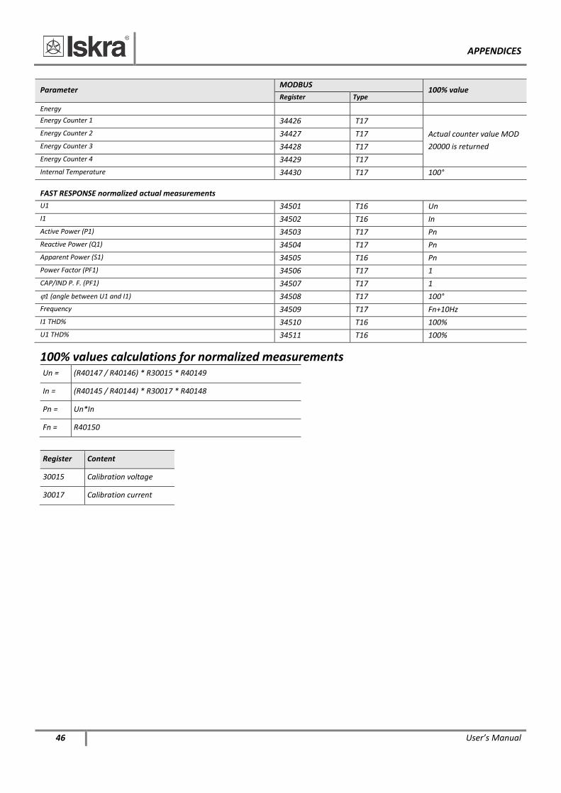
Energy
Energy Counter 1 34426 T17
Actual counter value MOD
20000 is returned
Energy Counter 2 34427 T17
Energy Counter 3 34428 T17
Energy Counter 4 34429 T17
Internal Temperature 34430 T17 100°
FAST RESPONSE normalized actual measurements
U1 34501 T16 Un
I1 34502 T16 In
Active Power (P1) 34503 T17 Pn
Reactive Power (Q1) 34504 T17 Pn
Apparent Power (S1) 34505 T16 Pn
Power Factor (PF1) 34506 T17 1
CAP/IND P. F. (PF1) 34507 T17 1
1 (angle between U1 and I1) 34508 T17 100°
Frequency 34509 T17 Fn+10Hz
I1 THD% 34510 T16 100%
U1 THD% 34511 T16 100%
100% values calculations for normalized measurements
Un = (R40147 / R40146) * R30015 * R40149
In = (R40145 / R40144) * R30017 * R40148
Pn = Un*In
Fn = R40150
Register Content
30015 Calibration voltage
30017 Calibration current
APPENDICES
User’s Manual 47
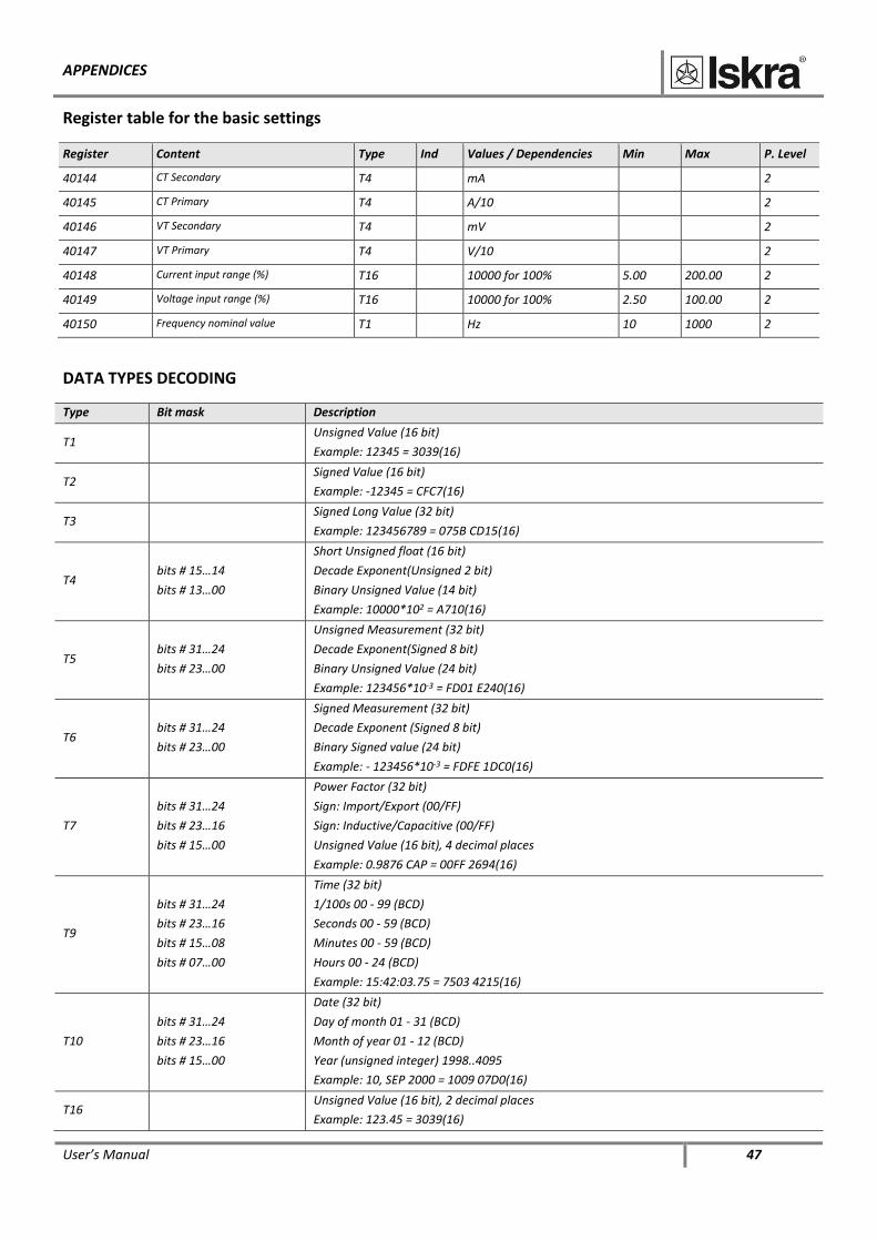
Register table for the basic settings
Register Content Type Ind Values / Dependencies Min Max P. Level
40144 CT Secondary T4 mA 2
40145 CT Primary T4 A/10 2
40146 VT Secondary T4 mV 2
40147 VT Primary T4 V/10 2
40148 Current input range (%) T16 10000 for 100% 5.00 200.00 2
40149 Voltage input range (%) T16 10000 for 100% 2.50 100.00 2
40150 Frequency nominal value T1 Hz 10 1000 2
DATA TYPES DECODING
Type Bit mask Description
T1 Unsigned Value (16 bit)
Example: 12345 = 3039(16)
T2 Signed Value (16 bit)
Example: -12345 = CFC7(16)
T3 Signed Long Value (32 bit)
Example: 123456789 = 075B CD15(16)
T4 bits # 15…14
bits # 13…00
Short Unsigned float (16 bit)
Decade Exponent(Unsigned 2 bit)
Binary Unsigned Value (14 bit)
Example: 10000*102 = A710(16)
T5 bits # 31…24
bits # 23…00
Unsigned Measurement (32 bit)
Decade Exponent(Signed 8 bit)
Binary Unsigned Value (24 bit)
Example: 123456*10-3 = FD01 E240(16)
T6 bits # 31…24
bits # 23…00
Signed Measurement (32 bit)
Decade Exponent (Signed 8 bit)
Binary Signed value (24 bit)
Example: - 123456*10-3 = FDFE 1DC0(16)
T7
bits # 31…24
bits # 23…16
bits # 15…00
Power Factor (32 bit)
Sign: Import/Export (00/FF)
Sign: Inductive/Capacitive (00/FF)
Unsigned Value (16 bit), 4 decimal places
Example: 0.9876 CAP = 00FF 2694(16)
T9
bits # 31…24
bits # 23…16
bits # 15…08
bits # 07…00
Time (32 bit)
1/100s 00 - 99 (BCD)
Seconds 00 - 59 (BCD)
Minutes 00 - 59 (BCD)
Hours 00 - 24 (BCD)
Example: 15:42:03.75 = 7503 4215(16)
T10
bits # 31…24
bits # 23…16
bits # 15…00
Date (32 bit)
Day of month 01 - 31 (BCD)
Month of year 01 - 12 (BCD)
Year (unsigned integer) 1998..4095
Example: 10, SEP 2000 = 1009 07D0(16)
T16 Unsigned Value (16 bit), 2 decimal places
Example: 123.45 = 3039(16)

APPENDICES
48 User’s Manual
T17 Signed Value (16 bit), 2 decimal places
Example: -123.45 = CFC7(16)
T_Str4 Text: 4 characters (2 characters for 16 bit register)
T_Str6 Text: 6 characters (2 characters for 16 bit register)
T_Str8 Text: 8 characters (2 characters for 16 bit register)
T_Str16 Text: 16 characters (2 characters for 16 bit register)
T_Str40 Text: 40 characters (2 characters for 16 bit register)
APPENDICES
User’s Manual 49
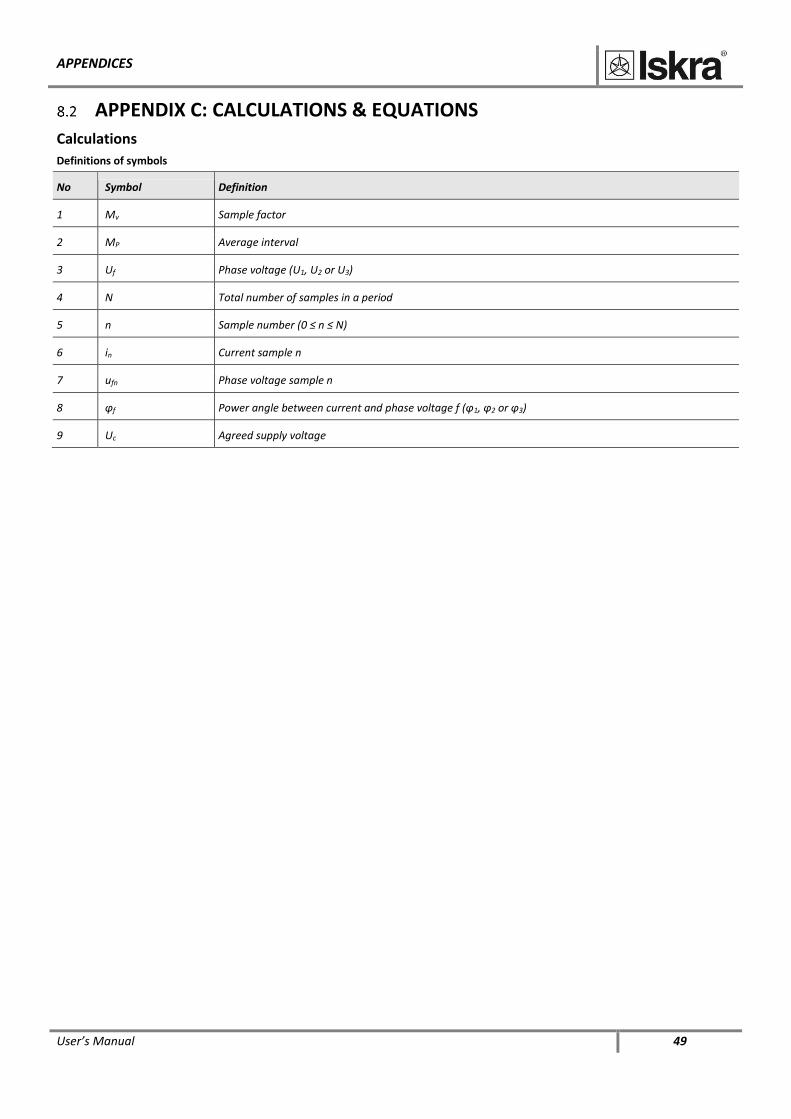
APPENDIX C: CALCULATIONS & EQUATIONS
Calculations
Definitions of symbols
No Symbol Definition
1 Mv Sample factor
2 MP Average interval
3 Uf Phase voltage (U1, U2 or U3)
4 N Total number of samples in a period
5 n Sample number (0 ≤ n ≤ N)
6 in Current sample n
7 ufn Phase voltage sample n
8 φf Power angle between current and phase voltage f (φ1, φ2 or φ3)
9 Uc Agreed supply voltage
APPENDICES
50 User’s Manual
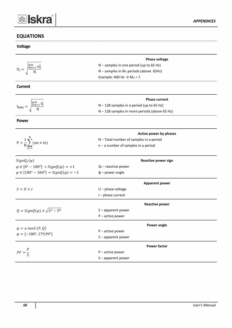
EQUATIONS
Voltage
Uf = √∑ un
2Nn=1
N
Phase voltage
N − samples in one period (up to 65 Hz)
N − samples in Mv periods (above 65Hz)
Example: 400 Hz → MV = 7
Current
IRMS = √∑ in
2Nn=1
N
Phase current
N − 128 samples in a period (up to 65 Hz)
N − 128 samples in more periods (above 65 Hz)
Power
P =1
N∑(un × in)
N
n=1
Active power by phases
N − Total number of samples in a period
n − a number of samples in a period
𝑆𝑖𝑔𝑛𝑄𝑓(𝜑)
𝜑 ∈ [0° − 180°] → 𝑆𝑖𝑔𝑛𝑄(𝜑) = +1
𝜑 ∈ [180° − 360°] → 𝑆𝑖𝑔𝑛𝑄(𝜑) = −1
Reactive power sign
Qf − reactive power
φ − power angle
𝑆 = 𝑈 × 𝐼
Apparent power
U − phase voltage
I − phase current
𝑄 = 𝑆𝑖𝑔𝑛𝑄(𝜑) × √𝑆2 − 𝑃2
Reactive power
S − apparent power
P − active power
𝜑 = 𝑎 𝑡𝑎𝑛2 (𝑃, 𝑄)
𝜑 = [−180°, 179,99°]
Power angle
P − active power
S − apparent power
𝑃𝐹 =𝑃
𝑆
Power factor
P − active power
S − apparent power

APPENDICES
User’s Manual 51
THD
𝐼𝑇𝐻𝐷(%) =√∑ 𝐼𝑛2𝑁
𝑛=2
𝐼1
100
Current THD
I1 − value of first harmonic
n − number of harmonic
𝑈𝑇𝐻𝐷(%) =√∑ 𝑈𝑛2𝑁
𝑛=2
𝑈1
100
Voltage THD
U1 − value of first harmonic
n − number of harmonic

Published by Iskra, d.o.o. • Subject to change without notice • Version 1.00 July 2021 • EN K22.496.700


![Chapter 3 Sensors and Transducers[1]](https://img.pdfslide.net/doc/110x75/63151b03fc260b71020fd938/chapter-3-sensors-and-transducers1.jpg)


