Embed Size (px)
Citation preview

International Symposium “Steel Structures:Culture & Sustainability 2010”
21-23 September 2010, Istanbul, Turkey
Paper No: 70
NUMERICAL STUDY ON THE BEHAVIOR OF STEEL COLUMNS
EMBEDDED ON BRICK WALLS SUBJECTED TO FIRE
Antonio M. CORREIA1,2
, João P. C. RODRIGUES2
and Valdir P. SILVA3
1 Superior School of Technology and Management of Oliveira do Hospital, Portugal
2 Faculty of Sciences and Technology of University of Coimbra, Portugal
3 Polytechnic School of the University of S. Paulo, Brazil.
ABSTRACT
Steel columns embedded on building brick walls are subjected to differential heating that lead to higher
thermal elongation on the exposed side of the cross-section. The strain field varies from the hot to the cold
side of the cross-section that induces a curvature in the columns towards the fire direction. Due to the
restraint to thermal elongation, provided by the surrounding structure, additional stresses will be generated in
the columns increasing their axial force.
A numerical study, using the finite element code ABAQUS, were carried out to study the behavior of steel
columns embedded on brick walls, subjected to fire and with restrained thermal elongation. Two column
cross-sections, two thicknesses of one-leaf brick walls per type of column cross-section and two orientations
of the buckling axis in relation to the wall surface, were tested. The results of these numerical simulations
were validated with the ones of fire resistance tests carried out at the University of Coimbra.
From this study it was concluded that the building walls on one hand had a detrimental effect leading in
certain cases to column thermal bowing and on the other hand a beneficial effect of column thermal
insulation.
Keywords: steel, column, fire, resistance, wall, buckling
INTRODUCTION
The behavior of steel columns is known to be strongly dominated by the loss of strength due to the
degradation of the mechanical properties with the increase of the temperature, namely the yield
strength and the Young’s modulus, and their interaction with the building structure in which they
are inserted.
EN1993-1-2(2005), presents a formulation for the calculation of the temperature evolution on steel
cross-sections totally engulfed in fire. The columns in real buildings are usually partially embedded
on walls that on one hand protect them from the excessive heating resulting from the fire and on
other hand induce high thermal gradients in the columns cross-section leading to differential strains
and thermal bowing.
The aim of this research is to study the influence of brick walls on the behavior of steel columns
subjected to fire. A great number of numerical simulations using the finite element program
ABAQUS were carried out. It was taken into account the material and geometric non-linearity of
the problem. They were tested H steel columns of different cross-sections, thickness of the brick
walls, and orientation of the buckling axis in relation to the wall surface and with and without
external loading.

The results of the numerical simulations were validated with the ones of some fire resistance tests
on steel columns embedded on walls, carried out at the Laboratory of Testing Materials and
Structures of the University of Coimbra. Several fire resistance tests were performed without
loading in order to assess the influence of the walls on the heating of the column while some were
performed with loading to study the structural behavior of the steel columns when embedded on
walls.
FIRE RESISTANCE TESTS
The test set-up consisted of a three-dimensional restraining frame (3) in which the specimen was
inserted (Figure 1). This frame that simulated the stiffness of the building structure to the column
subjected to fire was conceived in order to allow the consideration of different stiffness values.
However, the stiffness considered in these tests was 7kN/mm. The frame was built with beams and
columns HEA200, steel grade S355.
Figure 1. Test set-up for steel columns embedded on walls
The loading was applied by a hydraulic actuator (2) of 1MN controlled by a central unit. This
hydraulic actuator was mounted in a plane reaction frame (1). The loading was 70% of the design
value of the buckling load at ambient temperature, NbRd,20, calculated according to EN1993-1-
1(2005), and intended to simulate the serviceability load of the columns when in a real structure.
In both sides of the columns, brick walls (6) covered with 15mm of cement mortar in each surface
were built.
The heating was applied by a gas fire furnace (5) following the standard ISO 834 fire curve. The
thermal action was applied only on one side of the specimen.
Displacement transducers were used to measure the axial displacements in the columns during the
tests (4). They were placed at 3 different points, orthogonally arranged, in order to assess the
different planes of deformation of the columns, allowing with this, not only to measure the axial
displacements but also the rotations at their ends. The lateral displacements, in the direction
perpendicular to the wall surface, were also measured.
Temperatures inside and on the wall surface, at three different levels and deeps, and in the columns
were also measured. For that purpose type K thermocouples were used.
1
2
4
3
4
5
6

NUMERICAL SIMULATIONS
A numerical model was built with solid elements from the ABAQUS library of finite elements
(Figure 2a). The elements chosen for the columns were the C3D20RT while for the rest of the
surrounding structure were the C3D8RT. The C3D8RT is a 8-node while the C3D20RT is a 20
node linear finite element with reduced integration, an hourglass control solid element and a first-
order (linear) interpolation. These elements have one integration point, three degrees-of-freedom
per node corresponding to translations and six stress components in each element output.
The finite element mesh was generated automatically by the ABAQUS program and the side of the
finite elements was 50 mm in the specimen, walls and upper beams of the restraining frame and
100mm in the columns of the restraining frame (Figure 2b).
a) b)
Figure 2. Three-dimensional model and finite element mesh for the restraining frame and specimen
a) steel column embedded on a wall b) isolated bare steel column
The thermal and mechanical properties at high temperatures of the concrete were defined according
to EN 1992-1-2(2004) and of the steel according to EN1993-1-2(2005). For the bricks the
properties were not considered varying with temperature due to a lack of data available in the
literature of the specialty. Values used in the software Ozone, from the University of Liège, were
adopted (Cadorin, 2003).
On the un-exposed side, a convection coefficient of 4 Wm2/ºC and emissivity coefficients of 0.7 for
the concrete and 0.8 for the steel, and on the exposed side a convection coefficient of 25 Wm2/ºC
and an emissivity of 0.7 were used for both materials.
CASES STUDY
Table 1 and figure 3 describe the cases study in the numerical simulations and the correspondent
fire resistance test. The specimens were made of HEA160 and HEA200 profiles, 3m tall, with end
steel plates of 450mm x 450mm x 30mm, all of steel grade S355. The reference “Exx” indicates the
tests carried out on columns embedded on walls while the reference “Iyy” indicates the tests carried
out on isolated bare steel columns.
They were considered walls with the thickness nearly the same or smaller than the columns width or
height, depending on the orientation of the buckling axis in relation to the wall surface. The walls
thicknesses were chosen according to the commercial dimensions of the bricks.
Two different orientations of the profile in relation to the wall surface were considered: web parallel
and perpendicular to the walls surface. The reason for this choice is that a different behaviour was

expected, since in the two cases, bending occurred around the weak or strong axis of the cros
sections.
Test Steel profile Web in relation
wall surface
E03 HEA 200 parallel
E04 HEA 200 perpendicul
E05 HEA 160 parallel
E06 HEA 160 perpendicul
E08 HEA 200 parallel
E09 HEA 200 perpendicul
E10 HEA 160 parallel
E11 HEA 160 perpendicul
I16 HEA 160 No walls
I20 HEA 200 No walls
Figure 3 presents also the location of the thermocouples in the cross
numerical tests.
Figure 3. Cases study and location of thermocouples in the cross
Figure 4a) to d) presents a view cut
a) b) c) d)
Figure 4. Model of the FE mesh of the specimen
expected, since in the two cases, bending occurred around the weak or strong axis of the cros
Table 1. Cases Study
in relation to the
wall surface
Wall thickness
(mm)
Serviceability load
(kN)
parallel 180 1088
perpendicular 180 1088
parallel 140 704
perpendicular 140 704
parallel 140 1088
perpendicular 140 1088
parallel 100 704
perpendicular 100 704
No walls - 704
No walls - 1088
Figure 3 presents also the location of the thermocouples in the cross-section in the experimental and
n of thermocouples in the cross-section of the columns.
of the cases study.
a) b) c) d)
mesh of the specimens a) Test E03 b) Test E04 a) Test E08
expected, since in the two cases, bending occurred around the weak or strong axis of the cross
Slenderness
42.2
42.2
52.8
52.8
42.2
42.2
52.8
52.8
52.8
42.2
section in the experimental and
section of the columns.
Test E08 a) Test E09

RESULTS
Thermal bowing
In Figure 5 a) and b) the behavior of the steel columns embedded on walls is observed. In the
beginning, the displacement is towards the side of the furnace, i.e., the side of the thermal action,
after which there is an inversion causing the column to move to the opposite side. Also, rotations on
top and bottom of the columns suffer the corresponding inversion. In figure 5c) a view of the
deformed shape of an isolated HEA200 is shown.
a) b) c)
Figure 5. Deformed shape of the columns a) Test E05 – instant t=440s (scale factor=10) b) Test
E05 – instant t=1445s (scale factor=5) c) Test I20 – instant=468s (scale factor=5)
Temperatures
In figure 6 the evolution of temperatures in several points (according to Figure 3), are depicted, at
mid-height of the steel columns. It is observed a very uniform temperature distribution in the
isolated column (test I16) and a great thermal gradient in the column embedded on walls (test E04).
(a) Test I16 (b) Test E04
Figure 6. Evolution of temperatures along the time at mid-height of the columns
Restraining forces
Figure 7 presents the variation of the restraining forces for steel columns HEA200 and HEA160
embedded on walls and isolated in function of the time. The values are refered to the initial applied
load (serviceability load). The fire resistance is here defined as the instant when the restraining
forces reach again the initial applied load.
0
100
200
300
400
500
600
700
0 2 4 6 8
Te
mp
era
ture
(ºC
)
t (min)
T2
T4
T6
T1
T5
T3
0
100
200
300
400
500
600
700
0 6 12 18 24 30
Te
mp
era
ture
(ºC
)
t (min)
T2
T4
T6
T1
T5
T3
(a) HEA 200 (b) HEA 160
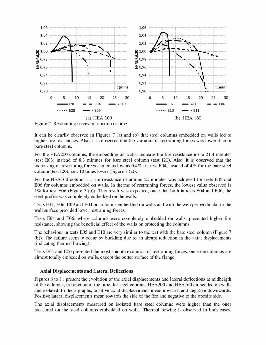
Figure 7. Restraining forces in function of time
It can be clearlly observed in Figures 7 (a) and (b) that steel columns embedded on walls led to
higher fire resistances. Also, it is observed that the variation of restraining forces was lower than in
bare steel columns.
For the HEA200 columns, the embedding on walls, increase the fire resistance up to 21.4 minutes
(test E03) instead of 8.3 minutes for bare steel column (test I20). Also, it is observed that the
increasing of restraining forces can be as low as 0.4% for test E04, instead of 4% for the bare steel
column (test I20), i.e., 10 times lower (Figure 7 (a)).
For the HEA160 columns, a fire resistance of around 20 minutes was achieved for tests E05 and
E06 for columns embedded on walls. In therms of restraining forces, the lowest value observed is
1% for test E06 (Figure 7 (b)). This result was expected, once that both in tests E04 and E06, the
steel profile was completely embedded on the walls.
Tests E11, E06, E09 and E04 on columns embedded on walls and with the web perpendicular to the
wall surface provided lower restraining forces.
Tests E04 and E06, where columns were completely embedded on walls, presented higher fire
resistance, showing the beneficial effect of the walls on protecting the columns.
The behaviour in tests E05 and E10 are very similar to the test with the bare steel column (Figure 7
(b)). The failure seem to occur by buckling due to an abrupt reduction in the axial displacements
(indicating thermal bowing).
Tests E04 and E06 presented the most smooth evolution of restraining forces, once the columns are
almost totally embeded on walls, except the outter surface of the flange.
Axial Displacements and Lateral Deflections
Figures 8 to 11 present the evolution of the axial displacements and lateral deflections at midheigth
of the columns, in function of the time, for steel columns HEA200 and HEA160 embedded on walls
and isolated. In these graphs, positive axial displacements mean upwards and negative downwards.
Positive lateral displacements mean towards the side of the fire and negative to the oposite side.
The axial displacements measured on isolated bare steel columns were higher than the ones
measured on the steel columns embedded on walls. Thermal bowing is observed in both cases,
0,90
0,92
0,94
0,96
0,98
1,00
1,02
1,04
1,06
0 5 10 15 20 25 30
N/N
bR
d,2
0
t (min)
I20 E04 E03
E08 E09
0,90
0,92
0,94
0,96
0,98
1,00
1,02
1,04
1,06
0 5 10 15 20 25 30
N/N
bR
d,2
0
t (min)
I16 E05 E06
E10 E11

characterised by a slow deflection towards the fire and afterwards a suden inversion to the oposite
side. Failure occurs due to a sudden vertical displacement acompained by a big lateral deflection.
(a) E03 (wall thicness=180mm) (b) E08 (wall thicness=140mm)
Figure 8. Axial displacements and lateral deflections for isolated and embedded on walls HEA200
steel columns - web parallel to the wall surface
In Figure 8 it can be observed that the axial displacements were practically the same in both tests
(about 5mm). The column in test E08 after reach the value of the maximum axial displacement
presented a sudden decreasing confirming a deformation by buckling. The lateral deflections
towards the side of the fire where higher for specimens with a thinner wall.
(a) E04 (wall thicness=180mm) (b) E09 (wall thicness=140mm)
Figure 9. Axial displacements and lateral deflections for isolated and embedded on walls HEA200
steel columns - web perpendicullar to the wall surface
In Figure 9 both the axial displacements and the lateral deformations were very similar in tests E04
and E09. However the axial displacements in this case were nearly a half of the ones registered on
-10
-8
-6
-4
-2
0
2
4
6
8
10
0 5 10 15 20 25
Dis
pla
cem
en
t (m
m)
t (min)
Axial Displ - I20
Lateral Deflect - I20
Axial Displ - E03
Lateral Deflect - E03
-10
-8
-6
-4
-2
0
2
4
6
8
10
0 5 10 15 20
Dis
pla
cem
en
t (m
m)
t (min)
Axial Displ - I20
Lateral Deflect - I20
Axial Displ - E08
Lateral Deflect - E08
-10
-8
-6
-4
-2
0
2
4
6
8
10
0 5 10 15 20 25 30
Dis
pla
cem
en
t (m
m)
t (min)
Axial Displ - E04
Lateral Deflect - E04
Axial Displ - I20
Lateral Deflect - I20
-10
-8
-6
-4
-2
0
2
4
6
8
10
0 5 10 15 20
Dis
pla
cem
en
t (m
m)
t (min)
Axial Displ - I20
Lateral Deflect - I20
Axial Displ - E09
Lateral Deflect - E09

columns with the web parallel to the wall surface (Figure 8). This may be justified by the mass of
steel directly exposed to the heating source.
For the case of the test E08 and E09 the inversion of the lateral deflections and the axial
deformations occurred for different instants of time showing with this some influence of the wall
thickness on the behaviour of these columns.
(a) E05 (wall thicness=140mm) (b) E10 (wall thicness=100mm)
Figure 10. Axial displacements and lateral deflections for isolated and embedded on walls HEA160
steel columns - web parallel to the wall surface
In Figure 10 the lateral deflections and the vertical displacements were similar between them.
a) E06 (wall thicness=140mm) b) E11 (wall thicness=100mm)
Figure 11. Axial displacements and lateral deflections for isolated and embedded on walls HEA160
steel columns - web perpendicullar to the wall surface
In Figure 11 the shape of the curves are very similar to the ones observed in the corresponding tests
for columns HEA200, E04 and E09. Once again the axial displacements in this case were nearly a
half of the ones registered on columns with the web parallel to the wall surface (Figure 10).
-10
-8
-6
-4
-2
0
2
4
6
8
10
0 5 10 15 20 25
Dis
pla
cem
en
t (m
m)
t (min)
Axial Displ - I16
Lateral Deflect - I16
Axial Displ - E05
Lateral Deflect - E05
-10
-8
-6
-4
-2
0
2
4
6
8
10
0 5 10 15 20
Dis
pla
cem
en
t (m
m)
t (min)
Axial Displ - I16
Lateral Deflect - I16
Axial Displ - E10
Lateral Deflect - E10
-10
-8
-6
-4
-2
0
2
4
6
8
10
0 5 10 15 20 25 30
Dis
pla
cem
en
t (m
m)
t (min)
Axial Displ - I16
Lateral Deflect - I16
Axial Displ - E06
Lateral Deflect - E06
-10
-8
-6
-4
-2
0
2
4
6
8
10
0 5 10 15 20 25 30
Dis
pla
cem
en
t (m
m)
t (min)
Axial Displ - I16
Lateral Deflect - I16
Axial Displ - E11
Lateral Deflect - E11

The inversion of lateral deflections and axial deformations, as registered in
for different instants of time showing with this some influence of the wall thickness on the
behaviour of the columns.
The specimens with columns with th
(th=140mm for HEA200 and th=100mm for HEA160), respectivelly tests
(b) and 11 (b), showed an abrupt decay of the vertical displacement
displacement reaches again the initial position. This fact may be
terms of fire resistance.
Fire Resistances
Table 3 presents the fire resistance
that the columns in contact with walls have a higher fire resistance than the ba
Furthermore, it is observed that the orientation of the web has no major influence in the
resistance. In fact, the fire resistance is
perpendicular to the wall surface but the differences are very small. The main influence is provide
by the thickness of the walls: thicker walls provided
Table 3. Fire resistance of the Test columns
HEA 160
Web
parallel
to the wall
Web
perpendicular
to the wall
Thick wall 18.8 20.2
Thin wall 16.3 9.4
COLUMNS AFTER
Figure 12 presents the deformed shape of
and (b) show HEA200 columns with the web perpendicular
with thick (th=180mm) and thin (th=100mm)
HEA160 columns with the same orientations of the web in relation to the walls, embedded
walls (th=140mm). In Figures 12 (e
HEA200 steel columns after fire.
(a)E04 HEA 200 (b)E08 HEA 200 (c
Figure 12. Columns after fire resistance tests
This study showed that steel columns
totally engulfed in fire. This means that the beneficial effect of the insulation provided by the walls
The inversion of lateral deflections and axial deformations, as registered in Figure 9, also occurred
for different instants of time showing with this some influence of the wall thickness on the
with the web perpendicular to the wall surface and
(th=140mm for HEA200 and th=100mm for HEA160), respectivelly tests E09 and E11
an abrupt decay of the vertical displacement some mi
the initial position. This fact may be considered to be favourable in
presents the fire resistance obtained in this study for the columns. The main conclusion is
that the columns in contact with walls have a higher fire resistance than the bare
observed that the orientation of the web has no major influence in the
resistance is in general slightly higher for columns with the web
but the differences are very small. The main influence is provide
e walls: thicker walls provided greater fire resistances.
est columns (minutes)
HEA 200 HEA160
bare steel
HEA200
bare steelperpendicular
to the wall
Web
parallel
to the wall
Web
perpendicular
to the wall
21.4 15.4 7.7 8.
14.9 8.7
COLUMNS AFTER FIRE RESISTANCE TESTS
Figure 12 presents the deformed shape of some columns after the fire resistance tests.
with the web perpendicular and parallel to the wall surface
thin (th=100mm) wall respectivelly. Figures 12 (c
ame orientations of the web in relation to the walls, embedded
e) and (f) are presented the deformed shape of bare
c)E06 HEA 160 (d)E05 HEA160 (e) I16 HEA160
Columns after fire resistance tests
CONCLUSIONS
steel columns embedded on walls presented higher fire resistanc
fire. This means that the beneficial effect of the insulation provided by the walls
Figure 9, also occurred
for different instants of time showing with this some influence of the wall thickness on the
e web perpendicular to the wall surface and thin wall
9 and E11, Figures 9
ome minutes after the
considered to be favourable in
The main conclusion is
re steel columns.
observed that the orientation of the web has no major influence in the fire
columns with the web
but the differences are very small. The main influence is provided
HEA200
bare steel
8.3
columns after the fire resistance tests. Figures 12 (a)
to the wall surface tested
c) and (d) show
ame orientations of the web in relation to the walls, embedded on thick
are presented the deformed shape of bare HEA160 and
(f) I20 HEA200
higher fire resistance than those
fire. This means that the beneficial effect of the insulation provided by the walls

plays a major influence over the detrimental effect of the thermal gradients developed in the column
cross-section.
In all situations under test, thermal bowing was observed, causing an inversion of lateral deflections
from the hot to the cold side of the wall. This behaviour led to a failure mode by bending, instead of
buckling. Buckling was only observed in bare steel columns.
The slenderness of the columns did not influence strongly the fire resistance, (for the tested
columns). Although, the higher was the slenderness the lower was the fire resistance.
The main parameter that influenced the behavior of the columns subjected to fire was the wall
thickness: thinner walls provided lower fire resistances.
The walls were also effective in preventing the columns with the web perpendicular to the wall
surface to fail around the minor axis. In these cases, the detrimental effect of the thermal bowing
seems to be canceled by the fact that failure is forced to occur around the strong axis. Moreover, no
local buckling was observed in the flanges due to the contact with the walls.
In experimental tests was observed some detachment of the columns in relation to the walls. This
reduces the fire resistance of the columns. The problem could be solved by welding some steel
connectors to the columns that will enhance the connection between the columns and the walls.
The fire resistance of the columns embedded on walls could also be enhanced by mounting bricks
between the flanges of the profiles.
Acknowledgement
The authors acknowledge the Portuguese Foundation for Science and Technology - FCT - MCTES
for their support.
REFERENCES
Cadorin, Jean-François (2003), Compartment Fire Models For Structural Engineering, PhD Thesis,
Faculté de Sciences Appliqués, Université de Liège.
Correia, A.M., Rodrigues J. P., Silva, V. P., (2007), Studies on the fire behavior of steel columns
embedded on walls, Proceedings of 11th
International Conference on Fire Science and Engineering
- Interflam. London. UK., 641-652.
Correia, A.M., Rodrigues J. P., Silva, V. P. (2009), Experimental Research on the Fire Behavior of
Steel Columns Embedded on Walls, Proceedings. of International Conference Applications of
Structural Fire Engineering, Prague, Czech Republic, 417-422.
Correia, A.M., Rodrigues J. P., Silva, V. P., Laim, L. (2009), Section Factor and Steel Columns
Embedded in Walls, Proceedings. of 11th
Nordic Steel Construction Conference, Malmö, Sweden.
EN1993-1-1(2005). “Design of steel structures – part 1-1: General Rules and rules for buildings”,
CEN, Brussels.
EN1993-1-2(2005). “Design of steel structures – part 1-2: General Rules – Structural fire design”, CEN, Brussels.
EN1992-1-2(1995). “Design of concrete structures – part 1-2: General Rules – Structural fire
design”, CEN, Brussels.
EN1992-1-2(1995). “Design of concrete structures – part 1-2: General Rules – Structural fire
design”, CEN, Brussels.
EN1991-1-2(2002). “Eurocode 1: Actions on structures – part 1-2: General actions – Actions on
structures exposed to fire”, CEN, Brussels.


