Embed Size (px)
Citation preview

Ž .Powder Technology 118 2001 193–202www.elsevier.comrlocaterpowtec
Particle separation from gases using cross-flow filtration
V. Sibanda a,b, R.W. Greenwood a, J.P.K. Seville a,)
a School of Chemical Engineering, The UniÕersity of Birmingham, Edgbaston, Birmingham B15 2TT, UKb Department of Chemical Engineering, National UniÕersity of Science and Technology, P.O. Box AC 939 Ascot, Bulawayo, Zimbabwe
Abstract
Most filters used in solidrgas separation are applied in the Adead-endB mode, where the aerosol particles arrive at the filter ontrajectories that are approximately perpendicular to it. This study concerns the alternative method of cross-flow filtration, which is in
w Ž . xcommon use for filtering liquids. In this mode, previously studied by Menard et al. Powder Technol. 71 1992 263 , Thomas et al.w Ž . x w Ž . xPowder Technol. 76 1993 79 and Ferrer et al. Powder Technol. 113 200 197 , some of the flow passes through the filter, depositingparticles on the surface, while some sweeps past the surface, causing shear on the deposited cake. Depending on the operating conditions,particle aggregation can occur on the surface and the resulting aggregates can be removed by the through-flow and collected in adownstream device. Laboratory scale equipment has been set up in which a cross-flow filter module is coupled to a cyclone postseparatorto separate the aggregates leaving the filter. The filters used were ceramic tubes of 6 cm outside diameter, 4 cm inside diameter and
Ž .variable lengths. An aerosol of limestone dust particles mmds5.0 mm in ambient air enters the inside of the filter along the axis; due tothe aerodynamic conditions within the filter some of the particles are deflected towards the filter and are captured. The results show thatthe cake is detached in the form of loose agglomerates rather than individual particles, which are easily collected by means of the cyclone.
Ž .The collection efficiency shown by the cross-flow filterrcyclone combination is over 99% for 5.0 mm mmd particles under optimumconditions compared to f90% shown by the stand-alone cyclone. This separation efficiency is comparable to that of a surface filter andthe pressure loss savings with this system make it an attractive gas cleaning option. q 2001 Elsevier Science B.V. All rights reserved.
Keywords: Filtration; Ceramic filter; Cyclone; Filter cake; Separation; Aggregation
1. Background
Cross-flow filtration has found considerable applicationin solidrliquid separation processes, particularly in filter-
Žing slurries and other non-Newtonian suspensions e.g.w x.Refs. 4,5,6 . In principle, the distinction between this
type of filtration and the more conventional Adead-endBfiltration is in the way the particle-laden fluid approachesthe filter membrane surface as shown in Figs. 1 and 2. Indead-end filtration, the aerosol particles arrive at the filtersurface on trajectories that are approximately perpendicu-lar to the filter and the whole challenging flow passesthrough the filter medium. This causes deposition of parti-cles either on the upstream face, i.e. surface filtration, orinside the filter in the case of depth filtration. In cross-flow
) Corresponding author. School of Chemical Engineering, Universityof Birmingham, Edgbaston, Birmingham B15 2TT, UK. Tel.: q44-121-414-5322; fax: q44-121-414-5377.
Ž .E-mail address: [email protected] J.P.K. Seville .
filtration, the principal feature is that some of the dust-ladengas sweeps past the filter surface and roughly parallel to it;only a part of the flow filters through the medium, thus
w xdepositing a cake on the surface 1,2 .When the particles enter the filter with the flow, the
aerodynamic field causes them to migrate towards thefilter medium. Those particles that are sufficiently de-flected can be deposited on the medium surface or onprecaptured particles to form a filter cake. Under certaincircumstances, that cake can then be removed by the shearforces resulting from the through-flow. In cross-flow filtra-tion, cake formation and detachment are not intermittentprocesses as in surface filtration, but rather they occursimultaneously. Under the right conditions, a dynamicequilibrium can be set up, as previously demonstrated for
w x w xgas filtration by Menard et al. 1 and Thomas et al. 2 .When that is the case, the rate of cake reentrainment isequal to the rate of particle deposition and the averagecake areal loading remains constant.
In characterising the filtration in the cross-flow mode, aŽ .dimensionless parameter called the cross-flow ratio F is
0032-5910r01r$ - see front matter q 2001 Elsevier Science B.V. All rights reserved.Ž .PII: S0032-5910 01 00311-4

( )V. Sibanda et al.rPowder Technology 118 2001 193–202194
Fig. 1. Schematic of the dead-end filtration mode.
used, defined as the ratio of the filtering flow rate to thew xtotal flow rate 1 :
QfFs . 1Ž .
QT
Since only a fraction of the total dust loading is de-posited on the filter, a secondary device is required inorder to eliminate the particles that leave the filter with thethrough-flow. A simple cyclone separator mounted down-stream of the filter has been used in this work to separatethe aggregated particles. In an industrial context, thisarrangement has several precedents in cases where two ormore gas cleaning devices have been operated in conjunc-tion with each other. Cyclones have been used extensively
Ž w x.as preseparators to rigid ceramic filters e.g. Ref. 7 , i.e.Ž .in pressurised fluidised bed combustors PFBC and inte-
Ž .grated gasification combined cycles IGCC and as presep-arators to fabric filters. There are very few cases in whichcyclones have been used as postseparation devices, as
w xproposed here. Campanile et al. 8 have proposed the useof a fluidised bed as a preagglomerator to a cyclone inremoval of diesel fumes. The same idea was exploited by
w xGhadiri et al. 9 for removal of aggregated carbon fines
using a pre agglomerating fluidised bed into which heavyoil was injected as a binding agent.
The combination of a steady-state filtration regime,possibly without need for intermittent cleaning, and theaggregation effect in the cross-flow filtration process sug-gests that this system has potential for industrial use. Ifceramic filtration materials are used, the principle could beapplied at high temperatures, as demonstrated on a small
w xscale by Ferrer et al. 3 . In this case, the removal of theneed for back-pulsing would represent considerable operat-ing advantages, particularly since many or even most filterfailures at high temperatures have been related to thermal
w xshock 10 .
2. Experimental apparatus
Filtration tests were carried out using a test rig shownschematically in Fig. 3. The apparatus was made up of a
Ž .number of components. i Dust feeder: the feeder usedwas a rotating disc type feeder with a circumferentialgroove that carries a known amount of dust material. Thedust flow rate was calculated from the mass fill of the
Fig. 2. Schematic of the cross-flow filtration mode.

( )V. Sibanda et al.rPowder Technology 118 2001 193–202 195
Fig. 3. Schematic of the experimental facility.
groove and the rotation speed of the disc. Positive pressurefeeding, using compressed air, was preferred to suction asit improves the dispersion of the feed particles. The localfeeding environment was also heated to ensure that theparticles were entrained at constant relative humidity of
Ž .f15%. ii The cross-flow module: the cross-flow filterŽused was a cylindrical ceramic element Madison Filter
.Group, Haslingden, UK formed from bonded aluminosili-cate fibres, with an interfibre voidage of 0.85, internaldiameter of 4 cm and external diameter of 6 cm. In theexperiments, the filter length was varied, as described
Ž .below. Limestone dust Omya, Dorking, UK with a massmedian diameter of 5.0 mm was used as the feed material.
The total gas flow rate in these experiments was fixedat 90 lrmin corresponding to a superficial velocity of 6.0cmrs under dead-end conditions for a 200-mm-long filter.The proportions of the filtering and the axial flows wereregulated via a series of in-line and by-pass valves asillustrated in Fig. 3.
The filtration conditions were, therefore, similar to thosew x w xemployed by Menard et al. 1 , Thomas et al. 2 and Ferrer
w xet al. 3 , except that the through-flow velocity in thepresent work was one to two orders of magnitude less thanin their case. Clearly, the selection of the filter tubedimensions and the cross-flow ratio are important factorsin determining the overall economics of an industrial filter.
The filter outflow was directed to a cyclone separatorŽ w x .high efficiencyrmedium throughput Stairmand 7 design .
Ž . ŽA high efficiency particulate air HEPA filter Gelman.Sciences, Northampton, UK was incorporated into the
circuit downstream of the cyclone to collect the finesleaving the cyclone. This is effectively an absolute filter
for this aerosol size and was used to close the materialbalance. The HEPA filter could be loaded for over an hourduring the experiments without alteration in the pressuredrop. This was essential in order not to disturb the overallpressure balance of the system.
This paper discusses two methods that have been usedto evaluate the extent of particle aggregation during simul-taneous filtration and detachment of the cake. In the firstmethod, a single-stage cyclone is used, as described above,to separate the particles leaving the filter; in the secondmethod, scanning electron microscopy has been used toview aggregates which have been separated by isokineticsampling.
In the sampling experiments, the sampler was posi-tioned between the filter and the cyclone. Since the pri-mary particles used in the tests are approximately 5 mm inmass mean diameter, they are considered to have sufficientinertia that isokinetic sampling is necessary. The filtermembranes used were 40-mm-diameter polycarbonate mi-
Ž .cro-pore filter coupons Sartorius, Epsom, UK with poresizes of about 0.2 mm. A polypropylene in-line filterholder was used to support the membrane. A sample of gaswas extracted for 10 s through a 15-mm-diameter probelocated on the axis of the sampling unit.
3. Material balance
Let M be the total mass of particles entering the filter.T
An amount M is collected on the filter, an amount M isf c
collected in the cyclone and M is lost with the gas flowe

( )V. Sibanda et al.rPowder Technology 118 2001 193–202196
leaving the cyclone. Since the ceramic filter is effectivelyabsolute for this aerosol, the mass lost with gas passingthrough the filter is zero:
M sM qM qM . 2Ž .T f c e
The overall efficiency of the cyclone is then:
Mch s =100%, 3Ž .c M yMT f
while the overall efficiency of the cross-flow filter pluscyclone combination is:
M qMc fh s =100%. 4Ž .fc MT
4. Results and discussion
4.1. EÕolution of the pressure drop during cake formation
An experiment similar to that described by Menard etw xal. 1 was performed to determine the evolution of the
pressure drop across the filter cake during cross-flowfiltration. This was done by continuously logging the
Ž .pressure drop DP between the dirty side and the clean1
side of the filter medium against filtration time. TheŽ .cross-flow ratios F used in these experiments were 0.1,
0.2, 0.3, 0.5, 0.6, and 1. Fig. 4 shows the results obtained.It can be seen that at lower filtration rates, i.e. Fs0.1, 0.2and 0.3, there is a tendency to reach a steady state. Atsteady state, the pressure drop across the cake, obtained bysubtracting the clean medium pressure drop from DP ,1
becomes independent of time, indicating that the transientfilter cake has reached a limiting thickness. This phe-
w xnomenon was observed by Menard et al. 1 at Fs0.15.At Fs0.5 to 1, there is a transition to a case where asteady state is not achievable. It may be concluded that athigher values of F , the through-flow is insufficient toremove the cake from the filter surface. In this case, therate of pressure drop increase with time continues to grow,
Fig. 4. Evolution of pressure drop during cake buildup.
Table 1Baseline efficiencies of the cyclones
Ž . Ž .Cyclone number i F h %b
1 0.1 912 0.2 923 0.3 904 0.4 88.55 0.5 896 0.6 90
because of the progressive reduction in surface area as thecake is deposited on the inside of the cylindrical filter.This is not the only effect, however. The increased pres-sure difference also causes densification of the cake, accel-
w xerating the increase further 11 .
4.2. Cyclone baseline efficiencies
The purpose of this work was to measure the perfor-mance of the cross-flow filter over a range of values of thecross-flow ratio, F . It was, therefore, necessary to use adownstream cyclone of constant efficiency. Since the gasflows to the cyclone vary with F , a set of cyclones of thesame efficiency at different throughputs was constructed.These were based on Stairmand’s high-efficiency,
w xmedium-throughput design 7 and were fabricated to cor-respond to the exit flow rate at each of the experimentalconditions. The inlet velocity to each of the six cycloneswas fixed at 15 mrs, and the efficiencies of each of thecyclones, referred to here as baseline efficiencies, h , wereb
determined. This was done by feeding the aerosol directlyinto the cyclone without first passing through the filter.
It was taken into account that at each value of F , aŽ .different amount of dust M is delivered to the filter.f
Preliminary runs were performed to determine M and thef
difference between M and M at each F was divided byT f
the axial volumetric flow rate to get the average concentra-tions for base line efficiency calculations:
M yMŽ .T f FC s , 5Ž .F Q yQŽ .T f F
Ž 3.where C is the dust concentration at F kgrm .F
Table 1 gives the measured baseline efficiencies, h , ofb
the six different cyclones used at the different experimen-tal cross-flow ratios. The weights of the cyclone and theHEPA filter were measured after a 30-min experiment and
Ž .Eq. 3 used to calculate the efficiency.The results confirm that the six different cyclones had
effectively the same overall efficiencies at the differentoperating throughputs.
4.3. Effect of the filter on cyclone efficiency
In the first experiments of this series, a 200-mm-longfilter tube was introduced upstream of the cyclone as

( )V. Sibanda et al.rPowder Technology 118 2001 193–202 197
depicted in Fig. 3. This system was then used to filter theaerosol of constant concentration of 9.8 grm3 for a dura-tion of 30 min at each of the cross-flow filtration ratios. Atthe end of each experiment, the masses of the dust thataccumulated on the filter, in the cyclone and in the HEPAfilter were measured and the new overall cyclone effi-
Ž .ciency was calculated using Eq. 5 . Fig. 5 compares theefficiency of the cyclones with the filter on-line with thebaseline efficiencies. The results show a clear increase inthe cyclone efficiency with the filter in the system at allthe cross-flow filtration ratios. These observations suggestthat an increase in the number concentration of largerparticles occurs, causing an increase in the cyclone effi-ciency. The overall efficiency as a function of the cross-flow filtration ratio, increases to a maximum and thendeclines. The peak, according to Fig. 5, occurs at Ff0.35.
The same set of experiments was repeated using a newfilter length of 400 mm, corresponding to twice the filtra-tion surface area. The filtration and the axial flow rateswere kept at the same values as before. The results of theoverall cyclone efficiency, with this filter on line, arecompared with the baseline efficiency at each rate inFig. 6.
The same trend emerges, showing firstly an increase inthe efficiency with the addition of a filter and secondly amaximum efficiency. This maximum has shifted fromFs0.35 with the 200-mm filter to Fs0.6 with the
Ž .400-mm filter. The face velocity Q rA using the 400-mmf
filter is half of that using the 200-mm filter at a givenvalue of F ; however, the through-flow velocity remainsthe same. As a result, the local conditions at any F usingthe 200-mm filter are the same as those at 2F using the400-mm filter.
Fig. 7 compares the effect of the filter length directly,and it can be seen that the longer filter results in furtherenhancement of aggregation. This result is not surprising
ŽFig. 6. Effect of a cross-flow filter on overall cyclone efficiency 400-.mm-long filter . Experimental duration: 30 min.
because increasing the length of the filter increases theresidence time of particles in the filter environment andthis is likely to promote more particle–particle interactionsthat lead to more aggregation.
In practice, the overall efficiency of the gas cleaningtrain, which in this case is the combined efficiency of thefilter and the cyclone, is of most importance, and this
Ž .efficiency is calculated using Eq. 6 . Fig. 8 compares thefilterrcyclone system efficiency with the cyclone effi-ciency when a 400-mm-long filter is used. It can beobserved that efficiencies of over 99% can be achieved bythe combination.
4.4. Dependency of aggregate size on the cross-flow ratio
Sampling of the material leaving the filter was initiatedafter the filter cake had reached an areal loading of f500grm2. However, at Fs0.1, the limiting cake thickness
2 Ž 2 .was found to be far less than 500 grm f260 grm
Ž .Fig. 5. Effect of a cross-flow filter on overall cyclone efficiency 200-mm-long filter . Experimental duration: 30 min.

( )V. Sibanda et al.rPowder Technology 118 2001 193–202198
Fig. 7. Effect of filter length on aggregation.
and this was therefore used as the sampling point. A fewresults selected from the scanning electron microscopy
Ž . Ž .analysis are shown in Fig. 9 a–d . Fig. 9 a shows theŽ .SEM of the feedrprimary particles, Fig. 9 b–d are sam-
ples collected at Fs0.1, 0.3 and 0.6, respectively. Thefeed particles appear discrete and they show a range of
Ž .sizes which is as expected. In Fig. 9 b , particles areŽ .clearly becoming less discrete and Fig. 9 c shows parti-
Ž .cles in strongly agglomerated form. In Fig. 9 d , particlesappear to have become more discrete again though theyare certainly larger than those shown in the feed SEM.
ŽConsidering the whole range of SEMs some not.shown , it can be seen that the intensity of aggregation
increases with an increase in the cross-flow ratio up toapproximately Fs0.3, which coincides with the point ofmaximum efficiency in Fig. 5. For cross-flow ratios higherthan that the particles become less agglomerated and larger.
The reason that less aggregation is observed at lowvalues of F may be that the filtration flow is not sufficient
Fig. 8. Comparison of the system efficiency with the cyclone efficiencyfor a 400-mm-long filter.
to compact the cake while the axial flow is too high andcauses redispersion. At high values of F , the cake strengthis higher due to the compression effect of the high filtra-tion flow, while the through-flow is insufficient to removethe cake from the filter surface. The particles that aresampled could represent those that might have had noopportunity to enter the filter cake because of their highinertia; hence, they appear larger and as discrete as theprimary particles. The following section discusses resultsobtained from the analysis of the relationship between thecake strength and the shear stress at each experimentalcondition.
4.5. Critical shear strength of the cake
The efficiency of the cyclone shows a maximum atconditions that give the Abest aggregationB. The relation-ship between the aggregate size and the cross-flow ratiowill depend on the interplay between the cake strength,which depends on the face velocity at which the cake wasformed, and the shear stresses that the axial flow exerts onthe cake. Experiments were performed to measure thecritical shear strength of the cakes formed at three different
Ž .conditions of F 0.1, 0.3 and 0.6 . The experimentalscheme involved building up a cake at each condition up
Ž . 2to an areal loading cake mass per unit area of 500 grmand stopping the supply of the dust. The axial velocity wasreduced to 10 cmrs and a stable pressure drop wasrecorded. The cake was then subjected to successive incre-
Žmental changes in the through-flow velocity with no.filtration and after each increase a stable cake pressure
loss reading was taken.w xFrom elementary fluid flow in pipes 12 , the shear
Ž .stress t is given as:
ts f=1r2rV 2 , 6Ž .

( )V. Sibanda et al.rPowder Technology 118 2001 193–202 199
Ž . Ž . Ž .Fig. 9. Scanning electron micrographs of a particles of the feed material; b particles leaving the filter during filtration at Fs0.1; c particles leavingŽ .the filter during filtration at Fs0.3; d particles leaving the filter during filtration at Fs0.6.
where f is the wall friction factor and V is the gasvelocity.
The friction factor depends on the roughness of thefilter cake surface, which varies with time, making it
Fig. 10. Shear resistance of filter cake formed at Fs0.6.

( )V. Sibanda et al.rPowder Technology 118 2001 193–202200
Fig. 11. Shear resistance of filter cake formed at Fs0.3.
difficult to determine. Assuming that the cake surface issmooth, and taking into account that the through-flowReynolds number for the filter in pipe-flow is alwaysgreater than 2000, f could be estimated from the Blasius
w xcorrelation 1–3 :
fs0.079Rey0 .25 . 7Ž .Ž . Ž . Ž .Combining Eqs. 6 and 7 , the shear stress t , acting
on the filter cake is given by:
0.316r 0.75V 1.75m0.25t
ts , 8Ž .0.258 D
where r is the gas density, V is the axial flow velocity, mt
is the gas viscosity and D is the free-flow diameter of thefilter. The free-flow diameter takes into account the cakethickness.
Figs. 10–12 show the pressure drop across the cakeafter every increase in the axial velocity, plotted against
Ž .the corresponding shear stress, calculated from Eq. 8 .The regions where the pressure drop is constant represent astable filter cake. It might be expected that cake reentrain-ment would commence at a critical shear stress, resultingin a decrease in the measured pressure drop across thecake. However, the opposite is the case: at a critical shearstress, the gradient changes such that the pressure differ-ence across the cake increases with each increment inshear stress. This can only correspond to rearrangement ofthe cake to decrease its void fraction. Nevertheless, thepoint of marked change of gradient represents the criticalshear strength of the cake. This was confirmed visually byobserving the gas flow leaving the filter through thetransparent glass channel connecting the filter to the cy-
Fig. 12. Shear resistance of filter cake formed at Fs0.1.
( )V. Sibanda et al.rPowder Technology 118 2001 193–202 201
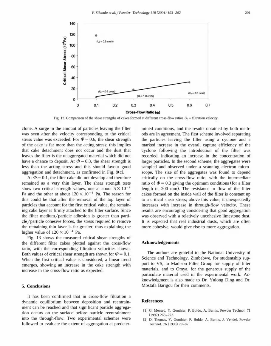
Fig. 13. Comparison of the shear strengths of cakes formed at different cross-flow ratios U s filtration velocity.f
clone. A surge in the amount of particles leaving the filterwas seen after the velocity corresponding to the criticalstress value was exceeded. For Fs0.6, the shear strengthof the cake is far more than the acting stress; this impliesthat cake detachment does not occur and the dust thatleaves the filter is the unaggregated material which did nothave a chance to deposit. At Fs0.3, the shear strength isless than the acting stress and this should favour good
Ž .aggregation and detachment, as confirmed in Fig. 9 c .At Fs0.1, the filter cake did not develop and therefore
remained as a very thin layer. The shear strength testsshow two critical strength values, one at about 5=10y4
Pa and the other at about 120=10y4 Pa. The reason forthis could be that after the removal of the top layer ofparticles that account for the first critical value, the remain-ing cake layer is firmly attached to the filter surface. Sincethe filter mediumrparticle adhesion is greater than parti-clerparticle cohesive forces, the stress required to removethe remaining thin layer is far greater, thus explaining thehigher value of 120=10y4 Pa.
Fig. 13 shows the measured critical shear strengths ofthe different filter cakes plotted against the cross-flowratio, with the corresponding filtration velocities shown.Both values of critical shear strength are shown forFs0.1.When the first critical value is considered, a linear trendemerges, showing an increase in the cake strength withincrease in the cross-flow ratio as expected.
5. Conclusions
It has been confirmed that in cross-flow filtration adynamic equilibrium between deposition and reentrain-ment can be reached and that significant particle aggrega-tion occurs on the surface before particle reentrainmentinto the through-flow. Two experimental schemes werefollowed to evaluate the extent of aggregation at predeter-
mined conditions, and the results obtained by both meth-ods are in agreement. The first scheme involved separatingthe particles leaving the filter using a cyclone and amarked increase in the overall capture efficiency of thecyclone following the introduction of the filter wasrecorded, indicating an increase in the concentration oflarger particles. In the second scheme, the aggregates weresampled and observed under a scanning electron micro-scope. The size of the aggregates was found to dependcritically on the cross-flow ratio, with the intermediate
Žratio of Fs0.3 giving the optimum conditions for a filter.length of 200 mm . The resistance to flow of the filter
cakes formed on the inside wall of the filter is constant upto a critical shear stress; above this value, it unexpectedlyincreases with increase in through-flow velocity. Theseresults are encouraging considering that good aggregationwas observed with a relatively uncohesive limestone dust.It is expected that real industrial dusts, which are oftenmore cohesive, would give rise to more aggregation.
Acknowledgements
The authors are grateful to the National University ofScience and Technology, Zimbabwe, for studentship sup-port to VS, to Madison Filter Group for supply of filtermaterials, and to Omya, for the generous supply of theparticulate material used in the experimental work. Ac-knowledgment is also made to Dr. Yulong Ding and Dr.Mostafa Barigou for their comments.
References
w x1 G. Menard, Y. Gonthier, P. Boldo, A. Bernis, Powder Technol. 71Ž .1992 263–272.
w x2 D. Thomas, Y. Gonthier, P. Boldo, A. Bernis, J. Vendel, PowderŽ .Technol. 76 1993 79–87.

( )V. Sibanda et al.rPowder Technology 118 2001 193–202202
w x3 Y. Ferrer, J.C. Templier, Y. Gonthier, A. Bernis, Powder Technol.Ž .113 2000 197–204.
w x4 R.G. Holdich, I.W. Cumming, B. Ismail, Trans. Inst. Chem. Eng.,Ž .Part A 73 1995 20–25.
w x5 I.W. Cumming, R.G. Holdich, B. Ismail, IChemE Jubilee Res. EventŽ .1 1997 377–380.
w x Ž .6 J.Q. Marchant, R.J. Wakeman, IChemE Jubilee Res. Event 2 19971061–1064.
w x Ž .7 R. Clift, in: J.P.K. Seville Ed. , Gas Cleaning in DemandingApplications, KluwerrBlackie, Amsterdam, 1997, 41, et seq.
w x8 A. Campanile, G.M. Carlomagno, A. de Vita, G. Donsi, A. Scog-namiglio, L. Massimila, U.S. Patent 4,340,400, 1982.
w x9 M. Ghadiri, J.P.K. Seville, R. Clift, Trans. Inst. Chem. Eng., Part AŽ .71 1993 371–381.
w x Ž .10 M.A. Alvin, T.E. Lippert, J.E. Lane, Ceram. Bull. 70 1991 1491.w x11 V. Sibanda, R.W. Greenwood, J.P.K. Seville, World Filtration
Congress 8, Brighton, UK, 2000, pp. 249–252.w x12 J.M. Coulson, J.F. Richardson, 3rd edn., Chemical Engineering, vol.
1, 1977, p. 42.


