Embed Size (px)
Citation preview
UNIVERSITY OF CALIFORNIA RIVERSIDE
Experimental Studies on Dehydration Embrittlement of Serpentinized Peridotite and Effect of
Pressure on Creep of Olivine
A Dissertation submitted in partial satisfaction of the requirements for the degree of
Doctor of Philosophy
in
Geological Sciences
by
Gang Xia
March 2013
Dissertation Committee: Dr. Harry W. Green, II, Chairperson Dr. Larissa Dobrzhinetskaya Dr. David D. Oglesby

Copyright by Gang Xia
2013
The Dissertation of Gang Xia is approved:
____________________________________________________________
____________________________________________________________
____________________________________________________________ Committee Chairperson
University of California, Riverside
ACKNOWLEDGEMENT
There are many individuals whom I must deeply thank for. First and foremost, I'd
like to thank my adviser, Harry Green, for providing such a precious study opportunity to
me. He has been a great mentor guiding me through this work and giving me the most
important help for the completion of this dissertation. His instruction, patience, trust
and encouragement during the last 5 years set me a great model of a knowledgeable and
brilliant scientist.
I'd like to acknowledge numerous good advices and generous help from Junfeng
Zhang and Larissa Dobrzhinetskaya, not only on my scientific research, but also on my
life activities. Specially thanks to Junfeng Zhang and Yongfeng Wang for instructing me
the procedure of Griggs-apparatus experimentation and post-experiment analysis,
Krassimir Bozhilov and Stephen McDaniel for teaching me the art of electron microscopy,
Feng Shi and Wenlong Liu for their help in FTIR analysis. I am indebted to Liang Liu,
Danling Chen, Leping Yue and Jinglan Luo, this story would not have been possible
without their support and understanding.
I am very grateful to David LeFay, Jeff Lefler, Daniel Adams and Michael Fournier for
making parts for experimental sample assemblies, welding platinum capsules, and
iv
maintaining the apparatus. Appreciation should also be given to John Herring, Jennifer
Reising, Sheila Mabee, Louise DeHayes and Melody Powell, without their assistance this
work would take much longer time to be accomplished.
I'd like to appreciate the generous financial support of the US National Science
Foundation (Grant No. EAR#1015246 and EAR#1247951 to H. W. Green), which provide
research funding for this work. I'd also like to acknowledge the generous fellowship
provided by the Department of Earth Sciences at the University of California, Riverside
through my graduate studies.
Saving the best for last, I'd especially like to thank my family, my father Ruiting Xia,
my mother Suqin Wu, and my wife Miaomiao Luo, who always support and encourage
me, especially during those discouraging periods. Without their love, I could never have
made it.
v
ABSTRACT OF THE DISSERTATION
Experimental Studies on Dehydration Embrittlement of Serpentinized Peridotite and the Effect of
Pressure on Creep of Olivine
by
Gang Xia
Doctor of Philosophy, Graduate Program in Earth Sciences University of California, Riverside, March 2013
Dr. Harry W. Green, II, Chairperson
The origin of intermediate depth earthquakes has been debated for 90 years yet
is still under active discussion. These earthquakes are localized in double seismic zones in
descending lithosphere; both zones originate very close to oceanic trenches. A leading
proposed initiation mechanism for these earthquakes since 1968 has been dehydration
embrittlement of serpentine under stress. Despite the considerable evidence favoring
this mechanism, a major argument against it has been that the lower seismic zone
initiates at ~40 km depth almost immediately below trenches and there does not appear
to be a vehicle to carry water sufficiently deep to hydrate otherwise dry lithosphere. To
directly address this problem, an experimental study has been carried out to investigate
the minimum amount of serpentine that is required to trigger the dehydration
embrittlement instability in serpentinized peridotite at high pressure (1-3 GPa) and
temperature (720-750˚C). The results show that embrittlement occurs during
vi
dehydration of antigorite (the phase of serpentine stable at elevated pressure) in a wide
range of compositions but both nearly dry peridotite and extensively altered peridotite
are ductile. Fresh, unaltered, synthetic harzburgite and harzburgite with 4 vol%
distributed antigorite are ductile, as are specimens with greater than 65% antigorite.
Only compositions between 8 vol% and 65 vol% antigorite develop the instability. We
suggest that very small degrees of serpentinization do not release sufficient H2O to
trigger the instability and that extensive serpentinization avoids the instability because
soft, ductile, antigorite becomes the interconnected matrix with olivine and pyroxene
existing only as isolated crystals. In that case, dehydration simply facilitates flow.
These systematics suggest that small amounts of H2O transported down deep
normal (bending) faults at trenches are sufficient to enable the instability in the lower
seismic zones, thus providing additional support for dehydration embrittlement as the
mechanism of intermediate-depth earthquakes. At the other end of the spectrum of
serpentinization, these results are consistent with previous suggestions that extensive
dehydration of altered subducting crust and mantle release copious amounts of H2O that
rise to the surface of the descending slab and react with the cool mantle of the overlying
plate to lead to extensive serpentinization, thereby explaining serpentine diapers in the
forearc and lack of seismicity along the plate interface deeper than about 35km.
vii
Another long-lived controversy in mantle geophysics involves the pressure
dependence of creep in olivine, the most abundant and softest phase in unaltered
mantle rocks. The pressure dependence of any thermodynamically-controlled
phenomenon is commonly expressed as the activation volume, ∆V*. Previous
experimental investigations on the effect of pressure on creep in olivine have produced
bimodal results. ΔV* obtained from solid-medium (Griggs) and gas-medium (Paterson)
deformation apparatus at relatively lower pressures is ~15 cm3/mol or higher. In contrast,
higher-pressure studies using multianvil apparatus at sites of synchrotron X-radiation
(D-DIA apparatus) report a ΔV* near zero. To decipher this enigma and to provide a
much-needed calibration of stress in the D-DIA apparatus, I have conducted systematic
experiments on a synthetic, iron-free, forsterite at 1200 ˚C and pressure between 1 and
2.5 GPa using the UCR 5 GPa modified Griggs apparatus, the only apparatus capable of
performing these experiments. Our results show a robust ΔV* value of 12 ± 2 cm3/mol,
indicating a fairly significant pressure dependence of creep in olivine to pressures of
~3GPa (approximately 100 km). In collaboration with other experimentalists, we plan to
measure the ΔV* for creep of this material over a pressure range of 2-8GPa in the D-DIA
apparatus to both calibrate stress measurement in the D-DIA and resolve the question of
change in ∆V* at higher pressures.
viii
Table of Contents
LIST OF FIGURES XI
LIST OF TABLES XIII
CHAPTER 1
GENERAL INTRODUCTION 1
1.1 STRUCTURE OF THE DISSERTATION 2 1.2 GOAL OF THE DISSERTATION 4 1.3 GEOPHYSICAL SIGNIFICANCE OF SERPENTINE IN SUBDUCTIONSYSTEMS 5 1.4 GEOLOGICAL IMPORTANCE OF OLIVINE IN UPPER MANTLE 9 1.5 METHOD OF INVESTIGATION 14
CHAPTER 2
COMPOSITIONAL DEPENDENCE OF DEHYDRATION EMBRITTLEMENT IN SERPENTINIZED PERIDOTITE 26
2.1 ABSTRACT 27 2.2 INTRODUCTION 29 2.3 STARTING MATERIALS AND METHODS 39 2.4 RESULTS AND DISCUSSION 45 2.5 CONCLUSION 68 2.3 GEOPHYSICAL IMPLICATIONS 69 2.3 FUTURE PERSPECTIVES 71
CHAPTER 3
EFFECT OF PRESSURE ON CREEP OF OLIVINE 72
3.1 ABSTRACT 73 3.2 INTRODUCTION 74 3.3 MOTIVATION OF THIS STUDY 78 3.4 STARTING MATERIALS AND EXPERIEMTNAL DESCRIPTION 81 3.5 RESULTS AND DISCUSSION 84 3.6 CONCLUSION 98 3.7 FUTURE PERSPECTIVES 101
ix
CHAPTER 4
CONCLUSIONS AND FUTURE WORK 103
4.1 SERPENTINE DEHYDRATION EMBRITTLEMENT 104 4.2 ΔV* IN CREEP OF OLIVINE 106
REFERENCES 109
x
List of Figures
Page
Fig. 1.1 Photograph of Rig-2 Griggs apparatus 16
Fig. 1.2 Photograph of Rig-3 Griggs apparatus 17
Fig. 1.3 Schematic drawing of Rig-3 Griggs apparatus 18
Fig. 1.4 Schematic drawing of high pressure sample assembly 22 for Griggs apparatus
Fig. 1.5 Photograph of Scanning electron microscope (SEM) 24
Fig. 1.6 Photograph of Transmission electron micoscope (TEM) 25
Fig. 2.1 Globally averaged number of earthquakes per year as a function of depth (after Frohlich, 1989) 30
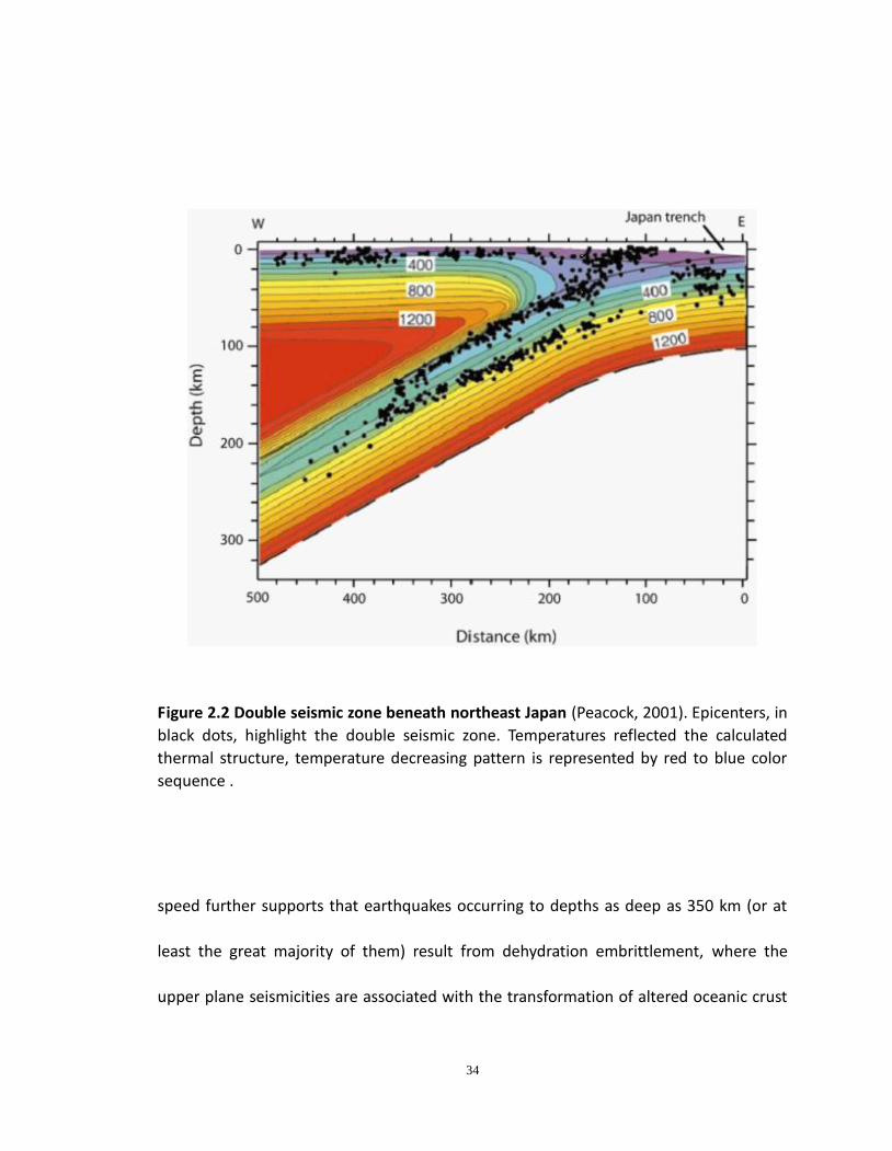
Fig. 2.2 Double seismic zone beneath northeast Japan (Peacock, 2001) 34
Fig. 2.3 Phase diagram for antigorite dehydration reactions 38 (after Ulmer and Trommsdorff, 1995)
Fig. 2.4 SEM(BSE) Images of Starting materials 40
Fig. 2.5 Two types of specimen configurations 41
Fig. 2.6 Stress versus strain plot 47
Fig. 2.7 SEM (BSE) images of GL844 50
Fig. 2.8 Continued SEM (BSE) images of GL844 51
Fig. 2.9 SEM (BSE) images of GL840 52
xi
Fig. 2.10 Continued SEM (BSE) images of GL840 53
Fig. 2.11 SEM (BSE) image of GL870 55
Fig. 2.12 TEM foil cut through focused ion beam (FIB) 56
Fig. 2.13 High resolution images of fault zone contents 58
Fig. 2.14 SEM (BSE) images of faulting in GB476 60
Fig. 2.15 SEM (BSE) images of GB513 61
Fig. 2.16 SEM (BSE) images of microcracks and fluid inclusion (bubble) trails in 63 dehydrated material
Fig. 2.17 SEM (BSE) images of ductile harzburgite specimens 64
Fig. 2.18 SEM (BSE) image of GL495 65
Fig. 2.19 SEM (BSE) images of faulted experiment GB493 67
Fig. 3.1 Initial Stress/Ln stress versus pressure plots 86
Fig. 3.2 Stress drop before getting to steady state 87
Fig. 3.3 SEM images of high angle and cataclastic zones in specimens cracks 88
Fig. 3.4 Typical differential stress versus displacements curves 92
Fig. 3.5 Stress versus strain plot at a strain rate of 10-4/s 93
Fig. 3.6 Stress/Ln stress versus pressure plot at a strain rate of 10-4/s 94
Fig. 3.8 Stress versus strain plot of experiments at a strain rate of 10-5/s 96
Fig. 3.9 Stress/Ln Stress versus pressure plot at a strain rate of 10-5/s 97
xii
List of Tables
Page
Table 2.1 Composition of Starting materials used in experiments 42
Table 2.2 Experimental conditions and mechanical results 46
Table 3.1 Selected results from previous studies 79
Table 3.2 A summary of experimental condition and mechanical results 84
xiii

Chapter 1.
General Introduction
1
1.1 Structure of this dissertation
In this dissertation, I present the results from my experimental studies on two
major projects:
(i) Compositional dependence of dehydration embrittlement in serpentinized Peridotite;
(ii) Pressure dependence of creep in olivine and its importance for measurement of
upper mantle rheology.
In chapter 1, I present the geophysical settings and significances of olivine as well as
serpentine, the two major minerals used in my studies. I also present the method of
experimental investigation, including the description of apparatus, sample assembly and
analytical techniques.
Chapter 2 provides a detailed description of the quantitative experimental study of
dehydration embrittlement in serpentinized peridotite. I present an experimental
investigation that covers a wide range of serpentinization, ranging from 4 vol% antigorite
to ~75 vol% antigorite. Using two different starting material configurations, I show that
at 1GPa, the serpentine dehydration-induced faulting instability is encountered between
8 vol% antigorite and 75 vol% antigorite. At 4 vol%, there is too little water being
released to induce instability; at the other end, when serpentine, the weaker phase, is
2
the dominant mineral and becomes the interconnected framework in the whole
specimen, the sample deforms plastically and faulting instability is absent.
Chapter 3 of this dissertation focuses on the measurement of activation volume of
olivine, ΔV*, which reflects the effect of pressure on the creep in olivine. I show that
there is a great discrepancy between the ΔV* results measured from low pressure (<~2
GPa) to high pressure (>~ 5 GPa). Examination of experimental details suggests that the
results from high pressure studies may very likely suffer from their small grain-size
and/or inaccurate stress derivation. Small grain-size, less than ~10 μm, will favor grain
boundary sliding rather than generation and movement of dislocations, and inaccurate
stress derivation may lead to an erroneous ΔV* value. Using the 5 GPa modified Griggs
deformation apparatus with the molten salt assembly, we have obtained a robust and
constant ΔV* value of 12 ± 2 cm3/mol between 0.4GPa and 3 GPa for iron-free forsterite
in the dislocation creep field. Although beyond the scope of this dissertation due to
technical barriers, our overall intention is to use the same material to measure the ΔV*
for creep of olivine in additional experiments at higher pressures in the D-DIA apparatus
using in situ experiments at synchrotron X-ray sources. Arrangements are in place to
complete these experiments in collaboration with others. The result should enable
resolution of the disagreements about ∆V* of creep and simultaneously will provide an
3
important calibration standard for a wide variety of studies at elevated pressure using
the D-DIA apparatus.
In chapter 4, I summarize the relevant works presented as well as the potential
directions that experimentalists may take to move this subject forward in the future.
1.2 Goal of this dissertation
Two active debates in the scientific community relevant to the rheology of the
upper mantle of Earth are:
(1) What are the fundamental physical processes underlying dehydration
embrittlement of serpentinized peridotite and is this the mechanism of
intermediate-focus earthquakes?
(2) What is the pressure dependence of creep in olivine and does it change with
pressure?
My experimental studies are designed to place quantitative constraints on these debates
as follows:
(i) Determine the minimum amount of serpentine required to produce faulting
during its dehydration and the implications of that result for subduction zone
Earthquakes.
4
(ii) Measure the ΔV* value for creep in iron-free forsterite below 3 GPa and provide
a calibration standard for stress measurement in the D-DIA apparatus.
(iii) To test how much serpentine, at maximum, can still trigger the instability.
The first two goals were designed at the inception of my PhD study; the last one
was picked up adventitiously during my work on the first goal.
1.3 Geophysical Significance of Serpentine in Subduction Systems
Serpentinite, the official state rock of California, forms at the expense of hydration
of peridotite which is the major constituent of Earth's upper mantle. Serpentinite is
considered to be of salient importance for a variety of tectonic phenomena, including
intermediate-depth earthquakes (e.g. Peacock, 2001; Dobson et al., 2002; Hacker et al.,
2003; Jung et al., 2004), serpentinization of the forearc mantle wedge (e.g. Hyndman
and Peacock, 2003; Rüpke et al., 2004), water recycling into the deep mantle (e.g.
Thompson, 1992; Kawakatsu and Wadata, 2007) or not (Green et al., 2010; Kawakatsu
and Yoshioka, 2011) and seismic anisotropy in the subduction systems (e.g. Long and
Silver, 2008; Manuele et al., 2008; Katayama et al., 2009).
Serpentine has been under active study for over half a century since Gutenberg and
Richter (1954) defined the intermediate-depth earthquakes as those occurred between ~
70 to ~ 300 km depth range. Earthquakes in this depth range have been noted to define
5
two planes of seismicity in many subduction zones. Brudzinski et al. (2007) showed that
all subduction zones show such double seismic zones and that the separation can vary
between 15-40 km, depending on the age and rate of the subducting plate. Seismic
studies have shown a strong correlation between seismicity and corresponding hydrous
phases (e.g. Zhang H et al. 2004). Upper plane seismicity at shallow depths is associated
with dehydration of altered oceanic crust whereas the lower plane seismicity, lying
within the subducting mantle lithosphere, spatially corresponds to the location where
dehydration of antigorite is to be expected (Peacock, 2001; Hacker et al., 2003; Yamasaki
and Seno, 2003; Jung et al., 2004). Although another mechanism, shear heating
instability, has been proposed to explain intermediate-depth earthquakes, dehydration
embrittlement of serpentinite, regarding both geophysical and experimental evidence,
remains the most viable mechanism for earthquakes at intermediate depth. The biggest
concern currently is the level of hydration in the subducting mantle lithosphere. Seismic
reflection study has shown that sea water can percolate along normal faults, which
formed at the outer rise regions, to ~20 km depth (Ranero et al., 2003), but how and/or
how much water can penetrate down over 40 km deep to hydrate the mantle where the
lower plane of seismicity initiates is still enigmatic and awaits deciphering.
Serpentinization of the forearc mantle wedge, resulting from hydrothermal
alteration of peridotite, was first proposed by Fyfe and McBirney (1975). As the backarc
6
is usually too hot (> 800 ˚C) for hydrous phases to be stable, the forearc mantle, adjacent
to the subducting oceanic crust, is a cool location (400 ~ 600 ˚C) where hydrous phases,
e.g. serpentine, can be stable (Bostock et al., 2002; Hyndman and Peacock, 2003).
Seismic tomographic studies showed low velocity and high Poisson's ratio regions in the
forearc mantle (Kamiya and Kobayashi, 2000; Bostock et al., 2002; DeShon, 2004; Seno,
2005), indicating extensive serpentinization of forearc mantle (serpentine has unusual
low seismic wave velocity -- Vp=5.5 km/s, Vs=2.6 km/s -- and remarkable high Poisson's
ratio, 0.5 compared with 0.25 for ambient peridotite) (Christenson, 1996). Commonly
observed serpentinite diapirs in the forearc provide strong evidence that the forearc
mantle is partially serpentinized (Fryer, 1995). The aseismic forearc mantle may be
explained by serpentinization since serpentinite is considerably weaker than dry
peridotite (Hyndman and Peacock, 2003), and stable sliding of serpentinite may impede
stress buildup and control the downdip limit of thrust earthquakes in subduction zones
(Tichelaar et al., 1993; Hyndman et al., 1997; Oleskevich et al., 1999; Peacock and
Hyndman, 1999; Seno, 2005; Hilairet et al., 2007). The serpentinized forearc mantle
wedge can be dragged downward by the oceanic plate, leading to subsequent
dehydration that may cause partial melting of mantle and eventually lead to arc
magmatism (Davis and Stevenson, 1992; Hacker el., 2003), Geochemical study has
shown that arc lava components originate from the subducted slab (Elliot et al., 1997).
7
The deformation of serpentine has also been used to explain the trench-parallel seismic
anisotropy in the hydrated mantle wedge (Katayama et al., 2009).
It is commonly believed that significant amounts of water are recycled into the
Earth’s deep interior through the subduction system. Water can be bound within
hydrous phases and released through metamorphic dehydration reactions at elevated
temperature and pressure. Serpentine, ~Mg3Si2O5(OH)4, is the most abundant hydrous
mineral in altered ultramafic rocks because the ratio of Mg/Si in serpentine is 1.5/1,
sitting between that of olivine (2/1), and orthopyroxene (1/1) (Hydnman and Peacock,
2003). Serpentinite can store up to ~13 wt% water, which makes it the most important
water carrier in hydrated mantle rock (Ulmer and Trommsdorff, 1995). Antigorite is the
high pressure serpentine polymorph; it’s stability limit rises to 700 ˚C at 2.2 GPa, then
falls steadily to 600˚C by 6 GPa. Seismic studies have shown a nearly one-to-one
correlation between dehydration reactions and seismicity to a depth of around 250 km
(Zhang et al., 2004; Green et al., 2010). Although clinohumite (Stalder and Ulmer, 2001)
and dense hydrous magnesium silicates (DHMS) (Angel, 2001) are capable of carrying
water further down, the correlation between dehydration reactions and seismicities is
not observed at greater depth, suggesting dry slabs below ~400 km. Besides, metastable
olivine, which is incompatible with the presence of H2O (Diedrich et al., 2009), has now
been reported from 5 subducting slabs (Iidaka and Suetsugu, 1994; Chen and Brudzinski,
8
2001; Kaneshima et al., 2007; Jiang et al., 2008; Kawakatsu & Yoshioka, 2011) requiring
that only very small amounts of water could be transported below ~400 km in
subducting slabs. If the mantle transition zone and lower mantle are not essentially dry
(Green et al., 2010; Kawakatsu & Yoshioka, 2011), there must be another pathway.
1.4 Geological Importance of Olivine in Upper Mantle
Olivine is the magnesium/iron orthosilicate with the chemical formula (Mg, Fe)2SiO4.
Olivine has a complete solid solution between the two end members: forsterite Mg2SiO4
and fayalite Fe2SiO4. Olivine is stable from the Earth's surface to the bottom of the upper
mantle, corresponding to ~410 km where its structure becomes unstable and transforms
to its higher pressure polymorph: wadsleyite.
Olivine dominates the composition of upper mantle, consequently, it controls the
mantle rheology down to 410 km. One of the most intrinsic problems that is still under
active investigation is the pressure dependence of the creep of olivine, represented by
∆V*. The earlier low-pressure studies (less than 2.5 GPa) produced a ∆V* around 15
cm3/mol, suggesting a fairly large pressure effect of the creep of olivine (e.g., Bai and
Green, 1998; Borch and Green, 1987; Green and Borch, 1987; Karato and Jung, 2003).
With the development of technology, more results were reported from experimental
studies using higher pressure limit apparatus, e.g., Deformation-DIA (e.g., Li et al., 2004;
9
Li et al., 2006; Raterron et al., 2007), these studies produced a ∆V* near zero. However,
it is not immediately obvious that the newer high pressure results are better than the
older ones. Contrarily, it is quite possible that the newer ∆V* derived from stress using
synchrotron radiation is inaccurate in that the stress one derives from X-ray diffraction
rings is different from each ring (reflecting the fact that different rings sample different
populations of grains rather than the macro stress supported by the whole specimen).
How one inverts such data to arrive at the macroscopic stress state necessary for
comparison with conventional apparatus that measure stress with a load cell is
controversial. There is currently no experimental "bridge" linking the measurement of
∆V* from both low and high pressure studies. The results from chapter 2 in this
dissertation provide a robust ∆V* below 3 GPa and completion of our future study using
the D-DIA on this same material should provide not only the resolution of the ∆V*
controversy but also the needed calibration standard for future studies using high
pressure apparatus.
As the most abundant phase in the Earth's upper mantle, olivine also plays a key
role in a wide range of dynamic processes, including upper mantle rheology, evolution of
subduction zones (e.g., van Keken et al., 2002, Gerya and Stöckhert, 2002), Earth's deep
seismicity (e.g., Green and Burnley, 1989; Green et al., 1990, Green and Houston, 1995;
Green, 2007), upper mantle seismic anisotropy (e.g., Kneller et al., 2005 & 2007,
10
Mainprice et al, 2005; Jung et al., 2008), post-seismic mantle relaxation (e.g., Freed and
Bürgmann) and attenuation of upper mantle seismic anisotropy (e.g., Hammond and
Humphreys, 2000; Jackson et al., 2002). Among them, I would like to summarize some
previous work on seismic anisotropy induced from olivine’s lattice preferred orientation
(LPO) because of its intrinsic relevance to this dissertation and its future perspectives,
since recent studies have shown a potential correlation between transition of olivine’s
LPO and the discrepancy of ∆V* values in olivine.
In addition to its well-known application in the scientific study of earthquakes,
seismology is also capable of providing information about mantle deformation through
the analysis of seismic anisotropy (Silver, 1996). Seismic anisotropy is a term used to
describe that in anisotropic rocks, seismic waves exhibit birefringence, much like
propagation of light through crystals; in such rocks seismic energy traveling in a
particular direction is partitioned into two waves polarized perpendicular to each other
and traveling at different speeds. Moreover, they travel at different velocities as a
function of direction within the anisotropic materials. Seismic wave velocities depend on
the elastic properties of materials; they are functions of temperature, pressure,
composition and stress. Seismic anisotropy is mainly caused by the lattice preferred
orientation (LPO) that arises during deformation of anisotropic minerals by dislocation
creep (e.g. Karato, 2008). Therefore, one can determine the LPO of a mineral by
11
experimental deformation or, if one knows the dislocation mechanisms in a material one
can calculate it. It follows that the relation between LPO and deformation conditions can
be used to describe the mechanical behavior of upper mantle minerals and a variety of
other geophysical and engineering problems. Experimentalists began to study the
relationship between LPO of minerals and deformation conditions in the 1960s (e.g.
Green et al., 1970); for olivine the major early papers were Carter and Ave Lallemant
(1970), Nicolas et al. (1973) and Bouiller & Nicolas, (1973). Solid-medium Griggs
apparatus were used in all of these studies except the last which addresses natural
deformations in mantle xenoliths from kimberlite. Deformation-induced microstructures
observed in the optical microscope level resolved that the (010) plane is perpendicular
to the maximum shortening direction and that the [100] axis is parallel to the slip
direction (Raleigh, 1968). Subsequent analysis using transmission electron microscopy
(TEM) confirmed this mechanism as the dominant slip system of [100]/(010) (Green and
Radcliffe, 1972), later referred to as the A-type LPO by Jung and Karato (2001). The latter
authors extended the study of LPO in olivine and found that, depending on the water
content, several other LPOs can develop.
More relevant to my study, the effect of pressure on olivine's LPO could also be
significant. Although it was proposed that the pressure influence is only through its
effects on water fugacity and homologous temperature, with no apparent effect of
12
pressure on olivine's LPO (Karato et al., 2008), evidence has accumulated showing that
the reality may be more complex. Couvey et al. (2004) conducted simple shear
experiments on olivine at 11 GPa and 1673 K, and reported a dominant slip system
similar to the C-type LPO, [001]/(100). They suggested that this transition is the result of
the effect of pressure rather than H2O as predicted by Jung and Karato (2001).
However, post-experiment examination of their samples showed substantial amount of
water (~2000 ppm H/Si), complicating the interpretation. Similar results were
summarized by Mainprice et al. (2005), in which they also suggested that the
attenuation of seismic anisotropy below ~ 250 km is induced from the transition of
olivine's LPO from A-type to [001]/(hk0), corresponding to B or C-type. Raterron et al.
(2007) carried out deformation experiments on "dry" forsterite single crystals under
upper mantle conditions, their results showed that the dominant slip system changed
from A-type to B-type LPO, [001]/(010) around 5 GPa, although their results were at
rather high stresses which also could be responsible for this transition. Results from our
laboratory on dry harzburgite Jung et al (2009) were conducted at stresses equal to or
lower than the wet experiments of Jung and Karato (2001), yet at 3GPa showed the
same LPO transition pattern as Ratteron et al. (2007). More recent experimental studies
suggested that there is a potential link between the transition of olivine's LPO and the
discrepancy from measurement of ∆V* values that reflect the effect of pressure on creep
13
in olivine (e.g. Raterron et al., 2011). They reported A-type LPO below 5.7 GPa associated
with a ∆V* of 15±3 cm3/mol, while above 5.7GPa the B-type LPO appeared and resulted
in a ∆V* of 0±1.2 cm3/mol.
1.5 Method of Investigation
1.5.1 Griggs Deformation Apparatus
The Griggs apparatus is a piston cylinder high-pressure machine modified by
inserting a movable piston down the center of the standard piston. The central piston
is then driven by a motor through a gear train or a hydraulic drive into the high pressure
volume to deform a cylindrical specimen that stands inside a graphite furnace. There are
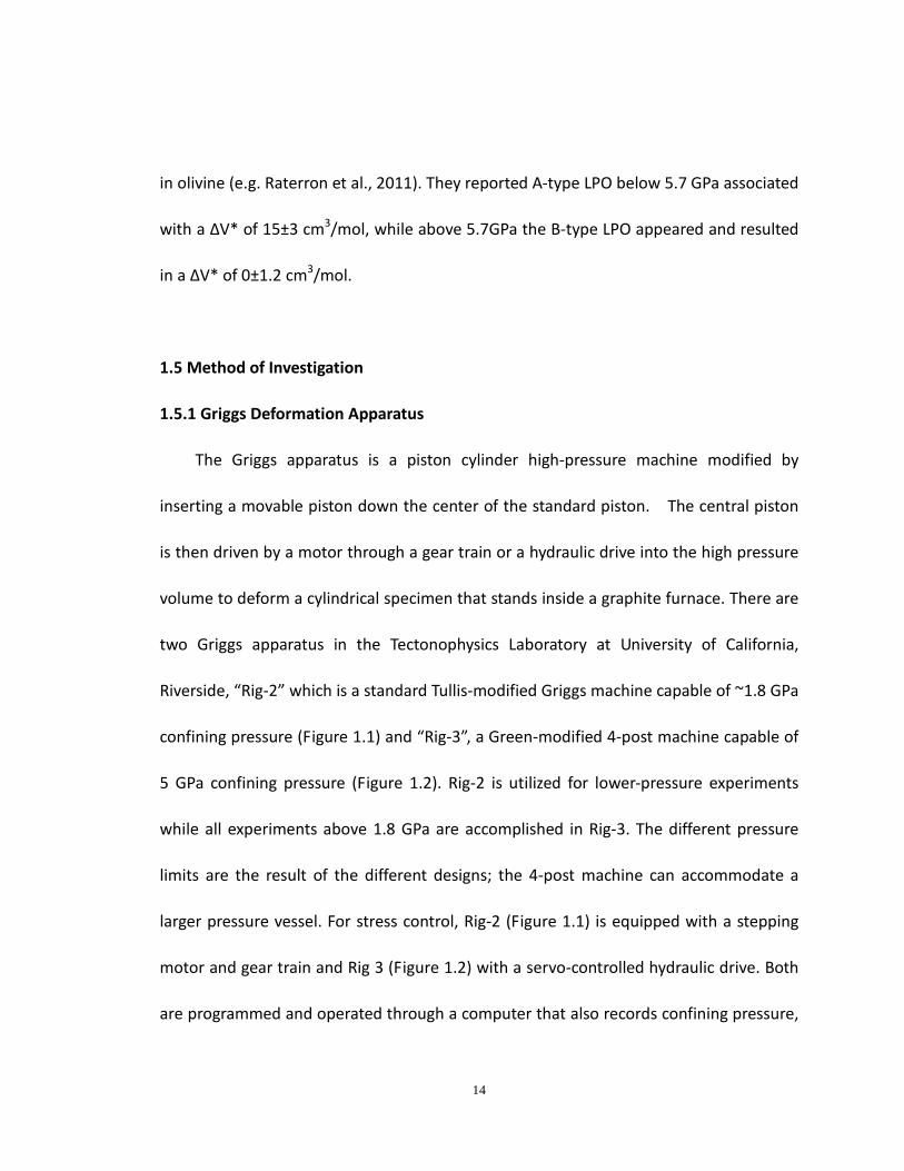
two Griggs apparatus in the Tectonophysics Laboratory at University of California,
Riverside, “Rig-2” which is a standard Tullis-modified Griggs machine capable of ~1.8 GPa
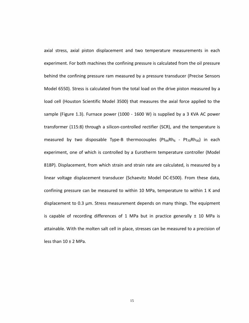
confining pressure (Figure 1.1) and “Rig-3”, a Green-modified 4-post machine capable of
5 GPa confining pressure (Figure 1.2). Rig-2 is utilized for lower-pressure experiments
while all experiments above 1.8 GPa are accomplished in Rig-3. The different pressure
limits are the result of the different designs; the 4-post machine can accommodate a
larger pressure vessel. For stress control, Rig-2 (Figure 1.1) is equipped with a stepping
motor and gear train and Rig 3 (Figure 1.2) with a servo-controlled hydraulic drive. Both
are programmed and operated through a computer that also records confining pressure,
14
axial stress, axial piston displacement and two temperature measurements in each
experiment. For both machines the confining pressure is calculated from the oil pressure
behind the confining pressure ram measured by a pressure transducer (Precise Sensors
Model 6550). Stress is calculated from the total load on the drive piston measured by a
load cell (Houston Scientific Model 3500) that measures the axial force applied to the
sample (Figure 1.3). Furnace power (1000 - 1600 W) is supplied by a 3 KVA AC power
transformer (115:8) through a silicon-controlled rectifier (SCR), and the temperature is
measured by two disposable Type-B thermocouples (Pt94Rh6 - Pt70Rh30) in each
experiment, one of which is controlled by a Eurotherm temperature controller (Model
818P). Displacement, from which strain and strain rate are calculated, is measured by a
linear voltage displacement transducer (Schaevitz Model DC-E500). From these data,
confining pressure can be measured to within 10 MPa, temperature to within 1 K and
displacement to 0.3 µm. Stress measurement depends on many things. The equipment
is capable of recording differences of 1 MPa but in practice generally ± 10 MPa is
attainable. With the molten salt cell in place, stresses can be measured to a precision of
less than 10 ± 2 MPa.
15
Figure 1.1 Photograph of Rig-2 Griggs apparatus in the Tectonophysics Laboratory at University of California, Riverside.
16
Figure 1.2 Photograph of Rig-3 Griggs apparatus in the Tectonophysics Laboratory at University of California, Riverside.
17
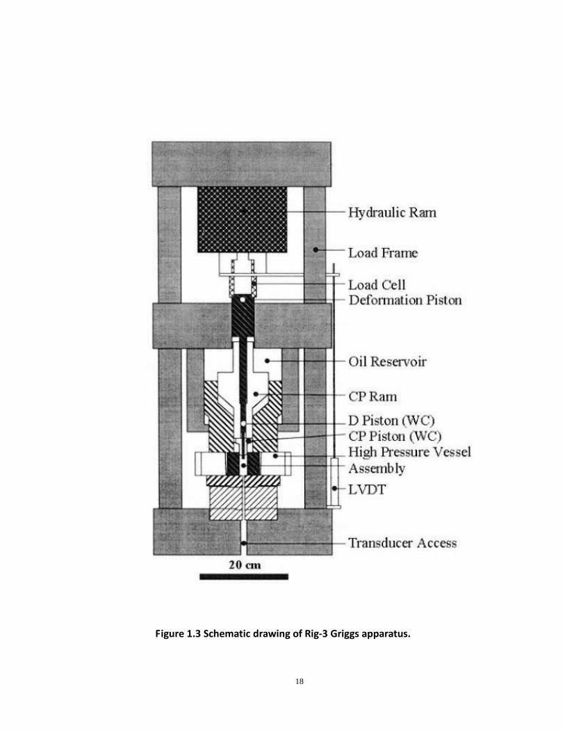
Figure 1.3 Schematic drawing of Rig-3 Griggs apparatus.
18
To prevent overheating, recirculated cooling water at 23 ˚C is used to cool the apparatus
and room-temperature mineral oil is used to cool the pressure vessel. Data acquisition is
programmed by FORTRAN language, the output data is then used to calculate the stress
and strain using both Kaleidagraph and Origin software. For each machine, real-time
output of all measured parameters is recorded on a strip-chart recorder to monitor
experiment progress and to make decisions during the experiment if necessary.
1.5.2 Sample assembly
The sample assembly (Figure 1.4) is designed to (i) minimize stresses on the various
parts during pressurization and, especially, during experiments; (ii) minimize
temperature gradients within the sample and furnace lifetime; (iii) provide as weak a
confining medium as possible; (iv) minimize friction on internal pistons and the sample
itself. It is designed for experimental conditions up to 5 GPa and 1400 ˚C. The schematic
cross section of Fig. 1.4 shows: From top to bottom, (i) the lower end of the tungsten
carbide (WC) deformation piston that sticks up out of the pressure vessel, (ii) two
packing rings on top of a lead cylinder that ensures that all parts of the assembly are
stressed equally during pressurization. The outer packing ring forms a static seal during
experiments to maintain constant confining pressure; the inner one forms a sliding seal
around the deformation piston that progressively enters the high-pressure volume
during an experiment. (iii) A graphite cap that grounds the graphite furnace to the wall
19
of the pressure vessel. The small gaps shown between the graphite cap and the tops of
the furnace and the inner soft-fired pyrophyllite sleeve are there to protect those parts
as pressurization begins; they close as the assembly compacts during pressurization. (iv)
The graphite furnace is tapered at the bottom to generate extra heat to compensate for
heat flow through the bottom of the assembly, thereby helping ensure an approximately
isothermal specimen. The furnace sits on a graphite ring that cushions its thin fragile end
and ensures good electrical contact. (v) the nickel sleeve provides a highly conducting
material to assist in keeping the specimen approximately isothermal (vi) the inner and
outer soft-fired pyrophyllite sleeves protect the furnace from reaction with the salt
inside and outside the furnace, respectively; the inner sleeve also insulates the furnace
from the nickel sleeve. It is particularly important to protect the furnace when the
internal salt is molten because the molten salt, with time, destroys the furnace. (vii) The
outer NaCl salt simply fills the unused volume of the assembly. (viii) The thermocouples
are assembled and put into place prior to casting molten CsCl around the specimen. (ix)
The two Al2O3 solid cylinders at the base provide a stand upon which the specimen sits
within the hot spot of the furnace. (x) The WC base anvil serves as both the hot electrical
lead and the strong base upon which everything fits and the hard-fired pyrophyllite
sleeve + unfired pyrophyllite ring around the base anvil both insulate the base anvil
electrically and serve as a very high friction seal to prevent blow outs at the bottom. (xi)
20
The upper CsCl part provides a very low friction sleeve around the Al2O3 upper piston
that the WC piston impinges upon as the experiment begins. (xii) Prior to insertion of the
assembly into the pressure vessel, the entire outer cylindrical surface is wrapped with
teflon tape to minimize the friction between sample assembly and the tungsten carbide
core as well as protect the core from salt and lead. A type-B (Pt94Rh6-Pt70Rh30)
thermocouple is placed near each end of the specimen to monitor the homogeneity of
temperature in the specimen. The optimal temperature difference between the two
thermocouples is less than 15 ˚C. 99.8% dense alumina tubing is used for the short
pieces of the thermocouples sheaths, to support the thermocouples where they
penetrate the furnace and sleeves. Mullite, which can collapse around the thermocouple
wires to protect them from breaking, is used for thermocouples sheaths outside the
furnace.
1.5.3 Analytical Methods
In order to examine the post-experiment specimens, over 100 samples were
prepared as doubly-polished petrographic thin sections, which were subsequently
investigated utilizing polarized optical microscopy, scanning electron microscopy (SEM)
(Figure 1.5), and transmission electron microscopy (TEM) (Figure 1.6), SEM and TEM are
located in the Central Facility for Advance Microscopy and Microanalysis (CFAMM) on
the UCR campus. All the SEM figures are back-scattered electron images taken with an
21
accelerating voltage of 15 kV in a Philips XL-30 field mission SEM equipped with energy
dispersive x-ray microanalysis (EDAX). Samples with nanometric crystals were also
examined in an FEI-Philips CM300 TEM equipped with Phoenix EDX microanalyzer at 300
kV accelerating voltage. The TEM foils (10 μm × 5μm × 100 nm) were prepared by FEI
Company using the focused ion beam (FIB) technique. The FIB technique is now widely
used to prepare specimens for TEM observation that require very thin foils (~100 nm).
The FIB allows precise choice of the region to be thinned by use of SEM images for
location. A platinum “strap” is evaporated along the line where the foil will be cut,
thereby providing strength to hold the foil together if cracks develop during thinning and
ensuring that the resulting foil will be electrically conductive and therefore much less
vulnerable to charging than it otherwise would be. Then a high energy Ga+ ion beam
sputters away material and in that way "digs" two wedge-shaped troughs on both sides
of the plane of the desired TEM foil. When the foil is thin enough to become transparent
to electrons, it is separated from the bulk sample by a sophisticated “lift-out” device and
placed on a TEM grid.
22
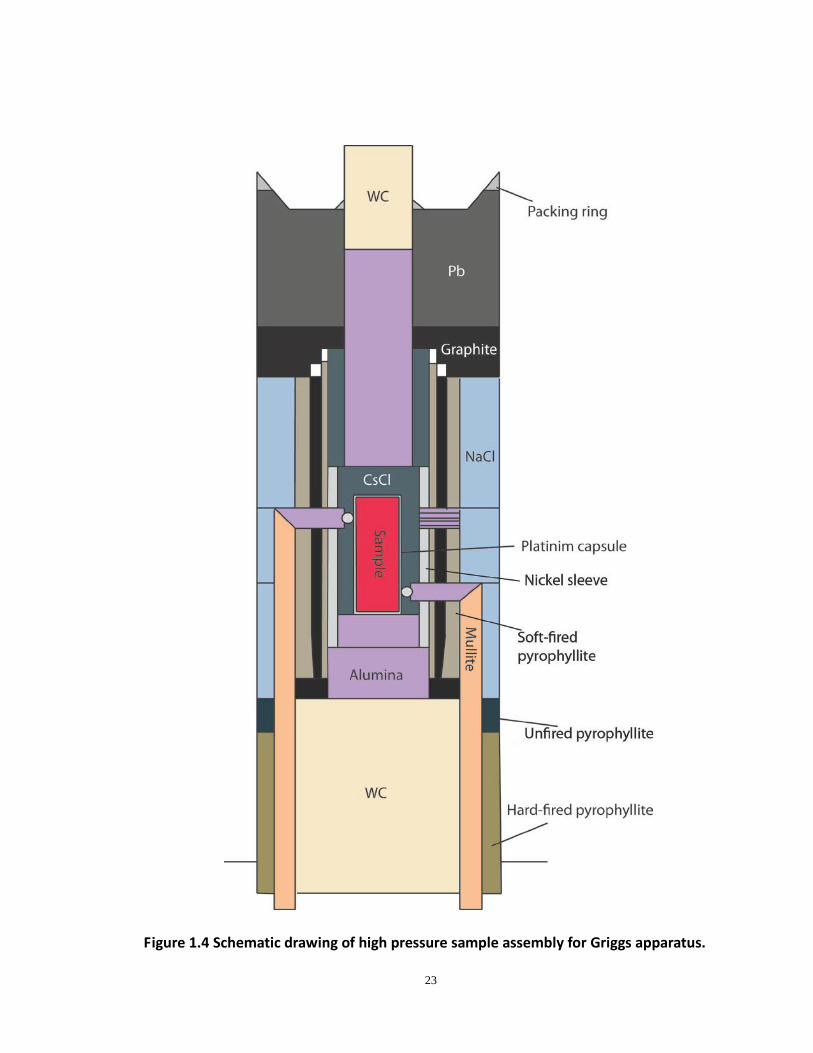
Figure 1.4 Schematic drawing of high pressure sample assembly for Griggs apparatus.
23
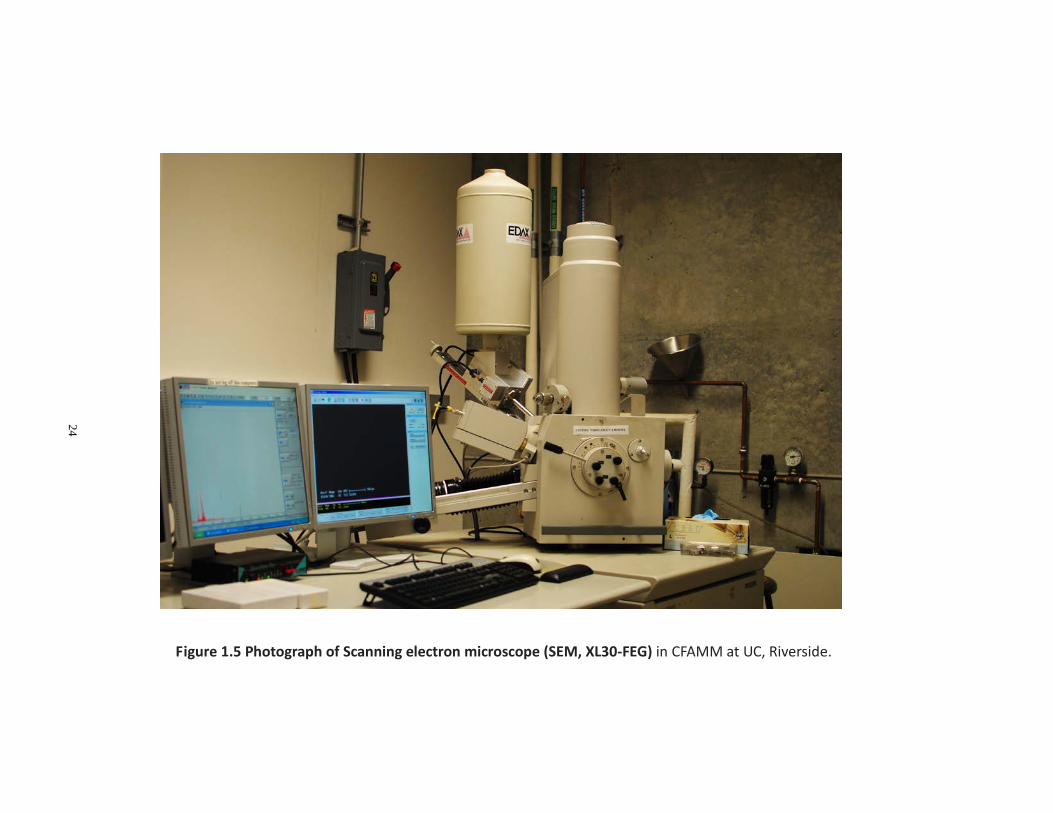
Figure 1.5 Photograph of Scanning electron microscope (SEM, XL30-FEG) in CFAMM at UC, Riverside.
24
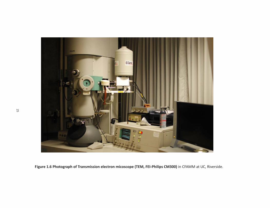
Figure 1.6 Photograph of Transmission electron micoscope (TEM, FEI-Philips CM300) in CFAMM at UC, Riverside.
25
26
Chapter 2.
Compositional Dependence of Dehydration
Embrittlement in Serpentinized Peridotite
27
2.1 Abstract
Double seismic zones (DSZ) which have two parallel planes of seismicity separated
by 15-40 km are a global feature of subduction zones in the 70-250 km depth range
(Brudzinski et al., 2007). While the physical mechanism of lower plane seismicity is still
controversial, the leading hypotheses currently are associated with dehydration of
antigorite serpentine within the subducting mantle plate (Peacock, 2001; Jung et al.,
2004). In this study, we are conducting high-pressure (1-3GPa), high-temperature (720˚C),
deformation experiments on specimens of varying compositions of serpentine plus
peridotite in our 4GPa Modified Griggs apparatus. Using samples composed of
interlayered thin discs of antigorite and harzburgite, we find that dehydration
embrittlement occurs down to less than ~30 vol % antigorite. Interlayered mineralogy
was impractical at lower antigorite fractions so we prepared homogeneous mixtures of
powders of the two rock types (35-75 µm grain-size) and “warm” pressed them to a
coherent solid with little porosity. Subsequent deformation of these specimens extended
the faulting regime to as little as ~8 vol % antigorite. In summary, we find that faulting
occurs during dehydration in a wide range of serpentinized peridotite compositions but
not during dehydration of nearly pure serpentinite nor nearly pure peridotite. We
suggest that the lack of faulting in nearly pure peridotite is a consequence of too little
H2O production and the lack of faulting in nearly pure serpentine is due to extensive
28
crystal plasticity, as proposed previously by Chernak and Hirth (2011). We would expect
that slower strain rates may change the compositions at which faulting stops but are
unlikely to change the fact that there are cutoffs at both ends of the spectrum.
Likely consequences of this behavior in subduction zones are: (i) aseismic behavior
of the plate interface that becomes serpentinized as fluid escapes from the slab due to
dehydration below; (ii) serpentine diapirs frequently found in forearc basins; (iii)
earthquake generation from moderately serpentinized lithosphere during dehydration.
29
2.2 Introduction
Earthquakes occurring at shallow depth (< 70km) result from brittle failure and
frictional sliding along preexisting faults. However, rocks are expected to behave
differently at greater depths. The fracture strength of rock increases rapidly with
increasing pressure but is insensitive to temperature (Scholz, 2002), whereas the flow
strength of rock decreases rapidly with increasing temperature and increases only
moderately with increasing pressure (Poirier, 1985). The combination of these two facts
indicates that unassisted brittle phenomena should be inhibited at depths greater than
50-70 km because both pressure and temperature increase with depth. Instead, rocks
are expected to flow; any fault or potential fault would be replaced by homogeneous
flow or, perhaps, a ductile shear zone. Nevertheless, Earthquakes are observed from the
surface to the bottom of mantle transition zone (~700km), where they cease abruptly
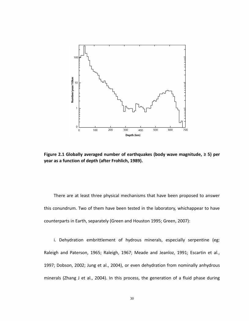
(e.g. Frohlich, 1989). The overall number of subduction earthquakes decreases from ~50
km to a minimum at ~300 km. Then it increase between 400-600km before dropping
exponentially to zero between 600 and 680 km (Figure 2.1). In addition, just like shallow
earthquakes, deep earthquakes (>70 km) display double-couple focal mechanisms,
indicating offset across a plane, like slip on a fault (Kawakatsu, 1991; Green and Houston,
1995).
30
Figure 2.1 Globally averaged number of earthquakes (body wave magnitude, ≥ 5) per
year as a function of depth (after Frohlich, 1989).
There are at least three physical mechanisms that have been proposed to answer
this conundrum. Two of them have been tested in the laboratory, whichappear to have
counterparts in Earth, separately (Green and Houston 1995; Green, 2007):
i. Dehydration embrittlement of hydrous minerals, especially serpentine (eg:
Raleigh and Paterson, 1965; Raleigh, 1967; Meade and Jeanloz, 1991; Escartin et al.,
1997; Dobson, 2002; Jung et al., 2004), or even dehydration from nominally anhydrous
minerals (Zhang J et al., 2004). In this process, the generation of a fluid phase during
31
dehydration reaction promotes the opening of microcracks and activate their interaction,
which results in reactivation of a preexisting fault or nucleation of a new fault. Perrillat et
al. (2005) showed that dehydration kinetics of antigorite, under undrained conditions, is
faster than the relaxation time for antigorite (Hilariet et al., 2007), and therefore is
enough to build up pore pressure and lead to earthquakes. Seismic and petrologic
studies ( Peacock, 2001; Hacker et al., 2003; Zhang H et al., 2004) strongly support this
mechanism for intermediate-depth earthquakes (70-300 km). Both results from Meade
and Jeanloz (1991) and Jung et al. (2004) suggested that this mechanism could support
faulting to depths even greater than seismogenic zone if an appropriate dehydrating
phase is present. However, the seismic identification of metastable olivine (incompatible
with fluid released from hydrous phases) and the lack of evidence linking deep
earthquakes with dehydration of high-pressure hydrous phases powerfully suggests that
subduction zones are essentially dry below 400 km (Green et al., 2010; Kawakatsu and
Yoshioka, 2011), limiting this mechanism to depths less than the mantle transition zone
(MTZ) that begins ~400km.
ii. Phase-transformation -induced faulting (Green an Burnley, 1989; Green et al.,
1990; Burnley et al., 1991; Kirby et al., 1991; 1996; Green and Houston, 1995; Green and
Marone, 2002; Green, 2007). This mechanism only can operate under certain restricted
conditions during exothermic polymorphic phase transformations involving a volume
32
change (Green and Zhou, 1996; Gleason and Green, 2008; Zhao et al., 2011). This
reaction is known to occur when olivine transforms to its higher-pressure polymorphs
under nucleation-inhibited condition and pressure comparable to that in the MTZ, the
region between the two prominent seismic discontinuities at ~400 km and ~700 km. It
means that this mechanism cannot operate at depths shallower than 400 km where
olivine is stable. Ample seismic evidence for the presence of metastable olivine in the
mantle transition zone of at least four cold subduction zones: Tonga (Chen & Brudzinski,
2001; 2003), southwest Japan (Iidaka & Suetsugu, 1992), Mariana (Kaneshima et al.,
2007), and northeast Japan (Jiang et al., 2008), powerfully supports this mechanism to
be responsible for the deepest earthquakes, making it a potential explanation for the
second peak of bimodal distribution of earthquakes as a function of depth.
iii. Shear heating instabilities. Assuming hydrous phases are absent, it has also been
proposed that localized shearing could generate heat faster than dissipation via
conduction, which would speed up the slip and therefore generate more heat, etc. This
shear-induced thermal runaway could lead to melting along the fault and trigger
earthquakes (Ogawa, 1987; Karato et al, 2001). Kanamori et al. (1998) tried to use this
mechanism to explain the 1994 Bolivian deep earthquakes which is the greatest rupture
ever recorded below 300 km. Unfortunately, they explained why the earthquake could
only grow so large because of shear heating mechanism based on an unspecified
33
mechanism that triggered the earthquake. More recently, Kelemen and Hirth (2007)
used numerical simulation to model intermediate-depth earthquakes by such shear
heating instability mechanism, but failure, in their model, can be achieved before
reaching the melting point. Considering the lack of direct experimental studies
supporting this mechanism, it is still not clear whether this mechanism can lead to the
nucleation of deep earthquakes.
2.2.1 Double Seismic Zones
In a number of subduction zones, including Alaska (Abers, 1996), Aleutians (Abers
and Sarker, 1992; Engdahl and Scholz, 1977), Tonga (Kawakatsu, 1986) and Northeast
Japan (Hasegawa et al., 1978; Hacker et al., 2003), earthquakes occurring at
intermediate-depths (70-350 km) define at least two planes of seismicities separated by
20-50 km, which appear to merge at greater depths (Figure 2.2).
Brudzinski et al. (2007) have now demonstrated that double seismic zones are a
global feature observed in all subduction zones. They further demonstrated that the
thickness of the "silent" zone between the two zones varies as a function of subducting
plate age in such a way that they are consistent with the view that lower plane
earthquakes are caused by dehydration embrittlement of antigorite serpentine, as
originally proposed by Peacock (2001). Seismic study focused on the ratio of P- to S-wave
34
Figure 2.2 Double seismic zone beneath northeast Japan (Peacock, 2001). Epicenters, in
black dots, highlight the double seismic zone. Temperatures reflected the calculated
thermal structure, temperature decreasing pattern is represented by red to blue color
sequence .
speed further supports that earthquakes occurring to depths as deep as 350 km (or at
least the great majority of them) result from dehydration embrittlement, where the
upper plane seismicities are associated with the transformation of altered oceanic crust
35
(Kirby et al., 1996; Zhang H et al., 2004) and the lower plane seismicities are triggered by
dehydration embrittlement of antigorite in the oceanic mantle (Peacock, 2001; Hacker,
2003; Yamasaki and Seno, 2003; Jung et al., 2004).
2.2.2 Hydration of subducting lithosphere
A critical prerequisite for the dehydration embrittlement mechanism to function is
for the lithosphere to be hydrated (e.g. serpentinized) continuously during subduction at
least in the regions where seismicity is observed. Therefore, if the lower plane of
seismicity in slabs is due to dehydration embrittlement, the slabs must be hydrated to a
depth of 30-40 km almost immediately below trenches. Studies of ophiolites and ocean
floor dredge hauls show that the oceanic crust is significantly altered by the
hydrothermal circulation through the fractures created in the vicinity of mid ocean ridges.
In contrast, mantle xenoliths from oceanic volcanoes show very little evidence of
hydrous alteration and seismic velocities of the mantle immediately beneath the oceanic
lithosphere are not consistent with significant serpentinization. As a consequence, if
hydration is required almost immediately beneath trenches, that hydration must occur at
the trench. However, this argument has been resisted for many years because it is not
clear how hydration could occur so deeply along the faults that accommodate slab
bending at the trench.
36
Seno and Yamanaka (1996) suggested that hydration of mantle lithosphere could
occur when it passes over a plume or superplume, but this mechanism can only be used
to explain a few subduction zones that have recently passed over such a feature.
Moreover, we have every reason to expect that the earthquake distribution seen in slabs
is a steady-state phenomenon that requires a continuing source of hydrous alteration,
not something that might happen by chance now and then. The results from Brudzinski
et al. (2007) required that the hydration corresponding to the lower plane seismicity in
the mantle lithosphere must occur in all subducting slabs, which indicates that the
hydration must takes place at outer rise zones just before subduction. Ranero et al.
(2003) demonstrated that significant numbers of normal faults are formed to depth in
excess of 20 km as an ocean slab bends down for subduction, potentially providing
conduits for deep hydration. A recent modeling study by Faccenda et al. (2009) produced
more promising results. They envisioned that bending and unbending of oceanic
lithosphere can provide a downward pressure gradient, pumping the water down the
fault. Therefore, although the mechanism of water into the slab remains obscure, a
plausible path is identified and the lower plane of seismicity is consistent with
dehydration embrittlement of antigorite (Peacock, 2001; Brudzinski et al., 2007). In
combination, this makes for a powerful argument.
37
2.2.3 Motivation and goal of this study
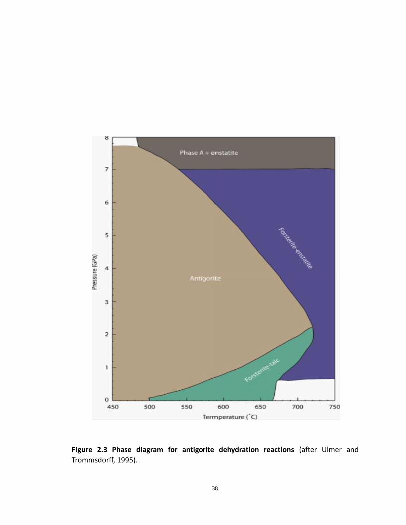
The antigorite phase diagram (Figure 2.3) shows that the total volume change, ΔV,
of dehydration reaction changes from positive at pressure lower than 2.2GPa to negative
at pressure above 2.2GPa. A negative ΔV is expected to inhibit dehydration
embrittlement from the view of conventional rock mechanics (Ko et al., 1997; Wong et
al., 1997). However, Jung et al. (2004) demonstrated that dehydration-induced faulting in
peridotite that is partially altered to antigorite serpentine occurs even at pressures much
higher than 2.2 GPa, under which the ΔV is negative. Nevertheless, a more recent study
by Chernak and Hirth (2011) showed that experiments on pure serpentine did not lead
to embrittlement during dehydration. Only localized shear zones and slow slip were
found; macroscopic faulting was not observed during dehydration of antigorite.
Both seismic evidence showing limited deep mantle hydration and current
experimental results indicate that the there could be very small amount of
serpentine formed at depth corresponding to the lower layer seismicity. Hence the first
order issue we want to investigate is how much serpentine at minimum is required to
produce such dehydration embrittlement. The result of this study will, in
turn, put constraints on the level of hydration in subducting lithosphere and therefore
the amount (lower bound) of H2O that could penetrate into the deep mantle.
38
Figure 2.3 Phase diagram for antigorite dehydration reactions (after Ulmer and
Trommsdorff, 1995).
39
Moreover, although in the earlier work of Jung et al. (2004) it was clear that the
solid and fluid products of antigorite dehydration reaction separate almost immediately
after their generation, the resolution and contrast were inadequate to examine how
ultrafine-grained products are separated and distributed. In this study, I use high
resolution SEM and TEM to investigate the fault configuration as well as the
microstructure of dehydration products. This study will promote our understanding of
the physics behind the dehydration embrittlement mechanism.
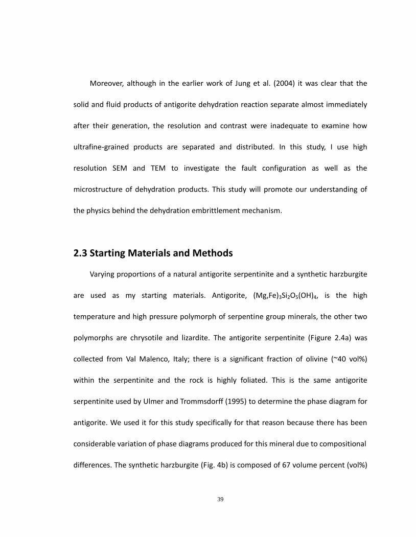
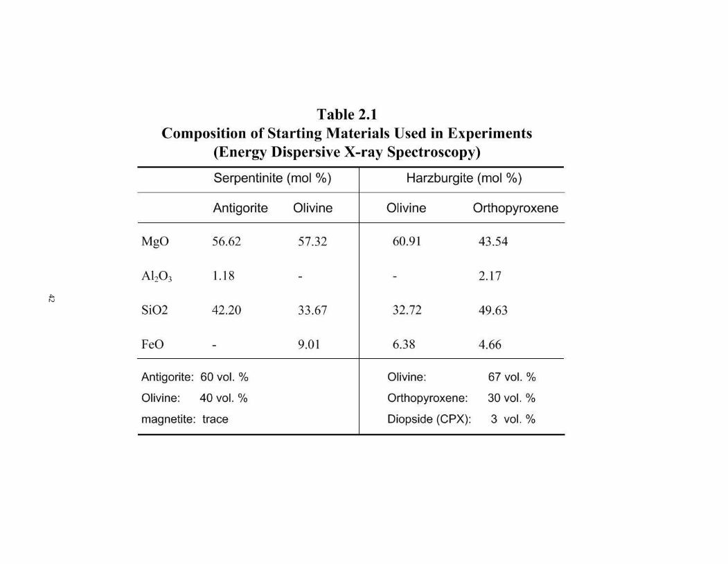
2.3 Starting Materials and Methods
Varying proportions of a natural antigorite serpentinite and a synthetic harzburgite
are used as my starting materials. Antigorite, (Mg,Fe)3Si2O5(OH)4, is the high
temperature and high pressure polymorph of serpentine group minerals, the other two
polymorphs are chrysotile and lizardite. The antigorite serpentinite (Figure 2.4a) was
collected from Val Malenco, Italy; there is a significant fraction of olivine (~40 vol%)
within the serpentinite and the rock is highly foliated. This is the same antigorite
serpentinite used by Ulmer and Trommsdorff (1995) to determine the phase diagram for
antigorite. We used it for this study specifically for that reason because there has been
considerable variation of phase diagrams produced for this mineral due to compositional
differences. The synthetic harzburgite (Fig. 4b) is composed of 67 volume percent (vol%)
40
olivine, (Mg,Fe)2SiO4 and 30 vol% ortho-pyroxene (Mg,Fe)SiO3, and ~3 vol% of diopside
MgCaSi2O6. Such a combination (Table 1) provides a good approximation of the
composition of upper mantle mineralogy of the subducting oceanic plate. Both
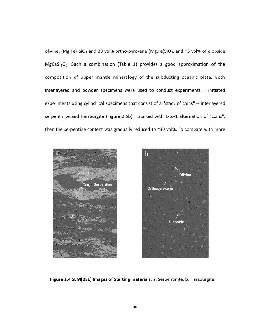
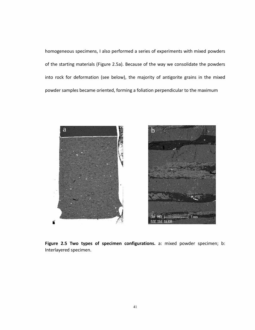
interlayered and powder specimens were used to conduct experiments. I initiated
experiments using cylindrical specimens that consist of a "stack of coins" -- interlayered
serpentinite and harzburgite (Figure 2.5b). I started with 1-to-1 alternation of "coins",
then the serpentine content was gradually reduced to ~30 vol%. To compare with more
Figure 2.4 SEM(BSE) Images of Starting materials. a: Serpentinite; b: Harzburgite.
b a
41
homogeneous specimens, I also performed a series of experiments with mixed powders
of the starting materials (Figure 2.5a). Because of the way we consolidate the powders
into rock for deformation (see below), the majority of antigorite grains in the mixed
powder samples became oriented, forming a foliation perpendicular to the maximum
Figure 2.5 Two types of specimen configurations. a: mixed powder specimen; b:
Interlayered specimen.
a b
42
43
compression direction, comparable with the orientation of serpentine grains in the
interlayered samples. Both Serpentine and harzburgite separates were crushed and
sieved to a grain size of 35~75μm for the mixed powder experiments.
Samples, both interlayered and mixed powders, were loaded into platinum capsules
with dimensions 3 mm diameter and 9mm long. The capsules consist of two cylindrical
parts, one of which slides smoothly into the other; both parts consist of tubes (0.01”
thick) with one end welded shut with a platinum cap (0.01'' thick). When assembled, the
capsule has walls of thickness 0.02” thick. Pressurization produces a cold weld that
becomes fully sealed. The oxygen fugacity was buffered by placing two thin Ni foils inside
the capsule, one at each end of the specimen. The capsule was then placed into a
standard high-pressure sample assembly for the Griggs apparatus (Figure 1.1 & 1.2).
Experiments with interlayered specimens were cold compacted with pressurization
up to 280 MPa, then the temperature was increased to 300 ˚C at a heating rate of 7˚/min.
Further pressurization to 800 MPa was achieved at 2 MPa/min, followed by increasing
temperature to desired temperature (720 ˚C). Samples were then annealed at target
pressure 1 GPa and temperature 720 ˚C for ~60 min, and axially deformed at a strain rate
of 10-4/s. Immediately following deformation, the sample was quenched to room
temperature in seconds by turning off the power to the zero. In comparison,
44
experiments with mixed powder specimens were initially cooked at 3 GPa and 600 ˚C for
12 hours to produce fully compacted polycrystalline specimens. We established this
protocol to ensure that all porosity was removed from the specimens prior to
deformation. This “warm pressing” process results in a largely uniaxial shortening of the
powder during compaction, thus producing the foliation of original antigorite grains
mentioned in the previous paragraph. At the end of this protocol, the temperature was
first reduced to 300 ˚C followed by slow pressure reduction to 1 GPa to insure integrity of
the sample assembly during the process. Temperature was then ramped up again and
deformation was carried out at P = 1 GPa, T = 720 ˚C and 10-4 ~ 10-5/s, identical with
that in interlayered-sample experiments.
45
2.4 Results and Discussion
2.4.1 Mechanical Results
In this study, a series of deformation experiments on serpentinized peridotite was
carried out at P = 1 GPa and T = 720 ˚C, with different proportions of
antigorite-harzburgite mixture. The experimental conditions and mechanical results are
listed in Table 2.
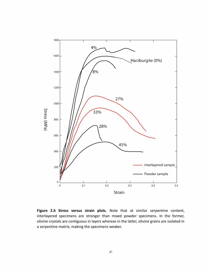
Stress vs Strain curves are shown in Figure 6. To establish that the materials studied
do not fail by normal brittle failure, we deformed a dry synthetic harzburgite at the
same conditions as all other experiments. That specimen (GB478) was fully ductile
with a flow strength 1600 MPa, stronger than all but one experiment containing
antigorite (GB513, ~4 vol% serpentine content). Given the fact that the differential stress
is almost double the confining pressure, the difference between these two experiments
is not likely to be significant. The decrease of stress at the end of deformation of GB478
(dashed line) was caused by progressive tilting of the specimen. At constant temperature,
the strengths of variably serpentinized specimens vary as a function of antigorite
content in either mixed powder specimens or interlayered specimens. The more
antigorite a specimen contains, the weaker the specimen is expected to be. That
explanation is true for each type of experiment but, for a given amount of serpentine,
the mixed powder specimens are weaker than the layered ones. We attribute that
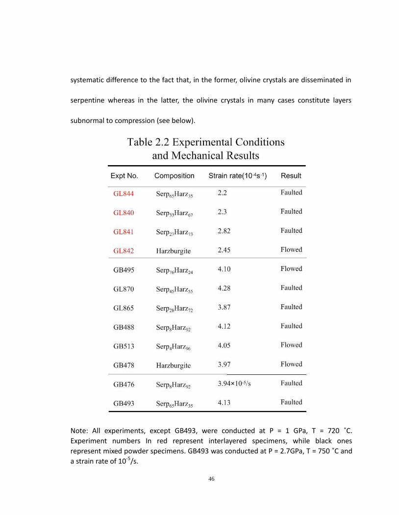
46
systematic difference to the fact that, in the former, olivine crystals are disseminated in
serpentine whereas in the latter, the olivine crystals in many cases constitute layers
subnormal to compression (see below).
Note: All experiments, except GB493, were conducted at P = 1 GPa, T = 720 ˚C.
Experiment numbers In red represent interlayered specimens, while black ones
represent mixed powder specimens. GB493 was conducted at P = 2.7GPa, T = 750 ˚C and
a strain rate of 10-5/s.
47
Figure 2.6 Stress versus strain plots. Note that at similar serpentine content,
interlayered specimens are stronger than mixed powder specimens. In the former,
olivine crystals are contiguous in layers whereas in the latter, olivine grains are isolated in
a serpentine matrix, making the specimens weaker.
48
Experiments on interlayered specimens showed that dehydration-induced faulting
occurred down to a serpentine content of 27 vol%. This specimen configuration allowed
imaging of clear evidence of offset along faults (Figure 2.7a). Unfortunately, this
technique is limited; specimens with lower amounts of serpentine could not be
fabricated because making thinner layers of serpentine became essentially impossible
due to their fragility. By contrast, one can fabricate a specimen with as little serpentine
content as desired with mixed powder specimens. The latter also provides a much more
homogeneous distribution of minerals throughout the specimen. With such specimens,
dehydration embrittlement was observed in two specimens with only 8 vol% serpentine
(GB476 & GB488) but GB513, with 4 vol% serpentine, was macroscopically ductile but
displayed an irregular stress/strain curve after yielding (Figure 2.6) and a tiny incipient
fault (see discussion of microstructures below).
2.4.2 SEM and TEM Microanalysis
In order to examine the fault configuration and evidence of dehydration reaction,
Scanning Electron Microscopy (SEM) was applied in this study. All SEM images shown in
this dissertation were taken using the Back Scattered Electron Detector (BSE) which
provides sharp contrast among different phases. In our case, the darkest phase is
antigorite; other phases (principally olivine and talc) are various shades of lighter gray.
49
Rare magnetite is very bright white. In addition, Transmission Electron Microscopy (TEM)
was also adopted appropriately to study the nanostructure of dehydration products
within fault zones.
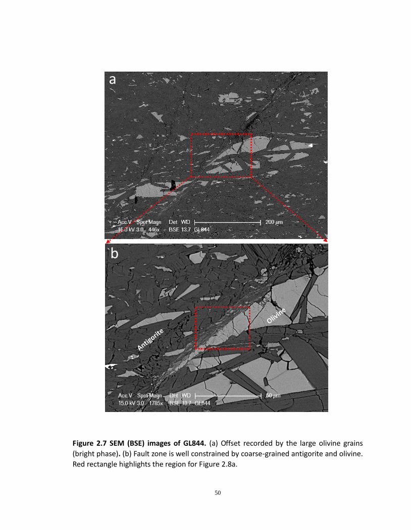
Here, I describe several examples of our typical observations. Of the interlayered
specimens, GL844 (Figure 2.7 & 2.8) contained the highest fraction of antigorite (65
vol%). The fault experienced a significant offset (~100 μm), as shown by displacement of
olivine layers across the fault (Figure 2.7a). At larger magnification, it is clearly seen that
the fault zone is sharply defined between coarse-grained antigorite and olivine (Figure
2.7b). Because the experiment was at an early stage of dehydration, away from the fault
we can see that the reaction initiated at the grain boundaries of antigorite, leaving the
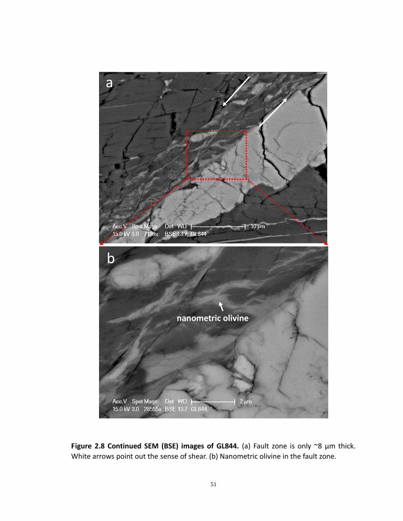
grain interiors still un-reacted. The fault zone is less than 8 μm thick (Figure 2.8a) and
contains a high concentration of extremely fine-grained solid dehydration products. With
further increased magnification, individual submicron-sized olivine grains are observed
within the fault zone (Figure 2.8b).
50
Figure 2.7 SEM (BSE) images of GL844. (a) Offset recorded by the large olivine grains
(bright phase). (b) Fault zone is well constrained by coarse-grained antigorite and olivine.
Red rectangle highlights the region for Figure 2.8a.
a
b
51
Figure 2.8 Continued SEM (BSE) images of GL844. (a) Fault zone is only ~8 μm thick.
White arrows point out the sense of shear. (b) Nanometric olivine in the fault zone.
nanometric olivine
a
b
52
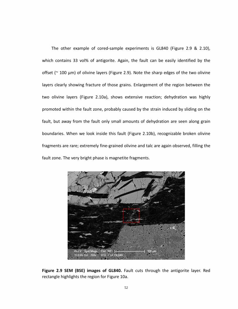
The other example of cored-sample experiments is GL840 (Figure 2.9 & 2.10),
which contains 33 vol% of antigorite. Again, the fault can be easily identified by the
offset (~ 100 μm) of olivine layers (Figure 2.9). Note the sharp edges of the two olivine
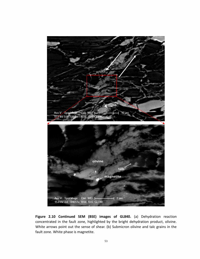
layers clearly showing fracture of those grains. Enlargement of the region between the
two olivine layers (Figure 2.10a), shows extensive reaction; dehydration was highly
promoted within the fault zone, probably caused by the strain induced by sliding on the
fault, but away from the fault only small amounts of dehydration are seen along grain
boundaries. When we look inside this fault (Figure 2.10b), recognizable broken olivine
fragments are rare; extremely fine-grained olivine and talc are again observed, filling the
fault zone. The very bright phase is magnetite fragments.
Figure 2.9 SEM (BSE) images of GL840. Fault cuts through the antigorite layer. Red
rectangle highlights the region for Figure 10a.
53
Figure 2.10 Continued SEM (BSE) images of GL840. (a) Dehydration reaction
concentrated in the fault zone, highlighted by the bright dehydration product, olivine.
White arrows point out the sense of shear. (b) Submicron olivine and talc grains in the
fault zone. White phase is magnetite.
54
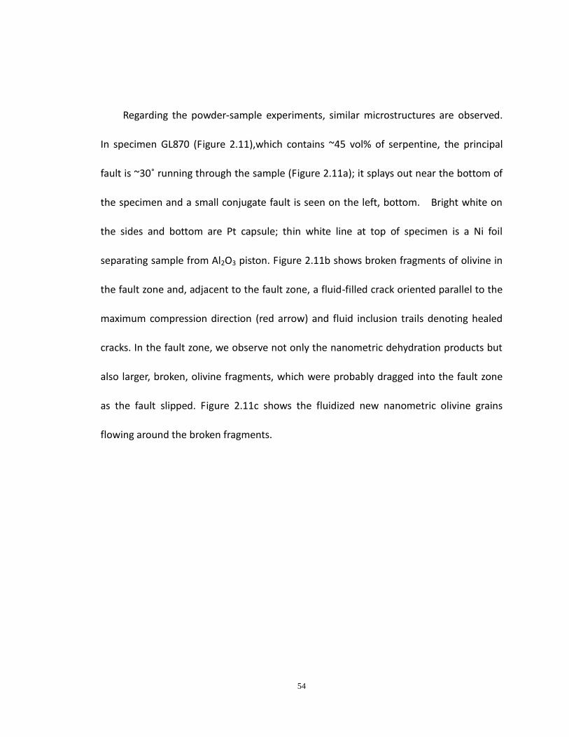
Regarding the powder-sample experiments, similar microstructures are observed.
In specimen GL870 (Figure 2.11),which contains ~45 vol% of serpentine, the principal
fault is ~30˚ running through the sample (Figure 2.11a); it splays out near the bottom of
the specimen and a small conjugate fault is seen on the left, bottom. Bright white on
the sides and bottom are Pt capsule; thin white line at top of specimen is a Ni foil
separating sample from Al2O3 piston. Figure 2.11b shows broken fragments of olivine in
the fault zone and, adjacent to the fault zone, a fluid-filled crack oriented parallel to the
maximum compression direction (red arrow) and fluid inclusion trails denoting healed
cracks. In the fault zone, we observe not only the nanometric dehydration products but
also larger, broken, olivine fragments, which were probably dragged into the fault zone
as the fault slipped. Figure 2.11c shows the fluidized new nanometric olivine grains
flowing around the broken fragments.
55
Figure 2.11 SEM (BSE) image of GL870. (a) Fault running through the sample at ~30˚ to
the maximum compression direction. (b) Broken fragments of olivine and antigorite
were observed in the fault zone (upper image). Fluid inclusion trails are also seen and
highlighted by the mode I crack (red arrow). (c) Nanometric dehydration products are
flowing around the large fragments (lower image).
a b
c
56
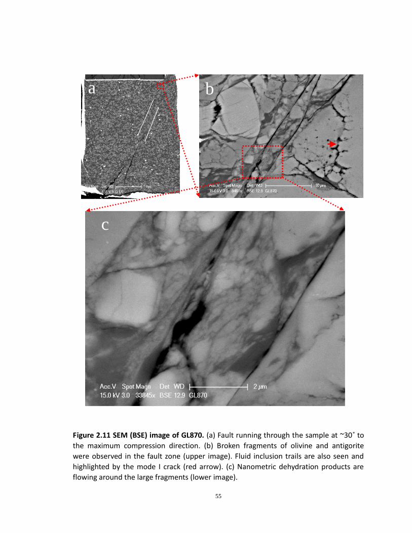
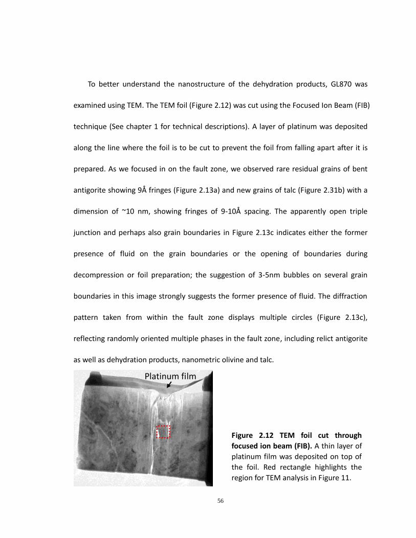
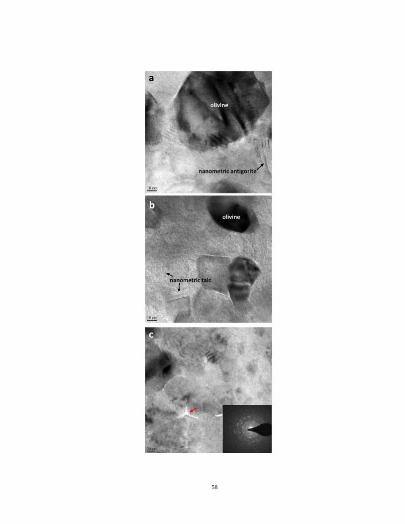
To better understand the nanostructure of the dehydration products, GL870 was
examined using TEM. The TEM foil (Figure 2.12) was cut using the Focused Ion Beam (FIB)
technique (See chapter 1 for technical descriptions). A layer of platinum was deposited
along the line where the foil is to be cut to prevent the foil from falling apart after it is
prepared. As we focused in on the fault zone, we observed rare residual grains of bent
antigorite showing 9Å fringes (Figure 2.13a) and new grains of talc (Figure 2.31b) with a
dimension of ~10 nm, showing fringes of 9-10Å spacing. The apparently open triple
junction and perhaps also grain boundaries in Figure 2.13c indicates either the former
presence of fluid on the grain boundaries or the opening of boundaries during
decompression or foil preparation; the suggestion of 3-5nm bubbles on several grain
boundaries in this image strongly suggests the former presence of fluid. The diffraction
pattern taken from within the fault zone displays multiple circles (Figure 2.13c),
reflecting randomly oriented multiple phases in the fault zone, including relict antigorite
as well as dehydration products, nanometric olivine and talc.
Platinum film
Figure 2.12 TEM foil cut through
focused ion beam (FIB). A thin layer of
platinum film was deposited on top of
the foil. Red rectangle highlights the
region for TEM analysis in Figure 11.
57
Figure 2.13 High resolution images of fault zone contents. (a) Residual olivine and
antigorite in fault zone. Lattice fringes are visible in the relatively large olivine fragment
(top) and also in the bent antigorite crystal. (b) Nanometric talc produced by
dehydration. Note that the scale bar is 10 nm, and the dimension of talc is only 8 -10
unit cells thick. (c) Triple junction (black arrow) between nanometric grains of fault
gouge. Open junction and some grain boundaries suggest former presence of fluid
before foil preparation. Inset is the X-ray diffraction pattern from fault zone materials,
indicating multiple phases with random crystallographic orientations.
58
59
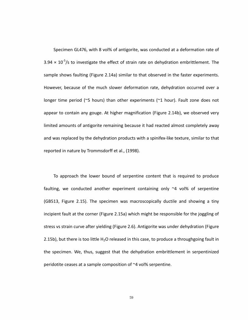
Specimen GL476, with 8 vol% of antigorite, was conducted at a deformation rate of
3.94 × 10⁻⁵/s to investigate the effect of strain rate on dehydration embrittlement. The
sample shows faulting (Figure 2.14a) similar to that observed in the faster experiments.
However, because of the much slower deformation rate, dehydration occurred over a
longer time period (~5 hours) than other experiments (~1 hour). Fault zone does not
appear to contain any gouge. At higher magnification (Figure 2.14b), we observed very
limited amounts of antigorite remaining because it had reacted almost completely away
and was replaced by the dehydration products with a spinifex-like texture, similar to that
reported in nature by Trommsdorff et al., (1998).
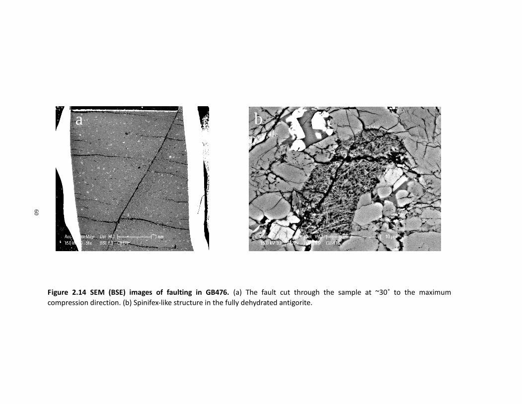
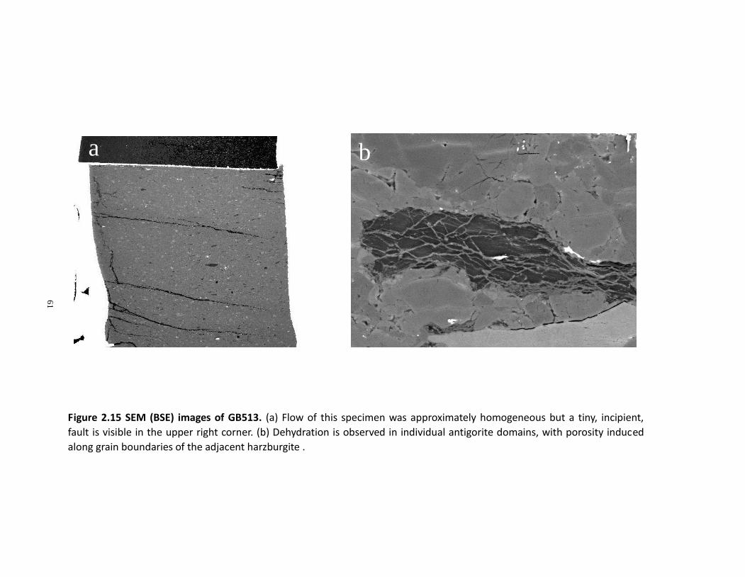
To approach the lower bound of serpentine content that is required to produce
faulting, we conducted another experiment containing only ~4 vol% of serpentine
(GB513, Figure 2.15). The specimen was macroscopically ductile and showing a tiny
incipient fault at the corner (Figure 2.15a) which might be responsible for the joggling of
stress vs strain curve after yielding (Figure 2.6). Antigorite was under dehydration (Figure
2.15b), but there is too little H2O released in this case, to produce a throughgoing fault in
the specimen. We, thus, suggest that the dehydration embrittlement in serpentinized
peridotite ceases at a sample composition of ~4 vol% serpentine.
60
Figure 2.14 SEM (BSE) images of faulting in GB476. (a) The fault cut through the sample at ~30˚ to the maximum
compression direction. (b) Spinifex-like structure in the fully dehydrated antigorite.
a b
61
Figure 2.15 SEM (BSE) images of GB513. (a) Flow of this specimen was approximately homogeneous but a tiny, incipient,
fault is visible in the upper right corner. (b) Dehydration is observed in individual antigorite domains, with porosity induced
along grain boundaries of the adjacent harzburgite .
a b

62
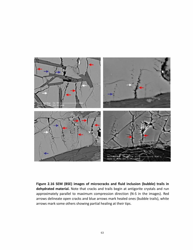
In addition to fluid inclusion trails mentioned briefly above (Figure 2.11b), evidence
of fluid inclusion trails was wide-spread in all specimens containing enough
coarse-grained olivine to allow them to be seen (Figure 2.16). Everywhere, healed cracks
and fluid inclusion trails are approximately parallel to the plane of least compression
(parallel to σ1) The starting material shows no fluid inclusion trails, hence their presence
here records the formation of Mode I microcracks and their healing before the end of
the experiment that occurred only a few minutes later. These healed cracks and also
those that remained open at the end of the experiment also display braches (smaller
cracks), radiating from them. Compared to the solid reaction products that remain
where they formed, fluid inclusion trails and cracks initiated from antigorite and
propagated into relict olivine grains, demonstrating that separation of solid and fluid
reaction products is very fast after dehydration (Jung et al., 2004).
63
Figure 2.16 SEM (BSE) images of microcracks and fluid inclusion (bubble) trails in
dehydrated material. Note that cracks and trails begin at antigorite crystals and run
approximately parallel to maximum compression direction (N-S in the images). Red
arrows delineate open cracks and blue arrows mark healed ones (bubble trails), white
arrows mark some others showing partial healing at their tips.
64
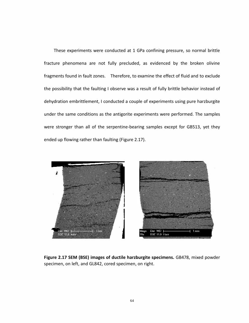
These experiments were conducted at 1 GPa confining pressure, so normal brittle
fracture phenomena are not fully precluded, as evidenced by the broken olivine
fragments found in fault zones. Therefore, to examine the effect of fluid and to exclude
the possibility that the faulting I observe was a result of fully brittle behavior instead of
dehydration embrittlement, I conducted a couple of experiments using pure harzburgite
under the same conditions as the antigorite experiments were performed. The samples
were stronger than all of the serpentine-bearing samples except for GB513, yet they
ended up flowing rather than faulting (Figure 2.17).
Figure 2.17 SEM (BSE) images of ductile harzburgite specimens. GB478, mixed powder
specimen, on left, and GL842, cored specimen, on right.
65
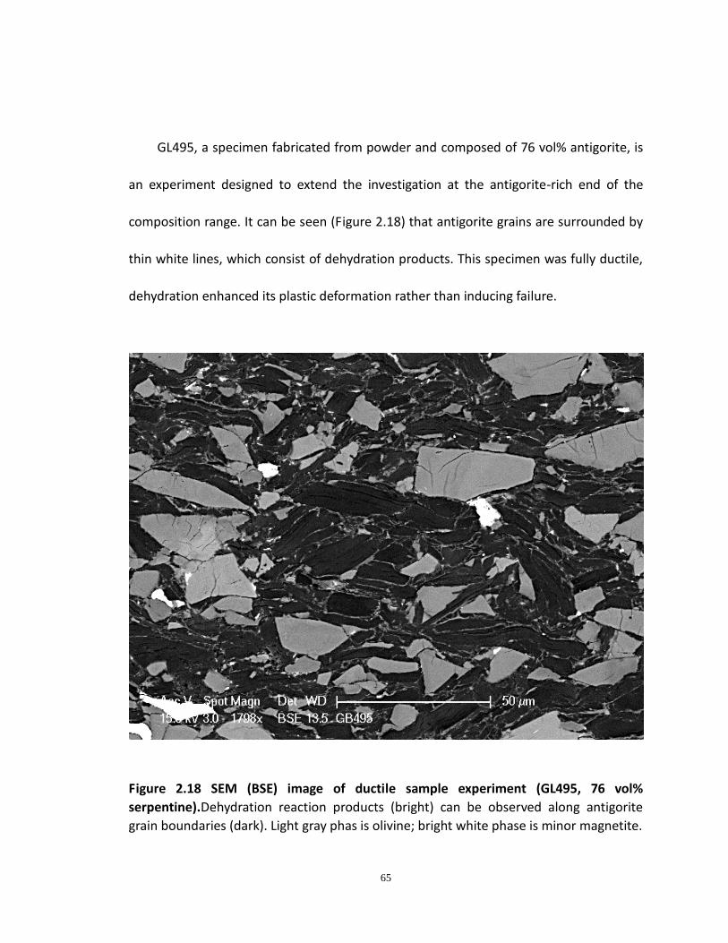
GL495, a specimen fabricated from powder and composed of 76 vol% antigorite, is
an experiment designed to extend the investigation at the antigorite-rich end of the
composition range. It can be seen (Figure 2.18) that antigorite grains are surrounded by
thin white lines, which consist of dehydration products. This specimen was fully ductile,
dehydration enhanced its plastic deformation rather than inducing failure.
Figure 2.18 SEM (BSE) image of ductile sample experiment (GL495, 76 vol%
serpentine).Dehydration reaction products (bright) can be observed along antigorite
grain boundaries (dark). Light gray phas is olivine; bright white phase is minor magnetite.
66
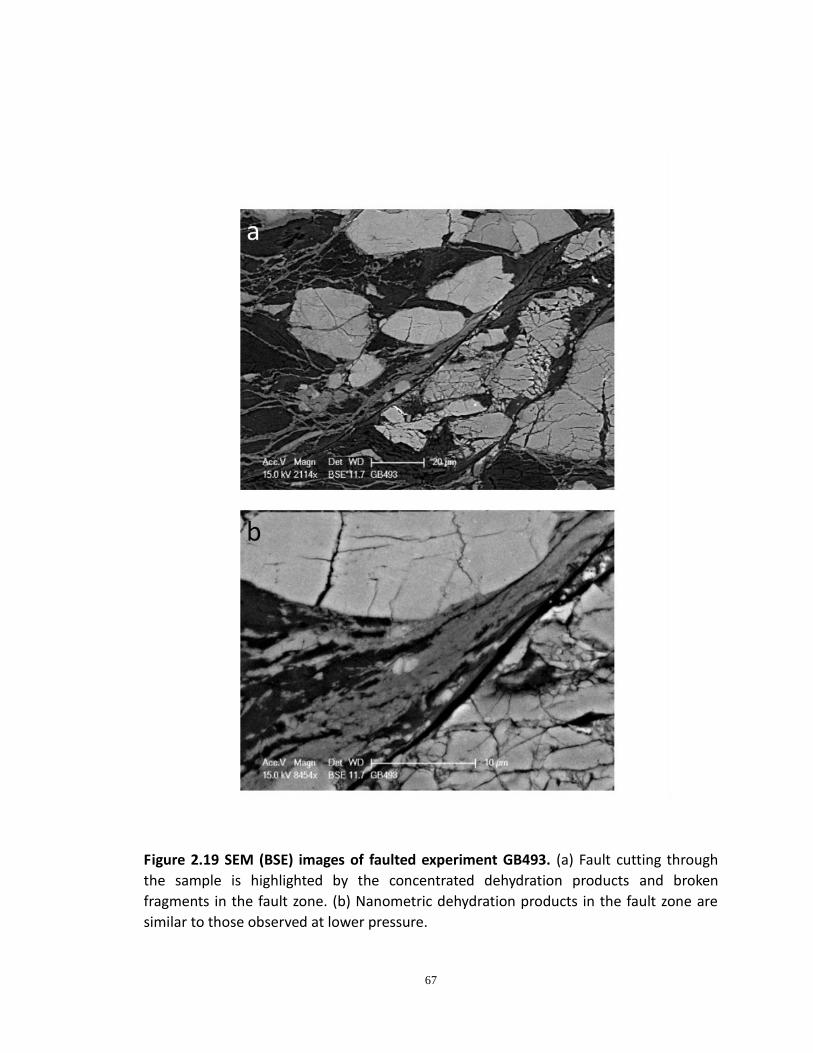
To further investigate the dehydration embrittlement phenomenon, I conducted an
additional experiment at 2.7 GPa and 720 ˚C (GB493, ~60 vol % serpentine content),
where unassisted brittle failure would be extremely unlikely and where the slope of the
dehydration reaction is negative, implying that the volume change of the reaction is also
negative. Given that these specimens are very strong, performing this experiment was
quite challenging. Because the strength would be every high at 2.8 GPa and 720 ˚C, there
was a significant probability that the stress on the tungsten carbide (WC) load piston
could reach the fracture strength, resulting in catastrophic failure. To control the stress
on the deformation piston safely below its failure limit, I used a sample of smaller
diameter (~2.55 mm) and placed a sleeve of palladium around it to fill out the specimen
capsule. Therefore, the same level of stress on the WC piston would generate a larger
stress on the sample because of its reduced diameter. The specimen was prepared as for
lower-pressure powder experiments; the original antigorite serpentinite was crushed,
mixed and encapsulated. The experiment was successful; at the end of deformation, the
specimen failed just below the stress limit of the piston. Faulting and dehydration
products were observed in the specimen by post-experiment SEM imaging, revealing
similar microstructures as those produced at lower pressures (Figure 2.19).
67
Figure 2.19 SEM (BSE) images of faulted experiment GB493. (a) Fault cutting through
the sample is highlighted by the concentrated dehydration products and broken
fragments in the fault zone. (b) Nanometric dehydration products in the fault zone are
similar to those observed at lower pressure.
68
This finding is consistent with previous work from our laboratory (Jung et al., 2004;
Jung and Green, 2004) that was also confirmed by acoustic emissions during dehydration
(Jung et al., 2009). As previously, our faulting microstructures are closely similar at all
pressures, even though here we have observed the faulting in a much wider composition
range. We, thus, confirm that the dehydration embrittlement mechanism is working
even under conditions where the total volume change of the dehydration reaction is
negative.
2.5 Conclusion
Over the last several years, experimental as well as numerical studies from different
groups have reached contrary conclusions about whether or not serpentinite fails by
ductile or brittle processes (e.g. Jung et al., 2004; Jung et al., 2009; Hirth and Kelemen,
2007; Chernak and Hirth, 2011). Results from my experiments provide an answer to this
dilemma, showing that dehydration-induced faulting occurs in a wide rang of
compositions but not in nearly pure serpentinite nor nearly pure peridotite (Xia et al.,
2012). Close to the peridotite end (GB513), there is too little H2O being released during
dehydration to produce bulk faulting. Similarly, as one looks at specimens of increasing
proportions of serpentine, specimens also become ductile. However, this is not because
more fluid is released but because the composition reaches sufficient antigorite so that
69
relict peridotite mineralogy is dispersed in the serpentinite matrix (GB495). Under such
conditions, antigorite rheology becomes the dominant factor in bulk rheology, the rock is
further weakened by dehydration but the material flows rather than fractures. The
amount of serpentine required to trigger the instability, in my study, is very limited, as
low as ~8 vol% at 1GPa, 993K and 10-4s-1.
Microanalysis from SEM and TEM strongly supported that both fluid release and the
solid dehydration products (nanometric olivine and talc) were involved in the weakening
process and fault formation. However, it is still not clear whether the fault is weakened
by the super-fine-grained materials or the fault itself promoted the super-fine-grained
materials within the fault zone.
2.6 Geophysical Implications
We observed, from SEM images, that in most specimens antigorite was at very early
stage of dehydration; only less than 5 vol% of antigorite was decomposed to olivine, talc
and water. This observation, combined with the fact that as little as 8 vol% antigorite
within the specimen was sufficient to induce faulting, indicates that less than 1 vol% of
water, released during dehydration, was enough to produce instability. This result is
consistent with that demonstrated by Zhang et al. (2004) who showed that less than 0.1
vol% fluid was sufficient to induce faulting and that whether or not specimens failed
70
could be controlled by manipulating the flow stress to be above or below the fracture
stress. Based on this result, we also suggest that faulting by this mechanism would still
occur even if hydration of oceanic mantle lithosphere is very limited, which is consistent
with the current consensus that there is not an apparent conduit for ocean water to
percolate down deep and extensively hydrate mantle peridotite. Perhaps partial
hydration of the deep portions of surficial faults produced during slab bending could be
the answer, although most such faults would be quasi-vertical in subducting lithosphere
and it has been shown by Warren et al. (2007) and Kiser et al. (2011) that
intermediate-depth earthquakes occur on quasi-horizontal faults. Indeed, our results
also suggest a way out of this latter conundrum. If the abundant trenchward-dipping
faults in subducting slabs are sufficiently serpentinized to enable them to slip silently
and at the same time small amounts of serpentine form on grain boundaries of bulk
mantle harzburgite, then the partially-altered harzburgite could fail during dehydration
yielding earthquakes on new faults in the conjugate orientation (subhorizontal).
Moreover, we suggest that the results of Chernak and Hirth (2011) may very well
explain the aseismic creep along the plate interface if that interface is cold enough to
stablize antigorite as fluid evolves from below as the altered crust and/or mantle of the
down-going slab dehydrates. Should that serpentine reach its dehydration point, the
71
fluid released would enhance ductility as proposed by Jung and Green (2005) and
demonstrated by Chernak and Hirth (2011).
2.7 Future Perspective
Most of experiments in this study are accomplished at 1 GPa. As it has been
proposed that the dehydration embrittlement of serpentine can still function at elevated
pressure conditions even when the total volume change of dehydration reaction
becomes negative, therefore It would be important to further investigate the pattern of
dehydration embrittlement of serpentinized peridotite at elevated pressure conditions,
corresponding to the deeper range of intermediate-depth earthquakes. Another series of
deformation experiments, similar to that accomplished at 1GPa, could be carried out at
3GPa and 6GPa in the Deformation-DIA apparatus installed at a synchrotron X-ray
radiation source, using acoustic emission monitoring, which would allow capture of
faulting "in situ". Subsequent tomographic imaging of the 3-D specimen geometry and
electron microscopy would confirm fault configurations.
72
ChapterChapterChapterChapter 3.3.3.3.EffectEffectEffectEffect ofofofof PressurePressurePressurePressure onononon CreepCreepCreepCreep ofofofof OlivineOlivineOlivineOlivine
73
3.13.13.13.1 AbstractAbstractAbstractAbstract
Rheological properties of mantle minerals are critical for understanding the
dynamics of Earth's deep interior. Polycrystalline olivine, which makes up more than 60
vol% of mantle portion of oceanic lithosphere, predominantly represents the rheology of
this region. Nevertheless, previous experimental studies carried out at varied pressures,
measuring the rheological properties of olivine at high temperature, produce bimodal
results. The activation volume (ΔV*) for creep of olivine reported from Griggs and
Paterson apparatus at relatively lower pressures is ~15 cm3/mol or even higher, while
higher pressure studies from D-DIA apparatus report a ΔV* near zero. In order to
address this issue and provide a standard for strength comparison between different
apparatus, we have conducted a series of experiments on a synthetic polycrystalline
forsterite, the Mg end member of olivine, in a modified Griggs apparatus with molten or
near-molton CsCl pressure media that is capable of high-quality measurement of stress
during deformation experiments under confining pressures up to ≥ 3 GPa. Our results
show a tightly constrained ΔV* of 12 ± 2 cm3/mol, which is similar to that for Mn2GeO4
olivine measured over the range of 0.4 - 4.0 GPa (Bai and Green, 1998), demonstrating a
significant pressure dependence of creep in nominally dry olivine at pressure lower than
3 GPa in the dislocation creep field.
74
3.23.23.23.2 IntroductionIntroductionIntroductionIntroduction
Olivine is stable over a wide pressure range, from that at Earth's surface to
approximately 15 GPa, corresponding to a depth of ~410 km where it transforms to its
higher pressure polymorph, wadsleyite. As the most abundant phase and the weakest
phase in the upper mantle, the rheological properties of olivine control the dynamic
processes of the upper mantle, including evolution of subduction zones (e.g. van Keken
et al., 2002, Gerya and Stöckhert, 2002), Earth's deep seismicity (e.g. Green and Burnley,
1989; Green et al., 1990, Green and Houston, 1995), upper mantle seismic anisotropy
(e.g. Kneller et al., 2005 & 2007, Mainprice et al, 2005; Jung et al., 2008), post-seismic
mantle relaxation (e.g. Freed and Bürgmann, 2004) and seismic attenuation (e.g. Jackson
et al., 2002). It has been known that the dominant deformation mechanism in olivine is
different from low temperature to high temperature (> ~900 ˚C) (Carter and
Ave'Lallemant, 1970; Nishihara et al., 2010; Raleigh, 1968; Tsenn and Carter, 1987; ).
In this study, high temperature dislocation creep behavior of olivine in the upper
mantle is described by the power-law equation:
)exp()1(**
2 RTVPEfA h
OHn ∆+∆
−⋅+⋅⋅= σε& (1)
where ε& is strain rate, A is material constant, σ is flow stress, n is stress exponent, h is
the water fugacity exponent for creep, ΔE* is activation energy, P is confining pressure,
75
ΔV* is activation volume, R is gas constant, T is temperature. Among these parameters,
the effect of pressure, represented by ΔV*, is probably one of the most intrinsic issues
that is still controversial. It is often argued that the strength of plastic flow material is
relatively insensitive to pressure compared to that in brittle regime where brittle
strength increases rapidly with pressure. However, the pressure range in Earth’s mantle
is so great that the ∆V* of mantle rocks is very important for Earth's deep interior. Plastic
deformation always involves overcoming the barrier for defect motion, which is
expressed by the effect of pressure on free energy for defect motion, namely the
activation volume ΔV* (Karato, 2008). The larger the pressure, the higher energy for
defect motion will be required. More importantly, the effect of pressure on fugacity of
some chemical species, e.g. H2O, will change the defect mobility with pressure. Borch
and Green (1989) also suggested that water enhances the pressure dependence of creep
in olivine, at least to pressure around 2 GPa. Therefore pressure dependence on plastic
deformation can be quite complicated under conditions of Earth's deep interior.
The earliest attempt to investigate the pressure dependence of creep in olivine can
be traced back to 50 years ago when Griggs et al. (1960) tried to test olivine-bearing
rocks under pressure. Currently the highest quality data on plastic deformation are
obtained by using the Paterson apparatus with gas pressure medium and internal
load-cell (Paterson, 1990). Experimental studies using Paterson apparatus with
76
well-controlled chemical environment have produced very important and accurate
results on plastic deformation of olivine (e.g., Mei and Kohlstedt, 2000). Despite the high
accuracy of stress measurement from Paterson apparatus, this apparatus can be
operated only at pressures up to 0.5 GPa, hence rheological properties under most
upper mantle condition have been inferred from results under low pressure condition,
but this kind of extrapolation could be wrong. Taking ΔV* as an example, it has been
argued that the effect of pressure on creep of minerals may itself be a function of
pressure (Borch and Green, 1989) rather than a constant. It becomes a more
complicated case when water is taken into account because it is known that water has a
significant effect on rheological properties of silicates, and the amount of water
dissolved in a mineral depends on the fugacity of water which increases as a function of
pressure (Karato, 2009). Bai and Green (1998) conducted experiments on α-Mn2GeO4
(olivine structure) and their results showed that the strengthening effect of pressure was
counteracted by the water-weakening effect, and the water weakening effect increases
with pressure because of higher H2O fugacity. This observation may explain the small ΔV*
value measured from high pressure studies (e.g. Li et al., 2006) as they used
water-bearing materials for their pressure media. All of these factors will make the
extrapolation questionable. Therefore, despite its accuracy in stress measurement, the
Paterson apparatus is limited by its limitation to low pressures.
77
The original Griggs apparatus, a modified piston cylinder device, extended the
experimental investigation of rock deformation up to ~1.8 GPa. Ross et al. (1979) carried
out the first creep experiments on dunite (polycrystalline olivine) and reported ΔV*≈13.4
cm3/mol. Unfortunately, their results are suspect because of the low accuracy of data
resulting from the very strong solid pressure medium that was available at that time; the
friction between the solid pressure medium and both the sample and the deformation
piston significantly compromised their stress measurements. Borch and Green (1989)
solved this problem by using the molten salt assembly, although their samples may have
contained sufficient water to interfere with their measurements (Hirth and Kohlstedt,
1996). They found their data to be inconsistent with a constant ΔV*; the implication of
their data was that ∆V* falls with increasing pressure. Karato and Jung (2003), using solid
NaCl or KCl as pressure medium reported ΔV* values of 14 ± 1 cm3/mol under dry
conditions and 24 ± 2 cm3/mol under wet conditions. Their stress values were deduced
from dislocation density; whether this method is appropriate for stress calculation
without adjustment for pressure effects needs to be further examined.
With significant technical progress in the last few decades, deformation apparatus
covering larger pressure ranges have been developed, including the Deformation-DIA
(D-DIA) apparatus (Wang et al., 2003) and Rotational Drickamer apparatus (RDA)
(Yamazaki and Karato, 2001). Li et al. (2004) reported a smaller ΔV* (less than 10
78
cm3/mol) at 8 GPa and 1200˚C. Multi-anvil apparatus were used in their studies, in which
control and knowledge of the level and state of differential stress is difficult. Li et al.,
(2006) extended their study using in situ D-DIA experiments while measuring stress and
strain with synchrotron X-ray radiation. They concluded that there is little or no effect of
pressure on dislocation creep of olivine, yielding a ΔV* of 0 ± 5 cm3/mol. Because they
used natural rocks and water-bearing pressure media, the effect of water was not well
characterized. Raterron et al., (2007) also reported a small ΔV* value of less than 3
cm3/mol, but a small activation energy for "dry" olivine single crystal (100 kJ/mol
compared to the well-known 400-500 kJ/mol), suggesting that Peierls mechanism, rather
than dislocation creep may have dominated deformation in their experiments. Kawazoe
et al. (2009) conducted shear deformation experiments on dry polycrystalline olivine
using RDA. They obtained a ΔV* of 15-20 cm3/mol. But their results have been
questioned for the macroscopic stress derivation (Burnley et al., 2008).
3.33.33.33.3 MotivationMotivationMotivationMotivation ofofofof thisthisthisthis studystudystudystudy
Table 3.1 lists some results from previous experimental studies. In spite of
substantial technical development during the last few decades, the high-pressure studies,
using the D-DIA apparatus, have amplified the discrepancy instead of placing constraints
on the earlier results. Reported ΔV* values, ranging from 0 to 28 cm3/mol, can cause
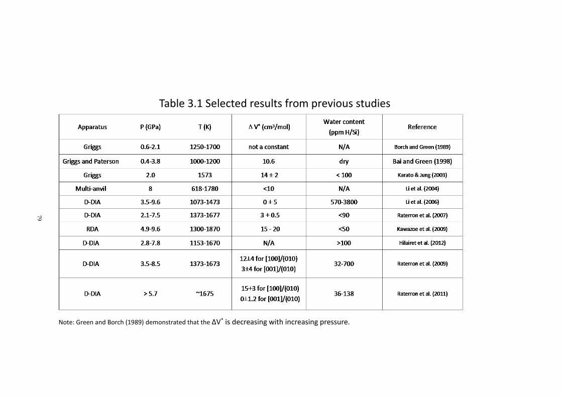
79
Table 3.1 Selected results from previous studies
Note: Green and Borch (1989) demonstrated that the ΔV* is decreasing with increasing pressure.
80
a difference in effective viscosity of olivine of 10 orders of magnitude at the bottom of
the upper mantle (~410 km) (Durham et al., 2009). Therefore, the effect of pressure on
creep in olivine is, at best, poorly understood. Part of this problem involves different
studies using different starting materials and part of it may well be due to apparatus
calibration for the very high-pressure apparatus.
In addition, evidence has emerged that there is a potential correlation between the
discrepancy of ΔV* value and the transition of lattice preferred orientation (LPO) in
olivine (Raterron et al., 2007 2009 & 2011, Hilairet et al., 2012). LPO (sometimes called
CPO, crystallographic preferred orientation) records the crystallographic rotations
induced by the active slip systems in materials flowing by dislocation creep. The pattern
of LPO in a material is termed its “fabric” (sometimes “microfabric”) in the geological
literature and is referred to as “texture” in the materials literature. It is very important
microstructural characteristic by which one can determine the underlying physical
process(es) of deformation or how a rock was formed in a certain environment. There
are quite a few LPOs that have been documented for olivine, among which A-type LPO
[100]/(010), a-slip, and B-type LPO [001]/(010), c-slip, could be responsible for the
difference of ΔV* value between low and high pressure studies. It has been proposed
that a-slip is inhibited with increasing pressure, resulting in a large ΔV* value, while c-slip,
which is virtually insensitive to pressure, results in a small ΔV* value (e.g., Raterron et al.,
81
2009). As single crystals were used in these studies, whether the result can be directly
applied to Earth's mantle, where polycrystalline aggregates are present, is not yet
established.
In order to examine the potential correlation between LPO and ΔV* in olivine using a
polycrystalline sample, as well as to obtain a robust ΔV* value and simultaneously
provide a standard for strength examination and comparison for various types of
apparatus, we have conducted a series of experiments on synthetic polycrystalline
forsterite with a confining pressure from 1 to 2.5 GPa to measure ΔV* of high
temperature dislocation creep in olivine.
3.43.43.43.4 StartingStartingStartingStarting MaterialsMaterialsMaterialsMaterials andandandand ExperimentalExperimentalExperimentalExperimental DescriptionDescriptionDescriptionDescription
3.4.13.4.13.4.13.4.1 StaringStaringStaringStaringMaterialsMaterialsMaterialsMaterials
Olivine is both the weakest phase in the upper mantle and also the most abundant
one, making up more than 60 vol% of the upper mantle at depths less than 410 km.
Therefore, to a first order approximation, upper mantle rheology is that of olivine. In our
study, we use iron-free forsterite (Mg2SiO4) plus a small excess of SiO2 that results in ~ 3
vol% coexisting enstatite, MgSiO3, to buffer the point defect populations appropriately
for comparison to the mantle. It has been shown that olivine has different point defect
distributions depending on whether it is in equilibrium with enstatite (MgSiO3) or with
82
periclase (MgO) and such differences can significantly affect the flow properties of
olivine (Kohlstedt et al., 1995), so a little extra SiO2 in the bulk materials can ensure that
the defect populations in forsterite are in equilibrium with enstatite (as in the mantle),
not periclase. Using forsterite, the Mg end member of the olivine series, undoubtedly
somewhat overestimates the strength of mantle olivine (Mg0.9,Fe0.1)2SiO4. However, it
also avoids the myriad problems that Fe can add to the experiments because of the
sensitivity of Fe to the oxygen fugacity, meaning that it can change from Fe2+ to Fe3+,
with a variety of corresponding difficulties. Our samples are essentially dry in that
molten alkali halides are very strong “getters” for H2O, hence any remaining
grain-boundary H2O is efficiently scavenged by the confining medium prior to
deformation.
3.4.23.4.23.4.23.4.2 SampleSampleSampleSample AssemblyAssemblyAssemblyAssembly andandandand ExperimentalExperimentalExperimentalExperimental ProcedureProcedureProcedureProcedure
Cylindrical Specimens, approximately 9mm long and 3 mm diameter were cored
from a ~7cm diameter specimen that was prepared by commercial hot pressing at 1400
˚C and 100 MPa. Both ends of each specimen were separately polished flat and square.
Each specimen was preheated in the vacuum oven at 110 ˚C for ~12 hours to remove any
interstitial or adsorbed molecular water before loading it into a cylindrical platinum
capsule. Capsules consist of two “half-capsules” of different diameter, each with a blind
end; one of which fits snugly over the other to make a closed capsule that cold welds
83
upon pressurization. A 25 μm thick Nickel foil was included within capsules at both top
and bottom to buffer the oxygen fugacity at Ni/NiO. The specimens, within their Pt
capsules, were then cast into molten salt pressure media as appropriate (CsCl or NaCl). A
standard sample assembly would be put together and seated into our modified 4 GPa
Griggs apparatus.
In our early experiments, specimens were first pressurized at room temperature to
~280MPa, the temperature was then ramped to 300˚C, followed by resumed
pressurization to target values. The temperature was then increased to 1200˚C, followed
by 1 hour annealing at target pressure and temperature. Deformation experiments were
conducted at strain rates of 10-5-10-4/s and a temperature of 1200˚C. Molten alkali
halides are very strong “getters” for H2O and hydrogen can diffuse through Pt at elevated
temperatures, hence any remaining grain-boundary H2O is efficiently scavenged by the
confining medium prior to deformation. The small amount of oxygen generated by this
loss of H as well as any residual oxygen trapped within the capsules during assembly will
react with the Ni foils at the ends of the specimens, thereby buffering the experiments
at the Ni-NiO oxygen buffer.
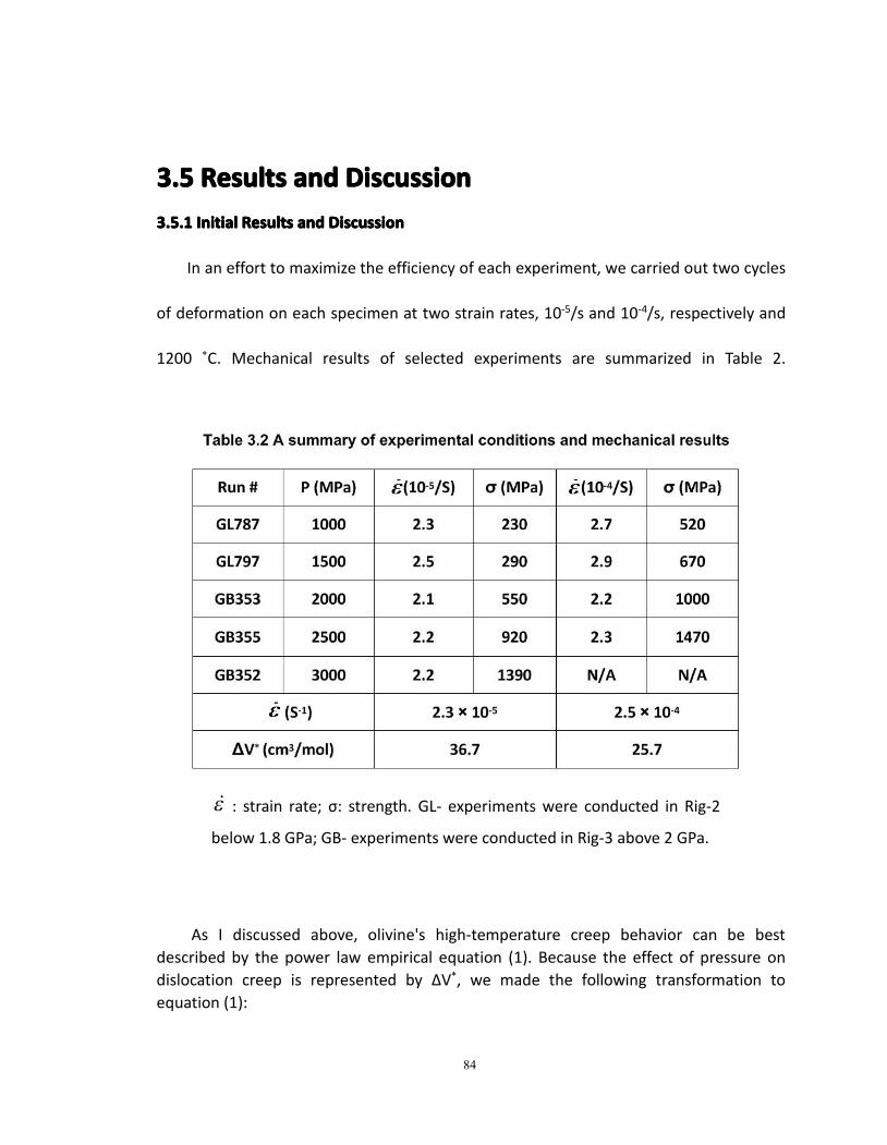
84
3.53.53.53.5 ResultsResultsResultsResults andandandand DiscussionDiscussionDiscussionDiscussion3.5.13.5.13.5.13.5.1 InitialInitialInitialInitial ResultsResultsResultsResults andandandand DiscussionDiscussionDiscussionDiscussion
In an effort to maximize the efficiency of each experiment, we carried out two cycles
of deformation on each specimen at two strain rates, 10-5/s and 10-4/s, respectively and
1200 ˚C. Mechanical results of selected experiments are summarized in Table 2.
As I discussed above, olivine's high-temperature creep behavior can be bestdescribed by the power law empirical equation (1). Because the effect of pressure ondislocation creep is represented by ΔV*, we made the following transformation toequation (1):
ε& : strain rate; σ: strength. GL- experiments were conducted in Rig-2
below 1.8 GPa; GB- experiments were conducted in Rig-3 above 2 GPa.
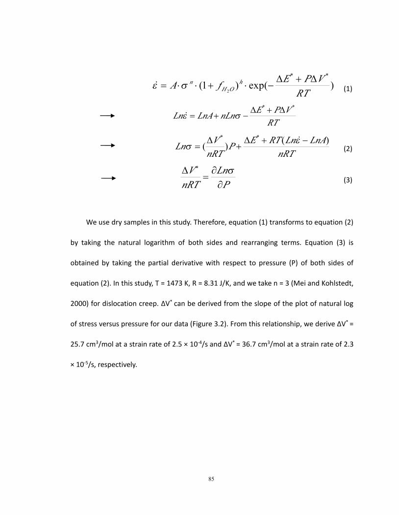
85
)exp()1(**
2 RTVPEfA h
OHn ∆+∆
−⋅+⋅⋅= σε& (1)
RTVPEnLnLnALn
** ∆+∆−+= σε&
nRTLnALnRTEP
nRTVLn )()(
** −+∆+
∆=
εσ
&(2)
PLn
nRTV
∂∂
=∆ σ∗
(3)
We use dry samples in this study. Therefore, equation (1) transforms to equation (2)
by taking the natural logarithm of both sides and rearranging terms. Equation (3) is
obtained by taking the partial derivative with respect to pressure (P) of both sides of
equation (2). In this study, T = 1473 K, R = 8.31 J/K, and we take n = 3 (Mei and Kohlstedt,
2000) for dislocation creep. ΔV* can be derived from the slope of the plot of natural log
of stress versus pressure for our data (Figure 3.2). From this relationship, we derive ΔV* =
25.7 cm3/mol at a strain rate of 2.5 × 10⁻⁴/s and ΔV* = 36.7 cm3/mol at a strain rate of 2.3
× 10-5/s, respectively.
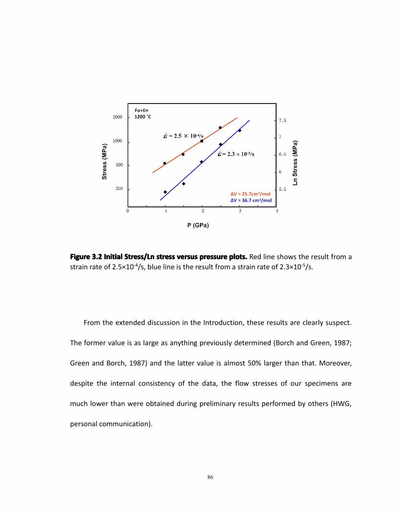
86
FigureFigureFigureFigure 3.23.23.23.2 InitialInitialInitialInitial Stress/LnStress/LnStress/LnStress/Ln stressstressstressstress versusversusversusversus pressurepressurepressurepressure plots.plots.plots.plots. Red line shows the result from astrain rate of 2.5×10⁻⁴/s, blue line is the result from a strain rate of 2.3×10⁻⁵/s.
From the extended discussion in the Introduction, these results are clearly suspect.
The former value is as large as anything previously determined (Borch and Green, 1987;
Green and Borch, 1987) and the latter value is almost 50% larger than that. Moreover,
despite the internal consistency of the data, the flow stresses of our specimens are
much lower than were obtained during preliminary results performed by others (HWG,
personal communication).
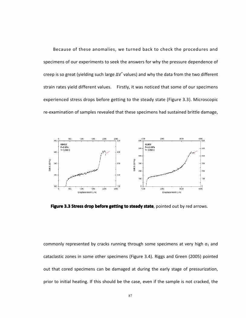
87
Because of these anomalies, we turned back to check the procedures and
specimens of our experiments to seek the answers for why the pressure dependence of
creep is so great (yielding such large ΔV* values) and why the data from the two different
strain rates yield different values. Firstly, it was noticed that some of our specimens
experienced stress drops before getting to the steady state (Figure 3.3). Microscopic
re-examination of samples revealed that these specimens had sustained brittle damage,
FigureFigureFigureFigure 3.33.33.33.3 StressStressStressStress dropdropdropdrop beforebeforebeforebefore gettinggettinggettinggetting totototo steadysteadysteadysteady statestatestatestate, pointed out by red arrows.
commonly represented by cracks running through some specimens at very high σ1 and
cataclastic zones in some other specimens (Figure 3.4). Riggs and Green (2005) pointed
out that cored specimens can be damaged at during the early stage of pressurization,
prior to initial heating. If this should be the case, even if the sample is not cracked, the
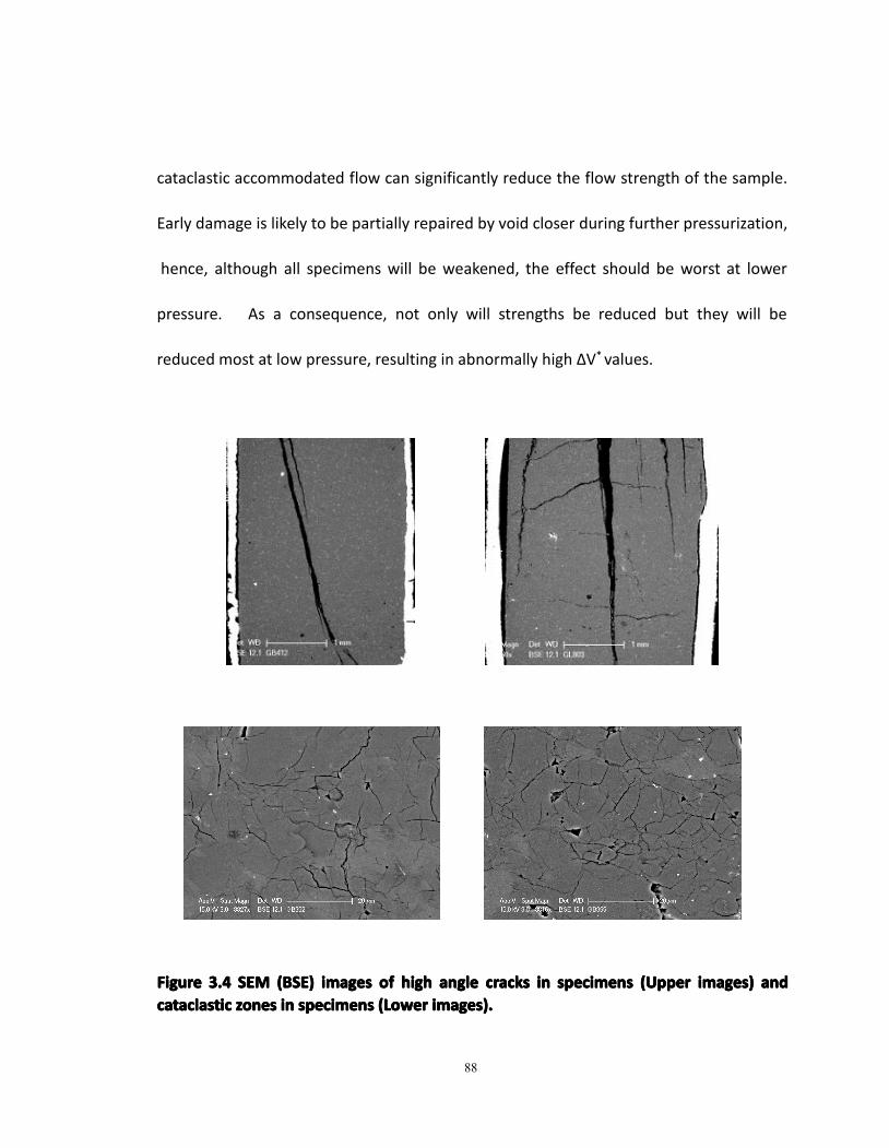
88
cataclastic accommodated flow can significantly reduce the flow strength of the sample.
Early damage is likely to be partially repaired by void closer during further pressurization,
hence, although all specimens will be weakened, the effect should be worst at lower
pressure. As a consequence, not only will strengths be reduced but they will be
reduced most at low pressure, resulting in abnormally high ΔV* values.
FigureFigureFigureFigure 3.43.43.43.4 SEMSEMSEMSEM (BSE)(BSE)(BSE)(BSE) imagesimagesimagesimages ofofofof highhighhighhigh angleangleangleangle crackscrackscrackscracks inininin specimensspecimensspecimensspecimens (Upper(Upper(Upper(Upper images)images)images)images) andandandandcataclasticcataclasticcataclasticcataclastic zoneszoneszoneszones inininin specimensspecimensspecimensspecimens (Lower(Lower(Lower(Lower images).images).images).images).
89
3.5.23.5.23.5.23.5.2ModifiedModifiedModifiedModified ProcedureProcedureProcedureProcedure andandandand ResultsResultsResultsResults
In order to rectify these problems, I started over this series of experiments with
revised experimental procedures developed by Riggs and Green (2005). Brittle damage
was avoided by much more gentle pressurization. In our sample assembly, void space
is purposefully left between the upper graphite disk and the carbon furnace to protect
the furnace from damage while going to pressure (see discussion in Chapter 1).
However, a side effect of that procedure is that until the graphite disk and the furnace
make contact, the temperature cannot be raised. Therefore, to enable sample heating
at a lower pressure to avoid brittle damage, we shortened the top salt ring of the
assembly (see Figure 1.4) by 0.03'' (0.76mm) to allow contact between graphite cap and
furnace at a lower pressure and thereby enable initiation of heating earlier. Previously,
cold compression to ~ 200 MPa was required to establish furnace contact and initiate
heating. With this small change, early stage heating could begin at a pressure of 40 MPa.
In addition, because the sample material of this study is very refractory, we accomplish
the remainder of pressurization very slowly (~1 MPa/min) at an elevated temperature of
527 ˚C. As a consequence, the modified procedure is very beneficial overall; it allows
early softening of assembly parts which efficaciously avoids brittle damage to the
specimen and to the furnace.
90
In addition, in the new series of experiments, we carried out only one cycle of
deformation for each specimen to minimize the possibility of specimen damage during
back and forth of the deformation piston at high temperature. CsCl and NaCl salt
pressure media were used for experiments below 1.5 GPa and above 2 GPa, respectively.
Using these two salts in this way, we were able to have the confining medium molten or
very close to the melting temperature (and therefore very weak) in all experiments,
maximizing the accuracy of stress measurement at all pressures to obtain a
better-constrained ΔV* value. We changed salts at 2 GPa because the molten salt cell
works best when the salt around the specimen is molten but that otherwise the salt is
solid, stabilizing the assembly.
With these changes in place, we repeated our previous experiments, focusing on a
strain rate of 10-4s-1. Typical force-time curves (expressed as stress on the piston vs.
displacement) are shown in Figure 3.5. Red arrows point out the abrupt steepening of
the force curve when the Al2O3 piston encounters the specimen. Note that the force
record prior to the “hit point” is essentially horizontal, indicating that the friction on the
piston is constant as it advances through the low-viscosity molten salt and abruptly
“hits” the specimen (Borch and Green, 1989). As a result of the friction not being time
dependent, the force difference between the hit point and the flow stress is
unambiguously an accurate measurement of the stress applied to the specimen.
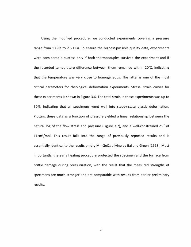
91
Using the modified procedure, we conducted experiments covering a pressure
range from 1 GPa to 2.5 GPa. To ensure the highest-possible quality data, experiments
were considered a success only if both thermocouples survived the experiment and if
the recorded temperature difference between them remained within 20˚C, indicating
that the temperature was very close to homogeneous. The latter is one of the most
critical parameters for rheological deformation experiments. Stress- strain curves for
these experiments is shown in Figure 3.6. The total strain in these experiments was up to
30%, indicating that all specimens went well into steady-state plastic deformation.
Plotting these data as a function of pressure yielded a linear relationship between the
natural log of the flow stress and pressure (Figure 3.7), and a well-constrained ΔV* of
11cm3/mol. This result falls into the range of previously reported results and is
essentially identical to the results on dry Mn2GeO4 olivine by Bai and Green (1998). Most
importantly, the early heating procedure protected the specimen and the furnace from
brittle damage during pressurization, with the result that the measured strengths of
specimens are much stronger and are comparable with results from earlier preliminary
results.
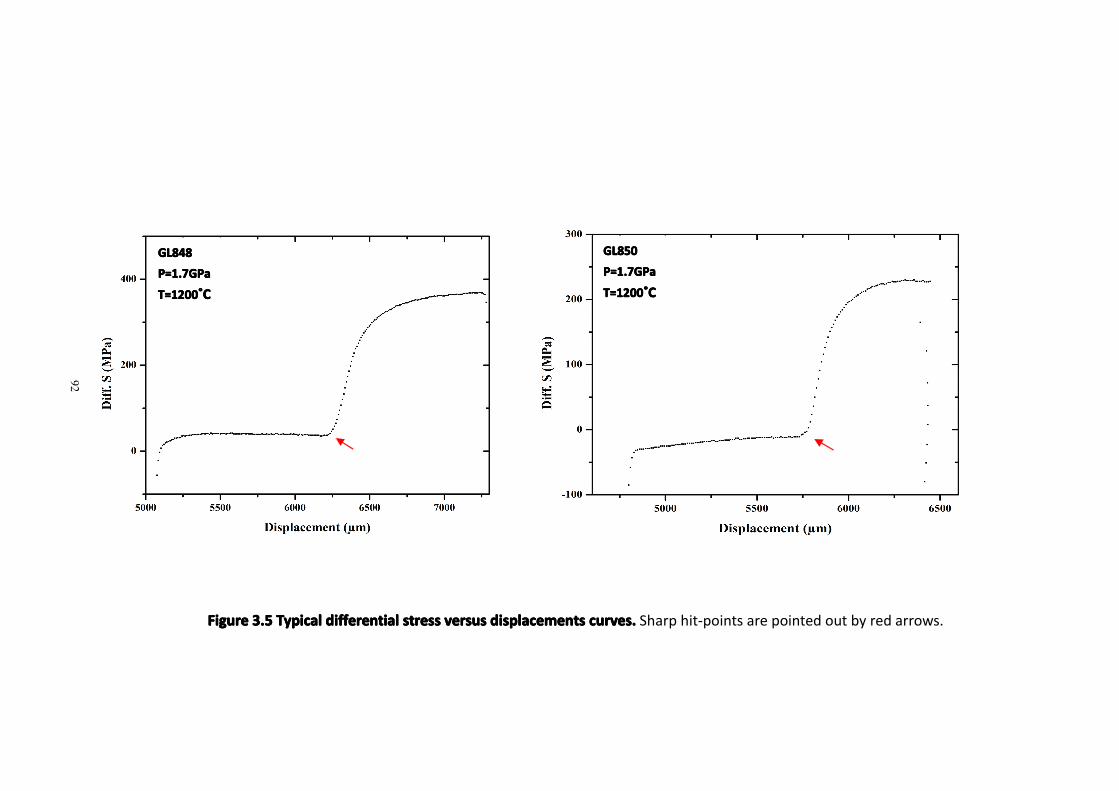
FigureFigureFigureFigure 3.53.53.53.5 TypicalTypicalTypicalTypical differentialdifferentialdifferentialdifferential stressstressstressstress versusversusversusversus displacementsdisplacementsdisplacementsdisplacements curves.curves.curves.curves. Sharp hit-points are pointed out by red arrows.
GL848GL848GL848GL848P=1.7GPaP=1.7GPaP=1.7GPaP=1.7GPa
T=1200T=1200T=1200T=1200˚̊̊̊CCCC
GL850GL850GL850GL850P=1.7GPaP=1.7GPaP=1.7GPaP=1.7GPa
T=1200T=1200T=1200T=1200˚̊̊̊CCCC
92
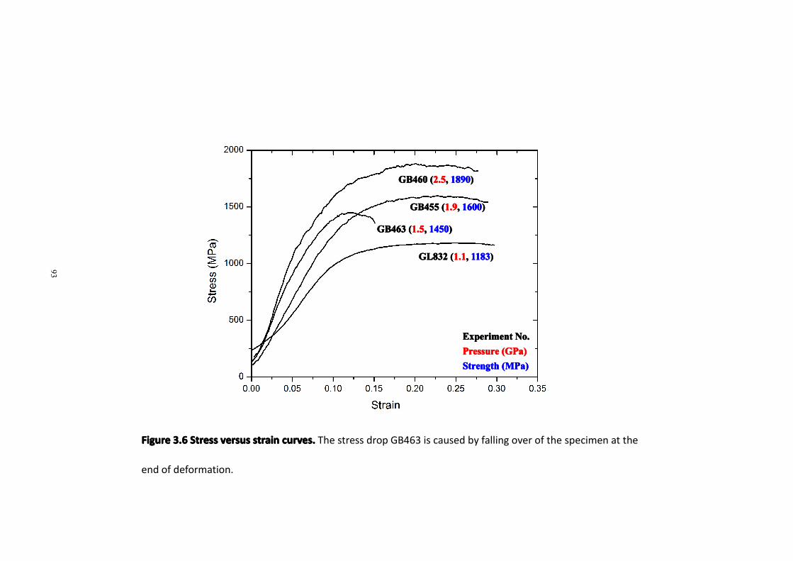
93
FigureFigureFigureFigure 3.63.63.63.6 StressStressStressStress versusversusversusversus strainstrainstrainstrain curves.curves.curves.curves. The stress drop GB463 is caused by falling over of the specimen at the
end of deformation.
GL832GL832GL832GL832 ((((1.11.11.11.1,,,, 1183118311831183))))
GB463GB463GB463GB463 ((((1.51.51.51.5,,,, 1450145014501450))))
GB455GB455GB455GB455 ((((1.91.91.91.9,,,, 1600160016001600))))
GB460GB460GB460GB460 ((((2.52.52.52.5,,,, 1890189018901890))))
ExperimentExperimentExperimentExperiment No.No.No.No.PressurePressurePressurePressure (GPa)(GPa)(GPa)(GPa)StrengthStrengthStrengthStrength (MPa)(MPa)(MPa)(MPa)
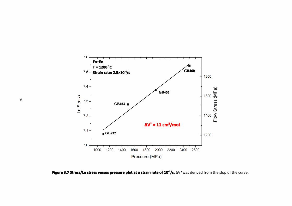
94
FigureFigureFigureFigure 3.73.73.73.7 Stress/LnStress/LnStress/LnStress/Ln stressstressstressstress versusversusversusversus pressurepressurepressurepressure plotplotplotplot atatatat aaaa strainstrainstrainstrain raterateraterate ofofofof 10101010-4-4-4-4/s./s./s./s. ΔV*was derived from the slop of the curve.
GL832GL832GL832GL832
GB463GB463GB463GB463
GB455GB455GB455GB455
GB460GB460GB460GB460
Fo+Fo+Fo+Fo+EnEnEnEnTTTT ==== 1200120012001200 ˚̊̊̊CCCCStrainStrainStrainStrain rate:rate:rate:rate: 2.52.52.52.5××××10101010-4-4-4-4/s/s/s/s
ΔΔΔΔVVVV**** ==== 11111111 cmcmcmcm3333/mol/mol/mol/mol
95
In order to confirm the ΔV* value as well as to examine the strain rate effect on
ΔV*, we carried out a few experiments at strain rates of 10-5/s and a temperature of
1200 ˚C. The stress versus strain curves are shown in Figure 3.8. These curves were
smoothed by polynomial fitting to minimize the disturbance from mechanical noise
in the apparatus due to a noisy control valve on the hydraulic drive. As we found for
10-4s-1 experiments, measured strengths are higher than those in the initial series of
experiments. Again, there is a linear relationship between the natural log of stress
and pressure (Figure 3.9), but in this case resulting in a ΔV* value of 14.7 cm3/mol.
Given the noisy data at a strain rate of 10-5/s and the less-abrupt hit points in the
measurements, we do not consider this slightly larger ΔV* value to be significantly
different from the value obtained at 10-4/s. We believe that our results are best
represented by a value of 12 ± 2 cm3/mol.
Based on the presentation above and the rigorous control of these experiments,
we conclude that ΔV* = 12 ± 2 cm3/mol is a robust value for creep of dry olivine at P <
3 GPa.
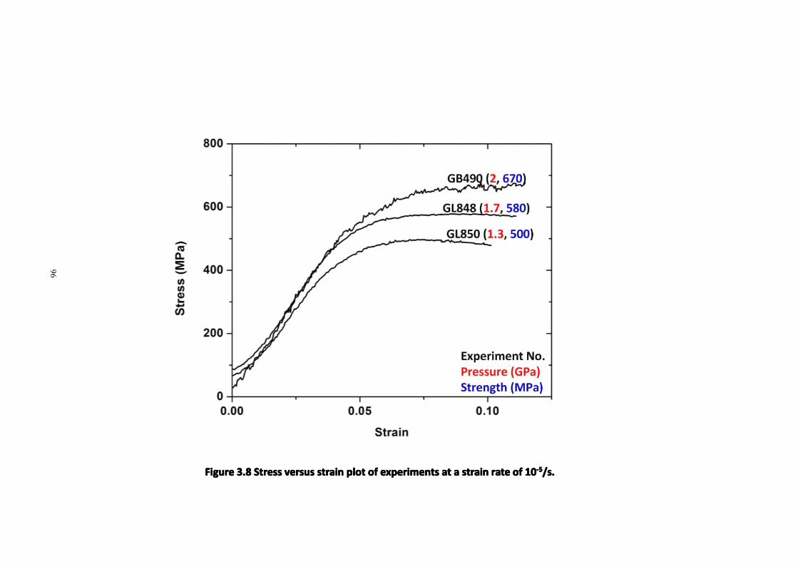
96
FigureFigureFigureFigure 3.83.83.83.8 StressStressStressStress versusversusversusversus strainstrainstrainstrain plotplotplotplot ofofofof experimentsexperimentsexperimentsexperiments atatatat aaaa strainstrainstrainstrain raterateraterate ofofofof 10101010-5-5-5-5/s./s./s./s.
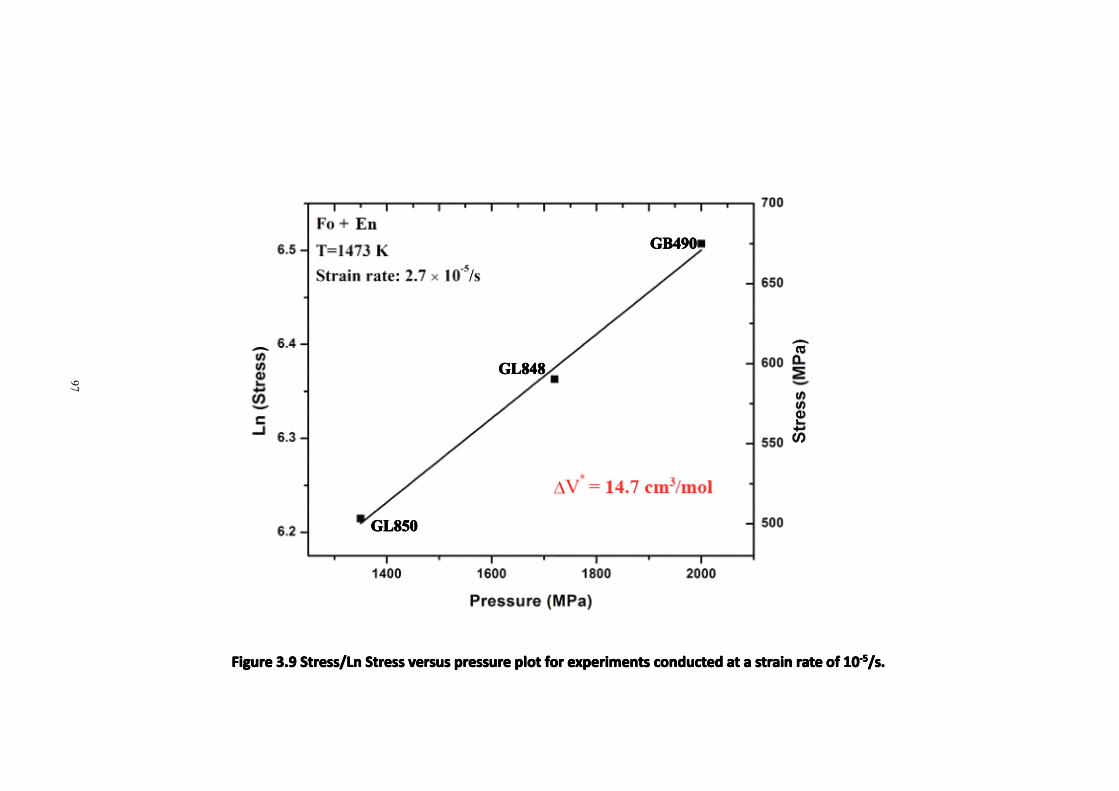
97
FigureFigureFigureFigure 3.93.93.93.9 Stress/LnStress/LnStress/LnStress/Ln StressStressStressStress versusversusversusversus pressurepressurepressurepressure plotplotplotplot forforforfor experimentsexperimentsexperimentsexperiments conductedconductedconductedconducted atatatat aaaa strainstrainstrainstrain raterateraterate ofofofof 10101010-5-5-5-5/s./s./s./s.
GL850GL850GL850GL850
GL848GL848GL848GL848
GB490GB490GB490GB490
98
3.63.63.63.6 ConclusionConclusionConclusionConclusion
The results of this study provide a very robust result for the ∆V* of olivine at
relatively low pressures under dry conditions. By comparison, ΔV* values from very
high pressure studies (> ~6 GPa) are very small, near zero (Li et al., 2004 & 2006).
The most obvious difference between the very high pressure studies and ours is the
starting material. We have used synthetic forsterite and others have used natural
rocks that contain significant amounts of water, plus they used water-bearing
pressure media. Much of the difference between their results and ours, therefore,
may be that their ΔV*measurement are a result for wet olivine. Bai and Green (1998),
using the same apparatus as ours (and including low-pressure data obtained in the
Kohlstedt gas apparatus) demonstrated that the presence of water can significantly
weaken the flow strength of manganese germanate olivine, and this water
weakening effect is greater at higher pressure than at lower pressure. It is likely
that this is the result of both the solubility of water in olivine and the fugacity of H2O
increase substantially with increasing pressure.
Another major difference between our 5 GPa Griggs apparatus and multi-anvil
apparatus is that in the latter case, stress measurement is by X-ray diffraction (using
synchrotron radiation) and the correct procedure for reducing such microstress
measurements to macroscopic stress remains controversial (Burnley and Zhang,
2008). The problem is that X-ray diffraction measurements of specimens under stress
99
in synchrotron experiments yields individual diffraction ellipses that differ in their
ellipticity and therefore, by implication, different elastic strains from which different
stresses are calculated. The explanation of this apparent paradox is that each
diffraction ellipse is sampling a different population of grains and those different
populations actually are supporting different stresses. A nontrivial question then
arises concerning how to extract the macroscopic stress like that measured in
conventional apparatus (like ours) from these families of crystal orientations.
Fortunately, important progress has been made to solve this problem during the last
few years. Using the Elastic-Plastic Self Consistent (EPSC) modeling, coded by Tuner
and Tome (1994), Burnley and Zhang (2008) successfully calculated the macroscopic
stress and strain for their quartz specimens deformed in the D-DIA. At minimum,
this process yields an objective result relieving the experimentalist from the danger
of perhaps choosing a favored diffraction ellipse that yields the wrong answer.
However, in the particular case of Burnley and Zhang (2008), their calculations
yielded the counter-intuitive result that the macrostress supported by the sample
was greater than the stress inferred from any of their diffraction ellipses. Such a
result is not impossible; the experimentalist is restricted to the strongest diffraction
lines and those may not sample the most highly stressed family of grains. Stress
measurement in the synchrotron remains an area of active research in itself.
100
Another complexity was alluded to earlier in this dissertation. The discrepancy
between our ΔV* value and the smaller values found at higher pressure could be
related to a pressure-induced transition of easiest slip systems in olivine. Evidence
has been accumulated that there is correlation between the drop of ΔV* value and
transition of slip system in olivine (Durinck et al., 2005; Raterron et al., 2007, 2009 &
2011; Hilairet et al., 2012). Raterron et al. (2007) documented a slip system transition
in dry olivine with increasing pressure from a-slip to c-slip, with a-slip dominating at
pressure lower than 3 GPa. This could explain the attenuation of seismic anisotropy
in the upper mantle, while c-slip, dominant at pressure higher than 7 GPa, could
explain the seismic-anisotropy anomalies observed along subduction zones. Jung
and Karato (2001) demonstrated that water fugacity can change the dominant slip
system and thereby produce LPO transitions in olivine. However, Jung et al. (2008)
later showed that pressure alone can induce the LPO transition in olivine from a-slip
to c-slip at ~3GPa. More recently, Raterron et al. (2009) carried out D-DIA
experiments on San Carlos olivine single crystals, oriented to promote either a-slip or
c-slip, respectively. Their result pointed out, the first time, that the discrepancy of
ΔV* measurement between low and high pressure studies could be explained by the
transition of slip system in olivine. They found that a-slip is very sensitive to pressure,
resulting in a large ΔV* (12 ± 4 cm3/mol) that is similar to our results whereas c-slip is
essentially insensitive to pressure, resulting in a small ΔV*= 3 ± 4 cm3/mol that is
similar to other high pressure results. Hilairet et al. (2012) resolved the dominant slip
101
system using EPSC modeling, showing a gradual transition of slip system in olivine
between 3-4 GPa. They also suggested that the comparison of ΔV* value should be
based on more detailed work on the deformation mechanism, as most high pressure
studies on synchrotron facilities use samples with very small grain sizes (less than 10
μm) that will significantly affect the dominant deformation mechanism.
3.73.73.73.7 FutureFutureFutureFuture perspectivesperspectivesperspectivesperspectives
Based on the discussion above, resolution of understanding of the pressure
dependence of creep in olivine would appear to be on the horizon. Questions
remaining involve the accuracy and procedure of stress measurement in the D-DIA as
well as more detailed understanding of the effects of water and slip systems. Based
upon our robust determination of the pressure dependence of creep in olivine at
pressures below 3 GPa, we are planning to perform collaborative experiments in the
D-DIA apparatus on the same forsterite polycrystalline sample we used in this study.
Using an overlapping pressure range should allow us to both calibrate stress
measurement in the D-DIA and simultaneously investigate the ∆V* of forsterite over
a wide range of pressure, perhaps to as high as 12 GPa.
Moreover, with the progress of technical development, electron backscatter
diffraction (EBSD) measurements in the SEM have been widely used to study the LPO
of various phases. We are planning to carry out the post-experiment analysis,
102
combining the use of EBSD to examine the LPO in olivine deformed at both low
pressure and high pressure conditions as well as direct slip-system determination
using TEM and oxidation techniques in the SEM. These studies should enable us to
determine whether the difference of ∆V* at low and high pressures is induced by slip
system transition or is somehow the result of inappropriate calibration of high
pressure apparatus (e.g. D-DIA).

Chapter 4. Conclusions and Future Work
103
In this dissertation, I report my experimental studies on compositional
dependence of dehydration embrittlement in serpentinized peridotite and the effect
of pressure on creep in olivine, including detailed description of systematic
experimental investigation on serpentinized peridotite and forsterite, extensive SEM
analysis and a TEM analysis on the microstructure of fault zone materials induced by
serpentine dehydration. My results provide new pieces of important information for
intermediate-depth earthquakes, hydration of oceanic mantle lithosphere, and upper
mantle rheology.
4.1 Serpentine Dehydration Embrittlement
4.1.1 Summary
I conducted high pressure (1-2.7 GPa) and high temperature (720-750 ˚C)
deformation experiments on variably serpentinized peridotite. Microscopic analysis
shows coherent submicron-sized solid dehydration products, olivine and talc, in the
fault zones, and Mode I cracks as well as fluid inclusion trails in surrounding olivine
grains close to the fault. At 1 GPa and a strain rate of 10-4/s, dehydration induced
faulting is observed from ~8 vol% antigorite specimen to ~65 vol% antigorite
specimen. The 2.7 GPa experiment, containing ~60 vol% serpentine, demonstrates
similar dehydration-induced faulting configuration as well as the nanometric
dehydration products in the fault zone.
104
4.1.2 Conclusion
I conclude that (i) dehydration embrittlement occurs in a wide window of the
composition of serpentinized peridotite, ranging from very small amounts of
antigorite to more than half antigorite; (ii) near the composition of pure harzburgite,
there is too little H2O production during dehydration to produce a faulting instability;
(iii) In compositions in which antigorite, greatly dominates, dehydration simply
facilitates flow of serpentinite because soft and ductile antigorite becomes the
interconnected matrix and relict peridotite mineralogy is dispersed in the matrix. This
observation can be used to explain the serpentine diapers in the forearc and the
aseismic forearc mantle wedge that is believed to be highly serpentinized. (iv)
Observation of nanometric solid dehydration products in the fault zone, and
extensive Mode I cracks as well as fluid inclusion trails in the surrounding olivine
grains indicate their involvement in the fault initiation process. (v) Dehydration
embrittlement can still function at elevated pressure conditions where the total
volume change becomes negative (Jung et al., 2004; Jung and Green, 2004). (vi)
serpentinization of oceanic mantle lithosphere could be very limited and yet still
trigger faulting during dehydration, providing a potential answer to the conundrum
of how ocean water can percolate as deep as 40 km beneath trenches and trigger
earthquakes.
105
4.1.3 Future Work
Most of my experiments were carried out at 1 GPa. Whether such a
compositional dependence pattern for serpentine dehydration embrittlement is
repeatable at higher pressures is still unknown. In the future, it would be of salient
interest to investigate the pattern of dehydration embrittlement of serpentinized
peridotite at higher pressure conditions, corresponding to the deeper range of
intermediate-depth earthquakes. Another series of deformation experiments, similar
to that accomplished at 1GPa, could be carried out at 3GPa and even 6GPa in a
Deformation-DIA apparatus installed at a synchrotron X-radiation source, using
acoustic emission monitoring which would allow capture of faulting "in situ".
Subsequent tomographic imaging of the 3-D specimen geometry and electron
microscopy would confirm fault configurations.
4.2 ΔV* in Creep of Olivine
4.2.1 Summary
Because the ΔV*value is still poorly constrained, I conducted high pressure
(1-2.5 GPa) and high temperature (1200 ˚C) deformation experiments on forsterite
using the 5 GPa Green-modified Griggs apparatus at strain rates of 10-4/s and 10-5/s
respectively, and showed a robust ΔV* of 12 ± 2 cm3/mol below 3 GPa for iron-free
forsterite in the dislocation creep field.
106
4.2.2 Conclusion
My results indicate a significant pressure dependence of creep in olivine down
to ~100km. After careful examination, we suggest that the ΔV* (near zero) obtained
from higher-pressure experimental studies, using D-DIA apparatus at synchrotron
x-ray radiation source, are questionable because of the small sample grain size (less
than 10μm) used and, perhaps, inadequate stress derivation from X-ray diffraction
patterns. Moreover, results from single-crystal experiments by Ratteron et al. (2009 &
2011) may not be directly extrapolated to Earth which are made up of polycrystalline
minerals. Last but not least, when natural rocks and/or water-bearing pressure media
are used, it could be H2O, rather than pressure, that is responsible for a ΔV* near
zero, e.g. Li et al., 2006. That argument was initially made 15 years ago with a
very-high-quality data set on the flow of Mn2GeO4 olivine (Bai and Green, 1998).
4.2.3 Future Work
In collaboration with other experimentalists, we will carry out experiments on
the same forsterite starting material as this study using D-DIA apparatus and derive
stress via EPSC modeling that can generate more representatively macroscopic stress.
The result will eventually provide an important calibration standard for a wide variety
of studies at elevated pressure using the D-DIA apparatus. As it has been proposed
that there is a correlation between the transition of LPO in olivine and the
discrepancy in ∆V* values, it would be of great importance to measure the LPO in
107
olivine from both low and high pressure experiments. The results should enable
resolution of the disagreements about ∆V* of creep and improve our understanding
on the correlation between LPO and ∆V* of olivine.
108
References
Abers, G. A., 1992. Relationship between shallow- and intermediate-depth seismicity in the Eastern Aleutian Subduction Zone. Geophys. Res. Lett. 19: 2019-2022.
Abers, G. A., 1996. Plate structure and the origin of double seismic zones. Geophys. Monogr. Ser. 96: 223-228.
Akira, H., Norihito, U., and Akio, T., 1978. Double-planed structure of the deep seismic zone in the northeastern Japan arc. Tectonophysics, 47: 43-58.
Angel, R. J., Frost, D. J., Ross, N. L., and Hemley, R., 2001. Stabilities and equations of state of dense hydrous magnesium silicates. Phys. Earth. Planet. Int. 127: 181-196.
Bai, Q. and Green II, H., 1998. Plastic Flow of Mn2GeO4 I: Toward a Rheological Model of the Earth's Transition Zone. Geophysical Monograph- American Geophysical Union, 101: 461-472.
Borch, R. S., and Green II, H. W., 1987. Dependence of creep in olivine on homologous temperature and its implications for flow in the mantle. Nature, 330: 345-348.
Borch, R. S. and Green II, H. W., 1989. Deformation of peridotite at high pressure in a new molten salt cell: comparison of traditional and homologous temperature treatments. Phys. Earth. Planet. Int. 55: 69-76.
Bostock, M., Hyndman, R., Rondenay, S., and Peacock, S., 2002. An inverted continental Moho and serpentinization of the forearc mantle. Nature, 417, 536-538.
Boulller, A. M. and Nicolas, A., l973. Texture and fabric of peridotite nodules from kimberlite at Mothae, Thaba Putsoa and Kimberley. In Lesotho Kimberlites (editor, P. H. Nixon), pp. 56-66.
Brudzinski, M., Thurber, C., Hacker, B., and Engdahl, E., 2007. Global prevalence of double Benioff zones. Science, 316: 1472-1474.
109
Burnley, P. C., Green II, H. W., and Prior, D. J., 1991. Faulting associated with the olivine to spinel transformation in Mg2GeO4 and its implications for deep-focus earthquakes. J. Geophys. Res. 96: 425-443.
Burnley, P. C. and Zhang, D., 2008. Interpreting in situ x-ray diffraction data from high pressure deformation experiments using elastic–plastic self-consistent models: an example using quartz. J. Physics : Condensed Matter 20: 285201-285210.
Carter, N.L., Ave'Lallemant, H. G., 1970. High Temperature Flow of Dunite and Peridotite. Geo. Soc. Am. Bull. 81: 2181.
Chen, W. and Brudzinski, M., 2001. Evidence for a large-scale remnant of subducted lithosphere beneath Fiji. Science, 292: 2475-2479.
Chen, W. and Brudzinski, M., 2003. Seismic anisotropy in the mantle transition zone beneath Fiji-Tonga. Geophys. Res. Lett. 30: 1682-1685.
Chernak, L. J. and Hirth, G., 2011. Syndeformational antigorite dehydration produces stable fault slip. Geology, 39: 847-850.
Christensen, N. I., 1996. Poisson's ratio and crustal seismology. J. Geophys. Res. 101: 3139-3156.
Couvy, H., Frost, D. J., Heidelbach, F., Nyilas, K., Ungar, T., Mackwell, S., and Cordier, P., 2004. Shear deformation experiments of forsterite at 11 GPa - 1400°C in the multianvil apparatus. Eur. J. Mineral. 16: 877-889.
Davies, J. H. and Stevenson, D., 1992. Physical model of source region of subduction zone volcanics. J. Geophys. Res. 97: 2037-2070.
DeShon, H. R., Schwartz, S. Y., 2004. Evidence for serpentinization of the forearc mantle wedge along the Nicoya Peninsula, Costa Rica. Geophys. Res. Lett. 31: L21611.
Diedrich, T., Sharp, T. G., Leinenweber, K., and Holloway, J. R., 2009. The effect of small amounts of H2O on olivine to ringwoodite transformation growth rates and implications for subduction of metastable olivine. Chem. Geol. 262: 87-89.
110
Dobson, D., Meredith, P., and Boon, S., 2002. Simulation of subduction zone seismicity by dehydration of serpentine. Science, 298: 1407-1410. Dupas-Bruzek, C., Tingle, T., and Green, H., 1998. The rheology of olivine and spinel magnesium germanate (Mg2GeO4): TEM study of the defect microstructures. Phys. chem. Minerals. 25: 501-514. Durham, W. B., Mei, S., Kohlstedt, D. L., Wang, L., and Dixon, N. A., 2009. New measurements of activation volume in olivine under anhydrous conditions. Phys. Earth. Planet. Int. 172: 67-73. Durinck, J., Legris, A., and Cordier, P., 2005. Pressure sensitivity of olivine slip systems: first-principle calculations of generalised stacking faults. Phys. chem. Minerals. 32: 646-654. Elliott, T., Plank, T., Zindler, A., White, W., and Bourdon, B., 1997. Element transport from slab to volcanic front at the Mariana arc. J. Geophys. Res. 102: 14991. Engdahl, E. and Scholz, C., 1977. A double Benioff zone beneath the central Aleutians: An unbending of the lithosphere. Geophys. Res. Lett. 4: 473-476. Escartin, J., Hirth, G., and Evans, B., 1997. Nondilatant brittle deformation of serpentinites: Implications for Mohr-Coulomb theory and the strength of faults. J.Geophys. Res. 102: 2897-2913. Faccenda, M., Burlini, L., Gerya, T. V., and Mainprice, D., 2008. Fault-induced seismic anisotropy by hydration in subducting oceanic plates. Nature, 455: 1097-1100. Faccenda, M., Gerya, T. V., and Burlini, L., 2009. Deep slab hydration induced by bending-related variations in tectonic pressure. Nat. Geosci. 2: 790-793. Freed, A. and Bürgmann, R., 2004. Evidence of power-law flow in the Mojave desert mantle. Nature, 430: 548-551. Frohlich, C., 1989. The nature of deep-focus earthquakes. Annu. rev. earth planet. Sci. 17: 227-254.
111
Fryer, P., Mottl, M., Johnson, L., Haggerty, J., Phipps, S., and Maekawa, H., 1995. Serpentine bodies in the forearcs of Western Pacific convergent margins: Origin and associated fluids. Geophys. Monogr. Ser. 88: 259-279. Fyfe, W. S. and McBirney, A. R., 1975. Subduction and the structure of andesitic volcanic belts. Am. J. Sci. 275: 285-297. Gerya, T. and Stöckhert, B., 2002. Exhumation rates of high pressure metamorphic rocks in subduction channels: the effect of rheology. Geophy. Res. Lett. 29: 1261. Gleason, G. C., Green II, H. W., 2009. A general test of the hypothesis that transformation-induced faulting cannot occur in the lower mantle. Phys. Earth. Planet. Int. 172: 91-103. Green II, H. W., 2007. Shearing instabilities accompanying high-pressure phase transformations and the mechanics of deep earthquakes. Proc. Natl. Acad. Sci. U.S.A. 104: 9133-9138. Green II, H. W., Borch, R. S., 1987. The pressure dependence of creep. Acta. Metall. 35: 1301-1305. Green II, H. W., Burnley, P. C., 1989. A new self-organizing mechanism for deep-focus earthquakes. Nature, 341: 733-737. Green, H. W., Chen, W.-P., and Brudzinski, M., 2010. Seismic evidence of negligible water carried below 400-km depth in subducting lithosphere. Nature, 467: 828-831. Green, H. W. II, Griggs, D. T., and Christie, J. M., 1970 Syntectonic and annealing recrystallization of fine-grained quartz aggregates, 272-334. In: P. Paulitsch (Ed.), Experimental and Natural Rock Deformation, Springer-Verlag, Berlin.
Green II, H. and Houston, H., 1995. The mechanics of deep earthquakes. Annu. Rev. Earth Planet. sci. 23: 169-213. Green II, H. W. and Marone, C., 2002. Instability of Deformation. Rev. Mineral. Geochem. 51: 181-199.
112
Green, H. W. II and Radcliffe, S. V., 1972. Dislocation mechanisms in olivine and flow in the upper mantle. Earth. Planet. Sci. Letts. 15:239-247. Green II, H., Young, T., Walker, D., and Scholz, C., 1990. Anticrack-associated faulting at very high pressure in natural olivine. Nature 348: 720-722. Green II, H. W., Zhou Y., 1996. Transformation-induced faulting requires an exothermic reaction and explains the cessation of earthquakes at the base of the mantle transition zone. Tectonophysics 256: 39-56.
Griggs, D., Turner, F., and Heard, H., 1960. Deformation of rocks at 500 to 800 ˚C. J.(eds.), Rock deformation: Geological Society of America Memoir 79, 39 104. Gutenberg, B. and Richter, C. F., 1954. Seismicity of the earth and related phenomena. Princeton (NJ). Hacker, B. R., Abers, G. A., and Peacock, S. M., 2003. Subduction factory 1. Theoretical mineralogy, densities, seismic wave speeds, and H2O contents. J. Geophys. Res. 108: 2029. Hacker, B. R., Peacock, S. M., Abers, G. A., Holloway, S. D., 2003. Subduction factory 2. Are intermediate-depth earthquakes in subducting slabs linked to metamorphic dehydration reactions? J. Geophys. Res. 108: 2030. Hammond, W. C. and Humphreys, E. D., 2000. Upper mantle seismic wave attenuation- Effects of realistic partial melt distribution. J. Geophys. Res. 105: 987-910. Hilairet, N., Reynard, B., Wang, Y., Daniel, I., Merkel, S., Nishiyama, N., and Petitgirard, S., 2007. High-pressure creep of serpentine, interseismic deformation, and initiation of subduction. Science, 318: 1910-1913.
Hilairet, N., Wang, Y., Sanehira, T., Merkel, S., and Mei, S., 2012. Deformation of olivine under mantle conditions: An in situ high-pressure, high-temperature study using monochromatic synchrotron radiation. J. Geophys. Res. 117: B01203. Hirth, G., Kohlstedt, D., 1996. Water in the oceanic upper mantle: implications for rheology, melt extraction and the evolution of the lithosphere. Earth. Planet. Sci. Lett. 144: 93-108.
113
Hyndman, R. D., Peacock, S. M., 2003. Serpentinization of the forearc mantle. Earth. Planet. Sci. Lett. 212: 417-432. Hyndman, R. D., Yamano, M., and Oleskevich, D. A., 1997. The seismogenic zone of subduction thrust faults. Island Arc, 6: 244-260. Iidaka, T., Suetsugu, D., 1992. Seismological evidence for metastable olivine inside a subducting slab. Nature, 356: 593-595. Jackson, I., Fitz Gerald, J. D., Faul, U. H., and Tan, B.H., 2002. Grain-size-sensitive seismic wave attenuation in polycrystalline olivine. J. Geophys. Res. 107: 2360. Jiang, G., Zhao, D., and Zhang, G., 2008. Seismic evidence for a metastable olivine wedge in the subducting Pacific slab under Japan Sea. Earth. Planet. Sci. Lett. 270: 300-307. Johnson, E. A. and Rossman, G. R., 2004. A survey of hydrous species and concentrations in igneous feldspars. Am. Mineral. 89: 586-600. Jung, H., Green II, H., 2004. Experimental faulting of serpentinite during dehydration: implications for earthquakes, seismic low-velocity zones, and anomalous hypocenter distributions in subduction zones. Int. Geol.Rev. 46: 1089-1102.
Jung, H., Green II, H., and Dobrzhinetskaya, L., 2004. Intermediate-depth earthquake faulting by dehydration embrittlement with negative volume change. Nature, 428: 545-549. Jung, H., Green II, H., 2005. Fluids, faulting, and flow. Elements, 1: 31-37.
Jung, H., Karato, S., 2001. Water induced fabric transitions in olivine. Science, 293: 1460-1463.
Jung, H., Mo, W., and Green II, H., 2008. Upper mantle seismic anisotropy resulting from pressure-induced slip transition in olivine. Nat. Geosci. 2: 73-77. Jung, H., Fei, Y., Silver, P. G., & Green, H. W., 2009. Frictional sliding in serpentine at very high pressure. Earth. Planet. Sci. Lett. 277: 273-279.
Kamiya, S. i. and Kobayashi, Y., 2000. Seismological evidence for the existence of serpentinized wedge mantle. Geophys. Res. Lett. 27: 819-822.
114
Karato, S., 1995. Effect of water on seismic wave velocities in the upper mantle. Proceedings of the Japan Academy. Ser. 71: 61-66. Karato, S., 2008. Deformation of Earth Materials. Cambridge Univ. Press. New York.
Karato, S., 2010. Rheology of the deep upper mantle and its implications for the preservation of the continental roots: A review. Tectonophysics. 481: 82-98.
Karato, S., Jung, H., 2003. Effects of pressure on high-temperature dislocation creep in olivine. Phil.Mag. 83: 401-414. Karato, S., Jung, H., Katayama, I., and Skemer, P., 2008. Geodynamic significance of seismic anisotropy of the upper mantle: New insights. Annu. Rev. Earth. Planet. Sci. 36: 59-95.
Karato, S., Riedel, M., Yuen, D., 2001. Rheological structure and deformation of subducted slabs in the mantle transition zone: implications for mantle circulation and deep earthquakes. Phys. Earth. Planet. Int. 127: 83-108. Kanamori, H., Anderson, D., and Heaton, T., 1998. Frictional melting during the rupture of the 1994 Bolivian earthquake. Science, 279: 839-842. Kaneshima, S., Okamoto, T., and Takenaka, H., 2007. Evidence for a metastable olivine wedge inside the subducted Mariana slab. Earth. Planet. Sci. Lett. 258: 219-227. Katayama, I., Hirauchi, K.-i., Michibayashi, K., and Ando, J.-i., 2009. Trench-parallel anisotropy produced by serpentine deformation in the hydrated mantle wedge. Nature 461: 1114-1117. Kawakatsu, H., 1986. Downdip tensional earthquakes beneath the tonga arc: a double seismic zone? J. Geophys. Res. 91: 6432-6440. Kawakatsu, H., 1991. Insignificant isotropic component in the moment tensor of deep earthquakes. Nature, 351: 50-53. Kawakatsu, H. and Watada, S., 2007. Seismic evidence for deep-water transportation in the mantle. Science, 316: 1468-1471.
115
Kawakatsu, H., Yoshioka, S., 2011. Metastable olivine wedge and deep dry cold slab beneath southwest Japan. Earth. Planet. Sci. Lett. 303: 1-10. Kawazoe, T., Karato, S., Otsuka, K., Jing, Z., and Mookherjee, M., 2009. Shear deformation of dry polycrystalline olivine under deep upper mantle conditions using a rotational Drickamer apparatus (RDA). Phys. Earth Planet. Int. 174: 128-137. Kelemen, P. and Hirth, G., 2007. A periodic shear-heating mechanism for intermediate-depth earthquakes in the mantle. Nature, 446: 787-790. Kirby, S., Durham, W., and Stern, L., 1991. Mantle phase changes and deep-earthquake faulting in subducting lithosphere. Science, 252: 216-225. Kirby, S. H., Stein, S., Okal, E. A., and Rubie, D. C., 1996. Metastable mantle phase transformations and deep earthquakes in subducting oceanic lithosphere. Rev. Geophys. 34: 261-306. Kiser, E., Ishii, M., Langmuir, C. H., Shearer, P. M., and Hirose, H., 2011. Insights into the mechanism of intermediate-depth earthquakes from source properties as imaged by back projection of multiple seismic phases. J. Geophys. Res. 116: B06310. Kneller, E. and van Keken, P., 2007. Trench-parallel flow and seismic anisotropy in the Mariana and Andean subduction systems. Nature, 450: 1222-1225. Kneller, E. A., ven Keken, P. E., Karato, S., and Park, J., 2005. B-type olivine fabric in the mantle wedge: Insights from high-resolution non-Newtonian subduction zone models. Earth. Planet. Sc. Lett. 237: 781-797. Kohlstedt, D., Evans, B., and Mackwell, S., 1995. Strength of the lithosphere: Constraints imposed by laboratory experiments. J. Geophys. Res. 100: 17587-17602. Ko, S., Olgaard, D., and Wong, T., 1997. Generation and maintenance of pore pressure excess in a dehydrating system 1. Experimental and microstructural observations. J. Geophys. Res. 102: 825-839. Li, L., Weidner, D., Raterron, P., Chen, J., Vaughan, M., 2004. Stress measurements of deforming olivine at high pressure. Phys. Earth. Planet. Int. 143-144: 357-367.
116
Li, L., Weidner, D., Raterron, P., Chen, J., Vaughan, M., Mei, S., and Durham, B., 2006. Deformation of olivine at mantle pressure using the D-DIA. Eur. J. of Mineral. 18: 7-19. Li, L., Raterron, P., Weidner, D., and Chen, J., 2003. Olivine flow mechanisms at 8 GPa. Phys. Earth. Planet. Int. 138: 113-129. Long, M. and Silver, P., 2008. The subduction zone flow field from seismic anisotropy: a global view. Science, 319: 315-318. Mackwell, S. and Kohlstedt, D., 1985. The role of water in the deformation of olivine single crystals. J. Geophys. Res. 90: 11319-11333. Mainprice, D., Tommasi, A., Couvy, H., Cordier, P., and Frost, D., 2005. Pressure sensitivity of olivine slip systems and seismic anisotropy of Earth's upper mantle. Nature, 433: 731-733. Meade, C. and Jeanloz, R., 1991. Deep-Focus Earthquakes and Recycling of Water into the Earth's Mantle. Science, 252: 68-72. Mei, S. and Kohlstedt, D., 2000. Influence of water on plastic deformation of olivine aggregates, 2, Dislocation creep regime. J. Geophys. Res. 105: 21471-21481. Nicolas, A., Boudier, F., and Boullier, A. M., 1973. Mechanisms of flow in naturally and experimentally deformed peridotites. Am. J. Sci. 273: 858-876. Nishihara, Y., Funakoshi, K., Higo, Y., Tsujino, N., Kawazoe, T., Kubo, T., Shimojuku, A., Terasaki, H., and Nishiyama, N., 2010. Stress relaxation experiments of olivine under conditions of subducted slab in Earth's deep upper mantle. Phys. Earth. Planet. Int. 183: 164-174. Ogawa, M., 1987. Shear instability in a viscoelastic material as the cause of deep focus earthquakes. J. Geophys. Res. 92: 13801. Oleskevich, D., Hyndman, R., and Wang, K., 1999. The updip and downdip limits to great subduction earthquakes: thermal and structural models of Cascadia, south Alaska, SW Japan, and Chile. J. Geophys. Res. 104: 14965.
117
Paterson, M., 1990. Rock deformation experimentation. The Brittle-Ductile Transition in Rocks, Geophys. Monogr. Ser. 56: 187-194. Peacock, S. M., 2001. Are the lower planes of double seismic zones caused by serpentine dehydration in subducting oceanic mantle? Geology, 29: 299-302.
Peacock, S. M., Hyndman, R. D., 1999. Hydrous minerals in the mantle wedge and the maximum depth of subduction thrust earthquakes. Geophys. Res. Lett. 26: 2517-2520. Perrillat, J.-P., Daniel, I., Koga, K. T., Renard, B., Cardon, H., and Crichton, W. A., 2005. Kinetics of antigorite dehydration: A real-time X-ray diffraction study. Earth. Planet. Sci. Lett. 236: 899-913. Poirier, J. P., 1985. Creep of crystals. Cambridge Univ. Press, New York.
Raleigh, C. and Paterson, M., 1965. Experimental deformation of serpentinite and its tectonic implications. J. Geophys. Res. 70: 3965-3985. Raleigh, C. B., 1967. Tectonic Implications of Serpentinite Weakening. Geophys. J. Roy. Astr. S. 14: 113-118. Raleigh, C. B., 1968. Mechanisms of plastic deformation of olivine. J. Geophys. Res. 79: 5391-5406. Ranero, C., Morgan, J., McIntosh, K., and Reichert, C., 2003. Bending-related faulting and mantle serpentinization at the Middle America trench. Nature, 425: 367-373. Raterron, P., Chen, J., Geenen, T., and Girard, J., 2011. Pressure effect on forsterite dislocation slip systems: Implications for upper-mantle LPO and low viscosity zone. Phys. Earth. Planet. Int. 188: 26-36. Raterron, P., Chen, J., Li, L., Weidner, D., and Cordier, P., 2007. Pressure-induced slip-system transition in forsterite: Single-crystal rheological properties at mantle pressure and temperature. Am. Mineral. 92: 1436-1445. Riggs, E. and Green II, H., 2005. A new class of microstructures which lead to transformation-induced faulting in magnesium germanate. J. Geophys. Res. 110: B03202.
118
Ross, J., Ave'lallemant, H., and Carter, N., 1979. Activation volume for creep in the upper mantle. Science, 203: 261-263. Rüpke, L., 2004. Serpentine and the subduction zone water cycle. Earth. Planet. Sci. Lett. 223: 17-34. Scholz, C. H., 2002. The mechanics of earthquakes and faulting. Cambridge university press. Seno, T. and Yamanaka, Y., 1996. Double seismic zones, compressional deep trench-outer rise events, and superplumes. Geophys. Monogr. Ser. 96:347-355. Seno, T., Zhao, D., and Kobayashi…, Y., 2001. Dehydration of serpentinized slab mantle: Seismic evidence from southwest Japan. Earth. Planet. Sci. Lett. 53: 861-871. Silver, P., 1996. Seismic anisotropy beneath the continents: probing the depths of geology. Annu. rev. earth planet. Sci. 24: 385-432. Stalder, R., Ulmer, P., Thompson, A., and Günther, D., 2001. High pressure fluids in the system MgO-SiO2-H2O under upper mantle conditions. Contrib. Mineral. Petr. 140: 607-618. Tetsuzo, S., 2005. Variation of downdip limit of the seismogenic zone near the Japanese islands: implications for the serpentinization mechanism of the forearc mantle wedge. Earth. Planet. Sci. Lett. 231: 249-262. Thompson, A. B., 1992. Water in the Earth's upper mantle. Nature, 358: 295-302. Trommsdorff, V., Sánchez-Vizcaíno, V. L., Gomez-Pugnaire, M., and Müntener, O., 1998. High pressure breakdown of antigorite to spinifex-textured olivine and orthopyroxene, SE Spain. Contrib. Mineral. Petr. 132: 139-148. Tsenn, M. C., Carter, N. L., 1987. Upper limits of power law creep of rocks. Tectonophysics, 136: 1-26. Turner, P. A. and Tomé, C. N., 1994. A study of residual stresses in Zircaloy-2 with rod texture. Acta Metall. Mater. 42: 4143-4153.
119
Ulmer, P. and Trommsdorff, V., 1995. Serpentine stability to mantle depths and subduction-related magmatism. Science, 268: 858-861. ven Keken, P. E., 2002. High-resolution models of subduction zones: Implications for mineral dehydration reactions and the transport of water into the deep mantle. Geochem. Geophys. Geosy. 3: 1056. Wang, Y., Durham, W., Getting, I., and Weidner, D., 2003. The deformation-DIA: A new apparatus for high temperature triaxial deformation to pressures up to 15 GPa. Rev. Sci. Instr. 74: 3002-3011. Warren, L. M., Hughes, A. N., Silver, P. G., 2007. Earthquake mechanics and deformation in the Tonga-Kermadec subduction zone from fault plane orientations of intermediate- and deep-focus earthquakes. J. Geophys. Res. 112: B05314. Wong, T.-f., David, C., and Zhu, W., 1997. The transition from brittle faulting to cataclastic flow in porous sandstones: Mechanical deformation. J. Geophys. Res. 102: 3009-3025. Xia, G., Zhang, J., Green II, H., 2009, Pressure Dependence of Creep in Olivine and Its Importance for Measurement of Mantle Rheology. Amer. Geophys. Union, V43D-2284. Xia, G., Zhang, J., Green II, H., 2011, How Much Serpentine is Necessary for Dehydration Embrittlement ? Amer. Geophys. Union, T13A-2352.
Yamazaki, D. and Karato, S.-i., 2001. High-pressure rotational deformation apparatus to 15 GPa. Rev. Sci. Instr. 72: 4207-4211. Ymasaki, T., Seno, T., 2003. Double seismic zone and dehydration embrittlement of the subducting slab. J. Geophys. Res. 108: 2212. Zhang, H., Thurber, C., Shelly, D., Ide, S., Beroza, G., and Hasegawa, A., 2004. High-resolution subducting-slab structure beneath northern Honshu, Japan, revealed by double-difference tomography. Geology, 32: 361-364. Zhang, J., Green, H., Bozhilov, K., and Jin, Z., 2004. Faulting induced by precipitation of water at grain boundaries in hot subducting oceanic crust. Nature 428, 633-636.
120
Zhang, S., Karato, S., 1995. Lattice preferred orientation of olivine aggregates deformed in simple shear. Nature, 375: 774-777. Zhao, S., Jin, Z., Zhang, J., Xu, H., Xia, G., and Green II, H., 2012. Does subducting lithosphere weaken as it enters the lower mantle? Geophys. Res. Lett. 39: L10311.
121