Embed Size (px)
Citation preview
PHYSICAL REVIEW E 67, 016501 ~2003!
Relativistic electron dynamics in intense crossed laser beams:Acceleration and Compton harmonics
Yousef I. Salamin*Theoretische Quantendynamik, Fakulta¨t fur Physik, Universita¨t Freiburg, Hermann-Herder-Strasse 3, D-79104 Freiburg, Germany
and Physics Department, Birzeit University, P.O. Box 14-Birzeit, West Bank, Palestinian Authority
Guido R. Mocken† and Christoph H. Keitel‡
Theoretische Quantendynamik, Fakulta¨t fur Physik, Universita¨t Freiburg, Hermann-Herder-Strasse 3, D-79104 Freiburg, Germany~Received 9 November 2002; revised manuscript received 3 September 2002; published 8 January 2003!
Electron motion and harmonic generation are investigated in the crossed-beam laser-accelerator scheme in avacuum. Exact solutions of the equations of motion of the electron in plane-wave fields are given, subject to arestricted set of initial conditions. The trajectory solutions corresponding to axial injection are used to calculateprecise emission spectra. Guided by hindsight from the analytic investigations, numerical calculations are thenperformed employing a Gaussian-beam representation of the fields in which terms of ordere5, wheree is thediffraction angle, are retained. Present-day laser powers and initial conditions on the electron motion thatsimulate realistic laboratory conditions are used in the calculations. The analytic plane-wave work shows, andthe numerical investigations confirm, that an optimal crossing angle exists, i.e., one that renders the electronenergy gain a maximum for a particular set of parameters. Furthermore, the restriction to small crossing anglesis not made anywhere. It is also shown that energy gains of a few GeV and energy gradients of several TeV/mmay be obtained using petawatt power laser beams.
DOI: 10.1103/PhysRevE.67.016501 PACS number~s!: 52.75.Di, 42.65.2k, 52.38.2r, 42.50.Vk
aa
th
a
altadhethnf. Eemithldhet
sra
ub-
rts.en-
en-c-
.sticerthe
gh-ires
rator
o
I. INTRODUCTION
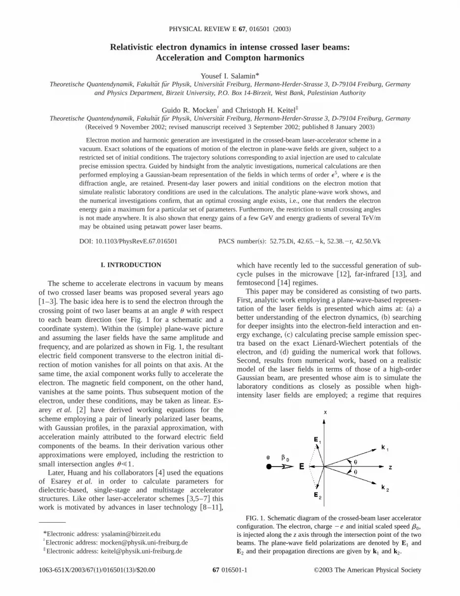
The scheme to accelerate electrons in vacuum by meof two crossed laser beams was proposed several years@1–3#. The basic idea here is to send the electron throughcrossing point of two laser beams at an angleu with respectto each beam direction~see Fig. 1 for a schematic andcoordinate system!. Within the ~simple! plane-wave pictureand assuming the laser fields have the same amplitudefrequency, and are polarized as shown in Fig. 1, the resuelectric field component transverse to the electron initialrection of motion vanishes for all points on that axis. At tsame time, the axial component works fully to accelerateelectron. The magnetic field component, on the other havanishes at the same points. Thus subsequent motion oelectron, under these conditions, may be taken as lineararey et al. @2# have derived working equations for thscheme employing a pair of linearly polarized laser beawith Gaussian profiles, in the paraxial approximation, wacceleration mainly attributed to the forward electric fiecomponents of the beams. In their derivation various otapproximations were employed, including the restrictionsmall intersection anglesu!1.
Later, Huang and his collaborators@4# used the equationof Esarey et al. in order to calculate parameters fodielectric-based, single-stage and multistage accelerstructures. Like other laser-accelerator schemes@3,5–7# thiswork is motivated by advances in laser technology@8–11#,
*Electronic address: [email protected]†Electronic address: [email protected]‡Electronic address: [email protected]
1063-651X/2003/67~1!/016501~13!/$20.00 67 0165
nsgoe
ndnti-
ed,thes-
s,
ro
tor
which have recently led to the successful generation of scycle pulses in the microwave@12#, far-infrared @13#, andfemtosecond@14# regimes.
This paper may be considered as consisting of two paFirst, analytic work employing a plane-wave-based represtation of the laser fields is presented which aims at:~a! abetter understanding of the electron dynamics,~b! searchingfor deeper insights into the electron-field interaction andergy exchange,~c! calculating precise sample emission spetra based on the exact Lie´nard-Wiechert potentials of theelectron, and~d! guiding the numerical work that followsSecond, results from numerical work, based on a realimodel of the laser fields in terms of those of a high-ordGaussian beam, are presented whose aim is to simulatelaboratory conditions as closely as possible when hiintensity laser fields are employed; a regime that requ
FIG. 1. Schematic diagram of the crossed-beam laser acceleconfiguration. The electron, charge2e and initial scaled speedb0,is injected along thez axis through the intersection point of the twbeams. The plane-wave field polarizations are denoted byE1 andE2 and their propagation directions are given byk1 andk2.
©2003 The American Physical Society01-1

ton-ids
almk
dictanit
thdtuv-ry
eoysati
thlsri
alcleatina
sin
inle
ereaditaforgca
inesliese2
. IbfieTho-het
nc
atigatet theingthe
c-um-in
ors
int
ex-
s-ons
c.
ntsa
ofthe
-de-
SALAMIN, MOCKEN, AND KEITEL PHYSICAL REVIEW E 67, 016501 ~2003!
focusing over small spatial dimensions. This will allow usinvestigate stability of the electron motion under initial coditions less ideal than the forward injection case, by consering off-axis injection and injection at various initial speed
Chief among the results of the analytic work is the reization that, corresponding to any given set of field paraeters, an optimum beam crossing angle exists which mathe electron energy gain a maximum. Furthermore, the rative losses turn out to be small and the emission speexhibit the expected Doppler shifts, line enhancement,tendency to be of approximately the same strength, all wincreasing intensity. On the other hand, we learn fromnumerical work that small deviations from initial forwarinjection result in considerable bending and large deparfrom linear motion. More importantly, energy gain, of seeral GeV from interaction with laser beams of laboratointensities, is shown to be possible.
In the analytic work a set of working equations for thcrossed-beam accelerator scheme are developed, emplthe phase of the accelerating field as a variable. In termthis variable, exact expressions for the electron energyspeed are obtained by direct integration of the relativisequations of motion of the electron. An expression forelectron position as a function of the laser field phase is aobtained in terms of an integral which we carry out numecally for our purposes in this paper. Our equations are vfor all crossing angles and allow us to follow the subcyevolution of the energy gradient, energy gain, speed, radipower, and the time rate of change of energy gain durinteraction with two different wave patterns, namely,strictly plane-wave pattern and a pattern modeled by a2
envelope.Although we investigate the electron dynamics during
teraction with wave patterns containing several field cyc~in a sense to be described below!, our analysis also suitssituations in which a subcycle pulse may be used@15–17#.During a decelerating phase of the motion the electron spmay drop to zero and its direction of motion may beversed, depending upon its initial injection energy. This leto loss of energy through Bremsstrahlung and places limtions on the maximum energy attainable. In spite of that,example, our numerical work shows that a maximum enegain of about 1.9 GeV may be achieved using identibeams of 10 PW power focused down to 7mm waist radii.This occurs for 2.555 MeV injected electrons and a crosshalf-angle u53.1°. The acceleration to this energy takplace over an axial distance of less than 2 mm, which impan energy gradient of nearly 1 TeV/m. The plane-wave-bacalculations exaggerate these numbers by a factor ofsometimes even much more.
The rest of this paper is organized as follows. In Secwe formulate the problem, modeling the laser fieldspulse-shape functions dependent entirely upon the laserphase, and setting up the relevant equations of motion.is followed by the analytic solution of the equations of mtion and by a derivation of the evolution equations, in tsaid phase, of the electron dynamics. Next we investigateradiative losses that accompany the motion of the electrothe laser fields and present examples of the emission spe
01650
-.--esa-radhe
re
ingofndceo
-id
edg
-s
ed-s-ryl
g
sd
or
Iyldis
heintra.
In Sec. III the most general description of the fields ofGaussian beam are presented and then used to invesseveral issues pertinent to the acceleration scheme. Firsissue of a preferred crossing angle will be taken up. Usthe preferred angles suggested by the numerical work,effect ~on the trajectories as well as on the energy gain! of aspread in the injection initial conditions, including the injetion energies and positions, is discussed next. Finally, a smary of our main results and conclusions will be givenSec. IV.
II. THE PLANE-WAVE ANALYSIS
A. Formulation of the problem
Referring to Fig. 1, we represent the propagation vectof the two identical beams byk15v/c( i sinu1k cosu) andk25(v/c)(2 i sinu1k cosu), where v is the laser fre-quency,c is the speed of light in vacuum, andi , j , andk areunit vectors in the directions of increasingx, y, andz, respec-tively. Let the phases of the fields at any space-time po(t,r ) be given byh15vt2k1•r , andh25vt2k2•r . Intro-ducingg(h j ) as an envelope function for thej th beam andassuming the beams have the same amplitudeE0, the electricand magnetic fields of the two beams are
E15E0g~h1!cosh1~ i cosu2 k sinu!, ~1!
E252E0g~h2!cosh2~ i cosu1 k sinu!, ~2!
B15E0g~h1!cosh1 j, ~3!
B252E0g~h2!cosh2 j. ~4!
Note that theE and B fields given in Eqs.~1!–~4! satisfyMaxwell’s equations. We employ these equations in theploratory analytic work.
Utilizing the axial symmetry of the problem, the tranverse motion of the electron may be neglected for electrinjected exactly axially~along z). This will receive solidsupport and full justification from the numerical work of SeIII. Under these conditions,h1 ,h2→h5v@ t2(z/c)cosu#.Moreover, the resultant magnetic field vanishes for all poion the z axis, while the resultant electric field has onlynonvanishing axial component given by
Ez~0,0,z!522E0g~h!sinu cosh. ~5!
This accelerating field has an amplitude 2E0 sinu g(h), aphase h, and hence, a phase velocityvph5c/cosu.c.Henceforth, but within the plane-wave context,one (acceler-ating) field cyclewill mean h52p. Since the speed of theelectron can never exceedc it will phase-slip behind theaccelerating field. In the remainder of this sectionh will beused as a variable in terms of which all physical quantitiesrelevance will be written and discussed. Our analysis ofelectron dynamics will cover several integer values ofh/2p@15–17#. In a practical situation, the interaction will be confined to a region of space around the origin whose size
1-2

ncleo
ei
l-
en
t
s
ng
u
e-ld
in
in
e.s,s, in
rur-mayns
e-ld inttera-
erech
of
tions
p
c-ye
ler-
RELATIVISTIC ELECTRON DYNAMICS IN INTENSE . . . PHYSICAL REVIEW E 67, 016501 ~2003!
pends on the shape and size of the beam cross sectiofocus. Hence the electron will practically interact with a fration of a cycle of the accelerating field, or a few such cycat most, depending upon the parameters used. Chief amthose parameters are the beam waist radii, the Rayllengths, and the crossing angle.
Let the electron have a massm and a charge2e. A solu-tion to the following equations of motion will now be deveoped (E5E11E2 andB5B11B2)
dp
dt52e~E1b3B!,
dEdt
52ecb•E. ~6!
In Eq. ~6! p5gmcb is the relativistic momentum of theelectron andE5gmc2 is its energy, whereb is the velocityvector normalized by the speed of light andg5(12b2)21/2 is the Lorentz factor. Withb5(bx ,by ,bz), theexact equations of motion are equivalent to four componones. Thex- andy-component equations result in no motiodue to the vanishing of the magnetic field on thez axis. Theremaining two equations then take the form
d~gbz!
dt52qv sinug~h!cosh, ~7!
dg
dt52qv sinu g~h!bz cosh, ~8!
where we have introducedq5eE0 /(mcv) as a conveniendimensionless intensity parameter. Recall that
Il25S mc2
e D 2S pc
2 Dq2'1.37531018q2~W/cm2!~mm!2.
~9!
Equation~9! will be employed in computing the intensitieused in Figs. 6 and 7.
B. Electron dynamics
It will be assumed that the electron is sent initially alothez axis at the scaled speedb0, and that it will be overcomeby the front edges of the crossed laser beams simultaneoat time t50, at the origin of coordinates. The electronen-ergy gain, as a result of interaction withh/2p cycles of theaccelerating field, may be defined by
W~h
n
av
ty
y
ewoevs
teld
n
ss
ngh
fthththtrnd
rstTheyclend
der-t istion
c-eVhctione
omighte-
e an
-
eld
those
SALAMIN, MOCKEN, AND KEITEL PHYSICAL REVIEW E 67, 016501 ~2003!
~12b cosu!
~12b2!3/2db52qg~h!sinu cosh dh. ~14!
Integration subject to the above mentioned initial conditiofinally yields
g~b2cosu!5g0~b02cosu!12q f~h!sinu[s~h!,
~15!
where
f ~h!5Eh0
hg~h8!cosh8 dh8. ~16!
For book-keeping purposes note that for the plane-wand sin2 patterns one has (h050)
f ~h!5sinh, ~17!
and
f ~h!5sinh
22
sin@~11k!h#
4~11k!2
sin@~12k!h#
4~12k!, ~18!
respectively.Equation~15! may now be solved for the electron veloci
scaled by the speed of light
b~h!5cosu1sAs21sin2 u
11s2. ~19!
Alternatively, Eq.~15! may be solved for the electron energscaled bymc2,
g~h!5s cosu1As21sin2 u
sin2 u. ~20!
Equations~19! and~20! have the correct limits. Consider thcase ofu50, for example. This case corresponds to tco-propagated beams. For the chosen polarizations, howthe electric fields cancel out at all time and, hence, subquent motion of an electron that has initially been injecexactly along the z axis should not be affected by such fieNote that settingu50 in Eq. ~15! gives s52g0(12b0),0. When this result is used in Eqs.~19! and ~20!, andprovided the square roots are handled with care, one fiout thatb(h)→b0 andg(h)→g0, as they should.
With Eq. ~20! for the scaled energy we can now discuthe energy gainW(h), defined by Eq.~10!. We begin byshowing this quantity in Figs. 3~a! and 3~b! for two differentpulse-shape envelopes. Due to the fact that each of the elope functions is normalized to have a unit maximum heiat focus, the energy gain has the same maximum valueboth of them. Note that in all cases all gain is lost aselectron is left behind the pattern, in agreement withLawson-Woodward theorem. This is due essentially toinherent symmetry of the plane-wave model. This symmegets destroyed by focusing over small spatial dimensioand a net gain becomes possible, as will be demonstrate
01650
s
e
er,e-ds.
ds
ve-toreeeys,in
Sec. III. Moreover, the gain increases during, say, the fiquarter of a field cycle and the electron is accelerated.gain reaches a maximum at the end of the first quarter cand then drops down during interaction with the secoquarter cycle. The Lorentz factorg changes a little fromunity during interaction with the next half cycle~dotted line,electron initially at rest!. This explains the flat portion~actu-ally concave upward! of W vs h/2p between theh/2p50.5 and 1 marks in the dotted line of Fig. 3~a!. In fact, theLorentz factor reaches a value less thang0 ~solid line, g0530) and drops down to unity asb→0 in this region, andWbecomes slightly negative there. This may be better unstood by studying Fig. 5 for the scaled speed, where ishown that the electron slows down and reverses its direcof motion.
Another important point to note in Fig. 3 is that the eletron is accelerated from rest to a maximum of about 3.4 Gand from roughly 15 MeV to a little over 3.8 GeV. Botresults are achieved regardless of what pulse-shape fung(h) is used to model the field of 10 PW power. This will bshown to be about twice the gain obtained numerically frthe Gaussian-beam-based calculation. Only at a plane rthrough its focus,z50, ~and too far away from focus, wherthe intensity may be negligible anyway! does a Gaussianbeam exhibit plane-wave characteristics.
Of more interest to the experimentalist would be to sedisplay of W vs z. To produce such a figure we need aexpression for the axial electron coordinatez(h) which wenow derive. Using the chain rule of differentiation and employing Eqs.~13! and ~19! we get
dz
dh5
dz
dt
dt
dh5
c
v
b~h!
@12b~h!cosu#. ~21!
FIG. 3. Electron energy gain vs the number of accelerating ficycles and also vs the forward distance of travelz. ~a! and~c!: Theplane-wave pattern, and~b! and ~d!: The wave pattern with a sin2
pulse shape. The remaining field parameters are the same asof Fig. 2.
1-4

owts
altteur-ooedr-
ago
gy
r-
thtr
b
-stg
ra
fthui
tte-
t
pti-axi-this
seder-
dyd inintheesits
ub-ate
the
-ler-
eredrp-
Th
r of
RELATIVISTIC ELECTRON DYNAMICS IN INTENSE . . . PHYSICAL REVIEW E 67, 016501 ~2003!
The remaining integration in Eq.~21! will be carried outnumerically, for the sake of the discussion below. We shW vs z in Figs. 3~c! and 3~d!. Note the presence of whalooks like cusps in these plots. In fact, each of these culooking portions is a tiny loop, too small to show on the scused. Inspection of the data used to produce, say the doline in Fig. 3~c!, reveals a turning point in the trajectory thelectron reaches as its speed drops to zero. It then taround, moves a fraction of 1mm to the left to another turning point and then speeds up to the right again. Over the lstructure the electron moves at speeds too small comparthe speed of light, which explains why it hardly moves foward ~or backward! during interaction with about half of a~mostly decelerating! field cycle.
The examples considered in Fig. 3 exhibit large averacceleration gradients. Ejection at the top of the first humpeach line in Fig. 3~a!, for example, achieves average energradients of roughly 25 TeV/m~solid line! and 23 TeV/m~dotted line!.
The initial conditions laid down above are admittedly atificial, somehow. We have simply stated that the electronborn at the origin of coordinates att50 inside the planewave which, by definition, has an infinite extension in bospace and time. Figure 3 suggests that such an elecstands to gain more energy from the field if itstarts offat ahigher speed. Figure 4 shows this to be indeed the casenot indefinitely. The gain exhibits saturation~at about 3.575GeV, for the parameters used! after an initial steep rise, withincreasing injection energy.
The sinusoidal dependence uponh of the scaled speed@cf. Eqs. ~15!–~19!# shows clearly in the oscillations displayed in Fig. 5. The scaled speed drops from a relativivalue close to unity down to zero and even becomes netive, as the field changes direction and works to decelethe electron. The minimum~negative! value reached bybdepends, of course, on the value ofb0 although this may notbe seen in Fig. 5 because in it we employ parameters oextremely powerful laser system. In such an environmentacceleration to ultrarelativistic speeds takes place qswiftly.
We conclude this section by noting that in a recent leSalamin and Keitel@3# have studied this electron-field configuration employing sinh plane-wave fields and allowingfor interaction with only half of a field cycle. An importan
FIG. 4. The maximum energy gain~calculated forh/2p53.2)is seen here to saturate with increasing initial injection energy.parameters used are the same as in Fig. 2.
01650
p-eed
ns
pto
ef
is
on
ut
ica-te
ane
te
r
outcome of that work was the demonstration that an omum crossing angle, one that makes the overall gain a mmum, exists for each set of chosen parameters. More onissue will be found in Sec. III below.
C. Radiative losses
Electron motion in the scheme of acceleration by croslaser beams is essentially linear, provided injection is pfectly axial. It is well-known@19# that radiative losses in alinear accelerator are negligibly small.
However, this is a fact if the particle undergoes steaacceleration. As may be seen in Fig. 5, the electron speethis scheme oscillates: it becomes extremely relativisticthe forward direction as the electron absorbs energy fromfield and then it falls down to zero when the field changdirection. It may even become negative, depending uponinjection value. During deceleration the electron loses sstantial energy through Bremsstrahlung. We now investigthe radiative losses employing the relativistic version ofLarmor formula for the radiated power@19#
P~ t !52
3
e2
cg6H Fdb
dt G2
2Fb3db
dt G2J . ~22!
For motion along a straight line, the second term in Eq.~22!vanishes. Equation~14! may then be used to write the expression for the radiated power as a function of the acceating field phase
P~h!52
3
e2
c@2qvg~h!sinu cosh#2. ~23!
Equation~23! gives the rate at which energy is lost by thelectron through radiation. This quantity should be compawith the rate at which the electron gains energy by absotion from the field. The rate of energy gain is
e
FIG. 5. Forward scaled speed of the electron vs the numbeaccelerating field cycles.~a! Plane-wave pattern, and~b! sin2 pat-tern. The field parameters used are the same as in Fig. 2.
1-5

n-
ac
e
lslig
arm
trelraWth
on
a
troo
dh,theg
n-e
ntion
jec-to
wella
ial
leitia
:
on
ser
r--
SALAMIN, MOCKEN, AND KEITEL PHYSICAL REVIEW E 67, 016501 ~2003!
dW
dt5
dEdt
5mc2@2qvg~h!sinu cosh#b~h!, ~24!
from Eqs.~8! and~10!. Construction of the ratio ofP(h) todW/dt runs into difficulty due to the fact that the latter vaishes at several values ofh.
We show these quantities separately in Fig. 6 for intertion with a field of intensity of 1.37531020 W/cm2 @q510, according to Eq.~9!# and employing the pulse-shapfunctions used in Figs. 2–5. In the small regions ofh spacecorresponding to deceleration, the ratio ofPmax to(dW/dt)max can be non-negligible~a few percent! as theelectron loses part of the gained energy by radiation. Ewhere, during acceleration, the same ratio becomes negbly small, typically less than 1027. Our single-particle analy-sis gets a little modified when the bunch characteristicstaken into account by introduction of suitable bunch fofactors@20#.
D. Emission spectra
We have seen in the previous subsections that the elecundergoes violent acceleration and deceleration in the fiof two crossed laser beams. It has also been demonstthat the resulting radiative losses can be non-negligible.devote this section to a study of the emission spectra offree electron in the prescribed fields. Production of harmics of the incident radiation field, for free@21–32# and bound@33–40# electrons is an active area of investigation. It halso been shown recently@20# that characteristics of theemitted radiation may be used as a valuable tool for elecbunch diagnosis, a tool that does not involve interceptingdeflecting the electron beam substantially.
FIG. 6. The radiated power and the rate of change of the etron energy vs the number of accelerating field cycles. The inelectron scaled injection energies areg051 ~solid lines! and g0
530 ~dotted lines!. Note the solid and dotted lines coincide in~a!and ~b! on account of the fact thatP(h) is independent ofb0. ~a!and ~c! are for the plane-wave patterng(h)51, while ~b! and ~d!are for the pattern withg(h)5sin2(h/12). The field parameters arel51 mm, q510, or I 51.37531020 W cm22 @see Eq.~9!#, andu50.1 rad.
01650
-
e-i-
re
ondstedee-
s
nr
In this section we will be usingv to denote the generatefrequency andv0 to denote the laser frequency. Althougthe spectra to be shown in Fig. 7 are calculated usingexact Lienard-Wiechert potentials, we employ the followinequation, as a starting point for the discussion@19# ~far fieldapproximation!
d2E~v,V!
dV dv5
e2
4p2cU E
0
T n3@ n2b~ t !#3b~ t !
@12n•b~ t !#2
3expH ivF t2n•r ~ t !
cG J dtU2
. ~25!
In Eq. ~25! E is temporarily used to denote the radiated eergy, n is a unit vector in the direction of propagation of themitted radiation~direction of observation!, b is the particleacceleration scaled by the speed of light, andT is used tem-porarily to denote the time interval over which interactiobetween the electron and the laser field takes place. Equa~25! holds as long as the dimensions of the electron tratory are much smaller than the distance from the electronthe observation point. This has been demonstrated quiteby the trajectory analysis given above. In what follows,spectrum will be reported in terms of the doubly-differentscattering cross section, given by
d2s~v,V!
dV dv5
1
T
8pcr02
~eqv0!2
d2E~v,V!
dV dv. ~26!
c-l
FIG. 7. ~Color online!. Sample emission spectra of an electrinitially at rest (g051) at the origin or with initial speed (g055)along thez axis and subsequently subjected to two crossed labeams (u50.1 rad) modeled by plane-wave patterns (gh51) withl51 mm. The observation point is in thexz plane and located bypolar anglesQ580 mrad andF50. The calculation has been caried out for interaction withN field cycles and using intensity parametersq51 (I'1.37531018 W/cm2) and q520 (I'5.531020 W/cm2). The intensities were calculated using Eq.~9!.
1-6

ne
n
al
ha
e,nn
th
eiti
acy.eir
dentred
lds,th
n-hift,
ngleataninthe
caltheIfer
sesn-
s,ies,e toase
wnrk.rgybe
Oncan, alds
thelopstheploy
, the
tes
RELATIVISTIC ELECTRON DYNAMICS IN INTENSE . . . PHYSICAL REVIEW E 67, 016501 ~2003!
Equation~26! has been obtained by dividing the radiant eergy, emitted into a unit solid angle per unit frequency punit time, by the incident energy flux~of one beam!,(eqv0)2/8pcr0
2, r 0 being the classical electron radius. Aintegration by parts may next be performed on Eq.~25!which when followed by a change of variable fromt to h5v0@ t2(z/c)cosu# results in ~atomic units, with e5m51, are used!
1
r 02
d2s~v,V!
dV dv5
v0
N~qpv0!2 UU~v!2 i S v
v0DV~v!U2
,
~27!
where
U~v!5F n3n3b~h!
12n•b~h!GexpH i
v
v0Fh1
v0
c@z cosu
2n•r ~h!#G J U0
2pN
5@~n1n3! i1~n2n3! j1~n3221!k#
3F b
12n3bGexpH iv
v0Fh1
v0
cz~cosu2n3!G J
0
2pN
,
~28!
V~v!5v0
c E0
2pNF n3n3dr
dhGexpH iv
v0Fh1
v0
c@z cosu
2n•r ~h!#G J dh
5v0
c@~n1n3! i1~n2n3! j1~n3
221!k#
3E0
2pN dz
dhexpH i
v
v0Fh1
v0
cz~cosu2n3!G J dh.
~29!
Note that in the second equalities of Eqs.~28! and~29! thesubscript has been dropped frombz . Furthermore, locationof the observation point will be given in sphericpolar coordinates, i.e., n5(n1 ,n2 ,n3)5(sinQ cosF,sinQ sinF,cosQ). The coordinate system is the same as tof Fig. 1, in whichQ is measured relative to the positivezaxis andF relative to1x. It should be mentioned that thintegration in Eq.~25! has a highly oscillating integrandwhich makes the calculation quite laborious. Obviously,radiation is expected to be emitted along the forward abackward directions,Q50 andp, respectively, as bothUandV may be seen to vanish identically in these cases.
Sample emission spectra, calculated numerically usingexact version@19# of Eq. ~25!, are shown in Fig. 7 for anobservation point in thexz plane,F50. Interaction timesequivalent to 20 and 200 field cycles have been taken. Rsonably sharp spectral lines have been produced. In add
01650
-r
t
od
e
a-on
to the emission at the fundamental~pump! frequency, over20 harmonics could be calculated with reasonable accurNote that the lines are Doppler shifted to the right of thexpected positions~integer values ofv/v0) as the source,the electron, reaches relativistic speeds. This is most eviin the cases where high-intensity incident light is scattefrom electrons injected with high initial momenta.
On the other hand, in the presence of high-intensity fiethe role of the initial momentum in determining the strengof the lines, and the overall shift in their positions, dimiishes. Thus lines of comparable strength, and overall sresult for both cases of electron initially at rest, Fig. 7~c!, andone that is initially incident with high velocity, Fig. 7~f!.
III. THE GAUSSIAN-BEAM ANALYSIS
We have presented an analysis of the dynamics of a sielectron in vacuum in the field of two laser beams crossingan angle, using a set of exact equations stemming fromanalytic solution to the equations of motion of the electronthe plane-wave fields. No restrictions have been made onvalue of the crossing angle or laser field intensity. Practiconsiderations, however, may place severe limits onrange of values ofu and q in a realistic accelerator design.conditions allow the electron to interact with a large numbof field cycles, the length of the accelerator unit increadramatically. An ideal situation would be to confine the iteraction to one half of a field cycle@3# by suitably choosingthe crossing angle and the field parameters~especially spotsize!. On the other hand, arbitrarily high field intensitieessential for achieving the desired high electron energmay be difficult to use due to the damage they may causthe optical components needed for the design. In any cexpert knowledge in mirror material and the breakdomechanism will be required to make an arrangement wo
In order to be able to achieve the desired high-enegains, an investigation of the electron dynamics ought toconducted in the relativistic regime of laser intensities.the other hand, the required high intensity-laser fieldsonly be realized by focusing over small dimensions. Thusdetailed knowledge of the laser electric and magnetic fienear the focus of the Gaussian beam is essential@41–45#.This is done next.
A. The fields
In the Gaussian description of a focused laser beam,plane-wave symmetry is destroyed and the beam devefield components along the three spatial directions. Foracceleration scheme of interest to us in this paper, we emthe coordinate system shown in Fig. 8~a!. Subscripts 1 and 2are used to label the beams. Like in the plane-wave casex’s andz’s are taken in the plane of the paper, while they’spoint out of it. It is easy to demonstrate that the coordinaobey the following transformation relations
x15x cosu2z sinu, y15y, z15x sinu1z cosu,~30!
x252x cosu2z sinu, y25y, z252x sinu1z cosu.
~31!
1-7

.d
rd
ke-
.tial
t a
h
thea-
er
tor
elo
n
u13
SALAMIN, MOCKEN, AND KEITEL PHYSICAL REVIEW E 67, 016501 ~2003!
Geometry of a Gaussian beam is shown in Fig. 8~b!. Thebeam axis is taken alongz, with its propagation directionalong1z andstationaryfocus at the origin of coordinates OThe beam cross section at focus is circular and has a raw0; a cross section at an arbitraryz is also circular withradiusw(z)5w0A11(z/zr)
2. Furthermore,zr5kw02/2 is the
Rayleigh length, ande5w0 /zr is the diffraction angle. Now,letting j5x/w0 , y5y/w0, andz5z/zr , the electric compo-nents of the laser field associated with such a beam, to oe5, are@41,42,44,46,47#
Ex5EH S01e2Fj2S22r4S3
4 G1e4FS2
82
r2S3
4
2r2~r2216j2!S4
162
r4~r212j2!S5
81
r8S6
32 G J ,
~32!
Ey5EjyH e2@S2#1e4Fr2S42r4S5
4 G J , ~33!
Ez5EjH e@C1#1e3F2C2
21r2C32
r4C4
4 G1e5F23C3
8
23r2C4
81
17r4C5
162
3r6C6
81
r8C7
32 G J . ~34!
Similarly, the magnetic field components are given by
FIG. 8. ~Color online!. ~a! Coordinate system employed in thGaussian-beam analysis. The field propagation directions are az1 andz2 , E1x andE2x point alongx1 andx2, respectively, andy1
and y are out of the page~and y2 is into the page! through thecommon coordinate origin at O.~b! Geometry of the Gaussiabeam~see the text for explanations!. On the circle on the left handside of~b! the dots mark the initial positions, in thexy plane, of 13electrons; one at the center and 12 evenly distributed on the circference, whose motion and energetics we discuss in Figs. 11–
01650
ius
er
Bx50, ~35!
By5EH S01e2Fr2S2
22
r4S3
4 G1e4F2S2
81
r2S3
41
5r4S4
16
2r6S5
41
r8S6
32 G J , ~36!
Bz5EyH e@C1#1e3FC2
21
r2C3
22
r4C4
4 G1e5F3C3
81
3r2C4
81
3r4C5
162
r6C6
41
r8C7
32 G J .
~37!
In Eqs.~32!–~37!, we have taken
E5E0
w0
wg~h!expF2
r 2
w2G , ~38!
Sn5S w0
w D n
sin~c1ncG!, ~39!
Cn5S w0
w D n
cos~c1ncG!. ~40!
Furthermore,k5v/c, kA05E0 , r 25x21y2, andr5r /w0.For a continuous beam with a stationary focus we will tag(h)51 in this work. For more of the details of the calculation leading to Eqs.~32!–~37! see the Appendix in Ref@47#. These equations were derived from a vector potenpolarized alongx, has an amplitudeA0, and a frequencyv.The remaining symbols in Eqs.~32!–~37! have the followingdefinitions
c5c01cP2cR1cG , ~41!
cP5vt2kz, ~42!
cG5tan21 z, ~43!
cR5kr2
2R, ~44!
R~z!5z1zr
2
z. ~45!
Note that c0 is a constant,cP5h is the plane wavephase,cG is the Guoy phase associated with the fact thaGaussian-beam undergoes a total phase change ofp as zchanges from2` to 1`, cR is the phase associated witthe curvature of the wave fronts, and thatR(z) is the radiusof curvature of a wave-front intersecting the beam axis atcoordinatez. The fields given above satisfy Maxwell’s equtions“•E505“•B, plus terms of ordere6 @46,47#.
A laser system is often characterized by its output powP. For the fields given by Eqs.~32!–~37! the power may becalculated by integrating the time-averaged Poynting vec
ng
m-.
1-8
o
uthe
sndtiin
-tathe
c
rengo
istiof
iohillf
po-
n’s
alersl-ingdi-ain,a
tive
ter-the
-
onthelsothisingeldrnstionng
n beall,
ain
lly
teat,
d in
lsedults
lyticag-alf-
RELATIVISTIC ELECTRON DYNAMICS IN INTENSE . . . PHYSICAL REVIEW E 67, 016501 ~2003!
over a plane through the beam focus and perpendicular taxis. Dropping terms in the result of ordere6 and smaller,one gets
P@TW#5pw0
2
2I 0F11
e2
41
e4
8 G ,'0.0216S qw0
l D 2F11e2
41
e4
8 G , ~46!
whereI 05I (0,0,0)5cE02/8p is the peak intensity~at the fo-
cus!. Equation~46! clearly shows that for a fixed laser outppower, the peak intensity is inversely proportional to tsquare of the beam waist radius, or equivalentlyq is in-versely proportional tow0. Note that Eq.~46! has alreadybeen used to compute theq value employed in Figs. 2–5.
For the crossed-beam acceleration scheme two setfields are needed, one for each beam with subscripts 1 aused to distinguish their parameter values and propagacharacteristics. The resultant field components then enterthe equations of motion~6! in the form
Ex5~E1x2E2x!cosu1~E1z2E2z!sinu, ~47!
Ey5E1y2E2y , ~48!
Ez52~E1x1E2x!sinu1~E1z1E2z!cosu. ~49!
Similarly,
Bx5~B1z2B2z!sinu, ~50!
By5B1y2B2y , ~51!
Bz5~B1z1B2z!cosu. ~52!
Retention of terms of ordere and higher in the field expressions brings about corrections which can be quite imporwhen ultrahigh-intensity laser systems are employed. Forbusiness of acceleration the corrections to the electric fiterms affect the energy gain directly through theb•E term inthe second of Eqs.~6!, while corrections to the magnetifield components play an indirect role via theb3B term inthe first equation. We have recently demonstrated@46,47#that focusing down to a waist radius of a few micronsquires inclusion of all corrections, i.e., up to and includithee5 terms. Previous calculations for the crossed-beam cfiguration @1–4# have at most included the term of ordere.
The remainder of this section will be devoted to the dcussion of a number of issues related to the accelerascheme and based upon numerical calculations using thefields. Obviously, solutions based on low-order perturbattheory @48# cannot be relied upon, considering the higintensity fields we are concerned with in this work. We wassume that the two beams have the same intensity andquency, that their propagation directions and field comnents point as shown in Fig. 8~a!, and that they have a common stationary focus at O. The electron will be assumed
01650
its
of2
onto
nte
ld
-
n-
-n
ulln-
re--
to
be injected att50 from a point with coordinates (x0 ,y0 ,z0).b0 will be used to denote the magnitude of the electroinitial scaled velocity.
B. A preferred crossing angle
Continued improvements in the technology of opticcomponents@4# capable of withstanding present-day lasfield intensities@9–11# have motivated us to explore domainof high q andu values. Guided by the analytic work deveoped in Sec. II and Fig. 3 we have found that, correspondto a given set of laser parameters and electron initial contions, a crossing angle exists that renders the energy gdue to interaction with a given number of field cycles,maximum. This is apparently made possible by construcinterference of the two beams.
Figure 3 seems to suggest that, if the electron-field inaction is to terminate in the neighborhood of any one ofpoints corresponding toh5(2M11/2)p, where M50,1,2, . . . , theelectron will escape with a maximum energy gain. The gain will be an absolute maximum forM53 in the sin2 pattern case, for example. Confining attentito the situation corresponding to one of these maxima inenergy gain, we have found that a maximum gain is aobtained for a particular crossing angle. In a sense, atcrossing angle, constructive interference of the crossbeams presents the electron with a maximum electric fistrength to interact with and absorb energy from. As it tuout, the optimal crossing angle, in the case of accelerafrom rest, lends itself to an analytic derivation. So, settih5(2M11/2)p, b050, andg051 in Eqs.~15! and ~20!,and extremizing the gain expression with respect tou, onegets the value
umax5tan21F1
qG , ~53!
in the plane-wave case. So, the optimal crossing angle caquite large, in which case the resulting gain would be smof course.
The equation resulting from extremizing the energy gis quite complicated in the case of a sin2 wave pattern. Thuswe opt for showing the preferred crossing angle graphicain Fig. 9 for interaction corresponding toM52, i.e., h55p/2. The gain is shown clearly to exhibit an absolumaximum as a function of the crossing angle. Note thguided by hindsight from Figs. 2 and 3, the case displayeFig. 9~b! would have resulted in a duplicate of 9~a! had weopted for a calculation of the gain ath513p/2 instead. Thischoice corresponds to a point close to the focus of the pupattern. It is also interesting to note that a net gain reseven when the crossing angle isp/2 ~the counter-propagating beam case!.
Figure 9~c! is similar to ~a! and ~b! but for the Gaussian-beam case. General agreement with the plane-wave anapredictions is obvious. While the plane-wave analysis exgerates the gain, it gives a smaller optimum crossing hangle than does the Gaussian-beam calculation.
1-9

rgth
Fiain
mre/mar
s
illom,13
the
-etry
the
tes7.ldat
ond
ofe
to
n
men
th
l to
iusof
n
SALAMIN, MOCKEN, AND KEITEL PHYSICAL REVIEW E 67, 016501 ~2003!
In order to get a feeling for what energy gains and enegradients may be optimally achieved, we have chosencrossing half-angleu53.1° for further calculations. Thisangle lies roughly in a neighborhood of theumax of Fig. 9~c!.Samples of gain vs forward distance results are shown in10. Note that the electron-field interaction seems to terminwithin 1 mm, for the parameters used. The electron gamore than 1.8 GeV from interaction with the 10 PW beaand over 400 MeV from the 1 PW fields. These gains corspond to the energy gradients 1.8 TeV/m and 0.4 TeVrespectively, assuming all the gain occurred over a forwdistance of roughly 1 mm.
C. Off-axis parallel injection
Only a small fraction of the electrons in a bunch, of tranverse dimensions of a few microns@20#, sent along thez axis
FIG. 9. ~a! and~b! Electron energy gain at the end of interactiowith 1.25 field cycles~one cycle meansDh52p) of two beams vsthe crossing half-angleu. ~c! The same, but for the Gaussian-beacase where motion of the electron is followed for a time equivalto 104 laser field periods~one period here meansT5l/c). Theinitial injection energy,g051.0002, and the legends given in~a!apply everywhere.
FIG. 10. Energy gain vs the forward distance of travel whencrossing half-angle isu'umax in Fig. 9~c!.
01650
ye
g.tess-,d
-
of Fig. 8~a! will typically enter the interaction region withprecisely zero initial transverse coordinates. The rest wcome in, perhaps parallel to, but a transverse distance frthat axis. In this section, we consider the trajectories ofelectrons whose initial coordinates in thexy plane are asfollows: one is incident perfectly axially,x05y050; a sec-ond has initialxy coordinates (x0 ,y0)5(0.5,0) mm, and theremaining 11 electrons are initially equally spaced oncircumference of a circle in thexy plane of radius 0.5mmand centered on the point (0,0,25) mm. These initial coor-dinates are marked on the circle on the left of Fig. 8~b! andgiven the labels 0,1,2, . . . ,12. Theresulting subsequent trajectories are shown in Figs. 11 and 12. The perfect symmof the configuration on both sides of thexz plane is reflectedin all the trajectories displayed in Figs. 11 and 12, and ingains in Fig. 13 as well.
Note first the case of electrons whose initial coordinaare confined to thexz plane, those labeled by 1, 0, andNumerical solution of the equations of motion then yietrajectories, in the full fields, that are also confined to thplane. At all points in thexz plane (y50), the field compo-nentsEy andBz vanish identically at all times. This is easy tsee from the geometrical symmetry of the configuration afrom the choice of identical beams we have made@or else bysettingy50 in Eqs.~33! and ~37!#. With Bx50, these arethe only field components capable of inducing motion outthe xz plane for an electron initially moving in it. Hencthree of the above mentioned electrons, those with initialxycoordinates~0.5,0!, ~0,0!, and (20.5,0) mm and labeled by1, 0, and 7, respectively, will follow trajectories confined
t
e
FIG. 11. ~a!–~c! Projections, onto thexz, yz, and xy planes,respectively, of the trajectories of 13 electrons injected parallethe z axis and whose initial coordinates in thexy plane are asfollows. One of them starts at the center of a circle of rad0.5 mm and the rest are evenly distributed on the circumferencethe same circle, with the first at (x0 ,y0)5(0.5,0) mm, and so on. In~d!–~f! we merely zoom on small portions of~a!–~c!, respectively.The remaining parameters are:l51.056mm, w057 mm, z0520.5 mm, g056, u53.1°, laser power at 1 PW, and interactiotime equivalent to 1000 laser periods.
1-10

gh.
th
T
ede
e ad
thetheionoses tontjec-
hesub-ss
at-
rgynscal-redere000eldsngs.n-
ate
the
0,gndt ofuiten,
tolec-ics
ain
ote
.
nc.00
RELATIVISTIC ELECTRON DYNAMICS IN INTENSE . . . PHYSICAL REVIEW E 67, 016501 ~2003!
the xz plane. They make excursions transverse toz whosesizes depend upon the value ofx0. In particular, axial injec-tion through the point (x0 ,y0)5(0,0) leads to a perfectlyaxial trajectory. This trajectory is clearly evident as a strailine in Figs. 11~a!–11~e! and itsxy projection appears in Fig11~f! as the dot at~0,0!.
Overall, we note that electrons which are injected inmanner just described~over a circle of radius 0.5mm) getspread out asymmetrically in the transverse dimensions.spreading is from 0.5mm to about 40mm in thex direction,and from 0.5mm to a maximum of roughly 14mm in theydirection. A careful look at the trajectory portions displayin Figs. 11~d!–11~f! reveals clearly that points slightly to th
FIG. 12. Same as Fig. 11, but for a laser power of 10 PW
FIG. 13. Electron energy gain as a function of the axial distafor the electrons whose trajectories are given in Figs. 11 and 12this figure the interaction time has been taken equivalent to 5laser field periods.
01650
t
e
he
right of the common focus of the crossed beams act likstrongscattering centerfor the electrons. That neighborhoomay be viewed as adynamic scattering center, one that os-cillates by responding to the local phase variations offields. Conversely, roughly the same neighborhood, forsituation depicted in Fig. 12, acts like a center of attractcausing the trajectories to bend in directions opposite thof Fig. 11. In both cases, however, the electron appeargain momentum from the fields in the form of a few violeimpulses, as evidenced by the sudden kicks along the tratories shown.
We conclude from Figs. 11 and 12 that, provided tspace charge effects are neglected, most electrons in amicro bunch~a bunch of electrons with, say, a circular crosection of transverse radius less than 1mm), which is in-jected initially with its center of mass on thez axis, willfollow trajectories that diverge considerably due to the sctering process described above.
Now to answer the question of whether the final enegain will suffer any spreading as a result of the electropossessing a spread in the injection positions, we haveculated the gain with axial distances for all cases considein Figs. 11 and 12. The results are shown in Fig. 13, whthe interaction time has been taken as equivalent to 5laser periods. Here too, because of the fact that the fiexhibit rapid local phase variations, electrons injected alodifferent initial paths experience drastically different fieldThis results in them gaining widely differing amounts of eergy as can be seen in Fig. 13~b!. In this figure, the above-mentioned 13 electrons gain energies in the approximrange 80–240 MeV. By contrast, one sees in Fig. 13~a!, andfrom examination of the data used to construct it, thatelectrons injected through (x0 ,y0)5(0,0), ~0.5,0!, and~20.5,0! mm ~initial positions corresponding to 0, 4, and 1respectively! gain about 1.86 GeV. Gain by the remaininelectrons is as follows: 1 and 7 gain 1.168 GeV; 2, 6, 8, a12 gain 1.175; and finally 3, 5, 9, and 11 escape with a neabout 1.193 GeV each. These associations reflect qclearly the perfect symmetry exhibited by the configuratioand by the fields, on both sides of thexz plane.
D. Effect of injection energy spread
Our theoretical study in this paper has been confinedthe single-particle aspects. In a real accelerator design etrons will be injected in bunches of certain characteristwhich must be taken into account@20,49#.
In this subsection, we calculate the spread in energy gdW that may result from a spreaddE05mc2dg0 in the in-jection energy. In the plane-wave case, to begin with, nthatdg05b0g0
3db0. Next, differentiation with respect tob0
of Eqs.~10!, ~15!, and~20! yields
dW5F ~cosu2b0!1s~12b0 cosu!
As21sin2 uG dE0
b0 sin2u, ~54!
wheres(h) is given in Eq.~15!. Assuming an initial injec-tion energy spreaddE0 /E050.5% @24#, Eq. ~54! gives, for
eIn0
1-11

e
htusiosuveuvadue
meerklite,-nanu-onyco
amrdsie
ailder,
benla
t ois
anruc-insion
ibleofw-
ithdlyAt
therthsf.
mex-ed
ion
y
SALAMIN, MOCKEN, AND KEITEL PHYSICAL REVIEW E 67, 016501 ~2003!
electrons ejected at a point corresponding toh513p/2 inFig. 3, dW/W50.0042%, almost the same for both pulsshape functions.
A look at Fig. 14 leads to the following conclusion. Sligvariations in the initial injection energy lead to enormojumps in the final resulting gain, as long as those injectenergies do not exceed a few MeV. Agreement with the reof the order-of-magnitude calculation made above, howeis good for injection energies in excess of about 5 MeV, dto the saturation alluded to in our comments on Fig. 4 aboThese conclusions agree quite well with the numerical cculations employing the full Gaussian-beam fields, as ispicted in Fig. 12. Saturation is seen here to set in for valof g0 beyond about 10.
IV. SUMMARY AND CONCLUSIONS
The dynamics of a single electron injected in vacuuthrough the intersection point of two laser beams has binvestigated analytically and numerically. The analytic woresulted in exact working equations for the crossed-beamser accelerator when the electron is injected axially, i.e., wits initial direction of motion making equal angles with thbeam propagation directions. In particular, expressionsterms ofh5v(t2z cosu/c), for the energy gradient, the energy gain, and the velocity, have been found. Only the fiexpression for the scattered electronz coordinate has beeleft with an integral which could be easily performed nmerically. The obtained velocity and coordinate expressiwere then used to show that the acceleration process maaccompanied by radiative losses. Sample, reasonably preemission spectra, containing typically up to 20 harmonicsthe laser frequency have been obtained.
In both analytic and numerical investigations the becrossing angle has been assumed arbitrary; in other wonowhere has the analysis been restricted to small crosangles@2,4#. Otherwise, the two beams have been assumidentical as far as their intensities, frequencies, and wradii are concerned. In the numerical simulations, the fieof a Gaussian beam have been used, where terms of ordto and includinge5, wheree is the beam diffraction anglehave been employed in modeling them.
It can be fairly stated that good qualitative agreementtween the simple plane-wave analysis and the precisemerical computations has been established. In particuboth have arrived at the conclusion that, for a given sefield parameters and initial conditions, a crossing angle ex
l.
.
01650
-
nltr,ee.l-e-s
n
a-h
in
l
sbe
ise,f
s,ngd
stsup
-u-r,fts
for which gain can be a maximum. Apparently, for suchangle, the electron encounters fields that interfere consttively maximally and favor gain. Furthermore, energy gaof several GeV have been shown to result from interactwith laser beams of present-day PW power.
Our single-particle calculations have also made it possto arrive at important conclusions regarding the dynamicsan electron bunch in this acceleration scheme. For loenergy electrons~typically less than a few MeV! a smalldistribution of initial injection energies~or speeds! leads toan enormous distribution of energy gains~or final speeds!.Conversely, for electrons incident on the arrangement whigh injection energies, the final gains turn out to be harsensitive to any spread in those initial injection energies.high injection energies, the swift energy gain results inelectron reaching an ultrarelativistic speed; it henceforides with the waveand gains little extra energy. Thisaturation phenomenon implies a limit on the utility othe crossed-beam configuration as a booster accelerator
ACKNOWLEDGMENTS
Y.I.S. gratefully acknowledges support for this work frothe German DAAD Gastdozentenprogramm and the Alander von Humboldt Stiftung. G.R.M. and C.H.K. are fundby the German Science Foundation~Nachwuchsgruppewithin Grant No. SFB 276!.
FIG. 14. Electron energy gain as a function of the interacttime, given on a logarithmic scale in terms of the laser periodT5l/c. The lines shown differ in the initial scaled injection energand demonstrate saturation with increasingg0 at a gain of about 2.1GeV.
ier,
@1# C.M. Haaland, Opt. Commun.114, 280 ~1995!.@2# E. Esarey, P. Sprangle, and J. Krall, Phys. Rev. E52, 5443
~1995!.@3# Y.I. Salamin and C.H. Keitel, Appl. Phys. Lett.77, 1082
~2000!.@4# Y.C. Huang, D. Zheng, W.M. Tulloch, and R.L. Beyer, App
Phys. Lett.68, 753 ~1996!; Y.C. Huang and R.L. Beyer,ibid.69, 2175 ~1996!; Y.C. Huang and R.L. Beyer, Nucl. Instrum
Methods Phys. Res. A407, 316 ~1998!; Rev. Sci. Instrum.69,2629 ~1998!.
@5# Y.I. Salamin and F.H.M. Faisal, Phys. Rev. A61, 043801~2000!.
@6# Y.I. Salamin, F.H.M. Faisal, and C.H. Keitel, Phys. Rev. A62,053809~2000!.
@7# Y.I. Salamin and C.H. Keitel, J. Phys. B33, 5057~2000!.@8# C.P.J. Barty, G. Korn, F. Raksi, C. Rose-Petruck, J. Squ
1-12

,
g,
ks
.
nd
.
ys
s.
J.
ev.
hl,r-
T
.
ev.
RELATIVISTIC ELECTRON DYNAMICS IN INTENSE . . . PHYSICAL REVIEW E 67, 016501 ~2003!
A.-C. Tien, K.R. Wilson, V.V. Yakovlev, and K. YamakawaOpt. Lett.21, 219 ~1996!.
@9# D.M. Perry, D. Pennington, and V. Yanovsky, Opt. Lett.24,160 ~1999!.
@10# S. Backuset al., Rev. Sci. Instrum.69, 1207~1998!.@11# N. Bloembergen, Rev. Mod. Phys.71, S283~1999!.@12# C.W. Domier, N.C. Luhmann, Jr., A.E. Chou, W-M. Zhan
and A.J. Romanowsky, Rev. Sci. Instrum.66, 399 ~1995!.@13# C. Raman, C.W.S. Conover, C.I. Sukenik, and P.H. Buc
baum, Phys. Rev. Lett.76, 2436~1996!.@14# A. Bonvalet, M. Joffre, J.L. Martin, and A. Migus, Appl. Phys
Lett. 67, 2907~1995!.@15# B. Rau, T. Tajima, and H. Hojo, Phys. Rev. Lett.78, 3310
~1997!.@16# X. Wang, Y.K. Ho, Q. Kong, L.J. Zhu, L. Feng, S. Scheid, a
H. Hora, Phys. Rev. E58, 6575~1998!; ibid. 60, 7473~1999!.@17# V.P. Kalosha and J. Herrmann, Phys. Rev. Lett.83, 544~1999!.@18# J.D. Lawson, IEEE Trans. Nucl. Sci.NS-26, 4217~1979!; P.M.
Woodward, J. IEE93, 1554~1947!.@19# J. D. Jackson,Classical Electrodynamics, 2nd ed.~Wiley, New
York, 1975!.@20# C.P. Neumann, W.S. Graves, and P.G. O’Shea, Phys. Rev
Accel. Beams3, 030701~2000!.@21# E.S. Sarachik and G.T. Schappert, Phys. Rev. D1, 2738
~1970!.@22# F.V. Hartemann, A.L. Troha, and N.C. Luhmann, Jr., Ph
Rev. E54, 2956~1996!.@23# J.H. Eberly and A. Sleeper, Phys. Rev.176, 1570~1968!.@24# E. Esarey, S.K. Ride, and P. Sprangle, Phys. Rev. E48, 3003
~1993!.@25# E. Esarey and P. Sprangle, Phys. Rev. A45, 5872~1992!.@26# S. Varro and F. Ehlotzky, Z. fu¨r Phys. D22, 619 ~1992!.@27# Y.I. Salamin and F.H.M. Faisal, Phys. Rev. A54, 4383~1996!;
J. Phys. A31, 1319~1997!; Phys. Rev. A55, 3964~1997!.@28# Y.I. Salamin, Phys. Rev. A60, 3276~1999!.@29# Y.I. Salamin and F.H.M. Faisal, Phys. Rev. A58, 3221~1998!.@30# J.-P. Connerade and C.H. Keitel, Phys. Rev. A53, 2748~1996!.
01650
-
ST
.
@31# M.W. Walser, C. Szymanowski, and C.H. Keitel, EurophyLett. 48, 533 ~1999!.
@32# M.W. Walser and C.H. Keitel, J. Phys. B33, L221 ~2000!.@33# C.H. Keitel, P.L. Knight, and K. Burnett, Europhys. Lett.24,
539 ~1993!.@34# C.H. Keitel, C. Szymanowski, P.L. Knight, and A. Maquet,
Phys. B31, L75 ~1998!.@35# Q. Wang and A.F. Starace, Phys. Rev. A55, 815 ~1997!.@36# M. Bao, I. Fabrikant, and A.F. Starace, Phys. Rev. A58, 411
~1998!.@37# D.B. Milosevic and A.F. Starace, Phys. Rev. Lett.81, 5097
~1998!.@38# N.L. Manakov, V.D. Ovsiannikov, and A.F. Starace, Phys. R
Lett. 82, 4791~1999!.@39# Q. Su, B.A. Smetanko, and R. Grobe, Opt. Express2, 277
~1998!.@40# R.E. Wagner, Q. Su, and R. Grobe, Phys. Rev. A60, 3233
~1999!.@41# L.W. Davis, Phys. Rev. A19, 1177~1979!.@42# J.P. Barton and D.R. Alexander, J. Appl. Phys.66, 2800
~1989!.@43# M.O. Scully and M.S. Zubairy, Phys. Rev. A44, 2656~1991!.@44# K.T. McDonald, www.hep.princeton.edu/;mcdonald/accel/
gaussian.ps; www.hep.princeton.edu/;mcdonald/accel/gaussian2.ps.
@45# F.V. Hartemann, J.R. Van Meter, A.L. Troha, E.C. LandaN.C. Luhmann, Jr., H.A. Baldis, Atul Gupta, and A.K. Keman, Phys. Rev. E58, 5001~1998!.
@46# Y.I. Salamin and C.H. Keitel, Phys. Rev. Lett.88, 095005~2002!.
@47# Y. I. Salamin, G. R. Mocken, and C. H. Keitel, Phys. Rev. SAccel. Beams5, 101301~2002!.
@48# V.V. Apollonov, M.V. Fedorov, A.M. Prokhorov, and A.GSuzdaltsev, IEEE J. Quantum Electron.28, 265-271~1992!,and references therein.
@49# N.E. Andreev, S.V. Kuznetsov, and I.V. Pogorelsky, Phys. RST Accel. Beams3, 021301~2000!.
1-13