Embed Size (px)
Citation preview
ChE 483: Capstone Design Project1
Removal of Heavy Metal Ions inAdvanced Wastewater Treatment UsingPolymer-Enhanced Ultrafiltration
(PEUF)
Final Report
Group 17: C. F Choy (20350816), M. A Ferko (20348023), J Markus (20348932), W Hancharek (20197806)
Academic Supervisors: X Feng, Y Huang
Department of Chemical Engineering, University of Waterloo, Waterloo, 200 University Ave W, ON N2L 3G1
Summary: The goal of this project is to design a Polymer-EnhancedUltrafiltration (PEUF) process for the removal of heavy metals fromwaste water which is a relatively new and commercially untestedmembrane technology. The process will be designed to accommodatewastewater from manufacturing facilities, with the output adheringto and surpassing wastewater regulations so that it can be reused inthe facility or safely be returned back to the environment.
In PEUF, the metal ion-polymer complexes in the wastewater areretained by the membrane whereas solutes with relatively lower masspass through. The heavy metal ions are adsorbed by the water-solublepolymer which is subsequently isolated in the retention stream. Bymanipulating the pH, PEUF technology enables an enhanced recyclingrate of polymer while ensuring wastewater is treated efficiently.
The ultrafiltration membrane selected is polyethersulfone or PES-10
ChE 483: Capstone Design Project2
from Sepro Membranes Inc. [Mitsui Chemicals Inc, 2004].The water-soluble complexing polymer used will be poly(vinyl formamide-co-vinylamine) or Lupamin 9095. The monomers consist of a large numberof vinyl formamide which which are good electron donors incoordination with metal ions [Rivas, 2003]. Vinyl formamide ispolymerized and then hydrolyzed to form Lupamin 9095, a linear highmolecular weight polyvinylamine [BASF Corporation, 2002].
The group has completed a working simulation model on SuperProDesigner. The results of the modeling and a comprehensive analysisof the theoretical and economic performance of the selected designare disclosed in the final report . The likelihood of this project’ssuccess is high, as any setbacks in modeling can be overcome withtechnical aptitude and effort.
Table of ContentsList of Figures......................................................4
List of Tables.......................................................51.0 Introduction.....................................................6
2.0 Project Description and Literature Review........................82.1 Technical Background............................................9
2.1.2 Reverse Osmosis...........................................92.1.2 Ultrafiltration and Polymer Enhanced Filtration.............9
2.2 Project Goals and Objective....................................112.3 Comparison of Wastewater Treatment Technologies................12
2.4 Success Criteria and Needs Analysis............................122.4.1 Methodology for Evaluation of Criteria.....................13
2.5 Scope and Items beyond Scope.................................142.6 Design Criteria and Alternatives...............................14
2.6.1 Ultrafiltration Membrane...................................142.6.2 Complexing Polymers........................................14
ChE 483: Capstone Design Project3
2.6.3 Operating pH Values........................................15
2.6.4 Reactor Types..............................................162.7 Wastewater Input Data..........................................20
3.0 Functional Constraints..........................................213.1 Material Constraints...........................................21
3.2 Energy Constraints.............................................213.3 Control Systems................................................21
3.4 Operational pH range Constraint................................213.5 Safety Constraints.............................................21
3.6 Economic Constraints...........................................223.7 Timing Constraints.............................................23
4.0 Discussion of Risks and Hazards.................................244.1 Overview of Risk Identification and Management.................24
4.2 Overview and Significance of Environmental Risks...............254.2.1 The Complexing Polymer.....................................25
4.2.2 Improperly Treated Wastewater..............................254.3 Overview and Significance of Health Risks......................25
4.3.1 The Complexing Polymer.....................................254.3.2 Heavy Metal Wastewater Streams.............................26
4.4 Overview and Significance of Process Safety Risks..............264.4.1 Explosion or High Potential Energy Release Risk............26
4.4.2 Flammability Risk..........................................264.4.3 Corrosion Risk.............................................26
4.4.4 Leakage or Burst Risk......................................264.4.5 Equipment Failure and Reliability Risk.....................27
4.4.6 Low or High-Flow Risk......................................274.4.7 Temperature Variability Risk...............................27
4.4.8 Instrumentation and Calibration Risk.......................27
ChE 483: Capstone Design Project4
4.4.9 Process Control, Automation, and General Operational Risk. .27
5.0 Mitigating Measures for Selected Risks and Hazards..............295.1 NaOH and HCl Tanks and Associated Corrosion....................29
5.2 Characterization of Incoming Wastewater........................295.3 Mitigation of Leakage and Spillage.............................29
5.4 Mitigation of Equipment Failure or Insufficient Amounts of Polymer............................................................29
5.5 Inlet Flow Regulation..........................................306.0 Overview of Energy and Material Costs...........................31
7.0 Design Methodology..............................................327.1 SuperPro Simulation Model......................................32
7.1.1 Pre-Treatment Process......................................327.1.2 Primary Treatment Process..................................34
7.1.3 Secondary Treatment Process................................357.1.4 Tertiary Treatment Process.................................37
7.1.5 Sewage Management..........................................4012.0 Appendices.....................................................45
12.1 Equipment Specifications......................................4512.2 SuperPro Designer Simulation Model............................45
ChE 483: Capstone Design Project5
List of FiguresFigure 1. Contamination of heavy metals in water is a threat to environment and human beings.........................................6Figure 2. Heavy metals as listed on periodic table of elements.......8Figure 3. Reverse Osmosis............................................9Figure 4. Introduction to Ultrafiltration...........................10Figure 5. Electrostatic interactions between cations and anions.....11Figure 6. Polyvinylamine: a large number of primary amine groups [Spange, et al., 2006]..............................................15Figure 7. Tubular Flow Reactor......................................17Figure 8. Hollow Fiber Membrane Reactor.............................18Figure 9. Spiral Wound Membrane Reactor.............................18Figure 10. Selection of Ultrafiltration Module Reactor..............19Figure 11. Pre-Treatment Processes..................................32Figure 12. Primary Treatment Process................................34Figure 13. Secondary Treatment Process..............................35Figure 14. Tertiary or Advanced Treatment Process...................37Figure 15. Copper Adsorption Isotherm...............................39Figure 16. Nickel Adsorption Isotherm...............................39Figure 17. Sludge Management Process................................40
ChE 483: Capstone Design Project6
List of TablesTable 1. Comparison of Wastewater Treatment Technologies............12Table 2. Required heavy metal concentration as set by regulations fromUSEPA...............................................................13Table 3. Allocation of weights of selected criteria.................14Table 4. Typical Physical Properties of Lupamin [BASF Corporation, 2002]...............................................................15Table 5. Comparison of PEUF Membrane Module Designs [Belfort, 1988] [Operation and Maintenance Manual - UF-6-HF Ultrafiltration System, 2013]...............................................................19Table 6. Compositions of the wastewater streams entering the wastewater treatment plants.........................................20Table 7. Risk Identification and Management.........................25Table 8. Comparison between pseudo first order and pseudo second orderkinetic model for Cu(II) and Ni(II) sorption by PVA primary blend [Hema, et al., 2011]................................................38
ChE 483: Capstone Design Project7
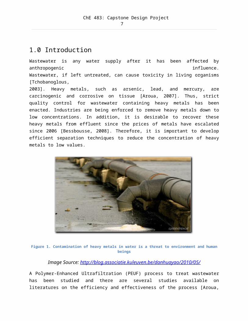
1.0 IntroductionWastewater is any water supply after it has been affected byanthropogenic influence.Wastewater, if left untreated, can cause toxicity in living organisms[Tchobanoglous,2003]. Heavy metals, such as arsenic, lead, and mercury, arecarcinogenic and corrosive on tissue [Aroua, 2007]. Thus, strictquality control for wastewater containing heavy metals has beenenacted. Industries are being enforced to remove heavy metals down tolow concentrations. In addition, it is desirable to recover theseheavy metals from effluent since the prices of metals have escalatedsince 2006 [Bessbousse, 2008]. Therefore, it is important to developefficient separation techniques to reduce the concentration of heavymetals to low values.
Figure 1. Contamination of heavy metals in water is a threat to environment and humanbeings
Image Source: http://blog.associatie.kuleuven.be/danhuayao/2010/05/
A Polymer-Enhanced Ultrafiltration (PEUF) process to treat wastewaterhas been studied and there are several studies available onliteratures on the efficiency and effectiveness of the process [Aroua,
ChE 483: Capstone Design Project8
2007] [Bessbousse, 2008] [Camarillo, 2012]. However, despite thepotential cost savings and environmental benefits, the PEUF processhas not yet been implemented in any waste water treatment plant forseveral reasons. First, PEUF is still a relatively new researchtopic, and its applications in industry are limited as a result.Second, membrane based processes have difficulties accommodating thelarge scale flows experienced by waste water treatment plants, makingindustrial scale applications difficult. Finally, while membraneprocesses are generally less expensive than conventional methods toremove heavy metals, there has been no study conducting a rigorouseconomic and environmental analysis to determine the actual costsavings of using a PEUF design. This last hurdle is what we intend toaddress with our modeling of a PEUF process.
By developing a working model of a PEUF process for removal of heavymetals, we will take the first step in theoretically validating theeconomic and environmental benefits of a PEUF process over aconventional heavy metals removal process. In addition, we will laythe groundwork for the initial design of a PEUF process in a wastewater treatment plant.
At the conclusion of our design project, the main deliverable of thisproject will be a completed simulation model of our finalized process,along with a report discussing the final simulation operatingparameters, the expected results, and economic analysis of using saidprocess in a manufacturing facility. If time and resources permit, de-complexation, which allows complexing polymer to be recovered in theprocess, will also be covered. With this report and simulation,feasibility and economic studies could be done with third partywastewater treatment plants to determine if it would be beneficial toincorporate a PEUF process in their systems.
ChE 483: Capstone Design Project9
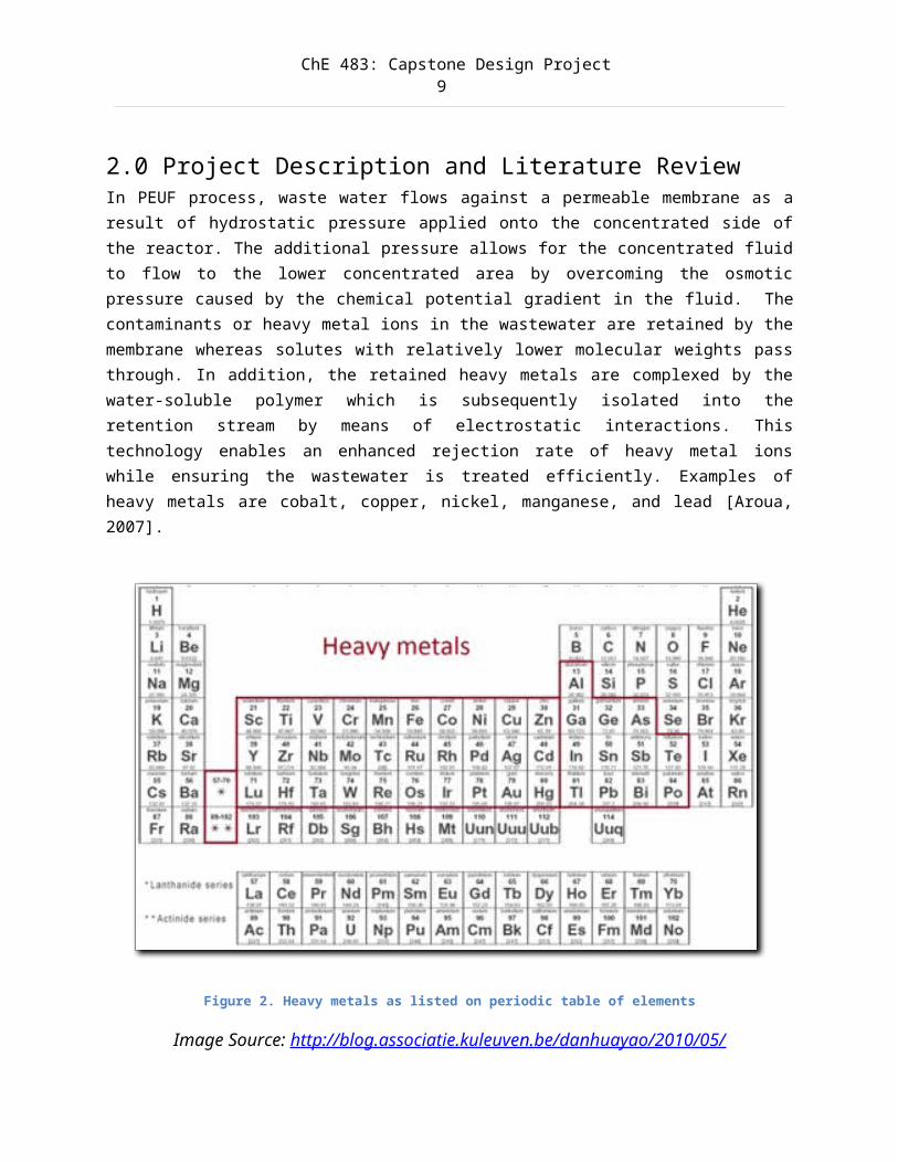
2.0 Project Description and Literature ReviewIn PEUF process, waste water flows against a permeable membrane as aresult of hydrostatic pressure applied onto the concentrated side ofthe reactor. The additional pressure allows for the concentrated fluidto flow to the lower concentrated area by overcoming the osmoticpressure caused by the chemical potential gradient in the fluid. Thecontaminants or heavy metal ions in the wastewater are retained by themembrane whereas solutes with relatively lower molecular weights passthrough. In addition, the retained heavy metals are complexed by thewater-soluble polymer which is subsequently isolated into theretention stream by means of electrostatic interactions. Thistechnology enables an enhanced rejection rate of heavy metal ionswhile ensuring the wastewater is treated efficiently. Examples ofheavy metals are cobalt, copper, nickel, manganese, and lead [Aroua,2007].
Figure 2. Heavy metals as listed on periodic table of elements
Image Source: http://blog.associatie.kuleuven.be/danhuayao/2010/05/
ChE 483: Capstone Design Project10
Extensive research was conducted to determine the design criteria,process parameters, and design alternatives. Of the designsconsidered, the most promising is the tubular reactor design with flowgoing from the inner section to the outer section [Tamime, 2013].Other designs being considered include hollow fibre membrane reactors[Cheryan, 1998] and spiral-wound reactors with flow going from theouter section to the inner section [Belfort, 1988].
The next sections will be focused on finalizing the design criteria for the PEUF process. This will involve determining the minimum removal rates that are required by industries and government regulations, as well as the minimum flow rates. We will also conduct further investigation into the practicality and efficiency of each design alternative.
2.1 Technical Background
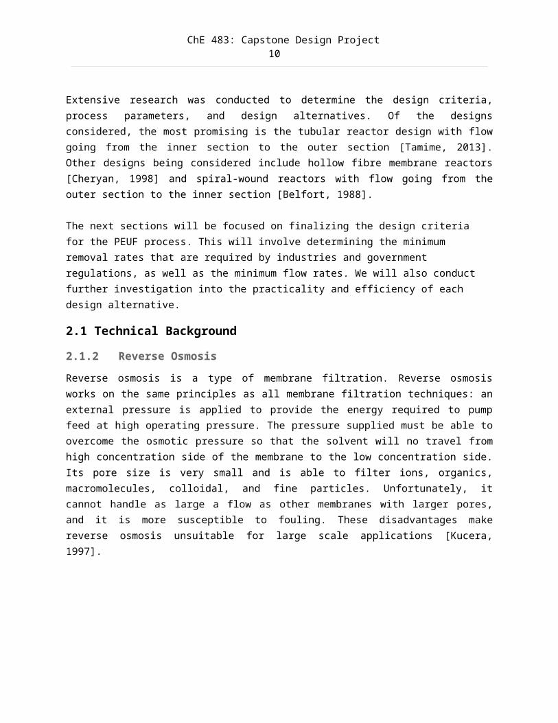
2.1.2 Reverse OsmosisReverse osmosis is a type of membrane filtration. Reverse osmosisworks on the same principles as all membrane filtration techniques: anexternal pressure is applied to provide the energy required to pumpfeed at high operating pressure. The pressure supplied must be able toovercome the osmotic pressure so that the solvent will no travel fromhigh concentration side of the membrane to the low concentration side.Its pore size is very small and is able to filter ions, organics,macromolecules, colloidal, and fine particles. Unfortunately, itcannot handle as large a flow as other membranes with larger pores,and it is more susceptible to fouling. These disadvantages makereverse osmosis unsuitable for large scale applications [Kucera,1997].
ChE 483: Capstone Design Project11
Figure 3. Reverse Osmosis
Image Source: www.hcti.com
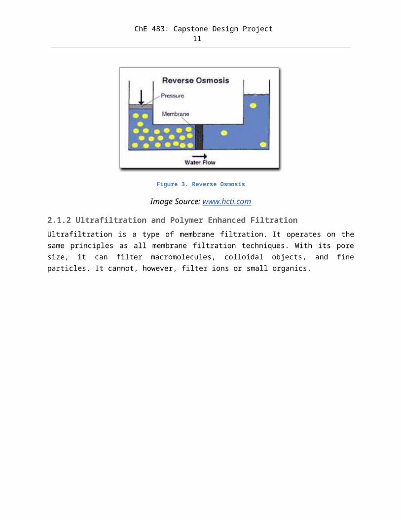
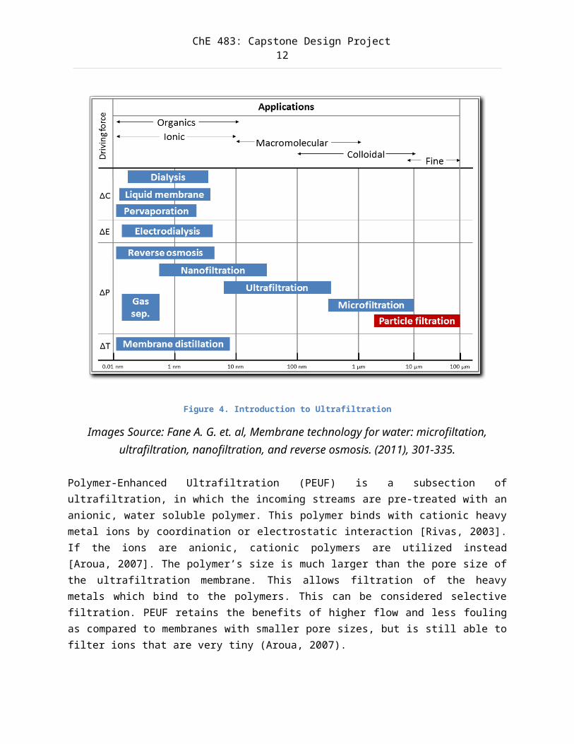
2.1.2 Ultrafiltration and Polymer Enhanced FiltrationUltrafiltration is a type of membrane filtration. It operates on thesame principles as all membrane filtration techniques. With its poresize, it can filter macromolecules, colloidal objects, and fineparticles. It cannot, however, filter ions or small organics.
ChE 483: Capstone Design Project12
Figure 4. Introduction to Ultrafiltration
Images Source: Fane A. G. et. al, Membrane technology for water: microfiltation,ultrafiltration, nanofiltration, and reverse osmosis. (2011), 301-335.
Polymer-Enhanced Ultrafiltration (PEUF) is a subsection ofultrafiltration, in which the incoming streams are pre-treated with ananionic, water soluble polymer. This polymer binds with cationic heavymetal ions by coordination or electrostatic interaction [Rivas, 2003].If the ions are anionic, cationic polymers are utilized instead[Aroua, 2007]. The polymer’s size is much larger than the pore size ofthe ultrafiltration membrane. This allows filtration of the heavymetals which bind to the polymers. This can be considered selectivefiltration. PEUF retains the benefits of higher flow and less foulingas compared to membranes with smaller pore sizes, but is still able tofilter ions that are very tiny (Aroua, 2007).
ChE 483: Capstone Design Project13
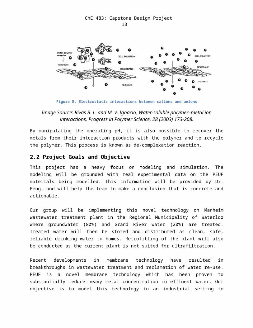
Figure 5. Electrostatic interactions between cations and anions
Image Source: Rivas B. L. and M. V. Ignacio, Water-soluble polymer–metal ioninteractions, Progress in Polymer Science, 28 (2003) 173-208.
By manipulating the operating pH, it is also possible to recover themetals from their interaction products with the polymer and to recyclethe polymer. This process is known as de-complexation reaction.
2.2 Project Goals and ObjectiveThis project has a heavy focus on modeling and simulation. Themodeling will be grounded with real experimental data on the PEUFmaterials being modelled. This information will be provided by Dr.Feng, and will help the team to make a conclusion that is concrete andactionable.
Our group will be implementing this novel technology on Manheimwastewater treatment plant in the Regional Municipality of Waterloowhere groundwater (80%) and Grand River water (20%) are treated.Treated water will then be stored and distributed as clean, safe,reliable drinking water to homes. Retrofitting of the plant will alsobe conducted as the current plant is not suited for ultrafiltration.
Recent developments in membrane technology have resulted inbreakthroughs in wastewater treatment and reclamation of water re-use.PEUF is a novel membrane technology which has been proven tosubstantially reduce heavy metal concentration in effluent water. Ourobjective is to model this technology in an industrial setting to
ChE 483: Capstone Design Project14
produce a disposable effluent without causing harm to the surroundingenvironment and prevent pollution.
The goal of the project is to develop three models of a PEUF system,and evaluate each system based on the economic costs, performance,robustness, ease of operation, and scalability.
Completion of this project will enable wastewater management companiesto begin the discussion on whether PEUF is suitable for their wastewater treatment processes. This will help companies to reduce their energy requirements, and help us move further towards a greener future. With this anticipated impact, we feel strongly that this project is worth pursuing.
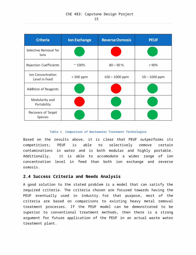
2.3 Comparison of Wastewater Treatment TechnologiesIon exchange and reverse osmosis are two typical technologies whichare commonly used in industrial and municipal facilites for regulatingheavy metal concentration. The table below lists their operatingcapacities and compares them with PEUF.
ChE 483: Capstone Design Project15
Table 1. Comparison of Wastewater Treatment Technologies
Based on the results above, it is clear that PEUF outperforms itscompetitiors; PEUF is able to selectively remove certaincontaminations in water and is both modular and highly portable.Additionally, it is able to accomodate a wider range of ionconcentration level in feed than both ion exchange and reverseosmosis.
2.4 Success Criteria and Needs AnalysisA good solution to the stated problem is a model that can satisfy therequired criteria. The criteria chosen are focused towards having thePEUF eventually used in industry. For that purpose, most of thecriteria are based on comparisons to existing heavy metal removaltreatment processes. If the PEUF model can be demonstrated to besuperior to conventional treatment methods, then there is a strongargument for future application of the PEUF in an actual waste watertreatment plant.
ChE 483: Capstone Design Project16
The criteria for success are as follows:
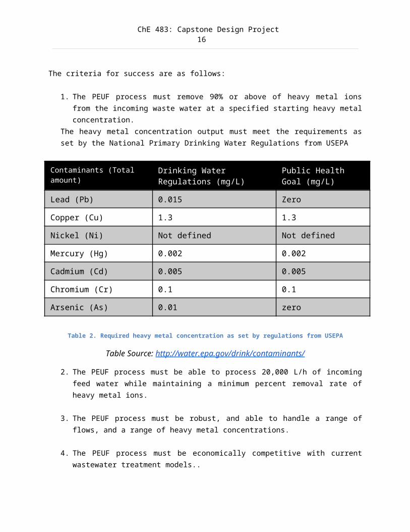
1. The PEUF process must remove 90% or above of heavy metal ionsfrom the incoming waste water at a specified starting heavy metalconcentration.
The heavy metal concentration output must meet the requirements asset by the National Primary Drinking Water Regulations from USEPA
Contaminants (Total amount)
Drinking Water Regulations (mg/L)
Public Health Goal (mg/L)
Lead (Pb) 0.015 Zero
Copper (Cu) 1.3 1.3
Nickel (Ni) Not defined Not defined
Mercury (Hg) 0.002 0.002
Cadmium (Cd) 0.005 0.005
Chromium (Cr) 0.1 0.1
Arsenic (As) 0.01 zero
Table 2. Required heavy metal concentration as set by regulations from USEPA
Table Source: http://water.epa.gov/drink/contaminants/
2. The PEUF process must be able to process 20,000 L/h of incomingfeed water while maintaining a minimum percent removal rate ofheavy metal ions.
3. The PEUF process must be robust, and able to handle a range offlows, and a range of heavy metal concentrations.
4. The PEUF process must be economically competitive with currentwastewater treatment models..
ChE 483: Capstone Design Project17
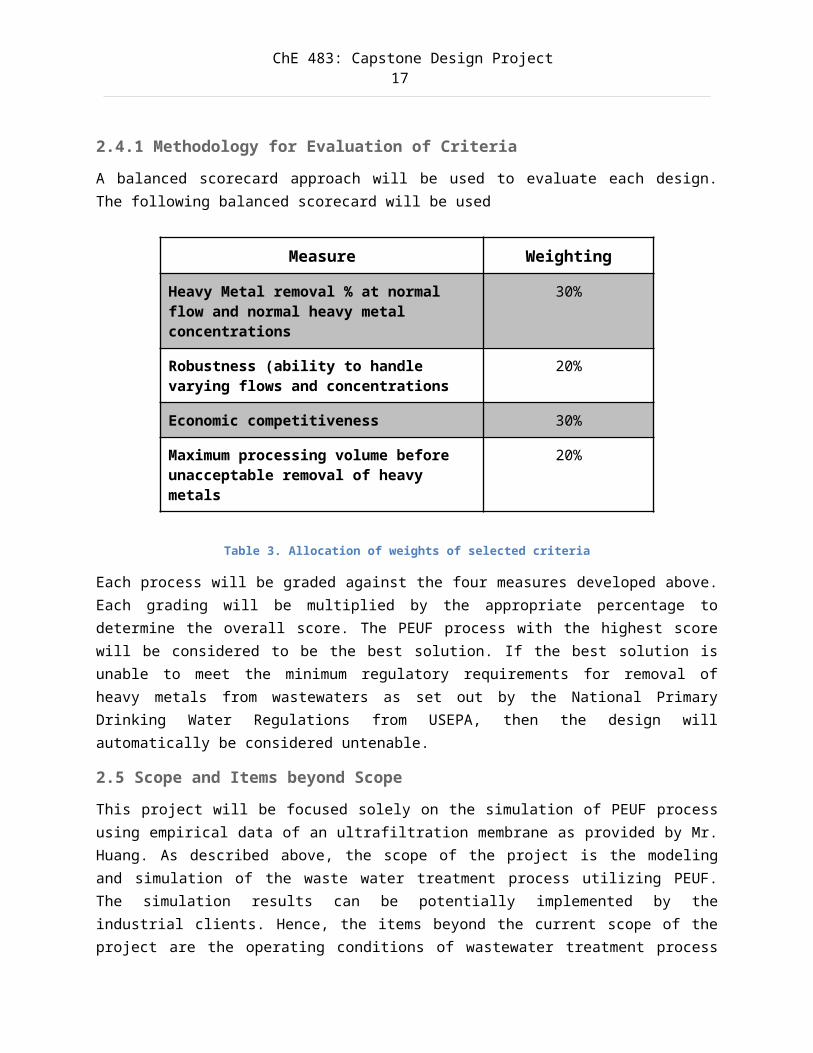
2.4.1 Methodology for Evaluation of CriteriaA balanced scorecard approach will be used to evaluate each design.The following balanced scorecard will be used
Measure Weighting
Heavy Metal removal % at normal flow and normal heavy metal concentrations
30%
Robustness (ability to handle varying flows and concentrations
20%
Economic competitiveness 30%
Maximum processing volume before unacceptable removal of heavy metals
20%
Table 3. Allocation of weights of selected criteria
Each process will be graded against the four measures developed above.Each grading will be multiplied by the appropriate percentage todetermine the overall score. The PEUF process with the highest scorewill be considered to be the best solution. If the best solution isunable to meet the minimum regulatory requirements for removal ofheavy metals from wastewaters as set out by the National PrimaryDrinking Water Regulations from USEPA, then the design willautomatically be considered untenable.
2.5 Scope and Items beyond ScopeThis project will be focused solely on the simulation of PEUF processusing empirical data of an ultrafiltration membrane as provided by Mr.Huang. As described above, the scope of the project is the modelingand simulation of the waste water treatment process utilizing PEUF.The simulation results can be potentially implemented by theindustrial clients. Hence, the items beyond the current scope of theproject are the operating conditions of wastewater treatment process
ChE 483: Capstone Design Project18
implemented by the potential industrial clients which would beinvestigated in the later stage of the design project. In addition, iftime and resources permit our team is interested in designing aprocess that will allow de-complexation of water-soluble polymer fromheavy metal ions by varying the pH conditions. This will enable theprocess to recycle the water-soluble polymer back to the PEUF processand potentially save on operating costs.
2.6 Design Criteria and AlternativesDesign criteria and alternatives were considered on several fronts:
2.6.1 Ultrafiltration MembraneThe components used in the PEUF process: the two main parts of a PEUFare the complexing polymers, and the ultrafiltration membrane. Areview of current research has uncovered several main complexingpolymers, and several types of ultrafiltration membranes. Scientificjournals have shown a variety of combinations between theseultrafiltration membranes and complexing membranes.
The ultrafiltration (UF) membrane selected is polyethersulfone or PES-10 from Sepro Membranes Inc. The membrane has a molecular weight cut-off ratio of 10 kDa. The membrane is a heat-resistant, transparent andnon-crystalline plastic. Moreover, it is a rigid and tough resin whichremains in satisfactory condition under long-term continuous usage andhigh operating temperature [Mitsui Chemicals Inc, 2004].
2.6.2 Complexing PolymersTo obtain the highest retention, complexing polymers of electriccharge opposite to that of the ions to be removed have to be used. Ananionic polymer is often selected for the effective removal of heavymetal ions in PEUF. If the metal is present in the inlet solution inan anionic form, a cationic polymer is employed.
The water-soluble polymer used will be poly(vinyl formamide-co-vinylamine) or Lupamin 9095 from BASF Corporation. The monomersconsist of a large number of vinyl formamide which which are good
ChE 483: Capstone Design Project19
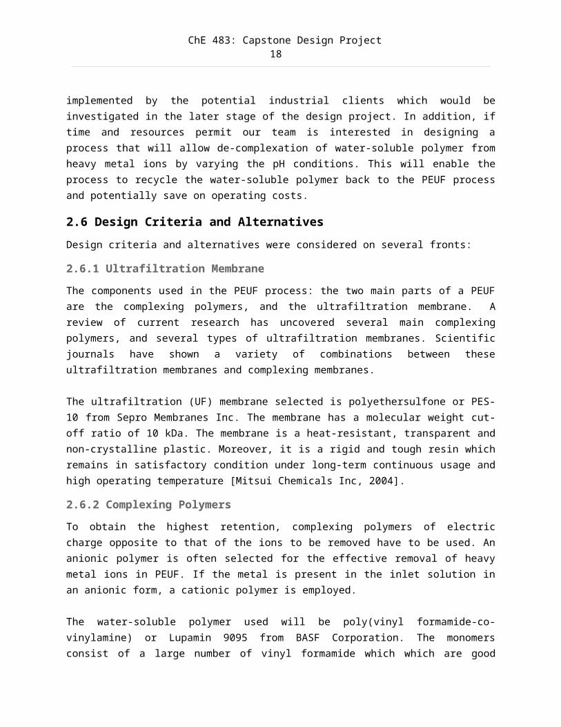
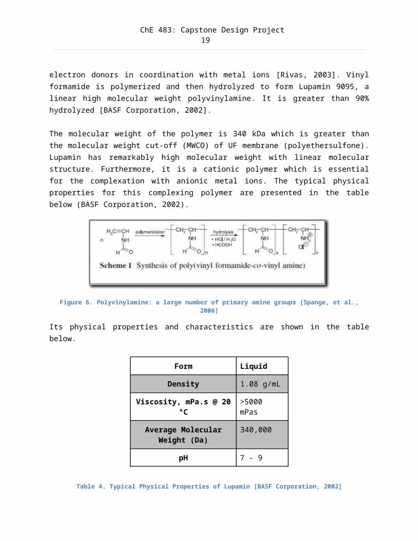
electron donors in coordination with metal ions [Rivas, 2003]. Vinylformamide is polymerized and then hydrolyzed to form Lupamin 9095, alinear high molecular weight polyvinylamine. It is greater than 90%hydrolyzed [BASF Corporation, 2002]. The molecular weight of the polymer is 340 kDa which is greater thanthe molecular weight cut-off (MWCO) of UF membrane (polyethersulfone).Lupamin has remarkably high molecular weight with linear molecularstructure. Furthermore, it is a cationic polymer which is essentialfor the complexation with anionic metal ions. The typical physicalproperties for this complexing polymer are presented in the tablebelow (BASF Corporation, 2002).
Figure 6. Polyvinylamine: a large number of primary amine groups [Spange, et al.,2006]
Its physical properties and characteristics are shown in the tablebelow.
Form Liquid
Density 1.08 g/mL
Viscosity, mPa.s @ 20°C
>5000 mPas
Average MolecularWeight (Da)
340,000
pH 7 - 9
Table 4. Typical Physical Properties of Lupamin [BASF Corporation, 2002]
ChE 483: Capstone Design Project20
2.6.3 Operating pH ValuesThe pH value is a very important factor in most cases of polymericbinding. The higher the pH, the higher the degree of complexation dueto higher free amino content which bonds with metal ions. As pH ofsolution increases, generally retention of metal ions also increasesin the acidic region up to certain pH value. Higher pH leads to lessercompetition of metal ions and hydrogen protons to bind onto thecomplexation sites (amino groups) [Spange, et al., 2006].
One benefit of PEUF is the regeneration of the water-soluble polymer.The dependence of the interaction species compound stability upon pHis used for the recovery of metals from their interaction productswith the polymer and to recycle the polymer (i.e. de-complexation). Bydecreasing the pH of the permeate, heavy metal ions are decomplexedfrom the polymer due to the increasing competition of metal andhydrogen protons to bind with the polymer [Spange, et al., 2006].
Many metal ions form soluble hydroxyl complexes at high pH regions.Since pH sensitivities of metal-polymer complex formation varysignificantly from metal to metal, this can be exploited for theirselective separation. When decreasing the pH of the effluent, the useof hydrochloric acid (HCl) is preferred than nitric acid (HNO3) sinceit may result in membrane degradation.
For complexation, a pH range of 5-8 is chosen. For de-complexation, apH range of 2-5 is chosen.
2.6.4 Reactor TypesThe type of reactor and its associated configuration of the membranemodule are discussed.
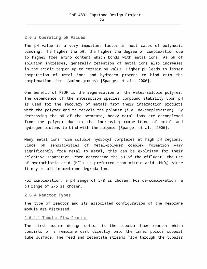
2.6.4.1 Tubular Flow Reactor
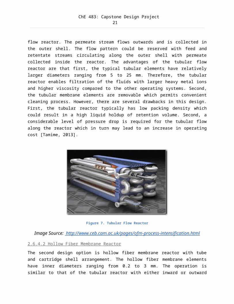
The first module design option is the tubular flow reactor whichconsists of a membrane cast directly onto the inner porous supporttube surface. The feed and retentate streams flow through the tubular
ChE 483: Capstone Design Project21
flow reactor. The permeate stream flows outwards and is collected inthe outer shell. The flow pattern could be reserved with feed andretentate streams circulating along the outer shell with permeatecollected inside the reactor. The advantages of the tubular flowreactor are that first, the typical tubular elements have relativelylarger diameters ranging from 5 to 25 mm. Therefore, the tubularreactor enables filtration of the fluids with larger heavy metal ionsand higher viscosity compared to the other operating systems. Second,the tubular membrane elements are removable which permits convenientcleaning process. However, there are several drawbacks in this design.First, the tubular reactor typically has low packing density whichcould result in a high liquid holdup of retention volume. Second, aconsiderable level of pressure drop is required for the tubular flowalong the reactor which in turn may lead to an increase in operatingcost [Tamime, 2013].
Figure 7. Tubular Flow Reactor
Image Source: http://www.ceb.cam.ac.uk/pages/ofm-process-intensification.html
2.6.4.2 Hollow Fiber Membrane Reactor
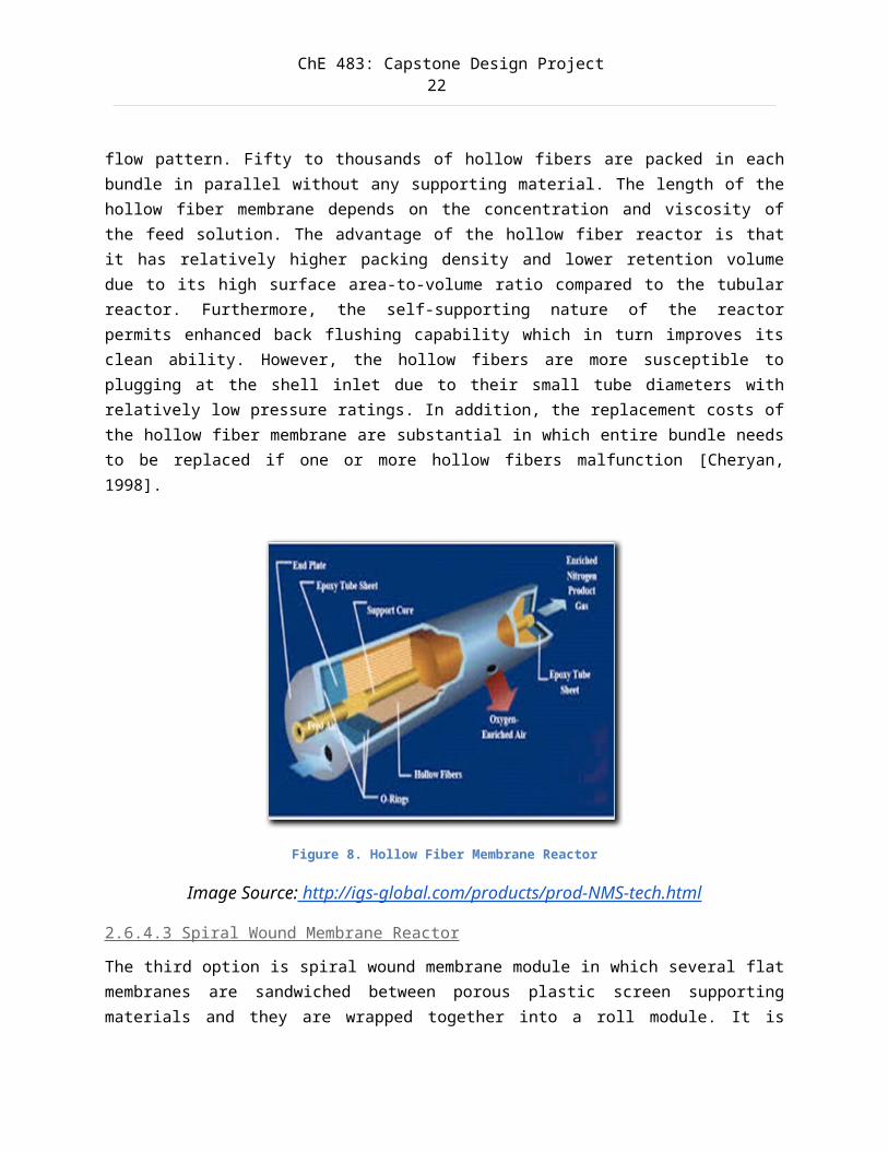
The second design option is hollow fiber membrane reactor with tubeand cartridge shell arrangement. The hollow fiber membrane elementshave inner diameters ranging from 0.2 to 3 mm. The operation issimilar to that of the tubular reactor with either inward or outward
ChE 483: Capstone Design Project22
flow pattern. Fifty to thousands of hollow fibers are packed in eachbundle in parallel without any supporting material. The length of thehollow fiber membrane depends on the concentration and viscosity ofthe feed solution. The advantage of the hollow fiber reactor is thatit has relatively higher packing density and lower retention volumedue to its high surface area-to-volume ratio compared to the tubularreactor. Furthermore, the self-supporting nature of the reactorpermits enhanced back flushing capability which in turn improves itsclean ability. However, the hollow fibers are more susceptible toplugging at the shell inlet due to their small tube diameters withrelatively low pressure ratings. In addition, the replacement costs ofthe hollow fiber membrane are substantial in which entire bundle needsto be replaced if one or more hollow fibers malfunction [Cheryan,1998].
Figure 8. Hollow Fiber Membrane Reactor
Image Source: http://igs-global.com/products/prod-NMS-tech.html
2.6.4.3 Spiral Wound Membrane Reactor
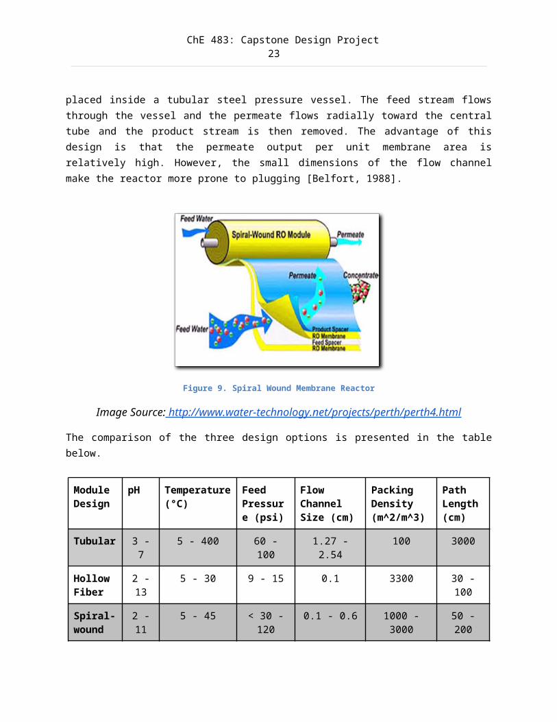
The third option is spiral wound membrane module in which several flatmembranes are sandwiched between porous plastic screen supportingmaterials and they are wrapped together into a roll module. It is
ChE 483: Capstone Design Project23
placed inside a tubular steel pressure vessel. The feed stream flowsthrough the vessel and the permeate flows radially toward the centraltube and the product stream is then removed. The advantage of thisdesign is that the permeate output per unit membrane area isrelatively high. However, the small dimensions of the flow channelmake the reactor more prone to plugging [Belfort, 1988].
Figure 9. Spiral Wound Membrane Reactor
Image Source: http://www.water-technology.net/projects/perth/perth4.html
The comparison of the three design options is presented in the tablebelow.
Module Design
pH Temperature(°C)
Feed Pressure (psi)
Flow Channel Size (cm)
Packing Density (m^2/m^3)
Path Length(cm)
Tubular 3 -7
5 - 400 60 -100
1.27 -2.54
100 3000
Hollow Fiber
2 -13
5 - 30 9 - 15 0.1 3300 30 -100
Spiral-wound
2 -11
5 - 45 < 30 -120
0.1 - 0.6 1000 -3000
50 -200
ChE 483: Capstone Design Project24
Table 5. Comparison of PEUF Membrane Module Designs [Belfort, 1988] [Operation and Maintenance Manual - UF-6-HF Ultrafiltration System, 2013]
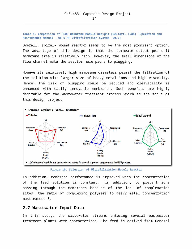
Overall, spiral- wound reactor seems to be the most promising option.The advantage of this design is that the permeate output per unitmembrane area is relatively high. However, the small dimensions of theflow channel make the reactor more prone to plugging.
Howeve its relatively high membrane diameters permit the filtration ofthe solution with larger size of heavy metal ions and high viscosity.Hence, the risk of plugging could be reduced and cleavability isenhanced with easily removable membranes. Such benefits are highlydesirable for the wastewater treatment process which is the focus ofthis design project.
Figure 10. Selection of Ultrafiltration Module Reactor
In addition, membrane performance is improved when the concentrationof the feed solution is constant. In addition, to prevent ionspassing through the membranes because of the lack of complexationsites, the ratio of complexing polymers to heavy metal concentrationmust exceed 5.
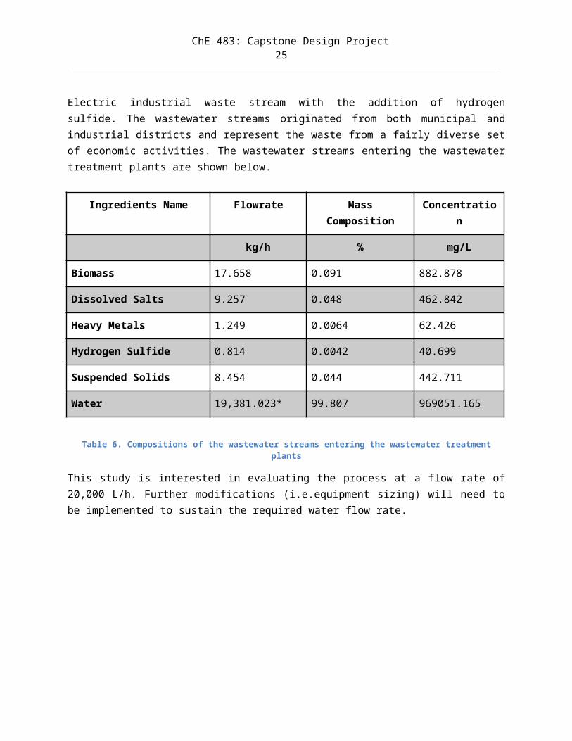
2.7 Wastewater Input DataIn this study, the wastewater streams entering several wastewatertreatment plants were characterized. The feed is derived from General
ChE 483: Capstone Design Project25
Electric industrial waste stream with the addition of hydrogensulfide. The wastewater streams originated from both municipal andindustrial districts and represent the waste from a fairly diverse setof economic activities. The wastewater streams entering the wastewatertreatment plants are shown below.
Ingredients Name Flowrate MassComposition
Concentration
kg/h % mg/L
Biomass 17.658 0.091 882.878
Dissolved Salts 9.257 0.048 462.842
Heavy Metals 1.249 0.0064 62.426
Hydrogen Sulfide 0.814 0.0042 40.699
Suspended Solids 8.454 0.044 442.711
Water 19,381.023* 99.807 969051.165
Table 6. Compositions of the wastewater streams entering the wastewater treatmentplants
This study is interested in evaluating the process at a flow rate of20,000 L/h. Further modifications (i.e.equipment sizing) will need tobe implemented to sustain the required water flow rate.
ChE 483: Capstone Design Project26
3.0 Functional Constraints3.1 Material ConstraintsThe two main parts of a PEUF are the complexing polymers, and theultrafiltration membrane. Based on the selection of Mr. Huang as wellas one of the team’s supervisors, Lupamin 9095 would be implemented inthe simulated wastewater treatment process [BASF Corporation, 2002].
The selected ultrafiltration membrane is polyethersulfone (PES-10,Sepro Membranes Inc.) which is a heat-resistant, transparent and non-crystalline plastic. Moreover, it is a rigid and tough resin whichremains in satisfactory condition under long-term continuous usage andhigh operating temperature [Mitsui Chemical Inc, 2004].
There are no alternative materials available, and we are constrainedto this selection for the simulation and design.
3.2 Energy ConstraintsThe energy required to create this simulation will be minimal and isnot a constraint on this project. For the final design, the energyusage should be less than the alternative conventional treatmentmethod for wastewater heavy metals (i.e. reverse osmosis). This isnearly guaranteed to be true at small scales, considering that thePEUF method only requires a pressure differential across the membranesurface to function. As the scale rises, energy usage by the PEUFprocess may increase faster than the energy usage for a conventionalprocess. For the design to be successful, it must use less energy perunit volume of waste water treated compared to a conventionaltreatment process. If this constraint is not met, then the economicfeasibility of our design will be in doubt.
3.3 Control SystemsThere are no constraints found in the control systems.
ChE 483: Capstone Design Project27
3.4 Operational pH range ConstraintThe typical pH range for a PEUF process is roughly between 2 and 8.Both extremes can present an environmental hazard, and exceedance ofeither extreme could lead to severe damage to the membrane or polymer.Observance of this pH range is necessary for long term usage of thePEUF process.
3.5 Safety ConstraintsThese streams are part of the process’ normal operating conditions: aconcentrated heavy metal stream coming out of the de-complexing unitis to be expected. Treatment of this concentrate stream is outside thescope of the project; however it is assumed that the ions will beflocculated and precipitated in order to yield usable solid metal.Heavy metals have well-known serious ill effects on health and so thesignificance of their health risk cannot be understated. Operatorexposure to heavy metal ion streams must be limited, though there isno risk of harmful volatile vapors in water streams where heavy metalsare the only pollutant.Under abnormal operating conditions, heavy metal concentration may beunexpectedly high in the permeate stream coming from the de-complexingmembrane unit, or high in the polymer stream coming from the de-complexing unit. These situations could occur if one or both of thecomplexing and de-complexing membrane units fail. Measures will needto be taken to ensure that heavy metal concentration is regulated inthe permeate stream and low in the regenerated polymer streams.Operators should not, under any circumstances, consume water from anystream. Also, water from the permeate stream of the de-complexingmembrane unit should not be released to municipality. Water from thepermeate stream of the complexing unit may not be directly accessiblefor use unless multiple tests confirm that the heavy metalconcentration is sufficiently low.
Modern processes make heavy use of process control and automation(PC&A) systems to monitor and control processes. If these systems areimproperly programmed or if their underlying models are faulty, there
ChE 483: Capstone Design Project28
is great process risk. Operators should be monitoring all aspects ofthe process and need to be able to react and override computercontrols in the event of a miscalculation or otherwise abnormal event.Programming risks can be managed by testing automation scripts insimulated environment before using them in a live process.
There is also risk in process control even if no automation isinvolved. If an operator adds too much or too little polymer in thestorage tank, if a valve is improperly turned, or if a membranebecomes clogged, then the process is not being controlled properly andthere is significant risk. Control and operational risk has topotential to cause improper water treatment and can lead to waste ofmaterial and energy.
3.6 Economic ConstraintsThe industrial wastewater streams produced from numerous industries,such as metal plating, mining operations and batteries manufacture,are contaminated with heavy metal ions. Such wastewater streams are ofgreat environmental concern as it is one of the major sources ofaquatic pollution. As a result, there is an increasing demand for anefficient wastewater treatment process in removing heavy metal ionsfrom the wastewater streams. Therefore, the market for PEUF as part ofthe treatment process is very promising as it could be applied in theaforementioned industries in order to reduce their environmentalimpact.
Since this design project has a great emphasis on the processsimulation, the major source of design costs is originated from theuse of licensed simulation software (SuperPro Designer). However,these simulation softwares are accessible at the Electrical ComputerEngineering Department at the University of Waterloo, thus it isexpected that there would not be any associated design costs on thesimulation process.
Although there is a time constraint for this project which is expected
ChE 483: Capstone Design Project29
to be completed by April 2014, the team has made considerable progresson the overall process design thus far with continuous support fromthe supervisors. The next steps for the project involve contacting thepotential industrial clients, obtaining the experimental wastewaterdata as well as feedback from Mr. Huang and Dr. Feng..For the design itself, the process, when scaled, should be able toprocess the same volume of waste water in equal or better timecompared to a conventional process for an equivalent, or lesseroperating cost. If this requirement cannot be met then the viabilityof this technology would be doubtful, and would be a hurdle to actualimplementation.
3.7 Timing ConstraintsThe simulation of PEUF processes was successfully initiated by January31st, and completed at by March 31st. This is necessary to allowadequate time for analysis and testing. The data for the simulationwas by January 15th, to ensure that there is adequate time to analyzeit before it is modelled in the simulation.
Final deliverables (i.e. working simulation model and final report)are to be completed by April 15, 2014.
ChE 483: Capstone Design Project30
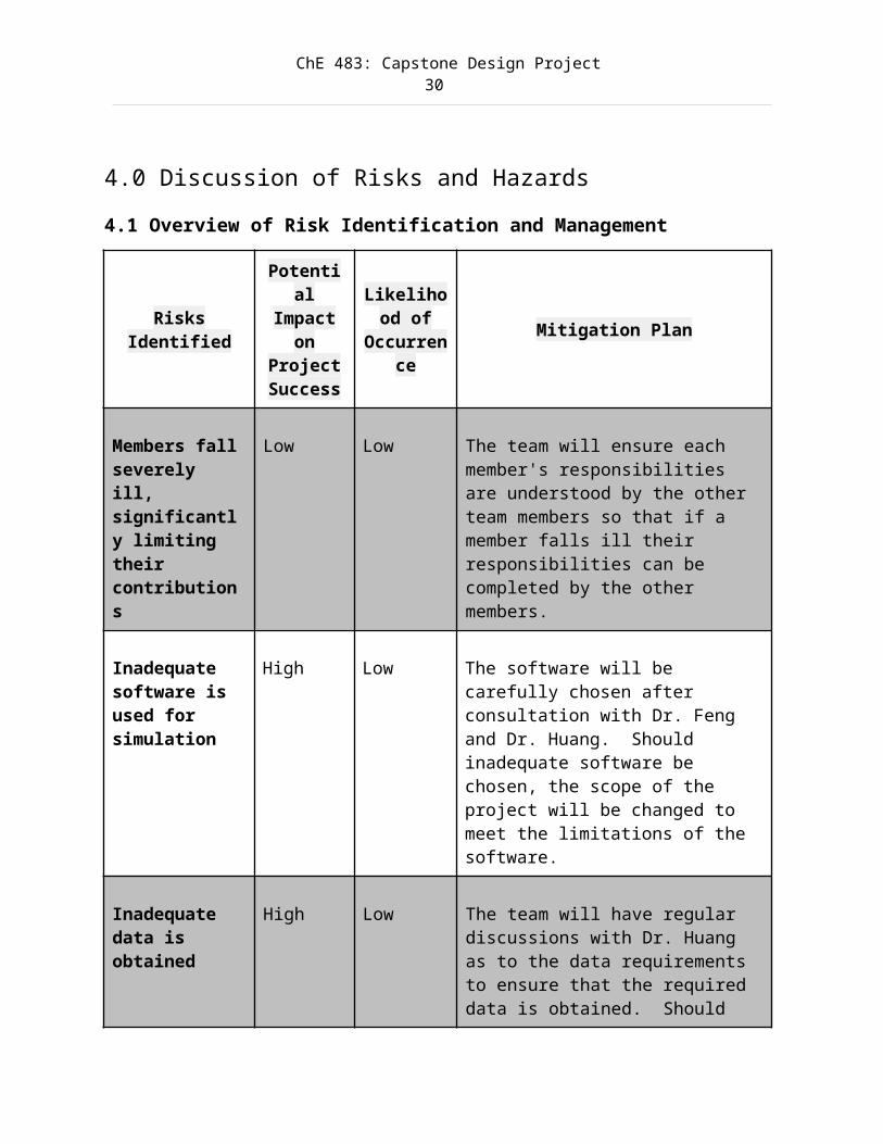
4.0 Discussion of Risks and Hazards4.1 Overview of Risk Identification and Management
RisksIdentified
Potential
Impacton
ProjectSuccess
Likelihood of
Occurrence
Mitigation Plan
Members fallseverely ill, significantly limiting their contributions
Low Low The team will ensure each member's responsibilities are understood by the other team members so that if a member falls ill their responsibilities can be completed by the other members.
Inadequate software is used for simulation
High Low The software will be carefully chosen after consultation with Dr. Feng and Dr. Huang. Should inadequate software be chosen, the scope of the project will be changed to meet the limitations of the software.
Inadequate data is obtained
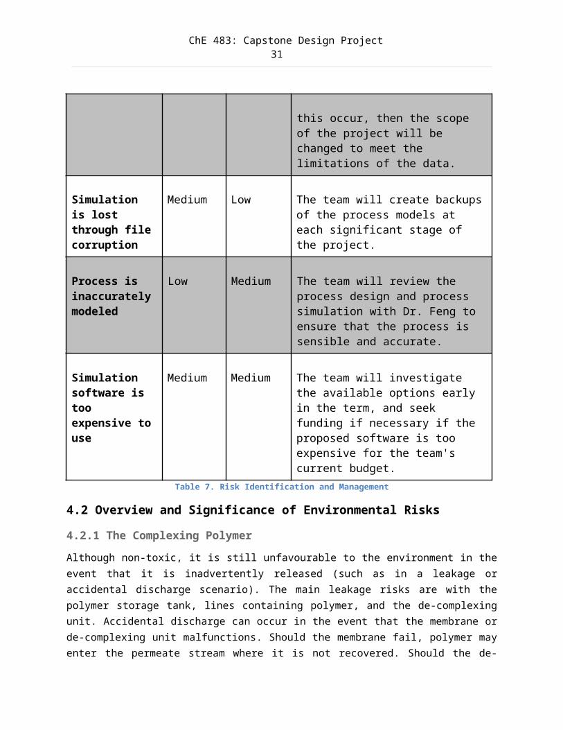
High Low The team will have regular discussions with Dr. Huang as to the data requirements to ensure that the required data is obtained. Should
ChE 483: Capstone Design Project31
this occur, then the scope of the project will be changed to meet the limitations of the data.
Simulation is lost through filecorruption
Medium Low The team will create backupsof the process models at each significant stage of the project.
Process is inaccuratelymodeled
Low Medium The team will review the process design and process simulation with Dr. Feng to ensure that the process is sensible and accurate.
Simulation software is too expensive touse
Medium Medium The team will investigate the available options early in the term, and seek funding if necessary if the proposed software is too expensive for the team's current budget.
Table 7. Risk Identification and Management
4.2 Overview and Significance of Environmental Risks
4.2.1 The Complexing PolymerAlthough non-toxic, it is still unfavourable to the environment in theevent that it is inadvertently released (such as in a leakage oraccidental discharge scenario). The main leakage risks are with thepolymer storage tank, lines containing polymer, and the de-complexingunit. Accidental discharge can occur in the event that the membrane orde-complexing unit malfunctions. Should the membrane fail, polymer mayenter the permeate stream where it is not recovered. Should the de-
ChE 483: Capstone Design Project32
complexing unit fail, polymer could enter the concentrated metal ionstream and not be recovered.
4.2.2 Improperly Treated WastewaterA significant risk of heavy metal streams lies with accidental releaseto the environment, where the contaminated water may poison organismsand find its way to consumption water supplies. Organisms that aredirectly at risk include fish and other organisms living in an aqueousenvironment. Organisms at secondary risk include those that consumeaquatic organisms living in contaminated water.
Heavy metals streams are also a risk if they are accidentally releasedto a process area that is not equipped to handle wastewatercontaminated with heavy metals (such as a small municipal system or anindustrial system that does not handle metals). These externalprocesses may not even be equipped to detect the presence of heavymetals, and their discharge streams could be directly linked to theoutside environment (such as in a lake or stream). Accidental releasefrom the heavy metal treatment process could occur in the event thatthe treatment process fails catastrophically. Process failure could bethe result of an unplanned lack of polymer, a disintegrated membrane,a pump failure, a pH adjustment failure, etc.
4.3 Overview and Significance of Health Risks
4.3.1 The Complexing PolymerComplexing polymers are of particular concern because of their heavyuse in PEUF process. Under ideal process conditions, the polymershould not leave the process where it may be recovered and operatorsshould not be in constant exposure to it. However, polymer may have tobe added after a membrane change (because polymer may get stuck in anold membrane) or after a plant abnormality (in the event of anaccidental discharge). The polymer currently under consideration,Lupamin 9095, does not pose any serious health concern to anindividual as per the MSDS sheet provided by its vendor BASF. It isnot an irritant to the skin or the eyes, non-corrosive, and poses no
ChE 483: Capstone Design Project33
inhalation risk. It also poses very low ingestion risks, though ofcourse ingestion by operators should be prohibited.The health risk in using Lupamin 9095 is therefore considered lowoverall, but the final design process will have to limit operatorexposure to the polymer. As well, polymer concentrations will have tobe monitored to ensure that no abnormal operating conditions arepresent.
4.3.2 Heavy Metal Wastewater StreamsThese streams are part of the process’ normal operating conditions: aconcentrated heavy metal stream coming out of permeate stream of thede-complexing unit is to be expected. Treatment of this concentratestream is outside the scope of the project; however it is assumed thatthe ions will be precipitated in order to yield usable solid metal.Heavy metals have well-known serious ill effects on health and so thesignificance of their health risk cannot be understated. Operatorexposure to heavy metal ion streams must be limited, though there isno risk of harmful volatile vapors in water streams where heavy metalsare the only pollutant.
4.4 Overview and Significance of Process Safety Risks
4.4.1 Explosion or High Potential Energy Release RiskThe heavy metal wastewater treatment process does not have anyinherent explosive or high potential energy dangers. The processoperates at low to moderate pressures and temperatures. Complexingpolymer is also not explosive.
4.4.2 Flammability RiskThe process has no units susceptible to a flammability risk. Theflowing material is heavy metal contaminated wastewater which will notignite. Complexing polymer is non- flammable and does not self-igniteas per its MSDS sheet. The polymer should not be stored or processedat temperatures exceeding 200 ˚C; however no part of the process isexpected to reach even one quarter of that temperature. There is alsono energy pathway that would allow the polymer to reach this
ChE 483: Capstone Design Project34
potentially hazardous temperature.
4.4.3 Corrosion RiskThe operational pH of a PEUF system is within the range of 5 to 8,which is considered relatively non-corrosive. Also, the polymerLupamin 9095 is non-corrosive as per its MSDS sheet. General processpiping should not be at great risk of corrosion. However, theoperational pH of the de-complexing unit is well within the corrosionrange (2-5). In addition, there may be pH and corrosion concerns insodium hydroxide (NaOH) and hydrochloric acid (HCl) solution storagetanks and piping coming from these tanks. There may also be corrosionrisk in pipes upstream of the membrane filtration unit if inletwastewater is significant outside the non corrosive pH range.
4.4.4 Leakage or Burst RiskThere is a risk associated with process pipes leaking or bursting. Thepotential hazard is especially serious if leaks go undetected, aswastewater contaminated with heavy metal has significant environmentaland health risks as mentioned above. Leaks could occur if pipe jointsfail, if pumps fail, if tank seals break, if valves fail, ifinstrumentation fails, etc. Proper installation of equipment shouldprevent most leaks from occurring.
Burst risk is low, as the process is not operating at hightemperatures or pressure. Also, nearly all flow streams are non-corrosive so there should be no catastrophic structural failure ofpipes. Storage tanks containing NaOH, HCl (or HNO3), and the connectingpipes are at the greatest risk of leaks and bursts due to thecorrosive nature of these chemicals.
4.4.5 Equipment Failure and Reliability RiskThe risk linked with the failure of equipment such as pumps, valves,and membranes is considered low. All mission-critical componentsshould be selected to be highly reliable. Furthermore, there should bespare pumps on standby-by with multiple bypass lines available in theevent of pump failure or line blockage/leakage.
ChE 483: Capstone Design Project35
4.4.6 Low or High-Flow RiskInlet wastewater flow rates may be highly variable, and the treatmentprocess must be able to accommodate these variations. While there maybe no way of controlling what is happening upstream of the treatmentprocess, it is possible to design the treatment process to make itflow-flexible. The overall risk of extreme inlet flow scenarios isconsidered moderate because of its uncertain nature.
4.4.7 Temperature Variability RiskThe process may be exposed to seasonal temperature changes significantenough to impact the performance of the polymer and membrane. Thetemperature control unit, upstream of the membrane unit, will have toincorporate heat exchangers to either cool or heat the inletwastewater during times where its temperature is significantly outsidethe optimal PEUF range. The overall risk of temperature changes in theinlet stream is considered moderate because heat exchanging systemsmust always be kept functional.
4.4.8 Instrumentation and Calibration Risk Control and automation systems rely heavily on instrumentation that isboth functional and properly calibrated. Instrumentation is alsocritical when detecting or locating leaks or equipment failures in theprocess. To prevent losses and damages from instrumentation andcalibration risk, care must be taken to select reliable and high-quality instruments. Care must also be taken to properly calibrateevery piece of equipment. Control and automation computer systemsshould also be located in safe environments, isolated from high-riskareas of the process so that they may still function in the event ofan emergency. As well, digital communication lines used by bothoperators and computer systems should be shielded and isolated.
4.4.9 Process Control, Automation, and General Operational RiskModern processes make heavy use of process control and automation(PC&A) systems to monitor and control processes. If these systems areimproperly programmed or if their underlying models are faulty, there
ChE 483: Capstone Design Project36
is great process risk. Operators should be monitoring all aspects ofthe process and need to be able to react and override computercontrols in the event of a miscalculation or otherwise abnormal event.Programming risks can be managed by testing automation scripts insimulated environment before using them in a live process.
There is also risk in process control even if no automation isinvolved. If an operator adds too much or too little polymer in thestorage tank, if a valve is improperly turned, or if a membranebecomes clogged, then the process is not being controlled properly andthere is significant risk. Control and operational risk has topotential to cause improper water treatment and can lead to waste ofmaterial and energy.
ChE 483: Capstone Design Project37
5.0 Mitigating Measures for Selected Risks andHazards5.1 NaOH and HCl Tanks and Associated CorrosionThe NaOH and HCl used to adjust the pH of the incoming waste streamcan be very corrosive and potentially very damaging if spillage wereto occur. To mitigate this risk, the design for the PEUF will includebuffer tanks that can be used to neutralize the HCl and NaOH. Aswell, tanks with appropriate wall thicknesses and chemical stabilitywill be selected. The buffer tanks would be located upstream of thePEUF process so that injection could stabilize any pH abnormalitiesbefore reaching the membrane, which may have an adverse reaction to pHfluctuations outside of its operating range.
Furthermore, the location of the tanks would be placed in an easilyaccessible location to ensure that a regular inspection process can bescheduled.
5.2 Characterization of Incoming WastewaterWastewaters having numerous hazardous chemicals are common, and to beexpected. As a consequence, Waste treatment facilities commonly testincoming wastewater streams to characterize the composition, leachability, and potentially harmful/hazardous components.
There are currently initiatives for the unification of the testingregimes conducted by each waste treatment plant in Europe, but ingeneral, the characterization of wastewater in each country iscustomized to that country’s needs. For the proposed PEUF process theneed for characterization of the incoming waste stream is stillnecessary and will follow conventional waste water treatment testingregimes appropriate for Canada.
As well as characterization of the incoming waste stream, testing willbe conducted downstream of the PEUF process to analyze heavy metal
ChE 483: Capstone Design Project38
content removal, and polymer recovery. Should testing indicate thatthe waste stream still has an unacceptably high amount of heavy metalions, a recycle loop will feed back the waste stream to the PEUF foranother pass as a first step.
5.3 Mitigation of Leakage and SpillageTo mitigate spillage and leakage in the PEUF process, the use of aregular monitoring schedule, along with appropriately selectedmaterials (such as using PVC piping for corrosion and impactresistance) could ensure that leakage was minimal, and quicklydetected if it should occur. Monitoring will occur through dailychecks of the HCl and NaOH tanks to ensure tank integrity.
5.4 Mitigation of Equipment Failure or Insufficient Amountsof PolymerIn the case of equipment failure such as membrane damage orinsufficient addition of Lupamin, the removal of heavy metal ions willbe severely compromised. To guard against this possible failure mode,testing should be conducted after the waste stream passes through themembrane. Should the level of heavy metal ions be too high, the wastewater stream should be able to be redirected to a temporary holdingtank. Furthermore, multiple PEUF processes should be able to be runin parallel, so one PEUF could be put offline for maintenance, whilethe other PEUF system stayed online. This would also help withsituations of insufficient Lupamin injection.
5.5 Inlet Flow RegulationThe PEUF system is designed with a certain flow rate capacity, andexceedance of this flow capacity could exceed the acceptable pressurechange at the membrane. Two methods of regulating the inlet flow willbe used. First, each PEUF will have a buffer inlet tank to ensurethat flows to the filter membranes are smooth and predictable. Thiswill isolate the membranes from spikes in inlet flows. For long termchanges in the flow rate, duplicate PEUF systems will be activated ordeactivated to accommodate the increased/decreased flow.

ChE 483: Capstone Design Project39
ChE 483: Capstone Design Project40
6.0 Overview of Energy and Material CostsThe PEUF method for waste water treatment is much more energyefficient than a conventional wastewater treatment process (e.g.microfiltration, reverse osmosis, hybrid flotation, chemicalprecipitation/coagulation).This is due to the reduced chemical agents,the absence of sludge, and a relatively straight forward treatmentprocess. However, the PEUF is not a complete wastewater treatmentprocess. The PEUF process has only been studied for its effectivenessat removing heavy metals, and not biological contaminants or any otherchemical hazards. Therefore, a wastewater treatment plant would havethe PEUF process as perhaps a final step of water treatment.
A major concern is the flow rates possible with a PEUF process.Currently, most PEUF processes have been tested with relatively smallflows. To the research group’s knowledge, application in a high flowrate wastewater treatment plant has not been carried out. At low flowrates, the energy cost of a PEUF compared to conventional treatmentmethods is very favorable due to the lack of any significant wastestreams such as sludge. As well, there is no need to heat or cool thewaste water as there is no considerable heat of reaction takingplace. Testing at higher flow rates is necessary to determine if theenergy and material costs are less.
As far as energy re-use and saving within the treatment process,streams coming out of the membrane and de-complexing units can bematched with their inlet stream counterparts if these inlet streamsneed preheating. However, the need for inlet preheating may not begreat enough to justify complex routing systems and the cost ofadditional heat exchangers. Energy requirements of the process pumpsare not expected to be very high, and the screener unit will workthrough simple gravity drainage.
Costs of chemicals and equipment used in PEUF process will be coveredin detailed in the Economic Analysis section.

ChE 483: Capstone Design Project41
ChE 483: Capstone Design Project42
7.0 Design MethodologyThe SuperPro model can be viewed in the Appendix section. The modeldemonstrates a complete process of wastewater treatment and heavymetal removal using PEUF. The detailed description of the simulationis explained in the following sections.
7.1 SuperPro Simulation Model
7.1.1 Pre-Treatment Process
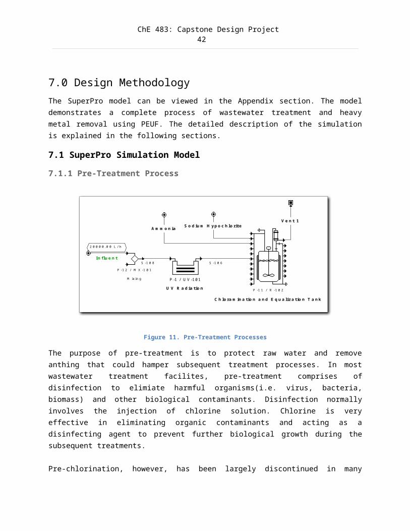
Figure 11. Pre-Treatment Processes
The purpose of pre-treatment is to protect raw water and removeanthing that could hamper subsequent treatment processes. In mostwastewater treatment facilites, pre-treatment comprises ofdisinfection to elimiate harmful organisms(i.e. virus, bacteria,biomass) and other biological contaminants. Disinfection normallyinvolves the injection of chlorine solution. Chlorine is veryeffective in eliminating organic contaminants and acting as adisinfecting agent to prevent further biological growth during thesubsequent treatments.
Pre-chlorination, however, has been largely discontinued in many
P -1 / U V -101
U V R a d ia tio n P -1 1 / R -1 0 2
C h lo ra m in a tio n a n d E q u a liza tio n T a n k
S -1 0 6
S o d iu m H yp o c h lo riteA m m o n ia
P -1 2 / M X -1 0 1
M ixin g
In flu e n t
2 0 0 0 0 .0 0 L /h
S -1 0 8
V e n t 1
ChE 483: Capstone Design Project43
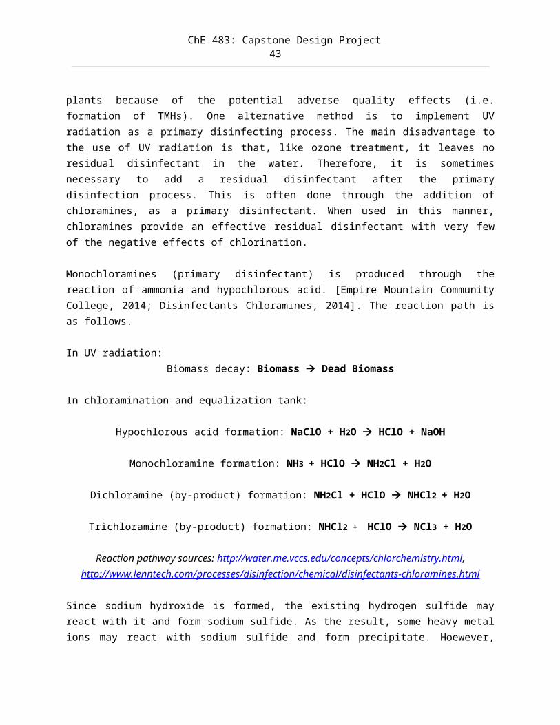
plants because of the potential adverse quality effects (i.e.formation of TMHs). One alternative method is to implement UVradiation as a primary disinfecting process. The main disadvantage tothe use of UV radiation is that, like ozone treatment, it leaves noresidual disinfectant in the water. Therefore, it is sometimesnecessary to add a residual disinfectant after the primarydisinfection process. This is often done through the addition ofchloramines, as a primary disinfectant. When used in this manner,chloramines provide an effective residual disinfectant with very fewof the negative effects of chlorination.
Monochloramines (primary disinfectant) is produced through thereaction of ammonia and hypochlorous acid. [Empire Mountain CommunityCollege, 2014; Disinfectants Chloramines, 2014]. The reaction path isas follows.
In UV radiation:Biomass decay: Biomass Dead Biomass
In chloramination and equalization tank:
Hypochlorous acid formation: NaClO + H2O HClO + NaOH
Monochloramine formation: NH3 + HClO NH2Cl + H2O
Dichloramine (by-product) formation: NH2Cl + HClO NHCl2 + H2O
Trichloramine (by-product) formation: NHCl2 + HClO NCl3 + H2O
Reaction pathway sources: http://water.me.vccs.edu/concepts/chlorchemistry.html,http://www.lenntech.com/processes/disinfection/chemical/disinfectants-chloramines.html
Since sodium hydroxide is formed, the existing hydrogen sulfide mayreact with it and form sodium sulfide. As the result, some heavy metalions may react with sodium sulfide and form precipitate. Hoewever,
ChE 483: Capstone Design Project44
metal sulfide formation usually occurs under high pH condition (pH 10-14) Metal sulfides are have lower solubilities than its correspondingmetal hydroxides, thus allowing lower residual metal concentration inwastewater. Since one of our objective is to recover heavy metal in aconcentrated stream and reduce heavy metal content in the sludge, thepresence of metal sulfide is highly undesired.
Sodium sulfide formation: H2S + 2NaOH Na2S + 2H2O
Sulfide Precipitation: Heavy Metal + Na2S Metal Sulfide + 2Na+
One advantage of this reaction path is the production of sodiumhydroxide which increases the pH of the water. Making the waterslightly alkaline helps coagulation and flocculation processes workeffectively and also helps to minimize the risk of lead beingdissolved from lead pipes and from lead solder in pipe fittings.Excessive production of sodium hydroxide may further promote sulfideprecipitation.
ChE 483: Capstone Design Project45
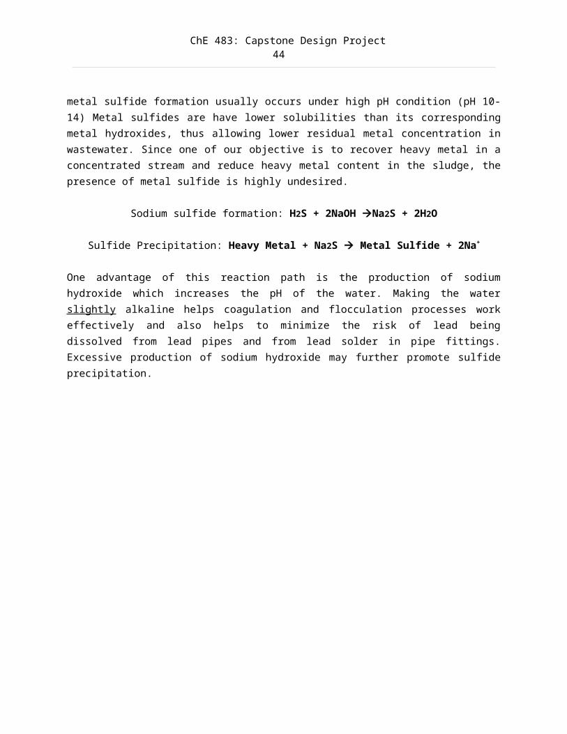
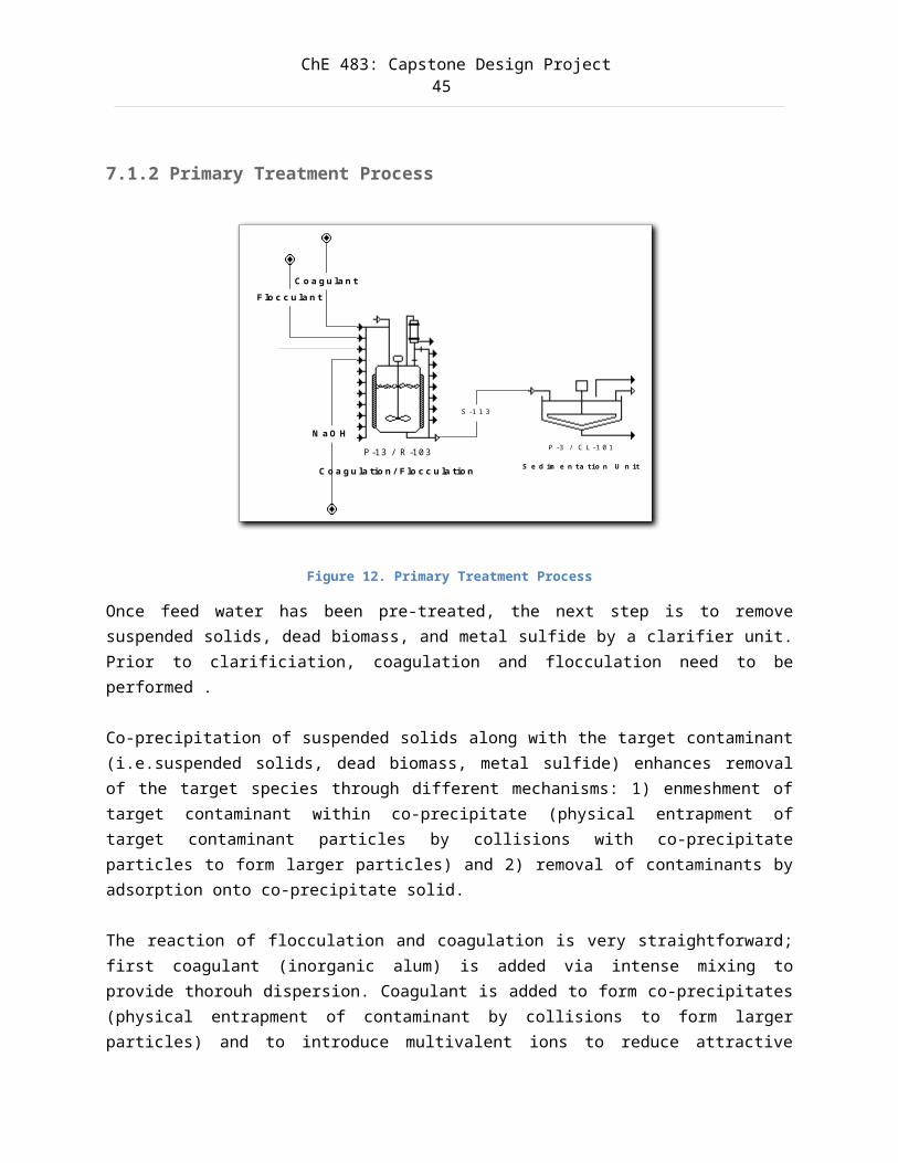
7.1.2 Primary Treatment Process
Figure 12. Primary Treatment Process
Once feed water has been pre-treated, the next step is to removesuspended solids, dead biomass, and metal sulfide by a clarifier unit.Prior to clarificiation, coagulation and flocculation need to beperformed . Co-precipitation of suspended solids along with the target contaminant(i.e.suspended solids, dead biomass, metal sulfide) enhances removalof the target species through different mechanisms: 1) enmeshment oftarget contaminant within co-precipitate (physical entrapment oftarget contaminant particles by collisions with co-precipitateparticles to form larger particles) and 2) removal of contaminants byadsorption onto co-precipitate solid.
The reaction of flocculation and coagulation is very straightforward;first coagulant (inorganic alum) is added via intense mixing toprovide thorouh dispersion. Coagulant is added to form co-precipitates(physical entrapment of contaminant by collisions to form largerparticles) and to introduce multivalent ions to reduce attractive
P -3 / C L -1 0 1
S e d im e n ta tio n U n itP -13 / R -10 3
C o a g u la tio n / F lo c c u la tio n
C o a g u la n tF lo c c u la n t
S -1 1 3
N a O H
ChE 483: Capstone Design Project46
forces. Usually lime is used since Ca2+ is an excellent coagulant;however gypsum may form. Sodium hydroxide is used instead. Use of limemay also promote hydroxy precipitation since it leads to lowestresidual metal ion [Christoe, 1976; Water Online, 2014].
Co-precipitate or aluminum hydroxide is formed by adding alum alongwith lime or caustic. The reaction will form Al(OH)3 co-precipitate andsodium sulfate as the pH is raised.
Formation of co-precipiate: Al2(SO4)3.14H2O +6 NaOH 2Al(OH)3+3Na2SO4+ 14H2O
Clarifier then removes large solid particles by gravity settling. Thesludge formed is transported to sewage management unit for volumeminimization.
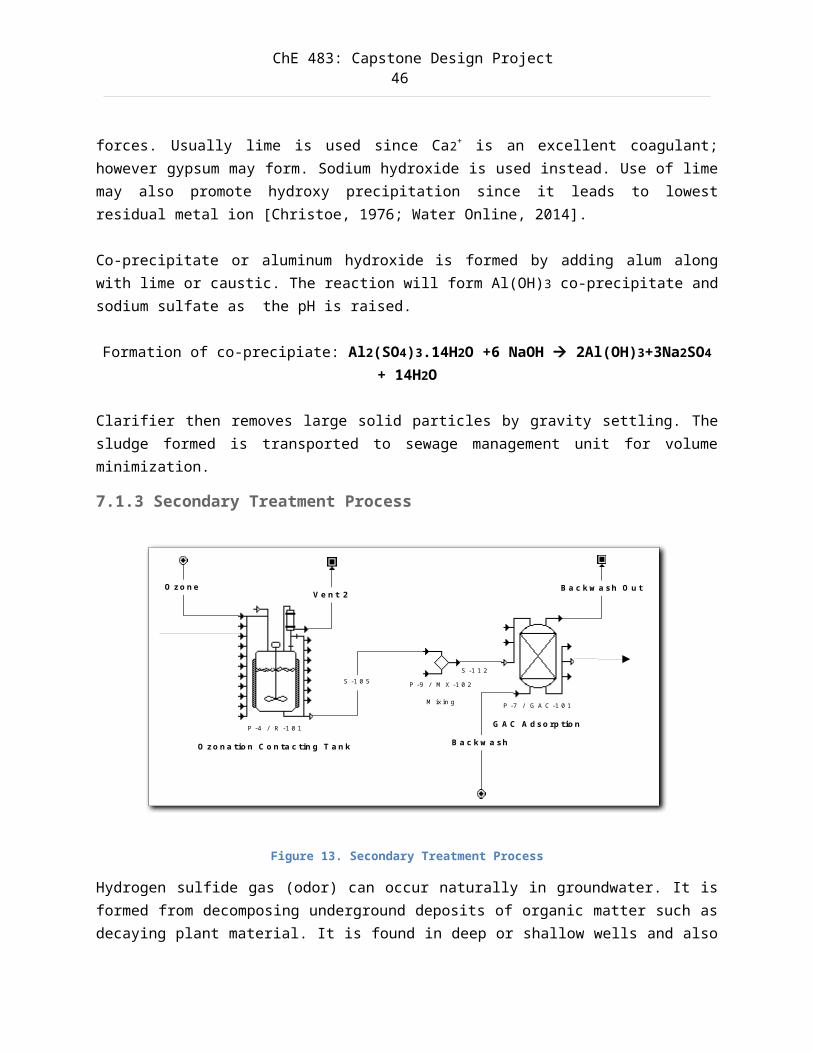
7.1.3 Secondary Treatment Process
Figure 13. Secondary Treatment Process
Hydrogen sulfide gas (odor) can occur naturally in groundwater. It isformed from decomposing underground deposits of organic matter such asdecaying plant material. It is found in deep or shallow wells and also
P -7 / G A C -1 0 1
G A C A d so rp tio n
B a c k w a sh
B a c k w a sh O u t
P -9 / M X -1 0 2
M ixin g
S -1 1 2
P -4 / R -1 0 1
O zo n a tio n C o n ta c tin g T a n k
S -1 0 5
O zo n eV e n t 2
ChE 483: Capstone Design Project47
can enter surface water through springs, although it quickly escapes to the atmosphere. Ozone is a powerful oxidizer that can destroy thesulfur reducing bacteria, this will reduce odors emanating from waterand improve water quality [Ozone Solutions, 2014; AtmosphericEnvironmental Pergamon Press, 1969].
Removal of odor by ozonation: H2S + O3 SO2 + H2O
Some hydrogen sulfide may be unreacted (<100% conversion as assumed).This unreacted sulfide is removed from wastewater by adsorption byactivated carbon (GAC).
Sodium sulfide formed during pre-chloramination can be furtheroxidized by ozone to form sodium sulfate:
Oxidation of sulfide: Na2S + 43O3 Na2SO4
Sulfur dioxide and water are the main products thermodynamically[Spartan Water Treatment, 2014]. Other disinfection byproducts (DBP)are further treated by GAC adsorption. Note that sulfur dioxide isvented; sulfur dioxide can be collected and further used to decolorizewastewater and to treat chlorinated wastewater prior to release toconvert free chlorine to chloride. Sulfur dioxide is fairly solublein water; thus it can pass through activated carbon easily. Sodium bisulfite (strong reducing agent) may be added to perform ozonequenching. It is not needed to improve water treatment performance butto prevent high concentration of ozone released into ambient airduring mixing. This ozone off gassing may result in unsafe workingcondition. Residual ozone quenching may be avoided when minimal andtolerable ozone concentration exist [Rakness, 2005].
Following ozonation is Granular Active Carbon (GAC) adsorption. GAC isoften implemented after ozonation for the removal of disinfection by-products (DBP, including dead biomass), chloramine, odor (hydrogen
ChE 483: Capstone Design Project48
sulfide), and other contaminants [Environmental Protection Agency,2014; U. S. Department of the Interior Bureau of Reclamation, 2014;International Ozone Association, 2014].
GAC systems designed for free-chlorine removal may need to beretrofitted for monochloramine removal. The reaction rate formonochloramine removal is considerably slower than removing freechlorine using traditional GAC. At least two to four times more emptybed contacting tank (EBCT) will be required for monochloramine removalwith traditional GAC. Regulatory authorities and some standards mayrequire 10 minutes EBCT when removing monochloramine from water.Manufacturers have developed surfaced-enhanced activated carbons.These activated carbons have surface reaction sites enhanced duringthe manufacturing process. They are superior for monochloramineremoval compared to traditional GAC. For surface-enhanced GAC, an EBCTof three minutes will be sufficient to remove monochloramine fromwater [Potwora, 2009].
ChE 483: Capstone Design Project49
7.1.4 Tertiary Treatment Process
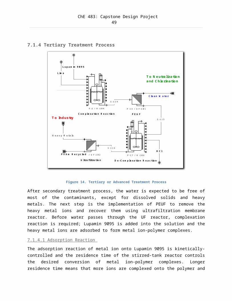
Figure 14. Tertiary or Advanced Treatment Process
After secondary treatment process, the water is expected to be free ofmost of the contaminants, except for dissolved solids and heavymetals. The next step is the implementation of PEUF to remove theheavy metal ions and recover them using ultrafiltration membranereactor. Before water passes through the UF reactor, complexationreaction is required; Lupamin 9095 is added into the solution and theheavy metal ions are adsorbed to form metal ion-polymer complexes.
7.1.4.1 Adsorption Reaction
The adsorption reaction of metal ion onto Lupamin 9095 is kinetically-controlled and the residence time of the stirred-tank reactor controlsthe desired conversion of metal ion-polymer complexes. Longerresidence time means that more ions are complexed onto the polymer and
P -2 / R -1 0 4
C o m p le xa tio n R e a c tio n
P -1 4 / U F -1 0 1
P E U F
L im e
S -1 1 4
C le a n W a te r
P -1 6 / U F -1 0 2
U ltra filtra tio n
H e a v y M e ta ls
T o Industry
L u p a m in 9 0 9 5
T o N e utraliza tion a nd C hlo rinatio n
P V A m R e c yc le d P -1 7 / R -1 0 6
D e -C o m p le xa tio n R e a c tio n
H C l
S -1 1 5
S -1 1 6
ChE 483: Capstone Design Project50
thus rejected by the UF membrane. The complexation reaction is asfollows:
Complexation reaction: A + M+ AM+
where A = complexing site of Lupamin 9095,M+ = metal ion,AM+ = occupied site.
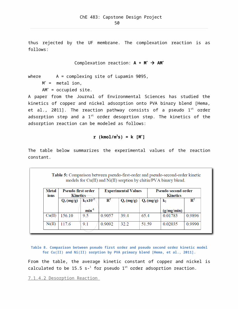
A paper from the Journal of Environmental Sciences has studied thekinetics of copper and nickel adsorption onto PVA binary blend [Hema,et al., 2011]. The reaction pathway consists of a pseudo 1st orderadsorption step and a 1st order desoprtion step. The kinetics of theadsorption reaction can be modeled as follows:
r (kmol/m3s) = k [M+]
The table below summarizes the experimental values of the reactionconstant.
Table 8. Comparison between pseudo first order and pseudo second order kinetic modelfor Cu(II) and Ni(II) sorption by PVA primary blend [Hema, et al., 2011].
From the table, the average kinetic constant of copper and nickel iscalculated to be 15.5 s-1 for pseudo 1st order adsoprtion reaction.
7.1.4.2 Desorption Reaction
ChE 483: Capstone Design Project51
Unlike the adsorption reaction, the desorption or decomplexationreaction is very fast in acidic environment (pH 2-5) [Bessbousse,2008].
Decomplexation reaction: AM+ A + M+
The reaction is modeled as an equilibrium-limited reaction with 100%conversion.
7.1.4.3 Effects of pH
A higher pH increases the degree of heavy metal complexation ontoLupamin 9095 due to higher free amino content. As well, higher pHreduces the competition between metal ions and hydrogen protons tobind onto the complexation site.
By decreasing the pH, heavy metal ions are decomplexed from thepolymer due to the increasing competition of metal and hydrogen ionsto bind onto the polymer. As the result, regeneration of polymer canbe made possible.
pH values for complexation: 5-8 pH values for decomplexation: 2-5
Many metal ions form soluble hydroxyl complexes at alkaline regions.Since pH senstivities vary significantly from metal to metal, this canbe exploited for selection separation [Bessbousse, 2008].
7.1.4.4 Langmuir Adsorption Theorem
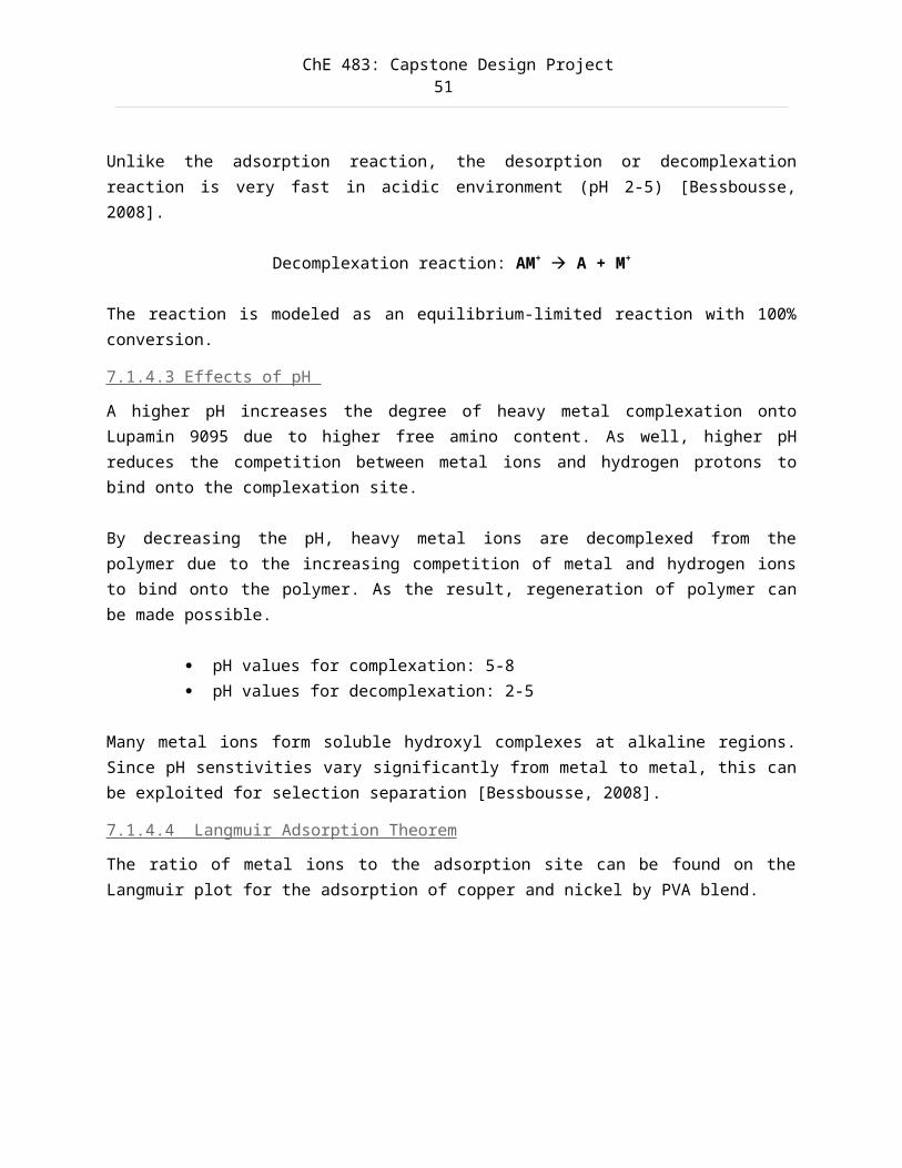
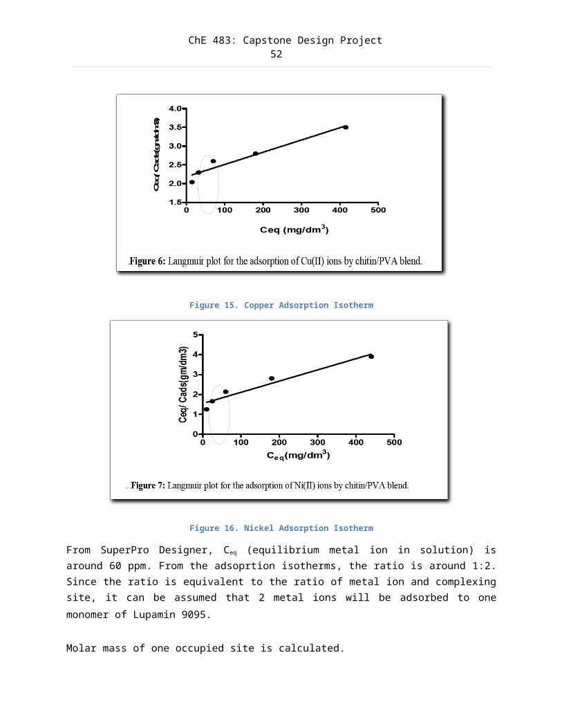
The ratio of metal ions to the adsorption site can be found on theLangmuir plot for the adsorption of copper and nickel by PVA blend.
ChE 483: Capstone Design Project52
Figure 15. Copper Adsorption Isotherm
Figure 16. Nickel Adsorption Isotherm
From SuperPro Designer, Ceq (equilibrium metal ion in solution) isaround 60 ppm. From the adsoprtion isotherms, the ratio is around 1:2.Since the ratio is equivalent to the ratio of metal ion and complexingsite, it can be assumed that 2 metal ions will be adsorbed to onemonomer of Lupamin 9095.
Molar mass of one occupied site is calculated.
ChE 483: Capstone Design Project53
Mone occupied site = Mmonomer of Lupamin 9095 + 2Mmetal ions
Mone occupied site = 138. 67 g/mol + 2(55.845 g/mol) = 250.33 g/mol
This is however not the actual mass of the metal ion-polymercomplexes. Further laboratory experiments are required.
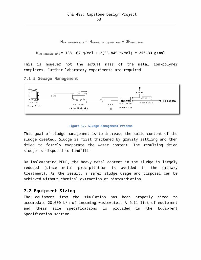
7.1.5 Sewage Management
Figure 17. Sludge Management Process
This goal of sludge management is to increase the solid content of thesludge created. Sludge is first thickened by gravity settling and thendried to forcely evaporate the water content. The resulting driedsludge is disposed to landfill.
By implementing PEUF, the heavy metal content in the sludge is largelyreduced (since metal precipitation is avoided in the primarytreatment). As the result, a safer sludge usage and disposal can beachieved without chemical extraction or bioremediation.
7.2 Equipment SizingThe equipment from the simulation has been properly sized toaccomodate 20,000 L/h of incoming wastewater. A full list of equipmentand their size specifications is provided in the EquipmentSpecification section.
P -5 / V -1 0 2
S to ra g e T a n kP -6 / T H -1 0 1
S lu d g e T h ic k e n in g
S -1 0 1
P -8 / S L D R -1 0 1
S lu d g e D ryin g
S -1 0 4
A ir In
A ir O u t
D rie d S lu d g e
7 9 .1 5 L / h
T o La ndfill
ChE 483: Capstone Design Project54
8.0 Results and Discussion
8.1 Analysis of Simulation Results
8.2 Economic Analysis
8.3 Environmental Analysis
9.0 Conclusions
10.0 Recommendations
ChE 483: Capstone Design Project55
11.0 ReferencesA New Process For Sulfate Removal From Industrial Waters. Water Online. Retrieved on February 8, 2014 from http://www.wateronline.com/doc/a-new-process-for-sulfate-removal-from-indust-0001
Aroua, Mohamed Kheireddine, Fathiah Mohamed Zuki, and Nik Meriam Sulaiman. (2007). "Removal of chromium ions from aqueous solutions bypolymer-enhanced ultrafiltration." Journal of Hazardous Materials 147.3: 752-758.
Baltpurvins, K.A., Burns, R.C., Lawrance, G.A., Stuart, A.D., 1997. Effect of electrolyte composition on zinc hydroxide precipitation by lime. Water Res. 31, 973e980.
BASF Corporation. (2002). Lupamin 9095 High Molecular Weight Linear Polyvinylamine - Technical Bulletin. Retrieved November 3, 2013, from http://www.docstoc.com/docs/5935789/Lupamin_9095---PDF---PDF
Belfort, Georges. (1988). "Membrane modules: comparison of different configurations using fluid mechanics". Journal of Membrane Science 35 (3): 245–270
Bessbousse, H., et al. "Removal of heavy metal ions from aqueous solutions by filtration with a novel complexing membrane containing poly (ethyleneimine) in a poly (vinyl alcohol) matrix." Journal of Membrane Science 307.2 (2008): 249-259.
Camarillo, Rafael, et al. "Removal of heavy metal ions by polymer enhanced ultrafiltration: Batch process modeling and thermodynamics ofcomplexation reactions." Desalination 286 (2012): 193-199.
Cheryan, M. (1998). “Ultrafiltration and Microfiltration Handbook’. CRC Press.
Chlorination Chemistry. Empire Mountain Community College. Retrieved on February 2, 2014 from
ChE 483: Capstone Design Project56
http://water.me.vccs.edu/concepts/chlorchemistry.html
Christoe, J. R. (1976). Removal of Sulfate from Industrial Wastewaters. Journal (Water Pollution Control Federation), 48 (12):2804-2808. http://www.jstor.org/discover/10.2307/25040094?uid=3739448&uid=2&uid=3737720&uid=4&sid=21103552776073
Disinfectants Chloramines. Lenntech. Retrieved on February 4, 2014 from http://www.lenntech.com/processes/disinfection/chemical/disinfectants-chloramines.htm
Feng, Xianshe. "Xianshe Feng." Chemical Engineering. University of Waterloo. Web. 23 Dec 2013. <https://uwaterloo.ca/chemical-engineering/people-profiles/xianshe-feng>.
Ganeshalingam, S., Zhang, M. and Moll, J. (2013). Chemical EngineeringUnit Operations Laboratory Manual, University of Waterloo (2013
Granular Activated Carbon. Environmental Protection Agency. Retrieved on February 3, 2014 from http://iaspub.epa.gov/tdb/pages/treatment/treatmentOverview.do?treatmentProcessId=2074826383
Granular Activated Carbon. U. S. Department of the Interior Bureau of Reclamation. Retrieved on February 5, 2014 from http://www.usbr.gov/pmts/water/publications/reportpdfs/Primer%20Files/07%20-%20Granular%20Activated%20Carbon.pdf
Grosvenor, T. (2000). Strategies for Minimizing Ozonation By-Products in Drinking Water. Water & Wastes Digest. Retrieved on February 8, 2014 from http://www.wwdmag.com/microfiltration/strategies-minimizing-ozonation-products-drinking-water
Hales, J. M., et al. (1969). The rate of reaction between dilute
ChE 483: Capstone Design Project57
hydrogen sulfide and ozone in air. Atmospheric Environmental Pergamon Press, 3: 657-667 http://deepblue.lib.umich.edu/bitstream/handle/2027.42/32876/0000254.pdf?sequence=1
Hema, S., T. M. Kumaran, and P. N. Sudha. "Adsorption of copper (II) and nickel (II) ions on chitin/polyvinyl alcohol binary blend: Kinetics and equilibrium studies." International Journal of Environmental Sciences 2.2 (2011): 624-637.
Hydrogen Sulfide Removal with Ozone. Spartan Water Treatment. Retrieved on February 10, 2014 from http://www.spartanwatertreatment.com/hydrogen-sulfide-removal.html
Kucera, Jane. Properly Apply Reverse Osmosis Chemical Engineering Progress. February 1997. Pgs 54-61.
Mannheim Water Treatment Plant - Processing Schematic. Region of Waterloo. Retrieved on January 10, 2014 from http://www.regionofwaterloo.ca/en/aboutTheEnvironment/resources/Mannheim.pdf
Mitsui Chemicals Inc. (2004). Polyethersulfone (PES) - Technical Literature. Retrieved November 3, 2013, from http://bdml.stanford.edu/twiki/pub/Haptics/MaterialSelection/Polyethersulfone_PES.pdf
Morris, R. D., Audet, A. M., Angelillo, I. F., Chalmers, T. C., & Mosteller, F. (1992). Chlorination, chlorination by-products, and cancer: a meta-analysis.American journal of public health, 82(7), 955-963.
Nakao, Shin‐Ichi, Tsuyoshi Nomura, and Shoji Kimura. "Characteristics of macromolecular gel layer formed on ultrafiltration tubular membrane." AIChE Journal 25.4 (1979): 615-622
Operation and Maintenance Manual - UF-6-HF Ultrafiltration System. Con-Serv Manufacturing. Retrieved 21 October 2013. From
ChE 483: Capstone Design Project58
http://www.con-servwater.com/uploads/CON-SERV_6_GPM_UF_SYSTEM_OPERATING_MANUAL_7-28-11_Rev.pdf
Ozonation and Granular Activated Carbon Filtration - The Solution to Many Problems. International Ozone Association.. Retrieved on February10, 2014 from http://www.degremont-technologies.com/IMG/pdf/tech_ozonia_ozonation-and-gac.pdf
Potwora, R. (2009). Chlorine and Chloramine Removal with Activated Carbon. Carbon Resources. Retrieved on February 1, 2014 from http://www.carbonresources.com/pdf/0906Potwora.pdf
Rakness, K. L. (2005). Ozone in Drinking Water Treatment: Process Design, Operation, and Optimization. American Water Works Association.Retrieved on February 3, 2014 from http://books.google.ca/books?id=qCPRoGC64mMC&pg=PA209&lpg=PA209&dq=sodium+bisulfite+ozone+quenching&source=bl&ots=EWqvocgmWy&sig=zjcHq-IN91HwvVSmJxRqz-ej-0A&hl=en&sa=X&ei=jcoIU7rZEJP7yAGBt4GABw&ved=0CCkQ6AEwAA#v=onepage&q=sodium%20bisulfite%20ozone%20quenching&f=false
Rivas B. L. and M. V. Ignacio, Water-soluble polymer–metal ion interactions, Progress in Polymer Science, 28 (2003) 173-208.
Spange, S., Wolf, S., & Simon, F. (2006). Adsorption of poly (vinyl formamide-co-vinyl amine)(PVFA-co-PVAm) onto metal surfaces. In Characterization of Polymer Surfaces and Thin Films (pp. 110-116). Springer Berlin Heidelberg.
Sulfate and Hydrogen Sulfide in Water. Ozone Solutions. Retrieved on February 6, 2014 from http://www.ozoneapplications.com/info/sulfur.htm
Tamime, A. Y. (2013). “Membrane Processing Dairy and Beverage Applications”. Chicester: Wiley.
Tchobanoglous, George, and Franklin L. Burton. "Wastewater
ChE 483: Capstone Design Project59
engineering."MANAGEMENT 7 (2003): p. 1-24.
Üstün, Gökhan Ekrem. (2009). "Occurrence and removal of metals in urban wastewater treatment plants." Journal of hazardous materials 172.2: 833-838.
Vahedpour, M., et al. (2013). Prediction of Mechanism and Thermochemical Properties of O3 + H2S Atmospheric Reaction. Journal ofChemistry, 2013 ID: 659682http://www.hindawi.com/journals/jchem/2013/659682/
12.0 Appendices 12.1 Equipment Specifications
12.2 SuperPro Designer Simulation ModelA SuperPro Designer model, Economic Evaluation report, and Environmental Impact report are available upon request. The model has been finalized and is working properly. Preliminary optimization has been performed.
A SuperPro Designer software is required. Software is available from Professore W.Anderson.
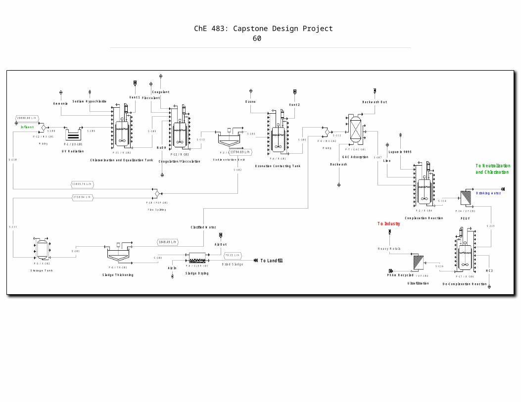
ChE 483: Capstone Design Project60
P -3 / C L -1 0 1
S e d im e n ta tio n U n it
P -5 / V -1 0 2
S to ra g e T a n kP -6 / T H -1 0 1
S lu d g e T h ic k e n in g
S -1 0 1
P -1 / U V -101
U V R a d ia tio n
P -8 / S L D R -1 0 1
S lu d g e D ryin g
S -1 0 4
A ir In
A ir O u t
D rie d S lu d g e
7 9 .1 5 L / h
T o La ndfill
P -7 / G A C -1 0 1
G A C A d so rp tio n
B a c k w a sh
P -1 1 / R -1 0 2
C h lo ra m in a tio n a n d E q u a liza tio n T a n k
S -1 0 6
S o d iu m H yp o c h lo riteA m m o n ia B a c k w a sh O u t
P -1 0 / F S P -1 0 1
F lo w S p littin g
S -1 0 2
137 94.6 9 L/h
P -1 2 / M X -1 0 1
M ixin g
In flu e n t
2 0 0 0 0 .0 0 L / h
S -1 1 0
1 1 0 3 5 .7 6 L /h
S -1 1 1
2 7 5 8 .9 4 L /h
S -1 0 8
P -9 / M X -1 0 2
M ix in g
C la rifie d W a te r
184 8.49 L/h
S -1 1 2
P -4 / R -1 0 1
O zo n a tio n C o n ta c tin g T a n k
S -1 0 3
S -1 0 5
O zo n eV e n t 2
P -13 / R -10 3
C o a g u la tio n / F lo c c u la tio n
C o a g u la n tF lo c c u la n t
S -1 0 9
S -1 1 3
P -2 / R -1 0 4
C o m p le xa tio n R e a c tio n
P -1 4 / U F -1 0 1
P E U F
S -1 0 7L im e
S -1 1 4
D rin k in g w a te r
P -1 6 / U F -1 0 2
U ltra filtra tio n
H e a v y M e ta ls
T o Industry
L u p a m in 9 0 9 5
T o N eutralization a nd C hlo rinatio n
P V A m R e c yc le d P -1 7 / R -1 0 6
D e -C o m p le xa tio n R e a c tio n
H C l
S -1 1 5
S -1 1 6
V e n t 1
N a O H