Embed Size (px)
Citation preview
�����������������
Citation: Han, L.; Duan, J.; Qian, D.;
Gong, Y.; Wang, Y.; Xie, F.; Su, Y.
Research on Homogeneous Charge
Compression Ignition Combustion of
Intake Port Exhaust Gas
Recirculation Based on Cam Drive
Hydraulic Variable Valve Actuation
Mechanism. Energies 2022, 15, 438.
https://doi.org/10.3390/en15020438
Academic Editor: Katarzyna Antosz
Received: 14 December 2021
Accepted: 4 January 2022
Published: 8 January 2022
Publisher’s Note: MDPI stays neutral
with regard to jurisdictional claims in
published maps and institutional affil-
iations.
Copyright: © 2022 by the authors.
Licensee MDPI, Basel, Switzerland.
This article is an open access article
distributed under the terms and
conditions of the Creative Commons
Attribution (CC BY) license (https://
creativecommons.org/licenses/by/
4.0/).
energies
Article
Research on Homogeneous Charge Compression IgnitionCombustion of Intake Port Exhaust Gas Recirculation Based onCam Drive Hydraulic Variable Valve Actuation MechanismLinghai Han 1, Jiaquan Duan 1, Dingchao Qian 1, Yanfeng Gong 1, Yaodong Wang 2,*, Fangxi Xie 2 and Yan Su 2
1 State Key Laboratory of Comprehensive Technology on Automobile Vibration and Noise & Safety Control,Changchun 130013, China; [email protected] (L.H.); [email protected] (J.D.);[email protected] (D.Q.); [email protected] (Y.G.)
2 State Key Laboratory of Automotive Simulation and Control, Jilin University, Changchun 130025, China;[email protected] (F.X.); [email protected] (Y.S.)
* Correspondence: [email protected]
Abstract: The thermal efficiency of an efficient gasoline engine is only about 40% and it will producea large number of harmful products. Curbing harmful emissions and enhancing thermal efficiencyhave always been the goals pursued and emission regulations are also being tightened gradually. Asone of the main consumers of fossil fuels, automobile engines must further reduce fuel consumptionand emissions to comply with the concept of low-carbon development, which will also help themcompete with electric vehicles. Homogeneous charge compression ignition (HCCI) combustioncombined with variable valve actuation (VVA) technology is one of the important ways to improveengine emissions and economy. HCCI combustion based on VVA can only be realized at small andmedium loads. The actual application on the entire vehicle needs to be combined with spark ignition(SI) combustion to achieve full working condition coverage. Therefore, HCCI combustion needs fastvalve response characteristics; however, the valve lift and timing of the existing VVA mechanisms aremostly controlled separately, resulting in poor valve response. In order to solve this problem, the camdriven hydraulic variable valve actuation (CDH-VVA) mechanism was designed. The valve lift andtiming can be adjusted at the same time and the switching of valve lift and timing can be completed in1~2 cycles. A set of combustion mode switching data is selected to show the response characteristicsof the CDH-VVA mechanism. When switching from spark ignition (SI) to HCCI, it switches to HCCIcombustion after only one combustion cycle and it switches to stable HCCI combustion after twocombustion cycles, which proves the fast response characteristics of the CDH-VVA mechanism. Atthe same time, the CDH-VVA mechanism can form the intake port exhaust gas recirculation (EGR),as one type of internal EGR. This paper studies the HCCI combustion characteristics of the CDH-VVA mechanism in order to optimize it in the future and enable it to realize more forms of HCCIcombustion. At 1000 rpm, if the maximum lift of the exhaust valve (MLEV) is higher than 5.0 mmor lower than 1.5 mm, HCCI combustion cannot operate stably, the range of excess air coefficient(λ) is largest when the MLEV is 4.5 mm, ranging from 1.0~1.5. Then, as the MLEV decreases, therange of λ becomes smaller. When the MLEV drops to 1.5 mm, the range of λ shortens to 1.0~1.3. Themaximum value of the MLEV remains the same at the three engine speeds (1000 rpm, 1200 rpm and1400 rpm), which is 5.0 mm. The minimum value of the MLEV gradually climbs as the engine speedincrease, 1000 rpm: 1.5 mm, 1200 rpm: 2.0 mm, 1400 rpm: 3.0 mm. With the increase of engine speed,the range of indicated mean effective pressure (IMEP) gradually declines, 3.53~6.31 bar (1000 rpm),4.11~6.75 bar (1200 rpm), 5.02~6.09 bar (1400 rpm), which proves that the HCCI combustion loadsof the intake port EGR are high and cannot be extended to low loads. The cyclic variation of HCCIcombustion basically climbs with the decrease of the MLEV and slightly jumps with the increase ofthe engine speed. At 1000 rpm, when the MLEV is 5.0 mm, the cyclic variation range is 0.94%~1.5%.As the MLEV drops to 1.5 mm, the cyclic variation range rises to 3.5%~4.5%. Taking the maximumvalue of the MLEV as an example, the cyclic variation range of 1000 rpm is 0.94%~1.5%, 1200 rpmbecomes 1.5%~2.3% and 1400 rpm rises to 2.0%~2.5%.
Energies 2022, 15, 438. https://doi.org/10.3390/en15020438 https://www.mdpi.com/journal/energies
Energies 2022, 15, 438 2 of 16
Keywords: variable valve actuation; homogeneous charge compression ignition; exhaust gas recircu-lation; cyclic variation
1. Introduction
Automobile fuel consumption and emission regulations are becoming more and morestrict. Major automotive markets require light-duty vehicles to expand fuel economy by3~6% per year, and in the European Union, the target for carbon dioxide (CO2) emissionsfrom new cars in 2030 is to lessen 37.5%, compared to 95 g/km for passenger cars and145 g/km for light commercial vehicles in 2020 [1]. China National VI Phase B emissionstandards will be implemented in 2023, requiring lower emissions, further restricts thepermissible amounts of total hydrocarbons (HC), non-methane hydrocarbon (NMHC)and nitrogen oxides (NOx) by more than 30%, from 100, 68 and 60 mg/km to 50, 35 and25 mg/km, respectively [2]. The thermal efficiency of an efficient gasoline engine is onlyabout 40% and there is much room to ameliorate [3]. For automotive engines, as one of themain consumers of fossil fuels, while facing fierce competition from electric vehicles, mustfurther decline fuel consumption and emissions. In recent years, variable compressionratio technology and more flexible variable valve actuation (VVA) technology have beengradually applied to automotive engines, such as Infiniti’s variable compression ratioengine and Fiat’s MultiAir VVA technology. The further optimization of VVA is conduciveto engine performance and economy [4,5].
The energy of fossil fuels is released through combustion. Therefore, more efficientcombustion methods can also save energy and lessen emissions. Homogeneous chargecompression ignition (HCCI) combustion has been proved to have high thermal efficiencyand lower NOX and CO2 emissions at low and medium loads, which meets the develop-ment needs of the current energy society. The HCCI combustion research of gasoline engineoriginated from two-stroke engine. Onishi et al. [6] observed gasoline spontaneous com-bustion in a two-stroke engine, this combustion method is called active thermo-atmospherecombustion (ATAC). Gentili et al. [7] deeply studied the reasons why two-stroke gasolineengine can realize gasoline spontaneous combustion at low loads. The study found thatthe internal exhaust gas recirculation (EGR) is the way to realize gasoline self-ignition, thefresh mixture is heated by the hot exhaust gas and further pointed out that the tempera-ture stratification between internal EGR and fresh mixture is the main reason for gasolineself-ignition. Compared with spark ignition (SI) combustion in two-stroke engine, HCCIcombustion can reduce fuel consumption at low and medium loads [8,9]. Different fromthe four-stroke engine, the two-stroke engine is easier to trap a large amount of EGR in thecylinder, so the two-stroke engine can realize HCCI combustion without the help of othertechnologies. In the early stage, most of the methods such as intake air heating, externalEGR coupled intake air heating and high compression ratio were used to study the HCCIcombustion of the four-stroke gasoline engine. Gowthaman et al. [10] studied the influenceof intake air temperature on HCCI combustion based on intake air heating, finding that theengine has better economy, power and emission characteristics at the inlet air temperatureof 130 ◦C. Thring [11] studied the HCCI combustion using the external EGR coupled intakeair heating in a single cylinder four-stroke engine and fuel compression spontaneous com-bustion was named HCCI combustion for the first time in this paper. The paper pointed outthat under proper conditions, the fuel economy of HCCI combustion can be compared withdirect injection diesel engine. Christensen et al. [12] used variable compression ratio andintake air heating technologies to study the HCCI combustion characteristics of n-heptane,isooctane, gasoline, alcohol and natural gas. The research results showed that under thecondition of not requiring intake air heating, n-heptane, isooctane and gasoline (98 RON)require engine compression ratio of 11, 21.5 and 22.5; when the compression ratio is 21,ethanol and natural gas require 80 ◦C and 120 ◦C for the heating temperature of the intakeair. Intake air heating requires additional heat source and its own thermal inertia, which is
Energies 2022, 15, 438 3 of 16
difficult to accurately control and apply on a large scale. The high compression ratio canrealize HCCI combustion, but it cannot cover all working conditions. If it is to be appliedin practice, it needs to be combined with variable compression ratio technology, but itsimplementation is complicated and difficult to apply in practice. After a lot of research, theHCCI combustion of the internal EGR is realized based on VVA. The exhaust valve closesearly and the exhaust valve lift drops to increase the EGR in the cylinder and the fresh gasmixture is heated by the high temperature exhaust gas. The heated fresh air mixture reachesthe self-ignition state at the end of compression, thus forming HCCI combustion. Willandet al. [13] used the method of negative valve overlap angle to achieve HCCI combustionfor the first time. By reducing the valve opening duration, more than 40% of the residualexhaust gas is retained and HCCI combustion is achieved. Kontarakis et al. [14] found thatthe range of HCCI combustion is low to medium speed and low to medium loads; HCCIcombustion has low NOx emission and slightly higher HC emission; HCCI combustion hasa relatively narrow sensitivity range to changes in air-fuel ratio; HCCI combustion speed isfast and the combustion duration is basically unchanged when the excess air coefficient (λ)is equal to 1. Li et al. [15] studied HCCI Combustion based on VVA technology and foundthat the fuel consumption of HCCI combustion is reduced by more than 5~30%. The loadrange of HCCI combustion can be expanded by spark ignition assisted combustion [16,17]and external EGR [18].
HCCI combustion based on VVA can only be realized at small and medium loads.The actual application on the entire vehicle needs to be combined with SI combustion toachieve full working condition coverage. Therefore, the smooth switching of SI and HCCIcombustion is the focus of attention. The smoothness of mode switching is affected bythe following two points, the characteristics of the VVA mechanism (valve lift and timingswitching mode) and the transient control strategy. Among them, the transient controlstrategy needs to fully consider the characteristics of the VVA mechanism. As a maturesolution, VVA has been widely used in SI engine. The application of VVA technology in SIengine is to enhance the charging efficiency of the engine at different speeds and obtainbetter performance. The response speed of SI engine to VVA mechanism is much lowerthan that of HCCI engine. When the response speed of the VVA mechanism is poor, theHCCI combustion is easy to misfire or knock. At present, most of the VVA mechanisms thatrealize HCCI combustion are refitted from SI engine VVA mechanisms, the timing and liftof the VVA mechanism are mostly controlled separately. The valve timing is continuouslyvariable by solenoid valve and hydraulic oil [19–22]. The valve lift is divided into two-stagetype [20,23] and fully variable type [19,21,22], which is controlled by solenoid valve [20],solenoid valve coupling hydraulic oil [22] or stepping motor [19,21]. The method of ad-justing valve lift and timing separately results in poor valve response, the intermediateprocess of combustion mode switching is still more than five cycles after optimization [21].In the literature [19], there are even more than 10 cycles; it is precisely because of the slowvalve response speed that the excessive mode is designed, which increases the difficulty ofcontrol and the time for mode conversion. When the combustion mode is switched, thevalve lift and timing need to be able to respond quickly and accurately, which is a test forVVA mechanism design. Recent research on HCCI combustion mainly focuses on alterna-tive fuels, numerical simulation, control strategies and load expansion. Calam et al. [24]analyzed engine performance and emission characteristics of ethanol, methanol, fusel oil,butanol, isopropanol and naphtha with n-heptane blends on HCCI engine, found that thestart timing of combustion and combustion duration of HCCI combustion can be controlledby using alternative fuels. Verma et al. [25] studied the performance characteristics ofHCCI engine for various fuels and additives. The research shows that the HCCI engine isabout 20% more efficient than the traditional SI and Compression ignition (CI) engine; thethermal efficiency of natural gas is about 10% higher than that of diesel and 5~10% higherthan that of gasoline in the HCCI engine. Asghari et al. [26] developed a new numericalmodel to predict the knocking combustion in HCCI engines. D’Amato et al. [27] simulatedthe relationship between turbulence, combustion chamber structure and swirl motion and
Energies 2022, 15, 438 4 of 16
found that the swirl motion can dissipate turbulence, which promotes combustion; theflat-piston geometry burn faster than the cup-in-piston geometry and emit fewer emissions.Zhou et al. [28] fully considered the characteristics of HCCI combustion, namely, lean burnand high EGR rate and developed HCCI combustion models for ethanol, natural gas andprimary reference fuel blends. Hikita et al. [29] built a model-based feedforward controller,generated the target Gross IMEP cycle by cycle, which was impossible with a map-basedcontrol constructed by steady state operation experiments and realized the stable HCCIcombustion. Nam et al. [30] proposed a novel modeling, estimation and control frameworkfor HCCI engines by utilizing cylinder pressure sensor. This framework can cover thewide combustion spectrum of HCCI engines, including partial combustion and misfire andcan also achieve more stable and precise transient control. Zhu et al. [31] used pressuresensor and ion current sensor dropped the recognition error of incomplete combustion andexpanded HCCI combustion range based on water injection.
Through a large number of studies, HCCI combustion based on VVA mechanism hasbeen a mature combustion mode, but there are relatively few studies dedicated to promotingthe response characteristics of VVA mechanism for HCCI combustion. Regarding the issueabove, the cam driven hydraulic variable valve actuation (CDH-VVA) mechanism wasdeveloped; the valve opening time is unchanged and the valve lift and closing time can beadjusted at the same time; the lift is continuously adjustable from 0 to the maximum [32].The CDH-VVA mechanism can complete the switching of valve lift and timing in 1~2 cycles,which can better meet the requirement of HCCI combustion for valve response. This paperstudies the switching process of SI combustion and HCCI combustion and demonstrates theresponse characteristics of the CDH-VVA mechanism. HCCI combustion can be realized inthe following ways based on VVA mechanism: combustion chamber EGR, early exhaustport EGR, parallel exhaust port EGR, late exhaust port EGR and intake port EGR [33]. Therange of HCCI combustion in different EGR forms is different. The CDH-VVA mechanismcan form intake port EGR. Another purpose of this paper is to study the HCCI combustionrange of the intake port EGR, which is rarely studied, in order to optimize the CDH-VVAto research the HCCI combustion of other internal EGR. At three selected engine speeds(1000 rpm, 1200 rpm and 1400 rpm), the exhaust valve lift range of HCCI combustion isstudied. At each exhaust valve lift curve, the paper studies the λ range and cycle variation.Finally, the indicated mean effective pressure (IMEP) range of the CDH-VVA engine isacquired. A set of combustion mode switching data is selected to prove the fast responsecharacteristics of the CDH-VVA mechanism.
2. Experimental Setup and Methods2.1. Experimental Setup
The experimental engine is refitted from a single cylinder four stroke direct injectiondiesel engine and the parameters are shown in Table 1. Adopt intake port injection andinstall spark plug with miniature pressure sensor in the fuel injector of the original dieselengine. Install an air throttle in the intake port to control the engine intake.
Table 1. The diesel engine parameters.
Engine Properties Specifications
Engine type Single/HorizontalCombustion chamber type ω
Bore/Stroke 80 mm/80 mmConnecting rod length 130 mm
Displacement 0.402 LRated speed 2600 rpmRated power 5.67 kW
Compression ratio 17.5:1Intake valve number 1
Exhaust valve number 1
Energies 2022, 15, 438 5 of 16
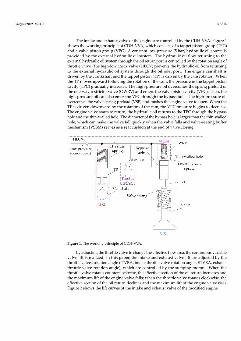
The intake and exhaust valve of the engine are controlled by the CDH-VVA. Figure 1shows the working principle of CDH-VVA, which consists of a tappet piston group (TPG)and a valve piston group (VPG). A constant low-pressure (5 bar) hydraulic oil source isprovided by the external hydraulic oil system. The hydraulic oil flow returning to theexternal hydraulic oil system through the oil return port is controlled by the rotation angle ofthrottle valve. The high-low check valve (HLCV) prevents the hydraulic oil from returningto the external hydraulic oil system through the oil inlet port. The engine camshaft isdriven by the crankshaft and the tappet piston (TP) is driven by the cam rotation. Whenthe TP moves upward following the rotation of the cam, the pressure in the tappet pistoncavity (TPC) gradually increases. The high-pressure oil overcomes the spring preload ofthe one-way restrictor valve (OWRV) and enters the valve piston cavity (VPC). Then, thehigh-pressure oil can also enter the VPC through the bypass hole. The high-pressure oilovercomes the valve spring preload (VSP) and pushes the engine valve to open. When theTP is driven downward by the rotation of the cam, the VPC pressure begins to decrease.The engine valve starts to return, the hydraulic oil returns to the TPC through the bypasshole and the thin-walled hole. The diameter of the bypass hole is larger than the thin-walledhole, which can make the valve fall quickly when the valve falls and valve-seating buffermechanism (VSBM) serves as a seat cushion at the end of valve closing.
Energies 2022, 15, x FOR PEER REVIEW 5 of 16
camshaft is driven by the crankshaft and the tappet piston (TP) is driven by the cam rota-
tion. When the TP moves upward following the rotation of the cam, the pressure in the
tappet piston cavity (TPC) gradually increases. The high-pressure oil overcomes the
spring preload of the one-way restrictor valve (OWRV) and enters the valve piston cavity
(VPC). Then, the high-pressure oil can also enter the VPC through the bypass hole. The
high-pressure oil overcomes the valve spring preload (VSP) and pushes the engine valve
to open. When the TP is driven downward by the rotation of the cam, the VPC pressure
begins to decrease. The engine valve starts to return, the hydraulic oil returns to the TPC
through the bypass hole and the thin-walled hole. The diameter of the bypass hole is larger
than the thin-walled hole, which can make the valve fall quickly when the valve falls and
valve-seating buffer mechanism (VSBM) serves as a seat cushion at the end of valve clos-
ing.
Table 1. The diesel engine parameters.
Engine Properties Specifications
Engine type Single/Horizontal
Combustion chamber type ω
Bore/Stroke 80 mm/80 mm
Connecting rod length 130 mm
Displacement 0.402 L
Rated speed 2600 rpm
Rated power 5.67 kW
Compression ratio 17.5:1
Intake valve number 1
Exhaust valve number 1
Figure 1. The working principle of CDH-VVA.
By adjusting the throttle valve to change the effective flow area, the continuous var-
iable valve lift is realized. In this paper, the intake and exhaust valve lift are adjusted by
the throttle valves rotation angle (ITVRA, intake throttle valve rotation angle; ETVRA,
exhaust throttle valve rotation angle), which are controlled by the stepping motors. When
the throttle valve rotates counterclockwise, the effective section of the oil return increases
Figure 1. The working principle of CDH-VVA.
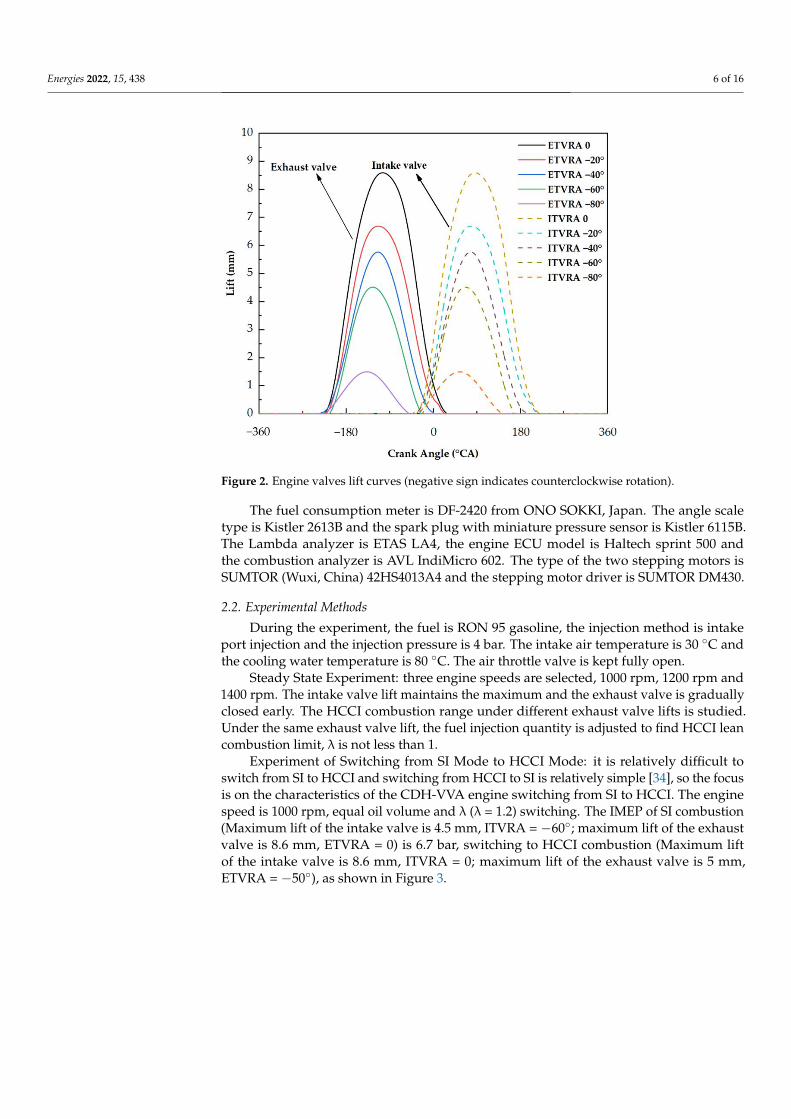
By adjusting the throttle valve to change the effective flow area, the continuous variablevalve lift is realized. In this paper, the intake and exhaust valve lift are adjusted by thethrottle valves rotation angle (ITVRA, intake throttle valve rotation angle; ETVRA, exhaustthrottle valve rotation angle), which are controlled by the stepping motors. When thethrottle valve rotates counterclockwise, the effective section of the oil return increases andthe maximum lift of the engine valve falls; when the throttle valve rotates clockwise, theeffective section of the oil return declines and the maximum lift of the engine valve rises.Figure 2 shows the lift curves of the intake and exhaust valve of the modified engine.
Energies 2022, 15, 438 6 of 16
Energies 2022, 15, x FOR PEER REVIEW 6 of 16
and the maximum lift of the engine valve falls; when the throttle valve rotates clockwise,
the effective section of the oil return declines and the maximum lift of the engine valve
rises. Figure 2 shows the lift curves of the intake and exhaust valve of the modified engine.
Figure 2. Engine valves lift curves (negative sign indicates counterclockwise rotation).
The fuel consumption meter is DF-2420 from ONO SOKKI, Japan. The angle scale
type is Kistler 2613B and the spark plug with miniature pressure sensor is Kistler 6115B.
The Lambda analyzer is ETAS LA4, the engine ECU model is Haltech sprint 500 and the
combustion analyzer is AVL IndiMicro 602. The type of the two stepping motors is
SUMTOR (Wuxi, China) 42HS4013A4 and the stepping motor driver is SUMTOR DM430.
2.2. Experimental Methods
During the experiment, the fuel is RON 95 gasoline, the injection method is intake
port injection and the injection pressure is 4 bar. The intake air temperature is 30 °C and
the cooling water temperature is 80 °C. The air throttle valve is kept fully open.
• Steady State Experiment: three engine speeds are selected, 1000 rpm, 1200 rpm and
1400 rpm. The intake valve lift maintains the maximum and the exhaust valve is
gradually closed early. The HCCI combustion range under different exhaust valve
lifts is studied. Under the same exhaust valve lift, the fuel injection quantity is ad-
justed to find HCCI lean combustion limit, λ is not less than 1.
• Experiment of Switching from SI Mode to HCCI Mode: it is relatively difficult to
switch from SI to HCCI and switching from HCCI to SI is relatively simple [34], so
the focus is on the characteristics of the CDH-VVA engine switching from SI to HCCI.
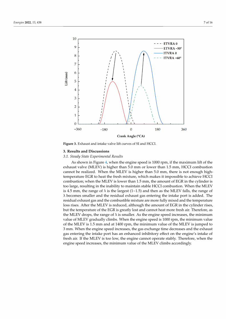
The engine speed is 1000 rpm, equal oil volume and λ (λ = 1.2) switching. The IMEP
of SI combustion (Maximum lift of the intake valve is 4.5 mm, ITVRA = −60°; maxi-
mum lift of the exhaust valve is 8.6 mm, ETVRA = 0) is 6.7 bar, switching to HCCI
combustion (Maximum lift of the intake valve is 8.6 mm, ITVRA = 0; maximum lift of
the exhaust valve is 5 mm, ETVRA = −50°), as shown in Figure 3.
Figure 2. Engine valves lift curves (negative sign indicates counterclockwise rotation).
The fuel consumption meter is DF-2420 from ONO SOKKI, Japan. The angle scaletype is Kistler 2613B and the spark plug with miniature pressure sensor is Kistler 6115B.The Lambda analyzer is ETAS LA4, the engine ECU model is Haltech sprint 500 andthe combustion analyzer is AVL IndiMicro 602. The type of the two stepping motors isSUMTOR (Wuxi, China) 42HS4013A4 and the stepping motor driver is SUMTOR DM430.
2.2. Experimental Methods
During the experiment, the fuel is RON 95 gasoline, the injection method is intakeport injection and the injection pressure is 4 bar. The intake air temperature is 30 ◦C andthe cooling water temperature is 80 ◦C. The air throttle valve is kept fully open.
Steady State Experiment: three engine speeds are selected, 1000 rpm, 1200 rpm and1400 rpm. The intake valve lift maintains the maximum and the exhaust valve is graduallyclosed early. The HCCI combustion range under different exhaust valve lifts is studied.Under the same exhaust valve lift, the fuel injection quantity is adjusted to find HCCI leancombustion limit, λ is not less than 1.
Experiment of Switching from SI Mode to HCCI Mode: it is relatively difficult toswitch from SI to HCCI and switching from HCCI to SI is relatively simple [34], so the focusis on the characteristics of the CDH-VVA engine switching from SI to HCCI. The enginespeed is 1000 rpm, equal oil volume and λ (λ = 1.2) switching. The IMEP of SI combustion(Maximum lift of the intake valve is 4.5 mm, ITVRA = −60◦; maximum lift of the exhaustvalve is 8.6 mm, ETVRA = 0) is 6.7 bar, switching to HCCI combustion (Maximum liftof the intake valve is 8.6 mm, ITVRA = 0; maximum lift of the exhaust valve is 5 mm,ETVRA = −50◦), as shown in Figure 3.
Energies 2022, 15, 438 7 of 16Energies 2022, 15, x FOR PEER REVIEW 7 of 16
Figure 3. Exhaust and intake valve lift curves of SI and HCCI.
3. Results and Discussions
3.1. Steady State Experimental Results
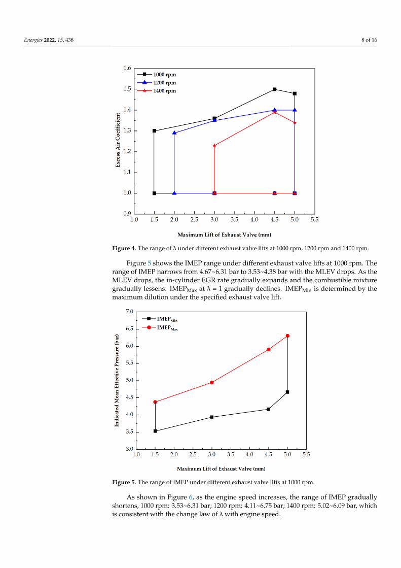
As shown in Figure 4, when the engine speed is 1000 rpm, if the maximum lift of the
exhaust valve (MLEV) is higher than 5.0 mm or lower than 1.5 mm, HCCI combustion
cannot be realized. When the MLEV is higher than 5.0 mm, there is not enough high-tem-
perature EGR to heat the fresh mixture, which makes it impossible to achieve HCCI com-
bustion; when the MLEV is lower than 1.5 mm, the amount of EGR in the cylinder is too
large, resulting in the inability to maintain stable HCCI combustion. When the MLEV is
4.5 mm, the range of λ is the largest (1~1.5) and then as the MLEV falls, the range of λ
becomes smaller and the residual exhaust gas entering the intake port is added. The re-
sidual exhaust gas and the combustible mixture are more fully mixed and the temperature
loss rises. After the MLEV is reduced, although the amount of EGR in the cylinder rises,
but the temperature of the EGR is greatly lost and cannot heat more fresh air. Therefore,
as the MLEV drops, the range of λ is smaller. As the engine speed increases, the minimum
value of MLEV gradually climbs. When the engine speed is 1000 rpm, the minimum value
of the MLEV is 1.5 mm and at 1400 rpm, the minimum value of the MLEV is jumped to 3
mm. When the engine speed increases, the gas exchange time decreases and the exhaust
gas entering the intake port has an enhanced inhibitory effect on the engine’s intake of
fresh air. If the MLEV is too low, the engine cannot operate stably. Therefore, when the
engine speed increases, the minimum value of the MLEV climbs accordingly.
Figure 3. Exhaust and intake valve lift curves of SI and HCCI.
3. Results and Discussions3.1. Steady State Experimental Results
As shown in Figure 4, when the engine speed is 1000 rpm, if the maximum lift of theexhaust valve (MLEV) is higher than 5.0 mm or lower than 1.5 mm, HCCI combustioncannot be realized. When the MLEV is higher than 5.0 mm, there is not enough high-temperature EGR to heat the fresh mixture, which makes it impossible to achieve HCCIcombustion; when the MLEV is lower than 1.5 mm, the amount of EGR in the cylinder istoo large, resulting in the inability to maintain stable HCCI combustion. When the MLEVis 4.5 mm, the range of λ is the largest (1~1.5) and then as the MLEV falls, the range ofλ becomes smaller and the residual exhaust gas entering the intake port is added. Theresidual exhaust gas and the combustible mixture are more fully mixed and the temperatureloss rises. After the MLEV is reduced, although the amount of EGR in the cylinder rises,but the temperature of the EGR is greatly lost and cannot heat more fresh air. Therefore, asthe MLEV drops, the range of λ is smaller. As the engine speed increases, the minimumvalue of MLEV gradually climbs. When the engine speed is 1000 rpm, the minimum valueof the MLEV is 1.5 mm and at 1400 rpm, the minimum value of the MLEV is jumped to3 mm. When the engine speed increases, the gas exchange time decreases and the exhaustgas entering the intake port has an enhanced inhibitory effect on the engine’s intake offresh air. If the MLEV is too low, the engine cannot operate stably. Therefore, when theengine speed increases, the minimum value of the MLEV climbs accordingly.
Energies 2022, 15, 438 8 of 16Energies 2022, 15, x FOR PEER REVIEW 8 of 16
Figure 4. The range of λ under different exhaust valve lifts at 1000 rpm, 1200 rpm and 1400 rpm.
Figure 5 shows the IMEP range under different exhaust valve lifts at 1000 rpm. The
range of IMEP narrows from 4.67~6.31 bar to 3.53~4.38 bar with the MLEV drops. As the
MLEV drops, the in-cylinder EGR rate gradually expands and the combustible mixture
gradually lessens. IMEPMax at λ = 1 gradually declines. IMEPMin is determined by the max-
imum dilution under the specified exhaust valve lift.
Figure 5. The range of IMEP under different exhaust valve lifts at 1000 rpm.
As shown in Figure 6, as the engine speed increases, the range of IMEP gradually
shortens, 1000 rpm: 3.53~6.31 bar; 1200 rpm: 4.11~6.75 bar; 1400 rpm: 5.02~6.09 bar, which
is consistent with the change law of λ with engine speed.
Figure 4. The range of λ under different exhaust valve lifts at 1000 rpm, 1200 rpm and 1400 rpm.
Figure 5 shows the IMEP range under different exhaust valve lifts at 1000 rpm. Therange of IMEP narrows from 4.67~6.31 bar to 3.53~4.38 bar with the MLEV drops. As theMLEV drops, the in-cylinder EGR rate gradually expands and the combustible mixturegradually lessens. IMEPMax at λ = 1 gradually declines. IMEPMin is determined by themaximum dilution under the specified exhaust valve lift.
Energies 2022, 15, x FOR PEER REVIEW 8 of 16
Figure 4. The range of λ under different exhaust valve lifts at 1000 rpm, 1200 rpm and 1400 rpm.
Figure 5 shows the IMEP range under different exhaust valve lifts at 1000 rpm. The
range of IMEP narrows from 4.67~6.31 bar to 3.53~4.38 bar with the MLEV drops. As the
MLEV drops, the in-cylinder EGR rate gradually expands and the combustible mixture
gradually lessens. IMEPMax at λ = 1 gradually declines. IMEPMin is determined by the max-
imum dilution under the specified exhaust valve lift.
Figure 5. The range of IMEP under different exhaust valve lifts at 1000 rpm.
As shown in Figure 6, as the engine speed increases, the range of IMEP gradually
shortens, 1000 rpm: 3.53~6.31 bar; 1200 rpm: 4.11~6.75 bar; 1400 rpm: 5.02~6.09 bar, which
is consistent with the change law of λ with engine speed.
Figure 5. The range of IMEP under different exhaust valve lifts at 1000 rpm.
As shown in Figure 6, as the engine speed increases, the range of IMEP graduallyshortens, 1000 rpm: 3.53~6.31 bar; 1200 rpm: 4.11~6.75 bar; 1400 rpm: 5.02~6.09 bar, whichis consistent with the change law of λwith engine speed.
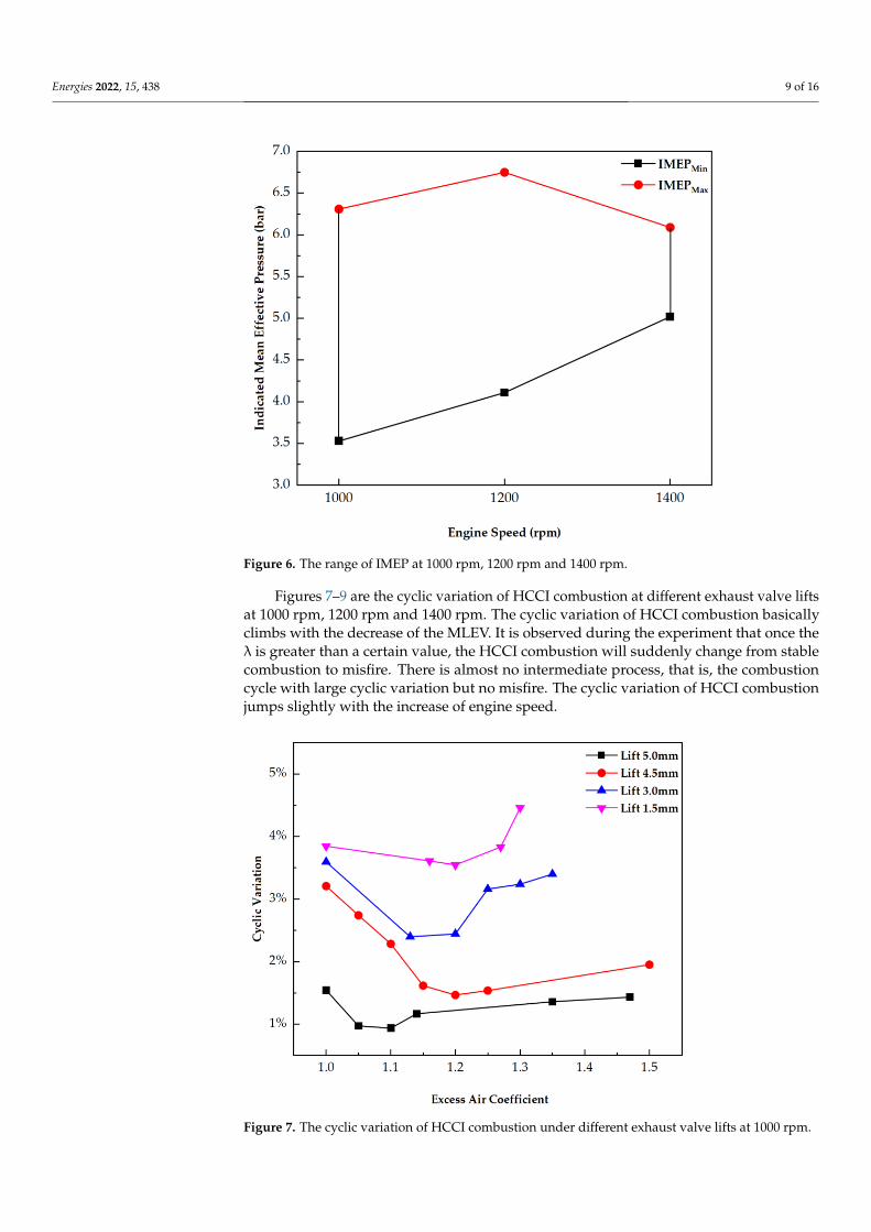
Energies 2022, 15, 438 9 of 16Energies 2022, 15, x FOR PEER REVIEW 9 of 16
Figure 6. The range of IMEP at 1000 rpm, 1200 rpm and 1400 rpm.
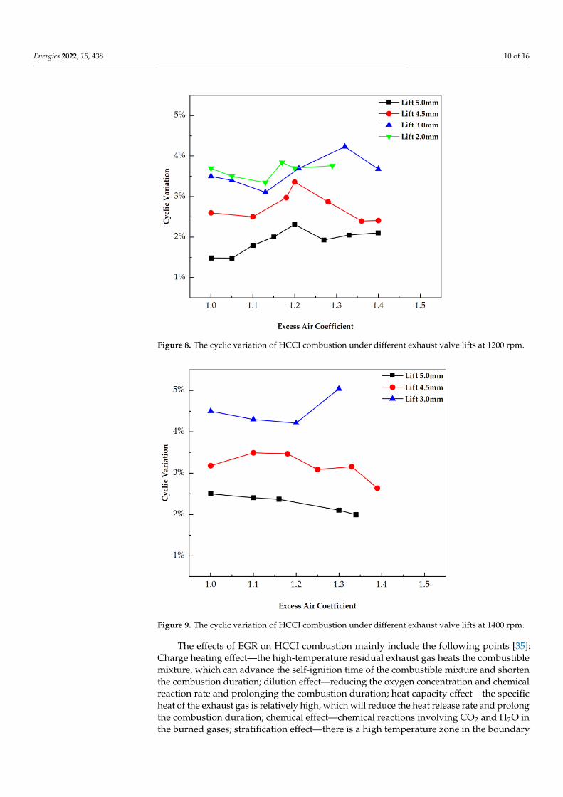
Figures 7–9 are the cyclic variation of HCCI combustion at different exhaust valve
lifts at 1000 rpm, 1200 rpm and 1400 rpm. The cyclic variation of HCCI combustion basi-
cally climbs with the decrease of the MLEV. It is observed during the experiment that once
the λ is greater than a certain value, the HCCI combustion will suddenly change from
stable combustion to misfire. There is almost no intermediate process, that is, the combus-
tion cycle with large cyclic variation but no misfire. The cyclic variation of HCCI combus-
tion jumps slightly with the increase of engine speed.
Figure 7. The cyclic variation of HCCI combustion under different exhaust valve lifts at 1000 rpm.
Figure 6. The range of IMEP at 1000 rpm, 1200 rpm and 1400 rpm.
Figures 7–9 are the cyclic variation of HCCI combustion at different exhaust valve liftsat 1000 rpm, 1200 rpm and 1400 rpm. The cyclic variation of HCCI combustion basicallyclimbs with the decrease of the MLEV. It is observed during the experiment that once theλ is greater than a certain value, the HCCI combustion will suddenly change from stablecombustion to misfire. There is almost no intermediate process, that is, the combustioncycle with large cyclic variation but no misfire. The cyclic variation of HCCI combustionjumps slightly with the increase of engine speed.
Energies 2022, 15, x FOR PEER REVIEW 9 of 16
Figure 6. The range of IMEP at 1000 rpm, 1200 rpm and 1400 rpm.
Figures 7–9 are the cyclic variation of HCCI combustion at different exhaust valve
lifts at 1000 rpm, 1200 rpm and 1400 rpm. The cyclic variation of HCCI combustion basi-
cally climbs with the decrease of the MLEV. It is observed during the experiment that once
the λ is greater than a certain value, the HCCI combustion will suddenly change from
stable combustion to misfire. There is almost no intermediate process, that is, the combus-
tion cycle with large cyclic variation but no misfire. The cyclic variation of HCCI combus-
tion jumps slightly with the increase of engine speed.
Figure 7. The cyclic variation of HCCI combustion under different exhaust valve lifts at 1000 rpm. Figure 7. The cyclic variation of HCCI combustion under different exhaust valve lifts at 1000 rpm.
Energies 2022, 15, 438 10 of 16Energies 2022, 15, x FOR PEER REVIEW 10 of 16
Figure 8. The cyclic variation of HCCI combustion under different exhaust valve lifts at 1200 rpm.
Figure 9. The cyclic variation of HCCI combustion under different exhaust valve lifts at 1400 rpm.
The effects of EGR on HCCI combustion mainly include the following points [35]:
Charge heating effect—the high-temperature residual exhaust gas heats the combustible
mixture, which can advance the self-ignition time of the combustible mixture and shorten
the combustion duration; dilution effect—reducing the oxygen concentration and chemi-
cal reaction rate and prolonging the combustion duration; heat capacity effect—the spe-
cific heat of the exhaust gas is relatively high, which will reduce the heat release rate and
prolong the combustion duration; chemical effect—chemical reactions involving CO2 and
H2O in the burned gases; stratification effect—there is a high temperature zone in the
boundary area between hot exhaust gas and combustible mixture, which promotes HCCI
combustion. During the experiment, the intake valve maintains the maximum lift (ITVRA
= 0), the exhaust valve gradually closes early and the MLEV gradually falls. Figure 10
shows the cylinder pressure curves of intake port EGR type HCCI combustion at 1000
rpm. The second peak of the cylinder pressure curves does not exceed 7 bar and appears
Figure 8. The cyclic variation of HCCI combustion under different exhaust valve lifts at 1200 rpm.
Energies 2022, 15, x FOR PEER REVIEW 10 of 16
Figure 8. The cyclic variation of HCCI combustion under different exhaust valve lifts at 1200 rpm.
Figure 9. The cyclic variation of HCCI combustion under different exhaust valve lifts at 1400 rpm.
The effects of EGR on HCCI combustion mainly include the following points [35]:
Charge heating effect—the high-temperature residual exhaust gas heats the combustible
mixture, which can advance the self-ignition time of the combustible mixture and shorten
the combustion duration; dilution effect—reducing the oxygen concentration and chemi-
cal reaction rate and prolonging the combustion duration; heat capacity effect—the spe-
cific heat of the exhaust gas is relatively high, which will reduce the heat release rate and
prolong the combustion duration; chemical effect—chemical reactions involving CO2 and
H2O in the burned gases; stratification effect—there is a high temperature zone in the
boundary area between hot exhaust gas and combustible mixture, which promotes HCCI
combustion. During the experiment, the intake valve maintains the maximum lift (ITVRA
= 0), the exhaust valve gradually closes early and the MLEV gradually falls. Figure 10
shows the cylinder pressure curves of intake port EGR type HCCI combustion at 1000
rpm. The second peak of the cylinder pressure curves does not exceed 7 bar and appears
Figure 9. The cyclic variation of HCCI combustion under different exhaust valve lifts at 1400 rpm.
The effects of EGR on HCCI combustion mainly include the following points [35]:Charge heating effect—the high-temperature residual exhaust gas heats the combustiblemixture, which can advance the self-ignition time of the combustible mixture and shortenthe combustion duration; dilution effect—reducing the oxygen concentration and chemicalreaction rate and prolonging the combustion duration; heat capacity effect—the specificheat of the exhaust gas is relatively high, which will reduce the heat release rate and prolongthe combustion duration; chemical effect—chemical reactions involving CO2 and H2O inthe burned gases; stratification effect—there is a high temperature zone in the boundary
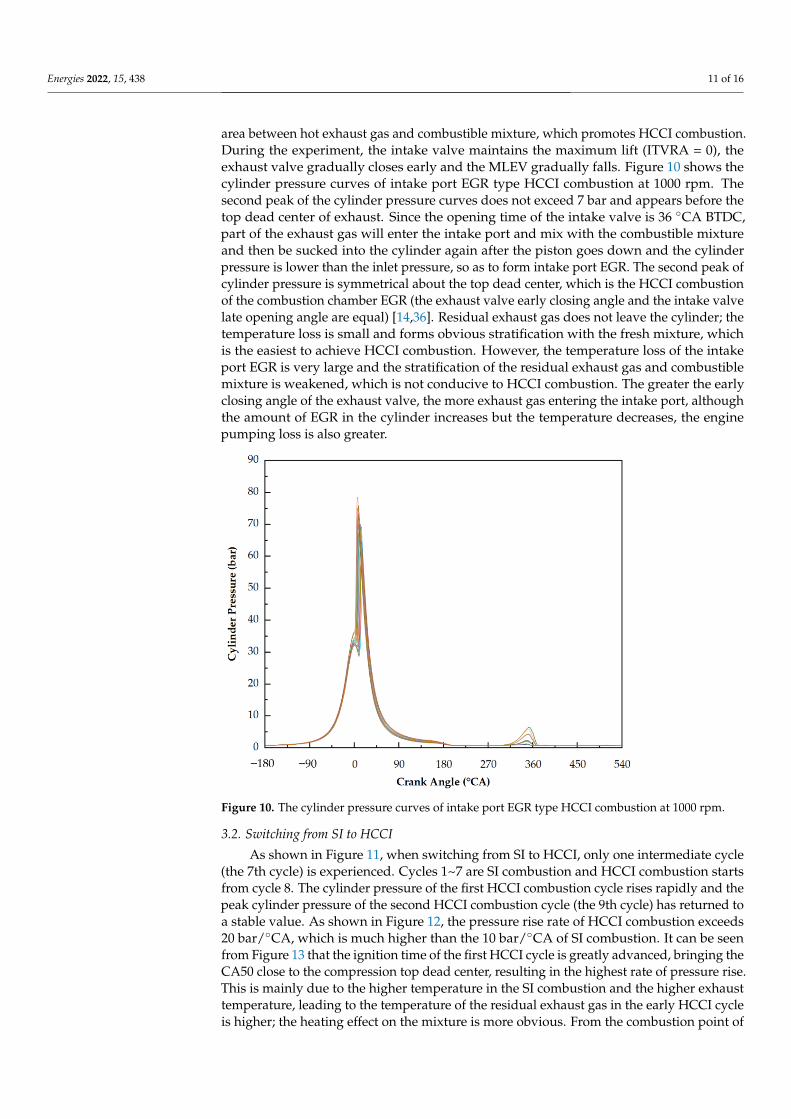
Energies 2022, 15, 438 11 of 16
area between hot exhaust gas and combustible mixture, which promotes HCCI combustion.During the experiment, the intake valve maintains the maximum lift (ITVRA = 0), theexhaust valve gradually closes early and the MLEV gradually falls. Figure 10 shows thecylinder pressure curves of intake port EGR type HCCI combustion at 1000 rpm. Thesecond peak of the cylinder pressure curves does not exceed 7 bar and appears before thetop dead center of exhaust. Since the opening time of the intake valve is 36 ◦CA BTDC,part of the exhaust gas will enter the intake port and mix with the combustible mixtureand then be sucked into the cylinder again after the piston goes down and the cylinderpressure is lower than the inlet pressure, so as to form intake port EGR. The second peak ofcylinder pressure is symmetrical about the top dead center, which is the HCCI combustionof the combustion chamber EGR (the exhaust valve early closing angle and the intake valvelate opening angle are equal) [14,36]. Residual exhaust gas does not leave the cylinder; thetemperature loss is small and forms obvious stratification with the fresh mixture, whichis the easiest to achieve HCCI combustion. However, the temperature loss of the intakeport EGR is very large and the stratification of the residual exhaust gas and combustiblemixture is weakened, which is not conducive to HCCI combustion. The greater the earlyclosing angle of the exhaust valve, the more exhaust gas entering the intake port, althoughthe amount of EGR in the cylinder increases but the temperature decreases, the enginepumping loss is also greater.
Energies 2022, 15, x FOR PEER REVIEW 11 of 16
before the top dead center of exhaust. Since the opening time of the intake valve is 36 °CA
BTDC, part of the exhaust gas will enter the intake port and mix with the combustible
mixture and then be sucked into the cylinder again after the piston goes down and the
cylinder pressure is lower than the inlet pressure, so as to form intake port EGR. The sec-
ond peak of cylinder pressure is symmetrical about the top dead center, which is the HCCI
combustion of the combustion chamber EGR (the exhaust valve early closing angle and
the intake valve late opening angle are equal) [14,36]. Residual exhaust gas does not leave
the cylinder; the temperature loss is small and forms obvious stratification with the fresh
mixture, which is the easiest to achieve HCCI combustion. However, the temperature loss
of the intake port EGR is very large and the stratification of the residual exhaust gas and
combustible mixture is weakened, which is not conducive to HCCI combustion. The
greater the early closing angle of the exhaust valve, the more exhaust gas entering the
intake port, although the amount of EGR in the cylinder increases but the temperature
decreases, the engine pumping loss is also greater.
Figure 10. The cylinder pressure curves of intake port EGR type HCCI combustion at 1000 rpm.
3.2. Switching from SI to HCCI
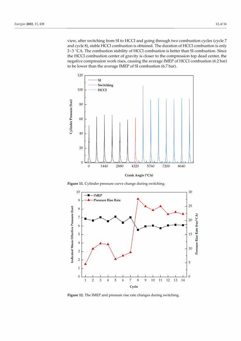
As shown in Figure 11, when switching from SI to HCCI, only one intermediate cycle
(the 7th cycle) is experienced. Cycles 1~7 are SI combustion and HCCI combustion starts
from cycle 8. The cylinder pressure of the first HCCI combustion cycle rises rapidly and
the peak cylinder pressure of the second HCCI combustion cycle (the 9th cycle) has re-
turned to a stable value. As shown in Figure 12, the pressure rise rate of HCCI combustion
exceeds 20 bar/°CA, which is much higher than the 10 bar/°CA of SI combustion. It can be
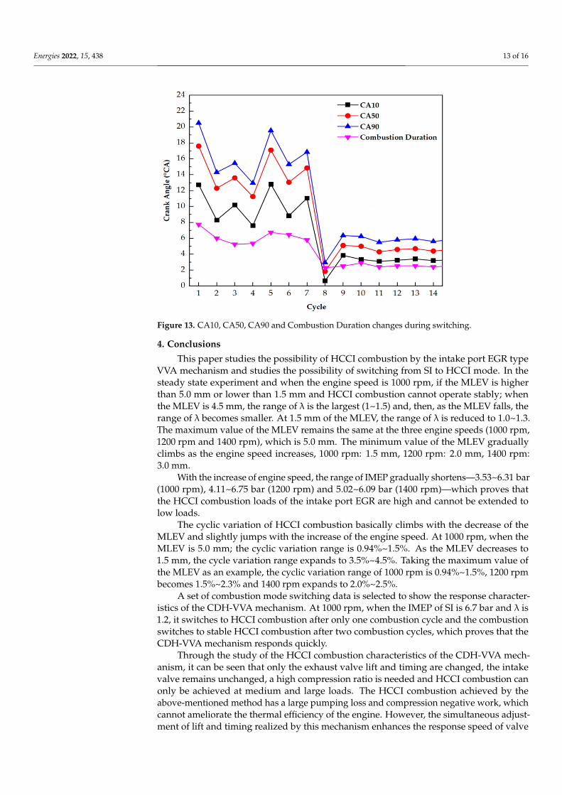
seen from Figure 13 that the ignition time of the first HCCI cycle is greatly advanced,
bringing the CA50 close to the compression top dead center, resulting in the highest rate
of pressure rise. This is mainly due to the higher temperature in the SI combustion and
the higher exhaust temperature, leading to the temperature of the residual exhaust gas in
the early HCCI cycle is higher; the heating effect on the mixture is more obvious. From
the combustion point of view, after switching from SI to HCCI and going through two
combustion cycles (cycle 7 and cycle 8), stable HCCI combustion is obtained. The duration
of HCCI combustion is only 2~3 °CA. The combustion stability of HCCI combustion is
better than SI combustion. Since the HCCI combustion center of gravity is closer to the
compression top dead center, the negative compression work rises, causing the average
Figure 10. The cylinder pressure curves of intake port EGR type HCCI combustion at 1000 rpm.
3.2. Switching from SI to HCCI
As shown in Figure 11, when switching from SI to HCCI, only one intermediate cycle(the 7th cycle) is experienced. Cycles 1~7 are SI combustion and HCCI combustion startsfrom cycle 8. The cylinder pressure of the first HCCI combustion cycle rises rapidly and thepeak cylinder pressure of the second HCCI combustion cycle (the 9th cycle) has returned toa stable value. As shown in Figure 12, the pressure rise rate of HCCI combustion exceeds20 bar/◦CA, which is much higher than the 10 bar/◦CA of SI combustion. It can be seenfrom Figure 13 that the ignition time of the first HCCI cycle is greatly advanced, bringing theCA50 close to the compression top dead center, resulting in the highest rate of pressure rise.This is mainly due to the higher temperature in the SI combustion and the higher exhausttemperature, leading to the temperature of the residual exhaust gas in the early HCCI cycleis higher; the heating effect on the mixture is more obvious. From the combustion point of
Energies 2022, 15, 438 12 of 16
view, after switching from SI to HCCI and going through two combustion cycles (cycle 7and cycle 8), stable HCCI combustion is obtained. The duration of HCCI combustion is only2~3 ◦CA. The combustion stability of HCCI combustion is better than SI combustion. Sincethe HCCI combustion center of gravity is closer to the compression top dead center, thenegative compression work rises, causing the average IMEP of HCCI combustion (6.2 bar)to be lower than the average IMEP of SI combustion (6.7 bar).
Energies 2022, 15, x FOR PEER REVIEW 12 of 16
IMEP of HCCI combustion (6.2 bar) to be lower than the average IMEP of SI combustion
(6.7 bar).
Figure 11. Cylinder pressure curve change during switching.
Figure 12. The IMEP and pressure rise rate changes during switching.
Figure 11. Cylinder pressure curve change during switching.
Energies 2022, 15, x FOR PEER REVIEW 12 of 16
IMEP of HCCI combustion (6.2 bar) to be lower than the average IMEP of SI combustion
(6.7 bar).
Figure 11. Cylinder pressure curve change during switching.
Figure 12. The IMEP and pressure rise rate changes during switching. Figure 12. The IMEP and pressure rise rate changes during switching.
Energies 2022, 15, 438 13 of 16Energies 2022, 15, x FOR PEER REVIEW 13 of 16
Figure 13. CA10, CA50, CA90 and Combustion Duration changes during switching.
4. Conclusions
This paper studies the possibility of HCCI combustion by the intake port EGR type
VVA mechanism and studies the possibility of switching from SI to HCCI mode. In the
steady state experiment and when the engine speed is 1000 rpm, if the MLEV is higher
than 5.0 mm or lower than 1.5 mm and HCCI combustion cannot operate stably; when the
MLEV is 4.5 mm, the range of λ is the largest (1~1.5) and, then, as the MLEV falls, the
range of λ becomes smaller. At 1.5 mm of the MLEV, the range of λ is reduced to 1.0~1.3.
The maximum value of the MLEV remains the same at the three engine speeds (1000 rpm,
1200 rpm and 1400 rpm), which is 5.0 mm. The minimum value of the MLEV gradually
climbs as the engine speed increases, 1000 rpm: 1.5 mm, 1200 rpm: 2.0 mm, 1400 rpm: 3.0
mm.
With the increase of engine speed, the range of IMEP gradually shortens—3.53~6.31
bar (1000 rpm), 4.11~6.75 bar (1200 rpm) and 5.02~6.09 bar (1400 rpm)—which proves that
the HCCI combustion loads of the intake port EGR are high and cannot be extended to
low loads.
The cyclic variation of HCCI combustion basically climbs with the decrease of the
MLEV and slightly jumps with the increase of the engine speed. At 1000 rpm, when the
MLEV is 5.0 mm; the cyclic variation range is 0.94%~1.5%. As the MLEV decreases to 1.5
mm, the cycle variation range expands to 3.5%~4.5%. Taking the maximum value of the
MLEV as an example, the cyclic variation range of 1000 rpm is 0.94%~1.5%, 1200 rpm be-
comes 1.5%~2.3% and 1400 rpm expands to 2.0%~2.5%.
A set of combustion mode switching data is selected to show the response character-
istics of the CDH-VVA mechanism. At 1000 rpm, when the IMEP of SI is 6.7 bar and λ is
1.2, it switches to HCCI combustion after only one combustion cycle and the combustion
switches to stable HCCI combustion after two combustion cycles, which proves that the
CDH-VVA mechanism responds quickly.
Through the study of the HCCI combustion characteristics of the CDH-VVA mecha-
nism, it can be seen that only the exhaust valve lift and timing are changed, the intake
valve remains unchanged, a high compression ratio is needed and HCCI combustion can
only be achieved at medium and large loads. The HCCI combustion achieved by the
above-mentioned method has a large pumping loss and compression negative work,
which cannot ameliorate the thermal efficiency of the engine. However, the simultaneous
adjustment of lift and timing realized by this mechanism enhances the response speed of
valve adjustment and the switching between SI and HCCI modes is relatively rapid. Com-
bining the above information, it is precisely because of the rapid response speed of the
Figure 13. CA10, CA50, CA90 and Combustion Duration changes during switching.
4. Conclusions
This paper studies the possibility of HCCI combustion by the intake port EGR typeVVA mechanism and studies the possibility of switching from SI to HCCI mode. In thesteady state experiment and when the engine speed is 1000 rpm, if the MLEV is higherthan 5.0 mm or lower than 1.5 mm and HCCI combustion cannot operate stably; whenthe MLEV is 4.5 mm, the range of λ is the largest (1~1.5) and, then, as the MLEV falls, therange of λ becomes smaller. At 1.5 mm of the MLEV, the range of λ is reduced to 1.0~1.3.The maximum value of the MLEV remains the same at the three engine speeds (1000 rpm,1200 rpm and 1400 rpm), which is 5.0 mm. The minimum value of the MLEV graduallyclimbs as the engine speed increases, 1000 rpm: 1.5 mm, 1200 rpm: 2.0 mm, 1400 rpm:3.0 mm.
With the increase of engine speed, the range of IMEP gradually shortens—3.53~6.31 bar(1000 rpm), 4.11~6.75 bar (1200 rpm) and 5.02~6.09 bar (1400 rpm)—which proves thatthe HCCI combustion loads of the intake port EGR are high and cannot be extended tolow loads.
The cyclic variation of HCCI combustion basically climbs with the decrease of theMLEV and slightly jumps with the increase of the engine speed. At 1000 rpm, when theMLEV is 5.0 mm; the cyclic variation range is 0.94%~1.5%. As the MLEV decreases to1.5 mm, the cycle variation range expands to 3.5%~4.5%. Taking the maximum value ofthe MLEV as an example, the cyclic variation range of 1000 rpm is 0.94%~1.5%, 1200 rpmbecomes 1.5%~2.3% and 1400 rpm expands to 2.0%~2.5%.
A set of combustion mode switching data is selected to show the response character-istics of the CDH-VVA mechanism. At 1000 rpm, when the IMEP of SI is 6.7 bar and λ is1.2, it switches to HCCI combustion after only one combustion cycle and the combustionswitches to stable HCCI combustion after two combustion cycles, which proves that theCDH-VVA mechanism responds quickly.
Through the study of the HCCI combustion characteristics of the CDH-VVA mech-anism, it can be seen that only the exhaust valve lift and timing are changed, the intakevalve remains unchanged, a high compression ratio is needed and HCCI combustion canonly be achieved at medium and large loads. The HCCI combustion achieved by theabove-mentioned method has a large pumping loss and compression negative work, whichcannot ameliorate the thermal efficiency of the engine. However, the simultaneous adjust-ment of lift and timing realized by this mechanism enhances the response speed of valve
Energies 2022, 15, 438 14 of 16
adjustment and the switching between SI and HCCI modes is relatively rapid. Combiningthe above information, it is precisely because of the rapid response speed of the CDH-VVAmechanism, combined with future optimization to expand the HCCI combustion range, it isbelieved that the CDH-VVA mechanism has great potential in improving engine economy,power and emissions.
Author Contributions: Data curation, writing—original draft preparation, Y.W.; Conceptualization,methodology, validation, investigation, resources, J.D. and D.Q.; writing—review and editing, super-vision, project administration, funding acquisition, L.H., Y.G. and Y.S.; validation, investigation, F.X.All authors have read and agreed to the published version of the manuscript.
Funding: This work is a key research and development plan supported by the Foundation of StateKey Laboratory of Comprehensive Technology on Automobile Vibration and Noise & Safety Control(Grant No. FAWSKL2020KFJJC1) and the National Natural Science Foundation of China (Grant No.51876079).
Acknowledgments: This work is supported by the Foundation of State Key Laboratory of Comprehen-sive Technology on Automobile Vibration and Noise & Safety Control (Grant No. FAWSKL2020KFJJC1)and the National Natural Science Foundation of China (Grant No. 51876079).
Conflicts of Interest: The authors declare no conflict of interest.
Nomenclature
VVA variable valve actuationHCCI homogeneous charge compression ignitionEGR exhaust gas recirculationCDH-VVA cam driven hydraulic variable valve actuationSI spark ignitionCI compression ignitionTPG tappet piston groupVPG valve piston groupHLCV high-low check valveTP tappet pistonTPC tappet piston cavityOWRV one-way restrictor valveVPC valve piston cavityVSP valve spring preloadVSBM valve-seating buffer mechanismITVRA intake throttle valve rotation angleETVRA exhaust throttle valve rotation angleλ excess air coefficientIMEP indicated mean effective pressureMLEV maximum lift of the exhaust valveCA crank angleCA10 crank angle of 10% fuel burnedCA50 crank angle of 50% fuel burnedCA90 crank angle of 90% fuel burnedCombustion Duration crank angle of 10%–90% fuel burnedBTDC before top dead center
References1. Joshi, A. Review of vehicle engine efficiency and emissions. SAE Int. J. Adv. Curr. Pract. Mobil. 2019, 1, 734–761.2. Lyu, M.; Bao, X.F.; Zhu, R.C.; Matthews, R. State-of-the-art outlook for light-duty vehicle emission control stand-ards and
technologies in China. Clean Technol. Environ. Policy 2020, 22, 757–771. [CrossRef]3. Pan, S.; Wang, J.; Huang, Z. Development of 1.5L Dedicated Hybrid Engine with 42.6% Brake Thermal Efficiency. SAE Int. J.
Engines 2021. [CrossRef]4. De Bellis, V. Performance optimization of a spark-ignition turbocharged VVA engine under knock limited oper-ation. Appl.
Energy 2016, 164, 162–174. [CrossRef]
Energies 2022, 15, 438 15 of 16
5. Teodosio, L.; De Bellis, V.; Bozza, F. Combined Effects of Valve Strategies, Compression Ratio, Water Injection, and Cooled EGRon the Fuel Consumption of a Small Turbocharged VVA Spark-Ignition Engine. SAE Int. J. Engines 2018, 11, 643–656. [CrossRef]
6. Onishi, S.; Jo, S.H.; Shoda, K.; Jo, P.D.; Kato, S. Active Thermo-Atmosphere Combustion (ATAC)—A New Combustion Process forInternal Combustion Engines. SAE Int. 1979, 88, 1851–1860.
7. Gentili, R.; Frigo, S.; Tognotti, L.; Habert, P.; Lavy, J. Experimental Study on ATAC (Active Thermo-Atmosphere Combustion) in aTwo-Stroke Gasoline Engine. SAE Int. 1997, 106, 638–644. [CrossRef]
8. Noguchi, M.; Tanaka, Y.; Tanaka, T.; Takeuchi, Y. A Study on Gasoline Engine Combustion by Observation of In-termediateReactive Products during Combustion. SAE Int. 1979, 88, 2816–2828.
9. Ishibashi, Y.; Asai, M. Improving the Exhaust Emissions of Two-Stroke Engines by Applying the Activated Radical Combustion.SAE Int. 1996, 105, 982–992.
10. Gowthaman, S.; Sathiyagnanam, A.P. Analysis the optimum inlet air temperature for controlling homogeneous charge compres-sion ignition (HCCI) engine. AEJ -Alex. Eng. J. 2017, 57, 2209–2214. [CrossRef]
11. Thring, R.H. Homogeneous-Charge Compression-Ignition (HCCI) Engines; SAE Technical Paper 892068; SAE: Warrendale, PA,USA, 1989. [CrossRef]
12. Christensen, M.; Johansson, B.; Einewall, P. Homogeneous Charge Compression Ignition (HCCI) Using Isooctane, Ethanol andNatural Gas—A Comparison with Spark Ignition Operation. SAE Int. 1997, 106, 1104–1114. [CrossRef]
13. Willand, J.; Nieberding, R.-G.; Vent, G.; Enderle, C. The Knocking Syndrome—Its Cure and Its Potential. SAE Int. 1998, 107,1122–1129. [CrossRef]
14. Kontarakis, G.; Collings, N.; Ma, T. Demonstration of HCCI Using a Single Cylinder Four-stroke SI Engine with Modified ValveTiming. SAE Int. 2000, 109, 2057–2067. [CrossRef]
15. Li, J.; Zhao, H.; Ladommatos, N.; Ma, T. Research and Development of Controlled Auto-Ignition (CAI) Combustion in a 4-StrokeMulti-Cylinder Gasoline Engine. SAE Int. 2001, 110, 2114–2122. [CrossRef]
16. Persson, H.W.; Pfeiffer, R.A.; Hultqvist, A.; Johansson, B.; Ström, H. Cylinder-to-Cylinder and Cycle-to-Cycle Variations at HCCIOperation with Trapped Residuals; SAE Technical Paper 2005-01-0130; SAE: Warrendale, PA, USA, 2005. [CrossRef]
17. Takazawa, M.; Komura, K.; Kitamura, T. Transient Control Technology of Spark Assisted HCCI; SAE Technical Paper 2015-01-0880;SAE: Warrendale, PA, USA, 2015. [CrossRef]
18. Cairns, A.; Blaxill, H. The Effects of Combined Internal and External Exhaust Gas Recirculation on Gasoline Controlled Auto-Ignition; SAETechnical Paper 2005-01-0133; SAE: Warrendale, PA, USA, 2005. [CrossRef]
19. Zhang, Y.; Xie, H.; Zhou, N.; Chen, T.; Zhao, H. Study of SI-HCCI-SI Transition on a Port Fuel Injection Engine Equipped with 4VVAS;SAE Technical Paper 2007-01-0199; SAE: Warrendale, PA, USA, 2007. [CrossRef]
20. Nier, T.; Kulzer, A.; Karrelmeyer, R. Analysis of the Combustion Mode Switch Between SI and Gasoline HCCI; SAE Technical Paper2012-01-1105; SAE: Warrendale, PA, USA, 2012. [CrossRef]
21. Liu, Y.; Li, L.; Lu, H.; Schmitt, S.; Deng, J.; Rao, L. SI/HCCI Mode Switching Optimization in a Gasoline Direct Injection EngineEmploying Dual Univalve System. J. Eng. Gas Turbines Power 2019, 141, 031001.1–031001.8. [CrossRef]
22. Milovanovic, N.; Dave, B.; Gedge, S.; Turner, J.W.G. Cam Profile Switching (CPS) and Phasing Strategy vs Fully Variable ValveTrain (FVVT) Strategy for Transitions between Spark Ignition and Controlled Auto Ignition Modes. In Proceedings of the 2005SAE World Congress, Detroit, MI, USA, 11–14 April 2005; 2005. [CrossRef]
23. Tian, G.-H.; Wang, Z.; Ge, Q.-Q.; Wang, J.-X.; Shuai, S.-J. Study of SI-HCCI-SI mode switching in a GDI engine. Trans. CSICE 2007,25, 229–234.
24. Calam, A.; Aydogan, B.; Halis, S. The comparison of combustion, engine performance and emission characteristics of ethanol,methanol, fusel oil, butanol, isopropanol and naphtha with n-heptane blends on HCCI engine. Fuel 2020, 266, 117071. [CrossRef]
25. Verma, S.K.; Gaur, S.; Akram, T.; Samsher Kumar, A. Performance characteristic of HCCI engine for different fuels. Mater. Today:Proc. 2021, 47, 6030–6034. [CrossRef]
26. Asghari, M.; Saray, R.K.; Neshat, E. Mathematical Modeling of Knocking Combustion and Created Pressure In-homogeneityInside the Combustion Chamber in HCCI Engines Via Multi Zone Model. Flow Turbul. Combust. 2020, 105, 213–236. [CrossRef]
27. D’Amato, M.; Viggiano, A.; Magi, V. On the Turbulence-Chemistry Interaction of an HCCI Combustion Engine. Energies 2020,13, 5876. [CrossRef]
28. Zhou, Y.; Lawler, B. Validation of Kinetic Mechanisms against Various Ignition Delay Data and the Development of Ignition DelayCorrelations for Ethanol, Natural Gas, and Primary Reference Fuel Blends under Homogeneous Charge Compression IgnitionConditions. SAE Int. J. Engines 2021, 15. [CrossRef]
29. Hikita, T.; Mizuno, S.; Fujii, T.; Yamasaki, Y.; Hayashi, T.; Kaneko, S. Study on Model-Based Control for HCCI Engine. IFAC-PapersOnLine 2018, 51, 290–296. [CrossRef]
30. Nam, Y.; Kim, J.; Bahk, C.; Jang, I.; Song, H.H.; Lee, N. Modeling, Estimation, and Control of HCCI Engine with In-CylinderPressure Sensing. J. Dyn. Syst. Meas. Control. 2018, 140, 061015. [CrossRef]
31. Zhu, D.; Deng, J.; Wang, S.; Zhang, H.; Wu, Z.; Andert, J.; Li, L. Cycle resolved control for HCCI engine load range ex-pansion bycombining ion current and pressure sensor. Proc. Combust. Inst. 2021, 38, 5685–5694. [CrossRef]
32. Jin, Z.; Hong, W.; You, T.; Su, Y.; Li, X.; Xie, F. Effect of Multi-Factor Coupling on the Movement Characteristics of the HydraulicVariable Valve Actuation. Energies 2020, 13, 2870. [CrossRef]

Energies 2022, 15, 438 16 of 16
33. Wolters, P.; Salber, W.; Geiger, J.; Duesmann, M.; Dilthey, J. Controlled Auto Ignition Combustion Process with an Electromechani-cal Valve Train. SAE Int. 2003, 112, 160–168. [CrossRef]
34. Santoso, H.; Matthews, J.; Cheng, W.K. Managing SI/HCCI Dual-Mode Engine Operation; SAE Technical Paper 2005-01-0162; SAE:Warrendale, PA, USA, 2005. [CrossRef]
35. Zhao, H.; Peng, Z.; Williams, J.; Ladommatos, N. Understanding the Effects of Recycled Burnt Gases on the Con-trolledAutoignition (CAI) Combustion in Four-Stroke Gasoline Engines. SAE Int. 2001, 110, 2100–2113.
36. Liu, F.-F.; Wang, Y.-K.; Li, H.; Gao, F.-J.; Huang, W.-J.; Guo, Y.-N. Performances of electro-hydraulic valve train and application.Trans. CSICE 2011, 29, 54–60.