Embed Size (px)
Citation preview
1
Governors America Corp. © 2021 Copyright All Rights ReservedICM200 Series Ignition Control Module 2021-05-A2 PIB4143
ICM200 SeriesIgnition Control Module
1 INTRODUCTION
The Ignition Control Module (ICM) 200 Series controller is part of GAC’s comprehensive Fuel and Ignition Management System (FIMS) for gas-eous-fueled, spark-ignited engines.
The ICM200 charges a high-energy inductive ignition coil using technology featuring fixed and variable timing modes as well as in-field timing trim/offset capability. Configuring is easy with GAC’s free SmartVU software and no proprietary adapters are required. • Supports camshaft/crankshaft engine position sensors of either the
Hall effect or variable reluctance type• Fixed timing with in-field global trim capacity as well as two variable
timing maps based on engine speed and load• Easy configuration and customization using GAC SmartVU software
RELIABILITYVibration 10 G, 20-2000 Hz
Shock 20 G Peak
Testing 100 % Functional Testing
COMPLIANCE / STANDARDSAgency CE and RoHS Requirements
Communications RS-232-C, IEEE J1939
PARAMETERSOffset Angle 0 - 180 °
Timing Angle 0 - 60 °
Number of Cylinders 2,3,4,5,6,8 Sequential4,6,8,10,12,16 Waste-Spark
Maximum Dwell Time 1-100 ms
Ignition Coil Current 0 - 12 A
Overspeed 0 - 6000 RPM
Timing Trim Adjustment -10 ° to 10 °
Crank Trigger Wheel Setup 40-1, 60-2, others...
Cam Trigger Wheel Setup #Cylinder + 1, 24-1, others...
PERfORMANCESteady State Accuracy ± 1° Crankshaft Angle
ENvIRONMENTALTemperature Range -40 to 125 °C (-40 to 257 °F)
Relative Humidity Up to 95%
PHYSICALDimension See Section 2, Installation
Weight 1.06 lb (0.48 kg)
Mounting Vertical Preferred
INPUT / OUTPUT
Supply 12-24 V DC Battery Systems(6.5 to 33 V DC)
Polarity Negative Ground (Case Isolated)
Power Consumption 100mA max. continuous plus ignition coil current
Reverse Power Protection Yes
Engine Position Sensor Input Hall Effect or Variable Reluctance
Ignition Coil Current 10 A Peak / Channel
Manifold Absolute Pressure / Timing Trim Pot. Input 0 - 5 V DC
2 SPECIFICATIONS
MODEL DESCRIPTIONICM200-4 4 Output Channels Maximum (Up to 4 Sequential, 8 Wasted Spark)
ICM200-6 6 Output Channels Maximum (Up to 6 Sequential, 12 Wasted Spark)
ICM200-8 8 Output Channels Maximum (Up to 8 Sequential, 16 Wasted Spark)
The complete ICM installation also includes these GAC products. The full list is in Section 17.
ICM SOLUTION COMPONENTSENGINE COILS MATING CONNECTORS
ENGINE POSITION / TIMING SENSORS SPARK PLUGS and WIRES
SENSOR and CAMSHAFT TRIGGER WHEEL MAP SENSOR (FOR OPTIONAL Variable Timing)
2
Governors America Corp. © 2021 Copyright All Rights ReservedICM200 Series Ignition Control Module 2021-05-A2 PIB4143
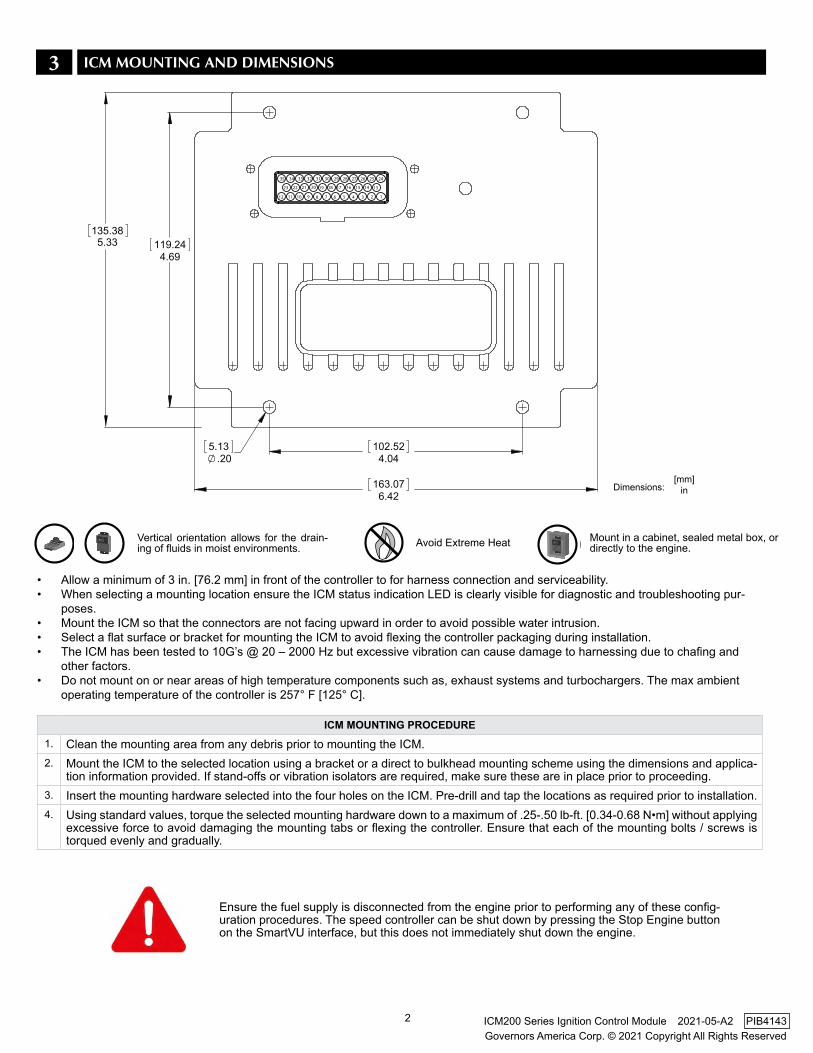
3 ICM MOUNTING AND DIMENSIONS
Mount in a cabinet, sealed metal box, or directly to the engine.
Vertical orientation allows for the drain-ing of fluids in moist environments. Avoid Extreme Heat
ICM MOUNTING PROCEDURE1. Clean the mounting area from any debris prior to mounting the ICM.2. Mount the ICM to the selected location using a bracket or a direct to bulkhead mounting scheme using the dimensions and applica-
tion information provided. If stand-offs or vibration isolators are required, make sure these are in place prior to proceeding.3. Insert the mounting hardware selected into the four holes on the ICM. Pre-drill and tap the locations as required prior to installation.4. Using standard values, torque the selected mounting hardware down to a maximum of .25-.50 lb-ft. [0.34-0.68 N•m] without applying
excessive force to avoid damaging the mounting tabs or flexing the controller. Ensure that each of the mounting bolts / screws is torqued evenly and gradually.
[mm]inDimensions:
12
35
2 7
21 22
11
23
10 8 9
20 19
34 33 3132 30
4
1617
6
18
5 3
15 14
29 28 2627 25
1
13
24
• Allow a minimum of 3 in. [76.2 mm] in front of the controller to for harness connection and serviceability.• When selecting a mounting location ensure the ICM status indication LED is clearly visible for diagnostic and troubleshooting pur-
poses.• Mount the ICM so that the connectors are not facing upward in order to avoid possible water intrusion.• Select a flat surface or bracket for mounting the ICM to avoid flexing the controller packaging during installation.• The ICM has been tested to 10G’s @ 20 – 2000 Hz but excessive vibration can cause damage to harnessing due to chafing and
other factors.• Do not mount on or near areas of high temperature components such as, exhaust systems and turbochargers. The max ambient
operating temperature of the controller is 257° F [125° C].
Ensure the fuel supply is disconnected from the engine prior to performing any of these config-uration procedures. The speed controller can be shut down by pressing the Stop Engine button on the SmartVU interface, but this does not immediately shut down the engine.
3
Governors America Corp. © 2021 Copyright All Rights ReservedICM200 Series Ignition Control Module 2021-05-A2 PIB4143
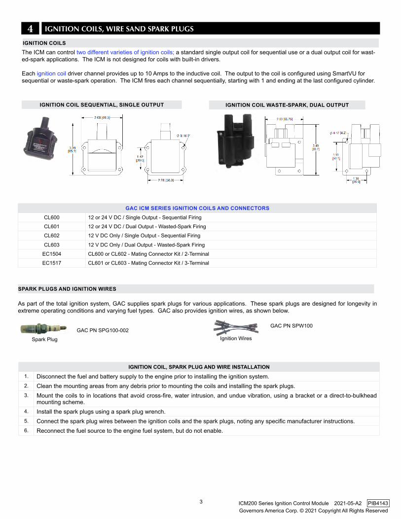
4 IGNITION COIlS, WIRE SAND SPARk PlUGS
The ICM can control two different varieties of ignition coils; a standard single output coil for sequential use or a dual output coil for wast-ed-spark applications. The ICM is not designed for coils with built-in drivers.
Each ignition coil driver channel provides up to 10 Amps to the inductive coil. The output to the coil is configured using SmartVU for sequential or waste-spark operation. The ICM fires each channel sequentially, starting with 1 and ending at the last configured cylinder.
IGNITION COIL WASTE-SPARk, DUAL OUTPUT
GAC ICM SERIES IGNITION COILS AND CONNECTORSCL600 12 or 24 V DC / Single Output - Sequential Firing
CL601 12 or 24 V DC / Dual Output - Wasted-Spark Firing
CL602 12 V DC Only / Single Output - Sequential Firing
CL603 12 V DC Only / Dual Output - Wasted-Spark Firing
EC1504 CL600 or CL602 - Mating Connector Kit / 2-Terminal
EC1517 CL601 or CL603 - Mating Connector Kit / 3-Terminal
IGNITION COIL SEqUENTIAL, SINGLE OUTPUT
As part of the total ignition system, GAC supplies spark plugs for various applications. These spark plugs are designed for longevity in extreme operating conditions and varying fuel types. GAC also provides ignition wires, as shown below.
IGNITION COIL, SPARk PLUG AND WIRE INSTALLATION1. Disconnect the fuel and battery supply to the engine prior to installing the ignition system.2. Clean the mounting areas from any debris prior to mounting the coils and installing the spark plugs.3. Mount the coils to in locations that avoid cross-fire, water intrusion, and undue vibration, using a bracket or a direct-to-bulkhead
mounting scheme.4. Install the spark plugs using a spark plug wrench.5. Connect the spark plug wires between the ignition coils and the spark plugs, noting any specific manufacturer instructions. 6. Reconnect the fuel source to the engine fuel system, but do not enable.
Ignition WiresSpark Plug
GAC PN SPG100-002GAC PN SPW100
SPARk PLUGS AND IGNITION WIRES
IGNITION COILS
4
Governors America Corp. © 2021 Copyright All Rights ReservedICM200 Series Ignition Control Module 2021-05-A2 PIB4143
5 ENGINE POSITION / TIMING SENSOR
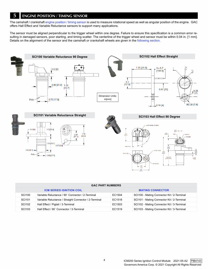
The camshaft / crankshaft engine position / timing sensor is used to measure rotational speed as well as angular position of the engine. GAC offers Hall Effect and Variable Reluctance sensors to support many applications.
The sensor must be aligned perpendicular to the trigger wheel within one degree. Failure to ensure this specification is a common error re-sulting in damaged sensors, poor starting, and timing scatter. The centerline of the trigger wheel and sensor must be within 0.04 in. [1 mm]. Details on the alignment of the sensor and the camshaft or crankshaft wheels are given in the following section.
SCI100 variable Reluctance 90 Degree SCI102 Hall Effect Straight
SCI101 Variable Reluctance Straight SCI103 Hall Effect 90 Degree
Dimension Units: in[mm]
GAC PART NUMBERSICM SERIES IGNITION COIL MATING CONNECTOR
SCI100 Variable Reluctance / 90˚ Connector / 2-Terminal EC1504 SCI100 - Mating Connector Kit / 2-Terminal
SCI101 Variable Reluctance / Straight Connector / 2-Terminal EC1518 SCI101 - Mating Connector Kit / 2-Terminal
SCI102 Hall Effect / Pigtail / 3-Terminal EC1503 SCI102 - Mating Connector Kit / 3-Terminal
SCI103 Hall Effect / 90˚ Connector / 3-Terminal EC1519 SCI103 - Mating Connector Kit / 3-Terminal
5
Governors America Corp. © 2021 Copyright All Rights ReservedICM200 Series Ignition Control Module 2021-05-A2 PIB4143
The ICM can control two types of trigger wheel usage; Crankshaft and Camshaft. GAC recommends creating a Firing Order table before starting this installation and determining use of wasted spark or sequential ignition.
Using one of the engine timing position sensors, the sensor must be aligned perpendicular to the trigger wheel within one degree. Failure to ensure this specification is a common error resulting in damaged sensors, poor starting, and timing scatter.
Both crankshaft and camshaft triggering wheel inputs are designed to interface to most Hall Effect and variable reluctance sensors. A reg-ulated 5 V DC output is available on ICM pin 33 for a powered Hall Effect sensor. The signal output of the sensor is wired to the cam/crank input; the ground side is wired to ground. If the sensor is a variable reluctance magnetic pickup, then the polarity does not matter unless shared with other devices. The offset angle parameter calibrates the sensor with respect to TDC. Whenever a change is made to the crank or camshaft sensor, ignition timing should be reverified.
There is a direct relationship between the number of cylinders and the number of coils. Using the crankshaft trigger wheel the ICM will automatically use wasted-spark and utilize only half the ignition channels. If a camshaft trigger wheel is used the ICM pairs each cylinder with its own ignition output channel. Crankshaft installation and Camshaft installation instructions are included here.
GAC offers a 24 -1 camshaft trigger wheel. The trigger wheel is a multi tooth design, providing high RPM resolution for accuracy and quick-er engine start. GAC does not offer large camshaft or crankshaft wheels. Contact GAC for compatible universal selection types.
Wiring is dependent upon the use of wasted spark or single cylinder firing.
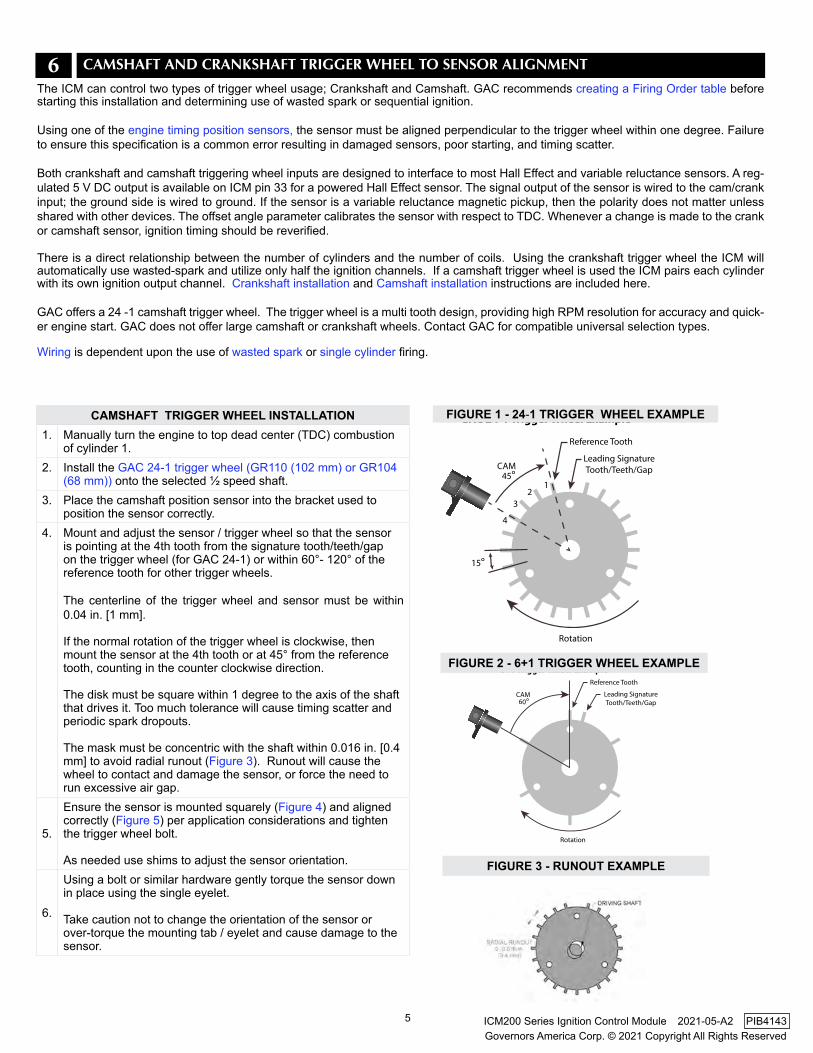
CAMSHAfT TRIGGER WHEEL INSTALLATION1. Manually turn the engine to top dead center (TDC) combustion
of cylinder 1.2. Install the GAC 24-1 trigger wheel (GR110 (102 mm) or GR104
(68 mm)) onto the selected ½ speed shaft.3. Place the camshaft position sensor into the bracket used to
position the sensor correctly. 4. Mount and adjust the sensor / trigger wheel so that the sensor
is pointing at the 4th tooth from the signature tooth/teeth/gap on the trigger wheel (for GAC 24-1) or within 60°- 120° of the reference tooth for other trigger wheels.
The centerline of the trigger wheel and sensor must be within 0.04 in. [1 mm].
If the normal rotation of the trigger wheel is clockwise, then mount the sensor at the 4th tooth or at 45° from the reference tooth, counting in the counter clockwise direction.
The disk must be square within 1 degree to the axis of the shaft that drives it. Too much tolerance will cause timing scatter and periodic spark dropouts. The mask must be concentric with the shaft within 0.016 in. [0.4 mm] to avoid radial runout (Figure 3). Runout will cause the wheel to contact and damage the sensor, or force the need to run excessive air gap.
5.
Ensure the sensor is mounted squarely (Figure 4) and aligned correctly (Figure 5) per application considerations and tighten the trigger wheel bolt.
As needed use shims to adjust the sensor orientation.
6.
Using a bolt or similar hardware gently torque the sensor down in place using the single eyelet.
Take caution not to change the orientation of the sensor or over-torque the mounting tab / eyelet and cause damage to the sensor.
Leading Signature Tooth/Teeth/Gap
Reference Tooth
Rotation
12
3
4
GAC 24-1 Trigger Wheel Example
45°
15°
CAM
6 CAMSHAFT AND CRANkSHAFT TRIGGER WHEEl TO SENSOR AlIGNMENT
Leading Signature Tooth/Teeth/Gap
Reference Tooth
Rotation
60°
6+1 Trigger Wheel Example
CAM
fIGURE 1 - 24-1 TRIGGER WHEEL EXAMPLE
fIGURE 2 - 6+1 TRIGGER WHEEL EXAMPLE
fIGURE 3 - RUNOUT EXAMPLE
6
Governors America Corp. © 2021 Copyright All Rights ReservedICM200 Series Ignition Control Module 2021-05-A2 PIB4143
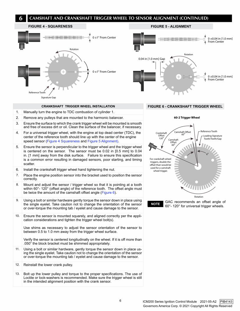
CRANkSHAfT TRIGGER WHEEL INSTALLATION
1. Manually turn the engine to TDC combustion of cylinder 1.2. Remove any pulleys that are mounted to the harmonic balancer.3. Ensure the surface to which the crank trigger wheel will be mounted is smooth
and free of excess dirt or oil. Clean the surface of the balancer, if necessary.4. For a universal trigger wheel, with the engine at top dead center (TDC), the
center of the reference tooth should line up with the center of the engine speed sensor (Figure 4 Squareness and Figure 5 Alignment).
5. Ensure the sensor is perpendicular to the trigger wheel and the trigger wheel is centered on the sensor. The sensor must be 0.02 in [0.5 mm] to 0.04 in. [1 mm] away from the disk surface. Failure to ensure this specification is a common error resulting in damaged sensors, poor starting, and timing scatter.
6. Install the crankshaft trigger wheel hand tightening the nut. 7. Place the engine position sensor into the bracket used to position the sensor
correctly. 8. Mount and adjust the sensor / trigger wheel so that it is pointing at a tooth
within 60°- 120° (offset angle) of the reference tooth. The offset angle must be twice the amount of the camshaft offset angle (Figure 6).
9. Using a bolt or similar hardware gently torque the sensor down in place using the single eyelet. Take caution not to change the orientation of the sensor or over-torque the mounting tab / eyelet and cause damage to the sensor.
10. Ensure the sensor is mounted squarely, and aligned correctly per the appli-cation considerations and tighten the trigger wheel bolt(s).
Use shims as necessary to adjust the sensor orientation of the sensor to between 0.5 to 1.0 mm away from the trigger wheel surface.
Verify the sensor is centered longitudinally on the wheel. If it is off more than .050” the block bracket must be shimmed appropriately.
11. Using a bolt or similar hardware, gently torque the sensor down in place us-ing the single eyelet. Take caution not to change the orientation of the sensor or over-torque the mounting tab / eyelet and cause damage to the sensor.
12. Reinstall the lower crank pulley.
13. Bolt up the lower pulley and torque to the proper specifications. The use of Loctite or lock-washers is recommended. Make sure the trigger wheel is still in the intended alignment position with the crank sensor.
Rotation
60°
For crankshaft wheel triggers, double the oset than would be used for a camshaft
wheel trigger.
60-2 Trigger Wheel
120° CamshaftOset
CrankshaftOset Leading Signature
Tooth/Teeth/Gap
Reference ToothCamshaft Oset60°
6°
GAC recommends an offset angle of 60°- 120° for universal trigger wheels.NOTE
6 CAMSHAFT AND CRANkSHAFT TRIGGER WHEEl TO SENSOR AlIGNMENT (CONTINUED)
fIGURE 6 - CRANkSHAfT TRIGGER WHEEL
0 ±1° From Center
0 ±1° From Center
0 ±0.04 in [1.0 mm]From Center
0 ±0.04 in [1.0 mm] From Center
0.04 in [1.0 mm] Gap
Signature Gap
Reference Tooth
Rotation
Rotation
0 ±1° From Center
0 ±1° From Center
0 ±0.04 in [1.0 mm]From Center
0 ±0.04 in [1.0 mm] From Center
0.04 in [1.0 mm] Gap
Signature Gap
Reference Tooth
Rotation
Rotation
fIGURE 4 - SqUARENESS fIGURE 5 - ALIGNMENT
7
Governors America Corp. © 2021 Copyright All Rights ReservedICM200 Series Ignition Control Module 2021-05-A2 PIB4143
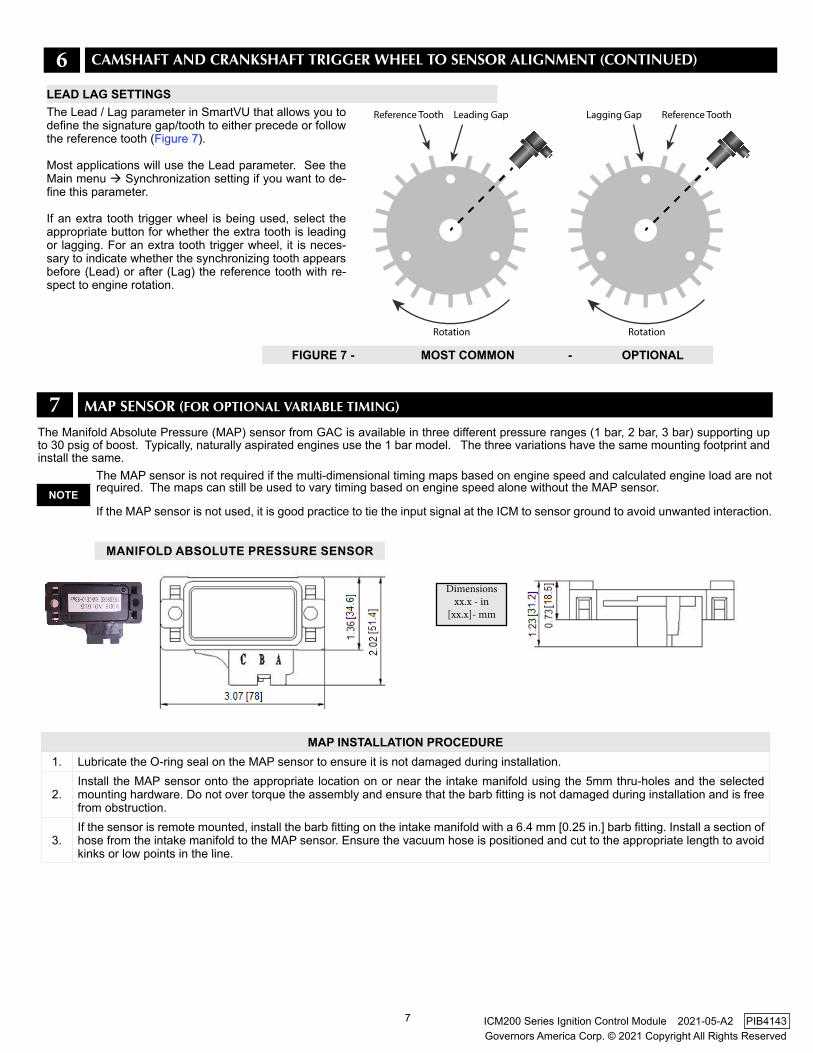
MAP INSTALLATION PROCEDURE1. Lubricate the O-ring seal on the MAP sensor to ensure it is not damaged during installation.
2.Install the MAP sensor onto the appropriate location on or near the intake manifold using the 5mm thru-holes and the selected mounting hardware. Do not over torque the assembly and ensure that the barb fitting is not damaged during installation and is free from obstruction.
3.If the sensor is remote mounted, install the barb fitting on the intake manifold with a 6.4 mm [0.25 in.] barb fitting. Install a section of hose from the intake manifold to the MAP sensor. Ensure the vacuum hose is positioned and cut to the appropriate length to avoid kinks or low points in the line.
The MAP sensor is not required if the multi-dimensional timing maps based on engine speed and calculated engine load are not required. The maps can still be used to vary timing based on engine speed alone without the MAP sensor.
If the MAP sensor is not used, it is good practice to tie the input signal at the ICM to sensor ground to avoid unwanted interaction.NOTE
MANIfOLD ABSOLUTE PRESSURE SENSOR
Dimensionsxx.x - in
[xx.x]- mm
7 MAP SENSOR (FOR OPTIONAl VARIAblE TIMING)
The Manifold Absolute Pressure (MAP) sensor from GAC is available in three different pressure ranges (1 bar, 2 bar, 3 bar) supporting up to 30 psig of boost. Typically, naturally aspirated engines use the 1 bar model. The three variations have the same mounting footprint and install the same.
6 CAMSHAFT AND CRANkSHAFT TRIGGER WHEEl TO SENSOR AlIGNMENT (CONTINUED)
Reference Tooth Leading Gap
Rotation
Lagging Gap Reference Tooth
Rotation
The Lead / Lag parameter in SmartVU that allows you to define the signature gap/tooth to either precede or follow the reference tooth (Figure 7).
Most applications will use the Lead parameter. See the Main menu Synchronization setting if you want to de-fine this parameter.
If an extra tooth trigger wheel is being used, select the appropriate button for whether the extra tooth is leading or lagging. For an extra tooth trigger wheel, it is neces-sary to indicate whether the synchronizing tooth appearsbefore (Lead) or after (Lag) the reference tooth with re-spect to engine rotation.
fIGURE 7 - MOST COMMON - OPTIONAL
LEAD LAG SETTINGS
8
Governors America Corp. © 2021 Copyright All Rights ReservedICM200 Series Ignition Control Module 2021-05-A2 PIB4143
8 WIRING
24
1
3429
1514
25
13
26 2827
16 17
2 3 54 6
32
2019
30
18
31 33
21 22
7 8 109 11
35
23
12
ICM 35 PIN MATING CONNECTOR
12
35
2 7
21 22
11
23
10 8 9
20 19
34 33 3132 30
4
1617
6
18
5 3
15 14
29 28 2627 25
1
13
24
24
1
34 29
15 14
25
13
2628 27
1617
235 46
32
20 19
30
18
3133
2122
7810 911
35
23
12
ICM 35 PIN MATING CONNECTOR
CONNECTOR ORIENTATION
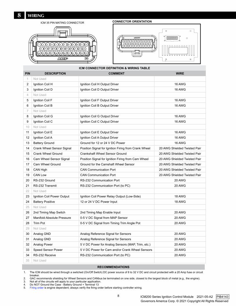
ICM CONNECTOR DEfINITION & WIRING TABLEPIN DESCRIPTION COMMENT WIRE
1 Not Used
2 Ignition Coil H Ignition Coil H Output Driver 16 AWG
3 Ignition Coil D Ignition Coil D Output Driver 16 AWG
4 Not Used
5 Ignition Coil F Ignition Coil F Output Driver 16 AWG
6 Ignition Coil B Ignition Coil B Output Driver 16 AWG
7 Not Used
8 Ignition Coil G Ignition Coil G Output Driver 16 AWG
9 Ignition Coil C Ignition Coil C Output Driver 16 AWG
10 Not Used
11 Ignition Coil E Ignition Coil E Output Driver 16 AWG
12 Ignition Coil A Ignition Coil A Output Driver 16 AWG
13 Battery Ground Ground for 12 or 24 V DC Power 16 AWG
14 Crank Wheel Sensor Signal Position Signal for Ignition Firing from Crank Wheel 20 AWG Shielded Twisted Pair
15 Crank Wheel Ground Crankshaft Wheel Sensor Ground 20 AWG Shielded Twisted Pair
16 Cam Wheel Sensor Signal Position Signal for Ignition Firing from Cam Wheel 20 AWG Shielded Twisted Pair
17 Cam Wheel Ground Ground for the Camshaft Wheel Sensor 20 AWG Shielded Twisted Pair
18 CAN High CAN Communication Port 20 AWG Shielded Twisted Pair
19 CAN Low CAN Communication Port 20 AWG Shielded Twisted Pair
20 RS-232 Ground RS-232 Communication Port 20 AWG
21 RS-232 Transmit RS-232 Communication Port (to PC) 20 AWG
22 Not Used
23 Ignition Coil Power Output Ignition Coil Power Relay Output (Low-Side) 18 AWG
24 Battery Positive 12 or 24 V DC Power Input 18 AWG
25 Not Used
26 2nd Timing Map Switch 2nd Timing Map Enable Input 20 AWG
27 Manifold Absolute Pressure 0-5 V DC Signal from MAP Sensor 20 AWG
28 Trim Pot 0-5 V DC Signal from Timing Trim Angle Pot 20 AWG
29 Not Used
30 Analog GND Analog Reference Signal for Sensors 20 AWG
31 Analog GND Analog Reference Signal for Sensors 20 AWG
32 Analog Power 5 V DC Power for Analog Sensors (MAP, Trim, etc.) 20 AWG
33 Speed Sensor Power 5 V DC Power for Cam and/or Crank Wheel Sensors 20 AWG
34 RS-232 Receive RS-232 Communication Port (to PC) 20 AWG
35 Not Used
RECOMMENDATIONS1.
2.3. 4.5.
The ICM should be wired through a switched (On/Off Switch) DC power source of 8 to 32 V DC and circuit protected with a 20 Amp fuse or circuit breaker. GAC recommends shielding for Wheel Sensors and CANbus be terminated on one side, closest to the largest block of metal (e.g., the engine).Not all of the circuits will apply to your particular application. Do NOT Ground the Case - Battery Ground + Terminal 13Firing order is engine dependent; always verify the firing order before starting controller wiring.
9
Governors America Corp. © 2021 Copyright All Rights ReservedICM200 Series Ignition Control Module 2021-05-A2 PIB4143
24
1
3429
1514
25
13
26 2827
16 17
2 3 54 6
32
2019
30
18
31 33
21 22
7 8 109 11
35
23
12
C B A
A B C
3 25
SERIAL COMM. PORTRS23212/24 V DC
+ -
TIMING TRIM OFFSETPOTENTIOMETER
2ND TIMING MAPSELECTION SWITCH
IGNITION SWITCH
20 A CIRCUIT PROTECTION
CAMSHAFT ENGINE POSITIONSENSOR MATING CONNECTOR
(HALL EFFECT SHOWN)
IGNITION COIL POWER RELAYMATING CONNECTOR
CIRCUIT TYPEPOWERGROUNDINPUTOUTPUTCOMMUNICATION
COLORCOLOR CODE LEGEND
MANIFOLD ABSOLUTE PRESSURE SENSOR MATING CONNECTOR
SEQUENTIAL (SINGLE OUTPUT) IGNITION COILS MATING CONNECTORS
COIL ECOIL FCOIL GCOIL H COIL ACOIL BCOIL CCOIL D
120 Ω
CAN HIGH
CAN LOW
OPTIONAL - CUSTOMER SUPPLIED
J1939 CAPABLE
DEVICE
ICM 35 PINMATING CONNECTOR
CAM
SIG
NAL
CAM
RET
UR
N
CAM
PO
WER
TIM
ING
SW
ITC
H IN
TRIM SIGNAL
TRIM RETURN
MAP/TRIM POWER
MAP RETURN
MAP SIGNAL
RS232 RXRS232 TX
RS232 GND
BATTERY (+) BATTERY (-)
COIL OUTPUTS
POWER RELAY CONTROLCOIL SWITCH POWER
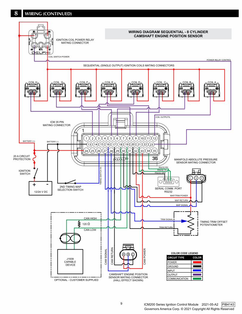
WIRING DIAGRAM SEqUENTIAL - 8 CYLINDERCAMSHAfT ENGINE POSITION SENSOR
8 WIRING (CONTINUED)
10
Governors America Corp. © 2021 Copyright All Rights ReservedICM200 Series Ignition Control Module 2021-05-A2 PIB4143
MANIFOLD ABSOLUTE PRESSURE SENSOR MATING CONNECTOR
24
1
3429
1514
25
13
26 2827
16 17
2 3 54 6
32
2019
30
18
31 33
21 22
7 8 109 11
35
23
12
C B A
SERIAL COMM. PORTRS232
TIMING TRIM OFFSETPOTENTIOMETER
2ND TIMING MAPSELECTION SWITCH
IGNITION SWITCH
20A CIRCUIT PROTECTION
CRANKSHAFT ENGINE POSITIONSENSOR MATING CONNECTOR
(VARIABLE RELUCTANCE SHOWN)
120 Ohm
CAN HIGH CAN LOW
OPTIONAL - CUSTOMER SUPPLIED
J1939 CAPABLE
DEVICE
WASTED SPARK (DUAL-OUTPUT) IGNITION COILS MATING CONNECTORS
COIL A/BCOIL C/DCOIL E/FCOIL G/H
ICM 35 PINMATING CONNECTOR
IGNITION COIL POWER RELAYMATING CONNECTOR
CIRCUIT TYPEPOWERGROUNDINPUTOUTPUTCOMMUNICATION
COLORCOLOR CODE LEGEND
1 1 1 13 3 3 3
3 25
12/24 V DC
+ -
TIM
ING
SW
ITC
H IN
TRIM SIGNAL
TRIM RETURN
MAP/TRIM POWER
MAP RETURN
MAP SIGNAL
RS232 RXRS232 TX
RS232 GND
BATTERY (+)
BATTERY (-)
COIL OUTPUTS
POWER RELAY CONTROL
COIL SWITCHED POWER
CRANK SIGNAL
SENSOR GROUND
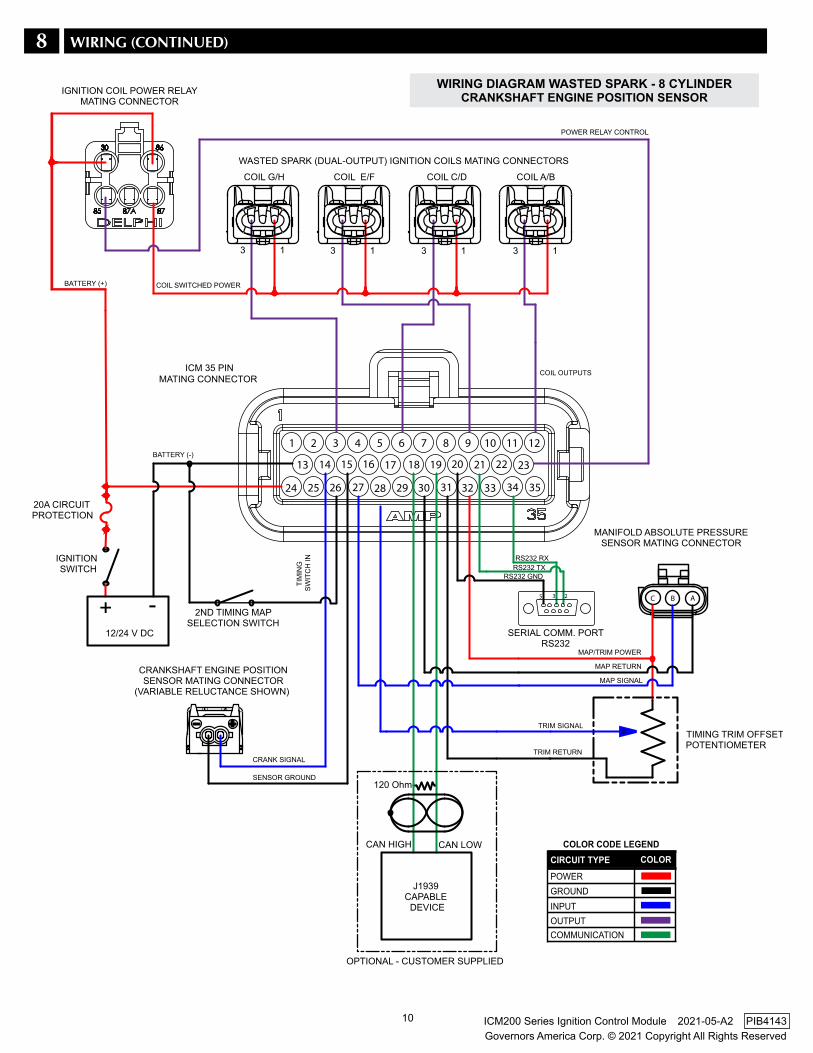
WIRING DIAGRAM WASTED SPARk - 8 CYLINDERCRANkSHAfT ENGINE POSITION SENSOR
8 WIRING (CONTINUED)
11
Governors America Corp. © 2021 Copyright All Rights ReservedICM200 Series Ignition Control Module 2021-05-A2 PIB4143
OvERSPEEDThe overspeed function (setting in SmartVU) provides emergency shutdown by discontinuing the firing sequence and the power control relay. If the ignition coils and a gas valve are powered through the relay and the engine trips the overspeed set-point the relay will open the contacts and shutdown the engine.
When the engine is shutdown due to overspeed, the diagnostic LED will blink yellow to indicate the condition. A power cycle is needed to clear the condition and resume normal operation.
COIL AIGNITION COIL POWER RELAYMATING CONNECTOR
+-
13ICM MATING CONNETOR AND IGNITION SWITCH
ICM MATING CONNETOR
COIL A/BTO SEQUENTIALOR WASTED SPARKIGNITION COILS
87
87
FROM IGNITION COILPOWER RELAY
FROM IGNITION COILPOWER RELAY
TO NEXT COIL
TO NEXT COIL23
24
ICM MATINGCONNETOR
ICM MATINGCONNETOR
WASTE SPARK IGNITION COILSMATING CONNECTORS(DUAL OUTPUT)
SEQUENTIAL IGNITION COILSMATING CONNECTORS(DUAL OUTPUT)
or
Overspeed is not a replacement for a mechanical fail-safe. In the event of an overspeed shutdown, it is important to determine the root cause of the overspeed and to take corrective action to fix the problem.
Care must be taken upon engine restart to vent trapped fuel.
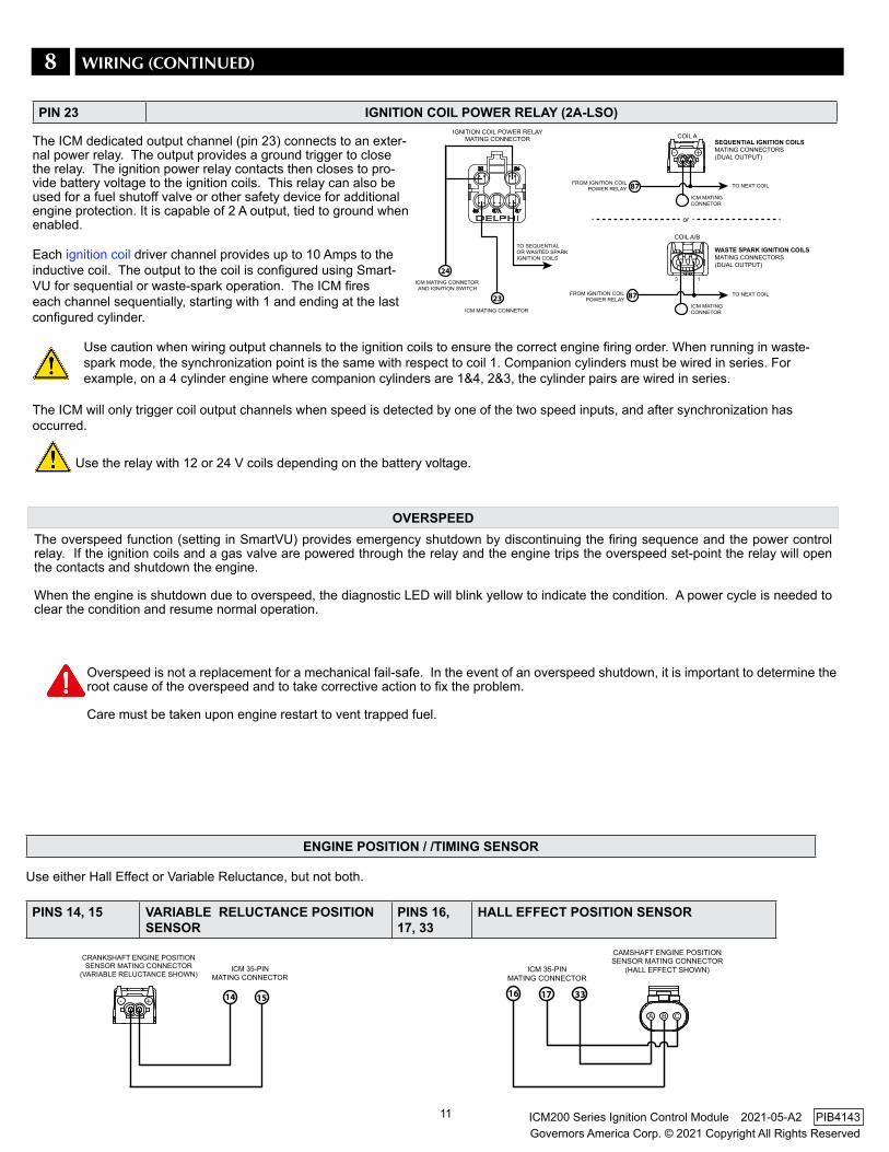
Use the relay with 12 or 24 V coils depending on the battery voltage.
ICM 35-PINMATING CONNECTOR
14 15+-
CRANKSHAFT ENGINE POSITIONSENSOR MATING CONNECTOR
(VARIABLE RELUCTANCE SHOWN)ICM 35-PIN
MATING CONNECTOR
16 17
CAMSHAFT ENGINE POSITIONSENSOR MATING CONNECTOR
(HALL EFFECT SHOWN)
33
A B C
PIN 23 IGNITION COIL POWER RELAY (2A-LSO)
The ICM dedicated output channel (pin 23) connects to an exter-nal power relay. The output provides a ground trigger to close the relay. The ignition power relay contacts then closes to pro-vide battery voltage to the ignition coils. This relay can also be used for a fuel shutoff valve or other safety device for additional engine protection. It is capable of 2 A output, tied to ground when enabled.
Each ignition coil driver channel provides up to 10 Amps to the inductive coil. The output to the coil is configured using Smart-VU for sequential or waste-spark operation. The ICM fires each channel sequentially, starting with 1 and ending at the last configured cylinder.
Use caution when wiring output channels to the ignition coils to ensure the correct engine firing order. When running in waste-spark mode, the synchronization point is the same with respect to coil 1. Companion cylinders must be wired in series. For example, on a 4 cylinder engine where companion cylinders are 1&4, 2&3, the cylinder pairs are wired in series.
The ICM will only trigger coil output channels when speed is detected by one of the two speed inputs, and after synchronization has occurred.
ENGINE POSITION / /TIMING SENSOR
Use either Hall Effect or Variable Reluctance, but not both.
PINS 14, 15 vARIABLE RELUCTANCE POSITION SENSOR
PINS 16, 17, 33
HALL EffECT POSITION SENSOR
8 WIRING (CONTINUED)
12
Governors America Corp. © 2021 Copyright All Rights ReservedICM200 Series Ignition Control Module 2021-05-A2 PIB4143
C B A
MANIFOLD ABSOLUTE PRESSURE SENSOR MATING CONNECTOR ICM 35-PIN
MATING CONNECTOR
27 3230
ICM 35-PINMATING CONNECTOR
32
TIMING TRIM OFFSETPOTENTIOMETER
28 31
1
9
5 4 3 2
8 7 6
20 3421
ICM 35-PINMATING CONNECTOR
Gnd Tx Rx
18 19
Case
CAN H CAN L
ICM 35-PINMATING CONNECTOR
120 Ohm
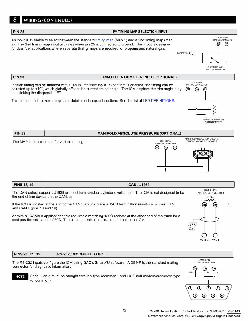
NOTE Serial Cable must be straight-through type (common), and NOT null modem/crossover type (uncommon).
PIN 28 TRIM POTENTIOMETER INPUT (OPTIONAL)
Ignition timing can be trimmed with a 0-5 kΩ resistive input. When trim is enabled, the timing can be adjusted up to ±10°, which globally offsets the current timing angle. The ICM displays the trim angle is by the blinking the diagnostic LED.
This procedure is covered in greater detail in subsequent sections. See the list of LED DEFINITIONS.
PINS 18, 19 CAN / J1939
The CAN output supports J1939 protocol for individual cylinder dwell times. The ICM is not designed to be the end of line device on the CANbus.
If the ICM is located at the end of the CANbus trunk place a 120Ω termination resistor is across CAN H and CAN L (pins 18 and 19).
As with all CANbus applications this requires a matching 120Ω resistor at the other end of the trunk for a total parallel resistance of 60Ω. There is no termination resistor internal to the ICM.
PINS 20, 21, 34 RS-232 / MODBUS / TO PC
The RS-232 inputs configure the ICM using GAC’s SmartVU software. A DB9-F is the standard mating connector for diagnostic information.
PIN 28 MANIfOLD ABSOLUTE PRESSURE (OPTIONAL)
The MAP is only required for variable timing.
8 WIRING (CONTINUED)
ICM 35-PINMATING CONNECTOR
13 26
BATTERY (-)
2nd TIMING MAPSELECTION SWITCH
PIN 25 2ND TIMING MAP SELECTION INPUT
An input is available to select between the standard timing map (Map 1) and a 2nd timing map (Map 2). The 2nd timing map input activates when pin 25 is connected to ground. This input is designed for dual fuel applications where separate timing maps are required for propane and natural gas.
13
Governors America Corp. © 2021 Copyright All Rights ReservedICM200 Series Ignition Control Module 2021-05-A2 PIB4143
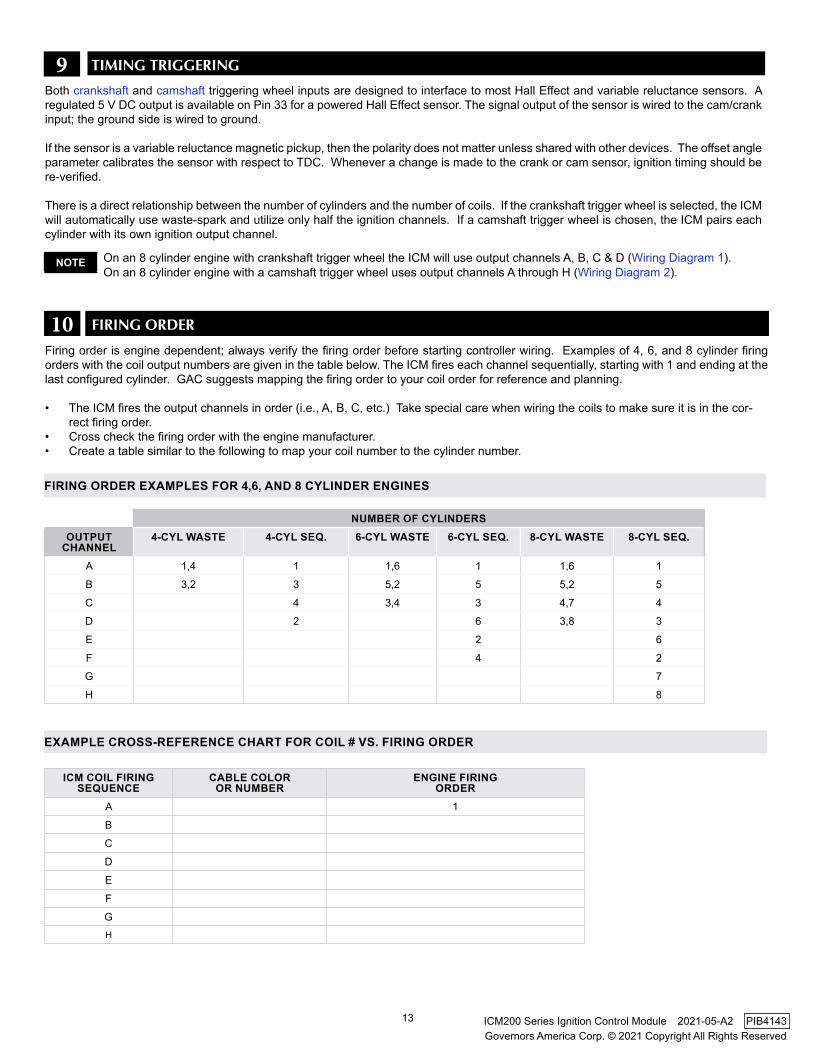
9 TIMING TRIGGERING
On an 8 cylinder engine with crankshaft trigger wheel the ICM will use output channels A, B, C & D (Wiring Diagram 1).On an 8 cylinder engine with a camshaft trigger wheel uses output channels A through H (Wiring Diagram 2).
NOTE
Both crankshaft and camshaft triggering wheel inputs are designed to interface to most Hall Effect and variable reluctance sensors. A regulated 5 V DC output is available on Pin 33 for a powered Hall Effect sensor. The signal output of the sensor is wired to the cam/crank input; the ground side is wired to ground.
If the sensor is a variable reluctance magnetic pickup, then the polarity does not matter unless shared with other devices. The offset angle parameter calibrates the sensor with respect to TDC. Whenever a change is made to the crank or cam sensor, ignition timing should be re-verified.
There is a direct relationship between the number of cylinders and the number of coils. If the crankshaft trigger wheel is selected, the ICM will automatically use waste-spark and utilize only half the ignition channels. If a camshaft trigger wheel is chosen, the ICM pairs each cylinder with its own ignition output channel.
Firing order is engine dependent; always verify the firing order before starting controller wiring. Examples of 4, 6, and 8 cylinder firing orders with the coil output numbers are given in the table below. The ICM fires each channel sequentially, starting with 1 and ending at the last configured cylinder. GAC suggests mapping the firing order to your coil order for reference and planning.
• The ICM fires the output channels in order (i.e., A, B, C, etc.) Take special care when wiring the coils to make sure it is in the cor-rect firing order.
• Cross check the firing order with the engine manufacturer. • Create a table similar to the following to map your coil number to the cylinder number.
10 FIRING ORDER
ICM COIL fIRING SEqUENCE
CABLE COLOR OR NUMBER
ENGINE fIRINGORDER
A 1
B
C
D
E
F
GH
EXAMPLE CROSS-REfERENCE CHART fOR COIL # vS. fIRING ORDER
NUMBER Of CYLINDERSOUTPUT
CHANNEL4-CYL WASTE 4-CYL SEq. 6-CYL WASTE 6-CYL SEq. 8-CYL WASTE 8-CYL SEq.
A 1,4 1 1,6 1 1,6 1
B 3,2 3 5,2 5 5,2 5
C 4 3,4 3 4,7 4
D 2 6 3,8 3
E 2 6
F 4 2
G 7
H 8
fIRING ORDER EXAMPLES fOR 4,6, AND 8 CYLINDER ENGINES
14
Governors America Corp. © 2021 Copyright All Rights ReservedICM200 Series Ignition Control Module 2021-05-A2 PIB4143
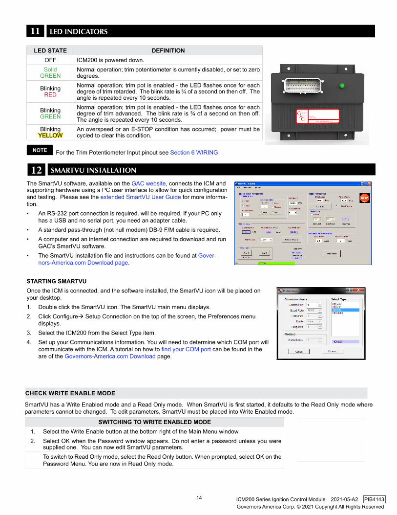
11 lED INDICATORS
LED STATE DEfINITIONOFF ICM200 is powered down.Solid
GREENNormal operation; trim potentiometer is currently disabled, or set to zero degrees.
BlinkingRED
Normal operation; trim pot is enabled - the LED flashes once for each degree of trim retarded. The blink rate is ¾ of a second on then off. The angle is repeated every 10 seconds.
BlinkingGREEN
Normal operation; trim pot is enabled - the LED flashes once for each degree of trim advanced. The blink rate is ¾ of a second on then off. The angle is repeated every 10 seconds.
BlinkingYELLOW
An overspeed or an E-STOP condition has occurred; power must be cycled to clear this condition.
For the Trim Potentiometer Input pinout see Section 6 WIRINGNOTE
12 SMARTVU INSTAllATION
The SmartVU software, available on the GAC website, connects the ICM and supporting hardware using a PC user interface to allow for quick configuration and testing. Please see the extended SmartVU User Guide for more informa-tion.• An RS-232 port connection is required. will be required. If your PC only
has a USB and no serial port, you need an adapter cable.• A standard pass-through (not null modem) DB-9 F/M cable is required.• A computer and an internet connection are required to download and run
GAC’s SmartVU software. • The SmartVU installation file and instructions can be found at Gover-
nors-America.com Download page.
STARTING SMARTvU Once the ICM is connected, and the software installed, the SmartVU icon will be placed on your desktop. 1. Double click the SmartVU icon. The SmartVU main menu displays. 2. Click Configure Setup Connection on the top of the screen, the Preferences menu
displays. 3. Select the ICM200 from the Select Type item. 4. Set up your Communications information. You will need to determine which COM port will
communicate with the ICM. A tutorial on how to find your COM port can be found in the are of the Governors-America.com Download page.
SmartVU has a Write Enabled mode and a Read Only mode. When SmartVU is first started, it defaults to the Read Only mode where parameters cannot be changed. To edit parameters, SmartVU must be placed into Write Enabled mode.
SWITCHING TO WRITE ENABLED MODE1. Select the Write Enable button at the bottom right of the Main Menu window.2. Select OK when the Password window appears. Do not enter a password unless you were
supplied one. You can now edit SmartVU parameters.To switch to Read Only mode, select the Read Only button. When prompted, select OK on the Password Menu. You are now in Read Only mode.
CHECk WRITE ENABLE MODE
15
Governors America Corp. © 2021 Copyright All Rights ReservedICM200 Series Ignition Control Module 2021-05-A2 PIB4143
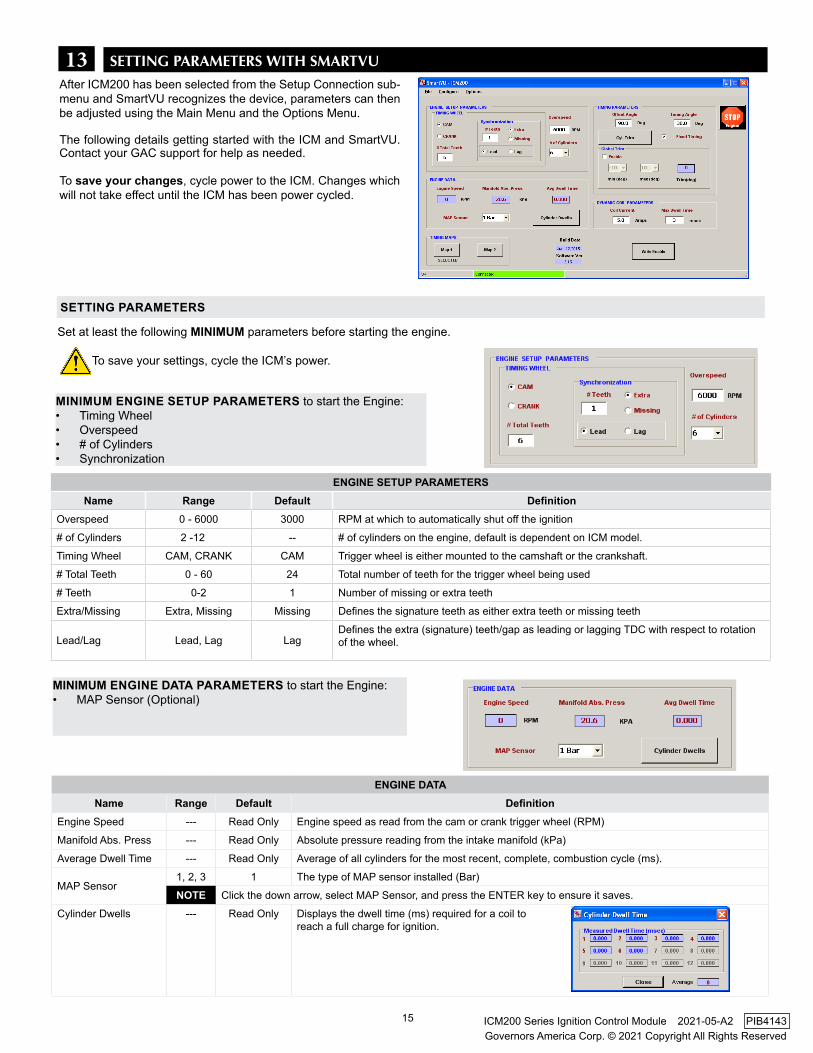
13After ICM200 has been selected from the Setup Connection sub-menu and SmartVU recognizes the device, parameters can then be adjusted using the Main Menu and the Options Menu.
The following details getting started with the ICM and SmartVU. Contact your GAC support for help as needed.
To save your changes, cycle power to the ICM. Changes which will not take effect until the ICM has been power cycled.
SETTING PARAMETERS WITH SMARTVU
Set at least the following MINIMUM parameters before starting the engine.
To save your settings, cycle the ICM’s power.
ENGINE SETUP PARAMETERSName Range Default Definition
Overspeed 0 - 6000 3000 RPM at which to automatically shut off the ignition
# of Cylinders 2 -12 ... -- # of cylinders on the engine, default is dependent on ICM model.
Timing Wheel CAM, CRANk CAM Trigger wheel is either mounted to the camshaft or the crankshaft.
# Total Teeth 0 - 60 24 Total number of teeth for the trigger wheel being used
# Teeth 0-2 1 Number of missing or extra teeth
Extra/Missing Extra, Missing Missing Defines the signature teeth as either extra teeth or missing teeth
Lead/Lag Lead, Lag LagDefines the extra (signature) teeth/gap as leading or lagging TDC with respect to rotation of the wheel.
MINIMUM ENGINE SETUP PARAMETERS to start the Engine: • Timing Wheel• Overspeed• # of Cylinders• Synchronization
SETTING PARAMETERS
ENGINE DATAName Range Default Definition
Engine Speed --- Read Only Engine speed as read from the cam or crank trigger wheel (RPM)
Manifold Abs. Press --- Read Only Absolute pressure reading from the intake manifold (kPa)
Average Dwell Time --- Read Only Average of all cylinders for the most recent, complete, combustion cycle (ms).
MAP Sensor1, 2, 3 1 The type of MAP sensor installed (Bar)
NOTE Click the down arrow, select MAP Sensor, and press the ENTER key to ensure it saves.
Cylinder Dwells --- Read Only Displays the dwell time (ms) required for a coil to reach a full charge for ignition.
MINIMUM ENGINE DATA PARAMETERS to start the Engine: • MAP Sensor (Optional)
16
Governors America Corp. © 2021 Copyright All Rights ReservedICM200 Series Ignition Control Module 2021-05-A2 PIB4143
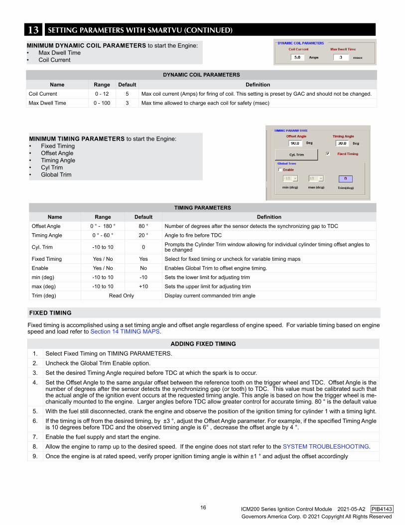
DYNAMIC COIL PARAMETERS
Name Range Default DefinitionCoil Current 0 - 12 5 Max coil current (Amps) for firing of coil. This setting is preset by GAC and should not be changed.
Max Dwell Time 0 - 100 3 Max time allowed to charge each coil for safety (msec)
13 SETTING PARAMETERS WITH SMARTVU (CONTINUED)
MINIMUM DYNAMIC COIL PARAMETERS to start the Engine: • Max Dwell Time• Coil Current
TIMING PARAMETERSName Range Default Definition
Offset Angle 0 ° - 180 ° 80 ° Number of degrees after the sensor detects the synchronizing gap to TDC
Timing Angle 0 ° - 60 ° 20 ° Angle to fire before TDC
Cyl. Trim -10 to 10 0 Prompts the Cylinder Trim window allowing for individual cylinder timing offset angles to be changed
Fixed Timing Yes / No Yes Select for fixed timing or uncheck for variable timing maps
Enable Yes / No No Enables Global Trim to offset engine timing.
min (deg) -10 to 10 -10 Sets the lower limit for adjusting trim
max (deg) -10 to 10 +10 Sets the upper limit for adjusting trim
Trim (deg) Read Only Display current commanded trim angle
Fixed timing is accomplished using a set timing angle and offset angle regardless of engine speed. For variable timing based on engine speed and load refer to Section 14 TIMING MAPS.
ADDING fIXED TIMING1. Select Fixed Timing on TIMING PARAMETERS.2. Uncheck the Global Trim Enable option.3. Set the desired Timing Angle required before TDC at which the spark is to occur.4. Set the Offset Angle to the same angular offset between the reference tooth on the trigger wheel and TDC. Offset Angle is the
number of degrees after the sensor detects the synchronizing gap (or tooth) to TDC. This value must be calibrated such that the actual angle of the ignition event occurs at the requested timing angle. This angle is based on how the trigger wheel is me-chanically mounted to the engine. Larger angles before TDC allow greater control for accurate timing. 80 ° is the default value
5. With the fuel still disconnected, crank the engine and observe the position of the ignition timing for cylinder 1 with a timing light.6. If the timing is off from the desired timing, by ±3 °, adjust the Offset Angle parameter. For example, if the specified Timing Angle
is 10 degrees before TDC and the observed timing angle is 6° , decrease the offset angle by 4 °.7. Enable the fuel supply and start the engine. 8. Allow the engine to ramp up to the desired speed. If the engine does not start refer to the SYSTEM TROUBLESHOOTING.9. Once the engine is at rated speed, verify proper ignition timing angle is within ±1 ° and adjust the offset accordingly
fIXED TIMING
MINIMUM TIMING PARAMETERS to start the Engine: • Fixed Timing• Offset Angle• Timing Angle• Cyl Trim• Global Trim
17
Governors America Corp. © 2021 Copyright All Rights ReservedICM200 Series Ignition Control Module 2021-05-A2 PIB4143
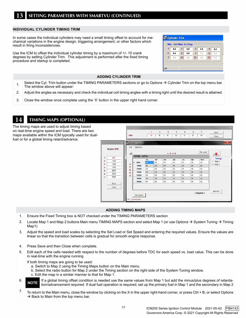
14 TIMING MAPS (OPTIONAl)The timing maps are used to adjust timing based on real-time engine speed and load. There are two maps available within the ICM typically used for dual-fuel or for a global timing retard/advance.
ADDING TIMING MAPS1. Ensure the Fixed Timing box is NOT checked under the TIMING PARAMETERS section2. Locate Map 1 and Map 2 buttons Main menu TIMING MAPS section and select Map 1 (or use Options System Tuning Timing
Map1)3. Adjust the speed and load scales by selecting the Set Load or Set Speed and entering the required values. Ensure the values are
linear so that the transition between cells is gradual for smooth engine response.
4. Press Save and then Close when complete.5. Edit each of the cells needed with respect to the number of degrees before TDC for each speed vs. load value. This can be done
in real-time with the engine runningIf both timing maps are going to be used: a. Switch to Map 2 using the Timing Maps button on the Main menu. b. Select the radio button for Map 2 under the Timing section on the right side of the System Tuning window. c. Edit the map in a similar manner to that for Map 1.
6. NOTE If a global timing offset condition is needed use the same values from Map 1 but add the minus/plus degrees of retarda-tion/advancement required. If dual fuel operation is required; set up the primary fuel in Map 1 and the secondary in Map 2
7. To return to the Main menu, close the window by clicking on the X in the upper right-hand corner, or press Ctrl + B, or select Options Back to Main from the top menu bar.
ADDING CYLINDER TRIM
1. Select the Cyl. Trim button under the TIMING PARAMETERS sections or go to Options Cylinder Trim on the top menu bar. The window above will appear:
2. Adjust the angles as necessary and check the individual coil timing angles with a timing light until the desired result is attained.
3. Close the window once complete using the ‘X’ button in the upper right hand corner.
INDIvIDUAL CYLINDER TIMING TRIM
In some cases the individual cylinders may need a small timing offset to account for me-chanical variations in the engine design, triggering arrangement, or other factors which result in firing inconsistencies.
Use the ICM to offset the individual cylinder timing by a maximum of +/- 10 crank degrees by setting Cylinder Trim. This adjustment is performed after the fixed timing procedure and startup is completed.
13 SETTING PARAMETERS WITH SMARTVU (CONTINUED)
18
Governors America Corp. © 2021 Copyright All Rights ReservedICM200 Series Ignition Control Module 2021-05-A2 PIB4143
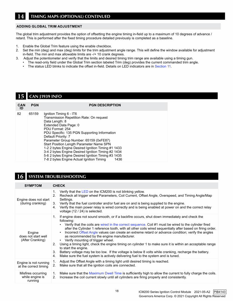
SYMPTOM CHECk
Engine does not start (during cranking)
1. Verify that the LED on the ICM200 is not blinking yellow.2. Recheck all trigger wheel Parameters, Coil Current, Offset Angle, Overspeed, and Timing Angle/Map
Settings.3. Verify that the fuel controller and/or fuel are on and is being supplied to the engine.4. Verify the main power relay is wired correctly and is being enabled at power on and the correct relay
voltage (12 / 24) is selected.
Engine does not start well(After Cranking)
1. If engine does not sound smooth, or if a backfire occurs, shut down immediately and check the following:• Verify that the coils are wired in the correct sequence. Coil #1 must be wired to the cylinder fired
after the Cylinder 1 reference tooth, with all other coils wired sequentially after based on firing order.• Incorrect Offset Angle values can create an extreme retard or advance condition; verify the angles
as recommended by the engine manufacturer.• Verify mounting of trigger wheel.
2. Using a timing light, check the engine timing on cylinder 1 to make sure it is within an acceptable range to start the engine.
3. Battery voltage may be too low. If the voltage is below 8 volts while cranking, recharge the battery.4. Make sure the fuel system is actively delivering fuel to the system and is tuned.
Engine is not running at the correct timing
1. Adjust the Offset Angle with a timing light until desired timing is reached.2. Make sure that all the ignition coils are connected.
Misfires occurring while engine is
running
1. Make sure that the Maximum Dwell Time is sufficiently high to allow the current to fully charge the coils.2. Increase the coil current slowly until all cylinders are firing properly and consistently.
16 SYSTEM TROUblESHOOTING
15 CAN J1939 INFO
CAN ID
PGN PGN DESCRIPTION
82 65159 Ignition Timing 6 - IT6Transmission Repetition Rate: On requestData Length: 8Extended Data Page: 0PDU Format: 254PDU Specific: 135 PGN Supporting InformationDefault Priority: 7Parameter Group Number: 65159 (0xFE87)Start Position Length Parameter Name SPN1-2 2 bytes Engine Desired Ignition Timing #1 14333-4 2 bytes Engine Desired Ignition Timing #2 14345-6 2 bytes Engine Desired Ignition Timing #3 14357-8 2 bytes Engine Actual Ignition Timing 1436
14 TIMING MAPS (OPTIONAl) CONTINUED
The global trim adjustment provides the option of offsetting the engine timing in-field up to a maximum of 10 degrees of advance / retard. This is performed after the fixed timing procedure detailed previously is completed as a baseline.
1. Enable the Global Trim feature using the enable checkbox.2. Set the min (deg) and max (deg) limits for the trim adjustment angle range. This will define the window available for adjustment
in-field. The min and max allowable limits are -/+ 10 crank degrees.3. Adjust the potentiometer and verify that the limits and desired timing trim range are available using a timing gun.
• The read-only field under the Global Trim section labeled Trim (deg) provides the current commanded trim angle.• The status LED blinks to indicate the offset in-field. Details on LED indicators are in Section 11.
ADDING GLOBAL TRIM ADJUSTMENT
19
Governors America Corp. © 2021 Copyright All Rights ReservedICM200 Series Ignition Control Module 2021-05-A2 PIB4143
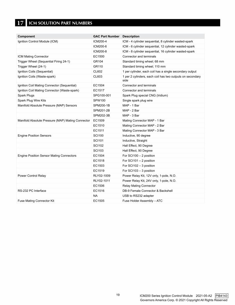
Component GAC Part Number DescriptionIgnition Control Module (ICM) ICM200-4 ICM - 4 cylinder sequential, 8 cylinder wasted-spark
ICM200-6 ICM - 6 cylinder sequential, 12 cylinder wasted-sparkICM200-8 ICM - 8 cylinder sequential, 16 cylinder wasted-spark
ICM Mating Connector EC1500 Connector and terminalsTrigger Wheel (Sequential Firing 24-1) GR104 Standard timing wheel; 68 mmTrigger Wheel (24-1) GR110 Standard timing wheel; 110 mmIgnition Coils (Sequential) CL602 1 per cylinder, each coil has a single secondary outputIgnition Coils (Waste-spark) CL603 1 per 2 cylinders, each coil has two outputs on secondary
sideIgnition Coil Mating Connector (Sequential) EC1504 Connector and terminalsIgnition Coil Mating Connector (Waste-spark) EC1517 Connector and terminalsSpark Plugs SPG100-001 Spark Plug special CNG (Iridium)Spark Plug Wire kits SPW100 Single spark plug wireManifold Absolute Pressure (MAP) Sensors SPM200-1B MAP - 1 Bar
SPM201-2B MAP - 2 BarSPM202-3B MAP - 3 Bar
Manifold Absolute Pressure (MAP) Mating Connector EC1509 Mating Connector MAP - 1 BarEC1510 Mating Connector MAP - 2 BarEC1511 Mating Connector MAP - 3 Bar
Engine Position Sensors SCI100 Inductive, 90 degreeSCI101 Inductive, StraightSCI102 Hall Effect, 90 DegreeSCI103 Hall Effect, 90 Degree
Engine Position Sensor Mating Connectors EC1504 For SCI100 – 2 positionEC1518 For SCI101 – 2 positionEC1503 For SCI102 – 3 positionEC1519 For SCI103 – 3 position
Power Control Relay RLY02-1009 Power Relay Kit, 12V only, 1-pole, N.O.RLY02-1011 Power Relay Kit, 24V only, 1-pole, N.O.EC1506 Relay Mating Connector
RS-232 PC Interface EC1516 DB-9 Female Connector & BackshellNA USB to RS232 adapter
Fuse Mating Connector kit EC1505 Fuse Holder Assembly – ATC
17 ICM SOlUTION PART NUMbERS