Embed Size (px)
Citation preview
VISVESVARAYA TECHNOLOGICAL UNIVERSITY BELAGAVI - 590018
KARNATAKA
A project report on
“KEYLESS IGNITION SYSTEM AND SMART RIDING”
submitted in partial fulfillment of the requirement for the award
of
BACHELOR OF ENGINEERING DEGREE in
ELECTRONICS AND COMMUNICATION ENGINEERING Submitted by
LOKESH.G 1NH12EC049 VISHAL.C.RAI 1NH13EC127 PRUTHVI RAJ A 1NH14EC418 BHARATH M 1NH14EC426
Under guidance of
Ms. APARNA
Senior Assistant Professor, ECE, NHCE

DEPARTMENT OF ELECTRONICS AND COMMUNICATION ENGINEERING
CERTIFICATE
2017-18
This is to certify that the project work entitled “KEYLESS IGNITION SYSTEM AND SMART
RIDING” carried out by Mr. LOKESH.G, Mr. VISHAL.C.RAI, Mr. PRUTHVI RAJ A and
Mr. BHARATH M bearing 1NH12EC049,1NH13EC127,1NH14EC418 and 1NH14EC426
bonafide student of New Horizon College of Engineering, Bengaluru in partial fulfillment for the
award of Bachelors of Engineering in Electronics & Communication Engineering of the
Visvesvaraya Technological University, Belagavi during the year 2017-18. It is certified that all
corrections/suggestions indicated for Internal Assessment have been incorporated in the Report
deposited in the departmental library. The project report has been approved as it satisfies the
academic requirements in respect of Project Work prescribed for the said degree.
…………………………..
Signature of the Guide
………………………….. Signature of the HOD
…………………………………
Signature of the Principal
(Ms. Aparna) (Prof.Aravinda K)
(Dr. Manjunatha)
External Viva
Name of the Examiners Signature with date
1………………………… …………………………….
2………………………… …………………………….

i
ACKNOWLEDGEMENT
It is our proud privilege and duty to acknowledge the kind of help and guidance received
from several people in preparation of this report. It would not have been possible to prepare
this report in this form without their valuable help, cooperation and guidance.
First and foremost, we wish to record our sincere gratitude to Management of New
Horizon College of Engineering, Chairman, Mohan Manganani and to our beloved
Principal, Dr. Manjunatha, New Horizon College of Engineering, Bangalore for his
constant support and encouragement in preparation of this report and for making available
library and laboratory facilities needed to prepare this report.
Our sincere thanks to Prof. Aravinda.K, Head, Department of Electronics and
Communication Engineering, NHCE, for his valuable suggestions and guidance throughout
the period of this report.
The project on “KEYLESS IGNITION SYSTEM AND SMART RIDING” was very
helpful to us in giving the necessary background information and inspiration in choosing
this topic for the project. Our sincere thanks to Professor Aparna, Project Guide and
Professor Divya Sharma, Project Coordinator for having supported the work related to
this project. Their contributions and technical support in preparing this report are greatly
acknowledged.
Last but not the least, we wish to thank our parents for financing our studies in this college
as well as for constantly encouraging us to learn engineering. Their personal sacrifice in
providing this opportunity to learn engineering is gratefully acknowledged.

ii
ABSTRACT The paper proposes a Smart Riding; the main advantage of this system is that it can provide
ease of access and can also prevent road accidents to a great extent. The bike riders in our
country are increasing day by day and the traffic rule followers are outnumbered. The driver
can start the bike without any key just by walking next to the bike, the driver should have RF
transmitter with him which is detected by the RF receiver in the bike and the second module
consists of smart helmet. The module in the helmet consists of IR Module which finds out if
the driver is wearing the helmet. If the driver is not wearing the helmet the engine will not start.
If the driver tries to remove the helmet and ride the bike fails to start. The helmet circuit is
connected to bike using RF module. If someone tries to disrupt the vehicle trying to steal or
damage the vehicle the gsm module will send a message to the owner
iii
Table of Contents INTRODUCTION ............................................................................................................... 6
LITERATURE SURVEY ................................................................................................... 8
2.1Accident and its Impact on Humans .............................................................................. 8
2.2Accident Prevention Techniques suggested so far ......................................................... 8
RF MODULE .................................................................................................................... 10
3.1 Description ................................................................................................................ 10
3.2 HT12D DECODER ................................................................................................... 15
3.3 HT12E ENCODER ................................................................................................... 17
3.4 RF modules (434mhz) ............................................................................................... 19
3.5 PIN DIAGRAM ........................................................................................................ 20
3.6 Features of RF Module: ............................................................................................. 20
BLOCK DIAGRAM ......................................................................................................... 21
TRANSMITTER PROGRAM.......................................................................................... 22
RECEIVER PROGRAM .................................................................................................. 23
GSM INTERFACE ........................................................................................................... 26
7.1 Use SIM900 GSM Module ........................................................................................ 27
7.2 Check the power requirements of GSM module ......................................................... 28
7.3 Check for TTL Output Pins in the module ................................................................. 28
7.4 Connecting GSM Module to 8052: ............................................................................ 29
7.5 Features: .................................................................................................................... 31
LI FI ................................................................................................................................... 33
8.1 HISTORY ................................................................................................................. 33
8.2 HOW IT WORKS ..................................................................................................... 34
8.3 Li-Fi vs Wi-Fi ........................................................................................................... 35
8.4 The future of Li-Fi: .................................................................................................... 36
iv
8.5 APPLICATIONS ...................................................................................................... 37
INTELLIGENT HELMET ............................................................................................... 39
9.1 Abstract : ................................................................................................................... 39
9.2 Smart Helmet for Indian Bike Rider : ........................................................................ 39
9.3 Principle Of Operation:.............................................................................................. 39
9.4 Smart helmet Using GSM & GPS Technology for Accident Detection and Reporting
System: ........................................................................................................................... 40
COMPONENTS USED ..................................................................................................... 43
CONCLUSION ................................................................................................................. 44
REFERENCES .................................................................................................................. 45
v
LIST OF FIGURE
FIG NO. TITLE PAGE NO.
1.1 Road Accidents Statistics by “WHO” 7
1.2 Statistics of Accidents 8
3.1 RF Module Transmission 12
3.2 Encoder Module 13
3.3 Decoder Module 14
3.4 Circuit Diagram of Transmitter and Receiver 15
3.5 Pin Diagram of HT12D Decoder 16
3.6 Pin Diagram of HT12E Encoder 18
3.7 RF Module 20
3.8 Pin diagram of RF Module 21
7.1 Shows SIM 900 Module 29
7.2 GSM Module 30
7.3 Connections from 8052 To GSM 32
7.4 Shows Top View of GSM 33
7.5 Shows Pin Sheet 33
8.1 LIFI Vs WIFI 38
8.2 Lifi Transmission 39
9.1 Shows Brightness Detection by Ir Sensors 42
9.2 Module of Helmet 44

KEYLESS IGNITION SYSTEM AND SMART RIDING
Department of ECE, NHCE Page | 6
CHAPTER 1
INTRODUCTION Drowsy driving is one of the major causes behind fatal road accidents. Recent studies show
that one out of five road accidents are caused by drowsy driving which is roughly around 21%
of road accidents, and this percentage is increasing every year as per Global Status Report on
Road Safety 2015, based on the data from 180 different countries. This certainly highlights the
fact that across the world the total numbers of road traffic deaths are very high due to driver’s
drowsiness. Driver fatigue, drink-and-drive and carelessness are coming forward as major
reasons behind such road accidents. Many lives and families are getting affected due to this
across various countries. The total number of road accidents are the world is shown in fig
Fig 1.1 Road Accidents Statistics by “WHO”
KEYLESS IGNITION SYSTEM AND SMART RIDING
Department of ECE, NHCE Page | 7
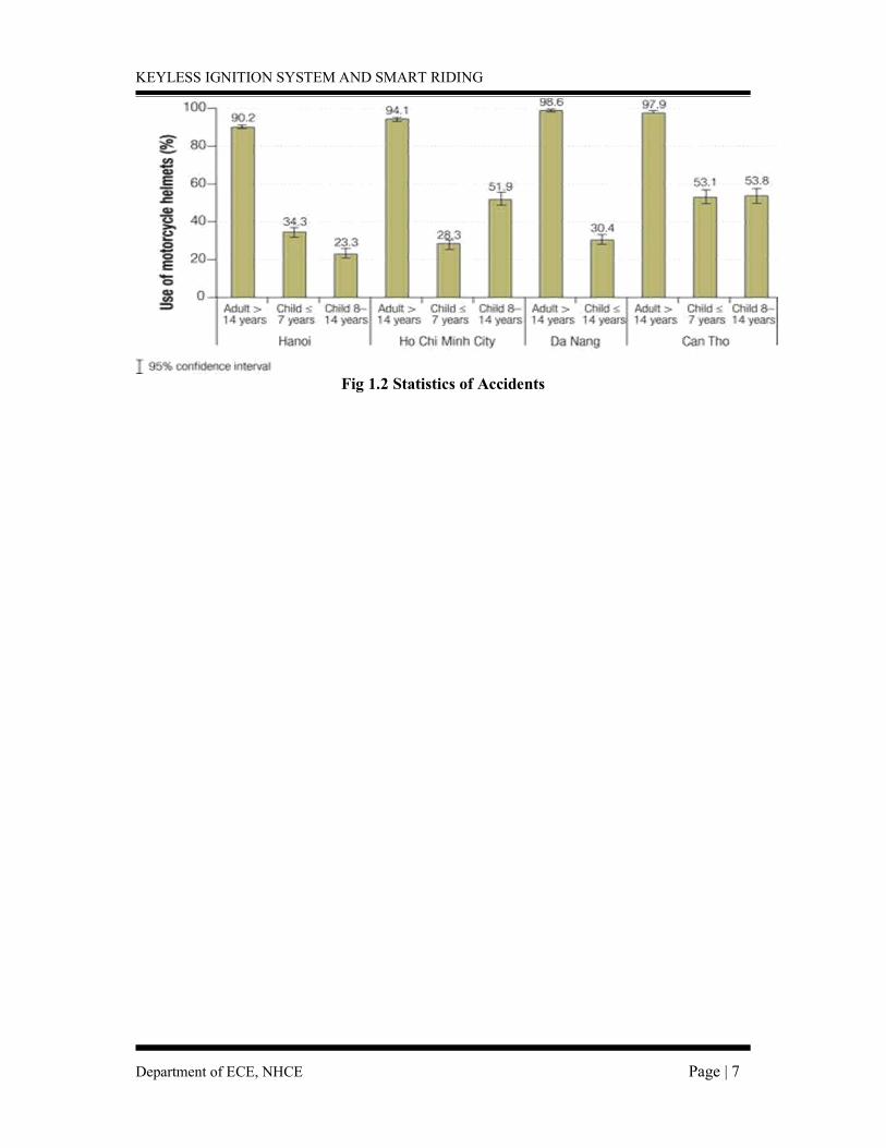
Fig 1.2 Statistics of Accidents
KEYLESS IGNITION SYSTEM AND SMART RIDING
Department of ECE, NHCE Page | 8
CHAPTER 2
LITERATURE SURVEY
2.1Accident and its Impact on Humans
In general, an unplanned, unexpected, and undersigned (not purposefully caused) event
which occurs suddenly and causes (1) injury or loss, (2) a decrease in value of the resources,
or (3) an increase in liabilities. As a technical term 'accident' does not have a clearly defined
legal meaning. In insurance terminology, an accident is the event which is not deliberately
caused, and which is not inevitable.
Drowsiness is one of the main reasons for accidents. Safe driving is a major concern of
societies all over the world. Thousands of people are killed or seriously injured due to drivers
falling asleep at the wheels each year.
Being involved in a serious car accident can cause you to deal with injuries that could
have a major impact on your day-to-day life. Additionally, it is important to recognize the fact
that a traumatic experience such as a car accident can also cause you to deal with several
emotional problems. After all, it is understandable that someone who was seriously injured in
a traffic incident that was not their fault could end up dealing with a high level of anxiety the
next time they get behind the wheel.
2.2Accident Prevention Techniques suggested so far
In 2008, Hong Su described ‘A Partial Least Squares Regression-Based Fusion Model
for Predicting the Trend in Drowsiness’. They proposed a new technique of modeling driver
drowsiness with multiple eyelid movement features based on an information fusion technique-
Partial Least Squares Regression (PLSR), with which to cope with the problem of strong
collinear relations among eyelid movement features and, thus, predicting the tendency of the
drowsiness. The predictive precision and robustness of the model thus established are
validated, which show that it provides a novel way of fusing multi-features together for
enhancing our capability of detecting and predicting the state of drowsiness
KEYLESS IGNITION SYSTEM AND SMART RIDING
Department of ECE, NHCE Page | 9
. In 2011, M.J. Flores described ‘Driver drowsiness detection system under infrared
illumination for an intelligent vehicle’. They proposed that to reduce the amount of such
fatalities, a module for an advanced driver assistance system, which caters for automatic
driver drowsiness detection and also driver distraction, is presented. Artificial intelligence
algorithms are used to process the visual information in order to locate, track and analyze
both the driver’s face and eyes to compute the drowsiness and distraction indexes. This real-
time system works during nocturnal conditions as a result of a near-infrared lighting system.
Finally, examples of different driver images taken in a real vehicle at nighttime are shown to
validate the proposed algorithms.
In June, 2012, A. Cheng described 'Driver Drowsiness Recognition Based on Computer
Vision Technology’. They presented a nonintrusive drowsiness recognition method using eye-
tracking and image processing. A robust eye detection algorithm is introduced to address the
problems caused by changes in illumination and driver posture. Six measures are calculated
with percentage of eyelid closure, maximum closure duration, blink frequency, average
opening level of the eyes, opening velocity of the eyes, and closing velocity of the eyes. These
measures are combined using Fisher’s linear discriminated functions using a stepwise method
to reduce the correlations and extract an independent index. Results with six participants in
driving simulator experiments demonstrate the feasibility of this video-based drowsiness
recognition method that provided 86% accuracy.
In 2013, G. Kong described ‘Visual Analysis of Eye State and Head Pose for Driver
Alertness Monitoring’. They presented visual analysis of eye state and head pose (HP) for
continuous monitoring of alertness of a vehicle driver. Most existing approaches to visual
detection of non-alert driving patterns rely either on eye closure or head nodding angles to
determine the driver drowsiness or distraction level. The proposed scheme uses visual features
such as eye index (EI), pupil activity (PA), and HP to extract critical information on non-
alertness of a vehicle driver. A support vector machine (SVM) classifies a sequence of video
segments into alert or non-alert driving events. Experimental results show that the proposed
scheme offers high classification accuracy with acceptably low errors and false alarms for
people of various ethnicity and gender in real road driving condition
KEYLESS IGNITION SYSTEM AND SMART RIDING
Department of ECE, NHCE Page | 10
CHAPTER 3
RF MODULE
This circuit utilizes the RF module (TX/RX) for making a wireless remote, which could
be used to drive an output from a distant place. RF module, as the name suggests, uses radio
frequency to send signals. These signals are transmitted at a particular frequency and a baud
rate. A receiver can receive these signals only if it is configured for that frequency.
A four channel encoder/decoder pair has also been used in this system. The input
signals, at the transmitter side, are taken through four switches while the outputs are monitored
on a set of four LEDs corresponding to each input switch. The circuit can be used for designing
Remote Appliance Control system. The outputs from the receiver can drive corresponding
relays connected to any household appliance. 3.1 Description
This radio frequency (RF) transmission system employs Amplitude Shift Keying
(ASK) with transmitter/receiver (TX/RX) pair operating at 434 MHz. The transmitter
module takes serial input and transmits these signals through RF. The transmitted signals
are received by the receiver module placed away from the source of transmission.
The system allows one-way communication between two nodes, namely, transmission
and reception. The RF module has been used in conjunction with a set of four channel
encoder/decoder ICs. Here HT12E & HT12D have been used as encoder and decoder
respectively. The encoder converts the parallel inputs (from the remote switches) into serial set
of signals. These signals are serially transferred through RF to the reception point. The decoder
is used after the RF receiver to decode the serial format and retrieve the original signals as
outputs. These outputs can be observed on corresponding LEDs
KEYLESS IGNITION SYSTEM AND SMART RIDING
Department of ECE, NHCE Page | 11
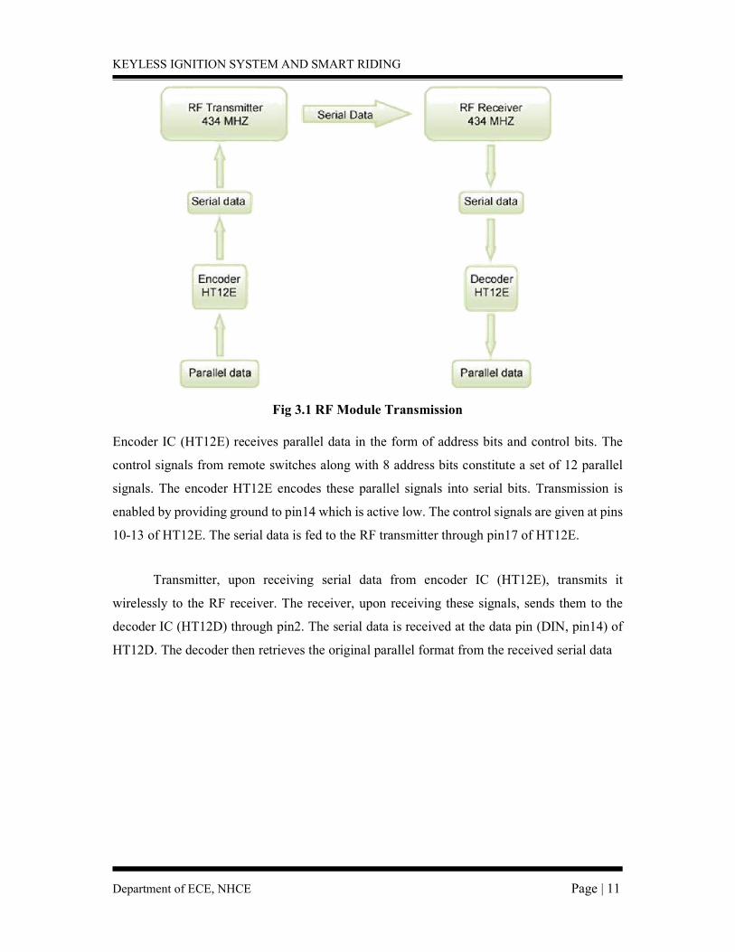
Fig 3.1 RF Module Transmission Encoder IC (HT12E) receives parallel data in the form of address bits and control bits. The
control signals from remote switches along with 8 address bits constitute a set of 12 parallel
signals. The encoder HT12E encodes these parallel signals into serial bits. Transmission is
enabled by providing ground to pin14 which is active low. The control signals are given at pins
10-13 of HT12E. The serial data is fed to the RF transmitter through pin17 of HT12E.
Transmitter, upon receiving serial data from encoder IC (HT12E), transmits it
wirelessly to the RF receiver. The receiver, upon receiving these signals, sends them to the
decoder IC (HT12D) through pin2. The serial data is received at the data pin (DIN, pin14) of
HT12D. The decoder then retrieves the original parallel format from the received serial data
KEYLESS IGNITION SYSTEM AND SMART RIDING
Department of ECE, NHCE Page | 12
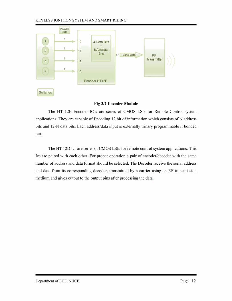
Fig 3.2 Encoder Module
The HT 12E Encoder IC’s are series of CMOS LSIs for Remote Control system
applications. They are capable of Encoding 12 bit of information which consists of N address
bits and 12-N data bits. Each address/data input is externally trinary programmable if bonded
out.
The HT 12D Ics are series of CMOS LSIs for remote control system applications. This
Ics are paired with each other. For proper operation a pair of encoder/decoder with the same
number of address and data format should be selected. The Decoder receive the serial address
and data from its corresponding decoder, transmitted by a carrier using an RF transmission
medium and gives output to the output pins after processing the data.
KEYLESS IGNITION SYSTEM AND SMART RIDING
Department of ECE, NHCE Page | 13
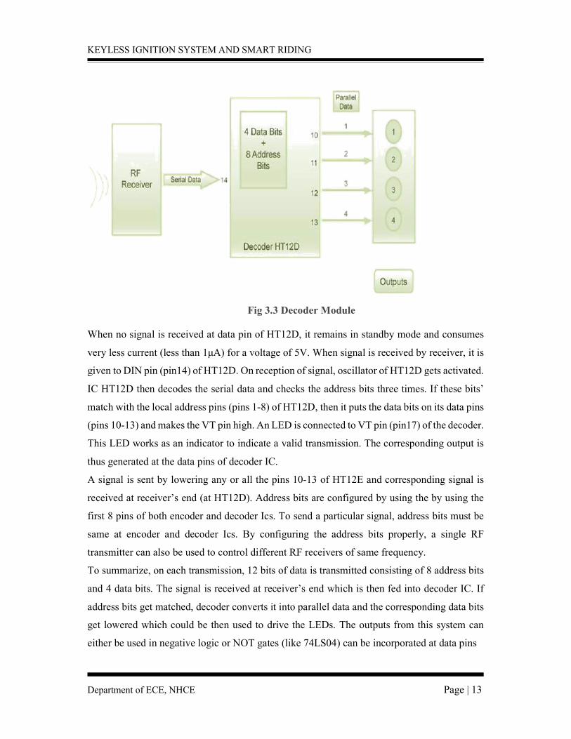
Fig 3.3 Decoder Module
When no signal is received at data pin of HT12D, it remains in standby mode and consumes
very less current (less than 1μA) for a voltage of 5V. When signal is received by receiver, it is
given to DIN pin (pin14) of HT12D. On reception of signal, oscillator of HT12D gets activated.
IC HT12D then decodes the serial data and checks the address bits three times. If these bits’
match with the local address pins (pins 1-8) of HT12D, then it puts the data bits on its data pins
(pins 10-13) and makes the VT pin high. An LED is connected to VT pin (pin17) of the decoder.
This LED works as an indicator to indicate a valid transmission. The corresponding output is
thus generated at the data pins of decoder IC.
A signal is sent by lowering any or all the pins 10-13 of HT12E and corresponding signal is
received at receiver’s end (at HT12D). Address bits are configured by using the by using the
first 8 pins of both encoder and decoder Ics. To send a particular signal, address bits must be
same at encoder and decoder Ics. By configuring the address bits properly, a single RF
transmitter can also be used to control different RF receivers of same frequency.
To summarize, on each transmission, 12 bits of data is transmitted consisting of 8 address bits
and 4 data bits. The signal is received at receiver’s end which is then fed into decoder IC. If
address bits get matched, decoder converts it into parallel data and the corresponding data bits
get lowered which could be then used to drive the LEDs. The outputs from this system can
either be used in negative logic or NOT gates (like 74LS04) can be incorporated at data pins
KEYLESS IGNITION SYSTEM AND SMART RIDING
Department of ECE, NHCE Page | 14
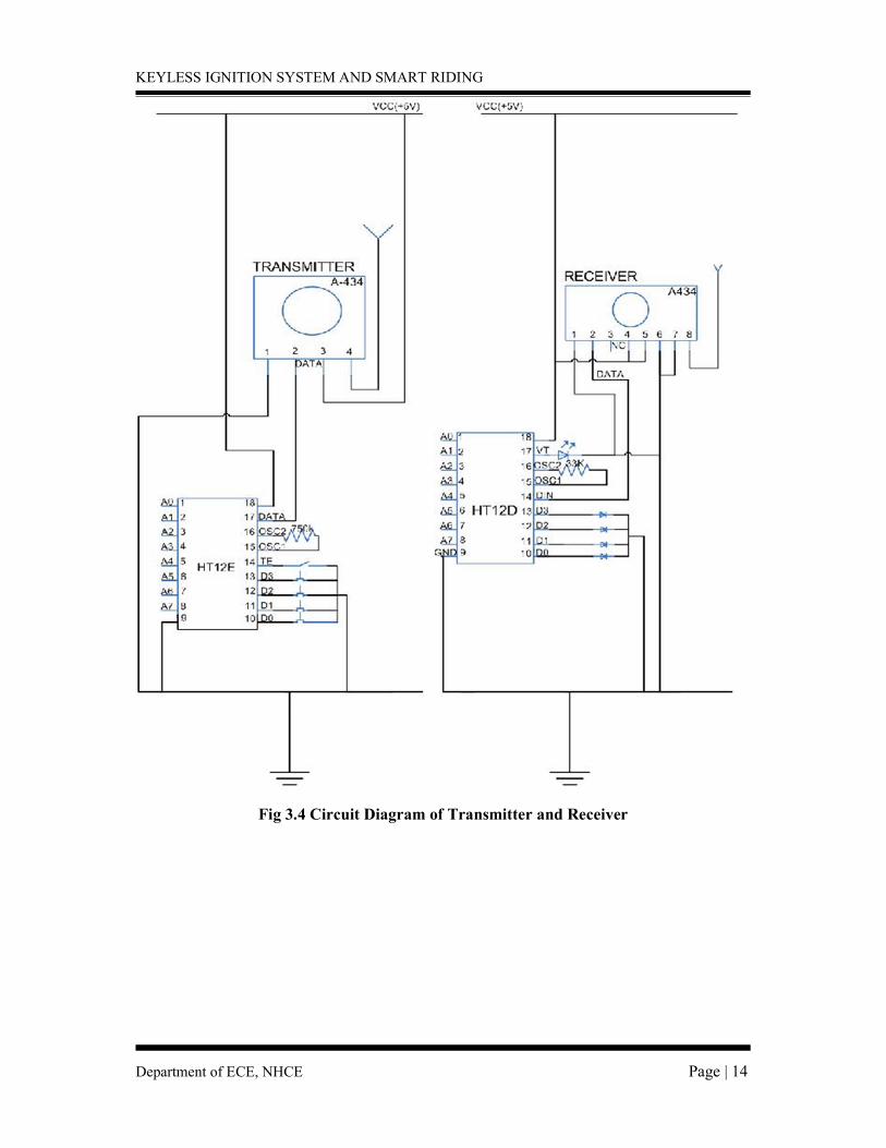
Fig 3.4 Circuit Diagram of Transmitter and Receiver
KEYLESS IGNITION SYSTEM AND SMART RIDING
Department of ECE, NHCE Page | 15
3.2 HT12D DECODER
HT12D IC comes from HolTek Company. HT12D is a decoder integrated circuit that
belongs to 212 series of decoders. This series of decoders are mainly used for remote control
system applications, like burglar alarm, car door controller, security system etc. It is mainly
provided to interface RF and infrared circuits. They are paired with 212 series of encoders.
The chosen pair of encoder/decoder should have same number of addresses and data format.
In simple terms, HT12D converts the serial input into parallel outputs. It decodes the serial
addresses and data received by, say, an RF receiver, into parallel data and sends them to
output data pins. The serial input data is compared with the local addresses three times
continuously. The input data code is decoded when no error or unmatched codes are found. A
valid transmission in indicated by a high signal at VT pin. HT12D is capable of decoding 12
bits, of which 8 are address bits and 4 are data bits. The data on 4-bit latch type output pins
remain unchanged until new is received.
Fig 3.5 Pin diagram of HT12D Decoder
KEYLESS IGNITION SYSTEM AND SMART RIDING
Department of ECE, NHCE Page | 16
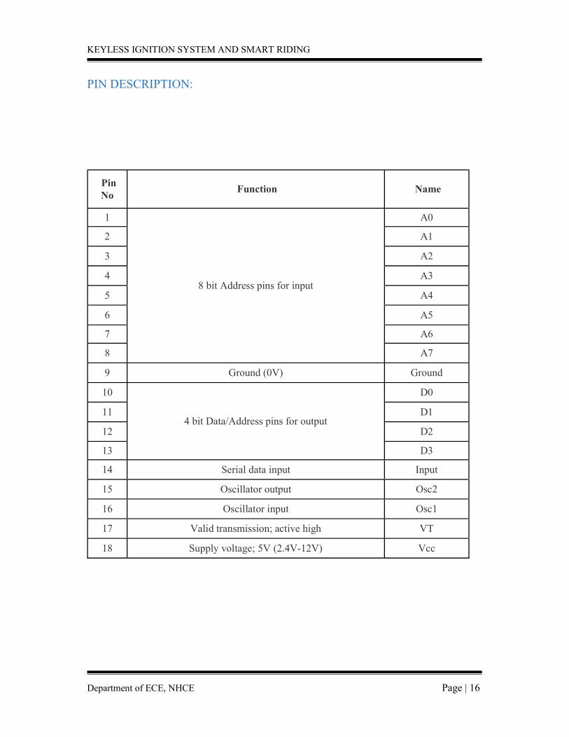
PIN DESCRIPTION:
Pin No
Function Name
1
8 bit Address pins for input
A0
2 A1
3 A2
4 A3
5 A4
6 A5
7 A6
8 A7
9 Ground (0V) Ground
10
4 bit Data/Address pins for output
D0
11 D1
12 D2
13 D3
14 Serial data input Input
15 Oscillator output Osc2
16 Oscillator input Osc1
17 Valid transmission; active high VT
18 Supply voltage; 5V (2.4V-12V) Vcc
KEYLESS IGNITION SYSTEM AND SMART RIDING
Department of ECE, NHCE Page | 17
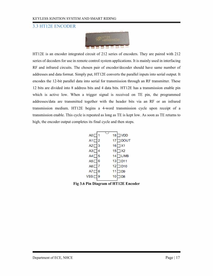
3.3 HT12E ENCODER
HT12E is an encoder integrated circuit of 212 series of encoders. They are paired with 212
series of decoders for use in remote control system applications. It is mainly used in interfacing
RF and infrared circuits. The chosen pair of encoder/decoder should have same number of
addresses and data format. Simply put, HT12E converts the parallel inputs into serial output. It
encodes the 12-bit parallel data into serial for transmission through an RF transmitter. These
12 bits are divided into 8 address bits and 4 data bits. HT12E has a transmission enable pin
which is active low. When a trigger signal is received on TE pin, the programmed
addresses/data are transmitted together with the header bits via an RF or an infrared
transmission medium. HT12E begins a 4-word transmission cycle upon receipt of a
transmission enable. This cycle is repeated as long as TE is kept low. As soon as TE returns to
high, the encoder output completes its final cycle and then stops.
Fig 3.6 Pin Diagram of HT12E Encoder
KEYLESS IGNITION SYSTEM AND SMART RIDING
Department of ECE, NHCE Page | 18
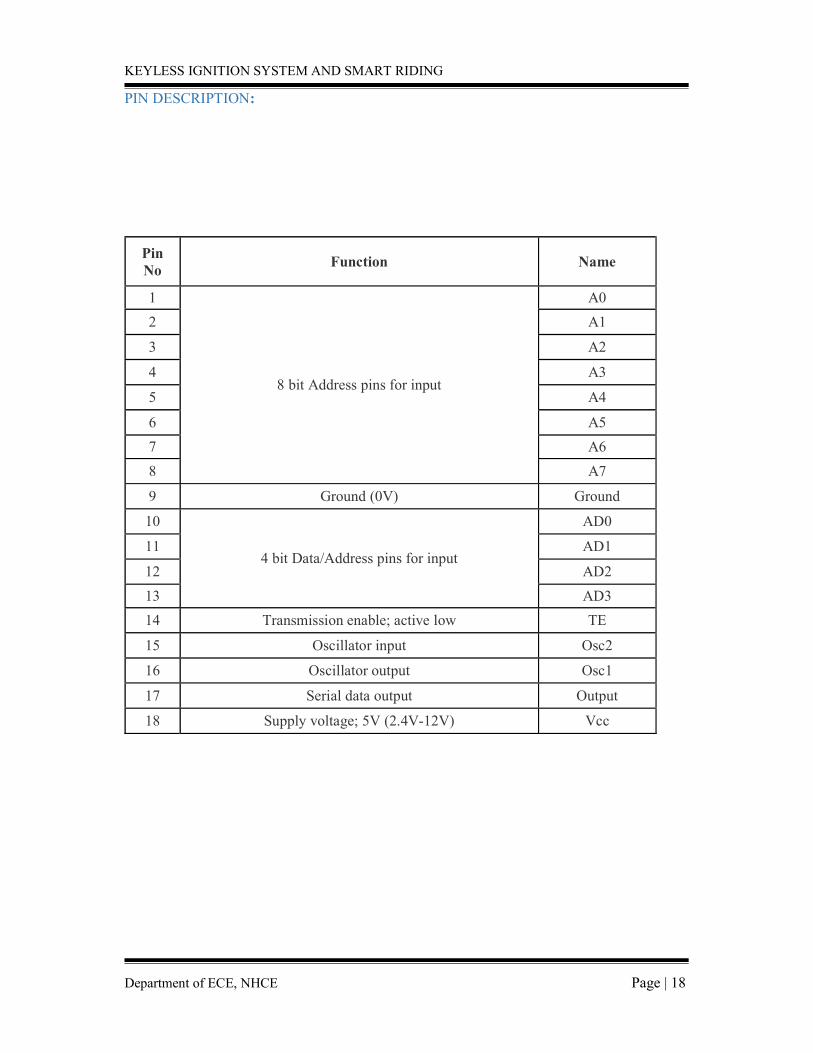
PIN DESCRIPTION:
Pin No
Function Name
1
8 bit Address pins for input
A0
2 A1
3 A2
4 A3
5 A4
6 A5
7 A6
8 A7
9 Ground (0V) Ground
10
4 bit Data/Address pins for input
AD0
11 AD1
12 AD2
13 AD3
14 Transmission enable; active low TE
15 Oscillator input Osc2
16 Oscillator output Osc1
17 Serial data output Output
18 Supply voltage; 5V (2.4V-12V) Vcc
KEYLESS IGNITION SYSTEM AND SMART RIDING
Department of ECE, NHCE Page | 19
3.4 RF modules (434mhz)
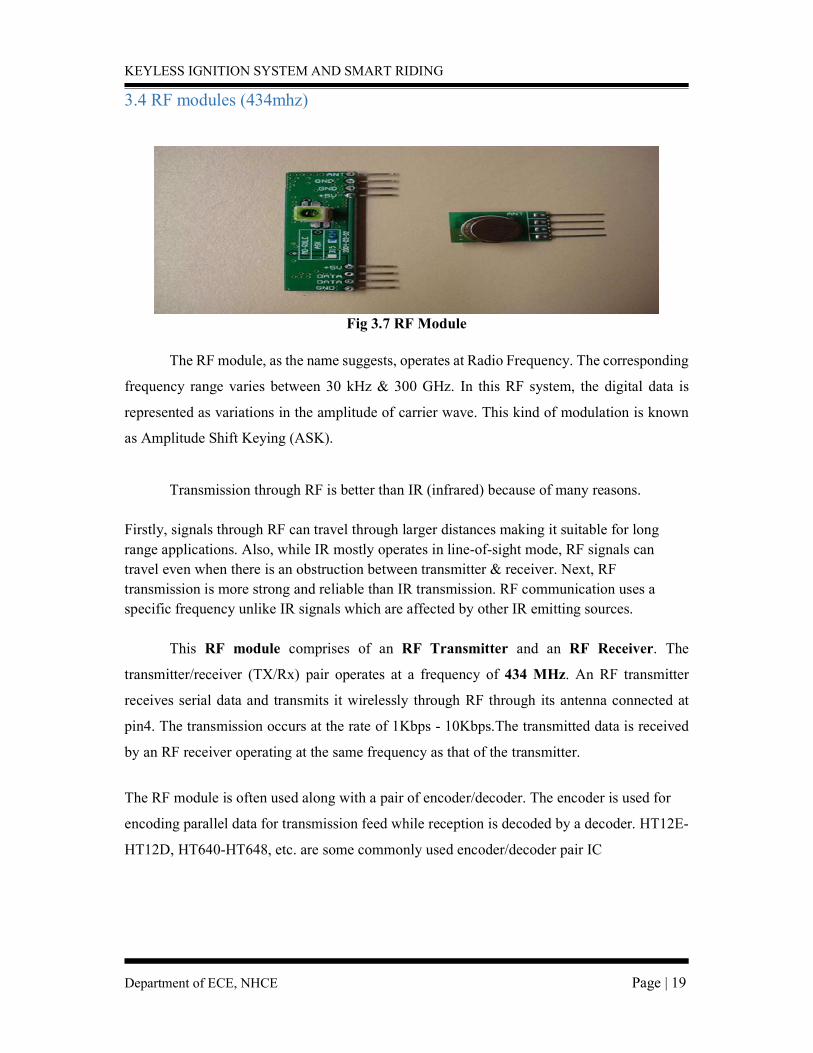
Fig 3.7 RF Module
The RF module, as the name suggests, operates at Radio Frequency. The corresponding
frequency range varies between 30 kHz & 300 GHz. In this RF system, the digital data is
represented as variations in the amplitude of carrier wave. This kind of modulation is known
as Amplitude Shift Keying (ASK).
Transmission through RF is better than IR (infrared) because of many reasons. Firstly, signals through RF can travel through larger distances making it suitable for long range applications. Also, while IR mostly operates in line-of-sight mode, RF signals can travel even when there is an obstruction between transmitter & receiver. Next, RF transmission is more strong and reliable than IR transmission. RF communication uses a specific frequency unlike IR signals which are affected by other IR emitting sources.
This RF module comprises of an RF Transmitter and an RF Receiver. The
transmitter/receiver (TX/Rx) pair operates at a frequency of 434 MHz. An RF transmitter
receives serial data and transmits it wirelessly through RF through its antenna connected at
pin4. The transmission occurs at the rate of 1Kbps - 10Kbps.The transmitted data is received
by an RF receiver operating at the same frequency as that of the transmitter.
The RF module is often used along with a pair of encoder/decoder. The encoder is used for
encoding parallel data for transmission feed while reception is decoded by a decoder. HT12E-
HT12D, HT640-HT648, etc. are some commonly used encoder/decoder pair IC
KEYLESS IGNITION SYSTEM AND SMART RIDING
Department of ECE, NHCE Page | 20
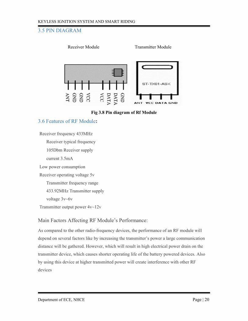
3.5 PIN DIAGRAM
Receiver Module Transmitter Module
Fig 3.8 Pin diagram of Rf Module
3.6 Features of RF Module: Receiver frequency 433MHz
Receiver typical frequency
105Dbm Receiver supply
current 3.5mA Low power consumption
Receiver operating voltage 5v
Transmitter frequency range
433.92MHz Transmitter supply
voltage 3v~6v Transmitter output power 4v~12v
Main Factors Affecting RF Module’s Performance: As compared to the other radio-frequency devices, the performance of an RF module will
depend on several factors like by increasing the transmitter’s power a large communication
distance will be gathered. However, which will result in high electrical power drain on the
transmitter device, which causes shorter operating life of the battery powered devices. Also
by using this device at higher transmitted power will create interference with other RF
devices
KEYLESS IGNITION SYSTEM AND SMART RIDING
Department of ECE, NHCE Page | 21
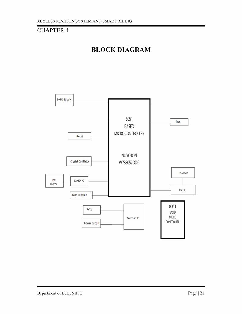
CHAPTER 4
BLOCK DIAGRAM

KEYLESS IGNITION SYSTEM AND SMART RIDING
Department of ECE, NHCE Page | 22
CHAPTER 5
TRANSMITTER PROGRAM
#include<reg51.h> sbit data1=P1^0; sbit data2=P1^1; sbit data3=P1^2; sbit data4=P1^3;
void delay (unsigned int);
void main () { data1=1; data1=0; data1=1; data1=0;
delay (100); data1=0; data1=1; data1=0; data1=1; delay (100); } void delay (unsigned int d) { unsigned int k; for (d; d>0; d--);
{
for (k=255; k>0; k--);
for (k=255; k>0; k--);}}

KEYLESS IGNITION SYSTEM AND SMART RIDING
Department of ECE, NHCE Page | 23
CHAPTER 6
RECEIVER PROGRAM #include<reg51.h> sbit data0=P1^0; sbit data1=P1^1; sbit data2=P1^2; sbit data3=P1^3; sbit led= P1^4; sbit ir=P1^5; sbit led1=P1^6; sbit m1=P2^4; sbit m2=P2^5; sbit m3=P2^6; sbit m4=P2^7; sbit gsm=P2^3;//GND CONNECT TO P2^3 MSG WILL BE SEND
void delay1(unsigned int msec) // Function for delay {
int i,j;
for(i=0;i<msec;i++)
} for(j=0; j<1275; j++);
void delay(unsigned char);
void init_serial() // Initialize serial port {
TMOD=0x20;
// Mode2 TH1=0xfd; // 9600 baud SCON=0x50; // Serial mode=1 ,8-Bit data,1 Stop bit ,1 Start bit, Receiving on
} TR1=1; // Start timer
void transmit_data(unsigned char str) // Function to transmit data through serial port {
SBUF=str;
//Store data in SBUF while(TI==0); //Wait till data transmits
// delay(15); TI=0;
KEYLESS IGNITION SYSTEM AND SMART RIDING
Department of ECE, NHCE Page | 24
} void transString (char *x) { unsigned char ch; while (*x! =0) { ch =*x; transmit_data(ch); delay1(1); x++; } } char number[]="9535245791"; void main() { m1=0; m2=0; m3=0; m4=0; if(data0==1&&data1==0&&data2==1&&data3==0) { led=0; if(ir==0) { led1=0; m1=0; m2=1; m3=0; m4=1; delay(100); m1=0; m2=0; m3=0; m4=0; delay(100); } } else { led=1; if(gsm==0) {
KEYLESS IGNITION SYSTEM AND SMART RIDING
Department of ECE, NHCE Page | 25
{ init_serial();
delay1(500); transmit_data('A'); // Transmit 'A' to serial port
delay1(1);
transmit_data('T'); // Transmit 'T' to serial port
delay1(1); transmit_data(0x0d);
// Transmit carriage return to serial port
delay1(50); transString("AT+CMGF=1"); transmit_data(0x0d); delay1(50);
transString("AT+CMGS=\""); transString(number); transmit_data('\"'); transmit_data(';'); delay1(1); transmit_data(0x0d); delay1(1); transString("THIEF DETECTION"); delay1(1); transmit_data(0x1A); transmit_data(0x0d); delay(1); } } } void delay(unsigned char i) { unsigned int d; for(i;i>0;i--) { for(d=1;d;d++); for(d=1;d;d++);
KEYLESS IGNITION SYSTEM AND SMART RIDING
Department of ECE, NHCE Page | 26
CHAPTER 7
GSM INTERFACE In this article, we are going to see how to interface GSM Module to 8052. There are different
kinds of GSM modules available in market. We are using the most popular module based on
Simcom SIM900 and 8051.Interfacing a GSM module to 8052 is pretty simple. You only need
to make 3 connections between the gsm module and 8052.
A GSM Module is basically a GSM Modem (like SIM 900) connected to a PCB with
different types of output taken from the board – say TTL Output (for Arduino, 8051 and other
microcontrollers) and RS232 Output to interface directly with a PC (personal computer). The
board will also have pins or provisions to attach mic and speaker, to take out +5V or other
values of power and ground connections. These type of provisions vary with different modules.
Lots of varieties of GSM modem and GSM Modules are available in the market to
choose from. For our project of connecting a gsm modem or module to 8052 and hence send
and receive sms using 8052 – it’s always good to choose an 8052 compatible GSM Module –
that is a GSM module with TTL Output provisions.
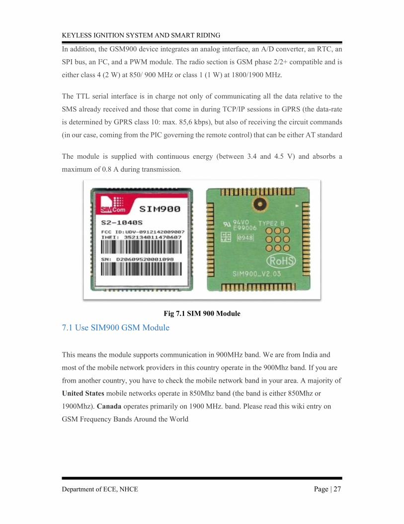
This is a GSM/GPRS-compatible Quad-band cell phone, which works on a frequency
of 850/900/1800/1900MHz and which can be used not only to access the Internet, but also for
oral communication (provided that it is connected to a microphone and a small loud speaker)
and for SMSs. Externally, it looks like a big package (0.94 inches’ x 0.94 inches’ x 0.12 inches)
with L-shaped contacts on four sides so that they can be soldered both on the side and at the
bottom. Internally, the module is managed by an AMR926EJ-S processor, which controls
phone communication, data communication (through an integrated TCP/IP stack), and (through
an UART and a TTL serial interface) the communication with the circuit interfaced with the
cell -phone.
KEYLESS IGNITION SYSTEM AND SMART RIDING
Department of ECE, NHCE Page | 27
In addition, the GSM900 device integrates an analog interface, an A/D converter, an RTC, an
SPI bus, an I²C, and a PWM module. The radio section is GSM phase 2/2+ compatible and is
either class 4 (2 W) at 850/ 900 MHz or class 1 (1 W) at 1800/1900 MHz.
The TTL serial interface is in charge not only of communicating all the data relative to the
SMS already received and those that come in during TCP/IP sessions in GPRS (the data-rate
is determined by GPRS class 10: max. 85,6 kbps), but also of receiving the circuit commands
(in our case, coming from the PIC governing the remote control) that can be either AT standard
The module is supplied with continuous energy (between 3.4 and 4.5 V) and absorbs a
maximum of 0.8 A during transmission.
Fig 7.1 SIM 900 Module
7.1 Use SIM900 GSM Module
This means the module supports communication in 900MHz band. We are from India and
most of the mobile network providers in this country operate in the 900Mhz band. If you are
from another country, you have to check the mobile network band in your area. A majority of
United States mobile networks operate in 850Mhz band (the band is either 850Mhz or
1900Mhz). Canada operates primarily on 1900 MHz. band. Please read this wiki entry on
GSM Frequency Bands Around the World
KEYLESS IGNITION SYSTEM AND SMART RIDING
Department of ECE, NHCE Page | 28
7.2 Check the power requirements of GSM module
GSM modules are manufactured by different companies. They all have different input power
supply specs. You need to double check your GSM modules power requirements. In this
tutorial, our gsm module requires a 12 volts input. So we feed it using a 12V,1A DC power
supply. I have seen gsm modules which require 15 volts and some other types which needs
only 5 volts input. They differ with manufacturers. If you are having a 5V module, you can
power it directly from 8052’s 5V out. Note: - GSM Modules are manufactured by connecting a particular GSM modem to a PCB and
then giving provisions for RS232 outputs, TTL outputs, Mic and Speaker interfacing provisions
etc. The most popular modem under use is SIM 900 gsm modem from manufacturer SIMCom.
They also manufacture GSM Modems in bands 850, 300 and other frequency bands.
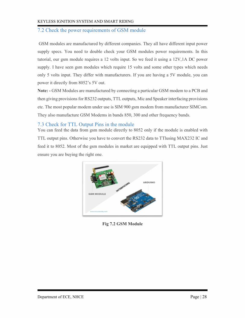
7.3 Check for TTL Output Pins in the module You can feed the data from gsm module directly to 8052 only if the module is enabled with
TTL output pins. Otherwise you have to convert the RS232 data to TTlusing MAX232 IC and
feed it to 8052. Most of the gsm modules in market are equipped with TTL output pins. Just
ensure you are buying the right one.
Fig 7.2 GSM Module

KEYLESS IGNITION SYSTEM AND SMART RIDING
Department of ECE, NHCE Page | 29
7.4 Connecting GSM Module to 8052:
There are two ways of connecting GSM module to 8052. In any case, the
communication between 8052 and GSM module is serial. So we are supposed to use serial pins
of 8052 (Rx and TX). So if you are going with this method, you may connect the TX pin of
GSM module to Rx pin of 8052 and Rx pin of GSM module to TX pin of 8052. You read it
right? GSM TX –>8052 Rx and GSM Rx –>8052Tx. Now connect the ground pin of 8052 to
ground pin of gsm module! So that’s all! You made 3 connections and the wiring is over! Now
you can load different programs to communicate with gsm module and make it work.
NOTE: The problem with this connection is that, while programming 8052 uses serial ports to
load program from the 8052 IDE. If these pins are used in wiring, the program will not be
loaded successfully to 8052. So you have to disconnect wiring in Rx and TX each time you
burn the program to 8052. Once the program is loaded successfully, you can reconnect these
pins and have the system working!
To avoid this difficulty, I am using an alternate method in which two digital pins of 8052
are used for serial communication. We need to select two PWM enabled pins of 8052 for this
method. So I choose pins 9 and 10 (which are PWM enabled pins). This method is made
possible with the Software Serial Library of Arduino. Software Serial is a library of 8052 which
enables serial data communication through other digital pins of 8052. The library replicates
hardware functions and handles the task of serial communication.
I hope you understood so far! Let’s get to the circuit diagram! So given below is the
circuit diagram to connect gsm module to 8052 – and hence use the circuit to send sms and
receive sms using 8052 and gsm modem
KEYLESS IGNITION SYSTEM AND SMART RIDING
Department of ECE, NHCE Page | 30
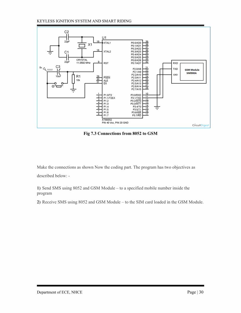
Fig 7.3 Connections from 8052 to GSM
Make the connections as shown Now the coding part. The program has two objectives as
described below: -
1) Send SMS using 8052 and GSM Module – to a specified mobile number inside the program 2) Receive SMS using 8052 and GSM Module – to the SIM card loaded in the GSM Module.
KEYLESS IGNITION SYSTEM AND SMART RIDING
Department of ECE, NHCE Page | 31
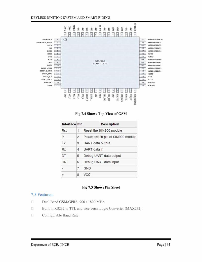
Fig 7.4 Shows Top View of GSM
Fig 7.5 Shows Pin Sheet
7.5 Features: Dual Band GSM/GPRS: 900 / 1800 MHz. Built in RS232 to TTL and vice versa Logic Converter (MAX232) Configurable Baud Rate

KEYLESS IGNITION SYSTEM AND SMART RIDING
Department of ECE, NHCE Page | 32
SMA (Sub Miniature Version A) connector with GSM L Type Antenna
Built in SIM (Subscriber Identity Module) Card holder
Built in Network Status LED
Inbuilt Powerful TCP / IP (Transfer Control Protocol / Internet Protocol) stack for
internet data transfer through GPRS (General Packet Radio Service)
. GSM Interfacing Board
GSM (Global System for Mobile) / GPRS (General Packet Radio Service) TTL Modem is
SIM900A Dual-band GSM / GPRS device, works on frequencies 900 MHZ and 1800 MHZ.
It is very compact in size and easy to use as plug in GSM Modem. The Modem is designed
with 3V3 and 5V DC TTL interfacing circuitry, which allows User to directly interface with
5V Microcontrollers (PIC, AVR, Arduino, 8051 etc.) as well as 3V3 Microcontrollers (ARM,
ARM Cortex XX, etc.). The baud rate can be configurable from 9600-115200 bps through
AT (Attention) commands. This GSM/GPRS TTL Modem has internal TCP/IP stack to
enable User to connect with internet through GPRS feature. It is suitable for SMS as well as
DATA transfer application in mobile phone to mobile phone interface. o Audio Interface Connectors (Audio in and Audio out) o Most Status and Controlling pins are available o Normal Operation Temperature: -20 °C to +55 °C o Input Voltage: 5V to 12V DC DB9 connector (Serial Port) provided for easy interfacing
KEYLESS IGNITION SYSTEM AND SMART RIDING
Department of ECE, NHCE Page | 33
CHAPTER 8
LI FI Li-Fi is a bidirectional high-speed and fully networked wireless communication technology
similar to Wi-Fi. The term was coined by Harald Haas and is a form of visible light
communication and a subset of optical wireless communication (OWC) and could be a
complement to RF communication (Wi-Fi or cellular networks, or even a replacement in
contexts of data broadcasting. It is wire and UV visible-light communication or infrared and near-ultraviolet instead of radio-
frequency spectrum, part of optical wireless communications technology, which carries much
more information and has been proposed as a solution to the RF-bandwidth limitations.
8.1 HISTORY The general term visible light communication (VLC), whose history dates back to the 1880s,
includes any use of the visible light portion of the electromagnetic spectrum to transmit
information. The D-Light project at Edinburgh's Institute for Digital Communications was
funded from January 2010 to January 2012. Haas promoted this technology in his 2011 TED
Global talk and helped start a company to market it. Pure LiFi, formerly pure VLC, is an
original equipment manufacturer (OEM) firm set up to commercialize Li-Fi products for
integration with existing LED lighting systems. Oledcomm, French company founded by Pr
Suat Topsu from Paris-Saclay University (one of the inventors of the LiFi in 2005), launched
in May 2017 during the Paris Healthcare Week the first bidirectional lamp dedicated to hospital
patient room.
In October 2011, companies and industry groups formed the Li-Fi Consortium, to promote
high-speed optical wireless systems and to overcome the limited amount of radio-based
wireless spectrum available by exploiting a completely different part of the electromagnetic
spectrum.
A number of companies offer uni-directional VLC products, which is not the same as Li-Fi -
a term defined by the IEEE 802.15.7r1 standardization committee.
VLC technology was exhibited in 2012 using Li-Fi. By August 2013, data rates of over 1.6
Gbit/s were demonstrated over a single color LED. In September 2013, a press release said
that Li-Fi, or VLC systems in general, do not require line-of-sight conditions. In October
2013, it was reported Chinese manufacturers were working on Li-Fi development kits.

KEYLESS IGNITION SYSTEM AND SMART RIDING
Department of ECE, NHCE Page | 34
8.2 HOW IT WORKS Li-Fi and Wi-Fi are quite similar as both transmit data electromagnetically. However, Wi-Fi
uses radio waves while Li-Fi runs on visible light.
As we now know, Li-Fi is a Visible Light Communications (VLC) system. This means that it
accommodates a photo-detector to receive light signals and a signal processing element to
convert the data into 'stream-able' content.
An LED lightbulb is a semi-conductor light source meaning that the constant current of
electricity supplied to an LED lightbulb can be dipped and dimmed, up and down at extremely
high speeds, without being visible to the human eye.
For example, data is fed into an LED light bulb (with signal processing technology), it then
sends data (embedded in its beam) at rapid speeds to the photo-detector (photodiode).
The tiny changes in the rapid dimming of LED bulbs is then converted by the 'receiver' into
electrical signal.
The signal is then converted back into a binary data stream that we would recognize as web,
video and audio applications that run on internet enables devices
KEYLESS IGNITION SYSTEM AND SMART RIDING
Department of ECE, NHCE Page | 35
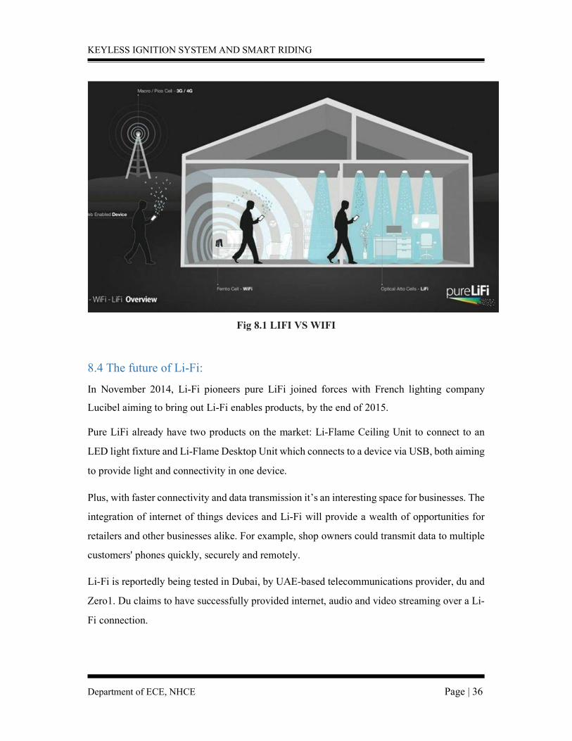
8.3 Li-Fi vs Wi-Fi
While some may think that Li-Fi with its 224 gigabits per second leaves Wi-Fi in the dust, Li-
If’s exclusive use of visible light could halt a mass uptake.
Li-Fi signals cannot pass through walls, so in order to enjoy full connectivity, capable LED
bulbs will need to be placed throughout the home. Not to mention, Li-Fi requires the lightbulb
is on at all times to provide connectivity, meaning that the lights will need to be on during the
day.
What's more, where there is a lack of lightbulbs, there is a lack of Li-Fi internet so Li-Fi does
take a hit when it comes to public Wi-Fi networks.
In an announcement yesterday, an extension of standard Wi-Fi is coming and it's called Wi-Fi
Hallow
This new project claims to double the range of connectivity while using less power. Due to
this, Wi-Fi Hallow is reportedly perfect for battery powered devices such as smartwatches,
smartphones and lends itself to Internet of Things devices such as sensors and smart
applications.
But it's not all doom and gloom! Due to its impressive speeds, Li-Fi could make a huge impact
on the internet of things too, with data transferred at much higher levels with even more devices
able to connect to one another.
What's more, due to its shorter range, Li-Fi is more secure than Wi-Fi and it's reported
that embedded light beams reflected off a surface could still achieve 70 megabits per second.
KEYLESS IGNITION SYSTEM AND SMART RIDING
Department of ECE, NHCE Page | 36
Fig 8.1 LIFI VS WIFI
8.4 The future of Li-Fi: In November 2014, Li-Fi pioneers pure LiFi joined forces with French lighting company
Lucibel aiming to bring out Li-Fi enables products, by the end of 2015. Pure LiFi already have two products on the market: Li-Flame Ceiling Unit to connect to an
LED light fixture and Li-Flame Desktop Unit which connects to a device via USB, both aiming
to provide light and connectivity in one device.
Plus, with faster connectivity and data transmission it’s an interesting space for businesses. The
integration of internet of things devices and Li-Fi will provide a wealth of opportunities for
retailers and other businesses alike. For example, shop owners could transmit data to multiple
customers' phones quickly, securely and remotely.
Li-Fi is reportedly being tested in Dubai, by UAE-based telecommunications provider, du and
Zero1. Du claims to have successfully provided internet, audio and video streaming over a Li-
Fi connection.
KEYLESS IGNITION SYSTEM AND SMART RIDING
Department of ECE, NHCE Page | 37
What's more, reports suggest that Apple may build future iPhones with Li-Fi capabilities. A
Twitter user found that within its iOS 9.1 code there were references to Li-Fi written as 'LiFi
Capability' hinting that Apple may integrate Li-fi with iPhones in the future. Whether or not
Li-Fi will live up to its hype is yet to be decided. Watch this space...
8.5 APPLICATIONS
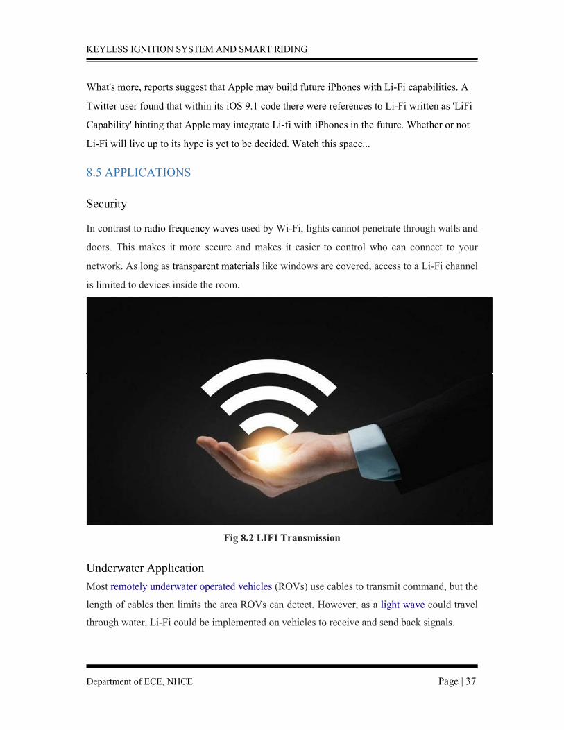
Security In contrast to radio frequency waves used by Wi-Fi, lights cannot penetrate through walls and
doors. This makes it more secure and makes it easier to control who can connect to your
network. As long as transparent materials like windows are covered, access to a Li-Fi channel
is limited to devices inside the room.
Fig 8.2 LIFI Transmission
Underwater Application Most remotely underwater operated vehicles (ROVs) use cables to transmit command, but the
length of cables then limits the area ROVs can detect. However, as a light wave could travel
through water, Li-Fi could be implemented on vehicles to receive and send back signals.
KEYLESS IGNITION SYSTEM AND SMART RIDING
Department of ECE, NHCE Page | 38
While it is theoretically possible for Li-Fi to be used in underwater applications, its utility is
limited by the distance light can penetrate water. Significant amounts of light do not penetrate
further than 200 meters. Past 1000 meters, no light penetrates. Hospital Many treatments now involve multiple individuals, Li-Fi system could be a better system to
transmit communication about the information of patients. Besides providing a higher speed,
light waves also have little effect on medical instruments and human bodies. Vehicles Vehicles could communicate with one another via front and back lights to increase road safety.
Also street lights and traffic signals could also provide information about current road
situations
KEYLESS IGNITION SYSTEM AND SMART RIDING
Department of ECE, NHCE Page | 39
CHAPTER 9
INTELLIGENT HELMET 9.1 Abstract:
As the bikers in our country are increasing, the road mishaps are also increasing day by
day, due to which many casualties, most of them are caused due to most common negligence
of not wearing the helmets, and also many deaths occur due to lack of prompt medical attention
needed by the injured person. This motivates us to think about making a system which ensures
the safety of biker, by making it necessary to wear helmet, as per government guidelines, also
to get proper and prompt medical attention, after meeting with an accident. The proposed
system is an intelligent helmet. A module affixed in the helmet, such that, the module will sync
with the module affixed on bike. Additional feature of accident detection module will be
installed on the bike, which will be able to detect accident and will be able to notify quickly
the accident to police control room and in case if the accident is minor, rider can abort message
sending by pressing the abort switch.
9.2 Smart Helmet for Indian Bike Rider: This paper presents the smart helmet that makes sure that the rider cannot start the bike
without wearing it. This helmet replaces the cable connections for wirelessly switching on a
bike, so that the bike would not start without both the key and the helmet. A LED indicator is
used to demonstrate the working of the model. The system is a simple telemetry system, which
is activated with the help of a pressure that is applied to the inner side of the helmet when the
rider wears it. The framework model uses a DPDT electromechanical relay and hence there is
some time lag in wearing the helmet and switching on of the circuit.
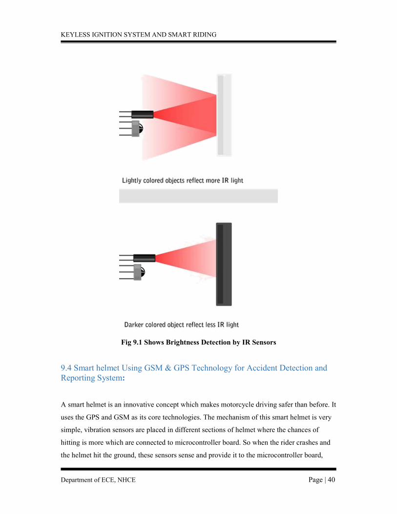
9.3 Principle of Operation: We have already discussed how a light sensor works. IR Sensors work by using a specific
light sensor to detect a select light wavelength in the Infra-Red (IR) spectrum. By using an
LED which produces light at the same wavelength as what the sensor is looking for, you can
look at the intensity of the received light. When an object is close to the sensor, the light from
the LED bounces off the object and into the light sensor. This results in a large jump in the
intensity, which we already know can be detected using a threshold
KEYLESS IGNITION SYSTEM AND SMART RIDING
Department of ECE, NHCE Page | 40
Fig 9.1 Shows Brightness Detection by IR Sensors
9.4 Smart helmet Using GSM & GPS Technology for Accident Detection and Reporting System:
A smart helmet is an innovative concept which makes motorcycle driving safer than before. It
uses the GPS and GSM as its core technologies. The mechanism of this smart helmet is very
simple, vibration sensors are placed in different sections of helmet where the chances of
hitting is more which are connected to microcontroller board. So when the rider crashes and
the helmet hit the ground, these sensors sense and provide it to the microcontroller board,
KEYLESS IGNITION SYSTEM AND SMART RIDING
Department of ECE, NHCE Page | 41
then controller extract GPS data using the GPS module that is integrated to it. When
the data goes below the minimum stress limit then GSM module automatically sends alerting
message to ambulance or family members. The hardware used in this system is alcohol sensor,
GSM, GPS, microcontroller, pressure sensor and vibration sensor.
Helmet part:
It basically consists of an IR Sensor, Alcohol Sensor, Accelerometer, Microcontroller
and Transmitter. IR Sensor: An IR sensor consists of an emitter, detector and associated
circuitry. The emitter is simply an IR LED (Light Emitting Diode) and the detector is simply
an IR photodiode which is sensitive to IR light of the same wavelength as that emitted by the
IR LED. The LOW or HIGH output of the IR sensor determines if the helmet is worn or not
worn Microcontroller:
All the analog outputs from all the sensors on the helmet are sent to this microcontroller
as input. According to the threshold set for alcohol sensor, accelerometer and the low or high
output of the IR sensor, a decision is made and sent to the module on bike wirelessly
Transmitter:
A RF transmitter operating at 434 MHz Radio Frequency is used to transmit the serial
data to the receiver over wireless media.
Bike Part: It basically consists of a Receiver, Microcontroller, GSM Module and Abort switch.
Receiver: A RF receiver operating at 434 MHz Radio Frequency is used to receive the data
over wireless medium

KEYLESS IGNITION SYSTEM AND SMART RIDING
Department of ECE, NHCE Page | 42
Microcontroller:
This is the actual decision making unit of the entire circuit and the programs will be fed into it.
According to the data it will receive from the module on bike it will control the output of
remaining components. Based on the output of both the accelerometers on bike and helmet, it
will send message to nearest police station in case of an accident using GSM module and based
on the outputs of IR sensor, it will send a relay output to the engine.
GSM Module:
This GSM Modem can accept any GSM network operator SIM card and act just like a mobile
phone with its own unique phone number. Applications like SMS Control, data transfer, remote
control and logging can be developed easily. The modem can be connected directly to any
microcontroller. It can be used to send and receive SMS or make/receive voice calls. We will
be using SMS application of it to send an SMS to the police station in case of accident. Abort Switch: Abort switch is used to abort the operation in case of a minor accident occurred.
Fig 9.2 Module of Helmet
KEYLESS IGNITION SYSTEM AND SMART RIDING
Department of ECE, NHCE Page | 43
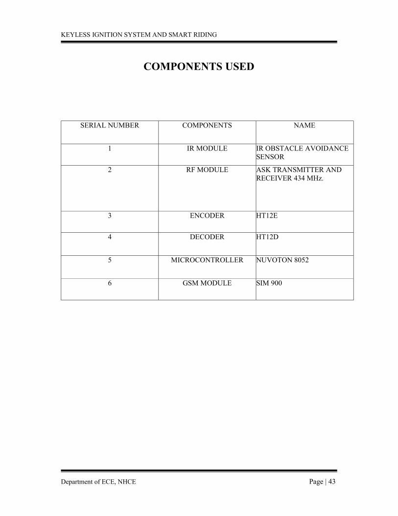
COMPONENTS USED
SERIAL NUMBER COMPONENTS NAME
1 IR MODULE IR OBSTACLE AVOIDANCE SENSOR
2 RF MODULE ASK TRANSMITTER AND RECEIVER 434 MHz.
3 ENCODER HT12E
4 DECODER HT12D
5 MICROCONTROLLER NUVOTON 8052
6 GSM MODULE SIM 900
KEYLESS IGNITION SYSTEM AND SMART RIDING
Department of ECE, NHCE Page | 44
CHAPTER 10
CONCLUSION
Intelligent Helmet ensures the safety of the rider, by making it necessary to wear helmet. If
any of these prime safety rules are violated, the system will prevent the biker from starting
the bike. The system also helps in efficient handling of the aftermath of accidents by sending
a SMS with the location of the biker to the police station. This ensures that the victims get
proper and prompt medical attention, if met with an accident.
KEYLESS IGNITION SYSTEM AND SMART RIDING
Department of ECE, NHCE Page | 45
CHAPTER 11
REFERENCES
[1] National Crime Records Bureau. Accidental deaths and suicides in India. New Delhi:
Ministry of Home Affairs, Government of India; 2005.
[2] V.Krishna Chaitanya, K.Praveen Kumar, “Smart helmet using Arduino”, Hyderabad,
2013.
[3] R. Prudhvi Raj, Ch. Sri Krishna Kanth, A. BhargavAdityaandK. Bharath, “Smart-Tec
Helmet,” AEEE, India.
[4] Manjesh N, Prof. Sudarshan Raj, “Smart Helmet Using GSM&GPS Technology for
Accident Detection and Reporting System”, International Journal of Electrical and Electronics
Research, Vol. 2, Issue 4, October - December 2014.
[5] SudharsanaVijayan, Vineed T Govind, Merin Mathews, SimnaSurendran, Muhammed
Sabah,” Alcohol detection using smart helmet system”, IJETCSE, Volume 8 Issue
[6] Ruize Xu, Shengli Zhou, Li, W.J. “MEMS Accelerometer Based Nonspecific-User Hand
Gesture Recognition”, IEEE, Volume:12 Issue:5, 05 September 2011.
[7] Muhammad Ali Mazidi and Janice Gillispie Mazidi, “The 8051 Microcontroller and Embedded Systems”, Pearson Education.
[8] “Wireless accident information using gps and gsm” September15, 2012, Research Journal of Applied Sciences, Engineering and Technology, Maxwell Scientific Organization, 2012.
[9] Y. Zhao, “Mobile phone location determination and its impact on intelligent
transportation systems.