Embed Size (px)
Citation preview
The Journal of Arthroplasty 29 (2014) 377–382
Contents lists available at ScienceDirect
The Journal of Arthroplasty
j ourna l homepage: www.arth rop lasty journa l .o rg
Research Synthesis of Recommended Acetabular Cup Orientations forTotal Hip Arthroplasty☆
Claire L. Harrison, BEng a, Avril I. Thomson, PhD b, Steven Cutts, FRCS c,Philip J. Rowe, PhD a, Philip E. Riches, PhD a
a Department of Biomedical Engineering, University of Strathclyde, Glasgow, UKb Department of Design Manufacture and Engineering Management, University of Strathclyde, Glasgow, UKc James Paget University Hospital, Great Yarmouth, UK
a b s t r a c ta r t i c l e i n f o
☆ This is an open-access article distributed under the tAttribution License, which permits unrestricted use, disany medium, provided the original author and source ar
The Conflict of Interest statement associated with thidx.doi.org/10.1016/j.arth.2013.06.026.
Reprint requests: Claire L. Harrison, DepartmenUniversity of Strathclyde, Wolfson Centre, 106 Rottenrow
0883-5403/2902-0026$36.00/0 – see front matter © 20http://dx.doi.org/10.1016/j.arth.2013.06.026
Article history:Received 26 March 2013Accepted 15 June 2013
Keywords:acetabular cupcorrect orientationmalpositioningtotal hip arthroplasty
Total hip arthroplasty (THA) is regarded as one of themost successful surgical procedures of modern times yetcontinues to be associated with a small but significant complication rate. Many early failures may beassociated with poor component positioning with, in particular, acetabular component orientation dependenton the subjective judgement of the surgeon. In this paper, we compare the manufacturers' instructions onacetabular cup orientation with the literature-based recommended safety zones and surgical technique, bytransforming them onto a single, clinically-relevant framework in which the different reference systems,safety guidelines and current instrumentation surgical techniques can be evaluated. The observed limitedconsensus between results reflects ongoing uncertainty regarding the optimum acetabular componentpositioning. As malpositioning of the acetabular cup increases the risk of revision surgery, any ambiguity overthe correct position can have a causal effect. Our analysis highlights the need for a surgical reference systemwhich can be used to describe the position of the acetabular cup intra-operatively.
erms of the Creative Commonstribution, and reproduction ine credited.s article can be found at http://
t of Biomedical Engineering,, Glasgow, G4 0NW, UK.
14 The Authors. Published by Elsev
© 2014 The Authors. Published by Elsevier Inc. All rights reserved.
Success in total hip arthroplasty (THA) is critically dependent oncorrect acetabular positioning [1]. When the acetabular component ismalpositioned, there is an increased risk of impingement, dislocation,pelvic osteolysis and wear and early revision [2–10]. As the annualnumber of THA procedures increases, the economic burden of revisionsurgery will increase with it [11].
Errors in component positioning may be the result of poortechnique [12]: whilst some surgeons now use computer navigationmost continue to use mechanical guides. Navigation systems areconsidered to extend operating times, are expensive and areassociated with a significant learning curve [13]. In the operatingtheatre environment, surgeons use the vertical and the operatingtable itself as a reference frame for mechanical guides rather than thepatient therefore accurate use of mechanical guides is dependent onthe surgeon correctly aligning the guide with this reference.However this technique is based on the assumption that thetransverse axis of the pelvis is perfectly perpendicular to the tablealthough, in reality, this is rarely the case [14]. Preoperatively,
optimum orientation is considered by the surgeon based onmeasurements taken from radiographs however this can be difficultto replicate during surgery.
There is limited consensus in the literature as to what constitutesthe optimum orientation of the acetabular component [15]. Differ-ences in reference systems, surgical techniques and measurementsystems make objective comparisons of published studies difficult.
Orientations of inclination and anteversion are currently definedin 3 differentmeasurement systems: the radiographic, anatomical andoperative orientations; with conversion equations [16] allowingcomparison between different manufacturers and literature guide-lines. Lewinnick's [3] definition of a 40° lateral opening angle and 15°anteversion with a safety zone of ±10° appears to be the most widelyaccepted as the desired orientation for the acetabular cup andadherence to these guidelines has been shown to reduce the chanceof dislocation [3]. In comparison, McCollum and Gray [17] suggested aposition of 40° ± 10° abduction and 30° ± 10° flexion to preventimpingement and dislocation. Harris [18] recommends a position of30° abduction and 20° anteversion; however, the Harris angles arereferenced using a mechanical guide and the trunk of the patient.Pedersen [19] used a CAD model to show that a position of less than40° tilt and less than 10° anteversion would achieve the optimal rangeof motion. Yoon et al [20] conducted a study comparing some of thecurrent recommendations from literature and converted these into aglobal system however there is no comparison of manufacturers'instructions and how this impacts current surgical technique.
ier Inc. All rights reserved.

Fig. 1. Diagram defining the acetabular axis (AA) and the acetabular axis plane.
378 C.L. Harrison et al. / The Journal of Arthroplasty 29 (2014) 377–382
The aim of this research synthesis is to compare the plannedorientation of the acetabular cup, as per the manufacturers' in-structions, to the literature based recommended safety zones andsurgical techniques to highlight any potential disparities betweenthem and, more importantly, to identify a common consensus of bestpractice. Greater understanding of the optimal acetabular cuporientation would reduce the risk of revision surgery and alleviatethe economic burden of revision surgery.
Reference System Definitions
Acetabular Axis
The acetabular axis originates at the geometric centre of theacetabular socket and is orthogonal to the acetabular plane (Fig. 1)[21]. The acetabular axis plane lies on the acetabular axis and isperpendicular to the acetabular plane.
The three different reference systems (operative, radiographic andanatomical), are used together with the acetabular axis to quantifyacetabular orientation. These are outlined below. For brevity's sake,the reader is directed elsewhere [3,16] for a more completedescription of these reference systems.
Fig. 2. Comparison of operative (A), radiographi
Operative Reference System
The operative reference system is defined [18] by the intra-operative pose of the patient on the operating table. The recom-mended inclination angle (δ) is defined when the arm of the guide isparallel to the operating table and the recommended operativeanteversion angle (ϕ) is described when the arm of the guide isparallel to the longitudinal axis of the patient. Therefore, in the ideallateral decubitis orientation, with the sagittal plane horizontal, andcoronal and transverse planes both vertically oriented, δ is the anglebetween the acetabular axis and the sagittal plane whilst ϕ is theangle between acetabular axis as projected onto the sagittal plane andthe coronal plane (Fig. 2).
Radiographic Reference System
The radiographic definition [3] of inclination and anteversionrelies on measurements taken from x-rays which are used forpreoperative planning and used postoperatively to measure thesuccess of the procedure. This definition would also be used ifthe operation is carried out with the patient in the supine pose. Theradiographic inclination angle (θ) is defined as the angle betweenthe longitudinal axis of the body and projection of the acetabularaxis in the coronal plane and the radiographic anteversion angle (α)is the angle between the acetabular axis and the coronal plane[16] (Fig. 2).
Anatomical Reference System
The anatomical reference [22] defines the anatomical inclination(β) as the angle between the acetabular axis and the longitudinal axisof the patient and the anatomical anteversion (γ) as the anglebetween the acetabular axis, as projected onto the transverse plane,and the transverse axis [16]. The three reference systems are depictedin Fig. 2.
Methodology
The recommended position of the acetabular cup was collatedfrom the literature [3,17–19] and academic textbooks [23–25]. TheNational Joint Registry for England andWales was used to identify themost commonly used implants, the surgical guidelines for which weresubsequently selected for inclusion in the analysis [26–33]. Allorientations were transformed to the operative reference frame (δ,ϕ) for comparison using the equations below [16]:
sin δð Þ ¼ sin θð Þ cos αð Þ ¼ sin βð Þ cos γð Þtan ϕð Þ ¼ tan αð Þ= cos θð Þ ¼ sin γð Þ tan βð Þ
c (B) and anatomical (C) reference systems.

Table 1Safety Guidelines for Inclination and Anteversion Angles from the Literature.
Source
Inclination Anteversion
OriginalDefinitionsDegrees (°)
OriginalReferenceFrame
OperativeDegrees (°)
RadiographicDegrees (°)
AnatomicalDegrees (°)
OriginalDefinitionsDegrees (°)
OriginalReferenceFrame
OperativeDegrees (°)
RadiographicDegrees (°)
AnatomicalDegrees (°)
Lewinnick [4] 40 ± 10°Lateral Opening
Radiographic 38 ± 11 40 ± 10 42 ± 12 15 ± 10°Anteversion
Radiographic 21 ± 15 15 ± 10 25 ± 18
McCollum andGray [18]
40 ± 10°Abduction
Radiographic 36 ± 12 40 ± 10 45 ± 11 30 ± 10°Flexion
Operative 30 ± 10 25 ± 11 36 ± 19
Harris [19] 30° Abduction Radiographic 28 30 34 20° ForwardFlexion
Operative 20 18 32
Pedersen [20] b40° Tilt Radiographic 35 ± 5 35 ± 5 36 ± 6 b10°Anteversion
Radiographic 6 ± 6 5 ± 5 10 ± 10
Table 2Suggested Acetabular Cup Inclination and Anteversion Angles from Surgical Technique in Academic Textbooks.
Source
Inclination Anteversion
OriginalDefinitionsDegrees (°)
OriginalReferenceFrame
OperativeDegrees (°)
RadiographicDegrees (°)
AnatomicalDegrees (°)
OriginalDefinitionsDegrees (°)
OriginalReferenceFrame
OperativeDegrees (°)
RadiographicDegrees (°)
AnatomicalDegrees (°)
Jayson Total HipReplacement [23]
45° Open Radiographic 45 46 45 10°Anteversion
Operative 10 10 7
CalandruccioCampbell'sOperativeOrthopaedics [21]
35° - 45°Inclination
Radiographic 39 ± 6 40 ± 5 41 ± 6 10°–20°Anteversion
Operative 15 ± 5 12 ± 5 19 ± 9
Charnley [24] 45°Inclination
Anatomical 45 45 45 0°Anteversion
Anatomical 0 0 0
Muller [25] 45° FacingLaterally
Radiographic 44 45 46 10°Anteversion
Operative 13 ± 3 9 ± 2 13 ± 3
379C.L. Harrison et al. / The Journal of Arthroplasty 29 (2014) 377–382
Results
Compilation of the different recommended orientations of theacetabular cup from the literature showed a variety of orientationsusing different terms, reference and measurement systems. Table 1displays the different guidelines from the literature in the originaldefinitions and converted operative, radiographic and anatomicalinclination and anteversion definitions.
The suggested inclination angles ranged from 24° to 50° and thesuggested anteversion angles ranged from 0° to 40° in the operativereference frame.
The recommended orientations of the acetabular cup from a rangeof surgical techniques found in academic textbooks also showed avariety of orientations which are displayed in Table 2. The majority ofthe orientations used the radiographic reference system to describethe inclination angle and the operative reference system to describe
0
5
10
15
20
25
30
35
40
45
0 10 20 30 40 50 60
An
teve
rsio
n (
Deg
rees
)
Inclination (Degrees)
Calandruccio Campbell's Operative Orthopaedics (24)
Charnley (24)
Harris (19)
Lewinnick (4)
McCollum & Gray (18)
M ller (25)
Pedersen (20)
Jayson Total Hip Replacement(23)
Fig. 3. Recommended safe zones of the acetabular cup in the operative reference system.
the anteversion angle. The range was considerably smaller than theliterature guidelines with suggested inclination angles between 33°and 45° and the suggested anteversion angles ranging from 0° to 20°in the operative reference frame.
Fig. 3 details the comparison of the recommended safety zonesfrom the literature and textbooks in the operative reference frame.The majority of the recommended implant orientations arecontained within Lewinnick's definition of the safe zone howeverHarris is on the edge of the safe zone, Calandruccio Campbell'sOperative Orthopaedics and Pedersen are partially overlapping thesafe zone and Charnley is not at all contained within the Lewinnicksafe zone.
Suggested orientations, as per the manufacturers' instructions,showed less variability in the adopted reference system andrecommended orientation. With the exception of DePuy, mostmanufacturers used the radiographic definition to describe the
0
5
10
15
20
25
30
35
40
45
0 10 20 30 40 50 60
An
teve
rsio
n (
Deg
rees
)
Inclination (Degrees)
Calandruccio Campbell's Operative Orthopaedics (24)
Lewinnick (4)
Biomet: C2a taper (31)
De Puy: Duralock (32)
De Puy: Pinnacle (33)
Implanet: Mambo (30)
Smith & Nephew: Reflection(28)
Stryker: Trident Acetabular System (26)
Wright Medical: Conserve (29)
Zimmer: Trilogy (27)
Fig. 4. Comparison of desired orientation of the acetabular cup from the safetyguidelines from literature and current surgical guidelines: operative definition.
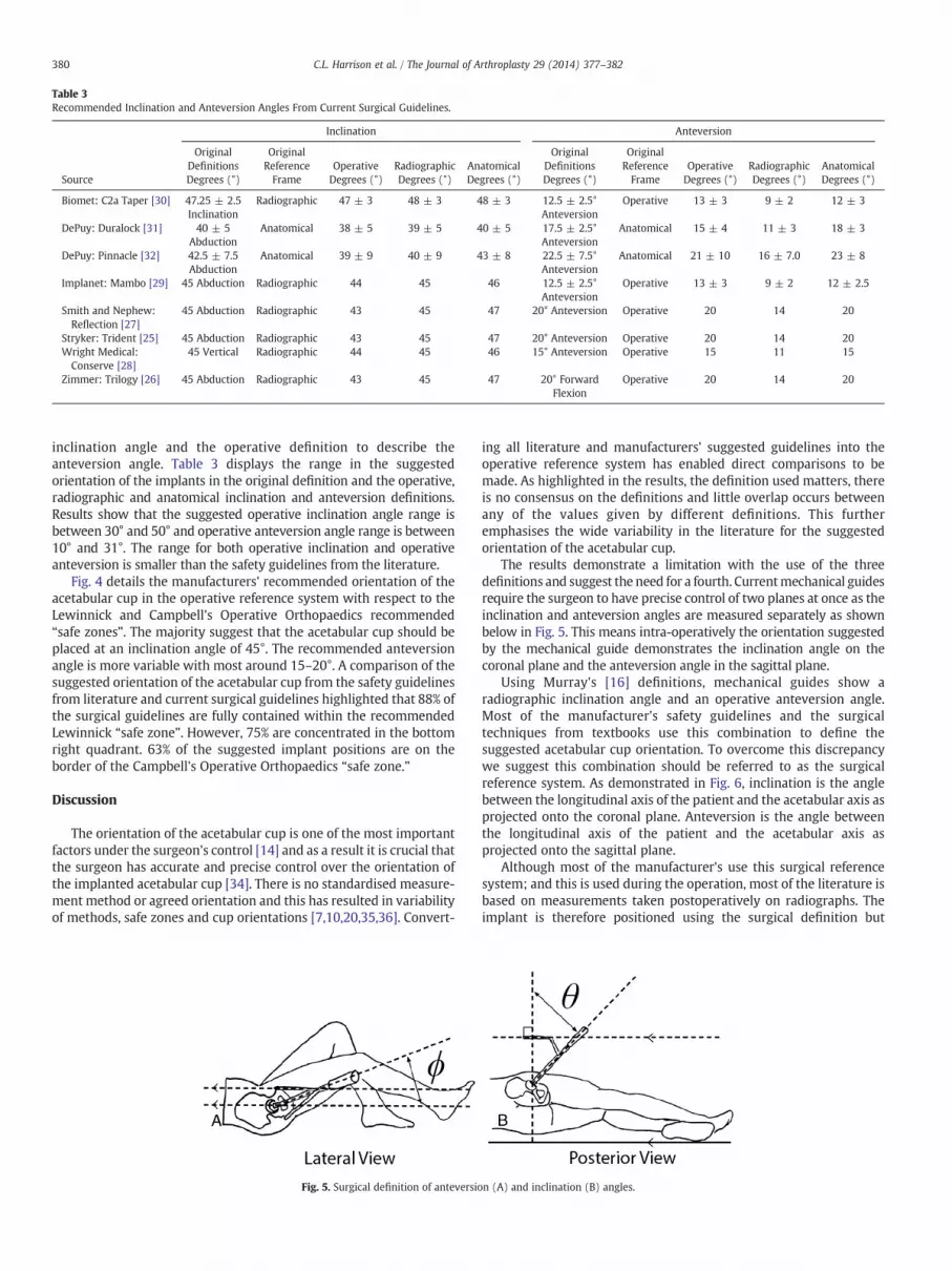
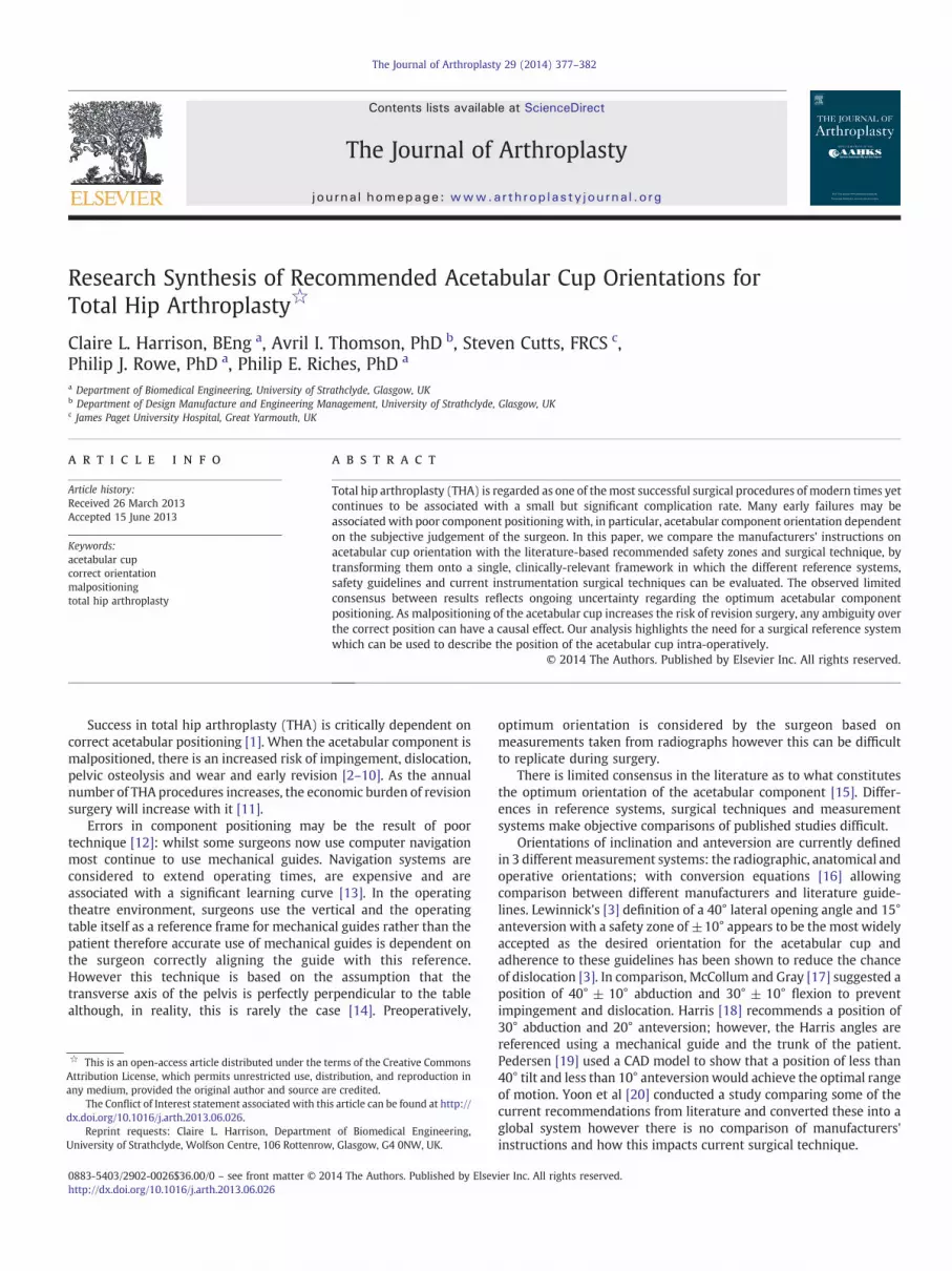
Table 3Recommended Inclination and Anteversion Angles From Current Surgical Guidelines.
Source
Inclination Anteversion
OriginalDefinitionsDegrees (°)
OriginalReferenceFrame
OperativeDegrees (°)
RadiographicDegrees (°)
AnatomicalDegrees (°)
OriginalDefinitionsDegrees (°)
OriginalReferenceFrame
OperativeDegrees (°)
RadiographicDegrees (°)
AnatomicalDegrees (°)
Biomet: C2a Taper [30] 47.25 ± 2.5Inclination
Radiographic 47 ± 3 48 ± 3 48 ± 3 12.5 ± 2.5°Anteversion
Operative 13 ± 3 9 ± 2 12 ± 3
DePuy: Duralock [31] 40 ± 5Abduction
Anatomical 38 ± 5 39 ± 5 40 ± 5 17.5 ± 2.5°Anteversion
Anatomical 15 ± 4 11 ± 3 18 ± 3
DePuy: Pinnacle [32] 42.5 ± 7.5Abduction
Anatomical 39 ± 9 40 ± 9 43 ± 8 22.5 ± 7.5°Anteversion
Anatomical 21 ± 10 16 ± 7.0 23 ± 8
Implanet: Mambo [29] 45 Abduction Radiographic 44 45 46 12.5 ± 2.5°Anteversion
Operative 13 ± 3 9 ± 2 12 ± 2.5
Smith and Nephew:Reflection [27]
45 Abduction Radiographic 43 45 47 20° Anteversion Operative 20 14 20
Stryker: Trident [25] 45 Abduction Radiographic 43 45 47 20° Anteversion Operative 20 14 20Wright Medical:Conserve [28]
45 Vertical Radiographic 44 45 46 15° Anteversion Operative 15 11 15
Zimmer: Trilogy [26] 45 Abduction Radiographic 43 45 47 20° ForwardFlexion
Operative 20 14 20
380 C.L. Harrison et al. / The Journal of Arthroplasty 29 (2014) 377–382
inclination angle and the operative definition to describe theanteversion angle. Table 3 displays the range in the suggestedorientation of the implants in the original definition and the operative,radiographic and anatomical inclination and anteversion definitions.Results show that the suggested operative inclination angle range isbetween 30° and 50° and operative anteversion angle range is between10° and 31°. The range for both operative inclination and operativeanteversion is smaller than the safety guidelines from the literature.
Fig. 4 details the manufacturers' recommended orientation of theacetabular cup in the operative reference system with respect to theLewinnick and Campbell's Operative Orthopaedics recommended“safe zones”. The majority suggest that the acetabular cup should beplaced at an inclination angle of 45°. The recommended anteversionangle is more variable with most around 15–20°. A comparison of thesuggested orientation of the acetabular cup from the safety guidelinesfrom literature and current surgical guidelines highlighted that 88% ofthe surgical guidelines are fully contained within the recommendedLewinnick “safe zone”. However, 75% are concentrated in the bottomright quadrant. 63% of the suggested implant positions are on theborder of the Campbell's Operative Orthopaedics “safe zone.”
Discussion
The orientation of the acetabular cup is one of the most importantfactors under the surgeon's control [14] and as a result it is crucial thatthe surgeon has accurate and precise control over the orientation ofthe implanted acetabular cup [34]. There is no standardised measure-ment method or agreed orientation and this has resulted in variabilityof methods, safe zones and cup orientations [7,10,20,35,36]. Convert-
Fig. 5. Surgical definition of anteversio
ing all literature and manufacturers' suggested guidelines into theoperative reference system has enabled direct comparisons to bemade. As highlighted in the results, the definition used matters, thereis no consensus on the definitions and little overlap occurs betweenany of the values given by different definitions. This furtheremphasises the wide variability in the literature for the suggestedorientation of the acetabular cup.
The results demonstrate a limitation with the use of the threedefinitions and suggest the need for a fourth. Currentmechanical guidesrequire the surgeon to have precise control of two planes at once as theinclination and anteversion angles are measured separately as shownbelow in Fig. 5. This means intra-operatively the orientation suggestedby the mechanical guide demonstrates the inclination angle on thecoronal plane and the anteversion angle in the sagittal plane.
Using Murray's [16] definitions, mechanical guides show aradiographic inclination angle and an operative anteversion angle.Most of the manufacturer's safety guidelines and the surgicaltechniques from textbooks use this combination to define thesuggested acetabular cup orientation. To overcome this discrepancywe suggest this combination should be referred to as the surgicalreference system. As demonstrated in Fig. 6, inclination is the anglebetween the longitudinal axis of the patient and the acetabular axis asprojected onto the coronal plane. Anteversion is the angle betweenthe longitudinal axis of the patient and the acetabular axis asprojected onto the sagittal plane.
Although most of the manufacturer's use this surgical referencesystem; and this is used during the operation, most of the literature isbased on measurements taken postoperatively on radiographs. Theimplant is therefore positioned using the surgical definition but
n (A) and inclination (B) angles.

Fig. 6. Surgical reference system.
381C.L. Harrison et al. / The Journal of Arthroplasty 29 (2014) 377–382
evaluated using a radiographic orientation. Using the surgicaldefinition intra-operatively and a radiographic definition postopera-tively can lead to further discrepancy and confusion.
When reviewing the recommended implant orientations in thesurgical reference system, there is no suggested safe zone in the literatureor the surgical techniques that corresponds with all the suggestedimplant orientations from the manufacturers. Although 87.5% of thesurgical guidelines are contained within the Lewinnick safe zone, theyare congregated at the bottom right corner and the majority of thesurgical guidelines within the Campbell's Operative Orthopaedicsrecommended orientation are on the edge of that zone. This puts asurgeon in a quandary: small deviations from the manufacturers'recommended orientation may place the cup in an orientation out witha safe zone, but contrastingly, aiming for the middle of the safe zonewill contradict manufacturers' guidelines. In the surgical referencesystem, the Lewinnick safe zone is no longer square which makes itdifficult for the surgeon to ensure the implant is within therecommended area. Creating a square which is based on the Lewinnickzone and restricting anteversions to no less than 5° and no more than30°, suggest a new safety zone centred on the bottom right handcorner of Lewinnick's zone at approximately 40° surgical inclinationand 17–18° surgical anteversion. This cup placement may be a simpletarget which could be used for all such arthroplasties irrespective ofimplant manufacturer. As this safe zone is defined in the surgicaldefinition, it could be used with current surgical guidelines and usedintra-operatively removing the need for surgeons to convert between
Fig. 7. Comparison of desired orientation of the acetabular cup from current surgicalguidelines and the proposed Strathclyde Safety Zone: surgical definition.
definitions and the subsequent potential for error. The vast majority ofthe suggested acetabular cup positions from the safety guidelines areenclosed within this area (Fig. 7). Nevertheless, before such a safe zonecan be recommended for surgical use, further validation of this safetyzone would be required.
Comparison of the results displayed in Tables 1, 2 and 3 showed alarger range in the recommended anteversion angles compared toinclination angles. Anteversion is harder than inclination to evaluateusing current techniques [37] which could account for this widerange; however, the anteversion angle is critical as it has been shownto be one of the biggest influencing factors that can lead to dislocation[4,5,38]. The significance of the anteversion angle along with the widerange of values found further emphasises the need for more clarity onorientation guidelines.
There are a number of limitations in these measurement systemswhich must be taken into consideration. Operatively, this referencesystem relies on the patient being positioned and remaining on tablein a perfect lateral decubitus pose. Radiographically, as the image is aprojection, any rotation of the pelvis can add error [39]. Pelvic tilt,which is the angle between anterior pelvic plane and the coronalplane [36] must be taken into consideration when positioning theacetabular cup. Knowing the exact orientation of the hip on theoperating table is very difficult [17]; however, the orientation ofthe cup is critically dependent on the position of the patient'spelvis [35]. Pelvic tilt has been shown to have a direct impact onthe anteversion angle [40,41], therefore this should be taken intoconsideration in any measurement system. Correct orientation ofthe acetabular cup is also dependent on other variables such as theorientation of the femoral stem, design of the implant andindividual patient anatomy. Each of these factors must also betaken into consideration when positioning the acetabular cup.
This study demonstrates there is no consensus in the optimumorientation of the acetabular component in THA. Ensuring that allliterature and guidelines are in the same definition would, at least,allow direct comparison to be made between the currentapproaches enabling further research to relate outcomes to cuporientation. This could lead to a reduction in the variability ofrecommended orientations and the development of clearer defini-tions and better standards.
Acknowledgments
The authors would like to thank the Engineering and PhysicalSciences Research Council for providing the funding for this research.

382 C.L. Harrison et al. / The Journal of Arthroplasty 29 (2014) 377–382
References
1. Najarian BC, Kilgore JE, Markel DC. Evaluation of component positioning in primarytotal hip arthroplasty using an imageless navigation device compared withtraditional methods. J Arthroplasty 2009;24:1.
2. Oki H, Ando M, Omori H, et al. Relation between vertical orientation and stability ofacetabular component in the dysplastic hip simulated by nonlinear three-dimensional finite element method. Artif Organs 2004;28(11):1050.
3. Lewinnek GE, Lewis JL, Tarr R, et al. Dislocations after total hip replacementarthroplasties. J Bone Joint Surg Am 1978;60-A(2):217.
4. Masaoka T, Yamamoto K, Shishido T, Katori Y, Mizoue T, Shirasu H, Nunoda D.Study of hip joint dislocation after total hip arthroplasty. Int Orthop (SICOT)2006;30:26.
5. Nishii T, Sugano N, Miki H, et al. Influence of component positions on dislocation.J Arthroplasty 2004;19(2):162.
6. Yuan LJ, Shih CH. Dislocation after total hip arthroplasty. Arch Orthop Trauma Surg1999;119:263.
7. D’Lima DD, Urquhart AG, Buehler KO, et al. The effect of the orientation of theacetabular and femoral components on the range of motion of the hip at differenthead-neck ratios. J Bone Joint Surg 2000;82-A(3):315.
8. Kummer FJ, Shah S, Iyer S, et al. The effect of acetabular cup orientations on limitinghip rotation. J Arthroplasty 1999;14(4):509.
9. Robinson RP, Simonian PT, Gradisar IM, et al. Joint motion and surface contact arearelated to component position in total hip arthroplasty. J Bone Joint Surg Br1997;79-B(1):140.
10. Malik A, Maheshwari A, Dorr LD. Impingement with total hip replacement. J BoneJoint Surg Am 2007;8:1932.
11. National Joint Registry. National Joint Registry for England and Wales 8th AnnualReport. National Joint Registry; 2011 ISSN 1745–1450.
12. DeChenne CL, Jayaram U, Lovell T, et al. A novel acetabular alignment guide for THRusing selective anatomic landmarks on the pelvis. J Biomech 2005;38:1902.
13. Minoda Y, Ohzono K, Aihara M, et al. Are acetabular component alignment guidesfor total hip arthroplasty accurate? J Arthroplasty 2010;25(6):986.
14. Echeverri S, Leyvraz P, Zambelli P, et al. Reliable acetabular cup orientation with anew gravity-assisted guidance system. J Arthroplasty 2006;21(3):413.
15. Revell M, Davis ET. Hip replacement: clinical perspectives. In: Revell PA, editor.Joint replacement technology. Cambridge: Woodhead Publishing; 2008.
16. Murray DM. The definition andmeasurement of acetabular orientation. J Bone JointSurg Br 1993;75-B(2):228.
17. McCollum DE, Gray WJ. Dislocation after total hip arthroplasty. Causes andprevention. Clin Orthop Relat Res 1990;261:159.
18. Harris W. Advances in surgical technique for total hip replacement: withoutand with osteotomy of the greater trochanter. Clin Orthop Relat Res 1990;146:188.
19. Pedersen DR, Callaghan JJ, Brown TD. Activity-dependence of the “safe zone” forimpingement versus dislocation avoidance. Med Eng Phys 2005;27:323.
20. Yoon Y, Hodgson AJ, Tonetti J, et al. Resolving inconsistencies in defining the targetorientation for the acetabular cup angles in total hip arthroplasty. Clin Biomech2008;23:253.
21. Calandruccio RA. Arthroplasty of hip. In: Crenshaw AH, editor. Campbell’sOperative Orthopaedics, Vol. 2. St. Louis: CV Mosby; 1987. p. 1213.
22. Walker PS. Human joints and their artificial replacements; 1977.23. Jayson MIV. Total hip replacement. Sector Publishing Ltd; 1971 0950145815.24. Canale ST, Beaty JH. Campbell's Operative Orthopaedics. 11th ed. Philadelphia,
Pennsylvania: Mosby Elseiver; 2008. 978-0-323-03329-3.25. SL, Turek. Orthopaedics Priciples and Their Application 4th ed. Philadelphia: J.B.
Lippincott Company, 1984. IBSN 0-397-50604-X.26. Stryker. Trident Acetabular System: Hemispherical Surgical Protocol; 2009.27. Zimmer. Trilogy Acetabular System: Surgical Technique; 2010.28. Smith & Nephew. Reflection; 2006.29. Wright Medical Technology. Conserve Total Super-fix Acetabular System: Surgical
Technique; 2005.30. Implanet. Mambo Hip Cemented Cup.31. Biomet Orthopedics. C2a- Taper Ceramic on Ceramin Articulation; 2007.32. De Puy. Duraloc Option Ceramic Acetabular Cup, System; 2005.33. De Puy. Pinnacle Acetabular, System; 2006.34. Bosker BH, Verheyen CCPM, Horstmann WG, et al. Poor accuracy of freehand cup
positioning during total hip arthroplasty. Arch Orthop Trauma Surg 2007;127:375.35. Haaker RGA, Tiedjen K, Ottersbach A, et al. Comparison of conventional versus
computer-navigated acetabular component insertion. J Arthroplasty 2007;22(2):151.36. Wan Z, Malik A, Jaramaz B, et al. Imaging and navigation measurement of
acetabular component position in THA. Clin Orthop Relat Res 2009;467:32.37. Ackland MK, Bourne W, Uhthoff HK. Anteversion of the acetabular cup:
measurement of angle after total hip replacement. J Bone Joint Surg Br 1986;68-B(3):409.
38. He R, Yan S, Wu L, et al. Position of the prosthesis and the incidence of dislocationfollowing total hip replacement. Chin Med J 2007;120(13):1140.
39. Widmer KH, Zurfluh B. Compliant positioning of total hip components for optimalrange of motion. J Orthop Res 2004;22:815.
40. Fabeck L, Farrock D, Tolley M, et al. A method to measure acetabular cupanteversion after total hip replacement. Acta Orthop Belgiua 1999;65(4):487.
41. Babisch JW, Layher F, Amiot LP. The rationale for tilt-adjusted acetabular cupnavigation. J Bone Joint Surg Am 2008;90:357.