Embed Size (px)
Citation preview
Journal of
Scientific & Industrial
IN THIS ISSUE:
• Electronic Meteoro· logical Instruments
• Fluidization Technique in Chemical Engineering
• Zinc Oxide Manufacture
• Manufacture of Calcium Gluconate
• Elastic Properties of Jute Fibres
• Chemotherapeutic Derivatives of Acridine Series
• Chemical Examination of Cucumls Seeds
• Distillation of Madhya Pradesh Woods
Research V. 9, No.9, SEPTEMBER 1950
PUBLISHED BY THE COUNC.~ OF SCIE.NTlfIC & INDUSTi\IAL RESEARCH, INDIA
J. sci. industr. Res., V. 9A, No.9, Pp. 307-348 j & V. 98, No.9, Pp. 215-238, New Delhi. September 1950
/ 6
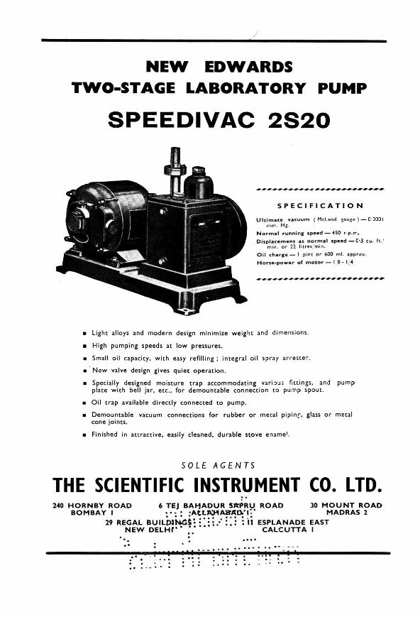
NEW EDWARDS TWO-STAGE LABORATORY PUMP
SPEEDIVAC 2820
SPECIFICATION
Ul t imate vacuum ( McLeod gauge) - C·JOOI mm . Hg.
Normal runnina: speed - 0450 r . p.rr.
Di s placement at normal speed - c·a cu . ft . 1 min . or 12 lit re s,' min .
O il cha.r-Ie - I p in t or 600 mi . ilpprox .
Horse-power of motor - 1 8 - 1, <4
• Light alloys and modern design minimize weight and dimensions .
• High pumping speeds at low pressures.
• Small oil capacity, with easy refilling; integral oil spray ar rester.
• . New valve design gives quiet operation .
• Specially designed moisture trap accommodating vari~u ; fittings, and pump plate with bell jar, etc ., for demountable connect ion to pu mp spout .
• Oil trap available directly connected to pump.
• Demountable ' vacuum connections for rubber or me tal pip inf' glass or metal cone joints.
• Finished in attractive , easily cleaned, durable stove ename l.
SOLE AGENTS
THE SCIENTIFIC INSTRUMENT CO. LTD. 240 HORNBY ROAD 6 TEJ BAI-1ADUR 5#ICPRU ROAD 30 MOUNT ROAD
BOMBAY I •••• ·At.L~~A.o.·I:· MADRAS 2
29 REGAL BUILDJN:ci! :':!", ::: : ii ESPLANADE EAST NEW DELHf" •••• CALCUTTA
.' .' . 1
I'r ................... . <. '. . . Ii - -. . . , ~ . ~ .. . .- . -_ ....

Journal of
Scientific & Industrial Research
v. 9A, No.9, SEPTEMBER 1950
EDITORIAL BOARD
S. S. BHATNAGAR, O.B.E., F.R.S .• D.Sc., F.lnst.P., F.R .I.C., Director, Scientific & Industrial Research (ex officio Chairman)
H • .J. BHABA, Ph.D., D.Sc., F.R.S., Tata Institute of Fundamental Researcb, Bombay
.J. C. GHOSH, D.Sc., F.N.I.. DirectorGeneral. Industry & Supply, New Delhi
.JIVARA.J N. MEHTA, M.D. , M.R.C.P., F.C. P.S., Minister for Public Works Department, Government of Bombay, Bombay
S. J[RISHNA, C.I.E.. Ph.D.. D.Sc., F.R.I.C. , F.N.J., Forest Research Institute, Dehra Dun
It. S.- J[RISHNAN, D.Sc., F.R.S., National Physical Laboratory, Delhi
MATA PRASAD, D.Sc .. F.R.I.C .• F.N.I., Royal Institute of Science, Bombay
c. V. RAMAN, F.R.S., N.L., Raman Research Institute, Bangalore
M. N. SAHA, D.Sc., F.R.S., Univtrsity CoUece of Science, Calcutta
D.N. WADIA, F.G.S.,F.R.G.S. ,F.R.A.S.B., Geolocical Adviser to the Department of Scientific Research, New Delhi
B. N. SASTRI, M.Sc., F .R.I.C:, A.I.I.Sc., Editor & ex officio Secretary
A. J[RISHNAMURTHI, M.Sc., Assistant Editor
S. B. DESHAPRABHU, Liaison Officer (Production)
CONTENTS
The Indian Salt Industry Characteristics of the Ionosphere over Calcutta
(June 1950) S. S. Baral, R. K. Mitra, D. C. Choudhury,
R. B. Banerjee & A. P. Mitra Electronic Meteorolollical Instruments In the
India Meteorolollical Department S. P . Venkiteshwaran
Fluidization - A New Technique: Part I M. S. Iyengar
Manufacture of Zinc Oxide from Zinc Sulphide Flotation Concentrates - Literature Report No. 11
P . 1. A. Narayanan & G. P. Mathur Reviews Non-Technical Notes
MANUFACTURE OF FILTER PADS FOR STERILIZING LIQUIDS
PRODUCTION OF CITRIC ACID
M ANUFACTURE OF CALCIUM GLUCONATE
Notes & News ... Prollress Reports Indian Patents .. .
Patented Inventions of the Council of Scientific & Industrial Research ...
For Contents to Section B, see page A 19 For Index to Advertisers, see page A 15
COVER PICTURE
307
309
310
314
323
329
335 335 336 337 345 347
348
The picture on the cover shows the Radar arrangement with five Yagi arrays ( see page 312) set up at the Meteorological Department's Observatories at New Delhi and Poona for obtaining meteorological data.
The JOURNAL OF ScIENTIFIC & INDUSTRIAL RESEARCH is issued monthly. The Council of Scientific IS- Industrial Research assumes no responsibility for the statements and
opinions advanced by contributors. The Editorial Board in its work of examining papers received for publication is assisted, in an honorary
capadty, by a large number of distinguished scientists working in various parts of India. Editorial communications and books and periodicals for review should be addressed to the Editor,
JOURNAL OF SciENTIFIC & INDUSTRIAL RESEARCH, National Physical Laboratory, Hillside Road, New Delhi.
Communications regarding subscriptions and advertisements should be addressed to the Secretary, Council of Scientific IS- Industrial Research, 'P' Block, Raisina Road, New Delhi.
ANNUAL 8VB8CRIPTION Ra. 9 ( "'Iaad ) ; IS ab. (Iorellln). SINGLE COPY: Re. I (Ial ... d) ; l eb, ( loreilla )

Bengal Chemical &. Pharmaceutical Works Ld. ~-The largest Chemical Works in lndia--_
Manufacturers of Pharmaceutical Drugs, Indigenous Medicines, Perfumery, Toilet and Medicinal Soaps, Surgical Dressings, Sera and Vaccines, Disinfectants, Tar Products, Road Dressing Meterials, etc.
A 4
Ether, Chloroform, Mineral Acids, Ammonia, Alum, Ferro-Alum, Aluminium Sulphate, Sulphate of Magnesium, Ferri Sulph., Potassium Permanganate, Caffeine and various other Pharmaceutical and Research Chemicals.
Surgical Sterilizers, Oxygen Apparatus, Distilled Water Stills, Operation Tables, Instrument Cabinets and other Hospital Accessories.
Chemical Balance, Scientific Apparatus for Laboratories and Schools and Colleges, Gas and Water Cocks for Laboratory use, Gas Plants, Laboratory Furniture and Fittings.
Fire Extinguishers, Printing Inks, etc.
Office 94 CHITTARANJAN AVENUE, CALCUTTA
Factories CAL CUT T A: 1 6 4 MAN I K TO LAM A I N R 0 A D PANIHA T I: BARRACKPORE TRUNK ROAD B 0 MBA Y: CAD ELL R 0 AD, DAD A R
-_:>=
Manufacturers of SCIENTIFIC APPARATUS,
VIALS, TEST-TUBES, NEUTRAL GLASS, AMPOULES,
ETC., ETC.
• For further particulars, write to :
BOMBAY SCIENTIFIC GLASS WORKS
ARAB HOUSE, KHETWADI 13TH LANE
BOMBAY 4
.------~-. \ ~
I! for HOSPITAL &
LABORATORY EQU IPMENT
\ . LABORATORY CHEMICALS
FOR SCHOOLS, COLLEGES &
RESEARCH INSTITUTIONS
please consult
UNION SCIENTIFIC SYNDICATE 52-58 NEW HANUMAN LANE
BOMBAY 2
Phone: .) 28465 Gram.: .. PETROLIUM ..

THE PERFECT ANSWER TO A SCIENTIST'S PRAYER
METTLER* BALANCES ANALYTICAL. SEMI-MICRO. MICRO
ANALYTICAL BALANCE E 5 READING TO 0'0001 g.
Manu(actu red by :
E. METTLER, ZURICH SWITZERLAND
THREE MODELS:
ES: Capacity 200 g. reading to 0'0000 I g.
E6: Capacity 100 g. reading to 0'00002 g.
Micro : Capacity 20 g. reading to 0'000002 g.
With the following sensational features:
• Automatic weighments up to 200. 100 or 20 g. ( depending upon the model)
• Large optical scale, range 0- 115 mg.
• Constant loadin~ of the beam. resulting in constant sensitivity throughout the whole range
• Single dial registering the weight
• Built-ln. standardized, rust-free. first quality weights
• Quick reading - each weighing (from putting sample on pan to recording the weight) takes only 30 seconds
• Personal error reduced to a minimum
o ~ 8).6 •
E 5 READING: 123'7306 g.
• Sapphire bearings: harder than agate
• Perfect damping
• Absolutely foolproof: even a schoolboy can take weights in less than a minute!
• Prices fairly competitive with normal type balances
• Ask for demonstration - No obligations
SOLE AGENTS
RAJ-DER-KAR & Co. COMMISSARIAT BUILDING, HORNBY ROAD
FORT, B 0 MBA Y
Telephone: 27304 (2 lines) Telegrams: TECHLAB
* These very balances are sold in U.S.A. by Fisher & Co. under the name Gram-matic.
A 5

Safe & Dependable
INdECTABLES A wide range of parenteral preparations for meeting the growing requirements
of the medical profession are processed In our laboratories. They are made from standard chemicals employing double distilled and PYROGEN FREE water. Their containers (ampoules) undergo rigid neutrality tests before they are selected for use. These Injectables are, therefore, guaranteed to be absolutely safe and dependable.
The following are but a few of our well-known injectables :
• RETICULIN - A potent Extract of Liver • HEXOPURIN - An Urinary Antiseptic • CALCITOL -Injectable Calcium Gluconate • BEVITAMIN -Injectable Vitamin B. • CEVITAMIN -Injectable Vitamin C • GLUCOSE SOLN. -Injectable Pure Dextrose
THE MYSORE INDUSTRIAL & TESTING LABORATORY, LTD. MALLESWARAM P.O., BANGALORE 3
.,##~# •••••••• # •• ~#.# ••• # .... # ••• # ••••••••••••• # ••• # ••••••••••••
t :
i i For i l \ i QUALITY & STANDARD i , ~ ; • Heavy Chemicals (Mineral acids & salts) i l • Pharmaceuticals (Tinctures & B.P. products) • t • Printing Inks t : • Textile Auxiliaries : t • Disinfectants ' : • Insecticides, &c., &c. ! : •.. are manufactured by us under careful control and : ~ " • supervision. \ . , : You can buy our products with confidence. Quality is : , guaranteed. , t i i EASTERN CHEMICAL Co. (INDIA) : t DOUGALL ROAD, BALLARD ESTATE i , BOMBAY \ , \ ..................................... ~-.. -.. -.--.. --------~-~--o A6
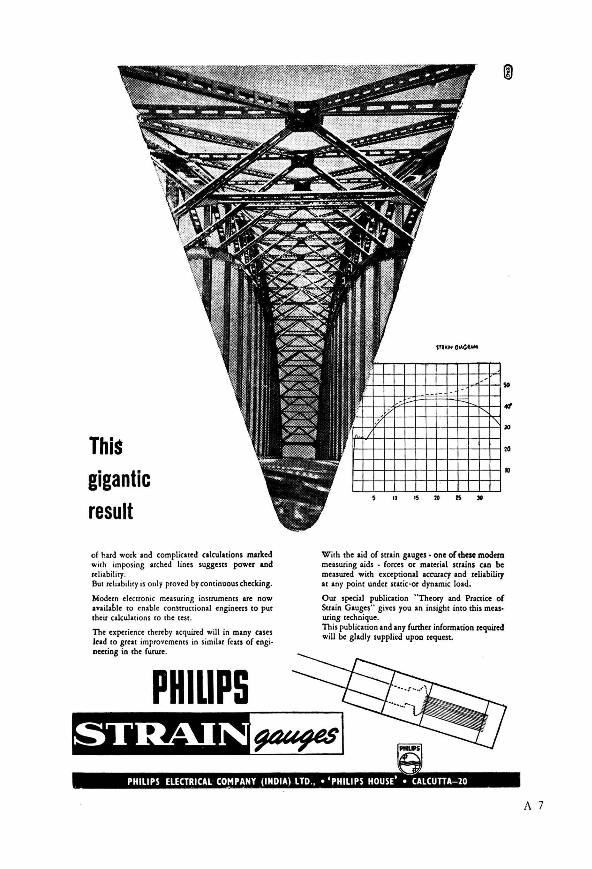
This gigantic result
of hard work and complicatod calculations marked with imposing arched lines suggests power and reliability. Bur reliability is only proved by continuous checking.
Modern electronic measuring instruments are now Ivallable to enable con:ntuctional engineers to put their calculations (0 the tcSt.
The cx~rjencc thereby acquired will in many cases Itad to great improvements in similar (cats of cnginettiog in the future.
PHiliPS
~~~~-+-+-+-+-+-+-+-+-+~20
H~-t-+-t---t--t-+-+-+-t-H~IO
10 15 2. IS
With the aid of strain gauges. one of these modem measuring aids . forces or m.u~rial strains can be measured with exceptional accuracy and reliability at any point under static·or dyn&mic load.
Our special publication "Theory and Practice of Suaio Gluges" gives you an insight into this meas· uring technique. This publication Ind Iny further information required will be gladly supplied upon ,.quest.
A 7

PETROL GAS PLANTS NAMES OF A FEW OUT OF MANY INSTALLATIONS:
Electrically Worked Our • G S' Plants are found most suitable for Laboratory, Industrial and Domestic uses.
Simple but sturdy construction and mechanism, requiring no expert for installation or working: cheap and efficient.
Made in various capacities from 10 to 250 B. Burners: Prices from Rs. 650/- to Rs. 60001-
Also Makers of all types of laboratory gas burners and hardwares, viz. Gas Taps, Clamps, Stands, Ovens, etc., etc.
College of Technology, Colmbatore School of Military EngineerIng, Kirkee H.Q. Engineering Laboratory ( Solis), Klrkee ' Medical College, Ahmedabad Pharmacy College, Ahmedabad Sarabhal General Hospital, Ahmedabad Central Drug Research Institute, Lucknow . P.W.D. Relearch Laboratory, Lucknow Co-operative Dairy Laboratory, Lucknow Patna Women's College, Patna Fuel Research Institute, Jealgora, Dhanbad
GANSONS Ltd. Office _ DADA", P.O. B 5576,
BOMBAY Work. - LALBAUG, BOMBAY
FARMING THE JOURNAL OF
AGRICULTURAL PROGRESS
* Britain's leading technical monthly for farmers, breeders and growers. Articles by leading authorities describe the practical application of the latest scientific and technological advances to their particular branch of the industry.
SINGLE COPIES, MONTHLY 1/6d ANNUAL SUBSCRIPTION 19/- post free
A 8
* From any bookseller, or direct (rom:
JARROLD & SONS L rD. COWGATE, NORWICH
ENGLAND
THE MAGAZINE OF SCIENTIFIC PROGRESS
* Britain's leading magaZine for scientists and laymen alike. Authoritative, fullyillustrated articles explain in non-technical language the latest developments in all branches of scientific and technological progress.
SINGLE COPIES, MONTHLY 1/6d ANNUAL SUBSCRIPTION 19/- post free
'* From any bookseller, or direct (rom :
JARROLD & SONS LTD. COWGATE, NORWICH
ENGLAND

\ \ \ \ \ \ \ \ \ \ \ \ \ \ \ \ \ \ \
Perhaps you may find just the chemical or material you need to improve your product, or increase
" your production efficiency. These Du Pont com· pounds are the result of years of patient, persistent research, for which Du Pont is world·famous. And manufacturers everywhere use them with complete confidence.
We couldn'j list them in detail, so please write us for more information on those that interest you. Tell us your problem. We'll offer individual Technical Service-help you in any way we can. Write to: Organic Chemicals Department, Room 704, Export Section, E. I. du Pont de Nemours & Co. (Inc.), Wilmington 98, Delaware. U.S.A. , or to your local Du Pont
\ \
distributor. ..... ..... " "
forunlfor .... lty and high quality, count OR the.e product. of Du Pont Chemical lIe.earch
for the TEXTILE industry A complete line of dyeflu.s to meet practically every color requirement for conon, rayon, 'nylon, silk, wool, linen, jute and other libers. HOliery finishes. "Zelan" and uAridex" water repeUents. Softening, finishing, cleaning. wening. scouring agents.
for the PETROLEUM industry Antioxidani •• Colors. Metal deacti. vator • Tetraethyllead (gasoline anti· knock compound.) • Lubricant as· • i.tants.
®P08J) "It. U. s. ,,..,. Of',
for the RUBBER industry Accelerators and antioxidant. for rub. ber or .ynthetic rubber • Colors for dry rubber and latex. Stabilizing. wet. ting, blowing and peptizing agent •• Neoprene (synthetic rubber (or mak. ing product. which re.i.t the action of oils, solvents, heat, oxidation, sunlight).
for many other industries Dyes for paper. leather. wood • Inter. mediate •• Camphor (tablet or bulk) • Aromatic chemicals. Falty alcohol_ Resin products. Solvents. Vitamio •• "Delsterol" (Vitamin 0,) • "ul·O. Glass" (plaslic-coated wire me.h),
IETTIa THINGS .oa lima LMNO • • • THlOIJOH CHfAISlIIr
ORGANIC CHEMICALS DEPARTMENT
A 9

~ .......... ~.",..."..~~~..",...",.."~.,~.".",.""...",....,...""...,..,,.,..,
Our :Reliable' &, Prompt Service I'
A BOON TO THE INDUSTRIES \
DIRECT IMPORTERS & STOCKISTS
OF LABORATORY REQUISITES OF
EVERY DESCRIPTION FROM" A" TO "Z"
INC L U DIN G C HEM I CAL S, ETC.
Full particulars from:
~ ~
I U N I QUE ~~~~N~ l
51·53 NEW HANUMAN LANE 1 s--_____ -... .............. ~~~~ _____ l
"BOROSIL" AMBER NEUTRAL VACCINE BULBS
ALL CAPACITIES • MACHINE MADE
-Can be had from:
BOROSIL GLASS WORKS
• PROPRIETORS:
INDUSTRIAL & ENGINEERING APPARATUS Co. Ltd.
A 10
CHOTANI ESTATES, PROCTOR ROAD
BOMBAY 7
+++++++++++++++++++++-++++++++.++++++++++++++

.61
ONLY ONE CAN 8E FIRST
7 .
• sulphatriad Is . a neW drug. I ha_therapy.
More than ,ust w Idea In sU p stallur1a. fundamentall~ n~ to eliminated ~~~ster full
a IIy des1gne to a m mpll-Speclflca . d' permits you
f of renal cO
• Sulphatna d s without ear therapeutiC ose . powerful cations. f three of the ~~~~iazole and
Comprised 0 Iphadiazlne. sulp tion based on sulphonam~~~~;~~n a speclalc~,:b~:tlre range n~~ sulphamer rch. It covers dlvldual compou clinical resea hlch the In conditions ~~~h;tO employed. have been
L AMONG SULPHONAM/DES IT'S
~SULPHATRIAD' Brand COMPOUND SULPHONAMIDE TABLETS
EACH TABLET CONTAINS Sulphadlazine Sulphathluole Sulphamerazlne
0' 185 Gm. 0'185 Gm. 0 ' 130 Gm.
• SUPPLIES :
25 x 0'50 Gm. tablets 100 x 0'50 Gm. tablets 500 x 0'50 Gm. tablets
MAY & BAKER LTD. • Tud. Hark
D , It.'b. .. ,. , I1AY • IAKIII (INDIA)LTD . • IOI1IAy . CALCUTTA.I1AD~AS.LUCKNOW
, A 11

Please include us in your suppliers' list
FOR EVERYTHING IN
IMPORTED LABORATORY & SCIENTIFIC GLASSWARE GOODS & MEDICAL, HOSPITAL, RUBBER & SURGICAL GOODS
• Ask for our catalogue
BOMBAY SURGICO-MEDICAL AGENCY LTD. LARGEST IMPORTERS '" STOGKISTS OF SURGICO.MEDICAL '" SCIENTIFIC GOODS
113 CHITTARANJAN AVENUE CALCUTTA 12
BHARUCHA BUILDING PRINCESS STREET, BOMBAY 2
rs~i~~~ifi;" 'i~;;;~~~~~~'" .............. ·1
. LABORATORY GLASSWARE t t• SILICA WARE & PORCELAINW ARE ;
PLATINUM-WARE HYDROMETERS & THERMOMETERS CINTERED GLASS FUNNELS &
CRUCIBLES FILTER PAPER, CHEMICALS, ETC.
Available from:
ZILL & CO. 128, PRINCESS STREET B 0 MBA Y 2 ( India) .......................................... .. -.
A 1-2

Sole Agents for INDIA
BURMA Ir CEYLON
for laboratory and small-scale production
a mechanically operated pestle and mortar serves a useful purpose. The Pascali End Runner Mill is ideal for grinding and mixing dry or wet material. Fitted with 10' dia. porcelain mortar and hinged pestle that can be swung clear of the mortar. Available either motorized or with pulleys for drive from an existing line shaft.
PASCALL END RUNNER MILL
GIDVANI & CO. PEOPLE'S BUILDING
SIR PHEROZESHAH MEHTA ROA~, FORT, BOMBAY
T HIS new B.D.H. development has already found practical application in many laboratories. Con
centrated volumetric solutions can be stored without danger of deterioration ~nd in small space.
The contents of each 80 ml. ampoule. when diluted as directed. provide 500 ml. of solution accura tely standardized within the factor limits of 0.999 ar.d 1.001.
B.D.H. CONCENTRATED VOLUMETRIC SOLUTIONS
in cartons each containing seven ampoules Prices and further information on request
THE BRITISH DRUG HOUSES LTD.
B.D.H. LABORATORY CHEMICALS GROUP POOLE ENGLAND
Dlatrlbutore la ladle
BRITISH DRUG HOUSES (INDIA) LTD.
P.O. Box 1341, Bombay P.O. Box 9024, Calcutta
CVS/Ind/2
A 13

And NOW G-R Decade-Inductor Units and Decade
As companion instruments to the popular Decade Resistance and Decade Condenser Boxes, G-R announces equally useful laboratory accessories in
the new Type 940 Decade-Inductor Units and Type 1490 Decade Inductors.
These high-quality decade inductors cover the range from one millihenry to ten henrys. They are intended primarily for use at audio and lower ultrasonic frequencies as convenient, ac<.:urately adjusted and stable elements in wave filters and tuned circuits.
FEATURES • Toroidal Construction: each unit is an assembly of four
toroids wound on stabilized molybdenum permalloy dust cores; the coils ( relative value of I, 2, 2, 5) are connected in series, the switch short-circuiting combinations of coils to give eleven successive values from 0 to 10.
• Storage Factor Q: much higher than obtained with aircore coils; maximum values of 200-300 occur between 2 and 5 kc.
• Multi-layer Windings: to minimize doc ohms-per-henry ratios and increase both storage factor Q and natural frequency; special toroidal winding machine used to produce a progressive multi-layer winding.
• Astatic to External Magnetic Fields: complete and uniform toroidal winding essentially astatic except for equivalent singleturn loop effect.
• Low Copper Loss: doc resistance of lowest decade 60 ohms per h ; other three decades 44 ohms per h.
• Good Electrostatic Shielding provided by aluminium mounting frames and coil covers.
• Accurately Adjusted: at zero frequency and initial permeability between ± 2% for the I mh step. and ± 0'25 % for the I h step.
• Very Low Temperature Coefficient: about -24 parts per million per deg. C.
• Metal Cabinet adds to shielding; both terminals insulated from panel .. . ground terminal provided .
• Maximum Voltage of 500 volts r-m-s for all coils. TYPE 1490-A DECADE -INDUCTOR,I henry total. in steps of
0'00 I henry. TYPE 1490-8 DECADE - INDUCTOR, 10 henrys total. in steps
of 0'001 henry. Factory Representatives:
Inductors
tnE 940 OEC .. DE .... DUCTO. UNITS
TYPE MO .. A , 0 .0 1 hf!flry in 0 .00 1 h ,fep.
TYPE 90t0.t. 0.1 henry in 0 .0' h ,tep.
TYPE .40,,(, 1 henry in O. t h ".p. TYPE '''0· 0, 10 henry. in 1 h ,tep.
EASTERN ELECTRIC & ENGINEERING co. ESTABLISHED 1909 Telegram: Telephone:
30937 (J line.) 127, Mahatma Gandhi Road, Post Box 459. Fort, Bombay .. EASLEKTRIK ..
AGENTS:
THE 25. Chowringhee
Post Box 2589 CALCUTTA
Phone : Bank 1953
A14
CHICAGO TELEPHO NE -48, Hazratganj 196, Mount Road
Post Box 46 Post Box 5238 LUCKNOW MADRAS 2 Phone: 860 Phone: 84357
TELEGRAMS .. CHIPHONE"
& RADIO CO., LTD. 68. Queensway -422, Lamington Road
Post Box -47 BOMBAY 4 NEW DELHI Phone: 7179 Phon e : 40033
ALL OFFICES

, :
I
........................................................... .............,. ...................................................................................... · ..................... t
SILICA GEL ! PRACTICAL VALUE
The adsorbed substances can be removed from Silica Gel by application of heat and the Gel used again for furth.n adsorption. This process of adsorption and desorption
can . be repeated indefinitely.
, LABORATORIES are requested to use it in place of calcium chloride or
sulphuric acid and thus save money.
Can be had NATURAL or with INDICATOR , from ~
I RA!~S~I~ BUI~N~~NB~OADCO. I ; FORT, BOMBAY ~
1 Telegrams: TECHLAB Telepbone : 2730f i .... ~ ... ~ ................ ~~ .............................. # ........... # ...................... #.# .. # .. .
i###----####~~~:;~#-~~--~-~-~-~#~~~#~-;-~-~-----##--.-#-i
\ PAGE :
: ANDHRA S CIENTIFI C Co. LTD., MADRAS A 17 ,t ASSOCIATED INSTRUMENT MANUFACTURERS ( INDIA) LTD., CALCUTTA A 20
: BENGAL CHEMICAL & PHARMACEUTICAL WORKS LTD . , CALCUTTA A 4 , , BOMBAY SCIENTIFIC GLASS WORKS, BOMBAY ' A 4 , , BOMBAY SURGICO-MEDICAL AGENCY LTD ., BOMBAY A 12 ; : BRITISH DRUG HOUSES (INDIA) LTD. , BOMBAY . .. A 13 , , C OUNCIL OF SCIENTIFIC & INDUSTRIAL RESEARCH, NEW DELHI A 16 ; : DISCOVERY, EMPIRE PRESS, NORWICH, ENGLAND.. . A 8 • , EASTERN CHEMICAL CO. ( INDIA), BOMBAY A 6 , ~ EASTERN ELECTRIC & ENGINEERING CO., BOMBAY A 14 t • E . 1. Du PONT DE NEMOURS & CO . ( INC. ) A 9 , FARMING, EMPIRE PRESS, NORWICH, ENGLAND A 8 t : GANSONS LTD., BOMBAY. . . A 8 " , GENERAL ELECTRIC CO . LTD . , BOMBAY A 21 ,
,~ GIDVANI & Co. , BOMBAY . .. A 13 , GRIFFIN & TATLOCK ( INDIA) LTD., CALCUTTA A 18 ,
, INDUSTRIAL & ENGINEERING ApPARATUS CO. LTD ., BOMBAY.. . A 10 , , MARTIN & HARRIS, LTD ., BOMBAY A 22 ,
,~ AAl~ 'I • MAY & BAKER (INDIA) LTD., BOMDAY MYSORE INDUSTRIAL & TESTING LABORATORY LTD . , BANGALORE
~ NATIONAL REGISTER OF SCIENTIFIC & TECHNICAL PERSONNEL IN INDIA • •• A 16 , PHILIPS ELECTRI CAL Co . ( INDIA) LTD ., CALCUTTA A 7 ,
: R AJ-DER-KAR & Co., BOMBAY A 5, A 15 , , THE SCIENTIFIC INSTRUMENT CO. LTD., CALCUTTA A 2 t : UNION SCIENTIFIC SYNDICATE, BOMBAY A 4 , , UNIQUE TRADING CORPORATION, BOMBAY A 10 , , ZILL & Co. , BOMBAY A 12 ,
~ ~ ... ~ ................. ~ ......... # .. #.-......... -~ ... -..... #~.-.---•. --.--.-..... . A 15

COUNCil OF SCIENTIFIC & INDUSTRIAL RESEARCH Applications are Invited for the following posts in the Soils and Bituminous
Divisions of the Central Road. Research Institute, New Delhi:
SCALE OF pAY
I. SENIOR SCIENTIFIC OFFICERS - Rs. 350-30/2-410-30-590-EB-30-770-40-850
2. SENIOR SCIENTIFIC ASSISTANTS - Rs. 250-25-500
3. JUNIOR SCIENTIFIC ASSISTANTS - Rs . 160-10-330
4. LABORATORY ASSISTANTS - Rs. 100-5-120-8-200-10/2-220
QUALIFICATIONS
Degree in Engineering, Ph.D., or M.Sc., or B.Sc., with Road Research exparic. nce.
Last date for receipt of applications is 16th September 1950. Full perticulars and
forms of application can be obtained fl-om
THE SECRETARY COUNCIL OF SCIENTIFIC & INDUSTRIAL RESEARCH 'P' BLOCK, RAISINA ROAD NEW DELHI
NATIONAL REGISTER OF SCIENTIFIC & TECHNICAL PERSONNEL IN INDIA
The Council of Scientific & Industrial Research has pleasure in announcing the publication of Vol. I, Part I of the NATIONAL REGISTER OF SCIENTIFIC & TECHNICAL PERSONNEL IN INDIA.
A 16
Vol. 1- ENGINEERS, Part I No. of pages 392 Price Rs. II
Now Ready
Vol. 11- MEDICAL PERSONNEL, Part I
For copies and particulars, please write to : THE CHIEF EDITOR DICTIONARY OF ECONOMIC PRODUCTS &
INDUSTRIAL RESOURCES OF INDIA 20 PUSA ROAD, KAROL BAGH NEW DELHI

POLARIMETER IDEAL FOR CHEMISTS - RESEARCH & INDUSTRIAL
LABORATORIES
Fitted with lippich device which makes the instrument sufficiently accurate and at the same time simple. Can be used with sodium burner or an electric lamp with suitable filter interposed into position between the source of light and the polimeter.
The circular head attached near to the analysing Nicol and a Vernier movable with this enables reading of the optical rotation accurate to 0'1 degree. A 200 mm. tube forthecontainerofthesolution under study for its optical activity is su pplied with the instrument. Mounted upon asuitable base.
FOR FURTHER INFORMATION
PLEASE WRITE
THE ANDHRA SCIENTIFIC Co. Ltd. TO US.
Head Office &
Factory
MASULIPATAM
Sales Warehouse & 8ranches Show Room BOMBAY
4, BLACKER'S ROAD, MOUNT RD., GUNTUR MADRAS 2 VIZAGAPATAM
A 17

A 18
OERTLING
APERIODIC PRISMATIC
REFLECTING BALANCE
* Sole Agents •
GRIFFIN & TATLOCK (India) LTD. BS Clive BUildings
P.O. Box No. 2136 CALCUTTA
274 Hornby Road
BOMBAY
76 Queensway
NEW DELHI

The Indian Salt Industry
T HE Report of the Committee of Salt Experts constituted by the Government of India in April 1948, which has now become available, deals
comprehensively with the present position of the Indian salt industry and discusses the directions in which the industry should be developed so that it may attain, within a short time, the status it is entitled to by virtue of its importance as an article of food and as a basic raw material for the heavy chemical industry. With the abolition of the excise duty on salt, the present Salt Department of the Government of India has ceased to be a revenue-collecting organization ; its functions have to be oriented to those of a development department. How should the Department be reorganized so that it may fulfil its new responsibilities ? What are the problems of the salt industry which await investigation and research so that it may develop into its full stature? These are the questions which the Report discusses in a refreshingly realistic manner.
The Committee confirms the view generally held in knowledgeable circles that salt production in India can be increased within a short period, and that self-sufficiency with regard to this vital requirement of the population can be attained. Urgent as the improvement in quantitative production is, the need for raising the quality of salt and for recovering the valuable by-products of the salt industry is no less urgent and important. It must be emphasized that common salt has the unique distinction of being the foundation material for the great modern chemical industry. The Leblanc process for making soda ash from common salt is regarded as the beginning of the inorganic chemical industry. Competent
authorities aver that the -electrolytic chlorine cell is the fundamental basis of the prodigious array of organic chemicals. The production, standardization and utilization of a raw material so basic to the chemical industry, and yet so abundant, should necessarily receive serious attention. The example of Dow Chemicals Ltd. illustrates the possibilities for the production of chemicals from the limitless deep, and thanks to the research programme consistently fostered by the enlightened founder of the organization, Dr. Herbert Henry Dow, a gigantic _chemical industry based on common salt has . been built up. That similar possibilities exist in India has been amply demonstrated by the pioneering efforts of the late Mr. Kapilram H. Vakil who planned and directed the salt works and the by-product plants at Mithapur. Such developments are, however, exceptional; the Indian salt industry remains, by and large, in a recumbent and primitive condition, and traditional rule-of-thumb methods, uninfluenced by modern technological developments, operate in salt production. The salt manufactured in many areas is sub-standard and that in some areas, such as Didwana, is unfit for human consumption. The industry is in dire need of technical aid, and the time has arrived for directing serious attention to improving the quality of Indian salt.
The industrial plants at Mithapur for the systematic recovery of magnesium chloride, magnesium sulphate, potassium chloride, bromine and, more recently, gypsum, provide an object lesson in the utilization of marine salts for the development of chemical industry. The unique rewurces .of the landlocked lakes of Rajputana have so far received but scanty attention. These inland lakes represent vast chemical reservoirs
307

J. SCI. INDUSTR. RES., V. 9A, 1950
constantly replenished by streams flowing over salt-bearing beds. The spontaneous salt formed in the Rann of Kutch and distributed over the catchment area of the lakes by stormy winds is dissolved by rain water and carried to the lakes whose salt contents are thus continuously enriched. The resources of some of these lakes are inexhaustible. Like the Salt Lakes of California and Nebraska, the Great Salt Lake of Utah and the Dead Sea, the Rajputana desert lakes provide resources which await exploration and planned exploitation. Climatic conditions prevailing in the lake areas are conducive to the development of the industry. Low rainfall, long periods of dry weather, high winds and fairly high temperature provide ideal conditions for solar evaporation. The climate is a most valuable asset next only to the richness of the lakes. By supplying proper conditions for the crystallization of marine salts, it is possible to separate the valuable salts from those of lesser value and individual salts from their mixed solutions. The Desert Chemical Co. of California recovers from the saline water of the Dale Lake (which is similar in many respects to the lake water of Didwana) not only common salt of high quality, but also the valuable by-product sodium sulphate. The Palestine Potash Ltd. has been exploiting the resources of the Dead Sea for the extraction of potassium salts and bromine. Science and technology provide the means for utilizing the natural resources of the inland salt lakes for building up chemical industries.
The waters of Sambhar and Didwana lakes are rich sources of sodium sulphate,
308
sodium carbonate and sodium bicarbonate. For every ton of common salt recovered from Didwana Lake, it is possible to recover 1 to t ton of sodium sulphate. This valuable material has many industrial applications among which may be mentioned the production of caustic soda and sulphuric acid by electrolysis. The recovery of all these by-products would not only help in building up a flourishing chemical industry but, at the same time, also improve the quality of salt produced and lower the costs of production.
The Indian salt industry poses many problems for solution. The Salt Research Committee of the Council of Scientific & Industrial Research, which is fully seized of their importance, has already initiated a few research projects of practical importance. The Committee of Salt Experts has recommended the establishment of model factories with facilities for undertaking largescale development programmes in the more important salt-producing regions. This recommendation is opportune and must be welcomed. If this recommendation is accepted and brought into effect, new facilities would become available for the commercial utilization of the results of research and inquiry sponsored by the Council of Scientific & Industrial Research. Knowledge and means for acquiring more knowledge required for solving the problems of the salt industry exist. What is needed now for developing the industry is a determined effort by all concerned - scientists, technologists and industrialists-to put knowledge into action, to transform plans and visions into plants and processes.

Characteristics of the Ionosphere over Calcutta (June 1950)
S. S. BARAL, R. K. MITRA, D. C. CHOUDHURY, R. B. BANERJEE & A. P. MITRA Ionosphere Laboratory, University College of Science, Calcutta
T HE following are the ionospheric data observed at Calcutta for the month of June 1950. The mean hourly values of the
penetration frequency of region E and the penetration frequencies and virtual heights of region F2 are represented in Fig. 1 in graphical form. The figures are obtained from average values of data taken for each hour of the day for 5 days a week. Fig. 2 gives the prediction of the maximum usable frequencies for different distances of transmission by reflection at the F region over Calcutta for the month of September 1950. Table I records the occasions during routine observations when sporadic E ionization was observed and the correspond-
16,-------------------,
14
4
2 _ .. -_ .. _-
32~--------------------------~
4
o 4 8 12 16 LOCAL MEAN TIME
AT POINT OF REFLECTION.
20
FIG. 2 - PREDICTED M.U.F. VIA F. LAYER DURING THE MONTH OF SEPTEMBER 1950.
ing values of penetration frequencies and heights.
Sporadic E ionization was found to occur keqUeIrffy during evening and night and sometimes during the afternoon. Sporadic E occurred more frequently during night than during day in the present month. Region F2 ionization was found to remain steady up to midnight and during the evening ,there was a slight rise. The fall in ionization during night is very slow and the
°O~--4-!---8-:!---1-':-2--j-':-/j--l7:0:--~0 lowest value of fOF. reached (6·8 Mc./s.) LOCAL MEAN TIME is several times larger than the corres
5 HOURS 54 MINUTES AHEAD OF G,M.T. FIG. 1 - JUNE 1950.
ponding value (3·0 Mc./s.) during the last winter months.
309

J. SCI. INDUSTR. RES., V. 9A, 1950
TABLE I TABLE I - coli/d.
MONTH & DATE HOURS rEs hEs MONTH & DATE HOU RS r hEs YEAR YEAR
Es
Me. Km. Me. Km.
June 1950 00.00 6 ·00 120 June 1950 15 20.00 3·35 105 .01.00 3 ·70 105 22.00 4·00 120 02.00 3·50 105
2 3 ·30 90 16 09.00 9·50 ISO
1B.00 17.00 4·15 135 22.00 4·10 105 1B.00 4·15 135 23.00 5 ' 00 120 21.00 3 ·00 120
3 00.00 4·20 105 22.00 4 · 00 105
01.00 4 ' 10 120 17 09.00 3·70 90 02.00 3·20 105
6 1B.00 4· 20 105 19 22.00 3·00 105
19.00 4·20 120 20 02.00 4 ·05 105 20.00 3·60 135
21 .00 4 ·00 120 03.00 4'SO 120 22.00 3 ' SO 105 04.00 4·50 120
16.00 4 · 50 120 7 17.00 3 ·70 105 17.00 4 ' 00 105
1B.00 4 · 25 120 18.00 4 ·05 120 19.00 B'OO 135 20.00 B' 15 150 21 21.00 3 · B5 105 21.00 6 · 20 ISO 22.00 3 ' B5 90 22.00 4· 50 ISO 23.00 4 · 10 120 23.00 4 '00 135
B 06.00 5'00 135 22 _ 23.00 3 ·00 105
07.00 4 ·20 120 23 00.00 4 · 25 120
9 01.00 5-00 135 04.00 3-00 105 02.00 4 ·20 120 23.00 3-60 105
14 20.00 ' ·15 120 24 00.00 4 ·05 105 21.00 3·70 105 01.00 3 -00 120 22.00 3·50 105 03.00 3 ' 40 105
Electronic Meteorological Instruments in the India Meteorological Department
S. P. VENKITESHWARAN
I nstrumel1ts Section, Meteorological Office, Poona
T HE techniques of electronics have found application in many branches of experimental science. In meteorology, the tendency to use these
techniques has been growing rapidly and, in India, various instruments employing radio tubes are being designed or are being used for meteorological observations on the ground and in the upper air. Some of the instruments designed and in use by workers in agricultural meteorology at Poona have been described in a paper by Ramdas1. The present paper describes briefly a few of the other instruments designed
310
or in use in the India Meteorological Department.
The Radiosonde
The first instrument to be designed and constructed was the radiosonde to measure the pressure, temperature and humidity in the upper air. This consists of a meteorograph in which the elements which vary with pressure, temperature and humidity modulate a light single-valve wireless transmitter on a wavelength of about 4 metres. The wireless signals are received and recorded on the ground with special equipment <\nd

VENKITESHWARAN: E LECTR ON IC METEOROLOGICA L I NSTRUMENTS
the data evaluated. Two types of instruments are in usc by the Department, one of which was developed at Delhi and employs a small clock-work rotating a special contacting arrangement to transmit the signals. This is in regular use at four observatories in India. The second type (FIG. 1), which was designed at Poona and is now in use at eight stations in India, employs a paper fan rotating during the ascent of the balloon and operating a different type of switching arrangement. These instruments have been described in some of the publications of the India Meteorological Department2•3• Many accessories required for their manufacture, calibration, etc.. have been designed and constructed4•5• The ground equipment to receive and record the wireless signals from the F-type meteorograph sent up with the balloon is shown in Fig. 2.
The Radar
A later and more recent application of electronic equipment for the measurement of meteorological elements has been made by using the radar. Knowledge of the speed and direction of the wind in the upper
FIG. 1 - F -TYPE METEOROGRAPH.
FIG. 2 - GROUND EQUIPMENT TO RECEIVE AND RECORD WIRELESS SIGNALS FROM THE F-TYPE METEOROGRAPH .
air is helpful for the forecasting of weather and this information is normally obtained by observing the movement of hydrogenfilled balloons with the help of theodolites. This method fails completely during bad weather, as the balloon cannot be followed
311

J. SCI. INDUSTR. RES., V. 9A, 1950
when it enters the cloud. No information about winds will, therefore, be available above the cloud base. This difficulty has been overcome by the meteorologist by adapting the radar for this . purpose. An artificial target is suspended from the hydrogen-filled balloon to reflect the energy from the radar transmitter and this enables the position of the balloon to be located in the sky. It is thus possible to obtain information about upper winds to great heights even above the cloud. base and at night when the usual theodolite method fails.
The India Meteorological Department has acquired a few radars which are being used regularly at the observatories at New Delhi and Poona. This radar (A.A. No.3, Mk. III ) is of the early type and works on a frequency of 204 mc. One Yagi array is used for transmission and four Yagi arrays are used for reception through a lobe switching arrangement (see Cover). The range is determined by an automatic range unit. The balloon is tracked both in elevation and azimuth by two observers and one observer keeps note of the range. Corner reflector type of targets are efficient at microwaves, but they are not so effective at 200 me. and, therefore, crossed dipole targets are used, which absorb the radiation of the radar transmitter and re-radiate.
The method of determining upper winds with the radar by using a passive target, i.e. a target which does not originate a signal but merely reflects the incident energy, has some disadvantages. Usually, only shorter ranges are obtainable with radars. The greatest handicap is the ground clutter and other unwanted echoes which tend to mask the desired signal. This difficulty can be overcome if, instead of a passive target, a small wireless transmitter on 204 mc. is attached to the balloon, which can be followed with the receiving equipment of the radar. Equipment employing active targets is more expensive, if employed only for obtaining upper wind information. However, active targets are employed in all types of radio-meteorographs and, as such, it should be possible to track them with the receiving equipment of the radar for upper winds. Maximum advantages will be obtained from the radar if it can be used to follow both active or passive targets. When an active target like the radio-meteorograph
312
signaller is followed, the transmitter in the radar set will not be operated.
Earlier observations on the influence of the troposphere were found to be most marked for radio-wave trajectories near the surface of the earth, and they were mostly reports of unorthodox vision beyond the geometrical horizon, maximum ranges sometimes extending to even ten times the distance of the geometrical horizon. This started a new branch of study of propagation of these waves and how they are influenced by the meteorological conditions of the atmosphere. Some interesting observations regarding the behaviour of the radar waves on 204 me., when employed to follow balloons carrying dipole targets, have been made at Poona. It is observed that in certain seasons and under certain temperature and humidity distributions, reflections from the balloon target are lost below certain angles of elevation. Detailed examination of this phenomenon is on hand.
Though the India Meteorological Department has, at present, the old type of radars operating on a wavelength of 1·5 metres, it is most likely that a few radars operating on much lower wavelengths, of the order of about 10 cm. or less, may be obtained in the near future. When radio waves are incident on rain drops, a part of the energy is absorbed and a part is scattered. Due to these processes, the incident beam is attenuated and this effect increases as the wavelength is reduced. The effects are not important on wavelengths of one metre and above, but become appreciable at wavelengths of 10 cm. and below. The scattering by water drops or precipitation in frozen form are observed as radar echoes, and the meteorologist is able to get from them an idea of the distances of the region of precipitation and also the distribution of rain in the weather phenomenon. Radars operating on such short wavelengths can be used both for tracking balloons with suitable targets for determining upper winds and in connection with storm detection and consequent improvements in short-range weather forecasting.
Distant Readin~ Wind Instruments
With the increased use of aviation for civilian transport, the demand for meteorological reports from aerodromes have also increased considerably. The data have to be

VENKlTESHWAHAN: ELECTRONIC MEtEOROLOGICAL INSTRUMENTS
FIG. 3 - THE DISTANT READING ELECTRONIC WIND-SPEED INDICATOR.
supplied both to the planes in the air and on the ground with the least delay. Different types of instruments have been designed to measure the velocity and direction of the surface winds from the room of the observer without going up to the anemometer or windvane which are usually located in places which are not easily accessible. The Instruments Section at Poona has developed a distant reading wind-speed indicator and a windvane using Selsyn motors6 (FIG. 3). In the electronic windspeed indicator, a radio frequency voltage of 30 kc. is generated in the observer's room and fed through a pair of cables into a coil fixed in a box at the foot of the spindle of the 4-cup anemometer. Another coil is fixed just below the first and the voltage induced in this is fed to an amplifier in the observer's room through a pair of cables. A brass circular vane with ten sectors fixed on the anemometer spindle rotates in the space between the two coils and varies the mutual inductance between them. The induced voltage in. the secondary coil is modulated by the rotation of the vane and the modulation frequency will be proportional to the rotation of the spindle, i.e. the velocity of the wind. The induced
voltage is amplified and the varying portion of the voltage, which is obtained after detection, is converted into square wave pulses of constant amplitude and then fed into a frequency discrimination circuit which indicates the frequency of the modulation by means of a microammeter, calibrated in miles per hour. The direction of the wind is obtained at a distance by coupling a Selsyn motor to the spindle on the vane.
The Ceilometer
The knowledge of the height of low clouds is very important to the aviator. At night it is determined quickly by measuring the angle of elevation of the illuminated patch under the . base of the cloud from a vertical beam of light from a searchlight situated at a known distance from the place of observation. However, this method cannot be used during the day. A photoelectric method of measuring cloud heights , in the day time has been developed in the U.S.A. The light spot on the cloud cannot be seen in the day time as the brightness of the underside of the cloud is very much brighter than the spot. When a modulated light beam is used, and a photoelectric telescope which is sensitive only to the modulated beam and not to the steady light of the day is employed, . the angle of elevation of the illuminated patch can be determined. It appears that the circuit we have already employed in the Poona electronic anemometer appears to be suitable for this purpose. Steps are being taken to design in our laboratories a ceilometer on the above lines which can be used to determine the height of the base of clouds both by day and by night.
REFERENCES
1. RAMDAS, L. A. : J. sci. industy. Res., 1948, 7, 16. 2. MATHUR, L. S.: India Met. Deptt. Sci. Notes,
9, No. 112. 3. VENKITESHWARAN, S. P., THATTE, R. P. &
KESAVAMURTHY, A.: ibid., 9, No. 113. 4. VENKITESHWARAN, S. P.: ibid ., 11, No. 134. 5. VENKITESHWARAN, S. P., KESAVAMURTHY, A.,
HUDDAR, B. B. & GUPTA, B. K.: ibid., 11, No. 133.
6. KESAVAMURTHY, A. & VENKITESHWARAN, S. P. : Undey publication.
313

Fluidization - A New Technique . Part I
M. S. lYE N GAR Central Laboratories for Scientific 0- Industrial Research, Hyderabad (Deccan)
ONE of the outstanding achievements of chemical engineering in recent years which has revolutionized a number of industries and which has
opened up new possibilities in other industries is the technique of fluidization. It is only in recent years that the importance of this technique is being more and more realized and a number of countries including India are engaged in intensive research on its applications. In this paper, an attempt has been made to present the salient features of fluidization, its applications to a few industries, and indicate the recent trends in its development.
The imparting of certain fluid characteristics or properties to solid particles is known as fluidization. When a stream of fluid is passed upwards through a mass of solid particles, reproducible changes in physical behaviour are observed which pass through successive stages as the velocity of the fluid is increased. When the velocity of fluid flowing up through a mass of solid particles is insufficient to lift or support any of the solid, the mass is called fixed or moving bed, depending on whether the solid is stationary or moving with respect to the container. With increasing fluid velocities, in the absence of chanelling, the pressure drop through the bed rises until it approaches the net effective weight of the solid per unit area, when the packing arrangement of the particles becomes more open so that the bed expands; with further slight increases in velocity, the particles are fully supported and the expanding bed becomes fluidized. Just at the point of fluidization the mass may form a quiescent fluidized bed. With liquid-solid systems, further increases in fluid velocity give a progressive separation of the particles which remain individually and uniformly dispersed in particulate fluidization. With many gas-solid systems, the bed expands to only a limited extent and a portion of the gas tends to accumulate in gas pockets or bubbles passing through the
314
fluidized bed in aggregative fluidization. In small tubes, the bubbles may grow to a size substantially filling the cross-section of the vessel resulting in slugging. Normally, however, these bubbles remain small with respect to the vessel and the mass becomes a turbulent fluidized bed. Such a turbulent bed can even be maintained above the freefalling velocity for the solid particles in a gas-solid system if the rate at which solids are fed is kept high enough. Finally, if the fluid velocity is still further increased or if the solid feed rate is too low, the surface of the fluidized bed disappears and the whole mass becomes a dispersed suspension.
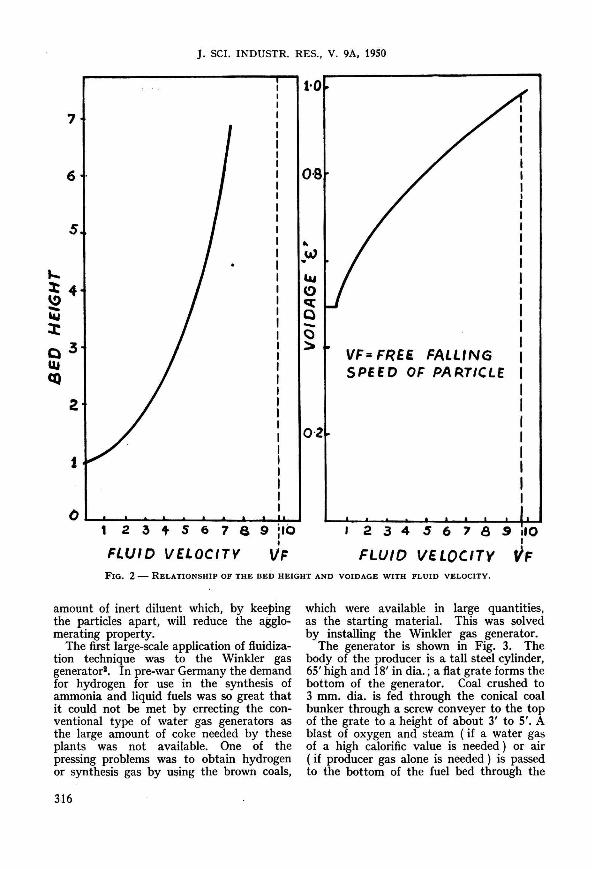
The variation of pressure drop with increase in the velocity of fluid is shown in Fig. 1. It will be noticed that the pressure drop increases with increase in fluid velocity up to the fluidizing stage when it becomes fairly constant and remains independent of further increase in the velocity of fluid. In Fig. 2 are shown the relationship of bed height with fluid velocity and fractional voidage with fluid velocity.
When the solid particles are in turbulent fluidized state or in dispersed suspension, they flow through pipe lines and valves as easily as if they were liquids. They also respond to pressure heads. The turbulent motion of solid particles in the fluidized state also leads to homogeneous mixtures being formed rapidly; or if suitable arrangements are made to measure the temperatures at different regions of the bed, it will be seen that equalization of temperature takes place throughout the bed. The freedom of movement which solid particles possess when in this state is analogous to the freedom of movement which distinguishes the molecules of a fluid from those of a solid. Hence the term fluidization has been given to the process.
The first outstanding application of fluidization technique was to the Winkler gas generator developed in Germany as long back as 1929. This was followed by its

IYENGAR: FLUIDIZATION - A NEW TECHNIQUE
FLUID VELOCITY ~ FIG. t - VARIATION OF PRESSURE DROP WITH
INCREASE IN FLUID VELOCITY.
adoption to the catalytic cracking of petroleum in the United States; its success in this process led to a widespread recognition of the technique as a new method of handling solids. In recent years the technique has been applied to the synthesis of liquid fuels, gasification of coal, washing of coals, purification of town's gas from sulphur, conversion of sulphur dioxide to sulphur trioxide and the oxidation of naphthalene to phthalic anhydride and a score of other processes.
The salient features of the fluidization technique are as follows:
1. The fluidized bed of solid particles acts like a thermal fly-wheel transferring heat from one hot part of the system to the cooler part and so the control of temperature of the reaction is easier. This is due partly to the rapid motion of the solid particles but also due to the fact that powdered solid particles impart heat capacity to the fluid and guard against rapid temperature changes.
2. The rapid motion and frequent collisions of particles prevent the development of abnormal conditions in localized areas. In the usual static bed with a stream of fluid percolating through it, the reaction will have proceeded to a greater extent in the front layers than in the back. But in a fluidized bed, uniform conditions are very quickly established and relatively easy to maintain. Consequently, it is possible to
operate with a much deeper bed, and this is a very important practical advantage that may have a deciding influence on the economic possibility of the process.
3. The fluidized bed of solid particles resembles somewhat a boiling liquid; one characteristic which they have in common is a high rate of heat transfer. This is obviously advantageous where heat exchange is a primary object, but it is also a desirable feature when exothermic chemical reactions take place in the fluidized bed because it makes possible the maintenance of a high through-put without fear of temperature becoming excessive.
4. When a chemical reaction is taking place between a gas and a solid, the effect of increase in surface due to the solid particles being in a fluidized state, as compared to the static bed, will lead to a higher reaction rate. This is so because of the continual relative movement of the individual particles whose surfaces are kept fresh by collisions, and the streaming gas which reduces the film resistance between the reactants.
5. And finally, it offers an easy method of moving large quantities of solids from one part of a process to another and is adaptable to continuous as opposed to intermittent or batch operations.
As opposed to these main advantages, there are two outstanding disadvantages of the fluidization technique. The first is that the rapid mixing and turbulent motion of the particles leads to a greater degree of short-circuiting by the solid between its entrance and its exit than in the case of the conventional static or moving bed. It is, therefore, not possible to use this technique to achieve counter-current flow effect between solid and fluid .
The second objection applies to those processes in which the solid is undergoing change during a reaction, that is, in general, to the non-catalytic processes. Here a difficulty is encountered by the need of maintaining always a suitable gradation of particle size in the fluidizing column. The particle size will be reduced during the reaction. For example, in the gasification of caking coals, due to the agglomerating property, the coal particles will stick to one another resulting in the collapse of the fluidized bed. However, this may be overcome by including with the solids certain
315
J. SCI. INDUSTR. RES., V. 9A, 1950
7
5 ... . w
.... 3:4 ~ -..., J: Q3 lU q)
2
t
O .................. L..-...o"---'----"'----L----L--L--L-!-L-' 1 2 ~ t S 6 7 S 9 .10
I
FLUID VELOCITV VF
&II C) c:(
Q -C) :::.
0·2
VF= FREe FALLING SPE E 0 OF PA RoT/eLf
2 3 4 5 6 7 8 g .10 I
FLUID VE toe/TY VF FIG. 2 - RELATIONSHIP OF THE BED HEIGHT AND VOIDAGE WITH FLUID VELOCITY.
amount of inert diluent which, by keeping the particles apart, will reduce the agglomerating property.
The first large-scale application of fluidization technique was to the Winkler gas generator2. In pre-war Germany the demand for hydrogen for use in the synthesis of ammonia and liquid fuels was so great that it could not be met by errecting the conventional type of water gas generators as the large amount of coke needed by these plants was not available. One of the pressing problems was to obtain hydrogen or synthesis gas by using the brown coals,
316
which were available in large quantities, as the starting material. This was solved by installing the Winkler gas generator.
The generator is shown in Fig. 3. The body of the producer is a tall steel cylinder, 65' high and 18' in dia.; a flat grate forms the bottom of the generator. Coal crushed to 3 mm. dia. is fed through the conical coal bunker through a screw conveyer to the top of the grate to a height of about 3' to 5'. A blast of oxygen and steam (if a water gas of a high calorific value is needed) or air ( if producer gas alone is needed) is passed to the bottom of the fuel bed through the
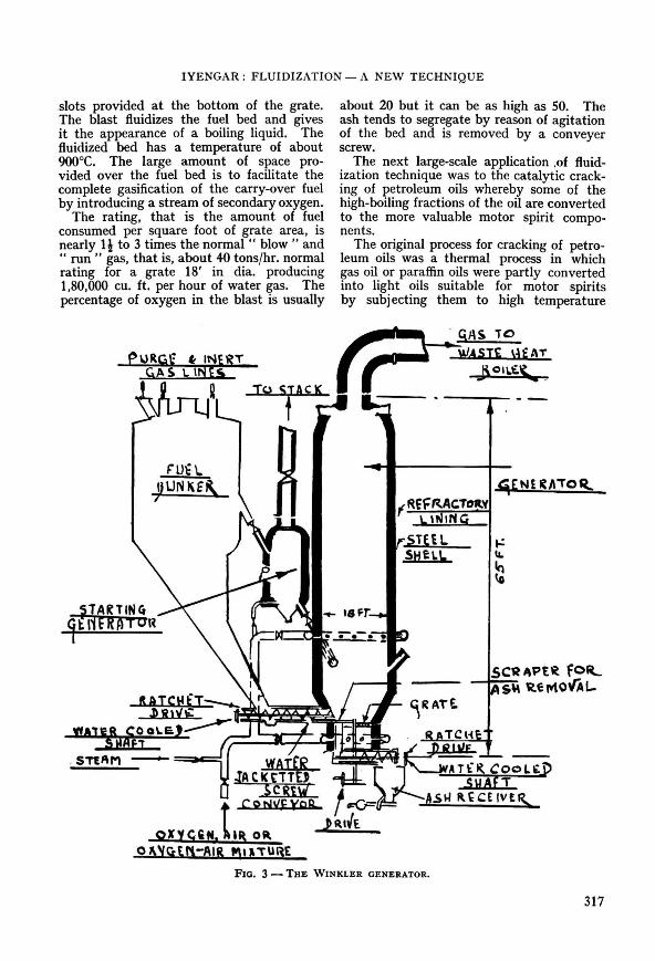
IYENGAR : FLUIDIZATION - A NEW TECHNIQUE
slots provided at the bottom of the grate. The blast fluidizes the fuel bed and gives it the appearance of a boiling liquid. The fluidized bed has a temperature of about 900°C. The large amount of space provided over the fuel bed is to facilitate the complete gasification of the carry-over fuel by introducing a stream of secondary oxygen.
The rating, that is the amount of fuel consumed per square foot of grate area, is nearly Ii to 3 times the normal" blow" and " run .. gas, that is, about 40 tons/hr. normal rating for a grate 18' in dia. producing 1,80,000 cu. ft. per hour of water gas. The percentage of oxygen in the blast is usually
ru-= \. IIUNKE!\ ;
about 20 but it can be as high as 50. The ash tends to segregate by reason of agitation of the bed and is removed by a conveyer screw.
The next large-scale application .of fluidization technique was to the catalytic cracking of petroleum oils whereby some of the high-boiling fractions of the oil are converted to the more valuable motor spirit components.
The original process for cracking of petroleum oils was a thermal process in which gas oil or paraffin oils were partly converted into light oils suitable for motor spirits by sUbjecting them to high temperature
. GAS TO
WASH. ,-\EAT I\OII.~t..
:;..r ~5
fRE~RACTcmv \,,1 ING
r.STEi L. SHt\.L.
SC'R 4Pt~ fOIL AS" ~tMOVAL-
FIG. 3 - THE WINKLER GENERATOR.
317

J. SCI. INDUSTR. RES., V. 9A, 1950
FIG. 4 - SCHEMATIC REPRESENTATION OF THE PLANT EMPLOYING FLUIDIZATION PROCESS FOR THE CATALYTIC CRACKING OF PETROLEUM OILS.
treatment. Later on it was found that the same objective could be achieved yielding a better quality product by passing the vapours of the oils over a suitable catalyst. In the Houdry process the catalyst comprising of activated natural clay or synthetic catalyst of the silicaalumina type was in pellet forms, kept over fixed beds, and the oil vapours were passed over it. But the selective molecular breakdown of oils by catalysis is accompanied by carbonaceous deposits on the surface of the catalyst. This reduces the efficiency or activity of the catalyst and would ultimately inactivate it completely. The successful operation of the catalytic cracking of petroleum oils, therefore, depended on the continuous regeneration of the spent catalyst. This problem was solved by the application of fluidization to the process. The process is schematically represented in Fig. 4. The catalyst in a fine state is entrained by oil vapours and in this condition is conveyed to the reactor. Here the catalyst is maintained in a fluidized state and in this condition the vapours come into better contact with the catalyst. The cracked hydrocarbons are separated from the top. The spent catalyst is drawn from the bottom, entrained by a stream of air and conveyed to the regenerator. Here the carbon on the catalyst is burnt and the regenerated catalyst is ready again to be entrained by a fresh stream of the oil vapours. Thus the cycle of operation is completed.
318
Although high concentrations of solid arc maintained in the reactor and regenerator, the mixture is extremely turbulent and each particle is in rapid motion. It is found that the turbulence results in a very uniform temperature throughout the mass - even in the large-scale reactors the temperature variation between the top and the bottom of the bed is not more than 5°F. in the range 800° to 1,000°F. for the reactor and 1,000° to 1 ,200°F. for the regenerator. The temperatures are varied by changing the amount of heat applied to the oil vaporizer or by altering the amount of hot catalyst in circulation. The degree of cracking of oil vapours depends on the depth of the catalyst bed and on the ratio of the catalyst to the oil vapours, both of which are controllable. It will be appreciated that the fluidization technique has given considerable flexibility to the cracking operation, a quality which is very important from the point of view of process adaptation.
The fluidized bed in the reaction vessel may contain as much as 75 to 100 tons of catalyst in the reactor and 150 to 300 tons in the regenerator. The rate of flow in the different sections of the plant is controllable by sliding valves.
There are about 40 plants in the United States alone using the fluid-catalyst system for oil cracking and some have a capacity of 7,50,000 gal. per day.
In recent years the fluidization technique has been applied to the synthesis of liquid fuels by the Fischer-Tropsch synthesis. In this synthesis pure carbon monoxide and
________ ---'r-~~PRO~U(TS
FIG. 5 - TYPICAL CATALYST BOX USEO IN THE FISCHER-TROPSCH SYNTHESIS PLANT IN GERMANY.

IYENGAR : FLUIDIZATION - A NEW TECHNIQUE
hydrogen in the ratio of one to two are passed over a suitable catalyst kept at a temperature of about 230°C. when the synthesis of liquid hydrocarbon takes place. Since the reaction is an exothermic one, unless suitable provision is made to remove the heat liberated, the reaction products will decompose into methane, carbon monoxide and other less useful products. One of the chemical engineering problems involved in the commercial exploitation of the reaction for the synthesis of liquid fuels is to devise a suitable method of dissipating the heat evolved during the reaction. The Germans solved this problem by passing the synthesis gas through a series of boxes packed with a suitable catalyst, in which there was arrangement for circulating water through coils. Fig. 5 shows a typical catalyst box used in Germany. By varying the amount of wa,.ter in ci~culation through the coils the reaction was ' controlled . . , One catalyst box alone weighed ' about 47 tons when empty and each box contained about 3 tons of catalyst. In a plant producing 1,80,000 gal. of liquid fuel per day there were some 120 similar catalyst boxes. Despite such elaborate set-up occupying a large area, the conversion of synthesis gas to liquid fuel was only 30 to 40 per cent. The motor spirit that was obtained was also of a very poor quality having an octane number of only 40.
In recent years the Americans have applied the fluidization technique to the Fischer-Tropsch synthesis. In the process they have developed the catalyst is kept
FIG, 6 - FLOW-SHEET OF THE EXPERIMENTAL UNIT SET UP AT THE FUEL RESEARCH STATION, GREENWICH, ENGLAND, FOR FISCHER-TROPSCH SYNTHESIS.
PERFORATED GRID
CATALYST SPA(G ---w.
STEEL BALL
GASINLET FIG, 7 - THE LOWER PORTION OF THE REACTION
TUBE IN THE EXPERIMENTAL FISCHER-TROPSCH SYNTHESIS UNIT AT THE FUEL RESEARCH STATION, GREENWICH, ENGLAND.
in a fluidized state by the synthesis gas. Unfortunately no detailed account of the plants is available. According to the little information available, the Kellogg "Synthol" process,·5 is capable of producing 75 ASTM octane number (83 Research) gasoline for about 5 cents per gal., using natural gas at 5 cents per 1,000 cu. ft. and figuring plant depreciation at 10 per cent per year. According to the Kellogg claims, by keeping an iron catalyst in fluidized state the major product which can be leaded to 80 ASTM octane number by addition of tetraethyllead can be obtained.
Hall' at the Fuel Research Station, Greenwich, has been using the fluidization technique in his experiments on FischerTropsch synthesis. The experimental set-up that he adopted is shown in Fig. 6. The reaction vessel employed consisted of a 3·05 metre length steel tube, 2·5 cm. internal dia., fitted with a conical gas inlet at the lower end and with a 30·5 by 7·6 cm. disengaging column at the top to allow entrained catalyst to separate from the gas
319

J. SCI. INDUSTR. RES., V. 9A, 1950
WC.-"' :-__ tOAlA""a""uSf Plu, "'DtU" __ _ r_ c .... ,....ye. *"'1£ 'Lu~ "'Ii'~'" ---- ...... .. __ . __ Cl~." ""eD1\I".
~~t. --l Of 1
I
--~I 1 : I ! t L.
-- _. -_.-0 10
•• 9 •• fl .... 'Uf'I'. FIG. 8 - FLOW-SHEET OF THE HEAVY MEDIA SEPARATION UNIT WHICH IS BEING INSTALLED AT THE
CENTRAL RESEARCH LABORATORIES, HYDERABAD (DECCAN) .
stream. A central tube, 0·8 cm. external dia., served as a thermocouple pocket and as a support for grids cut from steel gauge (4 mesh/cm.) which were made slightly convex to the gas flow and spaced at 5 cm. interval up the tube. .
The reaction tube and the disengaging column were heated electrically, no special heat-dissipating means (aluminium block or liquid jacket) being employed. The lower portion of the reaction tube is shown in Fig. 7.
Another recent application of fluidization technique to exothermic reaction that may be mentioned is the oxidation of naphthalene to phthalic anhydride'. Naphthalene is oxidized by air at 340° to 400°C. in the presence of vanadium peroxide as catalyst. There is a considerable evolution of heat during the reaction - 10,000 B.Th.U.jlb. of naphthalene converted - and the advan-
320
tage that fluidization offers in the dissipation of heat is one of its main advantages. The vaporized naphthalene is mixed with air and flows into a chamber,S' dia. by 30' high, where it fluidizes the catalyst bed and is converted to phthalic anhydride. In this case the catalyst is not inactivated by any of the reaction products and so no regenerator is required. the product gases, after leaving the dense catalyst phase, pass through a settling zone and cyclone separators to remove entrained catalyst and then to condensers which liquefy the phthalic anhydride. The through-put is 400 lb. of naphthalene per hour and the product is 99 per cent pure which is better than 96 to 98 per cent purity obtained in the conventional processes.
The fluidization technique has been applied to the washing of coal on the sink and float principle in the heavy media separation

iYENGAR : FLUIDIZATION - A NEW TECHNIQUE
PRE ~IE ATE" elf ANE2 4
CA~BONISAT'ON GAS
COAL.
t,
A
e.~OW G!I!>/S. pUR Gt"
c
t
\0
l--.-;l;;..-e __ COT H ~
" .sTEAM •
BLOW ~A£.
F I.!.JlP !SE t> SUi P kt' I , I FIG. 9 - FLOW-SHEET OF A SEMI-TECHNICAL MOVING BURDEN WATER GAS PLANT.
unit developed by the American Cynamide C orporation8 • The installation of an experimental plant of 500 lb. capacity is being completed at the Central Laboratories, Hyderabad (Dn.) . The flow diagram of the unit is shown in Fig. 8. In the unit, finely ground, low cost magnetite (sp. gr. 5·0 to 5·2)
is fluidized by a stream of water furnishing a medium that very closely duplicates a true heavy liquid as regards fluidity and stability in a range of gravities from 1·25 to 2·50. Coal of size coarser than It" is fed from sizing screen (I) to the separatory cone (2) through which is flowin~ the fluidized
321
J. SCI. INDUSTR. RES .• V. 9A. 1950
magnetite. The clean coal separates out at the top and is removed to the draining screen (4) where it is separated from the medium. The impurities of coal sink to the bottom of the medium in the separatory cone. entrained by a stream of air and lifted up to the draining screen where the medium is recovered from the impurities. In the recovery and control of concentration of the medium. advantage is taken of the magnetic property of magnetite.
In the heavy media separation unit. coals of as low a specific gravity as 1·2S and as high a specific gravity as 2·5 can efficiently be treated.
The fluidization technique has been applied in recent years to a number of processes. Dr. Garside. at the University of Leeds. has developed a novel method of purifying town's gas from sulphur. Prof. Mertens. at the University of Louvain. Belgium. has developed an interesting method of converting sulphur dioxide to sulphur trioxide. It is not possible in this paper to go into details about all these processes. However. it may be interesting to describe briefly the pilot plant developed by the I.C.I. for carbonization and gasification of non-caking coalsll to indicate the recent trends in _ the development of fluidization technique. The plant is represented diagrammatically in Fig. 9. Coal. as particles of 1·0 mm. dia. or less according to design. is carbonized by direct contact with hot particles in the gas space of the vessel A by injecting it through (1) into a regulated stream of hot burden ( coke and ash at 1,100°C.) flowing from the hopper D through valve (2); the bed in this carbonization vessel is fluidized by the carbonization gas produced (3) , part of which is recycled through (4) after cooling, cleaning and reheating. The bed level is automatically maintained by a governor tube (5) from the hopper. The burden containing freshly carbonized coal is transferred by a downcomer (6) and a stream of hot nitrogen or blow gas (7) to the combustion tube C, in which it is partially burnt, to raise its temperature to l,lOO°C., while being entrained into the hopper D by air (8) preheated to 500°C. ; the blow gas produced is drawn off at (9). Water gas production takes place in vessel B, hot
322
burden from D flowing into B via the governor tube (10) which regulates the level of the bed through which steam is blown (11), the water gas and undecomposed steam leaving by (12). As on the carbonization side, the burden is taken from B by the downcomer (13) and an inert gas stream (14) to the combustion stage where it combines with the carbonization burden circulation. The dimensions of the vessel B, the steam rate and the rate of circulation of the burden are such that the gas contact time is adequate (a few seconds) for economic steam decomposition and that the steam rate will ., boil" the bed and achieve good gas-solid distribution. The process as a whole. therefore, consists of two continuous circulations of burden for the carbonization and steaming stages, with a common combustion stage in which the heat required for the endothermic processes is restored by partial combustion of the burden.
It will be seen from the diagram ( FIG. 9) that there are many problems to be solved before full-scale process plant can be designed - problems in carbonization conditions~ dust and tar removal, control of heat of reaction in blow vessel to prevent slugging, control of flow of powders, design of heat exchangers, etc. The I.C.I. have studied this process on a laboratory scale and on a semi-technical scale. Many of the snags in the detailed operating conditions have been overcome and progress has been sufficiently satisfactory to justify a small pilot plant . This will have a capacity of 500 cu. m./hr. of water gas (about 300 c.f.m.).
REFERENCES
1. MURPHY. W. J.: Ind. Eng. Chem. , 1949. '., 1249.
2. WALTER. J. F . : Inst . Petrol. J., 1946. 32, 295. 3. BIOS Report No. C 30/364. 4. ROBERTS. G. & PHINNEY. J. A.: Oil Gas J ..
1947, ", 139. 5. KEITH, P . C. : ibid .• 1946. '5, 102. 6. HALL. C. C. : .. Industrial Chemistry " ( 1949). 7. LEE. J. A.: Chem. & M et. Eng., 1945,52,100. 8. "Mineral Dressing Notes" , American C.ynamide
Co., Report No. 16, Feb. 1948. 9. KING, J. G. : Inst. Gas Eng., Report No. 315/136.
10. BOYLE, J. L. : Int . Ind. , April 1948, 181. 11 . TOWNEND, D. T. A. : William Young Memorial
Lecture, 1947.

Manufacture of Zinc Oxid~ from Zinc Sulphide Flotation Concentrates-Literature Report No. I I
P. LA. NARAYANAN & G. P. MATHUR
National Metallurgical Laboratory, C.S.I.R., Jamshedpur
T HE most important use of zinc oxide is in the pigment industry although it has various other uses also such as in the ceramic and the rubber
industries. For white paints, pure zinc oxide is used but for certain other grades, leaded zinc oxide is used. The physical and the chemical 'characteristics of the oxide particles are of importance, e.g. for paints; acicular or needle-shaped particles ( anisotropic) are desirable for giving superior weathering properties. For use in the rubber industry, uniformly sized round (isotropic) particles measuring about 0·22 microns are preferred. This indicates that the process by which the oxide is manufactured has a considerable influence over the quality of the product and, consequently, its suitability for various uses.
In this article, the various methods of manufacture of zinc oxide, as practised in other countries, are briefly described.
In India, zinc oxide is manufactured from imported spelter. This is an indirect method of producing the oxide and is naturally very costly. India has been adopting this process for obvious reasons, because zinc ore was not produced till now in this country. The Metal Corporation of India Ltd., which operates a lead-zinc mine at Udaipur, are shortly expected to bring their ore-dressing plant into production stage when about 12-15 tons of zinc sulphide concentrates will be produced daily. Till a reduction plant is put up in India to utilize these concentrates for production of spelter, perhaps the best possible outlet for these flotation concentrates will be for the manufacture of zinc oxide. This will also eliminate imports of spelter into India for this purpose.
Comparative merits and demerits of various processes have been discussed and their suitability for adoption in India is suggested.
Manufacture The three processes employed for the
manufacture of zinc oxide are: 1. The .. Direct Process" which produces
the oxide direct from the sulphide ore or sulphide concentrates. This is achieved by reducing zinc sulphide by means of carbonaceous fuel and immediately burning the evolved zinc vapour to oxide. This process is also known as the .. American Process " ,
2. The alternate method of producing pigment zinc oxide is the "Indirect Process", also known as the .. French Process". The raw material is metallic zinc which is volatilized and burnt to oxide.
3. The "Wet Process" precipitates the carbonate or hydrate from zinc-bearing liquors and then calcines the precipitate.
1. Direct Process - Following are the different methods adopted at various places for the manufacture of oxide from ore or sulphide concentrates:
(a) The Wetherill-grate furnace method (b) The travelling-grate furnace method (c) The Waelz process (d) The electrothermic process (e) The electric process (f) The flash-fume process
(a) Wetherill Furnace Method1,2-
Two types of furnaces, called the Eastern and the Western Wetherill furnaces, are used. The essential difference between the two types is that in the Eastern type, zinc fumes from various furnaces are led to a system of combustion chambers for oxidation, whereas in the other type of furnace the fumes are conducted through a common flue to a combustion chamber.
Ore and anthracite coal or any other small-sized smokeless fuel are thorougbly mixed with water. The charge is spread over the grate after the furnace has been properly lighted. Zinc vapour produced is burnt to oxide in combustion chambers.
323

J. SCI. INDUSTR RES .. V. 9A. 1950
1. Concentrated unloading station. 2. Roaster. 3. Mixing plant. 4. Charging bin. 5. Furnace block. 6. Bag house. 7. Refinery. 8. Packing house. 9. Warehouse.
FIG. 1 - FLOW-SHEET FOR MANUFACTURE OF ZINC OXIDE BY WESTERN WETHERILL PROCESS (American 7.inc Oxide Co.).
The oxide along with gases is passed through bag filters where the zinc oxide is collected.
Flow-sheet for this method is given in Fig. 1.
(b) Travelling-grate Method1-Ore and coal are used in the form of briquettes. Ore briquette is composed of 80 per cent finely divided ore plus 20 per cent fine-sized anthracite (coal briquette is prepared from low grade fine anthracite) . Sulphite liquor is used as binder for coal briquetting as well as for ore briquetting.
The travelling grate, in its forward journey, first picks up coal briquettes which start burning as the grate enters ignition zone. A layer of ore briquettes is then deposited over the incandescent coal bed and the grate enters the reduction zone under a forced draft. Zinc fumes produced are passed on to a combustion chamber and oxide is formed.
A flow-sheet of the process is given in Fig 2.
(c) Waelz Process1.3 - Ore is subjected to a preliminary roasting if the sulphur content is high (more than 10 per cent). Fine-sized ore (75 per cent) is thoroughly mixed with' coke dust (25 .per cent) and
water. This charge is fed into an inclined rotary kiln which is heated by pulverized charcoal and is under an induced draft. Zinc fumes produced are passed through the oxidizing chamber and then to bag filters.
(d) Electrothermic P rocess1.4 -Ore or sulphide concentrate is first roasted whereby most of the sulphur is eliminated as S02' The roasted concentrate is then thoroughly mixed with a flux, fuel and water and sintered at about l,600°C. The sintered cake is crushed, screened and combined with carefully sized coke and preheated to about 750°C. The preheated material is then charged into an electric furnace in which the charge itself serves as the resistance in developing temperature. Air is forced inside the furnace which oxidizes the zinc fumes. Oxide is then passed through a cyclone separator to the bag house.
The electrothermic process is adopted by St. Joseph Lead Co., U.S.A. , with an ore of the composition: Zn 57 per cent, Pb 0·6 per cent, Fe 6·6 per cent, Cd 0·1 per cent, Si02 1 per cent, CaO and MgO 0·7 per cent. The typical example of the final product is ZnO 99·4 per cent, PbO 0·01 to 0·5 per cent, CdO
1. Coal bin. 2. Ore bin. 3. Weighing hopper. 4. Elevator. 5. Mixed storage bin. 6. Conveyer. 7. Binder. 8. Paddle mixer. 9. Pan mixer. 10. Elevator. 11. Large briquetting press. 12. Briquette pan dryer. 13. Fan. 14. Fire box. 15. Oxide furnace. 16. Blow house. 17. Fan house. 18. Cyclone
separator. 19. Bag house. 20. Packing house. 21. Oxide storage.
FIG. 2 - FLOW-SHEET FOR TRAVELLING-GRATE FURNACE METHOD .
324

NARAYANAN et al.: MANUFACTURE OF ZINC OXIDE
0·002 per cent, Fep3 0·002 per cent, total S as S03 0·06 per cent.
Flow-sheet of the process is given in Fig. 3.
(e) Electric Process5 -Zinc ore or concentrate is roasted with free access of air in an electric furnace whose carbon sides serve as electrodes. A layer of powdered charcoal connects the electrodes before starting. Air is forced in from the top of the furnace. Zinc oxide formed is passed through cyclone separator and bag filters.
(f) Flash-fume Process6 - Zinc sulphide concentrate, after being completely dried, is dispersed into four or more furnaces by compressed air nozzles and ignition is accomplished by natural gas burners. Sulphur in the concentrate burns like powdered coal or atomized oil. The collected zinc oxide is sent for heat treatment to improve its physical and chemical properties. It is then discharged into a hammer mill to break any agglomerated particles formed during heat treatment. The oxide then passes on to a blending plant.
If leaded zinc oxide is desired, a calculated amount of basic lead sulphate is added to zinc oxide.
2. Indirect Process7,8 - Oxidation of zinc in crucibles each with its own furnace gives good quality oxide if very pure zinc is used. Zinc is vaporized in a reducing atmosphere at approximately 1,200°C. and then passed to the combustion chamber when a forced
draft is maintained keeping the temperature at 1 ,100°C. The gases and oxide are then passed to another chamber where temperature is kept at 850°C. They are passed to the next chamber with gradually decreasing temperature until they reach the bag filters.
The oxide is refined by reheating. If cadmium is present, it is removed by preheating in a reducing temperature.
3. Wet Process' - Zinc ores, preferably roasted; are heated with an excess of sul-
. phurous acid solution with the formation of soluble zinc bisulphite which, when heated, separates out as insoluble zinc sulphite. The sulphite is washed, redissolved in excess of sulphurous acid and the liquor is treated with milk of lime, which precipitates zinc hydroxide. The latter is digested with ammonia to form ammonium zincate, from which zinc oxide is obtained by calcination. Ammonia is regenerated.
Comparative Merits & Demerits of Different Methods
Among the three grate-type furnaces, the travelling grate is more advantageous to operate than the others. Rate of combustion of the charge has a great influence over certain physical properties of pigment. A free-burning open charge, rapidly worked, produces material different from that produced by a charge that is dense and slowworking. The use of briquetted charge in
1. Ore storage. 2. Roaster. 3. Hammer mill. 4. Screen. 5. Mixer. 6. Sinter machine. 7. Ignition furnace. 8. Tooth-roll crusher. 9. Smooth-roll crusher. 10. Trommels. 11. Cottrell dust precipitator. 12. Preheater. 13. Electric furnace. 14. Fan. 15. Agglomerate trap. 16. Filler bags. 17. Bag house.
18. Blend bin. 19. Packer. 20. Screen. 21. Storage bins.
FIG. 3 - FLOW-SHEET FOR ELECTROTHERMIC PROCESS (St. Joseph Lead Co.).
325

J. SCI. INDUSTR. RES., V. 9A, 1950
the travelling-grate method helps to attain the above working conditions.
In the Waelz process, the necessity for pre-roasting is eliminated as ferrites, ferrates, sweet roast and sulphate roast are all easily reduced in the kiln. As the reducing and oxidizing zones are superimposed over the whole length of the reduction zone, the amount of heat consumed by chemical reactions is balanced. A lesser amount of fuel is needed as the burning of zinc vapours gives back a corresponding quantity of energy.
The tr~atmej}t of slags from lead-smelting blast furnaces for extraction of these zinc contents and recovery as oxidized fume is done on a large scale by this process at the East Helena Slag-treating Plant oj the Anaconda Copper Mining Co. and elsewhere. Electrolytic back-leach residues need not be dried, for the process will treat slimes running 40 per cent moisture without preliminary drying. Fuel consumption is also low and almost any sort of coke can be used.
St. Joseph Lead Co. of ]osephtown is using the electrothermic process. The process requires elaborate equipment and hence is costly.
The success of the electric process depends on the availability of cheap power.
Flash fuming of sulphide ores is the latest development towards the production of pure zinc oxide for use as a pigment. The process is simple and there is a great increase in furnace capacity and perfect control over the desulphurization. But there is the disadvantage of a large amount of dusting. The method is in the experimental stage andits use on an industrial scale has not yet been adopted.
Purification oj Zinc Oxide9 ~- The principal impurities in zinc oxide are the oxides of Bi, Sb, Cd, Se, Te and basic lead sulphate. Zinc oxide can be purified by digesting it under slightly reduced pressure with 4-N ammonium carbonate at ordinary temperature. All the zinc oxide is dissolved together with Cd and a small quantity of Ag, leaving a residue of basic lead carbonate and other impurities. The filtered solution is passed through a cylinder containing scrap zinc to remove Cd and Ag and then distilled with live steam, whereby zinc is deposited as carbonate which can be converted into oxide by heating at 400°C.
326
Zinc oxide condenses at 1,370°C. whereas other volatile oxide impurities condense at 1,060°C. By careful control, this difference in condensation temperatures can be utilized for the separation of zinc oxide from its impurities.
Uses oj Zinc OxideR•13 - Various uses are in :
1. Pigment industry 2. -Rubber industry 3. Ceramic industry
(a) Glazes (b) Enamel (c) Glasses
4. Cosmetics and medicinal purposes.
For white pigment, pure oxide is essential; sometimes leaded zinc oxide' is also used. The most common blends for the latter type of pigments are (i) 35 parts sublimed white lead with 65 parts zinc oxide, and (ii) 50 parts of sublimed white lead plus 50 parts of zinc oxide.
In rubberll, the oxide acts as an accelerator, activator and imparts high strength to the finished product. As a reinforcing agent, it is second only to carbon blocks. Where high tensile and tear resistance are required and colour is also important, it holds the field. It is used as a compounding ingredient for all synthetic rubber such as Butadiene-styrene rubber, Butyl rubber, Neoprene, Thiokol, etc., and serves as the curing agent. Best results are normally obtained with 5 per cent based on the rubber, but in tyre treads and other such carbon black compounds, 8 or 10 per cent is often used.
In the ceramic industry12, it is commonly used in glazes and in many optical glasses to reduce their tendency to crystallize on cooling. In glazes, it acts as a fluxing agent, reduces the expansion, prevents crazing and increases the gloss and improves the whiteness and opacity.
Zinc oxide in sheet-iron enamels13 increases fusibility, gives a superior gloss, lowers frit solubility and increases acid resistance.
Specifications for Zinc Oxide for Pigments" - 1. Zinc Oxide
Composition & Properties (a) Dry Pigmen t - The pigment shall
be zinc oxide of either the American process

NARAYANAN et al.: MANUFACTURE OF ZINC OXIDE
type or the French process type to conform to the following requirements:
Zinc oxide .. . Total sulphur Moisture and other volatile
matter Total impurities including
moisture and other volatile matter
Coarse particles ( total residue retained on a
American process
type r--"-----, max. min.
% % 98
0·2
0,5
2·0
French process
type r--"-----, max. min.
% % 99
0·1
0·5
1'0
No. 325-44 micron sieve) 1·0 1·0
(b) Paste in Oil-· The paste shall be made by thoroughly grinding the specified pigment with linseed oil. As received it shall not be caked in the container and shall break up readily in oil to form a smooth paint of brushing consistency. The paste shall conform to the following requirements: Pigment, per cent 80-16 Linseed oil, per cent 14-20 Moisture and other volatile matter,
per cent Coarse particles and skin ( total residue
retained on 'a No. 325 sieve ), per
0·5 max.
cent of dry pigment 1·5 max.
(c) In the event that either an acicular or a nodular type of zinc oxide is desired, the particle shape shall be determined by examining or photographing microscopic mounts ( 1000X or more) of the samples.
2. Leaded Zinc Oxide
Composition & Praperties (a) Dry Pigment - The pigment shall
consist ()f z.inc oxide and normal or basic lead sulphate and shall conform to the following requirements:
Zinc oxide, per cent Matter soluble in water, per cent Moisture and other volatile matter,
per cent Total impurities including moisture
35% leaded 62-67 1'0 max.
0'5 max.
and other volatile matter, per cent 2'0 Normal or basic lead sulphate remainder Coarse particles (total residue re-
tairiedonaNo. 325 sieve), percent 1'0 max
(b) Paste in Oil- The paste shall he a dispersion of the specified pigment in linseed oil. As received, it shall not be caked in the container and shall break up readily in oil to form a smooth paint of brushing consistency. It shall mix readily
in all proportion, without curding with linseed oil, turpentine or volatile petroleum spirits or any mixture of these substances. The paste shall conform to the following requirements : Pigment, per cent 81-87 Linseed oil, per cent 13-19 Moisture and other volatile matter,
per cent O· 5 max. Coar3e particles of skins ( total resi
due retained on a No. 325 sieve ), per cent of dry pigment l' 5 max.
Specification for Zinc Oxide from . Messrs Paint Federation, Calcutta
Description - The material shall consist of zinc oxide in the form of dry powder.
Moisture - Maximum 0·5 per cent. Composition - After drying at 98° to
102°C., it shall contain not less than 99·5 per cent of zinc oxide. The percentage of lead expressed as PbO shall not exceed 0·2.
Coarse Particles - It shall not contain more than 0·1 per cent of coarse particles when tested in the manner described under the general clause.
Oil Absorption - The oil absorption of the material shall not be less than 12 or more than 20 when determined in the manner described under the general clause.
Colour & Reducing Power - In whiteness and reducing power, the material shall be equal to the agreed sample. The test for reducing power shall be carried out in the manner described under the ..general clause.
The zinc concentrates that may be available from Zawar Mines is expected to have the following approximate analysis:
% Zn 55-60 Pb up to 5 Cd 0'5-0'7
Conclusion
The electrothermic process produces high grade of zinc oxide, but the initial cost of installation of the plant is high, so also is the operating cost.
Much is not known either about the flashfume process or the direct electric process.
Out of the remaining, the Wetherill and the Wae1z processes are extensively used in the United States. With the Wetherill furnace, it is necessary to counteract the tendency of the blast to break through the charge, making blow-holes and craters. This requires constant attention. These disadvantages were overcome by the New
327

J. SCI. INDUSTR. RES. , V. 9A, 1950
Jersey Zinc Co. by briquetting the charge made up of ore and coal. This opened the travelling-grate method by which the output per furnace increased, resulting in lower operating and investment cost per pound of product. The quality of product is also under better control.
The Waelz process is simple and relatively cheap for treating low grade ores and for recovery of zinc from lead smelting blast furnaces.
The process suitable for zinc sulphide concentrates appears to be the improved Wetherill process employing the travelling grate.
A c k now led gem e n .t
The authors wish to express their thanks to the Director, National Metallurgical Laboratory, for permission to publish this report.
REFERENCES
1. WEATON. G. F.: Trans. Arner. Inst. of Min . 6-Metall . Engs., 1936, 121, 599 ; also BUNCE, E . H . & HASLAM, H. M. : ibid. , 678 ; HARRIS, W . E . : ibid., 702.
2. EIDE, A. C. & EASLEY, M. K. : Engng. 6- Min. I ., 1938, 139, 67.
3. MATHY, C.: Indus/r. 6- Engng. Chern., News Ed., 1932, 10, 146.
4. Chern . 6- Metall. Engng., 1935, 42, 598. 5. SIMM, W. & SIMM, H . : J. Soc. Chern. Ind .•
1907. 26, 1150. 6. HALLOWS, R. L. : Engng. 6- Min. I ., 1943. 144,
113. 7. MACONOCHIE, H . & DERos. D. : I . Soc. Chern.
Ind., 1918, 37, 622A. 8. DANIELS, R. G. : Chern. Abs., 1928. 783. 9. FERRERE, P.: I. Soc. Chern .• 1915. 34, 228.
10. WARING, W . G. : Chern. Abs .• B, 1926. 95. 11. Chern. Age, 1949. 60, 22. 12. Cer. Ind .• 1948. 50, 132. 13. FETTEROLF. L. D.: Arner. Cer. Soc. I .. 1933.
16, 319. 14. A.S.T.M. Standards, 1946, Part II, 862.
Nriffield Foundation Travelling Fellowships for India
THE NUFFIELD FOUNDATION, WITH THE object of advancing the interests of India and for further strengthening the academic ties between India and the United Kingdom, has decided to make available to India five Travelling Fellowships from 1951-52. An Advisory Committee consisting of Shri Gaganvihari L. Mehta (Chairman), Shri S. Varadachariar, Dr. C. V. Raman and Shri J. J. Ghandy has been appointed to advise the Foundation on the administration of the scheme. The Fellowships will be awarded by the Trustees of the Foundation on the recommendation of this Advisory Committee.
It has been decided to award Fellowships during 1951-52 in the following subjects:
Two Fellowships in Medical Sciences , preference being given to candidates wishing to study (1) Physiology or Bacteriology, and (2) Industrial Medicine or Public Health. One Fellowship in Engineering, preference being given to candidates wishing to study Electrical Engineering (Generation or Distribution). One Fellowship in Natural Sciences, preference being given to candidates wishing to study Plant Genetics or Soil Science; and one Fellowship in Social Sciences, preference being given to candidates wishing to study Industrial Relations or Personnel Management, and Agricultural Economics.
328
The purpose of the Fellowships is to enable Indian graduates of outstanding ability to gain experience and training in the U.K. in their chosen fields. and to make contacts with scholars working in those fields. with a view to the Fellows equipping themselves to take up senior posts in research and teaching in India.
The Fellowships are intended for men or women of first-rate intellectual and personal qualities, who have already shown unusual capacity to advance knowledge and teaching in one of the fields concerned. Candidates must be Indian nationals, normally between the ages of 25 to 40 years, and must be university graduates holding, preferably. a Master's or a Doctor's degree and having subsequently had a year or more of teaching or research experience on the staff of a university or comparable institution.
A Fellowship will normally be tenable for one year, but in exceptional cases may be extended by a few months, the tolal value of the award being (exclusive of travelling expenses) £ 770 to £ 890 a year.
Applications for Fellowships to begin in 1951 should be submitted not later than the 31st March 1951 to the Secretary, Nuffield Foundation Advisory Committee in India, C/o Planning Commission, Government House, New Delhi, from whom copies of the form of application may be obtained.

Organic Chemistry, by Paul Karrer, translated by A. ]. Mee ( Elsevier Publishing Co., Amsterdam, London, New York & Brussels) , 1950, Fourth English Edition, pp. 983. Price 57s. 6d.
KARRER'S "ORGANIC CHEMISTRY", THE first English edition of which was published in 1938, has now established itself throughout the world as one of the standard textbooks on the subject. The first German edition (Lehrbuch der Organischen Chemie) appeared in 1928, and the English translation made in 1938 was based on the fifth German edition. In view of the fact that Karrer is among the greatest organic chemists of all time, this is a safe choice of a text-book giving a clear, comprehensive and balanced account of a vast and rapidly expanding science. Considering the scope and size of the book, it makes very pleasant reading from end . to end. Karrer's approach is essentially classical and his treatment lays emphasis on synthetic reactions, experimental methods and the steps by which the structures of naturally occurring compounds are determined. Both synthetic and natural substances of biological interest receive special attention. In revising the third edition, much of the material has been brought up to date. Some of the additions are streptomycin, organic silicon compounds such as the silicones, and organic compounds containing carbon and nitrogen isotopes. The chapters or sections dealing with microanalysis, sex hormones, vitamins and alkaloids have been largely rewritten. The chemistry of chloromycetin (chloramphenicol) was apparently not known in time for inclusion.
Deficiencies in the book are mainly in the sense that for a full course in organic chemistry it must be supplemented by books on the theory of organic chemistry, the technique of organic chemistry and organic chemical technology or, at least, by Bernthsen and Sudborough's text-book which covers a wider range of topics treated in a systematic manner. Karrer's classification according to functional groups and ring systems is generally satisfactory, but leads
REV IE W'S
to such anomalies as the widely separated occurrence of sulphanilamide, sulphathiazole and sulphapyridine. There are no references to the original literature. There are a few references to books, sometimes not to the latest book on the subject, e.g. for diazo compounds, Hantzsch and Reddelien's classical book is rightly cited, but Saunders, 1936 and 1949, might well have been added. The importance ofthe sulphanilamides would have been demonstrated very simply if a reference to Northey's book of 660 pages had been made.
Although it is obvious that a text-book cannot be an encyclopaedia and omissions are inevitable, there are some which need to be noticed, e.g. preparation of succinic acid by catalytic reduction of maleic acid; chromatography and in particular the separation and identification of amino acids by paper partition chromatography; lauryl al cohol, sodium lauryl sulphate and other wetting agents and detergents; the oxidation of ethylene to ethylene oxide and the technical ·importance of the latter; 9: lO-dimethyl-1 : 2-benzanthracene and 20-methylcholanthrene as most potent carcinogens; Bardhan's synthesis of pheminthrenes; diaminodiphenylsulphone; trifluoromethylbenzene and its derivatives; the Raschig process for phenol; technical production of phthalic acid from o-xylene, of benzoic. acid by decarboxylation of phthalic acid and of benzoyl chloride from benzotrichloride; esters of phthalic acid and their uses as plasticizers; the use of phthalic anhydride in the manufacture of alkyd resins; zinc chloride double salts of diazonium salts (the common type of s.tabilized diazonium salts); azoic coupling components other than Naphtol AS; formation of complexes by trinitrobenzene; technical preparation of m-nitrotoluene by fractionation of the nitro toluenes ; 4- and 5-aminosalicylic acid; the technical importance of terephthalic acid; selenium dioxide oxidation of o-hydroxychalkones to flavones ; copper chromite, Raney nickel and lithium aluminium hydride reductions; preparation of thionaphthene from thioindoxyl (which is superior to the method mentioned); cyanine dyes other ( and far mare important)
321

J. SCI. INDUSTR. RES., V. 9A, 1950
than the quinoline derivatives; the Pfitzinger, Willgerodt and various other important reactions. The title of chapter 39 (" Quinone Dyes with Closed Rings" ) is inappropriate. Erroneous structures are given for diazotized sulphanilic acid and Indanthrene Bordeaux B. A new structure is suggested for Hydron Blue with no reference to experimental data. Algol Yellow 3G is mentioned as Algol Yellow G.
K.V.
Progressive Mathematics, by P. Clyne, (Chapman & Hall Ltd., London), 1950, pp. xii + 270. Price 15s. net.
THE AUTHOR, IN HIS PREFACE, HAS EXplained that the object of his book is to develop the mathematics from about the School Certificate stage to Higher National Certificate level, as a serial story, sweeping into appendices all interesting mathematical results which do not fit in the picture. We have the authority of the foreword that the method of the text has worked successfully with many students of our ., Responsible Lecturer". The reader is perhaps to be congratulated on his being carried a long way in a short space, though the process may be rather risky. The long way starts from zeroes, infinites and their quotients, determinate and indeterminate, and labours through differentiation, maxima and minima,
. infinite series, integration, conic sections, vectors, Fourier series and differential equations. To the appendices are relegated equations, triangle mensuration, permutation and combination, the binomial theorem,
, important curves like the catenary, the cycloid and the cardioide, polar co-ordinates and determinants.
The short space in which ·the author has woven such a variety of topics could have been made even shorter with a little restraint of diction and doubtful humour. What is the use of such a definition as "Successive points are those which are closer together than · any specified distance, yet both on a curve" (p. 9) ?
The author's humour may be tolerated in a serious text-book if it does not go too far into fields of irrelevancy and coarseness and does not waste the reader's time. Such terms of expression as .. integrating the brute" and " formula-fiends" serve no purpose. The dialogues between the student
330
and the teacher, though sometimes spicy, become of doubtful significance when they are enigmatic (p. 14).
The reviewer is constrained to remark that there are certain definitely wrong teachings in the text. One wonders how intelligent students with adult minds can readily swallow the different-sized zeroes ( p. 21 ), the proof of the indeterminacy of 1" (p. 5 ), the proof of the area of the circle based on
L t Sin 6 6 -+0 e-
which is itself proved with the help of the formula 7tr2 (pp. 41. 42), the mode of gradual distortion of a circle into an ellipse, a parabola and a hyperbola (p. 117) and the conditions for convergence which are half-truths, since convergence and finite oscillations are not clearly distinguished (p. 71). Though the author does not wish himself to be regarded as a creature of tradition, he has thought fit innocently to repeat such traditional mistaken notions as (1) the lesser of the turning value must be the minimum (p. 60) and (2) a parabola is obtained by taking a section plane parallel to one of the generating lines (p. 117).
In spite of all the erratic and' unconventional modes of presentation and misplaced rhetoric, there is a certain sincerity of exposition underlying Progressiue M athematics which gives the book its real value . The chapters on integration and Fourier series are particularly well done. There are numerous worked examples with applications to engineering and there is a good collection of exercises at the end of each chapter and answers are also provided for them. Any student carefully plodding through the book will get a useful mathematical foundation which will stand him in good stead in various practical applications of mathematics.
The printing and get-up of the book are just what may be expected of the well-known publishers, Chapman & Hall. The latter part of the book contains a few printing mistakes which may be rectified in a second edition.
A. A . KRISHNASWAMI AYYANGAR
The Vanderbilt Rubber Handbook, edited by S. S. Rogers (R. T. Vanderbilt Co., New York), 1948, pp. 719.
THis IMPORTANT BOOK, NOW IN ITS NINTH edition, is based on the formulations for the

REVIEWS
compounding of rubber products with the compounding materials marketed by the VanderbiU Co. True to its tradition, the book admirably maintains the role of initiating .. new men coming to the rubber industry in the fundamentals of compounding and to provide the more experienced technologists with a fund of reference material in a handy form".
The book is divided into five sections. The articles in these sections are written by specialists and bear their stamp of authority for accuracy. Section I, covering the field of compounding, both of dry rubber and latex, has chapters on types of polymers, both synthetic and natural and their reclaims, role of fillers, accelerators, antioxidants, vulcanizing agents, processing aids and the principal processing operations involved in general rubber goods manufacture. Section II gives a tabular summary of the properties and uses of Vanderbilt compounding materials. Under Section III are given test methods and equipment covering essentially the methods which have been developed by the various rubber manufacturing concerns to compare and evaluate the products and have the approval of the trade or of the American Society for Testing Materials. It is rightly emphasized that no laboratory tests can quantitatively predict the service behaviour of the product but are merely a check on the properties of a component which within the experience of the technologist has given a satisfactory product. This section could probably have been made more complete by inclusion of methods for the chemical analysis of rubber products ( A.S.T.M., D. 297-43 T).
Section IV gives general articles on subjects like yarns and fabrics, textile testing, rubber derivatives, application of X-ray and electron microscope methods and induction heating in the field of rubber, etc. The treatment of these articles is elementary, but each one is enriched with an excellent bibliography to guide those interested in further information.
In Section V are assembled tables and charts on the statistics of rubber, both natural and synthetic, their consumption, price movements over a number of years, specific gravity of rubber compounding ingredients, gravity and weight charts useful in designing a rubber compound, steam pressure-temperature charts and other valuable conversion data needed by a rubber technologist.
The book is a mine of information and the publishers, who have been issuing .. Vanderbilt News" and other laboratory reports on rubber materials and processing, have done a signal service in issuing them in the form of the above book. Rubber industry is known for its .. bugs" and this book may help to locate these.
M. R. VERMA
En~ineering Supersonic Aerodynamics. by E. Arthur Bonney (McGraw-Hill Book Co. Inc., New York), 1950, pp. xxii + 329. Price $ 3.00.
IF AN AERONAUTICAL ENGINEER IS LOOKING . for a book that will introduce him to the basic information on the subject of supersonic aerodynamics, he will find such a book in Arthur Bonney's Engineering Supersonic Aerodynamics. The goal set by the author . in his preface is fulfilled in an admirable manner. He has endeavoured to present the practical applied information to the engineer engaged in the design of supersonic aircraft.
In order to understand the basic principles outlined in the book, one should have a knowledge of differential and integral calculus, differential equations and a thorough understanding of thermodynamics in addition to simple mechanics. This book, however, cannot be used as a standard text-book for the graduate course, as all mathematical derivations are purposely avoided by the author, whose aim, throughout the book, has been not to disturb the continuity of the physical picture of the supersonic flow.
The book consists of seven chapters, beginning with "Compression and Expansion Waves" and ending with the "Composite Design and Performance". A large number of problems is worked out in the body of the book, and at the end of each chapter many typical examples, emphasizing the principles involved, are set for the students to solve.
A few noteworthy features of this volume are the presentation of the graphical results of the conical shock-wave solution by Taylor and Maccoll, the linearized theory solution for bodies of revolution by von Karman, Tsein and Ferrari, and a descriptive introduction to the supersonic wind tunnel construction and experimental procedure. The most recent work on the aerodynamic characteristics of delta wings by Pucket and Stewart is also included. In the last
331

J. SCI. INDUSTR. RES., V. 9A, 1950
chapter, the author concludes the book by briefly discussing the physical aspects of wing-body-tail interference, propulsion and performance.
It is observed that the discussion on topics like entropy and enthalpy seems to be somewhat brief and inadequate. Today, an aeronautical engineer would better appreciate the physical picture of shock wave if his attention is drawn to the increase of entropy rather than to a decrease of total pressure and hence the reviewer feels that the author should have devoted on the aforesaid topics much more space than what has been done in this book.
Though the mathematical treatment is simple and within the scope of an undergraduate student, the physical picture presented in the book seems to be a bit advanced for him to grasp. In the opinion of the reviewer, one should have a thorough grasp of the subsonic aerodynamics for conventional types before he proceeds to tackle problems on supersonic aircraft, and this knowledge one can acquire only in the graduate school. However, the author is to be congratulated for having written this volume in such a lucid language so as to bring the subject-matter within the grasp of an undergraduate student.
V. CADAMBE
Colours and How We See Them, by H. Hartridge (G. Bell & Sons Ltd., London), 1949, pp. xi + 158. Price 15s.
THE ROYAL INSTITUTION CHRISTMAS LECtures have produced some of the best books on popular science. Dr. Hartridge's fascinating volume is the first book based on these lectures to be published since the war.
The lectures, which have been improved upon to suit the book form, are more exhaustive than its title is likely to suggest and cover a wide range of SUbjects. They include, amongst others,. a very vivid description of several optical phenomena such as diffraction, interference, polarization, etc. One full chapter is devoted to "Some Illusions of Colour" and another to " Colours and Their Uses in Science and Arts". The latter chapter comprises certain details as to how colours are made use of by animals and plants. The dominating chapter is the one wherein the author deals at length with the mechanism of vision and claims the
332
superiority of the eye over the photographic camera, for he asks" where is a camera the iris of which adjusts itself according to the intensity of light or the photographic plate which works almost as well for the dim interior of the cellar as it does for the most brilliantly lit landscape? ..
A prominent feature of the book is the large number of illustrations and plates. The methods which the author presents for projecting Newton's rings, spectra and similar phenomena to a large audience are very interesting and should prove of considerable value to teachers for demonstration purposes.
SOHAN SINGH
Electrical Power System Control, Monographs on Electrical Engineering, Vol. XI, by H. P. Young (Chapman & Hall Ltd., London), 1950, pp. xvi+456, Cloth Bound. Price 28s. net.
THIS IS A VERY USEFUL VOLUME IN THE series of " Monographs on Electrical Engineering" under the editorship of Mr. H. P. Young, and contains valuable information on the operation of generating equipment in large power-stations, regulation of their voltages, synchronizing arrangements and the methods of interconnection with other power-stations. It gives valuable information about the switch-gear and protective equipment of large power-stations.
Chapters I to V deal with parallel operation of generating voltage control, types of automatic regulators and their operation, automatic synchronizing of generators and control of power by reactance. Results of latest investigations and developments have been made clear and understandable by men in charge of power-stations as well as those who teach electrical engineering in technical colleges.
Chapters VI to VIII deal with circuit breakers, their design and principles of operation, rupturing capacity, latest development in low oil content and air blast switch-gear, arrangements of power-stations, switch-gear and short-circuit calculations.
Chapters IX to XI deal with interconnection of power-stations and apparatus for such control. The principles of automatic supervisory control are clearly explained.
Chapters XII and XIII deal with the automatic protective system for feeders,

REVIEWS
generators, transformers and bus bars. Typical protective systems of the latest design and the principles of operation are clearly explained. The get-up of the book is excellent like other volumes of the series and makes it a very useful addition for the technical library of engineers in the power engineering profession and of colleges.
B. K. R. PRASAD
Elements of Thermodynamics and Heat Transfer, by Edward F. Obert ( McGrawHill Book Co. Inc., New Ym'k), 1949, pp. xiv + 372. Price $ 4.50.
THE BOOK UNDER REVIEW IS A VERY WELcome addition to thermodynamic literature. While there are excellent treatises on thermodynamics, both on the elementary and the advanced portions of the subject, there would appear to be a real need for books intended mainly for students taking up an engineering course. The aim of the author has been to satisfy this demand. No one who has gone through the pages of this book would deny that the author has succeeded in this purpose remarkably well. He can also justly claim that the presentation of the subject has been throughout" simple and direct without sacrificing rigour or the emphasis on the fundamentalaspectsandcontinuityofthe Science ".
The book begins with a chapter on units and dimensions. The student should find this particularly useful since the subject has considerable applications in other branches of engineering; and a basic knowledge of it will, therefore, greatly facilitate his work. The second chapter deals with the fundamental concepts of thermodynamics like energy, work, state, etc. The next three chapters are devoted to a treatment of the first and second laws of thermodynamics. The properties of liquids and gases are discussed in chapters VI, VII and VIII. Chapters IX to XIV deal with the application of thermodynamics to fluid flow, power cycles and refrigeration. The last chapter is on heat transfer. A specially noteworthy feature of the book is a selection of fine and wellgraded examples which an engineer often comes across'in his everyday work. There are also useful appendices on physical constants for ready reference.
By way of criticism the reviewer feels that the arrangement of the text at certain places could have been a little different, leading to
some gain in logical coherence and elimination of repetition. For example, the definition of heat capacities and specific heats occurs as late as in page 57 in the middle of a discussion on reversibility. Thermodynamical calculations are postponed to chapter XI, thus slightly obscuring their depenq.ence on the first law. Discussion of the boilers, reciprocating piston pumps, etc., immediately after defining the first law in chapter III, looks rather early. The carnot cycle has been virtually discussed thrice, in chapters V, XII and XIII. Incidentally, no mention is made of Hess's law in connection with thermochemistry. With regard to chapter XIV on refrigeration, a fuller discussion ' of heat pumps and their applications in industry would have been more profitable, as this is a subject which is fast developing. The introduction or at least a brief mention of Maxwell's relationships and their applications would have been welcome in later chapters on account of their importance in thermodynamics.
Apart from these minor points the book will prove to be a valuable introduction to basic thermodynamics for engineers. The get-up of the book maintains the high standard set up by the publishers. The diagrams are excellent and illustrate the text extremely well.
P. K. KICHLU
Railway Track, by K. F. Antia (New Book Co. Ltd., Bombay), 1949, pp. xix + 416. Price Rs. 16.
IN BRINGING OUT THE SECOND EDITION OF his book on railway track, which is quite pleasing and attractive, the author has endeavoured to include the latest and more up-to-date methods in the construction and maintenance of railway track, For this purpose he has revised most of the chapters and added a new chapter on track stresses. The author's experience as Deputy Chief Controller of Standardization in the Central Standards Office for Indian Railways has afforded him the fullest opportunities to come into contact with recent investigations and research on tracks inIndia and elsewhere, and the information he has furnished should be of considerable benefit to those who are engaged in similar investigations.
The book contains very useful information and is a valuable guide to track engineers and inspectors. Its utility would, however,
333

J. SCI. INDUSTR. RES" V. 9A, 1950
have been enhanced if the fundamental principles underlying the design of track sub-structure and super-structure were treated with greater clarity. As it is, the inexperienced reader may be bewildered with the mass of details and apt to miss the basic principles. This is perhaps inevitable as the book was originally prepared from the notes taken by the author during his work in the railways. His second edition is, however, a great improvement on the first in this respect.
A few statements made by the author are misleading and require correction. In the first chapter, on page 6, the maximum axle loads in India are stated to be 28 tons for broad gauge, 17 tons for metre gauge and 13 tons for narrow gauge. Although at one time these axle loads were contemplated, no locomotive was actually built for Indian railways with such heavy axle loads and the maximum axle loads on Indian railways
\ have so far been limited to 22·5 tons, 12 tons and 8 tons respectively for broad, metre and narrow gauges. In the second chapter, on page 12, it is stated that the approximate permissible axle load in America is taken as . 300 times the weight of the rail per yard. This reference should have been the wheel load and not the axle load.
In the chapter on track stresses (page 93) the magnitUde of the steam effect is stated to be small. In practice, the steam effect is quite appreciable when compared to the hammer blow due to the overbalance as the figures on page 97 against hammer blow and steam effect reveaL The statement in . the seventeenth chapter on page 297 that the wrong type of spring or alteration in the length of the spring hanger might completely unload the wheel is exaggerated. Within limits and provided the compensating beam doe,S not touch the stop, variation in the length of hanger is not considered to be of material importance.
On the whole, track men should feel greatly indebted to Mr. Antia for this book which provides a very handy and useful manual for permanent way.
V.V.
Cannin~ Practice and Control, by Osman Jones (Chapman & Hall Ltd., London), 1949, Third Edition, Revised & Enlarged, pp. vi + 314 and Index. Price 36s. net.
THE GREAT POPULARITY OF THE FIRST TWO editions of the book has led to the publication
334
of the third edition. Mr. Osman Jones is the sole author of the present edition, Mr. J. W. Jones having resigned his rights of coauthorship.
During the seven years that have intervened between the pUblication of the second and third editions there have been many developments in the theory and practice of canning and the author has made a thorough revision of the subject-matter in the light of these developments. Particular mention may be made of the recent methods of vitamin assay, examination of suspected materials in food poisoning cases, new culture media, modern sealing compounds, etc. The microbiology of canning is discussed at length and the importance of hygienic conditions in canning practice has been clearly brought out. In this chapter the author has been eminently successful in imparting to his readers, who may not have had any grounding in bacteriology, an understanding of the implications of microbiology as applied to canning.
The book is profusely illustrated with photographs of processing techniques employed in canning and photomicrographs of spoilage micro-organisms. It is regrettable that several misprints have crept in, and we have no doubt that these will be eliminated while reprinting the volume.
S.A.C.
Publications Received
PRINCIPLES OF AERODYNAMICS, by James H. Dwinnell, McGraw-Hill Book Co. Inc., $ 5.50
CHEMICAL ENGINEERS HANDBOOK (Third Edition ), by John H. Perry, McGraw-Hill Book Co. Inc., $ 12.50
CHEMICAL AGE, C : 19 Sitaram Buildings, Bombay 1, Rs. 10
WELDING DESIGN & PROCESSES, by B. Richard Hilton, Chapman & Hall Ltd., 36s.
PROGRESS IN CHROMATOGRAPHY ( 1939-1947), by L. Zechmeister, Chapman & Hall Ltd., 45s.
CELL PHYSIOLOGY & PHARMACOLOGY, by J . F . Danielli, Elsevier Publishing Co. Ltd., $ 3.00
DRILLING & SAMPLING OF BITUMINOUS SANDS OF NORTHERN ALBERTA, Vol. 1, Canada Department of Mines & Resources, 25 cents

N on- Technical Notes
MANUFACTURE OF FILTER PADS FOR STERILIZING LIQUIDS
SPECIAL TYPES OF FILTER PADS ARE required for preparing bacteria-free filtrates in pharmaceutical and biological work. Prior to the World War, the country's requirements of such pads were met by imports of well-known foreign brands such as the Seitz E.K. pads manufactured in Germany. With the cessation of supplies from Germany and other foreign sources during the war, there was an urgent demand for the manufacture of these pads in this country. As a result of the investigations carried out in the laboratories of the Council of Scientific & Industrial Research, a process has been worked out for their manufacture from raw materials readily available in the country. The pads manufactured by this process satisfy all the standard specifications with respect to sterility of the filtrate, rate of filtration, etc.
The process consists of the following steps: 1. Preparation of the absorbent. 2. Preparation of the pulp medium. 3. Incorporation of the absorbent powder
in the pulp medium. 4. Preparation of the final suspension. 5. Preparation of the pads. The following equipment costing about
Rs. 2,500 is required : 1. Aluminium or enamelled pans. 2. Mechanical shaker. 3. Sterilizer to stand a pressure of 50 lb.
per sq. in. 4. Vacuum pump. 5. Hot-air oven. 6. Hand press. 7. Punches, dies, etc.
Manufacturing Cost
Cost of raw materials and chemicals per 1,000 pads of
Rs. as. p.
7 cm. dia. 12 0 0 Manufacturing costs 13 0 0 Cost per set of 25 pads 0 8 0
As these pads are to be used for aseptic purposes, it is necessary to pack them in properly sterilized paper or plastic covers.
The demand for these pads was fairly heavy during the last World War and is likely to
. grow with the development of industries concerned with pharmaceutical or biological processes involving aseptic filtration. The manufacture of these pads can be profitably taken up by surgical goods manufacturers.
PRODUCTION OF CITRIC ACID
CITRIC ACID AND CITRATES ARE IMPORTANT chemicals with a variety of industrial applications. They are used in pharmaceutical preparations, in the food industries and, to a lesser extent, in dyeing and calico printing, silvering, engraving and in ink m_anufacture, Citric acid and citrates also find application in the plastics industry.
Citric acid is now manufactured almost entirely by the mould fermentation method. India's requirements of citric acid, averaging to 250 tons per annum, are met entirely by imports. The panel on Fine Chemicals, Drugs and Pharmaceuticals, in fixing a target of production for citric acid, assessed the country's annual requirement at 500 tons by 1957. In view of the rapid growth of the pharmaceutical industry and of the aerated waters' and soft drinks' industry in India, the target may be exceeded in the near future.
Investigations on citric acid fermentation carried out under the auspices of the Council of Scientific & Industrial Research have resulted in the isolation of a giant strain of Aspergillus niger with outstanding citric acid producing ability, and in establishing the conditions under which this fungus can be employed for the commercial production of citric acid. An important feature in the use of this organism is that no oxalic acid is produced during fermentation. The fungal mycelia, obtained in the process, has been used in the production of calcium gluconate.
The method consists essentially in fermenting technical glucose or cane sugar under controlled conditions, employing cultures of the special strain of A. niger men~ tioned above. Conversion of glucose to citric acid takes place in 9 to 10 days, after which the fermented liquor is filtered, concentrated and the citric acid allowed to crystallize out. The yield in terms of the weight of raw material used up is 70 per cent
335

]. SCI. INDUSTR. RES., V. 9A, 1950
with glucose and 50 per cent with cane sugar. When molasses are used, the yields are not consistent.
RAW MATERIALS
1. Technical glucose or cane sugar. 2. Ammonium nitrate, potassium dihydrogen
phosphate and magnesium sulphate. 3. Slaked lime and sulphuric acid ( if alternative
recovery process via calcium citrate is adopted).
EQUIPMENT
1. Fermentation chamber of cement concrete for one ton plant, 112t' x 70' x 16'.
2. Fermentation trays of aluminium or sheet iron or wood suitably coated.
3. Sterilization vessel, wood. 4. Sedimentation wooden tank. 5. Filter presses (plate and frame type and
rotary type). 6. Vacuum evaporators, either lead-lined or of
stainless steel. 7. Settling and decolourization wooden tanks. 8. ] acketed enamelled iron crystallizing vessel. 9. Basket centrifuge.
10. Air-conditioner, and 11. Boiler.
CAPITAL OUTLAY (for 1 ton of citric acid per day) Rs.
1. Fermentation chamber @ Rs. 10/-per sq. ft.
2. Air-conditioning equipment 3. Evaporators 4. Trays and other equipment 5_ Boiler
TOTAL
PRODUCTION COSTS (a) Glucose as Raw Material-
1. Technical glucose, 1·43 tons, @ Rs. 70/- per cwt.
2. Other chemicals 3. Power @ -/1/- per kW. 4. Steam, 17 tons, @ Rs. 10/- per ton 5. Depreciation @ 15 per cent 6. Insurance @ 2 per cent 7. Salaries and wages
Cost of 2,240 lb. of citric acid Cost per lb.
1,00,000 40,000 80,000 80,000 15,000
3,15,000
Rs. as. p.
2,002 00 400 00
50 00 170 00 150 00
20 00 160 00
2.952 00 1 5 0
(b) Using Cane Sugar as RaUl Matcrial-1. 2 tons of cane sugar @ Rs. 40/-
per cwt. 1,600 0 0 2. Other expenses [ as in (a) 2·7 ] 950 0 0
Cost of 2,240 lb. of citric acid 2,550 0 0 Cost per lb. 1 2 3
(The estimates are basedonlaboratorr experiments.)
MANUFACTURE OF CALCIUM GLUCONATE
As A RESULT OF THE WOR~ CARRIED OUT IN the laboratories of the Council of Scientific &
336
Industrial Research, a simple enzymic process has been developed for the production of calcium gluconate. The method which is covered by Indian Patent No. 39441 and corresponding foreign patents, has the following advantages over the older fermentation methods: (i) avoids the use of live cultures and, consequently, no special precautions or equipment are required for sterilizing media, etc.; (ii) the equipment required is simple; (iii) fungal mycelia from citric acid or penicillin production are utilized in the process; and (iv) side reactions are avoided and, consequently, the purity and yield of gluconic acid are improved. Technical glucose or starch hydrolysate is employed as raw material.
RAW MATERIALS
1. Technical glucose or st:uch hydrolysate. 2. Calcium carbon:J.t~.
EQUIPMENT
1. Shallow pans ( total area, 50 sq. ft .) for culturing the organism.
2. Refrigerator ( household) for storage of culture.
3. Laboratory autoclave. 4. Aeration vessel made of wood with stirrers. 5. Filter press, wooden frames and plates. 6. Vacuum evaporator of stainless steel. 7. Shallow hemispherical crystallizing vessels
with enamelled stainless steel anchor stirrers.
8. Centrifuge. 9. Storage vessel made of wood;
10. Drying oven. 11. Grinder, and 12. Compres3eJ air plant.
CAPITAL COSTS
1. Cost of equipment for a plant capable of producing 250 lb. of crystalline
Rs.
calcium gluconate in two days 1.00.000 2. Cost of building. 2.000 sq. ft ., @
Rs. 10/- per sq. ft. 20.000 Total capital cost excluding cost of
land 1.20.000
WORKING EXPENSES
Cost of 500 lb. of technical glucose @ Rs. 70/- per cwt.
Cost of calcium carbonate Sundry chemicals Electricity and fuel Depreciation @ 15 per cent Insurance @ 2 per cent Labour and supervision
Cost of 250 lb. of calcium gluconate Cost per lb. of calcium gluconate
Rs. as. p.
310 00 21 0 0 12 00 30 00
120 00 16 0 0 60 0 0
569 0 0 240
(The estimates are based on laboratory experiments.)

NOTES & NEWS Scientific Supplies
Stores in India
THE LEADING ARTICLE PUBLISHED in a recent issue of Current Science puts forth a plea for the establishment of scientific supplies stores in India (1950, 19, 167) . At present essential supplies, research equipment, glassware and chemicals are obtained by Government departments, research institutes and the universities through : (1) reputed commercial concerns, or (2) some government agency such as the Indian Stores Department, Director-General of Industries and Supplies, Trade Commissioners, Scientific Liaison Officers and Supply Missions attached to the Indian Embassies, etc. It is estimated that the cost of articles obtained through commercial concerns is 21 to 5 times more than when the stores are directly imported. This is attributed to the absence of any central organizations for obtaining these supplies and arranging for their storage and distribution.
The estabHshment of regional scientific supplies stores, at important centres, to be either directly in the charge of the Department of Scientific Research, Government of India, or to be managed by a private firm under the control of the Central Government , is suggested for speedy and economic procurement of scientific supplies. Research institutions, university laboratories, etc., within the orbit of each of these centres would be served effectivelv from these centres. Each o( these centres would collect the requirements for the next two years of various institutions in their zones, secure currency releases for articles to be imported, call for quotations, arrange for inspection and stock the material. The laboratory or the department concerned would then merely arrange to draw from these stores its requirements as and when needed .
This procedure would save much unnecessary expense and delay in procurement of supplies and would effect a substantial saving in cost of materials as also in packing, freight, insurance costs, etc. More-
over, research and other institutions would be saved a lot of administrative work in arranging for these supplies.
Exhibition of Scientific Instruments
A WIDE VARIETY OF SCIENTIFIC instruments and associated apparatus designed for industrial and power application and scientific process control in industry were on display at the 34th Ph)'Sical Society Exhibition held in April 1950 at the Imperial College, London.
Among the pick-up, or initial measuring devices, the emphasis was on instruments measuring radioactivity, e.g. an instrument measuring material thickness by radioactive means. Radiation detection and measurement apparatus, varying from simple Geiger-Muller counters to radioisotope analysers, was demonstrated. Among the amplifiers, 12 different designs of d .c. or a .c. amplifiers suitable for application to the measurement of small currents or potentials were incorporated. Some examples of new miniature electrical instruments covering all types of movements were shown and also a neat and small frequency meter with 5 vibrating reeds for use on 50 c./s. A new compact dynamometer has been produced. A small compact moving coil grapher in a metal case, a 3 in. wide chart with two paper speeds, was the most prominent of the graphic recording instruments. A compact single-pen operation grapher or marker, with an eight-day mains-driven drum chart, was on show. This was developed for statistical investigation of consumer demand when using water-heaters and similar appliances and records the time and duration of the load.
Three new instruments for process control were exhibited. The largest has a 10 in. wide chart with self-contained motor-driven pen and integral potentiometer balance. Full-scale deflection is given for 10 mY. For portable use, one type was shown which could be servo-operated. The
whole equipment could be accommodated in a portable case with a disc chart record. The use of electro-sensitive paper was a feature of several other recording instruments.
Improved forms of voltage regulators and transformers were exhibited. A transformer for high frequency use, which can deal with loads of 500 VA. , was notable for its small size. An equipment, designed for stabilization of a .c. voltages for accurate laboratory work, has a short-term stability within two parts in 10,000. A valuable accessory for control purposes was the vacuum switch. Two new magnetically operated models work with 1SA a .c . or d.c. at 600V. respectively and the same current at l.S00V. in 10 milliseconds.
A powerful miniature selfstarting motor, having a torque of 0·75 in. per oz. at 3,000 r .p.m. , was shown . Its larger prototype produces 6 in. per oz. at the same speed. Other designs with various terminable shaft speeds and torques were also available.
Some new portable test instruments for laboratory and industrial use were put on show. One portable wattmeter was capable of measuring power without breaking the circuit and is available in ranges from 50 kW. upwards ; a plug-in ammeter movement was also available.
New additions to the wide range of insulation testers were made. One of these, hand operated, had a maximum test pressure of 2,SOOV. d.c. and six ranges from 50,000 megohms downwards, while another with a test pressure of S,oooV. d.c. had ranges down from 1.00,000 megohms.
Many demonstrations were suggestive of the future trends in development. The use of the Hall effect in germanium crystal was one example. Two prototype equipment was operated to show how accurate measurements of magnetic flux may be made using a tiny probe, 3 mm. square; this would be of immense help in investigations of complicated or small magnetic circuits (Electrical Rtiview, 1950, No.4).
'Mercerization of Jute
THE TRANSFORMATION OF NATIVE cellulose (Cellulose-I) into the hydrate modification (C"llulc,se II) by the action of caustic soda on raw jute has been studied at
337
J. SCI. INDUSTR. RES., V. 9A, 1950
the Textile Physics Laboratory, University of Leeds (Natltre, 1950, 165,818 ).
The soda-cellulose obtained by treating raw jute without tension in caustic soda solutions of various concentrations was examined for the native modification which was found to be absent for concentrations greater than 10 per cent ( w/w ) but reappeared when alkali was washed off. The incomplete transformation, therefore, is not due to the failure of the alkali to penetrate into the cellulose crystallites but to at least partial reversibility of the native~ soda-cellulose reaction.
In ramie the conditions for a partial transformation of this kind are much more critical and appear to be such that only part of the cellulose has been acted upon by alkali. The differential behaviour from jute is ascribed to the effect of lignin in the latter, when perhaps by forming cross-linkages between the cellulose chains near the boundaries of the crystallites, it introduces an element of stability absent in the purer fibres. Another effect, which is observed only in jute, for a narrow range of concentrations of the alkali (about 10 per cent), is the formation of an abnormal soda-cellulose-I and is perhaps the consequence of extra crystallite cellulose-lignin linkages.
Direct Plating of Aluminium
A NEW PROCESS FOR DIRECT plating of aluminium with the help ' of a suitable etching agent has been developed at the Food Investigation Organization of the D.S.l.R., London (]. Electrodepositors' Tech . Soc., 1950, 26).
The relative efficiency of various etching agents was determined by immersing etched and washed specimens in a solution of iodine (containing 0·1 N iodine and 0·13 N sodium iodide) .
Etching solutions containing acid in combination with the chloride ion, viz. sulphuric (H.SO.HCI), hydrochloric (HCI NaCl, RCI AICI.), acetic (CH.COOHNaCI) and trichloracetic (CCI.COOH), were the most effective in dissolving the surface film. Trichloracetic acid etches best taking only one or two minutes and leaving a very smooth surface free from pits. The addition of a hydroxy organic substance, e .g. dextrin to the etchan t forms a soluble complex salt with alumi-
338
nium and prevents the precipitation of aluminium hydroxide or basic salts of aluminium. The best etching solution found so far consists of dextrin 50 gm., water 150 c.c., trichloracetic acid (melted crystals) made to 1 litre. The average loss of aluminium (99·3 per cent) incurred during etching at 95°C. for 1 to 2 min. was 0·14 gm. per cm.· ( 1·3 gm. per sq. ft . ) of surface area, equivalent to removal of 0·0005 cm. (0·0002") thickness.
The disadvantages of this etching agent are: (1) the cost is higher than that of the usual etch ants ; (2) the solution is rather viscous and the loss through drag-out is likely to be appreciable; (3) the fumes which arise at 95°C. are objectionable and steps must be taken to reduce or eliminate them; and (4) the operator needs to wear rubber gloves.
The activity of the aluminium at the time of plating has to be maintained by washing in an inert liquid, such as acetone, or it can be reduced by means of a controlled wash in water or a mixture of acetone and water. The results of tests on the effect of varying the time of immersion of etched aluminium in cold or boiling water on the electrodeposition of nickel (from nickel sulphate solution) showed that a brief rinse in boiling water, or 30 min . in cold water, permitted a good deposit. Cold water treatment gave thinner and better conductive films than those formed in boiling water. Further washing should be done with minimum exposure of the etched surface to air and the metal shoulJ not be allowed to dry before immersion in the plating solution.
The following have given the best results for plating copper and nickel as aluminium after the preliminary etching treatment in the trichloracetic-dextrin solution.
ChemicalDisplacement: CopperThe etched metal is washed in two separate lots of acetone, rinsed in a mixture of equal parts of acetone and water and immersed in a saturated solution of copper sul.phate for 3 to 10 min . at room temperature. Nichel- The etched metal is treated as above and immersed in the following solution for about 15 min . at 95°C. : nickel sulphate 250 gm. ; nickel chloride 50 gm., ammonium citrate 100 gm. ; Perminal BX 3 gm., made to 1 litre with water. The coatings thus produced have a good appearance and permit a fairly
strong soldered joint but are porous and may possibly serve as undercoats for an electro-deposited metal.
Electro-deposition: Copper-The etched metal is treated as above and plating is done in an agitated solution of the following composition for 2 min. at 50 amp. per sq. ft. and then 13 min. at 25 amp. per sq. ft . at room temperature, using a copper anode and a bath of copper sulphate 300 gm., boric acid 20 gm., Perminal BX 2 gm., madetollitrewith water. NichelTreated as for copper and plating is done in the following solution for 30 min. at 50 amp. per sq. ft. at room temperature, using nickel anode and a bath of nickel sulphate 100 gm.; ammonium sulphate 50 gm.; boric acid 2 gm. , made to 1 litre with water.
Stainless Steel Linings
THE COMPARATIVE MERITS OF stainless steel lined, stainless steel clad and solid stainless steel equipment and the welding techniques employed in these vessels are discussed (Chern . Eng. , 1950, 57, 117).
Considering the wall thickness, the following linings are recommended as most economical: 0·25 in. or under, solid stainless steel, a careful comparison of costs is necessary; 0·25 to 0·5 in . solid stainless steel and stainless steel clad; O· 5 to 1·0 in . stainless steel clad and stainless steel lined; 1·0 in. or more stainless steel lined; 0·75 in. or below in conditions severely corrosive, solid stainless steel; 0·75 in. and above, conditions severely corrosive, either clad or lined construction.
Plug welding, strip welding, spot welding and poke welding are commonly used. The choice of a particular method is determined by the vessel design, operating conditions and skill of workmen.
Plltg Welding - The method is easier to test for leaks and is found satisfactory in many cases. There is little opportunity for crevice corrosion if the plugs are properly sealed. Comparison of plug welding costs with those for strip welding method is of the order of 10 to 30 per cent more expensive than 2-bead butt weld, 5 to 15 per cent more expensive than 3-bead butt weld and lap weld with formed edges and about 15 per cent less expensive than the butt strap arrangement. The method, however, does not neccs-
sarily afford stronger attachment to the shell than the strip method: in fact there is more possibility of harmful dilution of weld metal in plug welds than in any of the strip methods except the single-bead butt weld.
Strip Lining-The major variations of method are: three-bead, two-bead and single-bead butt welds, butt straps, lap welds with formed edges and shingle method. In three-bead butt weld, laying of the cover bead is not easy and fit-up is rather exacting . . It is slightly more expensive than lap weld with formed edges, and less expensive than butt strap. Twobead butt weld offers the best all-round combination of freedom from dilution and crevice corrosion and ease of fit-up at moderate cost . Single-bead butt welds have been successfully used in lining work but require the highest welding skill to securely attach the liner and seal the joints with one bead. Even then dilution and crevice corrosion are more likely and unsound welds may occur. Use of a butt strap is the most satisfactory although it is the most expensive on account of four welds required for each joint. Lap weld with formed edges is as satisfactory as the butt strap. Cost of forming is more than overcome by using only two beads per joint instead of four . The ridged effect, however, may cause some inconvenience in cleaning. Shingle method is a variation of lap weld with formed edges. The method is seldom used because it is difficult to make the lapping edge meet properly the flat surface of the lapped strip with the result that the welds are unsound and not crevice-free.
Spot u'elding methods have been quite successful, especially when the vessel interior is new and smooth . The method and the equipment are patented.
The poke welding gun, making use of the inert gas shielded arc principle, is a recent development. The gun fusion welds two lapped pieces of metal without the necessity of making holes in either piece. It is applied to only one side of the joint. The equipment is patented.
Petroleum from Oil S~nds
THE DEMONSTRATION PLANT AT Bitumount, Canada, the site of Alberta's Oil Sands Project on the Athabaska river, is the only plant of its kind in the world extracting
NOTES & NEWS
petroleum from Alberta's oil-rich sands. These deposits constitute the largest single reservoir of petroleum in the world and are estimated to contain 100 billion to 5()() billion gallons of oil. The separation and refining processes employed are described (Chem. Eng., 1950, 57, 103).
The oil sand deposits consist of unconsolidated sand, clay and silt containing varying amounts of heavy asphaltic oil, 4 per cent to 16 per cent by weight. The sand particles are 50 to 200 mesh and the oil is largely in the form of thin films surrounding the sand grains.
The sand is fed to the plant through steam-jacketed screw conveyers after injecting it with high-pressure steam. Hot water is added to adjust the gross water content of the feed to about 12 per cent by weight. A rotary screen removes limestone and other foreign bodies. The oil sand passes through the screen as a heavy pulp containing about 25 per cent by weight of liquid. Adjusting a weir at the discharge end regulates retention t ime in the mixer. During mixing the oil film surrounding each sand grain is broken and the sand is wetted with water . The tiny air particles so formed coagulate to form droplets. These are aerated byagitation in the mixer.
In the distributor, the oil, water and sand are mixed with 200°F. recycle water circulating at 400 gal. per min . The sand enters the separation cell as individual grains and oil inclusion is prevented. Conditions in the cell are q uiescen t, so all but the finest mineral matter settles rapidly and is carried along through the bottom to the foot of a twin-screw dewatering conveyer which lifts the sand above the liq uid level in the cell before discharging into the tailings receiver. The oil-water interface in the separation cell is maintained slightly below the reach of three sets of rotating paddles that carry the oil out of the cell. A conventional thickener removes almost all fine clay particles mixed with the oil sand .
Oil leaving the separation cell contains 25 to 30 per cent water and 4 per cent mineral matter. This is cleaned up by diluting, setting and flash vaporizing the water . Diluent is a 30°-API distillate produced in the refinery. Water in the diluted crude is removed by heating to 400°F .
under 20 to 30 ·p .s,i. back pressure in a conventional tube still and flashing. Distillate flashed with water is recombined with dry crude from the bottom of the flash water.
Refining is restricted to a mild vis-breaking operation (1) recovery of diluent added to facilitate cleaning of the crude: (2) production of new diluent to balance production losses; and (3) production of fuel oil for the power house, refinery heater and dehydration heater.
Dry diluted crude oil is heated to 825°F. under 50 p .s.i. back pressure and flashed. Overhead from the flash tower is fractionated into naphtha, distillate, light gas oil and heavy gas oil. Heavy gas oil is recombined with the flash tower bottoms and the blend used as fuel.
Pilot-plant trials of a cold water separation process and a fluidizedbed operation are under investigation.
Recovery of Stainless Steel Scrap
A NEW TECHNIQUE, OXYGEN LANCing, which speeds up the production , improves the quality and reduces the cost of stainless steel, was discussed at a recent meeting of the British Iron & Steel Federation (Chem . Age, 1950, 62, 819). The technique is regarded as an important development in the manufacture of stainless steel since its initial discovery. The new process makes possible the utilization of stainless steel scrap.
The scrap is melted in an arc furnace at 3,OOO°C. and pure oxygen is blown into the steel through a long, thin pipe thrust through the door of the furnace. The oxygen oxidizes silicon and manganese which tend to increase the t emperature of the molten steel. Subsequently, carbon ( contamination from the electrode) is burnt or oxidized and its content can be brought down to 0·05 per cent. During oxygen injection some chromium is oxidized, thereby generating more heat, and this chromium mainly passes into the slag. At a later stage, this chromium is made to pass back into the molten steel to the extent of about 96 per cent. Thus fourfifths of the chromium in the metal is retained when a stainless steel with 18 per cent chromium is made, and all of it is retained when processing a "rustless"
339

J. SCI. INDUSTR. RES .• V. 9A. 1950
steel with 12 per cent chromium. thereby effecting a considerable saving of the expensive metal and obviating the necessity of rebuilding the chromium content. Great saving in electric current is also effected by this method; 10 minutes of oxygen lancing completes the operation which would ' normally take 30 to 45 minutes by the old method. The steel made this way takes high polish quickly.
Rapid Analysis of Silicates
THE STANDARD METHODS OF ANAlysis of clays and other silicates are time-consuming and are not very accurate. Colorimetric and spectrographic methods developed and perfected at the Royal Institute of Technology. Stockholm. and at the University of Ghent respectively (Research. 1950. 3, 74) offer rapid and simplified analytical techniques.
Colorimetric Method - Three solutions l){ the clay sample are prepared. The first solution. for determination of SiO.. Al.O •• Fe.O. and TiO. is obtained by fusion of 0·2 gm'. of clay with sodium carbonate. precipitation of silica by hydrochloric acid and separation from chlorides of iron. aluminium and titanium. and dissolution of silica in sodium hydroxide to form sodium silicate. Each filtrate is made up to 1 litre. Silica is determined colorimetrically in this solution by the yellow colour produced on forming silicomolybdic acid. the Al.O. by the yellow colour formed with "aluminon ". the Fe.O. by the red colour formed on addition of potassium thiocyanate and the TiO. by the yellow produced by hydrogen peroxide.
The second solution for the determination of calcium and magnesium oxides is obtained by the fusion of 0·5 gm. clay with sodium carbonate. precipitation of silica with hydrochloric acid. addition of hydrogen peroxide to dissolve MnO. as the chloride. precipitation of iron. aluminium and titanium as their hydroxides by ammonia. and filtration of the solution into a 250 c.c. graduated flasj{. The preci pi tate is redissolved in hydrochloric acid. reprecipitated by ammonia and washed with four portions of 2 per cent ammonium chloride solution. The washings are added to the filtrate in the 250 c .c. flask. the whole acidified with hydrochloric acid and made up to 250 C.c.
340
Calcium oxide is determined by precipitation as calcium oxalate and titration with decinomal potassium permanganate. Magnesium oxide is determined co!orimetrically by means of titanium yellow which. on co-precipitation with magnesium hydroxide. produces a red colouration .
The third solution. for determination of alkalies. is obtained by treating 2 gm. of clay with hydrofluoric and sulphuric acids. followed by neutralization with ammonia to pH 5 and washing of the precipitate with hot water. The filtrate is made of 200 c.c , in a graduated flask . Sodium oxide is estimated by precipitation with uranyl acetate and estimated colorimetrically by the brown colouration formed with uranium in presence of hydrogen peroxide and ammonium carbonate. Potassium oxide is estimated by precipitation with chloroplatinic acid and addition of potassium iodide. when a red colouration is formed due to the Ptln2-ion.
Complete analysis of clay with this method can be finished within 8 hr. The results are comparable in every way with the results obtained by gravimetric methods. The method is applicable to the analysis of mica. feldspar. sands. slags from blast furnaces and cement. It requires a combined colorimeter and nephelometer with two photoelectric cells of a selenium barrier layer type. connected by a compensating circuit to a galvanometer as null point indicator.
Emission Spectrographic Method - A master solution for determination of AlIO •. Fe.O •• TiO •• CaO and MgO is prepared by dissolving 1 gm. clay in hydrochloric and sulphuric acids in a platinum crucible so as to volatilize the silica. After evaporation to dryness the residue is taken up in hydrochloric acid and warmed to dissolve the salts completely. This is again evaporated to dryness and redissolved in 10 C.c. of a standard copper sulphate containing 2·5 gm. copper in 1 litre of 2 N HCI. 0·02 c,c. is evaporated at 90°C. on a Hilger graphite electrode of 5 mm. diameter with a flat surface. previously cleaned by a preliminary discharge for 1 min. The upper electrode is also of graphite and the excitation is by intermittent arc. The intensity of the lines is compared with that of the copper which furnishes
an internal standard, The curves produced permit the determination of Al.O •. Fe.O •• TiO •• CaO. MgO and Na.O in various concentration rays. Very low concentrations are obtained on further simple treatments of the master solution. Silica is determined by difference.
More rapid determinations may be carried out by working directly on a specimen of finely powdered clay. 0·1 gm. clay. 0·4 gm. copper oxide and 0·5 c.c. alcohol are mixed in an agate mortar and ground finely until the alcohol has completely evaporated. The mixture is dispersed in 1 c.c. alcohol and.in order to deal with the whole of the suspension. it is withdrawn by means of a glass tube of diameter less than that of the flat electrode and placed on the electrode; the alcohol disappears by absorption and evaporation. Except sodium and potassium oxides (which cannot be determined by this method). the other oxides can be· determined in concentrations of 1 per cent and below. A maximum of 15 to 20 min . is required for the determination of the principal constituents. Reproducibility is excellent. with a mean error of 3 to 5 per cent.
New Rabies Vaccine A NEW VACCINE FOR PROTECTING dogs against rabies is reported (Sci . Newsletter. 1950. 57, 279) .
The vaccine is made from a live rabies virus modified by growing in chick embryos and. unlike the older vaccines. does not contain any mammalian brain or spinal cord tissue. The vaccine provides a high degree of immunity. Dogs inoculated with a single injection were found to be completely resistant to virus infection for 5 to 27 weeks. The chick embryo vaccine is highly stable and maintains its immunizing capacity for at least 18 months.
Improved Metal Cleaner A NEW AND SIMPLE METHOD FOR making and using di-phase metal cleaners with very good detergent properties is based on a system in which the water and solvent remain as separate layers.
The solvent consists of a chlorinated 'solvent such as trichlorethylene to which is added mineral spirits to give a final specific gravity greater than the water layer which remains on top of the solvent. Phosphates are frequently

added to the water to help in removing water-soluble d irt from the metals.
The efficiency of this system depends on the add it ion of polyethy lene glycol 400 (d i, tri) Ricinoleate S-556U (Glyco Products Co. Inc., U.S.A. ) about 0'5 per cent to the solvent. S-556 U ac ts as an organic solvent wetting agent for the t;netals, helping to remove grease a nd oils from the metals rapidly . No t onl y does it act as a preferentia l wetting agent in t he solvent for meta ls, but a lso as an emulsi fying agent when the metal parts are raised through the water layer, causing more effecti ve removal of trace grease and other adhering dirt.
Cleaning by this di-phase system is done simply by dipping the meta l parts through the water layer into the solven t and then, after a short time, bringing them up through the water layer with a minimum of agitation . H eating is not resorted to at a ny stage, thus eliminating toxic fumes, fire hazard, loss o f solvent and change in composition of the two phases.
Sheep-marking Composition
A NEW SHEEP-BRANDING FLUID, which eliminates special processing and docs not ha rm the sheep or the wool, has been produced by the Australian Commonwealt h Scientific & Industrial R esearch Organization a fter seven years of research and investigation (Agr. Newsletler, Austral ia).
The composition is prepared as under : Lanolin (26 lb . ). resin ( 101 lb.). s tearic acid (7 lb .) and tallow ( 3i lb . ) are melted at 230°F. The molten mixture is poured slowly into an ammonia solution ( sp. gr. 0·88) wi t h slow mechan ical stirring. A preservative such as toluene or oi l o f eucalyptus phellandra (1 lb.) is then added with stirring a nd a suitable pigment (5 lb.). e.g. Monolite Scarlet R.N.S., Monastrol Blue B.S. weak, or carbon black is mixed in . The product keeps well without a ny sedimentation for at least three years and its marks on sheep a re readable for as long as 12 months.
High Frequency Induction Furnace
A HIGH FREQUENCY 5 kW. INDUCtion furnace for metallurgical research has been designed at t he Research Laboratories of t he General Electric Co. Two t ypes are
NOTES & NEWS
~IG . 1 - HIGH FREQUENCY I NDUCTION FURNACE.
illustrated (FIG. 1 ). The 5 kW. one is the smaller o f the two.
The furnace is housed in a sheet metal cabinet with a top of heatresisting material. A lever operating through a notched gate is used to raise or lower the cruci ble a nd d uring operation the furnace is covered with a lid which has a small hole to a llow for the observation of t he charge or for the insertion of a pyrometer. The lid , table top and removable rear panel are a ll fitted with safety switches t o prevent power being switched on when they are not in a position. A graphite and refractory crucible is used with the equipment. Power for the furnace is supplied from a 5 kW. high frequency heating generator and the overall consumption, when the equipment is in full operation, is 10 kW. from a 400 to HOV. three-phase supply. Typical per formance figures for the plant a re : 2 kg. o f copper can be melted in about 15 min. and 1 kg. of steel in 12 to 15 min.
Chemical Survey of Australian Pla nts
MORE THAN 750 AUSTRALIAN plants have been examined as sources o f drugs and chemicals in a recent survey conducted jointly hy the C.S. I. R.O. and the Uni ver-
s ities of Melbourne, Sydney and Queensland. The su rvey has been specially initiated to search for plants which might provide a starting-point for the manufacture of cor t isone, which shows promise in the treatment of rheumatoid arthriti s. P lant saponins, it is suggested, may make possible the la rge-scale production of this substance.
One hundred and forty-five o f the p lant s examined seem likely to contain a lkaloids which are being identified. Eleven plants have been found to contain prussic acid and may be dangerous to stock under certain cond itions of growth.
Timber for P acking Cases
A PRELIM I NARY SURVEY OF INDIAN timbers suitable for the manufacture o f packing cases has been made in a pamphlet (Indian Forest Leaflet No . 106) , recently issued by the Forest Research Institute, Dehra Dun. The survey shows that there a re extensive possibi lities for the manufacture and supply of box shooks from indigenous timbers.
Besides listing t he various timbers which are a lready in use for making packing cases, names and descriptions of other woods which a re considered suitable but have
341

J. SCI. INDUSTR. RES., V. 9A, 1950
not been tried so far are given. In all there are about 125 species distributed over various regions as under: (1) North-west Region ( East Punjab, HimachafPradesh, etc. ),8; United Provinces Region, 15; East Indian Region (including Bengal, Assam, Andamans, Bihar and Orissa), 50; Central Indian Region (including the Madhya Bharat, the Deccan and Deccan States), 10 ; South-eastern Region (including the Western Ghats, Malabar, Mysore, Coorg, Cochin and Travancore). 40.
Three classes of timbers have been considered: woods with an air-dry weight of 20 to 30 lb. per cu. ft., 30 to 35 lb. per cu. ft. and 35 to 40 lb. per cu. ft. The methods of seasoning and protective measures against attacks from insect pests are described.
lSI Committee on Weights & Measures
THE SPECIAL COMMITTEE ON Weights and Measures set up by the Indian Standards Institution in 1949 to recommend ways and means for standardization of the numerous systems of weights and measures prevalent in the country has recommended the adoption of the metric system in its report recently published by the lSI.
Several committees since 1801 have been appointed by the central and provincial governments but the results achieved did not go beyond the Regulation VII of 1833 which fixed the weight of the Furruckabad rupee at 180 grains English weight, the Government of India resolution of 1854 which fixed the standard railway maund at 40 seers (82~· lb. ); and the Measure of Length Act of 1889 which fixed the imperial yard with its subdivisions in feet and inches as the primary unit of length. The report of the lSI. Committee, which is based on a countrywide consensus of opinion of scientists, technologists ind ustrialists and Government departments, recommends the adoption of the metric system as the standard system. The Committee have outlined detailed programmes for systematic and gradual adoption of the metric standards in everyday trade activities, a complete change-over being extended over a period of 15 years in three distinct stages, viz. a preparatory stage of 3 to 5 years for intensive dissemination of information on
342
the new system, followed by a change-over stage of about the same period and a final stagc for overall transi tion . After tha t period, the only system accorded legal recognition would be the metric system.
The introduction of decimalized currency, in which the weights and dimensions of coins should be related to the metric system, is also recommended in the early stage of the change-over.
The Committee endorses the decision of the lSI to accept the recommendation of the Empire Scientific Conference of 1946 that whenever units are expressed in scientific literature in systems other than the metric, metric equivalents should always be indicated. This practice should be immediately adopted as a general rule in all technical publications issued in India. With regard to the nomenclature of the new system, the use of international nomenclature is recommended. For the implementation of the Committee's recommendation, the report stresses the need for an early central legislation for the recognition of the metric system and the creation of an agency to co-ordinate all related measures for the change-over.
Spun Silk Industry in India
THE DEVELOPMENT OF THE SPUN silk industry in India and its manufacture from silk waste are reviewed in a bulletin (No.8) issued by the Central Silk Board, India.
In India, the production of spun silk commenced in 1939 with the establishment in Mysore of the Mysore Spun Silk Mills Ltd. The annual production of silk waste in India is estimated at about 11.00,000 lb. of which Mysore contributes nearly 75 per cent. The factory is the only silkspinning -factory working in the whole of India and South-east Asia. The annual consumption of silk waste by the factory has also gone up to 6 lakh lb. from 4 lakh . Steps are now being taken in pursuance of the recommendations of the Silk Panel appointed by the Government of India to establish another spun silk factory in Bihar.
The cost of production of spun silk in India, however, continues to be high. This is accounted for primarily by the poor quality of silk waste which cannot withstand
the severe combing operations of the waste-silk spinning machinery and also by the coarse denier waste . For this, it is, therefore, necessary that production of higher grade silk (which is conducive to the production of high grade waste) is expanded as rapidly as possible to displace the crude charka silk. A blending of superior long staple foreign waste with the short staple Indian waste is capable of producing the best spun silk yarn, but this is not possible at present owing to difficulty of imports from abroad. In this connection the analogy of the Indian woollen industry is cited . There is no import duty on import of raw wool for manufacture of fine quality wear. In order to help the Indian spun silk industry to similarly produce better quality goods, it is necessary to allow the mills to import superior silk waste from abroad and remove the present productive duty imposed thereon. This course is recommended only until larger supplies of filature waste become available in the country itself. It is possible to improve the quality of charka waste, to a certain extent, by removing at the time of its preparation the pupal and extraneous matter from the waste and drying it on bamboos or other hangers instead of on the ground. It is also necessary to study and take note of the advances made in the technique by other sericultural countries like Japan and Italy which are the main competitors in the field and get suitable machinery which would help to bring down the cost of production and at the same time increase the yield and better the quality of the goods.
Protective Duties
BASED ON THE RECOMMENDATIONS
of the Indian Tariff Board, the Government of India have revised the duties with respect to certain industries. Thff Indian Tariff Board has been examining the progress of several industries with special reference to the renewal of protection. The Board has also undertaken an inquiry into the claims of some industries for protection. The following table summarizes the recommendations of the Board (as accepted by the Government of India) with respect to certain industries formulated during recent surveys.

INDUSTRY
ANTIMONY
BICHROMATES
CALCIUM CHLORIDE
COCOA POWDER & CHOCOLATE
COTTON & HAIR BELTING
COTTON TEXTILE MACHINERY
DRY BATTERY
ELECTRIC MOTORS
FERRO-SILICON
GLASS & GLASSWARE
GLUCOSE
NON-FERROUS METALS
PHOSPHATES & PHOSPHORIC ACID
PLASTICS
POTASSIUM PERMANGANATE
SEWING MACHINES
SMALL TOOLS
SODA ASH
STARCH
STEARIC & OLEIC ACIDS
STEEL BELT LACING
SUGAR
WOOl) SCREWS
NOTES & NEWS
TARIFFS RECOMMENDED
Protective duties of 30 per cent and 20 per cent ad valorem on antimony and crude antimony respectively. up to March 1952
30 per cent ad valorem protective duty up to March 1952
Protectiv.e duty of Rs. 3/4 and Rs. 4/14 per cwt. on British and nonBritish manufactures respectively and 10 per cent ad valorem on imports from Burma up to March 1952
Protective duty of 30 per cent ad valorem up to March 1952
Protective duty of 71 per cent ad valorem up to March 1952
Protective duty of 10 per cent up to March 1953
Protective duty of 30 per cent ad valorem on imports up to December 31. 1951
Protective duty of 10 per cent ad valorem on motors up to 20 h.p. up to March 1953
Duty of 18t per cent ad valorem up to March 1951
Protective duty of 45 per cent ad valorem on sheet glass of all gauges up to March 1952
Protective duty of 30 per cent ad valorem to continue up to March 31. 1951
Existing protective duty on various items to continue up to March 31. 1951
Revenue duty of 64 per cent ad valorem on phosphoric acid and 37 per cent ad valorem on sodium phosphate from April 1950
(i) Protective duty of 30 per cent ad valorem on phenol-formaldehyde moulding powder; (ii) refund of import duty on phenol formaldehyde and hexamine to moulding powder manufacturers producing 200 tons or more per annum; (iii) 20 per cent ad valorem duty on cellulose nitrate. rennet casein and polyvinyl chloride resin; (iv) protective duty of 30 per cent on electrical accessories imported from U.K. ; (v) 20 per cent duty on raw celluloid up to March 1953
Protective duty is replaced by a revenue duty with effect from April 1. 1950
Protective duties of 24 per cent and 30 per cent ad valorem on imports of British and non-British manufactures respectively up to March 1953
5 per cent ad valorem duty on special steels of British manufacture and 15 per cent ad valorem on steels other than British manufacture
Protective duty of 30 per cent ad valorem preferential and 40 per cent standard granted
Duty of 40 per cent ad valorem preferential and 50 per cent standard. A subsidy at Re. 1 per cwt. to be granted to soda ash produced in the country. Protection up to March 1953
20 per cent ad valorem protective duty up to March 1952
Protective duty of 30 per cent ad valorem up to December 31. 1951
Protective duty discontinued
Protection withdrawn
30 per cent ad valorem duty to continue up to March 1952
343

J. SCI. INDUSTR. RES., V. 9A, 1950
Conservation of Museum Objects
THE INTERNATIONAL INSTITUTE for the Conservation of Museum Objects recently established with its headquarters in London fulfils an urgent need for an organization aimed at setting and maintaining a high standard of skill and competence in the conservation of all kinds of valuable and artistic material and national treasures. Its office-bearers are authorities of international reputation in their respective fields and Dr. G. L. Stout, formerly Head of the Department of Conservation and Research, Fogg Art Museum, Harvard University, is its first President.
The Institute will help to bring about collaboration between experts of different nations and those intimately interested in conservation of museum objects. The organization will pay particular attention to the training of personnel in the theory and practice of conservation and co-operate with all institutions providing for such instruction. The Institute proposes to publish from time to time articles on technical studies in the field.
A booklet giving full details of the Institute's aims and regulations is in preparation (Nature, 1950, 165,903).
Indo-Pacific Fisheries Council
AT ITS SECOND ANNUAL MEETING
at Cronulla (Australia) in April 1950, the Indo-Pacific Fisheries Council elected Dr. J. D. F. Hardenberg of Indonesia as its Chairman and Dr. A. V. Villaotolid of the Philippines as its ViceChairman for 1950-51. Technical committees and various ad hoc sub-committees were set up tq carry out investigations on Tunas, neritic-pelagic group of fish, fish culture, transplantation of fish, planktology, hydrology, taxonomy and survey of fish industries in this region.
One of the Council's major projects is the compilation of a register of the projects, institutions, and personnel concerned with fisheries work in the IndoPacific region.
Australian Journal of Marine & Freshwater
Research
THE COMMONWEALTH SCIENTIFIC and Industrial Research Organiza-
344
tion has decided to publish the Australian Journal of Marine and Freshwater Research as a medium for the publication of res~arch papers on the results of original investigations on sea, estuarine and freshwater fisheries and cognate subjects. It is expected that two issues of the journ:j.l will be published each year; each issue will cost 7s. 6d.
The New Publication-.. Chemical Age "
"CHEMICAL AGE", SERIES I (TECHnical Press Publication, Bombay, April 1950, Price Rs. 10), is the first of a series of comprehensi ve biennial issues covering the chemical process industries of India. The inaugural number features a wide range of review articles dealing with various developmental and technical aspects of the heavy chemical, fine chemical, synthetics and fertilizer industries. Special emphasis is laid on artificial manures and pesticides, both vital to the agricultural economy of the country.
The articles are contributed by eminent scientists and writersall specialists in their respective fields. The annotated bibliographies, graphical flow sheets, production charts and abundant illustrations of plant and equipment have increased the usefulness of the volume.
Board of Engineering Research
THE PRESIDENT, INDIAN COUNCIL of Scientific & Industrial Research, has constituted a Board of Engineering Research to function as an Advisory Body to the Governing Body of the Council. The following have been nominated to serve on the Board up to March 1953: Shri A. N. Khosla, Chairman, Shri Kasturbhai Lalbhai, Shri S. Moolgaokar, Shri S. L. Malhotra, Shri Ramesh Chandra or alternately Shri J . M. Trehan, Shri F. C. Budhwar, Shri Jang Bir Singh, Shri B. S. Puri, Dr. S. S. Bhatnagar, Shri G. D. Birla, Shri K. D. Jalan, Sardar Teja Singh Malik, Shri D. V. Joglekar, Prof. C. A. Hart, Prof. M. S. Thacker, Prof. A. Viswanathan, Director, National Metallurgical Laboratory, Dr. K. S. Krishnan and an engineer as Secretary.
The Board's main functions will be to initiate and co-ordinate research work in various branches of engineering.
Government of India to Purchase Uranium Stocks
THE GOVERNMENT OF INDIA HAVE decided to purchase all stocks of uranium available with dealers and mine-owners. A minimum uranium content equivalent to 10 per cent by weight of uranium oxide is required in the ores or concentrates which will be pajd for at a minimum rate of Rs. 9 per lb. of contained uranium oxide. Uranium dealers and mine-owners should contact the Secretary, Atomic Energy Commission, Department of Scientific Research, New Delhi.
Announcements
Prof. P . Maheshwari, Head of the Department of Biology, Delhi University, has been elected Chairman of the Plant Embryology Section of the International Union of Biological Sciences for a period offive years. Prof.Maheshwariwill prepare a directory of the scientific institutions and individuals carrying on research work in plant embryology and will also conduct a censusofrecentresearchin this field .
Dr. R . C. Sahney of the National Physical Laboratory, New Delhi, has been granted the 1851 Empire Exhibition Scholarship for 1950. The scholarship awarded to him is for research in Physical Chemistry at Cambridge University.
The Lady Tata Memorial Trust have announced the following awards of Scholarships and Grants for the year 1950-51 on the occasion of the 1950 death anniversary of Lady Meherbai Dorabji Tata. The International Awards totalling £3,000 for research in diseases of blood with special reference to Leucaemias are made to Dr. Edith Paterson (England), Dr. Pascou A tanasi u ( France) , Dr. J. Bichel ( Denmark). Dr. E. Kelemen ( Hungary), Dr. Charles Oberling ( France), Dr. Giinther Shallock ( Germany), Dr. Astrid Fagraeus and Dr. Bo Thorell (jointly) ( Sweden). Dr. Niels M. G. Harboe ( Denmark). Dr. M. Henri P . L. Febure ( France) and Dr. George Discombe (England) .
Indian Scholarships of Rs. 250 per month each for one year are awarded to Mr. P. R. Srinivasan ( Coonoor), Mr. Siva Sankar (Madras),Dr.Dharmendra,Dr. Pal Singh (Agra), Dr. Srinivasa Sriramacharyulu (Andhra) and Dr. ( Miss) Sunita Popatlal Bharani ( Bombay).

INDIAN CENTRAL COTTON COMMITTEE
THE ANNUAL REPORT OF THE TECHNOLOGICAL Laboratory of the Indian Central Cotton Committ~e ending 31st May 1949 records steady progress In technological, applied and fundamental research. Some of the investigations completed during the year have been of direct benefit to the cotton breeder.
One of the important items of work completed during the period under review rel3;tes to the estimation of spinning values of Indian cottons from a knowledge of their chief fibre properties. Regression equations and correlation coefficients have been worked out for G. hirsutum, G. herbaceum L. Va, frutescens (Delile) H 6- G., G. a,boreum Var neglectum forma indica and G. arboreum Varneglectum forma bengalensis. By using these formulae a cotton breeder can now easily estimate the spinning value of any new strain with a fair degree of accuracy from its fibre properties. The partial correlation coefficients have also been calculated to assess the relative importance of the fibre properti.es.
Pre-cleaning and ginning tests have been carned out on Mathio cofton with saw gin, single roller gm and double roller gin and the lint obtained was tested for fibre length and spinning value. Saw gin gave about t ·50 per cent lower ginning perc~ntage than either single roller or double roller gm. The power consumed in double roller gin was practically the same as that in ,the, sa~ gin for an e9u~1 weight of seed cotton, while In smgle roller gIn It was about twice as much. Yarns spun from samples ginned in the saw gin were, on the aver<~,ge, stronger than those spun from the other two gms, An apparatus specially designed and calibrated in the laboratory was used for the purpose of determining the strength of attachment of fibres to the seed. These studies showed that the strength of attachment of the fibres to the seed was very much greater at the micropylar end than those attached to other regions.
A new gin suitable for small s~mp!es ,has been designed in the Laboratory. ThiS gm I~ of, the Macarthy type having a, roller len,gth o~ 7 With a chain drive on ball beanngs and IS deSigned both for hand and for electrical drive. The machine, even in its wooden model, has been found to be quite satisfactory and can conveniently be used in place of Platt's hand gin recommended in the standard ginning technique for small samples.
Studies on the effect of agronomical factors on the fineness of cotton were completed during the year. Ammonium sulphate applications have been found to lower the mean fibre length, fibre maturity, swollen wall thickness, bundle strength and intri~sic strength. Application of manure just before so,":"mg proved more useful to fibre length. 40 lb. of mtrogen gave the highest bundle strength :value ,,:h.en broadcast 3 weeks before sowing on high fertlitty soil. On the whole, doses of nitrogen over 20 lb. are harmful to fibre properties.
Progress Reports
A systematic study of the incidence of 5truct~ral deformities such as binds and spurs and apical ends on the standard Indian cottons was made. Observations on the incidence of (i) hairiness of leaf-bits found in raw cottons, (ii) immature and insect-attacked .seeds in the Kapas and (iii) neps at various stages of yarn ma~uf~cture were. ~ncluded in the investigation. A slgmficant posltt:ve correlation between the percentage by weight of neps in the sliver and the number of neps per gm. of the yarn, counted according to either of the two methods, shows that the quantity of neppy material taken out while preparing the sliver can be taken as an index of the neppiness of the cotton.
A study on the causes of a.bnor~al spinning performance in Indian cottons IS bemg conducted at the Laboratory. It has been found that the roving generally has a mean fibre length less than that of the raw cotton and possesses a greater fibre length irregularity percentage and is about 10 per cent stronger. The decrease in I~ngth and regular.ity in the roving is pronounced In the case of Indian cottons whose staple length is about 0·93' and over. .
The use of polarized light for evolving a qu~ck method of determining fibre maturity was Investigated. Under the polarized light the mature fibres appear yellow and green, while the. immature ones appear pink and blue. Based on thiS observation an efficient and a quick method has been worked out.
Routine and other tests were carried out on 1207 cotton yarn and cloth samples received from cotton breede~s and the cotton trade and industry. Comparative mill and laboratory tests were carried out on j ayawant and j aydhar varieties as regards their mean fibre length and spinning performance. J'he examination of the results obtained for the three seasons 1944-47 showed that jaydhar yields distinctly ~tronger y~rns than jayawant in alliocaliti~s. The mill tests also gave the same result except In the case of Transition Tract and Eastern Tract. Comparative tests on· Ladog 1 and Laxmi (9-3) showed that Laxmi yields stronger yarns.
Standard Indian cottons of the 1947-48 season were subjected to detailed fibre and spinning tests and a bulletin containing the results of these tests was published during the period under revie:w. Four cotton~, Jayawant, V 434 (;ikola), Gao,am 6 and Cambodta Co. 32, showed an Improvement over their performance of last season.
IRRIGATION RESEARCH IN MADRAS
THE ACTIVITIES OF THE IRRIGATION RESEARCH Station, Poondi, Madras, reviewed in its an~ual report for 1948, show conside~able progress I~ a number of research projects Investtgated dunng the year. The studies have contributed to increased efficiency in the deSign of works and considerable reduction in their cost has been effected.
345

J. SCI. INDUSTR. RES., V. 9A, 1950
In river control studies, experiments on ai/I 50 scale model of the Godavari for testing the alignments of the cellular dams for the Rampadasagar Project were pursued with a tilted bed and data obtained for application to bed movement in the proto-type. A large number of anicuts was designed and tested. Novel features were introduced in these designs with a view to increase their efficiency in performance and economy in construction. Savings of Rs. 12,000 and Rs. 20,000 were effected on the Shambipettai odai and Uttiramerur anicuts respectively. Another saving of nearly a lakh of rupees was made on the Jedarpalayam anicut. The design of stilling basins with one or two rows of floor blocks and with or without buttresses evolved at the station has proved very efficient as a dissipating arrangement for a spi1\way dam. Adjustability to variations in discharge and tail water levels to a very wide range is particularly satisfactory in this design. Considerable extension of irrigated area was effected by remodelling the existing sluices so as to increase the discharge drawn through them. As a result of tests on earth dam models, a large portion of the Lower Bhavani Dam, originally proposed to be constructed in masonry, is now proposed to be constructed in earth. The reduction in cost due to this change-over is likely to be of the order of Rs. 50 lakhs.
Studies conducted on building materials and construction led to the adoption of cheap and easily provided substitutes in place of the conventional materials that have become costly and difficult to procure. Soil-cement blocks, cement-concrete slates and tiles, reinforced cement concrete frames for doors and roof trusses, etc., have been satisfactorily used for many buildings in the project camps with great economy.
SCIENTIFIC ACTIVITIES OF THE NATIONAL METALLURGICAL
LABORATORY
A FEW OF THE PROBLEMS UNDER INVESTIGATION IN the National Metallurgical Laboratory are : Electrolytic polishing and etching of ferrous and nonferrous metals and alloys and the detection of temper brittleness; a study of austenitic grain size control of nickel-chrome high alloy steels; anodizing of aluminium and its alloys, and the production of titanium tetrachloride from Indian ilmenite. The characteristics of Indian moulding sands are being studied.
Experiments carried out to convert low-grade manganese ores (from Madhya Pradesh) into manganese sulphate have yielded encouraging results. Attempts have been made to prepare
3f6
electrolytic manganese and high purity manganese dioxide from manganese sulphate.
A scheme on the production of heryllium from beryl on pilot-plant scale, based on a process developed by the Beryllium Corporation, has been prepared.
Investigations have been carried out on the corrosion of stainless steels in solutions containing nitric and sulphuric acids, electrolytic recovery of nickel, from silver refinery waste and electro-refining of copper from cuprous chloride solutions.
The Refractories Division has initiated investigations on the production of sillimanite, zircon and carbon refractories. Preparation of carbon electrodes is also being investigated.
Work on the measurement of wear resistance of steels under varying service conditions wi1\ be undertaken shortly. Preliminary work on the production of iron-aluminium-cobalt sintered magnets by the powder metallurgy method is in progress. For this purpose experiments are being conducted for preparing an iron-aluminium master alloy by the sinter method.
Ore-dressing Laboratory problems under investigation are: (i) separation of cryolite from carbon dust produced in the aluminium reduction furnaces at Jakaynagar, (ii) concentration of ilmenite sands, and (iii) beneficiation of low-grade chrome ore from Dodkanya, Mysore, and other sources.
DICTIONARY OF ECONOMIC PRODUCTS & INDUSTRIAL
RESOURCES OF INDIA
THE FIRST VOLUME OF THIS ENCYCLOPAEDIA COVERing letters A and B, which was published in January 1950, has been very favourably reviewed in many of the leading scientific journals of the world. The second volume covering the letter C is now in the press and will be published in about a month. Like the first volume it is divided into two parts: one dealing with "Raw Materials" and the other with "Industrial Products". The raw materials volume consists of about 300 main articles, including tea, coffee, coconut, citrus, cinchona, coal and clay and is profusely illustrated with text illustrations and plates. The part dealing with the industrial products is also profusely illustrated. This part includes articles on canning, cotton textiles, ceramics, coir, etc.
The Office of the Dictionary of Economic Products is now busily engaged in compiling articles for the third volume which will be published in 1951. In addition to the main work of compiling the Dictionary, this office has been acting as a clearing house of scientific information on raw materials and industrial products of India.

INDIAN PATENTS The following is a list of a few of the Patent Applications notified as accepted in the Gazette of India, Part II, Section 1, for July 1950.
Paints. Varnlsbes A: Lacquers
41456. Extraction of titania from titanium-bearing materials: Treating the raw material with sulphuric acid and a bivalent metal or its oxide or sulphate and thereafter igniting the double sulphate to obtain titania therefrom - MEHTA & PATEL
41457. Titanium pigments: Double sulphate of titanium and of a bivalent metal is treated with an alkali and thereafter calcined at 700°-800°C. -MEHTA & PATEL
lIlor .... lc Cbemlcals
41005 & 41006. Sodium bicarbonate: Adding 0·1 to 2 per cent of very finely powdered calcium hydroxy phosphate or basic magnesium carbonate to sodium bicarbonate powder: Adding 0·1 to 2 per cent of potato starch powder to sodium carbonate powder -I.C.1. LTD.
41755. Method of extracting potassium from dilute solutions: Precipitating potassium aminate with a suspension of highly nitrated secondary aromatic free amine in presence of a base capable of forming soluble salt with the amine - NORSK HYDRO-ELEKTRISK KVAELSTOFAKTIESELSKAB
42886. Manufacture of manganous sulphate: By heating pyrolusite with iron pyrites - MOORTHY, DATAR & ZAHEER
Metals A: Metal Products
41821. Manufacture of cast irons : Cast iron with boron and aluminium as alloying elementsSINGH
42221. Treating ores bearing chromium or titanium: Establishing and maintaining a bed of material containing iron compound with titanium or chromirtm oxide in finely divided condition and passing gases containing chlorine and carbon monoxide - THE DORR Co.
43046. Manufacture of cast irons with improved nodular structure and malleable characteristics: Molten cast iron containing magnesium. nickel and/or copper - SINGH
41838. Distillation of aluminium from aluminiumbearing material: Including the' circulation of
the halide vapour in the system by the use of an injector - INTERNATIONAL ALLOYS LTD.
43095. Desulphurization of metals and alloys by silicon: Desulphurizing by heating at reduced pressure with silicon - ELECTRIC FURNACE PRODUCTS Co. LTD.
Rubber & Rubber Products
42672. A process fOf spinning solutions of natural rubber: Solution of rubber plasticized to standard viscosity lower than 10 poises in toluene is used for obtaining threads in a bath saturated with SO. - N. V. ONDERZOEKINGSINTITUUT RESEARCH
Stone. Clay & Glass Products
41342. Foam glass: Powdered glass consists of glass powder of comparatively large grain size to which has been added fine grain glass powder -RAM. VARSHNEY. RAO & SHARMA
42403. Grinding of granulated slag or similar materials: Feeding a grinding mill with variable specific gravity and hardness without previous homogenization - TRIEF & TRIEF
Miscellaneous
42441. Treatment of tars and pitches: Dissolving in volatile solvent separating solid from liquid. removing solvent from filtrate. again distilling the secondary tar and repeating the whole process with the residual secondary pitch - C. D. PATENTS LTD.
42450. Manufacture of moulded carbon articles from pitch: .. Free carbon" obtained from pitch by treating with a solvent is moulded and fired to 550°C. in a non-oxidizing atmosphereC. D. PATENTS LTD.
42760. Converting a petrol-operated internal combustion engine into a kerosine oil-operated engine: Combustion air and fuel independently preheated by exhaust of engine before entering carburellor. air heating chamber has pipes heated by the exhaust. fuel heated by contact with surfaces of fuel-heating chamber heated by the exhaust - BHARGAVA
PATENTED INVENTIONS OF THE C.S.I.R. - Continued/rom page 348
No. 39427
B. B. DEY. R. K. MALLER & B. R. PAl
2. 4-Diaminophenol is obtained by the electro· lytic reduction of 2. 4-dinitrophenol in strong sulphuric acid at 118°C. in an yield of 94'4 per cent. No attempt appears to have been made to reduce 2. 4-dinitrophenol in dilute sulphuric acid at a
lower temperature and obtain the compound in good yields.
According to this process. byelectrolysing an emulsion of 2. 4-dinitrophenol in 30 per cent sulphuric acid at a copper cathode. in the absence of a catalyst at a current density of 1·99 amp./sq. dm . and 90°C .• 2. 4-diaminophenol has been obtained in a pure condition (as the sulphate) i!l81 per cent yield.
34-7

Patented Inventions of the Scientific & Industrial
Council of Research
COMPOSITION FOR THE MANUFACTURE OF PATENT LEATHER
No. 38063 U.S.A. & British Patents pending
S. SIDDIQUI & D. C. DHAR
A SUITABLE AND ECONOMICAL COMPOSITION FOR the manufacture of patent leather has been prepared from easily available and. as far as possible. indigenous ingredients. An oil resin is first prepared. as described in patent No. 38064. by copolymerizing vegetable oils with bhilawan shell liquid and turpentine or rosin (or like oleoresinous materials), by treatment with aitric acid; the said oil resin is dissolved, along with film scraps, in butyl acetate and solvent naphtha. The ingredients are mixed by vigorous agitation in a shaking machine.
In respect of successive coatings, variations may be made in the ingredients as illustrated below:
(a) The following further ingredients are added to constitute the first coating composition: butanol or fusel oil; methanol ; turpentine; and dibutyl phthalate ;
(b) the following further ingredients are added to the first" coating composition to constitute the second coating composition : bhilawan enamel; castor oil ;
(c) the third coating composition is composed of butyl acetate; butanol or fusel oil; methanol; solvent naphtha; film scraps; dibutyl phthalate and acetone.
The proportions of the various ingredients are described in the patent. Bhilawan enamel is added to the composition for obtaining a fine glossy jet black film.
The coating compositions are applied to leather ( preferably chrome-tanned) in the manner widely known in patent leather trades.
CONVERSION OF BHILAW AN SHELL LIQUID
No. 40752 S. SIDDIQUI, K. K. SARIN & A. SINGH
THE INVENTION RELATES TO THE CONVERSION OF bhilawan. shell liquid to a non-vesicating drying product for the manufacture of lacquer varnishes, stoving enamels or water-resistant and flameresistant paints. It consists in treating bhilawan shell liquid with chlorine until the chlorination has proceeded at least up to 25 to 30 per cent.
The chlorine treatment is carried out in a solvent medium such as kerosene or white spirit at temperatures ranging from 30° to 70°C. After chlorination, the solvent is partially driven off by heating the chlorinated product at temperatures between 80° and 100°C. The chlorine-treated product, which is a viscous mass at this stage, is converted to a non-vesicating, semi-solid to solid , drying resin on removal of the solvent, excess chlorine and hydrochloric acid formed during the reaction, at t em-
348
peratures ranging up to 150°C. This resin which has chlorine content up to 55 per cent by weight is soluble in benzene, turpentine or the like hydrocarbon solvents. For the manufacture of paints, pigments such as zinc carbonate and magnesium carbonate are worked into the varnish . The paint is applied by brushing or spraying to fibres, fabric or like materials to render them water resistant and flame resistant.
PRODUCTION OF ·2, 4·DlAMINOPHENOL
No. 35328
R. B. DEY, T. R. GOVINDACHARI & H . V. UDUPA
2. 4-DIAMINOPHENOL SALTS ARE USED EXTENSIVELY as photographic developers. The chemical is commonly prepared by reducing 2 • .J-dinitrophenol with a metal and acid, or electrolytically. It has also been obtained by the direct reduction of metadinitrobenzene or meta-nitraniline in cOncentrated sulphuric acid. electrolytically. In the present invention. the substance is produced by the electrolytic reduction of meta-dinitrobenzene in dilute acid emulsion.
Example - 40 gm. meta-dinitrobenzene. 400 c.c. of sulphuric acid of ·40 per cent strength, 1 gm. mercuric sulphate at copper cathode. current density 7 amp./sq. dm .• temperature 95°C. gave 24·4 gm. of 2. 4-diaminophenol oxalate ( 48 per cent yield ).
No. 37566
B, B. DEY. H. V. UDUPA & B. R. PAl
In the present patent 2, .J-diaminophenol is produced by the electrolytic reduction of m-nitraniline in dilute sulphuric acid emulsion. Byelectrolysing a solution of m-nitraniline in 30 per cent sulphuric acid at a monel cathode. using 0·2 gm. of mercuric sulphate for every 400 C.c. of the sulphuric acid at a current density of 2·3 amp./sq. dm. and 80°C .• 2. 4-diaminophenol has been obtained in 50 per cent yield. The 2, 4-diaminophenol is first isolated as the sulphate and then in a pure condition as the oxalate.
No. 39426
B. B. DEY. R. K. MALLER. B. R. PAl & H. V. UDUPA
The yield of 2, 4-diaminophenol is improved by the reduction of m-nitraniline in dilute sulphuric acid solution at a copper cathode in the presence of copper sulphate.
Example - By electrolysing a solution of mnitraniline in 40 per cent sulphuric acid at a copper cathode, using 1·0 gm. of copper sulphate for every 400 C.c. of the sulphuric acid at a current density of 1·0 amp./sq. dm. and 80°C .• 2, 4-diaminophenol has been obtained in 69 per cent yield.
Continued atl page 347

Journal of
Scientific & Industrial Research V. 9B, No.9, SEPTEMBER 1950
EDITORIAL BOARD
S. S. BHATNAGAR, O.D.E., F.R.S., D.Sc., F.lnst.P., F.R.I.e., Director, Scientific' & Industrial Research (ex officio Chairman)
H • .1. BHABA, Ph.D., D.Se., F.R.S., Tata Institute of Fundamental Research, Bombay
.1. C. GHOSH, D.Se., F.N.I. , Director· General , Industry & Supply, New Delhi
.1IVARA.1 N. MEHTA, M.D., M.R.C.P., F.C.P.S., Minister for Public Works Department, Government of Bombay, Bombay
S. KRISHNA, C.I.E.. Ph.D., D.Sc., F.R.I.C., F.N.I. , Forest Research Institute, Debra Dun
K. S. KRISHNAN, D.Se., F.R.S., National Physical Laboratory, Delhi
MATA PRASAD, D.Se., F.R.I .C., F.N.I., Royal Institute of Science, Bombay
C. V. RAMAN, F.R.S., N.L., Raman Research Institute, Bangalore
M. N. SAHA, D.Sc., F.R.S., University College of Science, Calcu tta
D. N. WADIA, F.G.S. ,F .R.G.S.,F.R.A.S.B., Geological Adviser to the Department 01 Scientific Research, New Delhi
B. N. SASTRI, M.Sc., F.R.I.C., A.I.I.Se., Editor & ex officio Secretary
A. KRISHNAMURTHI, M.Sc., Assistant Editor
S. B. DESHAPRABHU, !.iai50n Officer (Production)
CONTENTS
Ultrasonic Studies In Electrolytes : Part 1-Alkali Halides
Bh. Krishnamurty The Elastic Properties of SlnAle Jute Filaments:
III - Nature of the ,Torsional RIAldlty Modulus
K. R. Sen Studies in the Chemotherapeutic Derivatives
of Acridine Series : Part II - Some Derivatives of 2-lodo-7-ethoxy-9-substltuted Amlnoacrldlne ... .. . ...
Surjit Singh Nitration of 4-Chloro-6-methoxy-qulnaldlne ...
U. P. Basu & K. R. Chandran Chemical Examination of the Seeds of Cucumis
utilissimus Roxb. Maharaja M. Bhasin, A. S. Gupta & J. S. Aggarwal
Destructive Distillation of Some Central Provinces Woods U. R. Warhadpande, P . S. Mene & S. A. Saletore
Letters to the Editor ACTIVATED CHARCOAL FROM GROUNDNUT HULLS
H . A. Khan, D. S. Datar & S. Husain Zahear A NEW REAGENT FOR URANIUM
A. K. Dasgupta & J. Gupta LOW-GRADE CLAY FOR THE MANUFACTURE OF
ALUMINA FERRIC
D. S. Datar & Y. Venkatesham ApPLICATIONS OF MUSCOVITE CHLORITE SCHISTS
N. R. Kamath & R. K. Kulkarni
The JOURNAL OF SCIENTIFIr;: & INDUSTRIAL RESEARCH is issued monthly.
215
219
226
228
230
234
236
237
237
238
The Council of Scientific cf>. Industrial Research assumes no responsibility for the statements and opinions advanced by contributors.
The Editorial Board in its work of examining papers received for publication is assisted, in an honorary capacity, by a large nuw.ber of distinguished scientists 11.0rking in various parts of India.
Editorial communications and books and periodicals for review should be addressed to the Editoy, JOURNAL O F SCIENTIFIC & INDUSTRIAL RESEARCH , National Physical Laboratory, Hillside Road, New Delhi.
Communications regarding subscriptions and adveytisements should be addressed to the Secyetary , Council of Scientific cf>. Industrial Research, 'P' Block. Raisina Road, N ew Delhi.
ANNUAL SUBSCRIPTION Ra. 9 ( IDlaDd ) ; 18 ab. ( foreIIlD). SINGLE COPY: Re. I (1DIaDd); lab. (forelp)
BECK
MICROSCOPES
No. 50
UN I VERSAL
MICROSCOPE
This microscope forms a complete apparatus for examinations either visually or by projection or photography.
R. & d. BECK L TO.
* SOLE AGENTS
Associated Instrument Manufacturers
BOMBAY
A 20
( India) Limited B5 Clive Buildings
P.O. Box 430 • CALCUTTA • NEW DELHI

Ultrasonic Studies in Electrolytes: Part I-Alkali Halides BH. KRISHNAMURTY Department of Physics, Andhra University, Waltair
Ultrasonic methods have been employed for studylnQ the Influence of concentration on the viscosity and surface tension of aqueous solutions of' alkali halides, KI, KBr, KF and NaF. The viscosity-concentration curves show a maximum at 0'3 mol. concn. In all the' cases. The surface tension Increases with concn. In all the cases. In the ranQe of concns. studied, the followlnQ empirical relationships hold good: (I) '1\ = 2-0 X 101~ and (2) T = 1-2 x 10-'p), where f3 represents adiabatic compresslblllty ; p. density; and v, ultrasonic velocity.
THE addition of an electrolyte to water is found to influence some of its molecular properties like the adiabatic and apparent molar compressibilities,
viscosity, surface tension, etc. Investigations relating to the variation of these properties with different concentrations of the electrolyte, especially utilizing ultrasonic methods, have been few in number, and do not give any definite idea of the nature and extent of influence, especially in regard to the latter two. The variation of the adiahatic compressibility was, however, found to conform to a relation of the type
~ = ~o+Ac+Bc¥, deduced by Bachem1,
where ~ is the adiabatic compressibility of the solution at the molar concentration c, ~o is that of water, A and B are constants, A being large and negative and B small and positive. According to this equation, therefore, the adiabatic compressibility decreases continuously with increasing concentration and remains always below that of water. An explanation for this lowering of the adiabatic compressibility can be sought in DebyeHuckel theory. The electrostatic field around
each ion in solution exerts a large electrostatic pressure which, just like an enormous external pressure, lowers the compressibility.
Similarly, the apparent molar compressibility cP (which is a function of ~) of the electrolytes is found to follow the linear relation cP = a+by'c, obtained by Gucker2,
where a and b are constants, and a = CPo' the apparent molar compressibility at infinite dilution (i.e. c = 0). Gucker calculated the values of cP for many electrolytes using the compressibility data obtained by Mair and Lanmann3, Perman and Urry' and others by piezometer measurements. He had shown that the apparent molar compressibility follows the linear relation set forth above. Also Falkenhagen and Bachem5, and Bachem' independently studying solutions of NaCl, KBr, BaCI., NatCoa, MgSO" etc., by ultrasonic methods had shown that Gucker's relationship is followed by all the electrolytes. Ultrasonic velocity measurements in solutions of electrolytes were carried out by Hubbard and Loomis7,
and Szalay8, and they obtained linear graphs between velocity and concentration.
Some of the alkali halides like KI and NaI and KNO~, however, show a departure from such a linear relationship, especially at lower concentrations.
In case of viscosity and surface tension, no such simple relationships have been proposed.
In the present investigation, 4 alkali halides, KI, KBr, KF and NaF, have been chosen to test the linear relationships in these cases, especially at close concentrations in the low concentration range (up to 0·5 mol.) where departures have been
215

J. SCI. INDUSTR. RES., V. 9B, 1950
reported for some electrolytes. Under the same conditions of temperature and atmospheric pressure, the viscosity and surface tension determinations have also been made. A correlative study of these different properties may give a better insight into the cause and extent of their variation.
Also for each electrolyte, at all concentrations, the values of
N2 where (Xr is the absorption coefficient of sound at the frequency N, have been calculated using Stoke's10 form:lla
(Xr 8 7t 21)
N2 =:3 v 3? where v, p, "I are the ultrasonic velocity, density and viscosity at the corresponding concentration.
Experimental The ultrasonic velocities have been determi
ned by the well-known D~bye-Searsl1arrangement for the diffraction of light by ultrasonics. The densities are determined by a sensitive Bunge balance and the adiabatic compressibility is calculated using the equation
1 ~ = v2?
The apparent molar compressibility is calcu-lated using the relationship .
<p = 1000~ _~ {lOOOd _ Ms} c d l c
where ~ is the adiabatic compressibility at the molar concentration c, ~l and dl are adiabatic compressibility and density of water, and M. is the molecular weight of the electrolyte. -
The viscosity "I is determined by the syphon method. The surface tension T is determined by observing the rise in a capillary tube. Curves representing the relation between (1) ~ and c, (2) <p and V C. (3) "I and c, (4) T and c, and (5) ~; and c, have been
drawn. Empirical relationships between (1) "I and ~, and (2) T, v and P have been proposed. The results are given in Table I and also graphically represented in Figs. 1-5.
Accuracy of ReslIlts - The density dete.rminations are accurate up to one part m 1000. The accuracy of the fringe width measurements is estimated as 2 parts in 1000. The wavemeter (Philips heterodyne type ) used to fix the frequency of the oscillator measures with an accuracy of 0·2 per cent. Hence the estimated accuracy of the velocity determinations is about 2
TABLE
c, P v, (3 x 10' <p x 10' "1710' ~ X I017 7J/{3710' T -.:; x 10' mo!./lit. meters N' pvI
KI, Temp. 31'C. 0·1 1·012 1538 42·29 -17 · 2 8·230 5·89 2·0 71·61 1·2 0 ·2 1·022 1528 42·38 - 6 · 7 8·578 6·20 2·0 73·02 1 ·2 0·3 1·036 1517 42'45 - 3·7 8 ·326 6 ·06 2·0 74·54 1 · 2 0·4 1·045 1526 41·60 - 4·1 8'1O! 5 · 75 2·0 74·16 1·2 0 ·5 1'059 1523 41 · 23 - 3'9 8·021 5·65 2·0 74·85 1 ·2 ] ,0 1 · 114 1541 38 ·25 - 3 · 6 7'416 4 ·79 1 ·9 75·15 1 ' 1
KBr, Temp. 29' C.
0 '1 1 ·005 1549 41 · 96 -21·5 8·079 5 · 696 1·9 73·98 1·2 0 ·2 1 ' 015 1534 42 · 37 - 8 · 3 8·364 6·013 2· 0 75 '77 1·2 0·3 1 ·023 1526 42'47 - 4·6 8 · 874 6 ·427 2·1 0 ' 4 1'029 1532 41 · 88 - 4 · 3 8 ' 925 6·3;18 2 ' 1 77 · 59 1·2 0 '0 1·040 1545 40 · 71 - 5 ·7 8·572 6·878 2'1 77 · 41 1·2 1 ·0 1 ' 078 1547 39'18 - 3 ' 4 8 · 668 5·711 2·2 77·23 1·2
KF, Temp. 28'C. 0·1 1·002 1541 42·50 -18,6 8'470 6'078 2·0 72 ·07 1 ·2 0·2 1'005 1523 43'40 - 4·2 8·952 6·640 2·1 75·04 1 ·3 0·3 1 ·009 1519 43'46 - 2·2 8·872 6·607 2·0 75 ' 18 1 · 3 0'4 1 ' 014 1549 41·57 - 6'4 8'913 6·226 2'1 76 · 93 1·2 0·5 1·018 1569 40·37 - 7 ·2 9·06g 6·074 2·2 76·60 1 ·2 1·0 1 ·037 1572 39'50 - 4·1 9 ·625 6 ·292 2'4 75·95 1 ·2
NaF, Temp. 28' C. 0·1 1 ' 003 1538 42 ·64 -18,2 8'624 6·222 2 ·0 75'48 1·3 0·2 1·008 1526 43 ·06 - 7 · 2 8·760 6'440 2 ·0 75·51 1·3 0·3 1 ·013 1561 41·03 -11,7 8·498 5·813 2·1 75·56 1 · 2 0'4 1 ·015 1531 42·57 - 4·7 8·258 5·977 1·9 76·58 1·3 0 ·5 1 ·021 1531 42·34 - 4·3 8 ·754 6·302 2 · 1 1·0 1 ' 036 1545 40·90 - 3'4 77·02
216

KRISHNAMURTY : ULTRASONIC STUDIES IN ELECTROLYTES
.n 38~~~~ ____________ ~ ____ ~
(N O-~ O'l 0 '. 0-, 0-6 0-, ' o-S 0"' J CONctNTRAT'ON IN MOLS
FIG. t - ADIABATIC COMPRESSIBILITY (~) VS. MOLAR CONCENTRATION (C).
D~--------------------------~
5
IS
20
2S.~~~~ __ r--T __ ~ __ ~~~~~ 00/ 0·2 0·3 0'4 00$ 0'6 0" 0'8 0" . 1
.JC-FIG. 2 - ApPARENT MOLAR COMPRESSIBILITY ('l')
VS. MOLAR CONCENTRATION (vC').
parts in 1000, and this gives an equivalent accuracy to the factors calculated from the values of the velocity.
Discussion
Adiabatic Compressibility - The adiabatic compressibility for the 4 electrolytes chosen, of course, remains at all concentrations below the corresponding value of water at the temperature at which the experiments were carried out as required by Debye's theory, but departs from Bachem's linear relation; for the ~ instead of falling down gradually, slightly rises up to a concentration of very
nearly 0·3 mol. where it shows a maximum, and then falls off linearly. It is interesting to note that the maxima correspond to a reduction of ~ of approximately 4 per cent in the case of KI and KBr, and 3 per cent in the case of KF and NaF. This considerably erratic variation of ~ at very low concentrations lying between 0 to 0·3 may, perhaps, also be due to the large osmotic activity evidenced at these very low concentrations, being superposed on the Debye effect. At comparatively large concentrations, say, above 0·3 mol. the osmotic activity may lessen, and hence the Debye effect is the only influencing factor, so that ~ goes on gradually falling~
Apparent Molar Compressibility - The apparent molar compressibility is negative, as is the case with electrolytes in general.
IO~---------------------------' 1Jwc --eli • __ -
_t!-I
7L--......... -....--....-----.....-......---.--..-~ (H o·z ()~ ~ o·~ H 0;" "'8 " ·1
CtJNCfNTRATION IN MOLS ·
FIG. 3 - VISCOSITY (7}) VS. MOLAR CONCENTRATION (e).
78 Tine:
77
76
t t-
74
71
70L-~--", __ ~--'-__ "--r __ ..-~~ 0 " 0 '2 0'3 0'4 0 '$ 0" 0 -' 0-& 0" J
CONCENTRATION IN MOLS
FIG. 4 - SURFACE TENSION (T) VS. MOLAR CONCENTRATION (C).
217

J. SCI. INDUSTR. RES., V. 9B, 1950
7~---------------------------'
6'5
t 5 ·5
~~,S '11I Z
<1'5
4L-~--__ ~ __ ~ __ T-~ __ ~ ____ -J
0,/ 0 '2 0 ·3 0,,, 0'5 0 '6 0'1 0-8 O·q t
CONC£NTRATION IN MOLS
O(e
FIG. 5 - No' VS. MOLAR CONCENTRATION
(e) ; O(e IS THE ABSORPTION COEFFICIENT OF SOUND AT THE FREQUENCY N.
But the interest is that all the 4 halides show a departure from the linear relation of Gucker. Though no maxima and minima are shown, ~ first rises with concentration steeply up to a value of O· 5 of y'c: and then rather flatly. It is interesting to note that in the case of all the 4 electrolytes studied, the curves are almost parallel to each other, which shows that the nature and extent of variation of ~ are the same.
Viscosity 0- Sound Absorption - The viscosities mostly remain above the value of water except in the case of KI where, after showing a maximum, it gradually decreases and goes below that of water. An interesting feature shown by the 4 halides is that the curves show a maximum at a concentration of very nearly 0·2 mol. The values of TJ at these points of maxima correspond roughly to 8 per cent rise in case of KI and KBr and 6·5 per cent rise in case of KF and NaF (analogous to the case of fall in ~, where KI and KBr show the same percentage of fall and KF and NaF a different percentage, slightly lower). After the maximum, the curves for KI and KBr go on gradually falling off whereas the curves of KF and NaF show a minimum and begin to rise again. However, no simple relationship between TJ and c is possible.
It is interesting to note that the curves (FIG. 4) representing the relation between
calculated values of ~. (N = 2·5 megacycles
per second in these measurements) and c are closely similar to the respective viscosity curves in all the 4 cases.
218
Surface Tension - The surface tension of the solutions of the 4 electrolytes goes on increasing with increasing concentration, though no simple relationship exists between the two. The rise is rather steep at first and flat afterwards ( between 0·5 and 1 mol. concentrations) in case of KI, and reverse is the case of NaF. The KBr and KF curves (FIG. 5) first rise steeply up to a maximum at 0·4 mol. and then show a tendency to decrease slowly. . .
Empirical Relationships proposed zn thzs Investigation - This correlative study of the adiabatic compressibility, ultrasonic velocity, viscosity and surface tension has afforded the following empirical relationships at the concentration range chosen.
(a) Between Viscosity 0- Adiabatic Compressibility (lJ <5- 13) - In all the 4 electrolytes, the ratio of 1) to 13 is a c?nstant, quite independent of the concentration and temperature, as can be seen from the. values in column 8, Table 1. The constant IS very nearly 2·0 x '102 in almost all the cases, so that the relationship lJ = 2'0 X 102 (3 exists.
(b) Between S urface Tension, Ultras?nic Velocities <5- Density - The simple relatIOn-ship T = 1·2 X 10-0 Pv~ is found to exist between T, v and P at all concentrations in all the electrolytes, so that
T
" pv'" is a constant, 1·2 X 10-6, independent of concentration and temperature, as can be seen from column 10, Table 1.
Summary
The adiabatic compressibility in the 4 halide solutions though remains always below the corresponding value of water, yet shows a departure from Bachem's linear type of relationship, in the sense that it shows maxima at a concentration of 0·3 mol. Above this concentration only it falls off gradually. The large osmotic a~tivity evidenced at very low conce?tratIOns, it is suggested, may have somethmg to do with the cause of the departure.
The linear relationship of Gucker, ~ =
a + b .Jc, between ~, the apparent molar compressibility, and .Jc, is not followed by these halides. Though no maxima and minima exist, the <f' rises steeply first up to a value of 0·5 of v'c and is then rather flat.

SEN: ELASTIC PROPERTIES OF SINGLE JUTE FILAMENTS
The curves are closely parallel to each other, showing that the nature and extent of variation of Cf with ";c is the same in all the halides.
The viscosity curves show a maximum at 0·2 mol. concentration nearly in all the 4 cases. The curves of KI and KBr run down after the maximum, whereas KF and NaF show a minimum and rise up again continuously.
The surface tension, in the 4 cases, gradually increases with increasing concentration. .
The following empirical relationships have been proposed in the range of concentrations chosen:
(1) 't) = 2'0 X 102 ~ and (2) T = 1·2 X 10-6 Pv t
REFERENCES
1. BACHEM : Z . f. Physik., 1936, 101,341. 2. GUCKER: Chern. Reviews, 1933, 13, 111. 3. MAIR & LANMANN : ( Unpublished) Quoted by
Gucker in R ef. 2. 4. PERMAN & URRY : Proc. Roy. Soc. London, 1929,
Al16, 44. 5. FALKENHAGEN, H. & BACH EM : Z . Eleclrochem.,
1935, 41, 570. 6. BACH EM : Vide R ef. 1. 7. H UBBARD & LOOMIS : Phil. Mag. (VII), 1928,
5, 1177. 8. SZALAY: Phys. Z., 1934, 35, 639. 9. DUTT & GHOSH : Ind. J. Phys. , 1942, 17(1),
. 19. 10. STOKES, G. G . : Cam. Trans. Phil. Soc., 1845,
8, 287. 11. DEBYE & SEARS: P,oc. Nat. Acad. Sci . Wash.,
1932, 18, .410.
The Elastic Properties of Single Jute Filaments: III - Nature of the Torsional Rigidity Modulus
K. R. SEN
Jute Technological Laboratories, Calcutta
The nature of the torsional rigidity of single jute filaments, both in the raw and batched conditions, has been studied by using the method of the torsion pendulum. A procedure for comparinl\ different jute varieties for twist resistance is indicated.
APPLICATION of twist is of prime importance in the formation of a spun textile yarn. It is immaterial whether the filaments are derived
from plant or animal sources, or are regenerated from cellulosic or protein bases, or derived from man-made high-polymers. It also does not make any difference, except in respect of degree, as to whether the filaments are long and continuous, or cut to short lengths from such material. Some twist, either a few or even, as for cotton, more than a score over a couple and a half centimetres, needs must be applied in making a usable thread.
The purpose of applying twist may, of course, differ. In the case of the continuous filaments like rayon, nylon, etc., which may be made to have any desired length, a few
twists only are imparted with a view to make the otherwise slippery materials easy to work with or handle. On the other hand, for the relatively much shorter natural fibres, twist happens to be an essential factor for building up of a compact and continuous yarn structure.
Twist always involves a shearing stress. So, whenever a twist is applied to a textile filament the rigidity of the filament introduces an opposing force of restitution to counteract the shear that follows the application of torsion. The magnitude of this force of restitution varies with the amount of shear imposed, i.e. the magnitude of the angle through which the material is deformed by the applied twist. If, therefore, a torsion pendulum is constructed using the textile fibre for suspension of a suitable " bob " , then, between the force of the applied torsion and the proportionally generated one of restitution, a uni-planar periodic oscillation of the bob of the simple harmonic type can be set up. The period of oscillation of such a torsion pendulum will depend
219

J. SCI. INDUSTR. RES., V. 9B, 1950
on the moment of inertia of the oscillating bob and the cross-section of the suspending fibre. A very simple relation exists between the modulus of rigidity of the suspending fibre and the period of oscillation of such a pendulum. .
It is intended in the present arbcle to study the nature of the torsional rigidity of single jute filaments both in the raw lI;nd the batched conditions ( the filaments being derived separately from the middle and the base of the plant) by using the method of the torsion pendulum. The first attempt to measure the torsional quality of a textile filament by this method was by Peircel for cotton. Recently Lochnerl determined the rigidity modulus of · wool and other fibres by a similar method which was also adapted to measure the damping capacity.
The rigidity of a textile fibre sets a limit to the amount of twist which can be tolerated in a unit length of the yarn of a particular diameter, without detracting from its quality. If jute filaments, for example, were less rigid, it would b,e possible to ,apply mo~e twist to any parbcular yarn, Wlthln certain limits, without imparing its strength or increasing the stiffness. A larger number of twists in a unit length would, under the circumstances, result ' in greater binding effect and, probably, less hairiness' of the yarn. The importance of the study of the rigidity of the fibres, in view of its effect on both the utility and the appearance of the yarn, is, therefore, obvious. Since ~he rigidity of a textile fibre may even be vaned by appropriate chemical · tn;atment, t~e importance of the study of thIS property IS further accentuated from the standpoint of reducibility by such treatment.
Experimental
Details of the Method - For the purpose of the experiments under considerat~on , a jute filament was regarded as possessing an eUiptical cross-section. Such an . a~sumption was necessary to make the incIdental calculations easy to execute. The true shape of the cross-section of a jute filament is, however, irregularly polygonal. The approximation of the actual polygonal structure to an ellipse is not considered likely to have any significant effect on the pr~cision of the measurement; for, as SmIth' pointed out, the shape of the cross-section of a textile filament is much less important
220
o
. FIG. 1 - TORSION PENDULUM. .
AB, filament ; I, length of the filament; D" b.rass rod: d, aluminium rod; L, length of t~e ,alummlUm rod,
2R, the diameter of alummlUm rod.
for the purpose of calculating the elastic modulus than its size.
The construction of the filament pendulum is shown in Fig. 1. Here AB represents a single filament, f , of a definite. test leng~h , t. One end, A, of the filament IS fixed Wlth shellac to a brass rod D. During an experiment D is held by a clamp (aI ' a., etc., in PQ, FIG. 2), su<;h that th.e end holding the filament is suffiCIently prOJected forward. The other end, B, of the filament is attached to the mid-point of an aluminium rod d, of known mass m, and length Land ?iameter 2R. The filament, AB, is reqUIred to be mounted accurately at right angles to the lengths of the rods D and d respectively. When, therefore, D is clamped in a horizontal position, d can oscillate freely in a horizontal plane.
The rod d is made to oscillate freely by means of a small, carefully executed push
G H
.~ ~s c : F
'WI = P , D I J' 11- <"i-- ---.- ---4, a I'
v )( , , I , . ,
M
FIG. 2 - PENDULUM HOUSE.
GK and RN, glass sides (RN, sliding door); PQ, horizontal rod provided with holes ; a" ai' etc" to insert D's ; VX, sliding horizontal brass rod mounted
with the vibration inducer Z.

SEN: ELASTIC PROPERTIES OF SINGLE JUTE FILAMENTS
with the sliding vibration inducer Z (FIG. 2). Great care is necessary in executing the push so that the oscillation takes place in the hOrVontal plane and is of a purely simple harmonic type. Of course, the angular displacement is immaterial; for, even when this is large, the oscillation of a torsion pendulum is accurately simple harmonic&.
In order to determine with sufficient accuracy the period T of one complete oscillation, it is necessary to note the time taken by 2 to 5 successive oscillations, depending upon the rigidity of the filament. For exact measurement of T, the transit of an edge of the oscillating rod across the vertical cross-wire of a telescope was noted.
In one set of experiments m, I, Land R are kept constant while the semi-axes of the elliptical cross-sections, a and b, and the period of oscillation, T, vary from filament to filament. The rigidity modulus, n, of a filament is derived from a consideration of the moment of inertia of the oscillating bob, the laws of simple harmonic motion, and the physical definition of the modulus of rigidity in relation to the applied torque. The formula employed is:
[L! R2] [a 2+b2
] n=; 4'1t ml 12 + 4" .Pasbs
For a circular cross-section, a = b = r ( radius), and so
8'1t Il n = Pr'
for, the moment of inertia of the rod d, or
I=m( ~; + ~2 )
Peirce has defined this quantity
nr' ( = 8;;t ) as the rigidity of the fibre.
For the present experiments, a batch of rods, d, was at first numbered serially and kept in separate, correspondingly numbered receptacles. The mass and the dimensional particulars, m, Land 2R for each rod was determined. The values were: m r-' 0·398 grn. ; L r-' 1·88cm.; and ·2R r-' 0·313 cm.
The length, t, of all the jute filaments examined was maintained at 5 cm.
The single filaments were obtained by the method described in an earlier papert. The middle point of each rod, d, was marked beforehand by a sharp thin scratch for
correct mounting. The mounting' was done by means of a suitable mixture of good quality red sealing wax and paraffin. The test filaments, af~er mounting, were conditioned overnight inside a desiccator in an atmosphere of about 75 per cent relative humidity (RH.), maintained by using a saturated solution of ammonium chloride. Slight variations in RH. occurred due to the fluctuation of the room temperature. Filaments to be tested were taken out of the conditioning desiccator and placed in position inside the test chamber (FIG. 2) in which also the same RH. as in the desiccator was maintained, and the period of oscillation, T, determined. Later, all the tested filaments were measured for their width with the help of the apparatus described earlier7• A similar procedure to thtl previous one reported, was, mutatis mutandis, adopted for mounting on the apparatus and also for measuring the width. The larger values of width (WI) were pooled together, as also the smaller ones WZ' WI and Wz corresponded to the axes 211 and 2b of the elliptical section mentioned above. One hundred filaments were examined for each mean value recorded here.
Material- The fibre from the crop, the middle and the base' portions of the reeds of a single variety, in both the raw as well as the batched conditions, were tested separately. The batching and the binning were carried out as for the standard spinning procedure followed up in these laboratories8•
The reference numbers of the tested varieties with the respective measures of yarn quality are given in Table I. In the present investigation 5 varieties of jute with widely divergent quality measure were tested.
Re su Its
The test material was obtained by sampling as described in an earlier investigations.
The arithmetic mean values of the rigidity moduli for the filaments are given in Table II.
TABLE I-THE VARIETIES OF JUTE TESTED
REP. No. VARIETY QUALITY MEASURE-
J 1780 (W) Cap.,""". 77
1 ~ m~i;-V) grt::!:;'$ : J 1749 (T) OliloN... 108 J 1751 (T) OWOI"u. 97
• Tb r breaking load in lb. 00 e ra 10, grist in lb./spindle X 1
221

J. SCI. INDUSTR. RES., V. 9B, 1950
The arithmetic mean values of the greater ( WI) and the smaller ( w2 ) widths measured at right angles in a cross-section of the tested filaments are noted for the different test samples in Table III.
Discussion
Koshal and Turner' found from their studies . on cotton that the distribution of fibre rigidity was " extremely asymmetrical". They found the coefficients of asymmetry to vary from +0·096 to +0·351. Individual values, which were sometimes as much as ten-jold the arithmetic mean, were observed. These two authors followed Peirce's technique in their measurements and did not take into account the actual dimensional measures of the cross-section of
the fibres . However, the general conclusions reached by Koshal and Turner seem to apply to jute filaments also.
It may b~ pointed out here that since the occurrence of extreme individual values affect the arithmetic mean, so far as the filament rigidity of a textile material is concerned, the arithmetic mean cannot be taken as an efficient criterion of the overall quality of the material. It is obvi3us, therefore, that the most important thing about the rigidity of jute filaments is the actual distribution of the various rigidity grades in a sample. It is possible that this feature characterizes particularly all fibres of natural origin.
The distributions present experiments
obtained from the are shown graphically
TABLE II-ARITHMETIC MEAN OF THE RIGIDITY MODULI OF FILAMENTS"
JUTE CONDITION CROP MIDDLE BASE REF. No. DURING A. . ~--.... -.. .
TEST RIGIDITY MODULUS TEMP. RIGJDITY MODULUS TEMP. RIGIDITY MODULUS TEMP. ,-------'------, (OF.) . ( OF.) r----"-------, ( OF .)
Mean S.E . Mean S.E. Mean S.E. (10' dynes, (10' dynes/ ( 10' dynes/
sq. cm.) sq. cm.) sq. cm.)
JRaw 4 · 24 0·235 78 4·07 0·222 84 3 ' 41 0 ·187 78 JI780(W)
lBatcbed 4·64 0·235 81 3·97 0 ·209 79 3 ·53 t 0·224 78
raw 3·11 0·284 74 3 ·20 0 ·243 83 5·05 0·267 87
J1763A(W) Batched 2·80 0·289 86 2 '81 0'172 82 3·03 0 · 253 75
raw 5'42 0·332 87 4·34 0 ·24.> 82 4·92 0 ·293 81
J1736(T) Batcbed 5·21 0·308 86 5·95 0·359 85 6·32 t 0 '350 86
raw 2·28 0·163 86 2'32 0 · 152 89 3·21 0·205 87
J1749(T) Batched 2·22 0·179 87 2·38 0·185 86 2 ' 91 t 0 ' 194 91
raw 3·37 0 · 248 77 2·92 0·212 84 3·01 0·195 87
JI751(T) Batcbed 3'00 t 0 · 209 72 3·57 t 0·244 79 2·70 t 0 ' 151 86
• R.H. varied between 77 and 70 per cent. t Tbese were tested within 2 or 3 days after batching and binning. Others were tested after an interval of more than 10 days
after batcbing.
TABLE III - MEAN WIDTHS AT RIGHT ANGLES OF THE CROSS-SECTION OF FILAMENTS
CROP MIDDLE BASE JUTE CONDITION .
REF. No. DURING Width (.10~· cm.) ~ Width (10-' cm.) ..!!. Width ( ~o-. cm.) ~ TEST
W . ~-----. «'I W, w, W, ( 10-' ) w, W, (10" ) w, w, ( 10")
raw 7 ' 218 4 ·513 6 ·25 7·287 4·832 6·63 7 · 950 5'191 6 '53
J1780(W) Batcbed 7 ' 191 4'475 6·22 7·300 4 · 674 6'40 8 ·001 4·996 6·24"
raw 7· 908 5 · 338 6·75 7·622 5·396 7·08 7'456 4·699 6 · 30
JI763A(W) Batched 7 · 769 5·712 7 ·35 7·298 5·273 7·23 7·828 5·824 7'44
raw 6·843 3·807 5·56 7·274 4'409 6·06 6·687 4 · 124 6'17
Jl736(T) Batcbed 7·076 3·878 5'48 6·545 3·798 5·80 6·634 4·028 6·07"
raw 6·925 4·754 6·86 6·559 4·808 7·33 6·234 4·909 7·87
Jl749(T) Batched 7·011 5·014 7'15 7·511 5·356 7·13 5·968 4·659 7·81"
raw 6·876 5·194 7·55 6·725 4·734 7 ·04 6·541 5 · 138 7·86
JI751(T) Batcbed 7'402 5 · 698 7 ·70" 5·990 4 ' 417 7 ·37" 6 · 992 5'142 7 · 35·
• These were tested within 2 or 3 days after hatching and binning. after batcbing.
Others were tested after an interval of more than 10 days
222

SEN : ELASTIC PROPERTIES OF SINGLE JUTE FILAMENTS
in Fig. 3. The extreme asymmetry of the distributions of the rigidity of jute filaments is striking. The statistical coefficient of asymmetry, measured by the method used by Koshal and Turner (loc. cit.), is found to range between +0·027 and +0·325. The range for jute is apparently a little wider than that of cotton. To illustrate the similarity of the nature of actual distributions of rigidity of the jute and the cotton fibres, typical cases of cotton can be seen from Koshal and Turner's report. The types for cotton compare favourably with those in Fig. 3.
Koshal and Turner (loc. cit.) have explained the observed asymmetry of distribution for cotton fibres in the following words: " . . . as the rigidity of the fibre . depends upon the square of the area of the cross-section, the observed rigidity will be largely dependent upon the existence of thin places in the fibre; and the effect of such thin places will be exaggerated out of all proportion to their frequency and extent". This view is supported by the fact that jute, despite differences in structure and composition from cotton, exhibits the same kind of asymmetry.
It may be noted here that Koshal and Turner presumably assumed circular section for the cotton fibre and thus ignored the possibility of unequal inter-fibre or intervarietal differences in the dimensions of the cross-widths. If the cross-sections are circular, equal amount of variation, when any larger or smaller cross-section is encountered, must occur in the case of all the diameters within it. The possibility of variation of cross-sectional dimensions is thus very much limited. For an elliptical cross-section, on the other hand, the variation may occur in either or both the dimensions and the latter simultaneously, in the cross-sections measured for the same or different filaments; and the extent of variation may be also the same or different. There is thus a very much wider possibility of variation in the cross-sectional areas of filaments of elliptical section than in those of the fibres of circular section. This greater possibility of variation in sectional area induces greater liability to produce extremely variable values
'of the rigidity modulus in the case of jute than in that of any fibre with circular section.
The graphs given in Fig. 3 show that the hatching treatment often fails to effect any
significant change in the distribution of the rigidity modulus of jute. If reference is made to the mean moduli reported in Table II, it is observed here also that while, in some cases, the batched fibre records a lower value of the arithmetic mean, in others, similarly treated, an increase in value over that of. the raw fibre occurs. Of course, as indicated before, the arithmetic mean provides no precise measure of the quality.
But referring to the ratio W I/W2, given in Table III, it is found that in most cases a lowering of the ratio to a notable extent results from the batching treatment. This indicates the probability of the widths along the two different axes of a cross-section changing differently under the treatment of an oilwater emulsion. This may then be regarded as providing more or less an evidence of the constitutional anisotropy of the jute filament.
Table IV provides the data for the coefficient of asymmetry calculated for the different test samples.
It is observed from this table that while in some cases batching induces greater asymmetry of distribution, in others the asymmetry in the raw state is higher. Further, one cannot also say that the degree of asymmetry is affected in a definite way by a particular part of the plant stem, viz. the crop, the middle or the base.
Now, in a yarn it is the integrated rigidity values of the component filaments present in a region which detennine the stability of structure in that region. There the characters of all the relevant individuals exert collectively their full share of influence, vis a vis the distribution curve, in bringing about the twist-resisting effect observed in the yarn. The smoothed out average, such as one obtains by testing a bundle, even if it be of a known number of individuals, is hardly a suitable measure for comparing the structural qualities of yarns. It is to be noted also that in testing a bundle of separate entities, as a unit, what is measured is not the pure torsional rigidity, but merely a complex quantity, more or less of an uncertain nature, and detennined by the torsional cum flexural rigidities of the constituent entities. Moreover, the dimensional specifications of such a bundle can only be rather uncertain.
From the above discussion, one may safely conclude that whether a jute will be, on the whole, more twist-worthy by batching, or by
223

JO 20
10
o
50
~40 30
).. .. 20 U ~ ID
~ 0 Lu Q:: l.&.. 50 .
~ 40 t:: 30 « ..... ~ 10
D
.$0
224
J. SCI. INDUSTR. RES .• V. 9B, 1950
CROP ~ MIDDLE
f\
3 S 7 9 JJ J3 3 S 7 9 11 13 RIGIDITY MODULUS. DYNES/SQ. CM.
BASE
..J.1760 (W)
J.1763A (W)
~ \J.17aCS (T) \ \
Gl ,
'\ J.1749 (TJ
b~
..1.1751 (T)
135791113
FIG. 3 - DISTRIBUTION OF RIGIDITY GRADES IN VARIOUS JUTE SAMPLES.

SEN : ELASTIC PROPERTIES OF SINGLE JUTE FILAMENTS
TABLE IV - COEFFICIENT OF ASYMMETRY OF DISTRIBUTION OF RIGIDITY MODULI
JUTE CROP MIDDLE BASE REF. No. . . .
Raw Batched Raw Batched Raw Batched
JI760(W) +0·104 +O·OU +0·155 +0'115 +0 ·050 +0·104 jI763A(W) +U ' 182 +0'413 +0'239 +0 · 226 +0·107 +0 ' 325 JI736(T) +0·114 +0·027 +0·131 +0'152 +0'165 +0·157 jIHO(T) +0·237 +0·239 +0·149 +0·258 +0·168 +0 ·218 jI751(T) +0'139 +0'248 +0'144 +0'097 +0'128 +0·175
TABLE V - APPROXIMATE PROPORTION ( PER CENT) OF FILAMENTS HAVING MODULI OF RIGIDITY NOT EXCEEDING THE ARITHMETIC MEAN
JUTE CROP REP. No. .
Raw Batched
.Tl760(W) 72 64 jI763A(W) 67 74 jl736(T) 62 56 jlH9(T) 81 81 J1751(T) 67 71
sorting out the material from a particular part of the plant, is uncertain.
An approximate proportion of filaments whose moduli of rigidity do not exceed the mean value appreciably is given for each sample in Table V.
An important point to be noted here is that a majority, and very often a large majority, of filaments considering all the different cases examined, seems to possess a rigidity, the modulus of which does not much exceed the arithmetic mean. Therefore, there is a useful application of the mean rigidity modulus also, for el'ample, in the matter of showing up the limit of rigidity within which most filaments may be found to occur. The arithmetic mean of the rigidity moduli may thus provide a rough basis of of comparing different jute varieties for twistresistance quality.
Conclusions
1. The rigidity modulus of jute filaments is distributed with a distinct bias in favour of the small values. The distribution possesses features similar to those of cotton.
2. The procedure of batching or of sorting from a particular part of the stem does not seem to systematically affect either the mean rigidity modulus or even the distribution of the moduli in one particular direction. In other words, batching does -not necessarily make a jute more twistworthy.
3. The extreme departure of the distribution of the rigidity moduli from normality precludes any effective study of the character by normal statistics. The different
r-MIDDLE BASE . .
Raw Batched Raw Batched
75 75 58 58 60 73 59 71 72 71 67 62 83 80 63 71 70 57 67 72
varieties may, however, be more or less roughly compared by the arithmetic mean value of rigidity, because, generally a large majority of the filaments possess a rigidity modulus not much exceeding this limit.
4. The variable effect of batching on the mutually perpendicular directions of a crosssection of a jute filament provides an evidence of its probable anisotropic nature.
The present work forms the third part of , a series of studies undertaken in respect of the elastic properties of single jute filaments. The first two parts deal with the flexural rigidity2 and the creep qualitylO of jute fibres.
Acknowledgement
The author wishes to thank Messrs P. R. Mukherjf:!e, S. R. Guha and S. K. Bose for helping him with the painstaking measurements and Dr. P. B. Sarkar, Director, for his help and encouragement.
REFERENCES
1. PEIRCE, F . T . : J. Text. Inst., 1924, 14, t. 2. LOCHNER, J. P. A.: ibid ., 1949, 40, T220. 3. SEN, K. R. : J. Sci . Club, 1947, 1,34. 4. SMITH DEWITT, H. : 19th Edgar Marburg Lec
ture, U.S.A., 1944. S. ALLEN, H . S. & MOOR, H . : A Text Book of
Practical Physics (Macmillan & Co.), 1934. p. 16t.
6. SEN, K. R. : Sci . & Cult ., 1949, 15,210. 7. Idem. : J. Text . Inst., 1948,39,339. 8. NODDER, C. R. & GILLIES, A. S.: Tech . Res.
Mem ., Indian Centro Jute Comm., No. 1. 1940. 9. KOSHAL, R. S. & TURNER, A. J.: J. Text. Inst.,
1930, 21, T32S. 10. SEN, K. R. : Under publication.
225

Studies in the Chemotherapeutic Derivatives of Acridine Series: Part II - Some Derivatives of 2-Iodo-7-ethoxY-9-substituted Aminoacridine
SURJIT SINGH Chemical Laboratories, C.S.I.R., Delhi
2-Iodo-7-ethoxy-9-chloroacrldine has been synthesized from two different routes, and condensed with 0- and p-anlsldlnes, toluldines, phenetldines, p-chloro-, bromo-, lodo-anlUnes, 2-aminopyrldlne and m-xyUdine. 2-Iodo-7-ethoxy-9-aminoacrldine shows marked bacteriostatic action against Vibrio cholera. B . shigae. B. jlexner, B. coli. B. paratyphosum B and Staph. aureus.
I Na previous communicationl it was reported that some derivatives of 2-iodo-7-methyl-9-aminoacridine showed distinct bacteriostatic action. The pre
sent communication deals with the synthesis of allied compounds in which the methyl
, group in position 7 has been replaced by ethoxy group, keeping the iodo group fixed in position 2. Ethoxy group is known to confer high antiseptic properties to this class of compounds and the findings of Morgenroth2
that ethoxy group was the best substituent at position 2 or 7 (both being interchangeable) in the acridine nucleus for enhanced therapeutic properties supports this view. The well-known drug "Rivanol" also has an ethoxy group in this position.
Singh et al.a have reported that some N-substituted compounds having p-anisidine, p-phenetidine, p-toluidine and pchloroaniline substituents at position 9 in the acridine series possess considerable antiseptic activity and in some cases these compounds showed preferential action against gram-negative organisms.
In view of the above findings, it was of interest to study the influence of ortho substitution in some of the radicals which have been found to impart a fair degree of antiseptic activity to the parent compound. Ortho anisidine, phenetidine and toluidine have been condensed with 2-iodo-7-ethoxy-9-chloroacridine with this idea in view. It may be mentioned that the solubilities of these compounds are considerably more than
226
their p-isomers. Other substituents at position 9 include p-toluidine, p-anisidine, p-phenetidine, p-chloro-, bromo- and iodoanilines, 2-aminopyridine and m-xylidine.
2: 5-Di-iodobenzoic acid was condensed with p-phenetidine in the usual way and the resulting 5-iodo-N-5' -ethoxy-N-phenylanthranilic acid on ring closure gave 2-iodo-7-ethoxy-9-chloroacridine. A confirmatory* synthesis of the above product has also been achieved by the condensation of m-ethoxy-6-bromobenzoic acid with p-iodoaniline. The resulting 5-ethoxy-N -5' -iodophenylanthranilic acid, on ring closure, gave 2-ethoxy-7-iodo-9-chloroacridine which was identical with the product already described. 2-Iodo-7-ethoxy-9-aminoacridine was obtained from it by adding ammonium carbonate to the hot phenolic solution according to the procedure of Albert and Gledhill'.
2-Iodo-7-ethoxy-9-aminoacridine has been found to possess high inhibitory action against Vibrio cholera in a dilution of 1 : 3,20,000 and is active against Staph. aureus, B. coli, B. paratyphosum B, B. shigae and B.flexner in a dilution of 1 : 80,000. It shows moderate activity against B. typhosum A, and Proteus X-19. 2-Aminopyridine derivative has also shown moderate activity. Other compounds are inactive. The results of the assay have been communicated elsewhere5•
Experimental
5-lodo-N-5'-ethoxyphenylanthranilic AcidThis compound was obtained by the condensation of 2: 5-di-iodobenzoic acid with p-phenetidine by the same procedure as reported earlier in the case of p-toluidinel •
The reprecipitated acid, on crystallization from glacial acetic acid, came out in the form of faint-green rh~mbohydrons melting
* This . part of the work was done in the National Chemical Laboratory of India, Poona 7.

SINGH: CHEMOTHERAPEUTIC DERIVATIVES OF ACRIDINE SERIES
at 208°_9°C. (yield 80 per cent) . Found,. N, 3·65; M.W., 381; CJ5HuQaNI requires N, 3·68 per cent; M.W., 383.
2-Iodo-7-ethoxy-9-chloracridine - 15 gm. of the above acid were refluxed with excess (50 c.c.) of phosphorus oxychloride for 4 hr. at 120°C. in an oil bath: Excess of phosphorus oxychloride was removed under reduced pressure and an ice-cold solution of dilute ammonia was added to the contents with constant stirring. The liberated base was filtered and washed with water and dried in vacuum. On crystallization from absolute benzene, it came out in fine silky yellow needles which melted at 170°_72°C. Found N, 3·72 ; C15HllONCI requires N, 3·68 per cent.
3-Ethoxy-6-bromobenzoic Acid - 20 gm. (1 mol.) of m-hydroxy-6-bromobenzaldehyde were dissolved in 60 C.c. of 10 per cent sodium hydroxide (1'5 mol.) and heated gently under reflux. 20 gm. (1·4 mol.) of freshly distilled ethyl sulphate were slowly added to the above mixture and heating continued for 2 hr. The ethylated product separated out as an oil was not purified further but was used as such for oxidation.
17 gm. of potassium permanganate and 10 gm. of sodium carbonate dissolved in hot water were added in the course of 1 hr. to m-ethoxy-6-bromobenzaldehyde heated on a water bath. Heating of the reaction mixture was continued for 2 hr. more, after which the precipitated manganese dioxide was filtered off and excess of potassium pcrmanganate removed by the addition of a small amount of sodium bisulphite. On acidification with dilute hydrochloric acid, 3-ethoxy-6-bromobenzoic acid came out as a fluffy precipitate which was filtered and washed with cold water. It crystallized from 60 per cent alcohol in colourless slender needles, m.p. 115°-16°c' Found, C, 48·5; H, 3·5; C,H,oaBr requires C, 47·7; H, 3'67 per cent.
5-Ethoxy-N -5' -iodophenyl-anthranilic Acid -A mixture of 14·2 gm. ( 1 mol.) of potassium salt of m' -ethoxy-6-bromoben7,Oic acid, 16 gm. ( 1·5 mol.) of p-iodoaniline, 7 gm. (1 mol.) of anhydrous potassium carbonate and 20 C.c. of iso-amyl alcohol was refluxed in an oil bath at 140°-45°C. for 4 hr. A pinch of copper powder was added as a catalyst. At the end of this period, steam was passed through the reaction mixture to remove iso-amyl alcohol, filtered hot and acidified
with dilute hydrochloric acid. The acid was purified through its ammonium salt which, on crystallization from absolute alcohol, yielded green needles, m.p. 208°C, Found N, 3·55 ; ClsHuOaNI requires N, 3·68 per cent.
2-Ethoxy-7-iodo-9-chloroacridine was prepared by heating 5-ethoxy-5' -iodophenylanthranilic acid with phosphorus oxychloride at 120°C. for 4 hr., removing the excess of phosphorus oxychloride under reduced pressure and working out in the usual way. It crystallized from absolute benzene in the form of fluffy yellow needles, I'll. p. 170°-71 0c, I t showed no depression in its melting point when mixed with a sample of 2-iodo-7-ethoxy-9-chloroacridine prepared earlier.
2-Iodo-7-ethoxy-9-aminoacridine was prepared in the usual way by adding ammonium carbonate to the hot phenolic solution of the corresponding 9-chloro derivative. The hydrochloride, on crystallization from a mixture of absolute alcohol and methanol, came out in the form of deep-yellow needles, m.p. 302°-4°C. (decomp.). The base was liberated from it by warming with 2 per cent sodium hydroxide which, when -crystallized from absolute alcohol, formed light-yellow needles, m.p. 244°-46°C. Found N, 7·82; C1sH13NZOI requires N, 7·69 per cent.
2-Iodo-7-ethoxy-9-chloroacridine was further condensed with ortho and para toluidines, anisidine and phenetidines, p-chloro-, bromoand iodo-anilines, m-xylidine and 2-aminopyridine as described in the general procedure below. Analytical data for the bases and their hydrochlorides are reported in Table I.
General Procedure
The condensation was carried out according to the method of Gilman et at.'. 2-Iodo-7-ethoxy-9-chloroacridine ( 1 mol.) was dissolved in phenol at 80°C, and 1·1 mol. of the required amine was added to it and the contents heated for 3-4 hr. in a boiling water bath. When the reaction did not start at this temperature the mixture was heated in an oil bath at 130°-40°c' for 3 hr. A deep red to scarlet colour change indicates that the condensation has proceeded to completion. Ether was added after cooling the contents, when the base hydrochloride separated out. I t was filtered and washed with ether and acetone. The hydrochloride crystallized from glacial acetic acid or absolute alcohol. The free base was obtained by treating the
227

J. SCI. INDUSTR. RES .. v. 9B. 1950
TABLE I -l-IODO-7-ETHOXY-9N-SUBSTITUTED AMINOAORIDINES
SUBSTITUENT -AT BASE M.P .• BASE M.P .• BASE ANALYSIS OF BASE: POSITION 9 · C. HYDROCHLORIDE · C. PO.MULA NITRO?EN, %
'Found ,
Calculated
1. p. Toluidine Yel10w prismatic plates 206·207 Golden~yeJlow slen· 307·308 C"H"ON,I 6·3 6 · ~8 der needles
2. p~Anisidine Reddish-violet minute 234·235 Orange needles ·296·297 C .. HuN•O•1 6·1 5·96 needles
3. p·Phenetidine Bright-scarlet stout 183·184 Yellow fluffy silky 302·303 C .. HuO,NII 5 ·7 5 ·77 needles needles
4. p·Chloroaniline Chrome-yellow prismatic 19J.l92 Slender yellow 800 C"H .. ON,CII 5 ·9 6·09 rods needles
5. /J-Bromoaniline Greenish-yeUow plates 172·175 Silk y yellow needles 298·299 C,.HuON,Br. I 5·35 5 ·50 6. p·lodoaniline Yellow needles 186·187 C .. HuON,I. 4·9 5 ·09 7. o-Toluidine Yellow needles 171-172
Ruby-red"prisms C"H .. ON,I 6·25 6 · 18
8. o-Anisidine Yellow slender silky 164-165 278 C!tHuO.NII 5·8 5 ·96 needles
9, o-Phenetidine Yellow slender silky 168-169 Ruby-red prisms 268-269 C .. HuOIN.I 5·65 S·77 needles
10. m-Xylidine Greenish-yellow plates 176-178 11. 2·Aminopyridine Yellow needles 176
hydrochloride with 5 per cent sodium hydroxide in the hot. After drying it could be crystallized from absolute alcohol or suitable mixed solvents. Both the base and the hydrochlorides are not very soluble in organic solvents and solubility in water is poor.
Acknowledgement
I am thankful to Dr. S, Siddiqui and Prof. Mahan Singh for their keen interest in the work.
C"H.IN.I 6 · 3 6 ·20 CttH"ON.1 9 · 65 y . ,:!"
REFERENCES
1. SURJIT SINGH & MAHAN SINGH: J. sci. industr. Res .. 1950. 98, 27.
2. MORGENROTH: Chemistry of Chemotherapy (Ernst Benn Ltd .. London). p. 169.
3. SINGH et al.: Ind. J. med. Res .• 1948. 36, 397.
4. ALBERT & GLEDHILL: J. Soc. Chem. Ind .• 1945. 69, 166.
5. SURJIT SINGH: Ind. J. med. Res .• under publication.
6. GILMAN et al. : J. Amer. Chem. Soc.. 1946. 68, 326.
Nitration of 4-Chloro-6-methoxy-quinaldine
U. P. BASU & K. R. CHANDRAN
Bengal Immunity Research Institute, _ Calcutta
The preparation of 4-hYdroxy-6-methoxyquinaldine and its nitro derivative is described. Starting with the nitro derivative, a number of amino and chloro derivatives have been prepared.
I N our attempts to prepare 8-aminoquinoline derivatives (whicn might find use as possible anti-malarials). it was considered desirable to introduce certain
substituents in the pyridine nucleus as it is found that the quinine molecule undergoes biological oxidation at 2-position. and that some of the 4-substituted quinoline derivatives have been found to exhibit pro-
228
nounced anti-malarial activity. Attempts to prepare 8-nitro-4-hydroxy-quinaldine from a-nitroaniline and ethylacetoacetate by the method of Conrad and Limpachl were unsuccessful, probably due to the presence of a-nitro group in the aromatic amine. We have also experienced the same difficulty with regard to 4-methoxy-a-nitroaniline_
Halcrow and Kermack2 have shown that when 4-chloro-quinaldine is nitrated with potassium nitrate and sulphuric acid (100 per cent) the product obtained contains mainly 4-chloro-8-nitro derivative along with some of the S-nitro and 6-nitro isomers. Hence it would be of interest to study the nitration
BASU et al.: NITRATION OF 4-CHLORO-6-METHOXY-QUINALDINE
of 6-methoxy-4-chloro-quinaldine which can be prepared by the condensation of p-anisidine and ethylacetoacetate.
4-Hydroxy-6-methoxy-quinaldine was prepared by condensing p-anisidine with acetoacetic ester according to the method of Conrad and Limpach. This was converted to the 4-chloro derivative and nitrated when the 8-nitro derivative was obtained as the sole product. The orientation of the nitro group has been established by reducing it to 8-amino derivative and then to 4: 6-dimethoxy-8-amino-quinaldine. Employing Gattermann reaction it was then converted to 4: 6-dimethoxy-8-chloro derivative. Its identity was established by comparing it with an authentic sample of the same compound prepared by an alternative route, i.e. by subjecting 2-chloro-4-methoxy-aniline (obtained by the simultaneous reduction and chlorination of p-nitro anisole3 ) to Conrad and Limpach reaction. The 4-hydroxy-6-methoxy-8-chloro-quinaldine so obtained was converted to 4 : 6-dimethoxy-8-chloro-quinaldine.
Experimental
4-Hydroxy-6-methoxy-quinaldine was prepared by condensing p-anisidine and ethylacetoacetate in the presence of an acid catalyst. The resulting ester was cyclized in diphenyl ether to get 4-hydroxy-6-methoxy-quinaldine which crystallized from ethanol as shining plates; m.p. 317°-18°C. ( decomp.).
4-Chloro-6-methoxy-qui naldi ne-To hydroxy quinaldine (46 gm.) was added phosphorus oxychloride (75 c.c.) and refluxed at 120°-25°C. After one hour another lot of phosphorus oxychloride ( 75 c.c.) was added and refluxing continued for another two hours. Excess of phosphorus oxychloride was removed by distillation under reduced pressure. The white residue was then mixed with 700 C.c. of iced water and well stirred. The clear solution obtained was treated with charcoal twice and filtered and the filtrate made alkaline with 20 per cent sodium hydroxide. The precipitate was filtered, washed free of alkali and dried. It crystallized from ethanol as shining crystals, m.p. 92°_93°C. Found N, 6'69; CllH100NCI requires N, 6·75 per cent.
Nitration of 4-chloro-6-methoxy-quinal-dine - The base ( 45 gm.) was dissolved in sulphuric acid ( 100 per cent, 300 gm.) and the
solution cooled in a freezing mixture and stirred with a mechanical stirrer. Finely powdered potassium nitrate (35 gm.) was added gradually over a period of one hour. Stirring was continued for two hours and the mixture kept overnight at 15°C. The mixture was poured into 600 C.c. of iced water and made alkaline with 20 per cent sodium hydroxide. The precipitate was filtered, washed and dried ( 58 gm.). It crystallized from ethanol as shining prisms, m.p. 119°-20°C. Found N, 10·98; Cu Hg03N2Cl requires N, 11·09 per cent. .
4-Chloro-6-methoxy-8-ami110quinaldine-The nitro compound (50 gm.) was dissolved in concentrated hydrochloric acid (330 c.c.) and to the solution was added a solution of stannous chloride ( 160 gm.) in concentrated hydrochloric acid (250 c.c.) and water (250 c.c.). The mixture was refluxed for two hours, charcoaled and the solution filtered hot. The filtrate was made alkaline with 20 per cent sodium hydroxide when shining yellow crystals separated out ; yield 25 gm. A portion crystallized from ethanol melted at 100°-101 °C. Found N, 12·48; CllHllON,CI requires N, 12·58 per cent.
4: 6-Dimethoxy-8-aminoquinalditte - 4-Chloro-6-methoxy-8-aminoquinaldine (2 gm.) and sodium pellets (0'4 gm.) in absolute methanol ( 20 c.c.) was refluxed on a steam bath for two hours. Most of the methanol was then - removed and the residue was diluted with water and the precipitate filtered, washed and dried. The residue (2 gm.) crystallized from ethanol as shining plates, m.p. 227°-28°C. (decomp.). Found N, 12·65; C12H140,Na requires N, 12·84 per crnt.
4 : 6-Dimethoxy-8-chloro-q1einaldine - The aminoquinaldine (1·5 gm.). water (5 c.c.) and conc. hydrochloric acid (5 c.c.) were cooled in a freezing mixture and diazotized with a solution of sodium nitrite (0·75 gm. in 4 C.c. of water). To the diazotized solution was added copper bronze powder (1 gm.) gradually with stirring when a light-yellow precipitate separated out. After the evolution of nitrogen had stopped, 20 c.c. of water were added and the mixture heated on a water bath when the yellow precipitate went into solution. It was filtered and the filtrate made alkaline with ammonia. The precipitate formed was filtered, dried ( yield, 1·1 gm.) and crystallized from water (charcoaled) when white shining plates, m.p.
229

J. SCI.INDUSTR. RES. , V. 9B. 1950
95°-98°C., were obtained. Found N, 6·08; CIlHuOINCl requires N, 6'29 per cent.
2-Chloro-4-methoxy aniline was prepared according to the method of Hurst and Thorpe3 by the simultaneous reduction and chlorination of p-nitroanisole with concentrated hydrochloric acid and tin.
4-H ydroxy-6-methoxy-8-chloro-quinaldine -2-Chloro-4-methoxy aniline (4'3 gm.) was mixed with ethyl acetoacetate (3·6 gm.), dilute hydrochloric acid (3 drops) added and the mixture left overnight. The resulting ester was separated and dried over anhydrous magnesium sulphate. The dried ester (6·5 gm.) was added to boiling diphenyl ether (30 c.c.) and refiuxed for 15 min. The crystals which separated out on cooling were washed with acetone, m.p. 300°-301°C. ; yield 1·1 gm. Found N, 6·1 ; CnH1001NCI requires N, 6·26 per cent. The compound was found to be insoluble in common organic solvents.
4: 6-Dimethoxy-8-chloro-quinaldine - To 4 - hydroxy - 6 -methoxy -8 - chloro-quinaldine (0·5 gm.) dissolved in 10 per cent sodium hydroxide (10 c.c.) was added distilled methyl sulphate (2 c.c.) and the mixture well shaken for half an hour, after which it was heated on a water bath for another half an hour. Finally it was cooled, filtered and the residue washed and dried (yield, 0·45 gm.). After crystallization from water it was obtained as shining plates, m.p. 95°_96°C. This sample, when mixed with that prepared by the previous procedure, melted without any depression in the melting point.
REFERENCES
1. CONRAD & LIMPACH : Ber .. 1884, 11, 1981. 2. HALCROW, B. E. & KERMACK, W. O. : J. Chem.
Soc. , 1945, 415. 3. HURST & THORPE: ibid., 1915, 934.
Chemical Examination of the Seeds of Cucumis utilissimus Roxb. MAHARAJA M. BHASIN, A. S. GUPTA & J. S. AGGARWAL
Natiotlal Chemical Laboratory, Poona
A detailed chemical examination of oils from seed kernels of two varieties (Lucknow and Saharanpur) of Cucumis utilissimus Roxb. has been carried out. The oils from both varieties are of the semi-drying class and are almost identical in composition.
CUCUMIS utilissimus Roxb. (Hindi: kakri) belongs to the natural order Cucurbitaceae. Its seed kernels are edible and are used in confec
tionery in India; a drink made from the ground kernels has a refreshing and cooling effect. A detailed chemical examination of the seed kernels of two varieties ( Saharanpur and Lucknow) has been undertaken and the results obtained are recorded in this paper. The Saharanpur variety is about l' to 1·5' long and is of green colour,
230
while the Lucknow variety is only 9w to 12W
in length and is of pale-green colour. The seed kernels of both the varieties
contain about 43·75 per cent oil, having the following fatty acid composition:
Acids Saharanpur Lucknow variety variety
% % L~uric 0.12 Myristic 0·50 2·05 Palmitic 12-8 11-14 Stearic 7-88 3·03 Oleic 27·45 31-18 Linoleic 50·40 52-60
The kernels contain about 37·1 and 35·6 per cent proteins respectively. The kernels of both varieties are rich in phosphate ( 1·02 and 1-13 per cent PZOI respectively).

BHASIN et al.: CHEMICAL EXAMINATION OF CUCUMIS SEEDS
The unsaponifiable fractions of the oils of both the varieties are partly soluble in hot alcohol; this portion proved to be sitosterol (m.p. 140°C.; acetate, m.p. 130°_ 31 °C.). The major portions of the fraction, however, cry~tallized from glacial acetic acid in lamina-like plates melting at 51 °C. and proved to be cetyl alcohol (mixed m.p. with the authentic specimen, 50°-51 °C.). On oxidation with chromic acid in glacial acetic acid solution, palmitic acid (m.p. 62°C.) was obtained.
The oils from both varieties belong to the semi-drying class and are of almost identical composition.
Experimental
The seeds of Saharanpur and Lucknow varieties contain about 70 and 67 per cent kernels respectively. The powdered kernels were extracted 4 times with petroleum ether (b.p. 40°-60°C.). After removing the solvent, 43·75 per cent of clear, lightyellow bland oils were obtained. They had the following characteristics:
Sp. gr. at 40°C. Viscosity at 40°C. Ref. index at 25°C. Acid value Sap. value Iodine value (Wijs) Thiocyanogen value Acetyl value Hexabromide value Unsaponifiable matter, % Hehner value Soluble fatty acids cal
culated as butyric acid Saturated fatty acid, %
(modified Bertram method' )
Saharanpur Lucknow variety variety
0·9145 39·32 C.s. 1-4730 5'58
193-2 118·5 74·95 14·9
nil 0·85
94'7 nil
20·4
0·9135 37·15 C.s. 1-4738 5·54
189·5 123-3 76·55 18·79
nil 1·83
93-97 0·3
16-4
250 gm. of the oil were saponified with alcoholic potash, the alcohol was distilled off and the residual soap dissolved in water. The unsaponifiable matter was removed with ether and the soap solution was decomposed with dilute sulphuric acid. When heated on the water bath, the fatty acids formed a clear oily layer at the top. They were removed with ether and dried in vacuum at 100°C. The acids (200 gm.) were dissolved in 95 per cent alcohol (1 ,000 c.c.), the solution boiled and mixed with a boiling solution of lead acetate (150 gm.) in 95 per cent alcohol (1,000 c.c.), the alcohol
in both cases containing 1·5 per cent glacial acetic acid. The insoluble lead salts obtained on cooling overnight at 15°C. were crystallized from alcohol containing 1·5 per cent glacial acetic acid when a pale-yellow crystalline material was obtained. The solid acids were regenerated from the lead salts. The liquid acids were recovered from the lead salts left over 011 evaporation of the mixed alcohol mother liquors. The quantities of soluble and insoluble lead salts of fatty acids from both the oils and some of their characteristics are given in Table I.
Soluble Lead-salt Fatty Acids
The soluble lead-salt fatty acids, on oxidations with potassium permanganate (modified Bertram methodS), gave 1·0 and 2·5 per cent saturated acids respectivdy.
The liquid acids were converted into methyl esters and a known weight was fractionally distilled under reduced pressure'. The results obtained are given in Table II .
The losses in distillation (1·26 and 1·92 respectively) were proportionately divided and added to each fraction; the saponification and iodine values were determined and the amounts of individual esters in each fraction were calculated. These results are given in Tables III and IV respectively.
The acids from L-3 and L-6 from both the varieties were oxidized with dilute alkaline potassium permanganate5 when tetrahydroxy stearic acid (m.p. 173°C.) and dihydroxy stearic acid (m.p. 130°c.) were isolated from both the fractions. A product melting at 155°-66°C. was also obtained which may be an eutectic mixture of 0(
and ~ sativic acids6• The compositions. of the soluble lead-salt fatty · acids are as follows:
Lauric acid Myristic acid Palmitic acid Linoleic acid Oleic acid
Saharanpur variety
%
0'16} 0·64 0·95 0·15
64·43 34·62
Lucknow variety
%
2:04} 2+4 0·40
61-69 35·87
The bromine addition derivatives of the soluble lead-salt fatty acids from both the varieties were prepared according to the method of Eibner and Muggenthalor7 as
231

FATTY ACID
Total Soluble lead ,alt Insoluble lead salt
La L, L, L, L. L, L, L, L,
CORRECTED WT., gm.
La 7·78
t: 11 '~ 10· 2
L, 12 ' 26 L. 12·18 L. 14 ·67 L, 1.'53 L, 10·27 L, 11·21
TOTAL 105·83
ESTER CORRECTED FRACTION
La L, L, L, L. L. L, L.
TOTAL
WT., gm.
11 ·6 13·77 7·51
10-2.> 11 -85 14'42 14 ' 42 12 ·93
96·75
J. SCI. INDUSTR. RES., V. 9B, 1950
TABLE
SAHARANPUR VARIETY LUCKNOW VARIETY
Quantity, Neutraliza- Iodine Tbiocyanogen' Quantity, Neutralization value
Iodine Tbiocyanoge~ % tion value value value % value value
202 ·8 122·0 77'13 79 · 35 201·5 148·0 91·96 20·65 208·4 4 ' 9
TABLE II
SAHARAN PUR VARIETY :
85':9 14 ' 10
20t · 1 202 ·8 208 ·3
128·2 82'42 145·0 00 ·04
6·73
LUCKN'OW VARIETY: WEIGHT OF THE ESTERS DIS~ILLED, 105 ·83 GM. WEIGHT OF THE F.STE~S DISTILLED, 06·75 CM.
'Temperature range,
·C.
1SO·Hi5 20;-207 208 209-210 213-214 215 217-218 220 Residue
IODINE VALUE
132 137 -1 140 ' 4 142·2 144 · 3 145 ' 4 147·7 148·5 125 ' 4
IODINE VALUE
128·9 135'1 137·5 140·6 143·3 144 -8 145'7 119 ·0
. Pressure, Wt.of Temperature Pre-55ufe, mm. fraction, range, mm.
gm ·C.
1 ·0 7·69 100-195 1 ·5 1 · 5 11 · 50 195-196 1 · 5 l ' 5 10'17 208-2\0 2 ·5 1 · 5 12 · 11 208 2 ·0 1·8 12 ·0t 20:; 1·5 1·8 14 ' 49 215-216 2 · 5 1 -5 15·34 2\0 1·5 1 -8 10 ' 15 Residue
11 ·08
104·57
TABLE III - SAHARANPUR VARIETY
SAPONIFICA- MEAN MOL. WEIGHT OF ESTERS TIOW VALUE WT.
'Methyl Methyl Methyl Methyl laurate myristate palmitate linoleate
195 287-7 0'18 0·32 4·95 93·0 200 · 7 0 · 32 0·\0 6·97
192· 1 292·0 0 ·0:; 0 ·07 6 ·61 100 · 3 294·7 7·99 100 ' 1 295 · 1 8·23 100·0 295 · 2 10·09 100·2 294 · 9 11 ' 10 100·4 294·6 7·43 189 ' 5 296'1 0 · 16
0 ' 18 0 · 69 0·17 68'17
TABLE IV - LUCKNOW VARIETY
SAPONIPICA- MEAN NOL. TION VALUE
196 ' 8 195'0 194·3 194 · 5 100'4 100·2 100·0 189 ·8
WT_
285·1 287 ·0 288 ·7 288 · 5 294 ·6 29t ·9 295 ·2 295 ·6
r-Methyl myristate
1·15 0·67 0 ·22
2 ·0t
TABLE V
WEIGHT OF ESTERS "-
Methyl Methyl palmitate linoleate
0 ·01 6 ·94 0·09 8·60 0·08 4 ·79 0 ·20 6·69
7 ·88 9 ·81 9·98 4·97
0·38 69·06
SAHARANPUR VARIETY: LUCKNOW VARIETY:
Wt.of fraction,
gm_
11·37 13 · 50
7 · 36 10·05 11·62 14 ' 13 14·13 12 ·67
94-83
Methyl oleate
2 · 69 4·25 3 · 56 4 · 27 3 ·95 4·53 4'43 2 · 84 6 ·05
36'62
Methyl oleate
3·50 4'41 2 ' 42 3 ·36 3 ·97 4·61 4 ' 44 7·96
34 -67
ESTER FRACTION r-_____ W_T_-__ OP __ E_S_T_E_R_D_'_ST~:_L_L_ED_, __ 3_5_. 3_5 __ G_M_. ______ ~ WT. of ESTER DISTI!-LED, 27·76 GM.
Temperature Pressure, Wt. of fraction,
s, S. S. S, S.
232
Temperature range, • c.
170-181 185-187 187-100 195-205 Residue
Pressure, mm.
1 · 5 1 · 5 l' 5 2'0
Wt. of fraction, gm.
4 · 26 7·85 5·70 9'44 7 ·62
34·87
range, mm. gm. · C .
180-182 184 185-186 Residue
1 ·0 1·5 1 ·5
4'47 6 ·31 6·27 5 ·26
21·31

BHASIN et al.: CHEMICAL EXAMINATION OF CUCUMIS SEEDS
described by Jamieson and Boughmann8•
The results are as follows :
Saharanpur variety
Soluble lead-salt fatty 3·2860 gm. acids taken for analysis
Lucknow variety
4·2334 gm.
Saturated acids from Ber- 0·0328 gm. 0·1058 gm. tram's method .
Linoleic tetrabromide in- 2·1609 gm. 2·9340 gm. soluble in petrol ether ( m.p. 113°_14°C.)
Residue (tetrabromide, 4·1802 gm. 5·2050 gm. dibromide and saturated acids)
Bromine contents of the 45·35 % residue
Linoleic tetrabromide in 2·3067 gm. the residue
43·44 %
2·428 gm.
Total tetrabromide found 4·4674 gm. 5·362 gm. Linoleic acid equivalent 2·0850 gm. 2·5015 gm.
to tetrabromide (63,45 %) (59,1 %) Saturated acid 1'0 % 2·5 % Oleic acid 35·55 % 38,4 %
The mean values obtained for thes~ acids from iodine value, distillation and bromination results are:
Saturated acids Linoleic acids Oleic acid
Saharanpu, variety
0·99 64·21 34·80 -
Insoluble Lead-salt Fatty Acids
Lucknow varitty
2-48 61·23 36·29
The insoluble lead-salt acids, after conversion into methyl esters, were distilled under reduced pressure. The fractions obtained are given in Table V.
The losses in distillation were added proportionately to each fraction. The iodine and saponification values and mean molecular weights of all the fractions were calculated according to the method of Jamieson and Boughmann8 (TABLES VI and VII).
The acids from fraction S2 from both the varieties, on repeated crystallization from
alcohol, gave palmitic acid, while those from S4' on repeated crystallization from alcohol and acetone, gave a product melting at 68°-70°C. showing it to be principally stearic acid. -
The amounts of individual saturated components in the insoluble lead-salt fatty acids are:
Myristic acid Palmitic acid Stearic acid
Saharanpur variety
%
61·52 38·48
Lucknow variety
% 1·95
76·51 21·54
From the above analysis, the total fatty acid constituents of the oils from the seed kernels of two varieties of Cuc1tmis utilissimus Roxb. are:
Lauric acid Myristic acid Palmitic acid Stearic acid Linoleic acid Oleic acid
Saharanpttr variety
% 0·12 0·50
12·83 7·94
50·98 27·63
Lucknow variety
%
2·05 11-14 3·03
52·6 31-18
The composition of the two oils, therefore, are:
Glvcerides 'Lauric acid Myristic acid Palmitic acid Stearic acid Linoleic acid Oleic acid
Unsaponifiable matter consisting of sitosterol and cetyl alcohol
Seed Kernel Cake
Oil from Saharanpur
variety
0·12 0·50
12-80 7·88
50·40 27-45 0·85
Oil from Lucimow variety
2·04 11·00 2·98
51-48 30·67
1·83
The cakes obtained from the seed kernels, after complete removal of the petrol ether
TABLE VI-SAHARANPUR VARIETY
s, s, s, S, s,
CORRECTED WT " gm.
4 · 32 7·96 5'78 9·57 7·72
35·35
IODINE SAPONIFICATION VALUE VALUE
2·7 204·6 3-15 203·7 3·27 203·5 4 ·09 199 ·2 6 ·8 189·5
MEAN MOL. WT.
274 · 3 275 ·4 275·7 281·6 296 ' 1
Methyl palmitate
3 ·72 6 ' 50 4·65 0·68 0·60
21 ' 15
WEIGHT OF ESTERS, GM. .
Methyl stearate
0·52 1 · 28 1 ·00 3·61 6 · 75
13 ·16
Unsaturated esters
0·08 0·18 0'13 0·28 0'37
1·04
233

J. SCI. INDUSTR. RES., V. 9B, 1950
TABLE VIJ- LUCKNOW VARIETY
CORRECTED WT., gm.
IODIN E SAPONIFICATION MEAN WEIGHT OF ES1ERS, VALUE VALUE MOL. GM •
s. S, S, S,
4·57 5 ' 42 6'40 5·37
21·76
2·2 3 ·32 4 ' 58
13 ' 45
209·2 206 · 1 202·5 195·4
soluble fraction , were analysed according to the method described in the Official 0-Tentative Methods of A nalysis. The following results were obtained:
Moisture Proteins (N x 6·25 ) Ash Crude fibre Carbohydrates ( by dif-
ference)
Saharanpur wriety
% 11·56 66·00
9·12 4·03 9·29
Lucknow variety '
% 9·52
63-28 9·77 4·72
12·71
The ash from both the cakes, on analysis, gave 19·79 and 20·52 per cent phosphate calculated as PP6 respectively.
WT.
268 · 2 272 · 2 277'0 287·2
Methyl myrista te
0·41
0 ' 41
Methyl palmitate
4·09 5 ,0·1 4·81 2·0.
15·98
REFERENCES
. , Methyl Unsaturated stearate esters
0·07 0 · 26 0'12 l ' 39 0 · 2 2·83 0 · 50
44 · 8 0 ·89
1. DHINGRA, D. R. & NARAIN, P. J. : Indian Chem. Soc., 1945, 22, 123.
2. SONI, (Miss) PADMINI. GUPTA, S. C. & AGGARWAL, J. S. : }. sci. industr. Res., 1949, 8B, 210.
3. BERTRAM, S. H. : Z. Utersuch Lebensum, 1928. 55, 179.
4. HILDITCH, T. P . : The Chemical Constitution of Natural Fats (Chapman & Hall. London). 1947, p. 476.
5. SULLIVAN, B. & BAILEY, C. H.: }. Am. Chem. Soc., 1936, 58, 383.
6. JAMIESON, G. S. : Vegetable Fats &- Oils (Reinhold Publishing Corp., New York), 1943, p. 348.
7. EIBNER & MUGGENTHALOR : Chemical Technology of Oils, Fats &- Waxes, by Lewkowitsch, 1938, 6th Ed., Vol. I, p. 574, 585.
8. JAMiESON, G. S. & BOUGHMANN, W. F. : }. Am. Chem. Soc., 1920, 42, 152.
Destructive Distillation of Some Central Provinces Woods U.R. WARHADPANDE, P. S. MENE & S. A. SALETORE
Laxminarayan Institllte of Technology, Nagpur
The products of dest~ctive distillation of 19 woods from Central Provinces and Berar have been studied. The yields are tabulated.
NEARLY half the area in Central Provinces and Berar is under forest and considerable quantities of charcoal, estimated at 1,80,000 tons, worth
Rs. 7,20,000, are being produced by wasteful indigenous methods. If a judicious selection of woods available in the State is made, and if modern techniques of wood distillation are adopted and the by-products recovered,
234
there is scope for establishing a flourishing wood distillation industry in this State.
Nineteen varieties of firewood have been subjected to dry distillation on a laboratory scale and the yields of charcoal and other byproducts have been recorded. The results of this exploratory investigation give a fair idea of the suitability of different woods for the wood distillation industry.
Experimental
The apparatus consists of an electrically heated cylindrical mild steel retort (capacity, 1 litre), a Liebig's condenser made of

WARHADPANDE et al.: DISTILLATION OF SOME CENTRAL PROVINCES WOODS
copper, G.I. gooseneck, a water manometer, a 500 c.c. measuring jar which serves as a receiver for the distillate and a wet-gas meter to measure the quantity and the rate at which gases are evolved. The retort was provided with two thermometer pockets for recording temperatures at the periphery and centre of the charge.
Distillation Procedure
The wood received in logs ( 3' long and 12" girth) was debarked and chipped to approximately I" X I" X 2" pieces. About 2 kg. of the chips were dried in an air oven at 105°e. to constant weight. The dried chips were used for charging the retort, which was then heated. No attempt was made to control the distillation at the exothermic stage. The heating was stopped when the temperature at the centre of the charge reached 360°C. The distillation schedule for one variety of wood is given in Table I.
A nalysis of Products - The distillate was allowed to settle overnight in a measuring jar ana the volume of tar and pyroligneous liquor read off the next day. The acetic acid in the pyroligneous liquor was estimated according to the new method by Warhadpande and Menel . Formic acid in the pyroligneous liquor was estimated by noting the difference in total acidity and acetic acidity in 10 C.c. of the liquor. The total acidity was determined by distilling 10 c.c. of the liquor with xylene (Grotlisch2 ) and titrating the distillate with N/5 NaOH. Methyl alcohol was estimated according to the method of GriffinS. Soluble tar was estimated by weighing the residue after evaporating 10 c:c. of the liquor in a dish and ascertaining the density of the liquor in a Westphal balance. The yield of gas was calculated from the gasometer readings. The results obtained for 19 different species of woods are given in Table II.
TABLE I Wood used: Hiwar (A. leucophloea) ; weight of wood, 678 gon. ; weight of charcoal obtained. 2U gm. ; settled tar. 45 c .c.;
total gas evolved, 8 · 97 cu. ft . TIME PERIPH E RAL TEMP. AT TOTAL MANOMETER REMARKS
T E MP. , CENTRE, LIQUOR, READING, · C. ·c. C.C. WATER
11.45 a.m. 1.25 p.m. 170 ll5 nil 0 ' 2 Distillation starts 1.85 194 140 10 0 · 2 1.45 214 155 25 0 · 2 1.50 228 185 85 0·3 1.55 238 172 46 0·4 Tar distils over 2.00 258 190 llO 0 ' 4 Distillate turbid 2.05 274 217 175 0'4 2.10 284 245 205 0·3 2.15 290 284 220 0 · 2 Tar be~ins to settle and more
tar distils over 2.30 302 266 240 0'2 2.45 314 270 245 0 ·2 3.00 324 278 247 0 · 2 8.30 342 294 250 0·2 4.00 360 307 255 0 · 2 4.30 378 330 260 0 · 2 Distilla tion slows down 5.00 395 352 260 0 · 2
. TABLE II-YIELD OF DISTILLATION PRODUCTS FROM 100 GM. OF DRY WOOD N AMES OF THE WOOD CHARCOAL, ACETIC FORMIC METHYL SOLUBLE SETTLED PYRO- GAS, . ------. gm. ACID, ACID, ALCOHOL, TAR, TAR, LIGNEOUS litres
Botanical name Vernacular gm. gm. gm. gm. c.c, LIQUOR, name c.c.
Sch,lber" swidenWdes Mokha 34 ·66 2 ·22 0 ·21 1·57 4·30 8 · 53 28 ' 49 13·81 Zinphus xylophyra Ghoot 34 ' 85 2 ·08 0·29 1 · 72 5·81 6·04 31'42 13 ·91 CleistatUhus colli"us Garari 37·86 2 ' 56 0·29 1·41 5·26 4· 31 35·37 14'49 Dalbergia r:;"ictll4lA Dhobin 36 ' 29 2·01 0 ·08 1 ·24 3·73 5·64 32'08 15·85 M atlhuca ifol'" Mahua 37'46 2 ' 06 0'18 1'14 3·50 5·50 30'28 15 ' 47 Aegle _""elos B.I 34·37 2·42 0·14 0·88 5· 25 9 · 69 35 ·22 15·87 Emblica ojJi&illa/;, Aoola 39 ' 16 2 ·76 0'43 0·80 4 ' 64 5 ·03 30 ,do 15·76 Bulea froMosa Pal .. 39 ·21 0·86 0·14 1·33 2·30 5 · 03 26 ·88 18·91 Diospyrous _lano.."l"" Temur 36·58 2·12 0 · 35 1·24 3'49 6·33 31 · 65 17·28 Ad ..... eMdifol'" Haldu 36'61 1 ' 80 0'30 0·38 4'90 9·30 31'40 15 ' 84 Albillia odoratissima Chichwa 36 ' 84 2 ' 01 0 ·25 0 ' 60 3'49 5'15 25'12 9 ' 96 SclJleichera oleosa Kusum 40 ' 65 1 ' 95 0 ' 20 0 '56 3 ' ll 6 ' 89 28 ' 78 14·86 Nyctantlou arbonrmil Kharasi 33'04 8·85 0·10 0·73 6·81 3·87 37·59 15·58 Acaci4 le'"!'Ploloea Hiwar 34 · 23 2 ·83 0 ' 06 0 ·92 4 · 96 6·31 35 ·75 16·89 Acaci4 arAlrica Babul 34·93 2 ·91 0'66 0'44 4·34 5·17 30·28 12·29 H ard'w".'" billa/a Anjan 37 · 24 2 ·70 0 · 28 0 · 31 5'75 g ' 91 26·58 13·21 Zmph ... i"i"ba Ber 35 ' 81 2 ·27 0 ' 06 0'49 4 ' 56 5'49 31·21 13 ·OS Shor ... robNSla Sal 87·20 2 ·50 0 ' 27 0·76 4·91 4·31 28'55 12:65 X yl'" ".y/0carf>4 Suria 41·31 1 · 68 0 ' 25 1·35 3 ' 47 10·05 27·S4 18· 76
235

J. SCI. INDUSTR. RES .• V. 9B. 1950
Results Among the woods investigated Aonla,
Palas, Suria and Kusum give the best yields of charcoal (c . 40 per cent), while others yield 35 to 38 per cent. Kharasi gives the lowest yield ( 33 per cent ).
Kharasi gives the highest yield of acetic acid (3'6 per cent) ; the yields from other varieties generally vary from 2 to 2·5 per cent.
The yield of formic acid varies from 0·08 per cent in the case of D. paniculata to 0·66 per cent in the case of A. arabica.
The highest yield of wood alcohol was obtained with Z. xylopyra. The highest
Letters
ACTIVATED CHARCOAL FROM GROUNDNUT HULLS
ANNUALLY ABOUT 1.00.000 TONS OF GROUNDnut hulls are available in Hyderabad. which at present are burnt as fuel. Nearly 40,000 tons of charcoal are obtainable from this quantity, which may be used as domestic fuel after briquetting. The hulls can be employed also as basic material for the manufacture of activated charcoal.
Mukerji and Bhattacharyal prepared activated charcoal by heating groundnut hulls in a closed crucible ejther alone or in presence of zinc chloride. The yield of charcoal was poor and the results were not reproducible.
A process for the preparation . of active charcoal for groundnut hulls, without employing an activating agent, has been worked out in our laboratories.
E x per i men t a I . ... ;..._
The experiments were carried -out in a tube furnace (30 cm. x 2·8 CIlUj. 10 gm. of groundnut hull powder (20 mesh) was put into a quartz tube ( 1·6 cm. dia.), open a~ ~~e e'r1d,_~!'i.d the tube was placed in the middle. p~rL~L furna~e. The material was
.~
yield of settled tar (10'05 per cent) was given by Xylia xylocarpa.
The amount of gas generated varies from about 10 to 17 litres per 100 gm. of wood distilled; D. melanoxylon (Temur) gives the highest yield (16·91 litres) while A. odoratassima (Chichwa) gives the lowest yield (9·96 litres).
REFERENCES
1. W ARHADPANDE & MENE : Curro Sci.. 1949, 18, 296.
2. GROTLISCH : Ind. Eng. Chem.. 1920. 12, 1183. 3. GRIFFIN S : T echnical M ethods of Analysis, Mc
Graw-Hill (1927). p. 497.
to the Editor
gradually heated to the desired temperature, the total period of heating being 4 hr. The quartz tube was sealed off after the completion of heating and the contents allowed to cool in the furnace.
The charcoal was powdered and the fraction passing through 60-mesh screen used for adsorption measurements2• Weighed quantities of charcoal were shaken up with iodine, methylene blue and potassium permanganate solutions of known strength for 3 hr. and allowed to stand overnight. The charcoal was separated by centrifuging. The residual methylene blue was estimated by the colorimetric method. The loss of iodine during centrifuging was corrected by running a control. Iodine and permanganate were estimated titrimetrically. The results are recorded in Table I.
The yield of charcoal obtained by us is nearly three times that obtained by Mukerji and Bhattacharyal who prepared active charcoal having an adsorption value of 760-850 mg. of iodine per gram of charcoal with an overall -yield of only 10-13 per cent on the weight of the hulls. We have observed that when carbonization is effected in crucibles where air has partial access to the material inside, there is considerable loss of

LETTERS TO THE EDITOR
TABLE I
S. No. TEMPERATURE. OP YIELD OF ADSORPTION PER G~. OP CHARCOAL, KG: CARBONIZATION, CHARCOAL, ,... LOG T
·c. % Iodine
1 320 44 616 2 370 41 649 3 420 645 4 500 985 5 640 34 837 6 820 31 555
carbon. We have further noticed that the activity of charcoal is affected if the charcoal remains in contact with air during cooling.
It will be noted that the yield of activated charco~l i~ related to the temperature of carbomzatIon (FIG. I). The values in the last column of Table I for log T/I00-X further show that the volatile matter liberated on heating the husk out of contact with air is proportional to the logarithm of temperature.
il~1 W H H H ~
LOOT
FIG. 1 - YIELD OF ACTIVATED CHARCOAL IN RELATION TO TEMPERATURE OF CARBONIZATION.
The yield of charcoal diminishes with rise in temperature of carbonization while the actiyity of charcoal does not vary very much wIth the temperature of carbonization between 320°-420°C. The samples obtained ~t . 500°C. show . maximum activity. The l~me and potasslUm permanganate adsorptIon values for samples obtained at higher temperature (820°C.) are lower than those at 500°C. The results indicate that the optimum temperature for activation is about 500°C.
The work is being continued;
Central Laboratories jor
H. A. KHAN D. S. DATAR S. HUSAIN ZAHEAR
Scientific c& Industrial Research Hytkrabad (Deccan)
Methylene blue Potassium l00·X permanganate
30 125 0'049 29 126 0'048
267
30 220 0'045 127 0'044
REFERENCES 1. MUKERJI & 'BHATTACHARYA: j. sci. industl'.
Res .. 1945. 5. 235. 2. Cf. CHOWDHURY. CHAKRABORTy&GHOSH:j. Ind.
Chem. Soc. , Ind. 6- News Ed., 1947. 10.40.
A NEW ·REAGENT FOR URANIUM
OXALO-HYDROXAMIC ACID IS FOUND TO GIVE deeply coloured complexes with a number of cations in slightly acid or ammoniacal solution.s. S~cial a.ttention has been given to uramum WIth whIch the reagent gives an orange complex. The formation of this comp!ex has been found to provide a very effectIve method, both for detection and colorimetric estimation of uranium. In the absence of excess of electrolytes or in the presence of peptizing agents, the orange complex can be kept in solution even in moderate excess of ammonia and serves as a very suitable reagent for colorimetry. The maximum absorption of the coloured solution is at 420 mIL and obeys Beer's law . closely. The limit of identification determined on a spot plate is 0'2r and the limit of dilution is 1 : 2,40.000.
. The applicability of this reagent in uramum ore analysis and the effect of ions like phosphates, oxalates, iron, vanadium alkaline earths, etc., are being studied 'and a paper giving complete details will shortly follow.
A. K. DASGUPTA J. GUPTA
National Chemical Laboratory Poona August I, .1950
LOW-GRADE CLAY FOR THE MANUFACTURE OF ALUMINA FERRIC
ALUMINA FERRIC IS USUALLY liANUFACtured from rich aluminous ores, e.g. bauxite
~37
J. SCI. INDUSTR. RES., V. 9B, 1950
and kaolin. When low grade clay is employed, only a part of the sulphuric acid is utilized and for obtaining . a given quantity of alumina ferric, a lot more sulphuric acid is required than when bauxite is used. The use of low-grade clay is thus wasteful of sulphuric acid and the cost of production of alumina ferric is consequently high.
A modified process has been worked out in these laboratories for the treatment of low-grade clays such as those occurring in Asifabad district, Hyderabad State (alumina content, 20 per cent). In this process,
; the clay is digested with sulphuric acid . (sp. gr. 1·25) at 105°-10°C. for 12 hr.
Only 70 per cent of the acid is used up. The acid remaining . over is utilized for digesting the bauxite added to the digestion mixture at this stage. The mixture is then heated for a further period of 8 hr. A part of the bauxite can be replaced by kaolin. In this manner about 99 per cent of the acid is used up.
The settling of silica in the digested mixture is slow in the cold, but is hastened by warming. The rate of sedimentation at 60°C. is nearly twice that at 30°C.
Calcination of the clay prior to digestion does not offer any advantage; calcination at temperatures exceeding 800°C. renders the clay less soluble.
D. S. DATAR Y. VENKATESHAM
Central Laboratories for Scientific 0- Industrial Research
Hyderabad ( Deccan)
238
APPLICATIONS OF MUSCOVITE CHLORITE SCHISTS
THE MUSCOVITE CHLORITE SCHISTS, FOUND IN abundance in Belgaum and Ratnagiri districts of Bombay State, are usually considered to be of no economic value, although they contain a high proportion of mica. Unlike the ordinary mica the mineral is usually found in the highly crushed and stained condition, the size of the flakes being very small. The mineral can, however, be easily disintegrated in a hammer mill, and the powdered material has the following characteristics: moisture 1·22 per cent, water solubles 0·74 per cent, acid solubles 3·15 per cent, sp. gr. 2·68 and oil absorption 50·39 gm. per 100 gm. The finely ground powder, in conjunction with barium chromate is found to have great potentialities in the formulation of rust-resisting primers for structural steel, replacing the usual compositions containing red lead. Also addition of the powder to distempers to the extent of 5 to 10 per cent results in the prevention of settling and improved washability: the coatings having a smoother feel and greater impermeability to moisture. The powdered material has also been employed as a filler for thermosetting plastics.
Further work on the uses <,nd applications of the powdered mineral as such or after " micronization " is in progress.
N. R. KAMATH R. K. KULKARNI
Department of Chemical Technology University of Bombay June 22, 1950
11 K V. 250 MVA solenoid o?crlted truck cubicle
Switchboard .
METALCLAD SWITCHGEAR
light, Medium or Heavy Duty Voltages: .400 - 33000 Volts Capacities: 150 - 2500 MV A
FO R POWER STATIONS. SUB·STATIONS • MILLS. CEMENT WORKS
COAL MINES. IRON & STEEL WORKS. ETC., ETC.
THE GENERAL ELECTRIC COMPANY LIMITED Of ENGLAND
Represented by THE GENERAL ELECTRIC COMPANY Of INDIA LIMITED Bombay. Calcutta. Delhi • Kanpur • Madras " Bangalore • Coimbatore • Setunderabad
Also Tepresented ill Karachi • Lahore • Chittagong • Rangoon

BAUSCH & LOMB
"MONOCHROMATIC" COLORIMETER
tt is new . . . . It is different! This is the only Photo-electric
Colorimeter with . Narrow-band Interference Filters as Standard Equipment.
* Sole Agents:
MARTIN & HARRIS, L .TD. SCIENTIFIC DEPARTMENT
SAVOY CHAMBERS, WALLACE STREET BOMBAY I
Printed by H. J ACQUEMOTTE, S.J ., at the Ca tholic Press, Ranchi. India Published by the Cou ncil of Scientific & Industrial Research, India. Editor : B. N. SASTRI, M.Sc.