Embed Size (px)
Citation preview
Signs 101 Manual
November 2014
Office of Traffic, Safety and Technology

MnDOT Signs 101 Course Manual
N o v e m b e r 2 0 1 4 P a g e | i T a b l e o f C o n t e n t s
TABLE OF CONTENTS
1. INTRODUCTION .......................................................................................................................... 1-1 1.1 Background ........................................................................................................................................ 1-1 1.2 Goals of Course .................................................................................................................................. 1-1 1.3 Disclaimer ........................................................................................................................................... 1-1 1.4 Acknowledgements ........................................................................................................................... 1-1 1.5 Contact Information ........................................................................................................................... 1-2 1.6 MnDOT OTST Website ....................................................................................................................... 1-2 1.7 Glossary of Terms ............................................................................................................................... 1-2
2. SIGNING OVERVIEW ................................................................................................................... 2-1 2.1 Purpose of Signs ................................................................................................................................. 2-1 2.2 What is Retroreflectivity? .................................................................................................................. 2-1
2.2.1 Retroreflective Sheeting Materials ............................................................................................... 2-2 2.2.2 Why is Retroreflectivity Important? ............................................................................................. 2-3 2.2.3 Minimum Retroreflectivity ........................................................................................................... 2-3
2.3 Five Principles of Traffic Control Devices ........................................................................................... 2-4 2.4 Classification of Signs ......................................................................................................................... 2-4 2.5 Design of Signs ................................................................................................................................... 2-5
2.5.1 Sign Nomenclature ....................................................................................................................... 2-5 2.5.2 Elements of Traffic Sign Design .................................................................................................... 2-6 2.5.3 Shape ............................................................................................................................................. 2-6 2.5.4 Color .............................................................................................................................................. 2-7 2.5.5 Size ................................................................................................................................................ 2-8 2.5.6 Legend .........................................................................................................................................2-11
2.6 Legal Authority for Placement of Traffic Signs ................................................................................2-12 2.6.1 Traffic Signs Installed by MnDOT Maintenance Forces ..............................................................2-12 2.6.2 Traffic Signs Installed by Contract ..............................................................................................2-12 2.6.3 Traffic Signs Installed by Others by Maintenance Permit ..........................................................2-12 2.6.4 Temporary Traffic Control Signs Installed by Construction Contracts and Public Utility
Companies at Work Sites ............................................................................................................2-12 2.7 Associated Manuals .........................................................................................................................2-13
2.7.1 Federal Manual on Uniform Traffic Control Devices ..................................................................2-13 2.7.2 Minnesota Manual on Uniform Traffic Control Devices ............................................................2-14 2.7.3 Traffic Engineering Manual .........................................................................................................2-15 2.7.4 Minnesota Standard Signs Manual .............................................................................................2-16 2.7.5 Standard Signs Summary ............................................................................................................2-16 2.7.6 Guide Sign Design Manual ..........................................................................................................2-17 2.7.7 At-Grade Signing Manual ............................................................................................................2-17 2.7.8 Freeway Signing Manual .............................................................................................................2-18
3. WHY SIGNS ARE INSTALLED ........................................................................................................ 3-1 3.1 Introduction ....................................................................................................................................... 3-1 3.2 Engineering Standards ....................................................................................................................... 3-1
3.2.1 MN MUTCD Text Headings ........................................................................................................... 3-1 3.2.2 Signing Standards .......................................................................................................................... 3-2
MnDOT Signs 101 Course Manual
N o v e m b e r 2 0 1 4 P a g e | ii T a b l e o f C o n t e n t s
3.2.3 Engineering Judgment and Documentation ................................................................................. 3-3 3.3 Signing Priorities ................................................................................................................................. 3-3 3.4 Functional Classifications of Traffic Signs .......................................................................................... 3-4 3.5 Sign Effectiveness ............................................................................................................................... 3-4 3.6 Excessive Use of Signs ......................................................................................................................3-25
3.6.1 Sign Clutter ..................................................................................................................................3-25 3.6.2 Sign Grouping ..............................................................................................................................3-25
3.7 Sign Justification ...............................................................................................................................3-25 3.7.1 Politically Motivated Signs ..........................................................................................................3-26
3.8 Advertising Signs vs. Traffic Control Signs .......................................................................................3-27 3.8.1 Logo Signs ....................................................................................................................................3-27 3.8.2 Bonus Law (1958) ........................................................................................................................3-28 3.8.3 Highway Beautification Act (1965) .............................................................................................3-29
4. TYPES OF SIGNS .......................................................................................................................... 4-1 4.1 Functional Classifications of Traffic Signs .......................................................................................... 4-1
4.1.1 Department Classification by Sign Design Type ........................................................................... 4-1 4.2 Regulatory Signs ................................................................................................................................. 4-5
4.2.1 Application of Regulatory Signs .................................................................................................... 4-5 4.2.2 Establishment of Priorities ............................................................................................................ 4-5 4.2.3 MUTCD Chapter 2B Handout ........................................................................................................ 4-5
4.3 Warning Signs ...................................................................................................................................4-23 4.3.1 MUTCD Chapter 2C Handout ......................................................................................................4-23
4.4 Guide Signing....................................................................................................................................4-36 4.4.1 Purpose .......................................................................................................................................4-36 4.4.2 MUTCD Chapter 2D and 2E Handouts ........................................................................................4-36
4.5 Work Zone and Detour Signing ........................................................................................................4-45 4.6 2013 Standard Signs Summary ........................................................................................................4-45
5. SIGN AGREEMENTS .................................................................................................................... 5-1 5.1 Supplemental Signs and Costs ........................................................................................................... 5-1
5.1.1 Supplemental Guide Signing ......................................................................................................... 5-1 5.1.2 Tourist-Oriented Directional Signs ............................................................................................... 5-2 5.1.3 General Motorist Service .............................................................................................................. 5-2 5.1.4 LOGO (Specific Service) ................................................................................................................. 5-3 5.1.5 Major Traffic Generator ................................................................................................................ 5-3 5.1.6 Minor Traffic Generators .............................................................................................................. 5-4
5.2 Supplemental Sign Handouts ............................................................................................................. 5-4 5.3 Requester Pay Memo ......................................................................................................................5-47 5.4 External Sign Variance Committee ..................................................................................................5-53
6. SIGN COMPONENTS ................................................................................................................... 6-1 6.1 Common Signs.................................................................................................................................... 6-1 6.2 Sign Structures ................................................................................................................................... 6-5 6.3 Other Signs ......................................................................................................................................... 6-8 6.4 Sign Degradation ..............................................................................................................................6-10 6.5 Sign Installations and Maintenance .................................................................................................6-11
MnDOT Signs 101 Course Manual
N o v e m b e r 2 0 1 4 P a g e | iii T a b l e o f C o n t e n t s
7. SIGNING PLAN SETS .................................................................................................................... 7-1 7.1 Design ................................................................................................................................................. 7-1 7.2 Title Sheet / Estimate of Quantities ................................................................................................... 7-2
7.2.1 Plan Description and Location ...................................................................................................... 7-3 7.2.2 Governing Specifications and Index of Sheets ............................................................................. 7-3 7.2.3 Plan Preparation Certification Note ............................................................................................. 7-4 7.2.4 Project Numbers and Sheet Numbers .......................................................................................... 7-4 7.2.5 Signature Block ............................................................................................................................. 7-4 7.2.6 Index Map ..................................................................................................................................... 7-5 7.2.7 Project Location ............................................................................................................................ 7-5 7.2.8 Plan Revisions Block ...................................................................................................................... 7-5
7.3 Sign Data Sheets ................................................................................................................................. 7-6 7.4 General Layout Sheets ....................................................................................................................... 7-8
7.4.1 Clear Zone Requirements ...........................................................................................................7-11 7.5 Sign Panel Layout Sheet ...................................................................................................................7-12 7.6 Structural Details ..............................................................................................................................7-13
8. MAINTENANCE OF SIGNS ........................................................................................................... 8-1 8.1 Signing Responsibilities ...................................................................................................................... 8-1 8.2 Maintenance Handout ....................................................................................................................... 8-1
9. OTHER SIGN TECHNOLOGIES ...................................................................................................... 9-1 9.1 Wildlife Detection and Warning System ........................................................................................... 9-1 9.2 Intersection Collision Avoidance........................................................................................................ 9-1 9.3 Dynamic Speed Display Signs ............................................................................................................. 9-2 9.4 Curve Warning System ....................................................................................................................... 9-2 9.5 Variable Speed Limit (VSL) Signs ........................................................................................................ 9-3 9.6 Overheight Warning System .............................................................................................................. 9-3 9.7 Water on Road System ...................................................................................................................... 9-4 9.8 Fog Warning System .......................................................................................................................... 9-4
10. APPENDIX ................................................................................................................................ 10-1 10.1 Frequently Asked Question .............................................................................................................10-1
10.1.1 Business Signing Questions .........................................................................................................10-1 10.1.2 Non-Business Signing Questions ................................................................................................10-4 10.1.3 Signing Specifications Questions ................................................................................................10-5
10.2 Sample Plan Set ................................................................................................................................10-7
MnDOT Signs 101 Course Manual
N o v e m b e r 2 0 1 4 P a g e | iv T a b l e o f C o n t e n t s
LIST OF EXHIBITS EXHIBIT 1-1 MNDOT SIGNING TECHNICAL EXPERT CONTACTS ............................................................................................ 1-2 EXHIBIT 1-2 MNDOT OTST WEBSITE ............................................................................................................................ 1-2 EXHIBIT 2-1 TYPES OF RETROREFLECTION ........................................................................................................................ 2-2 EXHIBIT 2-2 GRAPHIC ILLUSTRATION OF THE OBSERVATION ANGLE ...................................................................................... 2-2 EXHIBIT 2-3 STOP SIGN RETROREFLECTIVITY DIFFERENCE DAY VS. NIGHT............................................................................... 2-3 EXHIBIT 2-4 SAMPLE REGULATORY, WARNING AND GUIDE SIGNS........................................................................................ 2-4 EXHIBIT 2-5 SAMPLE SIGN NOMENCLATURE .................................................................................................................... 2-6 EXHIBIT 2-6 USE OF SIGN SHAPES (SOURCE: MN MUTCD TABLE 2A-4) ............................................................................. 2-7 EXHIBIT 2-7 SPEED LIMIT SIGN, R2-1 SIZING ................................................................................................................... 2-9 EXHIBIT 2-8 SPEED LIMIT SIGN, R2-4B SIZING ................................................................................................................. 2-9 EXHIBIT 2-9 RELATIVE SIZE COMPARISON OF SIGNS ........................................................................................................... 2-9 EXHIBIT 2-10 RELATIVE SIZE COMPARISON FOR GUIDE SIGN ............................................................................................... 2-11 EXHIBIT 2-11 MINNESOTA STATUTES WEBSITE ................................................................................................................ 2-12 EXHIBIT 2-12 FEDERAL MUTCD ................................................................................................................................... 2-13 EXHIBIT 2-13 MINNESOTA MUTCD .............................................................................................................................. 2-14 EXHIBIT 2-14 MNDOT TRAFFIC ENGINEERING MANUAL (TEM) ......................................................................................... 2-15 EXHIBIT 2-15 MNDOT STANDARD SIGNS MANUAL .......................................................................................................... 2-16 EXHIBIT 2-16 MNDOT STANDARD SIGNS SUMMARY ........................................................................................................ 2-16 EXHIBIT 2-17 GUIDE SIGN DESIGN MANUAL.................................................................................................................... 2-17 EXHIBIT 2-18 AT-GRADE SIGNING PLAN DESIGN COURSE MANUAL ..................................................................................... 2-17 EXHIBIT 2-19 FREEWAY SIGNING PLAN COURSE DESIGN COURSE MANUAL ........................................................................... 2-18 EXHIBIT 3-1 TEXT HEADING EXAMPLE FROM MN MUTCD ................................................................................................ 3-1 EXHIBIT 3-2 EXAMPLE SIGNING DECISIONS ...................................................................................................................... 3-2 EXHIBIT 3-3 EXAMPLE OF SIGN CLUTTER ....................................................................................................................... 3-25 EXHIBIT 3-4 ADVERTISING VS. HIGHWAY SIGNS .............................................................................................................. 3-27 EXHIBIT 3-5 LOGO SIGNING ........................................................................................................................................ 3-28 EXHIBIT 5-1 SAMPLE SUPPLEMENTAL GUIDE SIGNS ........................................................................................................... 5-1 EXHIBIT 5-2 SAMPLE TOURIST-ORIENTED DIRECTIONAL SIGNS ............................................................................................ 5-2 EXHIBIT 5-3 SAMPLE GENERAL MOTORIST SERVICE SIGN ................................................................................................... 5-3 EXHIBIT 5-4 SAMPLE LOGO (SPECIFIC SERVICE) SIGN ......................................................................................................... 5-3 EXHIBIT 5-5 SAMPLE MAJOR TRAFFIC GENERATOR SIGN .................................................................................................... 5-4 EXHIBIT 5-6 SAMPLE MINOR TRAFFIC GENERATOR SIGN .................................................................................................... 5-4 EXHIBIT 6-1 STOP SIGNS .............................................................................................................................................. 6-1 EXHIBIT 6-2 YIELD SIGNS .............................................................................................................................................. 6-2 EXHIBIT 6-3 SPEED LIMIT SIGN ...................................................................................................................................... 6-2 EXHIBIT 6-4 LANE USE SIGNS ........................................................................................................................................ 6-3 EXHIBIT 6-5 STOP AHEAD SIGNS .................................................................................................................................... 6-3 EXHIBIT 6-6 SCHOOL CROSSING SIGNS ............................................................................................................................ 6-3 EXHIBIT 6-7 GUIDE SIGNS ............................................................................................................................................. 6-4 EXHIBIT 6-8 SIGN ON TELESPAR® SQUARE POST ............................................................................................................... 6-5 EXHIBIT 6-9 CANTILEVER GUIDE SIGN MOUNTING ............................................................................................................ 6-5 EXHIBIT 6-10 TRUSS STRUCTURE GUIDE SIGN MOUNTING ................................................................................................... 6-6 EXHIBIT 6-11 U-POST MOUNTED SIGNS WITH KNEE BRACES ................................................................................................ 6-7 EXHIBIT 6-12 TRAFFIC SIGNAL MOUNTED SIGNS ................................................................................................................ 6-8 EXHIBIT 6-13 MINNESOTA SEQUENTIAL SIGN INSTALLATION ................................................................................................. 6-8 EXHIBIT 6-14 SIX PANEL LOGO SIGNS ............................................................................................................................... 6-9 EXHIBIT 6-15 MEMORIAL SIGNING .................................................................................................................................. 6-9 EXHIBIT 6-16 HIDDEN AND FADED GUIDE SIGN ................................................................................................................ 6-10 EXHIBIT 6-17 SIGN REMOVAL ....................................................................................................................................... 6-11
MnDOT Signs 101 Course Manual
N o v e m b e r 2 0 1 4 P a g e | v T a b l e o f C o n t e n t s
EXHIBIT 6-18 REPAIRING SIGNS ..................................................................................................................................... 6-11 EXHIBIT 6-19 FLASHING STOP SIGN INSTALLATION ............................................................................................................ 6-12 EXHIBIT 6-20 INSTALLING MAST ARM SIGNING ................................................................................................................ 6-12 EXHIBIT 6-21 IMAGES OF SIGN HIT BY CONTRACTOR EQUIPMENT ........................................................................................ 6-13 EXHIBIT 6-22 IMAGES OF SIGN HIT BY VEHICLE................................................................................................................. 6-14 EXHIBIT 9-1 WILDLIFE DETECTION WARNING SYSTEM ....................................................................................................... 9-1 EXHIBIT 9-1 INTERSECTION COLLISION AVOIDANCE SIGNS .................................................................................................. 9-1 EXHIBIT 9-2 DYNAMIC SPEED DISPLAY SIGNS ................................................................................................................... 9-2 EXHIBIT 9-3 CURVE WARNING SYSTEM SIGNS .................................................................................................................. 9-2 EXHIBIT 9-4 VARIABLE SPEED LIMIT (VSL) SIGNS .............................................................................................................. 9-3
MnDOT Signs 101 Course Manual
N o v e m b e r 2 0 1 4 P a g e | vi T a b l e o f C o n t e n t s
This page is intentionally left blank
MnDOT Signs 101 Course Manual
N o v e m b e r 2 0 1 4 P a g e | 1-1 I n t r o d u c t i o n
1. INTRODUCTION
1.1 Background
This is a one‐day introductory Traffic Signs 101 Course that is designed to enable participants to acquire a basic understanding of how and why the determination is made to place a traffic sign at a particular site. This course serves as an introduction to for entry level traffic technicians and engineers, refresher course for experienced staff or an introduction to additional subjects related to traffic signs which may assist participants in responding to sign requests from the public.
1.2 Goals of Course
This is an introduction to traffic signs in Minnesota course. The main emphasis is to provide an overview of the lifecycle of a traffic sign from initiation, design, installation and maintenance.
At the end of each course, you will be able to:
List the principles of traffic control devices
Name the different functional classifications of signs
Navigate the appropriate laws and manuals related to signing
Note the considerations for why signs are installed
Define the difference between advertising and traffic signs
Describe some types of agreements used in signing
Recognize some of the typical components used in signing
List the typical sheets in a signing plan set
Describe some of the maintenance responsibilities related to signs
List some of the new technologies in traffic signing
1.3 Disclaimer
This manual is disseminated under the sponsorship of the Minnesota Department of Transportation (MnDOT), Office of Traffic, Safety and Technology. MnDOT and Albeck and Associates assume no liability for its contents or use thereof.
MnDOT does not endorse products or manufacturers. Trademarks of manufacturer’s names appear herein only because they are considered essential to the object of this manual.
1.4 Acknowledgements
The development of this Signing 101 Manual has been a result of the efforts of the MnDOT Office of Traffic, Safety and Technology (OTST) and Albeck and Associates. The contributions by Heather Lott, Rick Sunstrom and Janelle Anderson are gratefully acknowledged.
MnDOT Signs 101 Course Manual
N o v e m b e r 2 0 1 4 P a g e | 1-2 I n t r o d u c t i o n
1.5 Contact Information
MnDOT’s technical experts are listed below with contact information.
Exhibit 1-1 MnDOT Signing Technical Expert Contacts
Name Email Phone
Heather Lott [email protected] 651-234-7371
Rick Sunstrom [email protected] 651-234-7381
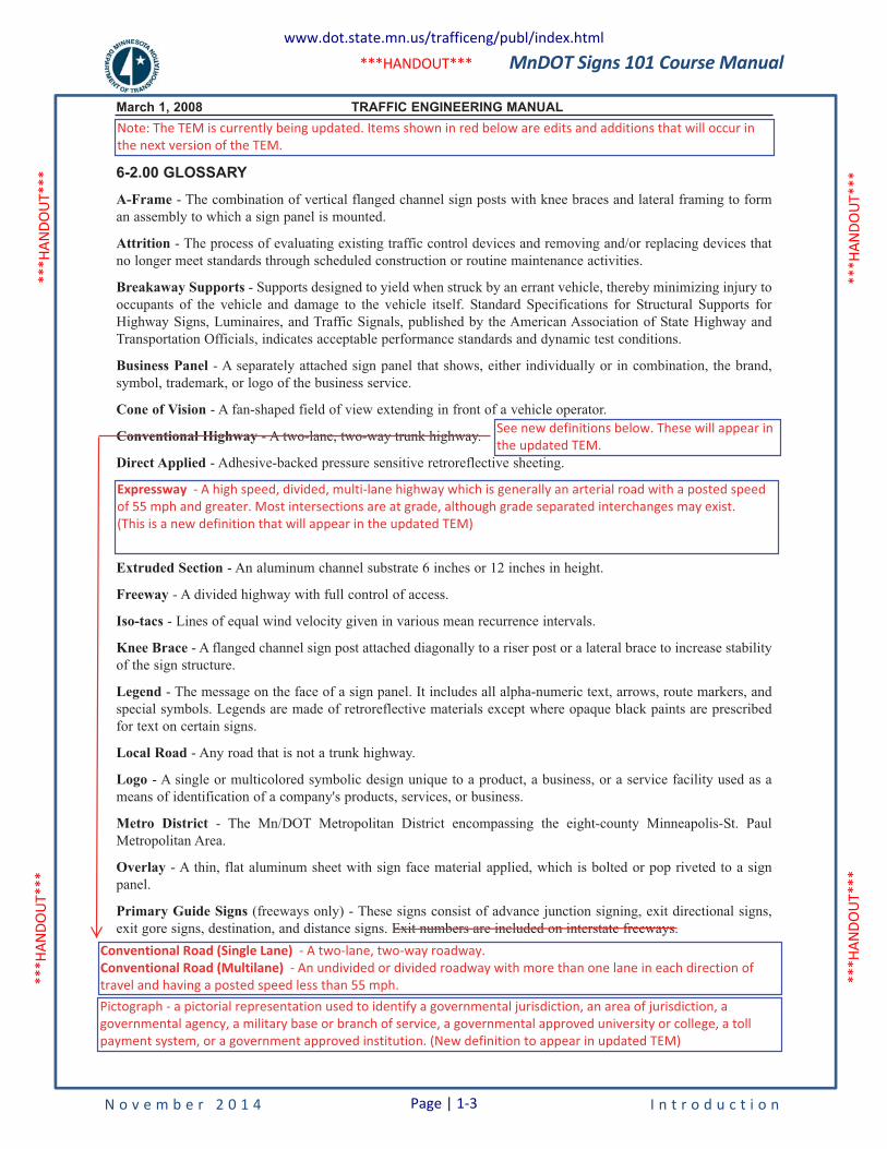
1.6 MnDOT OTST Website
The MnDOT Office of Traffic, Safety and Technology website (see Exhibit 1-2) includes a wide variety of traffic engineering information, including traffic signing. The website can be visited by going to:
http://www.dot.state.mn.us/trafficeng/.
Click on the links on the right side to proceed to the appropriate Traffic Engineering Site.
Exhibit 1-2 MnDOT OTST Website
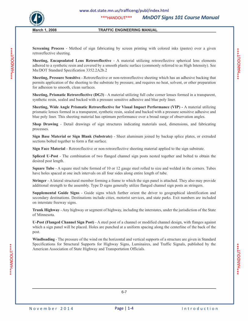
1.7 Glossary of Terms
The following is a handout from Chapter 6 of the Traffic Engineering Manual (TEM) Glossary of Terms. The original document can be downloaded from the OTST website, publications link:
www.dot.state.mn.us/trafficeng/publ/index.html.
MnDOT Signs 101 Course Manual
N o v e m b e r 2 0 1 4 I n t r o d u c t i o n
***H
ANDO
UT**
* **
*HAN
DOUT
***
***H
ANDO
UT**
* **
*HAN
DOUT
***
***HANDOUT***
March 1, 2008 TRAFFIC ENGINEERING MANUAL
6-6
6-2.00 GLOSSARY
A-Frame - The combination of vertical flanged channel sign posts with knee braces and lateral framing to forman assembly to which a sign panel is mounted.
Attrition - The process of evaluating existing traffic control devices and removing and/or replacing devices thatno longer meet standards through scheduled construction or routine maintenance activities.
Breakaway Supports - Supports designed to yield when struck by an errant vehicle, thereby minimizing injury tooccupants of the vehicle and damage to the vehicle itself. Standard Specifications for Structural Supports forHighway Signs, Luminaires, and Traffic Signals, published by the American Association of State Highway andTransportation Officials, indicates acceptable performance standards and dynamic test conditions.
Business Panel - A separately attached sign panel that shows, either individually or in combination, the brand,symbol, trademark, or logo of the business service.
Cone of Vision - A fan-shaped field of view extending in front of a vehicle operator.
Conventional Highway - A two-lane, two-way trunk highway.
Direct Applied - Adhesive-backed pressure sensitive retroreflective sheeting.
Expressway - A high speed, multi-lane highway which is generally an arterial road with the design speed 45 mphand greater. Two types of expressways exist, divided and undivided for both urban and rural sections. Mostintersections are at grade, although grade separation and interchanges may be needed in some areas where highvolume road or rail crossings exist, or terrain conditions favor grade separation.
Extruded Section - An aluminum channel substrate 6 inches or 12 inches in height.
Freeway - A divided highway with full control of access.
Iso-tacs - Lines of equal wind velocity given in various mean recurrence intervals.
Knee Brace - A flanged channel sign post attached diagonally to a riser post or a lateral brace to increase stabilityof the sign structure.
Legend - The message on the face of a sign panel. It includes all alpha-numeric text, arrows, route markers, andspecial symbols. Legends are made of retroreflective materials except where opaque black paints are prescribedfor text on certain signs.
Local Road - Any road that is not a trunk highway.
Logo - A single or multicolored symbolic design unique to a product, a business, or a service facility used as ameans of identification of a company's products, services, or business.
Metro District - The Mn/DOT Metropolitan District encompassing the eight-county Minneapolis-St. PaulMetropolitan Area.
Overlay - A thin, flat aluminum sheet with sign face material applied, which is bolted or pop riveted to a signpanel.
Primary Guide Signs (freeways only) - These signs consist of advance junction signing, exit directional signs,exit gore signs, destination, and distance signs. Exit numbers are included on interstate freeways.
Conventional Road (Single Lane) - A two-lane, two-way roadway. Conventional Road (Multilane) - An undivided or divided roadway with more than one lane in each direction of travel and having a posted speed less than 55 mph.
See new definitions below. These will appear in the updated TEM.
Expressway - A high speed, divided, multi-lane highway which is generally an arterial road with a posted speed of 55 mph and greater. Most intersections are at grade, although grade separated interchanges may exist. (This is a new definition that will appear in the updated TEM)
Pictograph - a pictorial representation used to identify a governmental jurisdiction, an area of jurisdiction, a governmental agency, a military base or branch of service, a governmental approved university or college, a toll payment system, or a government approved institution. (New definition to appear in updated TEM)
Note: The TEM is currently being updated. Items shown in red below are edits and additions that will occur in the next version of the TEM.
www.dot.state.mn.us/trafficeng/publ/index.html
Page | 1-3
MnDOT Signs 101 Course Manual
N o v e m b e r 2 0 1 4 I n t r o d u c t i o n
***H
ANDO
UT**
* **
*HAN
DOUT
***
***H
ANDO
UT**
* **
*HAN
DOUT
***
***HANDOUT***
March 1, 2008 TRAFFIC ENGINEERING MANUAL
6-7
Screening Process - Method of sign fabricating by screen printing with colored inks (pastes) over a givenretroreflective sheeting.
Sheeting, Encapsulated Lens Retroreflective - A material utilizing retroreflective spherical lens elementsadhered to a synthetic resin and covered by a smooth plastic surface (commonly referred to as High Intensity). SeeMn/DOT Standard Specification 3352.2A2b.2
Sheeting, Pressure Sensitive.-.Retroreflective or non-retroreflective sheeting which has an adhesive backing thatpermits application of the sheeting to the substrate by pressure, and requires no heat, solvent, or other preparationfor adhesion to smooth, clean surfaces.
Sheeting, Prismatic Retroreflective (DG3) - A material utilizing full cube corner lenses formed in a transparent,synthetic resin, sealed and backed with a pressure sensitive adhesive and blue poly liner.
Sheeting, Wide Angle Prismatic Retroreflective for Visual Impact Performance (VIP) - A material utilizingprismatic lenses formed in a transparent, synthetic resin, sealed and backed with a pressure sensitive adhesive andblue poly liner. This sheeting material has optimum performance over a broad range of observation angles.
Shop Drawing - Detail drawings of sign structures indicating materials used, dimensions, and fabricatingprocesses.
Sign Base Material or Sign Blank (Substrate) - Sheet aluminum joined by backup splice plates, or extrudedsections bolted together to form a flat surface.
Sign Face Material - Retroreflective or non-retroreflective sheeting material applied to the sign substrate.
Spliced U-Post - The combination of two flanged channel sign posts nested together and bolted to obtain thedesired post length.
Square Tube - A square steel tube formed of 10 or 12 gauge steel rolled to size and welded in the corners. Tubeshave holes spaced at one inch intervals on all four sides along entire length of tube.
Stringer - A lateral structural member forming a frame to which the sign panel is attached. They also may provideadditional strength to the assembly. Type D signs generally utilize flanged channel sign posts as stringers.
Supplemental Guide Signs - Guide signs which further orient the driver to geographical identification andsecondary destinations. Destinations include cities, motorist services, and state parks. Exit numbers are includedon interstate freeway signs.
Trunk Highway - Any highway or segment of highway, including the interstates, under the jurisdiction of the Stateof Minnesota.
U-Post (Flanged Channel Sign Post) - A steel post of a channel or modified channel design, with flanges againstwhich a sign panel will be placed. Holes are punched at a uniform spacing along the centerline of the back of thepost.
Windloading - The pressure of the wind on the horizontal and vertical supports of a structure are given in StandardSpecifications for Structural Supports for Highway Signs, Luminaires, and Traffic Signals, published by theAmerican Association of State Highway and Transportation Officials.
www.dot.state.mn.us/trafficeng/publ/index.html
Page | 1-4
MnDOT Signs 101 Course Manual
N o v e m b e r 2 0 1 4 P a g e | 2-1 S i g n i n g O v e r v i e w
2. SIGNING OVERVIEW
2.1 Purpose of Signs
One cannot over emphasized the importance of good signing since national studies indicate that deficient signing is the number one complaint of 60 percent of drivers and is the third leading cause of crashes. In addition, sign improvements have one of the highest benefit-to-cost ratio of all safety improvements.
Traffic signs regulate, warn, and guide motorists, pedestrians, and other traffic on all public roads. The traffic sign is the most commonly used traffic control device, and it is the oldest device for controlling, safe guarding, and expediting traffic. Signs are not ordinarily needed to confirm the basic rules of the road, but they are essential to inform highway users of specific regulations, to warn users where hazards are not self-evident, and to furnish information and guidance.
The Minnesota Manual on Uniform Traffic Control Devices (MN MUTCD) provides legal standards, allowable limits, and alternatives for the design, use, and application of traffic signs. The purpose of this chapter is to describe typical applications and procedures related to placement of traffic signs on MnDOT streets and highways.
Since the basic principles of signing are set forth in the MN MUTCD and must be adhered to, the engineers, technicians, and maintenance personnel responsible for the design, selection, and placement of these devices should have ready access to and be familiar with the MN MUTCD. The MUTCD is discussed in more detail throughout this manual.
2.2 What is Retroreflectivity?
The MUTCD requires traffic signs to be either retroreflective or illuminated to show the same shape and color both day and night. Since it is more cost effective to make signs retroreflective than it is to illuminate them, retroreflective sheeting material is used on all signs.
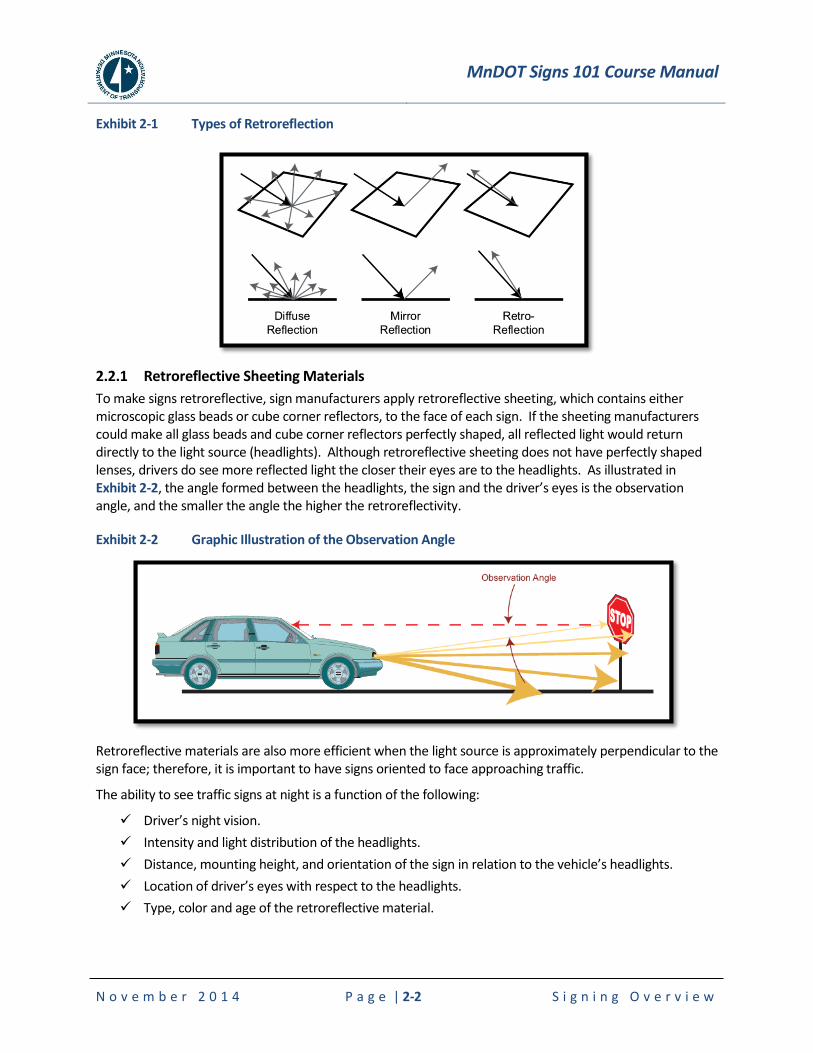
Most objects reflect light. The most common type of reflection is “diffuse reflection” where light scatters after striking rough surfaces such as trees, clothing and carpet. Only a very small amount of the diffused light reflects back toward the light source.
Another type of reflection is “mirror reflection” that occurs when light strikes smooth or glossy surfaces, and the light reflects off the surface at an equal but opposite angle. Mirror reflection frequently occurs at night on wet roads when the headlights of approaching vehicles create extensive glare. Sign faces also produce some mirror reflection due to their glossy surfaces, and for this reason; it is a good practice to rotate signs away from the driver.
In contrast, “retroreflection” is the unique ability of a surface to reflect light back toward the light source, and “retroreflectivity” is the measurable property of a material to redirect light back to its source.
MnDOT Signs 101 Course Manual
N o v e m b e r 2 0 1 4 P a g e | 2-2 S i g n i n g O v e r v i e w
Exhibit 2-1 Types of Retroreflection
2.2.1 Retroreflective Sheeting Materials
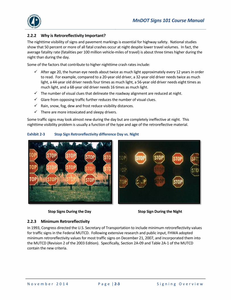
To make signs retroreflective, sign manufacturers apply retroreflective sheeting, which contains either microscopic glass beads or cube corner reflectors, to the face of each sign. If the sheeting manufacturers could make all glass beads and cube corner reflectors perfectly shaped, all reflected light would return directly to the light source (headlights). Although retroreflective sheeting does not have perfectly shaped lenses, drivers do see more reflected light the closer their eyes are to the headlights. As illustrated in Exhibit 2-2, the angle formed between the headlights, the sign and the driver’s eyes is the observation angle, and the smaller the angle the higher the retroreflectivity.
Exhibit 2-2 Graphic Illustration of the Observation Angle
Retroreflective materials are also more efficient when the light source is approximately perpendicular to the sign face; therefore, it is important to have signs oriented to face approaching traffic.
The ability to see traffic signs at night is a function of the following:
Driver’s night vision.
Intensity and light distribution of the headlights.
Distance, mounting height, and orientation of the sign in relation to the vehicle’s headlights.
Location of driver’s eyes with respect to the headlights.
Type, color and age of the retroreflective material.
MnDOT Signs 101 Course Manual
N o v e m b e r 2 0 1 4 P a g e | 2-3 S i g n i n g O v e r v i e w
2.2.2 Why is Retroreflectivity Important?
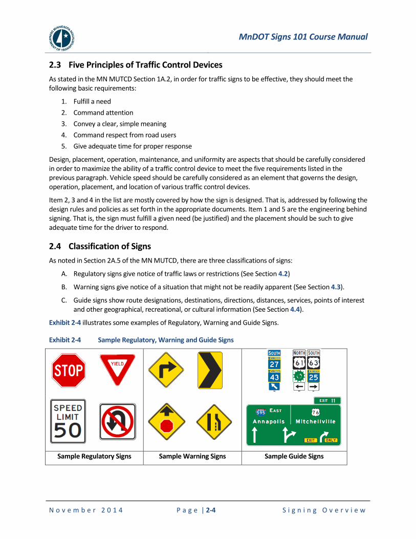
The nighttime visibility of signs and pavement markings is essential for highway safety. National studies show that 50 percent or more of all fatal crashes occur at night despite lower travel volumes. In fact, the average fatality rate (fatalities per 100 million vehicle-miles of travel) is about three times higher during the night than during the day.
Some of the factors that contribute to higher nighttime crash rates include:
After age 20, the human eye needs about twice as much light approximately every 12 years in order to read. For example, compared to a 20-year old driver, a 32-year old driver needs twice as much light, a 44-year old driver needs four times as much light, a 56-year old driver needs eight times as much light, and a 68-year old driver needs 16 times as much light.
The number of visual clues that delineate the roadway alignment are reduced at night.
Glare from opposing traffic further reduces the number of visual clues.
Rain, snow, fog, dew and frost reduce visibility distances.
There are more intoxicated and sleepy drivers.
Some traffic signs may look almost new during the day but are completely ineffective at night. This nighttime visibility problem is usually a function of the type and age of the retroreflective material.
Exhibit 2-3 Stop Sign Retroreflectivity difference Day vs. Night
Stop Signs During the Day
Stop Sign During the Night
2.2.3 Minimum Retroreflectivity
In 1993, Congress directed the U.S. Secretary of Transportation to include minimum retroreflectivity values for traffic signs in the Federal MUTCD. Following extensive research and public input, FHWA adopted minimum retroreflectivity values for most traffic signs on December 21, 2007, and incorporated them into the MUTCD (Revision 2 of the 2003 Edition). Specifically, Section 2A-09 and Table 2A-1 of the MUTCD contain the new criteria.
MnDOT Signs 101 Course Manual
N o v e m b e r 2 0 1 4 P a g e | 2-4 S i g n i n g O v e r v i e w
2.3 Five Principles of Traffic Control Devices
As stated in the MN MUTCD Section 1A.2, in order for traffic signs to be effective, they should meet the following basic requirements:
1. Fulfill a need
2. Command attention
3. Convey a clear, simple meaning
4. Command respect from road users
5. Give adequate time for proper response
Design, placement, operation, maintenance, and uniformity are aspects that should be carefully considered in order to maximize the ability of a traffic control device to meet the five requirements listed in the previous paragraph. Vehicle speed should be carefully considered as an element that governs the design, operation, placement, and location of various traffic control devices.
Item 2, 3 and 4 in the list are mostly covered by how the sign is designed. That is, addressed by following the design rules and policies as set forth in the appropriate documents. Item 1 and 5 are the engineering behind signing. That is, the sign must fulfill a given need (be justified) and the placement should be such to give adequate time for the driver to respond.
2.4 Classification of Signs
As noted in Section 2A.5 of the MN MUTCD, there are three classifications of signs:
A. Regulatory signs give notice of traffic laws or restrictions (See Section 4.2)
B. Warning signs give notice of a situation that might not be readily apparent (See Section 4.3).
C. Guide signs show route designations, destinations, directions, distances, services, points of interest and other geographical, recreational, or cultural information (See Section 4.4).
Exhibit 2-4 illustrates some examples of Regulatory, Warning and Guide Signs.
Exhibit 2-4 Sample Regulatory, Warning and Guide Signs
Sample Regulatory Signs Sample Warning Signs Sample Guide Signs

MnDOT Signs 101 Course Manual
N o v e m b e r 2 0 1 4 P a g e | 2-5 S i g n i n g O v e r v i e w
2.5 Design of Signs
The primary purpose of the MN MUTCD is to improve safety and reduce driver frustration by promoting uniformity in the design and application of traffic control devices. Uniform designs and applications of traffic signs help everyone, because as drivers we can see and understand the sign messages, and the systematic advance placement of warning signs provide sufficient notice for us to take appropriate actions.
To that end, the MN MUTCD (see Section 2.7.2) establishes the basic framework for the design and application of signs, and the Standard Highway Signs and Markings manual (see Section 2.7.4) provides detailed drawings of the standard signs and alphabets.
The MN MUTCD also states in Section 2A.06:
“Except as provided in the option below and except for the Carpool Information (D12-2) sign (see Section 2I.11), Internet addresses and e-mail addresses, including domain names and uniform resource locators (URL),shall not be displayed on any sign, supplemental plaque, sign panel (including logo sign panels on Specific Service signs) or changeable message signs.”
2.5.1 Sign Nomenclature
The Standard Signs Summary (see Section 2.7.5) defines a unique nomenclature to all common types of traffic signs. The first letter in sign nomenclature conforms to the following:
R Series: Regulatory
W Series: Warning
M Series: Route Markers and Auxiliaries
G Series: Construction Information
S Series: School Warning
D Series: Guide Signs - Conventional Roads
I Series: Informational
E Series: Guide Signs - Expressway, Freeway
X Series: Miscellaneous
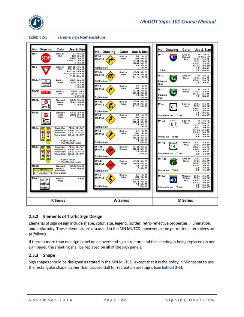
Exhibit 2-5 shows examples of sign nomenclature as listed in the 2013 Standard Signs Summary (www.dot.state.mn.us/trafficeng/publ/index.html). The “No.” in the left-hand column of the figure shows the sign number (nomenclature).
MnDOT Signs 101 Course Manual
N o v e m b e r 2 0 1 4 P a g e | 2-6 S i g n i n g O v e r v i e w
Exhibit 2-5 Sample Sign Nomenclature
R Series W Series M Series
2.5.2 Elements of Traffic Sign Design
Elements of sign design include shape, color, size, legend, border, retro-reflective properties, illumination, and uniformity. These elements are discussed in the MN MUTCD; however, some permitted alternatives are as follows.
If there is more than one sign panel on an overhead sign structure and the sheeting is being replaced on one sign panel, the sheeting shall be replaced on all of the sign panels.
2.5.3 Shape
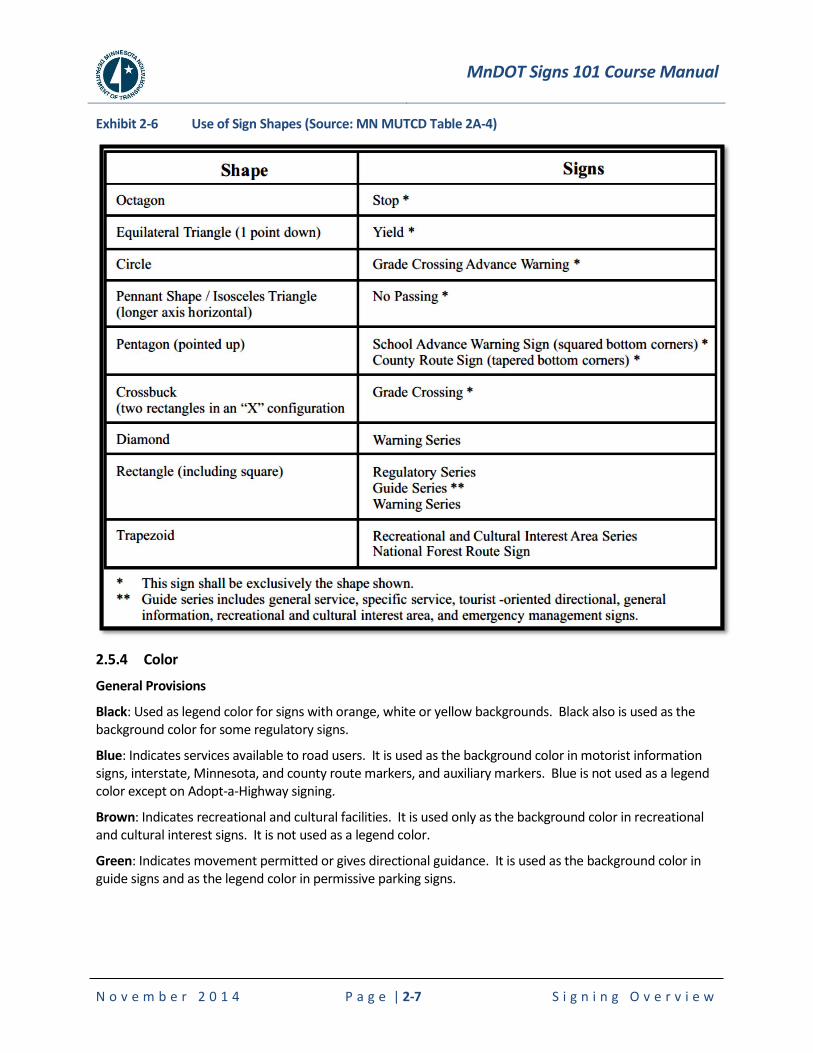
Sign shapes should be designed as stated in the MN MUTCD, except that it is the policy in Minnesota to use the rectangular shape (rather than trapezoidal) for recreation area signs (see Exhibit 2-6).
MnDOT Signs 101 Course Manual
N o v e m b e r 2 0 1 4 P a g e | 2-7 S i g n i n g O v e r v i e w
Exhibit 2-6 Use of Sign Shapes (Source: MN MUTCD Table 2A-4)
2.5.4 Color
General Provisions
Black: Used as legend color for signs with orange, white or yellow backgrounds. Black also is used as the background color for some regulatory signs.
Blue: Indicates services available to road users. It is used as the background color in motorist information signs, interstate, Minnesota, and county route markers, and auxiliary markers. Blue is not used as a legend color except on Adopt-a-Highway signing.
Brown: Indicates recreational and cultural facilities. It is used only as the background color in recreational and cultural interest signs. It is not used as a legend color.
Green: Indicates movement permitted or gives directional guidance. It is used as the background color in guide signs and as the legend color in permissive parking signs.
MnDOT Signs 101 Course Manual
N o v e m b e r 2 0 1 4 P a g e | 2-8 S i g n i n g O v e r v i e w
Orange: Warns of temporary traffic conditions with a higher than normal potential hazard level. It is used as the background color in temporary traffic control signs and is most commonly seen in construction zones. It is not used as a legend color.
Red: Indicates right-of-way control, prohibition or exclusion. It is used as the background color for STOP, DO NOT ENTER, WRONG WAY, and interstate route marker signs and as the legend color for YIELD, parking prohibition and prohibitory (circular with slash) signs.
White: White either indicates a law, regulation or legal requirement in effect at or near the sign or provides directional guidance. It is used as the background color for regulatory signs, route markers and route marker auxiliaries. It also is used as the legend color for signs with a black, blue, brown, green or red background.
Yellow: Warns of a potential hazard. It is used as the background color for warning signs and as the legend color for county route marker signs.
Fluorescent-Yellow Green: Designated for use as background color for warning signs and their supplemental plaques associated with pedestrians, bicyclists, playgrounds and schools. SCHOOL plaque is also included.
Fluorescent Pink: Incident Management
Purple: Electronic Toll Accounts (ETC) such as Minnesota’s MnPASS lanes. More details on color usage can be found in the MN MUTCD Section 2F.3.
2.5.5 Size
In general, the following items control the size of the sign:
Message on sign
Font use for text
Letter and object spacing
Borders and margins
An accepted “rule-of-thumb” to follow for legibility for signs other than Interstate is to have 1 inch of letter height for every 30 feet of desired legibility. Whenever practicable, the overall dimensions of the sign plates should be in multiples of 6 inches.
Standard Signs
Both sign and letter size have been established for standard signs (regulatory, warning, etc). The Federal Manual on Uniform Traffic Control Devices sets forth criteria establishing the series of letters to be used and the spacing between letters for these two classifications of signs. The resulting sign sizes are listed in the Minnesota Standard Signs Summary (see Section 2.7.5). The size of the sign selected is than based on the type of roadway and speed.
Speed Limit Sign Size Example
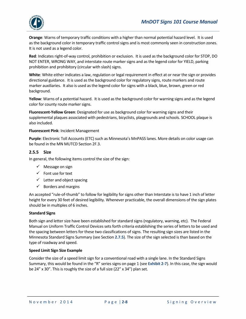
Consider the size of a speed limit sign for a conventional road with a single lane. In the Standard Signs Summary, this would be found in the “R” series signs on page 1 (see Exhibit 2-7). In this case, the sign would be 24” x 30”. This is roughly the size of a full size (22” x 34”) plan set.
MnDOT Signs 101 Course Manual
N o v e m b e r 2 0 1 4 P a g e | 2-9 S i g n i n g O v e r v i e w
Exhibit 2-7 Speed Limit Sign, R2-1 Sizing
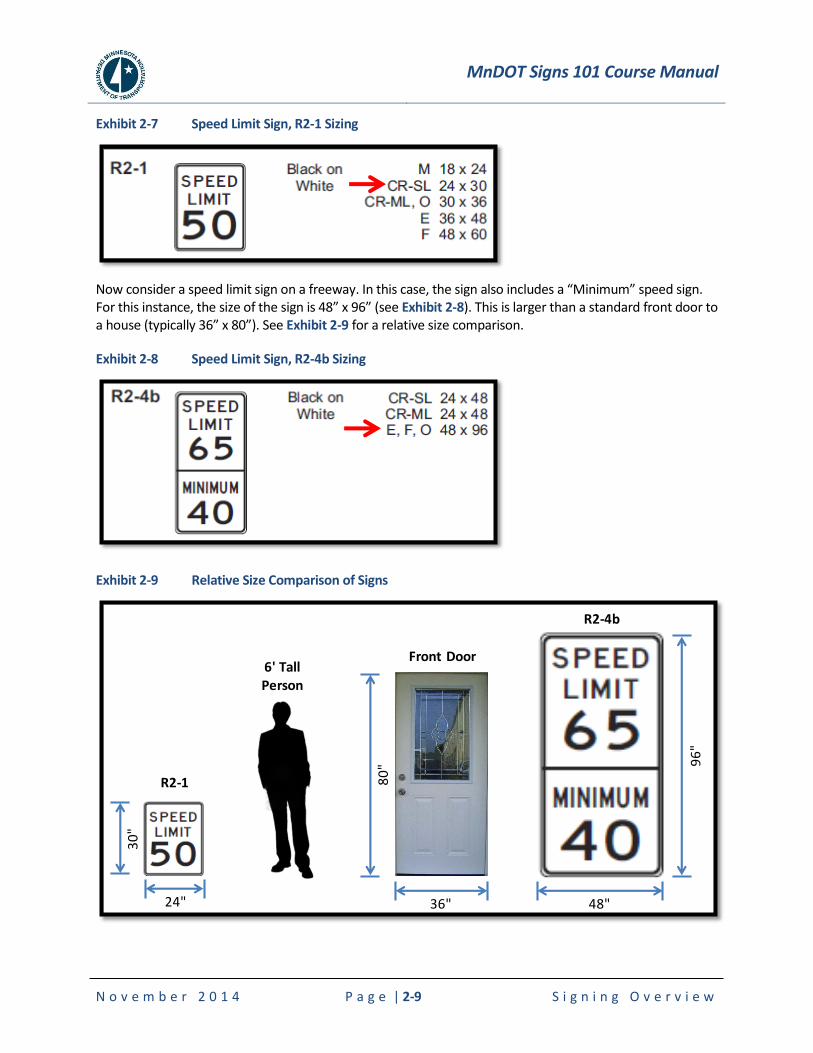
Now consider a speed limit sign on a freeway. In this case, the sign also includes a “Minimum” speed sign. For this instance, the size of the sign is 48” x 96” (see Exhibit 2-8). This is larger than a standard front door to a house (typically 36” x 80”). See Exhibit 2-9 for a relative size comparison.
Exhibit 2-8 Speed Limit Sign, R2-4b Sizing
Exhibit 2-9 Relative Size Comparison of Signs
36" 48"
96
"
80
"
Front Door6' Tall Person
24"
30
"
R2-1
R2-4b

MnDOT Signs 101 Course Manual
N o v e m b e r 2 0 1 4 P a g e | 2-10 S i g n i n g O v e r v i e w
Guide Signs
For guide signs, only minimum sizes have been established. The letter size needed to give motorists ample opportunity to read a sign easily at normal approach speed will, in general, determine the size of sign needed. Sign design is dependent upon many variables:
1. The sign reading behavior of drivers is a highly adaptive process - the manner in which a driver obtains information from a sign heavily depends on the following factors:
a. Visual loads on the driver's visual information acquisition and processing functions
b. Driver's informational need
i. type of informational need
ii. urgency associated in obtaining information
iii. driver's familiarity with the route
c. Size of letters displaying information on the sign
d. Amount of message displayed on the signs and its relevancy to driver's informational need
e. Driver's visual capabilities
f. Vehicle velocity
g. Location of the sign with respect to the path of the driver
Drivers do not concentrate on a sign until they obtain the required information from the sign - they share their time between the sign, objects on the road and performing other driving tasks.
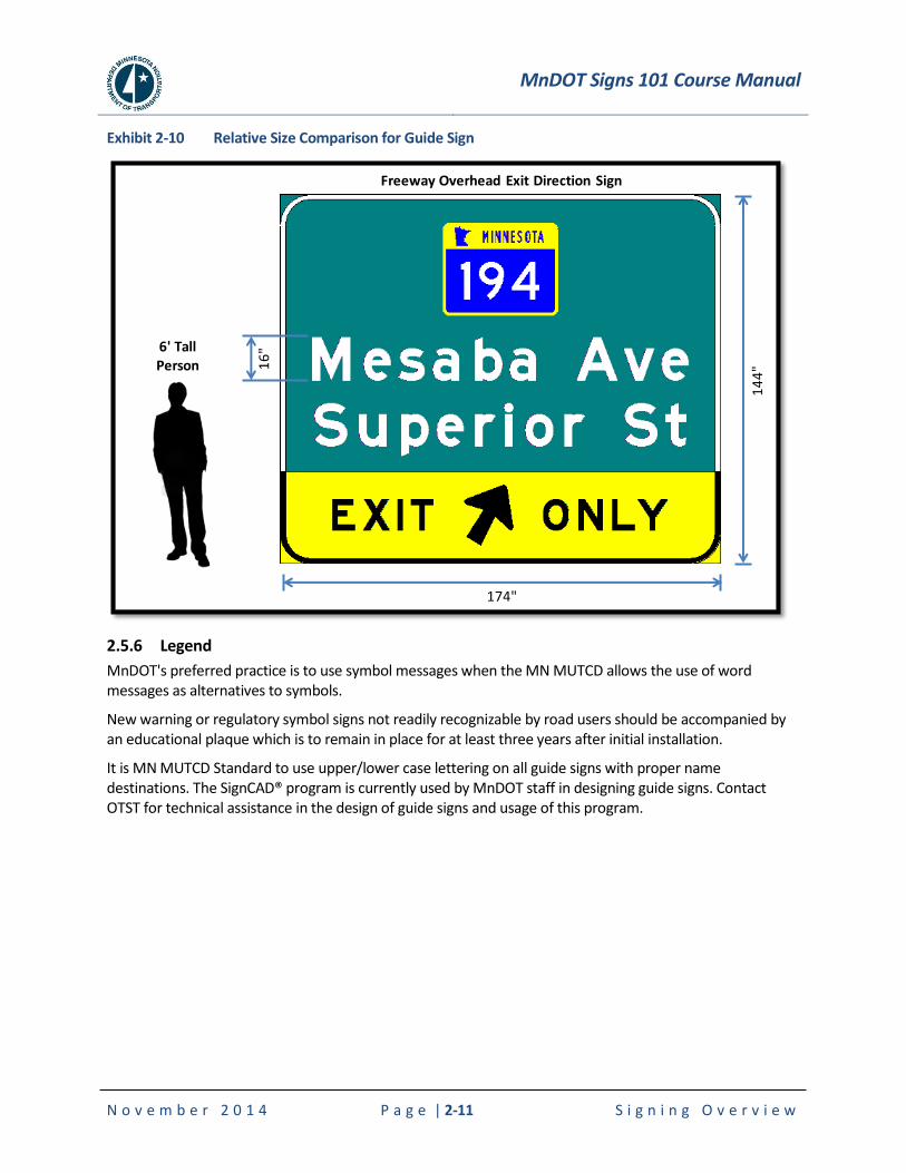
The SignCAD® program is currently used by MnDOT staff in designing guide signs. The software will assist in sizing the sign based on the legend and objects placed on the sign panel. On a two-way highway, the font size is typically 6”. However, on a freeway section, the font size is 16”. See Exhibit 2-10 for a relative guide sign size comparison comparing an overhead freeway sign to a 6’ tall person.
MnDOT Signs 101 Course Manual
N o v e m b e r 2 0 1 4 P a g e | 2-11 S i g n i n g O v e r v i e w
Exhibit 2-10 Relative Size Comparison for Guide Sign
2.5.6 Legend
MnDOT's preferred practice is to use symbol messages when the MN MUTCD allows the use of word messages as alternatives to symbols.
New warning or regulatory symbol signs not readily recognizable by road users should be accompanied by an educational plaque which is to remain in place for at least three years after initial installation.
It is MN MUTCD Standard to use upper/lower case lettering on all guide signs with proper name destinations. The SignCAD® program is currently used by MnDOT staff in designing guide signs. Contact OTST for technical assistance in the design of guide signs and usage of this program.
6' Tall Person
174"
14
4"
Freeway Overhead Exit Direction Sign
16
"
MnDOT Signs 101 Course Manual
N o v e m b e r 2 0 1 4 P a g e | 2-12 S i g n i n g O v e r v i e w
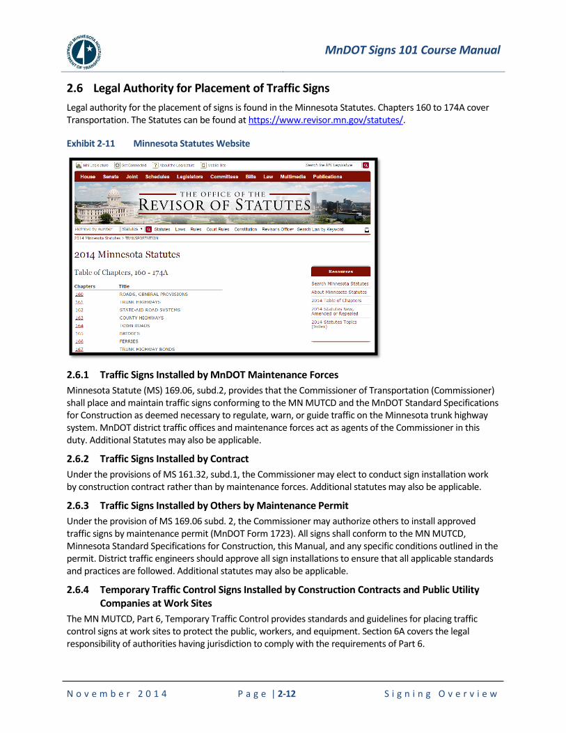
2.6 Legal Authority for Placement of Traffic Signs
Legal authority for the placement of signs is found in the Minnesota Statutes. Chapters 160 to 174A cover Transportation. The Statutes can be found at https://www.revisor.mn.gov/statutes/.
Exhibit 2-11 Minnesota Statutes Website
2.6.1 Traffic Signs Installed by MnDOT Maintenance Forces
Minnesota Statute (MS) 169.06, subd.2, provides that the Commissioner of Transportation (Commissioner) shall place and maintain traffic signs conforming to the MN MUTCD and the MnDOT Standard Specifications for Construction as deemed necessary to regulate, warn, or guide traffic on the Minnesota trunk highway system. MnDOT district traffic offices and maintenance forces act as agents of the Commissioner in this duty. Additional Statutes may also be applicable.
2.6.2 Traffic Signs Installed by Contract
Under the provisions of MS 161.32, subd.1, the Commissioner may elect to conduct sign installation work by construction contract rather than by maintenance forces. Additional statutes may also be applicable.
2.6.3 Traffic Signs Installed by Others by Maintenance Permit
Under the provision of MS 169.06 subd. 2, the Commissioner may authorize others to install approved traffic signs by maintenance permit (MnDOT Form 1723). All signs shall conform to the MN MUTCD, Minnesota Standard Specifications for Construction, this Manual, and any specific conditions outlined in the permit. District traffic engineers should approve all sign installations to ensure that all applicable standards and practices are followed. Additional statutes may also be applicable.
2.6.4 Temporary Traffic Control Signs Installed by Construction Contracts and Public Utility Companies at Work Sites
The MN MUTCD, Part 6, Temporary Traffic Control provides standards and guidelines for placing traffic control signs at work sites to protect the public, workers, and equipment. Section 6A covers the legal responsibility of authorities having jurisdiction to comply with the requirements of Part 6.

MnDOT Signs 101 Course Manual
N o v e m b e r 2 0 1 4 P a g e | 2-13 S i g n i n g O v e r v i e w
2.7 Associated Manuals
There are a variety of manuals related to highway signs in Minnesota. In this section, some of the more common manuals are presented.
2.7.1 Federal Manual on Uniform Traffic Control Devices
The Federal Highway Administration (FHWA) publishes the MUTCD, which contains all national design, application, and placement, standards, guidance, options, and support provisions for traffic control devices. At the time of publication of this manual, the 2009 edition dated December of 2009 is the current version. The national MUTCD website is located at:
http://mutcd.fhwa.dot.gov/index.htm.
The purpose of the MUTCD is to provide uniformity of these devices, which include signs, signals, and pavement markings, to promote highway safety and efficiency on the Nation's streets and highways.
Title 23 of the Code of Federal Regulations requires all States to do one of three things within two years after a new national MUTCD edition is issued or any national MUTCD amendments are made:
1. adopt the new or revised national MUTCD as the standard for traffic control devices in the State;
2. adopt the national MUTCD with a State Supplement that is in substantial conformance with the new or revised national MUTCD; or
3. adopt a State MUTCD that is in substantial conformance with the new or revised national MUTCD.
Minnesota develops and adopts a State MUTCD (3 above) that is in substantial conformance with the national MUTCD.
Exhibit 2-12 Federal MUTCD
Chapter 2 of the Federal MUTCD related to Traffic Signs
The Federal MUTCD is not just a “policy”. It is not a MnDOT document. It applies to all public roads in the United States. The MUTCD is part of Federal Law and the MN MUTCD is part of State Law. The Federal government issues the MUTCD and gives states a certain amount of time to adopt it, or lose federal funding. Some states adopt it “as is”, many states publish a supplement. Minnesota re-writes the document. Those that re-write can be more conservative, but not less. State Law, trumps the federal manual.

MnDOT Signs 101 Course Manual
N o v e m b e r 2 0 1 4 P a g e | 2-14 S i g n i n g O v e r v i e w
2.7.2 Minnesota Manual on Uniform Traffic Control Devices
As noted above, Minnesota develops and adopts a state MUTCD that is in substantial conformance with the Federal MUTCD. The Minnesota MUTCD (MN MUTCD) was recently updated in July 2013. Chapter 2 of the MN MUTCD is dedicated to traffic signs.
Exhibit 2-13 Minnesota MUTCD
Chapter 2 of the MN MUTCD related to Traffic Signs
The MN MUTCD contains Standards, Guidance, and Options for the signing of all types of highways, and private roads open to public travel. Detailed sign requirements are located in the following Chapters of Part 2 of the MN MUTCD:
Chapter 2B — Regulatory Signs, Barricades, and Gates
Chapter 2C — Warning Signs and Object Markers
Chapter 2D — Guide Signs for Conventional Roads
Chapter 2E — Guide Signs for Freeways and Expressways
Chapter 2F — Toll Road Signs
Chapter 2G — Preferential and Managed Lane Signs
Chapter 2H — General Information Signs
Chapter 2I — General Service Signs
Chapter 2J — Specific Service (Logo) Signs
Chapter 2K — Tourist-Oriented Directional Signs
Chapter 2L — Changeable Message Signs
Chapter 2M — Recreational and Cultural Interest Area Signs
Chapter 2N — Emergency Management Signs
MnDOT Signs 101 Course Manual
N o v e m b e r 2 0 1 4 P a g e | 2-15 S i g n i n g O v e r v i e w
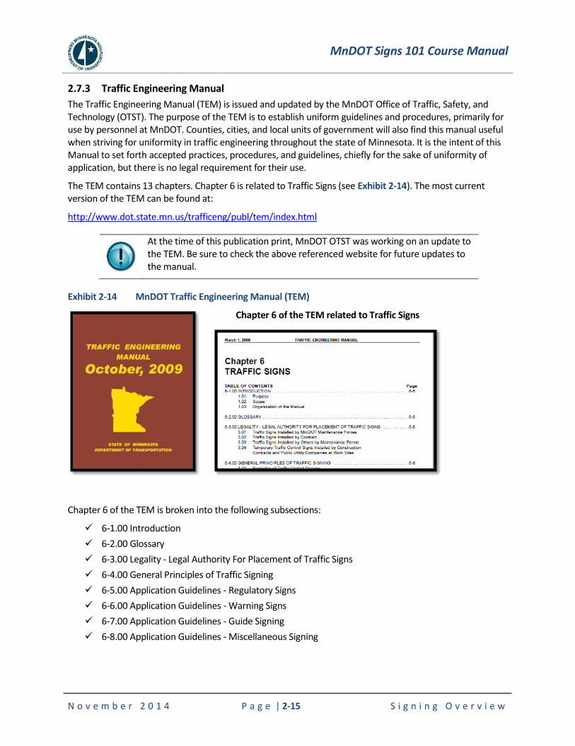
2.7.3 Traffic Engineering Manual
The Traffic Engineering Manual (TEM) is issued and updated by the MnDOT Office of Traffic, Safety, and Technology (OTST). The purpose of the TEM is to establish uniform guidelines and procedures, primarily for use by personnel at MnDOT. Counties, cities, and local units of government will also find this manual useful when striving for uniformity in traffic engineering throughout the state of Minnesota. It is the intent of this Manual to set forth accepted practices, procedures, and guidelines, chiefly for the sake of uniformity of application, but there is no legal requirement for their use.
The TEM contains 13 chapters. Chapter 6 is related to Traffic Signs (see Exhibit 2-14). The most current version of the TEM can be found at:
http://www.dot.state.mn.us/trafficeng/publ/tem/index.html
At the time of this publication print, MnDOT OTST was working on an update to the TEM. Be sure to check the above referenced website for future updates to the manual.
Exhibit 2-14 MnDOT Traffic Engineering Manual (TEM)
Chapter 6 of the TEM related to Traffic Signs
Chapter 6 of the TEM is broken into the following subsections:
6-1.00 Introduction
6-2.00 Glossary
6-3.00 Legality - Legal Authority For Placement of Traffic Signs
6-4.00 General Principles of Traffic Signing
6-5.00 Application Guidelines - Regulatory Signs
6-6.00 Application Guidelines - Warning Signs
6-7.00 Application Guidelines - Guide Signing
6-8.00 Application Guidelines - Miscellaneous Signing
MnDOT Signs 101 Course Manual
N o v e m b e r 2 0 1 4 P a g e | 2-16 S i g n i n g O v e r v i e w
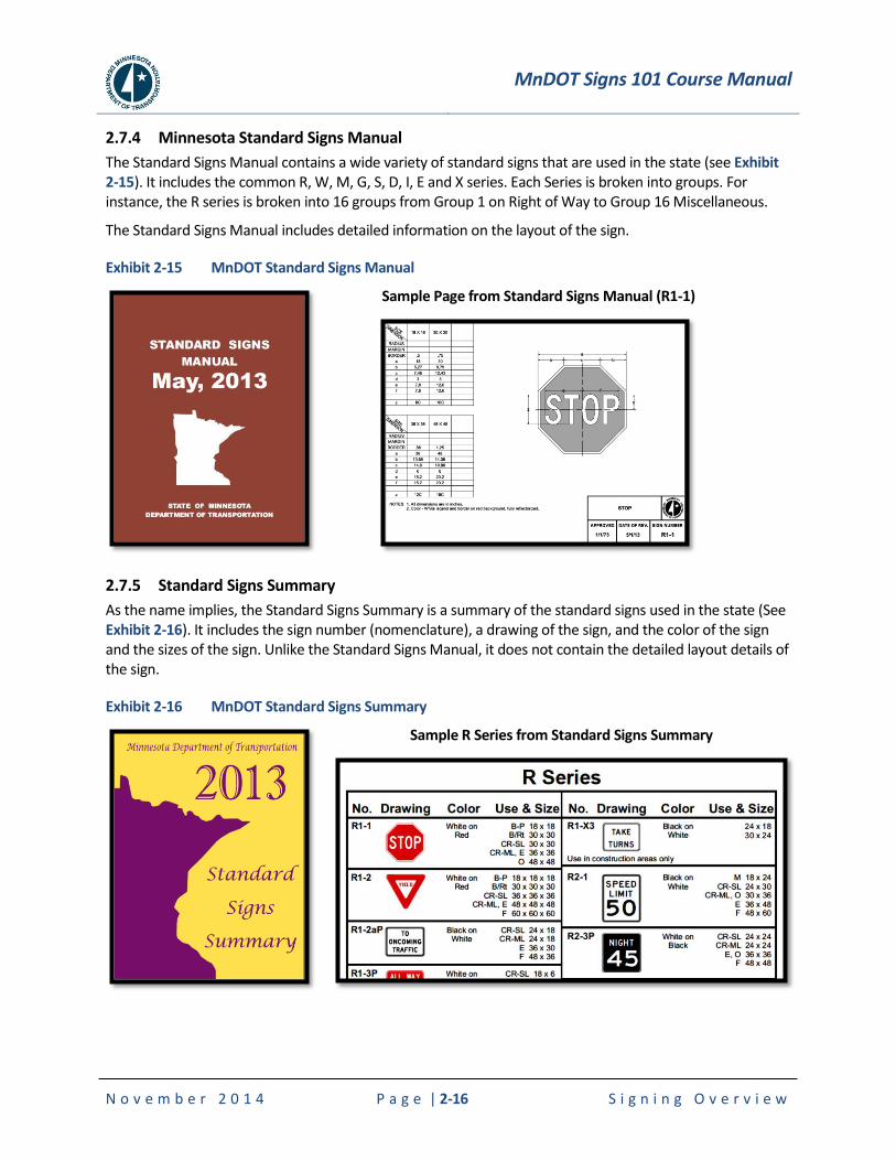
2.7.4 Minnesota Standard Signs Manual
The Standard Signs Manual contains a wide variety of standard signs that are used in the state (see Exhibit 2-15). It includes the common R, W, M, G, S, D, I, E and X series. Each Series is broken into groups. For instance, the R series is broken into 16 groups from Group 1 on Right of Way to Group 16 Miscellaneous.
The Standard Signs Manual includes detailed information on the layout of the sign.
Exhibit 2-15 MnDOT Standard Signs Manual
Sample Page from Standard Signs Manual (R1-1)
2.7.5 Standard Signs Summary
As the name implies, the Standard Signs Summary is a summary of the standard signs used in the state (See Exhibit 2-16). It includes the sign number (nomenclature), a drawing of the sign, and the color of the sign and the sizes of the sign. Unlike the Standard Signs Manual, it does not contain the detailed layout details of the sign.
Exhibit 2-16 MnDOT Standard Signs Summary
Sample R Series from Standard Signs Summary
MnDOT Signs 101 Course Manual
N o v e m b e r 2 0 1 4 P a g e | 2-17 S i g n i n g O v e r v i e w
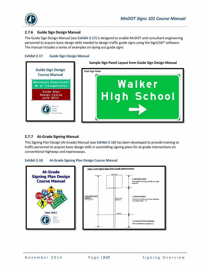
2.7.6 Guide Sign Design Manual
The Guide Sign Design Manual (see Exhibit 2-17) is designed to enable MnDOT and consultant engineering personnel to acquire basic design skills needed to design traffic guide signs using the SignCAD® software. The manual includes a series of examples on laying out guide signs.
Exhibit 2-17 Guide Sign Design Manual
Sample Sign Panel Layout from Guide Sign Design Manual
2.7.7 At-Grade Signing Manual
This Signing Plan Design (At-Grade) Manual (see Exhibit 2-18) has been developed to provide training to traffic personnel to acquire basic design skills in assembling signing plans for at-grade intersections on conventional highways and expressways.
Exhibit 2-18 At-Grade Signing Plan Design Course Manual
MnDOT Signs 101 Course Manual
N o v e m b e r 2 0 1 4 P a g e | 2-18 S i g n i n g O v e r v i e w
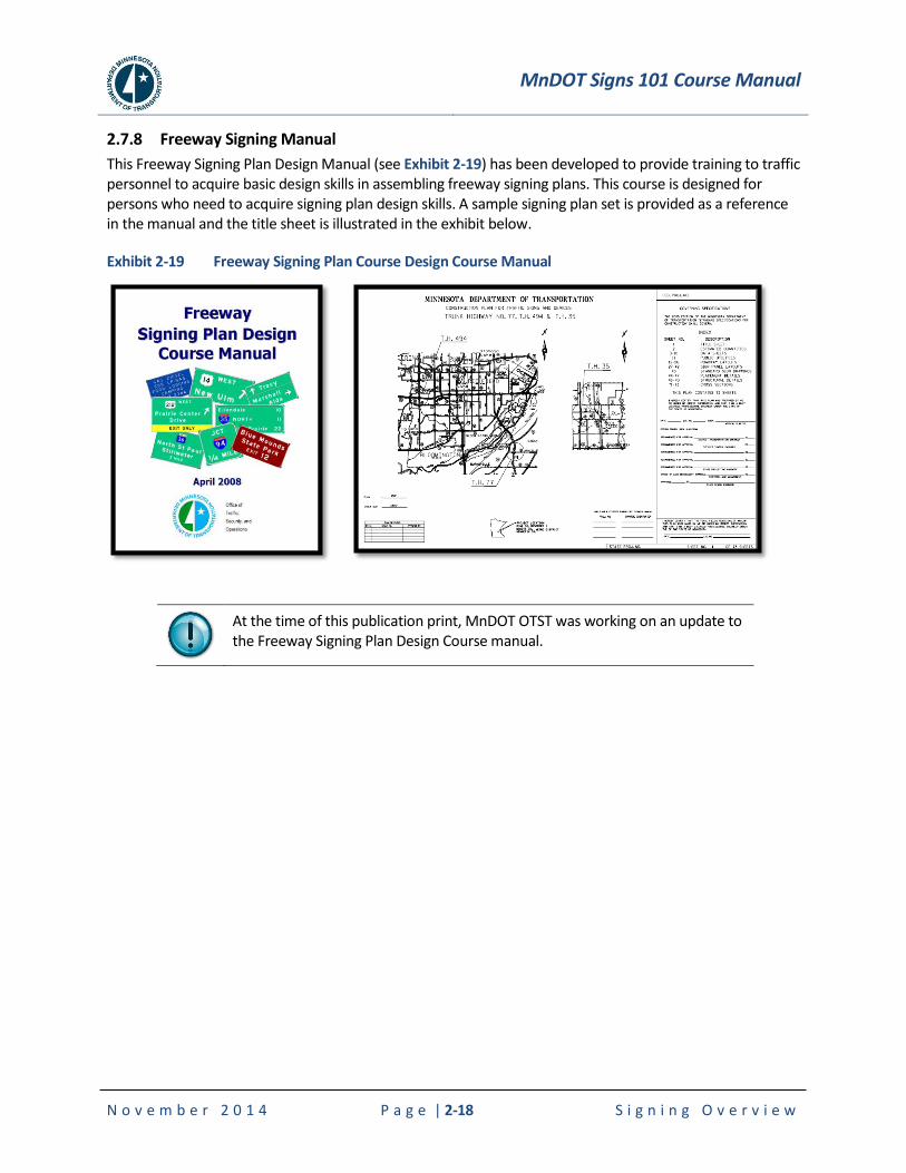
2.7.8 Freeway Signing Manual
This Freeway Signing Plan Design Manual (see Exhibit 2-19) has been developed to provide training to traffic personnel to acquire basic design skills in assembling freeway signing plans. This course is designed for persons who need to acquire signing plan design skills. A sample signing plan set is provided as a reference in the manual and the title sheet is illustrated in the exhibit below.
Exhibit 2-19 Freeway Signing Plan Course Design Course Manual
At the time of this publication print, MnDOT OTST was working on an update to the Freeway Signing Plan Design Course manual.
MnDOT Signs 101 Course Manual
N o v e m b e r 2 0 1 4 P a g e | 3-1 W h y S i g n s a r e I n s t a l l e d
3. WHY SIGNS ARE INSTALLED
3.1 Introduction
A request for a traffic sign may be initiated in a variety of ways. A request for a sign may come from a developer, the city or county, a politician, the general public or the state. The following sections provide information on why a sign is installed, not simply due to a request for one.
3.2 Engineering Standards
3.2.1 MN MUTCD Text Headings
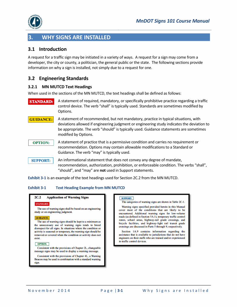
When used in the sections of the MN MUTCD, the text headings shall be defined as follows:
A statement of required, mandatory, or specifically prohibitive practice regarding a traffic control device. The verb “shall” is typically used. Standards are sometimes modified by Options.
A statement of recommended, but not mandatory, practice in typical situations, with deviations allowed if engineering judgment or engineering study indicates the deviation to be appropriate. The verb “should” is typically used. Guidance statements are sometimes modified by Options.
A statement of practice that is a permissive condition and carries no requirement or recommendation. Options may contain allowable modifications to a Standard or Guidance. The verb “may” is typically used.
An informational statement that does not convey any degree of mandate, recommendation, authorization, prohibition, or enforceable condition. The verbs “shall”, “should”, and “may” are not used in Support statements.
Exhibit 3-1 is an example of the text headings used for Section 2C.2 from the MN MUTCD.
Exhibit 3-1 Text Heading Example from MN MUTCD
MnDOT Signs 101 Course Manual
N o v e m b e r 2 0 1 4 P a g e | 3-2 W h y S i g n s a r e I n s t a l l e d
3.2.2 Signing Standards
As previously presented, signs should:
1. Fulfill a need
2. Command attention
3. Convey a clear, simple meaning
4. Command respect from road users
5. Give adequate time for proper response
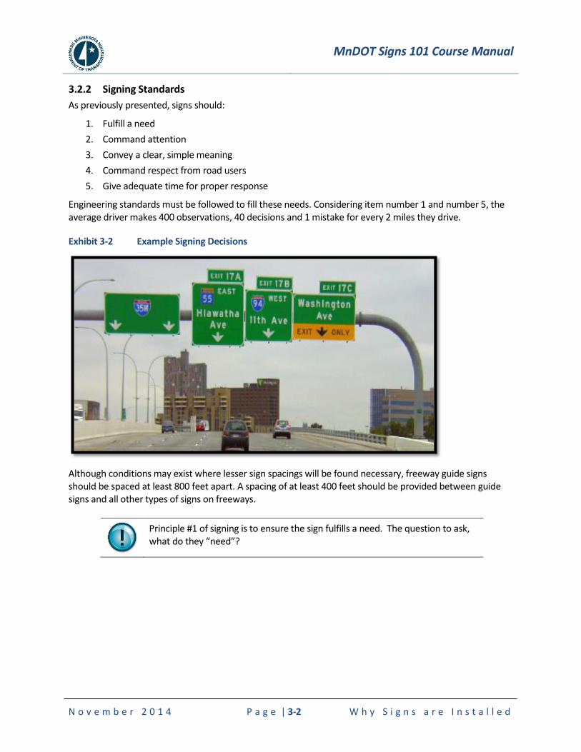
Engineering standards must be followed to fill these needs. Considering item number 1 and number 5, the average driver makes 400 observations, 40 decisions and 1 mistake for every 2 miles they drive.
Exhibit 3-2 Example Signing Decisions
Although conditions may exist where lesser sign spacings will be found necessary, freeway guide signs should be spaced at least 800 feet apart. A spacing of at least 400 feet should be provided between guide signs and all other types of signs on freeways.
Principle #1 of signing is to ensure the sign fulfills a need. The question to ask, what do they “need”?
MnDOT Signs 101 Course Manual
N o v e m b e r 2 0 1 4 P a g e | 3-3 W h y S i g n s a r e I n s t a l l e d
3.2.3 Engineering Judgment and Documentation
In many instances, engineering judgment is required when standards cannot be fully met. For instance, in the definition of Guidance above, it states, “deviations allowed if engineering judgment or engineering study indicates the deviation”. The definition of engineering judgment from the MN MUTCD states:
“Engineering Judgment - the evaluation of available pertinent information, and the application of appropriate principles, provisions, and practices as contained in this Manual and other sources, for the purpose of deciding upon the applicability, design, operation, or installation of a traffic control device. Engineering judgment shall be exercised by an engineer, or by an individual working under the supervision of an engineer, through the application of procedures and criteria established by the engineer. Documentation of engineering judgment is not required.”
While “documentation of engineering judgment is not required”, it is highly recommended. For liability purposes, it is important to document engineering judgment. Often, tort claims occur many months or years later. Documentation of decisions, including minutes of meetings, notes in a diary, notes on a plan, etc. become very important during depositions and trials.
Proper documentation of decision making during design and proper review and implementation during construction results in not only a better design and safer work zone, but clearly reduces risk and liability.
3.3 Signing Priorities
According to the ITE Traffic Control Devices Handbook, when signs compete for the same physical space, there is a need to determine priorities based on the following order of precedence:
Regulatory Signs (location specific)
Warning Signs
Regulatory Signs (non-location specific)
Guide Signs
Motorist Services
Traffic generator signs
General information signs

MnDOT Signs 101 Course Manual
N o v e m b e r 2 0 1 4 P a g e | 3-4 W h y S i g n s a r e I n s t a l l e d
3.4 Functional Classifications of Traffic Signs
The MN MUTCD classifies signs by their functional usage as follows:
1. Regulatory signs inform road users of traffic laws or regulations and indicate the applicability of legal requirements that would not otherwise be apparent.
2. Warning signs are used to call attention to unexpected conditions on or adjacent to a highway, street or private road open to public travel and to situations that would not be readily apparent to the motorist.
3. Guide signs are used to provide directions to motorists, informing them of intersecting routes, directing them to cities and other important destinations, and guiding them to available services, points of interest, and other geographic, recreational, or cultural sites.
Further, guide signs for highways have two (2) sub-classifications:
1. Primary guide signs consist of advance junction signing, exit directional signs, exit gore signs and destination signs. On interstate freeways, exit numbers are included. Distance signs are also primary guide signs.
2. Supplemental guide signs further provide the driver geographic orientation and secondary destinations at certain interchanges. Destinations include cities, motorist services, or traffic generators.
3.5 Sign Effectiveness
The information on the following pages are handouts related to sign effectiveness. The first is “Effectiveness of Traffic Signs on Local Roads” and can be found at www.lrrb.org/pdf/trs1002.pdf. The second is Chapter F of the “Minnesota’s Best Practices for Traffic Sign Maintenance / Management Handbook” and can be found at www.mnltap.umn.edu/publications/handbooks/.
MnDOT Signs 101 Course Manual
N o v e m b e r 2 0 1 4 W h y S i g n s a r e I n s t a l l e d
***H
ANDO
UT**
* **
*HAN
DOUT
***
***H
ANDO
UT**
* **
*HAN
DOUT
***
***HANDOUT***
January 2010
TRS 1002
Effectiveness of Traffic Signs on Local Roads
IntroductionThe 2009 edition of the Manual on Uniform Traffic Control Devices includes requirements for the management and maintenance of all roadway signs. Management of large numbers of signs can pose administrative and financial challenges for local road authorities. The Minnesota Department of Transportation is reviewing whether the removal of ineffective traffic signs may be part of an overall sign management strategy and has asked CH2M Hill to prepare a best practices guide for removing traffic signs. In support of this work, CTC & Associates was tasked by Mn/DOT with performing a literature search and synthesis of research demonstrating the effectiveness or lack of effectiveness of various types of traffic signs on local roads, including low-volume roads.
SummaryThere does not appear to be significant credible research demonstrating the outright ineffectiveness of particular traffic warning signs. The research we identified provides support for opposing points of view: that traffic warning signs have a minimal or neutral effect on safety, or, alternatively, that warning signs are effective at reducing crash rates and severity. National guidance recommends that traffic warning signs be employed based on engineering studies and engineering judgment, and suggests that the excessive use of signs can reduce their effectiveness.
The MUTCD guidance on warning signs begins with the direction that “the use of warning signs shall be based on an engineering study or on engineering judgment.” It further indicates that “the use of warning signs should be kept to a minimum as the unnecessary use of warning signs tends to breed disrespect for all signs.” That directive is not followed by guidance or research indicating what types of signs are actually ineffective.
Traffic sign effectiveness appears to be more a matter of perception and opinion than of fact based on evidence. For example, NCHRP Synthesis 186, Supplemental Advance Warning Devices (1993, page 1), found that “the majority of the devices encountered in this project were not evaluated by formal effectiveness studies, but are simply perceived to be effective by the responding agency.” A study of the effectiveness of static warning signs by the Institute of Transportation Engineers (“Static Warning Signs of Occasional Hazards: Do They Work?”) came to a similar conclusion. In that study 18 percent of responding state transportation agencies thought the use of static warning signs for occasional hazards was effective, but 93 percent indicated that no studies had been done to investigate the actual effectiveness of the signs.
On the other hand, Fred Ranck, FHWA safety and design engineer, indicated in an interview that warning signs have proven safety benefits (see the National Research and Guidelines section on page 3).
www.lrrb.org/pdf/trs1002.pdf
Page | 3-5
MnDOT Signs 101 Course Manual
N o v e m b e r 2 0 1 4 W h y S i g n s a r e I n s t a l l e d
***H
ANDO
UT**
* **
*HAN
DOUT
***
***H
ANDO
UT**
* **
*HAN
DOUT
***
***HANDOUT***
We organize our findings into the following two sections: � National Research and Guidelines � State Research and Guidance
The National Research and Guidelines section contains research from FHWA, NCHRP, TRB and the Institute of Transportation Engineers. The research includes studies that show particular signs to have minimal impact on safety, and studies that point out that the effectiveness of the signs has simply not been vigorously tested. This section also includes an article from FHWA’s Public Roads that points to the effectiveness of increasing the number of warning signs in Mendocino County, Calif.
The State Research and Guidance section includes studies from Kansas, Iowa and Washington state. The Iowa publication Guidelines for Removal of Traffic Control Devices in Rural Areas, addresses many of the issues involved with the removal of traffic signs. The paper is focused exclusively on stop and yield signs and does not present research on the safety effectiveness of other types of signs. The other two studies cited in this section found that the use of particular types of warning signs (such as deer crossing and ice warning) are minimally effective.
www.lrrb.org/pdf/trs1002.pdf
Page | 3-6
MnDOT Signs 101 Course Manual
N o v e m b e r 2 0 1 4 W h y S i g n s a r e I n s t a l l e d
***H
ANDO
UT**
* **
*HAN
DOUT
***
***H
ANDO
UT**
* **
*HAN
DOUT
***
***HANDOUT***
National Research and Guidelines
Interview with Fred Ranck, Safety Design Engineer, FHWA Resource Center, Matteson, Ill., [email protected],(708) 283-3534. Mr. Ranck indicated in an interview that warning signs have proven safety benefits. He pointed to the large volume of research data regarding the effectiveness of signs as a crash reduction strategy found at http://www.cmfclearinghouse.org/resources.cfm. (Scroll to the sections titled “Resources for Countermeasure Selection” and “Publications.”) The “Publications” section includes issue briefs on the effectiveness of countermeasures—including signs—on intersection crashes, pedestrian crashes and roadway departure crashes. These issue briefs contain tables listing the types of signs, their effectiveness and the research that exists to support those conclusions.
Mr. Ranck also pointed to NCHRP Report 500, Guidance for Implementation of the AASHTO Strategic Highway Safety Plan, as a resource for information regarding the use of traffic signs to improve safety. This report consists of 19 volumes pertaining to specific types of highway crashes or contributing factors. Volume 7 is cited on page 4 of this report.
In general, Mr. Ranck said that “signs can be very effective.” He said warning signs that use black lettering on a yellow diamond are the most effective and that the use of larger signs and flashers also increases effectiveness.
While there is research pointing to the effectiveness of warning signs in reducing accidents, there is a distinct lack of research on the effectiveness of regulatory and guide signs. According to Mr. Ranck, “We don’t really know that much about the credibility of regulatory or guide signs.”
Manual on Uniform Traffic Control Devices, FHWA, 2009.http://mutcd.fhwa.dot.gov/htm/2009/html_index.htmThe latest version of the MUTCD was adopted in December 2009. Section 5 of the new version is titled “Traffic Control Devices for Low-Volume Roads.”
Section 5: http://mutcd.fhwa.dot.gov/htm/2009/part5/part5_toc.htmSection 5A.02, Application, includes this guidance:
“It is possible, in many cases, to provide essential information to road users on low-volume roads with a limited number of traffic control devices. The focus might be on devices that:
A. Warn of conditions not normally encountered, B. Prohibit unsafe movements, or C. Provide minimal destination guidance.”
The 2009 MUTCD also includes general guidance for the placement of traffic warning signs.
Section 2: http://mutcd.fhwa.dot.gov/htm/2009/part2/part2c.htmSection 2C.02, Application of Warning Signs, includes this guidance:
“The use of warning signs shall be based on an engineering study or on engineering judgment.
The use of warning signs should be kept to a minimum as the unnecessary use of warning signs tends to breed disrespect for all signs. In situations where the condition or activity is seasonal or temporary, the warning sign should be removed or covered when the condition or activity does not exist.”
Safety Evaluation of Advance Street Name Signs, FHWA, Frank Gross, Bhagwant Persaud, Andrea Piesse, Nancy Lefler, Kimberly Eccles, James Jenness, June 2009. http://ntl.bts.gov/lib/31000/31000/31091/FHWA-HRT-09-029.pdfThis FHWA-funded study of 26 states evaluated low-cost safety strategies as part of its strategic highway safety effort. The goal was to assess several unproven safety strategies outlined in the NCHRP 500 series reports. This report focuses on the effectiveness of advance street name signs on the number and severity of crashes. The report includes detailed descriptions of the objective, methodology and data collected in the study.
www.lrrb.org/pdf/trs1002.pdf
Page | 3-7
MnDOT Signs 101 Course Manual
N o v e m b e r 2 0 1 4 W h y S i g n s a r e I n s t a l l e d
***H
ANDO
UT**
* **
*HAN
DOUT
***
***H
ANDO
UT**
* **
*HAN
DOUT
***
***HANDOUT***
The report concludes that “advance street name signs have a minimal effect on the total number of crashes at signalized intersections. Similarly, there were no significant changes in rear-end, older driver, or injury-related crashes.” (page 37)
Toolbox of Countermeasures and Their Potential Effectiveness for Intersection Crashes, FHWA Issue Brief 8,August 2008. http://safety.fhwa.dot.gov/tools/crf/briefs/interissuebrief.pdfThis issue brief contains data on the effectiveness of a variety of traffic control measures to reduce crashes at intersections. Table 3, beginning on page 9, evaluates the use of signs to reduce traffic accidents. The data included in the table and the literature cited in support indicate engineering research support for the use of traffic warning and regulatory signs to reduce traffic accidents and their severity.
Static Warning Signs of Occasional Hazards: Do They Work? Ahmed Al-Kaisy, Amanda Hardy, Charles P. Nemfakos, Institute of Transportation Engineers, ITE Journal, Vol. 78, No. 6, June 2008: 38. Abstract: http://ntlsearch.bts.gov/tris/record/tris/01108533.htmlThis article discusses the effectiveness of static warning signs of nonpermanent hazards. The study included a literature search and a survey of state departments of transportation. From the abstract: “The literature review revealed that there is a lack of distinction in the literature between warning signs for permanent potential hazards (curves, winding roads, etc.) versus those for occasional hazards.” The authors noted that the studies did not look at the effectiveness of the static warning signs themselves, but used the signs as a comparison to enhanced warning devices.
The survey of transportation departments revealed that “most agencies had not done any evaluations of the effectiveness of [static warning signs for occasional hazards], but that most perceived that SWSOH were only somewhat effective.” (page 38)
The study concludes that “despite the extensive use of MUTCD static warning signs in the highway system, the effectiveness of these signs in improving traffic safety has hardly been investigated.” (page 38)
The authors of the study argue that the extensive use of these signs despite the lack of research on effectiveness “may be attributed in part to the perceived ‘legal obligation’ of using these signs to minimize tort liability in the case of crashes.” (page 38)
Signs Show the Way to Cost-Effective Rural Safety, Gib Peaslee, Public Roads, FHWA, January/February 2005. http://www.tfhrc.gov/pubrds/05jan/08.htmThis article describes the success Mendocino County, Calif., had in reducing traffic accidents by installing more traffic signs. According to the article, the Mendocino County Transportation Board reduced crashes by 42.1 percent from 1992 to 1998 at a cost of $79,260 over the same period. The money was spent on installing traffic warning signs on county roads.
Eugene C. Calvert, P.E., former director of transportation with MCDOT and now principal project manager for the Collier County Transportation Services Division in Florida, said, “We believe that the most cost-effective method for enhancing safety on rural roads is to make the driver more aware of road conditions through consistent signing and markings.”
Guidance for the Implementation of the AASHTO Strategic Highway Safety Plan, NCHRP Report 500, Vol. 7, 2004. http://onlinepubs.trb.org/onlinepubs/nchrp/nchrp_rpt_500v7.pdfThis report analyzes the effectiveness of a variety of strategies used to keep vehicles on the road and to minimize the consequences of leaving the road. A discussion of the effectiveness of traditional advance warning signs ahead of curves begins on page 7 of Section V. The report states:
“Research suggests that the proliferation of curve warning signs, especially those supplemented with advisory speed plates, may have lessened the average motorist’s respect for the messages that they convey.” (page 8)
That finding is tempered by the fact that “none of the studies designed to evaluate the effectiveness of traditional advance warning treatments at horizontal curves question the importance of providing a curve warning sign in
www.lrrb.org/pdf/trs1002.pdf
Page | 3-8
MnDOT Signs 101 Course Manual
N o v e m b e r 2 0 1 4 W h y S i g n s a r e I n s t a l l e d
***H
ANDO
UT**
* **
*HAN
DOUT
***
***H
ANDO
UT**
* **
*HAN
DOUT
***
***HANDOUT***
advance of unexpected or sharp curves, but conflicting results have been obtained on the effectiveness of advisory speed signs.” (page 9)
Effectiveness of Do Not Block Intersection Signs, J.L. Gattis, Z. Igbal, Transportation Research Record,No. 1456, 1994: 27-33. Abstract: http://ntlsearch.bts.gov/tris/record/tris/00677588.htmlThis study analyzes the effectiveness of Do Not Block Intersection signs on driver behavior. From the abstract: “The data indicated that at three of the four sites the sign had no effect on driver behavior the proportion of blockages did not decrease after the signs were installed. At the fourth site, a higher-volume shopping center driveway, a minimal impact was associated with the installation of the sign.”
The authors indicate that these findings “may help officials faced with intersection blockages and citizen complaints avoid unproductive and ineffective remedial actions.”
Advisory Speed Signs and Curve Signs and Their Effect on Driver Eye Scanning and Driving Performance,H.T. Zwahlen, Transportation Research Record, No. 1111, 1987: 110-120. Abstract: http://ntlsearch.bts.gov/tris/record/tris/00464602.htmlThis paper discusses the effectiveness of advisory speed signs leading into roadway curves. From the abstract: “It may be concluded that advisory speed signs are not more effective in causing drivers to reduce their speeds through curves than curve and turn signs alone. It appears that the bent black arrow in the yellow diamond of the curve or turn warning sign represents such a strong and primary visual stimulus that an advisory speed sign adds very little additional information for the driver.”
The recommendation based on the conclusion of the research is that “advisory speed sign maintenance and especially new installation be given a low priority.”
State Research and Guidance
Assessing the Effectiveness of Deer Warning Signs, Eric Meyer, University of Kansas, Lawrence, April 2006. Abstract: http://ntlsearch.bts.gov/tris/record/tris/01027350.htmlThis is a Kansas study that examines the effectiveness of deer warning signs by a comparison of crash rates before and after installation. From the abstract: “In Kansas, the most common countermeasure is the deer warning sign, even though its effectiveness is suspect, and accident records have traditionally been used to identify locations for installation.”
Guidelines for Removal of Traffic Control Devices in Rural Areas, Reginald R. Souleyrette, Ryan Tenges, Tom McDonald, Tom Maze, Center for Transportation Research and Education, October 2005. http://publications.iowa.gov/3629/1/signs_removal.pdfThis research focused on ultra-low-volume (less than 150 daily entering vehicles) unpaved intersections in rural areas of Iowa. The starting point was the fact that each county had as many as 300 or more stop sign pairs. From the abstract: “Four conclusions are supported by this research: (1) there is no statistical difference in the safety performance of ultra-low-volume stop-controlled and uncontrolled intersections for all drivers or for younger and older drivers (although interestingly, older drivers are underrepresented at both types of intersections); (2) compliance with stop control (as indicated by crash performance) does not appear to be affected by the use or excessive use of STOP signs, even when adjusted for volume and a sight distance proxy; (3) crash performance does not appear to be improved by the liberal use of stop control; (4) safety performance of uncontrolled intersections appears to decline relative to stop-controlled intersections above about 150 daily entering vehicles Subject to adequate sight distance, traffic professionals may wish to consider removal of control below this threshold.”
The report also includes a section outlining an implementation strategy for the removal of excessive stop signs (beginning on page 52). Operational and legal issues are discussed. The legal liability concerns addressed are specific to Iowa but are emblematic of what any state would face in similar circumstances.
It is worth noting that this 2005 study contains 47 citations; 30 relate to traffic sign management or safety studies surrounding traffic signs. Of those 30 citations, 18 are dated prior to 1990.
www.lrrb.org/pdf/trs1002.pdf
Page | 3-9
MnDOT Signs 101 Course Manual
N o v e m b e r 2 0 1 4 W h y S i g n s a r e I n s t a l l e d
***H
ANDO
UT**
* **
*HAN
DOUT
***
***H
ANDO
UT**
* **
*HAN
DOUT
***
***HANDOUT***
Prepared by CTC & Associates LLC 6
The Effect of Ice Warning Signs on Ice-Accident Frequencies and Severities, Jodi Carson, Fred Mannering, Accident Analysis and Prevention, Vol. 33, No. 1, 2001. Abstract: http://ntlsearch.bts.gov/tris/record/tris/00805036.htmlThe purpose of this study was to statistically evaluate the effectiveness of ice-warning signs in Washington state and to provide guidance for effective sign placement. The research discusses the challenges of effective warning sign placement and whether the current warning signs in Washington are effective at reducing accident rates and severity.
The authors surveyed other states to determine potential sign placement strategies and found that states have “compensated for the difficulties in predicting ice as a roadway hazard by resorting to oversigning and/or standardized sign placement (placing signs on all bridges, regional boundaries or other standard roadway features).” The authors state that these policies “seem to be intended to protect state transportation agencies from liability as much as they are intended to improve highway safety.”
The authors state, “Too many signs or ice-warning signs posted at potentially inappropriate locations (i.e., locations where the ice hazard is rarely present) can desensitize drivers, thereby negating any safety enhancement the signs may have.” This particular statement regarding the ineffectiveness of oversigning is found in many studies and handbooks, but is not followed by a citation of any studies that support this conclusion.
This study concludes that “ice-warning signs do not have a statistically significant impact on the frequency or severity of vehicular accidents that involve ice. This suggests that current ice-warning sign placement practices are ineffective and that there is an urgent need for standardized sign-placement procedures that will reduce the frequency and severity of ice-related accidents.”
Effectiveness of “Children at Play” Warning Signs, Transportation Synthesis Report, CTC & Associates LLC, WisDOT Research and Library Unit, 2007. http://on.dot.wi.gov/wisdotresearch/database/tsrs/tsrchildrenwarningsigns.pdfThis synthesis report addresses the effectiveness of “Children at Play” warning signs. The report cites U.S. DOT, FHWA, NCHRP, the Institute of Transportation Engineers and several state DOTs to support the conclusion that “there is no evidence that special warning signs of this sort reduce driver speeds or crash rates.”
www.lrrb.org/pdf/trs1002.pdf
Page | 3-10
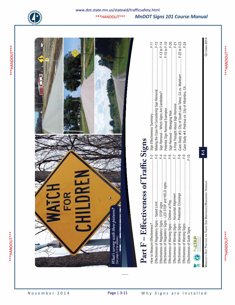
MnDOT Signs 101 Course Manual
N o v e m b e r 2 0 1 4 W h y S i g n s a r e I n s t a l l e d
***H
ANDO
UT**
* **
*HAN
DOUT
***
***H
ANDO
UT**
* **
*HAN
DOUT
***
***HANDOUT***
OC
TOB
ER 2
014
MIN
NESO
TA’S
BES
T PRA
CTIC
ES FO
R TR
AFFI
C SI
GN M
AINT
ENAN
CE/M
ANAG
EMEN
T HAN
DBOO
KF-1
Par
t F
– E
ffec
tive
nes
s o
f Tra
ffic
Sig
ns
How
to M
easu
re E
ffect
iven
ess?
......
......
......
......
......
......
......
......
......
......
......
......
...F-
2Ef
fect
iven
ess
of R
egul
ator
y Si
gns
– Sp
eed
Lim
it ....
......
......
......
......
......
......
......
....F
-3Ef
fect
iven
ess
of R
egul
ator
y Si
gns
– ST
OP s
igns
.....
......
......
......
......
......
......
......
...F-
4 Ef
fect
iven
ess
of R
egul
ator
y Si
gns
- LED
STO
P an
d YI
ELD
sign
s ....
......
......
......
.....F
-5Ef
fect
iven
ess
of W
arni
ng S
igns
– C
hild
ren
at P
lay .
......
......
......
......
......
......
......
.....F
-6Ef
fect
iven
ess
of W
arni
ng S
igns
– H
orizo
ntal
Alig
nmen
t ....
......
......
......
......
......
......
F-7
Effe
ctiv
enes
s of
War
ning
Sig
ns –
Ped
estri
an C
ross
ings
.....
......
......
......
......
......
....F
-8Ef
fect
iven
ess
of W
arni
ng S
igns
.....
......
......
......
......
......
......
......
......
......
......
......
....F
-9Ef
fect
iven
ess
of G
uide
Sig
ns ..
......
......
......
......
......
......
......
......
......
......
......
......
...F-
10
Sign
Effe
ctiv
enes
s Su
mm
ary .
......
......
......
......
......
......
......
......
......
......
......
......
....F
-11
Mak
ing
the
Case
For
Con
side
ring
Sign
Rem
oval
......
......
......
......
......
......
......
......
.F-1
2Si
gn R
emov
al –
Whi
ch S
igns
Are
Can
dida
tes?
......
......
......
......
......
......
...F-
13 to
F-1
4Po
tent
ial S
ign
Rem
oval
Exa
mpl
es ..
......
......
......
......
......
......
......
......
......
..F-
15 to
F-1
9Si
gn R
emov
al –
Man
agin
g Ri
sk ..
......
......
......
......
......
......
......
......
......
......
......
.....
F-20
A Fi
nal T
houg
ht A
bout
Sig
n Re
mov
al ..
......
......
......
......
......
......
......
......
......
......
...F-
21Ca
se S
tudy
#3:
City
of S
outh
Lak
e Ta
hoe,
CA
vs. M
arkh
am ..
......
......
....F
-22
to F
-23
Case
Stu
dy #
4: P
edro
sa v
s. C
ity o
f Alh
ambr
a, C
A ....
......
......
......
......
......
......
.....
F-24
Wha
t’s wr
ong w
ith th
ese pi
ctures
?(S
ee p
age
G-3
for a
nsw
er.)
www.dot.state.mn.us/stateaid/trafficsafety.html
Page | 3-11
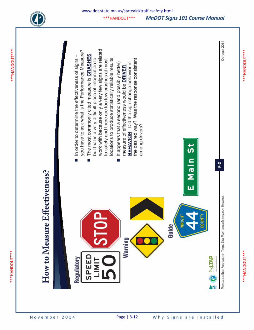
MnDOT Signs 101 Course Manual
N o v e m b e r 2 0 1 4 W h y S i g n s a r e I n s t a l l e d
***H
ANDO
UT**
* **
*HAN
DOUT
***
***H
ANDO
UT**
* **
*HAN
DOUT
***
***HANDOUT***
F-2
OC
TOB
ER 2
014
MIN
NESO
TA’S
BES
T PRA
CTIC
ES FO
R TR
AFFI
C SI
GN M
AINT
ENAN
CE/M
ANAG
EMEN
T HAN
DBOO
K
Ho
w t
o M
easu
re E
ffec
tive
nes
s?
�
In o
rder
to d
eter
min
e th
e ef
fect
iven
ess
of s
igns
–
you
have
to a
sk w
hat i
s th
e P
erfo
rman
ce M
easu
re?
�
The
mos
t com
mon
ly c
ited
mea
sure
is C
RA
SH
ES
, bu
t tha
t is
a ve
ry d
iffic
ult p
iece
of i
nfor
mat
ion
to
wor
k w
ith b
ecau
se o
nly
a ve
ry fe
w s
igns
are
rel
ated
to
saf
ety
and
ther
e ar
e to
o fe
w c
rash
es a
t mos
t lo
catio
ns to
pro
duce
sta
tistic
ally
rel
iabl
e re
sults
.
�
It ap
pear
s th
at a
sec
ond
(and
pos
sibl
y be
tter)
m
easu
re o
f effe
ctiv
enes
s w
ould
be
DR
IVE
R
BE
HA
VIO
R.
Did
the
sign
cha
nge
beha
vior
in
the
desi
red
way
? W
as th
e re
spon
se c
onsi
sten
t am
ong
driv
ers?
Regulatory W
arning
Guide
www.dot.state.mn.us/stateaid/trafficsafety.html
Page | 3-12
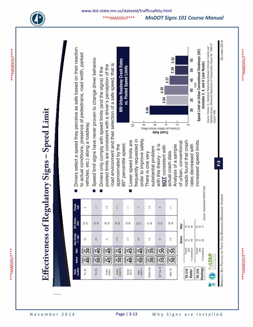
MnDOT Signs 101 Course Manual
N o v e m b e r 2 0 1 4 W h y S i g n s a r e I n s t a l l e d
***H
ANDO
UT**
* **
*HAN
DOUT
***
***H
ANDO
UT**
* **
*HAN
DOUT
***
***HANDOUT***
F-3
OC
TOB
ER 2
014
MIN
NESO
TA’S
BES
T PRA
CTIC
ES FO
R TR
AFFI
C SI
GN M
AINT
ENAN
CE/M
ANAG
EMEN
T HAN
DBOO
K
Eff
ecti
ven
ess
of
Reg
ula
tory
Sig
ns
– S
pee
d L
imit
�
Driv
ers
sele
ct a
spe
ed th
ey p
erce
ive
as s
afe
base
d on
thei
r re
actio
n to
act
ual c
ondi
tions
, pre
senc
e of
ped
estr
ians
, roa
d w
idth
, par
ked
vehi
cles
, etc
.) a
long
a r
oadw
ay.
�
Spe
ed li
mit
sign
s ha
ve n
ever
pro
ven
to c
hang
e dr
iver
beh
avio
r.
�
Driv
ers
only
com
ply
with
spe
ed li
mits
(an
d th
e si
gns)
if th
e po
sted
lim
its a
re c
onsi
sten
t with
a d
river
’s p
erce
ptio
n of
the
road
env
ironm
ent a
nd th
eir
sele
ctio
n of
a s
afe
spee
d, th
at is
ap
prox
imat
ed b
y th
e 85
th p
erce
ntile
spe
ed.
�
Low
er s
peed
lim
its a
re
frequ
ently
req
uest
ed in
or
der
to im
prov
e sa
fety
. Th
ere
is o
ne v
ery
subs
tant
ial p
robl
em
with
this
theo
ry –
it is
N
OT
cons
iste
nt w
ith
actu
al c
rash
dat
a.
Ana
lysi
s of
a s
ampl
e of
urb
an, c
onve
ntio
nal
road
s fo
und
that
cra
sh
rate
s de
crea
sed
with
in
crea
sed
spee
d lim
its.
Stud
y Lo
catio
nSi
gn C
hang
e +
/- m
ph85
% B
efor
e Af
ter
Chan
gem
ph
T.H.
65
-10
34 340
T.H.
65
-10
44 45+
1
Anok
aCS
AH 1
-548 50
+2
Anok
aCS
AH 2
4+
1549 50
+1
Anok
aCR
51
+5
45 46+
1
Henn
.CS
AH 4
-10
52 51-1
Nobl
es A
ve.
TH 2
10Ba
xter
+5
37 40+
3
62nd
Ave
. N-5
Befo
reAf
ter
55 57 68
Post
ed85
%%
Com
plia
nce
45 53 38
37 370
Mis
s. S
t.+
539 40
+1
Befo
reAf
ter
TH 3
16Ha
stin
gs
45 47 60
Post
ed85
%%
Com
plia
nce
35 45 12
6.96
3.94 35
40
Spee
d Li
mit
on U
rban
Con
vent
iona
l Roa
dway
s (U
C)(In
clud
es 2
, 4, a
nd 6
Lan
e Ro
ads)
MN
Urba
n Ro
adw
ay C
rash
Rat
esvs
. Pos
ted
Spee
d Li
mits
mph
4550
5530
4.30
3.37
2.38
2.32
0246810
Crash Rate(Crashes per Million Vehicle Miles)
Sour
ce:
Unp
ublis
hed M
nDO
T D
ata
Sour
ce:
Pre
ston,
H.,
Sta
tistic
al R
elat
ions
hip B
etw
een
Veh
icul
ar C
rash
es a
nd
Hig
hway
Acc
ess,
Min
neso
ta D
epar
tmen
t of
Tran
sport
atio
n R
eport
No.
19
98
-27
,
Aug
ust
19
98
.
www.dot.state.mn.us/stateaid/trafficsafety.html
Page | 3-13
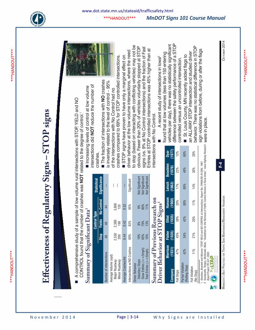
MnDOT Signs 101 Course Manual
N o v e m b e r 2 0 1 4 W h y S i g n s a r e I n s t a l l e d
***H
ANDO
UT**
* **
*HAN
DOUT
***
***H
ANDO
UT**
* **
*HAN
DOUT
***
***HANDOUT***
F-4
OC
TOB
ER 2
014
MIN
NESO
TA’S
BES
T PRA
CTIC
ES FO
R TR
AFFI
C SI
GN M
AINT
ENAN
CE/M
ANAG
EMEN
T HAN
DBOO
K
Eff
ecti
ven
ess
of
Reg
ula
tory
Sig
ns
– S
TO
P s
ign
s
�
A c
ompr
ehen
sive
stu
dy o
f a s
ampl
e of
low
vol
ume
rura
l int
erse
ctio
ns w
ith S
TOP,
YIE
LD a
nd N
O
CO
NTR
OL
foun
d th
at th
e nu
mbe
r of c
rash
es w
as N
OT
rela
ted
to th
e de
gree
of c
ontro
l.1
�
Incr
easi
ng le
vels
of c
ontro
l at l
ow v
olum
e in
ters
ectio
ns d
id N
OT
redu
ce th
e nu
mbe
r of
cras
hes.
�
The
fract
ion
of in
ters
ectio
ns w
ith N
O c
rash
es
is in
vers
ely
rela
ted
to th
e le
vel o
f con
trol –
95%
of
the
inte
rsec
tions
with
No
Con
trol h
ad n
o cr
ashe
s co
mpa
red
to 6
9% fo
r STO
P co
ntro
lled
inte
rsec
tions
. �
STO
P si
gns
have
pro
ven
to h
ave
only
a m
argi
nal e
ffect
on
driv
er b
ehav
ior a
t the
low
vol
ume
inte
rsec
tions
, whe
re th
e ne
ed
to s
top
(bas
ed o
n in
tera
ctin
g w
ith c
onfli
ctin
g ve
hicl
es) m
ay n
ot b
e ob
viou
s. F
ewer
than
20%
of v
ehic
les
volu
ntar
ily s
topp
ed a
t STO
P
sign
s (v
s. 9
% a
t No
Con
trol i
nter
sect
ions
) and
the
fract
ion
of F
ast
Ent
ries
at S
TOP
cont
rolle
d in
ters
ectio
ns w
as 4
5% h
ighe
r tha
n at
in
ters
ectio
ns w
ith N
o C
ontro
l. �
A re
cent
stu
dy o
f int
erse
ctio
ns in
Iow
a2 fo
und
that
at l
ow v
olum
es (l
ess
than
150
ent
erin
g ve
hicl
es p
er d
ay),
ther
e w
as n
o st
atis
tical
ly s
igni
fican
t di
ffere
nce
betw
een
the
safe
ty p
erfo
rman
ce o
f a S
TOP
co
ntro
lled
vers
us a
n un
cont
rolle
d in
ters
ectio
n. �
St.
Loui
s C
ount
y, M
N re
cent
ly a
dded
flag
s to
an
ALL
-WAY
STO
P in
ters
ectio
n an
d st
udie
d dr
iver
be
havi
or. T
here
was
no
stat
istic
al d
iffer
ence
in S
TOP
si
gn v
iola
tions
from
bef
ore,
dur
ing
or a
fter t
he fl
ags
wer
e in
pla
ce.
Su
mm
ary
of
Pre
vio
us
Res
earc
h o
n
Dri
ver
Beh
avio
r at
ST
OP
Sig
ns1
Com
pany
Mor
rison
(193
1)Fi
sher
(193
5)El
liot
(193
5)Ha
nson
(196
0)Le
isch
(196
3)Be
aubi
en(1
976)
Dyar
(197
7)Fu
ll St
ops
47%
45%
38%
20%
17%
22%
12%
Part
ial V
iola
tion
(Rol
ling
Stop
)42
%34
%
42%
69%
69%
48%
60%
Full
Viol
atio
n(N
o St
op)
11%
21%
20%
11%
14%
30%
28%
Su
mm
ary
of
Sig
nifi
can
t D
ata1
Cont
rol T
ype
Stat
istic
alSi
gnifi
canc
eSt
opYi
elds
No C
ontr
olNu
mbe
r of i
nter
sect
ions
4848
44—
Aver
age
Volu
me
(vpd
)
Maj
or R
oadw
ay
Min
or R
oadw
ay2,
530
200
2,38
019
03,
800
120
— —
Aver
age
Cras
hes/
Int
0.44
0.42
0.32
—
Inte
rsec
tions
w/N
O Cr
ashe
s69
%83
%95
%Si
gnifi
cant
Driv
er B
ehav
ior
Vo
lunt
ary
Stop
s
Slow
Ent
ries
(<=
5mph
)
Fast
Ent
ries
(>=
5mph
)
19%
65%
16%
8% 79%
13%
9% 80%
11%
Not S
igni
fican
tNo
t Sig
nific
ant
Not S
igni
fican
t
1
Sto
ckto
n, B
rack
ett
and M
oun
ce “
STO
P, Y
IELD
and
NO
CO
NTR
OL
at In
ters
ectio
ns,
Rep
ort
No.
FHW
A/R
D-8
1/0
84
, 1
98
1
2
Soul
eyre
tte,
Ten
ges
, M
cDona
ld,
Maz
e, “
Gui
del
ines
for
the
Rem
ova
l of
Traf
fic C
ont
rol D
evic
es in
Rur
al A
reas
”, Io
wa
Hig
hway
Res
earc
h
Boar
d P
roje
ct T
R-5
27
, 2
00
5
www.dot.state.mn.us/stateaid/trafficsafety.html
Page | 3-14
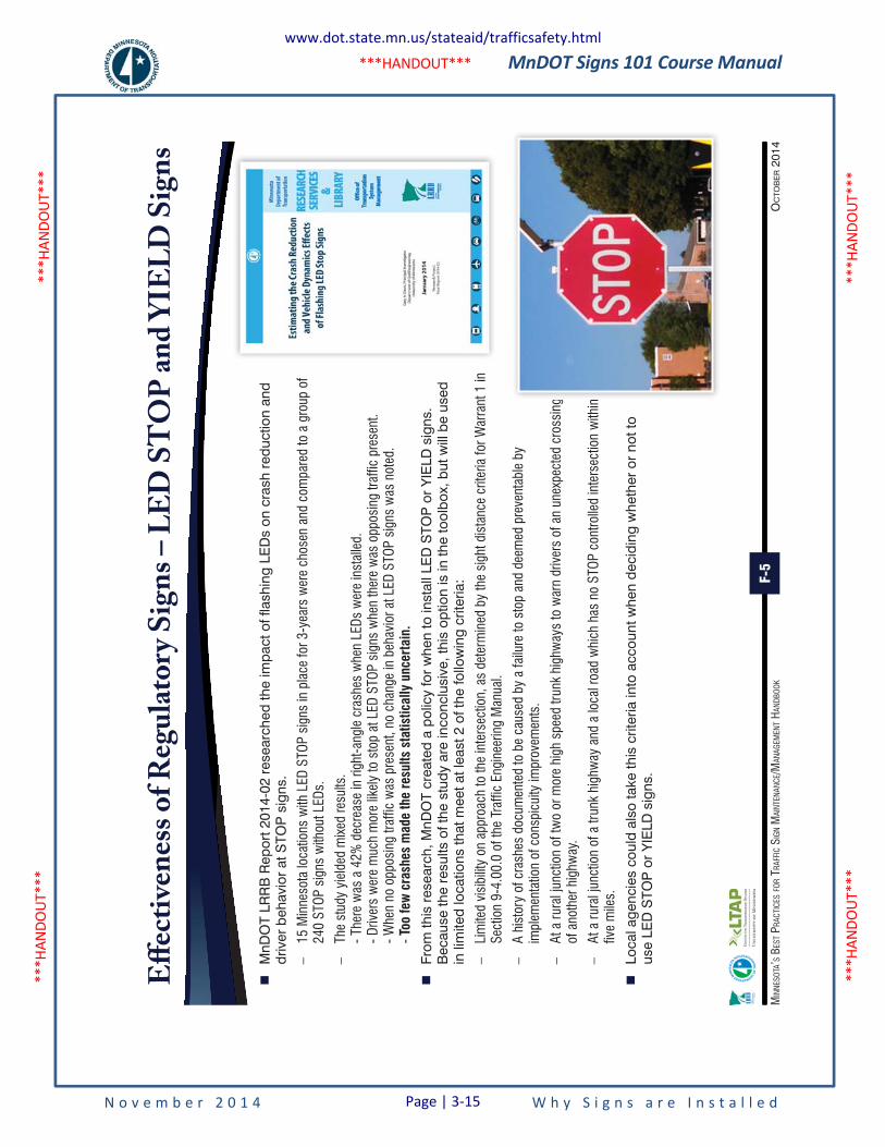
MnDOT Signs 101 Course Manual
N o v e m b e r 2 0 1 4 W h y S i g n s a r e I n s t a l l e d
***H
ANDO
UT**
* **
*HAN
DOUT
***
***H
ANDO
UT**
* **
*HAN
DOUT
***
***HANDOUT***
F-5
OC
TOB
ER 2
014
MIN
NESO
TA’S
BES
T PRA
CTIC
ES FO
R TR
AFFI
C SI
GN M
AINT
ENAN
CE/M
ANAG
EMEN
T HAN
DBOO
K
Eff
ecti
ven
ess
of
Reg
ula
tory
Sig
ns
– L
ED
ST
OP
an
d Y
IEL
D S
ign
s
�
MnD
OT
LRR
B R
epor
t 201
4-02
res
earc
hed
the
impa
ct o
f fla
shin
g LE
Ds
on c
rash
red
uctio
n an
d dr
iver
beh
avio
r at
STO
P s
igns
.
–15
Min
neso
ta lo
catio
ns w
ith L
ED S
TOP
sign
s in
pla
ce fo
r 3-y
ears
wer
e ch
osen
and
com
pare
d to
a g
roup
of
240
STOP
sig
ns w
ithou
t LED
s.
–Th
e st
udy
yiel
ded
mix
ed re
sults
. - T
here
was
a 4
2% d
ecre
ase
in ri
ght-a
ngle
cra
shes
whe
n LE
Ds w
ere
inst
alle
d.
- Driv
ers
wer
e m
uch
mor
e lik
ely
to s
top
at L
ED S
TOP
sign
s w
hen
ther
e w
as o
ppos
ing
traffi
c pr
esen
t. - W
hen
no o
ppos
ing
traffi
c w
as p
rese
nt, n
o ch
ange
in b
ehav
ior a
t LED
STO
P si
gns
was
not
ed.
- Too
few
cra
shes
mad
e th
e re
sults
sta
tistic
ally
unc
erta
in.
�
From
this
res
earc
h, M
nDO
T cr
eate
d a
polic
y fo
r w
hen
to in
stal
l LE
D S
TOP
or
YIE
LD s
igns
. B
ecau
se th
e re
sults
of t
he s
tudy
are
inco
nclu
sive
, thi
s op
tion
is in
the
tool
box,
but
will
be
used
in
lim
ited
loca
tions
that
mee
t at l
east
2 o
f the
follo
win
g cr
iteria
:
–Li
mite
d vi
sibi
lity
on a
ppro
ach
to th
e in
ters
ectio
n, a
s de
term
ined
by
the
sigh
t dis
tanc
e cr
iteria
for W
arra
nt 1
in
Sect
ion
9-4.
00.0
of t
he T
raffi
c En
gine
erin
g M
anua
l.
–A
hist
ory
of c
rash
es d
ocum
ente
d to
be
caus
ed b
y a
failu
re to
sto
p an
d de
emed
pre
vent
able
by
impl
emen
tatio
n of
con
spic
uity
impr
ovem
ents
.
–At
a ru
ral j
unct
ion
of tw
o or
mor
e hi
gh s
peed
trun
k hi
ghw
ays
to w
arn
driv
ers
of a
n un
expe
cted
cro
ssin
g of
ano
ther
hig
hway
.
–At
a ru
ral j
unct
ion
of a
trun
k hi
ghw
ay a
nd a
loca
l roa
d w
hich
has
no
STOP
con
trolle
d in
ters
ectio
n w
ithin
fiv
e m
iles.
�
Loca
l age
ncie
s co
uld
also
take
this
crit
eria
into
acc
ount
whe
n de
cidi
ng w
heth
er o
r no
t to
use
LED
STO
P o
r Y
IELD
sig
ns.
www.dot.state.mn.us/stateaid/trafficsafety.html
Page | 3-15
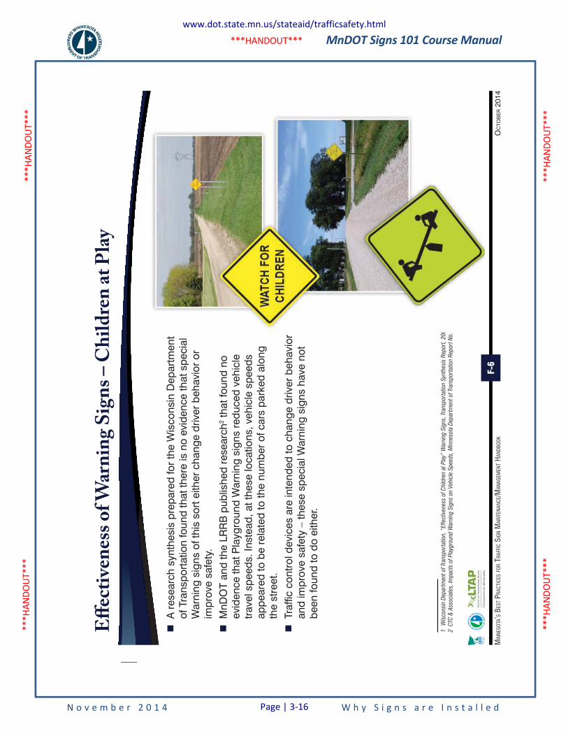
MnDOT Signs 101 Course Manual
N o v e m b e r 2 0 1 4 W h y S i g n s a r e I n s t a l l e d
***H
ANDO
UT**
* **
*HAN
DOUT
***
***H
ANDO
UT**
* **
*HAN
DOUT
***
***HANDOUT***
F-6
OC
TOB
ER 2
014
MIN
NESO
TA’S
BES
T PRA
CTIC
ES FO
R TR
AFFI
C SI
GN M
AINT
ENAN
CE/M
ANAG
EMEN
T HAN
DBOO
K
Eff
ecti
ven
ess
of W
arn
ing
Sig
ns
– C
hil
dre
n a
t P
lay
�
A r
esea
rch
synt
hesi
s pr
epar
ed fo
r th
e W
isco
nsin
Dep
artm
ent
of T
rans
port
atio
n fo
und
that
ther
e is
no
evid
ence
that
spe
cial
W
arni
ng s
igns
of t
his
sort
eith
er c
hang
e dr
iver
beh
avio
r or
im
prov
e sa
fety
.
�M
nDO
T an
d th
e LR
RB
pub
lishe
d re
sear
ch2 t
hat f
ound
no
evid
ence
that
Pla
ygro
und
War
ning
sig
ns r
educ
ed v
ehic
le
trav
el s
peed
s. In
stea
d, a
t the
se lo
catio
ns, v
ehic
le s
peed
s ap
pear
ed to
be
rela
ted
to th
e nu
mbe
r of
car
s pa
rked
alo
ng
the
stre
et.
�
Traf
fic c
ontr
ol d
evic
es a
re in
tend
ed to
cha
nge
driv
er b
ehav
ior
and
impr
ove
safe
ty –
thes
e sp
ecia
l War
ning
sig
ns h
ave
not
been
foun
d to
do
eith
er.
1
Wis
cons
in D
epar
tmen
t of
Tran
sport
atio
n, “
Eff
ectiv
enes
s of
Chi
ldre
n at
Pla
y” W
arni
ng S
igns
, Tr
ansp
ort
atio
n S
ynth
esis
Rep
ort
, 2
00
7
2
CTC
& A
ssoci
ates
, Im
pac
ts o
f P
layg
roun
d W
arni
ng S
igns
on
Veh
icle
Spee
ds,
Min
neso
ta D
epar
tmen
t of
Tran
sport
atio
n R
eport
No.
20
12
-06
TS,
May
20
12
.
07 20
12
-06
TS,
May
20
10
1111111111112
.22222222222222222
.22
.2222
.222222222222222222222222
.222222222222222222
.22
..
www.dot.state.mn.us/stateaid/trafficsafety.html
Page | 3-16
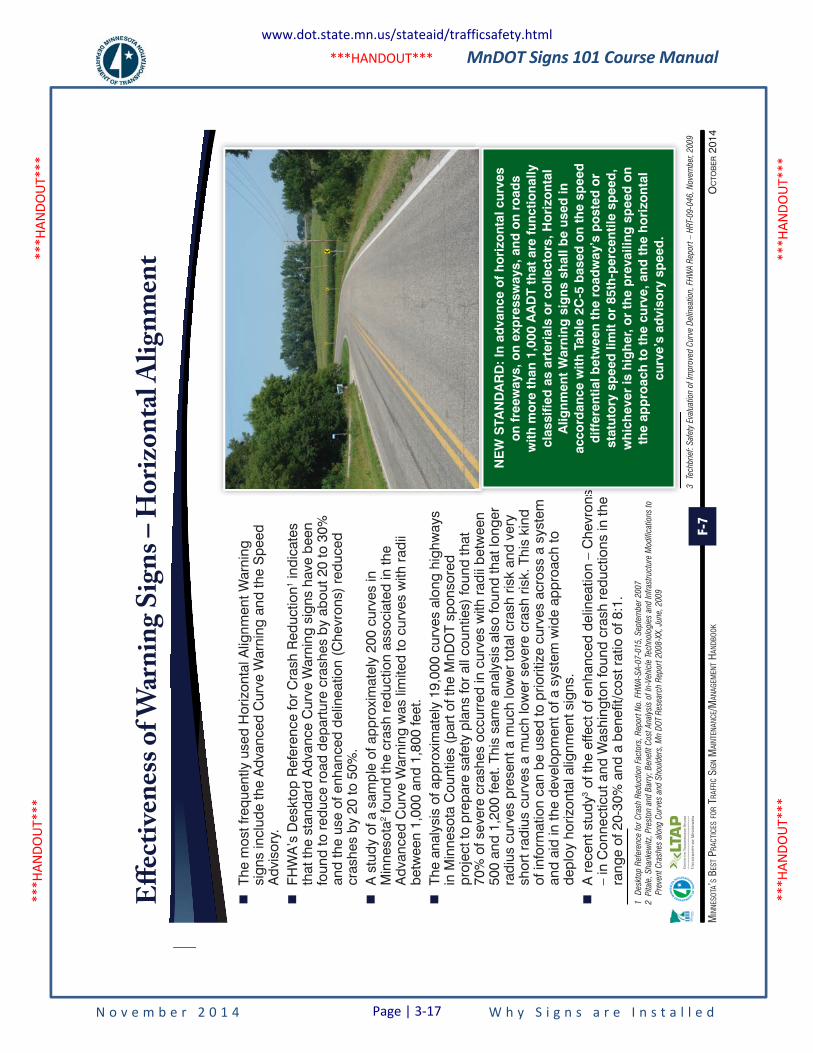
MnDOT Signs 101 Course Manual
N o v e m b e r 2 0 1 4 W h y S i g n s a r e I n s t a l l e d
***H
ANDO
UT**
* **
*HAN
DOUT
***
***H
ANDO
UT**
* **
*HAN
DOUT
***
***HANDOUT***
F-7
OC
TOB
ER 2
014
MIN
NESO
TA’S
BES
T PRA
CTIC
ES FO
R TR
AFFI
C SI
GN M
AINT
ENAN
CE/M
ANAG
EMEN
T HAN
DBOO
K
Eff
ecti
ven
ess
of W
arn
ing
Sig
ns
– H
ori
zon
tal A
lign
men
t
�
The
mos
t fre
quen
tly u
sed
Hor
izon
tal A
lignm
ent W
arni
ng
sign
s in
clud
e th
e A
dvan
ced
Cur
ve W
arni
ng a
nd th
e S
peed
A
dvis
ory.
�
FHW
A’s
Des
ktop
Ref
eren
ce fo
r C
rash
Red
uctio
n1 ind
icat
es
that
the
stan
dard
Adv
ance
Cur
ve W
arni
ng s
igns
hav
e be
en
foun
d to
red
uce
road
dep
artu
re c
rash
es b
y ab
out 2
0 to
30%
an
d th
e us
e of
enh
ance
d de
linea
tion
(Che
vron
s) r
educ
ed
cras
hes
by 2
0 to
50%
. �
A s
tudy
of a
sam
ple
of a
ppro
xim
atel
y 20
0 cu
rves
in
Min
neso
ta2 f
ound
the
cras
h re
duct
ion
asso
ciat
ed in
the
Adv
ance
d C
urve
War
ning
was
lim
ited
to c
urve
s w
ith r
adii
betw
een
1,00
0 an
d 1,
800
feet
. �
The
anal
ysis
of a
ppro
xim
atel
y 19
,000
cur
ves
alon
g hi
ghw
ays
in M
inne
sota
Cou
ntie
s (p
art o
f the
MnD
OT
spon
sore
d pr
ojec
t to
prep
are
safe
ty p
lans
for
all c
ount
ies)
foun
d th
at
70%
of s
ever
e cr
ashe
s oc
curr
ed in
cur
ves
with
rad
ii be
twee
n 50
0 an
d 1,
200
feet
. Thi
s sa
me
anal
ysis
als
o fo
und
that
long
er
radi
us c
urve
s pr
esen
t a m
uch
low
er to
tal c
rash
ris
k an
d ve
ry
shor
t rad
ius
curv
es a
muc
h lo
wer
sev
ere
cras
h ris
k. T
his
kind
of
info
rmat
ion
can
be u
sed
to p
riorit
ize
curv
es a
cros
s a
syst
em
and
aid
in th
e de
velo
pmen
t of a
sys
tem
wid
e ap
proa
ch to
de
ploy
hor
izon
tal a
lignm
ent s
igns
. �
A r
ecen
t stu
dy3 o
f the
effe
ct o
f enh
ance
d de
linea
tion
– C
hevr
ons
– in
Con
nect
icut
and
Was
hing
ton
foun
d cr
ash
redu
ctio
ns in
the
rang
e of
20-
30%
and
a b
enef
it/co
st r
atio
of 8
:1.
1
Des
ktop R
efer
ence
for
Cra
sh R
educ
tion
Fact
ors
, R
eport
No.
FHW
A-S
A-0
7-0
15
, S
epte
mber
20
07
2
Pita
le,
Sha
nkew
itz,
Pre
ston
and B
arry
; B
enef
it C
ost
Ana
lysi
s of
In-V
ehic
le T
echn
olo
gie
s an
d In
fras
truc
ture
Modifi
catio
ns t
o
Pre
vent
Cra
shes
alo
ng C
urve
s an
d S
houl
der
s, M
n D
OT
Res
earc
h R
eport
20
08
-XX,
June
, 2
00
9
s
NE
W S
TAN
DA
RD
: In
adva
nce
of
ho
rizo
ntal
cur
ves
on
free
way
s, o
n ex
pre
ssw
ays,
and
on
road
s w
ith m
ore
th
an 1
,000
AA
DT
that
are
fun
ctio
nally
cl
assi
fied
as
arte
rial
s o
r co
llect
ors
, Ho
rizo
ntal
A
lignm
ent
War
ning
sig
ns s
hal
l be
used
in
acco
rdan
ce w
ith T
able
2C
-5 b
ased
on
the
spee
d
diff
eren
tial b
etw
een
the
road
way
’s p
ost
ed o
r st
atut
ory
sp
eed
lim
it o
r 85
th-p
erce
ntile
sp
eed
, w
hic
hev
er is
hig
her
, or
the
pre
vaili
ng s
pee
d o
n th
e ap
pro
ach
to
th
e cu
rve,
and
th
e h
ori
zont
al
curv
e’s
advi
sory
sp
eed
.
3
Tech
bri
ef:
Saf
ety
Eva
luat
ion
of
Impro
ved C
urve
Del
inea
tion,
FH
WA
Rep
ort
– H
RT-
09
-04
6,
Nove
mber
, 2
00
9
www.dot.state.mn.us/stateaid/trafficsafety.html
Page | 3-17
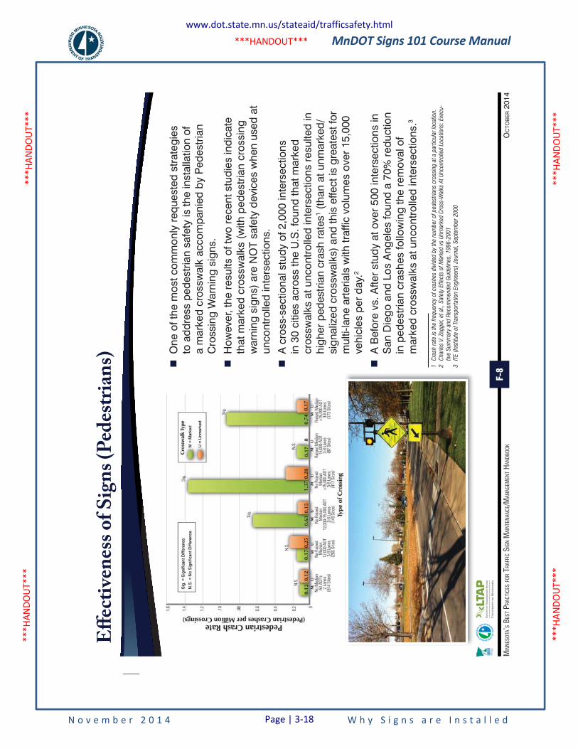
MnDOT Signs 101 Course Manual
N o v e m b e r 2 0 1 4 W h y S i g n s a r e I n s t a l l e d
***H
ANDO
UT**
* **
*HAN
DOUT
***
***H
ANDO
UT**
* **
*HAN
DOUT
***
***HANDOUT***
F-8
OC
TOB
ER 2
014
MIN
NESO
TA’S
BES
T PRA
CTIC
ES FO
R TR
AFFI
C SI
GN M
AINT
ENAN
CE/M
ANAG
EMEN
T HAN
DBOO
K
Eff
ecti
ven
ess
of
Sig
ns
(Ped
estr
ian
s) �
One
of t
he m
ost c
omm
only
req
uest
ed s
trat
egie
s to
add
ress
ped
estr
ian
safe
ty is
the
inst
alla
tion
of
a m
arke
d cr
ossw
alk
acco
mpa
nied
by
Ped
estr
ian
Cro
ssin
g W
arni
ng s
igns
.
�
How
ever
, the
res
ults
of t
wo
rece
nt s
tudi
es in
dica
te
that
mar
ked
cros
swal
ks (
with
ped
estr
ian
cros
sing
w
arni
ng s
igns
) ar
e N
OT
safe
ty d
evic
es w
hen
used
at
unco
ntro
lled
inte
rsec
tions
.
�
A c
ross
-sec
tiona
l stu
dy o
f 2,0
00 in
ters
ectio
ns
in 3
0 ci
ties
acro
ss th
e U
.S. f
ound
that
mar
ked
cros
swal
ks a
t unc
ontr
olle
d in
ters
ectio
ns r
esul
ted
in
high
er p
edes
tria
n cr
ash
rate
s1 (th
an a
t unm
arke
d/si
gnal
ized
cro
ssw
alks
) an
d th
is e
ffect
is g
reat
est f
or
mul
ti-la
ne a
rter
ials
with
traf
fic v
olum
es o
ver
15,0
00
vehi
cles
per
day
.2
�
A B
efor
e vs
. Afte
r st
udy
at o
ver
500
inte
rsec
tions
in
San
Die
go a
nd L
os A
ngel
es fo
und
a 70
% r
educ
tion
in p
edes
tria
n cr
ashe
s fo
llow
ing
the
rem
oval
of
mar
ked
cros
swal
ks a
t unc
ontr
olle
d in
ters
ectio
ns.3
1
Cra
sh r
ate
is t
he f
reque
ncy
of
cras
hes
div
ided
by
the
num
ber
of
ped
estr
ians
cro
ssin
g a
t a
par
ticul
ar lo
catio
n.
2
Cha
rles
V.
Zegger
, et
al.,
Saf
ety
Eff
ects
of
Mar
ked v
s U
nmar
ked C
ross
-Wal
ks A
t U
ncont
rolle
d L
oca
tions
: Exe
cu-
tive
Sum
mar
y an
d R
ecom
men
ded
Gui
del
ines
, 1
99
6-2
00
1
3
ITE (
Inst
itute
of
Tran
sport
atio
n Eng
inee
rs)
Jour
nal,
Sep
tem
ber
20
00
www.dot.state.mn.us/stateaid/trafficsafety.html
Page | 3-18
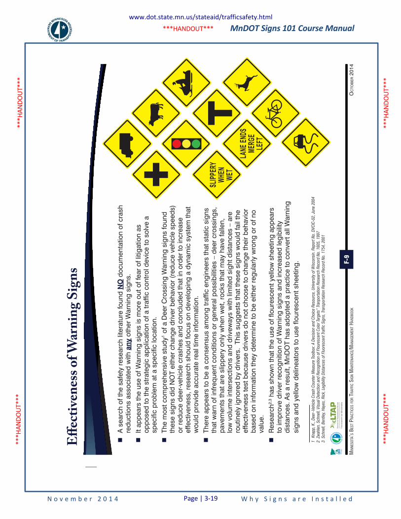
MnDOT Signs 101 Course Manual
N o v e m b e r 2 0 1 4 W h y S i g n s a r e I n s t a l l e d
***H
ANDO
UT**
* **
*HAN
DOUT
***
***H
ANDO
UT**
* **
*HAN
DOUT
***
***HANDOUT***
F-9
OC
TOB
ER 2
014
MIN
NESO
TA’S
BES
T PRA
CTIC
ES FO
R TR
AFFI
C SI
GN M
AINT
ENAN
CE/M
ANAG
EMEN
T HAN
DBOO
K
Eff
ecti
ven
ess
of W
arn
ing
Sig
ns
SLIPP
ERY
WHEN
WET
LANE
ENDS
MERG
ELE
FT
�
A s
earc
h of
the
safe
ty r
esea
rch
liter
atur
e fo
und
NO
doc
umen
tatio
n of
cra
sh
redu
ctio
ns a
ssoc
iate
d w
ith a
ny o
ther
War
ning
sig
ns.
�
It ap
pear
s th
e us
e of
War
ning
sig
ns is
mor
e ou
t of f
ear
of li
tigat
ion
as
oppo
sed
to th
e st
rate
gic
appl
icat
ion
of a
traf
fic c
ontr
ol d
evic
e to
sol
ve a
sp
ecifi
c pr
oble
m a
t a s
peci
fic lo
catio
n.
�
The
mos
t com
preh
ensi
ve s
tudy
1 of a
Dee
r C
ross
ing
War
ning
sig
ns fo
und
thes
e si
gns
did
NO
T ei
ther
cha
nge
driv
er b
ehav
ior
(red
uce
vehi
cle
spee
ds)
or r
educ
e de
er-v
ehic
le c
rash
es a
nd c
oncl
uded
that
in o
rder
to in
crea
se
effe
ctiv
enes
s, r
esea
rch
shou
ld fo
cus
on d
evel
opin
g a
dyna
mic
sys
tem
that
w
ould
pro
vide
acc
urat
e re
al ti
me
info
rmat
ion.
�
Ther
e ap
pear
s to
be
a co
nsen
sus
amon
g tr
affic
eng
inee
rs th
at s
tatic
sig
ns
that
war
n of
infre
quen
t con
ditio
ns o
r ge
nera
l pos
sibi
litie
s –
deer
cro
ssin
gs,
pave
men
ts th
at a
re s
lippe
ry o
nly
whe
n w
et, r
ocks
that
may
hav
e fa
llen,
lo
w v
olum
e in
ters
ectio
ns a
nd d
rivew
ays
with
lim
ited
sigh
t dis
tanc
es –
are
ro
utin
ely
igno
red
by d
river
s. T
his
sugg
ests
that
thes
e si
gns
wou
ld fa
il th
e ef
fect
iven
ess
test
bec
ause
driv
ers
do n
ot c
hoos
e to
cha
nge
thei
r be
havi
or
base
d on
info
rmat
ion
they
det
erm
ine
to b
e ei
ther
reg
ular
ly w
rong
or
of n
o va
lue.
�
Res
earc
h2,3 h
as s
how
n th
at th
e us
e of
flou
resc
ent y
ello
w s
heet
ing
appe
ars
to im
prov
e dr
iver
rec
ogni
tion
of W
arni
ng s
igns
and
incr
ease
d le
gibi
lity
dist
ance
s. A
s a
resu
lt, M
nDO
T ha
s ad
opte
d a
prac
tice
to c
onve
rt a
ll W
arni
ng
sign
s an
d ye
llow
del
inea
tors
to u
se fl
oure
scen
t she
etin
g.
1
Kna
pp,
K.,
Dee
r–V
ehic
le C
rash
Coun
ter
Mea
sure
Toolb
ox:
A D
ecis
ion
and C
hoic
e R
esour
ce,
Uni
vers
ity o
f W
isco
nsin
. R
eport
No.
DV
CIC
-02
, Ju
ne 2
00
4
2
Zwah
len,
Sch
nell,
Vis
ual D
etec
tion
and R
ecogni
tion
of
Flour
esce
nt C
olo
r Ta
rget
s” T
ranp
ort
atio
n R
esea
rch
Rec
ord
No.
16
05
, 1
99
7
3
Sch
nell,
Ben
tley,
Hay
es,
Ric
k, L
egib
ility
Dis
tanc
es o
f Fl
uore
scen
t Tr
affic
Sig
ns,
Tran
sport
atio
n R
esea
rch
Rec
ord
No.
17
54
, 2
00
1
www.dot.state.mn.us/stateaid/trafficsafety.html
Page | 3-19
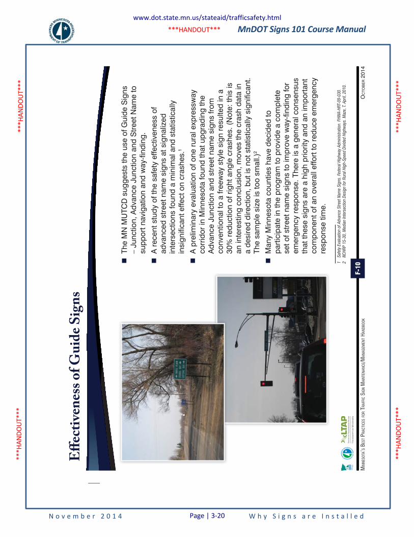
MnDOT Signs 101 Course Manual
N o v e m b e r 2 0 1 4 W h y S i g n s a r e I n s t a l l e d
***H
ANDO
UT**
* **
*HAN
DOUT
***
***H
ANDO
UT**
* **
*HAN
DOUT
***
***HANDOUT***
F-10
OC
TOB
ER 2
014
MIN
NESO
TA’S
BES
T PRA
CTIC
ES FO
R TR
AFFI
C SI
GN M
AINT
ENAN
CE/M
ANAG
EMEN
T HAN
DBOO
K
Eff
ecti
ven
ess
of
Gu
ide
Sig
ns
�
The
MN
MU
TCD
sug
gest
s th
e us
e of
Gui
de S
igns
–
Junc
tion,
Adv
ance
Jun
ctio
n an
d S
tree
t Nam
e to
su
ppor
t nav
igat
ion
and
way
-find
ing.
�
A r
ecen
t stu
dy o
f the
saf
ety
effe
ctiv
enes
s of
ad
vanc
ed s
tree
t nam
e si
gns
at s
igna
lized
in
ters
ectio
ns fo
und
a m
inim
al a
nd s
tatis
tical
ly
insi
gnifi
cant
effe
ct o
n cr
ashe
s.1
�
A p
relim
inar
y ev
alua
tion
of o
ne r
ural
exp
ress
way
co
rrid
or in
Min
neso
ta fo
und
that
upg
radi
ng th
e A
dvan
ce J
unct
ion
and
stre
et n
ame
sign
s fro
m
conv
entio
nal t
o a
freew
ay s
tyle
sig
n re
sulte
d in
a
30%
red
uctio
n of
rig
ht a
ngle
cra
shes
. (N
ote:
this
is
an in
tere
stin
g co
nclu
sion
, mov
es th
e cr
ash
data
in
a de
sire
d di
rect
ion,
but
is n
ot s
tatis
tical
ly s
igni
fican
t. Th
e sa
mpl
e si
ze is
too
smal
l.)2
�
Man
y M
inne
sota
cou
ntie
s ha
ve d
ecid
ed to
pa
rtic
ipat
e in
the
prog
ram
to p
rovi
de a
com
plet
e se
t of s
tree
t nam
e si
gns
to im
prov
e w
ay-fi
ndin
g fo
r em
erge
ncy
resp
onse
. The
re is
a g
ener
al c
onse
nsus
th
at th
ese
sign
s ar
e a
high
prio
rity
and
an im
port
ant
com
pone
nt o
f an
over
all e
ffort
to r
educ
e em
erge
ncy
resp
onse
tim
e.
1
Saf
ety
Eva
luat
ion
of
Adva
nce
Str
eet
Nam
e S
igns
. Fe
der
al H
ighw
ay A
dm
inis
trat
ion.
FH
WA
-HR
T-0
9-0
30
.
2
NC
HR
P 1
5-3
0,
Med
ian
Inte
rsec
tion
Des
ign
for
Rur
al H
igh-
Spee
d D
ivid
ed H
ighw
ays.
Maz
e, T
. A
pri
l, 2
01
0.
www.dot.state.mn.us/stateaid/trafficsafety.html
Page | 3-20
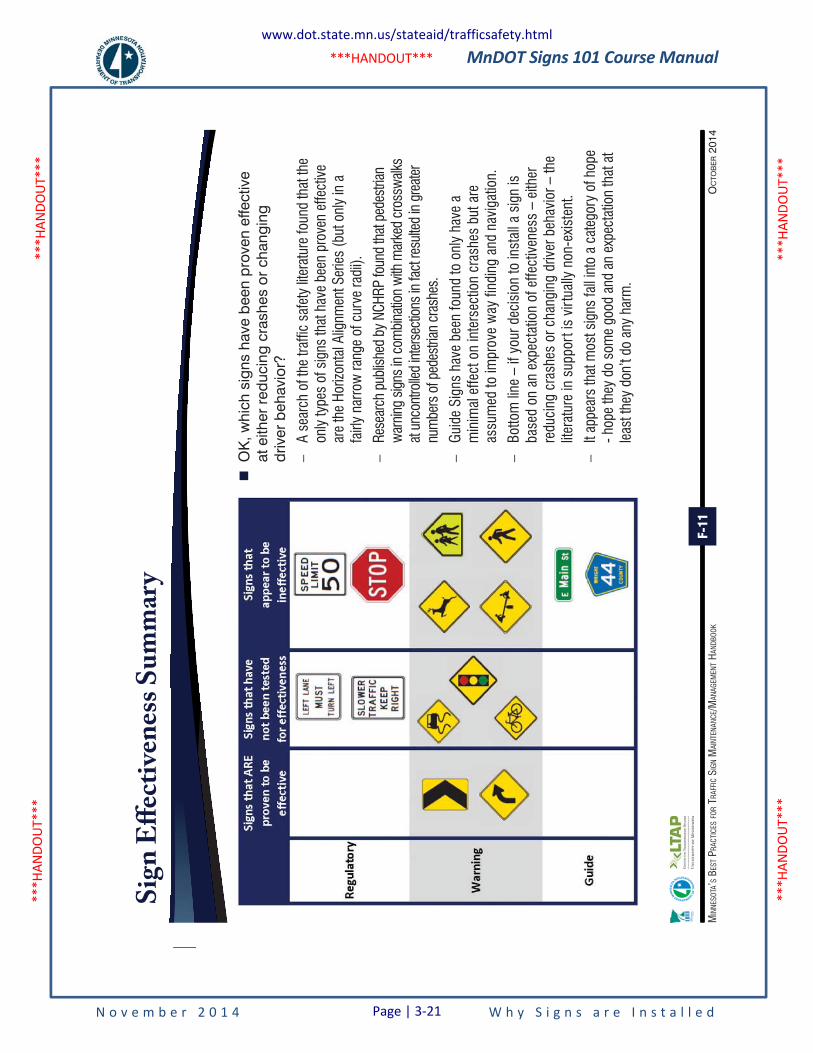
MnDOT Signs 101 Course Manual
N o v e m b e r 2 0 1 4 W h y S i g n s a r e I n s t a l l e d
***H
ANDO
UT**
* **
*HAN
DOUT
***
***H
ANDO
UT**
* **
*HAN
DOUT
***
***HANDOUT***
F-11
OC
TOB
ER 2
014
MIN
NESO
TA’S
BES
T PRA
CTIC
ES FO
R TR
AFFI
C SI
GN M
AINT
ENAN
CE/M
ANAG
EMEN
T HAN
DBOO
K
Sig
n E
ffec
tive
nes
s S
um
mar
y
�
OK
, whi
ch s
igns
hav
e be
en p
rove
n ef
fect
ive
at e
ither
red
ucin
g cr
ashe
s or
cha
ngin
g dr
iver
beh
avio
r?
–A
sear
ch o
f the
traf
fic s
afet
y lit
erat
ure
foun
d th
at th
e on
ly ty
pes
of s
igns
that
hav
e be
en p
rove
n ef
fect
ive
are
the
Horiz
onta
l Alig
nmen
t Ser
ies
(but
onl
y in
a
fairl
y na
rrow
rang
e of
cur
ve ra
dii).
–Re
sear
ch p
ublis
hed
by N
CHRP
foun
d th
at p
edes
trian
w
arni
ng s
igns
in c
ombi
natio
n w
ith m
arke
d cr
ossw
alks
at u
ncon
trolle
d in
ters
ectio
ns in
fact
resu
lted
in g
reat
er
num
bers
of p
edes
trian
cra
shes
.
–Gu
ide
Sign
s ha
ve b
een
foun
d to
onl
y ha
ve a
m
inim
al e
ffect
on
inte
rsec
tion
cras
hes
but a
re
assu
med
to im
prov
e w
ay fi
ndin
g an
d na
viga
tion.
–Bo
ttom
line
– if
you
r dec
isio
n to
inst
all a
sig
n is
ba
sed
on a
n ex
pect
atio
n of
effe
ctiv
enes
s –
eith
er
redu
cing
cra
shes
or c
hang
ing
driv
er b
ehav
ior –
the
liter
atur
e in
sup
port
is v
irtua
lly n
on-e
xist
ent.
–It
appe
ars
that
mos
t sig
ns fa
ll in
to a
cat
egor
y of
hop
e - h
ope
they
do
som
e go
od a
nd a
n ex
pect
atio
n th
at a
t le
ast t
hey
don’
t do
any
harm
.
www.dot.state.mn.us/stateaid/trafficsafety.html
Page | 3-21
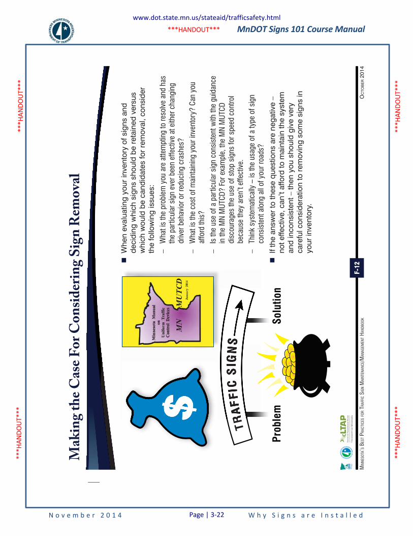
MnDOT Signs 101 Course Manual
N o v e m b e r 2 0 1 4 W h y S i g n s a r e I n s t a l l e d
***H
ANDO
UT**
* **
*HAN
DOUT
***
***H
ANDO
UT**
* **
*HAN
DOUT
***
***HANDOUT***
F-12
OC
TOB
ER 2
014
MIN
NESO
TA’S
BES
T PRA
CTIC
ES FO
R TR
AFFI
C SI
GN M
AINT
ENAN
CE/M
ANAG
EMEN
T HAN
DBOO
K
Mak
ing
the
Cas
e F
or
Co
nsi
der
ing
Sig
n R
emo
val
�
Whe
n ev
alua
ting
your
inve
ntor
y of
sig
ns a
nd
deci
ding
whi
ch s
igns
sho
uld
be r
etai
ned
vers
us
whi
ch w
ould
be
cand
idat
es fo
r re
mov
al, c
onsi
der
the
follo
win
g is
sues
:
–W
hat i
s th
e pr
oble
m y
ou a
re a
ttem
ptin
g to
reso
lve
and
has
the
part
icul
ar s
ign
ever
bee
n ef
fect
ive
at e
ither
cha
ngin
g dr
iver
beh
avio
r or r
educ
ing
cras
hes?
–W
hat i
s th
e co
st o
f mai
ntai
ning
you
r inv
ento
ry?
Can
you
affo
rd th
is?
–Is
the
use
of a
par
ticul
ar s
ign
cons
iste
nt w
ith th
e gu
idan
ce
in th
e M
N M
UTCD
? Fo
r exa
mpl
e, th
e M
N M
UTCD
di
scou
rage
s th
e us
e of
sto
p si
gns
for s
peed
con
trol
beca
use
they
are
n’t e
ffect
ive.
–Th
ink
syst
emat
ical
ly –
is th
e us
age
of a
type
of s
ign
cons
iste
nt a
long
all
of y
our r
oads
?
�
If th
e an
swer
to th
ese
ques
tions
are
neg
ativ
e –
not e
ffect
ive,
can
’t af
ford
to m
aint
ain
the
syst
em
and
inco
nsis
tent
– th
en y
ou s
houl
d gi
ve v
ery
care
ful c
onsi
dera
tion
to r
emov
ing
som
e si
gns
in
your
inve
ntor
y.
$
Prob
lem
Solu
tion
Minne
sota
Man
ual
onUniform
Traffi
cCo
ntrolDevices
MN
MUTC
DMay
2005
MMMMMMMMMMMMMMMMMMMMi
Mi
Mi
MiiiinininininnnnnnnnnnnnnnnnnnnnnnnnnnnneneneneneneneeeeeesesesesesesesesessososososososososooototototototototototottttttaaaaaaaaaaaaaaaMMMMMMMMMMMa
Ma
Ma
Ma
Ma
Ma
Ma
Man
Man
Man
Man
Manananan
uan
uan
uan
unununua
nunua
nua
nuauaual
ual
ual
ual
ualalalalalalll
ooooooooooonononononononononnnnnnnnnnUUUUUUUUUUUUUUUUUUUUUn
Un
Un
Un
Un
Un
Un
Un
Un
Unnnnnnnnnnininininininif
nif
nif
nif
nif
nif
nifififififoifoifoifoifoifofofofofofofofofofofor
for
fororororororororororororororrrrrrrrmmmmmmmmmmmmmmmmmmmmmmmmmmm
TTTTTTTTTTTTTTTTTTTTTTTc
rrarararararaffi
raffi
raffi
raffi
raffi
raffi
raffi
raffi
raffi
raffiaffic
affic
affic
affic
affic
affic
ffic
ffic
ffic
ffic
ffic
ffic
ffic
ffic
fficcccc
TTTTTTTTTTTTTTTTTTTTTTTTTTCCCCCCCCCCCCCCCCCCCCCCCCCoCoCoCoCoCoCoCoCoCoCoCoCoCoCoCoCoCoCoCoCooooo
nononononononononononononononononont
ont
ontntntntntntntntntntntntntntntntntntntnttttttttttttrrrrrrrrrrrrrrrrrrrrrrrooooooooooooooooooooooooooolllllllllllllllllllllllDevic
DDDDDDDDDDe
De
De
De
De
De
De
Dev
Dev
Dev
Dev
Dev
Dev
Devi
Devi
Devic
Devi
Devi
Devic
evic
evic
evic
evice
evice
evice
vices
vices
vices
vices
vices
ices
icesces
ces
ces
cesesesesesss
MMMMMMMMMMMMMMMMMMMMMMMMMMMMMMMMMMMMMMMMMMMMMMMMMMMMMMMMMMMMMMMMMMMMMMMMMMMMMMMMMMMMMMMMMMMMNNNNNNNNNNNNNNNNNNNNNNNNNNNNNNNNNNNNNNNNNNNNNNNNNNNNNNNNN
MMMMMMU
MU
MUT
MUTC
MUTC
MUTC
DMUTC
DMUTC
DMUTC
DMUTC
DMUTC
DMUTC
DMUTC
DMUTC
DMUTC
DMUTC
DMUTC
DMUTC
DMUTC
DMUTC
DMUTC
DMUTC
DMUTC
DMUTC
DM
MMMa
Ma
Ma
Ma
Ma
Ma
Ma
Myyyyyyyyy22020
0520
0520
0520
0520
0520
0500505
www.dot.state.mn.us/stateaid/trafficsafety.html
Page | 3-22
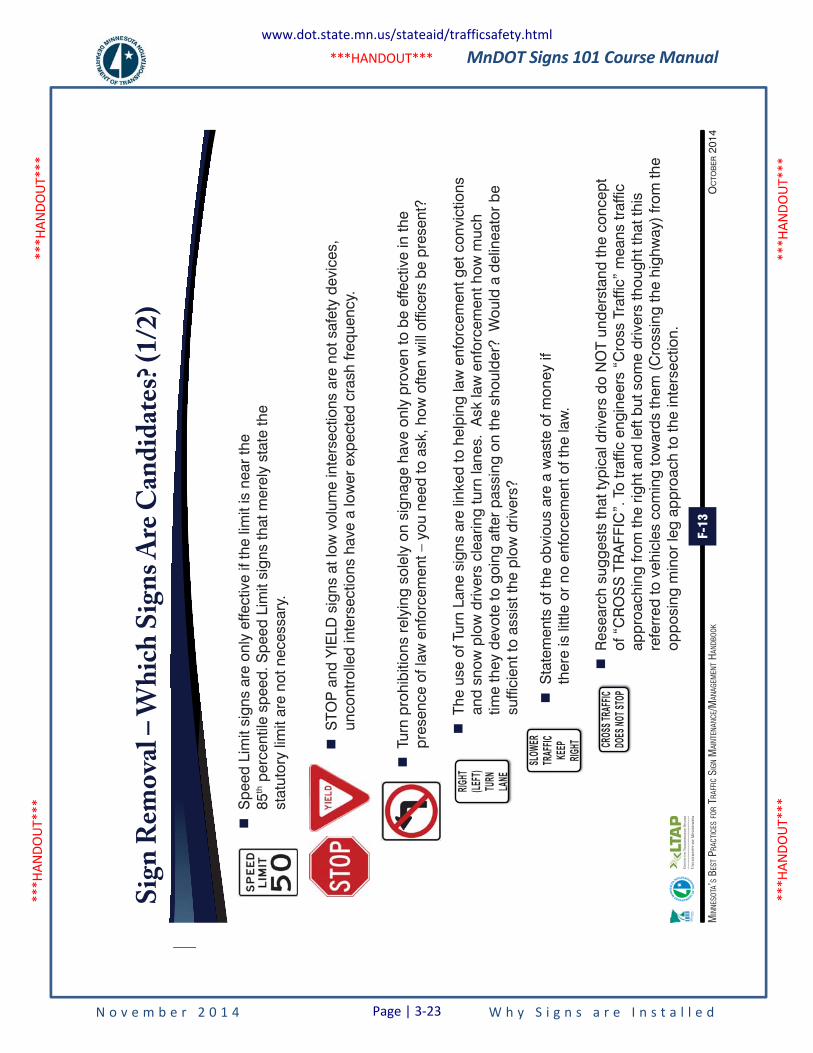
MnDOT Signs 101 Course Manual
N o v e m b e r 2 0 1 4 W h y S i g n s a r e I n s t a l l e d
***H
ANDO
UT**
* **
*HAN
DOUT
***
***H
ANDO
UT**
* **
*HAN
DOUT
***
***HANDOUT***
F-13
OC
TOB
ER 2
014
MIN
NESO
TA’S
BES
T PRA
CTIC
ES FO
R TR
AFFI
C SI
GN M
AINT
ENAN
CE/M
ANAG
EMEN
T HAN
DBOO
K
Sig
n R
emo
val –
Wh
ich
Sig
ns
Are
Can
did
ates
? (1
/2)
�
Spe
ed L
imit
sign
s ar
e on
ly e
ffect
ive
if th
e lim
it is
nea
r th
e
85th p
erce
ntile
spe
ed. S
peed
Lim
it si
gns
that
mer
ely
stat
e th
e st
atut
ory
limit
are
not n
eces
sary
.
�
STO
P a
nd Y
IELD
sig
ns a
t low
vol
ume
inte
rsec
tions
are
not
saf
ety
devi
ces,
un
cont
rolle
d in
ters
ectio
ns h
ave
a lo
wer
exp
ecte
d cr
ash
frequ
ency
.
�
Turn
pro
hibi
tions
rel
ying
sol
ely
on s
igna
ge h
ave
only
pro
ven
to b
e ef
fect
ive
in th
e pr
esen
ce o
f law
enf
orce
men
t – y
ou n
eed
to a
sk, h
ow o
ften
will
offi
cers
be
pres
ent?
�
The
use
of T
urn
Lane
sig
ns a
re li
nked
to h
elpi
ng la
w e
nfor
cem
ent g
et c
onvi
ctio
ns
and
snow
plo
w d
river
s cl
earin
g tu
rn la
nes.
Ask
law
enf
orce
men
t how
muc
h tim
e th
ey d
evot
e to
goi
ng a
fter
pass
ing
on th
e sh
ould
er?
Wou
ld a
del
inea
tor
be
suffi
cien
t to
assi
st th
e pl
ow d
river
s?
�
Sta
tem
ents
of t
he o
bvio
us a
re a
was
te o
f mon
ey if
th
ere
is li
ttle
or n
o en
forc
emen
t of t
he la
w.
�
Res
earc
h su
gges
ts th
at ty
pica
l driv
ers
do N
OT
unde
rsta
nd th
e co
ncep
t of
“C
RO
SS
TR
AFF
IC”.
To
traf
fic e
ngin
eers
“C
ross
Tra
ffic”
mea
ns tr
affic
ap
proa
chin
g fro
m th
e rig
ht a
nd le
ft bu
t som
e dr
iver
s th
ough
t tha
t thi
s re
ferr
ed to
veh
icle
s co
min
g to
war
ds th
em (
Cro
ssin
g th
e hi
ghw
ay)
from
the
oppo
sing
min
or le
g ap
proa
ch to
the
inte
rsec
tion.
RIGHT
(LEFT
)TU
RNLA
NE
SLOW
ER
TRAF
FIC
KEEP
RIG
HT CROS
S TRA
FFIC
DOES
NOT S
TOP
www.dot.state.mn.us/stateaid/trafficsafety.html
Page | 3-23
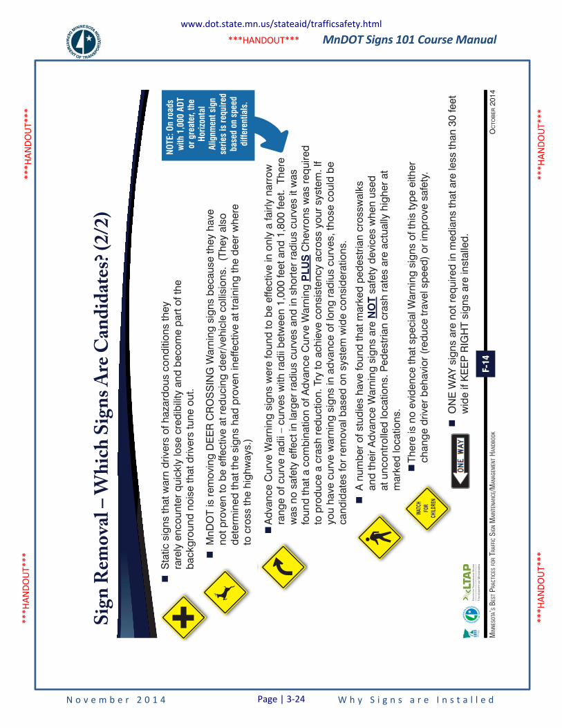
MnDOT Signs 101 Course Manual
N o v e m b e r 2 0 1 4 W h y S i g n s a r e I n s t a l l e d
***H
ANDO
UT**
* **
*HAN
DOUT
***
***H
ANDO
UT**
* **
*HAN
DOUT
***
***HANDOUT***
F-14
OC
TOB
ER 2
014
MIN
NESO
TA’S
BES
T PRA
CTIC
ES FO
R TR
AFFI
C SI
GN M
AINT
ENAN
CE/M
ANAG
EMEN
T HAN
DBOO
K
Sig
n R
emo
val –
Wh
ich
Sig
ns
Are
Can
did
ates
? (2
/2)
�
Sta
tic s
igns
that
war
n dr
iver
s of
haz
ardo
us c
ondi
tions
they
ra
rely
enc
ount
er q
uick
ly lo
se c
redi
bilit
y an
d be
com
e pa
rt o
f the
ba
ckgr
ound
noi
se th
at d
river
s tu
ne o
ut.
WATC
HFO
RCH
ILDRE
N
�
MnD
OT
is r
emov
ing
DE
ER
CR
OS
SIN
G W
arni
ng s
igns
bec
ause
they
hav
e no
t pro
ven
to b
e ef
fect
ive
at r
educ
ing
deer
/veh
icle
col
lisio
ns.
(The
y al
so
dete
rmin
ed th
at th
e si
gns
had
prov
en in
effe
ctiv
e at
trai
ning
the
deer
whe
re
to c
ross
the
high
way
s.)
�
Adv
ance
Cur
ve W
arni
ng s
igns
wer
e fo
und
to b
e ef
fect
ive
in o
nly
a fa
irly
narr
ow
rang
e of
cur
ve r
adii
– cu
rves
with
rad
ii be
twee
n 1,
000
feet
and
1,8
00 fe
et.
Ther
e w
as n
o sa
fety
effe
ct in
larg
er r
adiu
s cu
rves
and
in s
hort
er r
adiu
s cu
rves
it w
as
foun
d th
at a
com
bina
tion
of A
dvan
ce C
urve
War
ning
PLU
S C
hevr
ons
was
req
uire
d to
pro
duce
a c
rash
red
uctio
n. T
ry to
ach
ieve
con
sist
ency
acr
oss
your
sys
tem
. If
you
have
cur
ve w
arni
ng s
igns
in a
dvan
ce o
f lon
g ra
dius
cur
ves,
thos
e co
uld
be
cand
idat
es fo
r re
mov
al b
ased
on
syst
em w
ide
cons
ider
atio
ns.
�
A n
umbe
r of
stu
dies
hav
e fo
und
that
mar
ked
pede
stria
n cr
ossw
alks
an
d th
eir
Adv
ance
War
ning
sig
ns a
re N
OT
safe
ty d
evic
es w
hen
used
at
unc
ontr
olle
d lo
catio
ns. P
edes
tria
n cr
ash
rate
s ar
e ac
tual
ly h
ighe
r at
m
arke
d lo
catio
ns.
�
Ther
e is
no
evid
ence
that
spe
cial
War
ning
sig
ns o
f thi
s ty
pe e
ither
ch
ange
driv
er b
ehav
ior
(red
uce
trav
el s
peed
) or
impr
ove
safe
ty.
�
ON
E W
AY s
igns
are
not
req
uire
d in
med
ians
that
are
less
than
30
feet
w
ide
if K
EE
P R
IGH
T si
gns
are
inst
alle
d.
NOTE
: On
road
s w
ith 1
,000
ADT
or
gre
ater
, the
Ho
rizon
tal
Alig
nmen
t sig
n se
ries
is re
quire
d ba
sed
on s
peed
di
ffere
ntia
ls.
www.dot.state.mn.us/stateaid/trafficsafety.html
Page | 3-24
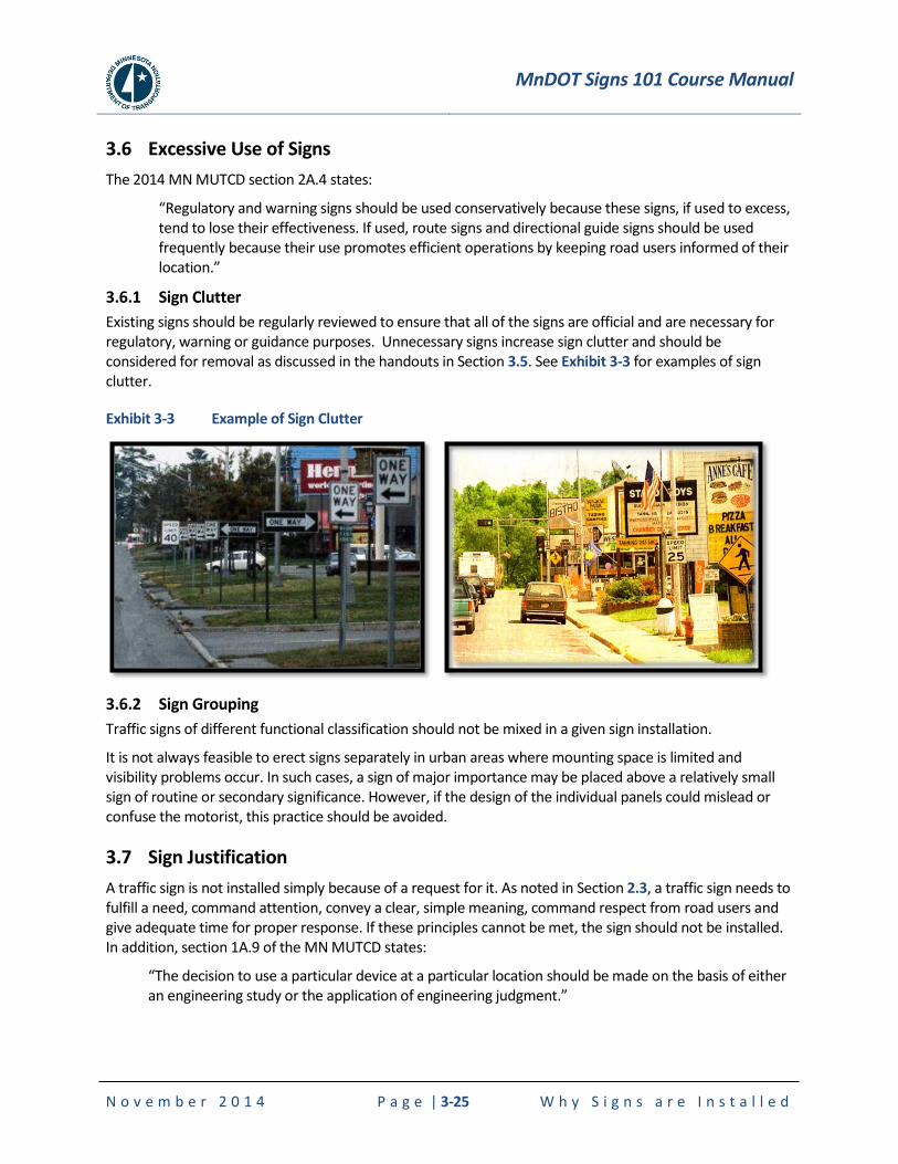
MnDOT Signs 101 Course Manual
N o v e m b e r 2 0 1 4 P a g e | 3-25 W h y S i g n s a r e I n s t a l l e d
3.6 Excessive Use of Signs
The 2014 MN MUTCD section 2A.4 states:
“Regulatory and warning signs should be used conservatively because these signs, if used to excess, tend to lose their effectiveness. If used, route signs and directional guide signs should be used frequently because their use promotes efficient operations by keeping road users informed of their location.”
3.6.1 Sign Clutter
Existing signs should be regularly reviewed to ensure that all of the signs are official and are necessary for regulatory, warning or guidance purposes. Unnecessary signs increase sign clutter and should be considered for removal as discussed in the handouts in Section 3.5. See Exhibit 3-3 for examples of sign clutter.
Exhibit 3-3 Example of Sign Clutter
3.6.2 Sign Grouping
Traffic signs of different functional classification should not be mixed in a given sign installation.
It is not always feasible to erect signs separately in urban areas where mounting space is limited and visibility problems occur. In such cases, a sign of major importance may be placed above a relatively small sign of routine or secondary significance. However, if the design of the individual panels could mislead or confuse the motorist, this practice should be avoided.
3.7 Sign Justification
A traffic sign is not installed simply because of a request for it. As noted in Section 2.3, a traffic sign needs to fulfill a need, command attention, convey a clear, simple meaning, command respect from road users and give adequate time for proper response. If these principles cannot be met, the sign should not be installed. In addition, section 1A.9 of the MN MUTCD states:
“The decision to use a particular device at a particular location should be made on the basis of either an engineering study or the application of engineering judgment.”
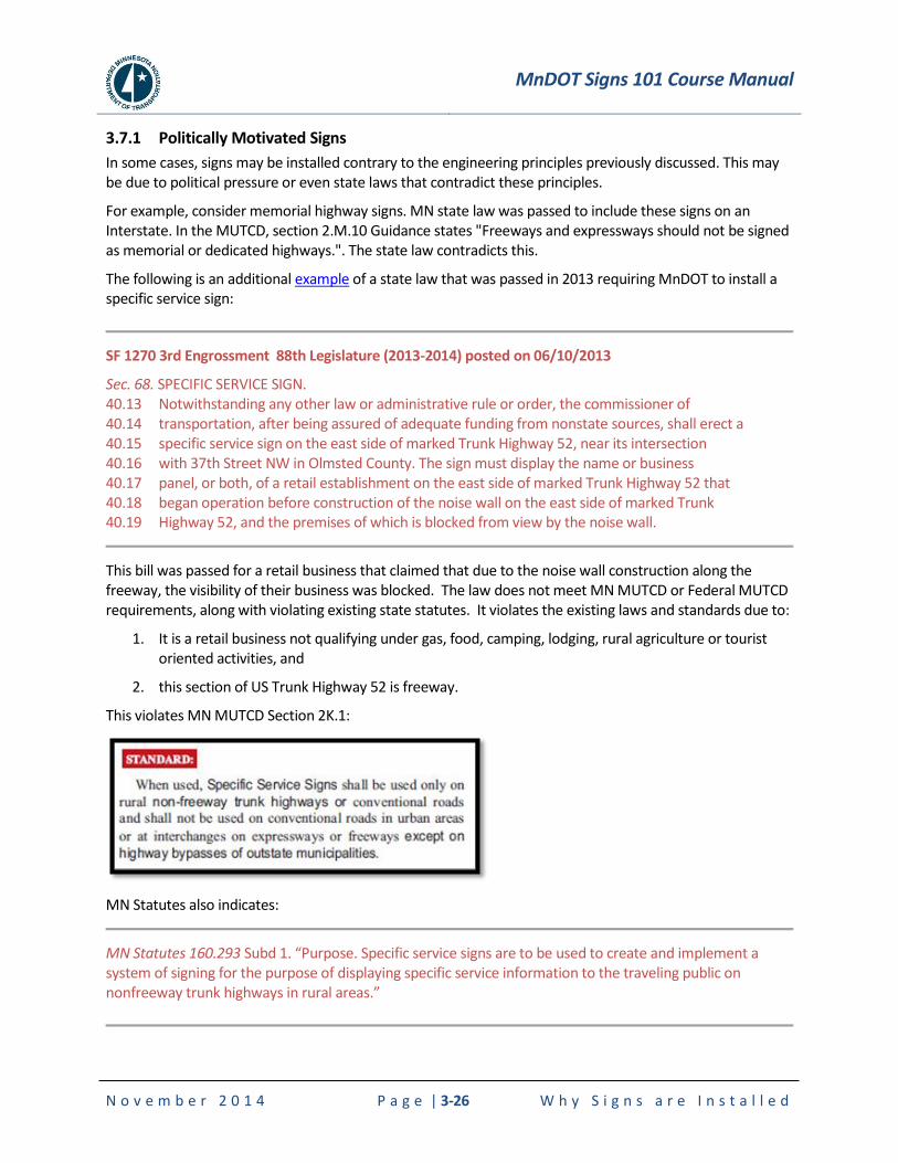
MnDOT Signs 101 Course Manual
N o v e m b e r 2 0 1 4 P a g e | 3-26 W h y S i g n s a r e I n s t a l l e d
3.7.1 Politically Motivated Signs
In some cases, signs may be installed contrary to the engineering principles previously discussed. This may be due to political pressure or even state laws that contradict these principles.
For example, consider memorial highway signs. MN state law was passed to include these signs on an Interstate. In the MUTCD, section 2.M.10 Guidance states "Freeways and expressways should not be signed as memorial or dedicated highways.". The state law contradicts this.
The following is an additional example of a state law that was passed in 2013 requiring MnDOT to install a specific service sign:
SF 1270 3rd Engrossment 88th Legislature (2013-2014) posted on 06/10/2013
Sec. 68. SPECIFIC SERVICE SIGN. 40.13 Notwithstanding any other law or administrative rule or order, the commissioner of 40.14 transportation, after being assured of adequate funding from nonstate sources, shall erect a 40.15 specific service sign on the east side of marked Trunk Highway 52, near its intersection 40.16 with 37th Street NW in Olmsted County. The sign must display the name or business 40.17 panel, or both, of a retail establishment on the east side of marked Trunk Highway 52 that 40.18 began operation before construction of the noise wall on the east side of marked Trunk 40.19 Highway 52, and the premises of which is blocked from view by the noise wall.
This bill was passed for a retail business that claimed that due to the noise wall construction along the freeway, the visibility of their business was blocked. The law does not meet MN MUTCD or Federal MUTCD requirements, along with violating existing state statutes. It violates the existing laws and standards due to:
1. It is a retail business not qualifying under gas, food, camping, lodging, rural agriculture or tourist oriented activities, and
2. this section of US Trunk Highway 52 is freeway.
This violates MN MUTCD Section 2K.1:
MN Statutes also indicates:
MN Statutes 160.293 Subd 1. “Purpose. Specific service signs are to be used to create and implement a system of signing for the purpose of displaying specific service information to the traveling public on nonfreeway trunk highways in rural areas.”
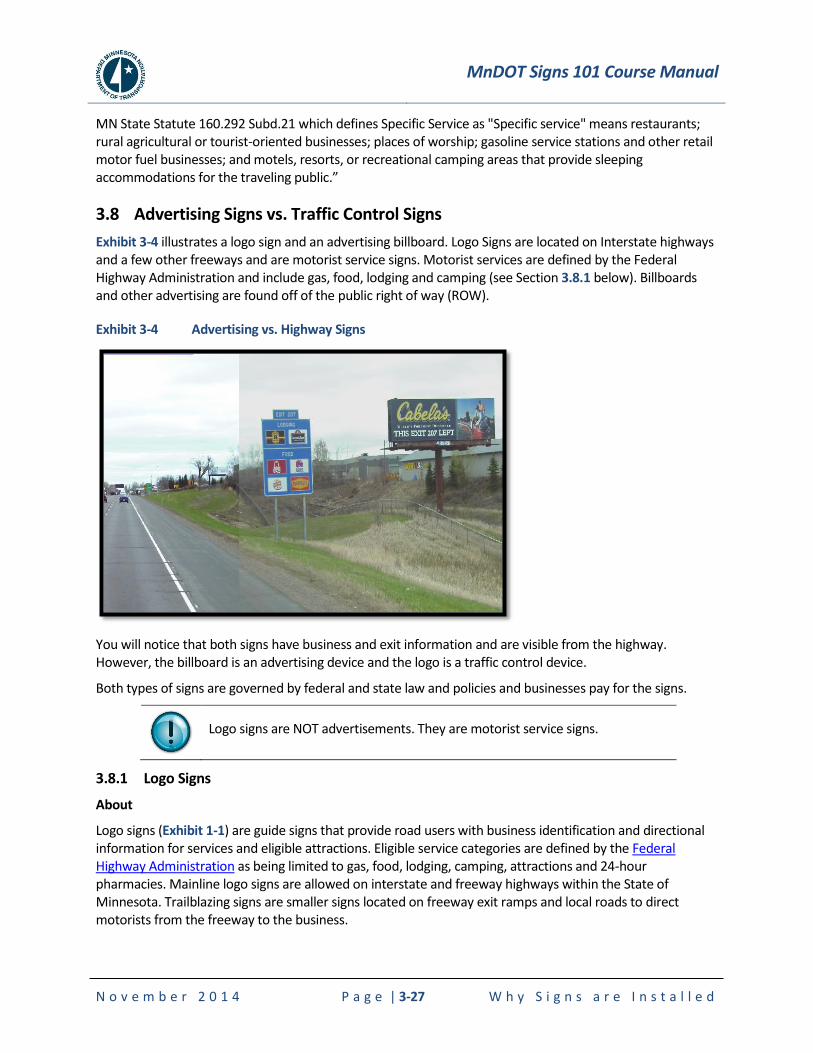
MnDOT Signs 101 Course Manual
N o v e m b e r 2 0 1 4 P a g e | 3-27 W h y S i g n s a r e I n s t a l l e d
MN State Statute 160.292 Subd.21 which defines Specific Service as "Specific service" means restaurants; rural agricultural or tourist-oriented businesses; places of worship; gasoline service stations and other retail motor fuel businesses; and motels, resorts, or recreational camping areas that provide sleeping accommodations for the traveling public.”
3.8 Advertising Signs vs. Traffic Control Signs
Exhibit 3-4 illustrates a logo sign and an advertising billboard. Logo Signs are located on Interstate highways and a few other freeways and are motorist service signs. Motorist services are defined by the Federal Highway Administration and include gas, food, lodging and camping (see Section 3.8.1 below). Billboards and other advertising are found off of the public right of way (ROW).
Exhibit 3-4 Advertising vs. Highway Signs
You will notice that both signs have business and exit information and are visible from the highway. However, the billboard is an advertising device and the logo is a traffic control device.
Both types of signs are governed by federal and state law and policies and businesses pay for the signs.
Logo signs are NOT advertisements. They are motorist service signs.
3.8.1 Logo Signs
About
Logo signs (Exhibit 1-1) are guide signs that provide road users with business identification and directional information for services and eligible attractions. Eligible service categories are defined by the Federal Highway Administration as being limited to gas, food, lodging, camping, attractions and 24-hour pharmacies. Mainline logo signs are allowed on interstate and freeway highways within the State of Minnesota. Trailblazing signs are smaller signs located on freeway exit ramps and local roads to direct motorists from the freeway to the business.
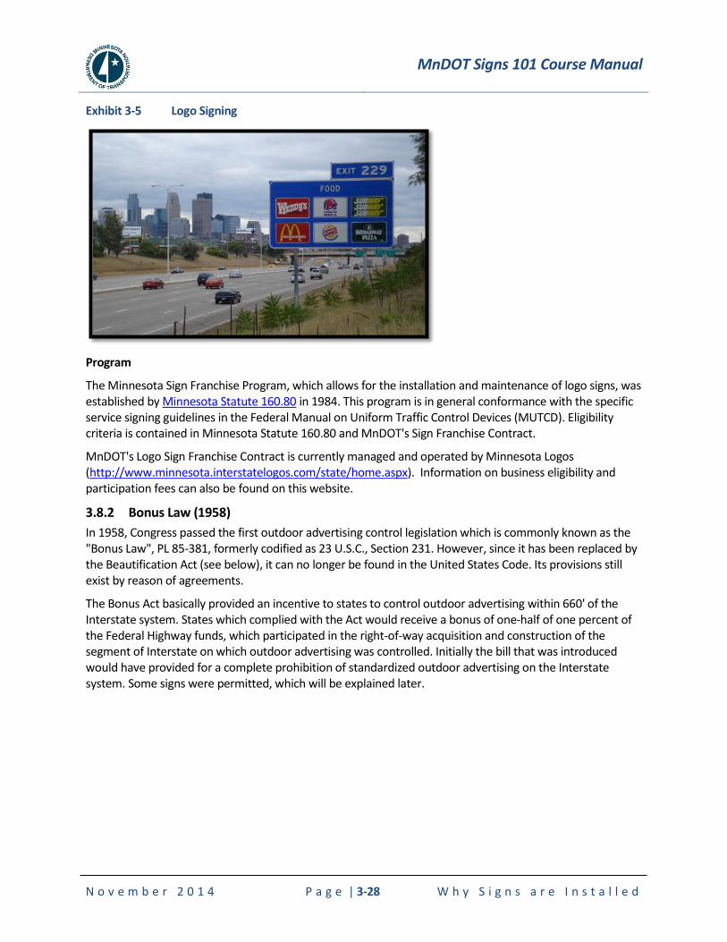
MnDOT Signs 101 Course Manual
N o v e m b e r 2 0 1 4 P a g e | 3-28 W h y S i g n s a r e I n s t a l l e d
Exhibit 3-5 Logo Signing
Program
The Minnesota Sign Franchise Program, which allows for the installation and maintenance of logo signs, was established by Minnesota Statute 160.80 in 1984. This program is in general conformance with the specific service signing guidelines in the Federal Manual on Uniform Traffic Control Devices (MUTCD). Eligibility criteria is contained in Minnesota Statute 160.80 and MnDOT's Sign Franchise Contract.
MnDOT's Logo Sign Franchise Contract is currently managed and operated by Minnesota Logos (http://www.minnesota.interstatelogos.com/state/home.aspx). Information on business eligibility and participation fees can also be found on this website.
3.8.2 Bonus Law (1958)
In 1958, Congress passed the first outdoor advertising control legislation which is commonly known as the "Bonus Law", PL 85-381, formerly codified as 23 U.S.C., Section 231. However, since it has been replaced by the Beautification Act (see below), it can no longer be found in the United States Code. Its provisions still exist by reason of agreements.
The Bonus Act basically provided an incentive to states to control outdoor advertising within 660' of the Interstate system. States which complied with the Act would receive a bonus of one-half of one percent of the Federal Highway funds, which participated in the right-of-way acquisition and construction of the segment of Interstate on which outdoor advertising was controlled. Initially the bill that was introduced would have provided for a complete prohibition of standardized outdoor advertising on the Interstate system. Some signs were permitted, which will be explained later.

MnDOT Signs 101 Course Manual
N o v e m b e r 2 0 1 4 P a g e | 3-29 W h y S i g n s a r e I n s t a l l e d
3.8.3 Highway Beautification Act (1965)
The Highway Beautification Act of 1965 called for control of outdoor advertising, including removal of certain types of signs, along the nation's growing Interstate Highway System and the existing federal-aid primary highway system. It also required certain junkyards along Interstate or primary highways to be removed or screened and encouraged scenic enhancement and roadside development.
Some highlights on the laws and:
Signs allowed: directional or other official signs required or authorized by law
87% of motorists prefer logo signs to billboards or high-rise signs. These provide information without creating an eyesore.
Billboards detract from scenery and contribute to visual pollution.
Traffic control devices shall not bear any advertising message or any other message that is not related to traffic control.
Tourist-oriented directional signs and Specific Service signs are not considered advertising; rather they are classified as motorist service signs.
The following information are from the Billboard Permits site (www.dot.state.mn.us/roadsides/billboards/) and are related to Minnesota Outdoor Advertising Control Act and Fee Schedule for Advertising Devices.
MnDOT Signs 101 Course Manual
N o v e m b e r 2 0 1 4 W h y S i g n s a r e I n s t a l l e d
***H
ANDO
UT**
* **
*HAN
DOUT
***
***H
ANDO
UT**
* **
*HAN
DOUT
***
***HANDOUT***
THE MINNESOTA OUTDOOR ADVERTISING CONTROL ACT BECAME EFFECTIVE JUNE 7, 1971. THE ACT REQUIRES THAT YOUR ADVERTISING DEVICE HAVE A STATE PERMIT AND BE RENEWED EACH YEAR.
1. NO ADVERTISING DEVICE ALLOWED WITHIN THE LIMITS OF ANY HIGHWAY. Devices must be located entirely on private property. 2. Church and Service Club Signs are exempt provided they are under eight square feet and are directional or
contain information related to meeting.
ADVERTISING DEVICES ERECTED AFTER JUNE 7, 1971 ARE ALLOWED ONLY IN THE FOLLOWING LOCATIONS:
1. On land zoned for business, industrial or commercial activities. 2. On unzoned land within 800 feet of a business area. (Business area defined as an unzoned area on which
there is one or more permanent structures devoted to commercial or industrial activity, or on which a commercial or industrial activity, or on which a commercial or industrial activity, or on which a commercial or industrial activity is actually conducted whether or not a permanent structure is located thereon.
PROHITED AREAS1. Within 100 feet of a church or school property.
SPACING
Interstate and fully controlled freeways: 1. 500 feet between signs. 2. Unincorporated area: Signs must be 500 feet from the entrance or exit ramp widening. Primary Highways: 1. Incorporated areas: 100 feet between signs. 2. Unicorporated zoned areas: 300 feet between signs; no signs within 300 feet of an intersection with
another highway, public road or railroad. 3. Unicorporated unzoned areas: 400 feet between signs; no sign within 300 feet of an intersection with
another highway, public road or railroad.
ADVERTISING PERMIT APPLICATION
1. Read instruction on back of application. 2. Items 1 through 18 must be completed. 3. Landowner must sign item 16 or submit letter granting use of the property. A copy of the lease is also
acceptable.4. Advertising device erection must comply with Local Ordinances. 5. Fee must accompany application. Make check payable to the Commissioner of Transportation and return
application to the address below. 6. Please call for correct fee.
www.dot.state.mn.us/roadsides/billboards/
Page | 3-30

MnDOT Signs 101 Course Manual
N o v e m b e r 2 0 1 4 W h y S i g n s a r e I n s t a l l e d
***H
ANDO
UT**
* **
*HAN
DOUT
***
***H
ANDO
UT**
* **
*HAN
DOUT
***
***HANDOUT***
Minnesota Department of Transportation ������
FEE SCHEDULE FOR ADVERTISING DEVICES��
���������������� ������������ ������������������� ������������ ���������������������� ������������������ ����� ����������������������� ������������ ������ ������������������������� �������������������������������������������� �����������
�� ������������ ������������� ������ ������������������������� ��� �������������� �������������������������� ��������������
������������������ !"�#$��$$%� &�%'�(& (&�%'�)&&��������������'*$#�)&&��� +���� ,)&�&&� ,-&�&&�������������������,��&�&&��� ������� �.�(&� ((�&&�����������������������&�&&��� ��������� �(�&&� (&�&&����������������������&&�&&��� '������� ���(&� �(�&&� /&�&&��� 0�������� �&�&&� �&�&&� 1&�&&��� 2�������� �.�(&� )(�&&� .&�&&��� + �� ��� �(�&&� )&�&&� -&�&&��� ����� ��� ���(&� �(�&&� (&�&&��� 3 ���� �&�&&� �&�&&� �&�&&��� ������ .�(&� �(�&&� )&�&&��� 3 �� (�&&� �&�&&� �&�&&��� +���� ��(&� (�&&��&�&&�������
An Equal Opportunity Employer
www.dot.state.mn.us/roadsides/billboards/
Page | 3-31

(This page is intentionally left blank)
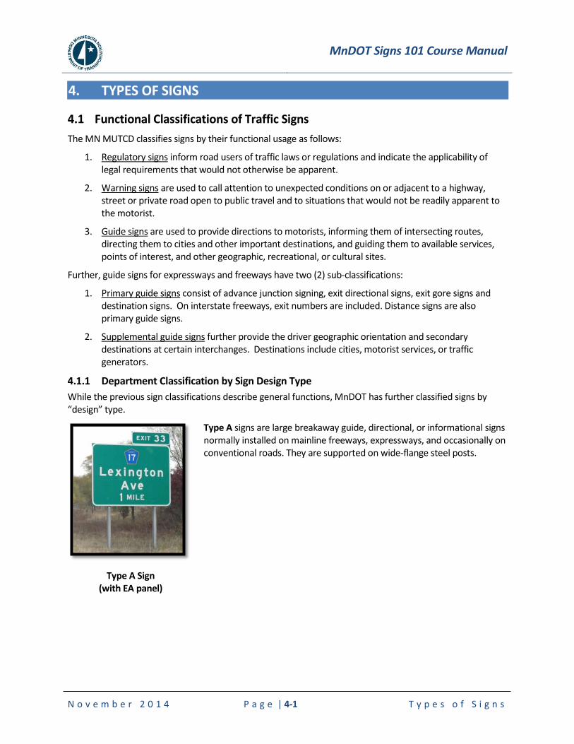
MnDOT Signs 101 Course Manual
N o v e m b e r 2 0 1 4 P a g e | 4-1 T y p e s o f S i g n s
4. TYPES OF SIGNS
4.1 Functional Classifications of Traffic Signs
The MN MUTCD classifies signs by their functional usage as follows:
1. Regulatory signs inform road users of traffic laws or regulations and indicate the applicability of legal requirements that would not otherwise be apparent.
2. Warning signs are used to call attention to unexpected conditions on or adjacent to a highway, street or private road open to public travel and to situations that would not be readily apparent to the motorist.
3. Guide signs are used to provide directions to motorists, informing them of intersecting routes, directing them to cities and other important destinations, and guiding them to available services, points of interest, and other geographic, recreational, or cultural sites.
Further, guide signs for expressways and freeways have two (2) sub-classifications:
1. Primary guide signs consist of advance junction signing, exit directional signs, exit gore signs and destination signs. On interstate freeways, exit numbers are included. Distance signs are also primary guide signs.
2. Supplemental guide signs further provide the driver geographic orientation and secondary destinations at certain interchanges. Destinations include cities, motorist services, or traffic generators.
4.1.1 Department Classification by Sign Design Type
While the previous sign classifications describe general functions, MnDOT has further classified signs by “design” type.
Type A Sign (with EA panel)
Type A signs are large breakaway guide, directional, or informational signs normally installed on mainline freeways, expressways, and occasionally on conventional roads. They are supported on wide-flange steel posts.
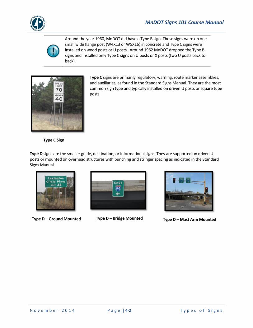
MnDOT Signs 101 Course Manual
N o v e m b e r 2 0 1 4 P a g e | 4-2 T y p e s o f S i g n s
Around the year 1960, MnDOT did have a Type B sign. These signs were on one small wide flange post (W4X13 or W5X16) in concrete and Type C signs were installed on wood posts or U posts. Around 1962 MnDOT dropped the Type B signs and installed only Type C signs on U posts or X posts (two U posts back to back).
Type C Sign
Type C signs are primarily regulatory, warning, route marker assemblies, and auxiliaries, as found in the Standard Signs Manual. They are the most common sign type and typically installed on driven U posts or square tube posts.
Type D signs are the smaller guide, destination, or informational signs. They are supported on driven U posts or mounted on overhead structures with punching and stringer spacing as indicated in the Standard Signs Manual.
Type D – Ground Mounted
Type D – Bridge Mounted
Type D – Mast Arm Mounted
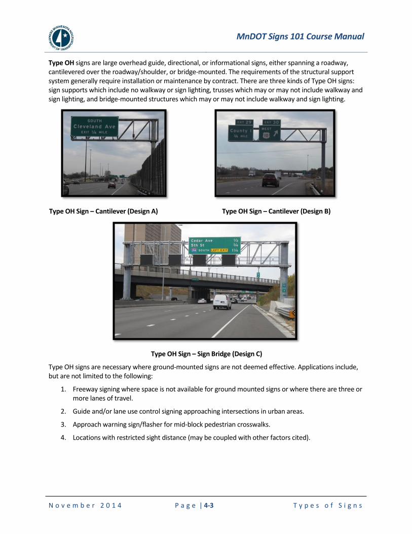
MnDOT Signs 101 Course Manual
N o v e m b e r 2 0 1 4 P a g e | 4-3 T y p e s o f S i g n s
Type OH signs are large overhead guide, directional, or informational signs, either spanning a roadway, cantilevered over the roadway/shoulder, or bridge-mounted. The requirements of the structural support system generally require installation or maintenance by contract. There are three kinds of Type OH signs: sign supports which include no walkway or sign lighting, trusses which may or may not include walkway and sign lighting, and bridge-mounted structures which may or may not include walkway and sign lighting.
Type OH Sign – Cantilever (Design A)
Type OH Sign – Cantilever (Design B)
Type OH Sign – Sign Bridge (Design C)
Type OH signs are necessary where ground-mounted signs are not deemed effective. Applications include, but are not limited to the following:
1. Freeway signing where space is not available for ground mounted signs or where there are three or more lanes of travel.
2. Guide and/or lane use control signing approaching intersections in urban areas.
3. Approach warning sign/flasher for mid-block pedestrian crosswalks.
4. Locations with restricted sight distance (may be coupled with other factors cited).
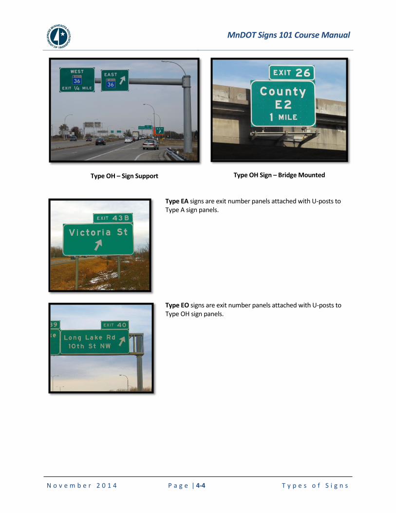
MnDOT Signs 101 Course Manual
N o v e m b e r 2 0 1 4 P a g e | 4-4 T y p e s o f S i g n s
Type OH – Sign Support
Type OH Sign – Bridge Mounted
Type EA signs are exit number panels attached with U-posts to Type A sign panels.
Type EO signs are exit number panels attached with U-posts to Type OH sign panels.

MnDOT Signs 101 Course Manual
N o v e m b e r 2 0 1 4 P a g e | 4-5 T y p e s o f S i g n s
4.2 Regulatory Signs
4.2.1 Application of Regulatory Signs
Regulatory signs shall be used to inform road users of selected traffic laws or regulations and indicate the applicability of the legal requirements. Regulatory signs shall be installed at or near where the regulations apply. The signs shall clearly indicate the requirements imposed by the regulations and shall be designed and installed to provide adequate visibility and legibility in order to obtain compliance.
Regulatory signs shall be retroreflective (see Section 1.1) or illuminated to show the same shape and similar color by both day and night, unless specifically stated otherwise in the text discussion in the MN MUTCD for a particular sign or group of signs.
The requirements for sign illumination shall not be considered to be satisfied by street, highway, or strobe lighting.
4.2.2 Establishment of Priorities
Signs should be used only where warranted by facts and field studies. Signs are essential where special regulations apply at specific places or at specific times only, or where hazards are not self-evident.
Regulatory signs are not necessary to confirm rules of the road.
4.2.3 MUTCD Chapter 2B Handout
The information on the following pages are a handout from the 2011 MN MUTCD, Chapter 2B on Regulatory Signs. The entire section is not included, but only pages of interest for this manual. For full details on the MUTCD, refer to the OTST publications website found at, www.dot.state.mn.us/trafficeng/publ/index.html.
In addition, the entire 2011 Standard Signs Summary is included at the end of this chapter.
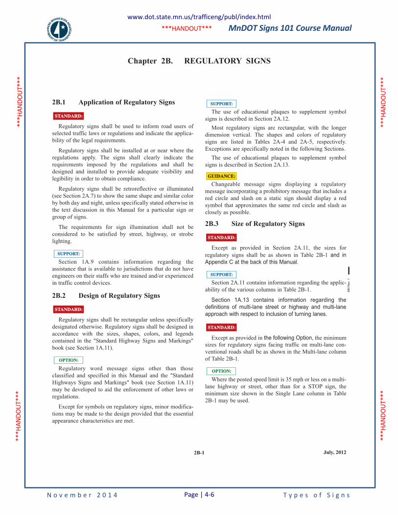
MnDOT Signs 101 Course Manual
N o v e m b e r 2 0 1 4 T y p e s o f S i g n s
***H
ANDO
UT**
* **
*HAN
DOUT
***
***H
ANDO
UT**
* **
*HAN
DOUT
***
***HANDOUT***
2B-1 July, 2012
Chapter 2B. REGULATORY SIGNS
2B.1 Application of Regulatory Signs
Regulatory signs shall be used to inform road users of
selected traffic laws or regulations and indicate the applica-
bility of the legal requirements.
Regulatory signs shall be installed at or near where the
regulations apply. The signs shall clearly indicate the
requirements imposed by the regulations and shall be
designed and installed to provide adequate visibility and
legibility in order to obtain compliance.
Regulatory signs shall be retroreflective or illuminated
(see Section 2A.7) to show the same shape and similar color
by both day and night, unless specifically stated otherwise in
the text discussion in this Manual for a particular sign or
group of signs.
The requirements for sign illumination shall not be
considered to be satisfied by street, highway, or strobe
lighting.
Section 1A.9 contains information regarding the
assistance that is available to jurisdictions that do not have
engineers on their staffs who are trained and/or experienced
in traffic control devices.
2B.2 Design of Regulatory Signs
Regulatory signs shall be rectangular unless specifically
designated otherwise. Regulatory signs shall be designed in
accordance with the sizes, shapes, colors, and legends
contained in the "Standard Highway Signs and Markings"
book (see Section 1A.11).
Regulatory word message signs other than those
classified and specified in this Manual and the "Standard
Highways Signs and Markings" book (see Section 1A.11)
may be developed to aid the enforcement of other laws or
regulations.
Except for symbols on regulatory signs, minor modifica-
tions may be made to the design provided that the essential
appearance characteristics are met.
OPTION:OPTION:
STANDARD:STANDARD:
SUPPORT:SUPPORT:
STANDARD:STANDARD:The use of educational plaques to supplement symbol
signs is described in Section 2A.12.
Most regulatory signs are rectangular, with the longer
dimension vertical. The shapes and colors of regulatory
signs are listed in Tables 2A-4 and 2A-5, respectively.
Exceptions are specifically noted in the following Sections.
The use of educational plaques to supplement symbol
signs is described in Section 2A.13.
Changeable message signs displaying a regulatory
message incorporating a prohibitory message that includes a
red circle and slash on a static sign should display a red
symbol that approximates the same red circle and slash as
closely as possible.
2B.3 Size of Regulatory Signs
Except as provided in Section 2A.11, the sizes for
regulatory signs shall be as shown in Table 2B-1 and in
Appendix C at the back of this Manual.
Section 2A.11 contains information regarding the applic-
ability of the various columns in Table 2B-1.
Section 1A.13 contains information regarding the
definitions of multi-lane street or highway and multi-lane
approach with respect to inclusion of turning lanes.
Except as provided in the following Option, the minimum
sizes for regulatory signs facing traffic on multi-lane con-
ventional roads shall be as shown in the Multi-lane column
of Table 2B-1.
Where the posted speed limit is 35 mph or less on a multi-
lane highway or street, other than for a STOP sign, the
minimum size shown in the Single Lane column in Table
2B-1 may be used.
OPTION:OPTION:
STANDARD:STANDARD:
SUPPORT:SUPPORT:
STANDARD:STANDARD:
SUPPORT:SUPPORT:
GUIDANCE:GUIDANCE:
MN
Re
v. 1
www.dot.state.mn.us/trafficeng/publ/index.html
Page | 4-6
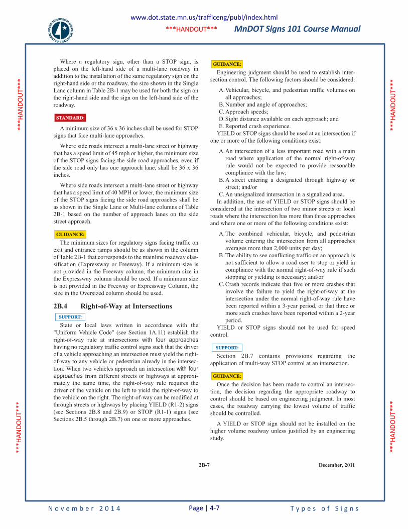
MnDOT Signs 101 Course Manual
N o v e m b e r 2 0 1 4 T y p e s o f S i g n s
***H
ANDO
UT**
* **
*HAN
DOUT
***
***H
ANDO
UT**
* **
*HAN
DOUT
***
***HANDOUT***
2B-7 December, 2011
Where a regulatory sign, other than a STOP sign, is
placed on the left-hand side of a multi-lane roadway in
addition to the installation of the same regulatory sign on the
right-hand side or the roadway, the size shown in the Single
Lane column in Table 2B-1 may be used for both the sign on
the right-hand side and the sign on the left-hand side of the
roadway.
A minimum size of 36 x 36 inches shall be used for STOP
signs that face multi-lane approaches.
Where side roads intersect a multi-lane street or highway
that has a speed limit of 45 mph or higher, the minimum size
of the STOP signs facing the side road approaches, even if
the side road only has one approach lane, shall be 36 x 36
inches.
Where side roads intersect a multi-lane street or highway
that has a speed limit of 40 MPH or lower, the minimum size
of the STOP signs facing the side road approaches shall be
as shown in the Single Lane or Multi-lane columns of Table
2B-1 based on the number of approach lanes on the side
street approach.
The minimum sizes for regulatory signs facing traffic on
exit and entrance ramps should be as shown in the column
of Table 2B-1 that corresponds to the mainline roadway clas-
sification (Expressway or Freeway). If a minimum size is
not provided in the Freeway column, the minimum size in
the Expressway column should be used. If a minimum size
is not provided in the Freeway or Expressway Column, the
size in the Oversized column should be used.
2B.4 Right-of-Way at Intersections
State or local laws written in accordance with the
"Uniform Vehicle Code" (see Section 1A.11) establish the
right-of-way rule at intersections with four approacheshaving no regulatory traffic control signs such that the driver
of a vehicle approaching an intersection must yield the right-
of-way to any vehicle or pedestrian already in the intersec-
tion. When two vehicles approach an intersection with four
approaches from different streets or highways at approxi-
mately the same time, the right-of-way rule requires the
driver of the vehicle on the left to yield the right-of-way to
the vehicle on the right. The right-of-way can be modified at
through streets or highways by placing YIELD (R1-2) signs
(see Sections 2B.8 and 2B.9) or STOP (R1-1) signs (see
Sections 2B.5 through 2B.7) on one or more approaches.
SUPPORT:SUPPORT:
GUIDANCE:GUIDANCE:
STANDARD:STANDARD:
Engineering judgment should be used to establish inter-
section control. The following factors should be considered:
A.Vehicular, bicycle, and pedestrian traffic volumes on
all approaches;
B. Number and angle of approaches;
C. Approach speeds;
D.Sight distance available on each approach; and
E. Reported crash experience.
YIELD or STOP signs should be used at an intersection if
one or more of the following conditions exist:
A.An intersection of a less important road with a main
road where application of the normal right-of-way
rule would not be expected to provide reasonable
compliance with the law;
B. A street entering a designated through highway or
street; and/or
C. An unsignalized intersection in a signalized area.
In addition, the use of YIELD or STOP signs should be
considered at the intersection of two minor streets or local
roads where the intersection has more than three approaches
and where one or more of the following conditions exist:
A.The combined vehicular, bicycle, and pedestrian
volume entering the intersection from all approaches
averages more than 2,000 units per day;
B. The ability to see conflicting traffic on an approach is
not sufficient to allow a road user to stop or yield in
compliance with the normal right-of-way rule if such
stopping or yielding is necessary; and/or
C. Crash records indicate that five or more crashes that
involve the failure to yield the right-of-way at the
intersection under the normal right-of-way rule have
been reported within a 3-year period, or that three or
more such crashes have been reported within a 2-year
period.
YIELD or STOP signs should not be used for speed
control.
Section 2B.7 contains provisions regarding the
application of multi-way STOP control at an intersection.
Once the decision has been made to control an intersec-
tion, the decision regarding the appropriate roadway to
control should be based on engineering judgment. In most
cases, the roadway carrying the lowest volume of traffic
should be controlled.
A YIELD or STOP sign should not be installed on the
higher volume roadway unless justified by an engineering
study.
GUIDANCE:GUIDANCE:
SUPPORT:SUPPORT:
GUIDANCE:GUIDANCE:
www.dot.state.mn.us/trafficeng/publ/index.html
Page | 4-7
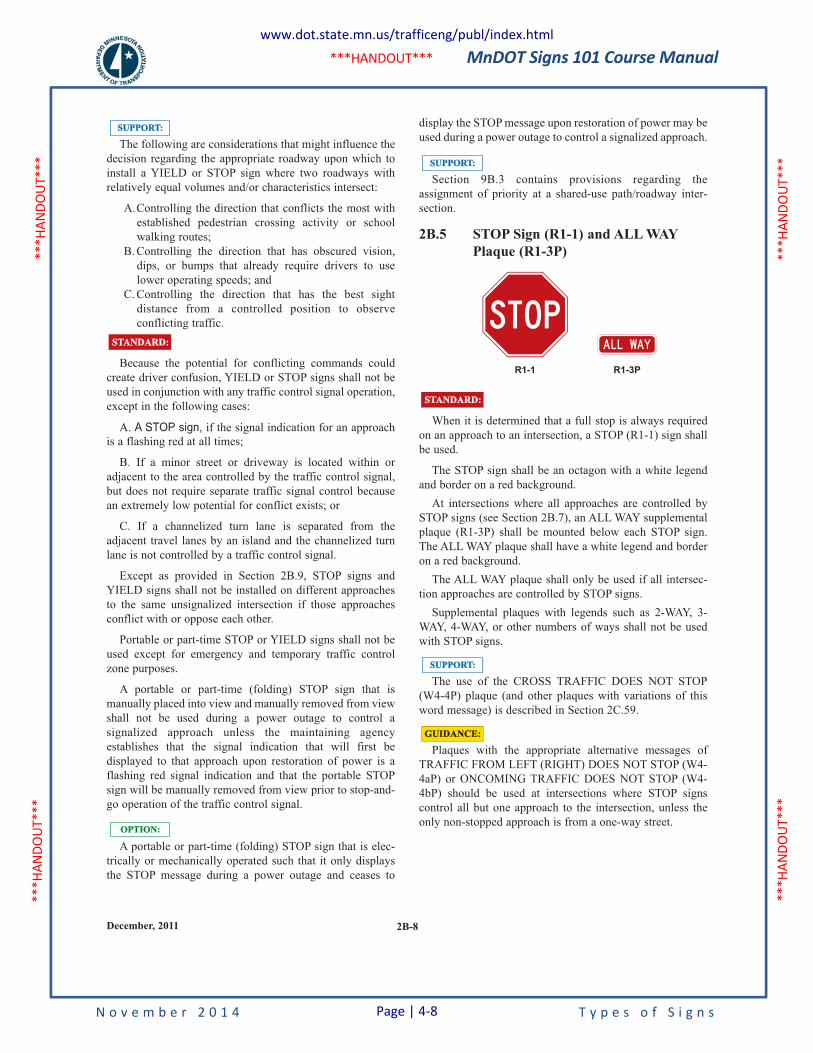
MnDOT Signs 101 Course Manual
N o v e m b e r 2 0 1 4 T y p e s o f S i g n s
***H
ANDO
UT**
* **
*HAN
DOUT
***
***H
ANDO
UT**
* **
*HAN
DOUT
***
***HANDOUT***
2B-8December, 2011
The following are considerations that might influence the
decision regarding the appropriate roadway upon which to
install a YIELD or STOP sign where two roadways with
relatively equal volumes and/or characteristics intersect:
A.Controlling the direction that conflicts the most with
established pedestrian crossing activity or school
walking routes;
B. Controlling the direction that has obscured vision,
dips, or bumps that already require drivers to use
lower operating speeds; and
C. Controlling the direction that has the best sight
distance from a controlled position to observe
conflicting traffic.
Because the potential for conflicting commands could
create driver confusion, YIELD or STOP signs shall not be
used in conjunction with any traffic control signal operation,
except in the following cases:
A. A STOP sign, if the signal indication for an approach
is a flashing red at all times;
B. If a minor street or driveway is located within or
adjacent to the area controlled by the traffic control signal,
but does not require separate traffic signal control because
an extremely low potential for conflict exists; or
C. If a channelized turn lane is separated from the
adjacent travel lanes by an island and the channelized turn
lane is not controlled by a traffic control signal.
Except as provided in Section 2B.9, STOP signs and
YIELD signs shall not be installed on different approaches
to the same unsignalized intersection if those approaches
conflict with or oppose each other.
Portable or part-time STOP or YIELD signs shall not be
used except for emergency and temporary traffic control
zone purposes.
A portable or part-time (folding) STOP sign that is
manually placed into view and manually removed from view
shall not be used during a power outage to control a
signalized approach unless the maintaining agency
establishes that the signal indication that will first be
displayed to that approach upon restoration of power is a
flashing red signal indication and that the portable STOP
sign will be manually removed from view prior to stop-and-
go operation of the traffic control signal.
A portable or part-time (folding) STOP sign that is elec-
trically or mechanically operated such that it only displays
the STOP message during a power outage and ceases to
OPTION:OPTION:
STANDARD:STANDARD:
SUPPORT:SUPPORT:display the STOP message upon restoration of power may be
used during a power outage to control a signalized approach.
Section 9B.3 contains provisions regarding the
assignment of priority at a shared-use path/roadway inter-
section.
2B.5 STOP Sign (R1-1) and ALL WAY
Plaque (R1-3P)
When it is determined that a full stop is always required
on an approach to an intersection, a STOP (R1-1) sign shall
be used.
The STOP sign shall be an octagon with a white legend
and border on a red background.
At intersections where all approaches are controlled by
STOP signs (see Section 2B.7), an ALL WAY supplemental
plaque (R1-3P) shall be mounted below each STOP sign.
The ALL WAY plaque shall have a white legend and border
on a red background.
The ALL WAY plaque shall only be used if all intersec-
tion approaches are controlled by STOP signs.
Supplemental plaques with legends such as 2-WAY, 3-
WAY, 4-WAY, or other numbers of ways shall not be used
with STOP signs.
The use of the CROSS TRAFFIC DOES NOT STOP
(W4-4P) plaque (and other plaques with variations of this
word message) is described in Section 2C.59.
Plaques with the appropriate alternative messages of
TRAFFIC FROM LEFT (RIGHT) DOES NOT STOP (W4-
4aP) or ONCOMING TRAFFIC DOES NOT STOP (W4-
4bP) should be used at intersections where STOP signs
control all but one approach to the intersection, unless the
only non-stopped approach is from a one-way street.
GUIDANCE:GUIDANCE:
SUPPORT:SUPPORT:
SUPPORT:SUPPORT:
STOPALL WAY
R1-1 R1-3P
STANDARD:STANDARD:
www.dot.state.mn.us/trafficeng/publ/index.html
Page | 4-8
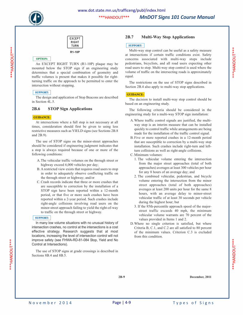
MnDOT Signs 101 Course Manual
N o v e m b e r 2 0 1 4 T y p e s o f S i g n s
***H
ANDO
UT**
* **
*HAN
DOUT
***
***H
ANDO
UT**
* **
*HAN
DOUT
***
***HANDOUT***
2B-9 December, 2011
An EXCEPT RIGHT TURN (R1-10P) plaque may be
mounted below the STOP sign if an engineering study
determines that a special combination of geometry and
traffic volumes is present that makes it possible for right-
turning traffic on the approach to be permitted to enter the
intersection without stopping.
The design and application of Stop Beacons are described
in Section 4L.5.
2B.6 STOP Sign Applications
At intersections where a full stop is not necessary at all
times, consideration should first be given to using less
restrictive measures such as YIELD signs (see Sections 2B.8
and 2B.9).
The use of STOP signs on the minor-street approaches
should be considered if engineering judgment indicates that
a stop is always required because of one or more of the
following conditions:
A.The vehicular traffic volumes on the through street or
highway exceed 6,000 vehicles per day;
B. A restricted view exists that requires road users to stop
in order to adequately observe conflicting traffic on
the through street or highway; and/or
C. Crash records indicate that three or more crashes that
are susceptible to correction by the installation of a
STOP sign have been reported within a 12-month
period, or that five or more such crashes have been
reported within a 2-year period. Such crashes include
right-angle collisions involving road users on the
minor-street approach failing to yield the right-of-way
to traffic on the through street or highway.
In many low volume situations with no unusual history of
intersection crashes, no control at the intersections is a cost
effective strategy. Research suggests that at most
locations, increasing the level of intersection control will not
improve safety (see FHWA-RD-81-084 Stop, Yield and No
Control at Intersections).
The use of STOP signs at grade crossings is described in
Sections 8B.4 and 8B.5.
SUPPORT:SUPPORT:
SUPPORT:SUPPORT:
OPTION:OPTION:
R1-10P
EXCEPTR I G H TTU R N
GUIDANCE:GUIDANCE:
2B.7 Multi-Way Stop Applications
Multi-way stop control can be useful as a safety measure
at intersections if certain traffic conditions exist. Safety
concerns associated with multi-way stops include
pedestrians, bicyclists, and all road users expecting other
road users to stop. Multi-way stop control is used where the
volume of traffic on the intersecting roads is approximately
equal.
The restrictions on the use of STOP signs described in
Section 2B.4 also apply to multi-way stop applications.
The decision to install multi-way stop control should be
based on an engineering study.
The following criteria should be considered in the
engineering study for a multi-way STOP sign installation:
A.Where traffic control signals are justified, the multi-
way stop is an interim measure that can be installed
quickly to control traffic while arrangements are being
made for the installation of the traffic control signal.
B. Five or more reported crashes in a 12-month period
that are susceptible to correction by a multi-way stop
installation. Such crashes include right-turn and left-
turn collisions as well as right-angle collisions.
C. Minimum volumes:
1. The vehicular volume entering the intersection
from the major street approaches (total of both
approaches) averages at least 300 vehicles per hour
for any 8 hours of an average day; and
2. The combined vehicular, pedestrian, and bicycle
volume entering the intersection from the minor
street approaches (total of both approaches)
averages at least 200 units per hour for the same 8
hours, with an average delay to minor-street
vehicular traffic of at least 30 seconds per vehicle
during the highest hour; but
3. If the 85th-percentile approach speed of the major-
street traffic exceeds 40 mph, the minimum
vehicular volume warrants are 70 percent of the
values provided in Items 1 and 2.
D.Where no single criterion is satisfied, but where
Criteria B, C.1, and C.2 are all satisfied to 80 percent
of the minimum values. Criterion C.3 is excluded
from this condition.
GUIDANCE:GUIDANCE:
SUPPORT:SUPPORT:
www.dot.state.mn.us/trafficeng/publ/index.html
Page | 4-9
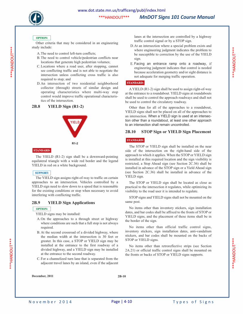
MnDOT Signs 101 Course Manual
N o v e m b e r 2 0 1 4 T y p e s o f S i g n s
***H
ANDO
UT**
* **
*HAN
DOUT
***
***H
ANDO
UT**
* **
*HAN
DOUT
***
***HANDOUT***
2B-10December, 2011
Other criteria that may be considered in an engineering
study include:
A.The need to control left-turn conflicts;
B. The need to control vehicle/pedestrian conflicts near
locations that generate high pedestrian volumes;
C. Locations where a road user, after stopping, cannot
see conflicting traffic and is not able to negotiate the
intersection unless conflicting cross traffic is also
required to stop; and
D.An intersection of two residential neighborhood
collector (through) streets of similar design and
operating characteristics where multi-way stop
control would improve traffic operational characteris-
tics of the intersection.
2B.8 YIELD Sign (R1-2)
The YIELD (R1-2) sign shall be a downward-pointing
equilateral triangle with a wide red border and the legend
YIELD in red on a white background.
The YIELD sign assigns right-of-way to traffic on certain
approaches to an intersection. Vehicles controlled by a
YIELD sign need to slow down to a speed that is reasonable
for the existing conditions or stop when necessary to avoid
interfering with conflicting traffic.
2B.9 YIELD Sign Applications
YIELD signs may be installed:
A.On the approaches to a through street or highway
where conditions are such that a full stop is not always
required.
B. At the second crossroad of a divided highway, where
the median width at the intersection is 30 feet or
greater. In this case, a STOP or YIELD sign may be
installed at the entrance to the first roadway of a
divided highway, and a YIELD sign may be installed
at the entrance to the second roadway.
C. For a channelized turn lane that is separated from the
adjacent travel lanes by an island, even if the adjacent
OPTION:OPTION:
SUPPORT:SUPPORT:
STANDARD:STANDARD:
R1-2
Y I E LD
OPTION:OPTION:lanes at the intersection are controlled by a highway
traffic control signal or by a STOP sign.
D.At an intersection where a special problem exists and
where engineering judgment indicates the problem to
be susceptible to correction by the use of the YIELD
sign.
E. Facing an entrance ramp onto a roadway, if
engineering judgment indicates that control is needed
because acceleration geometry and/or sight distance is
not adequate for merging traffic operation.
A YIELD (R1-2) sign shall be used to assign right-of-way
at the entrance to a roundabout. YIELD signs at roundabouts
shall be used to control the approach roadways and shall not
be used to control the circulatory roadway.
Other than for all of the approaches to a roundabout,
YIELD signs shall not be placed on all of the approaches to
an intersection. When a YIELD sign is used at an intersec-
tion other than a roundabout, at least one other approach
to an intersection shall remain uncontrolled.
2B.10 STOP Sign or YIELD Sign Placement
The STOP or YIELD sign shall be installed on the near
side of the intersection on the right-hand side of the
approach to which it applies. When the STOP or YIELD sign
is installed at this required location and the sign visibility is
restricted, a Stop Ahead sign (see Section 2C.36) shall be
installed in advance of the STOP sign or a Yield Ahead sign
(see Section 2C.36) shall be installed in advance of the
YIELD sign.
The STOP or YIELD sign shall be located as close as
practical to the intersection it regulates, while optimizing its
visibility to the road user it is intended to regulate.
STOP signs and YIELD signs shall not be mounted on the
same post.
No items other than inventory stickers, sign installation
dates, and bar codes shall be affixed to the fronts of STOP or
YIELD signs, and the placement of these items shall be in
the border of the sign.
No items other than official traffic control signs,
inventory stickers, sign installation dates, anti-vandalism
stickers, and bar codes shall be mounted on the backs of
STOP or YIELD signs.
No items other than retroreflective strips (see Section
2A.21) or official traffic control signs shall be mounted on
the fronts or backs of STOP or YIELD signs supports.
STANDARD:STANDARD:
STANDARD:STANDARD:
www.dot.state.mn.us/trafficeng/publ/index.html
Page | 4-10
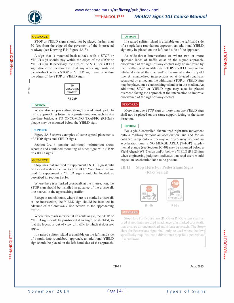
MnDOT Signs 101 Course Manual
N o v e m b e r 2 0 1 4 T y p e s o f S i g n s
***H
ANDO
UT**
* **
*HAN
DOUT
***
***H
ANDO
UT**
* **
*HAN
DOUT
***
***HANDOUT***
2B-11 July, 2013
STOP or YIELD signs should not be placed farther than
50 feet from the edge of the pavement of the intersected
roadway (see Drawing F in Figure 2A-3).
A sign that is mounted back-to-back with a STOP or
YIELD sign should stay within the edges of the STOP or
YIELD sign. If necessary, the size of the STOP or YIELD
sign should be increased so that any other sign installed
back-to-back with a STOP or YIELD sign remains within
the edges of the STOP or YIELD sign.
Where drivers proceeding straight ahead must yield to
traffic approaching from the opposite direction, such as at a
one-lane bridge, a TO ONCOMING TRAFFIC (R1-2aP)
plaque may be mounted below the YIELD sign.
Figure 2A-3 shows examples of some typical placements
of STOP signs and YIELD signs.
Section 2A.16 contains additional information about
separate and combined mounting of other signs with STOP
or YIELD signs.
Stop lines that are used to supplement a STOP sign should
be located as described in Section 3B.16. Yield lines that are
used to supplement a YIELD sign should be located as
described in Section 3B.16.
Where there is a marked crosswalk at the intersection, the
STOP sign should be installed in advance of the crosswalk
line nearest to the approaching traffic.
Except at roundabouts, where there is a marked crosswalk
at the intersection, the YIELD sign should be installed in
advance of the crosswalk line nearest to the approaching
traffic.
Where two roads intersect at an acute angle, the STOP or
YIELD sign should be positioned at an angle, or shielded, so
that the legend is out of view of traffic to which it does not
apply.
If a raised splitter island is available on the left-hand side
of a multi-lane roundabout approach, an additional YIELD
sign should be placed on the left-hand side of the approach.
GUIDANCE:GUIDANCE:
SUPPORT:SUPPORT:
OPTION:OPTION:
R1-2aP
GUIDANCE:GUIDANCE:
If a raised splitter island is available on the left-hand side
of a single lane roundabout approach, an additional YIELD
sign may be placed on the left-hand side of the approach.
At wide-throat intersections or where two or more
approach lanes of traffic exist on the signed approach,
observance of the right-of-way control may be improved by
the installation of an additional STOP or YIELD sign on the
left-hand side of the road and/or the use of a stop or yield
line. At channelized intersections or at divided roadways
separated by a median, the additional STOP or YIELD sign
may be placed on a channelizing island or in the median. An
additional STOP or YIELD sign may also be placed
overhead facing the approach at the intersection to improve
observance of the right-of-way control.
More than one STOP sign or more than one YIELD sign
shall not be placed on the same support facing in the same
direction.
For a yield-controlled channelized right-turn movement
onto a roadway without an acceleration lane and for an
entrance ramp onto a freeway or expressway without an
acceleration lane, a NO MERGE AREA (W4-5P) supple-
mental plaque (see Section 2C.40) may be mounted below a
Yield Ahead (W3-2) sign and/or below a YIELD (R1-2) sign
when engineering judgment indicates that road users would
expect an acceleration lane to be present.
2B.11 Stop Here For Pedestrians Signs
(R1-5 Series)
Stop Here For Pedestrians (R1-5b or R1-5c) signs shall be
used if stop lines are used in advance of a marked crosswalk
that crosses an uncontrolled multi-lane approach. The Stop
Here for Pedestrians signs shall only be used where the law
specifically requires that a driver must stop for a pedestrian
in a crosswalk.
R1-5c
H ER E
FO RP ED ESTR I AN S
STOP
R1-5b
H ER E
FO R
STOP
STANDARD:
STANDARD:STANDARD:
OPTION:OPTION:
OPTION:OPTION:
MN
Re
v. 1
MN
Rev.
2
2B.11 Stop Here For Pedestrians Signs
(R1-5 Series)
Stop Here For Pedestrians (R1-5b or R1-5c) signs shall be
used if stop lines are used in advance of a marked crosswalk
that crosses an uncontrolled multi-lane approach. The Stop
Here for Pedestrians signs shall only be used where the law
specifically requires that a driver must stop for a pedestrian
in a crosswalk.
R1-5c
H ER E
FO RP ED ESTR I AN S
STOP
R1-5b
H ER E
FO R
STOP
STANDARD:
MN
Rev.
2
www.dot.state.mn.us/trafficeng/publ/index.html
Page | 4-11
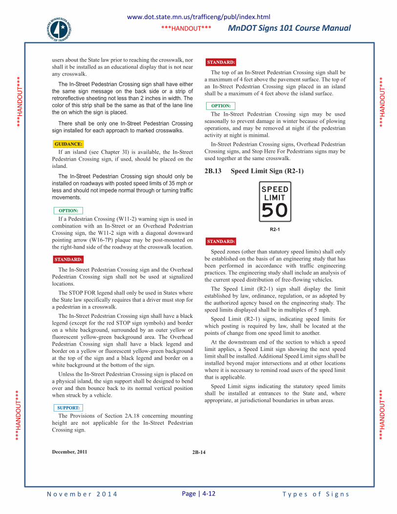
MnDOT Signs 101 Course Manual
N o v e m b e r 2 0 1 4 T y p e s o f S i g n s
***H
ANDO
UT**
* **
*HAN
DOUT
***
***H
ANDO
UT**
* **
*HAN
DOUT
***
***HANDOUT***
2B-14December, 2011
users about the State law prior to reaching the crosswalk, nor
shall it be installed as an educational display that is not near
any crosswalk.
The In-Street Pedestrian Crossing sign shall have either
the same sign message on the back side or a strip of
retroreflective sheeting not less than 2 inches in width. The
color of this strip shall be the same as that of the lane line
the on which the sign is placed.
There shall be only one In-Street Pedestrian Crossing
sign installed for each approach to marked crosswalks.
If an island (see Chapter 3I) is available, the In-Street
Pedestrian Crossing sign, if used, should be placed on the
island.
The In-Street Pedestrian Crossing sign should only be
installed on roadways with posted speed limits of 35 mph or
less and should not impede normal through or turning traffic
movements.
If a Pedestrian Crossing (W11-2) warning sign is used in
combination with an In-Street or an Overhead Pedestrian
Crossing sign, the W11-2 sign with a diagonal downward
pointing arrow (W16-7P) plaque may be post-mounted on
the right-hand side of the roadway at the crosswalk location.
The In-Street Pedestrian Crossing sign and the Overhead
Pedestrian Crossing sign shall not be used at signalized
locations.
The STOP FOR legend shall only be used in States where
the State law specifically requires that a driver must stop for
a pedestrian in a crosswalk.
The In-Street Pedestrian Crossing sign shall have a black
legend (except for the red STOP sign symbols) and border
on a white background, surrounded by an outer yellow or
fluorescent yellow-green background area. The Overhead
Pedestrian Crossing sign shall have a black legend and
border on a yellow or fluorescent yellow-green background
at the top of the sign and a black legend and border on a
white background at the bottom of the sign.
Unless the In-Street Pedestrian Crossing sign is placed on
a physical island, the sign support shall be designed to bend
over and then bounce back to its normal vertical position
when struck by a vehicle.
The Provisions of Section 2A.18 concerning mounting
height are not applicable for the In-Street Pedestrian
Crossing sign.
SUPPORT:SUPPORT:
STANDARD:STANDARD:
OPTION:OPTION:
GUIDANCE:GUIDANCE:
The top of an In-Street Pedestrian Crossing sign shall be
a maximum of 4 feet above the pavement surface. The top of
an In-Street Pedestrian Crossing sign placed in an island
shall be a maximum of 4 feet above the island surface.
The In-Street Pedestrian Crossing sign may be used
seasonally to prevent damage in winter because of plowing
operations, and may be removed at night if the pedestrian
activity at night is minimal.
In-Street Pedestrian Crossing signs, Overhead Pedestrian
Crossing signs, and Stop Here For Pedestrians signs may be
used together at the same crosswalk.
2B.13 Speed Limit Sign (R2-1)
Speed zones (other than statutory speed limits) shall only
be established on the basis of an engineering study that has
been performed in accordance with traffic engineering
practices. The engineering study shall include an analysis of
the current speed distribution of free-flowing vehicles.
The Speed Limit (R2-1) sign shall display the limit
established by law, ordinance, regulation, or as adopted by
the authorized agency based on the engineering study. The
speed limits displayed shall be in multiples of 5 mph.
Speed Limit (R2-1) signs, indicating speed limits for
which posting is required by law, shall be located at the
points of change from one speed limit to another.
At the downstream end of the section to which a speed
limit applies, a Speed Limit sign showing the next speed
limit shall be installed. Additional Speed Limit signs shall be
installed beyond major intersections and at other locations
where it is necessary to remind road users of the speed limit
that is applicable.
Speed Limit signs indicating the statutory speed limits
shall be installed at entrances to the State and, where
appropriate, at jurisdictional boundaries in urban areas.
STANDARD:STANDARD:
OPTION:OPTION:
STANDARD:STANDARD:
R2-1
50
SP EEDL I M I T
www.dot.state.mn.us/trafficeng/publ/index.html
Page | 4-12
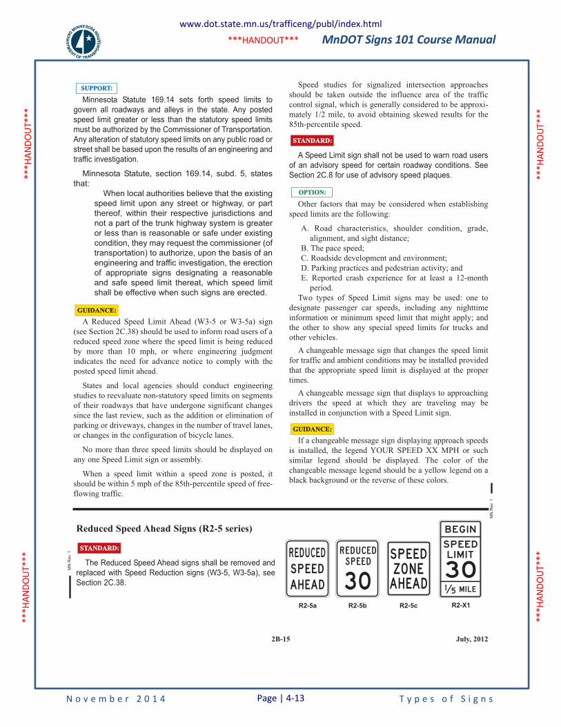
MnDOT Signs 101 Course Manual
N o v e m b e r 2 0 1 4 T y p e s o f S i g n s
***H
ANDO
UT**
* **
*HAN
DOUT
***
***H
ANDO
UT**
* **
*HAN
DOUT
***
***HANDOUT***
2B-15 July, 2012
Minnesota Statute 169.14 sets forth speed limits to
govern all roadways and alleys in the state. Any posted
speed limit greater or less than the statutory speed limits
must be authorized by the Commissioner of Transportation.
Any alteration of statutory speed limits on any public road or
street shall be based upon the results of an engineering and
traffic investigation.
Minnesota Statute, section 169.14, subd. 5, states
that:
When local authorities believe that the existing
speed limit upon any street or highway, or part
thereof, within their respective jurisdictions and
not a part of the trunk highway system is greater
or less than is reasonable or safe under existing
condition, they may request the commissioner (of
transportation) to authorize, upon the basis of an
engineering and traffic investigation, the erection
of appropriate signs designating a reasonable
and safe speed limit thereat, which speed limit
shall be effective when such signs are erected.
A Reduced Speed Limit Ahead (W3-5 or W3-5a) sign
(see Section 2C.38) should be used to inform road users of a
reduced speed zone where the speed limit is being reduced
by more than 10 mph, or where engineering judgment
indicates the need for advance notice to comply with the
posted speed limit ahead.
States and local agencies should conduct engineering
studies to reevaluate non-statutory speed limits on segments
of their roadways that have undergone significant changes
since the last review, such as the addition or elimination of
parking or driveways, changes in the number of travel lanes,
or changes in the configuration of bicycle lanes.
No more than three speed limits should be displayed on
any one Speed Limit sign or assembly.
When a speed limit within a speed zone is posted, it
should be within 5 mph of the 85th-percentile speed of free-
flowing traffic.
SUPPORT:SUPPORT:
GUIDANCE:GUIDANCE:
Speed studies for signalized intersection approaches
should be taken outside the influence area of the traffic
control signal, which is generally considered to be approxi-
mately 1/2 mile, to avoid obtaining skewed results for the
85th-percentile speed.
A Speed Limit sign shall not be used to warn road users
of an advisory speed for certain roadway conditions. See
Section 2C.8 for use of advisory speed plaques.
Other factors that may be considered when establishing
speed limits are the following:
A. Road characteristics, shoulder condition, grade,
alignment, and sight distance;
B. The pace speed;
C. Roadside development and environment;
D. Parking practices and pedestrian activity; and
E. Reported crash experience for at least a 12-month
period.
Two types of Speed Limit signs may be used: one to
designate passenger car speeds, including any nighttime
information or minimum speed limit that might apply; and
the other to show any special speed limits for trucks and
other vehicles.
A changeable message sign that changes the speed limit
for traffic and ambient conditions may be installed provided
that the appropriate speed limit is displayed at the proper
times.
A changeable message sign that displays to approaching
drivers the speed at which they are traveling may be
installed in conjunction with a Speed Limit sign.
If a changeable message sign displaying approach speeds
is installed, the legend YOUR SPEED XX MPH or such
similar legend should be displayed. The color of the
changeable message legend should be a yellow legend on a
black background or the reverse of these colors.
GUIDANCE:GUIDANCE:
STANDARD:STANDARD:
OPTION:OPTION:
Reduced Speed Ahead Signs (R2-5 series)
The Reduced Speed Ahead signs shall be removed and
replaced with Speed Reduction signs (W3-5, W3-5a), see
Section 2C.38.
STANDARD:STANDARD:
R ED U CEDS P E EDAH EAD 30
R E D U C E D
S P E E DZO N EAH EAD
S P EED
B EG I N
S P EED
L I M I T
3 0M I L E1 5
R2-5b R2-5c R2-X1R2-5a
MN
Rev.
1
MN
Rev.
1
www.dot.state.mn.us/trafficeng/publ/index.html
Page | 4-13
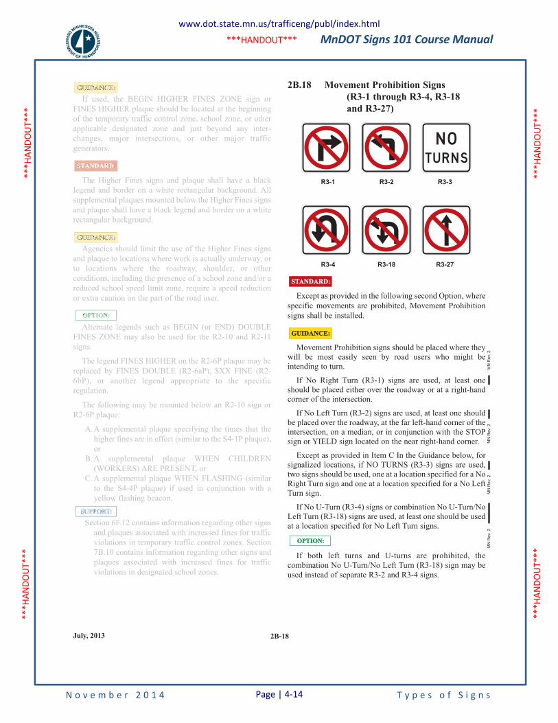
MnDOT Signs 101 Course Manual
N o v e m b e r 2 0 1 4 T y p e s o f S i g n s
***H
ANDO
UT**
* **
*HAN
DOUT
***
***H
ANDO
UT**
* **
*HAN
DOUT
***
***HANDOUT***
2B-18July, 2013
If used, the BEGIN HIGHER FINES ZONE sign or
FINES HIGHER plaque should be located at the beginning
of the temporary traffic control zone, school zone, or other
applicable designated zone and just beyond any inter-
changes, major intersections, or other major traffic
generators.
The Higher Fines signs and plaque shall have a black
legend and border on a white rectangular background. All
supplemental plaques mounted below the Higher Fines signs
and plaque shall have a black legend and border on a white
rectangular background.
Agencies should limit the use of the Higher Fines signs
and plaque to locations where work is actually underway, or
to locations where the roadway, shoulder, or other
conditions, including the presence of a school zone and/or a
reduced school speed limit zone, require a speed reduction
or extra caution on the part of the road user.
Alternate legends such as BEGIN (or END) DOUBLE
FINES ZONE may also be used for the R2-10 and R2-11
signs.
The legend FINES HIGHER on the R2-6P plaque may be
replaced by FINES DOUBLE (R2-6aP), $XX FINE (R2-
6bP), or another legend appropriate to the specific
regulation.
The following may be mounted below an R2-10 sign or
R2-6P plaque:
A.A supplemental plaque specifying the times that the
higher fines are in effect (similar to the S4-1P plaque),
or
B. A supplemental plaque WHEN CHILDREN
(WORKERS) ARE PRESENT, or
C. A supplemental plaque WHEN FLASHING (similar
to the S4-4P plaque) if used in conjunction with a
yellow flashing beacon.
Section 6F.12 contains information regarding other signs
and plaques associated with increased fines for traffic
violations in temporary traffic control zones. Section
7B.10 contains information regarding other signs and
plaques associated with increased fines for traffic
violations in designated school zones.
SUPPORT:
OPTION:
GUIDANCE:
STANDARD:
GUIDANCE: 2B.18 Movement Prohibition Signs
(R3-1 through R3-4, R3-18
and R3-27)
Except as provided in the following second Option, where
specific movements are prohibited, Movement Prohibition
signs shall be installed.
Movement Prohibition signs should be placed where theywill be most easily seen by road users who might beintending to turn.
If No Right Turn (R3-1) signs are used, at least oneshould be placed either over the roadway or at a right-handcorner of the intersection.
If No Left Turn (R3-2) signs are used, at least one shouldbe placed over the roadway, at the far left-hand corner of theintersection, on a median, or in conjunction with the STOPsign or YIELD sign located on the near right-hand corner.
Except as provided in Item C In the Guidance below, forsignalized locations, if NO TURNS (R3-3) signs are used,two signs should be used, one at a location specified for a NoRight Turn sign and one at a location specified for a No LeftTurn sign.
If No U-Turn (R3-4) signs or combination No U-Turn/NoLeft Turn (R3-18) signs are used, at least one should be usedat a location specified for No Left Turn signs.
If both left turns and U-turns are prohibited, the
combination No U-Turn/No Left Turn (R3-18) sign may be
used instead of separate R3-2 and R3-4 signs.
OPTION:OPTION:
R3-27
R3-3
N OTU R N S
R3-4
R3-2R3-1
R3-18
STANDARD:STANDARD:
GUIDANCE:GUIDANCE:
MN
Rev.
2M
N R
ev.
2M
N R
ev.
2M
N R
ev.
2
If used, the BEGIN HIGHER FINES ZONE sign or
FINES HIGHER plaque should be located at the beginning
of the temporary traffic control zone, school zone, or other
applicable designated zone and just beyond any inter-
changes, major intersections, or other major traffic
generators.
The Higher Fines signs and plaque shall have a black
legend and border on a white rectangular background. All
supplemental plaques mounted below the Higher Fines signs
and plaque shall have a black legend and border on a white
rectangular background.
Agencies should limit the use of the Higher Fines signs
and plaque to locations where work is actually underway, or
to locations where the roadway, shoulder, or other
conditions, including the presence of a school zone and/or a
reduced school speed limit zone, require a speed reduction
or extra caution on the part of the road user.
Alternate legends such as BEGIN (or END) DOUBLE
FINES ZONE may also be used for the R2-10 and R2-11
signs.
The legend FINES HIGHER on the R2-6P plaque may be
replaced by FINES DOUBLE (R2-6aP), $XX FINE (R2-
6bP), or another legend appropriate to the specific
regulation.
The following may be mounted below an R2-10 sign or
R2-6P plaque:
A.A supplemental plaque specifying the times that the
higher fines are in effect (similar to the S4-1P plaque),
or
B. A supplemental plaque WHEN CHILDREN
(WORKERS) ARE PRESENT, or
C. A supplemental plaque WHEN FLASHING (similar
to the S4-4P plaque) if used in conjunction with a
yellow flashing beacon.
Section 6F.12 contains information regarding other signs
and plaques associated with increased fines for traffic
violations in temporary traffic control zones. Section
7B.10 contains information regarding other signs and
plaques associated with increased fines for traffic
violations in designated school zones.
SUPPORT:
OPTION:
GUIDANCE:
STANDARD:
GUIDANCE:
www.dot.state.mn.us/trafficeng/publ/index.html
Page | 4-14
MnDOT Signs 101 Course Manual
N o v e m b e r 2 0 1 4 T y p e s o f S i g n s
***H
ANDO
UT**
* **
*HAN
DOUT
***
***H
ANDO
UT**
* **
*HAN
DOUT
***
***HANDOUT***
2B-19 December, 2011
If No Straight Through (R3-27) signs are used, at least
one should be placed either over the roadway or at a location
where it can be seen by road users who might be intending
to travel straight through the intersection.
If turn prohibition signs are installed in conjunction with
traffic control signals:
A. The No Right Turn sign should be installed adjacent
to a signal face viewed by road users in the right-hand
lane.
B. The No Left Turn (or No U-Turn or combination No
U-Turn/No Left Turn) sign should be installed
adjacent to a signal face viewed by road users in the
left-hand lane.
C. A NO TURNS sign should be placed adjacent to a
signal face viewed by all road users on that approach,
or two signs should be used.
If turn prohibition signs are installed in conjunction with
traffic control signals, an additional Movement Prohibition
sign may be post-mounted to supplement the sign mounted
overhead.
Where ONE WAY signs are used (see Section 2B.40),
Turn Prohibition signs may be omitted.
When the movement restriction applies during certain
time periods only, the following Movement Prohibition
signing alternatives may be used and are listed in order of
preference:
A. Changeable message signs, especially at signalized
intersections.
B. Permanently mounted signs incorporating a supple-
mentary legend showing the hours and days during
which the prohibition is applicable.
C. Portable signs, installed by proper authority, located
off the roadway at each corner of the intersection. The
portable signs are only to be used during the time that
the movement prohibition is applicable.
Movement Prohibition signs may be omitted at a ramp
entrance to an expressway or a channelized intersection
where the design is such as to indicate clearly the one-way
traffic movement on the ramp or turning lane.
The No Left Turn (R3-2) sign, the No U-Turn (R3-4)
sign, and the combination No U-Turn/No Left Turn (R3-18)
sign shall not be used at approaches to roundabouts to
prohibit drivers from turning left onto the circulatory
roadway of a roundabout.
STANDARD:STANDARD:
GUIDANCE:GUIDANCE:
OPTION:OPTION:
At roundabouts, the use of R3-2, R3-4, or R3-18 signs to
prohibit left turns onto the circulatory roadway might
confuse drivers about the possible legal turning movements
around the roundabout. Roundabout Directional Arrow (R6-
4 series) signs (see Section 2B.43) and/or ONE WAY (R6-
1R or R6-2R) signs are the appropriate signs to indicate the
travel direction within a roundabout.
2B.19 Intersection Lane Control Signs
(R3-5 through R3-8)
Intersection Lane Control signs, if used, shall require road
users in certain lanes to turn, shall permit turns from a lane
where such turns would otherwise not be permitted, shall
require a road user to stay in the same lane and proceed
straight through an intersection, or shall indicate permitted
movements from a lane.
Intersection Lane Control signs shall have three applica-
tions:
A. Mandatory Movement Lane Control (R3-5, R3-5a,
and R3-7) signs;
B. Optional Movement Lane Control (R3-6) sign; and
C. Advance Intersection Lane Control (R3-8 series)
signs.
When Intersection Lane Control signs are mounted
overhead, each sign should be placed over the lane or a
projection of the lane to which it applies.
On signalized approaches where through lanes that
become mandatory turn lanes, multiple-lane turns that
include shared lanes for through and turning movements, or
other lane-use regulations are present that would be
unexpected by unfamiliar road users, overhead lane control
signs should be installed at the signalized location over the
appropriate lanes or projections thereof and in advance of
the intersection over the appropriate lanes.
Where overhead mounting on the approach is impractical
for the advance and/or intersection lane-use signs, one of the
following alternatives should be employed:
A.At locations where through lanes become mandatory
turn lanes, a mandatory movement lane control (R3-7)
sign should be post-mounted on the left-hand side of
the roadway where a through lane is becoming a
mandatory left-turn lane on a one-way street or where
a median of sufficient width for the signs is available,
or on the right-hand side of the roadway where a
through lane is becoming a mandatory right-turn lane.
SUPPORT:SUPPORT:
STANDARD:STANDARD:
GUIDANCE:GUIDANCE:
www.dot.state.mn.us/trafficeng/publ/index.html
Page | 4-15
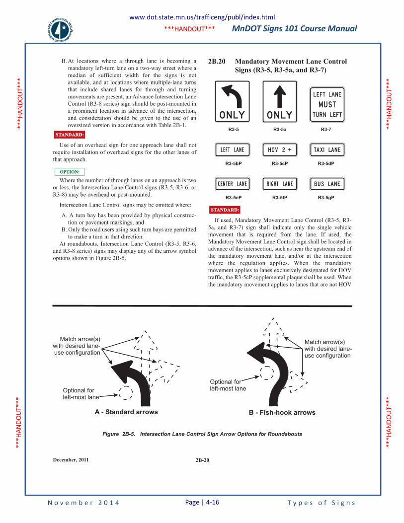
MnDOT Signs 101 Course Manual
N o v e m b e r 2 0 1 4 T y p e s o f S i g n s
***H
ANDO
UT**
* **
*HAN
DOUT
***
***H
ANDO
UT**
* **
*HAN
DOUT
***
***HANDOUT***
2B-20December, 2011
B. At locations where a through lane is becoming a
mandatory left-turn lane on a two-way street where a
median of sufficient width for the signs is not
available, and at locations where multiple-lane turns
that include shared lanes for through and turning
movements are present, an Advance Intersection Lane
Control (R3-8 series) sign should be post-mounted in
a prominent location in advance of the intersection,
and consideration should be given to the use of an
oversized version in accordance with Table 2B-1.
Use of an overhead sign for one approach lane shall not
require installation of overhead signs for the other lanes of
that approach.
Where the number of through lanes on an approach is two
or less, the Intersection Lane Control signs (R3-5, R3-6, or
R3-8) may be overhead or post-mounted.
Intersection Lane Control signs may be omitted where:
A. A turn bay has been provided by physical construc-
tion or pavement markings, and
B. Only the road users using such turn bays are permitted
to make a turn in that direction.
At roundabouts, Intersection Lane Control (R3-5, R3-6,
and R3-8 series) signs may display any of the arrow symbol
options shown in Figure 2B-5.
OPTION:OPTION:
STANDARD:STANDARD:
2B.20 Mandatory Movement Lane Control
Signs (R3-5, R3-5a, and R3-7)
If used, Mandatory Movement Lane Control (R3-5, R3-
5a, and R3-7) sign shall indicate only the single vehicle
movement that is required from the lane. If used, the
Mandatory Movement Lane Control sign shall be located in
advance of the intersection, such as near the upstream end of
the mandatory movement lane, and/or at the intersection
where the regulation applies. When the mandatory
movement applies to lanes exclusively designated for HOV
traffic, the R3-5cP supplemental plaque shall be used. When
the mandatory movement applies to lanes that are not HOV
STANDARD:STANDARD:
R3-5eP R3-5fP R3-5gP
C E N T E R LA N E R I G H T LA N E B U S LAN E
H OV 2 TAX I LA N EL E FT LA N E
R3-5 R3-5a R3-7
O N LY O N LY
LEFT
L E FTTU R N
M U ST
LAN E
R3-5bP R3-5cP R3-5dP
Figure 2B-5. Intersection Lane Control Sign Arrow Options for Roundabouts
A - Standard arrows B - Fish-hook arrows
Optional forleft-most lane
Optional forleft-most lane
Match arrow(s)with desired lane-use configuration
Match arrow(s)with desired lane-use configuration
www.dot.state.mn.us/trafficeng/publ/index.html
Page | 4-16
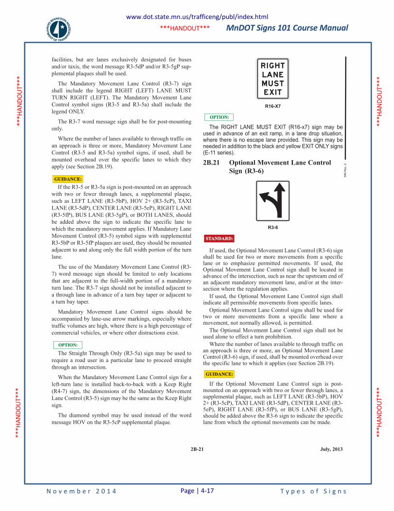
MnDOT Signs 101 Course Manual
N o v e m b e r 2 0 1 4 T y p e s o f S i g n s
***H
ANDO
UT**
* **
*HAN
DOUT
***
***H
ANDO
UT**
* **
*HAN
DOUT
***
***HANDOUT***
2B-21 July, 2013
facilities, but are lanes exclusively designated for buses
and/or taxis, the word message R3-5dP and/or R3-5gP sup-
plemental plaques shall be used.
The Mandatory Movement Lane Control (R3-7) sign
shall include the legend RIGHT (LEFT) LANE MUST
TURN RIGHT (LEFT). The Mandatory Movement Lane
Control symbol signs (R3-5 and R3-5a) shall include the
legend ONLY.
The R3-7 word message sign shall be for post-mounting
only.
Where the number of lanes available to through traffic on
an approach is three or more, Mandatory Movement Lane
Control (R3-5 and R3-5a) symbol signs, if used, shall be
mounted overhead over the specific lanes to which they
apply (see Section 2B.19).
If the R3-5 or R3-5a sign is post-mounted on an approach
with two or fewer through lanes, a supplemental plaque,
such as LEFT LANE (R3-5bP), HOV 2+ (R3-5cP), TAXI
LANE (R3-5dP), CENTER LANE (R3-5eP), RIGHT LANE
(R3-5fP), BUS LANE (R3-5gP), or BOTH LANES, should
be added above the sign to indicate the specific lane to
which the mandatory movement applies. If Mandatory Lane
Movement Control (R3-5) symbol signs with supplemental
R3-5bP or R3-5fP plaques are used, they should be mounted
adjacent to and along only the full width portion of the turn
lane.
The use of the Mandatory Movement Lane Control (R3-
7) word message sign should be limited to only locations
that are adjacent to the full-width portion of a mandatory
turn lane. The R3-7 sign should not be installed adjacent to
a through lane in advance of a turn bay taper or adjacent to
a turn bay taper.
Mandatory Movement Lane Control signs should be
accompanied by lane-use arrow markings, especially where
traffic volumes are high, where there is a high percentage of
commercial vehicles, or where other distractions exist.
The Straight Through Only (R3-5a) sign may be used to
require a road user in a particular lane to proceed straight
through an intersection.
When the Mandatory Movement Lane Control sign for a
left-turn lane is installed back-to-back with a Keep Right
(R4-7) sign, the dimensions of the Mandatory Movement
Lane Control (R3-5) sign may be the same as the Keep Right
sign.
The diamond symbol may be used instead of the word
message HOV on the R3-5cP supplemental plaque.
OPTION:OPTION:
GUIDANCE:GUIDANCE:
The RIGHT LANE MUST EXIT (R16-x7) sign may beused in advance of an exit ramp, in a lane drop situation,where there is no escape lane provided. This sign may beneeded in addition to the black and yellow EXIT ONLY signs(E-11 series).
2B.21 Optional Movement Lane Control
Sign (R3-6)
If used, the Optional Movement Lane Control (R3-6) signshall be used for two or more movements from a specificlane or to emphasize permitted movements. If used, theOptional Movement Lane Control sign shall be located inadvance of the intersection, such as near the upstream end ofan adjacent mandatory movement lane, and/or at the inter-section where the regulation applies.
If used, the Optional Movement Lane Control sign shallindicate all permissible movements from specific lanes.
Optional Movement Lane Control signs shall be used fortwo or more movements from a specific lane where amovement, not normally allowed, is permitted.
The Optional Movement Lane Control sign shall not beused alone to effect a turn prohibition.
Where the number of lanes available to through traffic onan approach is three or more, an Optional Movement LaneControl (R3-6) sign, if used, shall be mounted overhead overthe specific lane to which it applies (see Section 2B.19).
If the Optional Movement Lane Control sign is post-mounted on an approach with two or fewer through lanes, asupplemental plaque, such as LEFT LANE (R3-5bP), HOV2+ (R3-5cP), TAXI LANE (R3-5dP), CENTER LANE (R3-5eP), RIGHT LANE (R3-5fP), or BUS LANE (R3-5gP),should be added above the R3-6 sign to indicate the specificlane from which the optional movements can be made.
GUIDANCE:GUIDANCE:
OPTION:OPTION:
R16-X7
R I G HT
LAN E
M U ST
EX I T
R3-6
STANDARD:STANDARD:
MN
Re
v. 2
www.dot.state.mn.us/trafficeng/publ/index.html
Page | 4-17
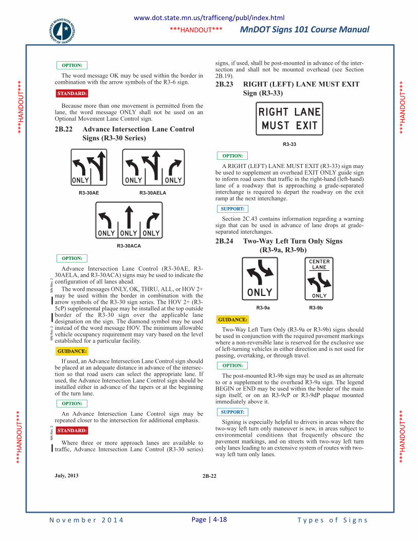
MnDOT Signs 101 Course Manual
N o v e m b e r 2 0 1 4 T y p e s o f S i g n s
***H
ANDO
UT**
* **
*HAN
DOUT
***
***H
ANDO
UT**
* **
*HAN
DOUT
***
***HANDOUT***
2B-22July, 2013
The word message OK may be used within the border incombination with the arrow symbols of the R3-6 sign.
Because more than one movement is permitted from thelane, the word message ONLY shall not be used on anOptional Movement Lane Control sign.
2B.22 Advance Intersection Lane Control
Signs (R3-30 Series)
Advance Intersection Lane Control (R3-30AE, R3-30AELA, and R3-30ACA) signs may be used to indicate theconfiguration of all lanes ahead.
The word messages ONLY, OK, THRU, ALL, or HOV 2+may be used within the border in combination with thearrow symbols of the R3-30 sign series. The HOV 2+ (R3-5cP) supplemental plaque may be installed at the top outsideborder of the R3-30 sign over the applicable lanedesignation on the sign. The diamond symbol may be usedinstead of the word message HOV. The minimum allowablevehicle occupancy requirement may vary based on the levelestablished for a particular facility.
If used, an Advance Intersection Lane Control sign shouldbe placed at an adequate distance in advance of the intersec-tion so that road users can select the appropriate lane. Ifused, the Advance Intersection Lane Control sign should beinstalled either in advance of the tapers or at the beginningof the turn lane.
An Advance Intersection Lane Control sign may berepeated closer to the intersection for additional emphasis.
Where three or more approach lanes are available totraffic, Advance Intersection Lane Control (R3-30 series)
STANDARD:STANDARD:
OPTION:OPTION:
GUIDANCE:GUIDANCE:
OPTION:OPTION:
STANDARD:STANDARD:
R3-30ACA
O N LY O N LYO N LY
OPTION:OPTION:
R3-30AE R3-30AELA
O N LY O N LY O N LY
signs, if used, shall be post-mounted in advance of the inter-section and shall not be mounted overhead (see Section2B.19).
2B.23 RIGHT (LEFT) LANE MUST EXIT
Sign (R3-33)
A RIGHT (LEFT) LANE MUST EXIT (R3-33) sign maybe used to supplement an overhead EXIT ONLY guide signto inform road users that traffic in the right-hand (left-hand)lane of a roadway that is approaching a grade-separatedinterchange is required to depart the roadway on the exitramp at the next interchange.
Section 2C.43 contains information regarding a warningsign that can be used in advance of lane drops at grade-separated interchanges.
2B.24 Two-Way Left Turn Only Signs
(R3-9a, R3-9b)
Two-Way Left Turn Only (R3-9a or R3-9b) signs shouldbe used in conjunction with the required pavement markingswhere a non-reversible lane is reserved for the exclusive useof left-turning vehicles in either direction and is not used forpassing, overtaking, or through travel.
The post-mounted R3-9b sign may be used as an alternateto or a supplement to the overhead R3-9a sign. The legendBEGIN or END may be used within the border of the mainsign itself, or on an R3-9cP or R3-9dP plaque mountedimmediately above it.
Signing is especially helpful to drivers in areas where thetwo-way left turn only maneuver is new, in areas subject toenvironmental conditions that frequently obscure thepavement markings, and on streets with two-way left turnonly lanes leading to an extensive system of routes with two-way left turn only lanes.
SUPPORT:SUPPORT:
OPTION:OPTION:
R3-33
R I G H T LAN EM U ST EX I T
SUPPORT:SUPPORT:
OPTION:OPTION:
O N LY
CENTERLAN E
O N LY
R3-9a R3-9b
GUIDANCE:GUIDANCE:
MN
Re
v. 2
MN
Re
v. 2
MN
Rev.
2
www.dot.state.mn.us/trafficeng/publ/index.html
Page | 4-18
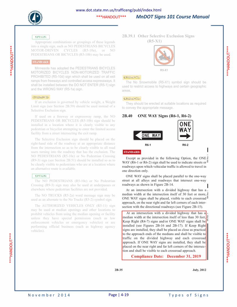
MnDOT Signs 101 Course Manual
N o v e m b e r 2 0 1 4 T y p e s o f S i g n s
***H
ANDO
UT**
* **
*HAN
DOUT
***
***H
ANDO
UT**
* **
*HAN
DOUT
***
***HANDOUT***
At an intersection with a divided highway that has a
median width at the intersection itself of less than 30 feet,
Keep Right (R4-7) signs and/or ONE WAY signs shall be
installed (see Figures 2B-16 and 2B-17). If Keep Right
signs are installed, they shall be placed as close as practical
to the approach ends of the medians and shall be visible to
traffic on the divided highway and each crossroad
approach. If ONE WAY signs are installed, they shall be
placed on the near right and far left corners of the intersec-
tion and shall be visible to each crossroad approach.
Compliance Date: December 31, 2019
2B-35 July, 2012
2B.39.1 Other Selective Exclusion Signs
(R5-X1)
The No Snowmobile (R5-X1) symbol sign should be
used to restrict access to highways and certain geographic
areas.
They should be erected at suitable locations as required
to convey the appropriate message.
2B.40 ONE WAY Signs (R6-1, R6-2)
Except as provided in the following Option, the ONE
WAY (R6-1 or R6-2) sign shall be used to indicate streets or
roadways upon which vehicular traffic is allowed to travel in
one direction only.
ONE WAY signs shall be placed parallel to the one-way
street at all alleys and roadways that intersect one-way
roadways as shown in Figure 2B-14.
At an intersection with a divided highway that has a
median width at the intersection itself of 30 feet or more,
ONE WAY signs shall be placed, visible to each crossroad
approach, on the near right and far left corners of each inter-
section with the directional roadways (see Figure 2B-15).
STANDARD:STANDARD:
R6-1 R6-2
O N E WAY
O N EWAY
GUIDANCE:
GUIDANCE:
R5-X1
Appropriate combinations or groupings of these legends
into a single sign, such as NO PEDESTRIANS BICYCLES
MOTOR-DRIVEN CYCLES (R5-10a), or NO
PEDESTRIANS OR BICYCLES (R5-10b) may be used.
Minnesota has adopted the PEDESTRIANS BICYCLES
MOTORIZED BICYCLES NON-MOTORIZED TRAFFIC
PROHIBITED (R5-10d) sign which shall be used on all exit
ramps from freeways and controlled access expressways. It
shall be installed between the DO NOT ENTER (R5-1) sign
and the WRONG WAY (R5-1a) sign.
If an exclusion is governed by vehicle weight, a Weight
Limit sign (see Section 2B.59) should be used instead of a
Selective Exclusion sign.
If used on a freeway or expressway ramp, the NO
PEDESTRIANS OR BICYCLES (R5-10b) sign should be
installed in a location where it is clearly visible to any
pedestrian or bicyclist attempting to enter the limited access
facility from a street intersecting the exit ramp.
The Selective Exclusion sign should be placed on the
right-hand side of the roadway at an appropriate distance
from the intersection so as to be clearly visible to all road
users turning into the roadway that has the exclusion. The
NO PEDESTRIANS (R5-10c) or No Pedestrian Crossing
(R9-3) sign (see Section 2B.51) should be installed so as to
be clearly visible to pedestrians who are at a location where
an alternative route is available.
The NO PEDESTRIANS (R5-10c) or No Pedestrian
Crossing (R9-3) sign may also be used at underpasses or
elsewhere where pedestrian facilities are not provided.
The NO TRUCKS (R5-2a) word message sign may be
used as an alternate to the No Trucks (R5-2) symbol sign.
The AUTHORIZED VEHICLES ONLY (R5-11) sign
may be used at median openings and other locations to
prohibit vehicles from using the median opening or facility
unless they have special permission (such as law
enforcement vehicles or emergency vehicles) or are
performing official business (such as highway agency
vehicles).
OPTION:
GUIDANCE:
OPTION:
STANDARD:
MN
Re
v. 1
MN
Re
v. 1
MN
Rev.
1
Appropriate combinations or groupings of these legends
into a single sign, such as NO PEDESTRIANS BICYCLES
MOTOR-DRIVEN CYCLES (R5-10a), or NO
PEDESTRIANS OR BICYCLES (R5-10b) may be used.
Minnesota has adopted the PEDESTRIANS BICYCLES
MOTORIZED BICYCLES NON-MOTORIZED TRAFFIC
PROHIBITED (R5-10d) sign which shall be used on all exit
ramps from freeways and controlled access expressways. It
shall be installed between the DO NOT ENTER (R5-1) sign
and the WRONG WAY (R5-1a) sign.
If an exclusion is governed by vehicle weight, a Weight
Limit sign (see Section 2B.59) should be used instead of a
Selective Exclusion sign.
If used on a freeway or expressway ramp, the NO
PEDESTRIANS OR BICYCLES (R5-10b) sign should be
installed in a location where it is clearly visible to any
pedestrian or bicyclist attempting to enter the limited access
facility from a street intersecting the exit ramp.
The Selective Exclusion sign should be placed on the
right-hand side of the roadway at an appropriate distance
from the intersection so as to be clearly visible to all road
users turning into the roadway that has the exclusion. The
NO PEDESTRIANS (R5-10c) or No Pedestrian Crossing
(R9-3) sign (see Section 2B.51) should be installed so as to
be clearly visible to pedestrians who are at a location where
an alternative route is available.
The NO PEDESTRIANS (R5-10c) or No Pedestrian
Crossing (R9-3) sign may also be used at underpasses or
elsewhere where pedestrian facilities are not provided.
The NO TRUCKS (R5-2a) word message sign may be
used as an alternate to the No Trucks (R5-2) symbol sign.
The AUTHORIZED VEHICLES ONLY (R5-11) sign
may be used at median openings and other locations to
prohibit vehicles from using the median opening or facility
unless they have special permission (such as law
enforcement vehicles or emergency vehicles) or are
performing official business (such as highway agency
vehicles).
OPTION:
GUIDANCE:
OPTION:
STANDARD:
2B.39.1 Other Selective Exclusion Signs
(R5-X1)
The No Snowmobile (R5-X1) symbol sign should be
used to restrict access to highways and certain geographic
areas.
They should be erected at suitable locations as required
to convey the appropriate message.
GUIDANCE:
GUIDANCE:
R5-X1
www.dot.state.mn.us/trafficeng/publ/index.html
Page | 4-19
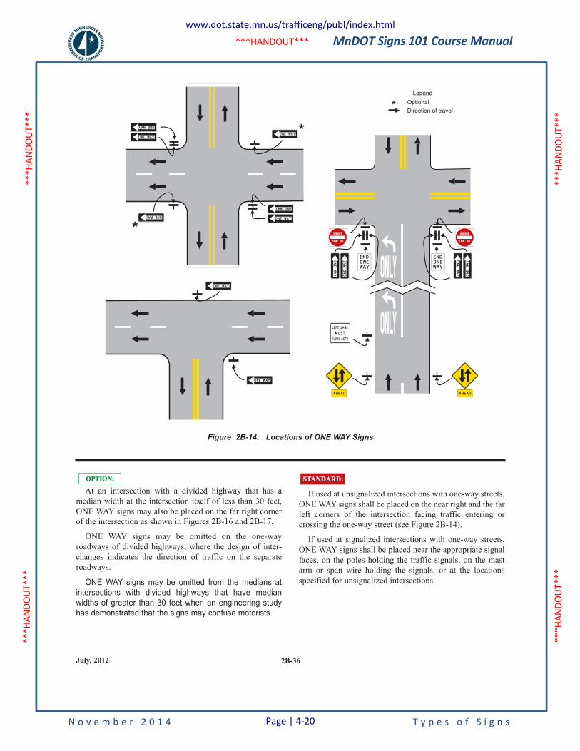
MnDOT Signs 101 Course Manual
N o v e m b e r 2 0 1 4 T y p e s o f S i g n s
***H
ANDO
UT**
* **
*HAN
DOUT
***
***H
ANDO
UT**
* **
*HAN
DOUT
***
***HANDOUT***
2B-36July, 2012
If used at unsignalized intersections with one-way streets,
ONE WAY signs shall be placed on the near right and the far
left corners of the intersection facing traffic entering or
crossing the one-way street (see Figure 2B-14).
If used at signalized intersections with one-way streets,
ONE WAY signs shall be placed near the appropriate signal
faces, on the poles holding the traffic signals, on the mast
arm or span wire holding the signals, or at the locations
specified for unsignalized intersections.
STANDARD:STANDARD:
At an intersection with a divided highway that has a
median width at the intersection itself of less than 30 feet,
ONE WAY signs may also be placed on the far right corner
of the intersection as shown in Figures 2B-16 and 2B-17.
ONE WAY signs may be omitted on the one-way
roadways of divided highways, where the design of inter-
changes indicates the direction of traffic on the separate
roadways.
ONE WAY signs may be omitted from the medians at
intersections with divided highways that have median
widths of greater than 30 feet when an engineering study
has demonstrated that the signs may confuse motorists.
OPTION:OPTION:
Figure 2B-14. Locations of ONE WAY Signs
www.dot.state.mn.us/trafficeng/publ/index.html
Page | 4-20
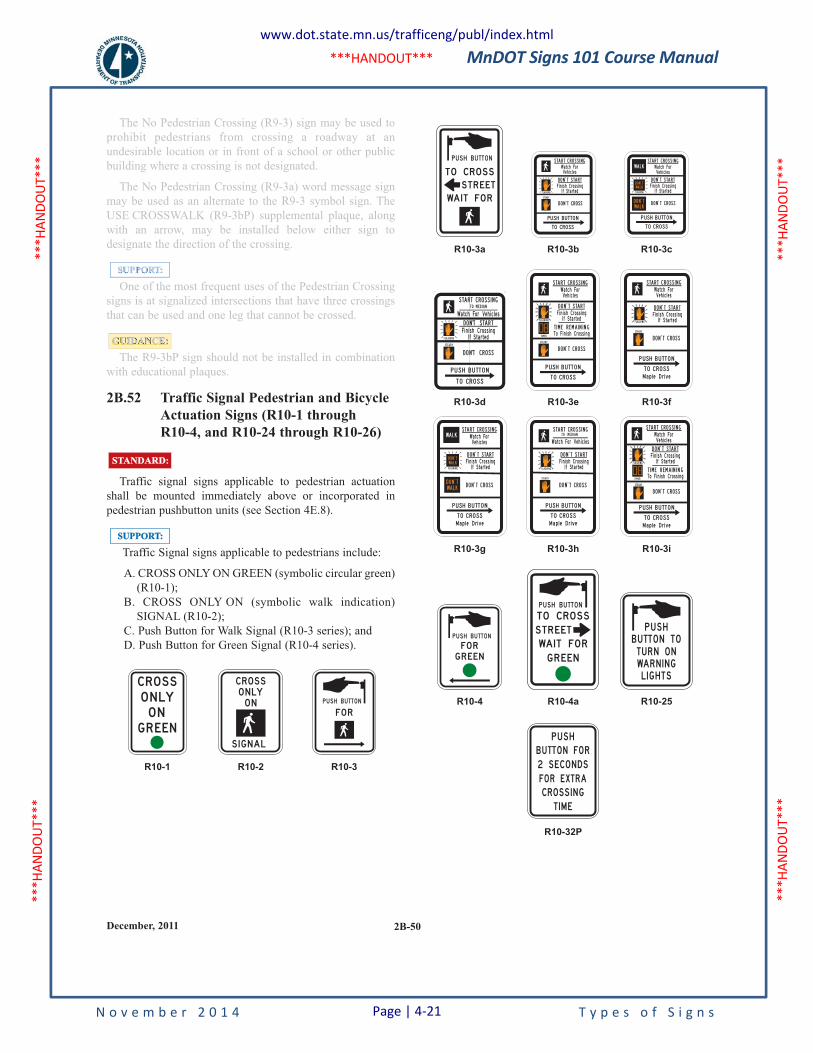
MnDOT Signs 101 Course Manual
N o v e m b e r 2 0 1 4 T y p e s o f S i g n s
***H
ANDO
UT**
* **
*HAN
DOUT
***
***H
ANDO
UT**
* **
*HAN
DOUT
***
***HANDOUT***
2B-50December, 2011
The No Pedestrian Crossing (R9-3) sign may be used to
prohibit pedestrians from crossing a roadway at an
undesirable location or in front of a school or other public
building where a crossing is not designated.
The No Pedestrian Crossing (R9-3a) word message sign
may be used as an alternate to the R9-3 symbol sign. The
USE CROSSWALK (R9-3bP) supplemental plaque, along
with an arrow, may be installed below either sign to
designate the direction of the crossing.
One of the most frequent uses of the Pedestrian Crossing
signs is at signalized intersections that have three crossings
that can be used and one leg that cannot be crossed.
The R9-3bP sign should not be installed in combination
with educational plaques.
2B.52 Traffic Signal Pedestrian and Bicycle
Actuation Signs (R10-1 through
R10-4, and R10-24 through R10-26)
Traffic signal signs applicable to pedestrian actuation
shall be mounted immediately above or incorporated in
pedestrian pushbutton units (see Section 4E.8).
Traffic Signal signs applicable to pedestrians include:
A. CROSS ONLY ON GREEN (symbolic circular green)
(R10-1);
B. CROSS ONLY ON (symbolic walk indication)
SIGNAL (R10-2);
C. Push Button for Walk Signal (R10-3 series); and
D. Push Button for Green Signal (R10-4 series).
R10-1 R10-2 R10-3
CROSSO N LYO N
G R EEN
CROSSO N LYO N
S I G NAL
PU S H B UTTO N
F O R
SUPPORT:SUPPORT:
STANDARD:STANDARD:
GUIDANCE:
SUPPORT:
R10-32P
P U S H
B UTTO N FO R
2 S ECO N DS
FO R EXTRA
CROSS I N G
T I M E
R10-4 R10-4a R10-25
FO RG R EEN
P U S H B UTTO N
T O CROSS
WA I T FO R
G R EEN
P U S H B UTTO N
S T R E ETB U TTO N TOTU R N O NWAR N I N GL I G H TS
P U S H
R10-3g R10-3h R10-3i
WA L K
D O N T
WA L K
D O N T
WA L K
S TA R T C R O S S I N G
Wa tc h Fo rVe h i c l es
D O N T C R O S S
D O N T S TA R T
F i n i s h C ross i n gI f S t a rt ed
TO C RO S S
P USH B U TTO N
M a p l e D r i ve
S TA R T C R O S S I N GT O M E D I A N
Wa tc h Fo r Ve h i c l es
D O N T C R O S S
D O N T S TA R T
F i n i s h C ross i n gI f S t a rt ed
TO C RO S S
P USH B U TTO N
M a p l e D r i ve
S TA R T C R O S S I N G
Wa tc h Fo rVe h i c l es
D O N T C R O S S
T O C RO S S
P USH B U TT O N
M a p l e D r i ve
D O N T S TA R T
T I M E R E M A I N I N G
F i n i s h C ross i n g
To F i n i s h C ross i n g
I f S t a rt ed
R10-3d R10-3e R10-3f
S T EA D Y
F LA S H I N G
D O N T C R O S S
P U S H B U TTO N
TO C ROS S
S TA R T C R O S S I N GT O M E D I A N
D O N T S TA R T
I f S t a rt edF i n i s h C ross i n g
Wa tc h Fo r Ve h i c l es
S TA R T C R O S S I N G
Wa tc h Fo rVe h i c l es
D O N T C R O S S
TO C RO S S
P USH B U TTO N
D O N T S TA R T
T I M E R E M A I N I N G
F i n i s h C ross i n g
To F i n i s h C ross i n g
I f S t a rt ed
S TA R T C R O S S I N G
Wa tc h Fo rVe h i c l es
D O N T C R O S S
D O N T S TA R T
F i n i s h C ross i n gI f S t a rt ed
TO C RO S S
P USH B U TTO N
M a p l e D r i ve
R10-3a R10-3b R10-3c
TO CROSS
WA I T FO R
P U S H B UTTO N
S T R E ET
S TA R T C R O S S I N G
D O N T S TA R T
Wa tc h Fo r
F i n i s h C ross i n g
Ve h i c l es
I f S t a rt ed
S TA R T C R O S S I N G
Wa tc h Fo rVe h i c l es
D O N T S TA R T
D O N T C R O S SD O N T
WA L K
WA L K
D O N T
WA L K F i n i s h C ross i n gI f S t a rt ed
TO C RO S S
P USH B U TTO N
The No Pedestrian Crossing (R9-3) sign may be used to
prohibit pedestrians from crossing a roadway at an
undesirable location or in front of a school or other public
building where a crossing is not designated.
The No Pedestrian Crossing (R9-3a) word message sign
may be used as an alternate to the R9-3 symbol sign. The
USE CROSSWALK (R9-3bP) supplemental plaque, along
with an arrow, may be installed below either sign to
designate the direction of the crossing.
One of the most frequent uses of the Pedestrian Crossing
signs is at signalized intersections that have three crossings
that can be used and one leg that cannot be crossed.
The R9-3bP sign should not be installed in combination
with educational plaques.
GUIDANCE:
SUPPORT:
www.dot.state.mn.us/trafficeng/publ/index.html
Page | 4-21
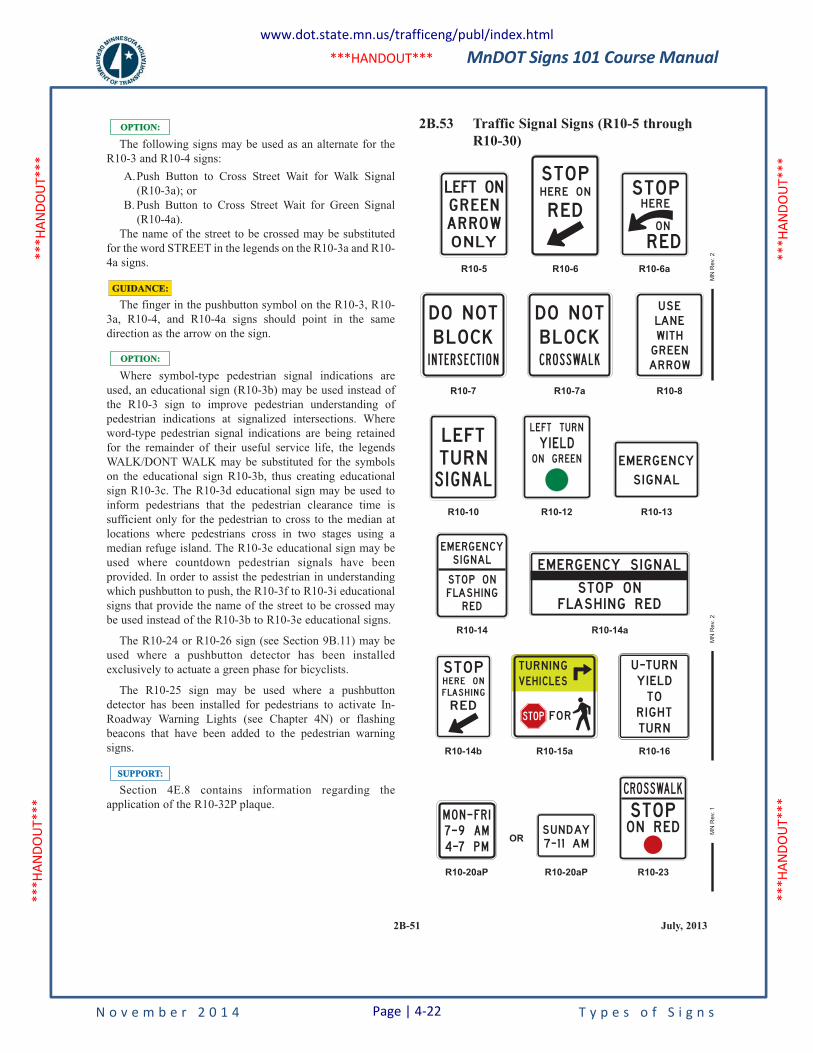
MnDOT Signs 101 Course Manual
N o v e m b e r 2 0 1 4 T y p e s o f S i g n s
***H
ANDO
UT**
* **
*HAN
DOUT
***
***H
ANDO
UT**
* **
*HAN
DOUT
***
***HANDOUT***
2B-51 July, 2013
The following signs may be used as an alternate for the
R10-3 and R10-4 signs:
A.Push Button to Cross Street Wait for Walk Signal
(R10-3a); or
B. Push Button to Cross Street Wait for Green Signal
(R10-4a).
The name of the street to be crossed may be substituted
for the word STREET in the legends on the R10-3a and R10-
4a signs.
The finger in the pushbutton symbol on the R10-3, R10-
3a, R10-4, and R10-4a signs should point in the same
direction as the arrow on the sign.
Where symbol-type pedestrian signal indications are
used, an educational sign (R10-3b) may be used instead of
the R10-3 sign to improve pedestrian understanding of
pedestrian indications at signalized intersections. Where
word-type pedestrian signal indications are being retained
for the remainder of their useful service life, the legends
WALK/DONT WALK may be substituted for the symbols
on the educational sign R10-3b, thus creating educational
sign R10-3c. The R10-3d educational sign may be used to
inform pedestrians that the pedestrian clearance time is
sufficient only for the pedestrian to cross to the median at
locations where pedestrians cross in two stages using a
median refuge island. The R10-3e educational sign may be
used where countdown pedestrian signals have been
provided. In order to assist the pedestrian in understanding
which pushbutton to push, the R10-3f to R10-3i educational
signs that provide the name of the street to be crossed may
be used instead of the R10-3b to R10-3e educational signs.
The R10-24 or R10-26 sign (see Section 9B.11) may be
used where a pushbutton detector has been installed
exclusively to actuate a green phase for bicyclists.
The R10-25 sign may be used where a pushbutton
detector has been installed for pedestrians to activate In-
Roadway Warning Lights (see Chapter 4N) or flashing
beacons that have been added to the pedestrian warning
signs.
Section 4E.8 contains information regarding the
application of the R10-32P plaque.
SUPPORT:SUPPORT:
OPTION:OPTION:
GUIDANCE:GUIDANCE:
OPTION:OPTION: 2B.53 Traffic Signal Signs (R10-5 through
R10-30)
DO N OTB LOCKI N T E R S E CT I O N
R10-14b
STO PH E R E O N
F LAS H I N G
R ED
R10-20aP R10-20aP R10-23
M O N - F R I
7 - 9 AM
4 -7 P MOR
S U N DAY7 - 1 1 AM
S TO PC RO S SWAL K
O N R ED
R10-15a R10-16
TU R N I N G
VEH I C L ES
FO RSTOP
U -TU R NY I E L DTO
R I G H TTU R N
R10-14 R10-14a
EM ERG EN CYS I G NAL
STO P O NFLAS H I N GR ED
EM ERG EN CY S I G NAL
STO P O NFLAS H I N G R ED
R10-10 R10-12 R10-13
L E FTTU R NS I G NA L
L E FT
O N G R EEN
TU R N
Y I E L DEM ERG EN CY
S I G NAL
R10-7 R10-7a R10-8
DO N OTB LOCKC R O S SWA L K
U S ELAN EW I T HG R E ENAR ROW
R10-5 R10-6 R10-6a
LEFT ON
G R E E N
AR ROW
O N LY
STO PH ER E O N
R E DSTO PH ER E
O N
R ED
MN
Rev.
1M
N R
ev.
2M
N R
ev.
2
www.dot.state.mn.us/trafficeng/publ/index.html
Page | 4-22

MnDOT Signs 101 Course Manual
N o v e m b e r 2 0 1 4 P a g e | 4-23 T y p e s o f S i g n s
4.3 Warning Signs
Warning signs call attention to unexpected conditions on or adjacent to a highway, street, or private roads open to public travel and to situations that might not be readily apparent to road users. Warning signs alert road users to conditions that might call for a reduction of speed or an action in the interest of safety and efficient traffic operations.
Since the primary purpose of warning signs is to gain attention of the unfamiliar motorist, the placement of warning signs is important. The placement must allow these drivers sufficient time to see the warning sign, understand the intent, identify the potential hazard, decide what action must be taken, and then to perform any necessary maneuver.
4.3.1 MUTCD Chapter 2C Handout
The information on the following pages are a handout from the 2011 MN MUTCD, Chapter 2C on Warning Signs. The entire section is not included, but only pages of interest for this manual. For full details on the MUTCD, refer to the OTST publications website found at, www.dot.state.mn.us/trafficeng/publ/index.html.
In addition, the entire 2011 Standard Signs Summary is included at the end of this chapter.
MnDOT Signs 101 Course Manual
N o v e m b e r 2 0 1 4 T y p e s o f S i g n s
***H
ANDO
UT**
* **
*HAN
DOUT
***
***H
ANDO
UT**
* **
*HAN
DOUT
***
***HANDOUT***
December, 20112C-1
PART 2. SIGNS
Chapter 2C. Warning Signs and Object Markers
2C.1 Function of Warning Signs
Warning signs call attention to unexpected conditions on
or adjacent to a highway, street, or private roads open to
public travel and to situations that might not be readily
apparent to road users. Warning signs alert road users to
conditions that might call for a reduction of speed or an
action in the interest of safety and efficient traffic
operations.
2C.2 Application of Warning Signs
The use of warning signs shall be based on an engineering
study or on engineering judgment.
The use of warning signs should be kept to a minimum as
the unnecessary use of warning signs tends to breed
disrespect for all signs. In situations where the condition or
activity is seasonal or temporary, the warning sign should be
removed or covered when the condition or activity does not
exist.
Consistent with the provisions of Chapter 2L, changeable
message signs may be used to display a warning message.
Consistent with the provisions of Chapter 4L, a Warning
Beacon may be used in combination with a standard warning
sign.
The categories of warning signs are shown in Table 2C-1.
Warning signs specified provided herein in this Manual
cover most of the conditions that are likely to be
encountered. Additional warning signs for low-volume
roads (as defined in Section 5A.1), temporary traffic control
zones, school areas, highway-rail grade crossings, and
bicycle facilities, and highway-light rail transit grade
crossings are discussed in Parts 5 through 9, respectively.
Section 1A.9 contains information regarding the
assistance that is available to jurisdictions that do not have
engineers on their staffs who are trained and/or experienced
in traffic control devices.
OPTION:OPTION:
STANDARD:STANDARD:
GUIDANCE:GUIDANCE:
SUPPORT:SUPPORT:
SUPPORT:SUPPORT:
2C.3 Design of Warning Signs
Except as provided in the following Option or unless
specifically designated otherwise, all warning signs shall be
diamond-shaped (square with one diagonal vertical) with a
black legend and border on a yellow background. Warning
signs shall be designed in accordance with sizes, shapes,
colors, and legends contained in the MnDOT “Standard
Signs Manual” (see Map & Manual Sales Unit, page ii), and
the FHWA "Standard Highway Signs and Markings" book
(see Section 1A.11).
A warning sign that is larger than the size shown in the
Oversized column in Table 2C-2 for that particular sign may
be diamond-shaped or may be rectangular or square in
shape.
Except for symbols on warning signs, minor modifica-
tions may be made to the design provided that the essential
appearance characteristics are met. Modifications may be
made to the symbols shown on combined horizontal
alignment/intersection signs (see Section 2C.11) and inter-
section warning signs (see Section 2C.46) in order to
approximate the geometric configuration of the intersecting
roadway(s).
Word message warning signs other than those provided in
this Manual may be developed and installed by State and
local highway agencies
Warning signs regarding conditions associated with
pedestrians, bicyclists, and playgrounds may have a black
legend and border on a yellow or fluorescent yellow-green
background.
Warning signs regarding conditions associated with
school buses and schools and their related supplemental
plaques shall have a black legend and border on a
fluorescent yellow-green background (see Section 7B.7).
STANDARD:STANDARD:
OPTION:OPTION:
STANDARD:STANDARD:
www.dot.state.mn.us/trafficeng/publ/index.html
Page | 4-24
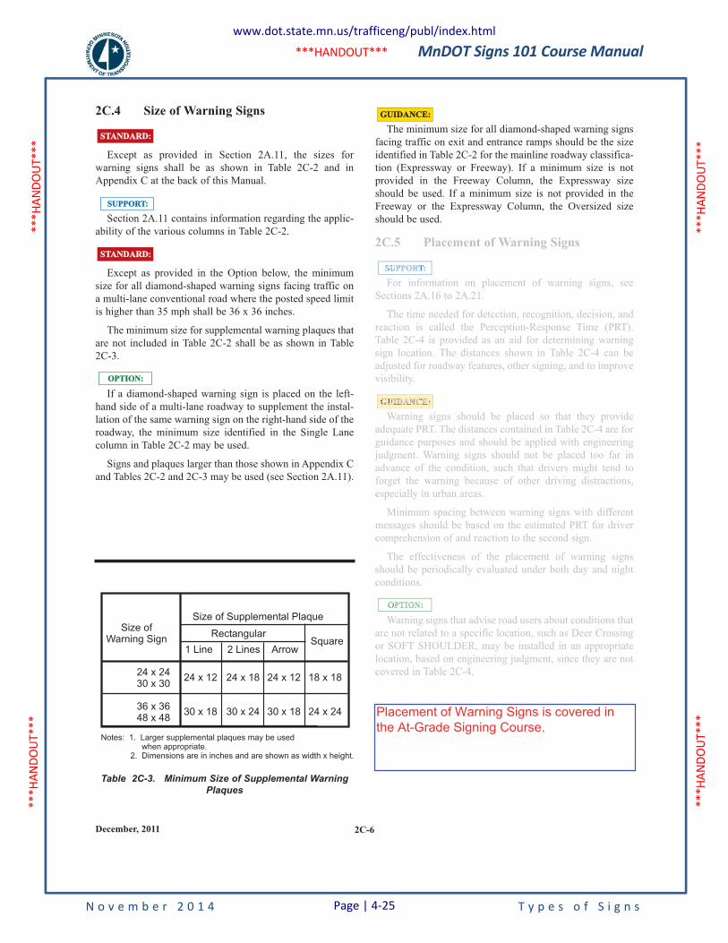
MnDOT Signs 101 Course Manual
N o v e m b e r 2 0 1 4 T y p e s o f S i g n s
***H
ANDO
UT**
* **
*HAN
DOUT
***
***H
ANDO
UT**
* **
*HAN
DOUT
***
***HANDOUT***
2C-6December, 2011
Table 2C-3. Minimum Size of Supplemental WarningPlaques
2C.4 Size of Warning Signs
Except as provided in Section 2A.11, the sizes for
warning signs shall be as shown in Table 2C-2 and in
Appendix C at the back of this Manual.
Section 2A.11 contains information regarding the applic-
ability of the various columns in Table 2C-2.
Except as provided in the Option below, the minimum
size for all diamond-shaped warning signs facing traffic on
a multi-lane conventional road where the posted speed limit
is higher than 35 mph shall be 36 x 36 inches.
The minimum size for supplemental warning plaques that
are not included in Table 2C-2 shall be as shown in Table
2C-3.
If a diamond-shaped warning sign is placed on the left-
hand side of a multi-lane roadway to supplement the instal-
lation of the same warning sign on the right-hand side of the
roadway, the minimum size identified in the Single Lane
column in Table 2C-2 may be used.
Signs and plaques larger than those shown in Appendix C
and Tables 2C-2 and 2C-3 may be used (see Section 2A.11).
OPTION:OPTION:
SUPPORT:SUPPORT:
STANDARD:STANDARD:
STANDARD:STANDARD:The minimum size for all diamond-shaped warning signs
facing traffic on exit and entrance ramps should be the size
identified in Table 2C-2 for the mainline roadway classifica-
tion (Expressway or Freeway). If a minimum size is not
provided in the Freeway Column, the Expressway size
should be used. If a minimum size is not provided in the
Freeway or the Expressway Column, the Oversized size
should be used.
2C.5 Placement of Warning Signs
For information on placement of warning signs, see
Sections 2A.16 to 2A.21.
The time needed for detection, recognition, decision, and
reaction is called the Perception-Response Time (PRT).
Table 2C-4 is provided as an aid for determining warning
sign location. The distances shown in Table 2C-4 can be
adjusted for roadway features, other signing, and to improve
visibility.
Warning signs should be placed so that they provide
adequate PRT. The distances contained in Table 2C-4 are for
guidance purposes and should be applied with engineering
judgment. Warning signs should not be placed too far in
advance of the condition, such that drivers might tend to
forget the warning because of other driving distractions,
especially in urban areas.
Minimum spacing between warning signs with different
messages should be based on the estimated PRT for driver
comprehension of and reaction to the second sign.
The effectiveness of the placement of warning signs
should be periodically evaluated under both day and night
conditions.
Warning signs that advise road users about conditions that
are not related to a specific location, such as Deer Crossing
or SOFT SHOULDER, may be installed in an appropriate
location, based on engineering judgment, since they are not
covered in Table 2C-4.
GUIDANCE:GUIDANCE:
OPTION:
GUIDANCE:
SUPPORT:
24 x 2430 x 30
36 x 3648 x 48
Size ofWarning Sign
24 x 12
30 x 18
24 x 18
30 x 24
24 x 12
30 x 18
18 x 18
24 x 24
1 Line 2 Lines Arrow
Rectangular
Size of Supplemental Plaque
Square
Notes: 1. Larger supplemental plaques may be usedwhen appropriate.
2. Dimensions are in inches and are shown as width x height.
2C.5 Placement of Warning Signs
For information on placement of warning signs, see
Sections 2A.16 to 2A.21.
The time needed for detection, recognition, decision, and
reaction is called the Perception-Response Time (PRT).
Table 2C-4 is provided as an aid for determining warning
sign location. The distances shown in Table 2C-4 can be
adjusted for roadway features, other signing, and to improve
visibility.
Warning signs should be placed so that they provide
adequate PRT. The distances contained in Table 2C-4 are for
guidance purposes and should be applied with engineering
judgment. Warning signs should not be placed too far in
advance of the condition, such that drivers might tend to
forget the warning because of other driving distractions,
especially in urban areas.
Minimum spacing between warning signs with different
messages should be based on the estimated PRT for driver
comprehension of and reaction to the second sign.
The effectiveness of the placement of warning signs
should be periodically evaluated under both day and night
conditions.
Warning signs that advise road users about conditions that
are not related to a specific location, such as Deer Crossing
or SOFT SHOULDER, may be installed in an appropriate
location, based on engineering judgment, since they are not
covered in Table 2C-4.
OPTION:
GUIDANCE:
SUPPORT:
Placement of Warning Signs is covered inthe At-Grade Signing Course.
www.dot.state.mn.us/trafficeng/publ/index.html
Page | 4-25
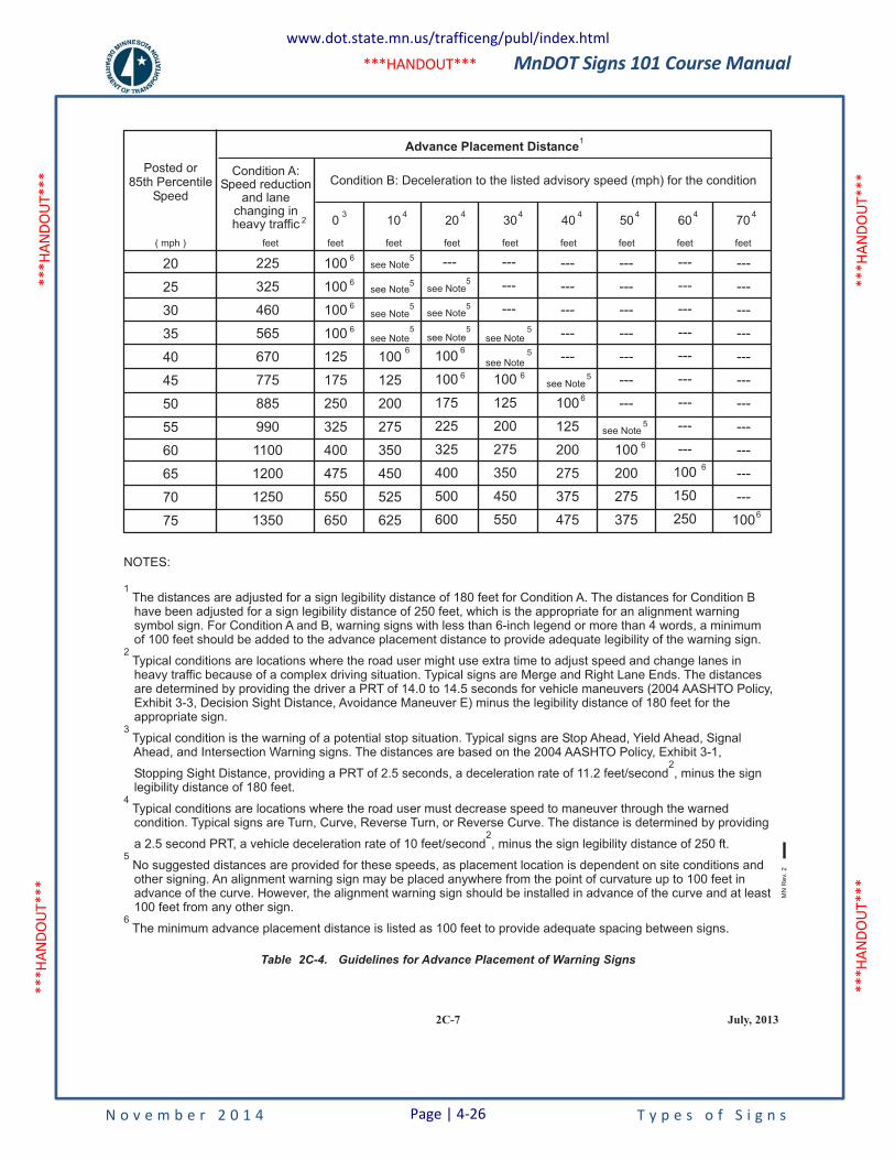
MnDOT Signs 101 Course Manual
N o v e m b e r 2 0 1 4 T y p e s o f S i g n s
***H
ANDO
UT**
* **
*HAN
DOUT
***
***H
ANDO
UT**
* **
*HAN
DOUT
***
***HANDOUT***
Table 2C-4. Guidelines for Advance Placement of Warning Signs
NOTES:
The distances are adjusted for a sign legibility distance of 180 feet for Condition A. The distances for Condition Bhave been adjusted for a sign legibility distance of 250 feet, which is the appropriate for an alignment warningsymbol sign. For Condition A and B, warning signs with less than 6-inch legend or more than 4 words, a minimumof 100 feet should be added to the advance placement distance to provide adequate legibility of the warning sign.
Typical conditions are locations where the road user might use extra time to adjust speed and change lanes inheavy traffic because of a complex driving situation. Typical signs are Merge and Right Lane Ends. The distancesare determined by providing the driver a PRT of 14.0 to 14.5 seconds for vehicle maneuvers (2004 AASHTO Policy,Exhibit 3-3, Decision Sight Distance, Avoidance Maneuver E) minus the legibility distance of 180 feet for theappropriate sign.
Typical condition is the warning of a potential stop situation. Typical signs are Stop Ahead, Yield Ahead, SignalAhead, and Intersection Warning signs. The distances are based on the 2004 AASHTO Policy, Exhibit 3-1,
Stopping Sight Distance, providing a PRT of 2.5 seconds, a deceleration rate of 11.2 feet/second , minus the signlegibility distance of 180 feet.
Typical conditions are locations where the road user must decrease speed to maneuver through the warnedcondition. Typical signs are Turn, Curve, Reverse Turn, or Reverse Curve. The distance is determined by providing
a 2.5 second PRT, a vehicle deceleration rate of 10 feet/second , minus the sign legibility distance of 250 ft.
No suggested distances are provided for these speeds, as placement location is dependent on site conditions andother signing. An alignment warning sign may be placed anywhere from the point of curvature up to 100 feet inadvance of the curve. However, the alignment warning sign should be installed in advance of the curve and at least100 feet from any other sign.
The minimum advance placement distance is listed as 100 feet to provide adequate spacing between signs.
1
2
3
2
4
2
5
6
Posted or85th Percentile
Speed
0
feet
3 4 4 4 4 4 4 410
feet
20
feet
30
feet
40
feet
50
feet
60
feet
70
feetfeet( mph )
225
325
460
565
670
775
885
990
1100
1200
1250
1350
see Note
see Note
see Note
see Note
see Note
see Note
see Note see Note
see Note
see Note
see Note
100
100
100
100
125
175
250
325
400
475
550
650
100
125
200
275
350
450
525
625
100
100
175
225
325
400
500
600
100
125
200
275
350
450
550
--- ---
---
---
---
---
---
---
---
100
125
200
275
375
475
---
---
---
---
---
---
---
100
200
275
375
---
---
---
---
---
---
---
---
---
100
150
250
---
---
---
---
---
---
---
---
---
---
---
100
20
25
30
35
40
45
50
55
60
65
70
75
Condition A:Speed reduction
and lanechanging inheavy traffic 2
Advance Placement Distance1
Condition B: Deceleration to the listed advisory speed (mph) for the condition
5
5
56
56
6
6
6
6 6
6
6
6
6
6
5
5
5
5
5 5
5
2C-7 July, 2013
MN
Rev.
2
www.dot.state.mn.us/trafficeng/publ/index.html
Page | 4-26
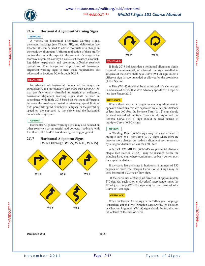
MnDOT Signs 101 Course Manual
N o v e m b e r 2 0 1 4 T y p e s o f S i g n s
***H
ANDO
UT**
* **
*HAN
DOUT
***
***H
ANDO
UT**
* **
*HAN
DOUT
***
***HANDOUT***
2C-8December, 2011
2C.6 Horizontal Alignment Warning Signs
A variety of horizontal alignment warning signs,
pavement markings (see Chapter 3B), and delineation (see
Chapter 3F) can be used to advise motorists of a change in
the roadway alignment. Uniform application of these traffic
control devices with respect to the amount of change in the
roadway alignment conveys a consistent message establish-
ing driver expectancy and promoting effective roadway
operations. The design and application of horizontal
alignment warning signs to meet those requirements are
addressed in Sections 2C.6 through 2C.15.
In advance of horizontal curves on freeways, on
expressways, and on roadways with more than 1,000 AADT
that are functionally classified as arterials or collectors,
horizontal alignment warning signs shall be used in
accordance with Table 2C-5 based on the speed differential
between the roadway's posted or statutory speed limit or
85th-percentile speed, whichever is higher, or the prevailing
speed on the approach to the curve, and the horizontal
curve's advisory speed.
Horizontal Alignment Warning signs may also be used on
other roadways or on arterial and collector roadways with
less than 1,000 AADT based on engineering judgment.
2C.7 Horizontal Alignment Signs
(W1-1 through W1-5, W1-11, W1-15)
W1-4 W1-5
OPTION:OPTION:
STANDARD:STANDARD:
W1-1 W1-2 W1-3
SUPPORT:SUPPORT:
If Table 2C-5 indicates that a horizontal alignment sign is
required, recommended, or allowed, the sign installed in
advance of the curve shall be a Curve (W1-2) sign unless a
different sign is recommended or allowed by the provisions
of this Section.
A Turn (W1-1) sign shall be used instead of a Curve sign
in advance of curves that have advisory speeds of 30 mph or
less (see Figure 2C-2).
Where there are two changes in roadway alignment in
opposite directions that are separated by a tangent distance
of less than 600 feet, the Reverse Turn (W1-3) sign should
be used instead of multiple Turn (W1-1) signs and the
Reverse Curve (W1-4) sign should be used instead of
multiple Curve (W1-2) signs.
A Winding Road (W1-5) sign may be used instead of
multiple Turn (W1-1) or Curve (W1-2) signs where there are
three or more changes in roadway alignment each separated
by a tangent distance of less than 600 feet.
A NEXT XX MILES (W7-3aP) supplemental distance
plaque (see Section 2C.55) may be installed below the
Winding Road sign where continuous roadway curves exist
for a specific distance
If the curve has a change in horizontal alignment of 135
degrees or more, the Hairpin Curve (W1-11) sign may be
used instead of a Curve or Turn sign.
If the curve has a change of direction of approximately
270 degrees, such as on a cloverleaf interchange ramp, the
270-degree Loop (W1-15) sign may be used instead of a
Curve or Turn sign.
When the Hairpin Curve sign or the 270-degree Loop sign
is installed, either a One-Direction Large Arrow (W1-6) sign
or Chevron Alignment (W1-8) signs should be installed on
the outside of the turn or curve.
GUIDANCE:GUIDANCE:
OPTION:OPTION:
GUIDANCE:GUIDANCE:
STANDARD:STANDARD:
W1-11 W1-15
www.dot.state.mn.us/trafficeng/publ/index.html
Page | 4-27
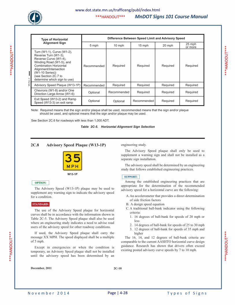
MnDOT Signs 101 Course Manual
N o v e m b e r 2 0 1 4 T y p e s o f S i g n s
***H
ANDO
UT**
* **
*HAN
DOUT
***
***H
ANDO
UT**
* **
*HAN
DOUT
***
***HANDOUT***
2C-10December, 2011
2C.8 Advisory Speed Plaque (W13-1P)
The Advisory Speed (W13-1P) plaque may be used to
supplement any warning sign to indicate the advisory speed
for a condition.
The use of the Advisory Speed plaque for horizontal
curves shall be in accordance with the information shown in
Table 2C-5. The Advisory Speed plaque shall also be used
where an engineering study indicates a need to advise road
users of the advisory speed for other roadway conditions.
If used, the Advisory Speed plaque shall carry the
message XX MPH. The speed displayed shall be a multiple
of 5 mph.
Except in emergencies or when the condition is
temporary, an Advisory Speed plaque shall not be installed
until the advisory speed has been determined by an
STANDARD:STANDARD:
OPTION:OPTION:
W13-1P
3 5M P H
engineering study.
The Advisory Speed plaque shall only be used to
supplement a warning sign and shall not be installed as a
separate sign installation.
The advisory speed shall be determined by an engineering
study that follows established engineering practices.
Among the established engineering practices that are
appropriate for the determination of the recommended
advisory speed for a horizontal curve are the following:
A.An accelerometer that provides a direct determination
of side friction factors
B. A design speed equation
C. A traditional ball-bank indicator using the following
criteria:
1. 16 degrees of ball-bank for speeds of 20 mph or
less
2. 14 degrees of ball-bank for speeds of 25 to 30 mph
3. 12 degrees of ball-bank for speeds of 35 mph and
higher
The 16, 14, and 12 degrees of ball-bank criteria are
comparable to the current AASHTO horizontal curve design
guidance. Research has shown that drivers often exceed
existing posted advisory curve speeds by 7 to 10 mph.
SUPPORT:SUPPORT:
Turn (W1-1), Curve (W1-2),Reverse Turn (W1-3),Reverse Curve (W1-4),Winding Road (W1-5), andCombination HorizontalAlignment/Intersection(W1-10 Series))(see Section 2C.7 todetermine which sign to use)
Chevrons (W1-8) and/or OneDirection Large Arrow (W1-6)
Exit Speed (W13-2) and RampSpeed (W13-3) on exit ramp
Advisory Speed Plaque (W13-1P)
Recommended
Recommended
Optional
Optional
Required
Required
Recommended
Optional
Required
Required
Required
Recommended
Required
Required
Required
Required
Required
Required
Required
Required
5 mph 10 mph 15 mph 20 mph 25 mphor more
Difference Between Speed Limit and Advisory SpeedType of HorizontalAlignment Sign
Note: Required means that the sign and/or plaque shall be used, recommended means that the sign and/or plaqueshould be used, and optional means that the sign and/or plaque may be used.
See Section 2C.6 for roadways with less than 1,000 ADT.
Table 2C-5. Horizontal Alignment Sign Selection
MN
Re
v. 2
www.dot.state.mn.us/trafficeng/publ/index.html
Page | 4-28
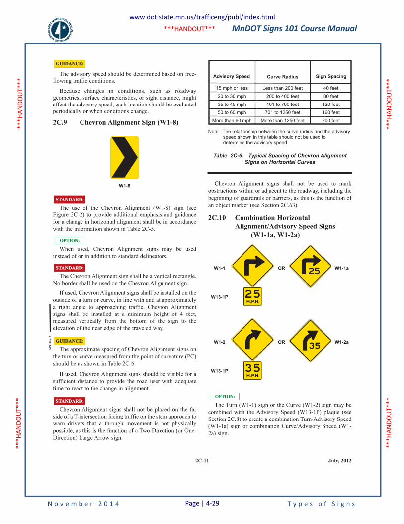
MnDOT Signs 101 Course Manual
N o v e m b e r 2 0 1 4 T y p e s o f S i g n s
***H
ANDO
UT**
* **
*HAN
DOUT
***
***H
ANDO
UT**
* **
*HAN
DOUT
***
***HANDOUT***
2C-11 July, 2012
The advisory speed should be determined based on free-
flowing traffic conditions.
Because changes in conditions, such as roadway
geometrics, surface characteristics, or sight distance, might
affect the advisory speed, each location should be evaluated
periodically or when conditions change.
2C.9 Chevron Alignment Sign (W1-8)
The use of the Chevron Alignment (W1-8) sign (see
Figure 2C-2) to provide additional emphasis and guidance
for a change in horizontal alignment shall be in accordance
with the information shown in Table 2C-5.
When used, Chevron Alignment signs may be used
instead of or in addition to standard delineators.
The Chevron Alignment sign shall be a vertical rectangle.
No border shall be used on the Chevron Alignment sign.
If used, Chevron Alignment signs shall be installed on the
outside of a turn or curve, in line with and at approximately
a right angle to approaching traffic. Chevron Alignment
signs shall be installed at a minimum height of 4 feet,
measured vertically from the bottom of the sign to the
elevation of the near edge of the traveled way.
The approximate spacing of Chevron Alignment signs on
the turn or curve measured from the point of curvature (PC)
should be as shown in Table 2C-6.
If used, Chevron Alignment signs should be visible for a
sufficient distance to provide the road user with adequate
time to react to the change in alignment.
Chevron Alignment signs shall not be placed on the far
side of a T-intersection facing traffic on the stem approach to
warn drivers that a through movement is not physically
possible, as this is the function of a Two-Direction (or One-
Direction) Large Arrow sign.
STANDARD:STANDARD:
OPTION:OPTION:
STANDARD:STANDARD:
GUIDANCE:GUIDANCE:
STANDARD:STANDARD:
W1-8
GUIDANCE:GUIDANCE:
Chevron Alignment signs shall not be used to mark
obstructions within or adjacent to the roadway, including the
beginning of guardrails or barriers, as this is the function of
an object marker (see Section 2C.63).
2C.10 Combination Horizontal
Alignment/Advisory Speed Signs
(W1-1a, W1-2a)
The Turn (W1-1) sign or the Curve (W1-2) sign may be
combined with the Advisory Speed (W13-1P) plaque (see
Section 2C.8) to create a combination Turn/Advisory Speed
(W1-1a) sign or combination Curve/Advisory Speed (W1-
2a) sign.
OPTION:OPTION:
W1-2aOR
3 5
W1-2
W13-1P
ORW1-1
W13-1P
W1-1a
2 5
Table 2C-6. Typical Spacing of Chevron AlignmentSigns on Horizontal Curves
15 mph or less
20 to 30 mph
35 to 45 mph
50 to 60 mph
More than 60 mph
Less than 200 feet
200 to 400 feet
401 to 700 feet
701 to 1250 feet
More than 1250 feet
40 feet
80 feet
120 feet
160 feet
200 feet
Advisory Speed Curve Radius Sign Spacing
Note: The relationship between the curve radius and the advisoryspeed shown in this table should not be used todetermine the advisory speed.
MN
Rev.
1
www.dot.state.mn.us/trafficeng/publ/index.html
Page | 4-29
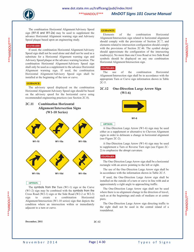
MnDOT Signs 101 Course Manual
N o v e m b e r 2 0 1 4 T y p e s o f S i g n s
***H
ANDO
UT**
* **
*HAN
DOUT
***
***H
ANDO
UT**
* **
*HAN
DOUT
***
***HANDOUT***
2C-12December, 2011
The combination Horizontal Alignment/Advisory Speed
sign (W1-6 and W1-2a) may be used to supplement the
advance Horizontal Alignment warning sign and Advisory
Speed plaque based upon an engineering study.
If used, the combination Horizontal Alignment/Advisory
Speed sign shall not be used alone and shall not be used as a
substitute for a Horizontal Alignment warning sign and
Advisory Speed plaque at the advance warning location. The
combination Horizontal Alignment/Advisory Speed sign
shall only be used as a supplement to the advance Horizontal
Alignment warning sign. If used, the combination
Horizontal Alignment/Advisory Speed sign shall be
installed at the beginning of the turn or curve.
The advisory speed displayed on the combination
Horizontal Alignment/Advisory Speed sign should be based
on the advisory speed for the horizontal curve using
recommended engineering practices (see Section 2C.8).
2C.11 Combination Horizontal
Alignment/Intersection Signs
(W1-10 Series)
The symbols from the Turn (W1-1) sign or the Curve
(W1-2) sign may be combined with the symbols from theCross Road (W2-1) sign or the Side Road (W2-2 or W2-3)
sign to create a combination Horizontal
Alignment/Intersection (W1-10 series) sign that depicts the
condition where an intersection within or immediately
adjacent to a turn or curve.
W1-10eW1-10dW1-10c
W1-10bW1-10aW1-10
OPTION:OPTION:
STANDARD:STANDARD:
GUIDANCE:GUIDANCE:
Elements of the combination Horizontal
Alignment/Intersection sign related to horizontal alignment
should comply with the provisions of Section 2C.7, and
elements related to intersection configuration should comply
with the provisions of Section 2C.46. The symbol design
should approximate the configuration of the intersecting
roadway(s). No more than one Cross Road or two Side Road
symbols should be displayed on any one combination
Horizontal Alignment/Intersection sign.
The use of the combination Horizontal
Alignment/Intersection sign shall be in accordance with the
appropriate Turn or Curve sign information shown in Table
2C-5.
2C.12 One-Direction Large Arrow Sign
(W1-6)
A One-Direction Large Arrow (W1-6) sign may be used
either as a supplement or alternative to Chevron Alignment
signs in order to delineate a change in horizontal alignment
(see Figure 2C-2).
A One-Direction Large Arrow (W1-6) sign may be used
to supplement a Turn or Reverse Turn sign (see Figure 2C-
2) to emphasize the abrupt curvature.
The One-Direction Large Arrow sign shall be a horizontal
rectangle with an arrow pointing to the left or right.
The use of the One-Direction Large Arrow sign shall be
in accordance with the information shown in Table 2C-5.
If used, the One-Direction Large Arrow sign shall be
installed on the outside of a turn or curve in line with and at
approximately a right angle to approaching traffic.
The One-Direction Large Arrow sign shall not be used
where there is no alignment change in the direction of travel,
such as at the beginnings and ends of medians or at center
piers.
The One-Direction Large Arrow sign directing traffic to
the right shall not be used in the central island of a
roundabout.
STANDARD:STANDARD:
GUIDANCE:GUIDANCE:
OPTION:OPTION:
W1-6
STANDARD:STANDARD:
www.dot.state.mn.us/trafficeng/publ/index.html
Page | 4-30
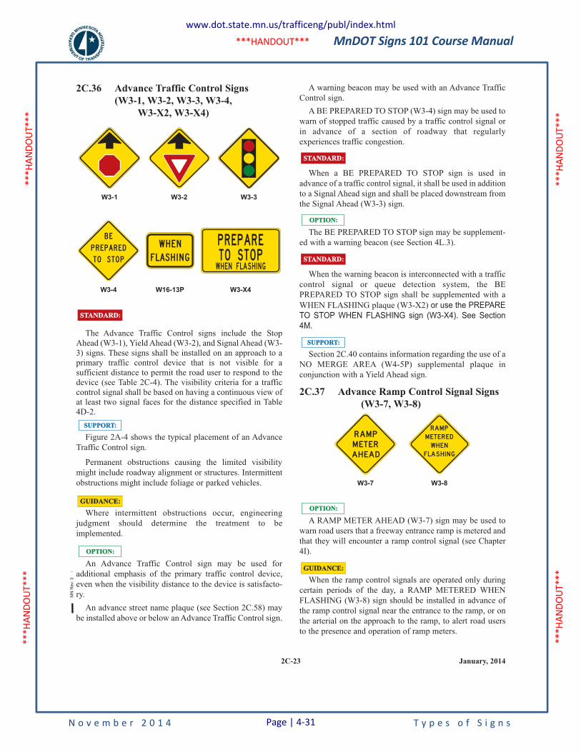
MnDOT Signs 101 Course Manual
N o v e m b e r 2 0 1 4 T y p e s o f S i g n s
***H
ANDO
UT**
* **
*HAN
DOUT
***
***H
ANDO
UT**
* **
*HAN
DOUT
***
***HANDOUT***
A warning beacon may be used with an Advance Traffic
Control sign.
A BE PREPARED TO STOP (W3-4) sign may be used to
warn of stopped traffic caused by a traffic control signal or
in advance of a section of roadway that regularly
experiences traffic congestion.
When a BE PREPARED TO STOP sign is used in
advance of a traffic control signal, it shall be used in addition
to a Signal Ahead sign and shall be placed downstream from
the Signal Ahead (W3-3) sign.
The BE PREPARED TO STOP sign may be supplement-
ed with a warning beacon (see Section 4L.3).
When the warning beacon is interconnected with a traffic
control signal or queue detection system, the BE
PREPARED TO STOP sign shall be supplemented with a
WHEN FLASHING plaque (W3-X2) or use the PREPARE
TO STOP WHEN FLASHING sign (W3-X4). See Section
4M.
Section 2C.40 contains information regarding the use of a
NO MERGE AREA (W4-5P) supplemental plaque in
conjunction with a Yield Ahead sign.
2C.37 Advance Ramp Control Signal Signs
(W3-7, W3-8)
A RAMP METER AHEAD (W3-7) sign may be used to
warn road users that a freeway entrance ramp is metered and
that they will encounter a ramp control signal (see Chapter
4I).
When the ramp control signals are operated only during
certain periods of the day, a RAMP METERED WHEN
FLASHING (W3-8) sign should be installed in advance of
the ramp control signal near the entrance to the ramp, or on
the arterial on the approach to the ramp, to alert road users
to the presence and operation of ramp meters.
GUIDANCE:GUIDANCE:
SUPPORT:SUPPORT:
STANDARD:STANDARD:
OPTION:OPTION:
STANDARD:STANDARD:
W3-8W3-7
RAM P
M ETER ED
WH EN
FLAS H I N G
RAM PM ETERAH EAD
OPTION:OPTION:
2C-23 January, 2014
2C.36 Advance Traffic Control Signs
(W3-1, W3-2, W3-3, W3-4,
W3-X2, W3-X4)
The Advance Traffic Control signs include the Stop
Ahead (W3-1), Yield Ahead (W3-2), and Signal Ahead (W3-
3) signs. These signs shall be installed on an approach to a
primary traffic control device that is not visible for a
sufficient distance to permit the road user to respond to the
device (see Table 2C-4). The visibility criteria for a traffic
control signal shall be based on having a continuous view of
at least two signal faces for the distance specified in Table
4D-2.
Figure 2A-4 shows the typical placement of an Advance
Traffic Control sign.
Permanent obstructions causing the limited visibility
might include roadway alignment or structures. Intermittent
obstructions might include foliage or parked vehicles.
Where intermittent obstructions occur, engineering
judgment should determine the treatment to be
implemented.
An Advance Traffic Control sign may be used for
additional emphasis of the primary traffic control device,
even when the visibility distance to the device is satisfacto-
ry.
An advance street name plaque (see Section 2C.58) may
be installed above or below an Advance Traffic Control sign.
WH E N
F LAS H I N G
W16-13P
W3-1 W3-2 W3-3
STANDARD:STANDARD:
W3-4 W3-X4
B E
P R E PA R E D
T O S T O P
P R EPAR ETO STO PWH EN FLAS H I N G
SUPPORT:SUPPORT:
GUIDANCE:GUIDANCE:
OPTION:OPTION:
MN
Rev.
3
www.dot.state.mn.us/trafficeng/publ/index.html
Page | 4-31
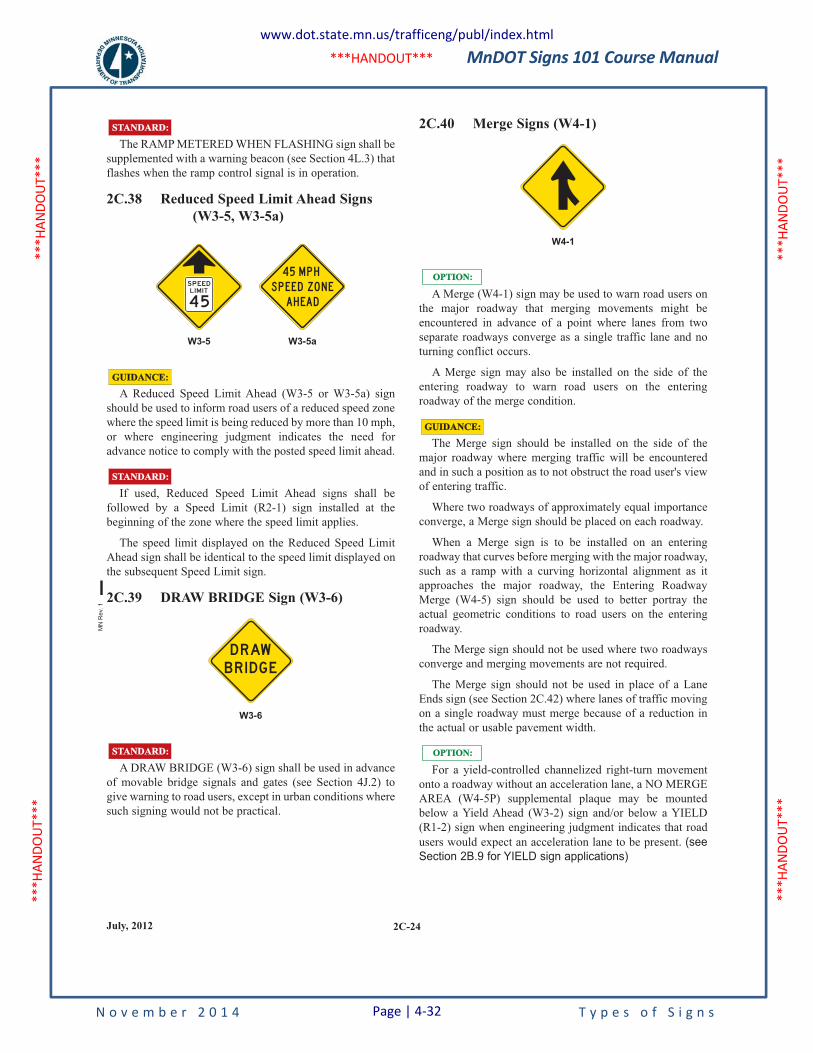
MnDOT Signs 101 Course Manual
N o v e m b e r 2 0 1 4 T y p e s o f S i g n s
***H
ANDO
UT**
* **
*HAN
DOUT
***
***H
ANDO
UT**
* **
*HAN
DOUT
***
***HANDOUT***
The RAMP METERED WHEN FLASHING sign shall be
supplemented with a warning beacon (see Section 4L.3) that
flashes when the ramp control signal is in operation.
2C.38 Reduced Speed Limit Ahead Signs
(W3-5, W3-5a)
A Reduced Speed Limit Ahead (W3-5 or W3-5a) sign
should be used to inform road users of a reduced speed zone
where the speed limit is being reduced by more than 10 mph,
or where engineering judgment indicates the need for
advance notice to comply with the posted speed limit ahead.
If used, Reduced Speed Limit Ahead signs shall be
followed by a Speed Limit (R2-1) sign installed at the
beginning of the zone where the speed limit applies.
The speed limit displayed on the Reduced Speed Limit
Ahead sign shall be identical to the speed limit displayed on
the subsequent Speed Limit sign.
2C.39 DRAW BRIDGE Sign (W3-6)
A DRAW BRIDGE (W3-6) sign shall be used in advance
of movable bridge signals and gates (see Section 4J.2) to
give warning to road users, except in urban conditions where
such signing would not be practical.
STANDARD:STANDARD:
W3-6
D RAWB R I D G E
STANDARD:STANDARD:
GUIDANCE:GUIDANCE:
W3-5 W3-5a
STANDARD:STANDARD:
45 M P H
S P E E D ZO N E
A H EA D
S P EED
L I M I T
4 5
2C.40 Merge Signs (W4-1)
A Merge (W4-1) sign may be used to warn road users on
the major roadway that merging movements might be
encountered in advance of a point where lanes from two
separate roadways converge as a single traffic lane and no
turning conflict occurs.
A Merge sign may also be installed on the side of the
entering roadway to warn road users on the entering
roadway of the merge condition.
The Merge sign should be installed on the side of the
major roadway where merging traffic will be encountered
and in such a position as to not obstruct the road user's view
of entering traffic.
Where two roadways of approximately equal importance
converge, a Merge sign should be placed on each roadway.
When a Merge sign is to be installed on an entering
roadway that curves before merging with the major roadway,
such as a ramp with a curving horizontal alignment as it
approaches the major roadway, the Entering Roadway
Merge (W4-5) sign should be used to better portray the
actual geometric conditions to road users on the entering
roadway.
The Merge sign should not be used where two roadways
converge and merging movements are not required.
The Merge sign should not be used in place of a Lane
Ends sign (see Section 2C.42) where lanes of traffic moving
on a single roadway must merge because of a reduction in
the actual or usable pavement width.
For a yield-controlled channelized right-turn movement
onto a roadway without an acceleration lane, a NO MERGE
AREA (W4-5P) supplemental plaque may be mounted
below a Yield Ahead (W3-2) sign and/or below a YIELD
(R1-2) sign when engineering judgment indicates that road
users would expect an acceleration lane to be present. (see
Section 2B.9 for YIELD sign applications)
OPTION:OPTION:
GUIDANCE:GUIDANCE:
W4-1
OPTION:OPTION:
2C-24July, 2012
MN
Re
v. 1
www.dot.state.mn.us/trafficeng/publ/index.html
Page | 4-32
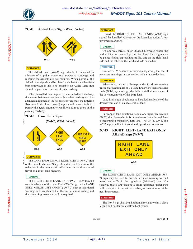
MnDOT Signs 101 Course Manual
N o v e m b e r 2 0 1 4 T y p e s o f S i g n s
***H
ANDO
UT**
* **
*HAN
DOUT
***
***H
ANDO
UT**
* **
*HAN
DOUT
***
***HANDOUT***
2C-25 July, 2012
If used, the RIGHT (LEFT) LANE ENDS (W9-1) sign
should be installed adjacent to the Lane-Reduction Arrow
pavement markings.
On one-way streets or on divided highways where the
width of the median will permit, two Lane Ends signs may
be placed facing approaching traffic, one on the right-hand
side and the other on the left-hand side or median.
Section 3B.9 contains information regarding the use of
pavement markings in conjunction with a lane reduction.
Where an extra lane has been provided for slower moving
traffic (see Section 2B.31), a Lane Ends word sign or a Lane
Ends (W4-2) symbol sign should be installed in advance of
the downstream end of the extra lane.
Lane Ends signs should not be installed in advance of the
downstream end of an acceleration lane.
In dropped lane situations, regulatory signs (see Section
2B.20) shall be used to inform road users that a through lane
is becoming a mandatory turn lane. The W4-2, W9-1, and
W9-2 signs shall not be used in dropped lane situations.
2C.43 RIGHT (LEFT) LANE EXIT ONLY
AHEAD Sign (W9-7)
The RIGHT (LEFT) LANE EXIT ONLY AHEAD (W9-
7) sign may be used to provide advance warning to road
users that traffic in the right-hand (left-hand) lane of a
roadway that is approaching a grade-separated interchange
will be required to depart the roadway on an exit ramp at the
next interchange.
The W9-7 sign shall be a horizontal rectangle with a black
legend and border on a yellow background.
GUIDANCE:GUIDANCE:
STANDARD:STANDARD:
OPTION:OPTION:
W9-7
R I G HT LAN E
EX I T O N LY
AH EAD
STANDARD:STANDARD:
GUIDANCE:GUIDANCE:
SUPPORT:SUPPORT:
OPTION:OPTION:
2C.41 Added Lane Sign (W4-3, W4-6)
The Added Lane (W4-3) sign should be installed in
advance of a point where two roadways converge and
merging movements are not required. When possible, the
Added Lane sign should be placed such that it is visible from
both roadways; if this is not possible, an Added Lane sign
should be placed on the side of each roadway.
When an Added Lane sign is to be installed on a roadway
that curves before converging with another roadway that has
a tangent alignment at the point of convergence, the Entering
Roadway Added Lane (W4-6) sign should be used to better
portray the actual geometric conditions to road users on the
curving roadway.
2C.42 Lane Ends Signs
(W4-2, W9-1, W9-2)
The LANE ENDS MERGE RIGHT (LEFT) (W9-2) sign
or the Lane Ends (W4-2) sign should be used to warn of the
reduction in the number of traffic lanes in the direction of
travel on a multi-lane highway.
The RIGHT (LEFT) LANE ENDS (W9-1) sign may be
used in advance of the Lane Ends (W4-2) sign or the LANE
ENDS MERGE LEFT (RIGHT) (W9-2) sign as additional
warning or to emphasize that the traffic lane is ending and
that a merging maneuver will be required.
OPTION:OPTION:
GUIDANCE:GUIDANCE:
W4-2 W9-1 W9-2
R I G H TLAN EEN DS
LAN E EN DS
M ERG ER I G H T
GUIDANCE:GUIDANCE:
W4-3 W4-6
MN
Re
v. 1
MN
Rev.
1
www.dot.state.mn.us/trafficeng/publ/index.html
Page | 4-33
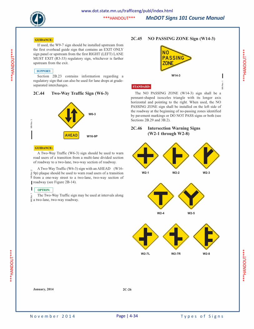
MnDOT Signs 101 Course Manual
N o v e m b e r 2 0 1 4 T y p e s o f S i g n s
***H
ANDO
UT**
* **
*HAN
DOUT
***
***H
ANDO
UT**
* **
*HAN
DOUT
***
***HANDOUT***
If used, the W9-7 sign should be installed upstream from
the first overhead guide sign that contains an EXIT ONLY
sign panel or upstream from the first RIGHT (LEFT) LANE
MUST EXIT (R3-33) regulatory sign, whichever is farther
upstream from the exit.
Section 2B.23 contains information regarding a
regulatory sign that can also be used for lane drops at grade-
separated interchanges.
2C.44 Two-Way Traffic Sign (W6-3)
A Two-Way Traffic (W6-3) sign should be used to warn
road users of a transition from a multi-lane divided section
of roadway to a two-lane, two-way section of roadway.
A Two-Way Traffic (W6-3) sign with an AHEAD (W16-
9p) plaque should be used to warn road users of a transition
from a one-way street to a two-lane, two-way section of
roadway (see Figure 2B-14).
The Two-Way Traffic sign may be used at intervals along
a two-lane, two-way roadway.
W16-9PAH EAD
W6-3
OPTION:OPTION:
GUIDANCE:GUIDANCE:
SUPPORT:SUPPORT:
GUIDANCE:GUIDANCE:
2C.45 NO PASSING ZONE Sign (W14-3)
The NO PASSING ZONE (W14-3) sign shall be a
pennant-shaped isosceles triangle with its longer axis
horizontal and pointing to the right. When used, the NO
PASSING ZONE sign shall be installed on the left side of
the roadway at the beginning of no-passing zones identified
by pavement markings or DO NOT PASS signs or both (see
Sections 2B.29 and 3B.2).
2C.46 Intersection Warning Signs
(W2-1 through W2-8)
W2-7L W2-7R W2-8
STANDARD:STANDARD:
W14-3
N OPASS I N GZONE
W2-1 W2-2 W2-3
W2-5W2-4
2C-26January, 2014
MN
Re
v. 1
MN
Re
v. 2
MN
Re
v. 1
MN
Re
v. 3
www.dot.state.mn.us/trafficeng/publ/index.html
Page | 4-34
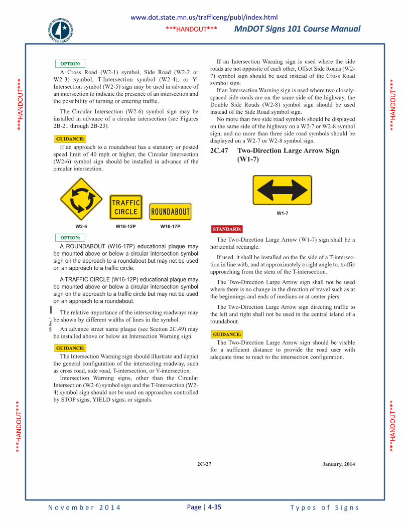
MnDOT Signs 101 Course Manual
N o v e m b e r 2 0 1 4 T y p e s o f S i g n s
***H
ANDO
UT**
* **
*HAN
DOUT
***
***H
ANDO
UT**
* **
*HAN
DOUT
***
***HANDOUT***
A Cross Road (W2-1) symbol, Side Road (W2-2 or
W2-3) symbol, T-Intersection symbol (W2-4), or Y-
Intersection symbol (W2-5) sign may be used in advance of
an intersection to indicate the presence of an intersection and
the possibility of turning or entering traffic.
The Circular Intersection (W2-6) symbol sign may be
installed in advance of a circular intersection (see Figures
2B-21 through 2B-23).
If an approach to a roundabout has a statutory or posted
speed limit of 40 mph or higher, the Circular Intersection
(W2-6) symbol sign should be installed in advance of the
circular intersection.
A ROUNDABOUT (W16-17P) educational plaque may
be mounted above or below a circular intersection symbol
sign on the approach to a roundabout but may not be used
on an approach to a traffic circle.
A TRAFFIC CIRCLE (W16-12P) educational plaque may
be mounted above or below a circular intersection symbol
sign on the approach to a traffic circle but may not be used
on an approach to a roundabout.
The relative importance of the intersecting roadways may
be shown by different widths of lines in the symbol.
An advance street name plaque (see Section 2C.49) may
be installed above or below an Intersection Warning sign.
The Intersection Warning sign should illustrate and depict
the general configuration of the intersecting roadway, such
as cross road, side road, T-intersection, or Y-intersection.
Intersection Warning signs, other than the Circular
Intersection (W2-6) symbol sign and the T-Intersection (W2-
4) symbol sign should not be used on approaches controlled
by STOP signs, YIELD signs, or signals.
GUIDANCE:GUIDANCE:
OPTION:OPTION:
W2-6 W16-12P W16-17P
TRAFF I C
C I R C L E R O U N D A B O U T
OPTION:OPTION:
GUIDANCE:GUIDANCE:
2C-27 January, 2014
If an Intersection Warning sign is used where the side
roads are not opposite of each other, Offset Side Roads (W2-
7) symbol sign should be used instead of the Cross Road
symbol sign.
If an Intersection Warning sign is used where two closely-
spaced side roads are on the same side of the highway, the
Double Side Roads (W2-8) symbol sign should be used
instead of the Side Road symbol sign.
No more than two side road symbols should be displayed
on the same side of the highway on a W2-7 or W2-8 symbol
sign, and no more than three side road symbols should be
displayed on a W2-7 or W2-8 symbol sign.
2C.47 Two-Direction Large Arrow Sign
(W1-7)
The Two-Direction Large Arrow (W1-7) sign shall be a
horizontal rectangle.
If used, it shall be installed on the far side of a T-intersec-
tion in line with, and at approximately a right angle to, traffic
approaching from the stem of the T-intersection.
The Two-Direction Large Arrow sign shall not be used
where there is no change in the direction of travel such as at
the beginnings and ends of medians or at center piers.
The Two-Direction Large Arrow sign directing traffic to
the left and right shall not be used in the central island of a
roundabout.
The Two-Direction Large Arrow sign should be visible
for a sufficient distance to provide the road user with
adequate time to react to the intersection configuration.
GUIDANCE:GUIDANCE:
STANDARD:STANDARD:
W1-7
MN
Re
v. 1
www.dot.state.mn.us/trafficeng/publ/index.html
Page | 4-35
MnDOT Signs 101 Course Manual
N o v e m b e r 2 0 1 4 P a g e | 4-36 T y p e s o f S i g n s
4.4 Guide Signing
4.4.1 Purpose
Guide signs are necessary to inform motorists of intersecting routes; to direct them to cities, towns, villages, or other important destinations; to identify nearby rivers, streams, parks, forests, and historical sites; and generally to give such information as will help them along their way in the most simple, direct manner possible.
Numbered traffic routes and directional signs facilitate travel by enabling motorists to reach their intended destination when using an accurate transportation map. Proper directional signing consists of Route Markers and Route Marker auxiliaries; Destination signs; Distance signs; and, where necessary, Advance Street Name signs.
Install Route Markers and Route Marker auxiliaries in sign assemblies to identify the numbered traffic route and provide additional guidance (such as general direction of the route and other information required to follow a designated numbered traffic route). Destination and Distance signs provide directions and distances to communities and points of interest that may be reached by following certain roads. Advance Street Name signs provide advance notice of the names of intersecting major streets and highways.
4.4.2 MUTCD Chapter 2D and 2E Handouts
The information on the following pages is a handout from the 2011 MN MUTCD, Chapter 2D on Guide Signs for Conventional Roads. The entire section is not included, but only pages of interest for this manual. For full details on the MUTCD, refer to the OTST publications website found at, www.dot.state.mn.us/trafficeng/publ/index.html.
In addition, the entire 2011 Standard Signs Summary is included at the end of this chapter.
MnDOT Signs 101 Course Manual
N o v e m b e r 2 0 1 4 T y p e s o f S i g n s
***H
ANDO
UT**
* **
*HAN
DOUT
***
***H
ANDO
UT**
* **
*HAN
DOUT
***
***HANDOUT***
July, 20132D-1
PART 2. SIGNS
Chapter 2D. Guide Signs - Conventional Roads
2D.1 Scope of Conventional Road
Guide Sign Standards
The provisions of this Chapter shall apply to any road or
street other than low-volume roads (as defined in Section
5A.1), expressways, and freeways.
2D.2 Application
Guide signs are essential to direct road users along streets
and highways, to inform them of intersecting routes, to
direct them to cities, towns, villages, or other important des-
tinations, to identify nearby rivers and streams, parks,
forests, and historical sites, and generally to give such
information as will help them along their way in the most
simple, direct manner possible.
Chapter 2A addresses placement, location, and other
general criteria for signs.
2D.3 Color, Retroreflection, and
Illumination
Requirements for illumination, retroreflection, and color
are stated under the specific headings for individual guide
signs or groups of signs. General provisions are given in
Sections 2A.7, 2A.8, and 2A.10.
Except where otherwise provided in this Manual for
individual signs or groups of signs, guide signs on streets
and highways shall have a white message and border on a
green background. All messages, borders, and legends shall
be retroreflective and all backgrounds shall be retroreflec-
tive or illuminated.
Color coding is sometimes used to help road users
distinguish between multiple potentially confusing destina-
tions. Examples of valuable uses of color coding include
guide signs for roadways approaching or inside an airport
property with multiple terminals serving multiple airlines,
and community wayfinding guide signs for various traffic
generator destinations within a community or area.
STANDARD:STANDARD:
STANDARD:STANDARD:
SUPPORT:SUPPORT:
SUPPORT:SUPPORT:
SUPPORT:SUPPORT:
Except where otherwise provided in this Manual,
different color sign backgrounds shall not be used to provide
color coding of destinations. The color coding shall be
accomplished by the use of different colored square or
rectangular sign panels on the face of the guide signs.
The different colored sign panels may include a black or
white (whichever provides the better contrast with the panel
color) letter, numeral, or other appropriate designation to
identify an airport terminal or other destination.
Two examples of color-coded sign assemblies are shown
in Figure 2D-1. Section 2D.50 contains specific provisions
regarding Community Wayfinding guide signs.
2D.4 Size of Signs
Except as provided in Section 2A.11, the sizes of conven-
tional road guide signs that have standardized designs shall
be as shown in Table 2D-1.
Section 2A.11 contains information regarding the applic-
ability of the various columns in Table 2D-1.
Signs larger than those shown in Table 2D-1 may be used
(see Section 2A.11).
For other guide signs, the legends are so variable that a stan-
dardized design or size is not appropriate. The sign size is
determined primarily by the length of the message, and the
size of lettering and spacing necessary for proper legibility.
SUPPORT:SUPPORT:
OPTION:OPTION:
SUPPORT:SUPPORT:
STANDARD:STANDARD:
SUPPORT:SUPPORT:
STANDARD:STANDARD:
OPTION:OPTION:
MN
Rev.
2
www.dot.state.mn.us/trafficeng/publ/index.html
Page | 4-37
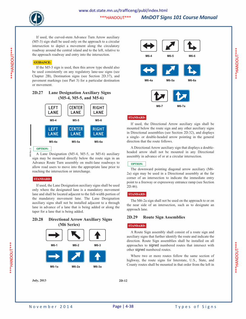
MnDOT Signs 101 Course Manual
N o v e m b e r 2 0 1 4 T y p e s o f S i g n s
***H
ANDO
UT**
* **
*HAN
DOUT
***
***H
ANDO
UT**
* **
*HAN
DOUT
***
***HANDOUT***
2D-12July, 2013
If used, the curved-stem Advance Turn Arrow auxiliary
(M5-3) sign shall be used only on the approach to a circular
intersection to depict a movement along the circulatory
roadway around the central island and to the left, relative to
the approach roadway and entry into the intersection.
If the M5-3 sign is used, then this arrow type should also
be used consistently on any regulatory lane-use signs (see
Chapter 2B), Destination signs (see Section 2D.37), and
pavement markings (see Part 3) for a particular destination
or movement.
2D.27 Lane Designation Auxiliary Signs
(M5-4, M5-5, and M5-6)
A Lane Designation (M5-4, M5-5, or M5-6) auxiliary
sign may be mounted directly below the route sign in an
Advance Route Turn assembly on multi-lane roadways to
allow road users to move into the appropriate lane prior to
reaching the intersection or interchange.
If used, the Lane Designation auxiliary signs shall be used
only where the designated lane is a mandatory movement
lane and shall be located adjacent to the full-width portion of
the mandatory movement lane. The Lane Designation
auxiliary signs shall not be installed adjacent to a through
lane in advance of a lane that is being added or along the
taper for a lane that is being added.
2D.28 Directional Arrow Auxiliary Signs
(M6 Series)
L E FT
LAN E
M6-1a M6-2a M6-3a
M5-6aM5-5aM5-4a
R I G H T
LAN E
C E N T E R
LAN E
M6-1 M6-2 M6-3
STANDARD:STANDARD:
OPTION:OPTION:
M5-4 M5-5 M5-6
L E FT
LAN E
C E N T E R
LAN E
R I G HT
LAN E
GUIDANCE:GUIDANCE:
If used, the Directional Arrow auxiliary sign shall be
mounted below the route sign and any other auxiliary signs
in Directional assemblies (see Section 2D.32), and displays
a single- or double-headed arrow pointing in the general
direction that the route follows.
A Directional Arrow auxiliary sign that displays a double-
headed arrow shall not be mounted in any Directional
assembly in advance of or at a circular intersection.
The downward pointing diagonal arrow auxiliary (M6-
2a) sign may be used in a Directional assembly at the far
corner of an intersection to indicate the immediate entry
point to a freeway or expressway entrance ramp (see Section
2D.46).
The M6-2a sign shall not be used on the approach to or on
the near side of an intersection, such as to designate an
approach lane.
2D.29 Route Sign Assemblies
A Route Sign assembly shall consist of a route sign and
auxiliary signs that further identify the route and indicate the
direction. Route Sign assemblies shall be installed on all
approaches to signed numbered routes that intersect with
other signed numbered routes.
Where two or more routes follow the same section of
highway, the route signs for Interstate, U.S., State, and
County routes shall be mounted in that order from the left in
M6-7aM6-7
STANDARD:STANDARD:
STANDARD:STANDARD:
OPTION:OPTION:
STANDARD:STANDARD:
M6-4a M6-5a M6-6a
M6-4 M6-5 M6-6
MN
Re
v. 2
www.dot.state.mn.us/trafficeng/publ/index.html
Page | 4-38
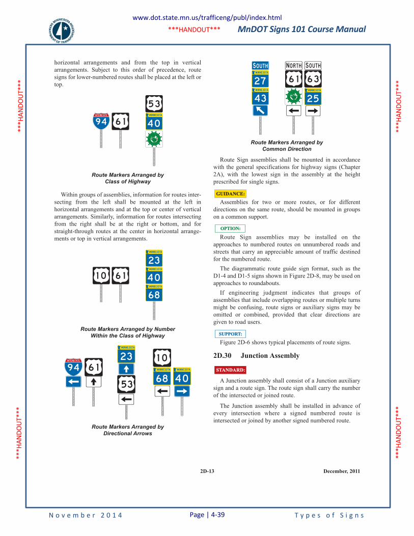
MnDOT Signs 101 Course Manual
N o v e m b e r 2 0 1 4 T y p e s o f S i g n s
***H
ANDO
UT**
* **
*HAN
DOUT
***
***H
ANDO
UT**
* **
*HAN
DOUT
***
***HANDOUT***
2D-13 December, 2011
horizontal arrangements and from the top in vertical
arrangements. Subject to this order of precedence, route
signs for lower-numbered routes shall be placed at the left or
top.
Within groups of assemblies, information for routes inter-
secting from the left shall be mounted at the left in
horizontal arrangements and at the top or center of vertical
arrangements. Similarly, information for routes intersecting
from the right shall be at the right or bottom, and for
straight-through routes at the center in horizontal arrange-
ments or top in vertical arrangements.
Route Markers Arranged byDirectional Arrows
1 0
6 853
23
6 194
I NT ERS TAT E
Route Markers Arranged by NumberWithin the Class of Highway
6 11 0
23
68
Route Markers Arranged byClass of Highway
94
I NT ERS TAT E
6 1
5 3
Route Sign assemblies shall be mounted in accordance
with the general specifications for highway signs (Chapter
2A), with the lowest sign in the assembly at the height
prescribed for single signs.
Assemblies for two or more routes, or for different
directions on the same route, should be mounted in groups
on a common support.
Route Sign assemblies may be installed on the
approaches to numbered routes on unnumbered roads and
streets that carry an appreciable amount of traffic destined
for the numbered route.
The diagrammatic route guide sign format, such as the
D1-4 and D1-5 signs shown in Figure 2D-8, may be used on
approaches to roundabouts.
If engineering judgment indicates that groups of
assemblies that include overlapping routes or multiple turns
might be confusing, route signs or auxiliary signs may be
omitted or combined, provided that clear directions are
given to road users.
Figure 2D-6 shows typical placements of route signs.
2D.30 Junction Assembly
A Junction assembly shall consist of a Junction auxiliary
sign and a route sign. The route sign shall carry the number
of the intersected or joined route.
The Junction assembly shall be installed in advance of
every intersection where a signed numbered route is
intersected or joined by another signed numbered route.
STANDARD:STANDARD:
SUPPORT:SUPPORT:
OPTION:OPTION:
GUIDANCE:GUIDANCE:
Route Markers Arranged byCommon Direction
6 1 6 3
2 543
27
N O RTH S O U THS O U THO U TH
www.dot.state.mn.us/trafficeng/publ/index.html
Page | 4-39
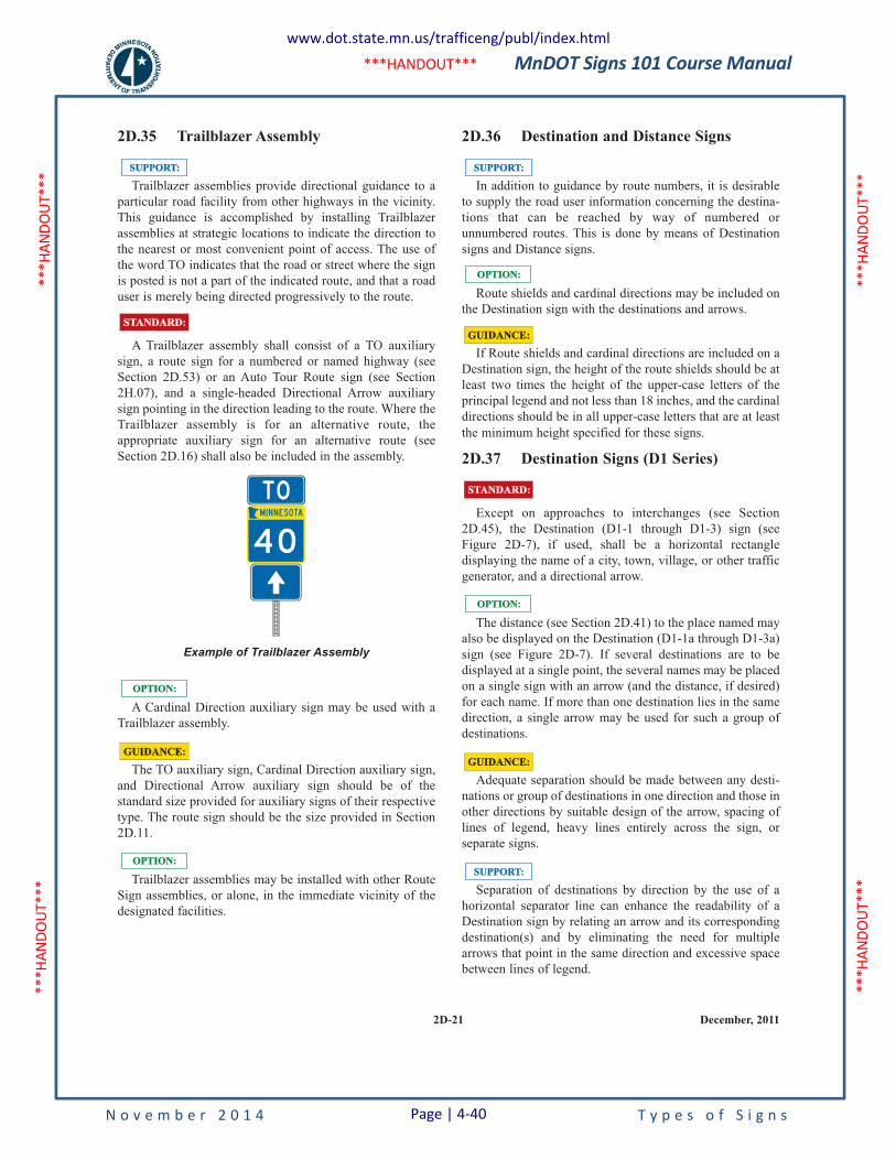
MnDOT Signs 101 Course Manual
N o v e m b e r 2 0 1 4 T y p e s o f S i g n s
***H
ANDO
UT**
* **
*HAN
DOUT
***
***H
ANDO
UT**
* **
*HAN
DOUT
***
***HANDOUT***
2D-21 December, 2011
2D.35 Trailblazer Assembly
Trailblazer assemblies provide directional guidance to a
particular road facility from other highways in the vicinity.
This guidance is accomplished by installing Trailblazer
assemblies at strategic locations to indicate the direction to
the nearest or most convenient point of access. The use of
the word TO indicates that the road or street where the sign
is posted is not a part of the indicated route, and that a road
user is merely being directed progressively to the route.
A Trailblazer assembly shall consist of a TO auxiliary
sign, a route sign for a numbered or named highway (see
Section 2D.53) or an Auto Tour Route sign (see Section
2H.07), and a single-headed Directional Arrow auxiliary
sign pointing in the direction leading to the route. Where the
Trailblazer assembly is for an alternative route, the
appropriate auxiliary sign for an alternative route (see
Section 2D.16) shall also be included in the assembly.
A Cardinal Direction auxiliary sign may be used with a
Trailblazer assembly.
The TO auxiliary sign, Cardinal Direction auxiliary sign,
and Directional Arrow auxiliary sign should be of the
standard size provided for auxiliary signs of their respective
type. The route sign should be the size provided in Section
2D.11.
Trailblazer assemblies may be installed with other Route
Sign assemblies, or alone, in the immediate vicinity of the
designated facilities.
OPTION:OPTION:
GUIDANCE:GUIDANCE:
OPTION:OPTION:
Example of Trailblazer Assembly
TO
STANDARD:STANDARD:
SUPPORT:SUPPORT:
2D.36 Destination and Distance Signs
In addition to guidance by route numbers, it is desirable
to supply the road user information concerning the destina-
tions that can be reached by way of numbered or
unnumbered routes. This is done by means of Destination
signs and Distance signs.
Route shields and cardinal directions may be included on
the Destination sign with the destinations and arrows.
If Route shields and cardinal directions are included on a
Destination sign, the height of the route shields should be at
least two times the height of the upper-case letters of the
principal legend and not less than 18 inches, and the cardinal
directions should be in all upper-case letters that are at least
the minimum height specified for these signs.
2D.37 Destination Signs (D1 Series)
Except on approaches to interchanges (see Section
2D.45), the Destination (D1-1 through D1-3) sign (see
Figure 2D-7), if used, shall be a horizontal rectangle
displaying the name of a city, town, village, or other traffic
generator, and a directional arrow.
The distance (see Section 2D.41) to the place named may
also be displayed on the Destination (D1-1a through D1-3a)
sign (see Figure 2D-7). If several destinations are to be
displayed at a single point, the several names may be placed
on a single sign with an arrow (and the distance, if desired)
for each name. If more than one destination lies in the same
direction, a single arrow may be used for such a group of
destinations.
Adequate separation should be made between any desti-
nations or group of destinations in one direction and those in
other directions by suitable design of the arrow, spacing of
lines of legend, heavy lines entirely across the sign, or
separate signs.
Separation of destinations by direction by the use of a
horizontal separator line can enhance the readability of a
Destination sign by relating an arrow and its corresponding
destination(s) and by eliminating the need for multiple
arrows that point in the same direction and excessive space
between lines of legend.
SUPPORT:SUPPORT:
GUIDANCE:GUIDANCE:
OPTION:OPTION:
STANDARD:STANDARD:
GUIDANCE:GUIDANCE:
OPTION:OPTION:
SUPPORT:SUPPORT:
www.dot.state.mn.us/trafficeng/publ/index.html
Page | 4-40
MnDOT Signs 101 Course Manual
N o v e m b e r 2 0 1 4 T y p e s o f S i g n s
***H
ANDO
UT**
* **
*HAN
DOUT
***
***H
ANDO
UT**
* **
*HAN
DOUT
***
***HANDOUT***
2D-22December, 2011
The closest destination lying straight ahead should be at
the top of the sign or assembly, and below it the closest des-
tinations to the left and to the right, in that order. The
destination displayed for each direction should ordinarily be
the next county seat or the next principal city, rather than a
more distant destination. In the case of overlapping routes,
only one destination should be displayed in each direction
for each route.
If more than one destination is displayed in the same
direction, the name of a nearer destination shall be displayed
above the name of a destination that is further away.
2D.38 Destination Signs at Circular
Intersections
Destination signs that are used at circular intersections
shall comply with the provisions of Section 2D.37, except as
provided in this Section.
Exit destination (D1-1d, D1-1e) signs (see Figure 2D-8)
with diagonal upward-pointing arrows or Directional
assemblies (see Section 2D.32) may be used to designate a
particular exit from a circular intersection.
Exit destination (D1-2d, D1-3d) signs (see Figure 2D-8)
with curved-stem arrows may be used on approaches to
circular intersections to represent the left-turn movements.
Curved-stem arrows on circular intersection destination
signs may point in diagonal directions to depict the location
of an exit relative to the approach roadway and entry into the
intersection.
Exit destination (D1-4 or D1-5) signs (see Figure 2D-8)
with a diagram of the circular intersection may be used on
approaches to circular intersections.
If curved-stem arrows are used on destination signs, then
this arrow type should also be used consistently on any
regulatory lane-use signs (see Chapter 2B), Directional
assemblies (see Section 2D.32), and pavement markings
(see Part 3) for a particular destination or movement.
Figure 2D-9 illustrates two examples of guide signing for
circular intersections.
Diagrammatic guide signs might be preferable where
space is available and where the geometry of the circular
SUPPORT:SUPPORT:
GUIDANCE:GUIDANCE:
OPTION:OPTION:
STANDARD:STANDARD:
STANDARD:STANDARD:
GUIDANCE:GUIDANCE:
Except as otherwise provided in this Manual, an arrow
pointing to the right shall be at the extreme right of the sign,
and an arrow pointing left or up shall be at the extreme left.
The distance numerals, if used, shall be placed to the right of
the destination names.
An arrow pointing up may be placed at the extreme right
of the sign when the sign is mounted to the left of the traffic
to which it applies.
Unless a sloping arrow will convey a clearer indication of
the direction to be followed, the directional arrows should be
horizontal or vertical.
If several individual name signs are assembled into a
group, all signs in the assembly should be of the same
horizontal width.
Destination signs should be used:
A. At the intersections of U.S. or State numbered routes
with Interstate, U.S., or State numbered routes; and
B. At points where they serve to direct traffic from U.S.
or State numbered routes to the business section of
towns, or to other destinations reached by
unnumbered routes.
Where a total of three or less destinations are provided on
the Advance Guide (see Section 2E.33) and Supplemental
Guide (see Section 2E.35) signs, no more than three
destination names shall be used on a Destination sign.
Where four destinations are provided by the Advance Guide
and Supplemental Guide signs, no more than four
destination names shall be used on a Destination sign.
If space permits, four destinations should be displayed as
two separate signs at two separate locations.
Where space does not permit, or where all four destina-
tions are in one direction, a single sign may be used. Where
a single sign is used and all destinations are in the same
direction, the arrow may be placed below the destinations
for the purpose of enhancing the conspicuity of the arrow.
Where a single four-name sign assembly is used, a heavy
line entirely across the sign or separate signs shall be used to
separate destinations by direction.
STANDARD:STANDARD:
OPTION:OPTION:
GUIDANCE:GUIDANCE:
STANDARD:STANDARD:
GUIDANCE:GUIDANCE:
OPTION:OPTION:
STANDARD:STANDARD:
www.dot.state.mn.us/trafficeng/publ/index.html
Page | 4-41
MnDOT Signs 101 Course Manual
N o v e m b e r 2 0 1 4 T y p e s o f S i g n s
***H
ANDO
UT**
* **
*HAN
DOUT
***
***H
ANDO
UT**
* **
*HAN
DOUT
***
***HANDOUT***
December, 20112E-1
PART 2. SIGNS
Chapter 2E. Guide Signs - Freeways and Expressways
2E.1 Scope of Freeway and Expressway
Guide Sign Standards
The provisions of this Chapter provide a uniform and
effective system of signing for high-volume, high-speed
motor vehicle traffic on freeways and expressways. The
requirements and specifications for expressway signing
exceed those for conventional roads (see Chapter 2D), but
are less than those for freeway signing. Since there are many
geometric design variables to be found in existing roads, a
signing concept commensurate with prevailing conditions is
the primary consideration. Section 1A.13 includes
definitions of freeway and expressway.
Guide signs for freeways and expressways are primarily
identified by the name of the sign rather than by an assigned
sign designation. Guidelines for the design of guide signs for
freeways and expressways are provided in the "Standard
Highway Signs and Markings" book (see Section 1A.11).
The provisions of this Chapter shall apply to any highway
that meets the definition of freeway or expressway facilities.
2E.2 Freeway and Expressway
Signing Principles
The development of a signing system for freeways and
expressways is approached on the premise that the signing is
primarily for the benefit and direction of road users who are
not familiar with the route or area. The signing furnishes
road users with clear instructions for orderly progress to
their destinations. Sign installations are an integral part of
the facility and, as such, are best planned concurrently with
the development of highway location and geometric design.
For optimal results, plans for signing are analyzed during the
earliest stages of preliminary design, and details are
correlated as final design is developed. The excessive
signing found on many major highways usually is the result
of using a multitude of signs that are too small and that are
poorly designed and placed to accomplish the intended
purpose.
Freeway and expressway signing is to be considered and
developed as a planned system of installations. An
engineering study is sometimes necessary for proper
STANDARD:STANDARD:
SUPPORT:SUPPORT:
SUPPORT:SUPPORT:
solution of the problems of many individual locations, but,
in addition, consideration of an entire route is necessary.
Road users should be guided with consistent signing on
the approaches to interchanges, when they drive from one
State to another, and when driving through rural or urban
areas. Because geographical, geometric, and operating
factors regularly create significant differences between
urban and rural conditions, the signing should take these
conditions into account.
Guide signs on freeways and expressways should serve
distinct functions as follows:
A. Give directions to destinations, or to streets or
highway routes, at intersections or interchanges;
B. Furnish advance notice of the approach to intersec-
tions or interchanges;
C. Direct road users into appropriate lanes in advance of
diverging or merging movements;
D. Identify routes and directions on those routes;
E. Show distances to destinations;
F. Indicate access to general motorist services, rest,
scenic, and recreational areas; and
G. Provide other information of value to the road user.
2E.3 Guide Sign Classification
Freeway and expressway guide signs are classified andtreated in the following categories:
A.Route signs and Trailblazer Assemblies (see Section2E.27),
B. At-Grade Intersection signs (see Section 2E.29), C. Interchange signs (see Sections 2E.30 through 2E.39), D.Interchange Sequence signs (see Section 2E.40), E. Community Interchanges Identification signs (see
Section 2E.41), F. NEXT XX EXITS signs (see Section 2E.42), G. Weigh Station signing (see Section 2E.54), H.Miscellaneous information signs (see Section 2H.04), I. Reference Location signs (see Section 2H.05), J. General Service signs (see Chapter 2I), K.Rest and Scenic Area signs (see Section 2I.05), L. Tourist Information and Welcome Center signs (see
Section 2I.08), M. Radio Information signing (see Section 2I.09), N.Carpool and Ridesharing signing (see Section 2I.11), O.Specific Service signs (see Chapter 2J), and P. Recreational and Cultural Interest Area signs (see
Chapter 2M).
SUPPORT:SUPPORT:
GUIDANCE:GUIDANCE:
www.dot.state.mn.us/trafficeng/publ/index.html
Page | 4-42
MnDOT Signs 101 Course Manual
N o v e m b e r 2 0 1 4 T y p e s o f S i g n s
***H
ANDO
UT**
* **
*HAN
DOUT
***
***H
ANDO
UT**
* **
*HAN
DOUT
***
***HANDOUT***
2E.4 General
Signs are designed so that they are legible to road users
approaching them and readable in time to permit proper
responses. Desired design characteristics include: (a) long
visibility distances, (b) large lettering, symbols, and arrows,
and (c) short legends for quick comprehension.
Standard shapes and colors shall be used so that traffic
signs can be promptly recognized by road users.
2E.5 Color of Guide Signs
Guide signs on freeways and expressways, except as
otherwise provided in this Manual, shall have white letters
and numerals, symbols, arrows, and borders on a green
background.
Color requirements for route signs and trailblazers, signs
with blank-out or changeable messages, signs for services,
rest areas, park and recreational areas, and for certain mis-
cellaneous signs are provided in the individual Sections
dealing with the particular sign or sign group.
2E.6 Retroreflection or Illumination
Letters, numerals, symbols, arrows, and borders of all
guide signs shall be retroreflectorized. The background of all
guide signs that are not independently illuminated shall be
retroreflective.
Where there is no serious interference from extraneous
light sources, retroreflectorized post-mounted signs usually
provide adequate nighttime visibility.
On freeways and expressways where much driving at
night is done with low-beam headlights, the amount of
headlight illumination incident to an overhead sign display
is relatively small.
Overhead sign installations should be illuminated unless
an engineering study shows that retroreflectorization alone
will perform effectively. The type of illumination chosen
should provide effective and reasonably uniform illumina-
tion of the sign face and message.
GUIDANCE:GUIDANCE:
STANDARD:STANDARD:
STANDARD:STANDARD:
SUPPORT:SUPPORT:
SUPPORT:SUPPORT:
SUPPORT:SUPPORT:
STANDARD:STANDARD:
2E.7 Characteristics of Urban Signing
Urban conditions are characterized not so much by city
limits or other arbitrary boundaries, as by the following
features:
A. Mainline roadways with more than two lanes in each
direction;
B. High traffic volumes on the through roadways;
C. High volumes of traffic entering and leaving inter-
changes;
D. Interchanges closely spaced;
E. Roadway and interchange lighting;
F. Three or more interchanges serving the major city;
G. A loop, circumferential, or spur serving a sizable
portion of the urban population; and
H. Visual clutter from roadside development.
Operating conditions and road geometrics on urban
freeways and expressways usually make special sign
treatments desirable, including:
A.Use of Interchange Sequence signs (see Section
2E.40);
B. Use of sign spreading to the maximum extent possible
(see Section 2E.11);
C. Elimination of General or Specific Service signing
(see Chapters 2I and 2J);
D.Reduction to a minimum of post-interchange signs
(see Section 2E.38);
E. Display of advance signs at distances closer to the
interchange, with appropriate adjustments in the
legend (see Section 2E.33);
F. Use of overhead signs on roadway structures and
independent sign supports (see Section 2E.25);
G. Use of Overhead Arrow-per-Lane or Diagrammatic
guide signs in advance of intersections and inter-
changes (see Sections 2E.21 and 2E.22); and
H.Frequent use of street names as the principal message
in guide signs.
.Lower speeds which are often characteristic of urban
operations do not justify lower signing standards.
Typical traffic patterns are more complex for the road
user to negotiate, and large, easy-to-read legends are,
therefore, just as necessary as on rural highways.
2E.8 Characteristics of Rural Signing
Rural areas ordinarily have greater distances between
interchanges, which permits adequate spacing for the
sequences of signs on the approach to and departure from
each interchange. However, the absence of traffic in
adjoining lanes and on entering or exiting ramps often adds
monotony or inattention to rural driving. This increases the
importance of signs that call for decisions or actions.
SUPPORT:SUPPORT:
SUPPORT:SUPPORT:
2E-2December, 2011
www.dot.state.mn.us/trafficeng/publ/index.html
Page | 4-43
MnDOT Signs 101 Course Manual
N o v e m b e r 2 0 1 4 T y p e s o f S i g n s
***H
ANDO
UT**
* **
*HAN
DOUT
***
***H
ANDO
UT**
* **
*HAN
DOUT
***
***HANDOUT***
Where there are long distances between interchanges and
the alignment is relatively unchanging, signs should be
positioned for their best effect on road users. The tendency
to group all signing in the immediate vicinity of rural inter-
changes should be avoided by considering the entire route in
the development of sign plans. Extra effort should be given
to the placement of signs at natural target locations to
command the attention of the road user, particularly when
the message requires an action by the road user.
2E.9 Signing of Named Highways
Section 2D.53 contains information, which is also
applicable to freeways and expressways, regarding the use
of highway names on the signing for unnumbered highways
to enhance route guidance and facilitate travel.
Section 2M.10 contains information regarding memorial
signing of routes, bridges, or highway components.
2E.10 Amount of Legend on Guide Signs
No more than two destination names or street names
should be displayed on any Advance Guide sign or Exit
Direction sign. A city name and street name on the same sign
should be avoided. Where two or three signs are placed on
the same supports, destinations or names should be limited
to one per sign, or to a total of three in the display. Sign
legends should not exceed three lines of copy, exclusive of
the exit number and action or distance information.
2E.11 Number of Signs at an Overhead
Installation and Sign Spreading
If overhead signs are warranted, as set forth in Section
2A.17, the number of signs at these locations should be
limited to only those essential in communicating pertinent
destination information to the road user. Exit Direction signs
for a single exit and the Advance Guide signs should have
only one sign with one or two destinations. Regulatory
signs, such as speed limits, should not be used in
conjunction with overhead guide sign installations. Because
road users have limited time to read and comprehend sign
messages, there should not be more than three guide signs
displayed at any one location either on the overhead
structure or its support.
At overhead locations, more than one sign may be
installed to advise of a multiple exit condition at an
OPTION:OPTION:
GUIDANCE:GUIDANCE:
GUIDANCE:GUIDANCE:
SUPPORT:SUPPORT:
GUIDANCE:GUIDANCE:interchange. If the roadway ramp or crossing roadway has
complex or unusual geometrics, additional signs with
confirming messages may be provided to properly guide the
road user.
Sign spreading is a concept where major overhead signs
are spaced so that road users are not overloaded with a group
of signs at a single location. Figure 2E-1 illustrates an
example of sign spreading.
Where overhead signing is used, sign spreading should be
used at all single exit interchanges and to the extent possible
at multi-exit interchanges. Sign spreading should be accom-
plished by use of the following:
A. The Exit Direction sign should be the only sign used
in the vicinity of the gore (other than the Exit Gore
sign). It should be located overhead near the
theoretical gore and generally on an overhead sign
support structure.
B. The Advance Guide sign to indicate the next
interchange exit should be placed near the crossroad
location. If the crossroad goes over the mainline, the
Advance Guide sign should be placed on the over-
crossing structure or on a separate structure
immediately in front of the overcrossing structure.
.
2E.12 Pull-Through Signs
Pull-Through (E6-2, E6-2a) signs (see Figure 2E-2) are
overhead guide signs intended for through traffic.
Pull-Through signs should be used where the geometrics
of a given interchange are such that it is not clear to the road
user as to which is the through roadway, or where additional
route guidance is desired. Pull-Through signs with down
arrows should be used where the alignment of the through
lanes is curved and the exit direction is straight ahead, where
the number of through lanes is not readily evident, and at
multi-lane exits where there is a reduction in the number of
through lanes.
Sections 2E.20 through 2E.24 contain information
regarding the use of Overhead Arrow-per-Lane or
Diagrammatic guide signs at multi-lane exits where there is
a reduction in the number of through lanes and a through
lane becomes an interior option lane for through or exiting
traffic.
SUPPORT:SUPPORT:
GUIDANCE:GUIDANCE:
SUPPORT:SUPPORT:
GUIDANCE:GUIDANCE:
SUPPORT:SUPPORT:
2E-3 December, 2011
www.dot.state.mn.us/trafficeng/publ/index.html
Page | 4-44
MnDOT Signs 101 Course Manual
N o v e m b e r 2 0 1 4 P a g e | 4-45 T y p e s o f S i g n s
4.5 Work Zone and Detour Signing
All traffic control devices used on MnDOT street and highway construction or maintenance work shall conform to the specifications of the latest edition of the MN MUTCD, the MnDOT Standard Specifications for Construction; and all other appropriate MnDOT technical manuals.
All devices shall be placed where they will convey their messages most effectively so the driver will have adequate time to react. All traffic control devices must be kept clean to insure proper effectiveness and retroreflectivity. All devices shall conform to the quality standards of the MN MUTCD Field Manual.
4.6 2013 Standard Signs Summary
The following is a handout from the 2013 Standard Signs Summary. The latest version can be downloaded from, www.dot.state.mn.us/trafficeng/publ/index.html.
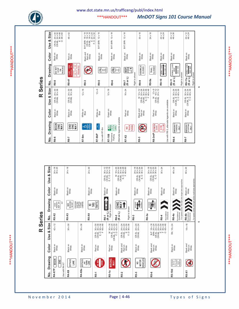
MnDOT Signs 101 Course Manual
N o v e m b e r 2 0 1 4 T y p e s o f S i g n s
***H
ANDO
UT**
* **
*HAN
DOUT
***
***H
ANDO
UT**
* **
*HAN
DOUT
***
***HANDOUT***
No
.D
raw
ing
Co
lor
Use
&S
ize
R5-1
R5-1
a
R5-2
R5-3
R5-6
RA
18
x2
4
24
x1
8
24
x3
0
24
x1
83
0x
24
R5-X
1
R5-1
0d
R5-X
3
R5-X
4
R5-X
2
Bla
ck
on
Wh
ite
Bla
ck
on
Wh
ite
Bla
ck
on
Wh
ite
Bla
ck
on
Wh
ite
No
.D
raw
ing
Co
lor
Use
&S
ize
R6-1
(Ro
rL
)R
igh
tis
sh
ow
n
Bla
ck
on
Wh
ite
CR
-SL
36
x1
2C
R-M
L5
4x
18
E,
F,
O5
4x
18
M1
8x
24
CR
-SL
24
x3
0C
R-M
L3
0x
36
E,
O3
6x
48
F4
8x
60
Bla
ck
on
Wh
ite
Bla
ck
on
Wh
ite
Bla
ck
on
Wh
ite
Bla
ck
on
Wh
ite
Ro
un
da
bo
ut
Dire
ctio
na
l
Ro
un
da
bo
ut
Dire
ctio
na
l
Fo
rsp
ee
dzo
ne
s<
45
mp
ha
nd
sin
gle
lan
ea
pp
roa
ch
es
Fo
rsp
ee
dzo
ne
s4
5m
ph
an
d/o
rm
ulti-la
ne
ap
pro
ach
es
>
Ro
un
da
bo
ut
Dire
ctio
na
l
Bla
ck
on
Wh
ite
Bla
ck
on
Wh
ite
24
x1
8C
R-S
L3
0x
24
CR
-ML
30
x2
4E
,O
36
x3
0
24
x1
8C
R-S
L3
0x
24
CR
-ML
30
x2
4E
,O
36
x3
0
30
x2
4
48
x2
4
60
x2
4
R6-2
(Ro
rL
)
R6-3
R6-3
a
R6-4
R6-4
a
R6-4
b
Re
do
nW
hite
Re
do
nW
hite
Bla
ck
an
dR
ed
on
Wh
ite
Bla
ck
an
dR
ed
on
Wh
ite
Bla
ck
an
dR
ed
on
Wh
ite
Bla
ck
on
Wh
ite
CR
-SL
30
x3
0C
R-M
L3
6x
36
E,
O3
6x
36
F4
8x
48
M3
0x
18
CR
-SL
36
x2
4C
R-M
L,
E4
2x
30
F,
O4
2x
30
B-P
18
x1
8B
/Rt
24
x2
4C
R-S
L2
4x
24
CR
-ML
24
x2
4E
30
x3
0F
36
x3
6O
48
x4
8
18
x1
8
CR
-SL
24
x2
4C
R-M
L2
4x
24
CR
-SL
24
x2
4C
R-M
L2
4x
24
E3
0x
30
F,
O3
6x
36
DONOT
ENTER
WRONG
WAY
NO
MOTOR
VEHICLES
PEDESTRIANS
TRAFFIC
NON-MOTORIZED
MOTORIZED
BICYCLES
BICYCLES
PROHIBITED
ONE
WAY
ONEWAY
OUT
STATE
PROPERTY
KEEPOFF
NO THRU
TRAFFIC
DIVIDED
HIGHWAY
DIVIDED
HIGHWAY
Bla
ck
on
Wh
ite
Bla
ck
on
Wh
ite
Bla
ck
on
Wh
ite
42
x1
2
30
x3
0
30
x3
6
R4-X
7P
R4-X
8
R4-X
8a
BEGIN
END
BYPASS
LANE
Use
with
R4
-X7
Rig
ht
issh
ow
n
BYPASS
AND
TURN
LANE
CROSSING
HUNTING
DUMPING
FISHING
CAMPING
5
R S
erie
sN
o.
Dra
win
gC
olo
rU
se
&S
ize
R7
-10
8
R7
-X2
R8
-3
R8
-3m
P
Use
with
R8
-3;
alte
rna
tele
ge
nd
sa
rea
va
ilab
le
R8
-4
48
x4
2
R8
-8
R8
-7
R9
-3
R9
-5
R8
-41
Bla
ck
on
Wh
ite
Bla
ck
an
dR
ed
on
Wh
ite
Bla
ck
on
Wh
ite
Re
do
nW
hite
No
.D
raw
ing
Co
lor
Us
e&
Siz
e
Bla
ck
on
Wh
ite
B-P
,B
/Rt
12
x1
8
24
x1
24
8x
24
24
x1
24
8x
36
B-P
,B
/Rt
12
x1
8B
lack
on
Wh
ite
Rig
ht
issh
ow
n
Rig
ht
issh
ow
n
Rig
ht
issh
ow
n
Bla
ck
on
Wh
ite
Bla
ck
on
Wh
ite
Bla
ck
on
Wh
ite
Bla
ck
on
Wh
ite
Bla
ck
on
Wh
ite
30
x1
8
24
x1
8
24
x1
24
8x
24
R9
-9
R9
-6
R9
-7(R
or
L)
R9
-9a
R9
-10
R9
-11
a(R
or
L)
R9
-11
(Ro
rL
)
Gre
en
on
Wh
ite
Alte
rna
tele
ge
nd
sa
va
ilab
le
Perm
issiv
eP
ark
ing
Re
do
nW
hite
Bla
ck
an
dR
ed
on
Wh
ite
Bla
ck
on
Wh
ite
Bla
ck
on
Wh
ite
Re
do
nW
hite
12
x1
8
18
x2
4
CR
-SL
30
x2
4C
R-M
L,
E3
0x
24
F,
O4
8x
36
CR
-SL
30
x2
4C
R-M
L,
E3
0x
24
F,
O4
8x
36
CR
-SL
24
x3
0C
R-M
L2
4x
30
E3
6x
48
O4
8x
60
B-P
,B
/Rt
18
x1
8C
R-S
L1
8x
18
CR
-ML
18
x1
8E
24
x2
4F,
O3
0x
30
B-P
,B
/Rt
12
x1
8
M1
2x
9C
R-S
L1
8x
12
CR
-ML
24
x1
2
M1
2x
12
CR
-SL
24
x2
4C
R-M
L3
0x
30
E,
O3
6x
36
F4
8x
48
15MIN
PARKING
8:00AM
TO5:00PM
NO
TRUCK
PARKING
EMERGENCY
PARKING
ONLY
EMERGENCY
STOPPING
ONLY
STOP
ON
TRACKS
DONOT
YIELD
TO
PEDS
USE
PED
SIGNAL
KEEP
LEFTRIGHT
SIDEWALK
CLOSED
TRAIL
CLOSED
Wh
ite
on
Blu
e
Wh
ite
on
Blu
e
Bla
ck
on
Wh
ite
Bla
ck
on
Wh
ite
CR
-SL
24
x3
0C
R-M
L3
0x
36
CR
-SL
24
x3
0C
R-M
L3
0x
36
12
x1
8
12
x6
R6
-6
R6
-7
R7
-8m
R7
-8b
P
Use
with
R7
-8mBEGIN
ONE
WAY
END
ONE
WAY
PARKING
VEHICLEID
REQUIRED
UPTO
$200FINE
FORVIOLATION
PARKING
PROHIBITED
LOITERING
OVERNIGHTPARKING
SEMITRUCKAND
VENDING
ONLY
PARK-RIDE
VAN
ACCESSIBLE
10PM
TO6AM
BETWEEN
SIGNS
SIDEWALKCLOSED
USEOTHERSIDE
SIDEWALKCLOSED
AHEAD
CROSSHERE
SIDEWALKCLOSED
CROSSHERE
6
R S
erie
s
www.dot.state.mn.us/trafficeng/publ/index.html
Page | 4-46
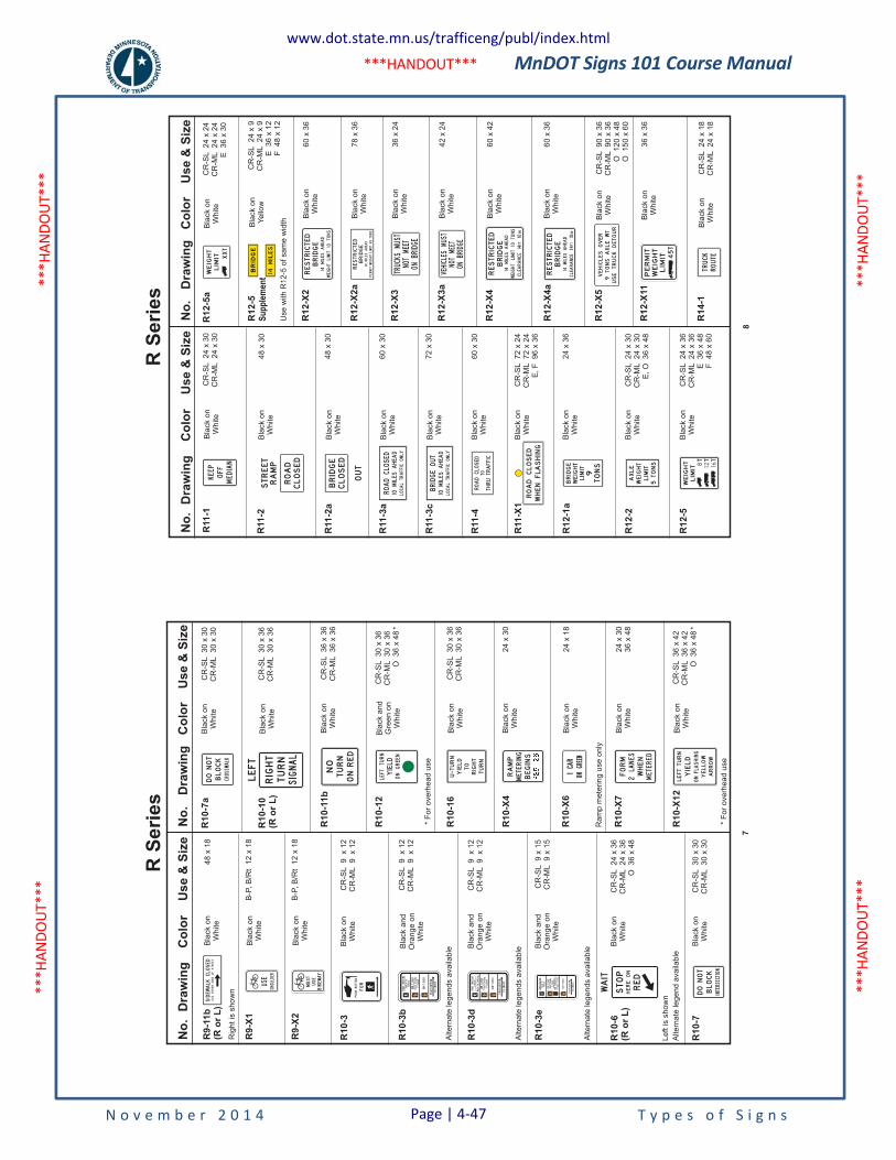
MnDOT Signs 101 Course Manual
N o v e m b e r 2 0 1 4 T y p e s o f S i g n s
***H
ANDO
UT**
* **
*HAN
DOUT
***
***H
ANDO
UT**
* **
*HAN
DOUT
***
***HANDOUT***
No
.D
raw
ing
Co
lor
Use
&S
ize
R10-3
e
R10-6
(Ro
rL
)
R10-7
R10-1
2
R10-1
6
R10-X
4
R10-1
1b
Bla
ck
an
dG
ree
no
nW
hite
Bla
ck
on
Wh
ite
Bla
ck
on
Wh
ite
*F
or
ove
rhe
ad
use
*F
or
ove
rhe
ad
use
No
.D
raw
ing
Co
lor
Use
&S
ize
Bla
ck
on
Wh
ite
24
x3
0
Le
ftis
sh
ow
n
Bla
ck
on
Wh
ite
Bla
ck
on
Wh
ite
Bla
ck
on
Wh
ite
24
x1
8
24
x3
03
6x
48
R10-X
6
R10-X
7
R10-X
12
Bla
ck
an
dO
ran
ge
on
Wh
ite
Alte
rna
tele
ge
nd
ava
ilab
le
Ra
mp
me
terin
gu
se
on
ly
Bla
ck
on
Wh
ite
Bla
ck
on
Wh
ite
CR
-SL
9x
15
CR
-ML
9x
15
CR
-SL
24
x3
6C
R-M
L2
4x
36
O3
6x
48
CR
-SL
36
x3
6C
R-M
L3
6x
36
CR
-SL
30
x3
6C
R-M
L3
0x
36
CR
-SL
30
x3
0C
R-M
L3
0x
30
*
CR
-SL
30
x3
6C
R-M
L3
0x
36
O3
6x
48
*
CR
-SL
36
x4
2C
R-M
L3
6x
42
O3
6x
48
STARTCROSSING
WatchFor
Vehicles
DONTCROSS
TOCROSS
PUSHBUTTON
DONTSTART
TIMEREMAINING
Finish
Crossing
ToFinish
Crossing
IfStarted
WAIT
STOP
HEREON
RED
LEFT
ONGREEN
TURN
YIELD
NO
TURN
ONRED
U-TURN
YIELD
TO
RIGHT
TURN
RAMP
BEGINS
METERING
1CAR
1CAR
ONGREEN
ONGREEN
FORM
WHEN
2LANES
METERED
Bla
ck
an
dO
ran
ge
on
Wh
ite
Bla
ck
an
dO
ran
ge
on
Wh
ite
CR
-SL
9x
12
CR
-ML
9x
12
CR
-SL
9x
12
CR
-ML
9x
12
R10-3
b
R10-3
d
Alte
rna
tele
ge
nd
sa
va
ilab
le
Alte
rna
tele
ge
nd
sa
va
ilab
le
Alte
rna
tele
ge
nd
sa
va
ilab
le
STARTCROSSING
TOMEDIAN
WatchForVehicles
DONTSTART
Finish
Crossing
IfStarted
DONTCROSS
TOCROSS
PUSHBUTTON
STARTCROSSING
DONTSTART
WatchFor
Finish
Crossing
Vehicles
IfStarted
Bla
ck
on
Wh
ite
CR
-SL
9x
12
CR
-ML
9x
12
R10-3
PUSHBUTTON
FOR
DONOT
BLOCK
INTERSECTION
R10-7
a
R10-1
0(R
or
L)
Bla
ck
on
Wh
ite
Bla
ck
on
Wh
ite
CR
-SL
30
x3
6C
R-M
L3
0x
36
CR
-SL
30
x3
0C
R-M
L3
0x
30
LEFT
RIGHT
TURN
SIGNAL
DONOT
BLOCK
CROSSWALK
B-P
,B
/Rt
12
x1
8
B-P
,B
/Rt
12
x1
8
Rig
ht
issh
ow
n
Bla
ck
on
Wh
ite
Bla
ck
on
Wh
ite
Bla
ck
on
Wh
ite
48
x1
8R
9-1
1b
(Ro
rL
)
R9-X
1
R9-X
2
SHOULDER
USE
MUST
USE
BIKEWAY
SIDEWALK
CLOSED
USEOTHERSIDEOFSTREET
7
R S
erie
sN
o.
Dra
win
gC
olo
rU
se
&S
ize
R11
-X1
R1
2-1
a
R1
2-2
R1
2-5
78
x3
6
42
x2
4
60
x4
2
R1
2-X
2
R1
2-X
3
R1
2-X
2a
R1
2-X
3a
R1
2-X
4
Bla
ck
on
Wh
ite
Bla
ck
on
Wh
ite
Bla
ck
on
Wh
ite
Bla
ck
on
Wh
ite
Bla
ck
on
Wh
ite
No
.D
raw
ing
Co
lor
Us
e&
Siz
e
R1
2-X
4a
Bla
ck
on
Wh
ite
60
x3
6
Bla
ck
on
Wh
ite
Bla
ck
on
Wh
ite
Bla
ck
on
Wh
ite
CR
-SL
90
x3
6C
R-M
L9
0x
36
O1
20
x4
8O
15
0x
60
36
x3
6
CR
-SL
24
x1
8C
R-M
L2
4x
18
R1
2-X
5
R1
2-X
11
R1
4-1
Bla
ck
on
Wh
ite
Bla
ck
on
Wh
ite
Bla
ck
on
Wh
ite
Bla
ck
on
Wh
ite
CR
-SL
72
x2
4C
R-M
L7
2x
24
E,
F9
6x
36
60
x3
6
36
x2
4
CR
-SL
24
x3
6C
R-M
L2
4x
36
E3
6x
48
F4
8x
60
CR
-SL
24
x3
0C
R-M
L2
4x
30
E,
O3
6x
48
WEIGHT
LIMIT
TONS
9
BRIDGE
AXLE
WEIGHT
LIMIT
TONS
5
TRUCK
ROUTE
WEIGHT
LIMIT8T
16T
12T
RESTRICTED
BRIDGE
MILES
AHEAD TONS
10LIMIT
WEIGHT
14 TRUCKS
MUST
MEET
NOT
ONBRIDGE
VEHICLES
MUST
MEET
NOT
ONBRIDGE
RESTRICTED
BRIDGE FT
IN14
10CLEARANCE
14MILES
AHEAD
R1
2-5
Su
pp
lem
ent
Bla
ck
on
Ye
llow
Use
with
R1
2-5
of
sa
me
wid
th
CR
-SL
24
x9
CR
-ML
24
x9
E3
6x
12
F4
8x
12
BRID
GE
14MILES
RESTRICTED
BRIDGE
MILESAHEAD
PERMITWEIGHTLIMIT45TONS
14
VEHICLES
TONS
USETRUCKDETOUR
AXLEWT
9OVER
PERMIT
WEIGHT
LIMIT 45T
Bla
ck
on
Wh
ite
Bla
ck
on
Wh
ite
Bla
ck
on
Wh
ite
60
x3
0
72
x3
0
60
x3
0
24
x3
6
R11
-3a
R11
-3c
R11
-4
ROADCLOSED
10MILES
AHEAD
LOCALTRAFFIC
ONLY
BRIDGEOUT
10MILES
AHEAD
LOCALTRAFFIC
ONLY
ROADCLOSED
THRUTRAFFIC
TO
Bla
ck
on
Wh
ite
Bla
ck
on
Wh
ite
48
x3
0
48
x3
0
R11
-2
R11
-2a
STREET
RAMP
ROAD
CLOSED
BRIDGE
CLOSED
OUT
RESTRICTED
BRIDGE FT
INCLEARANCE14
10
WEIGHTLIMIT
10TONS
14MILES
AHEAD
R1
2-5
aB
lack
on
Wh
ite
CR
-SL
24
x2
4C
R-M
L2
4x
24
E3
6x
30
WEIGHT
LIMIT XXT
Bla
ck
on
Wh
ite
CR
-SL
24
x3
0C
R-M
L2
4x
30
R11
-1KEEP
OFF
MEDIAN
8
R S
erie
s
www.dot.state.mn.us/trafficeng/publ/index.html
Page | 4-47
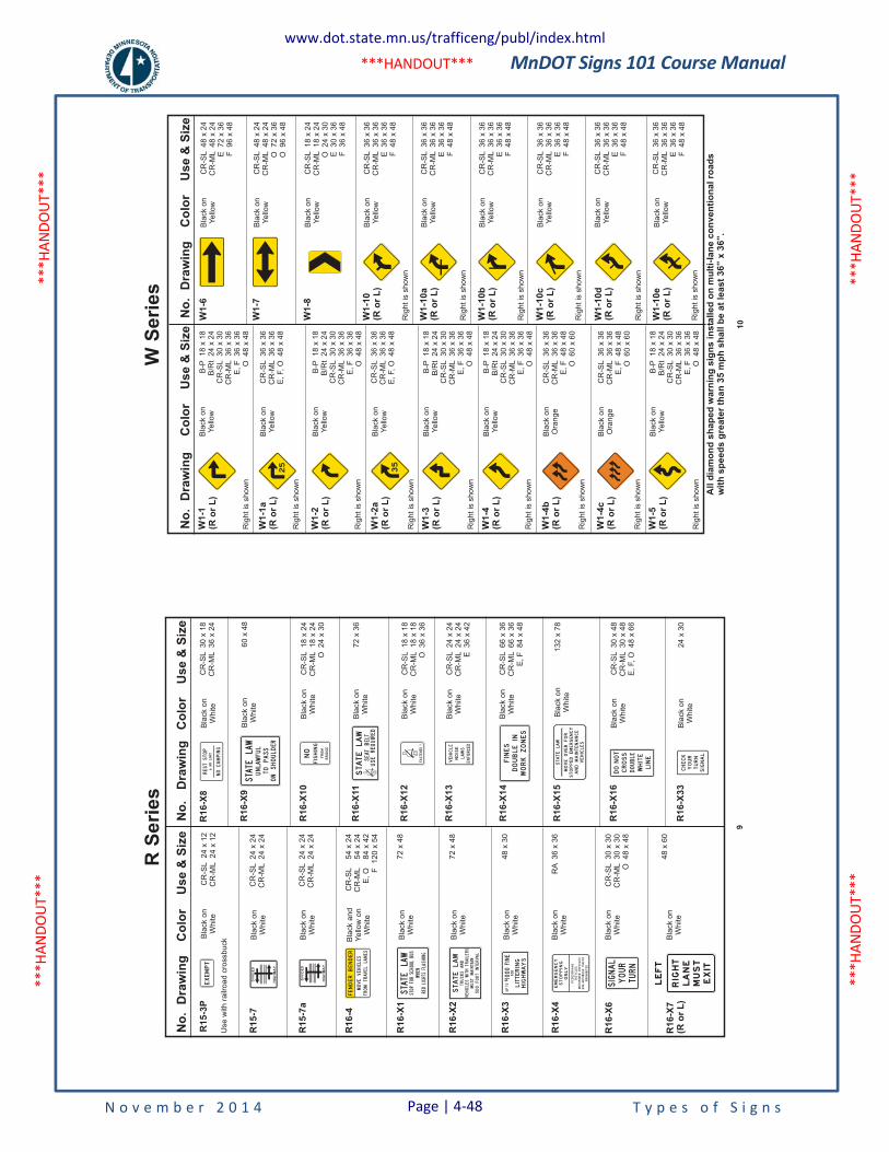
MnDOT Signs 101 Course Manual
N o v e m b e r 2 0 1 4 T y p e s o f S i g n s
***H
ANDO
UT**
* **
*HAN
DOUT
***
***H
ANDO
UT**
* **
*HAN
DOUT
***
***HANDOUT***
No
.D
raw
ing
Co
lor
Use
&S
ize
R16-X
4
R16-X
6
R16-X
7(R
or
L)
CR
-SL
18
x2
4C
R-M
L1
8x
24
O2
4x
30
CR
-SL
18
x1
8C
R-M
L1
8x
18
O3
6x
36
CR
-SL
24
x2
4C
R-M
L2
4x
24
E3
6x
42
R16-X
11
R16-X
10
R16-X
12
R16-X
13
Bla
ck
on
Wh
ite
Bla
ck
on
Wh
ite
Bla
ck
on
Wh
ite
Bla
ck
on
Wh
ite
No
.D
raw
ing
Co
lor
Use
&S
ize
R16-X
14
Bla
ck
on
Wh
ite
CR
-SL
66
x3
6C
R-M
L6
6x
36
E,
F8
4x
48
Bla
ck
on
Wh
ite
Bla
ck
on
Wh
ite
Bla
ck
on
Wh
ite
13
2x
78
CR
-SL
30
x4
8C
R-M
L3
0x
48
E,
F,
O4
8x
66
24
x3
0
R16-X
15
R16-X
16
R16-X
33
Bla
ck
on
Wh
ite
Bla
ck
on
Wh
ite
Bla
ck
on
Wh
ite
RA
36
x3
6
72
x3
6
48
x6
0
CR
-SL
30
x3
0C
R-M
L3
0x
30
O4
8x
48
EMERGENCY
STOPPING
ONLY
PEDESTRIANS
BICYCLES TR
AFFIC
MOTORIZED
NON-
PROHIBITED
MOTORIZEDBICYCLES
SIGNAL
YOUR
TURN
R16-X
8B
lack
on
Wh
ite
CR
-SL
30
x1
8C
R-M
L3
6x
24
RESTSTOP
6HRLIMIT
NOCAMPING
R16-X
9B
lack
on
Wh
ite
60
x4
8STATELAW
UNLAWFUL
TOPASS
ONSHOULDER
NO
FISHING
FROM
BRIDGE
STATELAW
SEATBELT
USEREQUIRED
FASTENED
?
LEFT
RIG
HT
LANE
MUST
EXIT
DONOT
CROSS
WHITE
LINE
DOUBLE
CHECK
YOUR
TURN
SIGNAL
Bla
ck
on
Wh
ite
Bla
ck
an
dY
ello
wo
nW
hite
Bla
ck
on
Wh
ite
Bla
ck
on
Wh
ite
Bla
ck
on
Wh
ite
CR
-SL
24
x2
4C
R-M
L2
4x
24
72
x4
8
72
x4
8
48
x3
0
CR
-SL
54
x2
4C
R-M
L5
4x
24
E,
O8
4x
42
F1
20
x5
4
R15-7
a
R16-4
R16-X
1
R16-X
2
R16-X
3
STATELAW
STOPFORSCHOOLBUS
WHEN
REDLIGHTSFLASHING
DIVIDED
HIGHWAY
MOVEVEHICLES
FENDERBENDER
FROMTRAVELLANES
STATELAW
TRUCKSAND
VEHICLESWITHTRAILERS
MUSTMAINTAIN
500FOOTINTERVAL
FOR
LITTERING
HIGHWAYS
FINE
1000
UPTOS
MOVEOVERFOR
STATELAW
STOPPEDEMERGENCY
ANDMAINTENANCE
VEHICLES
VEHICLE
NOISE
LAWS
ENFORCED
Bla
ck
on
Wh
ite
CR
-SL
24
x2
4C
R-M
L2
4x
24
R15-7
DIVIDED
HIGHWAY
Bla
ck
on
Wh
ite
Use
with
railr
oa
dcro
ssb
uck
CR
-SL
24
x1
2C
R-M
L2
4x
12
R15-3
PEXEMPT
9
R S
erie
sN
o.
Dra
win
gC
olo
rU
se
&S
ize
W1-1
(Ro
rL
)
W1-1
a(R
or
L)
W1-2
(Ro
rL
)
W1-2
a(R
or
L)
W1-3
(Ro
rL
)
W1-4
(Ro
rL
)
W1-4
b(R
or
L)
W1-4
c(R
or
L)
W1-5
(Ro
rL
)
Bla
ck
on
Ye
llow
Bla
ck
on
Ye
llow
Bla
ck
on
Ye
llow
Bla
ck
on
Ye
llow
Bla
ck
on
Ye
llow
Bla
ck
on
Ye
llow
Bla
ck
on
Ora
ng
e
Bla
ck
on
Ora
ng
e
Bla
ck
on
Ye
llow
B-P
18
x1
8B
/Rt
24
x2
4C
R-S
L3
0x
30
CR
-ML
36
x3
6E
,F
36
x3
6O
48
x4
8
CR
-SL
36
x3
6C
R-M
L3
6x
36
E,
F,
O4
8x
48
CR
-SL
36
x3
6C
R-M
L3
6x
36
E,
F,
O4
8x
48
B-P
18
x1
8B
/Rt
24
x2
4C
R-S
L3
0x
30
CR
-ML
36
x3
6E
,F
36
x3
6O
48
x4
8
B-P
18
x1
8B
/Rt
24
x2
4C
R-S
L3
0x
30
CR
-ML
36
x3
6E
,F
36
x3
6O
48
x4
8
B-P
18
x1
8B
/Rt
24
x2
4C
R-S
L3
0x
30
CR
-ML
36
x3
6E
,F
36
x3
6O
48
x4
8
CR
-SL
36
x3
6C
R-M
L3
6x
36
E,
F4
8x
48
O6
0x
60
CR
-SL
36
x3
6C
R-M
L3
6x
36
E,
F4
8x
48
O6
0x
60
B-P
18
x1
8B
/Rt
24
x2
4C
R-S
L3
0x
30
CR
-ML
36
x3
6E
,F
36
x3
6O
48
x4
8
No
.D
raw
ing
Co
lor
Use
&S
ize
W1-6
Bla
ck
on
Ye
llow
CR
-SL
48
x2
4C
R-M
L4
8x
24
E7
2x
36
F9
6x
48
W1-7
W1-8
W1-1
0(R
or
L)
W1-1
0a
(Ro
rL
)
W1-1
0b
(Ro
rL
)
W1-1
0c
(Ro
rL
)
W1-1
0d
(Ro
rL
)
W1-1
0e
(Ro
rL
)
Bla
ck
on
Ye
llow
Bla
ck
on
Ye
llow
Bla
ck
on
Ye
llow
Bla
ck
on
Ye
llow
Bla
ck
on
Ye
llow
Bla
ck
on
Ye
llow
Bla
ck
on
Ye
llow
Bla
ck
on
Ye
llow
CR
-SL
48
x2
4C
R-M
L4
8x
24
O7
2x
36
O9
6x
48
CR
-SL
18
x2
4C
R-M
L1
8x
24
O2
4x
30
E3
0x
36
F3
6x
48
CR
-SL
36
x3
6C
R-M
L3
6x
36
E3
6x
36
F4
8x
48
CR
-SL
36
x3
6C
R-M
L3
6x
36
E3
6x
36
F4
8x
48
CR
-SL
36
x3
6C
R-M
L3
6x
36
E3
6x
36
F4
8x
48
CR
-SL
36
x3
6C
R-M
L3
6x
36
E3
6x
36
F4
8x
48
CR
-SL
36
x3
6C
R-M
L3
6x
36
E3
6x
36
F4
8x
48
CR
-SL
36
x3
6C
R-M
L3
6x
36
E3
6x
36
F4
8x
48
All
dia
mo
nd
sh
ap
ed
warn
ing
sig
ns
insta
lled
on
mu
lti-
lan
eco
nven
tio
nalro
ad
sw
ith
sp
eed
sg
reate
rth
an
35
mp
hsh
all
be
at
least
36”
x36”.
Rig
ht
issh
ow
n
Rig
ht
issh
ow
n
Rig
ht
issh
ow
n
Rig
ht
issh
ow
n
Rig
ht
issh
ow
n
Rig
ht
issh
ow
n
Rig
ht
issh
ow
n
Rig
ht
issh
ow
n
Rig
ht
issh
ow
n
Rig
ht
issh
ow
n
Rig
ht
issh
ow
n
Rig
ht
issh
ow
n
Rig
ht
issh
ow
n
Rig
ht
issh
ow
n
Rig
ht
issh
ow
n
10
W S
erie
s
www.dot.state.mn.us/trafficeng/publ/index.html
Page | 4-48
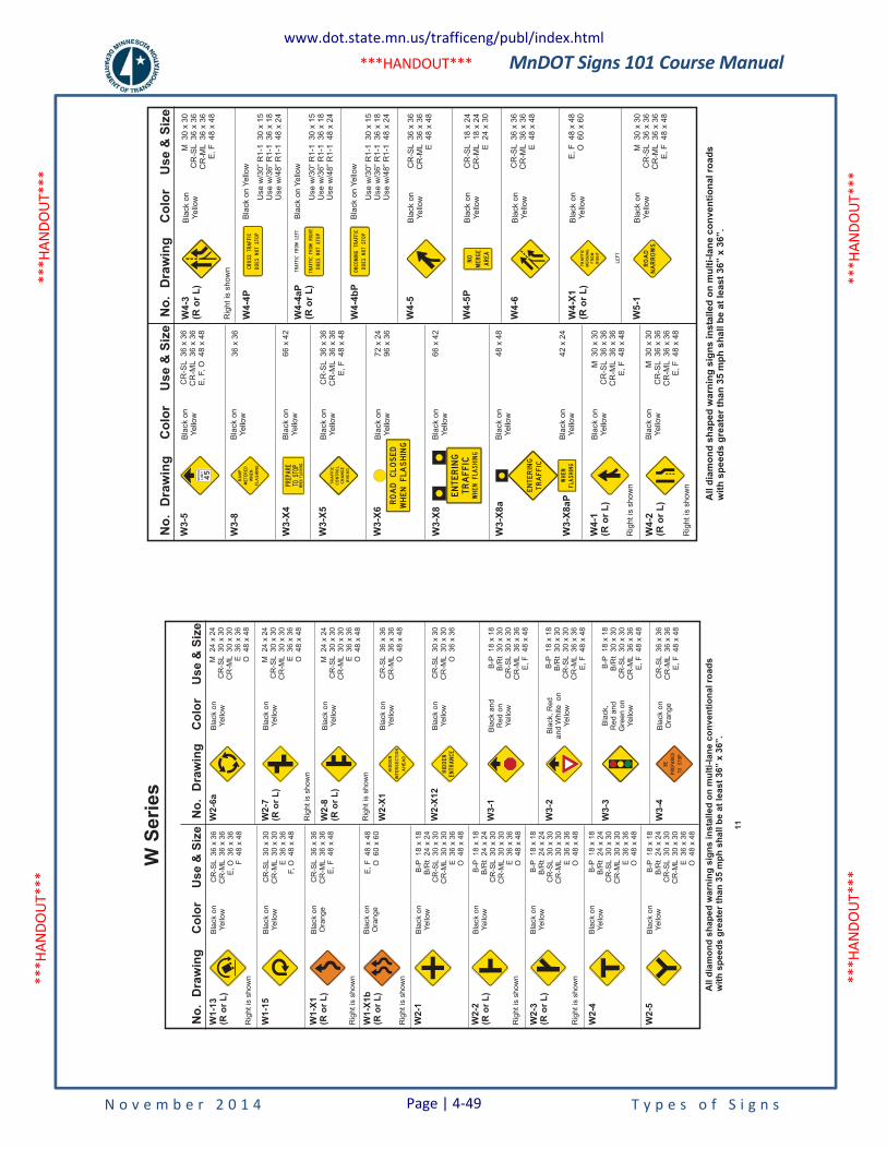
MnDOT Signs 101 Course Manual
N o v e m b e r 2 0 1 4 T y p e s o f S i g n s
***H
ANDO
UT**
* **
*HAN
DOUT
***
***H
ANDO
UT**
* **
*HAN
DOUT
***
***HANDOUT***
No
.D
raw
ing
Co
lor
Use
&S
ize
No
.D
raw
ing
Co
lor
Use
&S
ize
W1-1
3(R
or
L)
Bla
ck
on
Ye
llow
CR
-SL
36
x3
6C
R-M
L3
6x
36
E,
O3
6x
36
F4
8x
48
W1-1
5
W1-X
1(R
or
L)
W1-X
1b
(Ro
rL
)
W2-1
W2-2
(Ro
rL
)
W2-3
(Ro
rL
)
W2-4
Bla
ck
on
Ye
llow
Bla
ck
on
Ora
ng
e
Bla
ck
on
Ora
ng
e
Bla
ck
on
Ye
llow
Bla
ck
on
Ye
llow
Bla
ck
on
Ye
llow
Bla
ck
on
Ye
llow
CR
-SL
30
x3
0C
R-M
L3
0x
30
E3
6x
36
F,
O4
8x
48
CR
-SL
36
x3
6C
R-M
L3
6x
36
E,
F4
8x
48
E,
F4
8x
48
O6
0x
60
B-P
18
x1
8B
/Rt
24
x2
4C
R-S
L3
0x
30
CR
-ML
30
x3
0E
36
x3
6O
48
x4
8
B-P
18
x1
8B
/Rt
24
x2
4C
R-S
L3
0x
30
CR
-ML
30
x3
0E
36
x3
6O
48
x4
8
B-P
18
x1
8B
/Rt
24
x2
4C
R-S
L3
0x
30
CR
-ML
30
x3
0E
36
x3
6O
48
x4
8
B-P
18
x1
8B
/Rt
24
x2
4C
R-S
L3
0x
30
CR
-ML
30
x3
0E
36
x3
6O
48
x4
8
W2-5
Bla
ck
on
Ye
llow
B-P
18
x1
8B
/Rt
24
x2
4C
R-S
L3
0x
30
CR
-ML
30
x3
0E
36
x3
6O
48
x4
8
W2-6
aB
lack
on
Ye
llow
M2
4x
24
CR
-SL
30
x3
0C
R-M
L3
0x
30
E3
6x
36
O4
8x
48
W2-7
(Ro
rL
)
W2-8
(Ro
rL
)
W2-X
1
W2-X
12
W3-1
W3-2
Bla
ck
on
Ye
llow
Bla
ck
on
Ye
llow
Bla
ck
on
Ye
llow
Bla
ck
on
Ye
llow
Bla
ck
an
dR
ed
on
Ye
llow
Bla
ck,
Re
da
nd
Wh
ite
on
Ye
llow
CR
-SL
36
x3
6C
R-M
L3
6x
36
O4
8x
48
CR
-SL
30
x3
0C
R-M
L3
0x
30
O3
6x
36
M2
4x
24
CR
-SL
30
x3
0C
R-M
L3
0x
30
E3
6x
36
O4
8x
48
M2
4x
24
CR
-SL
30
x3
0C
R-M
L3
0x
30
E3
6x
36
O4
8x
48
B-P
18
x1
8B
/Rt
30
x3
0C
R-S
L3
0x
30
CR
-ML
36
x3
6E
,F
48
x4
8
B-P
18
x1
8B
/Rt
30
x3
0C
R-S
L3
0x
30
CR
-ML
36
x3
6E
,F
48
x4
8
HIDDEN
INTERSECTION
AHEAD
HIDDEN
ENTRANCE
All
dia
mo
nd
sh
ap
ed
warn
ing
sig
ns
insta
lled
on
mu
lti-
lan
eco
nven
tio
nal
road
sw
ith
sp
eed
sg
reate
rth
an
35
mp
hsh
all
be
at
least
36”
x36”.
Rig
ht
issh
ow
n
Rig
ht
issh
ow
n
Rig
ht
issh
ow
n
Rig
ht
issh
ow
n
Rig
ht
issh
ow
n
Rig
ht
issh
ow
n
Rig
ht
issh
ow
n
W3-3
Bla
ck,
Re
da
nd
Gre
en
on
Ye
llow
B-P
18
x1
8B
/Rt
30
x3
0C
R-S
L3
0x
30
CR
-ML
36
x3
6E
,F
48
x4
8
W3-4
Bla
ck
on
Ora
ng
e
CR
-SL
36
x3
6C
R-M
L3
6x
36
E,
F4
8x
48
BE
PREPARED
TOSTOP
11
W S
erie
sN
o.
Dra
win
gC
olo
rU
se
&S
ize
No
.D
raw
ing
Co
lor
Use
&S
ize
W3-5
W3-8
W3-X
4
W3-X
5
W3-X
6
W3-X
8
W3-X
8a
W3-X
8aP
Bla
ck
on
Ye
llow
Bla
ck
on
Ye
llow
Bla
ck
on
Ye
llow
Bla
ck
on
Ye
llow
Bla
ck
on
Ye
llow
Bla
ck
on
Ye
llow
Bla
ck
on
Ye
llow
Bla
ck
on
Ye
llow
36
x3
6
66
x4
2
CR
-SL
36
x3
6C
R-M
L3
6x
36
E,
F4
8x
48
72
x2
49
6x
36
66
x4
2
48
x4
8
42
x2
4
CR
-SL
36
x3
6C
R-M
L3
6x
36
E,
F,
O4
8x
48
SPEED
LIMIT
45
RAMP
METERED
WHEN
FLASHING
PREPARE
TOSTOP
WHENFLASHING
TRAFFIC
CONTROL
CHANGE
AHEAD
All
dia
mo
nd
sh
ap
ed
warn
ing
sig
ns
insta
lled
on
mu
lti-
lan
eco
nven
tio
nalro
ad
sw
ith
sp
eed
sg
reate
rth
an
35
mp
hsh
all
be
at
least
36”
x36”.
Bla
ck
on
Ye
llow
M3
0x
30
CR
-SL
36
x3
6C
R-M
L3
6x
36
E,
F4
8x
48
W4-1
(Ro
rL
)
Rig
ht
issh
ow
n
M3
0x
30
CR
-SL
36
x3
6C
R-M
L3
6x
36
E,
F4
8x
48
Bla
ck
on
Ye
llow
W4-2
(Ro
rL
)
Rig
ht
issh
ow
n
M3
0x
30
CR
-SL
36
x3
6C
R-M
L3
6x
36
E,
F4
8x
48
Bla
ck
on
Ye
llow
W4-4
P
W4-4
aP
(Ro
rL
)
W4-4
bP
W4-5
W4-5
P
W4-6
Bla
ck
on
Ye
llow
Bla
ck
on
Ye
llow
Bla
ck
on
Ye
llow
Bla
ck
on
Ye
llow
CR
-SL
36
x3
6C
R-M
L3
6x
36
E4
8x
48
Bla
ck
on
Ye
llow
Use
w/3
0”
R1
-13
0x
15
Use
w/3
6”
R1
-13
6x
18
Use
w/4
8”
R1
-14
8x
24
Bla
ck
on
Ye
llow
Use
w/3
0”
R1
-13
0x
15
Use
w/3
6”
R1
-13
6x
18
Use
w/4
8”
R1
-14
8x
24
Bla
ck
on
Ye
llow
Use
w/3
0”
R1
-13
0x
15
Use
w/3
6”
R1
-13
6x
18
Use
w/4
8”
R1
-14
8x
24
CR
-SL
18
x2
4C
R-M
L1
8x
24
E2
4x
30
CR
-SL
36
x3
6C
R-M
L3
6x
36
E4
8x
48
E,
F4
8x
48
O6
0x
60
W4-3
(Ro
rL
)
W4-X
1(R
or
L)
CROSSTRAFFIC
DOESNOTSTOP
TRAFFICFROMRIGHT
DOESNOTSTOP
TRAFFICFROMLEFT
DOESNOTSTOP
ONCOMINGTRAFFIC
NO
MERGE
AREA
Rig
ht
issh
ow
n
LEFT
W5-1
Bla
ck
on
Ye
llow
M3
0x
30
CR
-SL
36
x3
6C
R-M
L3
6x
36
E,
F4
8x
48
ROAD
NARROWS
www.dot.state.mn.us/trafficeng/publ/index.html
Page | 4-49
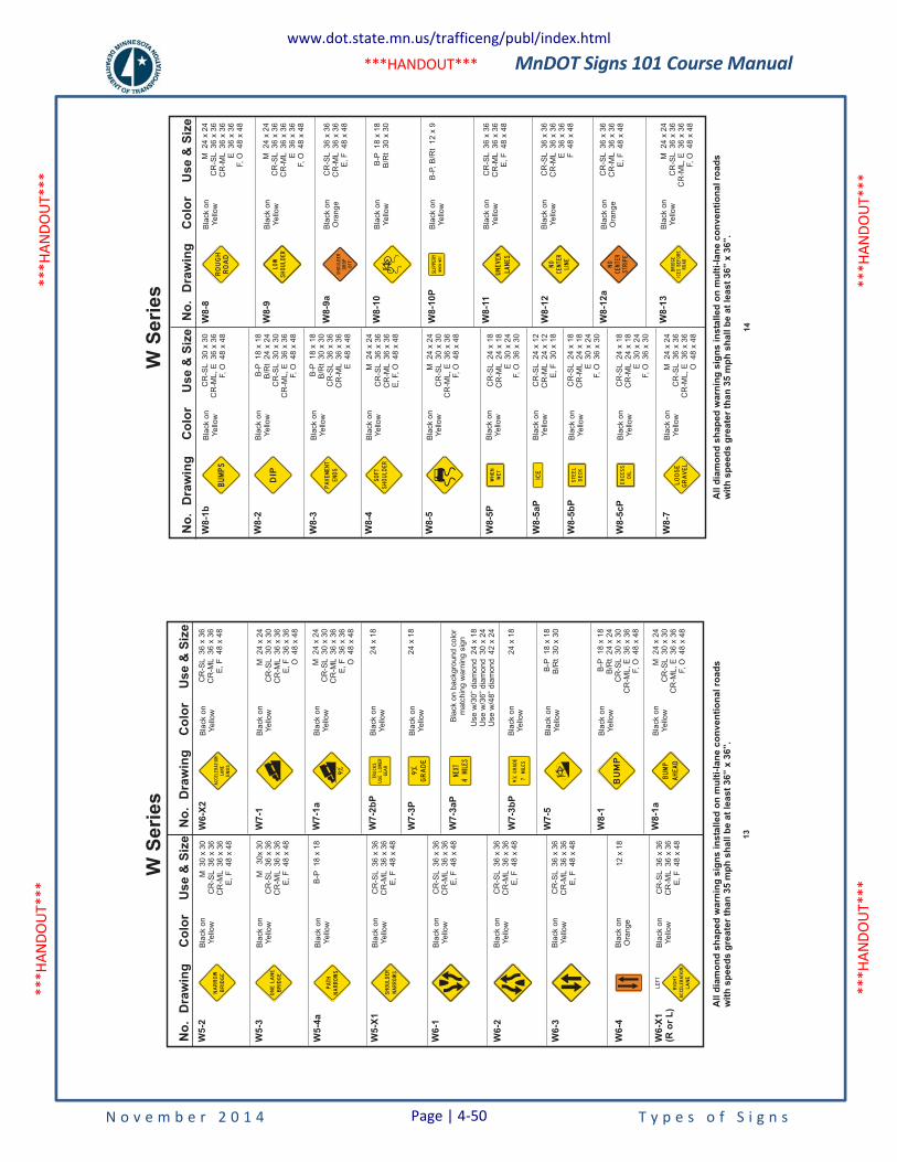
MnDOT Signs 101 Course Manual
N o v e m b e r 2 0 1 4 T y p e s o f S i g n s
***H
ANDO
UT**
* **
*HAN
DOUT
***
***H
ANDO
UT**
* **
*HAN
DOUT
***
***HANDOUT***
No
.D
raw
ing
Co
lor
Us
e&
Siz
e
W5
-2
W5
-3
W5
-4a
W5
-X1
W6
-1
W6
-2
W6
-3
W6
-4
Bla
ck
on
Ye
llow
Bla
ck
on
Ye
llow
Bla
ck
on
Ye
llow
Bla
ck
on
Ye
llow
Bla
ck
on
Ye
llow
Bla
ck
on
Ye
llow
Bla
ck
on
Ye
llow
Bla
ck
on
Ora
ng
e
M3
0x
30
CR
-SL
36
x3
6C
R-M
L3
6x
36
E,
F4
8x
48
B-P
18
x1
8
M3
0x
30
CR
-SL
36
x3
6C
R-M
L3
6x
36
E,
F4
8x
48
CR
-SL
36
x3
6C
R-M
L3
6x
36
E,
F4
8x
48
CR
-SL
36
x3
6C
R-M
L3
6x
36
E,
F4
8x
48
CR
-SL
36
x3
6C
R-M
L3
6x
36
E,
F4
8x
48
CR
-SL
36
x3
6C
R-M
L3
6x
36
E,
F4
8x
48
12
x1
8
No
.D
raw
ing
Co
lor
Us
e&
Siz
e
CR
-SL
36
x3
6C
R-M
L3
6x
36
E,
F4
8x
48
W6
-X2
W7
-1
W7
-1a
W7
-2b
P
W7
-3P
W7
-3a
P
W7
-3b
P
W7
-5
W8
-1
Bla
ck
on
Ye
llow
Bla
ck
on
Ye
llow
Bla
ck
on
Ye
llow
Bla
ck
on
Ye
llow
Bla
ck
on
Ye
llow
Bla
ck
on
ba
ckg
rou
nd
co
lor
ma
tch
ing
wa
rnin
gsig
n
Bla
ck
on
Ye
llow
Bla
ck
on
Ye
llow
Bla
ck
on
Ye
llow
M2
4x
24
CR
-SL
30
x3
0C
R-M
L3
6x
36
E,
F3
6x
36
O4
8x
48
M2
4x
24
CR
-SL
30
x3
0C
R-M
L3
6x
36
E,
F3
6x
36
O4
8x
48
24
x1
8
24
x1
8
Use
w/3
0”
dia
mo
nd
24
x1
8U
se
w/3
6”
dia
mo
nd
30
x2
4U
se
w/4
8”
dia
mo
nd
42
x2
4
24
x1
8
B-P
18
x1
8B
/Rt
30
x3
0
B-P
18
x1
8B
/Rt
24
x2
4C
R-S
L3
0x
30
CR
-ML
,E
36
x3
6F,
O4
8x
48
BRIDGE
NARROW
BRIDGE
ONELANE
NARROWS
PATH
9 GEAR
TRUCKS
LOWER
USE
GRADE
9 MILES
4
NEXT
GRADE
MILES
79
SHOULDER
NARROWS
ACCELERATION
LANE
ENDS
BUMP
All
dia
mo
nd
sh
ap
ed
wa
rnin
gs
ign
sin
sta
lle
do
nm
ult
i-la
ne
co
nv
en
tio
na
lro
ad
sw
ith
sp
ee
ds
gre
ate
rth
an
35
mp
hs
ha
llb
ea
tle
as
t3
6”
x3
6”.
W6
-X1
(Ro
rL
)B
lack
on
Ye
llow
CR
-SL
36
x3
6C
R-M
L3
6x
36
E,
F4
8x
48
ACCELERATION
RIGHT
LANE
LEFT
W8
-1a
Bla
ck
on
Ye
llow
M2
4x
24
CR
-SL
30
x3
0C
R-M
L,
E3
6x
36
F,
O4
8x
48
BUMP
AHEAD
13
W S
erie
sN
o.
Dra
win
gC
olo
rU
se
&S
ize
W8-1
b
W8-2
W8-3
W8-4
W8-5
W8-5
P
W8-5
aP
W8-5
bP
W8-5
cP
Bla
ck
on
Ye
llow
Bla
ck
on
Ye
llow
Bla
ck
on
Ye
llow
Bla
ck
on
Ye
llow
Bla
ck
on
Ye
llow
Bla
ck
on
Ye
llow
Bla
ck
on
Ye
llow
Bla
ck
on
Ye
llow
Bla
ck
on
Ye
llow
CR
-SL
30
x3
0C
R-M
L,
E3
6x
36
F,
O4
8x
48
B-P
18
x1
8B
/Rt
24
x2
4C
R-S
L3
0x
30
CR
-ML
,E
36
x3
6F,
O4
8x
48
B-P
18
x1
8B
/Rt
30
x3
0C
R-S
L3
6x
36
CR
-ML
36
x3
6E
48
x4
8
M2
4x
24
CR
-SL
36
x3
6C
R-M
L3
6x
36
E,
F,
O4
8x
48
M2
4x
24
CR
-SL
30
x3
0C
R-M
L,
E3
6x
36
F,
O4
8x
48
CR
-SL
24
x1
8C
R-M
L2
4x
18
E3
0x
24
F,
O3
6x
30
CR
-SL
24
x1
2C
R-M
L2
4x
12
E,
F3
0x
18
CR
-SL
24
x1
8C
R-M
L2
4x
18
E3
0x
24
F,
O3
6x
30
CR
-SL
24
x1
8C
R-M
L2
4x
18
E3
0x
24
F,
O3
6x
30
No
.D
raw
ing
Co
lor
Use
&S
ize
M2
4x
24
CR
-SL
36
x3
6C
R-M
L3
6x
36
E3
6x
36
F,
O4
8x
48
M2
4x
24
CR
-SL
36
x3
6C
R-M
L3
6x
36
E3
6x
36
F,
O4
8x
48
W8-8
W8-9
W8-9
a
W8-1
0
W8-1
0P
W8-1
1
W8-1
2
W8-1
2a
Bla
ck
on
Ye
llow
Bla
ck
on
Ye
llow
Bla
ck
on
Ora
ng
e
Bla
ck
on
Ye
llow
Bla
ck
on
Ye
llow
Bla
ck
on
Ye
llow
Bla
ck
on
Ye
llow
Bla
ck
on
Ora
ng
e
CR
-SL
36
x3
6C
R-M
L3
6x
36
E,
F4
8x
48
B-P
18
x1
8B
/Rt
30
x3
0
B-P
,B
/Rt
12
x9
CR
-SL
36
x3
6C
R-M
L3
6x
36
E,
F4
8x
48
CR
-SL
36
x3
6C
R-M
L3
6x
36
E3
6x
36
F4
8x
48
CR
-SL
36
x3
6C
R-M
L3
6x
36
E,
F4
8x
48
BUMPS
DIP
PAVEMENT
ENDS
SOFT
SHOULDER
WHEN
WET
ICE
STEEL
DECK
EXCESS
OIL
W8-7
Bla
ck
on
Ye
llow
M2
4x
24
CR
-SL
36
x3
6C
R-M
L,
E3
6x
36
O4
8x
48
LOOSE
GRAVEL
ROUGH
ROAD
LOW
SHOULDER
SHOULDER
DROP
OFF
UNEVEN
LANES
NO
CENTER
LINE
NO
CENTER
STRIPE
All
dia
mo
nd
sh
ap
ed
warn
ing
sig
ns
insta
lled
on
mu
lti-
lan
eco
nven
tio
nalro
ad
sw
ith
sp
eed
sg
reate
rth
an
35
mp
hsh
all
be
at
least
36”
x36”.
W8-1
3B
lack
on
Ye
llow
M2
4x
24
CR
-SL
36
x3
6C
R-M
L,
E3
6x
36
F,
O4
8x
48
BRIDGE
ICESBEFORE
ROAD
14
W S
erie
s
www.dot.state.mn.us/trafficeng/publ/index.html
Page | 4-50
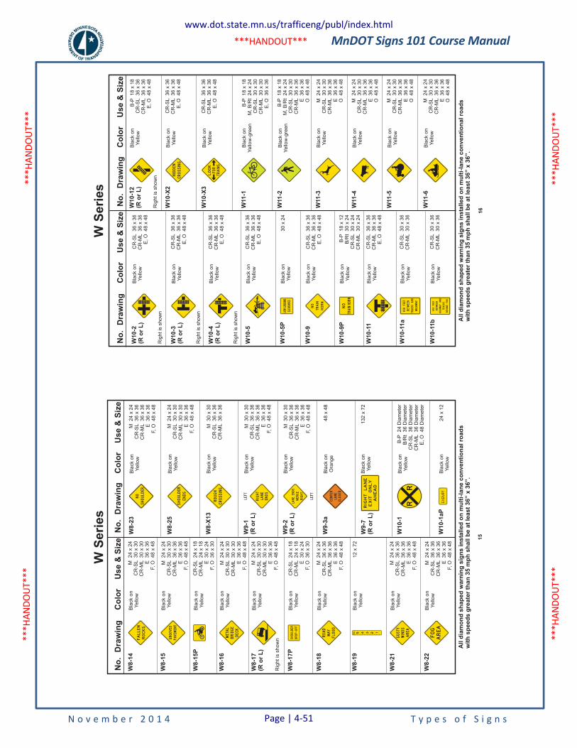
MnDOT Signs 101 Course Manual
N o v e m b e r 2 0 1 4 T y p e s o f S i g n s
***H
ANDO
UT**
* **
*HAN
DOUT
***
***H
ANDO
UT**
* **
*HAN
DOUT
***
***HANDOUT***
No
.D
raw
ing
Co
lor
Use
&S
ize
W8
-14
W8
-15
W8
-15
P
W8
-16
W8
-17
(Ro
rL
)
W8
-17
P
W8
-18
W8
-21
W8
-19
Bla
ck
on
Yello
w
Bla
ck
on
Yello
w
Bla
ck
on
Yello
w
Bla
ck
on
Yello
w
Bla
ck
on
Yello
w
Bla
ck
on
Yello
w
Bla
ck
on
Yello
w
Bla
ck
on
Yello
w
Bla
ck
on
Yello
w
M24
x24
CR
-SL
30
x30
CR
-ML
30
x30
E36
x36
F,O
48
x48
CR
-SL
24
x18
CR
-ML
24
x18
E30
x24
F,O
36
x30
M24
x24
CR
-SL
30
x30
CR
-ML
36
x36
E36
x36
F,O
48
x48
M24
x24
CR
-SL
30
x30
CR
-ML
30
x30
E36
x36
F,O
48
x48
M24
x24
CR
-SL
30
x30
CR
-ML
30
x30
E36
x36
F,O
48
x48
M24
x24
CR
-SL
36
x36
CR
-ML
36
x36
E36
x36
F,O
48
x48
M24
x24
CR
-SL
36
x36
CR
-ML
36
x36
E36
x36
F,O
48
x48
CR
-SL
24
x18
CR
-ML
24
x18
E30
x24
F,O
36
x30
12
x72
No
.D
raw
ing
Co
lor
Use
&S
ize
M24
x24
CR
-SL
36
x36
CR
-ML
36
x36
E36
x36
F,O
48
x48
M24
x24
CR
-SL
30
x30
CR
-ML
30
x30
E36
x36
F,O
48
x48
W8
-23
W8
-25
W8
-X1
3
W9
-1(R
or
L)
W9
-2(R
or
L)
W9
-3a
W9
-7(R
or
L)
W1
0-1
Bla
ck
on
Yello
w
Bla
ck
on
Yello
w
Bla
ck
on
Yello
w
Bla
ck
on
Yello
w
Bla
ck
on
Yello
w
Bla
ck
on
Ora
nge
Bla
ck
on
Yello
w
Bla
ck
on
Yello
w
M30
x30
CR
-SL
36
x36
CR
-ML
36
x36
M30
x30
CR
-SL
36
x36
CR
-ML
36
x36
E36
x36
F,O
48
x48
M30
x30
CR
-SL
36
x36
CR
-ML
36
x36
E36
x36
F,O
48
x48
48
x48
132
x72
B-P
24
Dia
mete
rB
/Rt
36
Dia
mete
rC
R-S
L36
Dia
mete
rC
R-M
L36
Dia
mete
rE
,O
48
Dia
mete
r
ROCKS
FALLEN
GROOVED
PAVEMENT
METAL
BRIDGE
DECK
SHOULDER
DROP-OFF
ROAD
MAY
FLOOD
12345FEET
GUSTY
WINDS
AREA
W8
-22
Bla
ck
on
Yello
wM
24
x24
CR
-SL
36
x36
CR
-ML
36
x36
E36
x36
F,O
48
x48
AREA
FOG
NO
SHOULDER
SHOULDER
ENDS
ROUGH
CROSSING
RIGHT
LANE
ENDS
LANEENDS
MERGE
RIGHT
RIGHTLANE
EXIT
ONLY
AHEAD
RR
CENTER
LANE
CLOSED
All
dia
mo
nd
sh
ap
ed
wa
rnin
gs
ign
sin
sta
lle
do
nm
ult
i-la
ne
co
nv
en
tio
na
lro
ad
sw
ith
sp
ee
ds
gre
ate
rth
an
35
mp
hs
ha
llb
ea
tle
as
t3
6”
x3
6”.
Rig
htis
show
n
LEFT
LEFT
W1
0-1
aP
Bla
ck
on
Yello
w24
x12
EX
EM
PT
15
W S
erie
sN
o.
Dra
win
gC
olo
rU
se
&S
ize
W10-2
(Ro
rL
)
W10-3
(Ro
rL
)
W10-4
(Ro
rL
)
W10-5
W10-5
P
W10-9
W10-9
P
W10-1
1
W10-1
1a
W10-1
1b
Bla
ck
on
Ye
llow
Bla
ck
on
Ye
llow
Bla
ck
on
Ye
llow
Bla
ck
on
Ye
llow
Bla
ck
on
Ye
llow
Bla
ck
on
Ye
llow
Bla
ck
on
Ye
llow
Bla
ck
on
Ye
llow
Bla
ck
on
Ye
llow
Bla
ck
on
Ye
llow
CR
-SL
36
x3
6C
R-M
L3
6x
36
E,
O4
8x
48
CR
-SL
36
x3
6C
R-M
L3
6x
36
E,
O4
8x
48
CR
-SL
36
x3
6C
R-M
L3
6x
36
E,
O4
8x
48
CR
-SL
36
x3
6C
R-M
L3
6x
36
E,
O4
8x
48
30
x2
4
B-P
18
x1
2B
/Rt
30
x2
4C
R-S
L3
0x
24
CR
-ML
30
x2
4
CR
-SL
36
x3
6C
R-M
L3
6x
36
E,
O4
8x
48
CR
-SL
36
x3
6C
R-M
L3
6x
36
E,
O4
8x
48
CR
-SL
36
x3
6C
R-M
L3
6x
36
E,
O4
8x
48
CR
-SL
36
x3
6C
R-M
L3
6x
36
E,
O4
8x
48
CR
-SL
30
x3
6C
R-M
L3
0x
36
CR
-SL
30
x3
6C
R-M
L3
0x
36
No
.D
raw
ing
Co
lor
Use
&S
ize
W10-1
2(R
or
L)
Bla
ck
on
Ye
llow
B-P
18
x1
8C
R-S
L3
6x
36
CR
-ML
36
x3
6E
,O
48
x4
8
W11-1
W10-X
2
W10-X
3
W11-2
W11-3
W11-4
W11-5
W11-6
Bla
ck
on
Ye
llow
-gre
en
Bla
ck
on
Ye
llow
Bla
ck
on
Ye
llow
Bla
ck
on
Ye
llow
-gre
en
Bla
ck
on
Ye
llow
Bla
ck
on
Ye
llow
Bla
ck
on
Ye
llow
Bla
ck
on
Ye
llow
B-P
18
x1
8M
,B
/Rt
24
x2
4C
R-S
L3
0x
30
CR
-ML
30
x3
0E
,O
36
x3
6
B-P
18
x1
8M
,B
/Rt
24
x2
4C
R-S
L3
0x
30
CR
-ML
36
x3
6E
36
x3
6O
48
x4
8
M2
4x
24
CR
-SL
30
x3
0C
R-M
L3
6x
36
E3
6x
36
O4
8x
48
M2
4x
24
CR
-SL
30
x3
0C
R-M
L3
6x
36
E3
6x
36
O4
8x
48
M2
4x
24
CR
-SL
30
x3
0C
R-M
L3
6x
36
E3
6x
36
O4
8x
48
M2
4x
24
CR
-SL
30
x3
0C
R-M
L3
6x
36
E3
6x
36
O4
8x
48
LOWGROUND
CLEARANCE
NO
TRAIN
HORN
NO
TRAINHORN
100FEET
BETWEEN
TRACKSAND
HIGHWAY
BETWEEN
HIGHWAYAND
TRACKS
BEHINDYOU
100FEET
All
dia
mo
nd
sh
ap
ed
warn
ing
sig
ns
insta
lled
on
mu
lti-
lan
eco
nven
tio
nalro
ad
sw
ith
sp
eed
sg
reate
rth
an
35
mp
hsh
all
be
at
least
36”
x36”.
Rig
ht
issh
ow
nR
igh
tis
sh
ow
n
Rig
ht
issh
ow
n
Rig
ht
issh
ow
n
HIDDEN
CROSSING
LOOK
TRAINS
FOR
16
W S
erie
s
www.dot.state.mn.us/trafficeng/publ/index.html
Page | 4-51
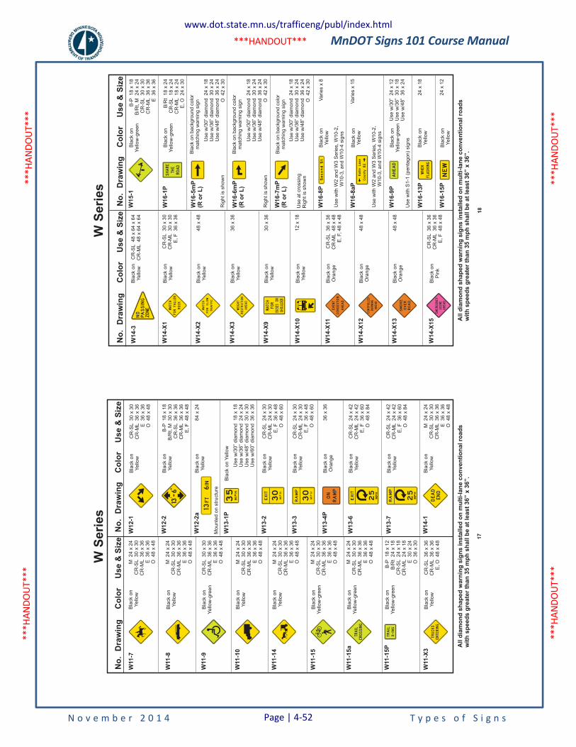
MnDOT Signs 101 Course Manual
N o v e m b e r 2 0 1 4 T y p e s o f S i g n s
***H
ANDO
UT**
* **
*HAN
DOUT
***
***H
ANDO
UT**
* **
*HAN
DOUT
***
***HANDOUT***
No
.D
raw
ing
Co
lor
Us
e&
Siz
e
W11
-9
W11
-10
W11
-14
W11
-15
W11
-15
a
W11
-15
P
W11
-X3
Bla
ck
on
Ye
llow
-gre
en
Bla
ck
on
Ye
llow
Bla
ck
on
Ye
llow
Bla
ck
on
Ye
llow
-gre
en
Bla
ck
on
Ye
llow
-gre
en
Bla
ck
on
Ye
llow
-gre
en
Bla
ck
on
Ye
llow
CR
-SL
30
x3
0C
R-M
L3
6x
36
E3
6x
36
O4
8x
48
M2
4x
24
CR
-SL
30
x3
0C
R-M
L3
6x
36
E3
6x
36
O4
8x
48
M2
4x
24
CR
-SL
30
x3
0C
R-M
L3
6x
36
E3
6x
36
O4
8x
48
M2
4x
24
CR
-SL
30
x3
0C
R-M
L3
6x
36
E3
6x
36
O4
8x
48
M2
4x
24
CR
-SL
30
x3
0C
R-M
L3
6x
36
E3
6x
36
O4
8x
48
B-P
18
x1
2B
/Rt
24
x1
8C
R-S
L2
4x
18
CR
-ML
24
x1
8E
30
x2
4O
36
x3
0
CR
-SL
36
x3
6C
R-M
L3
6x
36
E,
O4
8x
48
No
.D
raw
ing
Co
lor
Us
e&
Siz
e
W1
2-2
aB
lack
on
Ye
llow
Mo
un
ted
on
str
uctu
re
84
x2
4
W1
3-1
P
W1
3-2
W1
3-3
W1
3-4
P
W1
3-6
W1
3-7
W1
4-1
Bla
ck
on
Ye
llow
Bla
ck
on
Ye
llow
Bla
ck
on
Ye
llow
Bla
ck
on
Ora
ng
e
Bla
ck
on
Ye
llow
Bla
ck
on
Ye
llow
Bla
ck
on
Ye
llow
Use
w/3
0”
dia
mo
nd
18
x1
8U
se
w/3
6”
dia
mo
nd
24
x2
4U
se
w/4
8”
dia
mo
nd
30
x3
0U
se
w/6
0”
dia
mo
nd
36
x3
6
CR
-SL
24
x3
0C
R-M
L2
4x
30
E,
F3
6x
48
O4
8x
60
CR
-SL
24
x3
0C
R-M
L2
4x
30
E,
F3
6x
48
O4
8x
60
36
x3
6
CR
-SL
24
x4
2C
R-M
L2
4x
42
E,
F3
6x
60
O4
8x
84
CR
-SL
24
x4
2C
R-M
L2
4x
42
E,
F3
6x
60
O4
8x
84
M2
4x
24
CR
-SL
30
x3
0C
R-M
L3
6x
36
E3
6x
36
O4
8x
48
TRAIL
CROSSING
TRUCKS
ENTERING
35
MPH
MPH
30
EXIT
RAMP
ON
EXIT
25
MPH
RAMP
25
MPH
DEAD
END
W1
2-1
Bla
ck
on
Ye
llow
CR
-SL
30
x3
0C
R-M
L3
6x
36
E3
6x
36
O4
8x
48
FT
13IN6
W1
2-2
Bla
ck
on
Ye
llow
B-P
18
x1
8B
/Rt,
M3
0x
30
CR
-SL
36
x3
6C
R-M
L3
6x
36
E,
F4
8x
48
136
All
dia
mo
nd
sh
ap
ed
wa
rnin
gs
ign
sin
sta
lle
do
nm
ult
i-la
ne
co
nv
en
tio
na
lro
ad
sw
ith
sp
ee
ds
gre
ate
rth
an
35
mp
hs
ha
llb
ea
tle
as
t3
6”
x3
6”.
W11
-8B
lack
on
Ye
llow
M2
4x
24
CR
-SL
30
x3
0C
R-M
L3
6x
36
E3
6x
36
O4
8x
48
MPH
30
RAMP
W11
-7B
lack
on
Ye
llow
M2
4x
24
CR
-SL
30
x3
0C
R-M
L3
6x
36
E3
6x
36
O4
8x
48
17
W S
erie
sN
o.
Dra
win
gC
olo
rU
se
&S
ize
W14-X
2
W14-X
3
W14-X
9
W14-X
10
W14-X
11
W14-X
12
W14-X
13
W14-X
15
Bla
ck
on
Ye
llow
Bla
ck
on
Ye
llow
Bla
ck
on
Ye
llow
Bla
ck
on
Ye
llow
Bla
ck
on
Ora
ng
e
Bla
ck
on
Ora
ng
e
Bla
ck
on
Ora
ng
e
Bla
ck
on
Pin
k
48
x4
8
36
x3
6
12
x1
8
30
x3
6
CR
-SL
36
x3
6C
R-M
L4
8x
48
E,
F,
48
x4
8
48
x4
8
48
x4
8
CR
-SL
36
x3
6C
R-M
L3
6x
36
E,
F4
8x
48
No
.D
raw
ing
Co
lor
Use
&S
ize
W16-1
PB
lack
on
Ye
llow
-gre
en
B/R
t1
8x
24
CR
-SL
18
x2
4C
R-M
L1
8x
24
E,
O2
4x
30
W16-5
mP
(Ro
rL
)
W16-6
mP
(Ro
rL
)
W16-7
mP
(Ro
rL
)
W16-8
P
W16-8
aP
W16-9
P
W16-1
3P
W16-1
5P
Bla
ck
on
Ye
llow
Use
with
W2
an
dW
3S
erie
s,
W1
0-2
,W
10
-3,
an
dW
10
-4sig
ns
Use
with
W2
an
dW
3S
erie
s,
W1
0-2
,W
10
-3,
an
dW
10
-4sig
ns
Bla
ck
on
Ye
llow
Bla
ck
on
Ye
llow
-gre
en
Bla
ck
on
Ye
llow
Bla
ck
on
Ye
llow
Use
w/3
0”
24
x1
2U
se
w/3
6”
30
x1
8U
se
w/4
8”
36
x2
4
Va
rie
sx
8
Va
rie
sx
15
24
x1
8
24
x1
2
WATCH
FOR
TRAFFIC
SLOW
WEIGHT
RESTRICTION
AHEAD
SHOULDER
BUSES
FOR
WATCH ON
EVENT
AHEAD
CONGESTION
CONTROLLED
BURNING
AHEAD
SMOKE
OVER
ROAD
EMERGENCY
SCENE
AHEAD
W15-1
Bla
ck
on
Ye
llow
-gre
en
B-P
18
x1
8B
/Rt,
M2
4x
24
CR
-SL
30
x3
0C
R-M
L3
6x
36
E3
6x
36
SHARE
THE
ROAD
AHEAD
WHEN
FLASHING
NEW
KatieLane
County
B2
Second
St
Bla
ck
on
ba
ckg
rou
nd
co
lor
ma
tch
ing
wa
rnin
gsig
n
Bla
ck
on
ba
ckg
rou
nd
co
lor
ma
tch
ing
wa
rnin
gsig
n
Bla
ck
on
ba
ckg
rou
nd
co
lor
ma
tch
ing
wa
rnin
gsig
n
Use
w/3
0”
dia
mo
nd
24
x1
8U
se
w/3
6”
dia
mo
nd
30
x2
4U
se
w/4
8”
dia
mo
nd
36
x2
4O
42
x3
0
Use
w/3
0”
dia
mo
nd
24
x1
8U
se
w/3
6”
dia
mo
nd
30
x2
4U
se
w/4
8”
dia
mo
nd
36
x2
4O
42
x3
0
Use
w/3
0”
dia
mo
nd
24
x1
8U
se
w/3
6”
dia
mo
nd
30
x2
4U
se
w/4
8”
dia
mo
nd
36
x2
4O
42
x3
0
All
dia
mo
nd
sh
ap
ed
warn
ing
sig
ns
insta
lled
on
mu
lti-
lan
eco
nven
tio
nalro
ad
sw
ith
sp
eed
sg
reate
rth
an
35
mp
hsh
all
be
at
least
36”
x36”.
Use
with
S1
-1(p
en
tag
on
)sig
ns
W14-X
1B
lack
on
Ye
llow
CR
-SL
30
x3
0C
R-M
L3
0x
30
E,
F3
6x
36
WATCH
FOR ROCK
FALLEN
Use
at
cro
ssin
gR
igh
tis
sh
ow
n
W14-3
Bla
ck
on
Ye
llow
CR
-SL
48
x6
4x
64
CR
-ML
48
x6
4x
64
NOPASSING
ZONE
Rig
ht
issh
ow
n
Rig
ht
issh
ow
n
18
W S
erie
s
www.dot.state.mn.us/trafficeng/publ/index.html
Page | 4-52
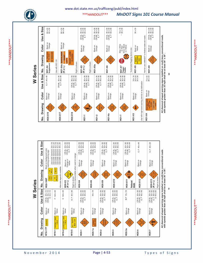
MnDOT Signs 101 Course Manual
N o v e m b e r 2 0 1 4 T y p e s o f S i g n s
***H
ANDO
UT**
* **
*HAN
DOUT
***
***H
ANDO
UT**
* **
*HAN
DOUT
***
***HANDOUT***
No
.D
raw
ing
Co
lor
Us
e&
Siz
e
W1
9-1
W1
9-2
W1
9-5
W2
0-1
W2
0-1
a
W2
0-2
W2
0-3
W2
0-3
a
W2
0-4
W2
0-7
Bla
ck
on
Ye
llow
Bla
ck
on
Ye
llow
Bla
ck
on
Ye
llow
Bla
ck
on
Ora
ng
e
Bla
ck
on
Ora
ng
e
Bla
ck
on
Ora
ng
e
Bla
ck
on
Ora
ng
e
Bla
ck
on
Ora
ng
e
Bla
ck
on
Ora
ng
e
Bla
ck
on
Ora
ng
e
F1
44
x4
8
E1
44
x4
8
CR
-SL
36
x3
6C
R-M
L3
6x
36
E,
F4
8x
48
CR
-SL
36
x3
6C
R-M
L3
6x
36
E,
F4
8x
48
CR
-SL
36
x3
6C
R-M
L3
6x
36
E,
F4
8x
48
CR
-SL
36
x3
6C
R-M
L3
6x
36
E,
F4
8x
48
CR
-SL
36
x3
6C
R-M
L3
6x
36
E,
F4
8x
48
CR
-SL
36
x3
6C
R-M
L3
6x
36
E,
F4
8x
48
CR
-SL
36
x3
6C
R-M
L3
6x
36
E,
F4
8x
48
CR
-SL
36
x3
6C
R-M
L3
6x
36
E,
F4
8x
48
CR
-SL
36
x3
6C
R-M
L3
6x
36
E,
F4
8x
48
CR
-SL
36
x3
6C
R-M
L3
6x
36
E,
F4
8x
48
CR
-SL
36
x3
6C
R-M
L3
6x
36
E,
F4
8x
48
O6
0x
60
B-P
18
x1
8
36
x1
8
E,
F9
0x
48
No
.D
raw
ing
Co
lor
Us
e&
Siz
e
W2
0-X
3(R
or
L)
Bla
ck
on
Ora
ng
eo
rY
ello
w
W2
0-X
4
W2
0-X
6
W2
0-X
9
W2
0-X
10
W2
0-X
11
Red
uce
dW
idth
W2
0-X
12
W2
0-X
13
(Ro
rL
)
Bla
ck
on
Ora
ng
e
Bla
ck
on
Ora
ng
e
Bla
ck
on
Ora
ng
e
Bla
ck
on
Ora
ng
e
Bla
ck
on
Ora
ng
e
Bla
ck
on
Ora
ng
e
Bla
ck
on
Ora
ng
e
E,
F4
8x
48
E,
F4
8x
48
ALLTRAFFIC
MUSTEXIT
ROAD
WORK
AHEAD
DETOUR
AHEAD
ROAD
CLOSED
AHEAD
ONELANE
ROAD
AHEAD
FREEWAY
ENDS
1MILE
EXPRESSWAY
ENDS
1MILE
TRAIL
CLOSED
AHEAD
SIDEWALK
WORKAHEAD
Bla
ck
on
ba
ckg
rou
nd
co
lor
ma
tch
ing
wa
rnin
gsig
n
Use
w/3
0”
dia
mo
nd
24
x1
8U
se
w/3
6”
dia
mo
nd
30
x2
4U
se
w/4
8”
dia
mo
nd
42
x1
8U
se
w/4
8”
dia
mo
nd
42
x2
4U
se
w/6
0”
dia
mo
nd
48
x3
6
W2
0-1
00
P
Alte
rna
tele
ge
nd
sa
va
ilab
le
500
FEET
1/4
MILE
15MILES
2MILES
MERGE
AHEAD
BYPASS
RIGHT
CLOSED
LANES
TWO
10 FT
AHEAD
BRIDGE
CLOSED
AHEAD
BRIDGE
WORK
AHEAD
SIGNAL
WORK
CENTER
MERGE
LEFT
LANE
All
dia
mo
nd
sh
ap
ed
wa
rnin
gs
ign
sin
sta
lle
do
nm
ult
i-la
ne
co
nv
en
tio
na
lro
ad
sw
ith
sp
ee
ds
gre
ate
rth
an
35
mp
hs
ha
llb
ea
tle
as
t3
6”
x3
6”.
Rig
ht
issh
ow
n
Rig
ht
issh
ow
nA
rro
wis
de
mo
un
tab
lew
he
nu
se
do
no
ran
ge
W1
6-1
7P
Bla
ck
on
Ye
llow
CR
-SL
36
x1
2C
R-M
L3
6x
12
O4
2x
12
ROUNDABOUT
19
W S
erie
sN
o.
Dra
win
gC
olo
rU
se
&S
ize
W20-X
18
W21-1
W21-2
W21-6
a
W21-7
W21-X
4
W21-X
3
Bla
ck
on
Ora
ng
e
Bla
ck
on
Ora
ng
e
Bla
ck
on
Ora
ng
e
Bla
ck
on
Ora
ng
e
Bla
ck
on
Ora
ng
e
Bla
ck
on
Ora
ng
e
Bla
ck
on
Ora
ng
e
CR
-SL
36
x3
6C
R-M
L3
6x
36
E,
F4
8x
48
CR
-SL
36
x3
6C
R-M
L3
6x
36
E,
F4
8x
48
CR
-SL
36
x3
6C
R-M
L3
6x
36
E,
F4
8x
48
CR
-SL
36
x3
6C
R-M
L3
6x
36
E,
F4
8x
48
CR
-SL
36
x3
6C
R-M
L3
6x
36
E,
F4
8x
48
CR
-SL
36
x3
6C
R-M
L3
6x
36
E,
F4
8x
48
CR
-SL
36
x3
6C
R-M
L3
6x
36
E,
F4
8x
48
CR
-SL
36
x3
6C
R-M
L3
6x
36
E,
F4
8x
48
CR
-SL
36
x3
6C
R-M
L3
6x
36
E,
F4
8x
48
18
x1
82
4x
24
30
x3
0
72
x4
29
6x
54
No
.D
raw
ing
Co
lor
Use
&S
ize
W21-X
5(R
or
L)
Bla
ck
on
Ora
ng
e
Bla
ck
on
Ora
ng
e
Bla
ck
on
Ora
ng
e
Bla
ck
on
Ora
ng
e
W21-X
5a
W21-X
6
W21-X
7F
lag
ge
rP
ad
dle
*A
uto
ma
ted
fla
gg
ing
de
vic
esiz
e
W21-X
8
W21-X
9
Sto
p:
Wh
ite
on
Re
dS
low
:B
lack
on
Ye
llow
Bla
ck
on
Ye
llow
No
tfo
ru
se
on
Mn
DO
To
rfe
de
ralsta
tea
idro
ad
s
18
x1
8*
36
x3
6
36
x3
0
CLOSED
TURN
LANE
FRESH
OIL
RIGHT
LANE
CLOSED
CREW
WORKING
AHEAD
MINIMUM
MAINTENANCE
ROAD
TRAVELATYOUROWNRISK
HIGH
SHOULDER
SURVEY
CREW
AHEAD
UTILITY
WORK
AHEAD
ROAD
RIGHT
CLOSED
LANE
AHEAD
WORK
LEFTLANE
RAMP
SHOULDER
CLOSED SLOW
W21-X
4S
up
ple
me
nt
W21-X
4a
(Ro
rL
)
Bla
ck
on
Ora
ng
e
Bla
ck
on
Ora
ng
e
60
x2
08
0x
26
66
x2
49
6x
36
BETOSTOP
PREPARED
NOSHOULDER
All
dia
mo
nd
sh
ap
ed
warn
ing
sig
ns
insta
lled
on
mu
lti-
lan
eco
nven
tio
nalro
ad
sw
ith
sp
eed
sg
reate
rth
an
35
mp
hsh
all
be
at
least
36”
x36”.
Use
with
hig
hle
ve
lw
arn
ing
de
vic
eo
ra
sd
elin
ea
tor
Rig
ht
issh
ow
n
Rig
ht
issh
ow
n
Use
with
W2
1-X
4
W20-X
16
W20-X
17
Bla
ck
on
Ora
ng
e
Bla
ck
on
Ora
ng
e
E,
F4
8x
48
CR
-ML
36
x3
6E
,F
48
x4
8LANES
NARROW
RAMP
AHEAD
CLOSED
20
W S
erie
s
www.dot.state.mn.us/trafficeng/publ/index.html
Page | 4-53
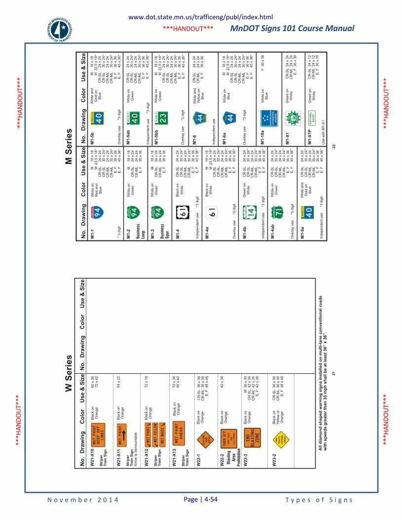
MnDOT Signs 101 Course Manual
N o v e m b e r 2 0 1 4 T y p e s o f S i g n s
***H
ANDO
UT**
* **
*HAN
DOUT
***
***H
ANDO
UT**
* **
*HAN
DOUT
***
***HANDOUT***
No
.D
raw
ing
Co
lor
Us
e&
Siz
e
W2
2-1
W2
2-2
W2
2-3
W2
3-2
Bla
ck
on
Ora
ng
e
Bla
ck
on
Ora
ng
e
Bla
ck
on
Ora
ng
e
Bla
ck
on
Ora
ng
e
Bla
ck
on
Ye
llow
or
Ora
ng
e
CR
-SL
36
x3
6C
R-M
L3
6x
36
E,
F4
8x
48
42
x3
6
M3
6x
30
CR
-SL
42
x3
6C
R-M
L4
2x
36
E,
F4
2x
36
CR
-SL
36
x3
6C
R-M
L3
6x
36
E,
F4
8x
48
72
x3
69
0x
42
No
.D
raw
ing
Co
lor
Us
e&
Siz
e
W2
1-X
13
Str
ipe
rT
rain
Sig
n
WETPAINT
AHEAD
BLASTING
ZONE
AHEAD
TURNOFF
2-WAYRADIO
AND
CELLPHONE
END
BLASTING
ZONE
NEW
TRAFFIC
PATTERN
AHEAD
All
dia
mo
nd
sh
ap
ed
wa
rnin
gs
ign
sin
sta
lle
do
nm
ult
i-la
ne
co
nv
en
tio
na
lro
ad
sw
ith
sp
ee
ds
gre
ate
rth
an
35
mp
hs
ha
llb
ea
tle
as
t3
6”
x3
6”.
60
x3
67
2x
42
54
x2
2
72
x1
8
Bla
ck
on
Ora
ng
e
Bla
ck
on
Ora
ng
e
Bla
ck
on
Ora
ng
e
W2
1-X
10
Str
ipe
rT
rain
Sig
n
W2
1-X
12
Str
ipe
rT
rain
Sig
n
W2
1-X
11
Str
ipe
rT
rain
Sig
nA
rro
wis
de
mo
un
tab
le
WETPAINT
LINES
KEEPOFF
WETPAINT
WETPAINT
WETYELLOW
WETWHITE
Bla
stin
gA
rea
Pro
hib
itio
n
21
W S
erie
sN
o.
Dra
win
gC
olo
rU
se
&S
ize
M1-1
M1-2
Busi
nes
sLo
op
M1-3
Busi
nes
s
Spur
M1-4
M1-4
a
M1-4
b
M1-4
ab
M1-5
a
Wh
ite
on
Re
da
nd
Blu
e
Wh
ite
on
Gre
en
Wh
ite
on
Gre
en
Bla
ck
on
Wh
ite
Gre
en
on
Wh
ite
Wh
ite
on
Gre
en
Wh
ite
an
dG
old
on
Blu
e
Bla
ck
on
Wh
ite
No
.D
raw
ing
Co
lor
Us
e&
Siz
e
M1-5
ab
M1-5
bb
M1-6
a
M1-6
M1-1
0a
M1-X
1
M1-X
1P
Use
with
M1
-X1
Wh
ite
on
Gre
en
Wh
ite
on
Gre
en
Wh
ite
an
dY
ello
wo
nB
lue
Wh
ite
on
Blu
e
Wh
ite
on
Blu
e
Gre
en
on
Wh
ite
Gre
en
on
Wh
ite
F3
6x
36
CR
-SL
24
x2
4C
R-M
L2
4x
24
E,
F3
6x
36
CR
-SL
24
x1
2C
R-M
L2
4x
12
E,
F3
6x
18
94
INTERSTATE
94
BUSINESS
LOOP
94
BUSINESS
SPUR
61
61
44
WRIGHT
COUNTY
BUSINESS
71
BUSINESS
BUSINESS
23
NATIONAL
ROUTE
44COUNTY
*3
dig
it
Ove
rla
yu
se
*3d
igit
Ove
rla
yu
se
*3d
igit
Ove
rla
yu
se
*3d
igit
Ove
rla
yu
se
*3d
igit
Ind
ep
en
de
nt
use
*3d
igit
Ind
ep
en
de
nt
use
*3d
igit
Ind
ep
en
de
nt
use
Ind
ep
en
de
nt
use
*3d
igit
Ind
ep
en
de
nt
use
*3d
igit
M1
8x
18
CR
-SL
24
x2
4C
R-M
L2
4x
24
E,
F3
6x
36
M1
8x
18
CR
-SL
24
x2
4C
R-M
L2
4x
24
E,
F3
6x
36
M1
8x
18
M2
2.5
x1
8C
R-S
L2
4x
24
CR
-SL
30
x2
4C
R-M
L2
4x
24
CR
-ML
30
x2
4E
,F
36
x3
6E
,F
45
x3
6
* * * *
M1
8x
18
M2
2.5
x1
8C
R-S
L2
4x
24
CR
-SL
30
x2
4C
R-M
L2
4x
24
CR
-ML
30
x2
4E
,F
36
x3
6E
,F
45
x3
6
* * * *
M1-5
bW
hite
an
dG
old
on
Blu
e
Ove
rla
yu
se
*3d
igit
M1
8x
18
M2
2.5
x1
8C
R-S
L2
4x
24
CR
-SL
30
x2
4C
R-M
L2
4x
24
CR
-ML
30
x2
4E
,F
36
x3
6E
,F
45
x3
6
* * * *
M1
8x
18
M2
2.5
x1
8C
R-S
L2
4x
24
CR
-SL
30
x2
4C
R-M
L2
4x
24
CR
-ML
30
x2
4E
,F
36
x3
6E
,F
45
x3
6
* * * *
M1
8x
18
M2
2.5
x1
8C
R-S
L2
4x
24
CR
-SL
30
x2
4C
R-M
L2
4x
24
CR
-ML
30
x2
4E
,F
36
x3
6E
,F
45
x3
6
* * * *
CR
-SL
24
x2
4C
R-M
L2
4x
24
E,
F3
6x
36
CR
-SL
24
x2
4C
R-S
L3
0x
24
CR
-ML
24
x2
4C
R-M
L3
0x
24
E,
F3
6x
36
E,
F4
5x
36
* * *
CR
-SL
24
x2
4C
R-S
L3
0x
24
CR
-ML
24
x2
4C
R-M
L3
0x
24
E,
F3
6x
36
E,
F4
5x
36
* * *
CR
-SL
24
x2
4C
R-S
L3
0x
24
CR
-ML
24
x2
4C
R-M
L3
0x
24
E,
F3
6x
36
E,
F4
5x
36
* * *
CR
-SL
24
x2
4C
R-S
L3
0x
24
CR
-ML
24
x2
4C
R-M
L3
0x
24
E,
F3
6x
36
E,
F4
5x
36
* * *
CR
-SL
24
x2
4C
R-S
L3
0x
24
CR
-ML
24
x2
4C
R-M
L3
0x
24
E,
F3
6x
36
E,
F4
5x
36
* * * 22
M S
erie
s
www.dot.state.mn.us/trafficeng/publ/index.html
Page | 4-54
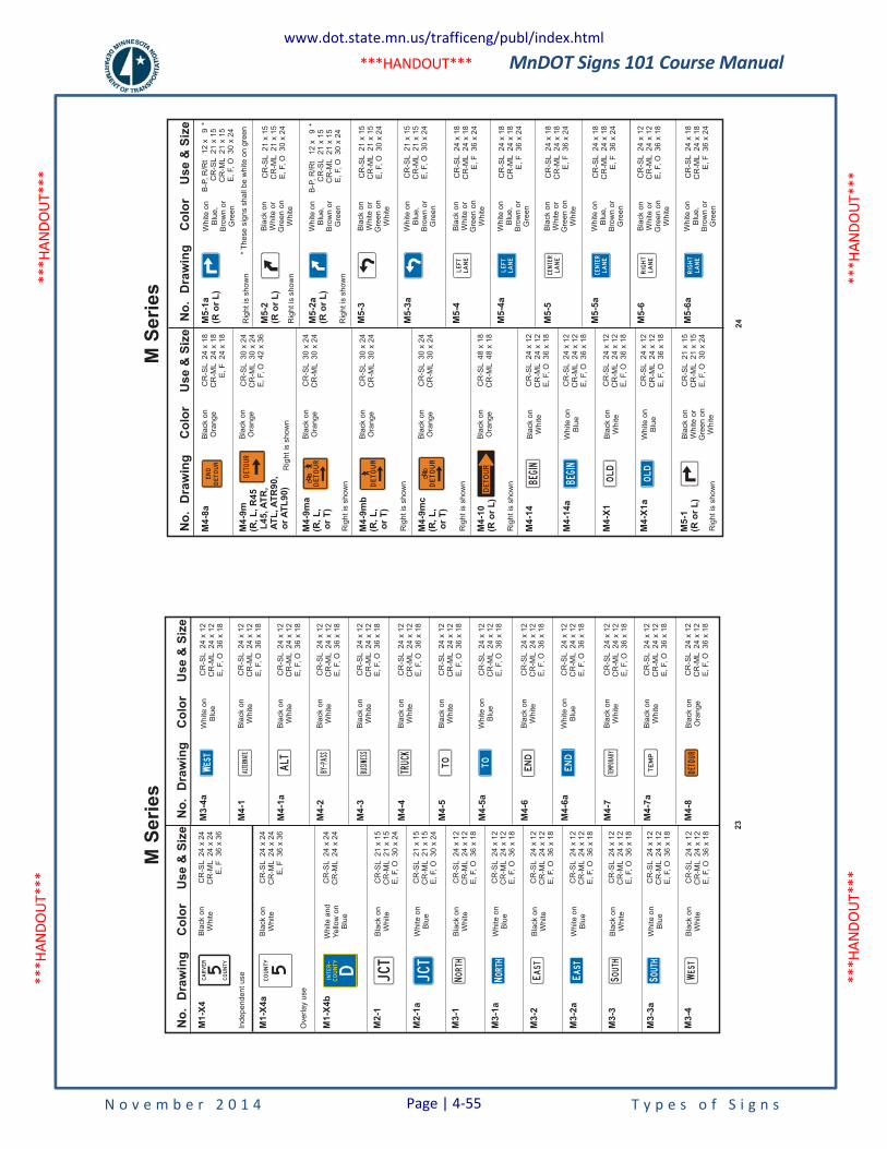
MnDOT Signs 101 Course Manual
N o v e m b e r 2 0 1 4 T y p e s o f S i g n s
***H
ANDO
UT**
* **
*HAN
DOUT
***
***H
ANDO
UT**
* **
*HAN
DOUT
***
***HANDOUT***
No
.D
raw
ing
Co
lor
Use
&S
ize
M1-X
4a
Overlay
use
M1-X
4b
M2-1
M3-1
M3-2
M3-3
M2-1
a
M3-1
a
M3-2
a
M3-3
a
Bla
ck
on
White
White
and
Yello
won
Blu
e
Bla
ck
on
White
Bla
ck
on
White
Bla
ck
on
White
Bla
ck
on
White
White
on
Blu
e
White
on
Blu
e
White
on
Blu
e
White
on
Blu
e
CR
-SL
24
x24
CR
-ML
24
x24
E,F
36
x36
CR
-SL
24
x24
CR
-ML
24
x24
CR
-SL
21
x15
CR
-ML
21
x15
E,F,O
30
x24
CR
-SL
24
x12
CR
-ML
24
x12
E,F,O
36
x18
CR
-SL
24
x12
CR
-ML
24
x12
E,F,O
36
x18
CR
-SL
24
x12
CR
-ML
24
x12
E,F,O
36
x18
CR
-SL
24
x12
CR
-ML
24
x12
E,F,O
36
x18
CR
-SL
24
x12
CR
-ML
24
x12
E,F,O
36
x18
CR
-SL
24
x12
CR
-ML
24
x12
E,F,O
36
x18
CR
-SL
21
x15
CR
-ML
21
x15
E,F,O
30
x24
No
.D
raw
ing
Co
lor
Use
&S
ize
Bla
ck
on
White
Bla
ck
on
White
Bla
ck
on
White
Bla
ck
on
White
Bla
ck
on
White
Bla
ck
on
White
Bla
ck
on
White
Bla
ck
on
White
White
on
Blu
e
White
on
Blu
e
CR
-SL
24
x12
CR
-ML
24
x12
E,F,O
36
x18
CR
-SL
24
x12
CR
-ML
24
x12
E,F,O
36
x18
CR
-SL
24
x12
CR
-ML
24
x12
E,F,O
36
x18
CR
-SL
24
x12
CR
-ML
24
x12
E,F,O
36
x18
CR
-SL
24
x12
CR
-ML
24
x12
E,F,O
36
x18
CR
-SL
24
x12
CR
-ML
24
x12
E,F,O
36
x18
CR
-SL
24
x12
CR
-ML
24
x12
E,F,O
36
x18
CR
-SL
24
x12
CR
-ML
24
x12
E,F,O
36
x18
CR
-SL
24
x12
CR
-ML
24
x12
E,F,O
36
x18
CR
-SL
24
x12
CR
-ML
24
x12
E,F,O
36
x18
M4-1
a
M4-4
M4-2
M4-5
M4-6
M4-7
M4-3
M4-5
a
M4-6
a
M4-7
a
COUNTY 5
INTER-
COUNTY D
NORTH
NORTH
E AST
EAST
SOUTH
SOUTH
M3-4
Bla
ck
on
White
CR
-SL
24
x12
CR
-ML
24
x12
E,F,O
36
x18
WEST
Bla
ck
on
White
CR
-SL
24
x12
CR
-ML
24
x12
E,F,O
36
x18
CR
-SL
24
x12
CR
-ML
24
x12
E,F,O
36
x18
M3-4
a
M4-1
White
on
Blu
eWEST
ALTERNATE
ALT
BY-PASS
BUSINESS
TRUCK
TO
TO
END
END
TEMPORARY
TEMP
M4-8
Bla
ck
on
Ora
nge
CR
-SL
24
x12
CR
-ML
24
x12
E,F,O
36
x18
DETOUR
Ind
ep
en
de
nt
use
M1-X
4B
lack
on
Wh
ite
CR
-SL
24
x2
4C
R-M
L2
4x
24
E,
F3
6x
36
CARVER
COUNTY5
23
M S
erie
sN
o.
Dra
win
gC
olo
rU
se
&S
ize
M4
-14
M4
-X1
M4
-14
a
M4
-X1
a
Bla
ck
on
Ora
ng
e
Bla
ck
on
Ora
ng
e
Bla
ck
on
Ora
ng
e
Bla
ck
on
Ora
ng
e
Bla
ck
on
Wh
ite
Bla
ck
on
Wh
ite
Wh
ite
on
Blu
e
Wh
ite
on
Blu
e
CR
-SL
24
x1
2C
R-M
L2
4x
12
E,
F,
O3
6x
18
CR
-SL
24
x1
2C
R-M
L2
4x
12
E,
F,
O3
6x
18
CR
-SL
30
x2
4C
R-M
L3
0x
24
CR
-SL
30
x2
4C
R-M
L3
0x
24
CR
-SL
30
x2
4C
R-M
L3
0x
24
CR
-SL
48
x1
8C
R-M
L4
8x
18
CR
-SL
24
x1
2C
R-M
L2
4x
12
E,
F,
O3
6x
18
CR
-SL
24
x1
2C
R-M
L2
4x
12
E,
F,
O3
6x
18
No
.D
raw
ing
Co
lor
Us
e&
Siz
e
Bla
ck
on
Wh
ite
or
Gre
en
on
Wh
ite
Bla
ck
on
Wh
ite
or
Gre
en
on
Wh
ite
Bla
ck
on
Wh
ite
or
Gre
en
on
Wh
ite
Bla
ck
on
Wh
ite
or
Gre
en
on
Wh
ite
CR
-SL
21
x1
5C
R-M
L2
1x
15
E,
F,
O3
0x
24
CR
-SL
24
x1
8C
R-M
L2
4x
18
E,
F3
6x
24
CR
-SL
24
x1
8C
R-M
L2
4x
18
E,
F3
6x
24
CR
-SL
24
x1
8C
R-M
L2
4x
18
E,
F3
6x
24
CR
-SL
24
x1
8C
R-M
L2
4x
18
E,
F3
6x
24
CR
-SL
24
x1
8C
R-M
L2
4x
18
E,
F3
6x
24
CR
-SL
21
x1
5C
R-M
L2
1x
15
E,
F,
O3
0x
24
CR
-SL
24
x1
2C
R-M
L2
4x
12
E,
F,
O3
6x
18
M5
-6
Wh
ite
on
Blu
e,
Bro
wn
or
Gre
en
Wh
ite
on
Blu
e,
Bro
wn
or
Gre
en
Wh
ite
on
Blu
e,
Bro
wn
or
Gre
en
Wh
ite
on
Blu
e,
Bro
wn
or
Gre
en
Wh
ite
on
Blu
e,
Bro
wn
or
Gre
en
OLD
OLD
DETOUR
DETOUR
M4
-9m
a(R
,L
,o
rT
)
M4
-9m
b(R
,L
,o
rT
)
M4
-9m
c(R
,L
,o
rT
)
M4
-10
(Ro
rL
)
M5
-3
M5
-4
M5
-4a
M5
-5
M5
-5a
M5
-6a
M5
-2a
(Ro
rL
)
Rig
ht
issh
ow
n
M5
-3a
DETOUR
DETOUR
BEGIN
BEGIN
Bla
ck
on
Wh
ite
or
Gre
en
on
Wh
ite
CR
-SL
21
x1
5C
R-M
L2
1x
15
E,
F,
O3
0x
24
B-P
,R
/Rt
12
x9
CR
-SL
21
x1
5C
R-M
L2
1x
15
E,
F,
O3
0x
24
*
M5
-1(R
or
L)
LEFT
LANE
LEFT
LANE
CENTER
LANE
CENTER
LANE
RIGHT
LANE
RIGHT
LANE
Rig
ht
issh
ow
n
Rig
ht
issh
ow
n
Rig
ht
issh
ow
n
Rig
ht
issh
ow
n
Rig
ht
issh
ow
n
Bla
ck
on
Wh
ite
or
Gre
en
on
Wh
ite
CR
-SL
21
x1
5C
R-M
L2
1x
15
E,
F,
O3
0x
24
B-P
,R
/Rt
12
x9
CR
-SL
21
x1
5C
R-M
L2
1x
15
E,
F,
O3
0x
24
*
*T
he
se
sig
ns
sh
all
be
wh
ite
on
gre
en
Wh
ite
on
Blu
e,
Bro
wn
or
Gre
en
M5
-2(R
or
L)
M5
-1a
(Ro
rL
)
Rig
ht
issh
ow
n
Rig
ht
issh
ow
n
M4
-8a
Bla
ck
on
Ora
ng
e
Bla
ck
on
Ora
ng
eC
R-S
L3
0x
24
CR
-ML
30
x2
4E
,F,
O4
2x
36
CR
-SL
24
x1
8C
R-M
L2
4x
18
E,
F2
4x
18
END
DETOUR
DETOUR
M4
-9m
(R,
L,
R4
5L
45
,A
TR
,A
TL
,A
TR
90
,o
rA
TL
90
)R
igh
tis
sh
ow
n
24
M S
erie
s
www.dot.state.mn.us/trafficeng/publ/index.html
Page | 4-55
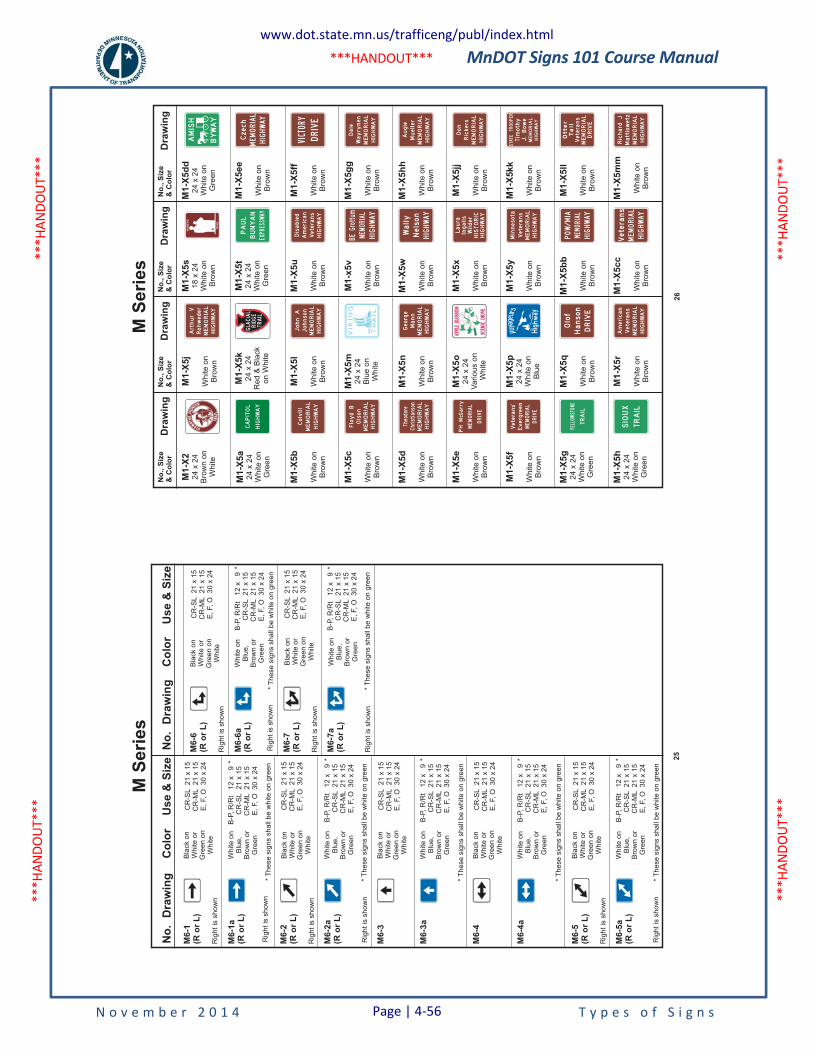
MnDOT Signs 101 Course Manual
N o v e m b e r 2 0 1 4 T y p e s o f S i g n s
***H
ANDO
UT**
* **
*HAN
DOUT
***
***H
ANDO
UT**
* **
*HAN
DOUT
***
***HANDOUT***
No
.D
raw
ing
Co
lor
Use
&S
ize
No
.D
raw
ing
Co
lor
Use
&S
ize
Bla
ck
on
Wh
ite
or
Gre
en
on
Wh
ite
Bla
ck
on
Wh
ite
or
Gre
en
on
Wh
ite
Bla
ck
on
Wh
ite
or
Gre
en
on
Wh
ite
Bla
ck
on
Wh
ite
or
Gre
en
on
Wh
ite
Bla
ck
on
Wh
ite
or
Gre
en
on
Wh
ite
CR
-SL
21
x1
5C
R-M
L2
1x
15
E,
F,
O3
0x
24
CR
-SL
21
x1
5C
R-M
L2
1x
15
E,
F,
O3
0x
24
CR
-SL
21
x1
5C
R-M
L2
1x
15
E,
F,
O3
0x
24
CR
-SL
21
x1
5C
R-M
L2
1x
15
E,
F,
O3
0x
24
*T
he
se
sig
ns
sh
all
be
wh
ite
on
gre
en
*T
he
se
sig
ns
sh
all
be
wh
ite
on
gre
en
*T
he
se
sig
ns
sh
all
be
wh
ite
on
gre
en
*T
he
se
sig
ns
sh
all
be
wh
ite
on
gre
en
*T
he
se
sig
ns
sh
all
be
wh
ite
on
gre
en
Wh
ite
on
Blu
e,
Bro
wn
or
Gre
en
Wh
ite
on
Blu
e,
Bro
wn
or
Gre
en
Wh
ite
on
Blu
e,
Bro
wn
or
Gre
en
Wh
ite
on
Blu
e,
Bro
wn
or
Gre
en
Wh
ite
on
Blu
e,
Bro
wn
or
Gre
en
M6-4
M6-2
(Ro
rL
)
Rig
ht
issh
ow
n
M6-5
(Ro
rL
)
Rig
ht
issh
ow
n
M6-3
M6-4
a
M6-2
a(R
or
L)
M6-5
a(R
or
L)
M6-3
a
CR
-SL
21
x1
5C
R-M
L2
1x
15
E,
F,
O3
0x
24
M6-7
(Ro
rL
)
Rig
ht
issh
ow
n
M6-7
a(R
or
L)
Rig
ht
issh
ow
nR
igh
tis
sh
ow
n
Rig
ht
issh
ow
n
B-P
,R
/Rt
12
x9
CR
-SL
21
x1
5C
R-M
L2
1x
15
E,
F,
O3
0x
24
*
B-P
,R
/Rt
12
x9
CR
-SL
21
x1
5C
R-M
L2
1x
15
E,
F,
O3
0x
24
*
B-P
,R
/Rt
12
x9
CR
-SL
21
x1
5C
R-M
L2
1x
15
E,
F,
O3
0x
24
*
B-P
,R
/Rt
12
x9
CR
-SL
21
x1
5C
R-M
L2
1x
15
E,
F,
O3
0x
24
*
Bla
ck
on
Wh
ite
or
Gre
en
on
Wh
ite
*T
he
se
sig
ns
sh
all
be
wh
ite
on
gre
en
Wh
ite
on
Blu
e,
Bro
wn
or
Gre
en
CR
-SL
21
x1
5C
R-M
L2
1x
15
E,
F,
O3
0x
24
M6-6
(Ro
rL
)
Rig
ht
issh
ow
n
M6-6
a(R
or
L)
Rig
ht
issh
ow
n
B-P
,R
/Rt
12
x9
CR
-SL
21
x1
5C
R-M
L2
1x
15
E,
F,
O3
0x
24
*
B-P
,R
/Rt
12
x9
CR
-SL
21
x1
5C
R-M
L2
1x
15
E,
F,
O3
0x
24
*
Bla
ck
on
Wh
ite
or
Gre
en
on
Wh
ite
Wh
ite
on
Blu
e,
Bro
wn
or
Gre
en
B-P
,R
/Rt
12
x9
CR
-SL
21
x1
5C
R-M
L2
1x
15
E,
F,
O3
0x
24
*
CR
-SL
21
x1
5C
R-M
L2
1x
15
E,
F,
O3
0x
24
*T
he
se
sig
ns
sh
all
be
wh
ite
on
gre
en
M6-1
(Ro
rL
)
Rig
ht
issh
ow
n
M6-1
a(R
or
L)
Rig
ht
issh
ow
n
25
M S
erie
sN
o.,
Siz
e
&C
olo
rD
ra
win
gN
o.,
Siz
e
&C
olo
rD
ra
win
gN
o.,
Siz
e
&C
olo
rD
ra
win
gN
o.,
Siz
e
&C
olo
rD
ra
win
g
M1-X
2
24
x24
Bro
wn
on
White
M1-X
5j
White
on
Bro
wn
M1-X
5k
24
x24
Red
&B
lack
on
White
M1-X
5l
White
on
Bro
wn
M1-X
5m
24
x24
Blu
eon
White
M1-X
5n
White
on
Bro
wn
M1-X
5o
24
x24
Various
on
White
M1-X
5p
24
x24
White
on
Blu
e
M1-X
5q
White
on
Bro
wn
M1-X
5r
White
on
Bro
wn
M1-X
5s
18
x24
White
on
Bro
wn
M1-X
5t
24
x24
White
on
Gre
en
M1-X
5u
White
on
Bro
wn
M1-x
5v
White
on
Bro
wn
M1-X
5w
White
on
Bro
wn
M1-X
5x
White
on
Bro
wn
M1-X
5y
White
on
Bro
wn
M1-X
5b
b
White
on
Bro
wn
M1-X
5cc
White
on
Bro
wn
M1-X
5d
d
24
x24
White
on
Gre
en
M1-X
5ee
White
on
Bro
wn
M1-X
5ff
White
on
Bro
wn
M1-X
5g
g
White
on
Bro
wn
M1-X
5h
h
White
on
Bro
wn
M1-X
5jj
White
on
Bro
wn
M1-X
5kk
White
on
Bro
wn
M1-X
5ll
White
on
Bro
wn
M1-X
5m
m
White
on
Bro
wn
M1-X
5a
24
x24
White
on
Gre
en
M1-X
5b
White
on
Bro
wn
M1-X
5c
White
on
Bro
wn
M1-X
5d
White
on
Bro
wn
M1-X
5e
White
on
Bro
wn
M1-X
5f
White
on
Bro
wn
M1-X
5g
24
x24
White
on
Gre
en
M1-X
5h
24
x24
White
on
Gre
en
Colvill
MEMORIAL
HIGHWAY
MEMORIAL
HIGHWAY
JohnA
Johnson
MEMORIAL
HIGHWAY
FloydB
Olson
MEMORIAL
HIGHWAY
George
Mann
HIGHWAY
Wally
Nelson
Veterans
HIGHWAY
Disabled
American
HISTORIC
HIGHWAY
Laura
Ingalls
Wilder
MEMORIAL
HIGHWAY
Minnesota
Veterans
HIGHWAY
MEMORIAL
Veterans
MEMORIAL
HIGHWAY
Don
Rickers
HIGHWAY
MEMORIAL
STATETROOPER
Timothy
J.Bowe
MEMORIAL
DRIVE
Tail
Otter
Veterans
MEMORIAL
HIGHWAY
Richard
JMattiowetz
HIGHWAY
MEMORIAL
Czech
HIGHWAY
MEMORIAL
BEGrottum
MEMORIAL
HIGHWAY
Augie
Mueller
MEMORIAL
HIGHWAY
Dale
Wayrynen
MEMORIAL
HIGHWAY
Theodore
Christianson
MEMORIAL
PHMcGarry
DRIVE
MEMORIAL
Evergreen
Veterans
DRIVE
DRIVE
Hanson
Olof
MEMORIAL
HIGHWAY
American
Veterans
MEMORIAL
HIGHWAY
ArthurV
Rohweder
26
M S
erie
s
www.dot.state.mn.us/trafficeng/publ/index.html
Page | 4-56
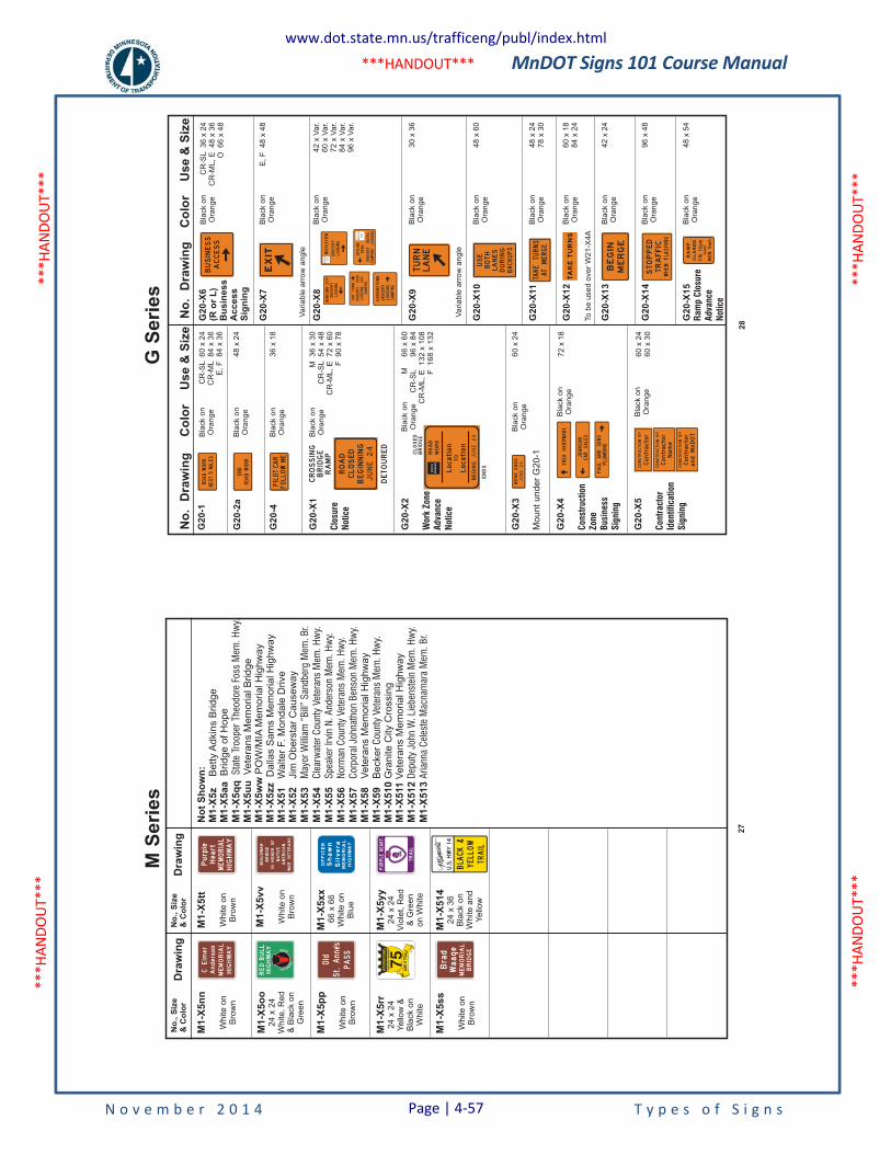
MnDOT Signs 101 Course Manual
N o v e m b e r 2 0 1 4 T y p e s o f S i g n s
***H
ANDO
UT**
* **
*HAN
DOUT
***
***H
ANDO
UT**
* **
*HAN
DOUT
***
***HANDOUT***
No
.,S
ize
&C
olo
rD
raw
ing
No
.,S
ize
&C
olo
rD
raw
ing
M1-X
5n
n
White
on
Bro
wn
M1-X
5tt
White
on
Bro
wn
No
tS
ho
wn
:M
1-X
5z
M1-X
5aa
Betty
Adkin
sB
ridge
Bridge
ofH
ope
M1-X
5q
q
M1-X
5u
uM
1-X
5w
wM
1-X
5zz
M1-X
51
M1-X
52
M1-X
53
M1-X
54
M1-X
55
M1-X
56
M1-X
57
M1-X
58
M1-X
59
M1-X
510
M1-X
511
M1-X
512
M1-X
513
Sta
teTr
oope
rThe
odo
reFo
ssM
em.
Hw
y.
May
or
Will
iam
“Bill
”S
andb
erg
Mem
.B
r.C
lear
wat
erC
oun
tyVet
eran
sM
em.
Hw
y.S
peak
erIr
vin
N.
And
erso
nM
em.
Hw
y.N
orm
anC
oun
tyVet
eran
sM
em.
Hw
y.C
orp
ora
lJohn
atho
nB
enso
nM
em.
Hw
y.
Coun
tyVet
eran
sM
em.
Hw
y.
Dep
uty
John
W.
Lieb
enst
ein
Mem
.H
wy.
Arian
naC
eles
teM
acna
mar
aM
em.
Br.
Vete
rans
Mem
orialB
ridge
PO
W/M
IAM
em
orialH
ighw
ay
Dalla
sS
am
sM
em
orialH
ighw
ay
Walter
F.M
ondale
Drive
Jim
Obers
tar
Causew
ay
Vete
rans
Mem
orialH
ighw
ay
Becker
Gra
nite
City
Cro
ssin
gV
ete
rans
Mem
orialH
ighw
ay
M1-X
5vv
White
on
Bro
wn
M1-X
5xx
66
x66
White
on
Blu
e
M1-X
5yy
24
x24
Vio
let,
Red
&G
reen
on
White
M1-X
514
24
x36
Bla
ck
on
White
and
Yello
w
M1-X
5o
o24
x24
White,R
ed
&B
lack
on
Gre
en
M1-X
5p
p
White
on
Bro
wn
M1-X
5rr
24
x24
Yello
w&
Bla
ck
on
White
M1-X
5ss
White
on
Bro
wn
HIGHWAY
MEMORIAL
Heart
Purple
MEMORIAL
OFFICER
Shawn
Silvera
HIGHWAY
PASS
Old
St.Annes
MEMORIAL
HIGHWAY
CElmer
Anderson
MEMORIAL
BRIDGE
Waage
Brad
27
M S
erie
sN
o.
Dra
win
gC
olo
rU
se
&S
ize
G2
0-1
G2
0-2
a
G2
0-4
G2
0-X
1
Clo
sure
Not
ice
G2
0-X
2
Wor
kZon
eA
dva
nce
Not
ice
G2
0-X
3
Mo
un
tu
nd
er
G2
0-1
G2
0-X
4
Con
stru
ctio
nZon
eB
usi
nes
sS
ignin
g
G2
0-X
5
Con
tract
orId
enti
fica
tion
Sig
nin
g
Bla
ck
on
Ora
ng
e
Bla
ck
on
Ora
ng
e
Bla
ck
on
Ora
ng
e
Bla
ck
on
Ora
ng
e
Bla
ck
on
Ora
ng
e
Bla
ck
on
Ora
ng
e
Bla
ck
on
Ora
ng
e
Bla
ck
on
Ora
ng
e
CR
-SL
60
x2
4C
R-M
L8
4x
36
E,
F8
4x
36
36
x1
8
M3
6x
30
CR
-SL
54
x4
8C
R-M
L,
E7
2x
60
F9
0x
78
M6
6x
60
CR
-SL
96
x8
4C
R-M
L,
E1
32
x1
08
F1
68
x1
32
60
x2
4
48
x2
4
72
x1
8
60
x2
46
0x
30
No
.D
raw
ing
Co
lor
Us
e&
Siz
e
G2
0-X
6(R
or
L)
Bu
sin
es
sA
cc
es
sS
ign
ing
Bla
ck
on
Ora
ng
e
Bla
ck
on
Ora
ng
e
Va
ria
ble
arr
ow
an
gle
Va
ria
ble
arr
ow
an
gle
To
be
use
do
ve
rW
21
-X4
A
Bla
ck
on
Ora
ng
e
Bla
ck
on
Ora
ng
e
Bla
ck
on
Ora
ng
e
Bla
ck
on
Ora
ng
e
Bla
ck
on
Ora
ng
e
Bla
ck
on
Ora
ng
e
Bla
ck
on
Ora
ng
e
Bla
ck
on
Ora
ng
e
CR
-SL
36
x2
4C
R-M
L,
E4
8x
36
O6
6x
48
E,
F4
8x
48
42
xV
ar.
60
xV
ar.
72
xV
ar.
84
xV
ar.
96
xV
ar.
30
x3
6
48
x6
0
48
x2
47
8x
30
60
x1
88
4x
24
42
x2
4
96
x4
8
48
x5
4
G2
0-X
7
G2
0-X
8
G2
0-X
9
G2
0-X
10
G2
0-X
11
G2
0-X
12
G2
0-X
13
G2
0-X
14
G2
0-X
15
Ram
pC
losu
reA
dva
nce
Not
ice
ROADWORK
END
ROADWORK
NEXT
MILES
5
PILOTCAR
FOLLOWME
CROSSING
BRIDGE
RAMP
DETOURED
ROAD
BEGINNING
CLOSED
JUNE24
BRIDGE
ENDS
CLOSED
BEGINSJUNE24
ROUTE
MARKER
ROAD
WORK
TO
Location
Location
WORKENDS
JUNE24
BUSINESS
ACCESS
EXIT
TURN
LANE
BOTH
LANES
DURING
BACKUPS
USE
TAKETURNS
ATMERGE
TAKETURNS
BEGIN
MERGE
STOPPED
TRAFFIC
WHENFLASHING
PLUMBING
PAULANDSONS
CARSALES
JOHNSON
SHEAHARDWARE
CONSTRUCTIONBY
CONSTRUCTIONBY
CONSTRUCTIONBY
Contractor
Contractor
Contractor
Name
andMnDOT
MON5am
FRI10pm
CLOSED
RAMP
THRU
28
G S
erie
s
www.dot.state.mn.us/trafficeng/publ/index.html
Page | 4-57
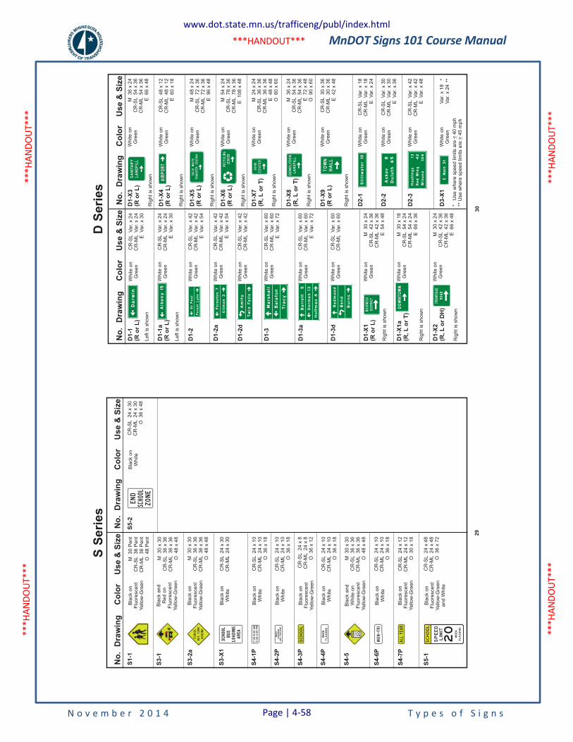
MnDOT Signs 101 Course Manual
N o v e m b e r 2 0 1 4 T y p e s o f S i g n s
***H
ANDO
UT**
* **
*HAN
DOUT
***
***H
ANDO
UT**
* **
*HAN
DOUT
***
***HANDOUT***
No
.D
raw
ing
Co
lor
Use
&S
ize
S1-1
Bla
ck
on
Flu
ore
sce
nt
Ye
llow
-Gre
en
Bla
ck
on
Flu
ore
sce
nt
Ye
llow
-Gre
en
Bla
ck
an
dR
ed
on
Flu
ore
sce
nt
Ye
llow
-Gre
en
M3
0P
en
tC
R-S
L3
6P
en
tC
R-M
L3
6P
en
tO
48
Pe
nt
S3-1
S3-2
a
M3
0x
30
CR
-SL
36
x3
6C
R-M
L3
6x
36
O4
8x
48
M3
0x
30
CR
-SL
36
x3
6C
R-M
L3
6x
36
O4
8x
48
S3-X
1
S4-2
P
S4-1
P
S4-4
P
CR
-SL
24
x3
0C
R-M
L2
4x
30
CR
-SL
24
x1
0C
R-M
L2
4x
10
O3
6x
18
CR
-SL
24
x1
0C
R-M
L2
4x
10
O3
6x
18
CR
-SL
24
x1
0C
R-M
L2
4x
10
O3
6x
18
CR
-SL
24
x1
0C
R-M
L2
4x
10
O3
6x
18
CR
-SL
24
x1
2C
R-M
L2
4x
12
O3
0x
18
CR
-SL
24
x8
CR
-ML
24
x8
O3
6x
12
S4-3
P
S4-5
S4-6
P
S4-7
P
Bla
ck
on
Wh
ite
Bla
ck
on
Wh
ite
Bla
ck
on
Wh
ite
Bla
ck
on
Wh
ite
Bla
ck
on
Flu
ore
sce
nt
Ye
llow
-Gre
en
Bla
ck
on
Flu
ore
sce
nt
Ye
llow
-Gre
en
Bla
ck
an
dW
hite
on
Flu
ore
sce
nt
Ye
llow
-Gre
en
Bla
ck
on
Wh
ite
M3
0x
30
CR
-SL
36
x3
6C
R-M
L3
6x
36
O4
8x
48
No
.D
raw
ing
Co
lor
Use
&S
ize
SPEED
LIMIT
SCHOOL
SPEED
LIMIT
20
WHEN
AREPRESENT
CHILDREN
SCHOOL
WHEN
FLASHING
ALLYEAR
MON-FRI
BUSTURN
AROUND
SCHOOL
SCHOOL
BUS
LOADING
AREA
CR
-SL
24
x3
0C
R-M
L2
4x
30
O3
6x
48
S5-2
Bla
ck
on
Wh
ite
END
ZONE
SCHOOL
CR
-SL
24
x4
8C
R-M
L2
4x
48
O3
6x
72
S5-1
Bla
ck
on
Flu
ore
sce
nt
Ye
llow
-Gre
en
an
dW
hite
SCHOOL
SPEED
LIMIT
20
WHEN
FLASHING
29
S Se
ries
No
.D
raw
ing
Co
lor
Use
&S
ize
D1-1
(Ro
rL
)
D1-1
a(R
or
L)
D1-2
D1-2
a
D1-2
d
D1-3
D1-3
a
D1-3
d
D1-X
1(R
or
L)
D1-X
1a
(R,L
or
T)
D1-X
2(R
,L
or
DH
)
Wh
ite
on
Gre
en
Wh
ite
on
Gre
en
Wh
ite
on
Gre
en
Wh
ite
on
Gre
en
Wh
ite
on
Gre
en
Wh
ite
on
Gre
en
Wh
ite
on
Gre
en
Wh
ite
on
Gre
en
Wh
ite
on
Gre
en
Wh
ite
on
Gre
en
Wh
ite
on
Gre
en
CR
-SL
Va
r.x
24
CR
-ML
Va
r.x
24
EV
ar.
x3
0
CR
-SL
Va
r.x
24
CR
-ML
Va
r.x
24
EV
ar.
x3
0
CR
-SL
Va
r.x
42
CR
-ML
Va
r.x
42
EV
ar.
x5
4
CR
-SL
Va
r.x
42
CR
-ML
Va
r.x
42
EV
ar.
x5
4
CR
-SL
Va
r.x
42
CR
-ML
Va
r.x
42
CR
-SL
Va
r.x
60
CR
-ML
Va
r.x
60
EV
ar.
x7
2
CR
-SL
Va
r.x
60
CR
-ML
Va
r.x
60
EV
ar.
x7
2
CR
-SL
Va
r.x
60
CR
-ML
Va
r.x
60
M3
0x
24
CR
-SL
42
x3
6C
R-M
L4
2x
36
E5
4x
48
M3
0x
18
CR
-SL
54
x2
4C
R-M
L5
4x
24
E6
6x
36
M3
0x
24
CR
-SL
42
x3
6C
R-M
L4
2x
36
E6
6x
48
No
.D
raw
ing
Co
lor
Use
&S
ize
Le
ftis
sh
ow
n
Rig
ht
issh
ow
n
Rig
ht
issh
ow
n
Rig
ht
issh
ow
n
Le
ftis
sh
ow
n
Darw
in
Alb
any
15
StPaul
ForestLake
Foreston7
Gilman3
Amity
Twin
Falls
BUSINESS
DISTRICT
D1-X
3(R
or
L)
Wh
ite
on
Gre
en
M3
6x
24
CR
-SL
54
x3
6C
R-M
L5
4x
36
E6
6x
48
Rig
ht
issh
ow
nSANITARY
LANDFILL
D1-X
4(R
or
L)
Wh
ite
on
Gre
en
CR
-SL
48
x1
2C
R-M
L4
8x
12
E6
0x
18
M4
8x
24
CR
-SL
72
x3
6C
R-M
L7
2x
36
E9
6x
48
M5
4x
24
CR
-SL
78
x3
6C
R-M
L7
8x
36
E1
08
x4
8
M2
4x
24
CR
-SL
36
x3
6C
R-M
L3
6x
36
E4
8x
48
O6
0x
60
Rig
ht
issh
ow
n
D1-X
5(R
or
L)
Wh
ite
on
Gre
en
Rig
ht
issh
ow
n
D1-X
6(R
or
L)
Wh
ite
on
Gre
en
Rig
ht
issh
ow
n
D1-X
7(R
,L
or
T)
Wh
ite
on
Gre
en
Rig
ht
issh
ow
n
D1-X
8(R
,L
or
T)
D1-X
9(R
or
L)
D2-1
D2-2
D2-3
D3-X
1
Wh
ite
on
Gre
en
Wh
ite
on
Gre
en
Wh
ite
on
Gre
en
Wh
ite
on
Gre
en
Wh
ite
on
Gre
en
M3
6x
24
CR
-SL
54
x3
6C
R-M
L5
4x
36
E7
2x
48
O9
0x
60
CR
-SL
30
x3
6C
R-M
L3
0x
36
E4
2x
48
CR
-SL
Va
r.x
18
CR
-ML
Va
r.x
18
EV
ar.
x2
4
CR
-SL
Va
r.x
30
CR
-ML
Va
r.x
30
EV
ar.
x3
6
CR
-SL
Va
r.x
42
CR
-ML
Va
r.x
42
EV
ar.
x4
8
Va
r.x
18
Va
r.x
24
* **
Rig
ht
issh
ow
n
Rig
ht
issh
ow
n
*U
se
wh
ere
sp
ee
dlim
its
are
40
mp
h**
Use
wh
ere
sp
ee
dlim
its
are
45
mp
h< >
AIRPORT
TRANSFERSTATION
SOLIDWASTE
CENTER
RECYCLING
Marshall
Balaton
Tracy
Barrett
5
Herman13
Hoffman4
Redmond
Bend
Burns
DOWNTOWN
FRONTAGE
ROAD
HHW
CENTER
DEMOLITION
LANDFILL
TOWN
HALL
Hastings
13
RedWing
42
Winona
104
Askov
8
Duluth
65
EMainSt
Stillw
ater
10W
hite
on
Gre
en
30
D S
erie
s
www.dot.state.mn.us/trafficeng/publ/index.html
Page | 4-58
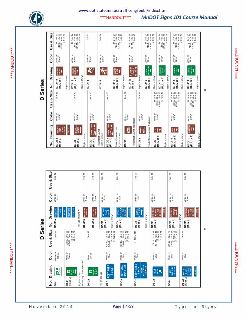
MnDOT Signs 101 Course Manual
N o v e m b e r 2 0 1 4 T y p e s o f S i g n s
***H
ANDO
UT**
* **
*HAN
DOUT
***
***H
ANDO
UT**
* **
*HAN
DOUT
***
***HANDOUT***
No
.D
raw
ing
Co
lor
Us
e&
Siz
e
D4
-1
D4
-2(R
or
L)
D4
-2a
D5
-1
D5
-1a
D5
-1c
D5
-2a
D5
-6
D5
-X1
(Ro
rL
)
Gre
en
on
Wh
ite
Wh
ite
on
Gre
en
Wh
ite
on
Gre
en
Wh
ite
on
Blu
e
Wh
ite
on
Blu
e
Wh
ite
on
Blu
e
Wh
ite
on
Blu
e
Wh
ite
on
Blu
e
Wh
ite
on
Blu
e
30
x2
4
CR
-SL
30
x3
6C
R-M
L3
0x
36
E3
6x
48
O5
4x
72
36
x4
2
CR
-SL
78
x3
6C
R-M
L7
8x
36
E11
4x
48
F1
32
x6
0
CR
-SL
78
x3
6C
R-M
L7
8x
36
E11
4x
48
F1
32
x6
0
F1
38
x11
4
CR
-SL
42
x4
8C
R-M
L4
2x
48
E6
6x
72
F7
8x
78
CR
-SL
78
x5
4C
R-M
L7
8x
54
E1
08
x6
6F
13
2x
78
36
x3
6
No
.D
raw
ing
Co
lor
Us
e&
Siz
e
Rig
ht
issh
ow
nF
or
use
with
D5
-X1
Tra
nsit
log
oto
be
sp
ecifie
d
Fo
ro
nsite
use
D5
-X1
aW
hite
on
Blu
e3
6x
12
36
x1
8
36
x1
8
36
x3
0
D5
-X1
b
D5
-X1
c
Wh
ite
on
Bro
wn
Wh
ite
on
Bro
wn
D5
-X2
(Ro
rL
)
Wh
ite
on
Blu
e
Rig
ht
issh
ow
n
Rig
ht
issh
ow
n
Rig
ht
issh
ow
n
D6
-2a
(Ro
rL
)
D6
-3a
(Ro
rL
)
D7
-X1
(Ro
rL
)
D7
-X5
(Ro
rL
)
D7
-X2
(Ro
rL
)
Wh
ite
on
Blu
e
Wh
ite
on
Blu
e
Wh
ite
on
Bro
wn
Wh
ite
on
Bro
wn
Wh
ite
on
Bro
wn
36
x3
6
36
x3
0
36
x3
6
36
x3
6
36
x3
0
P ARKIN
G
PARK
RIDE
-
RESTAREA
MILE
1RIDE
PARK-
RESTAREA
NEXTRIGHT
REST
AREA
MILE
1
NEXT
REST
AREA
25
MILES
REST
AREA
NEXT
RESTAREA
MILES
24
WAYSIDE
REST
MILE
ONRIGHT
12
ONLEFT
FIREPLACES
TOILETS
WATER
TELEPHONE
TOURISTINFO
WAYSIDE
REST
HISTORICAL
MARKER
GEOLOGICAL
MARKER
SCENIC
OVERLOOK
MILE
ONRIGHT
12
ONLEFT
ONLEFT
ONLEFT
SCENIC
OVERLOOK
GEOLOGICAL
MARKER
MILE
ONRIGHT
12
GEOLOGICAL
MARKER
HISTORICAL
MARKER
MILE
ONRIGHT
12
31
D S
erie
sN
o.
Dra
win
gC
olo
rU
se
&S
ize
No
.D
raw
ing
Co
lor
Use
&S
ize
Rig
ht
issh
ow
n
Rig
ht
issh
ow
n
D7-X
12
(R,L
or
T)
D7-X
13
D7-X
14
D7-X
15
(R,L
or
T)
D7-X
15a
(Ro
rL
)
D7-X
16
(R,L
or
T)
D7-X
17
(R,L
or
T)
D7-X
18
(R,L
or
T)
D7-X
19
(R,L
or
T)
D7-X
11a
(R,L
or
T)
Wh
ite
on
Bro
wn
Wh
ite
on
Bro
wn
Wh
ite
on
Bro
wn
Wh
ite
on
Bro
wn
Wh
ite
on
Bro
wn
Wh
ite
on
Gre
en
Wh
ite
on
Gre
en
Wh
ite
on
Gre
en
Wh
ite
on
Gre
en
Wh
ite
on
Bro
wn
M3
0x
24
CR
-SL
48
x3
6C
R-M
L4
8x
36
E5
4x
48
24
x2
4
24
x2
4
M2
4x
24
CR
-SL
36
x3
6C
R-M
L3
6x
36
E4
8x
48
CR
-SL
48
x3
6C
R-M
L4
8x
36
E6
6x
48
M3
6x
24
CR
-SL
54
x3
6C
R-M
L5
4x
36
E6
6x
48
M3
6x
24
CR
-SL
48
x3
6C
R-M
L4
8x
36
E6
6x
48
M3
0x
24
CR
-SL
42
x3
6C
R-M
L4
2x
36
E5
4x
48
M3
6x
24
CR
-SL
48
x3
6C
R-M
L4
8x
36
E6
6x
48
M3
0x
24
CR
-SL
48
x3
6C
R-M
L4
8x
36
E5
4x
48
Rig
ht
issh
ow
n
Rig
ht
issh
ow
n
Rig
ht
issh
ow
n
Rig
ht
issh
ow
n
Rig
ht
issh
ow
n
Rig
ht
issh
ow
n
Rig
ht
issh
ow
n
Rig
ht
issh
ow
n
Rig
ht
issh
ow
n
Rig
ht
issh
ow
n
Pu
blic
Bo
at
La
un
ch
Rig
ht
issh
ow
n
Pu
blic
Ca
no
eA
cce
ss
Rig
ht
issh
ow
n
Pu
blic
Bo
at
La
un
ch
Tra
ilbla
ze
r
Pu
blic
Ca
no
eA
cce
ss
Tra
ilbla
ze
r
D7-X
5a
(Ro
rL
)
D7-X
6(R
or
L)
D7-X
7(R
or
L)
D7-X
8
D7-X
7a
(Ro
rL
)
D7-X
8a
D7-X
9(R
,L
or
T)
D7-X
10
(R,L
or
T)
D7-X
11
(R,L
or
T)
Wh
ite
on
Bro
wn
Wh
ite
on
Bro
wn
Wh
ite
on
Bro
wn
Wh
ite
on
Bro
wn
Wh
ite
on
Bro
wn
Wh
ite
on
Bro
wn
Wh
ite
on
Bro
wn
Wh
ite
on
Bro
wn
Wh
ite
on
Bro
wn
36
x3
6
36
x3
0
Va
r.x
30
24
x2
4
Va
r.x
30
24
x2
4
M1
8x
24
CR
-SL
30
x3
6C
R-M
L3
0x
36
E4
2x
48
M1
8x
24
CR
-SL
30
x3
6C
R-M
L3
0x
36
E4
2x
48
M3
0x
24
CR
-SL
48
x3
6C
R-M
L4
8x
36
E6
0x
48
ONLEFT
HISTORIC
SITE
MILE
ONRIGHT
12
HISTORICAL
MARKER
LobsterLake
LobsterLake
STATE
PARK
CITY
PARK
HISTORIC
SITE
HISTORIC
DISTRICT
COUNTY
MUSEUM
COUNTY
PARK
COUNTY
PARK
MI
10
FAIRGROUND
COUNTY
INDUSTRIAL
PARK
WORKFORCE
CENTER
HIGH
SCHOOL
32
D S
erie
s
www.dot.state.mn.us/trafficeng/publ/index.html
Page | 4-59
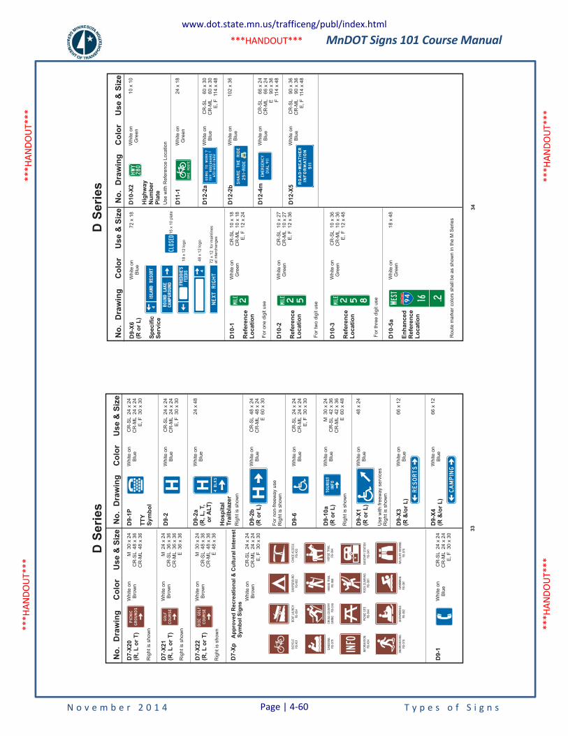
MnDOT Signs 101 Course Manual
N o v e m b e r 2 0 1 4 T y p e s o f S i g n s
***H
ANDO
UT**
* **
*HAN
DOUT
***
***H
ANDO
UT**
* **
*HAN
DOUT
***
***HANDOUT***
No
.D
raw
ing
Co
lor
Us
e&
Siz
eN
o.
Dra
win
gC
olo
rU
se
&S
ize
Rig
ht
issh
ow
n
D9
-2
D9
-2a
(R,
L,
T,
or
ALT
)
Ho
sp
ita
lT
rail
bla
ze
r
D9
-2b
(Ro
rL
)
D9
-6
D9
-10
a(R
or
L)
D9
-X1
(Ro
rL
)
D9
-X4
(R&
/or
L)
D9
-X3
(R&
/or
L)
D9
-1P
TT
YS
ym
bo
l
Wh
ite
on
Blu
e
Wh
ite
on
Blu
e
Wh
ite
on
Blu
e
Wh
ite
on
Blu
e
Wh
ite
on
Blu
e
Wh
ite
on
Blu
e
Wh
ite
on
Blu
e
Wh
ite
on
Blu
e
Wh
ite
on
Blu
e
24
x4
8
CR
-SL
48
x2
4C
R-M
L4
8x
24
E6
0x
30
48
x2
4
66
x1
2
66
x1
2
CR
-SL
24
x2
4C
R-M
L2
4x
24
E,
F3
0x
30
CR
-SL
24
x2
4C
R-M
L2
4x
24
E,
F3
0x
30
CR
-SL
24
x2
4C
R-M
L2
4x
24
E,
F3
0x
30
Rig
ht
issh
ow
n
Fo
rn
on
-fre
ew
ay
use
Rig
ht
issh
ow
n
Use
with
fre
ew
ay
se
rvic
es
Rig
ht
issh
ow
n
Rig
ht
issh
ow
n
Rig
ht
issh
ow
n
Rig
ht
issh
ow
n
D7
-X2
0(R
,L
or
T)
D7
-X2
1(R
,L
or
T)
D7
-X2
2(R
,L
or
T)
D7
-Xp
Ap
pro
ved
Recre
ati
on
al&
Cu
ltu
ralIn
tere
st
Sym
bo
lS
ign
s
D9
-1
Wh
ite
on
Bro
wn
Wh
ite
on
Bro
wn
Wh
ite
on
Bro
wn
Wh
ite
on
Bro
wn
Wh
ite
on
Blu
e
M3
0x
24
CR
-SL
48
x3
6C
R-M
L4
8x
36
M2
4x
24
CR
-SL
36
x3
6C
R-M
L3
6x
36
E3
6x
36
M3
0x
24
CR
-SL
48
x3
6C
R-M
L4
8x
36
E4
8x
36
M3
0x
24
CR
-SL
42
x3
6C
R-M
L4
2x
36
E6
0x
48
CR
-SL
24
x2
4C
R-M
L2
4x
24
E,
F3
0x
30
CR
-SL
24
x2
4C
R-M
L2
4x
24
E,
F3
0x
30
PICNIC
GROUNDS
DISCGOLF
COURSE
GOLF
COURSE
BIC
YC
LER
S-X
01
CA
NO
EIN
GR
S-0
79
BO
ATLA
UN
CH
RS
-054
CR
OS
SC
OU
NTR
YS
KIIN
GR
S-0
46
INFO
RM
ATIO
NR
S-X
04
SN
OW
SH
OEIN
GR
S-0
78
CA
MP
GR
OU
ND
RS
-X02
PIC
NIC
SIT
ER
S-0
44
SN
OW
MO
BIL
ER
S-0
52
CA
NO
EA
CC
ES
SR
S-X
03
RO
CK
CLI
MB
ING
RS
-081
SW
IMM
ING
RS
-061
HIK
ING
TR
AIL
RS
-068
HO
RS
ETR
AIL
RS
-064
SA
NIT
AR
YS
TATIO
NR
S-0
41
WIL
DLI
FEV
IEW
ING
RS
-076
4BLKS
H
H TOURIST
INFO
RESORTS
CAMPING
INFO
33
D S
erie
sN
o.
Dra
win
gC
olo
rU
se
&S
ize
No
.D
raw
ing
Co
lor
Use
&S
ize
D11-1
D12-2
a
D12-X
5
D12-2
b
D12-4
m
D10-X
2
Hig
hw
ay
Nu
mb
er
Pla
te
Wh
ite
on
Gre
en
Wh
ite
on
Blu
e
Wh
ite
on
Blu
e
Wh
ite
on
Blu
e
Wh
ite
on
Blu
e
Wh
ite
on
Gre
en
24
x1
8
CR
-SL
66
x2
4C
R-M
L6
6x
24
E9
0x
36
F11
4x
48
CR
-SL
90
x3
6C
R-M
L9
0x
36
E,
F11
4x
48
10
x1
0
CR
-SL
60
x3
0C
R-M
L6
0x
30
E,
F11
4x
48
Use
with
Re
fere
nce
Lo
ca
tio
n
D10-1
Refe
ren
ce
Lo
cati
on
D10-2
Refe
ren
ce
Lo
cati
on
D10-3
Refe
ren
ce
Lo
cati
on
D10-5
a
En
han
ced
Refe
ren
ce
Lo
cati
on
Wh
ite
on
Gre
en
Wh
ite
on
Gre
en
Wh
ite
on
Gre
en
Wh
ite
on
Gre
en
Fo
ro
ne
dig
itu
se
Fo
rtw
od
igit
use
Fo
rth
ree
dig
itu
se
Ro
ute
ma
rke
rco
lors
sh
all
be
as
sh
ow
nin
the
MS
erie
s
10
2x
36
CR
-SL
10
x1
8C
R-M
L1
0x
18
E,
F1
2x
24
CR
-SL
10
x2
7C
R-M
L1
0x
27
E,
F1
2x
36
CR
-SL
10
x3
6C
R-M
L1
0x
36
E,
F1
2x
48
18
x4
8
D9-X
6(R
or
L)
Sp
ecif
icS
erv
ice
Wh
ite
on
Blu
e7
2x
18
15
x1
0p
late
18
x1
2lo
go
48
x1
2lo
go
72
x1
2fo
rm
ain
line
sa
tin
terc
ha
ng
es
NEXTRIGHT
CLOSED
MILE
2 MILE
2 5 MILE
2 5 8 EST
W
16 294
INTERSTATE
BIKEROUTE
HWY
280
EMERGENCY
DIAL911
651-602-1602
GOINGTOWORK
TRYRIDESHARE
? !
SHARETHERIDE
251-RIDE
ROAD-W
EATHER
INFORMATION
511
34
D S
erie
s
www.dot.state.mn.us/trafficeng/publ/index.html
Page | 4-60
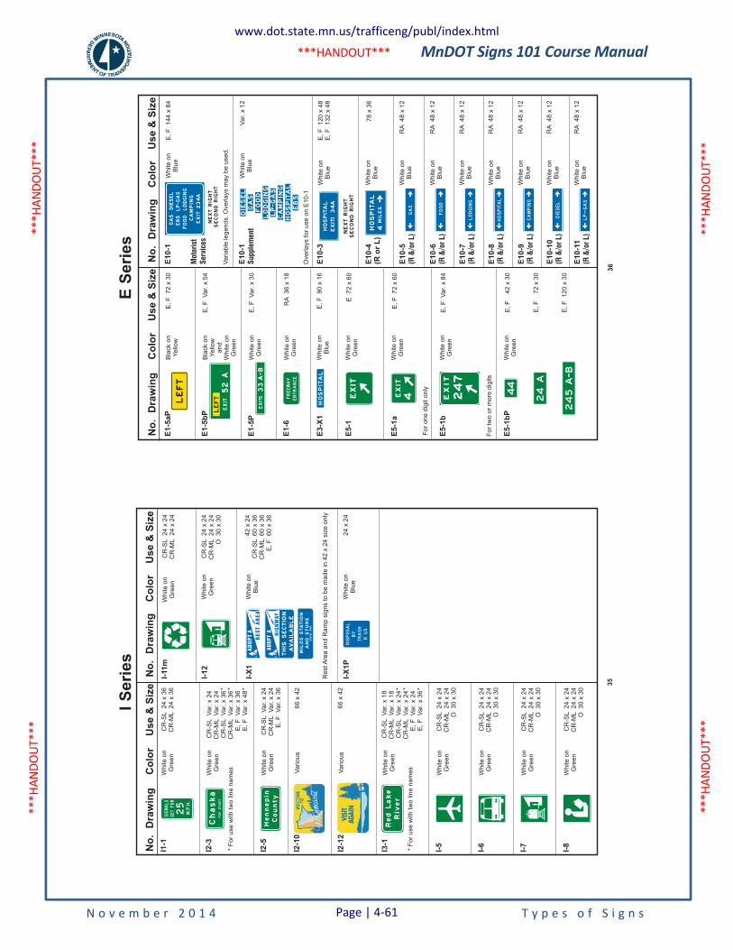
MnDOT Signs 101 Course Manual
N o v e m b e r 2 0 1 4 T y p e s o f S i g n s
***H
ANDO
UT**
* **
*HAN
DOUT
***
***H
ANDO
UT**
* **
*HAN
DOUT
***
***HANDOUT***
No
.D
raw
ing
Co
lor
Use
&S
ize
I1-1
I2-3
I2-5
I-5
I-6
I-7
I-8
I3-1
I2-1
0
I2-1
2
Wh
ite
on
Gre
en
Wh
ite
on
Gre
en
*F
or
use
with
two
line
na
me
s
*F
or
use
with
two
line
na
me
s
Wh
ite
on
Gre
en
Wh
ite
on
Gre
en
Wh
ite
on
Gre
en
Wh
ite
on
Gre
en
Wh
ite
on
Gre
en
Wh
ite
on
Gre
en
Vario
us
Vario
us
CR
-SL
24
x3
6C
R-M
L2
4x
36
CR
-SL
Va
r.x
24
CR
-ML
Va
r.x
24
CR
-SL
Va
r.x
36
CR
-ML
Va
r.x
36
E,
FV
ar.
x3
6E
,F
Va
r.x
48
* * *4
2x
24
CR
-SL
60
x3
6C
R-M
L6
0x
36
E,
F6
0x
36
CR
-SL
Va
r.x
18
CR
-ML
Va
r.x
18
CR
-SL
Va
r.x
24
CR
-ML
Va
r.x
24
E,
FV
ar.
x2
4E
,F
Va
r.x
36
* * *
CR
-SL
Va
r.x
24
CR
-ML
Va
r.x
24
E,
FV
ar.
x3
6
CR
-SL
24
x2
4C
R-M
L2
4x
24
O3
0x
30
CR
-SL
24
x2
4C
R-M
L2
4x
24
O3
0x
30
CR
-SL
24
x2
4C
R-M
L2
4x
24
O3
0x
30
CR
-SL
24
x2
4C
R-M
L2
4x
24
O3
0x
30
CR
-SL
24
x2
4C
R-M
L2
4x
24
O3
0x
30
66
x4
2
66
x4
2
No
.D
raw
ing
Co
lor
Use
&S
ize
Wh
ite
on
Gre
en
Wh
ite
on
Blu
e
Re
stA
rea
an
dR
am
psig
ns
tob
em
ad
ein
42
x2
4siz
eo
nly
Wh
ite
on
Blu
e2
4x
24
I-12
I-X
1
I-X
1P
SIGNALS
SETFOR
25
M.P.H.
Chaska
27,227
POP.
Hennepin
County
Red
Lake
Riv
er
I-11m
Wh
ite
on
Gre
en
CR
-SL
24
x2
4C
R-M
L2
4x
24
TRASH
RUS
THIS
SECTIO
N
AVAILABLE
`MILOSSTATION
ANDSTORE
SIN
CE1
998
35
I Ser
ies
No
.D
raw
ing
Co
lor
Us
e&
Siz
e
E1
-5b
P
E1
-5a
P
E1
-5P
E1
-6
E3
-X1
E5
-1
E5
-1a
E5
-1b
E5
-1b
P
Bla
ck
on
Ye
llow
an
dW
hite
on
Gre
en
Bla
ck
on
Ye
llow
Wh
ite
on
Gre
en
Wh
ite
on
Gre
en
Wh
ite
on
Blu
e
Wh
ite
on
Gre
en
Wh
ite
on
Gre
en
Wh
ite
on
Gre
en
Wh
ite
on
Gre
en
Fo
ro
ne
dig
ito
nly
Fo
rtw
oo
rm
ore
dig
its
E,
FV
ar.
x5
4
E,
F7
2x
30
E,
FV
ar.
x3
0
E,
F9
0x
16
RA
36
x1
8
E7
2x
60
E,
F7
2x
60
E,
FV
ar.
x8
4
E,
F4
2x
30
E,
F7
2x
30
E,
F1
20
x3
0
No
.D
raw
ing
Co
lor
Us
e&
Siz
e
E1
0-3
Wh
ite
on
Blu
e
Wh
ite
on
Blu
e
Wh
ite
on
Blu
e
Wh
ite
on
Blu
e
Wh
ite
on
Blu
e
Wh
ite
on
Blu
e
Wh
ite
on
Blu
e
Wh
ite
on
Blu
e
Wh
ite
on
Blu
e
E,
F1
20
x4
8E
,F
13
2x
48
E1
0-4
(Ro
rL
)
E1
0-5
(R&
/or
L)
E1
0-6
(R&
/or
L)
E1
0-7
(R&
/or
L)
E1
0-8
(R&
/or
L)
E1
0-9
(R&
/or
L)
E1
0-1
0(R
&/o
rL)
E1
0-1
1(R
&/o
rL)
78
x3
6
RA
48
x1
2
RA
48
x1
2
RA
48
x1
2
RA
48
x1
2
RA
48
x1
2
RA
48
x1
2
RA
48
x1
2
EXITS33A-B
EXIT
4EXIT
HOSPITAL
FREEWAY
ENTRANCE
E1
0-1
Mot
oris
tS
ervi
ces
E1
0-1
Supple
men
t
Wh
ite
on
Blu
e
Wh
ite
on
Blu
e
Va
ria
ble
leg
en
ds.
Ove
rla
ys
ma
yb
eu
se
d.
Ove
rla
ys
for
use
on
E1
0-1
E,
F1
44
x8
4
Va
r.x
12
FOOD
LODGIN
G
CAMPING
DIESEL
GAS
LP-G
AS
E85
EXIT
234A
NEXTRIGHT
RIGHT
SECOND
DIESEL
GAS
FOOD
LODGING
LP-GAS
CAMPING
HOSPITAL
E85
HOSPITAL
EXIT1
34A
NEXTRIGHT
RIGHT
SECOND
GAS
FOOD
LODGING
HOSPITAL
CAMPING
DIESEL
LP--GAS
EXIT
247
LEFT
LEFT
EXIT52A
44
24A
245A-B
HOSPITAL
4MILES
36
E Se
ries
www.dot.state.mn.us/trafficeng/publ/index.html
Page | 4-61
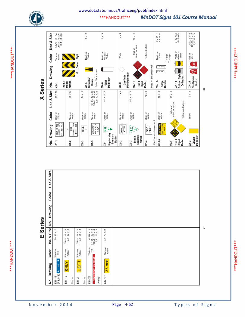
MnDOT Signs 101 Course Manual
N o v e m b e r 2 0 1 4 T y p e s o f S i g n s
***H
ANDO
UT**
* **
*HAN
DOUT
***
***H
ANDO
UT**
* **
*HAN
DOUT
***
***HANDOUT***
No
.D
raw
ing
Co
lor
Use
&S
ize
No
.D
raw
ing
Co
lor
Use
&S
ize
Ove
rla
y
Ove
rla
y
Ove
rla
y
Wh
ite
on
Blu
e
Bla
ck
on
Ye
llow
Bla
ck
on
Ye
llow
Wh
ite
on
Re
d
Bla
ck
on
Ye
llow
E10-1
2(R
&/o
rL)
E11-1
b
E11-2
E11-X
2
E13-1
P
RA
48
x1
2
CR
-ML
42
x1
4E
,F
52
x1
6
CR
-ML
44
x1
6E
,F
54
x1
8
M11
4x
10
CR
-SL
15
0x
14
CR
-ML
15
0x
14
E,
F1
86
x1
6
E,
F7
2x
24
ONLY
E85
PROHIB
ITED
VEHIC
LES
MPH
35LEFT
37
E Se
ries
No
.D
raw
ing
Co
lor
Us
e&
Siz
e
X3
-3
X3
-4
X3
-6a
X4
-3
X4
-2
6x
12
4x
4
X4
-6
X4
-5
X4
-8
Bla
ck
on
Wh
ite
or
Ye
llow
Bla
ck
on
Ye
llow
Ra
ise
Bla
de
sh
ow
n
Wh
ite
No
.D
raw
ing
Co
lor
Us
e&
Siz
e
X4
-12
aB
lack
on
Wh
ite
6x
15
6x
18
* **
* **4
-dig
it
5-d
igit
Re
do
nW
hite
Wh
ite
or
Ye
llow
on
Bla
ck
CR
-SL
8x
12
CR
-ML
8x
12
E,
F1
2x
18
9-
12
hig
h6
-8
wid
e
X4
-24
X4
-13
Bla
ck
on
Ye
llow
Ye
llowY
ello
wo
nB
lack
or
Ye
llow
Ye
llow
w/o
Bu
tto
ns
Bla
ck
on
Wh
ite
8x
24
18
x1
8
18
x1
2
6x
12
Bla
ck
on
Wh
ite
Bla
ck
on
Wh
ite
CR
-SL
42
x3
0C
R-M
L4
2x
30
E,
F7
2x
48
12
x8
12
x8
Use
dfo
rsce
nic
ea
se
me
nt
Use
dfo
re
nd
of
roa
dw
ay
X1
-5
X3
-1
X3
-2
Bla
ck
on
Wh
ite
Bla
ck
on
Wh
ite
24
x1
8
X1
-2
X1
-3
X4
-4B
lack
on
Ye
llow
CR
-SL
12
x3
6C
R-M
L1
2x
36
E,
F1
8x
36
Bla
ck
on
Wh
ite
60
x3
6
60
x3
6
X1
-1BEGIN10MILE
ODOMETERCHECK
1500FEETAHEAD
END
BEGIN
ODOMETERCHECK
HERE
MILE1
AIRCRAFT
APPROACH
AREA
Gre
en
on
Wh
ite
9.5
x1
2.7
5
Rig
ht
ofW
ay
Bou
ndary
Mark
er
Type
3O
bje
ctM
ark
er
RW B
Gre
en
on
Wh
ite
9.5
x1
2.7
5
Sce
nic
Ease
men
tM
ark
er
Type
1O
bje
ctM
ark
er
Culv
ert
Del
inea
tor
Fir
eH
ydra
nt
Mark
er
Cyl
inder
Sty
leD
elin
eato
r
Bri
dge
Num
ber
CONTROLLED
ACCESS
SC E
FEET
500
KEEPOFF
AREA
INFILTRATION
X4
-11
Re
do
nB
lack
or
Re
d
Re
dw
/oB
utt
on
s
18
x1
8
Type
4O
bje
ctM
ark
er
One-
Tenth
Mile
Del
inea
tor
Guid
eD
elin
eato
r
Snow
plo
wM
ark
er
Left
Cen
ter
Rig
ht
48
48
A1 2 3 4
1 2 3 54
38
X Se
ries
www.dot.state.mn.us/trafficeng/publ/index.html
Page | 4-62
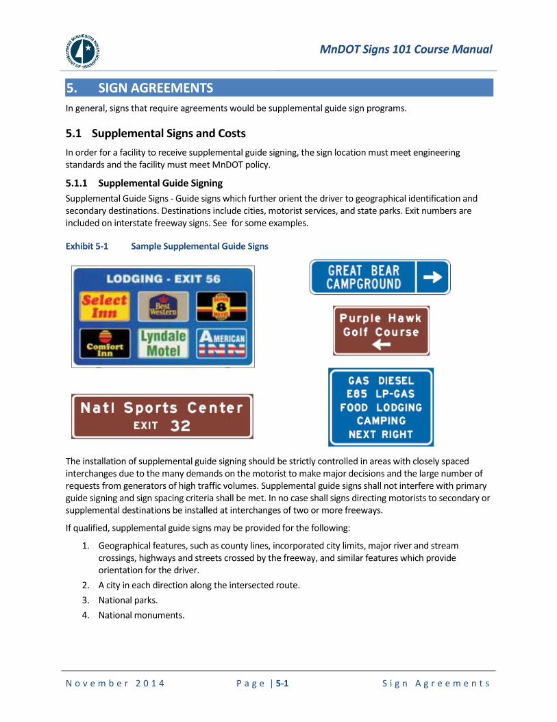
MnDOT Signs 101 Course Manual
N o v e m b e r 2 0 1 4 P a g e | 5-1 S i g n A g r e e m e n t s
5. SIGN AGREEMENTS
In general, signs that require agreements would be supplemental guide sign programs.
5.1 Supplemental Signs and Costs
In order for a facility to receive supplemental guide signing, the sign location must meet engineering standards and the facility must meet MnDOT policy.
5.1.1 Supplemental Guide Signing
Supplemental Guide Signs - Guide signs which further orient the driver to geographical identification and secondary destinations. Destinations include cities, motorist services, and state parks. Exit numbers are included on interstate freeway signs. See for some examples.
Exhibit 5-1 Sample Supplemental Guide Signs
The installation of supplemental guide signing should be strictly controlled in areas with closely spaced interchanges due to the many demands on the motorist to make major decisions and the large number of requests from generators of high traffic volumes. Supplemental guide signs shall not interfere with primary guide signing and sign spacing criteria shall be met. In no case shall signs directing motorists to secondary or supplemental destinations be installed at interchanges of two or more freeways.
If qualified, supplemental guide signs may be provided for the following:
1. Geographical features, such as county lines, incorporated city limits, major river and stream crossings, highways and streets crossed by the freeway, and similar features which provide orientation for the driver.
2. A city in each direction along the intersected route.
3. National parks.
4. National monuments.
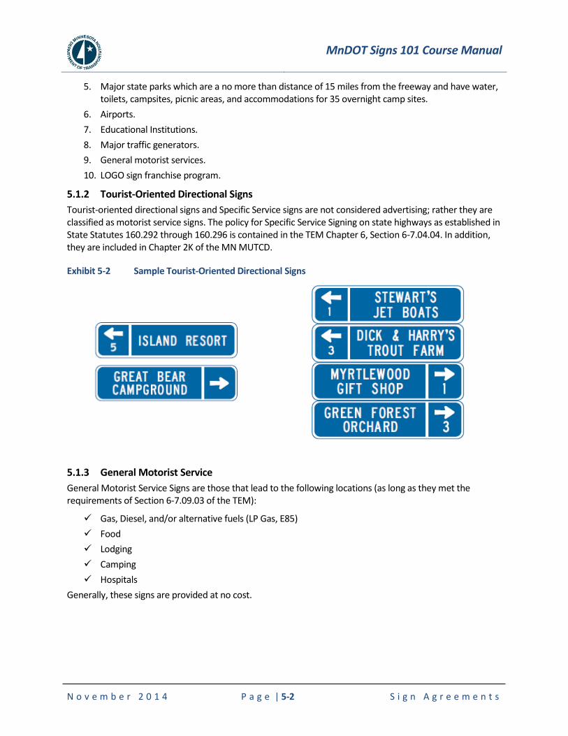
MnDOT Signs 101 Course Manual
N o v e m b e r 2 0 1 4 P a g e | 5-2 S i g n A g r e e m e n t s
5. Major state parks which are a no more than distance of 15 miles from the freeway and have water, toilets, campsites, picnic areas, and accommodations for 35 overnight camp sites.
6. Airports.
7. Educational Institutions.
8. Major traffic generators.
9. General motorist services.
10. LOGO sign franchise program.
5.1.2 Tourist-Oriented Directional Signs
Tourist-oriented directional signs and Specific Service signs are not considered advertising; rather they are classified as motorist service signs. The policy for Specific Service Signing on state highways as established in State Statutes 160.292 through 160.296 is contained in the TEM Chapter 6, Section 6-7.04.04. In addition, they are included in Chapter 2K of the MN MUTCD.
Exhibit 5-2 Sample Tourist-Oriented Directional Signs
5.1.3 General Motorist Service
General Motorist Service Signs are those that lead to the following locations (as long as they met the requirements of Section 6-7.09.03 of the TEM):
Gas, Diesel, and/or alternative fuels (LP Gas, E85)
Food
Lodging
Camping
Hospitals
Generally, these signs are provided at no cost.
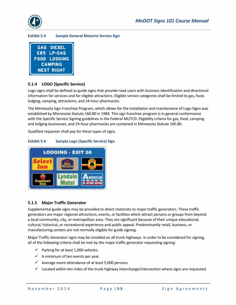
MnDOT Signs 101 Course Manual
N o v e m b e r 2 0 1 4 P a g e | 5-3 S i g n A g r e e m e n t s
Exhibit 5-3 Sample General Motorist Service Sign
5.1.4 LOGO (Specific Service)
Logo signs shall be defined as guide signs that provide road users with business identification and directional information for services and for eligible attractions. Eligible service categories shall be limited to gas, food, lodging, camping, attractions, and 24-hour pharmacies.
The Minnesota Sign Franchise Program, which allows for the installation and maintenance of Logo Signs was established by Minnesota Statute 160.80 in 1984. This sign franchise program is in general conformance with the Specific Service Signing guidelines in the Federal MUTCD. Eligibility criteria for gas, food, camping and lodging businesses, and 24-hour pharmacies are contained in Minnesota Statute 160.80.
Qualified requester shall pay for these types of signs.
Exhibit 5-4 Sample Logo (Specific Service) Sign
5.1.5 Major Traffic Generator
Supplemental guide signs may be provided to direct motorists to major traffic generators. These traffic generators are major regional attractions, events, or facilities which attract persons or groups from beyond a local community, city, or metropolitan area. They are significant because of their unique educational, cultural, historical, or recreational experience and public appeal. Predominantly retail, business, or manufacturing centers are not normally eligible for guide signing.
Major Traffic Generator signs may be installed on all trunk highways. In order to be considered for signing, all of the following criteria shall be met by the major traffic generator requesting signing:
Parking for at least 1,000 vehicles.
A minimum of ten events per year.
Average event attendance of at least 5,000 persons.
Located within ten miles of the trunk highway interchange/intersection where signs are requested.
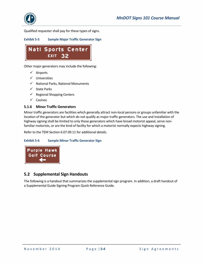
MnDOT Signs 101 Course Manual
N o v e m b e r 2 0 1 4 P a g e | 5-4 S i g n A g r e e m e n t s
Qualified requester shall pay for these types of signs.
Exhibit 5-5 Sample Major Traffic Generator Sign
Other major generators may include the following:
Airports
Universities
National Parks, National Monuments
State Parks
Regional Shopping Centers
Casinos
5.1.6 Minor Traffic Generators
Minor traffic generators are facilities which generally attract non-local persons or groups unfamiliar with the location of the generator but which do not qualify as major traffic generators. The use and installation of highway signing shall be limited to only those generators which have broad motorist appeal, serve non-familiar motorists, or are the kind of facility for which a motorist normally expects highway signing.
Refer to the TEM Section 6.07.09.11 for additional details.
Exhibit 5-6 Sample Minor Traffic Generator Sign
5.2 Supplemental Sign Handouts
The following is a handout that summarizes the supplemental sign program. In addition, a draft handout of a Supplemental Guide Signing Program Quick Reference Guide.
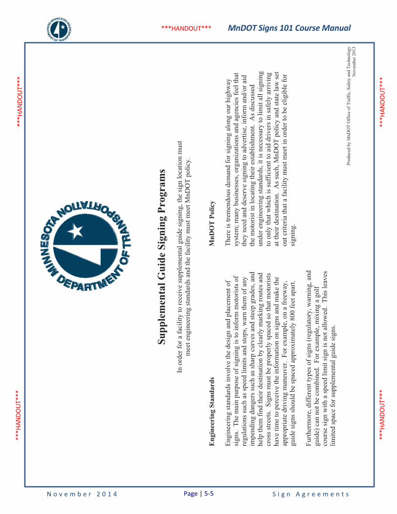
MnDOT Signs 101 Course Manual
N o v e m b e r 2 0 1 4 S i g n A g r e e m e n t s
***H
ANDO
UT**
* **
*HAN
DOUT
***
***H
ANDO
UT**
* **
*HAN
DOUT
***
***HANDOUT***
Prod
uced
by
MnD
OT
Off
ice
of T
raff
ic, S
afet
y an
d Te
chno
logy
N
ovem
ber 2
013
Supp
lem
enta
l Gui
de S
igni
ng P
rogr
ams
In o
rder
for a
faci
lity
to re
ceiv
e su
pple
men
tal g
uide
sign
ing,
the
sign
loca
tion
mus
t m
eet e
ngin
eerin
g st
anda
rds a
nd th
e fa
cilit
y m
ust m
eet M
nDO
T po
licy.
Eng
inee
ring
Sta
ndar
ds
Engi
neer
ing
stan
dard
s inv
olve
the
desi
gn a
nd p
lace
men
t of
sign
s. T
he m
ain
purp
ose
of si
gnin
g is
to in
form
mot
oris
ts o
f re
gula
tions
such
as s
peed
lim
its a
nd st
ops,
war
n th
em o
f any
im
pend
ing
dang
ers s
uch
as sh
arp
curv
es a
nd st
eep
grad
es, a
nd
help
them
find
thei
r des
tinat
ion
by c
lear
ly m
arki
ng ro
utes
and
cr
oss s
treet
s. S
igns
mus
t be
prop
erly
spac
ed so
that
mot
oris
ts
have
tim
e to
per
ceiv
e th
e in
form
atio
n on
sign
s and
mak
e th
e ap
prop
riate
driv
ing
man
euve
r. F
or e
xam
ple,
on
a fr
eew
ay,
guid
e si
gns s
houl
d be
spac
ed a
ppro
xim
atel
y 80
0 fe
et a
part.
Furth
erm
ore,
diff
eren
t typ
es o
f sig
ns (r
egul
ator
y, w
arni
ng, a
nd
guid
e) c
an n
ot b
e co
mbi
ned.
For
exa
mpl
e, m
ixin
g a
golf
cour
se si
gn w
ith a
spee
d lim
it si
gn is
not
allo
wed
. Th
is le
aves
lim
ited
spac
e fo
r sup
plem
enta
l gui
de si
gns.
MnD
OT
Pol
icy
Ther
e is
trem
endo
us d
eman
d fo
r sig
ning
alo
ng o
ur h
ighw
ay
syst
em; m
any
busi
ness
es, o
rgan
izat
ions
and
age
ncie
s fee
l tha
t th
ey n
eed
and
dese
rve
sign
ing
to a
dver
tise,
info
rm a
nd/o
r aid
th
e m
otor
ist i
n lo
catin
g th
eir e
stab
lishm
ent.
As d
iscu
ssed
un
der e
ngin
eerin
g st
anda
rds,
it is
nec
essa
ry to
lim
it al
l sig
ning
to
onl
y th
at w
hich
is su
ffic
ient
to a
id d
river
s in
safe
ly a
rriv
ing
at th
eir d
estin
atio
n. A
s suc
h, M
nDO
T po
licy
and
stat
e la
w se
t ou
t crit
eria
that
a fa
cilit
y m
ust m
eet i
n or
der t
o be
elig
ible
for
sign
ing.
Page | 5-5
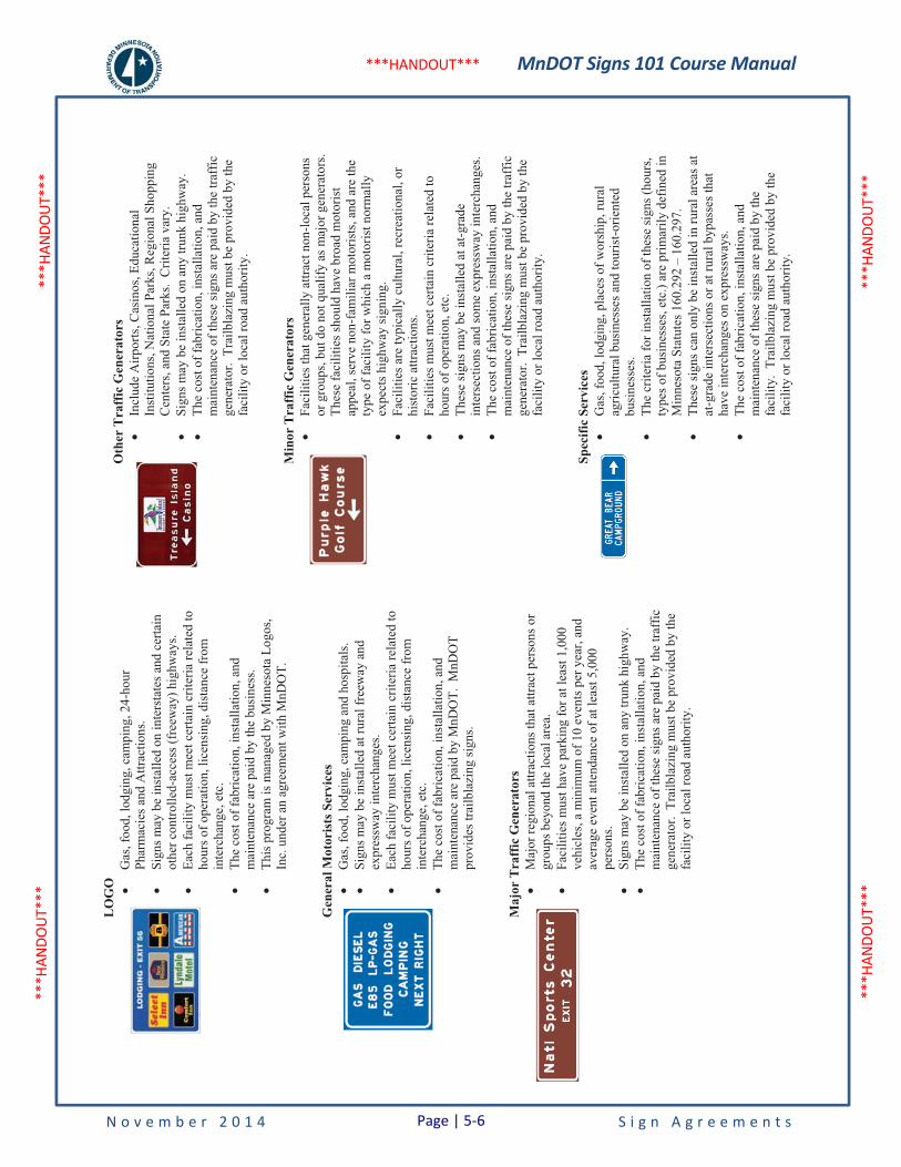
MnDOT Signs 101 Course Manual
N o v e m b e r 2 0 1 4 S i g n A g r e e m e n t s
***H
ANDO
UT**
* **
*HAN
DOUT
***
***H
ANDO
UT**
* **
*HAN
DOUT
***
***HANDOUT***
LO
GO
•
Gas
, foo
d, lo
dgin
g, c
ampi
ng, 2
4-ho
ur
Phar
mac
ies a
nd A
ttrac
tions
.
•Si
gns m
ay b
e in
stal
led
on in
ters
tate
s and
cer
tain
ot
her c
ontro
lled-
acce
ss (f
reew
ay) h
ighw
ays.
•
Each
faci
lity
mus
t mee
t cer
tain
crit
eria
rela
ted
to
hour
s of o
pera
tion,
lice
nsin
g, d
ista
nce
from
in
terc
hang
e, e
tc.
•
The
cost
of f
abric
atio
n, in
stal
latio
n, a
nd
mai
nten
ance
are
pai
d by
the
busi
ness
.
•Th
is p
rogr
am is
man
aged
by
Min
neso
ta L
ogos
, In
c. u
nder
an
agre
emen
t with
MnD
OT.
Gen
eral
Mot
oris
ts S
ervi
ces
•G
as, f
ood,
lodg
ing,
cam
ping
and
hos
pita
ls.
•Si
gns m
ay b
e in
stal
led
at ru
ral f
reew
ay a
nd
expr
essw
ay in
terc
hang
es.
•Ea
ch fa
cilit
y m
ust m
eet c
erta
in c
riter
ia re
late
d to
ho
urs o
f ope
ratio
n, li
cens
ing,
dis
tanc
e fr
om
inte
rcha
nge,
etc
. •
The
cost
of f
abric
atio
n, in
stal
latio
n, a
nd
mai
nten
ance
are
pai
d by
MnD
OT.
MnD
OT
prov
ides
trai
lbla
zing
sign
s.
Maj
or T
raff
ic G
ener
ator
s •
Maj
or re
gion
al a
ttrac
tions
that
attr
act p
erso
ns o
r gr
oups
bey
ond
the
loca
l are
a.
•Fa
cilit
ies m
ust h
ave
park
ing
for a
t lea
st 1
,000
ve
hicl
es, a
min
imum
of 1
0 ev
ents
per
yea
r, an
d av
erag
e ev
ent a
ttend
ance
of a
t lea
st 5
,000
pe
rson
s. •
Sign
s may
be
inst
alle
d on
any
trun
k hi
ghw
ay.
•Th
e co
st o
f fab
ricat
ion,
inst
alla
tion,
and
m
aint
enan
ce o
f the
se si
gns a
re p
aid
by th
e tra
ffic
ge
nera
tor.
Tra
ilbla
zing
mus
t be
prov
ided
by
the
faci
lity
or lo
cal r
oad
auth
ority
.
Oth
er T
raff
ic G
ener
ator
s •
Incl
ude
Airp
orts
, Cas
inos
, Edu
catio
nal
Inst
itutio
ns, N
atio
nal P
arks
, Reg
iona
l Sho
ppin
g C
ente
rs, a
nd S
tate
Par
ks.
Crit
eria
var
y.
•Si
gns m
ay b
e in
stal
led
on a
ny tr
unk
high
way
. •
The
cost
of f
abric
atio
n, in
stal
latio
n, a
nd
mai
nten
ance
of t
hese
sign
s are
pai
d by
the
traff
ic
gene
rato
r. T
railb
lazi
ng m
ust b
e pr
ovid
ed b
y th
e fa
cilit
y or
loca
l roa
d au
thor
ity.
Min
or T
raff
ic G
ener
ator
s •
Faci
litie
s tha
t gen
eral
ly a
ttrac
t non
-loca
l per
sons
or
gro
ups,
but d
o no
t qua
lify
as m
ajor
gen
erat
ors.
Th
ese
faci
litie
s sho
uld
have
bro
ad m
otor
ist
appe
al, s
erve
non
-fam
iliar
mot
oris
ts, a
nd a
re th
e ty
pe o
f fac
ility
for w
hich
a m
otor
ist n
orm
ally
ex
pect
s hig
hway
sign
ing.
•
Faci
litie
s are
typi
cally
cul
tura
l, re
crea
tiona
l, or
hi
stor
ic a
ttrac
tions
. •
Faci
litie
s mus
t mee
t cer
tain
crit
eria
rela
ted
to
hour
s of o
pera
tion,
etc
. •
Thes
esi
gns m
ay b
e in
stal
led
at a
t-gra
de
inte
rsec
tions
and
som
e ex
pres
sway
inte
rcha
nges
. •
The
cost
of f
abric
atio
n, in
stal
latio
n, a
nd
mai
nten
ance
of t
hese
sign
s are
pai
d by
the
traff
ic
gene
rato
r. T
railb
lazi
ng m
ust b
e pr
ovid
ed b
y th
e fa
cilit
y or
loca
l roa
d au
thor
ity.
Spec
ific
Serv
ices
•
Gas
, foo
d, lo
dgin
g, p
lace
s of w
orsh
ip, r
ural
ag
ricul
tura
l bus
ines
ses a
nd to
uris
t-orie
nted
bu
sine
sses
. •
The
crite
ria fo
r ins
talla
tion
of th
ese
sign
s (ho
urs,
type
s of b
usin
esse
s, et
c.) a
re p
rimar
ily d
efin
ed in
M
inne
sota
Sta
tute
s 160
.292
– 1
60.2
97.
•Th
ese
sign
s can
onl
y be
inst
alle
d in
rura
l are
as a
t at
-gra
de in
ters
ectio
ns o
r at r
ural
byp
asse
s tha
t ha
ve in
terc
hang
es o
n ex
pres
sway
s. •
The
cost
of f
abric
atio
n, in
stal
latio
n, a
nd
mai
nten
ance
of t
hese
sign
s are
pai
d by
the
faci
lity.
Tra
ilbla
zing
mus
t be
prov
ided
by
the
faci
lity
or lo
cal r
oad
auth
ority
.
Page | 5-6

MnDOT Signs 101 Course Manual
N o v e m b e r 2 0 1 4 S i g n A g r e e m e n t s
***H
ANDO
UT**
* **
*HAN
DOUT
***
***H
ANDO
UT**
* **
*HAN
DOUT
***
***HANDOUT***
1
MnD
OT
Supp
lem
enta
l Gui
de S
igni
ng P
rogr
ams
Qui
ck R
efer
ence
Gui
de
Page | 5-7
DRAFT

MnDOT Signs 101 Course Manual
N o v e m b e r 2 0 1 4 S i g n A g r e e m e n t s
***H
ANDO
UT**
* **
*HAN
DOUT
***
***H
ANDO
UT**
* **
*HAN
DOUT
***
***HANDOUT***
2
GE
NE
RA
L C
RIT
ER
IA
(6-7
.09.
02)
See
the
Traf
fic E
ngin
eerin
g M
anua
l for
info
rmat
ion
on M
nDO
T’s S
uppl
emen
tal G
uide
Sig
ning
Pro
gram
s. U
nles
s spe
cific
ally
not
ed
unde
r a p
artic
ular
sign
ing
prog
ram
, the
follo
win
g ge
nera
l crit
eria
app
ly to
all
of M
nDO
T’s s
igni
ng p
rogr
ams.
1.M
nDO
T sh
all f
abric
ate,
inst
all,
and
mai
ntai
n si
gns o
n tru
nk h
ighw
ays u
nles
s oth
erw
ise
spec
ified
by
the
Dis
trict
Tra
ffic
En
gine
er.
2.Th
e co
st o
f fab
ricat
ion,
inst
alla
tion,
and
mai
nten
ance
shal
l be
paid
by
the
requ
este
r. 3.
App
ropr
iate
trai
lbla
zing
sign
s sha
ll be
the
resp
onsi
bilit
y of
the
faci
lity
and
appr
oved
by
the
road
aut
horit
y. I
f app
ropr
iate
tra
ilbla
zing
can
not
be
inst
alle
d, si
gnin
g on
trun
k hi
ghw
ays s
hall
not b
e in
stal
led.
The
col
or a
nd d
esig
n of
trai
lbla
zing
sign
ssh
ould
mat
ch th
at o
f the
sign
ing
inst
alle
d on
the
trunk
hig
hway
. 4.
Sign
s sha
ll no
t be
allo
wed
from
inte
rsec
tions
or i
nter
chan
ges t
hat d
o no
t pro
vide
the
clos
est o
r mos
t dire
ct ro
ute
from
a tr
unk
high
way
to a
faci
lity.
5.
MnD
OT
reta
ins t
he a
utho
rity
to sp
ecify
mes
sage
con
tent
(inc
ludi
ng a
bbre
viat
ions
), si
ze o
f sig
n, si
gn lo
catio
n, a
nd c
ombi
natio
n of
mes
sage
s, in
acc
orda
nce
with
stan
dard
s for
acc
epta
ble
sign
ing
prac
tice.
The
sign
des
ign,
incl
udin
g m
essa
ge a
nd lo
gos i
f ap
plic
able
, sha
ll be
iden
tical
on
ram
p an
d m
ainl
ine
sign
s at a
n in
terc
hang
e.
6.Lo
catio
n an
d pl
acem
ent o
f sig
ns is
dep
ende
nt u
pon
spac
e av
aila
bilit
y as
det
erm
ined
by
the
dist
rict t
raff
ic e
ngin
eer.
Sig
n in
stal
latio
ns sh
all m
eet s
ign
spac
ing
guid
elin
es fo
r the
type
of r
oadw
ay o
n w
hich
they
are
allo
wed
. N
o si
gn in
stal
latio
ns sh
all
be p
lace
d at
a lo
catio
n th
at w
ill in
terf
ere
with
oth
er n
eces
sary
sign
ing
as d
eter
min
ed b
y th
e di
stric
t tra
ffic
eng
inee
r. If
spac
e is
un
avai
labl
e, re
ques
ts sh
all b
e de
nied
. 7.
Mai
nlin
e si
gns s
hall
not b
e in
stal
led
for a
faci
lity
if th
ere
is n
o sp
ace
avai
labl
e to
inst
all s
igns
on
the
ram
p an
d vi
ce v
ersa
.8.
All
sign
inst
alla
tions
on
trunk
hig
hway
s sha
ll co
nfor
m to
MnD
OT’
s cur
rent
sign
des
ign
and
sign
shee
ting
stan
dard
s.9.
Sign
s not
mee
ting
MnD
OT’
s cur
rent
crit
eria
shal
l be
rem
oved
thro
ugh
attri
tion.
If m
ainl
ine
sign
ing
is re
mov
ed, r
amp
sign
ing
and
any
trailb
lazi
ng o
n tru
nk h
ighw
ays s
hall
also
be
rem
oved
. 10
.Onl
y on
e si
gn p
er fa
cilit
y m
ay b
e in
stal
led
in e
ach
dire
ctio
n al
ong
a tru
nk h
ighw
ay.
11.T
he c
riter
ia fo
r ins
talli
ng lo
gos (
busi
ness
pan
els)
on
spec
ific
serv
ice
and
LOG
O si
gns a
re sp
ecifi
ed in
Sec
tion
6-7.
09.1
3 an
d 6-
7.09
.09,
resp
ectiv
ely.
a.
Logo
s are
per
mitt
ed o
n gu
ide
sign
s for
the
follo
win
g su
pple
men
tal g
uide
sign
ing
prog
ram
s:
1)A
irpor
ts2)
Cas
inos
3)Ed
ucat
iona
l Ins
titut
ions
(pos
t-sec
onda
ry)
pi
ctog
raph
?4)
Maj
or T
raff
ic G
ener
ator
s 5)
Min
or T
raff
ic G
ener
ator
s 6)
Nat
iona
l Par
ks, N
atio
nal M
onum
ents
pict
ogra
ph?
7)R
egio
nal S
hopp
ing
Cen
ters
Page | 5-8
DRAFT

MnDOT Signs 101 Course Manual
N o v e m b e r 2 0 1 4 S i g n A g r e e m e n t s
***H
ANDO
UT**
* **
*HAN
DOUT
***
***H
ANDO
UT**
* **
*HAN
DOUT
***
***HANDOUT***
3
8)St
ate
Park
s
pict
ogra
ph?
9)Tr
ail A
cces
s
pi
ctog
raph
?b.
Logo
s sha
ll m
eet t
he fo
llow
ing
guid
elin
es:
1)Lo
gos s
hall
not r
esem
ble
a tra
ffic
con
trol d
evic
e.
2)In
appr
opria
te lo
gos o
r log
o pa
nels
shal
l not
be
perm
itted
. 3)
Ther
e sh
all b
e on
ly o
ne lo
go o
r log
o pa
nel p
er si
gn.
4)Th
e lo
go o
r log
o pa
nel s
hall
supp
lem
ent t
he te
xt m
essa
ge.
5)Th
e lo
go o
r log
o pa
nel s
hall
not e
xcee
d 33
per
cent
of t
he si
ze o
f the
sign
pan
el.
6)Th
e lo
go o
r log
o pa
nel s
hall
fit w
ithin
the
bord
er o
f the
sign
pan
el.
Logo
s or l
ogo
pane
ls sh
all n
ot b
e a
sepa
rate
atta
chm
ent o
utsi
de th
e lim
its o
f the
sign
pan
el.
7)Th
e lo
go a
nd si
gn p
anel
des
igns
shal
l be
revi
ewed
and
app
rove
d by
the
dist
rict t
raff
ic o
ffic
e pr
ior t
o fa
bric
atio
n.8)
The
logo
or l
ogo
pane
l sha
ll be
fabr
icat
ed o
n sh
eet a
lum
inum
con
form
ing
to M
nDO
T sp
ecifi
catio
n 33
52.
12.S
ign
may
be
cons
ider
ed o
n tru
nk h
ighw
ays t
hat i
nter
sect
with
loca
l roa
ds w
hich
serv
e as
logi
cal,
prim
ary
rout
es fo
r mot
oris
ts
appr
oach
ing
from
oth
er d
irect
ions
.
13.S
igns
shal
l not
be
prov
ided
if th
e fa
cilit
y is
read
ily v
isib
le o
r if e
ffec
tive
off r
ight
-of-
way
dire
ctio
nal s
igni
ng is
pre
sent
or c
an
be p
rovi
ded.
14
.MnD
OT
reta
ins t
he a
utho
rity
to d
eny
requ
ests
for s
igni
ng w
here
acc
epta
ble
stan
dard
s can
not b
e m
et, i
nclu
ding
loca
tions
whe
re
othe
r sup
plem
enta
l gui
de si
gns a
re a
lread
y in
pla
ce.
At t
he d
iscr
etio
n of
the
Dis
trict
Tra
ffic
Eng
inee
r, si
gnin
g re
ques
ts d
enie
dba
sed
on M
nDO
T po
licy
may
be
appe
aled
to th
e Ex
tern
al S
ign
Var
ianc
e C
omm
ittee
. R
eque
sts d
enie
d ba
sed
on M
inne
sota
st
atut
es o
r eng
inee
ring
stan
dard
s (i.e
. ins
uffic
ient
spac
e an
d de
sign
stan
dard
s fou
nd in
the
MN
MU
TCD
) may
not
be
appe
aled
. 15
.If a
dis
trict
traf
fic o
ffic
e de
cide
s tha
t a c
ontra
ct fo
r sig
ning
a m
inor
traf
fic g
ener
ator
is re
quire
d, th
e fo
llow
ing
proc
ess s
hall
be
used
: a.Th
e re
ques
ter s
houl
d ob
tain
pro
posa
ls fr
om a
t lea
st th
ree
cons
ultin
g en
gine
erin
g fir
ms t
o pr
epar
e th
e si
gnin
g co
ntra
ct.
b.Th
e re
ques
ter e
valu
ates
the
prop
osal
s and
ent
ers i
nto
a co
ntra
ct w
ith o
ne o
f the
con
sulti
ng e
ngin
eerin
g fir
ms t
o pr
ovid
e al
l of t
he fo
llow
ing:
1)
A c
ompl
ete
desi
gn o
f a si
gnin
g pl
an (i
nclu
ding
fiel
d cr
oss s
ectio
ns if
nec
essa
ry),
asse
mbl
y of
spec
ial
prov
isio
ns, a
nd p
ropo
sal.
Tec
hnic
al a
ssis
tanc
e is
ava
ilabl
e fr
om th
e St
ate
Sign
ing
Engi
neer
. 2)
Subm
it th
e pl
an a
nd p
ropo
sal t
o th
e si
gnin
g co
ntra
ctor
s. T
ypic
ally
allo
w 1
0 da
ys fo
r the
con
tract
or to
revi
ew
and
subm
it bi
ds.
3)R
evie
w th
e bi
ds a
nd a
war
d th
e co
ntra
ct to
the
sign
ing
cont
ract
or.
4)In
spec
t the
sign
ing
cont
ract
or’s
wor
k w
ith te
chni
cal a
ssis
tanc
e pr
ovid
ed b
y M
nDO
T’s d
istri
ct st
aff.
Page | 5-9
DRAFT
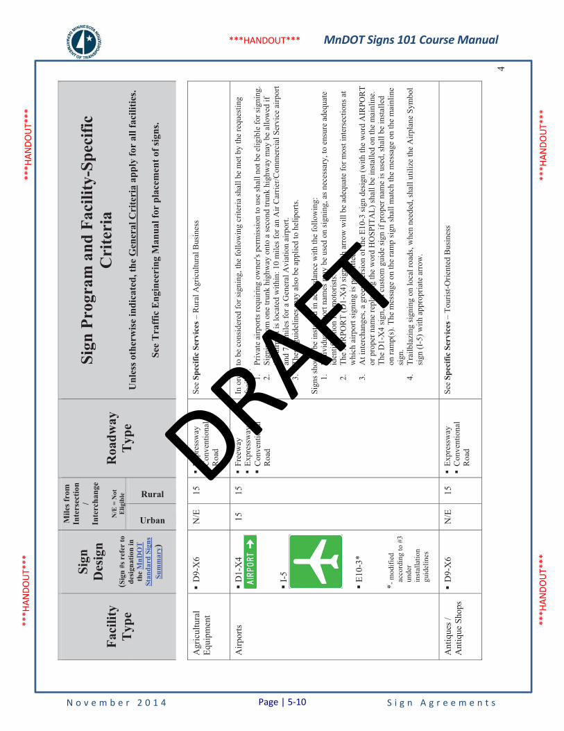
MnDOT Signs 101 Course Manual
N o v e m b e r 2 0 1 4 S i g n A g r e e m e n t s
***H
ANDO
UT**
* **
*HAN
DOUT
***
***H
ANDO
UT**
* **
*HAN
DOUT
***
***HANDOUT***
Faci
lity
Typ
e
Sign
Des
ign
(Sig
n #s
ref
er to
de
sign
atio
n in
th
eM
nDO
T
Stan
dard
Sig
ns
Sum
mar
y)
Mile
s fro
m
Inte
rsec
tion
/In
terc
hang
e
N/E
= N
ot
Elig
ible
Roa
dway
Typ
e
Sign
Pro
gram
and
Fac
ility
-Spe
cific
C
rite
ria
Unl
ess o
ther
wis
e in
dica
ted,
the
Gen
eral
Cri
teri
a ap
ply
for
all f
acili
ties.
See
Tra
ffic
Eng
inee
ring
Man
ual f
or p
lace
men
t of s
igns
.
Urban
Rural4
Agr
icul
tura
lEq
uipm
ent
�D
9-X
6 N
/E
15
�Ex
pres
sway
�
Con
vent
iona
l R
oad
See
Spec
ific
Serv
ices
– R
ural
Agr
icul
tura
l Bus
ines
s
Airp
orts
�D
1-X
4
�I-
5
�E1
0-3*
* - m
odifi
ed
acco
rdin
g to
#3
unde
rin
stal
latio
n gu
idel
ines
15
15
�Fr
eew
ay
�Ex
pres
sway
�
Con
vent
iona
l R
oad
In o
rder
to b
e co
nsid
ered
for s
igni
ng, t
he fo
llow
ing
crite
ria sh
all b
e m
et b
y th
e re
ques
ting
faci
lity:
1.
Priv
ate
airp
orts
requ
iring
ow
ner's
per
mis
sion
to u
se sh
all n
ot b
e el
igib
le fo
r sig
ning
. 2.
Sign
ing
from
one
trun
k hi
ghw
ay o
nto
a se
cond
trun
k hi
ghw
ay m
ay b
e al
low
ed if
th
e ai
rpor
t is l
ocat
ed w
ithin
: 10
mile
s for
an
Air
Car
rier/C
omm
erci
al S
ervi
ce a
irpor
t an
d 7.
5 m
iles f
or a
Gen
eral
Avi
atio
n ai
rpor
t. 3.
Thes
e gu
idel
ines
may
als
o be
app
lied
to h
elip
orts
.
Sign
s sho
uld
be in
stal
led
in a
ccor
danc
e w
ith th
e fo
llow
ing:
1.
Indi
vidu
al a
irpor
t nam
es m
ay b
e us
ed o
n si
gnin
g, a
s nec
essa
ry, t
o en
sure
ade
quat
e id
entif
icat
ion
for m
otor
ists
. 2.
The
AIR
POR
T (D
1-X
4) si
gn w
ith a
rrow
will
be
adeq
uate
for m
ost i
nter
sect
ions
at
whi
ch a
irpor
t sig
ning
is p
erm
itted
. 3.
At i
nter
chan
ges,
a gr
een
vers
ion
of th
e E1
0-3
sign
des
ign
(with
the
wor
d A
IRPO
RT
or p
rope
r nam
e re
plac
ing
the
wor
d H
OSP
ITA
L) sh
all b
e in
stal
led
on th
e m
ainl
ine.
Th
e D
1-X
4 si
gn, o
r a c
usto
m g
uide
sign
if p
rope
r nam
e is
use
d, sh
all b
e in
stal
led
on ra
mp(
s). T
he m
essa
ge o
n th
e ra
mp
sign
shal
l mat
ch th
e m
essa
ge o
n th
e m
ainl
ine
sign
.4.
Trai
lbla
zing
sign
ing
on lo
cal r
oads
, whe
n ne
eded
, sha
ll ut
ilize
the
Airp
lane
Sym
bol
sign
(I-5
) with
app
ropr
iate
arr
ow.
Ant
ique
s /
Ant
ique
Sho
ps
�D
9-X
6 N
/E
15
�Ex
pres
sway
�
Con
vent
iona
l R
oad
See
Spec
ific
Serv
ices
– T
ouris
t-Orie
nted
Bus
ines
s
Page | 5-10
DRAFT
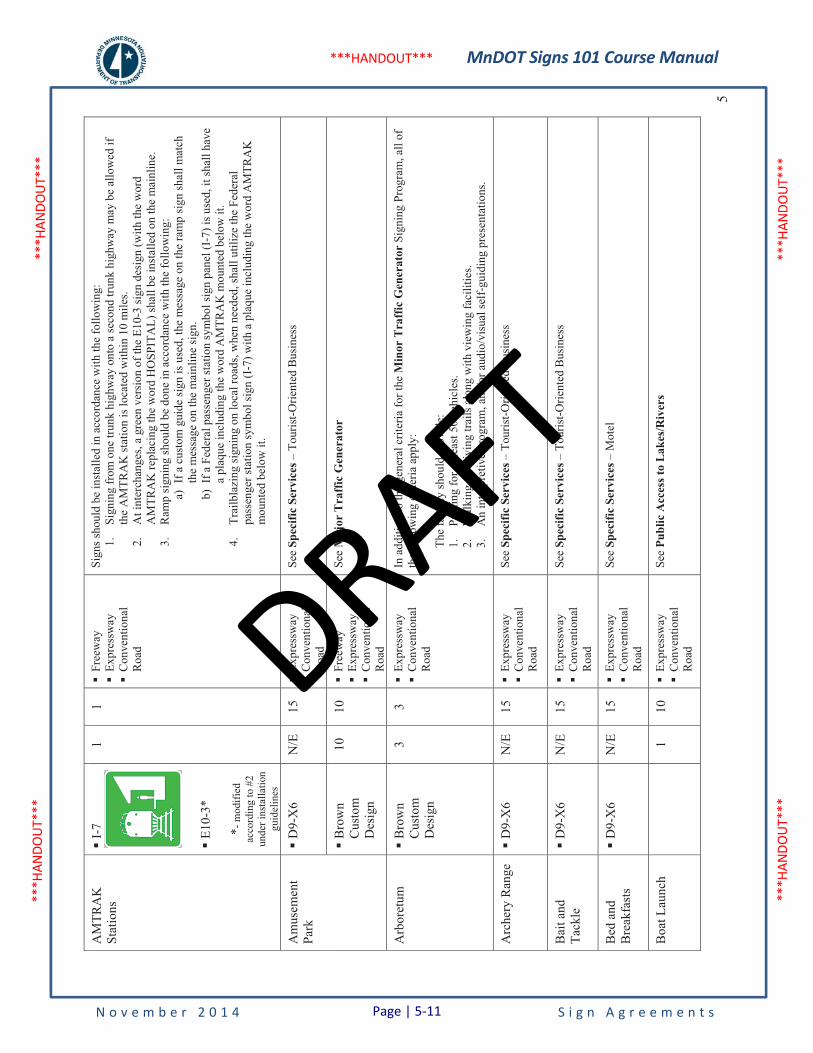
MnDOT Signs 101 Course Manual
N o v e m b e r 2 0 1 4 S i g n A g r e e m e n t s
***H
ANDO
UT**
* **
*HAN
DOUT
***
***H
ANDO
UT**
* **
*HAN
DOUT
***
***HANDOUT***
5
AM
TRA
KSt
atio
ns�
I-7
�E1
0-3*
* - m
odifi
ed
acco
rdin
g to
#2
unde
r ins
talla
tion
guid
elin
es
1 1
�Fr
eew
ay
�Ex
pres
sway
�
Con
vent
iona
l R
oad
Sign
s sho
uld
be in
stal
led
in a
ccor
danc
e w
ith th
e fo
llow
ing:
1.
Sign
ing
from
one
trun
k hi
ghw
ay o
nto
a se
cond
trun
k hi
ghw
ay m
ay b
e al
low
ed if
th
e A
MTR
AK
stat
ion
is lo
cate
d w
ithin
10
mile
s. 2.
At i
nter
chan
ges,
a gr
een
vers
ion
of th
e E1
0-3
sign
des
ign
(with
the
wor
d A
MTR
AK
repl
acin
g th
e w
ord
HO
SPIT
AL)
shal
l be
inst
alle
d on
the
mai
nlin
e.
3.R
amp
sign
ing
shou
ld b
e do
ne in
acc
orda
nce
with
the
follo
win
g:
a)If
a c
usto
m g
uide
sign
is u
sed,
the
mes
sage
on
the
ram
p si
gn sh
all m
atch
th
e m
essa
ge o
n th
e m
ainl
ine
sign
. b)
If a
Fed
eral
pas
seng
er st
atio
n sy
mbo
l sig
n pa
nel (
I-7)
is u
sed,
it sh
all h
ave
a pl
aque
incl
udin
g th
e w
ord
AM
TRA
K m
ount
ed b
elow
it.
4.
Trai
lbla
zing
sign
ing
on lo
cal r
oads
, whe
n ne
eded
, sha
ll ut
ilize
the
Fede
ral
pass
enge
r sta
tion
sym
bol s
ign
(I-7
) with
a p
laqu
e in
clud
ing
the
wor
d A
MTR
AK
m
ount
ed b
elow
it.
Am
usem
ent
Park
�D
9-X
6 N
/E
15
�Ex
pres
sway
�
Con
vent
iona
l R
oad
See
Spec
ific
Serv
ices
– T
ouris
t-Orie
nted
Bus
ines
s
�B
row
nC
usto
m
Des
ign
10
10
�Fr
eew
ay
�Ex
pres
sway
�
Con
vent
iona
l R
oad
See
Maj
or T
raff
ic G
ener
ator
Arb
oret
um�
Bro
wn
Cus
tom
D
esig
n
3 3
�Ex
pres
sway
�
Con
vent
iona
l R
oad
In a
dditi
on to
the
gene
ral c
riter
ia fo
r the
Min
or T
raff
ic G
ener
ator
Sig
ning
Pro
gram
, all
of
the
follo
win
g cr
iteria
app
ly:
The
faci
lity
shou
ld p
rovi
de:
1.Pa
rkin
g fo
r at l
east
50
vehi
cles
. 2.
Wal
king
or d
rivin
g tra
ils a
long
with
vie
win
g fa
cilit
ies.
3.A
n in
terp
retiv
e pr
ogra
m, a
nd/o
r aud
io/v
isua
l sel
f-gu
idin
g pr
esen
tatio
ns.
Arc
hery
Ran
ge
�D
9-X
6 N
/E
15
�Ex
pres
sway
�
Con
vent
iona
l R
oad
See
Spec
ific
Serv
ices
– T
ouris
t-Orie
nted
Bus
ines
s
Bai
t and
Ta
ckle
�
D9-
X6
N/E
15
�
Expr
essw
ay
�C
onve
ntio
nal
Roa
d
See
Spec
ific
Serv
ices
– T
ouris
t-Orie
nted
Bus
ines
s
Bed
and
B
reak
fast
s �
D9-
X6
N/E
15
�
Expr
essw
ay
�C
onve
ntio
nal
Roa
d
See
Spec
ific
Serv
ices
– M
otel
Boa
t Lau
nch
1
10
�Ex
pres
sway
�
Con
vent
iona
l R
oad
See
Publ
ic A
cces
s to
Lake
s/Riv
ers
Page | 5-11
DRAFT
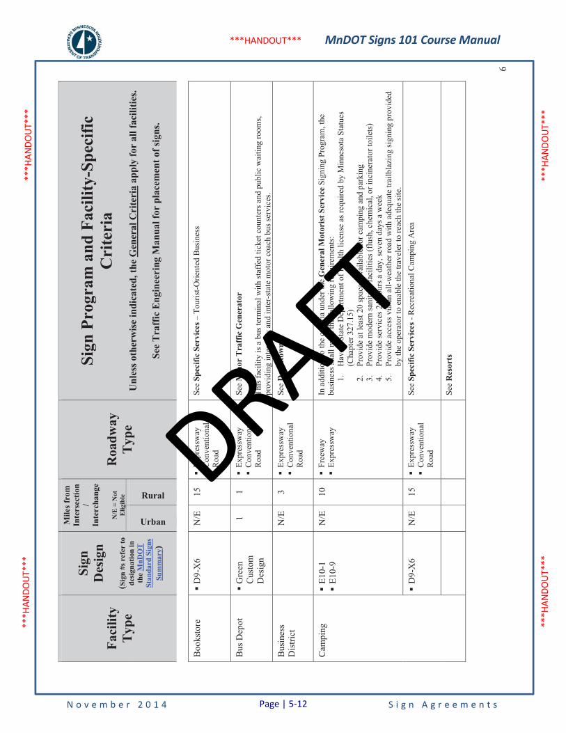
MnDOT Signs 101 Course Manual
N o v e m b e r 2 0 1 4 S i g n A g r e e m e n t s
***H
ANDO
UT**
* **
*HAN
DOUT
***
***H
ANDO
UT**
* **
*HAN
DOUT
***
***HANDOUT***
Faci
lity
Typ
e
Sign
Des
ign
(Sig
n #s
ref
er to
de
sign
atio
n in
th
eM
nDO
T
Stan
dard
Sig
ns
Sum
mar
y)
Mile
s fro
m
Inte
rsec
tion
/In
terc
hang
e
N/E
= N
ot
Elig
ible
Roa
dway
Typ
e
Sign
Pro
gram
and
Fac
ility
-Spe
cific
C
rite
ria
Unl
ess o
ther
wis
e in
dica
ted,
the
Gen
eral
Cri
teri
a ap
ply
for
all f
acili
ties.
See
Tra
ffic
Eng
inee
ring
Man
ual f
or p
lace
men
t of s
igns
.
Urban
Rural6
Boo
ksto
re�
D9-
X6
N/E
15
�
Expr
essw
ay
�C
onve
ntio
nal
Roa
d
See
Spec
ific
Serv
ices
– T
ouris
t-Orie
nted
Bus
ines
s
Bus
Dep
ot
�G
reen
Cus
tom
D
esig
n
1 1
�Ex
pres
sway
�
Con
vent
iona
l R
oad
See
Min
or T
raff
ic G
ener
ator
This
faci
lity
is a
bus
term
inal
with
staf
fed
ticke
t cou
nter
s and
pub
lic w
aitin
g ro
oms,
prov
idin
g in
ter-
city
and
inte
r-st
ate
mot
or c
oach
bus
serv
ices
.
Bus
ines
sD
istri
ct
N
/E
3 �
Expr
essw
ay
�C
onve
ntio
nal
Roa
d
See
Dow
ntow
n
Cam
ping
�
E10-
1 �
E10-
9 N
/E
10
�Fr
eew
ay
�Ex
pres
sway
In
add
ition
to th
e cr
iteria
und
er th
e G
ener
al M
otor
ist S
ervi
ce S
igni
ngPr
ogra
m, t
he
busi
ness
shal
l mee
t the
follo
win
g re
quire
men
ts:
1.H
ave
a St
ate
Dep
artm
ent o
f Hea
lth li
cens
e as
requ
ired
by M
inne
sota
Sta
tues
(C
hapt
er 3
27.1
5)
2.Pr
ovid
e at
leas
t 20
spac
es a
vaila
ble
for c
ampi
ng a
nd p
arki
ng
3.Pr
ovid
e m
oder
n sa
nita
ry fa
cilit
ies (
flush
, che
mic
al, o
r inc
iner
ator
toile
ts)
4.Pr
ovid
e se
rvic
es 2
4 ho
urs a
day
, sev
en d
ays a
wee
k 5.
Prov
ide
acce
ss v
ia a
n al
l-wea
ther
road
with
ade
quat
e tra
ilbla
zing
sign
ing
prov
ided
by
the
oper
ator
to e
nabl
e th
e tra
vele
r to
reac
h th
e si
te.
�D
9-X
6 N
/E
15
�Ex
pres
sway
�
Con
vent
iona
l R
oad
See
Spec
ific
Serv
ices
- R
ecre
atio
nal C
ampi
ng A
rea
See
Res
orts
Page | 5-12
DRAFT

MnDOT Signs 101 Course Manual
N o v e m b e r 2 0 1 4 S i g n A g r e e m e n t s
***H
ANDO
UT**
* **
*HAN
DOUT
***
***H
ANDO
UT**
* **
*HAN
DOUT
***
***HANDOUT***
7
Cam
ps, P
rivat
e �
Bro
wn
Cus
tom
D
esig
n
N/E
10
�
Expr
essw
ay
�C
onve
ntio
nal
Roa
d
This
faci
lity
is g
ener
ally
a sp
ecia
lized
, rur
al su
mm
er c
amp.
It i
s ope
rate
d or
spon
sore
d by
ch
urch
, fra
tern
al, s
cout
ing
or si
mila
r org
aniz
atio
ns a
nd is
not
ope
n to
the
gene
ral p
ublic
for
over
nigh
t cam
ping
. Th
e fa
cilit
y ge
nera
lly a
ccom
mod
ates
pre
-arr
ange
d se
ssio
ns o
f sev
eral
da
ys d
urat
ion
and
is o
rient
ed to
war
d re
crea
tion,
edu
catio
n, tr
aini
ng o
r com
bina
tions
ther
eof.
V
isito
rs a
re u
sual
ly n
ot fa
mili
ar w
ith th
e ca
mp
loca
tion.
In a
dditi
on to
the
gene
ral c
riter
ia fo
r the
Min
or T
raff
ic G
ener
ator
Sig
ning
Pro
gram
, all
of
the
follo
win
g cr
iteria
app
ly:
1.Th
e fa
cilit
y sh
all:
a)Pr
ovid
e fu
ll-tim
e st
aff o
n si
te to
acc
omm
odat
e cl
ient
ele
b)B
e a
priv
ate
oper
atio
n c)
Acc
ept p
re-a
rran
ged
acco
mm
odat
ions
onl
y d)
Not
allo
w p
ublic
, ove
rnig
ht c
ampi
ng
2.Fo
r a se
ason
al c
amp,
MnD
OT
may
inco
rpor
ate
sign
ing
indi
catin
g pe
riods
of
clos
ure
whe
re a
ppro
pria
te.
Cas
inos
�
Bro
wn
Cus
tom
D
esig
n
10
10
�Fr
eew
ay
�Ex
pres
sway
�
Con
vent
iona
l R
oad
In o
rder
to b
e co
nsid
ered
for s
igni
ng, t
he fo
llow
ing
crite
ria sh
all b
e m
et b
y th
e re
ques
ting
faci
lity:
1.
Even
ts o
r act
iviti
es sh
all b
e he
ld c
ontin
uous
ly th
roug
hout
the
year
. 2.
Even
ts o
r act
iviti
es sh
all b
e no
n-lo
cal i
n sc
ope
and
draw
vis
itors
from
out
side
the
loca
l are
a.
3.Th
e fa
cilit
y sh
all p
rovi
de a
dequ
ate
on-s
ite p
arki
ng o
r par
king
in th
e im
med
iate
are
a of
the
faci
lity.
4.
The
faci
lity
shal
l pro
vide
seat
ing
for a
t lea
st 2
00 p
eopl
e.
5.Si
gns s
hall
only
be
allo
wed
from
the
near
est t
runk
hig
hway
and
sign
s sha
ll no
t be
prov
ided
if th
e fa
cilit
y is
read
ily v
isib
le o
r if e
ffec
tive
off r
ight
-of-
way
dire
ctio
nal
sign
ing
is p
rese
nt o
r can
be
prov
ided
.
CA
SIN
O si
gns s
houl
d be
inst
alle
d in
acc
orda
nce
with
all
of th
e fo
llow
ing:
1.
Dis
tanc
es to
cas
inos
loca
ted
two
mile
s or m
ore
from
the
trunk
hig
hway
inte
rsec
tion
or in
terc
hang
e sh
all b
e sh
own
on th
e si
gn.
2.Si
gns s
hall
only
be
allo
wed
from
the
near
est t
runk
hig
hway
and
sign
s sha
ll no
t be
prov
ided
if th
e fa
cilit
y is
read
ily v
isib
le o
r if e
ffec
tive
off r
ight
-of-
way
dire
ctio
nal
sign
ing
is p
rese
nt o
r can
be
prov
ided
. 3.
Add
ition
al p
ropo
sed
sign
ing
loca
tions
on
othe
r tru
nk h
ighw
ays a
re to
be
proc
esse
d w
ith M
nDO
T in
acc
orda
nce
with
the
follo
win
g pr
oced
ure
(dev
elop
ed a
nd
conc
urre
d in
with
the
Indi
an A
ffai
rs C
ounc
il in
200
3):
a)Th
e Tr
ibe
asse
mbl
es th
e pr
opos
ed si
gnin
g pa
ckag
e (r
oad
syst
em m
ap,
loca
tions
of p
ropo
sed
sign
ing,
and
cas
ino
busi
ness
logo
pan
el d
esig
n).
b)Th
e Tr
ibe
forw
ards
the
prop
osed
sign
ing
pack
age
to th
e M
nDO
T di
stric
t en
gine
er fo
r eva
luat
ion
(incl
udin
g fie
ld re
view
of r
oadw
ay n
etw
ork
and
exis
ting
sign
ing)
. Thi
s may
incl
ude
coor
dina
tion
with
loca
l roa
d au
thor
ities
(cou
nty,
city
) if a
ny p
ropo
sed
sign
ing
is to
be
inst
alle
d on
lo
cal r
oads
. (Cas
inos
con
tinue
d on
the
next
pag
e)
Page | 5-13
DRAFT

MnDOT Signs 101 Course Manual
N o v e m b e r 2 0 1 4 S i g n A g r e e m e n t s
***H
ANDO
UT**
* **
*HAN
DOUT
***
***H
ANDO
UT**
* **
*HAN
DOUT
***
***HANDOUT***
Faci
lity
Typ
e
Sign
Des
ign
(Sig
n #s
ref
er to
de
sign
atio
n in
th
eM
nDO
T
Stan
dard
Sig
ns
Sum
mar
y)
Mile
s fro
m
Inte
rsec
tion
/In
terc
hang
e
N/E
= N
ot
Elig
ible
Roa
dway
Typ
e
Sign
Pro
gram
and
Fac
ility
-Spe
cific
C
rite
ria
Unl
ess o
ther
wis
e in
dica
ted,
the
Gen
eral
Cri
teri
a ap
ply
for
all f
acili
ties.
See
Tra
ffic
Eng
inee
ring
Man
ual f
or p
lace
men
t of s
igns
.
Urban
Rural8
(Cas
inos
con
tinue
d fr
om th
e pr
evio
us p
age)
c)In
ord
er to
ass
ist i
n th
e de
cisi
on m
akin
g pr
oces
s, th
e M
nDO
T di
stric
t of
fice
will
con
tact
the
Stat
e Tr
affic
Eng
inee
r and
Sta
te S
igni
ng E
ngin
eer
in M
nDO
T O
TST,
to fi
eld
revi
ew th
e pr
opos
ed si
gnin
g lo
catio
ns.
d)A
fter c
ompl
etio
n of
the
field
revi
ew a
nd e
valu
atio
n, M
nDO
T st
aff s
hall
asse
mbl
e a
resp
onse
pac
kage
(sig
n pa
nel d
esig
ns, p
rivat
e si
gn c
ompa
ny
cont
acts
, sig
n fa
bric
atio
n sp
ecifi
catio
ns) a
nd m
eet w
ith th
e Tr
ibe
to
pres
ent M
nDO
T's p
ropo
sed
sign
loca
tions
. e)
Upo
n co
ncur
renc
e of
acc
epta
ble
sign
loca
tions
by
the
Trib
e, th
e Tr
ibe
shal
l sub
mit
com
plet
ed a
pplic
atio
n fo
rm(s
) and
bus
ines
s log
o pa
nel
desi
gn to
the
Dis
trict
Tra
ffic
Eng
inee
r for
revi
ew a
nd a
ppro
val.
f)A
fter a
ppro
val b
y M
nDO
T, th
e Tr
ibe
shal
l sub
mit
sign
pan
el d
esig
ns,
busi
ness
logo
pan
el d
esig
n, a
nd fa
bric
atio
n sp
ecifi
catio
ns to
a p
rivat
e si
gn c
ompa
ny(ie
s) fo
r bid
(s).
g)Th
e pr
ivat
e si
gn v
endo
r inv
oice
s the
Trib
e an
d fa
bric
ates
and
del
iver
s si
gn p
anel
(s) t
o th
e Tr
ibe.
h)
The
Trib
e co
ordi
nate
s with
the
MnD
OT
dist
rict o
ffic
e to
arr
ange
for
inst
alla
tion
of si
gns.
Sign
inst
alla
tion
cost
s are
to b
e pa
id fo
r by
the
Trib
e.4.
In p
lace
cas
ino
sign
s sha
ll be
repl
aced
thro
ugh
attri
tion
in a
ccor
danc
e w
ith b
oth
the
gene
ral a
nd a
bove
crit
eria
. Exi
stin
g ca
sino
sign
s sho
uld
rem
ain
elig
ible
for s
igni
ng.
Chu
rche
s
Se
ePl
aces
of W
orsh
ip
Civ
ic /
Con
vent
ion
Cen
ters
�G
reen
Cus
tom
D
esig
n
1 1
�Ex
pres
sway
�
Con
vent
iona
l R
oad
This
faci
lity
acco
mm
odat
es v
ario
us ty
pes o
f act
iviti
es a
nd is
prim
arily
orie
nted
tow
ard
conv
entio
ns, m
eetin
gs, e
xpos
ition
s, an
d pe
rfor
man
ces.
In a
dditi
on to
the
gene
ral c
riter
ia fo
r the
Min
or T
raff
ic G
ener
ator
Sig
ning
Pro
gram
, all
of
the
follo
win
g cr
iteria
app
ly:
(Civ
ic/C
onve
ntio
n C
ente
rs c
ontin
ued
on th
e ne
xt p
age)
Page | 5-14
DRAFT
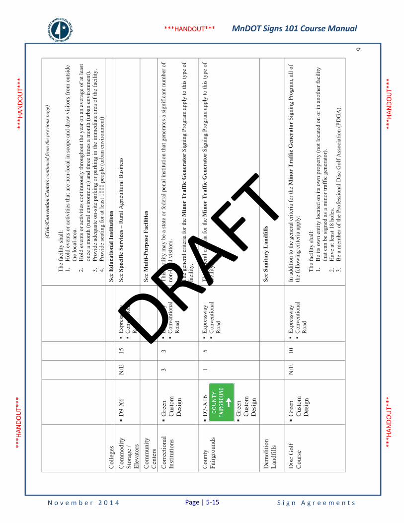
MnDOT Signs 101 Course Manual
N o v e m b e r 2 0 1 4 S i g n A g r e e m e n t s
***H
ANDO
UT**
* **
*HAN
DOUT
***
***H
ANDO
UT**
* **
*HAN
DOUT
***
***HANDOUT***
9
(Civ
ic/C
onve
ntio
n C
ente
rs c
ontin
ued
from
the
prev
ious
pag
e)
The
faci
lity
shal
l: 1.
Hol
d ev
ents
or a
ctiv
ities
that
are
non
-loca
l in
scop
e an
d dr
aw v
isito
rs fr
om o
utsi
de
the
loca
l are
a.
2.H
old
even
ts o
r act
iviti
es c
ontin
uous
ly th
roug
hout
the
year
on
an a
vera
ge o
f at l
east
on
ce a
mon
th (r
ural
env
ironm
ent)
and
thre
e tim
es a
mon
th (u
rban
env
ironm
ent).
3.
Prov
ide
adeq
uate
on-
site
par
king
or p
arki
ng in
the
imm
edia
te a
rea
of th
e fa
cilit
y.
4.Pr
ovid
e se
atin
g fo
r at l
east
100
0 pe
ople
(urb
an e
nviro
nmen
t).
Col
lege
s
Se
eE
duca
tiona
l Ins
titut
ions
Com
mod
ity
Stor
age
/ El
evat
ors
�D
9-X
6 N
/E
15
�Ex
pres
sway
�
Con
vent
iona
l R
oad
See
Spec
ific
Serv
ices
– R
ural
Agr
icul
tura
l Bus
ines
s
Com
mun
ity
Cen
ters
See
Mul
ti-Pu
rpos
e Fa
cilit
ies
Cor
rect
iona
lIn
stitu
tions
�
Gre
enC
usto
m
Des
ign
3 3
�Ex
pres
sway
�
Con
vent
iona
l R
oad
This
faci
lity
may
be
a st
ate
or fe
dera
l pen
al in
stitu
tion
that
gen
erat
es a
sign
ifica
nt n
umbe
r of
non-
loca
l vis
itors
.
The
gene
ral c
riter
ia fo
r the
Min
or T
raff
ic G
ener
ator
Sig
ning
Pro
gram
app
ly to
this
type
of
faci
lity.
Cou
nty
Fairg
roun
ds
�D
7-X
16
�G
reen
Cus
tom
D
esig
n
1 5
�Ex
pres
sway
�
Con
vent
iona
l R
oad
The
gene
ral c
riter
ia fo
r the
Min
or T
raff
ic G
ener
ator
Sig
ning
Pro
gram
app
ly to
this
type
of
faci
lity.
Dem
oliti
on
Land
fills
See
Sani
tary
Lan
dfill
s
Dis
c G
olf
Cou
rse
�G
reen
Cus
tom
D
esig
n
N/E
10
�
Expr
essw
ay
�C
onve
ntio
nal
Roa
d
In a
dditi
on to
the
gene
ral c
riter
ia fo
r the
Min
or T
raff
ic G
ener
ator
Sig
ning
Pro
gram
, all
of
the
follo
win
g cr
iteria
app
ly:
The
faci
lity
shal
l: 1.
Be
its o
wn
entit
y lo
cate
d on
its o
wn
prop
erty
(not
loca
ted
on o
r in
anot
her f
acili
ty
that
can
be
sign
ed a
s a m
inor
traf
fic g
ener
ator
).
2.H
ave
at le
ast 1
8 ho
les.
3.B
e a
mem
ber o
f the
Pro
fess
iona
l Dis
c G
olf A
ssoc
iatio
n (P
DG
A).
Page | 5-15
DRAFT
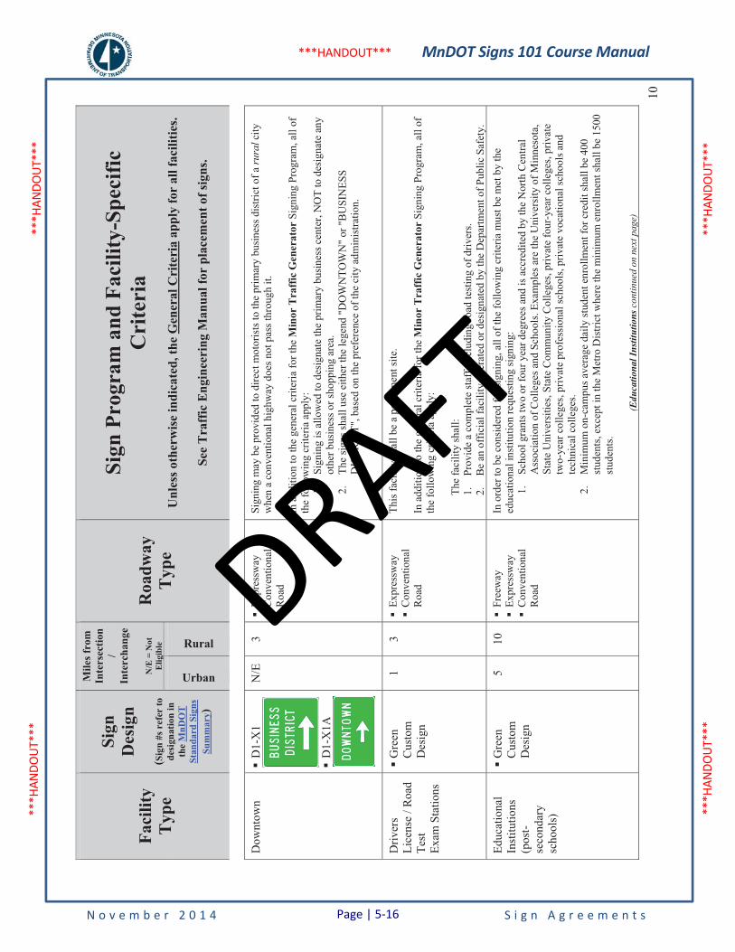
MnDOT Signs 101 Course Manual
N o v e m b e r 2 0 1 4 S i g n A g r e e m e n t s
***H
ANDO
UT**
* **
*HAN
DOUT
***
***H
ANDO
UT**
* **
*HAN
DOUT
***
***HANDOUT***
Faci
lity
Typ
e
Sign
Des
ign
(Sig
n #s
ref
er to
de
sign
atio
n in
th
eM
nDO
T
Stan
dard
Sig
ns
Sum
mar
y)
Mile
s fro
m
Inte
rsec
tion
/In
terc
hang
e
N/E
= N
ot
Elig
ible
Roa
dway
Typ
e
Sign
Pro
gram
and
Fac
ility
-Spe
cific
C
rite
ria
Unl
ess o
ther
wis
e in
dica
ted,
the
Gen
eral
Cri
teri
a ap
ply
for
all f
acili
ties.
See
Tra
ffic
Eng
inee
ring
Man
ual f
or p
lace
men
t of s
igns
.
Urban
Rural10
Dow
ntow
n�
D1-
X1
�D
1-X
1A
N/E
3
�Ex
pres
sway
�
Con
vent
iona
l R
oad
Sign
ing
may
be
prov
ided
to d
irect
mot
oris
ts to
the
prim
ary
busi
ness
dis
trict
of a
rura
l city
w
hen
a co
nven
tiona
l hig
hway
doe
s not
pas
s thr
ough
it.
In a
dditi
on to
the
gene
ral c
riter
ia fo
r the
Min
or T
raff
ic G
ener
ator
Sig
ning
Pro
gram
, all
of
the
follo
win
g cr
iteria
app
ly:
1.Si
gnin
g is
allo
wed
to d
esig
nate
the
prim
ary
busi
ness
cen
ter,
NO
T to
des
igna
te a
ny
othe
r bus
ines
s or s
hopp
ing
area
. 2.
The
sign
s sha
ll us
e ei
ther
the
lege
nd "
DO
WN
TOW
N" o
r "B
USI
NES
S D
ISTR
ICT"
, bas
ed o
n th
e pr
efer
ence
of t
he c
ity a
dmin
istra
tion.
Driv
ers
Lice
nse
/ Roa
d Te
stEx
am S
tatio
ns
�G
reen
Cus
tom
D
esig
n
1 3
�Ex
pres
sway
�
Con
vent
iona
l R
oad
This
faci
lity
shal
l be
a pe
rman
ent s
ite.
In a
dditi
on to
the
gene
ral c
riter
ia fo
r the
Min
or T
raff
ic G
ener
ator
Sig
ning
Pro
gram
, all
of
the
follo
win
g cr
iteria
app
ly:
The
faci
lity
shal
l:
1.Pr
ovid
e a
com
plet
e st
aff,
incl
udin
g ro
ad te
stin
g of
driv
ers.
2.B
e an
off
icia
l fac
ility
ope
rate
d or
des
igna
ted
by th
e D
epar
tmen
t of P
ublic
Saf
ety.
Educ
atio
nal
Inst
itutio
ns(p
ost-
seco
ndar
y sc
hool
s)
�G
reen
Cus
tom
D
esig
n
5 10
�
Free
way
�
Expr
essw
ay
�C
onve
ntio
nal
Roa
d
In o
rder
to b
e co
nsid
ered
for s
igni
ng, a
ll of
the
follo
win
g cr
iteria
mus
t be
met
by
the
educ
atio
nal i
nstit
utio
n re
ques
ting
sign
ing:
1.
Scho
ol g
rant
s tw
o or
four
yea
r deg
rees
and
is a
ccre
dite
d by
the
Nor
th C
entra
l A
ssoc
iatio
n of
Col
lege
s and
Sch
ools
. Exa
mpl
es a
re th
e U
nive
rsity
of M
inne
sota
, St
ate
Uni
vers
ities
, Sta
te C
omm
unity
Col
lege
s, pr
ivat
e fo
ur-y
ear c
olle
ges,
priv
ate
two-
year
col
lege
s, pr
ivat
e pr
ofes
sion
al sc
hool
s, pr
ivat
e vo
catio
nal s
choo
ls a
nd
tech
nica
l col
lege
s. 2.
Min
imum
on-
cam
pus a
vera
ge d
aily
stud
ent e
nrol
lmen
t for
cre
dit s
hall
be 4
00
stud
ents
, exc
ept i
n th
e M
etro
Dis
trict
whe
re th
e m
inim
um e
nrol
lmen
t sha
ll be
150
0 st
uden
ts.
(Edu
catio
nal I
nstit
utio
ns c
ontin
ued
on n
ext p
age)
Page | 5-16
DRAFT
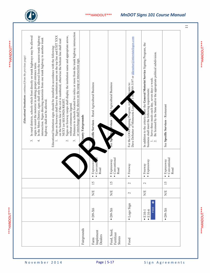
MnDOT Signs 101 Course Manual
N o v e m b e r 2 0 1 4 S i g n A g r e e m e n t s
***H
ANDO
UT**
* **
*HAN
DOUT
***
***H
ANDO
UT**
* **
*HAN
DOUT
***
***HANDOUT***
11
(Edu
catio
nal I
nstit
utio
ns c
ontin
ued
from
the
prev
ious
pag
e)
3.In
rura
l dis
trict
s, sc
hool
s whi
ch fr
ont d
irect
ly o
n tru
nk h
ighw
ays m
ay b
e al
low
ed
sign
s to
assi
st th
e m
otor
ist i
n m
akin
g pr
oper
ent
ranc
e tu
rns.
4.In
the
Met
ro D
istri
ct, s
igns
shal
l onl
y be
allo
wed
from
the
near
est t
runk
hig
hway
in
ters
ectio
n. S
igns
dire
ctin
g m
otor
ists
from
one
trun
k hi
ghw
ay to
ano
ther
trun
k hi
ghw
ay sh
all n
ot b
e al
low
ed.
Educ
atio
nal I
nstit
utio
n si
gns s
houl
d be
inst
alle
d in
acc
orda
nce
with
the
follo
win
g:
1.Si
gns o
n fr
eew
ays s
hall
have
the
inst
itutio
n na
me
on th
e to
p lin
e an
d EX
IT X
XX
on
the
botto
m li
ne if
the
exit
is n
umbe
red,
oth
erw
ise
the
botto
m li
ne sh
all r
ead
NEX
T (o
r SEC
ON
D) R
IGH
T.
2.Si
gns o
n fr
eew
ay ra
mps
shal
l dis
play
the
inst
itutio
n na
me
and
appr
opria
te a
rrow
, w
ithou
t ext
rane
ous l
egen
d.
3.D
ista
nces
to sc
hool
s loc
ated
two
mile
s or m
ore
from
the
trunk
hig
hway
inte
rsec
tion
or in
terc
hang
e sh
all b
e sh
own
on th
e ra
mp
or in
ters
ectio
n si
gn.
Fairg
roun
ds
See
Cou
nty
Fair
grou
nds
Farm
Im
plem
ent
Dea
lers
�D
9-X
6 N
/E
15
�Ex
pres
sway
�
Con
vent
iona
l R
oad
See
Spec
ific
Serv
ices
– R
ural
Agr
icul
tura
l Bus
ines
s
Feed
, See
d,
Ferti
lizer
Stor
es
�D
9-X
6 N
/E
15
�Ex
pres
sway
�
Con
vent
iona
l R
oad
See
Spec
ific
Serv
ices
– R
ural
Agr
icul
tura
l Bus
ines
s
Food
�
Logo
Sig
n 2
2 �
Free
way
Fo
r the
LO
GO
Sig
ning
Pro
gram
, ref
er a
pplic
ants
to:
Dav
e D
eSut
ter o
f Min
neso
ta L
ogos
at 1
-800
-769
-319
7 or
dde
sutte
r@in
ters
tate
logo
s.com
�E1
0-1
�E1
0-6
N/E
2
�Fr
eew
ay
�Ex
pres
sway
In
add
ition
to th
e cr
iteria
und
er th
e G
ener
al M
otor
ist S
ervi
ce S
igni
ng P
rogr
am, t
he
busi
ness
shal
l mee
t the
follo
win
g re
quire
men
ts:
1.Se
rve
thre
e m
eals
eac
h da
y, se
ven
days
a w
eek.
2.
Be
licen
sed
by th
e St
ate
and/
or th
e ap
prop
riate
pol
itica
l sub
divi
sion
.
�D
9-X
6 N
/E
15
�Ex
pres
sway
�
Con
vent
iona
l R
oad
See
Spec
ific
Serv
ices
- R
esta
uran
t
Page | 5-17
DRAFT
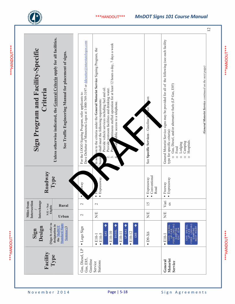
MnDOT Signs 101 Course Manual
N o v e m b e r 2 0 1 4 S i g n A g r e e m e n t s
***H
ANDO
UT**
* **
*HAN
DOUT
***
***H
ANDO
UT**
* **
*HAN
DOUT
***
***HANDOUT***
Faci
lity
Typ
e
Sign
Des
ign
(Sig
n #s
ref
er to
de
sign
atio
n in
th
eM
nDO
T
Stan
dard
Sig
ns
Sum
mar
y)
Mile
s fro
m
Inte
rsec
tion
/In
terc
hang
e
N/E
= N
ot
Elig
ible
Roa
dway
Typ
e
Sign
Pro
gram
and
Fac
ility
-Spe
cific
C
rite
ria
Unl
ess o
ther
wis
e in
dica
ted,
the
Gen
eral
Cri
teri
a ap
ply
for
all f
acili
ties.
See
Tra
ffic
Eng
inee
ring
Man
ual f
or p
lace
men
t of s
igns
.
Urban
Rural12
Gas
, Die
sel,
LP
Gas
, E85
, G
asol
ine
Serv
ice
Stat
ions
�Lo
go S
ign
2 2
�Fr
eew
ay
For t
he L
OG
O S
igni
ng P
rogr
am, r
efer
app
lican
ts to
: D
ave
DeS
utte
r of M
inne
sota
Log
os a
t 1-8
00-7
69-3
197
or d
desu
tter@
inte
rsta
telo
gos.c
om
�E1
0-1
�E1
0-5
�E1
0-10
�E1
0-11
�E1
0-12
N/E
2
�Fr
eew
ay
�Ex
pres
sway
In
add
ition
to th
e cr
iteria
und
er th
e G
ener
al M
otor
ist S
ervi
ce S
igni
ng P
rogr
am, t
he
busi
ness
shal
l mee
t the
follo
win
g re
quire
men
ts:
1.Pr
ovid
e ve
hicl
e se
rvic
es in
clud
ing
fuel
and
oil.
2.
Prov
ide
rest
room
faci
litie
s and
drin
king
wat
er.
3.Pr
ovid
e co
ntin
uous
staf
fed
oper
atio
n fo
r at l
east
12
hour
s a d
ay, 7
day
s a w
eek
4.
Prov
ide
publ
ic a
cces
s to
a te
leph
one.
�D
9-X
6 N
/E
15
�Ex
pres
sway
�
Con
vent
iona
l R
oad
See
Spec
ific
Serv
ices
- G
asol
ine
Serv
ice
Stat
ion
Gen
eral
M
otor
ist
Serv
ice
�E1
0-1
N/E
V
ari
es
�Fr
eew
ay
�Ex
pres
sway
G
ener
al M
otor
ist S
ervi
ce si
gns m
ay b
e pr
ovid
ed fo
r all
of t
he fo
llow
ing
(see
eac
h fa
cilit
y ty
pe fo
r spe
cific
crit
eria
): o
Gas
, Die
sel,
and/
or a
ltern
ativ
e fu
els (
LP G
as, E
85)
oFo
odo
Lodg
ing
oC
ampi
ng
oH
ospi
tals
.
(Gen
eral
Mot
oris
t Ser
vice
con
tinue
d on
the
next
pag
e)
Page | 5-18
DRAFT
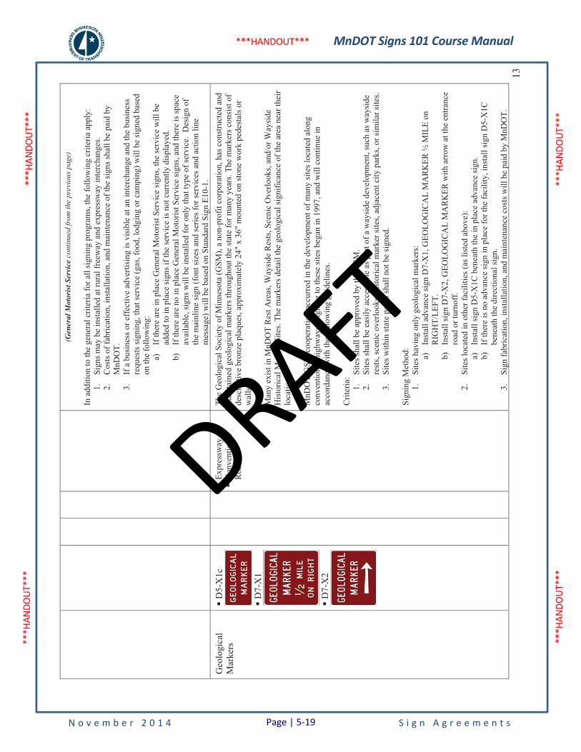
MnDOT Signs 101 Course Manual
N o v e m b e r 2 0 1 4 S i g n A g r e e m e n t s
***H
ANDO
UT**
* **
*HAN
DOUT
***
***H
ANDO
UT**
* **
*HAN
DOUT
***
***HANDOUT***
13
(Gen
eral
Mot
oris
t Ser
vice
con
tinue
d fr
om th
e pr
evio
us p
age)
In a
dditi
on to
the
gene
ral c
riter
ia fo
r all
sign
ing
prog
ram
s, th
e fo
llow
ing
crite
ria a
pply
: 1.
Sign
s may
be
inst
alle
d at
rura
l fre
eway
and
exp
ress
way
inte
rcha
nges
. 2.
Cos
ts o
f fab
ricat
ion,
inst
alla
tion,
and
mai
nten
ance
of t
he si
gns s
hall
be p
aid
by
MnD
OT.
3.
If a
bus
ines
s or e
ffec
tive
adve
rtisi
ng is
visi
ble
at a
n in
terc
hang
e an
d th
e bu
sine
ss
requ
ests
sign
ing,
that
serv
ice
(gas
, foo
d, lo
dgin
g or
cam
ping
) will
be
sign
ed b
ased
on
the
follo
win
g:
a)If
ther
e ar
e in
pla
ce G
ener
al M
otor
ist S
ervi
ce si
gns,
the
serv
ice
will
be
adde
d to
in p
lace
sign
s if t
he se
rvic
e is
not
cur
rent
ly d
ispl
ayed
. b)
If th
ere
are
no in
pla
ce G
ener
al M
otor
ist S
ervi
ce si
gns,
and
ther
e is
spac
e av
aila
ble,
sign
s will
be
inst
alle
d fo
r onl
y th
at ty
pe o
f ser
vice
. D
esig
n of
th
e m
ainl
ine
sign
(fon
t siz
es a
nd se
ries f
or se
rvic
es a
nd a
ctio
n lin
e m
essa
ge) w
ill b
e ba
sed
on S
tand
ard
Sign
E10
-1.
Geo
logi
cal
Mar
kers
�D
5-X
1c
�D
7-X
1
�D
7-X
2
�Ex
pres
sway
�
Con
vent
iona
l R
oad
The
Geo
logi
cal S
ocie
ty o
f Min
neso
ta (G
SM),
a no
n-pr
ofit
corp
orat
ion,
has
con
stru
cted
and
m
aint
aine
d ge
olog
ical
mar
kers
thro
ugho
ut th
e st
ate
for m
any
year
s. Th
e m
arke
rs c
onsi
st o
f de
scrip
tive
bron
ze p
laqu
es, a
ppro
xim
atel
y 24
" x
36"
mou
nted
on
ston
e w
ork
pede
stal
s or
wal
ls.
Man
y ex
ist i
n M
nDO
T R
est A
reas
, Way
side
Res
ts, S
ceni
c O
verlo
oks,
and/
or W
aysi
de
His
toric
al M
arke
r Site
s. Th
e m
arke
rs d
etai
l the
geo
logi
cal s
igni
fican
ce o
f the
are
a ne
ar th
eir
loca
tion.
MnD
OT-
GSM
coo
pera
tion
occu
rred
in th
e de
velo
pmen
t of m
any
site
s loc
ated
alo
ng
conv
entio
nal h
ighw
ays.
Sign
ing
to th
ese
site
s beg
an in
199
7, a
nd w
ill c
ontin
ue in
ac
cord
ance
with
the
follo
win
g gu
idel
ines
.
Crit
eria
:1.
Site
s sha
ll be
app
rove
d by
the
GSM
. 2.
Site
s sha
ll be
eas
ily a
cces
sibl
e as
par
t of a
way
side
dev
elop
men
t, su
ch a
s way
side
re
sts,
scen
ic o
verlo
oks,
hist
oric
al m
arke
r site
s, ad
jace
nt c
ity p
arks
, or s
imila
r site
s. 3.
Site
s with
in st
ate
park
s sha
ll no
t be
sign
ed.
Sign
ing
Met
hod:
1.
Site
s hav
ing
only
geo
logi
cal m
arke
rs:
a)In
stal
l adv
ance
sign
D7-
X1,
GEO
LOG
ICA
L M
AR
KER
½ M
ILE
on
RIG
HT/
LEFT
. b)
Inst
all s
ign
D7-
X2,
GEO
LOG
ICA
L M
AR
KER
with
arr
ow a
t the
ent
ranc
e ro
ad o
r tur
noff
. 2.
Site
s loc
ated
in o
ther
faci
litie
s (as
list
ed a
bove
): a)
Inst
all s
ign
D5-
X1C
ben
eath
the
in p
lace
adv
ance
sign
. b)
If th
ere
is n
o ad
vanc
e si
gn in
pla
ce fo
r the
faci
lity,
inst
all s
ign
D5-
X1C
be
neat
h th
e di
rect
iona
l sig
n.
3.Si
gn fa
bric
atio
n, in
stal
latio
n, a
nd m
aint
enan
ce c
osts
will
be
paid
by
MnD
OT.
Page | 5-19
DRAFT
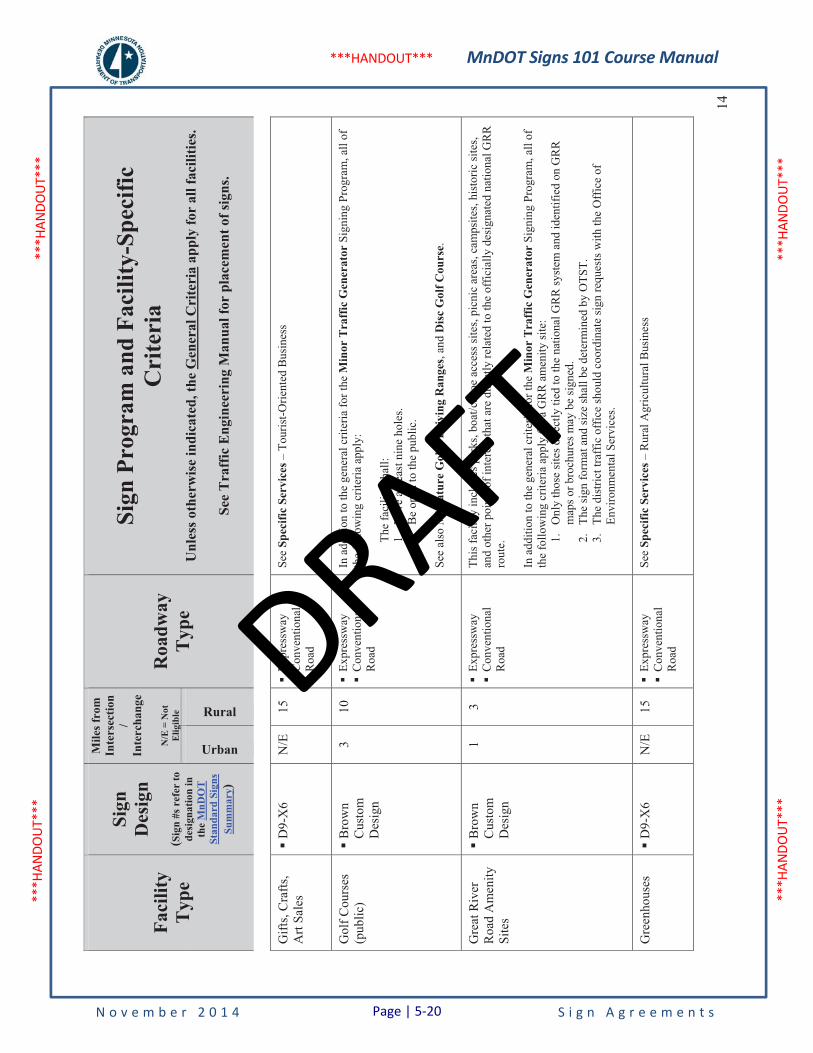
MnDOT Signs 101 Course Manual
N o v e m b e r 2 0 1 4 S i g n A g r e e m e n t s
***H
ANDO
UT**
* **
*HAN
DOUT
***
***H
ANDO
UT**
* **
*HAN
DOUT
***
***HANDOUT***
Faci
lity
Typ
e
Sign
Des
ign
(Sig
n #s
ref
er to
de
sign
atio
n in
th
eM
nDO
T
Stan
dard
Sig
ns
Sum
mar
y)
Mile
s fro
m
Inte
rsec
tion
/In
terc
hang
e
N/E
= N
ot
Elig
ible
Roa
dway
Typ
e
Sign
Pro
gram
and
Fac
ility
-Spe
cific
C
rite
ria
Unl
ess o
ther
wis
e in
dica
ted,
the
Gen
eral
Cri
teri
a ap
ply
for
all f
acili
ties.
See
Tra
ffic
Eng
inee
ring
Man
ual f
or p
lace
men
t of s
igns
.
Urban
Rural14
Gift
s, C
rafts
, A
rt Sa
les
�D
9-X
6 N
/E
15
�Ex
pres
sway
�
Con
vent
iona
l R
oad
See
Spec
ific
Serv
ices
– T
ouris
t-Orie
nted
Bus
ines
s
Gol
f Cou
rses
(p
ublic
) �
Bro
wn
Cus
tom
D
esig
n
3 10
�
Expr
essw
ay
�C
onve
ntio
nal
Roa
d
In a
dditi
on to
the
gene
ral c
riter
ia fo
r the
Min
or T
raff
ic G
ener
ator
Sig
ning
Pro
gram
, all
of
the
follo
win
g cr
iteria
app
ly:
The
faci
lity
shal
l: 1.
Hav
e at
leas
t nin
e ho
les.
2.
Be
open
to th
e pu
blic
.
See
also
Min
iatu
re G
olf /
Dri
ving
Ran
ges,
and
Dis
c G
olf C
ours
e.
Gre
at R
iver
R
oad
Am
enity
Si
tes
�B
row
nC
usto
m
Des
ign
1 3
�Ex
pres
sway
�
Con
vent
iona
l R
oad
This
faci
lity
incl
udes
par
ks, b
oat/c
anoe
acc
ess s
ites,
picn
ic a
reas
, cam
psite
s, hi
stor
ic si
tes,
and
othe
r poi
nts o
f int
eres
t tha
t are
dire
ctly
rela
ted
to th
e of
ficia
lly d
esig
nate
d na
tiona
l GR
R
rout
e.
In a
dditi
on to
the
gene
ral c
riter
ia fo
r the
Min
or T
raff
ic G
ener
ator
Sig
ning
Pro
gram
, all
of
the
follo
win
g cr
iteria
app
ly fo
r a G
RR
am
enity
site
: 1.
Onl
y th
ose
site
s dire
ctly
tied
to th
e na
tiona
l GR
R sy
stem
and
iden
tifie
d on
GR
R
map
s or b
roch
ures
may
be
sign
ed.
2.Th
e si
gn fo
rmat
and
size
shal
l be
dete
rmin
ed b
y O
TST.
3.
The
dist
rict t
raff
ic o
ffic
e sh
ould
coo
rdin
ate
sign
requ
ests
with
the
Off
ice
of
Envi
ronm
enta
l Ser
vice
s.
Gre
enho
uses
�D
9-X
6 N
/E
15
�Ex
pres
sway
�
Con
vent
iona
l R
oad
See
Spec
ific
Serv
ices
– R
ural
Agr
icul
tura
l Bus
ines
s
Page | 5-20
DRAFT
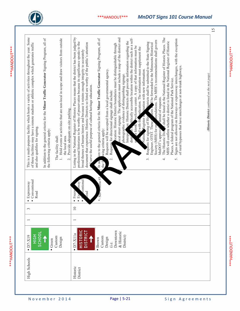
MnDOT Signs 101 Course Manual
N o v e m b e r 2 0 1 4 S i g n A g r e e m e n t s
***H
ANDO
UT**
* **
*HAN
DOUT
***
***H
ANDO
UT**
* **
*HAN
DOUT
***
***HANDOUT***
15
Hig
h Sc
hool
s �
D7-
X19
�G
reen
Cus
tom
D
esig
n
1 3
�Ex
pres
sway
�
Con
vent
iona
l R
oad
This
is a
mul
ti-pu
rpos
e fa
cilit
y w
hich
hos
ts a
var
iety
of a
ctiv
ities
thro
ugho
ut th
e ye
ar. S
ome
of th
ese
faci
litie
s may
hav
e a
rem
ote
stad
ium
or a
thle
tic c
ompl
ex w
hich
gen
erat
es tr
affic
an
d al
so q
ualif
ies f
or si
gnin
g.
In a
dditi
on to
the
gene
ral c
riter
ia fo
r the
Min
or T
raff
ic G
ener
ator
Sig
ning
Pro
gram
, all
of
the
follo
win
g cr
iteria
app
ly:
The
faci
lity
shal
l: 1.
Hol
d ev
ents
or a
ctiv
ities
that
are
non
-loca
l in
scop
e an
d dr
aw v
isito
rs fr
om o
utsi
de
the
loca
l are
a.
2.Pr
ovid
e ad
equa
te o
n-si
te p
arki
ng.
His
toric
Dis
trict
�
D7-
X11
a
�B
row
nC
usto
m
Des
ign
(i.e.
Dow
ntow
n&
His
toric
D
istri
ct)
1 10
�
Free
way
* �
Expr
essw
ay*
�C
onve
ntio
nal
Roa
d
*- S
ee c
riter
ia #
5
List
ing
in th
e N
atio
nal R
egis
ter o
f His
toric
Pla
ces m
eans
that
the
dist
rict h
as b
een
judg
ed b
y pr
ofes
sion
al h
isto
rians
to b
e w
orth
y of
pre
serv
atio
n be
caus
e its
sign
ifica
nce
spea
ks to
the
broa
d th
emes
of h
uman
his
tory
and
bec
ause
it re
tain
s eno
ugh
inte
grity
to a
ccur
atel
y do
cum
ent t
hat e
xper
ienc
e. H
isto
ric D
istri
cts s
o lis
ted
are
wor
thy
of th
e pu
blic
’s a
ttent
ion
and
serv
e th
e us
eful
pur
pose
of c
ultu
ral h
erita
ge e
duca
tion.
In a
dditi
on to
the
gene
ral c
riter
ia fo
r the
Min
or T
raff
ic G
ener
ator
Sig
ning
Pro
gram
, all
of
the
follo
win
g cr
iteria
app
ly:
1.R
eque
sts w
ill b
e ac
cept
ed fr
om a
loca
l gov
ernm
enta
l age
ncy.
2.
Req
uest
s for
dire
ctio
nal s
igna
ge sh
all i
nclu
de:
a)Lo
catio
n: H
isto
ric D
istri
ct b
ound
arie
s mus
t be
dist
ingu
isha
ble
thro
ugh
loca
l stre
et si
gnag
e. T
he a
pplic
atio
n m
ust i
nclu
de a
map
of t
he d
istri
ct a
nd
phot
ogra
phic
evi
denc
e of
dis
tingu
ishi
ng si
gnag
e.
b)In
terp
reta
tion:
His
toric
Dis
trict
s sha
ll pr
ovid
e in
form
atio
n re
gard
ing
the
dist
rict i
n a
publ
ical
ly a
cces
sibl
e lo
catio
n w
ithin
the
dist
rict s
uch
as a
self-
serv
ice
kios
k or
wel
com
e ce
nter
. A c
opy
of th
at in
form
atio
n m
ust b
e in
clud
ed w
ith th
e ap
plic
atio
n. T
he in
form
atio
n m
ust s
uppl
emen
t the
N
atio
nal R
egis
ter n
omin
atio
n w
ith n
ew in
form
atio
n.
3.R
eque
sts f
or si
gnin
g of
His
toric
Dis
trict
s sha
ll be
subm
itted
to th
e St
ate
Sign
ing
Engi
neer
, OTS
T. T
hese
requ
ests
shal
l be
forw
arde
d to
the
Min
neso
ta H
isto
rical
So
ciet
y (M
HS)
for r
ecom
men
datio
ns. T
he M
HS’
s rec
omm
enda
tions
shal
l gov
ern
MnD
OT’
s app
rova
l or d
enia
l of r
eque
sts.
4.
The
His
toric
Dis
trict
shal
l be
liste
d in
the
Nat
iona
l Reg
iste
r of H
isto
ric P
lace
s. Th
e M
HS
will
con
firm
whe
ther
a d
istri
ct is
list
ed in
the
Nat
iona
l Reg
iste
r of H
isto
ric
Plac
es, a
fede
ral p
rogr
am o
f the
Nat
iona
l Par
k Se
rvic
e.
5.Si
gns a
re n
ot a
llow
ed o
n fr
eew
ays o
r exp
ress
way
inte
rcha
nges
, with
the
exce
ptio
n of
rura
l byp
asse
s tha
t hav
e in
terc
hang
es a
t non
-trun
k hi
ghw
ays.
(His
tori
c D
istr
ict c
ontin
ued
on th
e ne
xt p
age)
Page | 5-21
DRAFT
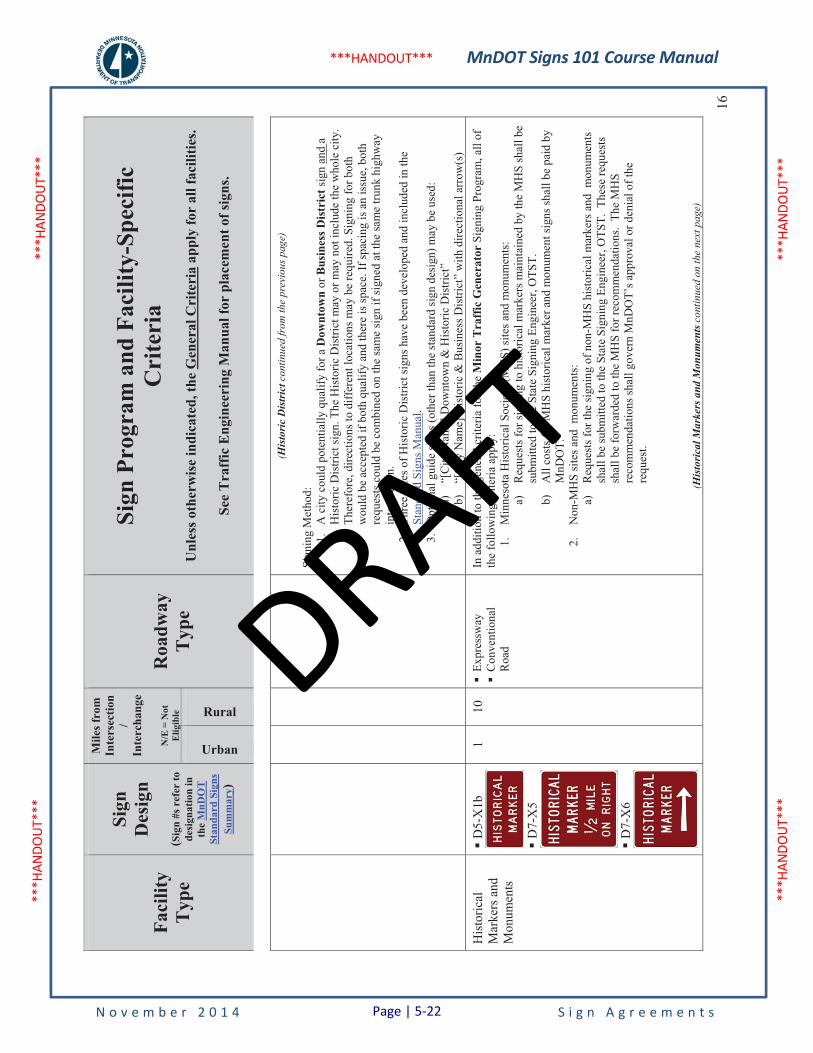
MnDOT Signs 101 Course Manual
N o v e m b e r 2 0 1 4 S i g n A g r e e m e n t s
***H
ANDO
UT**
* **
*HAN
DOUT
***
***H
ANDO
UT**
* **
*HAN
DOUT
***
***HANDOUT***
Faci
lity
Typ
e
Sign
Des
ign
(Sig
n #s
ref
er to
de
sign
atio
n in
th
eM
nDO
T
Stan
dard
Sig
ns
Sum
mar
y)
Mile
s fro
m
Inte
rsec
tion
/In
terc
hang
e
N/E
= N
ot
Elig
ible
Roa
dway
Typ
e
Sign
Pro
gram
and
Fac
ility
-Spe
cific
C
rite
ria
Unl
ess o
ther
wis
e in
dica
ted,
the
Gen
eral
Cri
teri
a ap
ply
for
all f
acili
ties.
See
Tra
ffic
Eng
inee
ring
Man
ual f
or p
lace
men
t of s
igns
.
Urban
Rural16
(His
tori
c D
istr
ict c
ontin
ued
from
the
prev
ious
pag
e)
Sign
ing
Met
hod:
1.
A c
ity c
ould
pot
entia
lly q
ualif
y fo
r a D
ownt
own
or B
usin
ess D
istri
ct si
gn a
nd a
H
isto
ric D
istri
ct si
gn. T
he H
isto
ric D
istri
ct m
ay o
r may
not
incl
ude
the
who
le c
ity.
Ther
efor
e, d
irect
ions
to d
iffer
ent l
ocat
ions
may
be
requ
ired.
Sig
ning
for b
oth
wou
ld b
e ac
cept
ed if
bot
h qu
alify
and
ther
e is
spac
e. If
spac
ing
is a
n is
sue,
bot
h re
ques
ts c
ould
be
com
bine
d on
the
sam
e si
gn if
sign
ed a
t the
sam
e tru
nk h
ighw
ay
inte
rsec
tion.
2.
Thre
e si
zes o
f His
toric
Dis
trict
sign
s hav
e be
en d
evel
oped
and
incl
uded
in th
e St
anda
rd S
igns
Man
ual.
3.O
ptio
nal g
uide
sign
s (ot
her t
han
the
stan
dard
sign
des
ign)
may
be
used
: a)
“[C
ity N
ame]
Dow
ntow
n &
His
toric
Dis
trict
” b)
“[C
ity N
ame]
His
toric
& B
usin
ess D
istri
ct”
with
dire
ctio
nal a
rrow
(s)
His
toric
alM
arke
rs a
nd
Mon
umen
ts
�D
5-X
1b
�D
7-X
5
�D
7-X
6
1 10
�
Expr
essw
ay
�C
onve
ntio
nal
Roa
d
In a
dditi
on to
the
gene
ral c
riter
ia fo
r the
Min
or T
raff
ic G
ener
ator
Sig
ning
Pro
gram
, all
of
the
follo
win
g cr
iteria
app
ly:
1.M
inne
sota
His
toric
al S
ocie
ty (M
HS)
site
s and
mon
umen
ts:
a)R
eque
sts f
or si
gnin
g to
his
toric
al m
arke
rs m
aint
aine
d by
the
MH
S sh
all b
e su
bmitt
ed to
the
Stat
e Si
gnin
g En
gine
er, O
TST.
b)
All
cost
s for
MH
S hi
stor
ical
mar
ker a
nd m
onum
ent s
igns
shal
l be
paid
by
MnD
OT.
2.
Non
-MH
S si
tes a
nd m
onum
ents
: a)
Req
uest
s for
the
sign
ing
of n
on-M
HS
hist
oric
al m
arke
rs a
nd m
onum
ents
sh
all b
e su
bmitt
ed to
the
Stat
e Si
gnin
g En
gine
er, O
TST.
The
se re
ques
ts
shal
l be
forw
arde
d to
the
MH
S fo
r rec
omm
enda
tions
. Th
e M
HS
reco
mm
enda
tions
shal
l gov
ern
MnD
OT’
s app
rova
l or d
enia
l of t
he
requ
est.
(His
tori
cal M
arke
rs a
nd M
onum
ents
con
tinue
d on
the
next
pag
e)
Page | 5-22
DRAFT
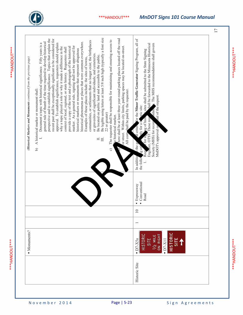
MnDOT Signs 101 Course Manual
N o v e m b e r 2 0 1 4 S i g n A g r e e m e n t s
***H
ANDO
UT**
* **
*HAN
DOUT
***
***H
ANDO
UT**
* **
*HAN
DOUT
***
***HANDOUT***
17
�M
onum
ents
? (H
isto
rica
l Mar
kers
and
Mon
umen
ts c
ontin
ued
from
the
prev
ious
pag
e)
b)A
his
toric
al m
arke
r or m
onum
ent s
hall:
I.
Doc
umen
t a to
pic
with
his
toric
al si
gnifi
canc
e. F
ifty
year
s is a
ge
nera
l rul
e of
thum
b of
the
time
requ
ired
to d
evel
op h
isto
rical
pe
rspe
ctiv
e an
d to
est
ablis
h si
gnifi
canc
e. T
opic
s tha
t exp
lain
the
rece
nt p
ast s
hall
be e
xcep
tiona
lly si
gnifi
cant
to b
e co
nsid
ered
for
appr
oval
. To
est
ablis
h si
gnifi
canc
e, re
ques
ters
shou
ld e
xpla
in
why
a to
pic
play
ed a
role
or w
hy it
mad
e a
diff
eren
ce in
the
cont
ext o
f loc
al, r
egio
nal,
or st
ate
hist
ory.
Req
uest
ers s
hall
prov
ide
a co
py o
f the
text
and
a p
hoto
grap
h of
the
hist
oric
al
mar
ker.
As a
gen
eral
rule
, sig
ning
shal
l not
be
appr
oved
for
hist
oric
al m
arke
rs o
r mon
umen
ts th
at re
pres
ent u
biqu
itous
hi
stor
ical
phe
nom
ena
or p
lace
s tha
t wer
e co
mm
on e
very
whe
re.
Exam
ples
of t
hese
pla
ces i
nclu
de: t
he si
tes o
f tow
ns,
com
mun
ities
, or s
ettle
men
ts th
at n
o lo
nger
exi
st; t
he b
irthp
lace
s or
gra
vesi
tes o
f sig
nific
ant i
ndiv
idua
ls; a
nd c
emet
erie
s. II
.B
e lo
cate
d on
pub
lic la
nd a
nd a
cces
sibl
e to
the
publ
ic.
III.
Be
legi
ble
usin
g le
tters
at l
east
5/8
inch
hig
h (ty
pica
lly a
font
size
22
or g
reat
er)
c)Th
e re
ques
ter s
hall
be re
spon
sibl
e fo
r mai
ntai
ning
and
ens
urin
g ac
cess
to
the
hist
oric
al m
arke
r. d)
Ther
e sh
all b
e at
leas
t thr
ee y
ear-
roun
d pa
rkin
g pl
aces
loca
ted
off t
he ro
ad
or st
reet
. W
ithin
city
lim
its, p
arki
ng sp
aces
may
be
loca
ted
on-s
treet
. e)
All
cost
s sha
ll be
pai
d by
the
requ
este
r.
His
toric
Site
�
D7-
X5a
�D
7-X
11
1 10
�
Expr
essw
ay
�C
onve
ntio
nal
Roa
d
In a
dditi
on to
the
gene
ral c
riter
ia fo
r the
Min
or T
raff
ic G
ener
ator
Sig
ning
Pro
gram
, all
of
the
follo
win
g cr
iteria
app
ly fo
r a h
isto
ric si
te:
1.R
eque
sts f
or si
gnin
g of
his
toric
site
s sha
ll be
subm
itted
to th
e St
ate
Sign
ing
Engi
neer
, OTS
T. T
hese
requ
ests
shal
l be
forw
arde
d to
the
Min
neso
ta H
isto
rical
So
ciet
y (M
HS)
for r
ecom
men
datio
ns. T
he M
HS
reco
mm
enda
tions
shal
l gov
ern
MnD
OT'
s app
rova
l or d
enia
l of t
he re
ques
t.
Page | 5-23
DRAFT
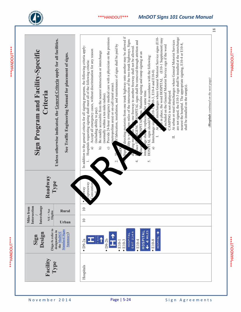
MnDOT Signs 101 Course Manual
N o v e m b e r 2 0 1 4 S i g n A g r e e m e n t s
***H
ANDO
UT**
* **
*HAN
DOUT
***
***H
ANDO
UT**
* **
*HAN
DOUT
***
***HANDOUT***
Faci
lity
Typ
e
Sign
Des
ign
(Sig
n #s
ref
er to
de
sign
atio
n in
th
eM
nDO
T
Stan
dard
Sig
ns
Sum
mar
y)
Mile
s fro
m
Inte
rsec
tion
/In
terc
hang
e
N/E
= N
ot
Elig
ible
Roa
dway
Typ
e
Sign
Pro
gram
and
Fac
ility
-Spe
cific
C
rite
ria
Unl
ess o
ther
wis
e in
dica
ted,
the
Gen
eral
Cri
teri
a ap
ply
for
all f
acili
ties.
See
Tra
ffic
Eng
inee
ring
Man
ual f
or p
lace
men
t of s
igns
.
Urban
Rural18
Hos
pita
ls�
D9-
2a
�D
9-2b
�E1
0-1
�E1
0-3
�E1
0-4
�E1
0-8
10
10
�Fr
eew
ay
�Ex
pres
sway
�
Con
vent
iona
l R
oad
In a
dditi
on to
the
gene
ral c
riter
ia fo
r all
sign
ing
prog
ram
s, th
e fo
llow
ing
crite
ria a
pply
: 1.
Hos
pita
ls re
ques
ting
sign
ing
shal
l mee
t all
of th
e fo
llow
ing
crite
ria:
a)A
ccep
t all
emer
genc
y ca
ses,
with
out d
iscr
imin
atio
n fo
r any
reas
on
(incl
udin
g ab
ility
to p
ay).
b)
Be
read
ily a
cces
sibl
e fr
om th
e ne
ares
t int
erse
ctio
n or
inte
rcha
nge
(nor
mal
ly w
ithin
a te
n m
ile ra
dius
). c)
Prov
ide
24-h
our e
mer
genc
y m
edic
al c
are
with
a p
hysi
cian
on
the
prem
ises
(m
etro
polit
an a
rea)
or o
n-ca
ll (r
ural
are
as).
2.Th
e co
sts o
f fab
ricat
ion,
inst
alla
tion,
and
mai
nten
ance
of s
igns
shal
l be
paid
by
MnD
OT.
3.
Sign
ing
dire
ctin
g m
otor
ists
from
one
trun
k hi
ghw
ay o
nto
anot
her m
ay b
e al
low
ed if
th
e fa
cilit
y is
with
in te
n m
iles o
f the
inte
rsec
tion
of th
e tw
o tru
nk h
ighw
ays.
Sign
s di
rect
ing
mot
oris
ts fr
om o
ne fr
eew
ay to
ano
ther
free
way
shal
l not
be
allo
wed
. 4.
In p
lace
EM
ERG
ENC
Y H
OSP
ITA
L si
gns s
hall
be re
mov
ed th
roug
h at
tritio
n an
d re
plac
ed w
ith H
OSP
ITA
L si
gns.
Mai
nlin
e si
gnin
g an
d ra
mp
sign
ing
at a
n in
terc
hang
e sh
all b
e re
plac
ed a
t the
sam
e tim
e.
5.H
OSP
ITA
L si
gns s
houl
d be
inst
alle
d in
acc
orda
nce
with
the
follo
win
g:
a)In
terc
hang
e si
gns (
E10-
1, E
10-3
, E10
-4 a
nd E
10-8
) I.
At r
ural
inte
rcha
nges
whe
re G
ener
al M
otor
ist S
ervi
ce si
gns (
E10-
1) a
re in
pla
ce, t
he w
ord
HO
SPIT
AL
(E
10-1
Sup
plem
ent)
may
be
incl
uded
on
the
Gen
eral
Mot
oris
t Ser
vice
sign
if th
e w
ord
CA
MPI
NG
is n
ot d
ispl
ayed
. II
.A
t urb
an o
r rur
al in
terc
hang
es w
here
Gen
eral
Mot
oris
t Ser
vice
s ar
e no
t sig
ned,
the
E10-
3 si
gn sh
all b
e in
stal
led
at th
e in
terc
hang
e ne
ares
t the
hos
pita
l. Th
e ap
prop
riate
sign
ing,
E10
-4 o
r E10
-8,
shal
l be
inst
alle
d on
the
ram
p(s)
.
(Hos
pita
lsco
ntin
ued
on th
e ne
xt p
age)
Page | 5-24
DRAFT
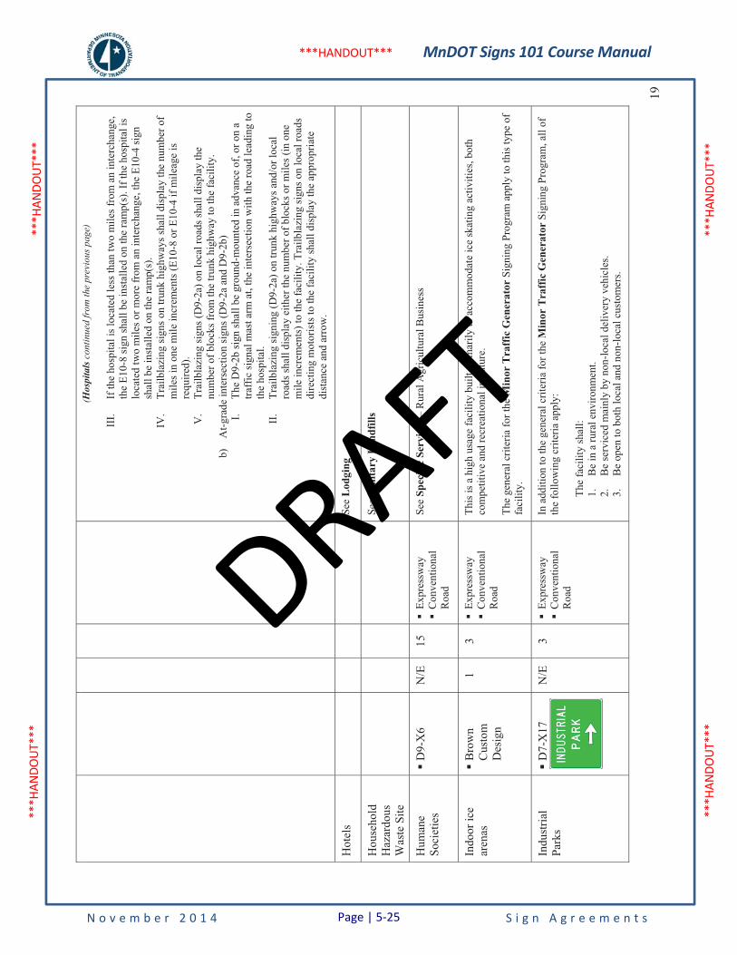
MnDOT Signs 101 Course Manual
N o v e m b e r 2 0 1 4 S i g n A g r e e m e n t s
***H
ANDO
UT**
* **
*HAN
DOUT
***
***H
ANDO
UT**
* **
*HAN
DOUT
***
***HANDOUT***
19
(Hos
pita
lsco
ntin
ued
from
the
prev
ious
pag
e)
III.
If th
e ho
spita
l is l
ocat
ed le
ss th
an tw
o m
iles f
rom
an
inte
rcha
nge,
th
e E1
0-8
sign
shal
l be
inst
alle
d on
the
ram
p(s)
. If t
he h
ospi
tal i
s lo
cate
d tw
o m
iles o
r mor
e fr
om a
n in
terc
hang
e, th
e E1
0-4
sign
sh
all b
e in
stal
led
on th
e ra
mp(
s).
IV.
Trai
lbla
zing
sign
s on
trunk
hig
hway
s sha
ll di
spla
y th
e nu
mbe
r of
mile
s in
one
mile
incr
emen
ts (E
10-8
or E
10-4
if m
ileag
e is
re
quire
d).
V.
Trai
lbla
zing
sign
s (D
9-2a
) on
loca
l roa
ds sh
all d
ispl
ay th
e nu
mbe
r of b
lock
s fro
m th
e tru
nk h
ighw
ay to
the
faci
lity.
b)
At-g
rade
inte
rsec
tion
sign
s (D
9-2a
and
D9-
2b)
I.Th
e D
9-2b
sign
shal
l be
grou
nd-m
ount
ed in
adv
ance
of,
or o
n a
traff
ic si
gnal
mas
t arm
at,
the
inte
rsec
tion
with
the
road
lead
ing
to
the
hosp
ital.
II.
Trai
lbla
zing
sign
ing
(D9-
2a) o
n tru
nk h
ighw
ays a
nd/o
r loc
al
road
s sha
ll di
spla
y ei
ther
the
num
ber o
f blo
cks o
r mile
s (in
one
m
ile in
crem
ents
) to
the
faci
lity.
Tra
ilbla
zing
sign
s on
loca
l roa
ds
dire
ctin
g m
otor
ists
to th
e fa
cilit
y sh
all d
ispl
ay th
e ap
prop
riate
di
stan
ce a
nd a
rrow
.
Hot
els
See
Lod
ging
Hou
seho
ldH
azar
dous
Was
te S
ite
See
Sani
tary
Lan
dfill
s
Hum
ane
Soci
etie
s �
D9-
X6
N
/E
15
�Ex
pres
sway
�
Con
vent
iona
l R
oad
See
Spec
ific
Serv
ices
– R
ural
Agr
icul
tura
l Bus
ines
s
Indo
or ic
e ar
enas
�
Bro
wn
Cus
tom
D
esig
n
1 3
�Ex
pres
sway
�
Con
vent
iona
l R
oad
This
is a
hig
h us
age
faci
lity
built
prim
arily
to a
ccom
mod
ate
ice
skat
ing
activ
ities
, bot
h co
mpe
titiv
e an
d re
crea
tiona
l in
natu
re.
The
gene
ral c
riter
ia fo
r the
Min
or T
raff
ic G
ener
ator
Sig
ning
Pro
gram
app
ly to
this
type
of
faci
lity.
Indu
stria
lPa
rks
�D
7-X
17N
/E
3 �
Expr
essw
ay
�C
onve
ntio
nal
Roa
d
In a
dditi
on to
the
gene
ral c
riter
ia fo
r the
Min
or T
raff
ic G
ener
ator
Sig
ning
Pro
gram
, all
of
the
follo
win
g cr
iteria
app
ly:
The
faci
lity
shal
l: 1.
Be
in a
rura
l env
ironm
ent.
2.B
e se
rvic
ed m
ainl
y by
non
-loca
l del
iver
y ve
hicl
es.
3.B
e op
en to
bot
h lo
cal a
nd n
on-lo
cal c
usto
mer
s.
Page | 5-25
DRAFT
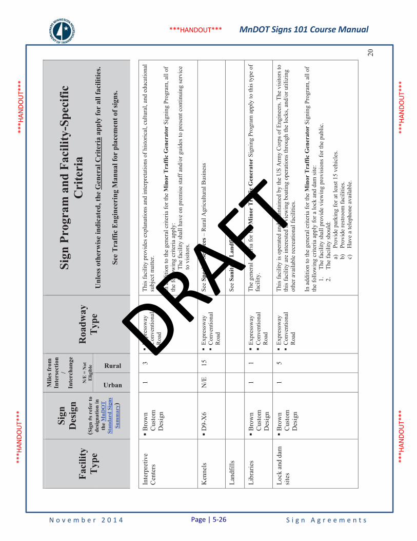
MnDOT Signs 101 Course Manual
N o v e m b e r 2 0 1 4 S i g n A g r e e m e n t s
***H
ANDO
UT**
* **
*HAN
DOUT
***
***H
ANDO
UT**
* **
*HAN
DOUT
***
***HANDOUT***
Faci
lity
Typ
e
Sign
Des
ign
(Sig
n #s
ref
er to
de
sign
atio
n in
th
eM
nDO
T
Stan
dard
Sig
ns
Sum
mar
y)
Mile
s fro
m
Inte
rsec
tion
/In
terc
hang
e
N/E
= N
ot
Elig
ible
Roa
dway
Typ
e
Sign
Pro
gram
and
Fac
ility
-Spe
cific
C
rite
ria
Unl
ess o
ther
wis
e in
dica
ted,
the
Gen
eral
Cri
teri
a ap
ply
for
all f
acili
ties.
See
Tra
ffic
Eng
inee
ring
Man
ual f
or p
lace
men
t of s
igns
.
Urban
Rural20
Inte
rpre
tive
Cen
ters
�B
row
nC
usto
m
Des
ign
1 3
�Ex
pres
sway
�
Con
vent
iona
l R
oad
This
faci
lity
prov
ides
exp
lana
tions
and
inte
rpre
tatio
ns o
f his
toric
al, c
ultu
ral,
and
educ
atio
nal
subj
ect m
atte
r.
In a
dditi
on to
the
gene
ral c
riter
ia fo
r the
Min
or T
raff
ic G
ener
ator
Sig
ning
Pro
gram
, all
of
the
follo
win
g cr
iteria
app
ly:
1.
The
faci
lity
shal
l hav
e on
pre
mis
e st
aff a
nd/o
r gui
des t
o pr
esen
t con
tinui
ng se
rvic
e to
vis
itors
.
Ken
nels
�D
9-X
6 N
/E
15
�Ex
pres
sway
�
Con
vent
iona
l R
oad
See
Spec
ific
Serv
ices
– R
ural
Agr
icul
tura
l Bus
ines
s
Land
fills
See
Sani
tary
Lan
dfill
s
Libr
arie
s�
Bro
wn
Cus
tom
D
esig
n
1 1
�Ex
pres
sway
�C
onve
ntio
nal
Roa
d
The
gene
ral c
riter
ia fo
r the
Min
or T
raff
ic G
ener
ator
Sig
ning
Pro
gram
app
ly to
this
type
of
faci
lity.
Lock
and
dam
si
tes
�B
row
nC
usto
m
Des
ign
1 5
�Ex
pres
sway
�
Con
vent
iona
l R
oad
This
faci
lity
is o
pera
ted
and
mai
ntai
ned
by th
e U
S A
rmy
Cor
ps o
f Eng
inee
rs. T
he v
isito
rs to
th
is fa
cilit
y ar
e in
tere
sted
in v
iew
ing
boat
ing
oper
atio
ns th
roug
h th
e lo
cks,
and/
or u
tiliz
ing
othe
r ava
ilabl
e re
crea
tiona
l fac
ilitie
s.
In a
dditi
on to
the
gene
ral c
riter
ia fo
r the
Min
or T
raff
ic G
ener
ator
Sig
ning
Pro
gram
, all
of
the
follo
win
g cr
iteria
app
ly fo
r a lo
ck a
nd d
am si
te:
1.Th
e fa
cilit
y sh
all p
rovi
de v
iew
ing
prov
isio
ns fo
r the
pub
lic.
2.Th
e fa
cilit
y sh
ould
: a)
Prov
ide
park
ing
for a
t lea
st 1
5 ve
hicl
es.
b)Pr
ovid
e re
stro
om fa
cilit
ies.
c)H
ave
a te
leph
one
avai
labl
e.
Page | 5-26
DRAFT
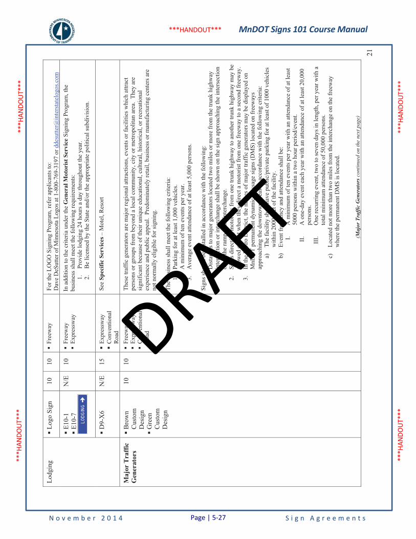
MnDOT Signs 101 Course Manual
N o v e m b e r 2 0 1 4 S i g n A g r e e m e n t s
***H
ANDO
UT**
* **
*HAN
DOUT
***
***H
ANDO
UT**
* **
*HAN
DOUT
***
***HANDOUT***
21
Lodg
ing
�Lo
go S
ign
10
10
�Fr
eew
ay
For t
he L
OG
O S
igni
ng P
rogr
am, r
efer
app
lican
ts to
: D
ave
DeS
utte
r of M
inne
sota
Log
os a
t 1-8
00-7
69-3
197
or d
desu
tter@
inte
rsta
telo
gos.c
om
�E1
0-1
�E1
0-7
N/E
10
�
Free
way
�
Expr
essw
ay
In a
dditi
on to
the
crite
ria u
nder
the
Gen
eral
Mot
orist
Ser
vice
Sig
ning
Pro
gram
, the
bu
sine
ss sh
all m
eet t
he fo
llow
ing
requ
irem
ents
: 1.
Prov
ide
lodg
ing
24 h
ours
a d
ay th
roug
hout
the
year
. 2.
Be
licen
sed
by th
e St
ate
and/
or th
e ap
prop
riate
pol
itica
l sub
divi
sion
.
�D
9-X
6 N
/E
15
�Ex
pres
sway
�C
onve
ntio
nal
Roa
d
See
Spec
ific
Serv
ices
– M
otel
, Res
ort
Maj
or T
raff
ic
Gen
erat
ors
�B
row
nC
usto
m
Des
ign
�G
reen
Cus
tom
D
esig
n
10
10
�Fr
eew
ay
�Ex
pres
sway
�
Con
vent
iona
l R
oad
Thes
e tra
ffic
gen
erat
ors a
re m
ajor
regi
onal
attr
actio
ns, e
vent
s or f
acili
ties w
hich
attr
act
pers
ons o
r gro
ups f
rom
bey
ond
a lo
cal c
omm
unity
, city
or m
etro
polit
an a
rea.
The
y ar
e si
gnifi
cant
bec
ause
of t
heir
uniq
ue e
duca
tiona
l, cu
ltura
l, hi
stor
ical
, or r
ecre
atio
nal
expe
rienc
e an
d pu
blic
app
eal.
Pre
dom
inat
ely
reta
il, b
usin
ess o
r man
ufac
turin
g ce
nter
s are
no
t nor
mal
ly e
ligib
le fo
r sig
ning
.
The
busi
ness
shal
l mee
t the
follo
win
g cr
iteria
: 1.
Park
ing
for a
t lea
st 1
,000
veh
icle
s. 2.
A m
inim
um o
f ten
eve
nts p
er y
ear.
3.A
vera
ge e
vent
atte
ndan
ce o
f at l
east
5,0
00 p
erso
ns.
Sign
s sho
uld
be in
stal
led
in a
ccor
danc
e w
ith th
e fo
llow
ing:
1.
Dis
tanc
es to
maj
or g
ener
ator
s loc
ated
two
mile
s or m
ore
from
the
trunk
hig
hway
in
ters
ectio
n or
inte
rcha
nge
shal
l be
show
n on
the
sign
app
roac
hing
the
inte
rsec
tion
or o
n th
e ra
mp
at a
n in
terc
hang
e.
2.Si
gns d
irect
ing
mot
oris
ts fr
om o
ne tr
unk
high
way
to a
noth
er tr
unk
high
way
may
be
allo
wed
exc
ept w
hen
they
dire
ct a
mot
oris
t fro
m o
ne fr
eew
ay to
a se
cond
free
way
. 3.
In th
e M
etro
Dis
trict
, the
nam
es o
f maj
or tr
affic
gen
erat
ors m
ay b
e di
spla
yed
on
MnD
OT
perm
anen
t dyn
amic
mes
sage
sign
s (D
MS)
loca
ted
on fr
eew
ays
appr
oach
ing
the
dow
ntow
n ar
eas i
n ac
cord
ance
with
the
follo
win
g cr
iteria
: a)
The
faci
lity
shal
l hav
e pu
blic
/priv
ate
park
ing
for a
t lea
st o
f 100
0 ve
hicl
es
with
in 2
000
feet
of t
he fa
cilit
y.
b)Ev
ent f
requ
ency
and
atte
ndan
ce sh
all b
e:
I.A
min
imum
of t
en e
vent
s per
yea
r with
an
atte
ndan
ce o
f at l
east
50
00 p
erso
ns w
ithin
a tw
o ho
ur p
erio
d/ev
ent.
II.
A o
ne-d
ay e
vent
eac
h ye
ar w
ith a
n at
tend
ance
of a
t lea
st 2
0,00
0 pe
rson
s. II
I.O
ne re
curr
ing
even
t, tw
o to
seve
n da
ys in
leng
th, p
er y
ear w
ith a
to
tal m
inim
um a
ttend
ance
of 5
0,00
0 pe
rson
s. c)
Loca
ted
not m
ore
than
two
mile
s fro
m th
e in
terc
hang
e on
the
free
way
w
here
the
perm
anen
t DM
S is
loca
ted.
(Maj
or T
raff
ic G
ener
ator
s con
tinue
d on
the
next
pag
e)
Page | 5-27
DRAFT

MnDOT Signs 101 Course Manual
N o v e m b e r 2 0 1 4 S i g n A g r e e m e n t s
***H
ANDO
UT**
* **
*HAN
DOUT
***
***H
ANDO
UT**
* **
*HAN
DOUT
***
***HANDOUT***
Faci
lity
Typ
e
Sign
Des
ign
(Sig
n #s
ref
er to
de
sign
atio
n in
th
eM
nDO
T
Stan
dard
Sig
ns
Sum
mar
y)
Mile
s fro
m
Inte
rsec
tion
/In
terc
hang
e
N/E
= N
ot
Elig
ible
Roa
dway
Typ
e
Sign
Pro
gram
and
Fac
ility
-Spe
cific
C
rite
ria
Unl
ess o
ther
wis
e in
dica
ted,
the
Gen
eral
Cri
teri
a ap
ply
for
all f
acili
ties.
See
Tra
ffic
Eng
inee
ring
Man
ual f
or p
lace
men
t of s
igns
.
Urban
Rural22
(Maj
or T
raff
ic G
ener
ator
s con
tinue
d fr
om th
e pr
evio
us p
age)
d)O
nly
the
faci
lity
nam
e(s)
shal
l be
disp
laye
d on
a p
erm
anen
t DM
S w
hich
is
loca
ted
on a
free
way
. e)
The
disp
lay
of a
uni
que
even
t by
nam
e (e
.g. W
inte
r Car
niva
l, A
quat
enni
al)
may
be
appr
oved
on
a ca
se b
y ca
se b
asis
by th
e di
stric
t tra
ffic
eng
inee
r an
d th
e R
TMC
. f)
If a
faci
lity
is h
avin
g an
eve
nt e
ither
con
curr
ent w
ith o
r ove
rlapp
ing
an
even
t with
ano
ther
faci
lity,
the
dura
tion
of th
e di
spla
y of
eac
h fa
cilit
y na
me
and
actio
n m
essa
ge o
n a
perm
anen
t DM
S w
ill b
e tw
o se
cond
s. Th
is
is b
ased
on
the
tota
l rea
ding
tim
e, in
clud
ing
the
chan
ge ti
me
betw
een
mes
sage
dis
play
s, at
veh
icle
ope
ratin
g sp
eeds
on
met
ro a
rea
free
way
s. g)
Not
mor
e th
an tw
o fa
cilit
ies (
each
with
an
actio
n m
essa
ge) m
ay b
e al
tern
atel
y di
spla
yed
on a
per
man
ent D
MS
with
the
entir
e m
essa
ge fo
r ea
ch fa
cilit
y di
spla
yed
at o
ne ti
me.
h)
The
faci
lity
nam
e an
d ac
tion
mes
sage
for a
n ev
ent m
ay b
e di
spla
yed
from
: I.
One
hou
r bef
ore
the
gate
ope
ns u
ntil
30 m
inut
es a
fter t
he e
vent
be
gins
whe
n no
rmal
atte
ndan
ce is
for t
he e
ntire
eve
nt (i
.e. a
sp
ortin
g ev
ent).
II
.O
ne h
our b
efor
e th
e ev
ent b
egin
s and
con
tinuo
usly
thro
ugho
ut
the
dura
tion
of th
e ev
ent w
hen
norm
al a
ttend
ance
is p
art t
ime
(i.e.
an
aut
omob
ile sh
ow).
i)Th
e du
ratio
n of
the
disp
lay
shal
l be
cont
inuo
us if
onl
y on
e fa
cilit
y is
ha
ving
an
even
t to
be d
ispla
yed
on a
per
man
ent D
MS.
j)
Mes
sage
s on
perm
anen
t DM
S di
rect
ing
mot
oris
ts to
a fa
cilit
y at
mor
e th
an
one
exit
on th
e sa
me
free
way
or t
o an
exi
t(s) o
n an
othe
r fre
eway
shal
l onl
y be
allo
wed
for t
raff
ic m
anag
emen
t at t
he d
iscr
etio
n of
the
dist
rict t
raff
ic
engi
neer
and
the
RTM
C.
(Maj
or T
raff
ic G
ener
ator
s con
tinue
d on
the
next
pag
e)
Page | 5-28
DRAFT
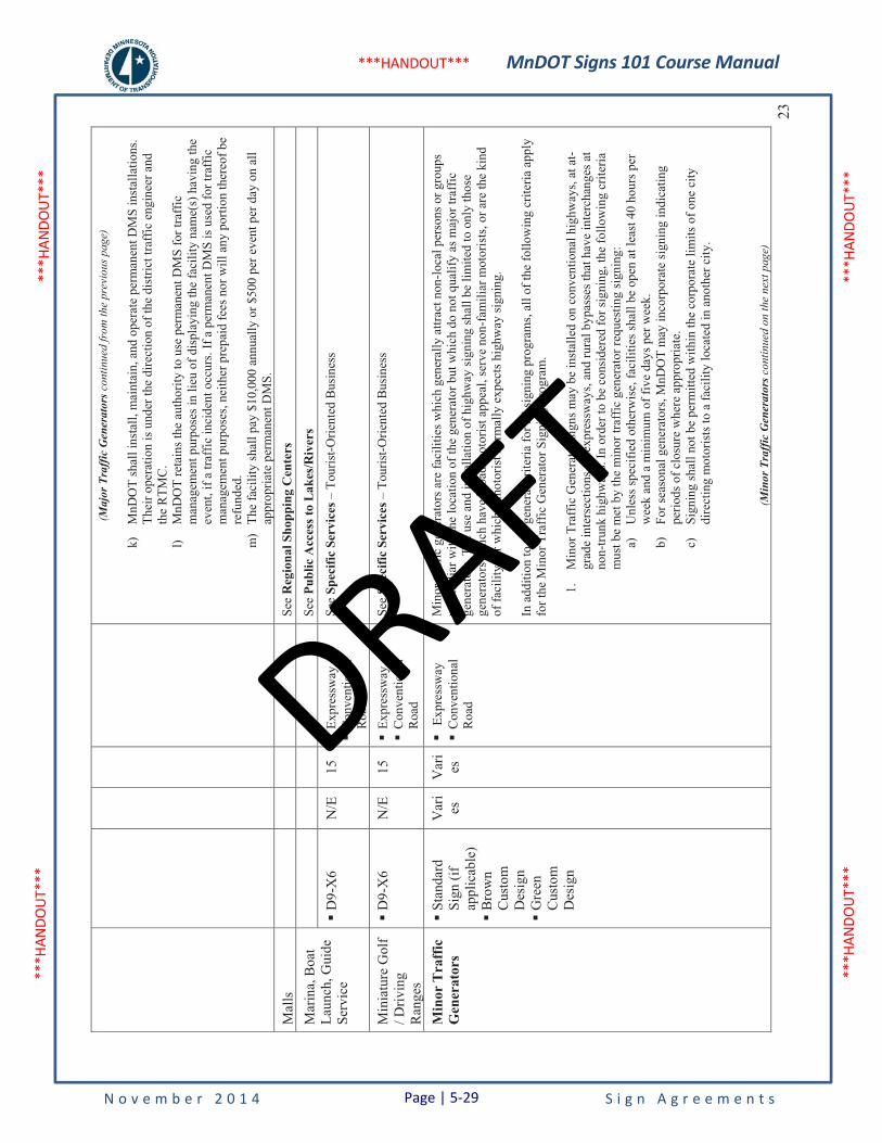
MnDOT Signs 101 Course Manual
N o v e m b e r 2 0 1 4 S i g n A g r e e m e n t s
***H
ANDO
UT**
* **
*HAN
DOUT
***
***H
ANDO
UT**
* **
*HAN
DOUT
***
***HANDOUT***
23
(Maj
or T
raff
ic G
ener
ator
s con
tinue
d fr
om th
e pr
evio
us p
age)
k)M
nDO
T sh
all i
nsta
ll, m
aint
ain,
and
ope
rate
per
man
ent D
MS
inst
alla
tions
. Th
eir o
pera
tion
is u
nder
the
dire
ctio
n of
the
dist
rict t
raff
ic e
ngin
eer a
nd
the
RTM
C.
l)M
nDO
T re
tain
s the
aut
horit
y to
use
per
man
ent D
MS
for t
raff
ic
man
agem
ent p
urpo
ses i
n lie
u of
dis
play
ing
the
faci
lity
nam
e(s)
hav
ing
the
even
t, if
a tra
ffic
inci
dent
occ
urs.
If a
per
man
ent D
MS
is u
sed
for t
raff
ic
man
agem
ent p
urpo
ses,
neith
er p
repa
id fe
es n
or w
ill a
ny p
ortio
n th
ereo
f be
refu
nded
. m
)Th
e fa
cilit
y sh
all p
ay $
10,0
00 a
nnua
lly o
r $50
0 pe
r eve
nt p
er d
ay o
n al
l ap
prop
riate
per
man
ent D
MS.
Mal
ls
See
Reg
iona
l Sho
ppin
g C
ente
rs
Mar
ina,
Boa
t La
unch
, Gui
de
Serv
ice
See
Publ
ic A
cces
s to
Lake
s/Riv
ers
�D
9-X
6 N
/E
15
�Ex
pres
sway
�C
onve
ntio
nal
Roa
d
See
Spec
ific
Serv
ices
– T
ouris
t-Orie
nted
Bus
ines
s
Min
iatu
re G
olf
/ Driv
ing
Ran
ges
�D
9-X
6 N
/E
15
�Ex
pres
sway
�C
onve
ntio
nal
Roa
d
See
Spec
ific
Serv
ices
– T
ouris
t-Orie
nted
Bus
ines
s
Min
or T
raff
ic
Gen
erat
ors
�St
anda
rdSi
gn (i
f ap
plic
able
)�
Bro
wn
Cus
tom
D
esig
n�
Gre
enC
usto
m
Des
ign
Var
ies
V
ari
es
�Ex
pres
sway
�C
onve
ntio
nal
Roa
d
Min
or tr
affic
gen
erat
ors a
re fa
cilit
ies w
hich
gen
eral
ly a
ttrac
t non
-loca
l per
sons
or g
roup
s un
fam
iliar
with
the
loca
tion
of th
e ge
nera
tor b
ut w
hich
do
not q
ualif
y as
maj
or tr
affic
ge
nera
tors
. The
use
and
inst
alla
tion
of h
ighw
ay si
gnin
g sh
all b
e lim
ited
to o
nly
thos
e ge
nera
tors
whi
ch h
ave
broa
d m
otor
ist a
ppea
l, se
rve
non-
fam
iliar
mot
oris
ts, o
r are
the
kind
of
faci
lity
for w
hich
a m
otor
ist n
orm
ally
exp
ects
hig
hway
sign
ing.
In a
dditi
on to
the
gene
ral c
riter
ia fo
r all
sign
ing
prog
ram
s, al
l of t
he fo
llow
ing
crite
ria a
pply
fo
r the
Min
or T
raff
ic G
ener
ator
Sig
ning
Pro
gram
.
1.M
inor
Tra
ffic
Gen
erat
or si
gns m
ay b
e in
stal
led
on c
onve
ntio
nal h
ighw
ays,
at a
t-gr
ade
inte
rsec
tions
on
expr
essw
ays,
and
rura
l byp
asse
s tha
t hav
e in
terc
hang
es a
t no
n-tru
nk h
ighw
ays.
In o
rder
to b
e co
nsid
ered
for s
igni
ng, t
he fo
llow
ing
crite
ria
mus
t be
met
by
the
min
or tr
affic
gen
erat
or re
ques
ting
sign
ing:
a)
Unl
ess s
peci
fied
othe
rwis
e, fa
cilit
ies s
hall
be o
pen
at le
ast 4
0 ho
urs p
er
wee
k an
d a
min
imum
of f
ive
days
per
wee
k.
b)Fo
r sea
sona
l gen
erat
ors,
MnD
OT
may
inco
rpor
ate
sign
ing
indi
catin
g pe
riods
of c
losu
re w
here
app
ropr
iate
. c)
Sign
ing
shal
l not
be
perm
itted
with
in th
e co
rpor
ate
limits
of o
ne c
ity
dire
ctin
g m
otor
ists
to a
faci
lity
loca
ted
in a
noth
er c
ity.
(Min
or T
raff
ic G
ener
ator
s con
tinue
d on
the
next
pag
e)
Page | 5-29
DRAFT

MnDOT Signs 101 Course Manual
N o v e m b e r 2 0 1 4 S i g n A g r e e m e n t s
***H
ANDO
UT**
* **
*HAN
DOUT
***
***H
ANDO
UT**
* **
*HAN
DOUT
***
***HANDOUT***
Faci
lity
Typ
e
Sign
Des
ign
(Sig
n #s
ref
er to
de
sign
atio
n in
th
eM
nDO
T
Stan
dard
Sig
ns
Sum
mar
y)
Mile
s fro
m
Inte
rsec
tion
/In
terc
hang
e
N/E
= N
ot
Elig
ible
Roa
dway
Typ
e
Sign
Pro
gram
and
Fac
ility
-Spe
cific
C
rite
ria
Unl
ess o
ther
wis
e in
dica
ted,
the
Gen
eral
Cri
teri
a ap
ply
for
all f
acili
ties.
See
Tra
ffic
Eng
inee
ring
Man
ual f
or p
lace
men
t of s
igns
.
Urban
Rural24
(Min
or T
raff
ic G
ener
ator
s con
tinue
d fr
om th
e pr
evio
us p
age)
d)G
ener
ator
s sha
ll be
loca
ted
with
in sp
ecifi
ed d
ista
nces
from
the
trunk
hi
ghw
ay in
ters
ectio
n or
inte
rcha
nge
at w
hich
sign
ing
is p
erm
itted
. The
se
dist
ance
s var
y de
pend
ing
on th
e ty
pe o
f gen
erat
or a
nd w
heth
er th
e si
gned
in
ters
ectio
n is
loca
ted
with
in a
n ur
ban
or ru
ral e
nviro
nmen
t. I.
Urb
an e
nviro
nmen
t - ty
pica
l cha
ract
eris
tics a
re h
ighl
y de
velo
ped
area
s hav
ing
slow
er sp
eeds
, hig
her p
ropo
rtion
of l
ocal
traf
fic,
incr
ease
d di
ffic
ulty
in fi
ndin
g ac
cept
able
loca
tions
for t
raff
ic
sign
s, an
d m
ore
stre
ssfu
l and
com
plic
ated
driv
ing
envi
ronm
ent.
II.
Rur
al e
nviro
nmen
t - ty
pica
l cha
ract
eris
tics a
re re
lativ
ely
unde
velo
ped
or a
gric
ultu
ral l
and,
hig
her s
peed
s, hi
gher
pr
opor
tion
of n
on-lo
cal t
raff
ic, e
asy
abili
ty to
find
acc
epta
ble
loca
tions
for t
raff
ic si
gns,
and
rela
tivel
y un
com
plic
ated
driv
ing
envi
ronm
ent.
Smal
l citi
es in
oth
erw
ise
rura
l are
as a
re in
clud
ed in
th
is d
efin
ition
. e)
Whe
n M
nDO
T de
term
ines
that
the
num
ber o
f qua
lifyi
ng g
ener
ator
s tha
t a
com
mun
ity is
requ
estin
g si
gnin
g fo
r can
not a
ll be
acc
omm
odat
ed o
n si
gnin
g at
the
sam
e in
ters
ectio
n du
e to
driv
er in
form
atio
n ov
erlo
ad a
nd
sign
spac
ing
guid
elin
es, t
he lo
cal g
over
ning
bod
y(ie
s) sh
all p
riorit
ize
whi
ch fa
cilit
ies m
ay b
e si
gned
. 2.
Sign
s sha
ll on
ly b
e al
low
ed fr
om th
e ne
ares
t tru
nk h
ighw
ay in
ters
ectio
n. S
igns
di
rect
ing
mot
oris
ts fr
om o
ne tr
unk
high
way
to a
noth
er tr
unk
high
way
shal
l not
be
allo
wed
. 3.
Sign
ing
shal
l not
be
prov
ided
if th
e fa
cilit
y is
read
ily v
isib
le o
r if e
ffec
tive
off
right
-of-
way
dire
ctio
nal s
igni
ng is
pre
sent
or c
an b
e pr
ovid
ed. V
isib
ility
from
the
appr
oach
to a
n in
ters
ectio
n m
ay b
e de
term
ined
by
addi
ng 1
75 fe
et to
Con
ditio
n B
(d
ecel
erat
ion
to te
n m
ph fr
om th
e po
sted
spee
d) in
MN
MU
TCD
Tab
le 2
C-4
.Si
gnin
g is
not
allo
wed
if th
e fa
cilit
y ca
n be
read
ily id
entif
ied
or if
eff
ectiv
e of
f hi
ghw
ay ri
ght-o
f-w
ay d
irect
iona
l sig
ning
is le
gibl
e at
or b
eyon
d th
is d
ista
nce.
(Min
or T
raff
ic G
ener
ator
s con
tinue
d on
the
next
pag
e)
Page | 5-30
DRAFT
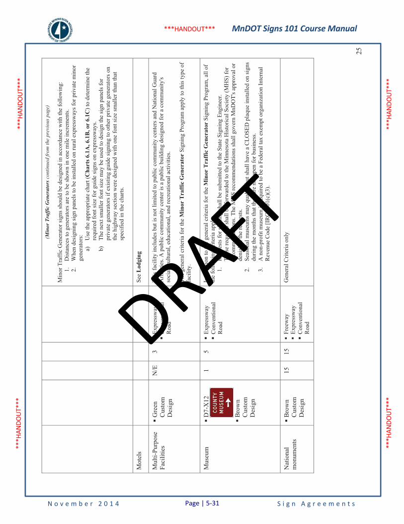
MnDOT Signs 101 Course Manual
N o v e m b e r 2 0 1 4 S i g n A g r e e m e n t s
***H
ANDO
UT**
* **
*HAN
DOUT
***
***H
ANDO
UT**
* **
*HAN
DOUT
***
***HANDOUT***
25
(Min
or T
raff
ic G
ener
ator
s con
tinue
d fr
om th
e pr
evio
us p
age)
Min
or T
raff
ic G
ener
ator
sign
s sho
uld
be d
esig
ned
in a
ccor
danc
e w
ith th
e fo
llow
ing:
1.
Dis
tanc
es to
gen
erat
ors a
re to
be
show
n in
one
mile
incr
emen
ts.
2.W
hen
desi
gnin
g si
gn p
anel
s to
be in
stal
led
on ru
ral e
xpre
ssw
ays f
or p
rivat
e m
inor
ge
nera
tors
: a)
Use
the
appr
opria
te c
hart
(Cha
rts 6
.1A
, 6.1
B, o
r 6.
1C) t
o de
term
ine
the
requ
ired
font
size
for g
uide
sign
s on
expr
essw
ays.
b)Th
e ne
xt sm
alle
r fon
t siz
e m
ay b
e us
ed to
des
ign
the
sign
pan
els f
or
priv
ate
gene
rato
rs if
exi
stin
g gu
ide
sign
ing
to o
ther
priv
ate
gene
rato
rs o
n th
e hi
ghw
ay se
ctio
n w
ere
desi
gned
with
one
font
size
smal
ler t
han
that
sp
ecifi
ed in
the
char
ts.
Mot
els
See
Lod
ging
Mul
ti-Pu
rpos
e Fa
cilit
ies
�G
reen
Cus
tom
D
esig
n
N/E
3
�Ex
pres
sway
�C
onve
ntio
nal
Roa
d
This
faci
lity
incl
udes
but
is n
ot li
mite
d to
pub
lic c
omm
unity
cen
ters
and
Nat
iona
l Gua
rd
Arm
orie
s. A
pub
lic c
omm
unity
cen
ter i
s a p
ublic
bui
ldin
g de
sign
ed fo
r a c
omm
unity
's so
cial
, cul
tura
l, ed
ucat
iona
l, an
d re
crea
tiona
l act
iviti
es.
The
gene
ral c
riter
ia fo
r the
Min
or T
raff
ic G
ener
ator
Sig
ning
Pro
gram
app
ly to
this
type
of
faci
lity.
Mus
eum
�
D7-
X12
�B
row
nC
usto
m
Des
ign
1 5
�Ex
pres
sway
�C
onve
ntio
nal
Roa
d
In a
dditi
on to
the
gene
ral c
riter
ia fo
r the
Min
or T
raff
ic G
ener
ator
Sig
ning
Pro
gram
, all
of
the
follo
win
g cr
iteria
app
ly:
1.R
eque
sts f
or si
gnin
g sh
all b
e su
bmitt
ed to
the
Stat
e Si
gnin
g En
gine
er.
Thes
e re
ques
ts sh
all b
e fo
rwar
ded
to th
e M
inne
sota
His
toric
al S
ocie
ty (M
HS)
for
reco
mm
enda
tions
. The
MH
S re
com
men
datio
ns sh
all g
over
n M
nDO
T's a
ppro
val o
r de
nial
of t
he re
ques
ts.
2.Se
ason
al m
useu
ms m
ay q
ualif
y bu
t sha
ll ha
ve a
CLO
SED
pla
que
inst
alle
d on
sign
s du
ring
the
mon
ths t
hat t
hey
are
not o
pen
for b
usin
ess.
3.A
non
-pro
fit m
useu
m is
requ
ired
to b
e a
Fede
ral t
ax e
xem
pt o
rgan
izat
ion
Inte
rnal
R
even
ue C
ode
[IR
C] 5
01(c
)(3)
.
Nat
iona
lm
onum
ents
�
Bro
wn
Cus
tom
D
esig
n
15
15
�Fr
eew
ay
�Ex
pres
sway
�
Con
vent
iona
l R
oad
Gen
eral
Crit
eria
onl
y
Page | 5-31
DRAFT
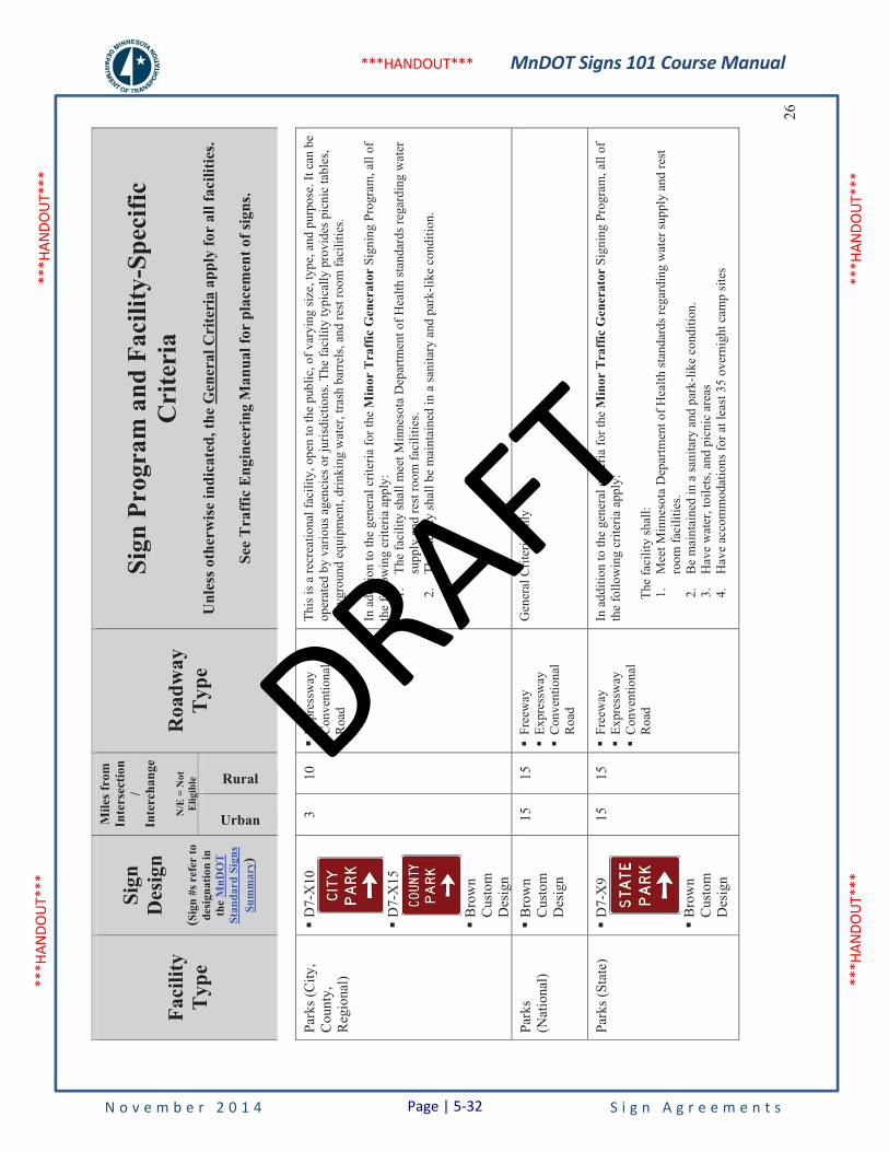
MnDOT Signs 101 Course Manual
N o v e m b e r 2 0 1 4 S i g n A g r e e m e n t s
***H
ANDO
UT**
* **
*HAN
DOUT
***
***H
ANDO
UT**
* **
*HAN
DOUT
***
***HANDOUT***
Faci
lity
Typ
e
Sign
Des
ign
(Sig
n #s
ref
er to
de
sign
atio
n in
th
eM
nDO
T
Stan
dard
Sig
ns
Sum
mar
y)
Mile
s fro
m
Inte
rsec
tion
/In
terc
hang
e
N/E
= N
ot
Elig
ible
Roa
dway
Typ
e
Sign
Pro
gram
and
Fac
ility
-Spe
cific
C
rite
ria
Unl
ess o
ther
wis
e in
dica
ted,
the
Gen
eral
Cri
teri
a ap
ply
for
all f
acili
ties.
See
Tra
ffic
Eng
inee
ring
Man
ual f
or p
lace
men
t of s
igns
.
Urban
Rural26
Park
s (C
ity,
Cou
nty,
R
egio
nal)
�D
7-X
10
�D
7-X
15
�B
row
nC
usto
m
Des
ign
3 10
�
Expr
essw
ay�
Con
vent
iona
l R
oad
This
is a
recr
eatio
nal f
acili
ty, o
pen
to th
e pu
blic
, of v
aryi
ng si
ze, t
ype,
and
pur
pose
. It c
an b
e op
erat
ed b
y va
rious
age
ncie
s or j
uris
dict
ions
. The
faci
lity
typi
cally
pro
vide
s pic
nic
tabl
es,
play
grou
nd e
quip
men
t, dr
inki
ng w
ater
, tra
sh b
arre
ls, a
nd re
st ro
om fa
cilit
ies.
In a
dditi
on to
the
gene
ral c
riter
ia fo
r the
Min
or T
raff
ic G
ener
ator
Sig
ning
Pro
gram
, all
of
the
follo
win
g cr
iteria
app
ly:
1.Th
e fa
cilit
y sh
all m
eet M
inne
sota
Dep
artm
ent o
f Hea
lth st
anda
rds r
egar
ding
wat
er
supp
ly a
nd re
st ro
om fa
cilit
ies.
2.Th
e fa
cilit
y sh
all b
e m
aint
aine
d in
a sa
nita
ry a
nd p
ark-
like
cond
ition
.
Park
s(N
atio
nal)
�B
row
nC
usto
m
Des
ign
15
15
�Fr
eew
ay
�Ex
pres
sway
�
Con
vent
iona
l R
oad
Gen
eral
Crit
eria
onl
y
Park
s (St
ate)
�
D7-
X9
�B
row
nC
usto
m
Des
ign
15
15
�Fr
eew
ay
�Ex
pres
sway
�
Con
vent
iona
l R
oad
In a
dditi
on to
the
gene
ral c
riter
ia fo
r the
Min
or T
raff
ic G
ener
ator
Sig
ning
Pro
gram
, all
of
the
follo
win
g cr
iteria
app
ly:
The
faci
lity
shal
l: 1.
Mee
t Min
neso
ta D
epar
tmen
t of H
ealth
stan
dard
s reg
ardi
ng w
ater
supp
ly a
nd re
st
room
faci
litie
s. 2.
Be
mai
ntai
ned
in a
sani
tary
and
par
k-lik
e co
nditi
on.
3.H
ave
wat
er, t
oile
ts, a
nd p
icni
c ar
eas
4.H
ave
acco
mm
odat
ions
for a
t lea
st 3
5 ov
erni
ght c
amp
site
s
Page | 5-32
DRAFT
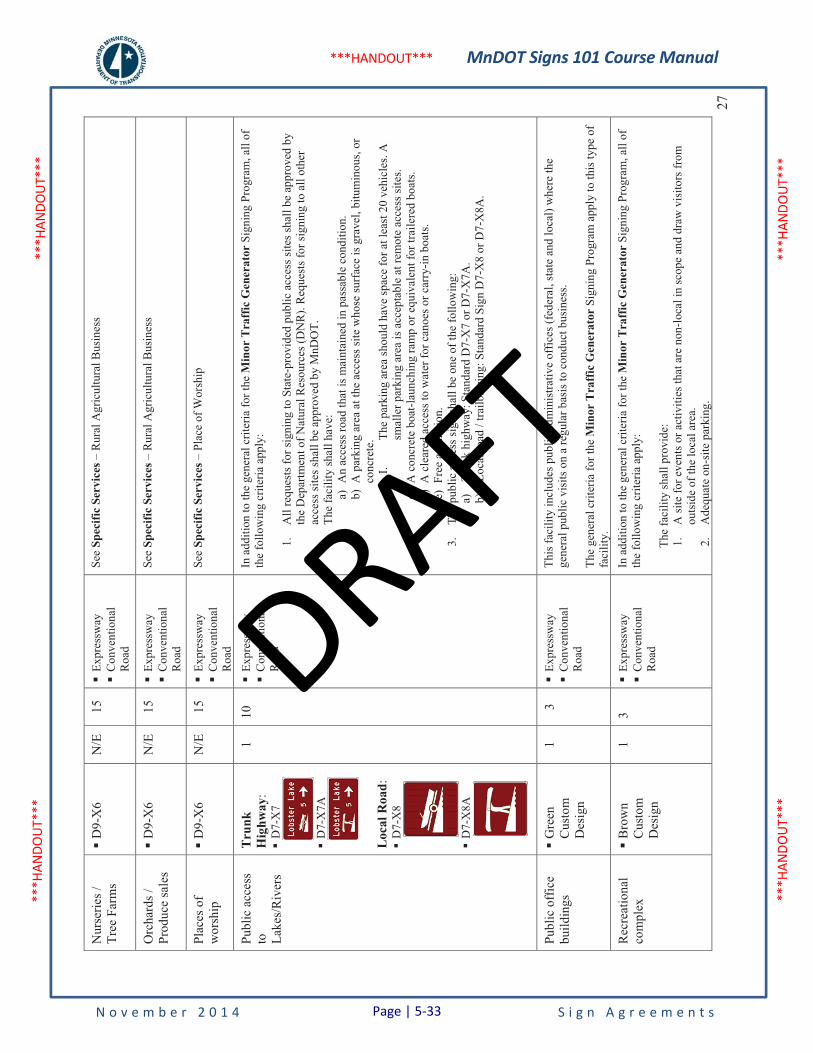
MnDOT Signs 101 Course Manual
N o v e m b e r 2 0 1 4 S i g n A g r e e m e n t s
***H
ANDO
UT**
* **
*HAN
DOUT
***
***H
ANDO
UT**
* **
*HAN
DOUT
***
***HANDOUT***
27
Nur
serie
s /
Tree
Far
ms
�D
9-X
6 N
/E
15
�Ex
pres
sway
�C
onve
ntio
nal
Roa
d
See
Spec
ific
Serv
ices
– R
ural
Agr
icul
tura
l Bus
ines
s
Orc
hard
s /Pr
oduc
e sa
les
�D
9-X
6 N
/E
15
�Ex
pres
sway
�C
onve
ntio
nal
Roa
d
See
Spec
ific
Serv
ices
– R
ural
Agr
icul
tura
l Bus
ines
s
Plac
es o
f w
orsh
ip�
D9-
X6
N/E
15
�
Expr
essw
ay�
Con
vent
iona
l R
oad
See
Spec
ific
Serv
ices
– P
lace
of W
orsh
ip
Publ
ic a
cces
s to La
kes/
Riv
ers
Tru
nkH
ighw
ay:
�D
7-X
7
�D
7-X
7A
Loc
al R
oad:
�D
7-X
8
�D
7-X
8A
1 10
�
Expr
essw
ay�
Con
vent
iona
l R
oad
In a
dditi
on to
the
gene
ral c
riter
ia fo
r the
Min
or T
raff
ic G
ener
ator
Sig
ning
Pro
gram
, all
of
the
follo
win
g cr
iteria
app
ly:
1.A
ll re
ques
ts fo
r sig
ning
to S
tate
-pro
vide
d pu
blic
acc
ess s
ites s
hall
be a
ppro
ved
by
the
Dep
artm
ent o
f Nat
ural
Res
ourc
es (D
NR)
. Req
uest
s for
sign
ing
to a
ll ot
her
acce
ss si
tes s
hall
be a
ppro
ved
by M
nDO
T.
2.Th
e fa
cilit
y sh
all h
ave:
a)
An
acce
ss ro
ad th
at is
mai
ntai
ned
in p
assa
ble
cond
ition
.
b)
A p
arki
ng a
rea
at th
e ac
cess
site
who
se su
rfac
e is
gra
vel,
bitu
min
ous,
or
conc
rete
. I.
The
park
ing
area
shou
ld h
ave
spac
e fo
r at l
east
20
vehi
cles
. A
smal
ler p
arki
ng a
rea
is a
ccep
tabl
e at
rem
ote
acce
ss si
tes.
c)A
con
cret
e bo
at-la
unch
ing
ram
p or
equ
ival
ent f
or tr
aile
red
boat
s. d)
A c
lear
ed a
cces
s to
wat
er fo
r can
oes o
r car
ry-in
boa
ts.
e)Fr
ee a
dmis
sion
. 3.
The
publ
ic a
cces
s sig
n sh
all b
e on
e of
the
follo
win
g:
a)Tr
unk
high
way
: Sta
ndar
d D
7-X
7 or
D7-
X7A
. b)
Loca
l roa
d / t
railb
lazi
ng: S
tand
ard
Sign
D7-
X8
or D
7-X
8A.
Publ
ic o
ffic
e bu
ildin
gs
�G
reen
Cus
tom
D
esig
n
1 3
�Ex
pres
sway
�C
onve
ntio
nal
Roa
d
This
faci
lity
incl
udes
pub
lic a
dmin
istra
tive
offic
es (f
eder
al, s
tate
and
loca
l) w
here
the
gene
ral p
ublic
vis
its o
n a
regu
lar b
asis
to c
ondu
ct b
usin
ess.
The
gene
ral c
riter
ia fo
r the
Min
or T
raff
ic G
ener
ator
Sig
ning
Pro
gram
app
ly to
this
type
of
faci
lity.
Rec
reat
iona
lco
mpl
ex
�B
row
nC
usto
m
Des
ign
1 3
�Ex
pres
sway
�C
onve
ntio
nal
Roa
d
In a
dditi
on to
the
gene
ral c
riter
ia fo
r the
Min
or T
raff
ic G
ener
ator
Sig
ning
Pro
gram
, all
of
the
follo
win
g cr
iteria
app
ly:
The
faci
lity
shal
l pro
vide
: 1.
A si
te fo
r eve
nts o
r act
iviti
es th
at a
re n
on-lo
cal i
n sc
ope
and
draw
vis
itors
from
ou
tsid
e of
the
loca
l are
a.
2.A
dequ
ate
on-s
ite p
arki
ng.
Page | 5-33
DRAFT
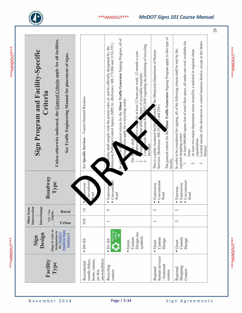
MnDOT Signs 101 Course Manual
N o v e m b e r 2 0 1 4 S i g n A g r e e m e n t s
***H
ANDO
UT**
* **
*HAN
DOUT
***
***H
ANDO
UT**
* **
*HAN
DOUT
***
***HANDOUT***
Faci
lity
Typ
e
Sign
Des
ign
(Sig
n #s
ref
er to
de
sign
atio
n in
th
eM
nDO
T
Stan
dard
Sig
ns
Sum
mar
y)
Mile
s fro
m
Inte
rsec
tion
/In
terc
hang
e
N/E
= N
ot
Elig
ible
Roa
dway
Typ
e
Sign
Pro
gram
and
Fac
ility
-Spe
cific
C
rite
ria
Unl
ess o
ther
wis
e in
dica
ted,
the
Gen
eral
Cri
teri
a ap
ply
for
all f
acili
ties.
See
Tra
ffic
Eng
inee
ring
Man
ual f
or p
lace
men
t of s
igns
.
Urban
Rural28
Rec
reat
iona
lre
ntal
s (bi
kes,
boat
s, ca
noes
, je
t ski
s, sn
owm
obile
s)
�D
9-X
6 N
/E
15
�Ex
pres
sway
�C
onve
ntio
nal
Roa
d
See
Spec
ific
Serv
ices
– T
ouris
t-Orie
nted
Bus
ines
s
Rec
yclin
g ce
nter
s �
D1-
X6
�G
reen
Cus
tom
D
esig
n (n
o sy
mbo
l)
1 5
�Ex
pres
sway
�C
onve
ntio
nal
Roa
d
This
faci
lity
shal
l com
ply
with
the
perm
it ru
les o
f, an
d be
off
icia
lly d
esig
nate
d by
, the
M
inne
sota
Pol
lutio
n C
ontro
l Age
ncy
(MPC
A).
(Ref
eren
ce: M
S 17
3.08
6 an
d 11
5A.5
55.)
In a
dditi
on to
the
gene
ral c
riter
ia fo
r the
Min
or T
raff
ic G
ener
ator
Sig
ning
Pro
gram
, all
of
the
follo
win
g cr
iteria
app
ly fo
r a re
cycl
ing
cent
er:
The
faci
lity
shal
l: 1.
Be
open
to re
ceiv
e m
ater
ials
at l
east
12
hour
s per
wee
k, 1
2 m
onth
s a y
ear.
2.A
ccep
t at l
east
four
diff
eren
t typ
es o
f rec
ycla
ble
mat
eria
ls.
3.C
ompl
y w
ith M
inne
sota
Rul
e 70
35.2
845
rega
rdin
g th
e pe
rmitt
ing
of re
cycl
ing
faci
litie
s.
Reg
iona
lhu
man
serv
ices
/ t
reat
men
t ce
nter
s
�G
reen
Cus
tom
D
esig
n
1 3
�Ex
pres
sway
�C
onve
ntio
nal
Roa
d
This
is a
pub
lic tr
eatm
ent f
acili
ty o
pera
ted
by th
e M
inne
sota
Dep
artm
ent o
f Hum
an
Serv
ices
. (R
efer
ence
: MS
252,
253
and
254
.)
The
gene
ral c
riter
ia fo
r the
Min
or T
raff
ic G
ener
ator
Sig
ning
Pro
gram
app
ly to
this
type
of
faci
lity.
Reg
iona
lSh
oppi
ng
Cen
ters
�G
reen
Cus
tom
D
esig
n
2 2
�Fr
eew
ay
�Ex
pres
sway
�C
onve
ntio
nal
Roa
d
In o
rder
to b
e co
nsid
ered
for s
igni
ng, a
ll of
the
follo
win
g cr
iteria
shal
l be
met
by
the
regi
onal
shop
ping
cen
ter:
1.
At l
east
600
,000
squa
re fe
et o
f ret
ail f
loor
spac
e, a
ll un
der o
ne ro
of, a
vaila
ble
for
leas
e.2.
A
t lea
st tw
o m
ajor
dep
artm
ent s
tore
s ow
ned
by a
nat
iona
l or r
egio
nal c
hain
or
gani
zatio
n.
3.
Loca
ted
outs
ide
of th
e do
wnt
own
or c
entra
l bus
ines
s dis
trict
, exc
ept i
n th
e M
etro
D
istri
ct.
Page | 5-34
DRAFT
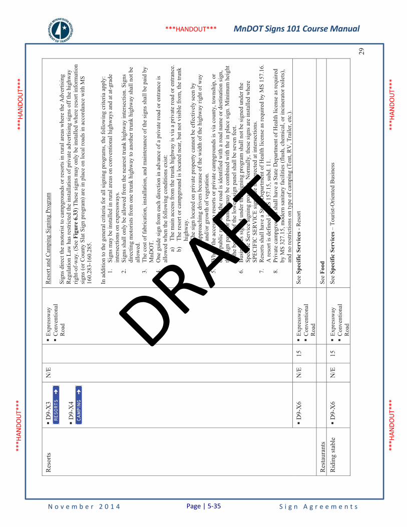
MnDOT Signs 101 Course Manual
N o v e m b e r 2 0 1 4 S i g n A g r e e m e n t s
***H
ANDO
UT**
* **
*HAN
DOUT
***
***H
ANDO
UT**
* **
*HAN
DOUT
***
***HANDOUT***
29
Res
orts
�
D9-
X3
�D
9-X
4
N/E
�Ex
pres
sway
�C
onve
ntio
nal
Roa
d
Res
ort a
nd C
ampi
ng S
igni
ng P
rogr
am
Sign
s dire
ct th
e m
otor
ist t
o ca
mpg
roun
ds o
r res
orts
in ru
ral a
reas
whe
re th
e A
dver
tisin
g R
egul
atio
n La
w h
as re
stric
ted
the
inst
alla
tion
of p
rivat
e ad
verti
sing
sign
s off
the
high
way
rig
ht-o
f-w
ay. (
See
Figu
re 6
.33)
The
se si
gns m
ay o
nly
be in
stal
led
whe
re re
sort
info
rmat
ion
sign
s (or
Cou
nty
Slat
Sig
n pr
ogra
m) a
re in
pla
ce o
n lo
cal r
oads
in a
ccor
danc
e w
ith M
S 16
0.28
3-16
0.28
5.
In a
dditi
on to
the
gene
ral c
riter
ia fo
r all
sign
ing
prog
ram
s, th
e fo
llow
ing
crite
ria a
pply
: 1.
Sign
s may
be
inst
alle
d in
rura
l are
as o
n co
nven
tiona
l hig
hway
s and
at a
t-gra
de
inte
rsec
tions
on
expr
essw
ays.
2.Si
gns s
hall
only
be
allo
wed
from
the
near
est t
runk
hig
hway
inte
rsec
tion.
Sig
ns
dire
ctin
g m
otor
ists
from
one
trun
k hi
ghw
ay to
ano
ther
trun
k hi
ghw
ay sh
all n
ot b
e al
low
ed.
3.Th
e co
st o
f fab
ricat
ion,
inst
alla
tion,
and
mai
nten
ance
of t
he si
gns s
hall
be p
aid
by
MnD
OT.
4.
One
gui
de si
gn fr
om e
ach
dire
ctio
n in
adv
ance
of a
priv
ate
road
or e
ntra
nce
is
allo
wed
whe
n th
e fo
llow
ing
cond
ition
s exi
st:
a)Th
e m
ain
acce
ss fr
om th
e tru
nk h
ighw
ay is
via
a p
rivat
e ro
ad o
r ent
ranc
e.
b)Th
e re
sort
or c
ampg
roun
d is
loca
ted
near
, but
not
vis
ible
from
, the
trun
k hi
ghw
ay.
c)Th
e si
gn lo
cate
d on
priv
ate
prop
erty
can
not b
e ef
fect
ivel
y se
en b
y ap
proa
chin
g dr
iver
s bec
ause
of t
he w
idth
of t
he h
ighw
ay ri
ght o
f way
an
d/or
gro
wth
of v
eget
atio
n.
5.W
here
the
acce
ss to
reso
rts o
r priv
ate
cam
pgro
unds
is v
ia c
ount
y, to
wns
hip,
or
othe
r pub
lic ro
ad a
nd th
e ro
ad is
iden
tifie
d w
ith a
road
nam
e or
des
tinat
ion
sign
, th
e si
gn p
anel
or p
anel
s may
be
com
bine
d w
ith th
e in
pla
ce si
gn. M
inim
um h
eigh
t to
the
botto
m o
f the
low
est s
ign
pane
l sha
ll be
seve
n fe
et.
6.B
usin
esse
s sig
ned
unde
r thi
s sig
ning
pro
gram
shal
l not
be
sign
ed u
nder
the
Spec
ific
Serv
ice
sign
ing
prog
ram
. Nor
mal
ly, t
hese
sign
s are
inst
alle
d w
here
SP
ECIF
IC S
ERV
ICE
sign
s are
not
ere
cted
at i
nter
sect
ions
. 7.
Res
orts
shal
l hav
e a
Stat
e D
epar
tmen
t of H
ealth
lice
nse
as re
quire
d by
MS
157.
16.
A re
sort
is d
efin
ed in
MS
157.
15, s
ubd.
11.
8.
Priv
ate
cam
pgro
unds
shal
l hav
e a
Stat
e D
epar
tmen
t of H
ealth
lice
nse
as re
quire
d by
MS
327.
15, m
oder
n sa
nita
ry fa
cilit
ies (
flush
, che
mic
al, o
r inc
iner
ator
toile
ts),
and
no re
stric
tions
on
type
of c
ampi
ng (T
ent,
RV
, Tra
iler,
etc.
).
�D
9-X
6 N
/E
15
�Ex
pres
sway
�C
onve
ntio
nal
Roa
d
See
Spec
ific
Serv
ices
- R
esor
t
Res
taur
ants
Se
eFo
od
Rid
ing
stab
le
�D
9-X
6 N
/E
15
�Ex
pres
sway
�C
onve
ntio
nal
Roa
d
See
Spec
ific
Serv
ices
– T
ouris
t-Orie
nted
Bus
ines
s
Page | 5-35
DRAFT
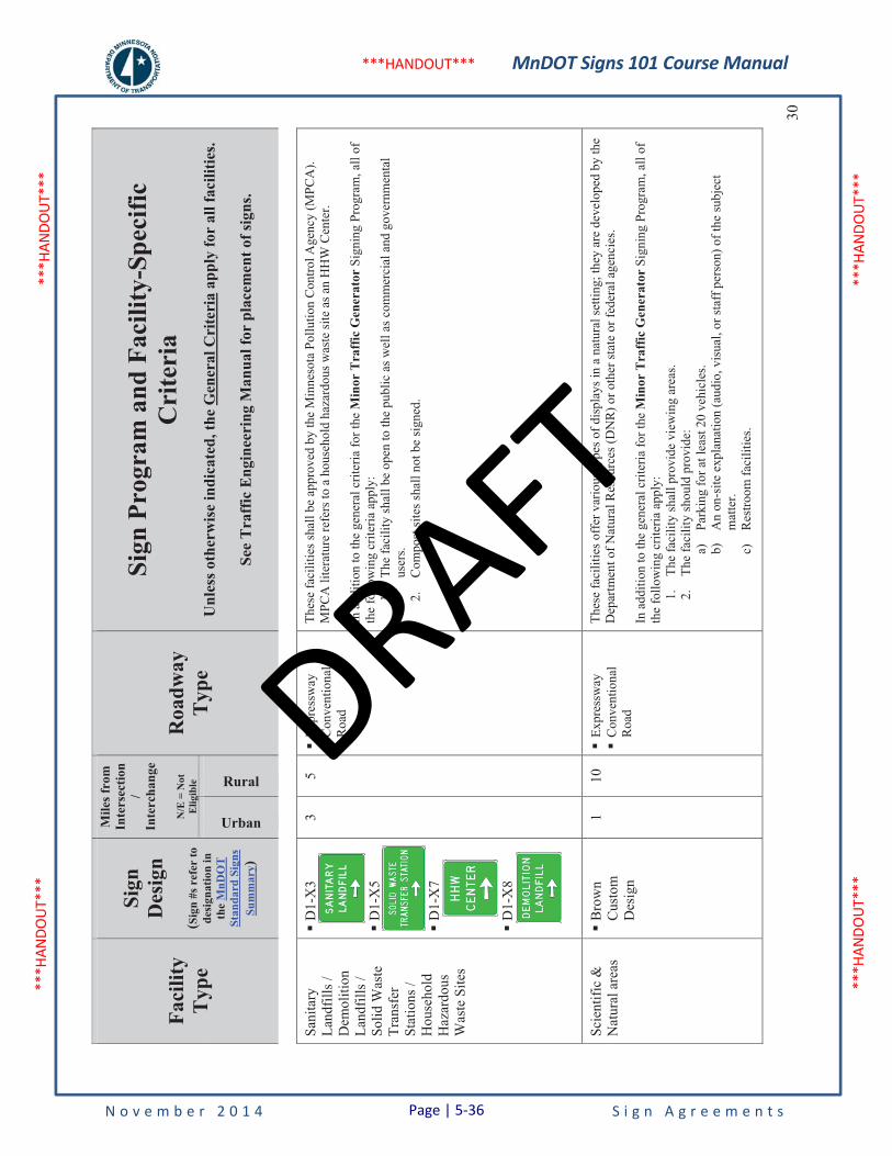
MnDOT Signs 101 Course Manual
N o v e m b e r 2 0 1 4 S i g n A g r e e m e n t s
***H
ANDO
UT**
* **
*HAN
DOUT
***
***H
ANDO
UT**
* **
*HAN
DOUT
***
***HANDOUT***
Faci
lity
Typ
e
Sign
Des
ign
(Sig
n #s
ref
er to
de
sign
atio
n in
th
eM
nDO
T
Stan
dard
Sig
ns
Sum
mar
y)
Mile
s fro
m
Inte
rsec
tion
/In
terc
hang
e
N/E
= N
ot
Elig
ible
Roa
dway
Typ
e
Sign
Pro
gram
and
Fac
ility
-Spe
cific
C
rite
ria
Unl
ess o
ther
wis
e in
dica
ted,
the
Gen
eral
Cri
teri
a ap
ply
for
all f
acili
ties.
See
Tra
ffic
Eng
inee
ring
Man
ual f
or p
lace
men
t of s
igns
.
Urban
Rural30
Sani
tary
La
ndfil
ls /
D
emol
ition
La
ndfil
ls /
Solid
Was
te
Tran
sfer
Stat
ions
/H
ouse
hold
Haz
ardo
usW
aste
Site
s
�D
1-X
3
�D
1-X
5
�D
1-X
7
�D
1-X
8
3 5
�Ex
pres
sway
�C
onve
ntio
nal
Roa
d
Thes
e fa
cilit
ies s
hall
be a
ppro
ved
by th
e M
inne
sota
Pol
lutio
n C
ontro
l Age
ncy
(MPC
A).
MPC
A li
tera
ture
refe
rs to
a h
ouse
hold
haz
ardo
us w
aste
site
as a
n H
HW
Cen
ter.
In a
dditi
on to
the
gene
ral c
riter
ia fo
r the
Min
or T
raff
ic G
ener
ator
Sig
ning
Pro
gram
, all
of
the
follo
win
g cr
iteria
app
ly:
1.Th
e fa
cilit
y sh
all b
e op
en to
the
publ
ic a
s wel
l as c
omm
erci
al a
nd g
over
nmen
tal
user
s. 2.
Com
post
site
s sha
ll no
t be
sign
ed.
Scie
ntifi
c &
N
atur
al a
reas
�
Bro
wn
Cus
tom
D
esig
n
1 10
�
Expr
essw
ay�
Con
vent
iona
l R
oad
Thes
e fa
cilit
ies o
ffer
var
ious
type
s of d
ispl
ays i
n a
natu
ral s
ettin
g; th
ey a
re d
evel
oped
by
the
Dep
artm
ent o
f Nat
ural
Res
ourc
es (D
NR
) or o
ther
stat
e or
fede
ral a
genc
ies.
In a
dditi
on to
the
gene
ral c
riter
ia fo
r the
Min
or T
raff
ic G
ener
ator
Sig
ning
Pro
gram
, all
of
the
follo
win
g cr
iteria
app
ly:
1.
The
faci
lity
shal
l pro
vide
vie
win
g ar
eas.
2.Th
e fa
cilit
y sh
ould
pro
vide
: a)
Park
ing
for a
t lea
st 2
0 ve
hicl
es.
b)A
n on
-site
exp
lana
tion
(aud
io, v
isua
l, or
staf
f per
son)
of t
he su
bjec
t m
atte
r.c)
Res
troom
faci
litie
s.
Page | 5-36
DRAFT
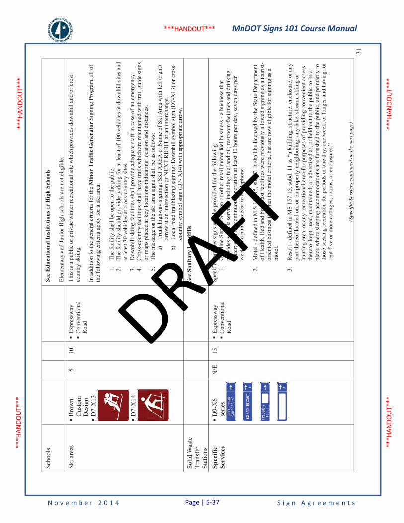
MnDOT Signs 101 Course Manual
N o v e m b e r 2 0 1 4 S i g n A g r e e m e n t s
***H
ANDO
UT**
* **
*HAN
DOUT
***
***H
ANDO
UT**
* **
*HAN
DOUT
***
***HANDOUT***
31
Scho
ols
See
Edu
catio
nal I
nstit
utio
ns o
r Hig
h Sc
hool
s
Elem
enta
ry a
nd Ju
nior
Hig
h sc
hool
s are
not
elig
ible
.
Ski a
reas
�
Bro
wn
Cus
tom
D
esig
n�
D7-
X13
�D
7-X
14
5 10
�
Expr
essw
ay�
Con
vent
iona
l R
oad
This
is a
pub
lic o
r priv
ate
win
ter r
ecre
atio
nal s
ite w
hich
pro
vide
s dow
nhill
and
/or c
ross
co
untry
skiin
g.
In a
dditi
on to
the
gene
ral c
riter
ia fo
r the
Min
or T
raff
ic G
ener
ator
Sig
ning
Pro
gram
, all
of
the
follo
win
g cr
iteria
app
ly fo
r a sk
i are
a:
1.Th
e fa
cilit
y sh
all b
e op
en to
the
publ
ic.
2.Th
e fa
cilit
y sh
ould
pro
vide
par
king
for a
t lea
st o
f 100
veh
icle
s at d
ownh
ill si
tes a
nd
at le
ast 3
0 ve
hicl
es a
t cro
ss-c
ount
ry si
tes.
3.D
ownh
ill sk
iing
faci
litie
s sha
ll pr
ovid
e ad
equa
te st
aff i
n ca
se o
f an
emer
genc
y.
4.C
ross
-cou
ntry
faci
litie
s sha
ll ha
ve tr
ails
whi
ch a
re m
aint
aine
d w
ith tr
ail g
uide
sign
s or
map
s pla
ced
at k
ey lo
catio
ns in
dica
ting
loca
tion
and
dist
ance
s. 5.
The
mes
sage
on
the
ski a
rea
sign
s sha
ll be
as f
ollo
ws:
a)
Trun
k hi
ghw
ay si
gnin
g: S
KI A
REA
or N
ame
of S
ki A
rea
with
left
(rig
ht)
arro
w a
t an
inte
rsec
tion
or N
EXT
RIG
HT
at a
n in
terc
hang
e.
b)Lo
cal r
oad
trailb
lazi
ng si
gnin
g: D
ownh
ill sy
mbo
l sig
n (D
7-X
13) o
r cro
ss
coun
try sy
mbo
l sig
n (D
7- X
14) w
ith a
ppro
pria
te a
rrow
.
Solid
Was
te
Tran
sfer
Stat
ions
See
Sani
tary
Lan
dfill
s
Spec
ific
Serv
ices
�
D9-
X6
serie
s N
/E
15
�Ex
pres
sway
�C
onve
ntio
nal
Roa
d
Spec
ific
Serv
ices
sign
s may
be
prov
ided
for t
he fo
llow
ing:
1.
Gas
olin
e Se
rvic
e St
atio
n or
oth
er re
tail
mot
or fu
el b
usin
ess -
a b
usin
ess t
hat
prov
ides
veh
icle
serv
ices
incl
udin
g fu
el a
nd o
il; re
stro
om fa
cilit
ies a
nd d
rinki
ng
wat
er; s
taff
for c
ontin
uous
ope
ratio
n at
leas
t 12
hour
s per
day
, sev
en d
ays p
er
wee
k; a
nd p
ublic
acc
ess t
o a
tele
phon
e.
2.M
otel
- de
fined
in M
S 1
57.1
5, su
b. 7
. It s
hall
be li
cens
ed b
y th
e St
ate
Dep
artm
ent
of H
ealth
. Bed
and
bre
akfa
st fa
cilit
ies w
ere
prev
ious
ly a
llow
ed si
gnin
g as
a to
uris
t-or
ient
ed b
usin
ess t
hat m
et th
e m
otel
crit
eria
, but
are
now
elig
ible
for s
igni
ng a
s a
mot
el.
3.R
esor
t - d
efin
ed in
MS
157.
15, s
ubd.
11
as “
a bu
ildin
g, st
ruct
ure,
enc
losu
re, o
r any
pa
rt th
ereo
f loc
ated
on,
or o
n pr
oper
ty n
eigh
borin
g, a
ny la
ke, s
tream
, ski
ing
or
hunt
ing
area
, or a
ny re
crea
tiona
l are
a fo
r pur
pose
s of p
rovi
ding
con
veni
ent a
cces
s th
eret
o, k
ept,
used
, mai
ntai
ned,
or a
dver
tised
as,
or h
eld
out t
o th
e pu
blic
to b
e a
plac
e w
here
slee
ping
acc
omm
odat
ions
are
furn
ishe
d to
the
publ
ic, a
nd p
rimar
ily to
th
ose
seek
ing
recr
eatio
n fo
r per
iods
of o
ne d
ay, o
ne w
eek,
or l
onge
r and
hav
ing
for
rent
five
or m
ore
cotta
ges,
room
s, or
enc
losu
res.”
(Spe
cific
Ser
vice
s con
tinue
d on
the
next
pag
e)
Page | 5-37
DRAFT

MnDOT Signs 101 Course Manual
N o v e m b e r 2 0 1 4 S i g n A g r e e m e n t s
***H
ANDO
UT**
* **
*HAN
DOUT
***
***H
ANDO
UT**
* **
*HAN
DOUT
***
***HANDOUT***
Faci
lity
Typ
e
Sign
Des
ign
(Sig
n #s
ref
er to
de
sign
atio
n in
th
eM
nDO
T
Stan
dard
Sig
ns
Sum
mar
y)
Mile
s fro
m
Inte
rsec
tion
/In
terc
hang
e
N/E
= N
ot
Elig
ible
Roa
dway
Typ
e
Sign
Pro
gram
and
Fac
ility
-Spe
cific
C
rite
ria
Unl
ess o
ther
wis
e in
dica
ted,
the
Gen
eral
Cri
teri
a ap
ply
for
all f
acili
ties.
See
Tra
ffic
Eng
inee
ring
Man
ual f
or p
lace
men
t of s
igns
.
Urban
Rural32
(Spe
cific
Ser
vice
s con
tinue
d fr
om th
e pr
evio
us p
age)
4.Pl
ace
of W
orsh
ip -
(no
legi
slat
ive
defin
ition
pro
vide
d) M
nDO
T de
fines
a p
lace
of
wor
ship
as a
ny c
hurc
h, c
hape
l, te
mpl
e, sy
nago
gue,
mos
que,
bui
ldin
g, a
rea,
spac
e,
plaz
a, o
r dw
ellin
g w
here
in o
r whe
reat
resp
ect,
reve
renc
e, o
r dev
otio
n is
pai
d to
a
Div
ine
Bei
ng. T
here
is n
o re
stric
tion
on ti
me
or fr
eque
ncy
of d
evot
iona
l act
iviti
es.
How
ever
, the
pla
ce o
r stru
ctur
e sh
ould
be
prim
arily
inte
nded
for s
uch
purp
ose,
and
m
ay n
ot b
e a
priv
ate
hom
e or
scho
ol o
r any
oth
er si
te w
hich
is n
ot p
rimar
ily a
pla
ce
of w
orsh
ip.
MS
173
allo
ws r
elig
ious
not
ices
sign
s to
be p
erm
itted
in a
reas
adj
acen
t to
trunk
hi
ghw
ay ri
ght-o
f-w
ay. I
f thi
s typ
e of
sign
ing
is p
erm
issi
ble
and
effe
ctiv
e, sp
ecifi
c se
rvic
e si
gns s
hall
not b
e in
stal
led.
5.R
ecre
atio
nal C
ampi
ng A
rea
- the
recr
eatio
nal c
ampi
ng a
rea
shal
l mee
t the
fo
llow
ing
crite
ria:
a)B
e lic
ense
d by
the
Stat
e D
epar
tmen
t of H
ealth
. b)
Prov
ide
at le
ast 1
5 ca
mpi
ng sp
aces
. c)
Prov
ide
mod
ern
sani
tary
faci
litie
s (flu
sh, c
hem
ical
, or i
ncin
erat
or to
ilets
) an
d dr
inki
ng w
ater
. d)
Serv
ices
ava
ilabl
e 24
hou
rs a
day
. e)
Acc
ept a
ll fo
rms o
f cam
pers
(ten
t, tra
iler,
mot
or h
ome,
etc
), un
less
re
stric
tion
is in
clud
ed in
the
offic
ial n
ame,
i.e.
"Sm
ith's
Tent
Cam
ping
" or
"Joe
's R
V C
ampi
ng".
(Spe
cific
Ser
vice
s con
tinue
d on
the
next
pag
e)
Page | 5-38
DRAFT

MnDOT Signs 101 Course Manual
N o v e m b e r 2 0 1 4 S i g n A g r e e m e n t s
***H
ANDO
UT**
* **
*HAN
DOUT
***
***H
ANDO
UT**
* **
*HAN
DOUT
***
***HANDOUT***
33
(Spe
cific
Ser
vice
s con
tinue
d fr
om th
e pr
evio
us p
age)
6.R
esta
uran
t – sh
all m
eet t
he fo
llow
ing
crite
ria:
a)Pr
ovid
e a
cont
inuo
usly
staf
fed
food
serv
ice
oper
atio
n op
en a
t lea
st fo
ur
hour
s a d
ay, f
ive
days
a w
eek
exce
pt h
olid
ays a
s def
ined
in M
S 64
5.44
, su
bd. 5
, and
exc
ept a
s pro
vide
d fo
r sea
sona
l res
taur
ants
, b)
Prov
ide
seat
ing
for a
t lea
st 2
0 pe
ople
, c)
Serv
e m
eals
pre
pare
d on
the
prem
ises
(reh
eate
d, p
repa
ckag
ed, r
eady
-to-e
at
food
is n
ot fo
od p
repa
red
on th
e pr
emis
es),
and
d)Po
sses
s any
requ
ired
stat
e or
loca
l lic
ensi
ng o
r app
rova
l.
e)Se
ason
al re
stau
rant
s sha
ll pr
ovid
e a
cont
inuo
us, s
taff
ed fo
od se
rvic
e op
erat
ion
at le
ast f
our h
ours
a d
ay, f
ive
days
a w
eek,
dur
ing
thei
r mon
ths
of o
pera
tion.
f)
Cof
fee
shop
s are
elig
ible
for s
igni
ng a
s res
taur
ants
pro
vide
d th
at th
ey m
eet
the
sam
e cr
iteria
, with
the
exce
ptio
n of
crit
eria
c.
7.R
ural
Agr
icul
tura
l Bus
ines
s - d
efin
ed in
MS
160.
292,
subd
. 20
. MnD
OT
furth
er
defin
es a
rura
l agr
icul
tura
l bus
ines
s as a
ny c
omm
erci
al a
ctiv
ity e
ngag
ed in
as a
m
eans
of l
ivel
ihoo
d or
pro
fit, l
ocat
ed c
ompl
etel
y ou
tsid
e an
y ur
ban
dist
rict o
r su
burb
an a
rea
or re
side
nce
dist
rict o
r bus
ines
s dis
trict
, whi
ch re
ceiv
es th
e m
ajor
po
rtion
of i
ts in
com
e fr
om p
rovi
ding
goo
ds, s
ervi
ces,
com
mer
ce tr
ade,
or i
ndus
try
dire
ctly
rela
ted
to a
gric
ultu
re o
r pro
vidi
ng fo
r the
car
e an
d w
ell-b
eing
of a
nim
als.
Y
ear-
roun
d bu
sine
sses
shal
l be
open
a m
inim
um o
f eig
ht h
ours
per
day
, six
day
s pe
r wee
k, a
nd 1
2 m
onth
s per
yea
r. S
easo
nal b
usin
esse
s sha
ll be
ope
n ei
ght h
ours
pe
r day
and
six
days
per
wee
k du
ring
the
norm
al se
ason
al p
erio
d.
Agr
icul
ture
is th
e sc
ienc
e or
art
of c
ultiv
atin
g th
e so
il, p
rodu
cing
cro
ps, o
r rai
sing
liv
esto
ck o
f any
kin
d, a
nd in
var
ying
deg
rees
pre
parin
g th
ese
prod
ucts
for
mar
ketin
g an
d co
nsum
er u
se.
Rur
al a
gric
ultu
ral b
usin
esse
s sha
ll be
loca
ted
in ru
ral a
reas
in o
rder
to b
e el
igib
le.
Th
e fo
llow
ing
is a
list
of e
ligib
le ru
ral a
gric
ultu
ral b
usin
esse
s:
oA
gric
ultu
ral e
quip
men
t
oC
omm
odity
stor
age/
elev
ator
o
Farm
impl
emen
t dea
ler
oFo
od, s
eed,
ferti
lizer
stor
e o
Gre
enho
use
oH
uman
e so
ciet
y o
Ken
nel
oO
rcha
rd/p
rodu
ce sa
les
oTr
ee fa
rm, n
urse
ry
oV
eter
inar
y cl
inic
o
Wel
ding
& m
achi
ne sh
op fo
r agr
icul
tura
l equ
ipm
ent
(Spe
cific
Ser
vice
s con
tinue
d on
the
next
pag
e)
Page | 5-39
DRAFT

MnDOT Signs 101 Course Manual
N o v e m b e r 2 0 1 4 S i g n A g r e e m e n t s
***H
ANDO
UT**
* **
*HAN
DOUT
***
***H
ANDO
UT**
* **
*HAN
DOUT
***
***HANDOUT***
Faci
lity
Typ
e
Sign
Des
ign
(Sig
n #s
ref
er to
de
sign
atio
n in
th
eM
nDO
T
Stan
dard
Sig
ns
Sum
mar
y)
Mile
s fro
m
Inte
rsec
tion
/In
terc
hang
e
N/E
= N
ot
Elig
ible
Roa
dway
Typ
e
Sign
Pro
gram
and
Fac
ility
-Spe
cific
C
rite
ria
Unl
ess o
ther
wis
e in
dica
ted,
the
Gen
eral
Cri
teri
a ap
ply
for
all f
acili
ties.
See
Tra
ffic
Eng
inee
ring
Man
ual f
or p
lace
men
t of s
igns
.
Urban
Rural34
(Spe
cific
Ser
vice
s con
tinue
d fr
om th
e pr
evio
us p
age)
8.To
uris
t-Orie
nted
Bus
ines
s – M
nDO
T de
fines
a to
uris
t-orie
nted
bus
ines
s as a
ge
nera
lly in
tera
ctiv
e re
crea
tiona
l bas
ed b
usin
ess t
hat r
ecei
ves a
maj
ority
of i
ts
inco
me
or v
isito
rs fr
om to
uris
m.
A b
usin
ess s
hall
have
a m
ajor
ity o
f its
reta
il flo
or
spac
e de
dica
ted
to th
e sp
ecifi
c ty
pe o
f bus
ines
s for
whi
ch si
gnin
g is
bei
ng
requ
este
d. Y
ear-
roun
d bu
sine
sses
shal
l be
open
a m
inim
um o
f eig
ht h
ours
per
day
, si
x da
ys p
er w
eek,
and
12
mon
ths p
er y
ear.
Sea
sona
l bus
ines
ses s
hall
be o
pen
eigh
t hou
rs p
er d
ay a
nd si
x da
ys p
er w
eek
durin
g th
e no
rmal
seas
onal
per
iod.
The
follo
win
g is
a li
st o
f bus
ines
ses t
hat a
re e
ligib
le fo
r sig
ns:
oA
mus
emen
t par
k o
Ant
ique
s, an
tique
shop
(>50
% to
tal i
nven
tory
is 5
0+ y
ears
old
) o
Arc
hery
rang
e o
Bai
t and
tack
le
oB
ooks
tore
(>25
% o
f tot
al in
vent
ory
is 5
0+ y
ears
old
) o
Gift
, cra
ft, a
rt sa
les
oM
arin
a, b
oat l
aunc
h, g
uide
serv
ice
oM
inia
ture
gol
f o
Rec
reat
iona
l ren
tals
(bic
ycle
, boa
t, ca
noe,
jet s
ki, s
now
mob
ile)
oR
idin
g st
able
o
Trap
& sk
eet s
hoot
ing
rang
e o
Wild
life
park
, ani
mal
par
k
(Spe
cific
Ser
vice
s con
tinue
d on
the
next
pag
e)
Page | 5-40
DRAFT

MnDOT Signs 101 Course Manual
N o v e m b e r 2 0 1 4 S i g n A g r e e m e n t s
***H
ANDO
UT**
* **
*HAN
DOUT
***
***H
ANDO
UT**
* **
*HAN
DOUT
***
***HANDOUT***
35
(Spe
cific
Ser
vice
s con
tinue
d fr
om th
e pr
evio
us p
age)
In a
dditi
on to
the
gene
ral c
riter
ia fo
r all
sign
ing
prog
ram
s, al
l of t
he fo
llow
ing
crite
ria a
pply
fo
r the
Spe
cific
Ser
vice
Sig
ning
Pro
gram
:
1.Sp
ecifi
c Se
rvic
es si
gns m
ay b
e in
stal
led
in ru
ral a
reas
at a
t-gra
de in
ters
ectio
ns o
n co
nven
tiona
l hig
hway
s and
exp
ress
way
s, an
d on
rura
l byp
asse
s of o
utst
ate
mun
icip
aliti
es th
at h
ave
inte
rcha
nges
at i
nter
sect
ions
of t
runk
hig
hway
s with
loca
l ro
ads o
r with
oth
er tr
unk
high
way
s.
2.A
Spe
cific
Ser
vice
sign
is a
llow
ed o
n an
app
roac
h to
an
inte
rsec
tion
if ei
ther
one
or
both
side
s of t
he a
ppro
ach
mee
ts le
ss th
an fo
ur o
f the
follo
win
g fa
ctor
s:
a)w
ithin
cor
pora
te li
mits
and
/or z
oned
(res
iden
tial,
com
mer
cial
, ind
ustri
al)
b)cu
rb a
nd g
utte
r c)
side
wal
k/tra
il d)
cont
inuo
us st
reet
ligh
ting
e)po
sted
spee
d lim
it of
45
mph
or l
ess
f)m
ulti-
lane
div
ided
hig
hway
g)
esta
blis
hed
loca
l roa
d sy
stem
h)
fron
tage
road
s
3.Th
e M
inne
sota
Sta
tute
s are
not
per
fect
ly c
lear
on
urba
n qu
alify
ing
busi
ness
es to
be
sign
ed fr
om ru
ral i
nter
sect
ions
. Th
e ge
nera
l aut
horiz
atio
n fo
r eac
h of
the
four
bas
ic
com
bina
tions
of s
peci
fic se
rvic
e/in
ters
ectio
n lo
catio
ns is
sum
mar
ized
as f
ollo
ws:
a)
Serv
ice
rura
l, in
ters
ectio
n ru
ral –
aut
horiz
ed
b)Se
rvic
e ru
ral,
inte
rsec
tion
urba
n –
not q
ualif
ied
c)Se
rvic
e ur
ban,
inte
rsec
tion
urba
n –
not q
ualif
ied
d)Se
rvic
e ur
ban,
inte
rsec
tion
rura
l – n
eeds
con
side
ratio
n of
the
follo
win
g:
I.Th
e en
viro
nmen
t of t
he ru
ral i
nter
sect
ion
as w
ell a
s mun
icip
al
boun
darie
s. II
.St
raig
ht a
head
sign
ing
if ov
erla
ppin
g ro
utes
are
invo
lved
and
one
ro
ute
does
not
serv
e th
e m
unic
ipal
ity.
4.In
ord
er b
e co
nsid
ered
for s
igni
ng o
n tru
nk h
ighw
ays,
the
follo
win
g cr
iteria
shal
l be
met
by
the
spec
ific
serv
ice
requ
estin
g si
gnin
g:
a)B
usin
esse
s sha
ll co
nfor
m w
ith a
ll ap
plic
able
law
s and
rule
s con
cern
ing
the
prov
isio
ns fo
r pub
lic a
ccom
mod
atio
n w
ithou
t reg
ard
to ra
ce, r
elig
ion,
co
lor,
sex,
or n
atio
nal o
rigin
. b)
Bus
ines
ses s
hall
be lo
cate
d w
ithin
15
mile
s of t
he si
gned
inte
rsec
tion
or
inte
rcha
nge.
(Spe
cific
Ser
vice
s con
tinue
d on
the
next
pag
e)
Page | 5-41
DRAFT
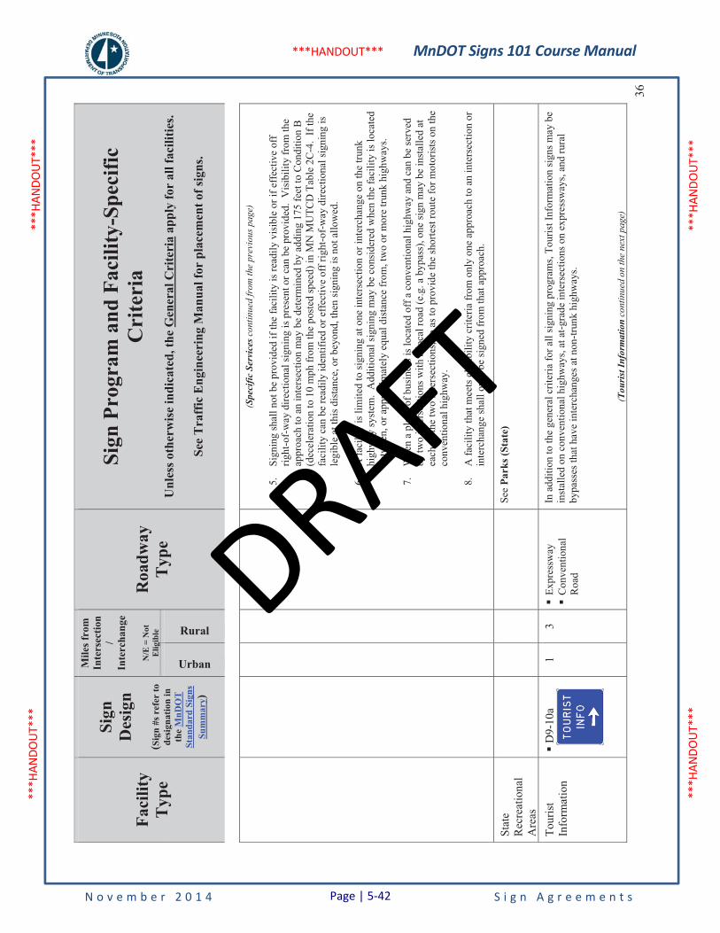
MnDOT Signs 101 Course Manual
N o v e m b e r 2 0 1 4 S i g n A g r e e m e n t s
***H
ANDO
UT**
* **
*HAN
DOUT
***
***H
ANDO
UT**
* **
*HAN
DOUT
***
***HANDOUT***
Faci
lity
Typ
e
Sign
Des
ign
(Sig
n #s
ref
er to
de
sign
atio
n in
th
eM
nDO
T
Stan
dard
Sig
ns
Sum
mar
y)
Mile
s fro
m
Inte
rsec
tion
/In
terc
hang
e
N/E
= N
ot
Elig
ible
Roa
dway
Typ
e
Sign
Pro
gram
and
Fac
ility
-Spe
cific
C
rite
ria
Unl
ess o
ther
wis
e in
dica
ted,
the
Gen
eral
Cri
teri
a ap
ply
for
all f
acili
ties.
See
Tra
ffic
Eng
inee
ring
Man
ual f
or p
lace
men
t of s
igns
.
Urban
Rural36
(Spe
cific
Ser
vice
s con
tinue
d fr
om th
e pr
evio
us p
age)
5.Si
gnin
g sh
all n
ot b
e pr
ovid
ed if
the
faci
lity
is re
adily
vis
ible
or i
f eff
ectiv
e of
f rig
ht-o
f-w
ay d
irect
iona
l sig
ning
is p
rese
nt o
r can
be
prov
ided
. V
isib
ility
from
the
appr
oach
to a
n in
ters
ectio
n m
ay b
e de
term
ined
by
addi
ng 1
75 fe
et to
Con
ditio
n B
(d
ecel
erat
ion
to 1
0 m
ph fr
om th
e po
sted
spee
d) in
MN
MU
TCD
Tab
le 2
C-4
. If
the
faci
lity
can
be re
adily
iden
tifie
d or
eff
ectiv
e of
f rig
ht-o
f-w
ay d
irect
iona
l sig
ning
is
legi
ble
at th
is d
ista
nce,
or b
eyon
d, th
en si
gnin
g is
not
allo
wed
.
6.A
faci
lity
is li
mite
d to
sign
ing
at o
ne in
ters
ectio
n or
inte
rcha
nge
on th
e tru
nk
high
way
syst
em.
Add
ition
al si
gnin
g m
ay b
e co
nsid
ered
whe
n th
e fa
cilit
y is
loca
ted
betw
een,
or a
ppro
xim
atel
y eq
ual d
ista
nce
from
, tw
o or
mor
e tru
nk h
ighw
ays.
7.W
hen
a pl
ace
of b
usin
ess i
s loc
ated
off
a c
onve
ntio
nal h
ighw
ay a
nd c
an b
e se
rved
by
two
inte
rsec
tions
with
a lo
cal r
oad
(e.g
. a b
ypas
s), o
ne si
gn m
ay b
e in
stal
led
at
each
of t
he tw
o in
ters
ectio
ns, s
o as
to p
rovi
de th
e sh
orte
st ro
ute
for m
otor
ists
on
the
conv
entio
nal h
ighw
ay.
8.A
faci
lity
that
mee
ts e
ligib
ility
crit
eria
from
onl
y on
e ap
proa
ch to
an
inte
rsec
tion
or
inte
rcha
nge
shal
l onl
y be
sign
ed fr
om th
at a
ppro
ach.
Stat
eR
ecre
atio
nal
Are
as
See
Park
s (St
ate)
Tour
ist
Info
rmat
ion
�D
9-10
a1
3 �
Expr
essw
ay�
Con
vent
iona
l R
oad
In a
dditi
on to
the
gene
ral c
riter
ia fo
r all
sign
ing
prog
ram
s, To
uris
t Inf
orm
atio
n si
gns m
ay b
e in
stal
led
on c
onve
ntio
nal h
ighw
ays,
at a
t-gra
de in
ters
ectio
ns o
n ex
pres
sway
s, an
d ru
ral
bypa
sses
that
hav
e in
terc
hang
es a
t non
-trun
k hi
ghw
ays.
(Tou
rist
Info
rmat
ion
cont
inue
d on
the
next
pag
e)
Page | 5-42
DRAFT

MnDOT Signs 101 Course Manual
N o v e m b e r 2 0 1 4 S i g n A g r e e m e n t s
***H
ANDO
UT**
* **
*HAN
DOUT
***
***H
ANDO
UT**
* **
*HAN
DOUT
***
***HANDOUT***
37
(Tou
rist
Info
rmat
ion
cont
inue
d fr
om th
e pr
evio
us p
age)
In o
rder
to b
e co
nsid
ered
for s
igni
ng, a
ll of
the
follo
win
g cr
iteria
mus
t be
met
: 1.
Onl
y O
ffic
e of
Tou
rism
site
s may
be
sign
ed.
2.R
eque
sts s
hall
only
be
acce
pted
from
a c
omm
unity
gro
up (e
.g. c
ham
ber o
f co
mm
erce
), bu
sine
ss a
ssoc
iatio
n, o
r gov
ernm
enta
l uni
t. 3.
Onl
y on
e si
te in
a c
ity o
r are
a m
ay b
e ap
prov
ed fo
r sig
ning
. 4.
A si
gn sh
all b
e in
pla
ce o
n th
e ou
tsid
e of
the
faci
lity,
cle
arly
stat
ing
the
oper
ator
an
d m
eans
of c
onta
ct.
5.If
the
faci
lity
is o
pera
ted
seas
onal
ly, t
he si
gns s
hall
be re
mov
ed, c
over
ed o
r the
cl
osur
e cl
early
indi
cate
d.
Tow
nshi
p H
all
�G
reen
Cus
tom
D
esig
n
2 2
�Ex
pres
sway
�C
onve
ntio
nal
Roa
d
In a
dditi
on to
the
Gen
eral
Crit
eria
in th
e M
inor
Tra
ffic
Gen
erat
or S
igni
ng p
rogr
am, t
he
follo
win
g cr
iteria
app
ly:
The
faci
lity:
1.
Shal
l hol
d m
onth
ly m
eetin
gs th
at a
re o
pen
to th
e pu
blic
. Tow
nshi
p ha
lls a
re n
ot
requ
ired
to b
e op
en e
ight
hou
rs p
er d
ay, f
ive
days
per
wee
k.2.
Shal
l be
prim
arily
inte
nded
for u
se a
s a to
wn
hall.
3.
Shou
ld p
rovi
de a
dequ
ate
on-s
ite p
arki
ng o
r par
king
in th
e im
med
iate
are
a.
4.Sh
all p
ost c
onta
ct in
form
atio
n th
at is
vis
ible
from
the
exte
rior o
f the
bui
ldin
g.
Sign
ing
met
hod:
1.
All
cost
s ass
ocia
ted
with
Tow
nshi
p H
all s
igni
ng sh
all b
e pa
id b
y th
e to
wns
hip.
2.
The
sign
shal
l hav
e th
e le
gend
“TO
WN
HA
LL”
with
dire
ctio
nal a
rrow
. 3.
If a
tow
nshi
p ha
ll is
in c
lose
pro
xim
ity to
ano
ther
tow
nshi
p ha
ll, a
nd th
e di
stric
t tra
ffic
eng
inee
r det
erm
ines
that
usi
ng th
e st
anda
rd si
gn c
ould
be
conf
usin
g fo
r m
otor
ists
, the
nam
e of
the
tow
nshi
p m
ay b
e in
clud
ed o
n th
e si
gn (s
ign
pane
l det
ail
atta
ched
).
Trai
l Acc
ess
�B
row
nC
usto
m
Des
ign
10
10
�Fr
eew
ay*
�Ex
pres
sway
�C
onve
ntio
nal
Roa
d
*- S
ee c
riter
ia #
1
Sign
ing
may
be
perm
itted
for a
cces
s poi
nts t
o m
ajor
recr
eatio
nal t
rails
hav
ing
impr
oved
and
w
ell m
aint
aine
d su
rfac
es fo
r hik
ing,
bik
ing,
etc
. All
trails
shal
l pro
vide
com
plet
e m
arki
ng o
r tra
il m
aps f
or u
ser g
uida
nce.
In a
dditi
on to
the
gene
ral c
riter
ia fo
r all
sign
ing
prog
ram
s, th
e fo
llow
ing
crite
ria a
pply
: 1.
Trai
l Acc
ess s
igns
may
be
inst
alle
d on
all
trunk
hig
hway
s, ex
cept
in th
e M
etro
D
istr
ict w
here
sign
s sha
ll no
t be
inst
alle
d on
free
way
s.2.
Park
ing
shal
l be
prov
ided
at t
he si
te o
r with
in th
e im
med
iate
vic
inity
. The
par
king
fa
cilit
y sh
all b
e su
rfac
ed a
nd m
aint
aine
d ye
ar-r
ound
. Par
king
shal
l be
prov
ided
for
at le
ast 4
0 ve
hicl
es a
t fre
eway
sign
ed si
tes 2
0+ v
ehic
les a
t oth
er si
tes.
Smal
ler l
ots
are
acce
ptab
le a
t rem
ote
area
s with
the
appr
oval
of t
he d
istri
ct tr
affic
eng
inee
r. 3.
The
min
imum
trai
l len
gth
shal
l be
five
mile
s. 4.
All
requ
ests
for s
igni
ng to
DN
R p
rovi
ded
publ
ic tr
ails
shal
l be
appr
oved
by
the
DN
R a
nd M
nDO
T. S
igni
ng fo
r oth
er tr
ails
is a
t the
dis
cret
ion
of M
nDO
T.
(Tra
il A
cces
s con
tinue
d on
the
next
pag
e)
Page | 5-43
DRAFT
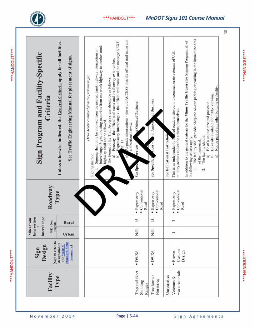
MnDOT Signs 101 Course Manual
N o v e m b e r 2 0 1 4 S i g n A g r e e m e n t s
***H
ANDO
UT**
* **
*HAN
DOUT
***
***H
ANDO
UT**
* **
*HAN
DOUT
***
***HANDOUT***
Faci
lity
Typ
e
Sign
Des
ign
(Sig
n #s
ref
er to
de
sign
atio
n in
th
eM
nDO
T
Stan
dard
Sig
ns
Sum
mar
y)
Mile
s fro
m
Inte
rsec
tion
/In
terc
hang
e
N/E
= N
ot
Elig
ible
Roa
dway
Typ
e
Sign
Pro
gram
and
Fac
ility
-Spe
cific
C
rite
ria
Unl
ess o
ther
wis
e in
dica
ted,
the
Gen
eral
Cri
teri
a ap
ply
for
all f
acili
ties.
See
Tra
ffic
Eng
inee
ring
Man
ual f
or p
lace
men
t of s
igns
.
Urban
Rural38
(Tra
il A
cces
s con
tinue
d fr
om th
e pr
evio
us p
age)
Si
gnin
g m
etho
d:
1.Si
gnin
g sh
all o
nly
be a
llow
ed fr
om th
e ne
ares
t tru
nk h
ighw
ay in
ters
ectio
n or
in
terc
hang
e. S
igns
dire
ctin
g m
otor
ists
from
one
trun
k hi
ghw
ay to
ano
ther
trun
k hi
ghw
ay sh
all n
ot b
e al
low
ed.
2.Th
e fo
rmat
of t
he T
rail
Acc
ess s
igns
shou
ld b
e as
follo
ws:
a)
Free
way
- th
e of
ficia
l tra
il na
me
and
the
free
way
exi
t num
ber.
b)Ex
pres
sway
inte
rcha
nges
- th
e of
ficia
l tra
il na
me
and
the
mes
sage
NEX
T R
IGH
T.c)
At-g
rade
inte
rsec
tions
- th
e w
ord
AC
CES
S pl
us th
e of
ficia
l tra
il na
me
and
a di
rect
iona
l arr
ow.
Trap
and
skee
t Sh
ootin
g R
ange
s
�D
9-X
6 N
/E
15
�Ex
pres
sway
�C
onve
ntio
nal
Roa
d
See
Spec
ific
Serv
ices
– T
ouris
t-Orie
nted
Bus
ines
s
Tree
farm
s /
Nur
serie
s �
D9-
X6
N/E
15
�
Expr
essw
ay�
Con
vent
iona
l R
oad
See
Spec
ific
Serv
ices
– R
ural
Agr
icul
tura
l Bus
ines
s
Uni
vers
ities
Se
eE
duca
tiona
l Ins
titut
ions
.
Vet
eran
s &
war
mem
oria
ls
�B
row
nC
usto
m
Des
ign
1 3
�Ex
pres
sway
�C
onve
ntio
nal
Roa
d
This
is a
n in
depe
nden
tly lo
cate
d ou
tdoo
r site
bui
lt to
com
mem
orat
e ve
tera
ns o
f U.S
. m
ilita
ry a
ctio
ns a
nd/o
r the
act
ions
them
selv
es.
In a
dditi
on to
the
gene
ral c
riter
ia fo
r the
Min
or T
raff
ic G
ener
ator
Sig
ning
Pro
gram
, all
of
the
follo
win
g cr
iteria
app
ly:
1.Th
e fa
cilit
y sh
all p
rovi
de a
dequ
ate
on-s
ite p
arki
ng o
r par
king
in th
e im
med
iate
are
a of
the
mem
oria
l. 2.
The
faci
lity
shou
ld:
a)B
e of
a u
niqu
e si
ze a
nd p
rese
nce.
b)
Be
easi
ly a
vaila
ble
for p
ublic
vie
win
g.
c)N
ot b
e pa
rt of
any
oth
er b
uild
ing
or fa
cilit
y.
Page | 5-44
DRAFT
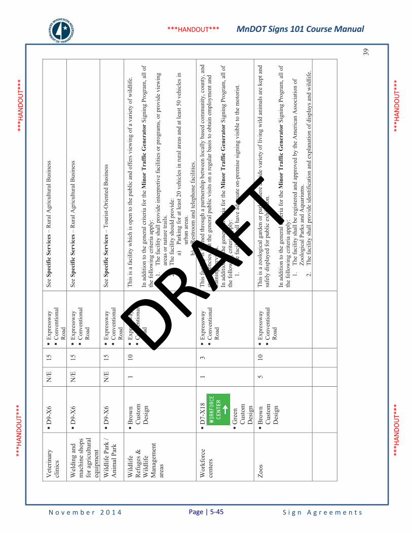
MnDOT Signs 101 Course Manual
N o v e m b e r 2 0 1 4 S i g n A g r e e m e n t s
***H
ANDO
UT**
* **
*HAN
DOUT
***
***H
ANDO
UT**
* **
*HAN
DOUT
***
***HANDOUT***
39
Vet
erin
ary
clin
ics
�D
9-X
6 N
/E
15
�Ex
pres
sway
�C
onve
ntio
nal
Roa
d
See
Spec
ific
Serv
ices
– R
ural
Agr
icul
tura
l Bus
ines
s
Wel
ding
and
m
achi
ne sh
ops
for a
gric
ultu
ral
equi
pmen
t
�D
9-X
6 N
/E
15
�Ex
pres
sway
�C
onve
ntio
nal
Roa
d
See
Spec
ific
Serv
ices
– R
ural
Agr
icul
tura
l Bus
ines
s
Wild
life
Park
/ A
nim
al P
ark
�D
9-X
6 N
/E
15
�Ex
pres
sway
�C
onve
ntio
nal
Roa
d
See
Spec
ific
Serv
ices
– T
ouris
t-Orie
nted
Bus
ines
s
Wild
life
Ref
uges
&
Wild
life
Man
agem
ent
area
s
�B
row
nC
usto
m
Des
ign
1 10
�
Expr
essw
ay�
Con
vent
iona
l R
oad
This
is a
faci
lity
whi
ch is
ope
n to
the
publ
ic a
nd o
ffer
s vie
win
g of
a v
arie
ty o
f wild
life.
In a
dditi
on to
the
gene
ral c
riter
ia fo
r the
Min
or T
raff
ic G
ener
ator
Sig
ning
Pro
gram
, all
of
the
follo
win
g cr
iteria
app
ly:
1.
The
faci
lity
shal
l pro
vide
inte
rpre
tive
faci
litie
s or p
rogr
ams,
or p
rovi
de v
iew
ing
area
s or n
atur
e tra
ils.
2.Th
e fa
cilit
y sh
ould
pro
vide
: a)
Park
ing
for a
t lea
st 2
0 ve
hicl
es in
rura
l are
as a
nd a
t lea
st 5
0 ve
hicl
es in
ur
ban
area
s. b)
Res
troom
and
tele
phon
e fa
cilit
ies.
Wor
kfor
cece
nter
s �
D7-
X18
�G
reen
Cus
tom
D
esig
n
1 3
�Ex
pres
sway
�C
onve
ntio
nal
Roa
d
This
faci
lity
is fo
rmed
thro
ugh
a pa
rtner
ship
bet
wee
n lo
cally
bas
ed c
omm
unity
, cou
nty,
and
st
ate
agen
cies
that
the
gene
ral p
ublic
vis
its o
n a
regu
lar b
asis
to o
btai
n em
ploy
men
t and
tra
inin
g se
rvic
es.
In a
dditi
on to
the
gene
ral c
riter
ia fo
r the
Min
or T
raff
ic G
ener
ator
Sig
ning
Pro
gram
, all
of
the
follo
win
g cr
iteria
app
ly:
1.Th
e fa
cilit
y sh
all h
ave
adeq
uate
on-
prem
ise
sign
ing
visi
ble
to th
e m
otor
ist.
Zoos
�B
row
nC
usto
m
Des
ign
5 10
�
Expr
essw
ay�
Con
vent
iona
l R
oad
This
is a
zoo
logi
cal g
arde
n or
par
k w
here
a w
ide
varie
ty o
f liv
ing
wild
ani
mal
s are
kep
t and
sa
fely
dis
play
ed fo
r pub
lic e
xhib
ition
.
In a
dditi
on to
the
gene
ral c
riter
ia fo
r the
Min
or T
raff
ic G
ener
ator
Sig
ning
Pro
gram
, all
of
the
follo
win
g cr
iteria
app
ly:
1.
The
faci
lity
shal
l be
regi
ster
ed a
nd a
ppro
ved
by th
e A
mer
ican
Ass
ocia
tion
of
Zool
ogic
al P
arks
and
Aqu
ariu
ms.
2.Th
e fa
cilit
y sh
all p
rovi
de id
entif
icat
ion
and
expl
anat
ion
of d
ispl
ays a
nd w
ildlif
e.
Page | 5-45
DRAFT
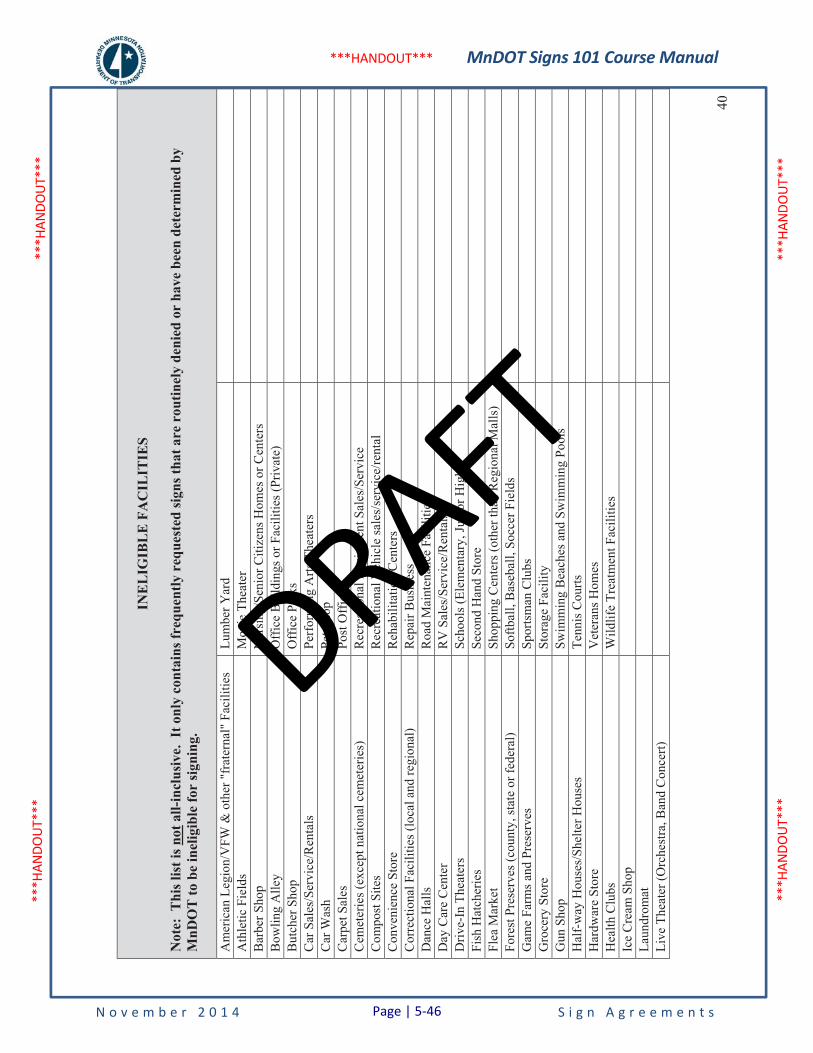
MnDOT Signs 101 Course Manual
N o v e m b e r 2 0 1 4 S i g n A g r e e m e n t s
***H
ANDO
UT**
* **
*HAN
DOUT
***
***H
ANDO
UT**
* **
*HAN
DOUT
***
***HANDOUT***
40
INE
LIG
IBL
E F
AC
ILIT
IES
Not
e: T
his l
ist i
s not
all-
incl
usiv
e. I
t onl
y co
ntai
ns fr
eque
ntly
req
uest
ed si
gns t
hat a
re r
outin
ely
deni
ed o
r ha
ve b
een
dete
rmin
ed b
y M
nDO
T to
be
inel
igib
le fo
r si
gnin
g.
Am
eric
an L
egio
n/V
FW &
oth
er "
frat
erna
l" F
acili
ties
Lum
ber Y
ard
Ath
letic
Fie
lds
Mov
ie T
heat
er
Bar
ber S
hop
Nur
sing
/Sen
ior C
itize
ns H
omes
or C
ente
rs
B
owlin
g A
lley
Off
ice
Bui
ldin
gs o
r Fac
ilitie
s (Pr
ivat
e)
But
cher
Sho
p O
ffic
e Pa
rks
Car
Sal
es/S
ervi
ce/R
enta
ls
Perf
orm
ing
Arts
The
ater
s C
ar W
ash
Pet S
hop
Car
pet S
ales
Po
st O
ffic
es
Cem
eter
ies (
exce
pt n
atio
nal c
emet
erie
s)
Rec
reat
iona
l Equ
ipm
ent S
ales
/Ser
vice
Com
post
Site
s R
ecre
atio
nal V
ehic
le sa
les/
serv
ice/
rent
al
C
onve
nien
ce S
tore
R
ehab
ilita
tion
Cen
ters
C
orre
ctio
nal F
acili
ties (
loca
l and
regi
onal
) R
epai
r Bus
ines
s D
ance
Hal
ls
Roa
d M
aint
enan
ce F
acili
ties
Day
Car
e C
ente
r R
V S
ales
/Ser
vice
/Ren
tals
D
rive-
In T
heat
ers
Scho
ols (
Elem
enta
ry, J
unio
r Hig
h)
Fish
Hat
cher
ies
Seco
nd H
and
Stor
e Fl
ea M
arke
t Sh
oppi
ng C
ente
rs (o
ther
than
Reg
iona
l Mal
ls)
Fo
rest
Pre
serv
es (c
ount
y, st
ate
or fe
dera
l) So
ftbal
l, B
aseb
all,
Socc
er F
ield
s G
ame
Farm
s and
Pre
serv
es
Spor
tsm
an C
lubs
G
roce
ry S
tore
St
orag
e Fa
cilit
y G
un S
hop
Swim
min
g B
each
es a
nd S
wim
min
g Po
ols
H
alf-
way
Hou
ses/
Shel
ter H
ouse
s Te
nnis
Cou
rts
Har
dwar
e St
ore
Vet
eran
s Hom
es
Hea
lth C
lubs
W
ildlif
e Tr
eatm
ent F
acili
ties
Ice
Cre
am S
hop
Laun
drom
at
Live
The
ater
(Orc
hest
ra, B
and
Con
cert)
Page | 5-46
DRAFT

MnDOT Signs 101 Course Manual
N o v e m b e r 2 0 1 4 P a g e | 5-47 S i g n A g r e e m e n t s
5.3 Requester Pay Memo
The following is a handout of Technical Memorandum No. 12-02-T-01 dates January 23, 2012.
Updates to Tech Memos can be found at http://techmemos.dot.state.mn.us/.
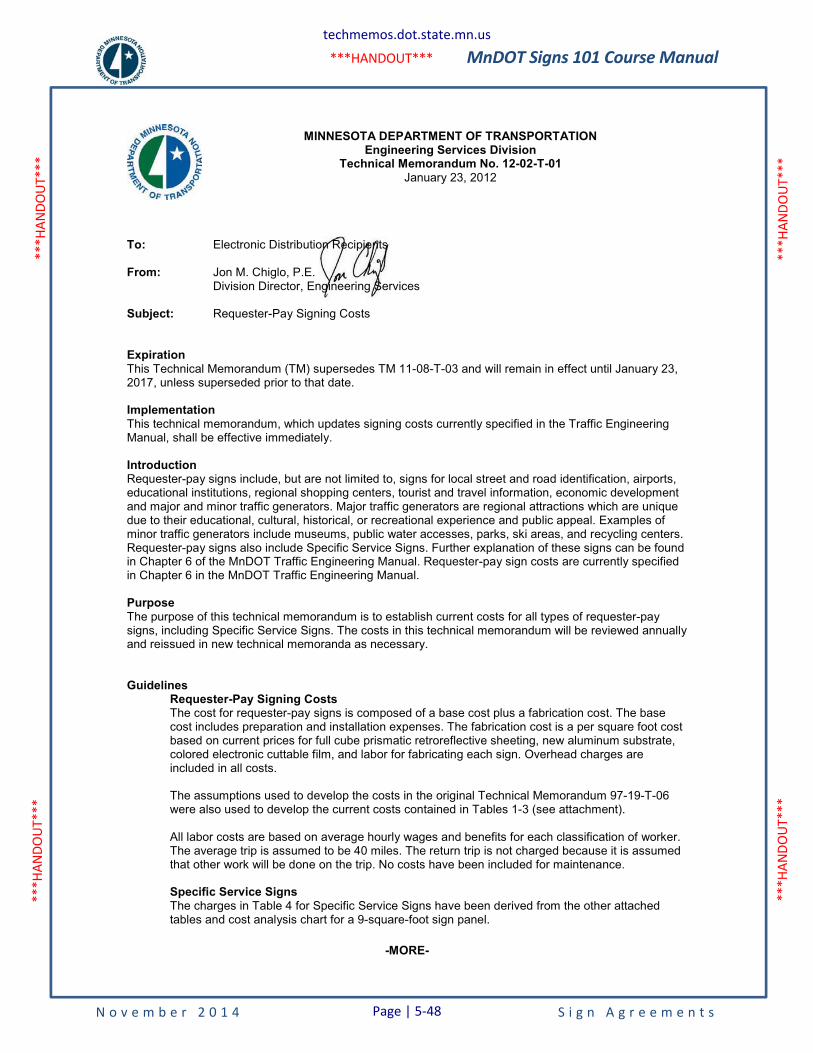
MnDOT Signs 101 Course Manual
N o v e m b e r 2 0 1 4 S i g n A g r e e m e n t s
***H
ANDO
UT**
* **
*HAN
DOUT
***
***H
ANDO
UT**
* **
*HAN
DOUT
***
***HANDOUT***
-MORE-
MINNESOTA DEPARTMENT OF TRANSPORTATION
Engineering Services Division Technical Memorandum No. 12-02-T-01
January 23, 2012
To: Electronic Distribution Recipients From: Jon M. Chiglo, P.E. Division Director, Engineering Services Subject: Requester-Pay Signing Costs Expiration This Technical Memorandum (TM) supersedes TM 11-08-T-03 and will remain in effect until January 23, 2017, unless superseded prior to that date. Implementation This technical memorandum, which updates signing costs currently specified in the Traffic Engineering Manual, shall be effective immediately. Introduction Requester-pay signs include, but are not limited to, signs for local street and road identification, airports, educational institutions, regional shopping centers, tourist and travel information, economic development and major and minor traffic generators. Major traffic generators are regional attractions which are unique due to their educational, cultural, historical, or recreational experience and public appeal. Examples of minor traffic generators include museums, public water accesses, parks, ski areas, and recycling centers. Requester-pay signs also include Specific Service Signs. Further explanation of these signs can be found in Chapter 6 of the MnDOT Traffic Engineering Manual. Requester-pay sign costs are currently specified in Chapter 6 in the MnDOT Traffic Engineering Manual. Purpose The purpose of this technical memorandum is to establish current costs for all types of requester-pay signs, including Specific Service Signs. The costs in this technical memorandum will be reviewed annually and reissued in new technical memoranda as necessary. Guidelines
Requester-Pay Signing Costs The cost for requester-pay signs is composed of a base cost plus a fabrication cost. The base cost includes preparation and installation expenses. The fabrication cost is a per square foot cost based on current prices for full cube prismatic retroreflective sheeting, new aluminum substrate, colored electronic cuttable film, and labor for fabricating each sign. Overhead charges are included in all costs. The assumptions used to develop the costs in the original Technical Memorandum 97-19-T-06 were also used to develop the current costs contained in Tables 1-3 (see attachment). All labor costs are based on average hourly wages and benefits for each classification of worker. The average trip is assumed to be 40 miles. The return trip is not charged because it is assumed that other work will be done on the trip. No costs have been included for maintenance. Specific Service Signs The charges in Table 4 for Specific Service Signs have been derived from the other attached tables and cost analysis chart for a 9-square-foot sign panel.
techmemos.dot.state.mn.us
Page | 5-48

MnDOT Signs 101 Course Manual
N o v e m b e r 2 0 1 4 S i g n A g r e e m e n t s
***H
ANDO
UT**
* **
*HAN
DOUT
***
***H
ANDO
UT**
* **
*HAN
DOUT
***
***HANDOUT***
Technical Memorandum No. 12-02-T-01 Requester-Pay Signing Costs January 23, 2012 Page 2
-END-
Questions For information on the technical contents of this memorandum, please contact Heather Lott, State Signing Engineer at (651) 234-7371. Any questions regarding publication of this Technical Memorandum should be referred to the Design Standards Unit, [email protected]. A link to all active and historical Technical Memoranda can be found at http://techmemos.dot.state.mn.us/techmemo.aspx. To add, remove, or change your name on the Technical Memoranda mailing list, please visit the web page http://techmemos.dot.state.mn.us/subscribe.aspx Attachments:
A. Tables (1 - 4) B. Cost analysis chart
techmemos.dot.state.mn.us
Page | 5-49
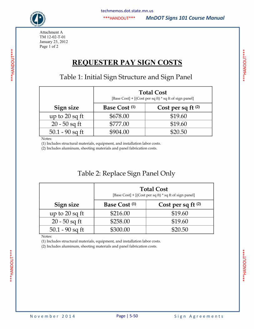
MnDOT Signs 101 Course Manual
N o v e m b e r 2 0 1 4 S i g n A g r e e m e n t s
***H
ANDO
UT**
* **
*HAN
DOUT
***
***H
ANDO
UT**
* **
*HAN
DOUT
***
***HANDOUT***
Attachment ATM 12-02-T-01 January 23, 2012 Page 1 of 2
REQUESTER PAY SIGN COSTS
Table 1: Initial Sign Structure and Sign Panel
Total Cost [Base Cost] + [(Cost per sq ft) * sq ft of sign panel]
Sign size Base Cost (1) Cost per sq ft (2) up to 20 sq ft $678.00 $19.60 20 - 50 sq ft $777.00 $19.60
50.1 - 90 sq ft $904.00 $20.50 Notes: (1) Includes structural materials, equipment, and installation labor costs. (2) Includes aluminum, sheeting materials and panel fabrication costs.
Table 2: Replace Sign Panel Only
Total Cost [Base Cost] + [(Cost per sq ft) * sq ft of sign panel]
Sign size Base Cost (1) Cost per sq ft (2) up to 20 sq ft $216.00 $19.60 20 - 50 sq ft $258.00 $19.60
50.1 - 90 sq ft $300.00 $20.50 Notes: (1) Includes structural materials, equipment, and installation labor costs. (2) Includes aluminum, sheeting materials and panel fabrication costs.
techmemos.dot.state.mn.us
Page | 5-50
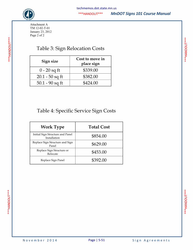
MnDOT Signs 101 Course Manual
N o v e m b e r 2 0 1 4 S i g n A g r e e m e n t s
***H
ANDO
UT**
* **
*HAN
DOUT
***
***H
ANDO
UT**
* **
*HAN
DOUT
***
***HANDOUT***
Attachment ATM 12-02-T-01 January 23, 2012 Page 2 of 2
Table 3: Sign Relocation Costs
Sign size Cost to move in place sign
0 - 20 sq ft $339.00 20.1 - 50 sq ft $382.00 50.1 - 90 sq ft $424.00
Table 4: Specific Service Sign Costs
Work Type Total Cost Initial Sign Structure and Panel
Installation $854.00 Replace Sign Structure and Sign
Panel $629.00 Replace Sign Structure or
Relocate $453.00 Replace Sign Panel $392.00
techmemos.dot.state.mn.us
Page | 5-51
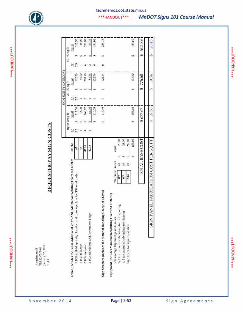
MnDOT Signs 101 Course Manual
N o v e m b e r 2 0 1 4 S i g n A g r e e m e n t s
***H
ANDO
UT**
* **
*HAN
DOUT
***
***H
ANDO
UT**
* **
*HAN
DOUT
***
***HANDOUT***
Atta
chm
ent B
TM 1
2-02
-T-0
1Ja
nuar
y ��
, 201
21
of 1
Labo
r (in
clud
es th
e La
bor A
dditi
ve o
f 27.
2% A
ND
Mai
nten
ance
/Bill
ing
Ove
rhea
d of
21.
5%Ra
te/h
rhr
equa
lhr
equa
lhr
equa
l1
TGS
to fi
eld
spot
sign
loca
tion
and
draw
up
plan
s for
TSS
wor
k or
der
452.
511
2.50
$
2.5
112.
50$
2.5
112.
50$
1 TG
S to
loca
te45
145
.00
$
1
45.0
0$
145
.00
$
2 TG
's to
inst
all
42.1
84
168.
72$
5
210.
90$
625
3.08
$
2
TG's
to re
loca
te a
nd/o
r rem
ove
1 si
gn42
.18
284
.36
$
2
84.3
6$
284
.36
$
410.
58$
0
452.
76$
049
4.94
$
Sign
Str
uctu
re (i
nclu
des
the
Mat
eria
l Han
dlin
g C
harg
e of
12.
59%
)11
3.49
$
017
0.24
$
0
255.
35$
Equi
pmen
t (in
clud
es M
aint
enen
ace/
Billi
ng O
verh
ead
of 2
1.5%
)U
se a
vera
ge tr
ip m
ileag
e of
40
mile
sra
te /
mile
mile
seq
ual
1/2
ton
exte
nded
cab
pic
kup
for f
ield
spot
ting
0.7
4028
.00
$
1/2
ton
exte
nded
cab
pic
kup
for l
ocat
ing
0.7
4028
.00
$
Sign
Tru
ck fo
r sig
n in
stal
latio
n2.
4440
97.6
0$
153.
60$
153.
60$
15
3.60
$
15
3.60
$
TOTA
L BA
SE C
OST
677.
67$
77
6.60
$
903.
89$
SIG
N P
AN
EL F
ABR
ICA
TIO
N C
OST
PER
SQ
. FT.
19.5
6$
19
.56
$
20
.45
$
REQ
UES
TER�P
AY
SIG
N C
OST
S
SIG
N S
IZE
BY C
ATE
GO
RYup
to 2
0 sq
ft20
- 50
sq ft
50 -
90 sq
ft
techmemos.dot.state.mn.us
Page | 5-52
MnDOT Signs 101 Course Manual
N o v e m b e r 2 0 1 4 P a g e | 5-53 S i g n A g r e e m e n t s
5.4 External Sign Variance Committee
MnDOT retains the authority to deny requests for signing where acceptable standards cannot be met, including locations where other supplemental guide signs are already in place. Requests denied based on Minnesota statutes or engineering standards (i.e. insufficient space and design standards) may not be appealed. At the discretion of the District Traffic Engineer, signing requests denied based on MnDOT policy may be appealed to the External Sign Variance Committee (ESVC).
The ESVC is composed of persons outside of MnDOT who meet periodically to consider various requests for signing. The group serves as a variance committee making recommendations to the Commissioner's Office on signing requests that have been denied by the district office. They review requests to see if the denials can be substantiated to have negative effects on the requester and/or motorists. The ESVC also reviews policies and criteria on informational signing matters.
The Chairperson is a MnDOT employee who serves in a non-voting capacity to organize and schedule all functions of the ESVC. This individual serves as secretary and records decisions on sign variance requests. The chair represents the ESVC, not MnDOT, on all matters pertaining to the ESVC.
The procedures for this Committee are as follows:
1. A requester who has been denied signing by the district office and is interested in appealing the decision must submit a written request for a hearing by the ESVC. The requester should contact the chair of the ESVC directly, and will then be advised of procedures and meeting date. The ESVC hears the requester's appeal and MnDOT's presentation separately. The recommendations of the ESVC will be based on pertinent factors, and will always consider the degree of financial hardship to the requester and safety implications.
2. For each signing request, the recommendations made by the ESVC and the State Traffic Engineer are forwarded to the Commissioner's Office for review. Presentations on each request are made to a special committee (Internal Sign Variance Committee) appointed by the Commissioner for final concurrence or denial. The requester and the district involved will be notified by the chair of the ESVC of the decision made by the Commissioner.
3. If the ESVC and the Commissioner approve the variance, the letter from the ESVC will notify the requester and the District Traffic Engineer with additional instructions. The requester will then work with the MnDOT District responsible for installing the sign to complete the process. All costs pertaining to signing will be the responsibility of the requester.
4. If the ESVC and the Commissioner deny the variance, the requestor will be unable to reapply unless there is a significant change in the request.
5. If the requestor is unable to attend the appointed ESVC meeting, they are required to notify the ESVC Chairperson at least 48 hours prior to the meeting date. Nonattendance without prior notification will result in an automatic denial for the facility. The requestor cannot present to the ESVC again unless there is a significant change in their request.

MnDOT Signs 101 Course Manual
N o v e m b e r 2 0 1 4 P a g e | 5-54 S i g n A g r e e m e n t s
This page is intentionally left blank.
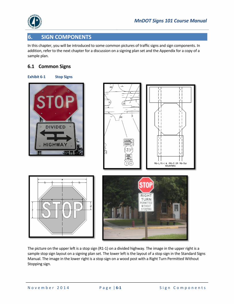
MnDOT Signs 101 Course Manual
N o v e m b e r 2 0 1 4 P a g e | 6-1 S i g n C o m p o n e n t s
6. SIGN COMPONENTS
In this chapter, you will be introduced to some common pictures of traffic signs and sign components. In addition, refer to the next chapter for a discussion on a signing plan set and the Appendix for a copy of a sample plan.
6.1 Common Signs
Exhibit 6-1 Stop Signs
The picture on the upper left is a stop sign (R1-1) on a divided highway. The image in the upper right is a sample stop sign layout on a signing plan set. The lower left is the layout of a stop sign in the Standard Signs Manual. The image in the lower right is a stop sign on a wood post with a Right Turn Permitted Without Stopping sign.
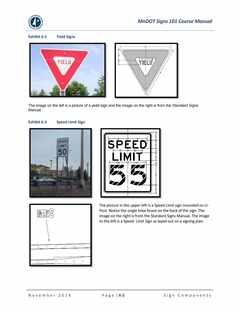
MnDOT Signs 101 Course Manual
N o v e m b e r 2 0 1 4 P a g e | 6-2 S i g n C o m p o n e n t s
Exhibit 6-2 Yield Signs
The image on the left is a picture of a yeild sign and the image on the right is from the Standard Signs Manual.
Exhibit 6-3 Speed Limit Sign
The picture in the upper left is a Speed Limit sign mounted on U-Post. Notice the single knee brace on the back of the sign. The image on the right is from the Standard Signs Manual. The image to the left is a Speed Limit Sign as layed out on a signing plan.
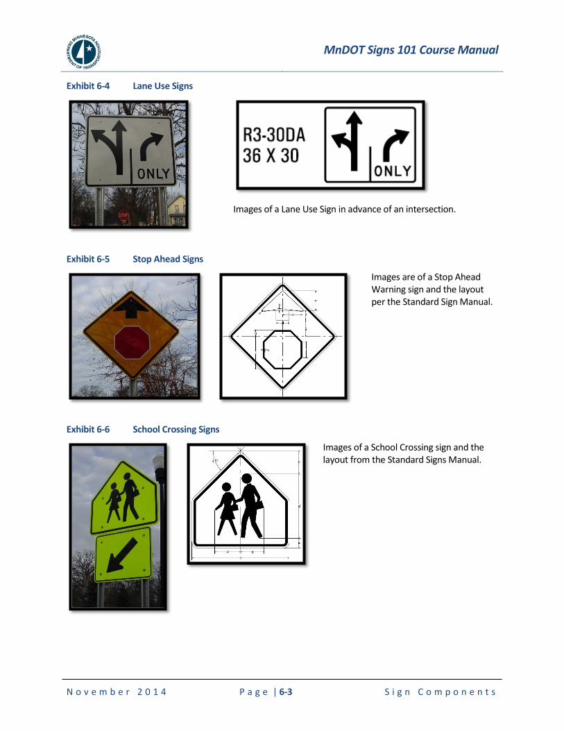
MnDOT Signs 101 Course Manual
N o v e m b e r 2 0 1 4 P a g e | 6-3 S i g n C o m p o n e n t s
Exhibit 6-4 Lane Use Signs
Images of a Lane Use Sign in advance of an intersection.
Exhibit 6-5 Stop Ahead Signs
Images are of a Stop Ahead Warning sign and the layout per the Standard Sign Manual.
Exhibit 6-6 School Crossing Signs
Images of a School Crossing sign and the layout from the Standard Signs Manual.
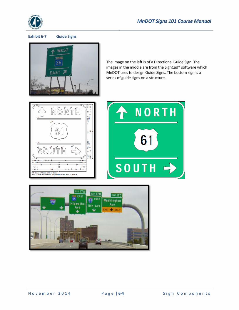
MnDOT Signs 101 Course Manual
N o v e m b e r 2 0 1 4 P a g e | 6-4 S i g n C o m p o n e n t s
Exhibit 6-7 Guide Signs
The image on the left is of a Directional Guide Sign. The images in the middle are from the SignCad® software which MnDOT uses to design Guide Signs. The bottom sign is a series of guide signs on a structure.
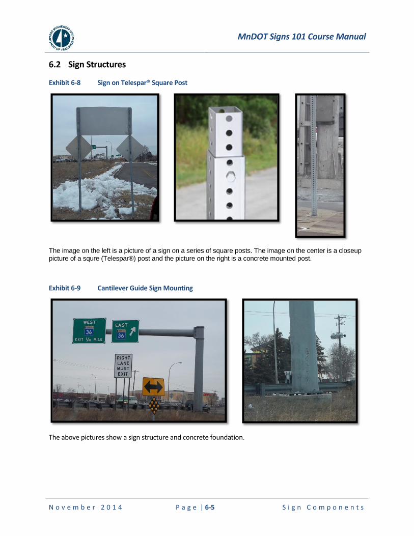
MnDOT Signs 101 Course Manual
N o v e m b e r 2 0 1 4 P a g e | 6-5 S i g n C o m p o n e n t s
6.2 Sign Structures
Exhibit 6-8 Sign on Telespar® Square Post
The image on the left is a picture of a sign on a series of square posts. The image on the center is a closeup picture of a squre (Telespar®) post and the picture on the right is a concrete mounted post.
Exhibit 6-9 Cantilever Guide Sign Mounting
The above pictures show a sign structure and concrete foundation.
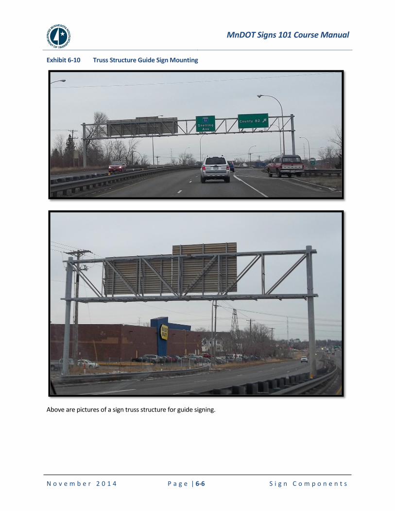
MnDOT Signs 101 Course Manual
N o v e m b e r 2 0 1 4 P a g e | 6-6 S i g n C o m p o n e n t s
Exhibit 6-10 Truss Structure Guide Sign Mounting
Above are pictures of a sign truss structure for guide signing.
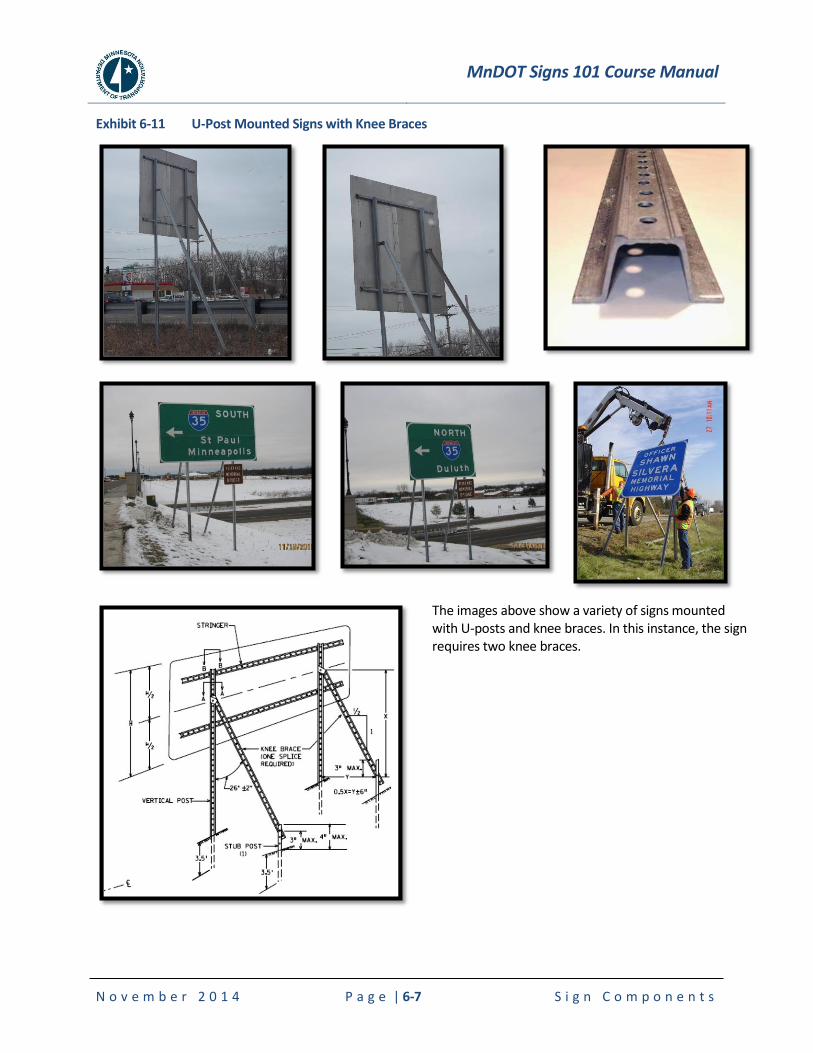
MnDOT Signs 101 Course Manual
N o v e m b e r 2 0 1 4 P a g e | 6-7 S i g n C o m p o n e n t s
Exhibit 6-11 U-Post Mounted Signs with Knee Braces
The images above show a variety of signs mounted with U-posts and knee braces. In this instance, the sign requires two knee braces.
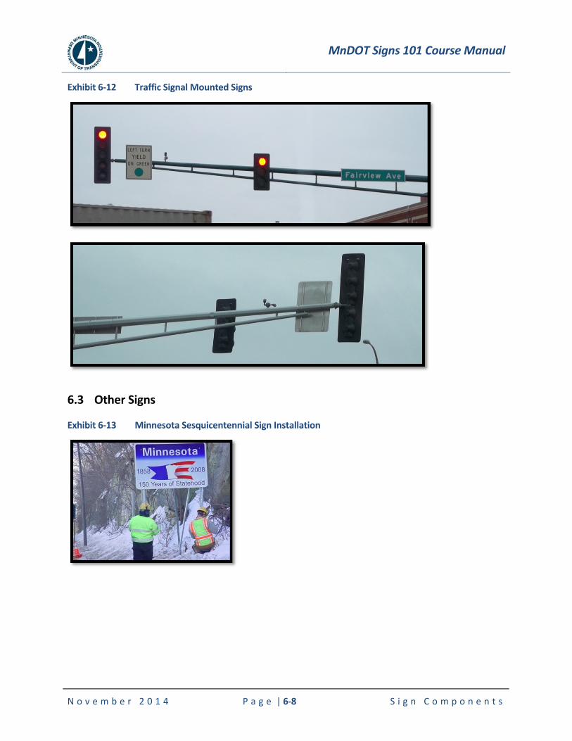
MnDOT Signs 101 Course Manual
N o v e m b e r 2 0 1 4 P a g e | 6-8 S i g n C o m p o n e n t s
Exhibit 6-12 Traffic Signal Mounted Signs
6.3 Other Signs
Exhibit 6-13 Minnesota Sesquicentennial Sign Installation
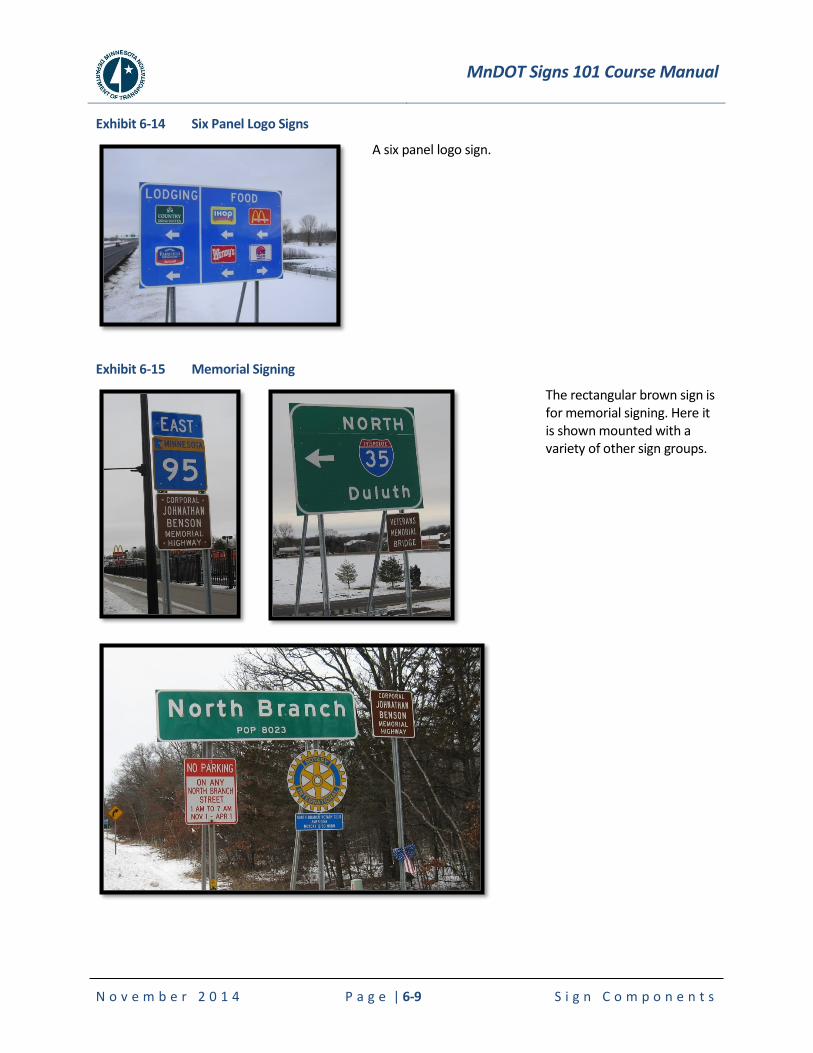
MnDOT Signs 101 Course Manual
N o v e m b e r 2 0 1 4 P a g e | 6-9 S i g n C o m p o n e n t s
Exhibit 6-14 Six Panel Logo Signs
A six panel logo sign.
Exhibit 6-15 Memorial Signing
The rectangular brown sign is for memorial signing. Here it is shown mounted with a variety of other sign groups.
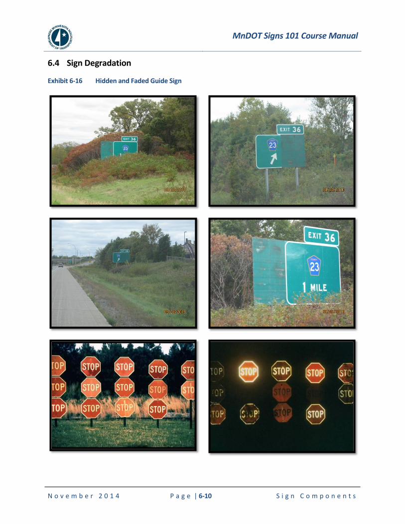
MnDOT Signs 101 Course Manual
N o v e m b e r 2 0 1 4 P a g e | 6-10 S i g n C o m p o n e n t s
6.4 Sign Degradation
Exhibit 6-16 Hidden and Faded Guide Sign
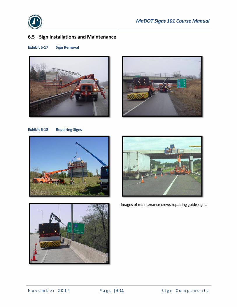
MnDOT Signs 101 Course Manual
N o v e m b e r 2 0 1 4 P a g e | 6-11 S i g n C o m p o n e n t s
6.5 Sign Installations and Maintenance
Exhibit 6-17 Sign Removal
Exhibit 6-18 Repairing Signs
Images of maintenance crews repairing guide signs.
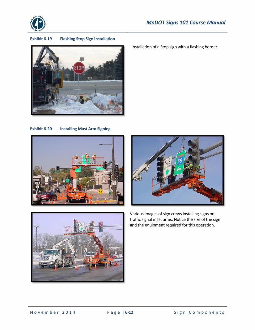
MnDOT Signs 101 Course Manual
N o v e m b e r 2 0 1 4 P a g e | 6-12 S i g n C o m p o n e n t s
Exhibit 6-19 Flashing Stop Sign Installation
Installation of a Stop sign with a flashing border.
Exhibit 6-20 Installing Mast Arm Signing
Various images of sign crews installing signs on traffic signal mast arms. Notice the size of the sign and the equipment required for this operation.
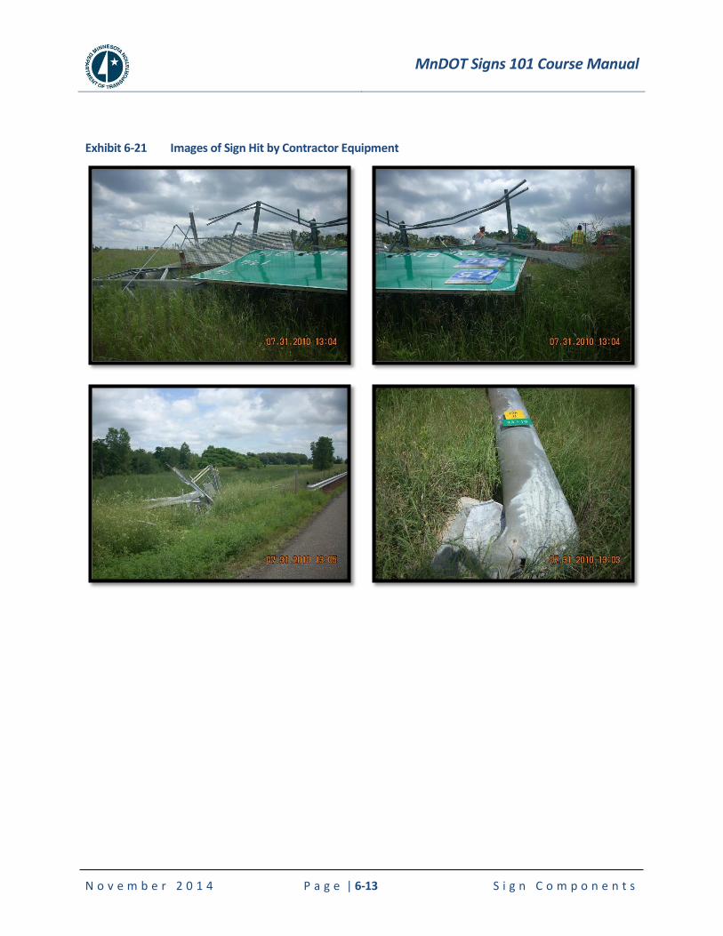
MnDOT Signs 101 Course Manual
N o v e m b e r 2 0 1 4 P a g e | 6-13 S i g n C o m p o n e n t s
Exhibit 6-21 Images of Sign Hit by Contractor Equipment
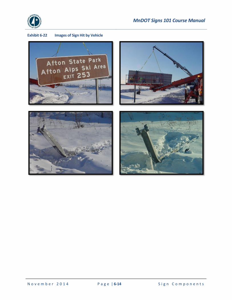
MnDOT Signs 101 Course Manual
N o v e m b e r 2 0 1 4 P a g e | 6-14 S i g n C o m p o n e n t s
Exhibit 6-22 Images of Sign Hit by Vehicle
MnDOT Signs 101 Course Manual
N o v e m b e r 2 0 1 4 P a g e | 7-1 S i g n i n g P l a n S e t s
7. SIGNING PLAN SETS
7.1 Design
Standard detail sheets for signing plans can be found on the OTST website:
www.dot.state.mn.us/trafficeng/
The plan format and sequence of details shall, generally, be as follows:
1. Title sheet.
2. Estimate of quantities.
3. Sign data sheets giving pertinent information for each sign.
4. Sign lighting, delineation, and traffic barrier data sheets.
5. Roadway plan sheets showing signing for mainline and interchanges.
6. Sign panel drawings for all non-standard signs.
7. Standard details.
8. Structural details.
9. Electrical details.
10. Cross sections for Type A and Type OH signs
Final signal plans should be prepared on 11” x 17” plan sheets.
The licensed professional engineer responsible for or under whose supervision the work is performed shall sign the title sheet.
A sample plan set is included in the Appendix in Section 10.2 on page 10-7. Most of the images shown in this Chapter come from the sample plan set. To see them in larger detail, refer to the Appendix handout. In addition, a few of the images come from other sources to illustrate items that may not be included in the sample plan.
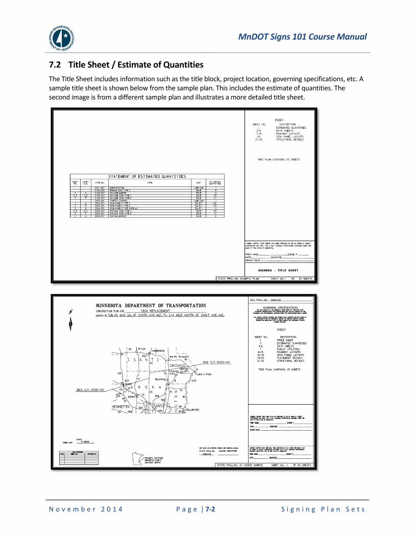
MnDOT Signs 101 Course Manual
N o v e m b e r 2 0 1 4 P a g e | 7-2 S i g n i n g P l a n S e t s
7.2 Title Sheet / Estimate of Quantities
The Title Sheet includes information such as the title block, project location, governing specifications, etc. A sample title sheet is shown below from the sample plan. This includes the estimate of quantities. The second image is from a different sample plan and illustrates a more detailed title sheet.
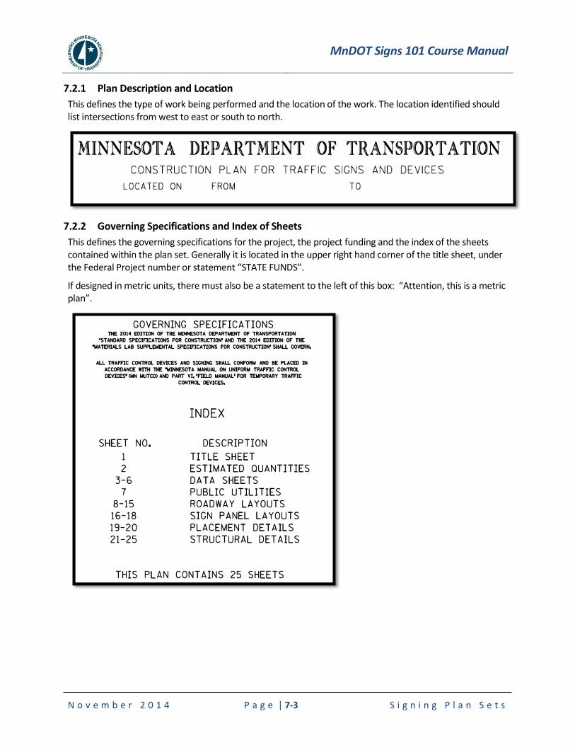
MnDOT Signs 101 Course Manual
N o v e m b e r 2 0 1 4 P a g e | 7-3 S i g n i n g P l a n S e t s
7.2.1 Plan Description and Location
This defines the type of work being performed and the location of the work. The location identified should list intersections from west to east or south to north.
7.2.2 Governing Specifications and Index of Sheets
This defines the governing specifications for the project, the project funding and the index of the sheets contained within the plan set. Generally it is located in the upper right hand corner of the title sheet, under the Federal Project number or statement “STATE FUNDS”.
If designed in metric units, there must also be a statement to the left of this box: “Attention, this is a metric plan”.
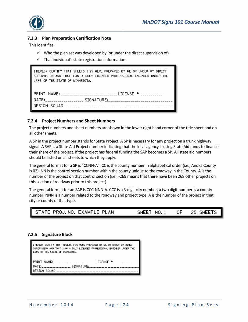
MnDOT Signs 101 Course Manual
N o v e m b e r 2 0 1 4 P a g e | 7-4 S i g n i n g P l a n S e t s
7.2.3 Plan Preparation Certification Note
This identifies:
Who the plan set was developed by (or under the direct supervision of)
That individual’s state registration information.
7.2.4 Project Numbers and Sheet Numbers
The project numbers and sheet numbers are shown in the lower right hand corner of the title sheet and on all other sheets.
A SP in the project number stands for State Project. A SP is necessary for any project on a trunk highway signal. A SAP is a State Aid Project number indicating that the local agency is using State Aid funds to finance their share of the project. If the project has federal funding the SAP becomes a SP. All state aid numbers should be listed on all sheets to which they apply.
The general format for a SP is “CCNN-A”. CC is the county number in alphabetical order (i.e., Anoka County is 02). NN is the control section number within the county unique to the roadway in the County. A is the number of the project on that control section (i.e., -269 means that there have been 268 other projects on this section of roadway prior to this project).
The general format for an SAP is CCC-NNN-A. CCC is a 3-digit city number, a two digit number is a county number. NNN is a number related to the roadway and project type. A is the number of the project in that city or county of that type.
7.2.5 Signature Block
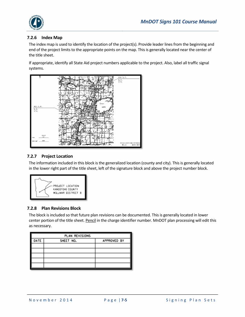
MnDOT Signs 101 Course Manual
N o v e m b e r 2 0 1 4 P a g e | 7-5 S i g n i n g P l a n S e t s
7.2.6 Index Map
The index map is used to identify the location of the project(s). Provide leader lines from the beginning and end of the project limits to the appropriate points on the map. This is generally located near the center of the title sheet.
If appropriate, identify all State Aid project numbers applicable to the project. Also, label all traffic signal systems.
7.2.7 Project Location
The information included in this block is the generalized location (county and city). This is generally located in the lower right part of the title sheet, left of the signature block and above the project number block.
7.2.8 Plan Revisions Block
The block is included so that future plan revisions can be documented. This is generally located in lower center portion of the title sheet. Pencil in the charge identifier number. MnDOT plan processing will edit this as necessary.
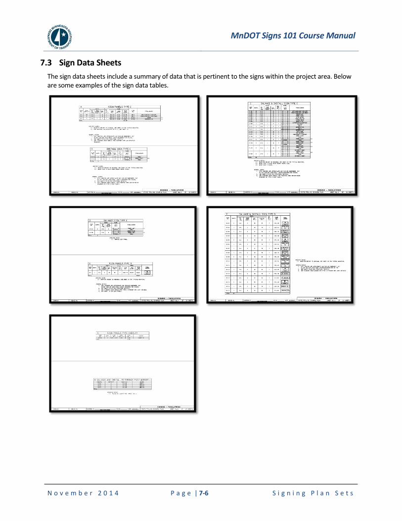
MnDOT Signs 101 Course Manual
N o v e m b e r 2 0 1 4 P a g e | 7-6 S i g n i n g P l a n S e t s
7.3 Sign Data Sheets
The sign data sheets include a summary of data that is pertinent to the signs within the project area. Below are some examples of the sign data tables.
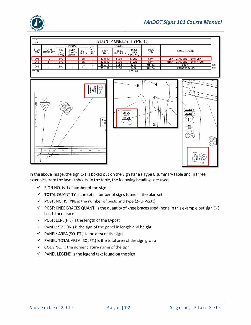
MnDOT Signs 101 Course Manual
N o v e m b e r 2 0 1 4 P a g e | 7-7 S i g n i n g P l a n S e t s
In the above image, the sign C-1 is boxed out on the Sign Panels Type C summary table and in three examples from the layout sheets. In the table, the following headings are used:
SIGN NO. is the number of the sign
TOTAL QUANTITY is the total number of signs found in the plan set
POST: NO. & TYPE is the number of posts and type (2- U-Posts)
POST: KNEE BRACES QUANT. Is the quantity of knee braces used (none in this example but sign C-3 has 1 knee brace.
POST: LEN. (FT.) is the length of the U-post
PANEL: SIZE (IN.) is the sign of the panel in length and height
PANEL: AREA (SQ. FT.) is the area of the sign
PANEL: TOTAL AREA (SQ. FT.) is the total area of the sign group
CODE NO. is the nomenclature name of the sign
PANEL LEGEND is the legend text found on the sign
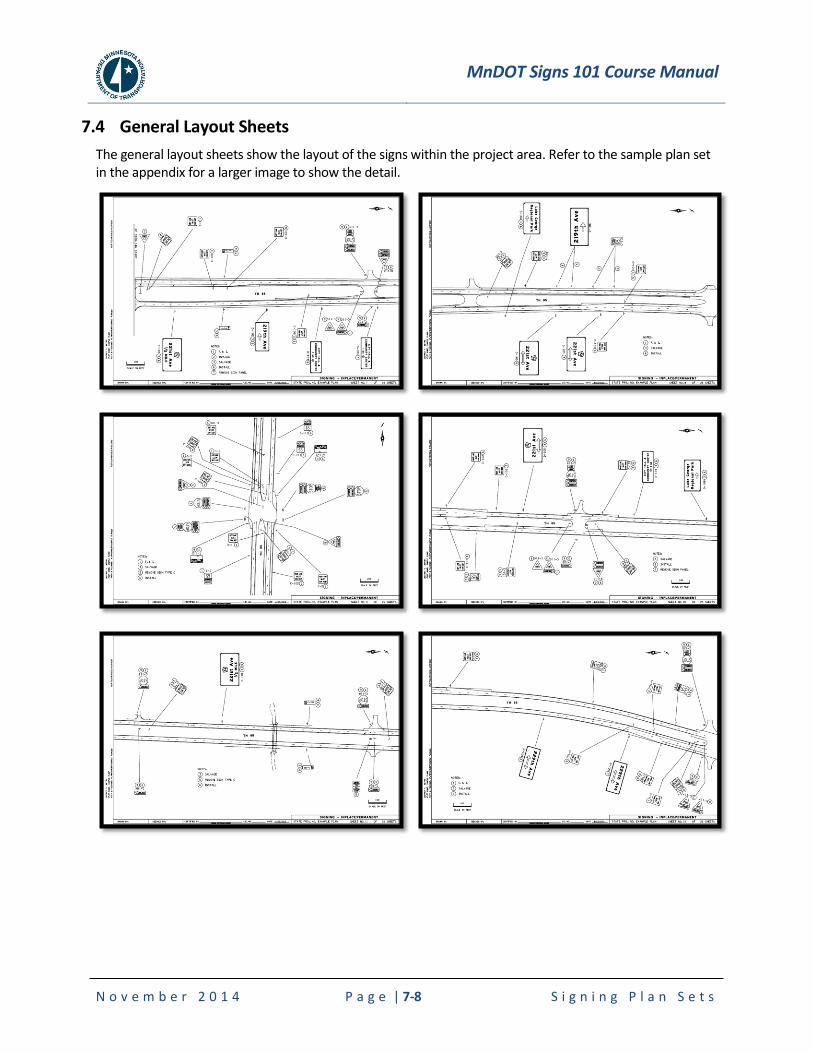
MnDOT Signs 101 Course Manual
N o v e m b e r 2 0 1 4 P a g e | 7-8 S i g n i n g P l a n S e t s
7.4 General Layout Sheets
The general layout sheets show the layout of the signs within the project area. Refer to the sample plan set in the appendix for a larger image to show the detail.
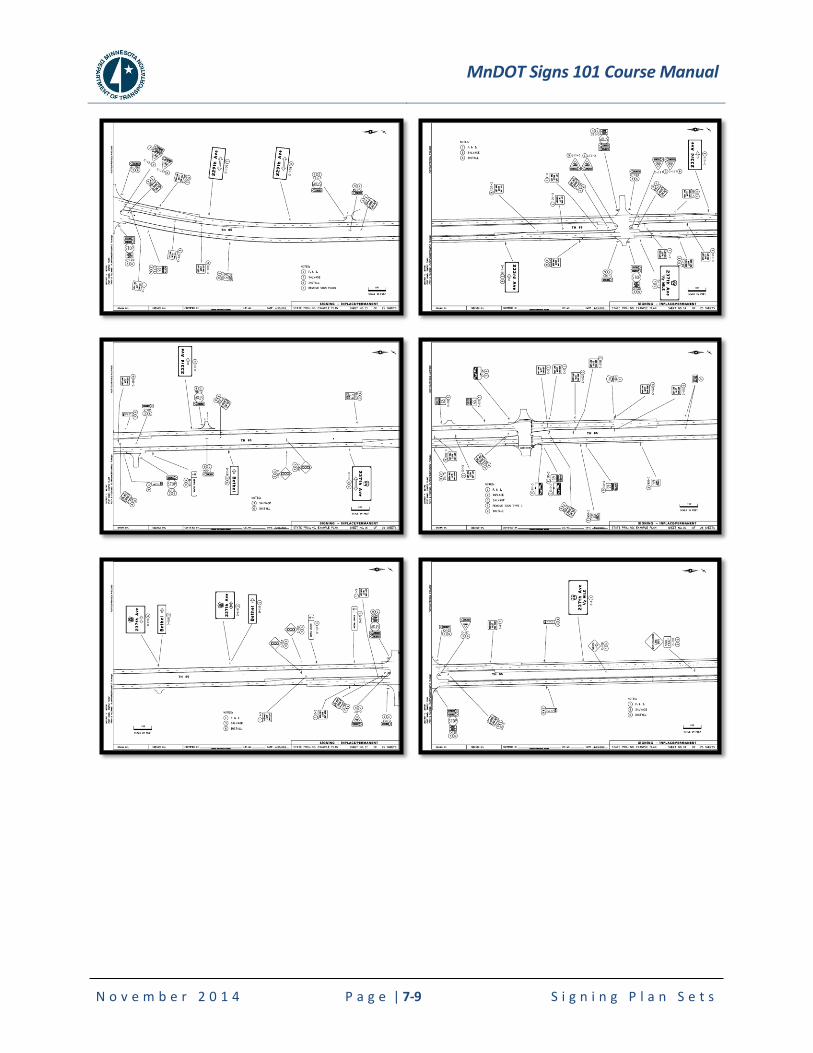
MnDOT Signs 101 Course Manual
N o v e m b e r 2 0 1 4 P a g e | 7-9 S i g n i n g P l a n S e t s
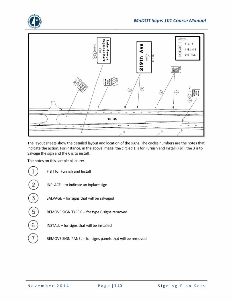
MnDOT Signs 101 Course Manual
N o v e m b e r 2 0 1 4 P a g e | 7-10 S i g n i n g P l a n S e t s
The layout sheets show the detailed layout and location of the signs. The circles numbers are the notes that indicate the action. For instance, in the above image, the circled 1 is for Furnish and Install (F&I), the 3 is to Salvage the sign and the 6 is to install.
The notes on this sample plan are:
F & I for Furnish and Install
INPLACE – to indicate an inplace sign
SALVAGE – for signs that will be salvaged
REMOVE SIGN TYPE C – for type C signs removed
INSTALL – for signs that will be installed
REMOVE SIGN PANEL – for signs panels that will be removed
MnDOT Signs 101 Course Manual
N o v e m b e r 2 0 1 4 P a g e | 7-11 S i g n i n g P l a n S e t s
7.4.1 Clear Zone Requirements
Clear Zones (from the Road Design Manual)
The roadside clear zone is the distance from the edge of the travel lane which should be free of any non-traversable hazard such as steep slopes or fixed objects. The clear zone distances are targeted towards allowing approximately 80 to 85 percent of all run-off-the-road vehicles to recover or come to a safe stop. The width of a clear zone along the horizontal alignment is dependent on roadside geometry, design speed, radius of horizontal curve, and the ADT. Higher speeds mean vehicles will travel farther before recovering. Horizontal curvature increases the likelihood of a vehicle leaving the highway and increases the distance it will travel off the highway, as will steeper fill slopes. In general, hazards within the clear zone which cannot be removed, relocated, or made breakaway will warrant guardrail.
The designer should not apply rigid adherence to the calculated clear zone distance. If a formidable hazard lies just beyond the clear zone, it should be removed or shielded if costs are reasonable. Conversely, the designer should not have the philosophy that the clear zone should be achieved at all costs. Limited right of way or unacceptable construction costs may lead to installation of a barrier or, perhaps, no protection at all if there are many hazards along the entire length of the roadway inside the calculated clear zone.
The designer should not use the clear zone distances as boundaries for introducing roadside hazards such as bridge piers, non-breakaway sign supports, or trees. These should be placed as far from the roadway as practical.
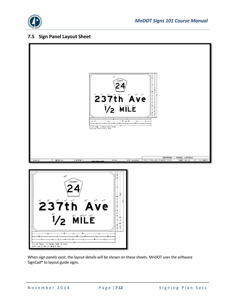
MnDOT Signs 101 Course Manual
N o v e m b e r 2 0 1 4 P a g e | 7-12 S i g n i n g P l a n S e t s
7.5 Sign Panel Layout Sheet
When sign panels exist, the layout details will be shown on these sheets. MnDOT uses the software SignCad® to layout guide signs.
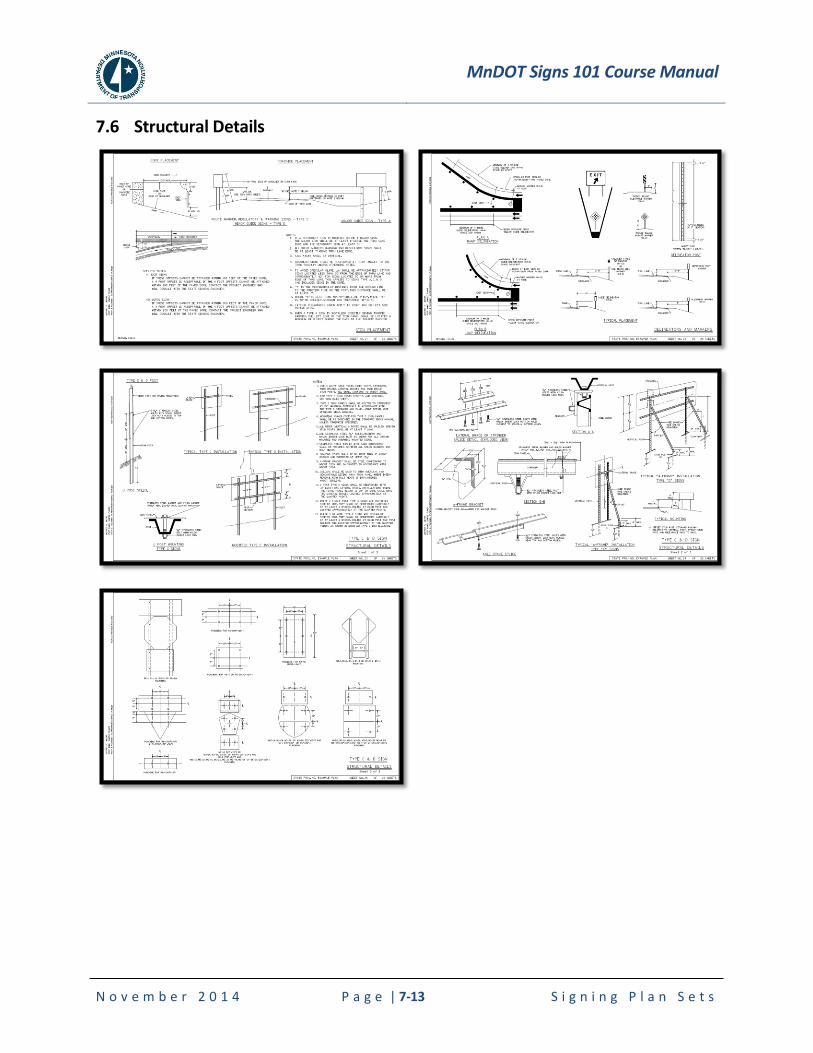
MnDOT Signs 101 Course Manual
N o v e m b e r 2 0 1 4 P a g e | 7-13 S i g n i n g P l a n S e t s
7.6 Structural Details
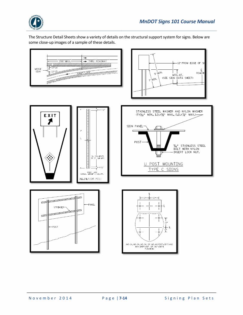
MnDOT Signs 101 Course Manual
N o v e m b e r 2 0 1 4 P a g e | 7-14 S i g n i n g P l a n S e t s
The Structure Detail Sheets show a variety of details on the structural support system for signs. Below are some close-up images of a sample of these details.

MnDOT Signs 101 Course Manual
N o v e m b e r 2 0 1 4 P a g e | 8-1 M a i n t e n a n c e o f S i g n s
8. MAINTENANCE OF SIGNS
8.1 Signing Responsibilities
Effective sign maintenance is important from a customer satisfaction perspective, and from a safety aspect in reducing crashes. Therefore, careful management of sign maintenance at all levels throughout the state is essential.
Altogether many organizations within the state are involved in signing and each has their necessary function and area of responsibility. The flow line of information and direction starts with state regulations and policies and ends with the actual installation and maintenance of the signs.
8.2 Maintenance Handout
The information on the following pages is a handout related to sign maintenance and inventory from “Minnesota’s Best Practices for Traffic Sign Maintenance / Management Handbook” which can be found at www.mnltap.umn.edu/publications/handbooks/.
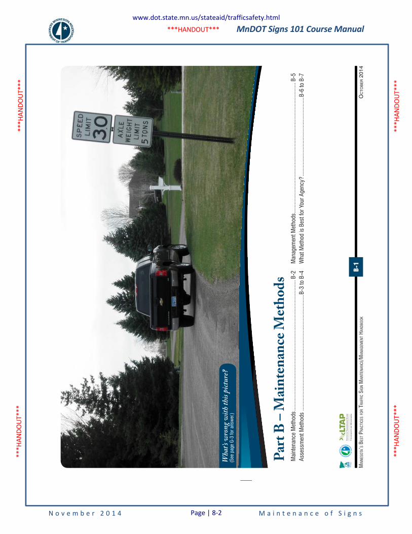
MnDOT Signs 101 Course Manual
N o v e m b e r 2 0 1 4 M a i n t e n a n c e o f S i g n s
***H
ANDO
UT**
* **
*HAN
DOUT
***
***H
ANDO
UT**
* **
*HAN
DOUT
***
***HANDOUT***
OC
TOB
ER 2
014
MIN
NESO
TA’S
BES
T PRA
CTIC
ES FO
R TR
AFFI
C SI
GN M
AINT
ENAN
CE/M
ANAG
EMEN
T HAN
DBOO
KB-1
Part
B – M
ainten
ance
Meth
ods
Mai
nten
ance
Met
hods
.....
......
......
......
......
......
......
......
......
......
......
......
......
......
.....
B-2
Asse
ssm
ent M
etho
ds ..
......
......
......
......
......
......
......
......
......
......
......
......
....B
-3 to
B-4
Man
agem
ent M
etho
ds ...
......
......
......
......
......
......
......
......
......
......
......
......
......
......
.B-5
Wha
t Met
hod
is B
est f
or Y
our A
genc
y? ...
......
......
......
......
......
......
......
......
..B-6
to B
-7
Wha
t’s wr
ong w
ith th
is pict
ure?
(See
pag
e G-
3 fo
r ans
wer
.)
www.dot.state.mn.us/stateaid/trafficsafety.html
Page | 8-2
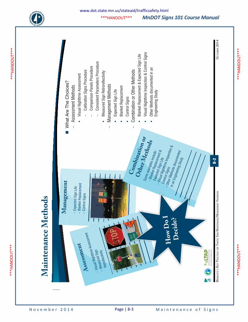
MnDOT Signs 101 Course Manual
N o v e m b e r 2 0 1 4 M a i n t e n a n c e o f S i g n s
***H
ANDO
UT**
* **
*HAN
DOUT
***
***H
ANDO
UT**
* **
*HAN
DOUT
***
***HANDOUT***
OC
TOB
ER 2
014
MIN
NESO
TA’S
BES
T PRA
CTIC
ES FO
R TR
AFFI
C SI
GN M
AINT
ENAN
CE/M
ANAG
EMEN
T HAN
DBOO
K
Main
tenan
ce M
ethod
s
�
Wha
t Are
The
Cho
ices
? –
Asse
ssm
ent M
etho
ds �
Visu
al N
ight
time
Asse
ssm
ent
–Ca
libra
tion
Sign
s Pr
oced
ure
–Co
mpa
rison
Pan
els
Proc
edur
e
–Co
nsis
tent
Par
amet
ers
Proc
edur
e
�M
easu
red
Sign
Ret
rore
flect
ivity
–M
anag
emen
t Met
hods
�Ex
pect
ed S
ign
Life
�Bl
anke
t Rep
lace
men
t
�Co
ntro
l Sig
ns
–Co
mbi
natio
n or
Oth
er M
etho
ds �
Blan
ket R
epla
cem
ent &
Exp
ecte
d Si
gn L
ife
�Vi
sual
Nig
httim
e In
spec
tion
& C
ontro
l Sig
ns
�Ot
her M
etho
ds d
ocum
ente
d in
an
Engi
neer
ing
Stud
y
Man
agem
ent
–Ex
pect
ed S
ign
Life
–Bl
anke
t Rep
lace
men
t –Co
ntro
l Sig
ns
M
Asses
smen
t
–Vi
sual
Nig
httim
e As
sess
men
t
–M
easu
red
Sign
Re
trofle
ctiv
ityty
�Vi
s
Comb
inatio
n or
Othe
r Meth
ods
Som
e ex
ampl
es in
clud
e:
–Bl
anke
t Rep
lace
men
t &
Expe
cted
Sig
n Li
fe –Vi
sual
Nig
httim
e In
spec
tion
&
Cont
rol S
igns
–Ot
her M
etho
ds d
ocum
ente
d
in a
n En
gine
erin
g St
udy
How
Do I
De
cide?
B-2
www.dot.state.mn.us/stateaid/trafficsafety.html
Page | 8-3
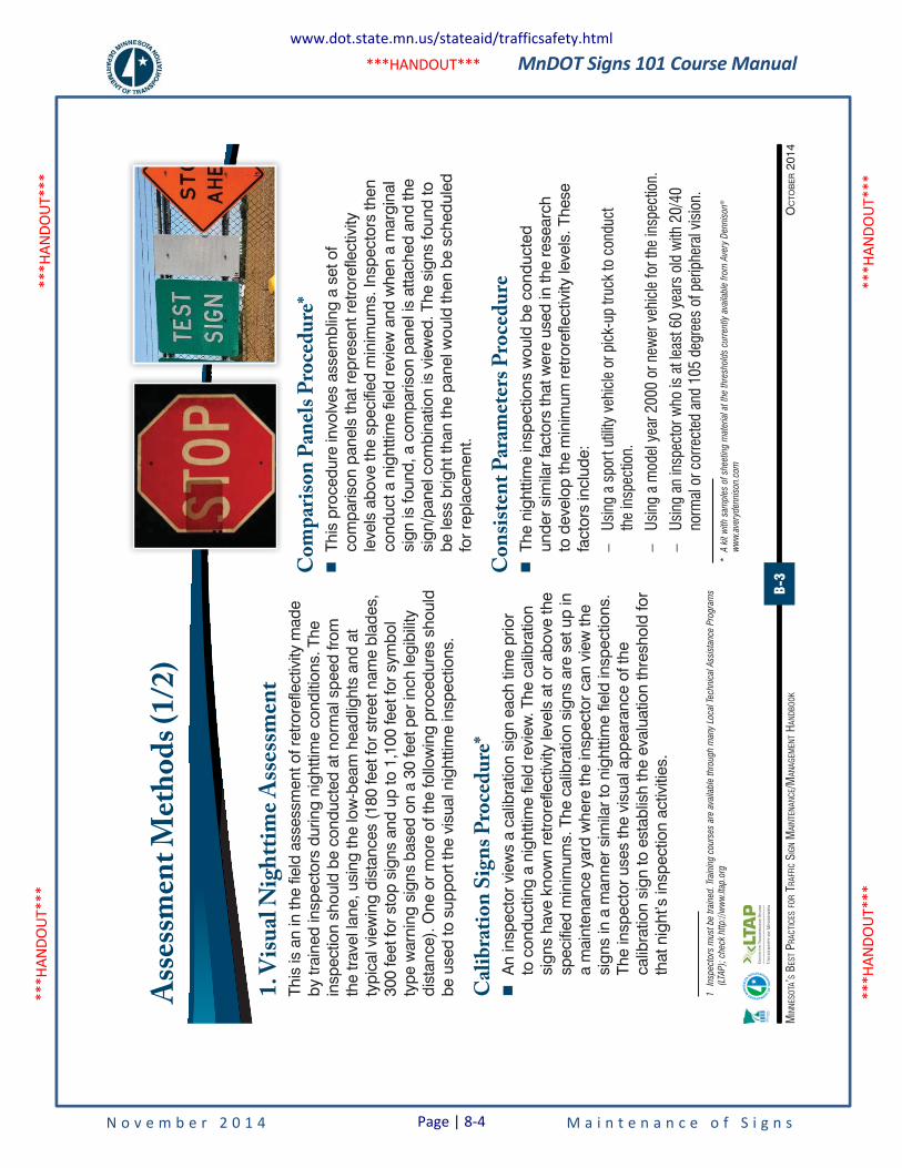
MnDOT Signs 101 Course Manual
N o v e m b e r 2 0 1 4 M a i n t e n a n c e o f S i g n s
***H
ANDO
UT**
* **
*HAN
DOUT
***
***H
ANDO
UT**
* **
*HAN
DOUT
***
***HANDOUT***
B-3
OC
TOB
ER 2
014
MIN
NESO
TA’S
BES
T PRA
CTIC
ES FO
R TR
AFFI
C SI
GN M
AINT
ENAN
CE/M
ANAG
EMEN
T HAN
DBOO
K
Asses
smen
t Meth
ods (
1/2)
1. Vi
sual
Nigh
ttime
Asse
ssmen
tTh
is is
an
in th
e fie
ld a
sses
smen
t of r
etro
refle
ctiv
ity m
ade
by tr
aine
d in
spec
tors
dur
ing
nigh
ttim
e co
nditi
ons.
The
in
spec
tion
shou
ld b
e co
nduc
ted
at n
orm
al s
peed
from
th
e tra
vel l
ane,
usi
ng th
e lo
w-b
eam
hea
dlig
hts
and
at
typi
cal v
iew
ing
dist
ance
s (1
80 fe
et fo
r stre
et n
ame
blad
es,
300
feet
for s
top
sign
s an
d up
to 1
,100
feet
for s
ymbo
l ty
pe w
arni
ng s
igns
bas
ed o
n a
30 fe
et p
er in
ch le
gibi
lity
dist
ance
). O
ne o
r mor
e of
the
follo
win
g pr
oced
ures
sho
uld
be u
sed
to s
uppo
rt th
e vi
sual
nig
httim
e in
spec
tions
.
Calib
ration
Sign
s Pro
cedu
re* �
An
insp
ecto
r vie
ws
a ca
libra
tion
sign
eac
h tim
e pr
ior
to c
ondu
ctin
g a
nigh
ttim
e fie
ld re
view
. The
cal
ibra
tion
sign
s ha
ve k
now
n re
trore
flect
ivity
leve
ls a
t or a
bove
the
spec
ified
min
imum
s. T
he c
alib
ratio
n si
gns
are
set u
p in
a
mai
nten
ance
yar
d w
here
the
insp
ecto
r can
vie
w th
e si
gns
in a
man
ner s
imila
r to
nigh
ttim
e fie
ld in
spec
tions
. Th
e in
spec
tor u
ses
the
visu
al a
ppea
ranc
e of
the
calib
ratio
n si
gn to
est
ablis
h th
e ev
alua
tion
thre
shol
d fo
r th
at n
ight
’s in
spec
tion
activ
ities
.1
1
Insp
ecto
rs m
ust
be
trai
ned.
Trai
ning
cour
ses
are
avai
lable
thr
oug
h m
any
Loca
l Tec
hnic
al A
ssis
tanc
e P
rogra
ms
(LTA
P);
che
ck h
ttp:/
/ww
w.lt
ap.o
rg
Comp
ariso
n Pan
els Pr
oced
ure*
�
This
pro
cedu
re in
volv
es a
ssem
blin
g a
set o
f co
mpa
rison
pan
els
that
repr
esen
t ret
rore
flect
ivity
le
vels
abo
ve th
e sp
ecifi
ed m
inim
ums.
Insp
ecto
rs th
en
cond
uct a
nig
httim
e fie
ld re
view
and
whe
n a
mar
gina
l si
gn is
foun
d, a
com
paris
on p
anel
is a
ttach
ed a
nd th
e si
gn/p
anel
com
bina
tion
is v
iew
ed. T
he s
igns
foun
d to
be
less
brig
ht th
an th
e pa
nel w
ould
then
be
sche
dule
d fo
r rep
lace
men
t.
Cons
isten
t Para
meter
s Pro
cedu
re �
The
nigh
ttim
e in
spec
tions
wou
ld b
e co
nduc
ted
unde
r sim
ilar f
acto
rs th
at w
ere
used
in th
e re
sear
ch
to d
evel
op th
e m
inim
um re
trore
flect
ivity
leve
ls. T
hese
fa
ctor
s in
clud
e:
–Us
ing
a sp
ort u
tility
veh
icle
or p
ick-
up tr
uck
to c
ondu
ct
the
insp
ectio
n.
–Us
ing
a m
odel
yea
r 200
0 or
new
er v
ehic
le fo
r the
insp
ectio
n.
–Us
ing
an in
spec
tor w
ho is
at l
east
60
year
s ol
d w
ith 2
0/40
no
rmal
or c
orre
cted
and
105
deg
rees
of p
erip
hera
l vis
ion.
*A
kit
with
sam
ple
s of
shee
ting m
ater
ial a
t th
e th
resh
old
s cu
rren
tly a
vaila
ble
fro
m A
very
Den
niso
n®
ww
w.a
very
den
niso
n.co
m
www.dot.state.mn.us/stateaid/trafficsafety.html
Page | 8-4
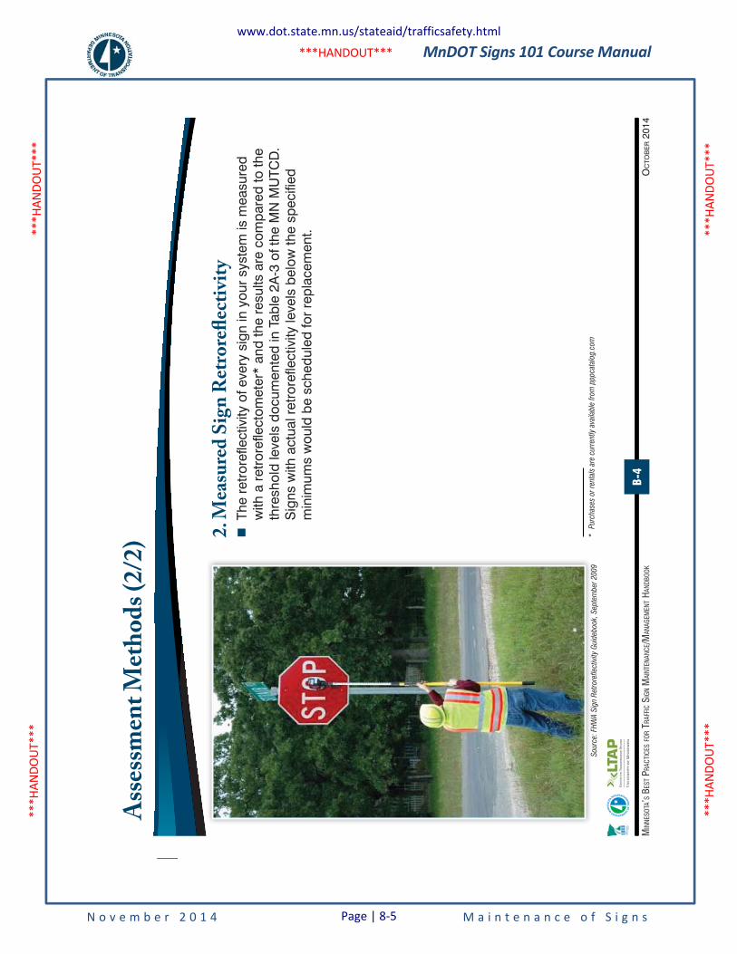
MnDOT Signs 101 Course Manual
N o v e m b e r 2 0 1 4 M a i n t e n a n c e o f S i g n s
***H
ANDO
UT**
* **
*HAN
DOUT
***
***H
ANDO
UT**
* **
*HAN
DOUT
***
***HANDOUT***
B-4
OC
TOB
ER 2
014
MIN
NESO
TA’S
BES
T PRA
CTIC
ES FO
R TR
AFFI
C SI
GN M
AINT
ENAN
CE/M
ANAG
EMEN
T HAN
DBOO
K
Asses
smen
t Meth
ods (
2/2)
2. M
easu
red Si
gn R
etror
eflec
tivity
�
The
retr
oref
lect
ivity
of e
very
sig
n in
you
r sy
stem
is m
easu
red
with
a r
etro
refle
ctom
eter
* an
d th
e re
sults
are
com
pare
d to
the
thre
shol
d le
vels
doc
umen
ted
in T
able
2A
-3 o
f the
MN
MU
TCD
. S
igns
with
act
ual r
etro
refle
ctiv
ity le
vels
bel
ow th
e sp
ecifi
ed
min
imum
s w
ould
be
sche
dule
d fo
r re
plac
emen
t.
Sour
ce:
FHW
A S
ign
Ret
rore
flect
ivity
Gui
deb
ook,
Sep
tem
ber
20
09
*
Pur
chas
es o
r re
ntal
s ar
e cu
rren
tly a
vaila
ble
fro
m p
ppca
talo
g.c
om
www.dot.state.mn.us/stateaid/trafficsafety.html
Page | 8-5
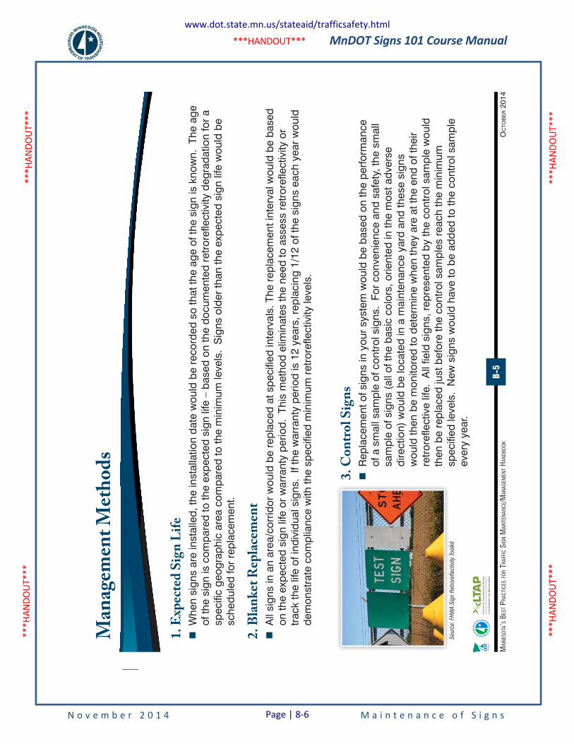
MnDOT Signs 101 Course Manual
N o v e m b e r 2 0 1 4 M a i n t e n a n c e o f S i g n s
***H
ANDO
UT**
* **
*HAN
DOUT
***
***H
ANDO
UT**
* **
*HAN
DOUT
***
***HANDOUT***
B-5
OC
TOB
ER 2
014
MIN
NESO
TA’S
BES
T PRA
CTIC
ES FO
R TR
AFFI
C SI
GN M
AINT
ENAN
CE/M
ANAG
EMEN
T HAN
DBOO
K
Man
agem
ent M
ethod
s
1. Ex
pecte
d Sign
Life
�
Whe
n si
gns
are
inst
alle
d, th
e in
stal
latio
n da
te w
ould
be
reco
rded
so
that
the
age
of th
e si
gn is
kno
wn.
The
age
of
the
sign
is c
ompa
red
to th
e ex
pect
ed s
ign
life
– ba
sed
on th
e do
cum
ente
d re
tror
efle
ctiv
ity d
egra
datio
n fo
r a
spec
ific
geog
raph
ic a
rea
com
pare
d to
the
min
imum
leve
ls.
Sig
ns o
lder
than
the
expe
cted
sig
n lif
e w
ould
be
sche
dule
d fo
r re
plac
emen
t.
2. Bl
anke
t Rep
lacem
ent
�
All
sign
s in
an
area
/cor
ridor
wou
ld b
e re
plac
ed a
t spe
cifie
d in
terv
als.
The
rep
lace
men
t int
erva
l wou
ld b
e ba
sed
on th
e ex
pect
ed s
ign
life
or w
arra
nty
perio
d. T
his
met
hod
elim
inat
es th
e ne
ed to
ass
ess
retr
oref
lect
ivity
or
trac
k th
e lif
e of
indi
vidu
al s
igns
. If
the
war
rant
y pe
riod
is 1
2 ye
ars,
rep
laci
ng 1
/12
of th
e si
gns
each
yea
r w
ould
de
mon
stra
te c
ompl
ianc
e w
ith th
e sp
ecifi
ed m
inim
um r
etro
refle
ctiv
ity le
vels
.
3. Co
ntro
l Sign
s �
Rep
lace
men
t of s
igns
in y
our
syst
em w
ould
be
base
d on
the
perfo
rman
ce
of a
sm
all s
ampl
e of
con
trol
sig
ns.
For
conv
enie
nce
and
safe
ty, t
he s
mal
l sa
mpl
e of
sig
ns (
all o
f the
bas
ic c
olor
s, o
rient
ed in
the
mos
t adv
erse
di
rect
ion)
wou
ld b
e lo
cate
d in
a m
aint
enan
ce y
ard
and
thes
e si
gns
wou
ld th
en b
e m
onito
red
to d
eter
min
e w
hen
they
are
at t
he e
nd o
f the
ir re
tror
efle
ctiv
e lif
e. A
ll fie
ld s
igns
, rep
rese
nted
by
the
cont
rol s
ampl
e w
ould
th
en b
e re
plac
ed ju
st b
efor
e th
e co
ntro
l sam
ples
rea
ch th
e m
inim
um
spec
ified
leve
ls.
New
sig
ns w
ould
hav
e to
be
adde
d to
the
cont
rol s
ampl
e ev
ery
year
.S
our
ce:
FHW
A S
ign
Ret
rore
flect
ivity
Toolk
it
www.dot.state.mn.us/stateaid/trafficsafety.html
Page | 8-6
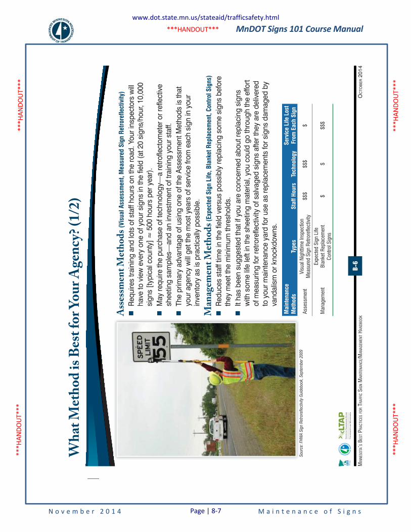
MnDOT Signs 101 Course Manual
N o v e m b e r 2 0 1 4 M a i n t e n a n c e o f S i g n s
***H
ANDO
UT**
* **
*HAN
DOUT
***
***H
ANDO
UT**
* **
*HAN
DOUT
***
***HANDOUT***
B-6
OC
TOB
ER 2
014
MIN
NESO
TA’S
BES
T PRA
CTIC
ES FO
R TR
AFFI
C SI
GN M
AINT
ENAN
CE/M
ANAG
EMEN
T HAN
DBOO
K
Wha
t Meth
od is
Best
for Y
our A
genc
y? (1/
2)
Asses
smen
t Meth
ods (V
isua
l Ass
essm
ent,
Mea
sure
d Si
gn R
etro
refle
ctiv
ity)
�
Req
uire
s tra
inin
g an
d lo
ts o
f sta
ff ho
urs
on th
e ro
ad. Y
our i
nspe
ctor
s w
ill
have
to v
iew
eve
ry o
ne o
f you
r sig
ns in
the
field
(at 2
0 si
gns/
hour
, 10,
000
����
����
���
����
���
����
����
����
���
���
����
�
May
requ
ire th
e pu
rcha
se o
f tec
hnol
ogy—
a re
trofle
ctom
eter
or r
efle
ctiv
e sh
eetin
g sa
mpl
es—
and
an in
vest
men
t of t
rain
ing
your
sta
ff. �
The
prim
ary
adva
ntag
e of
usi
ng o
ne o
f the
Ass
essm
ent M
etho
ds is
that
yo
ur a
genc
y w
ill g
et th
e m
ost y
ears
of s
ervi
ce fr
om e
ach
sign
in y
our
inve
ntor
y as
is p
ract
ical
ly p
ossi
ble.
Man
agem
ent M
ethod
s (Exp
ecte
d Si
gn L
ife, B
lank
et R
epla
cem
ent,
Cont
rol S
igns
)
�
Red
uces
sta
ff tim
e in
the
field
ver
sus
poss
ibly
repl
acin
g so
me
sign
s be
fore
th
ey m
eet t
he m
inim
um th
resh
olds
. �
It ha
s be
en s
ugge
sted
that
if y
ou a
re c
once
rned
abo
ut re
plac
ing
sign
s w
ith s
ome
life
left
in th
e sh
eetin
g m
ater
ial,
you
coul
d go
thro
ugh
the
effo
rt of
mea
surin
g fo
r ret
rore
flect
ivity
of s
alva
ged
sign
s af
ter t
hey
are
deliv
ered
to
you
r mai
nten
ance
yar
d fo
r use
as
repl
acem
ents
for s
igns
dam
aged
by
vand
alis
m o
r kno
ckdo
wns
.
Mai
nten
ance
M
etho
dsTy
pes
Staf
f Hou
rsTe
chno
logy
Serv
ice
Life
Los
t Fr
om E
ach
Sign
Asse
ssm
ent
Visu
al N
ight
time
Insp
ectio
nM
easu
red
Sign
Ret
rore
flect
ivity
$$$
$$$
$
Man
agem
ent
Expe
cted
Sig
n Li
feBl
anke
t Rep
lace
men
tCo
ntro
l Sig
ns$
$$$
$
Sour
ce:
FHW
A S
ign
Ret
rore
flect
ivity
Gui
deb
ook,
Sep
tem
ber
20
09
www.dot.state.mn.us/stateaid/trafficsafety.html
Page | 8-7
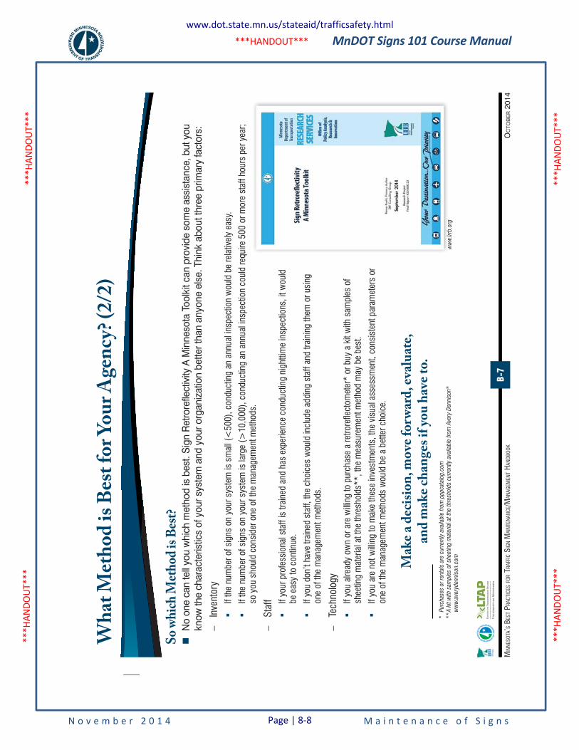
MnDOT Signs 101 Course Manual
N o v e m b e r 2 0 1 4 M a i n t e n a n c e o f S i g n s
***H
ANDO
UT**
* **
*HAN
DOUT
***
***H
ANDO
UT**
* **
*HAN
DOUT
***
***HANDOUT***
B-7
OC
TOB
ER 2
014
MIN
NESO
TA’S
BES
T PRA
CTIC
ES FO
R TR
AFFI
C SI
GN M
AINT
ENAN
CE/M
ANAG
EMEN
T HAN
DBOO
K
So wh
ich M
ethod
is Be
st? �
No
one
can
tell
you
whi
ch m
etho
d is
bes
t. Si
gn R
etro
refle
ctiv
ity A
Min
neso
ta T
oolk
it ca
n pr
ovid
e so
me
assi
stan
ce, b
ut y
ou
know
the
char
acte
ristic
s of
you
r sys
tem
and
you
r org
aniz
atio
n be
tter t
han
anyo
ne e
lse.
Thi
nk a
bout
thre
e pr
imar
y fa
ctor
s:
–In
vent
ory
�If
the
num
ber o
f sig
ns o
n yo
ur s
yste
m is
sm
all (
<50
0), c
ondu
ctin
g an
ann
ual i
nspe
ctio
n w
ould
be
rela
tivel
y ea
sy.
�If
the
num
ber o
f sig
ns o
n yo
ur s
yste
m is
larg
e (>
10,0
00),
cond
uctin
g an
ann
ual i
nspe
ctio
n co
uld
requ
ire 5
00 o
r mor
e st
aff h
ours
per
yea
r; so
you
sho
uld
cons
ider
one
of t
he m
anag
emen
t met
hods
.
–St
aff
�If
your
pro
fess
iona
l sta
ff is
trai
ned
and
has
expe
rienc
e co
nduc
ting
nigh
ttim
e in
spec
tions
, it w
ould
be
eas
y to
con
tinue
.
�If
you
don’
t hav
e tra
ined
sta
ff, th
e ch
oice
s w
ould
incl
ude
addi
ng s
taff
and
train
ing
them
or u
sing
on
e of
the
man
agem
ent m
etho
ds.
–Te
chno
logy
�If
you
alre
ady
own
or a
re w
illing
to p
urch
ase
a re
trore
flect
omet
er*
or b
uy a
kit
with
sam
ples
of
shee
ting
mat
eria
l at t
he th
resh
olds
**, t
he m
easu
rem
ent m
etho
d m
ay b
e be
st.
�If
you
are
not w
illing
to m
ake
thes
e in
vest
men
ts, t
he v
isua
l ass
essm
ent,
cons
iste
nt p
aram
eter
s or
on
e of
the
man
agem
ent m
etho
ds w
ould
be
a be
tter c
hoic
e.
Wha
t Meth
od is
Best
for Y
our A
genc
y? (2/
2)
ww
w.lr
rb.o
rgw
ww
lrrb
org
Mak
e a de
cision
, mov
e for
ward
, eva
luate,
an
d mak
e cha
nges
if you
have
to.
*
Pur
chas
es o
r re
ntal
s ar
e cu
rren
tly a
vaila
ble
fro
m p
ppca
talo
g.c
om
**
A k
it w
ith s
ample
s of
shee
ting m
ater
ial a
t th
e th
resh
old
s cu
rren
tly a
vaila
ble
fro
m A
very
Den
niso
n®
ww
w.a
very
den
niso
n.co
m
www.dot.state.mn.us/stateaid/trafficsafety.html
Page | 8-8
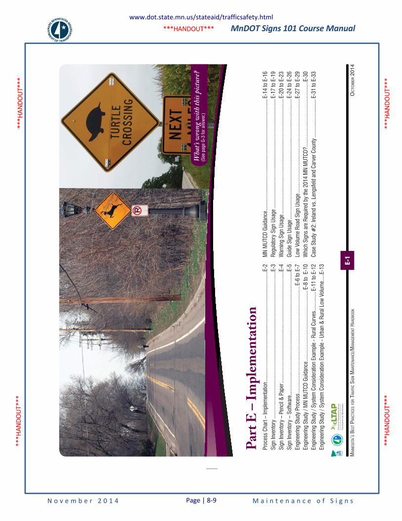
MnDOT Signs 101 Course Manual
N o v e m b e r 2 0 1 4 M a i n t e n a n c e o f S i g n s
***H
ANDO
UT**
* **
*HAN
DOUT
***
***H
ANDO
UT**
* **
*HAN
DOUT
***
***HANDOUT***
OC
TOB
ER 2
014
MIN
NESO
TA’S
BES
T PRA
CTIC
ES FO
R TR
AFFI
C SI
GN M
AINT
ENAN
CE/M
ANAG
EMEN
T HAN
DBOO
KE-1
Par
t E
– I
mp
lem
enta
tio
nPr
oces
s Ch
art –
Impl
emen
tatio
n ....
......
......
......
......
......
......
......
......
......
......
......
......
.....E
-2Si
gn In
vent
ory
......
......
......
......
......
......
......
......
......
......
......
......
......
......
......
......
......
......
E-3
Sign
Inve
ntor
y –
Penc
il &
Pape
r .....
......
......
......
......
......
......
......
......
......
......
......
......
.....E
-4Si
gn In
vent
ory
– So
ftwar
e....
......
......
......
......
......
......
......
......
......
......
......
......
......
......
...E-
5En
gine
erin
g St
udy
Proc
ess .
......
......
......
......
......
......
......
......
......
......
......
......
.....
E-6
to E
-7En
gine
erin
g St
udy
/ MN
MUT
CD G
uida
nce .
......
......
......
......
......
......
......
......
...E-
8 to
E-1
0En
gine
erin
g St
udy
/ Sys
tem
Con
side
ratio
n Ex
ampl
e - R
ural
Cur
ves .
......
......
.E-1
1 to
E-1
2En
gine
erin
g St
udy
/ Sys
tem
Con
side
ratio
n Ex
ampl
e - U
rban
& R
ural
Low
Vol
ume .
....E
-13
MN
MUT
CD G
uida
nce .
......
......
......
......
......
......
......
......
......
......
......
......
......
...E-
14 to
E-1
6Re
gula
tory
Sig
n Us
age
......
......
......
......
......
......
......
......
......
......
......
......
......
..E-
17 to
E-1
9W
arni
ng S
ign
Usag
e ....
......
......
......
......
......
......
......
......
......
......
......
......
......
..E-
20 to
E-2
3Gu
ide
Sign
Usa
ge ..
......
......
......
......
......
......
......
......
......
......
......
......
......
......
..E-
24 to
E-2
6Lo
w V
olum
e Ro
ad S
ign
Usag
e ....
......
......
......
......
......
......
......
......
......
......
.....
E-27
to E
-29
Whi
ch S
igns
are
Req
uire
d by
the
2014
MN
MUT
CD? .
......
......
......
......
......
......
......
.....E
-30
Case
Stu
dy #
2: Ir
elan
d vs
. Len
gsfe
ld a
nd C
arve
r Cou
nty
......
......
......
......
....E
-31
to E
-33
Wha
t’s wr
ong w
ith th
is pict
ure?
(See
pag
e G-
3 fo
r ans
wer
.)
www.dot.state.mn.us/stateaid/trafficsafety.html
Page | 8-9
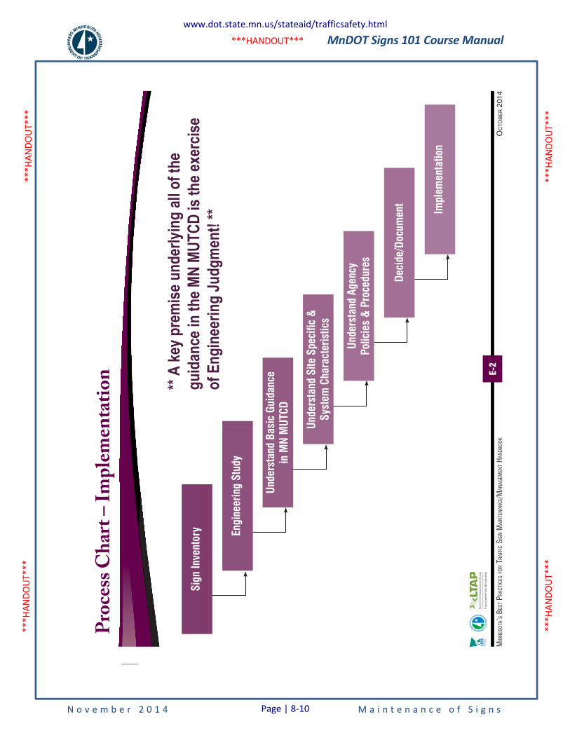
MnDOT Signs 101 Course Manual
N o v e m b e r 2 0 1 4 M a i n t e n a n c e o f S i g n s
***H
ANDO
UT**
* **
*HAN
DOUT
***
***H
ANDO
UT**
* **
*HAN
DOUT
***
***HANDOUT***
E-2
OC
TOB
ER 2
014
MIN
NESO
TA’S
BES
T PRA
CTIC
ES FO
R TR
AFFI
C SI
GN M
AINT
ENAN
CE/M
ANAG
EMEN
T HAN
DBOO
K
Pro
cess
Ch
art
– Im
ple
men
tati
on
Impl
emen
tatio
n
Sign
Inve
ntor
y Engi
neer
ing
Stud
y
Unde
rsta
nd B
asic
Gui
danc
e in
MN
MUT
CD
Unde
rsta
nd S
ite S
peci
fic &
Sy
stem
Cha
ract
eris
tics
Unde
rsta
nd A
genc
yPo
licie
s &
Pro
cedu
res
Deci
de/D
ocum
ent
** A
key p
rem
ise u
nder
lying
all o
f the
gu
idan
ce in
the M
N MU
TCD
is th
e exe
rcise
of
Eng
inee
ring
Judg
men
t! **
www.dot.state.mn.us/stateaid/trafficsafety.html
Page | 8-10
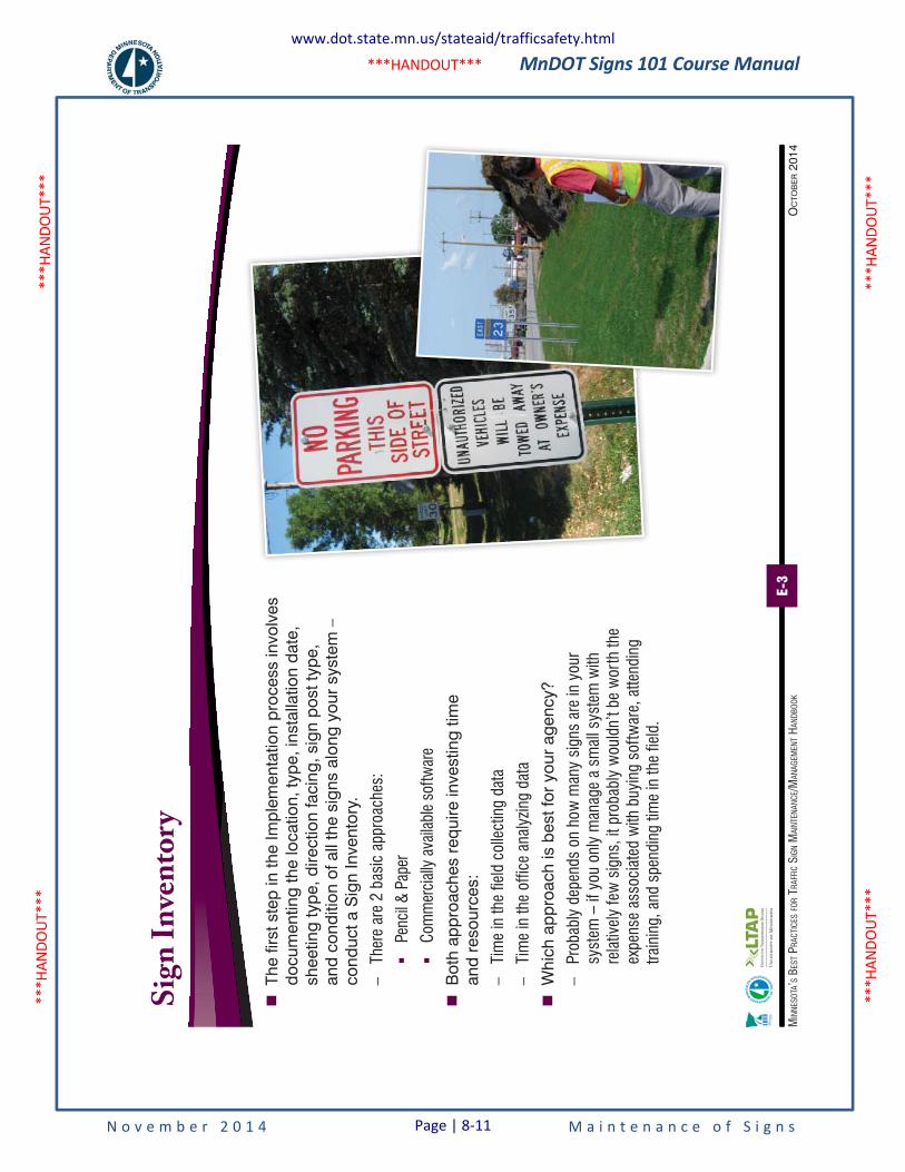
MnDOT Signs 101 Course Manual
N o v e m b e r 2 0 1 4 M a i n t e n a n c e o f S i g n s
***H
ANDO
UT**
* **
*HAN
DOUT
***
***H
ANDO
UT**
* **
*HAN
DOUT
***
***HANDOUT***
E-3
OC
TOB
ER 2
014
MIN
NESO
TA’S
BES
T PRA
CTIC
ES FO
R TR
AFFI
C SI
GN M
AINT
ENAN
CE/M
ANAG
EMEN
T HAN
DBOO
K
Sig
n I
nve
nto
ry
�
The
first
ste
p in
the
Impl
emen
tatio
n pr
oces
s in
volv
es
docu
men
ting
the
loca
tion,
type
, ins
talla
tion
date
, sh
eetin
g ty
pe, d
irect
ion
faci
ng, s
ign
post
type
, an
d co
nditi
on o
f all
the
sign
s al
ong
your
sys
tem
–
cond
uct a
Sig
n In
vent
ory.
–Th
ere
are
2 ba
sic
appr
oach
es:
�Pe
ncil
& Pa
per
�Co
mm
erci
ally
ava
ilabl
e so
ftwar
e
�
Bot
h ap
proa
ches
req
uire
inve
stin
g tim
e an
d re
sour
ces:
–Ti
me
in th
e fie
ld c
olle
ctin
g da
ta
–Ti
me
in th
e of
fice
anal
yzin
g da
ta
�
Whi
ch a
ppro
ach
is b
est f
or y
our
agen
cy?
–Pr
obab
ly d
epen
ds o
n ho
w m
any
sign
s ar
e in
you
r sy
stem
– if
you
onl
y m
anag
e a
smal
l sys
tem
with
re
lativ
ely
few
sig
ns, i
t pro
babl
y w
ould
n’t b
e w
orth
the
expe
nse
asso
ciat
ed w
ith b
uyin
g so
ftwar
e, a
ttend
ing
train
ing,
and
spe
ndin
g tim
e in
the
field
.
www.dot.state.mn.us/stateaid/trafficsafety.html
Page | 8-11
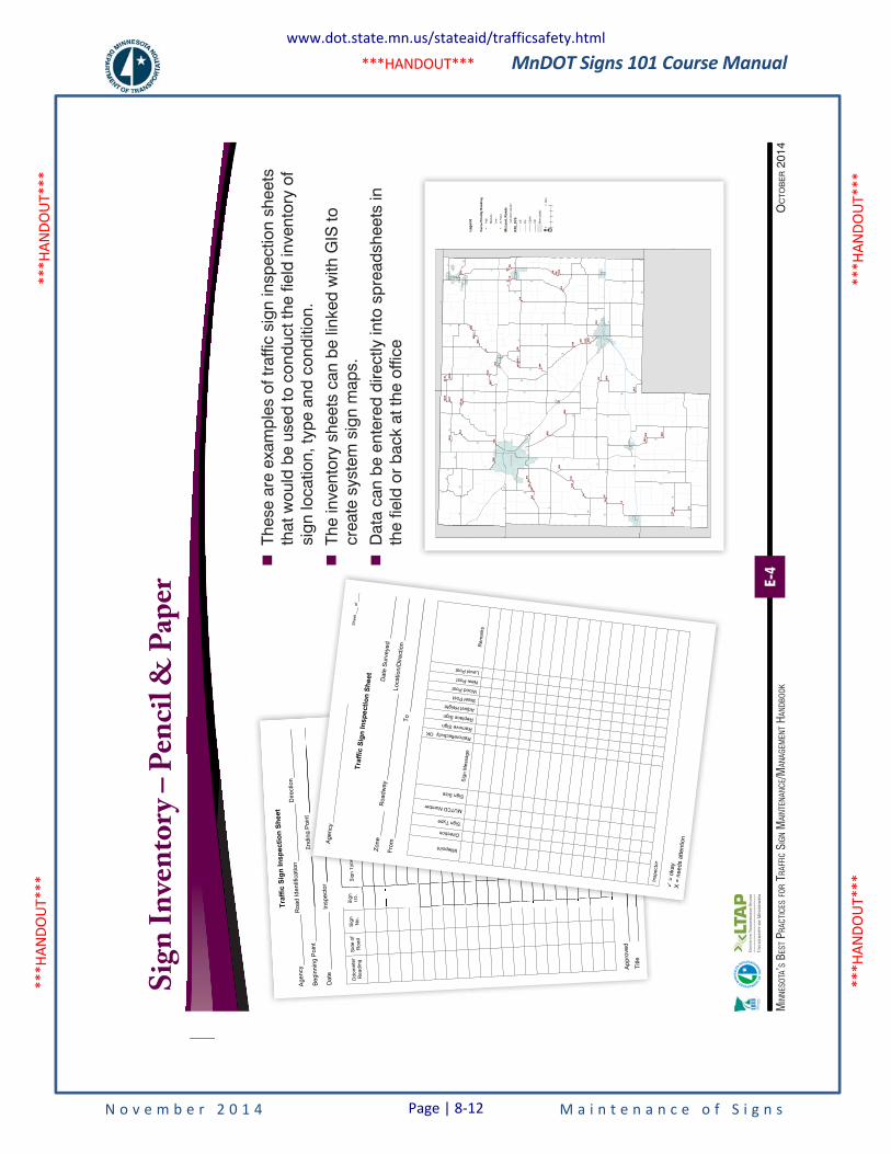
MnDOT Signs 101 Course Manual
N o v e m b e r 2 0 1 4 M a i n t e n a n c e o f S i g n s
***H
ANDO
UT**
* **
*HAN
DOUT
***
***H
ANDO
UT**
* **
*HAN
DOUT
***
***HANDOUT***
E-4
OC
TOB
ER 2
014
MIN
NESO
TA’S
BES
T PRA
CTIC
ES FO
R TR
AFFI
C SI
GN M
AINT
ENAN
CE/M
ANAG
EMEN
T HAN
DBOO
K
Sig
n I
nve
nto
ry –
Pen
cil &
Pap
er
�
Thes
e ar
e ex
ampl
es o
f tra
ffic
sign
insp
ectio
n sh
eets
th
at w
ould
be
used
to c
ondu
ct th
e fie
ld in
vent
ory
of
sign
loca
tion,
type
and
con
ditio
n.
�
The
inve
ntor
y sh
eets
can
be
linke
d w
ith G
IS to
cr
eate
sys
tem
sig
n m
aps.
�
Dat
a ca
n be
ent
ered
dire
ctly
into
spr
eads
heet
s in
th
e fie
ld o
r ba
ck a
t the
offi
ce
Tra
ffic
Sig
n I
ns
pe
cti
on
Sh
ee
t
Agency
Road Identification
Direction
Begin
nin
g P
oin
t E
ndin
g P
oin
t
Date
In
specto
r
S
ign
In
sp
ectio
n
Od
om
ete
r
Re
ad
ing
Sid
e o
f
Ro
ad
Sig
n
No
.
Sig
n
I.D
. S
ign
Typ
e
Da
te
Actio
n T
ake
n
Da
te
Actio
n T
ake
n
Appro
ved
Title
Pa
ge
__
_ o
f _
__
Endin
g P
oin
t
nspecto
r
Sig
n I
nsp
ectio
n
Sig
n
I.D
.S
ign
Typ
eD
ate
Actio
n T
ake
nD
ate
Actio
n T
ake
n
Pa
ge
__
_ o
f _
__
T
raff
ic S
ign
In
sp
ecti
on
Sh
eet
Date
Surv
eyed
Zone
Roadw
ay
Location/D
irection
Fro
m
To
Milepoint
Direction
Sign Type
MUTCD Number
Sign Size
Sig
n M
essa
ge
Retroreflectivity OK Remove Sign Replace Sign
Adjust Height
Steel Post
Wood Post
New Post
Level Post R
em
ark
s
In
sp
ecto
r
� =
okay
X =
needs a
ttention
Sh
ee
t _
__
of
__
__
Agency
__
__
__
__
__
__
__
__
__
__
__
__
__
__
__
__
__
__
__
__
__
__
__
__
__
__
_
!(
!(
!(
!(
!(
!(
!( !( !(
!(
!(!(
!(
!(!(
!(
!(!(
!(
!(!(
!(
!(!(
!(!(
!(
!(
!(
!(
!(
!(
!(
!(
!(
!(!(
!(!(!(
!(
!(!( !(
!(
!(!(
!(!(
!(
!(
!(
!(
!(
!(
!(
!(
!(
!(
!(
HU
TC
HIN
SO
NH
UT
CH
INS
ON
GLE
NC
OE
GLE
NC
OE
WIN
ST
ED
WIN
ST
ED
WIN
ST
ED
WIN
ST
ED
WIN
ST
ED
WIN
ST
ED
WIN
ST
ED
WIN
ST
ED
WIN
ST
ED
WIN
ST
ED
")54
")58
")60
")71
")68
")74
")79
")57
")
61
")56
")70
")84
")62
")65
")90
")81
")66
")52
")75
")51
")86
")89
")73
")53
")55
")85
")72
")59
")80
")63
")87
")83
")64
")93
")77
")69
")78
")76
")
92
")62
")60
")60
")71
")83
")
92
!(1
!(7
!(9
! (5
!(3
!(17
!(2
!(15
!(8
!(4
!(13
!(10
!(11
!(18
!(12
!(26
!(22
!(24
!(16
!(19
!(14
!(33
!(25
!(20
! (6
! (32
!(115
!(31
!(23
!(116
!(30
!(111
!(107
!(29
!(102
!(103
!(25
!(23
!(3
!(7
!(2
!(2
!(4
!(15
!(16
!(3
!(7
!(15
!(17
£ �212
" )7
")15
")22
")22
")22
9-99-8
9-6
9-5
9-1
8-6
8-5
8-4
8-3
8-2
7-8
7-7
7-6
7-5
7-3
7-2 7-1
4-4
4-3
3-6
2-8
2-1
1-4
1-2
1-1
86
-6
86
-5
86
-1
79
-3
74
-3
65
-5
65
-3
62
-2
61
-3
54
-1
52
-5
52
-452
-3
25
-3
24
-624
-5
24
-416
-5
15
-3
12
-2
9-1
0
7-1
4
7-1
17-1
0
2-1
3
2-1
2
2-1
1
2-1
0
79
-12
60
-20
60
-19
60
-18
60
-17
60
-11
L02
Mile
s
Le
ge
nd
Cu
rve P
rio
rity
Ra
nk
ing
!(H
igh
!(M
ed
ium
(Lo
w
° ²In
-Pla
ce
McL
eo
d_R
oa
ds
<a
ll oth
er
valu
es>
RT
E_S
YS
US
TH
CS
AH
CR
Mun
icip
alit
y
www.dot.state.mn.us/stateaid/trafficsafety.html
Page | 8-12
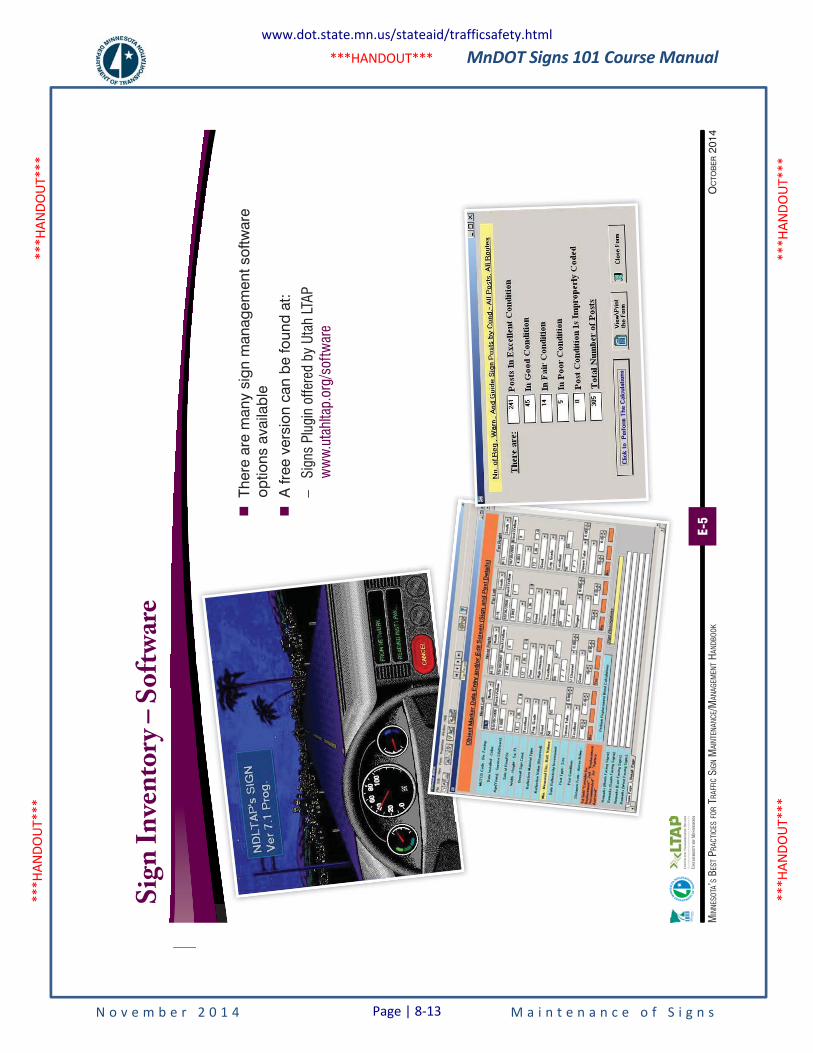
MnDOT Signs 101 Course Manual
N o v e m b e r 2 0 1 4 M a i n t e n a n c e o f S i g n s
***H
ANDO
UT**
* **
*HAN
DOUT
***
***H
ANDO
UT**
* **
*HAN
DOUT
***
***HANDOUT***
E-5
OC
TOB
ER 2
014
MIN
NESO
TA’S
BES
T PRA
CTIC
ES FO
R TR
AFFI
C SI
GN M
AINT
ENAN
CE/M
ANAG
EMEN
T HAN
DBOO
K
Sig
n I
nve
nto
ry –
So
ftw
are
�
Ther
e ar
e m
any
sign
man
agem
ent s
oftw
are
optio
ns a
vaila
ble
�
A fr
ee v
ersi
on c
an b
e fo
und
at:
–Si
gns
Plug
in o
ffere
d by
Uta
h LT
AP
ww
w.u
tahl
tap.
org/
softw
are
www.dot.state.mn.us/stateaid/trafficsafety.html
Page | 8-13
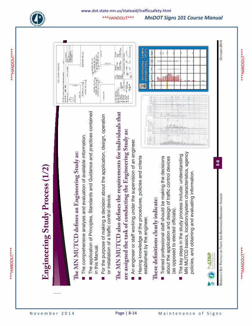
MnDOT Signs 101 Course Manual
N o v e m b e r 2 0 1 4 M a i n t e n a n c e o f S i g n s
***H
ANDO
UT**
* **
*HAN
DOUT
***
***H
ANDO
UT**
* **
*HAN
DOUT
***
***HANDOUT***
E-6
OC
TOB
ER 2
014
MIN
NESO
TA’S
BES
T PRA
CTIC
ES FO
R TR
AFFI
C SI
GN M
AINT
ENAN
CE/M
ANAG
EMEN
T HAN
DBOO
K
En
gin
eeri
ng
Stu
dy
Pro
cess
(1/
2)
The
MN
MU
TC
D d
efin
es a
n E
ngi
nee
rin
g S
tud
y as
:
�Th
e co
mpr
ehen
sive
ana
lysi
s an
d ev
alua
tion
of a
vaila
ble
info
rmat
ion.
�
The
appl
icat
ion
of P
rinci
ples
, Sta
ndar
ds a
nd G
uida
nce
and
prac
tices
con
tain
ed
in th
is M
anua
l.
�
For
the
purp
ose
of m
akin
g a
deci
sion
abo
ut th
e ap
plic
atio
n, d
esig
n, o
pera
tion
or in
stal
latio
n of
a tr
affic
con
trol
dev
ice.
The
MN
MU
TC
D a
lso
defi
nes
th
e re
qu
irem
ents
fo
r in
div
idu
als
that
ar
e as
sign
ed t
he
task
of
con
du
ctin
g th
e E
ngi
nee
rin
g S
tud
y as
:
�A
n en
gine
er o
r st
aff w
orki
ng u
nder
the
supe
rvis
ion
of a
n en
gine
er.
�
Hav
ing
know
ledg
e of
the
proc
edur
es, p
olic
ies
and
crite
ria
esta
blis
hed
by th
e en
gine
er.
Thes
e d
efin
itio
ns
clea
rly
ind
icat
e:
�Tr
aine
d pr
ofes
sion
al s
taff
shou
ld b
e m
akin
g th
e de
cisi
ons
abou
t the
app
licat
ion
and
desi
gn o
f tra
ffic
cont
rol d
evic
es
(as
oppo
sed
to e
lect
ed o
ffici
als)
.
�
The
key
step
s in
the
stud
y pr
oces
s in
clud
e: u
nder
stan
ding
M
N M
UTC
D b
asic
s, lo
catio
n/sy
stem
cha
ract
eris
tics,
age
ncy
polic
ies,
and
obt
aini
ng a
nd e
valu
atin
g in
form
atio
n.
www.dot.state.mn.us/stateaid/trafficsafety.html
Page | 8-14
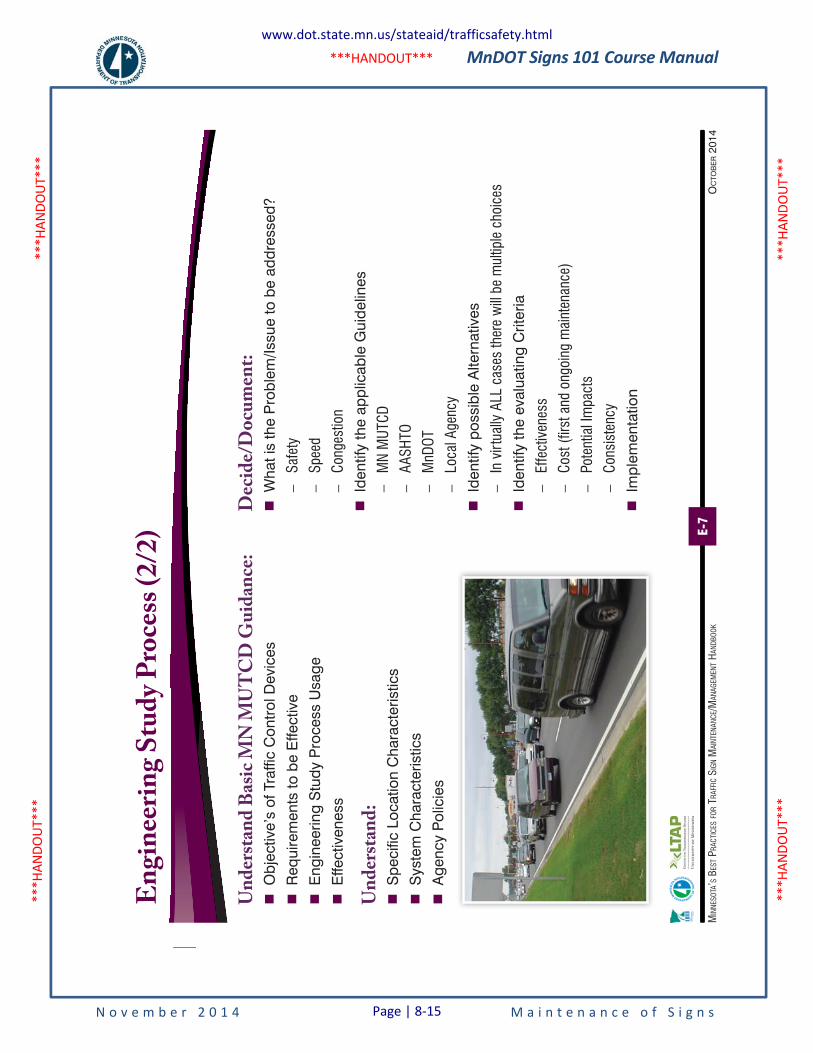
MnDOT Signs 101 Course Manual
N o v e m b e r 2 0 1 4 M a i n t e n a n c e o f S i g n s
***H
ANDO
UT**
* **
*HAN
DOUT
***
***H
ANDO
UT**
* **
*HAN
DOUT
***
***HANDOUT***
E-7
OC
TOB
ER 2
014
MIN
NESO
TA’S
BES
T PRA
CTIC
ES FO
R TR
AFFI
C SI
GN M
AINT
ENAN
CE/M
ANAG
EMEN
T HAN
DBOO
K
En
gin
eeri
ng
Stu
dy
Pro
cess
(2/
2)
Un
der
stan
d B
asic
MN
MU
TC
D G
uid
ance
:
�O
bjec
tive’
s of
Tra
ffic
Con
trol
Dev
ices
�
Req
uire
men
ts to
be
Effe
ctiv
e
�
Eng
inee
ring
Stu
dy P
roce
ss U
sage
�
Effe
ctiv
enes
s
Un
der
stan
d:
�
Spe
cific
Loc
atio
n C
hara
cter
istic
s
�
Sys
tem
Cha
ract
eris
tics
�
Age
ncy
Pol
icie
s
Dec
ide/
Do
cum
ent:
�
Wha
t is
the
Pro
blem
/Issu
e to
be
addr
esse
d?
–Sa
fety
–Sp
eed
–Co
nges
tion
�
Iden
tify
the
appl
icab
le G
uide
lines
–M
N M
UTCD
–AA
SHTO
–M
nDOT
–Lo
cal A
genc
y
�
Iden
tify
poss
ible
Alte
rnat
ives
–In
virt
ually
ALL
cas
es th
ere
will
be m
ultip
le c
hoic
es
�
Iden
tify
the
eval
uatin
g C
riter
ia
–Ef
fect
iven
ess
–Co
st (f
irst a
nd o
ngoi
ng m
aint
enan
ce)
–Po
tent
ial I
mpa
cts
–Co
nsis
tenc
y
�
Impl
emen
tatio
n
www.dot.state.mn.us/stateaid/trafficsafety.html
Page | 8-15
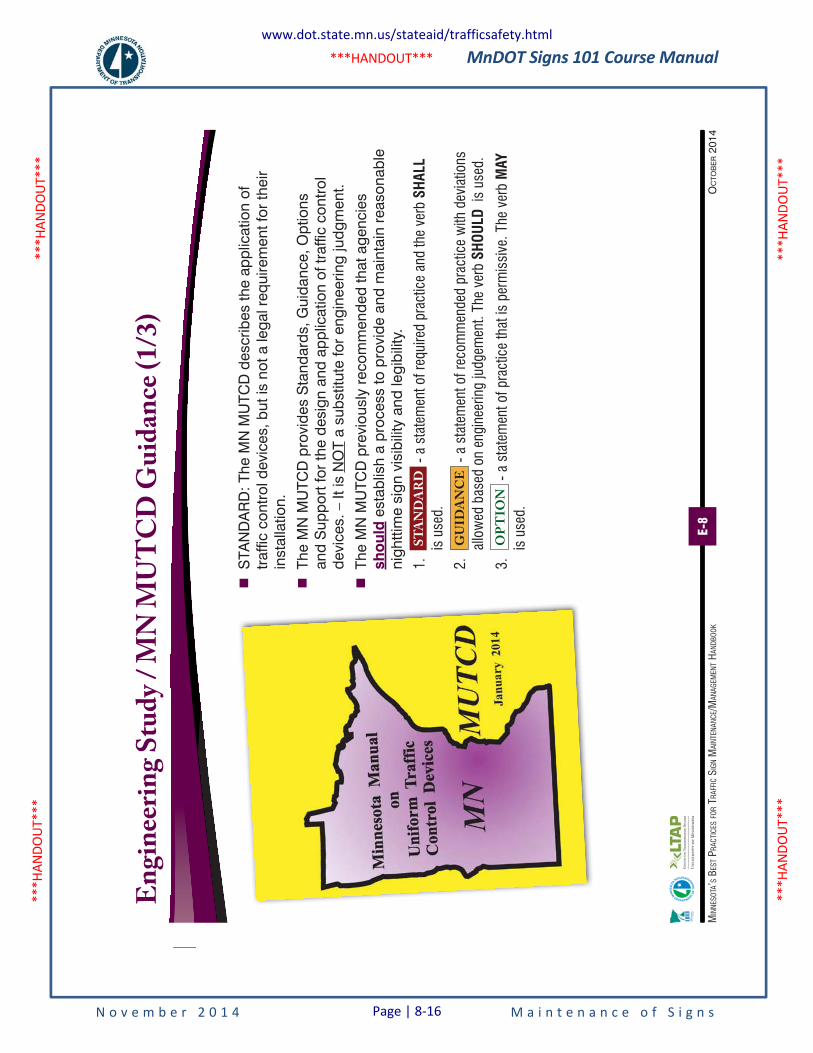
MnDOT Signs 101 Course Manual
N o v e m b e r 2 0 1 4 M a i n t e n a n c e o f S i g n s
***H
ANDO
UT**
* **
*HAN
DOUT
***
***H
ANDO
UT**
* **
*HAN
DOUT
***
***HANDOUT***
E-8
OC
TOB
ER 2
014
MIN
NESO
TA’S
BES
T PRA
CTIC
ES FO
R TR
AFFI
C SI
GN M
AINT
ENAN
CE/M
ANAG
EMEN
T HAN
DBOO
K
En
gin
eeri
ng
Stu
dy
/ M
N M
UT
CD
Gu
idan
ce (
1/3)
�
STA
ND
AR
D: T
he M
N M
UTC
D d
escr
ibes
the
appl
icat
ion
of
traf
fic c
ontr
ol d
evic
es, b
ut is
not
a le
gal r
equi
rem
ent f
or th
eir
inst
alla
tion.
�
The
MN
MU
TCD
pro
vide
s S
tand
ards
, Gui
danc
e, O
ptio
ns
and
Sup
port
for
the
desi
gn a
nd a
pplic
atio
n of
traf
fic c
ontr
ol
devi
ces.
– It
is N
OT
a su
bstit
ute
for
engi
neer
ing
judg
men
t.
�
The
MN
MU
TCD
pre
viou
sly
reco
mm
ende
d th
at a
genc
ies
sho
uld
est
ablis
h a
proc
ess
to p
rovi
de a
nd m
aint
ain
reas
onab
le
nigh
ttim
e si
gn v
isib
ility
and
legi
bilit
y.
1.
ST
AN
DA
RD
- a
stat
emen
t of r
equi
red
prac
tice
and
the
verb
SHA
LL
is u
sed.
2.
GU
IDA
NC
E -
a st
atem
ent o
f rec
omm
ende
d pr
actic
e w
ith d
evia
tions
al
low
ed b
ased
on
engi
neer
ing
judg
emen
t. Th
e ve
rb S
HOUL
D is
use
d.
3.
OP
TIO
N -
a st
atem
ent o
f pra
ctic
e th
at is
per
mis
sive
. The
ver
b M
AY
is u
sed.
www.dot.state.mn.us/stateaid/trafficsafety.html
Page | 8-16
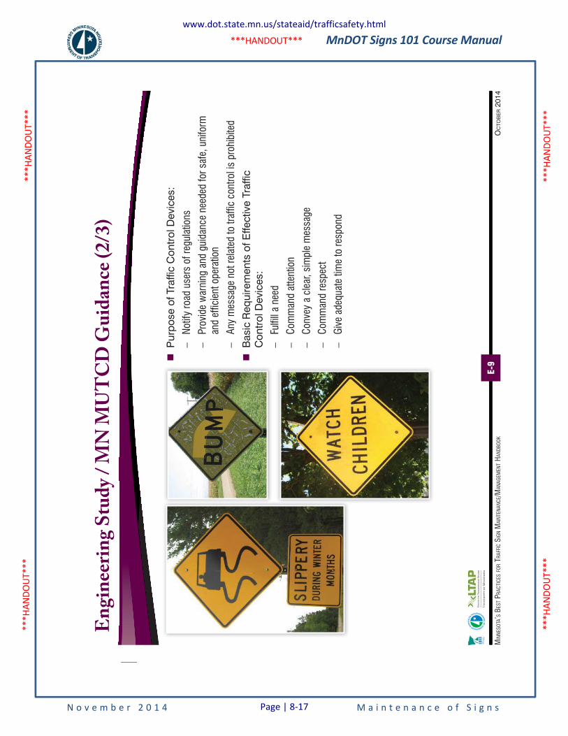
MnDOT Signs 101 Course Manual
N o v e m b e r 2 0 1 4 M a i n t e n a n c e o f S i g n s
***H
ANDO
UT**
* **
*HAN
DOUT
***
***H
ANDO
UT**
* **
*HAN
DOUT
***
***HANDOUT***
E-9
OC
TOB
ER 2
014
MIN
NESO
TA’S
BES
T PRA
CTIC
ES FO
R TR
AFFI
C SI
GN M
AINT
ENAN
CE/M
ANAG
EMEN
T HAN
DBOO
K
En
gin
eeri
ng
Stu
dy
/ M
N M
UT
CD
Gu
idan
ce (
2/3)
�
Pur
pose
of T
raffi
c C
ontr
ol D
evic
es:
–No
tify
road
use
rs o
f reg
ulat
ions
–Pr
ovid
e w
arni
ng a
nd g
uida
nce
need
ed fo
r saf
e, u
nifo
rm
and
effic
ient
ope
ratio
n
–An
y m
essa
ge n
ot re
late
d to
traf
fic c
ontro
l is
proh
ibite
d
�
Bas
ic R
equi
rem
ents
of E
ffect
ive
Traf
fic
Con
trol
Dev
ices
:
–Fu
lfill
a ne
ed
–Co
mm
and
atte
ntio
n
–Co
nvey
a c
lear
, sim
ple
mes
sage
–Co
mm
and
resp
ect
–Gi
ve a
dequ
ate
time
to re
spon
d
www.dot.state.mn.us/stateaid/trafficsafety.html
Page | 8-17
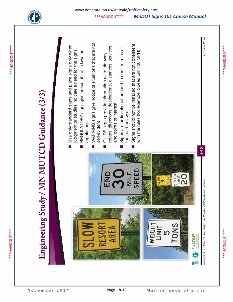
MnDOT Signs 101 Course Manual
N o v e m b e r 2 0 1 4 M a i n t e n a n c e o f S i g n s
***H
ANDO
UT**
* **
*HAN
DOUT
***
***H
ANDO
UT**
* **
*HAN
DOUT
***
***HANDOUT***
E-10
OC
TOB
ER 2
014
MIN
NESO
TA’S
BES
T PRA
CTIC
ES FO
R TR
AFFI
C SI
GN M
AINT
ENAN
CE/M
ANAG
EMEN
T HAN
DBOO
K
�
Use
onl
y st
anda
rd s
igns
and
pla
ce s
igns
onl
y w
hen
judg
men
t or
stud
ies
indi
cate
a n
eed
for
the
sign
s.
�
RE
GU
LATO
RY
sig
ns g
ive
notic
e of
traf
fic la
ws
or
regu
latio
ns.
�
WA
RN
ING
sig
ns g
ive
notic
e of
situ
atio
ns th
at a
re n
ot
self-
evid
ent
�
GU
IDE
sig
ns p
rovi
de in
form
atio
n as
to h
ighw
ay
rout
es, d
irect
ions
, des
tinat
ions
, dis
tanc
es, s
ervi
ces
and
poin
ts o
f int
eres
t.
�
Sig
ns a
re o
rdin
arily
not
nee
ded
to c
onfir
m r
ules
of
the
road
or
law
s.
�
Sig
ns s
houl
d no
t be
inst
alle
d th
at a
re n
ot c
onsi
sten
t w
ith th
e ru
les
(for
exa
mpl
e, S
peed
Lim
it 20
MP
H).
En
gin
eeri
ng
Stu
dy
/ M
N M
UT
CD
Gu
idan
ce (
3/3)
www.dot.state.mn.us/stateaid/trafficsafety.html
Page | 8-18
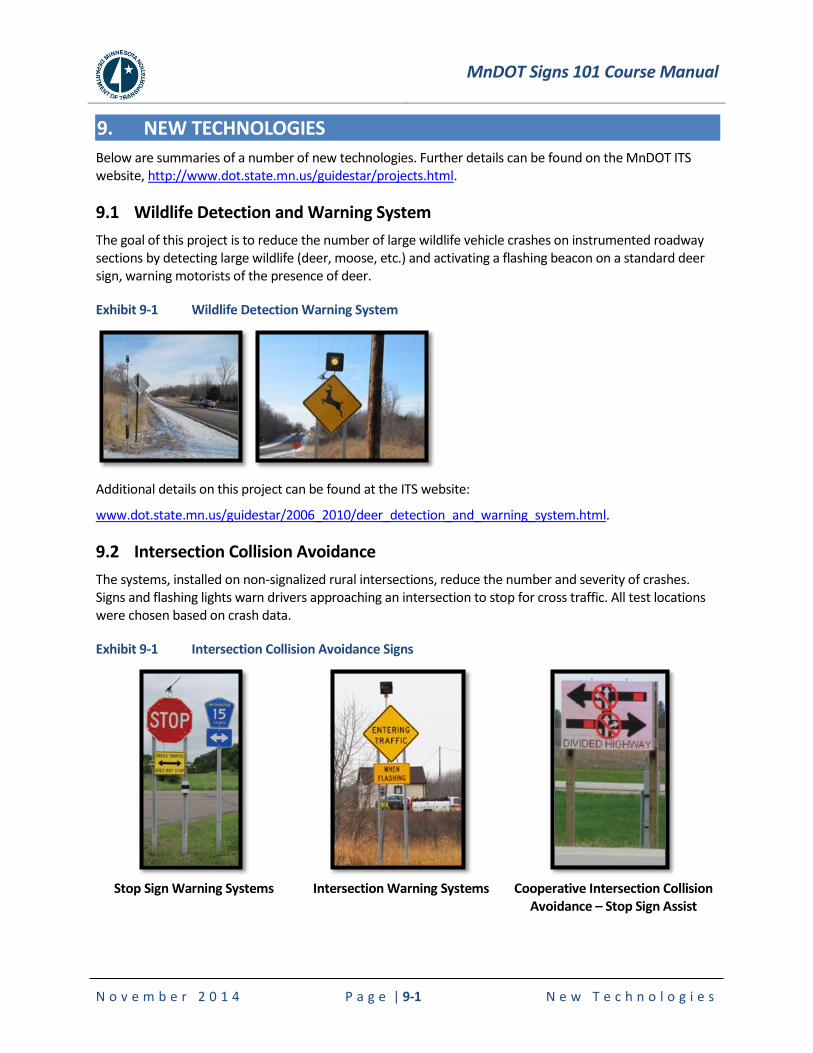
MnDOT Signs 101 Course Manual
N o v e m b e r 2 0 1 4 P a g e | 9-1 N e w T e c h n o l o g i e s
9. NEW TECHNOLOGIES
Below are summaries of a number of new technologies. Further details can be found on the MnDOT ITS website, http://www.dot.state.mn.us/guidestar/projects.html.
9.1 Wildlife Detection and Warning System
The goal of this project is to reduce the number of large wildlife vehicle crashes on instrumented roadway sections by detecting large wildlife (deer, moose, etc.) and activating a flashing beacon on a standard deer sign, warning motorists of the presence of deer.
Exhibit 9-1 Wildlife Detection Warning System
Additional details on this project can be found at the ITS website:
www.dot.state.mn.us/guidestar/2006_2010/deer_detection_and_warning_system.html.
9.2 Intersection Collision Avoidance
The systems, installed on non-signalized rural intersections, reduce the number and severity of crashes. Signs and flashing lights warn drivers approaching an intersection to stop for cross traffic. All test locations were chosen based on crash data.
Exhibit 9-1 Intersection Collision Avoidance Signs
Stop Sign Warning Systems Intersection Warning Systems Cooperative Intersection Collision
Avoidance – Stop Sign Assist
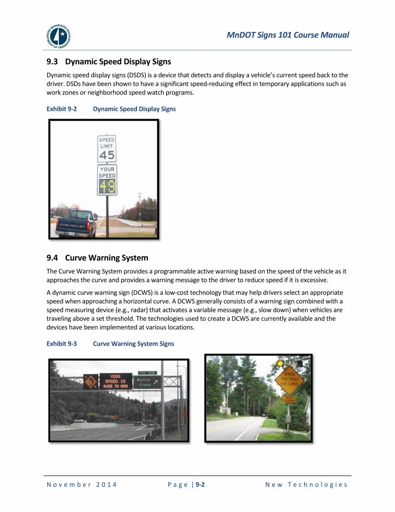
MnDOT Signs 101 Course Manual
N o v e m b e r 2 0 1 4 P a g e | 9-2 N e w T e c h n o l o g i e s
9.3 Dynamic Speed Display Signs
Dynamic speed display signs (DSDS) is a device that detects and display a vehicle’s current speed back to the driver. DSDs have been shown to have a significant speed-reducing effect in temporary applications such as work zones or neighborhood speed watch programs.
Exhibit 9-2 Dynamic Speed Display Signs
9.4 Curve Warning System
The Curve Warning System provides a programmable active warning based on the speed of the vehicle as it approaches the curve and provides a warning message to the driver to reduce speed if it is excessive.
A dynamic curve warning sign (DCWS) is a low-cost technology that may help drivers select an appropriate speed when approaching a horizontal curve. A DCWS generally consists of a warning sign combined with a speed measuring device (e.g., radar) that activates a variable message (e.g., slow down) when vehicles are traveling above a set threshold. The technologies used to create a DCWS are currently available and the devices have been implemented at various locations.
Exhibit 9-3 Curve Warning System Signs
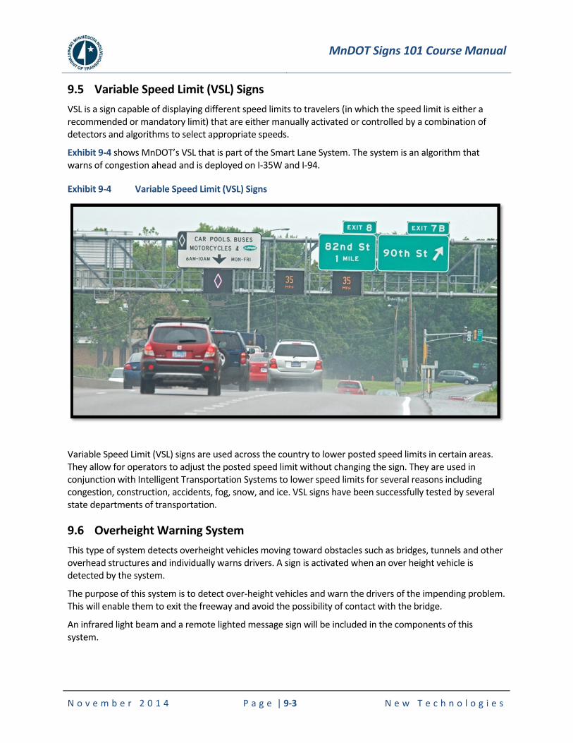
MnDOT Signs 101 Course Manual
N o v e m b e r 2 0 1 4 P a g e | 9-3 N e w T e c h n o l o g i e s
9.5 Variable Speed Limit (VSL) Signs VSL is a sign capable of displaying different speed limits to travelers (in which the speed limit is either a recommended or mandatory limit) that are either manually activated or controlled by a combination of detectors and algorithms to select appropriate speeds.
Exhibit 9-4 shows MnDOT’s VSL that is part of the Smart Lane System. The system is an algorithm that warns of congestion ahead and is deployed on I-35W and I-94.
Exhibit 9-4 Variable Speed Limit (VSL) Signs
Variable Speed Limit (VSL) signs are used across the country to lower posted speed limits in certain areas. They allow for operators to adjust the posted speed limit without changing the sign. They are used in conjunction with Intelligent Transportation Systems to lower speed limits for several reasons including congestion, construction, accidents, fog, snow, and ice. VSL signs have been successfully tested by several state departments of transportation.
9.6 Overheight Warning System This type of system detects overheight vehicles moving toward obstacles such as bridges, tunnels and other overhead structures and individually warns drivers. A sign is activated when an over height vehicle is detected by the system.
The purpose of this system is to detect over-height vehicles and warn the drivers of the impending problem. This will enable them to exit the freeway and avoid the possibility of contact with the bridge.
An infrared light beam and a remote lighted message sign will be included in the components of this system.
MnDOT Signs 101 Course Manual
N o v e m b e r 2 0 1 4 P a g e | 9-4 N e w T e c h n o l o g i e s
9.7 Water on Road System
This type of system is a highway sensor that measures the presence of water on the roadway and is linked to traveler information systems. The purpose is to warn drivers of water on a roadway advising them not to pass.
9.8 Fog Warning System
This type of system is a highway visibility sensor that measures the density of roadway fog and is linked to traveler information systems. The need for a highway fog warning system has long been internationally recognized. With such a system, motorists can avoid tragic pile-up accidents caused by dense or patchy fog, which are often fatal.

MnDOT Signs 101 Course Manual
N o v e m b e r 2 0 1 4 P a g e | 10-1 A p p e n d i x
10. APPENDIX
10.1 Frequently Asked Question
Source is from the MnDOT OTST Signing website
http://www.dot.state.mn.us/trafficeng/faq/faq-signing.html.
10.1.1 Business Signing Questions
Is my business or facility eligible to receive guide signing?
In order for a facility or business to receive supplemental guide signing, the sign location must meet engineering standards and the facility or business must meet MnDOT policy.
Engineering standards
Furthermore, different types of signs (regulatory, warning, and guide) cannot be combined. For example, mixing a golf course sign with a speed limit sign is not allowed. This leaves limited space for supplemental guide signs.
MnDOT policy
There is tremendous demand for signing along our highway system; many businesses, organizations and agencies feel that they need and deserve signing to advertise, inform and/or aid the motorist in locating their establishment. As discussed under engineering standards, it is necessary to limit all signing to only that which is sufficient to aid drivers in safely arriving at their destination. As such, MnDOT policy and state law set out criteria that a facility must meet in order to be eligible for signing.
What types of business signing does MnDOT allow on state highways?
Logo
Gas, food, lodging, and camping.
Signs may be installed on interstates and certain other controlled-access (freeway) highways.
Each facility must meet certain criteria related to hours of operation, licensing, distance from interchange, etc.
The cost of fabrication, installation, and maintenance are paid by the business.
This program is managed by Minnesota Logos, Inc. under an agreement with MnDOT.
General motorists services
Gas, food, lodging, camping and hospitals.
Signs may be installed at rural freeway and expressway interchanges.
Each facility must meet certain criteria related to hours of operation, licensing, distance from interchange, etc.
The cost of fabrication, installation, and maintenance are paid by MnDOT. MnDOT provides trailblazing signs.

MnDOT Signs 101 Course Manual
N o v e m b e r 2 0 1 4 P a g e | 10-2 A p p e n d i x
Major traffic generators
Major regional attractions that attract persons or groups beyond the local area.
Facilities must have parking for at least 1,000 vehicles, a minimum of 10 events per year, and average event attendance of at least 5,000 persons.
Signs may be installed on any trunk highway.
The cost of fabrication, installation, and maintenance of these signs are paid by the traffic generator. Trailblazing must be provided by the facility or local road authority.
Minor traffic generators
Facilities that generally attract non-local persons or groups, but do not qualify as major generators. These facilities should have broad motorist appeal, serve non-familiar motorists, and are the type of facility for which a motorist normally expects highway signing.
Facilities are typically cultural, recreational, or historic attractions.
Facilities must meet certain criteria related to hours of operation, etc.
These signs may be installed at at-grade intersections and some expressway interchanges.
The cost of fabrication, installation, and maintenance of these signs are paid by the traffic generator. Trailblazing must be provided by the facility or local road authority.
Other traffic generators
Include Airports, Casinos, Educational Institutions, National Parks, Regional Shopping Centers, and State Parks. Criteria vary.
Signs may be installed on any trunk highway.
The cost of fabrication, installation, and maintenance of these signs are paid by the traffic generator. Trailblazing must be provided by the facility or local road authority.
Specific services
Gas, food, lodging, places of worship, rural agricultural businesses and tourist-oriented businesses.
The criteria for installation of these signs (hours, types of businesses, etc.) are primarily defined in Minnesota Statutes 160.292 – 160.297.
These signs can only be installed in rural areas at at-grade intersections or at rural bypasses that have interchanges on expressways.
The cost of fabrication, installation, and maintenance of these signs are paid by the facility. Trailblazing must be provided by the facility or local road authority.
Who do I contact to see if my business qualifies for a sign?
To request signing for a facility on the state highway system, contact the appropriate District Traffic Engineer for your area.
In your request, please state the name and type of your business or facility, as well as its location.
What happens after I submit my request for signing (including costs)?

MnDOT Signs 101 Course Manual
N o v e m b e r 2 0 1 4 P a g e | 10-3 A p p e n d i x
District staff will work with you to determine whether your facility qualifies for signs on the trunk highway. This decision takes into account the type of facility and whether it meets the requirements of MnDOT’s various signing programs. Additionally, a field check is performed to determine whether there is available space for the sign(s) along the trunk highway as well as at exit ramps or near the closest intersection.
If signing is approved for your facility, the MnDOT District Traffic Office will contact you with an application form as well as the estimated cost of the sign(s). This cost includes the fabrication of the sign panel, structural materials, equipment, and installation labor costs. This is a one-time fee that lasts for the life of the sign.
After the completed application and payment are received by MnDOT, it may take 1- 3 months to have signs installed depending on weather.
What if my request for signing is not approved?
MnDOT retains the authority to deny requests for signing where acceptable standards cannot be met, including locations where other supplemental guide signs are already in place. Requests denied based on Minnesota statutes or engineering standards (i.e. insufficient space and design standards) may not be appealed. At the discretion of the District Traffic Engineer, signing requests denied based on MnDOT policy may be appealed to the External Sign Variance Committee (ESVC).
For more information regarding making an appeal to the ESVC, contact Joani Nilan at 651-234-7384.
How do I get my business logo placed on the blue freeway signs?
This is the Logo Sign Program, which operates separately from other state signing programs. Logo signs provide road users with business identification and directional information for services and for eligible attractions. FHWA limits the eligible service categories to include gas, food, lodging, 24-hour pharmacies, camping, and attractions.
Read more about Minnesota’s Logo Signing Program.
To request logo signing, contact Dave DeSutter, General Manager of Minnesota Logos, Inc. or go to http://www.minnesota.interstatelogos.com/state/home.aspx.

MnDOT Signs 101 Course Manual
N o v e m b e r 2 0 1 4 P a g e | 10-4 A p p e n d i x
10.1.2 Non-Business Signing Questions
How do I go about getting a STOP sign installed at an intersection?
If the local road intersects a state highway, a field evaluation and engineering study needs to be conducted by MnDOT; refer to the State Traffic Engineer's Directory and contact the appropriate district traffic office to initiate this process. If a local road intersects with another local road, contact the local road authority (i.e. City of Minneapolis or Hennepin County, etc).
I would like to have a deer crossing sign installed. How do I go about getting this accomplished?
Data has shown that installing static deer warning signs has not been effective in reducing deer-vehicle crashes. As such, MnDOT policy is to no longer install static deer crossing signs. Existing signs are being removed after they reach the end of their useful lives.
View a summary of MnDOT’s position regarding deer crossing signs and supporting research (PDF, 44 KB).
I would like to have a "deaf child/blind child/slow children at play" sign installed on my street/highway near my home. How do I get this accomplished?
MnDOT does not install this type of sign on state highways since it is not enforceable (it is a warning sign) and it can lead to a false sense of security. If you are requesting signing on a local road, contact the local road authority.
How do I go about having a bridge or highway section dedicated to a group (i.e. Vietnam Veterans Bridge or Highway)?
MnDOT does not memorialize highways. Memorialization of highways is done by an act of the Minnesota Legislature. If the legislature has memorialized a highway, MnDOT typically installs signs at specified location near the beginning of the route. On interstate routes, signs are placed in rest areas. Signs must meet the requirements of the Minnesota Manual on Uniform Traffic Control Devices. This document defines the size, color, shape, location, and allowable message on signs. This document is defined in both federal and state law and governs all traffic control devices on a roadway. If a route is memorialized the organization or individuals requesting the designation pay for the design, fabrication, installation and maintenance of the signs.
If the bridge or highway section is not on a state highway, contact the local road authority.
How do I obtain a sign to use as a graphic display for a workshop/training class?
MnDOT does not fabricate signs to sell to the public. To find out sign costs and have a sign fabricated contact:
Earl F. Andersen at 952-884-7300
Gopher Sign at 651-698-5095
Lyle Signs at 952-934-7653
M&R Sign at 218-736-5681

MnDOT Signs 101 Course Manual
N o v e m b e r 2 0 1 4 P a g e | 10-5 A p p e n d i x
10.1.3 Signing Specifications Questions
Why are some cities included on the large green guide signs at interstate highway intersections?
There is a national publication by the American Association of State Highway and Transportation Officials (AASHTO) that lists what are referred to as control cities. Control cities are “cities which have been determined by each state to be major destinations and population centers located on or near the Interstate Highway System.”
These cities are listed sequentially on guide signs along the Interstate, and remain on successive signs until that destination is reached.
What is the purpose of the numbers on signs every mile along state highways?
These are called reference location signs. They are installed every mile on all state highways. The beginning reference point is "0" at the western border of the state for east/west highways and "0" at the southern border of the state for north/south highways. If the highway does not extend to a western or southern border, then the beginning reference point is at the westernmost or southernmost limit of the highway.
How are EXIT Numbers determined?
Exit numbering in Minnesota is used on Interstate freeways. Exit numbering is based on the reference location signs as mentioned in the previous question (i.e.; an exit located between reference location sign 48 and 49 would be numbered Exit Number 48). If multiple exits are located within the same mile, the exit is numbered with a letter following, such as 48A and 48B. The lettering follows alphabetically from west to east and south to north. For more information, on the rules regarding the numbering system or the exit number for a specific interchange, contact Heather Lott at 651-234-7371 or Rick Sunstrom at 651-234-7381.
What manuals, standards, sample plans, specifications are available for review and guidance for roadway signing?
The most frequently used signing manuals are typically:
Minnesota Manual on Uniform Traffic Control Devices – state standards for uniformity of sign design and placement, based upon federal standards
Traffic Engineering Manual – Chapter 6 – supplements the Minnesota Manual on Traffic Control Devices by providing additional guidelines on use of standard signs, as well as MnDOT’s guide and business signing policies.
Minnesota Standard Signs Manual – listing of the standard signs used throughout Minnesota, including dimensioned drawings of sign panels for fabrication purposes
Minnesota Standard Sign Summary – handbook used for identifying standard signs and appropriate panel size based upon roadway type
Additional manuals can be found by checking the Signing - Manuals, Handbooks and Guidelines website and/or Traffic Engineering - Publications for a listing of available online documents.
What is the legal height for vehicles on highways and when does MnDOT install clearance signs?
The legal height for vehicles is 13 feet, 6 inches. The low clearance sign is used to warn road users of clearances less than 12 inches above this legal height. Clearance below bridges on freeways is typically 16 feet, 4 inches and for overhead mounted signs is 17 feet, 4 inches.

MnDOT Signs 101 Course Manual
N o v e m b e r 2 0 1 4 P a g e | 10-6 A p p e n d i x
What is the proper mounting height for Disabled Parking signs?
If installed for a parallel parking spot on an urban street, the bottom of the sign needs to be 7 feet above the sidewalk. If installed in a parking lot, the sign must be visible to the driver when the vehicle is parked in the disabled parking space.
What does the 6% mean on a hill sign?
6% refers to the amount of slope of the highway from the top to the bottom of the hill - 6 percent means that for every 100 feet horizontally, the highway drops 6 feet. These signs are placed in advance of steep grades requiring special precaution on the part of road users.
Does MnDOT use plywood or plastic for its signs?
No. MnDOT only uses aluminum as the base material for sign panels. Sheet aluminum is used for smaller signs; larger signs and overhead mounted signs are made with extruded aluminum panels.
What type of sheeting materials does MnDOT use for its signs?
MnDOT uses sheeting materials listed on our Approved Products List. Currently, the type of material used by MnDOT is Type XI retroreflective sheeting. For other specifics on MnDOT sign sheeting materials or the Approved Products List, contact Michelle Moser at 651-234-7380.
MnDOT Signs 101 Course Manual
N o v e m b e r 2 0 1 4 P a g e | 10-7 A p p e n d i x
10.2 Sample Plan Set
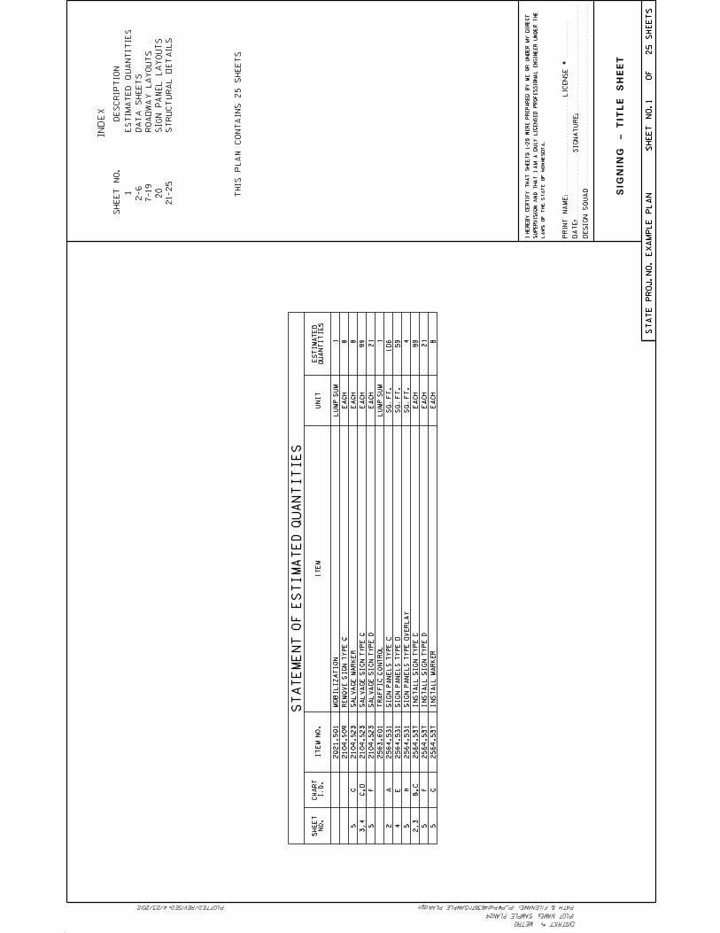
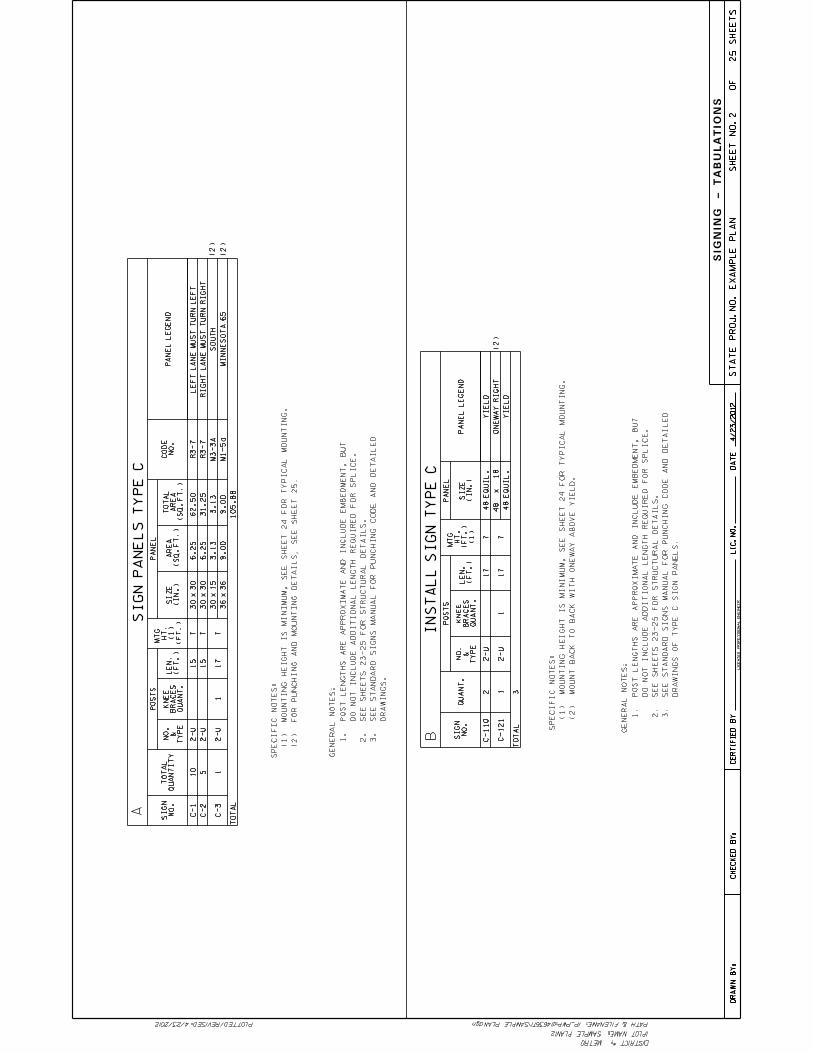
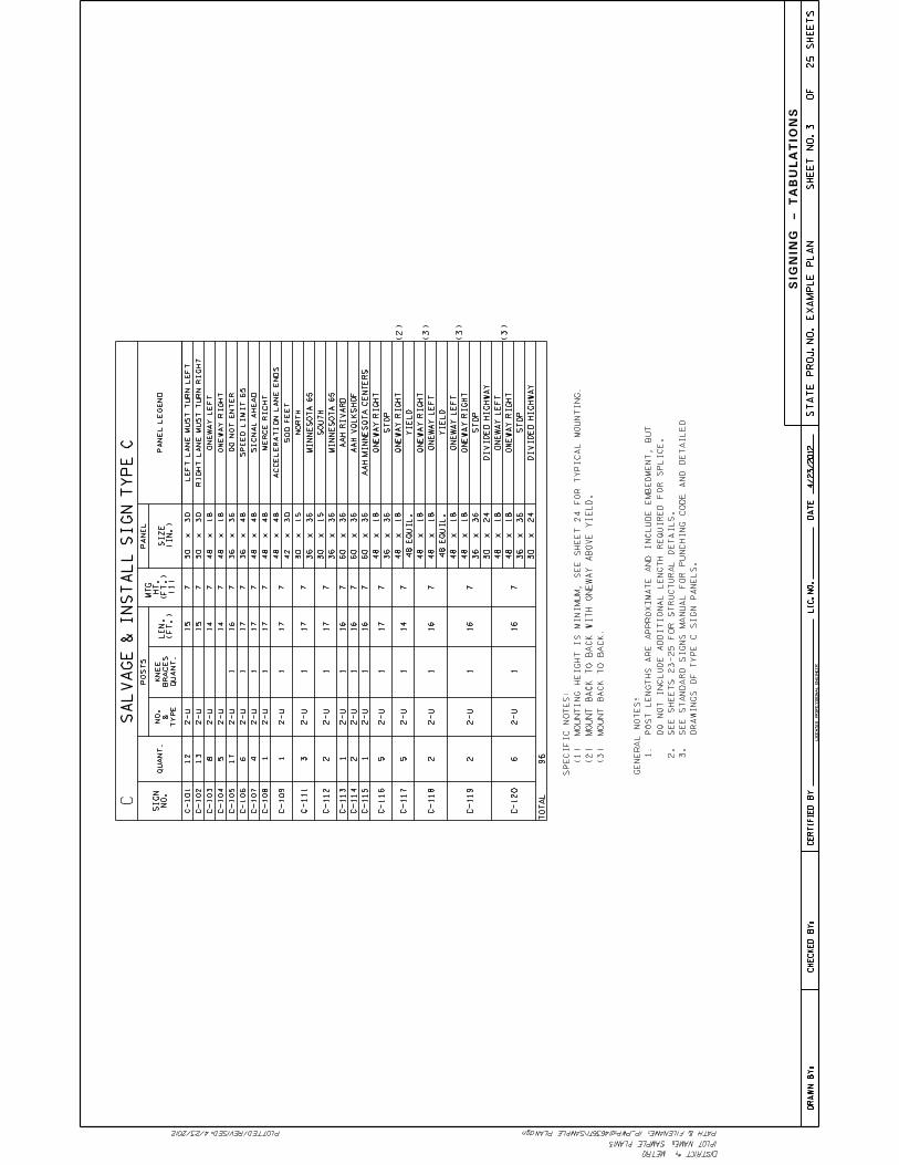
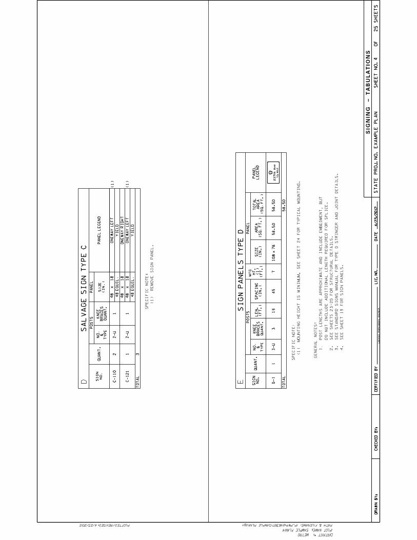
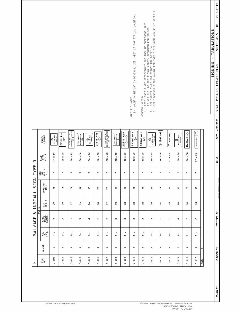

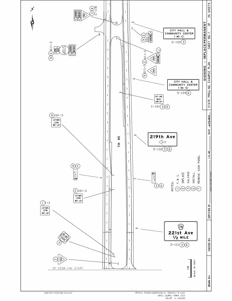
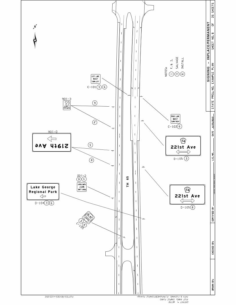
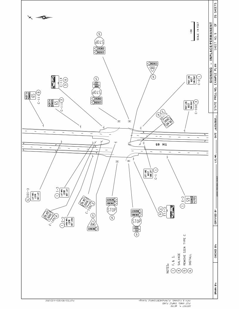
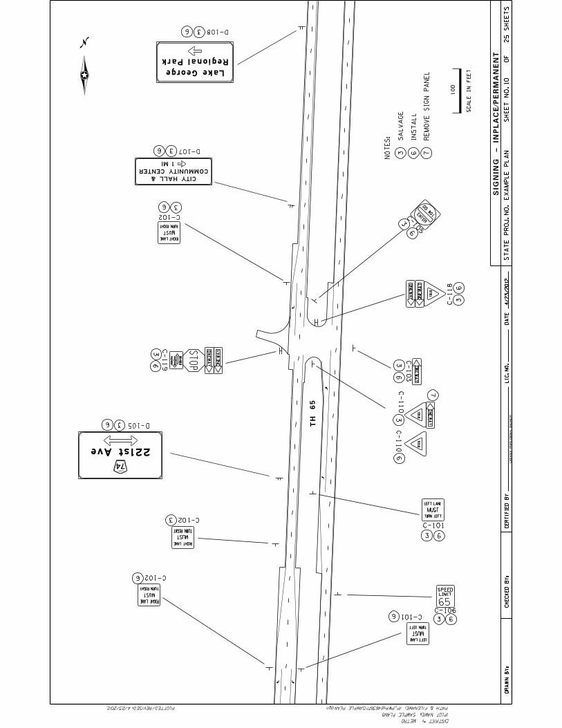
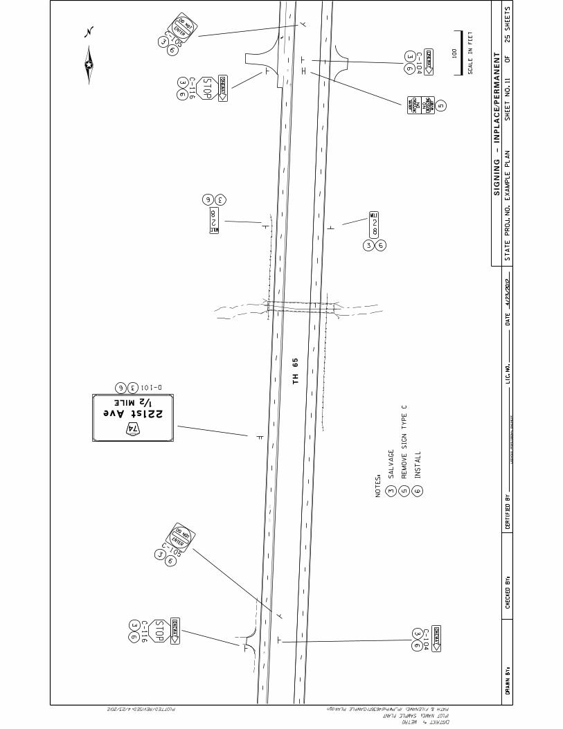
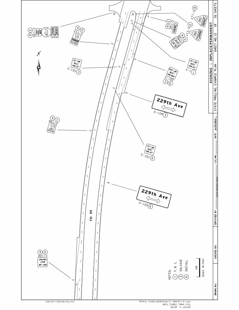
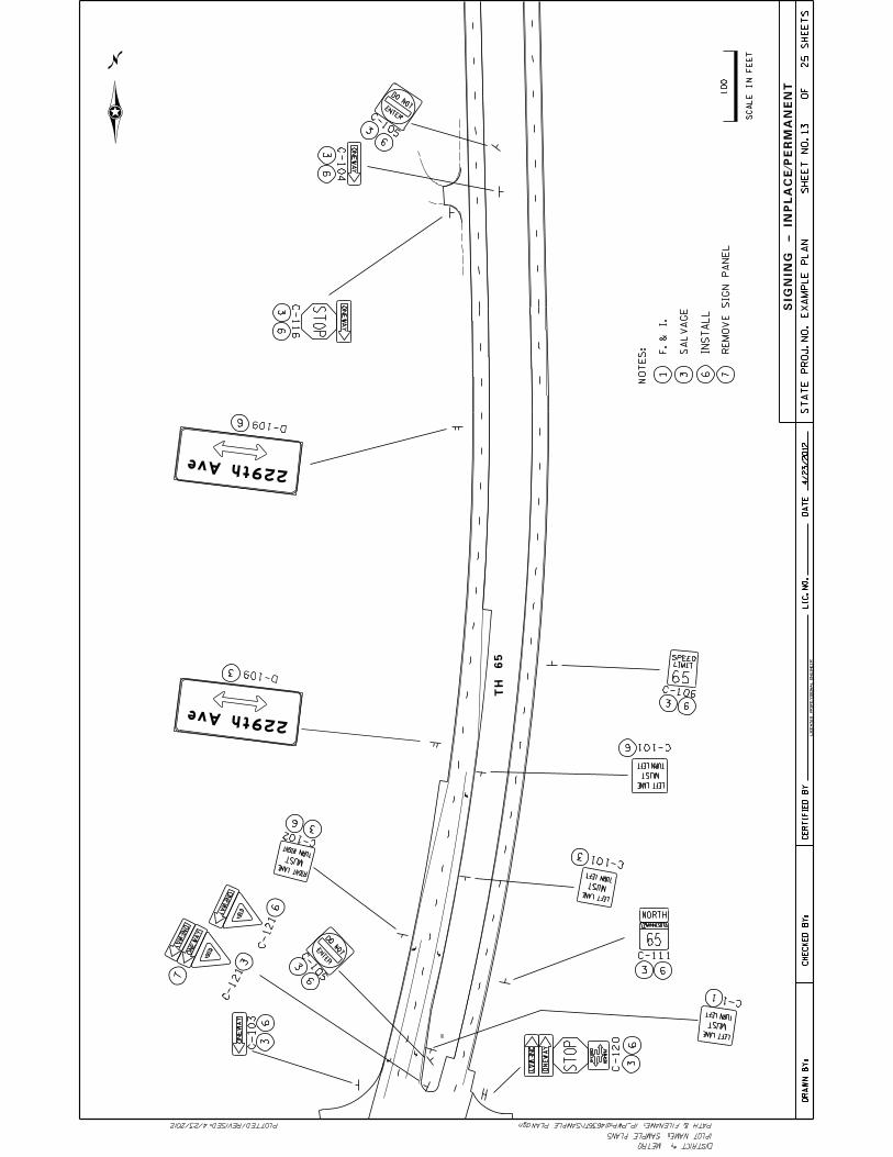
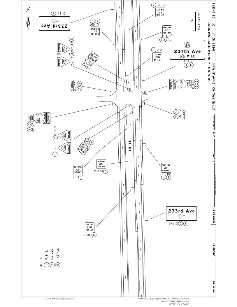
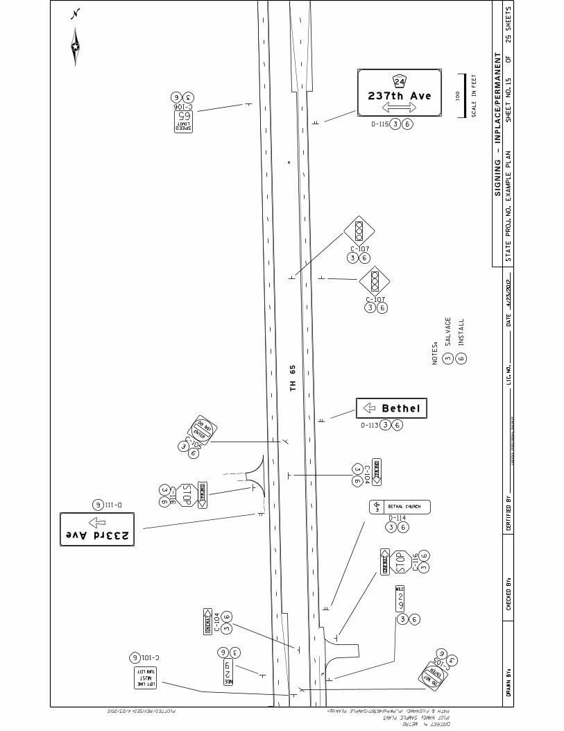
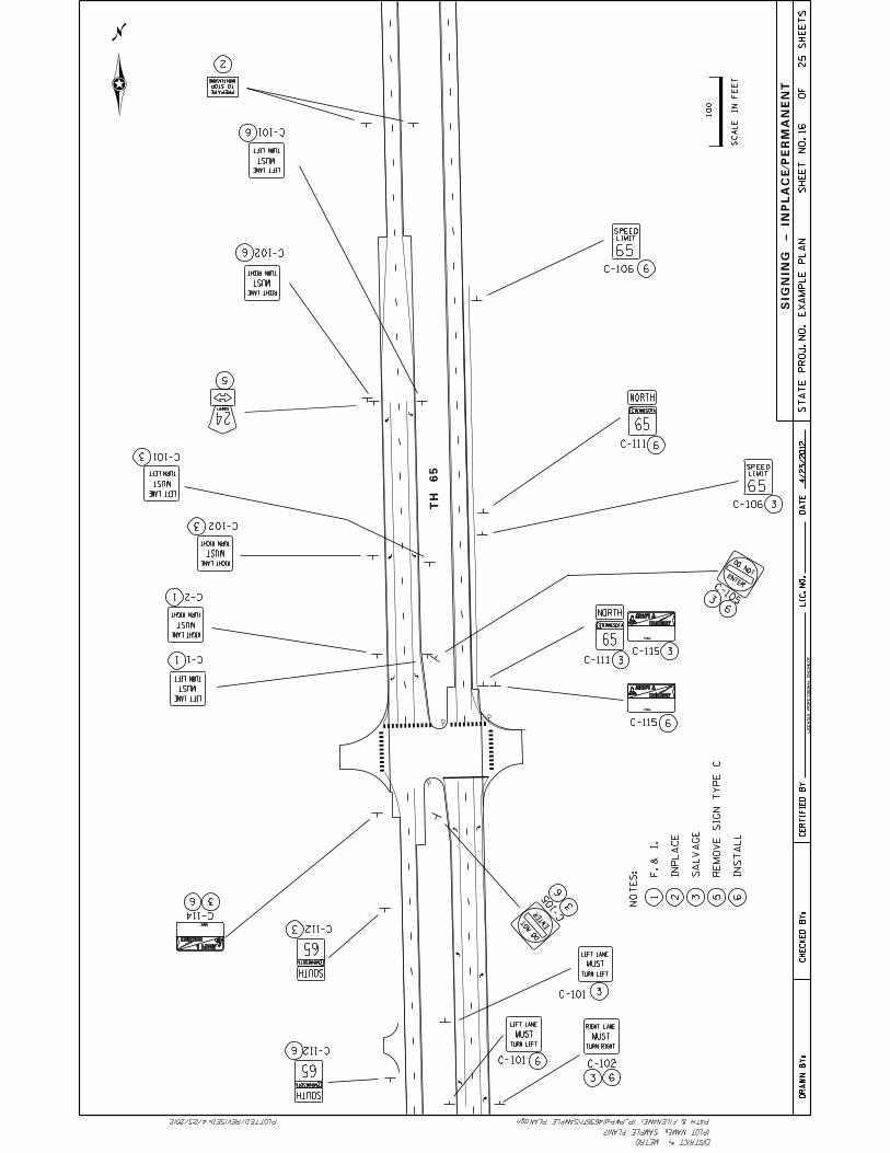
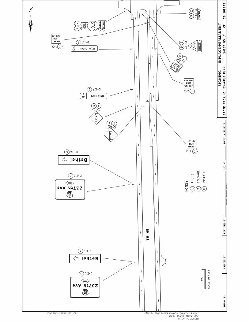
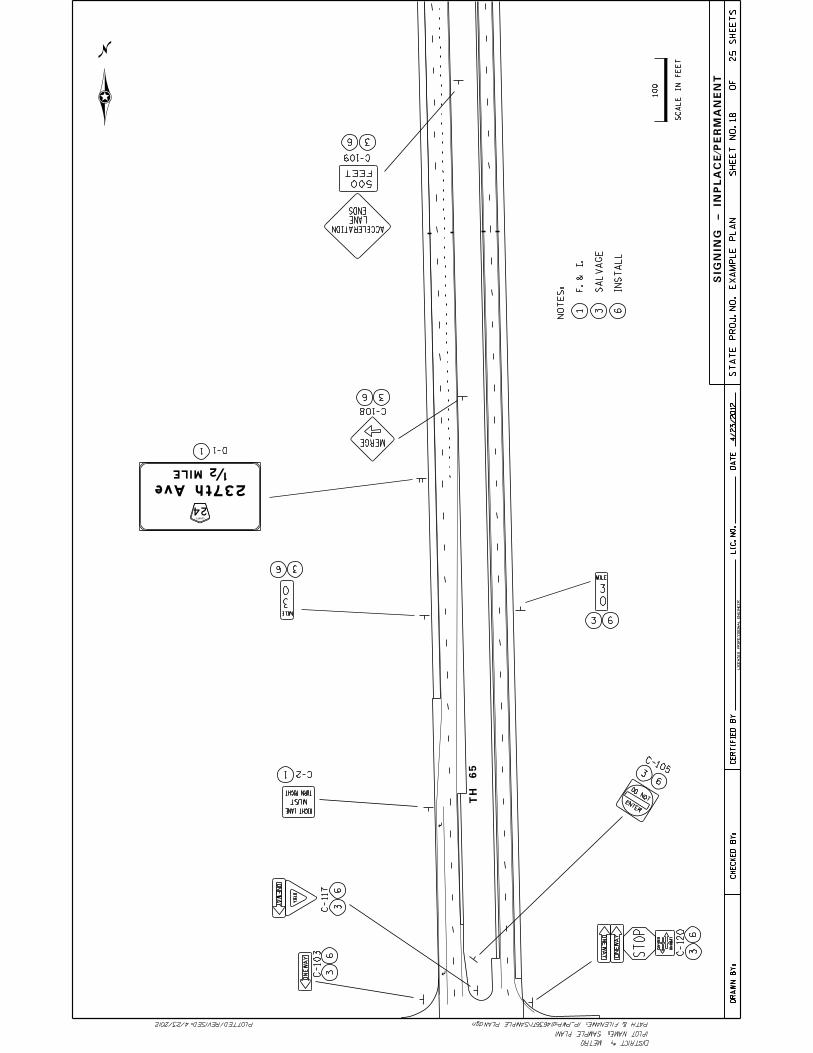
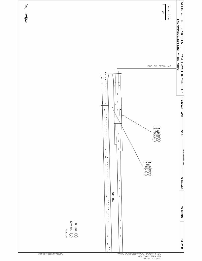
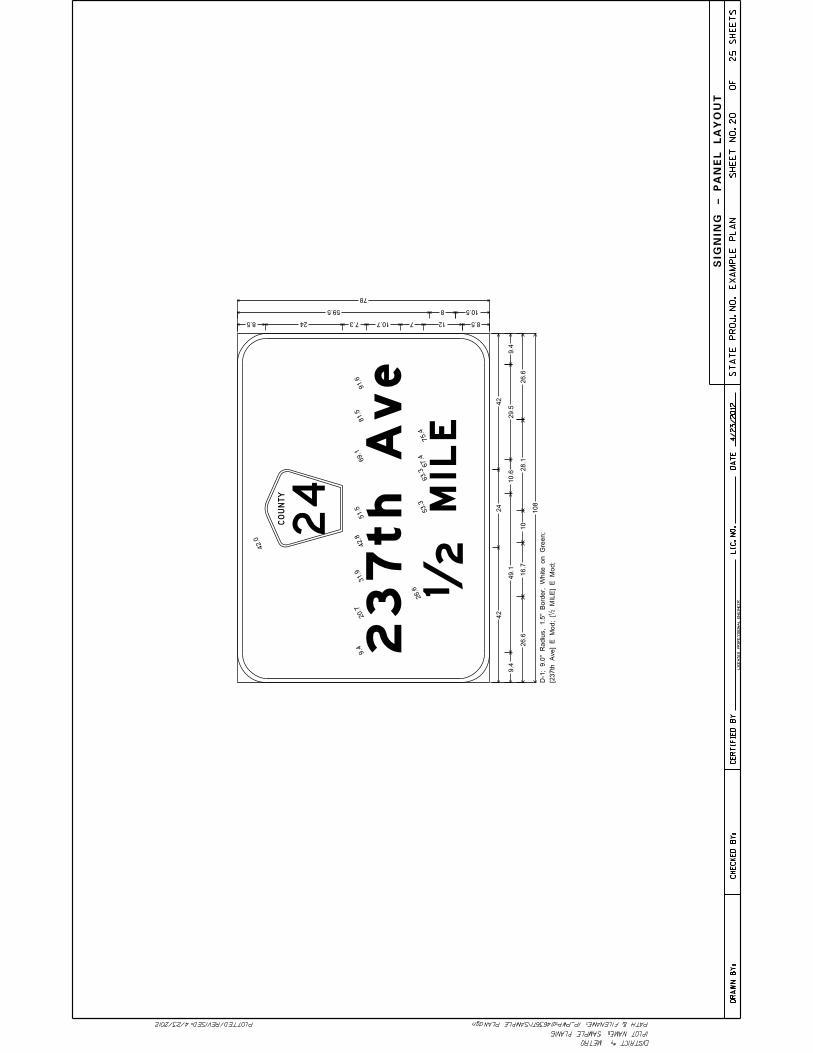
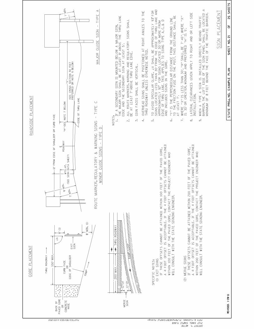
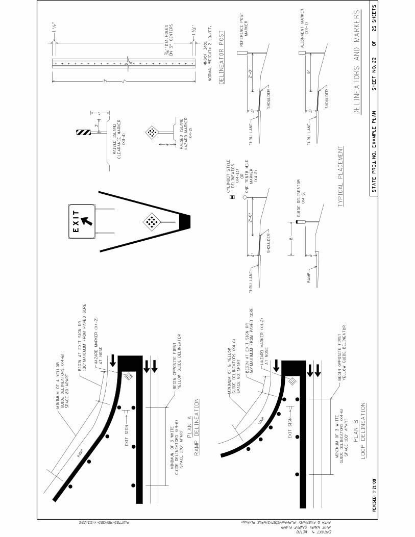
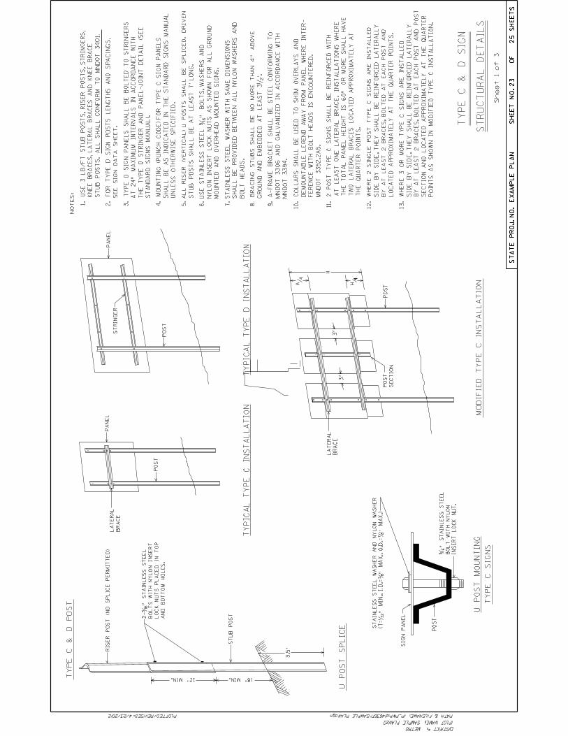
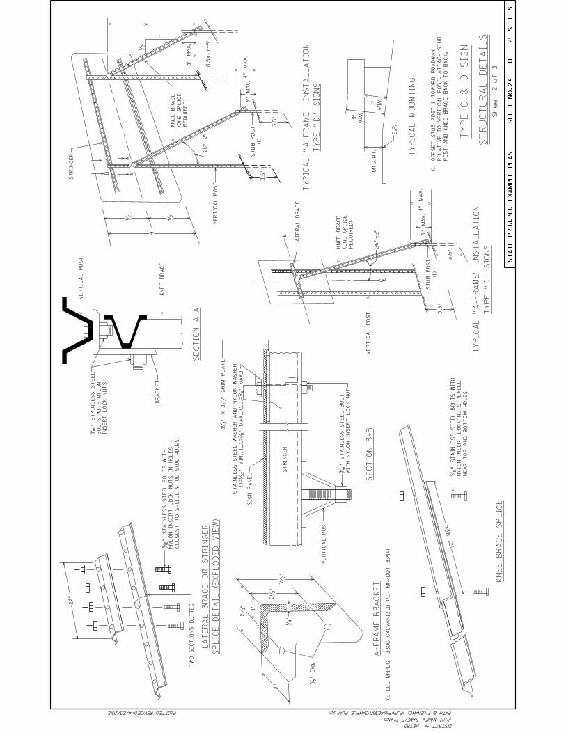
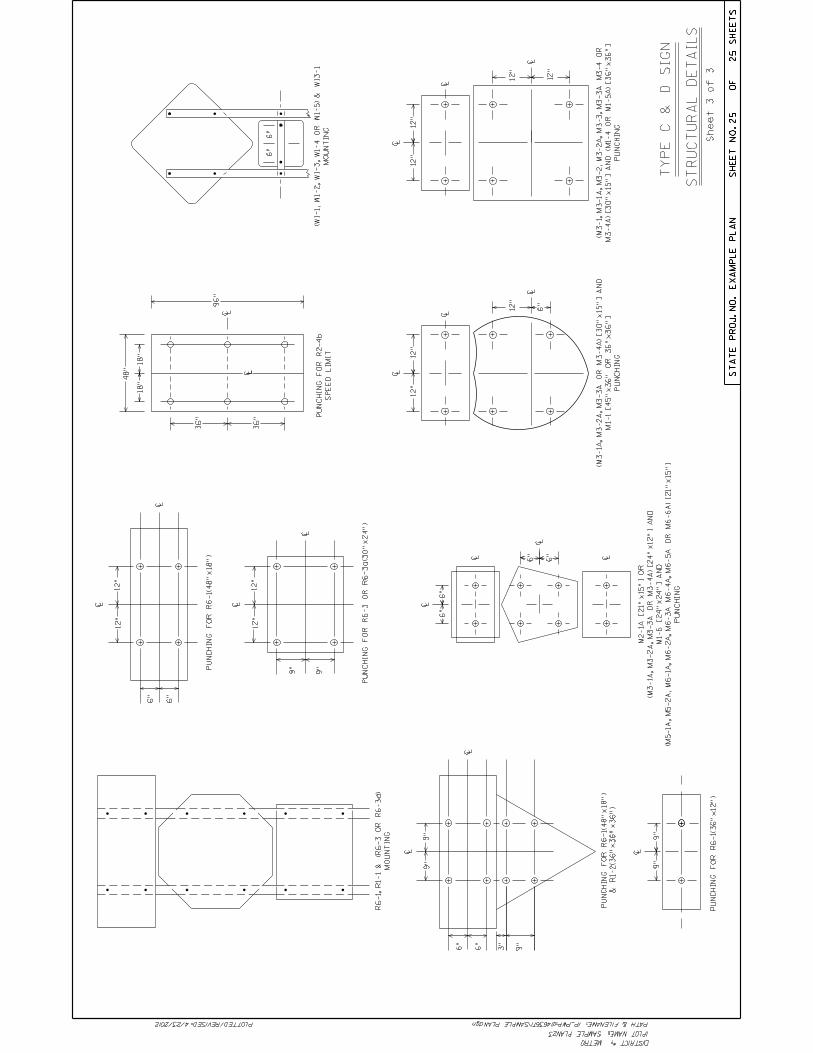

Notes:

Notes: