Embed Size (px)
Citation preview
INTERNATIONAL JOURNAL of RENEWABLE ENERGY RESEARCH Nazmul Islam Raju et al., Vol.3, No.3
Sinusoidal PWM Signal Generation Technique for
Three Phase Voltage Source Inverter with Analog
Circuit & Simulation of PWM Inverter for
Standalone Load & Micro-grid System
Nazmul Islam Raju*‡, Md. Shahinur Islam*, Ahmed Ahsan Uddin*
*Department of EEE, American International University-Bangladesh
([email protected], [email protected], [email protected])
‡Corresponding Author; Nazmul Islam Raju, Department of EEE,
American International University-Bangladesh, [email protected]
Abstract- Inverter is the most important device to utilize the renewable energy sources efficiently. The Sinusoidal Pulse Width
Modulation (SPWM) technique is one of the most popular PWM techniques for harmonic reduction of inverters since there are
used three sine waves displaced in 1200
phase difference as reference signals for three phase inverter. Nowadays the SPWM
switching signal is generated with the help of different FPGAs, microcontrollers and microprocessors. But for these kind of
devices it is necessary the programming or coding. This paper represents the SPWM technique for harmonic reduction &
shows how to generate SPWM switching signal using different simple Operational-Amplifier (Op-Amp) circuits/analog
circuits for three phase pulse width modulated (PWM) voltage source inverter (VSI). All the Op-Amp circuits are simulated
and their outputs are shown step by step. This analog circuit (Op-Amp) controlled voltage source inverter is simulated for both
standalone load & high voltage sensitive loads/systems like micro-grid system and large industrial machines respectively with
transformer & without transformer. The simulation results are shown before and after harmonic reduction using an appropriate
passive filter. Furthermore, the paper represents two typical inverter based micro grid system structures where one is with
common DC bus & another one is with common AC bus.
Keywords- Op-Amp, MOSFET, Inverter, VSI, SPWM, Load, Micro-grid, Harmonics, Filter
1. Introduction
In the last years, new energy sources have been proposed
and developed due to the dependency and constant increase
of costs of fossil fuels. On other hand, fossil fuels have a
huge negative impact on the environment. In this context, the
new energy sources are essentially renewable energies [1]. It
is estimated that the electrical energy generation from
renewable energy sources will increase from 19%, in 2010,
to 32%, in 2030, leading to a consequent reduction of CO2
emission [2]. In rural areas particularly in the developing
world, where most of the population up to 80% is located,
more than 1 billion people lack the essential energy services
to satisfy the most basic needs and to improve their social
and economic status [3]. The growing energy demand around
the world led us to utilize these renewable energy resources.
In recent years, the efforts to spread the use of renewable
energy resources instead of pollutant fossil fuels and other
forms have increased [4]. To utilize these renewable energy
resources an inverter is essential which converts DC power
to AC power as most of the renewable energy is found in DC
form. In hybrid power system and micro-grid system the use
of inverter is significant. In industrial applications, such as
single phase and Three Phase Induction Motor & other
rotating machines, variable frequency &variable voltage
supply is needed. To vary the supply frequency and supply
voltage, voltage source inverter (VSI) is used. The voltage
source inverters (VSIs), where the independently controlled
AC output is a voltage waveform, behave as voltage sources
required by many industrial applications [5]. While the
single-phase VSIs cover low-range power applications,
three-phase VSIs cover medium to high-power applications.
INTERNATIONAL JOURNAL of RENEWABLE ENERGY RESEARCH Nazmul Islam Raju et al., Vol.3, No.3
648
Three-phase bridge inverters are widely used in motor drives
and general-purpose AC supplies [5]. For the following
energy sources and loads inverters are necessary:
Photovoltaic System (PV).
Variable speed wind power system.
Hybrid power system.
UPS/IPS system.
Micro grid & Distributed generation (DG) system.
Electric & Hybrid vehicles.
FACTS.
Variable frequency drives (VFD). Etc.
Modern power electronics have contributed a great deal
to the development of new powerful applications and
industrial solutions; but at the same time, these advances
have increased the harmonic contamination present in line
currents, which ends up distorting the voltage waveforms [6].
For high efficiency DC-AC conversion and peak power
tracking it must have low harmonic distortion along with low
electromagnetic interference and high power factor [7]. An
inverter is evaluated after design by using the inverter
performance and testing standards which are IEEE 929-2000
and UL 1741 in US EN 61727 in EU and IEC 60364-7-712.
The total harmonic distortion (THD) generated by the
inverter is regulated by international standard IEC-61000-3-2
[8]. The total harmonic distortion (THD) of the voltage must
be kept at minimum and according to recommended limit by
IEEE Standard 519-1992 has to be kept at less than 5% for
harmonic spectra up to 49th
harmonic [9]. For the partial
loads THD is generally much higher. There are several
switching techniques to control the VSI and for harmonic
reduction. Pulse Width Modulation (PWM) technique is the
best one among them. Till now, many types of modulating
modes have been brought forward in motion control and
power conversion, such as sinusoidal PWM, space vector
PWM, current tracking PWM, harmonic elimination PWM
and so on [10-12]. These methods have some advantages and
disadvantages, but the most widely techniques used are the
sinusoidal PWM and the space vector PWM. Pulse Width
Modulation (PWM) has become the facto in industrial
standard. This technique is the heart of the inverter system
control signal [13].
In this paper firstly Voltage Source Inverter (VSI) and its
components is discussed. Later the Sinusoidal Pulse Width
Modulation (SPWM) techniques for harmonic reduction of
three phase inverter are described. Then the techniques of
generating SPWM switching signal using analog circuit
(Operational-Amplifiers) are described for three phase
SPWM voltage source inverter (VSI). All the components of
analog switching circuit are simulated and their simulation
outputs are shown. The switching circuit is checked by
simulating it for different types of loads. The simulation
outputs of the inverter are shown for both low voltage & high
voltage system before and after filtering step by step.
Moreover, two structures of inverter based micro grid system
are shown where one is common DC bus with a single
central inverter and another one is common AC bus with
individual inverters. To end with an appropriate passive filter
for micro-grid system is presented in the paper.
2. Components of Inverter
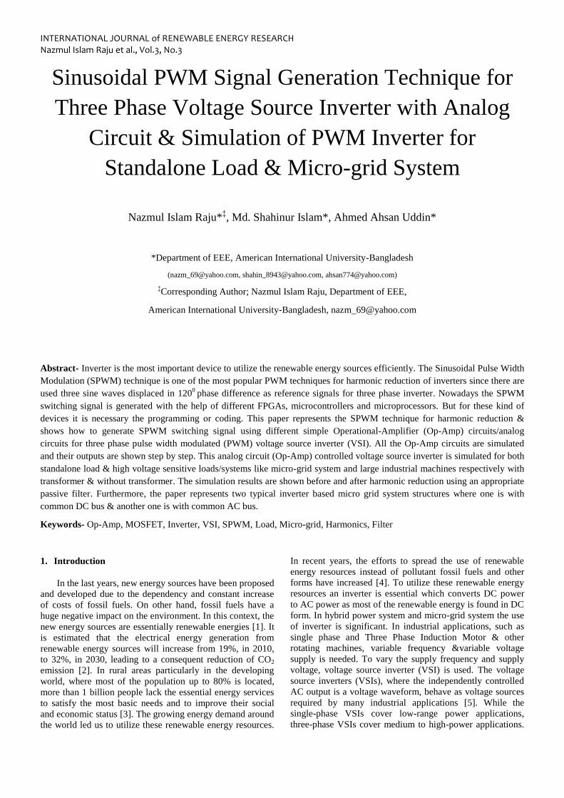
There are five main groups of power semiconductors.
They are: power diode, thyristor, power bipolar junction
transistor (BJT), insulated gate bipolar transistor (IGBT), and
static induction transistor (SIT). Figure 1 gives a picture of
each.
Fig. 1. Different power semiconductor switches
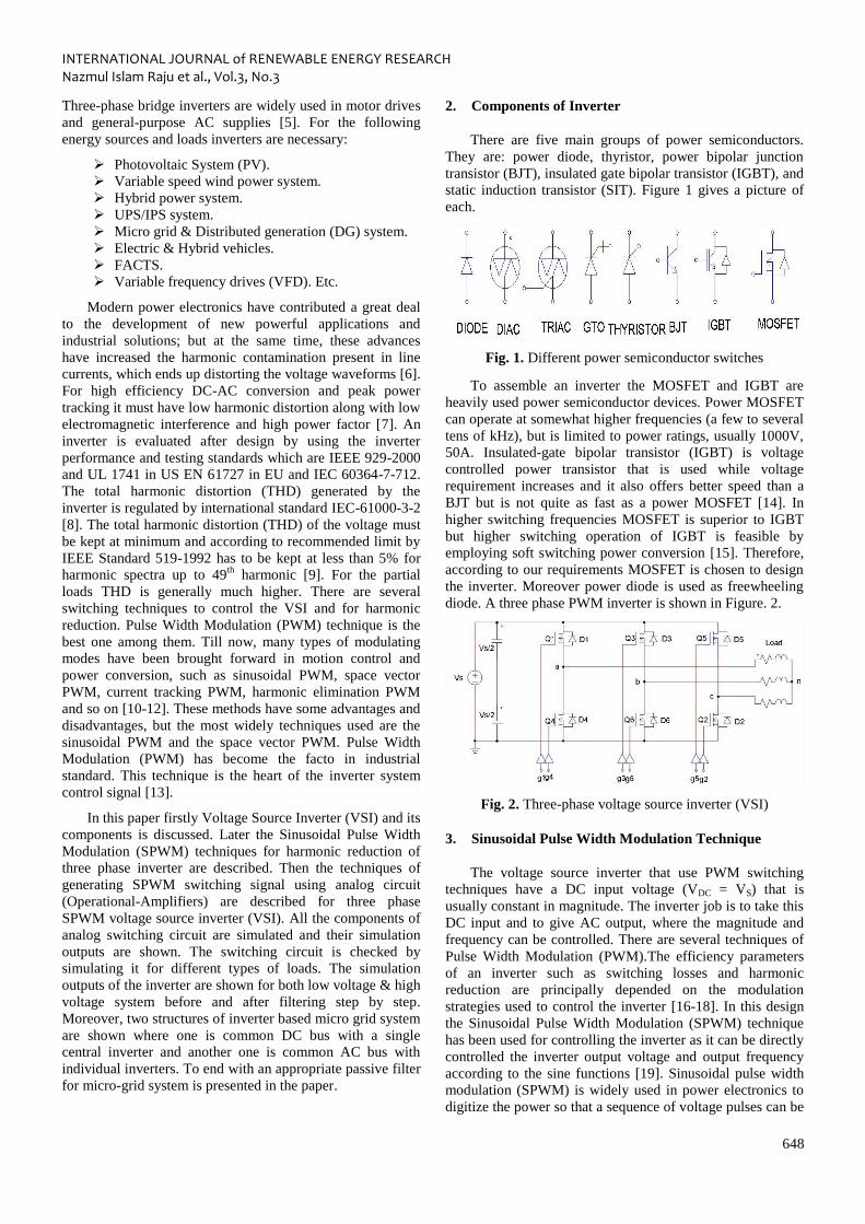
To assemble an inverter the MOSFET and IGBT are
heavily used power semiconductor devices. Power MOSFET
can operate at somewhat higher frequencies (a few to several
tens of kHz), but is limited to power ratings, usually 1000V,
50A. Insulated-gate bipolar transistor (IGBT) is voltage
controlled power transistor that is used while voltage
requirement increases and it also offers better speed than a
BJT but is not quite as fast as a power MOSFET [14]. In
higher switching frequencies MOSFET is superior to IGBT
but higher switching operation of IGBT is feasible by
employing soft switching power conversion [15]. Therefore,
according to our requirements MOSFET is chosen to design
the inverter. Moreover power diode is used as freewheeling
diode. A three phase PWM inverter is shown in Figure. 2.
Fig. 2. Three-phase voltage source inverter (VSI)
3. Sinusoidal Pulse Width Modulation Technique
The voltage source inverter that use PWM switching
techniques have a DC input voltage (VDC = VS) that is
usually constant in magnitude. The inverter job is to take this
DC input and to give AC output, where the magnitude and
frequency can be controlled. There are several techniques of
Pulse Width Modulation (PWM).The efficiency parameters
of an inverter such as switching losses and harmonic
reduction are principally depended on the modulation
strategies used to control the inverter [16-18]. In this design
the Sinusoidal Pulse Width Modulation (SPWM) technique
has been used for controlling the inverter as it can be directly
controlled the inverter output voltage and output frequency
according to the sine functions [19]. Sinusoidal pulse width
modulation (SPWM) is widely used in power electronics to
digitize the power so that a sequence of voltage pulses can be
INTERNATIONAL JOURNAL of RENEWABLE ENERGY RESEARCH Nazmul Islam Raju et al., Vol.3, No.3
649
generated by the on and off of the power switches. The PWM
inverter has been the main choice in power electronic for
decades, because of its circuit simplicity and rugged control
scheme. Sinusoidal Pulse Width Modulation switching
technique is commonly used in industrial applications or
solar electric vehicle applications [20].
SPWM techniques are characterized by constant
amplitude pulses with different duty cycles for each period.
The width of these pulses are modulated to obtain inverter
output voltage control and to reduce its harmonic content
[21]. Sinusoidal pulse width modulation is the mostly used
method in motor control and inverter application [20]. In
SPWM technique three sine waves and a high frequency
triangular carrier wave are used to generate PWM signal [5].
Generally, three sinusoidal waves are used for three phase
inverter. The sinusoidal waves are called reference signal and
they have 1200 phase difference with each other. The
frequency of these sinusoidal waves is chosen based on the
required inverter output frequency (50/60 Hz). The carrier
triangular wave is usually a high frequency (in several KHz)
wave. The switching signal is generated by comparing the
sinusoidal waves with the triangular wave. The comparator
gives out a pulse when sine voltage is greater than the
triangular voltage and this pulse is used to trigger the
respective inverter switches [22-23]. In order to avoid
undefined switching states and undefined AC output line
voltages in the VSI, the switches of any leg in the inverter
cannot be switched off simultaneously. The phase outputs are
mutually phase shifted by 1200 angles [5]. The ratio between
the triangular wave & sine wave must be an integer N, the
number of voltage pulses per half-cycle, such that, 2N= fc/fs.
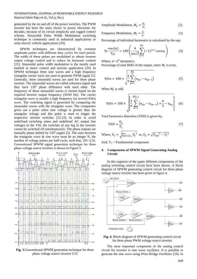
Conventional SPWM signal generation technique for three
phase voltage source inverter is shown in Figure 3.
Fig. 3.Conventional SPWM generation technique for three
phase voltage source inverter [13]
Amplitude Modulation,
(2)
Frequency Modulation,
(3)
Percentage of individual harmonics is calculated by the eqn.
(
√ ∑
)
Where, n= nth
harmonics.
Percentage of total RMS of the output, when is even,
√
∑( )
When is odd,
√
[
∑ ( )
]
Total harmonics distortion (THD) is given by,
Where, √∑
or, √
And, V1 = Fundamental component.
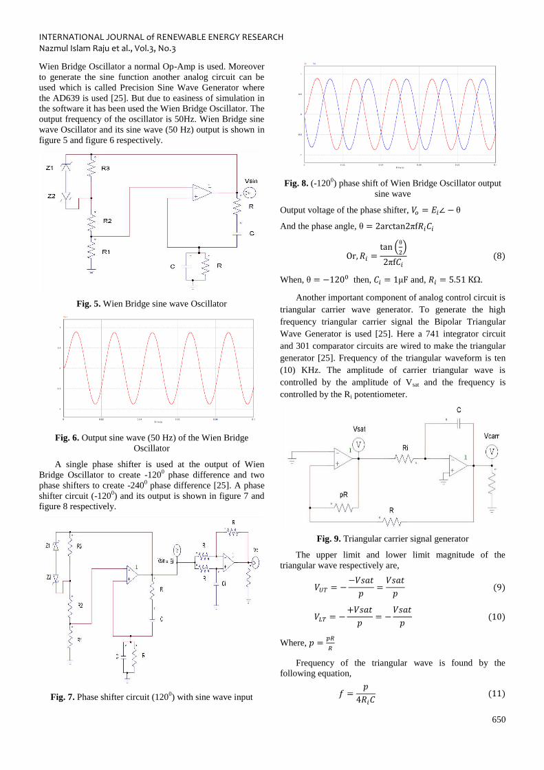
4. Components of SPWM Signal Generating Analog
Circuit
In this segment of the paper different components of the
analog switching control circuit have been shown. A block
diagram of SPWM generating control circuit for three phase
voltage source inverter has been given in figure 4.
Fig. 4. Block diagram of SPWM generating control circuit
for three phase PWM voltage source inverter
The most important component of the analog control
circuit for inverter is sine wave oscillator. It is possible to
generate the sine wave using Wien Bridge Oscillator [24]. In
INTERNATIONAL JOURNAL of RENEWABLE ENERGY RESEARCH Nazmul Islam Raju et al., Vol.3, No.3
650
Wien Bridge Oscillator a normal Op-Amp is used. Moreover
to generate the sine function another analog circuit can be
used which is called Precision Sine Wave Generator where
the AD639 is used [25]. But due to easiness of simulation in
the software it has been used the Wien Bridge Oscillator. The
output frequency of the oscillator is 50Hz. Wien Bridge sine
wave Oscillator and its sine wave (50 Hz) output is shown in
figure 5 and figure 6 respectively.
Fig. 5. Wien Bridge sine wave Oscillator
Fig. 6. Output sine wave (50 Hz) of the Wien Bridge
Oscillator
A single phase shifter is used at the output of Wien
Bridge Oscillator to create -1200 phase difference and two
phase shifters to create -2400 phase difference [25]. A phase
shifter circuit (-1200) and its output is shown in figure 7 and
figure 8 respectively.
Fig. 7. Phase shifter circuit (1200) with sine wave input
Fig. 8. (-1200) phase shift of Wien Bridge Oscillator output
sine wave
Output voltage of the phase shifter,
And the phase angle,
(
)
When, then, and, .
Another important component of analog control circuit is
triangular carrier wave generator. To generate the high
frequency triangular carrier signal the Bipolar Triangular
Wave Generator is used [25]. Here a 741 integrator circuit
and 301 comparator circuits are wired to make the triangular
generator [25]. Frequency of the triangular waveform is ten
(10) KHz. The amplitude of carrier triangular wave is
controlled by the amplitude of Vsat and the frequency is
controlled by the Ri potentiometer.
Fig. 9. Triangular carrier signal generator
The upper limit and lower limit magnitude of the
triangular wave respectively are,
Where,
Frequency of the triangular wave is found by the
following equation,
INTERNATIONAL JOURNAL of RENEWABLE ENERGY RESEARCH Nazmul Islam Raju et al., Vol.3, No.3
651
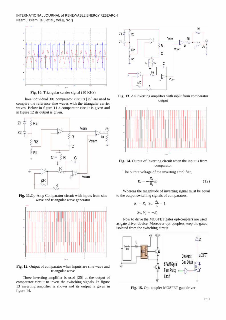
Fig. 10. Triangular carrier signal (10 KHz)
Three individual 301 comparator circuits [25] are used to
compare the reference sine waves with the triangular carrier
waves. Below in figure 11 a comparator circuit is given and
in figure 12 its output is given.
Fig. 11.Op-Amp Comparator circuit with inputs from sine
wave and triangular wave generator
Fig. 12. Output of comparator when inputs are sine wave and
triangular wave
Three inverting amplifier is used [25] at the output of
comparator circuit to invert the switching signals. In figure
13 inverting amplifier is shown and its output is given in
figure 14.
Fig. 13. An inverting amplifier with input from comparator
output
Fig. 14. Output of Inverting circuit when the input is from
comparator
The output voltage of the inverting amplifier,
Whereas the magnitude of inverting signal must be equal
to the output switching signals of comparators,
So,
So,
Now to drive the MOSFET gates opt-couplers are used
as gate driver device. Moreover opt-couplers keep the gates
isolated from the switching circuit.
Fig. 15. Opt-coupler MOSFET gate driver
INTERNATIONAL JOURNAL of RENEWABLE ENERGY RESEARCH Nazmul Islam Raju et al., Vol.3, No.3
652
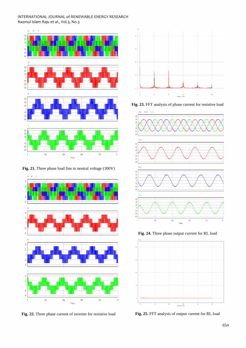
5. Generation of SPWM Switching Signal Using Analog
Control Circuit
All the components of analog control circuit are wired as
shown in the figure 16. Initially three sinusoidal reference
signals are generated using a Wien Bridge Sinusoidal
Oscillator circuit. In the next stage, phase difference (1200)
between the sinusoidal waves is generated using the phase
shifter circuits and the triangular carrier wave is generated
using Triangular Wave Generator. Then using three
individual comparator circuits SPWM switching signals g1,
g3 & g5 and using three inverting circuits g2, g4, g6 are
generated and these SPWM switching signals are applied to
the gates of MOSFET of three phase voltage source inverter.
Fig. 16. Circuit diagram of analog circuit controlled SPWM
three phase VSI without transformer for Standalone load
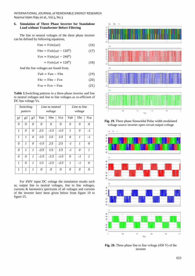
The reference sinusoidal signals with amplitude As are,
Fig. 17. Reference sine waves and carrier triangular signal
Fig. 18. Individual switching signals (g1, g2, g3, g4, g5, g6)
for three phase voltage source inverter
INTERNATIONAL JOURNAL of RENEWABLE ENERGY RESEARCH Nazmul Islam Raju et al., Vol.3, No.3
653
6. Simulation of Three Phase Inverter for Standalone
Load without Transformer Before Filtering
The line to neutral voltages of the three phase inverter
can be defined by following equations,
And the line voltages are found from,
Table 1.Switching patterns in a three-phase inverter and line
to neutral voltages and line to line voltages as co-efficient of
DC bus voltage Vs.
For 450V input DC voltage the simulation results such
as, output line to neutral voltages, line to line voltages,
currents & harmonics spectrums of all voltages and currents
of the inverter have been given below from figure 19 to
figure 25.
Fig. 19. Three phase Sinusoidal Pulse width modulated
voltage source inverter open circuit output voltage
Fig. 20. Three phase line to line voltage (450 V) of the
inverter
Switching
pattern
Line to neutral
voltage
Line to line
voltage
g1 g2 g3 Van Vbn Vcn Vab Vbc Vca
0 0 0 0 0 0 0 0 0
1 0 0 2/3 -1/3 -1/3 1 0 -1
1 1 0 1/3 1/3 1/3 0 1 -1
0 1 0 -1/3 2/3 2/3 -1 1 0
0 1 1 -2/3 1/3 1/3 -1 0 1
0 0 1 -1/3 -1/3 -1/3 0 -1 1
1 0 1 1/3 -2/3 -2/3 1 -1 0
1 1 1 0 0 0 0 0 0
INTERNATIONAL JOURNAL of RENEWABLE ENERGY RESEARCH Nazmul Islam Raju et al., Vol.3, No.3
654
Fig. 21. Three phase load line to neutral voltage (300V)
Fig. 22. Three phase current of inverter for resistive load
Fig. 23. FFT analysis of phase current for resistive load
Fig. 24. Three phase output current for RL load
Fig. 25. FFT analysis of output current for RL load
INTERNATIONAL JOURNAL of RENEWABLE ENERGY RESEARCH Nazmul Islam Raju et al., Vol.3, No.3
655
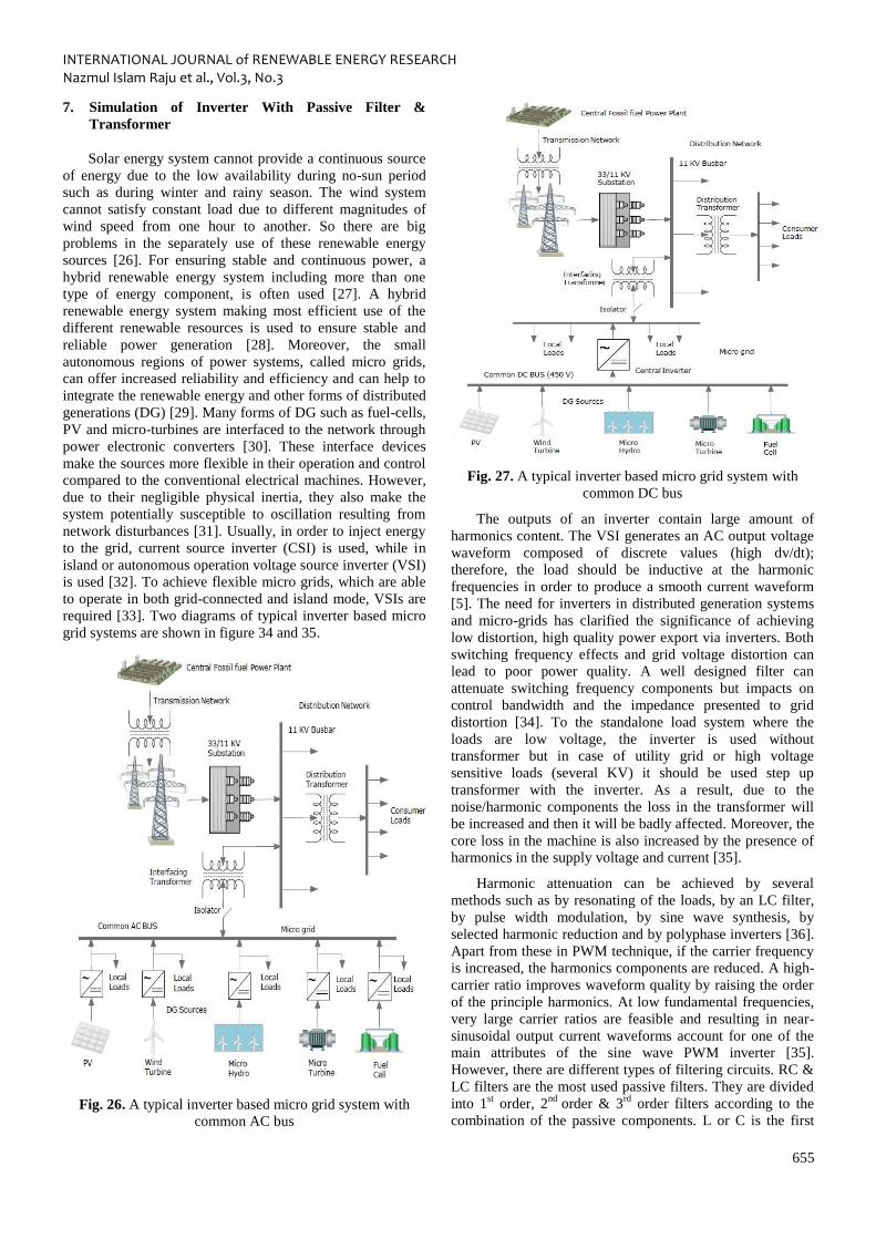
7. Simulation of Inverter With Passive Filter &
Transformer
Solar energy system cannot provide a continuous source
of energy due to the low availability during no-sun period
such as during winter and rainy season. The wind system
cannot satisfy constant load due to different magnitudes of
wind speed from one hour to another. So there are big
problems in the separately use of these renewable energy
sources [26]. For ensuring stable and continuous power, a
hybrid renewable energy system including more than one
type of energy component, is often used [27]. A hybrid
renewable energy system making most efficient use of the
different renewable resources is used to ensure stable and
reliable power generation [28]. Moreover, the small
autonomous regions of power systems, called micro grids,
can offer increased reliability and efficiency and can help to
integrate the renewable energy and other forms of distributed
generations (DG) [29]. Many forms of DG such as fuel-cells,
PV and micro-turbines are interfaced to the network through
power electronic converters [30]. These interface devices
make the sources more flexible in their operation and control
compared to the conventional electrical machines. However,
due to their negligible physical inertia, they also make the
system potentially susceptible to oscillation resulting from
network disturbances [31]. Usually, in order to inject energy
to the grid, current source inverter (CSI) is used, while in
island or autonomous operation voltage source inverter (VSI)
is used [32]. To achieve flexible micro grids, which are able
to operate in both grid-connected and island mode, VSIs are
required [33]. Two diagrams of typical inverter based micro
grid systems are shown in figure 34 and 35.
Fig. 26. A typical inverter based micro grid system with
common AC bus
Fig. 27. A typical inverter based micro grid system with
common DC bus
The outputs of an inverter contain large amount of
harmonics content. The VSI generates an AC output voltage
waveform composed of discrete values (high dv/dt);
therefore, the load should be inductive at the harmonic
frequencies in order to produce a smooth current waveform
[5]. The need for inverters in distributed generation systems
and micro-grids has clarified the significance of achieving
low distortion, high quality power export via inverters. Both
switching frequency effects and grid voltage distortion can
lead to poor power quality. A well designed filter can
attenuate switching frequency components but impacts on
control bandwidth and the impedance presented to grid
distortion [34]. To the standalone load system where the
loads are low voltage, the inverter is used without
transformer but in case of utility grid or high voltage
sensitive loads (several KV) it should be used step up
transformer with the inverter. As a result, due to the
noise/harmonic components the loss in the transformer will
be increased and then it will be badly affected. Moreover, the
core loss in the machine is also increased by the presence of
harmonics in the supply voltage and current [35].
Harmonic attenuation can be achieved by several
methods such as by resonating of the loads, by an LC filter,
by pulse width modulation, by sine wave synthesis, by
selected harmonic reduction and by polyphase inverters [36].
Apart from these in PWM technique, if the carrier frequency
is increased, the harmonics components are reduced. A high-
carrier ratio improves waveform quality by raising the order
of the principle harmonics. At low fundamental frequencies,
very large carrier ratios are feasible and resulting in near-
sinusoidal output current waveforms account for one of the
main attributes of the sine wave PWM inverter [35].
However, there are different types of filtering circuits. RC &
LC filters are the most used passive filters. They are divided
into 1st order, 2
nd order & 3
rd order filters according to the
combination of the passive components. L or C is the first
INTERNATIONAL JOURNAL of RENEWABLE ENERGY RESEARCH Nazmul Islam Raju et al., Vol.3, No.3
656
order filter, LC is the 2nd
order filter and LCL is the 3rd
order
filter.
Fig. 28. 1storder filter for 3 phase system
Fig. 29. 2nd
order LC filter for 3 phase system
Fig. 30. 3rd
order LCL filter for 3 phase system
With low inductance on the inverter side, it is difficult to
comply with IEEE519 standards without an LCL filter. An
LCL filter can achieve reduced levels of harmonic distortion
with lower switching frequencies and with less overall stored
energy [34]. In this system Lt is the inductance of the
transformer through which the inverter is connected to the
grid. After LC filter a transformer is used and the LCL filter
is formed. It eliminates all high order harmonics from the
output waveform of the inverter so that the output is 50Hz,
low distortion, pure sinusoidal voltage wave. The cut-off
frequency of the low pass filter is selected such that, total
THD is less than 5%. The calculation is done by the
following equation,
√
Fig. 31.Circuit diagram of three-phase inverter with
transformer
The simulation results of the transformer inputs after
filtering and transformer outputs have been given below,
Fig. 32. Three phase line to line voltage after filtering
Fig. 33. Three phase line to neutral voltage after filtering
Fig. 34. Three phase output current after filtering
INTERNATIONAL JOURNAL of RENEWABLE ENERGY RESEARCH Nazmul Islam Raju et al., Vol.3, No.3
657
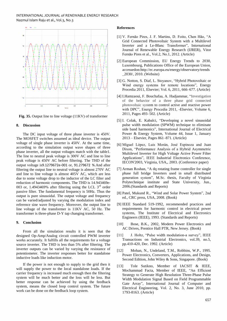
Fig. 35. Output line to line voltage (11KV) of transformer
8. Discussion
The DC input voltage of three phase inverter is 450V.
The MOSFET switches assumed as ideal device. The output
voltage of single phase inverter is 450V. At the same time,
according to the simulation output wave shapes of three
phase inverter, all the output voltages match with the table1.
The line to neutral peak voltage is 300V AC and line to line
peak voltage is 450V AC before filtering. The THD of the
output voltage is9.1279672e-001 or, 91.279672 %.And after
filtering the output line to neutral voltage is almost 270V AC
and line to line voltage is almost 405V AC, which are less
due to some voltage drop to the inductor of the LC filter and
reduction of harmonic components. The THD is 14.943469e-
003 or, 1.4943469% after filtering using the LCL 3rd
order
passive filter. The fundamental frequency is 50Hz. Thus the
output is pure sinusoidal. The output voltage and frequency
can be varied/adjusted by varying the modulation index and
reference sine wave frequency. Moreover, the output line to
line voltage of the transformer is 11KV AC, 50 Hz. The
transformer is three-phase D-Y tap changing transformer.
9. Conclusion
From all the simulation results it is seen that the
designed Op-Amp/Analog circuit controlled PWM inverter
works accurately. It fulfills all the requirements for a voltage
source inverter. The THD is less than 5% after filtering. The
inverter outputs can be varied by varying the resistance of
potentiometer. The inverter responses better for standalone
inductive loads like induction motor.
If the power is not enough to supply to the grid then it
will supply the power to the local standalone loads. If the
carrier frequency is increased much enough then the filtering
system will be much better and the loss will be less. But
better response can be achieved by using the feedback
system, means the closed loop control system. The future
work can be done on the feedback loop system.
References
[1] V. Fernão Pires, J. F. Martins, D. Foito, Chen Hão, “A
Grid Connected Photovoltaic System with a Multilevel
Inverter and a Le-Blanc Transformer”, International
Journal of Renewable Energy Research (IJRER), Vitor
Fernão Pires et al., Vol.2, No.1, 2012. (Article)
[2] European Commission, EU Energy Trends to 2030,
Luxembourg, Publications Office of the European Union,
accessedon:http://ec.europa.eu/energy/observatory/trends
_2030/, 2010. (Website)
[3] G. Notton, S. Diaf, L. Stoyanov, “Hybrid Photovoltaic or
Wind energy systems for remote locations”, Energy
Procedia 2011, Elsevier; Vol. 6, 2011, 666–677. (Article)
[4] I.Hamzaoui, F. Bouchafaa, A. Hadjammar, “Investigation
of the behavior of a three phase grid connected
photovoltaic system to control active and reactive power
with DPC”, Energy Procedia 2011, -Elsevier, Volume 6,
2011, Pages 493–502. (Article)
[5] I. Colak, E. Kabalci, “Developing a novel sinusoidal
pulse width modulation (SPWM) technique to eliminate
side band harmonics”, International Journal of Electrical
Power & Energy System, Volume 44, Issue 1, January
2013 – Elsevier, Pages 861–871. (Article)
[6] Miguel López, Luis Morán, José Espinoza and Juan
Dixon, “Performance Analysis of a Hybrid Asymmetric
Multilevel Inverter for High Voltage Active Power Filter
Applications”, IEEE Industrial Electronics Conference,
IECON'2003, Virginia, USA,, 2003. (Conference paper)
[7] Arman Roshan, “A dq rotating frame controller for single
phase full bridge Inverters used in small distributed
generation system”, M.Sc. thesis, Faculty of Virginia
Polytechnique institute and State University, Jun.,
2006.(Standards and Reports)
[8] Patel, Mukund R., “Wind and Solar Power System”, 2nd
ed., CRC press, USA, 2008. (Book)
[9] IEEE Standard 519-1992, recommended practices and
requirements for harmonic control in electrical power
systems, The Institute of Electrical and Electronics
Engineers (IEEE), 1993. (Standards and Reports)
[10] Bose, B.K., 2002, Modern Power Electronics and
AC Drives, Prentice Hall PTR, New Jersey. (Book)
[11] J. Holtz, “Pulse width modulation-a survey”, IEEE
Transactions on Industrial Electronics, vol.39, no.5,
pp.410-420, Dec. 1992. (Article)
[12] Mohan, N., Undeland, T.M., Robbins, W.P., 1995.
Power Electronics, Converters, Applications, and Design,
Second Edition, John Wiley & Sons, Singapore. (Book)
[13] Tole Sutikno, Member of IACSIT & IEEE,
Mochammad Facta, Member of IEEE, “An Efficient
Strategy to Generate High Resolution Three-Phase Pulse
Width Modulation Signal Based on Field Programmable
Gate Array”, International Journal of Computer and
Electrical Engineering, Vol. 2, No. 3, June 2010, pp.
1793-8163. (Article)
INTERNATIONAL JOURNAL of RENEWABLE ENERGY RESEARCH Nazmul Islam Raju et al., Vol.3, No.3
658
[14] Ned Mohan, Tore M. Undeland, William P.
Robbins, “Power Electronics: Converters, Applications,
and Design,” 1989. John Wiley & Sons, Inc. (Book)
[15] Nasser Kutkut- Power Designers, LLC – Madison,
WI, “MOSFETs vs. IGBTs: Which is better?” (Standards
& Reports)
[16] Babaei E, Hosseini SH, Gharehpetian G.,
“Reduction of THD and low order harmonics with
symmetrical output current for single-phase ac/ac matrix
converters.” International Journal of Electrical Power&
Energy System2010 – Elsevier; Volume 32, Issue 3,
March 2010, Pages 225–235. (Article)
[17] Ghaemi AH, Abyaneh HA, Mazlumi K. “Harmonic
indices assessment by wavelet transform.” International
Journal of Electrical Power & Energy System 2011–
Elsevier; Volume 33, Issue 8, October 2011, Pages 1399–
1409. (Article)
[18] Ramasamy M, Thangavel S. “Photovoltaic based
dynamic voltage restorer with power saver capability
using PI controller. International Journal of Electric
Power Energy System 2012– Elsevier; Volume 36, Issue
1, March 2012, Pages 51–59. (Article)
[19] Muhammad H. Rashid, “Power electronics: circuits,
devices, and applications”, 3rd ed. 2004, Pearson/Prentice
Hall. (Book)
[20] B. Ismail, S. T. (Nov 28-29, 2006), “Development
of a Single Phase SPWM Microcontroller-Based
Inverter,” First International Power and Energy
Conference PEC (p. 437), Putrajaya, Malaysia: IEEE.
(Conference paper)
[21] PK Sadhu, G Sarkar, A Rakshit, A microcontroller-
based variable voltage variable frequency sinusoidal
power source with a novel PWM generation strategy,
Measurement, 2012 – Elsevier, Volume 45, Issue 1,
January 2012, Pages 59–67. (Article)
[22] Dehbonei H., Borle L and Nayar C.V., “A review
and proposal for optimal harmonic mitigation in single
phase pulse width modulation”, Proceedings of 4th IEEE
International Conference on Power Electronics and Drive
System, 2001, Vol.1, Oct., 2001, pp.408-414.
(Conference paper)
[23] P.C. Sen, “Power Electronics”, Tata Mcgraw-hill,
India. (Book)
[24] A.Z.M. Shahriar Muttalib, S.M.Ferdous, A.
Mortuza Saleque, Md. M. Chowdhury, “Design and
Simulation of an Inverter with High Frequency
Sinusoidal PWM Switching Technique for Harmonic
Reduction in a Standalone/ Utility Grid Synchronized
Photovoltaic System”, Informatics, Electronics & Vision
(ICIEV), 2012 International Conference on 18-19 May
2012, p. 1168 – 1173, IEEE Explore. (Conference paper)
[25] R.F.Coughlin, F.F. Driscoll, “Operational amplifiers
and integrated circuits,” 6th
edition, Prentice Hall
Electronics. (Book)
[26] A Ozdamar, N Ozbalta, A Akin, ED Yildirim, “An
application of a combined wind and solar energy system
in Izmir”, Renewable and Sustainable Energy Reviews
2005, Elsevier, Volume 9, Issue 6, December 2005,
Pages 624–637. (Article)
[27] D. Saheb-Koussa, M. Haddadi, and M. Belhamel,
Economic and technical study of a hybrid system (wind-
photovoltaic-diesel) for rural electrification in Algeria.
Applied Energy 2009, - Elsevier, Volume 86, Issues 7–8,
July–August 2009, Pages 1024–1030. (Article)
[28] D. Saheb-Koussa, M. Koussa, M. Belhamel & M.
Haddadi, “Economic and environmental analysis for grid-
connected hybrid photovoltaic-wind power system in the
arid region”, Energy Procedia, 2011 – Elsevier, Volume
6, 2011, Pages 361–370. (Article)
[29] R. H. Lasseter, “Micro-grids”, Power Engineering
Society Winter Meeting, Vol. 1, pp. 305-308, Jan. 2002.
(Article)
[30] A. Arulamplam, M. Barnes, A. Engler, A. Goodwin,
and N. Jenkins, “Control of power electronic interfaces in
distributed generation micro-grids”, International Journal
of Electronics, Vol. 94, Issue 9, Sept. 2004. (Article)
[31] Nagaraju Pogaku, Milan Prodanovic and Timothy
C. Green, “Inverter-based micro-grids: Small-signal
modeling and testing,” IEEE Transactions on Power
Electronic, Vol. 22, No. 2, March 2007. (Article)
[32] P.L. Villeneuve, “Concerns generated by islanding,”
IEEE Power & Energy Magazine, May/June 2004, pp.49-
53. (Article)
[33] J.M. Guerrero, J. Matas, L. Garcia de Vicuna, M.
Castilla, and J. Miret, “Decentralized control for parallel
operation of distributed generation inverters using
resistive output impedance,” IEEE Trans. Ind. Electron.,
vol. 54, no. 2, April 2007, pp. 994-1004. (Article)
[34] Khaled H. Ahmed, Stephen J. Finney and Barry W.
Williams, “Passive Filter Design for Three-Phase Inverter
Interfacing in Distributed Generation”, Compatibility in
Power Electronics, 2007. CPE 2007, IEEE Explore.
(Conference paper)
[35] GK Singh, “A research survey of induction motor
operation with non-sinusoidal supply wave forms”,
Electric power systems research, 2005, Elsevier, Volume
75, Issues 2–3, August 2005, Pages 200–213. (Article)
[36] K.S. Rajashekara, Joseph Vithayathill, “Harmonics
in the voltage Source PWM Inverters,” International
Journal of Electronics, Vol. 50, Issue 5. Pp. 325 - 337.
(Article)


