Embed Size (px)
Citation preview
Strong Coupling of Epsilon-Near-Zero PhononPolaritons in Polar Dielectric Heterostructures
Nikolai Christian Passler,∗,† Christopher R. Gubbin,‡ Thomas Graeme Folland,¶
Ilya Razdolski,† D. Scott Katzer,§ David F. Storm,§ Martin Wolf,† Simone DeLiberato,‡ Joshua D. Caldwell,¶,§ and Alexander Paarmann∗,†
†Fritz-Haber-Institut der Max-Planck-Gesellschaft, Faradayweg 4-6,14195 Berlin, Germany‡School of Physics and Astronomy, University of Southampton, Southampton SO17 1BJ,
United Kingdom¶Vanderbilt Institute of Nanoscale Science and Engineering, 2301 Vanderbilt Place, PMB
350106, Nashville, TN 37235-0106, USA§US Naval Research Laboratory, 4555 Overlook Avenue SW, Washington DC 20375, USA
E-mail: [email protected]; [email protected]
Abstract
We report the first observation of epsilon nearzero (ENZ) phonon polaritons in an ultrathinAlN film fully hybridized with surface phononpolaritons (SPhP) supported by the adjacentSiC substrate. Employing a Hopfield strongcoupling model for the analysis of the disper-sion and electric field distribution in these hy-bridized modes, we show that they share themost prominent features of the two precursormodes. The novel ENZ-SPhP coupled polari-tons with a highly propagative character anddeeply sub-wavelength light confinement can beutilized as building blocks for future infraredand terahertz (THz) nanophotonic integrationand communication devices.
Keywords
surface phonon polariton, epsilon near zero,infrared, nanophotonics, polar crystal, strongcoupling, hybridization
Integrated THz photonics relies on the devel-opment of artificially designed nano-scale meta-materials, where subwavelength structures inperiodic patterns enable precise tuning of the
material’s optical response.1–3 Truly extraordi-nary light propagation characteristics can beachieved in metamaterial-based epsilon nearzero (ENZ) media,4,5 i.e. where the dielectricpermittivity is vanishingly small. In partic-ular, remarkable properties of the ENZ pho-tonic modes include tunneling through nar-row distorted channels,6,7 enhanced nonlinear-optical conversion efficiency via enforced phase-matching,8–10 provide high emission direction-ality11–13 and enable polaritonic waveguidingmodes with broken time inversion symmetryand reduced scattering rate.14,15 Commonly,these effects are studied for bulk ENZ photonicmodes excited in carefully designed metamate-rials based on plasmonic nanostructures, whichare usually characterized by high losses.16,17
A complimentary approach aims at utilizingthe naturally occuring zero-crossing of the di-electric function in the spectral vicinity of in-trinsic material vibrations, such as the trans-verse optical (TO) and longitudinal optical(LO) phonons in polar dielectric crystals.18–20
Simultaneously, these materials can supportsurface phonon polaritons (SPhPs) in the rest-strahlen band, which is bounded by these twophonon frequencies ωTO and ωLO,21,22 offeringthe appealing possibility to obtain ENZ po-
1
laritonic modes that could be employed as anideal information carrier enabling effective long-range nanophotonic communication.
An important challenge of future nanopho-tonics is to find an appropriate class of systemswhere these ENZ polaritons can be efficientlyexcited (without significant losses) and coupledto other photonic excitations, while maintain-ing highly propagative character with reason-able group velocities. Employing freestandingfilms of polar dielectrics,19 however, bears littlepractical importance, and the low dispersion re-sults in a non-propagative character of the ENZpolaritonic modes.18 In this work, we demon-strate the hybridization of an ENZ polaritonand a propagating low-loss SPhP at an adja-cent interface in the strong coupling regime,thus creating a new pair of coupled nanopho-tonic excitations to an evergrowing suite.23–27
We analyze the coupling of the ENZ and SPhPmodes in an AlN/SiC bilayer, where the ENZpolariton in AlN occurs within the reststrahlenband of SiC. The novel coupled ENZ-SPhPmodes inherit their properties from both ENZand SPhP components, thus enabling highly ef-ficient phase-matched exitation. Offering broadfunctionality, these ENZ-SPhP coupled modesfeature a unique combination of deeply sub-wavelength confinement, large enhancements ofthe local electromagnetic fields as well as an in-trinsically low-loss, propagative character withnon-zero group velocity.
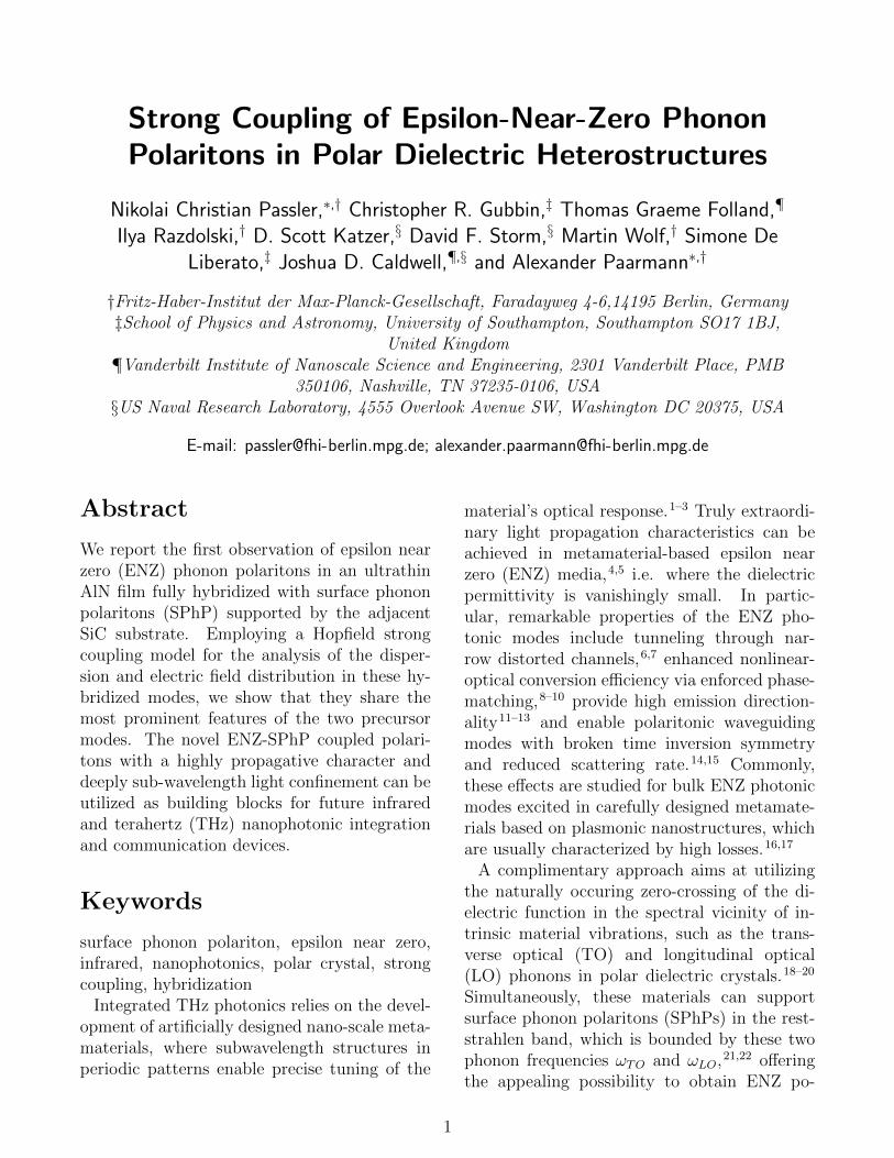
A SPhP mode supported at the interface ofa polar dielectric in the Reststrahlen band issplit into two branches upon reducing the filmthickness d (Fig. 1a), known as symmetric andantisymmetric modes.18,19,28 Remarkably, in ul-trathin films (d/λ ∼ 10−2, with λ being thefree-space wavelength) the upper (symmetric)mode is pushed towards the longitudinal optical(LO) phonon frequency,18 where the real partof the dielectric permittivity approaches zero(ε′(ω = ωLO) = 0). While this ultrathin filmENZ polariton loses its dispersive character, itsultra-long wavelength leads to a strongly sub-wavelength mode confinement, enabling a gi-gantic enhancement of the electric field withminimal phase change over several times thefree-space wavelength. The polariton disper-
Figure 1: Interaction of a surfacephonon polariton with an epsilon-near-zero mode. a A SPhP propagating at a sin-gle interface of air and a polar crystal has adispersion relation (green curve) ranging fromthe transversal optical phonon frequency ωTO
up to a cut-off frequency ωS, shown in green.For film thicknesses d < λ/2, where λ is thefree-space wavelength, a symmetric and an anti-symmetric branch appear (orange), splittingfurther apart with decreasing d. In the ultra-thin limit of d < λ/50, the upper branch ispushed close to the longitudinal optical phononfrequency ωLO (light blue), where it is termedan epsilon-near-zero mode. b When an ul-trathin AlN film is placed on bulk SiC, theAlN epsilon-near-zero mode (light blue) inter-sects the SiC SPhP dispersion relation (darkblue). These modes strongly interact, inducingan avoided crossing and forming two new dis-persion branches of the coupled system, drawnin red.
2
sion curves in the bilayer with an ultrathin AlNfilm on top of a SiC substrate are exemplified inFig. 1b. Individually, the AlN film exhibits anon-dispersive ENZ polariton mode (light blue)and the SiC a SPhP (dark blue). The com-bined bilayer structure (inset Fig. 1b), however,reveals a strong interaction between the twomodes, leading to two new dispersive branchesfeaturing an avoided crossing (red).
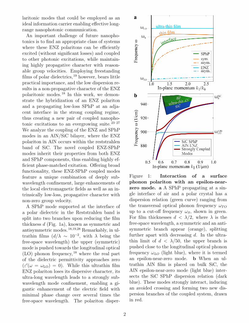
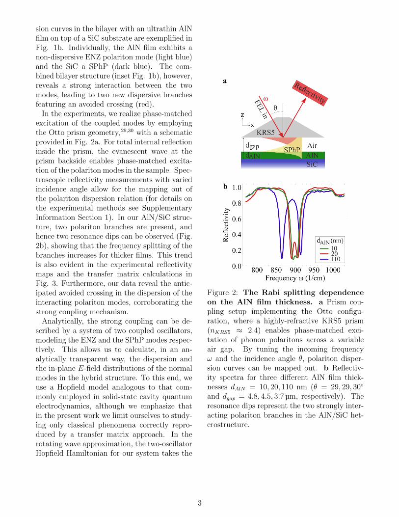
In the experiments, we realize phase-matchedexcitation of the coupled modes by employingthe Otto prism geometry,29,30 with a schematicprovided in Fig. 2a. For total internal reflectioninside the prism, the evanescent wave at theprism backside enables phase-matched excita-tion of the polariton modes in the sample. Spec-troscopic reflectivity measurements with variedincidence angle allow for the mapping out ofthe polariton dispersion relation (for details onthe experimental methods see SupplementaryInformation Section 1). In our AlN/SiC struc-ture, two polariton branches are present, andhence two resonance dips can be observed (Fig.2b), showing that the frequency splitting of thebranches increases for thicker films. This trendis also evident in the experimental reflectivitymaps and the transfer matrix calculations inFig. 3. Furthermore, our data reveal the antic-ipated avoided crossing in the dispersion of theinteracting polariton modes, corroborating thestrong coupling mechanism.
Analytically, the strong coupling can be de-scribed by a system of two coupled oscillators,modeling the ENZ and the SPhP modes respec-tively. This allows us to calculate, in an an-alytically transparent way, the dispersion andthe in-plane E-field distributions of the normalmodes in the hybrid structure. To this end, weuse a Hopfield model analogous to that com-monly employed in solid-state cavity quantumelectrodynamics, although we emphasize thatin the present work we limit ourselves to study-ing only classical phenomena correctly repro-duced by a transfer matrix approach. In therotating wave approximation, the two-oscillatorHopfield Hamiltonian for our system takes the
Figure 2: The Rabi splitting dependenceon the AlN film thickness. a Prism cou-pling setup implementing the Otto configu-ration, where a highly-refractive KRS5 prism(nKRS5 ≈ 2.4) enables phase-matched exci-tation of phonon polaritons across a variableair gap. By tuning the incoming frequencyω and the incidence angle θ, polariton disper-sion curves can be mapped out. b Reflectiv-ity spectra for three different AlN film thick-nesses dAlN = 10, 20, 110 nm (θ = 29, 29, 30◦
and dgap = 4.8, 4.5, 3.7 µm, respectively). Theresonance dips represent the two strongly inter-acting polariton branches in the AlN/SiC het-erostructure.
3
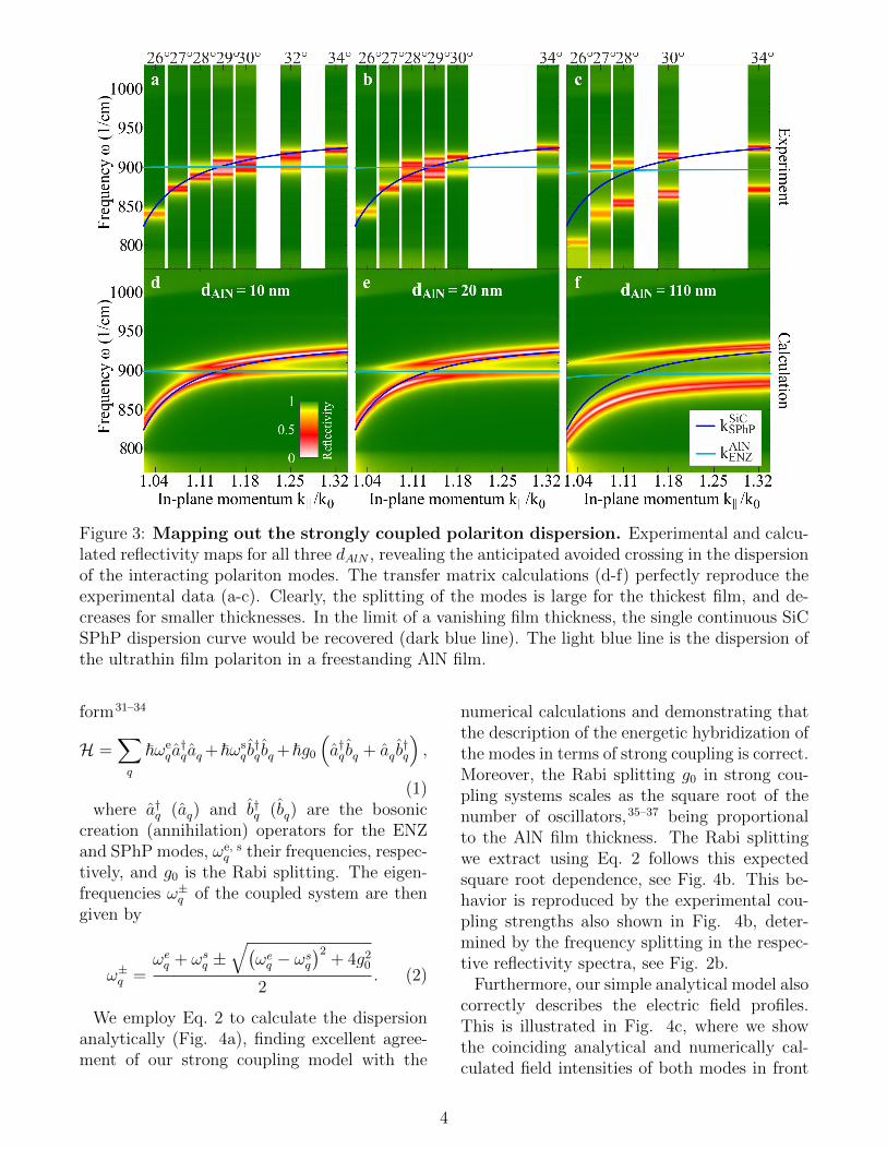
Figure 3: Mapping out the strongly coupled polariton dispersion. Experimental and calcu-lated reflectivity maps for all three dAlN , revealing the anticipated avoided crossing in the dispersionof the interacting polariton modes. The transfer matrix calculations (d-f) perfectly reproduce theexperimental data (a-c). Clearly, the splitting of the modes is large for the thickest film, and de-creases for smaller thicknesses. In the limit of a vanishing film thickness, the single continuous SiCSPhP dispersion curve would be recovered (dark blue line). The light blue line is the dispersion ofthe ultrathin film polariton in a freestanding AlN film.
form31–34
H =∑q
~ωeqa†qaq +~ωs
q b†q bq +~g0
(a†q bq + aq b
†q
),
(1)where a†q (aq) and b†q (bq) are the bosonic
creation (annihilation) operators for the ENZand SPhP modes, ωe, s
q their frequencies, respec-tively, and g0 is the Rabi splitting. The eigen-frequencies ω±q of the coupled system are thengiven by
ω±q =ωeq + ωs
q ±√(
ωeq − ωs
q
)2+ 4g20
2. (2)
We employ Eq. 2 to calculate the dispersionanalytically (Fig. 4a), finding excellent agree-ment of our strong coupling model with the
numerical calculations and demonstrating thatthe description of the energetic hybridization ofthe modes in terms of strong coupling is correct.Moreover, the Rabi splitting g0 in strong cou-pling systems scales as the square root of thenumber of oscillators,35–37 being proportionalto the AlN film thickness. The Rabi splittingwe extract using Eq. 2 follows this expectedsquare root dependence, see Fig. 4b. This be-havior is reproduced by the experimental cou-pling strengths also shown in Fig. 4b, deter-mined by the frequency splitting in the respec-tive reflectivity spectra, see Fig. 2b.
Furthermore, our simple analytical model alsocorrectly describes the electric field profiles.This is illustrated in Fig. 4c, where we showthe coinciding analytical and numerically cal-culated field intensities of both modes in front
4
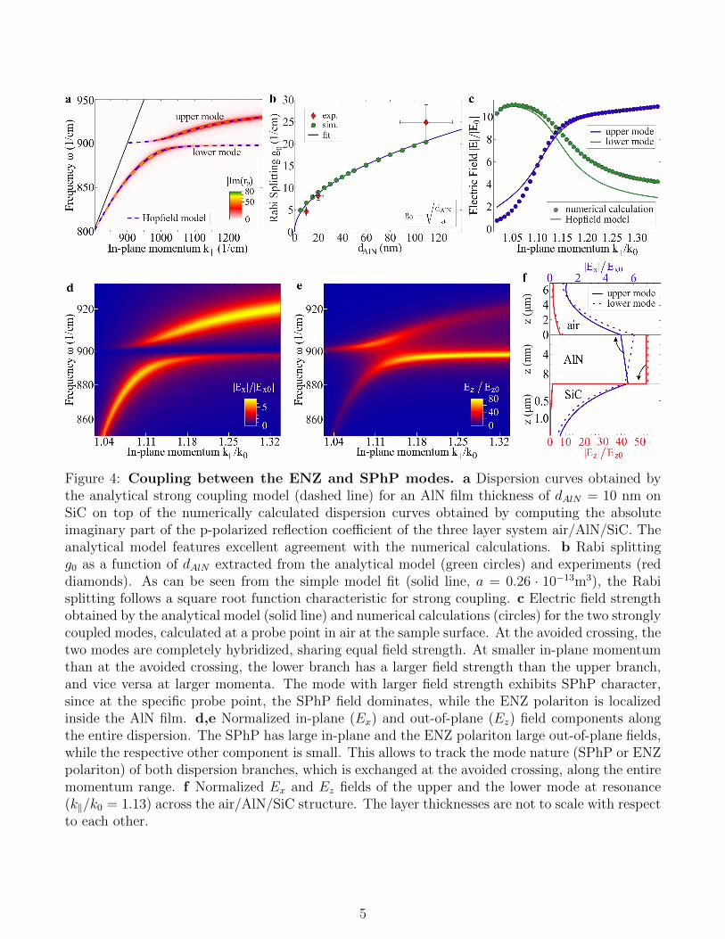
Figure 4: Coupling between the ENZ and SPhP modes. a Dispersion curves obtained bythe analytical strong coupling model (dashed line) for an AlN film thickness of dAlN = 10 nm onSiC on top of the numerically calculated dispersion curves obtained by computing the absoluteimaginary part of the p-polarized reflection coefficient of the three layer system air/AlN/SiC. Theanalytical model features excellent agreement with the numerical calculations. b Rabi splittingg0 as a function of dAlN extracted from the analytical model (green circles) and experiments (reddiamonds). As can be seen from the simple model fit (solid line, a = 0.26 · 10−13m3), the Rabisplitting follows a square root function characteristic for strong coupling. c Electric field strengthobtained by the analytical model (solid line) and numerical calculations (circles) for the two stronglycoupled modes, calculated at a probe point in air at the sample surface. At the avoided crossing, thetwo modes are completely hybridized, sharing equal field strength. At smaller in-plane momentumthan at the avoided crossing, the lower branch has a larger field strength than the upper branch,and vice versa at larger momenta. The mode with larger field strength exhibits SPhP character,since at the specific probe point, the SPhP field dominates, while the ENZ polariton is localizedinside the AlN film. d,e Normalized in-plane (Ex) and out-of-plane (Ez) field components alongthe entire dispersion. The SPhP has large in-plane and the ENZ polariton large out-of-plane fields,while the respective other component is small. This allows to track the mode nature (SPhP or ENZpolariton) of both dispersion branches, which is exchanged at the avoided crossing, along the entiremomentum range. f Normalized Ex and Ez fields of the upper and the lower mode at resonance(k‖/k0 = 1.13) across the air/AlN/SiC structure. The layer thicknesses are not to scale with respectto each other.
5
of the sample. We note that while a bare SiCsubstrate allows the SPhP component of thecoupled modes to be quantified, the ENZ polari-ton component depends decisively on the sub-strate material and hence cannot be straight-forwadly quantified. Therefore, we assumedthe ENZ polariton to be fully confined in theAlN film, i.e., the field at the probe point issolely determined by the SPhP component ofthe coupled modes. This assumption is the rea-son for the discrepancy between the analyticaland calculated field intensities at in-plane mo-menta where the respective mode features ENZcharacter (k‖/k0 < 1.1 and k‖/k0 > 1.2 in Fig.4c). However, despite its simplicity, our modelreproduces the numerical field amplitudes ex-tremely well, proving that the coupled modescan be described as a linear superposition of theENZ and SPhP modes, weighted by the Hop-field coefficients. In consequence of this linearrelationship, the strongly coupled modes at theavoided crossing share equal weights of SPhPand ENZ character, while the respective par-titions change along the dispersion: the lowerpolariton starts as pure SPhP at small k andswitches to ENZ beyond the avoided crossing,while the upper polariton shows the oppositebehavior.
This switching of the mode nature can be il-lustrated by means of the in-plane (Ex) andout-of-plane (Ez) electric field components in-side the AlN film, shown in Fig. 4d and e, re-spectively. Note that the SPhP is character-ized by a large in-plane field, whereas the ENZpolariton features pronounced out-of-plane fieldenhancement. The lower branch has strong in-plane fields at lower momentum (Fig. 4d), illus-trating that the mode is predominantly SPhP innature. In contrast, the upper branch exhibitsstrong out-of-plane character at low k‖ (Fig.4e). Across the strong coupling region, themodes interchange these characteristics, withthe upper branch exhibiting strong in-plane andthe lower out-of-plane fields. At the avoidedcrossing, the fields of both modes are apparentand of equal weight, and even the spatial Ex
and Ez field distributions of the modes acrossthe multilayer structure show high agreement(Fig. 4f). We have thus demonstrated the
strong coupling and full hybridization of an ul-trathin film ENZ phonon polariton with a SPhPin a polar dielectric heterostructure exempli-fied for AlN/SiC. However, we emphasize thatstrong coupling will emerge for a large num-ber of hybrid systems that feature overlappingreststrahlen bands of the two constituents.21,22
Furthermore, strong coupling can also be ob-served in the inverse structure of an ultrathinSiC film on AlN, ocurring at the TO frequencyof SiC (see Supplementary Information Section3).
Notably, the observed strong coupling physicsuniquely arises for ultrathin films with a deeplysub-wavelength thickness of d ∼ λ/1000 (11 nmfor AlN). Despite the mode splitting followingthe√d dependence for up to d & 500 nm,
already for film thicknesses d > 50 nm, theinteraction of the modes is not well-describedby the strong coupling model anymore. Thisdeviation from Eq. 1 is observed for both themode dispersion as well as the field profiles,see Supplementary Information Section 4. Incontrast, within the strong coupling regime,thinner films provide higher quality ENZ wavecharacteristics, yet featuring full hybridizationwith the low-loss, highly confined SPhP, seeFig. 4a-c. Thereby, the ENZ-SPhP modes of-fer a new promising approach for THz photon-ics on the nanoscale using traditional materi-als like III-V and II-VI semiconductors.22 Forinstance, PbSe/PbS core-shell nanostructures38
with wide tunability of the optical properties inthe near-infrared additionally feature stronglycoupled ENZ-SPhP modes in the THz range,allowing for a unique multispectral photonic in-tegration.
To demonstrate that the general character ofstrong coupling is not restricted to the prism-based experiments, we complement our re-sults with electromagnetic simulations of op-tical near-field scattering. Motivated by thepublished results on scattering type scanningnear field optical microscopy (s-SNOM) of Aunanostructures on SiC and boron nitride,39,40
we consider here a Au cylinder on top of theAlN film on a SiC substrate, see Fig. 5a. Inthe simulations, we monitor the spatial distri-bution of the electric field induced by normally
6
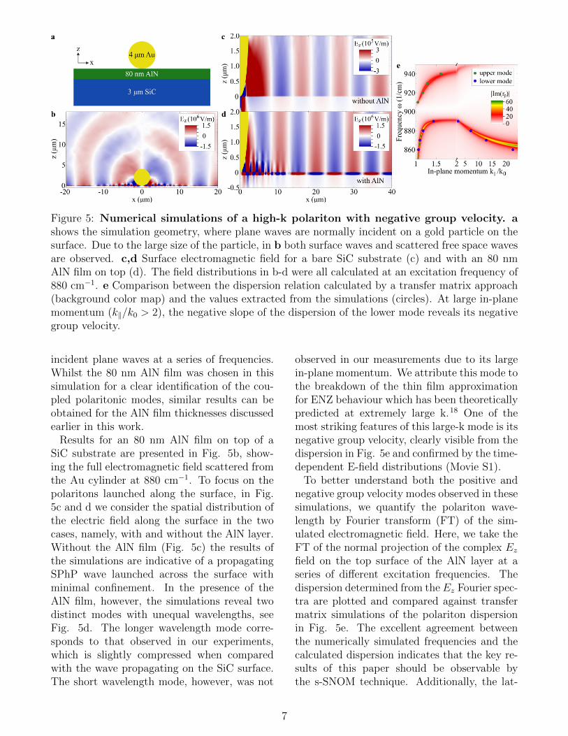
Figure 5: Numerical simulations of a high-k polariton with negative group velocity. ashows the simulation geometry, where plane waves are normally incident on a gold particle on thesurface. Due to the large size of the particle, in b both surface waves and scattered free space wavesare observed. c,d Surface electromagnetic field for a bare SiC substrate (c) and with an 80 nmAlN film on top (d). The field distributions in b-d were all calculated at an excitation frequency of880 cm−1. e Comparison between the dispersion relation calculated by a transfer matrix approach(background color map) and the values extracted from the simulations (circles). At large in-planemomentum (k‖/k0 > 2), the negative slope of the dispersion of the lower mode reveals its negativegroup velocity.
incident plane waves at a series of frequencies.Whilst the 80 nm AlN film was chosen in thissimulation for a clear identification of the cou-pled polaritonic modes, similar results can beobtained for the AlN film thicknesses discussedearlier in this work.
Results for an 80 nm AlN film on top of aSiC substrate are presented in Fig. 5b, show-ing the full electromagnetic field scattered fromthe Au cylinder at 880 cm−1. To focus on thepolaritons launched along the surface, in Fig.5c and d we consider the spatial distribution ofthe electric field along the surface in the twocases, namely, with and without the AlN layer.Without the AlN film (Fig. 5c) the results ofthe simulations are indicative of a propagatingSPhP wave launched across the surface withminimal confinement. In the presence of theAlN film, however, the simulations reveal twodistinct modes with unequal wavelengths, seeFig. 5d. The longer wavelength mode corre-sponds to that observed in our experiments,which is slightly compressed when comparedwith the wave propagating on the SiC surface.The short wavelength mode, however, was not
observed in our measurements due to its largein-plane momentum. We attribute this mode tothe breakdown of the thin film approximationfor ENZ behaviour which has been theoreticallypredicted at extremely large k.18 One of themost striking features of this large-k mode is itsnegative group velocity, clearly visible from thedispersion in Fig. 5e and confirmed by the time-dependent E-field distributions (Movie S1).
To better understand both the positive andnegative group velocity modes observed in thesesimulations, we quantify the polariton wave-length by Fourier transform (FT) of the sim-ulated electromagnetic field. Here, we take theFT of the normal projection of the complex Ez
field on the top surface of the AlN layer at aseries of different excitation frequencies. Thedispersion determined from the Ez Fourier spec-tra are plotted and compared against transfermatrix simulations of the polariton dispersionin Fig. 5e. The excellent agreement betweenthe numerically simulated frequencies and thecalculated dispersion indicates that the key re-sults of this paper should be observable bythe s-SNOM technique. Additionally, the lat-
7
ter should enable the observation of the high-kmode with negative dispersion, which is oth-erwise inaccessible in the prism-coupling ex-periments. We thus envisage rich perspectivesof near-field microscopy in visualizing coupledphonon-polaritonic modes in hybrid or multi-layer systems.
In conclusion, in this work we have demon-strated and characterized polaritonic modes ina strong coupling regime between an ENZ po-lariton and a bulk SiC SPhP in an ultrathinAlN/SiC structure. The full mode hybridiza-tion at the avoided crossing enables uniquepropagating ENZ polaritons. We have per-formed numerical simulations, revealing thatthe s-SNOM approach enables the observationof both the propagation length of the coupledENZ-SPhP modes, and the properties of polari-tons featuring negative group velocity. Our re-sults illustrate the high suitability of near-fieldtechniques like s-SNOM for the investigationof low-loss ENZ polaritons in polar dielectricheterostructures, in order to further establishtheir potential for nanophotonic applications.We envision the generalization of employing po-lar dielectric ENZ heterostructures to open upa new platform of deeply sub-wavelength inte-grated THz photonics based on strongly cou-pled ENZ-SPhPs.
Methods
Experimental
The substrate of our samples is hexagonal 6H-SiC for the 110 nm AlN film, and 4H-SiC forthe other two samples, all three with the ex-traordinary axis perpendicular to the sample(c-cut). The AlN layers were grown by RF-plasma assisted molecular beam epitaxy, andtherefore also exhibit a c-cut, hexagonal crystalstructure.
As an excitation source, we employ a mid-infrared free electron laser (FEL) with smallbandwidth (∼ 0.3%) and wide tunability of3 − 50 µm, covering the spectral ranges of theSiC and AlN reststrahlen bands (details on theFEL have been reported elsewhere41). While
the frequency is scanned by tuning the FEL,different in-plane momenta can be accessed viathe incidence angle θ by rotating the entireOtto geometry (see Supplementary InformationSection 1 for more details), thus allowing formapping out the complete dispersion curves ex-perimentally.30 In contrast to alternative ap-proaches, the Otto geometry features exper-imental control over the excitation efficiencythrough tunability of the air gap width dgap. Ateach incidence angle, spectra were taken at sev-eral dgap. For the reconstruction of the disper-sion curves (Fig. 3), we selected the spectra ata gap size of critical coupling conditions dcrit,
30
i.e. where the polariton is excited the most effi-ciently (Supplementary Information Section 2).Direct read-out of the gap width dgap with arange of d = 1 − 50 µm is realized via white-light interferometry, while the contrast of theinterference spectrum grants parallel alignmentof prism and sample.
Theoretical
Transfer Matrix
All calculations of the optical response and fielddistributions of Fig. 1-4 were performed usinga generalized 4×4 transfer matrix formalism.42
In short, the formalism allows for the calcula-tion of reflection and transmission coefficientsin any number of stratified media with arbi-trary dielectric tensor, which allows to accountfor the anisotropy of our samples.
Three-Layer Dispersion
The dispersion curves in Fig. 1 were obtainedby numerical evaluation of the three-layer po-lariton dispersion formula18,28,43
1 +ε1kz3ε3kz1
= i tan (kz2d)
(ε2kz3ε3kz2
+ε1kz2ε2kz1
),
(3)
where the subscripts i = 1, 2, 3 correspondto the three stacked media, ε is the dielectricfunction, d the film thickness of material 2,kzi =
√ωcεi − k‖ the out-of-plane momentum,
8
and k‖ the in-plane momentum conserved in alllayers.
Hopfield Model
The Rabi splitting g0 of the strong couplingmodel in Eq. 1 is introduced as a phenomeno-logical coupling parameter, and is equivalent tothe overlap of the substrate SPhP and ENZ po-lariton in a classical electromagnetic approach.The eigenfrequencies (Eq. 2) of the coupledsystem are found by diagonalization of theHopfield-Bogoliubov matrix Hq
33
Hq =
(ωeq g0g0 ωs
q
)(4)
for each in-plane wavevector q individually,where e and s stands for the ENZ polariton andthe substrate SPhP, respectively. The eigen-values of these matrices yield the eigenfrequen-cies ω±q shown in Eq. 2, and the respectivenormalized eigenvectors (Xq, Yq) are built fromthe Hopfield coefficients Xq and Yq, describingthe weighting factors of the ENZ polariton andthe substrate SPhP which compose the two hy-bridized modes along the avoided crossing. Thebosonic annihilation operators pq of the coupledmodes are then given by
p+q = Xqaq + Yq bq
p−q = Yqaq −Xq bq,(5)
where the superscripts + and − denote theupper and the lower coupled polariton branch,respectively.
CST Simulations
Simulations for Fig. 5 were performed inCST studio suite44 using the frequency domainsolver. To approximate the structure shownin Fig. 5a within a finite 3D model, a unitcell with a size of 250 µm by 0.6 µm was cho-sen, which minimized nearest neighbour inter-actions. The optical constants of the respectivematerials were taken from literature.45,46 Unitcell boundaries were used at the edges of thesubstrate, and a matched impedance layer wasused to suppress substrate reflections. Fourier
analysis was performed using a one dimensionalfield profile running along the top surface of theENZ film down the center of the unit cell.
Acknowledgement We thank WielandSchollkopf and Sandy Gewinner for operatingthe FEL. D.S.K., D.F.S, and J.D.C. were sup-ported by the Office of Naval Research throughthe U.S. Naval Research Laboratory and ad-ministered by the NRL Nanoscience Institute.The NRL team acknowledges the AlN char-acterization and processing contributions ofNeeraj Nepal, Brian P. Downey and Neil P.Green. S.D.L. is a Royal Society Research Fel-low and he acknowledges support from EPSRCGrant No. EP/M003183/1.
Supporting Information Avail-
able
The following files are available free of charge.Experimental details (Section 1), critical cou-
pling conditions of the strongly coupled modes(Section 2), strongly interacting modes inmaterials with overlapping reststrahlen bands(Section 3), deviation from strong couplingfor larger film thicknesses (Section 4), andsimulated time-dependent E-field distributions(Movie S1).
References
(1) Joannopoulos, J. D.; Johnson, S. G.;Winn, J. N.; Meade, R. D. Photonic Crys-tals: Molding the Flow of Light ; PrincetonUniversity Press, 2008.
(2) Burgos, S. P.; De Waele, R.; Polman, A.;Atwater, H. A. Nature Materials 2010, 9,407–412.
(3) Degl’Innocenti, R.; Kindness, S. J.;Beere, H. E.; Ritchie, D. A. Nanophoton-ics 2018, 7, 127–144.
(4) Li, Y.; Kita, S.; Munoz, P.; Reshef, O.;Vulis, D. I.; Yin, M.; Loncar, M.;Mazur, E. Nature Photonics 2015, 9, 738–742.
9
(5) Liberal, I.; Engheta, N. Nature Photonics2017, 11, 149–158.
(6) Silveirinha, M. G.; Engheta, N. PhysicalReview B - Condensed Matter and Mate-rials Physics 2007, 76, 1–17.
(7) Edwards, B.; Al, A.; Silveirinha, M. G.;Engheta, N. Journal of Applied Physics2009, 105 .
(8) Argyropoulos, C.; Chen, P. Y.;D’Aguanno, G.; Engheta, N.; Alu, A.Physical Review B - Condensed Matterand Materials Physics 2012, 85, 1–5.
(9) Suchowski, H.; O’Brien, K.; Wong, Z. J.;Salandrino, A.; Yin, X.; Zhang, X. Science2013, 342, 1223–1226.
(10) Mattiucci, N.; Bloemer, M. J.;D’Aguanno, G. Optics Express 2014, 22,6381.
(11) Enoch, S.; Tayeb, G.; Sabouroux, P.;Guerin, N.; Vincent, P. Physical ReviewLetters 2002, 89, 213902.
(12) Ziolkowski, R. W. Physical Review E -Statistical, Nonlinear, and Soft MatterPhysics 2004, 70, 1–12.
(13) Kim, J.; Dutta, A.; Naik, G. V.;Giles, A. J.; Bezares, F. J.; Ellis, C. T.;Tischler, J. G.; Mahmoud, A. M.;Caglayan, H.; Glembocki, O. J.; Kild-ishev, A. V.; Caldwell, J. D.; Boltas-seva, A.; Engheta, N. Optica 2016, 3, 339.
(14) Liu, R.; Roberts, C. M.; Zhong, Y.; Podol-skiy, V. A.; Wasserman, D. ACS Photonics2016, 3, 1045–1052.
(15) Engheta, N. Science 2007, 317, 1698–1702.
(16) Drachev, V. P.; Chettiar, U. K.; Kildi-shev, A. V.; Yuan, H.-K.; Cai, W.; Sha-laev, V. M. Optics Express 2008, 16,1186–1195.
(17) Khurgin, J. B.; Boltasseva, A. MRS Bul-letin 2012, 37, 768–779.
(18) Campione, S.; Brener, I.; Marquier, F.Physical Review B 2015, 91, 121408.
(19) Nordin, L.; Dominguez, O.;Roberts, C. M.; Streyer, W.; Feng, K.;Fang, Z. Applied Physics Letters 2017,111, 091105.
(20) Vassant, S.; Hugonin, J.-P.; Marquier, F.;Greffet, J.-J. Optics Express 2012, 20,23971.
(21) Caldwell, J. D.; Lindsay, L.; Gian-nini, V.; Vurgaftman, I.; Reinecke, T. L.;Maier, S. A.; Glembocki, O. J. Nanopho-tonics 2015, 4, 44–68.
(22) Feng, K.; Streyer, W.; Zhong, Y.; Hoff-man, A.; Wasserman, D. Optics Express2015, 23, A1418.
(23) Caldwell, J. D.; Vurgaftman, I.; Tis-chler, J. G.; Glembocki, O. J.; Owrut-sky, J. C.; Reinecke, T. L. Nature Nan-otechnology 2016, 11, 9–15.
(24) Basov, D. N.; Fogler, M. M.; Garcıa DeAbajo, F. J. Science 2016, 354 .
(25) Low, T.; Chaves, A.; Caldwell, J. D.;Kumar, A.; Fang, N. X.; Avouris, P.;Heinz, T. F.; Guinea, F.; Martin-Moreno, L.; Koppens, F. Nature Materials2017, 16, 182–194.
(26) Simpkins, B. S.; Fears, K. P.; Dres-sick, W. J.; Spann, B. T.; Dunkel-berger, A. D.; Owrutsky, J. C. ACS Pho-tonics 2015, 2, 1460–1467.
(27) Dunkelberger, A. D.; Spann, B. T.;Fears, K. P.; Simpkins, B. S.; Owrut-sky, J. C. Nature Communications 2016,7, 1–10.
(28) Burke, J. J.; Stegeman, G. I.; Tamir, T.Physical Review B 1986, 33, 5186–5201.
(29) Otto, A. Zeitschrift fur Physik 1968, 216,398–410.
(30) Passler, N. C.; Razdolski, I.; Gewinner, S.;Schollkopf, W.; Wolf, M.; Paarmann, A.ACS Photonics 2017, 4, 1048–1053.
10
(31) Hopfield, J. J. Physical Review 1958, 112,1555–1567.
(32) Savona, V.; Hradil, Z.; Quattropani, A.;Schwendimann, P. Physical Review B1994, 49, 8774–8779.
(33) Gubbin, C. R.; Martini, F.; Politi, A.;Maier, S. A.; De Liberato, S. Physical Re-view Letters 2016, 116, 1–6.
(34) Gubbin, C. R.; Maier, S. A.; De Liber-ato, S. Physical Review B 2016, 94, 1–9.
(35) Lidzey, D. G.; Bradley, D. D. C.; Skol-nick, M. S.; Virgili, T.; Walker, S.; Whit-taker, D. M. Nature 1998, 395, 53–55.
(36) Cade, N. I.; Ritman-Meer, T.;Richards, D. Physical Review B -Condensed Matter and Materials Physics2009, 79, 1–4.
(37) Baieva, S. V.; Hakala, T. K.; Toppari, J. J.Nanoscale research letters 2012, 7, 191.
(38) Lifshitz, E.; Brumer, M.; Kigel, A.;Sashchiuk, A.; Bashouti, M.; Sirota, M.;Galun, E.; Burshtein, Z.; Le Quang, A. Q.;Ledoux-Rak, I.; Zyss, J. The Journal ofPhysical Chemistry B 2006, 110, 25356–25365.
(39) Huber, A. J.; Deutsch, B.; Novotny, L.;Hillenbrand, R. Applied Physics Letters2008, 92, 2006–2009.
(40) Dai, S. et al. Nano Letters 2017, 17, 5285–5290.
(41) Schollkopf, W.; Gewinner, S.; Junkes, H.;Paarmann, A.; von Helden, G.; Bluem, H.;Todd, A. M. M. 2015, 9512, 95121L.
(42) Passler, N. C.; Paarmann, A. Journal ofthe Optical Society of America B 2017,34, 2128.
(43) Raether, H. Surface Plasmons on Smoothand Rough Surfaces and on Gratings ;Springer Tracts in Modern Physics, 1988;Vol. 111.
(44) CST, CST Studio Suite. https://www.
cst.com/products/csts2.
(45) Engelbrecht, F.; Helbig, R. Physical Re-view B 1993, 48, 15698–15707.
(46) Moore, W. J.; Freitas, J. A.; Holm, R. T.;Kovalenkov, O.; Dmitriev, V. AppliedPhysics Letters 2005, 86, 1–3.
11

Graphical TOC Entry
Some journals require a graphical entry for the Table of Contents. Thisshould be laid out “print ready” so that the sizing of the text is correct.Inside the tocentry environment, the font used is Helvetica 8 pt, asrequired by Journal of the American Chemical Society.The surrounding frame is 9 cm by 3.5 cm, which is the maximum per-mitted for Journal of the American Chemical Society graphical table ofcontent entries. The box will not resize if the content is too big: insteadit will overflow the edge of the box.This box and the associated title will always be printed on a separatepage at the end of the document.
12


