Embed Size (px)
Citation preview
Electrical Power and Energy Systems 63 (2014) 71–82
Contents lists available at ScienceDirect
Electrical Power and Energy Systems
journal homepage: www.elsevier .com/locate / i jepes
Synchronization of isolated microgrids with a communicationinfrastructure using energy storage systems
http://dx.doi.org/10.1016/j.ijepes.2014.05.0420142-0615/� 2014 Elsevier Ltd. All rights reserved.
⇑ Corresponding author. Tel.: +57 3167277994.E-mail address: [email protected] (J. Giraldo).
Jairo Giraldo a,⇑, Eduardo Mojica-Nava b, Nicanor Quijano a
a Departamento de Ingeniería Eléctrica y Electrónica, Universidad de los Andes, Bogotá, Colombiab Electrical and Electronics Department, National University of Colombia, Bogotá, Colombia
a r t i c l e i n f o a b s t r a c t
Article history:Received 21 December 2013Received in revised form 7 May 2014Accepted 27 May 2014Available online 25 June 2014
Keywords:Communication infrastructureEnergy storageFrequency controlMicrogridsMulti-agent systemsNetworked control systems
There exists an increasing interest in networked systems due to the wide number of applications in dis-tributed and decentralized control of large scale systems, such as smart grids. We address the problem ofdistributed frequency synchronization of several isolated microgrids, each one described by a linear-timecontinuous system, composed by different types of generators, whose outputs are measured and sentthrough a communication infrastructure. We assume that each microgrid possesses renewable resourceswith storage capabilities that helps to improve stability of the network when small damping ratio is con-sidered. Thus, using the smart grid communication infrastructure and the data flow through the network,we propose a cooperative control strategy based on the consensus algorithm that simultaneously man-ages the turbine governor input and the amount of energy that the storage devices have to absorb/injectfrom/into the grid. Nevertheless, physical constraints need to be included, which can be modeled usingsaturation non-linearities, and conditions to assure synchronization even with saturation are obtainedbased on multi-agent systems. Additionally, we consider that sensor measurements are sampled andwe extend the results of frequency synchronization with saturation to the case of control discretizationand sampling-period independence is demonstrated using passivity concepts.
� 2014 Elsevier Ltd. All rights reserved.
Introduction
The power network is a large-scale and complex system thatinvolves a wide number of elements (e.g., generators, loads, controldevices) that are interconnected. This makes control in power net-works a challenging research field that has been addressed in thelast century, where the main objective is to preserve stabilityand avoid unnecessary and damaging oscillations [1]. Neverthe-less, in the last few years the inclusion of small and medium volt-age generators and the increasing penetration of renewableresources have introduced new advantages due to the possibilityof producing clean, sustainable, and low cost energy [2]. However,new challenges have emerged because of the uncertainties inducedby the renewable resources, and the high amount of informationthat needs to be processed [3]. Furthermore, the future powernetwork (or smart grid) needs high speed, reliable, and secure datacommunication networks to manage the high amount of informa-tion coming from sensors all over the power network (fromgeneration to user level) and take smart decisions [4].
On the other hand, considering the smart grid as only one large-scale system increases the difficulty of analysis and design due tothe high amount of variables that need to be considered. In thisrespect, microgrids emerge as a solution to these problems.Microgrids (MGs) are smaller systems, usually of medium or smallvoltage, that include distributed generators (e.g., small hydro tur-bines, diesel generators, solar panels) and storage devices (e.g.,energy capacitors, batteries, flywheels). Microgrids could increasethe efficiency of power systems facilitating monitoring and controlbecause of its reduced size and the possibility of using hierarchicalcontrol [5]. Therefore, we can see the power network as the inter-connection of several microgrids, each one with control and energygeneration capabilities, and a communication infrastructure thattransmits data between them. In general, an MG can operate as agrid-connected system or as an island, where the latter takes placeby unplanned events like faults in the network or by plannedactions like maintenance requirements [6].
One of the main goals in control of a power system is frequencysynchronization, where each node needs to work at the same fre-quency and voltage in order to avoid failures and malfunctioning.The importance of synchronization lies in the fact that if a genera-tor works with a different speed (frequency) or voltage than thepower system due to failures or sudden changes in loads,
72 J. Giraldo et al. / Electrical Power and Energy Systems 63 (2014) 71–82
generators need to match frequency by accelerating or decelerat-ing its own speed, provoking mechanical stresses, disturbances,and oscillations that affect not only the health of the unsynchro-nized generator, but also the stability of the grid [7]. In this per-spective, if two microgrids are isolated and they workindividually with different frequencies, at the time when they con-nect back together, the oscillations and disturbances may provokefailures or blackouts. Commonly, frequency control of power net-works is developed using feedback gain control for each individualmicrogrid. Furthermore, PID controllers have been widely used inorder to assure that the frequency deviation is regulated at zero.However, if several microgrids are isolated it is not possible toassure frequency synchronization between them only using itsown state information. It is necessary that microgrids cooperateand exchange information between them in order to take smarterdecisions.
In this work, we focus our attention on frequency synchroniza-tion of multiple isolated microgrids, each one modeled as a lineartime-invariant (LTI) system with communication capacities andmultiple sources. Linear models can be considered for small fre-quency changes. The problem is addressed using the concepts ofsynchronization of multi-agent systems [8,9], such that a decentral-ized controller is proposed based on the consensus algorithm [10].The controller computes information from some neighbors (othermicrogrids), and handles the mechanical power generated by theturbine governor and simultaneously manages the injection/absorption of power to/from the microgrid using energy storage sys-tems (ESS). Then, microgrids will tend to remain synchronized evenwhen unknown changes in the loads occur, and we also show howthe stability of the network is improved with the inclusion of storagedevices, and instabilities provoked by small damping ratio and smallinertia can be mitigated. Nevertheless, control limitations thatemerge when the information is sent through communication linkshave to be addressed. For instance, phasorial measurement units(PMUs) measure the state of a node in the power network. This mea-surement is made each sampling instant, and the information isquantized, packed, and sent using a communication protocolthrough a wire or wireless link. That process introduces a varietyof issues such as time-delays [11], packet losses [12], informationlost due to quantization [13], and signal discretization, amongothers. However, we limit our attention to only sampled-datameasurements.
On the other hand, it is necessary to consider physical limita-tions on the turbine governor and the storage devices. They bothare limited by storage capabilities and actuator constraints dueto costs and design parameters. As a consequence, we assume thatinputs are constrained and synchronization criteria with saturationare established. Several works have addressed the problem ofsaturation using different models. In [14], authors have used thetangential hyperbolic function in order to model input saturations.On the other hand, [15] uses the anti-windup compensator in orderto minimize degradation of the global performance of a linear sys-tem under saturating inputs. In this work, we use some tools pre-sented in [16], where the authors illustrate different ways tomanage saturations based on polytopic approaches. Therefore,we propose a distributed control strategy based on the sampled-data information flow between microgrids and the actuator con-straints, (i.e., boundaries in the amount of power injected/absorbedby the turbine governor and the ESS).
The paper is organized as follows. Section ’Problem formulation’formulates the problem and the model of the smart grid. The lineartime system analysis and the control method is introduced inSection ’Synchronization of a dynamic network’. Conditions forsynchronization with saturation and sampling are analyzed inSections ’Synchronization with saturation constraints and Syn-chronization with saturation and sampling’ respectively. Finally,
simulation results are presented in Section ’Synchronization of iso-lated microgrids’.
Preliminaries
We give here some necessary definitions adapted from [17] tofollow the mathematical notation in this work.
Communication topologyLet G ¼ V; Ef g represents an undirected graph, where V ¼
1;2; . . . ;Nf g is the set of nodes or vertices, and E ¼ ði; jÞ j i; j 2 Vf gis the set of pairs called edges. If a pair ði; jÞ 2 E, then i; j are saidto be adjacent. The adjacency matrix AG ¼ ½aij� is the symmetricmatrix N � N, where aij ¼ 1 if ði; jÞ are adjacent, aij ¼ 0 otherwise,and aii ¼ 0 for all i 2 V. For the ith node, the set of neighbors isN i ¼ j j ði; jÞ 2 Ef g, and the degree of a vertex di is the number ofneighbors that are adjacent to i, i.e., di ¼
PNj¼1aij or N ij j. A sequence
of edges ði1; i2Þ; ði2; i3Þ; . . . ; ðir�1; irÞ is called a path from node i1 tonode ir . The graph G is said to be connected if for any i; j 2 V thereis a path from i to j. The degree matrix is D ¼ diag ðd1; d2; . . . ; dNÞ,and the Laplacian of G is defined as L ¼ D� AG, which has therow sum property. A vector 1N is of the form 1; . . . ;1½ � of size N.A block diagonal matrix R of N blocks is constructed asblkdiag fR1; . . . ;Rng, and a diagonal matrix T with N scalars in itsdiagonal is T ¼ diag fT1; . . . ; TNg.
Kronecker productThe Kronecker product, denoted by �, is an operation of two
matrices of arbitrarily size resulting in a block matrix, and it facil-itates the manipulation of matrices [18]. Let us consider two matri-ces E 2 Rn�m and F 2 Rp�q. The Kronecker product is an np�mqblock matrix
E� F ¼e11F . . . e1mF
..
. . ..
en1F � � � enmF
26643775
which possesses some important properties: (i) ðE� FÞðQ � RÞ ¼ðEQ � FRÞ, (ii) ðE� FÞ> ¼ E> � F>, and (iii) IN � E ¼ diag ðE; E; . . . ; EÞ,where IN is the identity matrix of size N � N.
Problem formulation
Microgrids are a fundamental part of the future power net-works, which have the capability to produce and store energyusing distributed generation and energy storage systems. A powernetwork may be formed by several microgrids that may interactbetween them. Then, a microgrid sends/receives information to/from other microgrids in order to take smart decisions through acommunication infrastructure. In this context, we address theproblem of synchronization of several isolated microgrids usinglinear time-invariant models and the inclusion of energy storagesystems. Next, the microgrid model, the ESS, and the communica-tion infrastructure for smart grids are briefly introduced.
Synchronous generators
Smart grids can be defined as the interaction of several microgr-ids with a high amount of communication and control devices.Microgrids are composed by different elements, such as synchro-nous generators, renewable resources with storage capabilities,and loads, where each generator can be synchronous (e.g., hydroturbine, diesel generator) and connected to a time-varying load.Microgrids can connect or disconnect between them (or to the util-ity network) at any time, depending on the needs of the network,
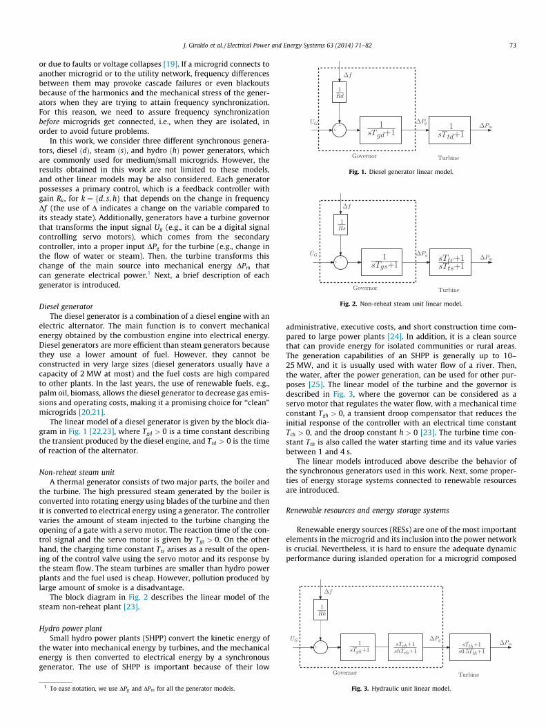
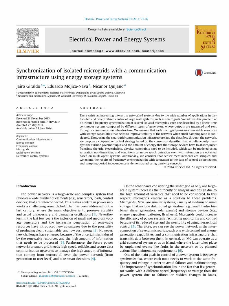
Fig. 1. Diesel generator linear model.
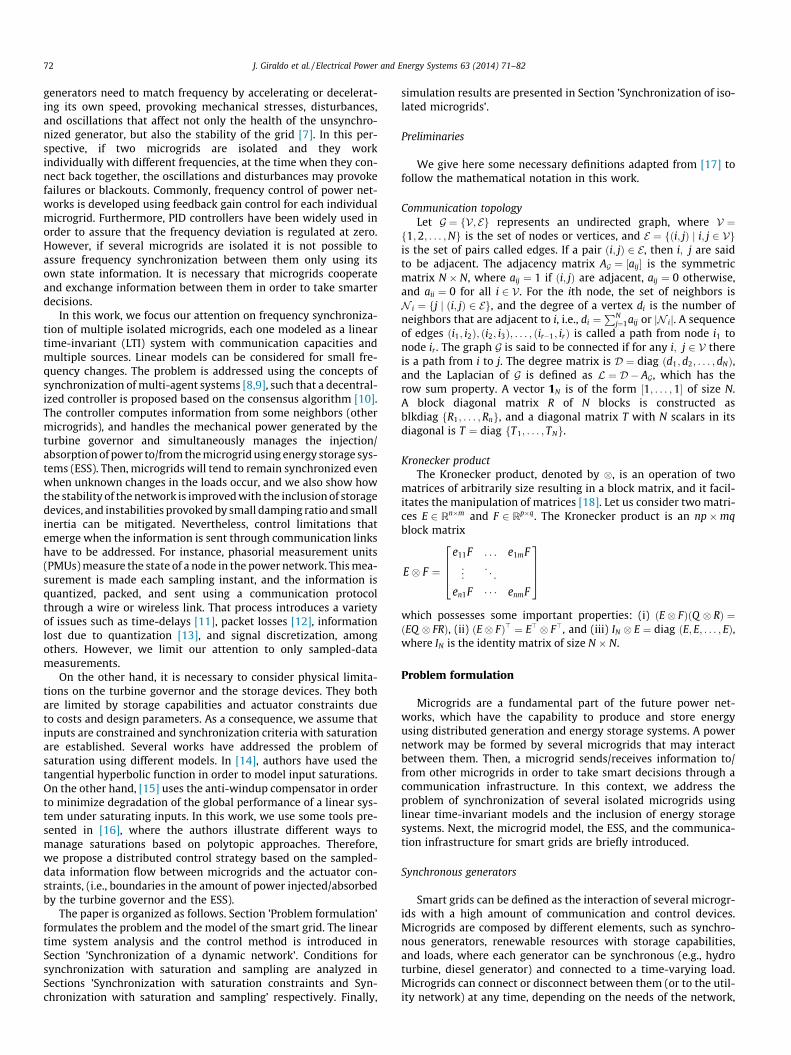
Fig. 2. Non-reheat steam unit linear model.
J. Giraldo et al. / Electrical Power and Energy Systems 63 (2014) 71–82 73
or due to faults or voltage collapses [19]. If a microgrid connects toanother microgrid or to the utility network, frequency differencesbetween them may provoke cascade failures or even blackoutsbecause of the harmonics and the mechanical stress of the gener-ators when they are trying to attain frequency synchronization.For this reason, we need to assure frequency synchronizationbefore microgrids get connected, i.e., when they are isolated, inorder to avoid future problems.
In this work, we consider three different synchronous genera-tors, diesel ðdÞ, steam ðsÞ, and hydro ðhÞ power generators, whichare commonly used for medium/small microgrids. However, theresults obtained in this work are not limited to these models,and other linear models may be also considered. Each generatorpossesses a primary control, which is a feedback controller withgain Rk, for k ¼ fd; s;hg that depends on the change in frequencyDf (the use of D indicates a change on the variable compared toits steady state). Additionally, generators have a turbine governorthat transforms the input signal Ug (e.g., it can be a digital signalcontrolling servo motors), which comes from the secondarycontroller, into a proper input DPg for the turbine (e.g., change inthe flow of water or steam). Then, the turbine transforms thischange of the main source into mechanical energy DPm thatcan generate electrical power.1 Next, a brief description of eachgenerator is introduced.
Diesel generatorThe diesel generator is a combination of a diesel engine with an
electric alternator. The main function is to convert mechanicalenergy obtained by the combustion engine into electrical energy.Diesel generators are more efficient than steam generators becausethey use a lower amount of fuel. However, they cannot beconstructed in very large sizes (diesel generators usually have acapacity of 2 MW at most) and the fuel costs are high comparedto other plants. In the last years, the use of renewable fuels, e.g.,palm oil, biomass, allows the diesel generator to decrease gas emis-sions and operating costs, making it a promising choice for ‘‘clean’’microgrids [20,21].
The linear model of a diesel generator is given by the block dia-gram in Fig. 1 [22,23], where Tgd > 0 is a time constant describingthe transient produced by the diesel engine, and Ttd > 0 is the timeof reaction of the alternator.
Non-reheat steam unitA thermal generator consists of two major parts, the boiler and
the turbine. The high pressured steam generated by the boiler isconverted into rotating energy using blades of the turbine and thenit is converted to electrical energy using a generator. The controllervaries the amount of steam injected to the turbine changing theopening of a gate with a servo motor. The reaction time of the con-trol signal and the servo motor is given by Tgs > 0. On the otherhand, the charging time constant Tts arises as a result of the open-ing of the control valve using the servo motor and its response bythe steam flow. The steam turbines are smaller than hydro powerplants and the fuel used is cheap. However, pollution produced bylarge amount of smoke is a disadvantage.
The block diagram in Fig. 2 describes the linear model of thesteam non-reheat plant [23].
Hydro power plantSmall hydro power plants (SHPP) convert the kinetic energy of
the water into mechanical energy by turbines, and the mechanicalenergy is then converted to electrical energy by a synchronousgenerator. The use of SHPP is important because of their low
1 To ease notation, we use DPg and DPm for all the generator models.
administrative, executive costs, and short construction time com-pared to large power plants [24]. In addition, it is a clean sourcethat can provide energy for isolated communities or rural areas.The generation capabilities of an SHPP is generally up to 10–25 MW, and it is usually used with water flow of a river. Then,the water, after the power generation, can be used for other pur-poses [25]. The linear model of the turbine and the governor isdescribed in Fig. 3, where the governor can be considered as aservo motor that regulates the water flow, with a mechanical timeconstant Tgh > 0, a transient droop compensator that reduces theinitial response of the controller with an electrical time constantTch > 0, and the droop constant h > 0 [23]. The turbine time con-stant Tth is also called the water starting time and its value variesbetween 1 and 4 s.
The linear models introduced above describe the behavior ofthe synchronous generators used in this work. Next, some proper-ties of energy storage systems connected to renewable resourcesare introduced.
Renewable resources and energy storage systems
Renewable energy sources (RESs) are one of the most importantelements in the microgrid and its inclusion into the power networkis crucial. Nevertheless, it is hard to ensure the adequate dynamicperformance during islanded operation for a microgrid composed
Fig. 3. Hydraulic unit linear model.
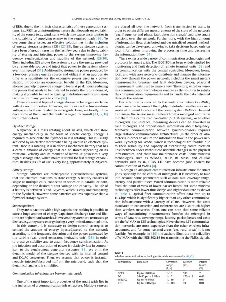
Table 1Wireless communication technologies for wide area networks [41,42].
Technology Data rate Coveragerange(km)
Latency(ms)
Packetlosses(%)
GPRS Up to 170 Kbps 1–10 500 23G 384 Kbps to 2 Mbps 1–10 170–412 0.49WiMAX Up to 75 Mbps 10–50 9 0.07LTE Up to 100 Mbps 10–100 10 0.01
74 J. Giraldo et al. / Electrical Power and Energy Systems 63 (2014) 71–82
of RESs, due to the intrinsic characteristics of these generation sys-tems, i.e., RES has an intermittent nature that depends on availabil-ity of the source (e.g., wind, sun), which may cause uncertainties inthe capability of supplying energy to the required loads [26]. Toovercome these issues, an effective solution lies in the inclusionof energy storage systems (ESS) [27,28]. Energy storage systemshave been of great interest in the last few years due to the capabil-ity of storing and injecting power to the system improving fre-quency synchronization and stability of the network [29,30].Then, including ESS allows the system to store the energy providedby a renewable source and inject that power to the system when-ever it is needed [31]. Additionally, storing the power produced bya low-cost primary energy source and utilize it at an appropriatetime as a substitute for the expensive power used in a powerstation, introduces an economical benefit of the ESS. Moreover,storage can help to provide energy to loads at peak hours, reducingthe power that needs to be installed to satisfy the future demand,making it possible to use the existing distribution and transmissionfacilities for many years to come [32].
There are several types of energy storage technologies, each onewith its own properties. However, we focus on the low-mediumvoltage applications related to microgrids. Here, we briefly intro-duce some of them, and the reader is urged to consult [33,32,34]for further details.
Flywheel storageA flywheel is a mass rotating about an axis, which can store
energy mechanically in the form of kinetic energy. Energy isrequired to accelerate the flywheel so it is rotating. This is usuallyachieved by an electric motor when being used in an electrical sys-tem. Once it is rotating, it is in effect a mechanical battery that hasa certain amount of energy that can be stored depending on itsrotational velocity and its moment of inertia. It possesses a veryhigh discharge rate, which makes it useful for fast storage capabil-ities. Besides, its life of use is very long, approximately of 20 years.
Battery storageStorage batteries are rechargeable electrochemical systems,
that use chemical reactions to store energy. A battery consists ofsingle or multiple cells, connected in series or in parallel or both,depending on the desired output voltage and capacity. The life ofa battery is between 3 and 12 years, which is very low comparingto the flywheel. However, some batteries are less expensive than aflywheel storage system.
SupercapacitorsThey are capacitors with a high capacitance, making it possible to
store a huge amount of energy. Capacitors discharge rate and life-time are higher than batteries. However, they are short-term storagedevices, e.g., they store energy during a very limited amount of time.
In this context, it is necessary to design control strategies tocontrol the amount of energy injected/stored to the networkaccording to the frequency deviation and the power generated bythe turbine (e.g., diesel generator, hydraulic unit) [35], in orderto preserve stability and to attain frequency synchronization. Asthe injection and absorption of power is relatively fast in compar-ison to the synchronous generator response [36], we omit thedynamic model of the storage devices with its internal controland DC/AC converters. Then, we assume that power is instanta-neously injected/absorbed to/from the microgrid, such that thedynamical analysis is simplified.
Communication infrastructure between microgrids
One of the most important properties of the smart grids lies inthe inclusion of a communication infrastructure. Multiple sensors
are placed all over the network, from transmission to users, inorder to obtain different measurements of the state of the network(e.g., frequency and phase, fault detection signals) and take smartdecisions over the network. Furthermore, with the high amountof information flow, distributed and decentralized control method-ologies can be developed, allowing to take decisions based only onlocal information, improving the processing time and decreasingthe information flow [37].
There exists a wide variety of communication technologies andprotocols for smart grids. The IEC6180 has been widely studied formonitoring and fault detection of remote terminal units [38] andits communication with the central controller. Moreover, home,local, and wide area networks distribute and manage the informa-tion flow through the power network, including the smart metersmeasurements, breakers and fault detection devices, phasorialmeasurement units, just to name a few. Therefore, wired or wire-less communication technologies emerge as the solution to satisfythe communication requirements and to handle the data deliveredthrough the system.
Our attention is directed to the wide area networks (WAN),which are able to connect the highly distributed smaller area net-works at different locations of the power system. WAN can be usedto manage the sensor measurements from a microgrid and trans-mit them to a centralized controller (SCADA system), or to othermicrogrids. For instance, measuring devices can be allocated ineach microgrid, and proportionate information about frequency.Moreover, communication between synchro-phasors requireslarge distance communication architectures (in the order of kilo-meters) in order to assure the information flow in the power net-work. Typically for WANs, wireless technologies are feasible dueto their scalability and capacity of establishing communicationlinks between nodes without considerable changes in the physicalinfrastructure, and their low maintenance costs. Some wirelesstechnologies, such as WiMAX, 3GPP, RF Mesh, and cellularnetworks such as 3G, GPRS, LTE have become good choices forcommunication of WANs [4].
To design an adequate communication infrastructure for smartgrids, specially for the control of microgrids, it is necessary to takeinto account some parameters such as data rate, coverage range,latency, and packet losses. Wired communication is more reliablefrom the point of view of lower packet losses, but some wirelesstechnologies offer lower time delays and higher data rate as shownin Table 1. Optical fiber communication offers data rate up to10 Gbps which is significantly higher than any other communica-tion infrastructure with a latency of 10 ms. However, the costsassociated to construction and maintenance are also much higherthan wireless networks. Then, one can note that some reliableways of transmitting measurements from/to the microgrid interms of data rate, coverage range, latency, packet losses and costsare the WiMAX or LTE technologies. Nevertheless, LTE communica-tion networks are most expensive than the other wireless infra-structures, and for some isolated areas (e.g., rural areas) it is notfeasible. For example, in [39] the authors illustrate the reliabilityof WiMAX with the IEEE 802.16 for transmitting the PMUs signals,
J. Giraldo et al. / Electrical Power and Energy Systems 63 (2014) 71–82 75
and in [40] some studies of the performance of LTE for smart gridsapplications have been developed.
Based on the aforementioned communication architecture andtechnologies, we assume that microgrids send the information ofthe PMUs to some neighbors using wide area networks with wire-less communications (e.g., WiMAX, LTE). Then, using the informa-tion from its neighbors, each microgrid is able to calculate a controlsignal to control the turbine governors input and the injection/absorption of power of the energy storage systems. Next, themicrogrid model is introduced.
Microgrid model
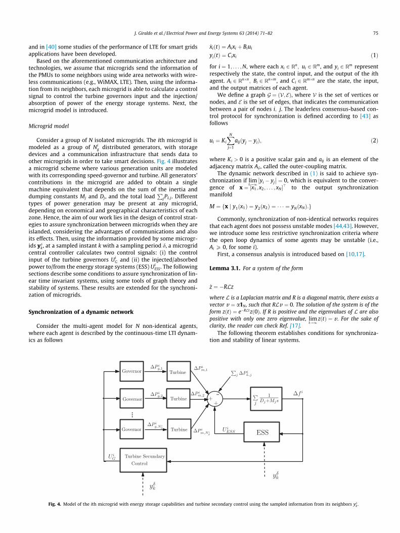
Consider a group of N isolated microgrids. The ith microgrid ismodeled as a group of Ni
g distributed generators, with storagedevices and a communication infrastructure that sends data toother microgrids in order to take smart decisions. Fig. 4 illustratesa microgrid scheme where various generation units are modeledwith its corresponding speed-governor and turbine. All generators’contributions in the microgrid are added to obtain a singlemachine equivalent that depends on the sum of the inertia anddumping constants Mj and Dj, and the total load
PjPL;j. Different
types of power generation may be present at any microgrid,depending on economical and geographical characteristics of eachzone. Hence, the aim of our work lies in the design of control strat-egies to assure synchronization between microgrids when they areislanded, considering the advantages of communications and alsoits effects. Then, using the information provided by some microgr-ids yd
k, at a sampled instant k with a sampling period d, a microgridcentral controller calculates two control signals: (i) the controlinput of the turbine governors Ui
G and (ii) the injected/absorbedpower to/from the energy storage systems (ESS) Ui
ESS. The followingsections describe some conditions to assure synchronization of lin-ear time invariant systems, using some tools of graph theory andstability of systems. These results are extended for the synchroni-zation of microgrids.
Synchronization of a dynamic network
Consider the multi-agent model for N non-identical agents,where each agent is described by the continuous-time LTI dynam-ics as follows
Fig. 4. Model of the ith microgrid with energy storage capabilities and turbine
_xiðtÞ ¼ Aixi þ Biui
yiðtÞ ¼ Cixi ð1Þ
for i ¼ 1; . . . ;N, where each xi 2 Rn; ui 2 Rm, and yi 2 Rm representrespectively the state, the control input, and the output of the ithagent. Ai 2 Rn�n; Bi 2 Rn�m, and Ci 2 Rm�n are the state, the input,and the output matrices of each agent.
We define a graph G ¼ ðV; EÞ, where V is the set of vertices ornodes, and E is the set of edges, that indicates the communicationbetween a pair of nodes i; j. The leaderless consensus-based con-trol protocol for synchronization is defined according to [43] asfollows
ui ¼ Ki
XN
j¼1
aijðyj � yiÞ; ð2Þ
where Ki > 0 is a positive scalar gain and aij is an element of theadjacency matrix AG, called the outer-coupling matrix.
The dynamic network described in (1) is said to achieve syn-chronization if lim
t!1yi � yj
�� �� ¼ 0, which is equivalent to the conver-gence of x ¼ ½x1; x2; . . . ; xN�> to the output synchronizationmanifold
M ¼ x j y1ðx1Þ ¼ y2ðx2Þ ¼ � � � ¼ yNðxNÞ:f g
Commonly, synchronization of non-identical networks requiresthat each agent does not possess unstable modes [44,43]. However,we introduce some less restrictive synchronization criteria wherethe open loop dynamics of some agents may be unstable (i.e.,Ai P 0, for some i).
First, a consensus analysis is introduced based on [10,17].
Lemma 3.1. For a system of the form
_z ¼ �RLz
where L is a Laplacian matrix and R is a diagonal matrix, there exists avector v ¼ a1N, such that RLv ¼ 0. The solution of the system is of theform zðtÞ ¼ e�RLtzð0Þ. If R is positive and the eigenvalues of L are alsopositive with only one zero eigenvalue, lim
t!1zðtÞ ¼ v . For the sake of
clarity, the reader can check Ref. [17].The following theorem establishes conditions for synchroniza-
tion and stability of linear systems.
secondary control using the sampled information from its neighbors ydk .
76 J. Giraldo et al. / Electrical Power and Energy Systems 63 (2014) 71–82
Theorem 3.1. Synchronization of non-identical agents. Let usconsider the synchronization problem for non-identical nodes where theagent dynamics are described by Eq. (1), with a control protocoldescribed in (2). We define K ¼ diagfK1; . . . KNg;A ¼blkdiagfA1; . . . ;ANg;B ¼ blkdiagfB1; . . . ;BNg, and C ¼ blkdiagfC1; . . . ;CNg. The Laplacian of the communication graph is denoted byLG. Then, synchronization is achieved if the communication graph isconnected, the pair ðA;BÞ is controllable, and A < BðKLG � ImÞC.
Proof. Note that Eq. (2) can be generalized for all i 2 V, such that
U ¼ ðKLG � ImÞy ð3Þ
where y ¼ ðC1x1; . . . ; CNxNÞ. Hence, the dynamics of the power net-work are given by
_x ¼ Ax� BU ð4Þ
As y ¼ Cx and A < BðKLG � ImÞC, the system is stable becauseA� BðKLG � ImÞC is Hurwitz, i.e., its eigenvalues are negative. Onthe other hand, the solution of the system is described by
xðtÞ ¼ eðA�BðKLG�ImÞCÞtxð0Þ ¼ eAte�BðKLG�ImÞCtxð0Þ
As the controller is consensus-based, the graph is connected, andA < BðKLG � ImÞC, then the states of the system will tend first tosynchronize according to Lemma 3.1 due to the term e�BðKLG�ImÞCt
and then they will converge to the equilibrium state xeq ¼ 0 becauseof the term eAt . �
Remark 3.1. If some of the rows of B are zero, it means that somestates are not affected by the controller and synchronization ofthose states is not achieved. However, if conditions of Theorem 3.1are satisfied, the noncontrolled states still converge to the equilib-rium point xeq ¼ 0.
Note that for the non-identical agents case, the consensus pro-tocol does not need to follow a leader because xeq is always zero.Then, the synchronization condition depends on the connectivityof the graph and the gain Ki, such that the unstable modes of thematrix Ai are compensated. Moreover, as the controller is consen-sus-based and it does not depend on the model of the system, itassures that even with changes in the model, synchronization isachieved. However, increasing connectivity or Ki implies an incre-ment of ui, which is not feasible for physical applications, wherecontrol inputs are constrained. Next, we introduce some synchro-nization conditions when control inputs are saturated using a sym-metric saturation nonlinearity.
Synchronization with saturation constraints
In real applications, it is not possible to neglect constraints inthe actuator signals. For instance, velocities, mechanical power,or electrical power injection is limited by physical constraints indynamic systems. For these reasons, we assume that the synchro-nization problem described in (1) is controlled with an input signalsubjected to a uniform symmetrical saturation constraint�v i 6 uiðtÞ 6 v i, for v i > 0, for all i 2 V. We assume symmetry inorder to ease the analysis, and it means that the storage devicecan deliver the total amount of power that it stores.
Saturation induces nonlinearities into the dynamical systemthat provokes lost of global stability [16]. Then, it is necessary tofind an admissible set of initial conditions X0 to assure attractionto the synchronization manifold. Several works have focused onthe analysis of stability under saturation, using hyperbolic func-tions that emulate the saturating behavior [14] or adding anti-windup control [15]. However, we use a simple but usefulapproach based on polytopic models [16] to define the set of
attraction and derive synchronization conditions. The main advan-tage in this case is that synchronization conditions can be obtaineddisappearing the nonlinearities induced by saturation.
First, we introduce some fundamental definitions adapted from[16] for closed-loop systems with saturations of the form:
_x ¼ Gxþ HsatðKxÞ ð5Þ
where K 2 Rm�n; G 2 Rn�n, H 2 Rm�n; x 2 Rn, u ¼ satðKxÞ 2 Rm, and
satðKxÞ ¼v if Kx > vKx if Kxj j 6 v�v if Kx 6 �v
8><>:We can define some regions of the state space with differentproperties.
Definition 3.1. The region of linearity, RL, is defined as the set ofstates x 2 Rn such that satðKxÞ ¼ Kx, i.e., the region where satura-tion is never active.
If we can assure that all the trajectories of a system under sat-urating inputs lie in RL, we can treat the system as a linear system.However, we want to introduce a more general region where thenonlinearity produced by saturation may be activated.
Definition 3.2. A region Rs is defined as a region of asymptoticstability (RAS) for the system in (5) if for xð0Þ 2 Rs; xðtÞ ! 0 ast !1.
The region of linearity is contained into the RAS such thatRL � Rs. Hence, any trajectory starting in Rs asymptoticallyconverges to the origin.
Definition 3.3. A system of the form in (5) is GAS if the pair ðG;HÞis stabilizable and the eigenvalues of matrix G do not have positivereal parts.
In this case we say that Rs is all the state space. However, GASconditions cannot be defined for systems with unstable dynamics,and the region Rs needs to be found.
Obtaining the exact set of initial conditions that assure asymp-totic convergence is not an easy task. It is necessary to obtain agood estimate of the RAS using some approaches based on Lyapu-nov functions and polytopic models.
Polytopic modelPolytopic linear models (PLM) are suitable for the analysis,
modeling, and control of nonlinear dynamical systems. The PLMstructure is introduced in order to describe nonlinear dynamicalsystems as a convex combination of linear models, each one ofwhich describes the system locally. Therefore, stability criteriaand control design can be defined based only on linear conditions.
For saturation nonlinearity, we use a polytopic modelillustrated in [16] of the form
satðKxÞ ¼ C aðxÞð ÞKx ð6Þ
where aðxÞ ¼ ½að1ÞðxÞ; . . . ;aðmÞðxÞ� and C aðxÞð Þ is a diagonal matrix,whose elements are described by
aðsÞðxÞ ¼
vðsÞKðsÞx
if KðsÞx > v ðsÞ1 if KðsÞx
�� �� 6 v ðsÞ� v ðsÞ
KðsÞxif KðsÞx 6 �v ðsÞ
8>><>>: ð7Þ
where KðsÞ is the sth row of K, for s ¼ 1; . . . ;m. It is easy to verifyfrom (7) that if there is no saturation satðKxÞ ¼ Kx, andsatðKxÞ ¼ v if the states saturate. Now, we need to find a set thatis larger than the region of linearity RL and that is contained inthe region of stability Rs. Then, we can define the following polyhe-dral set for a constant lower bound 0 6 aðsÞ 6 aðsÞðxÞ � 1:
J. Giraldo et al. / Electrical Power and Energy Systems 63 (2014) 71–82 77
Sðj K j;vaÞ ¼ fx 2 Rm :j KðsÞx j6 v ðsÞ=a sð Þg
for s ¼ 1; . . . ;m. If a is small, the set Sðj K j;vaÞ is large and it indi-cates that the maximum value of Kx is outside the region oflinearity.
On the other hand, we need to assure that the system in Eq. (5)is stable. Thus, using the Lyapunov stability criteria, we choose thestability domain as an ellipsoidal Lyapunov level set of the form
EðP;gÞ ¼ fx : x>Px 6 1=gg
for P > 0 and g a suitable positive scalar. As a result, any trajectorystarting inside the ellipsoid converges to the origin. As a conse-quence, the objective is to find a small a and a small value of g suchthat EðP;gÞ � Sðj K j;vaÞ, and those sets are as close as possible to Rs.Fig. 5 illustrates the different sets for systems with saturation wherea1 > a2.
Now, we need to represent the matrix CðaðxÞÞ as a convex linearcombination of matrices of the form CqðaÞ, for q ¼ 1; . . . ;2m, suchthat
CðaðxÞÞ ¼X2m
q¼1
bqðxÞCqðaÞ
whereP2m
q¼1bqðxÞ ¼ 1. Each CqðaÞ is a diagonal matrix whose ele-ments can be either aðsÞ or 1, and 2m is the total number of matrices.
Then, for x 2 Sðj K j;vaÞ; _xðtÞ can be determined as the convexlinear combination of the form
_xðtÞ ¼X2m
q¼1
bqðxÞ Gþ HCqðaðxÞÞ� �
xðtÞ;
and the set Sðj K j;vaÞ corresponds to the maximum set in which thepolytopic model can represent system (5).
To find the ellipsoidal set EðP;gÞ � Sðj K j;vaÞ, the problembecomes an optimization problem where we need to find P > 0and a vector a that satisfies 0 6 aðsÞ 6 1 such that
ðGþ HCqðaðxÞÞÞK�>P þ PðGþ HCqðaðxÞÞÞKÞ < 0
for q ¼ 1; . . . ;2m. Besides, to satisfy the conditionEðP;gÞ � Sðj K j;vaÞ, it is necessary to find the level set g�1 such that
P Pa2ðsÞK
>ðsÞKðsÞ
gv2ðsÞ
or using the Schur’s complement,
Fig. 5. Region of linearity (RL), Lyapunov level set (EðP;gÞ), region of stability (Rs),and two polyhedral sets Sðj K j; ta1 Þ; Sðj K j; ta2 Þ for a1 > a2.
P aðsÞK>ðsÞaðsÞKðsÞ gv2
ðsÞ
" #P 0
for s ¼ 1; . . . ;m.Then, any trajectory starting inside EðP;gÞ, asymptotically con-
verges to the origin.Now, we extend these results for the multi-agent system in
order to assure synchronization under saturation constraints.
Synchronization with input constraintsThe following theorem establish synchronization conditions
when the actuator is subjected to physical constraints using thepolytopic model previously introduced.
Theorem 3.2. Synchronization with saturated input: Considerthe system of N agents with saturation, where the dynamics of eachagent are given by
_xi ¼ Aixi � Bisat Ki
XN
j¼1
aijðCixi � CjxjÞ !
; ð8Þ
with a communication topology described by the graph G ¼ fAG;V; Egand the Laplacian LG. Assume that the control input is bounded and it isdescribed by ui ¼ sat Ki
PNj¼1aijðCixi � CjxjÞ
� �for v i 6 uiðtÞ 6 v i and
v i > 0, where v i ¼ fv ið1Þ; . . . ; v iðmÞg. The dynamics of the network withsaturation are then given by
_x ¼ Ax� Bsat ðKLG � ImÞCxð Þ: ð9Þ
If the graph is connected and there exist a symmetric and positive def-inite matrix P ¼ blkdiagfP1; . . . ; PNg, a vector a ¼ fa1; . . . ;aNg withai ¼ faið1Þ; . . . ;aiðmÞg, for all i 2 V, and a vector of size mN with positivescalar values g ¼ fg11m; . . . ;gN1mg satisfying
A� BCqðaÞðKLG � ImÞC� �>P
þ P A� BCqðaÞðKLG � ImÞC� �
< 0
for all q ¼ 1; . . . ;2m, and
P aðsÞ ðKLG � ImÞCð Þ>ðsÞaðsÞð KLG � ImÞCð ÞðsÞ gðsÞv2
ðsÞ
" #P 0; ð10Þ
where ðKLG � ImÞCð ÞðsÞ is the sth row of ðKLG � ImÞCð Þ fors ¼ 1; . . . ;mN, then the system synchronizes, and the set of admissibleinitial values E iðPi;giÞ is such that EiðPi;giÞ ¼ xi j x>i P>i xi 6 g�1
i
� �.
Proof. First, if there exists a positive definite symmetric matrix Pand a scalar g, such that
Ax� Bsat ðKLG � ImÞCxð Þð Þ>Pþ P Ax� Bsat ðKLG � ImÞCxð Þð Þ< 0 ð11Þ
then the region EðP;gÞ is a RAS region.Using the polytopic representation, we define
_x ¼X2m
q¼1
bqðxÞ A� BCqðaÞðKLG � ImÞ� �
Cx;
where CqðaÞ ¼ blkdiagfC1;qða1Þ; . . . ;CN;qðaNÞg. Hence, for allx 2 Sðj K j; vaÞ, condition (11) can be verified if
x>X2m
q¼1
bqðxÞ A� BCqðaÞðKLG � ImÞC� �>Ph
þ P A� BCqðaÞðKLG � ImÞC� �
x < 0;
and as a consequence, it is also verified if
A� BCqðaÞðKLG � ImÞC� �>Pþ P A� BCqðaÞðKLG � ImÞC
� �< 0
78 J. Giraldo et al. / Electrical Power and Energy Systems 63 (2014) 71–82
for all q ¼ 1; . . . ;2m. Finally, condition (10) ensures thatEðP;gÞ � Sðj K j;aÞ �
We have established some conditions for synchronization whensaturation is considered based on the solution of an LMI. Then, weobtain the set of initial conditions for each agent such that conver-gence to the synchronization manifold is assured. However, westill assume that communication between agents is perfect, i.e.,no communication effects have been considered. In the next sec-tion, we assume that each measurement is sampled with a finitesampling period, and we illustrate the sampling period indepen-dence of our proposed multi-agent system.
Synchronization with saturation and sampling
Communication between agents depends on the structure ofthe graph and the information that each agent has to deliver toits neighbors through a communication channel. Consequently,communication constraints must be considered, such as sampling,quantization, and channel capabilities.
Now, we will analyze the synchronization problem undersampling and we will introduce some conditions in order to assuresynchronization of non-homogenous LTI multi-agent systems.
Inclusion of data-measurementsLet us consider the synchronization problem introduced in
Section ’Synchronization of a dynamic network’. In order to easethe following definitions, we can rewrite the multi-agent synchro-nization representation with saturation in Eq. (8), such that
_xiðtÞ ¼ AixiðtÞ þ sat �BiKi
XN
j¼1
aijCixiðtÞ
þ BiKi
XN
j¼1
aijyjðxjÞ!:
Using the polytopic approach, we can find a vectorai, a positive scalargi, and a positive definite matrix Pi for all i 2 V according to Theo-rem 3.2. Thus, recalling that x ¼ ½x1; x2; . . . ; xN�>, the vector containingthe state vectors of all N agents, D ¼ diagðd1; d2; . . . ;dNÞ, wheredi ¼
PNj¼1aij; A ¼ blkdiagfA1; . . . ;ANg; B ¼ blkdiagfB1; . . . ;BNg, and
K ¼ diagfK1; . . . ;KNg, we can split the Laplacian matrix into D�AG,leading to the dynamics of the network described by
_x ¼ Ax�X2m
q¼1
bqðxÞCqðaÞBðKD� ImÞCxþX2m
q¼1
bqðxÞCqðaÞUN ð12Þ
where UN ¼ uN 11 ; . . . ;uNN
N
h i>¼ BðKAG � ImÞy is the input that
depends on the information received from the neighbors of eachagent i. Until now, we have not changed the synchronization prob-lem defined in the above section. However, as the information thateach agent receives from its neighbors is spatially distributed, thisinformation has to be sent through a communication network usingsampled-measurements with a sampling period d, according toFig. 6.
The discrete-time controller uN ii ðkÞ is calculated using discrete-
time signals. Then, this controller signal is retained using a zeroorder holder (ZOH), such that it is constant during each samplingperiod (i.e., it is constant during the interval ½dk; dðkþ 1ÞÞ, wherek is the sampling instant and the controller ui is a piecewisecontroller).
ZOH Σiu∗
i (t)uNii (k) yi(k)
δ δ
Fig. 6. Sampled data scheme for a dynamical system Ri , where the input ui is apiecewise control signal.
Defining bA ¼ A�P2m
q¼1bqðxÞCqðaÞBðKD� ImÞC, and bB ¼P2m
q¼1bqðxÞCqðaÞBðKAG � ImÞ, the continuous-time representationfor a time period r ¼ ½kd; ðkþ 1ÞdÞ can be described by
_xðrÞ ¼ bAxðrÞ þ bBU ð13Þ
for U ¼ y the piecewise measurements vector from all agents.Now, we introduce the following definitions adapted from [45],
that will help to illustrate the stability of the power network inde-pendent of sampling-period based on the concept of passivity forsystems with direct input–output links (i.e., output dependsdirectly on the input).
Passivity of sampled-data systemsLet us consider a continuous-time system of the form
_xcðtÞ ¼ f ðxcðtÞÞ þ gðxcðtÞÞucðtÞycðtÞ ¼ hðxcðtÞ;ucðtÞÞ ð14Þ
Definition 3.4. The system in (14) is passive if there exists astorage function VðxcðtÞÞ > 0, and Vð0Þ ¼ 0 such that
VðxcðtÞÞ � Vðxcð0ÞÞ 6Z t
0ycðsÞucðsÞds
Definition 3.5. For the continuous-time system representationabove, assume that the input depends on sampled-data with aZOH, such that uc is constant in the interval t 2 ½dk; dðkþ 1Þ�, whered is the sampling period. Passivity of the sampled-data representa-tion reduces to passivity of the continuous-time system in eachtime interval where uc is constant, xcð0Þ ¼ xcðkÞ, andxcðtÞ ¼ xcðkþ 1Þ, such that
Vðxcððkþ 1ÞÞÞ � VðxcðkÞÞ 6Z d
0ycðsÞds
�uc ð15Þ
The state xcðkÞ corresponds to the state of the discrete-time rep-resentation and xcðkþ 1Þ ¼ edðfþuc ðkÞgÞxcðkÞ is the solution for a con-stant ucðkÞ. Then, the term related to the outputycðtÞ ¼ hðxcðtÞ;ucðtÞÞ in Eq. (15) is described byZ d
0hðxcðsÞ;ucÞds ¼
Z d
0esðfþuc ðkÞgÞhðxcðkÞ;ucðkÞÞds:
It is evident the fact that the discrete-time output equivalent in theright-hand depends on the input ucðkÞ at each instant k. Hence, thefollowing definition adapted from [45] is derived.
Lemma 3.2. Passivity with input/output link: Passivity of thesampled-data representation is preserved if the continuous-timesystem possesses a direct input/output link such that the outputdepends on the input. Then, if there is not an input/output link,passivity is lost, and stability criteria cannot be defined using the samestorage function.
In order to define the synchronization and stability conditionsfor the sampled representation in (13), classical passivity condi-tions cannot be defined. Then, the following theorem gives someconditions for synchronization under sampling that can beextended to systems with saturations.
Theorem 3.3. Synchronization under sampling. Let us considerthe multi-agent synchronization model with sampled-data input in Eq.
(13), such that bA ¼ A�P2m
q¼1bqðxÞCqðaÞ BðKD� ImÞC; bB ¼P2m
q¼1bqðxÞCqðaÞBðKAG � ImÞ, and U ¼ y1; . . . ; yN� >. If its continu-
ous-time representation without sampling synchronizes according to
MG2 MG3
J. Giraldo et al. / Electrical Power and Energy Systems 63 (2014) 71–82 79
Theorem 3.2 with an output vector y ¼ qCxþ ð1� qÞU for 0 6 q 6 1,then synchronization is preserved independently of the samplingperiod.
MG1
MG5
MG4
MG6
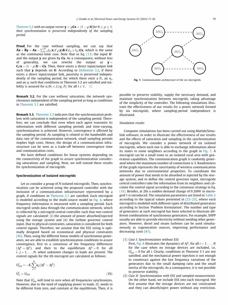
Fig. 7. Communication architecture of the six microgrids.
Proof. For the case without sampling, we can say thatbAxþ bBy ¼ Ax�P2m
q¼1bqðxÞCqðaÞBðKLG � ImÞCx, which is the sameas the continuous-time case. Note that in Eq. (13) the input U
and the output y are given by Cx. As a consequence, without lossof generality, we can rewrite the output as y ¼Cqxþ ð1� qÞU ¼ Cx. Then, there exists a direct input/output linksuch that y depends on U. According to Definition 3.2, if thereexists a direct input/output link, passivity is preserved indepen-dently of the sampling period, for which there exist a Pi, an gi,and an ai such that conditions in Theorem 3:2 are satisfied and sta-bility is assured for xið0Þ 2 E iðgi; PiÞ for all i 2 V. �
Remark 3.2. For the case without saturation, the network syn-chronizes independent of the sampling period as long as conditionsin Theorem 3.1 are satisfied.
Remark 3.3. Theorem 3.3 indicates that the synchronization prob-lem with saturation is independent of the sampling period. There-fore, we can conclude that even when each agent transmits itsinformation with different sampling periods and time-varying,synchronization is achieved. However, convergence is affected bythe sampling period. As sampling is related to the bandwidth anddata rate of the communication network, small sampling periodsimplies high costs. Hence, the design of a communication infra-structure can be seen as a trade-off between convergence timeand communication costs.
We have defined conditions for linear systems depending onthe connectivity of the graph to assure synchronization consider-ing saturations and sampling. Next, we will extend these resultsfor synchronization of microgrids.
Synchronization of isolated microgrids
Let us consider a group of N isolated microgrids. Then, synchro-nization can be achieved using the proposed controller with theinclusion of a communication infrastructure represented by agraph, if conditions in Theorem 3.1 are satisfied. Each microgridis modeled according to the multi-source model in Fig. 4, wherefrequency information is measured with a sampling period. Eachmicrogrid sends data through the communication network, whichis collected by a microgrid central controller such that two controlsignals are calculated: (i) the amount of power absorbed/injectedusing the storage system and (ii) the turbine governor controlinput. Due to physical constraints, saturation is considered for bothcontrol signals. Therefore, we assume that the ESS sizing is opti-mally designed based on economical and physical constraints[46]. Then, using the different linear models of synchronous gener-ators, we are able to establish synchronization conditions to assureconvergence, first to a consensus of the frequency differences(Df i ¼ Df j), and then to the equilibrium Df i ¼ 0 for alli; j ¼ 1; . . . ;N, when unknown changes in loads are present. Thecontrol signals for the ith microgrid are calculated as follows:
UiESS ¼ �Ki
XN
j¼i
aij Df i � Df j� �
_UiG ¼ UESS ð16Þ
Note that UiESS will tend to zero when all frequencies synchronizes.
However, due to the need of supplying power to loads, UiG needs to
be different from zero, and constant at the equilibrium. Then, it is
possible to preserve stability, supply the necessary demand, andmaintain synchronization between microgrids, taking advantageof the simplicity of the controller. The following simulations illus-trate the effectiveness of our results for a power network formedby six microgrids, where sampling-period independence isillustrated.
Simulation results
Computer simulations has been carried out using Matlab/Simu-link software, in order to illustrate the effectiveness of our resultsand the effects of saturation and sampling in the synchronizationof microgrids. We consider a power network of six isolatedmicrogrids, where each one is able to exchange information aboutits states to some neighbors according to the graph in Fig. 7. Amicrogrid can be a small town or an isolated rural area with gen-eration capabilities. The communication graph is randomly gener-ated where the maximum number of connections is 3. Randomnessof the graph represents the uncertainty of wireless communicationnetworks due to environmental properties. To coordinate theamount of power that needs to be absorbed or injected by the stor-age system, and to define the control governor input, microgridscentral controllers take the information from its neighbors and cal-culate the control signal according to the consensus strategy in Eq.(16). Besides, at 20s a sudden demand change of 0:2MW in micro-grid 1 is introduced. The simulation parameters are listed in Table 2according to the typical values presented in [23–25], where eachmicrogrid is modeled with different types of distributed generatorsaccording to Section ’Problem formulation’. The number and typeof generators at each microgrid has been selected to illustrate dif-ferent combinations of synchronous generators. For example, SHPPusually are able to provide electricity without needing other gener-ators. However, diesel and steam turbines can be used simulta-neously as cogeneration sources, improving performance anddecreasing costs [47].
(1) Case I: Synchronization without ESSFirst, Fig. 8 illustrates the dynamics of Df i, for all i ¼ 1; . . . ;Nfor the case when no storage devices are included, i.e,Ui
ESS ¼ 0 for all i. Clearly, conditions in Theorem 3:1 are notsatisfied, and the mechanical power injection is not enoughto counteract against the fast frequency variations of thegenerators due to the small damping ratio and the smallinertia of the microgrids. As a consequence, it is not possibleto preserve stability.
(2) Case II: Synchronization with ESS and sampled-measurementsOn the other hand, we include ESS into each microgrid. Wefirst assume that the storage devices are not constrainedand they can absorb/inject power without any restriction.
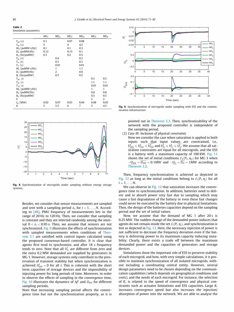
Table 2Simulation parameters.
MG1 MG2 MG3 MG4 MG5 MG6
Tgd (s) 0.1 0.07 0.08Ttd (s) 5 4 4.5Md (puMW s/Hz) 0.1 0.1 0.3Dd (puMW/Hz) 0.12 0.15 0.1Rd (Hz/puMW) 0.3 0.2 0.5Tgs (s) 0.4 0.2Tts (s) 0.3 0.3Ttr (s) 0.01 0.01Ms (puMW s/Hz) 1 1.1Ds (puMW/Hz) 2 0.8Rs (Hz/puMW) 0.5 0.5Tgh ðsÞ 0.5 0.5Tth ðsÞ 1.1 1.1Tch ðsÞ 0.01 0.01Mh (puMW s/Hz) 1 1Dh (puMW/Hz) 0.8 0.8Rh (Hz/puMW) 0.5 0.5h 2 2Ld (MW) 0.02 0.07 0.03 0.04 0.08 0.05K 5 5.5 6 7 5 4.5
0 5 10 15 20 25 30 35 40−0.03
−0.02
−0.01
0
0.01
Δfi
0 5 10 15 20 25 30 35 40
−0.2
0
0.2
UG
0 5 10 15 20 25 30 35 40−0.1
0
0.1
0.2
Time (sec)
UE
SS
MG1
MG2
MG3
MG4
MG5
MG6
Fig. 9. Synchronization of microgrids under sampling with ESS and the commu-nication infrastructure.
0 1 2 3 4 5 6 7 8 9 10−20
−15
−10
−5
0
5
10
15
20
25
30
Time (sec)
Δ f i
MG1
MG2
MG3
MG4
MG5
MG6
Fig. 8. Synchronization of microgrids under sampling without energy storagesystems.
80 J. Giraldo et al. / Electrical Power and Energy Systems 63 (2014) 71–82
Besides, we consider that sensor measurements are sampledand sent with a sampling period di, for i ¼ 1; . . . ;N. Accord-ing to [48], PMU frequency of measurements lies in therange of 20 Hz to 120 Hz. Then, we consider that samplingis constant and they are selected randomly among the inter-val 0 < di < 0:05 s. Then, we assume that sensors are notsynchronized. Fig. 9 illustrates the effects of synchronizationwith sampled measurements when conditions of Theo-rem 3.1 are satisfied with control inputs calculated usingthe proposed consensus-based controller. It is clear thatagents first tend to synchronize, and after 18 s frequencytends to zero. Note that all Ui
G are different from zero andthe extra 0.2 MW demanded are supplied by generators inMG 1. However, storage systems only contribute to the pres-ervation of transient stability but when synchronization isachieved Ui
ESS ¼ 0 for all i. This is coherent with the shortterm capacities of storage devices and the impossibility ofinjecting power for long periods of time. Moreover, in orderto observe the effects of sampling in the convergence time,Fig. 10 illustrates the dynamics of Df i and UESS for differentsampling periods.Note that increasing sampling period affects the conver-gence time but not the synchronization property, as it is
pointed out in Theorem 3.3. Then, synchronizability of thenetwork with the proposed controller is independent ofthe sampling period.
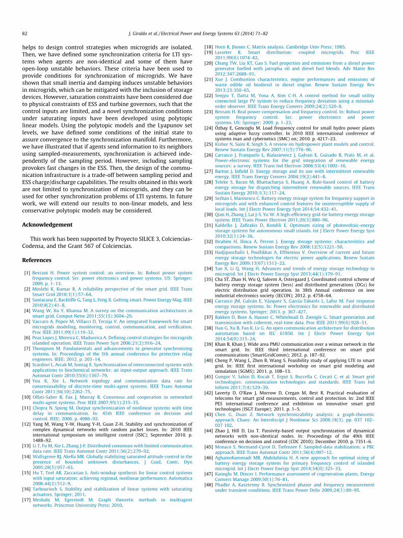
(3) Case III: Inclusion of physical constraintsNow we consider the case when saturation is applied to bothinputs such that input values are constrained, i.e.,Ui
ESS 6 UiESS 6 Ui
ESS and UiG 6 Ui
G 6 UiG. We assume that all sat-
uration constraints are equal for all microgrids, and the ESSis a battery with a maximum capacity of 100 KW. Fig. 11shows the set of initial conditions E3ðP3;g3Þ for MG 3 when�UESS ¼ UESS ¼ 0:1MW and �UG ¼ UG ¼ 1MW according toTheorem 3.2.
Then, frequency synchronization is achieved as depicted inFig. 12 as long as the initial conditions belong to E iðPi;giÞ for alli ¼ 1; . . . ;N.
We can observe in Fig. 12 that saturation increases the conver-gence time to synchronization. In addition, batteries need to deli-ver and to absorb power very fast due to sampling which maycause a fast degradation of the battery or even these fast changescould never be executed by the battery due to physical limitations.Then, the design of the batteries capacities depend on the samplingperiod and the set of initial values.
Now, we assume that the demand of MG 1 after 20 s is0.25 MW. The sudden change of the demanded power induces thatagents do not remain inside the set EiðPi;giÞ, and synchronization islost as depicted in Fig. 13. Here, the necessary injection of power isnot sufficient to decrease the frequency deviation even if the bat-tery is delivering power to its maximum capacity inducing insta-bility. Clearly, there exists a trade off between the maximumdemanded power and the capacities of generators and storagedevices.
Simulations show the important role of ESS to preserve stabilityof each microgrid, and how, with very simple calculations, it is pos-sible to maintain synchronization of all isolated microgrids, with-out including a coordinating central entity. However, severaldesign parameters need to be chosen depending on the communi-cation capabilities (which depends on geographical conditions andcosts), and the needs of each microgrid. For instance, the selectionof Ki is related to the speed of convergence and physical con-straints such as actuator limitations and ESS capacities. Large Ki
increases convergence speed but also increases the injection/absorption of power into the network. We are able to analyse the
0 10 20−1
−0.5
0
0.5
1
Time (sec)
ES
S (
MW
)
0 10 20−1
−0.5
0
0.5
1
Time (sec)
0 10 20−0.05
0
0.05δ=0.5s
0 10 20−1
−0.5
0
0.5
1
Time (sec)
0 10 20−0.05
0
0.05δ=1s
0 10 20−1
−0.5
0
0.5
1
Time (sec)
0 10 20−0.05
0
0.05δ=0.05s
0 10 20−0.05
0
0.05
Δ f i (
Hz)
δ=0.01s
Fig. 10. Synchronization of microgrids for several sampling periods.
0 5 10 15 20 25 30−1
−0.5
0
0.5
1
Δ f i
0 5 10 15 20 25 30−1
0
1
UG
0
0.1
UE
SS
MG1
MG2
MG3
MG4
MG5
MG6
Fig. 11. Initial condition set E3ðP3;g3Þ for microgrid 3 considering constraints in thestorage system and in the mechanical power injected to the governor.
0 5 10 15 20 25 30 35 40
−0.1−0.05
00.050.1
Δ f i
0 5 10 15 20 25 30 35 40−1
0
1
UG
0 5 10 15 20 25 30 35 40
−0.1
0
0.1
Time (sec)
UE
SS
MG1
MG2
MG3
MG4
MG5
MG6
Fig. 12. Synchronization of microgrids under sampling and saturation constraints.
J. Giraldo et al. / Electrical Power and Energy Systems 63 (2014) 71–82 81
set of admissible initial conditions depending on the capabilities ofstorage devices. Then, we can establish the requirements of the ESSto maintain frequency deviation inside some operating points. Onthe other hand, large sampling period is cost effective, butincreases the convergence time and induces some sudden changeson the absorption/injection of power that can deteriorate the stor-age devices. However, our results are not limited to the few gener-ators models introduced in this work. The improvement of thestorage devices and the high penetration of renewable resourcestend to decrease the number of synchronous generators, augment-ing the role of DC-sources into the microgrid. Therefore, our resultcan be extended to more complex models that also include voltagesynchronization and coordination of reactive power.
0 5 10 15 20 25 30
−0.1
Time (sec)
Fig. 13. Synchronization is not achieved when the demanded power increases,provoking that state trajectories do not remain inside the set EiðPi;giÞ.
Conclusions
Synchronization of microgrids is necessary to avoid failures inthe power network. The smart grids communication infrastructure
82 J. Giraldo et al. / Electrical Power and Energy Systems 63 (2014) 71–82
helps to design control strategies when microgrids are isolated.Then, we have defined some synchronization criteria for LTI sys-tems when agents are non-identical and some of them haveopen-loop unstable behaviors. These criteria have been used toprovide conditions for synchronization of microgrids. We haveshown that small inertia and damping induces unstable behaviorsin microgrids, which can be mitigated with the inclusion of storagedevices. However, saturation constraints have been considered dueto physical constraints of ESS and turbine governors, such that thecontrol inputs are limited, and a novel synchronization conditionsunder saturating inputs have been developed using polytopiclinear models. Using the polytopic models and the Lyapunov setlevels, we have defined some conditions of the initial state toassure convergence to the synchronization manifold. Furthermore,we have illustrated that if agents send information to its neighborsusing sampled-measurements, synchronization is achieved inde-pendently of the sampling period. However, including samplingprovokes fast changes in the ESS. Then, the design of the commu-nication infrastructure is a trade-off between sampling period andESS charge/discharge capabilities. The results obtained in this workare not limited to synchronization of microgrids, and they can beused for other synchronization problems of LTI systems. In futurework, we will extend our results to non-linear models, and lessconservative polytopic models may be considered.
Acknowledgement
This work has been supported by Proyecto SILICE 3, Colciencias-Codensa, and the Grant 567 of Colciencias.
References
[1] Bevrani H. Power system control: an overview. In: Robust power systemfrequency control. Ser. power electronics and power systems. US: Springer;2009. p. 1–13.
[2] Moslehi K, Kumar R. A reliability perspective of the smart grid. IEEE TransSmart Grid 2010;1(1):57–64.
[3] Santacana E, Rackliffe G, Tang L, Feng X. Getting smart. Power Energy Mag, IEEE2010;8(2):41–8.
[4] Wang W, Xu Y, Khanna M. A survey on the communication architectures insmart grid. Comput Netw 2011;55(15):3604–29.
[5] Vaccaro A, Popov M, Villacci D, Terzija V. An integrated framework for smartmicrogrids modeling, monitoring, control, communication, and verification.Proc IEEE 2011;99(1):119–32.
[6] Peas Lopes J, Moreira C, Madureira A. Defining control strategies for microgridsislanded operation. IEEE Trans Power Syst 2006;21(2):916–24.
[7] Thompson M. Fundamentals and advancements in generator synchronizingsystems. In: Proceedings of the 5th annual conference for protective relayengineers. IEEE; 2012. p. 203–14.
[8] Scardovi L, Arcak M, Sontag E. Synchronization of interconnected systems withapplications to biochemical networks: an input-output approach. IEEE TransAutomat Contr 2010;55(6):1367–79.
[9] You K, Xie L. Network topology and communication data rate forconsensusability of discrete-time multi-agent systems. IEEE Trans AutomatContr 2011;56(10):2262–75.
[10] Olfati-Saber R, Fax J, Murray R. Consensus and cooperation in networkedmulti-agent systems. Proc IEEE 2007;95(1):215–33.
[11] Chopra N, Spong M. Output synchronization of nonlinear systems with timedelay in communication. In: 45th IEEE conference on decision andcontrol. IEEE; 2006. p. 4986–92.
[12] Yang M, Wang Y-W, Huang Y-H, Guan Z-H. Stability and synchronization ofcomplex dynamical networks with random packet losses. In: 2010 IEEEinternational symposium on intelligent control (ISIC); September 2010. p.1488–92.
[13] Li T, Fu M, Xie L, Zhang J-F. Distributed consensus with limited communicationdata rate. IEEE Trans Automat Contr 2011;56(2):279–92.
[14] Wallsgrove RJ, Akella MR. Globally stabilizing saturated attitude control in thepresence of bounded unknown disturbances. J Guid, Contr, Dyn2005;28(5):957–63.
[15] Hu T, Teel AR, Zaccarian L. Anti-windup synthesis for linear control systemswith input saturation: achieving regional, nonlinear performance. Automatica2008;44(2):512–9.
[16] Tarbouriech S. Stability and stabilization of linear systems with saturatingactuators. Springer; 2011.
[17] Mesbahi M, Egerstedt M. Graph theoretic methods in multiagentnetworks. Princeton University Press; 2010.
[18] Horn R, Jhones C. Matrix analysis. Cambridge Univ Press; 1985.[19] Lasseter R. Smart distribution: coupled microgrids. Proc IEEE
2011;99(6):1074–82.[20] Chung TW, Liu KT, Gao S. Fuel properties and emissions from a diesel power
generator fuelled with jatropha oil and diesel fuel blends. Adv Mater Res2012;347:2688–91.
[21] Xue J. Combustion characteristics, engine performances and emissions ofwaste edible oil biodiesel in diesel engine. Renew Sustain Energy Rev2013;23:350–65.
[22] Senjyu T, Datta M, Yona A, Kim C-H. A control method for small utilityconnected large PV system to reduce frequency deviation using a minimal-order observer. IEEE Trans Energy Convers 2009;24(2):520–8.
[23] Bevrani H. Real power compensation and frequency control. In: Robust powersystem frequency control. Ser. power electronics and powersystems. US: Springer; 2009. p. 1–23.
[24] Özbay E, Gencoglu M. Load frequency control for small hydro power plantsusing adaptive fuzzy controller. In 2010 IEEE international conference ofsystems man and cybernetics (SMC) on; 2010. p. 4217–23.
[25] Kishor N, Saini R, Singh S. A review on hydropower plant models and control.Renew Sustain Energy Rev 2007;11(5):776–96.
[26] Carrasco J, Franquelo L, Bialasiewicz J, Galvan E, Guisado R, Prats M, et al.Power-electronic systems for the grid integration of renewable energysources: a survey. IEEE Trans Ind Electron 2006;53(4):1002–16.
[27] Barton J, Infield D. Energy storage and its use with intermittent renewableenergy. IEEE Trans Energy Convers 2004;19(2):441–8.
[28] Teleke S, Baran M, Bhattacharya S, Huang A. Rule-based control of batteryenergy storage for dispatching intermittent renewable sources. IEEE TransSustain Energy 2010;1(3):117–24.
[29] Serban I, Marinescu C. Battery energy storage system for frequency support inmicrogrids and with enhanced control features for uninterruptible supply oflocal loads. Int J Electr Power Energy Syst 2014;54:432–41.
[30] Qian H, Zhang J, Lai J-S, Yu W. A high-efficiency grid-tie battery energy storagesystem. IEEE Trans Power Electron 2011;26(3):886–96.
[31] Kaldellis J, Zafirakis D, Kondili E. Optimum sizing of photovoltaic-energystorage systems for autonomous small islands. Int J Electr Power Energy Syst2010;32(1):24–36.
[32] Ibrahim H, Ilinca A, Perron J. Energy storage systems: characteristics andcomparisons. Renew Sustain Energy Rev 2008;12(5):1221–50.
[33] Hadjipaschalis I, Poullikkas A, Efthimiou V. Overview of current and futureenergy storage technologies for electric power applications. Renew SustainEnergy Rev 2009;13(67):1513–22.
[34] Tan X, Li Q, Wang H. Advances and trends of energy storage technology inmicrogrid. Int J Electr Power Energy Syst 2013;44(1):179–91.
[35] Cha ST, Zhao H, Wu Q, Saleem A, Ostergaard J. Coordinated control scheme ofbattery energy storage system (bess) and distributed generations (DGs) forelectric distribution grid operation. In 38th Annual conference on ieeeindustrial electronics society (IECON); 2012. p. 4758–64.
[36] Carrasco JM, Galván E, Vázquez S, García-Tabarés L, Lafoz M. Fast responseenergy storage systems. In: Power electronics for renewable and distributedenergy systems. Springer; 2013. p. 367–427.
[37] Bakken D, Bose A, Hauser C, Whitehead D, Zweigle G. Smart generation andtransmission with coherent, real-time data. Proc IEEE 2011;99(6):928–51.
[38] Han G, Xu B, Fan K, Lv G. An open communication architecture for distributionautomation based on IEC 61850. Int J Electr Power Energy Syst2014;54(0):315–24.
[39] Khan R, Khan J. Wide area PMU communication over a wimax network in thesmart grid. In: IEEE third international conference on smart gridcommunications (SmartGridComm); 2012. p. 187–92.
[40] Cheng P, Wang L, Zhen B, Wang S. Feasibility study of applying LTE to smartgrid. In: IEEE first international workshop on smart grid modeling andsimulation (SGMS); 2011. p. 108–13.
[41] Gungor V, Sahin D, Kocak T, Ergut S, Buccella C, Cecati C, et al. Smart gridtechnologies: communication technologies and standards. IEEE Trans IndInform 2011;7(4):529–39.
[42] Laverty D, O’Raw J, Morrow D, Cregan M, Best R. Practical evaluation oftelecoms for smart grid measurements, control and protection. In: 2nd IEEEPES international conference and exhibition on innovative smart gridtechnologies (ISGT Europe); 2011. p. 1–5.
[43] Chen G, Duan Z. Network synchronizability analysis: a graph-theoreticapproach. Chaos: An Interdiscipl J Nonlinear Sci 2008;18(3). pp. 037 102–037 102.
[44] Zhao J, Hill D, Liu T. Passivity-based output synchronization of dynamicalnetworks with non-identical nodes. In: Proceedings of the 49th IEEEconference on decision and control (CDC 2010); December 2010. p. 7351–6.
[45] Monaco S, Normand-Cyrot D, Tiefensee F. Sampled-data stabilization; a PBCapproach. IEEE Trans Automat Contr 2011;56(4):907–12.
[46] Aghamohammadi MR, Abdolahinia H. A new approach for optimal sizing ofbattery energy storage system for primary frequency control of islandedmicrogrid. Int J Electr Power Energy Syst 2014;54(0):325–33.
[47] Kanoglu M, Dincer I. Performance assessment of cogeneration plants. EnergyConvers Manage 2009;50(1):76–81.
[48] Phadke A, Kasztenny B. Synchronized phasor and frequency measurementunder transient conditions. IEEE Trans Power Deliv 2009;24(1):89–95.


