Embed Size (px)
Citation preview
System Life CycleProcess Models: VeeSystem Life Cycle Process Models: Vee
The printable version is no longer supported and mayhave rendering errors. Please update your browserbookmarks and please use the default browser printfunction instead.
Lead Authors: Dick Fairley, Kevin Forsberg ,Contributing Author: Ray Madachy
There are a large number of life cycle process models.As discussed in the System Life Cycle Process Driversand Choices article, these models fall into three majorcategories: (1) primarily pre-specified and sequentialprocesses, the Vee Model; (2) evolutionary andconcurrent processes (e.g., the agile unified process andthe spiral models); and (3) primarily interpersonal andunconstrained processes (e.g., agile development,Scrum, extreme programming (XP), the dynamic systemdevelopment method, and innovation-based processes).
This article specifically focuses on the Vee Model as theprimary example of pre-specified and sequentialprocesses. In this discussion, it is important to note thatthe Vee model, and variations of the Vee model, alladdress the same basic set of systems engineering (SE)activities. The key difference between these models isthe way in which they group and represent theaforementioned SE activities.
General implications of using the Vee model for systemdesign and development are discussed below; for a morespecific understanding of how this life cycle modelimpacts systems engineering activities, please see theother knowledge areas (KAs) in Part 3.
ContentsA Primarily Pre-specified and Sequential Process Model:The Vee Model
Application of the Vee ModelFundamentals of Life Cycle Stages and ProgramManagement PhaseLife Cycle Stages
Concept StageDevelopment StageProduction StageUtilization StageSupport StageRetirement Stage
Life Cycle ReviewsReferences
Works CitedPrimary ReferencesAdditional ReferencesRelevant Videos
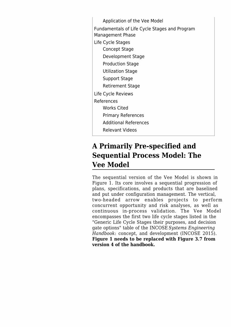
A Primarily Pre-specified andSequential Process Model: TheVee ModelThe sequential version of the Vee Model is shown inFigure 1. Its core involves a sequential progression ofplans, specifications, and products that are baselinedand put under configuration management. The vertical,two-headed arrow enables projects to performconcurrent opportunity and risk analyses, as well ascontinuous in-process validation. The Vee Modelencompasses the first two life cycle stages listed in the"Generic Life Cycle Stages their purposes, and decisiongate options" table of the INCOSE Systems EngineeringHandbook: concept, and development (INCOSE 2015).Figure 1 needs to be replaced with Figure 3.7 fromversion 4 of the handbook.
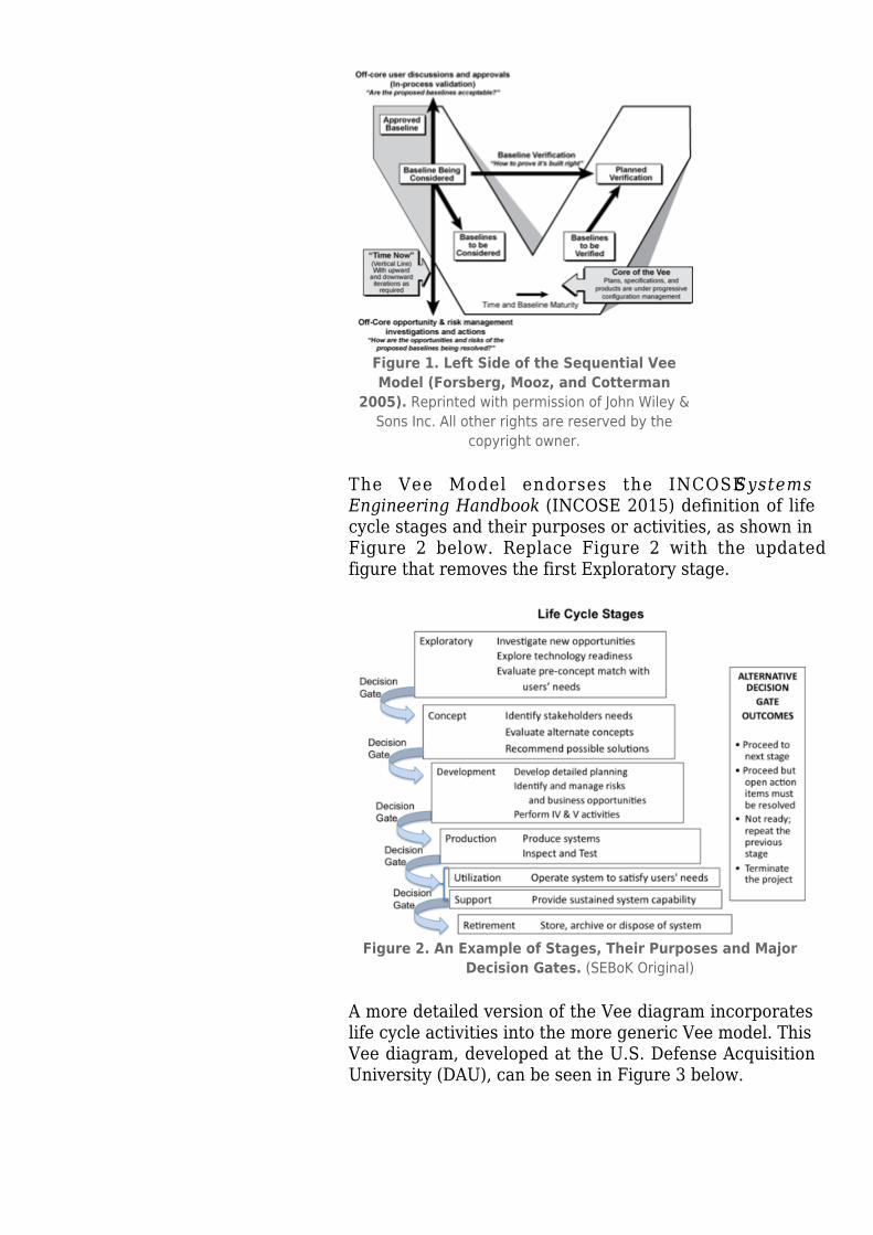
Figure 1. Left Side of the Sequential VeeModel (Forsberg, Mooz, and Cotterman
2005). Reprinted with permission of John Wiley &Sons Inc. All other rights are reserved by the
copyright owner.
The Vee Model endorses the INCOSE SystemsEngineering Handbook (INCOSE 2015) definition of lifecycle stages and their purposes or activities, as shown inFigure 2 below. Replace Figure 2 with the updatedfigure that removes the first Exploratory stage.
Figure 2. An Example of Stages, Their Purposes and MajorDecision Gates. (SEBoK Original)
A more detailed version of the Vee diagram incorporateslife cycle activities into the more generic Vee model. ThisVee diagram, developed at the U.S. Defense AcquisitionUniversity (DAU), can be seen in Figure 3 below.
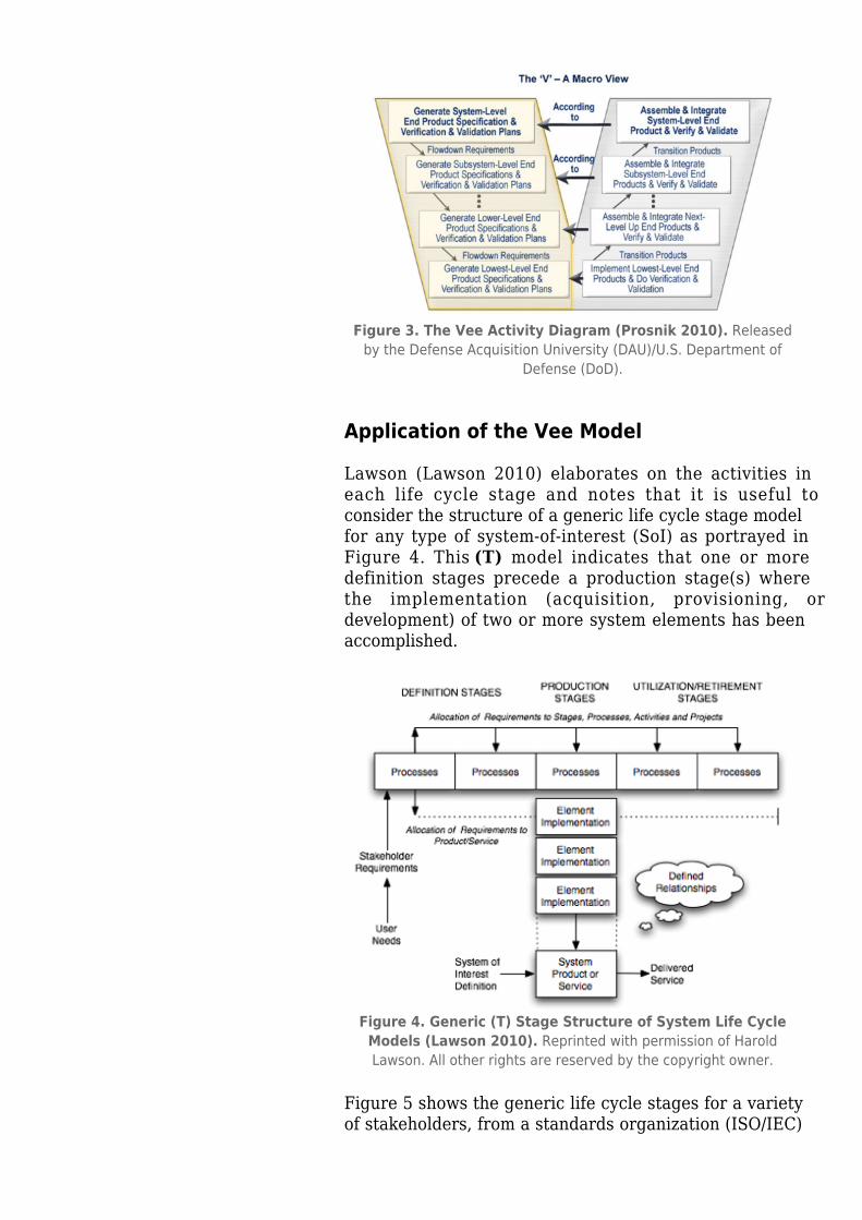
Figure 3. The Vee Activity Diagram (Prosnik 2010). Releasedby the Defense Acquisition University (DAU)/U.S. Department of
Defense (DoD).
Application of the Vee Model
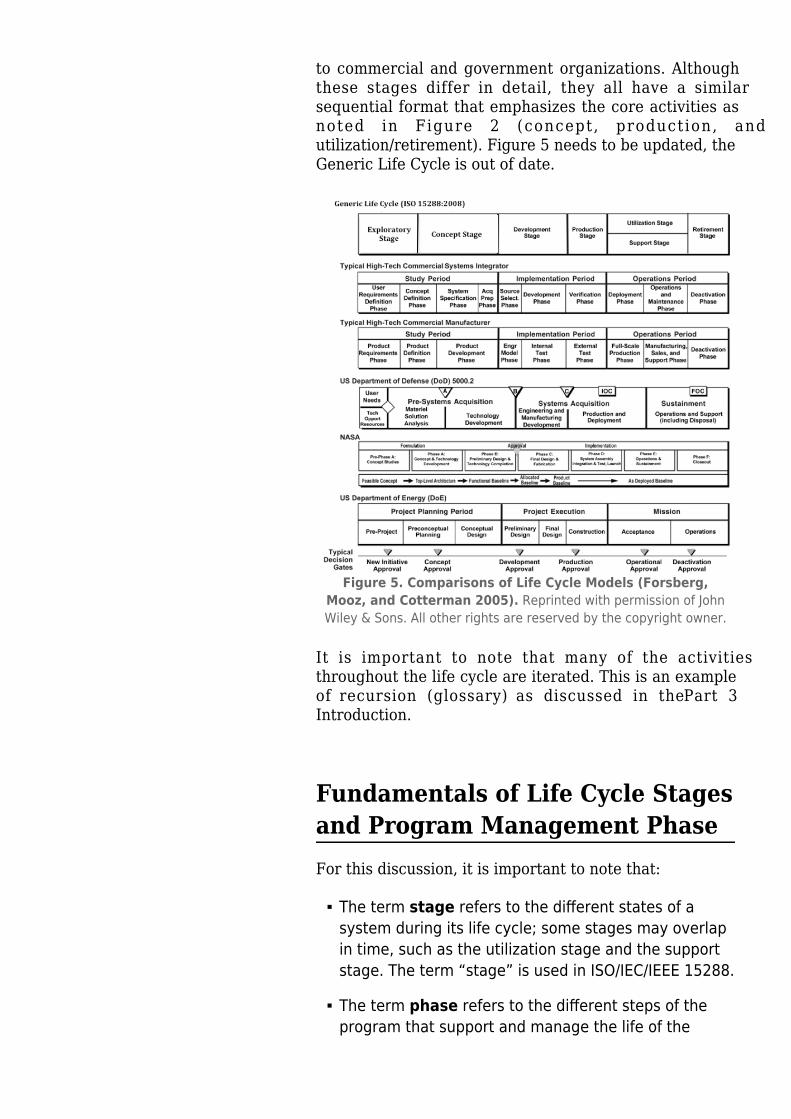
Lawson (Lawson 2010) elaborates on the activities ineach life cycle stage and notes that it is useful toconsider the structure of a generic life cycle stage modelfor any type of system-of-interest (SoI) as portrayed inFigure 4. This (T) model indicates that one or moredefinition stages precede a production stage(s) wherethe implementation (acquisition, provisioning, ordevelopment) of two or more system elements has beenaccomplished.
Figure 4. Generic (T) Stage Structure of System Life CycleModels (Lawson 2010). Reprinted with permission of HaroldLawson. All other rights are reserved by the copyright owner.
Figure 5 shows the generic life cycle stages for a varietyof stakeholders, from a standards organization (ISO/IEC)
to commercial and government organizations. Althoughthese stages differ in detail, they all have a similarsequential format that emphasizes the core activities asnoted in Figure 2 (concept, production, andutilization/retirement). Figure 5 needs to be updated, theGeneric Life Cycle is out of date.
Figure 5. Comparisons of Life Cycle Models (Forsberg,Mooz, and Cotterman 2005). Reprinted with permission of JohnWiley & Sons. All other rights are reserved by the copyright owner.
It is important to note that many of the activitiesthroughout the life cycle are iterated. This is an exampleof recursion (glossary) as discussed in the Part 3Introduction.
Fundamentals of Life Cycle Stagesand Program Management PhaseFor this discussion, it is important to note that:
The term stage refers to the different states of asystem during its life cycle; some stages may overlapin time, such as the utilization stage and the supportstage. The term “stage” is used in ISO/IEC/IEEE 15288.
The term phase refers to the different steps of theprogram that support and manage the life of the
system; the phases usually do not overlap. The term“phase” is used in many well-established models asan equivalent to the term “stage.”
Program management employs phases, milestones, anddecision gates which are used to assess the evolution ofa system through its various stages. The stages containthe activities performed to achieve goals and serve tocontrol and manage the sequence of stages and thetransitions between each stage. For each project, it isessential to define and publish the terms and relateddefinitions used on respective projects to minimizeconfusion.
A typical program is composed of the following phases:
The feasibility phase consists of studying thefeasibility of alternative concepts to reach a seconddecision gate before initiating the execution stage.During the feasibility phase, stakeholders'requirements and system requirements are identified,viable solutions are identified and studied, and virtualprototypes (glossary) can be implemented. During thisphase, the decision to move forward is based on:
whether a concept is feasible and is consideredable to counter an identified threat or exploit anopportunity;whether a concept is sufficiently mature to warrantcontinued development of a new product or line ofproducts; andwhether to approve a proposal generated inresponse to a request for proposal.
The execution phase includes activities related tofour stages of the system life cycle: development,production, utilization, and support. Typically, thereare two decision gates and two milestones associatedwith execution activities. The first milestone providesthe opportunity for management to review the plansfor execution before giving the go-ahead. The secondmilestone provides the opportunity to review progressbefore the decision is made to initiate production. Thedecision gates during execution can be used todetermine whether to produce the developed SoI andwhether to improve it or retire it.
These program management views apply not only to theSoI, but also to its elements and structure.
Life Cycle StagesVariations of the Vee model deal with the same generalstages of a life cycle:
New projects typically begin with an exploratoryresearch phase which generally includes the activitiesof concept definition, specifically the topics ofbusiness or mission analysis and the understanding ofstakeholder needs and requirements. These mature asthe project goes from the exploratory stage to theconcept stage to the development stage.The production phase includes the activities of systemdefinition and system realization, as well as thedevelopment of the system requirements (glossary)and architecture (glossary) through verification andvalidation.The utilization phase includes the activities of systemdeployment and system operation.The support phase includes the activities of systemmaintenance, logistics, and product and service lifemanagement, which may include activities such asservice life extension or capability updates, upgrades,and modernization.The retirement phase includes the activities ofdisposal and retirement, though in some models,activities such as service life extension or capabilityupdates, upgrades, and modernization are groupedinto the "retirement" phase.
Additional information on each of these stages can befound in the sections below (see links to additional Part 3articles above for further detail). It is important to notethat these life cycle stages, and the activities in eachstage, are supported by a set of systems engineeringmanagement processes.
Concept Stage
User requirements analysis and agreement is part of theconcept stage and is critical to the development ofsuccessful systems. Without proper understanding of theuser needs, any system runs the risk of being built tosolve the wrong problems. The first step in the conceptstage is to define the user (and stakeholder)requirements and constraints. A key part of this processis to establish the feasibility of meeting the user
requirements, including technology readinessassessment. As with many SE activities this is often doneiteratively, and stakeholder needs and requirements arerevisited as new information becomes available.
A recent study by the National Research Council(National Research Council 2008) focused on reducingthe development time for US Air Force projects. Thereport notes that, “simply stated, systems engineering isthe translation of a user’s needs into a definition of asystem and its architecture through an iterative processthat results in an effective system design.” The iterativeinvolvement with stakeholders is critical to the projectsuccess.
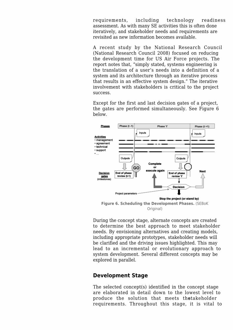
Except for the first and last decision gates of a project,the gates are performed simultaneously. See Figure 6below.
Figure 6. Scheduling the Development Phases. (SEBoKOriginal)
During the concept stage, alternate concepts are createdto determine the best approach to meet stakeholderneeds. By envisioning alternatives and creating models,including appropriate prototypes, stakeholder needs willbe clarified and the driving issues highlighted. This maylead to an incremental or evolutionary approach tosystem development. Several different concepts may beexplored in parallel.
Development Stage
The selected concept(s) identified in the concept stageare elaborated in detail down to the lowest level toproduce the solution that meets the stakeholderrequirements. Throughout this stage, it is vital to
continue with user involvement through in-processvalidation (the upward arrow on the Vee models). Onhardware, this is done with frequent program reviewsand a customer resident representative(s) (ifappropriate). In agile development, the practice is tohave the customer representative integrated into thedevelopment team.
Production Stage
The production stage is where the SoI is built ormanufactured. Product modifications may be required toresolve production problems, to reduce production costs,or to enhance product or SoI capabilities. Any of thesemodifications may influence system requirements andmay require system re-qualification, re-verification, orre-validation. All such changes require SE assessmentbefore changes are approved.
Utilization Stage
A significant aspect of product life cycle management isthe provisioning of supporting systems which are vital insustaining operation of the product. While the suppliedproduct or service may be seen as the narrow system-of-interest (NSOI) for an acquirer, the acquirer also mustincorporate the supporting systems into a wider system-of-interest (WSOI). These supporting systems should beseen as system assets that, when needed, are activatedin response to a situation that has emerged in respect tothe operation of the NSOI. The collective name for theset of supporting systems is the integrated logisticssupport (ILS) system.
It is vital to have a holistic view when defining,producing, and operating system products and services.In Figure 7, the relationship between system design anddevelopment and the ILS requirements is portrayed.
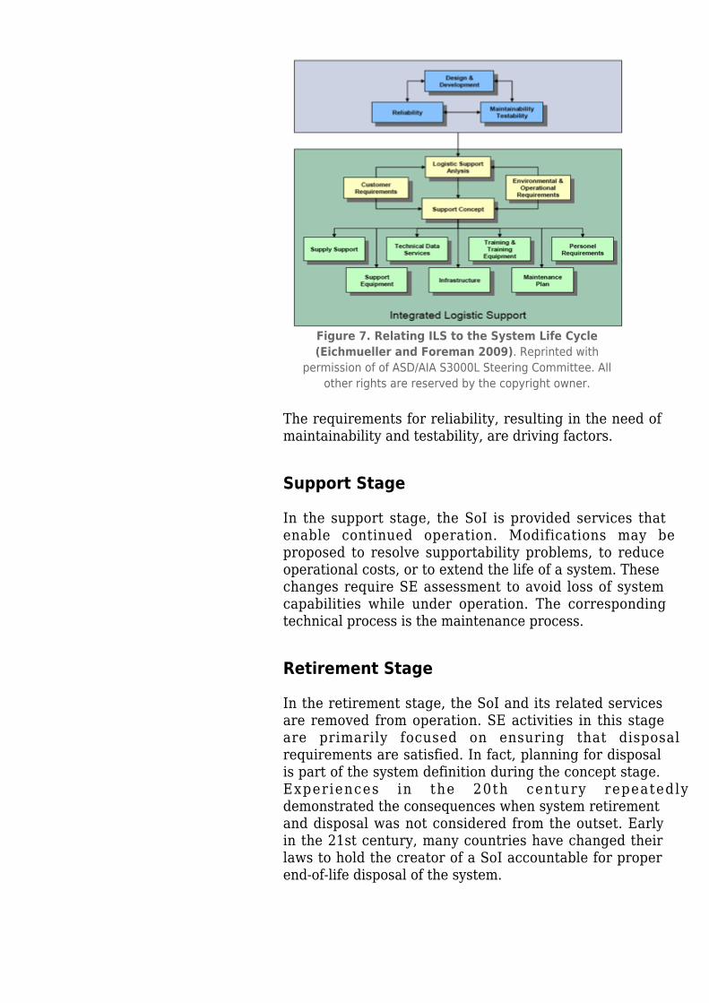
Figure 7. Relating ILS to the System Life Cycle(Eichmueller and Foreman 2009). Reprinted with
permission of of ASD/AIA S3000L Steering Committee. Allother rights are reserved by the copyright owner.
The requirements for reliability, resulting in the need ofmaintainability and testability, are driving factors.
Support Stage
In the support stage, the SoI is provided services thatenable continued operation. Modifications may beproposed to resolve supportability problems, to reduceoperational costs, or to extend the life of a system. Thesechanges require SE assessment to avoid loss of systemcapabilities while under operation. The correspondingtechnical process is the maintenance process.
Retirement Stage
In the retirement stage, the SoI and its related servicesare removed from operation. SE activities in this stageare primarily focused on ensuring that disposalrequirements are satisfied. In fact, planning for disposalis part of the system definition during the concept stage.Experiences in the 20th century repeatedlydemonstrated the consequences when system retirementand disposal was not considered from the outset. Earlyin the 21st century, many countries have changed theirlaws to hold the creator of a SoI accountable for properend-of-life disposal of the system.
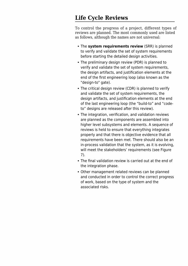
Life Cycle ReviewsTo control the progress of a project, different types ofreviews are planned. The most commonly used are listedas follows, although the names are not universal:
The system requirements review (SRR) is plannedto verify and validate the set of system requirementsbefore starting the detailed design activities.The preliminary design review (PDR) is planned toverify and validate the set of system requirements,the design artifacts, and justification elements at theend of the first engineering loop (also known as the"design-to" gate).The critical design review (CDR) is planned to verifyand validate the set of system requirements, thedesign artifacts, and justification elements at the endof the last engineering loop (the “build-to” and “code-to” designs are released after this review).The integration, verification, and validation reviewsare planned as the components are assembled intohigher level subsystems and elements. A sequence ofreviews is held to ensure that everything integratesproperly and that there is objective evidence that allrequirements have been met. There should also be anin-process validation that the system, as it is evolving,will meet the stakeholders’ requirements (see Figure7).The final validation review is carried out at the end ofthe integration phase.Other management related reviews can be plannedand conducted in order to control the correct progressof work, based on the type of system and theassociated risks.
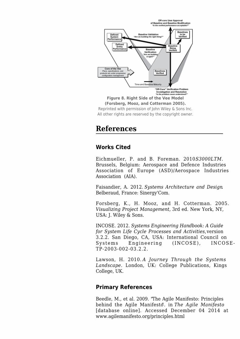
Figure 8. Right Side of the Vee Model(Forsberg, Mooz, and Cotterman 2005).
Reprinted with permission of John Wiley & Sons Inc.All other rights are reserved by the copyright owner.
References
Works Cited
Eichmueller, P. and B. Foreman. 2010. S3000LTM.Brussels, Belgium: Aerospace and Defence IndustriesAssociation of Europe (ASD)/Aerospace IndustriesAssociation (AIA).
Faisandier, A. 2012. Systems Architecture and Design.Belberaud, France: Sinergy'Com.
Forsberg, K., H. Mooz, and H. Cotterman. 2005.Visualizing Project Management, 3rd ed. New York, NY,USA: J. Wiley & Sons.
INCOSE. 2012. Systems Engineering Handbook: A Guidefor System Life Cycle Processes and Activities, version3.2.2. San Diego, CA, USA: International Council onSystems Engineer ing ( INCOSE) , INCOSE-TP-2003-002-03.2.2.
Lawson, H. 2010. A Journey Through the SystemsLandscape. London, UK: College Publications, KingsCollege, UK.
Primary References
Beedle, M., et al. 2009. "The Agile Manifesto: Principlesbehind the Agile Manifesto". in The Agile Manifesto[database online]. Accessed December 04 2014 atwww.agilemanifesto.org/principles.html
Boehm, B. and R. Turner. 2004. Balancing Agility andDiscipline. New York, NY, USA: Addison-Wesley.
Fairley, R. 2009. Managing and Leading SoftwareProjects. New York, NY, USA: J. Wiley & Sons.
Forsberg, K., H. Mooz, and H. Cotterman. 2005.Visualizing Project Management. 3rd ed. New York, NY,USA: J. Wiley & Sons.
INCOSE. 2012. Systems Engineering Handbook: A Guidefor System Life Cycle Processes and Activities, version3.2.2. San Diego, CA, USA: International Council onSystems Engineer ing ( INCOSE) , INCOSE-TP-2003-002-03.2.2.
Lawson, H. 2010. A Journey Through the SystemsLandscape. Kings College, UK: College Publications.
Pew, R., and A. Mavor (eds.) 2007. Human-SystemIntegration in the System Development Process: A NewLook. Washington, DC, USA: The National AcademiesPress.
Royce, W.E. 1998. Software Project Management: AUnified Framework. New York, NY, USA: AddisonWesley.
Additional References
Anderson, D. 2010. Kanban. Sequim, WA, USA: BlueHole Press.
Baldwin, C. and K. Clark. 2000. Design Rules: The Powerof Modularity. Cambridge, MA, USA: MIT Press.
Beck, K. 1999. Extreme Programming Explained. NewYork, NY, USA: Addison Wesley.
Beedle, M., et al. 2009. "The Agile Manifesto: Principlesbehind the Agile Manifesto". in The Agile Manifesto[database online]. Accessed 2010. Available at:www.agilemanifesto.org/principles.html
Biffl, S., A. Aurum, B. Boehm, H. Erdogmus, and P.Gruenbacher (eds.). 2005. Value-Based SoftwareEngineering. New York, NY, USA: Springer.
Boehm, B. 1988. “A Spiral Model of SoftwareDevelopment.” IEEE Computer 21(5): 61-72.
Boehm, B. 2006. “Some Future Trends and Implicationsfor Systems and Software Engineering Processes.”
Systems Engineering. 9(1): 1-19.
Boehm, B., A. Egyed, J. Kwan, D. Port, A. Shah, and R.Madachy. 1998. “Using the WinWin Spiral Model: A CaseStudy.” IEEE Computer. 31(7): 33-44.
Boehm, B., R. Turner, J. Lane, S. Koolmanojwong. 2014(in press). Embracing the Spiral Model: CreatingSuccessful Systems with the Incremental CommitmentSpiral Model. Boston, MA, USA: Addison Wesley.
Castellano, D.R. 2004. “Top Five Quality SoftwareProjects.” CrossTalk. 17(7) (July 2004): 4-19. Availablea t :http://www.crosstalkonline.org/storage/issue-archives/2004/200407/200407-0-Issue.pdf
Checkland, P. 1981. Systems Thinking, Systems Practice.New York, NY, USA: Wiley.
Crosson, S. and B. Boehm. 2009. “Adjusting SoftwareLife cycle Anchorpoints: Lessons Learned in a System ofSystems Context.” Proceedings of the Systems andSoftware Technology Conference, 20-23 April 2009, SaltLake City, UT, USA.
Dingsoyr, T., T. Dyba. and N. Moe (eds.). 2010. "AgileSoftware Development: Current Research and FutureDirections.” Chapter in B. Boehm, J. Lane, S.Koolmanjwong, and R. Turner, Architected AgileSolutions for Software-Reliant Systems. New York, NY,USA: Springer.
Dorner, D. 1996. The Logic of Failure. New York, NY,USA: Basic Books.
Forsberg, K. 1995. "'If I Could Do That, Then I Could…'System Engineering in a Research and DevelopmentEnvironment.” Proceedings of the Fifth AnnualInternational Council on Systems Engineering (INCOSE)International Symposium. 22-26 July 1995. St. Louis,MO, USA.
Forsberg, K. 2010. “Projects Don’t Begin WithRequirements.” Proceedings of the IEEE SystemsConference, 5-8 April 2010, San Diego, CA, USA.
Gilb, T. 2005. Competitive Engineering. MarylandHeights, MO, USA: Elsevier Butterworth Heinemann.
Goldratt, E. 1984. The Goal. Great Barrington, MA, USA:North River Press.
Hitchins, D. 2007. Systems Engineering: A 21st Century
Systems Methodology. New York, NY, USA: Wiley.
Holland, J. 1998. Emergence. New York, NY, USA:Perseus Books.
ISO/IEC. 2010. Systems and Software Engineering, Part1: Guide for Life Cycle Management. Geneva,Switzerland: International Organization forStandardization (ISO)/International ElectrotechnicalCommission (IEC), ISO/IEC 24748-1:2010.
ISO/IEC/IEEE. 2015. Systems and Software Engineering-- System Life Cycle Processes. Geneva, Switzerland:International Organisation for Standardisation /International Electrotechnical Commissions / Institute ofElectrical and Electronics Engineers. ISO/IEC/IEEE15288:2015.
ISO/IEC. 2003. Systems Engineering — A Guide for TheApplication of ISO/IEC 15288 System Life CycleProcesses. Geneva, Switzerland: InternationalOrganization for Standardization (ISO)/InternationalElectrotechnical Commission (IEC), ISO/IEC 19760:2003(E).
Jarzombek, J. 2003. “Top Five Quality SoftwareProjects.” CrossTalk. 16(7) (July 2003): 4-19. Availablea t :http://www.crosstalkonline.org/storage/issue-archives/2003/200307/200307-0-Issue.pdf.
Kruchten, P. 1999. The Rational Unified Process. NewYork, NY, USA: Addison Wesley.
Landis, T. R. 2010. Lockheed Blackbird Family (A-12,YF-12, D-21/M-21 & SR-71). North Branch, MN, USA:Specialty Press.
Madachy, R. 2008. Software Process Dynamics.Hoboken, NJ, USA: Wiley.
Maranzano, J.F., S.A. Rozsypal, G.H. Zimmerman, G.W.Warnken, P.E. Wirth, D.W. Weiss. 2005. “ArchitectureReviews: Practice and Experience.” IEEE Software.22(2): 34-43.
National Research Council of the National Academies(USA). 2008. Pre-Milestone A and Early-Phase SystemsEngineering. Washington, DC, USA: The NationalAcademies Press.
Osterweil, L. 1987. “Software Processes are SoftwareToo.” Proceedings of the SEFM 2011: 9th International
Conference on Software Engineering. Monterey, CA,USA.
Poppendeick, M. and T. Poppendeick. 2003. LeanSoftware Development: an Agile Toolkit. New York, NY,USA: Addison Wesley.
Rechtin, E. 1991. System Architecting: Creating andBuilding Complex Systems. Upper Saddle River, NY,USA: Prentice-Hall.
Rechtin, E., and M. Maier. 1997. The Art of SystemArchitecting. Boca Raton, FL, USA: CRC Press.
Schwaber, K. and M. Beedle. 2002. Agile SoftwareDevelopment with Scrum. Upper Saddle River, NY, USA:Prentice Hall.
Spruill, N. 2002. “Top Five Quality Software Projects.”CrossTalk. 15(1) (January 2002): 4-19. Available at:http://www.crosstalkonline.org/storage/issue-archives/2002/200201/200201-0-Issue.pdf.
Stauder, T. 2005. “Top Five Department of DefenseProgram Awards.” CrossTalk. 18(9) (September 2005):4 - 1 3 . A v a i l a b l e a thttp://www.crosstalkonline.org/storage/issue-archives/2005/200509/200509-0-Issue.pdf.
Warfield, J. 1976. Societal Systems: Planning, Policy, andComplexity. New York, NY, USA: Wiley.
Womack, J. and D. Jones. 1996. Lean Thinking. NewYork, NY, USA: Simon and Schuster.
Relevant Videos
Basic Introduction of Systems Engineering (V-method)[Part 1 of 2]Basic Introduction to Systems Engineering (V-Method)Part 2 of 2
< Previous Article | Parent Article | Next Article >SEBoK v. 2.5, released 15 October 2021
Retrieved from"https://www.sebokwiki.org/w/index.php?title=System_Life_Cycle_Process_Models:_Vee&oldid=62890"
This page was last edited on 14 October 2021, at 14:04.