Embed Size (px)
Citation preview
SUPPLY,INSTALLATION,TESTING,COMMISSIONING AND COMPREHENSIVE MAINTENANCE FOR MOTOR DRIVEN 400 SCMH VARIABLE INLET PRESSURE (VIP) CNG INTEGRATED COMPRESSOR PACKAGE
E-Tender ID - 50606Project No. P.014714Document No. P.014714 G 11031 R007Tender No. P.014714 G 11031 R007
CENTRAL UP GAS LIMITED (CUGL)KANPUR | INDIA
PUBLIC
08 June 2021
TECHNICAL DOCUMENTATIONTechnical , Vol II of II, Rev. 0
S.NO. DOCUMENT / DRAWING NO. REV. NO Page No. of PAGES
1 VOLUME I OF II
1 SECTION-I INVITATION FOR BID (IFB)
2 SECTION - II INSTRUCTION TO BIDDERS (ITB)
3 SECTION - III GENERAL CONDITIONS OF CONTRACT(GCC)
4 SECTION - IV SPECIAL CONDITION OF CONTRACT (SCC)
5 SECTION - V FORMS AND FORMAT
6 SECTION - VI SCHEDULE OF RATES
2 VOLUME II OF II
1 P.014714 G 11031 R 007 0 1 3
2 MR MATERIAL REQUISITION P.014714 G 11071 R 020 0 4 5
3 PTS
ELECTRIC MOTOR DRIVEN INTEGRATEDVIP COMPRESSOR UNIT(400 SCMH) P.014714 M 11077 R 020 0 9 144
TABLE OF CONTENTSSUPPLY OF MOTOR DRIVEN INTEGRATED VIP COMPRESSOR UNIT
(400 SCMH)
P.014714G 11031
R 007
P.014714 G 11031 R 007
INTRODUCTION
COMMERCIAL
TECHNICAL
DESCRIPTION
Supply of Electric Motor Driven Integrated VIP Compressor unit Page 1 of 1
INTRODUCTIONP.014714G 11031
R 007
0 23.05.2021 Issued for Procurement Saurabh Sharma Gunja Gupta Nitish Nandi
Rev. Date Description Prepared By Checked By Approved By
CENTRAL U.P GAS LIMITED (CUGL)
TRACTEBEL ENGINEERING PVT. LTD.
ELECTRIC MOTOR DRIVEN INTEGRATED VIPUNIT (COMPRESSOR + CASCADE + DISPENSER)
OF 400 SCMH CAPACITY
INTRODUCTION
Page 1 of 153
INTRODUCTIONP.014714G 11031
R 007
Rev. 0 Supply of Electric Motor Driven Integrated VIP Compressor unit
TABLE OF CONTENTS
1. INTRODUCTION
2. TECHNICAL SPECIFICATIION
Page 2 of 153
INTRODUCTIONP.014714G 11031
R 007
Rev. 0 Supply of Electric Motor Driven CNG Booster Compressor Package
1.0 INTRODUCTION
CENTRAL UP GAS LIMITED (CUGL), a joint venture company of GAIL and BPCL, is responsiblefor distribution of Natural Gas for household, commercial & Industrial sectors including setting up CNGrefueling stations for vehicles etc. in Kanpur (including Unnao), Jhansi and Bareilly.
Natural Gas (NG) is today increasingly gaining popularity over as alternate auto fuel primarily because itis environment friendly, economical and more efficient as compared to other conventional auto fuels.Emission of harmful oxide and other polluting particulates is minimal in case of CNG.
TRACTEBEL ENGINEERING pvt. ltd. (TE) has been appointed for providing consultancy services fortendering activities for CNG Expansion Project (hereinafter referred as Consultant), by CUGL.
Tractebel Engineering Pvt. Ltd. (TE) is now inviting tenders on Competitive Bidding basis forprocurement of “400 SCMH ELECTRIC MOTOR DRIVEN INTEGRATED VIPCOMPRESSORS PACKAGES (COMPRESSOR + CASCADE + DISPENSER)” for this project.
The present document covers the technical specifications for the tender.
2.0 TECHNICAL SPECIFICATIONS
The technical specifications for this present tender enquiry are as listed in Material Requisition.
S S S
Page 3 of 153
MATERIAL REQUISITIONP.014714G 11071
R 020
Rev. 0 Supply of Electric Motor Driven Integrated VIP Unit
CENTRAL U.P GAS LIMITED (CUGL)
TRACTEBEL ENGINEERING PVT. LTD.
ELECTRIC MOTOR DRIVEN INTEGRATED VIPUNIT (COMPRESSOR + CASCADE + DISPENSER)
OF 400 SCMH CAPACITY
MATERIAL REQUISITION
0 23.05.2021 Issued for Procurement Saurabh Sharma Gunja Gupta Nitish Nandi
Rev. Date Description Prepared By Checked By Approved By
Page 4 of 153
MATERIAL REQUISITIONP.014714G 11071
R 020
Rev. 0 Supply of Electric Motor Driven Integrated VIP Unit
Project : City Gas Distribution Project for M/s. CUGL
Subject : Electric Motor Driven Integated VIP Unit - Capacity 400 SCMH
A. DESCRIPTION OF GOODS AND/OR SERVICES
Item Quantity Description IdentificationNumber
400 SCMH Electric Motor Driven Integrated VIP Unit(Compressor + Cascade + Dispenser)
1. 04 Nos. · Design, Engineering, Manufacturing, Shop testing and supplyof CNG Electric Motor driven integrated compressorpackage having variable inlet pressure consisting ofCompression, Storage & Dispensing unit with dischargeflow capacity of 400 SCMH at the specified condition (asper Technical Specification) complete with drive electricmotor, Cooling system, Lubrication system, auxiliary AirCompressor system, Priority panel, Flame proof controlpanel (Local), and other accessories including erection andcommissioning spares including acoustic enclosures.
· Services for Erection, Testing, and Commissioning andperformance acceptance testing of compressor as defined inPTS- Motor driven CNG Compressor Packages.
· Scope also includes Comprehensive Maintenance for each compressor during warranty period of one year and further Four years after warranty period.
Capacity: 400 SCMH
Suction Pressure Range :
- 15-200 Kg/cm2 (g) (When used as a booster Compressor)
- 14-19 Kg/cm2 (g) (When used as an online Compressor)
Discharge Pressure: 255 kg/cm2 (g)
Page 5 of 153
MATERIAL REQUISITIONP.014714G 11071
R 020
Rev. 0 Supply of Electric Motor Driven Integrated VIP Unit
B. REMARKS / COMMENTS
1.0 VENDOR’S SCOPE
In Contractor’s scope of work is included the equipment with all internals and accessories shown on the datasheets, specifications and all unmentioned parts necessary for a satisfactory operation and testing, exceptthose which are indicated to be out of the Contractor’s supply.
2.0 INSPECTION
The bidder shall appoint Third Party Inspection Agency for carrying out the inspection at bidder’s works asper approved ITP/QAP/QCT and TPIA charges shall be borne by the bidder.
3.0 APPLICABLE DOCUMENTS
Applicable documents are listed in hereafter under Section C of this MR, complemented with generalspecifications, guidelines and / or standards, as listed in LIST OF REFERENCED DOCUMENTS as a partof specification.
In the event of any conflict occurring in applying the referenced documents, the order of precedence shallbe:
1 – Particular Technical Specification
2 – Attachments
4.0 VENDOR’S DOCUMENTS
4.1 Submittal of Calculation Note:
Design calculations will be well explained for demonstration of compliance to specified code(s) andstandard(s). Limitation to a listing of input data and series of results is not acceptable. The appliedformulations, sections, subsections, figures, subfigures from code(s) and/or standard(s) will be indicated atcalculation steps to permit straight verification.
4.2 Vendor’s Documents and Drawings
l All vendor documents and drawings shall be numbered according to Engineer’s in- chargespecification.
l All drawings shall use SI units.
l All graphical symbols to be recognized to industry standard.
l All text to be clearly legible when the drawing is reduced to A3 size.
l All drawings and calculations shall be checked, approved and signed by a competent and authorizedperson employed by the Contractor.
l Drawings to be issued bound in A3 size. In addition, the planning drawing to be issued in A1 forsubmission to the planning authority.
l Hard copy of Quality & design dossier (Drawing to be on A3 format) for review.
l All drawings shall be issued on CD in both Auto CAD & PDF formats.
l Installation, Commissioning, Operation & Maintenance manuals for CNG compressor package.
Page 6 of 153
MATERIAL REQUISITIONP.014714G 11071
R 020
Rev. 0 Supply of Electric Motor Driven Integrated VIP Unit
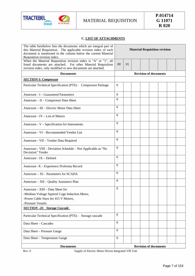
C. LIST OF ATTACHMENTS
The table herebelow lists the documents which are integral part ofthis Material Requisition. The applicable revision index of eachdocument is mentioned in the column below the current MaterialRequisition revision index.
Material Requisition revision
When the Material Requisition revision index is "A" or "1", alllisted documents are attached. For other Material Requisitionrevision index, only modified or new documents are attached.
00 01
Documents Revision of documents
SECTION-I: Compressor
Particular Technical Specification (PTS) - Compressor Package 0
Annexure - I – Guaranteed Parameters 0
Annexure – II – Compressor Data Sheet 0
Annexure – III – Electric Motor Data Sheet 0
Annexure - IV – List of Motors 0
Annexure - V – Specification for Instruments 0
Annexure - VI – Recommended Vendor List 0
Annexure - VII – Vendor Data Required 0
Annexure - VIII – Deviation Schedule – Not Applicable as “NoDeviation” Tender
0
Annexure - IX – Deleted 0
Annexure -X – Experience Proforma Record 0
Annexure – XI – Parameters for SCADA 0
Annexure – XII – Quality Assurance Plan 0
Annexure - XIII – Data Sheet for-Medium Voltage Squirrel Cage Induction Motor,-Power Cable Sizes for 415 V Motors,-Pressure Vessels
0
SECTION –II: Storage Cascade
Particular Technical Specification (PTS) - Storage cascade 0
Data Sheet – Cascades 0
Data Sheet – Pressure Gauge 0
Data Sheet – Temperature Gauge 0
Documents Revision of documents
Page 7 of 153
MATERIAL REQUISITIONP.014714G 11071
R 020
Rev. 0 Supply of Electric Motor Driven Integrated VIP Unit
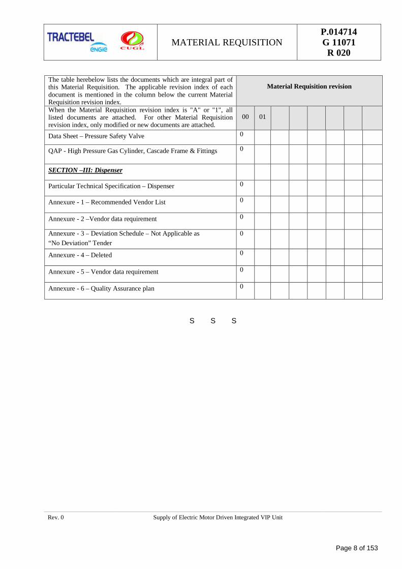
The table herebelow lists the documents which are integral part ofthis Material Requisition. The applicable revision index of eachdocument is mentioned in the column below the current MaterialRequisition revision index.
Material Requisition revision
When the Material Requisition revision index is "A" or "1", alllisted documents are attached. For other Material Requisitionrevision index, only modified or new documents are attached.
00 01
Data Sheet – Pressure Safety Valve 0
QAP - High Pressure Gas Cylinder, Cascade Frame & Fittings 0
SECTION –III: Dispenser
Particular Technical Specification – Dispenser 0
Annexure - 1 – Recommended Vendor List 0
Annexure - 2 –Vendor data requirement 0
Annexure - 3 – Deviation Schedule – Not Applicable as“No Deviation” Tender
0
Annexure - 4 – Deleted 0
Annexure - 5 – Vendor data requirement 0
Annexure - 6 – Quality Assurance plan 0
S S S
Page 8 of 153
PTS - INTEGRATED VIP UNIT(COMPRESSOR + CASCADE +
DISPENSER) OF 400 SCMHCAPACITY
P. 014714M 11077
R 020
CENTRAL U.P. GAS LTD. (CUGL)
CITY GAS DISTRIBUTION PROJECT
PTS – ELECTRIC MOTOR DRIVEN INTEGRATED VIPUNIT (COMPRESSOR + CASCADE + DISPENSER)
OF 400 SCMH CAPACITY
0 23.05.2021 Issued for Procurement Saurabh Sharma Gunja Gupta Nitish Nandi
Rev. Date Description Prepared By Checked By Approved By
Page 9 of 153
PTS - INTEGRATED VIP UNIT(COMPRESSOR + CASCADE +
DISPENSER) OF 400 SCMHCAPACITY
P. 014714M 11077
R 020
Rev. 0 Integrated CNG Compressor Packages for CGD Project of M/s CLIENT Page 1 of 2
TABLE OF CONTENTS1.0 GENERAL .......................................................................................................................... 12.0 MAINTENANCE ................................................................................................................. 33.0 CODES AND STANDARDS ................................................................................................. 64.0 PRECEDENCE .................................................................................................................... 65.0 PROCESS PARAMETERS .................................................................................................... 76.0 SCOPE OF SUPPLY FOR EACH INTEGRATED CNG COMPRESSOR PACKAGE ..................... 87.0 EXCLUSIONS .................................................................................................................. 118.0 BATTERY LIMITS ............................................................................................................ 119.0 UTILITIES ....................................................................................................................... 12SECTION – I: TECHNICAL SPECIFICATION FOR CNG COMPRESSOR - VARIABLE INLET PRESSURE(200-15 BAR) ................................................................................................................................. 131.0 GENERAL DESCRIPTION ................................................................................................ 142.0 SAFETY ........................................................................................................................... 153.0 BASIC DESIGN OF COMPRESSOR ................................................................................... 184.0 INSTRUMENTATION & CONTROLS ................................................................................. 245.0 SKID AND ENCLOSURE ................................................................................................... 286.0 INSPECTION & TESTING ................................................................................................ 307.0 GUARANTEE, LOADING AND PENALTY CRITERIA .......................................................... 318.0 SPECIAL TOOLS AND TACKLES ....................................................................................... 359.0 DOCUMENTATION .......................................................................................................... 35ANNEXURE – I : GUARANTEED PARAMETERS ............................................................................ 38ANNEXURE – II : COMPRESSOR DATA SHEET ............................................................................ 39ANNEXURE - III - DATA SHEET FOR ELECTRIC MOTOR ................................................................ 47ANNEXURE – IV : LIST OF MOTORS …………………………………………………………………….. ........ 49ANNEXURE – V: SPECIFICATIONS OF INSTRUMENTS................................................................... 50ANNEXURE – VI: RECOMMENDED VENDOR LIST .......................................................................... 59ANNEXURE – VII : VENDOR DATA REQUIRED ............................................................................ 68ANNEXURE – VIII: DEVIATION SCHEDULE FOR INTEGRATED CNG COMPRESSOR PACKAGE ...... 72ANNEXURE – IX : DELETED .......................................................................................................... 73ANNEXURE –X: EXPERIENCE PROFORMA RECORD ....................................................................... 74ANNEXURE – XI : PARAMETERS FOR SCADA ................................................................................. 78ANNEXURE – XII : QUALITY ASSURANCE PLAN ............................................................................ 80ANNEXURE-XIII: DATA SHEET....................................................................................................... 84SECTION – II: TECHNICAL SPECIFICATION FOR CASCADE .......................................................... 901.0 SCOPE ............................................................................................................................. 91
Page 10 of 153
PTS - INTEGRATED VIP UNIT(COMPRESSOR + CASCADE +
DISPENSER) OF 400 SCMHCAPACITY
P. 014714M 11077
R 020
Rev. 0 Integrated CNG Compressor Packages for CGD Project of M/s CLIENT Page 2 of 2
2.0 SITE ENVIRONMENT ...................................................................................................... 913.0 INSTRUCTIONS TO VENDORS ........................................................................................ 914.0 GAS COMPOSITION ........................................................................................................ 925.0 CODES AND STANDARDS TO BE FOLLOWED: ................................................................. 926.0 EXTENT OF SUPPLY AND SERVICES ............................................................................... 937.0 TECHNICAL SPECIFICATIONS ........................................................................................ 948.0 INSPECTION AND TESTING............................................................................................ 969.0 DOCUMENTATION .......................................................................................................... 9610.0 EXPERIENCE RECORD PERFORMA FOR CASCADE .......................................................... 97SECTION – III: TECHNICAL SPECIFICATION FOR CNG CAR DISPENSER ..................................... 991.0 SCOPE OF SUPPLY & SERVICES ................................................................................... 1002.0 DESIGN & ENGINEERING FOR DISPENSER ................................................................. 1023.0 EXPERIENCE RECORD SCHEDULE FOR DISPENSERS ................................................... 1024.0 DESIGN BASIS FOR DISPENSER .................................................................................. 1035.0 PRECEDENCE ................................................................................................................ 1046.0 CNG SPECIFICATION TO BE HANDLED BY DISPENSERS: ............................................ 1047.0 SAFETY ......................................................................................................................... 1048.0 TECHNICAL SPECIFICATIONS FOR CAR DISPENSER ................................................... 1049.0 DATA SHEETS ............................................................................................................... 10510.0 CLIMATIC CONDITIONS ............................................................................................... 10511.0 UTILITY SPECIFICATION ............................................................................................. 10512.0 INSPECTION AND TESTING.......................................................................................... 10513.0 PERFORMANCE GUARANTEE ........................................................................................ 10614.0 VENDOR DATA REQUIREMENT ..................................................................................... 106
Page 11 of 153
PTS - INTEGRATED VIP UNIT(COMPRESSOR + CASCADE +
DISPENSER) OF 400 SCMHCAPACITY
P. 014714M 11077
R 020
Rev. 0 Integrated CNG Compressor Packages for CGD Project Page 1 of 138
1.0 GENERAL.
Central UP Gas Limited (CUGL), a joint venture company of GAIL and BPCL, is responsible for distributionof Natural Gas for household, commercial & Industrial sectors including setting up CNG refueling stations forvehicles etc. in Kanpur (including Unnao), Jhansi and Bareilly.
1.1 Scope
· The intent of this tender is to outline minimum requirement for Design, Engineering, Manufacturing,Assembly, Inspection, Testing, Packaging, Supply, Erection & Commissioning including PerformanceAcceptance Test at site along with comprehensive AMC during One year warranty period and subsequentFour year period including supply of all spares and consumable items for “ ELECTRIC MOTOR DRIVENRECIPROCATING INTEGRATED VIP GAS COMPRESSOR PACKAGES” as required for dispensingCNG to vehicles at various locations as per this technical specification and applicable codes as referred.Various parts of this specification shall be read in conjunction with each other and in case where thedifferent parts of this specification differ, the more stringent requirement shall govern.
· Integrated CNG Compressor Package is to be installed at the CNG outlets of CLIENT and Oil andMarketing Company (OMC) retail Outlets located at various locations as per the instructions of Engineer incharge to increase the pressure of natural gas for dispensing in vehicles.
· Compressor packages may be installed in any of the GA of M/s. CUGL.
· Bidder shall be responsible for supply, erection, commissioning and field trial run. Noise level test andperformance test of all packages at sites. The field trial run of the Integrated CNG Compressor packagewill be for minimum of 72 hours (can be in multiple runs) and the package should be kept underobservation for stable operation and no major breakdown in which satisfactory performance of the packagetogether with all accessories auxiliaries and controls shall be established for satisfactory performance forspecified operating conditions.
· It will be the endeavour of all the parties to get the performance acceptance test (PAT) at site conductedwithin a period of 20 days from the start of commercial operation of a particular package. The bidder has tokeep the Integrated CNG Compressor package available round the clock and all the expenditures includingspares and consumables, oil etc. to make the Integrated CNG Compressor package operational shall have tobe borne by the bidder. The power required to run the Integrated CNG Compressor packages will beprovided by CLIENT/ OMC. The vendor shall maintain the Integrated CNG Compressor packages insound mechanical condition at all times. The vendor shall rectify the defects notified by CLIENTimmediately and should submit all the history log sheets and spares availability status along with the reportin the format mutually agreed between CLIENT and the bidder.
· The bidder shall depute adequate numbers of qualified, experienced and competent persons and supervisorsfor smooth maintenance of the Integrated CNG Compressor packages. The maintenance staffs have to beavailable round the clock daily throughout the year.
· Periodic inspections of Safety Valves, Transmitters, Pressure vessel gauge and any other equipment as perstatutory norms of Delhi Factory Rules 1950. SMPV and Gas Cylinder Rules shall have to be carried outby the bidder at his own cost during the period of maintenance by the bidder. The inspections have to becarried out by competent persons as per advice of Engineer-in-Charge and certificates have to be submittedto CLIENT.
· The bidder has to keep his services personnel ready to attend problems any time of the day. Name andmobile phone number of in-charge of the services team has to be provided to Engineer-in-Charge / hisrepresentatives.
· The bidder shall allow weekly rest and restrict daily working hours of his workmen as per relevantAct/Law/and Rule made there under. However, no work shall be left incomplete/ in dismantled conditionon any holiday/weekly rest. Technician provided shall have minimum qualification of ITI. The bidder inperson or his authorized representative shall be available on regular basis to interact with Engineer –in-charge.
Page 12 of 153
PTS - INTEGRATED VIP UNIT(COMPRESSOR + CASCADE +
DISPENSER) OF 400 SCMHCAPACITY
P. 014714M 11077
R 020
Rev. 0 Integrated CNG Compressor Packages for CGD Project Page 2 of 138
· The work force deployed by the bidder for the maintenance services at the CNG installation shall be ofsound relevant technical professional expertise which is otherwise also essential from the safety point ofview of the personnel of the vendor as well as for the installation.
· All personnel of the bidder entering on work premises shall be properly and neatly dressed while workingon premises of the company including work sites.
· Bidder shall maintain proper record of his working employee’s attendance and payment made to them.
· The bidder’s representative/supervisor shall report on regular basis to the Shift-in-charge at CLIENTcontrol rooms for day to day working.
· All the safety rules and regulations prevailing and applicable from time to time at the installations asdirected by CLIENT will be strictly adhered to by the Vendor and his workforce.
· The bidder shall plan schedule maintenance in consultation and prior permission of Engineer in-charge orhis representatives.
· The bidder shall be responsible for the discipline and good behaviour of all his personnel deployed to carryout the services. In case of any complaint received against any of his employee, he shall arrange to replacesuch persons within 24 hrs of notice issued by the Engineer-in-charge. The decision of the Engineer-in-charge in this matter shall be final and binding on the Vendor.
· The bidder shall arrange to supply/renew identity cards to his workforce at his own cost. The vendor’spersonnel shall be required to carry their respective identity cards while on duty and produce on demand.Without valid identity cards, they will not be allowed to enter into the CNG station.
· Engineer-in-charge shall have authority to issue instructions to the Vendor from time to time during thecontract period necessary for the purpose of proper and safe execution of the contract and the Vendor shallcarry out and bound by the same. In case of non-fulfilment of any obligations under the contract and /ornon-execution of any instruction issued by Engineer-in-charge as per terms and conditions of the contract,Engineer-in-charge shall have power to withhold payment for an amount equivalent to the amount to bespent for execution the obligations/instructions issued by him. The decision of engineer-in-charge in thisregard will be final and binding to the Vendor.
· Receipt at site, storage in warehouse as per manufacturer’s recommendation and safety and security fromtheft and breakage during transportation, handling including security guard at site.
· Submission of drawings & documents.
· Erection, O&M and all others relevant manuals for Integrated CNG Compressor package & its accessories,priority panel, electrical motor & all instrumentation.
· General Requirement
The vendor must follow the MAINTENANCE REQUIREMENT as stated below but not limited to andensure to provide trouble free services as defined in the bid documents.
A. ACCOMMODATION/ TRANSPORTATION/ MEDICAL
The vendor shall make his own arrangement for the accommodation of his personnel at respectivelocations and subsequent transportation arrangement for them from their place of residence to workplace or any other place as required and owner shall have no obligation in this respect.
B. DISCIPLINE
The vendor shall be responsible for the discipline and good behaviour of all his personnel deployed inthe services contracted out and should any complaint be received against any of his employee, he shallarrange to replace such persons within 24 hours of notice issued by the Engineer-in-Charge. Thedecision of the Engineer –in-Charge in this matter shall be final and binding on the vendor.
C. GATEPASS / IDENTITY CARD
The contract shall arrange to supply / renew identity card to his workforce at his own cost, if sorequired by OWNER for security or for any other reasons. Those vendor’s personnel shall be requiredto carry their respective identity cards while on duty and produce on demand.
Page 13 of 153
PTS - INTEGRATED VIP UNIT(COMPRESSOR + CASCADE +
DISPENSER) OF 400 SCMHCAPACITY
P. 014714M 11077
R 020
Rev. 0 Integrated CNG Compressor Packages for CGD Project Page 3 of 138
D. RIGHT TO GET SERVICES CARRIED OUT THROUGH OTHER AGENCIES
Nothing contained herein shall restrict OWNER from accepting similar service from other agencies, atits discretion and at the risk and cost of the vendor, if the vendor fails to provide the said services anytime.
The maintenance services shall be provided in terms of shift pattern or the round the clock basis asmentioned in the bid document.
E. CLIENT will notify the start date for Comprehensive Maintenance services
- After the successful completion of test run & commissioning, system taking over certificate shall beissued by the owner.
2.0 MAINTENANCE OF COMPRESSOR PACKAGES
· The vendor shall deploy adequate number of technicians / supervisors / Engineers / helpers as well as tools,spares, consumables and equipment for smooth and proper maintenance of the Integrated CNGCompressor package supplied in terms of the contract. In case required to meet operational requirements,the vendor shall augment the same as per direction of Engineer–in-Charge. Vendor to submit a detailedorganogram with key person details before starting maintenance of the Integrated CNG Compressorpackage.
· The vendor is required to carry out all services as mentioned in the Scope of Services and Schedule ofRates on all the 365 days including Sunday and all Holiday & around the clock i.e. 24X7.
· The contractor shall follow Central/State guidelines for labour laws, rules and regulations. However, nowork shall be left incomplete/unattended on any holiday/weekly rest. Technician/operators provided shallhave minimum qualification of ITI. Contract in person or his authorized representative shall provide theservices on daily basis to interact with Engineer-in-charge and deployed workman
· The work force deployed by the vendor for maintenance service of Compressors, Dispenser & cascadeshall be of sound relevant technical professional expertise which is otherwise also essential from the safetypoint of view of the personnel of the vendor as well as for the installation.
· Vendor has to ensure the safety of man and machine all the times. Damages of equipment due tonegligence will be recovered as per the decision of Engineer-in-Charge, which will be final.
· Regarding work completion, the decision of the Engineer-in-Charge will be final and binding.
· The vendor shall make his own arrangements to provide all facilities like boarding and transport etc. to hisworkmen.
· All personnel of the vendor entering on work premises shall be properly and neatly dressed and shall wearuniform, badges while working on premises of the Owner including work sites.
· Vendor shall maintain proper record of his working employee’s attendance and payment made to them.
· The vendor’s representative/supervisor shall report daily to the Shift-in-Charge for day to day working.
· All the safety rules and regulations prevailing and applicable from time to time at the installations asdirected by OWNER will be strictly adhered to by the vendor.
· It will be the responsibility of the vendor to pay as per the minimum wages of the appropriate governmentapplicable under the Minimum Wage Act 1948.
· The services shall be provided in terms of shift pattern on the round the clock basis. The vendor isresponsible to provide effective and efficient services in all shifts and assure that there is no disruption inthe services for want of any resources.
· The vendor shall deploy adequate number of technicians/ supervisors / engineers at various site offices inconsultation with Engineer-in-Charge to provide trouble free maintenance of the Integrated CNGCompressor packages.
· All arrangements for communication from control room to the contract person working on job under theservices shall be the responsibility of the vendor, viz. cell phone / walky-talky.
Page 14 of 153
PTS - INTEGRATED VIP UNIT(COMPRESSOR + CASCADE +
DISPENSER) OF 400 SCMHCAPACITY
P. 014714M 11077
R 020
Rev. 0 Integrated CNG Compressor Packages for CGD Project Page 4 of 138
· The successful bidder shall indemnify the Owner from any claim of the contract labour.
· The successful bidder shall comply to all the rules regarding PF, ESI etc. as stated in the tender document
· All the jobs mentioned under scope of services shall be carried out as per sound engineering practices,work procedure documentation, recommendation of the manufacturer and as per the guidelines/direction ofengineer-in-charge of authorized representative.
· Summary of breakdown hour’s station wise with analysis shall be submitted to CNG control room on afortnightly basis both in hard and soft form as per CLIENT format.
· The vendor has to submit the following documents on monthly basis along with the bill:
Ø Preventative maintenance compliance report for that month along with the detailed service report.
Ø Details of the Integrated CNG Compressor package breakdown, summary of break down hours for thatmonth and the cumulative break down hours along with breakdown response time.
Ø Integrated CNG Compressor package parameter logbook for the month.
Ø Certificate to be given by the bidder stating that they have complied with all the labour regulations andare following the minimum wages act.
· Maintenance of Integrated CNG Compressor package packages during the warranty period.
· All spares, consumables, oil and lubricants required for carrying out the Maintenance of the completecompressor packages including periodic breakdown and any other materials required for maintenance ofthe compressor packages, shall be provided by the bidder.
· Vendor to furnish the list of consumables required for normal operation of the integrated compressorpackage and the time interval between change of the consumables like filters, valve repair kit for bothsolenoid valve, 2-way & 3-way valves, breakaway coupling, display, reset switches etc.
· All tools, tackles and fixtures required for carrying out the above maintenance of the Integrated CNGCompressor package shall be in scope of the bidder. The scope will also include handling equipment’s likecrane, forklift, chain pulley block etc. required during the any maintenances activity.
· Any correspondence required to be made with the principal company or OEM or various offices shall bemade by the bidder or bidder’s agent. All arrangements like phone, fax, computer, Internet etc. required forabove correspondences shall be arranged by the bidder at his own cost.
· The periodic maintenance required to be done as per OEM recommendation shall be taken up promptly.The bidder shall provide the detailed preventative maintenance schedule along with
Ø Estimated down time required for each type of maintenance schedule.
Ø List of spares and their quantities required for each type of maintenance schedule perIntegrated CNG Compressor package.
Ø Type and number of man days required for each type of maintenance schedule perIntegrated CNG Compressor package.
· The bidder shall plan such maintenances during non-peak hours and in consultancy with the Engineer InCharge (EIC) of CLIENT. Any maintenance that needs to be taken up shall be well planned in advancewith due approval of the EIC.
· The bidder shall use only OEM’s certified spares during maintenances. All spares shall be kept in sealedOEM stamped packages. The packages shall be opened in front of CLIENT representative duringmaintenance. In case, the schedule maintenance of the OEM manual recommends to check and replaceparts like valve spring, valve plates, piston rings etc. after certain time interval, same shall replaced or usedfurther only on approval from the CLIENT representative. However, any untoward consequences for non-replacement of such parts shall be the responsibility of the bidder and spares, repair required to put backthe unit into operation will be to bidders account.
· All routine and periodic checks / inspections required to be done as per OEM recommendation shall bedone by the bidder. Instruments required for above inspection like vernier calliper, micrometer screw
Page 15 of 153
PTS - INTEGRATED VIP UNIT(COMPRESSOR + CASCADE +
DISPENSER) OF 400 SCMHCAPACITY
P. 014714M 11077
R 020
Rev. 0 Integrated CNG Compressor Packages for CGD Project Page 5 of 138
gauge, fill gauges, bore gauge etc shall be in scope of the bidder and these instruments shall be calibratedevery year.
· All parts replaced by the bidder during the above contract period shall be disposed off periodically withpermission from CLIENT.
· The vendor shall submit a copy of the daily / weekly / fortnightly / monthly / bimonthly / quarterly andyearly performance report to the EIC in both soft and hard form. All stationery including the printedmaterial such as Integrated CNG Compressor package parameter log book, complaint log book, servicereport, break down summary report etc. shall be in scope of the bidder.
· All the maintenance / inspection job carried out by the bidder shall be recorded in a service report and thereport of the same shall be jointly signed by CLIENT representative and submitted immediately aftercarrying out the maintenance. Service report format shall be approved by CLIENT.
· The EIC will be final authority to take decision with regards to maintenance or replacement of parts or anydisagreement between the bidder and CLIENT, during the execution of the contract.
· The bidder shall carryout calibration of gas detectors and flame detectors every six months or earlier as perrequirement or instruction of EIC of CLIENT. Also yearly calibration of all instruments such as pressuregauges, transmitters, switches, mass flow meters etc shall be in the scope of the bidder. In addition to theabove all safety relief valves shall also be tested and calibrated every year.
· Calibration shall be done from government-approved laboratories and shall be carried out at least 15 daysprior to the calibration due date.
· The bidder shall keep 1 set of safety relief valves in spare for the purpose of calibration.
· The bidder shall carry out retesting of pressure vessels periodically i.e. every year or earlier as per GasCylinder rules 2016 / Static & Mobile Pressure Vessels Rules.
· All spares, consumables, oil and lubricants required for carrying out the Maintenance of the completeIntegrated compressor packages for 1 year during warranty and 4 years period after warranty periodincluding periodic breakdown and any other materials required for maintenance of the compressorpackages, shall be provided by the bidder.
· All tools, tackles including special tools and tackles and fixtures required for carrying out the abovemaintenance of the Integrated CNG Compressor package shall be in scope of the bidder. The scope willalso include handling equipment’s like crane, forklift, chain pulley block, etc required during the anymaintenances activity.
· Any correspondence required to be made with the principal company or OEM or various offices shall bemade by the bidder or bidder’s agent. All arrangements like phone, fax, computer, internet etc. required forabove correspondences shall be arranged by the bidder at his own cost.
· The periodic maintenance required to be done as per OEM recommendation shall be taken up promptly.The bidder shall plan such maintenances during non-peak hours and in consultancy with the Engineer-In-Charge (EIC) of CLIENT. Any maintenance that needs to be taken up shall be well planned in advancewith due approval of the EIC. The scope shall include preparation of maintenance schedule for carryingout the maintenance during the contract period.
· In case, the schedule maintenance of the OEM manual recommends to check and replace parts like valvespring, valve plates, piston rings etc. after certain time interval, same shall replaced or used further only onapproval from the CLIENT representative.
· All routine and periodic checks / inspections required to be done as per OEM recommendation shall bedone by the bidder. Instruments required for above inspection like vernier calliper, micrometer screwgauge, fill gauge, bore gauge etc. shall be in scope of the vendor.
· All parts replaced by the bidder during the above contract period shall be properly packed and handed overto CLIENT, on replacement.
· The vendor shall submit a copy of the daily / weekly / fortnightly / monthly / bimonthly / quarterly andyearly performance report to the EIC in both soft and hard form.
Page 16 of 153
PTS - INTEGRATED VIP UNIT(COMPRESSOR + CASCADE +
DISPENSER) OF 400 SCMHCAPACITY
P. 014714M 11077
R 020
Rev. 0 Integrated CNG Compressor Packages for CGD Project Page 6 of 138
· A Log Book for time records shall be maintained in the central Control Room (Vendors) wherein therecords shall be made for the time integrated compressor package develops trouble and the time at whichthe trouble is rectified by vendor’s maintenance staff.
· Statutory compliances like calibration of safety relief valve, PT, PG & stamping of weights & measuredept. will be in vendor’s scope for comprehensive maintenance duration and shall be done minimum oncein a year.
3.0 CODES AND STANDARDS
The following National & International Codes & Standards of Latest editions shall be applicable.OISD 179, NFPA-52: 1995 or equivalentNFPA – 37NFPA – 12- CO2 Flooding systemIS: 325/ IEC or International standards. – Standards for electric MotorIS: 6382Applicable ANSI, ASTM, NEC, NEMA code.
NAG-E 403 (ex ET-ENRG-GD-Nº 3) NAG-E 441 (ex ET-ENRG-GD-Nº 141)
API – 618API – 11P 2nd editionAPI – 661 Specifications for Air cooled exchangersASME Section – VIII Div – 1/2 Design codes for pressure vessels.Gas Cylinder Rules 2016.Standard Specifications of Bureau of Indian Standards (BIS).Specifications/Recommendations of IEC.Indian Electricity Rules.Indian Explosives Act.Delhi Factory Rules, 1950ASME / ANSI – B-31.3 Code for Process Piping
4.0 PRECEDENCE
In case of any conflict among the various documents of this requisition the following preferential order shallgovern:
1. Data sheets/drawings
2. Technical Specification
3. International standards/codes as applicable
4. Indian Standards / codes as applicable
Compliance with these specifications shall not relieve the bidder of the responsibility of furnishing equipment andaccessories of proper design, material and workmanship to meet the specified operating conditions.
No deviations to the technical requirements and to the scope of supply specified in this enquiry document shall beaccepted and offers not in compliance to the same shall be rejected. In case a deviation is required due to inherentdesign of the equipment offered, the bidder shall list all such deviations at one place giving reasons thereon.
Bidder shall necessarily furnish the following along with the bid, without which the offer shall beconsidered incomplete:
Page 17 of 153
PTS - INTEGRATED VIP UNIT(COMPRESSOR + CASCADE +
DISPENSER) OF 400 SCMHCAPACITY
P. 014714M 11077
R 020
Rev. 0 Integrated CNG Compressor Packages for CGD Project Page 7 of 138
(1) Proven Track Record Formats duly filled in along with general reference list shall be submitted for theearlier supplied CNG compressor packages as per the BEC requirements.
(2) Checklist duly filled in with regards to scope of supply
(3) Completely filled in Data Sheets of compressor, motor
(4) Deviations if any to this Technical Specification
(5) Tentative Lay out/key plan/General Arrangement Drawing indicating size of skids, center distance betweenskids and space required along with maintenance requirements
(6) (a) Utilities requirements (b) Electrical Load summary
(7) Catalogues of Integrated CNG Compressor package, motor, instrumentation & controls
(8) Certificate from Compressor block manufacturer towards guaranteed shaft power calculation at 400 SCMper hour compression (on given parameter) and from Motor manufacturer towards their KWh consumption(KWh on guaranteed parameters) on above guaranteed shaft power to be submitted by bidders along withbid. A confirmation is required from bidders prior to bid opening.
5.0 PROCESS PARAMETERS
Complete Integrated CNG Compressor package shall be suitable to work under the following climaticconditions:
The climatic conditions to be considered for selection, design and derating of equipment shall be as indicatedbelow:
· Amb. temp min/max0C : 2 0C / 47.5 0C
· Design wet bulb temp (WBT), 0C : 27 0C
· Design relative humidity % : 90
· Altitude above MSL, M : 205
· Wind velocities km/hr (max) : 160
Air Cooler Design 0C : 47.50C DBT, 270C WBT & 90% RH
· Typical Gas Composition Range
GAS COMPOSITIONNormal Gas Composition Design Gas Composition
C1 82.43 – 99.10 89.45C2 7.27 – 0.90 4.58C3 3.47 – 0.00 0.83I C4 0.65 – 0.00 0.07N C4 0.78 – 0.00 0.06I C5 0.17 – 0.00 0.09N C5 0.13 – 0.00 0.28C6 0.10 – 0.00 0.17C7 0.00 – 0.00 0.00CO2 4.93 – 0.00 4.38N2 0.06 – 0.00 0.10H2O 0.01 – 0.00 0.00Total 100 100Average C.V.(kcal/SCM)
8950 – 8150 8302.3
Page 18 of 153
PTS - INTEGRATED VIP UNIT(COMPRESSOR + CASCADE +
DISPENSER) OF 400 SCMHCAPACITY
P. 014714M 11077
R 020
Rev. 0 Integrated CNG Compressor Packages for CGD Project Page 8 of 138
NOTE: Integrated CNG Compressor package guaranteed performance shall be estimated for the design gascomposition and performance shall be reported for the two extreme gas compositions above.
Both average over life cycle shaft power consumption & gas loss certificate from compressor blockmanufacturer to be provided.
6.0 SCOPE OF SUPPLY FOR EACH INTEGRATED CNG COMPRESSOR PACKAGE
The scope of work/services to be provided by the bidder shall be inclusive of but not limited to:
· Design, Engineering, Manufacture, assembly, testing at manufacturer’s works, erection, commissioning,field trial runs, Equipment performance test along with associated electricals, instrumentation etc. as perbid document.
· VIP type 400 SCMH compressor package. (Detail specification REFER SECTION-1).
· The compressor will be initially used as booster compressor with suction pressure range of 15 - 200kg/cm2(g) by taking gas from mobile cascade mounted on Light Commercial Vehicle (LCV). Later whenthe inlet pipeline is available at site, the compressor converted to online with inlet pressure range of 14-19kg/cm2(g) without major modification. However, if required compressor may be directly installed asonline.
· Flame proof Electric motor, the Motor rating should not be more than 50 KW.
· Three banks 450 Water Litre (minimum) capacity Cascade for 400 SCMH. (Detail specification REFERSECTION-2)
· The storage cylinders to be kept completely inside the enclosure of the machine.
· CNG Dispenser (1 no.) and Interconnected SS tubes & fittings. (Detail specification REFER SECTION-3).
· Dispenser should be detachable that can be used in separate location. If required vendor may be asked toconnect 2 dispensers with the unit. Provision for necessary modifications shall be provided.
· Dispenser shall be supplied with standard enclosure.
· All interconnections between compressor, cascade and dispenser upto the battery limit shall be in the scopeof bidder.
· Bidder need to submit copy of valid type approval for offered integrated compressor package from PESOalong with the bid. Bidder must submit duly peso approved mechanical drawings/ mechanical design of thecomposite/Integrated compressor along with the Bid.
· Enclosure wall and doors shall be fire resistant and insulated from inside with rockwool. The side wall ofthe enclosure/doors shall not have any louvers (To prevent accidental escape of debris/fire). Doors shallhave heavy duty double security locks to curtail sudden high pressure inside the enclosure.
· Since composite/Integrated Compressor is planned to be placed inside the forecourt in the CNG stationhence design of the enclosure should be impact resistant of slow moving vehicle and bidder should submitdetailed calculations for the value of impact to be sustained by the enclosure offered by the bidder.
· 4 nos. mass flow meters to measure the Natural Gas consumption at packages inlet – 1 no. & packagedischarge – 2 no. (part of dispenser section), both Coriolis type. The flow meters should be enabled with MODBUS/RS 485 communications. 1 No Thermal Mass flow meter to measure Vent Loss.
· All Mass flow meter shall be provided with a Liquid Crystal Display (LCD) for ongoing flow monitoring.
and totalizers.
· Bidder shall submit necessary engineering drawings, documents and calculations used to reduce or bypassthe inlet gas pressure while compressor is working as a Booster.
· PLC based control panel with HMI. PLC based control system with 10” touch screen display. PLC shall beprovided with mounting rack, CPU, Input output cards, Power supply card, communication card. PLC CPUshall be redundant (1W+1S) with auto switch over without manual intervene. Both CPU shall be connectedwith High-speed ling for bump less change over between primary and secondary CPU. This shall not affectcompressor operation. Failure alarm of CPU shall be provided in HMI. A dedicated modbus (RS 485) slave
Page 19 of 153
PTS - INTEGRATED VIP UNIT(COMPRESSOR + CASCADE +
DISPENSER) OF 400 SCMHCAPACITY
P. 014714M 11077
R 020
Rev. 0 Integrated CNG Compressor Packages for CGD Project Page 9 of 138
communication port shall be provided for Remote terminal unit (RTU) interface. Additionally, separatecommunication ports shall be provided for GPRS modem for communication with SCADA system.
· PLC shall be mounted in EX proof enclosure. Cabinet specification with Statutory certificate shall besubmitted during engineering stage for approval.
· Instrumentation and control system as specified on data sheets including Local panel, Console/Local gaugeboards, PLC. All the transmitters shall be Ex proof or intrinsically safe. PESO certificates shall besubmitted.
· Pressure Transmitter and Temperature Transmitters shall be used for CNG Gas application with 4-20 mAoutput signals to PLC. The units of measurement for flow shall be Kg/hr, for pressure shall be Kg/cm2 (g)or and for temperature shall be degree C. Pressure and temperature switches are not acceptable.
· Block & bleed valves/Two valve SS316 Manifold to be provided for Pressure gauges and pressureTransmitters.
· Common structural steel skid for the compressor- Motor combination and for all auxiliary systemsincluding cascade, dispenser, priority panel, control panel etc. with One number IR type point gasdetectors, one number Flame detector UV type inside the enclosure.
· Vendor shall submit documents during engineering stage for review & approval to client/consultant.Document are specification /data sheet with statutory approval certificate, W&M certificate, PESOcertificate of all the instruments as per P&ID, instrument index, input output list, power consumptioncalculation, cause & effect cables specification, cable schedule with termination details, operation &control philosophy, and PLC specification & architecture.
· Air-cooled heat exchanger for inter stage and discharge gas.
· 6 line (3 bank) Priority Panel at Compressor Discharge.
· 2 way/ 3 way valves with full flow ball valve for priority line.
· All interconnecting oil, gas, water, air piping within the compressor package, including priority panel,cascade & dispenser & interconnecting tubing.
· Impulse and pneumatic piping/Tubing for all valves, fittings as specified & required for mounting theinstruments.
· Junction boxes as required for interfacing to compressor package mounted control panel.
· NRV at final discharge.
· Structural supports within the Integrated CNG Compressor package for all piping, instruments etc.
· One no. relief valve at each stage discharge, first (1st) stage suction and Blow Down Vessel.
· Y- type strainers, valves, sight flow indicators, check valves, auto & manual drain traps etc. as required forvarious auxiliary systems i.e. frame lube oil, cylinder lubrication system, cooling water systems etc.according to manufacturer safe design.
· Coupling/V-belts/pulleys.
· Common CO2 extinguishing system consisting of two cylinders, piping, valves and control systems as perdetails given in this specification. Block & bleed valves/Two valve SS316 Manifold to be provided forPressure gauges and pressure Transmitters.
· Compressor Inlet and outlet manual and automatic isolating valves for maintenance & emergency.
· Complete Erection, Testing & Commissioning of integrated compressor packages.
· Field Performance test at site
· Supply of all essential spares as specified, erection & commissioning spares.
· One set of priced spare parts catalogue along with the priced bid (Part-II), as built drawings andMaintenance catalogue with each Integrated CNG Compressor package.
· An oil drain pot outside of the package shall be provided to collect all drains from packing, distance pieces,processes etc. The capacity of the drain pot should not be more than 2.5 Litres.
Page 20 of 153
PTS - INTEGRATED VIP UNIT(COMPRESSOR + CASCADE +
DISPENSER) OF 400 SCMHCAPACITY
P. 014714M 11077
R 020
Rev. 0 Integrated CNG Compressor Packages for CGD Project Page 10 of 138
· Only air cooled and lubricated compressor with suction/discharge volume bottles (dampers) for each stage(separators) with manual drains and automatic drain system, lube oil system, closed circuit cooling watersystem (console type)/Air cooled according to manufacturer safe design.
· Priority refuelling system inside of the package.
· Drive belt, if used shall be anti-static fire retardant type.
· Duplex suction filters with filteration level upto 5 Micron to be provided outside battery limits of thepackage at the inlet of package with DP gauge after Y- type strainer. Filters should be installed in series.
§ Suction filter shall be placed remotely as metering and filteration skid is not envisaged.
· Two stage filtration at discharge so as to limit oil carryover is to be provided.
· Three no. Emergency stop button (push type) along with one hooter in office/customer interface room.
· Wires mesh type guard for heat exchanger fan.
· Secondary lubrication system with check valve protector, HP Filter (for all lubricating points) & DNFTflow switches with standby pump according to manufacturer safe design. Secondary lubrication systemwith divider block shall be provided.
· Erection, Maintenance and all others relevant manuals for integrated compressor package & its accessories,priority panel, electrical motor & all field instruments, dispenser, storage cascade etc. for easy operation &trouble shooting.
· Annual comprehensive maintenance services for a period of 1 year during the warranty period, includingsupply of all spares and consumable items.
· Annual comprehensive Maintenance services for a period of 4 (Four) years after the warranty periodincluding supply of all spares and consumable items.
· Training to Owner’s Employees on the operation of unit for daily working including regular checks,troubleshooting etc. (at site or works as per owner’s permission)
· Master operator cum Maintenance technician needs to be available at one location of Client’s choice alongwith mandatory tools and spares. Master operator shall also provide necessary training to Client staff forsuccessful operation as and when required.
· For added safety, manufacturer shall provide Compressor, Cascade & Dispenser in three separate sections,isolated from each other using heavy gauge steel sheet wall of minimum 15 mm thickness
· Cablesa) Main incoming Power cable from owners Power Distribution Board (PDB) to main control panel
of the compressor through heavy duty GI conduit or trenches, all inter connecting cables incompressor package, including complete erection accessories like double compression cable gland,ex proof gland in hazardous area, cable tags, lugs etc. as required.
b) Cable from owners UPS system/DB to main control Panel of the compressor & Dispenser throughheavy duty GI conduit or trenches.
c) Electrical/Control Cables required for providing connectivity to Co2 system and emergencyswitch.
d) Supply, laying, glanding, lugging, ferruling, clamping, terminal of Instrumentation cable (signal,control, communication, ethernet & Power) from instrument to junction box/PLC inside enclosure,PGD, flame detectors to PLC, PLC to HMI. Emergency push button outside compressor enclosureto PLC.
e) Supply of signals and power cable from Emergency push button (field and control room) toCompressor PLC and RS 485 port cable of Compressor PLC to Client’s RTU. Vendor shallprovide all the RS 485 configuration details to RTU vendors/client/consultant required forconfiguration. Vendor shall also provide their support during configuration.
Page 21 of 153
PTS - INTEGRATED VIP UNIT(COMPRESSOR + CASCADE +
DISPENSER) OF 400 SCMHCAPACITY
P. 014714M 11077
R 020
Rev. 0 Integrated CNG Compressor Packages for CGD Project Page 11 of 138
Note -FRLS (Fire resistant low smoke) cables shall be used for gas detectors, flame & multisensorydetectors and emergency push buttons.
· Supply of Communication Cables, cable glands, termination of cable and cable laying from dispenser &Compressor PLC (in Integrated package) to junction box is in Vendor’s scope. Supply of standard make,WP IP 42 junction boxes, terminal blocks and installation of junction box shall be is in Vendor’s scope.Junction box shall have 8 inputs cables entry points (side) and two outgoing entry points including spare(bottom), cable entry from top is not accepted, size of junction box to be decided by vendor. All the spareentry shall be plugged properly. Vendor shall be responsible to provide all the signals at the junction boxwhich will be connected to RTU in future. During installation & commissioning of dispenser same will bechecked by CLIENT’s Engineer.
· Communication cable is single pair (1Px 1.5mm2), multi strand, armoured cable with HR PVC insulationand PVC st2 inner and outer sheath. Tentative cable length form each dispenser to junction box is approx.50 meters, however vendor shall provide cable length as per requirement.
· Vendor must share junction box termination details with CLIENT.
· All Instruments & electrical equipment shall be supplied with double compression type of cable glandstested & certified to be used in hazardous area classified as Zone-I.
· Appropriately plugged drain valves of the filter outside the dispenser housing with suitable arrangement tocollect the drained oil to facilitate the operator to drain the oil on regular basis without requiring to open thelock of the dispenser cabinet. The layout of tubing and other component should be such that it givesunhindered access to all parts and maintenance becomes easy.
· CLIENT's Logo and name to be displayed on dispenser side, in CLIENT approved colour scheme.CLIENT's Logo and name shall be painted on stainless steel panel with an appropriate colouredbackground or alternatively, vendor shall provide self-adhesive PE film sheet with CLIENT's Logo andname. The artwork shall be of three colours. The colours, Logo size and name size shall be informed tosuccessful bidder during detailed engineering.
· On-Site Training to CLIENT personnel (Three days each for three separate groups).
· Training to CLIENT personnel at vendors shop (10 personnel for three working days). The travelling,boarding & lodging of CLIENT’s Engineers shall be borne by CLIENT. The training module shall coverthe equipment construction features, operational & maintenance procedures, practical hands on experienceon assembling, dismantling. etc.
· Integrated Compressor package shall be suitable for outdoor installation without roof / shed.
· From safety point of view, manufacturer to provide Compressor, Cascade & Dispenser in three separatesections, isolated from each other using heavy acoustic wall.
· Maximum footprint of Integrated compressor frame Package shall not exceed 4.0 Sq Mtr. Maximum withintegration of all accessories.
7.0 EXCLUSIONS
The following are excluded from the scope of the bidder:· All civil works and foundation design, however the bidder shall furnish all the relevant data for design of
any pedestal if required.· All piping beyond battery limits except from air compressor & air piping for air and piping from CO2
cylinders up to the enclosure.
8.0 BATTERY LIMITS
· Supplier shall arrange its own ups supply for testing, installation and commissioning compressor controlcircuitry. UPS of adequate rating along with battery backup to be part of vendor’s scope.
· All customer interface connections (i.e. Gas inlet & gas outlet) shall be brought out to the package edge.
Page 22 of 153
PTS - INTEGRATED VIP UNIT(COMPRESSOR + CASCADE +
DISPENSER) OF 400 SCMHCAPACITY
P. 014714M 11077
R 020
Rev. 0 Integrated CNG Compressor Packages for CGD Project Page 12 of 138
· As and where specified on the data sheets all vents (i.e. Relief valve, distance piece, packing and startingair) shall be manifolded and terminated at skid edge outside the enclosure and vented to safe height atpackage roof. Silencer has to be provided in the starting air vent line.
· All drains from different process equipments, distance piece and packing shall be manifolded andterminated as single point for customer interface duly flanged with isolation valve. Drains should bethrough a common header and discharge to be allowed in a pit to avoid spillage around Integrated CNGCompressor package package.
9.0 UTILITIES
· Any auxiliary motor above 10 hp shall be provided with star delta/ soft starter (three phase controlled) typestarter. Single phase motor will be not acceptable above 1 hp rating.
· Bidder shall make his own provision for Instrument air if required with an electric motor driven aircompressor with a suitably sized receiver & Refrigerant type air drier system. Air Compressor motorshould be 415 V squirrel cage motor DOL / star delta starter having overload protection, single phasepreventer. Gas based actuator to used for compressor & dispensers hence no air compressor is required
· Drain should be through a common header and discharge to be allowed in pot outside the package (capacitynot more than 2.5 litres) to avoid spillage around the Integrated CNG Compressor package.
· All electrical and instrumentation terminals shall be as specified.
· Purchaser shall provide 415 V, 3Ph, 50Hz, 4 wire electric power for compressor motor drive at a singlepoint.
· Purchaser shall provide the 230V, 50Hz, 1Ph UPS, 3 wire for LCP at single point in the electrical room.
Page 23 of 153
PTS - INTEGRATED VIP UNIT(COMPRESSOR + CASCADE +
DISPENSER) OF 400 SCMHCAPACITY
P. 014714M 11077
R 020
Rev. 0 Integrated CNG Compressor Packages for CGD Project Page 13 of 138
SECTION – I: TECHNICAL SPECIFICATION FOR CNG COMPRESSOR -VARIABLE INLET PRESSURE (200-15 BAR)
Page 24 of 153
PTS - INTEGRATED VIP UNIT(COMPRESSOR + CASCADE +
DISPENSER) OF 400 SCMHCAPACITY
P. 014714M 11077
R 020
Rev. 0 Integrated CNG Compressor Packages for CGD Project Page 14 of 138
1.0 GENERAL DESCRIPTION
The Integrated CNG Compressor package is to be installed at CNG station.. The gas composition is as detailedabove.
The compressor will be initially used as booster compressor with suction pressure range of 15 - 200kg/cm2(g) by taking gas from mobile cascade mounted on Light Commercial Vehicle (LCV). Later whenthe inlet pipe line is available at site, the compressor converted to online with inlet pressure range of 14-19 kg/cm2(g) without major modification.
Package capacity shall be 400 Sm3/h at suction pr. of 16kg/cm2(g), inlet line pressure range 15 - 200kg/cm2(g) with performance range 14 to 19 kg/cm2(g) with discharge pressure 255 kg/cm2(g) with 6-line(3 Banks) priority panel electric motor as detailed in scope of work and technical specification.
Note: While working as a booster compressor inlet tubing provided will be of SS 316 ¾”size.
A. GENERAL DATA
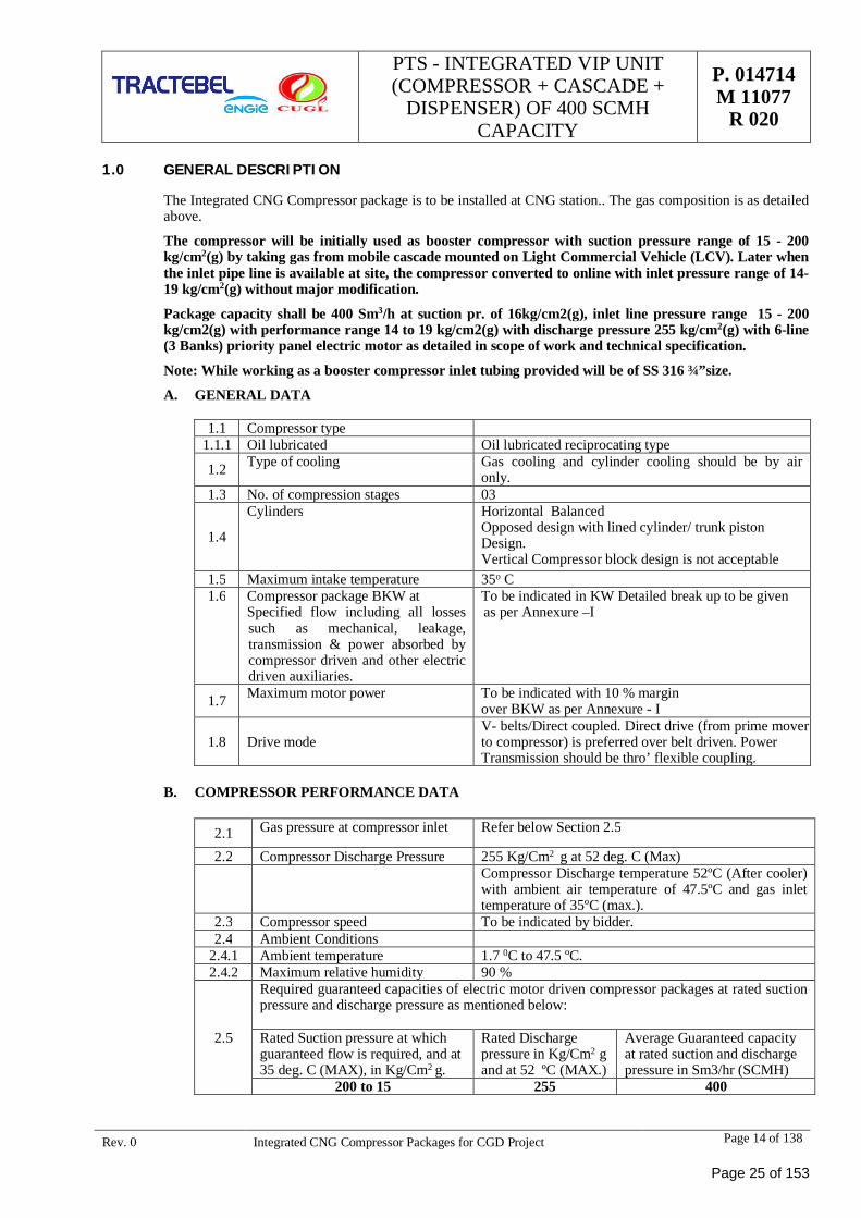
1.1 Compressor type1.1.1 Oil lubricated Oil lubricated reciprocating type
1.2 Type of cooling Gas cooling and cylinder cooling should be by aironly.
1.3 No. of compression stages 03
1.4
Cylinders Horizontal BalancedOpposed design with lined cylinder/ trunk pistonDesign.Vertical Compressor block design is not acceptable
1.5 Maximum intake temperature 35o C1.6 Compressor package BKW at
Specified flow including all lossessuch as mechanical, leakage,transmission & power absorbed bycompressor driven and other electricdriven auxiliaries.
To be indicated in KW Detailed break up to be givenas per Annexure –I
1.7 Maximum motor power To be indicated with 10 % marginover BKW as per Annexure - I
1.8 Drive modeV- belts/Direct coupled. Direct drive (from prime moverto compressor) is preferred over belt driven. PowerTransmission should be thro’ flexible coupling.
B. COMPRESSOR PERFORMANCE DATA
2.1 Gas pressure at compressor inlet Refer below Section 2.5
2.2 Compressor Discharge Pressure 255 Kg/Cm2 g at 52 deg. C (Max)Compressor Discharge temperature 52ºC (After cooler)with ambient air temperature of 47.5ºC and gas inlettemperature of 35ºC (max.).
2.3 Compressor speed To be indicated by bidder.2.4 Ambient Conditions
2.4.1 Ambient temperature 1.7 0C to 47.5 ºC.2.4.2 Maximum relative humidity 90 %
2.5
Required guaranteed capacities of electric motor driven compressor packages at rated suctionpressure and discharge pressure as mentioned below:
Rated Suction pressure at whichguaranteed flow is required, and at35 deg. C (MAX), in Kg/Cm2 g.
Rated Dischargepressure in Kg/Cm2 gand at 52 ºC (MAX.)
Average Guaranteed capacityat rated suction and dischargepressure in Sm3/hr (SCMH)
200 to 15 255 400
Page 25 of 153
PTS - INTEGRATED VIP UNIT(COMPRESSOR + CASCADE +
DISPENSER) OF 400 SCMHCAPACITY
P. 014714M 11077
R 020
Rev. 0 Integrated CNG Compressor Packages for CGD Project Page 15 of 138
Hereinafter the rated suction pressure, where guaranteed flow is required, will be referred as Rated SuctionPressure, which means 16 Kg/Cm2g for 400 SCMH compressors. Suction pressures will be measured at inletflange of the Integrated CNG Compressor package. Bidder has to ensure that compressors are designed suchthat the desired flow is achieved (without any negative tolerance) at Rated Suction Pressure.
Note:
a) Guaranteed average flow is 400 SCMH at 200 to 15 Kg/CM2
b) No advantage shall be given in case bidder offers compressor with flows higher than as detailed above forvarious types.
c) Graph for specification power consumption to be provided
d) Bidders offer shall be based on firm and final compressor model on which basis the offer shall beevaluated and no alternate compressor model or change of model, after submission of bid shall beentertained / considered. This is very important and all bidders shall take full cognizance of this matterbefore submitting the bid.
e) Bidder to indicate the capacity and absorbed power of the offered compressors at various suctionconditions starting from 200 Kg/Cm2 g to 16 Kg/Cm2 g (Temperature 35 deg C max.) and 255 Kg/Cm2gand 52 deg. C (max) discharge condition.
Performance curves and tables i.e. Flow versus suction pressure and temperature and power curves i.e.absorbed power versus suction pressure and temperature at specified discharge conditions shall befurnished. In addition to above, flow capacity and absorbed power values for suction conditions from 200Kg/Cm2 g to 16 Kg/Cm2 g in steps of 0.5 Kg/Cm2 shall also be given in tabular form. The graph shall beplotted at various suction pressures ranging from 200 Kg/Cm2g to 16 Kg/Cm2g and at various suctiontemperatures ranging from 20 to 35o C. Similarly, the graphs shall be plotted at various dischargepressures ranging from 16 Kg/Cm2g to 255 Kg/Cm2g, however at 520C (max) discharge conditions.
f) Bidder to note that the compressor package required shall be suitable for operating at a suction pressurefrom 200 Kg/Cm2g to 16Kg/Cm2g at 35 deg. C. Reduction of suction pressure if acheived by means ofpressure regulating valve (PRV) then necessary calculation of temperature reduction and solution shall besubmitted. Gas inlet pressure regulator of 300# class rating with an outlet discharge range of 200 Kg/Cm2g to 16 Kg/Cm2 g adjustable shall be provided within the compressor package. The first stage suction ofthe compressor must be capable of taking suction from 200 barg to 16 barg.
Bidder to note that negative tolerance on the guaranteed capacity will not be acceptable. Also noadvantage shall be given for positive tolerance of the capacity.
2.0 SAFETY
a) All controls shall operate in a fail-safe mode i.e. failure of any control shall not lead to running ofequipment in unsafe mode.
b) The hazardous area classification Class-I, Division I, Group D as per NEC or Zone I, Group II A/ II B asper IS/ IEC. Certificate from recognized agency to the effect that equipment supplied and/or installedconform to above area classification. All Devices shall meet the requirement for the specified areaclassification in which they are installed, including instrumentation leads.
c) All exposed rotating parts shall be provided with adequate guards of non-sparking type.
d) Driver belt if used shall be of anti-static and fire resistant type.
e) Piping shall be arranged in a manner so as to provide clear headroom and accessibility within thepackage. Adequate clearances shall be provided for all the engineered components.
f) Each package ENCLOSURE shall have One no. (1) LEL detectors with display (IR Type) and one no. (1)Ultra Violet (UV) fire detectors inside the enclosure.to cover the enclosure effectively as already spelt inthe scope of supply.
g) All material used in the package shall be flame retardant.
h) Relief valves shall be provided at suction and discharge and each inter stages of compressor with settingas per cl.7.20.4 of API-11P with R.V. venting as per cl. 7.20.4 of API-11P.All vented to common reliefvalve header.
Page 26 of 153
PTS - INTEGRATED VIP UNIT(COMPRESSOR + CASCADE +
DISPENSER) OF 400 SCMHCAPACITY
P. 014714M 11077
R 020
Rev. 0 Integrated CNG Compressor Packages for CGD Project Page 16 of 138
2.1 Carbon Dioxide (CO2) Flooding System
a) CO2 flooding system should be installed for the protection of CNG compressor by automatic actuationsystem. The package should be protected by automatic operated CO2 flooding system designed as perNFPA-12.
b) Gas Detection by installation of hydrocarbon gas detector with display (IR type) with self check functionand transmitter with adjustable alarm levels (0-100%) with preset of 10%, 20% and 50%.
c) Installation of flame detector (UV-IR type) with self check function and transmitter, alarm on detection offlame.
d) CO2 flooding system will consist of 2 nos. brand new CO2 cylinders of 45 Kg capacity. One cylinder willact as main & other as stand by, which shall have identical arrangement and connected to the system. Thecylinders should be placed in a shed raised above ground level to protect from weather and direct sunraysas per Gas Cylinder Rules, 2016. Cylinders shall be fitted with automatic actuated Valves, Solenoidvalves.
No extra utility as air, inert Gas shall be made available by CLIENT/used by the supplier to operate thesystem other than the UPS.
Cylinder should be ISI marked as per IS: 7285 and PESO approved.
e) The System shall be designed to operate on 24 V DC supply. FRLS (Fire resistant low smoke) cables shallbe used for the wiring of the system.
f) Interlock of CO2 Flooding system with compressor as per following sequence:
g) Compressor shall trip on detection of gas at preset level.
h) Compressor shall trip on detection of flame at preset level and automatic discharge of CO2 gas shall takeplace from the main cylinder simultaneously.
i) Compressor shall not start if the CO2 Flooding System is faulty, not working, SWITCHED OFF etc. Thecompressor shall be able to start only when the CO2 Flooding System is in healthy working condition.
j) Maintenance Override Switch shall be provided to keep the system off during maintenance.
k) Selector switch shall be provided to put Main/Stand by Cylinder in line at the turn of a switch as perrequirement.
l) Alarm panel for CO2 Flooding System shall be integral with the main compressor panel. Necessarydisplays as system ON, OFF, FAULT, RESET, Gas/ Flame indication, Remote actuation of solenoidvalve, distinguished hooter etc., shall be provided for CO2 flooding system.
m) CO2 Cylinders shall be provided outside the package at a safe place, minimum 4.5 meters away (aerialdistance), where it is not exposed to fire in case of fire in the compressor. Facility shall be made to operatethe system both manually from remote with the help of a switch/ call point and with help of pull downlever on cylinders.
n) Suitable online weight (CO2) loss monitoring/ indication device to be provided to ascertain the health ofthe CO2 flooding system.
o) All installation shall be compatible for hazardous area Class 1, Division 1, Group-D for Methane Gas.
p) The system designed by the supplier shall be duly approved by CLIENT.
q) Technical specifications, Operation and Maintenance Manual, PESO Certificate, Approval/Manufacturing certificates for cylinders and cylinder valves, gas detectors, flame detectors, solenoidvalves etc. shall be furnished by the supplier along with system. Software and hardware, calibrationprocedure shall be provided by the supplier along with the supply sufficient enough to handle the systemindependently. Necessary tools (1 set) shall be provided with the system.
r) System shall be offered for testing to CLIENT by the supplier after commissioning at site by creatingactual Gas leak and Gas fire situations and actual discharge of CO2 Gas from the Cylinders. This shallform a part of performance test and thereby acceptance of the package. The cylinders have to be refilledby the vendor at no extra cost to CLIENT after performance test. If the system fails during testing,subsequent testing and refilling would be at vendor’s cost.
Page 27 of 153
PTS - INTEGRATED VIP UNIT(COMPRESSOR + CASCADE +
DISPENSER) OF 400 SCMHCAPACITY
P. 014714M 11077
R 020
Rev. 0 Integrated CNG Compressor Packages for CGD Project Page 17 of 138
s) Warning and Operating instructions to be displayed at equipment as per the statutory/ safety regulations.
t) Piping of CO2 flooding system shall be seamless high pressure pipe of Schedule 40 of 50 mm dia ofappropriate length with a minimum safe distance of 4 Meter from CNG Compressor, The fittings likeelbows, Tees, Union, sockets should be of same schedule and capacity for installation in a high pressuresystem as per NFPA-12.
u) Flameproof online weighing system, complete frame with shed and all accessories should be of goodquality, weighing scale should be of reputed make.
v) Specifications:
Non Return Valve for CO2 High Pressure Hose:
As per BIS specificationsOperating Media: CO2Body Material: Brass, BIS: 319Ball: SS 316Pin: SS 316Seal: Teflon (PTFE)Working Pr.: 60BarsTest Pressure: 90 Bars for 1 minWeight: 70gmOutlet Size: ¾ BSP at manifold endInlet Size: ½” BSP at CO2 Discharge Hose endTemp. Range: -29° C to 66° CHose Adopter:As per BIS specificationsOperating Media: CO2Body Material: Mainly BrassTest Pressure: 250 BarMax. Working Load: 150 BarTemp. Range: -29° C to 66° CDischarge Nozzle:As per BIS specificationsOperating Media: CO2Body Material: Leaded Tin Bronze as per BIS: 318:1981Design Nozzle Pr.: Not less than 20.6 kgf/cm2 at 27° CTest Pressure: 140 kgf/cm2Marking for Code No. (on the basis of equivalent single orifice dia.): As per BIS: 6382:1982Temp. Range: -29° C to 66° CHigh Pressure Hoses:As per BIS 7285:1974Operating Media: CO2Hose Type: Double wire breaded (perforated) rubber coveredMin. Bursting Pr.: 420 kgf/ cm2 at 54° CLength: 40 cmCross-section: ½”End Connection: ½” BSP (F) xW21.614 TPI
Page 28 of 153
PTS - INTEGRATED VIP UNIT(COMPRESSOR + CASCADE +
DISPENSER) OF 400 SCMHCAPACITY
P. 014714M 11077
R 020
Rev. 0 Integrated CNG Compressor Packages for CGD Project Page 18 of 138
End Fittings: BrassTemp. Range: -29° C to 66° C
2.2 Following warning and caution signage shall be marked on the housing/package:
“No Smoking”
Caution notice “This Machine may automatically start at any time”.
“Flammable Gas”
3.0 BASIC DESIGN OF COMPRESSOR
3.1 Following specification is intended to give the bidder the technical and operating conditions the compressormust fulfil.
3.2 The bidder shall meet all applicable statutory codes, national law and local regulation for safety andenvironment protection.
3.3 The design shall conform to API 618 / API 11P, 2nd edition / other relevant reputed internationalstandards/Gas application design (bidders to indicate).
3.4 Cylinders of compressor should be horizontal balanced/ trunk piston design. Compressor shall utilizepreferably separate suction and discharge valves. Valve should be of preferably plate or spring type (non-metallic type) developed specifically for Natural gas.
3.5 Near Zero Gas Loss compressor package design is envisaged– Bidder to provide confirmation fromcompressor block manufacturer towards Discharge of Process Gas into the environment while in operationsand in idling condition. Compressor should be design in such a way that no gas venting is done in case ofemergency shutdown due to power cut etc.
3.6 State of the art technology shall be applied to the piston ring to ensure reliability and oil control with polymerrings fitted to the final stage according to manufacturer safe design. The bidder to indicate the life of pistonrings of all stages in terms of running hours.
3.7 Each pressurized component of the compressor package shall be subjected to hydraulic proving test and thefinal assembly shall be performance tested and certified.
3.8 The inter stage and final stage cooler tube material shall be carbon steel. Bidder to submit cooler sizingcalculation for review.
3.9 All gas piping shall be designed, fabricated and tested in accordance with ANSI B 31.3.
3.10 The relief valve sizing shall be in accordance to IBR, ASME code for boiler & pressure vessel and API RP-520. The relief valve and associated piping shall be sized for full block discharge.
3.11 Compressor maximum vibrations of cylinders shall not exceed 10 mm/sec. unfiltered peak velocity. Maximumvibration level installed compressor frame shall not exceed an unfiltered peak velocity of 5 mm/sec or 200micron unfiltered peak to peak vibration whichever is less. The bidder shall provide for all structural supportwithin the package so that these levels can be achieved or Vibrations should be limited according tomanufacturer safe design.
3.12 In case of lubricated cylinder & packing design, single plunger per point force feed mechanical lubricator shallprovide lubrication to compressor cylinders. Lubricators with double ball check valve shall be provided at eachlubricator point. Digital no flow timer shall be provided to stop the compressor in case of loss of cylinderlubrication.
3.13 The bidder along with the offer shall furnish the recommended lubricating oil type, grades & specificationalong with their quantity and frequency of change. The recommended oil shall be compatible with gaskets,O-ring, seals, packing, lubricator parts and other parts coming into contact.
3.14 Coolant tank must be provided with proper opening for flush/ clean of the tank, so that coolant level tripsystem works properly. Switch position should be such that sludge doesn’t deposit on float sensor. Material ofcoolant make up tank should be SS304.
3.15 Gauge panel with physical gauges for temperature and pressure shall be provided and should be visible fromoutside of the package. LCD display as an extension of PLC display is not acceptable.
Page 29 of 153
PTS - INTEGRATED VIP UNIT(COMPRESSOR + CASCADE +
DISPENSER) OF 400 SCMHCAPACITY
P. 014714M 11077
R 020
Rev. 0 Integrated CNG Compressor Packages for CGD Project Page 19 of 138
3.16 Proper oil draining system for the package is required. Packager should provide proper pocket system inpackage structure for draining coolant/ oil from inside the package. Package base frame block must beinterconnected & slope must be provided.
3.17 Level trips of oil & coolant must be provided with wire open alarm according to manufacturer safe design.
3.18 Package inlet flow meter should have isolation valve in upstream and NRV/Valve at downstream of flowmeter. Flow meters which are on piping should be connected with flexible hoses and should have properclamping support to avoid vibration so that correct reading are observed.
3.19 All cables entries should be from bottom/side in the FLP boxes (local control panel). There should be nocabling from the bottom of the package. All the cables should be routed from the side or top for easy troubleshooting.
3.20 All instruments and their cables should be at appropriate distances from the exhaust line/hot parts.
3.21 Status of all field instruments viz. switches should be displayed on PLC.
3.22 Direction of flow should be marked on the pipe line and nomenclature of all vessel (e.g. 1st stage dischargedampener etc.) should be written on them. Cross head inspection windows should be transparent for easy ofinspection during running. Set values should be prominently marked on the gauges.
3.23 Accessories To Be Included
Gas tight crankcase ZERO venting.
Packing case & pressure packing.
Drive motor with pulley/flywheel
Inter-stage coolers for all stages.
Final cooler.
Oil pump, oil filter
Oil cooler.
Crankcase breather piped back to suction.
Oil/moisture separators appropriate for selected cylinder configuration.
Automatic condensate drains system for all separators to remove oil / moisture periodically and ease starting.
Separator drain valves piped to collection drain block suitable for connection to gas recovery system.
Safety relief valve on each stage of compression.
Safety relief valve discharges connected to common manifold suitable to allow dispersion of gas via a ventstack and flame arrestor / trap.
PRV at the inlet of the system.
BDV at the inlet of the system.
Interconnecting piping between cylinders, coolers and separators.
Pulsation dampeners.
Interconnecting water piping between radiator and compressor.
Interconnecting instrumentation piping.
Suction & Discharge Mass flow meter
Thermal Mass flowmeter for vent loss
Priority panel with SS tubing- 3Bank
Cascade -3 Bank
Dispenser -3 Bank
3.24 Offered package shall be complete with compressor, electric motor, piping, cooling system, suction and
Page 30 of 153
PTS - INTEGRATED VIP UNIT(COMPRESSOR + CASCADE +
DISPENSER) OF 400 SCMHCAPACITY
P. 014714M 11077
R 020
Rev. 0 Integrated CNG Compressor Packages for CGD Project Page 20 of 138
discharge filters, priority fill system, control panel safety and control devices and other accessories required forautomatic and safe operation of the system. The supply shall include all interconnecting piping/tubing/cables.Cooling system shall be of closed circuit type. Only lubricated and air cooled compressor block is acceptable.
3.25 The compressor package control system shall be designed for unattended safe operation in automatic mode andshall unload, start, load, stop safely. The compressor shall start in auto in case high bank storage pressure fallsbelow 200 barg and stop once the pressure in all three banks of storage cascade reaches 250 barg.
3.26 Integrated 6 line (3 bank) priority fill system to be provided. The priority fill system shall ensure filling as perfollowing sequence:
· CNG Vehicle
· High bank of storage cascade.
· Medium bank of storage cascade
· Low bank of storage cascade
· The priority fill system shall ensure that in any case CNG vehicle shall be given first priority.
Compressor shall be designed to ensure flow capacity as follows:
S No Suction Pressure Flow Capacity
1. When used as an online compressor:
Flow capacity as on-line integrated compressor atsuction pressure of 16 kg/cm2. discharge pr. 255 kg/cm2
400 sm3/hr2. When used as a Booster compressor:
Average flow capacity (over range of suction pressurefrom 200 kg/cm2 to 15 kg/cm2 (varying on continuousbasis) . discharge pr. 255 kg/cm2
Maximum BKW = As per bidders design
Motor Rating = To be indicated by the Bidder
Maximum power requirement including the accessories to be indicated by the bidder and shall be minimum forthe requested performance.
Noise level shall not exceed 75 +3dBA at 1m from the compressor package enclosure.
Framework shall be mounted on a suitable skid type base, external-lifting lugs shall be provided at eachcorner. Duplex Suction filter, air compressor & UPS (if applicable) & CO2 flooding system can be placedseparately (outside of the canopy) and Electrical control panel can be placed in remote safe area foroptimisation of the foot print size. However, rest all items i.e. flow meters, priority panel, cascade, dispenser,junction boxes & PLC Control panel etc. should be enclosed / mounted on the same frame & maximumfootprint of that compressor frame Package shall be limited to 4.0 m2. These package dimensions & integrationof all accessories is essence of this tender & hence any deviation in these values & integration will not beaccepted.
3.27 The compressor package control system shall be so designed that the first item to go into alarm condition shall”Lock out” to indicate the cause of the trip though the cause of the trip may have disappeared. The lock outcondition shall be manually reset.
3.28 An automatic restart shall be provided on restoration of power with a 10-second delay after temporaryinterruption. Existing alarm condition shall remain indicated.
3.29 The compressor shall be vented into BDV before restarting in order to avoid overload to the main drive. In anycase venting of gas to atmosphere is not allowed. There is need to have a blow down vessel so that gas isvented to vessel. The size of the BDV should be the sufficient to allow main drive to start. BDV volume to be
Page 31 of 153
PTS - INTEGRATED VIP UNIT(COMPRESSOR + CASCADE +
DISPENSER) OF 400 SCMHCAPACITY
P. 014714M 11077
R 020
Rev. 0 Integrated CNG Compressor Packages for CGD Project Page 21 of 138
designed in such a way that gas accumulated in the process should not be vented out in any case of main powersupply failure /stopping/ emergency push of package. Calculation for BDV volume shall be considering 20%higher than calculated volume and it should be calculated on higher range (50 bar) of the operating pressure(16 bar to 50 bar). Bidder shall submit calculation for same at the time of designing/drawing approval to client.BDV should be preferably placed on top of package and if placed inside package, it should be in verticalposition.
3.30 Prime mover (Electric Motor)
The motor shall be flame proof/ explosion proof and confirm to IS: 2148 suitable for zone 1 group II area asper IS/IEC. The Motor shall be of standard frame size as per IS/IEC and rated for continuous duty with highefficiency and shall be designed for star-delta starting. The Motor shall be provided with class ‘F’ insulation,however, temperature rise shall be limited to the temperature specified for class ’B’ insulation as per IS andshall be suitable for voltage variation of 415V+ 10%. The bidder shall indicate the guaranteed total powerrequirement in KW. The motor rating shall be 110% of the greatest BKW required by the compressor.
Electrical panel for motor starter (VFD/Soft starter etc) to be provided with both induced draught and forceddraught ventilation
3.31 Motor Specification (To be provided separately for 400 SCMH)
Electric Motor
a) Type of drive Totally Enclose Fan Cooled (TEFC) high efficiency as per IEEMA standard-19-2000
b) Protection Flame proof & weather proof enclosure
c) Insulation Class F with class B temperature rise
d) Mounting Horizontal Foot Mounting
e) Specification standard By Bidder
f) Supply Voltage(assumed) 415(+/-) 10% volt, 3 phases,50(+/-) 5%Hz
g) Synchronous speed By bidder
h) Motor rating By Bidder
i) Motor Efficiency By Bidder
j) Power factor By Bidder
k) Speed of motor By Bidder
l) Nos. of hot & Cold starts of motor 2 hot and 3 cold starts per hour
m) Coupling Type By Bidder
n) Torque speed cure By Bidder
o) Starting torque
Speed, thermal withstand curve load, current speed curve, Efficiency power factor vs load curve by Bidder
Motor Accessories
a) Compressor grooved flywheel (if any)
b) Motor grooved drive pulley (if any)
c) Drive VEE belts (if any)
d) Flexible coupling for direct drive
e) Drive guard
f) Adjustable motor slide rails for belts tensioning to be used (if any)
Note:
1) Motor shall be three phase, AC, asynchronous, flameproof, high efficiency (IE2 or better, as perIEC60034-30), Ex’d’ rated, continuous duty, service factor 1.1, on IEC standard type. Designing shall be
Page 32 of 153
PTS - INTEGRATED VIP UNIT(COMPRESSOR + CASCADE +
DISPENSER) OF 400 SCMHCAPACITY
P. 014714M 11077
R 020
Rev. 0 Integrated CNG Compressor Packages for CGD Project Page 22 of 138
done on basis of 47.5 degrees package ambient temperature. Motor shall be suitable for soft starter / Stardelta/ VFD. Service factor shall not play any role in finalizing the rating of motor.
2) Main Motor Starter: Soft-starter / VFD.
3) Considering all de-rating factors as applicable, rating of soft starter (at 50 degree Celsius) shall match or begreater than the selected main motor rating.
4) Soft starter panel, LCP or any other power/ control panel need to be appropriately forced cooled tomaintain the temperature favorable for switch gear employed in panel.
5) Soft starter for motors should be three phase controlled type
6) Appropriate cable (wrt: size, material, and shielding) to be used for soft starter drive.
7) Cables used inside the package must be FRLS type. Sufficient distance to be maintain b/w cables andgas/oil tubings inside the package
8) Routing of soft starter and power cable shall be separated from control supply/ instrument cables.
9) Successful Bidders shall take prior approval of the Make for the items not covered above for whichcomplete technical credentials of the proposed vendors shall be required to be submitted for evaluation byPurchaser/ Consultant
10)Some of the items indicate only Indian makes. Successful foreign bidders may take prior approval of anyother make also for which complete technical credentials of the proposed vendors shall be required to besubmitted for evaluation by Purchaser/ Consultant.
3.32 Cooling system
Each compressor package shall be complete with its own cooling system. The cooler shall be air-cooled heatexchanger. The gas temperature after after-cooler shall not exceed 52 degree C.
Special attention to be given while designing the gas cooler considering the local conditions. Bidders shallensure that final delivered gas temperature is less than 520C.
Direction of flow should be marked on the pipe line and nomenclature of all vessels (e.g. 1st stage dischargedampener etc.) should be written on them. Cross head inspection windows if applicable should be transparentfor ease of inspection during running. Set values should be prominently marked on the gauges.
Packages design should be such that its vent should not go upward (package vent in vertical direction notrequired) i.e opening of package vent should be in horizontal directional with duct arrangement.
3.33 Oil Filter
The ingress of oil into CNG adversely effects vehicle emission and storage system. Only lubricated cylindercompressors are allowed and vendor shall supply oil separators after cooler at each stage with automatic drain.The maximum permissible oil content in CNG is 5 PPM.
Vendor to supply a proven, maintenance free oil removal system after after–cooler to remove oil fromcompressed gas. The offered oil mist removal system shall restrict the oil to less than 5PPM in discharge ofcompressor.
3.34 Gas recovery system
If required, the Vendor shall provide gas recovery system with gas recovery vessel. The gas recovery vesselshall be provided with pressure relief valve and necessary instrumentation to avoid cold flaring of gas. Gasrecovery vessel shall be ASME/IBR code designed.
3.35 Piping & Appurtenances
The materials for gas piping shall be seamless carbon steel of ASTM A-106 Grade B. The piping / tubing atthe outlet of the compressor and of priority fill system shall be of seamless stainless steel of proper pressurerating and specifications as under:
SS TUBING SPECIFICATIONS:
· Seamless SS Tubing
· Material of construction Stainless Steel 316L
Page 33 of 153
PTS - INTEGRATED VIP UNIT(COMPRESSOR + CASCADE +
DISPENSER) OF 400 SCMHCAPACITY
P. 014714M 11077
R 020
Rev. 0 Integrated CNG Compressor Packages for CGD Project Page 23 of 138
· Tube hardness shall be less than 80 RB
· Sizes : Metric system (inch)
· Max Working Pressure : 326 barg
SS FITTINGS & VALVES SPECIFICATIONS:
· Material of construction Stainless Steel 316
· Sizes : Metric/SI
· Standard : ASTM/ ASME/ DIM
· End connections : Single or Double ferrule Compression type / NPT
· Max Working Pressure : 326 barg
· PSV Vent Line to be extended above the package to safe height.
3.36 Electrical System
· All electrical equipment of compressor package shall be installed in accordance with NFPA 70, NEC forClass 1, Division 1, Group D, and IS 5571 and shall have approval of a recognized certifying authority.
· CLIENT shall provide 415+ 10% volts, 3 phase and 50+ 3% Hz electrical connection at CNG stationelectrical panel only. Vendor shall distribute electrical power to all equipment and control system byproviding cables and suitable switch-gear distribution panel.
· The electrical power supply distribution panel, switch gear panel and starter shall be in flame proofconstruction. Certificate from recognized agency to the effect that equipment supplied and or installedconform to above area classification. All devices shall meet the requirement for the specified areaclassification in which they are installed, including instrumentation leads.
· Heavy duty on-load phase changeover should be provided for H.E motor.
· Semiconductor fuses to be provided, where applicable.
· All illumination fittings should be single phase AC supply based.
· All wire/ cable to be used in compressor and panel shall be of copper conductor and FRLS type throughproper cable tray conduit etc.
· Compressor Motor and hence soft starter/VFD should always start on NO-LOAD for all start method(AUTO or MANUAL mode), selected for operation of compressor, no matter whatever may be the laststopping mode of the compressor viz, programmed or un-programmed. Loading in motor in no mannershall be more than the value as defined by motor manufacturer in motor characteristic curves.
· Sufficient space to be provided for Motor JB for cable glanding work.
· Suitable arrangement to be provided for easy extraction of motor from package
· Multifunction meter to be provided for metering of package total energy and other parameters (viz; KVAH,KWH, Voltage, current, PF, Frequency, MDI (KVA), MD (KWH) inside the panel and output display shallbe on HMI screen.
· Bidder to ensure that spares and service support of all switchgears, soft starter, instruments, or meter etcused in package/ panel, shall be available in Indian market.
· Overall power factor of the whole package should not be less than 0.99. vendor have to make arrangementinside the panel to maintain power factor at 0.99 or more by providing through means of SVG(static vargenerator) / capacitors etc.
· Motor feeder shall be provided with energy meter, MCCB with single phase presenter , contactors (AC-3Duty), bi-metal relay switch fuse unit, earth leakage relays & voltmeter, push buttons, (for start/stop/trip/etc. Ammeters should be part of PLC HMI. Stop push buttons shall be lockable and have stay put except incase of critical devices such as lube oil pumps etc.
Page 34 of 153
PTS - INTEGRATED VIP UNIT(COMPRESSOR + CASCADE +
DISPENSER) OF 400 SCMHCAPACITY
P. 014714M 11077
R 020
Rev. 0 Integrated CNG Compressor Packages for CGD Project Page 24 of 138
3.37 Earthing System
The design & installation of earthing system shall be as per IS 3043 or equivalent international specification.One or more no of earth plates with provision of inter connection to main earth grid shall be provided. Allhardware used for earthing system shall be hot dip galvanized or zinc passivated.
All cables shall be terminated at equipment by means of double compression type compression glands andshall be flame proof cable glands if located in hazardous area
3.38 Phase sequence preventer (Current based) shall be provided. Phase changeover to be provided for motorscontrolled through soft starter. Dedicated earth fault/leakage sensing relay to be provided inside the panel forelectrical safety
3.39 Vibration
Compressor maximum vibration of cylinders shall not exceed 10 mm/sec unfiltered peak velocity. Maximumvibration level of installed compressor frame shall not exceed an unfiltered peak velocity of 5mm/sec or 200micron unfiltered peak-to-peak vibration whichever is less. The bidder shall provide for all structural supportwithin the package so that these levels can be achieved or vibrations should be limited according tomanufacturer safe design. Local flameproof enclosure inside compressor to have provision of extra holes alongwith dead end plug to accommodate control cables for any future modification.
4.0 INSTRUMENTATION & CONTROLS
4.1 All the instruments and control shall be suitable for area Class I, Group D, Division1
4.2 All package mounted transmitters & temperature elements shall be intrinsic safe as per IEC 79-11 and solenoidvalves, switches and related junction boxes shall be flame proof ‘d’ as per IEC 79-1. Other special equipment /instrument, where intrinsic safety is not feasible or available, shall be flame proof/ explosion proof as per IEC79-1. All pressure gauges shall have an accuracy of + 1% of FSD and 65mm dial size. Pressure sensingelements shall be minimum of SS316 and movement of SS304. All pressure gauges on process lines havingrange more than 40kg / cm2g.
4.3 Following curve to included along with documents:
a) Discharge flow v/s suction pressure curveb) Energy consumption v/s suction pressure curvec) Discharge flow v/s energy consumption
4.4 There shall be provision of Two suction Coriolis based mass flow meters inside the compressor package. Flowmeters shall be suitably installed and clamped as per OEM guidelines/ recommendations to avoid measurementerrors due to external vibration. Relevant calibration certificates to be provided. Flow meters should haveintegral display to show instantaneous values of mass flow. The totalizer readings from the flow meter shouldbe communicated to PLC and PLC shall record the flow readings. Shift wise, day wise and month wise flowtotalizer readings should be available in PLC display.
4.5 1 Number Thermal Mass flowmeter for measuring Vent loss shall be installed as per Manufacturer’s design.
4.6 The temperature gauge shall be generally mercury in steel field type. Capillary tubing shall be min. SS304with SS flexible armouring. The gauge shall have an accuracy of +1% FSD and 65mm dial size. The rangeshall be 1.5 times of operating temperature. In PLC pressure process values should be taken from pressuretransmitters and should be independent from pressure gauges installed on local gauge panel. Temperatureprocess values should be taken from temperature transmitters and should be independent from temperaturegauges installed on local gauge panel. The compressor package instrumentation & control is to be configuredfor manual as well fully automatic control system including starting, shutdown as applicable for unattendedoperation.
4.7 Individual (2/3 core) cabling is required for each field instrument from field JB to avoid multiple JB’s andmulticore cables in field for easy trouble shooting & replacement.
4.8 Each cable shall be neatly tagged & dressed for each instrument.
4.9 Make of PLC should be as per vendors list, selection will be as per Bidder/manufacture standard to handlerequired input/output data specified in the tender .
4.10 There shall be provision of relay for DO cards between PLC & SOV & barriers/ isolators for DI cards between
Page 35 of 153
PTS - INTEGRATED VIP UNIT(COMPRESSOR + CASCADE +
DISPENSER) OF 400 SCMHCAPACITY
P. 014714M 11077
R 020
Rev. 0 Integrated CNG Compressor Packages for CGD Project Page 25 of 138
field & PLC. The barriers and isolators should be multichannel for easier replacement.
4.11 All the instrumentation shall be capable or operating for full range of operation.
4.12 Separate junction boxes shall be provided for each type of signal i.e. analog, digital, solenoids RTD,thermocouple, intrinsic safe and for power supply. No cable shall share power & signal.
4.13 Suitable bypass for interlocks shall be provided for start-up.
4.14 Compressor package shall be provided with the following indicators:
· Pressure indicator each stage suction and discharge.
· Oil pressure indicator on each pressure lubrication system
· Hydraulic oil cooler inlet & outlet temperature on local gauge panel (if required)
· Hydraulic oil pressures each stage on local gauge panel (if required) The Compressor package shall beprovided with the following trip devices:
a. High oil temperature devices
b. Low suction pressure protection devices
c. High discharge temperature protection device
d. Coolant flow low devices
· Flame detection
· Gas detection
· Emergency stop devices
· Fail safe/ wire break alarm for safe operation
· Interlocking provision in PLC program for tripping of machine
The compressor package shall be furnished with the following trip logic that shall stop the compressor andsuction of compressor shall be isolated:
· On high oil temperature
· On low suction gas pressure
· On high discharge pressure
· On high discharge gas temperature
· On coolant flow low
· On fire detection
· On gas detection
· On pressing manual sop button at local control panel
· On pressing emergency stop devices
4.15 Compressor package shall be furnished with following tripping circuit (the motor shall stop and suction ofcompressor shall be isolated)
· On actuation of gas detector alarm.
· On actuation of flame detection alarm.
· On pressing of manual stop button at compressor package
· On pushing of emergency stop device
4.16 Each compressor package shall be provided with an audible and visual alarm system for annunciation oncompressor abnormalities.
Page 36 of 153
PTS - INTEGRATED VIP UNIT(COMPRESSOR + CASCADE +
DISPENSER) OF 400 SCMHCAPACITY
P. 014714M 11077
R 020
Rev. 0 Integrated CNG Compressor Packages for CGD Project Page 26 of 138
4.17 Junction box shall be of explosion proof type with 10% extra terminal strip & cable gland shall be of doublecompression type.
4.18 Gas detectors and flame detectors should be mounted with the canopy.
4.19 ESD button (3 Nos.) shall be provided (Customer Interface room, locally mounted on package and Panel). Aseparate hooter for customer interface room shall be provided with annunciation window alarm of individualprotection device.
4.20 All instrument shall be of internationally reputed manufacturer
4.21 Emergency shut down devices
The emergency shut down (ESD) system is also in scope of vendor. This shall be in accordance with NZS5425. A fail safe system shall be designed and incorporated to isolate cascades storage from dispensers, stopcompressor isolate the compressor suction storage line and cut off power supply on activation of ESD switch.This ESD switch shall have to be manually reset to restart the compressor package again.
4.22 Compressor mounted Control Panel
· There shall be two independent ports available in the PLC with all the parameters available on eachindividual port.
· One port shall be for remote monitoring of the parameters. Besides PLC display, all the parameters whichare measured should be monitored on a HMI/ MMI for remote monitoring as well as of remote operation.Data should be stored at 2 places simultaneously, in case of failure of one device data can be retrieved fromsecond device. Trends, alarms, events should be logged for at least 3 months on day/ hour/ minutes/ basis.
· Second port shall be available for any third party interface which shall be OPC compliant for networking orSCADA. The recorded data or part of the data may be required to transmit to remote locations over open/secured network through internet/ Ethernet using local cable/ data card/ sim card (GPS/ GPRS/ CDMA).Vendor shall provide fully wired & configured Modem to transmit the data to remote location. This modemshall be dedicated for SCADA connectivity other than the modem for Compressor diagnostic.. Vendorshall provide protocol details to CLIENT and also provide necessary support for third party interface forremote data connectivity.
· PLC shall incorporate all process parameters (specified elsewhere) and status of compressor, engine &priority panels and shall be modular in construction with respect to CPU, Power supply, Interface. PLCcomponents/ system shall be tropicalized, MIL standard adopted with complete wiring and necessaryterminals. Wiring to be color coded with cross ferruling in position. PLC shall be capable of carrying outon line routines for at least ten separate loops without affecting the scan, cycle & updating time etc. PLCshall be configured as a remote terminal unit of supervisory computer and data acquisition system completewith GPRS and Ethernet connectivity. One card for transferring and accessing data from minimum twentydevices with RS485 port shall be provided. In case of failure of master/ active controller/ CPU, standbycontroller/ CPU should take over the control in bump less manner. All values & data should be availablethrough both the controllers immediately, i.e. there should be no data loss.
· Successful bidder to include in scope live demonstration of remote monitoring of all PLC loggedparameters in one machine at his works. CLIENT may ask for the same. However, this may be required tobe demonstrated at site.
· PLC based logic circuits shall be used for control & interlock of the compressor package with RS485SCADA Connectivity as per details in Annexure-IX.
· Local control panel shall be furnished with annunciation window (HMI) alarm of individual protectiondevice and a common hooter for audible alarm.
· Local panel should have separate push button for start, stop, emergency stop, alarm acknowledge, alarmrest & test button for checking healthiness of annunciation system will be part of HMI.
· PLC shall be housed inside flameproof IIA/ IIB (Ex’d’). Local operator panel shall also be provided on theflameproof enclosure. The operator panel is provided for parameterization, indication, monitoring, andalarms and first out sequence of the system. PLC system shall have memory modules for storing userprograms, symbol lists, program comments and should facilitate debugging/ trouble shooting without theapplication program. Program shall be ladder logic and communication shall be in English for each run.
Page 37 of 153
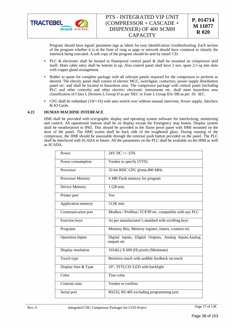
PTS - INTEGRATED VIP UNIT(COMPRESSOR + CASCADE +
DISPENSER) OF 400 SCMHCAPACITY
P. 014714M 11077
R 020
Rev. 0 Integrated CNG Compressor Packages for CGD Project Page 27 of 138
Program should have signal/ parameter tags as labels for easy identification/ troubleshooting. Each sectionof the program whether it is in the form of rung or page or network should have comment to classify theinterlock being executed. A soft copy of the program should be sent by email/ CD.
· PLC & electronic shall be housed in flameproof control panel & shall be mounted on compressor skiditself. Main cable entry shall be bottom to up. Also control panel shall have 2 nos. spare 2.5 sq mm slotswith copper gland arrangement.
· Bidder to quote for complete package with all relevant panels required for the compressor to perform asdesired. The electric panel shall consist of electric MCC, switchgear, contactors, power supply distributionpanel etc. and shall be located in hazardous area. The compressor package with control panel (includingPLC and other controls) and other electric/ electronic instruments etc. shall meet hazardous areaclassification of Class I, Division I, Group D as per NEC or Zone I, Group IIA/ IIB as per IS/ IEC.
· CPU shall be redundant (1W+1S) with auto switch over without manual intervene, Power supply, Interface& IO Cards.
4.23 HUMAN MACHINE INTERFACE
HMI shall be provided with text/graphic display and operating system software for interlocking, monitoringand control. All operational buttons shall be on display except the Emergency stop button. Display systemshall be weatherproof to IP65. This should be provided in the flame proof panel with HMI mounted on thedoor of the panel. The HMI screen shall be back side of the toughened glass. During running of thecompressor, the HMI should be assessable through the external push button provided on the panel. The PLCshall be interfaced with SCADA in future. All the parameters on the PLC shall be available on the HMI as wellas SCADA.
Power 24V DC +/- 15%
Power consumption Vendor to specify (VTS)
Processor 32-bit RISC CPU @min.800 MHz
Processor Memory 4 MB Flash memory for program
Device Memory 1 GB min.
Printer port Yes
Application memory 512K min
Communication port Modbus / Profibus/ TCP/IP etc. compatible with any PLC
Function keys As per manufacturer’s standard with scrolling keys
Programs Memory Bits, Memory register, timers, counters etc
Operation Inputs Digital inputs, Digital Outputs, Analog Inputs,Analogoutputs etc
Display resolution 1024(L) X 600 (H) pixels (Minimum)
Touch type Resistive touch with audible feedback on touch
Display Size & Type 10”, TFTLCD /LED with backlight
Color True color
Contrast ratio Vendor to confirm
Serial port RS232, RS 485 excluding programming port
Page 38 of 153
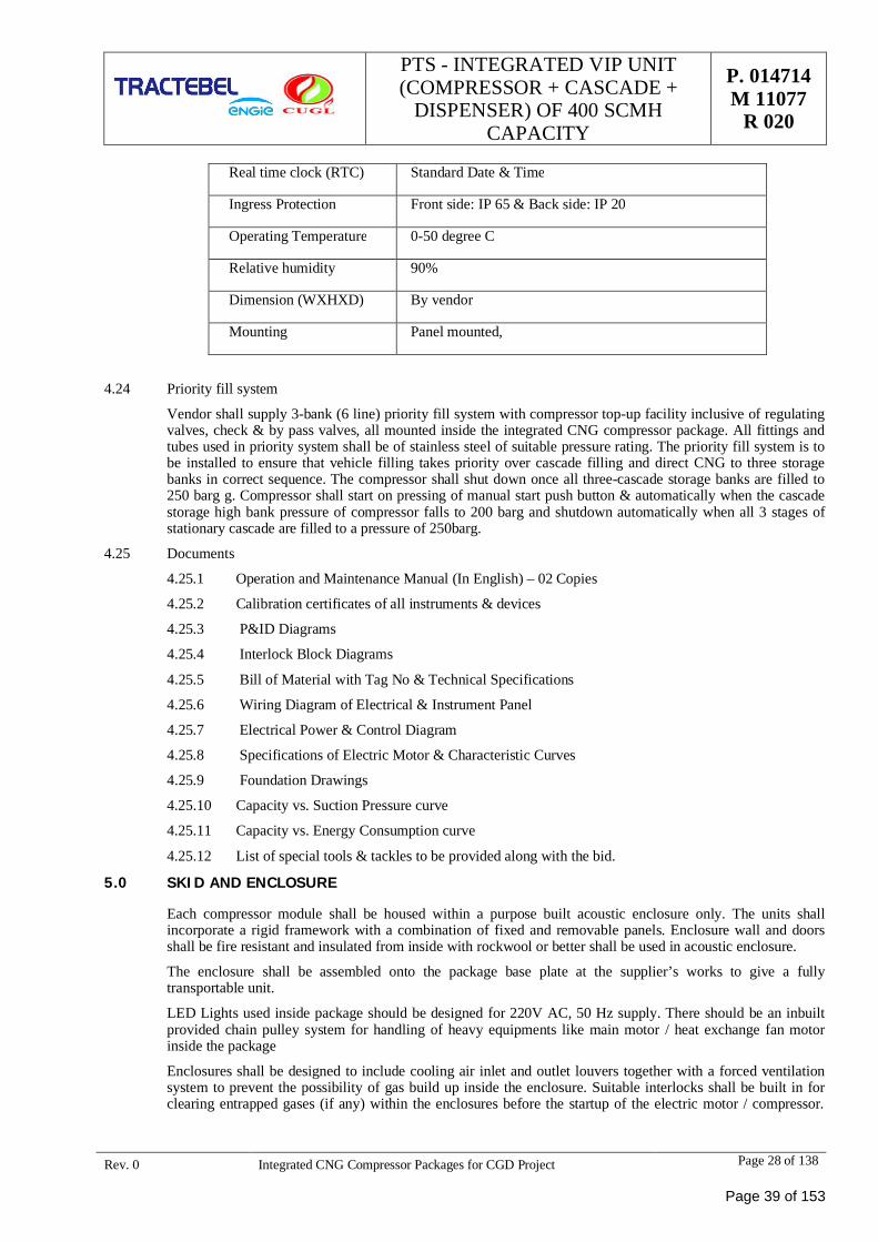
PTS - INTEGRATED VIP UNIT(COMPRESSOR + CASCADE +
DISPENSER) OF 400 SCMHCAPACITY
P. 014714M 11077
R 020
Rev. 0 Integrated CNG Compressor Packages for CGD Project Page 28 of 138
Real time clock (RTC) Standard Date & Time
Ingress Protection Front side: IP 65 & Back side: IP 20
Operating Temperature 0-50 degree C
Relative humidity 90%
Dimension (WXHXD) By vendor
Mounting Panel mounted,
4.24 Priority fill system
Vendor shall supply 3-bank (6 line) priority fill system with compressor top-up facility inclusive of regulatingvalves, check & by pass valves, all mounted inside the integrated CNG compressor package. All fittings andtubes used in priority system shall be of stainless steel of suitable pressure rating. The priority fill system is tobe installed to ensure that vehicle filling takes priority over cascade filling and direct CNG to three storagebanks in correct sequence. The compressor shall shut down once all three-cascade storage banks are filled to250 barg g. Compressor shall start on pressing of manual start push button & automatically when the cascadestorage high bank pressure of compressor falls to 200 barg and shutdown automatically when all 3 stages ofstationary cascade are filled to a pressure of 250barg.
4.25 Documents
4.25.1 Operation and Maintenance Manual (In English) – 02 Copies
4.25.2 Calibration certificates of all instruments & devices
4.25.3 P&ID Diagrams
4.25.4 Interlock Block Diagrams
4.25.5 Bill of Material with Tag No & Technical Specifications
4.25.6 Wiring Diagram of Electrical & Instrument Panel
4.25.7 Electrical Power & Control Diagram
4.25.8 Specifications of Electric Motor & Characteristic Curves
4.25.9 Foundation Drawings
4.25.10 Capacity vs. Suction Pressure curve
4.25.11 Capacity vs. Energy Consumption curve
4.25.12 List of special tools & tackles to be provided along with the bid.
5.0 SKID AND ENCLOSURE
Each compressor module shall be housed within a purpose built acoustic enclosure only. The units shallincorporate a rigid framework with a combination of fixed and removable panels. Enclosure wall and doorsshall be fire resistant and insulated from inside with rockwool or better shall be used in acoustic enclosure.
The enclosure shall be assembled onto the package base plate at the supplier’s works to give a fullytransportable unit.
LED Lights used inside package should be designed for 220V AC, 50 Hz supply. There should be an inbuiltprovided chain pulley system for handling of heavy equipments like main motor / heat exchange fan motorinside the package
Enclosures shall be designed to include cooling air inlet and outlet louvers together with a forced ventilationsystem to prevent the possibility of gas build up inside the enclosure. Suitable interlocks shall be built in forclearing entrapped gases (if any) within the enclosures before the startup of the electric motor / compressor.
Page 39 of 153
PTS - INTEGRATED VIP UNIT(COMPRESSOR + CASCADE +
DISPENSER) OF 400 SCMHCAPACITY
P. 014714M 11077
R 020
Rev. 0 Integrated CNG Compressor Packages for CGD Project Page 29 of 138
Packages design should be such that its vent should not go upward (package vent in vertical direction notrequired) i.e. opening of package vent should be in horizontal directional with duct arrangement.
The maximum temperature within the enclosure shall be limited to 520C. Adequate ventilation fans shall beprovided to meet the above and also to account heat dissipation of the coolers/ all other components.
Enclosures shall be engineered to give a noise level of maximum 75 + 3 Dba + measured at 1 meter.Specifying maximum burn extent with UL certification covering aluminum or steel with perforated steelinner face. Materials shall be non-combustible to deter spread of flame requirements.
The enclosure shall be designed for ease of access to the equipment within and has suitable entry doors.
To prevent the discharge of gas into the enclosure, all safety relief valves within to be connected to amanifold. From this connection a single pipe passes through the enclosure roof to a vent stack to allowsatisfactory dispersion of gas at a height of minimum 3m above ground level.
A viewing window at operating level to be fitted to allow monitoring of gauges, etc. without entering theenclosure.
External emergency stop push-button shall be fitted to wall of enclosure close to main access door. Total 3Nos. of Emergency shut off push buttons with hooter. One to be provided local at package mounted area,one on panel and one in customer interface room (control / sales room). Bidder to assume that the sales /control room and compressor area, each, will be max 50 Mtrs away from the compressor. Bidders to includethe cables along with cable trays / flexible PVC ducts for Emergency stop push buttons and have to installthe same at the site. Cables shall be PVC insulated with steel armored and of 1.1 KV grade. Any unutilizedcables shall be returned to CLIENT with no extra cost.
Enclosure shall have gas detection & Fire detection system consisting of 01 no. Infrared type LEL detectorsand 01 no. flame detectors (UV type) shall be provided. The detectors shall be re- calibrated at site duringcommissioning. Also the performance of the detectors shall be demonstrated at the time of commissioning.
Adequate fixed flameproof lighting (minimum at 1 location) shall be provided inside the enclosure.
Bidder shall optimize the compressor package for minimum possible space requirements considering spaceconstraints of sites where the compressors are proposed for installation.
Suitable gradient shall be provided on the enclosure roof for rain drainage and to avoid water pockets.Enclosures shall be designed with proper rain protection in the ducting or any other cut out to protect theinside equipment from rain water.
For handling of all heavy parts for maintenance purpose suitable lifting arrangement shall be providedaccording to manufacturer standard i.e. beam fitted with chain hoist arrangement or similar. The chain hoistarrangement i.e. chain pulley block shall be removable type, which can be disassembled and shifted onto theother machines. 1no. each shall be provided for tendered quantity of compressors. Eye bolt arrangement shallbe provided on heavier components like electric motor, cylinder crankcase, and wherever felt necessary forlifting during maintenance.
The bidder shall also provide 1 nos. monkey ladder, if required, for safe climbing on the top of the canopyalong with hand railing on the top for ease of maintenance and operation.
Jack arrangement required for alignment of the motor.
All FLP lighting inside enclosure should have LED lamp.
The bidder shall be providing a degree of protection equivalent to IP44 as defined in AS 1939.
All the pressure temperature & level indicators shall be visible from outside of enclosure.
The package shall be protected by automatically operated CO2 flooding system designed as per NFPA-12,which should have minimum following features as stated clause 4.1 of technical specification.
5.1 Painting and protection:
Packing shall be sufficiently robust to withstand rough handling during ocean shipment & inland journey.Sling points shall be clearly indicated on crates.
Painting of Internal process piping should be either manufacturer standard or as per international color codingstandard, e.g- Gas line-Yellow, Water line- green, Air line-Blue, Fire suppressing system – Red etc. The paint
Page 40 of 153
PTS - INTEGRATED VIP UNIT(COMPRESSOR + CASCADE +
DISPENSER) OF 400 SCMHCAPACITY
P. 014714M 11077
R 020
Rev. 0 Integrated CNG Compressor Packages for CGD Project Page 30 of 138
shall be chosen, primed and applied to have a service life of ten years the exterior of equipment and enclosureis required to be corrosion free for ten years.
6.0 INSPECTION & TESTING
a) For all the shop inspection & tests specified to be witnessed by CLIENT or CLIENT’s authorizedrepresentative. The bidder has to provide 15 days advance notice prior to said inspection & test. Thebidder shall be responsible for all sub bidders of specified inspection & testing requirements.
b) Bidder shall keep following data available for at least 5 years for examination by purchaser.
c) All necessary certification of materials, such as mill test reports.
d) Purchaser specification for all items on bills of materials.
e) Test data to verify that requirement of the specification have been met
f) Result of quality control test.
g) Pressure retaining parts including auxiliaries shall be hydrostatically tested with water at followingminimum test pressure for a minimum period of 1 hour :
· Cylinder: 1-1/2 times maximum allowable working pressure.
· Cylinder cooling jacket & packing case 1-1/2 times coolant pressure but not less than 8 barg effective.
6.1 Mechanical Running Test (MRT)
a) These tests shall have mechanical operation of compressor, driver and accessories, Instruments, controlsystem and the coolers.
b) The MRT for the 25% compressors block of the lot shall be carried out with job or shop driver includingcomplete job driving system i.e., job driven V-belt, job pulleys etc., for 4 hours continuously at thepremises of compressor block OEM. The compressor need not be pressure loaded for MRT test. Duringthis test following shall be recorded at agreed intervals (as applicable).
- Vibration levels measured on cylinders and frame
- Bearing temperature
- Oil cooler inlet and outlet temp
Subsequent to satisfactory run the compressor shall be examined as per standard procedure & followingshall be examined as minimum:
- Bore & other parts by opening a valve
- Piston & cylinder clearance
- Visual examination of position rod, cylinder guide bore without dismantling
If any of part found damaged, all similar components shall be stripped for inspection. The MRT test shallbe repeated after replacement of such parts.
6.2 Mechanical String Test
Mechanical String Test for 4 hrs is a mandatory requirement to be performed at packager’s shop beforedespatch in presence of CLIENT representatives (or a third party as arranged by CLIENT). This test can beclubbed up with the Mechanical Run Test of compressor as specified above, provided the job driver & lube Oilsystem is used for the test. At least 25% of the package lot ordered shall be string tested. String test on N2 orair is not acceptable. It shall be on natural gas.
6.3 Erection, Testing & commissioning at Site
The bidder shall be responsible for erection, testing, commissioning & performance test and noise level test ofall packages at site. Commissioning of various equipment and systems shall be carried out by the bidder as perthe accepted procedures and as per the instruction of the manufactures of the equipment. The units will beconsidered commissioned only after the successful performance tests are carried out by the bidder.
Page 41 of 153
PTS - INTEGRATED VIP UNIT(COMPRESSOR + CASCADE +
DISPENSER) OF 400 SCMHCAPACITY
P. 014714M 11077
R 020
Rev. 0 Integrated CNG Compressor Packages for CGD Project Page 31 of 138
The bidder shall ensure integrity of compressor package and safety of electrical supply system available atback end while testing package, at site. Also, bidder shall arrange its own control/ single phase (UPS supply)for testing and commissioning of package.
6.4 Field Trial Run
Bidder shall conduct a field trial run of each online compressor package for minimum 72 hrs. in whichsatisfactory operation of complete package together with all accessories controls shall be established forspecified operation conditions. In case of any defect, discrepancies under specified site conditions, bidder shallfirst rectify the same and repeat the field trial run. The bidder shall record data of field trial run.
6.5 Noise Level Test
During the field trial run, noise level test shall be carried out and bidder shall demonstrate /achieve the grantednoise level. All necessary instruments /accessories required for fields trial run and noise level test shall bearranged by the bidder.
6.6 Performance Acceptance Test (PAT)
Before conducting performance acceptance test at site, Bidder is required to clear all punch points (if any)raised by CLIENT / CLIENT’s authorized representative.
Compressor Package Performance test at sites shall be carried out as per ASME PTC9/equivalent according tomanufacturer standard. All necessary instruments/accessories required for this test at site shall be arranged bythe bidder and repatriated after successful performance test by the bidder.
All such instrument shall be pre-calibrated. In case any defect/deficiency is noticed under the specified siteconditions bidder shall first rectify the same and repeat the performance test. Bidder to quote for performancetest per compressor package separately at site inclusive of boarding, lodging office space, local transport forbidder personnel and hiring ;of local contractor, crane etc. bidder shall be liable to pay all local taxes, leviesapplicable and strictly comply with rules, laws prevailing in India.
Performance test shall be conducted at site for minimum 4 hours continuous duration at guaranteed parametersas quoted by the bidder (PAT procedure shall be in accordance with ASME-PTC-09).
However, if load is not available at site intermittent running for 4 hours shall be permitted with maintainingminimum continuous operation of ½ hour. Bidder to submit PG test procedure for review / approval. Completepackage shall be performance tested as a module whereby along with motor & compressor performance biddershall demonstrate all controls, shutdown, trips/alarms etc.
The test shall be the basis of, acceptance/rejection of the package thereon. Bidder shall submit the detail testprocedure for the same, which shall be approved by OWNER. The test for the package shall be witnessed byOWNER/ OWNER’s representatives.
7.0 GUARANTEE, LOADING AND PENALTY CRITERIA
The bidder shall furnish the guaranteed value for the following:
Compressor Capacity: Compressor shall guarantee the capacity as mentioned in Guaranteed Parameters.
Compressor BKW: Bidder shall indicate guaranteed BKW including all losses such as mechanical,transmission etc.
Motor Power Output of the prime mover (KW)
Total power required for the package including power consumed by accessories.
7.1 Compressor Capacity (As applicable for 400 SCMH)
(As variable input compressor)
a) Bidder shall guarantee 400 SCMH average capacity for variable suction pressure compressor with suctionpressure varying from 200 to 15 kg/cm2(g) on continuous basis and suction temperature of 350C, discharge
Page 42 of 153
PTS - INTEGRATED VIP UNIT(COMPRESSOR + CASCADE +
DISPENSER) OF 400 SCMHCAPACITY
P. 014714M 11077
R 020
Rev. 0 Integrated CNG Compressor Packages for CGD Project Page 32 of 138
pressure of 255 kg/cm2(g) continuously with the no negative tolerance for errors in instruments andmeasurements.
(As Online compressor)b) Bidder shall guarantee 400 SCMH capacity for Online suction pressure compressor with suction pressure
varying of 16 kg/cm2(g) on continuous basis and suction temperature of 350C, discharge pressure of 255kg/cm2(g) continuously with the no negative tolerance for errors in instruments and measurements.
For calculation purpose 1kg of CNG =1.44 SCM
(Based on density of Gas @ 0.692 Kg/SCM)
Density of Gas = Relative Density of Gas (0.56526) X Density of Air (1.22541 Kg/m3)
The same shall be used to establish the capacity during package performance test.
The same shall be used to establish the capacity at test bed during package performance test.
7.2 Loading:
Loading against Package Gas Loss
The bidder shall design the compressor package so that no venting and leakage of gas takes place. Bidder shallindicate actual vent & leakage losses through the compressor package. If package loss is quoted more than 1%of suction capacity gas consumption than bid shall be rejected. This quoted figure will be used for evaluationand total quoted price for all compressors towards supply, special tools and tackles, erection andcommissioning will be loaded as per following formulas:
F = G x H X I X N x W
Where,
F = Loading amount in Rs.
G = Vent/Leakage rate quoted in percentage
H = Cost of Natural Gas per Kg – Rs. 20/- per kg
I = Factor towards lifecycle in hours @ 73,000 hours
N = Number of machines
W = 278 kg for 400 SCMH
Note: Guaranteed parameters shall be confirmed during PAT at site and AMC period. If any deviationis observed from values declared at Bid Stage, CLIENT holds the right to Cancel the Contract / stopVendor from participation in future tenders.
Loading against Energy Consumption:
The compressor package shall be designed in such a way that Energy Consumption of Motor (KWH/Kg)should be minimum for production of CNG.
Bidder shall indicate actual power consumption for their compressor package. This quoted figure will be usedfor evaluation and total quoted price for all compressors towards supply, special tools & tackles, erection andcommissioning will be loaded as per following formulas:
F = (G-Q) x H x I x N
Where,
F = Loading amount in Rs.
G = Bidder’s Energy consumption rate quoted in KWH for every Average 400 SCMH (278 Kg) of CNGproduced
Q = Lowest Energy consumption rate quoted in KWH for every Average 400 SCMH (278 Kg) of CNGproduced
Page 43 of 153
PTS - INTEGRATED VIP UNIT(COMPRESSOR + CASCADE +
DISPENSER) OF 400 SCMHCAPACITY
P. 014714M 11077
R 020
Rev. 0 Integrated CNG Compressor Packages for CGD Project Page 33 of 138
H = Cost of Energy INR12/Kwh
I = Factor towards lifecycle in hours @ 73,000 hours
N = Number of machines
Note:
1. Motor rating of more than 50 KW is not acceptable and will be summarily rejected.
2. Guaranteed parameters shall be confirmed during PAT at site and AMC period. If any deviation isobserved from values declared at Bid Stage, CLIENT holds the right to Cancel the Contract / stopVendor from participation in future tenders.
Penalty towards Excess Gas Loss:
At the start of O&M period or even at any point of time during the O&M period, cost towards excess gas lossbeyond the quoted figure shall be deducted from O&M bills.
Following calculations shall be used for deduction towards excess gas loss:
F = [G-(Q*D)] * H
Where,
F = Penalty in Rupees to be deducted from O&M bill
G = Monthly Vent/Leakage loss observed during O&M period
Q = Vent / Leakage loss quoted in percentage
H = Cost of Natural Gas/Kg – Rs. 20/- per Kg
D = Production during the month (Discharge meter)
Considering:
G above shall be taken as (Suction – Discharge) OR Reading from Vent Mass Flow Meter, whichever ishigher.
Penalty towards Excess Energy Consumption:
At the start of O&M period or even at any point of time during the O&M period, cost towards excess powerconsumption beyond quoted figure shall be deducted from O&M bills.
Following calculations shall be used for deduction towards excess power consumption.
F = (G-Q) x H
Where,
F = Monthly Penalty in Rs.
G = Monthly Actual power consumption
Q = Guaranteed consumption rate quoted by supplier for every 278 Kg of CNG x CNG producedduring the month / 278
H = Cost of power Rs 12/Kwh
Penalty towards Package Efficiency Loss
This penalty shall be imposed on compressor blocks not capable of delivering rated capacity of 400 SCMH
Following calculations shall be used for penalty towards package efficiency loss:
This penalty shall be imposed on compressor blocks not capable of delivering rated capacity of 400 SCMH
Following calculations shall be used for penalty towards package efficiency loss:
F = 2 x {(400 x H x RD x AD) – M}
Where,
F = Penalty Amount in Rupees
Page 44 of 153
PTS - INTEGRATED VIP UNIT(COMPRESSOR + CASCADE +
DISPENSER) OF 400 SCMHCAPACITY
P. 014714M 11077
R 020
Rev. 0 Integrated CNG Compressor Packages for CGD Project Page 34 of 138
H = Hours clocked in a month
RD = Average RD for the month using GC Data
AD = Air Density = 1.22541
M = Discharge mass flow during the month in Kgs
Note:
· Gauge Pressure at Station Inlet shall be used as benchmark for imposition of penalties and not suctionpressure being displayed at the PLC.
· Pressure regulator shall not be used to reduce the pressure at the compressor block inlet below 16 Kg/Cm2.
· In case pipeline pressure at the station itself is less than 16 Kg/Cm2, then the penalty shall be imposed ifthe package delivery falls below discharge values corresponding to the station pressure.
Penalty for Non-Performance during Period of Maintenance
Details of Penalty for non -performance of equipments
a. On normal day (i.e. the day other than the schedule maintenance day):
i. The party has to ensure that the equipment are available for operation for minimum 20 hours per dayand on an average the equipment availability has to be 98% in a month.
ii. If the equipment is down for more than 4 hours on any day or availability is less than 98% in a month.Penalty would be applicable as follows:
· Upto 4 hours: Nil
· 4 hours to 12 hours: Rs. 5,000/- per day
· 12 hours to 24 hours: Rs. 10,000/- per day.
· More than 24 to 72 hours – 50 % of Monthly Maintenance charge
· More than 72 hours up to 7 days – 75 % of total Monthly Maintenance charges shall be deducted
· More than 7 days – Entire Monthly Maintenance charges shall be deducted
Vendor will make all efforts to maintain (availability) for duration of > 98%. In Case of monthly averageavailability is below 98%. Then penalty @ of Rs 5,000 per % or part thereof shall be applicable.
b. On schedule maintenance day:
i. The party would be required to carry out the recommended schedule/preventive maintenance of theequipments for which the party has to indicate the time required for each type of schedulemaintenance.
ii. If the equipment is down for beyond the time indicated for the agreed schedule maintenance, the partywould be penalized as per follows:
· Upto 4 hours: Nil
· 4 hours to 12 hours: Rs. 5,000/- per day
· 12 hours to 24 hours: Rs. 10,000/- per day.
· More than 24 to 72 hours – 50 % of Monthly Maintenance charge
· More than 72 hours up to 7 days – 75 % of total Monthly Maintenance charges shall be deducted
· More than 7 days – Entire Monthly Maintenance charges shall be deducted
Note:
· Further, CUGL reserves the right to suspend the CAMC with prior notice of 15 days to the vendor,due to reasons such as lockdown initiated by the Govt due to which Compressor cannot operate/Shutdown due to the business requirement of CUGL.
Page 45 of 153
PTS - INTEGRATED VIP UNIT(COMPRESSOR + CASCADE +
DISPENSER) OF 400 SCMHCAPACITY
P. 014714M 11077
R 020
Rev. 0 Integrated CNG Compressor Packages for CGD Project Page 35 of 138
· In case of major manufacturing defect observed in package, service provider is required to replacethe defective equipment for smooth operation of CNG station. In case bidder fails to do the same,recovery of defective equipment cost shall be done from service provider.
· In case any component of package is not working, maintenance is delayed from schedule andtechnical issues are not rectified by service provider within the 7 days from intimation given byCUGL, 10% of monthly O&M cost shall be kept hold till the rectification of problem.
8.0 SPECIAL TOOLS AND TACKLES
· Special tools & tackles for erection and commissioning and for operation & maintenance are required to bearranged by successful bidder.
· Vendor shall maintain sufficient spares to fulfill the warranty & subsequent 4 years period requirements. Incase of additional requirement during the warranty period, if any spare part is taken from CLIENT, the sameshall be replaced to CLIENT with new part supported by necessary document for its authenticity of beingnew & original spare part
9.0 DOCUMENTATION
· The drawings/documents to be submitted by the bidder shall be divided in three categories:
a. Drawing documents to be supplied with the offer
b. Drawing /document to be submitted for approval (After placement of order)
c. Drawing/document to be submitted for information (After placement of order)
· The bidder shall submit list of drawings, which shall be submitted by them in above three categories. Alldrawing /document shall be submitted in 2 sets.
· Title block of each drawing shall contain at least following information:
Name of the Client :
Name of the Consultant :
Name of the Project : ALL IN ONE CNG COMPRESSOR FOR CNG STATION
Name of Bidder :
Descriptive title :
Drg. No :
Revision No :
Sheet No./ Total No. of sheet in the drawing :
· Bidder shall furnish relevant calculation and protection relay setting table for the equipment /system beingsupplied by them, It shall also contain the manufacture’s catalogue, operation and maintenance manuals forall types of relays/components used,
· The bidder shall submit all drawing within specified time, in requisite number, for each equipment/item forapproval.
· Approval of drawings by Owner.
· The bidder shall submit furnish drawings as indicated/agreed for each item for approval of theOwner/Consultant.
· Owner/Consultant will scrutinize drawing/data furnished by Bidder and comments, if any, will becommunicated to the Bidder within 2 weeks from the date of receipt.
· The Bidder shall submit all the drawings/documents in two (2) sets. All the drawing of sub-bidder/biddersetc. shall be checked by Bidder for correctness and compliance with requirement of order/contract andsigned before submission to Owner.
· The drawings shall be stamped in either of following category and one print shall be returned to the Bidder.
Page 46 of 153
PTS - INTEGRATED VIP UNIT(COMPRESSOR + CASCADE +
DISPENSER) OF 400 SCMHCAPACITY
P. 014714M 11077
R 020
Rev. 0 Integrated CNG Compressor Packages for CGD Project Page 36 of 138
“APPROVED”
“APPROVED SUBJECT TO INCORPORATION OF COMMENTS”
“NOT APPOVED”
“FOR INFORMATION ONLY”
· Wherever drawings are returned to the Bidder with the marking “Approved subject to incorporation ofcomments” the bidder shall make the necessary modifications/corrections and resubmit the reviseddrawings and data for final approval.
· Bidder shall be responsible for correctly incorporating all the points conveyed to him and resubmit thedrawings to the Owner for final approval. Specified number of copies of approval drawing andreproducible of specified quality shall be submitted after the final approval of drawings.
· Approval of drawing by owner shall not relieve the suppliers of his contractual obligations andresponsibility for engineering design, workmanship, materials and performance of equipment, Work shallbe carried out exactly as indicated on the approved drawings and data and no alterations shall be madewithout the written approval of the Owner,
· If any subsequent alterations are found necessary and approved by the Owner, all drawings and dataaffected by such alterations shall be duly revised and re-submitted for the approval.
· Bidder shall incorporate/cause to incorporate all change made in the drawings from approval stage to thehanding over of equipment and submit as built drawings in the requisite sets (these will be in addition tothe sets submitted at the time of approval/for information and up to commissioning). The drawing to besubmitted shall include all the drawings submitted for approval, information as also the drawings requiredfor normal operations, trouble shooting repair, and maintenance and testing of equipment etc.
· Bidder shall submit the following drawings/data/document in bound volume prior to submission of finalbill to the Owner in soft and hard copies (2 Sets).
· All drawings submitted to Owner for approval information
· Equipment manufacturing drawings submitted for information of Owner.
· Equipment drawings required for operation and maintenance.
· Fault calculations, protection relay setting calculations and recommended settings.
· Inspection reports, factory and site test certificates in bounded volume.
· As built drawings incorporating all site modifications.
· Instruction manuals
· Operation and maintenance procedures for individual equipment and total system.
Page 47 of 153
PTS - INTEGRATED VIP UNIT(COMPRESSOR + CASCADE +
DISPENSER) OF 400 SCMHCAPACITY
P. 014714M 11077
R 020
Rev. 0 Integrated CNG Compressor Packages for CGD Project Page 37 of 138
ANNEXURES FOR SECTION - I
(BIDDER TO SUBMIT FILLED UP ANNEXURES FOR 400 SCMHSEPARATELY)
Page 48 of 153
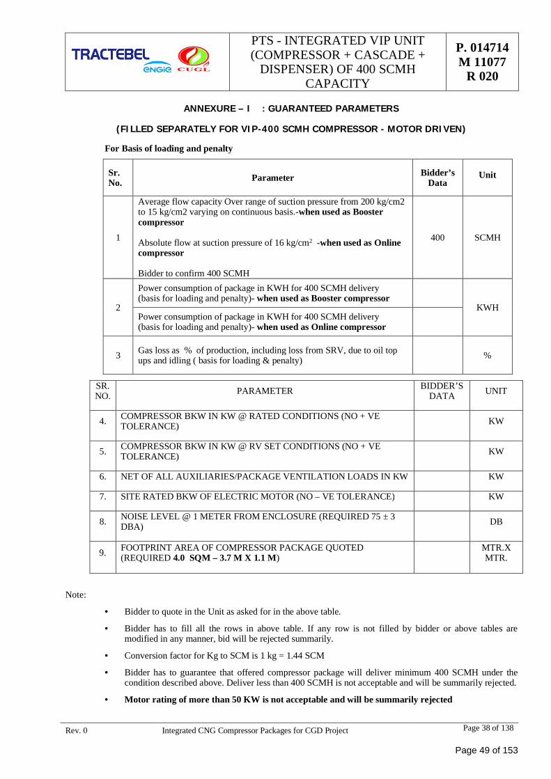
PTS - INTEGRATED VIP UNIT(COMPRESSOR + CASCADE +
DISPENSER) OF 400 SCMHCAPACITY
P. 014714M 11077
R 020
Rev. 0 Integrated CNG Compressor Packages for CGD Project Page 38 of 138
ANNEXURE – I : GUARANTEED PARAMETERS
(FILLED SEPARATELY FOR VIP-400 SCMH COMPRESSOR - MOTOR DRIVEN)
For Basis of loading and penalty
Sr.No. Parameter Bidder’s
DataUnit
1
Average flow capacity Over range of suction pressure from 200 kg/cm2to 15 kg/cm2 varying on continuous basis.-when used as Boostercompressor
Absolute flow at suction pressure of 16 kg/cm2 -when used as Onlinecompressor
Bidder to confirm 400 SCMH
400 SCMH
2
Power consumption of package in KWH for 400 SCMH delivery(basis for loading and penalty)- when used as Booster compressor
KWHPower consumption of package in KWH for 400 SCMH delivery(basis for loading and penalty)- when used as Online compressor
3 Gas loss as % of production, including loss from SRV, due to oil topups and idling ( basis for loading & penalty) %
Note:
· Bidder to quote in the Unit as asked for in the above table.
· Bidder has to fill all the rows in above table. If any row is not filled by bidder or above tables aremodified in any manner, bid will be rejected summarily.
· Conversion factor for Kg to SCM is 1 kg = 1.44 SCM
· Bidder has to guarantee that offered compressor package will deliver minimum 400 SCMH under thecondition described above. Deliver less than 400 SCMH is not acceptable and will be summarily rejected.
· Motor rating of more than 50 KW is not acceptable and will be summarily rejected
SR.NO. PARAMETER BIDDER’S
DATA UNIT
4. COMPRESSOR BKW IN KW @ RATED CONDITIONS (NO + VETOLERANCE) KW
5. COMPRESSOR BKW IN KW @ RV SET CONDITIONS (NO + VETOLERANCE) KW
6. NET OF ALL AUXILIARIES/PACKAGE VENTILATION LOADS IN KW KW
7. SITE RATED BKW OF ELECTRIC MOTOR (NO – VE TOLERANCE) KW
8. NOISE LEVEL @ 1 METER FROM ENCLOSURE (REQUIRED 75 ± 3DBA) DB
9. FOOTPRINT AREA OF COMPRESSOR PACKAGE QUOTED(REQUIRED 4.0 SQM – 3.7 M X 1.1 M)
MTR.XMTR.
Page 49 of 153
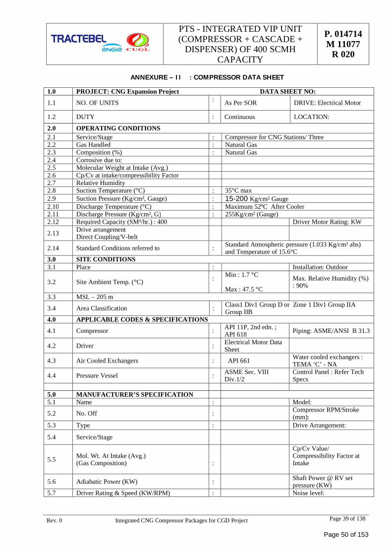
PTS - INTEGRATED VIP UNIT(COMPRESSOR + CASCADE +
DISPENSER) OF 400 SCMHCAPACITY
P. 014714M 11077
R 020
Rev. 0 Integrated CNG Compressor Packages for CGD Project Page 39 of 138
ANNEXURE – II : COMPRESSOR DATA SHEET
1.0 PROJECT: CNG Expansion Project DATA SHEET NO:
1.1 NO. OF UNITS : As Per SOR DRIVE: Electrical Motor
1.2 DUTY : Continuous LOCATION:
2.0 OPERATING CONDITIONS2.1 Service/Stage : Compressor for CNG Stations/ Three2.2 Gas Handled : Natural Gas2.3 Composition (%) : Natural Gas2.4 Corrosive due to:2.5 Molecular Weight at Intake (Avg.)2.6 Cp/Cv at intake/compressibility Factor2.7 Relative Humidity2.8 Suction Temperature (°C) : 35°C max2.9 Suction Pressure (Kg/cm², Gauge) : 15-200 Kg/cm² Gauge2.10 Discharge Temperature (°C) : Maximum 520C After Cooler2.11 Discharge Pressure (Kg/cm², G) : 255Kg/cm² (Gauge)2.12 Required Capacity (SM³/hr.) : 400 Driver Motor Rating: KW
2.13 Drive arrangementDirect Coupling/V-belt
2.14 Standard Conditions referred to : Standard Atmospheric pressure (1.033 Kg/cm² abs)and Temperature of 15.6°C
3.0 SITE CONDITIONS3.1 Place : Installation: Outdoor
3.2 Site Ambient Temp. (°C) : Min : 1.7 °C
Max : 47.5 °CMax. Relative Humidity (%): 90%
3.3 MSL – 205 m
3.4 Area Classification : Class1 Div1 Group D or Zone 1 Div1 Group IIAGroup IIB
4.0 APPLICABLE CODES & SPECIFICATIONS
4.1 Compressor : API 11P, 2nd edn. ;API 618 Piping: ASME/ANSI B 31.3
4.2 Driver : Electrical Motor DataSheet
4.3 Air Cooled Exchangers : API 661 Water cooled exchangers :TEMA ‘C’ - NA
4.4 Pressure Vessel : ASME Sec. VIIIDiv.1/2
Control Panel : Refer TechSpecs
5.0 MANUFACTURER’S SPECIFICATION5.1 Name : Model:
5.2 No. Off : Compressor RPM/Stroke(mm):
5.3 Type : Drive Arrangement:
5.4 Service/Stage
5.5 Mol. Wt. At Intake (Avg.)(Gas Composition) :
Cp/Cv Value/Compressibility Factor atIntake
5.6 Adiabatic Power (KW) : Shaft Power @ RV setpressure (KW)
5.7 Driver Rating & Speed (KW/RPM) : Noise level:
Page 50 of 153
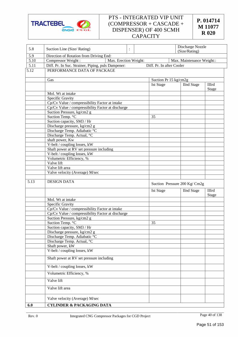
PTS - INTEGRATED VIP UNIT(COMPRESSOR + CASCADE +
DISPENSER) OF 400 SCMHCAPACITY
P. 014714M 11077
R 020
Rev. 0 Integrated CNG Compressor Packages for CGD Project Page 40 of 138
5.8 Suction Line (Size/ Rating) : Discharge Nozzle(Size/Rating)
5.9 Direction of Rotation from Driving End:5.10 Compressor Weight : Max. Erection Weight: Max. Maintenance Weight::5.11 Diff. Pr. In Suc. Strainer, Piping, puls Dampener: Diff. Pr. In after Cooler
5.12 PERFORMANCE DATA OF PACKAGE
Gas Suction Pr 15 kg/cm2gIst Stage IInd Stage IIIrd
StageMol. Wt at intakeSpecific GravityCp/Cv Value / compressibility Factor at intakeCp/Cv Value / compressibility Factor at dischargeSuction Pressure, kg/cm2 gSuction Temp. °C 35Suction capacity, SM3 / HrDischarge pressure, kg/cm2 gDischarge Temp. Adiabatic °CDischarge Temp. Actual, °Cshaft power, KwV-belt / coupling losses, kWShaft power at RV set pressure includingV-belt / coupling losses, kWVolumetric Efficiency, %Valve liftValve lift areaValve velocity (Average) M/sec
5.13 DESIGN DATA Suction Pressure 200 Kg/ Cm2g
Ist Stage IInd Stage IIIrdStage
Mol. Wt at intakeSpecific GravityCp/Cv Value / compressibility Factor at intakeCp/Cv Value / compressibility Factor at dischargeSuction Pressure, kg/cm2 gSuction Temp. °C 35Suction capacity, SM3 / HrDischarge pressure, kg/cm2 gDischarge Temp. Adiabatic °CDischarge Temp. Actual, °CShaft power, kWV-belt / coupling losses, kW
Shaft power at RV set pressure including
V-belt / coupling losses, kW
Volumetric Efficiency, %
Valve lift
Valve lift area
Valve velocity (Average) M/sec6.0 CYLINDER & PACKAGING DATA
Page 51 of 153
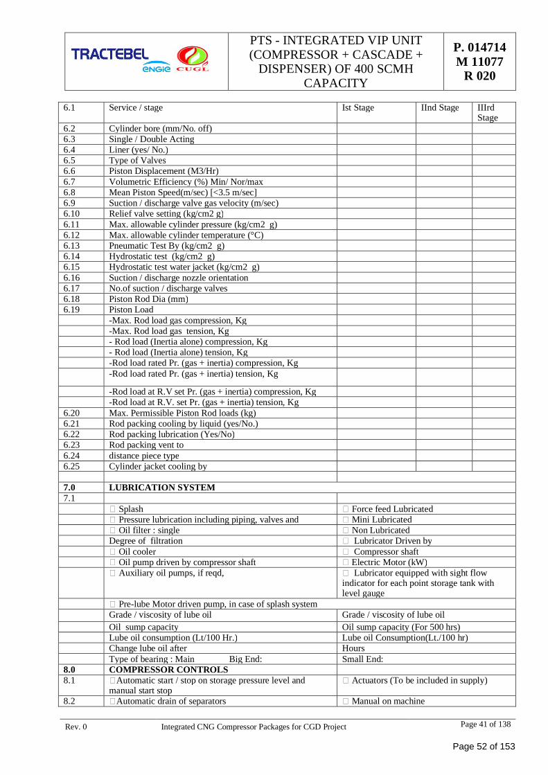
PTS - INTEGRATED VIP UNIT(COMPRESSOR + CASCADE +
DISPENSER) OF 400 SCMHCAPACITY
P. 014714M 11077
R 020
Rev. 0 Integrated CNG Compressor Packages for CGD Project Page 41 of 138
6.1 Service / stage Ist Stage IInd Stage IIIrdStage
6.2 Cylinder bore (mm/No. off)6.3 Single / Double Acting6.4 Liner (yes/ No.)6.5 Type of Valves6.6 Piston Displacement (M3/Hr)6.7 Volumetric Efficiency (%) Min/ Nor/max6.8 Mean Piston Speed(m/sec) [<3.5 m/sec]6.9 Suction / discharge valve gas velocity (m/sec)6.10 Relief valve setting (kg/cm2 g)6.11 Max. allowable cylinder pressure (kg/cm2 g)6.12 Max. allowable cylinder temperature (°C)6.13 Pneumatic Test By (kg/cm2 g)6.14 Hydrostatic test (kg/cm2 g)6.15 Hydrostatic test water jacket (kg/cm2 g)6.16 Suction / discharge nozzle orientation6.17 No.of suction / discharge valves6.18 Piston Rod Dia (mm)6.19 Piston Load
-Max. Rod load gas compression, Kg-Max. Rod load gas tension, Kg- Rod load (Inertia alone) compression, Kg- Rod load (Inertia alone) tension, Kg-Rod load rated Pr. (gas + inertia) compression, Kg-Rod load rated Pr. (gas + inertia) tension, Kg
-Rod load at R.V set Pr. (gas + inertia) compression, Kg-Rod load at R.V. set Pr. (gas + inertia) tension, Kg
6.20 Max. Permissible Piston Rod loads (kg)6.21 Rod packing cooling by liquid (yes/No.)6.22 Rod packing lubrication (Yes/No)6.23 Rod packing vent to6.24 distance piece type6.25 Cylinder jacket cooling by
7.0 LUBRICATION SYSTEM7.1
Splash Force feed LubricatedPressure lubrication including piping, valves and Mini LubricatedOil filter : single Non Lubricated
Degree of filtration Lubricator Driven byOil cooler Compressor shaftOil pump driven by compressor shaft Electric Motor (kW)Auxiliary oil pumps, if reqd, Lubricator equipped with sight flow
indicator for each point storage tank withlevel gauge
Pre-lube Motor driven pump, in case of splash systemGrade / viscosity of lube oil Grade / viscosity of lube oilOil sump capacity Oil sump capacity (For 500 hrs)Lube oil consumption (Lt/100 Hr.) Lube oil Consumption(Lt./100 hr)Change lube oil after HoursType of bearing : Main Big End: Small End:
8.0 COMPRESSOR CONTROLS8.1 Automatic start / stop on storage pressure level and
manual start stopActuators (To be included in supply)
8.2 Automatic drain of separators Manual on machine
Page 52 of 153
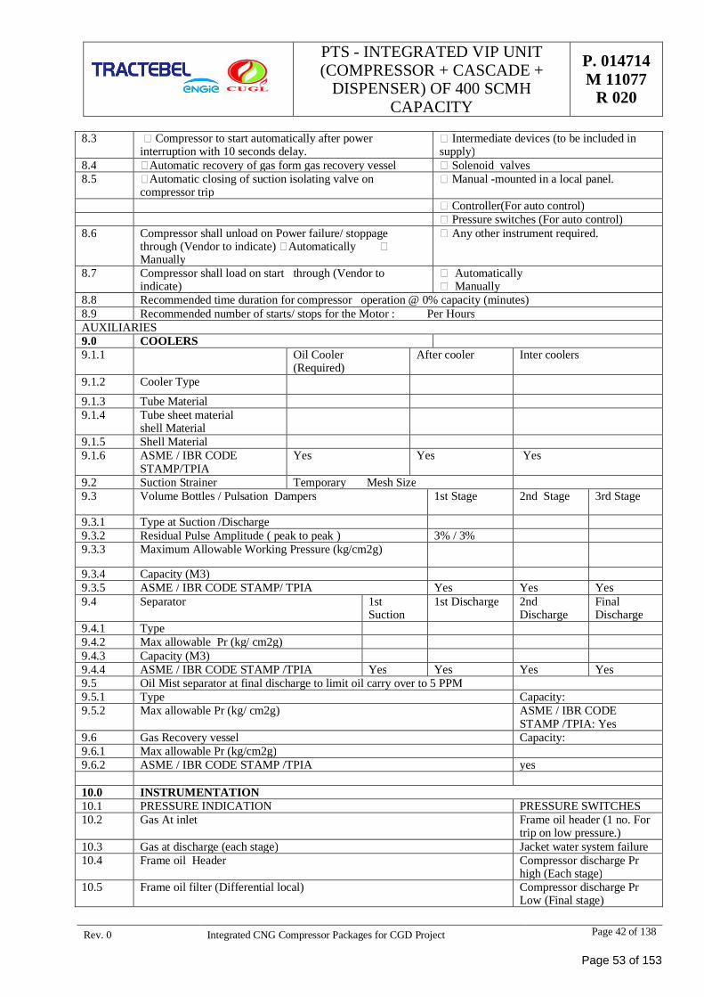
PTS - INTEGRATED VIP UNIT(COMPRESSOR + CASCADE +
DISPENSER) OF 400 SCMHCAPACITY
P. 014714M 11077
R 020
Rev. 0 Integrated CNG Compressor Packages for CGD Project Page 42 of 138
8.3 Compressor to start automatically after powerinterruption with 10 seconds delay.
Intermediate devices (to be included insupply)
8.4 Automatic recovery of gas form gas recovery vessel Solenoid valves8.5 Automatic closing of suction isolating valve on
compressor tripManual -mounted in a local panel.
Controller(For auto control)Pressure switches (For auto control)
8.6 Compressor shall unload on Power failure/ stoppagethrough (Vendor to indicate) AutomaticallyManually
Any other instrument required.
8.7 Compressor shall load on start through (Vendor toindicate)
AutomaticallyManually
8.8 Recommended time duration for compressor operation @ 0% capacity (minutes)8.9 Recommended number of starts/ stops for the Motor : Per HoursAUXILIARIES9.0 COOLERS9.1.1 Oil Cooler
(Required)After cooler Inter coolers
9.1.2 Cooler Type9.1.3 Tube Material9.1.4 Tube sheet material
shell Material9.1.5 Shell Material9.1.6 ASME / IBR CODE
STAMP/TPIAYes Yes Yes
9.2 Suction Strainer Temporary Mesh Size9.3 Volume Bottles / Pulsation Dampers 1st Stage 2nd Stage 3rd Stage
9.3.1 Type at Suction /Discharge9.3.2 Residual Pulse Amplitude ( peak to peak ) 3% / 3%9.3.3 Maximum Allowable Working Pressure (kg/cm2g)
9.3.4 Capacity (M3)9.3.5 ASME / IBR CODE STAMP/ TPIA Yes Yes Yes9.4 Separator 1st
Suction1st Discharge 2nd
DischargeFinalDischarge
9.4.1 Type9.4.2 Max allowable Pr (kg/ cm2g)9.4.3 Capacity (M3)9.4.4 ASME / IBR CODE STAMP /TPIA Yes Yes Yes Yes9.5 Oil Mist separator at final discharge to limit oil carry over to 5 PPM9.5.1 Type Capacity:9.5.2 Max allowable Pr (kg/ cm2g) ASME / IBR CODE
STAMP /TPIA: Yes9.6 Gas Recovery vessel Capacity:9.6.1 Max allowable Pr (kg/cm2g)9.6.2 ASME / IBR CODE STAMP /TPIA yes
10.0 INSTRUMENTATION10.1 PRESSURE INDICATION PRESSURE SWITCHES10.2 Gas At inlet Frame oil header (1 no. For
trip on low pressure.)10.3 Gas at discharge (each stage) Jacket water system failure10.4 Frame oil Header Compressor discharge Pr
high (Each stage)10.5 Frame oil filter (Differential local) Compressor discharge Pr
Low (Final stage)
Page 53 of 153
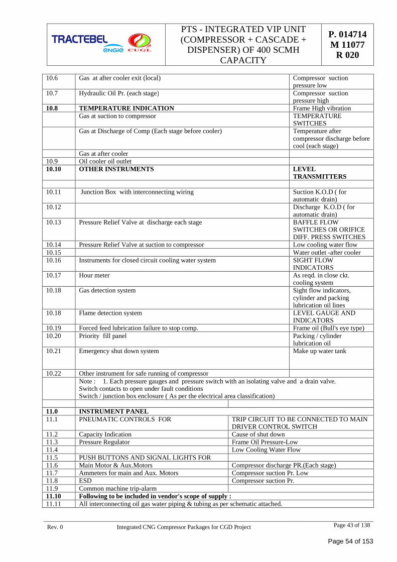
PTS - INTEGRATED VIP UNIT(COMPRESSOR + CASCADE +
DISPENSER) OF 400 SCMHCAPACITY
P. 014714M 11077
R 020
Rev. 0 Integrated CNG Compressor Packages for CGD Project Page 43 of 138
10.6 Gas at after cooler exit (local) Compressor suctionpressure low
10.7 Hydraulic Oil Pr. (each stage) Compressor suctionpressure high
10.8 TEMPERATURE INDICATION Frame High vibrationGas at suction to compressor TEMPERATURE
SWITCHESGas at Discharge of Comp (Each stage before cooler) Temperature after
compressor discharge beforecool (each stage)
Gas at after cooler10.9 Oil cooler oil outlet10.10 OTHER INSTRUMENTS LEVEL
TRANSMITTERS
10.11 Junction Box with interconnecting wiring Suction K.O.D ( forautomatic drain)
10.12 Discharge K.O.D ( forautomatic drain)
10.13 Pressure Relief Valve at discharge each stage BAFFLE FLOWSWITCHES OR ORIFICEDIFF. PRESS SWITCHES
10.14 Pressure Relief Valve at suction to compressor Low cooling water flow10.15 Water outlet -after cooler10.16 Instruments for closed circuit cooling water system SIGHT FLOW
INDICATORS10.17 Hour meter As reqd. in close ckt.
cooling system10.18 Gas detection system Sight flow indicators,
cylinder and packinglubrication oil lines
10.18 Flame detection system LEVEL GAUGE ANDINDICATORS
10.19 Forced feed lubrication failure to stop comp. Frame oil (Bull's eye type)10.20 Priority fill panel Packing / cylinder
lubrication oil10.21 Emergency shut down system Make up water tank
10.22 Other instrument for safe running of compressorNote : 1. Each pressure gauges and pressure switch with an isolating valve and a drain valve.Switch contacts to open under fault conditionsSwitch / junction box enclosure ( As per the electrical area classification)
11.0 INSTRUMENT PANEL11.1 PNEUMATIC CONTROLS FOR TRIP CIRCUIT TO BE CONNECTED TO MAIN
DRIVER CONTROL SWITCH11.2 Capacity Indication Cause of shut down11.3 Pressure Regulator Frame Oil Pressure-Low11.4 Low Cooling Water Flow11.5 PUSH BUTTONS AND SIGNAL LIGHTS FOR11.6 Main Motor & Aux.Motors Compressor discharge PR.(Each stage)11.7 Ammeters for main and Aux. Motors Compressor suction Pr. Low11.8 ESD Compressor suction Pr.11.9 Common machine trip-alarm11.10 Following to be included in vendor's scope of supply :11.11 All interconnecting oil gas water piping & tubing as per schematic attached.
Page 54 of 153
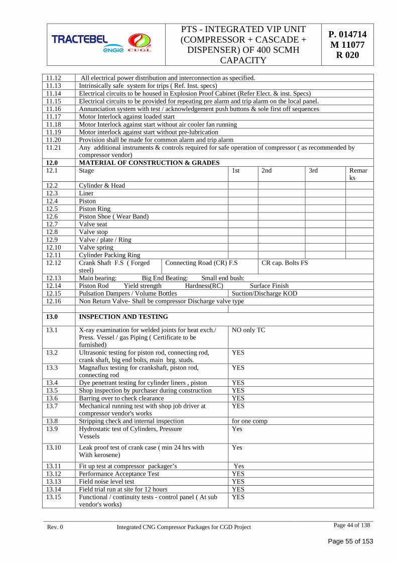
PTS - INTEGRATED VIP UNIT(COMPRESSOR + CASCADE +
DISPENSER) OF 400 SCMHCAPACITY
P. 014714M 11077
R 020
Rev. 0 Integrated CNG Compressor Packages for CGD Project Page 44 of 138
11.12 All electrical power distribution and interconnection as specified.11.13 Intrinsically safe system for trips ( Ref. Inst. specs)11.14 Electrical circuits to be housed in Explosion Proof Cabinet (Refer Elect. & inst. Specs)11.15 Electrical circuits to be provided for repeating pre alarm and trip alarm on the local panel.11.16 Annunciation system with test / acknowledgement push buttons & sole first off sequences11.17 Motor Interlock against loaded start11.18 Motor Interlock against start without air cooler fan running11.19 Motor interlock against start without pre-lubrication11.20 Provision shall be made for common alarm and trip alarm11.21 Any additional instruments & controls required for safe operation of compressor ( as recommended by
compressor vendor)12.0 MATERIAL OF CONSTRUCTION & GRADES12.1 Stage 1st 2nd 3rd Remar
ks12.2 Cylinder & Head12.3 Liner12.4 Piston12.5 Piston Ring12.6 Piston Shoe ( Wear Band)12.7 Valve seat12.8 Valve stop12.9 Valve / plate / Ring12.10 Valve spring12.11 Cylinder Packing Ring12.12 Crank Shaft F.S ( Forged
steel)Connecting Road (CR) F.S CR cap. Bolts FS
12.13 Main bearing: Big End Beating: Small end bush:12.14 Piston Rod Yield strength Hardness(RC) Surface Finish12.15 Pulsation Dampers / Volume Bottles Suction/Discharge KOD12.16 Non Return Valve- Shall be compressor Discharge valve type
13.0 INSPECTION AND TESTING
13.1 X-ray examination for welded joints for heat exch./Press. Vessel / gas Piping ( Certificate to befurnished)
NO only TC
13.2 Ultrasonic testing for piston rod, connecting rod,crank shaft, big end bolts, main brg. studs.
YES
13.3 Magnaflux testing for crankshaft, piston rod,connecting rod
YES
13.4 Dye penetrant testing for cylinder liners , piston YES13.5 Shop inspection by purchaser during construction YES13.6 Barring over to check clearance YES13.7 Mechanical running test with shop job driver at
compressor vendor's worksYES
13.8 Stripping check and internal inspection for one comp13.9 Hydrostatic test of Cylinders, Pressure
VesselsYes
13.10 Leak proof test of crank case ( min 24 hrs withWith kerosene)
Yes
13.11 Fit up test at compressor packager’s Yes13.12 Performance Acceptance Test YES13.13 Field noise level test YES13.14 Field trial run at site for 12 hours YES13.15 Functional / continuity tests - control panel ( At sub
vendor's works)YES
Page 55 of 153
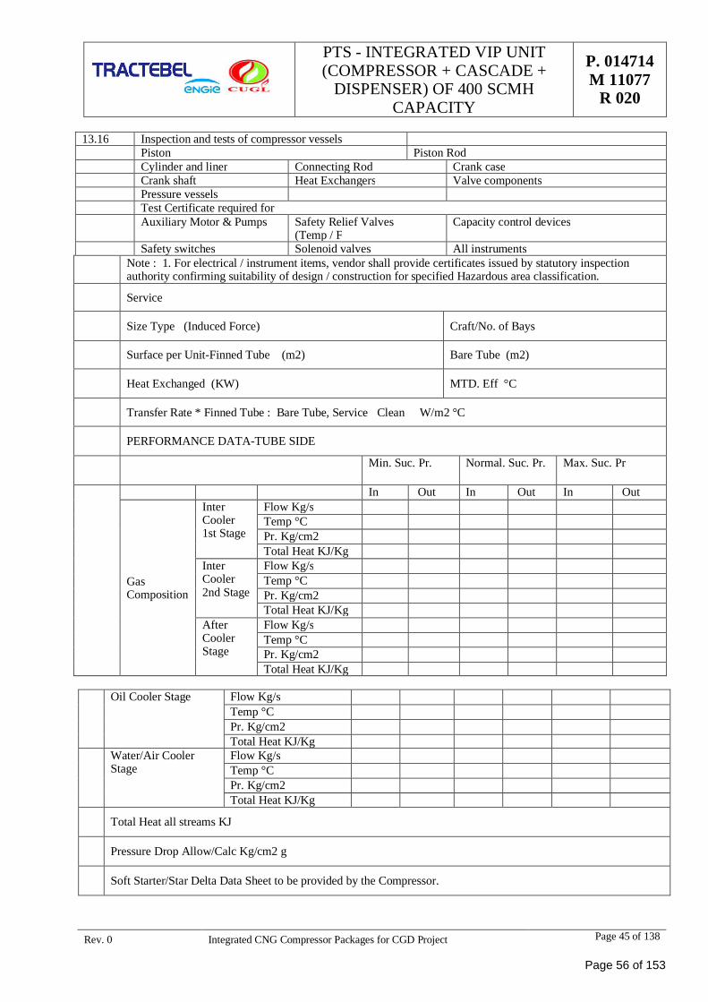
PTS - INTEGRATED VIP UNIT(COMPRESSOR + CASCADE +
DISPENSER) OF 400 SCMHCAPACITY
P. 014714M 11077
R 020
Rev. 0 Integrated CNG Compressor Packages for CGD Project Page 45 of 138
13.16 Inspection and tests of compressor vesselsPiston Piston RodCylinder and liner Connecting Rod Crank caseCrank shaft Heat Exchangers Valve componentsPressure vesselsTest Certificate required forAuxiliary Motor & Pumps Safety Relief Valves
(Temp / FCapacity control devices
Safety switches Solenoid valves All instrumentsNote : 1. For electrical / instrument items, vendor shall provide certificates issued by statutory inspectionauthority confirming suitability of design / construction for specified Hazardous area classification.
Service
Size Type (Induced Force) Craft/No. of Bays
Surface per Unit-Finned Tube (m2) Bare Tube (m2)
Heat Exchanged (KW) MTD. Eff °C
Transfer Rate * Finned Tube : Bare Tube, Service Clean W/m2 °C
PERFORMANCE DATA-TUBE SIDE
Min. Suc. Pr. Normal. Suc. Pr. Max. Suc. Pr
In Out In Out In Out
GasComposition
InterCooler1st Stage
Flow Kg/sTemp °CPr. Kg/cm2Total Heat KJ/Kg
InterCooler2nd Stage
Flow Kg/sTemp °CPr. Kg/cm2Total Heat KJ/Kg
AfterCoolerStage
Flow Kg/sTemp °CPr. Kg/cm2Total Heat KJ/Kg
Oil Cooler Stage Flow Kg/sTemp °CPr. Kg/cm2Total Heat KJ/Kg
Water/Air CoolerStage
Flow Kg/sTemp °CPr. Kg/cm2Total Heat KJ/Kg
Total Heat all streams KJ
Pressure Drop Allow/Calc Kg/cm2 g
Soft Starter/Star Delta Data Sheet to be provided by the Compressor.
Page 56 of 153
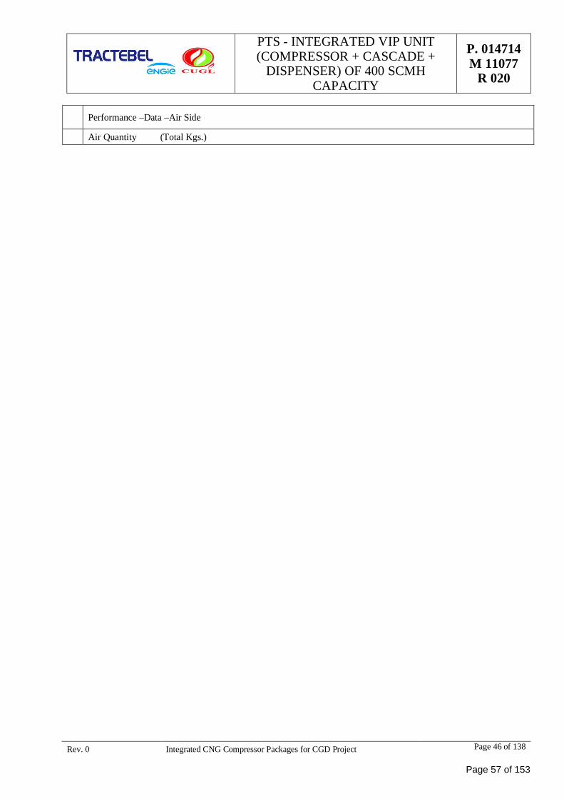
PTS - INTEGRATED VIP UNIT(COMPRESSOR + CASCADE +
DISPENSER) OF 400 SCMHCAPACITY
P. 014714M 11077
R 020
Rev. 0 Integrated CNG Compressor Packages for CGD Project Page 46 of 138
Performance –Data –Air Side
Air Quantity (Total Kgs.)
Page 57 of 153
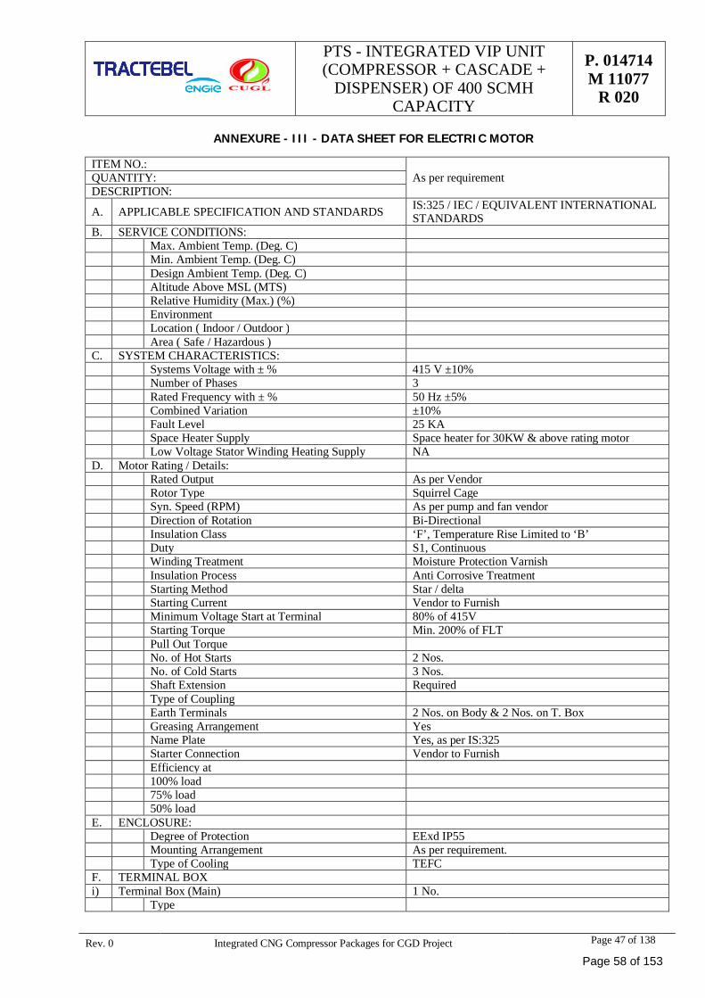
PTS - INTEGRATED VIP UNIT(COMPRESSOR + CASCADE +
DISPENSER) OF 400 SCMHCAPACITY
P. 014714M 11077
R 020
Rev. 0 Integrated CNG Compressor Packages for CGD Project Page 47 of 138
ANNEXURE - III - DATA SHEET FOR ELECTRIC MOTOR
ITEM NO.:As per requirementQUANTITY:
DESCRIPTION:
A. APPLICABLE SPECIFICATION AND STANDARDS IS:325 / IEC / EQUIVALENT INTERNATIONALSTANDARDS
B. SERVICE CONDITIONS:Max. Ambient Temp. (Deg. C)Min. Ambient Temp. (Deg. C)Design Ambient Temp. (Deg. C)Altitude Above MSL (MTS)Relative Humidity (Max.) (%)EnvironmentLocation ( Indoor / Outdoor )Area ( Safe / Hazardous )
C. SYSTEM CHARACTERISTICS:Systems Voltage with ± % 415 V ±10%Number of Phases 3Rated Frequency with ± % 50 Hz ±5%Combined Variation ±10%Fault Level 25 KASpace Heater Supply Space heater for 30KW & above rating motorLow Voltage Stator Winding Heating Supply NA
D. Motor Rating / Details:Rated Output As per VendorRotor Type Squirrel CageSyn. Speed (RPM) As per pump and fan vendorDirection of Rotation Bi-DirectionalInsulation Class ‘F’, Temperature Rise Limited to ‘B’Duty S1, ContinuousWinding Treatment Moisture Protection VarnishInsulation Process Anti Corrosive TreatmentStarting Method Star / deltaStarting Current Vendor to FurnishMinimum Voltage Start at Terminal 80% of 415VStarting Torque Min. 200% of FLTPull Out TorqueNo. of Hot Starts 2 Nos.No. of Cold Starts 3 Nos.Shaft Extension RequiredType of CouplingEarth Terminals 2 Nos. on Body & 2 Nos. on T. BoxGreasing Arrangement YesName Plate Yes, as per IS:325Starter Connection Vendor to FurnishEfficiency at100% load75% load50% load
E. ENCLOSURE:Degree of Protection EExd IP55Mounting Arrangement As per requirement.Type of Cooling TEFC
F. TERMINAL BOXi) Terminal Box (Main) 1 No.
Type
Page 58 of 153
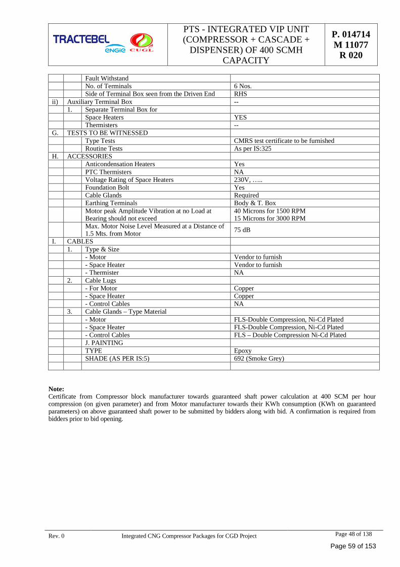
PTS - INTEGRATED VIP UNIT(COMPRESSOR + CASCADE +
DISPENSER) OF 400 SCMHCAPACITY
P. 014714M 11077
R 020
Rev. 0 Integrated CNG Compressor Packages for CGD Project Page 48 of 138
Fault WithstandNo. of Terminals 6 Nos.Side of Terminal Box seen from the Driven End RHS
ii) Auxiliary Terminal Box --1. Separate Terminal Box for
Space Heaters YESThermisters --
G. TESTS TO BE WITNESSEDType Tests CMRS test certificate to be furnishedRoutine Tests As per IS:325
H. ACCESSORIESAnticondensation Heaters YesPTC Thermisters NAVoltage Rating of Space Heaters 230V, …..Foundation Bolt YesCable Glands RequiredEarthing Terminals Body & T. BoxMotor peak Amplitude Vibration at no Load atBearing should not exceed
40 Microns for 1500 RPM15 Microns for 3000 RPM
Max. Motor Noise Level Measured at a Distance of1.5 Mts. from Motor 75 dB
I. CABLES1. Type & Size
- Motor Vendor to furnish- Space Heater Vendor to furnish- Thermister NA
2. Cable Lugs- For Motor Copper- Space Heater Copper- Control Cables NA
3. Cable Glands – Type Material- Motor FLS-Double Compression, Ni-Cd Plated- Space Heater FLS-Double Compression, Ni-Cd Plated- Control Cables FLS – Double Compression Ni-Cd PlatedJ. PAINTINGTYPE EpoxySHADE (AS PER IS:5) 692 (Smoke Grey)
Note:Certificate from Compressor block manufacturer towards guaranteed shaft power calculation at 400 SCM per hourcompression (on given parameter) and from Motor manufacturer towards their KWh consumption (KWh on guaranteedparameters) on above guaranteed shaft power to be submitted by bidders along with bid. A confirmation is required frombidders prior to bid opening.
Page 59 of 153
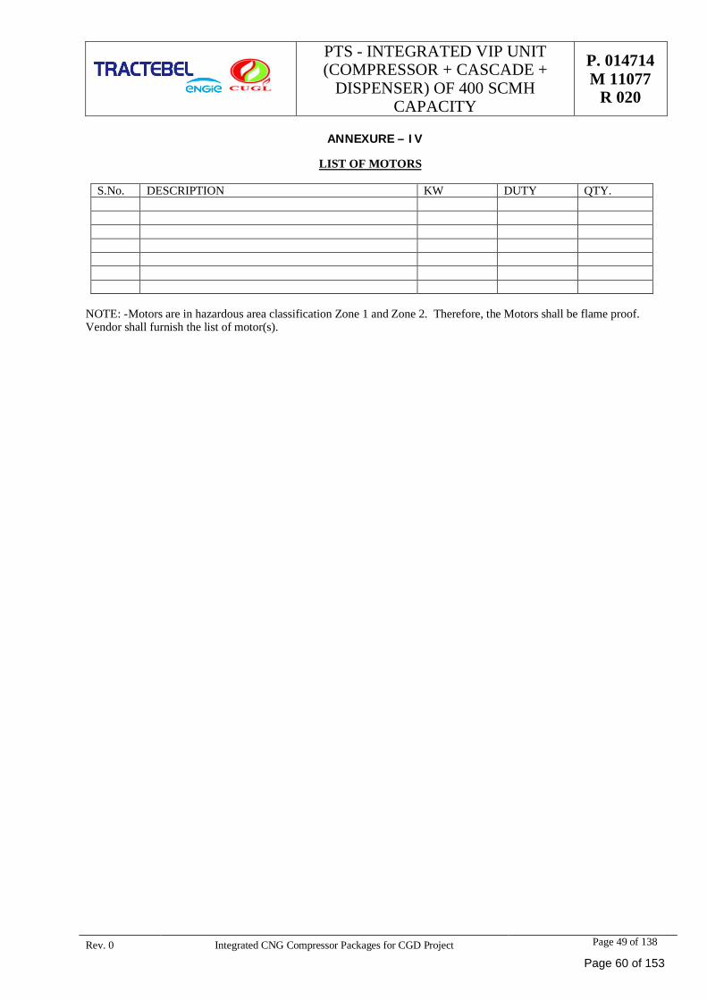
PTS - INTEGRATED VIP UNIT(COMPRESSOR + CASCADE +
DISPENSER) OF 400 SCMHCAPACITY
P. 014714M 11077
R 020
Rev. 0 Integrated CNG Compressor Packages for CGD Project Page 49 of 138
ANNEXURE – IV
LIST OF MOTORS
S.No. DESCRIPTION KW DUTY QTY.
NOTE: - Motors are in hazardous area classification Zone 1 and Zone 2. Therefore, the Motors shall be flame proof.Vendor shall furnish the list of motor(s).
Page 60 of 153
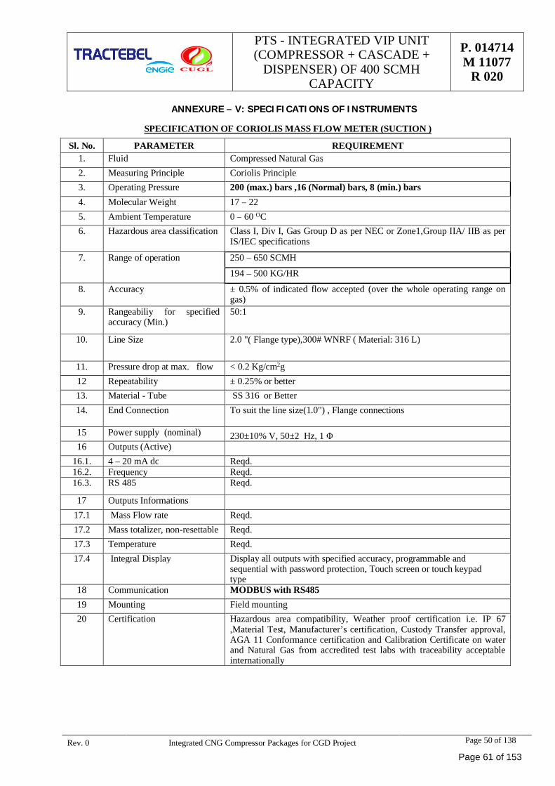
PTS - INTEGRATED VIP UNIT(COMPRESSOR + CASCADE +
DISPENSER) OF 400 SCMHCAPACITY
P. 014714M 11077
R 020
Rev. 0 Integrated CNG Compressor Packages for CGD Project Page 50 of 138
ANNEXURE – V: SPECIFICATIONS OF INSTRUMENTS
SPECIFICATION OF CORIOLIS MASS FLOW METER (SUCTION )
Sl. No. PARAMETER REQUIREMENT1. Fluid Compressed Natural Gas2. Measuring Principle Coriolis Principle3. Operating Pressure 200 (max.) bars ,16 (Normal) bars, 8 (min.) bars4. Molecular Weight 17 – 225. Ambient Temperature 0 – 60 OC6. Hazardous area classification Class I, Div I, Gas Group D as per NEC or Zone1,Group IIA/ IIB as per
IS/IEC specifications
7. Range of operation 250 – 650 SCMH
194 – 500 KG/HR
8. Accuracy ± 0.5% of indicated flow accepted (over the whole operating range ongas)
9. Rangeabiliy for specifiedaccuracy (Min.)
50:1
10. Line Size 2.0 "( Flange type),300# WNRF ( Material: 316 L)
11. Pressure drop at max. flow < 0.2 Kg/cm2g12 Repeatability ± 0.25% or better13. Material - Tube SS 316 or Better14. End Connection To suit the line size(1.0") , Flange connections
15 Power supply (nominal) 230±10% V, 50±2 Hz, 1 Φ16 Outputs (Active)
16.1. 4 – 20 mA dc Reqd.16.2. Frequency Reqd.16.3. RS 485 Reqd.
17 Outputs Informations17.1 Mass Flow rate Reqd.17.2 Mass totalizer, non-resettable Reqd.17.3 Temperature Reqd.17.4 Integral Display Display all outputs with specified accuracy, programmable and
sequential with password protection, Touch screen or touch keypadtype
18 Communication MODBUS with RS48519 Mounting Field mounting20 Certification Hazardous area compatibility, Weather proof certification i.e. IP 67
,Material Test, Manufacturer’s certification, Custody Transfer approval,AGA 11 Conformance certification and Calibration Certificate on waterand Natural Gas from accredited test labs with traceability acceptableinternationally
Page 61 of 153
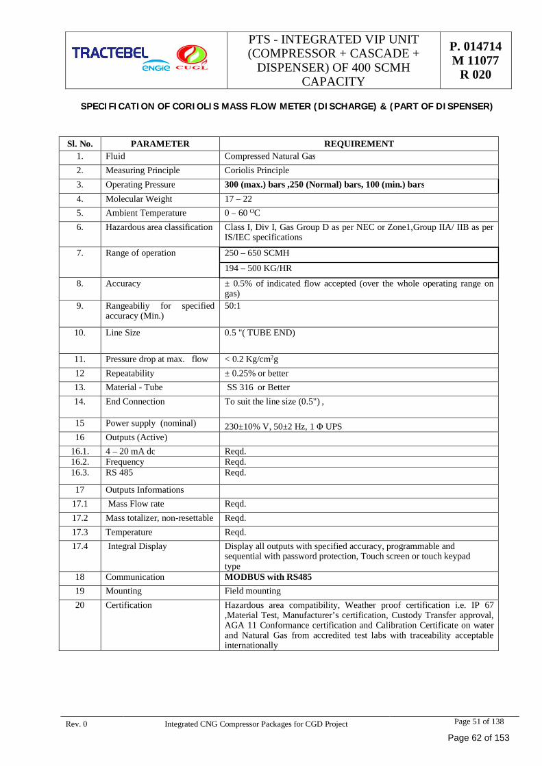
PTS - INTEGRATED VIP UNIT(COMPRESSOR + CASCADE +
DISPENSER) OF 400 SCMHCAPACITY
P. 014714M 11077
R 020
Rev. 0 Integrated CNG Compressor Packages for CGD Project Page 51 of 138
SPECIFICATION OF CORIOLIS MASS FLOW METER (DISCHARGE) & (PART OF DISPENSER)
Sl. No. PARAMETER REQUIREMENT1. Fluid Compressed Natural Gas2. Measuring Principle Coriolis Principle3. Operating Pressure 300 (max.) bars ,250 (Normal) bars, 100 (min.) bars4. Molecular Weight 17 – 225. Ambient Temperature 0 – 60 OC6. Hazardous area classification Class I, Div I, Gas Group D as per NEC or Zone1,Group IIA/ IIB as per
IS/IEC specifications
7. Range of operation 250 – 650 SCMH
194 – 500 KG/HR
8. Accuracy ± 0.5% of indicated flow accepted (over the whole operating range ongas)
9. Rangeabiliy for specifiedaccuracy (Min.)
50:1
10. Line Size 0.5 "( TUBE END)
11. Pressure drop at max. flow < 0.2 Kg/cm2g12 Repeatability ± 0.25% or better13. Material - Tube SS 316 or Better14. End Connection To suit the line size (0.5") ,
15 Power supply (nominal) 230±10% V, 50±2 Hz, 1 Φ UPS16 Outputs (Active)
16.1. 4 – 20 mA dc Reqd.16.2. Frequency Reqd.16.3. RS 485 Reqd.
17 Outputs Informations17.1 Mass Flow rate Reqd.17.2 Mass totalizer, non-resettable Reqd.17.3 Temperature Reqd.17.4 Integral Display Display all outputs with specified accuracy, programmable and
sequential with password protection, Touch screen or touch keypadtype
18 Communication MODBUS with RS48519 Mounting Field mounting20 Certification Hazardous area compatibility, Weather proof certification i.e. IP 67
,Material Test, Manufacturer’s certification, Custody Transfer approval,AGA 11 Conformance certification and Calibration Certificate on waterand Natural Gas from accredited test labs with traceability acceptableinternationally
Page 62 of 153
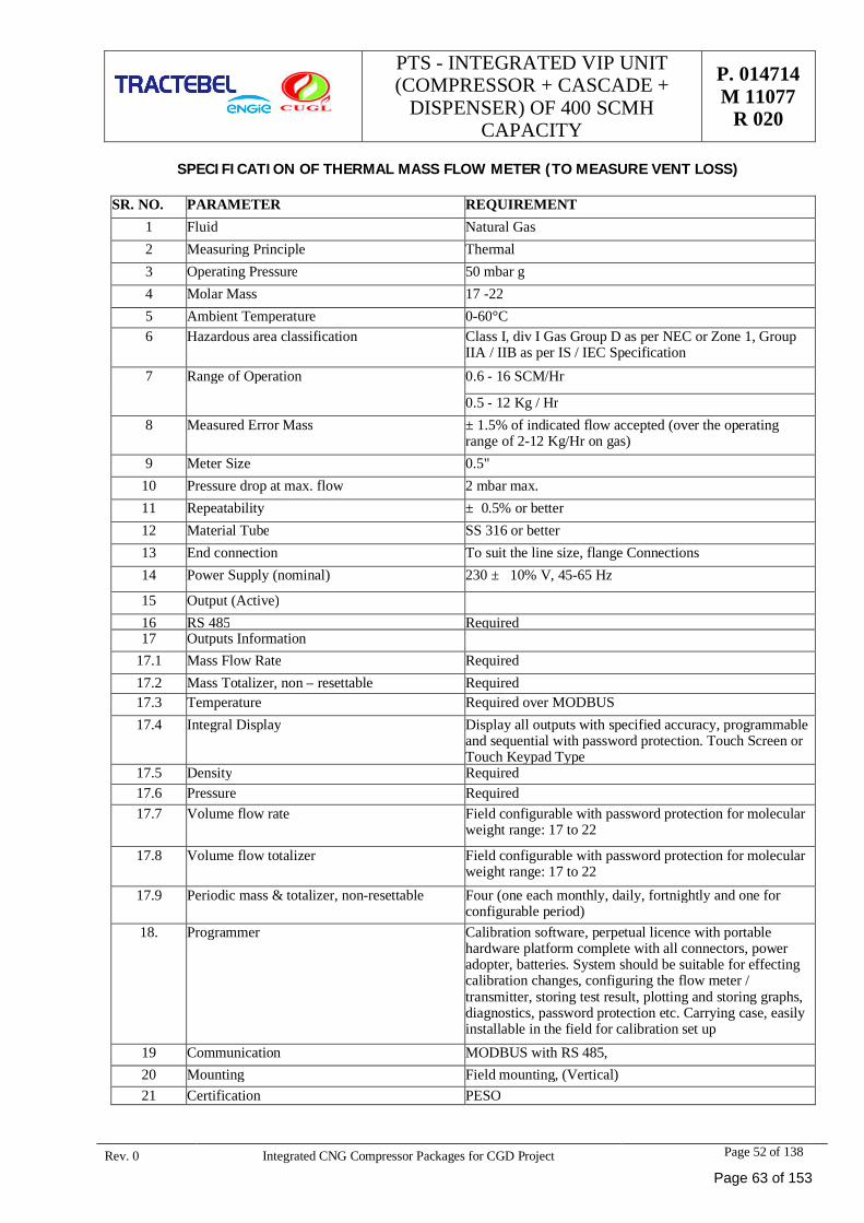
PTS - INTEGRATED VIP UNIT(COMPRESSOR + CASCADE +
DISPENSER) OF 400 SCMHCAPACITY
P. 014714M 11077
R 020
Rev. 0 Integrated CNG Compressor Packages for CGD Project Page 52 of 138
SPECIFICATION OF THERMAL MASS FLOW METER (TO MEASURE VENT LOSS)
SR. NO. PARAMETER REQUIREMENT1 Fluid Natural Gas2 Measuring Principle Thermal3 Operating Pressure 50 mbar g4 Molar Mass 17 -225 Ambient Temperature 0-60°C6 Hazardous area classification Class I, div I Gas Group D as per NEC or Zone 1, Group
IIA / IIB as per IS / IEC Specification7 Range of Operation 0.6 - 16 SCM/Hr
0.5 - 12 Kg / Hr8 Measured Error Mass ± 1.5% of indicated flow accepted (over the operating
range of 2-12 Kg/Hr on gas)9 Meter Size 0.5"
10 Pressure drop at max. flow 2 mbar max.11 Repeatability ± 0.5% or better12 Material Tube SS 316 or better13 End connection To suit the line size, flange Connections14 Power Supply (nominal) 230 ± 10% V, 45-65 Hz
15 Output (Active)16 RS 485 Required17 Outputs Information
17.1 Mass Flow Rate Required17.2 Mass Totalizer, non – resettable Required17.3 Temperature Required over MODBUS17.4 Integral Display Display all outputs with specified accuracy, programmable
and sequential with password protection. Touch Screen orTouch Keypad Type
17.5 Density Required17.6 Pressure Required17.7 Volume flow rate Field configurable with password protection for molecular
weight range: 17 to 22
17.8 Volume flow totalizer Field configurable with password protection for molecularweight range: 17 to 22
17.9 Periodic mass & totalizer, non-resettable Four (one each monthly, daily, fortnightly and one forconfigurable period)
18. Programmer Calibration software, perpetual licence with portablehardware platform complete with all connectors, poweradopter, batteries. System should be suitable for effectingcalibration changes, configuring the flow meter /transmitter, storing test result, plotting and storing graphs,diagnostics, password protection etc. Carrying case, easilyinstallable in the field for calibration set up
19 Communication MODBUS with RS 485,20 Mounting Field mounting, (Vertical)21 Certification PESO
Page 63 of 153
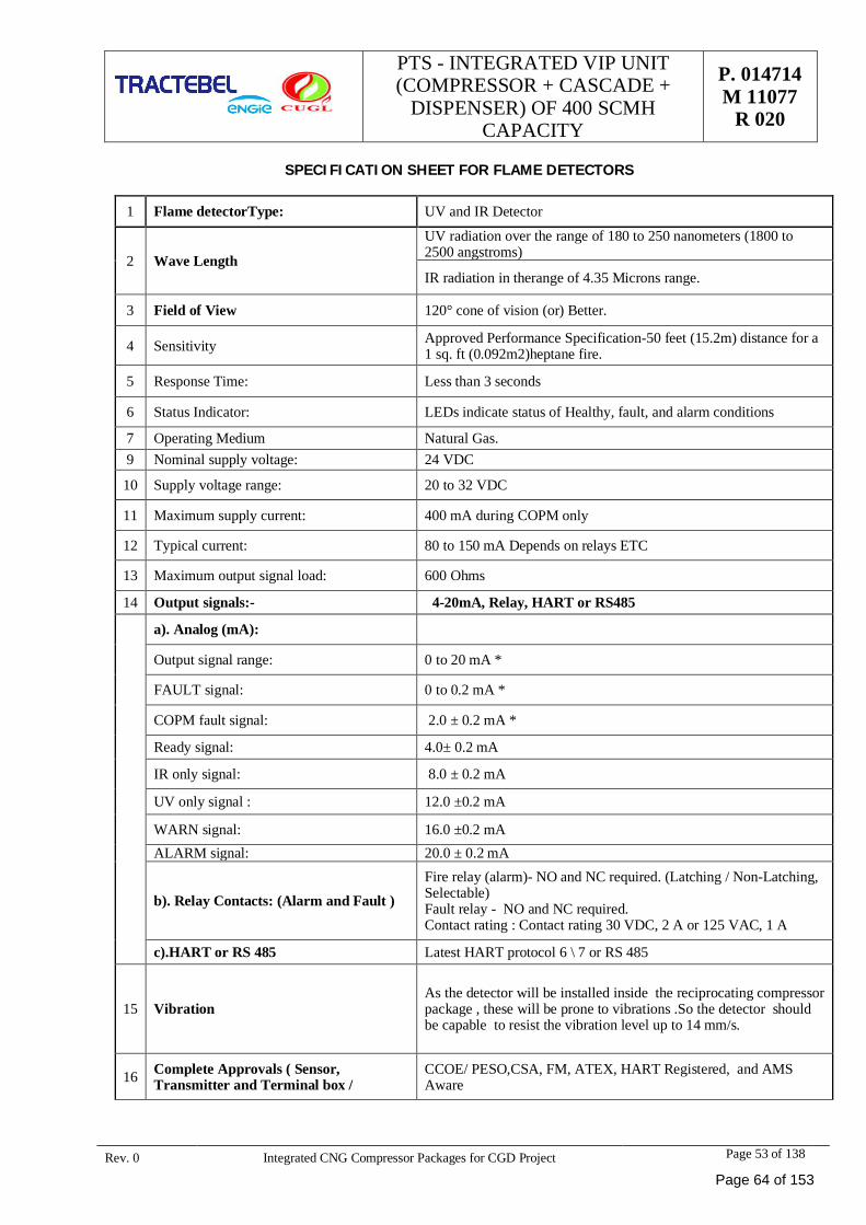
PTS - INTEGRATED VIP UNIT(COMPRESSOR + CASCADE +
DISPENSER) OF 400 SCMHCAPACITY
P. 014714M 11077
R 020
Rev. 0 Integrated CNG Compressor Packages for CGD Project Page 53 of 138
SPECIFICATION SHEET FOR FLAME DETECTORS
1 Flame detectorType: UV and IR Detector
2 Wave Length
UV radiation over the range of 180 to 250 nanometers (1800 to2500 angstroms)
IR radiation in therange of 4.35 Microns range.
3 Field of View 120° cone of vision (or) Better.
4 Sensitivity Approved Performance Specification-50 feet (15.2m) distance for a1 sq. ft (0.092m2)heptane fire.
5 Response Time: Less than 3 seconds
6 Status Indicator: LEDs indicate status of Healthy, fault, and alarm conditions
7 Operating Medium Natural Gas.9 Nominal supply voltage: 24 VDC
10 Supply voltage range: 20 to 32 VDC
11 Maximum supply current: 400 mA during COPM only
12 Typical current: 80 to 150 mA Depends on relays ETC
13 Maximum output signal load: 600 Ohms
14 Output signals:- 4-20mA, Relay, HART or RS485
a). Analog (mA):
Output signal range: 0 to 20 mA *
FAULT signal: 0 to 0.2 mA *
COPM fault signal: 2.0 ± 0.2 mA *
Ready signal: 4.0± 0.2 mA
IR only signal: 8.0 ± 0.2 mA
UV only signal : 12.0 ±0.2 mA
WARN signal: 16.0 ±0.2 mAALARM signal: 20.0 ± 0.2 mA
b). Relay Contacts: (Alarm and Fault )Fire relay (alarm)- NO and NC required. (Latching / Non-Latching,Selectable)Fault relay - NO and NC required.Contact rating : Contact rating 30 VDC, 2 A or 125 VAC, 1 A
c).HART or RS 485 Latest HART protocol 6 \ 7 or RS 485
15 VibrationAs the detector will be installed inside the reciprocating compressorpackage , these will be prone to vibrations .So the detector shouldbe capable to resist the vibration level up to 14 mm/s.
16 Complete Approvals ( Sensor,Transmitter and Terminal box /
CCOE/ PESO,CSA, FM, ATEX, HART Registered, and AMSAware
Page 64 of 153
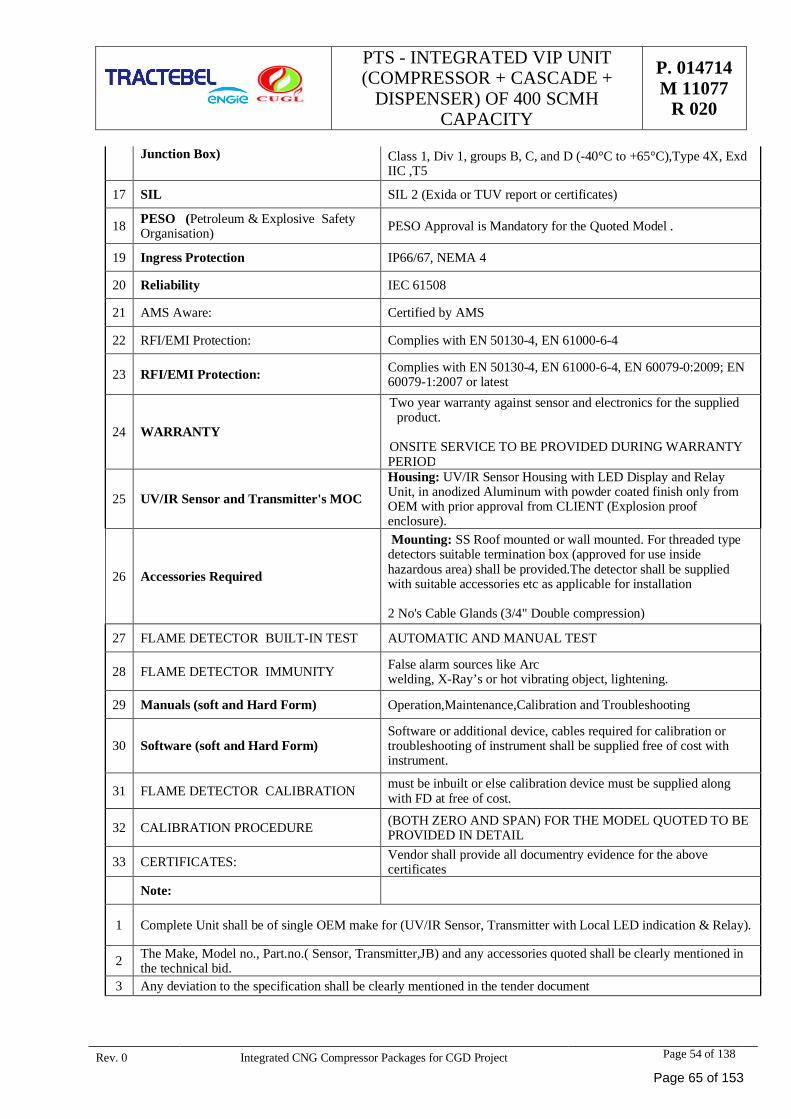
PTS - INTEGRATED VIP UNIT(COMPRESSOR + CASCADE +
DISPENSER) OF 400 SCMHCAPACITY
P. 014714M 11077
R 020
Rev. 0 Integrated CNG Compressor Packages for CGD Project Page 54 of 138
Junction Box) Class 1, Div 1, groups B, C, and D (-40°C to +65°C),Type 4X, ExdIIC ,T5
17 SIL SIL 2 (Exida or TUV report or certificates)
18 PESO (Petroleum & Explosive SafetyOrganisation) PESO Approval is Mandatory for the Quoted Model .
19 Ingress Protection IP66/67, NEMA 4
20 Reliability IEC 61508
21 AMS Aware: Certified by AMS
22 RFI/EMI Protection: Complies with EN 50130-4, EN 61000-6-4
23 RFI/EMI Protection: Complies with EN 50130-4, EN 61000-6-4, EN 60079-0:2009; EN60079-1:2007 or latest
24 WARRANTY
Two year warranty against sensor and electronics for the suppliedproduct.
ONSITE SERVICE TO BE PROVIDED DURING WARRANTYPERIOD
25 UV/IR Sensor and Transmitter's MOCHousing: UV/IR Sensor Housing with LED Display and RelayUnit, in anodized Aluminum with powder coated finish only fromOEM with prior approval from CLIENT (Explosion proofenclosure).
26 Accessories Required
Mounting: SS Roof mounted or wall mounted. For threaded typedetectors suitable termination box (approved for use insidehazardous area) shall be provided.The detector shall be suppliedwith suitable accessories etc as applicable for installation
2 No's Cable Glands (3/4" Double compression)
27 FLAME DETECTOR BUILT-IN TEST AUTOMATIC AND MANUAL TEST
28 FLAME DETECTOR IMMUNITY False alarm sources like Arcwelding, X-Ray’s or hot vibrating object, lightening.
29 Manuals (soft and Hard Form) Operation,Maintenance,Calibration and Troubleshooting
30 Software (soft and Hard Form)Software or additional device, cables required for calibration ortroubleshooting of instrument shall be supplied free of cost withinstrument.
31 FLAME DETECTOR CALIBRATION must be inbuilt or else calibration device must be supplied alongwith FD at free of cost.
32 CALIBRATION PROCEDURE (BOTH ZERO AND SPAN) FOR THE MODEL QUOTED TO BEPROVIDED IN DETAIL
33 CERTIFICATES: Vendor shall provide all documentry evidence for the abovecertificates
Note:
1 Complete Unit shall be of single OEM make for (UV/IR Sensor, Transmitter with Local LED indication & Relay).
2 The Make, Model no., Part.no.( Sensor, Transmitter,JB) and any accessories quoted shall be clearly mentioned inthe technical bid.
3 Any deviation to the specification shall be clearly mentioned in the tender document
Page 65 of 153
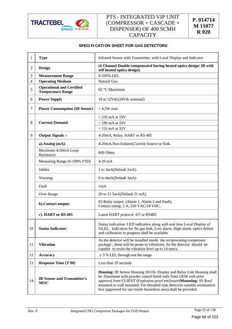
PTS - INTEGRATED VIP UNIT(COMPRESSOR + CASCADE +
DISPENSER) OF 400 SCMHCAPACITY
P. 014714M 11077
R 020
Rev. 0 Integrated CNG Compressor Packages for CGD Project Page 55 of 138
SPECIFICATION SHEET FOR GAS DETECTORS
1 Type Infrared Sensor with Transmitter, with Local Display and Indicator
2 Design (4 Channel Double compensated having heated optics design/ IR withself heated optics design).
3 Measurement Range 0-100% LEL4 Operating Medium Natural Gas.
5 Operational and CertifiedTemperature Range 65 °C Maximum
6 Power Supply 18 to 32Vdc(24Vdc nominal)
7 Power Consumption (IR Sensor) < 4.5W max
8 Current Demand< 235 mA at 18V< 190 mA at 24V< 155 mA at 32V
9 Output Signals :- 4-20mA, Relay, HART or RS 485
a).Analog (mA): 4-20mA,Non-Isolated,Current Source or Sink.
Maximum 4-20mA LoopResistance 600 Ohms
Measuring Range (0-100% FSD) 4-20 mA
Inhibit 1 to 3mA(Default 2mA)
Warning 0 to 6mA(Default 3mA)
Fault 1mA
Over-Range 20 to 21.5mA(Default 21 mA)
b).Contact output: 03 Relay output: (Alarm 1, Alarm 2 and Fault).Contact rating: 2 A, 230 VAC/24 VDC.
c). HART or RS 485 Latest HART protocol 6\7 or RS485
10 Status Indicator:Status indication: LED indication along with real time Local Display of%LEL. Indication for No gas leak, Low alarm, High alarm, optics failureand calibration in progress shall be available
11 VibrationAs the detector will be installed inside the reciprocating compressorpackage , these will be prone to vibrations .So the detector should becapable to resist the vibration level up to 14 mm/s.
12 Accuracy ± 3 % LEL through-out the range.
13 Response Time (T 90) Less than 10 seconds
14 IR Sensor and Transmitter'sMOC
Housing: IR Sensor Housing SS316. Display and Relay Unit Housing shallbe Aluminum with powder coated finish only from OEM with priorapproval from CLIENT (Explosion proof enclosure)Mounting: SS Roofmounted or wall mounted. For threaded type detectors suitable terminationbox (approved for use inside hazardous area) shall be provided.
Page 66 of 153
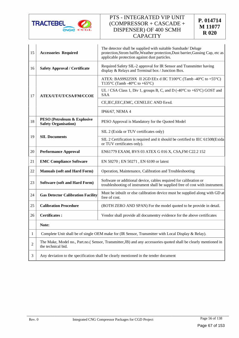
PTS - INTEGRATED VIP UNIT(COMPRESSOR + CASCADE +
DISPENSER) OF 400 SCMHCAPACITY
P. 014714M 11077
R 020
Rev. 0 Integrated CNG Compressor Packages for CGD Project Page 56 of 138
15 Accessories RequiredThe detector shall be supplied with suitable Sunshade/ Delugeprotection,Strom baffle,Weather protection,Dust barrier,Gassing Cap, etc asapplicable protection against dust particles.
16 Safety Approval / Certificate Required Safety SIL-2 approval for IR Sensor and Transmitter havingdisplay & Relays and Terminal box / Junction Box.
17 ATEX/UT/UT/CSA/FM/CCOE
ATEX: BAS992259X II 2GD EEx d IIC T100°C (Tamb -40°C to +55°C)T135°C (Tamb -40°C to +65°C)
UL / CSA Class 1, Div 1, groups B, C, and D (-40°C to +65°C) GOST andSAA
CE,IEC,EEC,EMC, CENELEC AND Eexd.
IP66/67, NEMA 4
18 PESO (Petroleum & ExplosiveSafety Organisation) PESO Approval is Mandatory for the Quoted Model
19 SIL DocumentsSIL 2 (Exida or TUV certificates only)
SIL 2 Certification is required and it should be certified to IEC 61508(Exidaor TUV certificates only).
20 Performance Approval EN61779 EXAM, BVS 03 ATEX G 016 X, CSA,FM C22.2 152
21 EMC Compliance Software EN 50270 ; EN 50271 , EN 6100 or latest
22 Manuals (soft and Hard Form) Operation, Maintenance, Calibration and Troubleshooting
23 Software (soft and Hard Form) Software or additional device, cables required for calibration ortroubleshooting of instrument shall be supplied free of cost with instrument.
24 Gas Detector Calibration Facility Must be inbuilt or else calibration device must be supplied along with GD atfree of cost.
25 Calibration Procedure (BOTH ZERO AND SPAN) For the model quoted to be provide in detail.
26 Certificates : Vendor shall provide all documentry evidence for the above certificates
Note:
1 Complete Unit shall be of single OEM make for (IR Sensor, Transmitter with Local Display & Relay).
2 The Make, Model no., Part.no.( Sensor, Transmitter,JB) and any accessories quoted shall be clearly mentioned inthe technical bid.
3 Any deviation to the specification shall be clearly mentioned in the tender document
Page 67 of 153
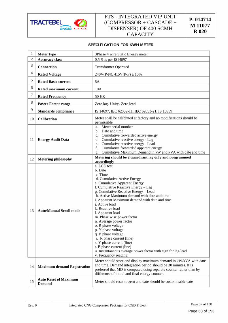
PTS - INTEGRATED VIP UNIT(COMPRESSOR + CASCADE +
DISPENSER) OF 400 SCMHCAPACITY
P. 014714M 11077
R 020
Rev. 0 Integrated CNG Compressor Packages for CGD Project Page 57 of 138
SPECIFICATION FOR KWH METER
1 Meter type 3Phase 4 wire Static Energy meter2 Accuracy class 0.5 S as per IS146973 Connection Transformer Operated4 Rated Voltage 240V(P-N), 415V(P-P) ± 10%5 Rated Basic current 5A6 Rated maximum current 10A7 Rated Frequency 50 HZ8 Power Factor range Zero lag- Unity- Zero lead9 Standards compliance IS 14697, IEC 62052-11, IEC 62053-21, IS 15959
10 Calibration Meter shall be calibrated at factory and no modifications should bepermissible
11 Energy Audit Data
a. Meter serial numberb. Date and timec. Cumulative forwarded active energyd. Cumulative reactive energy - Lage. Cumulative reactive energy - Leadf. Cumulative forwarded apparent energyg. Cumulative Maximum Demand in kW and kVA with date and time
12 Metering philosophy Metering should be 2 quardrant lag only and programmedaccordingly
13 Auto/Manual Scroll mode
a. LCD testb. Date c. Time d. Cumulative Active Energye. Cumulative Apparent Energyf. Cumulative Reactive Energy – Lagg. Cumulative Reactive Energy – Leadh. Active Maximum demand with date and time
i. Apparent Maximum demand with date and timej. Active loadk. Reactive loadl. Apparent loadm. Phase wise power factorn. Average power factoro. R phase voltagep. Y phase voltageq. B phase voltage r. R phase current (line)s. Y phase current (line)t. B phase current (line)u. Instantaneous average power factor with sign for lag/leadv. Frequency reading
14 Maximum demand RegistrationMeter should store and display maximum demand in kW/kVA with dateand time. Demand integration period should be 30 minutes. It ispreferred that MD is computed using separate counter rather than bydifference of initial and final energy counter.
15 Auto Reset of MaximumDemand Meter should reset to zero and date should be customisable date
Page 68 of 153
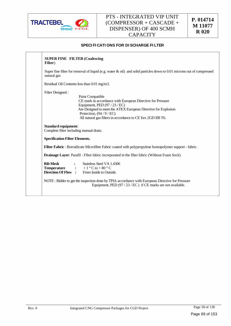
PTS - INTEGRATED VIP UNIT(COMPRESSOR + CASCADE +
DISPENSER) OF 400 SCMHCAPACITY
P. 014714M 11077
R 020
Rev. 0 Integrated CNG Compressor Packages for CGD Project Page 58 of 138
SPECIFICATIONS FOR DISCHARGE FILTER
SUPER FINE FILTER (CoalescingFilter)
Super fine filter for removal of liquid (e.g. water & oil) and solid particles down to 0.01 microns out of compressednatural gas
Residual Oil Contents less than 0.01 mg/m3.
Filter Designed :Paint CompatibleCE mark in accordance with European Directive for PressureEquipment, PED (97 / 23 / EC)
Are Designed to meet the ATEX European Directive for Explosion Protection, (94 / 9 / EC) All natural gas filters in accordance to CE Eex 2GD IIB T6.
Standard equipment:Complete filter including manual drain.
Specification Filter Elements.
Filter Fabric : Borosilicate Microfibre Fabric coated with polypropylene homopolymer support - fabric.
Drainage Layer: Parafil - Fibre fabric incorporated in the filter fabric (Without Foam Sock)
Rib Mesh : Stainless Steel VA 1.4306Temperature : + 1 ° C to + 80 ° CDirection Of Flow : From Inside to Outside.
NOTE : Bidder to get the inspection done by TPIA accordance with European Directive for PressureEquipment, PED (97 / 23 / EC ) if CE marks are not available.
Page 69 of 153
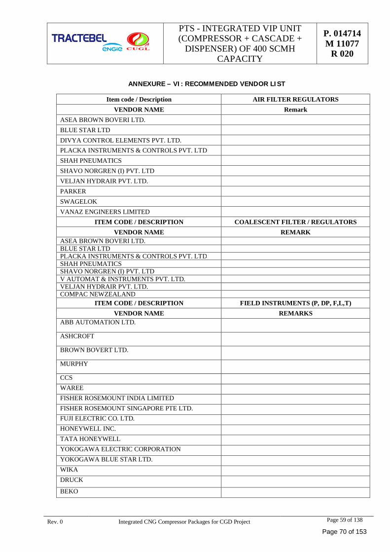
PTS - INTEGRATED VIP UNIT(COMPRESSOR + CASCADE +
DISPENSER) OF 400 SCMHCAPACITY
P. 014714M 11077
R 020
Rev. 0 Integrated CNG Compressor Packages for CGD Project Page 59 of 138
ANNEXURE – VI: RECOMMENDED VENDOR LIST
Item code / Description AIR FILTER REGULATORSVENDOR NAME Remark
ASEA BROWN BOVERI LTD.BLUE STAR LTDDIVYA CONTROL ELEMENTS PVT. LTD.PLACKA INSTRUMENTS & CONTROLS PVT. LTDSHAH PNEUMATICSSHAVO NORGREN (I) PVT. LTDVELJAN HYDRAIR PVT. LTD.PARKERSWAGELOKVANAZ ENGINEERS LIMITED
ITEM CODE / DESCRIPTION COALESCENT FILTER / REGULATORSVENDOR NAME REMARK
ASEA BROWN BOVERI LTD.BLUE STAR LTDPLACKA INSTRUMENTS & CONTROLS PVT. LTDSHAH PNEUMATICSSHAVO NORGREN (I) PVT. LTDV AUTOMAT & INSTRUMENTS PVT. LTD.VELJAN HYDRAIR PVT. LTD.COMPAC NEWZEALAND
ITEM CODE / DESCRIPTION FIELD INSTRUMENTS (P, DP, F,L,T)VENDOR NAME REMARKS
ABB AUTOMATION LTD.
ASHCROFT
BROWN BOVERT LTD.
MURPHY
CCSWAREEFISHER ROSEMOUNT INDIA LIMITEDFISHER ROSEMOUNT SINGAPORE PTE LTD.FUJI ELECTRIC CO. LTD.HONEYWELL INC.TATA HONEYWELLYOKOGAWA ELECTRIC CORPORATIONYOKOGAWA BLUE STAR LTD.WIKADRUCK
BEKO
Page 70 of 153
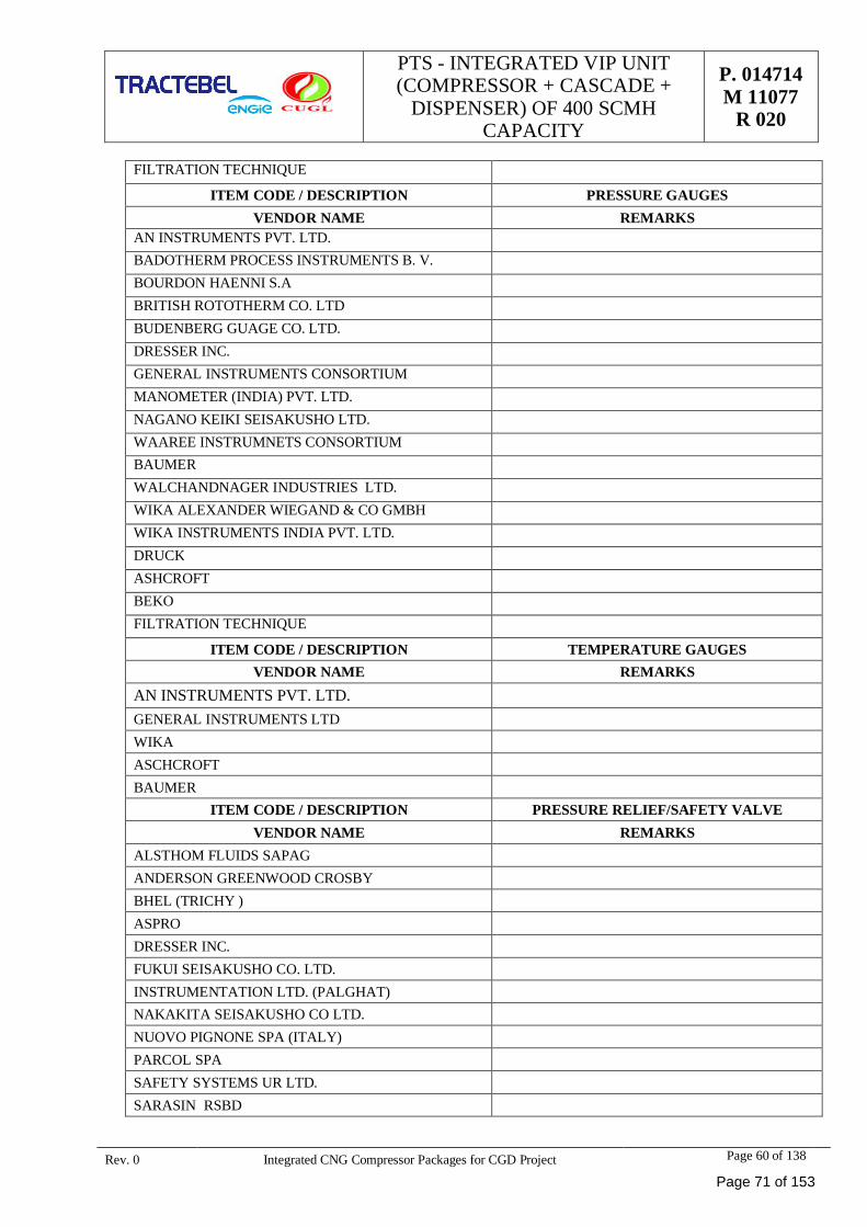
PTS - INTEGRATED VIP UNIT(COMPRESSOR + CASCADE +
DISPENSER) OF 400 SCMHCAPACITY
P. 014714M 11077
R 020
Rev. 0 Integrated CNG Compressor Packages for CGD Project Page 60 of 138
FILTRATION TECHNIQUE
ITEM CODE / DESCRIPTION PRESSURE GAUGESVENDOR NAME REMARKS
AN INSTRUMENTS PVT. LTD.BADOTHERM PROCESS INSTRUMENTS B. V.BOURDON HAENNI S.ABRITISH ROTOTHERM CO. LTDBUDENBERG GUAGE CO. LTD.DRESSER INC.GENERAL INSTRUMENTS CONSORTIUMMANOMETER (INDIA) PVT. LTD.NAGANO KEIKI SEISAKUSHO LTD.WAAREE INSTRUMNETS CONSORTIUMBAUMERWALCHANDNAGER INDUSTRIES LTD.WIKA ALEXANDER WIEGAND & CO GMBHWIKA INSTRUMENTS INDIA PVT. LTD.DRUCKASHCROFTBEKOFILTRATION TECHNIQUE
ITEM CODE / DESCRIPTION TEMPERATURE GAUGESVENDOR NAME REMARKS
AN INSTRUMENTS PVT. LTD.GENERAL INSTRUMENTS LTDWIKAASCHCROFTBAUMER
ITEM CODE / DESCRIPTION PRESSURE RELIEF/SAFETY VALVEVENDOR NAME REMARKS
ALSTHOM FLUIDS SAPAGANDERSON GREENWOOD CROSBYBHEL (TRICHY )ASPRODRESSER INC.FUKUI SEISAKUSHO CO. LTD.INSTRUMENTATION LTD. (PALGHAT)NAKAKITA SEISAKUSHO CO LTD.NUOVO PIGNONE SPA (ITALY)PARCOL SPASAFETY SYSTEMS UR LTD.SARASIN RSBD
Page 71 of 153
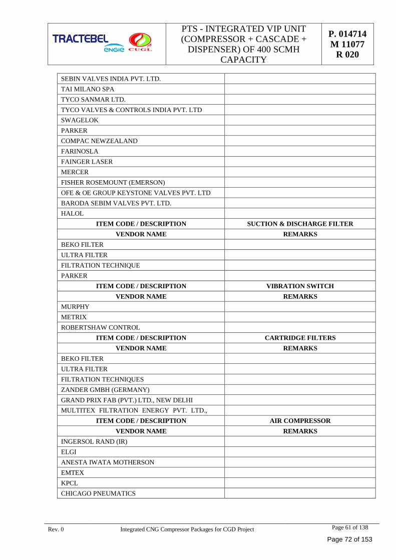
PTS - INTEGRATED VIP UNIT(COMPRESSOR + CASCADE +
DISPENSER) OF 400 SCMHCAPACITY
P. 014714M 11077
R 020
Rev. 0 Integrated CNG Compressor Packages for CGD Project Page 61 of 138
SEBIN VALVES INDIA PVT. LTD.TAI MILANO SPATYCO SANMAR LTD.TYCO VALVES & CONTROLS INDIA PVT. LTDSWAGELOKPARKERCOMPAC NEWZEALANDFARINOSLAFAINGER LASERMERCERFISHER ROSEMOUNT (EMERSON)OFE & OE GROUP KEYSTONE VALVES PVT. LTDBARODA SEBIM VALVES PVT. LTD.HALOL
ITEM CODE / DESCRIPTION SUCTION & DISCHARGE FILTERVENDOR NAME REMARKS
BEKO FILTERULTRA FILTERFILTRATION TECHNIQUEPARKER
ITEM CODE / DESCRIPTION VIBRATION SWITCHVENDOR NAME REMARKS
MURPHYMETRIXROBERTSHAW CONTROL
ITEM CODE / DESCRIPTION CARTRIDGE FILTERSVENDOR NAME REMARKS
BEKO FILTERULTRA FILTERFILTRATION TECHNIQUESZANDER GMBH (GERMANY)GRAND PRIX FAB (PVT.) LTD., NEW DELHIMULTITEX FILTRATION ENERGY PVT. LTD.,
ITEM CODE / DESCRIPTION AIR COMPRESSORVENDOR NAME REMARKS
INGERSOL RAND (IR)ELGIANESTA IWATA MOTHERSONEMTEXKPCLCHICAGO PNEUMATICS
Page 72 of 153
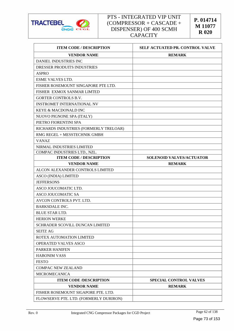
PTS - INTEGRATED VIP UNIT(COMPRESSOR + CASCADE +
DISPENSER) OF 400 SCMHCAPACITY
P. 014714M 11077
R 020
Rev. 0 Integrated CNG Compressor Packages for CGD Project Page 62 of 138
ITEM CODE / DESCRIPTION SELF ACTUATED PR. CONTROL VALVE
VENDOR NAME REMARKDANIEL INDUSTRIES INCDRESSER PRODUITS INDUSTRIESASPROESME VALVES LTD.FISHER ROSEMOUNT SINGAPORE PTE LTD.FISHER EXMOX SANMAR LIMTEDGORTER CONTROLS B.V.INSTROMET INTERNATIONAL NVKEYE & MACDONALD INCNUOVO PIGNONE SPA (ITALY)PIETRO FIORENTINI SPARICHARDS INDUSTRIES (FORMERLY TRELOAR)RMG REGEL + MESSTECHNIK GMBHVANAZNIRMAL INDUSTRIES LIMITEDCOMPAC INDUSTRIES LTD., NZL.
ITEM CODE / DESCRIPTION SOLENOID VALVES/ACTUATORVENDOR NAME REMARK
ALCON ALEXANDER CONTROLS LIMITEDASCO (INDIA) LIMITEDJEFFERSONSASCO JOUCOMATIC LTD.ASCO JOUCOMATIC SAAVCON CONTROLS PVT. LTD.BARKSDALE INC.BLUE STAR LTD.HERION WERKESCHRADER SCOVILL DUNCAN LIMITEDSEITZ AGROTEX AUTOMATION LIMITEDOPERATED VALVES ASCOPARKER HANIFENHABONIM VASSFESTOCOMPAC NEW ZEALANDMICROMECANICA
ITEM CODE /DESCRIPTION SPECIAL CONTROL VALVESVENDOR NAME REMARK
FISHER ROSEMOUNT SIGAPORE PTE. LTD.FLOWSERVE PTE. LTD. (FORMERLY DURIRON)
Page 73 of 153
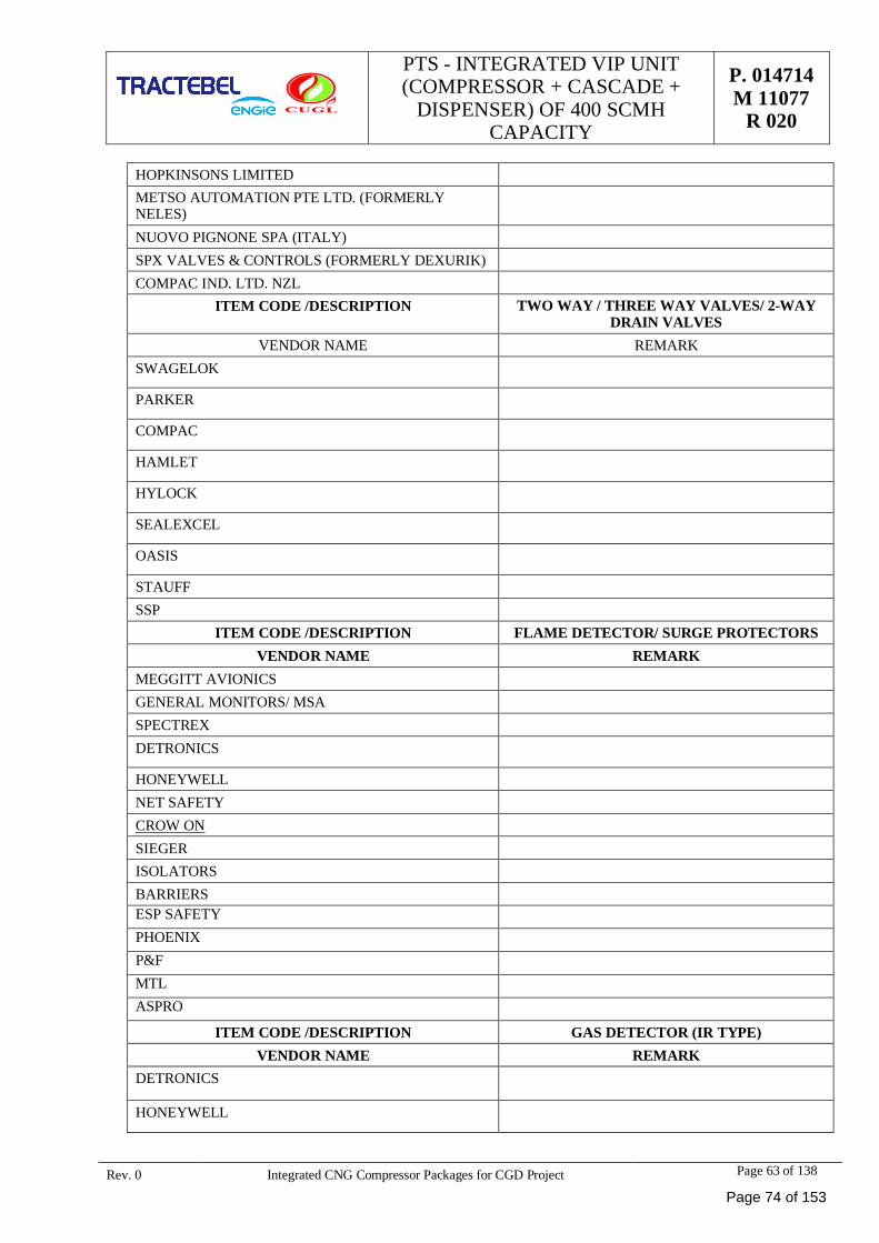
PTS - INTEGRATED VIP UNIT(COMPRESSOR + CASCADE +
DISPENSER) OF 400 SCMHCAPACITY
P. 014714M 11077
R 020
Rev. 0 Integrated CNG Compressor Packages for CGD Project Page 63 of 138
HOPKINSONS LIMITEDMETSO AUTOMATION PTE LTD. (FORMERLYNELES)NUOVO PIGNONE SPA (ITALY)SPX VALVES & CONTROLS (FORMERLY DEXURIK)COMPAC IND. LTD. NZL
ITEM CODE /DESCRIPTION TWO WAY / THREE WAY VALVES/ 2-WAYDRAIN VALVES
VENDOR NAME REMARKSWAGELOK
PARKER
COMPAC
HAMLET
HYLOCK
SEALEXCEL
OASIS
STAUFFSSP
ITEM CODE /DESCRIPTION FLAME DETECTOR/ SURGE PROTECTORSVENDOR NAME REMARK
MEGGITT AVIONICSGENERAL MONITORS/ MSASPECTREXDETRONICS
HONEYWELLNET SAFETYCROW ONSIEGERISOLATORSBARRIERSESP SAFETYPHOENIXP&FMTLASPRO
ITEM CODE /DESCRIPTION GAS DETECTOR (IR TYPE)VENDOR NAME REMARK
DETRONICS
HONEYWELL
Page 74 of 153
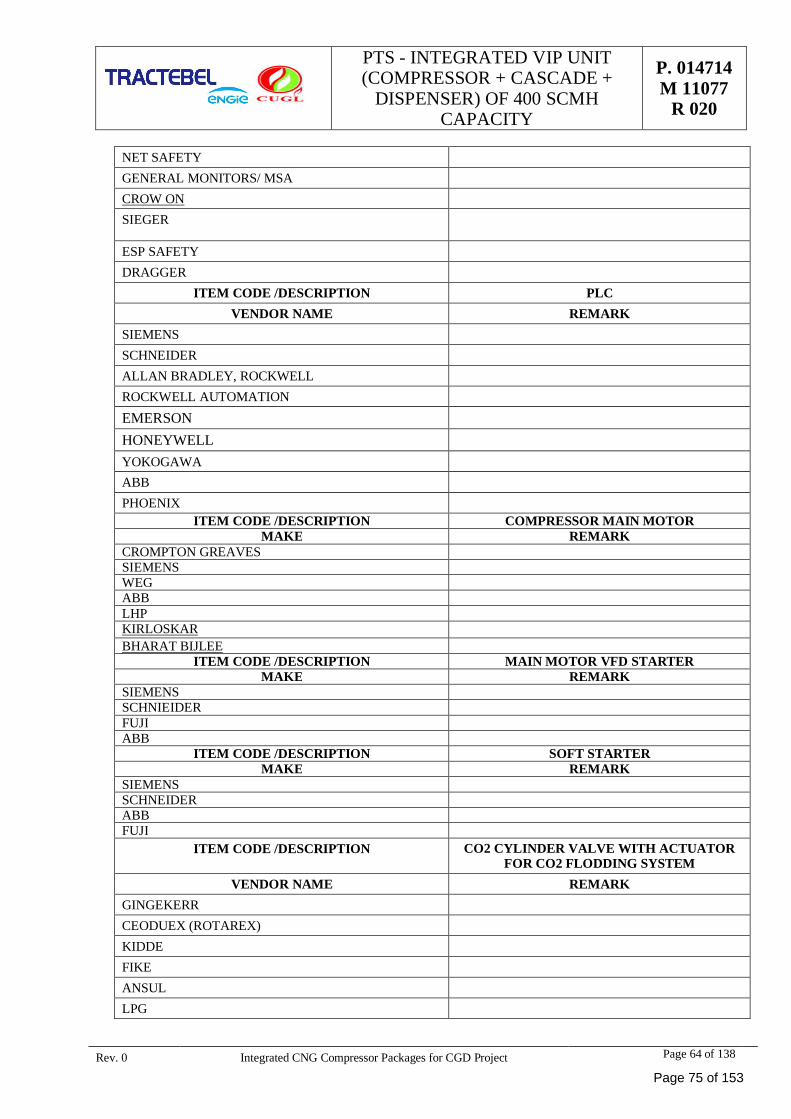
PTS - INTEGRATED VIP UNIT(COMPRESSOR + CASCADE +
DISPENSER) OF 400 SCMHCAPACITY
P. 014714M 11077
R 020
Rev. 0 Integrated CNG Compressor Packages for CGD Project Page 64 of 138
NET SAFETYGENERAL MONITORS/ MSACROW ONSIEGER
ESP SAFETYDRAGGER
ITEM CODE /DESCRIPTION PLCVENDOR NAME REMARK
SIEMENSSCHNEIDERALLAN BRADLEY, ROCKWELLROCKWELL AUTOMATIONEMERSONHONEYWELLYOKOGAWAABBPHOENIX
ITEM CODE /DESCRIPTION COMPRESSOR MAIN MOTORMAKE REMARK
CROMPTON GREAVESSIEMENSWEGABBLHPKIRLOSKARBHARAT BIJLEE
ITEM CODE /DESCRIPTION MAIN MOTOR VFD STARTERMAKE REMARK
SIEMENSSCHNIEIDERFUJIABB
ITEM CODE /DESCRIPTION SOFT STARTERMAKE REMARK
SIEMENSSCHNEIDERABBFUJI
ITEM CODE /DESCRIPTION CO2 CYLINDER VALVE WITH ACTUATORFOR CO2 FLODDING SYSTEM
VENDOR NAME REMARKGINGEKERRCEODUEX (ROTAREX)KIDDEFIKEANSULLPG
Page 75 of 153
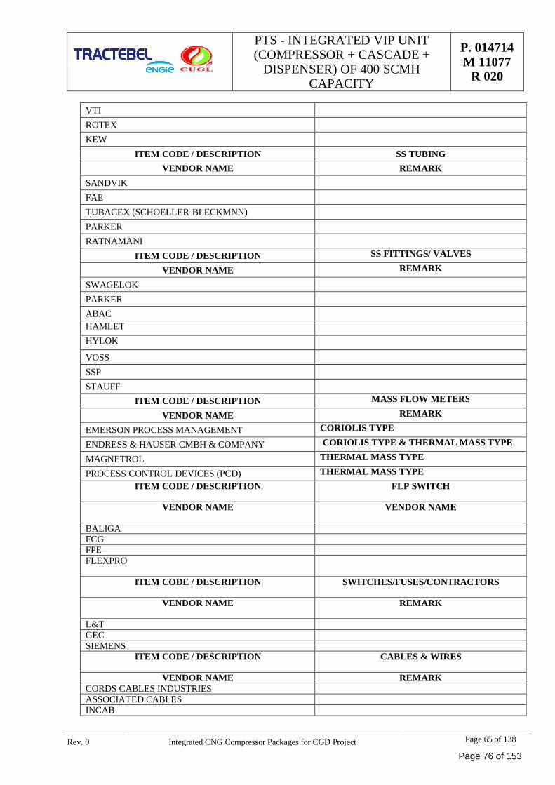
PTS - INTEGRATED VIP UNIT(COMPRESSOR + CASCADE +
DISPENSER) OF 400 SCMHCAPACITY
P. 014714M 11077
R 020
Rev. 0 Integrated CNG Compressor Packages for CGD Project Page 65 of 138
VTIROTEXKEW
ITEM CODE / DESCRIPTION SS TUBINGVENDOR NAME REMARK
SANDVIKFAETUBACEX (SCHOELLER-BLECKMNN)PARKERRATNAMANI
ITEM CODE / DESCRIPTION SS FITTINGS/ VALVES
VENDOR NAME REMARK
SWAGELOKPARKERABACHAMLETHYLOK
VOSSSSPSTAUFF
ITEM CODE / DESCRIPTION MASS FLOW METERS
VENDOR NAME REMARK
EMERSON PROCESS MANAGEMENT CORIOLIS TYPE
ENDRESS & HAUSER CMBH & COMPANY CORIOLIS TYPE & THERMAL MASS TYPE
MAGNETROL THERMAL MASS TYPE
PROCESS CONTROL DEVICES (PCD) THERMAL MASS TYPEITEM CODE / DESCRIPTION FLP SWITCH
VENDOR NAME VENDOR NAME
BALIGAFCGFPEFLEXPRO
ITEM CODE / DESCRIPTION SWITCHES/FUSES/CONTRACTORS
VENDOR NAME REMARK
L&TGECSIEMENS
ITEM CODE / DESCRIPTION CABLES & WIRES
VENDOR NAME REMARKCORDS CABLES INDUSTRIESASSOCIATED CABLESINCAB
Page 76 of 153
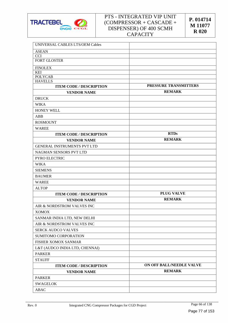
PTS - INTEGRATED VIP UNIT(COMPRESSOR + CASCADE +
DISPENSER) OF 400 SCMHCAPACITY
P. 014714M 11077
R 020
Rev. 0 Integrated CNG Compressor Packages for CGD Project Page 66 of 138
UNIVERSAL CABLES LTS/OEM Cables
ASEANCCIFORT GLOSTER
FINOLEXKEIPOLYCABHAVELLS
ITEM CODE / DESCRIPTION PRESSURE TRANSMITTERS
VENDOR NAME REMARK
DRUCKWIKAHONEY WELLABBROSMOUNTWAREE
ITEM CODE / DESCRIPTION RTDs
VENDOR NAME REMARK
GENERAL INSTRUMENTS PVT LTDNAGMAN SENSORS PVT LTDPYRO ELECTRICWIKASIEMENSBAUMERWAREEALTOP
ITEM CODE / DESCRIPTION PLUG VALVE
VENDOR NAME REMARK
AIR & NORDSTROM VALVES INCXOMOXSANMAR INDIA LTD, NEW DELHIAIR & NORDSTROM VALVES INCSERCK AUDCO VALVESSUMITOMO CORPORATIONFISHER XOMOX SANMARL&T (AUDCO INDIA LTD, CHENNAI)PARKERSTAUFF
ITEM CODE / DESCRIPTION ON OFF BALL/NEEDLE VALVE
VENDOR NAME REMARK
PARKERSWAGELOKABAC
Page 77 of 153
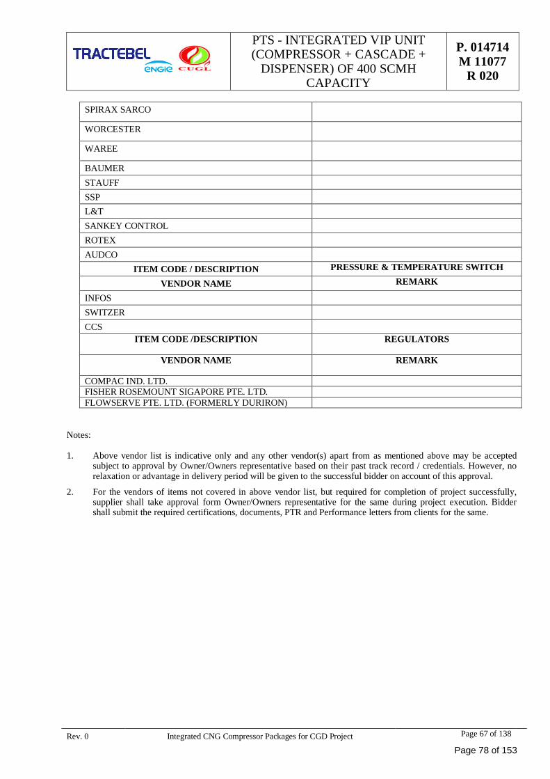
PTS - INTEGRATED VIP UNIT(COMPRESSOR + CASCADE +
DISPENSER) OF 400 SCMHCAPACITY
P. 014714M 11077
R 020
Rev. 0 Integrated CNG Compressor Packages for CGD Project Page 67 of 138
SPIRAX SARCO
WORCESTER
WAREE
BAUMERSTAUFFSSPL&TSANKEY CONTROLROTEXAUDCO
ITEM CODE / DESCRIPTION PRESSURE & TEMPERATURE SWITCH
VENDOR NAME REMARK
INFOSSWITZERCCS
ITEM CODE /DESCRIPTION REGULATORS
VENDOR NAME REMARK
COMPAC IND. LTD.FISHER ROSEMOUNT SIGAPORE PTE. LTD.FLOWSERVE PTE. LTD. (FORMERLY DURIRON)
Notes:
1. Above vendor list is indicative only and any other vendor(s) apart from as mentioned above may be acceptedsubject to approval by Owner/Owners representative based on their past track record / credentials. However, norelaxation or advantage in delivery period will be given to the successful bidder on account of this approval.
2. For the vendors of items not covered in above vendor list, but required for completion of project successfully,supplier shall take approval form Owner/Owners representative for the same during project execution. Biddershall submit the required certifications, documents, PTR and Performance letters from clients for the same.
Page 78 of 153
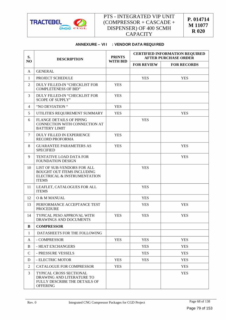
PTS - INTEGRATED VIP UNIT(COMPRESSOR + CASCADE +
DISPENSER) OF 400 SCMHCAPACITY
P. 014714M 11077
R 020
Rev. 0 Integrated CNG Compressor Packages for CGD Project Page 68 of 138
ANNEXURE – VII : VENDOR DATA REQUIRED
S.NO DESCRIPTION PRINTS
WITH BID
CERTIFIED INFORMATION REQUIREDAFTER PURCHASE ORDER
FOR REVIEW FOR RECORDS
A GENERAL
1 PROJECT SCHEDULE YES YES
2 DULY FILLED-IN “CHECKLIST FORCOMPLETENESS OF BID”
YES
3 DULY FILLED-IN “CHECKLIST FORSCOPE OF SUPPLY”
YES
4 “NO DEVIATION “ YES
5 UTILITIES REQUIREMENT SUMMARY YES YES
6 FLANGE DETAILS OF PIPINGCONNECTION WITH CONNECTION ATBATTERY LIMIT
YES
7 DULY FILLED IN EXPERIENCERECORD PROFORMA
YES
8 GUARANTEE PARAMETERS ASSPECIFIED
YES YES
9 TENTATIVE LOAD DATA FORFOUNDATION DESIGN
YES
10 LIST OF SUB-VENDORS FOR ALLBOUGHT OUT ITEMS INCLUDINGELECTRICAL & INSTRUMENTATIONITEMS
YES
11 LEAFLET, CATALOGUES FOR ALLITEMS
YES
12 O & M MANUAL YES
13 PERFORMANCE ACCEPTANCE TESTPROCEDURE
YES YES
14 TYPICAL PESO APPROVAL WITHDRAWINGS AND DOCUMENTS
YES YES YES
B COMPRESSOR
1 DATASHEETS FOR THE FOLLOWING
A - COMPRESSOR YES YES YES
B - HEAT EXCHANGERS YES YES
C - PRESSURE VESSELS YES YES
D - ELECTRIC MOTOR YES YES YES
2 CATALOGUE FOR COMPRESSOR YES YES
3 TYPICAL CROSS SECTIONALDRAWING AND LITERATURE TOFULLY DESCRIBE THE DETAILS OFOFFERING
YES
Page 79 of 153
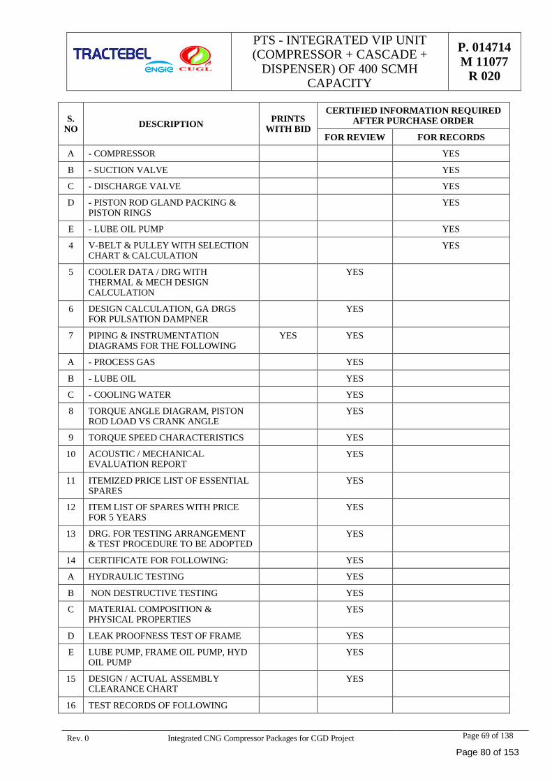
PTS - INTEGRATED VIP UNIT(COMPRESSOR + CASCADE +
DISPENSER) OF 400 SCMHCAPACITY
P. 014714M 11077
R 020
Rev. 0 Integrated CNG Compressor Packages for CGD Project Page 69 of 138
S.NO DESCRIPTION PRINTS
WITH BID
CERTIFIED INFORMATION REQUIREDAFTER PURCHASE ORDER
FOR REVIEW FOR RECORDS
A - COMPRESSOR YES
B - SUCTION VALVE YES
C - DISCHARGE VALVE YES
D - PISTON ROD GLAND PACKING &PISTON RINGS
YES
E - LUBE OIL PUMP YES
4 V-BELT & PULLEY WITH SELECTIONCHART & CALCULATION
YES
5 COOLER DATA / DRG WITHTHERMAL & MECH DESIGNCALCULATION
YES
6 DESIGN CALCULATION, GA DRGSFOR PULSATION DAMPNER
YES
7 PIPING & INSTRUMENTATIONDIAGRAMS FOR THE FOLLOWING
YES YES
A - PROCESS GAS YES
B - LUBE OIL YES
C - COOLING WATER YES
8 TORQUE ANGLE DIAGRAM, PISTONROD LOAD VS CRANK ANGLE
YES
9 TORQUE SPEED CHARACTERISTICS YES
10 ACOUSTIC / MECHANICALEVALUATION REPORT
YES
11 ITEMIZED PRICE LIST OF ESSENTIALSPARES
YES
12 ITEM LIST OF SPARES WITH PRICEFOR 5 YEARS
YES
13 DRG. FOR TESTING ARRANGEMENT& TEST PROCEDURE TO BE ADOPTED
YES
14 CERTIFICATE FOR FOLLOWING: YES
A HYDRAULIC TESTING YES
B NON DESTRUCTIVE TESTING YES
C MATERIAL COMPOSITION &PHYSICAL PROPERTIES
YES
D LEAK PROOFNESS TEST OF FRAME YES
E LUBE PUMP, FRAME OIL PUMP, HYDOIL PUMP
YES
15 DESIGN / ACTUAL ASSEMBLYCLEARANCE CHART
YES
16 TEST RECORDS OF FOLLOWING
Page 80 of 153
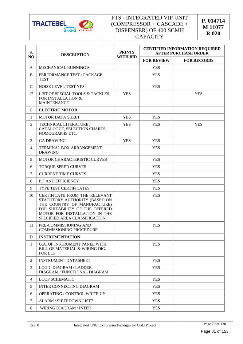
PTS - INTEGRATED VIP UNIT(COMPRESSOR + CASCADE +
DISPENSER) OF 400 SCMHCAPACITY
P. 014714M 11077
R 020
Rev. 0 Integrated CNG Compressor Packages for CGD Project Page 70 of 138
S.NO DESCRIPTION PRINTS
WITH BID
CERTIFIED INFORMATION REQUIREDAFTER PURCHASE ORDER
FOR REVIEW FOR RECORDS
A MECHANICAL RUNNING S YES
B PERFORMANCE TEST / PACKAGETEST
YES
C NOISE LEVEL TEST YES YES
17 LIST OF SPECIAL TOOLS & TACKLESFOR INSTALLATION &MAINTENANCE
YES YES
C ELECTRIC MOTOR
1 MOTOR DATA SHEET YES YES
2 TECHNICAL LITERATURE /CATALOGUE, SELECTION CHARTS,NOMOGRAPHS ETC.
YES YES YES
3 GA DRAWING YES YES
4 TERMINAL BOX ARRANGEMENTDRAWING
YES
5 MOTOR CHARACTERISTIC CURVES YES
6 TORQUE SPEED CURVES YES
7 CURRENT TIME CURVES YES
8 P.F AND EFFICIENCY YES
9 TYPE TEST CERTIFICATES YES
10 CERTIFICATE FROM THE RELEVANTSTATUTORY AUTHORITY (BASED ONTHE COUNTRY OF MANUFACTURE)FOR SUITABILITY OF THE OFFEREDMOTOR FOR INSTALLATION IN THESPECIFIED AREA CLASSIFICATION
YES
11 PRE-COMMISSIONING ANDCOMMISSIONING PROCEDURE
YES
D INSTRUMENTATION
1 G.A. OF INSTRUMENT PANEL WITHBILL OF MATERIAL & WIRING DIG.FOR LCP
YES
2 INSTRUMENT DATASHEET YES
3 LOGIC DIAGRAM / LADDERDIAGRAM / FUNCTIONAL DIAGRAM
YES
4 LOOP SCHEMATIC YES
5 INTER CONNECTING DIAGRAM YES
6 OPERATING / CONTROL WRITE UP YES
7 ALARM / SHUT DOWN LIST7 YES
8 WIRING DIAGRAM / INTER YES
Page 81 of 153
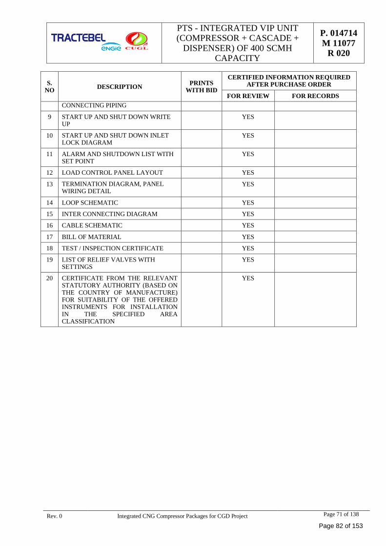
PTS - INTEGRATED VIP UNIT(COMPRESSOR + CASCADE +
DISPENSER) OF 400 SCMHCAPACITY
P. 014714M 11077
R 020
Rev. 0 Integrated CNG Compressor Packages for CGD Project Page 71 of 138
S.NO DESCRIPTION PRINTS
WITH BID
CERTIFIED INFORMATION REQUIREDAFTER PURCHASE ORDER
FOR REVIEW FOR RECORDSCONNECTING PIPING
9 START UP AND SHUT DOWN WRITEUP
YES
10 START UP AND SHUT DOWN INLETLOCK DIAGRAM
YES
11 ALARM AND SHUTDOWN LIST WITHSET POINT
YES
12 LOAD CONTROL PANEL LAYOUT YES
13 TERMINATION DIAGRAM, PANELWIRING DETAIL
YES
14 LOOP SCHEMATIC YES
15 INTER CONNECTING DIAGRAM YES
16 CABLE SCHEMATIC YES
17 BILL OF MATERIAL YES
18 TEST / INSPECTION CERTIFICATE YES
19 LIST OF RELIEF VALVES WITHSETTINGS
YES
20 CERTIFICATE FROM THE RELEVANTSTATUTORY AUTHORITY (BASED ONTHE COUNTRY OF MANUFACTURE)FOR SUITABILITY OF THE OFFEREDINSTRUMENTS FOR INSTALLATIONIN THE SPECIFIED AREACLASSIFICATION
YES
Page 82 of 153
PTS - INTEGRATED VIP UNIT(COMPRESSOR + CASCADE +
DISPENSER) OF 400 SCMHCAPACITY
P. 014714M 11077
R 020
Rev. 0 Integrated CNG Compressor Packages for CGD Project Page 72 of 138
ANNEXURE – VIII: DEVIATION SCHEDULE FOR INTEGRATED CNG COMPRESSOR PACKAGE
Vendor:
S.No. Vendor to specify Specification number and clausenumber against which Deviation is sought
Description of Deviation and give reasons insupport of Deviation
------------------NO DEVIATION--------------------------- ------------------NO DEVIATION-------------
Page 83 of 153
PTS - INTEGRATED VIP UNIT(COMPRESSOR + CASCADE +
DISPENSER) OF 400 SCMHCAPACITY
P. 014714M 11077
R 020
Rev. 0 Integrated CNG Compressor Packages for CGD Project Page 73 of 138
ANNEXURE – IX : DELETED
Page 84 of 153
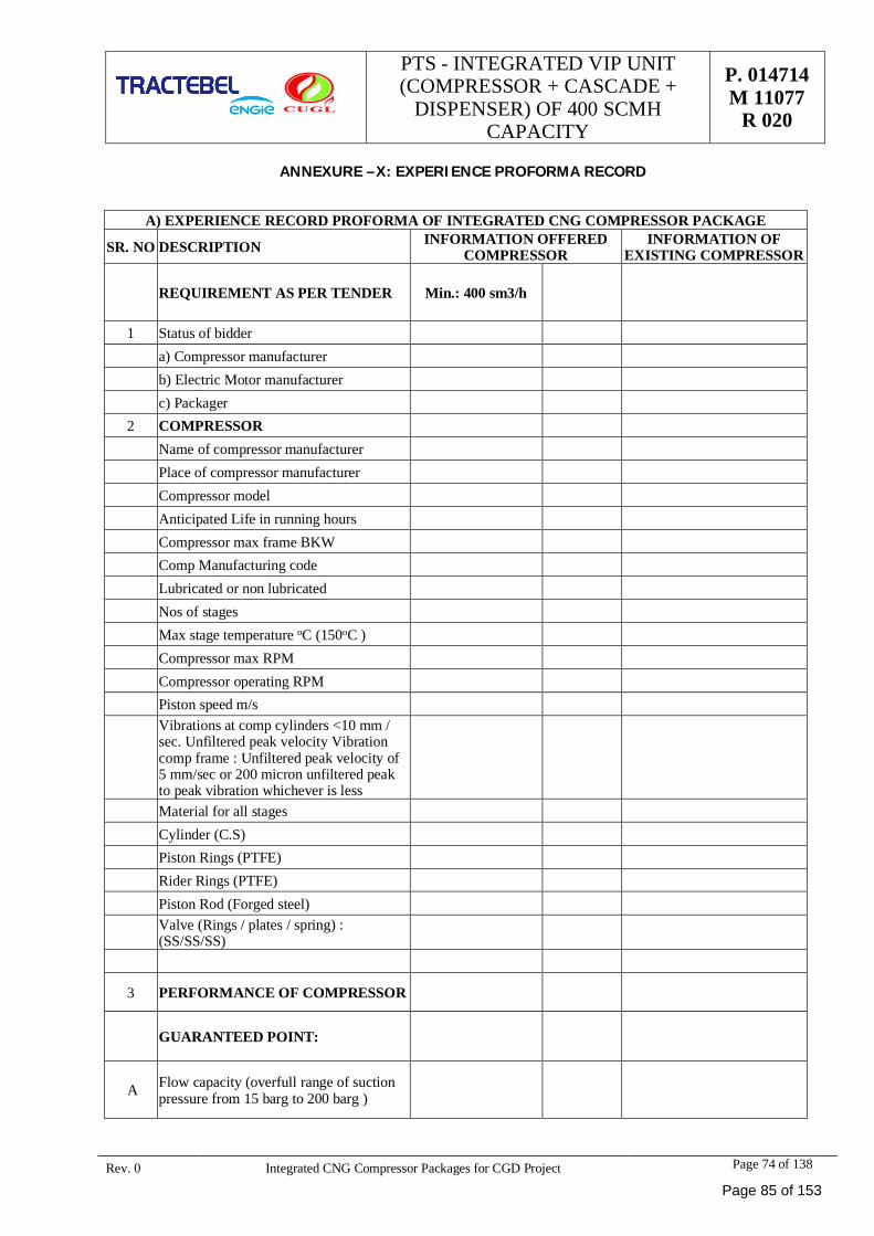
PTS - INTEGRATED VIP UNIT(COMPRESSOR + CASCADE +
DISPENSER) OF 400 SCMHCAPACITY
P. 014714M 11077
R 020
Rev. 0 Integrated CNG Compressor Packages for CGD Project Page 74 of 138
ANNEXURE –X: EXPERIENCE PROFORMA RECORD
A) EXPERIENCE RECORD PROFORMA OF INTEGRATED CNG COMPRESSOR PACKAGE
SR. NO DESCRIPTION INFORMATION OFFEREDCOMPRESSOR
INFORMATION OFEXISTING COMPRESSOR
REQUIREMENT AS PER TENDER Min.: 400 sm3/h
1 Status of bidder a) Compressor manufacturer b) Electric Motor manufacturer c) Packager2 COMPRESSOR Name of compressor manufacturer Place of compressor manufacturer Compressor model Anticipated Life in running hours Compressor max frame BKW Comp Manufacturing code Lubricated or non lubricated Nos of stages Max stage temperature oC (150oC ) Compressor max RPM Compressor operating RPM Piston speed m/s
Vibrations at comp cylinders <10 mm /sec. Unfiltered peak velocity Vibrationcomp frame : Unfiltered peak velocity of5 mm/sec or 200 micron unfiltered peakto peak vibration whichever is less
Material for all stages Cylinder (C.S) Piston Rings (PTFE) Rider Rings (PTFE) Piston Rod (Forged steel)
Valve (Rings / plates / spring) :(SS/SS/SS)
3 PERFORMANCE OF COMPRESSOR
GUARANTEED POINT:
A Flow capacity (overfull range of suctionpressure from 15 barg to 200 barg )
Page 85 of 153
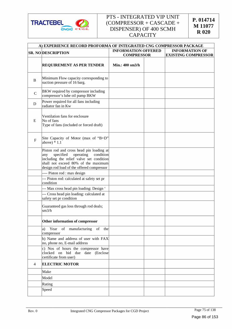
PTS - INTEGRATED VIP UNIT(COMPRESSOR + CASCADE +
DISPENSER) OF 400 SCMHCAPACITY
P. 014714M 11077
R 020
Rev. 0 Integrated CNG Compressor Packages for CGD Project Page 75 of 138
A) EXPERIENCE RECORD PROFORMA OF INTEGRATED CNG COMPRESSOR PACKAGE
SR. NO DESCRIPTION INFORMATION OFFEREDCOMPRESSOR
INFORMATION OFEXISTING COMPRESSOR
REQUIREMENT AS PER TENDER Min.: 400 sm3/h
B Minimum Flow capacity corresponding tosuction pressure of 16 barg.
C BKW required by compressor includingcompressor’s lube oil pump BKW
D Power required for all fans includingradiator fan in Kw
EVentilation fans for enclosureNo of fansType of fans (included or forced draft)
F Site Capacity of Motor (max of “B+D”above) * 1.1
Piston rod and cross head pin loading atany specified operating conditionincluding the relief valve set conditionshall not exceed 80% of the maximumdesign rod load of the offered compressor
---- Piston rod : max design--- Piston rod: calculated at safety set prcondition
--- Max cross head pin loading: Design ‘--- Cross head pin loading: calculated atsafety set pr condition
Guaranteed gas loss through rod deals;sm3/h
Other information of compressor
a) Year of manufacturing of thecompressorb) Name and address of user with FAXno, phone no, E-mail addressc) Nos of hours the compressor haveclocked on bid due date (Enclosecertificate from user)
4 ELECTRIC MOTOR
Make Model Rating
Speed
Page 86 of 153
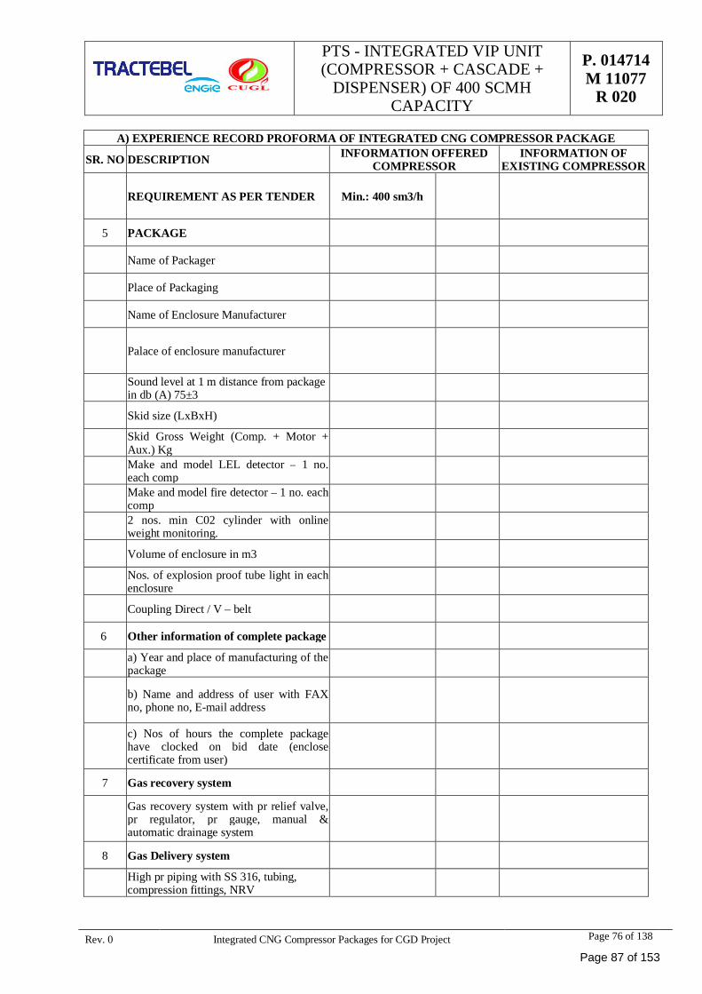
PTS - INTEGRATED VIP UNIT(COMPRESSOR + CASCADE +
DISPENSER) OF 400 SCMHCAPACITY
P. 014714M 11077
R 020
Rev. 0 Integrated CNG Compressor Packages for CGD Project Page 76 of 138
A) EXPERIENCE RECORD PROFORMA OF INTEGRATED CNG COMPRESSOR PACKAGE
SR. NO DESCRIPTION INFORMATION OFFEREDCOMPRESSOR
INFORMATION OFEXISTING COMPRESSOR
REQUIREMENT AS PER TENDER Min.: 400 sm3/h
5 PACKAGE
Name of Packager
Place of Packaging
Name of Enclosure Manufacturer
Palace of enclosure manufacturer
Sound level at 1 m distance from packagein db (A) 75±3
Skid size (LxBxH)
Skid Gross Weight (Comp. + Motor +Aux.) KgMake and model LEL detector – 1 no.each compMake and model fire detector – 1 no. eachcomp2 nos. min C02 cylinder with onlineweight monitoring.
Volume of enclosure in m3
Nos. of explosion proof tube light in eachenclosure
Coupling Direct / V – belt
6 Other information of complete package
a) Year and place of manufacturing of thepackage
b) Name and address of user with FAXno, phone no, E-mail address
c) Nos of hours the complete packagehave clocked on bid date (enclosecertificate from user)
7 Gas recovery system
Gas recovery system with pr relief valve,pr regulator, pr gauge, manual &automatic drainage system
8 Gas Delivery system
High pr piping with SS 316, tubing,compression fittings, NRV
Page 87 of 153
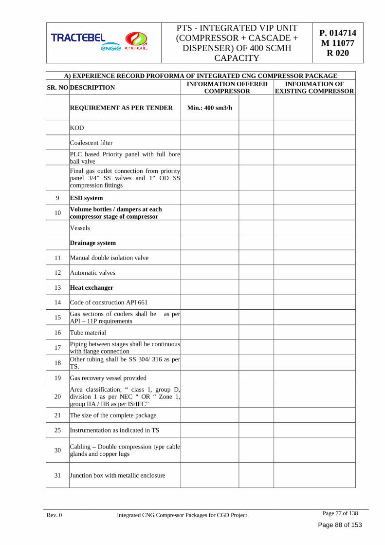
PTS - INTEGRATED VIP UNIT(COMPRESSOR + CASCADE +
DISPENSER) OF 400 SCMHCAPACITY
P. 014714M 11077
R 020
Rev. 0 Integrated CNG Compressor Packages for CGD Project Page 77 of 138
A) EXPERIENCE RECORD PROFORMA OF INTEGRATED CNG COMPRESSOR PACKAGE
SR. NO DESCRIPTION INFORMATION OFFEREDCOMPRESSOR
INFORMATION OFEXISTING COMPRESSOR
REQUIREMENT AS PER TENDER Min.: 400 sm3/h
KOD
Coalescent filter
PLC based Priority panel with full boreball valveFinal gas outlet connection from prioritypanel 3/4” SS valves and 1” OD SScompression fittings
9 ESD system
10 Volume bottles / dampers at eachcompressor stage of compressor
Vessels
Drainage system
11 Manual double isolation valve
12 Automatic valves
13 Heat exchanger
14 Code of construction API 661
15 Gas sections of coolers shall be as perAPI – 11P requirements
16 Tube material
17 Piping between stages shall be continuouswith flange connection
18 Other tubing shall be SS 304/ 316 as perTS.
19 Gas recovery vessel provided
20Area classification; “ class 1, group D,division 1 as per NEC “ OR “ Zone 1,group IIA / IIB as per IS/IEC”
21 The size of the complete package
25 Instrumentation as indicated in TS
30 Cabling – Double compression type cableglands and copper lugs
31 Junction box with metallic enclosure
Page 88 of 153
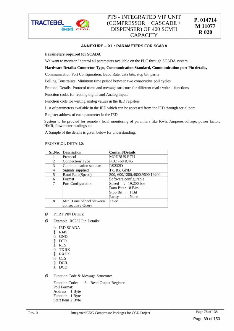
PTS - INTEGRATED VIP UNIT(COMPRESSOR + CASCADE +
DISPENSER) OF 400 SCMHCAPACITY
P. 014714M 11077
R 020
Rev. 0 Integrated CNG Compressor Packages for CGD Project Page 78 of 138
ANNEXURE – XI : PARAMETERS FOR SCADA
Parameters required for SCADA
We want to monitor / control all parameters available on the PLC through SCADA system.
Hardware Details: Connector Type, Communication Standard, Communication port Pin details,
Communication Port Configuration: Baud Rate, data bits, stop bit, parity
Polling Constraints: Minimum time period between two consecutive poll cycles.
Protocol Details: Protocol name and message structure for different read / write functions.
Function codes for reading digital and Analog inputs
Function code for writing analog values in the IED registers
List of parameters available in the IED which can be accessed from the IED through serial port.
Register address of each parameter in the IED.
System to be provied for remote / local monitoring of paramters like Kwh, Amperes,voltage, power factor,HMR, flow meter readings etc
A Sample of the details is given below for understanding:
PROTOCOL DETAILS:
Sr.No. Description Content/Details1 Protocol MODBUS RTU2 Connection Type FCC –68 RJ453 Communication standard RS232D4 Signals supplied Tx, Rx, GND5 Baud Rate(Speed) 300, 600,1200,4800,9600,192006 Format Software configurable7 Port Configuration Speed : 19,200 bps
Data Bits : 8 BitsStop Bit : 1 BitParity : None
8 Min. Time period betweenconsecutive Query
2 Sec.
Ø PORT PIN Details:
Ø Example: RS232 Pin Details:
§ IED SCADA§ RJ45§ GND§ DTR§ RTS§ TX RX§ RX TX§ CTS§ DCR§ DCD
Ø Function Code & Message Structure:
Function Code: 3 – Read Output RegisterPoll Format:Address 1 ByteFunction 1 ByteStart Item 2 Byte
Page 89 of 153
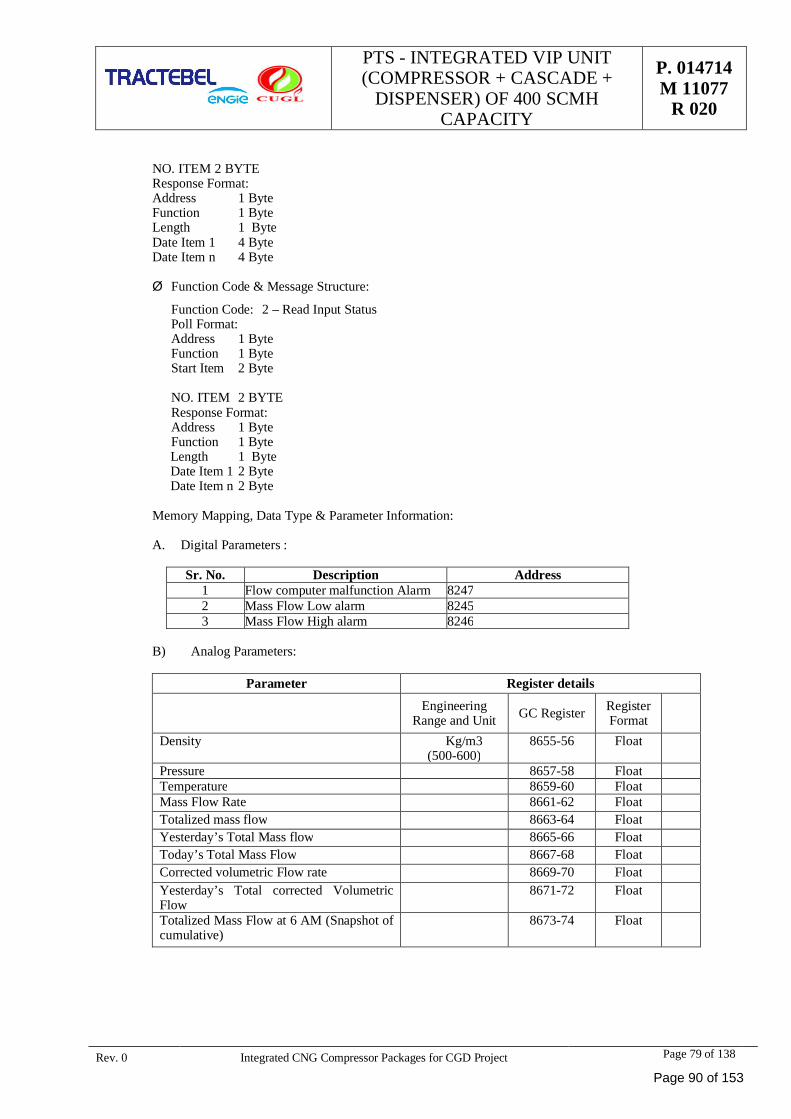
PTS - INTEGRATED VIP UNIT(COMPRESSOR + CASCADE +
DISPENSER) OF 400 SCMHCAPACITY
P. 014714M 11077
R 020
Rev. 0 Integrated CNG Compressor Packages for CGD Project Page 79 of 138
NO. ITEM 2 BYTEResponse Format:Address 1 ByteFunction 1 ByteLength 1 ByteDate Item 1 4 ByteDate Item n 4 Byte
Ø Function Code & Message Structure:
Function Code: 2 – Read Input StatusPoll Format:
Address 1 Byte Function 1 Byte Start Item 2 Byte
NO. ITEM 2 BYTEResponse Format:
Address 1 Byte Function 1 Byte Length 1 Byte Date Item 1 2 Byte Date Item n 2 Byte
Memory Mapping, Data Type & Parameter Information:
A. Digital Parameters :
Sr. No. Description Address1 Flow computer malfunction Alarm 82472 Mass Flow Low alarm 82453 Mass Flow High alarm 8246
B) Analog Parameters:
Parameter Register details
EngineeringRange and Unit GC Register Register
FormatDensity Kg/m3
(500-600)8655-56 Float
Pressure 8657-58 FloatTemperature 8659-60 FloatMass Flow Rate 8661-62 FloatTotalized mass flow 8663-64 FloatYesterday’s Total Mass flow 8665-66 FloatToday’s Total Mass Flow 8667-68 FloatCorrected volumetric Flow rate 8669-70 FloatYesterday’s Total corrected VolumetricFlow
8671-72 Float
Totalized Mass Flow at 6 AM (Snapshot ofcumulative)
8673-74 Float
Page 90 of 153
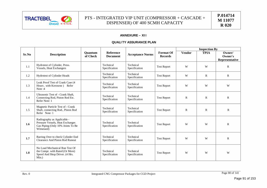
PTS - INTEGRATED VIP UNIT (COMPRESSOR + CASCADE +DISPENSER) OF 400 SCMH CAPACITY
P.014714M 11077
R 020
Rev. 0 Integrated CNG Compressor Packages for CGD Project Page 80 of 141
ANNEXURE – XII
QUALITY ASSURANCE PLAN
Sr.No Description Quantumof Check
ReferenceDocument Acceptance Norms Format Of
Records
Inspection ByVendor TPIA Owner/
Owner'sRepresentative
1.1 Hydrotest of Cylinder, Press.Vessels, Heat Exchangers
TechnicalSpecification
TechnicalSpecification Test Report W W R
1.2 Hydrotest of Cylinder Heads TechnicalSpecification
TechnicalSpecification Test Report W R R
1.3Leak Proof Test of Crank Case (4Hours . with Kerosene ) ReferNote :4
TechnicalSpecification
TechnicalSpecification Test Report W W W
1.4Ultrasonic Test of - Crank Shaft,Connecting Rod, Piston Rod Etc.Refer Note: 1
TechnicalSpecification
TechnicalSpecification Test Report R R R
1.5Magnetic Particle Test of - CrankShaft, connecting Rod., Piston RodRefer Note: 1
TechnicalSpecification
TechnicalSpecification Test Report R R R
1.6
Radiography as Applicable -Pressure Vessels, Heat Exchanger.Gas Piping (Only 10% Joints To BeWitnessed)
TechnicalSpecification
TechnicalSpecification Test Report W W R
1.7 Barring Over to check Cylinder EndClearance And Piston Rod Runout
TechnicalSpecification
TechnicalSpecification Test Report W W R
1.8No Load Mechanical Run Test Ofthe Compr. with Rated (Or More)Speed And Shop Driver. (4 Hrs.Min.)
TechnicalSpecification
TechnicalSpecification Test Report W W W
Page 91 of 153

PTS - INTEGRATED VIP UNIT (COMPRESSOR + CASCADE +DISPENSER) OF 400 SCMH CAPACITY
P.014714M 11077
R 020
Rev. 0 Integrated CNG Compressor Packages for CGD Project Page 81 of 141
1.9Strip Check And Internal InspectionAfter "NLMRT" Of All CompressorsRefer Note: 2
TechnicalSpecification
TechnicalSpecification Test Report W W W
1.10Electric Motor Performance Test- atSub-Vendor's Works as per ISO Std.Refer Note: 3
TechnicalSpecification
TechnicalSpecification
PerformanceTest Report R R R
1.11Material Test Certificates for: CrankShaft, Connecting Rods, Cylinder Liner,Piston (Compliance Cert.), PressureVessels, Heat Exchanger
TechnicalSpecification
TechnicalSpecification MTC R R R
1.12
Canopy Structure PaintingInspection At Works. SurfacePreparation to be Inspected aftercleaning and before application ofFirst Coat of Primer.
TechnicalSpecification
TechnicalSpecification
InspectionReport W W R
1.13 Functional / HV / Continuty Test forControl Panel (at Sub Vendor's Works)
TechnicalSpecification
TechnicalSpecification Test Report W R R
1.14Mechanical String Test for 4 Hours,25% of Package Lot for CNGCompressor
TechnicalSpecification
TechnicalSpecification Test Report W W W
1.15 Test Certificates For - Safety Switches,Safety Relief Valves, Solenoid Valves
TechnicalSpecification
TechnicalSpecification
TestCertificate R R R
1.16Final Mock-Up Assembly of thePackage - As Per GAFD, P& IDrawings. Wiring Diagram
TechnicalSpecification
TechnicalSpecification
P&ID, WiringDiagram W R R
1.17 Performance Test (at site ) at GuaranteedParameters.
TechnicalSpecification
TechnicalSpecification
PerformanceTest Report W W W
Page 92 of 153
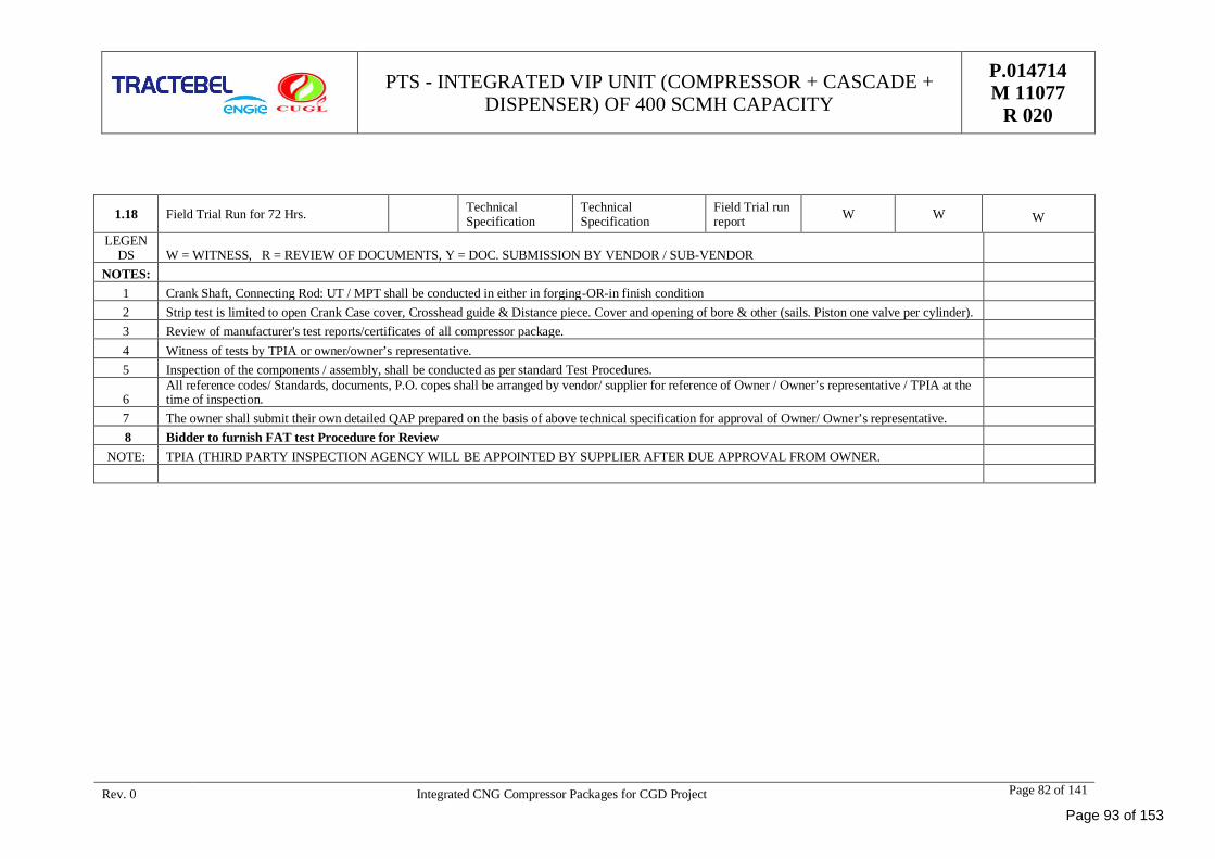
PTS - INTEGRATED VIP UNIT (COMPRESSOR + CASCADE +DISPENSER) OF 400 SCMH CAPACITY
P.014714M 11077
R 020
Rev. 0 Integrated CNG Compressor Packages for CGD Project Page 82 of 141
1.18 Field Trial Run for 72 Hrs. TechnicalSpecification
TechnicalSpecification
Field Trial runreport W W W
LEGENDS W = WITNESS, R = REVIEW OF DOCUMENTS, Y = DOC. SUBMISSION BY VENDOR / SUB-VENDOR
NOTES:1 Crank Shaft, Connecting Rod: UT / MPT shall be conducted in either in forging-OR-in finish condition2 Strip test is limited to open Crank Case cover, Crosshead guide & Distance piece. Cover and opening of bore & other (sails. Piston one valve per cylinder).3 Review of manufacturer's test reports/certificates of all compressor package.4 Witness of tests by TPIA or owner/owner’s representative.5 Inspection of the components / assembly, shall be conducted as per standard Test Procedures.
6All reference codes/ Standards, documents, P.O. copes shall be arranged by vendor/ supplier for reference of Owner / Owner’s representative / TPIA at thetime of inspection.
7 The owner shall submit their own detailed QAP prepared on the basis of above technical specification for approval of Owner/ Owner’s representative. 8 Bidder to furnish FAT test Procedure for Review
NOTE: TPIA (THIRD PARTY INSPECTION AGENCY WILL BE APPOINTED BY SUPPLIER AFTER DUE APPROVAL FROM OWNER.
Page 93 of 153
PTS - INTEGRATED VIP UNIT(COMPRESSOR + CASCADE +
DISPENSER) OF 400 SCMHCAPACITY
P. 014714M 11077
R 020
Rev. 0 Integrated CNG Compressor Packages for CGD Project Page 83 of 141
ANNEXURE - XIII
DATA SHEET
Page 94 of 153
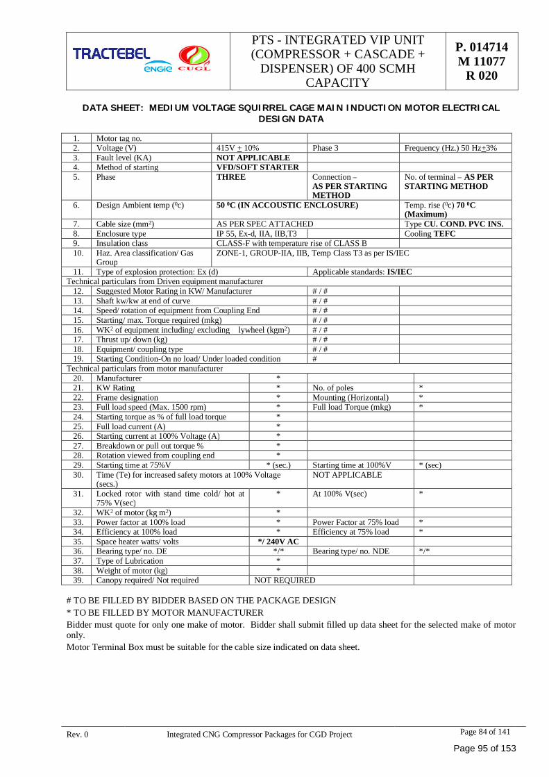
PTS - INTEGRATED VIP UNIT(COMPRESSOR + CASCADE +
DISPENSER) OF 400 SCMHCAPACITY
P. 014714M 11077
R 020
Rev. 0 Integrated CNG Compressor Packages for CGD Project Page 84 of 141
DATA SHEET: MEDIUM VOLTAGE SQUIRREL CAGE MAIN INDUCTION MOTOR ELECTRICALDESIGN DATA
1. Motor tag no.2. Voltage (V) 415V + 10% Phase 3 Frequency (Hz.) 50 Hz+3%3. Fault level (KA) NOT APPLICABLE4. Method of starting VFD/SOFT STARTER5. Phase THREE Connection –
AS PER STARTINGMETHOD
No. of terminal – AS PERSTARTING METHOD
6. Design Ambient temp (0c) 50 0C (IN ACCOUSTIC ENCLOSURE) Temp. rise (0c) 70 0C(Maximum)
7. Cable size (mm2) AS PER SPEC ATTACHED Type CU. COND. PVC INS.8. Enclosure type IP 55, Ex-d, IIA, IIB,T3 Cooling TEFC9. Insulation class CLASS-F with temperature rise of CLASS B10. Haz. Area classification/ Gas
GroupZONE-1, GROUP-IIA, IIB, Temp Class T3 as per IS/IEC
11. Type of explosion protection: Ex (d) Applicable standards: IS/IECTechnical particulars from Driven equipment manufacturer
12. Suggested Motor Rating in KW/ Manufacturer # / #13. Shaft kw/kw at end of curve # / #14. Speed/ rotation of equipment from Coupling End # / #15. Starting/ max. Torque required (mkg) # / #16. WK2 of equipment including/ excluding � lywheel (kgm2) # / #17. Thrust up/ down (kg) # / #18. Equipment/ coupling type # / #19. Starting Condition-On no load/ Under loaded condition #
Technical particulars from motor manufacturer20. Manufacturer *21. KW Rating * No. of poles *22. Frame designation * Mounting (Horizontal) *23. Full load speed (Max. 1500 rpm) * Full load Torque (mkg) *24. Starting torque as % of full load torque *25. Full load current (A) *26. Starting current at 100% Voltage (A) *27. Breakdown or pull out torque % *28. Rotation viewed from coupling end *29. Starting time at 75%V * (sec.) Starting time at 100%V * (sec)30. Time (Te) for increased safety motors at 100% Voltage
(secs.)NOT APPLICABLE
31. Locked rotor with stand time cold/ hot at75% V(sec)
* At 100% V(sec) *
32. WK2 of motor (kg m2) *33. Power factor at 100% load * Power Factor at 75% load *34. Efficiency at 100% load * Efficiency at 75% load *35. Space heater watts/ volts */ 240V AC36. Bearing type/ no. DE */* Bearing type/ no. NDE */*37. Type of Lubrication *38. Weight of motor (kg) *39. Canopy required/ Not required NOT REQUIRED
# TO BE FILLED BY BIDDER BASED ON THE PACKAGE DESIGN* TO BE FILLED BY MOTOR MANUFACTURERBidder must quote for only one make of motor. Bidder shall submit filled up data sheet for the selected make of motoronly.Motor Terminal Box must be suitable for the cable size indicated on data sheet.
Page 95 of 153
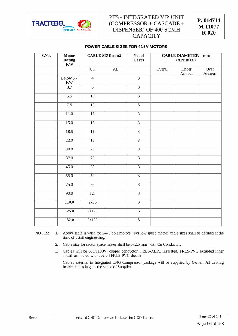
PTS - INTEGRATED VIP UNIT(COMPRESSOR + CASCADE +
DISPENSER) OF 400 SCMHCAPACITY
P. 014714M 11077
R 020
Rev. 0 Integrated CNG Compressor Packages for CGD Project Page 85 of 141
POWER CABLE SIZES FOR 415V MOTORS
S.No. MotorRating
KW
CABLE SIZE mm2 No. ofCores
CABLE DIAMETER - mm(APPROX)
CU AL Overall UnderArmour
OverArmous
Below 3.7KW
4 3
3.7 6 3
5.5 10 3
7.5 10 3
11.0 16 3
15.0 16 3
18.5 16 3
22.0 16 3
30.0 25 3
37.0 25 3
45.0 35 3
55.0 50 3
75.0 95 3
90.0 120 3
110.0 2x95 3
125.0 2x120 3
132.0 2x120 3
NOTES: 1. Above table is valid for 2/4/6 pole motors. For low speed motors cable sizes shall be defined at thetime of detail engineering.
2. Cable size for motor space heater shall be 3x2.5 mm2 with Cu Conductor.
3. Cables will be 650/1100V, copper conductor, FRLS-XLPE insulated, FRLS-PVC extruded innersheath armoured with overall FRLS-PVC sheath.
Cables external to Integrated CNG Compressor package will be supplied by Owner. All cablinginside the package is the scope of Supplier.
Page 96 of 153
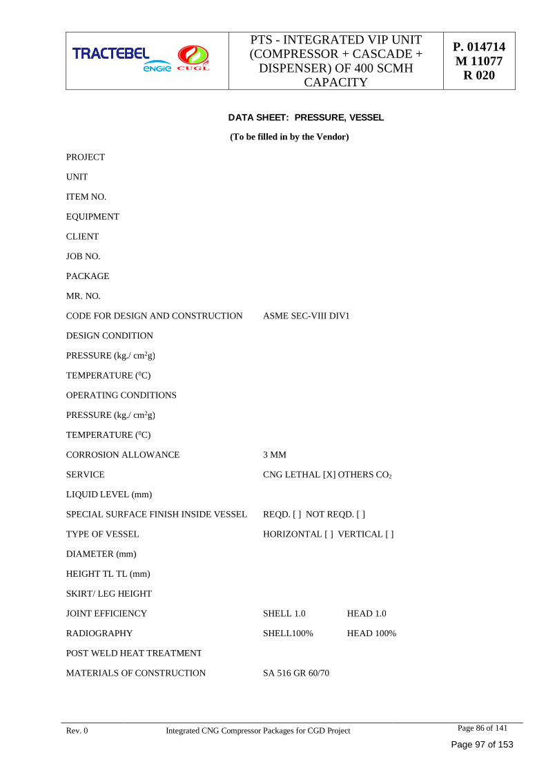
PTS - INTEGRATED VIP UNIT(COMPRESSOR + CASCADE +
DISPENSER) OF 400 SCMHCAPACITY
P. 014714M 11077
R 020
Rev. 0 Integrated CNG Compressor Packages for CGD Project Page 86 of 141
DATA SHEET: PRESSURE, VESSEL
(To be filled in by the Vendor)
PROJECT
UNIT
ITEM NO.
EQUIPMENT
CLIENT
JOB NO.
PACKAGE
MR. NO.
CODE FOR DESIGN AND CONSTRUCTION ASME SEC-VIII DIV1
DESIGN CONDITION
PRESSURE (kg./ cm2g)
TEMPERATURE (0C)
OPERATING CONDITIONS
PRESSURE (kg./ cm2g)
TEMPERATURE (0C)
CORROSION ALLOWANCE 3 MM
SERVICE CNG LETHAL [X] OTHERS CO2
LIQUID LEVEL (mm)
SPECIAL SURFACE FINISH INSIDE VESSEL REQD. [ ] NOT REQD. [ ]
TYPE OF VESSEL HORIZONTAL [ ] VERTICAL [ ]
DIAMETER (mm)
HEIGHT TL TL (mm)
SKIRT/ LEG HEIGHT
JOINT EFFICIENCY SHELL 1.0 HEAD 1.0
RADIOGRAPHY SHELL100% HEAD 100%
POST WELD HEAT TREATMENT
MATERIALS OF CONSTRUCTION SA 516 GR 60/70
Page 97 of 153
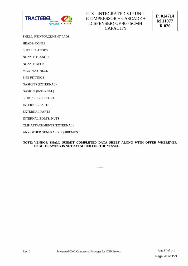
PTS - INTEGRATED VIP UNIT(COMPRESSOR + CASCADE +
DISPENSER) OF 400 SCMHCAPACITY
P. 014714M 11077
R 020
Rev. 0 Integrated CNG Compressor Packages for CGD Project Page 87 of 141
SHELL, REINFORCEMENT PADS
HEADS/ CONES
SHELL FLANGES
NOZZLE FLANGES
NOZZLE NECK
MAN-WAY NECK
PIPE FITTINGS
GASKETS (EXTERNAL)
GASKET (INTERNAL)
SKIRT/ LEG SUPPORT
INTERNAL PARTS
EXTERNAL PARTS
INTERNAL BOLTS/ NUTS
CLIP ATTACHMENTS (EXTERNAL)
ANY OTHER GENERAL REQUIREMENT
NOTE: VENDOR SHALL SUBMIT COMPLETED DATA SHEET ALONG WITH OFFER WHEREVERENGG. DRAWING IS NOT ATTACHED FOR THE VESSEL.
------
Page 98 of 153
PTS - INTEGRATED VIP UNIT(COMPRESSOR + CASCADE +
DISPENSER) OF 400 SCMHCAPACITY
P. 014714M 11077
R 020
Rev. 0 Integrated CNG Compressor Packages for CGD Project Page 88 of 141
1. DOCUMENT DISTRIBUTION SCHEDULE
1.1. Documents and drawings under column no. 3 shall be submitted with each copy of the bid.
1.2. Documents listed under column 4 are to be submitted in 2 copies
1.3. Documents listed in column 5 are to be submitted as hard bound indexed book containing the following detailsin Two (2) copies to be submitted within 4 weeks of release note/dispatch of materials/ equipment fromvendor's works.
For column no. 3, 4 & 5 refer Annexure – VII (Vendor Data Required).
2. DETAILS TO BE INCLUDED IN FINAL DOCUMENTS BOOKS
2.1. Copy of P.O. and all amendments.
2.2. Copy of Purchase Requisition and all amendments.
2.3. Manufacturing Data Book containing all test certificates of components, raw materials, stage manufacturingtests and inspections, final tests & inspection documents including welders' qualification & welding procedurequalification, repairs & reworking carried out in shops. All raw material test certificates must be correlated tothe P.O. Item No. & component to which they relate by clear noting on the certificates.
2.4. Spares details including assembly drawings, part numbers, delivery, prices and ordering information.
2.5. All design calculations carried out by the vendor.
2.6. Final Drawing Index and all as-built drawings reduced to A3/ A4 size and wherever reduction is not possible,full size copies duly folded and placed in plastic pockets.
2.7. Catalogues/leaflets of sub-vendors/suppliers of various bought out components highlighting the componentsactually supplied correlated to P.O Item Numbers.
2.8. Operating and maintenance instructions including lubrication schedules with details of suppliers forprocurement by OWNER for subsequent needs.
2.9. Release Note and Packing List.
2.10. Any other documents asked for in the Purchase Requisition.
2.11. All final drawings shall also be given to purchaser in digitized form on CD-ROM compatible to AUTOCADsoftware.
2.12. Final documents including operation and maintenance manual should be submitted, one copy per package plusone original.
2.13. Operation and maintenance manual shall include assembly and disassembly, specification (torque chart), partsmanual, complete list of bill of material, bought out spares and accessories. One original plus individualcopies for the no. of compressor packages supplied.
3. SPECIAL INSTRUCTIONS FOR SUBMISSION OF DWGS./DOCUMENTS:
3.1. Fold all prints to 216 MM x 279 MM size & roll transparencies.
3.2. Vendor to forward the drawings and documentation to CLIENT (Attention vendor prints control department)clearly specifying purchasers Job no. & Req. No.
3.3. The drawing/Document no. with Rev. No. is essential. The number may be upto a maximum of 28 charactersin length.
3.4. Each Drawing/Document submitted to CLIENT must be checked and signed/stamped by vendor before it issubmitted to CLIENT.
3.5. Revision number must change during subsequent submission of vendor document.
3.6. Multi-sheet documents other than drawings must be submitted in their entirety in the event of a re-submissioneven if only a few sheets are revised.
Page 99 of 153
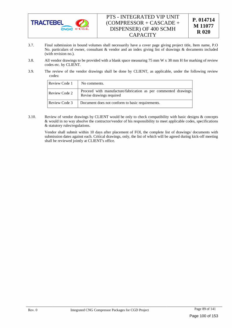
PTS - INTEGRATED VIP UNIT(COMPRESSOR + CASCADE +
DISPENSER) OF 400 SCMHCAPACITY
P. 014714M 11077
R 020
Rev. 0 Integrated CNG Compressor Packages for CGD Project Page 89 of 141
3.7. Final submission in bound volumes shall necessarily have a cover page giving project title, Item name, P.ONo. particulars of owner, consultant & vendor and an index giving list of drawings & documents included(with revision no.).
3.8. All vendor drawings to be provided with a blank space measuring 75 mm W x 38 mm H for marking of reviewcodes etc. by CLIENT.
3.9. The review of the vendor drawings shall be done by CLIENT, as applicable, under the following reviewcodes:
R Review Code 1 N No comments.
R Review Code 2 P Proceed with manufacture/fabrication as per commented drawings.Revise drawings required
R Review Code 3 D Document does not conform to basic requirements.
3.10. Review of vendor drawings by CLIENT would be only to check compatibility with basic designs & concepts& would in no way absolve the contractor/vendor of his responsibility to meet applicable codes, specifications& statutory rules/regulations.
Vendor shall submit within 10 days after placement of FOI, the complete list of drawings/ documents withsubmission dates against each. Critical drawings, only, the list of which will be agreed during kick-off meetingshall be reviewed jointly at CLIENT's office.
Page 100 of 153
PTS - INTEGRATED VIP UNIT(COMPRESSOR + CASCADE +
DISPENSER) OF 400 SCMHCAPACITY
P. 014714M 11077
R 020
Rev. 0 Integrated CNG Compressor Packages for CGD Project Page 90 of 141
SECTION – II: TECHNICAL SPECIFICATION FOR CASCADE
Page 101 of 153
PTS - INTEGRATED VIP UNIT(COMPRESSOR + CASCADE +
DISPENSER) OF 400 SCMHCAPACITY
P. 014714M 11077
R 020
Rev. 0 Integrated CNG Compressor Packages for CGD Project Page 91 of 141
1.0 SCOPE
This document covers, minimum requirement for design, engineering, procurement, fabrication/manufacture,assembly, inspection, testing of CNG Cascades to be supplies with integrated CNG package.
2.0 SITE ENVIRONMENT
The climatic conditions to be considered for selection, design and derating of equipment shall be as indicatedbelow:
The equipment offered shall be suitable for smooth, efficient and trouble free service in the tropical climateprevailing at site as indicated above.
The equipment shall be designed to give efficient and reliable performance under outdoor industrial conditionsand shall be rendered protected against rats, lizards and other vermin.
3.0 INSTRUCTIONS TO VENDORS
This specification describes the technical specification of the equipment to be supplied and/or installed forCNG stations of CLIENT.
Various parts of the specification shall be read in conjunction with each other. In cases where requirementsgiven in different parts differ, the most stringent shall govern.
The specification indicates the scope and requirements completely and clearly as possible. Any additionalwork/equipment or technical requirement not mentioned in the specification but required to make the offeredsystem complete in accordance with the specification or required for safe operation shall be deemed to beincluded in the offer.
Vendor may contact CLIENT and obtain clarifications, required, if any, at any stage, after award of LOA.
The Vendors are advised to visit the sites before submission of their offers, to ascertain for themselves type,nature and extent of work involved and actual site conditions. Failure to do so shall not absolve the Vendor oftheir responsibilities regarding supply, installation, testing, commissioning etc. under their scope of work.Further more, no plea of the Vendor based on unfavorable site conditions and/or non-availability/lack ofinformation shall be considered.
The Vendor shall confirm clause by clause acceptance of technical specification. Comments and/or deviationif any, of the Vendor on Owner/Consultant’s NIT document (including technical specification) shall be givenclause wise. Clauses, on which no specific comment or deviation will be indicated in the offer, shall be treatedas accepted by the Vendor.
It will be the responsibility of the Vendor to comply fully with relevant National/International standards,Indian Explosives Act, Regulations of Insurance association of India and Factories Act, while supplyingmaterials and/or carrying out work as per this specification.
Vendor’s responsibility shall also include preparing and submitting all necessary drawings, calculations, testcertificate etc. as required by concerned inspectorate / authorities.
The Vendor, free of cost and without affecting agreed milestones, shall carry out modifications suggested bythe statutory bodies.
Maximum Wind Velocity : 160 Km/hrMaximum Ambient Temperature : 47.5 °CMinimum Ambient Temperature : 1.7°CDesign wet bulb Temperature (WBT) : 27 °CRelative Humidity : 90%Altitude, M above MSL : 205 meters
Page 102 of 153
PTS - INTEGRATED VIP UNIT(COMPRESSOR + CASCADE +
DISPENSER) OF 400 SCMHCAPACITY
P. 014714M 11077
R 020
Rev. 0 Integrated CNG Compressor Packages for CGD Project Page 92 of 141
Civil engineering work i.e. foundation, trenches etc. shall be arranged by Owner. The vendor shall submitfoundation and other drawings indicating requirement of work to be carried out by Owner within two weeks ofplacement of order. In case the requisite information regarding requirement of slots, holes, pipe and otherfixing inserts etc. as required for proper installation of equipment is not indicated by the Vendor within twoweeks form placement of order, such facilities shall have to be arranged/provided by the Vendor at their owncost.
All work shall be carried out to the satisfaction of the Owner. Any work found to be carried out without theapproval of Owner or work which is considered to be unsatisfactory and of poor quality of workmanship shallbe rectified by the Vendor without any additional cost.
The Vendor shall not vary the scope of work as detailed in the approved drawings and specification, withoutwritten permission of the Owner. The work shall be done as per approved prints of the drawing only.
The Vendor shall submit a bar chart showing all important milestones for the completion of supply within 15days from the date of issuance of Fax of Intent (FOI) and shall provide the fortnightly progress report induplicate accordingly.
The Vendor shall attend progress meetings and all other meetings called by the Owner. The Vendor’srepresentative shall have the authority to make all decision related to the Contract.
All expenses for all the above activities shall be done and borne by the Vendor.
All pages of the offer shall be numbered and contents with page numbers shall be given at the beginning. Allpages of the offer shall be submitted in bound volume.
4.0 GAS COMPOSITION
GAS COMPOSITIONNormal Gas Composition Design Gas Composition
C1 82.43 – 99.10 89.45C2 7.27 – 0.90 4.58C3 3.47 – 0.00 0.83I C4 0.65 – 0.00 0.07N C4 0.78 – 0.00 0.06I C5 0.17 – 0.00 0.09N C5 0.13 – 0.00 0.28C6 0.10 – 0.00 0.17C7 0.00 – 0.00 0.00CO2 4.93 – 0.00 4.38N2 0.06 – 0.00 0.10H2O 0.01 – 0.00 0.00Total 100 100Average C.V.(kcal/SCM)
8950 – 8150 8302.3
5.0 CODES AND STANDARDS TO BE FOLLOWED:
The design, construction manufacture, supply, testing and other general requirements of the Storage Cascadesshould be strictly in accordance with the Applicable Standards and Codes and should comply fully withrelevant Indian/International standards, Gas Cylinder Rule 2016, Indian Explosives Act – 1884, Stationary andMobile Pressure Vessels (Unfired) Rules (SMPV)1981, Design Code,7285 (Part-2):2016, CNG CylinderValves, IS:3224-1979 (Amendments 1983,84,85,86,92,98), Hydrostatic Stretch Test, IS:5844-1970, SafetyDevices of Gas Cylinders, IS:5903-1970, regulations of Insurance Association of Indian and Factories Actwhile carrying out work as per the specification.
Page 103 of 153
PTS - INTEGRATED VIP UNIT(COMPRESSOR + CASCADE +
DISPENSER) OF 400 SCMHCAPACITY
P. 014714M 11077
R 020
Rev. 0 Integrated CNG Compressor Packages for CGD Project Page 93 of 141
The bidder without any additional cost and delivery implications should carry out any modification suggestedby the statutory bodies either during drawing approval or during inspection, if any.
CODES & STANDARDS TO BE FOLLOWED:
IS 7285 (Part-2):2004 Specification for seamless steel cylinders for permanent and high pressure liquefiablegases.
IS 3224:2002 Valve fittings for compressed gas cylinders excluding liquefied petroleum gas (LPG) cylinders.
OISD – 179 Safety requirements on compressors, storages, handling and refueling of natural gas for use inautomotive sector.
GAS CYLINDER RULES – 2016
FRAME STRUCTURAL STEEL SPECIFICATION-IS: 2062: 1992 GRADE-A
INDIAN EXPLOSIVES ACT.
SAFETY DEVICES OF GAS CYLIDNER IS:5903-1970, Regulations of insurance association
NFPA 52 Standards for CNG Vehicular systems
All the applicable statutory codes, national laws and local regulations for safety and Environment protectionshall be followed by the vendor for design , engineering, fabrication etc. the vendor shall obtain formconcerned authorities all necessary approvals.
6.0 EXTENT OF SUPPLY AND SERVICES
6.1 Supply
Supply of CNG storage cascades of capacity minimum 450 water liter (-0%, + 5%) at 15°C for 400 SCMHcompressor with following minimum details:
· All cylinders should be designed, constructed and tested in accordance with the Indian IS:7285(Part2):2004 or similar such other standard code approved by the Petroleum & Explosive SafetyOrganization.
· Each cylinder equipped with cylinder shut-off valve and Combination Bursting Disc & Fusible Plug(Conforming to IS 3224:2002).
· Robust painted Iron cascade frame. The iron surface shall be properly cleaned, primer and paint selectedand applied to have a service life of at least five years. The exterior of the equipment is required to becorrosion free for at least five years and to have a fade free life without oxidation of paint surface for atleast five years in an environment of bright sunlight with an intensive UV content. The bidder to specifythe grade of paint intended to be used.
· Interconnecting tubing/piping, fitting, valves.
· Non return valves (NRVs) as required for three-bank operation.
· Pressure gauge on each bank.
· All other items required for use of cascade as mobile for transportation of gas shall be properly fitted andthe drawing of cascade shall be approved by CLIENT prior to supply.
6.2 The services to be rendered by vendor shall include but not limited to the following:
· Obtaining approvals from concerned departments/agencies/statutory authorities such as BIS Certificate,PESO etc.
Page 104 of 153
PTS - INTEGRATED VIP UNIT(COMPRESSOR + CASCADE +
DISPENSER) OF 400 SCMHCAPACITY
P. 014714M 11077
R 020
Rev. 0 Integrated CNG Compressor Packages for CGD Project Page 94 of 141
· Procurement of raw materials, bought out components, fabrication, shop assembly.
· Shop inspection and testing including third party inspection (TPIA) or inspections by CLIENT’s delegateand statutory approvals.
· Testing at site.
· Packaging, crating, dispatch of cascades.
· Cascade commissioning assistance.
· Paintings as per the present document.
· Preparation and submission of documents/drawings as per schedule.
7.0 TECHNICAL SPECIFICATIONS
The following specification is to give the vendor the technical and operating conditions the cascades mustfulfill. Features other than those indicated herein but which call for a better design, increase in efficiency,enhance reliability, optimization may be accepted subjected to CLIENT’s approval. The cascade shall beshipped in completely assembled condition. Gas supply line and delivery connection shall be made at site.
The vendor shall bid in their main offer, items according to the technical specifications outlined below.
7.1 Cascade
· Cascade shall be a group of identical cylinders of capacity required to meet the specified total watercapacity, dimensional and weight limitations. The cascades shall be provided with structural framehaving facility of lifting and placement.
· Cascade storage Capacity.
The water storage capacity of static cascade shall be minimum 450 (-0%, +5%) water litres at 15 degreeC (Cylinders conforming to IS:7285 (Part 2)-2004) for 400 SCMH compressor.
· The water liter capacity of any individual cylinder in –group of cylinders forming cascades shall notexceed 125 liters at 15 degree C for 450 water liter capacity (Min.) cascades.
· The design, construction & testing of cylinder shall be as per IS 7285 – 2004 and approved by Petroleumand Explosives Safety Organization (PESO), Government of India for use in India for specifiedcondition.
· Working pressure of cascade cylinder shall be minimum 250 bar g at 15 degree C.
· Storage cylinder manufactured older than 2017 shall not be accepted.
· Cylinder material shall be seamless alloy steel (Cr-Mo) as per design/drawings approval by Petroleumand Explosive Safety Organization (PESO), Govt of India.
· Cylinder neck threading shall be as per IS 3224-2002 or as per design approved by Petroleum andExplosive Safety Organization (PESO), Govt of India.
· In case cascades with 50 litres cylinders are offered vendor shall observe minimum neck threads size ofdia 25.4 mm standard. Type 4 threads with a taper of 1 in 8 on diameter confirming to IS-3224:2002 orequivalent.
· The cylinder shut-off valve shall be with combination Bursting Disc and Fusible Plug conforming torequirements of IS 3224:2002 or as per design approved by Petroleum and Explosive SafetyOrganization (PESO), Govt of India.
· The burst disc shall rupture on excess pressure as well as excess temperature either individually orcombined. The burst disc discharge shall be manifold to a common header for safe venting. Vendor shallindicate burst pressure and temperature.
Page 105 of 153
PTS - INTEGRATED VIP UNIT(COMPRESSOR + CASCADE +
DISPENSER) OF 400 SCMHCAPACITY
P. 014714M 11077
R 020
Rev. 0 Integrated CNG Compressor Packages for CGD Project Page 95 of 141
· The cylinder shut-off valve orifice shall be designed for high flow to permit the combined flow of100kg/min from each bank at pressure of 250 bar g. Vendor to furnish necessary calculations indicatingoverall pressure drop for each bank, Coefficient of flow (Cv) values orifice size etc.
· Number of cylinders in the cascade shall be divided into three independent banks of low, medium andhigh pressure of different storage pressures. Vendor shall optimize the number of cylinders in each bankfor maximizing the recovery from the cascade storage and submit the calculations along with the bid.Vendor may assume the residual cylinder pressure of the vehicle coming for refill at 30 bar g.
· The interconnecting tube work of cylinders manifold in configuration suitable for priority filling andsequential dispensing system by the electronic CNG dispensers at the Retail Outlets.
· Full bore ball valves for isolation shall be provided at inlet of each fill line and at each bank outlet line.The final end connection at battery limit shall be 3/4” OD with nut and double ferrules for directlyconnecting a ¾ “OD tube.
· The interconnecting tube work shall be minimum of ¾ “OD tubing. The sizing of connecting tubingbetween each outlet and its associated cylinders shall be such that where they join the total incomingflow areas shall not be less than outgoing area. The loops in tube work shall be provided for absorbingcontraction, expansion and vibration piping/tubing shall be suitably clamped to the frame structure.
· All cylinders should be new and unused. Re-certified cylinders are not acceptable. Before using/refilling,the cylinders which has to be made free of air contained gas shall be purged by an inert gas or by theCNG gas. All cylinders in a cascade shall be of same capacity.
· Cylinders in the cascade may be vertically or horizontally placed. In case of horizontal configuration,minimum 30 mm cylinder to cylinder gap shall be provided (Conforming to requirements of OISD-179).The material used to separate the cylinders should be sufficiently strong enough and should not absorbmoisture. Special precautions should be taken to avoid corrosion at the point of contact.
· All cylinder valves and fittings must be rated for the full range of temperature and pressures and themanufacturer should stamp or otherwise permanently mark the valve body to indicate the service rating.
· Double compression ferrule Fittings shall be used in the connection tubes.
· All cylinders to be hydrostatically tested and approved by third party certification body. Test certificatesshall be duly endorsed by approval body and issued before delivery.
· The location of inlet/outlet tube and pressure gauges shall be as per approved drawing.
· Cascade to be purged with N2 after testing and shipped with a positive pressure of N2 in the cascade.Suitable vent as attached in the drawing to be provided for stationery cascade.
7.2 Piping/Tubing/Fitting/Pressure Gauges
· Materials used for the piping shall be stainless steel 316 fully annealed seamless confirming to ASTMA269 with maximum hardness of Rb80 or less and suitable for bending and flaring. OD tolerance shallnot exceed +0.005%.
· All fittings including valves shall be as per recommended vendor list. Material shall be SS 316conforming to ASTM A269. Open ends on fittings and vents shall be provided with caps.
· Double compression ferrule fittings shall be used in tube connections.
· Liquid filled pressure gauge of diameter 4”, (0-400 kg/cm2) with a 3 – way isolating valve on each bankshall be used. Thus each cascade shall have three pressure gauges. Pressure gauges shall be securelymounted.
· All end connections, pressure gauges, valves and fittings of cascade shall be within tamper proof, wirecage enclosure. There shall be on one side of cascade for ease of operation.
· Material of vent tubing shall be Copper & Brass fitting as per ASTM B75, B 68 and make shall be as perrecommended vendor list.
Page 106 of 153
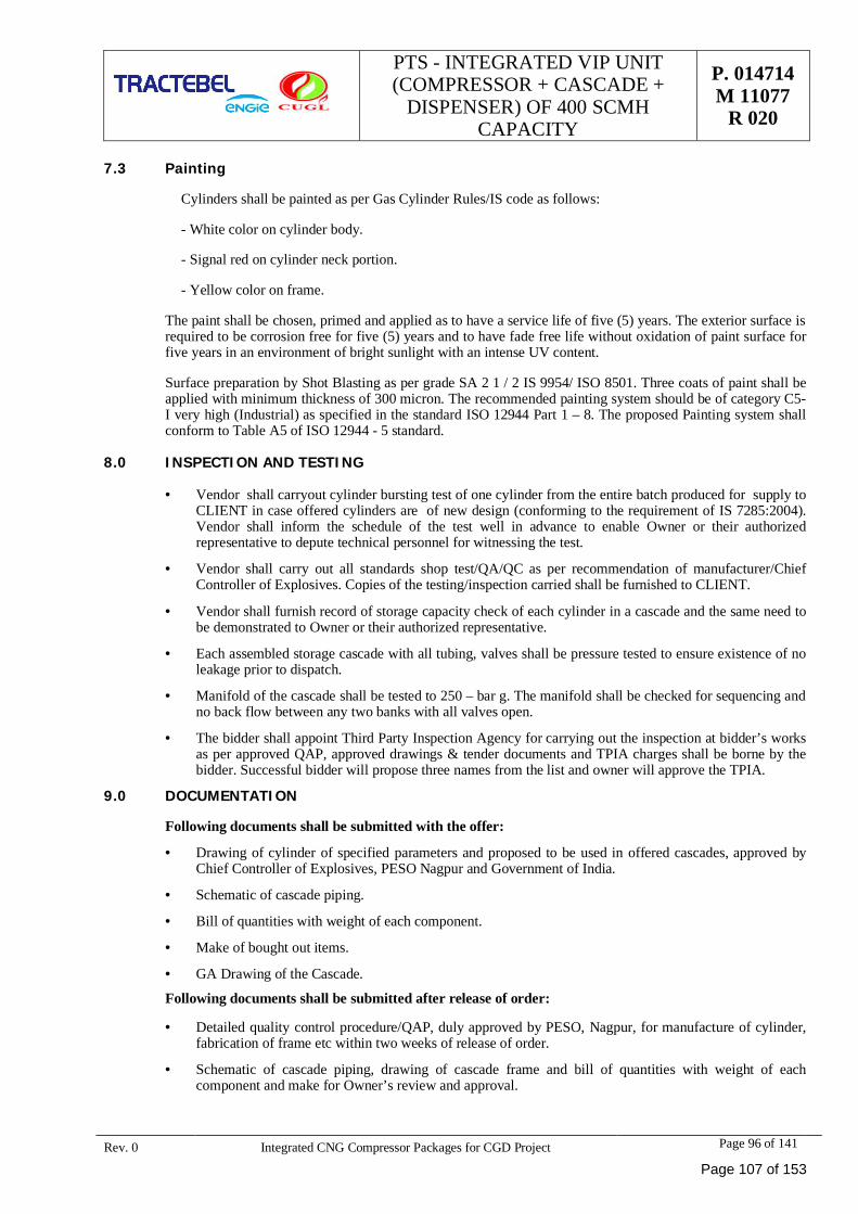
PTS - INTEGRATED VIP UNIT(COMPRESSOR + CASCADE +
DISPENSER) OF 400 SCMHCAPACITY
P. 014714M 11077
R 020
Rev. 0 Integrated CNG Compressor Packages for CGD Project Page 96 of 141
7.3 Painting
Cylinders shall be painted as per Gas Cylinder Rules/IS code as follows:
- White color on cylinder body.
- Signal red on cylinder neck portion.
- Yellow color on frame.
The paint shall be chosen, primed and applied as to have a service life of five (5) years. The exterior surface isrequired to be corrosion free for five (5) years and to have fade free life without oxidation of paint surface forfive years in an environment of bright sunlight with an intense UV content.
Surface preparation by Shot Blasting as per grade SA 2 1 / 2 IS 9954/ ISO 8501. Three coats of paint shall beapplied with minimum thickness of 300 micron. The recommended painting system should be of category C5-I very high (Industrial) as specified in the standard ISO 12944 Part 1 – 8. The proposed Painting system shallconform to Table A5 of ISO 12944 - 5 standard.
8.0 INSPECTION AND TESTING
· Vendor shall carryout cylinder bursting test of one cylinder from the entire batch produced for supply toCLIENT in case offered cylinders are of new design (conforming to the requirement of IS 7285:2004).Vendor shall inform the schedule of the test well in advance to enable Owner or their authorizedrepresentative to depute technical personnel for witnessing the test.
· Vendor shall carry out all standards shop test/QA/QC as per recommendation of manufacturer/ChiefController of Explosives. Copies of the testing/inspection carried shall be furnished to CLIENT.
· Vendor shall furnish record of storage capacity check of each cylinder in a cascade and the same need tobe demonstrated to Owner or their authorized representative.
· Each assembled storage cascade with all tubing, valves shall be pressure tested to ensure existence of noleakage prior to dispatch.
· Manifold of the cascade shall be tested to 250 – bar g. The manifold shall be checked for sequencing andno back flow between any two banks with all valves open.
· The bidder shall appoint Third Party Inspection Agency for carrying out the inspection at bidder’s worksas per approved QAP, approved drawings & tender documents and TPIA charges shall be borne by thebidder. Successful bidder will propose three names from the list and owner will approve the TPIA.
9.0 DOCUMENTATION
Following documents shall be submitted with the offer:
· Drawing of cylinder of specified parameters and proposed to be used in offered cascades, approved byChief Controller of Explosives, PESO Nagpur and Government of India.
· Schematic of cascade piping.
· Bill of quantities with weight of each component.
· Make of bought out items.
· GA Drawing of the Cascade.
Following documents shall be submitted after release of order:
· Detailed quality control procedure/QAP, duly approved by PESO, Nagpur, for manufacture of cylinder,fabrication of frame etc within two weeks of release of order.
· Schematic of cascade piping, drawing of cascade frame and bill of quantities with weight of eachcomponent and make for Owner’s review and approval.
Page 107 of 153
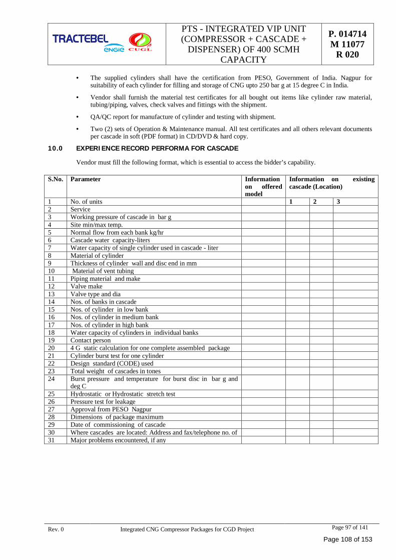
PTS - INTEGRATED VIP UNIT(COMPRESSOR + CASCADE +
DISPENSER) OF 400 SCMHCAPACITY
P. 014714M 11077
R 020
Rev. 0 Integrated CNG Compressor Packages for CGD Project Page 97 of 141
· The supplied cylinders shall have the certification from PESO, Government of India. Nagpur forsuitability of each cylinder for filling and storage of CNG upto 250 bar g at 15 degree C in India.
· Vendor shall furnish the material test certificates for all bought out items like cylinder raw material,tubing/piping, valves, check valves and fittings with the shipment.
· QA/QC report for manufacture of cylinder and testing with shipment.
· Two (2) sets of Operation & Maintenance manual. All test certificates and all others relevant documentsper cascade in soft (PDF format) in CD/DVD & hard copy.
10.0 EXPERIENCE RECORD PERFORMA FOR CASCADE
Vendor must fill the following format, which is essential to access the bidder’s capability.
S.No. Parameter Informationon offeredmodel
Information on existingcascade (Location)
1 No. of units 1 2 32 Service3 Working pressure of cascade in bar g4 Site min/max temp.5 Normal flow from each bank kg/hr6 Cascade water capacity-liters7 Water capacity of single cylinder used in cascade - liter8 Material of cylinder9 Thickness of cylinder wall and disc end in mm10 Material of vent tubing11 Piping material and make12 Valve make13 Valve type and dia14 Nos. of banks in cascade15 Nos. of cylinder in low bank16 Nos. of cylinder in medium bank17 Nos. of cylinder in high bank18 Water capacity of cylinders in individual banks19 Contact person20 4 G static calculation for one complete assembled package21 Cylinder burst test for one cylinder22 Design standard (CODE) used23 Total weight of cascades in tones24 Burst pressure and temperature for burst disc in bar g and
deg C25 Hydrostatic or Hydrostatic stretch test26 Pressure test for leakage27 Approval from PESO Nagpur28 Dimensions of package maximum29 Date of commissioning of cascade30 Where cascades are located: Address and fax/telephone no. of31 Major problems encountered, if any
Page 108 of 153
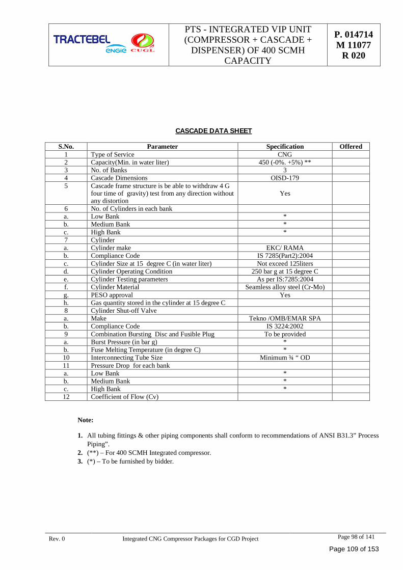
PTS - INTEGRATED VIP UNIT(COMPRESSOR + CASCADE +
DISPENSER) OF 400 SCMHCAPACITY
P. 014714M 11077
R 020
Rev. 0 Integrated CNG Compressor Packages for CGD Project Page 98 of 141
CASCADE DATA SHEET
S.No. Parameter Specification Offered1 Type of Service CNG2 Capacity(Min. in water liter) 450 (-0%. +5%) **3 No. of Banks 34 Cascade Dimensions OISD-1795 Cascade frame structure is be able to withdraw 4 G
four time of gravity) test from any direction withoutany distortion
Yes
6 No. of Cylinders in each banka. Low Bank *b. Medium Bank *c. High Bank *7 Cylindera. Cylinder make EKC/ RAMAb. Compliance Code IS 7285(Part2):2004c. Cylinder Size at 15 degree C (in water liter) Not exceed 125litersd. Cylinder Operating Condition 250 bar g at 15 degree Ce. Cylinder Testing parameters As per IS:7285:2004f. Cylinder Material Seamless alloy steel (Cr-Mo)g. PESO approval Yesh. Gas quantity stored in the cylinder at 15 degree C8 Cylinder Shut-off Valvea. Make Tekno /OMB/EMAR SPAb. Compliance Code IS 3224:20029 Combination Bursting Disc and Fusible Plug To be provideda. Burst Pressure (in bar g) *b. Fuse Melting Temperature (in degree C) *10 Interconnecting Tube Size Minimum ¾ “ OD11 Pressure Drop for each banka. Low Bank *b. Medium Bank *c. High Bank *12 Coefficient of Flow (Cv)
Note:
1. All tubing fittings & other piping components shall conform to recommendations of ANSI B31.3” ProcessPiping”.
2. (**) – For 400 SCMH Integrated compressor.3. (*) – To be furnished by bidder.
Page 109 of 153
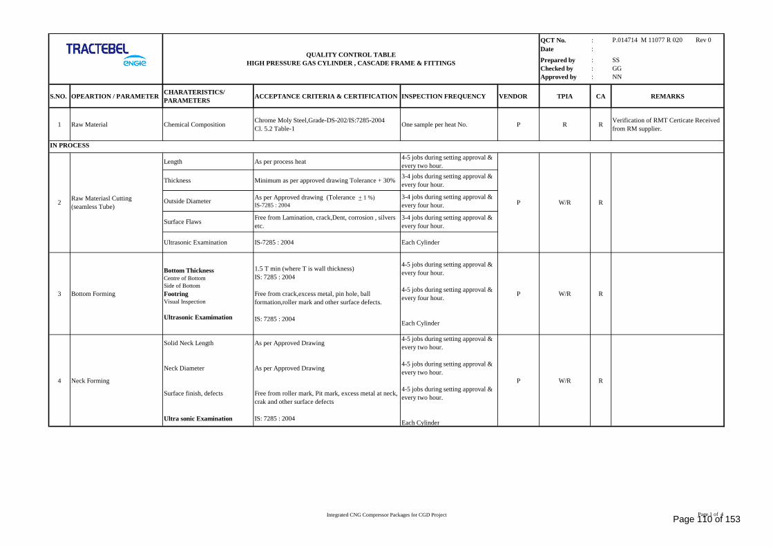
QCT No. : P.014714 M 11077 R 020 Rev 0Date :
Prepared by : SSChecked by : GGApproved by : NN
S.NO. OPEARTION / PARAMETER CHARATERISTICS/PARAMETERS ACCEPTANCE CRITERIA & CERTIFICATION INSPECTION FREQUENCY VENDOR TPIA CA REMARKS
1 Raw Material Chemical Composition Chrome Moly Steel,Grade-DS-202/IS:7285-2004Cl. 5.2 Table-1 One sample per heat No. P R R Verification of RMT Certicate Received
from RM supplier.
Length As per process heat 4-5 jobs during setting approval &every two hour.
Thickness Minimum as per approved drawing Tolerance + 30% 3-4 jobs during setting approval &every four hour.
Outside Diameter As per Approved drawing (Tolerance + 1 %)IS-7285 : 2004
3-4 jobs during setting approval &every four hour.
Surface Flaws Free from Lamination, crack,Dent, corrosion , silversetc.
3-4 jobs during setting approval &every four hour.
Ultrasonic Examination IS-7285 : 2004 Each Cylinder
3 Bottom Forming
Bottom ThicknessCentre of BottomSide of BottomFootringVisual Inspection
Ultrasonic Examimation
1.5 T min (where T is wall thickness)IS: 7285 : 2004
Free from crack,excess metal, pin hole, ballformation,roller mark and other surface defects.
IS: 7285 : 2004
4-5 jobs during setting approval &every four hour.
4-5 jobs during setting approval &every four hour.
Each Cylinder
P W/R R
4 Neck Forming
Solid Neck Length
Neck Diameter
Surface finish, defects
Ultra sonic Examination
As per Approved Drawing
As per Approved Drawing
Free from roller mark, Pit mark, excess metal at neck,crak and other surface defects
IS: 7285 : 2004
4-5 jobs during setting approval &every two hour.
4-5 jobs during setting approval &every two hour.
4-5 jobs during setting approval &every two hour.
Each Cylinder
P W/R R
IN PROCESS
2
QUALITY CONTROL TABLEHIGH PRESSURE GAS CYLINDER , CASCADE FRAME & FITTINGS
W/RRaw Materiasl Cutting(seamless Tube) P R
Integrated CNG Compressor Packages for CGD Project Page 1 of 4Page 110 of 153
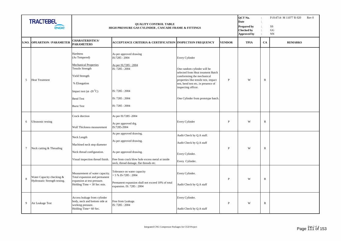
QCT No. : P.014714 M 11077 R 020 Rev 0Date :
Prepared by : SSChecked by : GGApproved by : NN
S.NO. OPEARTION / PARAMETER CHARATERISTICS/PARAMETERS ACCEPTANCE CRITERIA & CERTIFICATION INSPECTION FREQUENCY VENDOR TPIA CA REMARKS
QUALITY CONTROL TABLEHIGH PRESSURE GAS CYLINDER , CASCADE FRAME & FITTINGS
5 Heat Treatment
Hardness(As Tempered)
Mechanical PropertiesTensile Strength
Yield Strength
% Elongation
Impact test (at -20 0C)
Bend Test
Burst Test
As per approved drawingIS:7285 : 2004
As per IS;7285 : 2004IS: 7285 : 2004
IS: 7285 : 2004
IS: 7285 : 2004
IS: 7285 : 2004
Every Cylinder
One random cylinder will beselected from Heat treament Batchcomformimg the mechanicalproperties like tensile test, impacttest, bend test etc, in presence ofinspecting officer.
One Cylinder from prototype batch.
P W R
6 Ultrasonic testing
Crack dtection
Wall Thickness measurement
As per IS:7285 -2004
As per approved drg.IS:7285-2004
Every Cylinder P W R
7 Neck cutting & Threading
Neck Length
Machined neck step diameter
Neck thread configuration.
Visual inspection thread finish.
As per approved drawing.
As per approved drawing.
As per approved drawing.
Free from crack blow hole excess metal at insideneck, thread damage, flat threads etc.
Audit Check by Q.A staff.
Audit Check by Q.A staff
Every Cylinder.
Every Cylinder.
P W R
8 Water Capacity checking &Hydrostatic Strength testing.
Measurement of water capacity.Total expansion and permanentexpansion at test pressure.Holding Time = 30 Sec min.
Tolerance on water capacity+ 5 % IS-7285 : 2004
Permanent expansion shall not exceed 10% of totalexpansion. IS: 7285 : 2004
Every Cylinder.
Audit Check by Q.A staff
P W R
9 Air Leakage Test
Access leakage from cylinderbody, neck and bottom side atworking pressure.Holding Time= 60 Sec.
Free from Leakage.IS: 7285 : 2004
Every Cylinder.
Audit Check by Q.A staff
P W R
Integrated CNG Compressor Packages for CGD Project Page 2 of 4Page 111 of 153
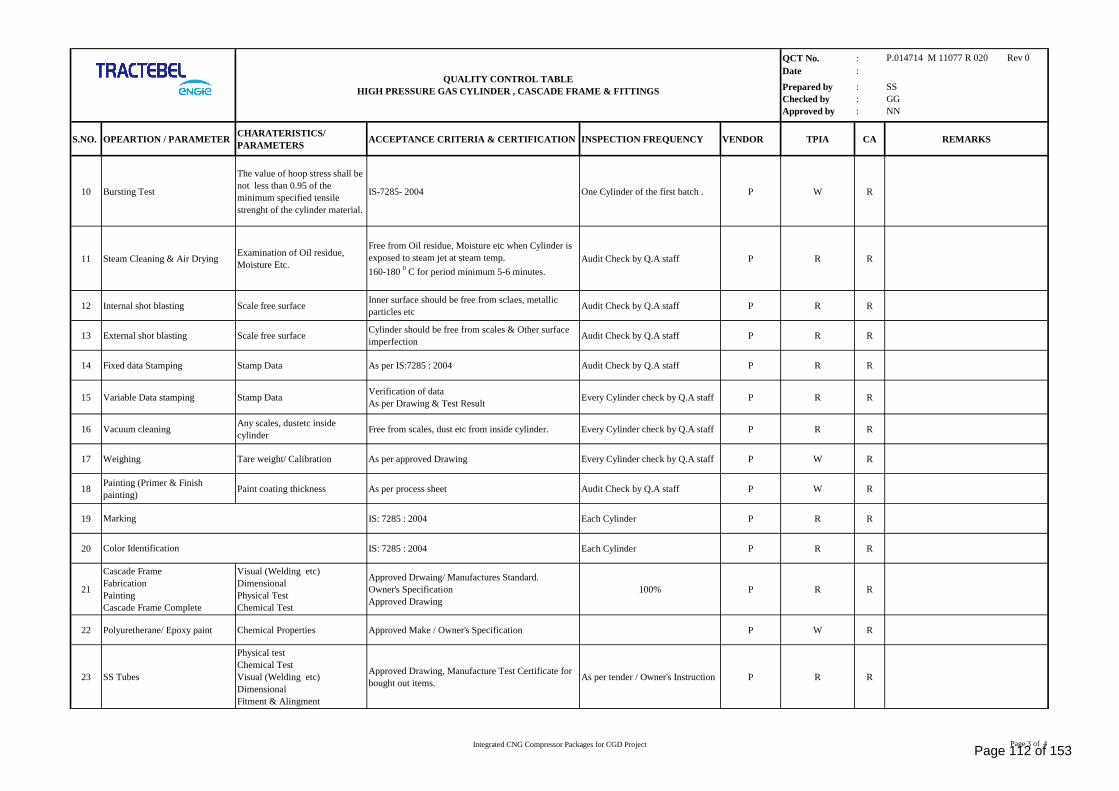
QCT No. : P.014714 M 11077 R 020 Rev 0Date :
Prepared by : SSChecked by : GGApproved by : NN
S.NO. OPEARTION / PARAMETER CHARATERISTICS/PARAMETERS ACCEPTANCE CRITERIA & CERTIFICATION INSPECTION FREQUENCY VENDOR TPIA CA REMARKS
QUALITY CONTROL TABLEHIGH PRESSURE GAS CYLINDER , CASCADE FRAME & FITTINGS
10 Bursting Test
The value of hoop stress shall benot less than 0.95 of theminimum specified tensilestrenght of the cylinder material.
IS-7285- 2004 One Cylinder of the first batch . P W R
11 Steam Cleaning & Air Drying Examination of Oil residue,Moisture Etc.
Free from Oil residue, Moisture etc when Cylinder isexposed to steam jet at steam temp.160-180 0 C for period minimum 5-6 minutes.
Audit Check by Q.A staff P R R
12 Internal shot blasting Scale free surface Inner surface should be free from sclaes, metallicparticles etc Audit Check by Q.A staff P R R
13 External shot blasting Scale free surface Cylinder should be free from scales & Other surfaceimperfection Audit Check by Q.A staff P R R
14 Fixed data Stamping Stamp Data As per IS:7285 : 2004 Audit Check by Q.A staff P R R
15 Variable Data stamping Stamp Data Verification of dataAs per Drawing & Test Result Every Cylinder check by Q.A staff P R R
16 Vacuum cleaning Any scales, dustetc insidecylinder Free from scales, dust etc from inside cylinder. Every Cylinder check by Q.A staff P R R
17 Weighing Tare weight/ Calibration As per approved Drawing Every Cylinder check by Q.A staff P W R
18 Painting (Primer & Finishpainting) Paint coating thickness As per process sheet Audit Check by Q.A staff P W R
19 IS: 7285 : 2004 Each Cylinder P R R
20 IS: 7285 : 2004 Each Cylinder P R R
21
Cascade FrameFabricationPaintingCascade Frame Complete
Visual (Welding etc)DimensionalPhysical TestChemical Test
Approved Drwaing/ Manufactures Standard.Owner's SpecificationApproved Drawing
100% P R R
22 Polyuretherane/ Epoxy paint Chemical Properties Approved Make / Owner's Specification P W R
23 SS Tubes
Physical testChemical TestVisual (Welding etc)DimensionalFitment & Alingment
Approved Drawing, Manufacture Test Certificate forbought out items. As per tender / Owner's Instruction P R R
Marking
Color Identification
Integrated CNG Compressor Packages for CGD Project Page 3 of 4Page 112 of 153
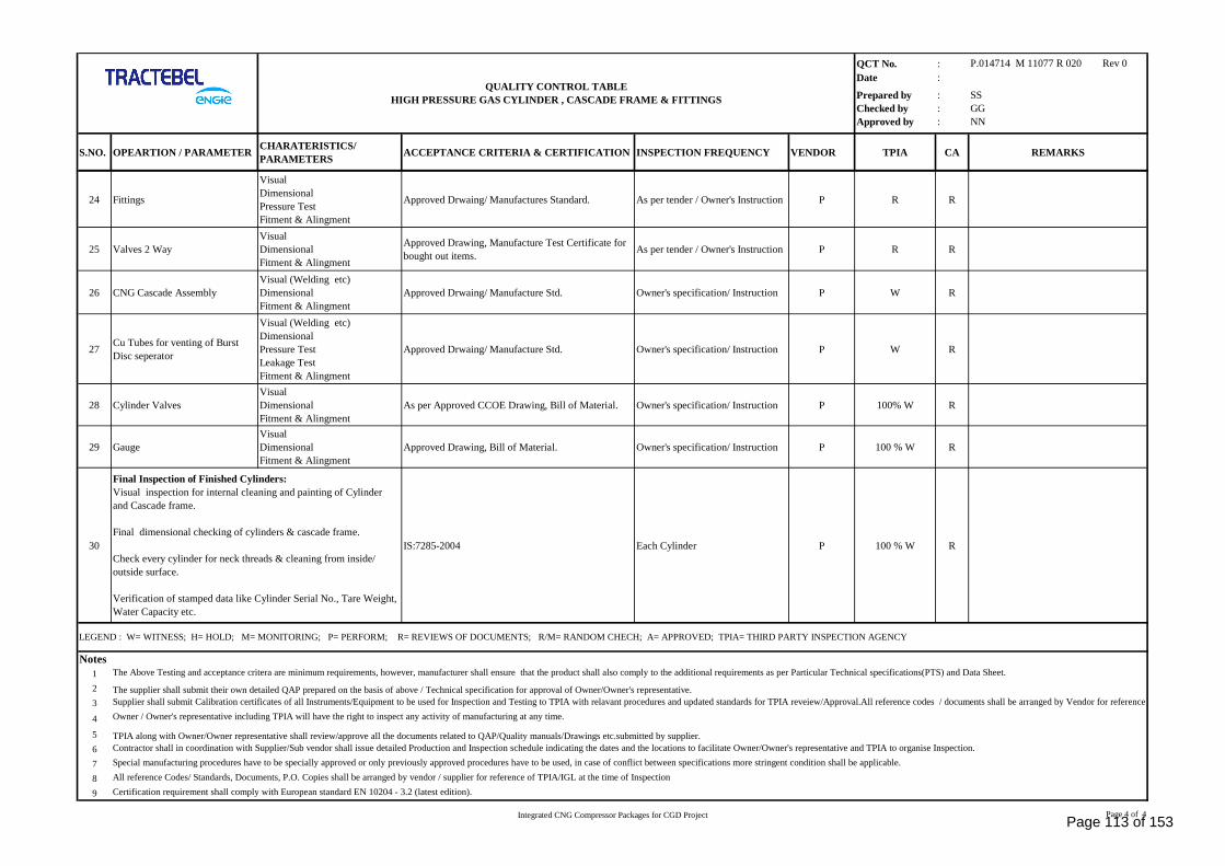
QCT No. : P.014714 M 11077 R 020 Rev 0Date :
Prepared by : SSChecked by : GGApproved by : NN
S.NO. OPEARTION / PARAMETER CHARATERISTICS/PARAMETERS ACCEPTANCE CRITERIA & CERTIFICATION INSPECTION FREQUENCY VENDOR TPIA CA REMARKS
QUALITY CONTROL TABLEHIGH PRESSURE GAS CYLINDER , CASCADE FRAME & FITTINGS
24 Fittings
VisualDimensionalPressure TestFitment & Alingment
Approved Drwaing/ Manufactures Standard. As per tender / Owner's Instruction P R R
25 Valves 2 WayVisualDimensionalFitment & Alingment
Approved Drawing, Manufacture Test Certificate forbought out items. As per tender / Owner's Instruction P R R
26 CNG Cascade AssemblyVisual (Welding etc)DimensionalFitment & Alingment
Approved Drwaing/ Manufacture Std. Owner's specification/ Instruction P W R
27 Cu Tubes for venting of BurstDisc seperator
Visual (Welding etc)DimensionalPressure TestLeakage TestFitment & Alingment
Approved Drwaing/ Manufacture Std. Owner's specification/ Instruction P W R
28 Cylinder ValvesVisualDimensionalFitment & Alingment
As per Approved CCOE Drawing, Bill of Material. Owner's specification/ Instruction P 100% W R
29 GaugeVisualDimensionalFitment & Alingment
Approved Drawing, Bill of Material. Owner's specification/ Instruction P 100 % W R
30 IS:7285-2004 Each Cylinder P 100 % W R
Notes123
4
56789
The supplier shall submit their own detailed QAP prepared on the basis of above / Technical specification for approval of Owner/Owner's representative.
LEGEND : W= WITNESS; H= HOLD; M= MONITORING; P= PERFORM; R= REVIEWS OF DOCUMENTS; R/M= RANDOM CHECH; A= APPROVED; TPIA= THIRD PARTY INSPECTION AGENCY
Final Inspection of Finished Cylinders:Visual inspection for internal cleaning and painting of Cylinderand Cascade frame.
Final dimensional checking of cylinders & cascade frame.
Check every cylinder for neck threads & cleaning from inside/outside surface.
Verification of stamped data like Cylinder Serial No., Tare Weight,Water Capacity etc.
Certification requirement shall comply with European standard EN 10204 - 3.2 (latest edition).
The Above Testing and acceptance critera are minimum requirements, however, manufacturer shall ensure that the product shall also comply to the additional requirements as per Particular Technical specifications(PTS) and Data Sheet.
All reference Codes/ Standards, Documents, P.O. Copies shall be arranged by vendor / supplier for reference of TPIA/IGL at the time of Inspection
Supplier shall submit Calibration certificates of all Instruments/Equipment to be used for Inspection and Testing to TPIA with relavant procedures and updated standards for TPIA reveiew/Approval.All reference codes / documents shall be arranged by Vendor for referenceof TPIA at the time of inspection.Owner / Owner's representative including TPIA will have the right to inspect any activity of manufacturing at any time.
TPIA along with Owner/Owner representative shall review/approve all the documents related to QAP/Quality manuals/Drawings etc.submitted by supplier.Contractor shall in coordination with Supplier/Sub vendor shall issue detailed Production and Inspection schedule indicating the dates and the locations to facilitate Owner/Owner's representative and TPIA to organise Inspection.Special manufacturing procedures have to be specially approved or only previously approved procedures have to be used, in case of conflict between specifications more stringent condition shall be applicable.
Integrated CNG Compressor Packages for CGD Project Page 4 of 4Page 113 of 153
PTS - INTEGRATED VIP UNIT(COMPRESSOR + CASCADE +
DISPENSER) OF 400 SCMHCAPACITY
P. 014714M 11077
R 020
Rev. 0 Integrated CNG Compressor Packages for CGD Project Page 99 of 141
SECTION – III: TECHNICAL SPECIFICATION FOR CNG CARDISPENSER
Page 114 of 153
PTS - INTEGRATED VIP UNIT(COMPRESSOR + CASCADE +
DISPENSER) OF 400 SCMHCAPACITY
P. 014714M 11077
R 020
Rev. 0 Integrated CNG Compressor Packages for CGD Project Page 100 of 141
SECTION: A - GENERAL SPECIFICATION
1.0 SCOPE OF SUPPLY & SERVICES
1.1 Supply of double arm type having flow capacity of ≥ 15 kg/min for a single arm under discharge toatmospheric condition. Each Car Dispenser shall have following as a minimum:-
1.1.1 Two CNG flexible electrically conductive twin (fill & vent) hose, with both hoses fitted with NGV-I for fillingof vehicles. However, both the hoses shall be suitable to be attached with NZS-5425 nozzles. Vendor shallinclude the supply of 3-way valve with each hose for filling & venting of gas. Vendor shall also include supplyof Breakaway Coupling, suitable for NGV Industry, in the hose. Hose shall be 3/8” ID 5000 psig, at least 3mlong. Both hoses should be provided with protective spiral cover .Vendor shall demonstrate the function ofbreakaway coupling during performance test. The dispensers shall be designed in such a way that freemovement of hoses is possible, by spring loaded high mast. Supply of NGV-I to NZS-5425 adapter nozzlesshall be in bidder’s scopeTwo numbers of Coriolis true mass flow metering system.All Mass flow meter shall be provided with a Liquid Crystal Display (LCD) for ongoing flow monitoring and totalizers.The preferred make shall be E&H or Emerson (Micromotion)
· Three rows of liquid crystal backlit display for night viewing showing total sale in Rupees (00000.00),quantity of gas sold in kg (00000.00), unit price of CNG in Rs/kg (000.00) for each hose on either sideof the dispenser (total two sets of three rows for each Dispenser, one display for each side). The wholedispenser electronic unit shall have IP - 65 protection and display cabinet shall have IP 54 protection.
· Non-resettable and non-volatile totalizer up to 999999.99 for total CNG sold in Kg with anindependent battery backup. For further details refer Section B: Instrumentation & Controlspecification.
· One number of three banks electronic software and controller including hardware for individual fillingarm.
· Two numbers of holster/ cradle for fill nozzles along with weather caps for the protection of nozzles.Holster/ cradle shall be suitable for both NZS and NGV nozzles. Holster/cradle shall be provided forNGV nozzle and shall be compatible to be attached with NZS-5425 nozzles.
· Two number of Hi-mast with flexible hose arrangement or Appropriate arrangement to be provided inorder to allow free movement of flexible hose, prevent strain on the fill hose connection and to avoidtouching the ground.
· Emergency stop switch is required on both side of the dispenser. However, the filling on both sidesshould stop in emergency condition, when any one of the emergency switch is pressed. Duringactivation of emergency switch, the power supply to the dispenser should be available.
· Two nos. of liquid filled 4” dia. (0-400 Kg/cm2g) pressure gauges showing the vehicle filling pressurefor each filling arm.
· Two Nos. bubble tight manual shut-off valve for fill hose.
· Vendor has to supply the dispensers with solenoid operated valve or actuated Ball Valve with NAMURIntrinsically Safe Solenoid Valve made of ANSI 316 SS, for ON-OFF control of flow, on the gas inletwith 1/2” tube OD end connection. Valves shall be provided for each bank per hose separately. Valvemake shall be approved by CLIENT and during detail engineering. CLIENT has an option to choosethe type of valve for supply of Dispensers. Vendor to ensure the system design in such a way that anygas if passes, should be recorded by dispenser and there should not be any possibility of unmetered gassupply through dispenser in case of malfunctioning of solenoid valves.
· The gas tubing inside the dispensers shall be seamless SS 316 fully annealed (Bright Annealed)conforming to ASTM A 269 with maximum hardness of RB 80 or less and suitable for bending andflaring. The tubes shall be fully annealed (bright annealed), 1/2” OD with a 1/2” SS 2-way Ball valve
Page 115 of 153
PTS - INTEGRATED VIP UNIT(COMPRESSOR + CASCADE +
DISPENSER) OF 400 SCMHCAPACITY
P. 014714M 11077
R 020
Rev. 0 Integrated CNG Compressor Packages for CGD Project Page 101 of 141
at inlet and 1/2” OD end connection suitable for connecting with 1/2” OD SS Tube. Any open ends onfittings and vents shall be provided with caps/ dust plugs.
· Coalescent and particulate Stainless Steel filter of Grade 6 or better to be provided at inlet of each banksupply line with manual drain valve to ensure that the oil carryover in the CNG being filled to vehicleis < 1 ppm and particulate size is < 0.01 Micron. Filter housing for said filter must be capable forcollection of oil for a drain interval of 24 hrs with oil carryover < 1 ppm. Filter elements made of papershall not be accepted. Vendor to provide appropriately plugged drain valve outside the dispenserhousing with suitable arrangement to collect the drained oil. Filter size shall be in accordance with maxflow through the dispenser.
· The CNG dispenser specification should meet the IS 15403:2000 (E) natural gas quality designationfor use as a compressed fuel for vehicles.
· Vendor shall ensure that the system design in such a way that in both options any gas if passes, shouldbe recorded by mass flow meter and there should not be any possibility of unmetered gas supplythrough dispenser in case of malfunctioning of solenoid or actuated Ball valves. Any unmetered gaspassing shall be recorded in the dispenser is retrievable as and when required.
· Any other item required for safe and accurate operation of Dispenser.
· Any spare(s) required during commissioning shall be in the scope of vendor.
· Supply of application program, ladder logic, list of error codes with description for programming thedispenser parameter.
· If dedicated programming unit is required for programming/ parameter change. The same shall besubmitted in “CD” along with supply of dispenser also hard copy of the same also be submitted.
· Vendor shall make a provision to change the price of CNG through the keypad inside the dispenser unitthat shall be covered with security lock. It shall also be possible to change the price from remote station(from SCADA/ from any part of the city). RS 485 port shall also be provided for price change. In casestandard RS485 port is not available in the dispenser, then RS232C to RS485 convertor with allrelevant hardware and software to be provided by vendor.
· RS 485 serial port shall be provided for down loading the CNG sale data with the help of Purchaser'sPersonal Computer for each shift (8 hours interval). In case standard RS485 port is not available in thedispenser, then RS232C to RS485 converter with all relevant hardware and software to be provided byvendor. Suitable software shall be provided to obtain the same for each shift (8 hours interval). Thisport shall be made available outside the explosion proof electronic housing for Purchaser's use.
· Vendor shall provide a common processor and open communication protocol/ RS 485 port for RTU totransfer all the dispenser data to central SCADA system. In case standard RS485 port is not availablein the dispenser, then RS232C to RS485 converter with all relevant hardware and software to beprovided by vendor.
· Vendor must note that non-standard/ propriety type communication protocol in dispenser forcommunication with RTU is not acceptable. Protocol must be standard as specified above or anystandard protocol with compatible convertor shall be made available and must be compatible to anymake of RTU. RTU will have Serial communication port RS 485 protocol to interface with dispenser.Vendor is responsible to provide the communication port compatibility with RTU. Vendor is requiredto carry the communication port functional test and display all the values in Lap top or in applicabledevice during dispenser inspection (FAT) at vendor premises. Also functional test shall be carried outby vendor after installation and looping is junction box at site. Vendor shall also share the dispenserprotocol details with CLIENT
· Vendor must furnish/ share the details of implemented MODBUS protocol like function codes for readand write, slave ID, list of signals to be transferred, CRC implementation, register addressing methods /
Page 116 of 153
PTS - INTEGRATED VIP UNIT(COMPRESSOR + CASCADE +
DISPENSER) OF 400 SCMHCAPACITY
P. 014714M 11077
R 020
Rev. 0 Integrated CNG Compressor Packages for CGD Project Page 102 of 141
mapping etc with M/s CLIENT and provide their assistance during interfacing with RTU to automationvendor.
Vendor must submit the following documents within 2 weeks of placement of LOI/ PO for review andapproval of CLIENT:
a) Detailed project schedule giving all activities such as Design and review, Major bought out items (suchas Mass flow meter, electronics, Valves, Hoses etc.), Sub-assemblies, Stage inspection, Final Assembly,Final factory testing of dispensers, Final inspection, dispatch etc.
b) Process and instruments diagram (P&ID) of gas flow giving Bill of Material. The Bill of Material shallclearly indicate all items, quantity of all items installed per dispenser, make and part number etc.
c) Certification from Weights and Measures department, PESO Department or other statutory authorities ofthe country of origin for offered model dispenser for specified flow and accuracy.
2.0 DESIGN & ENGINEERING FOR DISPENSER
· Design & engineering
· Manufacturing & Assembling
· Procurement from Sub-vendors.
· Inspection & Testing at Works.
· Documentation and obtaining statutory approvals from the country of origin.
· Submit/ apply for obtaining type approval for the offered dispensers from Petroleum & Explosive SafetyOrganisation, Govt. of India as per the provisions of Gas Cylinder Rules, 2016.
3.0 EXPERIENCE RECORD SCHEDULE FOR DISPENSERS
Sr. No. Parameter Information onoffered Model
Information on existing dispenser
1 2 3 4 5 6 7 8 9 10
1. Number of Units
2. Fluid handled CNG
3. Gas molecular weight range
4. Site min/max temp.
5. Dispenser rated flow
6. Dispenser overall Cv
7. Dispenser batch accuracy %
8. Dispenser with temperatureCompensation Yes
9. Number of Hoses Twin
10. Mass flow meter make/model.
11.Where dispenser is located:Address and fax/telephonenumber of contact person.
12. Any other information onInstallation
Page 117 of 153
PTS - INTEGRATED VIP UNIT(COMPRESSOR + CASCADE +
DISPENSER) OF 400 SCMHCAPACITY
P. 014714M 11077
R 020
Rev. 0 Integrated CNG Compressor Packages for CGD Project Page 103 of 141
13. Date of commissioning ofDispenser
14. Number of hours completed as onbid due date.
15. Major problems encountered, ifany
4.0 DESIGN BASIS FOR DISPENSER
· Area Classification
For details refer Electrical Specification at section-C attached with this Specification.
· Codes and Standards
Following Codes and Standards are referenced to and made part of this Material Requisition.
NFPA52 Standards for CNG Vehicular Fuel Systems
NGV 4.1/AG.A 2-92 Requirements for CNG Dispensing Equipment for Vehicles
NGV 4.2/AG.A 1-93 Requirements for Hoses for NGVs and Fuel Dispensers.
ANSI/NGV1 Compressed Natural Gas Fueling Connection Devices Standard for fuelingnozzles and receptacles.
NGV 4/AG.A Requirements for Breakaway Devices for CNG Vehicle Fuel Dispensers andFueling Hoses
AG.A 2-90 Compressed Natural Gas Fueling Appliances.
AG 901 Code of practice for NGV refueling stations.
IS 5572 Classification of hazardous areas (other than mines) for electrical installations.
IS 5571 Guide for selection of electrical equipment for hazardous area.
OISD 113 Classification of areas for electrical installations at hydrocarbon processing andhandling facilities.
OISD 179 Safety requirements of compression, storage, handling and refueling of CNGfor use in Automotive sector.
OIML TC8/SC7 Recommendation with regards to CNG dispensers, December 2000.
The Standards of Weights and Measures Act 1976.
The Standards of Weights and Measures (Enforcement) Act, 1985.
The Consumer Protection Act, 1986.
The Standards of Weights and Measures (General), Amendment Rules, 2005 –Part X (Compressed Gaseous Fuel (CNG) Measuring Systems for Vehicles
Any other Codes & Standards mentioned elsewhere in this Specification/MR. or which are required to becomplied with as per the prevailing Government of India regulations shall also be followed.
Page 118 of 153
PTS - INTEGRATED VIP UNIT(COMPRESSOR + CASCADE +
DISPENSER) OF 400 SCMHCAPACITY
P. 014714M 11077
R 020
Rev. 0 Integrated CNG Compressor Packages for CGD Project Page 104 of 141
5.0 PRECEDENCE
In case of any conflict between Job Specification & other documents, the following order of precedence shallapply:
Data sheets.
Particular technical Specifications (PTS)
Indian Standards/Codes as applicable, International Standards/Codes as applicable.
6.0 CNG SPECIFICATION TO BE HANDLED BY DISPENSERS:
Apart from Gas composition, the proposed specification of the CNG is as follows:
Gas Temperature : -10ºC to +70ºC
Oil Content : 10 PPM
Particulate matter : Less than 5 microns
Odorant : ≤10 mg/sm3 (Ethyl Mercaptane).
The CNG specification should meet the IS 15403:2000 (E) natural gas quality designation for use as acompressed fuel for vehicles.
7.0 SAFETY
7.1 All Electrical devices shall meet the requirement for the area classification specified elsewhere in tenderdocument.
7.2 Tubing & other devices shall be so arranged that there is proper access for operation & maintenance.
8.0 TECHNICAL SPECIFICATIONS FOR CAR DISPENSER
8.1 The specifications described herewith are intended to give vendor the technical & operating conditions theDispenser must fulfil. These are to be referred along with relevant description including in earlier sections.Vendor may indicate in his bid, the additional features, which his dispenser has in terms of better design,enhance reliability etc., however such feature may be accepted subject to CLIENT's review and approval.
8.2 The specifications of FLOW METER are described under Instrumentation & Control Specification Section-Battached with this Specification.
8.3 The Car dispensers shall be designed to handle flow rate of ≥ 15 kg/min under discharge to atmosphericcondition. The dispensers shall be suitable for a turn down of not less than 50:1 on flow.
8.4 Dispensers shall be based on three banks sequential filling. The sequential panel shall be within the cabinet ofthe dispenser itself and not as a separate unit. Sequencing should be on flow rate and pressure.
8.5 The normal operating pressure of CNG at dispenser inlet shall be 250Kg/cm²(g). However, supply fromdispenser to the Car shall get positively cut off at outlet pressure of 200 Kg/ cm² (g) to ensure the safety of thevehicle.
8.6 Once the particular-cycle of filling has been completely stopped (on achieving the maximum fill pressureand/or minimum flow rate) then next filling can be started only after initialization.
8.7 The normal operating temperature of wetted parts of dispenser shall be (-) 10 °C to 55°C.
8.8 The Dispenser shall automatically and immediately shut-off CNG supply to fill hose individually (with errorcodes for diagnose) in case of:
Power failure or excursion beyond permissible limit.
Loss of display
Power failure of mass meter (Provided with Single Error code for Power failure in Mass meter).
Failure for metering (Provided with single error code if Mass meter becomes faulty & will not work)
Flow beyond high and low limits
Page 119 of 153
PTS - INTEGRATED VIP UNIT(COMPRESSOR + CASCADE +
DISPENSER) OF 400 SCMHCAPACITY
P. 014714M 11077
R 020
Rev. 0 Integrated CNG Compressor Packages for CGD Project Page 105 of 141
Failure of totalizer
Overfill by quantity and/or pressure
Failure of pressure sensing transmitter
Malfunctioning / Passing of electro valve
Repeated operation of reset or start/ stop switch as per CLIENT customization.
Removal of any electrical wire connected to controller.
Program step is in hold due to any error.
8.9 Fill Hose & Fill Nozzle
8.9.1 Two CNG flexible electrically conductive twin (fill & vent) hose shall be included for supply of Dispensersmeeting the requirement of NFPA-52 and NGV 4.2. (As per specification & make provided in point no.3.1.1)
Both fill hose shall be fitted with NGV-I for filling of vehicles. The nozzle shall meet the requirements ofNGV-1 Type-2, Class B nozzle (As per specification & make provided in point no. 3.1.1). Vendor shallinclude the supply of 3-way valve with each hose for Filling & venting of gas. Vendor shall also includesupply of Breakaway Coupling, suitable for NGV Industry, in the hose (As per specification & make providedin point no. 3.1.1). Hose shall be 3/8” ID 5000 psig, at least 3m long. Vendor shall demonstrate the function ofbreakaway coupling during performance test.
Designing of the dispensers would take into account severity of service. The dispensers shall be designed insuch a way as to operate in cyclic (start, fill, stop, start.) round the clock basis with about 1 minute (typical)interval between stop and start modes. The dispenser also to work satisfactorily when the time between stopand start is indefinitely high, e.g. during lull time or when the dispenser is commissioned after it wasdecommissioned for prolonged period or in storage after initial commissioning. For this purpose if anyspecific storage facility is required, the same to be indicated by the bidder.
9.0 DATA SHEETS
Vendor shall fill up data the as per enclosed Data Sheet, attached with this job specification and submit alongwith bid.
10.0 CLIMATIC CONDITIONS
· Wind Velocity : 160.0 Km/Hr
· Minimum ambient temperature : 1.0 ºC
· Maximum ambient temperature : 47.5 ºC
· Maximum relative humidity : 98% non-condensing
· Maximum shed temperature : 47.5 ºC
11.0 UTILITY SPECIFICATION
· Electric Power Supply
Single phase, AC, 230 Volts ± 10%, 50Hz ± 3% will be provided by CLIENT. Surge protector device(Separate or inbuilt) is to be provided by the vendor at the 230 VAC inlet. All instrument (such as massmeter, solenoid, pressure transmitter/ switch etc.) power supply shall be of 24V DC only. Suitable voltageconditioning unit shall be in the scope of vendor wherever required.
Note: Vendor to confirm that supplied dispensers are suitable with the above power supply. Vendor toinclude suitable voltage conditioning unit in their scope, if required.
For further details refer Electrical Specification, Section-C, attached with this job specification.
12.0 INSPECTION AND TESTING
· The following activities shall be covered under inspection at vendor’s works:
Page 120 of 153
PTS - INTEGRATED VIP UNIT(COMPRESSOR + CASCADE +
DISPENSER) OF 400 SCMHCAPACITY
P. 014714M 11077
R 020
Rev. 0 Integrated CNG Compressor Packages for CGD Project Page 106 of 141
· Review of Q.A. documents.
· Review of calibration certificates for flow meter, dispenser, pressure transmitters, pressure gauges and allinstruments.
· Review of all statutory certificates including W &M, type approval from PESO, Govt. of India.
· Review of area classification compatibility of all items including bought out items.
· Review of Mill Test reports.
· Review of NDT reports.
· Review of bought out sub-assemblies/major components, test/inspection certificates.
· Dimensional checks as per approved drawings and data sheets.
· Safety shutdown of dispensers.
· Immediate cut off of dispensers due to abnormalities.
· Functional Test
· All the dispensers shall be tested to demonstrate the functioning of all the components and controls.
· Performance Acceptance Test at Site
· All the dispensers shall be performance tested for flow capacity, measuring accuracy and dispenserfunctioning with CNG/Nitrogen. CNG/Nitrogen shall be arranged by vendor.
· During the shop test of dispenser, in case the dispenser flow capacity from inlet of dispenser to the outlet offilling nozzle is found below the specified capacity the dispenser shall stand rejected.
· During the shop testing if the dispenser batch accuracy is found beyond ± 1.5% dispenser shall standrejected.
13.0 PERFORMANCE GUARANTEE
· The vendor shall guarantee the satisfactory performance of dispensing unit as per the operating parametersindicated in data sheets. The dispensers shall be performance tested after installation at CLIENT site.Vendor shall carry out tests as required by Govt. Statutory Agencies.
· Guaranteed Performance for the Dispensers shall be as follows:
Flow Rate (≥ 15 kg/min for Car Dispenser)
Batch Accuracy of + 1.5%.
Note:
1 All the dispensing units shall be tested by Vendor for their fuction & performance in presence ofCLIENT authorised representative.
2 Any part or component, which is not functioning to the satisfaction of CLIENT, shall be repaired orreplaced by the vendor without cost & time implication to purchaser and performance test shall becarried out all over again.
3 Vendor to execute performance test of all the dispensing unit after commissioning for accuracy andrepeatability and safety parameters.
4 Vendor to make all arrangements for carrying out performance test viz. Std. Mass Flow Meter, Laptopetc. Vendor shall also carry out tests as required by Govt. statutory agencies.
14.0 VENDOR DATA REQUIREMENT
Vendor data requirement shall be as per attached specification Annexure-2.
Page 121 of 153
PTS - INTEGRATED VIP UNIT(COMPRESSOR + CASCADE +
DISPENSER) OF 400 SCMHCAPACITY
P. 014714M 11077
R 020
Rev. 0 Integrated CNG Compressor Packages for CGD Project Page 107 of 141
SECTION: B:INSTRUMENTATION & CONTROL SPECIFICATION
1.0 SCOPE
The purpose of this specification is to define the minimum general requirements and philosophy ofinstrumentation & control for the dispenser package of CLIENT.
This specification cover the design, engineering, procurement, supply and testing, calibration &commissioning of instrumentation and control system with all accessories and materials and any special testrequirements required for completing the job in all respects.
Coriolis mass flow meter, electronics and other accessories shall be provided as required for the Dispenserarms.
Vendor's scope of instrumentation and control for the dispenser package shall include the following as:
a) Basic instrumentation and control indicated in this document.
b) All local and field-mounted instruments in dispenser panel.
c) All additional instruments and control system necessary for safe and efficient operation of the dispenserswhich are not listed specifically in this document but which are required as per vendor'sexperience/recommendations.
d) Impulse & pneumatic piping/tubing including all miniature valves, fittings and mounting to install all subvendor supplied instruments.
e) All other erection material necessary for mounting of instruments in vendor's scope as per CLIENTinstallation standard.
f) Shop testing of all instruments and control system under vendor supply.
g) Calibration, loop checking, pre commissioning and commissioning of the complete system.
h) All weather proof and explosion proof double compression type cable glands for all instruments, junctionboxes, dispenser panel etc.
i) All pressure relief valves.
In case of further clarifications, bidder shall obtain clarification/confirmation from CLIENT beforeproceeding.
All instruments must be procured from CLIENT recommend vendor list. However for thoseinstrument/equipment, which are not covered in the list, the sub vendors shall be approved by CLIENT.
2.0 DESIGN PHILOSOPHY
2.1 All Electrical and electronic instruments shall be installed in accordance with NFPA 70, IEC for Gas GroupIIA, IIB & Temperature Class T3 and shall have approval of a recognized certifying authority.
2.2 Mass flow meter shall be CORIOLIS type and shall conform to AGA 11 standard.
2.3 Each and every mass flow meter 'zeroing' shall be done before delivery from vendor's works.
2.4 Mass flow meter design considerations, piping, meter, zero verification and proving facility shall be as perAGA 11 standard.
2.5 Control valve, actuator and solenoid valves shall be of conventional type design, no integral design isacceptable.
2.6 Control valve body and trim materials selection shall be done by the bidder to ensure that there is no erosion,cavitations and flashing. Trim & seat shall be fully stellited.
3.0 SPECIAL INSTRUCTION TO VENDOR
3.1 Supply of Car dispenser with two arm of flow rate ≥ 15 kg/min under differential pressure of 200 kg/cm2 g.
Page 122 of 153
PTS - INTEGRATED VIP UNIT(COMPRESSOR + CASCADE +
DISPENSER) OF 400 SCMHCAPACITY
P. 014714M 11077
R 020
Rev. 0 Integrated CNG Compressor Packages for CGD Project Page 108 of 141
3.2 Each dispenser arm shall have Coriolis type mass flow meter with Display mounted on the flow meter withnecessary sensor, Transmitter and special cable recommended by vendor. Performance record and Weight andMeasure (W&M) certification of the meter to be submitted for acceptance.
3.3 Three rows liquid crystal backlit displays for night viewing showing total sale in Rupees of (00000.00),quantity of gas sold in Kg.(00000.000), unit price of CNG in Rs/Kg (000.00) for each hose of the dispenser(total two sets and three rows for each dispenser).
3.4 Vendor shall make a provision to change the price of CNG through the keypad inside the dispenser unit thatshall be covered with security lock. RS 485 port shall also be provided for price change. In case standardRS485 port is not available in the dispenser, then RS232C to RS485 convertor with all relevant hardware andsoftware to be provided by vendor.
3.5 Non-resettable and non-volatile totalizer upto 999999.99 (8 digits and a decimal) for total CNG sold in Kgs.Since the dispensers are used for custody transfer purpose, the totalizer must not reset/change/jump in anyeventuality not even in the case of electronic failure/power supply failure or excursion beyond permissiblelimit. If there is any abnormality in power circuit during filling, the running batch value should be added intotalizer. Dispenser electronics shall be common for both totalizers.
3.6 Totalizer figure would be displayed only when it is recalled through a remote keypad or some device integralto dispenser. The totalizer value would cover up to the last transaction details at the time of recall. Theseremote key pad device should not be used for any programming of the dispenser and are distinct from those, ifused for programming the dispenser while operating these keys in no way shall hinder the operations,functioning, veracity of display, storage of parameters and values. These remote keys can be used even whenthe filling is on without affecting up-counting/real time data.
3.7 Dispenser shall be capable of communicating with outside system using the open system architecture/protocol(OPC)/RS 485. Bidder must handover the details of communication port of dispenser and signals to betransferred to CLIENT. It should be possible to transfer the data through twisted pair wires, transaction data asalso flow meter data (both process and diagnostic) RTU.
3.8 One number of three bank electronic software and controller including hardware. Vendor shall includesolenoid operated valve made of ANSI 316 SS for dispensing of gas. Vendor to ensure the system design insuch a way that in both options any gas if passes, should be recorded by dispenser and there should not be anypossibility of unmetered gas supply through dispenser in case of malfunctioning of valves. The valveassembly shall be fatigue free and tight shut off characteristics at least for 8000 operation hours.
3.9 Two number of liquid filled 4" dia. (0-400 kg/cm2g) pressure gauge showing the vehicle filling pressure.Pressure gauge shall be provided with shatterproof glass. Vendor to provide a bypass isolation valve withassociated tubing to facilitate routine servicing/calibration of Pressure gauge without shut down of thedispenser.
3.10 Temperature compensator to limit fill pressure to an adjustable value (with normal value 200 Kg/cm2g)equivalent at 15 degree C. A temperature compensation facility button shall be provided to enable or disablethe temperature compensator.
3.11 To limit fill pressure to 200 Kg/ cm2 g, Vendor to provide the following options per hose / arm of thedispenser:
a) One number of pressure limiter (electronics transducer) (with adjustable value up to 250 Kg/cm2 g)
b) One number of mechanical pressure regulator or One number of pressure limiter (electronics transducer)with adjustable value upto 250 Kg/cm2 g.
c) One number additional pressure relief valve may also be provided as final safety to avoid overfilling.
In case vendor is providing Pressure regulator, same shall be designed in such a way that there shall not be anyflow restriction to the maximum flow of dispenser.
3.12 Back-up Power supply for displays so that display remains at least for 5 minutes after power failure. Vendorshall provide battery backup of 72 hours to the RAM of dispenser controller.
3.13 Hardware required with the dispenser for Weights and Measures (W&M) certification.
Page 123 of 153
PTS - INTEGRATED VIP UNIT(COMPRESSOR + CASCADE +
DISPENSER) OF 400 SCMHCAPACITY
P. 014714M 11077
R 020
Rev. 0 Integrated CNG Compressor Packages for CGD Project Page 109 of 141
3.14 All parameter setting shall be password protected. Facility of change of password also to be provided toenhance the security of password.
3.15 Car Dispensers shall be designed for handling flow rate of more than or equal to 15 kg/min. flow capacity withturn down of not less than 50:1.
3.16 The batch accuracy of dispensed gas shall be within ± 1.5% or better.
3.17 Bidder shall indicate overall flow coefficient Cv of dispenser from inlet to the dispenser upto outlet of nozzleincluding mass flow sensor, interconnecting tubing, valves, hose, fill valve etc.
3.18 Normal operating inlet pressure of dispenser shall be 220-250 Kg/cm²g. The dispenser supply to the vehicleshall be positively cut off at outlet pressure of 200 Kg/cm²g.
3.19 Normal operating temperature of wetted parts of dispenser shall be –10 to 55 deg C.
3.20 Vendor shall confirm that any momentarily flow of gas shall be registered in dispenser totalizer. Vendor shallenvisage a temper proof design. Dispenser shall generate error signal in case of passing valve with date andtime and display on the dispenser LCD.
3.21 After power on, the controller delay time to start filling be such that the mass meter and pressure transmitterare initialized properly to avoid any un-metered gas.
3.22 Complete control loop would be so fast that if the filling is terminated at any point of filling, the flow wouldstop immediately.
3.23 Reset switch assembly should be suitable for failure free operation and the same shall be supported withproper PTR for CNG duty.
3.24 Controller shall be in reset state for the SOV open signal to be generated. Any departure to this shall stop thedispenser. Dispenser controller shall monitor the status of flow, monitor the status of flow meter / transmitterand in case of any abnormality from set condition the dispenser shall shut down.
3.25 In case the power supply is beyond acceptable limit the dispenser shall not start at all. The controller shallprovide an operational alarm with pre-stated error code and it shall be displayed on LCD display.
3.26 Flow meter signal shall be considered as the highest level of interrupt. It shall not be possible to fill anyvehicle cylinders by repeated operations of reset switches. Reset time delay is required with adjustable time.
3.27 A Provision shall be available in dispenser unit, which shall be suitable for programmable/changeable fillingpressure from 180kg/cm²g to 220kg/cm²g in vehicle. Original filling shall be same as defined elsewhere indata sheet.
3.28 Emergency stop switch is required on both side of the dispenser. However, the filling on both sides shouldstop in emergency condition, when any one of the emergency switch is pressed. However during activation ofemergency switch, the power supply to the dispenser should be available.
3.29 Overfill Protection
Overfill protection shall be through electronically programmed hose to terminate the fill after 200 Kg/cm²g.Vendor shall include one number pressure transducer and one number pressure regulator per hose. Pressurerelief valve shall be provided to avoid overfilling. Relief valve set pressure shall be at 250kg/cm²g withresetting at 245kg/cm²g. Relief valve setting to be adjustable from 225kg/cm²g to 260kg/cm²g with resetting at220 to 255 kg/cm²g respectively. Calibration certificate shall be provided.
3.30 Electronics
3.30.1 Electronics controller shall be microprocessor based. The processor shall be the latest available in the field andshall be capable of processing the data faster. All the electronic cards shall be located in flameproof boxesinside the dispenser cabinet. No parts of electronics shall be filled with epoxy resin etc. The controllerelectronics should have immune to EMI interference and vendor to provide relevant certification in thisregard.
3.30.2 The dispenser electronics should have self-diagnostic features and should generate error code accordingly.Vendor should define such error codes in trouble shooting guide and procedure of their rectification. Errorcode related to operational parameters should also be displayed and defined in trouble shooting guide.Password protection should be provided for entry of critical data through key pad.
Page 124 of 153
PTS - INTEGRATED VIP UNIT(COMPRESSOR + CASCADE +
DISPENSER) OF 400 SCMHCAPACITY
P. 014714M 11077
R 020
Rev. 0 Integrated CNG Compressor Packages for CGD Project Page 110 of 141
3.30.3 The change in setting shall be done either through lap top computer or through hand held configurator throughthe port provided for this purpose with security lock.
3.30.4 Vendor shall provide suitable electronics for processing both arms dispenser data. Totalizer display anddisplay for both arms in the dispenser shall be shown separately
3.31 Tubing & Fittings
Materials used for the tubing shall be SS 316 fully annealed (Bright annealed) seamless conforming to ASTMA269 with maximum hardness of RB80 or less and suitable for bending and flaring. Open ends on fittings andvents shall be provided with caps/dust plugs.
3.32 Certification:
Equipment/instrument/systems shall be certified for use by statutory authorities for their use in area of theirapplication.
For all intrinsically safe/flame proof equipment/instruments/systems, certification by any approving authoritylike BASEEFA, FM, UL, PTB, LCIE, Petroleum & Explosive safety organization (PESO), India is mandatory.
The supplier should specify the hazardous area in accordance with the IS 5572 / Australian Re-fuellingStandard AG901 / NZS5425. All electrical equipment cabling and earthing should be appropriate for the zonein which it is fitted, and all cables passing from the hazardous to safe area should be equipped with appropriatebarriers where necessary.
All Instruments should be suitable for an area classification of “Class 1, Division 1, Group D as per NEC” OR“Zone 1, Group IIA / IIB as per IS 5780 / IEC 6007”. All dispensers mounted transmitters & temperatureelement should be intrinsic safe “exia” as per IEC 79-11. Solenoid Valves, Switches and related junctionboxes should be flame proof “Exd” as per IEC 79-1.
Other special equipments / instruments, where intrinsic safety is not feasible or available, should be flameproof as per IEC 79-1. Flying leads from any of the instrumentation items are not acceptable. The Electronicsof the dispenser shall not be open and shall be provided within a suitable enclosure. A complete dossier of allelectrical equipment will be provided, showing area classification and certification of equipment.
3.33 The mass flow meter shall have sensor, transmitter with local integral display. Transmitter along with displayshall be mounted on Mass flow meter sensor body for viewing mass flow meter diagnostic data. Mass flowmeter transmitter along with display shall be separately powered. There shall be separate part no. in cataloguefor Mass flow meter sensor, transmitter and display so that these can be replaced in future under faultcondition. There shall be two communication port on mass flow meter . Both ports shall be usedsimultaneously one for transmitter configuration and other with dispenser controller/ mother board connection.The mass flow meter signal through the transmitter shall be wired to the dispenser mother board/ controllerused in the dispenser and there shall not be any difference in reading between this mass flow meter displayunit and non-resettable display in the electronic control unit
3.34 Dispenser manufacturer is required to submit approval of weight & measure department, Gov of India. For thedispenser unit or for the mass flow meter installed in the dispenser unit. In future, if any non-conformity orobjection is raised by W&M department or if any penalty action is taken against CLIENT, vendor shall befully liable, indemnify CLIENT against any liquidity and shall bear all the cost implication, if any.
3.35 One no. of non-resettable and non-volatile totalizers per hose of the dispenser i.e. one integral local digitaltotalizer with display along with mass flow meter transmitter and the second totalizer of liquid crystal backlitdisplay in kg. (999999.99) on the front panel of the dispenser shall be provided. Besides this, an electro-mechanical type totalizer shall also be provided with 7 digits.
There shall be a non-resettable & non-volatile totalizer per hose of the dispenser with liquid crystal backlitdisplay in kg. (999999.99) on the front panel of dispenser. Besides this, a 7-digit electro-mechanical totalizershall also be provided.
3.36 All equipment should be communicated with the common communication protocol.(MODBUS/PROFIBUS/HART)
3.37 All the safety norms to be followed by vendor as per CLIENT guidelines.
Page 125 of 153
PTS - INTEGRATED VIP UNIT(COMPRESSOR + CASCADE +
DISPENSER) OF 400 SCMHCAPACITY
P. 014714M 11077
R 020
Rev. 0 Integrated CNG Compressor Packages for CGD Project Page 111 of 141
3.38 All the approvals and certification to be provided by vendor for the hardware, software supply as per CLIENTrequirements.
3.39 During installation & commissioning vendor will ensure that routine operation of the equipment will not sufferor vendor will install the equipments as per CLIENT guidelines.
3.40 RFID Systems
The dispenser must be compatible with future RFID system suitable for monitoring and control of vehicle/vehicle on-board cylinder authentication mechanism. (TBD)
4.0 REQUIREMENT FOR AUTOMATION SYSTEM IN DISPENSER
4.1 It is intended to monitor / control following parameters through automation system:
a. Mass Totalizer from Dispenser Motherboard.
b. Mass Flow per Filling.(note that Gas sale data- the reading which is visible to customer and used forbilling purpose is mandatory to be transmitted to server whether it is from flow meter or motherboard orfrom both)
c. To Read Gas Selling Price from Dispenser.
d. To download the gas selling price into the dispenser from Server system.
e. Mass Flow Meter Status.
f. Tripping Status Dispenser.
g. Reset Switch Operation Status.
h. Dispenser Power Supply Status.
i. Identity of vehicle using RFID (In-built option to be provided).
4.2 In addition to above bidder shall make provision for monitoring and control of following parameters as well
A. Shift Reports
(Shift – A: 6:00 to 14:00)
(Shift – B: 14:00 to 22:00)
(Shift – C: 22:00 to 06:00)
a) Showing Date /Start time/ Finish time of every shift
b) Individual Arm-wise and Dispenser-wise totals.
c) Total sale for each shift in Kgs and Rs.
d) Total sale with variable pricing.
e) Full day report with total Sale for the 24 Hr. period.
B. Remote Price Change facility to facilitate
· Station-wise sortable and selectable
· Time-wise selectable
· Area-wise selectable
· Variable price change in a day
C. Transaction reports
Remotely the following parameters can be viewed in transaction reports
· Station Name and Dispenser serial number.
· Showing Date /Start time/ End time of every filling.
Page 126 of 153
PTS - INTEGRATED VIP UNIT(COMPRESSOR + CASCADE +
DISPENSER) OF 400 SCMHCAPACITY
P. 014714M 11077
R 020
Rev. 0 Integrated CNG Compressor Packages for CGD Project Page 112 of 141
· Individual Arm-wise and Dispenser-wise totalizer at start of filling and end of filling.
· Transaction number totals for individual Arm-wise, Dispenser-wise and Station-wise to countnumber of fills in selectable particular duration. (Monthly and daily basis)
· Batch reading of fill.
· Sale for each batch in Kgs and Rs.
· Unit price Data.
· Dispenser power ON/OFF count.
· Pressure during last fill
· Vehicle pressure at start of filling
· Vehicle pressure at end of filling
· Temperature during the last fill
4.3 End of sale indicator (Code number showing the reason that the last sale stopped. This is useful if a dispenserstops during a fill for no apparent reason).
4.4 The remote monitoring and automation will consist of reading, transferring and controlling all thedata/parameter from the dispensers to RTU and then to any centralized remote server in India as per CLIENTrequirement.
4.5 The above list is tentative and final list shall be decided during execution phase.
5.0 VENDOR DATA REQUIREMENTS
Vendor data requirement shall be strictly as per Annexure-4 this job specification.
6.0 INSPECTION AND TESTING
6.1 Functional and simulation test for the following shall be carried out at vendor’s works and shall be witnessedby CLIENT/Third party.
6.2 Control panels along with all instruments mounted in it.6.3 Following tests shall be carried out by bidder at his works or his sub-vendor’s works and test certificates shall
be furnished :a) Calibration/test certificates for all instruments, control valves & safety valves.b) Seat leakage test for control valve and safety valve.c) Test certificates for safety valve set pressure and reset pressure.d) Radiographic test certificates for control valve and safety valve used for ANSI 600 lbs and above rating.e) Material test certificates for all line mounted instruments.f) Sub-vendors conformity certificates.
7.0 LIST OF ATTACHMENTS
Data sheet for CNG Dispenser for CAR.Data sheets formats (along with calibration certificate wherever applicable) forMass flow meterControl valveSolenoid valveSelf actuated control valvePressure relief valve & Pressure Gauge and transmitter
Page 127 of 153
PTS - INTEGRATED VIP UNIT(COMPRESSOR + CASCADE +
DISPENSER) OF 400 SCMHCAPACITY
P. 014714M 11077
R 020
Rev. 0 Integrated CNG Compressor Packages for CGD Project Page 113 of 141
SECTION: C: ELECTRICAL SPECIFICATION1.0 GENERAL
1.1 This specification defines the requirements of design, engineering, supply and installation, testing andcommissioning of electrical facilities for CNG Dispenser Package.
1.2 It is not intended to cover all aspects of design but to indicate the basic requirements only. Vendor shall ensurethat the design and installation on the skid is carried out as per good engineering practice to meet therequirements of safety, reliability, ease of maintenance and operation, aesthetics and interchange ability ofequipment.
2.0 CODES AND STANDARDS
2.1 All electrical equipment and complete package shall meet the requirement of relevant Publications and Codesof Practice of Bureau of Indian Standards, statutory regulations and good engineering practices. Completesystem must conform to the latest revisions of the following:
a. Indian Electricity Act and Rules framed there under.
b. Fire Insurance Regulations.
c. Petroleum Rules and any other regulations laid down by Petroleum & Explosive safety organization.
d. Regulations laid down by local statutory authorities and Electrical Inspectorate.
2.2 Vendor shall provide all assistance required for obtaining approvals from statutory authorities for materials,plant design/drawings and complete installation.
2.3 Where Indian Standards do not exist, the relevant IEC/British/ German (VDE) standards shall apply. AnyOther international standard may also be followed provided it is equivalent to or more stringent than thestandards specified above.
2.4 In case of any discrepancy/conflict between the specified codes and standards, the following order ofdecreasing precedence shall govern:
i) Statutory Regulations.
ii) Codes and Standards.
Owner’s concurrence shall, however, be sought before taking a decision in the matter.
3.0 AREA CLASSIFICATION AND EQUIPMENT SELECTION
3.1 In case of storage, handling or processing of flammable materials within the battery limits of the package, areaclassification shall be carried out in line with IS: 5572 & Petroleum Rules and OISD-179 guidelines whereapplicable.
3.2 Selection of the type of equipment for use in hazardous areas shall be done in accordance with IS: 5571 andother safety regulations as applicable. The electrical equipment shall meet the requirements of relevant IS, IECor NEC standards. Increased safety type Ex (e) equipment shall not be permitted for use in Zone-1 areas. ForZone-2 areas, Increased safety type Ex (e) or Non-Sparking Type Ex (n) equipment shall be provided as aminimum, subject to the same being acceptable to statutory authorities. Ordinary safe area type electricalequipment shall not be used in Zone-2 areas (even though this may be permitted by NEC for Div.2 areas).
3.3 Electrical equipment for hazardous areas shall be certified by CMRI and approved by PESO (or equivalentstatutory authority of the country of origin) for installation and use in the specified hazardous area. Flameproofequipment of indigenous origin shall be BIS marked. Vendor shall furnish the necessary certificates indicatingsuch approvals.
3.4 All the electrical and electronic component shall be in flame/explosion proof housing suitable for areaclassification: Hazardous area, Class 1, Division 1, Group D as per NEC or Class 1, Zone 1, Group IIA/IIB asper IS/IEC, Temperature Class T3, and completely enclosed in a securely lockable dispenser cabinet. Nocomponent of the dispenser shall be installed outside the cabinet.
Certificate from recognized agency to the effect is required to be produced that equipment supplied and/orinstalled conforms to above area classification.”
Page 128 of 153
PTS - INTEGRATED VIP UNIT(COMPRESSOR + CASCADE +
DISPENSER) OF 400 SCMHCAPACITY
P. 014714M 11077
R 020
Rev. 0 Integrated CNG Compressor Packages for CGD Project Page 114 of 141
4.0 EQUIPMENT SPECIFICATIONS
4.1 Specifications of equipment shall be furnished for review by the owner. All equipment and components shallbe new and supplied by approved reputed manufacturers. Equipment requiring specialized maintenance oroperation shall be avoided as far as possible and prototype equipment shall not be accepted. All equipmentshall be complete with all necessary weather protection including tropicalization to prevent damage due toclimate, dust and corrosive vapours.
4.2 Vendor shall be responsible for any damage to the equipment during transit. All packages shall be clearly,legibly and durably marked with uniform block letters giving the relevant equipment material details. Eachpackage shall contain a packing list in a waterproof envelope.
4.3 All electrical components and equipment shall be sized to suit the maximum load under the most severeoperating conditions.
4.4 All electrical equipments shall be supplied with double-compression cable glands, made of nickel-plated brass,tested and certified to be used in zone-1, hazardous area.
4.5 All electrical components should be suitably weather proof to prevent short circuits, corrosion and should besuitable for installation in Hazardous classification as class I, Division 1, Group D
4.6 Although the supply is being arranged through UPS System, but in some remote occasions, the power supplymay be from DG sets with poor regulations and thus power supply available from CLIENT may containharmonics, transients and surges etc. The Electronics shall be compatible to the supply system as no transient,surge or harmonics protection is provided by CLIENT. Bidder to include suitable surge protection device/voltage conditioning unit, as required, in their scope for accurate and safe operation of dispenser.
4.7 Rated voltage and frequency for the equipment shall be indicated below:
Ambient Temp: Max. 48 ºC & Min. 1 ºCSystem Voltage: 230V + 10% Single Phase ACSystem Frequency: 50 Hz + 3%System Earthing: Solidly Earthed
We have envisaged solid earthing for the system. However, if specific earthing is required for the system –electronics, the same to be highlighted by bidder; otherwise system earthing including making of earth-pitsetc. shall be provided by the successful bidder.
4.8 Name of the manufacturer, type of enclosure protection and certificate no. with name of testing/Certifyingagency shall be furnished with bids / for approval.
4.9 General Requirement
All power supply J.B.’s shall be flame-proof type as per area classification.
Fill hoses should be conductive type to mitigate the static charges.
Provision for connecting earth strip at two points inside the dispenser.
Supply cable entry to dispenser shall be suitable for armoured 2.5sq.mm. 4 core.
There should be effective static charges (as generated in hoses) mitigation design. All hoses shall beconductive so that auto earthing of static charges (as generated in system) could be ensured. Vendor shallsubmit the requisite documents/demonstration against the same at vendors shop.
Page 129 of 153
PTS - INTEGRATED VIP UNIT(COMPRESSOR + CASCADE +
DISPENSER) OF 400 SCMHCAPACITY
P. 014714M 11077
R 020
Rev. 0 Integrated CNG Compressor Packages for CGD Project Page 115 of 141
SECTION D: MECHANICAL SPECIFICATION
Specifications / make of hose, break away coupling, 3 way valves, SS fittings & nozzles are as follows:
1. Hoses - PARKER/SWAGELOK/EATON
2. Breakaway coupling - OPW/STAUBLI/WEH
3. 3 way valves - PARKER/SWAGELOK
4. NGV nozzles - OPW/ WEH/ STAUBLI
5. SS fittings -PARKER/ SWAGELOK/HAMLET/HY-LOK/SSP/VOSS
Hoses:
Two CNG flexible electrically conductive (fill & vent both should be separate) hose, having followingspecification:
1. Car long hose breakaway to nozzle:
a. Car Dispenser Fill hose (Long)
b. Hose ID- 3/8",
c. OD- 0.77",
d. Length- 3000 mm,
e. Minimum Bend Radius-4",
f. End SIZE 1:- 9/16"-18 UNF SAE6(M)
g. End SIZE 2:- 1/4 NPTM , in SS 316
h. Nominal Size-3/8",
i. Working Pressure: 5000 PSI (345 Bar),
j. Minimum Burst Pressure: 20000 PSI (1379 Bar),
k. Temperature Range: -40° C to 65° C),
l. Electrically conductive polymer core tube, two or more layers of fiber reinforcement, andabrasion-resistant urethane cover. Cover must be pinpricked for use with CNG. High-strengthconductive polymer core tube is required to dissipate static electrical build-up. Thick urethanecover for abrasion and wear resistance.
m. Spring guards must be provided at both ends for the assembly.
n. Hose should conform to NFPA 52 & ANSI / CSA NGV 4.2-2014 / CSA12.52-2014
2. Car short hose dispenser to break away:
a. Car Dispenser Fill hose- 1800 mm (Short),
b. Hose ID- 3/8",
c. OD- 0.77",
d. Length- 1800 mm,
e. Minimum Bend Radius-4",
f. End Size 1- 9/16"-18 UNF SAE 37* JIC (F) Swivel
g. End size 2- 9/16"-18 UNF SAE6(M) (Both Ends),in SS 316
h. Nominal Size-3/8",
i. Working Pressure :5000 PSI ( 345 Bar )
j. Minimum Burst Pressure : 20000 PSI ( 1379 Bar ),
Page 130 of 153
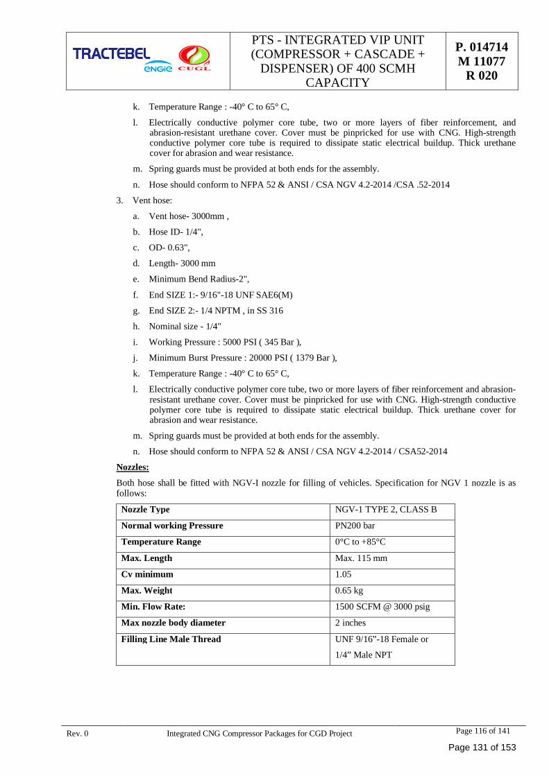
PTS - INTEGRATED VIP UNIT(COMPRESSOR + CASCADE +
DISPENSER) OF 400 SCMHCAPACITY
P. 014714M 11077
R 020
Rev. 0 Integrated CNG Compressor Packages for CGD Project Page 116 of 141
k. Temperature Range : -40° C to 65° C,
l. Electrically conductive polymer core tube, two or more layers of fiber reinforcement, andabrasion-resistant urethane cover. Cover must be pinpricked for use with CNG. High-strengthconductive polymer core tube is required to dissipate static electrical buildup. Thick urethanecover for abrasion and wear resistance.
m. Spring guards must be provided at both ends for the assembly.
n. Hose should conform to NFPA 52 & ANSI / CSA NGV 4.2-2014 /CSA .52-2014
3. Vent hose:
a. Vent hose- 3000mm ,
b. Hose ID- 1/4",
c. OD- 0.63",
d. Length- 3000 mm
e. Minimum Bend Radius-2",
f. End SIZE 1:- 9/16"-18 UNF SAE6(M)
g. End SIZE 2:- 1/4 NPTM , in SS 316
h. Nominal size - 1/4"
i. Working Pressure : 5000 PSI ( 345 Bar ),
j. Minimum Burst Pressure : 20000 PSI ( 1379 Bar ),
k. Temperature Range : -40° C to 65° C,
l. Electrically conductive polymer core tube, two or more layers of fiber reinforcement and abrasion-resistant urethane cover. Cover must be pinpricked for use with CNG. High-strength conductivepolymer core tube is required to dissipate static electrical buildup. Thick urethane cover forabrasion and wear resistance.
m. Spring guards must be provided at both ends for the assembly.
n. Hose should conform to NFPA 52 & ANSI / CSA NGV 4.2-2014 / CSA52-2014
Nozzles:
Both hose shall be fitted with NGV-I nozzle for filling of vehicles. Specification for NGV 1 nozzle is asfollows:
Nozzle Type NGV-1 TYPE 2, CLASS B
Normal working Pressure PN200 bar
Temperature Range 0°C to +85°C
Max. Length Max. 115 mm
Cv minimum 1.05
Max. Weight 0.65 kg
Min. Flow Rate: 1500 SCFM @ 3000 psig
Max nozzle body diameter 2 inches
Filling Line Male Thread UNF 9/16”-18 Female or
1/4” Male NPT
Page 131 of 153
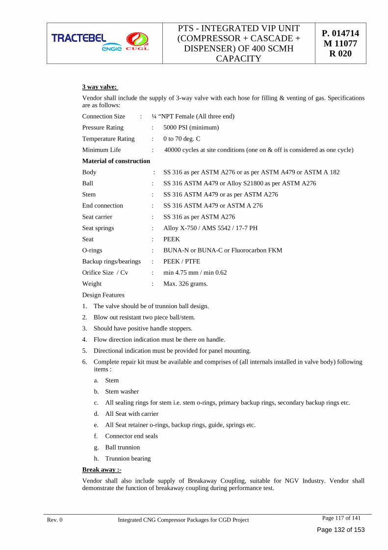
PTS - INTEGRATED VIP UNIT(COMPRESSOR + CASCADE +
DISPENSER) OF 400 SCMHCAPACITY
P. 014714M 11077
R 020
Rev. 0 Integrated CNG Compressor Packages for CGD Project Page 117 of 141
3 way valve:
Vendor shall include the supply of 3-way valve with each hose for filling & venting of gas. Specificationsare as follows:
Connection Size : ¼ “NPT Female (All three end)
Pressure Rating : 5000 PSI (minimum)
Temperature Rating : 0 to 70 deg. C
Minimum Life : 40000 cycles at site conditions (one on & off is considered as one cycle)
Material of construction
Body : SS 316 as per ASTM A276 or as per ASTM A479 or ASTM A 182
Ball : SS 316 ASTM A479 or Alloy S21800 as per ASTM A276
Stem : SS 316 ASTM A479 or as per ASTM A276
End connection : SS 316 ASTM A479 or ASTM A 276
Seat carrier : SS 316 as per ASTM A276
Seat springs : Alloy X-750 / AMS 5542 / 17-7 PH
Seat : PEEK
O-rings : BUNA-N or BUNA-C or Fluorocarbon FKM
Backup rings/bearings : PEEK / PTFE
Orifice Size / Cv : min 4.75 mm / min 0.62
Weight : Max. 326 grams.
Design Features
1. The valve should be of trunnion ball design.
2. Blow out resistant two piece ball/stem.
3. Should have positive handle stoppers.
4. Flow direction indication must be there on handle.
5. Directional indication must be provided for panel mounting.
6. Complete repair kit must be available and comprises of (all internals installed in valve body) followingitems :
a. Stem
b. Stem washer
c. All sealing rings for stem i.e. stem o-rings, primary backup rings, secondary backup rings etc.
d. All Seat with carrier
e. All Seat retainer o-rings, backup rings, guide, springs etc.
f. Connector end seals
g. Ball trunnion
h. Trunnion bearing
Break away :-
Vendor shall also include supply of Breakaway Coupling, suitable for NGV Industry. Vendor shalldemonstrate the function of breakaway coupling during performance test.
Page 132 of 153
PTS - INTEGRATED VIP UNIT(COMPRESSOR + CASCADE +
DISPENSER) OF 400 SCMHCAPACITY
P. 014714M 11077
R 020
Rev. 0 Integrated CNG Compressor Packages for CGD Project Page 118 of 141
DATA SHEETS
Page 133 of 153
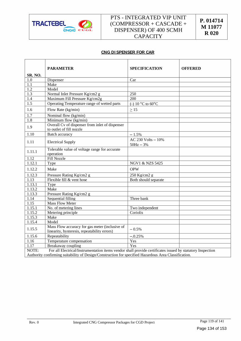
PTS - INTEGRATED VIP UNIT(COMPRESSOR + CASCADE +
DISPENSER) OF 400 SCMHCAPACITY
P. 014714M 11077
R 020
Rev. 0 Integrated CNG Compressor Packages for CGD Project Page 119 of 141
CNG DISPENSER FOR CAR
SR. NO.
PARAMETER SPECIFICATION OFFERED
1.0 Dispenser Car1.1 Make1.2 Model1.3 Normal Inlet Pressure Kg/cm2 g 2501.4 Maximum Fill Pressure Kg/cm2g 2001.5 Operating Temperature range of wetted parts (-) 10 °C to 60°C1.6 Flow Rate (kg/min) > 151.7 Nominal flow (kg/min)1.8 Minimum flow (kg/min)
1.9 Overall Cv of dispenser from inlet of dispenserto outlet of fill nozzle
1.10 Batch accuracy ± 1.5%
1.11 Electrical Supply AC 230 Volts ± 10%50Hz ± 3%
1.11.1 Tolerable value of voltage range for accurateoperation
1.12 Fill Nozzle1.12.1 Type NGV1 & NZS 54251.12.2 Make OPW1.12.3 Pressure Rating Kg/cm2 g 250 Kg/cm2 g1.13 Flexible fill & vent hose Both should separate1.13.1 Type1.13.2 Make1.13.3 Pressure Rating Kg/cm2 g1.14 Sequential filling Three bank1.15 Mass Flow Meter1.15.1 No. of metering lines Two independent1.15.2 Metering principle Coriolis1.15.3 Make1.15.4 Model
1.15.5 Mass Flow accuracy for gas meter (inclusive oflinearity, hysteresis, repeatability errors) ± 0.5%
1.15.6 Repeatability ±.0.25%1.16 Temperature compensation Yes1.17 Breakaway coupling YesNOTE: For all Electrical/Instrumentation items vendor shall provide certificates issued by statutory InspectionAuthority confirming suitability of Design/Construction for specified Hazardous Area Classification.
Page 134 of 153
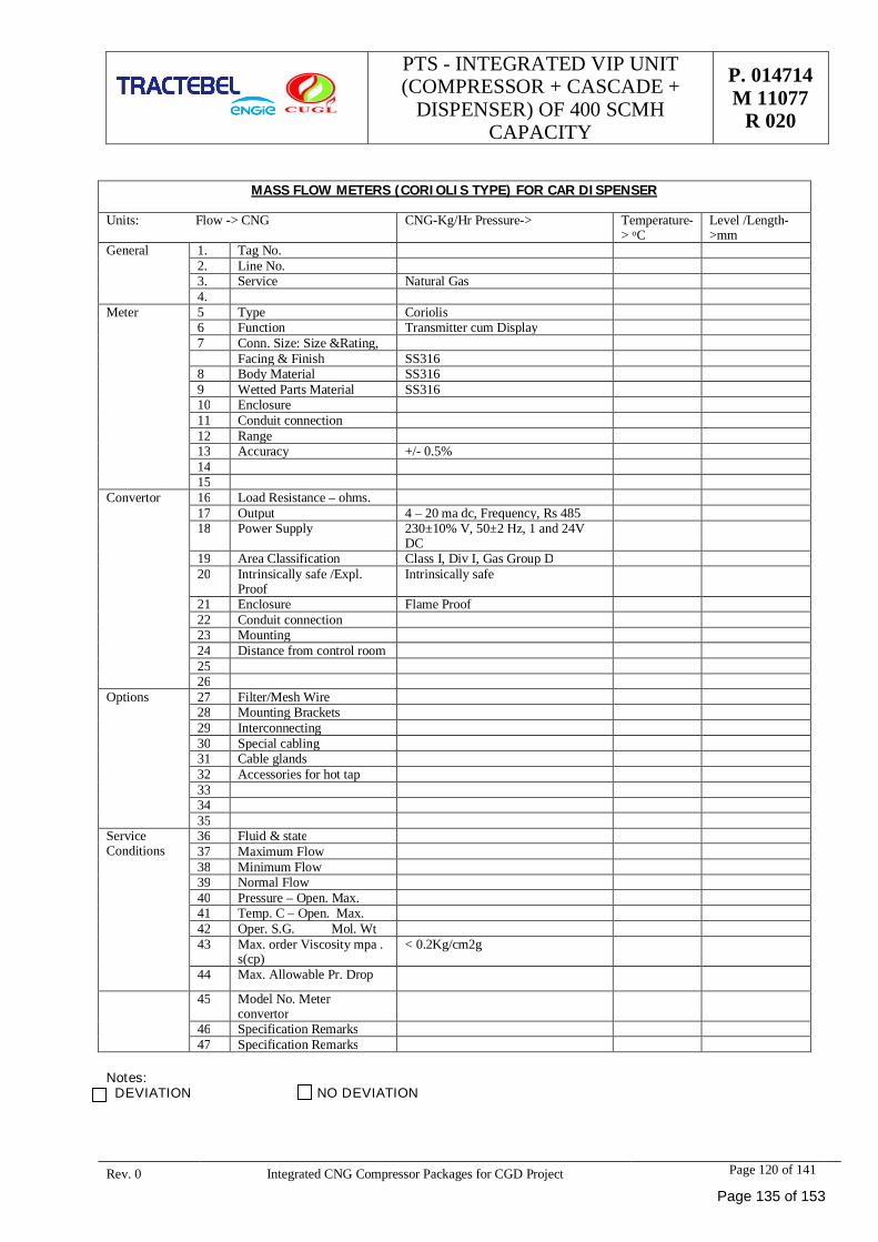
PTS - INTEGRATED VIP UNIT(COMPRESSOR + CASCADE +
DISPENSER) OF 400 SCMHCAPACITY
P. 014714M 11077
R 020
Rev. 0 Integrated CNG Compressor Packages for CGD Project Page 120 of 141
MASS FLOW METERS (CORIOLIS TYPE) FOR CAR DISPENSER
Units: Flow -> CNG CNG-Kg/Hr Pressure-> Temperature-> oC
Level /Length->mm
General 1. Tag No.2. Line No.3. Service Natural Gas4.
Meter 5 Type Coriolis6 Function Transmitter cum Display7 Conn. Size: Size &Rating,
Facing & Finish SS3168 Body Material SS3169 Wetted Parts Material SS31610 Enclosure11 Conduit connection12 Range13 Accuracy +/- 0.5%1415
Convertor 16 Load Resistance – ohms.17 Output 4 – 20 ma dc, Frequency, Rs 48518 Power Supply 230±10% V, 50±2 Hz, 1 and 24V
DC19 Area Classification Class I, Div I, Gas Group D20 Intrinsically safe /Expl.
ProofIntrinsically safe
21 Enclosure Flame Proof22 Conduit connection23 Mounting24 Distance from control room2526
Options 27 Filter/Mesh Wire28 Mounting Brackets29 Interconnecting30 Special cabling31 Cable glands32 Accessories for hot tap333435
ServiceConditions
36 Fluid & state37 Maximum Flow38 Minimum Flow39 Normal Flow40 Pressure – Open. Max.41 Temp. C – Open. Max.42 Oper. S.G. Mol. Wt43 Max. order Viscosity mpa .
s(cp)< 0.2Kg/cm2g
44 Max. Allowable Pr. Drop
45 Model No. Meterconvertor
46 Specification Remarks47 Specification Remarks
Notes: DEVIATION NO DEVIATION
Page 135 of 153
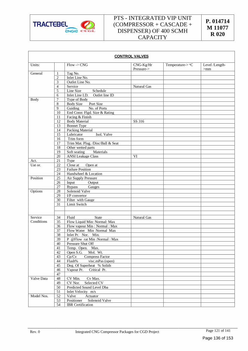
PTS - INTEGRATED VIP UNIT(COMPRESSOR + CASCADE +
DISPENSER) OF 400 SCMHCAPACITY
P. 014714M 11077
R 020
Rev. 0 Integrated CNG Compressor Packages for CGD Project Page 121 of 141
CONTROL VALVES
Units: Flow -> CNG CNG-Kg/HrPressure->
Temperature-> oC Level /Length->mm
General 1 Tag No.2 Inlet Line No.3 Outlet Line No.4 Service Natural Gas5 Line Size Schedule6 Inlet Line I.D. Outlet line ID
Body 7 Type of Body8 Body Size Port Size9 Guiding No. of Ports10 End Conn: Flgd. Size & Rating11 Facing & Finish12 Body Material SS 31613 Bonnet Type14 Packing Material15 Lubricator Isol. Valve16 Trim form17 Trim Mat. Plug. /Disc/Ball & Seat18 Other wetted parts19 Soft seating Materials20 ANSI Leakage Class VI
Act. 21 TypeUat or. 22 Close at Open at
23 Failure Position24 Handwheel & Location
Position 25 Air Supply Pressure26 Input Output27 Bypass Gauges
Options 28 Solenoid Valve29 I/P convertor30 Filter with Gauge31 Limit Switch
ServiceConditions
34 Fluid State Natural Gas35 Flow Liquid Min: Normal: Max36 Flow vapour Min : Normal : Max37 Flow Water Min Normal Max38 Inlet Pr. Nor. Min.39 P @Flow rat Min :Normal : Max40 Pressure Shut Off41 Temp. Open. Max.42 Open S.G. Mol. Wt.43 Cp/Cv Compress Factor44 Flash% visc.mPas (open)45 Deg. Of Superheat % Solids46 Vapour Pr. Critical Pr.47
Valve Data 48 CV Min. Cv Max.49 CV Nor. Selected CV50 Predicted Sound Level Dba51 Inlet Velocity m/s
Model Nos. 52 Valve Actuator53 Positioner Solenoid Valve54 IBR Certification
Page 136 of 153
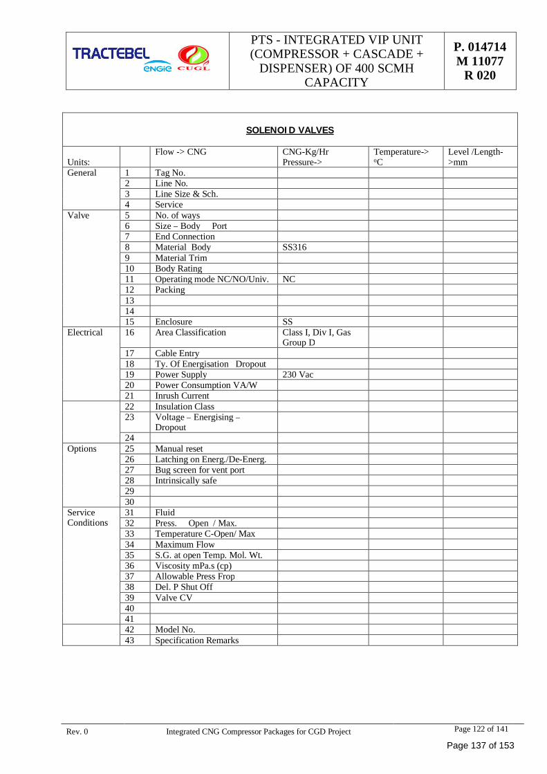
PTS - INTEGRATED VIP UNIT(COMPRESSOR + CASCADE +
DISPENSER) OF 400 SCMHCAPACITY
P. 014714M 11077
R 020
Rev. 0 Integrated CNG Compressor Packages for CGD Project Page 122 of 141
SOLENOID VALVES
Units:Flow -> CNG CNG-Kg/Hr
Pressure->Temperature->oC
Level /Length->mm
General 1 Tag No.2 Line No.3 Line Size & Sch.4 Service
Valve 5 No. of ways6 Size – Body Port7 End Connection8 Material Body SS3169 Material Trim10 Body Rating11 Operating mode NC/NO/Univ. NC12 Packing131415 Enclosure SS
Electrical 16 Area Classification Class I, Div I, GasGroup D
17 Cable Entry18 Ty. Of Energisation Dropout19 Power Supply 230 Vac20 Power Consumption VA/W21 Inrush Current22 Insulation Class23 Voltage – Energising –
Dropout24
Options 25 Manual reset26 Latching on Energ./De-Energ.27 Bug screen for vent port28 Intrinsically safe2930
ServiceConditions
31 Fluid32 Press. Open / Max.33 Temperature C-Open/ Max34 Maximum Flow35 S.G. at open Temp. Mol. Wt.36 Viscosity mPa.s (cp)37 Allowable Press Frop38 Del. P Shut Off39 Valve CV404142 Model No.43 Specification Remarks
Page 137 of 153
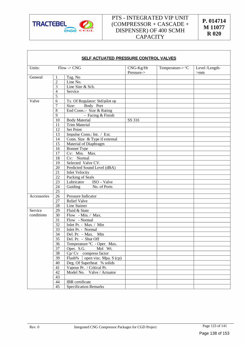
PTS - INTEGRATED VIP UNIT(COMPRESSOR + CASCADE +
DISPENSER) OF 400 SCMHCAPACITY
P. 014714M 11077
R 020
Rev. 0 Integrated CNG Compressor Packages for CGD Project Page 123 of 141
SELF ACTUATED PRESSURE CONTROL VALVES
Units: Flow -> CNG CNG-Kg/HrPressure->
Temperature-> oC Level /Length->mm
General 1 Tag. No2 Line No.3 Line Size & Sch.4 Service5
Valve 6 Ty. Of Regulator: Std/pilot op7 Size: Body Port8 End Conn.:- Size & Rating9 - Facing & Finish10 Body Material SS 31611 Trim Material12 Set Point13 Impulse Conn.: Int. / Ext.14 Conn. Size & Type if external15 Material of Diaphragm16 Bonnet Type17 Cv: Min. Max.18 Cv: Normal19 Selected Valve CV.20 Predicted Sound Level (dBA)21 Inlet Velocity22 Packing of Seals23 Lubricator ISO – Valve24 Guiding No. of Ports25
Accessories 26 Pressure Indicator27 Relief Valve28 Line Stainer
Serviceconditions
29 Fluid & State30 Flow - Min. / Max.31 Flow - Normal32 Inlet Pr. - Max. / Min33 Inlet Pr. - Normal34 Del. Pr. – Max. Min35 Del. Pr. - Shut Off36 Temperature ºC - Oper. Max.37 Oper. S.G. Mol Wt.38 Cp/ Cv compress factor39 Flash% open visc. Mpa. S (cp)40 Deg. Of Superheat % solids41 Vapour Pr. / Critical Pr.42 Model No. Valve / Actuator4344 IBR certificate45 Specification Remarks
Page 138 of 153
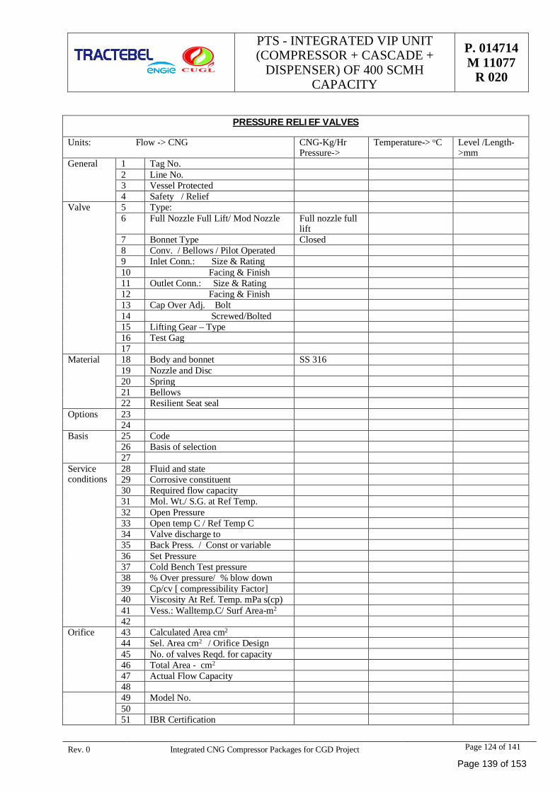
PTS - INTEGRATED VIP UNIT(COMPRESSOR + CASCADE +
DISPENSER) OF 400 SCMHCAPACITY
P. 014714M 11077
R 020
Rev. 0 Integrated CNG Compressor Packages for CGD Project Page 124 of 141
PRESSURE RELIEF VALVES
Units: Flow -> CNG CNG-Kg/HrPressure->
Temperature-> oC Level /Length->mm
General 1 Tag No.2 Line No.3 Vessel Protected4 Safety / Relief
Valve 5 Type:6 Full Nozzle Full Lift/ Mod Nozzle Full nozzle full
lift7 Bonnet Type Closed8 Conv. / Bellows / Pilot Operated9 Inlet Conn.: Size & Rating10 Facing & Finish11 Outlet Conn.: Size & Rating12 Facing & Finish13 Cap Over Adj. Bolt14 Screwed/Bolted15 Lifting Gear – Type16 Test Gag17
Material 18 Body and bonnet SS 31619 Nozzle and Disc20 Spring21 Bellows22 Resilient Seat seal
Options 2324
Basis 25 Code26 Basis of selection27
Serviceconditions
28 Fluid and state29 Corrosive constituent30 Required flow capacity31 Mol. Wt./ S.G. at Ref Temp.32 Open Pressure33 Open temp C / Ref Temp C34 Valve discharge to35 Back Press. / Const or variable36 Set Pressure37 Cold Bench Test pressure38 % Over pressure/ % blow down39 Cp/cv [ compressibility Factor]40 Viscosity At Ref. Temp. mPa s(cp)41 Vess.: Walltemp.C/ Surf Area-m2
42Orifice 43 Calculated Area cm2
44 Sel. Area cm2 / Orifice Design45 No. of valves Reqd. for capacity46 Total Area - cm2
47 Actual Flow Capacity4849 Model No.5051 IBR Certification
Page 139 of 153
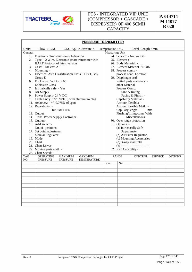
PTS - INTEGRATED VIP UNIT(COMPRESSOR + CASCADE +
DISPENSER) OF 400 SCMHCAPACITY
P. 014714M 11077
R 020
Rev. 0 Integrated CNG Compressor Packages for CGD Project Page 125 of 141
PRESSURE TRANSMITTER
Units: Flow -> CNG CNG-Kg/Hr Pressure-> Temperature-> oC Level /Length->mmGeneral
1. Function - Transmission & Indication2. Type: - 2 Wire, Electronic smart transmitter with
HART Protocol of latest version3. Case: - Die cast Al4. Mounting: -5. Electrical Area Classification Class I, Div I, Gas
Group D6. Enclosure : WP to IP 65
Enclosure Class7. Intrinsically safe: - Yes8. Air Supply9. Power Supply- 24 V DC10. Cable Entry: 1/2" NPT(F) with aluminium plug11. Accuracy: - +/- 0.075% of span12. Repeability: - TRNSMITTER13. Output14. Trans. Power Supply Controller15. Output:-16. A/M switch:-
No. of positions:-17. Set point adjustment18. Manual Regulator19. Mode20. Chart21. Chart Driver22. Moving parts matl.; -23. Chart Speed: -
Measuring Unit24. Service: - Natural Gas25. Element : -26. Body Material: -27. Element Material SS 31628. Process conn.: -
process conn. Location29. Diaphragm seal
wetted parts materials: -other MaterialProcess Conn.: Size & Rating Facing & Finish: -Capability Material:-Armour Flexible: -Armour Flexible Matl.: -Capillary length:- mmFlushing/filling conn. With Miscellaneous
30. Over range protection31. Options: -
(a) Intrinsically Safe Output meter(b) Air Filter Regulator(c) Mounting Accessories(d) 3-way manifold(e) --------------------------
32. Load Capability:-
TAGNO.
OPERATINGPRESSURE
MAXIMUMPRESSURE
MAXIMUMTEMPERATURE
RANGE CONTROL SERVICE OPTIONS
Span Set
Page 140 of 153
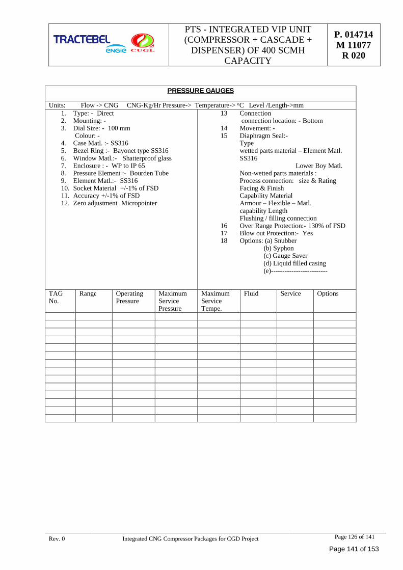
PTS - INTEGRATED VIP UNIT(COMPRESSOR + CASCADE +
DISPENSER) OF 400 SCMHCAPACITY
P. 014714M 11077
R 020
Rev. 0 Integrated CNG Compressor Packages for CGD Project Page 126 of 141
PRESSURE GAUGES
Units: Flow -> CNG CNG-Kg/Hr Pressure-> Temperature-> oC Level /Length->mm1. Type: - Direct2. Mounting: -3. Dial Size: - 100 mm
Colour: -4. Case Matl. :- SS3165. Bezel Ring :- Bayonet type SS3166. Window Matl.:- Shatterproof glass7. Enclosure : - WP to IP 658. Pressure Element :- Bourden Tube9. Element Matl.:- SS31610. Socket Material +/-1% of FSD11. Accuracy +/-1% of FSD12. Zero adjustment Micropointer
13 Connection connection location: - Bottom
14 Movement: -15 Diaphragm Seal:-
Typewetted parts material – Element Matl.SS316 Lower Boy Matl.Non-wetted parts materials :Process connection: size & RatingFacing & FinishCapability MaterialArmour – Flexible – Matl.capability LengthFlushing / filling connection
16 Over Range Protection:- 130% of FSD17 Blow out Protection:- Yes18 Options: (a) Snubber
(b) Syphon (c) Gauge Saver (d) Liquid filled casing (e)-------------------------
TAGNo.
Range OperatingPressure
MaximumServicePressure
MaximumServiceTempe.
Fluid Service Options
Page 141 of 153
PTS - INTEGRATED VIP UNIT(COMPRESSOR + CASCADE +
DISPENSER) OF 400 SCMHCAPACITY
P. 014714M 11077
R 020
Rev. 0 Integrated CNG Compressor Packages for CGD Project Page 127 of 141
ANNEXURES
Page 142 of 153
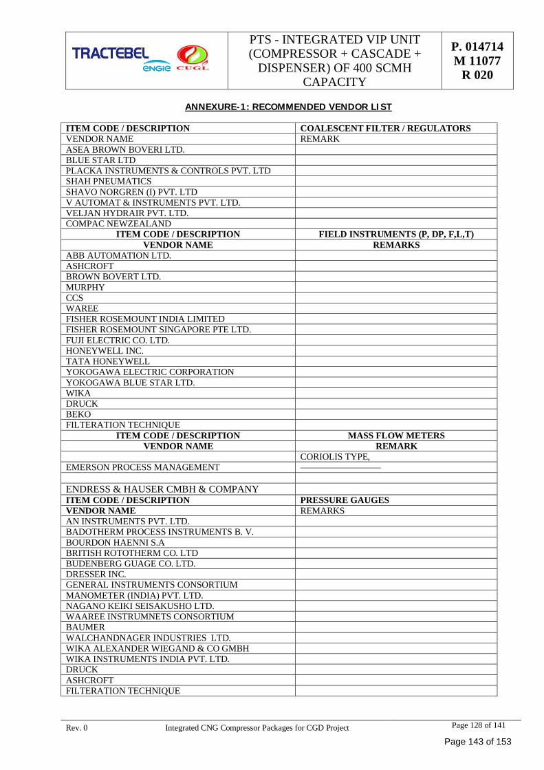
PTS - INTEGRATED VIP UNIT(COMPRESSOR + CASCADE +
DISPENSER) OF 400 SCMHCAPACITY
P. 014714M 11077
R 020
Rev. 0 Integrated CNG Compressor Packages for CGD Project Page 128 of 141
ANNEXURE-1: RECOMMENDED VENDOR LIST
ITEM CODE / DESCRIPTION COALESCENT FILTER / REGULATORSVENDOR NAME REMARKASEA BROWN BOVERI LTD.BLUE STAR LTDPLACKA INSTRUMENTS & CONTROLS PVT. LTDSHAH PNEUMATICSSHAVO NORGREN (I) PVT. LTDV AUTOMAT & INSTRUMENTS PVT. LTD.VELJAN HYDRAIR PVT. LTD.COMPAC NEWZEALAND
ITEM CODE / DESCRIPTION FIELD INSTRUMENTS (P, DP, F,L,T)VENDOR NAME REMARKS
ABB AUTOMATION LTD.ASHCROFTBROWN BOVERT LTD.MURPHYCCSWAREEFISHER ROSEMOUNT INDIA LIMITEDFISHER ROSEMOUNT SINGAPORE PTE LTD.FUJI ELECTRIC CO. LTD.HONEYWELL INC.TATA HONEYWELLYOKOGAWA ELECTRIC CORPORATIONYOKOGAWA BLUE STAR LTD.WIKADRUCKBEKOFILTERATION TECHNIQUE
ITEM CODE / DESCRIPTION MASS FLOW METERSVENDOR NAME REMARK
CORIOLIS TYPE,EMERSON PROCESS MANAGEMENT
ENDRESS & HAUSER CMBH & COMPANYITEM CODE / DESCRIPTION PRESSURE GAUGESVENDOR NAME REMARKSAN INSTRUMENTS PVT. LTD.BADOTHERM PROCESS INSTRUMENTS B. V.BOURDON HAENNI S.ABRITISH ROTOTHERM CO. LTDBUDENBERG GUAGE CO. LTD.DRESSER INC.GENERAL INSTRUMENTS CONSORTIUMMANOMETER (INDIA) PVT. LTD.NAGANO KEIKI SEISAKUSHO LTD.WAAREE INSTRUMNETS CONSORTIUMBAUMERWALCHANDNAGER INDUSTRIES LTD.WIKA ALEXANDER WIEGAND & CO GMBHWIKA INSTRUMENTS INDIA PVT. LTD.DRUCKASHCROFTFILTERATION TECHNIQUE
Page 143 of 153
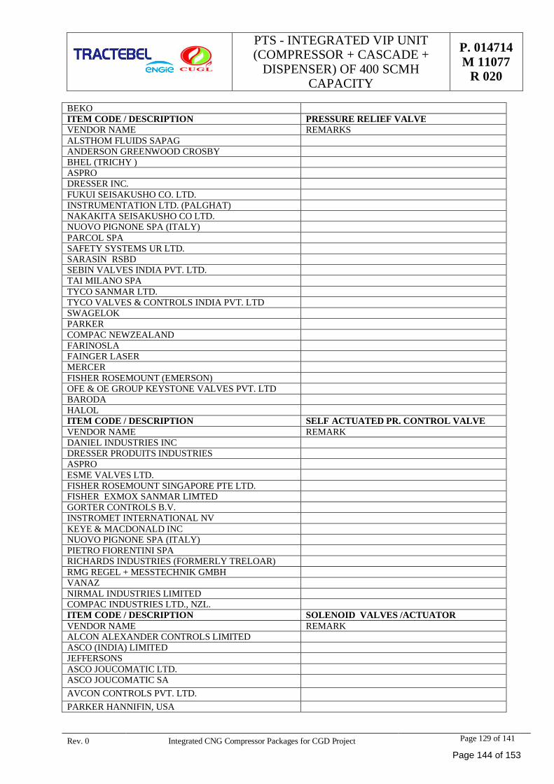
PTS - INTEGRATED VIP UNIT(COMPRESSOR + CASCADE +
DISPENSER) OF 400 SCMHCAPACITY
P. 014714M 11077
R 020
Rev. 0 Integrated CNG Compressor Packages for CGD Project Page 129 of 141
BEKOITEM CODE / DESCRIPTION PRESSURE RELIEF VALVEVENDOR NAME REMARKSALSTHOM FLUIDS SAPAGANDERSON GREENWOOD CROSBYBHEL (TRICHY )ASPRODRESSER INC.FUKUI SEISAKUSHO CO. LTD.INSTRUMENTATION LTD. (PALGHAT)NAKAKITA SEISAKUSHO CO LTD.NUOVO PIGNONE SPA (ITALY)PARCOL SPASAFETY SYSTEMS UR LTD.SARASIN RSBDSEBIN VALVES INDIA PVT. LTD.TAI MILANO SPATYCO SANMAR LTD.TYCO VALVES & CONTROLS INDIA PVT. LTDSWAGELOKPARKERCOMPAC NEWZEALANDFARINOSLAFAINGER LASERMERCERFISHER ROSEMOUNT (EMERSON)OFE & OE GROUP KEYSTONE VALVES PVT. LTDBARODAHALOLITEM CODE / DESCRIPTION SELF ACTUATED PR. CONTROL VALVEVENDOR NAME REMARKDANIEL INDUSTRIES INCDRESSER PRODUITS INDUSTRIESASPROESME VALVES LTD.FISHER ROSEMOUNT SINGAPORE PTE LTD.FISHER EXMOX SANMAR LIMTEDGORTER CONTROLS B.V.INSTROMET INTERNATIONAL NVKEYE & MACDONALD INCNUOVO PIGNONE SPA (ITALY)PIETRO FIORENTINI SPARICHARDS INDUSTRIES (FORMERLY TRELOAR)RMG REGEL + MESSTECHNIK GMBHVANAZNIRMAL INDUSTRIES LIMITEDCOMPAC INDUSTRIES LTD., NZL.ITEM CODE / DESCRIPTION SOLENOID VALVES /ACTUATORVENDOR NAME REMARKALCON ALEXANDER CONTROLS LIMITEDASCO (INDIA) LIMITEDJEFFERSONSASCO JOUCOMATIC LTD.ASCO JOUCOMATIC SAAVCON CONTROLS PVT. LTD.PARKER HANNIFIN, USA
Page 144 of 153
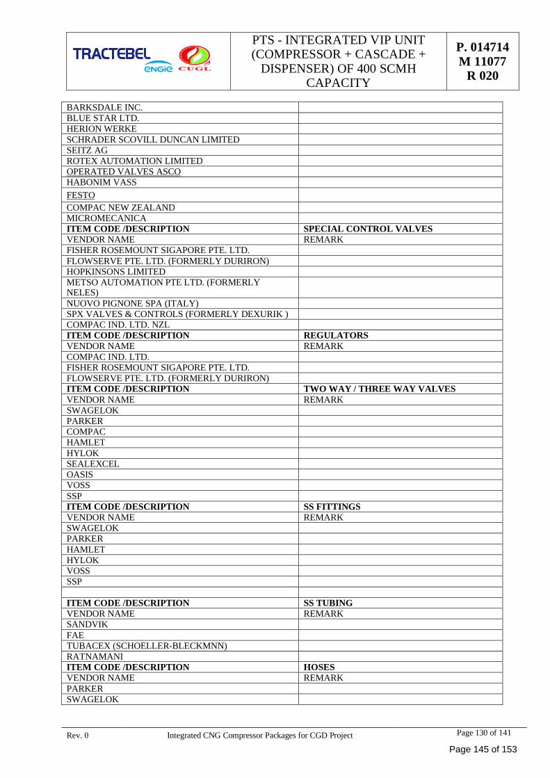
PTS - INTEGRATED VIP UNIT(COMPRESSOR + CASCADE +
DISPENSER) OF 400 SCMHCAPACITY
P. 014714M 11077
R 020
Rev. 0 Integrated CNG Compressor Packages for CGD Project Page 130 of 141
BARKSDALE INC.BLUE STAR LTD.HERION WERKESCHRADER SCOVILL DUNCAN LIMITEDSEITZ AGROTEX AUTOMATION LIMITEDOPERATED VALVES ASCOHABONIM VASSFESTOCOMPAC NEW ZEALANDMICROMECANICAITEM CODE /DESCRIPTION SPECIAL CONTROL VALVESVENDOR NAME REMARKFISHER ROSEMOUNT SIGAPORE PTE. LTD.FLOWSERVE PTE. LTD. (FORMERLY DURIRON)HOPKINSONS LIMITEDMETSO AUTOMATION PTE LTD. (FORMERLYNELES)NUOVO PIGNONE SPA (ITALY)SPX VALVES & CONTROLS (FORMERLY DEXURIK )COMPAC IND. LTD. NZLITEM CODE /DESCRIPTION REGULATORSVENDOR NAME REMARKCOMPAC IND. LTD.FISHER ROSEMOUNT SIGAPORE PTE. LTD.FLOWSERVE PTE. LTD. (FORMERLY DURIRON)ITEM CODE /DESCRIPTION TWO WAY / THREE WAY VALVESVENDOR NAME REMARKSWAGELOKPARKERCOMPACHAMLETHYLOKSEALEXCELOASISVOSSSSPITEM CODE /DESCRIPTION SS FITTINGSVENDOR NAME REMARKSWAGELOKPARKERHAMLETHYLOKVOSSSSP
ITEM CODE /DESCRIPTION SS TUBINGVENDOR NAME REMARKSANDVIKFAETUBACEX (SCHOELLER-BLECKMNN)RATNAMANIITEM CODE /DESCRIPTION HOSESVENDOR NAME REMARKPARKERSWAGELOK
Page 145 of 153
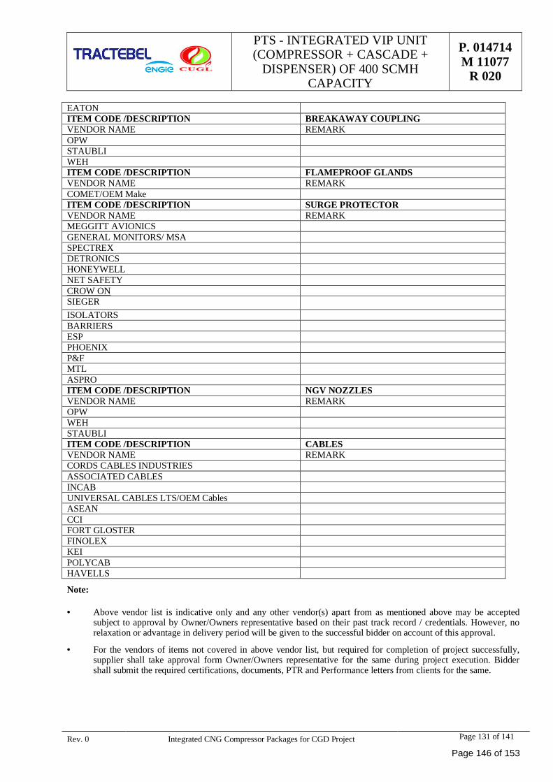
PTS - INTEGRATED VIP UNIT(COMPRESSOR + CASCADE +
DISPENSER) OF 400 SCMHCAPACITY
P. 014714M 11077
R 020
Rev. 0 Integrated CNG Compressor Packages for CGD Project Page 131 of 141
EATONITEM CODE /DESCRIPTION BREAKAWAY COUPLINGVENDOR NAME REMARKOPWSTAUBLIWEHITEM CODE /DESCRIPTION FLAMEPROOF GLANDSVENDOR NAME REMARKCOMET/OEM MakeITEM CODE /DESCRIPTION SURGE PROTECTORVENDOR NAME REMARKMEGGITT AVIONICSGENERAL MONITORS/ MSASPECTREXDETRONICSHONEYWELLNET SAFETYCROW ONSIEGERISOLATORSBARRIERSESPPHOENIXP&FMTLASPROITEM CODE /DESCRIPTION NGV NOZZLESVENDOR NAME REMARKOPWWEHSTAUBLIITEM CODE /DESCRIPTION CABLESVENDOR NAME REMARKCORDS CABLES INDUSTRIESASSOCIATED CABLESINCABUNIVERSAL CABLES LTS/OEM CablesASEANCCIFORT GLOSTERFINOLEXKEIPOLYCABHAVELLS
Note:
· Above vendor list is indicative only and any other vendor(s) apart from as mentioned above may be acceptedsubject to approval by Owner/Owners representative based on their past track record / credentials. However, norelaxation or advantage in delivery period will be given to the successful bidder on account of this approval.
· For the vendors of items not covered in above vendor list, but required for completion of project successfully,supplier shall take approval form Owner/Owners representative for the same during project execution. Biddershall submit the required certifications, documents, PTR and Performance letters from clients for the same.
Page 146 of 153
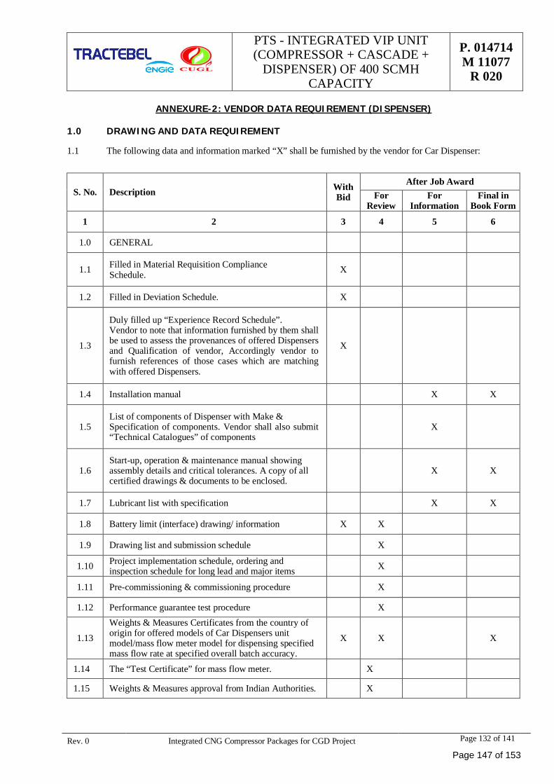
PTS - INTEGRATED VIP UNIT(COMPRESSOR + CASCADE +
DISPENSER) OF 400 SCMHCAPACITY
P. 014714M 11077
R 020
Rev. 0 Integrated CNG Compressor Packages for CGD Project Page 132 of 141
ANNEXURE-2: VENDOR DATA REQUIREMENT (DISPENSER)
1.0 DRAWING AND DATA REQUIREMENT
1.1 The following data and information marked “X” shall be furnished by the vendor for Car Dispenser:
S. No. Description WithBid
After Job AwardFor
ReviewFor
InformationFinal in
Book Form
1 2 3 4 5 6
1.0 GENERAL
1.1 Filled in Material Requisition ComplianceSchedule. X
1.2 Filled in Deviation Schedule. X
1.3
Duly filled up “Experience Record Schedule”.Vendor to note that information furnished by them shallbe used to assess the provenances of offered Dispensersand Qualification of vendor, Accordingly vendor tofurnish references of those cases which are matchingwith offered Dispensers.
X
1.4 Installation manual X X
1.5List of components of Dispenser with Make &Specification of components. Vendor shall also submit“Technical Catalogues” of components
X
1.6Start-up, operation & maintenance manual showingassembly details and critical tolerances. A copy of allcertified drawings & documents to be enclosed.
X X
1.7 Lubricant list with specification X X
1.8 Battery limit (interface) drawing/ information X X
1.9 Drawing list and submission schedule X
1.10 Project implementation schedule, ordering andinspection schedule for long lead and major items X
1.11 Pre-commissioning & commissioning procedure X
1.12 Performance guarantee test procedure X
1.13Weights & Measures Certificates from the country oforigin for offered models of Car Dispensers unitmodel/mass flow meter model for dispensing specifiedmass flow rate at specified overall batch accuracy.
X X X
1.14 The “Test Certificate” for mass flow meter. X
1.15 Weights & Measures approval from Indian Authorities. X
Page 147 of 153
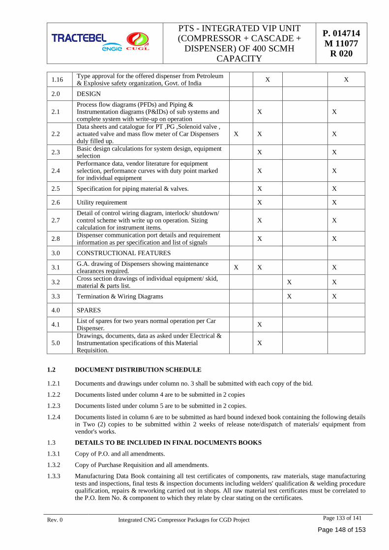
PTS - INTEGRATED VIP UNIT(COMPRESSOR + CASCADE +
DISPENSER) OF 400 SCMHCAPACITY
P. 014714M 11077
R 020
Rev. 0 Integrated CNG Compressor Packages for CGD Project Page 133 of 141
1.16 Type approval for the offered dispenser from Petroleum& Explosive safety organization, Govt. of India X X
2.0 DESIGN
2.1Process flow diagrams (PFDs) and Piping &Instrumentation diagrams (P&IDs) of sub systems andcomplete system with write-up on operation
X X
2.2Data sheets and catalogue for PT ,PG ,Solenoid valve ,actuated valve and mass flow meter of Car Dispensersduly filled up.
X X X
2.3 Basic design calculations for system design, equipmentselection X X
2.4Performance data, vendor literature for equipmentselection, performance curves with duty point markedfor individual equipment
X X
2.5 Specification for piping material & valves. X X
2.6 Utility requirement X X
2.7Detail of control wiring diagram, interlock/ shutdown/control scheme with write up on operation. Sizingcalculation for instrument items.
X X
2.8 Dispenser communication port details and requirementinformation as per specification and list of signals X X
3.0 CONSTRUCTIONAL FEATURES
3.1 G.A. drawing of Dispensers showing maintenanceclearances required. X X X
3.2 Cross section drawings of individual equipment/ skid,material & parts list. X X
3.3 Termination & Wiring Diagrams X X
4.0 SPARES
4.1 List of spares for two years normal operation per CarDispenser. X
5.0Drawings, documents, data as asked under Electrical &Instrumentation specifications of this MaterialRequisition.
X
1.2 DOCUMENT DISTRIBUTION SCHEDULE
1.2.1 Documents and drawings under column no. 3 shall be submitted with each copy of the bid.
1.2.2 Documents listed under column 4 are to be submitted in 2 copies
1.2.3 Documents listed under column 5 are to be submitted in 2 copies.
1.2.4 Documents listed in column 6 are to be submitted as hard bound indexed book containing the following detailsin Two (2) copies to be submitted within 2 weeks of release note/dispatch of materials/ equipment fromvendor's works.
1.3 DETAILS TO BE INCLUDED IN FINAL DOCUMENTS BOOKS
1.3.1 Copy of P.O. and all amendments.
1.3.2 Copy of Purchase Requisition and all amendments.
1.3.3 Manufacturing Data Book containing all test certificates of components, raw materials, stage manufacturingtests and inspections, final tests & inspection documents including welders' qualification & welding procedurequalification, repairs & reworking carried out in shops. All raw material test certificates must be correlated tothe P.O. Item No. & component to which they relate by clear stating on the certificates.
Page 148 of 153
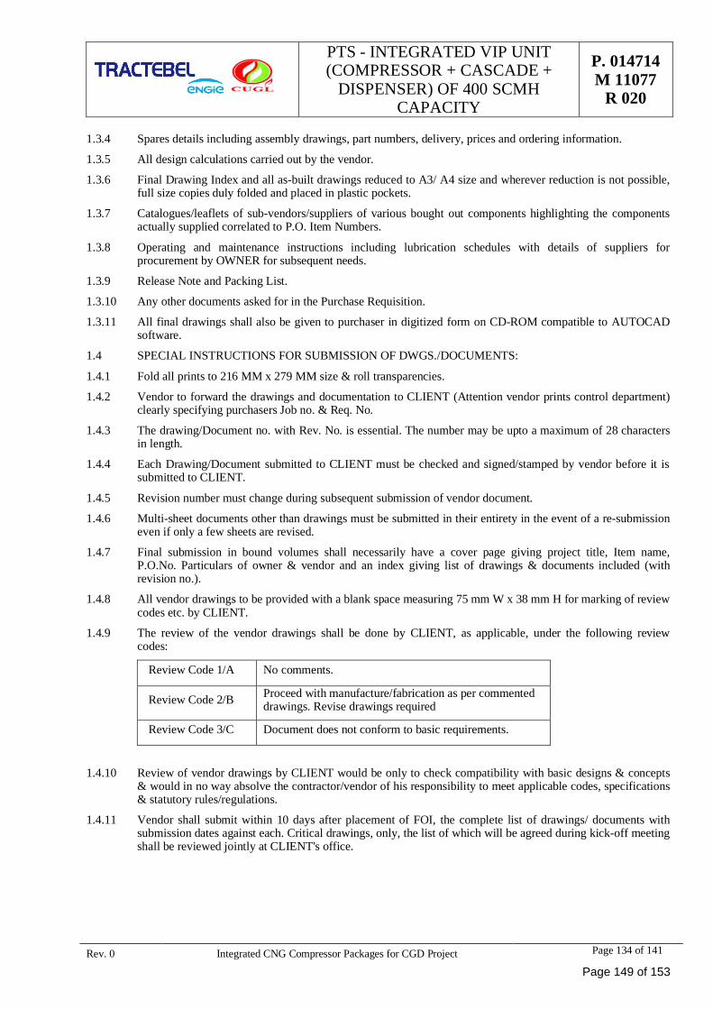
PTS - INTEGRATED VIP UNIT(COMPRESSOR + CASCADE +
DISPENSER) OF 400 SCMHCAPACITY
P. 014714M 11077
R 020
Rev. 0 Integrated CNG Compressor Packages for CGD Project Page 134 of 141
1.3.4 Spares details including assembly drawings, part numbers, delivery, prices and ordering information.
1.3.5 All design calculations carried out by the vendor.
1.3.6 Final Drawing Index and all as-built drawings reduced to A3/ A4 size and wherever reduction is not possible,full size copies duly folded and placed in plastic pockets.
1.3.7 Catalogues/leaflets of sub-vendors/suppliers of various bought out components highlighting the componentsactually supplied correlated to P.O. Item Numbers.
1.3.8 Operating and maintenance instructions including lubrication schedules with details of suppliers forprocurement by OWNER for subsequent needs.
1.3.9 Release Note and Packing List.
1.3.10 Any other documents asked for in the Purchase Requisition.
1.3.11 All final drawings shall also be given to purchaser in digitized form on CD-ROM compatible to AUTOCADsoftware.
1.4 SPECIAL INSTRUCTIONS FOR SUBMISSION OF DWGS./DOCUMENTS:
1.4.1 Fold all prints to 216 MM x 279 MM size & roll transparencies.
1.4.2 Vendor to forward the drawings and documentation to CLIENT (Attention vendor prints control department)clearly specifying purchasers Job no. & Req. No.
1.4.3 The drawing/Document no. with Rev. No. is essential. The number may be upto a maximum of 28 charactersin length.
1.4.4 Each Drawing/Document submitted to CLIENT must be checked and signed/stamped by vendor before it issubmitted to CLIENT.
1.4.5 Revision number must change during subsequent submission of vendor document.
1.4.6 Multi-sheet documents other than drawings must be submitted in their entirety in the event of a re-submissioneven if only a few sheets are revised.
1.4.7 Final submission in bound volumes shall necessarily have a cover page giving project title, Item name,P.O.No. Particulars of owner & vendor and an index giving list of drawings & documents included (withrevision no.).
1.4.8 All vendor drawings to be provided with a blank space measuring 75 mm W x 38 mm H for marking of reviewcodes etc. by CLIENT.
1.4.9 The review of the vendor drawings shall be done by CLIENT, as applicable, under the following reviewcodes:
Review Code 1/A No comments.
Review Code 2/B Proceed with manufacture/fabrication as per commenteddrawings. Revise drawings required
Review Code 3/C Document does not conform to basic requirements.
1.4.10 Review of vendor drawings by CLIENT would be only to check compatibility with basic designs & concepts& would in no way absolve the contractor/vendor of his responsibility to meet applicable codes, specifications& statutory rules/regulations.
1.4.11 Vendor shall submit within 10 days after placement of FOI, the complete list of drawings/ documents withsubmission dates against each. Critical drawings, only, the list of which will be agreed during kick-off meetingshall be reviewed jointly at CLIENT's office.
Page 149 of 153
PTS - INTEGRATED VIP UNIT(COMPRESSOR + CASCADE +
DISPENSER) OF 400 SCMHCAPACITY
P. 014714M 11077
R 020
Rev. 0 Integrated CNG Compressor Packages for CGD Project Page 135 of 141
ANNEXURE- 3: DELETED
Page 150 of 153
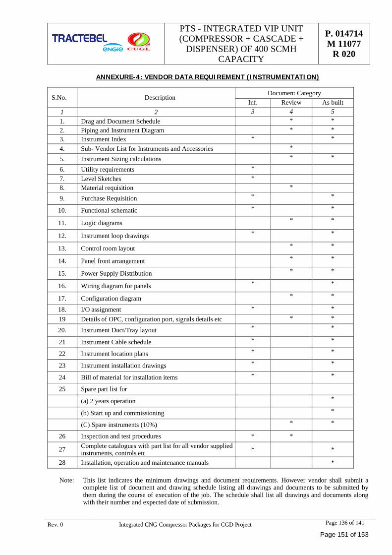
PTS - INTEGRATED VIP UNIT(COMPRESSOR + CASCADE +
DISPENSER) OF 400 SCMHCAPACITY
P. 014714M 11077
R 020
Rev. 0 Integrated CNG Compressor Packages for CGD Project Page 136 of 141
ANNEXURE-4: VENDOR DATA REQUIREMENT (INSTRUMENTATION)
S.No. DescriptionDocument Category
Inf. Review As built1 2 3 4 51. Drag and Document Schedule * *2. Piping and Instrument Diagram * *3. Instrument Index * *4. Sub- Vendor List for Instruments and Accessories *
5. Instrument Sizing calculations * *
6. Utility requirements *7. Level Sketches *8. Material requisition *
9. Purchase Requisition * *
10. Functional schematic * *
11. Logic diagrams * *
12. Instrument loop drawings * *
13. Control room layout * *
14. Panel front arrangement * *
15. Power Supply Distribution * *
16. Wiring diagram for panels * *
17. Configuration diagram * *
18. I/O assignment * *19 Details of OPC, configuration port, signals details etc * *
20. Instrument Duct/Tray layout * *
21 Instrument Cable schedule * *
22 Instrument location plans * *
23 Instrument installation drawings * *
24 Bill of material for installation items * *
25 Spare part list for
(a) 2 years operation *
(b) Start up and commissioning *
(C) Spare instruments (10%) * *
26 Inspection and test procedures * *
27 Complete catalogues with part list for all vendor suppliedinstruments, controls etc * *
28 Installation, operation and maintenance manuals *
Note: This list indicates the minimum drawings and document requirements. However vendor shall submit acomplete list of document and drawing schedule listing all drawings and documents to be submitted bythem during the course of execution of the job. The schedule shall list all drawings and documents alongwith their number and expected date of submission.
Page 151 of 153
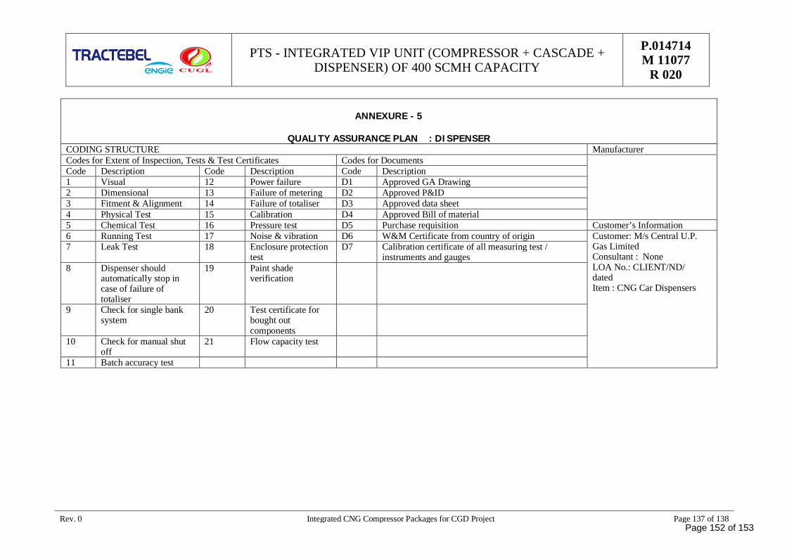
PTS - INTEGRATED VIP UNIT (COMPRESSOR + CASCADE +DISPENSER) OF 400 SCMH CAPACITY
P.014714M 11077
R 020
Rev. 0 Integrated CNG Compressor Packages for CGD Project Page 137 of 138
ANNEXURE - 5
QUALITY ASSURANCE PLAN : DISPENSERCODING STRUCTURE ManufacturerCodes for Extent of Inspection, Tests & Test Certificates Codes for DocumentsCode Description Code Description Code Description1 Visual 12 Power failure D1 Approved GA Drawing2 Dimensional 13 Failure of metering D2 Approved P&ID3 Fitment & Alignment 14 Failure of totaliser D3 Approved data sheet4 Physical Test 15 Calibration D4 Approved Bill of material5 Chemical Test 16 Pressure test D5 Purchase requisition Customer’s Information6 Running Test 17 Noise & vibration D6 W&M Certificate from country of origin Customer: M/s Central U.P.
Gas LimitedConsultant : NoneLOA No.: CLIENT/ND/datedItem : CNG Car Dispensers
7 Leak Test 18 Enclosure protectiontest
D7 Calibration certificate of all measuring test /instruments and gauges
8 Dispenser shouldautomatically stop incase of failure oftotaliser
19 Paint shadeverification
9 Check for single banksystem
20 Test certificate forbought outcomponents
10 Check for manual shutoff
21 Flow capacity test
11 Batch accuracy test
Page 152 of 153
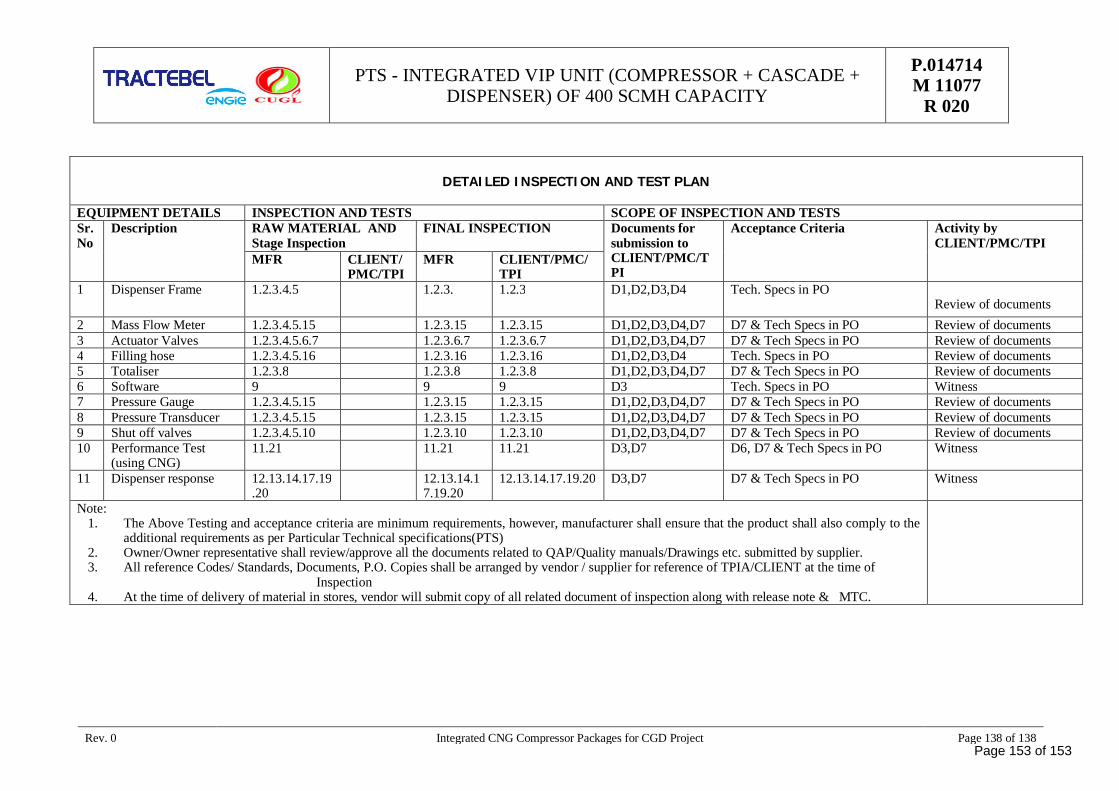
PTS - INTEGRATED VIP UNIT (COMPRESSOR + CASCADE +DISPENSER) OF 400 SCMH CAPACITY
P.014714M 11077
R 020
Rev. 0 Integrated CNG Compressor Packages for CGD Project Page 138 of 138
DETAILED INSPECTION AND TEST PLAN
EQUIPMENT DETAILS INSPECTION AND TESTS SCOPE OF INSPECTION AND TESTSSr.No
Description RAW MATERIAL ANDStage Inspection
FINAL INSPECTION Documents forsubmission toCLIENT/PMC/TPI
Acceptance Criteria Activity byCLIENT/PMC/TPI
MFR CLIENT/PMC/TPI
MFR CLIENT/PMC/TPI
1 Dispenser Frame 1.2.3.4.5 1.2.3. 1.2.3 D1,D2,D3,D4 Tech. Specs in POReview of documents
2 Mass Flow Meter 1.2.3.4.5.15 1.2.3.15 1.2.3.15 D1,D2,D3,D4,D7 D7 & Tech Specs in PO Review of documents3 Actuator Valves 1.2.3.4.5.6.7 1.2.3.6.7 1.2.3.6.7 D1,D2,D3,D4,D7 D7 & Tech Specs in PO Review of documents4 Filling hose 1.2.3.4.5.16 1.2.3.16 1.2.3.16 D1,D2,D3,D4 Tech. Specs in PO Review of documents5 Totaliser 1.2.3.8 1.2.3.8 1.2.3.8 D1,D2,D3,D4,D7 D7 & Tech Specs in PO Review of documents6 Software 9 9 9 D3 Tech. Specs in PO Witness7 Pressure Gauge 1.2.3.4.5.15 1.2.3.15 1.2.3.15 D1,D2,D3,D4,D7 D7 & Tech Specs in PO Review of documents8 Pressure Transducer 1.2.3.4.5.15 1.2.3.15 1.2.3.15 D1,D2,D3,D4,D7 D7 & Tech Specs in PO Review of documents9 Shut off valves 1.2.3.4.5.10 1.2.3.10 1.2.3.10 D1,D2,D3,D4,D7 D7 & Tech Specs in PO Review of documents10 Performance Test
(using CNG)11.21 11.21 11.21 D3,D7 D6, D7 & Tech Specs in PO Witness
11 Dispenser response 12.13.14.17.19.20
12.13.14.17.19.20
12.13.14.17.19.20 D3,D7 D7 & Tech Specs in PO Witness
Note:1. The Above Testing and acceptance criteria are minimum requirements, however, manufacturer shall ensure that the product shall also comply to the
additional requirements as per Particular Technical specifications(PTS)2. Owner/Owner representative shall review/approve all the documents related to QAP/Quality manuals/Drawings etc. submitted by supplier.3. All reference Codes/ Standards, Documents, P.O. Copies shall be arranged by vendor / supplier for reference of TPIA/CLIENT at the time of
Inspection4. At the time of delivery of material in stores, vendor will submit copy of all related document of inspection along with release note & MTC.
Page 153 of 153

At the helm of the Energy Transition, Tractebel provides a full range of engineering and advisory servicesthroughout the life cycle of its clients’ projects, including design and project management. As one of the world’sleading engineering and advisory companies and with more than 150 years of experience, it's our mission toactively shape the world of tomorrow. With about 5,000 experts and presence in more than 70 countries, we areable to offer our customers multidisciplinary solutions in energy, water and urban.
TRACTEBEL ENGINEERING PVT. LTD.
GURGAON OFFICEIntec House, 37Institutional Area, Sector 44122002 - Gurgaon - INDIAtractebel-engie.com
NITISH NANDItel. +91 124 469 8500fax +91 124 469 8586 [email protected]