Embed Size (px)
Citation preview
NED UNIVERSITY OF ENGINEERING AND TECHNOLOGY, KARACHI
TECHNICAL SPECIFICATIONS
���� SPECIFICATIONS FOR CIVIL WORKS ���� SPECIFICATIONS FOR PLUMBING WORKS ���� SPECIFICATIONS FOR ELECTRICAL WORKS
BIDDING DOCUMENTS
FOR
CONSTRUCTION OF 04 CLASSROOMS AT 2ND FLOOR, DEPARTMENT OF MATHEMATICS NED UNIVERSITY OF ENGINEERING AND TECHNOLOGY, KARACHI
( VOLUME – II )
OCTOBER – 2020
QAMAR & ASSOCIATES
Consulting Engineers, Architects & Planners
Office # E – 47, Executive Floor Glass Tower Near Teen Talwar, Clifton, Karachi.
Tel : 35639878 Fax : 021-35639879 email : [email protected]
FOUR VOLUMES Volume-I : Instructions to Bidders & Conditions of Contract Volume-II : Technical Specifications Volume-III : Bill of Quantities Volume-IV : Tender Drawings
I N D E X
S. No. Description Page No.
1.
Specifications for Civil Works
01 to 111
2.
Specifications for Plumbing Works
112 to 155
3.
Specifications for Electrical Works
156 to 193
(1)
TECHNICAL SPECIFICATIONS
FOR
CIVIL WORKS
(2)
SECTION - 1 : MATERIAL
1.0 GENERAL
Unless otherwise specified herein all materials to be used shall strictly comply with the specifications included in these documents.
1.1 CONCRETE SOLID OR HOLLOW BLOCKS
They shall be of uniform colour regular in shape and parallel faces. They shall conform to the requirements of British standard 2028, 1346:1968 “Pre-cast Concrete Blocks” unless specified otherwise.
1 The blocks shall be solid or hollow as required and shall be carefully made so that they are true in line and face with square corners and free from all defects. The ends of the blocks, which will form the vertical joints in the masonry, shall be double grooved or as directed. In the case of hollow blocks, the cavities shall be true to the shapes and sizes specified and shall have uniform wall thickness on the outside of the cavities. The cavities in hollow blocks shall not be more than 25% of the total volume.
1.1.1 Size and Strength
The nominal size of the concrete hollow blocks shall be 16” x 8" x 8” & 16” x 8” x 4” and solid blocks shall be 12” x 8” x 6” & 12” x 8” x 5” to 2” up to 1900 psi compressive strength.
1.2 FINE AGGREGATE 1.2.1 Source Fine Aggregate shall be obtained from approved sources. 1.2.2 Grading
Fine Aggregate shall consist of well graded sand stone screening other inert material of similar characterize - tics or a combination of these.
Fine Aggregate shall conform to the requirements of B.S. 882 and/or PS 243. Only Fine Aggregate of grading zones 1 to 3 (B.S. 882) shall be used. Aggregate of zone A may be used for special mixes only after written approval.
1.2.3 Cleanliness
Fine Aggregate shall be clean and free from clay lumps soft and flaky particles, shale alkali organic matter loam mica and injurious amounts of deleterious substances shall not exceed 5 percent by weight.
1.2.4 Quality Fine Aggregate shall be sharp cubical hard dense and durable.
(3)
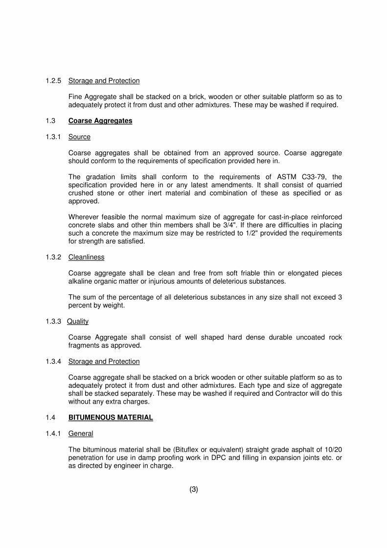
1.2.5 Storage and Protection
Fine Aggregate shall be stacked on a brick, wooden or other suitable platform so as to adequately protect it from dust and other admixtures. These may be washed if required.
1.3 Coarse Aggregates 1.3.1 Source
Coarse aggregates shall be obtained from an approved source. Coarse aggregate should conform to the requirements of specification provided here in.
The gradation limits shall conform to the requirements of ASTM C33-79, the specification provided here in or any latest amendments. It shall consist of quarried crushed stone or other inert material and combination of these as specified or as approved.
Wherever feasible the normal maximum size of aggregate for cast-in-place reinforced concrete slabs and other thin members shall be 3/4". If there are difficulties in placing such a concrete the maximum size may be restricted to 1/2" provided the requirements for strength are satisfied.
1.3.2 Cleanliness
Coarse aggregate shall be clean and free from soft friable thin or elongated pieces alkaline organic matter or injurious amounts of deleterious substances.
The sum of the percentage of all deleterious substances in any size shall not exceed 3 percent by weight.
1.3.3 Quality
Coarse Aggregate shall consist of well shaped hard dense durable uncoated rock fragments as approved.
1.3.4 Storage and Protection
Coarse aggregate shall be stacked on a brick wooden or other suitable platform so as to adequately protect it from dust and other admixtures. Each type and size of aggregate shall be stacked separately. These may be washed if required and Contractor will do this without any extra charges.
1.4 BITUMENOUS MATERIAL 1.4.1 General
The bituminous material shall be (Bituflex or equivalent) straight grade asphalt of 10/20 penetration for use in damp proofing work in DPC and filling in expansion joints etc. or as directed by engineer in charge.
(4)
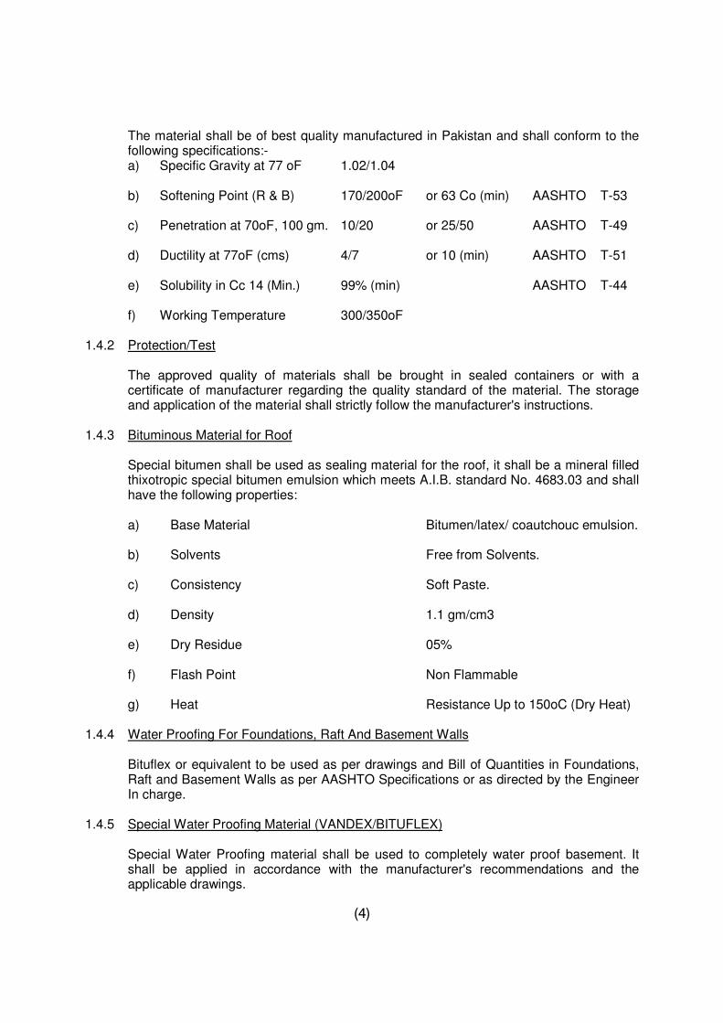
The material shall be of best quality manufactured in Pakistan and shall conform to the following specifications:-
a) Specific Gravity at 77 oF 1.02/1.04 b) Softening Point (R & B) 170/200oF or 63 Co (min) AASHTO T-53 c) Penetration at 70oF, 100 gm. 10/20 or 25/50 AASHTO T-49 d) Ductility at 77oF (cms) 4/7 or 10 (min) AASHTO T-51 e) Solubility in Cc 14 (Min.) 99% (min) AASHTO T-44 f) Working Temperature 300/350oF 1.4.2 Protection/Test
The approved quality of materials shall be brought in sealed containers or with a certificate of manufacturer regarding the quality standard of the material. The storage and application of the material shall strictly follow the manufacturer's instructions.
1.4.3 Bituminous Material for Roof
Special bitumen shall be used as sealing material for the roof, it shall be a mineral filled thixotropic special bitumen emulsion which meets A.I.B. standard No. 4683.03 and shall have the following properties:
a) Base Material Bitumen/latex/ coautchouc emulsion. b) Solvents Free from Solvents. c) Consistency Soft Paste. d) Density 1.1 gm/cm3 e) Dry Residue 05% f) Flash Point Non Flammable g) Heat Resistance Up to 150oC (Dry Heat) 1.4.4 Water Proofing For Foundations, Raft And Basement Walls
Bituflex or equivalent to be used as per drawings and Bill of Quantities in Foundations, Raft and Basement Walls as per AASHTO Specifications or as directed by the Engineer In charge.
1.4.5 Special Water Proofing Material (VANDEX/BITUFLEX)
Special Water Proofing material shall be used to completely water proof basement. It shall be applied in accordance with the manufacturer's recommendations and the applicable drawings.
(5)
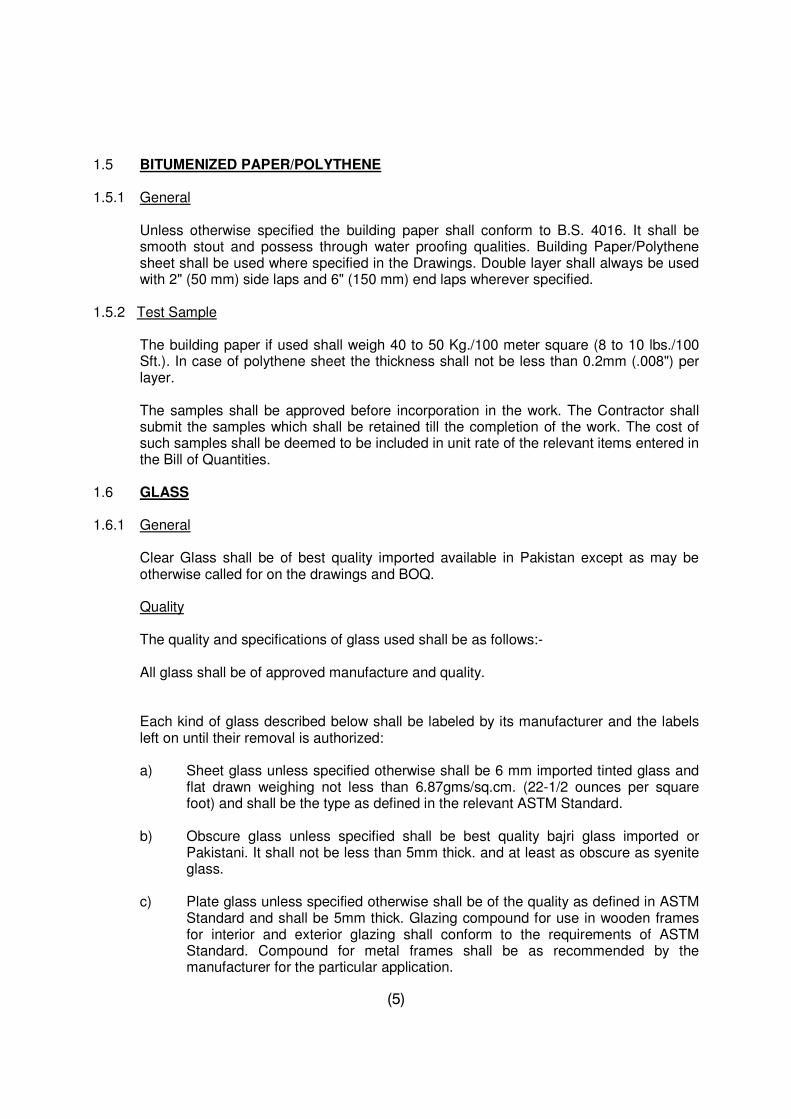
1.5 BITUMENIZED PAPER/POLYTHENE 1.5.1 General
Unless otherwise specified the building paper shall conform to B.S. 4016. It shall be smooth stout and possess through water proofing qualities. Building Paper/Polythene sheet shall be used where specified in the Drawings. Double layer shall always be used with 2" (50 mm) side laps and 6" (150 mm) end laps wherever specified.
1.5.2 Test Sample
The building paper if used shall weigh 40 to 50 Kg./100 meter square (8 to 10 lbs./100 Sft.). In case of polythene sheet the thickness shall not be less than 0.2mm (.008") per layer.
The samples shall be approved before incorporation in the work. The Contractor shall submit the samples which shall be retained till the completion of the work. The cost of such samples shall be deemed to be included in unit rate of the relevant items entered in the Bill of Quantities.
1.6 GLASS 1.6.1 General
Clear Glass shall be of best quality imported available in Pakistan except as may be otherwise called for on the drawings and BOQ.
Quality
The quality and specifications of glass used shall be as follows:-
All glass shall be of approved manufacture and quality.
Each kind of glass described below shall be labeled by its manufacturer and the labels left on until their removal is authorized: a) Sheet glass unless specified otherwise shall be 6 mm imported tinted glass and
flat drawn weighing not less than 6.87gms/sq.cm. (22-1/2 ounces per square foot) and shall be the type as defined in the relevant ASTM Standard.
b) Obscure glass unless specified shall be best quality bajri glass imported or
Pakistani. It shall not be less than 5mm thick. and at least as obscure as syenite glass.
c) Plate glass unless specified otherwise shall be of the quality as defined in ASTM
Standard and shall be 5mm thick. Glazing compound for use in wooden frames for interior and exterior glazing shall conform to the requirements of ASTM Standard. Compound for metal frames shall be as recommended by the manufacturer for the particular application.
(6)
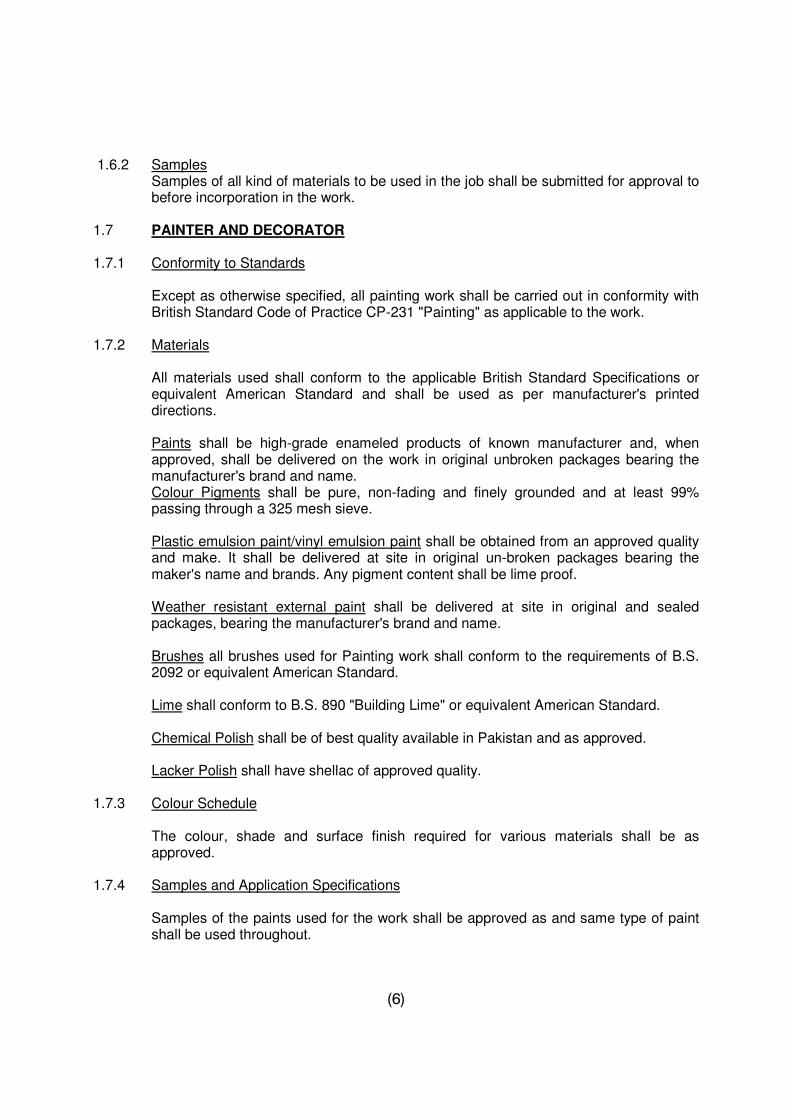
1.6.2 Samples Samples of all kind of materials to be used in the job shall be submitted for approval to before incorporation in the work. 1.7 PAINTER AND DECORATOR 1.7.1 Conformity to Standards
Except as otherwise specified, all painting work shall be carried out in conformity with British Standard Code of Practice CP-231 "Painting" as applicable to the work.
1.7.2 Materials
All materials used shall conform to the applicable British Standard Specifications or equivalent American Standard and shall be used as per manufacturer's printed directions.
Paints shall be high-grade enameled products of known manufacturer and, when approved, shall be delivered on the work in original unbroken packages bearing the manufacturer's brand and name.
Colour Pigments shall be pure, non-fading and finely grounded and at least 99% passing through a 325 mesh sieve.
Plastic emulsion paint/vinyl emulsion paint shall be obtained from an approved quality and make. It shall be delivered at site in original un-broken packages bearing the maker's name and brands. Any pigment content shall be lime proof.
Weather resistant external paint shall be delivered at site in original and sealed packages, bearing the manufacturer's brand and name.
Brushes all brushes used for Painting work shall conform to the requirements of B.S. 2092 or equivalent American Standard. Lime shall conform to B.S. 890 "Building Lime" or equivalent American Standard. Chemical Polish shall be of best quality available in Pakistan and as approved. Lacker Polish shall have shellac of approved quality. 1.7.3 Colour Schedule
The colour, shade and surface finish required for various materials shall be as approved.
1.7.4 Samples and Application Specifications
Samples of the paints used for the work shall be approved as and same type of paint shall be used throughout.
(7)
Certified data, test samples and detailed application specifications shall be submitted for approval. If the material is to be tested, this will be got done by the Contractor at his own cost from an approved laboratory.
1.8 VARNISH 1.8.1 Source Varnish shall be procured from an approved source or manufacturer. 1.8.2 Quality Varnish shall be clear, transparent and suitable for use on exterior or interior work, as specified and shall give a uniform and glossy coating, free from runs and specks. Varnish shall become surface dry not more than 6 hours for interior and 8 hours for exterior work and hard dry not more than 18 hours.
The loss in weight on heating in a suitable oven after placing on a metal dish at a temperature of 105 degree to 110 degrees centigrade for 3 hours shall not exceed 50%.
1.8.3 Composition Unless otherwise specified it shall be best English Copal. 1.8.4 Colour The colour and shade shall be as approved. 1.8.5 Supply and Storage
The readymade varnish shall be packed in sealed tins and shall bear the batch number of production and the date of manufacture. The varnish shall be used after one year of its manufacture.
1.9 PLASTIC EMULSION PAINT 1.9.1 Source Paint shall be obtained from an approved source or manufacturer as approved. 1.9.2 Quality
When thoroughly mixed and applied it shall give a permanent uniform colour free from runs and specks.
1.9.3 Storage
Paint shall be stored in sealed tins and only in such quantities as shall be consumed within one year of its manufacture.
(8)
1.10 TIMBER 1.10.1 Source
Timber shall be procured from an approved source and shall be in accordance with the requirements of B.S. 1186 - Part I.
1.10.2 Quality
Unless otherwise specified, timber shall mean Deodar wood for all carpentry, joinery and structural works, as specified in the drawings.
Timber shall be of good quality felled not less than two years before use for carpentry and four years for joinery work and shall be properly seasoned. Timber shall be uniform in texture, straight in fibres, free from open shakes, bore holes, fungus attack, rots, dots, decay, warps, twists, springs or cracks and all other defects and blemishes.
1.10.3 Sap Wood Sap wood shall not be permissible in any work i.e. in carpentry, joinery and structural works. 1.10.4 Knots
Timber shall be free from knots, other than sound knots appearing on surface only and not exceeding 1/2" (15mm) diameter. Such loose or decayed dead knots shall not be permissible in any joinery and shall be cut out and plugged properly.
1.10.5 Shakes
Straight splits or shakes shall be permissible in the ends up to a total for both ends of 2" (50mm) per metre of length at the time of passing.
Timber shall not be spongy or in brittle condition. 1.10.6 Size
The round logs of timber shall not be less than 10' (3 metre) and more than 40' (12 metre) in length and 7' (2.1 metre) in girth. Tapered logs shall not be less than 4' (1.2 metre) in girth at the small end.
Squares shall be of the size not less than 10' (3 metre) in length and 16"x16" (400mm x 400mm) in cross section.
Sleepers shall be obtained from logs cut from sound and mature trees. 1.10.7 Storage
Timber shall be stacked on a raised wooden or paved platform to eliminate chances of white ant attack.
(9)
It shall be stacked under a proper shelter, where maximum aeration is possible without subjecting it to the direct sun, rain or other weathering agents.
1.10.8 Miscellaneous In all other respects, timber should conform to the applicable requirements of B.S. 1186. 1.11 WATER 1.11.1 Source Water for construction shall be obtained from an approved source. 1.11.2 Quality Water shall be free from clay, vegetable, organic impurities and any other substance likely to cause efflorescence or interfere with setting of mortars or otherwise be harmful to the work. Broadly speaking any water which does not show an intensive odour or brackish taste shall be considered suitable for building works, whereas water fit for drinking, shall be accepted as suitable for all engineering works. P.H. value of water shall not lower than 5. Where doubts exists as to the suitability of water it shall be tested in accordance with ASTM C – 87, C – 40.
1.11.3 Storage
Water shall be stored in water tight tanks or containers adequately protected from the admixture of dust and other foreign matter.
1.12 PORTLAND CEMENT These specifications cover five types of port-land cement, as follows :-
Type - I For use in general concrete construction when the special properties specified for type-II, III, IV and V are not required.
Type - II For use in general concrete construction exposed to moderate sulphate
action, or when moderate heat of hydration is required.
Type – III For use when high early strength is required. Type - IV For use when low heat of hydration is required. Type - V For use when high sulphate resistance is required. 1.12.1 Definition
Portland cement is the product obtained by pulverizing clinker consisting essentially of hydraulic calcium silicates to which no additions have been made subsequent to calcinations, other than water and/or untreated calcium sulphate, except that addition of other non-deleterious materials may be added at the option of the manufacturer in an amount not to exceed 0.1%.
(10)
1.12.2 Physical Requirements
Portland cement of each of the five types shown above shall conform to the requirements of ASTM Designation C-150 or B.S. Specifications No: 12.
1.12.3 Packing and Marking
When the cement is delivered in packages, the name and brand of the manufacturer and the type shall be plainly identified thereon. When the cement is delivered in bulk this information shall be contained in the shipping invoice accompanying the shipment. A bag shall contain 50 Kg. All cement shall be fresh and of approved origin and manufacture.
1.12.4 Inspection
Every facility shall be provided for careful sampling and inspection either at the mill or at the site of work. The following periods from time of sampling shall be allowed for completion of testing.
1-day test 6 days 3-day test 8 days 7-day test 2 days 28-day test 33 days 1.12.5 Rejection The cement may be rejected if it fails to meet any of the requirements of these specifications.
Cement remaining in bulk storage at the mill, prior to shipment for a period greater than six months after completion of the tests, may be tested and may be rejected if it fails to conform to any of the requirements of these specifications.
If the variation in weight of any shipment is 3% on the lower side than the entire shipment may be rejected.
Cement failing to meet the test for soundness in the autoclave may be accepted if it passes a retest, using a new sample, at any time within 28 days thereafter. The provisional acceptance of cement at the mill shall not override the right to reject on a retest of soundness at the time of delivery of the cement.
The Contractor shall supply, if required, at fortnightly intervals, test Certificates with the dates of such tests, showing that the cement complies with the appropriate standard. These tests shall be carried out in a approved laboratory.
Only one brand of each type of cement shall be used for concrete in any individual member of the structure. Cement shall be used in the sequence of receipt of shipment, unless otherwise directed.
There shall be sufficient cement on site to ensure that each section of work is completed without interruption.
(11)
Cement reclaimed from cleaning of bags or from leaky containers shall not be used. The mixing together of different types of cement will not be permitted. 1.12.6 Method of Sampling and Testing
The sampling and testing of port-land cement shall be in accordance with relevant A.S.T.M. (C-150-74) standard specifications.
Contractor shall carry out tests on Ordinary Portland Cement, Sulphate Resistant Cement and White cement at his own cost, if and when required.
1.12.7 Method of Sampling and Testing
The sampling and testing of Portland Cement shall be in accordance with the relevant B.S. or ASTM (C-150-74) standard specifications.
i) The sacks should be stacked closely on a damp proof floor or on timber planks
raised 12" (300mm) or so from the ground with air space below. There should be similar air space between the stacks and walls and roof of the building, which should have sound weather proof walls and roof.
ii) To avoid bursting of bags and setting under pressure the height of the stacks
shall be limited to 8 bags. 1.12.8 Limitation of Use
No cement stored through a monsoon or for more than six months should be used, unless tests have been applied and cement meets the requisite standard.
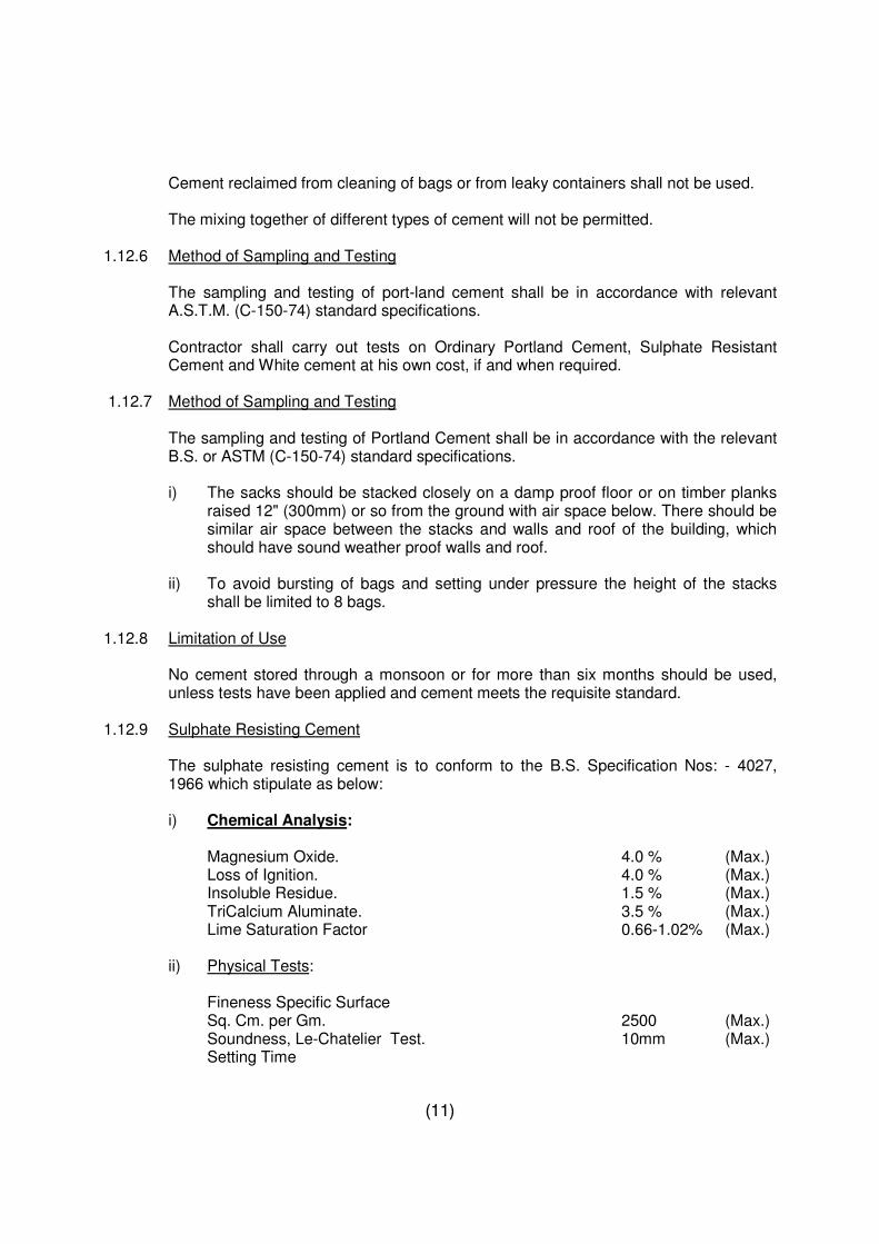
1.12.9 Sulphate Resisting Cement
The sulphate resisting cement is to conform to the B.S. Specification Nos: - 4027, 1966 which stipulate as below:
i) Chemical Analysis: Magnesium Oxide. 4.0 % (Max.) Loss of Ignition. 4.0 % (Max.) Insoluble Residue. 1.5 % (Max.) TriCalcium Aluminate. 3.5 % (Max.) Lime Saturation Factor 0.66-1.02% (Max.) ii) Physical Tests: Fineness Specific Surface Sq. Cm. per Gm. 2500 (Max.) Soundness, Le-Chatelier Test. 10mm (Max.) Setting Time
(12)
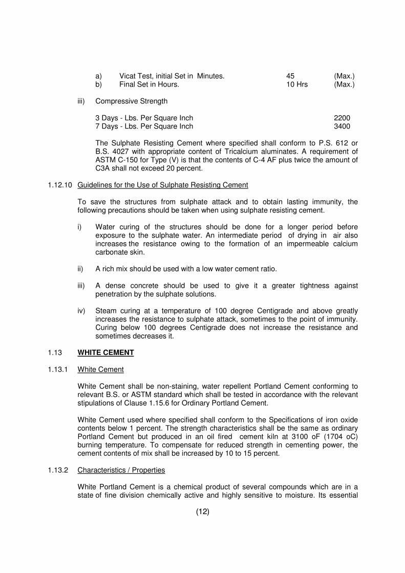
a) Vicat Test, initial Set in Minutes. 45 (Max.) b) Final Set in Hours. 10 Hrs (Max.) iii) Compressive Strength 3 Days - Lbs. Per Square Inch 2200 7 Days - Lbs. Per Square Inch 3400
The Sulphate Resisting Cement where specified shall conform to P.S. 612 or B.S. 4027 with appropriate content of Tricalcium aluminates. A requirement of ASTM C-150 for Type (V) is that the contents of C-4 AF plus twice the amount of C3A shall not exceed 20 percent.
1.12.10 Guidelines for the Use of Sulphate Resisting Cement To save the structures from sulphate attack and to obtain lasting immunity, the following precautions should be taken when using sulphate resisting cement. i) Water curing of the structures should be done for a longer period before
exposure to the sulphate water. An intermediate period of drying in air also increases the resistance owing to the formation of an impermeable calcium carbonate skin.
ii) A rich mix should be used with a low water cement ratio. iii) A dense concrete should be used to give it a greater tightness against
penetration by the sulphate solutions. iv) Steam curing at a temperature of 100 degree Centigrade and above greatly
increases the resistance to sulphate attack, sometimes to the point of immunity. Curing below 100 degrees Centigrade does not increase the resistance and sometimes decreases it.
1.13 WHITE CEMENT 1.13.1 White Cement
White Cement shall be non-staining, water repellent Portland Cement conforming to relevant B.S. or ASTM standard which shall be tested in accordance with the relevant stipulations of Clause 1.15.6 for Ordinary Portland Cement.
White Cement used where specified shall conform to the Specifications of iron oxide contents below 1 percent. The strength characteristics shall be the same as ordinary Portland Cement but produced in an oil fired cement kiln at 3100 oF (1704 oC) burning temperature. To compensate for reduced strength in cementing power, the cement contents of mix shall be increased by 10 to 15 percent.
1.13.2 Characteristics / Properties
White Portland Cement is a chemical product of several compounds which are in a state of fine division chemically active and highly sensitive to moisture. Its essential
(13)
qualities are hydraulic in nature i.e. it sets and hardens when worked with water. A good white cement which combines the properties of its numerous compounds, will set when water is added to it in a regulated time; it will harden and gain strength progressively, its strength will not show retrogression in strength at a later period and will have constancy of volume. Above all, the basic requirement it has to fulfill concerns its appearance which must be white, without any contamination of iron or anything else. To maintain this primary property viz. whiteness, great care has to be taken at every stage of its production. The characteristic and properties of white cement are fineness, setting time and soundness. It has to conform to the most rigorous specification in respect of soundness. This is most important, for any lack of proportion in the elements that produce it or any negligence in the production processes would spoil the product. In other words even the slightest defect in the manufacture would make the things made from it such as hydraulic tiles or other moulded articles unsatisfactory.
1.14 COLOURED CEMENT 1.14.1 Coloured Cement
Colours are imparted to ordinary cement by mixing colouring matter to it in the form of mineral pigments. Usually 5 to 10 percent of the colouring matter is added to obtain the required shade. The mineral oxide used as pigments are rather costly.
Iron oxide gives red, yellow or brown; Chromium oxide gives green colour; Cobalt gives blue colour. For black or brown colour manganese dioxide is used. White cement is prepared with raw materials almost free from iron; it has the normal setting of ordinary cement, except for the absence of any colour but white.
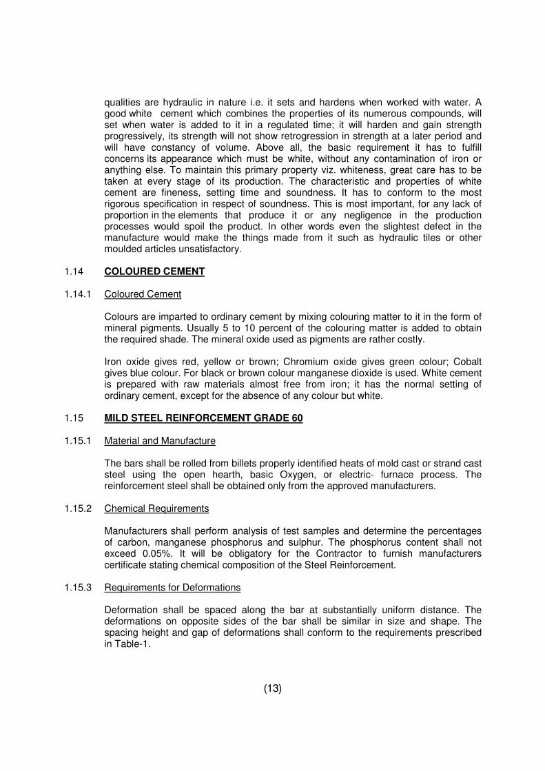
1.15 MILD STEEL REINFORCEMENT GRADE 60 1.15.1 Material and Manufacture
The bars shall be rolled from billets properly identified heats of mold cast or strand cast steel using the open hearth, basic Oxygen, or electric- furnace process. The reinforcement steel shall be obtained only from the approved manufacturers.
1.15.2 Chemical Requirements
Manufacturers shall perform analysis of test samples and determine the percentages of carbon, manganese phosphorus and sulphur. The phosphorus content shall not exceed 0.05%. It will be obligatory for the Contractor to furnish manufacturers certificate stating chemical composition of the Steel Reinforcement.
1.15.3 Requirements for Deformations
Deformation shall be spaced along the bar at substantially uniform distance. The deformations on opposite sides of the bar shall be similar in size and shape. The spacing height and gap of deformations shall conform to the requirements prescribed in Table-1.
(14)
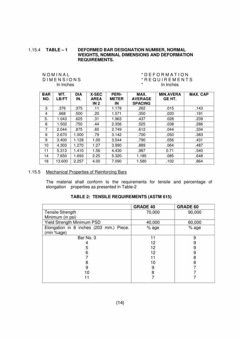
1.15.4 TABLE – 1 DEFORMED BAR DESIGNATION NUMBER, NORMAL
WEIGHTS, NOMINAL DIMENSIONS AND DEFORMATION REQUIREMENTS.
N O M I N A L * D E F O R M A T I O N D I M E N S I O N S * R E Q U I R E M E N T S In Inches * In Inches
BAR NO.
WT. LB/FT
DIA IN.
X-SEC AREA IN 2
PERI- METER
IN
MAX. AVERAGE SPACING
MIN.AVERAGE HT.
MAX. CAP
3 .376 .375 .11 1.178 .262 .015 .143
4 .668 .500 .20 1.571 .350 .020 .191
5. 1.043 .625 .31 1.963 .437 .028 .239
6 1.502 .750 .44 2.356 .525 .038 .286
7 2.044 .875 .60 2.749 .612 .044 .334
8 2.670 1.000 .79 3.142 .700 .050 .383
9 3.400 1.128 1.00 3.544 .790 .056 .431
10 4.303 1.270 1.27 3.990 .889 .064 .487
11 5.313 1.410 1.56 4.430 .987 0.71 .540
14 7.650 1.693 2.25 5.320 1.185 .085 .648
18 13.600 2.257 4.00 7.090 1.580 .102 .864
1.15.5 Mechanical Properties of Reinforcing Bars
The material shall conform to the requirements for tensile and percentage of elongation properties as presented in Table-2
TABLE 2: TENSILE REQUIREMENTS (ASTM 615)
GRADE 40 GRADE 60
Tensile Strength Minimum (in psi)
70,000 90,000
Yield Strength Minimum PSD 40,000 60,000
Elongation in 8 inches (203 mm.) Piece. (min %age)
% age % age
Bar No. 3 4 5 6 7 8 9
10 11
11 12 12 12 11 10 9 8 7
9 9 9 9 8 8 7 7 7
(15)
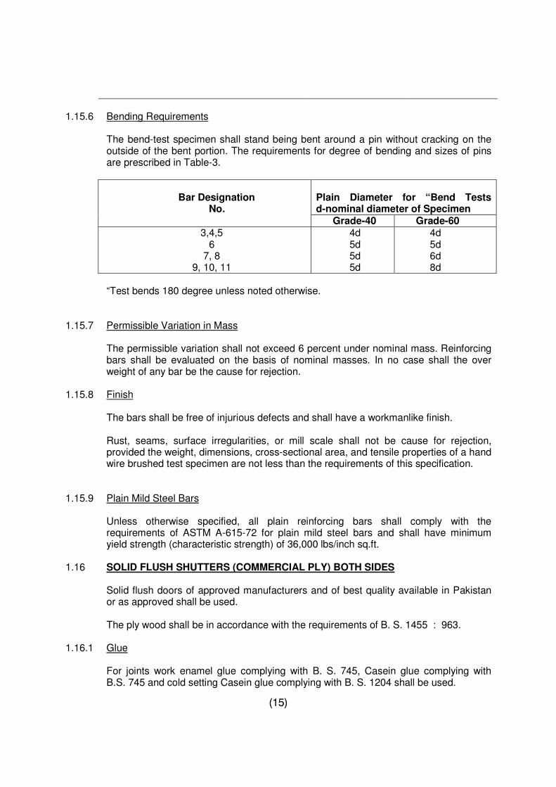
1.15.6 Bending Requirements
The bend-test specimen shall stand being bent around a pin without cracking on the outside of the bent portion. The requirements for degree of bending and sizes of pins are prescribed in Table-3.
Bar Designation No.
Plain Diameter for “Bend Tests d-nominal diameter of Specimen
Grade-40 Grade-60 3,4,5 6 7, 8 9, 10, 11
4d 5d 5d 5d
4d 5d 6d 8d
“Test bends 180 degree unless noted otherwise.
1.15.7 Permissible Variation in Mass
The permissible variation shall not exceed 6 percent under nominal mass. Reinforcing bars shall be evaluated on the basis of nominal masses. In no case shall the over weight of any bar be the cause for rejection.
1.15.8 Finish The bars shall be free of injurious defects and shall have a workmanlike finish.
Rust, seams, surface irregularities, or mill scale shall not be cause for rejection, provided the weight, dimensions, cross-sectional area, and tensile properties of a hand wire brushed test specimen are not less than the requirements of this specification.
1.15.9 Plain Mild Steel Bars
Unless otherwise specified, all plain reinforcing bars shall comply with the requirements of ASTM A-615-72 for plain mild steel bars and shall have minimum yield strength (characteristic strength) of 36,000 lbs/inch sq.ft.
1.16 SOLID FLUSH SHUTTERS (COMMERCIAL PLY) BOTH SIDES
Solid flush doors of approved manufacturers and of best quality available in Pakistan or as approved shall be used.
The ply wood shall be in accordance with the requirements of B. S. 1455 : 963. 1.16.1 Glue
For joints work enamel glue complying with B. S. 745, Casein glue complying with B.S. 745 and cold setting Casein glue complying with B. S. 1204 shall be used.
(16)
1.17 TERMITE PROOFING MATERIAL
Dieldrin / Alderin 20% emulsified concentrated or 0.5% solution of Heptachlor or de-Termite Emulsion or another approved shall be used as per manufacturers Specifications.
1.18 CHIP BOARD 1.18.1 General
The Chip Board in general shall be medium density of best quality available in the country and shall have uniform texture and thickness conforming to B.S. 2604 : 2604. The surface shall be of such nature so as to give good adhesion to the decorative lamination to be pressed on to it. They should be free from flaws, cracks, or any sort of weak spots. The density shall be in the range of 50-53 lbs/sft and the modulus of rupture shall be between 1,500 to 3,000 lbs/sq.in.
1.18.2 Samples The samples shall be submitted by the contractor for approval before placing order to the supplier and these samples will be retained till the completion of work. The cost of such samples shall be deemed to be included in the unit rates of the relevant items entered in the Bill of Quantities. PLUMBING AND SANITARY FIXTURES 1.19 WATER CLOSET 1.19.1 Source
Unless otherwise specified the water closet shall be of best quality manufactured in Pakistan as approved.
1.19.2 Composition The water closet shall be made of ceramic ware in one piece of material. 1.19.3 Quality
Each water closet shall show good workmanship without dents or faults. The surface and colour shall be uniform, non-corrodible, free from discoloration and imperfections.
1.19.4 Colour The colour of the water closet shall be white or as approved. 1.19.5 Type
Type of the water closet shall be Asian / European as specified in the drawings or as approved.
(17)
1.19.6 Size The size of the water closet shall be as specified in the drawings or as approved. 1.19.7 Trap
The trap shall be either S or P type as approved. For manufacture and quality it shall conform to the above specification for water closet. Each trap shall have a circular opening of 0.02 meter (4") l.d. for connection of anti-siphonage pipe.
1.19.8 Foot Rest
For squatting/Asiatic pattern type water closet the foot rest shall be an integral part of the water closet.
1.20 SEAT 1.20.1 Source
Unless otherwise specified the seat shall be in double seat cover comprising a seat and a cover hinged together of best quality manufactured in Pakistan or as approved.
1.20.2 Composition Seat shall be as per manufacturer's Standard. 1.20.3 Quality Seat shall be made in one piece. It shall be free from blisters. The surface shall be highly polished impervious and hygienic. 1.20.4 Type Seat shall be of closed or open pattern as per manufacturer's Standard. 1.20.5 Shape
The shape of the seat shall be in conformity with the type of water closet specified. The underside of the seat shall be flat and shall not be recessed. For closed pattern seat the hinging devices shall be either of good quality non-ferrous metal or any other corrosion resistant material.
1.20.6 Bolts
The bolts shall be of non-ferrous material 65 mm (2- 1/2") in length. Two bolts shall be provided with each seat.
1.20.7 Buffers
Seat shall be provided with rubber buffers of 25mm x 37mm (1" x 1-1/2") size and 9.5 mm x 3/8") thickness. The buffers shall be rigidly attached to the seat. The metal in
(18)
contact with buffers shall be non-ferrous. The cover of the seat for closed pattern shall have buffers not less than two in number.
1.20.8 Colour The colour of the seat shall be black or as approved. 1.21 FLUSHING CISTERN 1.21.1 Source
Cistern shall be obtained from approved source which shall be of the best quality manufactured in Pakistan or as approved.
1.21.2 Composition
Low level non completed coupled cistern shall be made of plastic or ceramic ware in one piece of materials. For manufacture and quality it shall conform to Specifications of water closet.
1.21.3 Capacity The capacity of the cistern shall be 13.5 liters (3 Gallons). 1.21.4 Quality
Each cistern shall show good workmanship without dents or faults. The surface and colour shall be uniform free from discoloration and imperfections.
1.21.5 Brackets/Bolt Kit
Brackets shall be of material as approved. The length of the bracket shall be such as to enable 100mm (4") embedding in the wall or fixed to the wall with the help of screws. Where bolt kit is available as standard Accessory it shall conform to manufacturers specifications.
1.21.6 Cover
For composition and quality the cistern cover shall conform to the corresponding specification of cistern.
1.21.7 Flush Pipe
Flush pipe shall be of 31mm (1-1/2") internal diameter. It shall be manufactured either from steel or non- ferrous materials as approved.
The steel pipe shall be either galvanized or chromium plated both internally and externally as approved. Moulded rubber cone shall be provided for connection with the water closet.
(19)
1.21.8 Ball Valve and Component Parts
Ball valve and its component parts shall be either of brass or gun metal or any corrosion resistant alloy or plastic. These shall be sound, hard, smooth and well finished. The mechanism of component parts shall be such that when the position is in contact with the face of seat the short arm of the level shall be in vertical position. Ball valve shall not leak when rested to a pressure of 210.9 x 10³ Kg/sq. meter (300 P.S.I.). It shall not displace water more than half its volume when left in water.
1.22 WASH HAND BASIN 1.22.1 Source and Type
Wash Hand Basins shall be of an approved best quality and type manufactured in Pakistan.
1.22.2 Composition
Wash Hand Basin shall be made as ceramic ware in one piece of material as approved.
1.22.3 Manufacture
Each Wash Hand Basin shall be fired at such a temperature as to produce satisfactory fused clay.
1.22.4 Quality
Each Wash Hand Basin shall show good workmanship without dents or faults. The surface and colour shall be uniform non-corrodible, free from discoloration and imperfections.
1.22.5 Colour Colour of the wash hand basin shall be white or as approved. 1.22.6 Size The size of the wash hand basin shall be as specified in the Bill of Quantities. 1.22.7 Overflow
Overflow shall be either of open ware type with removable grating or of a bolt type as specified. The slot for overflow shall be 63mm long 12.7 mm deep (2.5" long and 1/2" deep). It shall be so designed as to facilitate cleaning.
1.22.8 Soap tray or Sinking Soap tray or sinking shall be so provided as to drain into the basin.
(20)
1.22.9 Tap Holes
The tap holes shall be squarer to fit pillar taps and shall be beveled around the opening. They shall be so situated as to allow supply pipes to be clear of waste and vent pipes and shall have enough space to prevent the user striking the head on the tap.
1.22.10 Waste Hole and Grating
Waste hole shall have a minimum diameter of 63mm (2.5") the outlet shall be beveled or rebated. The tap hole shall be square in shape and each side shall be of 29mm (1.1/8") length. Chromium plated grating of appropriate diameter shall allow free drainage of water and be securely fitted to basin without any leakage.
1.22.11 Plug Chain and Stay Hole
Plug shall be of rubber. The diameter of the plug shall be such as to fit snugly in the waste hole. The chain shall be of brass/chromium plated one end fixed to the plug and the other end in the chain stay hole. The position of the stay hole shall not be lower than the over flow slot.
1.22.12 Brackets
Brackets shall be of an approved material. The length of the bracket shall be such as to enable 100mm (4") embedding in the wall or fixed to the wall with the help of screws.
1.22.13 Stud Slots
Stud slots shall be monolithically cast with the wash hand basin. These shall receive the brackets on the inside of the basin and shall be so situated that the brackets remain 50mm (2") away from the face. These shall not exceed 12.7 mm (1/2") in dia 7.9 mm (5/10" in height and shall be 300mm (12") from the back of the basin to the center of the side. The side studs shall be 63mm x 125mm x 16mm (2-1/8" x 5" x 5/8") and centre of stud shall be 300mm (12") from the back of the basin.
1.23 WASTE PIPE
Waste Pipe shall be of 38mm (1-1/2") internal diameter. It shall be UPVC painted with enamel paint, or chromium plated as specified in the BOQ.
1.23.1 Bottle Type Trap
All the wash hand basins shall be provided with a bottle type trap (Chromium plated or stainless steel as approved) and connected with the basin and waste pipe.
(21)
1.24 SINK 1.24.1 Source and Type Sink shall be of best quality and type manufactured in Pakistan and as approved. 1.24.2 Composition It shall be made of 18 gauge stainless steel or as approved. 1.24.3 Quality
Each sink shall show good workmanship without dents or faults. The surface and colour should be uniform non- ferrous free from discoloration and imperfections.
1.24.4 Size
Size of the stainless steel sink shall be as specified in the Bill of Quantities or as approved.
1.25 PILLAR COCK 1.25.1 General
Pillar Cock shall be chromium plated and of best quality manufactured in Pakistan. These shall be of screw down type with jam nut. Internal diameter of the tap shall be 15mm (1/2").
1.26 TAPS AND STOP COCKS (TEE ANGLE ETC.) 1.26.1 Source Taps and cocks shall be of best quality manufactured in Pakistan and as approved. 1.26.2 Composition
The bodies and heads shall be of hard brass or gun metal or hot pressings of brass of manganese bronze. Spindles, glands, crutches, washer plates and nuts shall be of brass or manganese.
1.26.3 Quality
Castings shall be from metal poured into the moulds while hot pressing shall be metal pressed between dies.
Pressing shall be smoother and shall present a better appearance. These shall be plated with zinc or chromium as specified.
(22)
1.26.4 Requirements
Tap and cocks shall be fitted with a cover of pressed sheet metal threaded for attachment to the head and which can be cleaned easily. The stem of washer, plate (called a jumper) shall be either loose or fixed by screwing to the spindle with the help of a grub screw.
1.26.5 Size Size of the taps and cocks shall be as specified or as approved. 1.27 C.P. SOAP DISH 1.27.1 Source and Type
C.P. Soap dish shall be of an approved best quality and type manufactured in Pakistan.
1.27.2 Composition
It shall be made of best quality materials duly chromium plated in accordance with the latest specifications as approved.
1.27.3 Quality
It shall be of best quality and show good workmanship. The surface and colour should be uniform non- corrodible, free from discoloration and imperfections.
1.27.4 Size The size of the C.P. Soap dish shall be as approved or as specified. 1.28 C.P. TOILET PAPER HOLDER 1.28.1 Source and Type
The C.P. Toilet Paper holder shall be of an approved best quality and type manufactured in Pakistan.
1.28.2 Composition
It shall be made of best quality materials duly chromium plated in accordance with the latest specifications as approved.
1.28.3 Quality
It shall be of best quality and show good workmanship. The surface and colour should be uniform non- corrodible, free from dis-colouration and imperfections.
1.28.4 Size The size of the toilet paper holder shall be as approved or as specified.
(23)
1.29 C.P. TOWEL RAIL 1.29.1 Source and Type C.P. Towel Rail shall be of an approved best quality and type manufactured in Pakistan. 1.29.2 Composition
It shall be make of best quality iron pipe duly chromium plated in accordance with the latest specifications as approved.
1.29.3 Quality
It shall be of best quality and show good workmanship smooth surface and colour should be uniform non- corrodible, free from dis-colouration and imperfections.
1.29.4 Size It shall be of 3/4" dia x 24" long (19mm x 600mm ) long. 1.30 MIRROR 1.30.1 Source and Type
Mirror shall be of best quality Belgium or local as specified make with Chromium plated screws.
1.30.2 Composition
It shall be made of best quality materials in accordance with the latest British Standard Specifications as approved.
1.30.3 Quality
It shall be of best quality and show good workmanship and surface should be uniform and free from imperfections and distortion.
1.30.4 Size Size of the mirror shall be 24" x 18" x 1/4" or as specified. 1.31 PLATE GLASS SHELVES WITH C.P. GUARD RAILS 1.31.1 Source and Type
Plate glass shelves with C.P. guard rails shall be of an approved best quality and type manufactured in Pakistan.
(24)
1.31.2 Composition
It shall be made of best quality materials in accordance with the latest specifications as approved.
1.31.3 Quality
It shall be of best quality and show good workmanship. The surface and colour should be uniform non- corrodible, free from discoloration and imperfections.
1.31.4 Size It shall be of size 24"x5"x3/16" (600x125x5mm) or as specified. 1.31.5 C.P. Hanger The C.P. hanger shall be of an approved best quality and type manufactured in Pakistan. 1.31.6 Composition
It shall be made of best quality materials duly chromium plated in accordance with the latest specifications.
1.31.7 Quality
It shall be of best quality and show good workmanship. The surface and colour should be uniform non- corrodible, free from discoloration and imperfections.
1.31.8 Size The size of the C.P. hanger shall be as approved. 1.32 FLOOR TRAPS 1.32.1 Source and Type The floor trap shall be of an approved best quality and type manufactured in Pakistan. 1.32.2 Composition
It shall be made of best quality cast iron in accordance with the latest specifications with C.P. Grating of specified size.
1.32.3 Quality
It shall be made of best quality and show good workman- ship. The surface shall be uniform, non-corrodible, non-ferrous and free from imperfections.
(25)
1.32.4 Size The size of the flow trap shall be as specified or as approved. 1.33 VALVES Air relief valves, non-return valves, gate valves etc. 1.33.1 Source and Type
The valves shall be heavy duty and of an approved best quality and type manufactured in Pakistan.
1.33.2 Composition a) Air relief valve shall have small orifice valve, rubber balls, brass air vent orifices,
gun metal nipple, screw down valve and seats, operating screws. The valve shall be capable to resist 153 meter of water pressure.
b) Non-return valves body shall be of cast iron or bronze with gun metal seats and
stainless steel hinges. The valve shall be capable to resist a pressure of 150 metre of water.
c) Gate valves, heavy duty type brass, gun metal or bronze of best quality,
manufactured in Pakistan as approved and capable to resist a pressure of 150 metre of water.
1.33.3 Size As per Bill of Quantities. 1.34 MANHOLE COVER AND FRAME 1.34.1 Source and Type
Manhole cover and frame shall be of an approved best quality and type manufactured in Pakistan conforming to B.S.S 497.
1.34.2 Quality
It shall be of best quality and show good workmanship. The surface shall be uniform, non-corrodible, non- ferrous and free from imperfections.
1.34.3 Size 18" (450mm) dia weight 1/2 Cwt or as specified in the B.O.Q. 1.34 CAST IRON SOIL PIPES (SPUN TYPE) 1.34.1 Cast iron soil pipes and fittings shall be of an approved best quality manufactured in
Pakistan which shall be truly cylindrical with clear internal diameter as specified having
(26)
a uniform thickness smooth and with strong and deep sockets free from flaws air bubbles, cracks, sand- holes and other defects. They shall not be brittle but shall allow for ready cutting chipping or drilling.
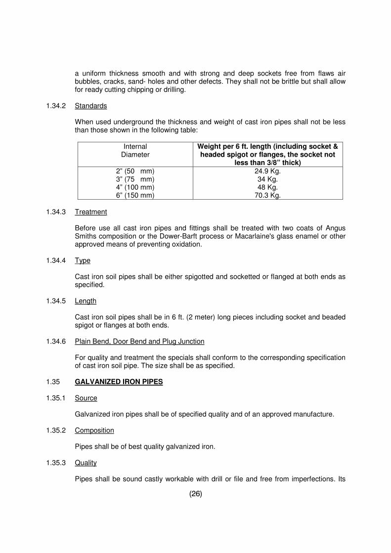
1.34.2 Standards
When used underground the thickness and weight of cast iron pipes shall not be less than those shown in the following table:
Internal
Diameter Weight per 6 ft. length (including socket & headed spigot or flanges, the socket not
less than 3/8” thick) 2” (50 mm) 3” (75 mm) 4” (100 mm) 6” (150 mm)
24.9 Kg. 34 Kg. 48 Kg.
70.3 Kg. 1.34.3 Treatment
Before use all cast iron pipes and fittings shall be treated with two coats of Angus Smiths composition or the Dower-Barft process or Macarlaine's glass enamel or other approved means of preventing oxidation.
1.34.4 Type
Cast iron soil pipes shall be either spigotted and socketted or flanged at both ends as specified.
1.34.5 Length
Cast iron soil pipes shall be in 6 ft. (2 meter) long pieces including socket and beaded spigot or flanges at both ends.
1.34.6 Plain Bend, Door Bend and Plug Junction
For quality and treatment the specials shall conform to the corresponding specification of cast iron soil pipe. The size shall be as specified.
1.35 GALVANIZED IRON PIPES 1.35.1 Source Galvanized iron pipes shall be of specified quality and of an approved manufacture. 1.35.2 Composition Pipes shall be of best quality galvanized iron. 1.35.3 Quality
Pipes shall be sound castly workable with drill or file and free from imperfections. Its
(27)
inner and outer surface shall be smooth. Each pipe shall be properly galvanized. It shall have screw threads on both ends for jointing with sockets.
1.36.4 Welding Socket
High frequency induction welding, Socket shall conform to the above specifications of galvanized iron pipes for composition and quality.
1.36.5 Requirements
All straight lengths of pipes and its threads shall be protected with socket and jute covering.
1.36.6 Test
Pipes shall be capable of withstanding a pressure 700 psi. The pipes shall comply with Specification ASTM F-1083 and A-865
1.36.7 Galvanized Iron Specials
The specials shall normally be of G.I. manufactured to the same specifications as the pipes but where these are not available locally manufactured gun metal specials can be used. It shall be ensured that the threads are not worn out. The fittings shall be tested by jointing at least 5 percent of the local supplies to straight pipes with sufficient pressure. Defective fittings invariably crack on application of pressure. The fittings shall also be examined to detect blisters and minor cracks. The fittings shall also be hydraulically tested to a pressure of 200 ft. of water head.
(28)
SECTION - 2 : CLEARANCES OF SITE & LAYOUT OF BUILDINGS
2.1 DESCRIPTION
The work to be done under this section consists of dismantling and demolition of existing structure (if any) including clearing out site of all rubbish, grass, shrubs, brush wood, under growth, roots and trees.
Securing permanent bench marks at given levels and grades wherever required. General grading and leveling of the site to achieve a proper drainage.
Removing all construction or demolition debris after completion of the work to a distance of at least 100 meters from the outermost lines of the site or as required by the local authorities.
All bench marks pegs, flags, pillars or any similar item and labour required for the setting out of the work shall be arranged by the Contractor. The cost of such item is to be included in the rate quoted by the Contractor in other items of work to be carried out under the Contract.
No tree shall be cut without the written orders. The wood obtained shall be neatly stacked and handed over to the Employer or his representative.
The ground shall be leveled and graded in accordance with the plans, sections or in the absence of such drawings as may be directed.
2.2 CONSTRUCTION REQUIREMENTS 2.2.1 Demolition Work
During demolition, the Contractor shall see that no damage or injury is done to the parts of the work which are to be retained, and that the demolition is executed with appropriate tools and in such a manner as to render unserviceable as little of the materials as possible.
Boards, battens, frames and wood work, sheets, tiles, slates, trusses, R.S. beams and all such materials likely to be damaged if dropped from a height, shall be carried to the ground or lowered with ropes.
2.2.2 Dust Prevention
To minimize nuisance from dust, arrangements shall be made for the erection and removal of screens or canvas or other suitable material and for watering the work as the demolition proceeds.
2.2.3 Sorting and Removal
All dismantled materials shall be property of the Employer and shall be sorted and stacked where ordered. Doors and windows shall be removed from the chowkhats with
(29)
their hinges before dismantling the later. The work of removing dismantled material upto 300 feet, sorting and stacking the same will be done within the rate.
2.2.4 Disposal
As required, the Contractor shall remove the whole or a portion of dismantled material from the site of work. The method of disposal of such material shall be subject to approval.
2.3 MEASUREMENT
The measurement for clearance of site and layout of Buildings shall not be made separately.
2.4 RATE AND PAYMENT
The cost for clearance of site and layout of Buildings shall be deemed to have been included in the rates of other items in the Bill of Quantities.
(30)
SECTION - 3 : EXCAVATION, FILLING, BACKFILLING & DISPOSAL
3.1 DESCRIPTION
The work under this Section consists of excavating, in all types of soil, lifting, transportation and disposal of the excavated material, back-fill and fill for building foundations, and under floors including all incidental work necessary for excavation to the required depth and dimensions and in accordance with the Drawings or as directed. The work shall be carried out in complete conformity with the specifications set-forth hereunder.
All fill or refill around structures, i.e. within the slopes and limits of the established lines for excavation for the structures and below the natural surface level, shall be defined as "Back Filling".
All fill or refill (from the excavated earth at site) about structures, i.e. above the natural surface level shall be defined as "filling under floors or embankment from excavated spoil".
All fill or refill, from the material provided and brought from outside the site (any lead), about structures, i.e. above the natural surface level shall be defined as " filling under floors with earth provided and brought from outside".
Filling shall be approved selected material from excavated or other predominantly granular material, free from slurry and organic or other unsuitable matter and capable of compaction by ordinary means.
Filling around pipes and cables shall be carefully placed; fine material shall cover the pipe of cable completely before the normal filling is placed.
Material for backfilling shall conform to the requirements of Specifications. It shall be placed in layers of 6" to 18” or as directed by the engineer incharge and saturated with sufficient water or otherwise compacted to produce not less than 95 percent in situ density with respect to the maximum density at optimum moisture content, achieved in Test No. 12 of B.S. 1377-1967.
Filling shall not be placed against foundation walls without first obtaining approval to do so. Filling shall be brought up evenly on each side of the walls as far as practicable. Heavy equipment for spreading and compacting the fill shall not be operated closer to the wall than a distance equal to the height of the fill above the top of footing.
3.1.1 Setting Out Lines and levels shall be set out by the Contractor who shall be responsible for maintaining all stakes and witness points set up for the work in strict accordance with the requirement and drawings. 3.1.2 Cleaning All areas requiring clearing shall be cleared of all trees, bushes, rubbish and other objectionable matter and such materials shall be removed from the site of work or
(31)
otherwise disposed off as approved. Any damage to the works of public or private property caused by Contractor's operation shall be made good through repair or replacement at the sole expenses of the Contractor. 3.2 AUTHORIZED OUTLINES
Unless otherwise specified or directed in writing, all earthwork, i.e. excavation of trenches, pits, etc. for foundations, filling under floors, etc. shall be executed to the widths, depths, lengths, alignments grades and levels shown on the drawings. If they are not indicated on the drawings then the Contractor shall prepare the drawing showing the existing ground levels and the actual grades and levels of excavation for obtaining necessary approval.
Similarly for all backfill and fill works the Contractor shall prepare drawings showing the existing ground levels and the actual finished level to ascertain the volume of fill for obtaining approval before the commencement of work.
3.3 CONSTRUCTION REQUIREMENTS 3.3.1 Excavation in Foundations & Backfilling
i) Lines and Grades The bottom and side slopes of excavation upon or against which structures or other required constructions are to be placed shall be finished accurately to the required grades and dimensions and, if required, shall be moistened with water and tamped or rolled with suitable tools or equipment for the purpose of forming firm foundation. Whenever the natural foundation material is disturbed or loosened or excavated beyond the approved lines and grades the loose material shall be removed and the extra excavation made good at Contractor's expense with selected materials which shall be thoroughly compacted by tamping rolling in layers not exceeding 6" to 18” or as directed by the Engineer In charge.
ii) Location for Placing Excavated/Surplus Materials
The excavated/surplus earth shall not be heaped within 5 ft. (1.5 m) of the top edge of any foundation. The surplus material shall be disposed off outside the project area without any additional cost.
iii) Inspection of Foundations
Foundation trenches shall be inspected and approved before foundation is laid. If safe foundation could not be obtained at the depth shown on the drawings, the work shall be carried out as directed by the Engineer In charge.
iv) Excavation to be kept Free of Water
All excavations shall be kept free from water from whatever source it may come at all times free of cost except where otherwise specified or permitted in writing.
(32)
v) Excess Excavation
In the event of any excavation being carried out wider or deeper than shown on the drawings, it shall be filled in by the Contractor at his own expense to meet the required dimension and levels with concrete or any other material approved for such purpose.
vi) Planking and Strutting
The Contractor shall provide at his own expense all timbering, piling, shoring, strutting and other approved supports to the sides of all excavation, trenches and all other works in such a way as will be sufficient to secure them from falling and to prevent any movement. The Contractor shall submit his proposals with drawings/sketches for approval prior to execution of any such construction work. All pecuniary and other responsibilities connected with this part of the work shall rest with the Contractor.
In removing timbering, shoring and strutting and all other supports from excavation and trenches etc., special care shall be taken to avoid bringing pressure to bear on any concrete or other work until it has hardened sufficiently to resist such pressure.
vii) Classification of Material
No classification will be made for payment purposes of any material excavated as to its class, nature, origin or condition, unless an unusual obstruction or embedded matter or substance is encountered. If this occurs, it shall be submitted by the Contractor for evaluation of design and working out of a necessary treatment. New items shall be mutually agreed.
viii) Transportation of Materials
All carts, trucks or other vehicles used by the Contractor for transportation of the material shall be suitably constructed or lined out to permit any leakage of soil while the vehicles are on the move. These would be so loaded and arranged as not to spill on the site and public roads. Whenever any vehicle so used is found leaking and unsuitable it shall be immediately withdrawn from the work.
ix) Termite Control The approved foundation trenches shall be treated with the termite control solution as provided under section "Termite Control". x) Compacted Fill and Backfill
It comprises returning, transportation and filling the selected excavated material around foundations, and at back of walls etc., upto finished levels shown on the drawings or as required in layers not exceeding 6” to 18” or as directed by the Engineer In charge carefully rammed and consolidated (with addition of water if required) so as to achieve a minimum relative density of 90%. No filling shall be made until the concrete foundations and footings etc., have been inspected and
(33)
approved. Earth to be used for filling must be free of all the organic impurities, debris or any other foreign matter. Earth which contains more than 1% of salts, particularly sulphates, will not be used in filling.
In case of non-sufficiency of excavated material and un-suitability of earth for back-filling, appropriate material conforming to the Specifications requirements shall be brought by the Contractor. Necessary Laboratory tests shall be carried out at the Contractor's expense.
3.4 EARTH FILLING UNDER FLOORS Excavation of Works
After the masonry has been laid up to the plinth level and the Damp Concrete Proof Course, if required is laid the space between the walls shall be cleared of debris and loose earth shall be laid in layers of 6" to 9” and each layer watered and compacted until the filling is completed up to the base level of the floor as shown on the drawings. Only sandy soil free from saltpeter either from the materials excavated from the foundations if such materials is suitable and sufficient or suitable material brought from outside shall be used.
3.5 SAND FILLING UNDER FLOOR
Unless otherwise specified the base of all ground floors shall be constructed in accordance with the following specifications:-
a) Sand filling shall be done in layers not more than 4" (100 mm) thick and shall be rammed after saturation to such an extent that 4" (100 mm) layer is reduced to about 2.7" (68 mm) after compaction.
The required in situ density w.r.t. maximum density to optimum moisture content shall be in compliance with test 12 of B.S. 1377-1967.
b) The base shall be perfectly level. A slope of 1:64 shall be provided in verandahs
and bath rooms if required.
c) Sand shall conform in all respect to the specifications for fine aggregate except for its grading, i.e. it shall pass through a sieve No. 16 and not more than 30% shall pass through a sieve No. 100.
3.6 MEASUREMENT a) For Excavation
The measurement shall be made for the actual Net quantity as per the approved drawings in cu.ft/cu.m. by taking measurements of trenches, pits, etc.
b) For Backfilling
The Measurement in Cu.ft/cu.m shall be made for the actual quantity backfilling as per approved drawing of the rammed/compacted earth.
(34)
c) For filling Earth/Sand under Floors
Measurement shall be made for actual quantity as per approved drawings in Cu.ft/cu.m by measurement of the rammed/compacted earth.
3.7 RATE AND PAYMENT a) For Excavation
Payment shall be made for the actual quantity as measured above in Cu.ft/cu.m at the corresponding unit rate of BOQ. The rate for excavation shall cover:
Excavation, backfilling, lifting and removal of surplus/excavated material for all leads and lifts; including compaction. The provision of drainage of surface subsoil/ground water and rain water in order to prevent accumulation of water around the foundations during the construction period. If a situation necessitates the execution of drainage, it shall be carried out by the Contractor at no extra cost. The duration of such activity shall be as per construction requirement or as directed.
b) For Backfilling
Payment shall be made for the actual quantity backfilled measured in cubic feet at the corresponding unit rate of BOQ.
The rate for backfilling shall cover filling the space between the building and the sides of the trenches with the excavated earth, laid in 6" to 18” layers watered and rammed including all labour, tools and plants required for the job.
c) For Filling under Floors/Embankment
Payment shall be made for the actual quantity of filling in cubic feet at the corresponding contract unit rates of BOQ. Such payment shall be considered as full compensation for the work specified above.
(35)
SECTION – 4 : TERMITE PROOFING
4.1 DESCRIPTION:
The work consists of providing termite control treatment in foundations plinth and under floors with the solution of Dieldrin/Aldrin 20% Emulsifiable concentrate (E.C.) or 0.5% solution of Heptachlor or another as approved.
4.2 MATERIAL REQUIREMENTS:
Dieldrin/Aldrin 20% Emulsifiable concentrate or 0.5% solution of Heptachlor shall be of approved manufacturers and shall be brought at site in manufacturers sealed tins.
4.3 CONSTRUCTION REQUIREMENTS: 4.3.1 Extent of Application:
Unless otherwise specified all sides of structural members below floor level and bottoms of excavated trenches/pits, floors beds and underside of plinth protection are to be sprayed with the solution.
4.3.2 Preparation of Solution: As per manufacturer’s recommendations. 4.3.3 Method of Application:
The solution shall be applied with approved pressure spraying equipment maintaining an adequate pressure to all applications to, on or in the earth. Solution shall also be sprayed in trenches around the building under plinth protection. Pesticide shall penetrate to a depth of 25 mm (1") minimum in porous earth at sides and 50 mm (2") to 75 mm (3") at bottoms of excavation and floor beds. After back-filling to plinth level, the area is again to be sprayed with pesticide solution. Wherever wooden/ply surfaces are to be treated by spraying, it shall be carried out with approved hand compression sprayer at the specified pressure as per instructions.
4.3.4 Rate of Application: The pesticide solution shall be applied as per manufacturer recommendations. 4.3.5 Precaution:
The contractor shall take extreme care to avoid any mishap due to the injurious effects of the chemicals and shall keep the "Owner" indemnified from any losses, damages or expenses in this connection whatsoever.
4.4 MEASUREMENT AND PAYMENT
The measurement shall be made in sq.m/sq.ft. by measuring and multiplying length into breath/height/depth of the actually treated surface by spraying the solution.
(36)
4.5 PAYMENT:
The payment shall be made in Sq.m/Sq.ft. of the actual work done as measured above at the corresponding unit rate given in BOQ.
Note: The General Contractor has to engage an approved Specialist Contractor for the
purposes of Termite proofing.
(37)
SECTION - 5 : PORTLAND CEMENT CONCRETE
5.1 DESCRIPTION
This item covers the manufacture, forming, transporting, placing, and stripping of forms, finishing and curing of plain and reinforced normal concrete in the structures included herein.
5.2 SPECIFICATIONS
Concrete work shall conform to all requirements of ACI 301-72, (Revised 1975), Specifications for Structural Concrete for Buildings, except as modified by supplemental requirements below. The Contractor shall submit, for approval before commencement of any work, his Method Statement which would provide complete details of the procedures and equipment to be used for the satisfactory execution of the work.
5.3 COMPOSITION AND QUALITY
Concrete shall be composed of Portland cement, water, fine and coarse aggregates and any admixtures as and when specified. The concrete mixtures will be designed by the Contractor who will determine the required quality of the concrete for the structures covered by these Specifications. The desired strength of concrete for various parts of the structure has been shown on the Drawings, or as provided in BOQ.
5.4 CEMENT 5.4.1 General:
Cement shall be furnished in sacks or in bulk form as approved. Unless otherwise permitted, cement from not more than two plants shall be used and in general, the product of only one plant shall be used in any particular section of the work. No cement recovered through cleaning sacks shall be used.
5.4.2 Portland Cement:
Portland cement shall be indigenous stuff unless otherwise approved. Portland cement shall conform to British Standard 12:1971, Specifications for Portland Cement or to ASTM Designation C150-74, Standard Specifications for Portland Cement Type - I conforming to ASTM Designation C150-74, Type - II or IV may also be used in certain parts of work as specified.
5.4.3 Tests: Cement shall be sampled at storage site and tested from time to time in accordance with the ASTM Designation C150-74 or its equivalent British Standards. Expenses for such tests shall be borne by the Contractor. If the tests prove that the cement has become unsatisfactory, it shall be removed from the site immediately. Cement which has been in storage longer than four months shall not be used until retesting proves it to be satisfactory.
(38)
5.4.4 Transportation of Cement:
Transportation of the cement from the mill to the site stores and to the point of use shall be accomplished in such a manner that the cement is completely protected from exposure to moisture. Cement which has been adversely affected by moisture shall be rejected. Cement in sacks shall be delivered in strong, well made, paper or cloth bags, each plainly marked with the manufacturer's name, brand, type of cement and the weight of cement contained therein. Packages varying more than 3 percent from the weight marked thereon may be rejected and if the average weight of packages in any consignment as shown by weighing fifty packages taken at random is less than that marked on the packages, the entire consignment may be rejected. Packages received in broken or damaged condition shall be rejected or may be accepted only as fractional packages.
5.4.5 Storage:
Cement shall be stored in dry, weather tight and properly ventilated structures. All storage facilities shall be subject to approval and shall be such as to permit easy access for inspection and identification of each consignment. Adequate storage capacity shall be furnished to provide sufficient cement to meet the peak needs of the project. Cement in sacks shall be stored on a damp proof floor and shall not be piled to a height exceeding 6 feet.
The Contractor shall use cement in the approximate chronological order in which it is received at the site. All empty sacks shall be promptly disposed off.
Cement storage facilities shall be emptied and cleaned by the Contractor when so directed, however, the interval between required cleaning normally will not be less than four months.
Suitable, accurate scales shall be provided at site for weighing the cement in stores and elsewhere on the work, if required, and he shall also furnish all necessary test weights.
5.4.6 Delivery and Usage Record:
Accurate records of deliveries of cement and its use in the works shall be kept by the Contractor. Copies of these records shall be supplied in such a form as may be required.
5.5. AGGREGATE 5.5.1 Requirements: Aggregates for normal concrete shall conform to the ASTM C-33 Designation 'Concrete Aggregates'. Following tests shall be carried out at the Contractor's cost to determine suitability of the material for the intended use. a) Mechanical properties b) Porosity. c) Organic impurities d) Clay and Silt Contents
(39)
e) Abrasion and Soundness Tests f) Alkali Re-activity Potential g) Water soluble Chloride Contents.
The nominal maximum size of the aggregate shall not be larger than one fifth of the narrowest dimension of the finished wall or slab, or larger than three fourth of the minimum clear spacing between the reinforcing steel and embedment. These limitations may be waived if the workability and method of consolidation be such that the concrete can be placed without honey-comb or voids.
5.5.2 Composition:
The use of natural sand or a combination of natural and manufactured sands may be permitted, provided that the fine aggregate meets the applicable requirements of the Specifications herein, for particular use intended. Coarse aggregate shall consist of gravel, crushed stone or a combination thereof.
5.5.3 Source:
The Contractor shall obtain concrete aggregate from deposits of natural sand and gravel or shall procure crushed aggregate from approved quarries which produce aggregates meeting the Specifications, sources for coarse aggregate Upper Pail, Gibbi and for fine aggregate Lawrancepur or source approved by the Employer
5.5.4 Sampling and Testing:
During construction, aggregates will be sampled and tested as delivered to the mixer to determine compliance with Specification. The Contractor shall provide facilities as may be necessary for the ready collection of representative test samples. Testing of concrete aggregates shall not relieve the Contractor of his responsibility to maintain control, to ensure the production, stockpiling and handling of both fine and coarse aggregates in accordance with these Specifications.
5.5.5 Processed Aggregate:
Aggregates, as delivered to the mixer, shall consist of clean, hard and uncoated particles. Light weight elements (chalk, clay, coal) will be separated by segregation under water by vibration (vibro-floatation process). Where required, fines shall be removed from the coarse aggregate by adequate washing. The coarse aggregate shall be re-screened just prior to delivery to the concrete mixer bins. The moisture content shall conform to the provisions of Clause 5.5.13 - Moisture Control. Compliance with the aggregate grading and uniformity requirements will be determined at the mixer. All aggregates shall be sieved and washed with the clean water. The aggregates shall conform to the following specific requirements.
5.5.6 Fine Aggregates:
The grading and uniformity of fine aggregate as delivered to the mixers shall conform to the following requirements. (ASTM C-33)
(40)
Sieve Designation U.S. Standard Square Mesh.
Percent Passing
3/8” (9.5 mm) 100 No.4 (4.75 mm) 95 to 100 No.8 (2.36 mm) 80 to 100 No.16 (1.18 mm) 50 to 85 No. 30 (600 µm) 25 to 60 No. 50 (300 µm) 10 to 30 No. 100 (150 µm) 2 to 10
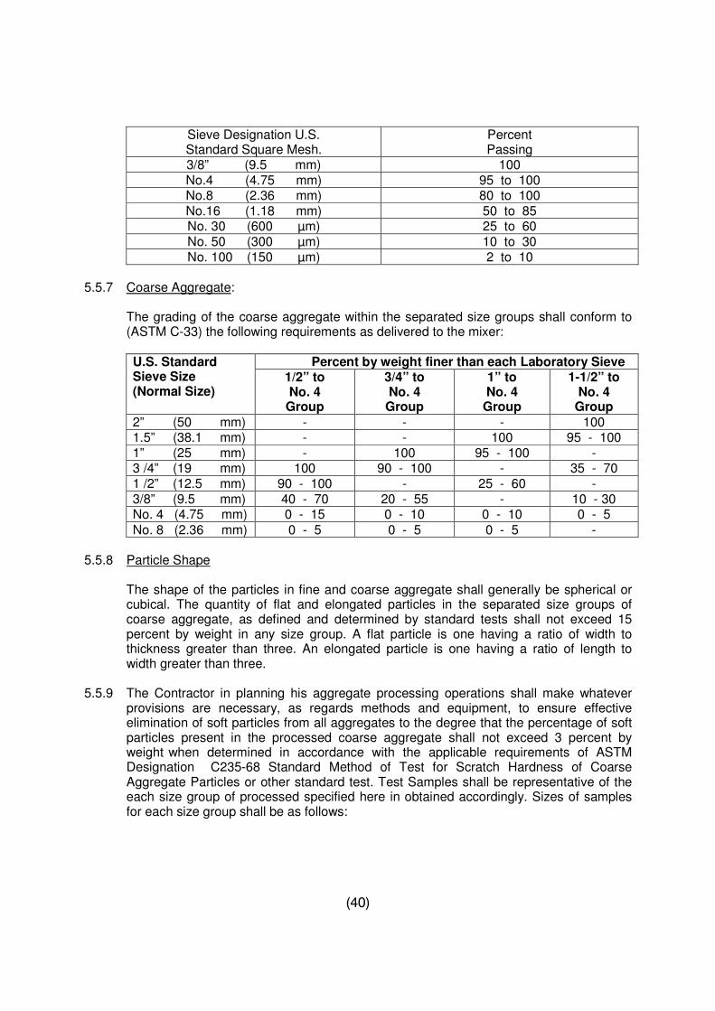
5.5.7 Coarse Aggregate:
The grading of the coarse aggregate within the separated size groups shall conform to (ASTM C-33) the following requirements as delivered to the mixer: U.S. Standard Sieve Size (Normal Size)
Percent by weight finer than each Laboratory Sieve 1/2” to No. 4
Group
3/4” to No. 4
Group
1” to No. 4
Group
1-1/2” to No. 4
Group
2” (50 mm) - - - 100 1.5” (38.1 mm) - - 100 95 - 100 1” (25 mm) - 100 95 - 100 - 3 /4” (19 mm) 100 90 - 100 - 35 - 70 1 /2” (12.5 mm) 90 - 100 - 25 - 60 - 3/8” (9.5 mm) 40 - 70 20 - 55 - 10 - 30 No. 4 (4.75 mm) 0 - 15 0 - 10 0 - 10 0 - 5
No. 8 (2.36 mm) 0 - 5 0 - 5 0 - 5 - 5.5.8 Particle Shape
The shape of the particles in fine and coarse aggregate shall generally be spherical or cubical. The quantity of flat and elongated particles in the separated size groups of coarse aggregate, as defined and determined by standard tests shall not exceed 15 percent by weight in any size group. A flat particle is one having a ratio of width to thickness greater than three. An elongated particle is one having a ratio of length to width greater than three.
5.5.9 The Contractor in planning his aggregate processing operations shall make whatever provisions are necessary, as regards methods and equipment, to ensure effective elimination of soft particles from all aggregates to the degree that the percentage of soft particles present in the processed coarse aggregate shall not exceed 3 percent by weight when determined in accordance with the applicable requirements of ASTM Designation C235-68 Standard Method of Test for Scratch Hardness of Coarse Aggregate Particles or other standard test. Test Samples shall be representative of the each size group of processed specified here in obtained accordingly. Sizes of samples for each size group shall be as follows:
(41)
Size Group Weight of Sample In Kilograms
____________ ___________________ ½” to No.4 1 ¾” to No. 4 1 1” to No. 4 7 1-1/2” to No. 4 10 5.5.10 Uniformity of Coarse Aggregate:
If the Contractor prefers to use blended crushed stone and natural gravel, the uniformity of proportions of crushed gravel to natural gravel in any size group of coarse aggregate shall be maintained relatively constant and in no event exceed a variation of 5 percent plus or minus in either component of a combination of crushed and natural gravel in any 24 hours period of mixing operation, except No.4 to 3/4" group, for which a variation larger than plus or minus 5 percent will be permitted. The limit of the larger variation will be determined after the gradation of fine aggregate has been approved and after the first month of operation of the Contractor's aggregates processing arrangements.
5.5.11 Deleterious Substances:
a) Fine Aggregate: The maximum percentages of deleterious substances in the fine aggregate, as delivered to the mixer, shall not exceed the following values:
Substances Percent of Weight Material passing No.200 Sieve 3 Shale 1 Total of other deleterious substances (such as as mica, chlorite, coated grains, and soft flaky
particles). 3
The sum of the percentages of all deleterious substances shall not exceed 05 percent, by weight
b) Coarse Aggregate: The maximum percentages of deleterious substances in any size of coarse aggregate, as delivered to the mixer, shall not exceed the following values:
Substances Percent by Weight Material passing No. 200 Sieve 1 Shale 1 Clay lumps ½ Other deleterious substances 1
The sum of the percentages of all deleterious substances in any size, as delivered to the mixer, shall not exceed 3 percent by weight.
(42)
Storage:
Aggregate shall be stored at the site in such a manner as to prevent its deterioration or the inclusion of foreign matter. Aggregate which has deteriorated or which has been contaminated shall not be used for concrete. All methods employed by the Contractor for loading, unloading, handling and stock-piling aggregates shall be subject at all times to approval.
5.5.12 Moisture Control:
All fine aggregate and smallest size group of the coarse aggregate shall remain in free draining storage at the site for at least 72 hours immediately prior to use. The free moisture content of the fine aggregate and of the smallest size group of coarse aggregate, as delivered to the mixer, shall be controlled so as not to exceed 4.0 and 1.0 respectively, expressed at percent by weight of the saturated surface dry aggregates unless higher limits are allowed. The moisture content of the other size of the coarse aggregates are delivered to the mixers with the least amount of free moisture and the least variation in free moisture practicable under the job conditions in addition to the limits on the maximum amounts of free moisture in aggregate, the moisture content shall be controlled so that for each size the variation in the percent of free moisture will not be more than 0.5 percent during any one hour of mixing plant operation. Under no conditions shall the aggregate be delivered to the mixed plant being dripping wet.
The Contractor shall carry out such tests as deemed necessary to determine the free moisture content of aggregate.
5.6 WATER: 5.6.1 General:
Water for washing aggregates and for mixing and curing concrete shall be clean and free from injurious maters such as oil, acid, alkali, salt, organic matter, or other deleterious substances as determined by standard tests. It shall meet the following chemical requirements:
Chlorides such as sodium chloride max. 3000 ppm
Sulphates such as sodium sulphate max. 2000 ppm Impurities max. 2 gm / litre Melted salt max. 15 gm / litre
The water for curing concrete should not have PH value lower than 5 and shall not contain impurities which cause discoloration of concrete.
5.7 PROPORTIONING OF CONCRETE: 5.7.1 Control:
Trial mixes and tests will be made by the Contractor for the purpose of designing the mixes and for quality control and subject to approval of the Engineer In charge. The Contractor shall cooperate and assist in obtaining samples and/or conducting field
(43)
tests. The proportions of all materials entering into the concrete shall be as directed. The proportions will be changed whenever such change is necessary to maintain the standard of quality required for the structures covered by these Specifications and to meet the varying conditions encountered during construction. The Contractor will be entitled to no compensation additional to that included in the prices for the applicable tender items in the Bill of Quantities because of such changes.
5.7.2 Measurement: All materials used to produce the concrete shall be measured by weight or by volume as approved. 5.7.3 Cement Content:
The cement content of concrete for various parts of the structure shall be established by trial mixes depending on the structural requirements, water cement ratio, size, type and gradation of the aggregate used. If at a particular place there is so large a quantity of steel that it becomes difficult to get the concrete well around and between it, then the specified batch of the concrete consisting of smaller size of aggregate and increased quantity of cement shall be used to achieve the same strength as for normal concrete.
5.7.4 Aggregate Content:
The maximum size of aggregate to be used in the various parts of the structure shall be shown on the drawings and where not shown, shall be as directed. Concrete mixes shall be of coarse aggregate practicable in accordance with Clause 5.5.
5.7.5 Water Content: The amount of water to be used shall be governed by the following considerations:
i) Water Cement Ratio: In general, the design will provide for water cement ratios by weight (exclusive of water absorbed by the aggregates), which will be determined on the basis of producing concrete having suitable workability, density, impermeability, durability and the required strength without the use of excessive amount of cement.
ii) Consistency: The amount of water used in the concrete will be regulated as
required to secure concrete of proper consistency taking into account the effect of any variation in either or both the moisture contents or grading of the aggregates as they enter the mixer. Addition of water to compensate for stiffening of concrete before placing will not be permitted. Uniformity in concrete consistency from batch to batch shall be ensured.
iii) Concrete Strength: Concrete for different parts of structure shall have cylinder
compressive strength at least equal to the minimum allowable strength shown in the following table except as otherwise indicated on the drawings or directed.
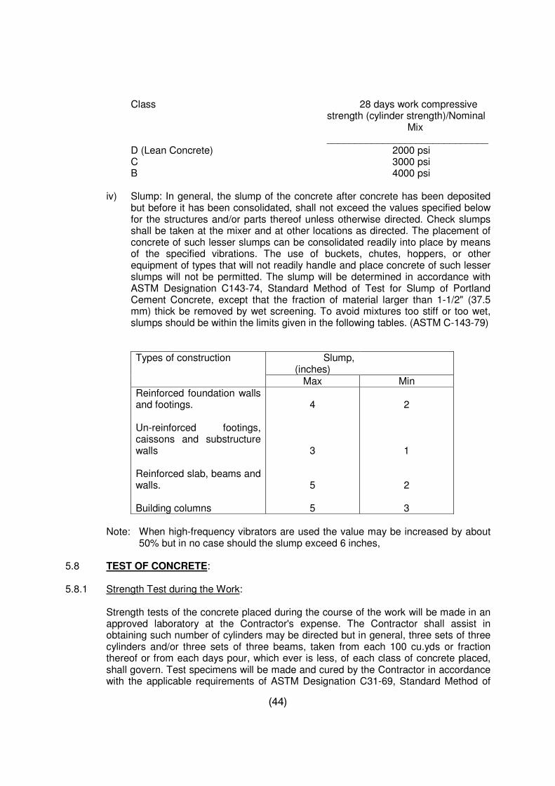
(44)
Class 28 days work compressive strength (cylinder strength)/Nominal Mix _____________________________
D (Lean Concrete) 2000 psi C 3000 psi B 4000 psi
iv) Slump: In general, the slump of the concrete after concrete has been deposited but before it has been consolidated, shall not exceed the values specified below for the structures and/or parts thereof unless otherwise directed. Check slumps shall be taken at the mixer and at other locations as directed. The placement of concrete of such lesser slumps can be consolidated readily into place by means of the specified vibrations. The use of buckets, chutes, hoppers, or other equipment of types that will not readily handle and place concrete of such lesser slumps will not be permitted. The slump will be determined in accordance with ASTM Designation C143-74, Standard Method of Test for Slump of Portland Cement Concrete, except that the fraction of material larger than 1-1/2" (37.5 mm) thick be removed by wet screening. To avoid mixtures too stiff or too wet, slumps should be within the limits given in the following tables. (ASTM C-143-79)
Types of construction Slump,
(inches)
Max Min Reinforced foundation walls and footings. Un-reinforced footings, caissons and substructure walls Reinforced slab, beams and walls. Building columns
4
3
5
5
2
1
2
3
Note: When high-frequency vibrators are used the value may be increased by about 50% but in no case should the slump exceed 6 inches,
5.8 TEST OF CONCRETE: 5.8.1 Strength Test during the Work:
Strength tests of the concrete placed during the course of the work will be made in an approved laboratory at the Contractor's expense. The Contractor shall assist in obtaining such number of cylinders may be directed but in general, three sets of three cylinders and/or three sets of three beams, taken from each 100 cu.yds or fraction thereof or from each days pour, which ever is less, of each class of concrete placed, shall govern. Test specimens will be made and cured by the Contractor in accordance with the applicable requirements of ASTM Designation C31-69, Standard Method of
(45)
Making and Curing Concrete Compressive and Flexural Test Specimens in the Field. Cylinders and beams will be tested in accordance with the applicable requirements of ASTM Designation C39-72, Standard Method of Test for Compressive Strength of Cylindrical Concrete Specimens and ASTM Designation C78-64, Standard Method of Test for Flexural Strength of Concrete (Using Simple Beam with Third Point Loading). The test result will be based on the average of the strength of the test specimens except that if one specimen in a set of three shows manifests evidence of improper sampling, moulding, or testing, the test result will be based on the average of the remaining two specimens.
The standard age of test will be 28 days, but 7 days test may be used to establish the relation between the 7-days and 28 days strengths of the concrete as established by tests for the materials and proportions used. If the strength tests of the specimens cured under laboratory controls, for any portion of the work, fall below the minimum standard at 28 days required for the class of concrete used in that portion, the proportions of the constituents of the concrete may be changed as necessary to secure the required strength for the remaining portions of the work. If the average strength of the specimens cured under actual field conditions as specified here-in-before falls below the minimum allowable strength, changes may be made in the conditions for temperature and moisture under which the concrete work is being placed and cured as may be necessary to secure the required strength.
5.8.2 Tests of Hardened Concrete:
Where the results of the strength tests of the control specimens indicate that the concrete as placed does not meet Specification requirements or there is other evidence that the quality of the concrete is below Specification requirements, core-boring tests will be made by the Contractor in accordance with the applicable requirements of ASTM Designation C42-68, "Standard Method of obtaining and Testing Drilled Cores and Sawed Beams of Concrete". If the concrete in the structure will be more than superficially wet under service conditions, the cores shall be immersed in water for at least 48 hours and tested wet. In the event that the core-boring test indicates that the concrete placed does not conform to the Drawings and Specifications measures as prescribed shall be taken to correct the deficiency. If a strength deficiency is found and is due to the Contractor's fault or negligence, the entire cost of the replacing faulty concrete shall be borne by the Contractor. Otherwise, payment for removing and replacing faulty concrete will be made under applicable items of the Bill of Quantities.
5.8.3 Strength Relation:
Where cylinders are made by wet screening of concrete with aggregate greater than one and a half inches (37.5 mm) size such as three-inches (75mm) aggregate concrete, the cylinders will be required to have a compressive test strength greater than the allowable strength shown on the drawings, to indicate that the respective concrete in place in the work has the allowable strength shown. The design will be such as that the average strength of the specimens tested be greater than the allowable strength shown on the Drawings for the three inches (75 mm) aggregate concrete. Such increments over the allowable strengths shown will be established after the mix design has been done and prior to mixing of concrete, and will be approximately ten percent.
(46)
5.9 BATCHING AND MIXING: 5.9.1 Type and Capacity: All concrete shall be produced in a batch and mix plant or a mechanical mixer.
The size of batch and mix plant shall be such that the proposed arrangement shall produce sufficient quantity of concrete meeting with all the other requirements of these Specifications and the construction schedule. The batched materials shall be thoroughly combined into a uniform mixture before the addition of water. The water be added gradually and the mixers operated for adequate duration of time so as to obtain a thoroughly mixed concrete of uniform colour and quality.
5.9.2 Mixers:
Hand mixed concrete shall not be used; however, it may be allowed to be mixed in small mixers. The mixer provided by the Contractor shall be capable of combining the materials into a uniform mixture and of discharging this mixture without segregation. Mixers shall not be charged in excess of the capacity recommended by the manufacturer and shall not be recharged before completely discharging the previous batches. Excessive over-mixing requiring additions of water will not be permitted. The mixers shall be operated at a drum speed designated by the manufacturer. The mixers shall be maintained in satisfactory operating condition, and mixer drums shall be kept free of hardened concrete. Mixer blades shall be replaced when worn down more than 10 percent of their depth.
5.9.3 Water Batcher:
A suitable water measuring device shall be provided by the Contractor which will be capable of measuring water within the specified requirements for each batch. The mechanism for delivering water to the mixer shall be such that no leakage will occur when the valves are closed.
5.9.4 Location:
The concrete plant/mixer shall be installed at the site of the work at locations selected by the Contractor duly approved.
5.9.5 Arrangement:
Separate bins and compartments shall be provided for each size or classification of aggregate and Portland cement. The compartments shall be of ample size and so constructed that the materials will be separated under all working conditions. Batching equipment/arrangement shall be capable of delivering concrete within the following limits of accuracy:
Material Percent Cement + 1% Water + 1% Aggregate Smaller than 3/4" + 2% Aggregate larger than 3/4" + 3%
(47)
5.9.6 Cooling:
Adequate cooling facilities shall be provided to ensure that the temperature of concrete when discharged from the mixers is sufficiently low to meet the temperature requirements. Cool mixing water, ice, pre-cooled aggregate, shading the stockpiles with roofing or any other arrangements may be used to accomplish the pre- cooling of the concrete. Any such approval shall not in any way relieve the Contractor of his responsibility of placing concrete at temperatures at or below the specified limits.
5.9.7 Scales:
Adequate and as approved weigh and volume batching facilities shall be provided by the contractor for the accurate measurement and control of each of the materials entering each batch of concrete. The accuracy of the weighing equipment shall conform to the requirements of applicable standards for such equipment. The weighing equipment shall be arranged so that the dials or indicators can be observed.
5.9.8 Mixing Time:
The mixing periods specified below are predicated on proper control of the speed of rotation of the mixer and of the proper introduction of the materials into the mixer. The mixing time will be increased when such increase is necessary to secure the required uniformity and consistency of the concrete. The mixing time for each batch after solid materials are in the mixer drum, provided that all the mixing water is introduced before one fourth of the mixing time has elapsed, shall be as follows:
Capacity of Mixer Mixing Time Upto 2 cu.yds. 1-1/2 minutes 3 cu.yds. 2 minutes 5.9.9 Testing Facilities:
The Contractor shall provide a concrete compressive test machine, a set of standard sieves and other relevant control testing equipment and a working space for the inspector and a space suitable for use in the plastic testing of concrete and moulding of concrete tests specimens.
5.10 CONVEYING:
Concrete shall be conveyed from mixer to the place of final deposit as rapidly as practicable, methods which will prevent segregation or loss of ingredients and in accordance with ACI-304-73, Recommended Practice for Measuring, Mixing Transporting and Placing Concrete. Any wet batch hopper through which the concrete passes shall be conical in shape. There shall be no vertical drop greater than 6 feet except where suitable equipment is provided to prevent segregation and where specifically authorized. Belt conveyors, chutes, or other similar equipment will not be permitted either for conveying concrete except where the use of such equipment is approved in writing. Each type or class of concrete shall be visually identified by placing a colored tag or marker on the bucket as it leaves the mixing plant so that the concrete may be positively identified and placed in the structure forms in the desired position.
(48)
5.11 PLACING: 5.11.1 General:
Concrete placing shall follow the Recommended Practice for Measuring, Mixing, Transporting and placing Concrete, ACI 304-73. No concrete shall be placed until all form-work, reinforcement, installation of parts to be embedded, bracing of forms and preparation of surface involved in the placing and the method of placement have been approved. Approval of the method of placement proposed will not relieve the Contractor of his responsibility under the Contract.
Before concrete is placed, all surfaces upon or against which concrete is to be placed shall be free from standing water, mud, debris or loose material. All surfaces of form and embedded material that have become encrusted with dried mortar or grout from concrete previously placed shall be cleaned of all such mortar or grout before the surrounding or adjacent concrete is placed. The surface of absorptive materials against or upon which concrete is to be placed shall be moistened thoroughly so that the moisture will not be drawn from the freshly placed concrete. Concrete shall be worked into the corners and angles of the forms and around all reinforcement and embedded items without permitting the material to its final position in the forms. The depositing of concrete shall be regulated so that the concrete may be effectively compacted with a minimum of lateral movement into horizontal layers approximately 1.5 feet in thickness. No concrete that has partially been hardened or contaminated by foreign materials shall be deposited in the structure, nor shall re-tampered concrete be used unless approved. The surfaces of construction joints shall be kept continuously wet for at least eighteen hours during the twenty four hours prior to placing concrete except as otherwise directed. All free water shall be removed and the construction joint shall be completely surface dry prior to placement of concrete. All concrete placing equipment and methods shall be subject to approval. Concrete placement will not be permitted when weather conditions prevent proper placement and consolidation.
Before placing concrete, care shall be taken to determine that all embedded items are properly placed as required under the Specifications and are firmly and securely fastened in place as indicated on the Drawings, or as required. Embedded items shall be free of oil and other foreign matter such as loose coatings of rust, paint, and scale. The embedding of wood or other foreign materials in concrete is prohibited.
5.11.2 Time Interval Between Mixing & Placing:
Concrete mixed in stationary mixers and transported by non-agitating equipment shall be placed within thirty minutes after it has been mixed, unless otherwise authorized. When a truck mixer or agitator is used for transporting concrete, the concrete shall be delivered to the site of the work and discharge shall be completed within 1-1/2 hours after introduction of the cement to the aggregates. The concrete shall be placed within 20 minutes after it has been discharged. In all cases, concrete shall be placed and compacted well within the initial setting time.
5.11.3 Placing Temperature:
Placing temperatures shall conform to the requirements herein specified for thin
(49)
sections, moderate sections and mass concrete. Concrete shall be placed at temperatures as follows:
Thin Sec.
Max. Temperature 32oC Min. Temperature 05oC
i) THIN SECTIONS: Concrete for thin sections shall be delivered to the forms at the coolest temperature which is practicable to produce under current conditions but in no case at a temperature in excess of 32 degree centigrade. Sections to which this provision shall apply will be considered to be sections 2.3 feet or less in thickness.
ii) MASS CONCRETE: Mass concrete shall have temperature of not more than 32
degree centigrade when placed. Mass concrete will be the one that is greater than 2.3 feet in thickness.
5.11.4 Lift in Concrete:
Concrete shall be installed in lifts or depths as shown on the drawings. The placement of concrete shall be carried on at such a rate and in such a manner that formation of cold joints is prevented. Slabs shall be placed in sections not exceeding 3600 sq.ft. (350 sq.m) unless otherwise authorized or directed. In walls, columns etc. lifts shall terminate such levels as will conform to structural details. Where slabs and beams are placed continuously with walls and columns, the concrete in walls and columns shall have been in place for at least three hours or for a longer period before placing concrete in the slabs and beams. The top surface of vertically formed lifts shall be generally level. The concrete in columns shall be placed in one continuous operation, unless otherwise authorized. In general, the construction joints in beams and slabs shall be located at mid span in both the directions as shown on the drawings and concrete shall be placed in the sequence indicated on the drawings or as authorized. The maximum differential in height between the various pours of the structure shall be as shown on the drawings or as directed.
5.11.5 Elapse Time between Placements of Lifts:
Except as otherwise approved on the basis of lift drawings submitted by the Contractor, a minimum of 72 hours shall elapse between the placing of successive lifts of walls and thin sections and 120 hours shall elapse between placing lifts of moderate sections and mass concrete. Thin sections and mass concrete have been defined in sub clause 5.11.3.
5.11.6 Time between adjacent Pours:
The time between adjacent pours shall be defined as the time elapsing from the end of the striking off of one pour to the start of placing the next pour. The minimum time elapsing between adjacent pours shall be 120 hours for mass concrete and 72 hours for all other concrete.
(50)
5.11.7 Placing Concrete through Reinforcement:
In placing concrete through reinforcement, care shall be taken that no segregation of the coarse aggregate occurs. In certain cases, like the bottom of beams and slabs, the congestion of steel near the forms may make placing difficult. In such cases, a layer of mortar of a composition compatible with the required concrete strength shall be first deposited to cover the surface to a depth of approximately 5/8".
5.11.8 Vibration of Concrete:
Recommended Practice for Consolidation of Concrete, ACI 309-72 shall be followed for concrete consolidation. Concrete shall be compacted with mechanical vibrating equipment supplemented by hand-spading and tamping. In no case shall vibrators be used to transport concrete inside the forms. The vibrating equipment shall be of the internal type and shall at all times be adequate in number of units and power of each unit to properly consolidate all concrete. Form or surface vibrations shall not be used unless specifically approved. The intensity (amplitude) of vibration shall be sufficient (frequency not less than 8,000 impulses per minute) to produce satisfactory consolidation. The duration of vibration shall be limited to that necessary to produce satisfactory consolidation. Excessive surface working will not be permitted.
5.12 FORMS: 5.12.1 General:
Forms shall be true to line and grade, mortar tight and sufficiently rigid to prevent objectionable deformation under load. Where forms for continuous surfaces are placed in successive units, care shall be taken to fit the forms over the completed surfaces so as to obtain accurate alignment of the surface and to prevent leakage of mortar. Responsibility for their adequacy shall rest with the Contractor, however, the type, shape, size, quality and strength of all materials of which the forms are made shall be subjected to specific approval. Bolts and rods used for internal ties shall be so arranged, that when the forms are removed, metal will not be less than 2" (50 mm) away from any concrete surface. Whenever from ties are used, their arrangement and spacing shall be in a regular pattern, in accordance with the dimensions of the form-work panels and as instructed. Wire ties will not be permitted where the concrete surface will be exposed to weathering and where discoloration will be objectionable. Depressions resulting from removal of the form ties shall be filled in accordance with the provisions of Clause 5.14 "Repair of Concrete". Suitable openings as required shall be provided in the form-work for the passage of piping ducts, channels etc. All forms shall be so constructed that they can be removed without damaging the concrete. All exposed joints, edges and external corners shall be chamfered 1-1/2" (27.5mm) at 45 degrees except as otherwise shown. Internal corners shall be filleted where indicated or required. Forms to be used more than once shall be maintained in serviceable condition and shall be thoroughly cleaned before reuse.
5.12.2 Coating:
Shortly before concrete is placed, forms for exposed surfaces shall be coated with approved non staining form oil which shall not interfere with the set of the concrete nor
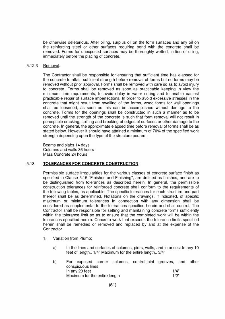
(51)
be otherwise deleterious. After oiling, surplus oil on the form surfaces and any oil on the reinforcing steel or other surfaces requiring bond with the concrete shall be removed. Forms for unexposed surfaces may be thoroughly wetted, in lieu of oiling, immediately before the placing of concrete.
5.12.3 Removal:
The Contractor shall be responsible for ensuring that sufficient time has elapsed for the concrete to attain sufficient strength before removal of forms but no forms may be removed without prior approval. Forms shall be removed with care so as to avoid injury to concrete. Forms shall be removed as soon as practicable keeping in view the minimum time requirements, to avoid delay in water curing and to enable earliest practicable repair of surface imperfections. In order to avoid excessive stresses in the concrete that might result from swelling of the forms, wood forms for wall openings shall be loosened, as soon as this can be accomplished without damage to the concrete. Forms for the openings shall be constructed in such a manner as to be removed until the strength of the concrete is such that form removal will not result in perceptible cracking, spilling and breaking of edges of surfaces or other damage to the concrete. In general, the approximate elapsed time before removal of forms shall be as stated below. However it should have attained a minimum of 70% of the specified work strength depending upon the type of the structure poured:
Beams and slabs 14 days Columns and walls 36 hours Mass Concrete 24 hours 5.13 TOLERANCES FOR CONCRETE CONSTRUCTION:
Permissible surface irregularities for the various classes of concrete surface finish as specified in Clause 5.15 "Finishes and Finishing", are defined as finishes, and are to be distinguished from tolerances as described herein. In general, the permissible construction tolerances for reinforced concrete shall conform to the requirements of the following tables, as applicable. The specific tolerances for each structure and part thereof shall be as determined. Notations on the drawings, if indicated, of specific maximum or minimum tolerances in connection with any dimension shall be considered as supplemental to the tolerances specified herein and shall control. The Contractor shall be responsible for setting and maintaining concrete forms sufficiently within the tolerance limit so as to ensure that the completed work will be within the tolerances specified herein. Concrete work that exceeds the tolerance limits specified herein shall be remedied or removed and replaced by and at the expense of the Contractor.
1. Variation from Plumb:
a) In the lines and surfaces of columns, piers, walls, and in arises: In any 10 feet of length.. 1/4" Maximum for the entire length.. 3/4"
b) For exposed corner columns, control-joint grooves, and other
conspicuous lines: In any 20 feet 1/4" Maximum for the entire length 1/2"
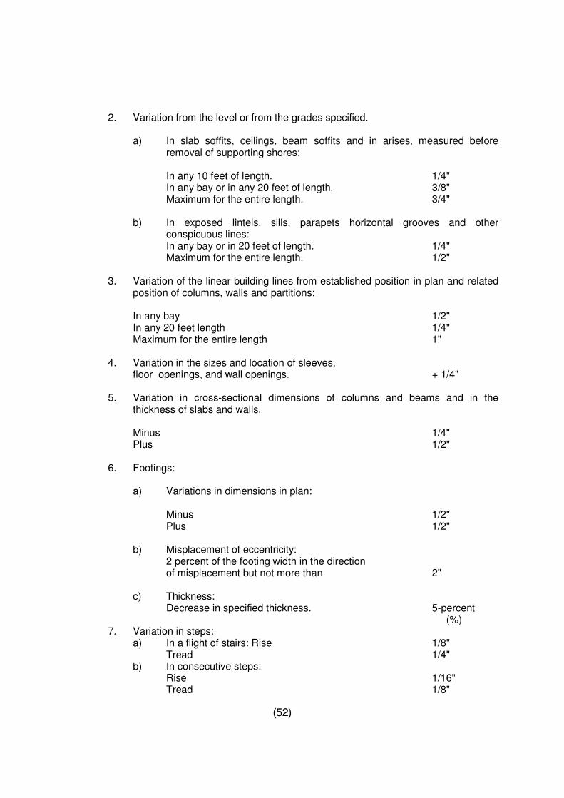
(52)
2. Variation from the level or from the grades specified.
a) In slab soffits, ceilings, beam soffits and in arises, measured before removal of supporting shores:
In any 10 feet of length. 1/4" In any bay or in any 20 feet of length. 3/8" Maximum for the entire length. 3/4"
b) In exposed lintels, sills, parapets horizontal grooves and other conspicuous lines:
In any bay or in 20 feet of length. 1/4" Maximum for the entire length. 1/2"
3. Variation of the linear building lines from established position in plan and related position of columns, walls and partitions:
In any bay 1/2" In any 20 feet length 1/4" Maximum for the entire length 1" 4. Variation in the sizes and location of sleeves,
floor openings, and wall openings. + 1/4"
5. Variation in cross-sectional dimensions of columns and beams and in the thickness of slabs and walls.
Minus 1/4" Plus 1/2" 6. Footings: a) Variations in dimensions in plan: Minus 1/2" Plus 1/2" b) Misplacement of eccentricity: 2 percent of the footing width in the direction
of misplacement but not more than 2" c) Thickness: Decrease in specified thickness. 5-percent
(%) 7. Variation in steps: a) In a flight of stairs: Rise 1/8" Tread 1/4" b) In consecutive steps: Rise 1/16" Tread 1/8"
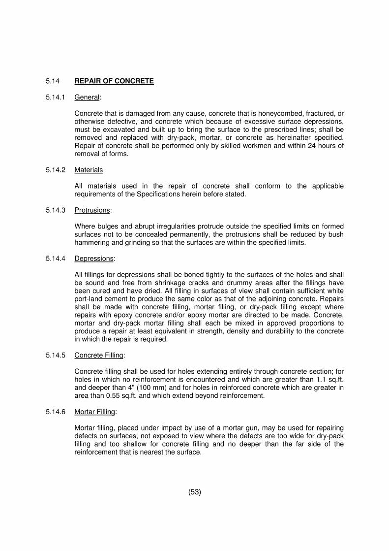
(53)
5.14 REPAIR OF CONCRETE 5.14.1 General:
Concrete that is damaged from any cause, concrete that is honeycombed, fractured, or otherwise defective, and concrete which because of excessive surface depressions, must be excavated and built up to bring the surface to the prescribed lines; shall be removed and replaced with dry-pack, mortar, or concrete as hereinafter specified. Repair of concrete shall be performed only by skilled workmen and within 24 hours of removal of forms.
5.14.2 Materials
All materials used in the repair of concrete shall conform to the applicable requirements of the Specifications herein before stated.
5.14.3 Protrusions:
Where bulges and abrupt irregularities protrude outside the specified limits on formed surfaces not to be concealed permanently, the protrusions shall be reduced by bush hammering and grinding so that the surfaces are within the specified limits.
5.14.4 Depressions:
All fillings for depressions shall be boned tightly to the surfaces of the holes and shall be sound and free from shrinkage cracks and drummy areas after the fillings have been cured and have dried. All filling in surfaces of view shall contain sufficient white port-land cement to produce the same color as that of the adjoining concrete. Repairs shall be made with concrete filling, mortar filling, or dry-pack filling except where repairs with epoxy concrete and/or epoxy mortar are directed to be made. Concrete, mortar and dry-pack mortar filling shall each be mixed in approved proportions to produce a repair at least equivalent in strength, density and durability to the concrete in which the repair is required.
5.14.5 Concrete Filling:
Concrete filling shall be used for holes extending entirely through concrete section; for holes in which no reinforcement is encountered and which are greater than 1.1 sq.ft. and deeper than 4" (100 mm) and for holes in reinforced concrete which are greater in area than 0.55 sq.ft. and which extend beyond reinforcement.
5.14.6 Mortar Filling:
Mortar filling, placed under impact by use of a mortar gun, may be used for repairing defects on surfaces, not exposed to view where the defects are too wide for dry-pack filling and too shallow for concrete filling and no deeper than the far side of the reinforcement that is nearest the surface.
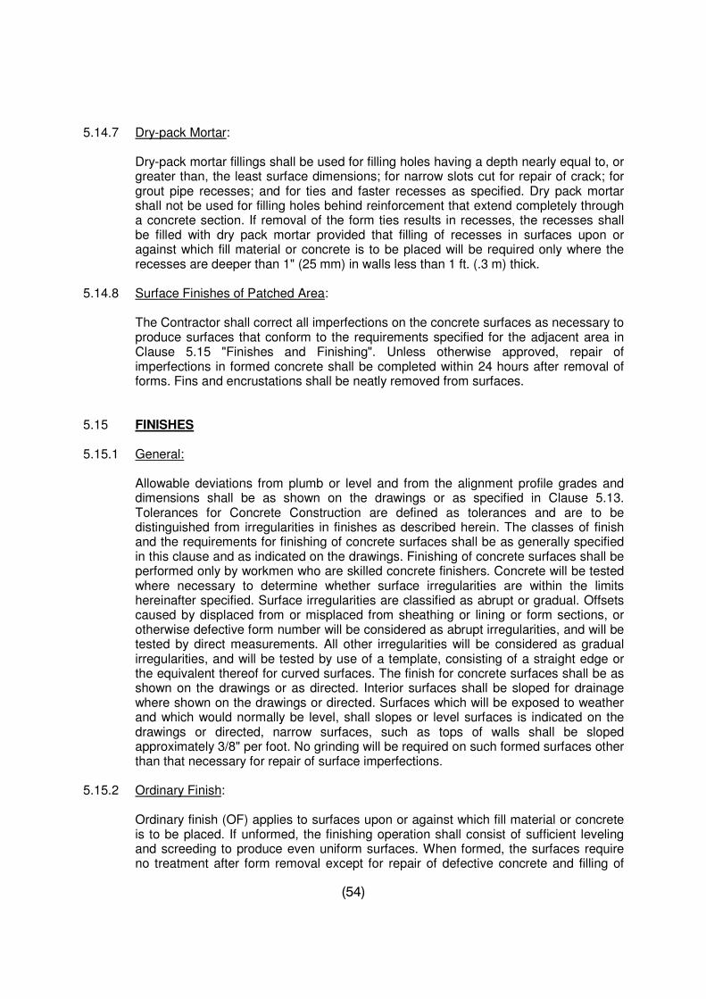
(54)
5.14.7 Dry-pack Mortar:
Dry-pack mortar fillings shall be used for filling holes having a depth nearly equal to, or greater than, the least surface dimensions; for narrow slots cut for repair of crack; for grout pipe recesses; and for ties and faster recesses as specified. Dry pack mortar shall not be used for filling holes behind reinforcement that extend completely through a concrete section. If removal of the form ties results in recesses, the recesses shall be filled with dry pack mortar provided that filling of recesses in surfaces upon or against which fill material or concrete is to be placed will be required only where the recesses are deeper than 1" (25 mm) in walls less than 1 ft. (.3 m) thick.
5.14.8 Surface Finishes of Patched Area:
The Contractor shall correct all imperfections on the concrete surfaces as necessary to produce surfaces that conform to the requirements specified for the adjacent area in Clause 5.15 "Finishes and Finishing". Unless otherwise approved, repair of imperfections in formed concrete shall be completed within 24 hours after removal of forms. Fins and encrustations shall be neatly removed from surfaces.
5.15 FINISHES 5.15.1 General:
Allowable deviations from plumb or level and from the alignment profile grades and dimensions shall be as shown on the drawings or as specified in Clause 5.13. Tolerances for Concrete Construction are defined as tolerances and are to be distinguished from irregularities in finishes as described herein. The classes of finish and the requirements for finishing of concrete surfaces shall be as generally specified in this clause and as indicated on the drawings. Finishing of concrete surfaces shall be performed only by workmen who are skilled concrete finishers. Concrete will be tested where necessary to determine whether surface irregularities are within the limits hereinafter specified. Surface irregularities are classified as abrupt or gradual. Offsets caused by displaced from or misplaced from sheathing or lining or form sections, or otherwise defective form number will be considered as abrupt irregularities, and will be tested by direct measurements. All other irregularities will be considered as gradual irregularities, and will be tested by use of a template, consisting of a straight edge or the equivalent thereof for curved surfaces. The finish for concrete surfaces shall be as shown on the drawings or as directed. Interior surfaces shall be sloped for drainage where shown on the drawings or directed. Surfaces which will be exposed to weather and which would normally be level, shall slopes or level surfaces is indicated on the drawings or directed, narrow surfaces, such as tops of walls shall be sloped approximately 3/8" per foot. No grinding will be required on such formed surfaces other than that necessary for repair of surface imperfections.
5.15.2 Ordinary Finish:
Ordinary finish (OF) applies to surfaces upon or against which fill material or concrete is to be placed. If unformed, the finishing operation shall consist of sufficient leveling and screeding to produce even uniform surfaces. When formed, the surfaces require no treatment after form removal except for repair of defective concrete and filling of
(55)
holes left by the removal of fasteners from the end of the tie rods as required under Clause 5.14 "Repair of Concrete". Correction of surface irregularities shall be required for depressions only and only for those which exceed 1 inch when measured as described in sub-Clause 5.15.1
5.15.3 Rough Concrete Finish
Rough concrete finish (RC) applies to surfaces which are intended to receive tiles or cement plaster as indicated on the drawings. After consolidation and leveling of concrete to the specified tolerances, the surface shall be roughened with stiff brushes or raked before final set. Where rough concrete finish is specified for wall surfaces, the same shall be obtained by use of form-work suitable to produce the required finish. Surface irregularities measured as described in sub-clause 5.15.1 "General" shall not exceed 3/8" for floor and 2/8" for walls.
5.15.4 Ordinary Slab Finish
Ordinary slab finish applies to floor surfaces which are intended to receive tiles and other floor coverings or without any coverings, as indicated. When the concrete surface has stiffened sufficiently, floating shall be performed by use of hand or power driven equipment, and shall be minimum necessary to produce a surface that is free from screed marks and is uniform in texture. Floating shall be continued until a small amount of mortar without excess water is brought to the surface so as to permit effective trowelling. Steel trowelling shall be started when the floated surface has hardened sufficiently to prevent excess of fine material from being drawn to the surface. Steel trowelling shall be performed with firm pressure such as will flatten the Sandy texture of the floated surface and produce a dense uniform surface, free from blemishes and trowel marks. Surface irregularities measured as described in sub Clause 5.15.1 general, shall not exceed 3/8".
5.15.5 Fair Finish
Fair finish (FF) applies to the exposed formed surfaces, the appearance of which is considered of special importance such as waffle slabs, Tee beams and other places shown on the drawings and the finish Schedule. Fair face means no touch afterwards.
5.16 CURING CONCRETE 5.16.1 General:
All concrete shall be cured by an approved method or combination of methods in accordance with ACI 308 than 71 and in this section, "Recommended Practice for Curing Concrete". The Contractor shall have all equipment and materials needed for adequate curing and protection of the concrete on hand and ready to use before actual concrete placement begins. Means shall be provided for the protection of concrete from the sun, drying winds, and traffic until the specified curing has been completed. The curing medium and method, or the combination of mediums and methods used, shall be subject to approval in writing. The curing medium shall be applied so as to prevent loss of moisture from the concrete. Concrete shall be protected from heavy rains for 24 hours and direct rays of the sun for 14 days. All concrete shall be adequately protected from damage. No fire or excessive heat, including the heat
(56)
resulting from the welding of any sort or reinforcing bars etc., shall be permitted near or in direct contact with concrete at any time. All galleries, conduits and other formed openings through the concrete shall be closed during the entire curing period.
5.16.2 Moist Curing:
Unless otherwise approved, the concrete shall be moist-cured by maintaining all surfaces continuously (not periodically) wet for at least 14 days immediately following the placing or until covered with fresh concrete. Curing water shall be removed without allowing stagnant pools of water to form on the exposed lift surface. Water for curing shall comply with the applicable requirements of Clause 5.6 Surfaces of concrete, which are to be permanently exposed, shall be cleaned if a water is used which stains the surfaces during curing. Where forms of tongue-and-groove or ship-lap sheeting are used and are left in place during curing, the sheathing shall be kept, at all times. When in contact with mass concrete, steel forms shall be kept wet. Horizontal construction joints and finished horizontal surfaces cured with sand which shall be covered with a minimum uniform thickness of 50 mm (2 inch) of sand which shall be kept continuously saturated. The following exceptions to the requirements for moist curing are permitted:
i) Horizontal construction joints may be allowed to dry for six hours immediately
prior to placing of the following lift:
ii) Moist curing of surfaces, against which back-fill is to be placed within 24 hours of concrete placement, will not be required:
5.17 PLACING REINFORCEMENT: 5.17.1 Supports:
Reinforcement, pro-stressing steel and ducts, shall be accurately placed and adequately supported before concrete is placed, and shall be secured against displacement within permitted tolerances. Welding of crossing bars shall not be permitted for assembly of reinforcement unless authorized.
5.17.2 Tolerances:
Unless otherwise specified, reinforcement, pre-stressing steel, and prostrating steel ducts shall be placed within the following tolerances:
For concrete protection and for depth, d in flexural members, walls, and compression members where d is:
8" or less + 1/4" More than 8" but less than 24" + 3/8" 24" or more + 1/2" but the cover shall not be reduced by more than one-third of specified cover.
For longitudinal location of bends and ends of bars: + 2" except at discontinuous ends of members where tolerance shall be + 1/2".
(57)
5.17.3 Draped Fabric:
When welded wire fabric with wire of 1/4" diameter or less is used for slab reinforcement in slabs not exceeding 10' in span, the reinforcement may be curved from a point near the top of the slab over the support to a point near the bottom of the slab at mid span, provided such reinforcement is either continuous over, or securely anchored at, the support.
5.18 MEASUREMENT
For any item of work constructed under this section, measurement shall be made by volume. The unit of measurement shall be made on cu.ft./cu.m. In computing the concrete quantity the dimensions used shall be the plan dimensions of the concrete with the neat lines shown on the plans except that no deduction will be made for weep holes and floor drains and no account shall be taken of chamfers, scorings, filters of 4 cm radius or less in cross section area.
The quantity to be paid for shall be the original plan quantity, measured as provided above, except that where the plans call for an estimated quantity of miscellaneous concrete for contingent uses such contingent concrete shall be measured as the actual quantity by the in-place and accepted.
No measurements for or other allowances will be made for work or material for forms, false work, pumping, bracing, etc. The volume of all material embedded in the concrete such as structural steel, pile heads, etc. except reinforcing steel, shall be deducted in computing the volume of concrete to be paid for.
5.19 RATE & PAYMENT:
The unit rate for various types of Portland Cement Concrete shall be full compensation for all the work specified. Payment for Portland Cement Concrete shall be made at the unit rates in the priced Bill of Quantities. Reinforcement will be paid for as applicable in Section of "Reinforcement". No separate payment for cement accordingly used or otherwise work shall be made.
(58)
SECTION – 6 : STEEL REINFORCEMENT
6.1 DESCRIPTION
The work to be done under this Section shall include furnish, cut, bend, and place all steel reinforcement as indicated on the Drawings or otherwise required. All reinforcement when surrounding concrete is placed shall be free from loose, flaky rust, and scale, and free from oil grease or other coating which might destroy or reduce its bond with the concrete. All placing shall be in accordance with Drawings furnished or approved. The use of reinforcement for the transmission of current for welding will not be permitted. All reinforcement, including dowels, remaining exposed in the work shall be suitably protected until embedded in concrete.
6.2 CUTTING AND BENDING
Steel reinforcement may be mill or field cut and bent. All bending shall be in accordance with standard approved practice and by approved machine methods. When bending is required, it shall be performed prior to embedding the bars in the concrete. In all such cases, the bars shall be cold bend. Bending or straightening of bars partially embedded in set concrete shall not be permitted except in isolated cases where corrective action or a field change is required and is so specifically approved.
Reinforcement shall not be bent or straightened in a manner that will injure the material. Special care shall be taken to ensure accurate bending of reinforcement for small and thin members, particularly in respect of binders.
Bending hot at a cheery-red heat (not exceeding 840 degree centigrade) will be allowed for mild steel bars. Bars bent hot should not be cooled by quenching.
6.3 QUALITY Concrete reinforcement bars shall be of following quality:- Deformed steel bars for concrete Reinforcement shall be Grade 60 conforming to ASTM 615-80.
The Contractor shall provide labour, materials, arrange fabrication and fixing measuring and testing facilities to ascertain quality, weight or quantity of steel at his own expense. No steel shall be incorporated in the work without prior approval.
6.4 PLACING AND POSITIONING
Reinforcement shall be placed and maintained within the specified tolerance of its position shown on the drawings. Where practicable, it is recommended that the reinforcement be performed into rigid cages, spot welding being permissible for this purpose. Where tying wires or clips are used, care should be taken to ensure that the projecting ends do not encroach into the concrete cover. Strict and constant vigilance must be exercised to ensure that the reinforcement is maintained in its correct position at all
(59)
stages and for all methods of placing and compacting the concrete. Normally, spacing blocks used for this purpose shall be made of mortar comparable in strength and durability with the main concrete.
Other kinds of spacers shall be of a proved and agreed type, suitable for the conditions to which the unit will be exposed.
6.5 RELATION TO BARS TO CONSTRUCTION SURFACES
The cover of all main reinforcement shall be as specified or shown on the Drawings. The dimensions, as shown on the drawings, indicate the clear distance from the edge of the main reinforcement to the concrete surface. The concrete covering of stirrups, spacer bars, and similar secondary reinforcement may be reduced by the diameter of such bars. The actual concrete cover to all steel at any point shall not be less than the required nominal cover by more than 1/8".
The effective depth of fully or nearly fully stressed tensile reinforcement shall not be less than that given on the Drawings by an amount exceeding 5 percent of the effective depth of the section being considered or 1/4" whichever is the greater.
6.6 SPLICING
Except as otherwise shown on the Drawings or specified herein, all splices, lengths of laps, splice locations, placement and embedment of reinforcement shall conform to the applicable requirements of American Concrete Institute 318-89 or 95, Building Code Requirements for Reinforced Concrete. All splices and locations of laps in reinforcement shall be as shown on the Drawings or as directed. Additional bar splices shall be provided as required, subject to approval. Lapped ends of bars may be placed in contact and securely wired or may be separated sufficiently to permit the embedment of the entire surface of each bar in concrete. If welded splices are proposed, welder of approved qualification and experience shall be employed after obtaining proper approval. Sufficient number of welds shall be tested to failure in each lot to maintain a check on the quality at the cost of the Contractor.
All reinforcement shall be secured in place by use of metal or concrete supports, spacers, or ties, as approved. Such supports shall be of sufficient strength to maintain the reinforcement in place throughout the concreting operation. The supports shall be used in such a manner that they will not be exposed or contribute in any way to the discoloration or deterioration of the concrete. Concrete supports shall be manufactured of the same concrete mix as used in the structure to be concreted.
6.7 TOLERANCES Following tolerances shall be observed: 6.7.1 Bars used for concrete reinforcement shall meet the following requirements for
fabricating tolerances: a) Sheared length : +1 in.
b) Depth of truss bars +0 - 1/2 in. c) Overall dimensions of stirrups, ties, and spirals : + 1/4 in. d) All other bends + 1 in.
(60)
6.7.2 Bars shall be placed to the following tolerances:
a) Clear distance to formed surface : + 1/4 in.
b) Minimum spacing between bars : 1.4 in.
c) Top bars in slabs and beams:
i) Members 8 in. deep or less + 1/4 in. ii) Members more than 8 in. but not over 2 feet deep : + 1/2 in.
d) Crosswise of Members : Spaced evenly within 2 in.
e) Lengthwise of Members : +2 in.
6.7.3 Bars may be moved as necessary to avoid interference with other reinforcing steel,
conduits or embedded items. If bars are moved more than one bar diameter, or enough to exceed the above tolerances, the resulting arrangement of bars shall be subject to approval.
6.8 EMBEDMENT ITEMS
Before placing concrete, care shall be taken to determine that all embedded items are properly placed as required under the Specifications and are firmly and securely fastened in place as indicated on the Drawings, or as required. Embedded items shall be free of oil and other foreign matter such as loose coatings of rust, paint, and scale. The embedding of wood or other foreign materials in concrete is prohibited.
6.9 MEASUREMENT
Measurement will be made of the number of kgs of reinforcing steel acceptably placed on the basis of the lengths of bars installed in accordance with the approved Drawings or bar schedules or as directed, converted to weights for the size of bars lists by the use of actual weights or unit weights per linear feet as follows :
Bar Designation Nominal Unit Weight Lbs. Per Foot.
# 3 0.376 # 4 0.668 # 5 1.043 # 6 1.502 # 7 2.044 # 8 2.670 # 9 3.400 # 10 4.303 # 11 5.313 # 14 7.650 # 18 13.600
(61)
- Unless otherwise specifically stated in the Bill of Quantities or herein, all items of
reinforcement shall be deemed to be inclusive of, but not limited to the following:-
- Reinforcement bar bending schedule to be provided by the Contractor for approval.
- Providing materials, attendance and costs for all sampling and testing.
- Cost of M.S. binding wire and concrete, metal or plastic chairs and spacers or hangers.
- Cleaning, cutting and bending, placing and fixing in position including binding
with wire and other material and placing supports and spacers. - All sorts of transportation involved in the process. - All sorts of loading and unloading within the boundary wall area.
- All reinforcement shall be provided in lengths shown in drawings and as per Specifications. Should the CONTRACTOR provide lengths of reinforcement which are greater than shown on the drawings no payment for extra lengths shall be made. Overlaps unless clearly shown in working drawings, shall not be allowed and measured.
6.10 RATE AND PAYMENT
The Contractor shall be paid for reinforcement by weight computed in accordance with Clause 6.9 from linear measurements of reinforcement actually used at Site as per drawings. No payment shall be made for steel chairs or wastage.
(62)
SECTION – 7 : DAMP PROOF COURSE
7.1 DESCRIPTION
The Damp Proof Course shall be horizontal and vertical as shown on the drawings and specified in the Bill of Quantities.
7.2 HORIZONTAL 7.2.1 In Walls
The horizontal D.P.C. shall consist of 1-1/2" thick, Class-C cement concrete with two intervening layers of polythene sheet and two (2) sand blinded coats of S.I.B. (Specified Industrial Bitumen) grade 10/20 or as specified in material section.
7.2.2 Under Floors
Same as in walls except bitumen layers to be laid on 1/2" - 3/4" blinding screed (1:6) to even out surface of hard core if required to be provided as per BOQ and drawings.
7.3 VERTICAL
The vertical D.P.C. shall consist of 3/4" thick 1:3 cement sand mortar with 5% pudlo and two (2) sand blinded coats of hot S.I.B or as specified in material section as per requirements of ASTM.
7.4 MATERIAL REQUIREMENTS
All materials i.e. cement, sand aggregate, water polythene sheet and bitumen shall conform to the specifications given in respective section.
7.5 CONSTRUCTION REQUIREMENTS
The Contractor shall lay the D.P.C. only when the level, quality of masonry work, etc. is approved.
The concrete work of D.P.C. shall conform to the relevant specifications given in this section for the execution of these items.
Horizontal D.P.C. shall extend to the full width of the wall i.e. upto the external faces. No portion of doors opening, etc. shall be left while laying D.P.C. The period of curing of concrete shall be not less than 72 hours. Every care should be taken that concrete is not left dry during this period. The work of laying Damp Proof Course shall be carried out as follows unless otherwise described in BOQ:-
a) Placing 1-1/2" thick layer of Class-C cement concrete.
b) Laying 2 coats of hot bitumen S.I.B. 10/20 grade @ 20 lbs. per % sq.ft. (each
coat) over entire width and lengths of concrete after the concrete has been properly cured for at least 72 hours, and sand blinding where specified.
(63)
c) Laying of polythene sheet 500 gauge over entire width and length of concrete
after the concrete has been treated with 2 coats of hot bitumen.
The application of bitumen coating in case of vertical D.P.C. shall be same as mentioned above or as per the recommendations of the manufacturers and instruction of the Engineer In charge.
7.6 MEASUREMENT AND PAYMENT
Measurement
The measurement shall be made in per sq.ft./sq.m. by measuring length and breadth/height of actual works done and as shown on the drawings.
7.7 RATE
The unit price for damp proofing shall be full compensation for furnishing and placing all materials and for all labour, equipment, tools and incidentals necessary to complete the work prescribed in this Section.
7.8 PAYMENT
The quantities determined as provided above shall be paid for at the unit price in the Bill of Quantities.
(64)
SECTION – 8 : CONCRETE BLOCK MASONRY
8.1 DESCRIPTION
The work covered by this section of the Specifications consists of furnishing all plant, labour, equipment, tools and appliances, and materials and in performing all the operations in connection with block masonry work, complete in strict accordance with the specifications herein and the applicable drawings.
8.1.1 MATERIAL REQUIREMENTS 8.1.2 Cement Cement shall be ordinary Portland Cement as specified in respective section. 8.1.3 Aggregates
Aggregates used shall meet the requirements specified under respective concrete section. All the aggregates dry and properly screened from approved source shall be acceptable for block making.
8.1.4 Concrete Masonry Units 8.1.4.1 Concrete masonry blocks shall be made on the site and shall be of the sizes required
as per drawings and shall generally conform to the requirements of British Standard 2028, 1346:1968 "Pre-cast Concrete Blocks" unless specified otherwise.
8.1.4.2 The blocks shall be solid or hollow as required and shall be carefully made so that they
are true in line and face with square corners and free from all defects. The ends of the blocks, which will form the vertical joints in the masonry, shall be double grooved or as directed. In the case of hollow blocks, the cavities shall be true to the shapes and sizes specified and shall have uniform wall thickness on the outside of the cavities. The cavities in hollow blocks shall not be more than 25% of the total volume.
8.1.4.3 The concrete for the blocks shall be mixed in a concrete mixer in the proportion of one
(1) part of cement, two (2) parts of sand and four (4) parts of well graded coarse aggregate not exceeding 3/4" (19mm) in size or 6 parts of well graded (all in aggregates) not exceeding 3/4" (19mm) in size.
All the aggregates, when used shall be spilt in coarse and fine aggregates for checking the proportions of fine to coarse aggregates and their grading.
8.1.4.4 Concrete blocks shall be machine moulded. The concrete shall be well worked into the
moulds, vibrated, tamped and pressed to ensure that the blocks are dense and free from voids.
8.1.4.5 The blocks shall be cured by keeping moist continuously for a period of at least ten
(10) days and then shall be allowed to dry in shade for at least twenty (20) days before use in masonry.
(65)
8.1.4.6 All blocks shall have clean cut straight and true edges, smooth dense faces of uniform
appearance without voids, honeycombs, projections and shall be free from cracks spells, chips, rugged edges or other defects detrimental to their use.
8.1.4.7 Where block are to be plastered or rendered, the block surface shall have a coarse
texture suitable for bonding the plaster as approved. 8.1.4.8 The average compressive strength of any ten blocks picked at random, after curing
and drying shall not be less than 1500 lbs/sq.inch when tested in accordance with B.S. 2028,1364:1968; Pre-cast concrete blocks.
8.1.4.9 The average moisture content of all the concrete masonry units shall not exceed 30
percent of the total water absorption of units. The shrinkage of cement concrete blocks is much greater at the time it dries for the first time after moulding and subsequent curing. It is, therefore, essential that contractor shall take full care to see that blocks are sufficiently and thoroughly dried so that their initial shrinkages is completed before the blocks are laid in the wall. Not only well dried blocks shall be used, but the blocks shall also be laid dry without wetting except with slightly moistened surfaces on which mortar is to be applied to obviate absorption of water from the mortar and even during curing of the mortar joints. The walls shall be slightly moistened and shall not be allowed to the excessively wet till they receive any plaster or render.
8.1.4.10 The blocks shall be stored in such a manner as to avoid any contact with moisture on
the site of works. The blocks shall be stock piled on platforms or other supports free from contact with the ground. If necessary cover for protection against wetting shall be provided. The blocks right from casting to curing drying, stock piling and their subsequent placing in masonry walls shall be handled with care.
8.2 CONSTRUCTION REQUIREMENT 8.2.1 Cement Mortar for Masonry Proportions
Cement Mortar shall be composed of one part of ordinary port-land cement to four (4) parts of sand for all concrete block walls or as specified in BOQ. Hand mixing, when permitted, shall be done on clean hard platform as much as required for immediate use with only just sufficient water, to produce mortar of a proper consistency. The mixing shall be done by mechanical mixers, the Sand shall be of an approved quality and shall pass 100% through 3/16" (5mm) sieve.
8.2.2 Gauging
The ingredients for mortar shall be measured in boxes. No re-tempering of mortar shall be allowed, nor shall mixing of any anti-freezing ingredients in mortar be permitted.
8.2.3 Mixing
The dry materials shall be dry mixed for approximately 2 minutes and for 3 minutes after addition of water making total minimum time of 5 minutes in a mortar mixer. When hand mixing is permitted, no adding water, until uniform colour or mixed
(66)
materials indicate cementitious material thoroughly distributed throughout the mass. After dry mixing is complete, add water until thoroughly mixed mortar of the required plasticity is obtained. If mixing is not satisfactorily done, then the contractor shall take such steps as directed. Mortar shall be used within half an hour of mixing. Mortar lying for more than half an hour shall not be used.
8.2.4 Masonry and Jointing 8.2.4.1 All masonry shall be laid in plumb, true to line and level in accurately spaced courses
with each breaking joints with the course below. Corners and reveals shall be plumb and true, Chases, grooves, regret blocks and raked out joints shall be kept free from mortar and other debris.
8.2.4.2 The thickness and length of various walls shall be as indicated on the drawings. 8.2.4.3 Unless otherwise shown on the drawings or specified, the spaces around frames and
other built-in-items shall be solidly filled with mortar, except the joints that are to be caulked shall be raked out 3/4" (19mm) deep.
8.2.4.4 Work required to be built in with masonry including anchors, wall plugs and
accessories shall be built in, as the work progresses. Wood plugs and blocking shall not be built into masonry.
8.2.4.5 All horizontal and vertical joints shall be completely and solidly filled with mortar as the
blocks are laid. In horizontal bedding joints, mortar shall be spread over the entire top surface of the block to a uniform layer of 3/8" (10mm) thick. For vertical joints, mortar shall be applied to a block unit, when it is standing vertically and then placing it horizontally on the horizontal bedding mortar and pressing it against the previously laid unit in that course, making a vertical joint of 3/8" (10mm) thickness. In horizontal bedding, joints mortar shall not be spread so much ahead of the actual laying of unit that it tends to stiffen and lose its plasticity, resulting in poor bond. If it happens the stiffened mortar shall be removed and fresh mortar laid by the contractor at his own cost. When the mortar has stiffened somewhat, it shall be firmly compacted with a jointing tool, to guard against its tendency.
8.2.4.6 The thickness of joints shall not exceed 3/8(10mm) and the joints shall be raked
1/2"(13mm) deep when the mortar is still fresh, so as to provide for proper bond for the plaster. Any mortar which falls on the floor from the joints or removed due to raking of joints shall not be reused.
8.2.4.7 No masonry to be erected when temperature of outside air is below 05 unless suitable
means, as approved are provided to heat material protected from cold and frost and ensure that material will harden without freezing.
8.2.4.8 When the masonry is to receive plaster on one side and pointing on the other, the
block shall be placed in such a way that the better face shall be on the side of pointing. 8.2.4.9 Where masonry work abuts columns, it shall be anchored there by means of anchor
steel bars or any other type of anchors as approved at a vertical spacing of approx. 12"(300mm) for walls up to 6"(150mm) thick and approximately 24"(600mm) for walls
(67)
more than 6"(150mm) thick unless otherwise directed. Alternatively the masonry may be built-up first, leaving the dovetail type ends the columns and the columns then be cast so that the concrete of the columns and the masonry make a dovetail type of joints, provided it is permitted in writing.
8.2.4.10 Erection of partition and panel walls shall be delayed, wherever possible, until the
frame of the structure has taken up, as much as possible to preclude deformation occurring due to structural loads. Otherwise the top course of partitions under slabs and beams shall not be laid until the forms have been removed and the roof slab placed.
8.2.4.11 In damp soils, to prevent the rise of moisture from the ground due to capillary action,
the foundation and basement masonry when, so directed, shall be laid in richer mortar then specified in which case the contractor shall be paid for the extra cost. In addition, a damp proof course shall be provided consisting of 1"(25mm) to 2"(50mm) thick layer 1:2:4 cement Pudlo mortar or an approved type of bituminous course.
8.2.5 Bonding
All masonry work and portions shall be bonded together as follows unless otherwise directed.
Masonry Bond by extending alternate course of masonry units of an intersecting wall or partition through the very thickness of the intersected wall of partition.
8.2.6 Coordination 8.2.6.1 Provide chases, and openings required under other sections to sizes and locations
shown on the drawings. 8.2.6.2 Cooperate with other trades in setting built-in-items, take special care in cutting,
fittings, setting units so that built in members are in their true, respective positions, flush voids full.
8.2.6.3 For items provided in other sections such as door, frames, hold fasts, miscellaneous
metal work occurring in the masonry, sleeves, anchors, supports, nailing strips, braces jambs, etc. are to be built-in the masonry.
8.2.6.4 Special care shall be taken in building block at door frames. Contractor shall see that frames are square and plumb. Check frames before building work around or against them. The contractors shall see that full electric conduits are not housed into frames, so as to prevent extension of frame anchor.
8.2.6.5 The contractor shall be responsible for any damage to this own work, as well as work
of other sections. 8.2.7 Protection and Cleaning 8.2.7.1 Surfaces of masonry, not being worked on, shall be properly protected at all times
during the construction operations. When rain is expected and the work is discontinued, the top of exposed masonry walls shall be covered with a strong water proof membrane, well secured in place.
(68)
8.2.7.2 Exposed masonry surfaces shall be cleaned with water and fiber brushes or as
directed. 8.2.7.3 Protect adjacent work during cleaning operations. Make good any damages from
neglect of this precaution. 8.3 SAMPLES
Samples of all kinds of materials, to be used on the job, shall be submitted for approval.
8.4 TESTING
All the materials and completed masonry work shall be tested for required standard and, if found below the recognized standard specifications such as BSS, ASTM or equal shall be rejected. Such material and work shall be removed from the site immediately. All testing shall be done at Contractor's cost.
8.5 CURING Curing shall be done as per specifications given under heading "Concrete Work". 8.6 MEASUREMENT
Measurement for block masonry under this section of the specification will be made for the actual works executed at the unit rate entered in the Bill of Quantities.
8.7 RATE AND PAYMENT
Payment shall be made at the unit rate stated in the Bill of Quantities. Such payment shall constitute full compensation for furnishing all materials equipment and labour including testing and all other incidentals necessary to complete the work according to drawings and specifications.
(69)
SECTOIN – 9 : CERAMIC TILE WORK
9.1 DESCRIPTION
The work covered under this section comprises of providing and laying best quality local made glazed/matt ceramic tiles of approved size and pattern wherever required or shown on the drawings or mentioned in the Bill of Quantities.
9.2 MATERIAL REQUIREMENTS
Except as otherwise specified on the drawings, shall be followed, applicable to materials and fixing methods for ceramic tile work:-
9.2.1 Joint Filling
Joint Filler shall be white Portland Cement grout which shall bond to dry tile, shall be non-shrinking, stain resistant, permanent in colour, and shall not inhabit fungus and bacterial growth. It shall be odorless and non-toxic, of smooth consistency for easy preparation and neat, rapid installation, and shall contain non- metallic material. Grout shall be water resistant and shall not wash out under water.
9.2.2 Adhesives
Adhesives for ceramic tiling as specified in the international codes Dry Bond Floor and wall thin set mortar as manufactured by Shabbir Tile and Ceramics Limited or equivalent approved.
9.2.3 Samples and Tests
The samples shall be furnished in sizes and colours and adequate in number for testing in an approved laboratory.
9.4 WORKING DRAWINGS
The Contractor shall prepare working drawings on the basis of working drawings for all the ceramic tile work to be carried out. These drawings will show clearly the sizes, method of fixing, jointing and the anchorage to be used in the process and the Contractor shall get approval in writing well in time before the actual start of the work.
9.5 CONSTRUCTION REQUIREMENTS a] In Cement Sand Mortar
Surfaces to receive the ceramic tiling shall be clean and free of dirt, dust, oil, grease or other objectionable matter. Setting beds and tile shall be installed with their respective surfaces to true planes, level or pitched to off-sets as required by the drawings, so that the surface of the completed tiling work will be at the elevations and grades shown. Re-tempering of mortar will not be permitted. Tiles shall be laid out from the centre lines of each space outward and adjustments made along walls, partitions and borders, if any, so as to symmetries the pattern with a minimum of cut tiles.
(70)
Joint between tiles shall be of uniform width and the same as the tile installed. Fractional changes in dimensions without varying the uniformity of joint widths shall be permitted. Tile shall be cut with a suitable cutting tool and rough edges shall be rubbed smooth. Cut-tile misfits shall be laid to the straight edges. Straight edges shall be accurately set to the lines established and reset at suitable intervals to keep the joints parallel over the entire area.
Over the existing bed a topping of 1-1/2" thick PCC 1:2:4 shall be laid. Scratch coats for application as foundation coats shall be not less than 5/8" thick and shall be composed by volume of 1 part Grey Portland Cement to 3 parts dry sand, mixed with the minimum amount of water necessary to produce a workable mass. Mortar for scratch coats shall be used within one hour after mixing and re-tempering will not be permitted. Scratch coats shall be applied in sufficient quantity and with sufficient pressure to cover the entire area and to form good keys, shall be deeply scoured or scratched and cross-scratched, shall be protected and kept moist during the curing period. Scratch coats shall be thoroughly damp-cured, and an interval of not less than 24 nor more than 48 hours shall be permitted between application of scratch coats and application of float coats.
Float coats shall be composed by volume of 1 part Grey Portland cement to 2 parts dry sand, mixed with a minimum amount of water necessary to produce a workable mass. Float coats shall be applied in sufficient quantity to entire area and to form a good key, shall be brought out flush with the temporary screeds or guide strips so placed as to give a true even surface at the proper distance from the finish suitable for reception of tiles.
Joints shall be straight, level perpendicular and of even width throughout. Vertical joints shall be maintained plumb for the entire height of the tile work. Each tile shall be brought to true level and plane by uniformly applied pressure under a straight edge or rubber faced block. Tiles that are out of true plane or misplaced shall be removed and reset. Damaged or defective tile shall be replaced. The tile shall be installed as follows:-
Wall tile shall be set by troweling a skim coat of neat Portland Cement on the float coat or by applying a skim coat to the back of each tile unit and immediately floating the tile into place. After tile has set remove mortar using a minimum of water. Replace damage tiles.
After the tiles have been thoroughly set, joints shall be grouted full with a plastic mix of neat, white cement immediately after a suitable area of tile has been set. The joints shall be struck flush and excess mortar shall be cut off and wiped from the mortar joints after grout has been cleaned from the surface shall be roughened at once and filled flush with the tile edge, before the mortar begins to harden. Tile skirting and coves shall be solidly backed with mortar.
b] In Thin Set Mortar
Tiles laid in Thin Set Mortar shall be applied as per details shown on drawings and shall consist of a P.C.C. base of specified thickness. Tiles shall be set by
(71)
troweling a skin coat of Dry Bond Mortar on the base coat and combed with a notched edge of trowel. Back butter each tile unit to ensure 100% mortar coverage and float the tile into place, tapping the tile to ensure maximum bond strength. All other installation requirements shall be as per specifications mentioned above.
9.6 MEASUREMENT
The measurement shall be made in Sq.Ft./sq.M. of the actual surfaces completed and approved.
9.7 RATE AND PAYMENT
The payment shall be made at the unit rates per Sq.Ft./sq.M. stated in the Bill of Quantities.
Such payment shall constitute full compensation for all materials, equipment labour including all incidentals, necessary to complete the work. The cost of PCC base is included in the cost of tile work.
(72)
SECTION – 10 : WOOD WORK
10.1 DESCRIPTION
The work covered under this section of Specifications consists of furnishing all labour and materials and performing all operations in connection with installation of all wood work, mill work, construction, assembly and surface finish treatment, building in of all cabinet type of items, complete in every respect, including all related items, supports etc. of wood or metal and incidentals, associated wood work appurtenances, the application of all 'Hardware' in connection with finished wood work, in strict accordance with requirements of Drawings, as specified herein subject to the terms and conditions of the Contract Documents. The work under this section shall further conform to the requirements of the British Standard Codes of Practice, e.g. Cp. 151:Part 11:1957, CP.112.100:1952 and all the British Standards relied therein and/or bearing relevance to this item of work.
10.2 MATERIALS 10.2.1 Timber Materials for the work included in this section shall conform to the following:
i) General Characteristics
The timber shall be in accordance with the requirements of BS:1186 'Quantity of Timber and Workman ship in Joinery', Part 1, 'Quality of Timber'.
First quality timber shall be from the heart of a sound tree, the sap wood being entirely removed, the wood being uniform in substance, straight in fiber, free from large or dead knots, flaws, shakes or blemishes of any kind. The colour of good timber shall be uniform throughout and among coloured timbers, darkness of colour is an apparent indication of strength and durability.
For first quality teak wood, the size of the knot shall not be more than 1/2" and there should not be more than one knot in every 9 Sft. of timber.
For first quality deodar wood, the size of the knot shall not be more than 1" and there shall not be more than one knot in every 4 Sft. of timber.
ii) Seasoning of Timber
Timber shall be properly seasoned. It shall be kiln or air dried to reduce the moisture content to a minimum of 20% of its natural weight.
The methods of seasoning timber are as follows: a) Air Seasoning
This consists of sawing the logs into planks or rectangular sections of convenient size for use and stacking them in such a way that air can
(73)
circulate around the wood, preferably in open sided sheds. The moisture contents will be reduced to about 15%. The time depends on the type of wood, its thickness and the weather. Generally, soft wood takes 2 to 3 months and hard wood about 8 to 12 months for every inch thickness.
b) Kiln Seasoning
This process consists of drying the wood in a kiln. The process consists of fanning a blend of warm dry air and warm moist air over the wood at a controlled humidity. Kiln drying is preferable for internal joinery and furniture as air seasoning does not reduce the moisture contents sufficiently to ensure a stable equilibrium. Time taken to kiln-dry hard woods varies from a few days in the case of thinner boards upto 3 to 4 weeks for 3 inch planks.
iii) Preservation of Timber
Preservatives may be applied in a variety of ways including pressure impregnation, hot and cold open-tank treatment, sleeping, dipping, brushing and spraying depending upon the use of timber and class of the preservative treatment according to the British Standard Code of Practice CP:98:1964. Local proprietary products of chemical wood preservatives under the label of "WOOD GUARD" or equivalent shall be used along-with their implied methods of use etc.
iv) Timber Quality
The requirements set forth in BS:1186, Part 1, shall serve as a general guide in selecting timber including ply wood of suitable quality.
v) Adhesives
For joiners work animal glues complying with BS:745, 'Animal Glues for Wood' casein glues complying with BS:745, 'Cold Setting Casein Glue for Wood', or synthetic resin adhesive complying with BS:1204, 'Cold Setting Synthetic Resin Adhesives for Construction Work in Wood' shall be used. For flush doors and other forms of construction that rely mainly upon the adhesive, and particularly where exposure conditions are severe and prolonged dampness is likely to occur, one of the more moisture resistant shall be employed, the choice depending upon the severity of the conditions to which the work will be exposed.
vi) Nails and Screws
For joiners work, wire nailsoval, chequered head, lost head round or panel-pins complying, with BS:1202, 'Wire Nails and Cut Nails for Building Purposes' or wood screws in accordance with BS:1210 shall be used. The gauge of nail or screw used shall be suited to the woods being fixed and to which a fixing is being made, and the length shall be such as will give a sufficiently strong and secure fixing. CP:112. 'The Structural Use of Timber in Buildings' shall be followed which gives relation ship between gauge, amount of penetration and strength. All nails and screws used with reactive timber (becoming stained and disfigured by reaction with ferrous metals) shall be of non-ferrous metals or shall be protected
(74)
in some manner before use if the wood work is likely to be subjected to moist conditions, e.g. external doors.
10.3 Ply Wood
BS:565:1963 Section 5, 'Glossary of Terms Applicable to Ply Wood', defines ply wood as 'an assembled product made up of plies and adhesives, the chief characteristic being the crossed plies which distribute the longitudinal wood strength'. The term ply wood in general sense includes similar products such as laminated board, block board and batten board. BS:1455:1963 shall be used for acceptable standards of ply wood.
i) Three Ply and Multiple Ply Wood
Three ply constructions include a 'face' a 'back' and a core or inner ply. Multiply includes a face, a back and a core of three or more inner plies. With very few exceptions the grain of each veneer in the core runs at right angles to that of the veneers on either side of it.
The construction of ply wood may be balanced with an odd number of veneers arranged symmetrically or unbalanced. The tendency of the finished board to distort is reduced by adopting a balanced construction.
The construction may vary for a given panel thickness by the inclusion of veneers of various thickness. This will affect the strength properties.
Ply wood according to BS:1455:1963 is classified into two main types, viz interior and resin bonded.
Interior type ply wood is suitable for most interior work including flush doors, door panels wall paneling, balustrades, sub-flooring, kitchen figments, and any location where resistance to moisture is not required. Adhesive used include casein, soya, blood albumen and animal glues as well as synthetic resin extended with other substances.
Synthetic resin bonded ply wood while being suitable for the same purpose as interior type, has a much greater resistance to moisture. The more resistant types are suitable for external flush doors and door panels, wall sheathing, shop front fascias, sign boards, shuttering and form work for concrete and for any purpose where it may be exposed to moisture. Adhesives used include urea, melamine phenol and resorcinol formaldehyde (arranged in order of increasing moisture resistance).
The CONTRACTOR shall procure ply wood according to various grades specified in BS:1455:1963 "Ply Wood Manufactured from Tropical Hard Woods" and are briefly given as under for guidance.
Grade 1Veneer: Shall be of one or two pieces of firm smoothly cut veneer. When of two pieces, the joint shall be approximately at the centre of the board. The veneers shall be free from knots, worm and beetle holes, splits, dotes, glue-stains, filling or inlaying of any kind or other defects. No end joints are permissible.
(75)
Grade 11 Veneer: Shall present a solid surface free from open defects. Veneers, when jointed need not necessarily be matched for colour or be of equal width. A few sound knots are permitted with occasional minor discoloration and slight glue stains, isolated pin holes not along the plane of the veneer. Occasional splits not wider than 1/32 inch and not longer than 1/10 of the length of the panel or slightly opened joints may be filled with suitable filler. No end joints are permissible.
Grade 111 Veneer: May include wood defects including work holes which are excluded from Grade 1 and 11 above in number and sized which will not impair the serviceability of the ply wood. It may also include manufacturing defects such as rough cutting, overlaps, gaps or splits provided these do not affect the use of the ply wood. No end joints are permitted.
The uses, for which ply wood made with the grades defined above are considered useful, are outlined hereunder:
Grade 1 For use in its natural state. Grade 11 For use where subsequent painting and / or veneering is intended. Grade 111 For use where it is not normally visible.
Under the Specifications where combinations of above grade are required, these combined grades may range from 1/11, 11/11 and 11/111, as additional grades of these Specifications.
ii) Laminated Board
This is built-up board, with narrow strip 3 to 7 mm wide, faced both sides with either one or two veneers from 1.2 mm to 3.7 mm thick. Where single or double face veneers are used, the grain usually runs at right angles to the grain of the core strip. This type of board when available varies between 1/2 inch to 1 inch and is an ideal base for the highest class of veneered wood. For detailed Specifications, BS:3444:1961, 'Block Board and Laminated Board' shall be used.
iii) Block Board
This board is of similar construction to laminated board but core is built-up of blocks upto 1 inch wide. It is used as a base for veneering and for painted work but is considered slightly inferior to laminated board for the former use. The range of size and thicknesses in which it is manufactured are similar to those of laminated board. For detailed Specifications BS:3444:1961, 'Block Board and Laminated Board' shall be used.
iv) Fabrication
Ply wood can be worked by all normal wood working tools, both hand and machine and can be fixed by panel pins, screws, rivets, gluing, grooving, into framing, tonguing and grooving and by metal tooth plate or split ring connectors. For exterior work, galvanized and copper nails and also water-proof adhesives shall be used.
(76)
10.4 Boards
The proprietary boards are known as fiber building boards and chip boards or particle boards. The fiber boards include hard boards insulation boards and straw boards. These boards follow the description in the following order:
i) Fiber Building Boards
Fiber building boards form the largest category with the number of different types as detailed hereunder:
a) Hard Board
Density from 30 to 50 lbs per cft. There are three main sub-divisions, being medium (30-50) lbs per cft.) Standard medium (50 lbs per cft.) tempered hard board/standard hard board treated to increase hardness and resistance to water.
b) Insulation Board
Maximum density 25 lbs per cft. minimum thickness 7/16 inch, maximum thermal conductivity (K) 0.45. They have five sub-divisions, viz homogeneous, laminated bitumen bonded, bitumen impregnated, acoustic (of low density and specially designed often with perforated surface to increase sound absorption). These boards have good qualities of thermal insulation and sound absorption and are of qualities of thermal insulation and sound absorption and are recommended accordingly.
c) Straw Boards
These are compressed straw slabs, consisting of straw formed into slabs 2 inches thick by heat and pressure and with proprietary paper glued to the sides. Edges too are bound with paper. The slabs are fairly stiff and have thermal conductivity (K) of 0.6.
ii) Wood - Chip Board (Particle Board)
Chip boards are made from wood particles in the form of chips or shavings of a controlled size combined with a thermosetting synthetic resin glue binder and formed into panels under the influence of mechanical pressure and heat. The process of adhesion is controlled resulting in a variety of boards with different, but predictable physical proper ties. Chip board lends itself well to uses such as sheathing, flooring and sub-flooring, wall paneling, partitions, shelves, furniture and veneered boards, core stock. It is little affected dimensionally by changes in atmospheric humidity, but in wet conditions it has a limited resistance to moisture.
The mechanical strength properties are good for high density boards. In the density range 30.55 lbs/cft typical value of the modulus of rupture lies between 1500 to 3000 lbs/sq. inch. An average value for the modulus of clasticity is 300,000 lbs/sq. inch.
(77)
The surface finish of standard boards is comparatively rough and to support a good quality paint or varnish finish requires sanding and filling. Special grade of the board are prepared for painting which have a paper surface permanently bonded to the board during manufacture.
Particle boards are made in grades of high, medium and low density but the bulk production has been of medium density mainly in thickness of 1/2" and 3/4". These Specifications rely on BS:2504:1963, 'Medium Density Resin Bonded Wood Chip Board' for quality of the board and requirements for density, strength and other properties. The density range of this board is from 30 lbs/cft to 50 lbs cft and thermal conductivity is of the order of 0.7 to 1.0 B.T.U. in/ft. 2/h oF, BS:18111961 will be relied upon for testing of the wood chip board.
10.5 CARPENTRY WORK 10.5.1 General
All work specified in the Bill of Quantities and shown on working Drawings and details is to be carried out in proper manner. The CONTRACTOR has to provide all loose planks, battens, trestles and ladders and to construct all scaffolding necessary for the proper execution of the work and to remove the same on completion.
10.5.2 Preservative Treatment
Where preservative treatment is specified, the timber is to be of the correct moisture content and free from surface moisture and dirt. In general, all portions of timber built into or against or close to masonry or concrete, and all junctions or rafters, purlins, framing scribe pieces and wall plates etc. shall be given two coats of hot solignum, creosote or other wood preservative or as approved. Preservative material shall be applied in strict accordance with recommendations of the preservative manufacturer and shall be given to all wood work which comes in contact with or built into any wall, floor, ceiling or any other structure. All rough wood work which is not the finished and exposed wood work whether abutting any structure or not shall be given a preservative treatment. No extra payment shall be made for such coating and will be considered inclusive in the rate of the respective item quoted by the Contract. Treatment is to be carried out after all cutting and shaping is completed and care is to be taken to avoid damage. A liberal application of preservatives is to be made to cut or damaged surface, CP 112:100:1952, 'Preservative Treatment for Timber used in Buildings' shall be relied upon regarding preservatives and methods in relation to uses of timber.
10.5.3 Moisture Content
The timber prior to preservative treatment is to be properly seasoned. Timber fit for carpentry is considered seasoned when it looses 1/5 of its weight and fit for joinery when about 1/3 of its weight has been lost after felling.
10.5.4 Workmanship and Construction
'Unwrought' timber shall be 'left from the saw', and shall be full to the dimensions stated except that occasional slight variation in sawing is permissible.
(78)
All framing shall be jointed as specified and/or as determined as most appropriate in the circumstances. The joints shall be as per standard practice depicted through architectural details and constructed so that load and stresses to which they will be subjected are properly transmitted.
Unless otherwise stated all joints shall be secured with a suitable type and sufficient number of nails. A butt joint shall, wherever possible, be secured with nails driven from the far side of the flanking member, if any. The joining surfaces of all connections exposed to the weather shall be thickly primed except where adhesives are specified. Where joints are designed in critical relation to loads, the size, spacing, type, positioning and number of nails, wood screws, bolts, washers and timber connectors shall be provided by the CONTRACTOR true to design details.
10.5.5 Procedure
The operations shall be planned and coordinated keeping in view the requirements and convenience of all tradesman concerned in the work.
The CONTRACTOR shall order materials for sizes and quantities as required to complete the job as per working Drawings and details. All work is to be set out and constructed to the dimensions given and as described on the Drawings and details. 10.5.6 Protection of Materials
All materials and assembled units shall be protected from the weather and stored in such a way as to prevent attack by fungus, decay and/or insect.
10.5.7 Inspection
Facilities shall be provided to inspect all work in progress in the workshops and on Site. All work under this section should be first Approved before being fixed in the building.
10.6 JOINERY WORK 10.6.1 General
All work specified in the Bill of Quantities and shown on working Drawings and details shall be carried out in proper manner. The CONTRACTOR shall manufacture, deliver to Site and fix in place all joinery including supply and fixing of metal, straps, lugs and dowels, priming, preservatives, polishing and all hardware specified and/or shown on the Drawings. Except where special finish is specified the joinery work shall be cleaned and scrubbed. The CONTRACTOR shall leave whole of his work in good order.
10.6.2 Preservative Treatment Same as in Clause as above 14.5.2
(79)
10.6.3 Moisture Contents Same as in Clause as above 14.5.3 10.6.4 Priming
Where priming is specified, the timber shall be coated with a thick mixture of red or white lead and linseed oil and priming shall comply with BS:2521:1954. The CONTRACTOR shall provide for priming and touching up primer where necessary during the progress of work.
Aluminium base primers may be used when timber is particularly resinous. Where synthetic paints are used, Manufacturers must be consulted on the type of primer.
10.6.5 Workmanship and Construction All "Wrought" timber is to be swan, planed, drilled or otherwise machined or worked to the correct sizes and shapes shown on the drawings and/or specified. The arrangement of jointing and fixing of all joinery works shall be such that shrinkage
in any part and in any direction shall not impair the strength and appearance of the finished work. Reasonable tolerance shall be provided at all connections between joinery works and the building caracass, whether of masonry or R.C.C. frame construction, so that any irregularities, settlements or other movements shall be adequately compensated.
The joiner shall perform all necessary mortising, tennoning, grooving, matching, tonguing, rebating and all other works necessary for correct jointing. He shall also provide all metal plates, screws, nails and other fixings that may be necessary for the proper execution of the joinery works specified. The joiner shall also carry out all works necessary for the proper construction of all framings, linings, hold-fasts and other contrivances as per architectural details for their adequate support and fixing in the building.
Loose joints are to be made where provision is required to be made for shrinkage or other movements acting in the direction other than that of the stresses because of loading. Glued joints are to be used where provision need not be made for shrinkage or other movements in the connection, and where sealed joints are required. All glued joints shall be cross-tongued or otherwise reinforced. All nails, springs etc. shall be punched and puttied. All cutting edges of tools shall be sharp to avoid burnishing.
All wood work, as far as practicable, shall be assembled in shop, finished and prime coated before delivery for fixing. In addition to machine sanding, all woodwork shall be smoothed by hand using "00" sand paper to obtain the required smooth surface, free from machine and tool marks, abrasions, raised grains and other un-desirable defects. All wood work shall be fitted to plaster and other finished work in a careful manner so as not to injure these surfaces. Where plaster or other work is damaged or disturbed, it shall be restored to its original state by the CONTRACTOR at no additional cost.
All wood work shall be neatly finished to the exact dimensions specified. All nails and screws shall be of approved type. Hammer shall not be used for driving in or starting in
(80)
the screws. All screws shall be dipped in oil before they are inserted in the wood. The heads of nails or screws shall be sunk and puttied or dealt with as directed.
The CONTRACTOR shall give at least 7 days notice in writing before any timber is to be covered in the ground or in walls or otherwise.
10.7 DOORS 10.7.1 Door Frames Door Frames shall be Steel Frames, Press Moulded 16 SWG for 9”/4 ½” Thick Walls complete in all respects including hold Fasts, ties for lateral movement, P.C.C (1:2:4) caving filling etc. or as directed by Engineer/In charge.
The frames shall be secured to masonry or concrete with M.S. hold-fasts 9" to 3" long
of type approved. These hold-fasts shall be screwed and not nailed to the frames. The hold-fasts shall be free of dust, scales, rust etc., and shall be painted with 2 coats of anti-corrosive paint before they are secured to masonry or concrete. The hold-fasts shall be cast in concrete work. The minimum number of hold-fasts used shall be (3x2) unless otherwise specified.
10.7.2 Flush Doors
The Flush doors shall be obtained from approved manufacturers and shall be of the quality and kind as per these Specifications and of dimensions as shown on Architectural Drawings and shall comply with the requirement of Pakistan Standard No.142 of 1961.
Flush doors shall be constructed of plywood as specified earlier. It shall be synthetic resin bounded ply wood suitable for both internal and external flush doors and shall be of the grades 1 and 11 as specified earlier. The facing shall be teak or commercial ply as specified.
The core shall be made up of solid laminated wood or as specified and shown on drawings. It shall have 3" wide solid wood edge rail of deodar wood all around and lock block of minimum 10" wide. The shutter shall be lipped and edged all around with hard wood. The core shall be chemically treated to be anti-termite without affecting the inherent qualities of the core material and shall be fabricated with the grain running parallel to the grain of face veneer. Core material shall be accurately machined on all sides to ensure tight fitting core, free of voids throughout the core assembly.
The adhesives used in the door manufacture shall be special urea-resin type (liquid or powder), unaffected by oil, gasoline, solvents, resistant to the growth of fungus and bacteria, immune from insects and shall be such as to remain unaffected by paint and lacquer solvents. It should weigh approximately 10 lbs. per gallon when mixed for use having approximately 60% of solids content.
10.7.3 Fitting, Hanging and Trimming
Doors shall be fitted, hung and trimmed as indicated on the Drawings. Hinges shall be counter sunk into the door frames as well as leafs. The recesses being cut to the exact
(81)
size and depth of the hinge. No subsequent packing shall be allowed. Brass screws shall be used with brass fittings unless otherwise specified. Hard ware shall be fixed as specified in the drawings. Locks and other hardware items shall be fixed at heights as shown on the Drawings or as directed.
10.8 HARDWARE
Items of hardware specified in the Drawings shall be carefully fitted and securely attached on completion of the work. Hardware shall be demonstrated to work freely, keys shall be fitted into their respective locks and upon acceptance of the work, keys shall be tagged and delivered in duplicate. No separate payment shall be made for hardware fittings and fixture or as specified in BOQ.
10.9 MADE GOOD DEFECTIVE WORK
Should any shrinkage or warping occur or any other defects appear in the joiner's work, such defective work shall be taken down and replaced. and any other work disturbed shall be made good at the CONTRACTOR's expense.
10.10 SAMPLES
The CONTRACTOR shall furnish 2 samples free of cost for approval of each fitting to be used prior to its use.
10.11 MEASUREMENT The measurement shall be made in Sq.Ft/sq.m of the actual surfaces completed and approved. 10.12 RATE AND PAYMENT
All wood work shall be paid at the rate as per complete item entered in the Bill of Quantities. Such payment shall constitute full compensation for all material, equipment, labour including all incidentals, necessary to complete the work including fly proofing, glazing, iron mongery etc.
(82)
SECTION – 16 : PLASTERING
11.1 DESCRIPTION
The work covered under this section of Specifications consist of furnishing all materials, labour and performing all operations in connection with plastering/rendering complete in every respect in accordance with the requirements of the Drawings and Specifications, and as directed.
The work carried under this section shall further con form to the requirements of the British Standard Codes of Practice CP:211:1966 and CP:221:1960 and all the British Standards and other Documents relied therein.
11.2 GENERAL
Except as may be otherwise shown or specified, all plaster shall be cement sand plaster. Except the plastered surfaces of Operation Theaters and x-ray rooms which shall be barium plaster. Plastered ceilings and walls shall include partitions, piers, columns, pilasters, plastered jambs and other returns, reveals and backs of recesses, alcoves, and jambs and heads of windows and doors, unless otherwise specified or shown on Drawings. Plaster on walls shall be carried down to Dado, Skirting and projection bases. Plaster work shall also include all plaster work on and under all concrete surfaces to be left exposed and concrete not required Fair Faced, until and unless specified otherwise. It would be the CONTRACTOR's responsibility to ensure that all electrical conduits, hidden or items to be embedded, ducts, pipes, brackets, doors, windows, ventilators and all other fixtures on walls, ceiling, columns or required elsewhere have been fixed in place before the plastering is started.
11.3 MATERIALS 11.3.1 Portland Cement shall be as described in section 5 "Portland Cement Concrete". 11.3.2 and shall comply with the requirements of ASTM designation C 35, 11.3.3 Water shall be clean, free from harmful amounts of deleterious matter and from any
unusual proportion of dissolved salts. Sea water, tidal estuary or brackish water shall not be used.
11.3.4 Metal lathing used as back ground for plastering should not weigh less than three
(5) lbs/sq. yard for sanded plaster and (3) lbs/sq. yard for light weight gypsum plasters and shall comply with B.S.1369 Metal Lathing (steel) for Plastering.
11.3.5 Galvanized wire netting where required to provide a mechanical key, 22 SWG
galvanized wire netting of mesh not greater than 2" and complying with BS 1485, 'Galvanized Wire Netting' shall be used.
11.3.6 Barites: For Barium Sulphate plaster, barium sulphate fines shall be used.
(83)
11.4 PROPORTIONING OF PLASTER 11.4.1 All plaster shall be Portland Cement plaster, except otherwise specified and shall be
mixed in the proportions by volume as indicated on Drawings. Volume batching shall be done by proper gauge boxes and not by the shovelful. 11.4.2 Mixing
Plaster ingredients in the specified proportions shall be thoroughly mixed by Mechanical means.
11.4.3 All coats of plaster in liquid retaining structures shall be water-proofed by the addition
of an Approved compound in liquid or solid form used at an Approved dose. The water-proofing compound shall be commercially pure with no oils or other ingredients which may be detrimental to the cement.
11.5 CARE OF TOOLS AND PLANT 11.5.1 All tools shall be cleaned by scrapping and washing at the end of each day's work, or
between uses with different materials. Metal tools shall be cleaned and if necessary greased after each operation. All tools shall be examined and thoroughly cleaned before plastering is begun.
11.5.2 Gauge Boxes
Gauge boxes shall always be used for proportioning plaster mixes by volume and shall be kept clean.
11.5.3 Mechanical Mixers
Plaster mix shall be mixed for two or three minutes, after which the batch shall be discharged and not left in the mixer. When the mixer is not in continuos use, it shall be washed out after every mix as soon as the batch is discharged. When in continuous use the mixer shall be washed out about four times a day.
11.6 CLEANLINESS AND PROTECTION
Cleanliness is essential in carrying out plaster work. Adequate protection shall be given to all existing work and fittings which are liable to be damaged not only in the areas of plastering operations but in the approaches thereto by covering up with boards, dust sheets etc. as necessary. This is particularly important when mechanical methods of application are used.
On completion, all works affected by plastering operations shall be left clean. Special care will be taken when removing set plaster from glass to avoid damaging the surface.
(84)
11.8 BACK GROUNDS 11.8.1 Characteristics of the Back Ground
The back ground shall not have received any prior treatment such as painting or impregnation which is incompatible with adequate bond.
11.8.2 Preparation of Back Ground
Preparatory Treatment: The preparatory treatment as necessitated for the application of plastering systems shall be as per British Standard Code of Practice and/or as instructed.
11.8.3 Treatment of Mixed Back Ground
Where plastering is to be continued across back grounds of different classes, expanded metal shall be fixed across the junction to minimize cracking due to differential movements. Where small width of one material is involved e.g. concrete column dividing block panels, the column width shall be bridged completely by fixing expanded metal over building paper into the material abutting the concrete in order to isolate the plaster from any movement of the column.
11.10 WATER PROOF PLASTER FOR WATER RETAINING STRUCTURES
All surfaces continuously exposed to wet conditions shall be given water proofing treatment.
The water proofing treatment shall be done in plaster by using water proofing cement compound (PUDLO) especially made for such purpose. It shall be applied as plaster in two successive layers of 3/4" each on all linear surfaces. The plaster shall be made by mixing the water proofing compound in the cement sand mix of 1:3 by volume according to the Manufacturer's instructions. Water proofing compound shall be allowed in sealed containers only. Only approved water proofing compound shall be allowed for use. Minimum five (5) lbs of water proofing compound shall be used for each bag of cement in preparation of water proof plaster. In water tank all corners, vertical as well as horizontal shall have triangular cant strips 6"x6" size in mortar 1:6. The surface to receive water proofing treatment shall be made rough by hacking and chiseling the concrete lightly to give a rough surface for bonding. After the surface has been made rough, metal lath (diamond mesh) shall be nailed to the entire surface in an approved manner. The first layer of water proofing plaster 3/4" thick shall then be applied and its surface shall be made rough by the use of a brush or other suitable instrument. The first layer shall be allowed to cure for a minimum of forty eight (48) hours before the second layer of water proofing plaster with metal lath as in first layer is applied. The second layer of plaster shall also be 3/4" thick and its surface shall be trowel finished by means of steel trowel to give a smooth and even surface from the inside. The plaster shall be cured for a minimum of fourteen (14) days after laying of second layer of water proofing plaster. Water proofing plaster work shall not be started until all pipes have been installed. Any damage or leak discovered in the tank shall be repaired by the CONTRACTOR at his own cost.
(85)
11.11 SAMPLING OF PLASTER Samples may be taken at any time from plaster work in place for testing. 11.12 PATCHING
Plaster containing cracks, blisters, pits, checks, or discoloration will not be accepted. Such plaster shall be removed and replaced with plaster conforming to this Specification.
11.13 MEASUREMENT
All plaster work shall be measured and paid for the actual work executed paid for at the unit rates entered in the Bills of Quantities.
11.14 RATE AND PAYMENT
The unit rate shall include the cost of furnishing all the materials, labour, scaffolding, appliances, tools and performing all operations in accordance with the specifications, drawings and instruction. The cost of plastering shall be deemed to be inclusive of grooves, metal lathing, mesh water proofing agent where required and preparation of surfaces. The rate quoted shall be taken as full compensation for all services and materials to be provided for finishing the work and in connection thereto.
(86)
SECTION – 12 : SURFACE RENDERING
12.1 DESCRIPTION
The work under this specification consists of furnishing all labour, materials, equipment, incidentals and operations to complete all external surface rendering/coating work on Masonry, concrete or any other surface as specified in this Section. The work generally includes but is not necessarily limited to the following:
i) Base coat of cement sand plaster (1:4) 1/2" thick, including grooves as specified.
ii) Finish coat of natural marble chips (mesh 14-large wall coating 1/8" thick including a clear coat of water repellent sealant on top.
12.2 MATERIAL REQUIREMENTS Plaster Materials: a) Portland Cement: ordinary conforming to the international specification.
b) Fine Aggregate: shall be hard coarse sand, crushed stone or gravel screenings and shall conform to requirements of international specification, B.S. 882. Fine aggregate shall be clean and free from clay loam, silt and other deleterious material.
c) Water: potable, clean and free from deleterious amounts of oils, salts, alkali
organic matter and other harmful materials. 12.3 FINISH COAT MATERIALS
a) Marble Chips Coating: The composition of this product shall consist of natural quartz pigments of high temperatures, acrylic resins in water emulsion anti bacteria and anti fungus additives.
b) Water repellent clear Coat: shall be a product suitable for exterior/interior
application. It shall protect the surface from the aggression of atmosphere agents. It should completely seal the exterior and should be water repellent and yet retain breathing capabilities to allow moisture to breathe through and evaporate. It shall also be resistant to sunlight, ultraviolet radiation, violent impacts, fungus salt and mildew.
12.4 SUBMITTALS
Samples: Submit two (2) 12"x12" size samples of wall coating for approval. All subsequent work shall conform to the approved samples. Colour of the approved samples shall be the colour standard by which all work will be compared.
12.5 SUPPLY AND STORAGE OF MATERIALS 12.5.1 Cement: shall be stored in weather tight sheds/stores which will provide protection
from dampness and contamination cement shall be delivered in unopened bags plainly
(87)
branded with the manufacturers name. It shall be stored in such a way that each consignment shall be used in the same order as that of receipt on site. Any cement damaged by water or otherwise defective, must be removed from the site immediately.
12.5.2 Fine Aggregate: The supply of fine aggregate shall be drawn only from the approved
source. The aggregate shall be determined and stored adequately at site. It shall not be stored on muddy ground or where it is likely to become dirty or contaminated, precautions shall be taken to avoid pollution by undesirable surrounding material and earth.
12.5.3 Wall Coating: Deliver materials in manufacturer's original un-opened packages or
containers with labels intact and legible indicating brand name and contents. Store materials off the ground, under cover, protected from dampness or wetting. Remove items delivered in broken, damaged, rusted or un-labeled condition from project site, immediately, Remove wet or deteriorated material from the project site.
12.6 CONSTRUCTION REQUIREMENTS Plastering of Base Coat 12.6.1 Preparation of Concrete Surfaces to be Plastered:
Concrete surface to be plastered shall be cleaned to remove all grease, form oil and other surface impurities which will otherwise adversely affect the adhesion of plaster to the surface concerned. The concrete surface shall be lightly hacked by approved means to give the required key for plastering. Not less than 40% of the surface shall be roughened to approval.
12.6.2 Preparation of Block/Brick Masonry and Surfaces to be Plastered
All surfaces to be plastered shall be cleaned to remove all matter which will otherwise adversely affect the adhesion of plaster to the surfaces. All block/brick surfaces shall be well wetted before the application of plaster.
12.6.3 Preparation of Cement Mortar for Plaster:
All the ingredients for plastering shall be proportioned by volume in containers of known capacity to maintain consistent proportion.
No lumpy or caked material shall be used. Mechanical mixers, mixing boxes, platforms and tools shall be cleaned before and after mixing the required number of batches. Materials shall be proportioned as specified in the Bill of Quantities. Plaster ingredients shall be thoroughly mixed either by hand on a clean cement concrete platform or by mechanical mixers as directed. Mixing shall be continuous until uniformity in colour and consistency is obtained.
Only limited water shall be added for proper workability and such quantity of the mortar shall be prepared as that which will be consumed in thirty minutes after preparation. Preparation of mortar in bulk quantity for use during the entire day or for any other time more than that stipulated above is prohibited. Re-tempering shall not be permitted and all mortar which has begun to stiffen shall be discarded.
(88)
12.6.4 Application of Base Plaster:
The surface on which plaster is to be applied shall in case of Brick/Block Masonry be properly raked and wetted before application of plaster. It shall be applied in a thickness of 1/2" and shall be carried out to the full length of the wall or to the natural points. Vertical or horizontal grooves shall be provided as shown on drawings or as specified The base coat shall be water cured for at least 7 days or as approved before the application of the final marble chip coating. Defective plastering if any shall be cut out and re-plastered at the expense of the Contractor.
12.7 MARBLE CHIP WALL COATING 12.7.1 General Before beginning "Marble Chip" coating the contractor shall ascertain that all electrical,
plumbing, built in items, door and windows frames and all other apparatus and appurtenances are fixed in final position. The Contractor shall rectify any deficiencies before the coating can begin.
12.7.2 Quality Assurance
Allowable tolerances of completed wall coating. Maximum deviation from a true plane shall be 1/32", as measured from the line of 10 feet straight edge placed at any location on the surface.
12.7.3 Mixing
The coating shall be readily mixed to a uniform consistency and the presence of an aggregate shall be apparent but there shall be no sign of caking, granulation or hardening of the material in the container.
12.7.4 Application of Wall Coating
It shall be applied to the cured and smooth surface of the base coat in the thickness not less than 2mm thick or as recommended by the manufacturer and approved. Grooves shall be provided as required and specified. The marble chip coating shall be trawled to a true even surface free from cratering, bubbles or pin holes in the dry film. The finish coat shall conform in appearance to approved samples.
12.7.5 Patching
Point up around trim and other work. Cut out and patch defective and damaged work. Patching of marble chip coating shall match existing work in texture and finish and shall finish flush and smooth with coating previously applied.
12.7.6 Water Repellent Clear Coat
Application of the clear coat shall be done in temperatures between + 5 degree centigrade and 55 degree centigrade (41 degree F and 131 degree F) with a relative humidity not exceeding 87%. Application shall be protected from direct rain fall, smoke
(89)
or dust. All surfaces shall be compact and seasoned and free of dirt and oil stains. Application shall be done by compressed spray to give a uniform finish.
12.7.7 Cleaning Up Remove protective materials and any "Marble Chip" coating from adjacent surfaces". 12.7.8 GUARANTEE
The finished marble chip coating shall be guaranteed for a period of 10 years from the date of final acceptance. Coating that does not meet the requirements during the 10 years guarantee period shall be removed and replaced at no additional cost.
12.9 MEASUREMENT
The Measurements of items covered under these specifications shall be made in Sq.Ft/sq.M. of the actual surfaces completed and approved. Deductions will be made for all openings for doors windows, ventilators etc.
12.10 RATE AND PAYAMENT
The rate for items of work under these specifications shall cover the cost of furnishing all materials, labour, scaffolding, laying, curing, grinding, polishing, finishing, cleaning and appliances at site and performing all operations at any height in accordance with the drawings, Bill of Quantities and as specified. The rate for base coat shall include the cost of surface preparation and the provision of grooves as specified. The rate for marble chip coating shall include the cost of surface preparation including the cost of water repellent clear coat on top of marble chip coating.
(90)
SECTION – 13 : POLYVINYL CHLORIDE WATERSTOP
13.1 DESCRIPTION
The work comprises of providing all labour, tools, equipments, to install, place and fabricate in position and locations rubber water stops together with all jointing and sealing materials as per recommendations, specifications of the Manufacturer and instructions. All embodiments in concrete, lapping, turning, sealing shall ensure absolute water tightness subjected to any pressures. The workmanship and operation shall be perfect and guarantee leak proof at places wherever used in the structure.
13.2 MATERIAL REQUIREMENTS
Polyvinyl chloride water-stop shall be extruded from an elestomeric plastic compound, the basic resin of which shall be polyvinyl chloride (PVC). The compound shall contain such additional resins, plasticizers, stabilizers or other materials needed to ensure that when the material is compounded and extruded to the shapes and dimensions shown, it will have physical characteristics when tested by the U.S. Corps of Engineers Test Method specified below :-
Physical Characteristic No. of Requirement Test Specimens’ Method
Tested
Tensile strength using die III, not less than 5 1750 psi 68 Ultimate elongation using die III, not less than 5 350% 573 Low temperature brittleness, no sign of failure such as cracking or chipping at 3 (-) 35 F 70 Stiffness in flexure, 1/2" span, not less than 3 400 psi 571 13.3 CONSTRUCTION REQUIREMENTS
Splices in the continuity or at the intersections of runs of PVC waters-tops shall be performed by heat sealing the adjacent surfaces in accordance with the manufacturer's recommendations or as directed. A thermostatically controlled electric source of heat shall be used to make all splices. The correct temperature at which splices should be made will differ with the material used but should be sufficient to melt but not char the plastic. After splicing, a remolding iron with ribs and corrugations to match the pattern of the water-stop shall be used to reform the ribs at the splice. The continuity of the characteristic components of the cross-section of the water-stop design (ribs, tabular center axis, protrusions, and the like) shall be maintained across the splice.
(91)
The expansion joints wherever indicated on drawings shall have centre bulb rubber water stops or its equivalent as indicated on drawings to be cast integrally with the in-situ-concrete of retaining walls, beams, columns, slabs or at any locations marked on the drawings incorporating junction places or as straight lengths with separate intersection pieces to be jointed at Site as per Manufacturer's recommendations and Specifications. The water stops shall be installed so as to hold them securely in their correct position during the placement of concrete. The concrete shall be fully and properly compacted around the water stops to ensure that no voids or porous areas remain. Where reinforcement is present adequate clearance shall be left between water stops and the reinforcement to permit proper compaction of concrete. No holes shall be made through any water stops. Hot or cold vulcanizing for jointing places of water-stops at site shall be done with the prior Approval in accordance with the Manufacturer's recommendations and specifications.
13.4 MEASUREMENT
Measurement will be made of the number of Lin.Ft./M. of polyvinyl chloride water-stop of the size and gauge shown on the drawings acceptably placed in the work. In computing the quantities, no allowance will be made for laps.
13.5 RATE AND PAYMENT
Payment will be made for the number of Lin.Ft/M. measured as provided above at the contract unit price per Ft/M. for Furnishing and installing polyvinyl chloride waters-top and shall include full compensation for splicing materials, splicing, sealant and all other work related to the section.
(92)
SECTION – 14 : ROOFING AND WATER PROOFING
14.1 DESCRIPTION Unless otherwise specified, the roofing and water proofing shall consist of: a) For Flat Roofs
Providing, laying, grouting and pointing 1st class burnt brick tiles 9"x4-1/2"x1-1/2" in 1:3 cement sand grout over (3") 76 mm (average) thick puddled earth laid to slopes and consolidated. The earth will be laid over water proofing, consisting of sand blinded coat of bitumen over R.C.C. roof, covered over with the one (1) layer of polythene sheet .008” thick over 2 coats of bitumen and one prime coat.
b) For Sloped Roofs, Vaults and Shades
Providing, laying, grouting and installing split tiles rough glazed of size indicated on the drawings, over 3/8" thick special Dry Bond Mortar over 1/2" thick Cement Sand base plaster (1:4) over RCC slab.
c) Over Drains 2 coats of VANDEX SUPER over drains on sloped roof. 14.2 MATERIAL REQUIREMENTS 14.2.1 Brick Tiles
Brick tiles shall conform to specifications of materials given in respective items of "Section-I Materials ".
14.2.2 Split Tile and Special Dry Bond Mortar - shall conform to specifications given in the
relevant Section and as shown on the drawings. 14.2.3 Mud Mortar
Puddled earth shall be composed of stiff clay to which an equal bulk of chopped rice husk/bhoosa shall be added.
14.3 CONSTRUCTION REQUIREMENTS 14.3.1 Inspection and Preparation of Roof Surface
Inspect all surfaces to receive roofing materials and water proofing, ascertain that they are sound, clean, smooth, dry and free of debris, loose material or defects which would have an adverse effect on the roofing application or performance.
(93)
14.4 Installation of Roofing 14.4.1 Over Flat Roof
a) One Prime coat and two flood coat of SIB 10/20 hot bitumen at the rate of 7 kg. per 100 sq.ft. each coat over RCC slab.
b) Apply one layer of polythene sheet (500) gauge, laid 3" side laps and 4" end laps
staggered with layers bonded together with bitumen, broom sheet to ensure that it is free of wrinkles.
c) Earth shall be laid to desired slopes and tiles shall be laid on a mortar bed
(average thickness 1") to the required slopes as shown on plans. The preparation of mud plaster shall be as follows:-
The clay containing sand not more than 5% shall be laid out in stakes not exceeding 12" height and saturated with water and allowed to stand for not less than 3 days, water being added during this period to ensure complete saturation. The binding material (Bhoosa) shall then be added and the mixture well puddled and left for 2 days or so. It will then be thoroughly mixed to the required consistency of mortar and laid to slope.
d) Brick tiles of specified size and first class quality shall be laid wet, grouted and
pointed flush in cement sand mortar (1:3). The top surface shall be smooth and accurately level in accordance with the specified slopes. No brick or cracked tile to be used. Special Tiles for sloped roof shall be laid as per details shown on the drawings.
14.4.2 Sloped Roof, Vaults and Shades
a) Split tiles rough glazed of size 9-1/2"x2- 1/4"x3/8" shall be laid in position over 3/8" thick special Dry bond mortar over 1/2" cement sand plaster (1:3) over RCC roof slab, vaults, shades. The tiles shall be grouted and flush pointed with special Dry Bond Mortar.
b) On drains near vaults, shades etc. 2 coats of Vandex Super over RCC slab.
14.4.3 Working Instructions of Applying of Vandex Super
Vandex Super in powder form shall be distributed over the concrete surface by means of a sieve with a sieve size of 2 mm just prior to trowelling the slab. The Vandex layer and the newly Cast Concrete shall be protected according to general description for concrete work. The Contractor shall co-ordinate the application of Vandex Super at the time of pouring and trowelling slabs.
14.5 CURING
Tiles, after laying, grouting and flush pointing is completed, shall be kept wet throughout for at least seven days.
(94)
14.6 PROTECTION
The Contractor shall take each and every care to maintain the slopes levels and shall protect the work from any damage. The Contractor shall have to remove, replace and rectify such damaged work at his own cost.
14.7 MEASUREMENT
The measurement under this item of specifications shall be made in Sq.Feet/sq.M. of the actual surfaces completed and approved.
14.8 RATE AND PAYMENT
The payment shall be made at the respective unit rates as entered in the Bill of Quantities and shall constitute full compensation for all materials, as given in specifications or BOQ or as directed by the Engineer In charge equipment, labour including all incidentals, i.e. flashing etc. necessary to complete the work.
(95)
SECTION – 15 : ALUMINIUM DOORS AND WINDOWS
15.1 DESCRIPTION The work covered under this section comprises of the following:
1 Fixing in position aluminium doors and windows complete with handles, locks, nylon wheels, vinyl weather strips etc. as shown on the drawings and specified hereunder.
2. Fixing glass of specified quality and thickness to windows and door. 15.2. General Compliance 15.2.1 Design Requirements: All doors, windows, railings, Handrails, etc. to comply with B.S.
4873 or equivalent in respect of materials, work sizes and manufacture. All sectional dimensions shown on drawings are only indicative. The CONTRACTOR shall be responsible to determine the adequacy of these with respect to actual structural and performance requirements. All extrusions shall be of adequate strength, not only to meet the structural performance, but also to minimize the risk of distortion in the finished surfaces.
15.2.2 Work Sizes: All dimensions given on drawings are between structural openings and/or
between finished surface and allowances shall be made for variation due to constructional tolerances. The CONTRACTOR shall be responsible to measure actual final dimensions from the Site before fabrication of doors, windows and other assemblies/units.
15.2.3 Weather Tightness: Weather tightness and operations shall suit the weather conditions
prevailing in the area of installation. All doors and windows will be fabricated as completely air and water tight units including gaskets for glazing, weather stripping, latches, locks, bolts for fixing etc.
15.2.4 Air Tightness: The fixed glazed windows shall be as far as possible 100% air tight
under all weather conditions.
Air infiltration for opening windows and doors when fully closed shall not exceed 3m /hr/meter length of opening joint at a test pressure of 498 N/M as tested in accordance with B.S. 4315 part 1.
15.2.5 Acoustic Performance: Windows when installed shall provide an average sound
reduction of 28 dB over a frequency range of 100-3150Hz. 15.3 MATERIAL REQUIREMENTS 15.3.1 Aluminum Sections
All aluminum doors and windows as shown on the drawings shall be fabricated with heavy-duty high strength aluminum extruded sections of aluminum alloy 6063-TS. Conforming to B.S 1474-1972 and B.S. 1470-1972 aluminum extrusions to be hard
(96)
colour anodized in dark bronze with an average anodic film thickness of 25 microns. The anodic treatment should conform to B.S. 3987:1974. Aluminum sections of ALCOP, THERMEC or approved equivalent shall be used.
15.3.2 Iron mongery, fittings, handles and locks shall be of bronze, stainless steel and
aluminum as shown on the drawings or as stated in the Bill of Quantities. 15.3.3 Glazing
The solar control float glass if specified shall conform to the latest revised B.S. 952. "First grade imported tinted bronze float glass shall be used subject to approval The quality, kind, thickness and size of the glass shall be as shown on the drawings or called for in the Bill of Quantities.
15.3.4 Sealants: The external joints between the building openings, window frames etc. shall
be formed to details shown on drawings and grooves shall be caulked with mastic sealants. External jointing sealants are to be suitable for the type and exposure of building. Material shall not be of a standard lower than one part polysulphade rubber sealant conforming to B.S 5215 and shall be applied strictly in accordance with the manufacture's instructions. The colour and quality of sealant shall be subject to approval. Where joints to be sealed are deep the sealant must be supported by suitable polythene backing.
15.3.5 Whether stripping: All opening section must be weather stripped with Neoprene
glazing gaskets or similar approved and polypropylene pile weather stripping around doors to ensure adequate weather proofing. Aluminum glazing beads are to snap on type without visible fixing and must be adjustable to allow for varying thickness of glass. No PVC weather stripping is acceptable.
15.4 SAMPLES 15.4.1 The Contractor shall submit, for approval, samples of each type of door and window
showing the quality of materials, workmanship and finish. The samples of iron mongery, fittings and fixtures shall also be got approved before purchases are made by the Contractor.
15.4.2 The samples of glass for each type of glazing alongwith specifications of the
manufacturer of special quality shall be submitted for approval before firm orders are placed for supplies.
15.5 CONSTRUCTION REQUIREMENTS
The aluminium doors and windows shall be manufactured by an approved manufacturer in this trade.
If required, the Contractor shall provide shop drawings based on Architectural drawings for the approval before orders are placed with the manufacturers.
The manufacturer shall use the latest and approved method of jointing employed in the manufacture of high class work viz. mechanical jointing, reinforced with concealed welding shall be used in the manufacture of doors and windows.
(97)
The workmanship of metal doors and windows shall conform to applicable provision of B.S. 990:1970.
a) WIND PRESSURE The Design wind speed to which the various elements of glazing and framing will
be subjected to shall be calculated in accordance with B.S. CP-3 and the following wind loads/speeds are to be taken into account :
Wind Velocity at 85 MPH Height Less than 30' - 16 lbs/sq.ft. Height 30' to 50' - 18.5 lbs/sq.ft. Height 50' to 90' - 21.18 lbs/sq.ft. Height 90' to 120' - 25.00 lbs/sq.ft.
All assemblies must be of appropriate shape, thickness and sections, to enable them to resist the loads produced by repeated imposed wind pressures. The maximum deflection over clear span of any member shall be such that it does not induce cracking in glass panels and render the assembly unsafe. No member shall suffer any permanent deformation. No part of the work shall rattle during use.
b) FIXING
The fixing of doors and windows to concrete openings shall be carried out in an approved method as indicated in the drawings or as directed. Provision of necessary groove or rebate and holdfasts in the concrete shall be made in the form work and no holing or drilling shall be allowed in the exposed concrete finishes. These shall be erected in position after the building structure is completed and by using proper holdfasts as shown on drawings or counter sunk bolts and screws as directed in accordance with site requirements.
c) HANDLING Care shall be taken in handling metal doors, windows, etc., during transportation
and at site. These shall be stored under cover and shall be installed only by skilled mechanics, set plumb, level, in alignment and properly braced to prevent distoration.
15.5.1 Protection:
a) The joint between window and door frames and the building should be caulked with approved building mastic for total weather proofing.
b) After installation, doors, and windows shall be protected from construction
hazards that will interfere with their operation or damage their appearance or finish. They shall be cleaned on inside and outside of all mortar, plaster, paint of other foreign matter to present a neat appearance. Hardware and moving parts shall be lubricated.
(98)
15.6 GLAZING
The work of fixing glazing to doors, windows shall be carried out with the type and quality of glass specified for each door and window and as indicated in the drawings or as directed.
The glazing of "Antisun" float glass should be in accordance with the recommendations of B.S. C.P. 152 : 1972 and subsequent amendments.
The sizes of glass indicated on the drawings are approximate only, and the actual sizes required shall be determined by measuring the frames to receive the glass. All glass shall be factory labeled on each pane and the label shall not be removed until finally approved. Glass will be fixed with best quality mastic compound of approved make suitable for the type of glass or with special bead or moulding as shown on the drawing or as directed. Special rubber lining and weather proof brush joints for sliding surfaces shall be provided where indicated.
Antisun' float glass shall be fixed using flexible compounds, sealants, performed strips or gaskets as per recommendation of the door/window manufacturer. The design shall allow for an edge clearance of at least 3mm (1/8") all around unless any dimension exceeds 1500mm (60") when the clearance shall be at least 5mm (3/16") edge cover shall be adequate to retain the glass in position under the design wind loading. The rebate depth edge clearance plus edge cover shall not be less than 11mm (7/16") for 6mm glass. The width of the rebate platform must accommodate the glass, the front and back compound, and glazing bead. The bead depth should not be less than the rebate depth. Setting blocks, distance pieces, and location blocks shall be used as appropriate.
Glass shall be protected against damage. After inspection, any labels, and paint spots shall be removed and glass shall be washed clean. Damages or broken glass shall be removed and replaced before acceptance at no extra expense. After the installation of 'Anitsun' float glass it shall be cleaned using a soft cloth with water and mild soap or liquid detergent, followed by rinsing with clean water and drying.
15.7 MEASUREMENT
Payment for doors and windows will be made by measuring clear opening area in brick work or concrete in square feet/sq.meters.
15.8 RATE AND PAYMENT
Rates for all the items under this Section shall cover the cost of furnishing all the materials labour, scaffoldings and appliances at Site and performing all operations in connection with their installation in accordance with instructions. It is particularly mentioned that the rates for fixing doors and windows etc. shall include fixing of all finished hardware iron mongery fittings such as locks, peg stays, handles, push plates, kicking plates, door closers, flexible compounds, rubber lining and appliances at site and performing all operations in accordance with the drawings BOQ and specifications.
(99)
SECTION – 16 : PAINTING & POLISHING
16.1 DESCRIPTION
The work covered by this section of Specifications consists of furnishing all labour, painting and polishing equipment, scaffolding, protective covering and materials, including that classified in particular as "Paint" hereinafter; and painting in performing as such, all plastered wall and ceiling surfaces, including soffits, sides of beams, etc. and the painting and polishing of all exposed interior metal work; miscellaneous and ornamental iron, steel and sheet metal and all wood work. The work under this section shall further conform to the requirements of British Standard Code of Practice CP: 231:1966, "Painting of Building" and all the British Standards relied therein or bearing relevance.
16.2 GENERAL 16.2.1 Where the word or term Paint and Polish is used or referred to 'as such' throughout the
"Specifications, it shall be interpreted to mean and include the surface finish treatment consisting of any, all or some of the following items:
Sealers, primers, fillers, body and final coats, emulsions, varnish, shellac, stain or enamels, as more specifically defined hereinafter as to kind and quality and function for various surfaces and finishes.
16.2.2 All paint, polish and accessory material incorporated in or forming a part thereof shall
be subject to the Approval and selection for colour, tint, finish etc. by the Engineer. 16.2.3 The determination of colour or tint of any particular surface, the depth of any colour or
tint selected or required shall in no instance be a subject for an additional cost or charge.
16.2.4 Painting of wood, except if specified otherwise and for plaster surfaces shall be three
(3) coat works in addition to the shop protection coats. 16.2.5 All paints shall be approved as manufactured locally and shall be brought on to the
Site in sealed containers and used without any admixture or adulteration except where recommended in the Manufacturer's printed instructions.
16.3 MATERIALS 16.3.1 The basic materials entering into the compounding and/or manufacture of all paints,
varnishes, shellac and other finish treatments shall be of the best grade and quality of their respective kinds for the intended purposes. They shall be the products or formulas of recognized and reputable Manufacturers of known reliability and integrity as approved.
16.3.2 All materials shall be delivered in their original unbroken containers or packages and
bear the Manufacturer's name, label and brand, and formula and be mixed and applied in accordance with his directions and/or instructions. The mixing of all paint or other covering finish treatments shall be done in the premises when required and as Approved.
(100)
16.3.3 Paints shall be well-ground, shall not settle badly, cake or thicken in the container,
shall be readily broken up with a paddle to a smooth consistency and shall show easy brushing properties. The paint shall be suitable for spraying when thinned with not more than twelve (12) percent by volume of mineral spirits.
16.3.4 Paints shall be lime-proof where used on concrete blocks, concrete or plaster. 16.3.5 Unless specified or directed otherwise, plastic emulsion paint shall be DULUX or
equivalent, oil-bound distemper shall be PAINTEX Vinyl Emulsion or equivalent, colour wash shall mean coloured chalk applied with gum at the rate of five (5) pound per bag of chalk, and snow cem shall be DUROCEM or equivalent. Synthetic enamel paint shall be SUPER GLOSS or Approved equivalent.
16.4 PROTECTIVE PAINTS 16.4.1 Unless otherwise specified all exterior and interior ferrous metal except reinforcing
steel, bolts, rough hardware and metals with nonferrous coatings shall be given a shop coat of protective paint of Approved quality. Surface to be painted shall be thoroughly cleaned of scale, dirt and rust by the use of steel scrapers, wire brushes and blast or other equally sui table tools or methods. Oil and grease shall be removed with benzene or other suitable solvent. Paint shall be kept well stirred whilst it is being applied.
16.4.2 No paint shall be used after it has caked or hardened. Paint shall be well worked into
all joints and corners; paint shall not be applied to damp sur aces nor when the temperature is below 40 degree F.
16.5 SAMPLE AND TEST
Samples of each type of paint and each colour proposed for use shall be submitted for Approval thereof before the material is used. Samples shall consist of one pint and three displays of each type and colour of paint applied to wood strips 2" by 6". Wood used for display stains, shall be the same kind as that on which the stain is ultimately to be applied. In addition to the submission of samples, the CONTRACTOR shall submit authenticated reports of tests of the materials proposed for use as may be required.
16.6 PREPARATION OF SURFACE AND APPLICATION OF PAINT 16.6.1 General
Hardware, accessories, plates, lighting fixtures and similar items in place shall be removed prior to painting operations or shall be otherwise protected. All surfaces to be painted shall be clean, smooth, dry and free from dust, grit and other objectionable materials. All work shall be done in a workmanlike manner, leaving the finished surfaces free from drips, ridges, waves, laps and brush marks. Except if specified or required, cement water paints shall be applied under dry and dust free conditions and shall not be applied when the temperature is below 40 degree F nor when a temperature drop of 20 degree F or more is forecast. All primer and intermediate coats of paint shall be un-scrapped and completely integral at the time of application of each
(101)
succeeding coat. Each coat of paint shall have a slight variation of colour to distinguish it from the proceeding coat. Sufficient time shall be allowed between coats to en sure proper drying. Paints shall be thoroughly stirred and kept at a uniform consistency during the application and shall not be timed in excess of the printed directions of the Manufacturer. Paint containers shall not be opened until required for use. Paint shall preferably be applied by the spray/brush/ roller or as directed. Floors, roofs and other adjacent work shall be properly protected by drop cloths or other coverings.
16.6.2 Concrete and Masonry
Concrete and masonry surfaces to be painted shall be prepared by removing all dirt, dust, oil and grease for good adhesion.
The method of surface preparation may be left to the discretion of the CONTRACTOR, provided the results are satisfactory and acceptable as required.
Surfaces to be painted with cement water paint, shall be thoroughly dampened with a fine spray of water before application of the paint. The interval between coats of cement-water paint shall be not less than twenty four (24) hours, and the first coat of cement- water paint shall be slightly dampened before application of the second coat. The paint shall be applied with a stiff brush, and thoroughly worked into the surface to seal all pores, cracks and voids. The paint shall be cured by wetting the surface between coats, and at intervals for a period of not less than two (2) days after the application of the finish coat. Nails and similar exposed metal occurring in concrete or masonry surfaces shall be coated with shell or oil paint before the cement water paint is applied. Masonry surface to be painted with oil base paint shall be free from alkali and shall be thoroughly dry before paint is applied.
16.6.3 Metal Work
Shop primed metal work shall be kept clean and free from corrosion following installation. Surfaces shall be retouched prior to finish painting, using the same type of paint as the priming coat.
16.6.4 Plaster Work
Plaster shall be at least two (2) months old (or less if allowed in writing and shall be thoroughly dry, clean, and free from grit, loose plaster, and surface irregularities before paint is applied. Cracks and holes shall be repaired with patching plaster such as plaster of Paris properly keyed to the existing plaster. All plaster surfaces shall be tested for the presence of Alkali, which if present, shall be removed with a solution of Zinc Sulphate mixed in the proportion of 2-1/2 to 3 pounds to a gallon of water. After drying, the precipitate shall be removed by brushing. Plaster patches shall be worked to match the appearance of the adjoining plaster.
16.6.5 Wood Work
Small dry seasoned knots shall be thoroughly cleaned and scraped and shall be given a thin coat of orange shellac varnish before the priming coat is applied. Large, open, unseasoned knots and all beads or streaks of pitch shall be heated by a blowtorch and then scrapped off, or if the pitch is still soft, it shall be removed with mineral or
(102)
denatured alcohol. Resulting voids, if any, shall be filled with putty. Nails shall be set. Painting shall proceed only when the wood is satisfactorily dry.
(1) Priming All mill work specified to be painted, shall be primed on all sides in the shop before delivery to the job. (2) Puttying and Glazing
After the priming coat has been applied, nail holes, cracks, and other depressions shall be filled flush with putty, coloured to match the finish coat and sand papered smooth. Putty shall be dry before subsequent painting.
Glazing, rebates and bends in exterior glazed doors shall be given one coat of exterior primer before glazing. All exposed putty shall be painted. A minimum of two subsequent coats of paint shall be applied and the surface finished satisfactory as specified.
16.7 SCHEDULE OF PAINT FINISHES 16.7.1 Chalk/Colour Wash Three coats of Approved quality shall be applied to all ceilings and other places as directed. 16.7.2 Distemper Three coats of Approved washable oil bound distemper shall be applied to internal wall or at locations as directed as per Manufacturer's instructions and direction. The distemper shall be of required shade and shall be the product of reputable of Manufacturer subject to the Approval. 16.7.3 Emulsion Paint to Plastered Surfaces
Plastic Emulsion Paint or vinyl Emulsion Paint shall be used as indicated in the Bill of Quantities. The plastered surfaces required to be painted with emulsion paint shall be painted with ready made Approved paint of the kind. The paint shall be applied in three coats strictly according to Manufacturer's instructions including preparing base coat. The paint may preferably be applied by spray or roller method of application unless permitted otherwise.
16.7.4 Enamel Paint to Plastered Surfaces/Wood Work/Steel Work
The plastered surfaces required to be painted with enamel paint shall be painted with ready-made Approved paint of the kind. The paint shall be applied in three coats strictly according to Manufacturer's instructions including preparing 'base coat'. The painted surface shall finally exhibit a glossy finish as Approved. This will also apply to hard wood work or wherever required.
(103)
16.7.5 White Wash/Colour Wash
Concrete, concrete block and plaster shall be painted with three (3) coats or white/colour wash.
The lime should be slaked at Site with an excess of water to the consistency of paste/cream and should remain under water for forty eight (48) hours. The mixture shall then be strained through coarse cloth and gum water added (having 60 gram gum to one (1) pint of water).
Colour washing shall be prepared as for white wash and colour added. The colouring matter is to be boiled and gum added to it and strained into white wash.
16.7.6 Painting to Wood Work Wood work required to be painted shall be painted with Approved oil paints as follows: After surface preparation as specified apply one coat of wood primer.
After wood primer has thoroughly dried, apply three (3) coats of oil paint of Approved manufacturer directly from containers strictly according to the Manufacturer's instructions.
16.7.7 Painting on Metal Work Except if specified otherwise all metal work shall have, in addition to shop primer coats, one coat of enamel under-coat and one coat of semi gloss (dull) enamel, as well as two coats of anticorrosive red oxide paint. 16.7.8 Cement-Water Paint
Preparation of surfaces: Before the application of the cement water paint, all holes in joints or masonry surfaces shall be filled with mortar and suitably tooled. Caulking installed around wood or metal frames built into masonry, shall be thoroughly checked. Masonry shall be clean and free from dust, dirt, grease or any other material which might affect the proper adhesion of paint.
Application of cement-water paint: Paint shall be mixed in accordance with the Manufacturer's directions and allowed to stand thirty (30) to forty five (45) minutes. Before application, the paint shall be mixed to uniform consistency and stirred frequently during application. The surface shall be uniformly dampened by spraying several minutes between coats for the moisture to penetrate. Paint shall be applied with a brush having relatively short, stiff, fiber bristles, scrubbing the paint into the surface voids. The first coat shall be cured by keeping the surface damp for at least twenty four (24) hours; the surface shall be sprayed as soon as the paint has hardened sufficiently to resist injury and the spraying repeated as often as necessary to keep the surface damp before applying the second coat. The second coat shall be applied in such a manner as to completely cover the first coat as specified above, except that curing shall be continued as long as practicable, and for not less than forty (40) hours. Paint shall be applied in shade rather than in bright sun light, especially during warm windy weather. In applying the finish coat an entire wall surface shall be completed in one operation. If this is impracticable, painting shall be carried out to some expedient stopping point.
(104)
16.7.9 I Interior Painting
Interior painting shall include the finishing of all ferrous metal work, wood work, concrete, concrete block, and plaster. Exposed pipes, pipe coverings, ducts, conduits, panel boxes, and other exposed ferrous metal work, for plumbing and electric work, shall be painted with wall or ceiling surface on or near which they occur, except where such surfaces are painted with resin emulsion paint, in which case the pipes, conduits, etc. shall be finished with three (3) coats of exterior oil paint. Pipe coverings, shall be sized with glue before being painted. Motors and other equipment for plumbing and electric work shall be painted as specified. Galvanized work shall be prepared in an Approved manner before being painted.
Interior wood work shall be finished as specified for exterior wood work except that the varnish shall be an interior varnish instead of a spar varnish. Wherever indicated on the Drawings, interior wood work shall be either painted or polished with sufficient coats of Approved paint or polish.
Concrete, concrete block and plaster shall be given three (3) coats of PAINTEX Vinyl Emulsion distemper including primer coat, wherever indicated on the Drawings.
Concrete, concrete block and plaster shall be painted with one coat of primer and two coats (or as specified) of DULUX Paint including finishing coat wherever indicated on the Drawings. 16.7.10 Weather Shield Paint
Weather shield paint shall be of ICI Dulux or approved equivalent and shall be as per manufacturers specifications. It shall be used on exposed surfaces wherever indicated on the drawings. It is a water thinnable emulsion, pigmented with light fast, alkali resistant non-lead pigments and contains a mould control additive. It is suitable where alkali resistance and exterior durability are the prime requirements. It shall be applied by Brush, roller or conventional spray.
16.7.11 All Rounder Paint
VIP all rounder interior super-matt paint shall be of Berger Robbialac or approved equivalent. It shall be applied by brush, roller or spray Thin where necessary with mineral turpentine. It is re-coatable in 6-8 hours under normal conditions. All-rounder paint shall be applied to surfaces wherever indicated on the drawings.
16.8 BURIED PIPING
All steel piping and all exposed threads of galvanized piping, where run in or through concrete or masonry, or buried under ground, shall be given one (1) coat of Approved asphalt varnish where specified.
16.9 SAMPLES
Prior to the start of the application of any paint and/or finish treatment otherwise, the CONTRACTOR shall apply samples of the required finish treatments to specific representative wall and ceiling surfaces or other areas or surfaces where indicated.
(105)
16.10 PROTECTION
CONTRACTOR shall protect all the work against damage or injury by his employees, or by the materials tools or utensils used in connection with the work of this CONTRACT. Any and all work damaged as a result of the execution of this CONTRACT shall be repaired at the CONTRACTOR'S expense, or if it can not be properly repaired it shall be replaced with new work by the CONTRACTOR without additional compensation therefore beyond the CONTRACT amount. At all times, the general and liberal use of drop cloths shall be a primary requirement for protection purposes.
16.11 TOUCHING-UP
At the completion of all Work specified herein all painted work shall be touched up and restored where damaged or defaced and the entire Work left free from blemishes.
16.12 CLEANING
The CONTRACTOR shall clean all paint, spots, daubs, oil and stains, entirely from all floors, wood-work, glass, hardware, metal work and all similar items upon completion and level the work in perfectly clean condition in ever respect.
All cloth and cotton waste, which might constitute a fire hazard shall be placed in metal containers or destroyed at the end of each work day. Upon completion of all work all staging, scaffolding, and containers shall be removed from the Site or destroyed in a satisfactory manner.
16.13 WAX POLISHING TEAK DOORS AND FRAMES
Surfaces to be Wax Polished shall be rubbed down to a smooth surface filled as necessary, dusted off and rubbed over with miner oil well rubbed in with a circular motion. The surface afterwards being wiped dry. After an interval of at least 48 hours wax polish shall be applied in two coats and shall be polished to an approved finish.
16.14 MEASUREMENT
The painting and finishing on all surfaces, other than timber and steel works which shall be deemed to be inclusive of painting and finishing in their own items of work, shall be measured and paid for at the unit rates entered in the Bill of Quantities. Where separate quantities for paint work are not shown in the Bill of Quantities, they shall be taken to have been already included in the rate of items to be finished and painted.
16.15 RATE & PAYMENT
The payment shall be made at the unit rates as stated in the Bill of Quantities. Such payment shall constitute full compensation for all materials, equipment, labour scaffolding including all incidental, necessary to complete the work.
(106)
SECTION – 17 : MISCELLANEOUS METAL WORKS
17.1 DESCRIPTION
The work covered under this section consists of1 fabricating, supplying, fixing, and installing all1 cast-in place inserts including plates, bolts, nuts, all balustrades and handrails, steel gates all inserts and anchor bolts to be instead and/or grouted after the concrete or masonry work is executed and all miscellaneous metal work in connection with the installation of equipment, sanitary installations and mechanical plant that the contractor may be called upon to execute.
17.2 DRAWINGS, CATALOGUE CLIPPINGS AND SCHEDULES
The Contractor shall furnish complete shop drawings and manufacturers, specification, where applicable, in respect of all work falling under this section for approval Material fabricated or delivered to the site, before the approval of shop drawings shall be liable to be rejected. Shop drawings shall show in detail the method of construction, erection data, materials list, and required connections. Schedules designating location, quantity and finishing details of each item shall accompany every shop drawing.
The shop drawings, schedules and manufacturer's data, if any, submitted by the Contractor shall be modified or revised, as required. When revisions are required either to drawings, schedules or manufacturer's data, they shall be resubmitted for approval.
17.3 CO-ORDINATION WITH OTHER TRADES
All work under this section shall be coordinated with1 the work to be done as specified under other sections1 of the specifications.
The Contractor shall furnish all information and1 instructions required for work by other trades.
The Contractor shall drill, tap, cut and fit the work1 included herein as required, to accommodate work of other trades in conjunction with it.
17.4 SAMPLES Samples of all materials specified shall be submitted for approval. 17.5 MATERIALS 17.5.1 a) Steel Plates and Sections Items involving steel plates and sections shall be made of mild steel conforming to the requirements of latest Pakistan Standards and/or B.S./ASTM Standards Specifications. 17.5.2 b) pipes If and where required pipes shall be full standard weight, of galvanized steel, mild steel or of cost iron and of sizes as indicated. Fittings, including clamps, shall be standard, malleable, galvanized, and of the best kind manufactured in Pakistan.
(107)
17.6 GENERAL
This section of the Specifications is intended to cover all miscellaneous items of various metals which are not specifically called for in other sections of these Specifications, Item shown or called for on the drawings, but not itemized herein, shall be furnished under the Conditions of this section and shall generally conform, as closely as possible to these Specifications unless otherwise directed.
17.7 CONSTRUCTION REQUIREMENTS 17.7.1 Fabrication
a) Metal shall be well formed to shape and size, with sharp line or angles. Shearing and punching shall leave clean, true lines and surfaces. Permanent connections shall be welded or riveted as shown on the drawings. The use of screws or bolts shall be avoided but where used, heads shall be counter sunk screwed on tight, and the threads nicked to prevent loosening. Curved work shall be evenly sprung. Casting shall be sound and free from warp, holes and defects that impair their strength and appearance. Exposed surfaces shall have a smooth finish and sharp well defined lines.
Machined joints shall be milled to a close fit. Necessary rabbets, lugs and brackets shall be provided so that work can be assembled in a neat and substantial manner. Fastenings shall be concealed where practicable. Thickness of metal and details of assembly and supports shall give ample strength and stiffness. Joints exposed to weather shall be formed to exclude water. Holes and connections shall be delivered and fixed in position at the proper time. All the work shall be installed in an approved and rigid manner, and where possible, shall be secured with galvanized toggle or double Cinch type expansion bolts.
17.7.2 Installation
1 All the item of work under this section of the Specifications shall be installed in accordance with manufacturers drawings and directions to ensure proper and smooth operation of moving parts.
17.7.3 Painting
All ferrous metal surfaces except working parts1 machinery, galvanized surfaces and other surfaces not1 normally painted, shall receive one coat of rust 1inhibitive metal primer to red lead paint and two coats1 of finish painting with enamel paint for which no1 separate payment shall be made to the Contractor.
17.7.4 Protection
All materials included herein shall be delivered to the site in satisfactory condition, and adequate precautions shall be taken to protect all material from damage and rust. Any portion that has been damaged will be rejected and shall be replaced with approved materials at contractor's cost. Installed material shall be protected from damage and rust until the works have been completed and handed over.
(108)
17.8 BUILT-IN-ITEMS
All items of miscellaneous metal which are to be built1 into the structure of the building shall be furnished1 as required during the progress of the work.
17.9 WELDING
Welding shall be continuous along entire line of Contact, except where spot welding is indicated on the drawings or so authorized. Exposed welds shall be ground smooth except otherwise directed.
17.10 RIVETING Riveting where exposed, shall be flush unless otherwise1 indicated or directed. 17.11 BOLTING
Bolting where permitted, shall be done with proper1 sized bolts. Nuts shall be drawn tight and threads1 nicked.
17.12 STAIR CASE RAILING
Unless otherwise Specified, the stair case railing shall comprise of 5/8" (16 mm) square mild steel balustrades 2'-6" to 3'-0" (762 mm - 914 mm) high (clear above the steps). The balustrades shall be as indicated on the drawings and shall be anchored/embedded in the stair case concrete as shown. The top of each bar of the balustrades shall be ground to a round shape to receive the M.S. flat. The M.S. flat shall then be continuously welded around the bar and the weld ground clean to a 45 degree centigrade angle filet. It will be the contractors responsibility to manufacture and install the balustrades so they are perfectly aligned and to finish the entire railing.
Ends of the M.S. flat shall be turned 90o and fixed to a 5"x5"x1/4" (127mmx127mmx6mm) M.S. plate embedded in the masonry or concrete wall as shown on the drawings.
1 The hand rail adjacent to the wall shall be anchored1 into masonry or concrete wall at 3'-0" c.c. (914 mm) or1 as shown on the drawings.
17.13 MEASUREMENT
All the items under this section of these specifications shall be measured paid for at their respective unit rates as entered in the Bill of Quantities and as shown on drawings.
a) Stair Case railings shall be measured per Lin. Ft./sq.M. complete and installed and acceptably11 completed and approved. On the longitudinal centre line along the finished hand rails up to the un-recessed face of the walls on which their ends are fixed.
b) Other items covered under this section shall be measured under the head of the
specific items in11 connection with which they are required to be11 executed.
(109)
17.14 RATE AND PAYMENT
The unit rates shall be full compensation for all work described under this section inclusive of welding cutting and shaping to size, all paint materials and painting. No separate payment shall be made for false work, any unspecified work done in fabricating workshops or yards, or other erection expenses including all required brackets, bolts and nuts etc. as shown on the detailed drawings and as required for the complete installation of all railings etc.
(110)
SECTION – 18 : EXTERNAL PAVING, PARKING AREAS
18.1 DESCRIPTION
The work covered under this Section consists of providing and making the following items as per specifications laid down here-in-under, drawings and Bill of Quantities.
� Washed Terrazzo in Pavings/Walkways. � Concrete Roads/Parking Areas � Split Tiles Work in Pavings/Walkways as dividing Strips/Panels. � Split Tiles on External Steps.
18.2 MATERIAL REQUIREMENTS 18.2.1 Cement, Sand, and Aggregate: shall conform to specifications given in the relevant
Section of "Materials". 18.2.2 Concrete Blocks: shall conform to specifications given in the relevant Section of
"CONCRETE BLOCK MASONRY ". 18.2.3 Split Tiles and Special Dry Bond Mortar: shall conform to specifications given in
relevant Section of "SPLIT TILE WORK". 18.2.4 Tuff Tiles Uniblock As per manufacturer's specifications (Tuff-Tiles (Pvt) Limited) local
agents SAMAAR ENTERPRISES, 71-Naqi Building, The Mall, Lahore or approved equivalent.
18.2.5 Chips for washed terrazzo shall conform to specifications given in relevant Section of
"Materials" and "Washed Terrazzo". 18.3 CONSTRUCTION REQUIREMENTS 18.3.1 The entire area under external paving shall be prepared by dressing earth, to a hard or
graded surface. Where necessary, the prepared surface shall be made upto the required levels by filling and consolidating earth in accordance with the specifications for earth filling under floors.
18.3.2 Washed Terrazzo
3/4" Terrazzo in pigmented grey cement 1:2 shall be laid over 1-3/4" Plain Cement Concrete Class-C over 4" thick Plain Cement Concrete Class-E over 4" thick sand over compacted earth for Paving/Footpaths.
After the Terrazzo topping has hardened sufficiently to prevent dislodging of the marble chipping, but before the cement has acquired enough hardness so as to disable removal, the cement shall be washed away moving a wire brush and a steady flow of water from a flexible hose. Terrazzo surface shall be washed carefully and sponged to expose grains.
(111)
18.3.3 Split Tile Strips
Washed Terrazzo in paving/walkway is divided into panels by providing and making strips of width indicated on the drawings with double glazed split tiles as specified hereunder:
The Tiles 9-1/2"x2-1/4"x3/8" shall be jointed in 3/8" thick Dry Bond Mortar and laid over 1-3/8" thick Plain Cement Concrete Class-C over 4" thick Plain Cement Concrete Class-E over compacted earth.
18.3.4 Parking Areas/Roads
Uni-Block Tuff pavers shall be installed over Parking Areas and Roads, the area under the paves shall be prepared to the required levels by compacting the earth to at least 95% modified AASHO max dry density, the compacted earth shall be tested and approved before the layer of sand is placed. The prepared sub-grade shall then be covered over by 6" of sand cushion compacted over which the specified pavers shall be laid closely packed tamped in place and filled with sand.
18.3.5 Finish on External Steps
Double glazed split tiles of approved shade and colour shall be fixed to the external stair steps of RCC with special Dry bond mortar over 3/4" thick Cement Sand base plaster (1:3).
18.4 CURING All work involving cement shall be cured thoroughly for at least 3 days. 18.5 MEASUREMENT
Measurement for all the items covered under this Section shall be made in Sq.Ft/sq.m. of the actual surfaces completed and approved.
18.6 RATE AND PAYMENT
The rate quoted for the work items covered in this Section shall constitute full compensation for all materials, labour, equipment, plant and all incidentals to complete the works.

(112)
TECHNICAL SPECIFICATIONS
FOR
PUBLIC HEALTH WORKS
(113)
SECTION – 1 : GENERAL SPECIFICATIONS OF PLUMBING WORKS
1.1 GENERAL
The stipulated therein, the direction as given below shall invariably be read with relevant clauses of Condition.
The materials used and workmanship shall be of highest quality and grade unless otherwise specified shall. Conform to the latest specifications of British Standards and Codes of Practice “Water Supply”, “Sanitary Pipe Work”, “Building Drainage”, “Surface Water and Sub-Soil Drainage” and applicable to details and work indicated on the Drawings and Bill of Quantities. In case of any discrepancy/ambiguity the decision of the Consultants shall be final, and the Contractor will act and perform accordingly.
1.2 DRAWINGS AND INFROMATION REQUIRED
a) The Contractor shall submit shop drawings for the entire installation including installation details for all items require or asked for approval of the consultants.
b) Approval by the Consultants of shop drawings for any material, device and
layout, shall not relative the Contractor from the responsibility of furnishing same of proper dimension, size quantity and all performance characteristic to efficiently perform the requirements and intent of the contract Documents, Such approval shall not relive the contractor from responsibility for errors of any sort in the shop drawings.
c) If the shop drawings deviate from the Contract Documents the Contractor shall
advice the Consultants of the deviations in writing accompanying the shop drawings including the reasons for the deviations. At the start of the project the Contractor shall periodically and thereafter submit to the consultants a list of all shop drawings, which will be submitted in the course of the project. The list shall show the disposition of each item including date of submission approval etc. the list shall be kept up to date through the entire course of construction.
1.3 CLEANING AND PROTECTION
The Contractor shall be responsible for his work until its completion and final acceptance, and shall replace any of the same, which may be damaged, lost or stolen without any additional cost to the Owner.
The openings left in floor for passage of lines of soil waste, vent and supply pipes shall be covered and protected. a) The pipes shall be protected with suitable covering as soon as set. All open ends
of pipes shall be closed by a plug fitting to prevent obstruction and damage. The use of new permanent water closets and other new plumbing fixtures during the progress of work is prohibited.
b) As soon as installed, all metal fixtures trimmings shall be thoroughly covered by
this Contractor with non-corrosive grease, which shall be maintained until all construction work is complete.
(114)
c) Upon the completion of the work, all fixtures and trimmings shall be thoroughly
cleaned and polished and left in first class condition.
d) Prior to delivering the plant to the Owner the Contractor shall thoroughly clean all equipment fixtures, fittings etc.
e) Before final connection are made and before operation of equipment and piping,
all piping interior shall be thoroughly blowout, 9r washed out at least twice in a manner as directed y he Consultants all accumulation of dirt chips or other deleterious materials. Make all temporary connection and furnish all appliance required for the purpose of cleaning as no extra expense to the Owner.
f) Before erection, all pipes, tubing, valves and fitting shall be thoroughly cleaned of
oil, grease or other combustible by washing in a hot solution of sodium carbonate or tri-sodium phosphate mixed in the preparation of one pound to three gallons of water.
1.4 RECORD DRWAING
a) During construction the contractor shall keep an accurate record of all dilations between the work as shown on the Contract Drawings and that, which is actually installed.
b) The Contractor shall secure from the Consultants after approval of his Shop
Drawings a complete set of drawings and not change thereon in ink.
c) The Contractor shall make a complete record of all changes and revisions in the original design, which exist, in the completed work.
The cost of furnishing above prints and preparing these for record shall be deemed to be included in the tendered cost and its effect spread over other its of work, and as such items shall not be a subject to payment. When all revisions showing he work as finally installed are delivered to the consultants before final payment for the completed work will be made.
1.5 OPERATING AND MAINTENANCE INSTRUCTION
Three sets of operating and maintenance instruction covering completely the operation’ and maintenance of all plumbing equipment, controls, heaters, pumps and the like shall be furnished to the Owners.
1.6 TESTS
a) The entire system of drains, waste and vent piping inside the building shall be
tested by the Contractor under a water test, which shall include the entire system from the lowest point 2to the highest pipes above the roof.
b) The water test shall be made in accordance with all local requirements. Every
portion of the system shall be tested to a hydrostatic pressure equivalent to at least 15 feet head of water. After fillings, the Contractor shall shut off water
(115)
supply and shall allow it to stand 2 hours under test during which time there shall be no less or leakage. This test procedure shall apply to C.I pipes.
c) Interior and exterior water distribution systems shall be tested whole or in part to
a pressure of at least 50 Psi gauge higher then their normal operating static or street main pressure, but no test shall be less then 150Psi gauge. Each test shall be conducted in he pressure of the Consultants and shall run for the two hours with no less of pressure.
d) The Contractor shall furnish and pay for device, materials supplies, labor and
power require for all tests. All tests shall be made in the presence and to the satisfaction of Consultants.
e) Defects disclosed by the test, shall be required or if required by the Consultants
defective work shall be replaced with new work, without any extra charge to the Owner test shall be operated as directed until the work is proved satisfactory.
f) Fixture shall be tested for soundness, stability of support and satisfactory
operation.
g) The Contractor shall notify the Consultants at least one week in advance of making the required tests. So the arrangements may be made for their presence to, witness the test.
h) Equipment shall be tested in service arid the Contractor shall demonstrate that
the equipment performs the work intended for it and that it complies with the requirements of these specifications for such equipment, to the satisfaction of Consultant.
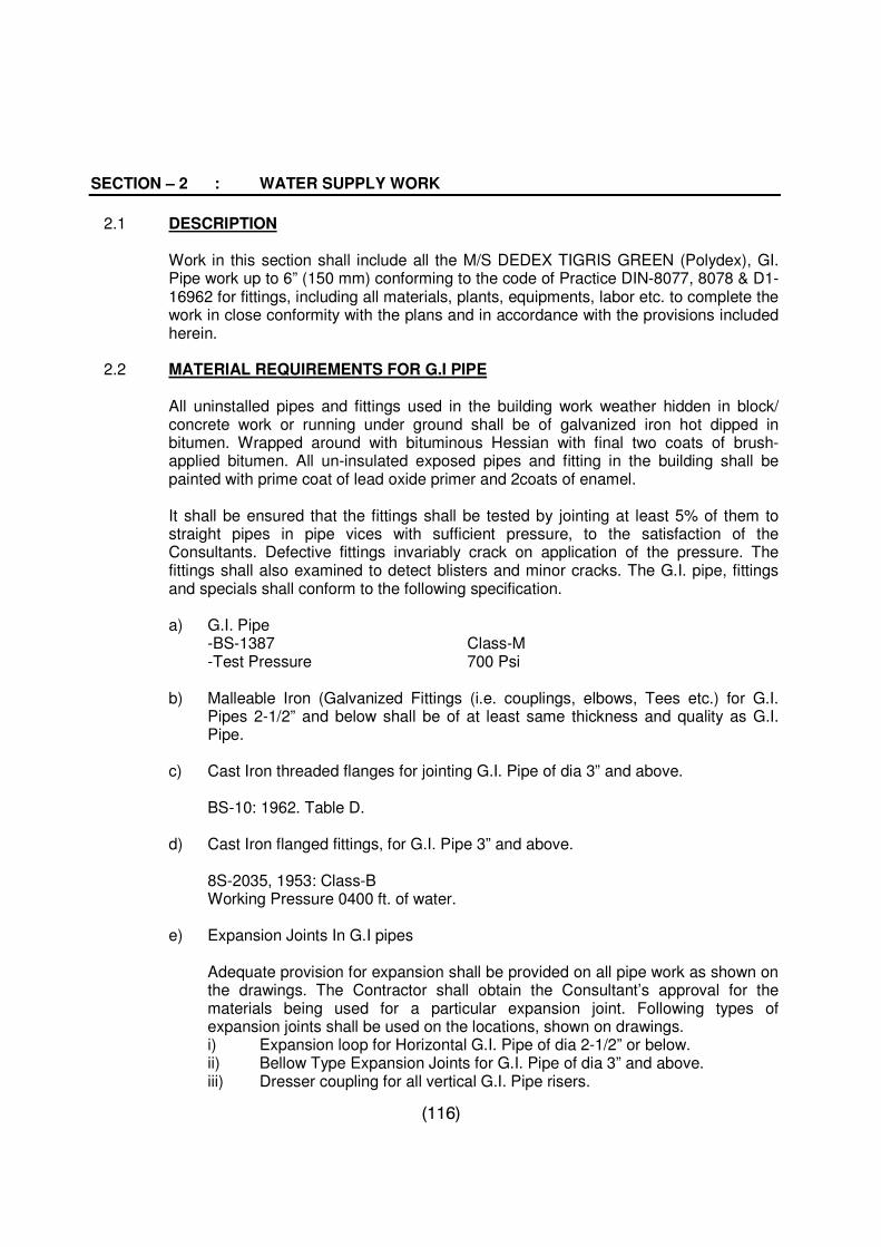
(116)
SECTION – 2 : WATER SUPPLY WORK
2.1 DESCRIPTION
Work in this section shall include all the M/S DEDEX TIGRIS GREEN (Polydex), GI. Pipe work up to 6” (150 mm) conforming to the code of Practice DIN-8077, 8078 & D1-16962 for fittings, including all materials, plants, equipments, labor etc. to complete the work in close conformity with the plans and in accordance with the provisions included herein.
2.2 MATERIAL REQUIREMENTS FOR G.I PIPE
All uninstalled pipes and fittings used in the building work weather hidden in block/ concrete work or running under ground shall be of galvanized iron hot dipped in bitumen. Wrapped around with bituminous Hessian with final two coats of brush-applied bitumen. All un-insulated exposed pipes and fitting in the building shall be painted with prime coat of lead oxide primer and 2coats of enamel.
It shall be ensured that the fittings shall be tested by jointing at least 5% of them to straight pipes in pipe vices with sufficient pressure, to the satisfaction of the Consultants. Defective fittings invariably crack on application of the pressure. The fittings shall also examined to detect blisters and minor cracks. The G.I. pipe, fittings and specials shall conform to the following specification.
a) G.I. Pipe
-BS-1387 Class-M -Test Pressure 700 Psi
b) Malleable Iron (Galvanized Fittings (i.e. couplings, elbows, Tees etc.) for G.I.
Pipes 2-1/2” and below shall be of at least same thickness and quality as G.I. Pipe.
c) Cast Iron threaded flanges for jointing G.I. Pipe of dia 3” and above.
BS-10: 1962. Table D.
d) Cast Iron flanged fittings, for G.I. Pipe 3” and above.
8S-2035, 1953: Class-B Working Pressure 0400 ft. of water.
e) Expansion Joints In G.I pipes
Adequate provision for expansion shall be provided on all pipe work as shown on the drawings. The Contractor shall obtain the Consultant’s approval for the materials being used for a particular expansion joint. Following types of expansion joints shall be used on the locations, shown on drawings. i) Expansion loop for Horizontal G.I. Pipe of dia 2-1/2” or below. ii) Bellow Type Expansion Joints for G.I. Pipe of dia 3” and above. iii) Dresser coupling for all vertical G.I. Pipe risers.
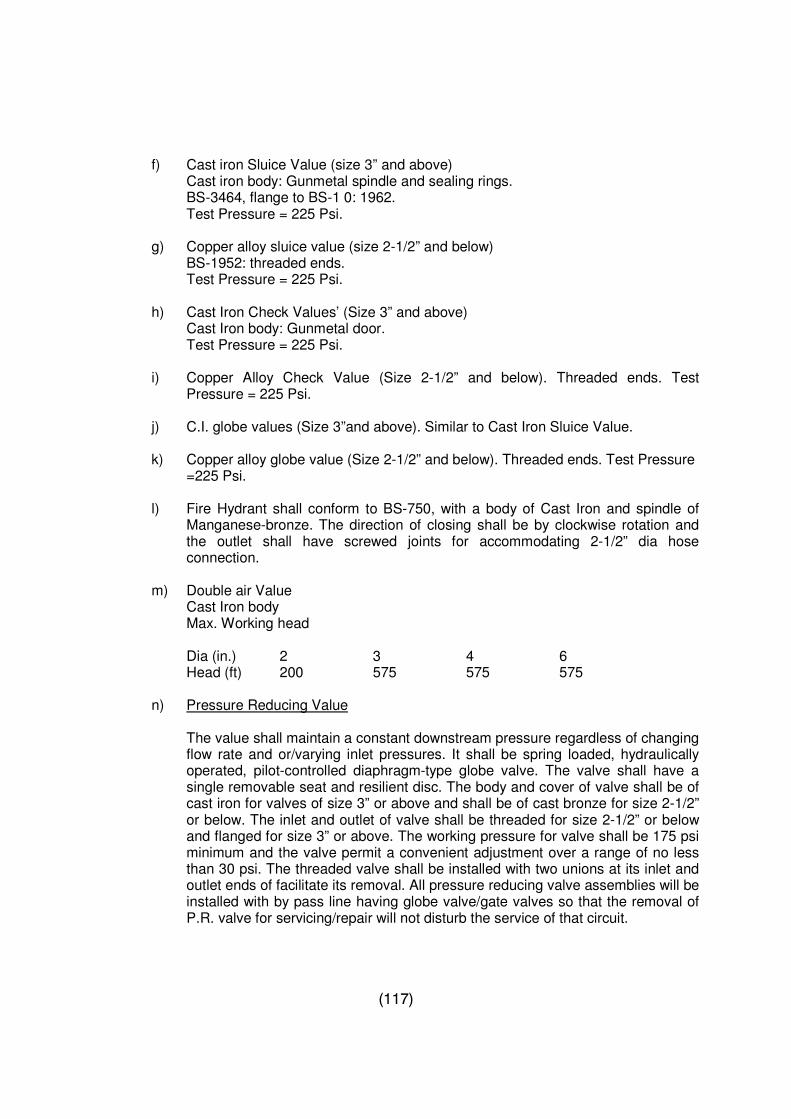
(117)
f) Cast iron Sluice Value (size 3” and above)
Cast iron body: Gunmetal spindle and sealing rings. BS-3464, flange to BS-1 0: 1962. Test Pressure = 225 Psi.
g) Copper alloy sluice value (size 2-1/2” and below) BS-1952: threaded ends. Test Pressure = 225 Psi.
h) Cast Iron Check Values’ (Size 3” and above)
Cast Iron body: Gunmetal door. Test Pressure = 225 Psi.
i) Copper Alloy Check Value (Size 2-1/2” and below). Threaded ends. Test Pressure = 225 Psi.
j) C.I. globe values (Size 3”and above). Similar to Cast Iron Sluice Value.
k) Copper alloy globe value (Size 2-1/2” and below). Threaded ends. Test Pressure
=225 Psi.
l) Fire Hydrant shall conform to BS-750, with a body of Cast Iron and spindle of Manganese-bronze. The direction of closing shall be by clockwise rotation and the outlet shall have screwed joints for accommodating 2-1/2” dia hose connection.
m) Double air Value
Cast Iron body Max. Working head Dia (in.) 2 3 4 6 Head (ft) 200 575 575 575
n) Pressure Reducing Value
The value shall maintain a constant downstream pressure regardless of changing flow rate and or/varying inlet pressures. It shall be spring loaded, hydraulically operated, pilot-controlled diaphragm-type globe valve. The valve shall have a single removable seat and resilient disc. The body and cover of valve shall be of cast iron for valves of size 3” or above and shall be of cast bronze for size 2-1/2” or below. The inlet and outlet of valve shall be threaded for size 2-1/2” or below and flanged for size 3” or above. The working pressure for valve shall be 175 psi minimum and the valve permit a convenient adjustment over a range of no less than 30 psi. The threaded valve shall be installed with two unions at its inlet and outlet ends of facilitate its removal. All pressure reducing valve assemblies will be installed with by pass line having globe valve/gate valves so that the removal of P.R. valve for servicing/repair will not disturb the service of that circuit.
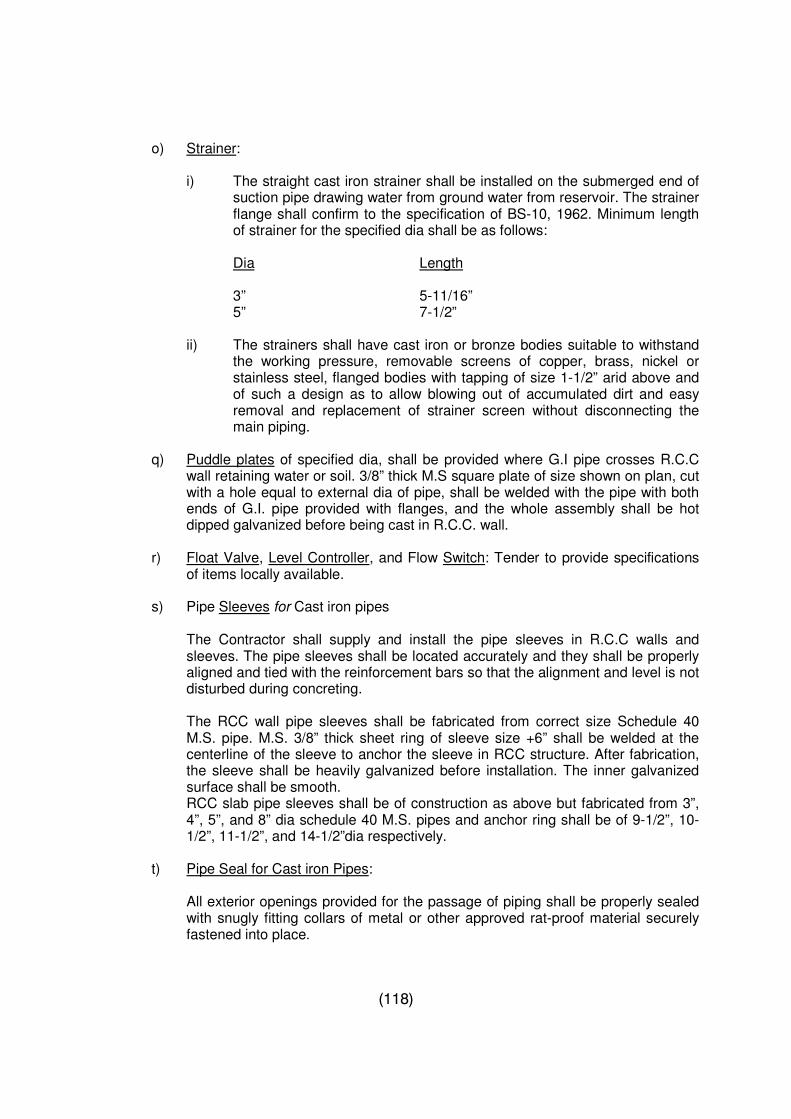
(118)
o) Strainer: i) The straight cast iron strainer shall be installed on the submerged end of
suction pipe drawing water from ground water from reservoir. The strainer flange shall confirm to the specification of BS-10, 1962. Minimum length of strainer for the specified dia shall be as follows:
Dia Length 3” 5-11/16” 5” 7-1/2”
ii) The strainers shall have cast iron or bronze bodies suitable to withstand
the working pressure, removable screens of copper, brass, nickel or stainless steel, flanged bodies with tapping of size 1-1/2” arid above and of such a design as to allow blowing out of accumulated dirt and easy removal and replacement of strainer screen without disconnecting the main piping.
q) Puddle plates of specified dia, shall be provided where G.I pipe crosses R.C.C
wall retaining water or soil. 3/8” thick M.S square plate of size shown on plan, cut with a hole equal to external dia of pipe, shall be welded with the pipe with both ends of G.I. pipe provided with flanges, and the whole assembly shall be hot dipped galvanized before being cast in R.C.C. wall.
r) Float Valve, Level Controller, and Flow Switch: Tender to provide specifications
of items locally available.
s) Pipe Sleeves for Cast iron pipes
The Contractor shall supply and install the pipe sleeves in R.C.C walls and sleeves. The pipe sleeves shall be located accurately and they shall be properly aligned and tied with the reinforcement bars so that the alignment and level is not disturbed during concreting.
The RCC wall pipe sleeves shall be fabricated from correct size Schedule 40 M.S. pipe. M.S. 3/8” thick sheet ring of sleeve size +6” shall be welded at the centerline of the sleeve to anchor the sleeve in RCC structure. After fabrication, the sleeve shall be heavily galvanized before installation. The inner galvanized surface shall be smooth. RCC slab pipe sleeves shall be of construction as above but fabricated from 3”, 4”, 5”, and 8” dia schedule 40 M.S. pipes and anchor ring shall be of 9-1/2”, 10-1/2”, 11-1/2”, and 14-1/2”dia respectively.
t) Pipe Seal for Cast iron Pipes:
All exterior openings provided for the passage of piping shall be properly sealed with snugly fitting collars of metal or other approved rat-proof material securely fastened into place.
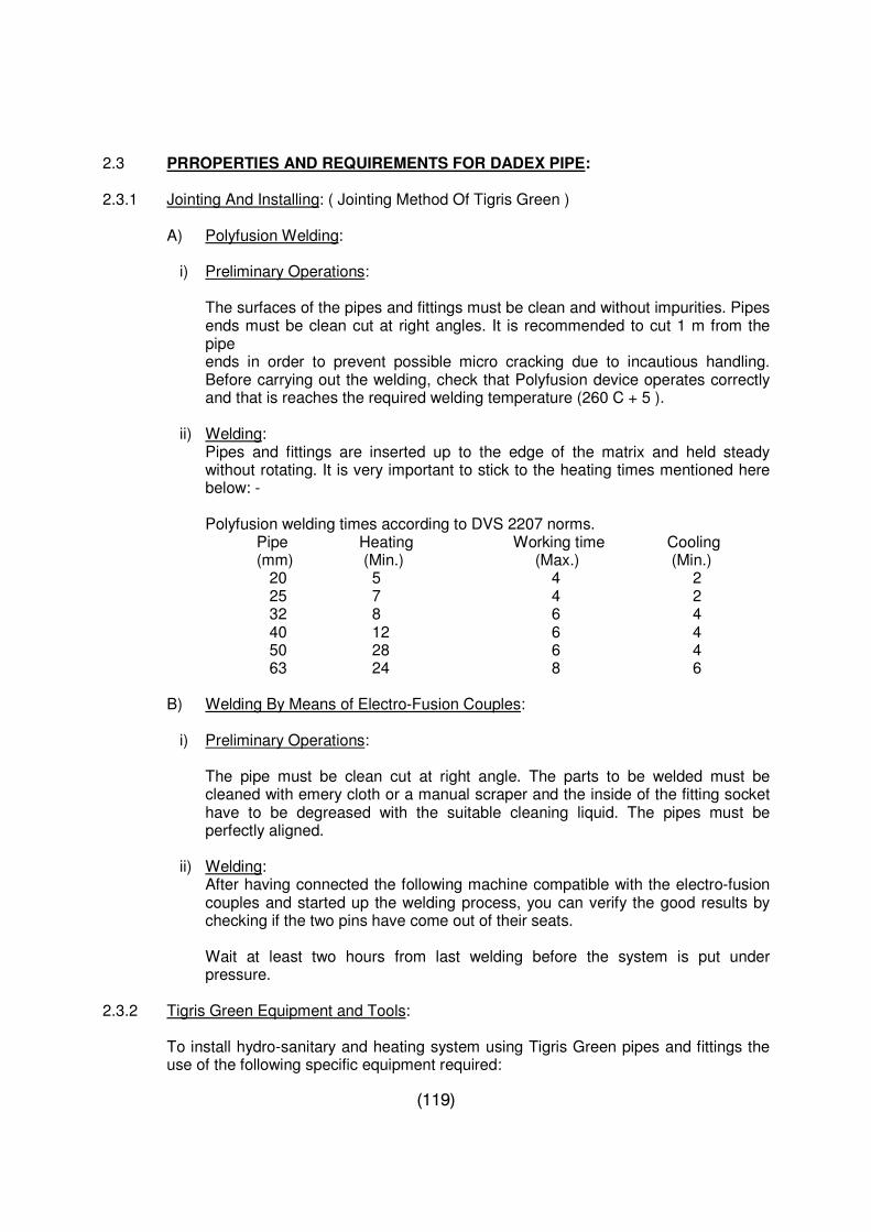
(119)
2.3 PRROPERTIES AND REQUIREMENTS FOR DADEX PIPE: 2.3.1 Jointing And Installing: ( Jointing Method Of Tigris Green )
A) Polyfusion Welding:
i) Preliminary Operations:
The surfaces of the pipes and fittings must be clean and without impurities. Pipes ends must be clean cut at right angles. It is recommended to cut 1 m from the pipe
ends in order to prevent possible micro cracking due to incautious handling. Before carrying out the welding, check that Polyfusion device operates correctly and that is reaches the required welding temperature (260 C + 5 ).
ii) Welding: Pipes and fittings are inserted up to the edge of the matrix and held steady
without rotating. It is very important to stick to the heating times mentioned here below: -
Polyfusion welding times according to DVS 2207 norms. Pipe Heating Working time Cooling (mm) (Min.) (Max.) (Min.) 20 5 4 2 25 7 4 2 32 8 6 4 40 12 6 4 50 28 6 4 63 24 8 6
B) Welding By Means of Electro-Fusion Couples:
i) Preliminary Operations:
The pipe must be clean cut at right angle. The parts to be welded must be cleaned with emery cloth or a manual scraper and the inside of the fitting socket have to be degreased with the suitable cleaning liquid. The pipes must be perfectly aligned.
ii) Welding: After having connected the following machine compatible with the electro-fusion couples and started up the welding process, you can verify the good results by checking if the two pins have come out of their seats. Wait at least two hours from last welding before the system is put under pressure.
2.3.2 Tigris Green Equipment and Tools:
To install hydro-sanitary and heating system using Tigris Green pipes and fittings the use of the following specific equipment required:
(120)
Pipe Cutter 0-63 Polyfusion device 20-63 (feeding 200 V ) Male and female material 20-63 Welding machine for electro-fusion couples 20-225 Bench welding machine 20-75
2.3.3 Exposure to UV-rays:
It is recommended neither to store nor to install the product in places, which are directly exposed to Ultraviolet rays.
2.3.4 Bending:
Bending for pipes will not be allowed.
2.3.5 Threaded joints:
To ensure tightness, Teflon or similar product can be used. 2.3.6 Pipe Cutting:
Cutting should be carried out using tools, which ensure a clean cut free from burns and perpendicular to the axis.
2.3.7 Low Temperature:
A temperature below 0c following precautions have to be taken.
Pay attention when cutting pipe. Check the cut make. Avoid impacts and excessive strains. Not to make elbows with very narrow radius.
In presence of cold draughts, welding must be carried out in protected areas, to avoid a quick cooling of the surfaces to be welded.
2.3.8 INSTALLING AND JOINTING KELEN: 1. Installing the pipes in short:
In practice the main riser can expand and contact laterally in the shaft between two floors if an anchor point is located next to the pipe that branches off from the main pipe. The distance between two anchor points in the shaft should not exceed 3.0 m. other methods can be used to accommodate the expansion such as expansion armor in the pipe branching off from riser.
2. Embedding the pipe:
Pipe work that is embedded in the wall, screed etc. is prevented from expanding. The pressure and tensile stress are absorbed without causing any damage to the
(121)
material. If the pipes are installed (in compliance with national standards) then the insulating material provides further room for expansion.
2.3.9 Exposed pipe work:
1. Preventing expansion by mechanical restraint d 20-50. Steel channels (KE88) can also be used to support pipe work.
The hangers are fixed to the channels, which are in turn fixed to the pipes (e/g
using cable ties). This practice reduces the expansion rate of plastic pipes to that of steel pipes.
2. Accommodating expansion by expansion loops d 63-110
All changes in direction of pipe work can be used to accommodate linear expansion. However, in some cases an expansion loop (U loop) is necessary. This method is primarily used for pipe sizes above d 50.
The anchor prints are positioned in such a way that the pipeline is divided into
sections and the force of expansion can be guided in the desired direction. Pipe support centers (in cm) for KELEN pipes transporting water. D mm Pn 10 20C 40C 60C 80C8
PN PN20 PN20 PN20 20 70 80 70 65 60 25 75 85 80 75 70 32 90 100 90 85 75 40 100 110 105 95 85 50 115 125 115 105 90 63 130 140 130 120 110 75 150 170 160 150 130 90 185 205 195 180 160 110 195 220 200 180 160 205 220
The pipe and fittings are joined by a self-regulating Polyfusion welding machine, at a temperature of 260 C. Connect the machine to the electricity supply (220 V) and wait. When the green light starts to blink the welding temperature has been reached and work can begin.
2.3.10 Safety first:
Cut 4-5 from each end of the pipe (the ends may have slightly damaged during handling) for this purpose KELEN pipes is in 4.10 m lengths.
2.3.11 WELDING PROCEDURE:
1. Ensure that the surface of the pipe and fitting are clean and free of grease.
2. Mark the insertion depth(equal to the socket depth of the fitting) on the pipe.
(122)
3. Heat the pipe to the insertion depth and the fitting to the socket depth on the welding tools.
4. When the heating time has elapsed see table push the pipe and fitting together
smoothly and evenly. The result is very strong and homogenous.
5. The position of the fitting can be adjusted for a few seconds immediately after the pipe and fitting have been joined. (See table)
6. Within a short period of time (See table) the joint is capable of withstanding a full
load.
7. The low weight and high flexibility of the material makes it possible to weld whole sections of pipe work at the workbench. Take advantage of this and save much time.
8. Some joints will have to be made in the wall. Try to keep the area here the joint
has to be made as accessible as possible. 9. Measure the correct length, not forgetting the depth of the pipe socket. Pipe
secateurs are used for cutting pipes up to 40.mm. Pipes with larger diameter are cut with a wheel pipe cutter. If necessary the pipes can also be cut with fine metal saw. Don/Et forget to insulate the pipes specified. The pipes can be covered with elastic insulating tubes (Kelinfix, kelon etc.) before they are installed. This can of course be done later but it is more difficult when the pipes have already been installed in the wall.
10. The distance between the draw-off points at the wall can be set (in all standard
distances) both horizontally and vertically with the template which is equipped with a spirit level.
2.3.12 KELEN WELDING MACHINE FOR LARGE DIAMETER:
1. Screw the heating elements for the desired diameter to the heating mirror.
2. Insert the reducers for the desired diameter in the clamp.
3. The clamps for the fitting are reversible. For d 20-d 40 use the small clamps and for dia 50 – 90 use large clamp. Secure the fitting in the clamp.
4. Select the centering bushing for the required dimension and release the
centering lever. Push the centering Bushing into the fitting and tighten the centering lever.
5. Pipe diameter Switch: This switch determines the insertion depth the pipe in the
fitting. Set the required diameter. The Welding Procedure:
1. Place the pipe in the clamp without tightening. Press down the spacing button and do not release. Move the sliding blocks with a hand wheel until the end of the
(123)
pipe is touching the end of the fitting. Release the spacing button and secure the pipe in the clamp.
2. Separate the two sliding blocks and pull down the welding mirror. Roll the two
sliding blocks together unit they are held by lock on the welding mirror. When the welding time has elapsed separate the sliding block and quickly remove the welding mirror.
3. Move the two sliding blocks together until the pipe diameter switch catches.
Never cool the remove the welded joints. Once the cooling period has elapsed the joint is ready to withstand a full load.
2.3.13. Butt welding machine for KELEN pn 10 pipes:
1. Loosen the screws and fit the required reducers in the clamps.
2. The end of the pipe should protrude from the clamps by no more than 30 mm. 3. Connect the following machine and start the motor. Move the two pipes together
and applying a little pressure until the pipes to remove the oxide layer at the weld zone (max. cutting thickness: o2mm). Ensure that the pipe ends are parallel to each other (max. divergence: 0.3 mm). The pipe ends must not be offset by more than 0.5 mm.
2.3.13 IMPORTANT:
The pipe ends must not be touched and must be welded immediately. If this is not possible and weld has to be made later then the welding zone must be cleaned and de-greased.
2.3.14 The welding procedure:
1. Before welding begins read from the manometer the pressure required for advancing the mobile part and add this to the working pressure given in the table.
2. Never cool the joint suddenly. If the weld has been made correctly a double bead
should be visible around the whole circumference of the pipe.
3. Insert the heating element (Temp: approx. 250C). Press the pipe ends on the heating element with the required joining pressure until a bead forms around the whole circumference of the pipe. During the reduced to the heating pressure once the heating time is over move the sliding blocks apart rapidly and remove the heating element.
4. The changeover time (time between removing the heating element and welding
the pipes) should be as short as possible.
5. The welding pressure should be built-up as smoothly as possible during the specified pressure attainment time (mi.0, 15 n/nm2).
6. The welding pressure must be maintained during the cooling period.
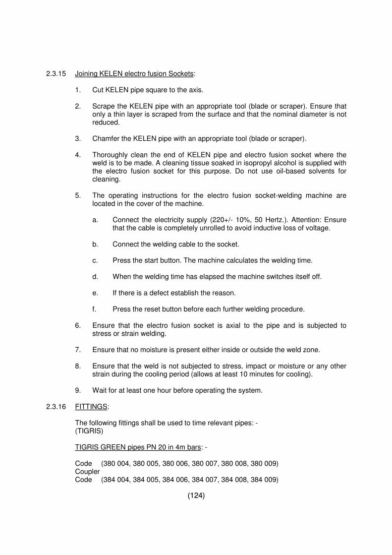
(124)
2.3.15 Joining KELEN electro fusion Sockets:
1. Cut KELEN pipe square to the axis. 2. Scrape the KELEN pipe with an appropriate tool (blade or scraper). Ensure that
only a thin layer is scraped from the surface and that the nominal diameter is not reduced.
3. Chamfer the KELEN pipe with an appropriate tool (blade or scraper).
4. Thoroughly clean the end of KELEN pipe and electro fusion socket where the
weld is to be made. A cleaning tissue soaked in isopropyl alcohol is supplied with the electro fusion socket for this purpose. Do not use oil-based solvents for cleaning.
5. The operating instructions for the electro fusion socket-welding machine are
located in the cover of the machine.
a. Connect the electricity supply (220+/- 10%, 50 Hertz.). Attention: Ensure that the cable is completely unrolled to avoid inductive loss of voltage.
b. Connect the welding cable to the socket.
c. Press the start button. The machine calculates the welding time.
d. When the welding time has elapsed the machine switches itself off.
e. If there is a defect establish the reason.
f. Press the reset button before each further welding procedure.
6. Ensure that the electro fusion socket is axial to the pipe and is subjected to
stress or strain welding. 7. Ensure that no moisture is present either inside or outside the weld zone. 8. Ensure that the weld is not subjected to stress, impact or moisture or any other
strain during the cooling period (allows at least 10 minutes for cooling). 9. Wait for at least one hour before operating the system. 2.3.16 FITTINGS: The following fittings shall be used to time relevant pipes: - (TIGRIS) TIGRIS GREEN pipes PN 20 in 4m bars: - Code (380 004, 380 005, 380 006, 380 007, 380 008, 380 009) Coupler Code (384 004, 384 005, 384 006, 384 007, 384 008, 384 009)
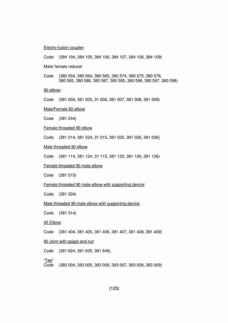
(125)
Electro-fusion coupler: Code (384 104, 384 105, 384 106, 384 107, 384 108, 384 109) Male/ female reducer Code (380 554, 380 564, 380 565, 380 574, 380 575, 380 576, 380 585, 380 586, 380 587, 380 595, 380 596, 380 597, 380 598) 90 elbow: Code (381 004, 381 005, 31 006, 381 007, 381 008, 381 009) Male/Female 90 elbow Code (381 244) Female threaded 90 elbow Code (381 014, 381 024, 31 015, 381 025, 381 026, 381 036) Male threaded 90 elbow Code (381 114, 381 124, 31 115, 381 125, 381 126, 381 136) Female threaded 90 male elbow Code (381 515) Female threaded 90 male elbow with supporting device: Code (381 304) Male threaded 90 male elbow with supporting device: Code (381 314) 45 Elbow: Code (381 404, 381 405, 381 406, 381 407, 381 408, 381 409) 90 Joint with spigot and nut: Code (381 624, 381 635, 381 646) “Tee” Code (383 004, 383 005, 383 006, 383 007, 383 008, 383 009)
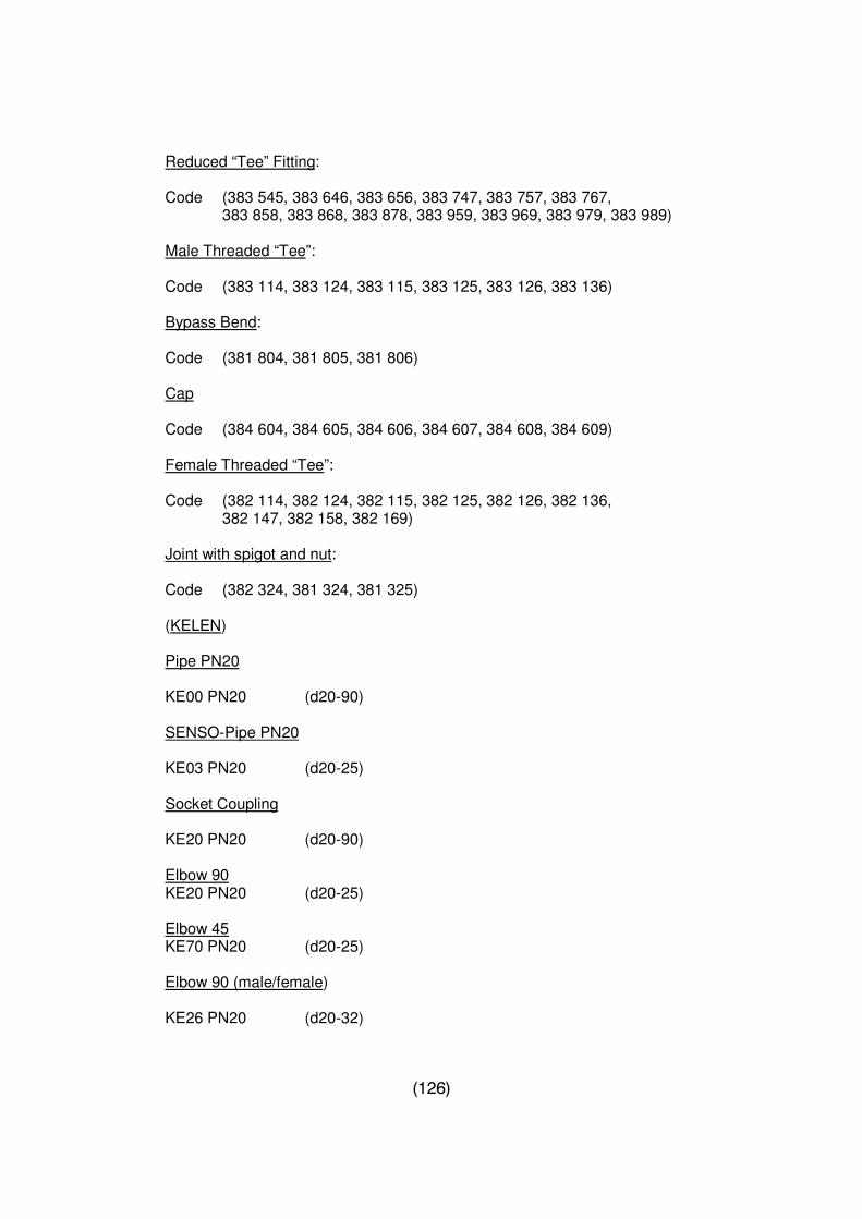
(126)
Reduced “Tee” Fitting: Code (383 545, 383 646, 383 656, 383 747, 383 757, 383 767, 383 858, 383 868, 383 878, 383 959, 383 969, 383 979, 383 989) Male Threaded “Tee”: Code (383 114, 383 124, 383 115, 383 125, 383 126, 383 136) Bypass Bend: Code (381 804, 381 805, 381 806) Cap Code (384 604, 384 605, 384 606, 384 607, 384 608, 384 609) Female Threaded “Tee”: Code (382 114, 382 124, 382 115, 382 125, 382 126, 382 136, 382 147, 382 158, 382 169) Joint with spigot and nut: Code (382 324, 381 324, 381 325) (KELEN) Pipe PN20 KE00 PN20 (d20-90) SENSO-Pipe PN20 KE03 PN20 (d20-25) Socket Coupling KE20 PN20 (d20-90) Elbow 90 KE20 PN20 (d20-25) Elbow 45 KE70 PN20 (d20-25) Elbow 90 (male/female) KE26 PN20 (d20-32)
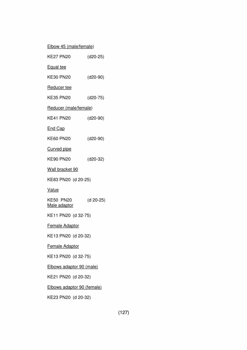
(127)
Elbow 45 (male/female) KE27 PN20 (d20-25) Equal tee KE30 PN20 (d20-90) Reducer tee KE35 PN20 (d20-75) Reducer (male/female) KE41 PN20 (d20-90) End Cap KE60 PN20 (d20-90) Curved pipe KE90 PN20 (d20-32) Wall bracket 90
KE83 PN20 (d 20-25)
Value
KE50 PN20 (d 20-25) Male adaptor
KE11 PN20 (d 32-75)
Female Adaptor
KE13 PN20 (d 20-32)
Female Adaptor
KE13 PN20 (d 32-75)
Elbows adaptor 90 (male)
KE21 PN20 (d 20-32)
Elbows adaptor 90 (female)
KE23 PN20 (d 20-32)

(128)
Tee (male thread)
KE33 PN20 (d 20-32)
Union (plastic-metal)
KE56 PN20 (d 20-90)
E-repair socket
KE17 PN20 (d 20-90)
Backing ring
KE18 PN20 (d 40-110)
Flange
KE19 PN20 (d 40-110)
Threaded connection for cavity walls
KE84 PN20 (1/2”)
Stopper (short) (1/2: -3/4”) Stopper (long) (1/2:-3/4”)
Poly fusion Welding programmed PN 10
Pipe PN10
KE02 PN10 (d 20-160)
SENSO- pipe PN10
KE04 PN 10 (d 20-25)
Socket coupling
KE10 PN10 (d 110)
Elbows 90
KE20 PN10 (110)
Elbows 45
KE70 PN10 (110)
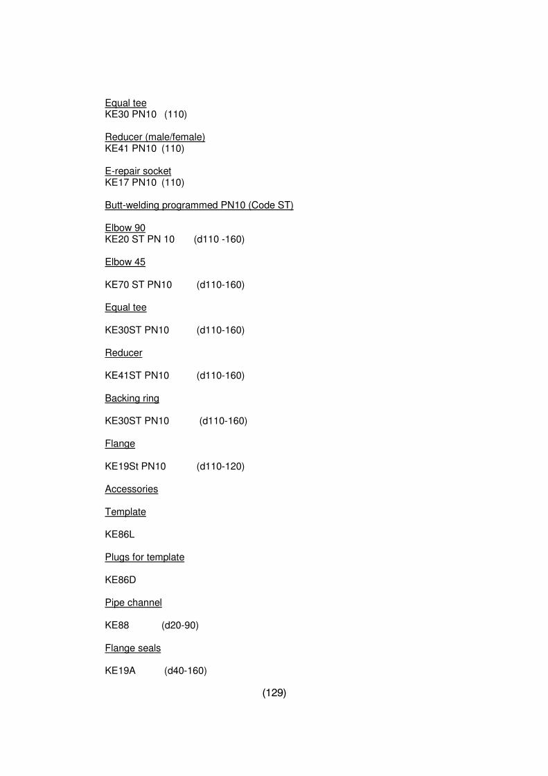
(129)
Equal tee KE30 PN10 (110)
Reducer (male/female) KE41 PN10 (110)
E-repair socket KE17 PN10 (110)
Butt-welding programmed PN10 (Code ST)
Elbow 90 KE20 ST PN 10 (d110 -160)
Elbow 45
KE70 ST PN10 (d110-160)
Equal tee
KE30ST PN10 (d110-160)
Reducer
KE41ST PN10 (d110-160)
Backing ring
KE30ST PN10 (d110-160)
Flange
KE19St PN10 (d110-120)
Accessories
Template
KE86L
Plugs for template
KE86D
Pipe channel
KE88 (d20-90)
Flange seals
KE19A (d40-160)
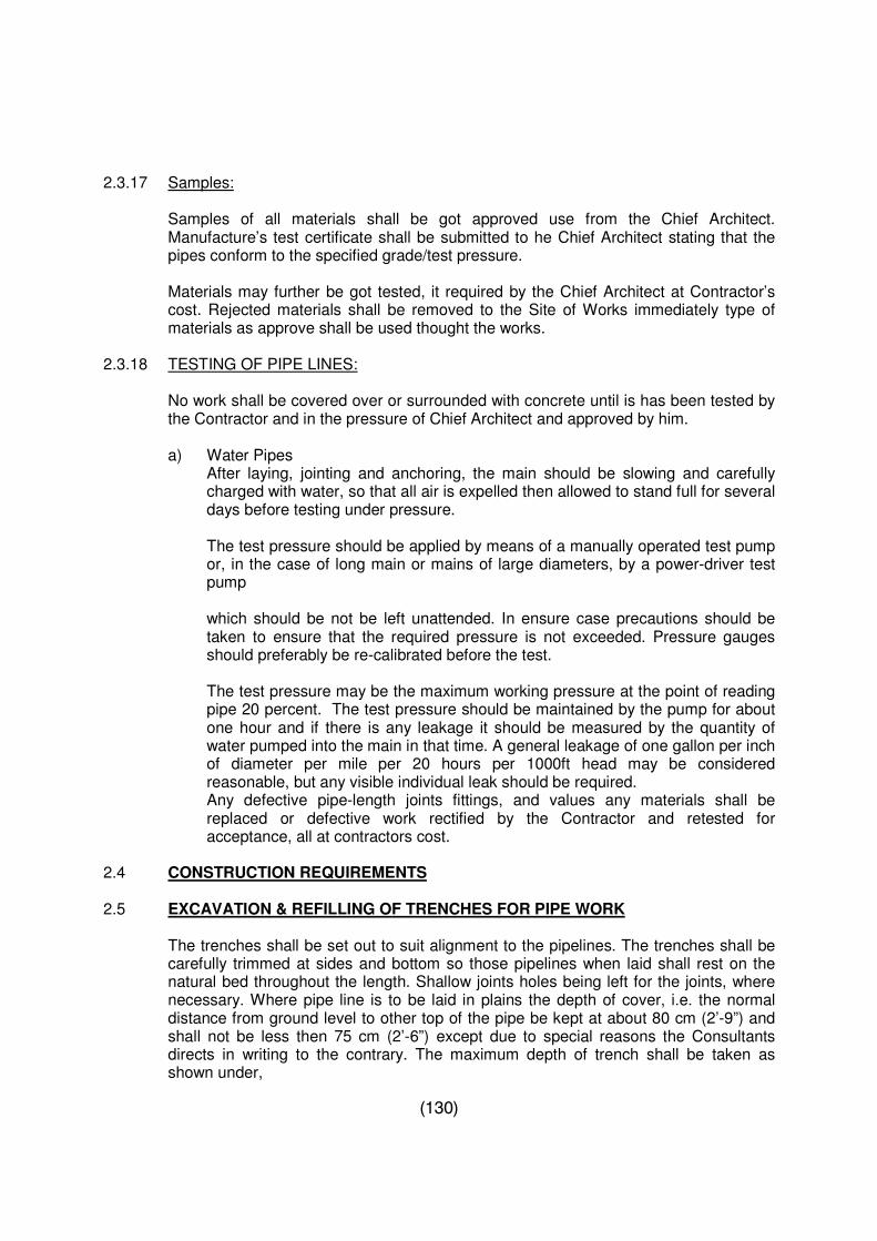
(130)
2.3.17 Samples:
Samples of all materials shall be got approved use from the Chief Architect. Manufacture’s test certificate shall be submitted to he Chief Architect stating that the pipes conform to the specified grade/test pressure.
Materials may further be got tested, it required by the Chief Architect at Contractor’s cost. Rejected materials shall be removed to the Site of Works immediately type of materials as approve shall be used thought the works.
2.3.18 TESTING OF PIPE LINES:
No work shall be covered over or surrounded with concrete until is has been tested by the Contractor and in the pressure of Chief Architect and approved by him.
a) Water Pipes
After laying, jointing and anchoring, the main should be slowing and carefully charged with water, so that all air is expelled then allowed to stand full for several days before testing under pressure. The test pressure should be applied by means of a manually operated test pump or, in the case of long main or mains of large diameters, by a power-driver test pump
which should be not be left unattended. In ensure case precautions should be taken to ensure that the required pressure is not exceeded. Pressure gauges should preferably be re-calibrated before the test.
The test pressure may be the maximum working pressure at the point of reading pipe 20 percent. The test pressure should be maintained by the pump for about one hour and if there is any leakage it should be measured by the quantity of water pumped into the main in that time. A general leakage of one gallon per inch of diameter per mile per 20 hours per 1000ft head may be considered reasonable, but any visible individual leak should be required. Any defective pipe-length joints fittings, and values any materials shall be replaced or defective work rectified by the Contractor and retested for acceptance, all at contractors cost.
2.4 CONSTRUCTION REQUIREMENTS 2.5 EXCAVATION & REFILLING OF TRENCHES FOR PIPE WORK
The trenches shall be set out to suit alignment to the pipelines. The trenches shall be carefully trimmed at sides and bottom so those pipelines when laid shall rest on the natural bed throughout the length. Shallow joints holes being left for the joints, where necessary. Where pipe line is to be laid in plains the depth of cover, i.e. the normal distance from ground level to other top of the pipe be kept at about 80 cm (2’-9”) and shall not be less then 75 cm (2’-6”) except due to special reasons the Consultants directs in writing to the contrary. The maximum depth of trench shall be taken as shown under,
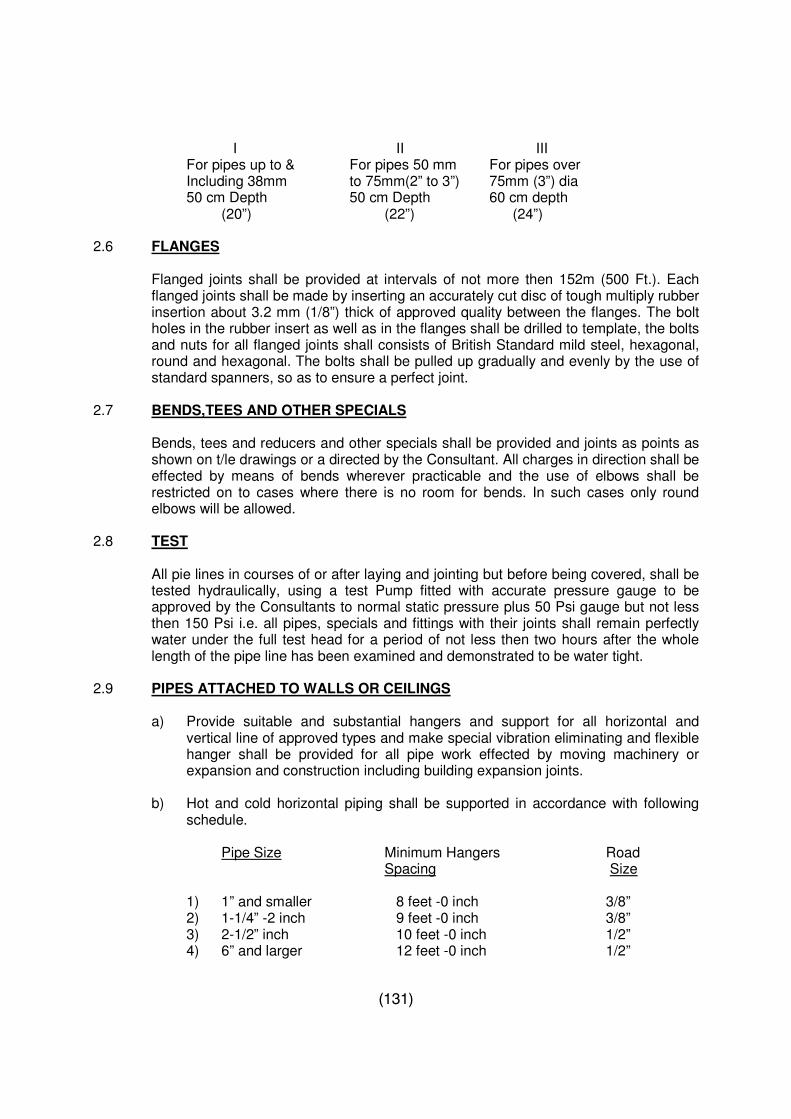
(131)
I II III For pipes up to & For pipes 50 mm For pipes over Including 38mm to 75mm(2” to 3”) 75mm (3”) dia 50 cm Depth 50 cm Depth 60 cm depth (20”) (22”) (24”)
2.6 FLANGES
Flanged joints shall be provided at intervals of not more then 152m (500 Ft.). Each flanged joints shall be made by inserting an accurately cut disc of tough multiply rubber insertion about 3.2 mm (1/8”) thick of approved quality between the flanges. The bolt holes in the rubber insert as well as in the flanges shall be drilled to template, the bolts and nuts for all flanged joints shall consists of British Standard mild steel, hexagonal, round and hexagonal. The bolts shall be pulled up gradually and evenly by the use of standard spanners, so as to ensure a perfect joint.
2.7 BENDS,TEES AND OTHER SPECIALS
Bends, tees and reducers and other specials shall be provided and joints as points as shown on t/le drawings or a directed by the Consultant. All charges in direction shall be effected by means of bends wherever practicable and the use of elbows shall be restricted on to cases where there is no room for bends. In such cases only round elbows will be allowed.
2.8 TEST
All pie lines in courses of or after laying and jointing but before being covered, shall be tested hydraulically, using a test Pump fitted with accurate pressure gauge to be approved by the Consultants to normal static pressure plus 50 Psi gauge but not less then 150 Psi i.e. all pipes, specials and fittings with their joints shall remain perfectly water under the full test head for a period of not less then two hours after the whole length of the pipe line has been examined and demonstrated to be water tight.
2.9 PIPES ATTACHED TO WALLS OR CEILINGS
a) Provide suitable and substantial hangers and support for all horizontal and vertical line of approved types and make special vibration eliminating and flexible hanger shall be provided for all pipe work effected by moving machinery or expansion and construction including building expansion joints.
b) Hot and cold horizontal piping shall be supported in accordance with following
schedule. Pipe Size Minimum Hangers Road Spacing Size
1) 1” and smaller 8 feet -0 inch 3/8” 2) 1-1/4” -2 inch 9 feet -0 inch 3/8” 3) 2-1/2” inch 10 feet -0 inch 1/2” 4) 6” and larger 12 feet -0 inch 1/2”
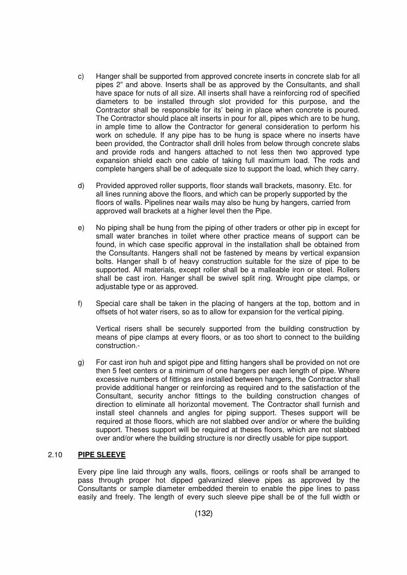
(132)
c) Hanger shall be supported from approved concrete inserts in concrete slab for all pipes 2” and above. Inserts shall be as approved by the Consultants, and shall have space for nuts of all size. All inserts shall have a reinforcing rod of specified diameters to be installed through slot provided for this purpose, and the Contractor shall be responsible for its’ being in place when concrete is poured. The Contractor should place alt inserts in pour for all, pipes which are to be hung, in ample time to allow the Contractor for general consideration to perform his work on schedule. If any pipe has to be hung is space where no inserts have been provided, the Contractor shall drill holes from below through concrete slabs and provide rods and hangers attached to not less then two approved type expansion shield each one cable of taking full maximum load. The rods and complete hangers shall be of adequate size to support the load, which they carry.
d) Provided approved roller supports, floor stands wall brackets, masonry. Etc. for all lines running above the floors, and which can be properly supported by the floors of walls. Pipelines near wails may also be hung by hangers, carried from approved wall brackets at a higher level then the Pipe.
e) No piping shall be hung from the piping of other traders or other pip in except for
small water branches in toilet where other practice means of support can be found, in which case specific approval in the installation shall be obtained from the Consultants. Hangers shall not be fastened by means by vertical expansion bolts. Hanger shall b of heavy construction suitable for the size of pipe to be supported. All materials, except roller shall be a malleable iron or steel. Rollers shall be cast iron. Hanger shall be swivel split ring. Wrought pipe clamps, or adjustable type or as approved.
f) Special care shall be taken in the placing of hangers at the top, bottom and in
offsets of hot water risers, so as to allow for expansion for the vertical piping.
Vertical risers shall be securely supported from the building construction by means of pipe clamps at every floors, or as too short to connect to the building construction.-
g) For cast iron huh and spigot pipe and fitting hangers shall be provided on not ore
then 5 feet centers or a minimum of one hangers per each length of pipe. Where excessive numbers of fittings are installed between hangers, the Contractor shall provide additional hanger or reinforcing as required and to the satisfaction of the Consultant, security anchor fittings to the building construction changes of direction to eliminate all horizontal movement. The Contractor shall furnish and install steel channels and angles for piping support. Theses support will be required at those floors, which are not slabbed over and/or or where the building support. Theses support will be required at theses floors, which are not slabbed over and/or where the building structure is nor directly usable for pipe support.
2.10 PIPE SLEEVE
Every pipe line laid through any walls, floors, ceilings or roofs shall be arranged to pass through proper hot dipped galvanized sleeve pipes as approved by the Consultants or sample diameter embedded therein to enable the pipe lines to pass easily and freely. The length of every such sleeve pipe shall be of the full width or
(133)
thickness of the wall and in the case of roof, ceiling or floor, shall be at least 4 cm )1-1/2”) longer then the thickness thereof and shall project to that extent above the upper surface thereof unless the Consultants orders to the contrary.
2.11 DISINFECTION FOR WATER SUPPLY
After the testing of the pipe work has been satisfactorily completed and when approved by the Consultants, the Contractor shall disinfect the pipe lines by dispensing chlorine solution through the entire pipe network to obtain minimum chlorine content of 50 mg/liter for a contact period of at least 30 minutes. The procedure and equipment used to introduce, disperse and test the chlorine in the pipe shall be subject to approval by the Consultants.
2.12 MEASUREMENT
The pipe work 150mm (up to 6” dia) shall be measured in running foot and no separate measurement will be done for tees, bends, elbows, unions and other fittings. Unit of measurement for pipe work shall be taken along the centerline and unit of measurement will be one linear Ft.
2.13 PAYMENT
The rate shall include all cost of material i.e. pipe, fitting, jointing material, lubricant, sleeve pipes, hangers and clamps, and labor of every type and incidentals.
(134)
SECTION – 3 : PLUMBING AND SANITATION WORK
3.1 DESCRIPTION
Work under this section includes supplying and fixing all sanitary works including English type W.C or Asia type W.C. wash hand basins, urinals, sinks, low down and high level cistern, automatic flushing tank, showers, Taps, valves also any special fixtures called for on the plans and mentioned in the Bill of Quantities.
3.1 MATERIAL REQUIREMENTS 3.1.1 Plumbing fixture and Fittings
1. European type water closet shall be of standard clear opening between flushing
rim in white earthenware best quality (local made) “P” or “S” trap 3 gallons (13.5 liters) enameled, wall type flushing tank, enameled flush bend, PVC symphonic type fittings complete with corrosion resistant alloy ball level of best quality manufacture in Pakistan. Standard seat cover with PVC rings and nuts and rubber buffers, etc. complete.
2. Asia/Orisa type water closet of standard clear opening as measured between
flushing rims with foot rest in white earthenware best quality (local madeaaaa0 with back and front flush, specified dia. C.I trap of same make, 3 gallons (13.5 Liters) Ceramic flushing tank with symphonic type flush fitting corrosion resistant alloy or plastic ball valve of Asia or equivalent 1-1/4” (31 mm) dia telescopic flush pipe made from PVC pipe of the same size fixed to wall with PVC/C.P. saddle.
3. Wash basin of specified size in white color best quality mounted on C.I. brackets
fixed to wall, (local made) with ½”(15 mm) C.P pillar cock, 1-1/4” (31 mm) C.P waste chain plug, local made heavy counter sunk screws, PVC/C.P down take waste pipe ½” (15 mm) PVC/C.P type cock heavy duty with ½”(15 mm) PVC/C.P inlet connection ½”(15 mm) C.P brass union nuts and washers, including 3 coats of approved enamel paint to C.I brackets.
4. Urinal size 17” (425 mm) in white earthenware best quality (local made) with C.I
automatic flush tank ½”(15 mm) C.P brass union nuts and washers. The urinals shall be connected with G.I pipe flushing assembly connected to each urinal and 1-1/2” (38 mm) PVC waste pipe.
5. The shower roses shall be chromium finish universal types with adjustable spray
of best quality local made as per approval.
6. The sink shall be stainless steel best quality local made with all accessories.
NOTE : C.P brass waste and union 1-1/2”, 1-1/4”(38mm/31mm) dia with PVC/C.P down pipe to be provided for sinks and wash hand basins.
(135)
3.1.2 Showers The showerhead shall be chromium plated with fountains of size specified in the B.O.Q. OR as approved by the consultants. Each shower shall be connected through a control valve to the hot and cold mixing valve. This shall be best quality manufactured approval shall be given by the consultants.
3.1.3 Taps
All taps shall be of heavy-duty type, chromium plated or brass as applicable and be of approved manufacture.
3.2 CONSTRUCTION REQUIREMENTS 3.2.1 Water Closets
The work shall consist of providing and mixing in position Orisa type water closet or European type water closet of an approved manufacture. The type pan shall be of white vitreous China, glazed fire, fire clay, or any other approved non- absorbent material with specified diameter trap of the same material and footrest. The surface shall have a glazed finish with minimum of fouling area and a seal depth greater than 50 mm. The outlet shall be placed well hack and the pan shall be sufficiently long to meet the design requirement. The flushing water connection shall be from the rear end.
The European type water closet shall also be vitreous China made of an approved manufacturer with low level flushing cistern and with double seat cover. The W.C shall be of symphonic type with large water area and deep seal, the cleaning being effected by symphonic action. It shall have a low trap at the floor line so that the closet can not be un-trapped by the emptying water.
The flushing cistern shall be of white glazed earthenware 13.6 liters as specified in the B.O.Q.
The flush pipe shall be PVC or chromium plated steel pipe, the holes of inlet, outlet and over flow in the cistern shall be made watertight by inserting rubber washers or other means of providing a watertight joint. The position of water closet shall be so arranged that it shall not face Qibla.
Every water closet shall be provided with a water supply bib tap for filling the small water cans in the site down position. A chromium plated toilet paper holder close to each water closet shall also be installed.
3.2.2 Sink
Sink shall be of stainless steel of size as specified in the BOQ with self-contained drain boards of approved manufacturers. The sink shall be fitted with rubber plug and washers, 38 mm dia. Chromium plated bottle with waste pipe with all necessary accessories for making the sink a complete unit. The internal angles shall be of a design of facilitate cleaning with a fall towards outlet to drain the contents completely.
(136)
3.2.3 Service Sink If required shall be made of stainless steel of 16 gauge as approved by consultants. The sink shall be used for drawing water for scrubbing and cleaning and dispose off the contents of scrub buckets and vessels containing slops. The edge of the sink shall be placed about 600 mm above the floor to minimize, lifting and to leave room for the trap beneath.
The water supply and drainage equipment for such sinks shall be similar to that for kitchen sinks, except that no hot water supply or mixer will be installed.
3.2.4 Water Pump
Pumps for domestic Water, Fire Fighting, Drainage and Sewage Lift Station The centrifugal pump-motor set shall be heavy-duty industrial type suitable for continuous and quiet operation. The centrifugal pumps shall be single stage, small size of vertically split casting and larger sizes or horizontally split casing as specified in the schedule of equipment.
The pumps to be volute type, cast iron body, fully bronze fitted, bronze impeller of radial type with double curvature vanes, stainless steel shaft or shaft sleeve, properly lubricated bearings, readily accessible stuffing box with packing and seal cage, flanged suction for the pump and the and the motor and the pump shafts covered with approved guard, pump casing to be completed with drain and vent plugs and designed, tested and proven tight for a test pressure at least equal to 1.5 times the maximum pressure.
The pumps to have the gate valves and strainers on the suction side globe valves on the discharge side and pressure gauges on suction and discharge sides. If pumps are operating in parallel than a check valve to be installed on the discharge side of each pump. The pumps shall be direct driven by a constant speed motor and provided with a suitable starter. The pump motor HP has been given for each system for guidance but it is intended that motor of higher HP shall be provided if required to ensure that it is not overloaded under any possible operating conditions of the pumps. Each pump shall be guaranteed for circulating the specified water quantity against specified net discharge head under the specified conditions of operation when operating continuously without over heating the motor, bearings etc. However the contractor will check and confirm the actual discharge head required before placing orders for the pump. The pumps shall be selected for quiet operation so that pump noise is not audible outside the plant room. The pump sound shall not be transmitted to the building structure. The pumps installed for one system should be suitable for parallel operation in all respects. The pump impeller and motor should be so selected that these are not overloaded when only one pump is operating and increased water flow is to be handled due to reduced system head.
The contractor shall supply anti-vibration foundation material (both pads for isolator of maim foundation and spring mounting for inertia mass) for isolating the pump foundations from the building structure. The number, size and conditions of operation for pumps required for different systems are specified in the schedule of equipment and pumps location shown in the drawings.
(137)
Certified performance data and curves shall be submitted by the CONTRACTOR for approval to confirming the purchase order on the manufacturer/supplier. All pumps to be supplied under this section to be of one manufacturer for the same type.
The pump motor sets to be of local manufacturer, KSB or approved equal, for the sizes manufactured locally.
a. Pump capacity in US gpm against pet discharge head, RPM, HP of motor, and pump maximum HP requirement.
b. Construction and other technical details.
c. Overall dimensions and operating weight.
d. Manufacturer’s performing guarantee certificate and performance data and curves and technical bulletin.
The sewage ejector submersible centrifugal pump motor sets shall be vertical heavy duty Industrial type with non-clogging impeller suitable for continuous operation.
The pump capacity rating shall be specified in the schedule of equipment.
The pump shall be vertical single entry single stage non self-priming. The pumps casting shall be radially split open towards the discharge end sealed off by a cover, suction end with a renewable wear plate and nozzle, impeller suitable for mixture of contaminated fluids, solid particles and sludge. The shaft length shall suit the installation depth shown in the drawings and shaft pieces joined together by threaded shaft coupling. The weight of the rotor and axial thrust will be absorbed, by deep groove ball bearing in the vertical hollow shaft motor. A grease pump mounted on the pump mounting plate shall continuously feed grease individually to every hearing during pump operation. The pump shall be fitted with soft packed stuffing box fed with sealing grease the pump base plate shall be sized large enough to enable the pump to be pulled out/lowered into terminated above the base plate. The wear plate shall be of cost iron, shaft-protecting sleeve of stainless steel, Shaft of carbon steel, base plate of steel, motor stool of steel/cast iron and bearing of lead bronze.
The pump motor sets to be of local manufacturer, KSB type KVP or approved equal.
The Tenderer to give following information for the pump.
a. Pump capacity in US gpm against specified head, RPM pump maximum BH requirement and motor HP.
b. Construction and other technical details.
c. Overall dimensions and operating weight, clear height required above base plate for pulling out the pump.
d. Manufacturers Performance Guarantee Certificate and performance data and
curves and technical bulletin.
(138)
Level Controller
Each group of the above pumps shall have a control system as detailed below:
A three position level controller shall automatically control the pump operation. The level controller shall start the pump at high level and stop the same at low level. A highest level, the level controller shall energize an audio video alarm.
3.2.5 Unions
Provide accessible unions in supply and return connections at all equipment fixtures, fixtures, special automatic valves, screwed end valves and at all other points will the system where required, in order to facilitate removal of specialties or equipment for repairs.
3.2.6 Expansion Joints For C.I Soil or Waste pipe
Expansion joint in C.I soil or waste pipe shall be provided as per plans, where the pipe crosses building expansion joint. These will be of non-pressure type, similar to imported Jossam Series.
3.3 MEASUREMENT
Measurement shall be made for the number of fixtures and toilet accessories acceptably provided and fixed in position.
3.4 PAYMENT
Payment shall be made for the number measured as provided above at the contract unit rate for the respective items in the Bill of Quantities and shall constitute full compensation for all labor material, use of equipment and tools required for work related to the item including providing and fixing all other work to complete the item in all respects as specified or as directed by the consultants.
(139)
SECTION – 4 : SEWERAGE / DRAINAGE WORK
4.1 DESCRIPTION 4.1.1 Sewerage
All sewerage/drainage pipes work inside the houses and buildings and up to the connection of the trunk sewer shall be covered under this section. The pipes shall be M/S DADEX, RCC or C.I as specified including soil, waste, vent and anti syphonic pipes.
4.2 MATERIAL REQUIREMENTS
All RCC/C.I pipes shall confirm to the specifications referred to in section “Material” and as specified in this section.
For cast iron pipes, the joints shall be lead caulked. The packing material shall be pure jute, hemp or hemp yam.
For M/s. DADEX, all activities should be in accordance with the manufacturer’s specifications.
For RCC pipes the cement mortar to be used on joints shall be of 1:1 ratio or as per plans.
Material specifications for sewerage and drainage shall be as follows:
a. Cast Iron Pipe, socket arid spigot (6’ length).
Minimum Weights Dia (in) 2 3 4 6 Weight (Lb.) 24.90 37.00 48.00 72.90 Test Pressure against leakage = 20 Psi.
b. Cast Iron Fittings
Minimum Weights (lb.)
TABLE-1 (BENDS)
Fittings (inches) 2 3 4 6
87-1/2 degree and 45 6.3 11 15 24.9 degree bend without access 87-1/2 degree and 45 7 11.9 18 29.9 degree bend with access
(140)
TABLE (WYES & REDUCERS) Fittings (inches) 2x2 2x3 3x3 2x4 3x4 4x4 87-1/2 degree and 45 9 15 16 17 20 24 degree without access 87-1/2 degree and 45 11 16 18 20 24 26 degree wye with access
Eccentric reducer with - 7.9 - 11 11 - Smaller sides socket Ted _____________________________________________________________
c. R.C.C Pipe BSS 556: Class-M < 9”
6”-dia pipe with collar 9” pipe, spigot and socket ASTM C76- 72-a >12”
4.2.1 Cast Iron Floor Trap Manhole Frames and Cover Grating
These shall be from a mixture of cast iron scrap and suitable grade of pig iron, and resultant metal shall be of strong gray structure, free from chips, air bubbles and sand holes and shall be smooth and even both inside and outside.
4.2.2 Grease Trap
Grease trap shall be made of cast iron, for specified capacity arid inlet/outlet dia and provided where shown on plans. Grease trap shall be embedded in raised floor and inlet shall be submerged.
4.2.3 Glazed Earthenware
Shall be of best and approved quality and the water seal shall not be less than 63.5 mm (2-1/2”) deep.
4.3 CONSTRUCTION REQUIREMENTS 4.3.1 Laying of Pipe
Pipes and accessories shall be carefully examined before being laid and defective damaged pipes shall not be used. The pipes shall be brushed clean inside and outside to remove any oil or foreign matter that may have accumulated, including inside of the sockets and outside of spigots, before being lowered into the trench, and shall be kept clean during laying operation by plugging or other approved method. The bottom of the trench shall e shaped to give substantially uniform circumferential support to the lower fourth of the each pipe. Pipe laying shall processed upgrade with the spigot ends of bell and spigot pipe pointing in the direction of flow. Each pipe shall be laid true to line and grade and in such a manner as to form close concentric joint
(141)
with the adjoining pipe. If the width of the trench at pipe is exceeded than necessary, due to any reason other than under direction from consultants, the contractor shall install at no additional cast to the Owner, such concrete cradling pipe encasement or other bedding as may be required to satisfactorily support the added load of the backfill.
Trenches shall be kept free from water until the line jointing material has set, and pipe shall not be laid when the condition of the trench or the weather condition is unsuitable for such work. At times when is not in progress, open ends of pipe and fittings shall be securely and satisfactorily closed so that no trench water, earth, or other substance will enter the pipe and fittings.
As the work progresses, the interior of the sewer shall be cleaned of all dirt and superfluous materials of every description. Where cleaning after laying is difficult because of small size, a suitable swab or drag shall be kept in the pipe and pulled forward past each joint immediately after the jointing has been completed.
Where sewers cross above water line the sewer pipe for a distance of 3 meter (10 feet) each side of the crossing shall be of cast iron steel or other acceptable pressure pipe and with no joint closer than 3 feet (900 mm) to the crossing, or shall be fully encased in concrete of nun. 15cm. (6”) thickness.
Any section of the pipe found to be defective before and after laying, shall be replaced with sound pipe without additional expense to the Owner. The jointing or pipes with collars shall be done first with spun yarn rope (dipped in hot maxphalt composition) fitted in between the ends of pipes and pressed together. The dia of rope shall not exceed 19mm (3/4”) or as directed by consultants.
The collar shall then be brought in the middle of the joint. Wooden wedges shall be placed at two or three places around the pipe so that the collar may have uniform gap all round the pipe for pressing pipes together. At a time five or six pipes shall be jointed together. After putting bitumen soaked hemp rope, suitable jacks and wedges or any other approved method shall be used. The inside of the collar and outside portion of the pipe shall be cleaned with brush and cement mortar of 1:1 proportion shall then be inserted from both ends of the collar. The mortar containing as little quantity of water as possible shall be carefully inserted by hand into the joints and tightly pressed with caulking tool. The mortar shall be finished off on the outside at an angle of 45 degree. The wooden wedges shall be carefully removed and mortar filled in the cavity before finishing. The joints shall be protected from weather and maintained wet for at least ten days and shall not be covered with backfill until the joints have been tested and approval given by the consultants.
For jointing of pipes with spigot and socket joints, the first pipe shall be bedded with the socket end upstream. The interior surface of the socket shall be carefully cleaned with a wet brush and its lower portion filled with mortar to such a depth so to bring together the inner surfaces of the abutting pipes flush and even. All further joints shall made in this manner. The remainder of the socket joint shall be filled in with mortar and well pressed with the help of caulking tool. The mortar shall be finished smooth on the outside at the angle of 85 degree. The joints shall be protected and cured as for collar joints.
(142)
4.4 FLOOR TRAPS
Floor traps with gratings shall be made of high grade, strong, tough, and even grained metals. Casting shall be free from blow holes porosity, hard spots, excessive shrinkage cracks, or other defects, shall be smooth and well cleaned both inside and outside. Casting shall not be repaired, plugged, brazed, or burned. The wall thickness of iron casting shall not be less than 6.4 mm (1/4”)
Joints for cast iron soil, waste and vent pipes shall be made with lead, jute, and hemp or hempen spun yarn. The packing material shall be well placed into the annular space so as to prevent the entrance of lead into the pipe. Run lead joints shall be applied to perfectly pipes. Under wet condition lead fiber joints shall be made both with quantities and depth of jointing materials arid by method as B.S Code C.P 301 (1950). The remainder of the space shall be filled with molten lead that hot enough to show a rapid change in color when stirred. The lead shall be caulked to form a tight joint without over straining the hell.
4.5 TESTING OF PIPE LINES
No work shall be covered over or surrounded with concrete until it has been inspected, tested and approved by the consultants.
4.6 DRAINAGE PIPES
The test shall be applied before the pipes are launched with concrete or covered in and repeated after backfilling the trench. Water test shall be carried out in drainage lines of RCC and the section of a test pressure of head of water equal to M.H depth by suitably plugging the lower end and filling the system with water.
The test pressure shall be maintained for 30 minutes without showing a drop of more than 7.5 cm (3”).
In RCC pipelines water should be added until absorption by pipes and joints have ceased. A slight amount of sweating which is uniform may be over looked but excessive. Sweating in a particular part of joint shall be taken as defect. Any leakage visible shall indicate defective work which shall be cut out and made good by replacement by the contractor at his own cost and retested for acceptance. Air test may be employed if allowed by the consultants where are adequate supplies of suitably plugged and air pumped until a pressure of 100 mm (4”) of water is indicated in a glass U-tube connected to the system. Without further pumping the pressure should not full below 75 mm (3”) during a period of 5 minutes.
After testing the pipelines as specified the interior of pipelines shall be inspected to ascertain that the pipes are entirely clear of obstruction and that the invert is smooth. For pipes less than 75 mm (3”) in diameter, a loose plug shall be passed through each pipeline to ensure that the pipes are entirely clear of obstruction and that the invert is smooth. The loose plug shall be in the form of a cylinder with solid ends made of timber not less than 2.5 cm (1”) in thickness, or by any other method as approved by the consultants.
(143)
RCC pipes below 300 mm dia shall confirm to B.S Class-A and dia 300 mm or above to ASTM C 76-72-a.
4.7 SAMPLES
Samples of all materials shall be got approved before use from the consultants manufacturer’s test certificate shall be submitted to the consultants stating that the pipes confirm to the specified grade/test pressure. Material may further be got tested, if required by the consultants at contractor’s cost. Rejected materials shall be removed from the site of works immediately and same type of material as approved shall be used throughout the works.
4.8 MEASUREMENT
All pipe work be measured in running foot of finished length. No wastage or length consumed in joints shall be measured for payment. Sockets spigot and RCC collar shall not be measured separately. For cast iron pipeline the length consumed in valves, fittings and specials shall be measured along with pipeline. Cast iron specials and fittings such as tees, tapers, bends, shoes, crosses, offsets, flanged sockets and spigot, and caps etc. shall be measured along with the pipeline.
4.9.1 PAYMENT The rate of all items under this section shall cover the cost of all materials, labor, tools, equipment and appliance and performing all operations for laying, fixing and jointing and all work as specified in accordance with drawings, bill of quantities and as directed by the consultants. Rate for pipe work shall also include making arid repairing cut holes and chases in walls, floors and slabs etc. painting pipes, supports and accessories cleaning and clearing pipe lines and testing till approved by the consultants.
(144)
SECTION – 5 : EXCAVATION FOR WATER SUPPLY LINES & APPURTENANCES
5.1 DESCRIPTION
The work covered by this section of the specifications consists of furnishing all plant, labor, equipment, appliances. And materials and performing all operations in connection with excavation, trenching and backfilling for water lines and appurtenances in strict accordance with this section of the specifications and the applicable drawings, and subject to the terms and conditions of the contract.
5.2 CLEANING AND GRUBBING
The sites of all excavations shall be cleared of all shrubs, plants, bushes, large roots, rubbish and other surface materials. All such materials shall be removed and disposed off in a manner satisfactory to the consultants. All trees and shrubbery that are designated by the consultants to remain shall adequately protected and preserved in an approved manner.
5.3 EXCAVATION
5.3.1 General
All excavations of whatever substance encountered shall be performed to the depths indicated or as otherwise specified. During excavation, material suitable for backfilling shall be stockpiled in an orderly manner at a sufficient distance from the banks, of the excavation to avoid overloading and to prevent sides from caving. All excavated material unsuitable or not required for backfill shall be removed and wasted at a location approved by the consultants. Excavation in the streets shall be done in such a manner that street passage is not blocked by excavated material. Grading shall be done as may be necessary to prevent surface water from flowing into trenches or other excavations, and any water accumulated therein shall be removed by pumping or by other approved methods. Unless, otherwise indicated or approved by the consultants, excavation shall be open cut.
5.3.2 Trench Excavation
Unless otherwise directed or permitted by the consultants not more than 500 feet of any trench in advance of the end of the pipe line already laid shall be opened at any time, unless otherwise directed or permitted by the consultants pot more than 1000 feet of anyone trench shall be worked on at a time from removal of pavement bottom, not exceeding 5 feet in depth shall be a maximum of 20 inches plus the external diameter of the pipe barrel and the width of the trench exceeding 5 feet in depth shall be maximum 30” plus external diameter of the pipe barrel. The banks of the pipe trench shall be as nearly vertical as practicable. Bell holes arid depressions for joints shall be dug after the trench bottom has been prepared. The pipe except for joints shall rest on the prepared bottom for its full length. Bell holes and depressions shall be only of such length, depth, and width as required for properly making the particular type of joints, stones shall be removed to avoid point bearing. Whenever wet or otherwise unstable material that is incapable of properly supporting the pipe as determined by the consultants is encountered in the bottom of the trench, such
(145)
material shall be removed to the depth required and the trench backfilled to the proper grade with coarse sand, or other suitable approved granular material. Such replacement of unsuitable material shall be paid for at he contract unit price for that item of work.
Trenches shall be of a depth to provide a maximum cover, over the top of the pipe, of 30” from he existing ground surface or finished grade whichever is closer except that trenches for the pipe laid in lanes and alleys of narrow traveled way (average width of 8 feet or less between structures) shall be of a depth to provide a minimum cover, over the top of the pipe, of 18” from the existing ground surface or finished grade whichever is closer.
5.3.3 Excavation for appurtenances
Excavation for appurtenances shall be sufficient to level at least 12” but not less than 24” between the outer surface and the embalmment or timber that may be used to hold and protect the banks. Any over depth exaction below such appurtenances that had not been directed by the consultant shall be considered unauthorized and shall be refilled with compacted sand, gravel or concrete, as directed by the consultants at no additional cost to the owner.
5.3.4 Maintenance of excavation
All excavation shall be properly maintained while they are open or exposed. Sufficient suitable barricades, warning lights, flood lights, signs, and similar items shall be provided by the contractor. The contractor shall be responsible for any damage due to his negligence.
5.3.5 Removal of Water
The contractor shall build all drains and do ditching, pumping, well pointing, hailing, and all other work necessary to keep the excavation clear of ground water, sewage and storm water during the progress of the work and until the finished work is safe from injury. All water pumped or drained from the work shall be disposed of in a manner satisfactory to the consultants and necessary precautions against flooding shall be taken.
5.3.6 Sheeting and Bracing
If ordinary open cut excavation is not possible or advisable, sheeting and bracing shall be finished to the work and provide working conditions, which are safe. The contractor shall furnish and place the sheeting, shorting, wail braces, necessary for the safety of the work, the general public and adjacent property. Sheeting, shoring and bracing shall be removed as work progress arid in such a manner as to prevent damage to finished work and adjacent structures and property. As soon as withdrawn, all voids left by the sheeting and bracing shall be carefully filled with sand and compacted. The contractor shall be fully responsible for the safety of work in progress, for the finished work, the workmen, the public and adjacent property.
(146)
5.3.7 Protection of Facilities
Existing subsurface facilities likely to be encountered during execution of work require special precaution for the protection, such as sewers, drain pipes, water main, conduits and electric cables and the foundation of adjacent structures. The contractor shall be fully responsible for the damage of any such facility and shall repair the same at his expanse whether or not this facility has been shown on the drawings.
5.3.8 Surplus materials
All surplus materials shall be disposed of at locations approved the consultants. Disposal of surplus material shall not interfere with other works and shall not damage or spoil other material. When it is necessary to haul earth or the material over street or pavement, the contractor shall prevent such material from filling on the street or pavement.
5.3.9 Cutting pavement
In cutting or breaking street surfacing, the contractor shall not equipment, which will damage the adjacent pavement. Existing paved surfaces shall be cut hack beyond the edges of the trenches to form neat square cuts. The road ballast brick pavement and other materials shall be placed on one side and shall be preserved for re-installment when the trench is filled. Where ever necessary or required for the convenience or the public or the individual residents, at street crossings and at private driveways, the contractor shall provide suitable temporary bridges over unfilled excavations. All such bridges shall be maintained in service until backfilling has been completed. The contractor shall keep the road crossings manned24 hours per day. During night time, enough red lights shall be provided to warn traffic.(Detour is necessary, the contractor shall make proper detour for the traffic and shall install signs 3 feet by 4 feet in size indicating the detour.
5.4 BACKFILLING
The trenches shall not be completely backfilled until all required pressure tests are performed and until the water lines as installed confirm to the requirements of specifications. Where in the opinion of the consultants, damage is likely to result from withdrawing sheeting, shoring, the same shall be left in place and cut off at a level 12” below ground surface. Sheeting left in place at the direction of the consultants will be paid for at the contract unit price/approved rate for that item of work. Trenches shall be backfilled to the ground surface with selected excavated material or other material that is suitable for proper compaction. Trenches improperly back filled shall be reopened to the depth required for proper compaction, then refilled and compacted to the specific density. The surface shall be restored to its original or better condition. Pavement and base course disturbed by the trenching operations shall be required.
5.4.1 Lower Portion of Trench Backfill material shall be deposited in 5” maximum thickness layers and compacted with suitable and hand tempers to 95% of maximum density until there is a cover of not less than 12” over water lines. The backfill material in this portion of trench shall consist of sandy clay or other approved materials free from stones and humps.
(147)
5.4.2 Remaining of Trench The remainder of the trench shall be backfilled with material that is free from stones larger than 5” in any dimension. Backfill material shall be compacted to 90% of maximum density for cohesive soils and 95% of maximum density for others.
5.4 BORROW
Where suitable material for backfill is not available in sufficient quantity from required excavations, suitable material shall be obtained from approved sources at the contractor’s responsibility. The necessary clearing and grubbing or borrow areas, disposal and burning of debris there from, the developing of sources including any access roads for hauling and the necessary right-of-way, and the satisfactory drainage of the borrow shall be considered as incidental items to borrow excavation.
5.5 GRADING
After completion of all backfilling operations, the contractor shall grade the work areas to be lines, grades and elevation shown on the drawings. Finished grading shall not be done until the installations of all waterlines has been completed and tested. The top surface after completion shall be in level to the adjacent existing surface. Prior to final acceptance, all damages due to settlement shall be repaired by and at the expense of the contractor.
5.6 TESTING DENSITY OF SOIL IN PLACE
The consultants may make tests using the calibrated sand cone method/core cutter method to determine the density of the soil in place. If soil in place fails to meet the specified degree of compaction the areas represented by the failing tests shall be removed, replaced and compacted to the specified density in the manner directed by the consultants and at no additional cost to the owner.
5.7 MEASUREMENT
The measurement shall be made for the actual quantity of work done in cubic feet. The maximum width of the trenches allowed for payment for various pipe sizes will be as under: a. Up to 2” diameter pipe, the trench width will be 15” b. Up to 3” diameter pipe, the trench width will be 18” c. Up to 4” diameter pipe, the trench width will be 18” d. Up to 6” diameter pipe, the trench width will be 21” e. Up to 8” diameter pipe, the trench width will be 24” f. Up to 10” diameter pipe, the trench width will be 26” g. Up to 12” diameter pipe, the trench width will be 28” h. Up to 16” diameter pipe, the trench width will be 32”
5.8 RATE The unit rate tendered in the priced bill of quantities for excavation of trenches for water supply lines shall be considered as full compensation for the work specified in this section and shall include constructing and removing of all temporary

(148)
arrangements, backfilling pumping, sand filling under pipes an dewatering, removal of soft soil from bottom of trenches, removing the surface material and all incidentals to complete this work.
5.9 PAYMENT
Payment shall be made for this item of work at the unit rate quoted in the priced bill of quantities for.
(149)
SECTION – 6 : EARTH WORK FOR SEWERS
6.1 DESCRIPTION
Work under this section shall consist of furnishing all materials, equipment and labor for excavation, trenching and backfilling for sewers, drainage facilities, structures and all other appurtenances of sewage collection system, in accordance with drawings to proper line and grade refilling the trenches and dressing them to proper surface.
6.2 CLEARING AND GRUBBING
The sides of all excavations shall be cleared of all shrubs, plants, large roots, rubbish and other surface materials. All such materials shall be removed and disposed of in a manner, satisfactory to the consultants, all trees and shrubbery that are designated by the preserved in an approved manner.
6.3 EXCAVATION 6.3.1 General
The contractor shall do all excavation of whatever substance encountered to the depth shown on the drawings or as otherwise specified. Excavation shall include without classification the removal and disposal of all material whatever nature would interfere with the proper construction and compaction of the work and shall include the furnishing, placing and maintenance of support of the sides of the excavations. The work shall also include all pumping, ditching, dewatering and other measures required for the removal and exclusion of water. During excavation, material suitable for backfilling shall be stockpiled in an orderly manner at a sufficient distance from the bank of the excavation to avoid overloading and to prevent sides from caving. All excavated material unsuitable or not required for backfilling shall be removed and disposed of at a location approved by the consultants.
For contact purposes hereunder, the earth excavation work has been classified into two categories, earth excavation in trenches and earth excavation for structures.
6.3.2 Earth Excavation in Trenches
Except otherwise provided herein, excavation for a sewer line shall be open cut trenches with vertical side and not more than 150 feet of any trench in advance of the end of the built sewer shall lie be opened at any time and unless written permission to the contractor is given by the consultants. Trench shall be excavated to its full depth for a distance permitted for the sewer to be laid. Trenches for sewer lines and appurtenances shall be to the lines and grades shown on the drawings or as ordered in writing by the consultants as necessary for the proper completion of the work. Belt holes and depressions for joints shall be dug after the trench bottom has been graded. The pipe except for joints shall rest on the prepared bottom for its full length. Belt holes and depressions, shall be only of such length, depth and width as required for properly making the particular type of joint. Stones shall be removed to avoid point bearing.
(150)
Where the bottom of the excavation is in material which in the judgment of the consultants by reason of its hardness cannot be excavated to provide a uniform hearing for the pipe, said material shall be removed to minimum of 6” below the grade of the bottom of the pipe, and the trench backfilled to the required pipe sub grade with the river sand or the other material acceptable to the required depth with concrete grade if so ordered. In no case material removed from such excavation shall be used as backfill material unless approved by the consultants. All instructions shall be in writing by the consultants.
6.3.3 Earth Excavation for structures
All earth excavation under this contract, which is not included under the classification of “Earth Excavation in Trenches” shall be classified and paid for as earth excavation for structures. The contractor shall provide adequate timbering or shoring for excavations, should the sides and ends of an excavations give way the contractor shall, at no extra cost, removed all disturbed ground. Any excavation carried outside limits shown or drawings and specified herein as the payment limits, shall not be treated as excavation and shall not be paid for.
When foundation level is reached, the consultant s representative will inspect the exposed ground and give directions as to what further excavation, if any, he considers necessary. The excavation should be done in such a manner, as to ensure that the work rests in a solid and perfectly clean foundations. If the contractor allows any portion of such foundations deteriorate due to exposure, he shall make good the foundation to the satisfaction of the consultants without extra cost.
6.3.4 Alignment and Grade
The sewers are to be laid to the alignment and gradient shown on the drawings, but subject to such modifications as shall be ordered by the consultants from time to time to meet the requirements of the works. No deviations from the lines, depths of cutting or gradients of the sewers shown on the drawings and sections shall be permitted except by express directions in writing of the consultants.
6.3.5 Setting of Sight Rails
The sewers shall be constructed and laid to a true grade and in straight lines between curves as shown on the plan. The sewer shall be laid and constructed to their proper levels with the aid of suitable boring rods and sight rails which shall be fixed according to the requirements of the consultants at intervals not exceeding 10 feet and also by leveling along the invert with leveling instruments. The sight rails and boning rods shall be provided, fixed and maintained by the contractor who shall also provide and maintain suitable leveling instruments and equipment and shall set the positions and levels of the sewers and other work according to the drawings and the second deodar timber or ample size and strength. The rails and the boning rods shall be suitably and accurately and no warped or otherwise defective or damaged sight rails or boning rods shall be used. Sight rails shall be secured to the posts by strong steel clamps to the approval of the consultants and in such a manner that they shall be fixed as immovable, in relation to the correct lines and levels. All boning rods and sight rails
(151)
shall have the center line accurately marked thereon by a fine saw cut and shall be painted, black and white to the requirements of the consultants. All boning rods shall suitably be showed with iron. At least 4 separate sight rails shaft always be maintained in correct level and alignment along the line of sewer at every place where construction work is proceeding and the alignment and level of the sight rails shall be checked by the level and line at least twice every day to ensure that no disturbance or interference of the alignment and level have taken place. Whenever required the contractor erects and maintains such additional such rails as the consultants shall direct. The contractor shall, at all times, see that these workmen or other unauthorized persons are not allowed, accidentally or otherwise, to temper or interfere with sight rails or other alignment or level marks. All bends and curves set be set out mathematically in a manner or approved by the consultants and the contractor shall provide and maintain for the purpose such additional sight rail posts and other wrought and rough timber work, steel wire and other articles as the consultants shall require from time to time.
6.3.6 Sheeting and Bracing
If ordinary open-cut excavation is not possible 0r advisable, sheeting and bracing shall be furnished and installed in excavations to prevent damage and delay to the work and to provide working conditions, which are safe. The contractor shall furnish and place all shoring, sheeting, wall braces, timbers and similar items necessary for the safety of work, the general public and adjacent property. Sheeting, shoring arid wall bracing shall be removed as the work progresses and in such a manner to prevent damage to the finished work and adjacent structure and property.
As soon as it is withdrawn all voids left by the sheeting and bracing shall be carefully filled with selected material and compacted. The contractor shall be fully responsible for the safety of the work in progress, the workmen, the public expenses, as part of the work under the excavation items and at no extra cost.
6.3.7 Dewatering of Trenches
As part of the work under the excavation items and at no extra cost, the contractor shall built at drains and do ditching, pumping, well poi tinting, hailing and all other work necessary to keep the excavation clear of ground water, sewage and storm water during the progress of the work and until the finished work is safe from injury, the contractor shall provide all necessary pumping equipment for the dewatering work, as well as operating personal, maintenance, power etc. all at on extra cost. All water pumped or drained from the work shall be disposed of in a manner satisfactory to the consultants. Necessary precautions against flooding shall be taken.
6.3.8 Maintenance of Excavation
All excavation made hereunder shall be properly maintained while these are open and exposed. Sufficient suitable barricades, warning lights, signs and similar items shall be provided by the contractor. The contractor shall be responsible for any personal injury of property damage due to his negligence.
(152)
6.3.9 Protection of Existing Facilities
The contractor shall take special care of existing surface facilities likely to be encountered during the excavation for their protection, such as sewers, drain pipes water main conduits, electric cables, communication cables and the foundations of adjacent structures. The contractor shall be responsible for any damage to any such facility and shall repair the same at his expense whether or not the facility has been shown on the drawings.
6.3.10 Disposal of Surplus Excavated Material
All surplus material excavated by the contractor shall be disposed of at locations approved by the consultants. The disposal of surplus material shall not interfere with other works and shall not damage or spoil other materials. When it is necessary to haul earth material over streets or pavements, the contractor shall prevent such material from falling on the streets or pavements.
6.4 BACKFILLING 6.4.1 General
After the completion of sewer line, drainage facilities foundations, walls and other structures below the elevation of the final grade all voids shall be backfilled with suitable materials specified below.
6.4.2 Backfilling for Structures
Backfilling operations for structures shall be performed as part of the contractor’s work under the payment items of earth excavation and at no extra cost. Backfilling material for foundations, walls and other structures shall consist of excavated soil, which is free from stones and hard clods not larger than 3” in any dimension, and also free from trash, lumber and other debris. Backfill material shall have enough moisture for proper compaction and shall be compacted in an approved manner to 90% of maximum density for cohesive soils and 95% of maximum density for cohesion-less soils. Backfill shall not be placed against foundation walls earlier that 4 days after placing of concrete or brick masonry.
6.4.3 Backfilling for Trenches
After the sewers have been constructed and approved to be water tight as per directions of the consultants the trenches shall be backfilled. Utmost care shall be taken in doing this so that no damage shall be caused to the sewer and other underground utilities. After this has been laid the trench and other excavation shall be backfilled carefully in 6” level with earth as approved by the consultants, each layer being watered to assist in the compaction unless the consultants shall otherwise direct.
6.5 MAXIMUM DENSITY DETERMINATION FOR COMPACTED SOIL
The maximum density of the soil shall be determined in accordance with the last revision of American Standard for Testing materials (ASTM) standard D-1556 Density Relations of Soils, using 15 lbs. rammer and 18” drop.
(153)
6.5.1 Testing Density of Soil
The consultants may make tests using the calibrated sand cone method/core cutter method to determine the density of soil will place in accordance with ASTM Designation D 2558, latest revision. If soil in place fails to meet the specified degree of compaction the areas represented by the failing tests shall be re-excavated and compacted to the specified density in the manner directed by the consultants at no extra cost.
6.5.2 Top Soil
Topsoil which has been stockpiled during excavation shall be used for the top 6” of backfill, in locations as ordered by the consultants. Topsoil shall be saturated with water and after it has dried, shall be spread to the required final grade and of required density. The work shall be performed at no extra cost.
6.5.3 Proximity to Building
Where buildings in the opinion of the consultants near excavation are likely to be affected, the contractor shall provide proper shoring to protect the buildings in addition to timbering of trenches. The contractor shall be required to leave timbering inside trenches if so required by the consultants for protection of these buildings at no extra cost.
6.6 LENGTH OF TRENCHES IN ADVANCE OF CONSTRUCTION
Unless otherwise directed in writing by the consultants of the work not more than 200 feet in advance of constructed or laid sewer shall be left open at any time. The trench shall, however be excavated to full width to minimum length of 16 feet in advance of the constructed laid sewer unless otherwise directed by the consultants.
6.7 DISPOSAL OF FILTH AND GARBAGE
No night soil filth and garbage met with during the excavation shall be allowed to be deposited on side of road / street so as to cause nuisance or obstruction to traffic. The same shall be disposed of by the contractor a place to the satisfaction of the consultants.
6.8 DISPOSAL OF SURPLUS EARTH
The contractor shall dispose of all surplus excavated materials not required to be used on the work. This shall include surplus earth after refilling and compaction.
6.9 TUNNELING 6.9.1 Formation of Soil
Tunneling shall only be permitted if strung hard and homogeneous, clay formation, which are not likely to collapse under normal working conditions. The work shall not be permitted in running sand. In weaker formation such as mixture of clay and sand, which are liable, to collapse when exposed to atmosphere. The roof shall be protected
(154)
by adequate timbering and shoring of roof and the walls, irrespective of any type of alluvial strata. If tunnel is subject to any sort of traffic, it shall be provided with adequate timbering and shoring for its roof and walls.
6.9.2 Length of tunnel
Normally the length of tunnel without adequate support shall not exceed 3 feet. This length shall, however, may be exceeded under the direction of the consultants, where the depth of tunnel below ground level is considerable to avoid any danger of collapse. The tunnel, however, shall be driven in longer length up to 150 feet, if drive casing is approved as the tunnel is being excavated.
6.9.3 Horizontal Boring Machines
When considered necessary by the consultants, horizontal boring machines shall be employed for crossing sewers underneath highways and canals. Whenever such machinery is used, drive casing of steel pipe, shall be drive to avoid any collapse of tunnel.
6.10 MEARSUREMENT
Measurement shall be made for the actual quantity in 3’ of excavated trenches. The maximum width of trenches allowed for payment will be as follows:
a. Trenches not exceeding 6 feet in depth 24” plus external diameter of the barrel of
the pipe sewers.
b. Trenches exceeding 6 feet and not exceeding 12’in depth 30” plus external diameter of the barrel of the pipe sewers.
c. Trenches exceeding 12 feet in depth 36” plus external diameter of the barrel of the
pipe sewers.
6.11 RATE
The unit rate tendered in the priced bill of quantities for excavation and backfilling of trenches of sewer lines, shall be full compensation for the cost of the materials, labor, 1:6:12 equipment, tools and all incidentals necessary completely to execute this item of work strictly as per specifications laid down in this section.
6.12 PAYMENT Payment shall be made at the unit rate quoted in the priced bill of quantities.
(155)
SECTION – 7 : MISCELLANEOUS WORK
7.1 DESCRIPTION
The work covered by this section of the specifications consists in furnishing all labor, equipment, appliances and materials and in performing all operation in connection with providing water, sewerage and drainage and gas connections to existing lines.
7.2 MEASUREMENT Measurements will be made for actual work executed at the unit rate entered in the bill of quantities, all connections to the specified lines (i.e. water, sewerage and drainage) shall be lump sum.
7.3 PAYMENT Payment shall be made at the unit rate stated in the bill of quantities. Such payment shall constitute full compensation for furnishing all materials equipment and labor including testing and all other incidentals necessary to complete the work according to the applicable drawings and directions of the consultants

(156)
TECHNICAL SPECIFICATIONS
FOR
ELECTRICALWORKS
(157)
SECTION – 1 : GENERAL SPECIFICATIONS
1.1 SCOPE OF WORK
The work under these specifications includes providing of all materials and equipment and performing the work necessary for the complete execution of all the electrical works, as shown on the drawings, and as specified herein, which shall include, but not the limited to, items in the bill of quantities.
The scope of work also includes the arrangement of inspection by and the obtaining of all necessary clearances, certificate, etc. from the relevant authorities.
1.2 CODES, STANDARDS, PERMITS
The electrification work shall be carried out by licensed workmen authorized to undertake such work under the provisions of the electricity Act, 1910 and the electricity rules 1937, and adopted and modified by the Government of Pakistan.
The installation in general shall be carried out in conformity with the electricity rules 1937, and the 15th Edition (1981) of the regulations for the electrical installation (IEE Wiring Regulation) issued by the Institution of Electrical Consultants, London (IEE). However in case of conflict between the technical specification and the EWW Regulation, these technical specifications shall be followed.
Any special requirements of the local electrical Supply Company and of the regional electrical inspector shall be complied with. The contractor shall also be responsible for submitting the test certificate and getting the installation passed by the Regional Electric Inspector, Government of Pakistan.
The contractor’s license number and supervising company certificate is to be furnished before the work is taken in hand. The bio-data of the supervisor shall be submitted before commencement of work for approval of the consultants/consultant.
The contractor shall familiarize him with all requirements as to permits license, fees and codes and arrange to comply with them. All permits, licenses, fees, inspection and arrangements required for the contractor at his own expenses shall obtain the work under this contract.
1.3 MATERIALS
All materials shall be in accordance with the types and manufacture described in the bill of quantities and or as shown on the relevant drawings. Where the contractor desires to use materials differing from those described, he shall obtain the approval of consultants/consultant in writing before tendering. Materials shall be in accordance with appropriate Pakistan and British and VDE standard specifications. The consultants/consultant to inspect materials on SITE at reasonable times and to reject any material not complying with the specifications reserves the rights. The cost of any dismantling and or re-erection of the installation occasioned by the removal of rejected materials shall be borne by the contractor.
(158)
1.4 CUTTING FLOORS, WALLS OR CEILING
The contractor should work out in advance the position of holes, channels etc. to be left in the building structure. Where this is not reasonably possible, cutting and chipping of walls etc. may be permitted only with the written permission of the consultants/consultant. All cutting and chipping of walls, etc. for installing materials concerning electrification will be done by the contractor who shall also repair any damage caused and will be responsible for bringing back the general finish to the position as it was before the cutting and chipping done by the contractor. Cutting, chipping, repairing, patching of plaster and finishing of carpentry work, metal work of concrete work, etc. which may be required for electrical work, shall be done by the craftsmen skilled in their respective trades, when cutting is required, it shall be done in such a manner so as not to weaken walls partition or floors. The holes required to be cut in floors must be drilled without breaking out around the holes. Where the patching is necessary in finished areas of the building, the consultants/consultant to determine the extent of such patching and or refinishing reserves rights. The work should be done only upon the express instructions of the consultants/consultant.
1.5 SLEEVES
Through floors and walls shall be of black iron pipe, flush with walls, and ceiling or finished floor of a size to accommodate the conduit. Sleeves trough outside walls shall be chalked with an approved chalking material.
1.6 IDENTIFICATIONS OF CIRCUITS
Switch panels, fuse boards, machine control centers and similar distribution units shall be designated in accordance with the reference of number used in the specifications and or shown not on the drawings but the legend and description shall clearly spell out the full name of the equipment.
a) All distribution boards shall be provided with detailed circuit sheet fixed by screws
inside the front cover. The function of each circuit shall be clearly printed on the chart under the respective circuit number. Spare branch way shall not print, “SPARE” but left blank.
b) On A .C system the phase sequence shall be maintained through the installation and all phase connection shall be in the order of red, yellow, blue from top to bottom and or left to right. Neutral connections are to be kept below or to the side of the phase connection of the link or us bars provided for the purpose.
c) Tee particular phase connected to a N.F.B and bus bar shall be clearly indicated
by making with the appropriate color.
d) Where low voltage of 400 or above exists a label shall be fitted externally so as to provide for easy access for operation, repair and maintenance. If concealed, access doors shall be provided.
1.7 ACCESS TO EQUIPMENT
Contactors, starters, switches, outlets, pull boxes, etc. shall be located so as to provide
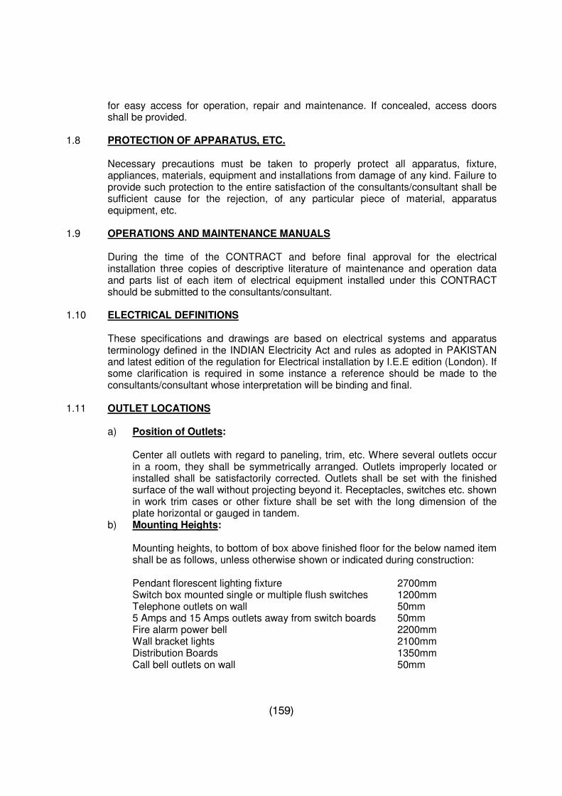
(159)
for easy access for operation, repair and maintenance. If concealed, access doors shall be provided.
1.8 PROTECTION OF APPARATUS, ETC.
Necessary precautions must be taken to properly protect all apparatus, fixture, appliances, materials, equipment and installations from damage of any kind. Failure to provide such protection to the entire satisfaction of the consultants/consultant shall be sufficient cause for the rejection, of any particular piece of material, apparatus equipment, etc.
1.9 OPERATIONS AND MAINTENANCE MANUALS
During the time of the CONTRACT and before final approval for the electrical installation three copies of descriptive literature of maintenance and operation data and parts list of each item of electrical equipment installed under this CONTRACT should be submitted to the consultants/consultant.
1.10 ELECTRICAL DEFINITIONS
These specifications and drawings are based on electrical systems and apparatus terminology defined in the INDIAN Electricity Act and rules as adopted in PAKISTAN and latest edition of the regulation for Electrical installation by I.E.E edition (London). If some clarification is required in some instance a reference should be made to the consultants/consultant whose interpretation will be binding and final.
1.11 OUTLET LOCATIONS
a) Position of Outlets:
Center all outlets with regard to paneling, trim, etc. Where several outlets occur in a room, they shall be symmetrically arranged. Outlets improperly located or installed shall be satisfactorily corrected. Outlets shall be set with the finished surface of the wall without projecting beyond it. Receptacles, switches etc. shown in work trim cases or other fixture shall be set with the long dimension of the plate horizontal or gauged in tandem.
b) Mounting Heights:
Mounting heights, to bottom of box above finished floor for the below named item shall be as follows, unless otherwise shown or indicated during construction:
Pendant florescent lighting fixture 2700mm Switch box mounted single or multiple flush switches 1200mm Telephone outlets on wall 50mm 5 Amps and 15 Amps outlets away from switch boards 50mm Fire alarm power bell 2200mm Wall bracket lights 2100mm Distribution Boards 1350mm Call bell outlets on wall 50mm
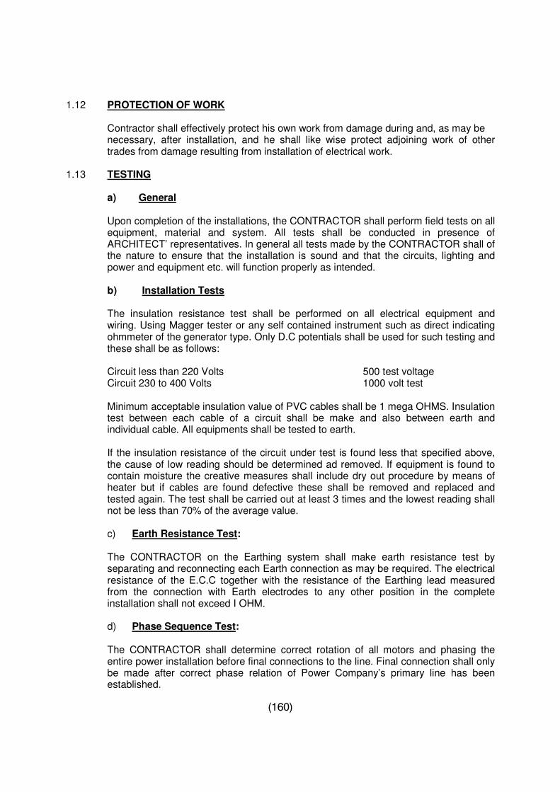
(160)
1.12 PROTECTION OF WORK
Contractor shall effectively protect his own work from damage during and, as may be necessary, after installation, and he shall like wise protect adjoining work of other trades from damage resulting from installation of electrical work.
1.13 TESTING
a) General
Upon completion of the installations, the CONTRACTOR shall perform field tests on all equipment, material and system. All tests shall be conducted in presence of ARCHITECT’ representatives. In general all tests made by the CONTRACTOR shall of the nature to ensure that the installation is sound and that the circuits, lighting and power and equipment etc. will function properly as intended.
b) Installation Tests
The insulation resistance test shall be performed on all electrical equipment and wiring. Using Magger tester or any self contained instrument such as direct indicating ohmmeter of the generator type. Only D.C potentials shall be used for such testing and these shall be as follows:
Circuit less than 220 Volts 500 test voltage Circuit 230 to 400 Volts 1000 volt test Minimum acceptable insulation value of PVC cables shall be 1 mega OHMS. Insulation test between each cable of a circuit shall be make and also between earth and individual cable. All equipments shall be tested to earth.
If the insulation resistance of the circuit under test is found less that specified above, the cause of low reading should be determined ad removed. If equipment is found to contain moisture the creative measures shall include dry out procedure by means of heater but if cables are found defective these shall be removed and replaced and tested again. The test shall be carried out at least 3 times and the lowest reading shall not be less than 70% of the average value.
c) Earth Resistance Test:
The CONTRACTOR on the Earthing system shall make earth resistance test by separating and reconnecting each Earth connection as may be required. The electrical resistance of the E.C.C together with the resistance of the Earthing lead measured from the connection with Earth electrodes to any other position in the complete installation shall not exceed I OHM.
d) Phase Sequence Test:
The CONTRACTOR shall determine correct rotation of all motors and phasing the entire power installation before final connections to the line. Final connection shall only be made after correct phase relation of Power Company’s primary line has been established.
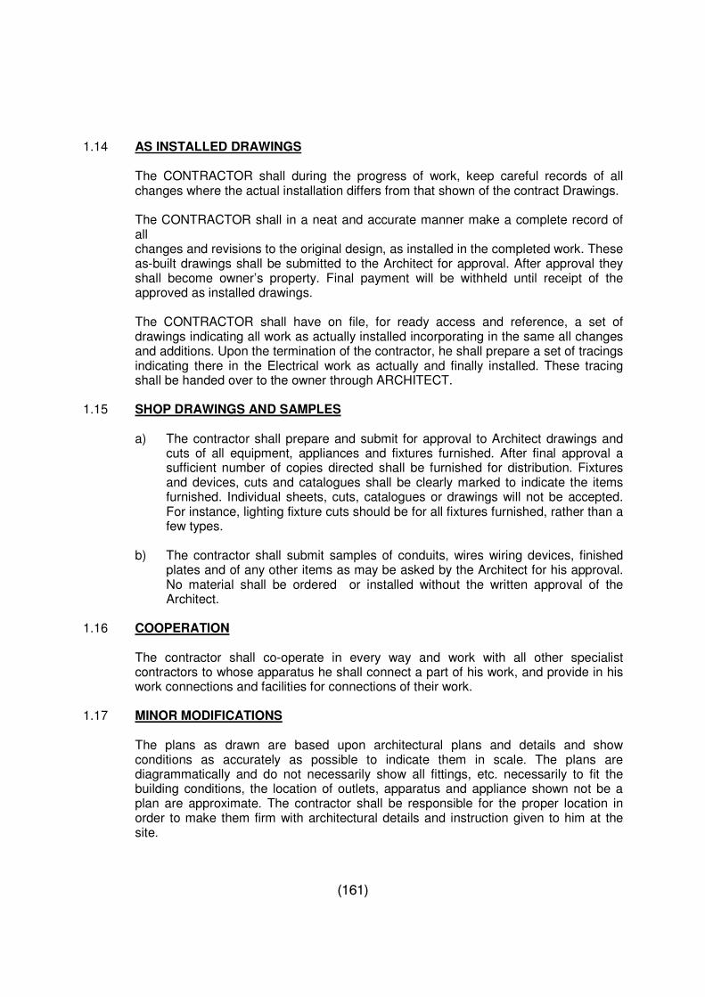
(161)
1.14 AS INSTALLED DRAWINGS
The CONTRACTOR shall during the progress of work, keep careful records of all changes where the actual installation differs from that shown of the contract Drawings. The CONTRACTOR shall in a neat and accurate manner make a complete record of all changes and revisions to the original design, as installed in the completed work. These as-built drawings shall be submitted to the Architect for approval. After approval they shall become owner’s property. Final payment will be withheld until receipt of the approved as installed drawings.
The CONTRACTOR shall have on file, for ready access and reference, a set of drawings indicating all work as actually installed incorporating in the same all changes and additions. Upon the termination of the contractor, he shall prepare a set of tracings indicating there in the Electrical work as actually and finally installed. These tracing shall be handed over to the owner through ARCHITECT.
1.15 SHOP DRAWINGS AND SAMPLES
a) The contractor shall prepare and submit for approval to Architect drawings and cuts of all equipment, appliances and fixtures furnished. After final approval a sufficient number of copies directed shall be furnished for distribution. Fixtures and devices, cuts and catalogues shall be clearly marked to indicate the items furnished. Individual sheets, cuts, catalogues or drawings will not be accepted. For instance, lighting fixture cuts should be for all fixtures furnished, rather than a few types.
b) The contractor shall submit samples of conduits, wires wiring devices, finished
plates and of any other items as may be asked by the Architect for his approval. No material shall be ordered or installed without the written approval of the Architect.
1.16 COOPERATION
The contractor shall co-operate in every way and work with all other specialist contractors to whose apparatus he shall connect a part of his work, and provide in his work connections and facilities for connections of their work.
1.17 MINOR MODIFICATIONS
The plans as drawn are based upon architectural plans and details and show conditions as accurately as possible to indicate them in scale. The plans are diagrammatically and do not necessarily show all fittings, etc. necessarily to fit the building conditions, the location of outlets, apparatus and appliance shown not be a plan are approximate. The contractor shall be responsible for the proper location in order to make them firm with architectural details and instruction given to him at the site.
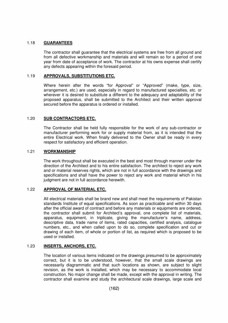
(162)
1.18 GUARANTEES
The contractor shall guarantee that the electrical systems are free from all ground and from all defective workmanship and materials and will remain so for a period of one year from date of acceptance of work. The contractor at his owns expense shall certify any defects appearing within the foresaid period.
1.19 APPROVALS, SUBSTITUTIONS ETC.
Where herein after the words “for Approval” or “Approved” (make, type, size, arrangement, etc.) are used, especially in regard to manufactured specialties, etc. or wherever it is desired to substitute a different to the adequacy and adaptability of the proposed apparatus, shall be submitted to the Architect and their written approval secured before the apparatus is ordered or installed.
1.20 SUB CONTRACTORS ETC.
The Contractor shall be held fully responsible for the work of any sub-contractor or manufacturer performing work for or supply material from, as it is intended that the entire Electrical work. When finally delivered to the Owner shall be ready in every respect for satisfactory and efficient operation.
1.21 WORKMANSHIP
The work throughout shall be executed in the best and most through manner under the direction of the Architect and to his entire satisfaction. The architect to reject any work and or material reserves rights, which are not in full accordance with the drawings and specifications and shall have the power to reject any work and material which in his judgment are not in full accordance herewith.
1.22 APPROVAL OF MATERIAL ETC.
All electrical materials shall be brand new and shall meet the requirements of Pakistan standards Institute of equal specifications. As soon as practicable and within 30 days after the official award of contract and before any materials or equipments are ordered, the contractor shall submit for Architect’s approval, one complete list of materials, apparatus, equipment, in triplicate, giving the manufacturer’s name, address, descriptive data, trade name of items, rated capacities, certified analysis, catalogue numbers, etc., and when called upon to do so, complete specification and cut or drawing of each item, of whole or portion of list, as required which is proposed to be used or installed.
1.23 INSERTS, ANCHORS, ETC.
The location of various items indicated on the drawings presumed to be approximately correct, but it is to be understood, however, that the small scale drawings are necessarily diagrammatic and that such locations as shown, are subject to slight revision, as the work is installed, which may be necessary to accommodate local construction. No major change shall be made, except with the approval in writing. The contractor shall examine and study the architectural scale drawings, large scale and
(163)
full size details, the approved shop drawings of other trades and he shall frequently conduct with the Architect to ascertain any changes that may have been made, and shall be guided accordingly before establishing the precise location of conduit runs, panel, pull and junction boxes, and outlets of all lighting, power telephone, fire alarm and sound system. All outlets covered for partially covered by ducts, piping etc. shall be extended laterally or to underside of it so that same, with proper clearance for fixtures as required.
1.24 INSPECTION, ACCEPTANCE AND REJECTION
a) The contractor shall furnish promptly without additional charge all reasonable facilities, labor and assistance for the safe, convenient inspection and or tests which may be required. All inspection and test will be performed in such a manner as to avoid unnecessary delay of the work.
b) The rights are reserved for all items and places by the architect to reject articles or materials to be furnished here under which in any respect, fail to meet the requirement of these specifications regardless of whether the defects in such articles or material are detected at the point of manufacture or after delivery to the site. If the architect, through an oversight or otherwise has accepted unsuitable materials, no matter in what stage or condition of manufacture or delivery, said material may be rejected. Compliance with the specification is the responsibility of the contractor and this shall not be vided by act of commission on the part of the Architect.
c) No inspection or acceptance of, or payment, by the owner of, for any of the
materials described herein shall relieve or release the contractor from any obligation pertaining to the conditions of contract.
d) Appointment of Inspector: The OWNER shall on own discretion appoint
representative for inspection of stores at manufacturer’s work and or at port of embarkation and disembarkation and or at site and his shall be conveyed to the CONTRACTOR who should then keep the representatives duly informed of the progress with copies to be submitted.
1.25 Foundation, Pads, Bases, Supports and Fasteners
a) Channel sills for leveling and support of all floors mounted electrical equipment
shall be provided as part of the electrical work.
b) Where an item of floor-mounted equipment is to be installed, floor and deck loading shall be checked. If it is found that permitted loading have exceeded by direct application of the equipment on the slab or deck, suitable Dun age approved by the Architect shall be provided, to make the electrical work to distribute the weight in a safe manner. The CONTRACTOR shall submit the load of each equipment to the ARCHITECT.
c) All necessary concrete foundation pads and bases exterior to the building for
lighting installation or other electrical equipment installed as part of the electrical work including such base or foundation as detailed on architectural drawings shall be provided as part of the electrical work.
(164)
d) Supporting methods for all electrical equipment and circuitry shall confirm to be best practice, shall utilize only approved materials and shall be in accordance with the standards published by the United States National Electrical Contractor Association B.S.S. specifications.
e) All fastenings to attach electrical work to the building structure shall be of an
approved type, in general, the only acceptable fastening methods shall be as follows.
i. Wood screws on wood. ii. Bolts and expansion shields on concrete or C.C. Masonry. iii. Toggle bolts on hollow masonry. iv. Machine screws approved clamps or welded threaded studs on steel.
1.26 Spares
a) When main equipment is part of OWNER’S supplied material, the 12 months maintenance spares supplied by the equipment manufacturer will be handed over to the CONTRACTOR who will maintain record. For equipment which are part of CONTRACTOR’S supplied material, the contractor will maintain a similar record of consumption of the maintenance spares supplied by the equipment supplier in accordance with the requirement of this contract and hand over the unutilized spare part to the OWNER at the end of the period.
b) Any spare parts required by the CONTRACTOR for satisfactory completion of the maintenance work during the maintenance period but not supplied by the manufacturer, as the CONTRACTOR through his own resources and at his own cost shall procure normal supply with equipment.
c) A list of spare parts as recommended by the manufacturer or as specified for the
maintenance of installation for a period of two years (or as specified otherwise) after expiry of maintenance period shall be quoted. Individual prices shall be quoted for each recommended spare.
1.27 Electrical service Connection
It shall be the CONTRACTOR’S responsibility to intimate the power supply authority and make such tests as required by them to demonstrate confirmation with their regulation prior to their connection to the installation. The extent of work here in specified represents the minimum requirements and the extent of work shall be extended as required to include at no increase in cost compliance and fulfillment of the requirements of the local power supply authority for an installation of this type.
If inspection by the government constituted body is to be carried out, the CONTRACTOR shall be responsible for carrying out him it. If any fee is paid for such inspection CONTRACTOR shall pay the same actual upon presentation of payment receipts.
(165)
SECTION – 2 : INTERIOR WIRING REQUIREMENTS
2.1 SCOPE OF WORK
The work included in this section consists of furnishing all labor, materials, services and skilled supervision necessary for the construction, erection, installation and collection of all circuits and equipment specified herein, shown or noted on drawings, and/0r normally for an installation of this type and its delivery to the EMPLOYER upon completion in all respects ready for use. The extent of work specified herein and/or shown on the DRAWINGS represent the minimum requirements.
2.2 WORKMANSHIP
All materials and equipments shall installed in accordance with recommendations of the manufacturer as approved by the EMPLOYER to be confirmed to the CONTRACT Documents. The workmen skilled in this type of work shall carry out the installation.
2.3 WIRING METHOD
The wiring shall consist of insulated conductors installed in PVC pressure pipe class D (Conduit) BS 3505 or flexible conduit for equipment connections or as shown on the drawings.
2.4 CONDUIT AND CONDUIT ACCESSORIES
The PVC pressure pipe class D (conduit) shall be electric grade manufactured according to BS 3505 1968 PVC pipe. Conduits shall be installed in accordance with applicable codes and regulations. Minimum size of the conduit shall be 25mm unless noted otherwise. Conduit shall be concealed within finished walls, ceilings, and floors were possible and shall be kept 150mm away from parallel runs if flues and steam or hot water pipes. Conduit shall be supported and secured at intervals of not more than 60mm. Exposed conditions shall have runs installed parallel or perpendicular to walls, structural members or intersections of vertical concrete places and ceilings. Field made bends and offsets shall be made with tools, specifically made for this purpose. Change in direction of runs shall be made with symmetrical bends or cast metal fittings. A maximum of two 90-degree bends will be permitted without a pull box. Cursed or deformed conduit shall to be installed. Trapped conduits in damp and wet locations shall be avoided where possible, care shall be taken to prevent the lodgment of plaster, dirt, or trash in conduit, boxes, fittings, and equipment during the course of construction. Clogged conduit shall be entirely freed of obstructions or shall be replaced. Conduits shall be fastened to all sheet metal boxes and cabinets with flanged couplings or with locking and insulation bushing cabinets with flanged couplings or with locking and insulation bushings duly approved by the ARCHITECT. Bushing shall be installed on the ends of all conduits.
These standards and specifications will be same as those of M/S NIC, M/s. Dadex.
(166)
2.5 INSTALLATION
General requirements applying to the installation of the conduits shall be as follows: a) Concealed Conduit Runs
The conduit runs shall be concealed in ceilings, floor slabs, columns, walls, etc. Changes in direction of conduit runs shall be made with sweep bends using bending machine in case of steel conduit or with being spring in case of PVC conduit. Standard conduit bends and elbows may be used to facilitate installation and where conduit runs out of thin slabs. Where conduit is to be concealed in RC work the laying of conduit shall be laid above the bottom reinforcement steel of the slab and shall be firmly secured to the steel in order to avoid displacement during the pouring or vibrating of concrete. After pouring, the conduit shall have a cover of 40mm to 50mm. Junction boxes; pull boxes, outlet boxes, etc. shall be held firmly and shall be flush with the soffits of the slab or beam. The heights these boxes shall thus be appropriately sized. No reinforcing steel shall be displaced to accommodate the instigation of conduit and outlet boxes. Outlet boxes shall be installed in beams. In general all embedded conditions shall be located in the physical center of the particular section of concrete. All opening through which concrete may leak should be carefully plugged and boxed they shall be suitable protected from filling with concrete.
All ends of conduit shall utilize flaring prevent sharp edges of conduit ends from cutting or damaging wires and cables to be pulled through them.
Conduits passing through expansion joints in concrete slabs shall be provided with expansion fittings.
Conduits to be installed in already poured RC members shall be placed in chases such that a minimum cover of 1.25” is available before plastering. Chasing routes shall be determined after co-ordination and clearance with all other trades. Holes for conduits passing through RC members shall be of minimum possible diameter and cleanly made. Conduits shall be run at least 6” away from flues, steam or water pipes.
b) Conduit on Surface
Exposed runs of conduits shall be indicated on the DRAWING. Conduits shall be firmly held to bearing surface by means of clamps, saddles, brackets, etc. surface rawal plugs or Phil plugs shall be used for fixing of such supports. In cases where the use of such plugs is not feasible, wooden plugs may be used with prior permission of the CONSULTANTS, such that these are fixed a maximum distance of 30” o.c. Straight runs of conduit shall run not more than 18” to 24” below the slab. If hindrances are encountered, conduits shall be run around, above or below such hindrance, as the case may require, and then the run shall continue at the same level as before. Exposed conduits and accessories shall be painted in approved anti-corrosive paint before and after installation in case of steel conduits. In all areas where conduits may be exposed to wet conditions, columns, etc., shall be mounted with a minimum gap of 6mm in
(167)
between. In no case shall a conduit be mounted flush or in contact with such bearing surfaces. A cross beams, plain stamped saddles shall be used. Samples of all such supporting devices shall be submitted to the ARCHITECT for approval prior to their incorporation in the work.
c) Conduit in plain concrete
Conduit shall not be placed in plain concrete such as cement toppings on R.C slabs, without prior approval of the ARCHITECT.
d) Conduit through Roof
Where conduit penetrates the roof seal, suitable pitch pockets or load flashing shall be provided. Shop drawings shall be provided for method used.
e) Conduit in Furred Spaces
In general, conduits shall be anchored and strapped to the building structure. Conduit shall not be installed resting on ceiling furring channels or attached to furred ceiling hanger wires without the CONSULTANTS written approval.
f) Straps and Hangers
Straps, suitable clamps or hanger to provide a rigid installation shall substantially support conduit. Perforated straphanger and twisted wire attachments will not be acceptable. In no case conduit shall be supported on other pipe.
g) Joints and Connections
Couplings and threaded connections in threaded conduit shall be made up watertight. All joints shall be cut square, reamed smooth and properly threaded. No running threads shall be fitted with an approved lock nut and brass bushing forming an approved right bond with box. Plastic bushings may be installed provided lock nuts are installed both inside and outside of the enclosure to which the conduit is attached.
h) Wiring Cables
All wiring cables should be copper. The cables shall be PVC insulated suitable for use in conduit or trucking. Wire connectors of insulated material or solder less pressure connectors properly taped shall be utilized for all splices. Soldered mechanical joints insulated with taps shall be kept to a minimum. Vinyl tape of suitable quality is acceptable in lieu of rubber and friction tapes. All devices and methods utilized or splicing and/or terminating cable shall be suitable for use with copper wires and shall be in strict accordance with the cable manufacture’s recommendations.
The BSS standards and specifications of wires and cables will be same as those of M/s Pakistan Cables (Pvt.) Ltd.
(168)
i) Conduit Sizes Conductor sizes shall not be less than the sizes indicated. Branch circuit conductors shall not be smaller than 1.5sq.mm. Remote control and single circuit conductors shall be not less than 2.5sq.mm.
j) Wire and Cable Installation All wires and cables shall be arranged to provide bends of reasonably large radii, whether run in conduit or on timber battens. Minimum radii shall be 10 times the overall diameter of the cables. Wiring between terminations shall be continuous and joints or connectors shall not be used unless prior approval of the ARCHITECT. On all wiring for HAVC equipment, live load and neutral shall be contained in the same conduit, and every single pole switch and circuit breaker in a 2 wire derived from 3 wire circuit or 4 wire circuit or supply must be fitted in the phase conductor or such supply. The quantity and size of cables contained in any one conduit shall not exceed the numbers as below, as per IEE Regulations:
Wire Size (mm) Conduit Size 20mm 25mm 32mm 1.5 1.5 10 17 31 2.5 2.5 7 11 20 4 4.0 5 9 16 6 6 4 7 4 10 10 2 4 7 16 16 - 3 5 25 25 - 2 3 35 35 - - 2 50 - - -
k) Water in Conduits
Water that has entered a conduit system shall be removed by drawing swabs through the conduits, or an alternate suitable method with a prior approval of the ARCHITECT. No cables shall be pulled until the water has thoroughly dried out.
(169)
l) Stripping off Insulation
The insulation of cables shall always be brought into fixtures such as luminaries, accessories, etc., to which cables are connected. All openings where insulation is removed shall be sealed by means of a plastic compound or other means with prior approval of the consultants.
m) Earth Continuity Conductor (ECC)
Circuit and sub-main wiring shall have an earth continuity conductor (ECC) as per IEE regulations, but not less than 2.5mm, run alongside it and bonded to all its fittings, as well as all other metal work not intended to carry current. When cables are run in conduits, ECC shall be run in the same conduit. The maximum continuity resistance form any point of the installation including the earth continuity and Earthing lead to the earth electrode shall not exceed one ohm.
The removal of insulation from the individual cores shall be carried out by thermal insulation removers and not be cable knives combination plies or side cutters as is conventionally practiced.
2.6 CONDUCTOR IDENTIFICATION
The conductor identification of branch circuits shall be by color coding. Control circuit conductor identification shall be made by color coded insulated conductor, plastic coated self sticking printed markers, permanently attached stamped metal foil makers, or equivalent means as approved by the ARCHITECT. Conductor identification shall be provided within each enclosure where a tap, splice or termination is made. Control circuit terminals of equipment shall be properly identified. Terminal and conductor identification shall match to that shown on approved shop drawings. Hand lettering or marking is not acceptable.
2.7 OUT LETS
Each outlet in the wiring or conduit systems shall be provided with an outlet box to suit the conditions concerned. Where outlet boxes are exposed to the weather or normally wet locations, including flush and surface mountings on exterior surfaces of exterior walls exposed on walls and in explosive locations, boxes shall be of the CST metal type having thread pubs. Boxes in other areas shall be of the black enameled sheet steel or zinc coated sheet steel type. Each box shall have sufficient volume to accommodate the number of conductors entering the boxes, in accordance with the code requirements. Ceiling and bracket outlet boxes shall be not less than 3” rectangular except the smaller boxes may be used where required by the particular fixtures to be installed or approved by the CONSULTANTS. Boxes installed in concealed locations shall be set flush with the finished surface and shall be provided with the proper type expansion rings or plaster cover where required.
a. Boxes for use with conduit system: shall be not less than 37.5mm deep except where lower boxes are required by structural conditions and are approved by the ARCHITECT. Switch and socket outlet boxes shall be not less than 90 x 90 x 75mm. Telephone outlets shall be sized as
(170)
recommended by the telephone department for the installation shown on the drawings. All boxes shall be concrete tight where installed in concrete or other fluid material.
b. Pull Boxes shall be not less than the minimum size required by the codes
and shall be constructed of heavy gauge sheet steel. Boxes shall be furnished with screw fastened covers for multiple cables passing through a common pull box, the feeders shall be tagged to indicate clearly the electrical characteristics, circuit number and panel designation.
The maximum spacing between pull boxes on conduit runs shall be as follows: 1. Straight Runs 100ft. 2. Runs with one 90 degree bend 50ft.
The maximum length of all inspection/pull boxes shall be four times the cable manufactures recommended bending radius of the respective cable.
2.8 Outlet Cover Plates
Where not integral with the device shall be of the one piece type and shall be provided for all outlets to suit the devices installed. Plates on unfinished walls or on the fittings shall be of primed sheet steel having rounded or beveled edges. Plates on finished walls shall be of brushed bronze or bronze plates brass, provided with beveled edges. Screws shall be of metal with counter sunk heads, in a color to match the finished wall surface without the use of mats or similar devices. Plates shall be installed vertically and with an alignment tolerance of 1.50mm. The use of sectional type device plates will not be permitted.
2.9 Socket Outlets
a) In general socket outlets are 3 wire, line neutral and ground, 5/15/20 Amps, 250 volts, with grounding slots.
b) All socket outlets in finished areas shall be flush mounted. Waterproof socket
outlets shall be installed in cast metal boxes, with screw cap to cover outlet.
Switched socket outlets with or without neon light will be 87mm x 87mm for 1-gang and 147mm x 87mm for 2-gang with or without neon lights. (E 15/5N, E 15/5, E15, E15N, E25, E25N, E426/15). There will also be polycarbonate thermal plastic, fire resistant, operation life 50,000 times (min), zero percent power losses on terminals, no sparking on terminals, 100% flexibility against voltage fluctuations.
All these will be as per BS.3676 British Standard and Specifications and those of M/s Clipsal Company.
2.10 Switches
In general switches shall be 5Amps in flush mounted installations or where surface mounted with covers of an identical size with the out let box. Where the DRAWINGS indicate two switches side by side or switch and receptacle side by side, they shall be

(171)
mounted in a multiple gang box with appropriate cover. Finish on all plates in painted area shall be brushed bronzed or as approved by the ARCHITECT. The sizes of these switches will be 87mm x 87mm for 1 gang, 2-gang, 3-gang, 4-gang and 5-gang. 1-way, 2-way, 2-terminal whereas size will be 147mm x 87mm for the gang, 1 way, 2 terminal flush type switches (E31/1/2A, E32/1/2A, E33/1/2A, E34/1/2A, E35/1/2A, E36/1/2A)(E-series). These will also be polycarbonate thermal plastic, fire resistant, operation life 50,000 times (min), zero % power losses on terminals, no sparking on terminals, and 100% flexibility against voltage fluctuations. The entire etc. will be as per BS: 3676 British Standards and specifications and those of M/s. Clipsal Co. or as approved by the CHIEF ARCHITECT.
(172)
SECTION – 3 : CABLES AND ACCESSORIES
3.1 GENERAL
Power cables conforming to these specifications, described in the BOQ and as shown on drawings shall be supplied, tested and installed. The cables shall e manufactured as specified hereunder.
3.2 11/15 KV POWER CABLES (H.T CABLES) All XLPE cables shall be manufactured to I.E.S. standard 502 or BSS-5467. The XLPE cables shall be provided with extruded semi conducting conductor screen over stranded circular copper conductors before XLPE insulation is provided. On each core of conductor an other layer of extruded semi-conducting core screen and copper tape screen are provided. The number of core required then shall e put together and the antisepses filled with non-hygroscopic fiber filler and binding tape. The core is extruded with another PVC bedding.
Galvanized steel Armour is provided underneath an overall PVC sheath.
11-KV XLPE cables shall be manufactured by M/S Pakistan Cables Ltd. or M/s. Pioneer Cables Ltd. or as approved by the Consultants In-charge. The high-tension cables shall be cross-linked polyethylene (XLPE) insulated of 11/15 K V grade. The conductor shall be of high purity copper stranded circular conductor. The conductor shall be provided with conductor screening with a layer of semi conducting cross-linked to polymer applied over the insulation. The cross shall have copper tape screened. The cable shall be PVC bedded, armored, and PVC over sheath. The Armor will comprise galvanized steel wire. The cable in general will comply with IEC 502-1978. The jointing accessories shall be of manufacturer of repute. The cold pouring resin-jointing system shall be applied. The resin shall be nontoxic bonding the thermoplastic sheet cable material with excellent electrical and mechanical prosperities. The resin shall two spare ingredients, a power and a liquid mixed in power bag. The mixed resin shall be given the time required for setting then back filling applied. For conductor and Armor connections, compression fitting of identical specification shall be used. The XLPE cable termination shall be made s shown on the drawings and shall be based on heat shrinkable material, it is necessary to make of the protective armoring. This to be done either by mechanical glands or by an alternative armor clamping arrangement.
3.3 L.T. CABLES
All the low tension cables shall be of size specified on the drawings or stated in the schedule of quantities, single core, 3 cores, of 3-1/2 cores, 4 cores, PVC insulated and PVC sheathed. The cables shall be used either in the floor trenches or in conduit and therefore should be suitable for above conditions. The low tension cables shall be manufactured to the requirements of B.S. 2004, B.S.
(173)
6004, B.S. 3346, B.S 6346, latest or VDE 0271 and rated at 250/400 and 600/1000 volts as the case may be. The cables for steel lighting shall be with split concentric neutral to B.S.S. 4553/latest. The cables shall be manufactured by approved manufacturer.
The conductor shall be annealed copper conductors, single or stranded, circular or shaped as the case may be, to B.S.S.6360/69. The conductors specified for use in the cables shall be at least 98% IASC conductivity.
The reference temperature for the purpose of determining the standard resistance of the conductors shall be 20 degree centigrade. The conductor shall be insulated with poly-vinyl-chloride insulation. The minimum thickness of the insulation shall be in conformity with the specifications to which it is manufactured.
On all multi-core cables proper markings for core identification shall be provided to B.S. specifications.
Power cables shall be multi-core cables, insulated and sheathed, armored or un-armored as required/approved. Various conductors forming the cables shall be laid together and voids shall be filled with soft plastic or fibrous materials so as to give a circular shape to the cable. A tough PVC shall be extruded over the cables so as to coyer the insulated conductors and fillers.
Where armoring is required, a soft PVC jacket shall be provided over the laid up cables. Steel wire armoring shall be applied on a tough PVC sheathed extruded over the cable so as to cover the insulated conductors fillers, jacket and armoring. Complete identification of the cable together with owner’s identification markings if required shall be embossed on the final over sheath of the cable at every meter length. The following tests shall be carried out by the manufacturers: i. Dielectric strength test. ii. Instantaneous and long-time break down strength test. iii. Temperature rise test. iv. High voltage test.
Test certificates covering all these tests shall accompany the cable supplied by the contractor. After carrying out the tests as laid down in these specifications both ends of the cables shall be sealed at the manufacturer’s works.
The cables shall be delivered wound over strong drums and completely protected in suitable manner to protect any injury to the cables during transportation and handling. The direction of rolling shall be clearly marked with bold arrows on both faces of the drums. The owner may require the Consultants/Consultant to witness the tests as specified herein and the contractor shall make necessary arrangements for the presence of the consultants on such tests and obtain their signature in testimony thereof without any cost to the owner.
(174)
The L.T cable end box shall be suitable for termination and sealing 3 ½ core 1000 volts, PVC insulated or armored and served cable of size specified confirming to B.S. 480, part-1 , 1954 and as used on 3 phase, 4 wire, 50 cycle system. Brass wiping glands of the universal, type suitable for a minimum size of cable shall be fitted to the box. The gland shall be tapered and grooved to facilitate cutting to suit cable of greater diameter up to the size of 300mm2. The box shall be made of ferrous material and shall be painted with corrosion resisting paint preferably in grey color. The box shall be fitted with horizontal insulator bushing placed vertically on above the other to suit bus bar connections. Insulator shall be made in one piece of glazed porcelain and shall confirm to B.S 223: 1956. Clamps for clamping and bending the armor of the cables to the terminal box and other insulation material s shall be provided where needed.
3.4 CABLE TERMINATIONS All PVC power cables shall be terminated with suitable tinned brass cable glands for securing the armor wires and incorporating a packing ring for exclusion of water and moisture. The cables shall be secured at required spacing by means of cleats fixed to walls or roofs or hangers and where multiple runs occur performed metal tray made of heavy gauge-galvanized steel shall be used.
3.5 CABLE MARKER For underground installation cable position markers shall be sited in the ground where cables change direction and at 30-meter intervals along straight runs of the cables. Markers shall also be provided to locate the position of joints. Cable markers shall be made of cast iron. Anyone of the following words shall be embossed/engraved for the identification of cable routs. 11000 V cable 440 V cable
11000 V cable joint 440 V cable joint
The markers shall comprise of a cast iron circular disc of 115mm dia and 10mm thick to which an angle iron 25 x 3mm bar 710 mm long shall be riveted at one end. The end of the bar shall be fork-opened up to a length of 75mm. This end shall be embedded in a cement concrete block ratio 1:3:6 to a length of 180mm. The concrete block shall have a shape of truncated pyramid with base dimensions of 305x305mm and top dimensions of 152x152mm and a vertical height of 200mm.The cable marker shall be buried in the ground such that its total above ground level is 267mm.
3.6 CABLE JOINTS The contractor shall be in possession of a cable jointing kit and all termination, shall be made by a bona-fide and experienced cable jointer. All cable termination boxes kits and glands shall be of recognized makes and complete with claw clamps, ferrules, lugs, tapes, solder and jointing compounds.
3.7 INSTALLATION INSTRUCTIONS
(175)
The contractor shall be under obligations to provide all labor, material and accessories for the installation on cables shown on the drawings and listed in the BOQ confirming to the specifications in this section. The contractor shall provide without any extra cost, all material for termination of cables such as lugs, solders, clamps, supports, ferrules, fluxes, tapes, fixing pins, identification tags, Earthing clip, straps for a complete terminal jointing operation in accordance with the best modern practice. For underground cable installation the depth of digging the trench shall be such that the top surface of the cable shall not be less than 900mm and more than 1100mm from the finished ground level. It will be contractor’s responsibility to obtain the true trench levels. Cable routs indicated on the drawings shall be followed unless otherwise specified or agreed to by the consultants/consultant. Where change in direction of cable is necessitated, the bending radius of the cable shall not be less than the diameter of the cable drum or 12-times the diameter of the cable whichever is greater. All road crossings the cable shall pass through 100/150mm dia PVC pipes shrouded in cast concrete , the mouth of which shall be sealed with cable bitumen compound of approved quality after drawing the cable. The road cuts shall be first filled with mud and 50mm size ballast up to 182mm level below the road surface and after ramming it properly 150mm thick layer of cement concrete 1:3:6 shall be laid over it. The cushion of sand to be provided in the trench before laying the cable shall not be less than 75mm and after laying the cable 150mm. The total depth of cushion of sand shall not be less than 225mm. Over the final layer of sand, cable marking tiles/bricks or concrete masonry blocks of adequate strength 2” thick and 300mm x 200mm in size shall be provided to the satisfaction of the Consultants/Consultant. The rest of trench shall be back filled with earth in 150mm layers and rammed properly before dressing. All trenches and holes dug for laying the cables shall not be left open and unprotected for any length of time without completing the job. And backfilling it to the satisfaction of the Consultants/Consultant. Where trenches are left open due to some unavoidable reasons the contractor shall exhibit suitable danger signals such as banners, red flags and red lamps etc. etc. All cables shall always be lead out or lead into the ground through 2.5-meter long G.I pipe of 75mm dia. Or size as approved by the Consultants/Consultant. The length of pipe in the ground shall be 600mm. The pipe should be attached to the poles with approved clamps. Markers of approved design and inscription shall be installed as specified. For installation of cable in perforated metal trays, the cable shall be tied or bunched properly in an approved manner. Similarly for installation of cables on cleats or raceways approval of the Consultants/Consultant shall be obtained.
3.8 MEASUREMENTS For the purposes of measurement this item shall be treated as actual lengths of cables installed in meters at site.
(176)
SECTION – 4 : SWITCHGEAR AND RELATED EQUIPMENT
4..1 GENERAL
a) All apparatus and equipment specified hereinafter in this section shall fully confirm to current standards of BSS to the extent applicable to each type and class of equipment and apparatus described, and individually bear the seal of manufacturer.
b) To the maximum extend feasible all such apparatus and materials shall be of one and the same manufacturer.
c) The type, class, and catalogue number hereinafter stated and employed to
establish the class and quality of apparatus and equipment required for this work.
4.2 ENCLOSURES a) The enclosure shall be of M.S sheet steel not less than 16 SWG dust protecting
for all apparatus mounted inside the building.
b) Ferrous parts of dust protecting type enclosure shall be adequately dust protected and shall be finished with a coat of paint stove dried and hardened.
c) Weatherproof type enclosure shall be provided with hot dip galvanized coating
complying with BS 729. A decorative finish is not required.
d) Provision for locking shall be provided unless specifically asked by the ARCHITECT not to provide.
e) Fixing holes in the dust protecting type enclosure may be inside or outside the
enclosure. Weather proof type enclosure will have external fixing lugs.
4.3 BUS-STRUCTURE a) Bus-bars shall have 98% conductivity, round edge, silver plated copper sized
2000 Amps per 25mm2 and shall be braced for 50,000 amps RMS symmetrical short circuit current.
b) Bus shall be mounted on supports of high impact, non-tracking insulating materials.
c) Provide a full length ground bus in the rear of each cubicle.
4.4 METERING EQUIPMENT Where mentioned on the Drawings provide material as detailed below.
a) One 112.5mm square 1% accuracy 250 degree indicating scale voltmeter having 0-500 volts scale.
b) One seven position voltmeter selector switch, 1-2,3-3,3-2,1-N,3-N and OFF.
(177)
c) One 112.5mm square 1% % accuracy 250 degree indicating scale ammeter
having required scale. Use 3 ammeters if asked. d) One flush type ammeter selector switch, 1,2,3 and OFF. e) Three required ratio current transformers.
4.5 CIRCUIT PROTECTIVE DEVICES
a) Molded case circuit breaker
Molded case circuit breakers shall be panel mooted having not less than 25,000 amps RMS symmetrical short circuit capacity. Trips shall be standard dual magnetic type or solid-state type with built in ground fault sized as shown on the drawings. Except where shown specifically breakers shall be manually operated.
b) Miniature Circuit Breaker
The miniature circuit breaker shall have built in overload and short circuit protection mechanism. The unit shall be suitable for rupturing capacity of 2500 amps RMS and 2000 switching operations.
c) Fuses
All fuses shall be totally sealed, HRC, complying fully with BS-88 for BS-11361. The fuses shall have category duty of AC-46 and fusing factor of Q-1. Where fuses are used in machine have fusing factor of Q-2. Where fuses are employed to provide backup protection to mould case or miniature circuit breakers their rating at particular point shall suit the short circuit level.
These will have standardized to 5 module types (in the pursuit of ever easier operation and allowing denationalization and standardization of the panel design), panel cutout design unified to include 30-800A frame, cassette type accessories (it provides flexibility when upgrading circuit), improved performance and safety (PSS-II) because of IEC 60947-2 compliance, rated service short circuit (Ics) will be equal to 100% Icu Utilization category ‘B’ (it is regulation on application with respect to selectivity), standardized as suitable for isolation and dispatching. Class-II insulation, IEC-664 (double insulation to make it safer than ever), digital current evaluation delivers a higher level of protection (safer and more reliable power), standard pre-alarm system lights LED and output signal (alarm function monitors and anticipates interruptions),coordinated protection for multiple(6) tripping characteristics improved protection against fluctuations in the load current, Neutral pole overload protection for 4-wire electronic circuit breakers (improved protection and safety), portable tester facilities checking and maintenance (i) Long-delay tripping (ii) Short-delay tripping (iii) Instantaneous tripping, (iv) Pre-alarm characteristics.
(178)
(These standards and specifications will be same as those of M/S Mitsubishi Electronic Co. and M/s ABB).
4.6 CIRCUIT BREAKER COMBINATION STARTERS
Circuit breaker combination starter shall be as follows: a) Full draw-out (plug-in) type (except load terminals) made in standard modular
sizes so that a starter form one motor control center can be moved to another motor control center without modification. It will not be necessary to remove control wiring from terminal blocks to withdraw the starter unit.
b) Circuit breakers in combination with the motor starters shall be of high interrupting capacity type having a minimum interrupting ability of 14,000 amps RMS symmetrical at 380 volts. Circuit breakers shall contain an auxiliary switch to disconnect control power when breaker is turned OFF.
c) Overload relays shall be provided in each let of the starter. Operation of the ‘rest’
button will not cause the starter to drop out.
d) Each starter shall be wired for a control voltage of 220 volts.
e) Starter operating coils shall be pressure molded hermetically sealed so that they will not bubbles, melt or extend so that they will not prohibit the starter from dropping out upon coil failure.
f) Each starter shall be provided with 220 volts, red running pilot light, and a hand-
off automatic or start-stop push button as required. Pilot light will be operated by an interlock contact on the starter placed across the operating coil.
g) In addition to the ‘Holding Interlock’ and the pilot light interlock, each starter shall
contain two extra interlock. These interlocks will be capable of being covered to normally close in the field.
h) Each starter shall be provided with a back luminous nameplate with 3.8mm high
white letters engraved to identity served.
4.7 DISCONNECT SWITCHES The disconnect switches shall be iron clad with or without fuse as noted. The switch shall be heavy duty double isolation quick make. Quick breaks and provided with pad locking arrangement. Disconnect switches shall be provided at each motor that is out of sight.
4.8 MOTOR CONTROL CENTERS a) Motor control centers shall be combination fuse/circuit breaker and starter type of
the size and rating as shown on the Drawings and designed, tested and assembled in accordance with NEMA or BSS standard.
(179)
b) The enclosures shall consist of standard modular cubicles bolted and bussed together to form a rigid, structure having the following features in each cubical, top and bottom lateral wiring pull boxes, one vertical wire way per vertical grouping of starter, capability making the addition of future cubicles by simply bolting on a new cubical and making the addition of simple splice plates to the main bus. All doors shall be formed up on all sides and shall be equipped with captive screw fasteners and concealed hinges.
Bus structure shall be as follows: Silver plated, 89% connectivity copper with provisions for coordination with incoming cables as indicated on the Drawings.
- Bracing shall be good for fault level of kA.
- Bus bars shall be supported on high impact, non tracking insulating
material.
- A ground bus shall be provided across the bottom of cubicle.
- Horizontal bus shall be rated for amps specified for each MCC and shall be braced to withstand short circuit stresses of, Amps RMS symmetrical at 380 volts.
- Bus shall be sized to limit temperature rise to 50 degree above a 40 degree
C Ambient with maximum current density of…… Amps per 25mm square.
- Bus shall be carried with fiberglass to protect for arcing fault to ground conditions.
These standards and specifications will be those of M/S Syed Bhai Electric Co., M/s. Siemens Consulting Co. or as given in the related items of BOQs or as approved by the Consultants / Consultant.
4.9 APPLIANCES, PLUGS AND SOCKETS GENERAL PURPOSE
For certain portable appliances and prepared machines socket outlets and plugs are to be provided and installed as per detail in drawings and BOQ. These socket outlets and plugs shall be wall mounted suitable for 240/415 volts, single phase of 3-phase Neutral + Earth with interlocked switch, made of castration; the rating shall be as per design Drawings requirements.
(180)
SECTION – 5 : DISTRIBUTION BOARDS.
5.1 GENERAL
The distribution boards shall be free standing cubic type or wall mounting type suitable for surface and/or recessed mounting. Each distribution board (D.B) shall be tropical in design, fully dust and vermin proof and liquid repellent. The cabinet housing the main components shall be fabricated from mild steel sheets 16 SWG thick and reinforced with structural steel members welded to it. Front access, mechanically locked and hinged doors, fully gasketed, having one or two leaves depending upon the size of the cabinet provided on each cabinet.
All open able parts shall be provided with gaskets or lining and screwed to the main body with chromium plated screws. The cabinets after fabrication shall be thoroughly cleaned completely de-rusted and greased before applying one coat of zinc or lead-based primer and then two coats of top quality synthetic emulsion or stove enamel paint in battleship grey color. All exposed parts of the DBs shall be covered with 5mm thick Bakelite sheet. A load distribution chart shall be provided in each DB showing the areas fed by each circuit and a suitably sized pocket inside the front door shall be provided for the purpose. Each DB shall be delivered complete with all instrument accessories, rating plates, designations, as approved by the Consultants/Consultant.
Suitable cable entry glands shall be provided as required for floor mounted boards on the incoming cables but for outgoing cables and/or wall mounted boards exact number of conduit entry holes as are required shall be provided with male brass bushes. The bushes shall be tinplated and fully shrouded or housed in gasket compartments.
5.2 COMPONANTS
The main components e.g. molded case circuit breakers, load break switches, HRC fuses and instruments that are required for DB’s as shown on the drawings and as described in the schedule of quantities (BOQs) shall be the same as described in the related section however miniature circuit breakers (MCBs) used in DBs are briefly described hereunder:
5.3 MCBs
The incoming shall have triple pole MCBs suitable for use on 512V 50HZ, AC and out going MCBs shall be single pole or single phase for use on 220V, 50HZ, AC. The ratings are as shown in Drawings and/or described in the schedule of quantities (BOQs).
The MCBs shall be molded case type having hydraulic magnetic short circuit releases, contacts, operating mechanism and arcing chambers.
The MCBs shall be manufactured and tested to BSS 3871/1966, and shall have a rupturing capacity of 7.5 KA. The final circuit MCBs, on the outgoing, shall however be rated 5KA. The MCBs manufactured by clipsal, Marlin & Gerin France or Mitsubishi Japan or as approved by the Consultants/Consultant. The distribution boards shall be manufactured by as approved manufacturer.
(181)
5.4 INSTALLATION INSTRUCTIONS
All labor, equipment, tools, plant and accessories, required to complete the installation, shall be provided by the contractor. The distribution shall be fixed as required in perfectline and plumb. All incoming and out going shall be terminated properly. All earth terminations shall be made of neutral block.
5.5 TESTING
All DBs shall be tested at manufacturer’s works and tests, shall be witnessed by the Consultants/Consultant without incurring any additional expense to the owner.
5.6 MEASUREMENTS Each distribution board for the purpose of measurement shall be treated as lump sum job.
(182)
SECTION – 6 : LIGHTING FIXTURES
6.1 GENERAL
The lighting fixtures are described in the bill of quantities/Drawings with a particular manufacturer’s catalogue number. The fixtures to be offered shall be either of the original manufacturers of whom the catalogue number is quoted or alternatively can be of any other standard manufacturers, but strictly complying as regards the shape quality, ague of material used and the workmanship to that of the original manufacturers. a) The ARCHITECT shall have the absolute right to judge for approval or rejection
the quality and shape of fixture for which the Tenderer shall have to submit samples for approval before commencing on the bulk procurement. Action taken for build procurement of light fixture prior to final approval shall entirely at the risk of the CONTRACTOR.
b) The Tenderer shall have to specifically mention the name of manufacturers of different types of light fixtures, which he is offering and shall become bound to supply fittings of the same manufactures.
c) The lighting fixtures are to be installed indoors or outdoors, and are to be treated
suitable for installations and use in the corresponding situation.
d) All pendant fixtures shall be supplied with required wiring material and down rods for hanging at the height specified along with complete hardware for suspension. Similarly, all bracket fittings are to be supplied with wiring leads and the required fixing hardware.
e) All light fixtures are to operate on the single-phase 230 volts, 50 cycles,
alternating current main supply. A fluctuation of 10% on this declared voltage has to be tolerated and therefore the stating gears to be furnished, particularly with the discharge type of lamps and tubes, has to be of suitable characteristics.
6.2 INCANDESCENT LIGHTING FIXTURES
a) The fixtures shall compromise of the metal part including the lamp holder, with
aluminum cylinder with stove enameled paint, the glass of the heat resisting grade or the opal plexiformed material, fixing or hanging attachment with necessary and connecting wiring leads, etc; requiring co eternal material for their installation.
b) The glass used throughout shall be opal with an absorption factor of 15%.
c) All pendant fixtures shall have suitable canopies constructed of sheet steel store enameled.
d) All ceiling mounted fixtures shall have suitable gallery constructed of heavy gauge sheet metal work with stove enameled with finish.
(183)
e) All screws to be used shall be with counter sunk heads, brass, chromium plated of the required gauge.
f) The flexible wires to be used for the purpose of connecting the fittings with the
permanent wiring shall be rounding, similar to Pakistan cables Ref. No. 09193 Y white in color with a minimum size of 23/. 0076” wherever the wire is exposed for hanging the pendant fittings and is to take the load of fittings. The third core to be connected to the earth terminal of the fittings of fixtures. Where the wires are to pass through the metal road or in bracket fittings, the wire used shall be similar to Pakistan Cables Ref. No. 98182Y.
g) Holders used through out shall besides being suitable for respective type of
service shall be of brass with porcelain inside or screw type porcelain lamp holder for processed glass lamp.
6.3 FLUORESCENT LIGHTING FIXTURES
a) The fixtures shall comprise of the metallic enclosure, reflectors, diffusers or
louvers, high power factor ballasts or choke with matching capacitors, holders, starter bases, fluorescent lamps and complete hanging attachment with suitable canopies.
b) The metallic enclosures shall be constructed of heavy gauge mild steel metal, power pressed to form the desired shape. End plates, etc; to riveted or welded and properly finished after the respective operation. The enclosure shall house the lamp gears and shall have proper ventilation.
c) The metallic reflectors shall be constructed of heavy gauge mild steel metal work
and shall be fixed to the enclosure with adequate number chromium plated screws. The reflector shall be machine pressed to the required shape.
d) The entire metal work shall be stove enameled white finish inside and outside,
through surface making and finishing.
e) The diffusers shall be either transparent or opal plexi material with absorption factor below 15% minimum, 3.8mm thick and of uniform destroy and sturdy construction of the shape and type as per schedule of quantities/Drawings. The fixing arrangement of the diffusers shall be such that it is quickly detachable for the purpose of replacement of lamps, etc.
f) The louvers shall be of unit construction type, molded from semi flexible material
under high pressure, opal color, diamond cut and sturdy in construction. The cutting of the unit shall be at the diamond corners, so as to leave complete diamonds at the end or M.S sheet metal louvers.
g) The ballast shall be of high power factor type of a combination of choke with
matching capacitors; both rated for the type of lamps to be connected to. The ballast shall confirms with reared to the general construction, creep age distances and clearances, high voltage test, temperature rise and endurance as well as the noise level to the relevant standards of B.S.S 2818 part-1: 1962. The capacitors, if separately installed, shall comply with the standards of B.S 4017.
(184)
h) The fluorescent tubes shall be of Bi-pin type 37.5mm dia. of length and wattage
specified in the Bill of Quantities/Drawings. These shall be “cool white” of “Day Light” in color as required. The types shall comply in every detail with B.S 1853:1960.
i) The lamp holders an bases for the starters shall be of bakelite, complying strictly
to B.S 1875.
j) The fluorescent lamp starter shall be of capacitor type suitable for the respective size of the lamp and complying strictly to the provisions of B.S 3772.
k) All wiring for connecting various gear of the fitting shall be suitably clamped. The
ends shall be soldered and terminated in a 2-way porcelain connector. The wire used shall be 23/. 0076 similar of Pakistan Cables Ref. No. 09183Y.
l) The load current per 40-watt fluorescent tube shall not exceed 0.46 amps on 230
volts, 50 cycles, and main supply.
m) The manufacturers shall of the size and shape generally recommended suspension rods and canopies. The rods shall be of minimum 12.7mm size light seamless pipe of 16 gauge thickness and canopy fabricated from heavy gauge sheet in power press both shall be stove enameled white after through surface making and cleaning.
n) The fixtures required to be installed in location where acidic fumes 0r other gases
encouraging the corrosion may be present, shall be provided with the fitting of the corrosion resistant construction employing all white PVC sheet and black nylon covers.
Fluorescent light fittings and fixtures shall be electro-galvanized steel body, fully powdered coated with pyrite’s exclusive pier white. Ripple edge to the body to avoid cut fingers and increase protection against corrosion. Rolled edges to large cable tray. Large terminal blocked positioned to give easy access for termination. Two numbers ballast in twin tube models at one end for faster wiring. Replaceable lamp holders quality approved ballast, capacitor, starter lamp holders and cable and captive cover plate screw. Lamp holders packed inside batten, snap-lock into position without tools. It will be fast, foolproof operation with no additional wiring required. Diffuser will be linear prismatic type will have 604mm (pin to pin) length and diameter 26mm, current 0.44 amps, voltage 103 and power 36 watts. Color temperature (K) and color renderings will be 4300K, 6200K (max) 75 for cool white and day light colors respectively. For 60mm GLS, E27 OR B22 caps 240 volts clear or pearl lamp maxi length forE27 = 104 mm + 3mm (for E22 = 102.5mm = 3mm) and maxi diameter for E27/B22 will be 60mm + 1mm. For main roads etc. lights will have heavily utilization factor, good large control, IP65 protection class for lamp compartment prevents ingress of moisture and dust, easy access to large tray, the bowl is kept in position by means of 3 clips, hence accidental opening of the diffuser bowl will be impossible and SABS 1277 mark
(185)
(Bekasun and bekalux). For parks and public area, the light will have IP55, SABS 1277 standards, corrosion resistant, robust top cover, easy maintenance, housing incorporates all electric gears and will be provided as wall-bracket or post-top fitting (Beka Ray). For façade/flood light, the light will have asymmetric IP65 for high intensity discharge lamps, die-cast aluminum body, 99.9% pure aluminum reflector, anodized and polished for greater reflectivity, PG 13.5 Nylon gland, lamps holder and wiring to BSS, tempered glass for thermal shock resistance, adjustable arming angle, symmetric reflector, approved by CEI-34-21, EN60598-1 and protection IP657.
6.4 BATTERY OPERATED ENERGY LIGHTS
The unit shall be combination of lead acid batteries, battery charger, sealed beam lamp, electrical circuitry. During the normal course the batteries shall be under charging state. When the main power fails, the batteries shall discharge through sealed beam lamps. The changeover shall be instantaneous, the unit shall incorporated 2 Nos. 12 volts 35 amps/hour lead acid batteries solid state silicon controlled battery charger with monitoring circuit, indication lamps showing following conditions.
6.5 CHARGE – POWER – TEST – LIGHTS
The unit shall have two lamps of 12 volts, 45-candle power sealed beam type mounted on swivel neck necessary wall mounting bracket, remote connection cord and 5A 3 pin plug. The unit with all its components shall be guaranteed for safe and useful line of minimum 12 months.
6.6 CEILING FANS AND EXHAUST FANS
These will be best in quality and durable in design, totally enclosed capacitor type motor, insulation quality as required by our extreme weather conditions, available with indication type regulator and dimmer switch, available in size 36”, 48”, 56” and 60”. For exhaust fans, these will be designed for the worst conditions, totally enclosed condenser motor, safety guard and blades. These standards and specifications will be same as that of M/s. GFC fans, M/s. Millat fans and M/s. Royal fans etc.
(186)
SECTION – 7 : EARTHING SYSTEM
7.1 GENERAL
All exposed conductive non-current carrying parts of the installation, comprising of conduit, switch gear, junction boxes, cable trays, etc. shall be efficiently earthed, where the insulation is supplied by a privacy owned transfer or where the supply is obtained from private generating plant in such a way that there is no metallic connection with the commercial public supply, the star point of the transformer or the generator shall be effectively earthed.
Earthing of non-current carrying conductive parts shall be independent of the earthing of star point of transformer or the generator.
The earthing shall be done to comply with the following regulations:
a) Electricity rules 1937 as adopted in Pakistan. b) Chapter 54 “Earthing Arrangements and protective Conductors” of IEE London
wiring regulations 15th edition. c) British standard code of practice CP 1013-1965. d) The specifications given hereinafter.
The earthing arrangement shall be such that:
- The value of resistance from consumers’ main earthing terminal to the earthed
point of supply is in accordance with the protective and functional requirements of the installation and expected to be continuously effective.
- Earth fault current and earth leakage currents likely to occur are carried without
danger, particularly from thermal, Electro-Mechanical and Thermo-Mechanical stresses.
- They are adequately so bust or have additional mechanical protection appropriate
to the accessed conditions of external influences.
- Necessary precaution is taken against the risk of damage to another metallic parts through electrolysis.
7.2 EARTH ELECTRODES
The following types of earth electrodes are recognized unless otherwise called in the Bill of Quantities for the purpose of earthing. a) Earth rod b) Earth tapes or wires. c) Earth plates. d) Earth electrode embedded in foundation e) Metallic reinforcement concrete. f) Metallic pipe system other than metal work of public gas and water services.
(187)
Lead sheaths and other metallic covering of cables not liable deterioration through excessive corrosion; provided that the consent of the owner of the cable is obtained and suitable arrangements exist for the owner of the electrical installation to be warned for any proposed change to the cable that might effect its suitability as an earth electrode wherever the earth plate is specified as earth electrode.
The work shall include excavation of the pit in the soil of SITE at least 30mm away from the building structure, refilling the pit with earth, lime and charcoal, watering, consolidation, and ramming of the layers to full compaction.
The earth plate other than transformer or generator star point earthing shall be 60 x 60 x 5mm copper plate buried in the ground at a depth of 5m or less according to moisture in this start.
Different earth electrodes shall be located 10 meter apart so that resistance shall not overlap the earth electrodes for transformer or generator star point shall be size indicated in the Bill of Quantities. The earthing connection shall distinctly bear indication “Not TO DISCONNECT”.
7.3 MAIN EARTHING TERMINAL
In the installation of main earthing terminal or bar shall be provided to connect the following conductors to earthing conductor.
a) The circuit protective conductor. b) The main bonding conductor. c) Functional earthing conductor.
The main earthing terminal shall be cast and machined in electrolytic copper.
The size of terminal shall be 300 x 100 x 10mm. The terminal shall be suitable for connecting two sets of earthing conductor and 10 or more protective conductor. Suitable number of brass bolt terminal shall be provided for terminating earthing conductor, protective conductors, and sheathing of armored cables.
Provisions shall be made in an accessible position for disconnecting the main earthing terminal from the main of earthing to permit measurement of the resistance of the earthing arrangement. The joints shall be such that it can be disconnected only by means of a tool, and shall be mechanically strong.
7.4 EARTHING CONDUCTOR The connection between earth terminal and earth electrode shall be made by means of earthing conductor. The earthing conductor shall be of size indicated on the drawings or bill of quantities, of soft annealed electrolytic copper. The earthing conductor shall run in G.I pipe or huge pipe of specified size as for as it runs in ground till it enters sub-station or electric room where it shall be fixed on saddles and supports.
The upper end of the jump pipe or G.I pipe shall terminate in a main hole so as to inject water for lowering the earth resistance as and when necessary. There shall be no joint in earthing conductor between the earth electrode and earth terminal.
(188)
The shortest route of the earthing conductor shall be adopted, but sharp bends and joints in all cases shall be avoided. The joint between earthing conductor and earth terminal shall be made by means of sweating sockets, bars nut and bolts and double washers so fixed to make a permanent and positive connection with the earth electrode.
7.5 TESTING
The earth electrode resistance shall be tested for effectiveness of earthing. The test shall be carried out by means of earth tester, the maximum continuity resistance from any point in the installation including earthing conductor to the earth electrode shall not exceed I Ohm. The CONTRACTOR therefore, must ensure that earthing conductor are sufficiently bonded to all metal works other that the currents carrying parts so that the above resistance limit is not exceeded. The testing shall be carried out as per procedure laid down in the regulations for electrical installation 15th edition.
7.6 LIGHTING PROTECTION SYSTEM
The system of lighting protection shall be installed so as to protect the building against lighting, confirming to B.S.S code op practice C.P 326.101 of 1948 (hereinafter referred as C.P 326.101) as per drawing.
The installation shall comprise the following:
a) Network of air terminations. b) Bonds c) Roof Conductors d) Down terminations e) Earth terminations f) Testing point
There shall be air termination points on the building installed 100mm above the finished floor levels as per drawings. The air termination shall be cast and machined in electrolytic copper, confirming to B.S.S 1400, as per drawings. The air termination shall be complete with single pointer, rod as per drawings. The rod shall be of high tensile brass bar, confirming to B.S.S 251C (Grady). The air termination shall be reinforced, so as to withstand the excessive pressure of air during storms.
The bends roof conductor shall be of soft annealed electrolytic copper strips 1” x 1/8” confirming to B.S.S No. 899.
The down conductors shall be of a soft annealed, electrolytic copper strip 12mm x 3mm, confirming to B.S.S 889. There shall be two down conductors for each building as per drawings. Each down conductor shall be equipped with independent testing points, earth termination lead and earth.
The earth termination lead shall be of soft annealed, electrolytic copper strip 12mm x 3mm confirming B.S.S 899.
(189)
SECTION – 8 : TELEPHONE SYSTEM
8.1 GENERAL
a) The telephone installation include following items: Supply and installation of telephone system comprising of steel conduit telephone channel, pull boxes, junction boxes, terminal strips and cabinets.
Supply and drawings of telephone cables, testing and making connections, subject to the approval of T & T Department of Pakistan.
b) The work shall be carried out in accordance with electrical code of practice CP
327-101, OP327-102 of England and to the entire satisfaction of the Telephone department of Pakistan and RCHITECT.
c) The main jumper stand in PDBX rectifier, Telephone Exchange Equipment and telephone instruments, telephone cables, will be supplied and installed by the Telephone Department of Pakistan or by nominated supplier of the OWNER.
d) The earth continuity shall be maintained through out the telephone installation.
An earth terminal in the pull-out box shall be used to feed earth continuity to telephone instruments. The earth continuity wire will be 14 SWG HDBC.
8.2 TELEPHONE JUNCTION CABINET
a) The junction cabinets shall be metal clad, made of safety dead from flush types,
cubical design with hinged doors, built in concealed locks.
b) The cabinet shall be designed for easy access, services and replacements.
c) The cabinets shall be made of heavy 16 SWG mild steel metal with standard concentric knockouts all around at suitable places. The doors of all the cabinets shall be keyed a like.
d) The cabinet shall be proofed against ingress of vermin. The cabinet shall be
designed to accommodate connecting terminals with indicating and marking arrangements. It shall be equipped with terminal as shown in BOQ.
e) The cabinets shall be equipped With PVC molded terminal strips and the screws
shall make of dull chrome plated brass.
8.3 TELEPHONE CABLES a) The telephone cables shall be installed indoor in conduit, under floor tucking, and
outdoor in G.I pipe and shall be designed and built to give efficient and reliable service continuously at the normal voltage, current and audition frequency ratings in the climatic and atmospheric conditions prevalent at SITE.
(190)
b) The telephone cables shall be indoor, PVC insulated with B.S.S 2746 and sheathed. It shall be possible to connect the conductors directly to the equipment circuit or through strip connector housed in the junction boxes and cabinets.
The cables shall be multi-pair as per drawings and schedule of quantities.
c) The conductors shall be of annealed high conductivity tinned copper, diameter
0.6mm weighing 2.7 kg/km PVC covered, nominal all thickness of 0.2mm wires twisted to pairs.
d) The conductor diameter 0.6mm at temperature shall have the following characteristics:
Maximum loop resistance 130 ohms/K.M Minimum insulation resistance 100 Meg. Ohms/K.M Test voltage 300 volts A.C Mutual capacity 160 MF/K.M Operating voltage 60 volts DC.
e) The cable shall drawn in conduit or under floor tucking in accordance with the
telephone layout drawings. All wires shall be continuous between the telephone outlet, junction boxes, and junction cabinet, junction posts and between junction boxes, as applicable in accordance with the drawings.
f) All connections shall be made, marked and identified on the terminal strips provided in the junction boxes, cabinets and the posts.
g) 2-METER length of cable beyond the rubber grommet shall be provided at each
telephone outlet to facilitate connection of telephone instruments.
h) Unless otherwise particularly approved, no wire shall be pulled in until the conduit and trucking system is completed. No grease, oil or lubricant other than powered soapstone shall be used facilitate the pulling of wires.
All the accessories that will be used in telephone, intercom and computer systems will have same standards and specifications as that of M/s Motab Co. and M/s Sysnet Co. or as approved by the Consultants/Consultant.
(191)
SECTION – 9 : TESTING
9.1 GENERAL
Upon completion of the installation the contractor shall perform field tests on all equipment, material and systems. All tests shall be conducted in the presence of the Consultants/Consultant for the purpose of demonstrating equipment or system compliance with specifications.
The contractor shall furnish, install and maintain all tools, instruments, test equipment, material, connections, etc. and furnish all personal including supervision and “standby” labor required for the testing, setting and adjustment of all electrical facilities and their component parts, putting the same into operation.
All tests shall be made with the proper regard for the protection of the equipment, and the contractor shall be responsible for adequate protection to all personal during such tests.
The contractor shall record all test values of the tests made by him on all equipment, giving both “as found” and “as left” conditions. Three (3) copies of all test data shall be given to the Consultants/Consultant for record purposes.
The witnessing of any test by the consultants/consultant do not relieve the Contractor of his guarantees for materials, equipment and workmanship as specified in the conditions of the contract.
9.2 INSULATION TESTS
Insulation resistance tests shall be made on all electrical equipment, using a self contained instrument such as the direct indicating ohmmeter of the generator type. Direct current potentials shall be used in these tests shall be as follows:
Circuit under 230 volts to 400 volts-1000 volts test.
The minimum acceptable insulation resistance value will be 5 Mega Ohms. The Contractor will furnish the test equipment for insulation testing.
Before making connections at the ends of each cable run, the insulation resistance test of each cable shall be made. Each conductor of a multi-core cable shall be tested individually to each other conductor of the group and also to earth. If insulation resistance test readings are found to be less than the specified minimum in any conductor, the entire cable shall be replaced and the new cable tested.
All transformers, and switchgear shall be given an insulation resistance measurement test to ground after insulation but before any wiring is energized. Insulation tests shall be made between open contacts of circuit breakers, switches and between each phase and earth.
(192)
If the insulation resistance of the circuit under test is less than that specified above, the cause of the low reading shall be determined and removed. Corrective measures shall include dry-out procedure by means of heaters if equipment is found to connection moisture. Where corrective measures have been necessary and the insulation resistance reading taken after the correction has been made it should satisfy the requirements specified herein. Repeated insulation resistance maintenance test shall be made twice and at least 12 hours apart. The maximum range for each reading on the 3 successive tests shall not be exceed 20% of the average value. After all tests have been made successfully, the equipment shall be reconnected. Alarm system, telephone system, sound distribution system shall be checked and tested as per manufacturer’s instructions and in the presence of the Consultants/Consultant. Each resistance test shall be made by the contractor on the earthing system, separating and reconnecting each earth connection as may be required by the Consultant In-charge. If it is indicated that soil treatment or other corrective measures are required to lower the ground resistance values, the Consultants In-charge/Consultant will determine the extent of such corrective measures. The electrical resistance of the ECC together with the resistance of the earthing lead measured from the connection with the earth electrode to any other position in the completed installation shall not exceed one Ohm. Earth resistance test shall be performed as per electrical Inspector’s requirements. Where more than one earthing sets are installed, the earth resistance test between two sets shall be measured by means of Resistance Bridge Instrument. The earth resistance between two sets shall not exceed one Ohm.
9.3 TRANSFORMER SWITCH GEAR In addition to the insulation resistance tests on the transformer, a polarity or phase rotation test shall also be made. Auxiliary devices, breather, Bucholz relay etc. shall be tested for satisfactory operation. Each air circuit breaker shall be operated electrically and mechanically, ascertaining that handle mechanisms are operating. All interlock control circuit shall be checked out for proper connections in accordance with the wiring diagrams given by the manufacturer. Services over current trip elements shall be checked against rating of equipment served. Also to be checked for correct size, function of fuses, disconnect switches, number of interlocks, indicating alarms and remote control devices. Nameplates shall be checked for proper designation of equipment.
9.4 OPERATING TESTS The load measurement shall be made on equipment and on all power and lighting feeders. The current reading shall be taken in each phase wire and each neutral wire while the circuit or equipment is operating under actual load conditions. Clip-on ammeter may be used to take current readings. All light fittings shall be tested electrically and mechanically to check whether they comply with the standard specifications. Fluorescent light fittings shall be tested so that when functioning properly no flickering is observed or choke noise is heard.

(193)
The lighting protection system shall be tested for earth resistance and for electrical and mechanical joints. The combined resistance to earth to the whole lighting protection system shall not exceed 5 Ohms.
The Alarm system, telephone system, sound distribution system shall be checked and tested as per manufacturer’s instructions and in the presence of the Consultants/Consultant. After any equipment has been tested, checked for operation etc. and is accepted by the Consultants/Consultant the contractor shall be responsible for the proper protection of such equipment for assurance that subsequent testing of other equipment of systems do not disturb the completed work.