Embed Size (px)
Citation preview
Time Synchronization and Communication Network Redundancy
for Power Network Automation
A thesis submitted to the University of Manchester for the degree of Doctor of Philosophy
in the Faculty of Science and Engineering
2016
Hao Guo
School of Electrical and Electronic Engineering

List of Contents 3
List of Contents
List of Figures .................................................................................................. 9
List of Tables ................................................................................................. 15
List of Abbreviations..................................................................................... 17
List of Devices ................................................................................................ 19
Abstract .......................................................................................................... 21
Declaration ..................................................................................................... 23
Copyright Statement ..................................................................................... 25
Acknowledgement ......................................................................................... 27
Chapter 1: Introduction ............................................................................... 29
1.1 Time Synchronization ................................................................................ 29
1.1.1 Time Synchronization Requirement .............................................................. 29
1.1.2 Conventional Time Synchronization Methods .............................................. 32
1.1.2.1 Dedicated Timing System ............................................................................ 32
1.1.2.2 Networked Timing System ........................................................................... 33
1.2 Communication Redundancy .................................................................... 35
1.2.1 Communication Recovery Time Requirements ............................................. 35
1.2.2 Conventional Communication Redundancy Protocols ................................. 37
1.3 Problems and Issues ................................................................................... 38
1.3.1 Costly Timing System based on Distributed GPS Receivers ........................ 39
1.3.2 Reliability Issue of Timing System based on Distributed GPS Receivers ..... 39
1.3.3 Limitation of Timing System based on NTP/SNTP ....................................... 40
1.3.4 Limitation of Conventional Communication Redundancy Technologies ..... 40
1.4 Motivation and Aim ................................................................................... 40
1.5 Contributions and Publications ................................................................ 43
1.6 Structure of the Thesis ............................................................................... 46
4 List of Contents
Chapter 2: IEEE 1588 Time Synchronization ............................................ 49
2.1 Introduction ................................................................................................ 49
2.2 What is IEEE 1588? ................................................................................... 49
2.3 Clock Types in IEEE 1588v2 .................................................................... 50
2.4 Working Principle of IEEE 1588v2 .......................................................... 54
2.4.1 Best Master Clock Algorithm ....................................................................... 54
2.4.2 Propagation Delay Mechanisms .................................................................. 57
2.4.2.1 Delay Request-Response Mechanism.......................................................... 59
2.4.2.2 Peer Delay Request-Response Mechanism ................................................. 61
2.4.3 Requirement for Ethernet Switches in 1588 Timing Network ...................... 64
2.5 Timestamping for IEEE 1588 Devices ..................................................... 65
2.6 Mapping of IEEE 1588 Messages ............................................................. 67
2.7 IEEE 1588v2 Profiles ................................................................................. 68
2.7.1 Delay Request-Response Default PTP Profile ............................................. 69
2.7.2 Peer Delay Request-Response Default PTP Profile ..................................... 70
2.7.3 IEEE 1588 Power Profile ............................................................................. 70
2.7.4 IEEE 1588 Telecom Profile .......................................................................... 72
2.8 Summary ..................................................................................................... 74
Chapter 3: IEC 62439-3 Communication Redundancy ............................. 77
3.1 Introduction ................................................................................................ 77
3.2 IEC 62439-3 Parallel Redundancy Protocol (PRP) ................................ 77
3.2.1 Overview of PRP .......................................................................................... 77
3.2.2 Structure of PRP Device ............................................................................... 78
3.2.3 PRP Frame ................................................................................................... 80
3.3 IEC 62439-3 High-availability Seamless Redundancy (HSR) ............... 81
3.3.1 Overview of HSR .......................................................................................... 81
3.3.2 Structure of HSR Device ............................................................................... 82
3.3.3 HSR Frame ................................................................................................... 84
3.4 Summary ..................................................................................................... 86
List of Contents 5
Chapter 4: Literature Review of Research on IEEE 1588 and IEC 62439-
3 PRP/HSR ..................................................................................................... 89
4.1 Introduction ................................................................................................ 89
4.2 IEEE 1588 Simulation ................................................................................ 89
4.3 IEEE 1588v2 Hardware Testing in LAN ................................................. 94
4.4 IEEE 1588 Hardware Testing in WAN .................................................. 100
4.5 Combination of IEEE 1588 and IEC 62439-3 ....................................... 103
4.6 Research Objectives ................................................................................. 105
4.7 Summary ................................................................................................... 107
Chapter 5: Simulation of IEEE 1588 and IEC 62439-3 .......................... 109
5.1 Introduction .............................................................................................. 109
5.2 Simulation Tool ........................................................................................ 110
5.3 Design of IEEE 1588v2 Ordinary Clock ................................................ 110
5.3.1 Local_Time Module .................................................................................... 114
5.3.2 Time_Difference_Statistic Module.............................................................. 115
5.3.3 1588_Message_Generation Module ........................................................... 116
5.3.4 1588_Message_Process Module ................................................................. 117
5.3.5 1588_Message_Sink Module ...................................................................... 118
5.3.6 mac Module ................................................................................................. 119
5.4 Design of IEEE 1588v2 End-to-End Transparent Clock ..................... 121
5.5 Design of IEC 62439-3 PRP RedBox ...................................................... 124
5.6 Background Traffic .................................................................................. 127
5.6.1 Approaches to Create Background Traffic ................................................. 127
5.6.2 Traffic Flow for Background Traffic Injection ........................................... 128
5.6.3 Traffic Profile for Traffic Flow ................................................................... 131
5.7 Verification of IEEE 1588v2 Ordinary Clock and End-to-End
Transparent Clock ................................................................................... 132
5.7.1 Simulation Scenarios .................................................................................. 132
6 List of Contents
5.7.2 Simulation Results and Discussions ........................................................... 134
5.8 Verification of IEC 62439-3 PRP RedBox ............................................. 141
5.8.1 Simulation Scenarios .................................................................................. 141
5.8.2 Simulation Results and Discussions ........................................................... 143
5.9 Verification of Compatibility among IEEE 1588v2 Ordinary Clock,
End-to-End Transparent Clock and IEC 62439 PRP RedBox ........... 146
5.9.1 Simulation Scenarios .................................................................................. 146
5.9.2 Simulation Results and Discussion ............................................................. 148
5.10 Summary ................................................................................................. 151
Chapter 6: Hardware Testing of GPS and IEEE 1588 ............................ 153
6.1 Introduction .............................................................................................. 153
6.2 Design of Time Synchronization System ................................................ 154
6.3 Design of Hardware Testbed ................................................................... 159
6.3.1 Performance Requirement .......................................................................... 159
6.3.2 Pulse Difference Measurement ................................................................... 160
6.3.3 Network Packets Capture ........................................................................... 161
6.3.4 Different Network Conditions ..................................................................... 164
6.3.5 GPS Receivers ............................................................................................ 164
6.3.6 IEEE 1588 Ordinary Clocks ....................................................................... 165
6.3.7 Ethernet Switches ....................................................................................... 166
6.4 Testing of GPS Receivers ........................................................................ 166
6.4.1 Long Term Accuracy of GPS Receivers ..................................................... 167
6.4.2 Transient Behaviour of GPS Receivers ...................................................... 170
6.5 Testing of IEEE 1588 Timing System .................................................... 173
6.5.1 Long Term Accuracy of IEEE 1588 Slaves ................................................ 174
6.5.2 IEEE 1588 Synchronization under Excessive Non-1588 Traffic ................ 179
6.5.3 IEEE 1588 Synchronization under Excessive IEEE 1588 Traffic .............. 182
6.5.4 IEEE 1588 Synchronization upon Loss of IEEE 1588 Messages ............... 184
6.5.5 IEEE 1588 Synchronization during Communication Link Loss ................. 186
6.5.6 IEEE 1588 Synchronization upon Complete GPS Signal Loss .................. 188
List of Contents 7
6.5.7 Summary of Testing..................................................................................... 190
6.6 Testing of Interaction between IEEE 1588 and Other Traffic ............ 190
6.7 Summary ................................................................................................... 194
Chapter 7: Implementation of IEEE 1588 for Real Substations ............ 197
7.1 Introduction .............................................................................................. 197
7.2 Principle of AS3 Architecture .................................................................. 197
7.3 Integration of IEEE 1588 into AS3 Architecture ................................... 199
7.4 Feasibility of Substation Wide IEEE 1588 Implementation ................ 202
7.5 Scalability of Substation Wide IEEE 1588 Implementation ................ 204
7.6 IEEE 1588 Timing upon Replacement of Ethernet Switch .................. 206
7.7 Effect of Long Communication Link on IEEE 1588 Timing ............... 208
7.8 Compatibility between IEEE 1588 Devices and IEDs/MUs ................. 212
7.9 Summary ................................................................................................... 216
Chapter 8: Conclusions and Future Work ............................................... 219
8.1 Conclusions ............................................................................................... 219
8.1.1 Simulation Modelling .................................................................................. 220
8.1.2 Simulation Results ....................................................................................... 222
8.1.3 Testbed Setup .............................................................................................. 223
8.1.4 Results for Timing System based on GPS Receivers ................................... 224
8.1.5 Results for Timing System based on GPS Receivers and IEEE 1588 ......... 225
8.1.6 Results for Substation Wide IEEE 1588 Implementation ........................... 227
8.2 Future Work ............................................................................................. 229
Reference ...................................................................................................... 233
Appendix A: Comparison between IEEE 1588 Default Profile and Power
Profile ........................................................................................................... 241
A.1 Difference between Peer Delay Request-Response Default PTP Profile
and Power Profile .................................................................................... 241
8 List of Contents
A.2 Reference .................................................................................................. 241
Appendix B: Benefits and Drawbacks of Different Implementations of
Time Dissemination System ........................................................................ 243
B.1 Quality of GPS Antennas and Receivers and Amount of Installation
Work ......................................................................................................... 243
B.2 Installation of GPS Antennas and Receivers ........................................ 244
B.3 Propagation Delay of Time Reference Output ..................................... 244
B.4 Measurement of Signal Delay ................................................................. 247
B.5 Time Distribution Network and Number of Output Modules on GPS
Receivers ................................................................................................... 247
B.6 Scalability ................................................................................................. 249
B.7 Effect of GPS Synchronization Degradation and Loss ........................ 250
B.8 Requirement of Specialized Ethernet Switches and Time Code
Translators ............................................................................................... 251
B.9 Maintenance and Replacement .............................................................. 252
B.10 Reference ................................................................................................ 255
Word Count: 47,342
List of Figures 9
List of Figures
Figure 1-1: Schematic of Current Differential Protection.................................................... 29
Figure 1-2: Double End Traveling Wave Fault Locator ...................................................... 30
Figure 1-3: Separate Timing Network and Data Network within Power Substation [15] ... 32
Figure 1-4: Propagation Delay Measurement for 1-PPS and IRIG-B [14] .......................... 33
Figure 1-5: Working Principle of NTP and SNTP Protocol [20] ........................................ 34
Figure 1-6: Combined Timing and Data Network in Substation [15] ................................. 35
Figure 1-7: Overview of IEC 61850 Substation Communication [25] ................................ 36
Figure 1-8: Principle of Conventional Network Redundancy Protocols [26] ...................... 37
Figure 2-1: Network of IEEE 1588v2 Clocks ...................................................................... 51
Figure 2-2: IEEE 1588 Ordinary Clocks [44] ...................................................................... 52
Figure 2-3: IEEE 1588 Boundary Clock .............................................................................. 52
Figure 2-4: End-to-End Transparent Clock Measuring 1588 Message Residence Time [40]
.............................................................................................................................................. 53
Figure 2-5: Peer-to-Peer Transparent Clock Measuring 1588 Message Residence Time and
Path Delay [44] .................................................................................................................... 54
Figure 2-6: Principle of Best Master Clock Algorithm ........................................................ 56
Figure 2-7: Master-Slave Hierarchy after Applying Best Master Clock Algorithm ............ 57
Figure 2-8: Delay Request-Response Mechanism ............................................................... 58
Figure 2-9: Propagation Delay between Port in Master State and Port in Slave State ........ 60
Figure 2-10: Peer Delay Request-Response Mechanism ..................................................... 62
Figure 2-11: Types of Switches used in Network with Delay Request-Response
Mechanism ........................................................................................................................... 65
Figure 2-12: Types of Switches used in Network with Peer Delay Request-Response
Mechanism ........................................................................................................................... 65
Figure 2-13: OSI 7 Layer Model [49] .................................................................................. 66
Figure 2-14: OSI Layers and IEEE 1588 Synchronizations ................................................ 67
Figure 2-15: IEEE 1588 Message over UDP over IP over Ethernet [50] ............................ 68
Figure 2-16: IEEE 1588 Message over Ethernet [50] .......................................................... 68
Figure 2-17: Steady State Performance Requirement of IEEE 1588 Power Profile [58] .... 71
Figure 2-18: IEEE 1588 Timing Implemented on IEC 61850 Communication Buses [58] ....
.............................................................................................................................................. 72
10 List of Figures
Figure 2-19: Combination of IEEE 1588 Power Profile and Telecom Profile .................... 73
Figure 3-1: An Example of PRP Network [60] ................................................................... 78
Figure 3-2: Structure of DANP [62] .................................................................................... 79
Figure 3-3: Structure of a PRP RedBox [59] ....................................................................... 80
Figure 3-4: Structure of a PRP Frame [60] .......................................................................... 81
Figure 3-5: An Example of HSR Network [59] ................................................................... 82
Figure 3-6: Structure of a DANH [63] ................................................................................ 83
Figure 3-7: Structure of an HSR RedBox [63] .................................................................... 84
Figure 3-8: Structure of an HSR Frame [63] ....................................................................... 84
Figure 4-1: Simulation Case for IEEE 1588v2 in OMNeT++ [64] ..................................... 90
Figure 4-2: Topologies for IEEE 1588v1 Evaluation [65] .................................................. 91
Figure 4-3: Simulation of IEEE 1588v2 in WAN [66] ........................................................ 92
Figure 4-4: Estimation of Packet Delay Variation using Probing Packets [67] .................. 93
Figure 4-5: Network Configuration to Evaluate the Packet Delay Estimation Method [67]
............................................................................................................................................. 94
Figure 4-6: Testing of IEEE 1588v2 in Real Substation Automation System [6]............... 95
Figure 4-7: Network Topology consisting of IEEE 1588v2 Peer-to-Peer Transparent
Clocks [17] ........................................................................................................................... 96
Figure 4-8: Experiment Setup to Evaluate IEEE 1588v2 Performance when Background
Traffic Presented [68] .......................................................................................................... 97
Figure 4-9: Star Topology with Two IEEE 1588v2 Transparent Clocks [69] .................... 98
Figure 4-10: Ring Topology with Four IEEE 1588v2 Transparent Clocks [69] ................. 99
Figure 4-11: RSTP Ring Topology with 16 Peer-to-Peer Transparent Clocks [70] .......... 100
Figure 4-12: IEEE 1588v1 Master Clock and Slave Clock in WAN [71]......................... 101
Figure 4-13: Implementation of IEEE 1588v2 over SDH Network [72] .......................... 103
Figure 4-14: Multi Port Clock Model for Combination of IEEE 1588 and IEC 62439 PRP
[74] ..................................................................................................................................... 104
Figure 4-15: Implementation of IEEE 1588 / HSR Device [75] ....................................... 105
Figure 5-1: Framework of IEEE 1588v2 Master Clock .................................................... 111
Figure 5-2: Framework of IEEE 1588v2 Slave Clock ....................................................... 112
Figure 5-3: Schematic of Local_Time Module ................................................................. 114
Figure 5-4: Schematic of Time_Difference_Statistic Module ........................................... 115
Figure 5-5: Structure of Sync Message ............................................................................. 116
Figure 5-6: Schematic of 1588_Message_Generation Module ......................................... 116
List of Figures 11
Figure 5-7: Structure of Delay_Resp Message .................................................................. 117
Figure 5-8: Schematic of 1588_Message_Process Module ............................................... 118
Figure 5-9: Schematic of 1588_Message_Sink Module .................................................... 118
Figure 5-10: Timestamping Point of IEEE 1588v2 Simulation ......................................... 120
Figure 5-11: Framework of IEEE 1588v2 End-to-End Transparent Clock ....................... 121
Figure 5-12: Part of Code for Queuing Delay Accumulation in the Pipeline Stage .......... 123
Figure 5-13: Use of Modified Pipeline Stage for Delay Accumulation to 1588 Messages
............................................................................................................................................ 124
Figure 5-14: Framework of IEC 62439-3 PRP RedBox .................................................... 125
Figure 5-15: Schematic of RedBox_Logic Module ........................................................... 126
Figure 5-16: Structure of IEC 62439-3 PRP Frame ........................................................... 126
Figure 5-17: Overall Process of Client-Server Messaging ................................................ 127
Figure 5-18: Baseline Load on the Link between 1588 Master and Slave ........................ 128
Figure 5-19: Framework of “Ethernet_ip_station_adv” Node Model ............................... 129
Figure 5-20: Typical Simulated Network with Background Traffic using Traffic Flow ... 129
Figure 5-21: Configuration of Traffic Flow ....................................................................... 130
Figure 5-22: Multiple Traffic Flow in a Simulated Network ............................................. 131
Figure 5-23: Simulation Scenarios to Verify the IEEE 1588v2 Ordinary Clocks and End-
to-End Transparent Clocks ................................................................................................. 133
Figure 5-24: Traffic Profile for Background Traffic.......................................................... 134
Figure 5-25: Convergence Time of Simulated IEEE 1588v2 Devices .............................. 135
Figure 5-26: Simulation Results to Verify IEEE 1588v2 Ordinary Clocks and End-to-End
Transparent Clock .............................................................................................................. 136
Figure 5-27: Default Configuration of a Switch Model in OPNET ................................... 137
Figure 5-28: Extra Simulation Scenarios to Verify IEEE 1588v2 End-to-End Transparent
Clock .................................................................................................................................. 138
Figure 5-29: Extra Simulation Results to Verify IEEE 1588v2 End-to-End Transparent
Clock .................................................................................................................................. 139
Figure 5-30: Simulation Scenarios to Validate IEC 62439-3 PRP RedBox ...................... 142
Figure 5-31: Simulation Scenarios to Validate IEC 62439-3 PRP RedBox ...................... 144
Figure 5-32: Traffic Injection into PRP RedBox ............................................................... 144
Figure 5-33: Simulation Scenarios to Verify the Compatibility between IEEE 1588v2 and
IEC 62439-3 PRP ............................................................................................................... 148
12 List of Figures
Figure 5-34: Simulation Results to Verify the Compatibility between IEEE 1588v2 and
IEC 62439 PRP .................................................................................................................. 149
Figure 6-1: Centralized GPS Antennas and Receivers with Legacy Output (1-PPS & IRIG-
B) ....................................................................................................................................... 155
Figure 6-2: Centralized GPS Antennas and Receivers with IEEE 1588 Output ............... 156
Figure 6-3: Distributed GPS Antennas and Receivers with Legacy Output (1-PPS & IRIG-
B) ....................................................................................................................................... 157
Figure 6-4: Definition of Transfer Time by IEC 61850 [13]............................................. 160
Figure 6-5: Overview of Measurement Server [99] .......................................................... 160
Figure 6-6: Experiment Setup to Validate Pulse Difference Measurement Accuracy ...... 161
Figure 6-7: Network Capture Card [100] .......................................................................... 162
Figure 6-8: Synchronization Setup for Capture Card ........................................................ 162
Figure 6-9: Ethernet Tap [101] .......................................................................................... 163
Figure 6-10: Network Latency Measurement .................................................................... 163
Figure 6-11: Traffic Generator and Impairment Device [102] .......................................... 164
Figure 6-12: GPS Receiver A [103] .................................................................................. 164
Figure 6-13: GPS Receiver B [104] ................................................................................... 164
Figure 6-14: GPS Receiver C [105] ................................................................................... 165
Figure 6-15: GPS Receiver D ............................................................................................ 165
Figure 6-16: Fibre-to-Copper Converter [106] .................................................................. 165
Figure 6-17: IEEE 1588 Slave Clock X [54] ..................................................................... 166
Figure 6-18: IEEE 1588 Slave Clock Y [107] ................................................................... 166
Figure 6-19: IEEE 1588 Ethernet Switch .......................................................................... 166
Figure 6-20: Test Setup for Synchronization Assessment of GPS Receivers ................... 167
Figure 6-21: Long Term Synchronization Accuracy of GPS Receiver B ......................... 168
Figure 6-22: Long Term Synchronization Accuracy of GPS Receiver C and D ............... 168
Figure 6-23: Installation and Position of GPS Antennas ................................................... 169
Figure 6-24: GPS Satellites Log by Reference GPS Receiver A ...................................... 170
Figure 6-25: Impact of GPS Loss on GPS Receiver B, C and D ....................................... 171
Figure 6-26: Impact of GPS Restoration on GPS Receiver B, C and D ............................ 172
Figure 6-27: Synchronization Assessment of IEEE 1588v2 Slaves using Star Topology ......
........................................................................................................................................... 175
Figure 6-28: Benchmark for IEEE 1588v2 Synchronization Assessment ......................... 175
List of Figures 13
Figure 6-29: Network Topologies used between IEEE 1588v2 Master Clocks and Slave
Clocks ................................................................................................................................. 176
Figure 6-30: Long Term Synchronization Accuracy of IEEE 1588 Slave X .................... 177
Figure 6-31: Long Term Synchronization Accuracy of IEEE 1588 Slave Y .................... 178
Figure 6-32: GPS Receiver A is overloaded by 25 Mb/s Traffic ....................................... 179
Figure 6-33: Accuracy of IEEE 1588 Slave X under Excessive Non-1588 Traffic .......... 180
Figure 6-34: Accuracy of IEEE 1588 Slave Y under Excessive Non-1588 Traffic .......... 180
Figure 6-35: Preservation for IEEE 1588 Packets by IEEE 1588 Ethernet Switch ........... 181
Figure 6-36: Injection of IEEE 1588 Traffic in HSR Ring Topology ............................... 182
Figure 6-37: Impact of Excess 1588 Traffic on IEEE 1588 Timing .................................. 183
Figure 6-38: IEEE 1588 Packets Captured by Capture Card under Excess 1588 Traffic.. 183
Figure 6-39: Emulation of IEEE 1588 Message Loss ........................................................ 184
Figure 6-40: Impact of IEEE 1588 Sync Packet Loss........................................................ 185
Figure 6-41: Impact of IEEE 1588 Follow_Up Packet Loss ............................................. 186
Figure 6-42: Impact of Communication Link Loss on IEEE 1588 Timing ....................... 187
Figure 6-43: Effect of Communication Link Recovery on IEEE 1588 Timing ................. 188
Figure 6-44: Impact of Complete GPS Signal Loss on IEEE 1588 Timing ...................... 189
Figure 6-45: Measurement of Latency of SV Packets ....................................................... 191
Figure 6-46: Impact of IEEE 1588 Traffic on SV Latency ................................................ 192
Figure 6-47: Traffic Interaction within an IEEE 1588 Ethernet Switch ............................ 193
Figure 7-1: AS3 Architecture for a Substation Feeder Bay ................................................ 198
Figure 7-2: High Level View of AS3 Architecture [118] ................................................... 199
Figure 7-3: Implementation of IEEE 1588 over AS3 Architecture .................................... 200
Figure 7-4: Physical Arrangement of Substation Wide IEEE 1588 Hardware Testbed .... 201
Figure 7-5: Pulse Difference for IEEE 1588 Slave Clocks during Feasibility Study ........ 203
Figure 7-6: Scalability Study of IEEE 1588 Timing System ............................................. 204
Figure 7-7: Pulse Difference for IEEE 1588 Slave Clocks during Scalability Study ........ 205
Figure 7-8: Test Setup for Study on Effect of Replacement of Ethernet Switch ............... 207
Figure 7-9: Behaviour of Slave X and Slave Y upon Switch Failure and Replacement ... 207
Figure 7-10: Study of Effect of Long Communication Link on IEEE 1588 Timing ......... 210
Figure 7-11: Pulse Difference for Slave Clocks when Long Fibre Optic is used .............. 210
Figure 7-12: Delay of Long Fibre Optic Measured and Compensated by 1588 Switches 212
Figure 7-13: Synchoronization Status of MU 1 on Process Bus 1 ..................................... 213
Figure 7-14: Synchronization Status of IED 1 on Process Bus 1 ...................................... 214
14 List of Figures
Figure 7-15: Synchoronization Status of MU 2 on Process Bus 2 .................................... 214
Figure 7-16: Synchronization Status of IED 2 on Process Bus 2 ...................................... 215
List of Tables 15
List of Tables
Table 1-1: Synchronization Requirements for Substation Applications .............................. 31
Table 1-2: Communication Recover Time Requirement for IEC 61850 Services .............. 36
Table 1-3: Overview of Ethernet Redundancy Solutions [29] ............................................. 38
Table 3-1: Difference between PRP and HSR ..................................................................... 86
Table 4-1: Configuration of Ordinary Clocks in OMNeT++ [64] ....................................... 90
Table 5-1: List of Modules for IEEE 1588v2 Ordinary Clock .......................................... 111
Table 5-2:Time Difference Statistics for Simulated IEEE 1588v2 Ordinary Clocks and
Transparent Clock .............................................................................................................. 140
Table 5-3: Time Difference Statistics for Validation of IEC 62439-3 PRP RedBox ........ 145
Table 5-4: Time Difference Statistics for Testing of Compatibility between IEEE 1588 and
PRP ..................................................................................................................................... 150
Table 6-1: Summary of Benefits and Drawbacks for Various Time Dissemination Systems
............................................................................................................................................ 158
Table 6-2: Measurement Error of Measurement Server .................................................... 161
Table 6-3: Measurement Error of Ethernet Tap and Capture Card .................................... 163
Table 6-4: Long Term Synchronization Accuracy of GPS Receivers ............................... 169
Table 6-5: Holdover Capability for GPS Receivers upon GPS Loss ................................. 172
Table 6-6: IEEE 1588 Power Profile Settings.................................................................... 173
Table 6-7: Statistics for Long Term Synchronization Accuracy of IEEE 1588 Slave X ... 177
Table 6-8: Statistics for Long Term Synchronization Accuracy of IEEE 1588 Slave Y ... 178
Table 6-9: Statistics for Accuracy of IEEE 1588 Slave X under Excessive Non-1588
Traffic ................................................................................................................................. 180
Table 6-10: Statistics for Accuracy of IEEE 1588 Slave Y under Excessive Non-1588
Traffic ................................................................................................................................. 181
Table 6-11: Statistics for SV Latency under Various IEEE 1588 Traffic.......................... 192
Table 7-1: Statistics for Accuracy of Slave Clocks in Substation Wide IEEE 1588 Timing
System ................................................................................................................................ 203
Table 7-2: Statistics for Accuracy of Slave Clocks during Scalability Study.................... 205
Table 7-3: Statistics for Accuracy of Slave Clocks when Using Long Fibre Optic .......... 211

16 List of Tables
List of Abbreviations 17
List of Abbreviations
1-PPS One Pulse Per Second
AS3 Architecture for Substation Secondary System
BCU Bay Control Unit
BER Bit Error Rate
BPDU Bridge Protocol Data Unit
CB Circuit Breaker
CBC Circuit Breaker Controller
CDP Current Differential Protection
CT Current Transformer
DANH Doubly Attached Node using HSR
DANP Doubly Attached Node using PRP
FPGA Field Programmable Gate Array
GOOSE Generic Object Oriented Substation Events
GPS Global Positioning System
HMI Human Machine Interface
HSR High-availability Seamless Redundancy
IEC International Electrotechnical Commission
IED Intelligent Electronic Device
IEEE Institute of Electrical and Electronic Engineer
IP Internet Protocol
IRIG-B Inter Range Instrumentation Group B
LAN Local Area Network
MAC Medium Access Control
MII Medium Independent Interface
MMS Manufacturing Message Specification
MP Main Protection
MPLS Multiple Protocol Label Switching
MTBF Mean Time Between Failures
MU Merging Unit
NS-2 Network Simulator-2
NTP Network Time Protocol
18 List of Abbreviation
OCXO Oven Controlled Crystal Oscillator
OMNeT++ Objective Modular Network Testbed in C++
OPNET Optimized Network Engineering Tool
OSI Open System Interconnection
P&C Protection and Control
PDV Packet Delay Variation
PHY Physical Layer
PMU Phasor Measurement Unit
PRP Parallel Redundancy Protocol
PTP Precise Time Protocol
RedBox Redundancy Box
RSTP Rapid Spanning Tree Protocol
SAN Singly Attached Node
SCADA Supervisory Control and Data Acquisition
SDH Synchronous Digital Hierarchy
SNTP Simplified Network Time Protocol
SONET Synchronous Optical Networking
SV Sampled Value
TCP Transport Control Protocol
TCXO Temperature Controlled Crystal Oscillator
TLV Type, Length, Value
TWFL Travelling Wave Fault Locator
UDP User Datagram Protocol
VLAN Virtual Local Area Network
VT Voltage Transformer
WAN Wide Area Network
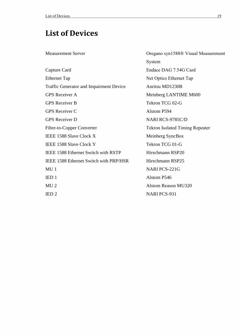
List of Devices 19
List of Devices
Measurement Server Oregano syn1588® Visual Measurement
System
Capture Card Endace DAG 7.54G Card
Ethernet Tap Net Optics Ethernet Tap
Traffic Generator and Impairment Device Anritsu MD1230B
GPS Receiver A Meinberg LANTIME M600
GPS Receiver B Tekron TCG 02-G
GPS Receiver C Alstom P594
GPS Receiver D NARI RCS-9785C/D
Fibre-to-Copper Converter Tekron Isolated Timing Repeater
IEEE 1588 Slave Clock X Meinberg SyncBox
IEEE 1588 Slave Clock Y Tekron TCG 01-G
IEEE 1588 Ethernet Switch with RSTP Hirschmann RSP20
IEEE 1588 Ethernet Switch with PRP/HSR Hirschmann RSP25
MU 1 NARI PCS-221G
IED 1 Alstom P546
MU 2 Alstom Reason MU320
IED 2 NARI PCS-931

20 List of Devices
Abstract 21
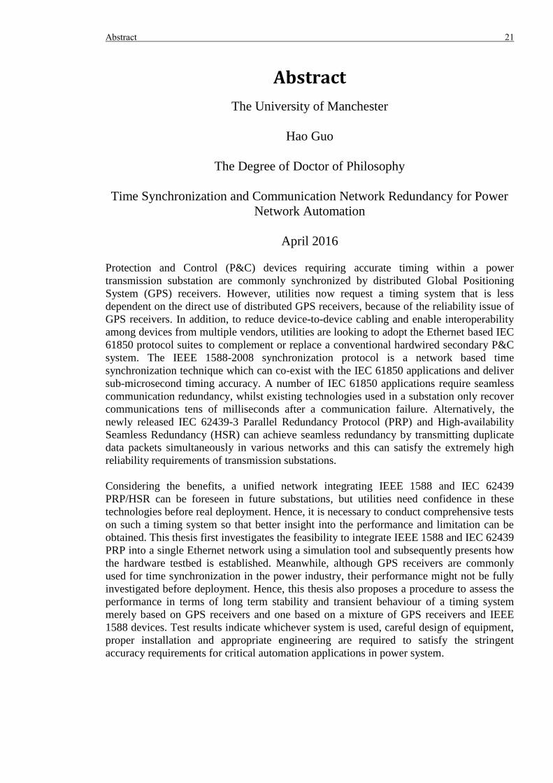
Abstract
The University of Manchester
Hao Guo
The Degree of Doctor of Philosophy
Time Synchronization and Communication Network Redundancy for Power
Network Automation
April 2016
Protection and Control (P&C) devices requiring accurate timing within a power
transmission substation are commonly synchronized by distributed Global Positioning
System (GPS) receivers. However, utilities now request a timing system that is less
dependent on the direct use of distributed GPS receivers, because of the reliability issue of
GPS receivers. In addition, to reduce device-to-device cabling and enable interoperability
among devices from multiple vendors, utilities are looking to adopt the Ethernet based IEC
61850 protocol suites to complement or replace a conventional hardwired secondary P&C
system. The IEEE 1588-2008 synchronization protocol is a network based time
synchronization technique which can co-exist with the IEC 61850 applications and deliver
sub-microsecond timing accuracy. A number of IEC 61850 applications require seamless
communication redundancy, whilst existing technologies used in a substation only recover
communications tens of milliseconds after a communication failure. Alternatively, the
newly released IEC 62439-3 Parallel Redundancy Protocol (PRP) and High-availability
Seamless Redundancy (HSR) can achieve seamless redundancy by transmitting duplicate
data packets simultaneously in various networks and this can satisfy the extremely high
reliability requirements of transmission substations.
Considering the benefits, a unified network integrating IEEE 1588 and IEC 62439
PRP/HSR can be foreseen in future substations, but utilities need confidence in these
technologies before real deployment. Hence, it is necessary to conduct comprehensive tests
on such a timing system so that better insight into the performance and limitation can be
obtained. This thesis first investigates the feasibility to integrate IEEE 1588 and IEC 62439
PRP into a single Ethernet network using a simulation tool and subsequently presents how
the hardware testbed is established. Meanwhile, although GPS receivers are commonly
used for time synchronization in the power industry, their performance might not be fully
investigated before deployment. Hence, this thesis also proposes a procedure to assess the
performance in terms of long term stability and transient behaviour of a timing system
merely based on GPS receivers and one based on a mixture of GPS receivers and IEEE
1588 devices. Test results indicate whichever system is used, careful design of equipment,
proper installation and appropriate engineering are required to satisfy the stringent
accuracy requirements for critical automation applications in power system.

22 Abstract

Declaration 23
Declaration
No portion of the work referred to in this thesis has been submitted in support of an
application for another degree or qualification of this, or any other university, or other
institute of learning.

24 Declaration
Copyright Statement 25
Copyright Statement
i. The author of this thesis (including any appendices and/or schedules to this thesis)
owns certain copyright or related rights in it (the “Copyright”) and s/he has given The
University of Manchester certain rights to use such Copyright, including for
administrative purposes.
ii. Copies of this thesis, either in full or in extracts and whether in hard or electronic copy,
may be made only in accordance with the Copyright, Designs and Patents Act 1988
(as amended) and regulations issued under it or, where appropriate, in accordance with
licensing agreements which the University has from time to time. This page must form
part of any such copies made.
iii. The ownership of certain Copyright, patents, designs, trade marks and other
intellectual property (the “Intellectual Property”) and any reproductions of copyright
works in the thesis, for example graphs and tables (“Reproductions”), which may be
described in this thesis, may not be owned by the author and may be owned by third
parties. Such Intellectual Property and Reproductions cannot and must not be made
available for use without the prior written permission of the owner(s) of the relevant
Intellectual Property and/or Reproductions.
iv. Further information on the conditions under which disclosure, publication and
commercialisation of this thesis, the Copyright and any Intellectual Property and/or
Reproductions described in it may take place is available in the University IP Policy
(see http://documents.manchester.ac.uk/DocuInfo.aspx?DocID=487), in any relevant
Thesis restriction declarations deposited in the University Library, The University
Library’s regulations (see http://www.manchester.ac.uk/library/aboutus/regulations)
and in The University’s policy on Presentation of Theses

26 Copyright Statement
Acknowledgement 27
Acknowledgement
I would like to thank the group of people who have helped me in the completion of this
thesis and the research work described in it. First of all, I would like to express my special
thanks to my supervisor, Prof. Peter Crossley, who has been giving great advice and
guidance throughout the PhD research and for his enthusiasm and free style supervision. I
would also like to thank Dr. Haiyu Li, Dr. David Ingram and Mr. Peter Green for their
inspirational ideas and invaluable contribution to the research work.
My thanks as well to my parents and Jingzhi Yang. Their love, inspiration and
understanding through the PhD journey have been essential and I am grateful for all of the
support and sacrifices. Many thanks also go to Xi Chen for her contribution and
collaboration during the hardware testing stage and Frank, Gary and other colleagues in the
Ferranti Building for the equipment installation.
Tekron, Meinberg, Oregano, Hirschmann, Anritsu and Endace supplied products for the
university research and I appreciate their support and advice during the research.

28 Acknowledgement
Chapter 1: Introduction 29
Chapter 1: Introduction
1.1 Time Synchronization
Transmission substations are key elements in the formation of a power network and
protection and control (P&C), using devices within substations, is extremely important in
preventing the power system from entering an abnormal state. In general, most P&C
devices require measurement of power system quantities (e.g. voltage, current, frequency
etc.) to identify a system event (e.g. short-circuit fault, auto-reclosing etc.) so that the next
action can be determined. Therefore, these measurements and records should reflect the
actual system state and operating conditions in real time [1] and this requires time
synchronization of the P&C devices operations within each substation.
1.1.1 Time Synchronization Requirement
Many P&C applications exist in power substations and the requirement for timing accuracy
varies significantly. One of the P&C applications requiring accurate timing is Current
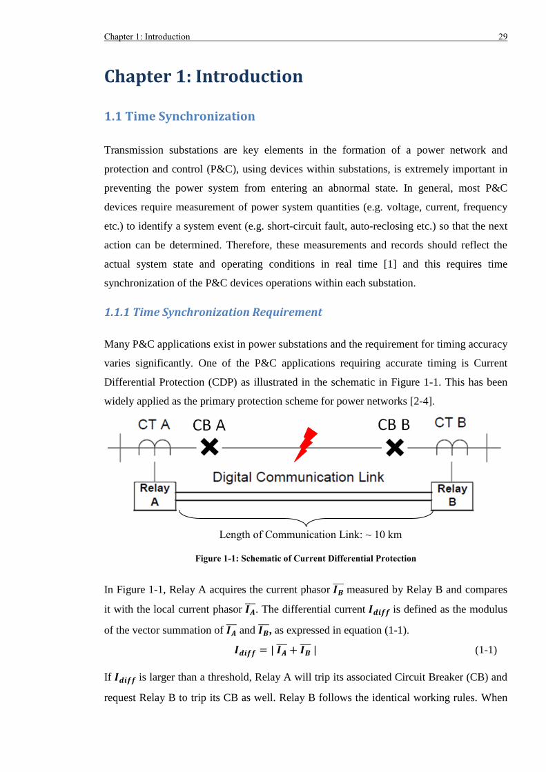
Differential Protection (CDP) as illustrated in the schematic in Figure 1-1. This has been
widely applied as the primary protection scheme for power networks [2-4].
Figure 1-1: Schematic of Current Differential Protection
In Figure 1-1, Relay A acquires the current phasor 𝑰𝑩 measured by Relay B and compares
it with the local current phasor 𝑰𝑨. The differential current 𝑰𝒅𝒊𝒇𝒇 is defined as the modulus
of the vector summation of 𝑰𝑨 and 𝑰𝑩
, as expressed in equation (1-1).
𝑰𝒅𝒊𝒇𝒇 = | 𝑰𝑨 + 𝑰𝑩
| (1-1)
If 𝑰𝒅𝒊𝒇𝒇 is larger than a threshold, Relay A will trip its associated Circuit Breaker (CB) and
request Relay B to trip its CB as well. Relay B follows the identical working rules. When
Length of Communication Link: ~ 10 km
30 Chapter 1: Introduction
there is no fault, the magnitude of 𝑰𝒅𝒊𝒇𝒇 mainly depends on the angle difference between 𝑰𝑨
and 𝑰𝑩 . The angle difference is a direct consequence of the difference in time when 𝑰𝑨
and
𝑰𝑩 are measured. Ignoring the charging current and assuming 𝑰𝑨
and 𝑰𝑩 are not time-
aligned, a large 𝑰𝒅𝒊𝒇𝒇 may present and might lead to relay mal-operation. Authors in [5, 6]
suggested the time synchronization accuracy for the current differential protection should
be in the range between 20 µs and 50 µs so that the protection scheme can operate
correctly.
Phasor Measurement Units (PMUs) [7] have been widely deployed in power substations to
monitor the power network and mitigate the risk of system instabilities and a wide blackout.
The associate standard IEEE C37.118 [8] requires that the Total Vector Error should not
exceed 1% radian or 0.57o, which corresponds to 31.8 µs at 50 Hz or 26.5 µs at 60 Hz.
Because the error margin includes the magnitude, angle and synchronization errors and the
portion related to magnitude and angle estimation is much larger, it is realistic that the time
synchronization error should not exceed 1 µs [8, 9].
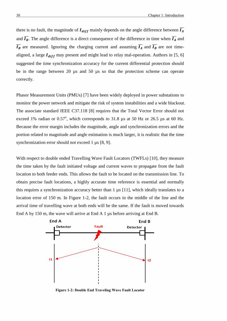
With respect to double ended Travelling Wave Fault Locators (TWFLs) [10], they measure
the time taken by the fault initiated voltage and current waves to propagate from the fault
location to both feeder ends. This allows the fault to be located on the transmission line. To
obtain precise fault locations, a highly accurate time reference is essential and normally
this requires a synchronization accuracy better than 1 µs [11], which ideally translates to a
location error of 150 m. In Figure 1-2, the fault occurs in the middle of the line and the
arrival time of travelling wave at both ends will be the same. If the fault is moved towards
End A by 150 m, the wave will arrive at End A 1 µs before arriving at End B.
Figure 1-2: Double End Traveling Wave Fault Locator
Chapter 1: Introduction 31
In the next generation substations, it is likely most P&C applications will be implemented
based on the IEC 61850 standard. Thus, it is necessary to explore the timing requirement
for different IEC 61850 applications and services. An IEC 61850 9-2 Sampled Value (SV)
application samples the secondary quantities of Current Transformer (CT) and Voltage
Transformer (VT) and then transmits the data packets containing the measurement. The de-
facto implementation of SV is defined by the 9-2 Light Edition [12], which specifies a
synchronization accuracy ≤ 1 µs.
Another application IEC 61850 8-1 Generic Object Oriented Substation Event (GOOSE) is
able to provide information about the substation events so P&C devices can better monitor
the substation equipment and correctly react to disturbance events. According to IEC
61850-5 [13], the synchronization requirement for P&C events should be in the range ±1
ms to ±10 ms. As GOOSE messaging is mainly used for P&C events, 1 ms timing
accuracy is reasonable.
There are also other automation applications in substations such as Supervisory Control
and Data Acquisition (SCADA) and Disturbance Recording. Their purpose is to collect
information and waveforms, both before and after substation events, and use the data to
facilitate post disturbance analysis. For this type of application, the accuracy requirement is
usually a few milliseconds [14].
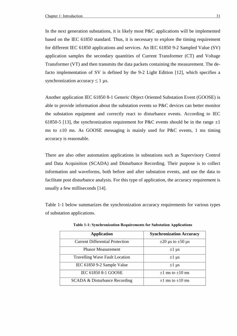
Table 1-1 below summarizes the synchronization accuracy requirements for various types
of substation applications.
Table 1-1: Synchronization Requirements for Substation Applications
Application Synchronization Accuracy
Current Differential Protection ±20 µs to ±50 µs
Phasor Measurement ±1 µs
Travelling Wave Fault Location ±1 µs
IEC 61850 9-2 Sample Value ±1 µs
IEC 61850 8-1 GOOSE ±1 ms to ±10 ms
SCADA & Disturbance Recording ±1 ms to ±10 ms
32 Chapter 1: Introduction
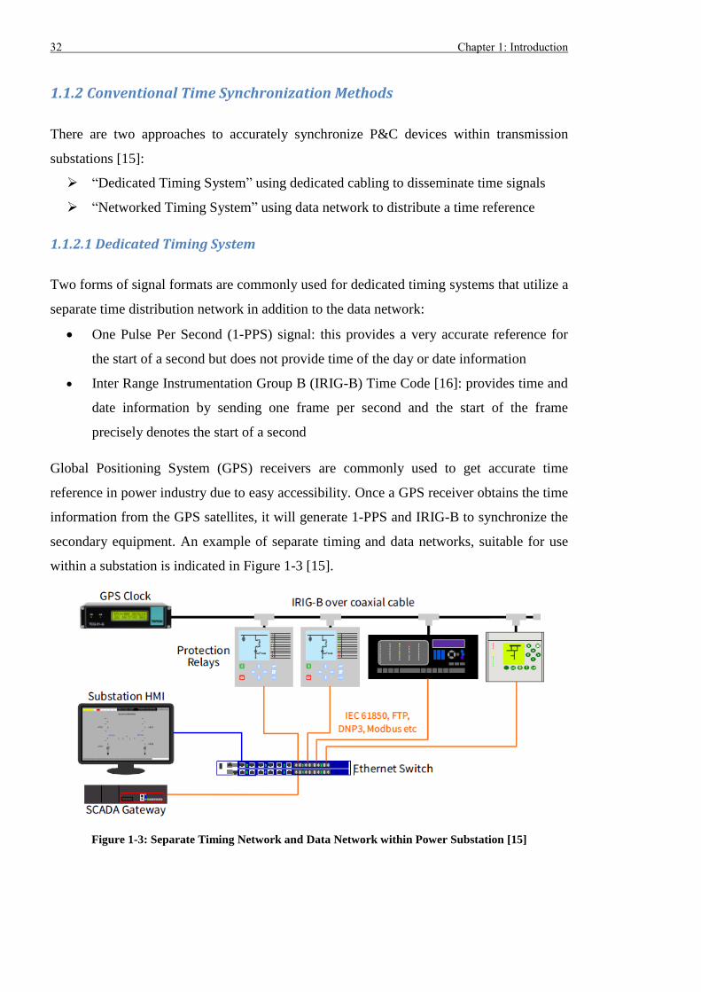
1.1.2 Conventional Time Synchronization Methods
There are two approaches to accurately synchronize P&C devices within transmission
substations [15]:
“Dedicated Timing System” using dedicated cabling to disseminate time signals
“Networked Timing System” using data network to distribute a time reference
1.1.2.1 Dedicated Timing System
Two forms of signal formats are commonly used for dedicated timing systems that utilize a
separate time distribution network in addition to the data network:
One Pulse Per Second (1-PPS) signal: this provides a very accurate reference for
the start of a second but does not provide time of the day or date information
Inter Range Instrumentation Group B (IRIG-B) Time Code [16]: provides time and
date information by sending one frame per second and the start of the frame
precisely denotes the start of a second
Global Positioning System (GPS) receivers are commonly used to get accurate time
reference in power industry due to easy accessibility. Once a GPS receiver obtains the time
information from the GPS satellites, it will generate 1-PPS and IRIG-B to synchronize the
secondary equipment. An example of separate timing and data networks, suitable for use
within a substation is indicated in Figure 1-3 [15].
Figure 1-3: Separate Timing Network and Data Network within Power Substation [15]
Chapter 1: Introduction 33
Within a harsh substation environment, the electromagnetic interference level is very high,
which requires the use of ruggedized complex electronic circuits to support the correct
operation of the GPS receiver. However, this significantly increases the cost, and also
requires the antenna used by the GPS receiver to be installed outside the relay room to
ensure it has a clear view of the sky and can deliver good GPS signal reception. Therefore,
an effective way to implement GPS synchronization in a large transmission substation is to
place the GPS receivers in a distant and less hostile environment, such as the
telecommunication room, and then route the 1-PPS and IRIG-B code to P&C devices
located in relay rooms via copper or fibre optic cables.
When 1-PPS and IRIG-B travel a long distance from the GPS receiver to the device, it is
inevitable that cable propagation delay will be introduced. Because there is no mechanism
to automatically measure and compensate the latency for 1-PPS and IRIG-B, it is necessary
to have this done manually during commissioning, and later checked during maintenance
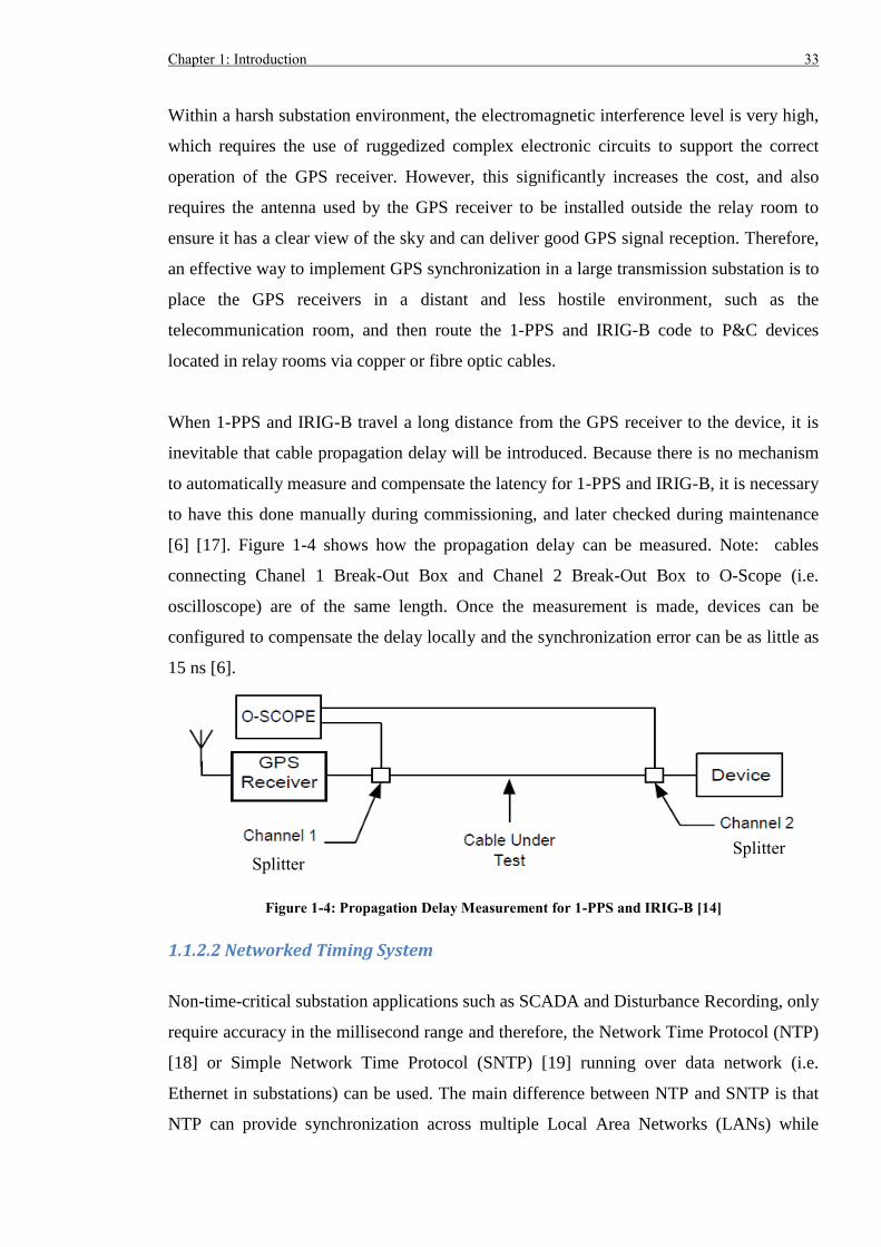
[6] [17]. Figure 1-4 shows how the propagation delay can be measured. Note: cables
connecting Chanel 1 Break-Out Box and Chanel 2 Break-Out Box to O-Scope (i.e.
oscilloscope) are of the same length. Once the measurement is made, devices can be
configured to compensate the delay locally and the synchronization error can be as little as
15 ns [6].
Figure 1-4: Propagation Delay Measurement for 1-PPS and IRIG-B [14]
1.1.2.2 Networked Timing System
Non-time-critical substation applications such as SCADA and Disturbance Recording, only
require accuracy in the millisecond range and therefore, the Network Time Protocol (NTP)
[18] or Simple Network Time Protocol (SNTP) [19] running over data network (i.e.
Ethernet in substations) can be used. The main difference between NTP and SNTP is that
NTP can provide synchronization across multiple Local Area Networks (LANs) while
Splitter Splitter
34 Chapter 1: Introduction
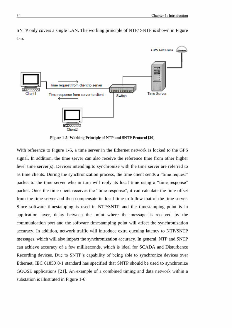
SNTP only covers a single LAN. The working principle of NTP/ SNTP is shown in Figure
1-5.
Figure 1-5: Working Principle of NTP and SNTP Protocol [20]
With reference to Figure 1-5, a time server in the Ethernet network is locked to the GPS
signal. In addition, the time server can also receive the reference time from other higher
level time server(s). Devices intending to synchronize with the time server are referred to
as time clients. During the synchronization process, the time client sends a “time request”
packet to the time server who in turn will reply its local time using a “time response”
packet. Once the time client receives the “time response”, it can calculate the time offset
from the time server and then compensate its local time to follow that of the time server.
Since software timestamping is used in NTP/SNTP and the timestamping point is in
application layer, delay between the point where the message is received by the
communication port and the software timestamping point will affect the synchronization
accuracy. In addition, network traffic will introduce extra queuing latency to NTP/SNTP
messages, which will also impact the synchronization accuracy. In general, NTP and SNTP
can achieve accuracy of a few milliseconds, which is ideal for SCADA and Disturbance
Recording devices. Due to SNTP’s capability of being able to synchronize devices over
Ethernet, IEC 61850 8-1 standard has specified that SNTP should be used to synchronize
GOOSE applications [21]. An example of a combined timing and data network within a
substation is illustrated in Figure 1-6.
Chapter 1: Introduction 35
Figure 1-6: Combined Timing and Data Network in Substation [15]
1.2 Communication Redundancy
The major responsibility of a power utility is to maintain a secure and reliable power
network, so that consumers can have safe and secure electrical energy. This requires that
all P&C devices should properly coordinate with each other to deliver robust and reliable
automation operations. Hence, communications between devices are vital within power
substations. Due to its low cost, high bandwidth and versatile levels of support for different
applications, Ethernet is now the de-facto standard for LANs around the world [22].
Developments in communication technologies for the power industry, means utilities are
replacing low speed serial communication system with high performance Ethernet [23].
Ethernet communication provides good performance at a relatively low cost, but it is
possible that Ethernet may become not available due to link or device failures. This is not
acceptable for mission-critical applications and thus it is necessary to employ redundancy
in the Ethernet communication systems used within substations.
1.2.1 Communication Recovery Time Requirements
Various P&C applications require different level of communication redundancy in terms of
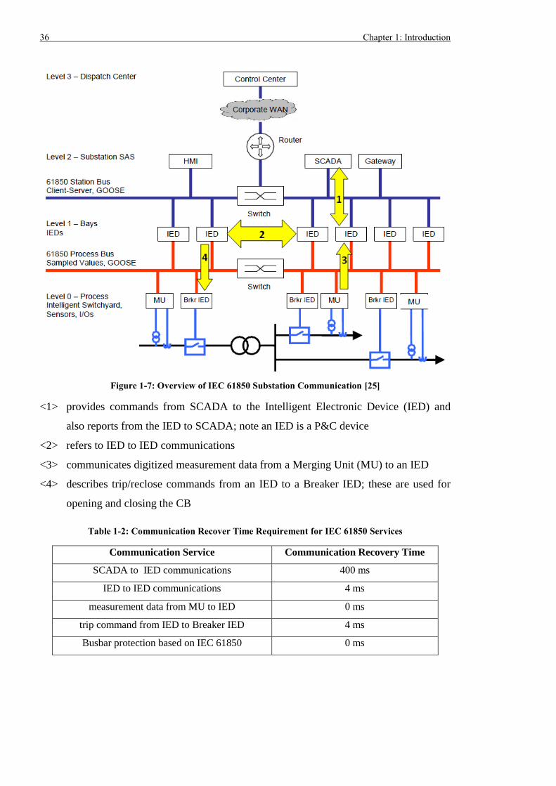
recovery time. IEC 61850-1 standard [24] defines four types of services as indicated in
Figure 1-7 while IEC 61850-5 [13] specifies the recovery time requirement for these
services, as summarized in Table 1-2.
36 Chapter 1: Introduction
Figure 1-7: Overview of IEC 61850 Substation Communication [25]
<1> provides commands from SCADA to the Intelligent Electronic Device (IED) and
also reports from the IED to SCADA; note an IED is a P&C device
<2> refers to IED to IED communications
<3> communicates digitized measurement data from a Merging Unit (MU) to an IED
<4> describes trip/reclose commands from an IED to a Breaker IED; these are used for
opening and closing the CB
Table 1-2: Communication Recover Time Requirement for IEC 61850 Services
Communication Service Communication Recovery Time
SCADA to IED communications 400 ms
IED to IED communications 4 ms
measurement data from MU to IED 0 ms
trip command from IED to Breaker IED 4 ms
Busbar protection based on IEC 61850 0 ms
Chapter 1: Introduction 37
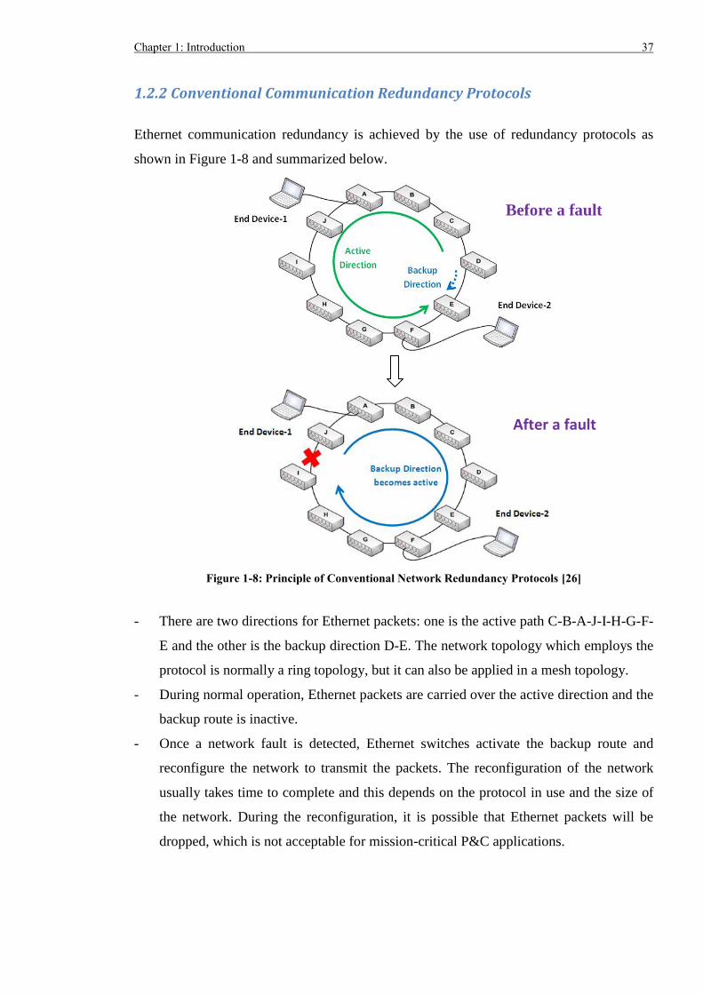
1.2.2 Conventional Communication Redundancy Protocols
Ethernet communication redundancy is achieved by the use of redundancy protocols as
shown in Figure 1-8 and summarized below.
Figure 1-8: Principle of Conventional Network Redundancy Protocols [26]
- There are two directions for Ethernet packets: one is the active path C-B-A-J-I-H-G-F-
E and the other is the backup direction D-E. The network topology which employs the
protocol is normally a ring topology, but it can also be applied in a mesh topology.
- During normal operation, Ethernet packets are carried over the active direction and the
backup route is inactive.
- Once a network fault is detected, Ethernet switches activate the backup route and
reconfigure the network to transmit the packets. The reconfiguration of the network
usually takes time to complete and this depends on the protocol in use and the size of
the network. During the reconfiguration, it is possible that Ethernet packets will be
dropped, which is not acceptable for mission-critical P&C applications.
Before a fault
After a fault
38 Chapter 1: Introduction
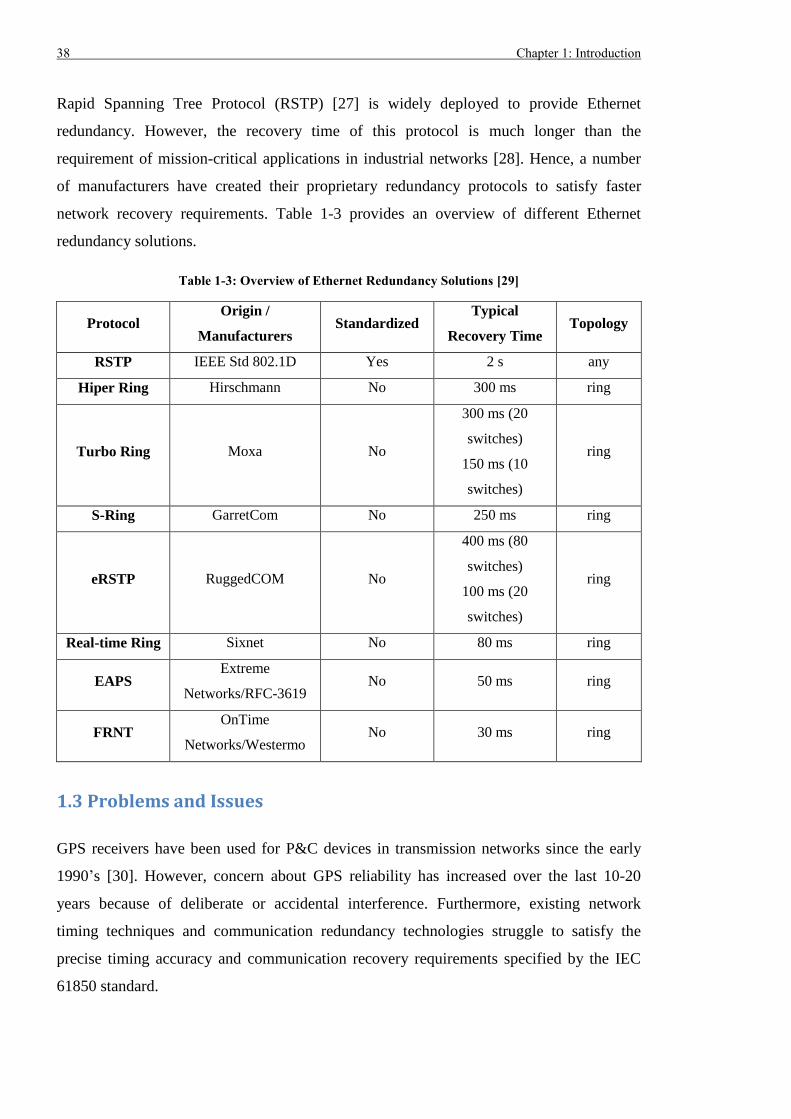
Rapid Spanning Tree Protocol (RSTP) [27] is widely deployed to provide Ethernet
redundancy. However, the recovery time of this protocol is much longer than the
requirement of mission-critical applications in industrial networks [28]. Hence, a number
of manufacturers have created their proprietary redundancy protocols to satisfy faster
network recovery requirements. Table 1-3 provides an overview of different Ethernet
redundancy solutions.
Table 1-3: Overview of Ethernet Redundancy Solutions [29]
Protocol Origin /
Manufacturers Standardized
Typical
Recovery Time Topology
RSTP IEEE Std 802.1D Yes 2 s any
Hiper Ring Hirschmann No 300 ms ring
Turbo Ring Moxa No
300 ms (20
switches)
150 ms (10
switches)
ring
S-Ring GarretCom No 250 ms ring
eRSTP RuggedCOM No
400 ms (80
switches)
100 ms (20
switches)
ring
Real-time Ring Sixnet No 80 ms ring
EAPS Extreme
Networks/RFC-3619 No 50 ms ring
FRNT OnTime
Networks/Westermo No 30 ms ring
1.3 Problems and Issues
GPS receivers have been used for P&C devices in transmission networks since the early
1990’s [30]. However, concern about GPS reliability has increased over the last 10-20
years because of deliberate or accidental interference. Furthermore, existing network
timing techniques and communication redundancy technologies struggle to satisfy the
precise timing accuracy and communication recovery requirements specified by the IEC
61850 standard.
Chapter 1: Introduction 39
1.3.1 Costly Timing System based on Distributed GPS Receivers
GPS synchronization provides sub-microsecond accuracy for applications that require
accurate time synchronization, if the signal propagation delay is precisely compensated.
For example, a 500 m fibre optic cable will introduce 2.5 μs delay and this must be
compensated. Because numerous P&C devices require a time source and a single cable (i.e.
copper or fibre optic) can only carry time information to limited number of devices, dozens
of distributed GPS receivers need to be used. Consequently, a dedicated network is needed
to disseminate the time reference in the format of 1-PPS and the IRIG-B time code. For a
large transmission substation, building a time distributing network is very costly and
complicated; this is especially true in an Air Insulated Substation due to the large number
of distributed GPS receivers required and the long dissemination distances.
1.3.2 Reliability Issue of Timing System based on Distributed GPS Receivers
In addition, reliability issues related to the use of GPS synchronization is of concern. In the
past 10 years, National Grid reported “most of the relay mal-operations on transmission
lines were caused by the incorrect timing data obtained from distributed GPS receivers” [4].
The system operator TRANSPOWER in New Zealand also experienced relay mal-
operations resulting from the use of GPS receivers; the risk was removed by disabling GPS
synchronization for the differential protection [31].
Other vulnerabilities in the use of GPS for timing exist: namely GPS jamming, Solar Flares
and GPS spoofing, as summarized in [32]. Increasing availability of GPS jammers poses a
threat to the availability of GPS in a substation, and may severely affect the operating
performance of a P&C system when data is obtained from devices synchronized to
different GPS receivers [33]. A Solar Flare is also believed to have negative impact on
GPS signal reception and during strong solar activities, some commercial GPS receivers
track fewer than four satellites [34], which is the minimum requirement to fully
synchronize a receiver with absolute time. There are no commercial GPS spoofers
available for legitimate reasons, but researchers in [35] built their own and successfully
confused critical devices that rely on a GPS signal, such as PMUs and Unmanned Aerial
Vehicles [36, 37]. Consequently, more stable and robust centralized time masters are
needed. Enhanced stability can be obtained by using various sources such as GPS and
microwave inputs, as well as local signal validation check.
40 Chapter 1: Introduction
1.3.3 Limitation of Timing System based on NTP/SNTP
With NTP and SNTP, there is no need to deploy an additional network for time
dissemination. The existing data network can be used, which significantly reduces the
capital and engineering expenditure. Besides, NTP and SNTP only require one GPS
receiver, although two is preferred for redundancy purpose in a substation. This
significantly reduces the device cost and improves the reliability of the synchronization
system. Although NTP/SNTP provides time synchronization at a lower cost and with
higher reliability, it can only be used for non time-critical applications, due to its relatively
low accuracy.
1.3.4 Limitation of Conventional Communication Redundancy Technologies
Table 1-3 shows most Ethernet redundancy solutions only provide recovery times in the
order of milliseconds, which cannot satisfy the requirement of most IEC 61850
applications listed in Table 1-2. In addition, all Ethernet redundancy protocols providing
tens of millisecond failover time are proprietary, which means devices from different
manufacturers are unlikely to interoperate correctly during network reconfiguration.
1.4 Motivation and Aim
Future digital substations require optimal network architectures that fully integrate all the
component of an IEC 61850 automation system. This requires all P&C devices, available
from different vendors to be plug-and-play. Many IEC 61850 applications require high
level timing accuracy and fast or seamless communication redundancy to operate correctly
and achieve the level of reliability required in a power transmission application.
Considering the cost and the reliability issues for timing systems based on distributed GPS
receivers, it would be advisable for utilities to employ less distributed GPS receivers whilst
use the saved capital to deploy more reliable and robust centralized time masters with
various input sources and sophisticated validation algorithms, to cope with deliberate and
natural interference. Provided that a robust centralized time source is available, reliable and
accurate time dissemination will be crucial for critical P&C applications requesting ±1 μs
timing accuracy. Hence, a time dissemination solution that is implemented over a
substation communication network (e.g. Ethernet) and delivers continuous precise timing
Chapter 1: Introduction 41
accuracy (e.g. at sub-microsecond level) will be prefered. Because conventional
redundancy protocols cannot satisfy the fast recovery time < 10 ms and seamless
communication requirement, other standardized solutions that can provide zero second
failover time are attractive for use in future substations.
In terms of time synchronization, the IEEE 1588 time synchronization system can offer
numerous advantages over a traditional distributed GPS receiver based system:
- No Dedicated Time Distribution Network: IEEE 1588 protocol uses the existing data
network to disseminate the reference time to devices. Thus IEEE 1588 can share the
data network (Ethernet) with other substation data and there is no need to build a
dedicated time dissemination network. The alternative is a pure GPS based system that
supplies 1-PPS synchronizing signal and IRIG-B coded message to P&C devices. If
the devices are fully compliant to the IEEE 1588 standard, they can be directly
synchronized after being connected to Ethernet and no other cabling is required. Even
if the devices are not compliant to IEEE 1588 standard and still require conventional
IRIG-B or 1-PPS input, an IEEE 1588 Slave located near the end device can convert
IEEE 1588 timing information to 1-PPS and IRIG-B; this significantly reduces the
amount of cabling required for distributing the time reference.
- Less GPS Receivers and Improved Reliability: As IEEE 1588 can disseminate
reference time over Ethernet, there is no need to install GPS receivers at every single
P&C device and the number of GPS receivers in a substation can be significantly
reduced. In addition, if IEEE 1588 Grandmasters embed atomic clocks as the time
source, the GPS signal will only be used for long term time calibration. As a result, a
power substation is much less dependent on the GPS system and the reliability of the
timing system can be improved.
- Less Engineering and Maintenance Work: IEEE 1588 can automatically measure and
compensate the time delay caused by the Ethernet network. Whilst in traditional IRIG-
B or 1-PPS system, manual measurement and compensation are inevitable, which
results in more engineering and maintenance work than in the IEEE 1588 timing
system.
42 Chapter 1: Introduction
- Good Accuracy: Unlike NTP and SNTP, IEEE 1588 synchronization can achieve
timing accuracy better than ±1 µs when it is implemented over Ethernet.
With respect to the Ethernet redundancy, the IEC 62439-3 Parallel Redundancy Protocol
(PRP) and High-availability Seamless Redundancy (HSR) can significantly improve the
network reliability due to:
- 0 s / Seamless Redundancy: In both IEC 62439-3 PRP and HSR network, two copies
of the same Ethernet packet are transmitted simultaneously from the source to the
destination. Even if one of the copies is lost because of a network failure, destination
devices can still receive the other copy of the packet and there is no outage time from
the perspective of the destination devices. By contrast, conventional network
reconfiguration techniques only use a single path to transmit the packets at any time. If
the original path is not available, the backup path will be activated, which will take
time to accomplish. During the reconfiguration, the communication channel is not
available and packets may be lost.
- Easy Maintenance & Replacement for Network Device: Most communication
network devices are designed to have a lifetime less than 10 years, which is much
shorter than that of P&C devices. Typically, the asset life of a P&C device is 15 years
in National Grid [38]. Hence, it would be necessary to conduct regular maintenance
work on network devices to extend their life span or implement a device replacement
strategy. Because IEC 62439-3 PRP employs two physically independent networks
and Ethernet packets are transmitted in both networks in parallel, taking out the
network devices (e.g. Ethernet switches) from one of the networks would not affect
the normal operation of the other network and thus does not affect the P&C operations.
This greatly simplifies the network device maintenance and replacement process. In an
IEC 62439-3 HSR network, Ethernet packets are transmitted through two paths. If an
IED does not support HSR, it needs to connect with a specialized HSR network device
and then to the HSR ring. Taking out such HSR network device only affects the IEDs
connected to that network device. If every IED supports HSR and has two ports, there
is no need to use the specialized HSR network device and thus no maintenance or
replacement for this network device is required.
Chapter 1: Introduction 43
The combination of IEEE 1588 synchronization and IEC 62439-3 PRP/HSR seamless
redundancy will probably become the preferred choice for future transmission and
distribution substations because it can significantly improve the performance and reliability
of Ethernet based secondary systems. However, as IEEE 1588 and IEC 62439-3 PRP/HSR
technologies have rarely been applied by electrical utilities, very limited understanding and
experience exists within the P&C community. Utilities need confidence in these
technologies before they can be rolled out to real substations. Hence, comprehensive tests
should be conducted on such a system so that users can have a better insight into their
feasibility, performance and operating limitations.
The aim of this research is first to model an Ethernet network combining IEEE 1588 time
synchronization and IEC 62439-3 PRP, and then investigate the feasibility of
implementing 1588 timing over PRP redundancy, using a simulation tool. This is critical to
enhance knowledge and understanding, before constructing a hardware testbed. Testing in
the UK on an Ethernet network in real transmission substation is impossible. Consequently,
a hardware testbed needs to be designed and built. Using the hardware testbed, a timing
system merely based on GPS receivers and one based on a mixture of GPS and IEEE 1588
devices can be comprehensively tested. Implementation of a substation wide IEEE 1588
timing is also trialled and the test results are used to provide suggestions for the design,
configuration, setting, application and development of IEEE 1588 timing, IEC 62439
PRP/HSR and RSTP redundancy. This is useful when defining a future technical
specification.
1.5 Contributions and Publications
The major contributions to knowledge from this research are related to the assessment of
existing time dissemination solution based on distributed GPS receivers and future solution
relying on IEEE 1588 and data network redundancy. The contributions fill the gaps in
previous research and testing of GPS and IEEE 1588 timing. For the first time, the
simulation of combination of IEEE 1588 and IEC 62439-3 was undertaken and the detailed
contributions in terms of software simulation are listed below.
- Creation and development of software simulation models of IEEE 1588 and IEC
62439 PRP devices
44 Chapter 1: Introduction
- Conducted performance tests on IEEE 1588 timing over IEC 62439 PRP redundant
network in various topologies (i.e. Star and PRP) with different network load
conditions.
- Findings from software simulation showed it was feasible to achieve ±1 μs accuracy
required by critical power system applications, even though these protocols were
based on opposite assumptions. It was suggested both Ethernet switches and PRP
devices should support IEEE 1588 features to guarantee sub-microsecond accuracy.
With regard to the hardware testing, the contribution and findings are summarized below.
- Design and construction of a hardware testbed with associated testing procedures to
evaluate the long term accuracy and transient behaviour of distributed GPS receivers
- Test results indicated the timing error would increase to approximately 1 µs, which
may pose a risk for mission-critical applications requesting sub-microsecond accuracy.
Increased GPS reception mask angle could help reduce the occurrence of timing error
spikes. It was also discovered the timing error of a specific GPS receiver became
much greater than ±1 μs after GPS signal restoration and the anomaly lasted for more
than 5 seconds, which could eventually cause relay mal-operation. Hence, the GPS
antennas need to be properly installed to improve the GPS signal reception whilst an
appropriate algorithm should be embedded to avoid mistiming upon GPS signal
restoration. In this way, reliable long term and transient performance can be achieved
when using distributed GPS receivers to synchronize substation equipment.
- Expansion of hardware testbed to integrated IEEE 1588 timing and different
communication redundancy technologies
- Development of testing procedures to assess the performance of mixed GPS/IEEE
1588 timing solution
- Findings of the testing demonstrated timing accuracy better than ±150 ns can be
achieved even when the data network was overloaded by non-1588 traffic. However,
excess 1588 traffic and loss of 1588 packets caused a 1588 device to lose
synchronization, which should be fixed by device firmware upgrade and taken into
account when defining cyber security strategy for future substation automation.
Communication redundancy including RSTP, PRP and HSR maintained correct time
synchronization upon communication link loss. Considering loss of 1588 packets may
break the synchronization, PRP and HSR were better options than RSTP for
Chapter 1: Introduction 45
communication redundancy. When the link recovered, no abnormal timing error spike
occurred and the mixed GPS/1588 timing solution was more stable than solution based
on distributed GPS receivers. When the GPS signal was completely not available, a
1588 clock did not follow the best GPS receiver in the network and timing islands
appeared. This could cause relay mal-operation and it needs to be ensured no timing
island will occur under extreme conditions if GPS/1588 timing solution is to be used
in real substations.
- Design and development of substation wide IEEE 1588 timing in economic way using
the hardware testbed
- Test results indicated two GPS/1588 clocks could cover the whole substation by
connecting the IEC 61850 Station Bus with Process Bus and filtering the traffic on the
link. Timing accuracy better than ±550 ns were achieved when the network contains 18
Ethernet switches and 100% non-1588 traffic. The scalability of the timing system
under test was estimated be able to deliver sub-microsecond accuracy with up to 33
Ethernet switches, which was more than 16 switches as defined by the IEEE 1588
Power Profile. It was also proved the timing accuracy of GPS/1588 solution was not
affected by long communication link and good compatibility were achieved between
1588 and non-1588 devices. Consequently, the GPS/1588 time dissemination approach
is a future proofed solution for Ethernet based substation automation system.
Publications related to the research of this thesis are listed below.
- H. Guo and P. Crossley, “Design of a Time Synchronization System based on GPS
and IEEE 1588 for Transmission Substations,” IEEE Transactions on Power Delivery,
Early-Access.
- P. Crossley, H. Guo and Z. Ma, “Time Synchronization for Transmission Substations
using GPS and IEEE 1588,” CSEE Journal of Power and Energy Systems, vol. 2, no. 3,
pp. 91-99, September 2016.
- X. Chen, H. Guo and P. Crossley, “Interoperability Performance Assessment of
Multivendor IEC61850 Process Bus,” IEEE Transactions on Power Delivery, vol. 31,
no. 4, pp. 1934-1944, August 2016.
46 Chapter 1: Introduction
- H. Guo, P. Crossley and R. Zhang, “Combination of IEEE 1588 Time Synchronization
and IEC 62439 PRP Communication Redundancy for Smart Grid Substation,” in 2015
CIGRE Study Committee B5 Colloquium, Nanjing, China, 20-26 September 2015, pp.
1-6.
- X. Chen, H. Guo and P. Crossley, “Performance Testing of IEC61850 Based
Architecture for UK National Grid Standardized Substation,” in 2015 IEEE Power &
Energy Society General Meeting, Denver, USA, 26-30 July 2015, pp. 1-5.
- H. Guo and P. Crossley, “Time synchronization (IEEE 1588) and seamless
communication redundancy (IEC 62439-3) techniques for Smart Grid Substations,” in
12th International Conference on Developments in Power System Protection (DPSP
2014), Copenhagen, Denmark, 31 March – 3 April 2014, pp. 1-6.
- X. Chen, P. Crossley and H. Guo, “Design, construction and validation of a next
generation protection and control system based on IEC61850 standards,” in 12th
International Conference on Developments in Power System Protection (DPSP 2014),
Copenhagen, Denmark, 31 March – 3 April 2014, pp. 1-5.
- H. Guo and P. Crossley, “Performance Tests on an IEEE 1588 / IEC 62439 PRP
Testbed,” in 5th International Conference on Advanced Power System Automation and
Protection (APAP 2013), Jeju, Korea, 28-31 October 2013, pp. 1-8.
1.6 Structure of the Thesis
Chapter 2 introduces the main features of IEEE 1588 timing protocol, including its
originality and development aspects, and the specifics of several types of IEEE 1588
devices. This chapter also describes how various 1588 devices communicate and
collaborate with each other within the synchronization hierarchy and how synchronization
can be achieved across the whole network. Different IEEE 1588 profiles are available and
used to specify the device configuration necessary to satisfy the application requirements
in diverse ranged industries or fields. The IEEE 1588 Power Profile should be applied in
power system applications and consequently, this is used for the tests conducted on the
hardware testbed.
Chapter 1: Introduction 47
Chapter 3 describes the main features of the IEC 62439-3 PRP and HSR protocols and how
these two protocols deliver seamless communication redundancy by sending duplicate
frames simultaneously over independent networks or in opposite directions in a ring
topology. The structure of PRP and HSR devices are introduced with detailed explanation
on the processing of duplicated PRP and HSR frames. Differences between PRP and HSR
in terms of topology, frame modification and device requirement are also compared and
discussed.
Previous research on IEEE 1588 synchronization and IEC 62439-3 PRP/HSR are reviewed
in Chapter 4. For the software simulation, work has been done to model IEEE 1588 end
devices. Comprehensive hardware testing has also been conducted to evaluate the
performance of IEEE 1588 system. However, there is more to do to evaluate the
performance of IEEE 1588 and IEC 62439-3 in terms of long term accuracy, effect of
extreme network conditions and scalability. Hence Chapter 4 also defines the objectives of
the research from the perspective of software simulation, hardware platform design and
testing methods.
Chapter 5 shows how to simulate IEEE 1588 time synchronization over IEC 62439-3 PRP
communication redundancy by modifying and developing existing device models in
OPNET software. Various test scenarios with diverse network topologies, devices and
traffic conditions are run to evaluate the feasibility, performance and limitation of IEEE
1588 timing over IEC 62439-3 seamless redundancy. Suggestions on the device
requirements are also provided.
In Chapter 6, timing systems that are suitable for the future digital substations are first
described. The detailed design of a hardware testbed is introduced and this testbed is used
to evaluate the performance of a timing system purely based on GPS receivers or a mixture
of GPS receivers and IEEE 1588 devices. Testing procedures are also proposed where
several conditions such as GPS signal loss/restoration, excessive traffic and
communication link loss are created in the testbed. This is necessary to assess the timing
accuracy of GPS receivers and IEEE 1588 Slave Clocks as well as the impact of IEEE
1588 traffic on other Ethernet based P&C applications. The experimental results are
presented and analysed to give advice and suggestions on real applications of GPS
receivers and IEEE 1588 devices.
48 Chapter 1: Introduction
As most future digital substations will use an Ethernet network for their secondary system
and many P&C devices will demand precise time synchronization, it is attractive to
implement the IEEE 1588 timing in real substations. Chapter 7 firstly describes National
Grid’s AS3 architecture for future digital substation automation system and how to
integrate the IEEE 1588 synchronization into the AS3 architecture. The hardware testbed in
Chapter 6 is expanded and various test procedures are conducted to assess the feasibility
and scalability of substation wide IEEE 1588 implementation as well as the effect of long
communication links and device replacement. Furthermore, the compatibility between
IEEE 1588 devices and IEC 61850 MUs/IEDs is also investigated.
Chapter 8 concludes the research work and summarizes the major findings related to the
performance and limitations of GPS receivers, IEEE 1588 timing and communication
redundancy. Suggestions on the application of GPS and IEEE 1588 timing as well as the
future research work are also presented.
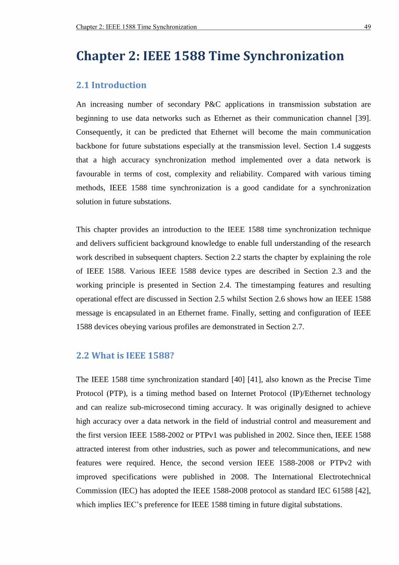
Chapter 2: IEEE 1588 Time Synchronization 49
Chapter 2: IEEE 1588 Time Synchronization
2.1 Introduction
An increasing number of secondary P&C applications in transmission substation are
beginning to use data networks such as Ethernet as their communication channel [39].
Consequently, it can be predicted that Ethernet will become the main communication
backbone for future substations especially at the transmission level. Section 1.4 suggests
that a high accuracy synchronization method implemented over a data network is
favourable in terms of cost, complexity and reliability. Compared with various timing
methods, IEEE 1588 time synchronization is a good candidate for a synchronization
solution in future substations.
This chapter provides an introduction to the IEEE 1588 time synchronization technique
and delivers sufficient background knowledge to enable full understanding of the research
work described in subsequent chapters. Section 2.2 starts the chapter by explaining the role
of IEEE 1588. Various IEEE 1588 device types are described in Section 2.3 and the
working principle is presented in Section 2.4. The timestamping features and resulting
operational effect are discussed in Section 2.5 whilst Section 2.6 shows how an IEEE 1588
message is encapsulated in an Ethernet frame. Finally, setting and configuration of IEEE
1588 devices obeying various profiles are demonstrated in Section 2.7.
2.2 What is IEEE 1588?
The IEEE 1588 time synchronization standard [40] [41], also known as the Precise Time
Protocol (PTP), is a timing method based on Internet Protocol (IP)/Ethernet technology
and can realize sub-microsecond timing accuracy. It was originally designed to achieve
high accuracy over a data network in the field of industrial control and measurement and
the first version IEEE 1588-2002 or PTPv1 was published in 2002. Since then, IEEE 1588
attracted interest from other industries, such as power and telecommunications, and new
features were required. Hence, the second version IEEE 1588-2008 or PTPv2 with
improved specifications were published in 2008. The International Electrotechnical
Commission (IEC) has adopted the IEEE 1588-2008 protocol as standard IEC 61588 [42],
which implies IEC’s preference for IEEE 1588 timing in future digital substations.
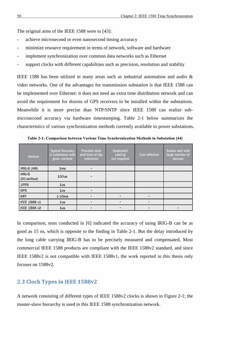
50 Chapter 2: IEEE 1588 Time Synchronization
The original aims of the IEEE 1588 were to [43]:
- achieve microsecond or even nanosecond timing accuracy
- minimize resource requirement in terms of network, software and hardware
- implement synchronization over common data networks such as Ethernet
- support clocks with different capabilities such as precision, resolution and stability
IEEE 1588 has been utilized in many areas such as industrial automation and audio &
video networks. One of the advantages for transmission substation is that IEEE 1588 can
be implemented over Ethernet: it does not need an extra time distribution network and can
avoid the requirement for dozens of GPS receivers to be installed within the substations.
Meanwhile it is more precise than NTP/SNTP since IEEE 1588 can realize sub-
microsecond accuracy via hardware timestamping. Table 2-1 below summarizes the
characteristics of various synchronization methods currently available in power substations.
Table 2-1: Comparison between Various Time Synchronization Methods in Substation [44]
In comparison, tests conducted in [6] indicated the accuracy of using IRIG-B can be as
good as 15 ns, which is opposite to the finding in Table 2-1. But the delay introduced by
the long cable carrying IRIG-B has to be precisely measured and compensated. Most
commercial IEEE 1588 products are compliant with the IEEE 1588v2 standard, and since
IEEE 1588v2 is not compatible with IEEE 1588v1, the work reported in this thesis only
focuses on 1588v2.
2.3 Clock Types in IEEE 1588v2
A network consisting of different types of IEEE 1588v2 clocks is shown in Figure 2-1; the
master-slave hierarchy is used in this IEEE 1588 synchronization network.
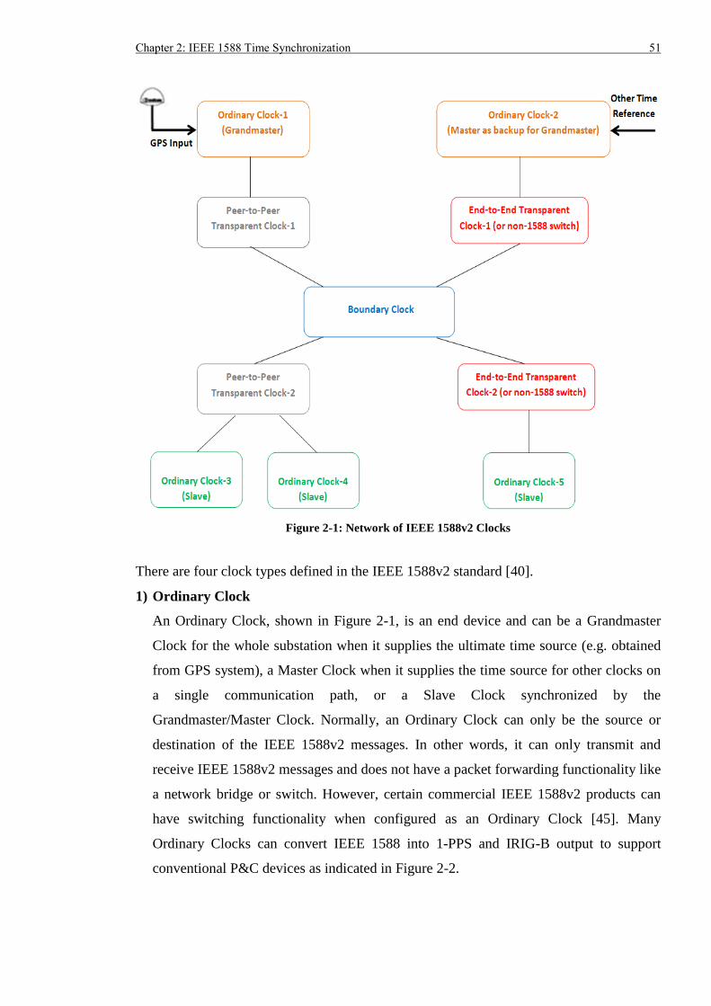
Chapter 2: IEEE 1588 Time Synchronization 51
Figure 2-1: Network of IEEE 1588v2 Clocks
There are four clock types defined in the IEEE 1588v2 standard [40].
1) Ordinary Clock
An Ordinary Clock, shown in Figure 2-1, is an end device and can be a Grandmaster
Clock for the whole substation when it supplies the ultimate time source (e.g. obtained
from GPS system), a Master Clock when it supplies the time source for other clocks on
a single communication path, or a Slave Clock synchronized by the
Grandmaster/Master Clock. Normally, an Ordinary Clock can only be the source or
destination of the IEEE 1588v2 messages. In other words, it can only transmit and
receive IEEE 1588v2 messages and does not have a packet forwarding functionality like
a network bridge or switch. However, certain commercial IEEE 1588v2 products can
have switching functionality when configured as an Ordinary Clock [45]. Many
Ordinary Clocks can convert IEEE 1588 into 1-PPS and IRIG-B output to support
conventional P&C devices as indicated in Figure 2-2.
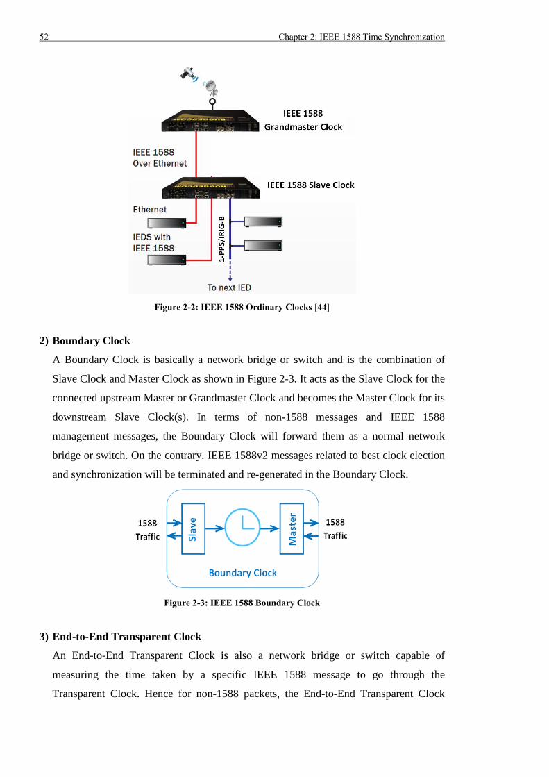
52 Chapter 2: IEEE 1588 Time Synchronization
Figure 2-2: IEEE 1588 Ordinary Clocks [44]
2) Boundary Clock
A Boundary Clock is basically a network bridge or switch and is the combination of
Slave Clock and Master Clock as shown in Figure 2-3. It acts as the Slave Clock for the
connected upstream Master or Grandmaster Clock and becomes the Master Clock for its
downstream Slave Clock(s). In terms of non-1588 messages and IEEE 1588
management messages, the Boundary Clock will forward them as a normal network
bridge or switch. On the contrary, IEEE 1588v2 messages related to best clock election
and synchronization will be terminated and re-generated in the Boundary Clock.
Figure 2-3: IEEE 1588 Boundary Clock
3) End-to-End Transparent Clock
An End-to-End Transparent Clock is also a network bridge or switch capable of
measuring the time taken by a specific IEEE 1588 message to go through the
Transparent Clock. Hence for non-1588 packets, the End-to-End Transparent Clock
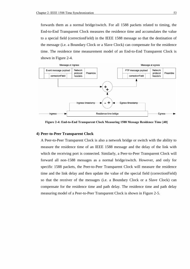
Chapter 2: IEEE 1588 Time Synchronization 53
forwards them as a normal bridge/switch. For all 1588 packets related to timing, the
End-to-End Transparent Clock measures the residence time and accumulates the value
to a special field (correctionField) in the IEEE 1588 message so that the destination of
the message (i.e. a Boundary Clock or a Slave Clock) can compensate for the residence
time. The residence time measurement model of an End-to-End Transparent Clock is
shown in Figure 2-4.
Figure 2-4: End-to-End Transparent Clock Measuring 1588 Message Residence Time [40]
4) Peer-to-Peer Transparent Clock
A Peer-to-Peer Transparent Clock is also a network bridge or switch with the ability to
measure the residence time of an IEEE 1588 message and the delay of the link with
which the receiving port is connected. Similarly, a Peer-to-Peer Transparent Clock will
forward all non-1588 messages as a normal bridge/switch. However, and only for
specific 1588 packets, the Peer-to-Peer Transparent Clock will measure the residence
time and the link delay and then update the value of the special field (correctionField)
so that the receiver of the messages (i.e. a Boundary Clock or a Slave Clock) can
compensate for the residence time and path delay. The residence time and path delay
measuring model of a Peer-to-Peer Transparent Clock is shown in Figure 2-5.
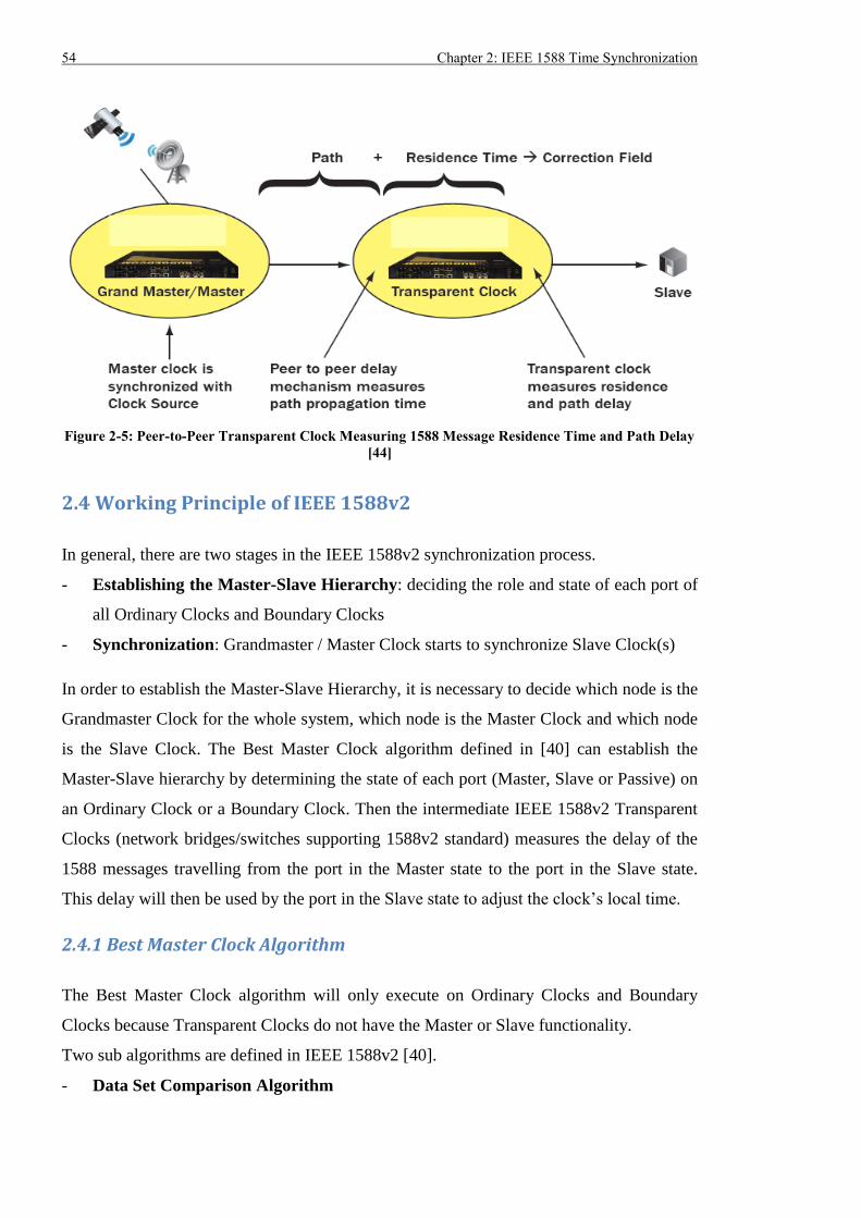
54 Chapter 2: IEEE 1588 Time Synchronization
Figure 2-5: Peer-to-Peer Transparent Clock Measuring 1588 Message Residence Time and Path Delay
[44]
2.4 Working Principle of IEEE 1588v2
In general, there are two stages in the IEEE 1588v2 synchronization process.
- Establishing the Master-Slave Hierarchy: deciding the role and state of each port of
all Ordinary Clocks and Boundary Clocks
- Synchronization: Grandmaster / Master Clock starts to synchronize Slave Clock(s)
In order to establish the Master-Slave Hierarchy, it is necessary to decide which node is the
Grandmaster Clock for the whole system, which node is the Master Clock and which node
is the Slave Clock. The Best Master Clock algorithm defined in [40] can establish the
Master-Slave hierarchy by determining the state of each port (Master, Slave or Passive) on
an Ordinary Clock or a Boundary Clock. Then the intermediate IEEE 1588v2 Transparent
Clocks (network bridges/switches supporting 1588v2 standard) measures the delay of the
1588 messages travelling from the port in the Master state to the port in the Slave state.
This delay will then be used by the port in the Slave state to adjust the clock’s local time.
2.4.1 Best Master Clock Algorithm
The Best Master Clock algorithm will only execute on Ordinary Clocks and Boundary
Clocks because Transparent Clocks do not have the Master or Slave functionality.
Two sub algorithms are defined in IEEE 1588v2 [40].
- Data Set Comparison Algorithm
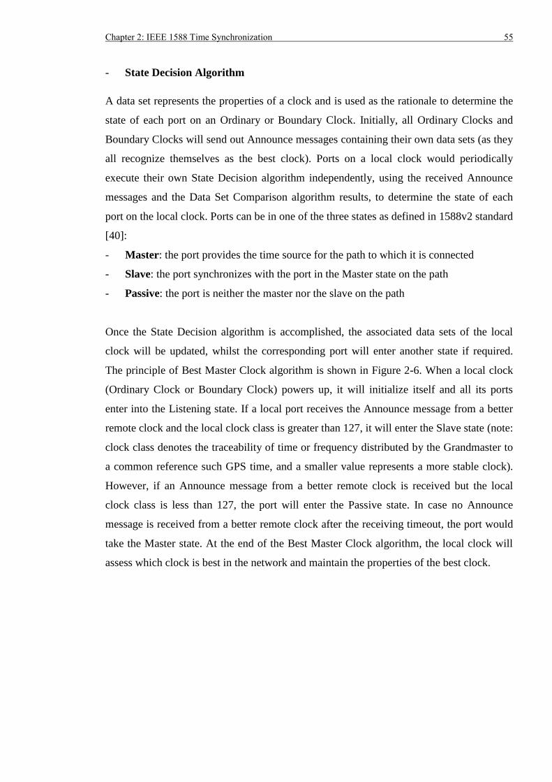
Chapter 2: IEEE 1588 Time Synchronization 55
- State Decision Algorithm
A data set represents the properties of a clock and is used as the rationale to determine the
state of each port on an Ordinary or Boundary Clock. Initially, all Ordinary Clocks and
Boundary Clocks will send out Announce messages containing their own data sets (as they
all recognize themselves as the best clock). Ports on a local clock would periodically
execute their own State Decision algorithm independently, using the received Announce
messages and the Data Set Comparison algorithm results, to determine the state of each
port on the local clock. Ports can be in one of the three states as defined in 1588v2 standard
[40]:
- Master: the port provides the time source for the path to which it is connected
- Slave: the port synchronizes with the port in the Master state on the path
- Passive: the port is neither the master nor the slave on the path
Once the State Decision algorithm is accomplished, the associated data sets of the local
clock will be updated, whilst the corresponding port will enter another state if required.
The principle of Best Master Clock algorithm is shown in Figure 2-6. When a local clock
(Ordinary Clock or Boundary Clock) powers up, it will initialize itself and all its ports
enter into the Listening state. If a local port receives the Announce message from a better
remote clock and the local clock class is greater than 127, it will enter the Slave state (note:
clock class denotes the traceability of time or frequency distributed by the Grandmaster to
a common reference such GPS time, and a smaller value represents a more stable clock).
However, if an Announce message from a better remote clock is received but the local
clock class is less than 127, the port will enter the Passive state. In case no Announce
message is received from a better remote clock after the receiving timeout, the port would
take the Master state. At the end of the Best Master Clock algorithm, the local clock will
assess which clock is best in the network and maintain the properties of the best clock.
56 Chapter 2: IEEE 1588 Time Synchronization
Figure 2-6: Principle of Best Master Clock Algorithm
After several rounds of Best Master Clock algorithm execution, the Master-Slave
Hierarchy indicated in Figure 2-7 can be established. From Figure 2-7, Ordinary Clock-1 is
the best clock for the whole network and it operates as the Grandmaster with its port in the
Master state. Ordinary Clock-2 acts as the backup Grandmaster with its port in the Passive
state. All ports on transparent clocks are in the Passive state, since they do not have Master
or Slave functionality. The port in the Slave state on the Boundary Clock receives the time
reference from Grandmaster and the time reference is then regenerated and sent via the
other ports in the Master state. In general, the time reference is generated from the port in
the Master state on the Grandmaster and passes through Peer-to-Peer Transparent Clock-1
to the port in the Slave state on the Boundary Clock. The ports in the Master state on the
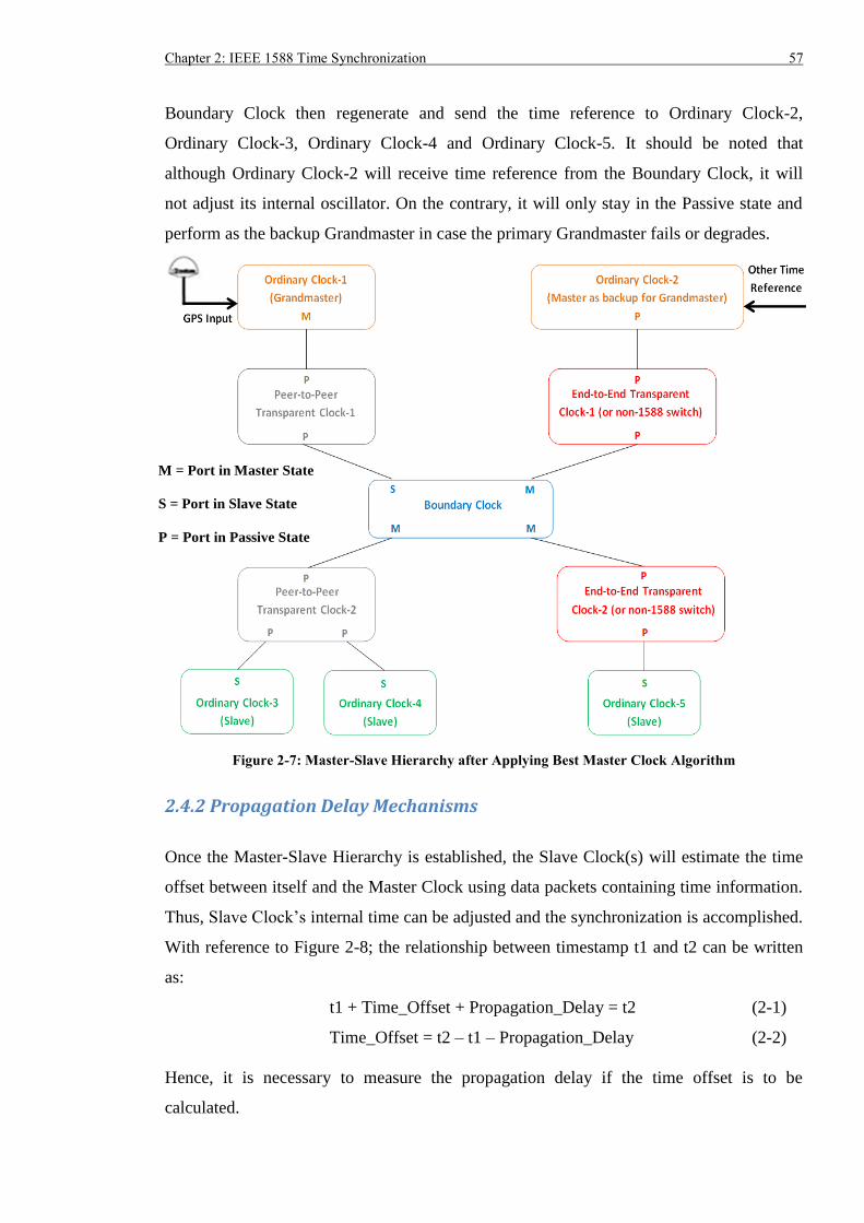
Chapter 2: IEEE 1588 Time Synchronization 57
Boundary Clock then regenerate and send the time reference to Ordinary Clock-2,
Ordinary Clock-3, Ordinary Clock-4 and Ordinary Clock-5. It should be noted that
although Ordinary Clock-2 will receive time reference from the Boundary Clock, it will
not adjust its internal oscillator. On the contrary, it will only stay in the Passive state and
perform as the backup Grandmaster in case the primary Grandmaster fails or degrades.
Figure 2-7: Master-Slave Hierarchy after Applying Best Master Clock Algorithm
2.4.2 Propagation Delay Mechanisms
Once the Master-Slave Hierarchy is established, the Slave Clock(s) will estimate the time
offset between itself and the Master Clock using data packets containing time information.
Thus, Slave Clock’s internal time can be adjusted and the synchronization is accomplished.
With reference to Figure 2-8; the relationship between timestamp t1 and t2 can be written
as:
t1 + Time_Offset + Propagation_Delay = t2 (2-1)
Time_Offset = t2 – t1 – Propagation_Delay (2-2)
Hence, it is necessary to measure the propagation delay if the time offset is to be
calculated.
M = Port in Master State
S = Port in Slave State
P = Port in Passive State
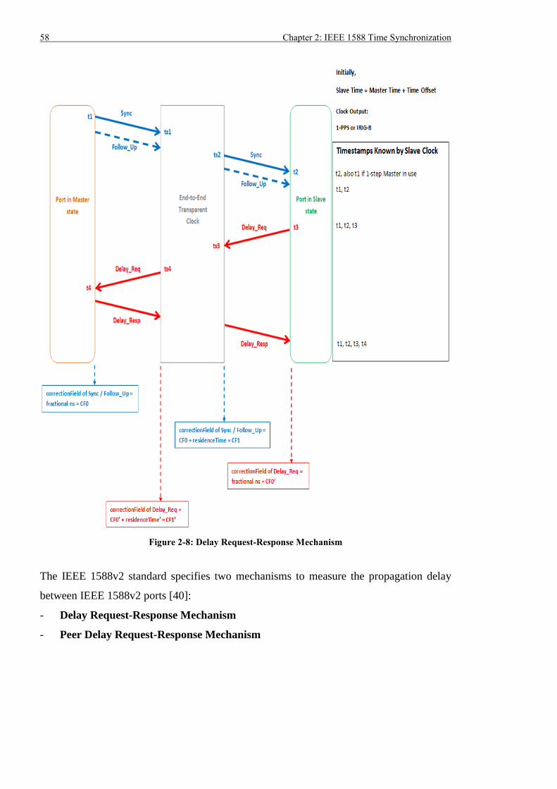
58 Chapter 2: IEEE 1588 Time Synchronization
Figure 2-8: Delay Request-Response Mechanism
The IEEE 1588v2 standard specifies two mechanisms to measure the propagation delay
between IEEE 1588v2 ports [40]:
- Delay Request-Response Mechanism
- Peer Delay Request-Response Mechanism
Chapter 2: IEEE 1588 Time Synchronization 59
2.4.2.1 Delay Request-Response Mechanism
The Delay Request-Response mechanism can directly measure the propagation delay
between the port in the Master state and the associated port(s) in the Slave state. IEEE
1588 messages Sync, Delay_Req and Delay_Resp as shown in Figure 2-8 are used.
If a one-step clock is used, there is no Follow_Up message. Otherwise, the Follow_Up
message is used for a two-step clock. The difference is that one-step clock can measure the
actual time t1 when the Sync message is sent out and then encapsulate the precise
timestamp in the Sync message. On the other hand, a two-step clock can only pack a coarse
timestamp in the Sync message and the actual time is carried in the later Follow_Up
message. The synchronization process using the Delay Request-Response mechanism can
be described as:
- Port in Master state generates the Sync message and transmits it. The time t1 when the
Sync message is sent out is carried in Sync (or Follow_Up if two-step clock is used).
If there is a fractional nanosecond in the timestamp, the fractional part is stored in the
correctionField of the Sync message (or Follow_Up).
- If there is an End-to-End Transparent Clock, timestamp ts1 will be recorded by the
Transparent Clock as the incoming timestamp when the Sync message arrives at it.
When the Sync message is forwarded, timestamp ts2 is generated as the outgoing
timestamp. The time difference between ts2 and ts1 is termed as residence time and
will be measured and accumulated in the correctionField of Sync (or Follow_Up) by
the Transparent Clock. If there are multiple End-to-End Transparent Clocks, the
residence time measurement process for the Sync message will be repeated in each
Transparent Clock.
- Port in Slave state receives the Sync message (and Follow_Up message), records the
receiving time t2 and extracts the timestamp t1 and correctionField data from the Sync
message (and Follow_Up if it exists).
- Port in Slave state generates the Delay_Req message and transmits it after a certain
delay. The transmitting time t3 is measured by the Port in Slave state.
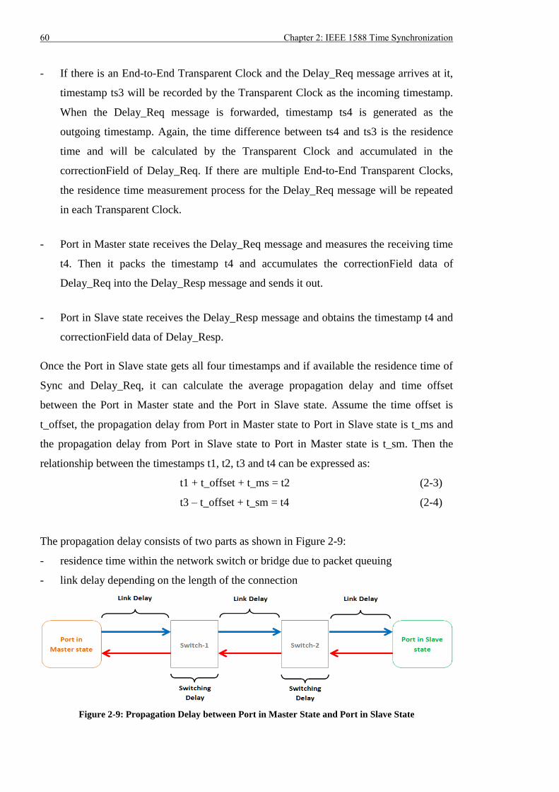
60 Chapter 2: IEEE 1588 Time Synchronization
- If there is an End-to-End Transparent Clock and the Delay_Req message arrives at it,
timestamp ts3 will be recorded by the Transparent Clock as the incoming timestamp.
When the Delay_Req message is forwarded, timestamp ts4 is generated as the
outgoing timestamp. Again, the time difference between ts4 and ts3 is the residence
time and will be calculated by the Transparent Clock and accumulated in the
correctionField of Delay_Req. If there are multiple End-to-End Transparent Clocks,
the residence time measurement process for the Delay_Req message will be repeated
in each Transparent Clock.
- Port in Master state receives the Delay_Req message and measures the receiving time
t4. Then it packs the timestamp t4 and accumulates the correctionField data of
Delay_Req into the Delay_Resp message and sends it out.
- Port in Slave state receives the Delay_Resp message and obtains the timestamp t4 and
correctionField data of Delay_Resp.
Once the Port in Slave state gets all four timestamps and if available the residence time of
Sync and Delay_Req, it can calculate the average propagation delay and time offset
between the Port in Master state and the Port in Slave state. Assume the time offset is
t_offset, the propagation delay from Port in Master state to Port in Slave state is t_ms and
the propagation delay from Port in Slave state to Port in Master state is t_sm. Then the
relationship between the timestamps t1, t2, t3 and t4 can be expressed as:
t1 + t_offset + t_ms = t2 (2-3)
t3 – t_offset + t_sm = t4 (2-4)
The propagation delay consists of two parts as shown in Figure 2-9:
- residence time within the network switch or bridge due to packet queuing
- link delay depending on the length of the connection
Figure 2-9: Propagation Delay between Port in Master State and Port in Slave State
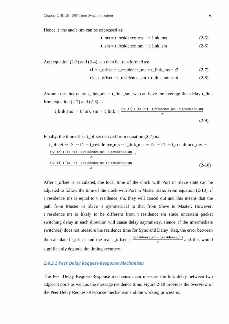
Chapter 2: IEEE 1588 Time Synchronization 61
Hence, t_ms and t_sm can be expressed as:
t_ms = t_residence_ms + t_link_ms (2-5)
t_sm = t_residence_sm + t_link_sm (2-6)
And equation (2-3) and (2-4) can then be transformed as:
t1 + t_offset + t_residence_ms + t_link_ms = t2 (2-7)
t3 – t_offset + t_residence_sm + t_link_sm = t4 (2-8)
Assume the link delay t_link_ms = t_link_sm, we can have the average link delay t_link
from equation (2-7) and (2-8) as:
t_link_ms = t_link_sm = t_link =(t2−t3) + (t4−t1) − t_residence_ms − t_residence_sm
2
(2-9)
Finally, the time offset t_offset derived from equation (2-7) is:
t_offset = t2 − t1 − t_residence_ms − t_link_ms = t2 − t1 − t_residence_ms −
(t2−t3) + (t4−t1) − t_residence_ms − t_residence_sm
2=
(t2−t1) + (t3−t4) − t_residence_ms + t_residence_sm
2 (2-10)
After t_offset is calculated, the local time of the clock with Port in Slave state can be
adjusted to follow the time of the clock with Port in Master state. From equation (2-10), if
t_residence_ms is equal to t_residence_sm, they will cancel out and this means that the
path from Master to Slave is symmetrical to that from Slave to Master. However,
t_residence_ms is likely to be different from t_residence_sm since uncertain packet
switching delay in each direction will cause delay asymmetry. Hence, if the intermediate
switch(es) does not measure the residence time for Sync and Delay_Req, the error between
the calculated t_offset and the real t_offset is t_residence_sm− t_residence_ms
2 and this would
significantly degrade the timing accuracy.
2.4.2.2 Peer Delay Request-Response Mechanism
The Peer Delay Request-Response mechanism can measure the link delay between two
adjacent ports as well as the message residence time. Figure 2-10 provides the overview of
the Peer Delay Request-Response mechanism and the working process is:
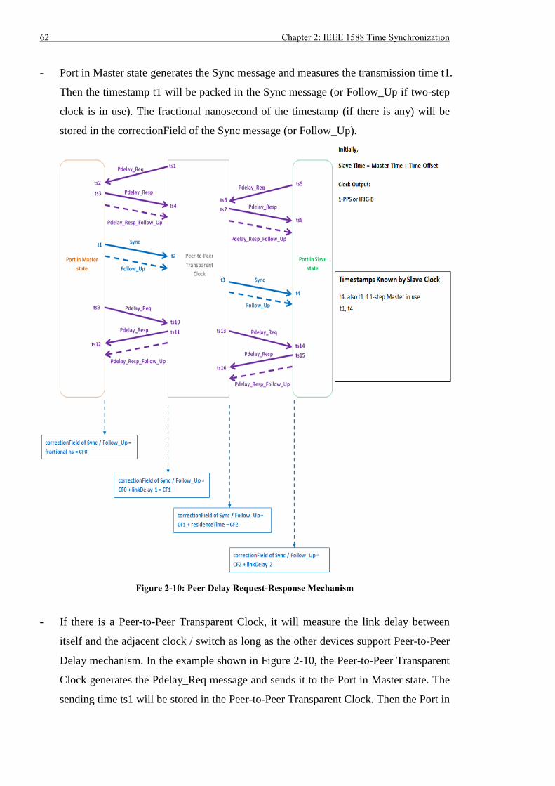
62 Chapter 2: IEEE 1588 Time Synchronization
- Port in Master state generates the Sync message and measures the transmission time t1.
Then the timestamp t1 will be packed in the Sync message (or Follow_Up if two-step
clock is in use). The fractional nanosecond of the timestamp (if there is any) will be
stored in the correctionField of the Sync message (or Follow_Up).
Figure 2-10: Peer Delay Request-Response Mechanism
- If there is a Peer-to-Peer Transparent Clock, it will measure the link delay between
itself and the adjacent clock / switch as long as the other devices support Peer-to-Peer
Delay mechanism. In the example shown in Figure 2-10, the Peer-to-Peer Transparent
Clock generates the Pdelay_Req message and sends it to the Port in Master state. The
sending time ts1 will be stored in the Peer-to-Peer Transparent Clock. Then the Port in
Chapter 2: IEEE 1588 Time Synchronization 63
Master state receives the Pdelay_Req message and marks the receiving time ts2. After
some delay, the Port in Master state generates the Pdelay_Resp message containing
the timestamp ts2 and the transmitting time ts3 (ts3 would be carried in the
Pdelay_Resp_Follow_Up message if two-step clock is used). The Peer-to-Peer
Transparent Clock gets the Pdelay_Resp message and measures the receiving
timestamp ts4. Suppose the link delay from the Transparent Clock to the Port in
Master state is t_link_tcm, the link delay from the Port in Master state to the
Transparent Clock is t_link_mtc and the time offset between them is t_offset, the
relationship between ts1, ts2, ts3 and ts4 can be expressed as:
ts1 – t_offset + t_link_tcm = ts2 (2-11)
ts3 + t_offset + t_link_mtc = ts4 (2-12)
Because the physical links in transmission and receiving directions are bundled in a
single cable, t_link_tcm and t_link_mtc are assumed to be symmetrical. Therefore, the
average link delay between the Port in Master state and the Transparent Clock can be
calculated as:
t_link = t_link_tcm = t_link_mtc = (ts4−ts1) − (ts3−ts2)
2 (2-13)
With timestamps ts1, ts2, ts3 and ts4, the Peer-to-Peer Transparent Clock can measure
the average link delay between the Port in Master state and the Transparent Clock.
- When the Sync message arrives at the Peer-to-Peer Transparent Clock, it will record
the receiving timestamp t2 and accumulate the calculated link delay value to the
correctionField of the Sync message (or Follow_Up).
- Peer-to-Peer Transparent Clock forwards the Sync message at time t3 and the
residence time (t3 – t2) is added to the correctionField of the Sync message (or
Follow_Up message). If there are multiple Peer-to-Peer Transparent Clocks, the link
delay and residence time measurement process will be repeated in each of them.
- In general, if the clock with Port in Slave state supports the Peer-to-Peer Delay
mechanism, it will also measure the link delay between itself and the upstream
connected clock/switch. When it receives the Sync message, it marks the receipt time
64 Chapter 2: IEEE 1588 Time Synchronization
t4 and accumulated the link delay value to the correctionField of Sync message (or
Follow_Up).
As soon as the Port in Slave state obtains the transmission time of Sync at Port in Master
state (t1), the correctionField value of Sync or Follow_Up (t_CF: contains the link delay
between the Port in Master state and Transparent Clock, residence time in Transparent
Clock and the link delay between the Transparent Clock and the Port in Slave state) and
the receiving time of Sync at Port in Slave state (t4), the time offset between Port in Master
state and Port in Slave state (t_offset) can be calculated as:
t_offset = t4 – t1 – t_CF (2-14)
According to Figure 2-10, it is worth noting that the Port in Master state would also
measure the link delay between itself and the Transparent Clock using timestamps ts9,
ts10, ts11 and ts12. The same procedure occurs as the Transparent Clock measure the link
delay between itself and the Port in Slave state.
In Delay Request-Response mechanism, the residence time of the 1588 packets can be
precisely measured. On the other hand, the Peer Delay Request-Response mechanism
could accurately measure both link delay and residence time. Hence, the estimation of time
offset between the Port in Slave state and Master state will be more accurate when Peer
Delay Request-Response mechanism is used. Although there may be error in average link
delay calculation due to the link asymmetry, the error should be negligible since the whole
path is divided into small parts with less asymmetry [46].
2.4.3 Requirement for Ethernet Switches in 1588 Timing Network
If ports employ the Delay Request-Response mechanism, mean path delay can be
calculated by using the Delay_Req and Delay_Resp messages even there is no IEEE 1588
compliant Ethernet switch. On the contrary, if Peer Delay Request-Response mechanism is
used, path delay measurement cannot be made without IEEE 1588 Ethernet switch. Hence,
IEEE 1588v2 protocol specifies that non-1588 switches and End-to-End Transparent
Clocks can be employed between ports deploying Delay Request-Response mechanism.
Whilst for ports implementing the Peer Delay Request-Response mechanism, if switch(es)
exist between them, these switches have to support Peer Delay Request-Response
mechanism. Note: Ports deploying Delay Request-Response mechanism do not work
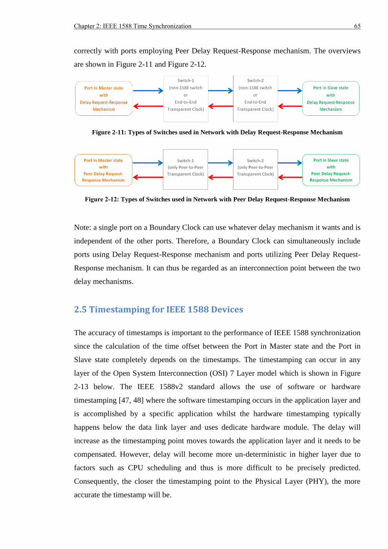
Chapter 2: IEEE 1588 Time Synchronization 65
correctly with ports employing Peer Delay Request-Response mechanism. The overviews
are shown in Figure 2-11 and Figure 2-12.
Figure 2-11: Types of Switches used in Network with Delay Request-Response Mechanism
Figure 2-12: Types of Switches used in Network with Peer Delay Request-Response Mechanism
Note: a single port on a Boundary Clock can use whatever delay mechanism it wants and is
independent of the other ports. Therefore, a Boundary Clock can simultaneously include
ports using Delay Request-Response mechanism and ports utilizing Peer Delay Request-
Response mechanism. It can thus be regarded as an interconnection point between the two
delay mechanisms.
2.5 Timestamping for IEEE 1588 Devices
The accuracy of timestamps is important to the performance of IEEE 1588 synchronization
since the calculation of the time offset between the Port in Master state and the Port in
Slave state completely depends on the timestamps. The timestamping can occur in any
layer of the Open System Interconnection (OSI) 7 Layer model which is shown in Figure
2-13 below. The IEEE 1588v2 standard allows the use of software or hardware
timestamping [47, 48] where the software timestamping occurs in the application layer and
is accomplished by a specific application whilst the hardware timestamping typically
happens below the data link layer and uses dedicate hardware module. The delay will
increase as the timestamping point moves towards the application layer and it needs to be
compensated. However, delay will become more un-deterministic in higher layer due to
factors such as CPU scheduling and thus is more difficult to be precisely predicted.
Consequently, the closer the timestamping point to the Physical Layer (PHY), the more
accurate the timestamp will be.
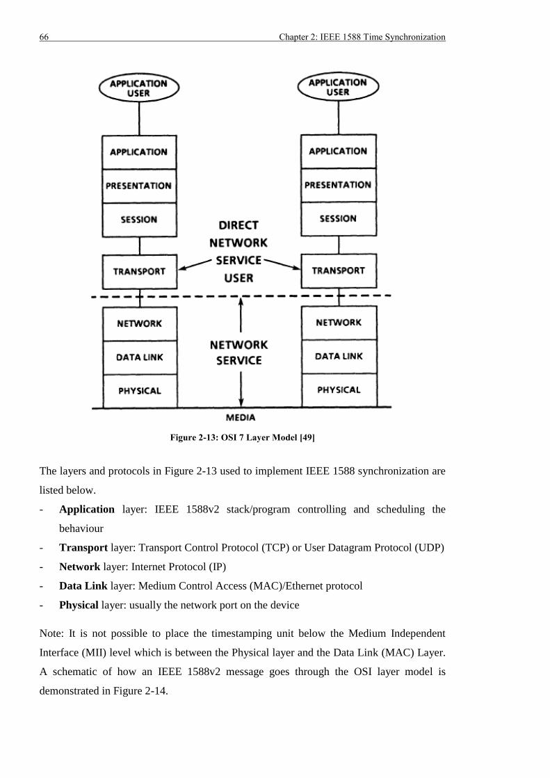
66 Chapter 2: IEEE 1588 Time Synchronization
Figure 2-13: OSI 7 Layer Model [49]
The layers and protocols in Figure 2-13 used to implement IEEE 1588 synchronization are
listed below.
- Application layer: IEEE 1588v2 stack/program controlling and scheduling the
behaviour
- Transport layer: Transport Control Protocol (TCP) or User Datagram Protocol (UDP)
- Network layer: Internet Protocol (IP)
- Data Link layer: Medium Control Access (MAC)/Ethernet protocol
- Physical layer: usually the network port on the device
Note: It is not possible to place the timestamping unit below the Medium Independent
Interface (MII) level which is between the Physical layer and the Data Link (MAC) Layer.
A schematic of how an IEEE 1588v2 message goes through the OSI layer model is
demonstrated in Figure 2-14.
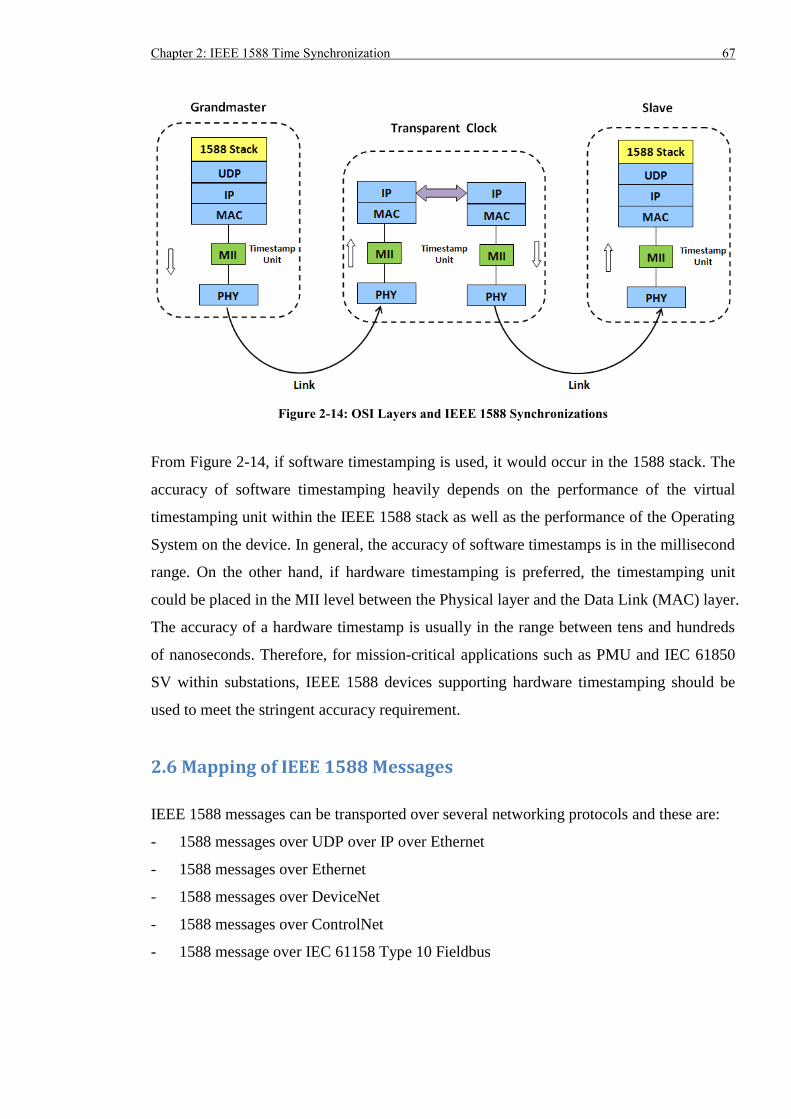
Chapter 2: IEEE 1588 Time Synchronization 67
Figure 2-14: OSI Layers and IEEE 1588 Synchronizations
From Figure 2-14, if software timestamping is used, it would occur in the 1588 stack. The
accuracy of software timestamping heavily depends on the performance of the virtual
timestamping unit within the IEEE 1588 stack as well as the performance of the Operating
System on the device. In general, the accuracy of software timestamps is in the millisecond
range. On the other hand, if hardware timestamping is preferred, the timestamping unit
could be placed in the MII level between the Physical layer and the Data Link (MAC) layer.
The accuracy of a hardware timestamp is usually in the range between tens and hundreds
of nanoseconds. Therefore, for mission-critical applications such as PMU and IEC 61850
SV within substations, IEEE 1588 devices supporting hardware timestamping should be
used to meet the stringent accuracy requirement.
2.6 Mapping of IEEE 1588 Messages
IEEE 1588 messages can be transported over several networking protocols and these are:
- 1588 messages over UDP over IP over Ethernet
- 1588 messages over Ethernet
- 1588 messages over DeviceNet
- 1588 messages over ControlNet
- 1588 message over IEC 61158 Type 10 Fieldbus
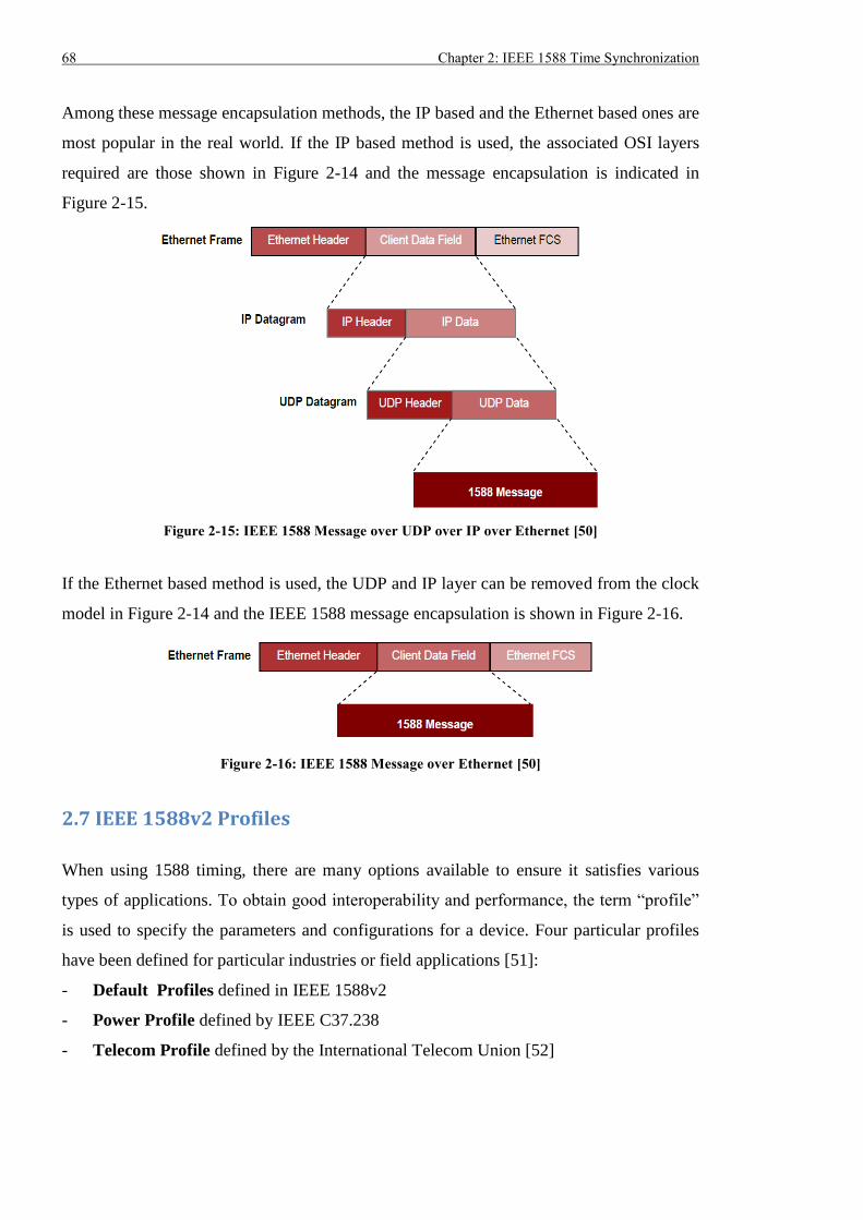
68 Chapter 2: IEEE 1588 Time Synchronization
Among these message encapsulation methods, the IP based and the Ethernet based ones are
most popular in the real world. If the IP based method is used, the associated OSI layers
required are those shown in Figure 2-14 and the message encapsulation is indicated in
Figure 2-15.
Figure 2-15: IEEE 1588 Message over UDP over IP over Ethernet [50]
If the Ethernet based method is used, the UDP and IP layer can be removed from the clock
model in Figure 2-14 and the IEEE 1588 message encapsulation is shown in Figure 2-16.
Figure 2-16: IEEE 1588 Message over Ethernet [50]
2.7 IEEE 1588v2 Profiles
When using 1588 timing, there are many options available to ensure it satisfies various
types of applications. To obtain good interoperability and performance, the term “profile”
is used to specify the parameters and configurations for a device. Four particular profiles
have been defined for particular industries or field applications [51]:
- Default Profiles defined in IEEE 1588v2
- Power Profile defined by IEEE C37.238
- Telecom Profile defined by the International Telecom Union [52]
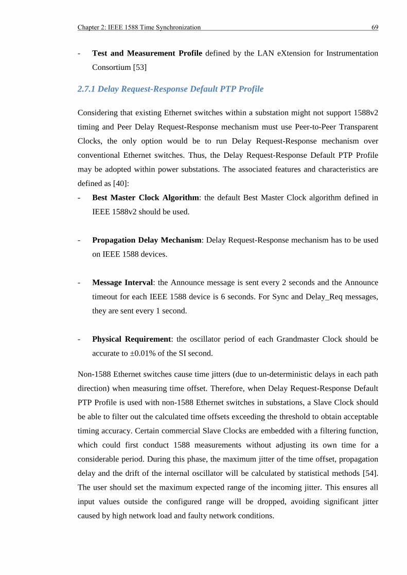
Chapter 2: IEEE 1588 Time Synchronization 69
- Test and Measurement Profile defined by the LAN eXtension for Instrumentation
Consortium [53]
2.7.1 Delay Request-Response Default PTP Profile
Considering that existing Ethernet switches within a substation might not support 1588v2
timing and Peer Delay Request-Response mechanism must use Peer-to-Peer Transparent
Clocks, the only option would be to run Delay Request-Response mechanism over
conventional Ethernet switches. Thus, the Delay Request-Response Default PTP Profile
may be adopted within power substations. The associated features and characteristics are
defined as [40]:
- Best Master Clock Algorithm: the default Best Master Clock algorithm defined in
IEEE 1588v2 should be used.
- Propagation Delay Mechanism: Delay Request-Response mechanism has to be used
on IEEE 1588 devices.
- Message Interval: the Announce message is sent every 2 seconds and the Announce
timeout for each IEEE 1588 device is 6 seconds. For Sync and Delay_Req messages,
they are sent every 1 second.
- Physical Requirement: the oscillator period of each Grandmaster Clock should be
accurate to ±0.01% of the SI second.
Non-1588 Ethernet switches cause time jitters (due to un-deterministic delays in each path
direction) when measuring time offset. Therefore, when Delay Request-Response Default
PTP Profile is used with non-1588 Ethernet switches in substations, a Slave Clock should
be able to filter out the calculated time offsets exceeding the threshold to obtain acceptable
timing accuracy. Certain commercial Slave Clocks are embedded with a filtering function,
which could first conduct 1588 measurements without adjusting its own time for a
considerable period. During this phase, the maximum jitter of the time offset, propagation
delay and the drift of the internal oscillator will be calculated by statistical methods [54].
The user should set the maximum expected range of the incoming jitter. This ensures all
input values outside the configured range will be dropped, avoiding significant jitter
caused by high network load and faulty network conditions.
70 Chapter 2: IEEE 1588 Time Synchronization
2.7.2 Peer Delay Request-Response Default PTP Profile
If Ethernet switches within a substation support 1588v2 timing and the Peer Delay
Request-Response mechanism, the Peer Delay Request-Response Default PTP Profile can
be used to achieve good timing accuracy. The associated features and characteristics are
[40]:
- Best Master Clock Algorithm: the default Best Master Clock algorithm defined in
IEEE 1588v2 should be used.
- Propagation Delay Mechanism: Peer Delay Request-Response mechanism has to be
used on IEEE 1588 devices.
- Message Interval: the Announce message is sent every 2 seconds and the Announce
timeout for each IEEE 1588 device is 6 seconds. For Sync and Pdelay_Req messages,
they are sent every 1 second.
- Physical Requirement: the oscillator period of each Grandmaster Clock should be
accurate to ±0.01% of the SI second.
2.7.3 IEEE 1588 Power Profile
The IEEE 1588 Power Profile is defined by the IEEE C37.238-2011 standard [55] for
power system applications and should be used when a 1588 timing network is constructed
in a substation. The major characteristics are [56]:
- Clock Steps: normally one-step clocks are preferred because they reduce the network
load but two-step clocks are allowed.
- Transport of IEEE 1588 Messages: the IEEE 1588 messages should be transmitted
as multicast traffic and encapsulated in Ethernet frame directly (i.e. no UDP/IP).
Virtual LAN (VLAN) tagging [57] with default priority = 4 should be used in each
1588 message.
- Best Master Clock Algorithm: the default Best Master Clock algorithm defined in
IEEE 1588v2 should be used on all IEEE 1588 devices. Unlike the default Delay
Request-Response and Peer Delay Request-Response profiles, only the potential
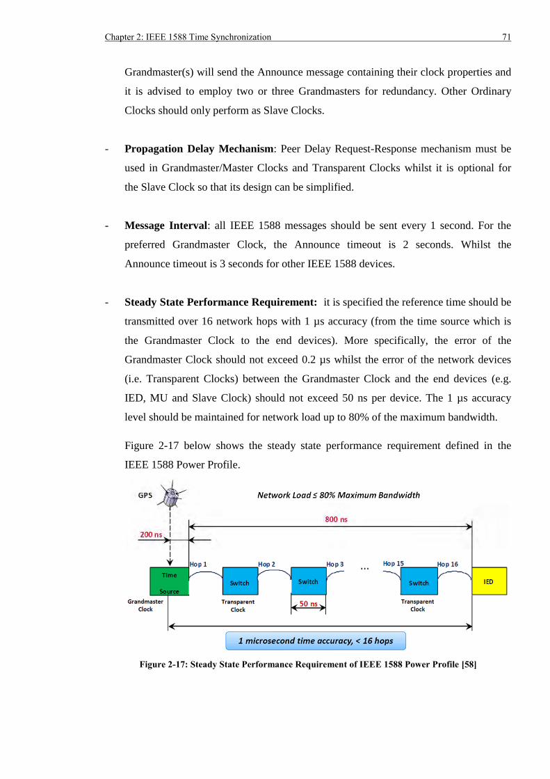
Chapter 2: IEEE 1588 Time Synchronization 71
Grandmaster(s) will send the Announce message containing their clock properties and
it is advised to employ two or three Grandmasters for redundancy. Other Ordinary
Clocks should only perform as Slave Clocks.
- Propagation Delay Mechanism: Peer Delay Request-Response mechanism must be
used in Grandmaster/Master Clocks and Transparent Clocks whilst it is optional for
the Slave Clock so that its design can be simplified.
- Message Interval: all IEEE 1588 messages should be sent every 1 second. For the
preferred Grandmaster Clock, the Announce timeout is 2 seconds. Whilst the
Announce timeout is 3 seconds for other IEEE 1588 devices.
- Steady State Performance Requirement: it is specified the reference time should be
transmitted over 16 network hops with 1 µs accuracy (from the time source which is
the Grandmaster Clock to the end devices). More specifically, the error of the
Grandmaster Clock should not exceed 0.2 µs whilst the error of the network devices
(i.e. Transparent Clocks) between the Grandmaster Clock and the end devices (e.g.
IED, MU and Slave Clock) should not exceed 50 ns per device. The 1 µs accuracy
level should be maintained for network load up to 80% of the maximum bandwidth.
Figure 2-17 below shows the steady state performance requirement defined in the
IEEE 1588 Power Profile.
Figure 2-17: Steady State Performance Requirement of IEEE 1588 Power Profile [58]
72 Chapter 2: IEEE 1588 Time Synchronization
- Transient State Performance Requirement: when a time reference signal is not
available, the grandmaster-capable devices should be able to holdover with accuracy
better than 2 µs for up to 5 seconds at constant temperature.
- Profile Specific Requirement: additional Type, Length, Value (TLV) fields: namely
ALTERNATE_TIME_OFFSET_INDICATOR and ORGANIZATION_EXTENSION,
have to be appended to the Announce messages.
Both Peer Delay Request-Response Default PTP Profile and Power Profile use the same
propagation delay mechanism and details about the difference between these two profiles
are summarized in Appendix A [56].
Considering that IEEE 1588 time synchronization can share the data network with IEC
61850 P&C applications, implementation of the IEEE 1588 Power Profile over IEC 61850
Station Bus and Process Buses is feasible and compatible in future digital substations as
indicated in Figure 2-18.
Figure 2-18: IEEE 1588 Timing Implemented on IEC 61850 Communication Buses [58]
2.7.4 IEEE 1588 Telecom Profile
Unlike the IEEE 1588 Power Profile which is normally deployed within power substations
(i.e. LAN), the IEEE 1588 Telecom Profile tends to apply outside a specific LAN and aims
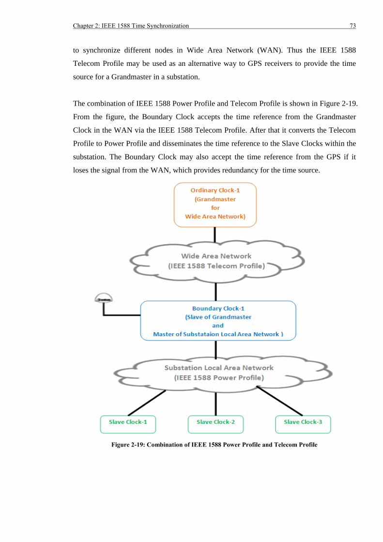
Chapter 2: IEEE 1588 Time Synchronization 73
to synchronize different nodes in Wide Area Network (WAN). Thus the IEEE 1588
Telecom Profile may be used as an alternative way to GPS receivers to provide the time
source for a Grandmaster in a substation.
The combination of IEEE 1588 Power Profile and Telecom Profile is shown in Figure 2-19.
From the figure, the Boundary Clock accepts the time reference from the Grandmaster
Clock in the WAN via the IEEE 1588 Telecom Profile. After that it converts the Telecom
Profile to Power Profile and disseminates the time reference to the Slave Clocks within the
substation. The Boundary Clock may also accept the time reference from the GPS if it
loses the signal from the WAN, which provides redundancy for the time source.
Figure 2-19: Combination of IEEE 1588 Power Profile and Telecom Profile
74 Chapter 2: IEEE 1588 Time Synchronization
The major features of the 1588 Telecom Profile are listed below [52].
- Clock Steps: normally one-step clocks are preferred because they reduce the network
load but two-step clocks are allowed.
- Clock Types: Ordinary Clocks and Boundary Clocks have to be used whilst
Transparent Clocks are prohibited between the Master and Slave Clocks in the WAN.
- Transport of IEEE 1588 messages: the IEEE 1588 messages should be transmitted
as multicast traffic and encapsulated in the Ethernet frame directly (i.e. no UDP/IP).
- Best Master Clock Algorithm: alternate Best Master Clock algorithm defined in [52]
should be used in all IEEE 1588 devices.
- Propagation Delay Mechanism: only Delay Request-Response mechanism can be
used according to the Telecom Profile.
- Message Interval: the Announce message is sent every 0.125 second and the
Announce timeout for each IEEE 1588 device is 0.375 second. For Sync and
Delay_Req message, they are sent every 0.0625 second.
2.8 Summary
The IEEE 1588v2 timing technology can be implemented over the data network to achieve
accuracy better than ±1 µs. Section 2.2 presented the originality and development of the
IEEE 1588 protocol. Section 2.3 introduced four types of devices: Ordinary Clock,
Boundary Clock, End-to-End Transparent Clock and Peer-to-Peer Transparent Clock that
could be used to implement the IEEE 1588 timing. An Ordinary Clock was an end device
which could be used as a Grandmaster/Master sending the time reference or a Slave
receiving the reference. A Boundary Clock or Transparent Clock was an Ethernet switch
embedding IEEE 1588 functionalities to mitigate the impact of propagation and
transmission delays. Working principle related to best clock selection, synchronization
hierarchy establishment and clock synchronization was described in Section 2.4. Each
Ordinary Clock and Boundary Clock sent the Announce message containing device
properties and the Best Master Clock algorithm was run on each clock to determine the
Chapter 2: IEEE 1588 Time Synchronization 75
best clock in the network and the state of the port(s). The Master-Slave Hierarchy could
then be established and Slave Clock(s) could be synchronized by the Grandmaster/Master
Clock using Delay Request-Response or Peer Delay Request-Response mechanism. In
order to reduce the synchronization error, the timestamping point for the IEEE 1588
messages should be as close to the Physical Layer as possible, as suggested in Section 2.5.
There are a few options when configuring an IEEE 1588 device and different profiles exist
to provide guidance. The Power Profile specified the use of Peer Delay Request-Response
mechanism on IEEE 1588 devices, the steady state timing accuracy requirement (≤ ±1 µs),
the use of VLAN tagging and the message interval. Section 2.7 indicated the IEEE 1588
Power Profile should be used for power system applications to achieve guaranteed
interoperability and performance. Consequently, the IEEE 1588 Power Profile was chosen
for use during the experiments on the hardware testbed.

76 Chapter 2: IEEE 1588 Time Synchronization
Chapter 3: IEC 62439-3 Communication Redundancy 77
Chapter 3: IEC 62439-3 Communication Redundancy
3.1 Introduction
Ethernet has been employed by many utilities for communications between devices and
with the proliferation of the IEC 61850 standards for power utility automation, an
increasing number of P&C applications will be implemented over Ethernet. Inevitably,
Ethernet may become unavailable due to device or link failure. This creates problems for
the security and reliability of the power system, and consequently P&C devices have to
properly coordinate with each other, even when a communication fault occurs. Ethernet
redundancy technologies such as RSTP are commonly used to rapidly recover
communications, so that P&C devices can keep operating correctly. However, Section 1.4
indicates conventional technologies cannot satisfy the failover time requirement for most
IEC 61850 applications. In comparison, the IEC 62439-3 PRP and HSR protocols can
deliver seamless communication redundancy.
In this chapter, the fundamental and working principle of the two newly released seamless
redundancy protocols IEC 62439-3 PRP and HSR are presented, which provides the
knowledge base and context for the specific research described in Chapter 4 to 6.
3.2 IEC 62439-3 Parallel Redundancy Protocol (PRP)
The IEC 62439-3 protocol suite [59] specifies two standardized seamless network
redundancy solutions - Parallel Redundancy Protocol (PRP) and High-availability
Seamless Redundancy (HSR). These are suitable for Ethernet based substation applications
in terms of the reliability (0 s network failover time) and interoperability (standardized
protocols).
3.2.1 Overview of PRP
The concept of PRP is to connect the PRP compliant devices to two isolated and
independent networks and transmit copies of the same data packets in both networks
simultaneously. An example of a PRP network is shown in Figure 3-1.
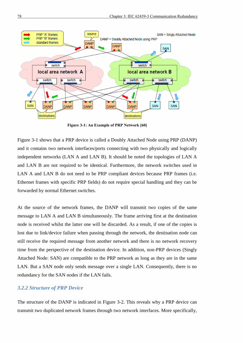
78 Chapter 3: IEC 62439-3 Communication Redundancy
Figure 3-1: An Example of PRP Network [60]
Figure 3-1 shows that a PRP device is called a Doubly Attached Node using PRP (DANP)
and it contains two network interfaces/ports connecting with two physically and logically
independent networks (LAN A and LAN B). It should be noted the topologies of LAN A
and LAN B are not required to be identical. Furthermore, the network switches used in
LAN A and LAN B do not need to be PRP compliant devices because PRP frames (i.e.
Ethernet frames with specific PRP fields) do not require special handling and they can be
forwarded by normal Ethernet switches.
At the source of the network frames, the DANP will transmit two copies of the same
message to LAN A and LAN B simultaneously. The frame arriving first at the destination
node is received whilst the latter one will be discarded. As a result, if one of the copies is
lost due to link/device failure when passing through the network, the destination node can
still receive the required message from another network and there is no network recovery
time from the perspective of the destination device. In addition, non-PRP devices (Singly
Attached Node: SAN) are compatible to the PRP network as long as they are in the same
LAN. But a SAN node only sends message over a single LAN. Consequently, there is no
redundancy for the SAN nodes if the LAN fails.
3.2.2 Structure of PRP Device
The structure of the DANP is indicated in Figure 3-2. This reveals why a PRP device can
transmit two duplicated network frames through two network interfaces. More specifically,
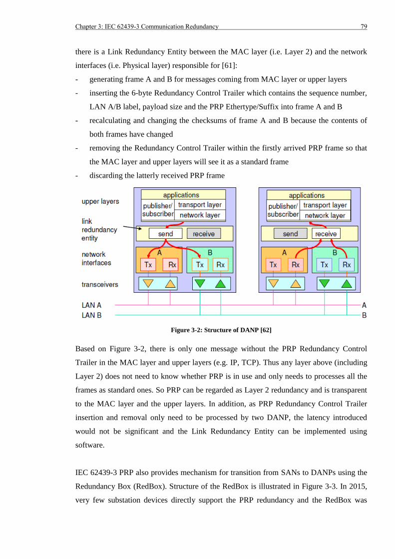
Chapter 3: IEC 62439-3 Communication Redundancy 79
there is a Link Redundancy Entity between the MAC layer (i.e. Layer 2) and the network
interfaces (i.e. Physical layer) responsible for [61]:
- generating frame A and B for messages coming from MAC layer or upper layers
- inserting the 6-byte Redundancy Control Trailer which contains the sequence number,
LAN A/B label, payload size and the PRP Ethertype/Suffix into frame A and B
- recalculating and changing the checksums of frame A and B because the contents of
both frames have changed
- removing the Redundancy Control Trailer within the firstly arrived PRP frame so that
the MAC layer and upper layers will see it as a standard frame
- discarding the latterly received PRP frame
Figure 3-2: Structure of DANP [62]
Based on Figure 3-2, there is only one message without the PRP Redundancy Control
Trailer in the MAC layer and upper layers (e.g. IP, TCP). Thus any layer above (including
Layer 2) does not need to know whether PRP is in use and only needs to processes all the
frames as standard ones. So PRP can be regarded as Layer 2 redundancy and is transparent
to the MAC layer and the upper layers. In addition, as PRP Redundancy Control Trailer
insertion and removal only need to be processed by two DANP, the latency introduced
would not be significant and the Link Redundancy Entity can be implemented using
software.
IEC 62439-3 PRP also provides mechanism for transition from SANs to DANPs using the
Redundancy Box (RedBox). Structure of the RedBox is illustrated in Figure 3-3. In 2015,
very few substation devices directly support the PRP redundancy and the RedBox was
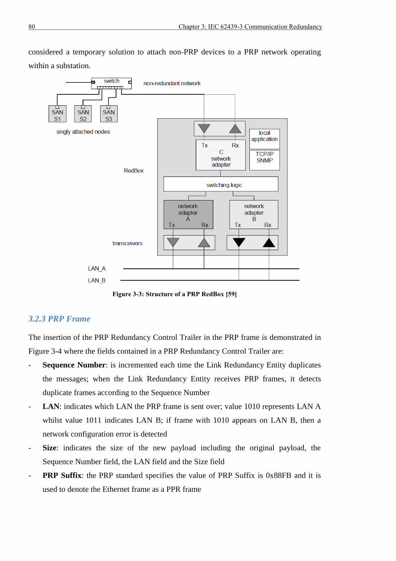
80 Chapter 3: IEC 62439-3 Communication Redundancy
considered a temporary solution to attach non-PRP devices to a PRP network operating
within a substation.
Figure 3-3: Structure of a PRP RedBox [59]
3.2.3 PRP Frame
The insertion of the PRP Redundancy Control Trailer in the PRP frame is demonstrated in
Figure 3-4 where the fields contained in a PRP Redundancy Control Trailer are:
- Sequence Number: is incremented each time the Link Redundancy Entity duplicates
the messages; when the Link Redundancy Entity receives PRP frames, it detects
duplicate frames according to the Sequence Number
- LAN: indicates which LAN the PRP frame is sent over; value 1010 represents LAN A
whilst value 1011 indicates LAN B; if frame with 1010 appears on LAN B, then a
network configuration error is detected
- Size: indicates the size of the new payload including the original payload, the
Sequence Number field, the LAN field and the Size field
- PRP Suffix: the PRP standard specifies the value of PRP Suffix is 0x88FB and it is
used to denote the Ethernet frame as a PPR frame
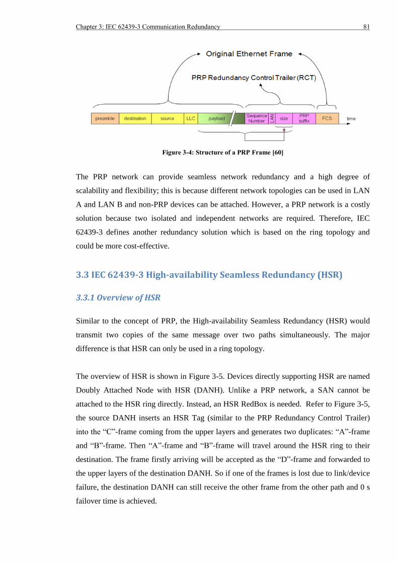
Chapter 3: IEC 62439-3 Communication Redundancy 81
Figure 3-4: Structure of a PRP Frame [60]
The PRP network can provide seamless network redundancy and a high degree of
scalability and flexibility; this is because different network topologies can be used in LAN
A and LAN B and non-PRP devices can be attached. However, a PRP network is a costly
solution because two isolated and independent networks are required. Therefore, IEC
62439-3 defines another redundancy solution which is based on the ring topology and
could be more cost-effective.
3.3 IEC 62439-3 High-availability Seamless Redundancy (HSR)
3.3.1 Overview of HSR
Similar to the concept of PRP, the High-availability Seamless Redundancy (HSR) would
transmit two copies of the same message over two paths simultaneously. The major
difference is that HSR can only be used in a ring topology.
The overview of HSR is shown in Figure 3-5. Devices directly supporting HSR are named
Doubly Attached Node with HSR (DANH). Unlike a PRP network, a SAN cannot be
attached to the HSR ring directly. Instead, an HSR RedBox is needed. Refer to Figure 3-5,
the source DANH inserts an HSR Tag (similar to the PRP Redundancy Control Trailer)
into the “C”-frame coming from the upper layers and generates two duplicates: “A”-frame
and “B”-frame. Then “A”-frame and “B”-frame will travel around the HSR ring to their
destination. The frame firstly arriving will be accepted as the “D”-frame and forwarded to
the upper layers of the destination DANH. So if one of the frames is lost due to link/device
failure, the destination DANH can still receive the other frame from the other path and 0 s
failover time is achieved.
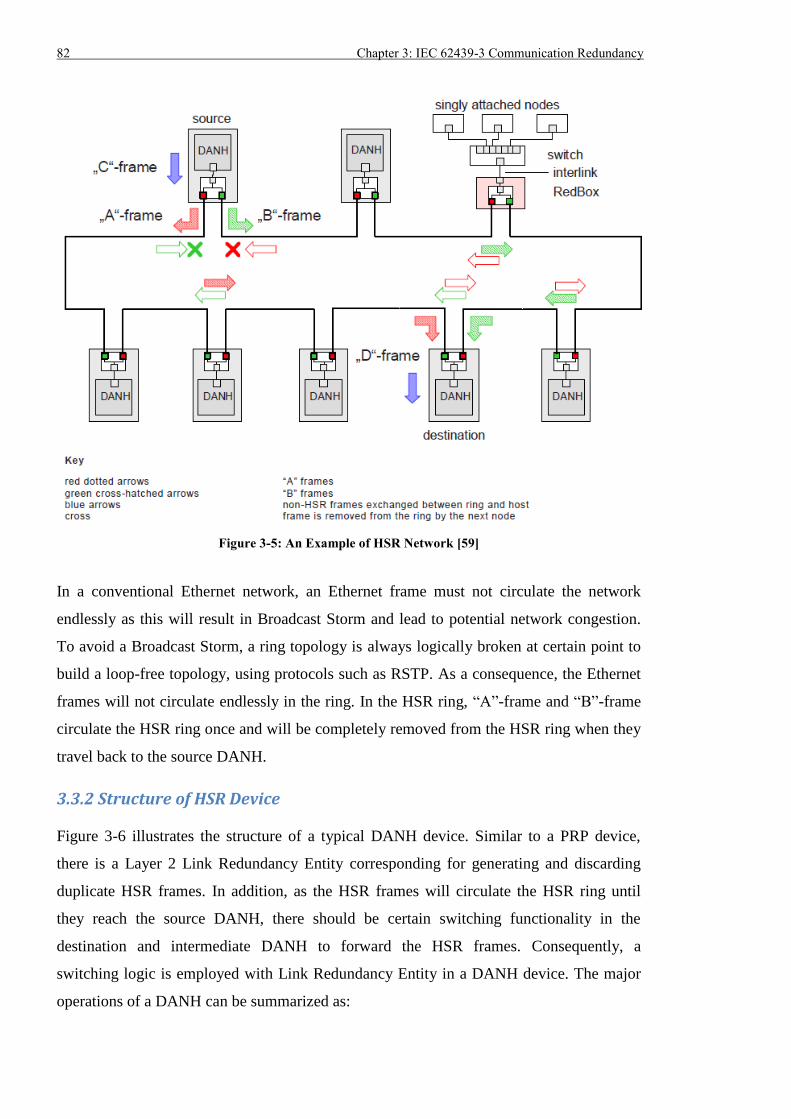
82 Chapter 3: IEC 62439-3 Communication Redundancy
Figure 3-5: An Example of HSR Network [59]
In a conventional Ethernet network, an Ethernet frame must not circulate the network
endlessly as this will result in Broadcast Storm and lead to potential network congestion.
To avoid a Broadcast Storm, a ring topology is always logically broken at certain point to
build a loop-free topology, using protocols such as RSTP. As a consequence, the Ethernet
frames will not circulate endlessly in the ring. In the HSR ring, “A”-frame and “B”-frame
circulate the HSR ring once and will be completely removed from the HSR ring when they
travel back to the source DANH.
3.3.2 Structure of HSR Device
Figure 3-6 illustrates the structure of a typical DANH device. Similar to a PRP device,
there is a Layer 2 Link Redundancy Entity corresponding for generating and discarding
duplicate HSR frames. In addition, as the HSR frames will circulate the HSR ring until
they reach the source DANH, there should be certain switching functionality in the
destination and intermediate DANH to forward the HSR frames. Consequently, a
switching logic is employed with Link Redundancy Entity in a DANH device. The major
operations of a DANH can be summarized as:
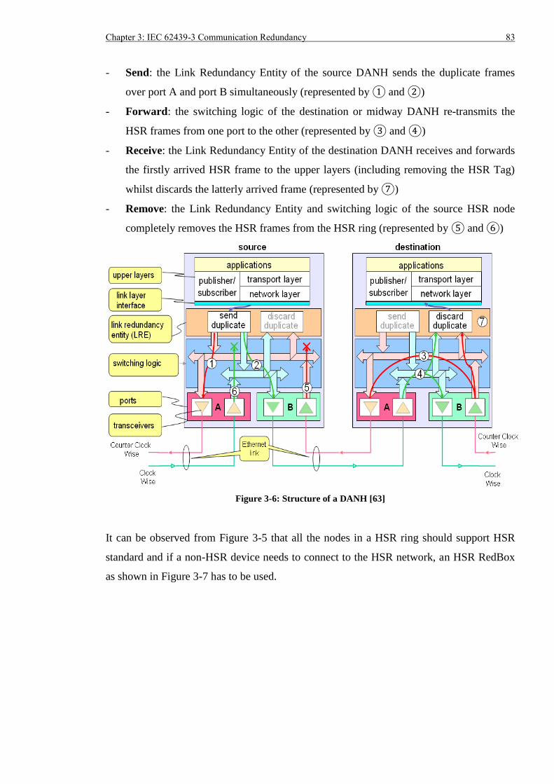
Chapter 3: IEC 62439-3 Communication Redundancy 83
- Send: the Link Redundancy Entity of the source DANH sends the duplicate frames
over port A and port B simultaneously (represented by ① and ②)
- Forward: the switching logic of the destination or midway DANH re-transmits the
HSR frames from one port to the other (represented by ③ and ④)
- Receive: the Link Redundancy Entity of the destination DANH receives and forwards
the firstly arrived HSR frame to the upper layers (including removing the HSR Tag)
whilst discards the latterly arrived frame (represented by ⑦)
- Remove: the Link Redundancy Entity and switching logic of the source HSR node
completely removes the HSR frames from the HSR ring (represented by ⑤ and ⑥)
Figure 3-6: Structure of a DANH [63]
It can be observed from Figure 3-5 that all the nodes in a HSR ring should support HSR
standard and if a non-HSR device needs to connect to the HSR network, an HSR RedBox
as shown in Figure 3-7 has to be used.
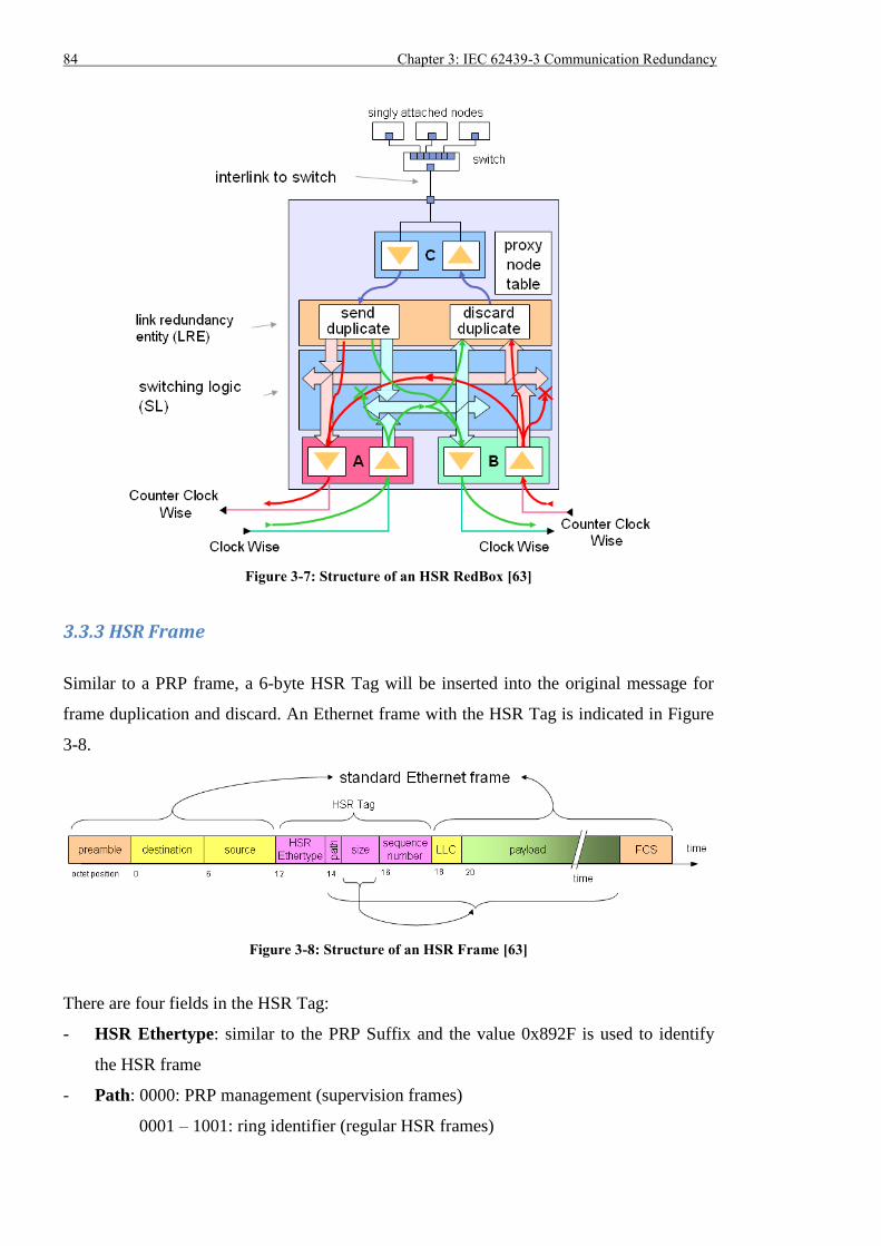
84 Chapter 3: IEC 62439-3 Communication Redundancy
Figure 3-7: Structure of an HSR RedBox [63]
3.3.3 HSR Frame
Similar to a PRP frame, a 6-byte HSR Tag will be inserted into the original message for
frame duplication and discard. An Ethernet frame with the HSR Tag is indicated in Figure
3-8.
Figure 3-8: Structure of an HSR Frame [63]
There are four fields in the HSR Tag:
- HSR Ethertype: similar to the PRP Suffix and the value 0x892F is used to identify
the HSR frame
- Path: 0000: PRP management (supervision frames)
0001 – 1001: ring identifier (regular HSR frames)
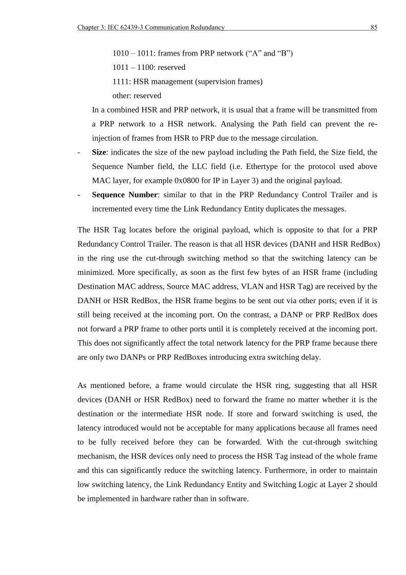
Chapter 3: IEC 62439-3 Communication Redundancy 85
1010 – 1011: frames from PRP network (“A” and “B”)
1011 – 1100: reserved
1111: HSR management (supervision frames)
other: reserved
In a combined HSR and PRP network, it is usual that a frame will be transmitted from
a PRP network to a HSR network. Analysing the Path field can prevent the re-
injection of frames from HSR to PRP due to the message circulation.
- Size: indicates the size of the new payload including the Path field, the Size field, the
Sequence Number field, the LLC field (i.e. Ethertype for the protocol used above
MAC layer, for example 0x0800 for IP in Layer 3) and the original payload.
- Sequence Number: similar to that in the PRP Redundancy Control Trailer and is
incremented every time the Link Redundancy Entity duplicates the messages.
The HSR Tag locates before the original payload, which is opposite to that for a PRP
Redundancy Control Trailer. The reason is that all HSR devices (DANH and HSR RedBox)
in the ring use the cut-through switching method so that the switching latency can be
minimized. More specifically, as soon as the first few bytes of an HSR frame (including
Destination MAC address, Source MAC address, VLAN and HSR Tag) are received by the
DANH or HSR RedBox, the HSR frame begins to be sent out via other ports; even if it is
still being received at the incoming port. On the contrast, a DANP or PRP RedBox does
not forward a PRP frame to other ports until it is completely received at the incoming port.
This does not significantly affect the total network latency for the PRP frame because there
are only two DANPs or PRP RedBoxes introducing extra switching delay.
As mentioned before, a frame would circulate the HSR ring, suggesting that all HSR
devices (DANH or HSR RedBox) need to forward the frame no matter whether it is the
destination or the intermediate HSR node. If store and forward switching is used, the
latency introduced would not be acceptable for many applications because all frames need
to be fully received before they can be forwarded. With the cut-through switching
mechanism, the HSR devices only need to process the HSR Tag instead of the whole frame
and this can significantly reduce the switching latency. Furthermore, in order to maintain
low switching latency, the Link Redundancy Entity and Switching Logic at Layer 2 should
be implemented in hardware rather than in software.
86 Chapter 3: IEC 62439-3 Communication Redundancy
The HSR solution provides seamless communication redundancy, like the PRP solution,
but it does not require the use of two independent networks, ensuring it is more cost
effective. However, to obtain low latency performance with an HSR solution, hardware-
based HSR devices need to be used. In addition, HSR does not provide the same level of
flexibility and scalability due to a constraint on the use of HSR compliant devices and ring
topology. The major differences between PRP and HSR are listed in Table 3-1.
Table 3-1: Difference between PRP and HSR
PRP HSR
Topology any in LAN A and LAN B ring
Principle transmitting two copies of the same
message in two independent networks
transmitting two copies of the same
message over clockwise and anti-
clockwise direction in the ring
Frame
Modification
PRP Redundancy Control Trailer is
inserted after payload of the original
frame;
store and forward switching
HSR Tag is inserted before payload
of the original frame; cut-through
switching to minimize the network
latency
Device
Requirement
need to support PRP only when a
device needs to connect to both PRP
LAN A and LAN B;
devices merely connected to LAN A
or LAN B do not need to support PRP
all devices have to support HSR
when connecting to the HSR ring
3.4 Summary
Both IEC 62439-3 PRP and HSR protocols can deliver seamless communication
redundancy for applications carried over Ethernet. Section 3.2 described the general
working principle of the PRP protocol where two separate networks and simultaneous
transmission of duplicate frames were used to ensure at least one copy of the frame would
arrive at the destination. The logical structure of a PRP node was discussed and a PRP
RedBox was necessary to connect a non-PRP end device to both PRP LAN A and LAN B.
Otherwise, a non-PRP device could directly connect to either PRP LAN A or LAN B. In
Section 3.3, an overview of HSR was introduced and it used ring topology and
transmission of duplicate frames over clockwise and anti-clockwise directions to realize 0 s
failover time. Unlike conventional Ethernet where logically loop-free topology was
Chapter 3: IEC 62439-3 Communication Redundancy 87
necessary to avoid Broadcast Storm, HSR allowed the circulation of frames in the ring
topology and removed the frames once they travelled back to the source HSR node. Thus,
all devices in the HSR ring had to support HSR, and a non-HSR device required an HSR
RedBox to connect to the HSR ring. For both PRP and HSR frames, a special 6-byte
Trailer/Tag was inserted so that they could be recognized and processed by the PRP and
HSR devices. For future critical smart grid applications requesting zero second network
failover time, the PRP and HSR redundancy technologies are anticipated to replace
existing techniques which uses a single activated path for communication and takes time to
reconfigure upon failure. If PRP and HSR are temporarily not deployed, the P&C devices
should block operations to avoid mal-operation when the communication is not available.
For non-mission-critical applications, existing techniques can still be used if the
reconfiguration time requirement can be satisfied.

88 Chapter 3: IEC 62439-3 Communication Redundancy
Chapter 4: Literature Review of Research on IEEE 1588 and IEC 62439-3 PRP/HSR 89
Chapter 4: Literature Review of Research on IEEE 1588 and IEC 62439-3 PRP/HSR
4.1 Introduction
Compared to conventional time synchronization solutions (e.g. distributed GPS receivers
with 1-PPS/IRIG-B and NTP/SNTP) and communication redundancy solutions (e.g.
RSTP), IEEE 1588v2 synchronization protocol and IEC 62439-3 PRP/HSR protocols are
still not widely used in power industry. One of the reasons is that they are relatively new
(neither has been released for more than 10 years) and minimal experience exists on using
these technologies in power substations. Without experience, it is difficult to judge whether
these solutions can perform as expected. Since the P&C equipment is extremely important
to maintain the normal operation of power system, it would not be viable to conduct
experimental tests in real substations. As a result, conducting research and laboratory based
tests is more realistic and more efficient in assessing the strength and weakness of the new
protocols.
Section 4.2 focuses on IEEE 1588 (both IEEE 1588v1 and IEEE 1588v2) simulation
realized by different simulation tools, whilst Section 4.3 and 4.4 review the hardware
testing of IEEE 1588v2 in LAN and WAN. Research into a combination of IEEE 1588v2
and IEC 62439-3 PRP/HSR is introduced in Section 4.5. Section 4.6 defines and
summarizes the objectives of the research from the perspectives of software simulation and
hardware testbed experiments.
4.2 IEEE 1588 Simulation
1) Modelling IEEE 1588v2 Ordinary Clocks using OMNeT++ Simulator [64]: the
Ordinary Clock was built using standard models of generic OSI layers (e.g. UDP, IP
and MAC) from the OMNeT++ tool as well as the self-developed IEEE 1588 modules
which could execute the Best Master Clock algorithm, handle the IEEE 1588
messages and accomplish the synchronization process. The IEEE 1588 timing was
implemented over UDP/IP and two Ordinary Clocks were directly connected with
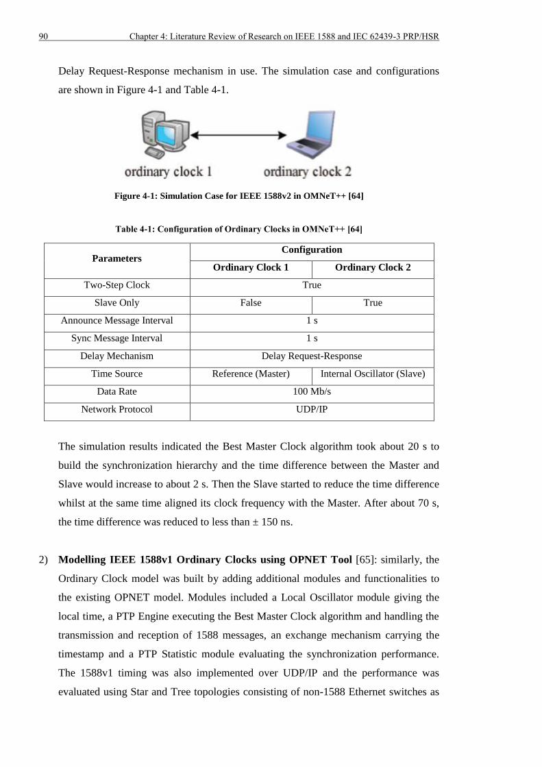
90 Chapter 4: Literature Review of Research on IEEE 1588 and IEC 62439-3 PRP/HSR
Delay Request-Response mechanism in use. The simulation case and configurations
are shown in Figure 4-1 and Table 4-1.
Figure 4-1: Simulation Case for IEEE 1588v2 in OMNeT++ [64]
Table 4-1: Configuration of Ordinary Clocks in OMNeT++ [64]
Parameters Configuration
Ordinary Clock 1 Ordinary Clock 2
Two-Step Clock True
Slave Only False True
Announce Message Interval 1 s
Sync Message Interval 1 s
Delay Mechanism Delay Request-Response
Time Source Reference (Master) Internal Oscillator (Slave)
Data Rate 100 Mb/s
Network Protocol UDP/IP
The simulation results indicated the Best Master Clock algorithm took about 20 s to
build the synchronization hierarchy and the time difference between the Master and
Slave would increase to about 2 s. Then the Slave started to reduce the time difference
whilst at the same time aligned its clock frequency with the Master. After about 70 s,
the time difference was reduced to less than ± 150 ns.
2) Modelling IEEE 1588v1 Ordinary Clocks using OPNET Tool [65]: similarly, the
Ordinary Clock model was built by adding additional modules and functionalities to
the existing OPNET model. Modules included a Local Oscillator module giving the
local time, a PTP Engine executing the Best Master Clock algorithm and handling the
transmission and reception of 1588 messages, an exchange mechanism carrying the
timestamp and a PTP Statistic module evaluating the synchronization performance.
The 1588v1 timing was also implemented over UDP/IP and the performance was
evaluated using Star and Tree topologies consisting of non-1588 Ethernet switches as
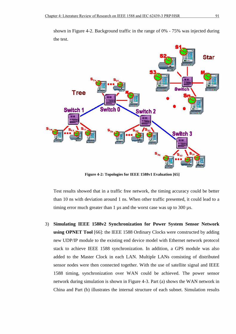
Chapter 4: Literature Review of Research on IEEE 1588 and IEC 62439-3 PRP/HSR 91
shown in Figure 4-2. Background traffic in the range of 0% - 75% was injected during
the test.
Figure 4-2: Topologies for IEEE 1588v1 Evaluation [65]
Test results showed that in a traffic free network, the timing accuracy could be better
than 10 ns with deviation around 1 ns. When other traffic presented, it could lead to a
timing error much greater than 1 µs and the worst case was up to 300 µs.
3) Simulating IEEE 1588v2 Synchronization for Power System Sensor Network
using OPNET Tool [66]: the IEEE 1588 Ordinary Clocks were constructed by adding
new UDP/IP module to the existing end device model with Ethernet network protocol
stack to achieve IEEE 1588 synchronization. In addition, a GPS module was also
added to the Master Clock in each LAN. Multiple LANs consisting of distributed
sensor nodes were then connected together. With the use of satellite signal and IEEE
1588 timing, synchronization over WAN could be achieved. The power sensor
network during simulation is shown in Figure 4-3. Part (a) shows the WAN network in
China and Part (b) illustrates the internal structure of each subnet. Simulation results
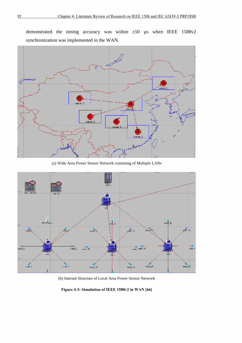
92 Chapter 4: Literature Review of Research on IEEE 1588 and IEC 62439-3 PRP/HSR
demonstrated the timing accuracy was within ±50 µs when IEEE 1588v2
synchronization was implemented in the WAN.
(a) Wide Area Power Sensor Network consisting of Multiple LANs
(b) Internal Structure of Local Area Power Sensor Network
Figure 4-3: Simulation of IEEE 1588v2 in WAN [66]
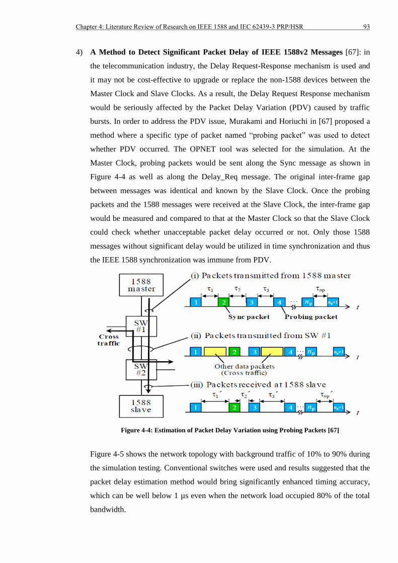
Chapter 4: Literature Review of Research on IEEE 1588 and IEC 62439-3 PRP/HSR 93
4) A Method to Detect Significant Packet Delay of IEEE 1588v2 Messages [67]: in
the telecommunication industry, the Delay Request-Response mechanism is used and
it may not be cost-effective to upgrade or replace the non-1588 devices between the
Master Clock and Slave Clocks. As a result, the Delay Request Response mechanism
would be seriously affected by the Packet Delay Variation (PDV) caused by traffic
bursts. In order to address the PDV issue, Murakami and Horiuchi in [67] proposed a
method where a specific type of packet named “probing packet” was used to detect
whether PDV occurred. The OPNET tool was selected for the simulation. At the
Master Clock, probing packets would be sent along the Sync message as shown in
Figure 4-4 as well as along the Delay_Req message. The original inter-frame gap
between messages was identical and known by the Slave Clock. Once the probing
packets and the 1588 messages were received at the Slave Clock, the inter-frame gap
would be measured and compared to that at the Master Clock so that the Slave Clock
could check whether unacceptable packet delay occurred or not. Only those 1588
messages without significant delay would be utilized in time synchronization and thus
the IEEE 1588 synchronization was immune from PDV.
Figure 4-4: Estimation of Packet Delay Variation using Probing Packets [67]
Figure 4-5 shows the network topology with background traffic of 10% to 90% during
the simulation testing. Conventional switches were used and results suggested that the
packet delay estimation method would bring significantly enhanced timing accuracy,
which can be well below 1 µs even when the network load occupied 80% of the total
bandwidth.
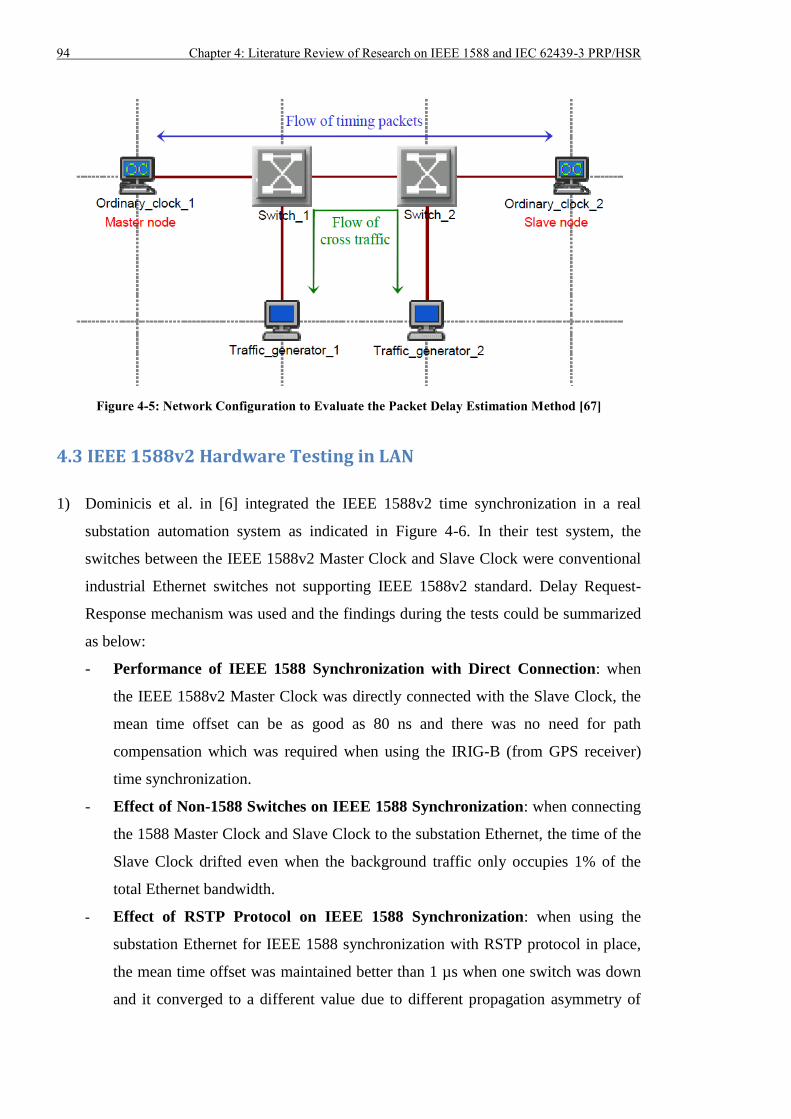
94 Chapter 4: Literature Review of Research on IEEE 1588 and IEC 62439-3 PRP/HSR
Figure 4-5: Network Configuration to Evaluate the Packet Delay Estimation Method [67]
4.3 IEEE 1588v2 Hardware Testing in LAN
1) Dominicis et al. in [6] integrated the IEEE 1588v2 time synchronization in a real
substation automation system as indicated in Figure 4-6. In their test system, the
switches between the IEEE 1588v2 Master Clock and Slave Clock were conventional
industrial Ethernet switches not supporting IEEE 1588v2 standard. Delay Request-
Response mechanism was used and the findings during the tests could be summarized
as below:
- Performance of IEEE 1588 Synchronization with Direct Connection: when
the IEEE 1588v2 Master Clock was directly connected with the Slave Clock, the
mean time offset can be as good as 80 ns and there was no need for path
compensation which was required when using the IRIG-B (from GPS receiver)
time synchronization.
- Effect of Non-1588 Switches on IEEE 1588 Synchronization: when connecting
the 1588 Master Clock and Slave Clock to the substation Ethernet, the time of the
Slave Clock drifted even when the background traffic only occupies 1% of the
total Ethernet bandwidth.
- Effect of RSTP Protocol on IEEE 1588 Synchronization: when using the
substation Ethernet for IEEE 1588 synchronization with RSTP protocol in place,
the mean time offset was maintained better than 1 µs when one switch was down
and it converged to a different value due to different propagation asymmetry of
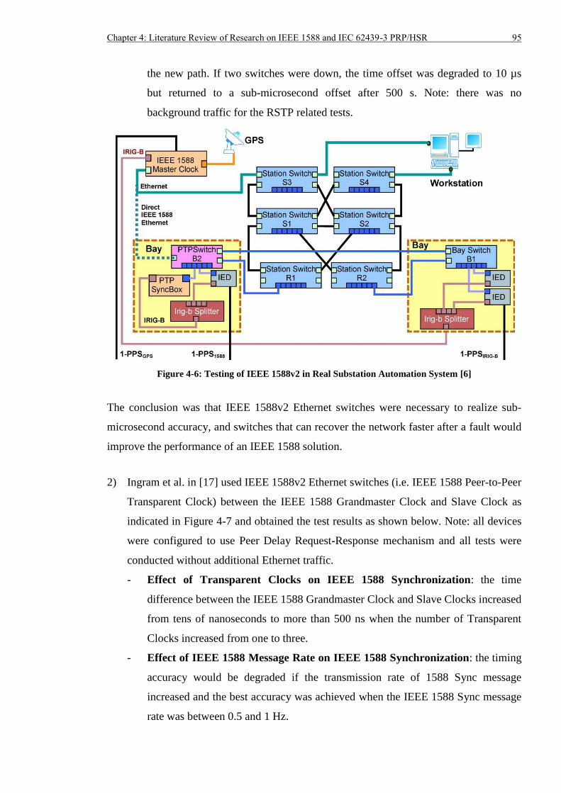
Chapter 4: Literature Review of Research on IEEE 1588 and IEC 62439-3 PRP/HSR 95
the new path. If two switches were down, the time offset was degraded to 10 µs
but returned to a sub-microsecond offset after 500 s. Note: there was no
background traffic for the RSTP related tests.
Figure 4-6: Testing of IEEE 1588v2 in Real Substation Automation System [6]
The conclusion was that IEEE 1588v2 Ethernet switches were necessary to realize sub-
microsecond accuracy, and switches that can recover the network faster after a fault would
improve the performance of an IEEE 1588 solution.
2) Ingram et al. in [17] used IEEE 1588v2 Ethernet switches (i.e. IEEE 1588 Peer-to-Peer
Transparent Clock) between the IEEE 1588 Grandmaster Clock and Slave Clock as
indicated in Figure 4-7 and obtained the test results as shown below. Note: all devices
were configured to use Peer Delay Request-Response mechanism and all tests were
conducted without additional Ethernet traffic.
- Effect of Transparent Clocks on IEEE 1588 Synchronization: the time
difference between the IEEE 1588 Grandmaster Clock and Slave Clocks increased
from tens of nanoseconds to more than 500 ns when the number of Transparent
Clocks increased from one to three.
- Effect of IEEE 1588 Message Rate on IEEE 1588 Synchronization: the timing
accuracy would be degraded if the transmission rate of 1588 Sync message
increased and the best accuracy was achieved when the IEEE 1588 Sync message
rate was between 0.5 and 1 Hz.
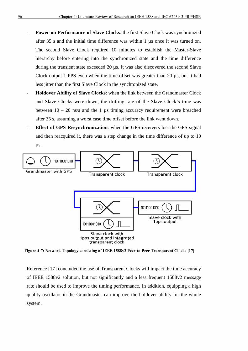
96 Chapter 4: Literature Review of Research on IEEE 1588 and IEC 62439-3 PRP/HSR
- Power-on Performance of Slave Clocks: the first Slave Clock was synchronized
after 35 s and the initial time difference was within 1 µs once it was turned on.
The second Slave Clock required 10 minutes to establish the Master-Slave
hierarchy before entering into the synchronized state and the time difference
during the transient state exceeded 20 µs. It was also discovered the second Slave
Clock output 1-PPS even when the time offset was greater than 20 µs, but it had
less jitter than the first Slave Clock in the synchronized state.
- Holdover Ability of Slave Clocks: when the link between the Grandmaster Clock
and Slave Clocks were down, the drifting rate of the Slave Clock’s time was
between 10 – 20 ns/s and the 1 µs timing accuracy requirement were breached
after 35 s, assuming a worst case time offset before the link went down.
- Effect of GPS Resynchronization: when the GPS receivers lost the GPS signal
and then reacquired it, there was a step change in the time difference of up to 10
µs.
Figure 4-7: Network Topology consisting of IEEE 1588v2 Peer-to-Peer Transparent Clocks [17]
Reference [17] concluded the use of Transparent Clocks will impact the time accuracy
of IEEE 1588v2 solution, but not significantly and a less frequent 1588v2 message
rate should be used to improve the timing performance. In addition, equipping a high
quality oscillator in the Grandmaster can improve the holdover ability for the whole
system.
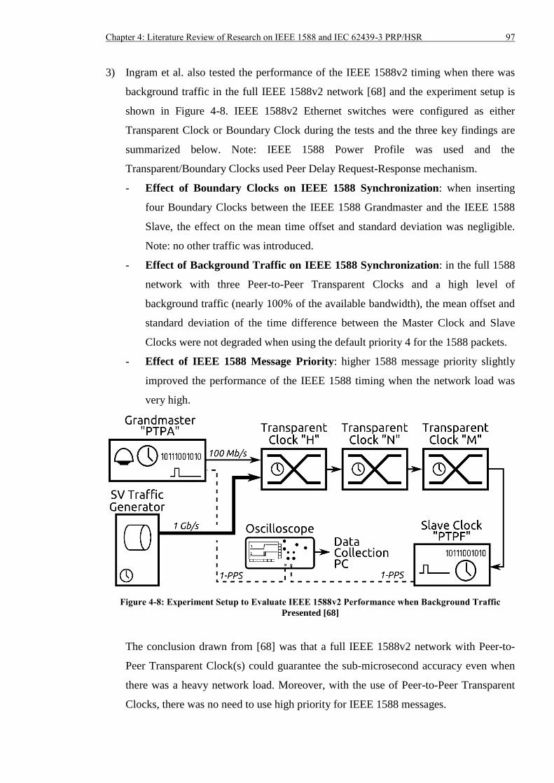
Chapter 4: Literature Review of Research on IEEE 1588 and IEC 62439-3 PRP/HSR 97
3) Ingram et al. also tested the performance of the IEEE 1588v2 timing when there was
background traffic in the full IEEE 1588v2 network [68] and the experiment setup is
shown in Figure 4-8. IEEE 1588v2 Ethernet switches were configured as either
Transparent Clock or Boundary Clock during the tests and the three key findings are
summarized below. Note: IEEE 1588 Power Profile was used and the
Transparent/Boundary Clocks used Peer Delay Request-Response mechanism.
- Effect of Boundary Clocks on IEEE 1588 Synchronization: when inserting
four Boundary Clocks between the IEEE 1588 Grandmaster and the IEEE 1588
Slave, the effect on the mean time offset and standard deviation was negligible.
Note: no other traffic was introduced.
- Effect of Background Traffic on IEEE 1588 Synchronization: in the full 1588
network with three Peer-to-Peer Transparent Clocks and a high level of
background traffic (nearly 100% of the available bandwidth), the mean offset and
standard deviation of the time difference between the Master Clock and Slave
Clocks were not degraded when using the default priority 4 for the 1588 packets.
- Effect of IEEE 1588 Message Priority: higher 1588 message priority slightly
improved the performance of the IEEE 1588 timing when the network load was
very high.
Figure 4-8: Experiment Setup to Evaluate IEEE 1588v2 Performance when Background Traffic
Presented [68]
The conclusion drawn from [68] was that a full IEEE 1588v2 network with Peer-to-
Peer Transparent Clock(s) could guarantee the sub-microsecond accuracy even when
there was a heavy network load. Moreover, with the use of Peer-to-Peer Transparent
Clocks, there was no need to use high priority for IEEE 1588 messages.
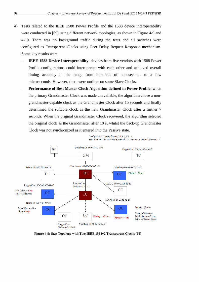
98 Chapter 4: Literature Review of Research on IEEE 1588 and IEC 62439-3 PRP/HSR
4) Tests related to the IEEE 1588 Power Profile and the 1588 device interoperability
were conducted in [69] using different network topologies, as shown in Figure 4-9 and
4-10. There was no background traffic during the tests and all switches were
configured as Transparent Clocks using Peer Delay Request-Response mechanism.
Some key results were:
- IEEE 1588 Device Interoperability: devices from five vendors with 1588 Power
Profile configurations could interoperate with each other and achieved overall
timing accuracy in the range from hundreds of nanoseconds to a few
microseconds. However, there were outliers on some Slave Clocks.
- Performance of Best Master Clock Algorithm defined in Power Profile: when
the primary Grandmaster Clock was made unavailable, the algorithm chose a non-
grandmaster-capable clock as the Grandmaster Clock after 15 seconds and finally
determined the suitable clock as the new Grandmaster Clock after a further 7
seconds. When the original Grandmaster Clock recovered, the algorithm selected
the original clock as the Grandmaster after 10 s, whilst the back-up Grandmaster
Clock was not synchronized as it entered into the Passive state.
Figure 4-9: Star Topology with Two IEEE 1588v2 Transparent Clocks [69]
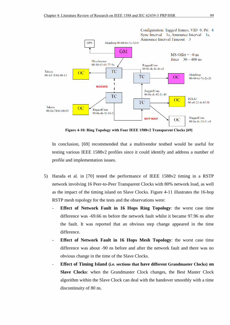
Chapter 4: Literature Review of Research on IEEE 1588 and IEC 62439-3 PRP/HSR 99
Figure 4-10: Ring Topology with Four IEEE 1588v2 Transparent Clocks [69]
In conclusion, [69] recommended that a multivendor testbed would be useful for
testing various IEEE 1588v2 profiles since it could identify and address a number of
profile and implementation issues.
5) Harada et al. in [70] tested the performance of IEEE 1588v2 timing in a RSTP
network involving 16 Peer-to-Peer Transparent Clocks with 80% network load, as well
as the impact of the timing island on Slave Clocks. Figure 4-11 illustrates the 16-hop
RSTP mesh topology for the tests and the observations were:
- Effect of Network Fault in 16 Hops Ring Topology: the worst case time
difference was -69.66 ns before the network fault whilst it became 97.96 ns after
the fault. It was reported that an obvious step change appeared in the time
difference.
- Effect of Network Fault in 16 Hops Mesh Topology: the worst case time
difference was about -90 ns before and after the network fault and there was no
obvious change in the time of the Slave Clocks.
- Effect of Timing Island (i.e. sections that have different Grandmaster Clocks) on
Slave Clocks: when the Grandmaster Clock changes, the Best Master Clock
algorithm within the Slave Clock can deal with the handover smoothly with a time
discontinuity of 80 ns.
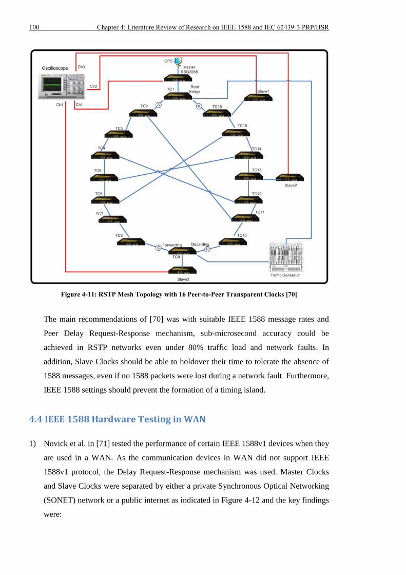
100 Chapter 4: Literature Review of Research on IEEE 1588 and IEC 62439-3 PRP/HSR
Figure 4-11: RSTP Mesh Topology with 16 Peer-to-Peer Transparent Clocks [70]
The main recommendations of [70] was with suitable IEEE 1588 message rates and
Peer Delay Request-Response mechanism, sub-microsecond accuracy could be
achieved in RSTP networks even under 80% traffic load and network faults. In
addition, Slave Clocks should be able to holdover their time to tolerate the absence of
1588 messages, even if no 1588 packets were lost during a network fault. Furthermore,
IEEE 1588 settings should prevent the formation of a timing island.
4.4 IEEE 1588 Hardware Testing in WAN
1) Novick et al. in [71] tested the performance of certain IEEE 1588v1 devices when they
are used in a WAN. As the communication devices in WAN did not support IEEE
1588v1 protocol, the Delay Request-Response mechanism was used. Master Clocks
and Slave Clocks were separated by either a private Synchronous Optical Networking
(SONET) network or a public internet as indicated in Figure 4-12 and the key findings
were:
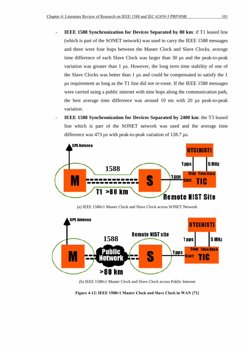
Chapter 4: Literature Review of Research on IEEE 1588 and IEC 62439-3 PRP/HSR 101
- IEEE 1588 Synchronization for Devices Separated by 80 km: if T1 leased line
(which is part of the SONET network) was used to carry the IEEE 1588 messages
and there were four hops between the Master Clock and Slave Clocks, average
time difference of each Slave Clock was larger than 30 µs and the peak-to-peak
variation was greater than 1 µs. However, the long term time stability of one of
the Slave Clocks was better than 1 µs and could be compensated to satisfy the 1
µs requirement as long as the T1 line did not re-route. If the IEEE 1588 messages
were carried using a public internet with nine hops along the communication path,
the best average time difference was around 10 ms with 20 µs peak-to-peak
variation.
- IEEE 1588 Synchronization for Devices Separated by 2400 km: the T3 leased
line which is part of the SONET network was used and the average time
difference was 473 µs with peak-to-peak variation of 128.7 µs.
(a) IEEE 1588v1 Master Clock and Slave Clock across SONET Network
(b) IEEE 1588v1 Master Clock and Slave Clock across Public Internet
Figure 4-12: IEEE 1588v1 Master Clock and Slave Clock in WAN [71]
1588
1588
102 Chapter 4: Literature Review of Research on IEEE 1588 and IEC 62439-3 PRP/HSR
Experimental results suggested that longer distance and more hops could generate
significant path asymmetry [71], which degraded the time synchronization accuracy.
One of the solutions was using symmetric paths such as T1 and T3 leased lines in
SONET network to transmit and receive IEEE 1588 messages. It was also suggested to
embed a GPS receiver in the Slave Clock so that it could holdover its time when the
accuracy of IEEE 1588 synchronization was degraded (e.g. due to communication
path switching).
2) Pravda et al. in [72] built up a communication system with four Synchronous Digital
Hierarchy (SDH) nodes, which is shown in Figure 4-13. Delay Request-Response
mechanism was used and the SDH nodes did not support IEEE 1588v2 protocol. The
performance of IEEE 1588v2 timing over SDH network was then tested. The major
discoveries were:
- IEEE 1588 over VC-12 channel (2.176 Mb/s) of SDH network: the tests were
conducted under three conditions: (i) all SDH nodes were in synchronized mode,
(ii) all SDH devices were in free-running mode, and (iii) one SDH node was
synchronized by an external clock signal whilst others were free-running. The
mean time difference corresponding to the three conditions were -12.3 µs, 10.1 µs
and -9.9 µs, respectively. The standard deviation was minimum under condition (i)
and was maximum under condition (iii).
- IEEE 1588 over VC-3 channel (48.384 Mb/s) of SDH network: the tests were
conducted under the three conditions described above and the associated mean
time difference was 5.2 µs, 4.9 µs and 3.9 µs, respectively. When IEEE 1588 was
implemented over VC-3 channel – the standard deviation was minimum under
condition (i) and maximum under condition (iii).
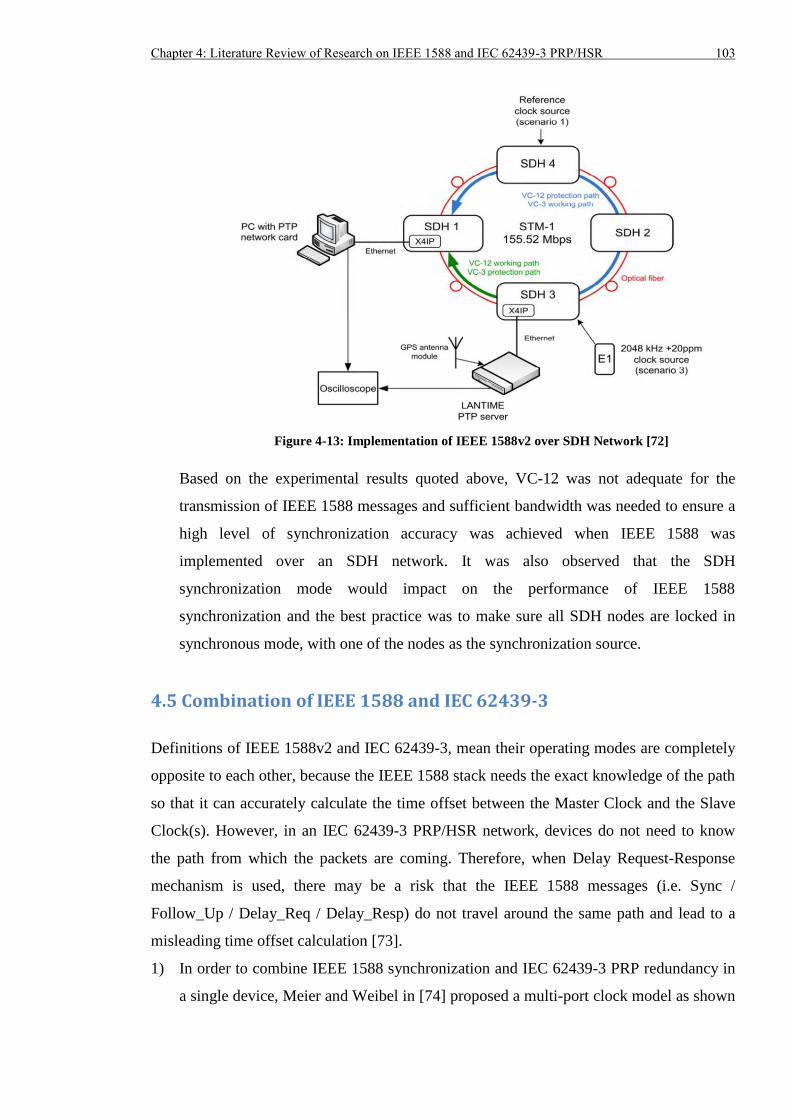
Chapter 4: Literature Review of Research on IEEE 1588 and IEC 62439-3 PRP/HSR 103
Figure 4-13: Implementation of IEEE 1588v2 over SDH Network [72]
Based on the experimental results quoted above, VC-12 was not adequate for the
transmission of IEEE 1588 messages and sufficient bandwidth was needed to ensure a
high level of synchronization accuracy was achieved when IEEE 1588 was
implemented over an SDH network. It was also observed that the SDH
synchronization mode would impact on the performance of IEEE 1588
synchronization and the best practice was to make sure all SDH nodes are locked in
synchronous mode, with one of the nodes as the synchronization source.
4.5 Combination of IEEE 1588 and IEC 62439-3
Definitions of IEEE 1588v2 and IEC 62439-3, mean their operating modes are completely
opposite to each other, because the IEEE 1588 stack needs the exact knowledge of the path
so that it can accurately calculate the time offset between the Master Clock and the Slave
Clock(s). However, in an IEC 62439-3 PRP/HSR network, devices do not need to know
the path from which the packets are coming. Therefore, when Delay Request-Response
mechanism is used, there may be a risk that the IEEE 1588 messages (i.e. Sync /
Follow_Up / Delay_Req / Delay_Resp) do not travel around the same path and lead to a
misleading time offset calculation [73].
1) In order to combine IEEE 1588 synchronization and IEC 62439-3 PRP redundancy in
a single device, Meier and Weibel in [74] proposed a multi-port clock model as shown
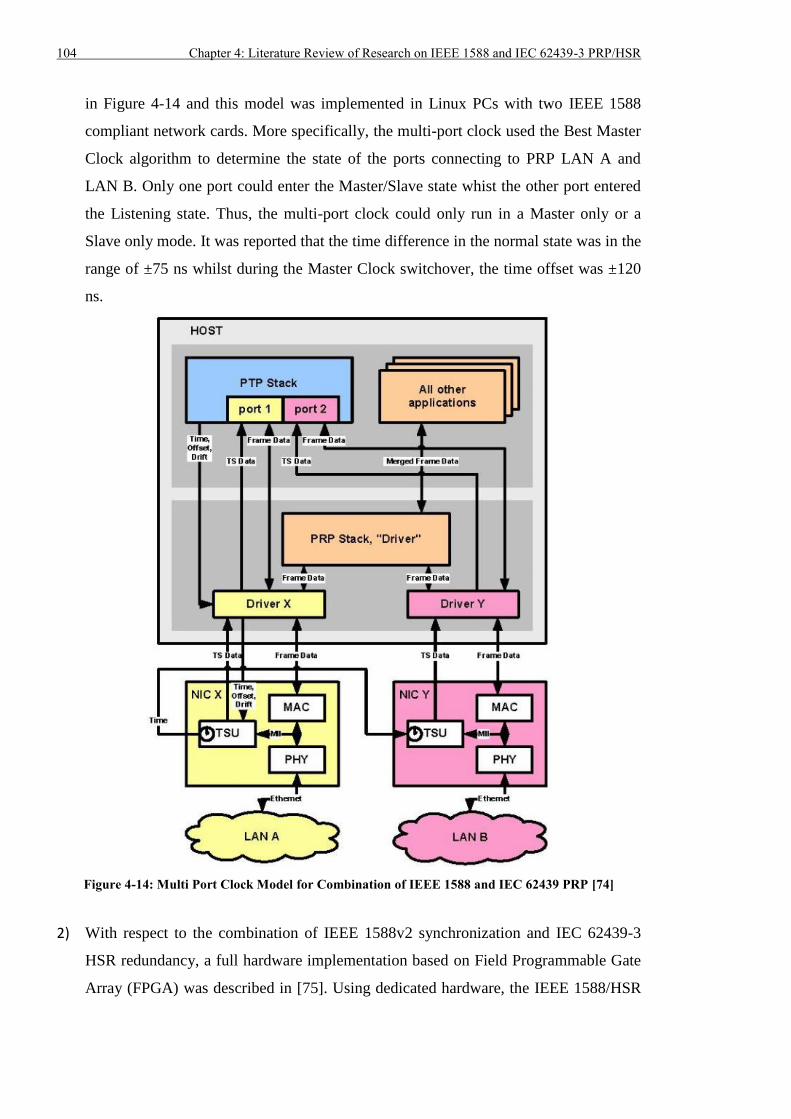
104 Chapter 4: Literature Review of Research on IEEE 1588 and IEC 62439-3 PRP/HSR
in Figure 4-14 and this model was implemented in Linux PCs with two IEEE 1588
compliant network cards. More specifically, the multi-port clock used the Best Master
Clock algorithm to determine the state of the ports connecting to PRP LAN A and
LAN B. Only one port could enter the Master/Slave state whist the other port entered
the Listening state. Thus, the multi-port clock could only run in a Master only or a
Slave only mode. It was reported that the time difference in the normal state was in the
range of ±75 ns whilst during the Master Clock switchover, the time offset was ±120
ns.
Figure 4-14: Multi Port Clock Model for Combination of IEEE 1588 and IEC 62439 PRP [74]
2) With respect to the combination of IEEE 1588v2 synchronization and IEC 62439-3
HSR redundancy, a full hardware implementation based on Field Programmable Gate
Array (FPGA) was described in [75]. Using dedicated hardware, the IEEE 1588/HSR
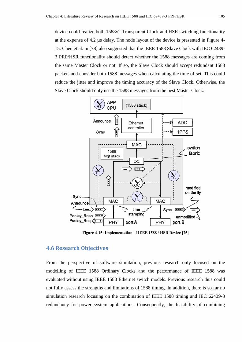
Chapter 4: Literature Review of Research on IEEE 1588 and IEC 62439-3 PRP/HSR 105
device could realize both 1588v2 Transparent Clock and HSR switching functionality
at the expense of 4.2 µs delay. The node layout of the device is presented in Figure 4-
15. Chen et al. in [78] also suggested that the IEEE 1588 Slave Clock with IEC 62439-
3 PRP/HSR functionality should detect whether the 1588 messages are coming from
the same Master Clock or not. If so, the Slave Clock should accept redundant 1588
packets and consider both 1588 messages when calculating the time offset. This could
reduce the jitter and improve the timing accuracy of the Slave Clock. Otherwise, the
Slave Clock should only use the 1588 messages from the best Master Clock.
Figure 4-15: Implementation of IEEE 1588 / HSR Device [75]
4.6 Research Objectives
From the perspective of software simulation, previous research only focused on the
modelling of IEEE 1588 Ordinary Clocks and the performance of IEEE 1588 was
evaluated without using IEEE 1588 Ethernet switch models. Previous research thus could
not fully assess the strengths and limitations of 1588 timing. In addition, there is so far no
simulation research focusing on the combination of IEEE 1588 timing and IEC 62439-3
redundancy for power system applications. Consequently, the feasibility of combining
106 Chapter 4: Literature Review of Research on IEEE 1588 and IEC 62439-3 PRP/HSR
these two protocols is not understood and this will obstruct the development and adoption
of the new technologies. In order to fill the gap in simulations for full 1588 network
assessment and study of the integration of IEEE 1588 synchronization and IEC 62439-3
redundancy, the objectives of the research in the simulation aspect are proposed below.
- To design and build simulated models compliant with IEEE 1588v2 and IEC 62439-3
protocols.
- To use the simulated models to set up various IEEE 1588 / IEC 62439-3 network
topologies.
- To inject background traffic into the simulated networks.
- To compare and analyse the performance of IEEE 1588v2 timing in diverse scenarios.
- To obtain lessons and develop suggestions on the application of IEEE 1588v2 and IEC
62439-3.
In this way, the simulation of combination of IEEE 1588 and IEC 62439-3 is undertaken
for the first time and IEEE 1588 timing and IEC 62439-3 redundancy can be fully tested
under different network conditions and can be proved whether they are feasible and
reliable to be deployed in substations.
In terms of the hardware testing, comprehensive tests have been conducted to evaluate the
performance of IEEE 1588 timing in Star and RSTP ring/mesh topology. Some tests used
conventional Ethernet switches whilst others employed IEEE 1588 Ethernet switches.
However, there is no research related to the testing of IEEE 1588v2 timing system
implemented over IEC 62439-3 PRP/HSR redundancy when the network is overloaded.
Previous research did not involve the investigation of long term timing stability, the impact
of IEEE 1588v2 message loss and the scalability of the IEEE 1588v2 synchronization
when it was used for power system applications. Furthermore, the timing accuracy and
stability of distributed GPS receivers was never fully investigated by utilities before they
were deployed in real substations. Uncertainties in the performance and limitations of pure
GPS and mixed GPS/1588 timing solutions will pose a threat to the reliability of substation
automation systems. To fill the gaps in physical testing of GPS and 1588 timing, the
research objectives in the hardware aspect are summarized as:
- To design and build a hardware testbed to investigate the steady-state and transient
behaviour of different GPS receivers.
Chapter 4: Literature Review of Research on IEEE 1588 and IEC 62439-3 PRP/HSR 107
- To integrate IEEE 1588v2 time synchronization and diverse communication
redundancy such as RSTP and IEC 62439-3 PRP/HSR into the hardware testbed with
various network topologies.
- To create different network conditions in the testbed and evaluate the performance of
IEEE 1588v2 time synchronization.
- To investigate the behaviour of IEEE 1588v2 Master and Slave Clocks when time
source signal (i.e. GPS signal in this research) is not received by all clocks.
- To examine the effect of IEEE 1588v2 messages on P&C applications sharing the
same Ethernet network such as IEC 61850 SV.
- To extend the hardware testbed and study the feasibility and scalability to implement
the IEEE 1588v2 timing system in real substations.
- To explore the impact of device outage and the effect of a long communication link on
IEEE 1588v2 synchronization.
- To test the compatibility between IEEE 1588v2 devices and IEC 61850 IEDs / MUs.
Thus, comprehensive investigation of GPS and IEEE 1588 timing (with different
redundancy technologies) can be conducted and recommendations based on the test results
will be provided to utilities for applications in real substations.
4.7 Summary
Research on IEEE 1588 time synchronization mainly falls into two categories: software
simulation and hardware testing. Section 4.2 indicated that previous research mainly
focused on the modelling of IEEE 1588 Ordinary Clocks and examined the performance of
IEEE 1588 system consisting of conventional Ethernet switches. Simulation results
showed sub-microsecond accuracy was difficult to achieve when other traffic shared the
data network, because non-deterministic packet delay would be introduced. With reference
to the hardware testing in LAN, Section 4.3 showed sub-microsecond timing accuracy
could be obtained even when there was up to 80% background traffic or network fault if
IEEE 1588 compliant Ethernet switches were used. Section 4.4 indicated when IEEE 1588
timing was implemented over WAN with non-1588 networking devices, the achievable
accuracy could only be in the range of many microseconds or even milliseconds, i.e. it did
not satisfy the ±1 µs requirement. As demonstrated in Section 4.5, previous research
related to the combination of IEEE 1588 and IEC 62439-3 mainly focused on the
108 Chapter 4: Literature Review of Research on IEEE 1588 and IEC 62439-3 PRP/HSR
implementation of real equipment. Section 4.6 described the main research objectives of
the thesis. These are associated with simulating a combination of IEEE 1588 timing and
IEC 62439-3 redundancy, and secondly undertaking comprehensive hardware testing on a
GPS timing system and an IEEE 1588 timing system.
Chapter 5: Simulation of IEEE 1588 and IEC 62439-3 109
Chapter 5: Simulation of IEEE 1588 and IEC 62439-3
5.1 Introduction
With software simulation, physical constraints can be avoided and thus it is more flexible
and convenient to verify the performance of specific techniques, especially when a large
scale test is not feasible in real life. Even though there have been projects on modelling the
IEEE 1588 synchronization [64-66], [76-78], there is no standard module in the
mainstream communication simulation tools, such as OPNET and NS-2. Therefore, it is
necessary to “translate” the expressions and rules defined in the IEEE 1588v2 protocol to
the code used in the simulation tool, to ensure the simulated devices behave as specified by
the protocol. In addition, there is significantly less research on IEC 62439-3 PRP/HSR
simulation than IEEE 1588, and it will be valuable to integrate them together in a software
simulation model.
Most existing networking devices in a substation do not support IEEE 1588v2 protocol.
Consequently, only Delay Request-Response mechanism can be used in conjunction with
non-1588 devices as suggested in Section 2.4.3. Therefore, it is reasonable to simulate the
Delay Request-Response mechanism. Considering the maturity of IEC 62439-3 and the
requirements for substations, PRP communication redundancy is more viable when
migrating towards a bump-less network [79]. To evaluate the performance of a time
synchronization solution, the most intuitive metric is the time difference between the
Master Clock and the Slave Clock. Hence, the simulation work focuses on the Delay
Request-Response mechanism in the synchronization phase, when Master-Slave Hierarchy
has been established.
This chapter describes how to simulate the IEEE 1588v2 Delay Request-Response
mechanism over the IEC 62439-3 PRP network. Section 5.2 explains why an OPNET
simulation tool is chosen, whilst the design of an IEEE 1588 Ordinary Clock including
different self-developed modules is presented in Section 5.3. Section 5.4 states how the
existing Ethernet switch model in OPNET can be modified to act as an IEEE 1588 End-to-
End Transparent Clock. Section 5.5 illustrates the structure and working principle of the
110 Chapter 5: Simulation of IEEE 1588 and IEC 62439-3
simulated IEC 62439-3 PRP RedBox. The method used to inject background traffic into
the simulated networks is described in Section 5.6. Various test scenarios and
corresponding simulation results with and without IEEE 1588 compliant devices and
background traffic are compared and analysed in Section 5.7 to 5.9.
5.2 Simulation Tool
Among various communication simulation programs, NS-2, OMNeT++ and OPNET are
the most popular [80]. The Network Simulator-2 (NS-2) [81] is a simulation tool running
in the Linux operating system and it has attracted a large amount of users due to its open
source property. Similarly, the Objective Modular Network Testbed in C++ (OMNeT++)
[82] is another open source tool and it can run in multiple operating systems. The
Optimized Network Engineering Tools (OPNET) Modeller [83] suite, is a commercial
simulation tool used by companies such as Cisco and BAE Systems for research and
development purposes, and there are many reusable modules within the tool. Because most
simulation models of OPNET have been validated by different industries, the simulation
results achieved from the OPNET Modeller are credible. As a result, the OPNET tool is
chosen and the simulation results can be used by utilities for technical assessment of new
technologies such as IEEE 1588v2 timing and IEC 62439-3 PRP/HSR redundancy.
5.3 Design of IEEE 1588v2 Ordinary Clock
In order to simulate the IEEE 1588v2 Ordinary Clock implementing the Delay Request-
Response mechanism, a few modules have to be developed / modified and integrated into
the existing OPNET models. The full list of such modules is indicated in Table 5-1 below.
According to the IEEE 1588 Power Profile [55], the 1588v2 messages can only be
transported directly over Ethernet within a power substation. Therefore, the pre-defined
OPNET node model “ethernet_station_adv” excluding the IP layer is selected for
development and modification, and will be used as either a Master Clock or a Slave Clock.
The framework of the Master Clock and Slave Clock are presented in Figure 5-1 and
Figure 5-2.
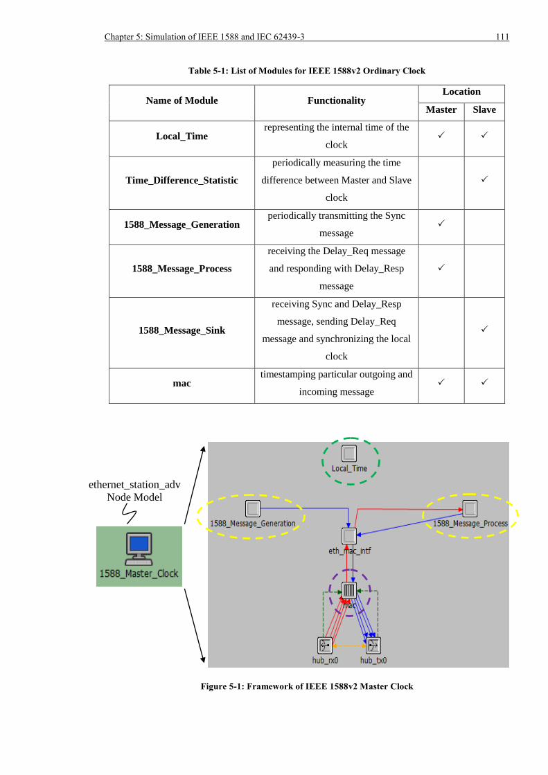
Chapter 5: Simulation of IEEE 1588 and IEC 62439-3 111
Table 5-1: List of Modules for IEEE 1588v2 Ordinary Clock
Name of Module Functionality Location
Master Slave
Local_Time representing the internal time of the
clock
Time_Difference_Statistic
periodically measuring the time
difference between Master and Slave
clock
1588_Message_Generation periodically transmitting the Sync
message
1588_Message_Process
receiving the Delay_Req message
and responding with Delay_Resp
message
1588_Message_Sink
receiving Sync and Delay_Resp
message, sending Delay_Req
message and synchronizing the local
clock
mac timestamping particular outgoing and
incoming message
Figure 5-1: Framework of IEEE 1588v2 Master Clock
ethernet_station_adv
Node Model
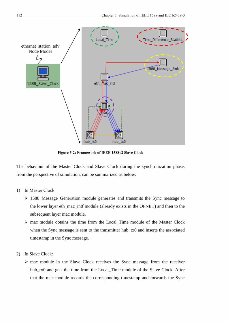
112 Chapter 5: Simulation of IEEE 1588 and IEC 62439-3
Figure 5-2: Framework of IEEE 1588v2 Slave Clock
The behaviour of the Master Clock and Slave Clock during the synchronization phase,
from the perspective of simulation, can be summarized as below.
1) In Master Clock:
1588_Message_Generation module generates and transmits the Sync message to
the lower layer eth_mac_intf module (already exists in the OPNET) and then to the
subsequent layer mac module.
mac module obtains the time from the Local_Time module of the Master Clock
when the Sync message is sent to the transmitter hub_tx0 and inserts the associated
timestamp in the Sync message.
2) In Slave Clock:
mac module in the Slave Clock receives the Sync message from the receiver
hub_rx0 and gets the time from the Local_Time module of the Slave Clock. After
that the mac module records the corresponding timestamp and forwards the Sync
ethernet_station_adv
Node Model
Chapter 5: Simulation of IEEE 1588 and IEC 62439-3 113
message to the upper layer eth_mac_intf module and then to the following layer
1588_Message_Sink module.
1588_Message_Sink module accepts the Sync message and calculates the time
difference between Slave Clock and Master Clock. Once the time difference is
derived, 1588_Message_Sink requests the Local_Time module of the Slave to
adjust the local time.
1588_Message_Sink module issues and sends Delay_Req message to lower layer
eth_mac_intf module and then to subsequent layer mac module after certain delay
from the time when the Sync message is processed.
mac module acquires the time from Local_Time module of the Slave Clock as it
forwards Delay_Req to the transmitter hub_tx0 and records the associated
timestamp.
3) In Master Clock
mac module of the Master Clock receives the Delay_Req message from the
receiver hub_rx0 and request the time from the Local_Time module of the Master
Clock. Then the associated timestamp is recorded and the Delay_Req message is
sent to upper layer eth_mac_intf module and then to the following layer
1588_Message_Process module.
1588_Message_Process module responds with sending out the Delay_Resp
message to the lower layer eth_mac_intf module and then to the subsequent layer
mac module.
mac module encapsulates the timestamp when Delay_Req is received into the
Delay_Resp message and forwards it to the transmitter hub_tx0.
4) In Slave Clock
mac module of the Slave Clock gets the Delay_Resp message from the receiver
hub_rx0 and relays it to the upper layer eth_mac_intf module and then to the
following layer 1588_Message_Sink module.
1588_Message_Sink module accepts the Delay_Resp message and calculates the
mean path delay between Slave Clock and Master Clock using the timestamps
associated with previous Sync message and Delay_Req message. After the mean
path delay is obtained or updated, it will be used when calculating the time
difference after subsequent Sync messages are received at the Slave.
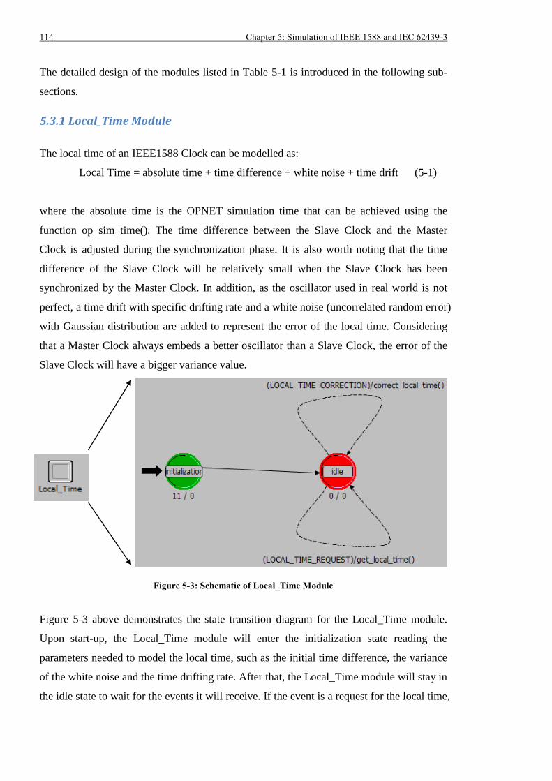
114 Chapter 5: Simulation of IEEE 1588 and IEC 62439-3
The detailed design of the modules listed in Table 5-1 is introduced in the following sub-
sections.
5.3.1 Local_Time Module
The local time of an IEEE1588 Clock can be modelled as:
Local Time = absolute time + time difference + white noise + time drift (5-1)
where the absolute time is the OPNET simulation time that can be achieved using the
function op_sim_time(). The time difference between the Slave Clock and the Master
Clock is adjusted during the synchronization phase. It is also worth noting that the time
difference of the Slave Clock will be relatively small when the Slave Clock has been
synchronized by the Master Clock. In addition, as the oscillator used in real world is not
perfect, a time drift with specific drifting rate and a white noise (uncorrelated random error)
with Gaussian distribution are added to represent the error of the local time. Considering
that a Master Clock always embeds a better oscillator than a Slave Clock, the error of the
Slave Clock will have a bigger variance value.
Figure 5-3: Schematic of Local_Time Module
Figure 5-3 above demonstrates the state transition diagram for the Local_Time module.
Upon start-up, the Local_Time module will enter the initialization state reading the
parameters needed to model the local time, such as the initial time difference, the variance
of the white noise and the time drifting rate. After that, the Local_Time module will stay in
the idle state to wait for the events it will receive. If the event is a request for the local time,
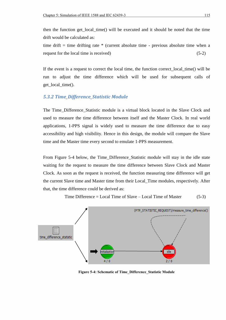
Chapter 5: Simulation of IEEE 1588 and IEC 62439-3 115
then the function get_local_time() will be executed and it should be noted that the time
drift would be calculated as:
time drift = time drifting rate * (current absolute time - previous absolute time when a
request for the local time is received) (5-2)
If the event is a request to correct the local time, the function correct_local_time() will be
run to adjust the time difference which will be used for subsequent calls of
get_local_time().
5.3.2 Time_Difference_Statistic Module
The Time_Difference_Statistic module is a virtual block located in the Slave Clock and
used to measure the time difference between itself and the Master Clock. In real world
applications, 1-PPS signal is widely used to measure the time difference due to easy
accessibility and high visibility. Hence in this design, the module will compare the Slave
time and the Master time every second to emulate 1-PPS measurement.
From Figure 5-4 below, the Time_Difference_Statistic module will stay in the idle state
waiting for the request to measure the time difference between Slave Clock and Master
Clock. As soon as the request is received, the function measuring time difference will get
the current Slave time and Master time from their Local_Time modules, respectively. After
that, the time difference could be derived as:
Time Difference = Local Time of Slave – Local Time of Master (5-3)
Figure 5-4: Schematic of Time_Difference_Statistic Module
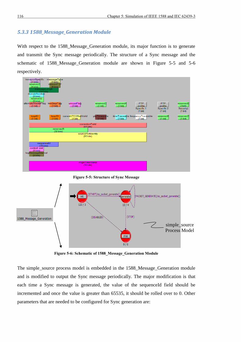
116 Chapter 5: Simulation of IEEE 1588 and IEC 62439-3
5.3.3 1588_Message_Generation Module
With respect to the 1588_Message_Generation module, its major function is to generate
and transmit the Sync message periodically. The structure of a Sync message and the
schematic of 1588_Message_Generation module are shown in Figure 5-5 and 5-6
respectively.
Figure 5-5: Structure of Sync Message
Figure 5-6: Schematic of 1588_Message_Generation Module
The simple_source process model is embedded in the 1588_Message_Generation module
and is modified to output the Sync message periodically. The major modification is that
each time a Sync message is generated, the value of the sequenceId field should be
incremented and once the value is greater than 65535, it should be rolled over to 0. Other
parameters that are needed to be configured for Sync generation are:
simple_source
Process Model
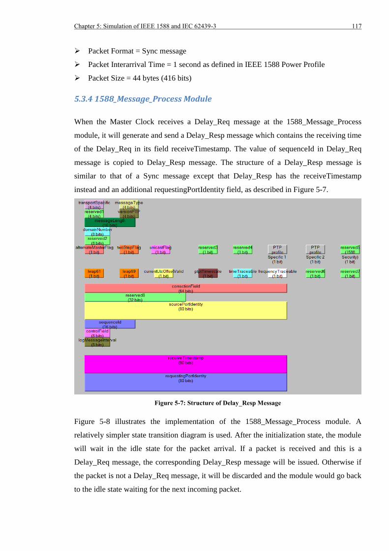
Chapter 5: Simulation of IEEE 1588 and IEC 62439-3 117
Packet Format = Sync message
Packet Interarrival Time = 1 second as defined in IEEE 1588 Power Profile
Packet Size = 44 bytes (416 bits)
5.3.4 1588_Message_Process Module
When the Master Clock receives a Delay_Req message at the 1588_Message_Process
module, it will generate and send a Delay_Resp message which contains the receiving time
of the Delay_Req in its field receiveTimestamp. The value of sequenceId in Delay_Req
message is copied to Delay_Resp message. The structure of a Delay_Resp message is
similar to that of a Sync message except that Delay_Resp has the receiveTimestamp
instead and an additional requestingPortIdentity field, as described in Figure 5-7.
Figure 5-7: Structure of Delay_Resp Message
Figure 5-8 illustrates the implementation of the 1588_Message_Process module. A
relatively simpler state transition diagram is used. After the initialization state, the module
will wait in the idle state for the packet arrival. If a packet is received and this is a
Delay_Req message, the corresponding Delay_Resp message will be issued. Otherwise if
the packet is not a Delay_Req message, it will be discarded and the module would go back
to the idle state waiting for the next incoming packet.
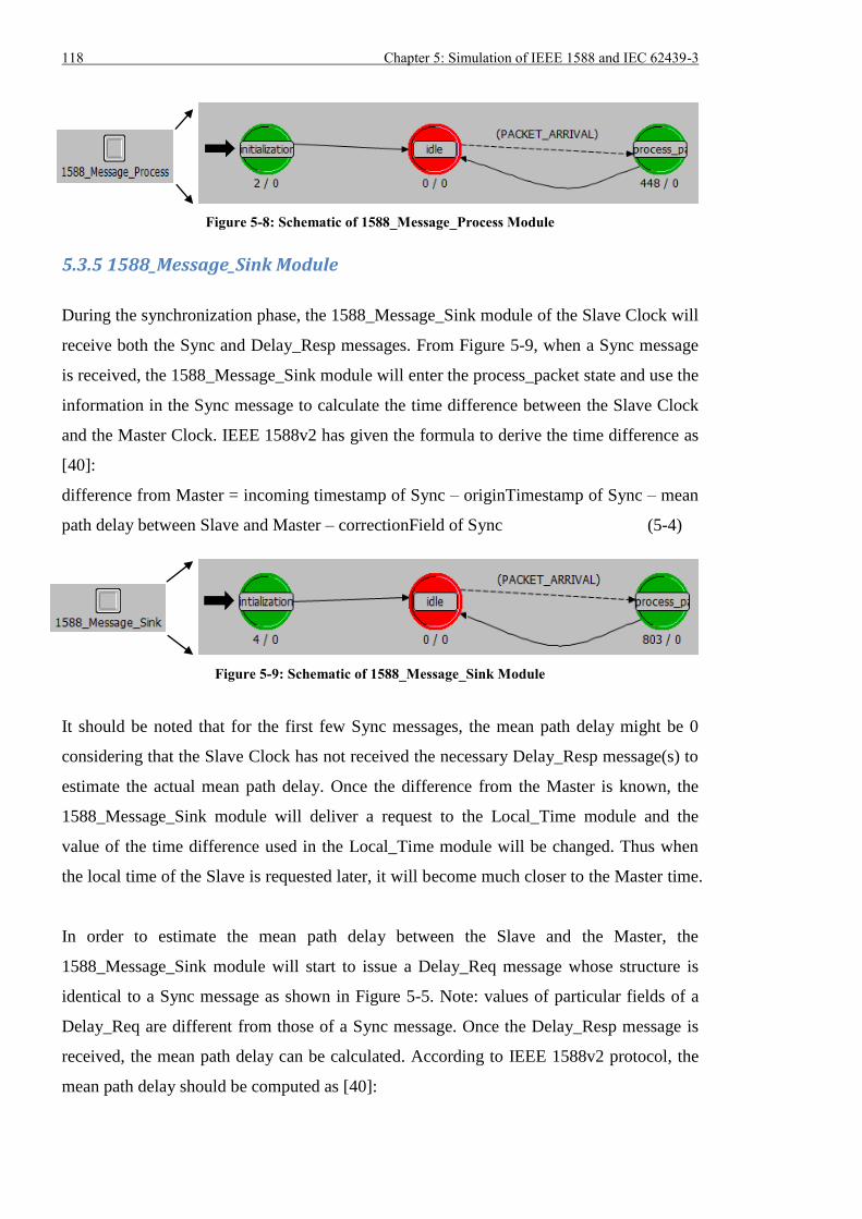
118 Chapter 5: Simulation of IEEE 1588 and IEC 62439-3
Figure 5-8: Schematic of 1588_Message_Process Module
5.3.5 1588_Message_Sink Module
During the synchronization phase, the 1588_Message_Sink module of the Slave Clock will
receive both the Sync and Delay_Resp messages. From Figure 5-9, when a Sync message
is received, the 1588_Message_Sink module will enter the process_packet state and use the
information in the Sync message to calculate the time difference between the Slave Clock
and the Master Clock. IEEE 1588v2 has given the formula to derive the time difference as
[40]:
difference from Master = incoming timestamp of Sync – originTimestamp of Sync – mean
path delay between Slave and Master – correctionField of Sync (5-4)
Figure 5-9: Schematic of 1588_Message_Sink Module
It should be noted that for the first few Sync messages, the mean path delay might be 0
considering that the Slave Clock has not received the necessary Delay_Resp message(s) to
estimate the actual mean path delay. Once the difference from the Master is known, the
1588_Message_Sink module will deliver a request to the Local_Time module and the
value of the time difference used in the Local_Time module will be changed. Thus when
the local time of the Slave is requested later, it will become much closer to the Master time.
In order to estimate the mean path delay between the Slave and the Master, the
1588_Message_Sink module will start to issue a Delay_Req message whose structure is
identical to a Sync message as shown in Figure 5-5. Note: values of particular fields of a
Delay_Req are different from those of a Sync message. Once the Delay_Resp message is
received, the mean path delay can be calculated. According to IEEE 1588v2 protocol, the
mean path delay should be computed as [40]:
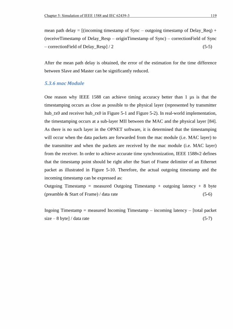
Chapter 5: Simulation of IEEE 1588 and IEC 62439-3 119
mean path delay = [(incoming timestamp of Sync – outgoing timestamp of Delay_Req) +
(receiveTimestamp of Delay_Resp – originTimestamp of Sync) – correctionField of Sync
– correctionField of Delay_Resp] / 2 (5-5)
After the mean path delay is obtained, the error of the estimation for the time difference
between Slave and Master can be significantly reduced.
5.3.6 mac Module
One reason why IEEE 1588 can achieve timing accuracy better than 1 µs is that the
timestamping occurs as close as possible to the physical layer (represented by transmitter
hub_tx0 and receiver hub_rx0 in Figure 5-1 and Figure 5-2). In real-world implementation,
the timestamping occurs at a sub-layer MII between the MAC and the physical layer [84].
As there is no such layer in the OPNET software, it is determined that the timestamping
will occur when the data packets are forwarded from the mac module (i.e. MAC layer) to
the transmitter and when the packets are received by the mac module (i.e. MAC layer)
from the receiver. In order to achieve accurate time synchronization, IEEE 1588v2 defines
that the timestamp point should be right after the Start of Frame delimiter of an Ethernet
packet as illustrated in Figure 5-10. Therefore, the actual outgoing timestamp and the
incoming timestamp can be expressed as:
Outgoing Timestamp = measured Outgoing Timestamp + outgoing latency + 8 byte
(preamble & Start of Frame) / data rate (5-6)
Ingoing Timestamp = measured Incoming Timestamp – incoming latency – [total packet
size – 8 byte] / data rate (5-7)
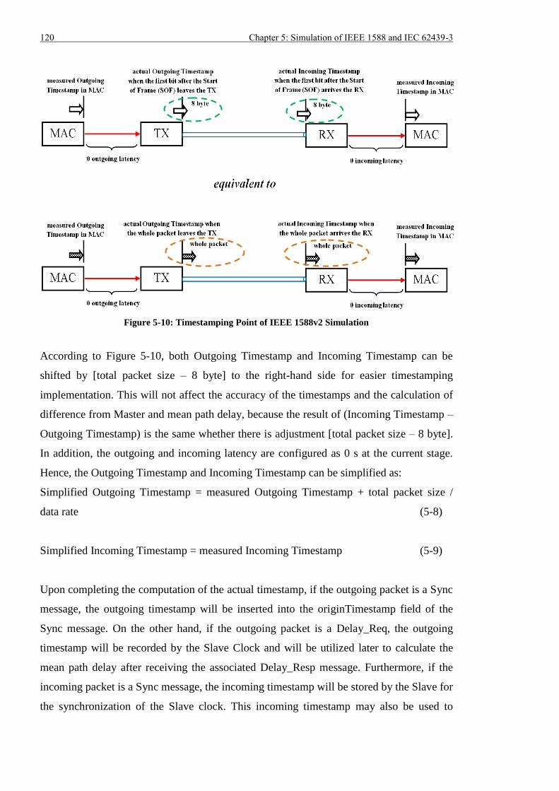
120 Chapter 5: Simulation of IEEE 1588 and IEC 62439-3
Figure 5-10: Timestamping Point of IEEE 1588v2 Simulation
According to Figure 5-10, both Outgoing Timestamp and Incoming Timestamp can be
shifted by [total packet size – 8 byte] to the right-hand side for easier timestamping
implementation. This will not affect the accuracy of the timestamps and the calculation of
difference from Master and mean path delay, because the result of (Incoming Timestamp –
Outgoing Timestamp) is the same whether there is adjustment [total packet size – 8 byte].
In addition, the outgoing and incoming latency are configured as 0 s at the current stage.
Hence, the Outgoing Timestamp and Incoming Timestamp can be simplified as:
Simplified Outgoing Timestamp = measured Outgoing Timestamp + total packet size /
data rate (5-8)
Simplified Incoming Timestamp = measured Incoming Timestamp (5-9)
Upon completing the computation of the actual timestamp, if the outgoing packet is a Sync
message, the outgoing timestamp will be inserted into the originTimestamp field of the
Sync message. On the other hand, if the outgoing packet is a Delay_Req, the outgoing
timestamp will be recorded by the Slave Clock and will be utilized later to calculate the
mean path delay after receiving the associated Delay_Resp message. Furthermore, if the
incoming packet is a Sync message, the incoming timestamp will be stored by the Slave for
the synchronization of the Slave clock. This incoming timestamp may also be used to
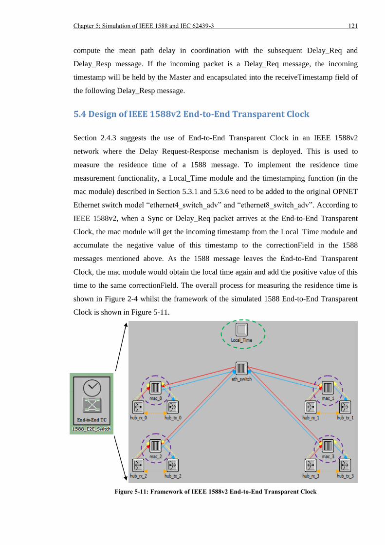
Chapter 5: Simulation of IEEE 1588 and IEC 62439-3 121
compute the mean path delay in coordination with the subsequent Delay_Req and
Delay_Resp message. If the incoming packet is a Delay_Req message, the incoming
timestamp will be held by the Master and encapsulated into the receiveTimestamp field of
the following Delay_Resp message.
5.4 Design of IEEE 1588v2 End-to-End Transparent Clock
Section 2.4.3 suggests the use of End-to-End Transparent Clock in an IEEE 1588v2
network where the Delay Request-Response mechanism is deployed. This is used to
measure the residence time of a 1588 message. To implement the residence time
measurement functionality, a Local_Time module and the timestamping function (in the
mac module) described in Section 5.3.1 and 5.3.6 need to be added to the original OPNET
Ethernet switch model “ethernet4_switch_adv” and “ethernet8_switch_adv”. According to
IEEE 1588v2, when a Sync or Delay_Req packet arrives at the End-to-End Transparent
Clock, the mac module will get the incoming timestamp from the Local_Time module and
accumulate the negative value of this timestamp to the correctionField in the 1588
messages mentioned above. As the 1588 message leaves the End-to-End Transparent
Clock, the mac module would obtain the local time again and add the positive value of this
time to the same correctionField. The overall process for measuring the residence time is
shown in Figure 2-4 whilst the framework of the simulated 1588 End-to-End Transparent
Clock is shown in Figure 5-11.
Figure 5-11: Framework of IEEE 1588v2 End-to-End Transparent Clock
122 Chapter 5: Simulation of IEEE 1588 and IEC 62439-3
As the timestamping occurs in the mac module, the packet waiting time in the
corresponding transmitter will not be accumulated to the 1588 messages. When
considerable packets compete with 1588 messages for the access to the transmitter, the
waiting time in the transmitter could significantly increase. Consequently, when the 1588
Slave Clock estimates the mean path delay, only part of the delay experienced by the
packet is considered and the synchronization error would be raised. In order to solve this
problem, the queuing delay within a transmitter should be included each time when a Sync
or Delay_Req message is sent out from the 1588 End-to-End switch. Based on the OPNET
user guide, the link object between two nodes consists of five pipeline stages including the
calculation of transmission delay [85]. The duplex 100 Mb/s link object used in the
simulation employs a pipeline stage code “eth_hub_txdel_bguil” to compute the packet
transmission delay based on the transmission rate of the transmitter and the packet queuing
delay each time a packet is send to the transmitter. Thus the idea is to add some extra code
to the “eth_hub_txdel_bguil” pipeline stage to accumulate the queuing delay into the
correctionField of a Sync or Delay_Req message. Figure 5-12 describes part of the original
code and extra code responsible for the delay accumulation in the newly defined pipeline
stage.
(a) Original Code in Pipeline Stage for Delay Computation
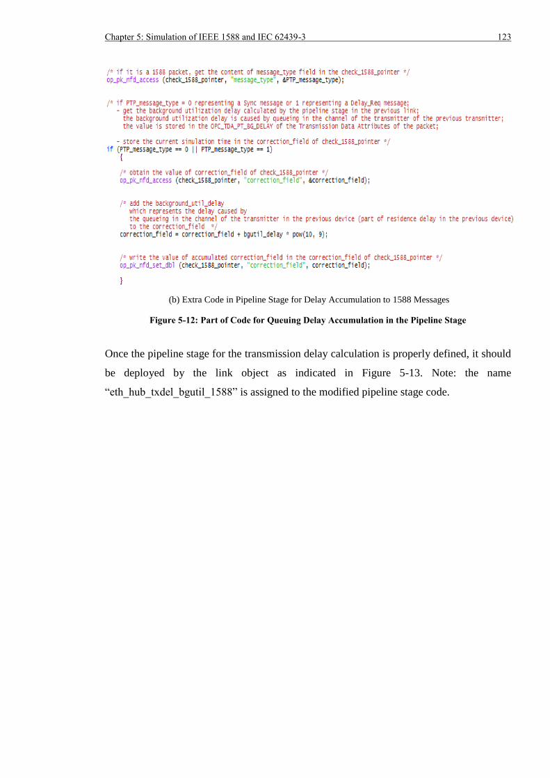
Chapter 5: Simulation of IEEE 1588 and IEC 62439-3 123
(b) Extra Code in Pipeline Stage for Delay Accumulation to 1588 Messages
Figure 5-12: Part of Code for Queuing Delay Accumulation in the Pipeline Stage
Once the pipeline stage for the transmission delay calculation is properly defined, it should
be deployed by the link object as indicated in Figure 5-13. Note: the name
“eth_hub_txdel_bgutil_1588” is assigned to the modified pipeline stage code.
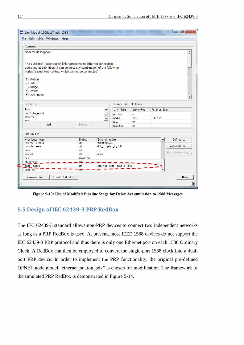
124 Chapter 5: Simulation of IEEE 1588 and IEC 62439-3
Figure 5-13: Use of Modified Pipeline Stage for Delay Accumulation to 1588 Messages
5.5 Design of IEC 62439-3 PRP RedBox
The IEC 62439-3 standard allows non-PRP devices to connect two independent networks
as long as a PRP RedBox is used. At present, most IEEE 1588 devices do not support the
IEC 62439-3 PRP protocol and thus there is only one Ethernet port on each 1588 Ordinary
Clock. A RedBox can then be employed to convert the single-port 1588 clock into a dual-
port PRP device. In order to implement the PRP functionality, the original pre-defined
OPNET node model “ethernet_station_adv” is chosen for modification. The framework of
the simulated PRP RedBox is demonstrated in Figure 5-14.
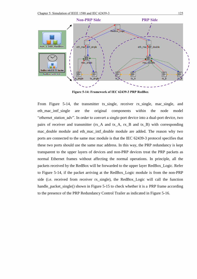
Chapter 5: Simulation of IEEE 1588 and IEC 62439-3 125
Figure 5-14: Framework of IEC 62439-3 PRP RedBox
From Figure 5-14, the transmitter tx_single, receiver rx_single, mac_single, and
eth_mac_intf_single are the original components within the node model
“ethernet_station_adv”. In order to convert a single-port device into a dual-port device, two
pairs of receiver and transmitter (rx_A and tx_A, rx_B and tx_B) with corresponding
mac_double module and eth_mac_intf_double module are added. The reason why two
ports are connected to the same mac module is that the IEC 62439-3 protocol specifies that
these two ports should use the same mac address. In this way, the PRP redundancy is kept
transparent to the upper layers of devices and non-PRP devices treat the PRP packets as
normal Ethernet frames without affecting the normal operations. In principle, all the
packets received by the RedBox will be forwarded to the upper layer RedBox_Logic. Refer
to Figure 5-14, if the packet arriving at the RedBox_Logic module is from the non-PRP
side (i.e. received from receiver rx_single), the RedBox_Logic will call the function
handle_packet_single() shown in Figure 5-15 to check whether it is a PRP frame according
to the presence of the PRP Redundancy Control Trailer as indicated in Figure 5-16.
Non-PRP Side PRP Side
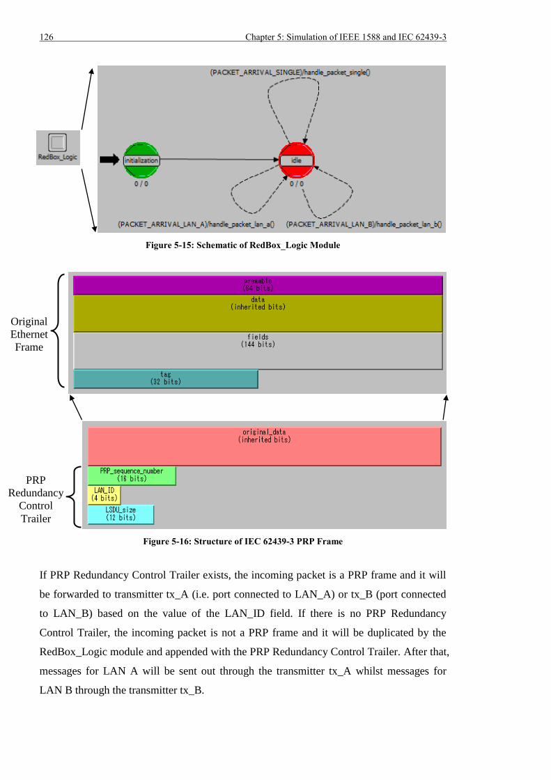
126 Chapter 5: Simulation of IEEE 1588 and IEC 62439-3
Figure 5-15: Schematic of RedBox_Logic Module
Figure 5-16: Structure of IEC 62439-3 PRP Frame
If PRP Redundancy Control Trailer exists, the incoming packet is a PRP frame and it will
be forwarded to transmitter tx_A (i.e. port connected to LAN_A) or tx_B (port connected
to LAN_B) based on the value of the LAN_ID field. If there is no PRP Redundancy
Control Trailer, the incoming packet is not a PRP frame and it will be duplicated by the
RedBox_Logic module and appended with the PRP Redundancy Control Trailer. After that,
messages for LAN A will be sent out through the transmitter tx_A whilst messages for
LAN B through the transmitter tx_B.
Original
Ethernet
Frame
PRP
Redundancy
Control
Trailer
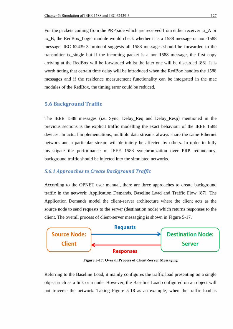
Chapter 5: Simulation of IEEE 1588 and IEC 62439-3 127
For the packets coming from the PRP side which are received from either receiver rx_A or
rx_B, the RedBox_Logic module would check whether it is a 1588 message or non-1588
message. IEC 62439-3 protocol suggests all 1588 messages should be forwarded to the
transmitter tx_single but if the incoming packet is a non-1588 message, the first copy
arriving at the RedBox will be forwarded whilst the later one will be discarded [86]. It is
worth noting that certain time delay will be introduced when the RedBox handles the 1588
messages and if the residence measurement functionality can be integrated in the mac
modules of the RedBox, the timing error could be reduced.
5.6 Background Traffic
The IEEE 1588 messages (i.e. Sync, Delay_Req and Delay_Resp) mentioned in the
previous sections is the explicit traffic modelling the exact behaviour of the IEEE 1588
devices. In actual implementations, multiple data streams always share the same Ethernet
network and a particular stream will definitely be affected by others. In order to fully
investigate the performance of IEEE 1588 synchronization over PRP redundancy,
background traffic should be injected into the simulated networks.
5.6.1 Approaches to Create Background Traffic
According to the OPNET user manual, there are three approaches to create background
traffic in the network: Application Demands, Baseline Load and Traffic Flow [87]. The
Application Demands model the client-server architecture where the client acts as the
source node to send requests to the server (destination node) which returns responses to the
client. The overall process of client-server messaging is shown in Figure 5-17.
Figure 5-17: Overall Process of Client-Server Messaging
Referring to the Baseline Load, it mainly configures the traffic load presenting on a single
object such as a link or a node. However, the Baseline Load configured on an object will
not traverse the network. Taking Figure 5-18 as an example, when the traffic load is
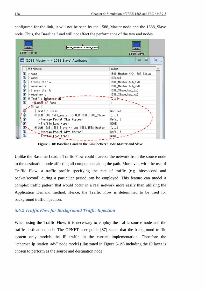
128 Chapter 5: Simulation of IEEE 1588 and IEC 62439-3
configured for the link, it will not be seen by the 1588_Master node and the 1588_Slave
node. Thus, the Baseline Load will not affect the performance of the two end nodes.
Figure 5-18: Baseline Load on the Link between 1588 Master and Slave
Unlike the Baseline Load, a Traffic Flow could traverse the network from the source node
to the destination node affecting all components along the path. Moreover, with the use of
Traffic Flow, a traffic profile specifying the rate of traffic (e.g. bits/second and
packet/second) during a particular period can be employed. This feature can model a
complex traffic pattern that would occur in a real network more easily than utilizing the
Application Demand method. Hence, the Traffic Flow is determined to be used for
background traffic injection.
5.6.2 Traffic Flow for Background Traffic Injection
When using the Traffic Flow, it is necessary to employ the traffic source node and the
traffic destination node. The OPNET user guide [87] states that the background traffic
system only models the IP traffic in the current implementation. Therefore the
“ethernet_ip_station_adv” node model (illustrated in Figure 5-19) including the IP layer is
chosen to perform as the source and destination node.
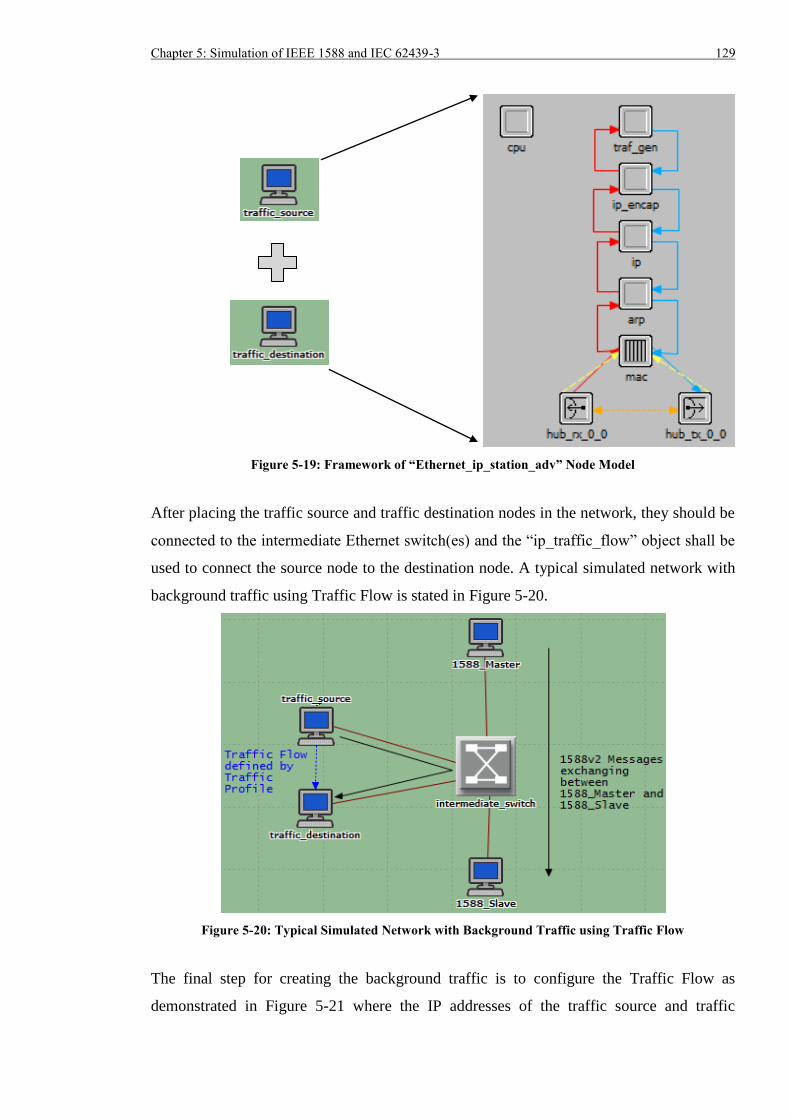
Chapter 5: Simulation of IEEE 1588 and IEC 62439-3 129
Figure 5-19: Framework of “Ethernet_ip_station_adv” Node Model
After placing the traffic source and traffic destination nodes in the network, they should be
connected to the intermediate Ethernet switch(es) and the “ip_traffic_flow” object shall be
used to connect the source node to the destination node. A typical simulated network with
background traffic using Traffic Flow is stated in Figure 5-20.
Figure 5-20: Typical Simulated Network with Background Traffic using Traffic Flow
The final step for creating the background traffic is to configure the Traffic Flow as
demonstrated in Figure 5-21 where the IP addresses of the traffic source and traffic
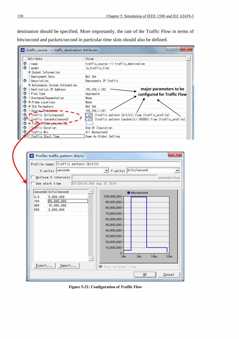
130 Chapter 5: Simulation of IEEE 1588 and IEC 62439-3
destination should be specified. More importantly, the rate of the Traffic Flow in terms of
bits/second and packets/second in particular time slots should also be defined.
Figure 5-21: Configuration of Traffic Flow
major parameters to be configured for Traffic Flow
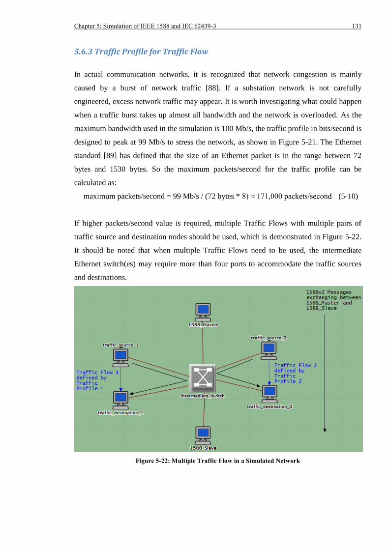
Chapter 5: Simulation of IEEE 1588 and IEC 62439-3 131
5.6.3 Traffic Profile for Traffic Flow
In actual communication networks, it is recognized that network congestion is mainly
caused by a burst of network traffic [88]. If a substation network is not carefully
engineered, excess network traffic may appear. It is worth investigating what could happen
when a traffic burst takes up almost all bandwidth and the network is overloaded. As the
maximum bandwidth used in the simulation is 100 Mb/s, the traffic profile in bits/second is
designed to peak at 99 Mb/s to stress the network, as shown in Figure 5-21. The Ethernet
standard [89] has defined that the size of an Ethernet packet is in the range between 72
bytes and 1530 bytes. So the maximum packets/second for the traffic profile can be
calculated as:
maximum packets/second = 99 Mb/s / (72 bytes * 8) ≈ 171,000 packets/second (5-10)
If higher packets/second value is required, multiple Traffic Flows with multiple pairs of
traffic source and destination nodes should be used, which is demonstrated in Figure 5-22.
It should be noted that when multiple Traffic Flows need to be used, the intermediate
Ethernet switch(es) may require more than four ports to accommodate the traffic sources
and destinations.
Figure 5-22: Multiple Traffic Flow in a Simulated Network
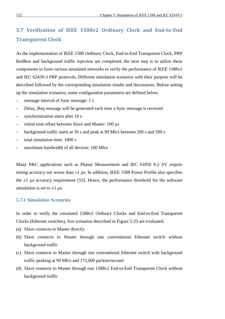
132 Chapter 5: Simulation of IEEE 1588 and IEC 62439-3
5.7 Verification of IEEE 1588v2 Ordinary Clock and End-to-End
Transparent Clock
As the implementation of IEEE 1588 Ordinary Clock, End-to-End Transparent Clock, PRP
RedBox and background traffic injection are completed, the next step is to utilize these
components to form various simulated networks to verify the performance of IEEE 1588v2
and IEC 62439-3 PRP protocols. Different simulation scenarios with their purpose will be
described followed by the corresponding simulation results and discussions. Before setting
up the simulation scenarios, some configuration parameters are defined below.
- message interval of Sync message: 1 s
- Delay_Req message will be generated each time a Sync message is received
- synchronization starts after 10 s
- initial time offset between Slave and Master: 100 µs
- background traffic starts at 50 s and peak at 99 Mb/s between 200 s and 500 s
- total simulation time: 1800 s
- maximum bandwidth of all devices: 100 Mb/s
Many P&C applications such as Phasor Measurement and IEC 61850 9-2 SV require
timing accuracy not worse than ±1 µs. In addition, IEEE 1588 Power Profile also specifies
the ±1 µs accuracy requirement [55]. Hence, the performance threshold for the software
simulation is set to ±1 µs.
5.7.1 Simulation Scenarios
In order to verify the simulated 1588v2 Ordinary Clocks and End-to-End Transparent
Clocks (Ethernet switches), five scenarios described in Figure 5-23 are evaluated.
(a) Slave connects to Master directly
(b) Slave connects to Master through one conventional Ethernet switch without
background traffic
(c) Slave connects to Master through one conventional Ethernet switch with background
traffic peaking at 99 Mb/s and 171,000 packets/second
(d) Slave connects to Master through one 1588v2 End-to-End Transparent Clock without
background traffic
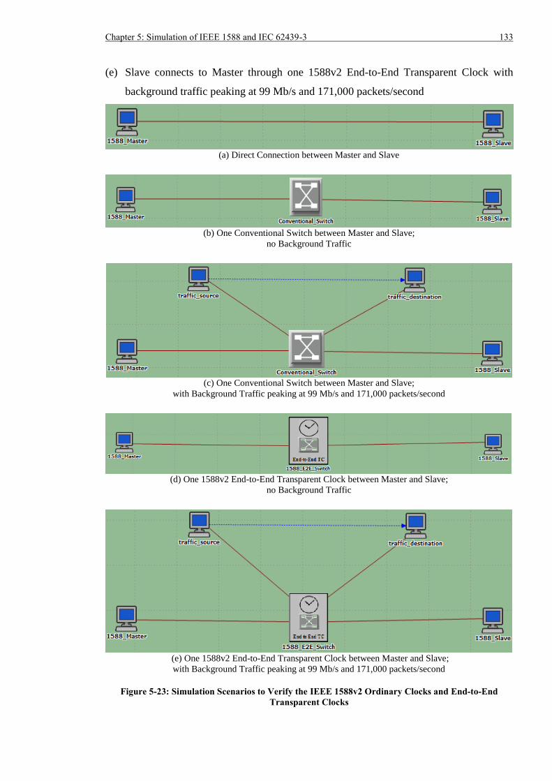
Chapter 5: Simulation of IEEE 1588 and IEC 62439-3 133
(e) Slave connects to Master through one 1588v2 End-to-End Transparent Clock with
background traffic peaking at 99 Mb/s and 171,000 packets/second
(a) Direct Connection between Master and Slave
(b) One Conventional Switch between Master and Slave;
no Background Traffic
(c) One Conventional Switch between Master and Slave;
with Background Traffic peaking at 99 Mb/s and 171,000 packets/second
(d) One 1588v2 End-to-End Transparent Clock between Master and Slave;
no Background Traffic
(e) One 1588v2 End-to-End Transparent Clock between Master and Slave;
with Background Traffic peaking at 99 Mb/s and 171,000 packets/second
Figure 5-23: Simulation Scenarios to Verify the IEEE 1588v2 Ordinary Clocks and End-to-End
Transparent Clocks
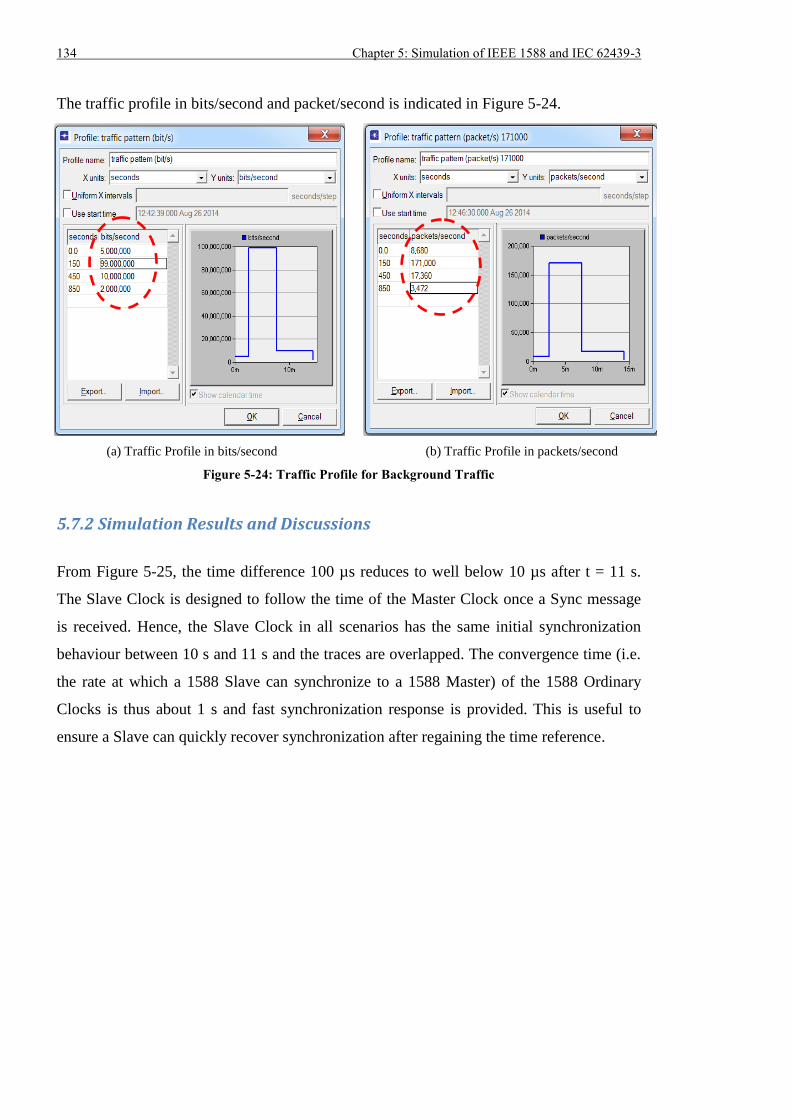
134 Chapter 5: Simulation of IEEE 1588 and IEC 62439-3
The traffic profile in bits/second and packet/second is indicated in Figure 5-24.
(a) Traffic Profile in bits/second (b) Traffic Profile in packets/second
Figure 5-24: Traffic Profile for Background Traffic
5.7.2 Simulation Results and Discussions
From Figure 5-25, the time difference 100 µs reduces to well below 10 µs after t = 11 s.
The Slave Clock is designed to follow the time of the Master Clock once a Sync message
is received. Hence, the Slave Clock in all scenarios has the same initial synchronization
behaviour between 10 s and 11 s and the traces are overlapped. The convergence time (i.e.
the rate at which a 1588 Slave can synchronize to a 1588 Master) of the 1588 Ordinary
Clocks is thus about 1 s and fast synchronization response is provided. This is useful to
ensure a Slave can quickly recover synchronization after regaining the time reference.
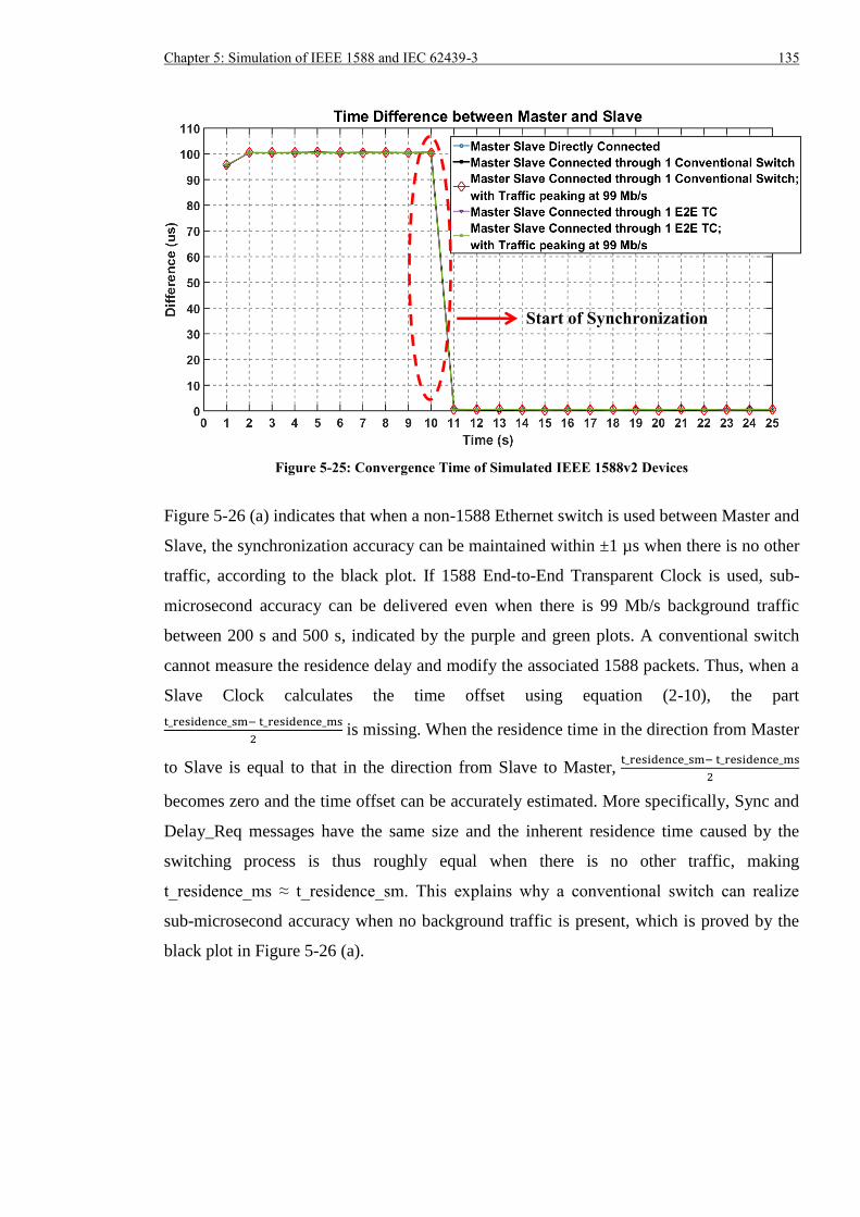
Chapter 5: Simulation of IEEE 1588 and IEC 62439-3 135
Figure 5-25: Convergence Time of Simulated IEEE 1588v2 Devices
Figure 5-26 (a) indicates that when a non-1588 Ethernet switch is used between Master and
Slave, the synchronization accuracy can be maintained within ±1 µs when there is no other
traffic, according to the black plot. If 1588 End-to-End Transparent Clock is used, sub-
microsecond accuracy can be delivered even when there is 99 Mb/s background traffic
between 200 s and 500 s, indicated by the purple and green plots. A conventional switch
cannot measure the residence delay and modify the associated 1588 packets. Thus, when a
Slave Clock calculates the time offset using equation (2-10), the part
t_residence_sm− t_residence_ms
2 is missing. When the residence time in the direction from Master
to Slave is equal to that in the direction from Slave to Master, t_residence_sm− t_residence_ms
2
becomes zero and the time offset can be accurately estimated. More specifically, Sync and
Delay_Req messages have the same size and the inherent residence time caused by the
switching process is thus roughly equal when there is no other traffic, making
t_residence_ms ≈ t_residence_sm. This explains why a conventional switch can realize
sub-microsecond accuracy when no background traffic is present, which is proved by the
black plot in Figure 5-26 (a).
Start of Synchronization
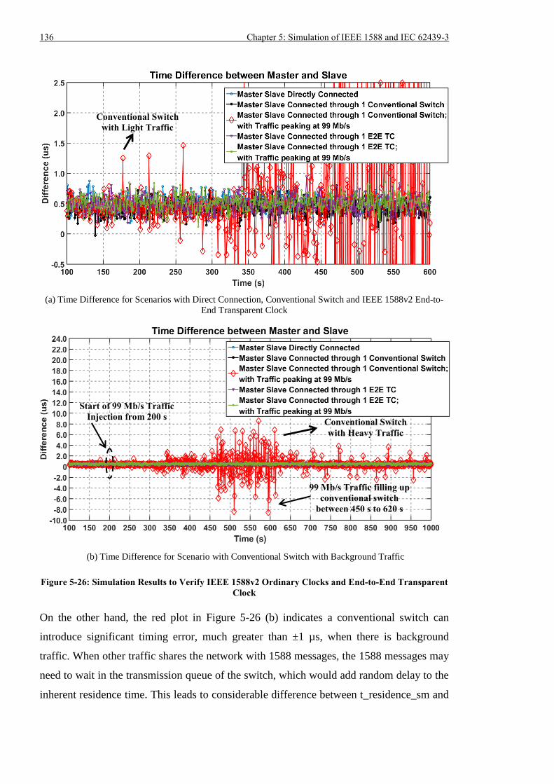
136 Chapter 5: Simulation of IEEE 1588 and IEC 62439-3
(a) Time Difference for Scenarios with Direct Connection, Conventional Switch and IEEE 1588v2 End-to-
End Transparent Clock
(b) Time Difference for Scenario with Conventional Switch with Background Traffic
Figure 5-26: Simulation Results to Verify IEEE 1588v2 Ordinary Clocks and End-to-End Transparent
Clock
On the other hand, the red plot in Figure 5-26 (b) indicates a conventional switch can
introduce significant timing error, much greater than ±1 µs, when there is background
traffic. When other traffic shares the network with 1588 messages, the 1588 messages may
need to wait in the transmission queue of the switch, which would add random delay to the
inherent residence time. This leads to considerable difference between t_residence_sm and
Start of 99 Mb/s Traffic
Injection from 200 s
99 Mb/s Traffic filling up
conventional switch
between 450 s to 620 s
Conventional Switch
with Light Traffic
Conventional Switch
with Heavy Traffic
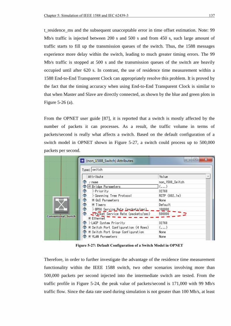
Chapter 5: Simulation of IEEE 1588 and IEC 62439-3 137
t_residence_ms and the subsequent unacceptable error in time offset estimation. Note: 99
Mb/s traffic is injected between 200 s and 500 s and from 450 s, such large amount of
traffic starts to fill up the transmission queues of the switch. Thus, the 1588 messages
experience more delay within the switch, leading to much greater timing errors. The 99
Mb/s traffic is stopped at 500 s and the transmission queues of the switch are heavily
occupied until after 620 s. In contrast, the use of residence time measurement within a
1588 End-to-End Transparent Clock can appropriately resolve this problem. It is proved by
the fact that the timing accuracy when using End-to-End Transparent Clock is similar to
that when Master and Slave are directly connected, as shown by the blue and green plots in
Figure 5-26 (a).
From the OPNET user guide [87], it is reported that a switch is mostly affected by the
number of packets it can processes. As a result, the traffic volume in terms of
packets/second is really what affects a switch. Based on the default configuration of a
switch model in OPNET shown in Figure 5-27, a switch could process up to 500,000
packets per second.
Figure 5-27: Default Configuration of a Switch Model in OPNET
Therefore, in order to further investigate the advantage of the residence time measurement
functionality within the IEEE 1588 switch, two other scenarios involving more than
500,000 packets per second injected into the intermediate switch are tested. From the
traffic profile in Figure 5-24, the peak value of packets/second is 171,000 with 99 Mb/s
traffic flow. Since the data rate used during simulation is not greater than 100 Mb/s, at least
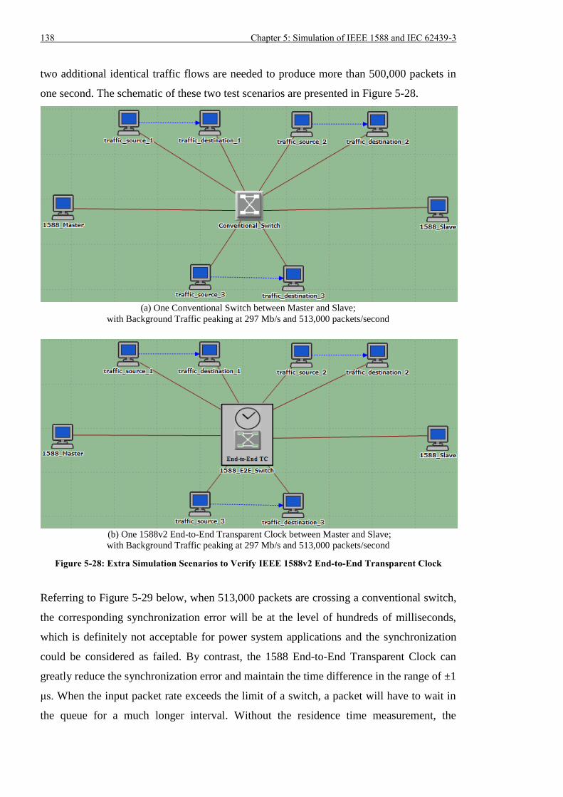
138 Chapter 5: Simulation of IEEE 1588 and IEC 62439-3
two additional identical traffic flows are needed to produce more than 500,000 packets in
one second. The schematic of these two test scenarios are presented in Figure 5-28.
(a) One Conventional Switch between Master and Slave;
with Background Traffic peaking at 297 Mb/s and 513,000 packets/second
(b) One 1588v2 End-to-End Transparent Clock between Master and Slave;
with Background Traffic peaking at 297 Mb/s and 513,000 packets/second
Figure 5-28: Extra Simulation Scenarios to Verify IEEE 1588v2 End-to-End Transparent Clock
Referring to Figure 5-29 below, when 513,000 packets are crossing a conventional switch,
the corresponding synchronization error will be at the level of hundreds of milliseconds,
which is definitely not acceptable for power system applications and the synchronization
could be considered as failed. By contrast, the 1588 End-to-End Transparent Clock can
greatly reduce the synchronization error and maintain the time difference in the range of ±1
μs. When the input packet rate exceeds the limit of a switch, a packet will have to wait in
the queue for a much longer interval. Without the residence time measurement, the
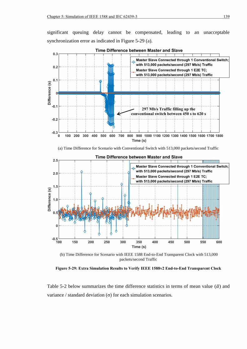
Chapter 5: Simulation of IEEE 1588 and IEC 62439-3 139
significant queuing delay cannot be compensated, leading to an unacceptable
synchronization error as indicated in Figure 5-29 (a).
(a) Time Difference for Scenario with Conventional Switch with 513,000 packets/second Traffic
(b) Time Difference for Scenario with IEEE 1588 End-to-End Transparent Clock with 513,000
packets/second Traffic
Figure 5-29: Extra Simulation Results to Verify IEEE 1588v2 End-to-End Transparent Clock
Table 5-2 below summarizes the time difference statistics in terms of mean value (��) and
variance / standard deviation (σ) for each simulation scenarios.
297 Mb/s Traffic filling up the
conventional switch between 450 s to 620 s
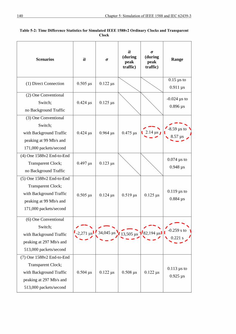
140 Chapter 5: Simulation of IEEE 1588 and IEC 62439-3
Table 5-2: Time Difference Statistics for Simulated IEEE 1588v2 Ordinary Clocks and Transparent
Clock
Scenarios �� 𝝈
��
(during
peak
traffic)
𝝈
(during
peak
traffic)
Range
(1) Direct Connection 0.505 μs 0.122 μs 0.15 µs to
0.911 µs
(2) One Conventional
Switch;
no Background Traffic
0.424 μs 0.125 μs -0.024 µs to
0.896 µs
(3) One Conventional
Switch;
with Background Traffic
peaking at 99 Mb/s and
171,000 packets/second
0.424 μs 0.964 μs 0.475 μs 2.14 μs -8.59 µs to
8.57 µs
(4) One 1588v2 End-to-End
Transparent Clock;
no Background Traffic
0.497 μs 0.123 μs 0.074 µs to
0.948 µs
(5) One 1588v2 End-to-End
Transparent Clock;
with Background Traffic
peaking at 99 Mb/s and
171,000 packets/second
0.505 μs 0.124 μs 0.519 μs 0.125 μs 0.119 µs to
0.884 µs
(6) One Conventional
Switch;
with Background Traffic
peaking at 297 Mb/s and
513,000 packets/second
-2,271 μs 34,045 μs 13,505 μs 82,194 μs -0.259 s to
0.221 s
(7) One 1588v2 End-to-End
Transparent Clock;
with Background Traffic
peaking at 297 Mb/s and
513,000 packets/second
0.504 μs 0.122 μs 0.508 μs 0.122 μs 0.113 µs to
0.925 µs
Chapter 5: Simulation of IEEE 1588 and IEC 62439-3 141
According to Table 5-2, use of IEEE 1588 End-to-End Transparent Clock implementing
the residence time measurement, can achieve synchronization accuracy better than ±1 μs
even when extremely large amount of packets flood the network. A conventional switch,
that is not able to measure the residence time of 1588 messages, can only obtain a sub-
microsecond timing error if there is no other traffic. However, the error could exceed the
±1 µs threshold even when low amount of background traffic is present. Furthermore, the
error will increase to milliseconds, with variance in the range of tens of milliseconds, when
the incoming packet rate exceeds the switch packet service rate. Consequently, it is
recommended to use IEEE 1588 End-to-End Transparent Clock if sub-microsecond
accuracy is required.
5.8 Verification of IEC 62439-3 PRP RedBox
5.8.1 Simulation Scenarios
For the validation of the IEC 62439-3 PRP RedBox, five scenarios illustrated in Figure 5-
30 are considered.
(a) Slave connects to Master directly
(b) Slave connects to Master through one pair of IEC 62439 PRP RedBoxes which do not
have residence time measurement and there is no background traffic
(c) Slave connects to Master through one pair of IEC 62439 PRP RedBoxes which do not
have residence time measurement and there is background traffic peaking at 99 Mb/s
and 171,000 packets/second
(d) Slave connects to Master through one pair of IEC 62439 PRP RedBoxes employing
residence time measurement and there is no background traffic
(e) Slave connects to Master through one pair of IEC 62439 PRP RedBoxes employing
residence time measurement and there is background traffic peaking at 99 Mb/s and
171,000 packets/second
Even though the simulated PRP RedBox has only three ports, it is possible to inject other
traffic as long as additional switches are used as shown in Figure 5-30 (c) and (e). IEEE
1588 End-to-End switches rather than conventional switches are used for the traffic
injection in order to investigate the effect of residence time measurement in the PRP
RedBox.
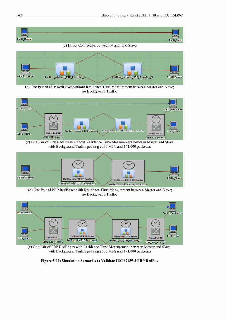
142 Chapter 5: Simulation of IEEE 1588 and IEC 62439-3
(a) Direct Connection between Master and Slave
(b) One Pair of PRP RedBoxes without Residence Time Measurement between Master and Slave;
no Background Traffic
(c) One Pair of PRP RedBoxes without Residence Time Measurement between Master and Slave;
with Background Traffic peaking at 99 Mb/s and 171,000 packets/s
(d) One Pair of PRP RedBoxes with Residence Time Measurement between Master and Slave;
no Background Traffic
(e) One Pair of PRP RedBoxes with Residence Time Measurement between Master and Slave;
with Background Traffic peaking at 99 Mb/s and 171,000 packets/s
Figure 5-30: Simulation Scenarios to Validate IEC 62439-3 PRP RedBox
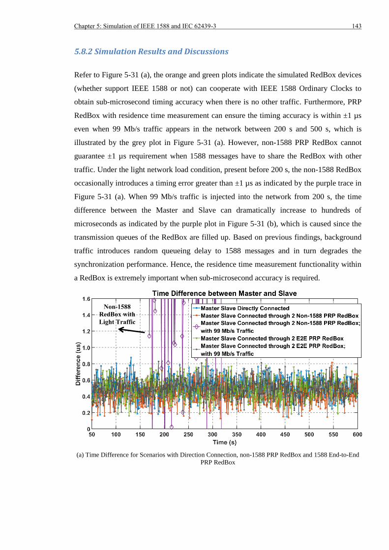
Chapter 5: Simulation of IEEE 1588 and IEC 62439-3 143
5.8.2 Simulation Results and Discussions
Refer to Figure 5-31 (a), the orange and green plots indicate the simulated RedBox devices
(whether support IEEE 1588 or not) can cooperate with IEEE 1588 Ordinary Clocks to
obtain sub-microsecond timing accuracy when there is no other traffic. Furthermore, PRP
RedBox with residence time measurement can ensure the timing accuracy is within ±1 µs
even when 99 Mb/s traffic appears in the network between 200 s and 500 s, which is
illustrated by the grey plot in Figure 5-31 (a). However, non-1588 PRP RedBox cannot
guarantee ±1 µs requirement when 1588 messages have to share the RedBox with other
traffic. Under the light network load condition, present before 200 s, the non-1588 RedBox
occasionally introduces a timing error greater than ±1 µs as indicated by the purple trace in
Figure 5-31 (a). When 99 Mb/s traffic is injected into the network from 200 s, the time
difference between the Master and Slave can dramatically increase to hundreds of
microseconds as indicated by the purple plot in Figure 5-31 (b), which is caused since the
transmission queues of the RedBox are filled up. Based on previous findings, background
traffic introduces random queueing delay to 1588 messages and in turn degrades the
synchronization performance. Hence, the residence time measurement functionality within
a RedBox is extremely important when sub-microsecond accuracy is required.
(a) Time Difference for Scenarios with Direction Connection, non-1588 PRP RedBox and 1588 End-to-End
PRP RedBox
Non-1588
RedBox with
Light Traffic
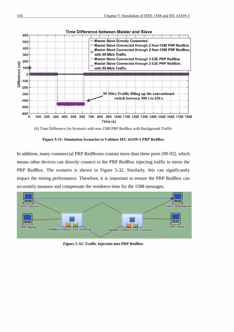
144 Chapter 5: Simulation of IEEE 1588 and IEC 62439-3
(b) Time Difference for Scenario with non-1588 PRP RedBox with Background Traffic
Figure 5-31: Simulation Scenarios to Validate IEC 62439-3 PRP RedBox
In addition, many commercial PRP RedBoxes contain more than three ports [90-92], which
means other devices can directly connect to the PRP RedBox injecting traffic to stress the
PRP RedBox. The scenario is shown in Figure 5-32. Similarly, this can significantly
impact the timing performance. Therefore, it is important to ensure the PRP RedBox can
accurately measure and compensate the residence time for the 1588 messages.
Figure 5-32: Traffic Injection into PRP RedBox
99 Mb/s Traffic filling up the conventional
switch between 300 s to 620 s
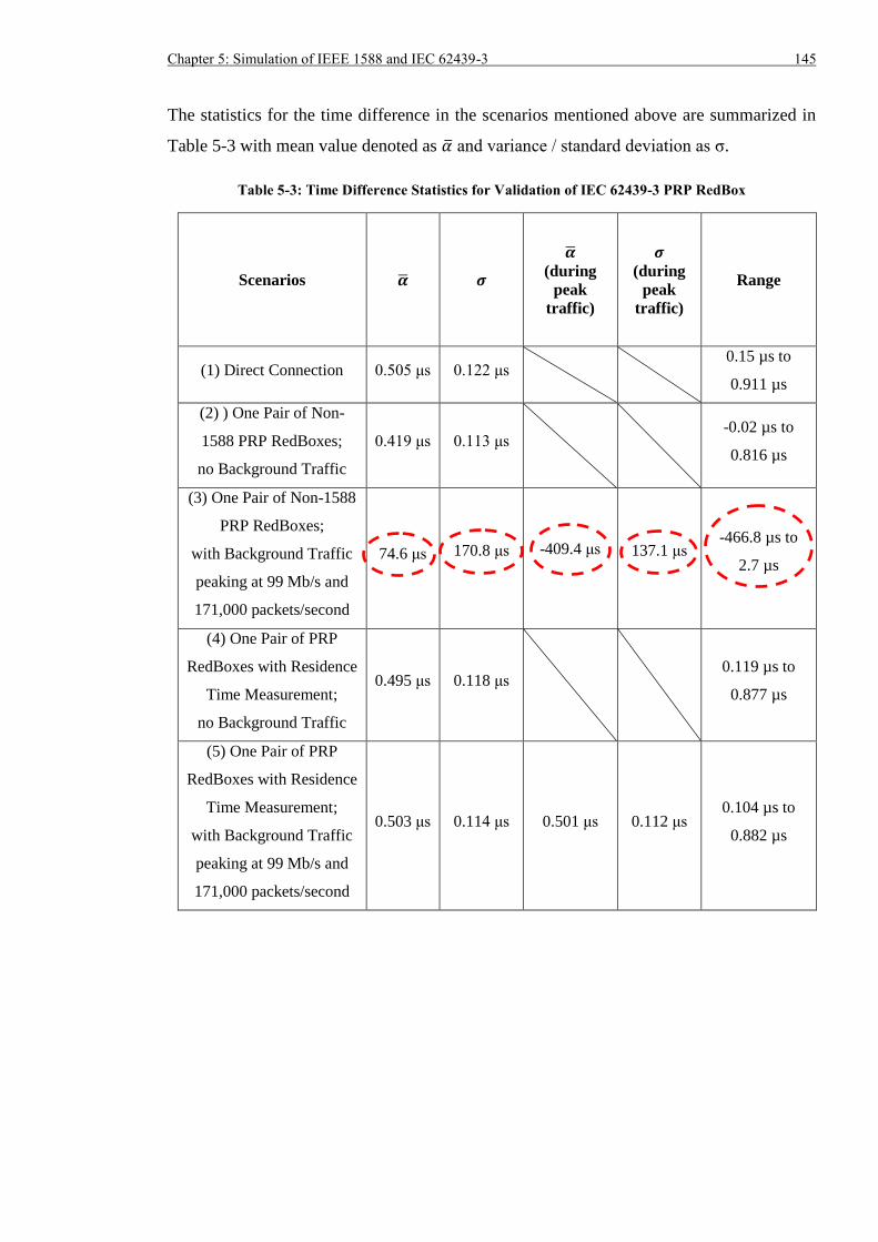
Chapter 5: Simulation of IEEE 1588 and IEC 62439-3 145
The statistics for the time difference in the scenarios mentioned above are summarized in
Table 5-3 with mean value denoted as �� and variance / standard deviation as σ.
Table 5-3: Time Difference Statistics for Validation of IEC 62439-3 PRP RedBox
Scenarios �� 𝝈
��
(during
peak
traffic)
𝝈
(during
peak
traffic)
Range
(1) Direct Connection 0.505 μs 0.122 μs 0.15 µs to
0.911 µs
(2) ) One Pair of Non-
1588 PRP RedBoxes;
no Background Traffic
0.419 μs 0.113 μs -0.02 µs to
0.816 µs
(3) One Pair of Non-1588
PRP RedBoxes;
with Background Traffic
peaking at 99 Mb/s and
171,000 packets/second
74.6 μs 170.8 μs -409.4 μs 137.1 μs -466.8 µs to
2.7 µs
(4) One Pair of PRP
RedBoxes with Residence
Time Measurement;
no Background Traffic
0.495 μs 0.118 μs 0.119 µs to
0.877 µs
(5) One Pair of PRP
RedBoxes with Residence
Time Measurement;
with Background Traffic
peaking at 99 Mb/s and
171,000 packets/second
0.503 μs 0.114 μs 0.501 μs 0.112 μs 0.104 µs to
0.882 µs
146 Chapter 5: Simulation of IEEE 1588 and IEC 62439-3
5.9 Verification of Compatibility among IEEE 1588v2 Ordinary Clock,
End-to-End Transparent Clock and IEC 62439 PRP RedBox
5.9.1 Simulation Scenarios
The purpose of the simulation is to combine all IEEE 1588v2 Ordinary Clocks, End-to-End
Transparent Clocks and IEC 62439-3 PRP RedBoxes in the same network and check the
performance of IEEE 1588 synchronization over PRP. In previous sections, no Transparent
Clock is used in PRP LAN A and LAN B. Hence, five scenarios involving Transparent
Clocks between the PRP RedBoxes as shown in Figure 5-33 are tested.
(a) Slave connects to Master directly
(b) Slave connects to Master through PRP RedBoxes with residence time measurement
and IEEE 1588 End-to-End Transparent Clocks and there is no background traffic
(c) Slave connects to Master through PRP RedBoxes with residence time measurement
and 1588 End-to-End Transparent Clocks and there is background traffic with peak
load at 99 Mb/s and 171,000 packets/second in LAN_A
(d) Slave connects to Master through PRP RedBoxes with residence time measurement
and 1588 End-to-End Transparent Clocks and there is background traffic with peak
load at 99 Mb/s and 171,000 packets/second in LAN_B
(e) Slave connects to Master through PRP RedBoxes with residence time measurement
and 1588 End-to-End Transparent Clocks and there is background traffic with peak
load at 99 Mb/s and 171,000 packets/second crossing both LAN_A and LAN_B
(a) Direct Connection between Master and Slave
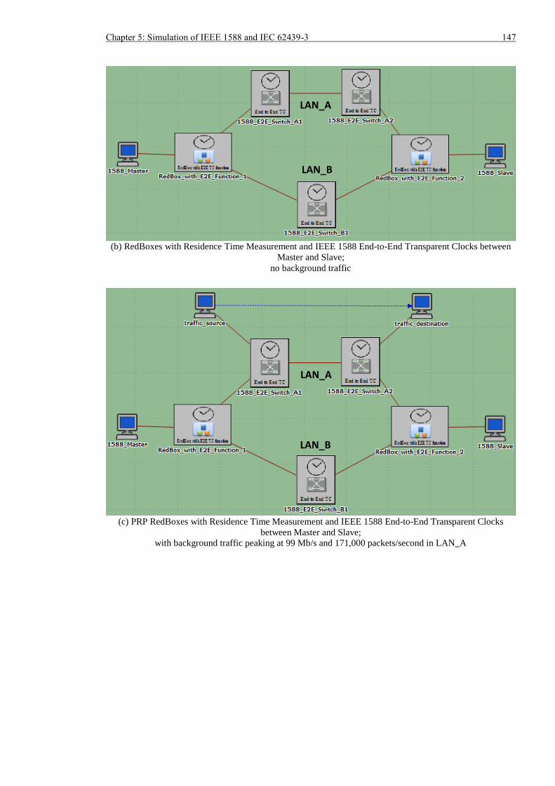
Chapter 5: Simulation of IEEE 1588 and IEC 62439-3 147
(b) RedBoxes with Residence Time Measurement and IEEE 1588 End-to-End Transparent Clocks between
Master and Slave;
no background traffic
(c) PRP RedBoxes with Residence Time Measurement and IEEE 1588 End-to-End Transparent Clocks
between Master and Slave;
with background traffic peaking at 99 Mb/s and 171,000 packets/second in LAN_A
LAN_A
LAN_B
LAN_A
LAN_B
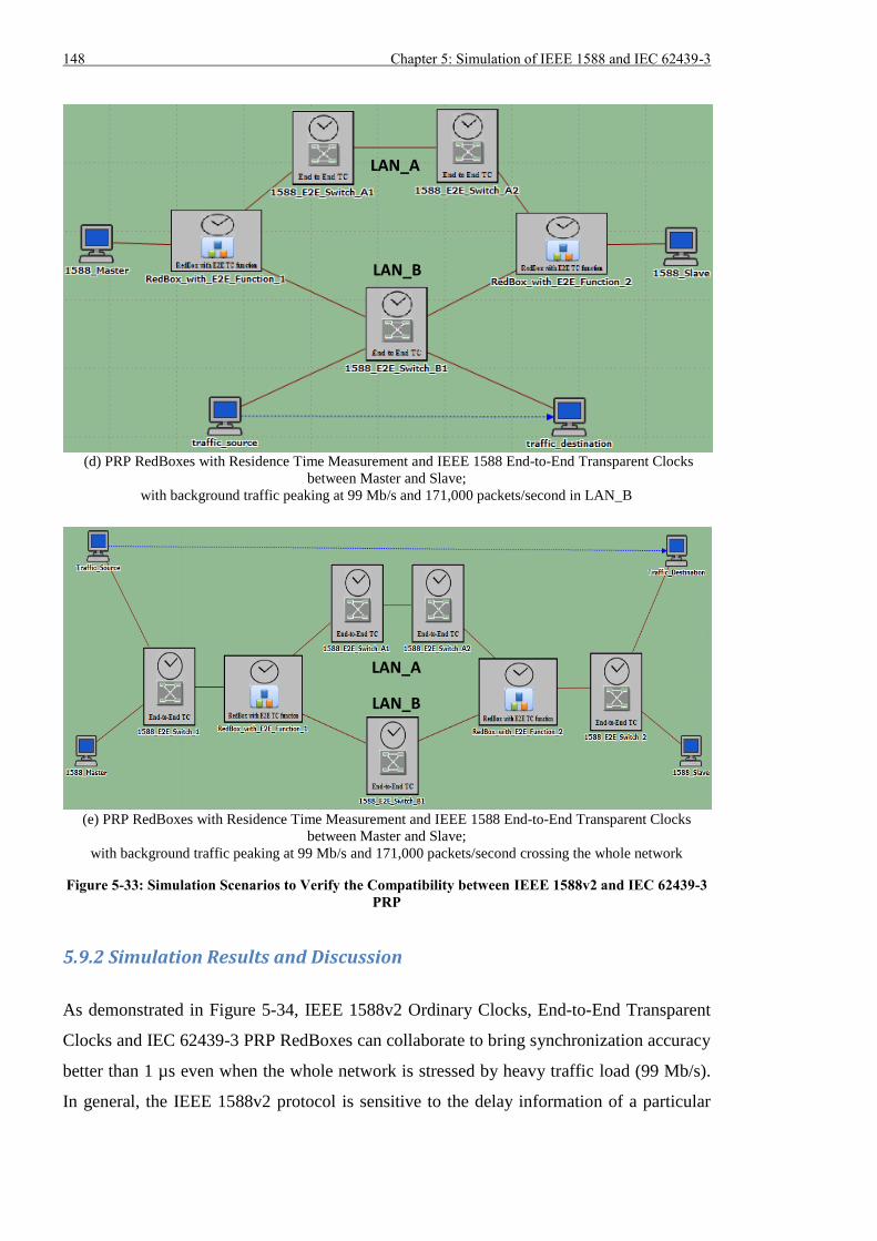
148 Chapter 5: Simulation of IEEE 1588 and IEC 62439-3
(d) PRP RedBoxes with Residence Time Measurement and IEEE 1588 End-to-End Transparent Clocks
between Master and Slave;
with background traffic peaking at 99 Mb/s and 171,000 packets/second in LAN_B
(e) PRP RedBoxes with Residence Time Measurement and IEEE 1588 End-to-End Transparent Clocks
between Master and Slave;
with background traffic peaking at 99 Mb/s and 171,000 packets/second crossing the whole network
Figure 5-33: Simulation Scenarios to Verify the Compatibility between IEEE 1588v2 and IEC 62439-3
PRP
5.9.2 Simulation Results and Discussion
As demonstrated in Figure 5-34, IEEE 1588v2 Ordinary Clocks, End-to-End Transparent
Clocks and IEC 62439-3 PRP RedBoxes can collaborate to bring synchronization accuracy
better than 1 µs even when the whole network is stressed by heavy traffic load (99 Mb/s).
In general, the IEEE 1588v2 protocol is sensitive to the delay information of a particular
LAN_A
LAN_B
LAN_A
LAN_B
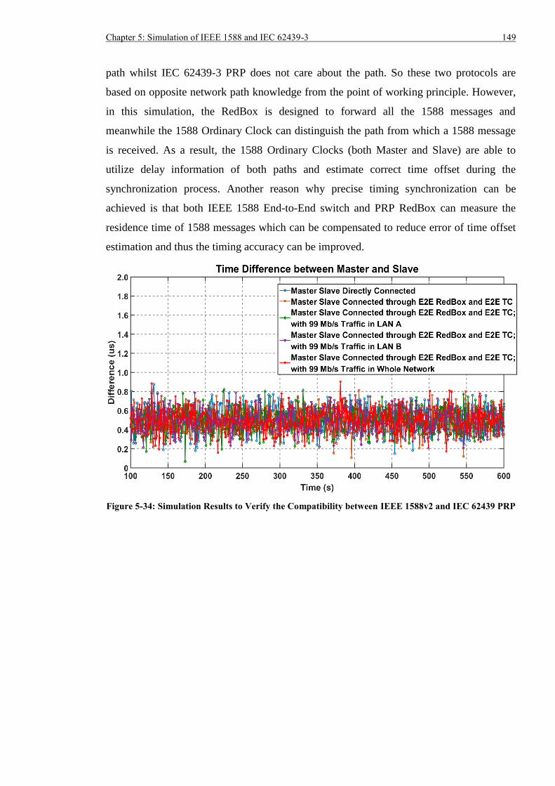
Chapter 5: Simulation of IEEE 1588 and IEC 62439-3 149
path whilst IEC 62439-3 PRP does not care about the path. So these two protocols are
based on opposite network path knowledge from the point of working principle. However,
in this simulation, the RedBox is designed to forward all the 1588 messages and
meanwhile the 1588 Ordinary Clock can distinguish the path from which a 1588 message
is received. As a result, the 1588 Ordinary Clocks (both Master and Slave) are able to
utilize delay information of both paths and estimate correct time offset during the
synchronization process. Another reason why precise timing synchronization can be
achieved is that both IEEE 1588 End-to-End switch and PRP RedBox can measure the
residence time of 1588 messages which can be compensated to reduce error of time offset
estimation and thus the timing accuracy can be improved.
Figure 5-34: Simulation Results to Verify the Compatibility between IEEE 1588v2 and IEC 62439 PRP
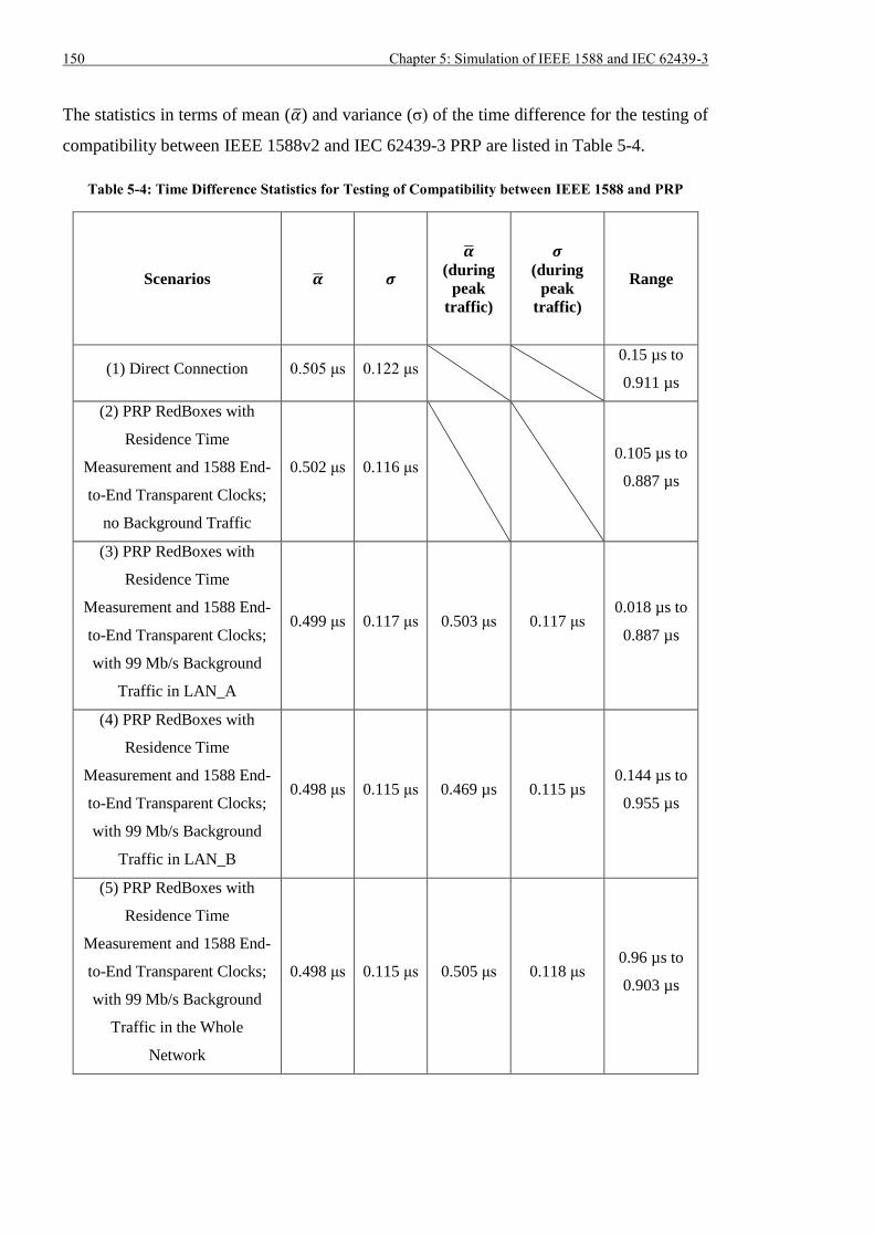
150 Chapter 5: Simulation of IEEE 1588 and IEC 62439-3
The statistics in terms of mean (��) and variance (σ) of the time difference for the testing of
compatibility between IEEE 1588v2 and IEC 62439-3 PRP are listed in Table 5-4.
Table 5-4: Time Difference Statistics for Testing of Compatibility between IEEE 1588 and PRP
Scenarios �� 𝝈
��
(during
peak
traffic)
𝝈
(during
peak
traffic)
Range
(1) Direct Connection 0.505 μs 0.122 μs 0.15 µs to
0.911 µs
(2) PRP RedBoxes with
Residence Time
Measurement and 1588 End-
to-End Transparent Clocks;
no Background Traffic
0.502 μs 0.116 μs 0.105 µs to
0.887 µs
(3) PRP RedBoxes with
Residence Time
Measurement and 1588 End-
to-End Transparent Clocks;
with 99 Mb/s Background
Traffic in LAN_A
0.499 μs 0.117 μs 0.503 μs 0.117 μs 0.018 µs to
0.887 µs
(4) PRP RedBoxes with
Residence Time
Measurement and 1588 End-
to-End Transparent Clocks;
with 99 Mb/s Background
Traffic in LAN_B
0.498 μs 0.115 μs 0.469 µs 0.115 µs 0.144 µs to
0.955 µs
(5) PRP RedBoxes with
Residence Time
Measurement and 1588 End-
to-End Transparent Clocks;
with 99 Mb/s Background
Traffic in the Whole
Network
0.498 μs 0.115 μs 0.505 μs 0.118 μs 0.96 µs to
0.903 µs
Chapter 5: Simulation of IEEE 1588 and IEC 62439-3 151
5.10 Summary
Simulation of IEEE 1588 Delay Request-Response mechanism and IEC 62439-3 PRP
seamless communication redundancy using OPNET software were described in this
chapter. It was proved that integration of IEEE 1588 End-to-End and IEC 62439 PRP
functionalities into a single device was possible. The simulation results suggested the
compensation of 1588 message residence time was critical to the achievement of sub-
microsecond accuracy especially when other traffics shared the data network. If there was
no other traffic, it was possible to obtain accuracy better than ±1 µs, but the performance
could not be guaranteed because some outliers were randomly observed. Therefore, if
precise timing accuracy is expected when implementing IEEE 1588v2 timing over IEC
62439-3 PRP network, three conditions are necessary.
First, the PRP RedBox should forward all IEEE 1588 messages.
Second, the IEEE 1588 Ordinary Clocks should be able to compute the time offset
irrespective of whether the incoming IEEE 1588 message is with or without the PRP
Redundancy Control Trailer.
Third, the residence time measurement functionality should be included in both the
Ethernet switch and the PRP RedBox. In addition, the timestamp used during the
residence time measurement should be generated as close to the physical layer (i.e.
transmitter) as possible.
The major purpose for the simulation of IEEE 1588 timing over PRP timing was to
demonstrate the feasibility of combining these two protocols that had opposed assumptions
and it was shown sub-microsecond timing accuracy was achievable. One of the limits for
the simulation was that a simple timestamping model in the simulated devices was used
and a more sophisticated and accurate one will be required in the future. In addition, the
configuration parameters of networking devices used the default values in simulation,
which might be different from those in real devices. Furthermore, the communication links
between simulated models were symmetrical (i.e. latency in both transmitting and
receiving directions were identical), which might not be guaranteed in actual applications.
Hence, the future work should also incorporate more realistic device setting values and link
model to better simulate real-world IEEE 1588 and IEC 62439-3 devices. In terms of the
traffic pattern used in the tests, it was not an accurate representation for the real substation
traffic. Therefore, the real substation traffic should be fully studied and analysed so that
precise modelling of background traffic can be obtained for future simulations. In this way,

152 Chapter 5: Simulation of IEEE 1588 and IEC 62439-3
the simulation results will be more trustworthy. Validation of the simulation models will
also be accomplished by conducting the same tests using the hardware testbed.
Chapter 6: Hardware Testing of GPS and IEEE 1588 153
Chapter 6: Hardware Testing of GPS and IEEE 1588
6.1 Introduction
IEEE 1588v2 time synchronization and IEC 62439-3 redundancy will probably be widely
applied in future Ethernet based Smart Grids due to their advantages. However, before
these two protocols can be fully employed in real-substations, utilities need to know more
about their performance, reliability and operating limitations. The simulation work has
proved the feasibility to implement IEEE 1588v2 timing over IEC 62439-3 PRP network
and sub-microsecond timing accuracy is achievable as long as the devices support IEEE
1588 protocol.
Even though a hardware testbed integrating IEEE 1588v2, IEC 62439-3 PRP/HSR and IEC
61850 was set up during the UCAIug Network Redundancy Interoperability
Demonstrations at CIGRE 2012 [93] and it was reported that good interoperability between
different vendors was obtained, it did not give utilities enough confidence on the new
technologies, because the testing period was too short. Therefore, it is necessary to build a
testbed that can combine IEEE 1588 synchronization, IEC 62439-3 redundancy and IEC
61850 communication and run long term tests under different network conditions.
The hardware testing of GPS receivers and IEEE 1588 timing system is presented in this
chapter. Note: the work described in this chapter does not validate the simulation results in
Chapter 5 as the network topology and IEEE 1588 mechanism in use are different.
Associated validations for the simulation will be covered in the future work described in
Chapter 8. Various time synchronization systems based on the use of GPS receivers and
IEEE 1588 devices are introduced in Section 6.2 and it is foreseen the centralized timing
system consisting of merely GPS receivers or a combination of GPS receivers and IEEE
1588 devices should be adopted in future digital substations. Section 6.3 then introduces
the detailed design of the hardware testbed to measure the 1-PPS difference of timing
devices as compared against the time source and also the network latency of Ethernet
packets. Different test scenarios and experimental results are demonstrated and analysed in
Section 6-4 to 6-6.
154 Chapter 6: Hardware Testing of GPS and IEEE 1588
6.2 Design of Time Synchronization System
There are currently three types of time dissemination systems within a power substation as
indicated in Figure 6-1 to Figure 6-3. The time source in all these implementations is
obtained using GPS antennas and receivers due to easy accessibility and high accuracy.
(i) Timing System based on Centralized GPS Antennas and Receivers with Legacy
Output (1-PPS & IRIG-B)
In this system, the time sources, namely the GPS receivers, are located in the central
control or communication room in a power substation. The 1-PPS and IRIG-B signal
are then disseminated to the P&C devices in bays and outdoor cubicles via a dedicated
timing network consisting of long fibre optic cables. Considering a single fibre optic
may only carry the time reference for limited number of P&C devices (using signal
splitter which can convert one input into several outputs) and the number of output
ports on a GPS receiver is also limited, this approach is not suitable for a substation
with a large number of P&C devices. In addition, as the distance from GPS receivers
to the end devices is around a few hundred meters, manual measurement and
compensation is required to remove the delay introduced by long optical fibres.
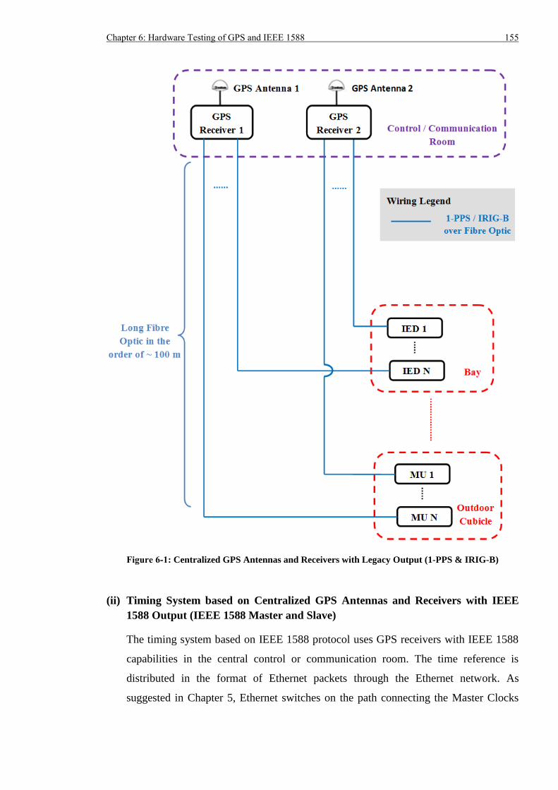
Chapter 6: Hardware Testing of GPS and IEEE 1588 155
Figure 6-1: Centralized GPS Antennas and Receivers with Legacy Output (1-PPS & IRIG-B)
(ii) Timing System based on Centralized GPS Antennas and Receivers with IEEE
1588 Output (IEEE 1588 Master and Slave)
The timing system based on IEEE 1588 protocol uses GPS receivers with IEEE 1588
capabilities in the central control or communication room. The time reference is
distributed in the format of Ethernet packets through the Ethernet network. As
suggested in Chapter 5, Ethernet switches on the path connecting the Master Clocks
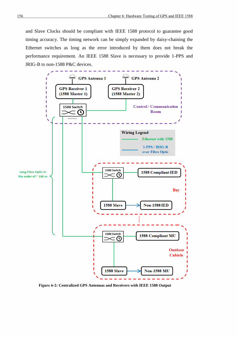
156 Chapter 6: Hardware Testing of GPS and IEEE 1588
and Slave Clocks should be compliant with IEEE 1588 protocol to guarantee good
timing accuracy. The timing network can be simply expanded by daisy-chaining the
Ethernet switches as long as the error introduced by them does not break the
performance requirement. An IEEE 1588 Slave is necessary to provide 1-PPS and
IRIG-B to non-1588 P&C devices.
Figure 6-2: Centralized GPS Antennas and Receivers with IEEE 1588 Output
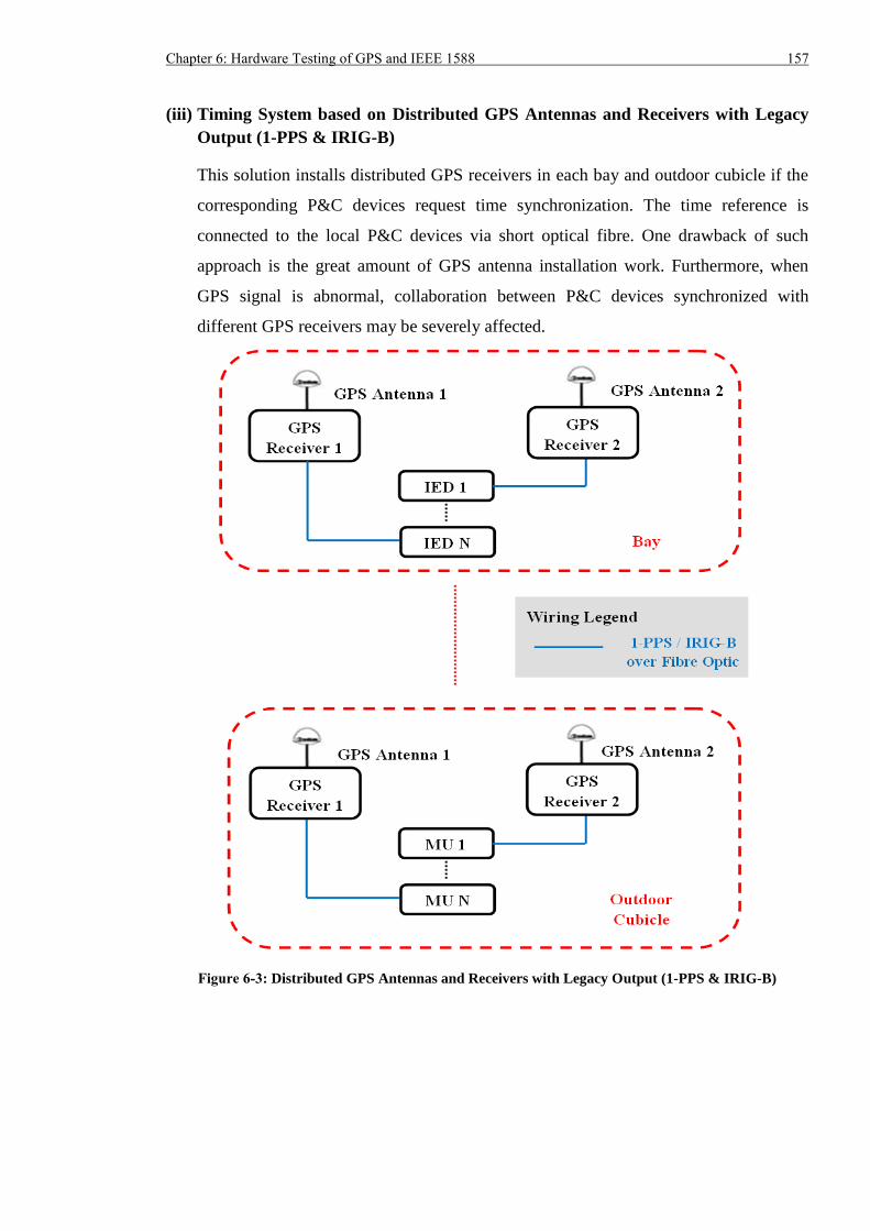
Chapter 6: Hardware Testing of GPS and IEEE 1588 157
(iii) Timing System based on Distributed GPS Antennas and Receivers with Legacy
Output (1-PPS & IRIG-B)
This solution installs distributed GPS receivers in each bay and outdoor cubicle if the
corresponding P&C devices request time synchronization. The time reference is
connected to the local P&C devices via short optical fibre. One drawback of such
approach is the great amount of GPS antenna installation work. Furthermore, when
GPS signal is abnormal, collaboration between P&C devices synchronized with
different GPS receivers may be severely affected.
Figure 6-3: Distributed GPS Antennas and Receivers with Legacy Output (1-PPS & IRIG-B)
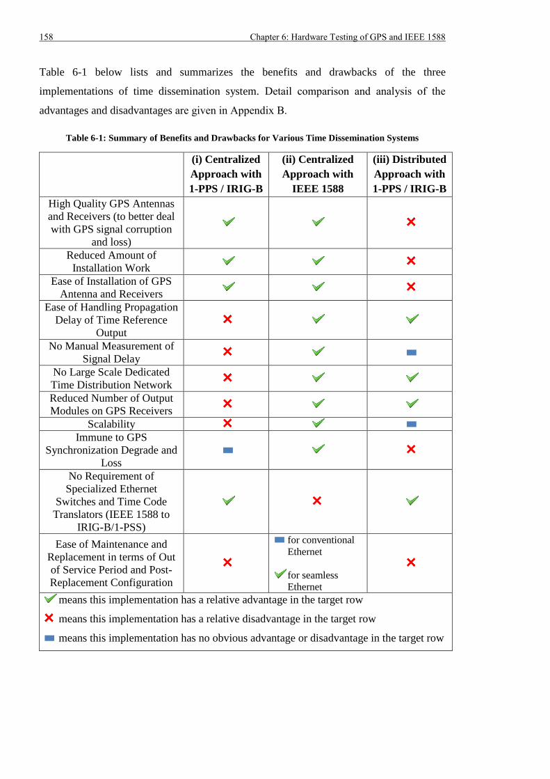
158 Chapter 6: Hardware Testing of GPS and IEEE 1588
Table 6-1 below lists and summarizes the benefits and drawbacks of the three
implementations of time dissemination system. Detail comparison and analysis of the
advantages and disadvantages are given in Appendix B.
Table 6-1: Summary of Benefits and Drawbacks for Various Time Dissemination Systems
(i) Centralized
Approach with
1-PPS / IRIG-B
(ii) Centralized
Approach with
IEEE 1588
(iii) Distributed
Approach with
1-PPS / IRIG-B
High Quality GPS Antennas
and Receivers (to better deal
with GPS signal corruption
and loss)
Reduced Amount of
Installation Work
Ease of Installation of GPS
Antenna and Receivers
Ease of Handling Propagation
Delay of Time Reference
Output
No Manual Measurement of
Signal Delay
No Large Scale Dedicated
Time Distribution Network
Reduced Number of Output
Modules on GPS Receivers
Scalability
Immune to GPS
Synchronization Degrade and
Loss
No Requirement of
Specialized Ethernet
Switches and Time Code
Translators (IEEE 1588 to
IRIG-B/1-PSS)
Ease of Maintenance and
Replacement in terms of Out
of Service Period and Post-
Replacement Configuration
for conventional
Ethernet
for seamless
Ethernet
means this implementation has a relative advantage in the target row
means this implementation has a relative disadvantage in the target row
means this implementation has no obvious advantage or disadvantage in the target row
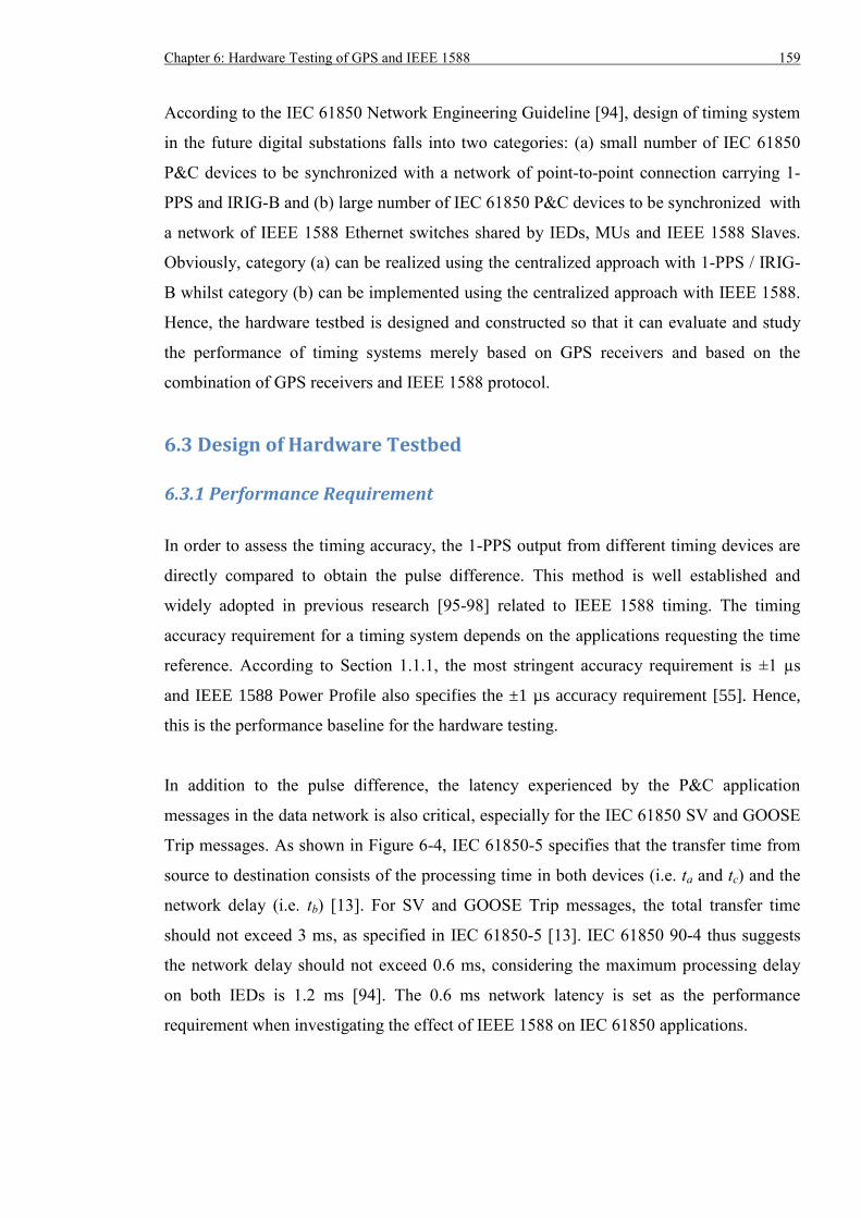
Chapter 6: Hardware Testing of GPS and IEEE 1588 159
According to the IEC 61850 Network Engineering Guideline [94], design of timing system
in the future digital substations falls into two categories: (a) small number of IEC 61850
P&C devices to be synchronized with a network of point-to-point connection carrying 1-
PPS and IRIG-B and (b) large number of IEC 61850 P&C devices to be synchronized with
a network of IEEE 1588 Ethernet switches shared by IEDs, MUs and IEEE 1588 Slaves.
Obviously, category (a) can be realized using the centralized approach with 1-PPS / IRIG-
B whilst category (b) can be implemented using the centralized approach with IEEE 1588.
Hence, the hardware testbed is designed and constructed so that it can evaluate and study
the performance of timing systems merely based on GPS receivers and based on the
combination of GPS receivers and IEEE 1588 protocol.
6.3 Design of Hardware Testbed
6.3.1 Performance Requirement
In order to assess the timing accuracy, the 1-PPS output from different timing devices are
directly compared to obtain the pulse difference. This method is well established and
widely adopted in previous research [95-98] related to IEEE 1588 timing. The timing
accuracy requirement for a timing system depends on the applications requesting the time
reference. According to Section 1.1.1, the most stringent accuracy requirement is ±1 µs
and IEEE 1588 Power Profile also specifies the ±1 µs accuracy requirement [55]. Hence,
this is the performance baseline for the hardware testing.
In addition to the pulse difference, the latency experienced by the P&C application
messages in the data network is also critical, especially for the IEC 61850 SV and GOOSE
Trip messages. As shown in Figure 6-4, IEC 61850-5 specifies that the transfer time from
source to destination consists of the processing time in both devices (i.e. ta and tc) and the
network delay (i.e. tb) [13]. For SV and GOOSE Trip messages, the total transfer time
should not exceed 3 ms, as specified in IEC 61850-5 [13]. IEC 61850 90-4 thus suggests
the network delay should not exceed 0.6 ms, considering the maximum processing delay
on both IEDs is 1.2 ms [94]. The 0.6 ms network latency is set as the performance
requirement when investigating the effect of IEEE 1588 on IEC 61850 applications.
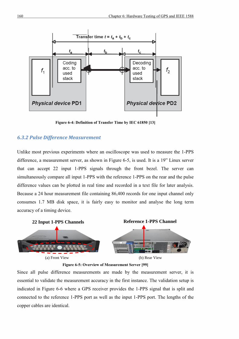
160 Chapter 6: Hardware Testing of GPS and IEEE 1588
Figure 6-4: Definition of Transfer Time by IEC 61850 [13]
6.3.2 Pulse Difference Measurement
Unlike most previous experiments where an oscilloscope was used to measure the 1-PPS
difference, a measurement server, as shown in Figure 6-5, is used. It is a 19” Linux server
that can accept 22 input 1-PPS signals through the front bezel. The server can
simultaneously compare all input 1-PPS with the reference 1-PPS on the rear and the pulse
difference values can be plotted in real time and recorded in a text file for later analysis.
Because a 24 hour measurement file containing 86,400 records for one input channel only
consumes 1.7 MB disk space, it is fairly easy to monitor and analyse the long term
accuracy of a timing device.
(a) Front View (b) Rear View
Figure 6-5: Overview of Measurement Server [99]
Since all pulse difference measurements are made by the measurement server, it is
essential to validate the measurement accuracy in the first instance. The validation setup is
indicated in Figure 6-6 where a GPS receiver provides the 1-PPS signal that is split and
connected to the reference 1-PPS port as well as the input 1-PPS port. The lengths of the
copper cables are identical.
22 Input 1-PPS Channels Reference 1-PPS Channel
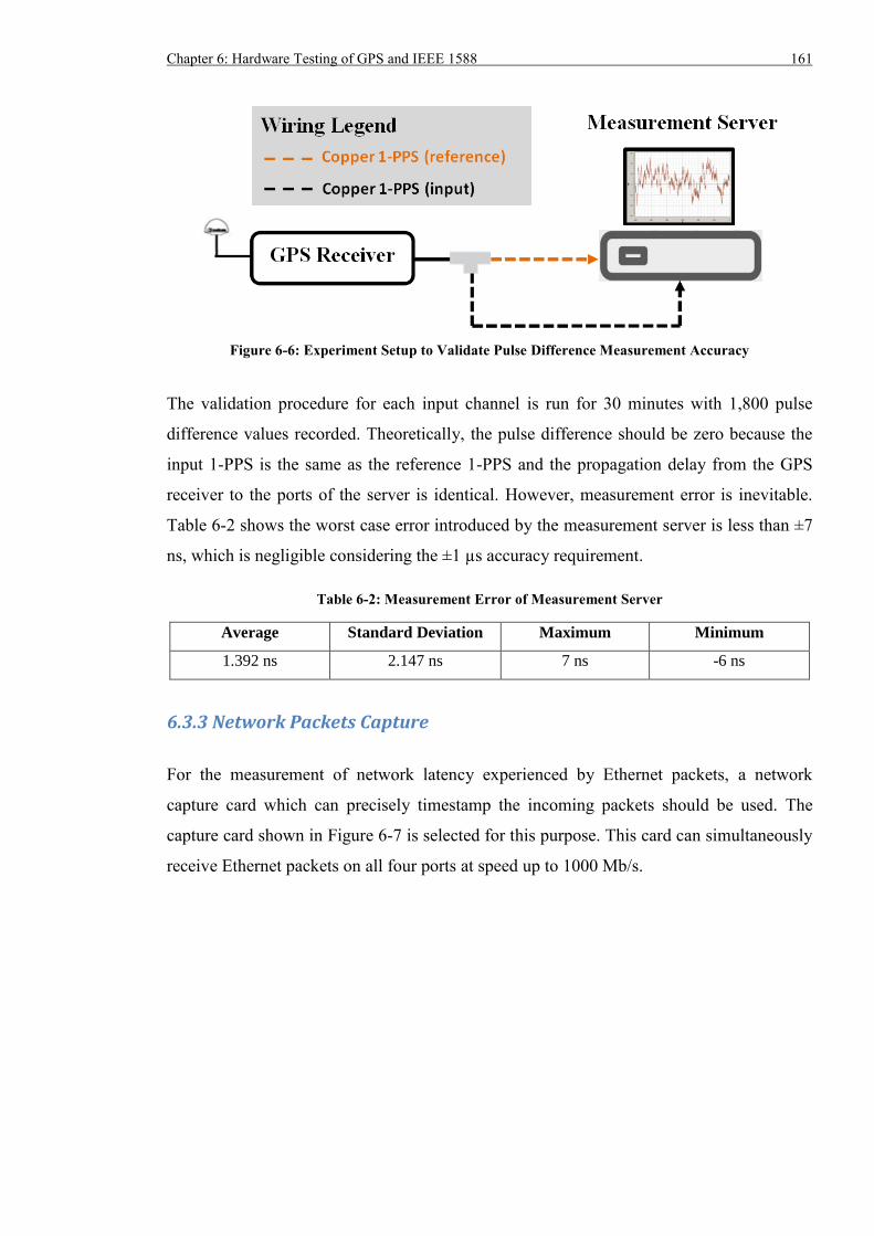
Chapter 6: Hardware Testing of GPS and IEEE 1588 161
Figure 6-6: Experiment Setup to Validate Pulse Difference Measurement Accuracy
The validation procedure for each input channel is run for 30 minutes with 1,800 pulse
difference values recorded. Theoretically, the pulse difference should be zero because the
input 1-PPS is the same as the reference 1-PPS and the propagation delay from the GPS
receiver to the ports of the server is identical. However, measurement error is inevitable.
Table 6-2 shows the worst case error introduced by the measurement server is less than ±7
ns, which is negligible considering the ±1 µs accuracy requirement.
Table 6-2: Measurement Error of Measurement Server
Average Standard Deviation Maximum Minimum
1.392 ns 2.147 ns 7 ns -6 ns
6.3.3 Network Packets Capture
For the measurement of network latency experienced by Ethernet packets, a network
capture card which can precisely timestamp the incoming packets should be used. The
capture card shown in Figure 6-7 is selected for this purpose. This card can simultaneously
receive Ethernet packets on all four ports at speed up to 1000 Mb/s.
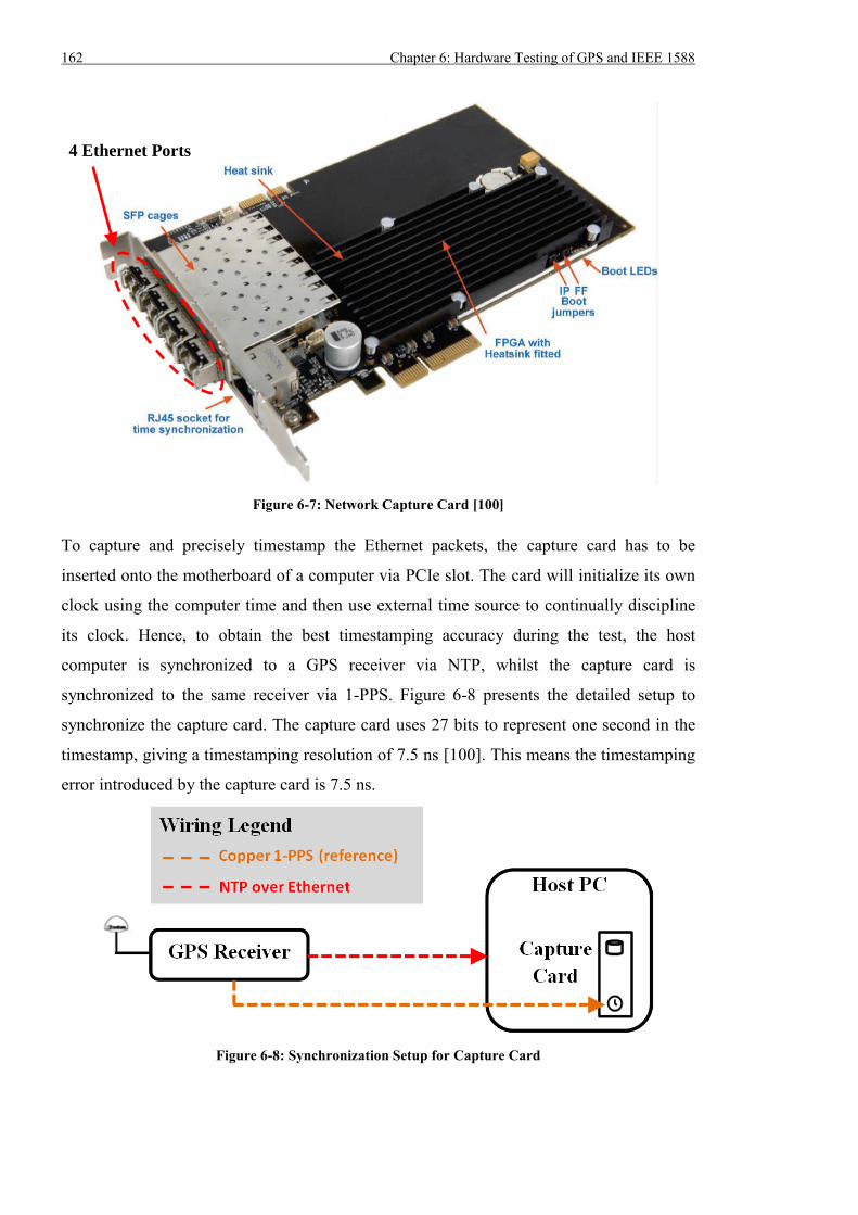
162 Chapter 6: Hardware Testing of GPS and IEEE 1588
Figure 6-7: Network Capture Card [100]
To capture and precisely timestamp the Ethernet packets, the capture card has to be
inserted onto the motherboard of a computer via PCIe slot. The card will initialize its own
clock using the computer time and then use external time source to continually discipline
its clock. Hence, to obtain the best timestamping accuracy during the test, the host
computer is synchronized to a GPS receiver via NTP, whilst the capture card is
synchronized to the same receiver via 1-PPS. Figure 6-8 presents the detailed setup to
synchronize the capture card. The capture card uses 27 bits to represent one second in the
timestamp, giving a timestamping resolution of 7.5 ns [100]. This means the timestamping
error introduced by the capture card is 7.5 ns.
Figure 6-8: Synchronization Setup for Capture Card
4 Ethernet Ports
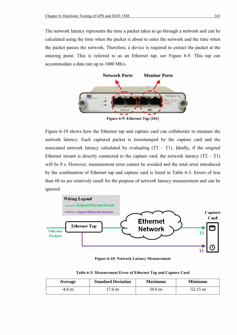
Chapter 6: Hardware Testing of GPS and IEEE 1588 163
The network latency represents the time a packet takes to go through a network and can be
calculated using the time when the packet is about to enter the network and the time when
the packet passes the network. Therefore, a device is required to extract the packet at the
entering point. This is referred to as an Ethernet tap, see Figure 6-9. This tap can
accommodate a data rate up to 1000 Mb/s.
Figure 6-9: Ethernet Tap [101]
Figure 6-10 shows how the Ethernet tap and capture card can collaborate to measure the
network latency. Each captured packet is timestamped by the capture card and the
associated network latency calculated by evaluating (T2 – T1). Ideally, if the original
Ethernet stream is directly connected to the capture card, the network latency (T2 – T1)
will be 0 s. However, measurement error cannot be avoided and the total error introduced
by the combination of Ethernet tap and capture card is listed in Table 6-3. Errors of less
than 60 ns are relatively small for the purpose of network latency measurement and can be
ignored.
Figure 6-10: Network Latency Measurement
Table 6-3: Measurement Error of Ethernet Tap and Capture Card
Average Standard Deviation Maximum Minimum
-4.8 ns 17.6 ns 59.6 ns -52.15 ns
Network Ports Monitor Ports
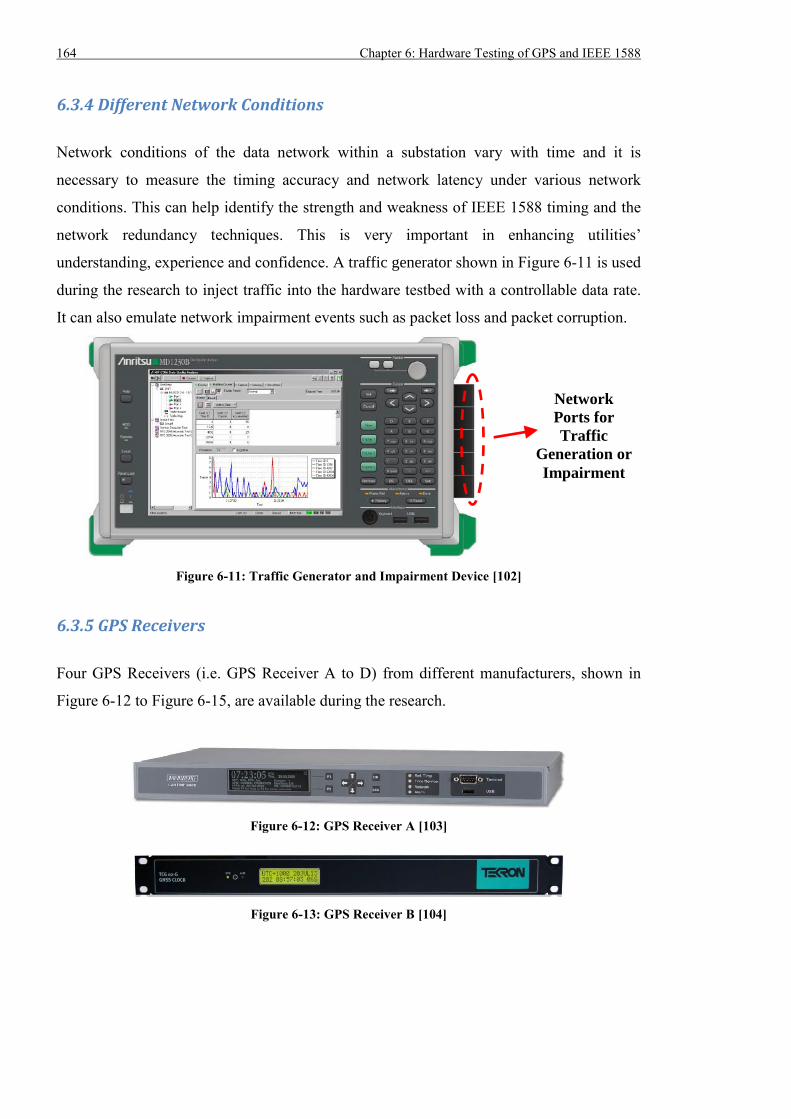
164 Chapter 6: Hardware Testing of GPS and IEEE 1588
6.3.4 Different Network Conditions
Network conditions of the data network within a substation vary with time and it is
necessary to measure the timing accuracy and network latency under various network
conditions. This can help identify the strength and weakness of IEEE 1588 timing and the
network redundancy techniques. This is very important in enhancing utilities’
understanding, experience and confidence. A traffic generator shown in Figure 6-11 is used
during the research to inject traffic into the hardware testbed with a controllable data rate.
It can also emulate network impairment events such as packet loss and packet corruption.
Figure 6-11: Traffic Generator and Impairment Device [102]
6.3.5 GPS Receivers
Four GPS Receivers (i.e. GPS Receiver A to D) from different manufacturers, shown in
Figure 6-12 to Figure 6-15, are available during the research.
Figure 6-12: GPS Receiver A [103]
Figure 6-13: GPS Receiver B [104]
Network
Ports for
Traffic
Generation or
Impairment
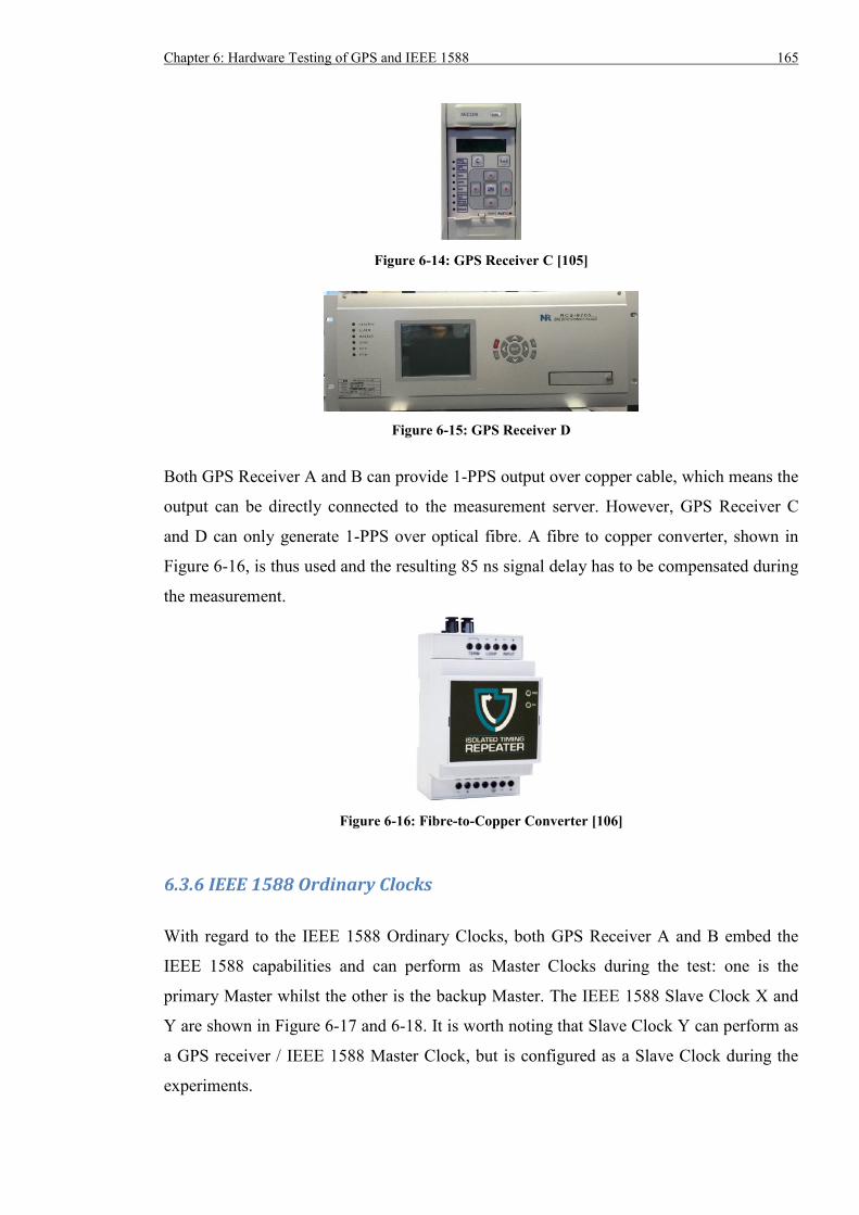
Chapter 6: Hardware Testing of GPS and IEEE 1588 165
Figure 6-14: GPS Receiver C [105]
Figure 6-15: GPS Receiver D
Both GPS Receiver A and B can provide 1-PPS output over copper cable, which means the
output can be directly connected to the measurement server. However, GPS Receiver C
and D can only generate 1-PPS over optical fibre. A fibre to copper converter, shown in
Figure 6-16, is thus used and the resulting 85 ns signal delay has to be compensated during
the measurement.
Figure 6-16: Fibre-to-Copper Converter [106]
6.3.6 IEEE 1588 Ordinary Clocks
With regard to the IEEE 1588 Ordinary Clocks, both GPS Receiver A and B embed the
IEEE 1588 capabilities and can perform as Master Clocks during the test: one is the
primary Master whilst the other is the backup Master. The IEEE 1588 Slave Clock X and
Y are shown in Figure 6-17 and 6-18. It is worth noting that Slave Clock Y can perform as
a GPS receiver / IEEE 1588 Master Clock, but is configured as a Slave Clock during the
experiments.
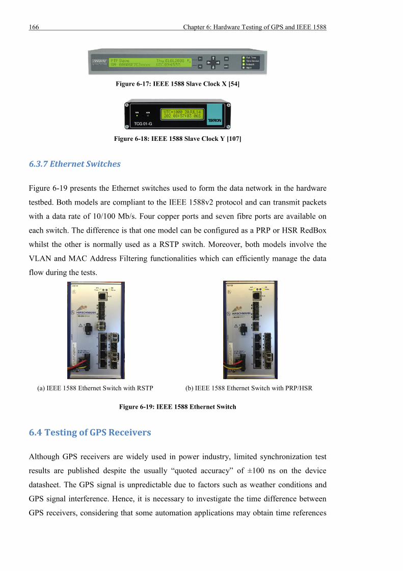
166 Chapter 6: Hardware Testing of GPS and IEEE 1588
Figure 6-17: IEEE 1588 Slave Clock X [54]
Figure 6-18: IEEE 1588 Slave Clock Y [107]
6.3.7 Ethernet Switches
Figure 6-19 presents the Ethernet switches used to form the data network in the hardware
testbed. Both models are compliant to the IEEE 1588v2 protocol and can transmit packets
with a data rate of 10/100 Mb/s. Four copper ports and seven fibre ports are available on
each switch. The difference is that one model can be configured as a PRP or HSR RedBox
whilst the other is normally used as a RSTP switch. Moreover, both models involve the
VLAN and MAC Address Filtering functionalities which can efficiently manage the data
flow during the tests.
(a) IEEE 1588 Ethernet Switch with RSTP (b) IEEE 1588 Ethernet Switch with PRP/HSR
Figure 6-19: IEEE 1588 Ethernet Switch
6.4 Testing of GPS Receivers
Although GPS receivers are widely used in power industry, limited synchronization test
results are published despite the usually “quoted accuracy” of ±100 ns on the device
datasheet. The GPS signal is unpredictable due to factors such as weather conditions and
GPS signal interference. Hence, it is necessary to investigate the time difference between
GPS receivers, considering that some automation applications may obtain time references
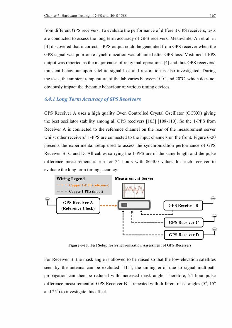
Chapter 6: Hardware Testing of GPS and IEEE 1588 167
from different GPS receivers. To evaluate the performance of different GPS receivers, tests
are conducted to assess the long term accuracy of GPS receivers. Meanwhile, An et al. in
[4] discovered that incorrect 1-PPS output could be generated from GPS receiver when the
GPS signal was poor or re-synchronization was obtained after GPS loss. Mistimed 1-PPS
output was reported as the major cause of relay mal-operations [4] and thus GPS receivers’
transient behaviour upon satellite signal loss and restoration is also investigated. During
the tests, the ambient temperature of the lab varies between 10oC and 20
oC, which does not
obviously impact the dynamic behaviour of various timing devices.
6.4.1 Long Term Accuracy of GPS Receivers
GPS Receiver A uses a high quality Oven Controlled Crystal Oscillator (OCXO) giving
the best oscillator stability among all GPS receivers [103] [108-110]. So the 1-PPS from
Receiver A is connected to the reference channel on the rear of the measurement server
whilst other receivers’ 1-PPS are connected to the input channels on the front. Figure 6-20
presents the experimental setup used to assess the synchronization performance of GPS
Receiver B, C and D. All cables carrying the 1-PPS are of the same length and the pulse
difference measurement is run for 24 hours with 86,400 values for each receiver to
evaluate the long term timing accuracy.
Figure 6-20: Test Setup for Synchronization Assessment of GPS Receivers
For Receiver B, the mask angle is allowed to be raised so that the low-elevation satellites
seen by the antenna can be excluded [111]; the timing error due to signal multipath
propagation can then be reduced with increased mask angle. Therefore, 24 hour pulse
difference measurement of GPS Receiver B is repeated with different mask angles (5o, 15
o
and 25o) to investigate this effect.
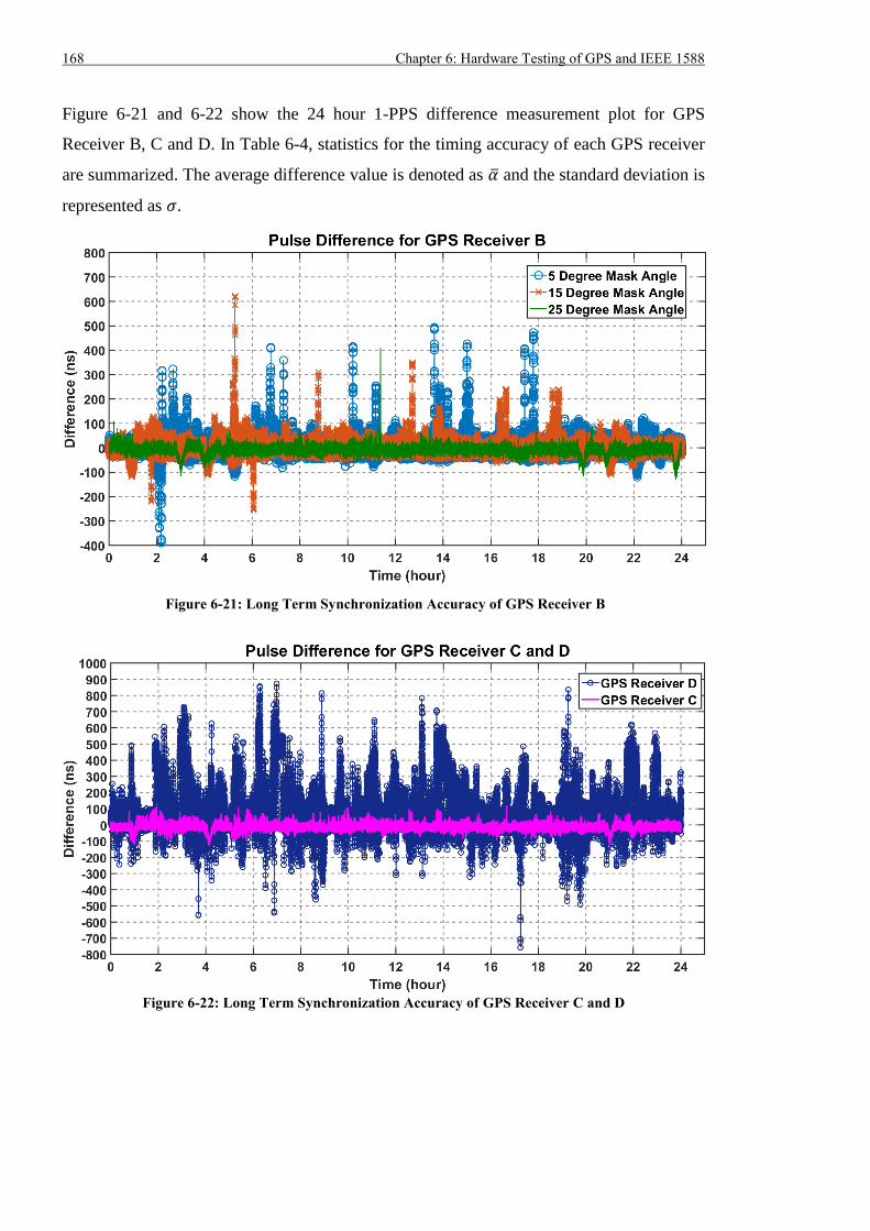
168 Chapter 6: Hardware Testing of GPS and IEEE 1588
Figure 6-21 and 6-22 show the 24 hour 1-PPS difference measurement plot for GPS
Receiver B, C and D. In Table 6-4, statistics for the timing accuracy of each GPS receiver
are summarized. The average difference value is denoted as �� and the standard deviation is
represented as 𝜎.
Figure 6-21: Long Term Synchronization Accuracy of GPS Receiver B
Figure 6-22: Long Term Synchronization Accuracy of GPS Receiver C and D
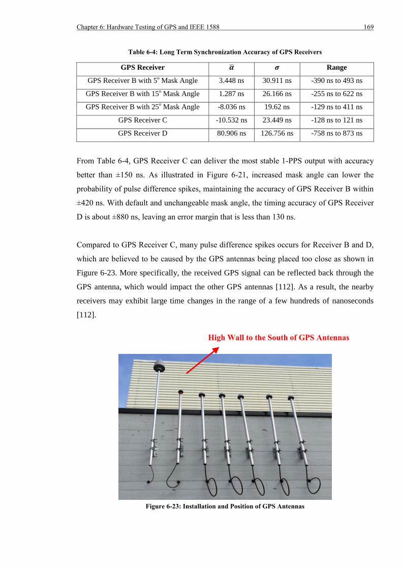
Chapter 6: Hardware Testing of GPS and IEEE 1588 169
Table 6-4: Long Term Synchronization Accuracy of GPS Receivers
GPS Receiver �� 𝝈 Range
GPS Receiver B with 5o Mask Angle 3.448 ns 30.911 ns -390 ns to 493 ns
GPS Receiver B with 15o Mask Angle 1.287 ns 26.166 ns -255 ns to 622 ns
GPS Receiver B with 25o Mask Angle -8.036 ns 19.62 ns -129 ns to 411 ns
GPS Receiver C -10.532 ns 23.449 ns -128 ns to 121 ns
GPS Receiver D 80.906 ns 126.756 ns -758 ns to 873 ns
From Table 6-4, GPS Receiver C can deliver the most stable 1-PPS output with accuracy
better than ±150 ns. As illustrated in Figure 6-21, increased mask angle can lower the
probability of pulse difference spikes, maintaining the accuracy of GPS Receiver B within
±420 ns. With default and unchangeable mask angle, the timing accuracy of GPS Receiver
D is about ±880 ns, leaving an error margin that is less than 130 ns.
Compared to GPS Receiver C, many pulse difference spikes occurs for Receiver B and D,
which are believed to be caused by the GPS antennas being placed too close as shown in
Figure 6-23. More specifically, the received GPS signal can be reflected back through the
GPS antenna, which would impact the other GPS antennas [112]. As a result, the nearby
receivers may exhibit large time changes in the range of a few hundreds of nanoseconds
[112].
Figure 6-23: Installation and Position of GPS Antennas
High Wall to the South of GPS Antennas
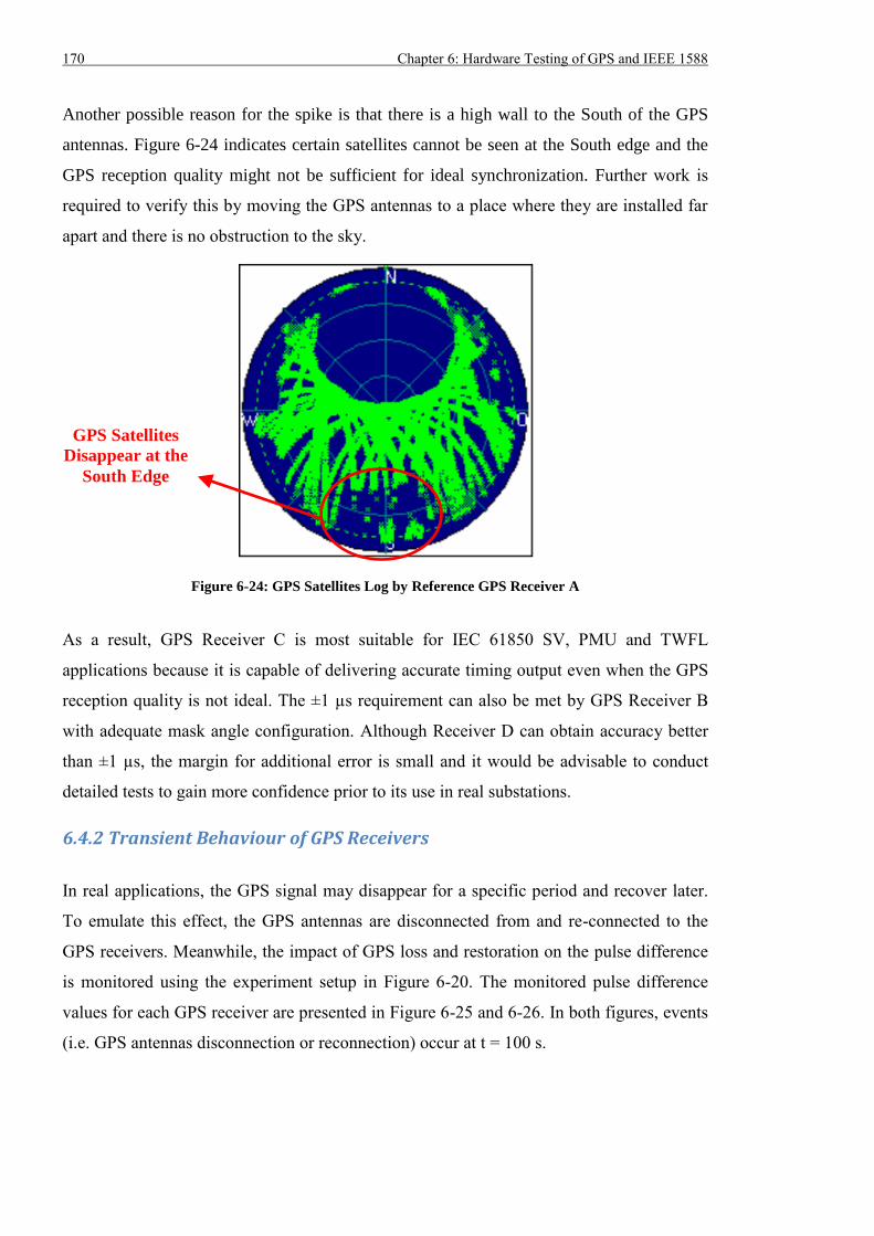
170 Chapter 6: Hardware Testing of GPS and IEEE 1588
Another possible reason for the spike is that there is a high wall to the South of the GPS
antennas. Figure 6-24 indicates certain satellites cannot be seen at the South edge and the
GPS reception quality might not be sufficient for ideal synchronization. Further work is
required to verify this by moving the GPS antennas to a place where they are installed far
apart and there is no obstruction to the sky.
Figure 6-24: GPS Satellites Log by Reference GPS Receiver A
As a result, GPS Receiver C is most suitable for IEC 61850 SV, PMU and TWFL
applications because it is capable of delivering accurate timing output even when the GPS
reception quality is not ideal. The ±1 µs requirement can also be met by GPS Receiver B
with adequate mask angle configuration. Although Receiver D can obtain accuracy better
than ±1 µs, the margin for additional error is small and it would be advisable to conduct
detailed tests to gain more confidence prior to its use in real substations.
6.4.2 Transient Behaviour of GPS Receivers
In real applications, the GPS signal may disappear for a specific period and recover later.
To emulate this effect, the GPS antennas are disconnected from and re-connected to the
GPS receivers. Meanwhile, the impact of GPS loss and restoration on the pulse difference
is monitored using the experiment setup in Figure 6-20. The monitored pulse difference
values for each GPS receiver are presented in Figure 6-25 and 6-26. In both figures, events
(i.e. GPS antennas disconnection or reconnection) occur at t = 100 s.
GPS Satellites
Disappear at the
South Edge
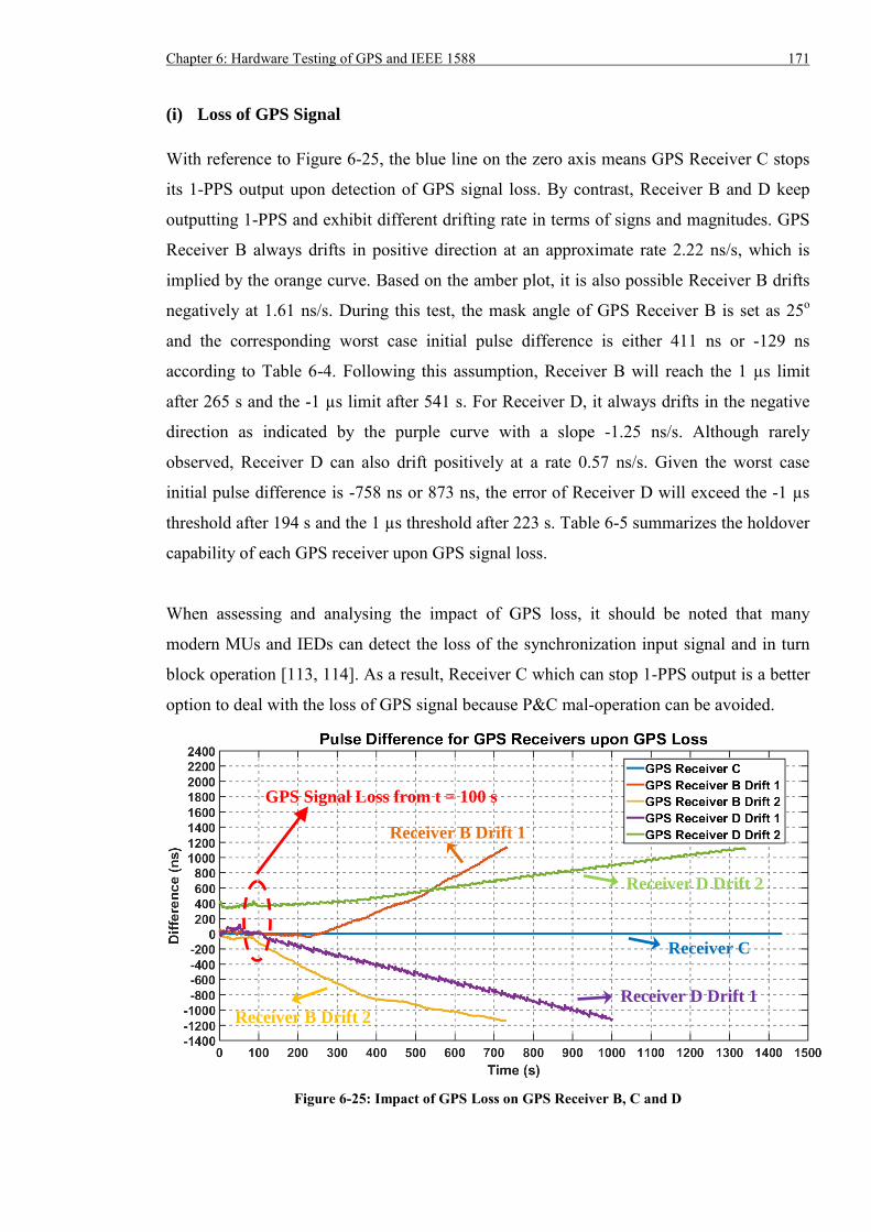
Chapter 6: Hardware Testing of GPS and IEEE 1588 171
(i) Loss of GPS Signal
With reference to Figure 6-25, the blue line on the zero axis means GPS Receiver C stops
its 1-PPS output upon detection of GPS signal loss. By contrast, Receiver B and D keep
outputting 1-PPS and exhibit different drifting rate in terms of signs and magnitudes. GPS
Receiver B always drifts in positive direction at an approximate rate 2.22 ns/s, which is
implied by the orange curve. Based on the amber plot, it is also possible Receiver B drifts
negatively at 1.61 ns/s. During this test, the mask angle of GPS Receiver B is set as 25o
and the corresponding worst case initial pulse difference is either 411 ns or -129 ns
according to Table 6-4. Following this assumption, Receiver B will reach the 1 µs limit
after 265 s and the -1 µs limit after 541 s. For Receiver D, it always drifts in the negative
direction as indicated by the purple curve with a slope -1.25 ns/s. Although rarely
observed, Receiver D can also drift positively at a rate 0.57 ns/s. Given the worst case
initial pulse difference is -758 ns or 873 ns, the error of Receiver D will exceed the -1 µs
threshold after 194 s and the 1 µs threshold after 223 s. Table 6-5 summarizes the holdover
capability of each GPS receiver upon GPS signal loss.
When assessing and analysing the impact of GPS loss, it should be noted that many
modern MUs and IEDs can detect the loss of the synchronization input signal and in turn
block operation [113, 114]. As a result, Receiver C which can stop 1-PPS output is a better
option to deal with the loss of GPS signal because P&C mal-operation can be avoided.
Figure 6-25: Impact of GPS Loss on GPS Receiver B, C and D
GPS Signal Loss from t = 100 s
Receiver B Drift 1
Receiver D Drift 2
Receiver C
Receiver D Drift 1
Receiver B Drift 2
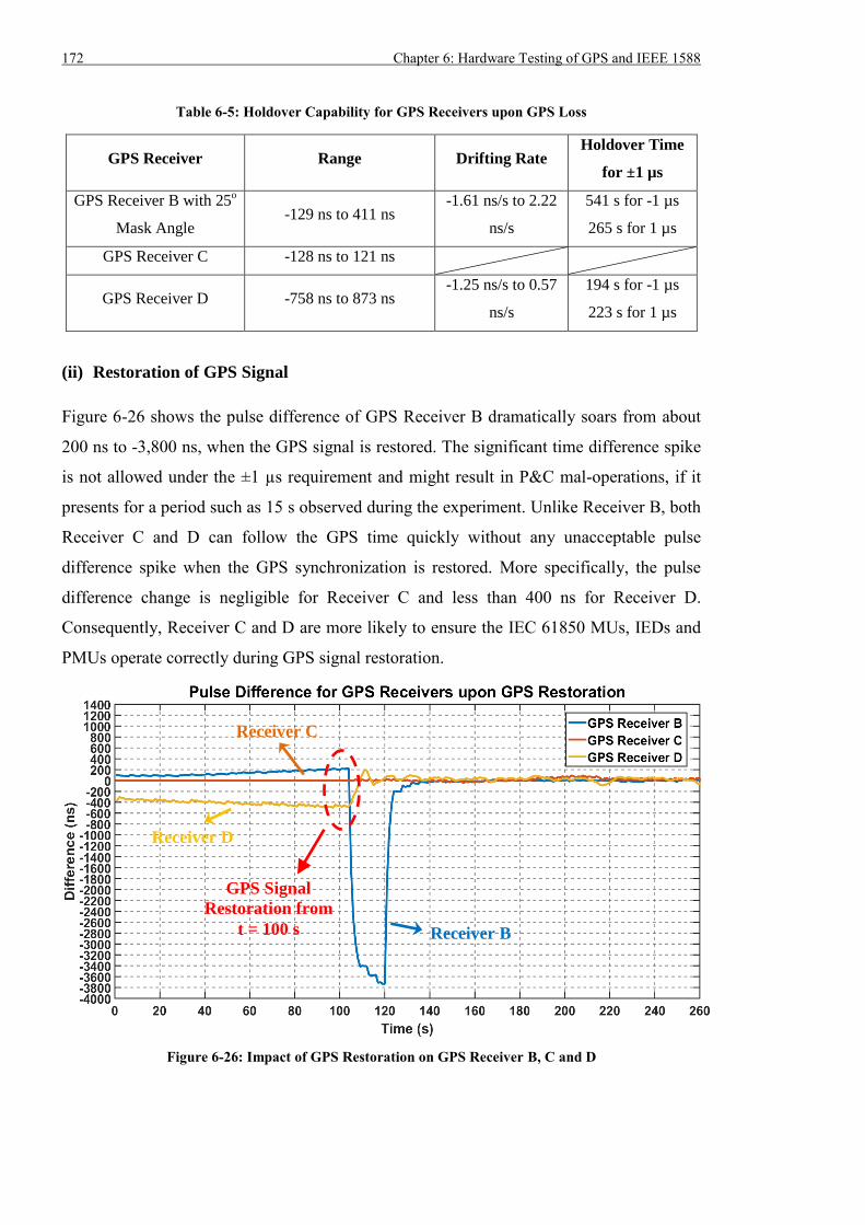
172 Chapter 6: Hardware Testing of GPS and IEEE 1588
Table 6-5: Holdover Capability for GPS Receivers upon GPS Loss
GPS Receiver Range Drifting Rate Holdover Time
for ±1 µs
GPS Receiver B with 25o
Mask Angle -129 ns to 411 ns
-1.61 ns/s to 2.22
ns/s
541 s for -1 µs
265 s for 1 µs
GPS Receiver C -128 ns to 121 ns
GPS Receiver D -758 ns to 873 ns -1.25 ns/s to 0.57
ns/s
194 s for -1 µs
223 s for 1 µs
(ii) Restoration of GPS Signal
Figure 6-26 shows the pulse difference of GPS Receiver B dramatically soars from about
200 ns to -3,800 ns, when the GPS signal is restored. The significant time difference spike
is not allowed under the ±1 µs requirement and might result in P&C mal-operations, if it
presents for a period such as 15 s observed during the experiment. Unlike Receiver B, both
Receiver C and D can follow the GPS time quickly without any unacceptable pulse
difference spike when the GPS synchronization is restored. More specifically, the pulse
difference change is negligible for Receiver C and less than 400 ns for Receiver D.
Consequently, Receiver C and D are more likely to ensure the IEC 61850 MUs, IEDs and
PMUs operate correctly during GPS signal restoration.
Figure 6-26: Impact of GPS Restoration on GPS Receiver B, C and D
GPS Signal
Restoration from
t = 100 s Receiver B
Receiver C
Receiver D
Chapter 6: Hardware Testing of GPS and IEEE 1588 173
(iii) Summary of Testing
In summary, the timing error of GPS Receiver B will become much greater than ±1 µs
when it re-synchronizes to GPS, which is not appropriate for critical P&C applications
requiring accurate timing. When the GPS signal is not available, it can only maintain ±1 µs
accuracy for about 260 s for the worst case. In terms of Receiver C, it can stop the 1-PPS
output upon GPS signal loss and this means the coordinating P&C devices should detect
the loss of 1-PPS input so that they can inhibit operation to avoid mal-operations. Once
Receiver C regains the GPS synchronization, it begins to produce 1-PPS and the resulting
pulse difference change from the GPS time is negligible. In comparison, and based on the
test results, Receiver D only maintains sub-microsecond accuracy for approx. 200 s after
the loss of GPS signal. Whilst it only introduces a pulse difference change of less than 400
ns and this will not affect the correct operation of P&C devices.
6.5 Testing of IEEE 1588 Timing System
Different from the direct use of various GPS receivers, IEEE 1588 timing relies on a wired
data network to disseminate the time reference from a single source within a substation.
This means it is more controllable than GPS timing as the data network can be carefully
designed, engineered and monitored to ensure each P&C devices can properly obtain the
time reference from the same source. Various tests are performed to evaluate the
performance of IEEE 1588 timing system under different network topologies, background
traffic, excessive IEEE 1588 traffic, IEEE 1588 packet loss, communication link loss and
GPS signal loss. All IEEE 1588 devices are configured according to the 1588 Power
Profile and the key settings are listed in Table 6-6. It is also worth noting the mask angle of
the backup Master Clock (GPS Receiver B) is set to 25o during all IEEE 1588 tests.
Table 6-6: IEEE 1588 Power Profile Settings
Parameter Value
Network Protocol Layer 2 Ethernet Multicast
VLAN ID 1588
VLAN Priority 4
Delay Mechanism Peer Delay Request-Response
Operation Mode Two-Step
174 Chapter 6: Hardware Testing of GPS and IEEE 1588
Power Profile TLVs in Announce Yes
Announce Message Interval 1 Second
Sync Message Interval 1 Second
Pdelay_Req Message Interval 1 Second
Domain Number 0
Priority 1
128 for Master Clocks;
255 for Slave Clocks;
Other Value if necessary
Priority 2 128 for Master Clocks;
255 for Slave Clocks
Slave Only Mode 0 for Master Clocks;
1 for Slave Clocks
1588 Switch Mode Transparent Clock
6.5.1 Long Term Accuracy of IEEE 1588 Slaves
The experiment setup in Figure 6-27 is used to measure the 24 hour pulse difference
between the primary Master Clock and Slave Clocks. Because Priority 1 of both Master
Clocks is set to 128, the Best Master Clock algorithm automatically selects GPS Receiver
A as the primary Master, assuming they both lock to the GPS time. The reason is that
Receiver A contains a better oscillator than Receiver B. Consequently, both Slave Clocks
are synchronized to Receiver A. Referring to Figure 6-28, Receiver A is directly connected
to Slave Clock X or Y to obtain the performance benchmark for the subsequent IEEE 1588
synchronization assessments.
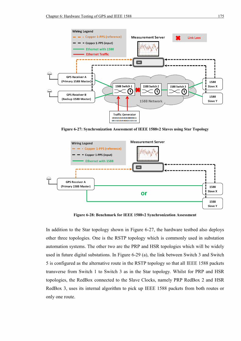
Chapter 6: Hardware Testing of GPS and IEEE 1588 175
Figure 6-27: Synchronization Assessment of IEEE 1588v2 Slaves using Star Topology
Figure 6-28: Benchmark for IEEE 1588v2 Synchronization Assessment
In addition to the Star topology shown in Figure 6-27, the hardware testbed also deploys
other three topologies. One is the RSTP topology which is commonly used in substation
automation systems. The other two are the PRP and HSR topologies which will be widely
used in future digital substations. In Figure 6-29 (a), the link between Switch 3 and Switch
5 is configured as the alternative route in the RSTP topology so that all IEEE 1588 packets
transverse from Switch 1 to Switch 3 as in the Star topology. Whilst for PRP and HSR
topologies, the RedBox connected to the Slave Clocks, namely PRP RedBox 2 and HSR
RedBox 3, uses its internal algorithm to pick up IEEE 1588 packets from both routes or
only one route.
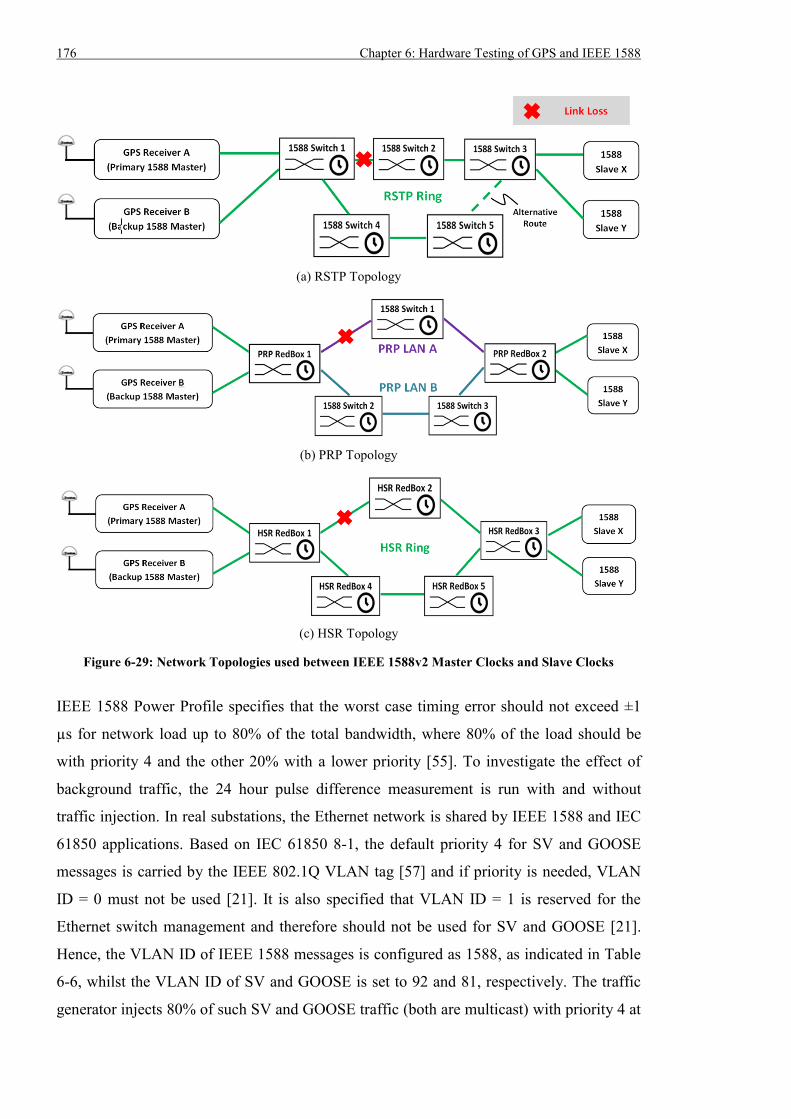
176 Chapter 6: Hardware Testing of GPS and IEEE 1588
(a) RSTP Topology
(b) PRP Topology
(c) HSR Topology
Figure 6-29: Network Topologies used between IEEE 1588v2 Master Clocks and Slave Clocks
IEEE 1588 Power Profile specifies that the worst case timing error should not exceed ±1
µs for network load up to 80% of the total bandwidth, where 80% of the load should be
with priority 4 and the other 20% with a lower priority [55]. To investigate the effect of
background traffic, the 24 hour pulse difference measurement is run with and without
traffic injection. In real substations, the Ethernet network is shared by IEEE 1588 and IEC
61850 applications. Based on IEC 61850 8-1, the default priority 4 for SV and GOOSE
messages is carried by the IEEE 802.1Q VLAN tag [57] and if priority is needed, VLAN
ID = 0 must not be used [21]. It is also specified that VLAN ID = 1 is reserved for the
Ethernet switch management and therefore should not be used for SV and GOOSE [21].
Hence, the VLAN ID of IEEE 1588 messages is configured as 1588, as indicated in Table
6-6, whilst the VLAN ID of SV and GOOSE is set to 92 and 81, respectively. The traffic
generator injects 80% of such SV and GOOSE traffic (both are multicast) with priority 4 at
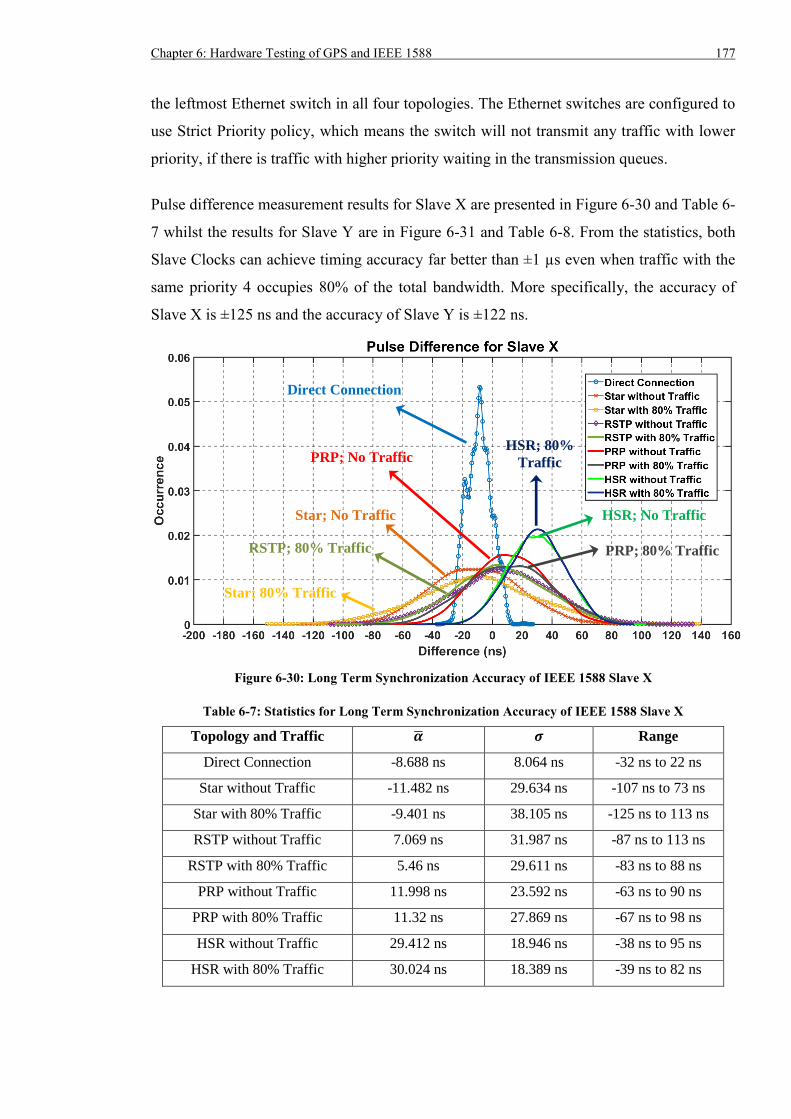
Chapter 6: Hardware Testing of GPS and IEEE 1588 177
the leftmost Ethernet switch in all four topologies. The Ethernet switches are configured to
use Strict Priority policy, which means the switch will not transmit any traffic with lower
priority, if there is traffic with higher priority waiting in the transmission queues.
Pulse difference measurement results for Slave X are presented in Figure 6-30 and Table 6-
7 whilst the results for Slave Y are in Figure 6-31 and Table 6-8. From the statistics, both
Slave Clocks can achieve timing accuracy far better than ±1 µs even when traffic with the
same priority 4 occupies 80% of the total bandwidth. More specifically, the accuracy of
Slave X is ±125 ns and the accuracy of Slave Y is ±122 ns.
Figure 6-30: Long Term Synchronization Accuracy of IEEE 1588 Slave X
Table 6-7: Statistics for Long Term Synchronization Accuracy of IEEE 1588 Slave X
Topology and Traffic �� 𝝈 Range
Direct Connection -8.688 ns 8.064 ns -32 ns to 22 ns
Star without Traffic -11.482 ns 29.634 ns -107 ns to 73 ns
Star with 80% Traffic -9.401 ns 38.105 ns -125 ns to 113 ns
RSTP without Traffic 7.069 ns 31.987 ns -87 ns to 113 ns
RSTP with 80% Traffic 5.46 ns 29.611 ns -83 ns to 88 ns
PRP without Traffic 11.998 ns 23.592 ns -63 ns to 90 ns
PRP with 80% Traffic 11.32 ns 27.869 ns -67 ns to 98 ns
HSR without Traffic 29.412 ns 18.946 ns -38 ns to 95 ns
HSR with 80% Traffic 30.024 ns 18.389 ns -39 ns to 82 ns
RSTP; 80% Traffic
PRP; No Traffic
PRP; 80% Traffic
HSR; No Traffic
HSR; 80%
Traffic
Star; 80% Traffic
Star; No Traffic
Direct Connection
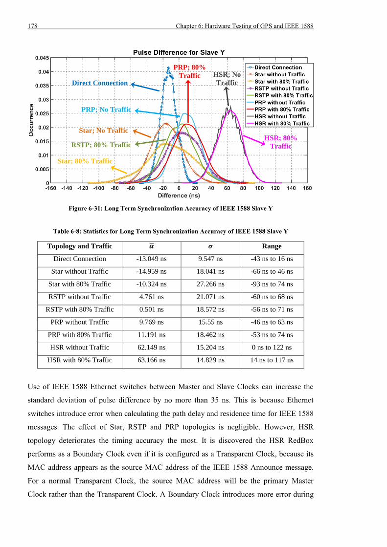
178 Chapter 6: Hardware Testing of GPS and IEEE 1588
Figure 6-31: Long Term Synchronization Accuracy of IEEE 1588 Slave Y
Table 6-8: Statistics for Long Term Synchronization Accuracy of IEEE 1588 Slave Y
Topology and Traffic �� 𝝈 Range
Direct Connection -13.049 ns 9.547 ns -43 ns to 16 ns
Star without Traffic -14.959 ns 18.041 ns -66 ns to 46 ns
Star with 80% Traffic -10.324 ns 27.266 ns -93 ns to 74 ns
RSTP without Traffic 4.761 ns 21.071 ns -60 ns to 68 ns
RSTP with 80% Traffic 0.501 ns 18.572 ns -56 ns to 71 ns
PRP without Traffic 9.769 ns 15.55 ns -46 ns to 63 ns
PRP with 80% Traffic 11.191 ns 18.462 ns -53 ns to 74 ns
HSR without Traffic 62.149 ns 15.204 ns 0 ns to 122 ns
HSR with 80% Traffic 63.166 ns 14.829 ns 14 ns to 117 ns
Use of IEEE 1588 Ethernet switches between Master and Slave Clocks can increase the
standard deviation of pulse difference by no more than 35 ns. This is because Ethernet
switches introduce error when calculating the path delay and residence time for IEEE 1588
messages. The effect of Star, RSTP and PRP topologies is negligible. However, HSR
topology deteriorates the timing accuracy the most. It is discovered the HSR RedBox
performs as a Boundary Clock even if it is configured as a Transparent Clock, because its
MAC address appears as the source MAC address of the IEEE 1588 Announce message.
For a normal Transparent Clock, the source MAC address will be the primary Master
Clock rather than the Transparent Clock. A Boundary Clock introduces more error during
RSTP; 80% Traffic
PRP; No Traffic
PRP; 80%
Traffic HSR; No
Traffic
HSR; 80%
Traffic
Star; 80% Traffic
Star; No Traffic
Direct Connection
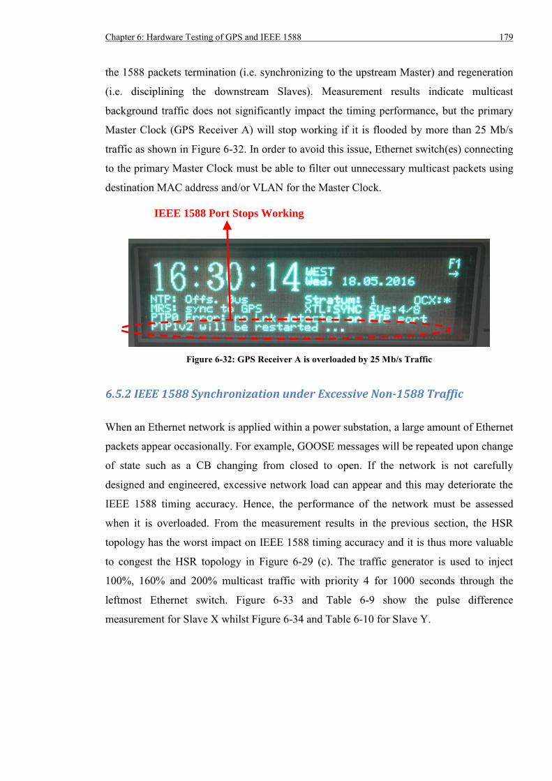
Chapter 6: Hardware Testing of GPS and IEEE 1588 179
the 1588 packets termination (i.e. synchronizing to the upstream Master) and regeneration
(i.e. disciplining the downstream Slaves). Measurement results indicate multicast
background traffic does not significantly impact the timing performance, but the primary
Master Clock (GPS Receiver A) will stop working if it is flooded by more than 25 Mb/s
traffic as shown in Figure 6-32. In order to avoid this issue, Ethernet switch(es) connecting
to the primary Master Clock must be able to filter out unnecessary multicast packets using
destination MAC address and/or VLAN for the Master Clock.
Figure 6-32: GPS Receiver A is overloaded by 25 Mb/s Traffic
6.5.2 IEEE 1588 Synchronization under Excessive Non-1588 Traffic
When an Ethernet network is applied within a power substation, a large amount of Ethernet
packets appear occasionally. For example, GOOSE messages will be repeated upon change
of state such as a CB changing from closed to open. If the network is not carefully
designed and engineered, excessive network load can appear and this may deteriorate the
IEEE 1588 timing accuracy. Hence, the performance of the network must be assessed
when it is overloaded. From the measurement results in the previous section, the HSR
topology has the worst impact on IEEE 1588 timing accuracy and it is thus more valuable
to congest the HSR topology in Figure 6-29 (c). The traffic generator is used to inject
100%, 160% and 200% multicast traffic with priority 4 for 1000 seconds through the
leftmost Ethernet switch. Figure 6-33 and Table 6-9 show the pulse difference
measurement for Slave X whilst Figure 6-34 and Table 6-10 for Slave Y.
IEEE 1588 Port Stops Working
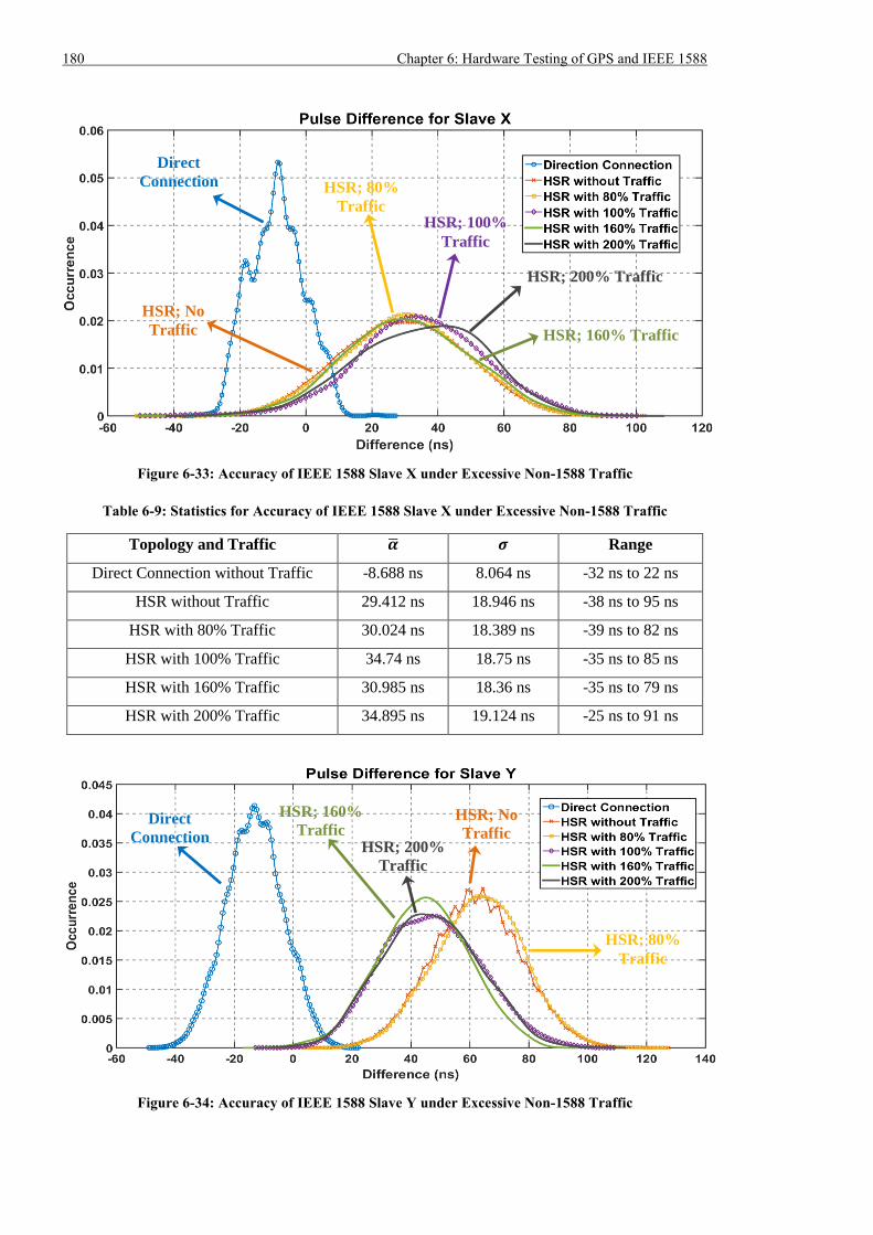
180 Chapter 6: Hardware Testing of GPS and IEEE 1588
Figure 6-33: Accuracy of IEEE 1588 Slave X under Excessive Non-1588 Traffic
Table 6-9: Statistics for Accuracy of IEEE 1588 Slave X under Excessive Non-1588 Traffic
Topology and Traffic �� 𝝈 Range
Direct Connection without Traffic -8.688 ns 8.064 ns -32 ns to 22 ns
HSR without Traffic 29.412 ns 18.946 ns -38 ns to 95 ns
HSR with 80% Traffic 30.024 ns 18.389 ns -39 ns to 82 ns
HSR with 100% Traffic 34.74 ns 18.75 ns -35 ns to 85 ns
HSR with 160% Traffic 30.985 ns 18.36 ns -35 ns to 79 ns
HSR with 200% Traffic 34.895 ns 19.124 ns -25 ns to 91 ns
Figure 6-34: Accuracy of IEEE 1588 Slave Y under Excessive Non-1588 Traffic
HSR; 160% Traffic
HSR; 200% Traffic
HSR; 160%
Traffic HSR; 200%
Traffic
HSR; 100%
Traffic
HSR; 80%
Traffic
HSR; No
Traffic
Direct
Connection
HSR; 80%
Traffic
HSR; No
Traffic Direct
Connection
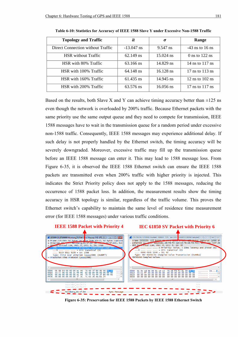
Chapter 6: Hardware Testing of GPS and IEEE 1588 181
Table 6-10: Statistics for Accuracy of IEEE 1588 Slave Y under Excessive Non-1588 Traffic
Topology and Traffic �� 𝝈 Range
Direct Connection without Traffic -13.047 ns 9.547 ns -43 ns to 16 ns
HSR without Traffic 62.149 ns 15.024 ns 0 ns to 122 ns
HSR with 80% Traffic 63.166 ns 14.829 ns 14 ns to 117 ns
HSR with 100% Traffic 64.148 ns 16.128 ns 17 ns to 113 ns
HSR with 160% Traffic 61.435 ns 14.945 ns 12 ns to 102 ns
HSR with 200% Traffic 63.576 ns 16.056 ns 17 ns to 117 ns
Based on the results, both Slave X and Y can achieve timing accuracy better than ±125 ns
even though the network is overloaded by 200% traffic. Because Ethernet packets with the
same priority use the same output queue and they need to compete for transmission, IEEE
1588 messages have to wait in the transmission queue for a random period under excessive
non-1588 traffic. Consequently, IEEE 1588 messages may experience additional delay. If
such delay is not properly handled by the Ethernet switch, the timing accuracy will be
severely downgraded. Moreover, excessive traffic may fill up the transmission queue
before an IEEE 1588 message can enter it. This may lead to 1588 message loss. From
Figure 6-35, it is observed the IEEE 1588 Ethernet switch can ensure the IEEE 1588
packets are transmitted even when 200% traffic with higher priority is injected. This
indicates the Strict Priority policy does not apply to the 1588 messages, reducing the
occurrence of 1588 packet loss. In addition, the measurement results show the timing
accuracy in HSR topology is similar, regardless of the traffic volume. This proves the
Ethernet switch’s capability to maintain the same level of residence time measurement
error (for IEEE 1588 messages) under various traffic conditions.
Figure 6-35: Preservation for IEEE 1588 Packets by IEEE 1588 Ethernet Switch
IEEE 1588 Packet with Priority 4 IEC 61850 SV Packet with Priority 6
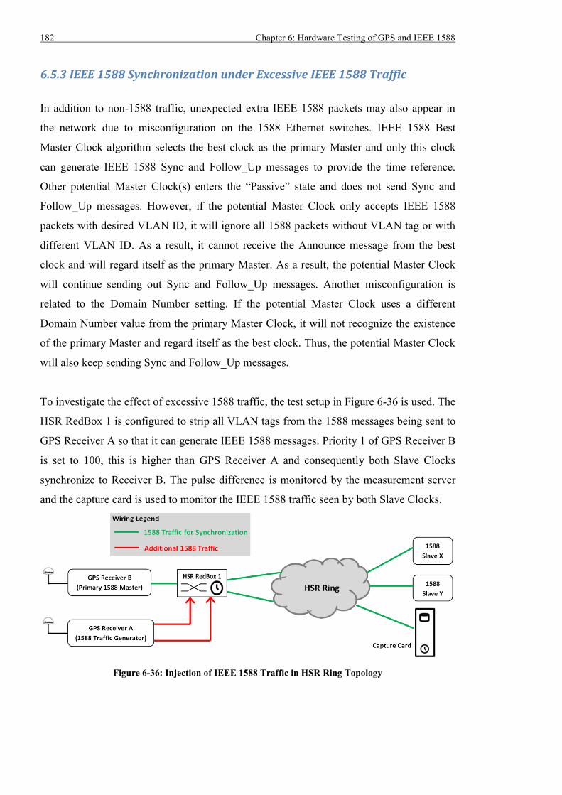
182 Chapter 6: Hardware Testing of GPS and IEEE 1588
6.5.3 IEEE 1588 Synchronization under Excessive IEEE 1588 Traffic
In addition to non-1588 traffic, unexpected extra IEEE 1588 packets may also appear in
the network due to misconfiguration on the 1588 Ethernet switches. IEEE 1588 Best
Master Clock algorithm selects the best clock as the primary Master and only this clock
can generate IEEE 1588 Sync and Follow_Up messages to provide the time reference.
Other potential Master Clock(s) enters the “Passive” state and does not send Sync and
Follow_Up messages. However, if the potential Master Clock only accepts IEEE 1588
packets with desired VLAN ID, it will ignore all 1588 packets without VLAN tag or with
different VLAN ID. As a result, it cannot receive the Announce message from the best
clock and will regard itself as the primary Master. As a result, the potential Master Clock
will continue sending out Sync and Follow_Up messages. Another misconfiguration is
related to the Domain Number setting. If the potential Master Clock uses a different
Domain Number value from the primary Master Clock, it will not recognize the existence
of the primary Master and regard itself as the best clock. Thus, the potential Master Clock
will also keep sending Sync and Follow_Up messages.
To investigate the effect of excessive 1588 traffic, the test setup in Figure 6-36 is used. The
HSR RedBox 1 is configured to strip all VLAN tags from the 1588 messages being sent to
GPS Receiver A so that it can generate IEEE 1588 messages. Priority 1 of GPS Receiver B
is set to 100, this is higher than GPS Receiver A and consequently both Slave Clocks
synchronize to Receiver B. The pulse difference is monitored by the measurement server
and the capture card is used to monitor the IEEE 1588 traffic seen by both Slave Clocks.
Figure 6-36: Injection of IEEE 1588 Traffic in HSR Ring Topology
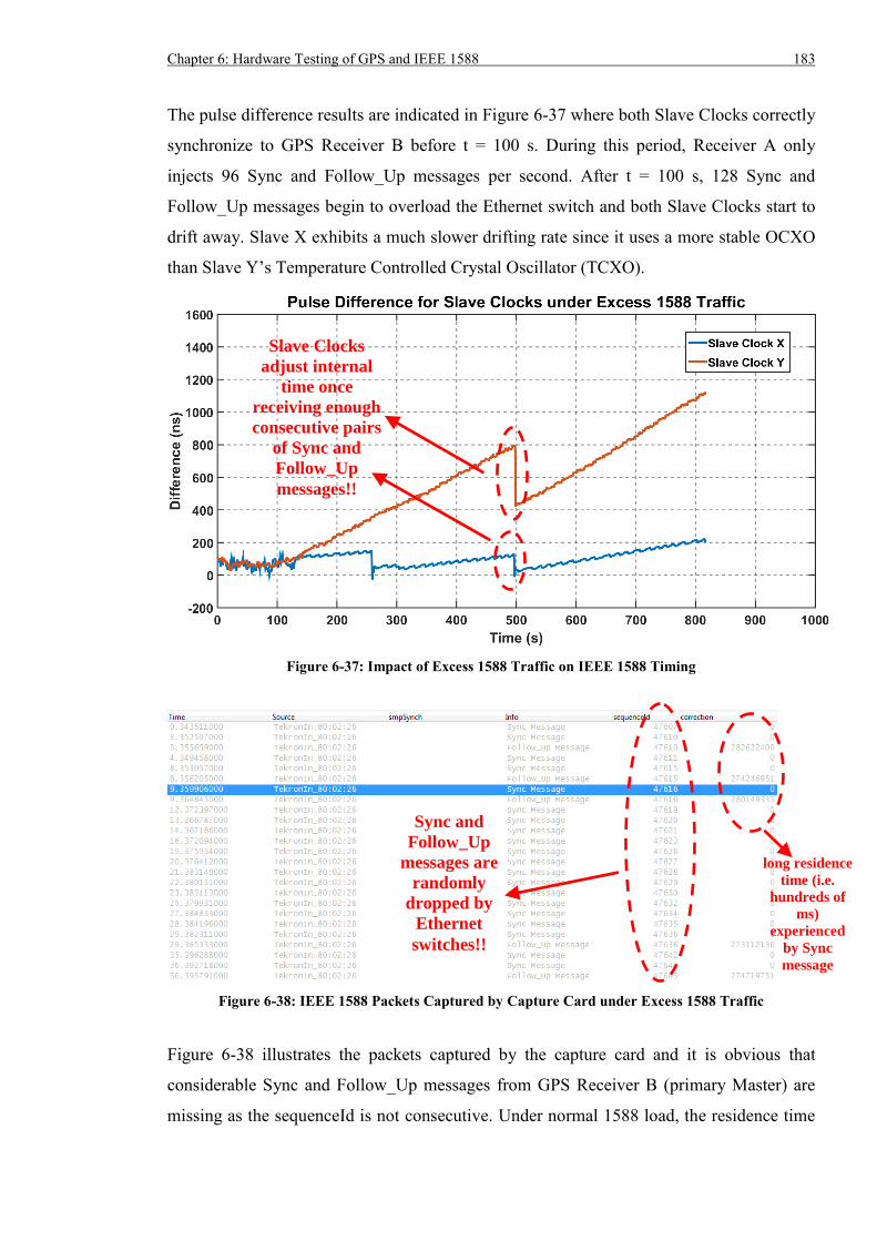
Chapter 6: Hardware Testing of GPS and IEEE 1588 183
The pulse difference results are indicated in Figure 6-37 where both Slave Clocks correctly
synchronize to GPS Receiver B before t = 100 s. During this period, Receiver A only
injects 96 Sync and Follow_Up messages per second. After t = 100 s, 128 Sync and
Follow_Up messages begin to overload the Ethernet switch and both Slave Clocks start to
drift away. Slave X exhibits a much slower drifting rate since it uses a more stable OCXO
than Slave Y’s Temperature Controlled Crystal Oscillator (TCXO).
Figure 6-37: Impact of Excess 1588 Traffic on IEEE 1588 Timing
Figure 6-38: IEEE 1588 Packets Captured by Capture Card under Excess 1588 Traffic
Figure 6-38 illustrates the packets captured by the capture card and it is obvious that
considerable Sync and Follow_Up messages from GPS Receiver B (primary Master) are
missing as the sequenceId is not consecutive. Under normal 1588 load, the residence time
Sync and
Follow_Up
messages are
randomly
dropped by
Ethernet
switches!!
Slave Clocks
adjust internal
time once
receiving enough
consecutive pairs
of Sync and
Follow_Up
messages!!
long residence
time (i.e.
hundreds of
ms)
experienced
by Sync
message
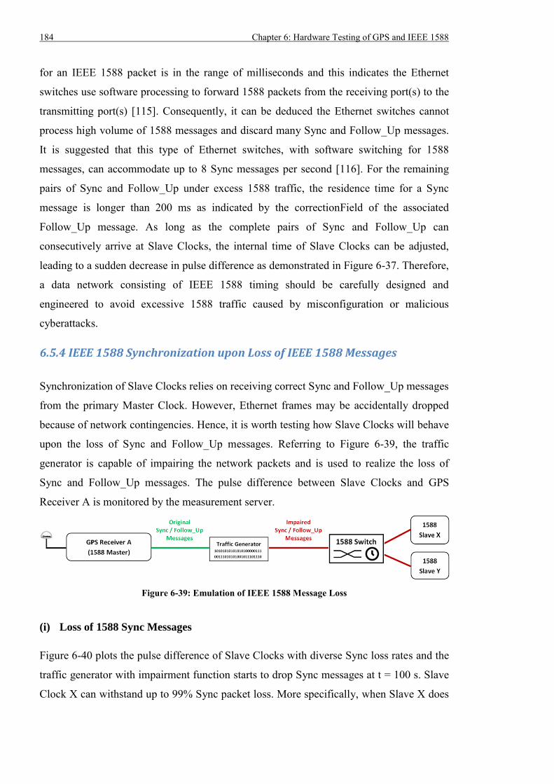
184 Chapter 6: Hardware Testing of GPS and IEEE 1588
for an IEEE 1588 packet is in the range of milliseconds and this indicates the Ethernet
switches use software processing to forward 1588 packets from the receiving port(s) to the
transmitting port(s) [115]. Consequently, it can be deduced the Ethernet switches cannot
process high volume of 1588 messages and discard many Sync and Follow_Up messages.
It is suggested that this type of Ethernet switches, with software switching for 1588
messages, can accommodate up to 8 Sync messages per second [116]. For the remaining
pairs of Sync and Follow_Up under excess 1588 traffic, the residence time for a Sync
message is longer than 200 ms as indicated by the correctionField of the associated
Follow_Up message. As long as the complete pairs of Sync and Follow_Up can
consecutively arrive at Slave Clocks, the internal time of Slave Clocks can be adjusted,
leading to a sudden decrease in pulse difference as demonstrated in Figure 6-37. Therefore,
a data network consisting of IEEE 1588 timing should be carefully designed and
engineered to avoid excessive 1588 traffic caused by misconfiguration or malicious
cyberattacks.
6.5.4 IEEE 1588 Synchronization upon Loss of IEEE 1588 Messages
Synchronization of Slave Clocks relies on receiving correct Sync and Follow_Up messages
from the primary Master Clock. However, Ethernet frames may be accidentally dropped
because of network contingencies. Hence, it is worth testing how Slave Clocks will behave
upon the loss of Sync and Follow_Up messages. Referring to Figure 6-39, the traffic
generator is capable of impairing the network packets and is used to realize the loss of
Sync and Follow_Up messages. The pulse difference between Slave Clocks and GPS
Receiver A is monitored by the measurement server.
Figure 6-39: Emulation of IEEE 1588 Message Loss
(i) Loss of 1588 Sync Messages
Figure 6-40 plots the pulse difference of Slave Clocks with diverse Sync loss rates and the
traffic generator with impairment function starts to drop Sync messages at t = 100 s. Slave
Clock X can withstand up to 99% Sync packet loss. More specifically, when Slave X does
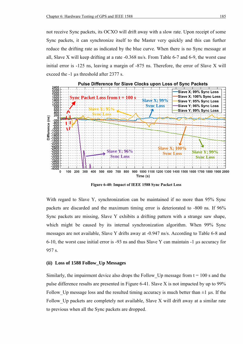
Chapter 6: Hardware Testing of GPS and IEEE 1588 185
not receive Sync packets, its OCXO will drift away with a slow rate. Upon receipt of some
Sync packets, it can synchronize itself to the Master very quickly and this can further
reduce the drifting rate as indicated by the blue curve. When there is no Sync message at
all, Slave X will keep drifting at a rate -0.368 ns/s. From Table 6-7 and 6-9, the worst case
initial error is -125 ns, leaving a margin of -875 ns. Therefore, the error of Slave X will
exceed the -1 µs threshold after 2377 s.
Figure 6-40: Impact of IEEE 1588 Sync Packet Loss
With regard to Slave Y, synchronization can be maintained if no more than 95% Sync
packets are discarded and the maximum timing error is deteriorated to -800 ns. If 96%
Sync packets are missing, Slave Y exhibits a drifting pattern with a strange saw shape,
which might be caused by its internal synchronization algorithm. When 99% Sync
messages are not available, Slave Y drifts away at -0.947 ns/s. According to Table 6-8 and
6-10, the worst case initial error is -93 ns and thus Slave Y can maintain -1 µs accuracy for
957 s.
(ii) Loss of 1588 Follow_Up Messages
Similarly, the impairment device also drops the Follow_Up message from t = 100 s and the
pulse difference results are presented in Figure 6-41. Slave X is not impacted by up to 99%
Follow_Up message loss and the resulted timing accuracy is much better than ±1 µs. If the
Follow_Up packets are completely not available, Slave X will drift away at a similar rate
to previous when all the Sync packets are dropped.
Sync Packet Loss from t = 100 s
Slave Y; 96%
Sync Loss Slave Y; 99%
Sync Loss
Slave X; 100%
Sync Loss
Slave Y; 95%
Sync Loss
Slave X; 99%
Sync Loss
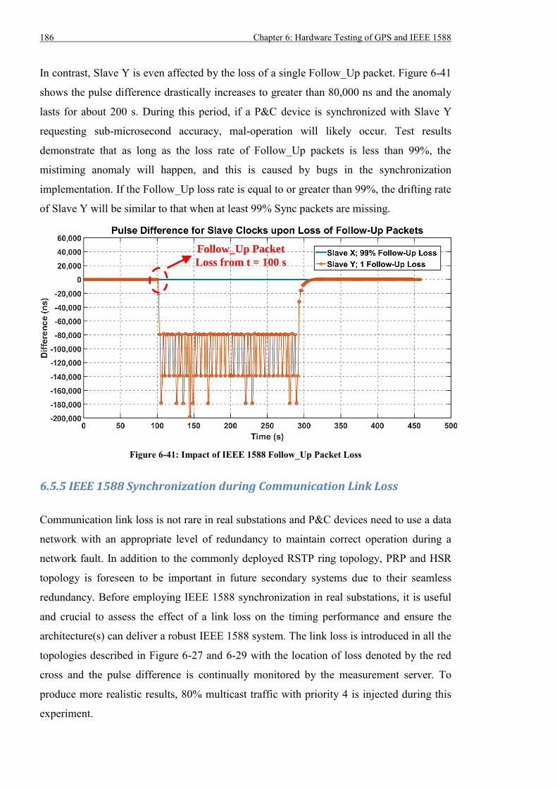
186 Chapter 6: Hardware Testing of GPS and IEEE 1588
In contrast, Slave Y is even affected by the loss of a single Follow_Up packet. Figure 6-41
shows the pulse difference drastically increases to greater than 80,000 ns and the anomaly
lasts for about 200 s. During this period, if a P&C device is synchronized with Slave Y
requesting sub-microsecond accuracy, mal-operation will likely occur. Test results
demonstrate that as long as the loss rate of Follow_Up packets is less than 99%, the
mistiming anomaly will happen, and this is caused by bugs in the synchronization
implementation. If the Follow_Up loss rate is equal to or greater than 99%, the drifting rate
of Slave Y will be similar to that when at least 99% Sync packets are missing.
Figure 6-41: Impact of IEEE 1588 Follow_Up Packet Loss
6.5.5 IEEE 1588 Synchronization during Communication Link Loss
Communication link loss is not rare in real substations and P&C devices need to use a data
network with an appropriate level of redundancy to maintain correct operation during a
network fault. In addition to the commonly deployed RSTP ring topology, PRP and HSR
topology is foreseen to be important in future secondary systems due to their seamless
redundancy. Before employing IEEE 1588 synchronization in real substations, it is useful
and crucial to assess the effect of a link loss on the timing performance and ensure the
architecture(s) can deliver a robust IEEE 1588 system. The link loss is introduced in all the
topologies described in Figure 6-27 and 6-29 with the location of loss denoted by the red
cross and the pulse difference is continually monitored by the measurement server. To
produce more realistic results, 80% multicast traffic with priority 4 is injected during this
experiment.
Follow_Up Packet
Loss from t = 100 s
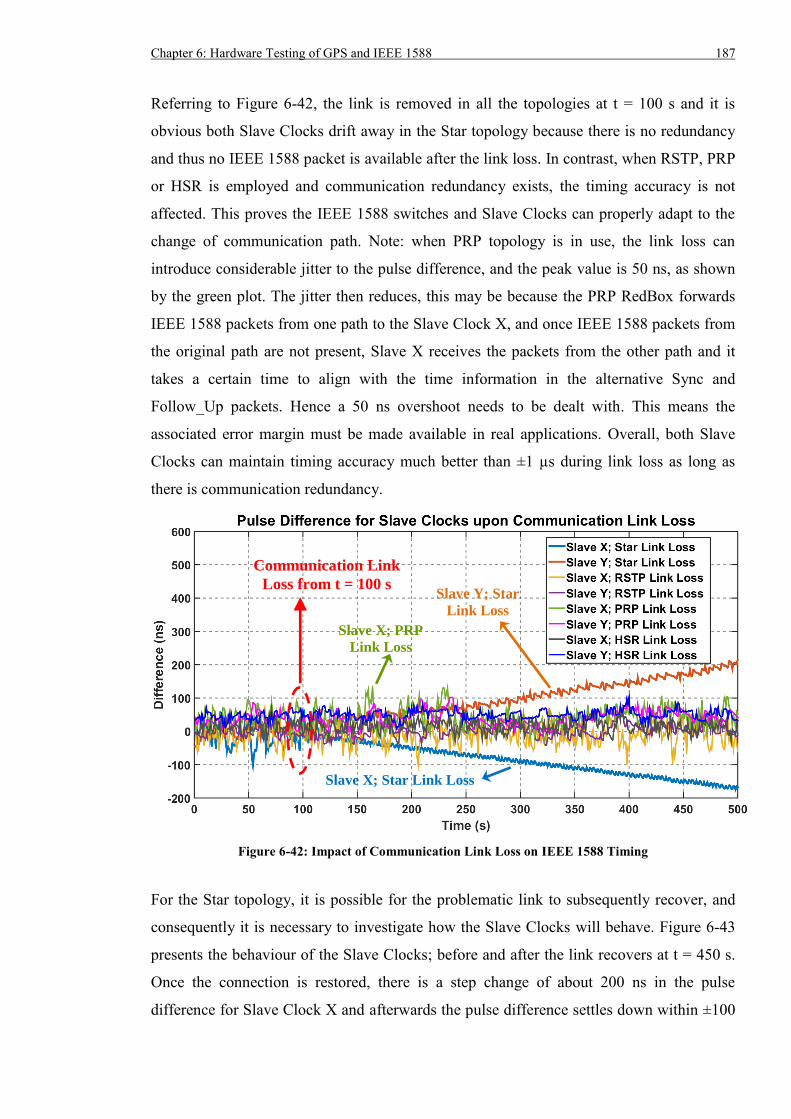
Chapter 6: Hardware Testing of GPS and IEEE 1588 187
Referring to Figure 6-42, the link is removed in all the topologies at t = 100 s and it is
obvious both Slave Clocks drift away in the Star topology because there is no redundancy
and thus no IEEE 1588 packet is available after the link loss. In contrast, when RSTP, PRP
or HSR is employed and communication redundancy exists, the timing accuracy is not
affected. This proves the IEEE 1588 switches and Slave Clocks can properly adapt to the
change of communication path. Note: when PRP topology is in use, the link loss can
introduce considerable jitter to the pulse difference, and the peak value is 50 ns, as shown
by the green plot. The jitter then reduces, this may be because the PRP RedBox forwards
IEEE 1588 packets from one path to the Slave Clock X, and once IEEE 1588 packets from
the original path are not present, Slave X receives the packets from the other path and it
takes a certain time to align with the time information in the alternative Sync and
Follow_Up packets. Hence a 50 ns overshoot needs to be dealt with. This means the
associated error margin must be made available in real applications. Overall, both Slave
Clocks can maintain timing accuracy much better than ±1 µs during link loss as long as
there is communication redundancy.
Figure 6-42: Impact of Communication Link Loss on IEEE 1588 Timing
For the Star topology, it is possible for the problematic link to subsequently recover, and
consequently it is necessary to investigate how the Slave Clocks will behave. Figure 6-43
presents the behaviour of the Slave Clocks; before and after the link recovers at t = 450 s.
Once the connection is restored, there is a step change of about 200 ns in the pulse
difference for Slave Clock X and afterwards the pulse difference settles down within ±100
Communication Link
Loss from t = 100 s
Slave X; Star Link Loss
Slave Y; Star
Link Loss
Slave X; PRP
Link Loss
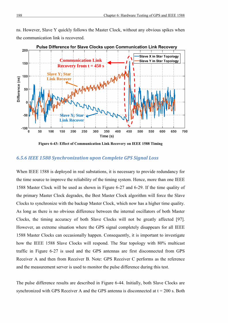
188 Chapter 6: Hardware Testing of GPS and IEEE 1588
ns. However, Slave Y quickly follows the Master Clock, without any obvious spikes when
the communication link is recovered.
Figure 6-43: Effect of Communication Link Recovery on IEEE 1588 Timing
6.5.6 IEEE 1588 Synchronization upon Complete GPS Signal Loss
When IEEE 1588 is deployed in real substations, it is necessary to provide redundancy for
the time source to improve the reliability of the timing system. Hence, more than one IEEE
1588 Master Clock will be used as shown in Figure 6-27 and 6-29. If the time quality of
the primary Master Clock degrades, the Best Master Clock algorithm will force the Slave
Clocks to synchronize with the backup Master Clock, which now has a higher time quality.
As long as there is no obvious difference between the internal oscillators of both Master
Clocks, the timing accuracy of both Slave Clocks will not be greatly affected [97].
However, an extreme situation where the GPS signal completely disappears for all IEEE
1588 Master Clocks can occasionally happen. Consequently, it is important to investigate
how the IEEE 1588 Slave Clocks will respond. The Star topology with 80% multicast
traffic in Figure 6-27 is used and the GPS antennas are first disconnected from GPS
Receiver A and then from Receiver B. Note: GPS Receiver C performs as the reference
and the measurement server is used to monitor the pulse difference during this test.
The pulse difference results are described in Figure 6-44. Initially, both Slave Clocks are
synchronized with GPS Receiver A and the GPS antenna is disconnected at t = 200 s. Both
Communication Link
Recovery from t = 450 s
Slave Y; Star
Link Recover
Slave X; Star
Link Recover
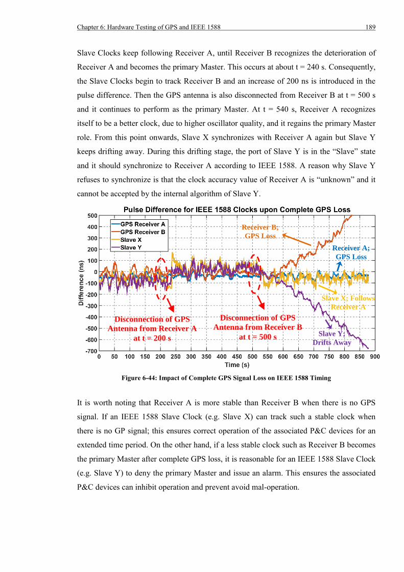
Chapter 6: Hardware Testing of GPS and IEEE 1588 189
Slave Clocks keep following Receiver A, until Receiver B recognizes the deterioration of
Receiver A and becomes the primary Master. This occurs at about t = 240 s. Consequently,
the Slave Clocks begin to track Receiver B and an increase of 200 ns is introduced in the
pulse difference. Then the GPS antenna is also disconnected from Receiver B at t = 500 s
and it continues to perform as the primary Master. At t = 540 s, Receiver A recognizes
itself to be a better clock, due to higher oscillator quality, and it regains the primary Master
role. From this point onwards, Slave X synchronizes with Receiver A again but Slave Y
keeps drifting away. During this drifting stage, the port of Slave Y is in the “Slave” state
and it should synchronize to Receiver A according to IEEE 1588. A reason why Slave Y
refuses to synchronize is that the clock accuracy value of Receiver A is “unknown” and it
cannot be accepted by the internal algorithm of Slave Y.
Figure 6-44: Impact of Complete GPS Signal Loss on IEEE 1588 Timing
It is worth noting that Receiver A is more stable than Receiver B when there is no GPS
signal. If an IEEE 1588 Slave Clock (e.g. Slave X) can track such a stable clock when
there is no GP signal; this ensures correct operation of the associated P&C devices for an
extended time period. On the other hand, if a less stable clock such as Receiver B becomes
the primary Master after complete GPS loss, it is reasonable for an IEEE 1588 Slave Clock
(e.g. Slave Y) to deny the primary Master and issue an alarm. This ensures the associated
P&C devices can inhibit operation and prevent avoid mal-operation.
Disconnection of GPS
Antenna from Receiver A
at t = 200 s
Disconnection of GPS
Antenna from Receiver B
at t = 500 s
Receiver A;
GPS Loss
Receiver B;
GPS Loss
Slave X; Follows
Receiver A
Slave Y;
Drifts Away
190 Chapter 6: Hardware Testing of GPS and IEEE 1588
6.5.7 Summary of Testing
Based on the testing results, both Slave Clock X and Y can deliver long term timing
accuracy better than ±150 ns in various network topologies when all the Ethernet switches
are compliant with IEEE 1588v2 standard and all the IEEE 1588 devices are configured
according to IEEE 1588 Power Profile. Use of IEEE 1588 Ethernet switches can eliminate
the impact of non-1588 traffic with equal or higher priority on the timing accuracy.
However, it should be noted that GPS Receiver A will be stalled by traffic at a rate of more
than 25 Mb/s. Consequently, any unnecessary traffic has to be filtered out by Ethernet
switch(es) for Receiver A. In terms of 1588 traffic, 128 Sync messages per second can
congest the Ethernet switches and lead to the loss of certain Sync and Follow_Up messages
from the primary Master. As a result, both Slave Clocks drifts away for most of the time
during this test. Because the Sync and Follow_Up messages are randomly lost, it is
possible consecutive complete pairs of Sync and Follow_Up messages can be received.
Hence, both Slave Clocks may randomly adjust their internal time. Slave X can keep
synchronized for up to a 99% Sync or Follow_Up loss and maintain sub-microsecond
accuracy for 2337 s when all Sync or Follow_Up packets are not available. For Slave Y, it
can deliver accuracy better than ±1 µs when the loss rate of Sync is less than 95% and may
break the performance requirement in less than 50 s if more than 95% of the Sync
messages are missing. Moreover, Slave Y is very sensitive to the loss of Follow_Up
packets and can be impacted even by the loss of a single Follow_Up packet, with a
mistiming greater than 80 µs. It is viable to implement IEEE 1588 timing over RSTP, PRP
or HSR redundancy and such redundancy can guarantee timing accuracy will not be
affected upon communication link loss. It is also observed no obvious pulse difference
spike is introduced when both Slave Clocks restore synchronization. Upon complete GPS
signal loss, Receiver A can produce a more stable timing output than Receiver B and Slave
X can synchronize to Receiver A. Although Slave Y recognizes Receiver A as the primary
Master, it does not track Receiver A.
6.6 Testing of Interaction between IEEE 1588 and Other Traffic
Since the IEEE 1588 traffic shares the data network with other traffic, interaction
inevitably exists. Previous test results have confirmed IEEE 1588 timing will not be
affected by other traffic, because an IEEE 1588 Ethernet switch can accurately measure the
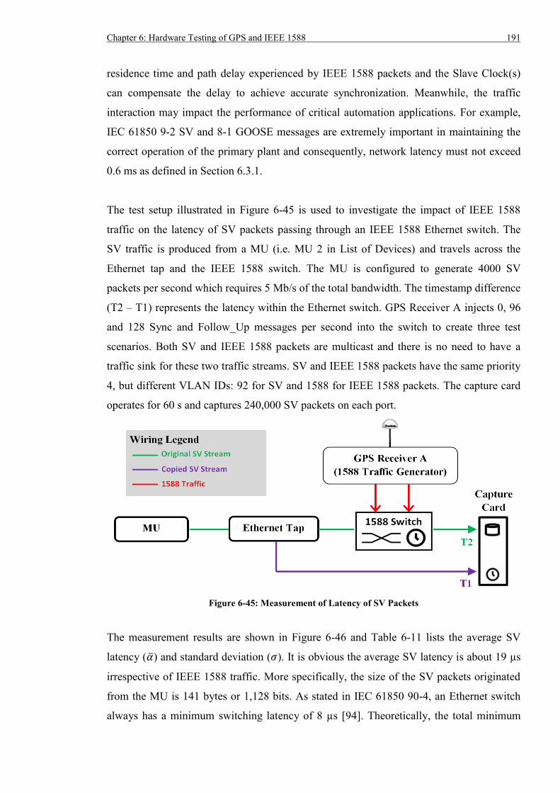
Chapter 6: Hardware Testing of GPS and IEEE 1588 191
residence time and path delay experienced by IEEE 1588 packets and the Slave Clock(s)
can compensate the delay to achieve accurate synchronization. Meanwhile, the traffic
interaction may impact the performance of critical automation applications. For example,
IEC 61850 9-2 SV and 8-1 GOOSE messages are extremely important in maintaining the
correct operation of the primary plant and consequently, network latency must not exceed
0.6 ms as defined in Section 6.3.1.
The test setup illustrated in Figure 6-45 is used to investigate the impact of IEEE 1588
traffic on the latency of SV packets passing through an IEEE 1588 Ethernet switch. The
SV traffic is produced from a MU (i.e. MU 2 in List of Devices) and travels across the
Ethernet tap and the IEEE 1588 switch. The MU is configured to generate 4000 SV
packets per second which requires 5 Mb/s of the total bandwidth. The timestamp difference
(T2 – T1) represents the latency within the Ethernet switch. GPS Receiver A injects 0, 96
and 128 Sync and Follow_Up messages per second into the switch to create three test
scenarios. Both SV and IEEE 1588 packets are multicast and there is no need to have a
traffic sink for these two traffic streams. SV and IEEE 1588 packets have the same priority
4, but different VLAN IDs: 92 for SV and 1588 for IEEE 1588 packets. The capture card
operates for 60 s and captures 240,000 SV packets on each port.
Figure 6-45: Measurement of Latency of SV Packets
The measurement results are shown in Figure 6-46 and Table 6-11 lists the average SV
latency (��) and standard deviation (𝜎). It is obvious the average SV latency is about 19 µs
irrespective of IEEE 1588 traffic. More specifically, the size of the SV packets originated
from the MU is 141 bytes or 1,128 bits. As stated in IEC 61850 90-4, an Ethernet switch
always has a minimum switching latency of 8 µs [94]. Theoretically, the total minimum
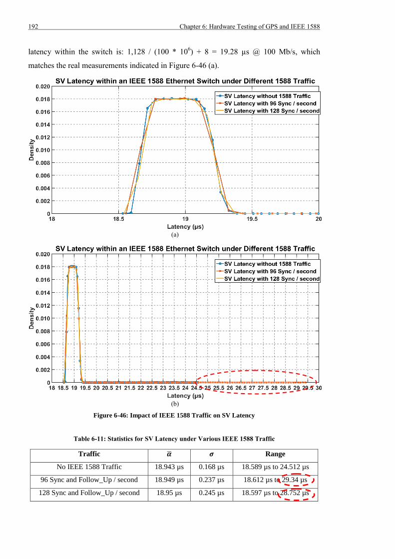
192 Chapter 6: Hardware Testing of GPS and IEEE 1588
latency within the switch is: 1,128 / (100 * 106) + 8 = 19.28 µs @ 100 Mb/s, which
matches the real measurements indicated in Figure 6-46 (a).
(a)
(b)
Figure 6-46: Impact of IEEE 1588 Traffic on SV Latency
Table 6-11: Statistics for SV Latency under Various IEEE 1588 Traffic
Traffic �� 𝝈 Range
No IEEE 1588 Traffic 18.943 µs 0.168 µs 18.589 µs to 24.512 µs
96 Sync and Follow_Up / second 18.949 µs 0.237 µs 18.612 µs to 29.34 µs
128 Sync and Follow_Up / second 18.95 µs 0.245 µs 18.597 µs to 28.752 µs
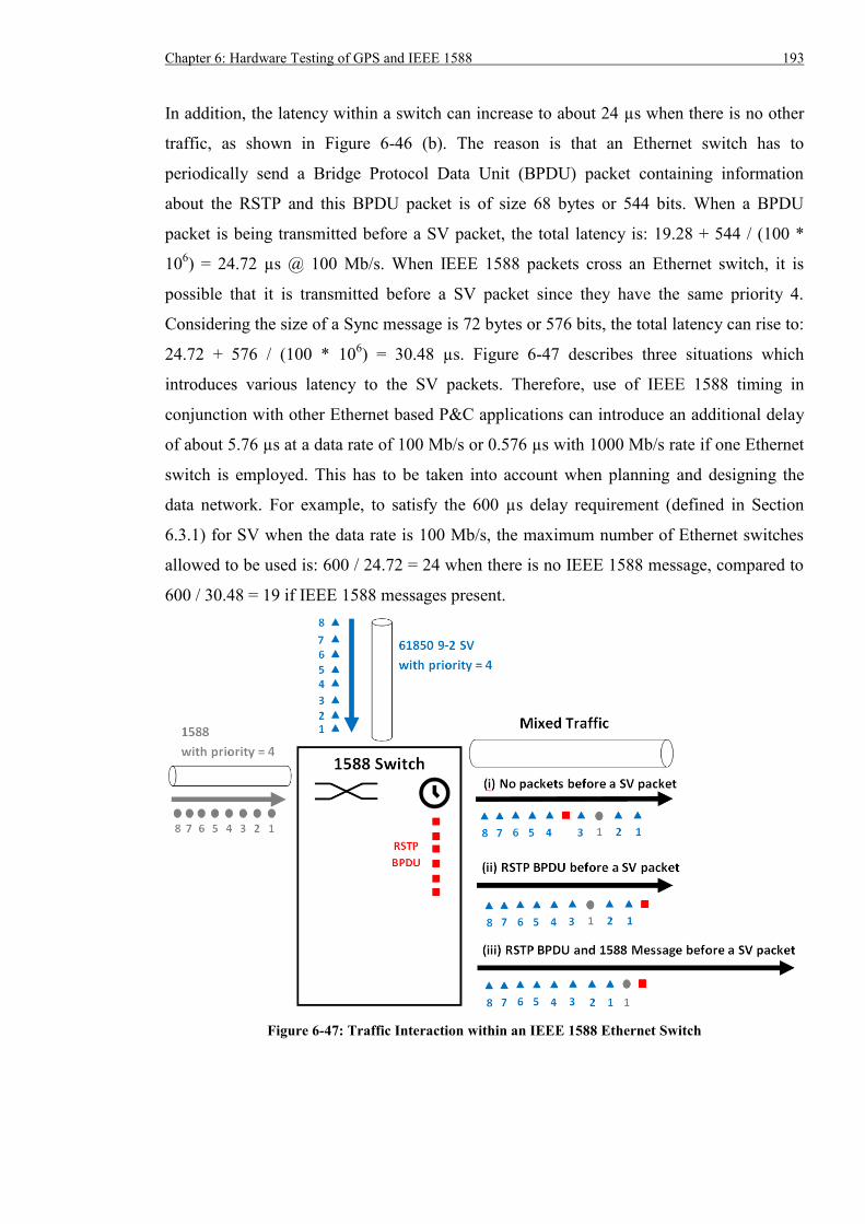
Chapter 6: Hardware Testing of GPS and IEEE 1588 193
In addition, the latency within a switch can increase to about 24 µs when there is no other
traffic, as shown in Figure 6-46 (b). The reason is that an Ethernet switch has to
periodically send a Bridge Protocol Data Unit (BPDU) packet containing information
about the RSTP and this BPDU packet is of size 68 bytes or 544 bits. When a BPDU
packet is being transmitted before a SV packet, the total latency is: 19.28 + 544 / (100 *
106) = 24.72 µs @ 100 Mb/s. When IEEE 1588 packets cross an Ethernet switch, it is
possible that it is transmitted before a SV packet since they have the same priority 4.
Considering the size of a Sync message is 72 bytes or 576 bits, the total latency can rise to:
24.72 + 576 / (100 * 106) = 30.48 µs. Figure 6-47 describes three situations which
introduces various latency to the SV packets. Therefore, use of IEEE 1588 timing in
conjunction with other Ethernet based P&C applications can introduce an additional delay
of about 5.76 µs at a data rate of 100 Mb/s or 0.576 µs with 1000 Mb/s rate if one Ethernet
switch is employed. This has to be taken into account when planning and designing the
data network. For example, to satisfy the 600 µs delay requirement (defined in Section
6.3.1) for SV when the data rate is 100 Mb/s, the maximum number of Ethernet switches
allowed to be used is: 600 / 24.72 = 24 when there is no IEEE 1588 message, compared to
600 / 30.48 = 19 if IEEE 1588 messages present.
Figure 6-47: Traffic Interaction within an IEEE 1588 Ethernet Switch
194 Chapter 6: Hardware Testing of GPS and IEEE 1588
6.7 Summary
Detailed design of the hardware testbed which could be used to evaluate the performance
of a timing system based on GPS receivers and IEEE 1588 devices was described in this
chapter. Test results showed no GPS receiver could deliver the ±100 ns timing accuracy as
stated in the device datasheet or manual, if we considered the worst case pulse difference
from the reference. However, increased mask angle could effectively reduce the mistiming
spike in the pulse difference. Upon GPS signal loss, GPS receivers would exhibit different
drifting rates and system operators needed to be aware of such information during the
planning and operation of the system. GPS receivers that would stop outputting timing
signal upon GPS signal loss should be used since the associated P&C devices could block
operation to avoid mal-operations. Consequently, system operators did not need to worry
about the drifting rate of GPS receivers. When the GPS signal was restored, certain GPS
receiver might introduce an unacceptable timing error, which breached the timing
threshold required for P&C applications. Hence, it was necessary to test and resolve this
problem before the receiver could be used in real substations. When utilities use timing
systems that are purely based on GPS receiver, recommendations can be made:
- The associated P&C devices shall stop timing outputs when GPS signal is lost.
- The GPS receivers must ensure no significant timing error will occur upon GPS signal
restoration.
In terms of the IEEE 1588 timing system, ±150 ns synchronization accuracy could be
obtained even when the network was extremely overloaded. This proved the feasibility to
integrate IEEE 1588 and IEC 61850 applications into a single data network for the future
digital substations. But this type of network should be carefully designed and engineered
because certain IEEE 1588 end device(s) might be shut down by excessive non-1588
traffic. Moreover, excessive IEEE 1588 traffic could exceed the processing capability of an
IEEE 1588 switch, leading to 1588 packet loss. As a result, synchronization could not be
maintained and the IEEE 1588 Slave Clocks drifted away. It should be noted that a Slave
Clock exhibited strange behaviour during loss of Sync (96% to 99% loss rate) and
Follow_Up messages, which needed to be fixed by a firmware upgrade. Similarly, it was
suggested that an IEEE 1588 Slave Clock could stop timing output and issued an alarm
once it detected there was no synchronization. In this way, the associated P&C devices
could recognize the incident and block operation to avoid mal-operations. The
Chapter 6: Hardware Testing of GPS and IEEE 1588 195
measurement results also suggested if communication redundancy was in use, the IEEE
1588 timing would not be evidently affected upon communication link loss. Unlike GPS
receiver restoration, IEEE 1588 Slave Clocks could quickly synchronize to the reference
clock without introducing significant spike in pulse difference. Upon complete GPS signal
loss, IEEE 1588 Slave Clocks would respond differently: some would track the primary
Master whilst the other would drift away. If the primary Master was very stable and could
maintain ±1 us accuracy for a long time after the GPS signal loss, it was advisable that the
Slave Clocks followed such a clock to ensure the correct operation of related P&C devices.
In contrast, if a less stable clock became the primary Master, Slave Clocks should not track
it and must send an alarm to warn the associated P&C devices there was no
synchronization. As a conclusion, the stability of IEEE 1588 Master Clocks and the
behaviour of IEEE 1588 Slave Clocks upon complete GPS signal loss should be fully
investigated and assessed before real deployment. Recommendations on utilities’ timing
system based on GPS and IEEE 1588 devices can be made:
- Appropriate network engineering policies such as maximum traffic load arrangement
and traffic filtering should be implemented to avoid excess traffic, in particular excess
IEEE 1588 traffic for Ethernet switches and excess traffic for IEEE 1588 clocks.
- Seamless communication redundancy such as IEC 62439 PRP and HSR are better
options than other techniques requiring reconfiguration time.
- IEEE 1588 master clocks with very stable oscillator (e.g. Rubidium oscillator) shall be
used and all IEEE 1588 slave clocks shall follow the same clock when GPS signal is
completely not available.
For the impact of IEEE 1588 traffic on other applications, measurement results indicated
that even with high volume of IEEE 1588 traffic, additional latency experienced by an
Ethernet packet with the same priority was only about 6 µs for one IEEE 1588 switch at
data rate of 100 Mb/s. This additional delay could be ignored in a network with small
number of Ethernet switches, but had to be considered for a bigger network as the total
allowance for the network latency was only 600 µs. The network for SV could involve up
to 24 Ethernet switches if IEEE 1588 was not used, whilst the number reduced to 19 when
IEEE 1588 messages existed.
During the tests on the hardware testbed, the bandwidth of the background traffic was
constant and it did not reflect the real-world traffic pattern within power substations.
196 Chapter 6: Hardware Testing of GPS and IEEE 1588
Therefore, the traffic pattern of real substations should be characterized and integrated into
the hardware testbed for performance tests. Device failures and corrupted packets can
occur in real applications and their occurrence is represented by Mean Time Between
Failures (MTBF) and Bit Error Rate (BER). These two parameters are very important for
substation automation systems as it will affect the asset management strategy and policy.
The hardware tests did not involve assessing the MTBF and BER of the GPS and IEEE
1588 devices. Consequently, tests with longer period should be conducted to characterize
the MTBF and BER of various devices. In this way, the device properties can be
investigated more comprehensively, producing more valuable information. The IEEE 1588
master clock Receiver A used only the GPS signal as the time reference source which can
be jammed or spoofed, causing more timing errors. Furthermore, the GPS coupling issue
can also impact the experimental results. In order to increase the credibility of the test
results, it is suggested to employ a very stable master clock with Rubidium oscillator that
can accept multiple time reference inputs such as GPS, radio and terrestrial signal. In this
way, the master clock can maintain good short term accuracy using the Rubidium oscillator
whilst obtain good long term accuracy using the time reference inputs. Appropriate GPS
antenna installation and spacing is also required in the future work.
Chapter 7: Implementation of IEEE 1588 for Real Substations 197
Chapter 7: Implementation of IEEE 1588 for Real Substations
7.1 Introduction
In previous sections, both software simulation and hardware testing results proved the
IEEE 1588 timing system can achieve sub-microsecond timing accuracy even under
extreme conditions such as excessive network load, IEEE 1588 packet loss and
communication link loss. Previous tests were conducted on a relatively small network to
better focus on the effect of a single condition. When IEEE 1588 is employed in real
substations, the scale of the network will be much bigger. Hence, the next step for the
hardware testing is to implement the IEEE 1588 timing in the context of a substation. More
specifically, factors such as substation automation architecture, length of communication
link, scalability of the timing system and device interoperability have to be considered.
Section 7.2 first describes the principle of National Grid’s Ethernet based substation
secondary architecture for its future digital substations and Section 7.3 describes how the
IEEE 1588 timing can be integrated into the architecture. Section 7.4 and Section 7.5
describes a study into the feasibility and scalability of the substation wide IEEE 1588
implementation. A fast and efficient procedure to replace the failed communication device
is shown in Section 7.6, followed by the impact analysis. Section 7.7 investigates the effect
of long communication links (e.g. 505 m, 1000 m) on IEEE 1588 timing, whilst Section
7.8 verifies the compatibility between IEEE 1588 devices and IEDs/MUs.
7.2 Principle of AS3 Architecture
To overcome the challenge associated with the short life (typically 15 years) [38] of
modern P&C devices, National Grid has proposed and developed a new Architecture for
Substation Secondary System (AS3) using IEC 61850 technologies [117] as shown in
Figure 7-1. Instead of directly connecting the CT and VT to the protective relays, the
analogue current and voltage signal are connected to MUs which then convert the analogue
value into IEC 61850 9-2 SV Ethernet packets. The SV packets are published on the
Process Bus and the IEDs (i.e. Main Protection 1 / MP1, Main Protection 2 / MP2)
198 Chapter 7: Implementation of IEEE 1588 for Real Substations
subscribe to the desired SV streams from the Process Bus. Once an IED detects a fault and
needs to trip the CB, it will issue an IEC 61850 8-1 GOOSE message and send it to the
Circuit Breaker Controller (CBC) through the Process Bus. The CBC will then trip the CB.
The communication between IEDs and Human Machine Interface (HMI) is done via IEC
61850 8-1 GOOSE and Manufacturing Message Specification (MMS) over the Station Bus.
The Bay Control Unit (BCU) is mainly used for Auto Reclosing and Sync Check. In terms
of Auto Reclosing, it takes the current value from the Process Bus. Whilst for the Sync
Check, as there are no VTs on the busbars in National Grid’s substations, the voltage
signal is obtained from a feeder already connected to the busbar. More specifically, BCU
obtains the local voltage signal from the Process Bus and the “busbar” voltage signal from
the Inter Bay Process Bus, after which the Sync Check function can be conducted.
Similarly, BCU controls the CB by sending GOOSE to the CBC via the Process Bus. Note:
the purpose of MU3 in Figure 7-1 is to provide the voltage signal for the BCUs in other
bays, rather than the local BCU.
Figure 7-1: AS3 Architecture for a Substation Feeder Bay
Chapter 7: Implementation of IEEE 1588 for Real Substations 199
In general, all the IEDs rely on the Station Bus to exchange information with the HMI and
the Station Bus will cross the whole substation covering all bays. Because the Inter Bay
Process Bus is mainly used for the Sync Check function to collect voltage signal from
multiple bays, it is also designed to cover the whole substation. Whilst for Process Bus 1
and 2, they are separated within a bay to provide independence and redundancy for the
protection schemes (e.g. MP1 and MP2). Furthermore, Process Buses are implemented to
cover only a single bay in order to reduce complexity. There is no connection between
these four communication buses. The overview of the AS3
communication buses are shown
in Figure 7-2.
Figure 7-2: High Level View of AS3 Architecture [118]
7.3 Integration of IEEE 1588 into AS3 Architecture
A time source is necessary to implement IEEE 1588 timing and a high quality GPS
receiver with IEEE 1588 capability is ideal for a substation. MUs are one of the major
devices that require precise synchronization. A normal approach is to employ at least one
GPS receiver as the IEEE 1588 Master Clock on each Process Bus, but this leads to the use
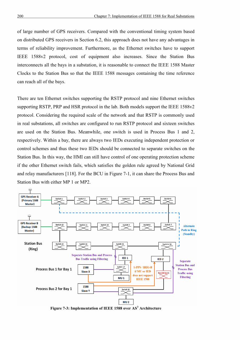
200 Chapter 7: Implementation of IEEE 1588 for Real Substations
of large number of GPS receivers. Compared with the conventional timing system based
on distributed GPS receivers in Section 6.2, this approach does not have any advantages in
terms of reliability improvement. Furthermore, as the Ethernet switches have to support
IEEE 1588v2 protocol, cost of equipment also increases. Since the Station Bus
interconnects all the bays in a substation, it is reasonable to connect the IEEE 1588 Master
Clocks to the Station Bus so that the IEEE 1588 messages containing the time reference
can reach all of the bays.
There are ten Ethernet switches supporting the RSTP protocol and nine Ethernet switches
supporting RSTP, PRP and HSR protocol in the lab. Both models support the IEEE 1588v2
protocol. Considering the required scale of the network and that RSTP is commonly used
in real substations, all switches are configured to run RSTP protocol and sixteen switches
are used on the Station Bus. Meanwhile, one switch is used in Process Bus 1 and 2,
respectively. Within a bay, there are always two IEDs executing independent protection or
control schemes and thus these two IEDs should be connected to separate switches on the
Station Bus. In this way, the HMI can still have control of one operating protection scheme
if the other Ethernet switch fails, which satisfies the golden rule agreed by National Grid
and relay manufacturers [118]. For the BCU in Figure 7-1, it can share the Process Bus and
Station Bus with either MP 1 or MP2.
Figure 7-3: Implementation of IEEE 1588 over AS
3 Architecture
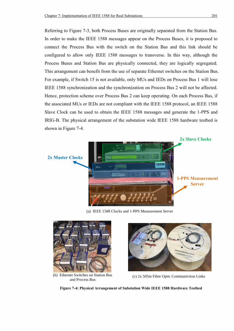
Chapter 7: Implementation of IEEE 1588 for Real Substations 201
Referring to Figure 7-3, both Process Buses are originally separated from the Station Bus.
In order to make the IEEE 1588 messages appear on the Process Buses, it is proposed to
connect the Process Bus with the switch on the Station Bus and this link should be
configured to allow only IEEE 1588 messages to transverse. In this way, although the
Process Buses and Station Bus are physically connected, they are logically segregated.
This arrangement can benefit from the use of separate Ethernet switches on the Station Bus.
For example, if Switch 15 is not available, only MUs and IEDs on Process Bus 1 will lose
IEEE 1588 synchronization and the synchronization on Process Bus 2 will not be affected.
Hence, protection scheme over Process Bus 2 can keep operating. On each Process Bus, if
the associated MUs or IEDs are not compliant with the IEEE 1588 protocol, an IEEE 1588
Slave Clock can be used to obtain the IEEE 1588 messages and generate the 1-PPS and
IRIG-B. The physical arrangement of the substation wide IEEE 1588 hardware testbed is
shown in Figure 7-4.
(a) IEEE 1588 Clocks and 1-PPS Measurement Server
(b) Ethernet Switches on Station Bus
and Process Bus
Figure 7-4: Physical Arrangement of Substation Wide IEEE 1588 Hardware Testbed
2x Slave Clocks
2x Master Clocks
1-PPS Measurement
Server
(c) 2x 505m Fibre Optic Communiction Links
202 Chapter 7: Implementation of IEEE 1588 for Real Substations
7.4 Feasibility of Substation Wide IEEE 1588 Implementation
In order to investigate the feasibility of a substation wide IEEE 1588 timing system, the
architecture shown in Figure 7-3 is used. GPS Receiver A automatically becomes the
primary Master Clock following the default configuration. After that, the pulse difference
of the Slave Clocks from Receiver A is monitored by the measurement server for 24 hours.
Details of the testing setup are listed below.
- 16 IEEE 1588 Ethernet switches on Station Bus
- 1 IEEE 1588 Ethernet switch on Process Bus 1 and 2, respectively
- All IEEE 1588 devices are configured according to IEEE 1588 Power Profile and
based on the settings in Table 6-6
- Traffic Generator simultaneously injects 100% SV traffic with priority 4 into Switch
17 and Switch 18; this congests Process Bus 1 and Process Bus 2
- Switch 17 on Process Bus 1 and Switch 18 on Process Bus 2 filter out SV packets so
they do not appear on the Station Bus
- Traffic Generator injects 100% GOOSE traffic with priority 4 via Switch 6 to flood
the Station Bus
- Switch 15 and 16 on the Station Bus filter out GOOSE packets so they do not appear
on the Process Buses
- RSTP ring is configured to preserve the link between Switch 1 and Switch 16 as the
alternate communication path, so that IEEE 1588 messages from the GPS Receiver A
can travel through the maximum number of Ethernet switches before they arrive at the
Slave Clocks: i.e. 16 Ethernet switches between Slave X and GPS Receiver A; and 17
Ethernet switches between Slave Y and GPS Receiver B
- All Ethernet switches support data rate up to 100 Mb/s
The 24 hour 1-PPS differences are presented in Figure 7-5 and Table 7-1 with average (��),
standard deviation (𝜎) and range. Test results prove that the proposed implementation of
IEEE 1588 timing across the whole substation, which consists of at least 16 hops between
Master Clock and Slave Clocks, can achieve timing accuracy better than ±510 ns even
when 100% traffic congests the whole network. This definitely satisfies the sub-
microsecond accuracy requirement. Compared with the test setups where direct connection
is used between the GPS Receiver A and Slave Clocks, the timing error tends to be larger
in positive direction. More specifically, the worst-case accuracy degradation is about 492
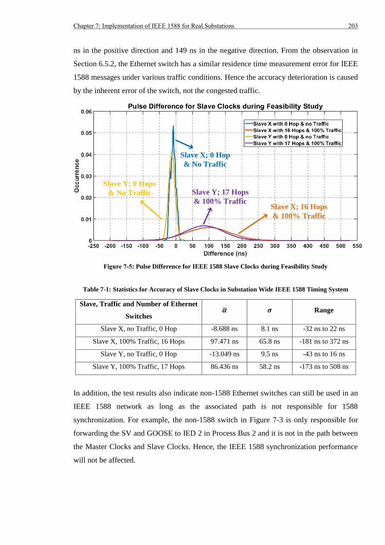
Chapter 7: Implementation of IEEE 1588 for Real Substations 203
ns in the positive direction and 149 ns in the negative direction. From the observation in
Section 6.5.2, the Ethernet switch has a similar residence time measurement error for IEEE
1588 messages under various traffic conditions. Hence the accuracy deterioration is caused
by the inherent error of the switch, not the congested traffic.
Figure 7-5: Pulse Difference for IEEE 1588 Slave Clocks during Feasibility Study
Table 7-1: Statistics for Accuracy of Slave Clocks in Substation Wide IEEE 1588 Timing System
Slave, Traffic and Number of Ethernet
Switches �� 𝝈 Range
Slave X, no Traffic, 0 Hop -8.688 ns 8.1 ns -32 ns to 22 ns
Slave X, 100% Traffic, 16 Hops 97.471 ns 65.8 ns -181 ns to 372 ns
Slave Y, no Traffic, 0 Hop -13.049 ns 9.5 ns -43 ns to 16 ns
Slave Y, 100% Traffic, 17 Hops 86.436 ns 58.2 ns -173 ns to 508 ns
In addition, the test results also indicate non-1588 Ethernet switches can still be used in an
IEEE 1588 network as long as the associated path is not responsible for 1588
synchronization. For example, the non-1588 switch in Figure 7-3 is only responsible for
forwarding the SV and GOOSE to IED 2 in Process Bus 2 and it is not in the path between
the Master Clocks and Slave Clocks. Hence, the IEEE 1588 synchronization performance
will not be affected.
Slave X; 0 Hop
& No Traffic
Slave X; 16 Hops
& 100% Traffic
Slave Y; 17 Hops
& 100% Traffic
Slave Y; 0 Hops
& No Traffic
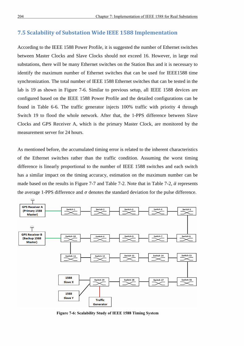
204 Chapter 7: Implementation of IEEE 1588 for Real Substations
7.5 Scalability of Substation Wide IEEE 1588 Implementation
According to the IEEE 1588 Power Profile, it is suggested the number of Ethernet switches
between Master Clocks and Slave Clocks should not exceed 16. However, in large real
substations, there will be many Ethernet switches on the Station Bus and it is necessary to
identify the maximum number of Ethernet switches that can be used for IEEE1588 time
synchronization. The total number of IEEE 1588 Ethernet switches that can be tested in the
lab is 19 as shown in Figure 7-6. Similar to previous setup, all IEEE 1588 devices are
configured based on the IEEE 1588 Power Profile and the detailed configurations can be
found in Table 6-6. The traffic generator injects 100% traffic with priority 4 through
Switch 19 to flood the whole network. After that, the 1-PPS difference between Slave
Clocks and GPS Receiver A, which is the primary Master Clock, are monitored by the
measurement server for 24 hours.
As mentioned before, the accumulated timing error is related to the inherent characteristics
of the Ethernet switches rather than the traffic condition. Assuming the worst timing
difference is linearly proportional to the number of IEEE 1588 switches and each switch
has a similar impact on the timing accuracy, estimation on the maximum number can be
made based on the results in Figure 7-7 and Table 7-2. Note that in Table 7-2, �� represents
the average 1-PPS difference and 𝜎 denotes the standard deviation for the pulse difference.
Figure 7-6: Scalability Study of IEEE 1588 Timing System
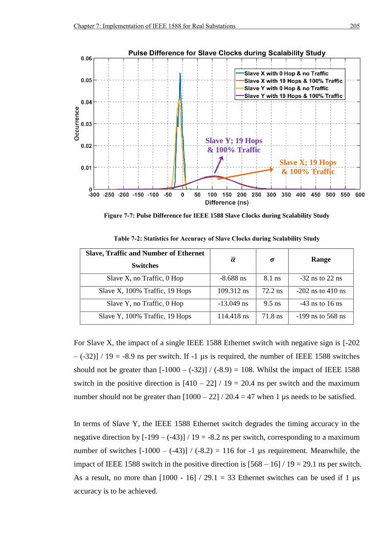
Chapter 7: Implementation of IEEE 1588 for Real Substations 205
Figure 7-7: Pulse Difference for IEEE 1588 Slave Clocks during Scalability Study
Table 7-2: Statistics for Accuracy of Slave Clocks during Scalability Study
Slave, Traffic and Number of Ethernet
Switches �� 𝝈 Range
Slave X, no Traffic, 0 Hop -8.688 ns 8.1 ns -32 ns to 22 ns
Slave X, 100% Traffic, 19 Hops 109.312 ns 72.2 ns -202 ns to 410 ns
Slave Y, no Traffic, 0 Hop -13.049 ns 9.5 ns -43 ns to 16 ns
Slave Y, 100% Traffic, 19 Hops 114.418 ns 71.8 ns -199 ns to 568 ns
For Slave X, the impact of a single IEEE 1588 Ethernet switch with negative sign is [-202
– (-32)] / 19 = -8.9 ns per switch. If -1 µs is required, the number of IEEE 1588 switches
should not be greater than [-1000 – (-32)] / (-8.9) = 108. Whilst the impact of IEEE 1588
switch in the positive direction is [410 – 22] / 19 = 20.4 ns per switch and the maximum
number should not be greater than [1000 – 22] / 20.4 = 47 when 1 µs needs to be satisfied.
In terms of Slave Y, the IEEE 1588 Ethernet switch degrades the timing accuracy in the
negative direction by [-199 – (-43)] / 19 = -8.2 ns per switch, corresponding to a maximum
number of switches [-1000 – (-43)] / (-8.2) = 116 for -1 µs requirement. Meanwhile, the
impact of IEEE 1588 switch in the positive direction is [568 – 16] / 19 = 29.1 ns per switch.
As a result, no more than [1000 - 16] / 29.1 = 33 Ethernet switches can be used if 1 µs
accuracy is to be achieved.
Slave X; 19 Hops
& 100% Traffic
Slave Y; 19 Hops
& 100% Traffic
206 Chapter 7: Implementation of IEEE 1588 for Real Substations
In summary, for an IEEE 1588 timing network consisting of both Slave X and Y, the
maximum number of IEEE 1588 switches between them and the Master Clock should not
be greater than 33 in order to meet the time synchronization requirement of ±1 µs. In the
AS3 architecture, each bay requires two Process Buses and this means at least two switches
on Station Bus should be used. Considering each Process Bus only uses one switch, 33
switches can accommodate up to 16 bays. For a substation containing more than 16 bays
such as National Grid’s Connah’s Quay with 24 bays, this will require at least 48 IEEE
1588 switches on the Station Bus and the 1588 timing may not deliver the required ±1 µs
accuracy. One of the solutions is to split the large Station Bus into two smaller ones and
use two separate IEEE 1588 timing systems. In addition, a conventional timing system
based on distributed GPS receivers may also be used to complement the IEEE 1588 system.
7.6 IEEE 1588 Timing upon Replacement of Ethernet Switch
A communication fault can occur in substations and following the fault, the RSTP ring
topology can restore communications within tens of milliseconds. Previous experiments
proved the IEEE 1588 timing would not be impacted by communication link loss in the
RSTP topology. In a worse case where an Ethernet switch is completely not working due
to a failure, it is necessary to have a fast and efficient procedure to replace the failed
device. For the IEEE 1588 Ethernet switches used during the test, an SD card can be
employed to store the configuration of the original switch, and then loads the configuration
to a new switch. Note: the test setup is identical to that used during the feasibility study in
Section 7.4.
Referring to Figure 7-8, the testing procedure is scheduled as below.
(i) Disconnect the power supply to Switch 15 to cause the switch to fail
(ii) Replace Switch 15 with a new switch and plug the SD card from the failed switch into
the new switch
(iii) Monitor the 1-PPS difference continually during the incident using the measurement
server
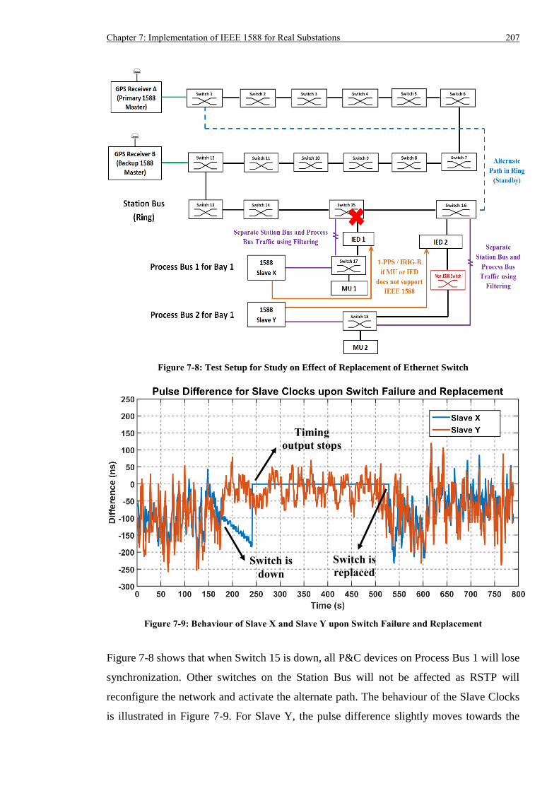
Chapter 7: Implementation of IEEE 1588 for Real Substations 207
Figure 7-8: Test Setup for Study on Effect of Replacement of Ethernet Switch
Figure 7-9: Behaviour of Slave X and Slave Y upon Switch Failure and Replacement
Figure 7-8 shows that when Switch 15 is down, all P&C devices on Process Bus 1 will lose
synchronization. Other switches on the Station Bus will not be affected as RSTP will
reconfigure the network and activate the alternate path. The behaviour of the Slave Clocks
is illustrated in Figure 7-9. For Slave Y, the pulse difference slightly moves towards the
Switch is
down
Timing
output stops
Switch is
replaced
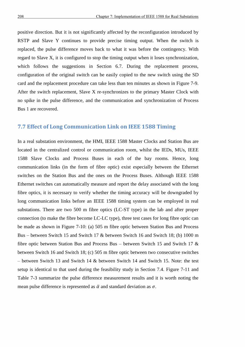
208 Chapter 7: Implementation of IEEE 1588 for Real Substations
positive direction. But it is not significantly affected by the reconfiguration introduced by
RSTP and Slave Y continues to provide precise timing output. When the switch is
replaced, the pulse difference moves back to what it was before the contingency. With
regard to Slave X, it is configured to stop the timing output when it loses synchronization,
which follows the suggestions in Section 6.7. During the replacement process,
configuration of the original switch can be easily copied to the new switch using the SD
card and the replacement procedure can take less than ten minutes as shown in Figure 7-9.
After the switch replacement, Slave X re-synchronizes to the primary Master Clock with
no spike in the pulse difference, and the communication and synchronization of Process
Bus 1 are recovered.
7.7 Effect of Long Communication Link on IEEE 1588 Timing
In a real substation environment, the HMI, IEEE 1588 Master Clocks and Station Bus are
located in the centralized control or communication room, whilst the IEDs, MUs, IEEE
1588 Slave Clocks and Process Buses in each of the bay rooms. Hence, long
communication links (in the form of fibre optic) exist especially between the Ethernet
switches on the Station Bus and the ones on the Process Buses. Although IEEE 1588
Ethernet switches can automatically measure and report the delay associated with the long
fibre optics, it is necessary to verify whether the timing accuracy will be downgraded by
long communication links before an IEEE 1588 timing system can be employed in real
substations. There are two 500 m fibre optics (LC-ST type) in the lab and after proper
connection (to make the fibre become LC-LC type), three test cases for long fibre optic can
be made as shown in Figure 7-10: (a) 505 m fibre optic between Station Bus and Process
Bus – between Switch 15 and Switch 17 & between Switch 16 and Switch 18; (b) 1000 m
fibre optic between Station Bus and Process Bus – between Switch 15 and Switch 17 &
between Switch 16 and Switch 18; (c) 505 m fibre optic between two consecutive switches
– between Switch 13 and Switch 14 & between Switch 14 and Switch 15. Note: the test
setup is identical to that used during the feasibility study in Section 7.4. Figure 7-11 and
Table 7-3 summarize the pulse difference measurement results and it is worth noting the
mean pulse difference is represented as �� and standard deviation as 𝜎.
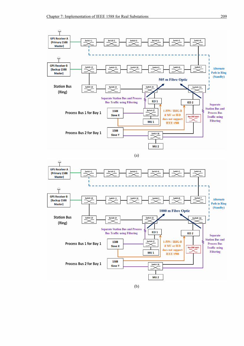
Chapter 7: Implementation of IEEE 1588 for Real Substations 209
(a)
(b)
505 m Fibre Optic
1000 m Fibre Optic
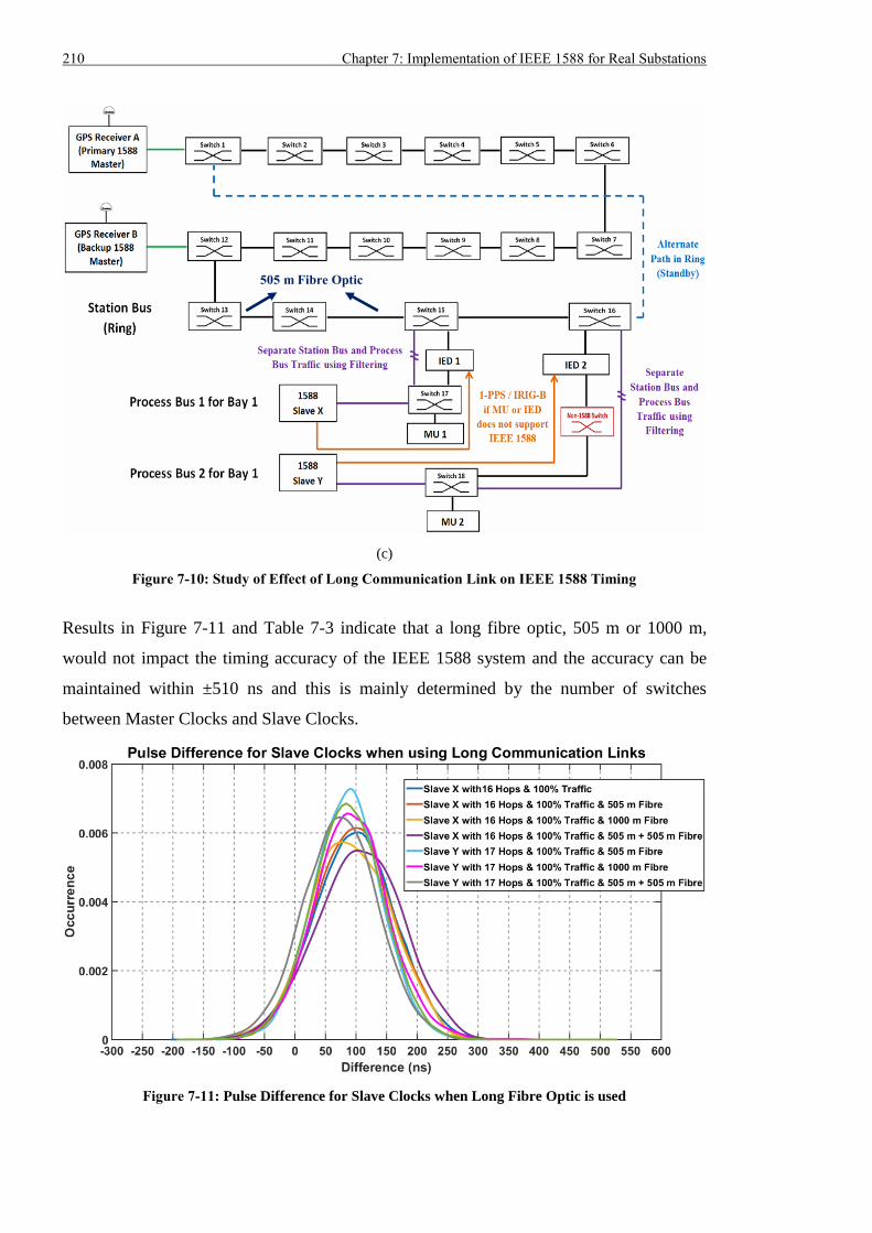
210 Chapter 7: Implementation of IEEE 1588 for Real Substations
(c)
Figure 7-10: Study of Effect of Long Communication Link on IEEE 1588 Timing
Results in Figure 7-11 and Table 7-3 indicate that a long fibre optic, 505 m or 1000 m,
would not impact the timing accuracy of the IEEE 1588 system and the accuracy can be
maintained within ±510 ns and this is mainly determined by the number of switches
between Master Clocks and Slave Clocks.
Figure 7-11: Pulse Difference for Slave Clocks when Long Fibre Optic is used
505 m Fibre Optic
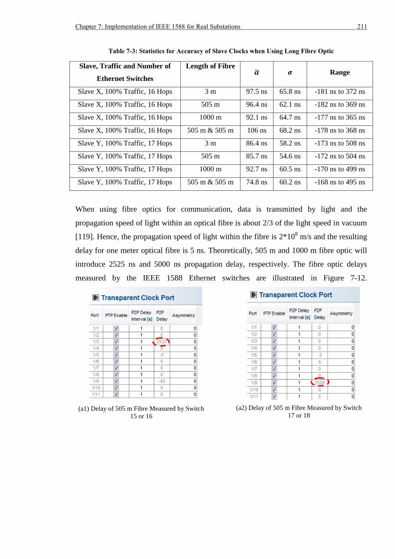
Chapter 7: Implementation of IEEE 1588 for Real Substations 211
Table 7-3: Statistics for Accuracy of Slave Clocks when Using Long Fibre Optic
Slave, Traffic and Number of
Ethernet Switches
Length of Fibre �� 𝝈 Range
Slave X, 100% Traffic, 16 Hops 3 m 97.5 ns 65.8 ns -181 ns to 372 ns
Slave X, 100% Traffic, 16 Hops 505 m 96.4 ns 62.1 ns -182 ns to 369 ns
Slave X, 100% Traffic, 16 Hops 1000 m 92.1 ns 64.7 ns -177 ns to 365 ns
Slave X, 100% Traffic, 16 Hops 505 m & 505 m 106 ns 68.2 ns -178 ns to 368 ns
Slave Y, 100% Traffic, 17 Hops 3 m 86.4 ns 58.2 ns -173 ns to 508 ns
Slave Y, 100% Traffic, 17 Hops 505 m 85.7 ns 54.6 ns -172 ns to 504 ns
Slave Y, 100% Traffic, 17 Hops 1000 m 92.7 ns 60.5 ns -170 ns to 499 ns
Slave Y, 100% Traffic, 17 Hops 505 m & 505 m 74.8 ns 60.2 ns -168 ns to 495 ns
When using fibre optics for communication, data is transmitted by light and the
propagation speed of light within an optical fibre is about 2/3 of the light speed in vacuum
[119]. Hence, the propagation speed of light within the fibre is 2*108 m/s and the resulting
delay for one meter optical fibre is 5 ns. Theoretically, 505 m and 1000 m fibre optic will
introduce 2525 ns and 5000 ns propagation delay, respectively. The fibre optic delays
measured by the IEEE 1588 Ethernet switches are illustrated in Figure 7-12.
(a1) Delay of 505 m Fibre Measured by Switch
15 or 16
(a2) Delay of 505 m Fibre Measured by Switch
17 or 18
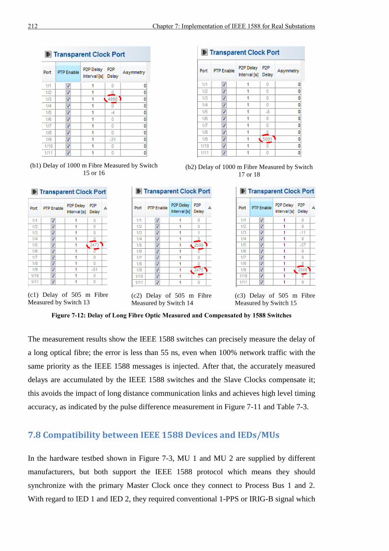
212 Chapter 7: Implementation of IEEE 1588 for Real Substations
(b1) Delay of 1000 m Fibre Measured by Switch
15 or 16
(b2) Delay of 1000 m Fibre Measured by Switch
17 or 18
(c1) Delay of 505 m Fibre
Measured by Switch 13
(c2) Delay of 505 m Fibre
Measured by Switch 14
(c3) Delay of 505 m Fibre
Measured by Switch 15
Figure 7-12: Delay of Long Fibre Optic Measured and Compensated by 1588 Switches
The measurement results show the IEEE 1588 switches can precisely measure the delay of
a long optical fibre; the error is less than 55 ns, even when 100% network traffic with the
same priority as the IEEE 1588 messages is injected. After that, the accurately measured
delays are accumulated by the IEEE 1588 switches and the Slave Clocks compensate it;
this avoids the impact of long distance communication links and achieves high level timing
accuracy, as indicated by the pulse difference measurement in Figure 7-11 and Table 7-3.
7.8 Compatibility between IEEE 1588 Devices and IEDs/MUs
In the hardware testbed shown in Figure 7-3, MU 1 and MU 2 are supplied by different
manufacturers, but both support the IEEE 1588 protocol which means they should
synchronize with the primary Master Clock once they connect to Process Bus 1 and 2.
With regard to IED 1 and IED 2, they required conventional 1-PPS or IRIG-B signal which
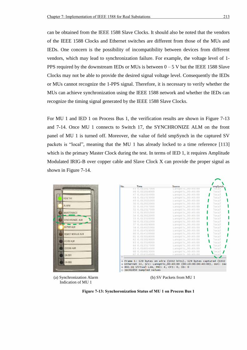
Chapter 7: Implementation of IEEE 1588 for Real Substations 213
can be obtained from the IEEE 1588 Slave Clocks. It should also be noted that the vendors
of the IEEE 1588 Clocks and Ethernet switches are different from those of the MUs and
IEDs. One concern is the possibility of incompatibility between devices from different
vendors, which may lead to synchronization failure. For example, the voltage level of 1-
PPS required by the downstream IEDs or MUs is between 0 – 5 V but the IEEE 1588 Slave
Clocks may not be able to provide the desired signal voltage level. Consequently the IEDs
or MUs cannot recognize the 1-PPS signal. Therefore, it is necessary to verify whether the
MUs can achieve synchronization using the IEEE 1588 network and whether the IEDs can
recognize the timing signal generated by the IEEE 1588 Slave Clocks.
For MU 1 and IED 1 on Process Bus 1, the verification results are shown in Figure 7-13
and 7-14. Once MU 1 connects to Switch 17, the SYNCHRONIZE ALM on the front
panel of MU 1 is turned off. Moreover, the value of field smpSynch in the captured SV
packets is “local”, meaning that the MU 1 has already locked to a time reference [113]
which is the primary Master Clock during the test. In terms of IED 1, it requires Amplitude
Modulated IRIG-B over copper cable and Slave Clock X can provide the proper signal as
shown in Figure 7-14.
(a) Synchronization Alarm
Indication of MU 1
(b) SV Packets from MU 1
Figure 7-13: Synchoronization Status of MU 1 on Process Bus 1
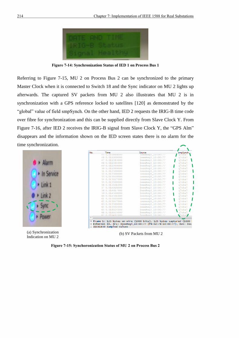
214 Chapter 7: Implementation of IEEE 1588 for Real Substations
Figure 7-14: Synchronization Status of IED 1 on Process Bus 1
Referring to Figure 7-15, MU 2 on Process Bus 2 can be synchronized to the primary
Master Clock when it is connected to Switch 18 and the Sync indicator on MU 2 lights up
afterwards. The captured SV packets from MU 2 also illustrates that MU 2 is in
synchronization with a GPS reference locked to satellites [120] as demonstrated by the
“global” value of field smpSynch. On the other hand, IED 2 requests the IRIG-B time code
over fibre for synchronization and this can be supplied directly from Slave Clock Y. From
Figure 7-16, after IED 2 receives the IRIG-B signal from Slave Clock Y, the “GPS Alm”
disappears and the information shown on the IED screen states there is no alarm for the
time synchronization.
(a) Synchronization
Indication on MU 2
(b) SV Packets from MU 2
Figure 7-15: Synchoronization Status of MU 2 on Process Bus 2
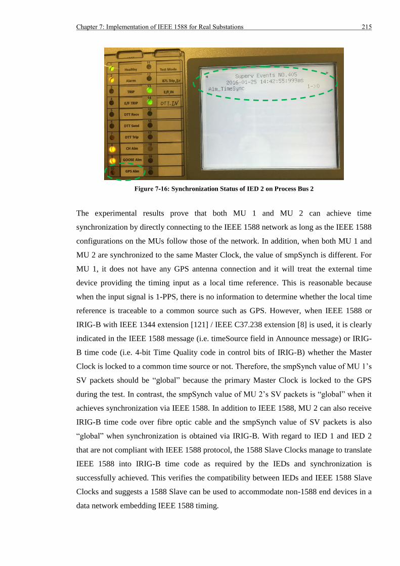
Chapter 7: Implementation of IEEE 1588 for Real Substations 215
Figure 7-16: Synchronization Status of IED 2 on Process Bus 2
The experimental results prove that both MU 1 and MU 2 can achieve time
synchronization by directly connecting to the IEEE 1588 network as long as the IEEE 1588
configurations on the MUs follow those of the network. In addition, when both MU 1 and
MU 2 are synchronized to the same Master Clock, the value of smpSynch is different. For
MU 1, it does not have any GPS antenna connection and it will treat the external time
device providing the timing input as a local time reference. This is reasonable because
when the input signal is 1-PPS, there is no information to determine whether the local time
reference is traceable to a common source such as GPS. However, when IEEE 1588 or
IRIG-B with IEEE 1344 extension [121] / IEEE C37.238 extension [8] is used, it is clearly
indicated in the IEEE 1588 message (i.e. timeSource field in Announce message) or IRIG-
B time code (i.e. 4-bit Time Quality code in control bits of IRIG-B) whether the Master
Clock is locked to a common time source or not. Therefore, the smpSynch value of MU 1’s
SV packets should be “global” because the primary Master Clock is locked to the GPS
during the test. In contrast, the smpSynch value of MU 2’s SV packets is “global” when it
achieves synchronization via IEEE 1588. In addition to IEEE 1588, MU 2 can also receive
IRIG-B time code over fibre optic cable and the smpSynch value of SV packets is also
“global” when synchronization is obtained via IRIG-B. With regard to IED 1 and IED 2
that are not compliant with IEEE 1588 protocol, the 1588 Slave Clocks manage to translate
IEEE 1588 into IRIG-B time code as required by the IEDs and synchronization is
successfully achieved. This verifies the compatibility between IEDs and IEEE 1588 Slave
Clocks and suggests a 1588 Slave can be used to accommodate non-1588 end devices in a
data network embedding IEEE 1588 timing.
216 Chapter 7: Implementation of IEEE 1588 for Real Substations
7.9 Summary
National Grid has proposed and developed the AS3 architecture for its future digital
substations. Because the AS3 architecture is based on Ethernet communication and IEC
61850 technologies, it is important to integrate the IEEE 1588 time synchronization into
the AS3 architecture. IEEE 1588 can share the data network with IEC 61850 applications,
which avoids a separated timing network and provides sub-microsecond accuracy to P&C
devices. To obtain the best economic outcome, this chapter reported on the connection of
Ethernet switches on the Station Bus to those on the Process Buses and configured the link
to allow only IEEE 1588 messages to pass. By doing this, the time reference messages of
the IEEE 1588 Master Clocks could reach all the P&C devices in the substation, which
significantly reduced the amount of GPS receivers required. In addition, as links between
Station Bus and Process Buses did not transmit IEC 61850 SV and GOOSE packets, they
were logically segregated, as if they were not connected in the original AS3 architecture.
The experimental results proved it was feasible to integrate IEEE 1588 timing into the AS3
architecture and obtain sub-microsecond timing accuracy even when the network was
loaded by 100% traffic with the same priority. As each IEEE 1588 Ethernet switch could
introduce error to the overall timing accuracy, we have to estimate the maximum number
of switches that can be used to maintain the ±1 µs requirement. Analysis showed no more
than 33 IEEE 1588 Ethernet switches should be used between the IEEE 1588 Master
Clocks and Slave Clocks. If each bay required two separate Ethernet switches on the
Station Bus for redundancy purposes and only one Ethernet switch on the dual Process
Buses, 33 Ethernet switches could accommodate substations with up to 16 bays. For larger
substations, separate 1588 timing systems or other synchronization approach such as
timing system based on distributed GPS receivers should be used. Long communication
links can exist in the data network within real substations. Test results showed the IEEE
1588 Ethernet switches could accurately measure the delay associated with long fibre optic
and the delay could then be handled by the Slave Clocks to guarantee precise timing. In
other word, a full IEEE 1588 network was immune to the delay of long communication
link. Finally, the compatibility between IEEE 1588 devices and MUs/IEDs were also
checked and verified. According to the results, both MUs, compliant to IEEE 1588
protocol, could operate correctly in conjunction with IEEE 1588 Master Clocks and
Ethernet switches supplied by different vendors to obtain synchronization. It was also
Chapter 7: Implementation of IEEE 1588 for Real Substations 217
proved IEEE 1588 Slave Clocks could effectively convert the IEEE 1588 messages and
generate the 1-PPS and IRIG-B signal required by the IEDs that did not support IEEE 1588
protocol.

218 Chapter 7: Implementation of IEEE 1588 for Real Substations
Chapter 8: Conclusions and Future Work 219
Chapter 8: Conclusions and Future Work
8.1 Conclusions
This thesis focused on time synchronization and communication redundancy for an
automation system within a transmission substation. Currently, different levels of timing
accuracies are required by diverse P&C applications. With the proliferation of IEC 61850
9-2 SV and increased use of PMUs and TWFLs, sub-microsecond timing will become
essential for future substations. Dedicated timing systems merely based on GPS receivers
can deliver timing accuracy better than ±1 µs, if the delay from the time source to the
secondary equipment can be properly measured and compensated. However, many GPS
receivers have to be used, because a single receiver can only provide a timing signal for a
limited number of devices. In addition, GPS receivers are not considered sufficiently
reliable for substation automation due to issues related to GPS jamming, natural
interference and GPS spoofing. Therefore, utilities now intend to reduce their dependence
on GPS receivers. A networked timing system is significantly more scalable, since the time
reference can reach anywhere covered by the data network within a substation. This can
significantly reduce the number of GPS receivers, but conventional networked
synchronization technology can only obtain timing accuracy in the order of milliseconds.
For communication redundancy, IEC 61850 automation applications mainly use Ethernet
to exchange data and network failure is relatively common in an Ethernet network. Many
IEC 61850 applications request the communication should recover within 10 ms, but
existing technologies used in substations cannot satisfy such a requirement.
The IEEE 1588-2008 (IEEE 1588v2) time synchronization is a network timing system that
can achieve sub-microsecond accuracy, and only needs to deploy a small number of GPS
receivers. In addition, the IEC 62439-3 PRP and HSR technologies can transmit the same
Ethernet messages through two parallel networks or paths. If one copy of the message is
lost due to network failure, the remaining one can still reach the destination. In this way,
there is no communication loss seen by the end device and “bump-less” communication
redundancy is achieved. Consequently, both IEEE 1588 timing and IEC 62439-3 seamless
redundancy are attractive for a future digital substation based on Ethernet. However, there
are limited published test results on using these two technologies separately or jointly. This
220 Chapter 8: Conclusions and Future Work
will deter utilities from applying these two technologies in real substations because most
P&C engineers lack knowledge and experience of their capabilities and utilities tend to be
risk adverse. Consequently, it is essential to provide detailed knowledge and experimental
results of IEEE 1588 and IEC 62439-3 PRP/HSR implementations to help utilities fully
exploit their technical and economic advantages. It is crucially important that utilities make
the right decision in the adoption of these technologies.
Comprehensive descriptions on the working principle and device characteristics of IEEE
1588 time synchronization and IEC 62439-3 PRP/HSR were presented. It was discovered
IEEE 1588 devices needed the exact information of the transmission path to derive the
time offset from the time source, whilst IEC 62439-3 PRP and HSR did not care about the
path over which a packet was carried. The principles of these two protocols were opposed
to each other and special handling of IEEE 1588 messages was required on the devices, if
IEEE 1588 timing was to be implemented with IEC 62439 PRP and HSR seamless
redundancy. Furthermore, comprehensive review of previous research on IEEE 1588 and
IEC 62439-3 PRP/HSR was completed, after which the research objectives were
determined and work was performed to evaluate the GPS timing, IEEE 1588 timing, IEC
62439-3 PRP/HSR seamless redundancy and other types of communication redundancy,
from the perspective of software simulation and hardware testing.
8.1.1 Simulation Modelling
Software simulation consisted of two parts, using the OPNET simulation tool: modelling
the synchronization phase of IEEE 1588v2 End-to-End Delay mechanism (i.e. Delay
Request-Response mechanism) over IEC 62439-3 PRP and the injection of bursts of
background traffic into the simulated networks. For the synchronization modelling, an
IEEE 1588 Master Clock model was develop based on the pre-defined “eth_station_adv”
node model. Three additional modules Local_Time, 1588_Message_Generation and
1588_Message_Process were added so that the Master Clock could obtain the local time,
issue the Sync message periodically and generate Delay_Resp message in response with
the incoming Delay_Req message. The original mac module was also modified so that the
outgoing Sync messages and incoming Delay_Req could be timestamped. Similarly, the
“eth_station_adv” node model was also used for developing the IEEE 1588 Slave Clock
model. Three additional modules were integrated into the Slave Clock model: Local_Time,
Chapter 8: Conclusions and Future Work 221
Time_Difference_Statistic and 1588_Message_Sink. The Slave Clock received its local
time from the Local_Time module and the time difference from the Master Clock was
periodically measured by the Time_Difference_Statistic module. With respect to the
1588_Message_Sink module, it computed the time difference between the Slave and the
Master as well as produced the Delay_Req message after the receipt of a Sync message.
When a Delay_Resp message was received, the 1588_Message_Sink module calculated
the mean path delay. The mac module within the Slave Clock was also modified to
timestamp the incoming Sync and outgoing Delay_Req messages.
A critical part of IEEE 1588 timing is the 1588 switch which can measure the message
residence time. It was implemented by modifying the original node model
“ethernet4_switch_adv” and “ethernet8_switch_adv”. A Local_Time module was added
and the mac module was modified to use the time from the Local_Time module and derive
the residence time of an IEEE 1588 message.
To combine IEEE 1588 timing and IEC 62439-3 PRP redundancy, a PRP RedBox was also
developed based on the node model “ethernet_station_adv”. A whole set of lower layer
modules including two pairs of transmitters and receivers, one mac module and one
eth_mac_intf module were added to the original model to build another two ports for the
RedBox. A RedBox_Logic module was also added so that the PRP RedBox could handle
both non-PRP and PRP messages. The mac module was again modified to integrate the
residence time measurement functionality into the RedBox.
To evaluate the performance of IEEE 1588 synchronization over IEC 62439-3 PRP
redundancy, bursts of background traffic were injected using the pre-defined
“ip_traffic_flow” object. Two “ethernet_ip_station_adv” node models with particular IP
addresses were used as the traffic source and the traffic destination. Using the Traffic
Profile, it was possible to inject up to 99 Mb/s traffic with 171,000 packets/second into the
simulated network using one set of traffic source, traffic destination and “ip_traffic_flow”.
If higher volume traffic was needed, multiple sets of traffic source, traffic destination and
“ip_traffic_flow” needed to be used.
222 Chapter 8: Conclusions and Future Work
8.1.2 Simulation Results
The simulation result showed synchronization accuracy better than ±1 μs could be
achieved when an IEEE 1588 End-to-End Transparent Clock was used with the IEEE 1588
Ordinary Clocks; even if an extremely large amount of background traffic was present (the
incoming packet rate exceeded the maximum value the Ethernet switch model can handle).
Whilst a conventional switch could only maintain sub-microsecond accuracy when there
was no other traffic. Furthermore, when the incoming packet rate exceeded the maximum
processing rate of a switch, the mean value increased to tens of milliseconds and the
variance in the time difference increased to hundreds of milliseconds.
When IEEE 1588 was implemented over PRP network, a PRP RedBox with IEEE 1588
End-to-End functionality (i.e. residence time measurement) delivered sub-microsecond
synchronization accuracy, in cooperation with the simulated IEEE 1588v2 clocks, even
when the network was heavily loaded (i.e. background traffic travelled through one of the
two PRP LANs or the whole network). On the contrary, non-1588 PRP RedBoxes
significantly degraded the timing accuracy when other traffic shared the data network. The
deterioration observed during peak traffic was in the range of hundreds of microseconds,
which was significantly more severe than that caused by a conventional Ethernet switch
under the same background traffic condition.
The simulation work demonstrated precise timing accuracy could be expected when
implementing IEEE 1588 over IEC 62439-3 PRP network. However, three conditions need
to be satisfied to ensure this is achieved.
First, the IEC 62439-3 PRP RedBoxes should forward all IEEE 1588 messages.
Second, the IEEE 1588 Ordinary Clocks need to be able to compute the time offset,
irrespective of whether the incoming IEEE 1588 message is with or without the PRP
Redundancy Control Trailer.
Third, the residence time measurement functionality needs to be included in both the
Ethernet switch and the PRP RedBox. Moreover, the timestamp used by the residence
time measurement should be generated as close to the physical layer (i.e. transmitter) as
possible.
Chapter 8: Conclusions and Future Work 223
8.1.3 Testbed Setup
In terms of the hardware testing, work was undertaken to design and construct the
hardware testbed. This hardware testbed was used to assess the performance of the timing
system, based on GPS receivers and a combination of GPS receivers and IEEE 1588
devices with different redundancy protocols. The feasibility and performance of the IEEE
1588 implementation, in conjunction with the IEC 61850 digital automation system was
also investigated using the hardware testbed.
The most important metric for a timing system is the pulse difference of a timing device
from a common time source such as GPS clock. A measurement server was selected to
measure the 1-PPS difference between the time reference and other timing devices; the
achievable measurement error was less than ±10 ns. The server can simultaneously
compare 22 input 1-PPS signals with the reference 1-PPS and monitor in real time the
pulse difference. The data could also be recorded for later analysis. Due to the low disk
space requirement, long term timing accuracy assessment could be easily conducted using
the measurement server.
As IEEE 1588 messages share the network infrastructure with critical P&C applications,
the resulting latency on P&C messages is also required to be measured and analysed. A
combination of an Ethernet tap and a capture card was used to sniff the Ethernet packets in
the network. The capture card was precisely synchronized by an external GPS receiver and
was able to timestamp the incoming Ethernet packets with a resolution of 7.5 ns. Latency
of an Ethernet packet could then be calculated by comparing the time before it entered the
network and the time after it went through the network. The measurement error introduced
by both the Ethernet tap and the capture card was less than ±60 ns, which was sufficiently
accurate considering the latency of an Ethernet packet was tens of microseconds.
Various network conditions exist in a real network and a traffic generator was used to
inject traffic that was configurable with respect to: amount, VLAN ID and priority to
emulate realistic traffic conditions. This device also created the loss of specific Ethernet
packets with various loss rates to emulate network contingency.
224 Chapter 8: Conclusions and Future Work
To assess the performance of timing system based on GPS Receivers, four GPS receivers
from different vendors were used and the 1-PPS output from each receiver was connected
to the measurement server which monitored and recorded the pulse difference. This setup
represented a conventional timing system based on distributed GPS receivers in power
substations.
With regard to a timing system based on GPS receivers and IEEE 1588 devices, two GPS
receivers with IEEE 1588 capabilities were used as redundant IEEE 1588 Master Clocks,
whilst two IEEE 1588 Slave Clocks were synchronized to the primary Master Clock in the
network. Ethernet switches between the IEEE 1588 Master Clocks and Slave Clocks could
be configured to execute different network redundancies – RSTP, PRP and HSR. Hence,
various network topologies could be used. In addition, extreme conditions such as excess
traffic, packet loss and device failure were created to stress the IEEE 1588 network. The 1-
PPS output from Master Clocks and Slave Clocks was connected to the measurement
server to derive the pulse difference.
8.1.4 Results for Timing System based on GPS Receivers
For the system based on GPS receivers, experimental results indicated a GPS receiver
could deliver stable 1-PPS output with a pulse difference less than ±150 ns. This was
suitable for the P&C applications requesting accurate time synchronization. Meanwhile,
timing error spikes could occur for certain GPS receivers which could be caused by
improper GPS antenna installation and non-ideal GPS reception. Although the timing
accuracy was still maintained within ±1 µs, the spikes could push the pulse difference
close to the threshold and increase the possibilities the associated P&C devices would mal-
operate. It was also shown an increased mask angle (if it was configurable on a GPS
receiver) could effectively reduce the occurrence of pulse difference spikes, which can
improve the performance of a GPS receiver when used in a real substation.
GPS loss and restoration can occasionally occur in real substations. Results showed the
drifting rate upon GPS loss differed from receiver to receiver in terms of sign and
magnitude. It was suggested to use the worst case timing error (as the initial value) and the
worst case drifting rate to estimate the holdover time of a GPS receiver upon GPS loss.
The system operator or integrator was then aware of the worst case scenario and could
Chapter 8: Conclusions and Future Work 225
derive strategies to cope with the issue. One GPS receiver stopped the 1-PPS output when
it lost the GPS signal. If the associated P&C devices could recognize the loss of input
timing signal, they could inhibit operation to avoid mal-operation. This could further
reduce a system operator or integrator’s concern about the effect of GPS loss. Once the
GPS signal was restored, two of the receivers under test locked to the GPS quickly and
smoothly, delivering accurate 1-PPS. However, another GPS receiver introduced a spike
significantly greater than ±1 µs in pulse difference, which could easily cause relay mal-
operation. This problem was expected to be resolved by a firmware or device upgrade.
Consequently, before employing a GPS receiver for secondary applications, it is critical to
verify its transient behaviour upon GPS loss and restoration. This should be undertaken in
the factory or lab and later during the commissioning stage of a real substation.
8.1.5 Results for Timing System based on GPS Receivers and IEEE 1588
When IEEE 1588 timing was used, both IEEE 1588 Slave Clocks could guarantee the 1-
PPS difference from the primary IEEE 1588 Master Clock was less than ±125 ns under
various topologies with up to 80% traffic. This was more stable than merely using GPS
receivers. It should be noted an HSR RedBox may act as a Boundary Clock even when it is
configured as a Transparent Clock and experimental results showed more timing error
would be introduced. Certain IEEE 1588 Ordinary Clock would stop working if too much
traffic appeared on its port. Hence, it was advised to filter out all the unnecessary Ethernet
traffic for IEEE 1588 Ordinary Clocks.
If excess non-1588 traffic was presented in the network, both Slave Clocks still maintained
the pulse difference within ±125 ns even when the whole network was overloaded by
200% traffic. Because IEEE 1588 Ethernet switches could preserve the transmission of
IEEE 1588 messages and accurately measure the residence time, additional delay caused
by excess non-1588 traffic would not obviously affect the overall timing accuracy. With
respect to excess 1588 traffic, the IEEE 1588 Ethernet switches under test used software
processing to forward the IEEE 1588 messages. Such Ethernet switches were not able to
keep pace with high volume of 1588 traffic and might drop IEEE 1588 messages. As a
result, Slave Clocks lost synchronization and their timing output drifted away.
226 Chapter 8: Conclusions and Future Work
Message loss is relatively common in a real network. The test results showed both Slave
Clocks could withstand Sync message loss at a rate up to 96%. For one Slave Clock, its
pulse difference rose dramatically, to more than a few microseconds, when the Sync loss
rate was 96%, which was expected to be resolved by a firmware upgrade. When the Sync
loss rate approached 99%, both Slave Clocks drifted away with various rate depending on
the quality of their internal oscillators. If Follow_Up messages were missing, the behaviour
of the better Slave Clock was similar to that when Sync messages were not available:
synchronization could be maintained for up to 99% message loss rate and the Slave drifted
away at similar rate when loss rate was higher than 99%. However, the other Slave became
abnormal; the pulse difference fluctuated between -80 μs and -180 μs for approximately
200 s, even if a single Follow_Up message was lost. This needed to be addressed by a
firmware upgrade.
In terms of communication link loss, if communication redundancy existed, the timing
accuracy of Slave Clocks was not evidently affected because communication could recover
very quickly by RSTP or seamlessly by IEC 62439-3 PRP/HSR. Hence, no IEEE 1588
messages were lost and thus the time synchronization was maintained. If communication
redundancy was not in place, Slave Clocks drifted away at various rates depending on their
internal oscillators. Once the communication recovered, both Slaves could follow the
primary Master Clock quickly with no spike in the 1-PPS difference, which showed better
transient characteristics than timing systems merely based on GPS receivers.
In extreme situations, GPS signal can completely disappear in a power substation.
According to the experimental results, when the primary Master Clock lost the GPS signal,
its quality degraded and both Slave Clocks automatically followed the backup Master
Clock with an increase in 1-PPS difference to less than 200 ns. When the GPS signal also
disappeared on the backup Master, the original primary Master retook the best clock role.
One Slave followed it whilst the other did not. If the best clock was very stable, it was
suggested that Slave Clocks followed this clock so that the associate P&C devices could
keep operating. If the best clock was not sufficiently stable, it was more reasonable for
Slave Clocks to ignore it and stopped the timing output so that the secondary devices could
recognize the loss of synchronization and block operations.
Chapter 8: Conclusions and Future Work 227
Compared with timing system merely using GPS receivers, IEEE 1588 timing system
could deliver more stable long term timing accuracy, i.e. within ±125 ns under various
topologies even with extremely heavy traffic. However, proper configuration should be set
to filter out excessive Ethernet traffic for IEEE 1588 Ordinary Clocks. The system operator
or integrator should also be aware of the IEEE 1588 switches’ maximum capability to
process the IEEE 1588 messages and ensure there was no excessive 1588 traffic in the
network. Communication redundancy should be used to maintain IEEE 1588
synchronization when communication link failure occurred. The drifting characteristics
and holdover time of each IEEE 1588 Ordinary Clock should be tested, and be known by
the system operator or integrator; so that appropriate strategies could be made to deal with
complete GPS signal loss and IEEE 1588 message loss.
8.1.6 Results for Substation Wide IEEE 1588 Implementation
The test results proved it was feasible to implement the IEEE 1588 timing over National
Grid’s AS3 architecture by connecting two IEEE 1588 Master Clocks to the Station Bus,
whilst two Slave Clocks operated on the independent Process Buses. Originally, the Station
Bus was separated from the Process Buses. To disseminate the IEEE 1588 messages across
the whole substation, the Station Bus was connected to the Process Buses via a link which
only allowed IEEE 1588 messages to transverse. Test results proved both Slave Clocks
obtained a timing accuracy better than ±550 ns, when there were more than 16 Ethernet
switches between the primary Master Clock and Slave Clocks and the whole network was
occupied by 100% traffic with the same priority level.
The experimental results also suggested the scalability of IEEE 1588 timing. Assuming the
timing error introduced by each IEEE 1588 Ethernet switch was similar (since all Ethernet
switches were from the same manufacturer in the testbed); the maximum number of such
Ethernet switch that could be used to keep the ±1 μs requirement was no more than 33. If
two Ethernet switches were required on the Station Bus and one Ethernet switch on the
Process Bus for each bay, 33 Ethernet switches could accommodate up to 16 bays. For
substations with more than 16 bays, other timing solutions should be used to complement
the IEEE 1588 system.
228 Chapter 8: Conclusions and Future Work
For the proposed IEEE 1588 implementation over National Grid’s AS3 architecture, when
one of the dual Ethernet switches on the Station Bus (for one bay) was not available, the
other protection scheme and IEEE 1588 synchronization that relied on the other Ethernet
switch would not be affected. Based on the previous suggestions, the affected Slave Clock
was configured to stop the timing output upon the loss of IEEE 1588 synchronization. An
external SD memory card could be used to store the configuration of the broken switch,
which could simplify the procedure to replace the Ethernet switch. Experimental results
indicated the replacement procedure could take less than ten minutes and the impacted
Slave Clock recovered synchronization quickly without any spikes in the pulse difference.
Long communication links exist in large scale substations and fibre optics of 505 m and
1000 m were used during the tests. Results showed the impact of long fibre optics was
negligible as the IEEE 1588 Ethernet switches could precisely measure the delay caused by
the link. The delay information was carried in the IEEE 1588 messages and would be
compensated in Slave Clocks. This showed the advantage of IEEE 1588 timing as the
propagation delay was automatically compensated. Unlike IEEE 1588, if 1-PPS and IRIG-
B were directly transmitted from GPS receivers to the P&C devices, the delay had to be
manually measured and compensated.
In real applications, IEEE 1588 devices may need to interoperate with each other and
provide the time signal to various P&C devices. Hence the compatibility between IEEE
1588 devices and IEDs/MUs need to be assessed. Two MUs supporting IEEE 1588 were
integrated during the verification of IEEE 1588 implementation within substations. These
two MUs were from vendors that are completely different from the Master Clocks, Slave
Clocks and IEEE 1588 switches. It was observed from the indicators and captured SV
packets that the MUs could successfully synchronize with the primary Master Clock. Two
IEDs not compliant with IEEE 1588 were also used and Slave Clocks needed to provide
the timing signal. It was shown both IEDs managed to recognize the timing signal from the
Slave Clocks and obtain synchronization.
Integrating IEEE 1588 synchronization into the IEC 61850 architecture containing Station
Bus and Process Bus(s) was feasible. In order to maximize the economic benefit, it was
proposed to disseminate the IEEE 1588 messages on the Station Bus so that they could
cover the whole substation. In architectures where Station Bus and Process Bus(s) were
Chapter 8: Conclusions and Future Work 229
physically isolated, Ethernet switches on Station Bus and Process Bus(s) could be
connected via links that only transmitted IEEE 1588 messages. In this way, a substation
only needed two redundant Master Clocks on the Station Bus and all other IEEE 1588
devices could be synchronized, irrespective of whether they were on Station Bus or
Process Bus. Before employing IEEE 1588 in real substations, the system operator or
integrator should assess the error characteristic of each IEEE 1588 switch to derive the
maximum number of switches that would not break the ±1 μs requirement. When a Slave
Clock completely lost IEEE 1588 synchronization, it was suggested to block its timing
output to reduce the probability of mal-operations. Using external memory to load original
configurations onto a newly replaced Ethernet switch could significantly simplify the
replacement procedure, which could in turn shorten the maintenance and outage time.
Experimental results also verified the IEEE 1588 timing was immune to the delay caused
by a long communication link, as well as provided good compatibility among IEEE 1588
and non-1588 devices.
8.2 Future Work
Following the work presented in this thesis, future work can be developed and
accomplished in the field of software simulation and hardware testing. Possible areas for
future work are listed below.
- IEEE 1588/IEC 62439-3 Software Simulation
Full Model of IEEE 1588 Ordinary Clock: the work done previously is based on
the assumption that the Master-Slave hierarchy has already been established and
that IEEE 1588v2 clocks are working in the synchronization phase. Hence, the
next step is to extend the simulation to cover the Master-Slave hierarchy
establishing aspect. A full model of IEEE 1588 Ordinary Clock should be
developed to contain a full state machine to handle received Announce messages
and execute the Best Master Clock algorithm. The full model should also integrate
the Peer Delay Request-Response mechanism.
Full Model of IEEE 1588 Ethernet Switch: the Delay Request-Response
capability is already added into the Ethernet switch model and the next step is to
develop and integrate the Peer Delay Request-Response mechanism. In addition,
230 Chapter 8: Conclusions and Future Work
the Ethernet switch can only perform as a Transparent Clock at present and the
Boundary Clock mode should also be implemented in the full model of IEEE
1588 Ethernet switch model.
Full Model of IEC 62439-3 PRP/HSR RedBox: at the moment, only the IEC
62439-3 PRP RedBox with Delay Request-Response feature is modelled and the
Peer Delay Request-Response mechanism should be added in the future. In the
meantime, a full model of HSR RedBox with both Delay Request-Response and
Peer Delay Request-Response functionalities should also be developed.
Extended Networks and Tests: once the full models of IEEE 1588 Ordinary
Clocks, IEEE 1588 Ethernet switches and IEC 62439-3 PRP/HSR RedBoxes are
completed, system containing more than two IEEE 1588 Ordinary Clocks with
multiple IEEE 1588 Ethernet switches and IEC 62439-3 PRP and HSR RedBoxes
should be tested under different network conditions. To increase the credibility of
the simulation results, traffic pattern of real substation loads and more precise
communication link model should be integrated.
Validation: the simulated models and networks should also be validated by
conducting the hardware tests using the same device and system configurations. In
this way, the simulated models can be reused by utilities for different purposes
such as substation planning and staff training.
- IEEE 1588/IEC 62439-3 Hardware Testing
Resolving Device Bugs: a firmware upgrade is required from the manufacturer to
fix the issues related to GPS signal restoration, Sync loss and Follow_Up loss.
Certain MU should also be upgraded so that they can correctly recognize and
indicate whether the synchronization signal is obtained from a common “global”
time source or an undefined “local” source.
Extended Network Topologies and Traffic Pattern: the topologies that have been
tested are Star, RSTP ring, PRP (with Star in LAN A AND LAN B) and HSR ring.
In the future, the PRP topology should be extended to integrate a large scale
RSTP ring in both LAN A and LAN B. LAN A and LAN B of PRP can also be
Chapter 8: Conclusions and Future Work 231
directly connected to the same HSR ring. Moreover, two HSR rings can be
connected together, using HSR QuadBoxes [122]. The size of the network
topologies should also be expanded to more accurately derive the scalability of an
IEEE 1588 timing network. With regard to the back ground traffic pattern,
research should be done to characterize the traffic profile in real substations,
which will be integrated into the hardware testbed for performance tests.
Reliability Assessment: future work should also involve evaluating the reliability
of devices in the hardware testbed (e.g. MTBF, BER) and the whole timing
system. Master clock(s) using more stable oscillator such as a Rubidium clock and
multiple time reference inputs (e.g. GPS, radio and terrestrial) will be assessed
during the reliability assessment. Note: the GPS antennas should be positioned so
that they are not electromagnetically coupled.
IEEE 1588 Testing in WAN: since IEEE 1588 uses Ethernet packets to realize
time synchronization, it would be possible to carry the IEEE 1588 messages over
WAN communication network such as SDH network and Multiprotocol Label
Switching (MPLS) network to realize wide area time synchronization. Hence, it is
also worth testing the performance of IEEE 1588 time synchronization over WAN.
For WAN communication, links are long and repeaters might be used to relay the
optical signal. A repeater might introduce delay asymmetry and the associated
effect will also be fully investigated.
Network Security for IEEE 1588/IEC 62439-3 Testbed: as both IEEE 1588 and
IEC 62439-3 protocols are based on IP/Ethernet technology, it is possible
malicious attacks can degrade the performance of these two technologies or even
make them not available, causing disastrous damages to the secondary P&C
system. Therefore, it is necessary to learn how various network attacks will affect
the IEEE 1588 / IEC 62439-3 testbed and then propose optimized solutions to
protect the testbed from cyber vulnerabilities.

232 Chapter 8: Conclusions and Future Work
Reference 233
Reference
[1] E. Southern, "GPS Synchronized Current Differential Protection," Ph.D.
dissertation, School of Electrical and Electronic Engineering, The University of
Manchester, Manchester, Lancashire, 1998.
[2] Y. Serizawa, M. Myoujin, K. Kitamura, N. Sugaya, M. Hori, A. Takeuchi, et al.,
"Wide-Area Current Differential Backup Protection Employing Broadband
Communications and Time Transfer Systems," IEEE Transactions on Power
Delivery, vol. 13, no. 4, pp. 1046-1052, October 1998.
[3] Z. Y. Xu, Z. Q. Du, L. Ran, Y. K. Wu, Q. X. Yang, and J. L. He, "A Current
Differential Relay for a 1000-kV UHV Transmission Line," IEEE Transactions on
Power Delivery, vol. 22, no. 3, pp. 1392-1399, July 2007.
[4] W. An, N. Tart, D. Barron, M. Bingham, and A. Hackett, "A transmission utility's
experience to date with feeder unit protection systems," in 11th IET International
Conference on Developments in Power Systems Protection (DPSP 2012),
Birmingham, UK, 23-26 April 2012, pp. 1-6.
[5] M. G. Adamiak, G. E. Alexander, and W. Premerlani, "A New Approach to Current
Differential Protection for Transmission Lines," presented at the ELECTRIC
COUNCIL OF NEW ENGLAND Protective Relaying Committee Meeting,
Portsmouth, USA, 22-23 October 1998.
[6] C. M. De Dominicis, P. Ferrari, A. Flammini, S. Rinaldi, and M. Quarantelli, "On
the Use of IEEE 1588 in Existing IEC 61850-Based SASs: Current Behavior and
Future Challenges," IEEE Transactions on Instrumentation and Measurement, vol.
60, no. 9, pp. 3070-3081, September 2011.
[7] A. G. Phadke and J. S. Thorp, Synchornized Phasor Measurement and Their
Applications. New York: Springer, 2008.
[8] IEEE Standard for Synchrophasor Measurements for Power Systems, IEEE Std
C37.118.1-2011, 28 December 2011.
[9] A. Carta, N. Locci, C. Muscas, F. Pinna, and S. Sulis, "GPS and 1588
synchronization for the measurement of synchrophasors in electric power systems,"
Computer Standards & Interfaces, vol. 33, no. 2, pp. 176-181, February 2011.
[10] P. A. Crossley and P. G. McLaren, "Distance Protection Based on Travelling
Waves," IEEE Transactions on Power Apparatus and Systems, vol. PAS-102, no.
9, pp. 2971-2983, September 1983.
[11] A. Elhaffar and M. Lehtonen, "An Improved GPS Current Traveling-Wave Fault
Locator in EHV Transmission Networks using Few Recordings," in 2005
International Conference on Future Power Systems, Amsterdam, Netherlands, 18
November 2005, pp. 1-5.
[12] UCA International Users Group. (2004, July 7), Implementation Guideline for
Digital Interface to Instrument Transformers using IEC 61850-9-2. (R2-1)
[Online]. Available:
http://iec61850.ucaiug.org/Implementation%20Guidelines/DigIF_spec_9-2LE_R2-
1_040707-CB.pdf
[13] Communication networks and systems for power utilities automation - Part 5:
Communication requirements for functions and device models, IEC 61850-5:2013,
May 2013.
[14] K. Behrendt and K. Fodero, "The Perfect Time: An Examination of Time
Synchronization Techniques," SEL Inc., TP6226-01, September 2005.
234 Reference
[15] D. Ingram and B. Smellie, "SOLVING ELECTRICAL SUBSTATION TIMING
PROBLEMS: A white paper on the use of Precision Time Protocol for substation
protection and control systems," October 2014.
[16] IRIG Serial Time Code Formats, IRIG STANDARD 200-04, September 2004.
[17] D. M. E. Ingram, P. Schaub, and D. A. Campbell, "Use of Precision Time Protocol
to Synchronize Sampled-Value Process Bus," IEEE Transactions on
Instrumentation and Measurement, vol. 61, no. 5, pp. 1173-1180, May 2012.
[18] Network Time Protocol Version 4: Protocol and Algorithm Specification, IETF
RFC 5905, June 2010.
[19] Simple Network Time Protocol (SNTP) Version 4 for IPv4, IPv6 and OSI, IETF
RFC 4330, January 2006.
[20] C. R. Ozansoy, A. Zayegh, and A. Kalam, "Time Synchronization in a IEC 61850
based substation automation system," in 2008 Australasian Universities Power
Engineering Conference (AUPEC'08), Sydney, Australia, 14-17 Dec. 2008, pp. 1-7.
[21] Communication networks and systems for power utility automation - Part 8-1:
Specific communication service mapping (SCSM) - Mappings to MMS (ISO 9506-1
and ISO 9506-2) and to ISO/IEC 8802-3, IEC 61850-8-1:2011, September 2011.
[22] C. Wester and M. Adamiak, "Practical Applications of Ethernet in Substations and
Industrial Facilities," in 64th Annual Conference on Protective Relays Engineers,
College Station, USA, 11 - 14 April 2011, pp. 67-78.
[23] D. C. Cooper, "Strategy for Substation Information, Control and Protection within
the National Grid Company," in IEE Colloquium on Substation Integration,
Protection and Control, Glasgow, UK, 21 April 1999, pp. 3/1-3/3.
[24] Communication networks and systems for power utility automation Part 1:
Introduction and overview, IEC 61850-1: 2013, March 2013.
[25] R. Moore and M. Goraj, "New Paradigm of Smart Transmission Substations –
Practical Experience with Ethernet Based Fiber Optic Switchyard at 500 Kilovolts,"
in 2011 2nd IEEE PES International Conference and Exhibition on Innovative
Smart Grid Technologies (ISGT Europe), Manchester, UK, 5-7 December 2011,
pp. 1-5.
[26] G. Prytz, "Network Recovery Time Measurements of RSTP in an Ethernet Ring
Topology," in 2007 IEEE Conference on Emerging Technologies and Factory
Automation (ETFA 2007), Patras, Greece, 25-28 September 2007, pp. 1247-1253.
[27] IEEE Standard for Local and Metropolitan Area Networks: Media Access Control
(MAC) Bridges, IEEE Std 802.1D-2004, 9 June 2004.
[28] L. Thrybom and G. Prytz, "QoS in Switched Industrial Ethernet," in 2009 IEEE
Conference on Emerging Technologies and Factory Automation (ETFA 2009),
Mallorca, Spain, 22-25 September 2009, pp. 1-8.
[29] G. Prytz, "Redundancy in Industrial Ethernet Networks," in 2006 IEEE
International Workshop on Factory Communication Systems, Torino, Italy, 27 June
2006, pp. 380-385.
[30] P. F. Gale, "THE USE OF GPS FOR PRECISE TIME TAGGING OF POWER
SYSTEM DISTURBANCES AND IN OVERHEAD LINE FAULT LOCATION,"
in Developments in the Use of Global Positioning Systems, Hoddesdon, UK, 8
Febuary 1994, pp. 5/1-5/2.
[31] TRANSPOWER. (2015, February 3), Customer Advice Notice Revision. [Online].
Available:
http://www.systemoperator.co.nz/sites/default/files/interfaces/can/CAN%20Islingto
n%20Livingston%20Rating%201672157110.pdf
Reference 235
[32] K. Fodero, C. Huntley, and D. Whitehead, "Secure, Wide-Area Time
Synchronization," SEL Inc., TP6395-01, January 2010.
[33] B. Baumgartner, C. Riesch, and W. Schenk, "GPS Receiver Vulnerabilities Urban
Legends or Sad, Hard Truth?," in PAC World American Conference 2014, Raleigh,
USA, 22-25 Sep. 2014, pp. 1-20.
[34] A. P. Cerruti, P. M. Kintner Jr, D. E. Gary, A. J. Mannucci, R. F. Meyer, P.
Doherty, et al., "Effect of intense December 2006 solar radio bursts on GPS
receivers," Space Weather, vol. 6, no. 10, pp. 1-10, October 2008.
[35] T. E. Humphreys, B. M. Ledvina, M. L. Psiaki, B. W. O'Hanlon, and P. M. Kintner
Jr, "Assessing the Spoofing Threat: Development of a Portable GPS Civilian
Spoofer," in 21st International Technical Meeting of the Satellite Division of The
Institute of Navigation (ION GNSS 2008), Savannah, USA, 16-19 Sep. 2008, pp.
2314-2325.
[36] D. P. Shepard, T. E. Humphreys, and A. A. Fansler, "Evaluation of the
vulnerability of phasor measurement units to GPS spoofing attacks," International
Journal of Critical Infrastructure Protection, vol. 5, no. 3-4, pp. 146-153,
December 2012.
[37] A. J. Kems, D. P. Shepard, J. A. Bhatti, and T. E. Humphreys, "Unmanned Aircraft
Capture and Control via GPS Spoofing," Journal of Field Robots, vol. 31, no. 4, pp.
617-636, April 2014.
[38] R. Zhang and B. Gwyn. (2010, Architecture of Substation Secondary Systems.
pacworld September 2010 Issue(Architecture ). Available:
https://www.pacw.org/issue/september_2010_issue/architecture/network_solutions
_and_their_usability_in_substation_applications.html
[39] C. Strauss, Practical Electrical Network Automation and Communication Systems.
Oxford: Newnes, 2003.
[40] IEEE Standard for a Precision Clock Synchronization Protocol for Networked
Measurement and Control Systems, IEEE Std 1588-2008, 24 July 2008.
[41] IEEE Standard for a Precision Clock Synchronization Protocol for Networked
Measurement and Control Systems, IEEE Std 1588-2002, 8 November 2002.
[42] Precision clock synchronization protocol for networked measurement and control
systems, IEC 61588, February 2009.
[43] H. Weibel. (2009), The Second Edition of the High Precision Clock
Synchronization Protocol. [Online]. Available:
http://www.in2p3.fr/actions/formation/Numerique12/PTPv2_eWorld_Luminary_v3
[44] RuggedCom Inc., "IEEE 1588 Precision Time Synchronization Solution for
Electric Utilities," 2011.
[45] RuggedCom Inc., "Rugged Operating System (ROS) v3.12.1 User Guide
RuggedComTM RSG2288," January 2013.
[46] C. Hoga, "Tutorial IEC 61850 - Moving towards Edition 2: Part 3 - Ethernet
Redundancy and High Precision Time Synchronization," presented at the CIGRE
Study Committee B5 Colloquium, Lausanne, Switzerland, 12-17 September 2011.
[47] T. Kovacshazy and B. Ferencz, "Performance Evaluation of PTPd, a IEEE 1588
implementation, on the x86 Linux platform for Typical Applications Scenarios," in
2012 IEEE International Instrumentation and Measurement Technology
Conference (12MTC), Graz, Austria, 13-16 May 2012, pp. 2548-2552.
[48] P. Ferrari, A. Flammini, S. Rinaldi, and G. Prytz, "Evaluation of Time Gateways
for Synchronization of Substation Automation Systems," IEEE Transactions on
236 Reference
Instrumentation and Measurement, vol. 61, no. 10, pp. 2612-2621, September
2012.
[49] M. D. Pardue, "Fine-Tuning the OSI Model: Layer Functions and Services," in
1987 IEEE Military Communications Conference – Crisis Communications: The
Promise and Reliability (MILCOM 1987), Washington DC, USA, 19-22 October
1987, pp. 0199-0203.
[50] Calnex Solution Ltd, "Implementing IEEE 1588v2 for use in the mobile backhaul,"
Technical Brief, 2009.
[51] Symmetricom Inc., "Profile for the Use of the Precision Time Protocol in Power
System," WP_PowerProfile/031813, 2013.
[52] Precision time protocol telecom profile for phase/time synchronization with full
timing support from the network, ITU-T G.8275.1/Y.1369.1, July 2014.
[53] LXI IEEE 1588 Profile 1.0, LXI IEEE 1588 Profile, December 2008.
[54] Meinberg Radio Clocks GmbH & Co. KG, "Manual SyncBox PTPv2/MC,"
September 2013.
[55] Standard Profile for Use of IEEE 1588 Precision Time Protocol in Power System
Applications, IEEE C37.238-2011, 14 July 2011.
[56] IEEE PES PSRC Working Group H7/Sub C7 Members and Guests, "Standard
Profile for Use of IEEE Std 1588-2008 Precision Time Protocol (PTP) in Power
System Applications," in 2012 International IEEE Symposium on Precision Clock
Synchronization for Measurement Control and Communication (ISPCS), San
Francisco, USA, 24-28 September 2012, pp. 1-6.
[57] IEEE Standard for Local and Metropolitan Area Networks: Virtual Bridged Local
Area Networks, IEEE 802.1Q-2003, 11 June 2003.
[58] D. Henderson and R. Holm, "How to Implement Microsecond Timing for Smart
Grid Substations," Symmetricom Inc.,March 2013.
[59] Industrial communication networks – High availability automation networks – Part
3: Parallel Redundancy Protocol (PRP) and High-availability Seamless
Redundancy (HSR), IEC 62439-3: 2012, September 2012.
[60] H. Kirrmann. (2016, April 7), Parallel Redundancy Protocol an IEC standard for a
seamless redundancy method applicable to hard-real time Industrial Ethernet.
[Online]. Available: http://lamspeople.epfl.ch/kirrmann/Pubs/IEC_62439-
3/IEC_62439-3.4_PRP_Kirrmann.pdf
[61] C. Hoga, "Seamless Communication Redundancy of IEC 62439," in 2011 The
International Conference on Advanced Power System Automation and Protection
(APAP 2011), Jeju, Korean, 16–20 October 2011, pp. 489–494.
[62] H. Kirrmann, M. Hansson, and P. Muri, "IEC 62439 PRP: Bumpless Recovery for
Highly Available, Hard Real-Time Industrial Networks," in 2007 IEEE Conference
on Emerging Technologies and Factory Automation (ETFA 2007), Patras, Greece,
25-28 September 2007, pp. 1396–1399.
[63] H. Kirrmann. (2016, February 28), HSR – High-availability Seamless Redundancy
Zero-recovery time fault-tolerance in Ethernet. [Online]. Available:
http://lamspeople.epfl.ch/kirrmann/Pubs/IEC_62439-3/IEC_62439-
3.5_HSR_Kirrmann.pdf
[64] Y. Liu and C. Yang, "OMNeT++ Based Modeling and Simulation of the IEEE
1588 PTP Clock," in 2011 International Conference on Electrical and Control
Engineering (ICECE), Yichang, China, 16-18 September 2011, pp. 4602-4605.
[65] A. Depari, P. Ferrari, A. Flammini, D. Marioli, and A. Taroni, "Evaluation of
Timing Characteristics of Industrial Ethernet Networks Synchronized by means of
Reference 237
IEEE 1588," in 2007 IEEE Instrumentation & Measurement Technology
Conference (IMTC 2007), Warsaw, Poland, 1-3 May 2007, pp. 1-5.
[66] L. Du, J.-k. Huang, and Q.-y. Liu, "OPNet Simulation of IEEE 1588 in Power
System Sensor Network," in 2012 Asia-Pacific Power and Energy Engineering
Conference (APPEEC), Shanghai, China, 27-29 March 2012, pp. 1-4.
[67] T. Murakami and Y. Horiuchi, "Improvement of Synchronization Accuracy in
IEEE 1588 Using a Queuing Estimation Method," in 2009 International
Symposium on Precision Clock Synchronization for Measurement, Control and
Communication (ISPCS 2009), Brescia, Italy, 12 – 16 October 2009, pp. 1-5.
[68] D. M. E. Ingram, P. Schaub, D. A. Campbell, and R. R. Taylor, "Performance
Analysis of PTP Components for IEC 61850 Process Bus Applications," IEEE
Transactions on Instrumentation and Measurement, vol. 62, no. 4, pp. 710-719,
April 2013.
[69] IEEE Power & Energy Society (PES) Power System Relaying Committee (PSRC),
"IEEE 1588 Power Profile Plugfest," January 2010.
[70] R. Harada, A. Abdul, and P. Wang, "Best Practice of transporting PTPv2 over
RSTP networks," in 2012 International IEEE Symposium on Precision Clock
Synchronization for Measurement Control and Communication (ISPCS 2012), San
Francisco, USA, 24–28 September 2012, pp. 1-6.
[71] A. Novick, M. Weiss, K. Lee, and D. Sutton, "Examination of Time and Frequency
Control Across Wide Area Networks Using IEEE-1588v2 Unicast Transmission,"
in 2011 Joint Conference of the Frequency Control and the European Frequency
and Time Forum (FCS 2011), San Fransisco, USA, 2–5 May 2011, pp. 1-6.
[72] M. Pravda, P. Lafata, and J. Vodrazka, "Precise Time Protocol in Ethernet Over
SDH Network," in 2011 34th International Conference on Telecommunications
and Signal Processing (TSP 2011), Budapest, Hungary, 18–20 August 2011, pp.
170-174.
[73] J.-C. Tournier, K. Weber, and C. Hoga, "Precise Time Synchronization on a High
Availability Redundant Ring Protocol," in 2009 International IEEE Symposium on
Precision Clock Synchronization for Measurement, Control and Communication
(ISPCS 2009), Brescia, Italy, 12–16 October 2009, pp. 1-4.
[74] S. Meier and H. Weibel, "IEEE 1588 applied in the environment of high
availability LANs," in 2007 IEEE International Symposium on Precision Clock
Synchronization for Measurement, Control and Communication (ISPCS 2007),
Vienna, Austria, 1–3 October 2007, pp. 100-104.
[75] H. Kirrmann, C. Honegger, D. Ilie, and I. Sotiropoulos, "Performance of a full-
hardware PTP implementation for an IEC 62439-3 redundant IEC 61850 substation
automation network," in 2012 IEEE International Symposium on Precision Clock
Synchronization for Measurement, Control and Communication (ISPCS 2012), San
Francisco, USA, 24–28 September 2012, pp. 1-6.
[76] M. Anyaegbu, C.-X. Wang, and W. Berrie, "Dealing with Packet Delay Variation
in IEEE 1588 Synchronization Using a Sample-Mode Filter," IEEE Intelligent
Transportation Systems Magazine, vol. 5, no. 4, pp. 20-27, Winter 2013.
[77] G. Gaderer, S. Rinaldi, and N. Kerö, "Master Failures in the Precision Time
Protocol," in 2008 IEEE International Symposium on Precision Clock
Synchronization for Measurement, Control and Communication (ISPCS 2008), Ann
Arbor, USA, 22-26 September 2008, pp. 59-64.
[78] J. Chen, H. Wang, C. Hu, K. Ma, and Z. Cai, "Modeling of IEEE1588 on OPNET
and Analysis of Asymmetric Synchronizing Error in Smart Substation," Energy and
Power Engineering, vol. 5, no. 4B, pp. 540-545, May 2013.
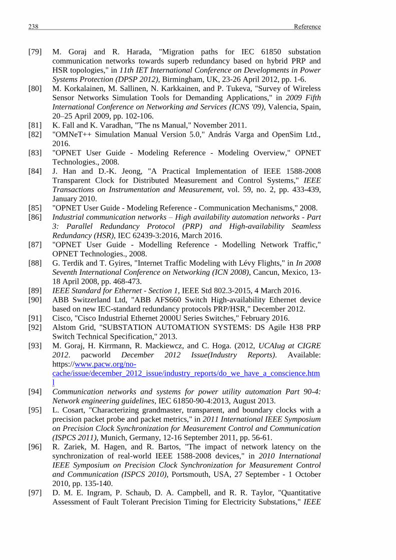
238 Reference
[79] M. Goraj and R. Harada, "Migration paths for IEC 61850 substation
communication networks towards superb redundancy based on hybrid PRP and
HSR topologies," in 11th IET International Conference on Developments in Power
Systems Protection (DPSP 2012), Birmingham, UK, 23-26 April 2012, pp. 1-6.
[80] M. Korkalainen, M. Sallinen, N. Karkkainen, and P. Tukeva, "Survey of Wireless
Sensor Networks Simulation Tools for Demanding Applications," in 2009 Fifth
International Conference on Networking and Services (ICNS '09), Valencia, Spain,
20–25 April 2009, pp. 102-106.
[81] K. Fall and K. Varadhan, "The ns Manual," November 2011.
[82] "OMNeT++ Simulation Manual Version 5.0," András Varga and OpenSim Ltd.,
2016.
[83] "OPNET User Guide - Modeling Reference - Modeling Overview," OPNET
Technologies., 2008.
[84] J. Han and D.-K. Jeong, "A Practical Implementation of IEEE 1588-2008
Transparent Clock for Distributed Measurement and Control Systems," IEEE
Transactions on Instrumentation and Measurement, vol. 59, no. 2, pp. 433-439,
January 2010.
[85] "OPNET User Guide - Modeling Reference - Communication Mechanisms," 2008.
[86] Industrial communication networks – High availability automation networks - Part
3: Parallel Redundancy Protocol (PRP) and High-availability Seamless
Redundancy (HSR), IEC 62439-3:2016, March 2016.
[87] "OPNET User Guide - Modelling Reference - Modelling Network Traffic,"
OPNET Technologies., 2008.
[88] G. Terdik and T. Gyires, "Internet Traffic Modeling with Lévy Flights," in In 2008
Seventh International Conference on Networking (ICN 2008), Cancun, Mexico, 13-
18 April 2008, pp. 468-473.
[89] IEEE Standard for Ethernet - Section 1, IEEE Std 802.3-2015, 4 March 2016.
[90] ABB Switzerland Ltd, "ABB AFS660 Switch High-availability Ethernet device
based on new IEC-standard redundancy protocols PRP/HSR," December 2012.
[91] Cisco, "Cisco Industrial Ethernet 2000U Series Switches," February 2016.
[92] Alstom Grid, "SUBSTATION AUTOMATION SYSTEMS: DS Agile H38 PRP
Switch Technical Specification," 2013.
[93] M. Goraj, H. Kirrmann, R. Mackiewcz, and C. Hoga. (2012, UCAIug at CIGRE
2012. pacworld December 2012 Issue(Industry Reports). Available:
https://www.pacw.org/no-
cache/issue/december_2012_issue/industry_reports/do_we_have_a_conscience.htm
l
[94] Communication networks and systems for power utility automation Part 90-4:
Network engineering guidelines, IEC 61850-90-4:2013, August 2013.
[95] L. Cosart, "Characterizing grandmaster, transparent, and boundary clocks with a
precision packet probe and packet metrics," in 2011 International IEEE Symposium
on Precision Clock Synchronization for Measurement Control and Communication
(ISPCS 2011), Munich, Germany, 12-16 September 2011, pp. 56-61.
[96] R. Zariek, M. Hagen, and R. Bartos, "The impact of network latency on the
synchronization of real-world IEEE 1588-2008 devices," in 2010 International
IEEE Symposium on Precision Clock Synchronization for Measurement Control
and Communication (ISPCS 2010), Portsmouth, USA, 27 September - 1 October
2010, pp. 135-140.
[97] D. M. E. Ingram, P. Schaub, D. A. Campbell, and R. R. Taylor, "Quantitative
Assessment of Fault Tolerant Precision Timing for Electricity Substations," IEEE
Reference 239
Transactions on Instrumentation and Measurement, vol. 62, no. 10, pp. 2694 -
2703, October 2013.
[98] R. Zarick, M. Hagen, and R. Bartoš, "Transparent Clocks vs. Enterprise Ethernet
switches," in 2011 International IEEE Symposium on Precision Clock
Synchronization for Measurement Control and Communication (ISPCS 2011),
Munich, Germany, 12-16 September 2011, pp. 62-68.
[99] Oregano Systems, "Visual Measurement System User Guide: syn1588® VMS User
Guide," 15 January 2015.
[100] Endace Technology Ltd., "DAG 7.5G4 Card User Guide," May 2012.
[101] Net Optics, "10/100/1000BaseT Tap," April 2009.
[102] Anritsu Corporation, "MD1230B Product Introduction," October 2013.
[103] Meinberg Radio Clocks GmbH & Co. KG, "MANUAL LANTIME
M600/MRS/PTP Multi Reference Source NTP Server with PTP Option," July
2014.
[104] Tekron International Ltd, "TCG 02-G USER MANUAL," December 2014.
[105] Alstom Grid, "PROTECTION PRODUCT SOLUTIONS: MiCOM Alstom P594
GPS synchronizing unit," 2013.
[106] Tekron International Ltd, "ISOLATED TIMING REPEATER COPPER, FIBER,
HV MOSFET."
[107] Tekron International Ltd, "TCG 01-G USER MANUAL," December 2014.
[108] Tekron International Ltd, "FULL FEATURED SATELLITE CLOCK TCG 02-G."
[109] Alstom Grid, "MiCOM ALSTOM P594 GPS Synchronizing Unit Technical
Manual," 2010.
[110] NR Electric Co. Ltd., "RCS-9785C/D GPS Synchronized Clock Instruction
Manual," 2011.
[111] L. Heng, T. Walter, P. Enge, and G. X. Gao, "GNSS Multipath and Jamming
Mitigation Using High-Mask-Angle Antennas and Multiple Constellations," IEEE
Transactions on Intelligent Transportation Systems, vol. 16, no. 2, pp. 741 - 750,
April 2015.
[112] Chronos Technology. (2013, July), GPS Antenna Installations Best Practice.
CTLan030 r1.1 [Online]. Available: http://www.chronos.co.uk/files/pdfs/cs-
an/GPS-Installation-Best-Practice.pdf
[113] NR Electric Co. Ltd., "PCS-221G Merging Unit Instruction Manual," 2012.
[114] Alstom Grid, "Technical Manual Current Differential Protection Relays," 2011.
[115] J. Burch, K. Green, J. Nakulski, and D. Vook, "Verifying the Performance of
Transparent Clocks in PTP Systems," in 2009 International IEEE Symposium on
Precision Clock Synchronization for Measurement, Control and Communication
(ISPCS 2009), Brescia, Italy, 12-16 October 2009, pp. 1-6.
[116] Hirschmann, "IEEE1588-2008: Precision Time Protocol Version 2."
[117] D. A. Barron and P. Holliday, "Implementation of IEC 61850 Process Bus. A
Utility View on Design, Installation, Testing and Commissioning, and Lifetime
Issues," in 10th IET International Conference on Developments in Power Systems
Protection (DPSP 2010), Manchester, UK, 29 March - 1 April, 2010, pp. 1-5.
[118] U. Anombem and H. Li, "EVALUATION OF IEC 61850 PROCESS BUS
ARCHITECTURE AND RELIABILITY Report No. 15 - AS3 STREAM 1
PROPOSED ARCHITECTURES AND THEIR APPLICATIONS," May 2010.
[119] V. Bobrovs, S. Spolitis, and G. Ivanovs, "Latency causes and reduction in optical
metro networks," in Optical Metro Networks and Short-Haul Systems VI, San
Diego, USA, 4-6 February 2014.
[120] Alstom Grid, "Reason MU320 Technical Manual " 2014.

240 Reference
[121] IEEE Standard for Synchrophasors for Power Systems, IEEE Std 1344-
1995(R2001), 17 March 2001.
[122] R. Hunt and B. Popescu, "Comparison of PRP and HSR Networks for Protection
and Control Applications," presented at the Western Protective Relay Conference,
Spokane, USA, 20-22 October 2015.
Appendix A: Comparison between IEEE 1588 Default Profile and Power Profile 241
Appendix A: Comparison between IEEE 1588 Default Profile and Power Profile
A.1 Difference between Peer Delay Request-Response Default PTP Profile and Power Profile
A.2 Reference
[A1] IEEE PES PSRC Working Group H7/Sub C7 Members and Guests, "Standard
Profile for Use of IEEE Std 1588-2008 Precision Time Protocol (PTP) in Power
System Applications," in 2012 International IEEE Symposium on Precision Clock
Synchronization for Measurement Control and Communication (ISPCS), San
Francisco, USA, 24-28 September 2012, pp. 1-6.

242 Appendix A: Comparison between IEEE 1588 Default Profile and Power Profile
Appendix B: Benefits and Drawbacks of Different Implementations of Time Dissemination System 243
Appendix B: Benefits and Drawbacks of Different Implementations of Time Dissemination System
The benefits and drawbacks for each implementation of time dissemination system are
described in this session.
= advantage
= disadvantage
= no obvious advantage or disadvantage
B.1 Quality of GPS Antennas and Receivers and Amount of Installation Work
(i) Centralized approach with 1-PPS / IRIG-B: High Quality of GPS Antennas
and Receivers with Small Amount of Installation Work - only a few sets of GPS
Antennas and Receivers are used to cover the whole substation. Hence, high quality
GPS Antennas and Receivers with anti-jamming features can be used considering the
total cost. High quality GPS Antennas and Receivers mean that the GPS multipath
error (due to extreme weather or reflection object near the GPS Antennas) and GPS
interference (caused by Solar Flare, GPS Jammers and Spoofing) can be better
distinguished and rejected. Therefore, the GPS signal can be better received and
decoded, providing more accurate time reference. Furthermore, high quality GPS
Antennas and Receivers would better maintain the timing output during loss of GPS
synchronization and upon GPS synchronization restoration. National Grid reported
that a number relay mal-operations were caused by corrupted GPS output when GPS
Receivers re-synced to the satellites after GPS signal loss, power loss or poor GPS
signal [B1]. The installation work is also greatly reduced due to the small number of
GPS Antennas and Receivers to be installed.
(ii) Centralized approach with 1588: High Quality of GPS Antennas and
Receivers with Small Amount of Installation Work – reasons as given for (i)
Centralized approach with 1-PPS / IRIG-B
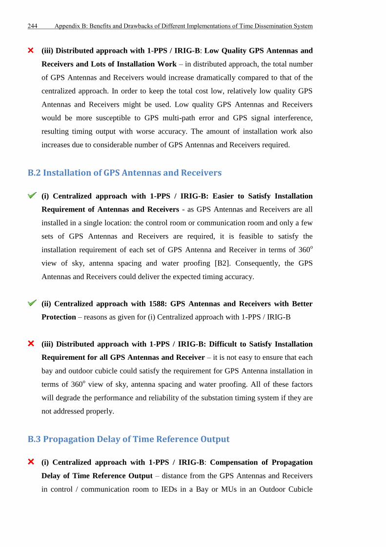
244 Appendix B: Benefits and Drawbacks of Different Implementations of Time Dissemination System
(iii) Distributed approach with 1-PPS / IRIG-B: Low Quality GPS Antennas and
Receivers and Lots of Installation Work – in distributed approach, the total number
of GPS Antennas and Receivers would increase dramatically compared to that of the
centralized approach. In order to keep the total cost low, relatively low quality GPS
Antennas and Receivers might be used. Low quality GPS Antennas and Receivers
would be more susceptible to GPS multi-path error and GPS signal interference,
resulting timing output with worse accuracy. The amount of installation work also
increases due to considerable number of GPS Antennas and Receivers required.
B.2 Installation of GPS Antennas and Receivers
(i) Centralized approach with 1-PPS / IRIG-B: Easier to Satisfy Installation
Requirement of Antennas and Receivers - as GPS Antennas and Receivers are all
installed in a single location: the control room or communication room and only a few
sets of GPS Antennas and Receivers are required, it is feasible to satisfy the
installation requirement of each set of GPS Antenna and Receiver in terms of 360o
view of sky, antenna spacing and water proofing [B2]. Consequently, the GPS
Antennas and Receivers could deliver the expected timing accuracy.
(ii) Centralized approach with 1588: GPS Antennas and Receivers with Better
Protection – reasons as given for (i) Centralized approach with 1-PPS / IRIG-B
(iii) Distributed approach with 1-PPS / IRIG-B: Difficult to Satisfy Installation
Requirement for all GPS Antennas and Receiver – it is not easy to ensure that each
bay and outdoor cubicle could satisfy the requirement for GPS Antenna installation in
terms of 360o view of sky, antenna spacing and water proofing. All of these factors
will degrade the performance and reliability of the substation timing system if they are
not addressed properly.
B.3 Propagation Delay of Time Reference Output
(i) Centralized approach with 1-PPS / IRIG-B: Compensation of Propagation
Delay of Time Reference Output – distance from the GPS Antennas and Receivers
in control / communication room to IEDs in a Bay or MUs in an Outdoor Cubicle
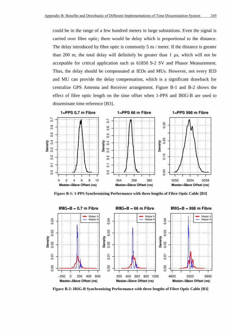
Appendix B: Benefits and Drawbacks of Different Implementations of Time Dissemination System 245
could be in the range of a few hundred meters in large substations. Even the signal is
carried over fibre optic; there would be delay which is proportional to the distance.
The delay introduced by fibre optic is commonly 5 ns / meter. If the distance is greater
than 200 m, the total delay will definitely be greater than 1 µs, which will not be
acceptable for critical application such as 61850 9-2 SV and Phasor Measurement.
Thus, the delay should be compensated at IEDs and MUs. However, not every IED
and MU can provide the delay compensation, which is a significant drawback for
centralize GPS Antenna and Receiver arrangement. Figure B-1 and B-2 shows the
effect of fibre optic length on the time offset when 1-PPS and IRIG-B are used to
disseminate time reference [B3].
Figure B-1: 1-PPS Synchronizing Performance with three lengths of Fibre Optic Cable [B3]
Figure B-2: IRIG-B Synchronizing Performance with three lengths of Fibre Optic Cable [B3]
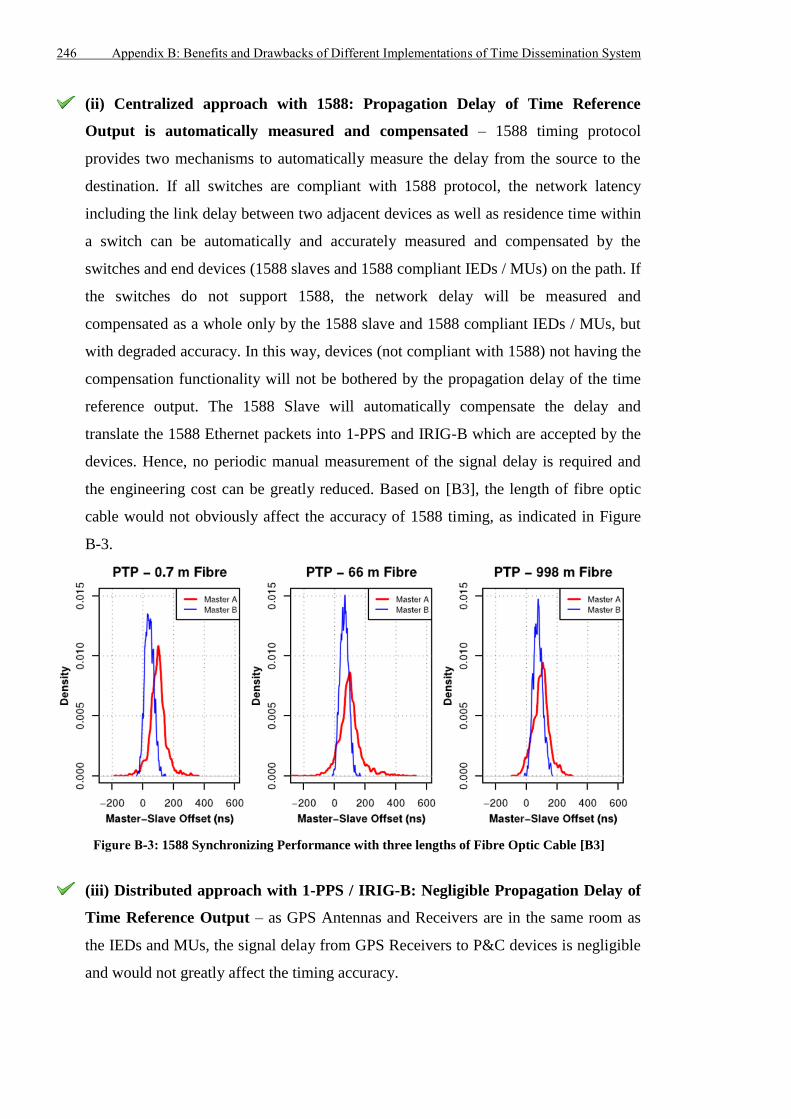
246 Appendix B: Benefits and Drawbacks of Different Implementations of Time Dissemination System
(ii) Centralized approach with 1588: Propagation Delay of Time Reference
Output is automatically measured and compensated – 1588 timing protocol
provides two mechanisms to automatically measure the delay from the source to the
destination. If all switches are compliant with 1588 protocol, the network latency
including the link delay between two adjacent devices as well as residence time within
a switch can be automatically and accurately measured and compensated by the
switches and end devices (1588 slaves and 1588 compliant IEDs / MUs) on the path. If
the switches do not support 1588, the network delay will be measured and
compensated as a whole only by the 1588 slave and 1588 compliant IEDs / MUs, but
with degraded accuracy. In this way, devices (not compliant with 1588) not having the
compensation functionality will not be bothered by the propagation delay of the time
reference output. The 1588 Slave will automatically compensate the delay and
translate the 1588 Ethernet packets into 1-PPS and IRIG-B which are accepted by the
devices. Hence, no periodic manual measurement of the signal delay is required and
the engineering cost can be greatly reduced. Based on [B3], the length of fibre optic
cable would not obviously affect the accuracy of 1588 timing, as indicated in Figure
B-3.
Figure B-3: 1588 Synchronizing Performance with three lengths of Fibre Optic Cable [B3]
(iii) Distributed approach with 1-PPS / IRIG-B: Negligible Propagation Delay of
Time Reference Output – as GPS Antennas and Receivers are in the same room as
the IEDs and MUs, the signal delay from GPS Receivers to P&C devices is negligible
and would not greatly affect the timing accuracy.
Appendix B: Benefits and Drawbacks of Different Implementations of Time Dissemination System 247
B.4 Measurement of Signal Delay
(i) Centralized approach with 1-PPS / IRIG-B: Manual Measurement of Signal
Delay – if one assumes the IEDs and MUs requiring GPS timing reference could
compensate the delay introduced by the long fibre optic, periodic measurement of
delay is inevitable to obtain accurate and reliable compensation. In general, the
measurement would be conducted manually and this might require outage of
protection and control devices, which will increase the cost for engineering and
maintenance.
(ii) Centralized approach with 1588: No Manual Measurement of Signal Delay –
since the 1588 compliant devices on the path could automatically measure the
propagation delay of the time information, no manual measurement for signal delay is
required.
(iii) Distributed approach with 1-PPS / IRIG-B: Optional Manual Measurement
of Signal Delay – as the propagation delay of time reference output is negligible,
manual measurement of the signal delay is not necessary. However, if very high
timing accuracy is required, manual measurement of signal delay should be carried out.
B.5 Time Distribution Network and Number of Output Modules on GPS Receivers
(i) Centralized approach with 1-PPS / IRIG-B: Dedicated Large Scale Time
Distribution Network Cabling and Lots of Output Modules on GPS Receivers - in
order to transmit 1-PPS and IRIG-B signal from the control / communication room to
bays and outdoor cubicles, separately dedicated fibre optic network in addition to the
data network has to be constructed. Furthermore, dozens of 1-PPS / IRIG-B modules
have to be installed on the GPS Receivers to accommodate the large number of
devices requesting the time reference as shown in Figure B-4.
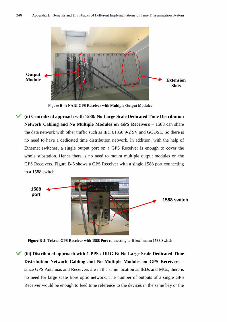
248 Appendix B: Benefits and Drawbacks of Different Implementations of Time Dissemination System
Figure B-4: NARI GPS Receiver with Multiple Output Modules
(ii) Centralized approach with 1588: No Large Scale Dedicated Time Distribution
Network Cabling and No Multiple Modules on GPS Receivers – 1588 can share
the data network with other traffic such as IEC 61850 9-2 SV and GOOSE. So there is
no need to have a dedicated time distribution network. In addition, with the help of
Ethernet switches, a single output port on a GPS Receiver is enough to cover the
whole substation. Hence there is no need to mount multiple output modules on the
GPS Receivers. Figure B-5 shows a GPS Receiver with a single 1588 port connecting
to a 1588 switch.
Figure B-5: Tekron GPS Receiver with 1588 Port connecting to Hirschmann 1588 Switch
(iii) Distributed approach with 1-PPS / IRIG-B: No Large Scale Dedicated Time
Distribution Network Cabling and No Multiple Modules on GPS Receivers –
since GPS Antennas and Receivers are in the same location as IEDs and MUs, there is
no need for large scale fibre optic network. The number of outputs of a single GPS
Receiver would be enough to feed time reference to the devices in the same bay or the
Extension
Slots
Output
Module
1588 switch
1588 port
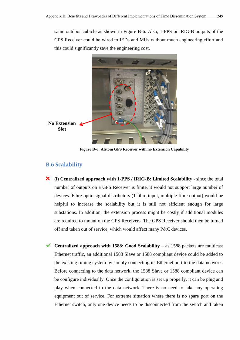
Appendix B: Benefits and Drawbacks of Different Implementations of Time Dissemination System 249
same outdoor cubicle as shown in Figure B-6. Also, 1-PPS or IRIG-B outputs of the
GPS Receiver could be wired to IEDs and MUs without much engineering effort and
this could significantly save the engineering cost.
Figure B-6: Alstom GPS Receiver with no Extension Capability
B.6 Scalability
(i) Centralized approach with 1-PPS / IRIG-B: Limited Scalability - since the total
number of outputs on a GPS Receiver is finite, it would not support large number of
devices. Fibre optic signal distributors (1 fibre input, multiple fibre output) would be
helpful to increase the scalability but it is still not efficient enough for large
substations. In addition, the extension process might be costly if additional modules
are required to mount on the GPS Receivers. The GPS Receiver should then be turned
off and taken out of service, which would affect many P&C devices.
Centralized approach with 1588: Good Scalability – as 1588 packets are multicast
Ethernet traffic, an additional 1588 Slave or 1588 compliant device could be added to
the existing timing system by simply connecting its Ethernet port to the data network.
Before connecting to the data network, the 1588 Slave or 1588 compliant device can
be configure individually. Once the configuration is set up properly, it can be plug and
play when connected to the data network. There is no need to take any operating
equipment out of service. For extreme situation where there is no spare port on the
Ethernet switch, only one device needs to be disconnected from the switch and taken
No Extension
Slot
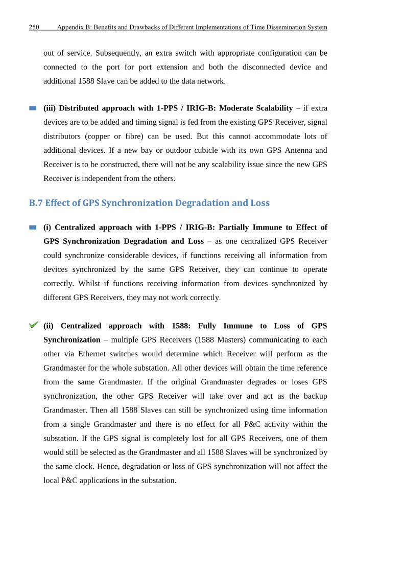
250 Appendix B: Benefits and Drawbacks of Different Implementations of Time Dissemination System
out of service. Subsequently, an extra switch with appropriate configuration can be
connected to the port for port extension and both the disconnected device and
additional 1588 Slave can be added to the data network.
(iii) Distributed approach with 1-PPS / IRIG-B: Moderate Scalability – if extra
devices are to be added and timing signal is fed from the existing GPS Receiver, signal
distributors (copper or fibre) can be used. But this cannot accommodate lots of
additional devices. If a new bay or outdoor cubicle with its own GPS Antenna and
Receiver is to be constructed, there will not be any scalability issue since the new GPS
Receiver is independent from the others.
B.7 Effect of GPS Synchronization Degradation and Loss
(i) Centralized approach with 1-PPS / IRIG-B: Partially Immune to Effect of
GPS Synchronization Degradation and Loss – as one centralized GPS Receiver
could synchronize considerable devices, if functions receiving all information from
devices synchronized by the same GPS Receiver, they can continue to operate
correctly. Whilst if functions receiving information from devices synchronized by
different GPS Receivers, they may not work correctly.
(ii) Centralized approach with 1588: Fully Immune to Loss of GPS
Synchronization – multiple GPS Receivers (1588 Masters) communicating to each
other via Ethernet switches would determine which Receiver will perform as the
Grandmaster for the whole substation. All other devices will obtain the time reference
from the same Grandmaster. If the original Grandmaster degrades or loses GPS
synchronization, the other GPS Receiver will take over and act as the backup
Grandmaster. Then all 1588 Slaves can still be synchronized using time information
from a single Grandmaster and there is no effect for all P&C activity within the
substation. If the GPS signal is completely lost for all GPS Receivers, one of them
would still be selected as the Grandmaster and all 1588 Slaves will be synchronized by
the same clock. Hence, degradation or loss of GPS synchronization will not affect the
local P&C applications in the substation.
Appendix B: Benefits and Drawbacks of Different Implementations of Time Dissemination System 251
(iii) Distributed approach with 1-PPS / IRIG-B: Significant Effect of GPS
Synchronization Degrade and Loss – only functions receiving information from
devices synchronized by the same GPS Receivers can continue to work. Such devices
will be those in the same bay or outdoor cubicle. However, many P&C applications
require data from devices in different bays and different outdoor cubicles. Hence, even
if there is only one GPS Receiver experiencing GPS synchronization degradation or
losing the synchronization signal, it would be disastrous for the P&C system.
B.8 Requirement of Specialized Ethernet Switches and Time Code Translators
(i) Centralized approach with 1-PPS / IRIG-B: Conventional Industrial Ethernet
Switches can be used and No Specialized Time Code Translators – as the time
reference is not transmitted over the data network, conventional industrial Ethernet
switches that are suitable for substation could be used. In addition, as most of P&C
devices natively support 1-PPS / IRIG-B, the time reference output could be directly
fed to P&C devices from GPS Receivers, without any time code translators.
(ii) Centralized approach with 1588: 1588 Compliant Switches Required for
Accurate Timing and 1588 to 1-PPS / IRIG-B Converter (for Non-1588 End
Devices) – Ethernet switches supporting 1588 technique are ideal if timing accuracy
better than a few hundred nanoseconds is required. Because the 1588 compliant
switches can measure and compensate the link delay between themselves and their
neighbour 1588 devices as well as the residence time of 1588 packets within
themselves, any factors (e.g. path change due to communication failure, variable
network traffic load) that will introduce unpredicted delay to 1588 packets will not
affect the performance of 1588. On the contrary, if non-1588 switches are used, the
delay of 1588 packets cannot be precisely measured and compensated, which would
affect the output of 1588 Slaves and lead to degraded timing accuracy. As a result, the
existing Ethernet switches for data exchange should be upgraded to support 1588
timing or replaced with 1588 compliant switches. This will significantly increase the
capital cost for equipment. For 1588 compliant end devices, they would perform as
1588 Slaves: accept and transmit 1588 packets to accurately compensate the delay of
1588 packets. Subsequently, these end devices will adjust their internal clocks. If end
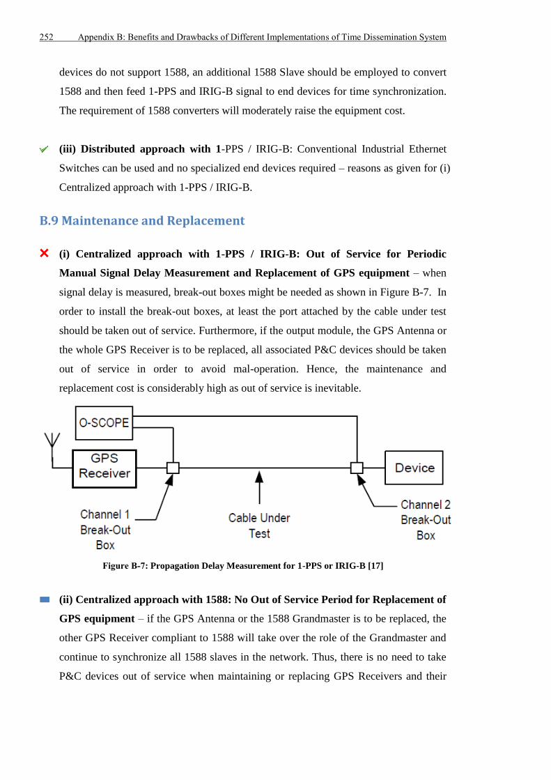
252 Appendix B: Benefits and Drawbacks of Different Implementations of Time Dissemination System
devices do not support 1588, an additional 1588 Slave should be employed to convert
1588 and then feed 1-PPS and IRIG-B signal to end devices for time synchronization.
The requirement of 1588 converters will moderately raise the equipment cost.
(iii) Distributed approach with 1-PPS / IRIG-B: Conventional Industrial Ethernet
Switches can be used and no specialized end devices required – reasons as given for (i)
Centralized approach with 1-PPS / IRIG-B.
B.9 Maintenance and Replacement
(i) Centralized approach with 1-PPS / IRIG-B: Out of Service for Periodic
Manual Signal Delay Measurement and Replacement of GPS equipment – when
signal delay is measured, break-out boxes might be needed as shown in Figure B-7. In
order to install the break-out boxes, at least the port attached by the cable under test
should be taken out of service. Furthermore, if the output module, the GPS Antenna or
the whole GPS Receiver is to be replaced, all associated P&C devices should be taken
out of service in order to avoid mal-operation. Hence, the maintenance and
replacement cost is considerably high as out of service is inevitable.
Figure B-7: Propagation Delay Measurement for 1-PPS or IRIG-B [17]
(ii) Centralized approach with 1588: No Out of Service Period for Replacement of
GPS equipment – if the GPS Antenna or the 1588 Grandmaster is to be replaced, the
other GPS Receiver compliant to 1588 will take over the role of the Grandmaster and
continue to synchronize all 1588 slaves in the network. Thus, there is no need to take
P&C devices out of service when maintaining or replacing GPS Receivers and their
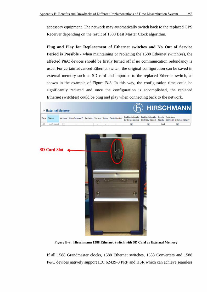
Appendix B: Benefits and Drawbacks of Different Implementations of Time Dissemination System 253
accessory equipment. The network may automatically switch back to the replaced GPS
Receiver depending on the result of 1588 Best Master Clock algorithm.
Plug and Play for Replacement of Ethernet switches and No Out of Service
Period is Possible - when maintaining or replacing the 1588 Ethernet switch(es), the
affected P&C devices should be firstly turned off if no communication redundancy is
used. For certain advanced Ethernet switch, the original configuration can be saved in
external memory such as SD card and imported to the replaced Ethernet switch, as
shown in the example of Figure B-8. In this way, the configuration time could be
significantly reduced and once the configuration is accomplished, the replaced
Ethernet switch(es) could be plug and play when connecting back to the network.
Figure B-8: Hirschmann 1588 Ethernet Switch with SD Card as External Memory
If all 1588 Grandmaster clocks, 1588 Ethernet switches, 1588 Converters and 1588
P&C devices natively support IEC 62439-3 PRP and HSR which can achieve seamless
SD Card Slot
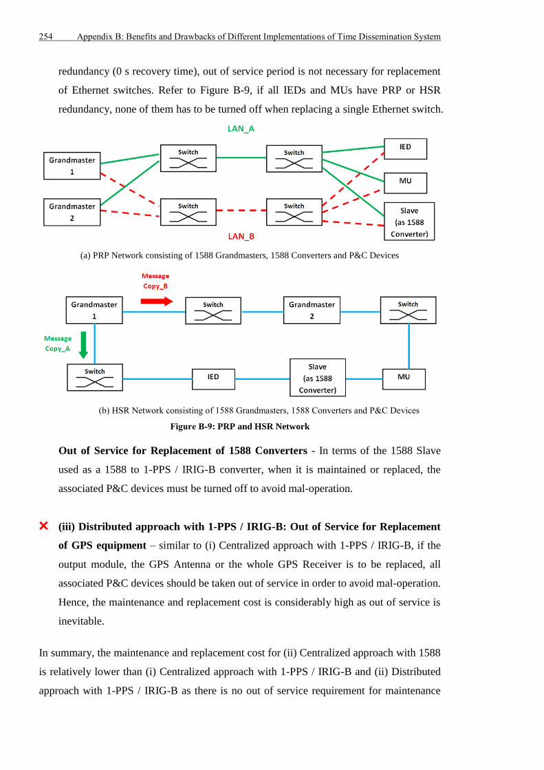
254 Appendix B: Benefits and Drawbacks of Different Implementations of Time Dissemination System
redundancy (0 s recovery time), out of service period is not necessary for replacement
of Ethernet switches. Refer to Figure B-9, if all IEDs and MUs have PRP or HSR
redundancy, none of them has to be turned off when replacing a single Ethernet switch.
(a) PRP Network consisting of 1588 Grandmasters, 1588 Converters and P&C Devices
(b) HSR Network consisting of 1588 Grandmasters, 1588 Converters and P&C Devices
Figure B-9: PRP and HSR Network
Out of Service for Replacement of 1588 Converters - In terms of the 1588 Slave
used as a 1588 to 1-PPS / IRIG-B converter, when it is maintained or replaced, the
associated P&C devices must be turned off to avoid mal-operation.
(iii) Distributed approach with 1-PPS / IRIG-B: Out of Service for Replacement
of GPS equipment – similar to (i) Centralized approach with 1-PPS / IRIG-B, if the
output module, the GPS Antenna or the whole GPS Receiver is to be replaced, all
associated P&C devices should be taken out of service in order to avoid mal-operation.
Hence, the maintenance and replacement cost is considerably high as out of service is
inevitable.
In summary, the maintenance and replacement cost for (ii) Centralized approach with 1588
is relatively lower than (i) Centralized approach with 1-PPS / IRIG-B and (ii) Distributed
approach with 1-PPS / IRIG-B as there is no out of service requirement for maintenance
Appendix B: Benefits and Drawbacks of Different Implementations of Time Dissemination System 255
and replacement of GPS Receivers and their accessory equipment and probably for
maintenance and replacement of Ethernet switch.
B.10 Reference
[B1] W. An, N. Tart, D. Barron, M. Bingham, and A. Hackett, "A transmission utility's
experience to date with feeder unit protection systems," in 11th IET International
Conference on Developments in Power Systems Protection (DPSP 2012),
Birmingham, UK, 23-26 April 2012, pp. 1-6.
[B2] Chronos Technology. (2013, July), GPS Antenna Installations Best Practice.
CTLan030 r1.1 [Online]. Available: http://www.chronos.co.uk/files/pdfs/cs-an/GPS-
Installation-Best-Practice.pdf
[B3] D. M. E. Ingram, P. Schaub, D. A. Campbell and R. R. Taylor, “Evaluation of
Precision Time Synchronization Methods for Substation Applications,” in 2012
International IEEE Symposium on Precision Clock Synchronization for
Measurement Control and Communication (ISPCS 2012), San Francisco, USA, 24–
28 September 2012, pp. 1-6.
[B4] K. Behrendt and K. Fodero, "The Perfect Time: An Examination of Time
Synchronization Techniques," SEL Inc., TP6226-01, September 2005.


