Embed Size (px)
Citation preview
BA_PA308Operating Manual
05.08
Type PA308Digital Indicator

Please read this operating manual before commissioningthe instrument. Keep the manual in a place accessible to allusers at all times. Your comments are appreciated and mayassist us in improving this manual.
All necessary settings are described in this operatingmanual. Manipulations not described in the manual orexpressly forbidden will jeopardise your warranty rights.Please contact the nearest subsidiary or the head office,should you encounter problems.
When accessing the inner parts of the unit and returningmodules, assemblies or components, please observe theregulations according to EN 61340-5-1 and EN 61340-5-2„Protection of electrostatic sensitive devices“. Only useESD packaging for transport.
Please note that we cannot accept any liability for damagecaused by ESD.
ESD=Electro Static Discharge
E
Postal address:: House address Fon (+49) 0 22 42-8703-0Postbox 1261 Löhestr. 37 Fax (+49) 0 22 42-8703-20
http: // www.tematec.de53759 Hennef 53773 Hennef e-mail: [email protected]
TEMATEC GmbH
Content
1 Introduction 7
1.1 Description ............................................................... 7
1.2 Typographical conventions ..................................... 9
2 Identifying the instrument version 11
2.1 Type designation .................................................... 11
2.2 Scope of delivery ................................................... 13
2.3 Accessories ............................................................ 13
3 Mounting 15
3.1 Mounting site and climatic conditions ................ 15
3.2 Dimensions ............................................................ 15
3.3 Fitting in position ................................................... 15
3.4 Removing the plug-in module .............................. 16
4 Electrical connection 17
4.1 Installation notes ................................................... 17
4.2 Electrical isolation ................................................. 19
4.3 Connection diagram .............................................. 20
4.4 Termination resistor for the RS422/485 interface 25
4.5 Connection of the PROFIBUS-DP connector ..... 26
Content
5 Operation 27
5.1 Displays and controls ............................................ 27
5.2 Level concept ......................................................... 28
5.3 Level inhibit ............................................................ 29
5.4 Entries and operator prompting ........................... 30
6 Operator level 31
7 Configuration 33
7.1 Analog inputs „INPUT“ .......................................... 35
7.2 Limit comparators „LIMITCOM“ .......................... 41
7.3 Outputs „OUTPUT“ ................................................ 48
7.4 Binary functions „BINFUNCT“ .............................. 51
7.5 Display / Operation „DISPLAY“ ............................ 53
7.6 Interfaces „INTERFCE“ ......................................... 57
8 Extra codes 59
8.1 Math and logic module ......................................... 59
8.2 Difference, humidity or ratio calculation ............. 60
Content
9 Retrofitting of modules 61
10 Appendix 63
10.1 Technical data ........................................................ 63
10.2 Alarm messages .................................................... 68
11 Index 69

Content
7
1 Introduction
1.1 Description
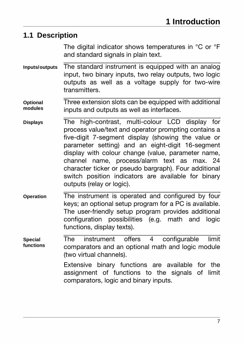
The digital indicator shows temperatures in °C or °Fand standard signals in plain text.
Inputs/outputs The standard instrument is equipped with an analoginput, two binary inputs, two relay outputs, two logicoutputs as well as a voltage supply for two-wiretransmitters.
Optionalmodules
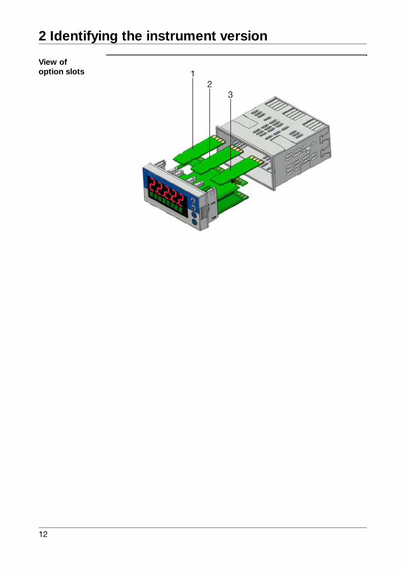
Three extension slots can be equipped with additionalinputs and outputs as well as interfaces.
Displays The high-contrast, multi-colour LCD display forprocess value/text and operator prompting contains afive-digit 7-segment display (showing the value orparameter setting) and an eight-digit 16-segmentdisplay with colour change (value, parameter name,channel name, process/alarm text as max. 24character ticker or pseudo bargraph). Four additionalswitch position indicators are available for binaryoutputs (relay or logic).
Operation The instrument is operated and configured by fourkeys; an optional setup program for a PC is available.The user-friendly setup program provides additionalconfiguration possibilities (e.g. math and logicfunctions, display texts).
Special functions
The instrument offers 4 configurable limitcomparators and an optional math and logic module(two virtual channels).
Extensive binary functions are available for theassignment of functions to the signals of limitcomparators, logic and binary inputs.
1 Introduction
8
Special functions(continued)
The computation results of both math functions canbe used for the different analog parameters (e.g. asvalue shown in the display).
Instruments with a second (optional) analog inputallow the computation of differential, humidity or ratiocomputations by means of default formulas.
Probes 10 types of probes (resistance thermometer,thermocouple, resistance transmitter, standardsignals) and more than 20 linearisations are availablefor analog input configuration. Customer-specificlinearisation with 10 interpolation points or by theentry of the polynomial coefficients is possible.
Interface and electricalconnection
An optional interface (RS422/485 or PROFIBUS-DP)can be used for integration of the instrument in a datanetwork.
The electrical connection is made at the back of theinstrument by means of screw terminals.
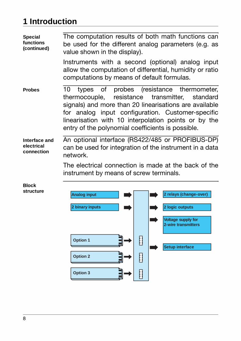
Blockstructure
Analog input
Option 1
Option 2
2 binary inputs
2 relays (change-over)
2 logic outputs
Voltage supply for2-wire transmitters
Option 3
Setup interface
9
1 Introduction
1.2 Typographical conventions
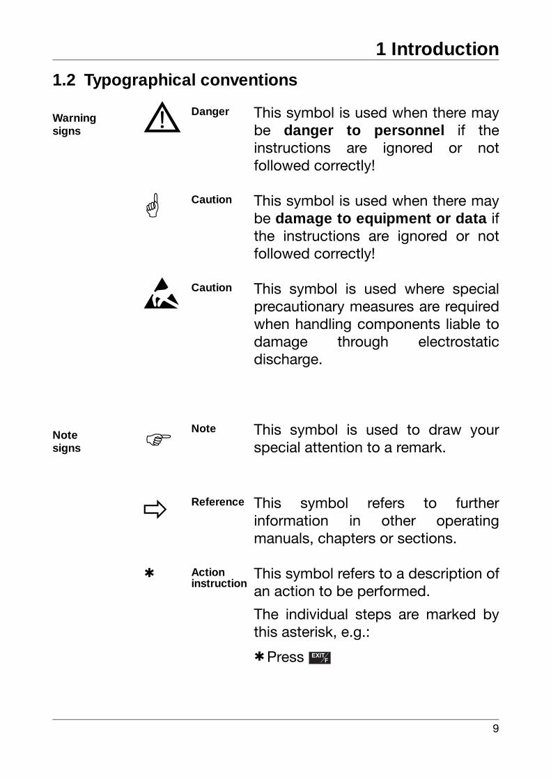
Warning signs V Danger This symbol is used when there may
be danger to personnel if theinstructions are ignored or notfollowed correctly!
Caution This symbol is used when there maybe damage to equipment or data ifthe instructions are ignored or notfollowed correctly!
E Caution This symbol is used where specialprecautionary measures are requiredwhen handling components liable todamage through electrostaticdischarge.
Notesigns H Note This symbol is used to draw your
special attention to a remark.
v Reference This symbol refers to furtherinformation in other operatingmanuals, chapters or sections.
h Actioninstruction
This symbol refers to a description ofan action to be performed.
The individual steps are marked bythis asterisk, e.g.:
hPress EXITF
EXITF

1 Introduction
10
Representa-tion
Menu items Text referring to the setup program isshown in italics, for example:„Display/Operation“.
Blinkingdisplay SE NSOR
11
2 Identifying the instrument version
2.1 Type designation
(1) Basic type
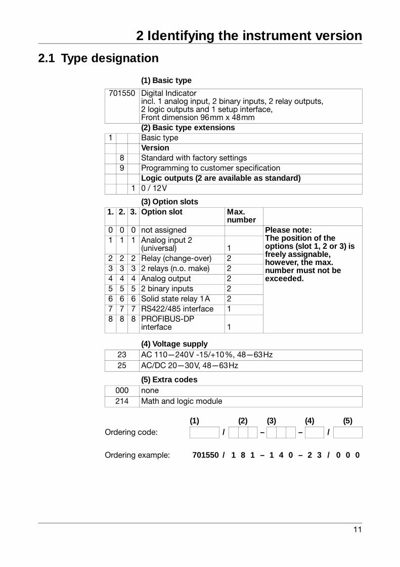
701550 Digital Indicatorincl. 1 analog input, 2 binary inputs, 2 relay outputs, 2 logic outputs and 1 setup interface,Front dimension 96mm x 48mm(2) Basic type extensions
1 Basic typeVersion
8 Standard with factory settings9 Programming to customer specification
Logic outputs (2 are available as standard)1 0 / 12V
(3) Option slots1. 2. 3. Option slot Max.
number0 0 0 not assigned Please note:
The position of the options (slot 1, 2 or 3) is freely assignable, however, the max. number must not be exceeded.
1 1 1 Analog input 2(universal) 1
2 2 2 Relay (change-over) 23 3 3 2 relays (n.o. make) 24 4 4 Analog output 25 5 5 2 binary inputs 26 6 6 Solid state relay 1A 27 7 7 RS422/485 interface 18 8 8 PROFIBUS-DP
interface 1
(4) Voltage supply23 AC 110—240V -15/+10%, 48—63Hz25 AC/DC 20—30V, 48—63Hz
(5) Extra codes000 none214 Math and logic module
(1) (2) (3) (4) (5)Ordering code: / – – /
Ordering example: 701550 / 1 8 1 – 1 4 0 – 2 3 / 0 0 0
2 Identifying the instrument version
12
View ofoption slots
32
1
13
2 Identifying the instrument version
2.2 Scope of delivery- Display instrument
- Seal
- Mounting brackets
- Operating Manual B70.1550.0 in DIN A6 format
2.3 Accessories
Mini-CD Mini-CD with demo setup program and PDFdocuments (operating manual and furtherdocumentation)
PC interface PC interface with TTL/RS232 converter and adapter(socket connector) for setup program
USB interface PC interface with USB/TTL converter, adapter (socketconnector) and adapter (pins)
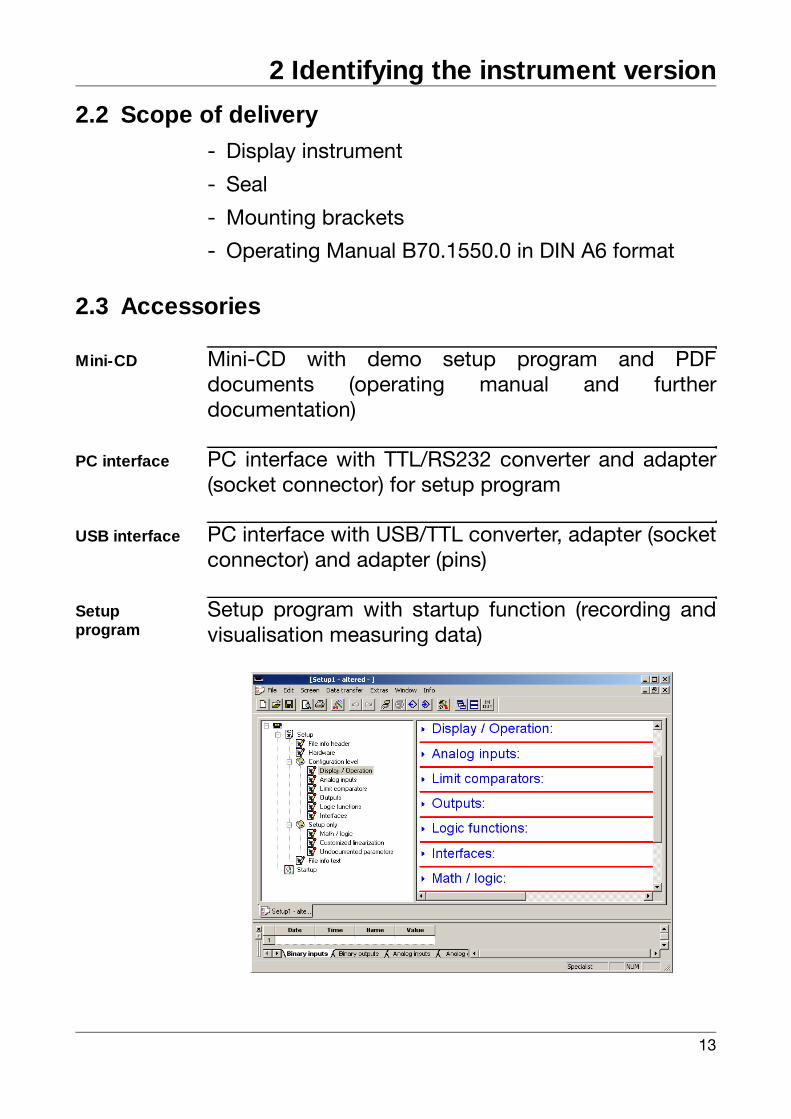
Setupprogram
Setup program with startup function (recording andvisualisation measuring data)
2 Identifying the instrument version
14
Setupprogram(continued)
Required hardware:
- PC Pentium 100 or compatible
- 128MB RAM, 30MB free fixed disk memory
- CD ROM drive
- free serial or USB interface
Required software:
Microsoft1 Windows 98/NT4.0/ME/2000/XP
1. Microsoft is a registered trademark of Microsoft Corporation
15
3 Mounting
3.1 Mounting site and climatic conditions
The conditions at the mounting site must meet therequirements specified in the technical data. Theambient temperature at the mounting site can rangefrom 0...55°C with a maximum relative humidity of≤ 90%.
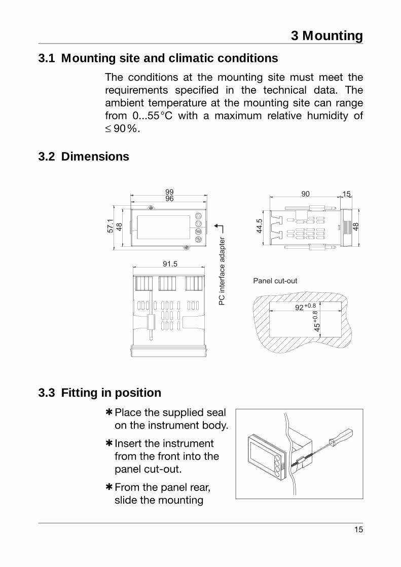
3.2 Dimensions
3.3 Fitting in position
hPlace the supplied seal on the instrument body.
h Insert the instrument from the front into the panel cut-out.
hFrom the panel rear, slide the mounting
57.1
9699
48
44.5
92+0.8
45
+0.8
15
48
90
91.5
PC
inte
rface
adapte
r
Panel cut-out
3 Mounting
16
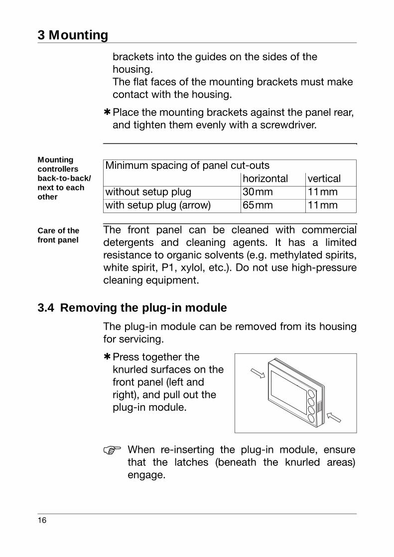
brackets into the guides on the sides of the housing.The flat faces of the mounting brackets must make contact with the housing.
hPlace the mounting brackets against the panel rear, and tighten them evenly with a screwdriver.
Mountingcontrollers back-to-back/next to each other
Care of the front panel
The front panel can be cleaned with commercialdetergents and cleaning agents. It has a limitedresistance to organic solvents (e.g. methylated spirits,white spirit, P1, xylol, etc.). Do not use high-pressurecleaning equipment.
3.4 Removing the plug-in module
The plug-in module can be removed from its housingfor servicing.
hPress together the knurled surfaces on the front panel (left and right), and pull out the plug-in module.
Minimum spacing of panel cut-outshorizontal vertical
without setup plug 30mm 11mmwith setup plug (arrow) 65mm 11mm
H When re-inserting the plug-in module, ensurethat the latches (beneath the knurled areas)engage.
17
4 Electrical connection
4.1 Installation notes
- The choice of cable, the installation and the electrical connection of the instrument must conform to the requirements of VDE 0100 "Regulations on the Installation of Power Circuits with Nominal Voltages below 1000V" or the appropriate local regulations.
- The electrical connection must only be carried out by qualified personnel.
- If contact with live parts is possible while working on the unit, it must be disconnected from the supply at both poles.
- The load circuit must be fused for the maximum relay current, in order to prevent the output relay contacts becoming welded in the event of a short circuit occurring at that point.
- Electromagnetic compatibility conforms to the standards and regulations cited in the technical data.
vChapter 10.1 „Technical data“
- Run input, output and supply cables separately and not parallel to one another.
- Sensor and interface cables should be shielded cables with twisted conductors. Do not run cables close to current-carrying components or cables. Ground the shielding on one side.
- Do not connect any additional loads to the supply terminals of the instrument.

4 Electrical connection
18
- The instrument is not suitable for use in areas with an explosion hazard (Ex areas).
Installation information on conductor cross sections and core ferrules
Minimumcross-section
Maximumcross-section
Min.length of core-end ferrule
Without core-end ferrule 0.34mm2 2.5mm2 10mm(stripped)
Core-end ferrule without lip 0.25mm2 2.5mm2 10mm
Core end ferrule with lip up to 1.5mm2
0.25mm2 1.5mm2 10mm
Core end ferrule with lip above 1.5mm2
1.5mm2 2.5mm2 12mm
Twin ferrule with lip 0.25mm2 1.5mm2 12mm
.
VOnly allow qualified personnel tocarry out the electrical connection.
H Identify the instrument version bymeans of the type code.
19
4 Electrical connection
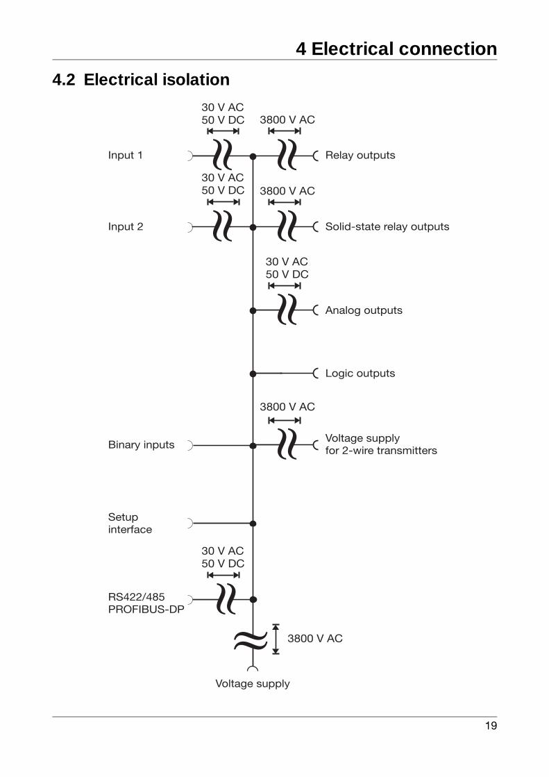
4.2 Electrical isolation
»
3800 V AC
»
»
30 V AC50 V DC
30 V AC50 V DC
»
3800 V AC
»
3800 V AC
»30 V AC50 V DC
Input 1
»
Relay outputs
Input 2 Solid-state relay outputs
Analog outputs
Logic outputs
Voltage supplyfor 2-wire transmittersBinary inputs
Setupinterface
RS422/485PROFIBUS-DP
Voltage supply
3800 V AC
»
30 V AC50 V DC
4 Electrical connection
20
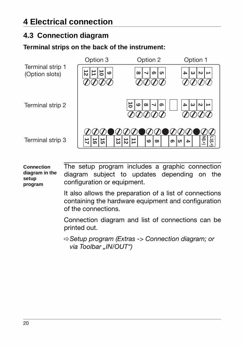
4.3 Connection diagram
Terminal strips on the back of the instrument:
Connection diagram in the setupprogram
The setup program includes a graphic connectiondiagram subject to updates depending on theconfiguration or equipment.
It also allows the preparation of a list of connectionscontaining the hardware equipment and configurationof the connections.
Connection diagram and list of connections can beprinted out.
vSetup program (Extras -> Connection diagram; or via Toolbar „IN/OUT“)
1234
1234
5678
678910
9101112
4 L1(L+)
5689111213151617
N(L+)
Option 1Option 2Option 3Terminal strip 1(Option slots)
Terminal strip 2
Terminal strip 3
21
4 Electrical connection
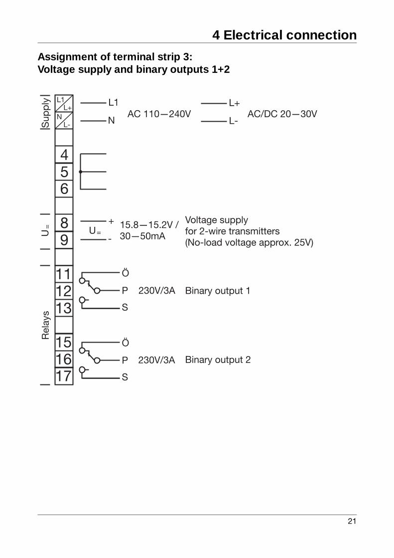
Assignment of terminal strip 3:Voltage supply and binary outputs 1+2
L1
N
L+
L-
456
8
AC 110—240V AC/DC 20—30V
Voltage supplyfor 2-wire transmitters(No-load voltage approx. 25V)
Sup
ply
9+
-U=
15.8—15.2V /30—50mAU
=
L1L+
NL-
230V/3A
Rel
ays
1211
13
151617
Ö
P
S
Ö
P
S
230V/3A Binary output 1
Binary output 2
4 Electrical connection
22
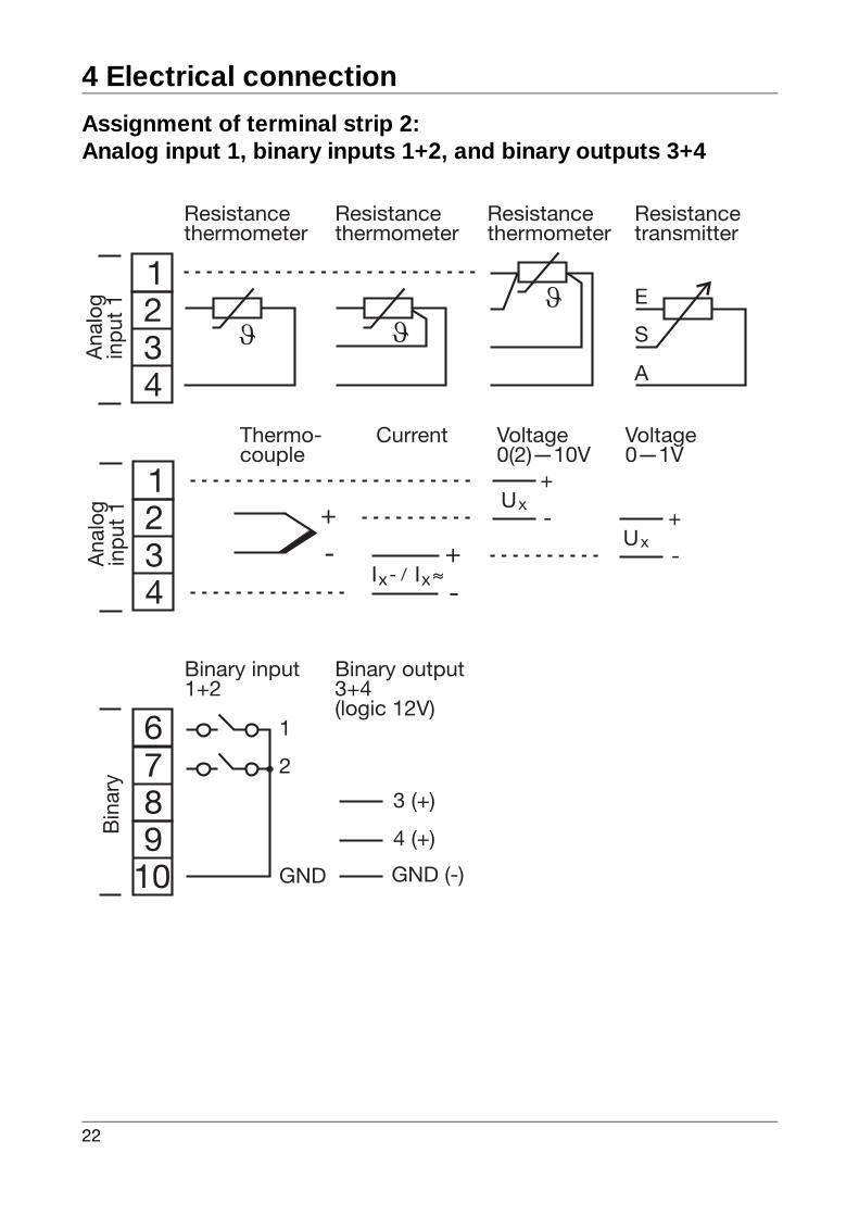
Assignment of terminal strip 2:Analog input 1, binary inputs 1+2, and binary outputs 3+4
12
43
678
E
S
A
Resistancethermometer
Resistancethermometer
Resistancethermometer
Resistancetransmitter
Binary input1+2
1
2
GND
Binary output3+4(logic 12V)
3 (+)
4 (+)
GND (-)
Ana
log
inpu
t 1B
inar
y
910
12
43A
nalo
gin
put 1
-
+
-
+IxIx- / ~~
Ux-
+
Ux-
+
Thermo-couple
Current Voltage0(2)—10V
Voltage0—1V
23
4 Electrical connection
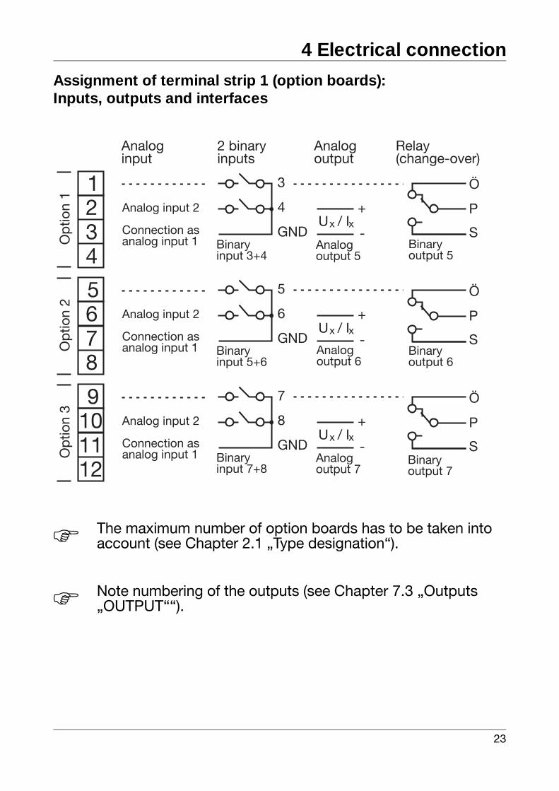
Assignment of terminal strip 1 (option boards):Inputs, outputs and interfaces
H The maximum number of option boards has to be taken into account (see Chapter 2.1 „Type designation“).
H Note numbering of the outputs (see Chapter 7.3 „Outputs „OUTPUT““).
12
43
Analoginput
2 binaryinputs
Analogoutput
Relay(change-over)
3
4
GND
+
-Ux
Ö
P
S
Analog input 2
Connection asanalog input 1 Binary
input 3+4Analogoutput 5
Binaryoutput 5
56
87
5
6
GND
+
-
Analog input 2
Connection asanalog input 1 Binary
input 5+6Analogoutput 6
Op
tion
1O
ptio
n 2
Ö
P
SBinaryoutput 6
910
1211
7
8
GND
+
-
Analog input 2
Connection asanalog input 1 Binary
input 7+8Analogoutput 7
Op
tion
3
Ö
P
SBinaryoutput 7
/ Ix
Ux / Ix
Ux / Ix
4 Electrical connection
24
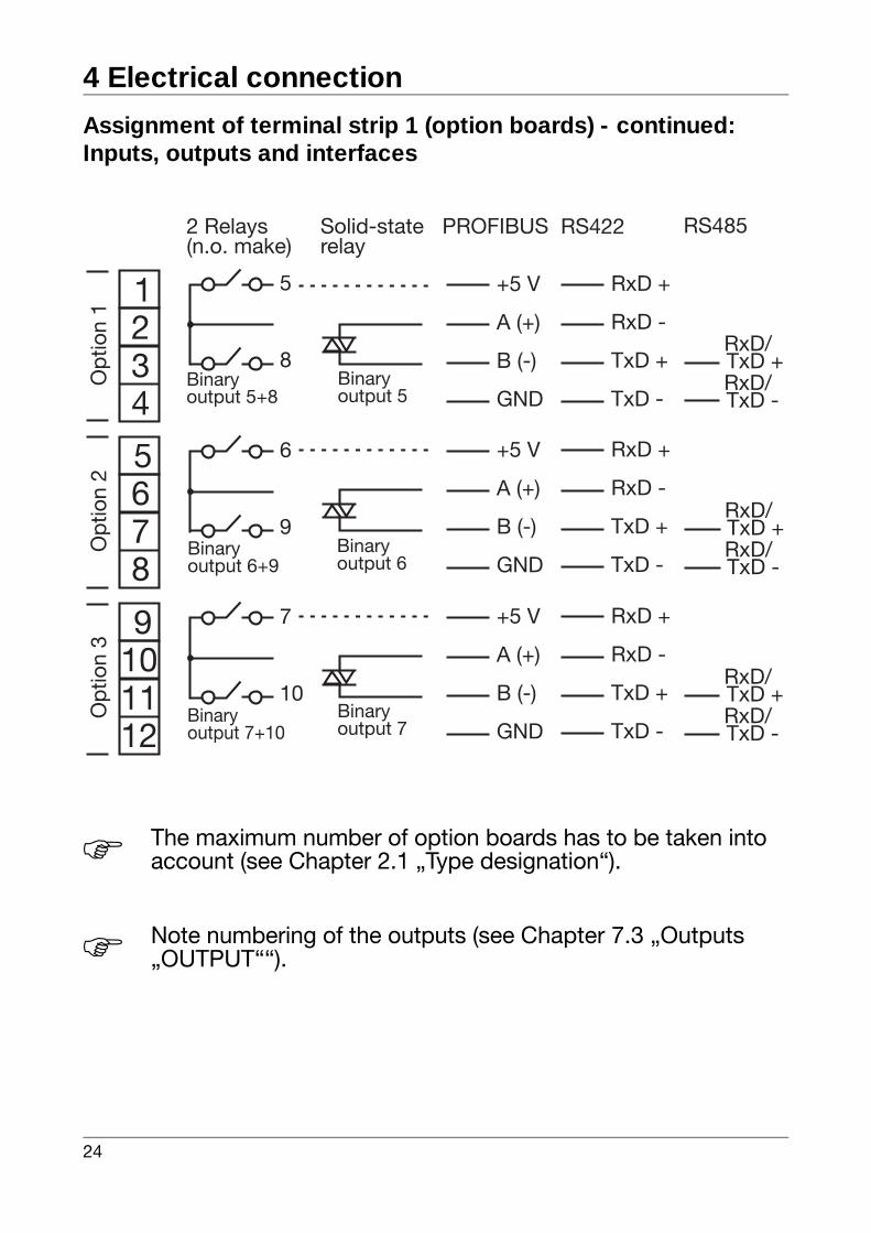
Assignment of terminal strip 1 (option boards) - continued:Inputs, outputs and interfaces
H The maximum number of option boards has to be taken into account (see Chapter 2.1 „Type designation“).
H Note numbering of the outputs (see Chapter 7.3 „Outputs „OUTPUT““).
12
43
2 Relays(n.o. make)
PROFIBUS RS422
5
8
+5 V
A (+)
B (-)
GND
RxD +
RxD -
TxD +
TxD -
RS485Solid-staterelay
Binaryoutput 5+8
Binaryoutput 5
56
87
+5 V
A (+)
B (-)
GND
RxD +
RxD -
TxD +
TxD -Binaryoutput 6
Op
tion
1O
ptio
n 2
6
9Binaryoutput 6+9
910
1211
+5 V
A (+)
B (-)
GND
RxD +
RxD -
TxD +
TxD -Binaryoutput 7
Op
tion
3
7
10Binaryoutput 7+10
RxD/TxD +RxD/TxD -
RxD/TxD +RxD/TxD -
RxD/TxD +RxD/TxD -
25
4 Electrical connection
4.4 Termination resistor for the RS422/485 interface
Settingresistors
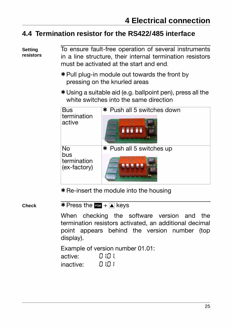
To ensure fault-free operation of several instrumentsin a line structure, their internal termination resistorsmust be activated at the start and end.
hPull plug-in module out towards the front by pressing on the knurled areas
hUsing a suitable aid (e.g. ballpoint pen), press all the white switches into the same direction
hRe-insert the module into the housing
Check hPress the P + i keys
When checking the software version and thetermination resistors activated, an additional decimalpoint appears behind the version number (topdisplay).
Example of version number 01.01:active: 01.01.
inactive: 01.01
Bustermination active
h Push all 5 switches down
Nobustermination(ex-factory)
h Push all 5 switches up
4 Electrical connection
26
4.5 Connection of the PROFIBUS-DP connector
Mounting theadapter
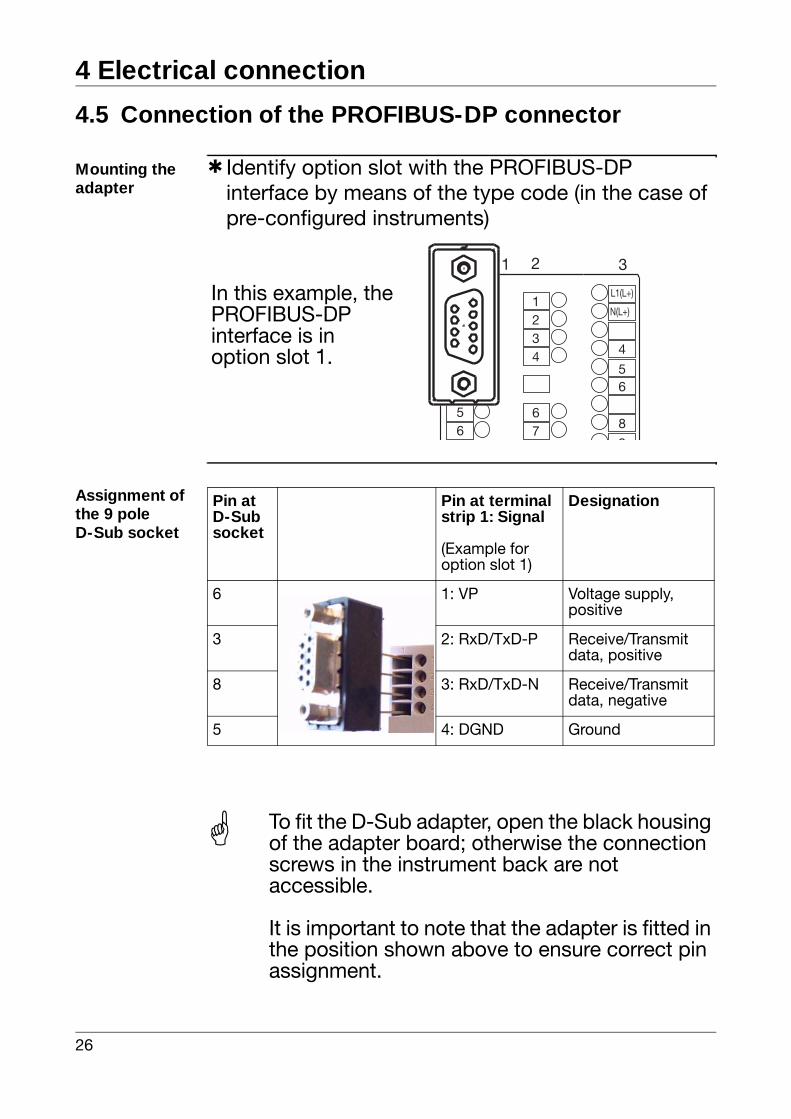
h Identify option slot with the PROFIBUS-DP interface by means of the type code (in the case of pre-configured instruments)
Assignment of the 9 poleD-Sub socket
1 2
1234
56
67
3
4
L1(L+)
56
8
9
N(L+)
1234
In this example, the PROFIBUS-DPinterface is inoption slot 1.
Pin at D-Subsocket
Pin at terminal strip 1: Signal
(Example for option slot 1)
Designation
6 1: VP Voltage supply, positive
3 2: RxD/TxD-P Receive/Transmit data, positive
8 3: RxD/TxD-N Receive/Transmit data, negative
5 4: DGND Ground
To fit the D-Sub adapter, open the black housing of the adapter board; otherwise the connection screws in the instrument back are not accessible.
It is important to note that the adapter is fitted in the position shown above to ensure correct pin assignment.
27
5 Operation
5.1 Displays and controls
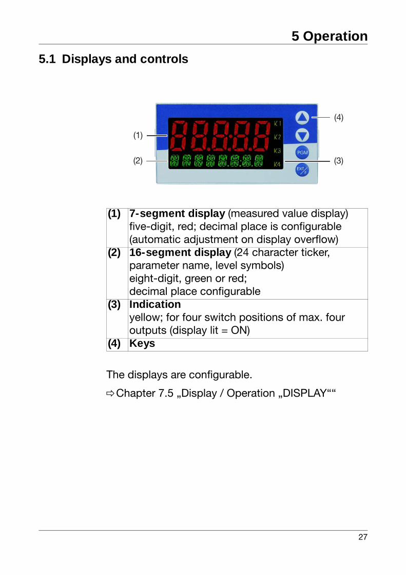
The displays are configurable.
vChapter 7.5 „Display / Operation „DISPLAY““
(1) 7-segment display (measured value display)five-digit, red; decimal place is configurable(automatic adjustment on display overflow)
(2) 16-segment display (24 character ticker,parameter name, level symbols)eight-digit, green or red;decimal place configurable
(3) Indicationyellow; for four switch positions of max. fouroutputs (display lit = ON)
(4) Keys
(4)
(2)
(1)
(3)
5 Operation
28
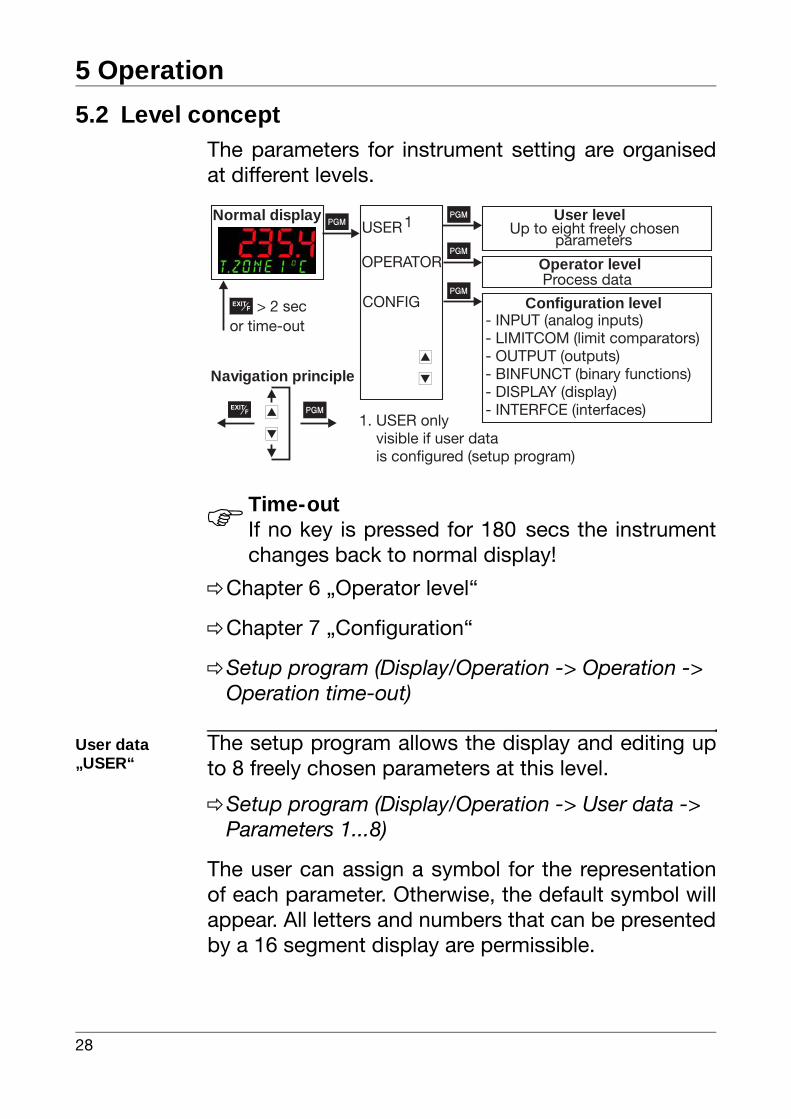
5.2 Level conceptThe parameters for instrument setting are organisedat different levels.
vChapter 6 „Operator level“
vChapter 7 „Configuration“
vSetup program (Display/Operation -> Operation -> Operation time-out)
User data „USER“
The setup program allows the display and editing upto 8 freely chosen parameters at this level.
vSetup program (Display/Operation -> User data -> Parameters 1...8)
The user can assign a symbol for the representationof each parameter. Otherwise, the default symbol willappear. All letters and numbers that can be presentedby a 16 segment display are permissible.
HTime-outIf no key is pressed for 180 secs the instrumentchanges back to normal display!
Normal display
OPERATORP
i
d
User levelP
Operator level
- INPUT (analog inputs)- LIMITCOM (limit comparators)- OUTPUT (outputs)- BINFUNCT (binary functions)- DISPLAY (display)- INTERFCE (interfaces)
Configuration level
Pi
d
CONFIGP
> 2 secor time-out
Navigation principle
PUSER
1. USER onlyvisible if user datais configured (setup program)
1 Up to eight freely chosen
Process data
EXITF
EXITF
parameters
29
5 Operation
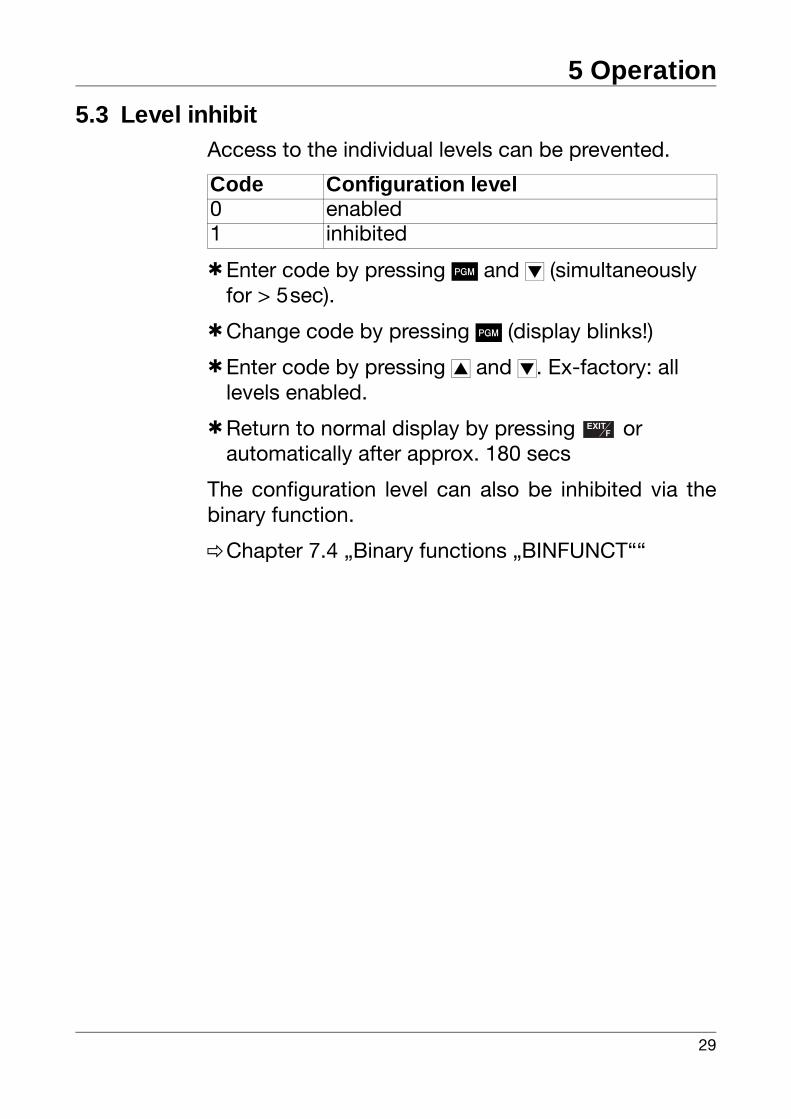
5.3 Level inhibitAccess to the individual levels can be prevented.
hEnter code by pressing P and d (simultaneously for > 5sec).
hChange code by pressing P (display blinks!)
hEnter code by pressing i and d. Ex-factory: all levels enabled.
hReturn to normal display by pressing or automatically after approx. 180 secs
The configuration level can also be inhibited via thebinary function.
vChapter 7.4 „Binary functions „BINFUNCT““
Code Configuration level0 enabled1 inhibited
EXITF
EXITF
5 Operation
30
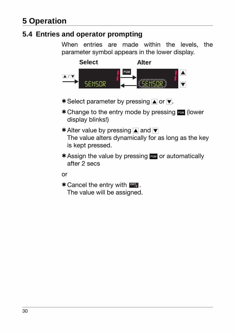
5.4 Entries and operator promptingWhen entries are made within the levels, theparameter symbol appears in the lower display.
hSelect parameter by pressing i or d.
hChange to the entry mode by pressing P (lower display blinks!)
hAlter value by pressing i and dThe value alters dynamically for as long as the key is kept pressed.
hAssign the value by pressing P or automatically after 2 secs
or
hCancel the entry with .The value will be assigned.
i d/P i
dSE NSOR SE NSOR
Select Alter
EXITF
EXITF
31
6 Operator level
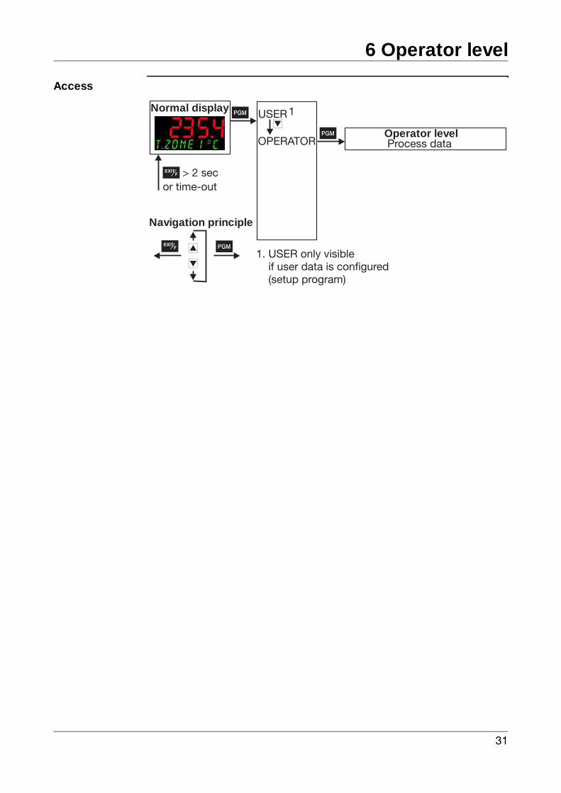
Access
Normal display
OPERATORP
P
Operator level
Pi
d
> 2 secor time-out
Navigation principle
USER
1. USER only visibleif user data is configured(setup program)
1
Process data
d
EXITF
EXITF
6 Operator level
32
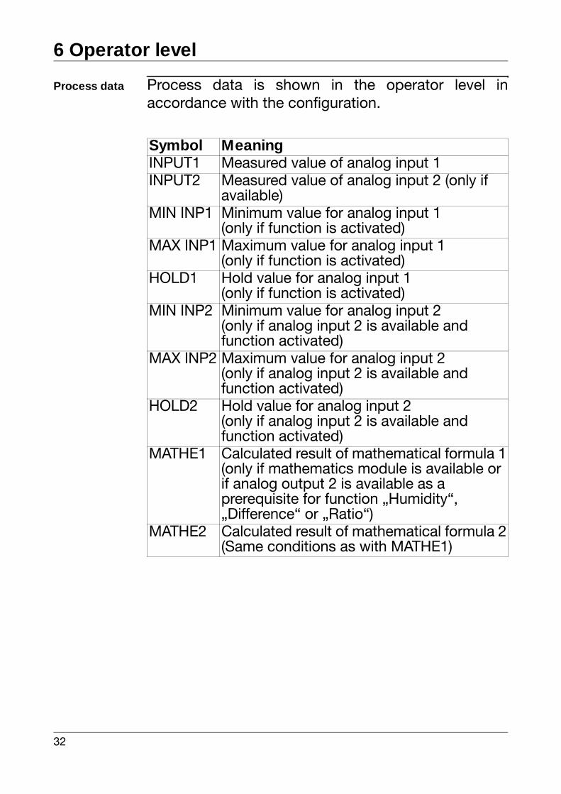
Process data Process data is shown in the operator level inaccordance with the configuration.
Symbol MeaningINPUT1 Measured value of analog input 1INPUT2 Measured value of analog input 2 (only if
available)MIN INP1 Minimum value for analog input 1
(only if function is activated)MAX INP1 Maximum value for analog input 1
(only if function is activated)HOLD1 Hold value for analog input 1
(only if function is activated)MIN INP2 Minimum value for analog input 2
(only if analog input 2 is available and function activated)
MAX INP2 Maximum value for analog input 2(only if analog input 2 is available and function activated)
HOLD2 Hold value for analog input 2(only if analog input 2 is available and function activated)
MATHE1 Calculated result of mathematical formula 1(only if mathematics module is available or if analog output 2 is available as a prerequisite for function „Humidity“, „Difference“ or „Ratio“)
MATHE2 Calculated result of mathematical formula 2(Same conditions as with MATHE1)
33
7 Configuration
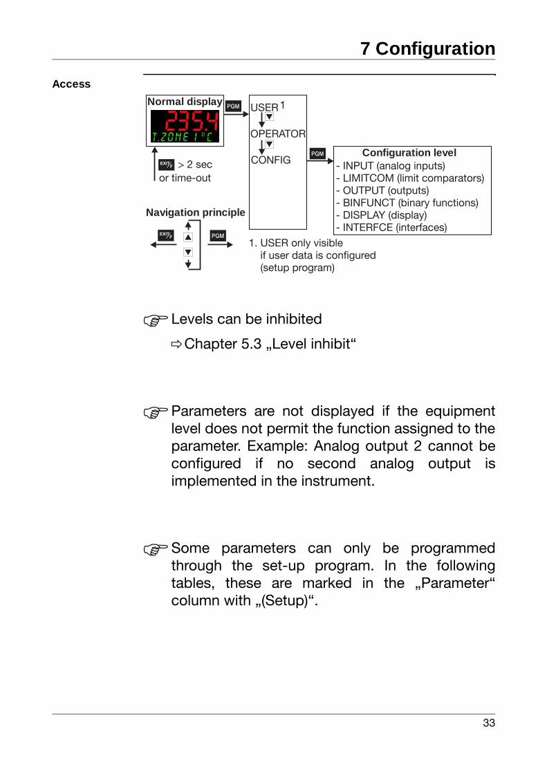
Access
HLevels can be inhibited
vChapter 5.3 „Level inhibit“
HParameters are not displayed if the equipmentlevel does not permit the function assigned to theparameter. Example: Analog output 2 cannot beconfigured if no second analog output isimplemented in the instrument.
HSome parameters can only be programmedthrough the set-up program. In the followingtables, these are marked in the „Parameter“column with „(Setup)“.
Normal display
OPERATOR
P
- INPUT (analog inputs)- LIMITCOM (limit comparators)- OUTPUT (outputs)- BINFUNCT (binary functions)- DISPLAY (display)- INTERFCE (interfaces)
Configuration level
Pi
d
CONFIGP
> 2 secor time-out
Navigation principle
USER
1. USER only visibleif user data is configured(setup program)
1d
d
EXITF
EXITF
7 Configuration
34
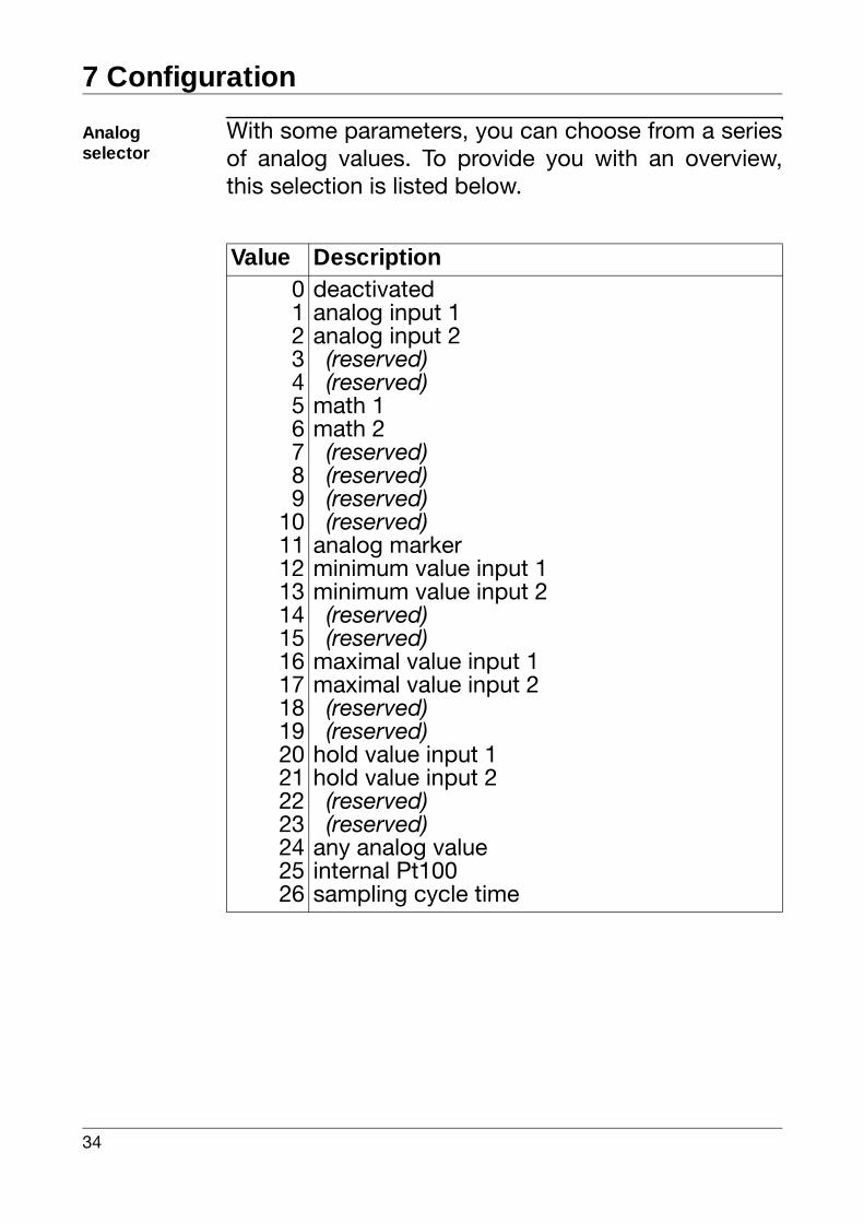
Analogselector
With some parameters, you can choose from a seriesof analog values. To provide you with an overview,this selection is listed below.
Value Description0123456789
1011121314151617181920212223242526
deactivatedanalog input 1analog input 2 (reserved) (reserved)math 1math 2 (reserved) (reserved) (reserved) (reserved)analog markerminimum value input 1minimum value input 2 (reserved) (reserved)maximal value input 1maximal value input 2 (reserved) (reserved)hold value input 1hold value input 2 (reserved) (reserved)any analog valueinternal Pt100sampling cycle time
35
7 Configuration
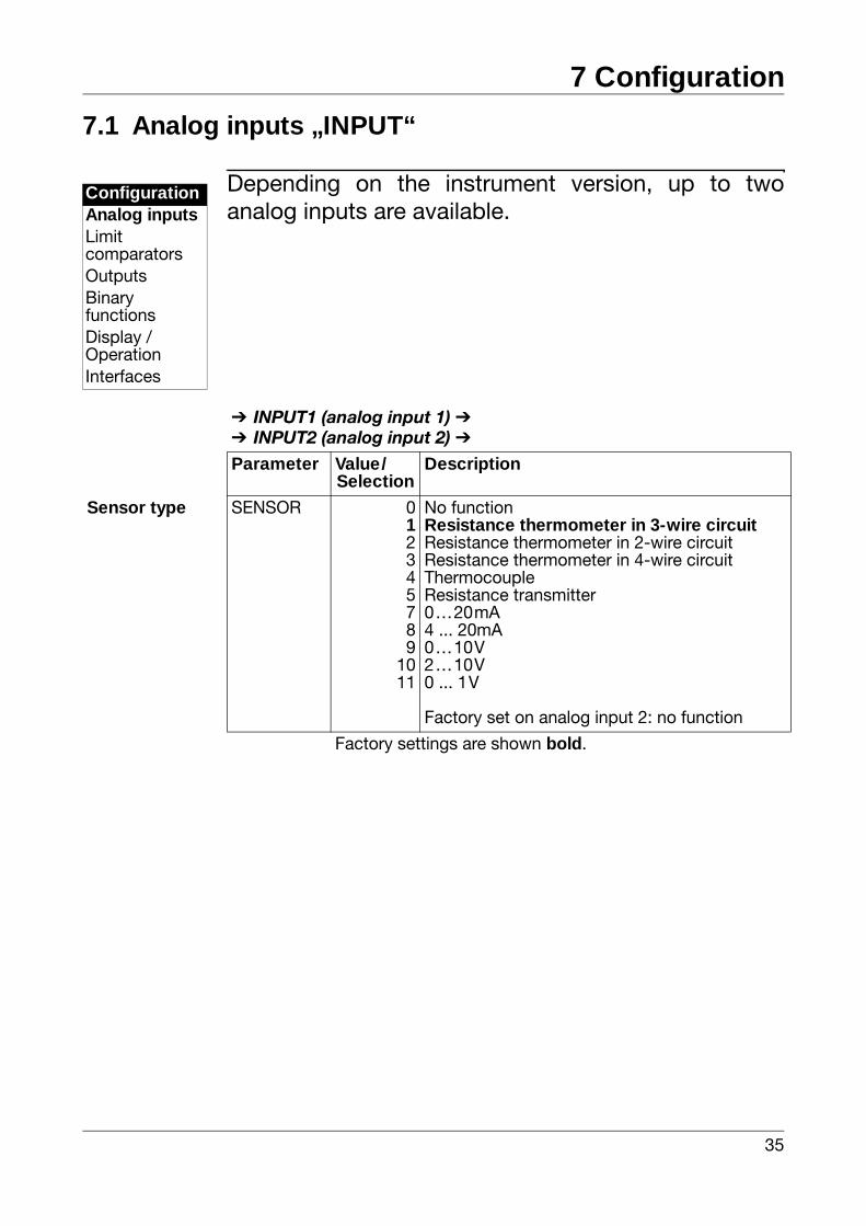
7.1 Analog inputs „INPUT“
Depending on the instrument version, up to twoanalog inputs are available.
ConfigurationAnalog inputsLimitcomparatorsOutputsBinaryfunctionsDisplay /OperationInterfaces
INPUT1 (analog input 1) INPUT2 (analog input 2)
Parameter Value/Selection
Description
Sensor type SENSOR 012345789
1011
No functionResistance thermometer in 3-wire circuitResistance thermometer in 2-wire circuitResistance thermometer in 4-wire circuitThermocoupleResistance transmitter0…20mA4 ... 20mA0…10V2…10V0 ... 1V
Factory set on analog input 2: no function
Factory settings are shown bold.
7 Configuration
36
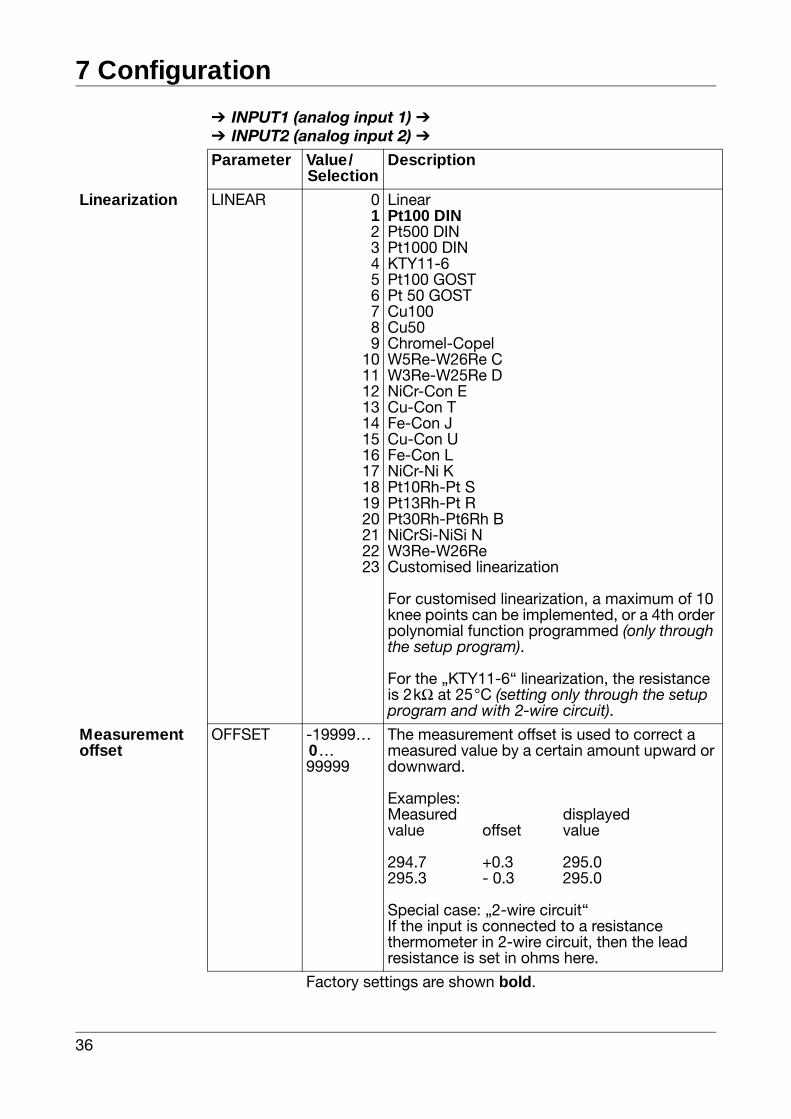
Linearization LINEAR 0123456789
1011121314151617181920212223
LinearPt100 DINPt500 DINPt1000 DINKTY11-6Pt100 GOSTPt 50 GOSTCu100Cu50Chromel-CopelW5Re-W26Re CW3Re-W25Re DNiCr-Con ECu-Con TFe-Con JCu-Con UFe-Con LNiCr-Ni KPt10Rh-Pt SPt13Rh-Pt RPt30Rh-Pt6Rh BNiCrSi-NiSi NW3Re-W26ReCustomised linearization
For customised linearization, a maximum of 10 knee points can be implemented, or a 4th order polynomial function programmed (only throughthe setup program).
For the „KTY11-6“ linearization, the resistance is 2kΩ at 25°C (setting only through the setup program and with 2-wire circuit).
Measurementoffset
OFFSET -19999… 0…99999
The measurement offset is used to correct a measured value by a certain amount upward or downward.
Examples:Measured displayedvalue offset value
294.7 +0.3 295.0295.3 - 0.3 295.0
Special case: „2-wire circuit“If the input is connected to a resistance thermometer in 2-wire circuit, then the lead resistance is set in ohms here.
INPUT1 (analog input 1) INPUT2 (analog input 2)
Parameter Value/Selection
Description
Factory settings are shown bold.
37
7 Configuration
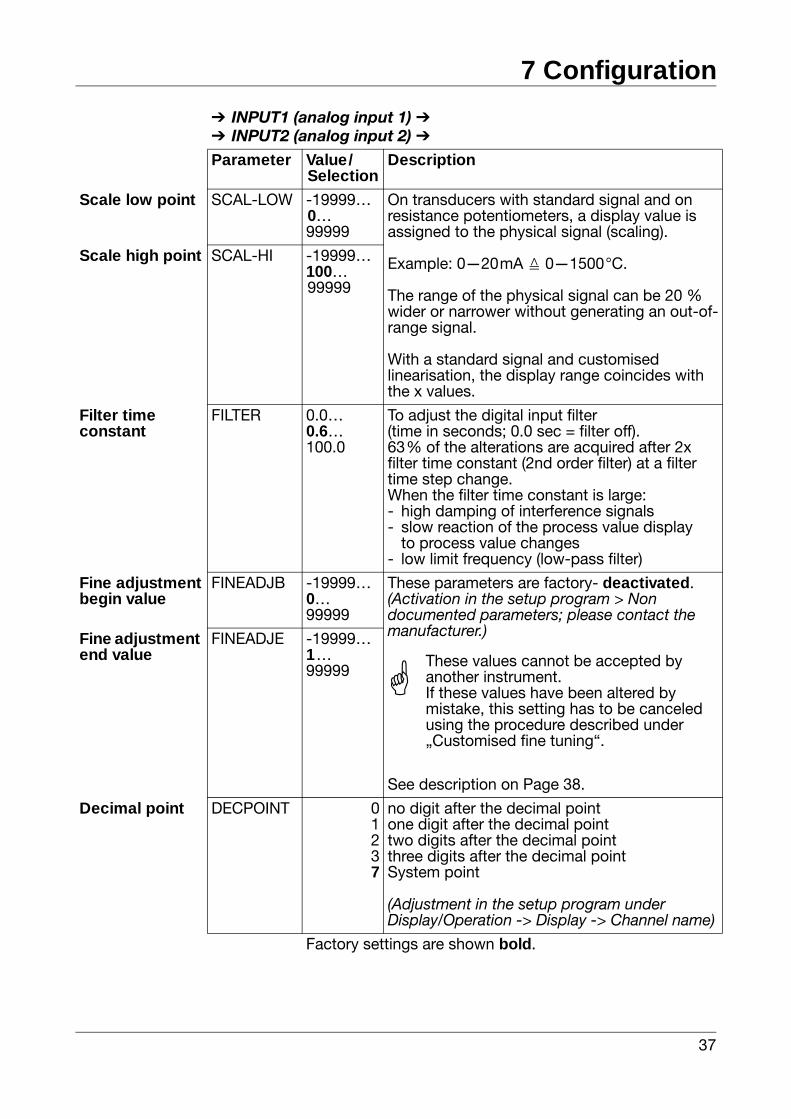
Scale low point SCAL-LOW -19999…0…99999
On transducers with standard signal and on resistance potentiometers, a display value is assigned to the physical signal (scaling).
Example: 0—20mA 0—1500°C.
The range of the physical signal can be 20 % wider or narrower without generating an out-of-range signal.
With a standard signal and customised linearisation, the display range coincides with the x values.
Scale high point SCAL-HI -19999…100…99999
Filter timeconstant
FILTER 0.0…0.6…100.0
To adjust the digital input filter(time in seconds; 0.0 sec = filter off).63% of the alterations are acquired after 2x filter time constant (2nd order filter) at a filter time step change.When the filter time constant is large:- high damping of interference signals- slow reaction of the process value display
to process value changes- low limit frequency (low-pass filter)
Fine adjustmentbegin value
FINEADJB -19999…0…99999
These parameters are factory- deactivated.(Activation in the setup program > Non documented parameters; please contact the manufacturer.)
See description on Page 38.
Fine adjustment end value
FINEADJE -19999…1…99999
Decimal point DECPOINT 01237
no digit after the decimal pointone digit after the decimal pointtwo digits after the decimal pointthree digits after the decimal pointSystem point
(Adjustment in the setup program under Display/Operation -> Display -> Channel name)
INPUT1 (analog input 1) INPUT2 (analog input 2)
Parameter Value/Selection
Description
Factory settings are shown bold.
AThese values cannot be accepted by another instrument.If these values have been altered by mistake, this setting has to be canceled using the procedure described under „Customised fine tuning“.
7 Configuration
38
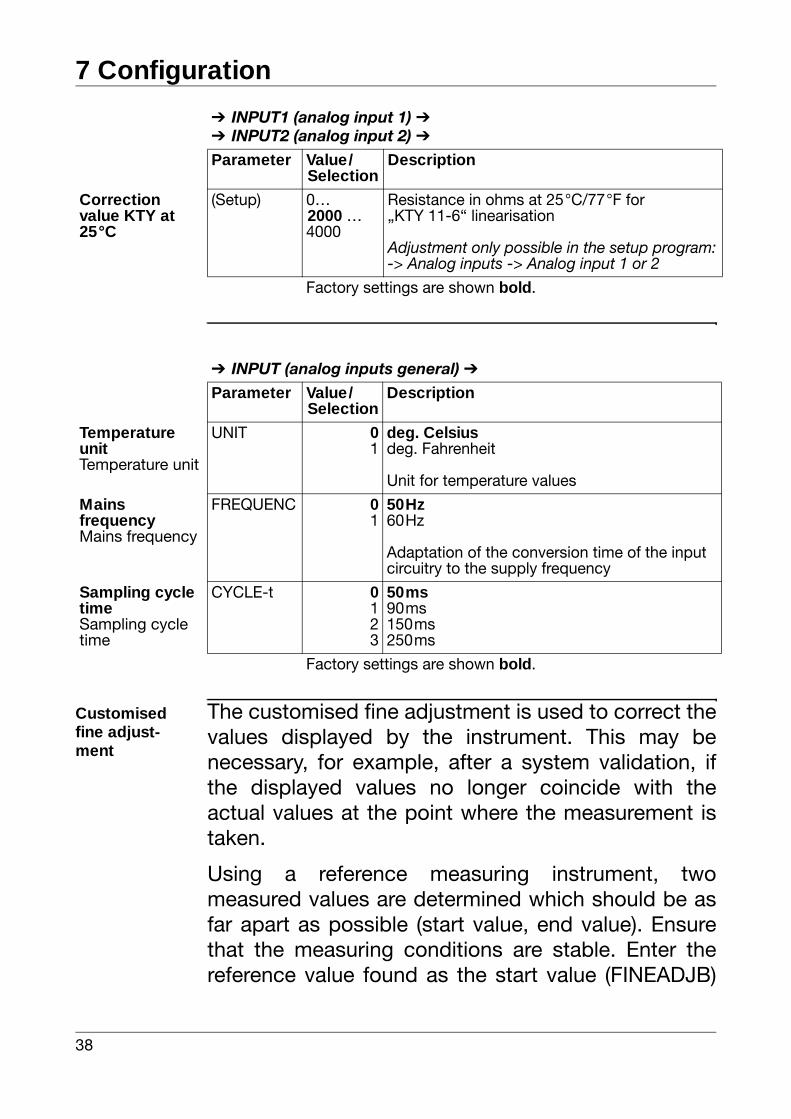
Customisedfine adjust-ment
The customised fine adjustment is used to correct thevalues displayed by the instrument. This may benecessary, for example, after a system validation, ifthe displayed values no longer coincide with theactual values at the point where the measurement istaken.
Using a reference measuring instrument, twomeasured values are determined which should be asfar apart as possible (start value, end value). Ensurethat the measuring conditions are stable. Enter thereference value found as the start value (FINEADJB)
Correction value KTY at 25°C
(Setup) 0…2000 …4000
Resistance in ohms at 25°C/77°F for „KTY 11-6“ linearisation
Adjustment only possible in the setup program:-> Analog inputs -> Analog input 1 or 2
INPUT1 (analog input 1) INPUT2 (analog input 2)
Parameter Value/Selection
Description
Factory settings are shown bold.
INPUT (analog inputs general)
Parameter Value/Selection
Description
Temperature unitTemperature unit
UNIT 01
deg. Celsiusdeg. Fahrenheit
Unit for temperature values
MainsfrequencyMains frequency
FREQUENC 01
50Hz60Hz
Adaptation of the conversion time of the input circuitry to the supply frequency
Sampling cycle timeSampling cycle time
CYCLE-t 0123
50ms90ms150ms250ms
Factory settings are shown bold.
39
7 Configuration
or end value (FINEADJE) on the instrument to betuned.
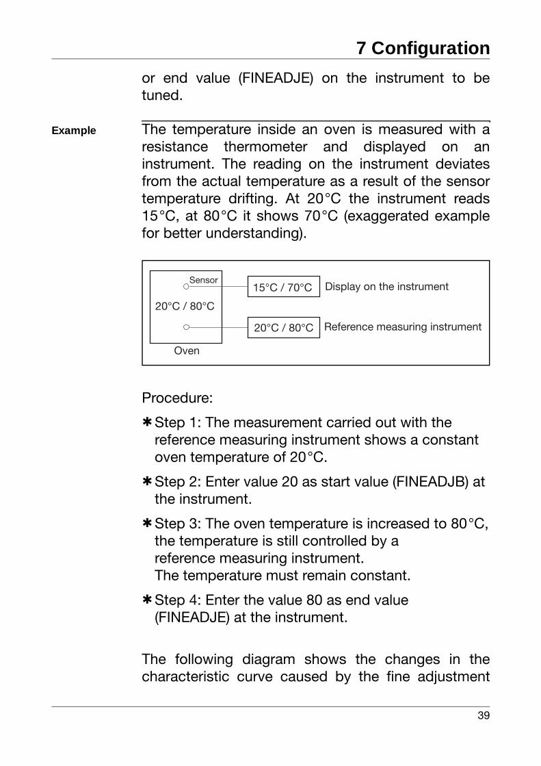
Example The temperature inside an oven is measured with aresistance thermometer and displayed on aninstrument. The reading on the instrument deviatesfrom the actual temperature as a result of the sensortemperature drifting. At 20°C the instrument reads15°C, at 80°C it shows 70°C (exaggerated examplefor better understanding).
Procedure:
hStep 1: The measurement carried out with the reference measuring instrument shows a constant oven temperature of 20°C.
hStep 2: Enter value 20 as start value (FINEADJB) at the instrument.
hStep 3: The oven temperature is increased to 80°C,the temperature is still controlled by areference measuring instrument.The temperature must remain constant.
hStep 4: Enter the value 80 as end value(FINEADJE) at the instrument.
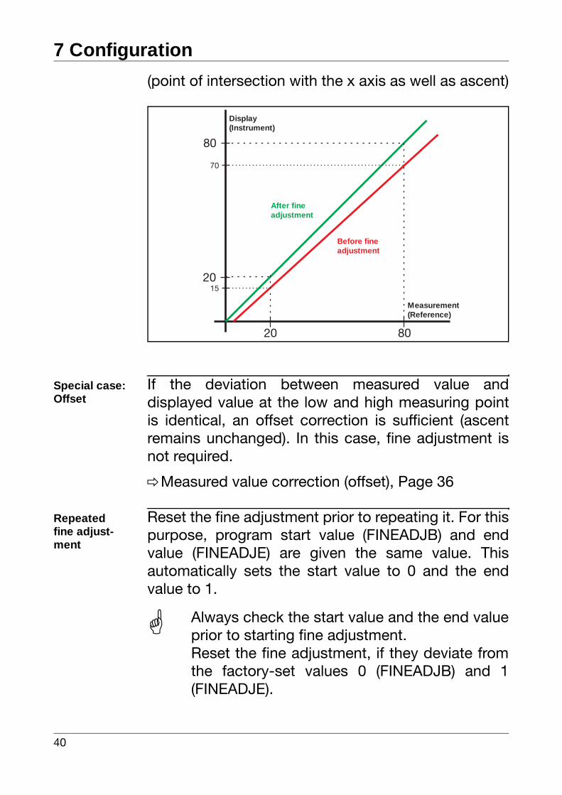
The following diagram shows the changes in thecharacteristic curve caused by the fine adjustment
20°C / 80°C
Oven
20°C / 80°C
15°C / 70°C Display on the instrument
Reference measuring instrument
Sensor
7 Configuration
40
(point of intersection with the x axis as well as ascent)
Special case:Offset
If the deviation between measured value anddisplayed value at the low and high measuring pointis identical, an offset correction is sufficient (ascentremains unchanged). In this case, fine adjustment isnot required.
vMeasured value correction (offset), Page 36
Repeatedfine adjust-ment
Reset the fine adjustment prior to repeating it. For thispurpose, program start value (FINEADJB) and endvalue (FINEADJE) are given the same value. Thisautomatically sets the start value to 0 and the endvalue to 1.
20 80
20
80
70
15
Before fineadjustment
After fineadjustment
Measurement(Reference)
Display(Instrument)
Always check the start value and the end valueprior to starting fine adjustment.Reset the fine adjustment, if they deviate fromthe factory-set values 0 (FINEADJB) and 1(FINEADJE).
41
7 Configuration
7.2 Limit comparators „LIMITCOM“
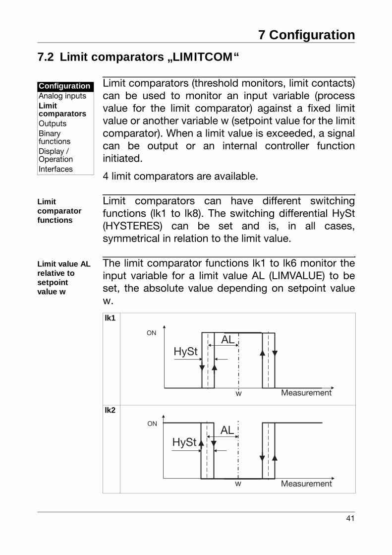
Limit comparators (threshold monitors, limit contacts)can be used to monitor an input variable (processvalue for the limit comparator) against a fixed limitvalue or another variable w (setpoint value for the limitcomparator). When a limit value is exceeded, a signalcan be output or an internal controller functioninitiated.
4 limit comparators are available.
Limit comparator functions
Limit comparators can have different switchingfunctions (lk1 to lk8). The switching differential HySt(HYSTERES) can be set and is, in all cases,symmetrical in relation to the limit value.
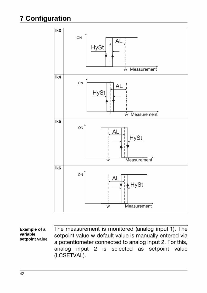
Limit value AL relative to setpointvalue w
The limit comparator functions lk1 to lk6 monitor theinput variable for a limit value AL (LIMVALUE) to beset, the absolute value depending on setpoint valuew.
ConfigurationAnalog inputsLimit comparatorsOutputsBinaryfunctionsDisplay /OperationInterfaces
lk1
lk2
w
ONAL
Measurement
HySt
AL
w
ON
Measurement
HySt
7 Configuration
42
Example of avariablesetpoint value
The measurement is monitored (analog input 1). Thesetpoint value w default value is manually entered viaa potentiometer connected to analog input 2. For this,analog input 2 is selected as setpoint value(LCSETVAL).
lk3
lk4
lk5
lk6
w
ONAL
Measurement
HySt
w
ONAL
Measurement
HySt
AL
w
ON
Measurement
HySt
AL
w
ON
Measurement
HySt
43
7 Configuration
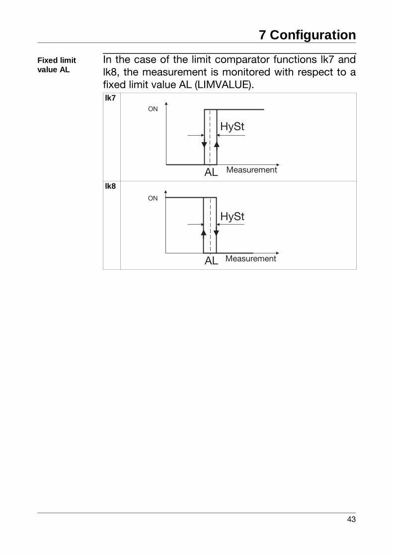
Fixed limit value AL
In the case of the limit comparator functions lk7 andlk8, the measurement is monitored with respect to afixed limit value AL (LIMVALUE).lk7
lk8
AL
ON
Measurement
HySt
AL
ON
Measurement
HySt
7 Configuration
44
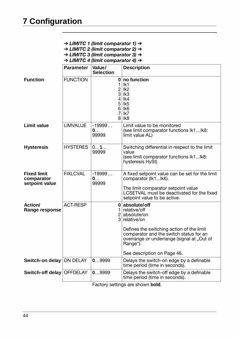
LIMITC 1 (limit comparator 1) LIMITC 2 (limit comparator 2) LIMITC 3 (limit comparator 3) LIMITC 4 (limit comparator 4)
Parameter Value/Selection
Description
Function FUNCTION 012345678
no functionlk1lk2lk3lk4lk5lk6lk7lk8
Limit value LIMVALUE -19999…0…99999
Limit value to be monitored(see limit comparator functions lk1... lk8:limit value AL)
Hysteresis HYSTERES 0…1…99999
Switching differential in respect to the limit value(see limit comparator functions lk1...lk8:hysteresis HySt)
Fixed limit comparator setpoint value
FIXLCVAL -19999…0…99999
A fixed setpoint value can be set for the limit comparator (lk1...lk6).
The limit comparator setpoint value LCSETVAL must be deactivated for the fixed setpoint value to be active.
Action/Range response
ACT-RESP 0123
absolute/offrelative/offabsolute/onrelative/on
Defines the switching action of the limit comparator and the switch status for an overrange or underrange (signal at „Out of Range“).
See description on Page 46.
Switch-on delay ON DELAY 0…9999 Delays the switch-on edge by a definable time period (time in seconds).
Switch-off delay OFFDELAY 0…9999 Delays the switch-off edge by a definable time period (time in seconds).
Factory settings are shown bold.
45
7 Configuration
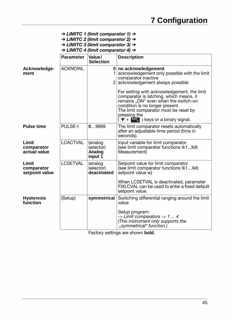
Acknowledge-ment
ACKNOWL 01
2
no acknowledgementacknowledgement only possible with the limit comparator inactiveacknowledgement always possible
For setting with acknowledgement, the limit comparator is latching, which means, it remains „ON“ even when the switch-on condition is no longer present. The limit comparator must be reset by pressing the(d + ) keys or a binary signal.
Pulse time PULSE-t 0…9999 The limit comparator resets automatically after an adjustable time period (time in seconds).
Limit comparator actual value
LCACTVAL (analog selector)Analog input 1
Input variable for limit comparator(see limit comparator functions lk1...lk8:Measurement)
Limit comparator setpoint value
LCSETVAL (analog selector)deactivated
Setpoint value for limit comparator(see limit comparator functions lk1... lk6:setpoint value w)
When LCSETVAL is deactivated, parameter FIXLCVAL can be used to enter a fixed default setpoint value.
Hysteresisfunction
(Setup) symmetrical Switching differential ranging around the limit value
Setup program:-> Limit comparators -> 1 ... 4(This instrument only supports the „symmetrical“ function.)
LIMITC 1 (limit comparator 1) LIMITC 2 (limit comparator 2) LIMITC 3 (limit comparator 3) LIMITC 4 (limit comparator 4)
Parameter Value/Selection
Description
Factory settings are shown bold.
EXITF
EXITF
7 Configuration
46
Switchingaction
Switching action means: limit comparator reaction toa limit value or setpoint value change as well as toPower ON.
„absolute“ switching action:
At the time of the change, the limit comparator reactsaccording to its function.
„relative“ switching action:
Following Power ON, the limit comparator remains inits „OFF“ switch position, even if the process value iswithin the switch-on range.
If the setpoint value or the limit value is altered whilethe limit comparator is in its „OFF“ position, whichleads to the actual value now being in the switch-onrange, the limit comparator still remains in the „OFF“switch position.
The limit comparator will only resume operationaccording to its function when the process value isoutside of the switch-on range. In other words: itremains „OFF“ until the process value has againreached the switch-on range.
See the following example:
47
7 Configuration
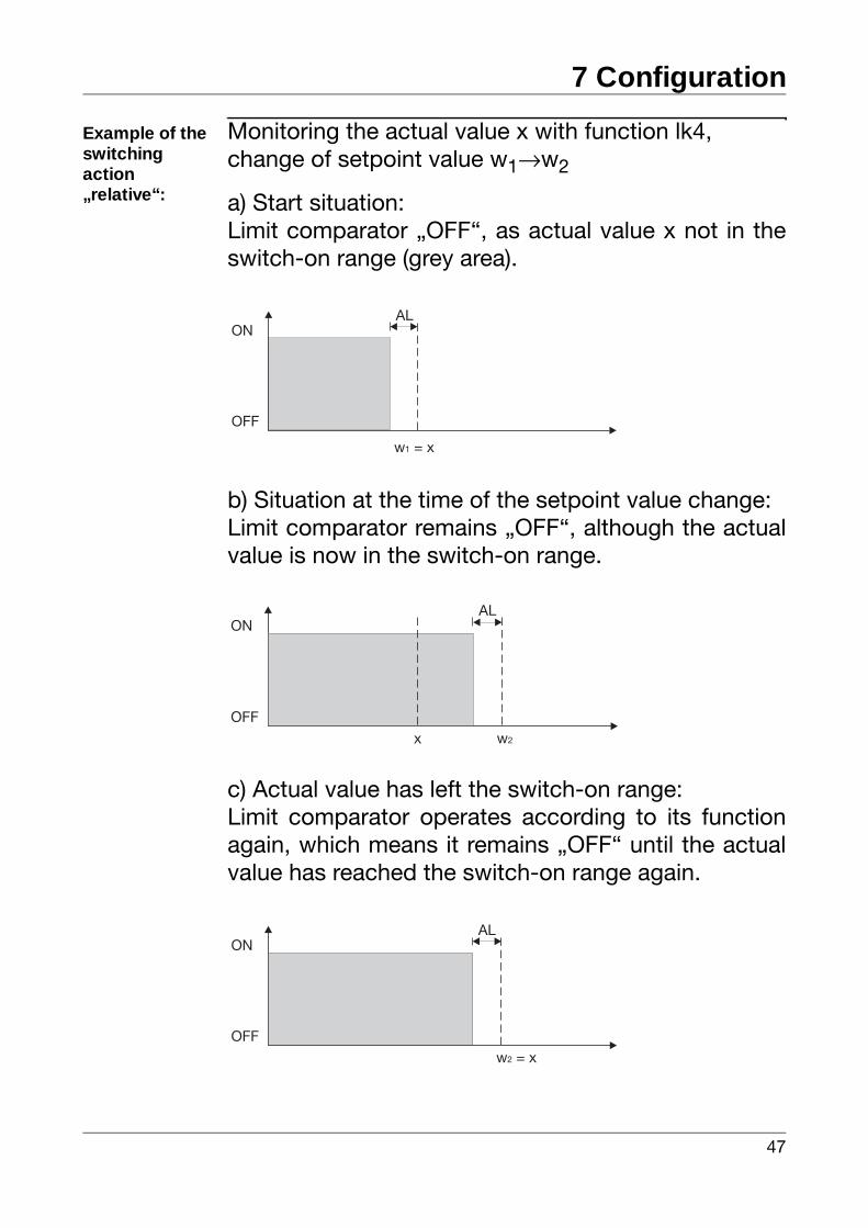
Example of theswitchingaction„relative“:
Monitoring the actual value x with function lk4,change of setpoint value w1→w2
a) Start situation:Limit comparator „OFF“, as actual value x not in theswitch-on range (grey area).
b) Situation at the time of the setpoint value change:Limit comparator remains „OFF“, although the actualvalue is now in the switch-on range.
c) Actual value has left the switch-on range:Limit comparator operates according to its functionagain, which means it remains „OFF“ until the actualvalue has reached the switch-on range again.
ON
w = x1
OFF
AL
ON
w2x
OFF
AL
ON
w = x2
OFF
AL
7 Configuration
48
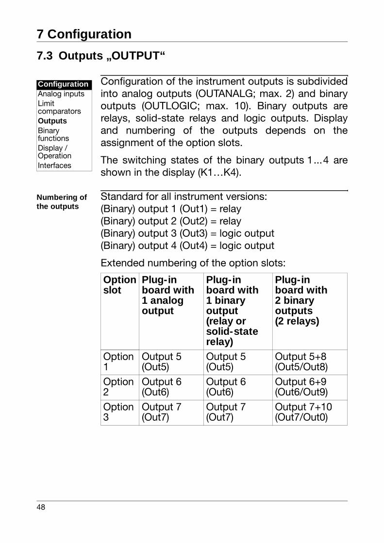
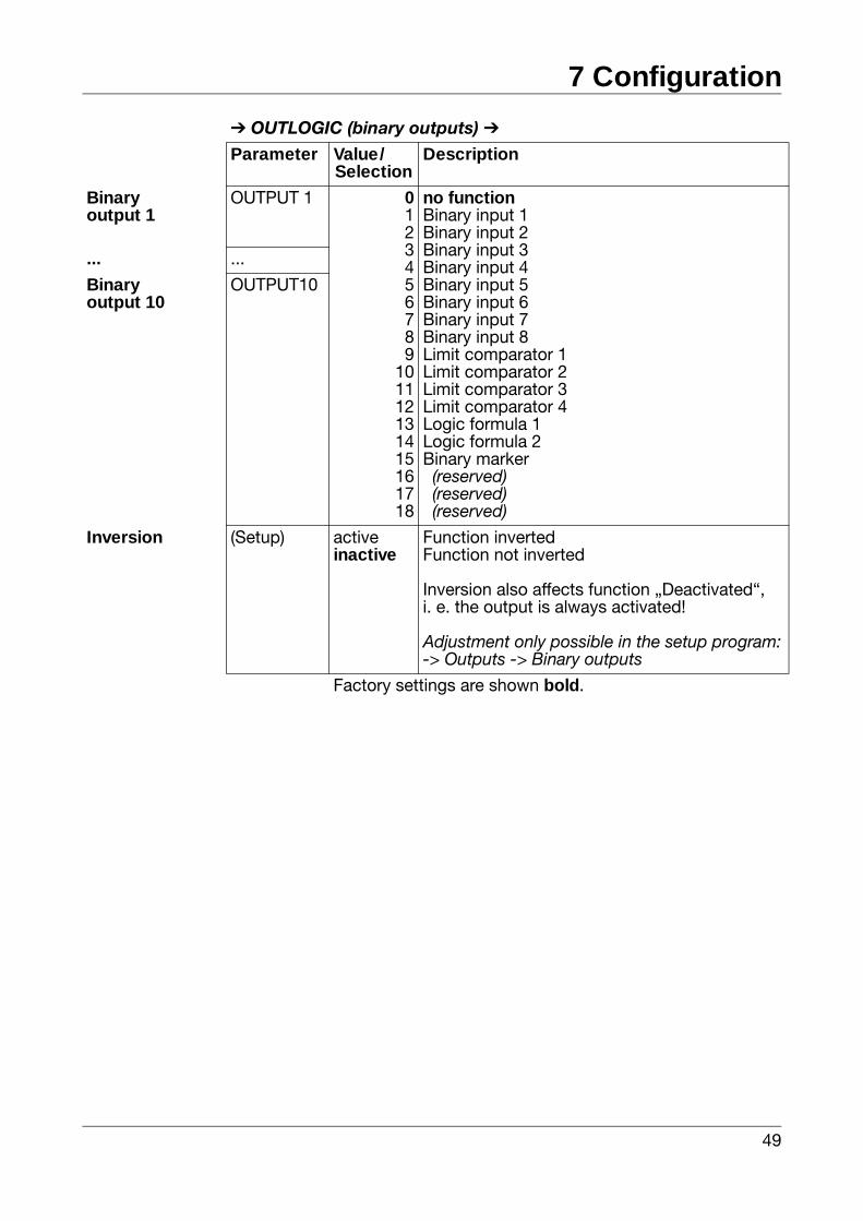
7.3 Outputs „OUTPUT“
Configuration of the instrument outputs is subdividedinto analog outputs (OUTANALG; max. 2) and binaryoutputs (OUTLOGIC; max. 10). Binary outputs arerelays, solid-state relays and logic outputs. Displayand numbering of the outputs depends on theassignment of the option slots.
The switching states of the binary outputs 1...4 areshown in the display (K1…K4).
Numbering of the outputs
Standard for all instrument versions: (Binary) output 1 (Out1) = relay(Binary) output 2 (Out2) = relay(Binary) output 3 (Out3) = logic output(Binary) output 4 (Out4) = logic output
Extended numbering of the option slots:
ConfigurationAnalog inputsLimitcomparatorsOutputsBinaryfunctionsDisplay /OperationInterfaces
Optionslot
Plug-inboard with 1 analog output
Plug-inboard with 1 binaryoutput(relay or solid-staterelay)
Plug-inboard with 2 binaryoutputs(2 relays)
Option 1
Output 5 (Out5)
Output 5 (Out5)
Output 5+8(Out5/Out8)
Option 2
Output 6 (Out6)
Output 6 (Out6)
Output 6+9(Out6/Out9)
Option 3
Output 7 (Out7)
Output 7 (Out7)
Output 7+10(Out7/Out0)
49
7 Configuration
OUTLOGIC (binary outputs)
Parameter Value/Selection
Description
Binaryoutput 1
OUTPUT 1 0123456789
101112131415161718
no functionBinary input 1Binary input 2Binary input 3Binary input 4Binary input 5Binary input 6Binary input 7Binary input 8Limit comparator 1Limit comparator 2Limit comparator 3Limit comparator 4Logic formula 1Logic formula 2Binary marker (reserved) (reserved) (reserved)
... ...
Binaryoutput 10
OUTPUT10
Inversion (Setup) activeinactive
Function invertedFunction not inverted
Inversion also affects function „Deactivated“, i. e. the output is always activated!
Adjustment only possible in the setup program:-> Outputs -> Binary outputs
Factory settings are shown bold.
7 Configuration
50
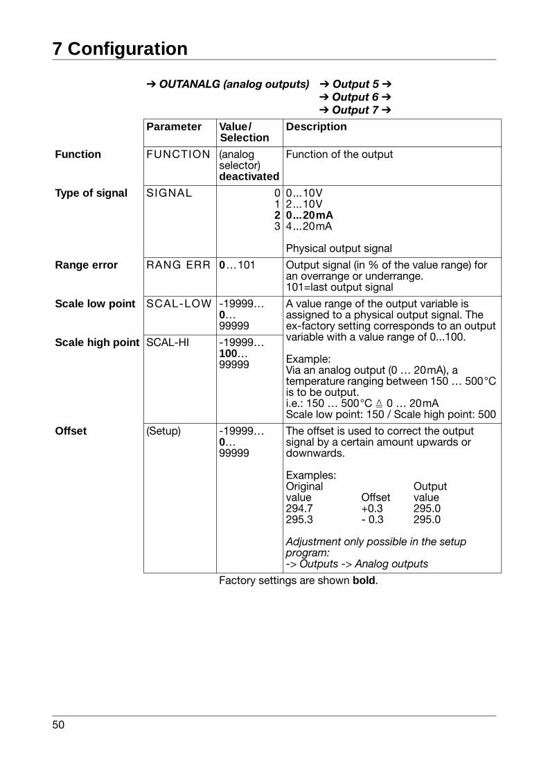
OUTANALG (analog outputs) Output 5 Output 6 Output 7
Parameter Value/Selection
Description
Function FUNCTION (analogselector)deactivated
Function of the output
Type of signal SIGNAL 0123
0...10V2...10V0...20mA4...20mA
Physical output signal
Range error RANG ERR 0…101 Output signal (in % of the value range) for an overrange or underrange.101=last output signal
Scale low point SCAL-LOW -19999…0…99999
A value range of the output variable is assigned to a physical output signal. The ex-factory setting corresponds to an output variable with a value range of 0...100.
Example:Via an analog output (0 … 20mA), a temperature ranging between 150 … 500°C is to be output.i.e.: 150 … 500°C 0 … 20mAScale low point: 150 / Scale high point: 500
Scale high point SCAL-HI -19999…100…99999
Offset (Setup) -19999…0…99999
The offset is used to correct the output signal by a certain amount upwards or downwards.
Examples:Original Outputvalue Offset value294.7 +0.3 295.0295.3 - 0.3 295.0
Adjustment only possible in the setup program:-> Outputs -> Analog outputs
Factory settings are shown bold.
51
7 Configuration
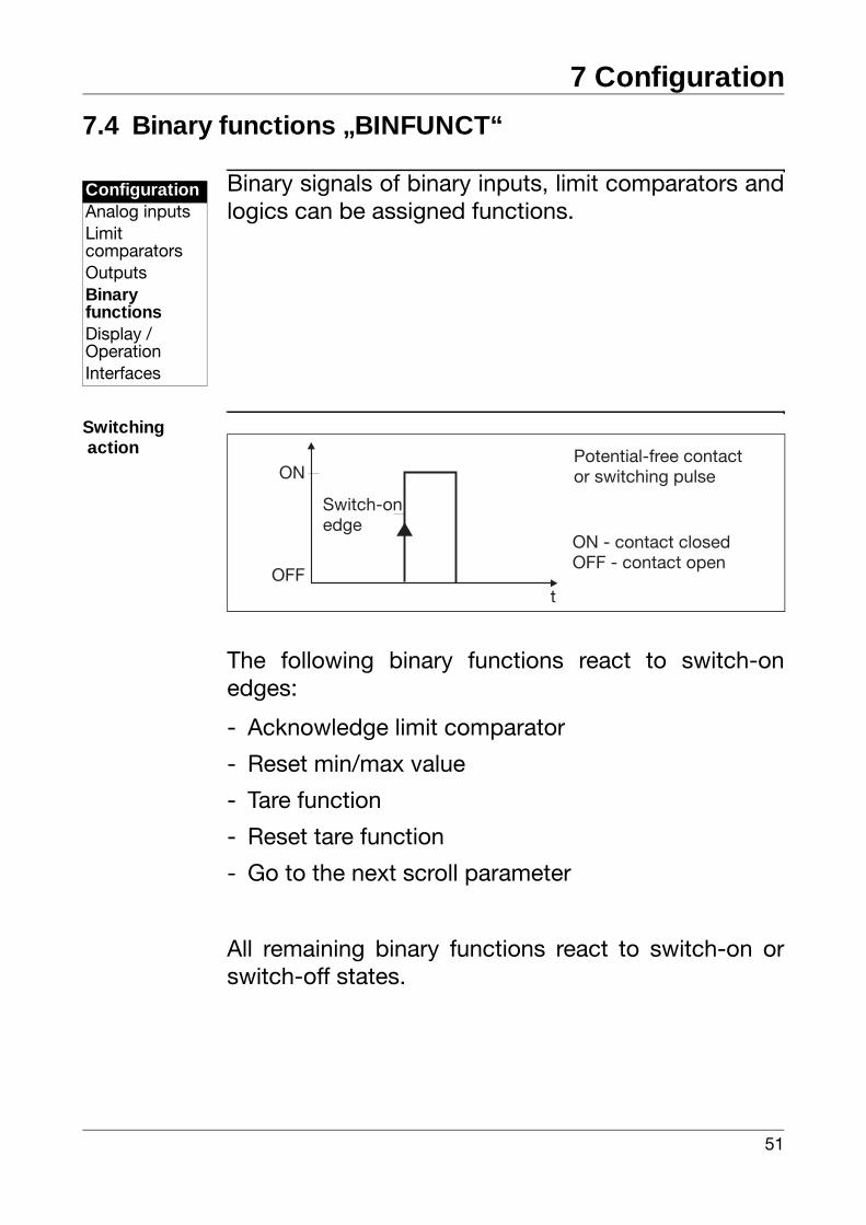
7.4 Binary functions „BINFUNCT“
Binary signals of binary inputs, limit comparators andlogics can be assigned functions.
Switching action
The following binary functions react to switch-onedges:
- Acknowledge limit comparator
- Reset min/max value
- Tare function
- Reset tare function
- Go to the next scroll parameter
All remaining binary functions react to switch-on orswitch-off states.
ConfigurationAnalog inputsLimitcomparatorsOutputsBinaryfunctionsDisplay /OperationInterfaces
ON
ON - contact closedOFF - contact open
Switch-onedge
Potential-free contactor switching pulse
OFFt
7 Configuration
52
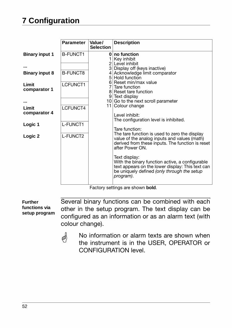
Furtherfunctions via setup program
Several binary functions can be combined with eachother in the setup program. The text display can beconfigured as an information or as an alarm text (withcolour change).
Parameter Value/Selection
Description
Binary input 1 B-FUNCT1 0123456789
1011
no functionKey inhibitLevel inhibitDisplay off (keys inactive)Acknowledge limit comparatorHold functionReset min/max valueTare functionReset tare functionText displayGo to the next scroll parameterColour change
Level inhibit:The configuration level is inhibited.
Tare function:The tare function is used to zero the display value of the analog inputs and values (math) derived from these inputs. The function is reset after Power ON.
Text display:With the binary function active, a configurable text appears on the lower display: This text can be uniquely defined (only through the setup program).
...
Binary input 8 B-FUNCT8
Limit comparator 1
LCFUNCT1
...
Limit comparator 4
LCFUNCT4
Logic 1 L-FUNCT1
Logic 2 L-FUNCT2
Factory settings are shown bold.
No information or alarm texts are shown whenthe instrument is in the USER, OPERATOR orCONFIGURATION level.
53
7 Configuration
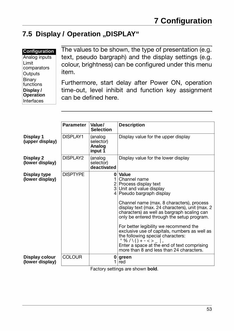
7.5 Display / Operation „DISPLAY“
The values to be shown, the type of presentation (e.g.text, pseudo bargraph) and the display settings (e.g.colour, brightness) can be configured under this menuitem.
Furthermore, start delay after Power ON, operationtime-out, level inhibit and function key assignmentcan be defined here.
ConfigurationAnalog inputsLimitcomparatorsOutputsBinaryfunctionsDisplay /OperationInterfaces
Parameter Value/Selection
Description
Display 1(upper display)
DISPLAY1 (analog selector)Analog input 1
Display value for the upper display
Display 2(lower display)
DISPLAY2 (analog selector)deactivated
Display value for the lower display
Display type(lower display)
DISPTYPE 01234
ValueChannel nameProcess display textUnit and value displayPseudo bargraph display
Channel name (max. 8 characters), process display text (max. 24 characters), unit (max. 2 characters) as well as bargraph scaling can only be entered through the setup program.
For better legibility we recommend the exclusive use of capitals, numbers as well as the following special characters: ° % / \ ( ) + - < > _ | ,Enter a space at the end of text comprising more than 8 and less than 24 characters.
Display colour (lower display)
COLOUR 01
greenred
Factory settings are shown bold.
7 Configuration
54
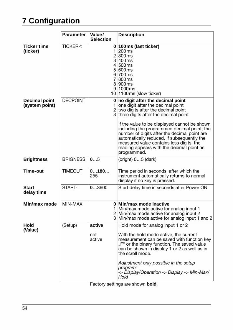
Ticker time(ticker)
TICKER-t 0123456789
10
100ms (fast ticker)200ms300ms400ms500ms600ms700ms800ms900ms1000ms1100ms (slow ticker)
Decimal point (system point)
DECPOINT 0123
no digit after the decimal pointone digit after the decimal pointtwo digits after the decimal pointthree digits after the decimal point
If the value to be displayed cannot be shown including the programmed decimal point, the number of digits after the decimal point are automatically reduced. If subsequently the measured value contains less digits, the reading appears with the decimal point as programmed.
Brightness BRIGNESS 0…5 (bright) 0...5 (dark)
Time-out TIMEOUT 0…180…255
Time period in seconds, after which the instrument automatically returns to normal display if no key is pressed.
Startdelay time
START-t 0…3600 Start delay time in seconds after Power ON
Min/max mode MIN-MAX 0123
Min/max mode inactiveMin/max mode active for analog input 1Min/max mode active for analog input 2Min/max mode active for analog input 1 and 2
Hold(Value)
(Setup) active
notactive
Hold mode for analog input 1 or 2
With the hold mode active, the current measurement can be saved with function key „F“ or the binary function. The saved value can be shown in display 1 or 2 as well as in the scroll mode.
Adjustment only possible in the setup program:-> Display/Operation -> Display -> Min-Max/Hold
Parameter Value/Selection
Description
Factory settings are shown bold.
55
7 Configuration
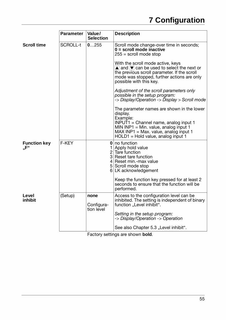
Scroll time SCROLL-t 0…255 Scroll mode change-over time in seconds;0 = scroll mode inactive255 = scroll mode stop
With the scroll mode active, keysi and d can be used to select the next or the previous scroll parameter. If the scroll mode was stopped, further actions are only possible with this key.
Adjustment of the scroll parameters only possible in the setup program:-> Display/Operation -> Display > Scroll mode
The parameter names are shown in the lower display.Example:INPUT1 = Channel name, analog input 1MIN INP1 = Min. value, analog input 1MAX INP1 = Max. value, analog input 1HOLD1 = Hold value, analog input 1
Function key „F“
F-KEY 0123456
no functionApply hold valueTare functionReset tare functionReset min.-max valueScroll mode stopLK acknowledgement
Keep the function key pressed for at least 2 seconds to ensure that the function will be performed.
Levelinhibit
(Setup) none
Configura-tion level
Access to the configuration level can be inhibited. The setting is independent of binary function „Level inhibit“.
Setting in the setup program:-> Display/Operation -> Operation
See also Chapter 5.3 „Level inhibit“.
Parameter Value/Selection
Description
Factory settings are shown bold.
7 Configuration
56
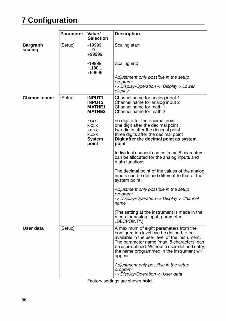
Bargraphscaling
(Setup) -19999... 0 ...+99999
-19999 ...100... +99999
Scaling start
Scaling end
Adjustment only possible in the setup program:-> Display/Operation -> Display > Lower display
Channel name (Setup) INPUT1INPUT2MATHE1MATHE2
xxxxxxx.xxx.xxx.xxxSystem point
Channel name for analog input 1Channel name for analog input 2Channel name for math 1Channel name for math 2
no digit after the decimal pointone digit after the decimal pointtwo digits after the decimal pointthree digits after the decimal pointDigit after the decimal point as system point
Individual channel names (max. 8 characters) can be allocated for the analog inputs and math functions.
The decimal point of the values of the analog inputs can be defined different to that of the system point.
Adjustment only possible in the setup program:-> Display/Operation -> Display > Channel name
(The setting at the instrument is made in the menu for analog input, parameter „DECPOINT“.)
User data (Setup) A maximum of eight parameters from the configuration level can be defined to be available in the user level of the instrument. The parameter name (max. 8 characters) can be user-defined. Without a user-defined entry, the name programmed in the instrument will appear.
Adjustment only possible in the setup program:-> Display/Operation -> User data
Parameter Value/Selection
Description
Factory settings are shown bold.
57
7 Configuration
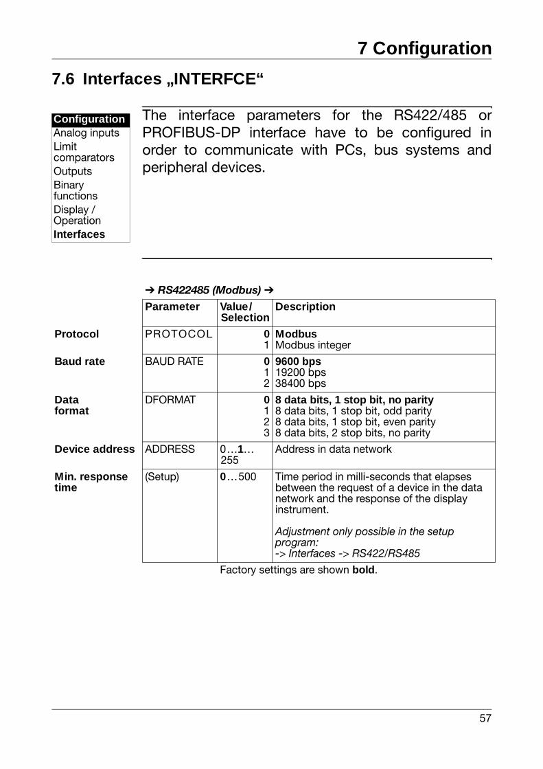
7.6 Interfaces „INTERFCE“
The interface parameters for the RS422/485 orPROFIBUS-DP interface have to be configured inorder to communicate with PCs, bus systems andperipheral devices.
ConfigurationAnalog inputsLimitcomparatorsOutputsBinaryfunctionsDisplay /OperationInterfaces
RS422485 (Modbus)
Parameter Value/Selection
Description
Protocol PROTOCOL 01
ModbusModbus integer
Baud rate BAUD RATE 012
9600 bps19200 bps38400 bps
Dataformat
DFORMAT 0123
8 data bits, 1 stop bit, no parity8 data bits, 1 stop bit, odd parity8 data bits, 1 stop bit, even parity8 data bits, 2 stop bits, no parity
Device address ADDRESS 0…1…255
Address in data network
Min. response time
(Setup) 0…500 Time period in milli-seconds that elapses between the request of a device in the data network and the response of the display instrument.
Adjustment only possible in the setup program:-> Interfaces -> RS422/RS485
Factory settings are shown bold.
7 Configuration
58
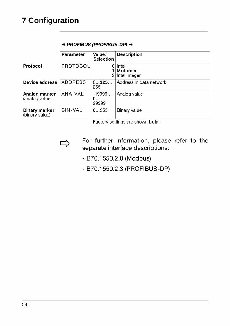
PROFIBUS (PROFIBUS-DP)
Parameter Value/Selection
Description
Protocol PROTOCOL 012
IntelMotorolaIntel integer
Device address ADDRESS 0…125…255
Address in data network
Analog marker(analog value)
ANA-VAL -19999…0…99999
Analog value
Binary marker(binary value)
BIN-VAL 0…255 Binary value
Factory settings are shown bold.
v For further information, please refer to theseparate interface descriptions:
- B70.1550.2.0 (Modbus)
- B70.1550.2.3 (PROFIBUS-DP)
59
8 Extra codes
8.1 Math and logic module
Prerequisite: The „Math“ extra code must be enabled.
vSetup program (Extras -> Enable extra codes)
The Setup program can be used to carry out twomathematical calculations or logical combinations ofvarious signals and process variables from thecontroller. The formula is created by means of aformula editor.
vSetup program (Math/Logic)
With math formulae, the calculated result is presentedthrough the two signals „Math 1“ and „Math 2“ of theanalog selector. With logic formulae, the result of thelogical combinations is available through the signals„Logic 1“ and „Logic 2“ of the binary selector whenconfiguring the binary functions.
vChapter 7.4 „Binary functions „BINFUNCT““
Enteringformulae
- The string of characters in the formula consists of ASCII characters. It can have a maximum length of 60 characters.
- The formula can only be entered in the setup program.
- Formulae can be freely entered according to the standard mathematical rules.
- In the string of characters of the formula, spaces can be inserted as required. Spaces are not permitted within function designations, variables names and constants.
8 Extra codes
60
8.2 Difference, humidity or ratio calculationThe controller can be configured through the Setupprogram such that a difference, humidity or ratiocalculation is carried out by means of a defaultformula. Analog input 2 must be available. Thefunctions need not be enabled.
vSetup program (Math/Logic)
Difference The difference of the measurements is formed fromanalog input 1 and 2.
Difference: E1-E2
Humidity The relative humidity is determined by means of apsychrometric humidity sensor, through themathematical combination of the wet bulb and drybulb temperature.
Relative humidity: (E1, E2)
E1 - dry bulb temperature via analog input 1E2 - wet bulb temperature via analog input 2
Ratio The math module forms the ratio of themeasurements from E1 and E2.
Ratio: E1/E2
Result The result is under „Math 1“ or „Math 2“ and can beused as analog value for various parameters.
vAnalog selector, Page 34

61
9 Retrofitting of modules
Safety notes
Removing the controller module
hPress together the knurled surfaces on the front panel (left and right), and pull out the controller module.
Identifying the module
h Identify the module by the sales number pasted on the packaging
A Only qualified personnel are permitted to carryout module retrofits.
E Risk of damage to the modules by electrostaticdischarge. For this reason, avoid electrostaticcharge during fitting and removal. Carry outretrofitting on a grounded workbench.
Modules Code SalesNo.
View of boards
Analog input 2 1 70/00442785
1 relay(changeover)
2 70/00442786
2 relays(make, N/O)
3 70/00442787
1 analog output 4 70/00442788
2 binary inputs 5 70/00442789
9 Retrofitting of modules
62
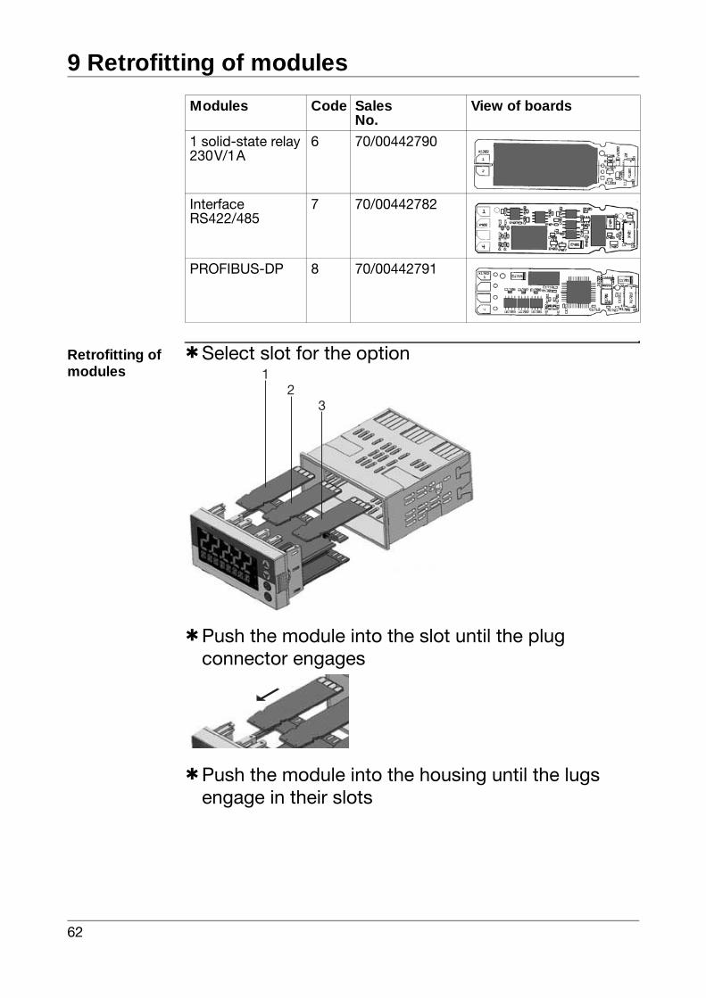
Retrofitting of modules
hSelect slot for the option
hPush the module into the slot until the plug connector engages
hPush the module into the housing until the lugs engage in their slots
1 solid-state relay230V/1A
6 70/00442790
InterfaceRS422/485
7 70/00442782
PROFIBUS-DP 8 70/00442791
Modules Code SalesNo.
View of boards
32
1
63
10 Appendix
10.1 Technical data
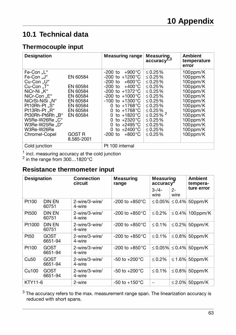
Thermocouple input
1 incl. measuring accuracy at the cold junction2 in the range from 300…1820°C
Resistance thermometer input
3 The accuracy refers to the max. measurement range span. The linearization accuracy is reduced with short spans.
Designation Measuring range Measuringaccuracy1,3
Ambienttemperature error
Fe-Con „L“Fe-Con „J“Cu-Con „U“Cu-Con „T“NiCr-Ni „K“NiCr-Con „E“NiCrSi-NiSi „N“Pt10Rh-Pt „S“Pt13Rh-Pt „R“Pt30Rh-Pt6Rh „B“W5Re-W26Re „C“W3Re-W25Re „D“W3Re-W26ReChromel-Copel
EN 60584
EN 60584EN 60584EN 60584EN 60584EN 60584EN 60584EN 60584
GOST R8.585-2001
-200 to +900°C-200 to +1200°C-200 to +600°C-200 to +400°C-200 to +1372°C-200 to +1000°C-100 to +1300°C 0 to +1768°C 0 to +1768°C 0 to +1820°C 0 to +2320°C 0 to +2495°C 0 to +2400°C-200 to +800°C
≤ 0.25%≤ 0.25%≤ 0.25%≤ 0.25%≤ 0.25%≤ 0.25%≤ 0.25%≤ 0.25%≤ 0.25%≤ 0.25% 2≤ 0.25%≤ 0.25%≤ 0.25%≤ 0.25%
100ppm/K100ppm/K100ppm/K100ppm/K100ppm/K100ppm/K100ppm/K100ppm/K100ppm/K100ppm/K100ppm/K100ppm/K100ppm/K100ppm/K
Cold junction Pt 100 internal
Designation Connectioncircuit
Measuringrange
Measuringaccuracy3
Ambienttempera-ture error3-/4-
wire2-wire
Pt100 DIN EN 60751
2-wire/3-wire/4-wire
-200 to +850°C ≤ 0.05% ≤ 0.4% 50ppm/K
Pt500 DIN EN 60751
2-wire/3-wire/4-wire
-200 to +850°C ≤ 0.2% ≤ 0.4% 100ppm/K
Pt1000 DIN EN 60751
2-wire/3-wire/4-wire
-200 to +850°C ≤ 0.1% ≤ 0.2% 50ppm/K
Pt50 GOST 6651-94
2-wire/3-wire/4-wire
-200 to +850°C ≤ 0.1% ≤ 0.8% 50ppm/K
Pt100 GOST 6651-94
2-wire/3-wire/4-wire
-200 to +850°C ≤ 0.05% ≤ 0.4% 50ppm/K
Cu50 GOST 6651-94
2-wire/3-wire/4-wire
-50 to +200°C ≤ 0.2% ≤ 1.6% 50ppm/K
Cu100 GOST 6651-94
2-wire/3-wire/4-wire
-50 to +200°C ≤ 0.1% ≤ 0.8% 50ppm/K
KTY11-6 2-wire -50 to +150°C − ≤ 2.0% 50ppm/K
10 Appendix
64
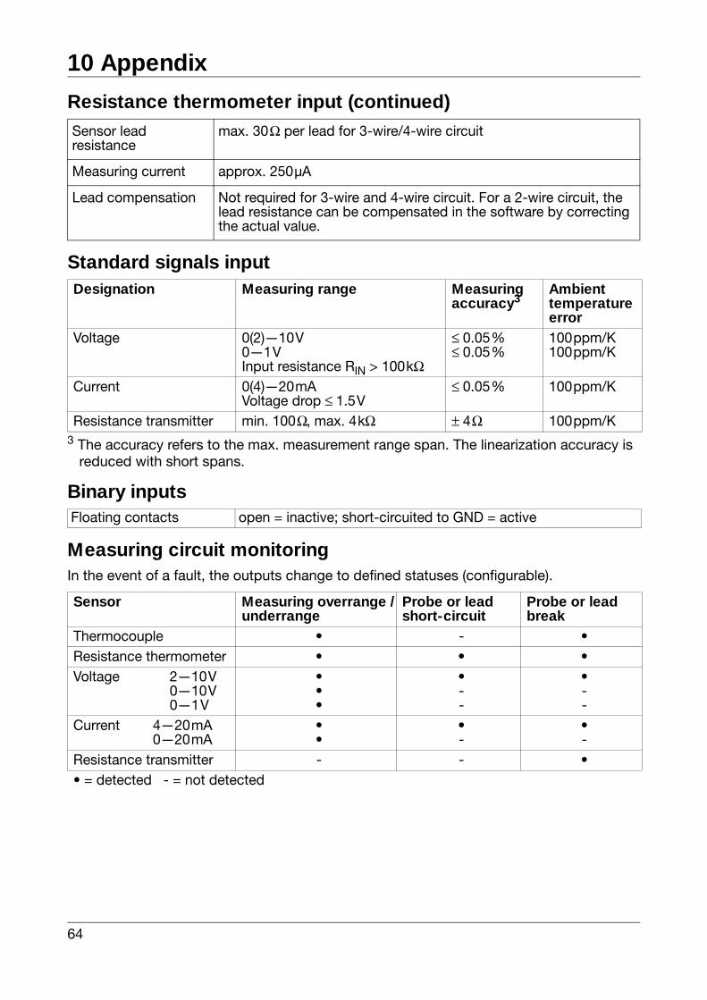
Resistance thermometer input (continued)
Standard signals input
3 The accuracy refers to the max. measurement range span. The linearization accuracy is reduced with short spans.
Binary inputs
Measuring circuit monitoringIn the event of a fault, the outputs change to defined statuses (configurable).
Sensor lead resistance
max. 30Ω per lead for 3-wire/4-wire circuit
Measuring current approx. 250µA
Lead compensation Not required for 3-wire and 4-wire circuit. For a 2-wire circuit, the lead resistance can be compensated in the software by correcting the actual value.
Designation Measuring range Measuringaccuracy3
Ambienttemperature error
Voltage 0(2)—10V 0—1V Input resistance RIN > 100kΩ
≤ 0.05%≤ 0.05%
100ppm/K100ppm/K
Current 0(4)—20mAVoltage drop ≤ 1.5V
≤ 0.05% 100ppm/K
Resistance transmitter min. 100Ω, max. 4kΩ ± 4Ω 100ppm/K
Floating contacts open = inactive; short-circuited to GND = active
Sensor Measuring overrange /underrange
Probe or lead short-circuit
Probe or lead break
Thermocouple • - •Resistance thermometer • • •Voltage 2—10V
0—10V0—1V
•••
•--
•--
Current 4—20mA0—20mA
••
•-
•-
Resistance transmitter - - •• = detected - = not detected
65
10 Appendix
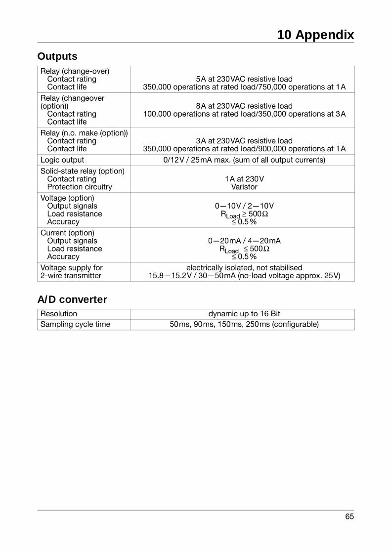
Outputs
A/D converter
Relay (change-over)Contact ratingContact life
5A at 230VAC resistive load350,000 operations at rated load/750,000 operations at 1A
Relay (changeover (option))
Contact ratingContact life
8A at 230VAC resistive load100,000 operations at rated load/350,000 operations at 3A
Relay (n.o. make (option))Contact ratingContact life
3A at 230VAC resistive load350,000 operations at rated load/900,000 operations at 1A
Logic output 0/12V / 25mA max. (sum of all output currents) Solid-state relay (option)
Contact ratingProtection circuitry
1A at 230VVaristor
Voltage (option)Output signalsLoad resistanceAccuracy
0—10V / 2—10VRLoad ≥ 500Ω
≤ 0.5%Current (option)
Output signalsLoad resistanceAccuracy
0—20mA / 4—20mARLoad ≤ 500Ω
≤ 0.5%Voltage supply for2-wire transmitter
electrically isolated, not stabilised15.8—15.2V / 30—50mA (no-load voltage approx. 25V)
Resolution dynamic up to 16 BitSampling cycle time 50ms, 90ms, 150ms, 250ms (configurable)
10 Appendix
66
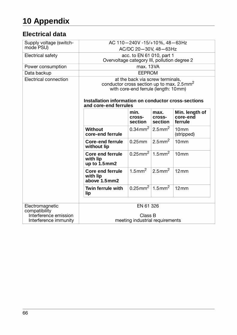
Electrical dataSupply voltage (switch- mode PSU)
AC 110—240V -15/+10%, 48—63HzAC/DC 20—30V, 48—63Hz
Electrical safety acc. to EN 61 010, part 1 Overvoltage category III, pollution degree 2
Power consumption max. 13VAData backup EEPROMElectrical connection at the back via screw terminals,
conductor cross section up to max. 2.5mm2
with core-end ferrule (length: 10mm)
Electromagnetic compatibility
Interference emissionInterference immunity
EN 61 326
Class Bmeeting industrial requirements
Installation information on conductor cross-sections and core-end ferrules
min.cross-section
max.cross-section
Min. length of core-end ferrule
Withoutcore-end ferrule
0.34mm2 2.5mm2 10mm(stripped)
Core-end ferrule without lip
0.25mm 2.5mm2 10mm
Core end ferrule with lip up to 1.5mm2
0.25mm2 1.5mm2 10mm
Core end ferrule with lip above 1.5mm2
1.5mm2 2.5mm2 12mm
Twin ferrule with lip
0.25mm2 1.5mm2 12mm
67
10 Appendix
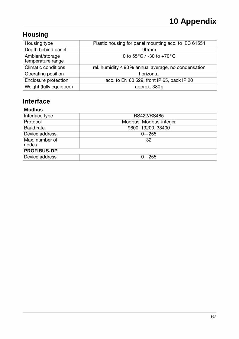
Housing
Interface
Housing type Plastic housing for panel mounting acc. to IEC 61554Depth behind panel 90mmAmbient/storagetemperature range
0 to 55°C / -30 to +70°C
Climatic conditions rel. humidity ≤ 90% annual average, no condensationOperating position horizontalEnclosure protection acc. to EN 60 529, front IP 65, back IP 20Weight (fully equipped) approx. 380g
ModbusInterface type RS422/RS485Protocol Modbus, Modbus-integerBaud rate 9600, 19200, 38400Device address 0—255Max. number ofnodes
32
PROFIBUS-DPDevice address 0—255
10 Appendix
68
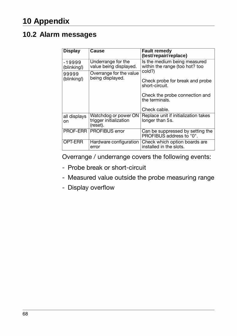
10.2 Alarm messages
Overrange / underrange covers the following events:
- Probe break or short-circuit
- Measured value outside the probe measuring range
- Display overflow
Display Cause Fault remedy(test/repair/replace)
-19999(blinking!)
Underrange for the value being displayed.
Is the medium being measured within the range (too hot? too cold?)
Check probe for break and probe short-circuit.
Check the probe connection and the terminals.
Check cable.
99999(blinking!)
Overrange for the value being displayed.
all displays on
Watchdog or power ON trigger initialization (reset).
Replace unit if initialization takes longer than 5s.
PROF-ERR PROFIBUS error Can be suppressed by setting the PROFIBUS address to "0".
OPT-ERR Hardware configuration error
Check which option boards are installed in the slots.
69
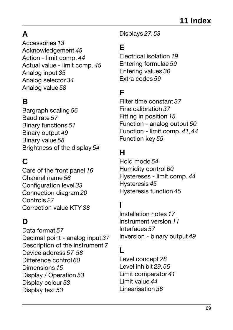
11 Index
AAccessories 13Acknowledgement 45Action - limit comp. 44Actual value - limit comp. 45Analog input 35Analog selector 34Analog value 58
BBargraph scaling 56Baud rate 57Binary functions 51Binary output 49Binary value 58Brightness of the display 54
CCare of the front panel 16Channel name 56Configuration level 33Connection diagram 20Controls 27Correction value KTY 38
DData format 57Decimal point - analog input 37Description of the instrument 7Device address 57–58Difference control 60Dimensions 15Display / Operation 53Display colour 53Display text 53
Displays 27, 53
EElectrical isolation 19Entering formulae 59Entering values 30Extra codes 59
FFilter time constant 37Fine calibration 37Fitting in position 15Function - analog output 50Function - limit comp. 41, 44Function key 55
HHold mode 54Humidity control 60Hystereses - limit comp. 44Hysteresis 45Hysteresis function 45
IInstallation notes 17Instrument version 11Interfaces 57Inversion - binary output 49
LLevel concept 28Level inhibit 29, 55Limit comparator 41Limit value 44Linearisation 36
11 Index
70
MMains frequency 38Math and logic module 59Measurement offset 36Measuring range 50Min/max mode 54Modbus 57Mounting site 15
OOffset - analog output 50Operation time-out 54Operator level 31Option slots 12Outputs 48
PPC interface 13Process data 32PROFIBUS-DP 58Protocol 57–58Pulse time - limit comp. 45
RRatio control 60Removing the controller module
16Response time 57Retrofitting of modules 61RS422/485 57
SSampling cycle time 38Scaling 37, 50Scope of delivery 13Scroll mode 55Sensor type 35Setpoint value - limit comp. 45Setup program 13Special characters 53Start delay time 54Switch status - limit comp. 44Switching action - binary func-
tion 51Switch-off delay 44Switch-on delay 44System point 54
TTare function 52Temperature unit 38Ticker 54Type designation 11Type of signal - analog output 50
UUSB interface 13User data 28, 56
VVariable setpoint value 42