Embed Size (px)
Citation preview
Aus- und Weiterbildung GmbH ELABOTrainingsSystemeELABOTrainingsSysteme
®
SO
LU
TIO
NS
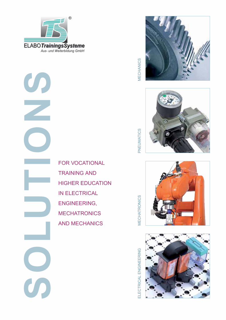
FOR VOCATIONAL
TRAINING AND
HIGHER EDUCATION
IN ELECTRICAL
ENGINEERING,
MECHATRONICS
AND MECHANICS
PN
EU
MAT
ICS
ELE
CTR
ICA
L E
NG
INE
ER
ING
ME
CH
ATR
ON
ICS
ME
CH
AN
ICS

S O L U T I O N S
ELABOTrainingsSysteme GmbH
Inspiring technologies
3
ELABOTrainingsSystemeELABOTrainingsSysteme
®
MECHANICAL ENGINEERING Page 14
MEDIA-T3BoxX Page 28
ELECTRICAL ENGINEERING / ELECTRONICS / DIGITAL TECHOLOGY Page 34
CONTROL ENGINEERING Page 50
POWER ENGINEERING Page 54
DRIVE TECHNOLOGY Page 72
PNEUMATICS Page 80
METROLOGY AND INSTRUMENTATION Page 84
PHOTOVOLTAICS Page 94
MECHATRONICS Page 98
BUILDING SYSTEMS ENGINEERING Page 104
AUTOMATION TECHNOLOGY Page 120
MICROCOMPUTERS Page 134
INFORMATION AND CONSULTING Page 140
P
P
P
P
P
P
P
P
P
P
P
P
P
P
INFO
�
bar
4
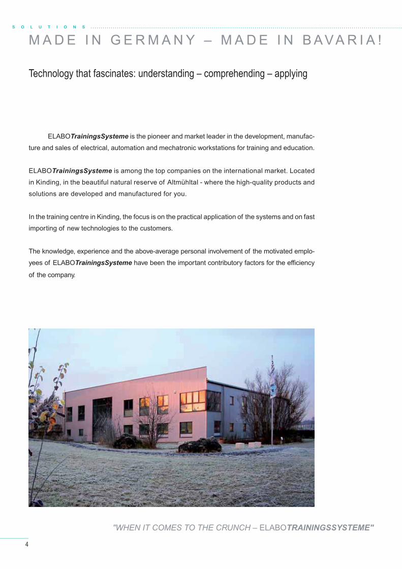
M A D E I N G E R M A N Y – M A D E I N B AVA R I A !
Technology that fascinates: understanding – comprehending – applying
ELABOTrainingsSysteme is the pioneer and market leader in the development, manufac-
ture and sales of electrical, automation and mechatronic workstations for training and education.
ELABOTrainingsSysteme is among the top companies on the international market. Located
in Kinding, in the beautiful natural reserve of Altmühltal - where the high-quality products and
solutions are developed and manufactured for you.
In the training centre in Kinding, the focus is on the practical application of the systems and on fast
importing of new technologies to the customers.
The knowledge, experience and the above-average personal involvement of the motivated emplo-
yees of ELABOTrainingsSysteme have been the important contributory factors for the effi ciency
of the company.
"WHEN IT COMES TO THE CRUNCH – ELABOTRAININGSSYSTEME"
S O L U T I O N S

5
ELABOTrainingsSystemeELABOTrainingsSysteme
®
Visit us in the valley of river Altmühl
INGOLSTADT HBF
NÜRNBERG HBF(Anschlüsse in alle Richtungen)
MÜNCHEN HBF
INGOLSTADT NORD
KINDING (Altmühltal)
ALLERSBERG (Rothsee)
Augsburg
Donauwörth
Treuchtlingen
Regensburg
Photographs sourced from "Naturpark Altmühltal" (www.naturpark-altmuehltal.de)
Kloster Weltenburg – photographs sourced from "fotolia"
With the start-up of the new ICE-route between Munich and
Nuremberg, the Altmühl region, with its regional railway station at Kinding
has got a new connection to the national and international railway network.
You now have the option to travel comfortably by train when you visit us for
seminars taking place in Kinding-Haunstetten. There are local taxi compa-
nies in service for the drive to Haunstetten. We would be happy to provide
help in organising the trip.

6
S O L U T I O N S
T E C H N O LO G Y A N D H U M A N – A S U C C E S S F U L
Welcome to ELABOTrainingsSysteme
ELABOTrainingsSysteme is your partner for
in-house and institutional education and training in
the professional fi elds of electrical engineering and
metal technology.
Subjects like drive technology, power electronics, au-
tomation engineering, sensor systems, bus systems,
instrumentation, gear technology and the comple-
te scope of building systems engineering including
renewable energies can all be counted among the
strengths of the company.
The spectrum of services off ered by ELABOTrainingsSysteme ranges from the planning and
outfi tting of complete training facilities to the provision of learning and teaching materials. Apart
from the after-sales service, the off ering of services is rounded off by practical workshops spe-
cially tailored for trainers and instructors.
Vocational schools, training centres of the chambers of commerce and trades or the industry, po-
lytechnics and universities are among the long-standing customers of ELABOTrainingsSysteme.
ELABOTrainingsSysteme supplies the complete equipment for modern training facilities. In ad-
dition, laboratory benches (for example, with concealed power supply attachments according
to customer specifi cations) with all the electrical and electronic devices and systems, seating
and storage cabinets, up to the comple-
te media supply and the IT. The service
covers everything from requirements
analysis to the turnkey handover of the
equipment. Moreover, ELABOTrainings-
Systeme also provides accompanying
didactic project manuals for subject-orien-
ted education.
"WHEN IT COMES TO THE CRUNCH – ELABOTrainingsSysteme"

7
ELABOTrainingsSystemeELABOTrainingsSysteme
®
Training facilities
C O M B I N AT I O N
TO PLAN A CUSTOM-MADE ROOM CONCEPT WITH YOU,
WE PROCEED IN THE FOLLOWING STEPS:
analysis
procurement
conception
execution, construction
consultation, planning
service
seminars
Planning a room concept is more than just selecting the furniture. A roomconcept has to be developed in response to the demands of the customer and to the conditions on site.
A good room concept is based on profound, professional consultation. And this requires a competent partner with experience and expert knowledge.
8
S O L U T I O N S
T R A I N I N G C O N C E P T
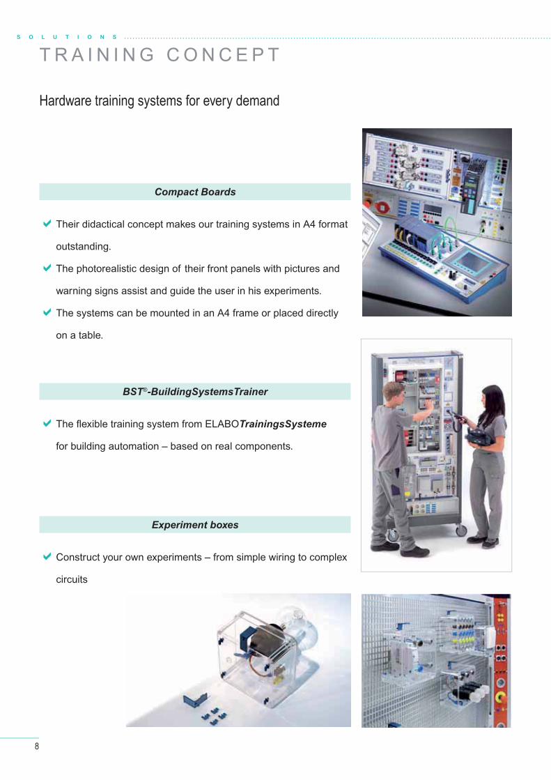
Hardware training systems for every demand
Their didactical concept makes our training systems in A4 format
outstanding.
The photorealistic design of their front panels with pictures and
warning signs assist and guide the user in his experiments.
The systems can be mounted in an A4 frame or placed directly
on a table.
The fl exible training system from ELABOTrainingsSysteme
for building automation – based on real components.
BST®-BuildingSystemsTrainer
Experiment boxes
Compact Boards
Construct your own experiments – from simple wiring to complex
circuits
9
ELABOTrainingsSystemeELABOTrainingsSysteme
®
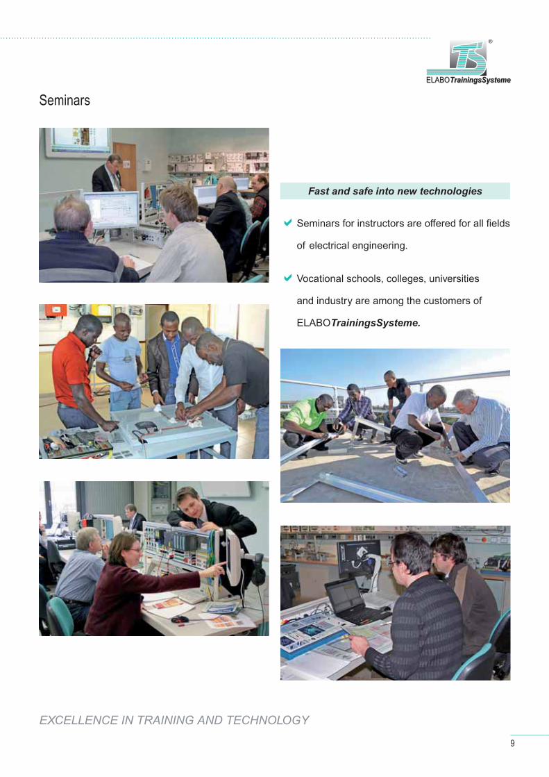
Seminars
Seminars for instructors are off ered for all fi elds
of electrical engineering.
Vocational schools, colleges, universities
and industry are among the customers of
ELABOTrainingsSysteme.
Fast and safe into new technologies
EXCELLENCE IN TRAINING AND TECHNOLOGY
10
S O L U T I O N S
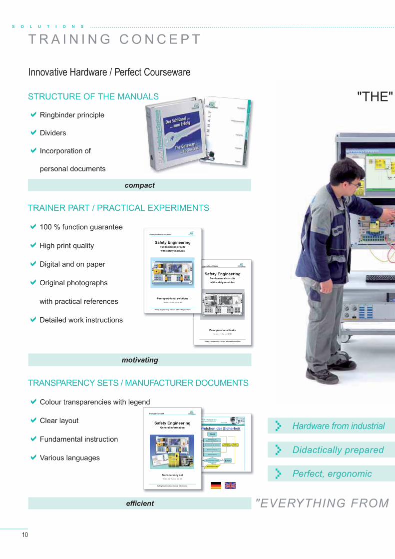
T R A I N I N G C O N C E P T
Innovative Hardware / Perfect Courseware
"THE"
Hardware from industrial
Didactically prepared
Perfect, ergonomic
Safety EngineeringFundamental circuits
with safety modules
Pan-operational tasks
Version 4.0 – Cat. no. 40 161
Pan-operational tasks
Safety Engineering: Circuits with safety modules
ELABOTrainingsSystemeELABOTrainingsSysteme
®
Folie 42
SicherheitstechnikAllgemeine Informationen
Prozess zum Erreichen der Sicherheit Prozess zum Erreichen der Sicherheit
Bestimmung der Grenzen der Maschine
Identifizierung der Maschine
Risikoeinschätzung
Risikobewertung
Ist die Maschine sicher?
Risikominimierung
Nein
EndeJa
BewertungEN ISO13849-1
Risiko-beurteilung
Start
S
n-op
Safety EngineeringFundamental circuits
with safety modules
Pan-operational solutions
Version 4.0 – Cat. no. 40 160
Pan-operational solutions
Safety Engineering: Circuits with safety modules
ELABOTrainingsSystemeELABOTrainingsSysteme
®
SichhheeeeerrhAllgeemmmmeeein
Prozess zum ErrrrrrreProzess zum EProzess zum ErrrrrrreProzess zum ErrrrrreSafety Engineering
General information
Transparency set
Version 4.2 – Cat. no. E40 167
Transparency set
Safety Engineering: General information
ELABOTrainingsSystemeELABOTrainingsSysteme
®
STRUCTURE OF THE MANUALS
Ringbinder principle
Dividers
Incorporation of
personal documents
TRAINER PART / PRACTICAL EXPERIMENTS
100 % function guarantee
High print quality
Digital and on paper
Original photographs
with practical references
Detailed work instructions
TRANSPARENCY SETS / MANUFACTURER DOCUMENTS
Colour transparencies with legend
Clear layout
Fundamental instruction
Various languages
effi cient
motivating
compact
ALS
"EVERYTHING FROM
11
ELABOTrainingsSystemeELABOTrainingsSysteme
®
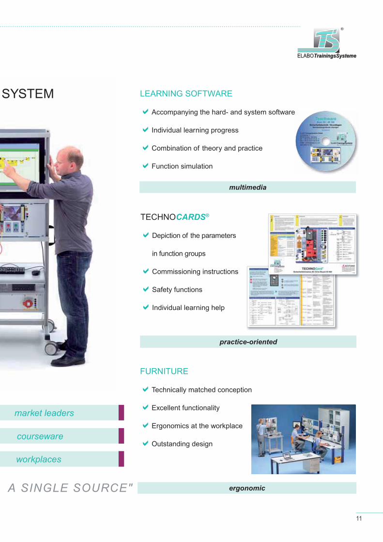
SYSTEM
market leaders
courseware
workplaces
LEARNING SOFTWARE
Accompanying the hard- and system software
Individual learning progress
Combination of theory and practice
Function simulation
TECHNOCARDS®
Depiction of the parameters
in function groups
Commissioning instructions
Safety functions
Individual learning help
FURNITURE
Technically matched conception
Excellent functionality
Ergonomics at the workplace
Outstanding design
ergonomic
practice-oriented
multimedia
A SINGLE SOURCE"
12
S O L U T I O N S
I N F O C E N T E R
Products and solutions
Electrical engineering / Electronics / Digital technology
Microcomputer / Microcontroller
Photovoltaics
Control engineering
Transformers
Electrical safety / Protective measures
Aus- und Weiterbildung GmbH ELABOTrainingsSystemeELABOTrainingsSysteme
®
elabo-ts.com
Electrical EngineeringElectrical EngineeringElectronicsElectronics
Electrical Engineering / Electronics
Aus- und Weiterbildung GmbH ELABOTrainingsSystemeELABOTrainingsSysteme
®
elabo-ts.com
Contactor ControlContactor ControlAutomation Automation Mechatronics Mechatronics
Control Technology / Automation / Mechatronics
Control technology
Safety engineering
Automation
Drive technology / Power electronics
Mechatronics
Pneumatics / Electropneumatics
Energy measurement technology
Robotics
ELABOTrainingsSysteme GmbHIm Hüttental 1185125 Kinding - Germany
Tel.: + 49 (0) 84 67 / 84 04 - 0Fax: + 49 (0) 84 67 / 84 04 44E-mail: [email protected]
INFO-Centerp r o d u c t s a n d s o l u t i o n s
V e r s i o n 6 . 3
ELABOTrainingsSysteme GmbH
I N S P I R I N G t e c h n o l o g i e s www.elabo-ts.com
TrainingsSystemeELABOELABOELABOELABOTrainingsSystemeTrainingsSystemeTrainingsSystemeAus- und Weiterbildung GmbH
®®
13
ELABOTrainingsSystemeELABOTrainingsSysteme
®
Installation engineering / Lighting technology
KNX
Electrical safety / Protective measures
Communication systems
Antenna technology
Bus-capable intercoms
SMART home
Energy measurement technology
Aus- und Weiterbildung GmbH ELABOTrainingsSystemeELABOTrainingsSysteme
®
elabo-ts.com
DistributedDistributedBuilding Systems TechnologyBuilding Systems Technology
Building Systems Technology
Mechanical engineeringGear units
Pneumatics / Electropneumatics
Room furnishingLaboratory furniture
Has the CD been taken out?Contact us and we will sendyou a current [email protected]
Measurement technology
Three Phase Network Analyzer
Energy measurement technology

14
M E C H A N I C A L E N G I N E E R I N G
H E L I C A L G E A R U N I T 1 - S TA G E E T S 1
Mechanical components for practical training NEW
L E A R N I N G O B J E C T I V E S
Assess assembly drawings, layout plans, and parts lists
Select suitable test equipment and create test reports
Create assembly plans for proper assembly and disassembly
Develop test criteria for functional test
Plan maintenance including environmentally-friendly disposal of material and operating fl uids
Analyze faults and determine components to be replaced
Assemble technical subsystems with subsequent function check
Convert existing systems according to customer request
Select tools and resources by means of function plans and design drawings
Analyze, plan, and organize workfl ows (assembly, disassembly and preventive
maintenance measures)

15
The model is ideally suited for explaining how to assemble and disassemble a 1-stage helical gear unit and how a helical gear unit works. All the tools and resources needed to carry out assembly and disassembly are integrated in this system. An illustrated, detailed assembly instruction provides trainees with a step-by-step explanation for correct assem-bly and disassembly.
The perfect order systemELABOTrainingsSystemeELABOTrainingsSysteme
®
Content of the case
Helical gear unit Assembly tools
Industrial helical gear unit Complete learning model (incl. all parts and tools) Portable and clearly structured Ideal for training in the metal industry Assembly and disassembly without pressing tools
Functions
57 307 Roll unit for suitcase
57 345 Helical gear unit (1-stage)in case for transportation and storage
57 306 Assembly toolsgear unit technology
H E L I C A L G E A R U N I T C A S E E T S 1
16
C O U R S E W A R EM E C H A N I C A L E N G I N E E R I N G
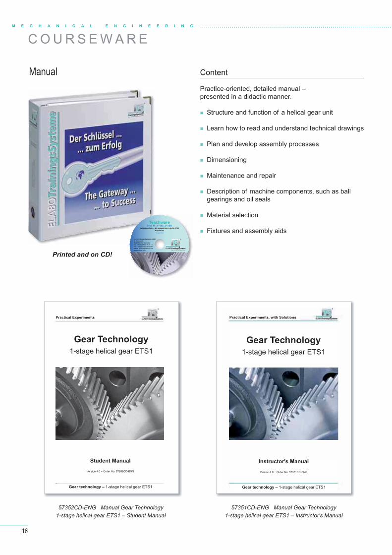
Manual
Printed and on CD!
57352CD-ENG Manual Gear Technology1-stage helical gear ETS1 – Student Manual
57351CD-ENG Manual Gear Technology1-stage helical gear ETS1 – Instructor's Manual
Gear TechnologyGear Technology
1-stage helical gear ETS11-stage helical gear ETS1
Student ManualStudent Manual
Version 4.0 − Order No. 57352CD-ENGVersion 4.0 − Order No. 57352CD-ENG
Gear technology – Gear technology – 1-stage helical gear ETS11-stage helical gear ETS1
Practical Experiments
Instructor's ManualInstructor's Manual
Version 4.0 − Order No. 57351CD-ENGVersion 4.0 − Order No. 57351CD-ENG
Gear TechnologyGear Technology
1-stage helical gear ETS11-stage helical gear ETS1
Gear technology – Gear technology – 1-stage helical gear ETS11-stage helical gear ETS1
Practical Experiments, with Solutions
Content
Practice-oriented, detailed manual – presented in a didactic manner.
Structure and function of a helical gear unit
Learn how to read and understand technical drawings
Plan and develop assembly processes
Dimensioning
Maintenance and repair
Description of machine components, such as ball gearings and oil seals
Material selection
Fixtures and assembly aids
Aus- und Weiterbildung GmbH ELABOTrainingsSystemeELABOTrainingsSysteme
®ELABOTrainingsSysteme GmbHIm Hüttental 11 85125 Kinding - GermanyTel.: +49 (0) 84 67/ 84 04 - 0 Fax: +49 (0) 84 67/ 84 04 44E-Mail: [email protected]
TeachwareBest.-Nr.: 57351CD-DEU
Getriebetechnik – Stirnradgetriebe 1-stufig ETS1Ausbilderteil
Version 4.0
17
ELABOTrainingsSystemeELABOTrainingsSysteme
®
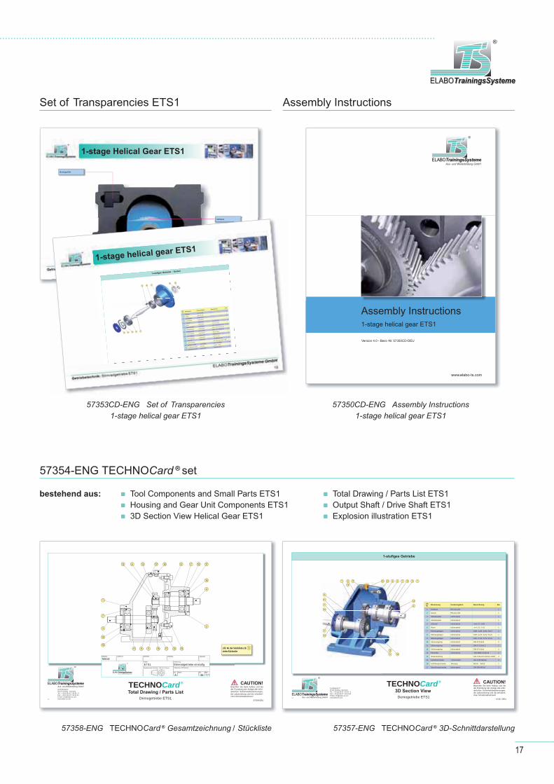
Assembly InstructionsSet of Transparencies ETS1
57354-ENG TECHNOCard ® set
57358-ENG TECHNOCard ® Gesamtzeichnung / Stückliste 57357-ENG TECHNOCard ® 3D-Schnittdarstellung
57350CD-ENG Assembly Instructions1-stage helical gear ETS1
57353CD-ENG Set of Transparencies1-stage helical gear ETS1
bestehend aus: Tool Components and Small Parts ETS1 Housing and Gear Unit Components ETS1 3D Section View Helical Gear ETS1
Total Drawing / Parts List ETS1 Output Shaft / Drive Shaft ETS1 Explosion illustration ETS1
Aus- und Weiterbildung GmbH ELABOTrainingsSystemeELABOTrainingsSysteme
®
Montageanleitung Stirnradgetriebe 1-stufig ETS1
www.elabo-ts.com
Version 4.0 - Best.-Nr. 57350CD-DEU
Assembly Instructions1-stage helical gear ETS1
Montagehilfe
GehäuseGehäuse
147
13
4 10
8 2 6 12
11
1-stufiges Getriebe – Deckel
14 11 10 7 4
13 8 26 12
Lfd. Nr.
Benennung Zusatzangaben BezeichnungStk.
1 GehäuseEN-GJL-200
1
2 DeckelEN-GJL-200
1
3 Abtriebswelle nichtrostend
1
4 Antriebswelle nichtrostend
1
5 Zahnradnichtrostend
m=1,75 Z=301
6 Ritzelnichtrostend
m=1,75 Z=231
7 Rillenkugellager nichtrostend6305 d=25 D=62 B=17 2
8 Rillenkugellager nichtrostend6205 d=25 D=52 B=15 1
9 Rillenkugellager nichtrostend6304 d=20 D=52 B=15 1
10 Sicherungsring nichtrostendDIN 472-62x2
2
11 Sicherungsring nichtrostendDIN 471-25x1,2
2
12 Sicherungsring nichtrostendDIN 471-16x1
2
13 Passfeder nichtrostend DIN 6885-A 5x5x16 2
14 WellendichtringDIN 3760-AS 22x62x7-NBR 2
15 Zylinderschraube nichtrostendISO 4762 M8x16 4
16 Entlüftungsschaube MessingM10x1 SW13
1
17 Verschlussschraube nichtrostendDIN 908-M10x1
2
1-stage helical gear ETS1
1-stage Helical Gear ETS1
Aus- und Weiterbildung GmbH ELABOTrainingsSystemeELABOTrainingsSysteme
®
Im Hüttental 11 85125 Kinding - GermanyTel.: + 49 (0) 84 67 / 84 04 - 0 Fax: + 49 (0) 84 67 / 84 04 44E-Mail: [email protected]
57 320
Beachten Sie beim Aufbau und bei der Erprobung der Anlage alle erfor-derlichen Sicherheitsbestimmungen, die Laborordnung und die erforderli-chen Schutzmaßnahmen!
ACHTUNG!
3
14
10
7
1
9 135 1217 15
612 1713 16 8 7 10 11
11
14
4
2
12 6 13 17 16 8 7 10 11
14
4
2
15121713591110
14
3
7
1
Lfd. Nr. der Stückliste z.B.siehe Rückseite
1
57358-DEU
TECHNOCard®
Gesamtzeichnung / StücklisteDemogetriebe ETS1
ETS1
Metall
Aus- und Weiterbildung GmbH ELABOTrainingsSystemeELABOTrainingsSysteme
®
DIN ISO 2768-mK
Total Drawing / Parts List
CAUTION!
Aus- und Weiterbildung GmbH ELABOTrainingsSystemeELABOTrainingsSysteme
®
Im Hüttental 11 85125 Kinding - GermanyTel.: + 49 (0) 84 67 / 84 04 - 0 Fax: + 49 (0) 84 67 / 84 04 44E-Mail: [email protected]
57 319
Beachten Sie beim Aufbau und bei der Erprobung der Anlage alle erfor-derlichen Sicherheitsbestimmungen, die Laborordnung und die erforderli-chen Schutzmaßnahmen!
ACHTUNG!
2 1
7
8
3
4
13
13
7
10
9
11
12
6
5
10 11
14
14
151617
1-stufiges Getriebe
1 6 17 16 15 8 2 77 10 11
14
4
125
13
14
3
10
9
11
7
13
57357-DEU
TECHNOCard®
3D-SchnittdarstellungDemogetriebe ETS1
Lfd. Nr. Benennung Zusatzangaben Bezeichnung Stk.
1 Gehäuse EN-GJL-200 1
2 Deckel EN-GJL-200 1
3 Abtriebswelle nichtrostend 1
4 Antriebswelle nichtrostend 1
5 Zahnrad nichtrostend m=1,75 Z=30 1
6 Ritzel nichtrostend m=1,75 Z=23 1
7 Rillenkugellager nichtrostend 6305 d=25 D=62 B=17 2
8 Rillenkugellager nichtrostend 6205 d=25 D=52 B=15 1
9 Rillenkugellager nichtrostend 6304 d=20 D=52 B=15 1
10 Sicherungsring nichtrostend DIN 472-62x2 2
11 Sicherungsring nichtrostend DIN 471-25x1,2 2
12 Sicherungsring nichtrostend DIN 471-16x1 2
13 Passfeder nichtrostend DIN 6885-A 5x5x16 2
14 Wellendichtring DIN 3760-AS 22x62x7-NBR 2
15 Zylinderschraube nichtrostend ISO 4762 M8x16 4
16 Entlüftungsschaube Messing M10x1 SW13 1
17 Verschlussschraube nichtrostend DIN 908-M10x1 2
3D Section View
CAUTION!

18
M E C H A N I C A L E N G I N E E R I N G
Assess assembly drawings, layout plans, and parts lists
Select suitable test equipment and create test reports
Create assembly plans for proper assembly and disassembly
Develop test criteria for functional test
Plan maintenance including environmentally-friendly disposal of material and operating fl uids
Analyze faults and determine components to be replaced
Assemble technical subsystems with subsequent function check
Convert existing systems according to customer request
Select tools and resources by means of function plans
and design drawings
Analyze, plan, and organize workfl ows (assembly, disassembly and preventive
maintenance measures)
H E L I C A L G E A R U N I T 2 - A N D 3 - S TAG E E T S 2
Mechanical components for practical training
L E A R N I N G O B J E C T I V E S
19
ELABOTrainingsSystemeELABOTrainingsSysteme
®
H E L I C A L G E A R U N I T C A S E E T S 2
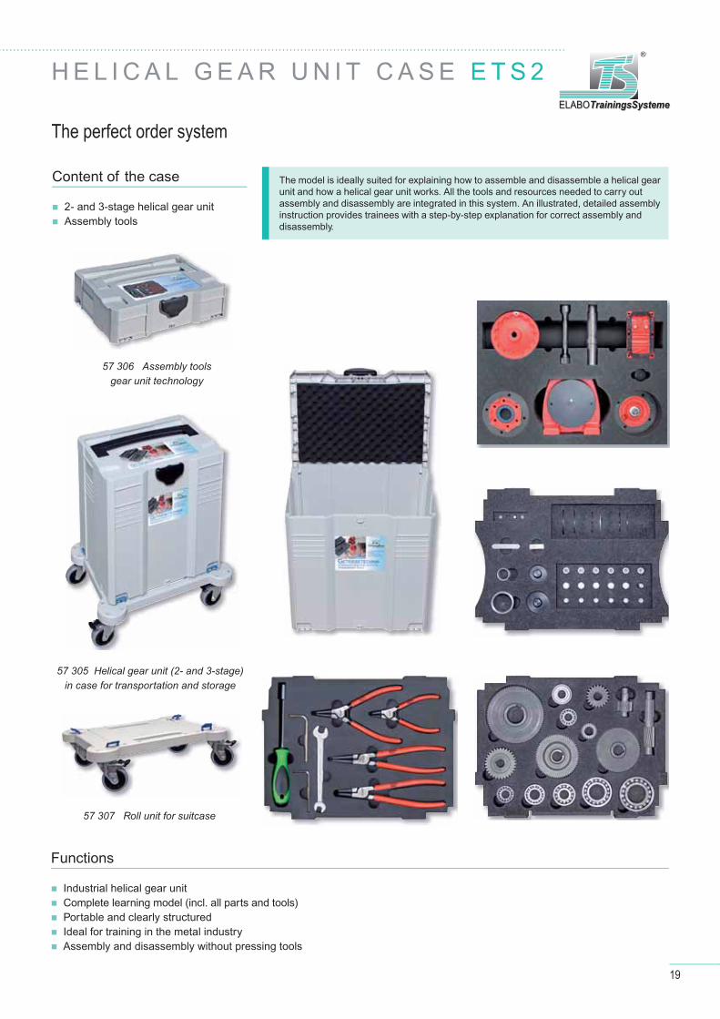
The model is ideally suited for explaining how to assemble and disassemble a helical gear unit and how a helical gear unit works. All the tools and resources needed to carry out assembly and disassembly are integrated in this system. An illustrated, detailed assembly instruction provides trainees with a step-by-step explanation for correct assembly and disassembly.
The perfect order system
Content of the case
2- and 3-stage helical gear unit Assembly tools
Industrial helical gear unit Complete learning model (incl. all parts and tools) Portable and clearly structured Ideal for training in the metal industry Assembly and disassembly without pressing tools
Functions
57 307 Roll unit for suitcase
57 305 Helical gear unit (2- and 3-stage)in case for transportation and storage
57 306 Assembly toolsgear unit technology

20
C O U R S E W A R EM E C H A N I C A L E N G I N E E R I N G
Manual Content
Practice-oriented, detailed manual – presented in a didactic manner.
Structure and function of a helical gear unit
Learn how to read and understand technical drawings
Plan and develop assembly processes
Dimensioning
Maintenance and repair
Description of machine components, such as ball gearings and oil seals
Material selection
Fixtures and assembly aids
Printed and on CD!
57312CD-ENG Manual Gear Technology2- and 3-stage helical gear ETS2 – Student Manual
57311CD-ENG Manual Gear Technology2- and 3-stage helical gear ETS2 – Instructor's Manual
Gear TechnologyGear Technology
2- and 3-stage helical gear ETS22- and 3-stage helical gear ETS2
Student ManualStudent Manual
Version 4.6 – Order No. 57312CD-ENGVersion 4.6 – Order No. 57312CD-ENG
Gear technology – Gear technology – 2- and 3-stage helical gear ETS22- and 3-stage helical gear ETS2
Practical Experiments
Instructor's ManualInstructor's Manual
Version 4.6 – Order No. 57311CD-DEUVersion 4.6 – Order No. 57311CD-DEU
Gear TechnologyGear Technology
2- and 3-stage helical gear ETS22- and 3-stage helical gear ETS2
Gear technology – Gear technology – 2- and 3-stage helical gear ETS22- and 3-stage helical gear ETS2
Practical Experiments, with Solutions
Aus- und Weiterbildung GmbH ELABOTrainingsSystemeELABOTrainingsSysteme
®ELABOTrainingsSysteme GmbHIm Hüttental 11 85125 Kinding - GermanyTel.: +49 (0) 84 67/ 84 04 - 0 Fax: +49 (0) 84 67/ 84 04 44E-Mail: [email protected]
TeachwareBest.-Nr.: 57311CD-DEU
Getriebetechnik - Stirnradgetriebe ETS2AusbilderteilVersion 4.6
21
ELABOTrainingsSystemeELABOTrainingsSysteme
®
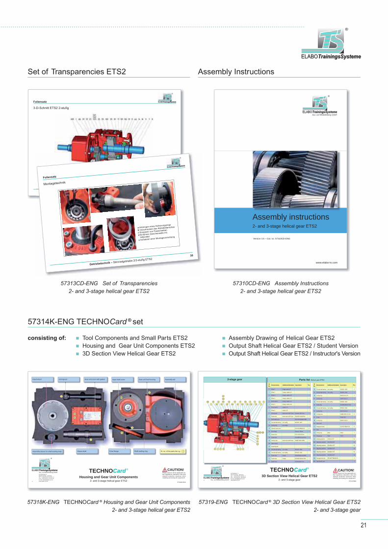
Assembly InstructionsSet of Transparencies ETS2
57314K-ENG TECHNOCard ® set
57318K-ENG TECHNOCard ® Housing and Gear Unit Components2- and 3-stage helical gear ETS2
57319-ENG TECHNOCard ® 3D Section View Helical Gear ETS22- and 3-stage gear
57310CD-ENG Assembly Instructions2- and 3-stage helical gear ETS2
57313CD-ENG Set of Transparencies2- and 3-stage helical gear ETS2
consisting of: Tool Components and Small Parts ETS2 Housing and Gear Unit Components ETS2 3D Section View Helical Gear ETS2
Assembly Drawing of Helical Gear ETS2 Output Shaft Helical Gear ETS2 / Student Version Output Shaft Helical Gear ETS2 / Instructor's Version
Aus- und Weiterbildung GmbH ELABOTrainingsSystemeELABOTrainingsSysteme
®
Im Hüttental 11 85125 Kinding - GermanyTel.: + 49 (0) 84 67 / 84 04 - 0 Fax: + 49 (0) 84 67 / 84 04 44E-mail: [email protected]
57318K-ENG
TECHNOCard®
Housing and Gear Unit Components2- and 3-stage helical gear ETS2
Please observe all the applicable sa-fety regulations, laboratory rules and required protective measures when installing and testing the equipment!
CAUTION!
Sr. no. of the parts list e.g. 1
Hand wheel Joining tool Gear unit cover with gasket
Output shaftAssembly sleeve for shaft sealing rings
Assembly aidGear unit foot housingInput shaft cover
Drive fl ange Shaft sealing ring
2
7
22
16
9
600
100
102
Aus- und Weiterbildung GmbH ELABOTrainingsSystemeELABOTrainingsSysteme
®
Im Hüttental 11 85125 Kinding - GermanyTel.: + 49 (0) 84 67 / 84 04 - 0 Fax: + 49 (0) 84 67 / 84 04 44E-mail: [email protected]
57319-ENG
Please observe all the applicable sa-fety regulations, laboratory rules and required protective measures when installing and testing the equipment!
CAUTION!TECHNOCard ®
3D Section View Helical Gear ETS2 2- and 3-stage gear
Parts list Helical gear ETS22-stage gear
600
1
88
29
22
23 25 100
20
81
17
101
102
19
11
40
14
16 7
859523
522
521
9
507506 508
39
131
37
181
30 2 3431 532 6
Sr. No.
Nomenclature Additional information Description Pcs.
1 Wheel 1 2-stage, coated, z27 1
1 Wheel 1 3-stage, coated, z21 1
2 Wheel 2 2-stage, coated, z78 1
2 Wheel 2 3-stage, coated, z31 1
3 Pinion shaft 3 3-stage, coated, z21 1
4 Wheel 4 3-stage, coated, z66 1
5 Pinion shaft 5 coated, z16 1
6 Wheel 6 coated, z93 1
7 Driving shaft stainless steel; ASEPTICplus Diameter 35x70 mm 1
8 Feather key stainless steel; ASEPTICplus DIN 6885 A10x8x56-Niro 1
9 Shaft sealing ring DIN 3760 AS40x62x7-NBR 1
11 Grooved ball bearing non-rusting DIN 625 - 6207 1
12 Locking ring non-rusting 1
14 Cylinder head screw ISO 4762 M8x20-8.8 6
16 Drive fl ange Diameter 160mm 1
17 Spacer tube D36 x D45x36,5mm 1
19 Feather key DIN 6885 B10x8x32 Niro 1
20 Venting valve stainless steel; ASEPTICplus W4087 M10x1-NIRO 1
22 Gear housing 1
23 Supporting disc 1
25 Grooved ball bearing non-rusting DIN 625 - 6206 1
30 Grooved ball bearing non-rusting DIN 625 - 6302
31 Feather key 2-stage DIN 6885 B6x6x16-55HRC 1
31 Feather key 3-stage DIN 6885 B6x6x14 Niro 1
32 Spacer tube D20,6xD25x22 mm 1
Sr. No.
Nomenclature Additional information Description Pcs.
34 Grooved ball bearing non-rusting DIN 625 - 6004 1
37 Grooved ball bearing non-rusting DIN 625 - 6303 1
39 Locking ring DIN 472 47x1,75 1
41 Locking ring DIN 472 35x1,5 1
42 Grooved ball bearing non-rusting DIN 625 - 6202 1
43 Feather key DIN 6885 B5x5x10 Niro 1
45 Grooved ball bearing non-rusting DIN 625 - 6202 1
47 Locking ring DIN 472 35x1,6 1
59 Locking screw W4085 M10x1-ST-A2L 5
81 O-ring W4283 66-3 1
88 Locking ring DIN 471 30x1,6 1
100 Gear cover 1
101 Hexagonal screw ISO 4017 M6x16-8.9 6
102 Seal 1
131 Closing cap Delrin 47x30 1
181 Closing cap Delrin 37x30 1
507 Adjusting washers 37x47x0,3-ST X)
508 Adjusting washers 37x47x0,5-ST X)
516 Adjusting washers 25x35x0,3-ST X)
517 Adjusting washers 25x35x0,5-ST X)
522 Adjusting washers 30x42x0,3-ST X)
523 Adjusting washers 30x42x0,5-ST X)
204 Hexagonal screw ISO 4017 M8x20-8.8 1
600 Input shaft cover 1
Aus- und Weiterbildung GmbH ELABOTrainingsSystemeELABOTrainingsSysteme
®
Assembly instructions2- and 3-stage helical gear ETS2
www.elabo-ts.com
Version 4.6 – Cat. no. 57310CD-ENG
22
M E C H A N I C A L E N G I N E E R I N G
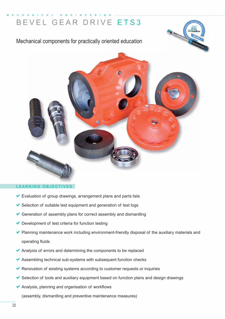
B E V E L G E A R D R I V E E T S 3
L E A R N I N G O B J E C T I V E S
Evaluation of group drawings, arrangement plans and parts lists
Selection of suitable test equipment and generation of test logs
Generation of assembly plans for correct assembly and dismantling
Development of test criteria for function testing
Planning maintenance work including environment-friendly disposal of the auxiliary materials and
operating fl uids
Analysis of errors and determining the components to be replaced
Assembling technical sub-systems with subsequent function checks
Renovation of existing systems according to customer requests or inquiries
Selection of tools and auxiliary equipment based on function plans and design drawings
Analysis, planning and organisation of workfl ows
(assembly, dismantling and preventive maintenance measures)
Mechanical components for practically oriented education
► With chapter
Qua
lity
Assu
ranc
e ► With chapter Quality Assurance ►
►W
e►
Quality ▲
Aus- und Weiterbildung GmbH ELABOTrainingsSystemeELABOTrainingsSysteme
®
WWWWWWWiiiiiittttthhhhccchhhapter
Qua
lityt
A surance
►►►►►WWWWWW
e►
Quality ▲
Aus- und Weiterbildung GmbH Aus- uOELABBOTraining y eELABOELABOELABOBOBOTrainin S t meTrainingsSystemeTrainingsSysteme
23
ELABOTrainingsSystemeELABOTrainingsSysteme
®
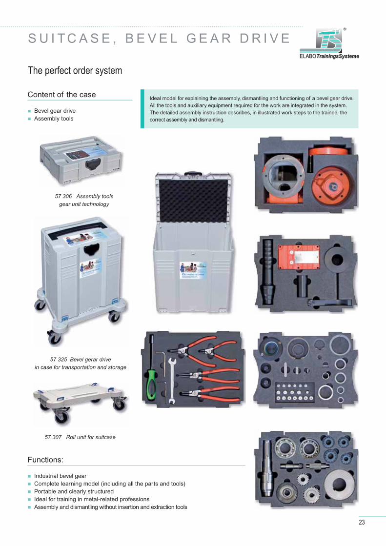
S U I T C A S E , B E V E L G E A R D R I V E
Content of the case
Bevel gear drive Assembly tools
Industrial bevel gear Complete learning model (including all the parts and tools) Portable and clearly structured Ideal for training in metal-related professions Assembly and dismantling without insertion and extraction tools
Functions:
The perfect order system
Ideal model for explaining the assembly, dismantling and functioning of a bevel gear drive. All the tools and auxiliary equipment required for the work are integrated in the system.The detailed assembly instruction describes, in illustrated work steps to the trainee, the correct assembly and dismantling.
57 307 Roll unit for suitcase
57 325 Bevel gerar drive in case for transportation and storage
57 306 Assembly toolsgear unit technology

24
C O U R S E W A R EM E C H A N I C A L E N G I N E E R I N G
Manual Content
Practice-oriented, detailed manual – presented in a didactic manner.
Structure and function of a bevel gear drive unit
Learn how to read and understand technical drawings
Plan and develop assembly processes
Dimensioning
Maintenance and repair
Description of machine components, such as ball gearings and oil seals
Material selection
Fixtures and assembly aids
NEW! With chapter Quality assurance
- The quality concept- Quality test- Quality assurance - Statistical analysis- Standard deviation- The Pareto method
Printed and on CD!
57332CD-ENG Manual Gear TechnologyBevel gear drive ETS3 – Student Manual
57331CD-ENG Manual Gear TechnologyBevel gear drive ETS3 – Instructor's Manual
Gear TechnologyGear Technology
Bevel gear drive ETS3Bevel gear drive ETS3
Student ManualStudent Manual
Version 4.1 – Order No. 57332CD-ENGVersion 4.1 – Order No. 57332CD-ENG
Gear technology – Gear technology – Bevel gear drive ETS3Bevel gear drive ETS3
Practical Experiments
Instructor's ManualInstructor's Manual
Version 4.1 – Order No. 57331CD-ENGVersion 4.1 – Order No. 57331CD-ENG
Gear TechnologyGear Technology
Bevel gear drive ETS3Bevel gear drive ETS3
Gear technology – Gear technology – Bevel gear drive ETS3Bevel gear drive ETS3
Practical Experiments, with Solutions
► With chapter
Qua
lity
Assu
ranc
e ► With chapter Quality Assurance ►
►W
e►
Quality ▲
Aus- und Weiterbildung GmbH ELABOTrainingsSystemeELABOTrainingsSysteme
®
rance
WWWWWWWiiiiiittttthhhhccchhhapter
Qua
lityt
A surance
►►►►►WWWWWW
e►
Quality ▲
Aus- und Weiterbildung GmbH Aus- uOELABBOTraining y meELABOELABOELABOBOBOTrainin S t meTrainingsSystemeTrainingsSysteme
TeachwareBest.-Nr.: 57331CD-DEU
Getriebetechnik - Kegelradgetriebe ETS3
Ausbilderteil
Version 4.1
Aus- und Weiterbildung GmbH ELABOTrainingsSystemeELABOTrainingsSysteme
®ELABOTrainingsSysteme GmbH Im Hüttental 11 85125 Kinding - GermanyTel.: + 49 (0) 84 67/ 84 04 - 0 Fax: + 49 (0) 84 67/ 84 04 44E-Mail: [email protected]
25
ELABOTrainingsSystemeELABOTrainingsSysteme
®
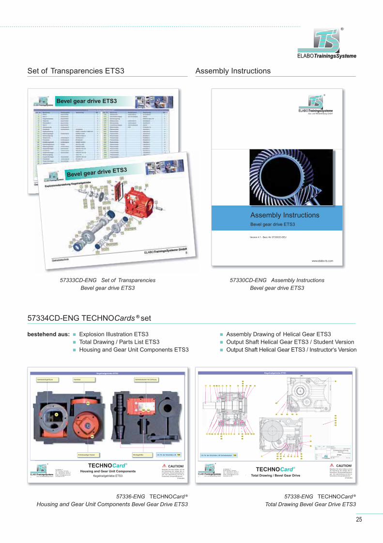
Assembly InstructionsSet of Transparencies ETS3
57334CD-ENG TECHNOCards ® set
57336-ENG TECHNOCard ® Housing and Gear Unit Components Bevel Gear Drive ETS3
57338-ENG TECHNOCard ®
Total Drawing Bevel Gear Drive ETS3
57330CD-ENG Assembly InstructionsBevel gear drive ETS3
57333CD-ENG Set of TransparenciesBevel gear drive ETS3
bestehend aus: Explosion Illustration ETS3 Total Drawing / Parts List ETS3 Housing and Gear Unit Components ETS3
Assembly Drawing of Helical Gear ETS3 Output Shaft Helical Gear ETS3 / Student Version Output Shaft Helical Gear ETS3 / Instructor‘s Version
Aus- und Weiterbildung GmbH ELABOTrainingsSystemeELABOTrainingsSysteme
®
Montageanleitung Kegelradgetriebe ETS3
www.elabo-ts.com
Version 4.1 - Best.-Nr. 57330CD-DEU
Assembly InstructionsBevel gear drive ETS3
Kegelradgetriebe ETS3
Kegelradgetriebe ETS3 Bevel gear drive ETS3
Bevel gear drive ETS3
4.1Aus- und Weiterbildung GmbH
ELABOTrainingsSystemeELABOTrainingsSysteme
®
Im Hüttental 11 85125 Kinding - GermanyTel.: + 49 (0) 84 67 / 84 04 - 0 Fax: + 49 (0) 84 67 / 84 04 44E-Mail: [email protected]
Kegelradgetriebe ETS3
57336-DEU
TECHNOCard ®
Gehäuse- und Getriebekomponenten
Kegelradgetriebe ETS3
Getriebefußgehäuse Handrad Getriebedeckel mit Dichtung
Antriebsseitiger Deckel Montagehilfen Lfd. Nr. der Stückliste z.B 100
800
813
22
100 102
Beachten Sie beim Aufbau und bei der Erprobung der Anlage alle er-forderlichen Sicherheitsbestimmun-gen, die Laborordnung und die er-forderlichen Schutzmaßnahmen!
ACHTUNG!
57338-DEU
TECHNOCard ®
Gesamtzeichnung Kegelradgetriebe ETS34.1
Aus- und Weiterbildung GmbH ELABOTrainingsSystemeELABOTrainingsSysteme
®
Im Hüttental 11 85125 Kinding - GermanyTel.: + 49 (0) 84 67 / 84 04 - 0 Fax: + 49 (0) 84 67 / 84 04 44E-Mail: [email protected]
Beachten Sie beim Aufbau und bei der Erprobung der Anlage alle er-forderlichen Sicherheitsbestimmun-gen, die Laborordnung und die er-forderlichen Schutzmaßnahmen!
ACHTUNG!
Kegelradgetriebe ETS3
Lfd. Nr. der Stückliste z.B Getriebedeckel 100
7
9 131 137 37 4 30 132 823 1613139 506 542 1335
507 543
508 544
823 6
8 819 12 17 25 521
522
523
820 11 19 88 89820
815
100 101 102 22
20
59
800
202
201
204
813
1
115
163
531
532
434211945
536533
537534
538535
3 2
530ETS3
Aus- und Weiterbildung GmbH ELABOTrainingsSystemeELABOTrainingsSysteme
®
Housing and Gear Unit Components
Total Drawing / Bevel Gear Drive
CAUTION! CAUTION!
26
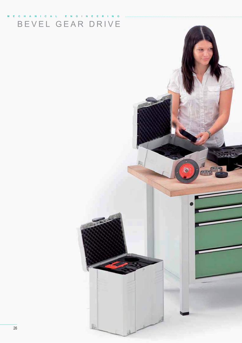
B E V E L G E A R D R I V EM E C H A N I C A L E N G I N E E R I N G

27
ELABOTrainingsSystemeELABOTrainingsSysteme
®

28
M E D I A - T 3 B O X X
Clear red stroke
Approx. 1000 questions and answers
14 examinations
Many PowerPoint transparencies
Each chapter is complete in itself
Hardware-independent learning
Modular ordering possible
H I G H L I G H T S
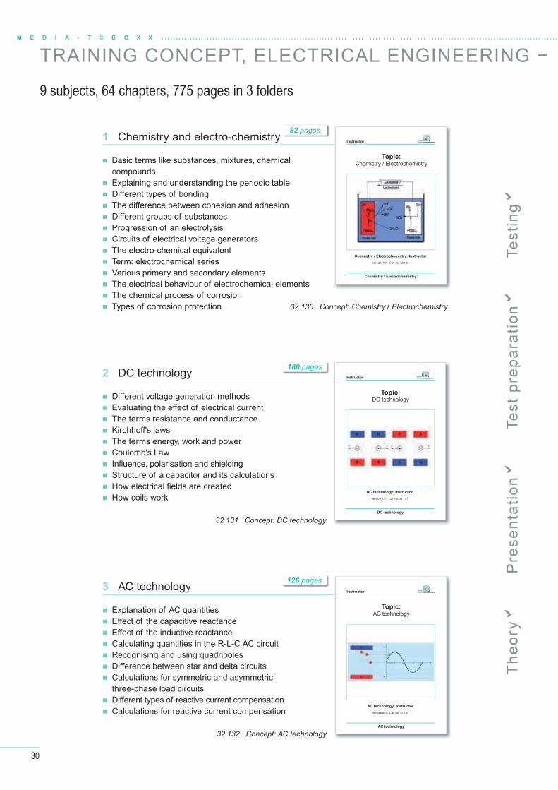
TRAINING CONCEPT, ELECTRICAL ENGINEERING −
9 subjects, 64 chapters, 775 pages in 3 folders
Enhance your lessons with fresh, easy and uncomplicated ideas with a hardware-independent training concept for electrical engineering.
In 9 chapters, participants are taught the principles of electrical engineering based on a student script.
The trainer's documents are highlighted by a connecting thread.
1000 questions and answers as well as many complete examination units make sustained training easily achievable.
The documents are divided into approx. 160 – 175 teaching units.
Special layout:
The instructor can see from the colours whether the student has the same information or whether he must work out the formulas, calculations or the diagram with the participants.
Discover the well thought-through concept of the MEDIA-T3BoxX.
Teaching • Training • Technology
29
ELABOTrainingsSystemeELABOTrainingsSysteme
®
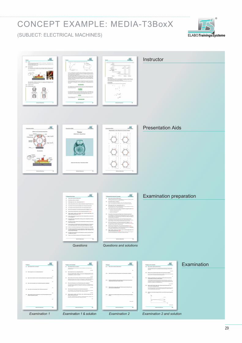
CONCEPT EXAMPLE: MEDIA-T3BoxX(SUBJECT: ELECTRICAL MACHINES)
Instructor
Presentation Aids
Examination preparation
Examination
Questions
Examination 1 Examination 2
Questions and solutions
Examination 1 & solution Examination 2 and solution
Dozent
Elektrische Maschinen 6
8.2.2 Rotor Bei Gleichstrommaschinen besteht der Rotor aus Rotorkörper, Rotorwicklung, Strom-wender und gegebenenfalls Lüfter. Bei Gleichstromgeneratoren wird in der Regel der Rotor als Anker bezeichnet, weil in ihm Spannungen induziert werden.
8.2.3 Stromwender Der Stromwender, auch mit Kollektor oder Kommutator bezeichnet, besteht aus einzel-nen in Umfangsrichtung voneinander und gegen die Welle isolierten Hartkupferlamellen.
Stromwender im Schnitt
Der Stromwender wandelt beim Generator die induzierte Wechselspannung in eine Gleichspannung um. Beim Motor dient er zur Umwandlung der angelegten Gleich-spannung in eine Wechselspannung.
8.2.4 Funktionsweise
8.2.4.1 Gleichstromgenerator
Welle
NN
SS
A1A1 A2A2
R
Lamellen
Isolation
Welle
Kohle
Lötfahne
IsolationSchlussring
Lauffläche
nn
Q
H
IA
Dozent
Elektrische Maschinen 16
Leerlaufkennlinie und Belastungskennlinie Nebenschlussgenerator
Aus der Leerlaufkennlinie ist erkennbar, dass die Spannung des Generators proportio-nal mit dem Erregerstrom ansteigt. Bei Einsetzen der Sättigung des Eisens knickt die Kurve entsprechend der Hysteresekurve ab und eine weitere Erregerstromerhöhung bewirkt keinen Spannungsanstieg mehr. Die Leerlaufkennlinie beginnt bei der Remanenzspannung, die vom vorhergehenden Betrieb des Generators im Eisen zurückgeblieben ist. Dabei ist darauf zu achten, dass der Strom bei Wiederaufnahme des Betriebes so gerichtet ist, dass sein Magnetfeld die gleiche Richtung aufweist, wie die Richtung des Feldes aus dem Restmagnetismus. Andernfalls würde der Restmagnetismus abgebaut und der Generator könnte seine Spannung nicht aufbauen.
Die Drehzahl während der Aufnahme der Leerlaufkennlinie ist konstant. Der Feldsteller und die Erregerwicklung liegen in Reihe. So ergibt sich die induzierte Spannung aus dem Produkt von Erregerstrom und den Widerständen von Erregerwicklung und Feldsteller.
)RR(IU STEe0
Eine Veränderung der Leerlaufspannung wird durch eine Erregerstromänderung über den Feldsteller erreicht. Aus diesem Zusammenhang kann der maximal mögliche Erre-gerstrom bestimmt werden.
0e
E ST
UIR R
Die Belastungskennlinie des Nebenschlussgenerators stellt die Abhängigkeit der Klemmspannung vom Belastungsstrom dar. Beim Nebenschlussgenerator wird ein Teil des Ankerstromes (2-6%) zur Nebenschlusswicklung abgezweigt. Daraus folgt, dass der Netzstrom um den Betrag des Erregerstromes geringer als der Ankerstrom ist.
N A eI I I
Die zur Verfügung stehende Klemmenspannung des Nebenschlussgenerators sinkt mit zunehmender Belastung.
Kl 0 N e iU U (I I ) R
Erregerstrom Ie
Spa
nnun
g U
Spa
nnun
g U
Strom I
UR = Remanenzspannung
Belastungspunkt
Differenz durch Ankerrückwirkung
Nennstrom
IK
Sättigung
Dozent
Elektrische Maschinen 40
StänderanlasserBeim Ständeranlasser werden in die Zuleitungen des Ständers Vorwiderstände ge-schaltet. Dadurch ergibt sich ein Spannungsteiler, die Spannung am Motor verringert sich und damit auch der Strom durch die Wicklungen. Großer Nachteil dieses Anlassverfahrens ist die Verlustleistung der Vorwiderstände.
KusaschaltungPrinzipdarstellung der Kusaschaltung (Kurzschlusssanftanlauf)
Präsentationshilfen
Elektrische Maschinen 60
Ständer einer Gleichstrommaschine
Stromwender
Präsentationshilfen
Elektrische Maschinen 59
Thema:Elektrische Maschinen
Elektrische Maschinen: Präsentationshilfen
Präsentationshilfen
Elektrische Maschinen 75
Magnetfelder in einer Maschine mit einem Polpaar
W2
W2
W2
W2
W2
W2
V2 V2
V2 V2
V2 V2
U1
U1
U1
U1
U1
U1
V1
V1
V1
V1
V1 V1
W1
W1
W1
W1
W1
W1
U2
U2
U2
U2
U2
U2
L1 L1
L1 L1
L1 L1
L2 L2
L2 L2
L2 L2
L3 L3
L3 L3
L3 L3
1.2.
3.
4.5.
6.
Prüfungsvorbereitung
Elektrische Maschinen 88
8.1 Wozu dienen elektrische Maschinen?
8.2 Was bedeutet Rotor und Stator?
8.3 Was besagt Innen- bzw. Außenpolmaschine?
8.4 Nach welchen Kriterien können elektrische Maschinen eingeteilt werden?
8.5 Aus welchen Teilen besteht der Ständer einer Gleichstrommaschine?
8.6 Aus welchen Teilen besteht der Läufer einer Gleichstrommaschine?
8.7 Wie ist der Kommutator einer Gleichstrommaschine aufgebaut?
8.8 Wozu dient der Stromwender in einer Gleichstrommaschine?
8.9 Wann besteht zwischen den Bürsten eines Gleichstromgenerators der größte Potentialunterschied?
8.10 Wann tritt bei Gleichstromgeneratoren das Ankerquerfeld auf und wovon ist es abhängig?
8.11 Was bewirkt das Ankerquerfeld in Bezug auf das Hauptfeld des Gleich-stromgenerators?
8.12 Wie äußert sich das Auftreten des Ankerquerfeldes in Bezug auf die elekt-risch neutrale Zone?
8.13 Warum kommt es bei Belastung des Gleichstromgenerators an den Bürs-ten zu einem Bürstenfeuer, und wie kann dieses unterbunden werden?
8.14 Wovon ist die induzierte Spannung eines Gleichstromgenerators abhängig?
8.15 Wo liegen die geometrische und die elektrische neutrale Zone im Leerlauf und bei Belastung eines Gleichstromgenerators (ohne Wendepole und Kompensationswicklung)?
8.16 Wo liegen die geometrische und die elektrisch neutrale Zone beim Gleich-stromgenerator immer?
8.17 Warum ist bei Gleichstrommotoren ein Stromwender erforderlich?
Prüfungsvorbereitung und Lösungen
Elektrische Maschinen 99
8.1 Wozu dienen elektrische Maschinen? Elektrische Maschinen dienen zur Umwandlung von mechanischer Energie in elektri-sche Energie (Generatoren) und umgekehrt (Motoren).
8.2 Was bedeutet Rotor und Stator? Rotor: Ist die Gesamtheit der beweglichen Teile in einer elektrischen Maschine.
Stator: Ist die Gesamtheit der feststehenden Teile in einer elektrischen Maschine.
8.3 Was besagt Innen- bzw. Außenpolmaschine?Bei Innenpolmaschinen wird das Hauptmagnetfeld im Läufer bereitgestellt und bei Au-ßenpolmaschinen wird es im Ständer bereitgestellt.
8.4 Nach welchen Kriterien können elektrische Maschinen eingeteilt werden? Gleichstrom- Wechselstrommaschinen
Außenpol- Innenpolmaschinen
Motoren und Generatoren
8.5 Aus welchen Teilen besteht der Ständer einer Gleichstrommaschine? Zum feststehenden Teil einer Gleichstrommaschine gehören das Joch , das (Gehäu-se), die Polkörper, das Klemmbrett, ggf. die Wendepole, die Erregerwicklung, ggf. die Wendepolwicklung, die Lagerschilde, ggf die Kompensationswicklung, die Kohlebürs-ten und die Halter der Kohlebürsten.
8.6 Aus welchen Teilen besteht der Läufer einer Gleichstrommaschine? Zum beweglichem Teil einer Gleichstrommaschine gehören die Rotorwelle, der Rotor-körper, die Lager, die Rotorwicklung, der Stromwender und ggf. der Lüfter.
8.7 Wie ist der Kommutator einer Gleichstrommaschine aufgebaut?Der Kommutator oder Kollektor besteht aus einzelnen in Umfangsrichtung voneinander und gegen die Welle isolierten Hartkupferlamellen.
8.8 Wozu dient der Stromwender in einer Gleichstrommaschine?Der Stromwender wandelt die in einem Gleichstromgenerator induzierte Wechselspan-nung in eine Gleichspannung um. Beim Gleichstrommotor dient er zur Umwandlung der angelegten Gleichspannung in eine Wechselspannung.
8.9 Wann besteht zwischen den Bürsten eines Gleichstromgenerators der größte Potentialunterschied?Der größte Potentialunterschied zwischen den Bürsten besteht bei Gleichstromgenera-toren, wenn die Bürstenbrücke in der elektrisch neutralen Zone steht.
Prüfung 1
Elektrische Maschinen 125
8.1 Was bedeuten Rotor und Stator?
Der Rotor einer elektrischen Maschine ist der sich drehende Teil, der Stator ist der festste-hende Teil:
5+5=10P.
8.2 Was besagt Innen- bzw. Außenpolmaschine?
Bei einer Innenpolmaschine handelt es sich um eine elektrische Maschine deren Hauptmag-netfeld im Läufer hervorgerufen wird. Bei der Außenpolmaschine wird das Hauptmagnetfeldim Ständer hervorgerufen.
5+5=10P.
8.3 Nach welchen Kriterien können elektrische Maschinen eingeteilt werden?
Elektrische Maschinen können in Motoren und Generatoren, in Gleichstrom-maschinen und Wechselstrommaschinen und in Innenpol- bzw. Außenpolmaschinen unterteilt werden.
6x3=18P.
8.4 Wie ist der Kommutator einer Gleichstrommaschine aufgebaut?
Der Kommutator einer Gleichstromstrommaschine besteht aus in Umfangsrichtung angeord-neten Hartkupferlamellen. Die Lamellen sind untereinander und gegen die Welle des Läu-fers isoliert.
5+5=10P.
8.5 Wozu dient der Stromwender einer Gleichstrommaschine?
Der Stromwender einer Gleichstrommaschine dient zur Umwandlung des Wechselstromes in Gleichstrom beim Generator, oder umgekehrt beim Motor.
5+5=10P.
8.6 Wann besteht zwischen den Bürsten eines Gleichstromgenerators der größte Potentialunterschied?
Der größte Potentialunterschied besteht bei Gleichstromgeneratoren zwischen den Bürsten wenn diese in der elektrischen neutralen Zone steht.
10P.
Prüfung 1 und Lösungen
Elektrische Maschinen 132
8.1 Was bedeuten Rotor und Stator?
Der Rotor einer elektrischen Maschine ist der sich drehende Teil, der Stator ist der feststehende Teil:
5+5=10P.
8.2 Was besagt Innen- bzw. Außenpolmaschine?
Bei einer Innenpolmaschine handelt es sich um eine elektrische Maschine deren Hauptmagnetfeld im Läufer hervorgerufen wird. Bei der Außenpolmaschine wird das Hauptmagnetfeld im Ständer hervorgerufen.
5+5=10P.
8.3 Nach welchen Kriterien können elektrische Maschinen eingeteilt werden?
Elektrische Maschinen können in Motoren und Generatoren, in Gleichstrommaschinen und Wechselstrommaschinen und in Innenpol- bzw. Außenpolmaschinen unterteilt werden.
6x3=18P.
8.4 Wie ist der Kommutator einer Gleichstrommaschine aufgebaut?
Der Kommutator einer Gleichstromstrommaschine besteht aus in Umfangsrichtung an-geordneten Hartkupferlamellen. Die Lamellen sind untereinander und gegen die Welle des Läufers isoliert.
5+5=10P.
8.5 Wozu dient der Stromwender einer Gleichstrommaschine?
Der Stromwender einer Gleichstrommaschine dient zur Umwandlung des Wechsel-stromes in Gleichstrom beim Generator, oder umgekehrt beim Motor.
5+5=10P.
8.6 Wann besteht zwischen den Bürsten eines Gleichstromgenerators der größte Potentialunterschied?
Der größte Potentialunterschied besteht bei Gleichstromgeneratoren zwischen den Bürsten wenn diese in der elektrischen neutralen Zone stehen.
10P.
Prüfung 2
Elektrische Maschinen 139
8.1.1 Wozu dienen elektrische Maschinen?
Elektrische Maschinen dienen zur Umwandlung von mechanischer Energie in elektrischer (Generatoren) oder zur Umwandlung von elektrischer Energie in mechanische (Motoren).
5+5=10P.
8.1.2 Warum kann bei Drehstrommaschinen der Stromwender entfallen?
Der Stromwender kann bei Drehstrommaschinen entfallen weil durch das Drehfeld des Netz-stromes ein umlaufendes Drehfeld bereitgestellt wird.
5P.
8.1.3 Welche grundsätzliche Unterscheidung wird für Drehstrommaschinen vorgenommen und woher resultiert diese?
Eine grundsätzliche Unterscheidung findet bei Drehstrommaschinen zwischen Synchronma-schinen und Asynchronmaschinen statt. Synchronmaschinen haben eine Läuferdrehzahl die gleich der Drehfelddrehzahl ist. Asynchronmaschinen haben eine Läuferdrehzahl die ungleich der Drehfelddrehzahl ist.
8.1.4 Warum dreht sich der Läufer einer Drehstromsynchronmaschine syn-chron mit der Drehfelddrehzahl?
Der Läufer einer Drehstromsynchronmaschine kann sich deshalb mit synchroner Drehzahl zum Drehfeld drehen weil seine Pole direkt gegenüber den ungleich-namigen Polen des Stän-derdrehfeldes stehen können.
10P.
8.1.5 Skizzieren Sie die Belastungskennlinien eines Drehstromsynchrongene-rators?
10+3x2=16P.
Prüfung 2 und Lösungen
Elektrische Maschinen 146
8.1.1 Wozu dienen elektrische Maschinen?
Elektrische Maschinen dienen zur Umwandlung von mechanischer Energie in elektri-sche (Generatoren) oder zur Umwandlung von elektrischer Energie in mechanischer (Motoren).
5+5=10P.
8.1.2 Warum kann bei Drehstrommaschinen der Stromwender entfallen?
Der Stromwender kann bei Drehstrommaschinen entfallen, weil durch das Drehfeld des Netzstromes ein umlaufendes Drehfeld bereitgestellt wird.
5P.
8.1.3 Welche grundsätzliche Unterscheidung wird für Drehstrommaschinen vorgenommen und woher resultiert diese?
Eine grundsätzliche Unterscheidung findet bei Drehstrommaschinen zwischen Syn-chronmaschinen und Asynchronmaschinen statt. Synchronmaschinen haben eine Läu-ferdrehzahl, die gleich der Drehfelddrehzahl ist. Asynchronmaschinen haben eine Läu-ferdrehzahl, die ungleich der Drehfelddrehzahl ist.
3+3+4+4=14P.
8.1.4 Warum dreht sich der Läufer einer Drehstromsynchronmaschine syn-chron mit der Drehfelddrehzahl?
Der Läufer einer Drehstromsynchronmaschine kann sich deshalb mit synchroner Dreh-zahl zum Drehfeld drehen, weil seine Pole direkt gegenüber den ungleichnamigen Po-len des Ständerdrehfeldes stehen können.
10P.
8.1.5 Skizzieren Sie die Belastungskennlinien eines Drehstromsynchrongenera-tors?
10+3x2=16P.
30
M E D I A - T 3 B O X X
TRAINING CONCEPT, ELECTRICAL ENGINEERING −
9 subjects, 64 chapters, 775 pages in 3 folders
2 DC technology
3 AC technology
1 Chemistry and electro-chemistry
Basic terms like substances, mixtures, chemical compounds
Explaining and understanding the periodic table Diff erent types of bonding The diff erence between cohesion and adhesion Diff erent groups of substances Progression of an electrolysis Circuits of electrical voltage generators The electro-chemical equivalent Term: electrochemical series Various primary and secondary elementsThe electrical behaviour of electrochemical elements
The chemical process of corrosion Types of corrosion protection
Diff erent voltage generation methods Evaluating the eff ect of electrical current The terms resistance and conductance Kirchhoff 's laws The terms energy, work and power Coulomb's Law Infl uence, polarisation and shielding Structure of a capacitor and its calculations How electrical fi elds are created How coils work
Explanation of AC quantities Eff ect of the capacitive reactance Eff ect of the inductive reactance Calculating quantities in the R-L-C AC circuit Recognising and using quadripoles Diff erence between star and delta circuits Calculations for symmetric and asymmetric three-phase load circuits
Diff erent types of reactive current compensation Calculations for reactive current compensation
Instructor
Topic:Chemistry / Electrochemistry
Chemistry / Electrochemistry: Instructor
Version 4.0 – Cat. no. 32 130
Chemistry / Electrochemistry:
ELABOTrainingsSystemeELABOTrainingsSysteme
®
Instructor
Topic:DC technology
DC technology: Instructor
Version 4.0 – Cat. no. 32 131
DC technology
ELABOTrainingsSystemeELABOTrainingsSysteme
®
Instructor
Topic:AC technology
AC technology: Instructor
Version 4.0 – Cat. no. 32 132
AC technology
ELABOTrainingsSystemeELABOTrainingsSysteme
®
32 130 Concept: Chemistry / Electrochemistry
32 131 Concept: DC technology
32 132 Concept: AC technology
180 pages
82 pages
126 pages
Th
eo
ry P
rese
nta
tio
n T
est
pre
pa
rati
on
Te
stin
g
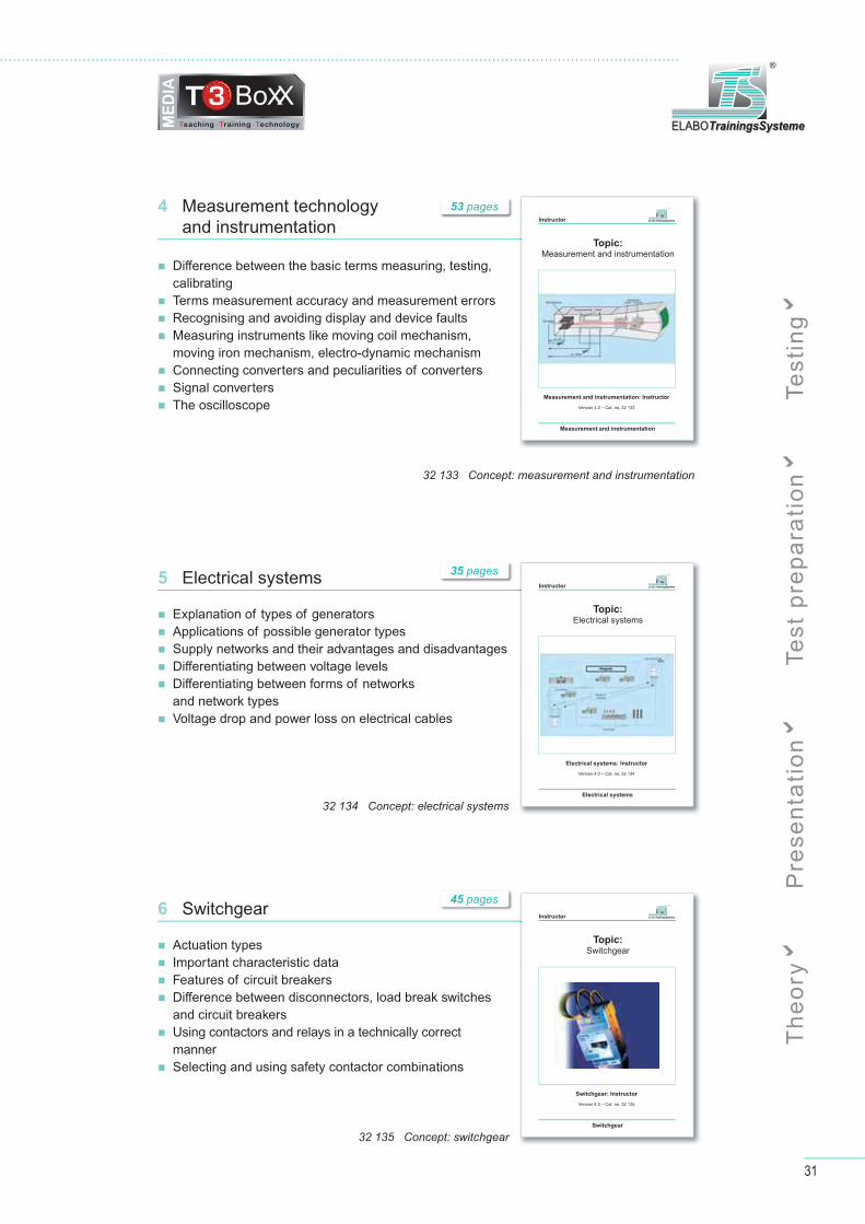
4 Measurement technologyand instrumentation
31
ELABOTrainingsSystemeELABOTrainingsSysteme
®
Diff erence between the basic terms measuring, testing, calibrating
Terms measurement accuracy and measurement errors Recognising and avoiding display and device faults Measuring instruments like moving coil mechanism, moving iron mechanism, electro-dynamic mechanism
Connecting converters and peculiarities of converters Signal converters The oscilloscope
6 Switchgear
Actuation types Important characteristic data Features of circuit breakers Diff erence between disconnectors, load break switches and circuit breakers
Using contactors and relays in a technically correct manner
Selecting and using safety contactor combinations
Instructor
Topic:Measurement and instrumentation
Measurement and instrumentation: Instructor
Version 4.0 – Cat. no. 32 133
Measurement and instrumentation
ELABOTrainingsSystemeELABOTrainingsSysteme
®
Instructor
Topic:Switchgear
Switchgear: Instructor
Version 4.0 – Cat. no. 32 135
Switchgear
ELABOTrainingsSystemeELABOTrainingsSysteme
®
32 135 Concept: switchgear
32 133 Concept: measurement and instrumentation
5 Electrical systems
Explanation of types of generators Applications of possible generator types Supply networks and their advantages and disadvantages Diff erentiating between voltage levels Diff erentiating between forms of networksand network types
Voltage drop and power loss on electrical cables
Instructor
Topic:Electrical systems
Electrical systems: Instructor
Version 4.0 – Cat. no. 32 134
Electrical systems
ELABOTrainingsSystemeELABOTrainingsSysteme
®
32 134 Concept: electrical systems
35 pages
53 pages
45 pages
Th
eo
ry P
rese
nta
tio
n T
est
pre
pa
rati
on
Te
stin
g
32
M E D I A - T 3 B O X X
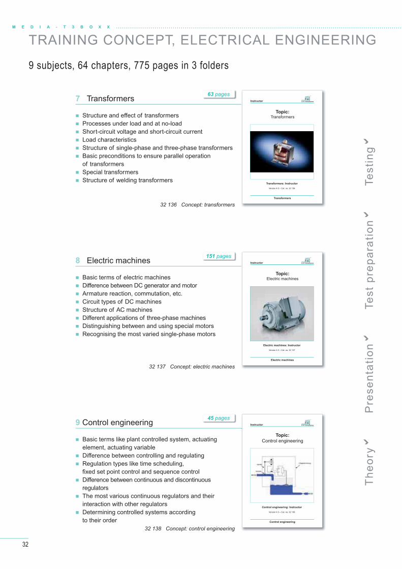
TRAINING CONCEPT, ELECTRICAL ENGINEERING
8 Electric machines
Basic terms of electric machines Diff erence between DC generator and motor Armature reaction, commutation, etc. Circuit types of DC machines Structure of AC machines Diff erent applications of three-phase machines Distinguishing between and using special motors Recognising the most varied single-phase motors
9 Control engineering
Basic terms like plant controlled system, actuating element, actuating variable
Diff erence between controlling and regulating Regulation types like time scheduling, fi xed set point control and sequence control
Diff erence between continuous and discontinuous regulators
The most various continuous regulators and their interaction with other regulators
Determining controlled systems accordingto their order
7 Transformers
Structure and eff ect of transformers Processes under load and at no-load Short-circuit voltage and short-circuit current Load characteristics Structure of single-phase and three-phase transformers Basic preconditions to ensure parallel operation of transformers
Special transformers Structure of welding transformers
Instructor
Topic:
Control engineering
Control engineering: Instructor
Version 4.0 – Cat. no. 32 138
Control engineering
ELABOTrainingsSystemeELABOTrainingsSysteme
®
Instructor
Topic:Electric machines
Electric machines: Instructor
Version 4.0 – Cat. no. 32 137
Electric machines
ELABOTrainingsSystemeELABOTrainingsSysteme
®
Instructor
Topic:Transformers
Transformers: Instructor
Version 4.0 – Cat. no. 32 136
Transformers
ELABOTrainingsSystemeELABOTrainingsSysteme
®
32 136 Concept: transformers
32 138 Concept: control engineering
32 137 Concept: electric machines
151 pages
63 pages
45 pages
9 subjects, 64 chapters, 775 pages in 3 folders
Th
eo
ry P
rese
nta
tio
n T
est
pre
pa
rati
on
Te
stin
g
33
ELABOTrainingsSystemeELABOTrainingsSysteme
®
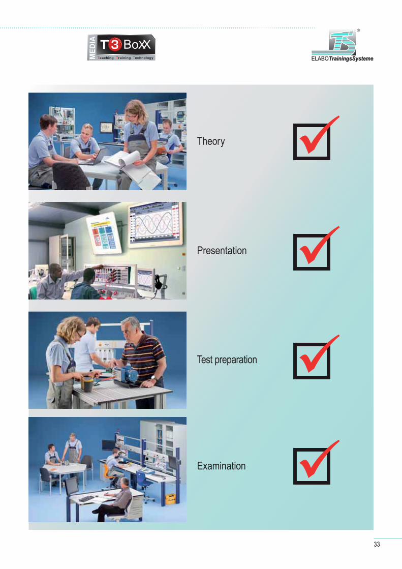
Theory
Presentation
Test preparation
Examination
�
�
�
�

34
E L E C T R I C A L E N G I N E E R I N G / E L E C T R O N I C S / D I G I T A L
AT T R A C T I V E , P O W E R F U L A N D S A F E
Functions and operating elements
T H R E E - P H A S E C U R R E N T
G E N E R ATO R
frequency: 1...120 Hz,, adjustable in 1Hz steps
phase voltage: 0...10 V rms line voltage: 0...17,3 V rms line current: max. 400 mA rms
all parameters available in the LC display short-circuit and back-feed proofup to
40V DC/ 24V AC
T R A N S F O R M E R
AC voltage sources2 x 12V AC / 0.2A; 50Hz(mains frequency), protected by polyswitchlyswitch
35
T E C H N O L O G Y
ELABOTrainingsSystemeELABOTrainingsSysteme
®
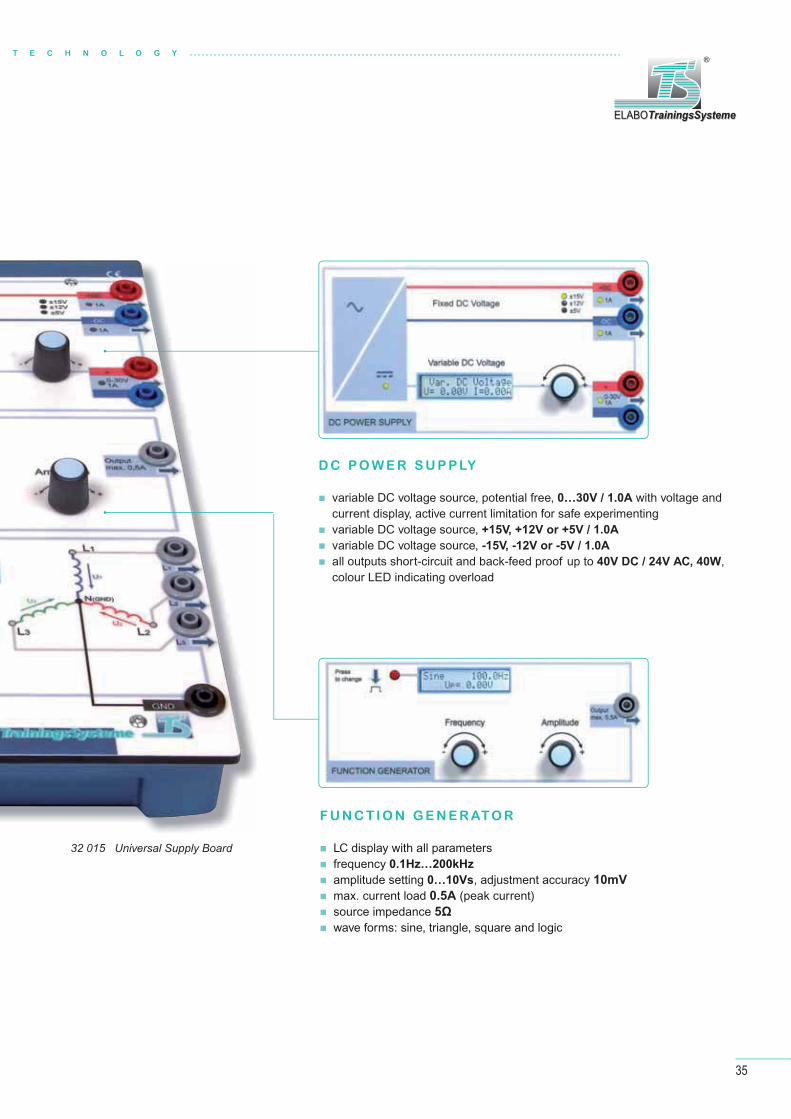
32 015 Universal Supply Board
F U N C T I O N G E N E R ATO R
LC display with all parameters frequency 0.1Hz…200kHz
amplitude setting 0…10Vs, adjustment accuracy 10mV
max. current load 0.5A (peak current) source impedance 5Ω
wave forms: sine, triangle, square and logic
D C P O W E R S U P P LY
variable DC voltage source, potential free, 0…30V / 1.0A with voltage and current display, active current limitation for safe experimenting
variable DC voltage source, +15V, +12V or +5V / 1.0A
variable DC voltage source, -15V, -12V or -5V / 1.0A
all outputs short-circuit and back-feed proof up to 40V DC / 24V AC, 40W, colour LED indicating overload

36
E L E C T R I C A L E N G I N E E R I N G / E L E C T R O N I C S / D I G I T A L
E L E C T R I C A L E N G I N E E R I N G / E L E C T R O N I C S
L E A R N I N G O B J E C T I V E S
Basics of electrical engineering
How to use oscilloscope, multimeter and
function generator
DC, AC and three-phase current technology
Operational amplifi er
Technical Data
Voltage sources: DC +/-15 V or +/-12 V or +/- 5 V/1 A; DC 0...30 V/ max. 1 A with voltage and current display AC 2 x 12 V/0,2 A (protected by polyswitch)
Function generator: frequency 0,1 Hz...200 kHz, variable amplitude (0…10Vp) and wave form, display of all parameters
Three-phase current 0…10Vrms; line voltage: 0…17.3Vrmss; frequency: 1…120Hz, adjustable, display of all parameters, phase current load: max. 400mArms
Experimenting fi eld: 4mm safety jacks arranged in a 19mm grid, surrounded by and electrically connected to four 2mm jacks.
Mains connection: 230 V AC; 50 Hz; 75 W; protection class I
Safety: Outputs short-circuit proof and back-feed protected up to 40V DC / 24V AC, 40W
Electronic Circuits Board II
32 200 Electronic Circuits Board II
Voltage-, temperature- and light-dependent resistors
Behaviour of semiconductors: diodes, transistors,
thyristors
Electronic circuits, amplifi ers, trigger and power
supply circuits
generator:

37
T E C H N O L O G Y
ELABOTrainingsSystemeELABOTrainingsSysteme
®
32 203 Device Set Electronics
Set of accessories, plugged on imprinted Storage Board:
Device Set Electronics
32 203 Device Set Electronics
28 fi lm resistors 10 Ω...1 MΩ 1 VDR resistor 1 LDR resistor 1 PTC resistor 1 NTC resistor 11 capacitors 100 pF...1 μF 4 electrolytic capacitors 10 μF...470 μF 1 potentiometer linear 1 kΩ, 0,5 W 1 potentiometer linear 10 kΩ, 0,5 W 1 transformer coil N = 300 2 transformer coils N = 900 1 tape-wound core (1 pair) 1 coil 100 mH 1 transistor NPN, BC 237, base left 1 transistor NPN, BC 140, base left 1 transistor NPN, BC 140, base right 1 transistor PNP, BC 160, base left 1 unijunction transistor PN, 2N 4870 1 D-MOS fi eld eff ect transistor, P-channel, BS 250 1 junction fi eld eff ect transistor, N-channel, 2N 5485 1 junction fi eld eff ect transistor, P-channel, 2N 5461 1 diac, ER 900 1 thyristor, TIC 106
1 triac, TIC 206 1 toggle switch 1 lamp, 15 V 1 light source 1 operational amplifi er 1 GA-AS light emitting diode, red 1 Ge diode, AA118 6 Si diodes, 1N4007 1 Zener diode, ZPD 3.3 V 1 Zener diode ZPD 10 V 1 relay DC 12...15 V NOC 1 relay DC 12...15 V NCC
... to put things straight
The storage boards for the plug-in components are imprinted with the corresponding symbols.
38
E L E C T R I C A L E N G I N E E R I N G / E L E C T R O N I C S / D I G I T A L
38
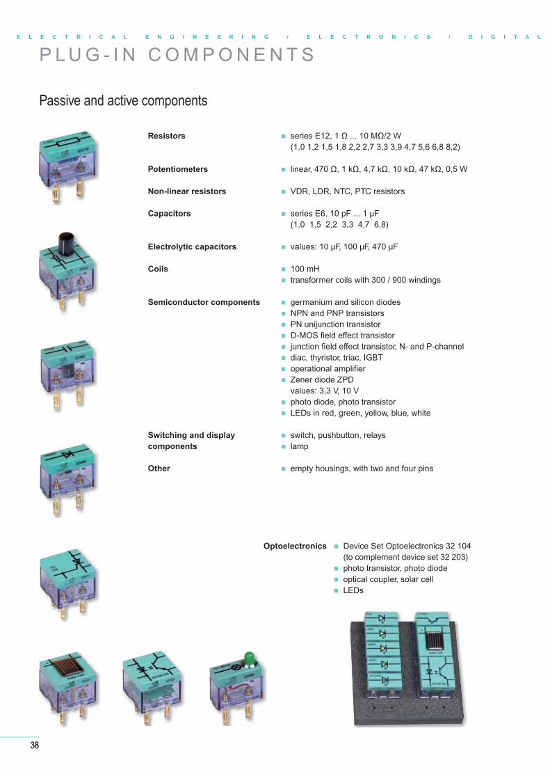
P L U G - I N C O M P O N E N T S
Passive and active components
Resistors series E12, 1 Ω ... 10 MΩ/2 W(1,0 1,2 1,5 1,8 2,2 2,7 3,3 3,9 4,7 5,6 6,8 8,2)
Potentiometers linear, 470 Ω, 1 kΩ, 4,7 kΩ, 10 kΩ, 47 kΩ, 0,5 W
Non-linear resistors VDR, LDR, NTC, PTC resistors
Capacitors series E6, 10 pF ... 1 μF(1,0 1,5 2,2 3,3 4,7 6,8)
Electrolytic capacitors values: 10 μF, 100 μF, 470 μF
Coils 100 mH transformer coils with 300 / 900 windings
Semiconductor components germanium and silicon diodes NPN and PNP transistors PN unijunction transistor D-MOS fi eld eff ect transistor junction fi eld eff ect transistor, N- and P-channel diac, thyristor, triac, IGBT operational amplifi er Zener diode ZPD
values: 3,3 V, 10 V photo diode, photo transistor LEDs in red, green, yellow, blue, white
Switching and display switch, pushbutton, relayscomponents lamp
Other empty housings, with two and four pins
Optoelectronics Device Set Optoelectronics 32 104(to complement device set 32 203)
photo transistor, photo diode optical coupler, solar cell LEDs

39
T E C H N O L O G Y
ELABOTrainingsSystemeELABOTrainingsSysteme
®
Overview of the single components
32 302 set of empty housings with 2 lamella plugs
32 305 set of empty housings with 2 lamella plugs
32 310 fi lm resistor 10 Ω/2 W
32 311 fi lm resistor 22 Ω/2 W
32 312 fi lm resistor 33 Ω/2 W
32 313 fi lm resistor 100 Ω/2 W
32 314 fi lm resistor 220 Ω/2 W
32 315 fi lm resistor 330 Ω/2 W
32 316 fi lm resistor 470 Ω/2 W
32 317 fi lm resistor 680 Ω/2 W
32 318 fi lm resistor 1 kΩ/2 W
32 319 fi lm resistor 2,2 kΩ/2 W
32 320 fi lm resistor 4,7 kΩ/2 W
32 321 fi lm resistor 10 kΩ/2 W
32 322 fi lm resistor 22 kΩ/2 W
32 323 fi lm resistor 47 kΩ/2 W
32 324 fi lm resistor 100 kΩ/2 W
32 325 fi lm resistor 1 MΩ/2 W
32 340 VDR resistor, 11 V/1 mA
32 342 NTC resistor (6 kΩ)
32 345 LDR resistor
32 370 capacitor 100 pF/500 V
32 371 capacitor 10 nF/500 V
32 372 capacitor 47 nF/500 V
32 373 capacitor 0,1 μF/160V
32 374 capacitor 0,22 μF/160 V
32 375 capacitor 0,47 μF/160 V
32 376 capacitor 1 μF/100 V
32 390 electrolytic capacitor 10 μF/6 V
32 391 electrolytic capacitor 100 μF/35 V
32 392 electrolytic capacitor 470 μF/35 V
32 402 linear potentiometer 1 kΩ 0,5 W
32 403 linear potentiometer 10 kΩ 0,5W
32 420 transformer coil N = 300
32 421 transformer coil N = 900
32 422 coil 100 mH
32 430 tape-wourn core (1 pair)
32 440 Zener diode 10 V/40 mA
32 441 Zener diode 3,3 V/130 mA
32 442 GA-AS light emitting diode, red,
without dropping reststor
32 443 light source
32 444 LED, 5 mm, blue
32 445 Ge diode, AA118
32 446 LED, 5 mm, warm white 32 601 IC Socket 14 Pin
32 447 LED, 5 mm, yellow
32 448 LED, 5 mm, green
32 450 Si-Diode 1 A
32 480 fl ip switch (TS12)
32 490 lamp, green, 15 V
32 501 transistor NPN, BC237, base left
32 502 transistor NPN, BC140, base left
32 503 transistor NPN, BC140, base right
32 504 transistor PNP, BC160, base left
32 505 unijunction transistor, PN 2N4870
32 506 D-MOS fi eld eff ect transistor, BC250, p-channel, gate left
32 507 JFET transistor 2N5485,
25 V/10 mA, n-channel, gate left
32 508 JFET transistor 2N5461,
20 V/10 mA, p-channel, gate left
32 510 diac, ER 900
32 511 thyristor, TIC 106
32 512 triac, TIC 206
32 520 photodiode
32 521 solar cell
32 522 optical coupler SFH615A
32 523 phototransistor LPT80A
32 598 operational amplifi er OP741
with 4mm connection sockets on the top
32 599 operational amplifi er OP741
with 4mm connection sockets on the top
32 485 relay DC 12...15 V NOC, 2A
32 486 relay DC 12...15 V relay DC 12...15 V NCC, 2A
32 601 IC Socket 14 Pin, plug-in module IC socket, 14-pin,
on plug-in plate for 19mm grid, plate equipped with
2mm jacks for easy connection
40
E L E C T R I C A L E N G I N E E R I N G / E L E C T R O N I C S / D I G I T A L
Stromversorgung Extern / InternMit dem Zuschalten der Netzbetriebsspannung ist das Electronic Circuits Board II betriebsbereit.Die zugeschaltete Netzspannung wird über die gelbe Leuchte im Einschalter angezeigt.Die Bereitschaftsanzeige der einzelnen DC- und AC-Spannungsquellen erfolgt über die leuchtenden grünen LED an den betreffenden Ausgängen. Die leuchtende grüne LED im Versorgungsblock zeigt die vorhandene interne Gleichspannung zum Betrieb des Prozessors an. Leuchtet diese LED nicht, so wurde auf Grund einer Überlast bzw. Fehlbeschaltung (Rückspeisung) die Spannungsversorgung abgeschaltet!Schalten Sie das Gerät aus und prüfen Sie Ihre experimentelle Schaltung! Entfernen Sie die Fehlbe-schaltung und schalten Sie das Gerät wieder ein.Sollte die zentrale LED und die Displays dunkel bleiben, so konsultieren Sie die Bedienanleitung.
Feste GleichspannungDie Festspannungsquelle liefert gegenüber der Gerätemasse am Ausgang „+DC“ +15 V, +12 V oder +5 V und am Ausgang „-DC“ -15 V, -12 V oder -5V. Jeder der beiden Ausgänge ist mindestens bis 1 A belastbar.Die leuchtende grüne LED zeigt den ordnungsgemäßen Betrieb des zugehörigen Ausgangs der Festspannungsquelle an. Tritt eine Überlast / Kurzschluss auf, so leuchtet die LED rot. Kommen Sie in den Überlas-tungsbereich oberhalb 1 A, so beginnt zuerst die LED im Wechsel Rot / Grün zu blinken.
Die Einstellung der Festspannung erfolgt über den Inkrementalsteller und das Display der variablen Gleichspannung. Um in den Einstellmodus für die festen Betriebsspannungen zu gelangen, ist der Inkrementalsteller der variablen Spannung mindestens 1s gedrückt zu halten. Danach wechselt das LC-Display in den Einstellmodus und zeigt dies an.
Durch Rechts- bzw. Linksdrehen des Inkrementalstellers der variablen Spannung wählen Sie die feste Spannung aus und bestätigen mit einem kurzen Druck auf den Inkremen-talsteller der variablen Spannung. Damit wird die gewählte Festspannung eingestellt, die gelbe LED mit dem entsprechenden Spannungswert leuchtet und das LC-Display der varia-blen Spannung zeigt wieder die Daten zur variablen Spannungsquelle an.
Variable GleichspannungDie einstellbare Gleichspannungsquelle dient zum Bereitstellen einer potenzialfreien Gleichspannung zwischen 0 V und 30 V. Die Einstellung der Ausgangsspannung erfolgt über den Inkrementalsteller. Die aktuelle Spannung am Ausgang der einstellbaren Gleich-spannungsquelle wird am LC-Display im unbelasteten Zustand mit einer absoluten Genauigkeit von ±20mV angezeigt. Der Ausgang ist nominal mindestens bis 1 A belastbar. Ab 1 A Laststrom kommen Sie ins Überstromregime. Die Spannung liegt wei-terhin an. Am Ausgang wird das Überstromregime durch grün / rotes Blinken der LED angezeigt.Ab 1,2 A Laststrom besteht Überlast. Die LED schaltet auf rot, das Display zeigt Überlast. Die Ausgangsspannung wird herunterge-schaltet. Zur Information wird der Laststrom mit einer Genauigkeit von wenigstens 5% angezeigt.
Die Einstellung der Gleichspannung erfolgt über den Inkrementalgeberund kann zwischen 0 und 30 V eingestellt werden. Die Potentialfreiheit gegenüber der Gerätemasse ermöglicht die Einstellung zwischen 0 und +30 V oder 0 und -30 V. Dieser Einsteller lässt sich durchgängig ohne Anschlag weiterdrehen. Beim langsamen Drehen nach rechts wird die Signalamplitude in kleinen
Schritten (10 mV) erhöht. Beim langsamen Drehen nach links wird die Signalamplitude in kleinen Schritten verringert. Ein schnelles drehen bewirkt eine Änderung der Signalamplitude in großen Schritten bis 1 V.Ein kurzes Drücken auf den Einstellknopf stellt die Gleichspannung auf 0 V zurück.Die leuchtende grüne LED zeigt den ordnungsgemäßen Betrieb des zugehörigen Ausgangs der variablen Gleichspannung an.
Tritt eine Überlast / Kurzschluss auf, so leuchtet die LED rot.
TransformatorDie Wechselspannungsquelle „Transformator“ stellt zwei getrennte Wechselspannungen potentialgetrennt vom Gerät zur Verfügung.Die Nominalspannungen werden mit 12 Veff bei einer Nominallast von 200 mA angegeben.Beide Quellen sind die getrennten Sekundärwicklungen eines Transformators. Die Leerlaufspannung ist last-abhängig vom Nominalwert höher. Die Ausgangsspan-nungen liegen an den 4mm-Sicherheitsbuchsen an.
Beide Ausgänge sind durch Polyswitch-Sicherungen gegen Überlast geschützt.Eine leuchtende grüne LED zeigt den ordnungsgemäßen Betrieb des zugehörigen Ausgangs des Transforma-tors an. Verlischt die LED, so ist der Ausgang überlastet.
FunktionsgeneratorDer Funktionsgenerator besitzt einen Signalausgang. Die Signalspannung liegt an der 4mm-Sicherheitsbuchse „OUTPUT“ gegenüber der zentralen Gerätemasse an.Die Einstellung der Signalamplitude erfolgt über den Inkrementalgeber „Amplitude“ und kann zwischen 0 und 10 VS eingestellt werden.Dieser Einsteller lässt sich durchgängig ohne Anschlag weiterdrehen. Beim langsamen Drehen nach rechts wird die Signalamplitude in kleinen Schritten (10 mV) erhöht. Beim langsamen Drehen nach links wird die Si-gnalamplitude in kleinen Schritten verringert. Ein schnelles drehen bewirkt
eine Änderung der Signalamplitude in großen Schritten bis 1 V.Ein kurzes Drücken auf den Einstellknopf stellt die Amplitude auf 0 V (Aus) zurück. Die Ausgangsamplitude wird im LC-Display angezeigt.
Die Kurvenform (Sinus, Dreieck, Rechteck, Logik) wird über den Taster „Waveform“ ausgewählt. Durch einen Tastendruck wird im-mer die nächstfolgende Kurvenform in der Reihenfolge:
am Signalausgang eingestellt. Die Kurvenform wird im LC-Display angezeigt.
Die Signalfrequenz wird am LC-Display dargestellt.Die Einstellung der Frequenz erfolgt über den Inkrementalgeber „Frequency“. Dieser Einsteller lässt sich durchgängig ohne Anschlagweiterdrehen. Beim langsamen Drehen nach rechts wird die Frequenz in kleinen Schritten (0,01 zum Grundbereich) erhöht. Beim langsamen Drehen nach links wird die Frequenz in kleinen Schritten verringert. Ein schnelles drehen bewirkt Frequenzänderung ingroßen Schritten vor der Kommastelle.Ein schnelles Auswählen des Frequenzbereichs (100 Hz, 1 kHz, 10 kHz und 100 kHz) kann durch einen Druck auf den Einstellknopf ausgeführt werden.
Die elektronische Drehstromquelle erzeugt an den drei Ausgängen L1, L2 und L3 eine sinusförmige Wech-selspannung mit einem Phasenunterschied von ±120° zwischen den benachbarten Ausgängen. Das Drehfeld ist rechts drehend. Die Effektivspannung an den Strän-gen ist einstellbar bis maximal 10 Veff gegenüber dem Sternpunkt.Die Strangspannungen liegen jeweils an einer 4mm-Sicherheitsbuchse an. Die Strangspannung wird im LC-Display angezeigt.Der Sternpunkt der Drehstromquelle ist mit der zentra-len Gerätemasse verbunden!
Die Einstellung der Signalamplitude erfolgt über den Inkrementalgeber „Amplitude“ und kann zwischen 0 und 10 Veff eingestellt werden.Dieser Einsteller lässt sich durchgängig ohne Anschlag weiterdrehen. Beim langsamen Drehen nach rechts wird die Strangspannung (Signalamplitude) in kleinen Schritten (10 mV) erhöht. Beim langsamen Drehen nach links wird die Signalamplitude in kleinen Schrit-ten verringert. Ein schnelles drehen bewirkt eine Änderung der Signalamplitude in großen Schritten bis 1 Veff.Ein kurzes Drücken auf den Einstellknopf schaltet die Ausgänge ab (0 V). Im Display wird „OFF“ angezeigt, die letzte eingestellteStrangspannung bleibt jedoch erhalten. Ein erneutes Drücken schaltet die Ausgänge wieder zu.
Die Signalfrequenz wird am LC-Display dargestellt. Die Einstellung der Frequenz von 1 Hz bis 120 Hz erfolgt über den Inkremental-geber „Frequency“. Dieser Einsteller lässt sich durchgängig ohne Anschlag weiterdrehen. Beim Drehen nach rechts wird die Fre-quenz in 1 Hz-Schritten erhöht. Beim Drehen nach links wird die Frequenz in 1 Hz-Schritten verringert.Ein schnelles Rücksetzen auf 50 Hz kann durch einen Druck auf den Einstellknopf ausgeführt werden.
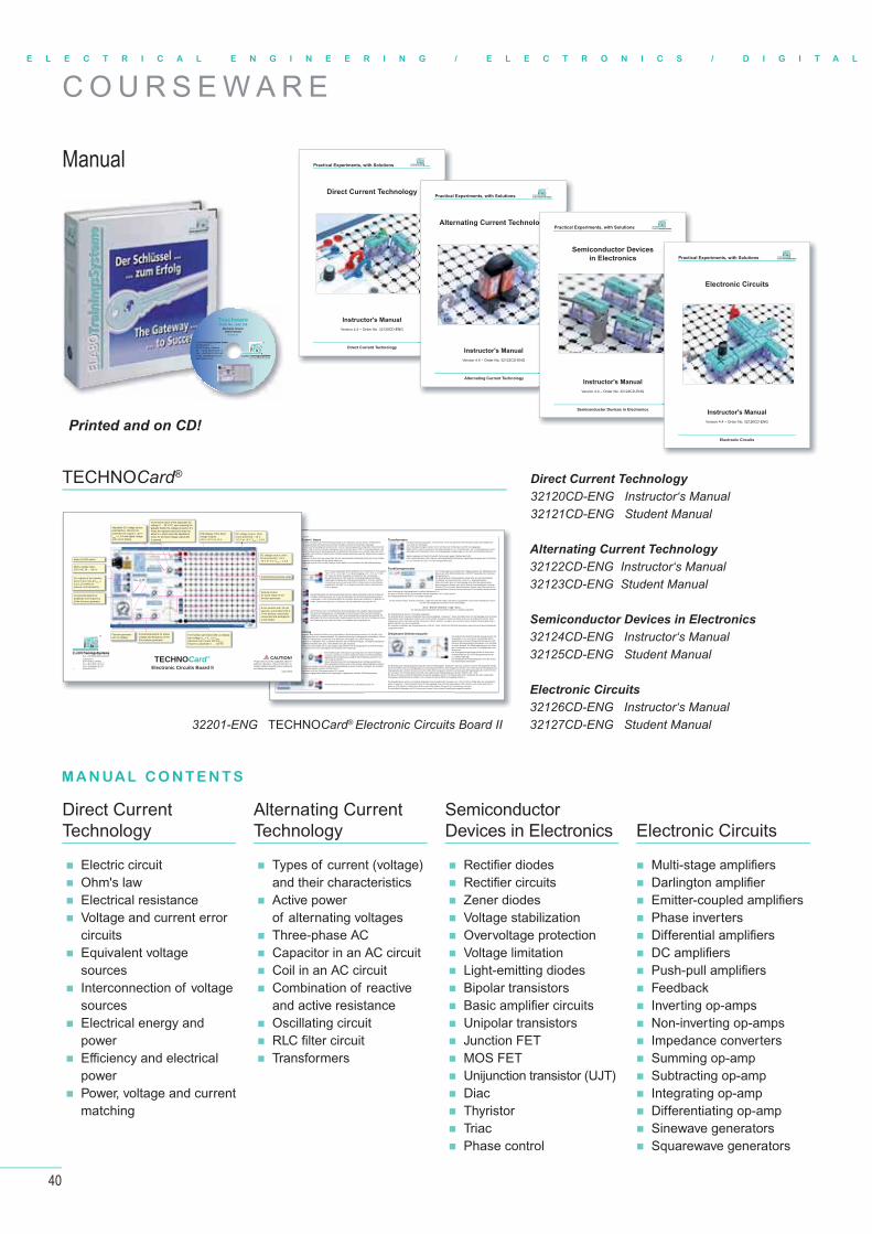
C O U R S E W A R E
Printed and on CD!
TECHNOCard®
ExterMit demDie zugeDie Beregrünendie vorhso wurdabgeschSchaltenschaltunSollte di
nung
annunngsquelle
nnung erfoDisplay imestens bias Überstberlast. Dder Lasts
m langsamder Signainstellknogt den ord
32201-ENG
TECHNOCard®
Electronic Circuits Board IIPlease observe all the applicable safety re-gulations, laboratory rules and take the ne-cessary safety precautions when setting up and testing the systems!
CAUTION!
4.1
Aus- und Weiterbildung GmbH ELABOTrainingsSystemeELABOTrainingsSysteme
®
Im Hüttental 11 85125 Kinding - GermanyTel.: + 49 (0) 84 67 / 84 04 - 0 Fax: + 49 (0) 84 67 / 84 04 44E-mail: [email protected]
Mains On/Off switch
Mains voltage input,230 V AC 50 … 60 Hz
AC outputs of the transfor-mer 2 X 12 V AC at INOM = 0.2 A; 50 Hz/60 Hz (secure via PolySwitch)
Incremental switch for phasevoltage and frequency of thethree-phase generator
Function generatorwith LC-display
Incremental switch foramplitude and frequencyof the function generator
Selector buttonfor wave shape of thefunction generator
Three-phase generator with LC-display; star-voltage UPh = 0…10 VRMS,maximum line current 400 mARMS,frequency adjustable 1 … 120 Hz
4 mm sockets with 19 mm spacing, surrounded with 4, 2 mm sockets, electrically connected and arranged in a star-shape
Experiment (exercise) areas
Adjustable DC voltage source, potential free, short-circuit protected, DC output 0...30 V / IMAX = 1.0 A with digital voltage and current display
Incremental switch of the adjustable DC voltage 0 … 30 V DC, upon pressing the
Press the adjuster and hold it down for about 1 s, where upon the adjustment
is opened.voltage outputs:±15 V, ±12 V or ±5 V
DC voltage source, short-circuit protected, -15 V, -12 V or -5 V / IMAX = 1.0 A
DC voltage source, short-circuit protected, +15 V, +12 V or +5 V / IMAX = 1.0 A
32201-ENG TECHNOCard® Electronic Circuits Board II
Direct Current Technology
32120CD-ENG Instructor‘s Manual32121CD-ENG Student Manual
Alternating Current Technology
32122CD-ENG Instructor‘s Manual32123CD-ENG Student Manual
Semiconductor Devices in Electronics
32124CD-ENG Instructor‘s Manual32125CD-ENG Student Manual
Electronic Circuits
32126CD-ENG Instructor‘s Manual32127CD-ENG Student Manual
Direct CurrentTechnology
Electric circuit Ohm's law Electrical resistance Voltage and current error
circuits Equivalent voltage
sources Interconnection of voltage
sources Electrical energy and
power Effi ciency and electrical
power Power, voltage and current
matching
Alternating CurrentTechnology
Types of current (voltage) and their characteristics
Active power of alternating voltages
Three-phase AC Capacitor in an AC circuit Coil in an AC circuit Combination of reactive
and active resistance Oscillating circuit RLC fi lter circuit Transformers
SemiconductorDevices in Electronics
Rectifier diodes Rectifier circuits Zener diodes Voltage stabilization Overvoltage protection Voltage limitation Light-emitting diodes Bipolar transistors Basic amplifier circuits Unipolar transistors Junction FET MOS FET Unijunction transistor (UJT) Diac Thyristor Triac Phase control
Electronic Circuits
Multi-stage amplifiers Darlington amplifier Emitter-coupled amplifiers Phase inverters Differential amplifiers DC amplifiers Push-pull amplifiers Feedback Inverting op-amps Non-inverting op-amps Impedance converters Summing op-amp Subtracting op-amp Integrating op-amp Differentiating op-amp Sinewave generators Squarewave generators
M A N UA L C O N T E N T S
Aus- und Weiterbildung GmbH ELABOTrainingsSystemeELABOTrainingsSysteme
®ELABOTrainingsSysteme GmbHIm Hüttental 11 85125 Kinding - GermanyTel.: +49 (0) 84 67/ 84 04 - 0 Fax: +49 (0) 84 67/ 84 04 44e-mail: [email protected]
TeachwareOrder No.: E32 126
Electronic CircuitsTrainer Section
Version 4.1
ManualDirect Current Technology
Instructor's Manual
Version 4.4 – Order No. 32120CD-ENG
Practical Experiments, with Solutions
Direct Current Technology
ELABOTrainingsSystemeELABOTrainingsSysteme
®
Alternating Current Technology
Practical Experiments, with Solutions
Alternating Current Technology
Instructor's Manual
Version 4.4 – Order No. 32122CD-ENG
ELABOTrainingsSystemeELABOTrainingsSysteme
®
o
Semiconductor Devices
in Electronics
Practical Experiments, with Solutions
Semiconductor Devices in Electronics
ELABOTrainingsSystemeELABOTrainingsSysteme
®
Instructor's Manual
Version 4.4 – Order No. 32124CD-ENG
Electronic Circuits
Instructor's Manual
Version 4.4 – Order No. 32126CD-ENG
Practical Experiments, with Solutions
Electronic Circuits
ELABOTrainingsSystemeELABOTrainingsSysteme
®
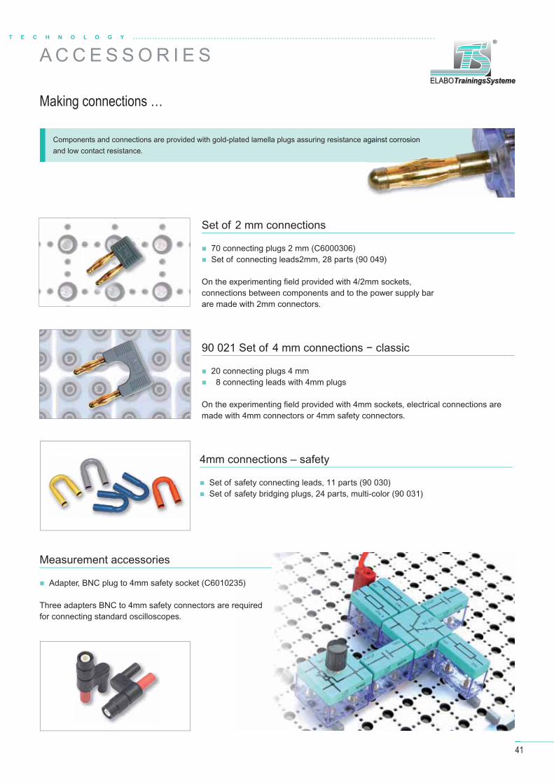
41
T E C H N O L O G Y
ELABOTrainingsSystemeELABOTrainingsSysteme
®
A C C E S S O R I E S
Making connections …
Components and connections are provided with gold-plated lamella plugs assuring resistance against corrosion and low contact resistance.
Set of 2 mm connections
70 connecting plugs 2 mm (C6000306) Set of connecting leads2mm, 28 parts (90 049)
On the experimenting fi eld provided with 4/2mm sockets, connections between components and to the power supply bar are made with 2mm connectors.
90 021 Set of 4 mm connections − classic
20 connecting plugs 4 mm 8 connecting leads with 4mm plugs
On the experimenting fi eld provided with 4mm sockets, electrical connections are made with 4mm connectors or 4mm safety connectors.
4mm connections – safety
Set of safety connecting leads, 11 parts (90 030) Set of safety bridging plugs, 24 parts, multi-color (90 031)
Measurement accessories
Adapter, BNC plug to 4mm safety socket (C6010235)
Three adapters BNC to 4mm safety connectors are required for connecting standard oscilloscopes.
against corrosion
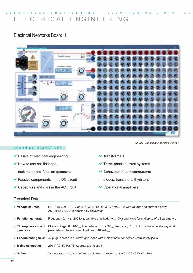
42
E L E C T R I C A L E N G I N E E R I N G / E L E C T R O N I C S / D I G I T A L
E L E C T R I C A L E N G I N E E R I N G
Electrical Networks Board II
32 020 Electrical Networks Board II
L E A R N I N G O B J E C T I V E S
Basics of electrical engineering
How to use oscilloscope,
multimeter and function generator
Passive components in the DC circuit
Capacitors and coils in the AC circuit
Transformers
Three-phase current systems
Behaviour of semiconductors:
diodes, transistors, thyristors
Operational amplifi ers
Technical Data
Voltage sources: DC +/-15 V or +/-12 V or +/- 5 V/1 A; DC 0...30 V / max. 1 A with voltage and current display AC 2 x 12 V/0,2 A (protected by polyswitch)
Function generator: Frequency 0,1 Hz...200 kHz, variable amplitude (0…10Vp) and wave form, display of all parameters
Three-phase current Phase voltage: 0…10Vrms; line voltage: 0…17.3Vrms; frequency: 1…120Hz, adjustable, display of all parameters, phase current load: max. 400mArms
Experimenting fi eld: 42 plug-in areas in a 19mm grid, each with 4 electrically connected 4mm safety jacks.
Mains connection: 230 V AC; 50 Hz; 75 W; protection class I
Safety: Outputs short-circuit proof and back-feed protected up to 40V DC / 24V AC, 40W
generator:
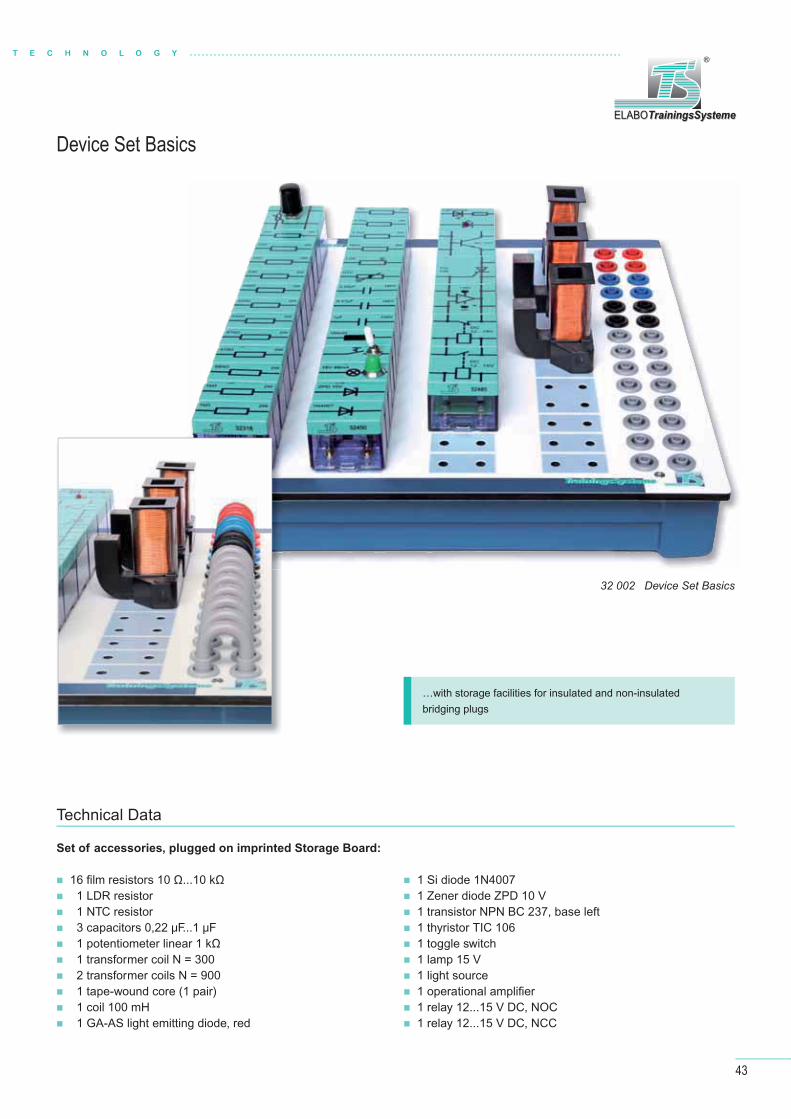
43
T E C H N O L O G Y
ELABOTrainingsSystemeELABOTrainingsSysteme
®
Device Set Basics
32 002 Device Set Basics
16 fi lm resistors 10 Ω...10 kΩ 1 LDR resistor 1 NTC resistor 3 capacitors 0,22 μF...1 μF 1 potentiometer linear 1 kΩ 1 transformer coil N = 300 2 transformer coils N = 900 1 tape-wound core (1 pair) 1 coil 100 mH 1 GA-AS light emitting diode, red
1 Si diode 1N4007 1 Zener diode ZPD 10 V 1 transistor NPN BC 237, base left 1 thyristor TIC 106 1 toggle switch 1 lamp 15 V 1 light source 1 operational amplifi er 1 relay 12...15 V DC, NOC 1 relay 12...15 V DC, NCC
Technical Data
Set of accessories, plugged on imprinted Storage Board:
…with storage facilities for insulated and non-insulated bridging plugs
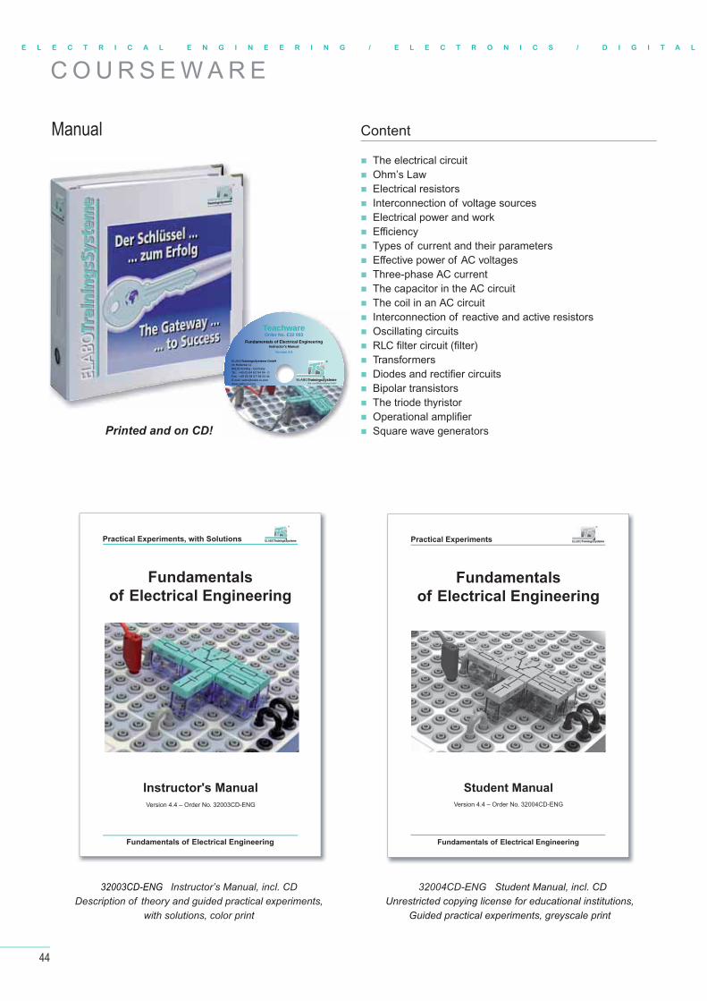
44
E L E C T R I C A L E N G I N E E R I N G / E L E C T R O N I C S / D I G I T A L
C O U R S E W A R E
Manual Content
The electrical circuit Ohm’s Law Electrical resistors Interconnection of voltage sources Electrical power and work Effi ciency Types of current and their parameters Eff ective power of AC voltages Three-phase AC current The capacitor in the AC circuit The coil in an AC circuit Interconnection of reactive and active resistors Oscillating circuits RLC fi lter circuit (fi lter)
Transformers Diodes and rectifi er circuits Bipolar transistors The triode thyristor Operational amplifi er Square wave generatorsPrinted and on CD!
32003CD-ENG Instructor’s Manual, incl. CDDescription of theory and guided practical experiments,
with solutions, color print
32004CD-ENG Student Manual, incl. CDUnrestricted copying license for educational institutions,
Guided practical experiments, greyscale print
Fundamentals
of Electrical Engineering
Instructor's Manual
Version 4.4 – Order No. 32003CD-ENG
Fundamentals of Electrical Engineering
Practical Experiments, with Solutions ELABOTrainingsSystemeELABOTrainingsSysteme
®
Fundamentals
of Electrical Engineering
Student Manual
Version 4.4 – Order No. 32004CD-ENG
Fundamentals of Electrical Engineering
Practical Experiments
Aus- und Weiterbildung GmbH ELABOTrainingsSystemeELABOTrainingsSysteme
®ELABOTrainingsSysteme GmbHIm Hüttental 11 85125 Kinding - GermanyTel.: +49 (0) 84 67/ 84 04 - 0 Fax: +49 (0) 84 67/ 84 04 44E-mail: [email protected]
TeachwareOrder No. E32 003
Fundamentals of Electrical EngineeringInstructor's Manual
Version 4.5
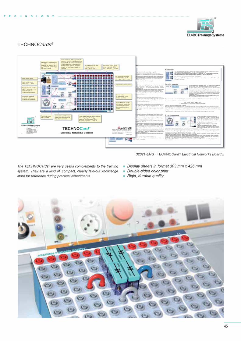
45
T E C H N O L O G Y
ELABOTrainingsSystemeELABOTrainingsSysteme
®
Power Supply, External / InternalThe Electronic Networks Board II is operational when the mains voltage is applied.The presence of the mains voltage is indicated by a yellow indicator lamp in the mains switch.The readiness indication of the individual DC and AC voltage sources is provided by a glowing green LED at the relevant outputs. The glowing green LED in the supply block displays the existing internal DC voltage for operating the processor. If this LED does not glow, it means that owing to an overload or a faulty circuit (feedback), the voltage supply gets switched off. Switch off the device and examine your experimental circuit.Correct the faulty circuit and switch on the device again.If the central LED and the displays remain dark, pleas refer to the user guide.
Fixed DC Voltagedepending on the setting, at output „+DC“, +15 V, +12 V or +5 V and at output „-DC“, -15 V, -12 V or -5 V. Each of the two outputs can be loaded with at least up to 1 A. The glowing green LED indicates proper operation of the relevant output
central earth of the device.
adjuster of the variable voltage must be kept pressed for at least 1s. Thereupon, the LC display changes into setting mode and indicates as such.
By rotating the incremental adjuster of the variable voltage to the right and the left, you can -
voltage value glows and the LC display of the variable voltage once again shows the data related to the variable voltage source.
Variable DC VoltageThe adjustable DC source serves for providing a potential-free DC between 0 V and 30 V. The setting of the output voltage is doneby means of the incremental adjuster. The current voltage at the output of the adjustable DC source is displayed at the LC display in the unloaded state with an absolute accuracy of ±20 mV. The output is nominally loadable up to minimum 1 A. From 1 A load current onwards, you enter the overload domain. The voltage
A load current from 1.2 A onwards is overload. The LED changes to red and the display shows overload. The output voltage is chan-ged down. For information, the load current is displayed with an accuracy of at least 5 %.
The DC voltage setting is done with the incremental adjuster and can be set between 0 and 30 V. The electrical isolation with respect to the earth of the device facilitates the setting between 0 and +30 V or 0 and -30 V.
voltages, which allows additional combinations.This adjuster can be rotated onward continuously without any stop. If rota-ted slowly to the right, the signal amplitude is incremented in small steps (10mV). If rotated slowly to the left, the signal amplitude is decremented in
small steps (mV). Rotating fast results in a change in the signal amplitude in large steps up to 1 V.
relevant output of the variable DC voltage.
If there is an overload / short-circuit, the LED glows red.In case of overload from 1.2 A onwards, feedback or short-circuit „Over-load“ is shown in the display.
TransformerThe AC voltage source „Transformer“ provides two separate AC voltages, potential-isolated from the device.
RMS with a nominal load of 200 mA.Both the sources are the isolated secondary windings of a transformer. The no-load voltage is higher, load-dependent on the nominal value. The output voltages are present at the 4mm safety sockets.
Both outputs are protected against overload with polyswitch fuses.A glowing green LED indicates proper operation of the relevant output of the transformer. If the LED goes off, the output is overloaded.
Function generatorThe function generator has a signal output. The signal voltage is present at the 4mm safety socket „OUTPUT“ opposite the central device earth.The signal amplitude setting is done with the incremental adjuster „Amplitu-de“ and can be set between 0 and 10 VS.This adjuster can be rotated onward continuously without any stop. If rota-ted slowly to the right, the signal amplitude is incremented in small steps (10 mV). If rotated slowly to the left, the signal amplitude is decremented in small steps (mV). Rotating fast results in a change in the signal amplitude in large steps up to 1 V.
The output amplitude is shown in the LC display.
The curve form (sinus, triangle, rectangle, logic) is selected with the „Waveform“ button. Upon pressing the button once, the nextcurve form in the sequence is selected, in the order:
at the signal output. The curve form is shown in the LC display.
The signal frequency is depicted on the LC display.The setting of the frequency is done by means of the incremental adjuster „Frequency“. This adjuster can be rotated onward conti-nuously without any stop. If rotated slowly to the right, the frequency is incremented in small steps (0.01 to the earth range). If rotated slowly to the left, the frequency is decremented in small steps. Fast turning effects a frequency change in large steps to the left of the decimal.Fast selection of the frequency range (100 Hz, 1 kHz, 10 kHz and 100 kHz) is possible by pressing on the setting knob.
Three-phase sourceThe electronic 3-phase current source generates, at the three outputs L1, L2 and L3, a sinusoidal AC with a phase difference of ±120° between the neighbouring
voltage at the phases is adjustable up to a maximum of 10 VRMS with respect to the star node.The phase voltages are present at a 4mm safety socket.The phase voltage is shown in the LC display.The star node of the three-phase source is connected to the central earth of the device. The signal amplitude
setting is done with the incremental adjuster „Amplitude“ and can be set between 0 and 10 VRMS.This adjuster can be rotated onward continuously without any stop. If rotated slowly to the right, the phase voltage (signal amplitude)is incremented in small steps (10 mV). If rotated slowly to the left, the signal amplitude is decremented in small steps (mV). Rotatingfast results in a change in the signal amplitude in large steps up to 1 VRMS.
that has been set remains. Pressing on it again switches on the outputs again.The signal frequency is shown in the LC display. The setting of the frequency from 1 Hz to 120 Hz takes place via the incrementalencoder „Frequency“. This adjuster can be rotated onward continuously without any stop. When rotated to the right, the frequency is incremented in 1 Hz steps. When rotated to the left, the frequency is decremented in 1 Hz steps.Fast resetting to 50 Hz (60 Hz) can be achieved by pressing on the adjustment knob. The starting and resetting frequencies are setin the service menu.
32021-ENG TECHNOCard ® Electrical Networks Board II
TECHNOCards®
The TECHNOCards® are very useful complements to the training system. They are a kind of compact, clearly laid-out knowledge store for reference during practical experiments.
Display sheets in format 303 mm x 426 mm Double-sided color print Rigid, durable quality
I is opge is individu
pply blow, itoff. Sch onys rem
endinput „-D at leaglow
tral ea
e voltaetting
ental a
d the voltag
DC betoutpu
oad cu
s to reaccur
DC voetweee devic
ges, wadjustowly tV). Ifamplit
If there is aIn case of oload“ is sho
32021-ENG4.1
TECHNOCard®
Electrical Networks Board IIPlease observe all the applicable safety re-gulations, laboratory rules and take the ne-cessary safety precautions when setting up and testing the systems!
CAUTION!Aus- und Weiterbildung GmbH ELABOTrainingsSystemeELABOTrainingsSysteme
®
Im Hüttental 11 85125 Kinding - GermanyTel.: + 49 (0) 84 67 / 84 04 - 0 Fax: + 49 (0) 84 67 / 84 04 44E-mail: [email protected]
Mains On/Off switch
Mains voltage input,230 V AC 50 … 60 Hz
AC outputs of the transfor-mer 2 X 12 V AC at INOM = 0.2 A; 50 Hz/60 Hz (secure via PolySwitch)
Function generatorwith LC-display
Incremental switch foramplitude and frequencyof the function generator
Selector buttonfor wave shape of thefunction generator
Three-phase generator with LC-display; star-voltage UPh = 0…10 VRMS,maximum line current 400 mARMS,frequency adjustable 1 … 120 Hz
mm spacing, electrically connected and arranged 4 pieces of 4mm safety sockets
Experiment (exercise) areas
Adjustable DC voltage source, potential free, short-circuit protected, DC output 0...30 V / IMAX = 1.0 A with digital voltage and current display
Incremental switch of the adjustable DC voltage 0 … 30 V DC, upon pressing the
Press the adjuster and hold it down for about 1 s, where upon the adjustment
is opened.voltage outputs:±15 V, ±12 V or ±5 V
DC voltage source, short-circuit protected, -15 V, -12 V or -5 V / IMAX = 1.0 A
DC voltage source, short-circuit protected, +15 V, +12 V or +5 V / IMAX = 1.0 A
Incremental switch for phasevoltage and frequency of thethree-phase generator
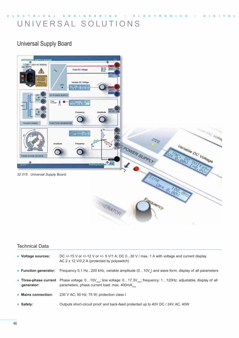
46
E L E C T R I C A L E N G I N E E R I N G / E L E C T R O N I C S / D I G I T A L
U N I V E R S A L S O L U T I O N S
Universal Supply Board
32 015 Universal Supply Board
Technical Data
Voltage sources: DC +/-15 V or +/-12 V or +/- 5 V/1 A; DC 0...30 V / max. 1 A with voltage and current display AC 2 x 12 V/0,2 A (protected by polyswitch)
Function generator: Frequency 0,1 Hz...200 kHz, variable amplitude (0…10Vp) and wave form, display of all parameters
Three-phase current Phase voltage: 0…10Vrms; line voltage: 0…17.3Vrms; frequency: 1…120Hz, adjustable, display of all parameters, phase current load: max. 400mArms
Mains connection: 230 V AC; 50 Hz; 75 W; protection class I
Safety: Outputs short-circuit proof and back-feed protected up to 40V DC / 24V AC, 40W
generator:
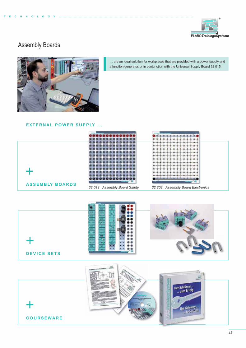
47
T E C H N O L O G Y
Aus- und Weiterbildung GmbH ELABOTrainingsSystemeELABOTrainingsSysteme
®ELABOTrainingsSysteme GmbHIm Hüttental 11 85125 Kinding - GermanyTel.: +49 (0) 84 67/ 84 04 - 0 Fax: +49 (0) 84 67/ 84 04 44E-mail: [email protected]
TeachwareOrder No. E32 003
Fundamentals of Electrical EngineeringInstructor's Manual
Version 4.5
ELABOTrainingsSystemeELABOTrainingsSysteme
®
Assembly Boards
… are an ideal solution for workplaces that are provided with a power supply and a function generator, or in conjunction with the Universal Supply Board 32 015.
+
+
+
E X T E R NA L P O W E R S U P P LY . . .
A S S E M B LY B OA R D S
D E V I C E S E T S
C O U R S E W A R E
AAuELABOELAABOELABOELABOTTT
ELABOTrainingsSysteme GmbHIm Hüttental 1185125 Kinding - GermanyTel.: +49 (0) 84 67/ 84 04 - 0Fax: +49 (0) 84 67/ 84 04 44E-mail: [email protected]
TeachwareOrder No. E32 003
Fundamentals of Electrical EnginInstructor's Manual
Version 4.5
32 012 Assembly Board Safety 32 202 Assembly Board Electronics

48
E L E C T R I C A L E N G I N E E R I N G / E L E C T R O N I C S / D I G I T A L
D I G I TA L T E C H N O L O G Y
Digital Trainer Board
33 000 Digital Trainer Board
L E A R N I N G O B J E C T I V E S
Basic logical circuits, properties and parameters of digital circuits
The laws of Boolean algebra
Multivibrators and counter circuits
Register and memory
Codes and code converters
Arithmetic circuits
Confi guring and analysing controls with digital components
Power supply: +5 V DC/5 A stabilized, short-circuit-proof
Clock generator: 0...10 kHz with subsequent frequency divider, division factors: 1:2/4/8/16
Mains connection: 110...240 V AC; 50...60 Hz
Features: Pushbuttons and switchesAND, NAND, OR, NOR, XOR gates, invertersMonofl op and fl ipfl opsAdders, binary and decimal countersLED and 7-segment displaysVoltage-supplied plug-in fi elds for additional modules or IC sockets
Technical Data

49
T E C H N O L O G Y
Logic gates – Overview Laws of Boolean algebra
A v A = A
A v A = A
A v 1 = A
A v 0 = 0
A v 1 = 1
A v 0 = A
A v A = 0
A v A = 1
A = A
Absorption law:A v (A v B) = A
A v (A v B) = A
Commutative law:A v B = B v A
A v B = B v A
The order of the variables in AND an OR expressionsdoes not affect the result.
Distributive law:A v (B v C) = (A v B) v (A v C)
A v (B v C) = (A v B) v (A v C)
Common variables can be distributed. Factoring is thedistributive law backwards.
v
v
v
v
The basic functions
v
v
Laws dealingwith thelinking of avariable withitself (idem-potence) orwith a con-stant or itsnegation:
Associative law:A v (B v C) = (A v B) v C
A v (B v C) = (A v B) v C
Variables may be regrouped within the samesequential order.
De Morgan’s rules:
1st law of De Morgan:
Z = A v B = A v B
A NAND gate can be substituted by an OR gate withinverted inputs.
2nd law of De Morgan:
Z = A v B = A v B
A NOR gate can be substituted by an AND gate withinverted inputs.
De Morgan’s laws can be extended to several variables:
1st law: Z = A v B v C v .... = A v B v C v ....
2nd law: Z = A v B v C v .... = A v B v C v ....
B
C
A
>1
&A
B &>1
A
C &
B
C
A
&
>1A
B >1&
A
C >1
B
C
A
&
&A
B &&
C
v v v v
B
C
A
>1
>1A
B >1>1
C
TypeDescription
Logicaloperatornotation
Rectangularshape acc. toIEC 60617-12
Distinctiveshape
German Indu-strial Standard
(old)
AND gateConjunction
Y = A v B
Y = A . B
Y = A B
OR gateDisjunction
Y = A v B
Y = A + B
NOT gateComplementgate, inver-ter, negation
Y = A
NAND gateNot-AND
Y = A v B
Y = A B
NOR gateNot-OR
Y = A v B
Y = A + B
XOR gateExclusivedisjunction
Y = A v B
Y = A + B
XNOR gateInverseexclusivedisjunction,logical equa-lity
Y = A v B
Y = A + B
v
&A
BY
A
BY Y
A
B
v
>1A
BY
1A
BY
&A
BY
>1A
BY
=1A
BY
=1A
BY
YA
B
YA
YA
B
YA
B
YA
B
YA
B
YA
B
YA
B
A
BY
A Y
or:
or:
A
BY
A
BY
A
BY
A
BY
v v
v v v
v v
&A
BZ
A
BZ>1
A
BZ
A
BZ>1 &
v
v
v v v
v v v
C O U R S E W A R EELABOTrainingsSystemeELABOTrainingsSysteme
®
Manual
Comparison of analog and digital technology Basic logic circuits Basic component combinations in digital techniques TTL integrated circuits in practice The laws of Boolean algebra Designing digital circuits Circuit analysis
Multivibrators, counter circuits Shift registers, memory registers Codes and code converters Calculation circuits Analog-digital – digital-analog converters Multiplexer ― demultiplexer Application examples
Content
TECHNOCard®
Logic gates – Overview
The basic functions Laws dealingwith thelinking of avariable withitself (idem-potence) orwith a con-stant or itsnegation:
TypeDescription
Logicaloperatornotation
Rectangularshape acc. toIEC 60617-12
Distinctiveshape
German Indu-strial Standard
(old)
AND gategConjunction
Y = A v B
Y = A . B
Y = A B
OR gategDisj nctionDisjunction
Y = A v B
Y = A + B
v
&A
BY
A
BY Y
AA
B
>1>1AA
BYY YY
AAAA
B
AA
BYYY
33008-ENG
TECHNOCard®
Digital Trainer BoardPlease observe all necessary safe-ty regulations, laboratory rules and required protective measures for in-stalling and testing the equipment!
CAUTION!
power switch and power supply for integrated short-circuit-proof power pack
4.3
Aus- und Weiterbildung GmbH ELABOTrainingsSystemeELABOTrainingsSysteme
®
Im Hüttental 11 85125 Kinding - GermanyTel.: + 49 (0) 84 67 / 84 04 - 0 Fax: + 49 (0) 84 67 / 84 04 44E-mail: [email protected]
8 bounce-free L/H input switches (snap and tap)
toggle switch (not debounced)
pushbutton for free use (not debounced)
function tables for the logical gates used
continuously adjustable clock generator 0 - 10 kHz with subsequent divider (division factors 2, 4, 8 and 16)
monofl op; time setting with potentiometer (max.10 s), control by positive or negative edge
inverters
jack row for supply of +5 V and GND
decimal counter with optical display
4-bit full adder
2-bit buffer memories (D-fl ipfl op) with release
8-bit decimal/hexideci-mal display (switchable) with release and reset
function tables for the fl ipfl ops used
4-bit forward/back-ward binary counter
OR/NOR gates with 2 and 4 inputs
JK master-slave fl ipfl opsXOR gates
3 x voltage supplyfor additional plug-in modules
AND/NAND gates with 2 and 4 inputs
pilot lamp for voltage +5 V DC
8 LEDs with preceding drivers: 6 x red, 1 x yellow, 1 x green
33008-ENG Digital Trainer Board
Fundamentals of
Digital Technology
Instructor's ManualVersion 4.2 – Order No. E33 006CD
Practical Experiments, with Solutions
Fundamentals of Digital Technology
ELABOTrainingsSystemeELABOTrainingsSysteme
®
Fundamentals of
Digital Technology
Student ManualVersion 4.2 – Order No. E33 007CD
Practical Experiments, with Solutions
Fundamentals of Digital Technology
ELABOTrainingsSystemeELABOTrainingsSysteme
®
Printed and on CD!
E33 006CD Fundamentals ofDigital TechnologyInstructor's Manual
E33 007CD Fundamentals ofDigital Technology
Student Manual
Aus- und Weiterbildung GmbH ELABOTrainingsSystemeELABOTrainingsSysteme
®ELABOTrainingsSysteme GmbHIm Hüttental 11 85125 Kinding - GermanyTel.: +49 (0) 84 67/ 84 04 - 0 Fax: +49 (0) 84 67/ 84 04 44e-mail: [email protected]
TeachwareOrder No.: E33 006
Fundamentals of Digital TechnologyTrainer Section
Version 4.2
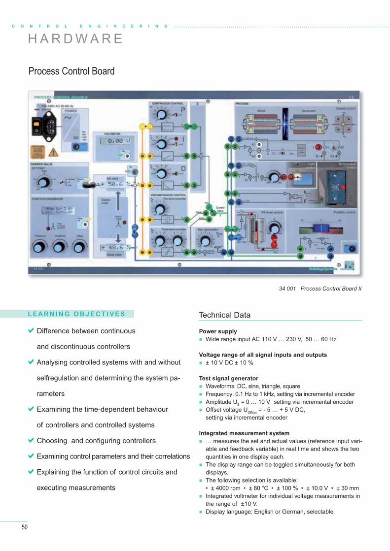
50
C O N T R O L E N G I N E E R I N G
H A R D W A R E
L E A R N I N G O B J E C T I V E S
Process Control Board
Diff erence between continuous
and discontinuous controllers
Analysing controlled systems with and without
selfregulation and determining the system pa-
rameters
Examining the time-dependent behaviour
of controllers and controlled systems
Choosing and confi guring controllers
Examining control parameters and their correlations
Explaining the function of control circuits and
executing measurements
Power supply
Wide range input AC 110 V … 230 V, 50 … 60 Hz
Voltage range of all signal inputs and outputs
± 10 V DC ± 10 %
Test signal generator
Waveforms: DC, sine, triangle, square Frequency: 0.1 Hz to 1 kHz, setting via incremental encoder Amplitude US = 0 … 10 V, setting via incremental encoder Off set voltage UOff set = - 5 … + 5 V DC,
setting via incremental encoder
Integrated measurement system
… measures the set and actual values (reference input vari-able and feedback variable) in real time and shows the two quantities in one display each.
The display range can be toggled simultaneously for both displays.
The following selection is available:• ± 4000 rpm • ± 80 °C • ± 100 % • ± 10.0 V • ± 30 mm
Integrated voltmeter for individual voltage measurements in the range of ±10 V.
Display language: English or German, selectable.
Technical Data
34 001 Process Control Board II

51
Functional groups
Controllers
P-element
Adjustment range: x 1 KP = 0 to 10, continuously x10 KP = 0 to 100, continuously
I-element
Can be connected in series or parallel to the P-controllerAdjustment range: TI = 0.01 to 10 s, in 14 stages
D-element
Can be connected in series or parallel to the P-controllerAdjustment range: TD = 0.001 s to 1 s, in 14 stages
Controlled systems
Rotational speed
… consists of a DC motor that is rigidly joined to a generator via the shafts. The manipulated vari-able is a voltage signal in the range of ± 10 V. The motor reaches rotational speeds of ± 4000 rpm.
Light
… consists of a white LED, which represents the room lighting to be regulated. The manipulated variable is a voltage signal in the range of 0 ... +10 V. The illumination in the room is measured by means of a photo-transistor.
Temperature
… simulates a heating cabinet and consists of two heating elements in a small, limited air volume. The door of the heating cabinet can be opened. The manipulated variable is a voltage signal in the range of 0 ... + 10 V. The temperature in the cabinet is measured by means of a temperature sensor.
Filling level
… simulates a fl uid tank with an inlet and outlet valve. The level in the tank is visu-alised by an LED
scrollbar. The manipulated variable is a voltage signal in the range 0 … + 10 V and controls the infl ow. The level of the tank is given in %. The output value is a propor-tional voltage 0 … + 10 V. Two red LED elements in the infl ow and outfl ow visually display the infl ow and outfl ow behaviour.
Position
… is a linear axis. It consists of a small, permanent magnet-excited DC motor, a li-near drive and a potentiometer for forming the feedback signal from - 10 V to + 10 V.
Stepmaker
The stepmaker is a special control circuit system for the three-position regula-tor. The stepmaker represents a motor-
driven adjusting device, which, upon receiv-ing a positive input signal, for example, opens a valve in steps. In the case of a negative input signal, the valve is once again closed in steps. In case of an input signal of 0 V, the actuating device remains frozen in the momentary state.
Two-level control
Adjustment range of thehysteresis: XH = 0 to 10 %, continuously
Three-level control
Adjustment range of thehysteresis:+ XH 0.5 to 10 %, continuously– XH 0.5 to 10 %, continuously
ELABOTrainingsSystemeELABOTrainingsSysteme
®
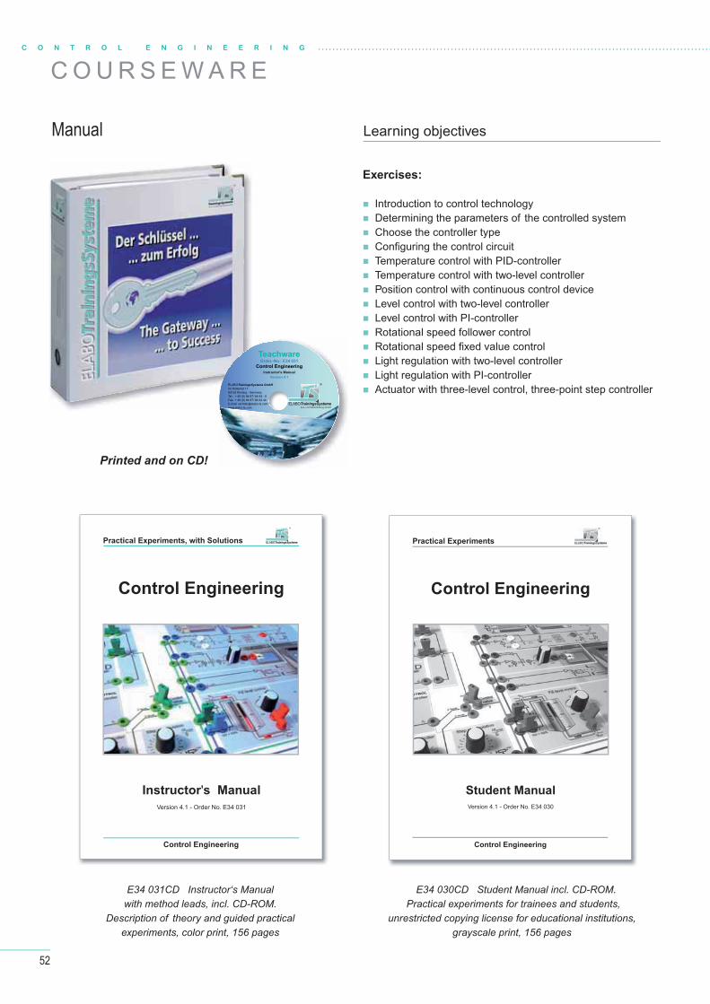
52
C O U R S E W A R EC O N T R O L E N G I N E E R I N G
Manual Learning objectives
Exercises:
Introduction to control technology Determining the parameters of the controlled system Choose the controller type Confi guring the control circuit Temperature control with PID-controller Temperature control with two-level controller Position control with continuous control device Level control with two-level controller Level control with PI-controller Rotational speed follower control Rotational speed fi xed value control
Light regulation with two-level controller Light regulation with PI-controller Actuator with three-level control, three-point step controller
Printed and on CD!
E34 031CD Instructor‘s Manual with method leads, incl. CD-ROM.
Description of theory and guided practicalexperiments, color print, 156 pages
E34 030CD Student Manual incl. CD-ROM. Practical experiments for trainees and students,
unrestricted copying license for educational institutions,grayscale print, 156 pages
Control Engineering
Instructor's Manual
Version 4.1 - Order No. E34 031
Control Engineering
Practical Experiments, with Solutions ELABOTrainingsSystemeELABOTrainingsSysteme
®
Control Engineering
Student Manual
Version 4.1 - Order No. E34 030
Control Engineering
Practical Experiments
TeachwareOrder.-No.: E34 031
Control Engineering
Instructor's Manual
Version 4.1
Aus- und Weiterbildung GmbH ELABOTrainingsSystemeELABOTrainingsSysteme
®ELABOTrainingsSysteme GmbH Im Hüttental 11 85125 Kinding - GermanyTel.: + 49 (0) 84 67/ 84 04 - 0 Fax: + 49 (0) 84 67/ 84 04 44E-mail: [email protected]

53
ELABOTrainingsSystemeELABOTrainingsSysteme
®
Control and test signals
Upon connecting the mains voltage supply, the Process Con-
trol Board is ready for operation.
The connected mains voltage is indicated by the yellow lamp
in the ON switch.
The green LED of the readiness display indicates that the
internal voltages are present.
Set value transmitter
The set value transmitter has a continuously variable adjustment
range of ±10 V DC.
The output signal can be connected continuously via the upper
switch position or momentarily via the lower switch position.
Test signal generator
The signal function can be toggled with the push button:
Sinusoidal, triangular, rectangular and variable DC-Voltage
The frequency of the output signal can be discretely adjusted
from 0.1 Hz to 1000 Hz and is shown in the display.
By slowly turning the adjusting regulator, ”Frequency“, the
frequency can be set correct to the nearest 1 or 0.1 Hz.
Rotating the knob faster results jumps of 10 Hz.
Pressing the frequency regulator knob „Frequency“ results in
the frequency getting reset to 100 Hz.
The amplitude UP of the output signal can be set by the adjusting regulator ”Amplitude“
from 0 to 10 V. The value is shown in the display.
The off set voltage UO of the output signal can be set with the adjusting regulator knob
”Off set“ from -5 V to +5 V. The value is shown in the display.
Integrated measurement system
The integrated measurement system measures the set and
actual values (reference input variable and feedback variable)
in real time and shows the two quantities in one display each.
The display range can be toggled simultaneously for both dis-
plays. The following selection is available:
±4000 revolutions/per minute (rpm)
±80 degrees Celsius
±100% ±10 V ±30 mm
Voltmeter for individual measurements can be freely
populated.
The measurement range is ±10 V
Controlled systems
Rotational speed
The controlled system ”Rotational speed“
consists of a DC motor that is rigidly joined
to a generator via the shafts. The actuating
variable is a voltage signal in the range of
±10 V. The motor reaches rotational speeds
of ± 4000 rpm.
A four-quadrant display with LED displays
the working regime of the motor.
Disturbances could optionally be:
fl ywheel mass that can be manually connected through a switch,
load of the generator that can be manually connected through a switch,
electronically switchable load of the generator.
The rotational speed system is type PT2:
Te = 4ms ±10 %, Tb= 165ms ±10 %, KPS = 1.8 ±10 %
LightThe controlled system ”Light“ consists of a
white LED, which represents the room ligh-
ting to be regulated. The actuating variable
is a voltage signal in the range of 0......+10 V.
The illumination in the room is measured by
means of a photo-transistor. The unit is given
in % for the sake of simplicity.
Disturbances could optionally be:
ambient light that can be manually adjustable with a potentiometer,
electronically adjustable ambient light.
The light controlled system is type PT1:
Tb = 12ms ±10 %, KPS = 1.0 ±10 %
Temperature
The controlled system „Temperature“ simulates a heating
cabinet and consists of two heating elements in a small, li-
mited air volume. The door of the heating cabinet can be
opened. The actuating variable is a voltage signal in the
range of 0......+10 V. The temperature in the cabinet is
measured by means of a temperature sensor. The unit is
given proportional to the voltage in °C and is maximum 80°C
(1 V 8°C). A red LED signals the operation of the heating
element. The depandance of the Temperature from the ac-
tuating variable is linear.
Disturbances can be:
Cooling process of the air volume,
Opening the door of the heating cabinet.
Temperature controlled system is type PT2:
Te = 3,5s ±10 %, Tb = 80s ±10 %, KPS = 1.2 ±10 %
LevelThe controlled system „Level“ simulates a fl uid tank with an in-
let and outlet valve. The level in the tank is visually displayed by
means of an LED scrollbar. The actuating variable is a voltage
signal in the range 0…+10 V and controls the infl ow. The level
in % of the tank is output proportionately as a voltage in Volt
and is 0 … + 10 V. Two red LED elements in the infl ow and out-
fl ow visually display the infl ow and outfl ow behaviour.
Disturbances can be:
drain valve, manually adjustable with a potentiometer,
electronically adjustable drain valve.
Level controlled system is type IT1:
Te = 0.15s ±10 %, TI = 5.4s ±10 % (in case of actuation variable step of 50 %)
Position
The controlled system „Position“ is a motor-potentiometer
combination. It consists of a small, permanent magnet-exci-
ted DC motor with linear drive.
The potentiometer, that is coupled to the linear drive, is for-
ming the feedback signal from -10V to +10V. The starting
voltage of the servomotor is about 3V.
The motor potentiometer is type IT1:
Te = 5ms ±10 %, TI = 150ms ±10 % (in case of actuation variable jump 60 %)
Step control
The stepmaker is a special controlled system for the three-
level control. The stepmaker represents a motor-driven adus-
ting device, which, upon receiving a positive input signal, for
example, opens a valve in steps. In the case of a negative
input signal, the valve is once again closed in steps. In case
of an input signal of 0 V, the actuating device remains frozen
in the momentary state.
The return signal is a voltage of 0 V to +10 V proportional to
the step position. The step width is 0.1 V.
With the potentiometer, the step duration can be adjusted in a continuously variable man-
ner from approx. 0.1 s to 10 s. The actuating element runtime is 10 … 1000 s.
Controller
P-element
Proportional action control element
Adjustment range:
x 1 KP = 0 to 10, continuously variable.
x10 KP = 0 to 100, continuously variable.
I-element
Integral action control element
Can be series or parallel connected to the P-controller.
Adjustment range: TI = 0.01 to 10s, in 14 stages.
D-element
Diff erential action control element
Can be series or parallel connected to the P-controller.
Adjustment range: TD = 0.001 to 1s, in 14 stages.
The I-controller additionally has a RESET. Using this button, the voltage at the output can
be manually reset to 0 V.
Two-level control
Discontinous with 2 levels of the output signal control device.
Adjustment range of the hysteresis:
XH = 0 bis 10 %, continuously.
Three-level control
Discontinous with 3 levels of the output signal control device.
Adjustment range of the hysteresis:
+XH = 0.5 to 10 %, continuously.
-XH = 0.5 to 10 %, continuously.
Each of the two control devices has a coloured LED for displaying an active output level.
The two-level control switches between the two voltage levels +10 V and -10 V.
The three-level control switches between the three voltage levels +10 V, 0 V and -10 V.
In the case of output level +10 V, the LED glows red. In the case of output level 0 V, the
LED does not glow. In the case of output level -10 V, the LED glows blue.
34032-ENG TECHNOCard ® Using the Process Control Board II
90273-ENG TECHNOCard ® Use of the PC measurement interface
TECHNOCards®
The TECHNOCards® are a very useful complement to the training system. They are a kind of compact, clearly laid-out knowledge store for reference during practical experiments.
Display sheets in format 303 mm x 426 mm
Double-sided color print
Rigid, durable quality
Control and test signals
Upon connecting the mains voltage supply, the Proces
trol Board is ready for operation.
The connected mains voltage is indicated by the yello
in the ON switch.
The green LED of the readiness display indicates
internal voltages are present.
Set value transmitter
The set value transmitter has a continuously variable ad
range of ±10 V DC.
The output signal can be connected continuously via
switch position or momentarily via the lower switch pos
Test signal generator
The signal function can be toggled with the push bu
Sinusoidal, triangular, rectangular and variable DC-
The frequency of the output signal can be discrete
from 0.1 Hz to 1000 Hz and is shown in the display
By slowly turning the adjusting regulator, ”Frequ
frequency can be set correct to the nearest 1
Rotating the knob faster results jumps of 10 Hz.
Pressing the frequency regulator knob „Frequency
the frequency getting reset to 100 Hz.
The amplitude UP of the output signal can be set by the adjusting regulator
from 0 to 10 V. The value is shown in the display.
The offset voltage Uffff O of the output signal can be set with the adjusting reg
”Off set“ from -5 V to +5 V. The value is shown in the display.
ffff
Integrated measurement system
The integrated measurement system measure
actual values (reference input variable and feed
in real time and shows the two quantities in one
The display range can be toggled simultaneous
plays. The following selection is available:
±4000 revolutions/per minute (rpm)
±80 degrees Celsius
±100% ±10 V ±30 mm
Aus- und Weiterbildung GmbH ELABOTrainingsSystemeELABOTrainingsSysteme
®
Im Hüttental 11 85125 Kinding - GermanyTel.: + 49 (0) 84 67 / 84 04 - 0 Fax: + 49 (0) 84 67 / 84 04 44E-mail: [email protected]
34032-ENG
TECHNOCard®
Using the Process Control Board II
At the time of installation of the plants and when testing them, comply with all the necessary safety regulations, the laboratory code of conduct and the necessary safety measures!
CAUTION!
Voltmeter for individual measurements
Set value transmitter setting range: ±10 V continuously variable. Can be connected via a locking key switch.
Test signal generatorsignal function: Sinusoidal, triangular, rectangular andvariable DC-voltage
Display of the set value
Test signal generator, frequency range setting: 0.1 to 1000 Hz
Test signal generator, amplitude setting: 0 to 10 V
Test signal generator off set setting: ±5 V DC
Toggle of the display ranges: ±10 V, ±100 %, ± 30 mm, ± 80°C, ± 4000 rpm
Display of theactual value Two-level controller
Three-level controller
Step controller Controlled system, lled level
Controlled system,position control
Electronically switchable disturbing quantity through
loading the generator
Manual connecting
disturbance feedforward
through loading the generator
Manual disturbance feedforward, torque
Diff erential action control element
Integral action control element
Proportional action control element
Readiness display of the operating voltage
Mains voltage supply as wide-range input110 V…240 V AC50…60 Hz
Switch of the manipulated value between continous or discontinous controllers Four-quadrant display of the motor
Controlled system, rotational speed
Controlled systemtemperature
Controlled systemlight
Use of the Multi-Channel Software
The basic preconditions for the proper operation of the PC measurement interface and the Multi-Channel Software are:
installed device driver, installed Multi-Channel Software, active USB connection between PC measurement interface and computer.
The Multi-Channel Software recognises, immediately after the start, the PC measurement interface as HS4DIFF-5 and will display channel 1.
In the first toolbar are the buttons with the functions of the
menus File and Quick Functions Display input markers
Device path
Trigger marker
Multimeter
Buttons for the function and configuration of the measurement conditions
Start / Stop of the
measurement
Auto-configuration of the measurement
Individual measurement (Single shot)
Measurement mode Block
or Data stream
Trigger configuration Configuration of the individual inputsTime parameter configuration
Sample
SampleSYNC F
NT
Current measurement interface, upon clicking on it,
there opens a context menu for configuration for the time parameters
and the resolution
Channel designation;can be changed by assigning an alias
CouplingAC / DC
Selection of the measurement range:
Auto-RangeAuto / manual
Display and selection of the measurement
range in case of manual selection
Quick measurement of a periodic signal Start the Multi-Channel Software. Stop the measurement Estimation of the amplitude of the signal to be measured:
a) Signal is expected to be smaller than Urms=50V AC or U = 120V DC Differential input 1:1 b) Signal is expected to be greater than Urms=50V AC or U = 120V DC Differential input 10:1 Connect the signal to be measured to channel 1 (CH1) of the corresponding input 1:1 or
10:1 in differential operation. Press the button ”Autoconfiguration of the measurement“ A .
Measurements at input 10:1During all measurements with the inputs over the 10:1 input range, all the input signals are weakened in the amplitude 10:1. For a correct display of all the amplitudes, therefore, it is necessary to set the probe settings to x10.To do so, click the right mouse button in the device path on the relevant channel. There opens a selection menu. Select ”Probe settings“ 10:1.The matching of the value ranges takes place automatically.
Manual setting of the time parametersAt least 1000 samplings are recommended for a good measurement resolution.
According to the formula of the synchronisation time: Sample
SampleSYNC F
NT
we get: AblenkzeitT
NF
SYNC
SampleSample
1000
Stopping the measurement. Mouse click on the currently valid number of samplings Selection of the number of samplings in the opened menu. Mouse click on the currently valid frequency of samplings (sample frequency) Selection of the sampling frequency in the opened menu. Start of measurement
Multi-channel measurement Stopping the measurement. Which signal in the multi-channel measurement is the synchronising signal for the trigger? Execution of the configuration for the synchronising signal according to ”Quick measurement“. Optimisation of the time parameters. Connecting additional measurement channels taking into consideration the estimation of
the amplitude values. With the mouse (click on icon and hold), capture the icon of the corresponding channel in
the device path and drag it into the diagram.
Note: If you wish to have the same ratio between the amplitudes shown, you must disable the buttons for Auto Range of the channels and by selecting the measurement range of the respective channel, set the same values.
Magnifying glass functionThe diagrams have a magnifying glass function. With the left mouse button held down, draw a rectangle around the area to be enlarged and then release the mouse button.To zoom out, press the key U on the keyboard or click the right mouse button on the diagram and in the context menu, select ”Zoom out“
synchr. time
e PC me
interfac
after the
s of th
eaasssuuurrem
nel designbe changgning an
Aus- und Weiterbildung GmbH ELABOTrainingsSystemeELABOTrainingsSysteme
®
Im Hüttental 11 85125 Kinding - GermanyTel.: + 49 (0) 84 67 / 84 04 - 0 Fax: + 49 (0) 84 67 / 84 04 44E-mail: [email protected]
E90 273
TECHNOCard ®
Use of the PC measurement interface
At the time of installation of the plants and when testing them, comply with all the necessary safety regulations, the laboratory code of conduct and the necessary safety measures!
CAUTION!
Measurement outside the SELV zoneCaution: In the case of measurements outside the safety extra-low voltage range SELV (Urms>50V AC or U > 120V DC), a connection of the protective conductor PE to the protective conductor connection PE of the PC measurement interface must be made without fail!This is generally worth recommending right from voltages Urms> 25V AC and U > 60V DC.
Typical measurement circuitsMeasurement with differential inputs (SELV-zone)
Measurement referred to earth (SELV-zone)
Measurement with reference potential N (e.g. star)
Measurement without reference potential (e.g. delta)
Operating voltage lead-through in
the zone 8 … 30V DC
USB connection socket type B
Protective conductor con-nection for onward lead in
the measurement setup
Common wire for input zone 10:1
Input zone 10:1,4 input channels CH1 … CH4
Common wire for input zone 1:1
Earth socket to the device earth of the measurement interface
Protective conductor connection for measurement interface for measurement outside SELV
Input zone 1:1,4 input channels CH1 … CH4
Operating voltage lead-through in the zone 8 … 30V DC,
serves simultaneously for optional provision of the operating voltage of the measurement interface
USB
USB
USB
L1
L1
L2
L2
L3
L3
N
N
PE/PEN
PE/PEN
USB
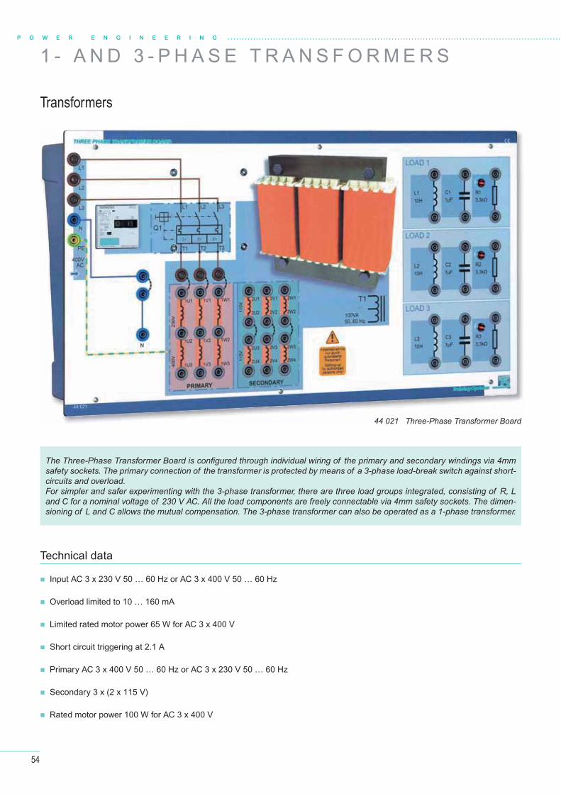
54
P O W E R E N G I N E E R I N G
1 - A N D 3 - P H A S E T R A N S F O R M E R S
Transformers
Input AC 3 x 230 V 50 … 60 Hz or AC 3 x 400 V 50 … 60 Hz
Overload limited to 10 … 160 mA
Limited rated motor power 65 W for AC 3 x 400 V
Short circuit triggering at 2.1 A
Primary AC 3 x 400 V 50 … 60 Hz or AC 3 x 230 V 50 … 60 Hz
Secondary 3 x (2 x 115 V)
Rated motor power 100 W for AC 3 x 400 V
Technical data
The Three-Phase Transformer Board is confi gured through individual wiring of the primary and secondary windings via 4mm safety sockets. The primary connection of the transformer is protected by means of a 3-phase load-break switch against short-circuits and overload. For simpler and safer experimenting with the 3-phase transformer, there are three load groups integrated, consisting of R, L and C for a nominal voltage of 230 V AC. All the load components are freely connectable via 4mm safety sockets. The dimen-sioning of L and C allows the mutual compensation. The 3-phase transformer can also be operated as a 1-phase transformer.
44 021 Three-Phase Transformer Board

55
ELABOTrainingsSystemeELABOTrainingsSysteme
®
The Three-Phase Network Analyzer Board (40 312) is ideally suited for the investigations on the transformer.
Investigations on 1-phase and 3-phase transformers
Structure of the manuals
E44 025CD Investigations on 1-phase and 3-phase transformers – Student manualE44 026CD Investigations on 1-phase and 3-phase transformers – Instuctor‘s manual
Description of the theory and the derived practical experiments in book form
Experiment section for trainees / students
Unrestricted copying licence of the task sheets for the training institute
Manual including CD-ROM
Transformers and their applications
1-phase transformer
Construction principle of transformers
Autotransformers
Transformer protection devices
3-phase transformer
Operational behaviour
Three-phase system
Load types
Circuit types and designations
Compensation
Switching groups
Effi ciency
L E A R N I N G O B J E C T I V E S
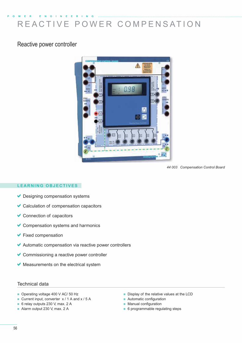
56
R E A C T I V E P O W E R C O M P E N S AT I O N
Reactive power controller
44 003 Compensation Control Board
L E A R N I N G O B J E C T I V E S
Designing compensation systems
Calculation of compensation capacitors
Connection of capacitors
Compensation systems and harmonics
Fixed compensation
Automatic compensation via reactive power controllers
Commissioning a reactive power controller
Measurements on the electrical system
Operating voltage 400 V AC/ 50 Hz Current input, converter x / 1 A and x / 5 A 6 relay outputs 230 V, max. 2 A Alarm output 230 V, max. 2 A
Display of the relative values at the LCD Automatic confi guration Manual confi guration 6 programmable regulating steps
Technical data
P O W E R E N G I N E E R I N G
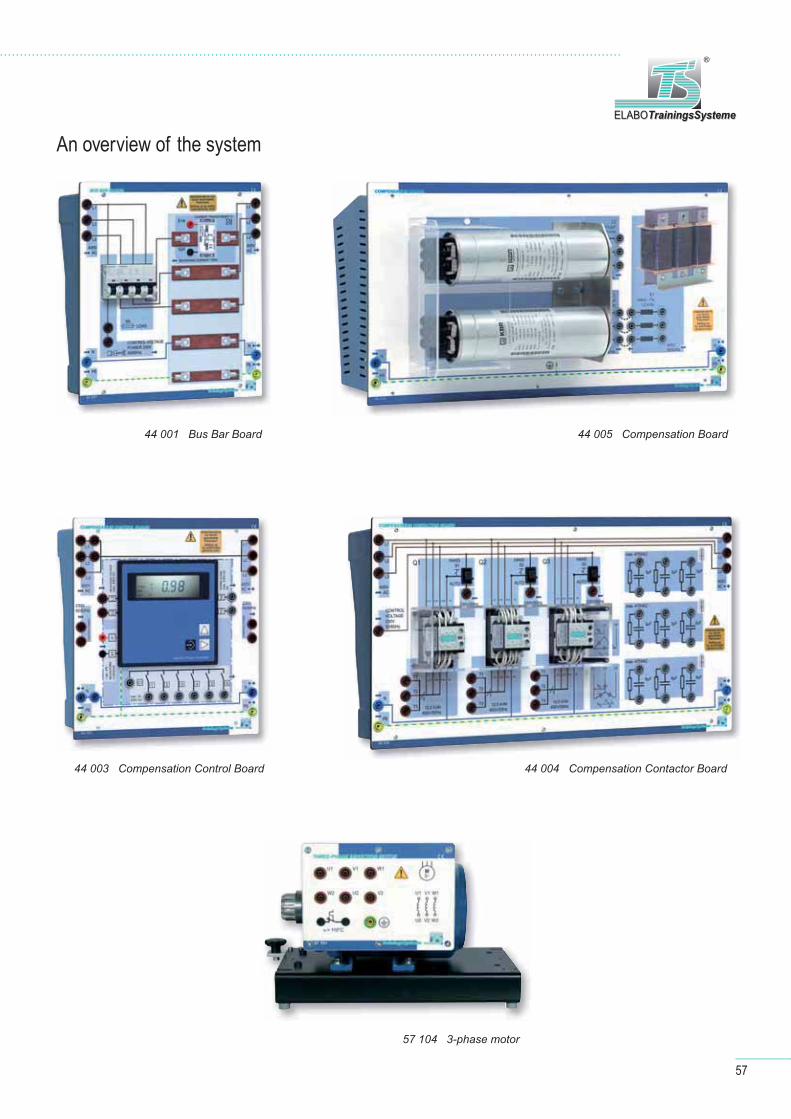
57
ELABOTrainingsSystemeELABOTrainingsSysteme
®
An overview of the system
44 005 Compensation Board44 001 Bus Bar Board
44 003 Compensation Control Board 44 004 Compensation Contactor Board
57 104 3-phase motor
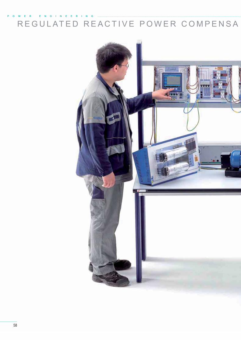
58
P O W E R E N G I N E E R I N G
R E G U L AT E D R E A C T I V E P O W E R C O M P E N S A
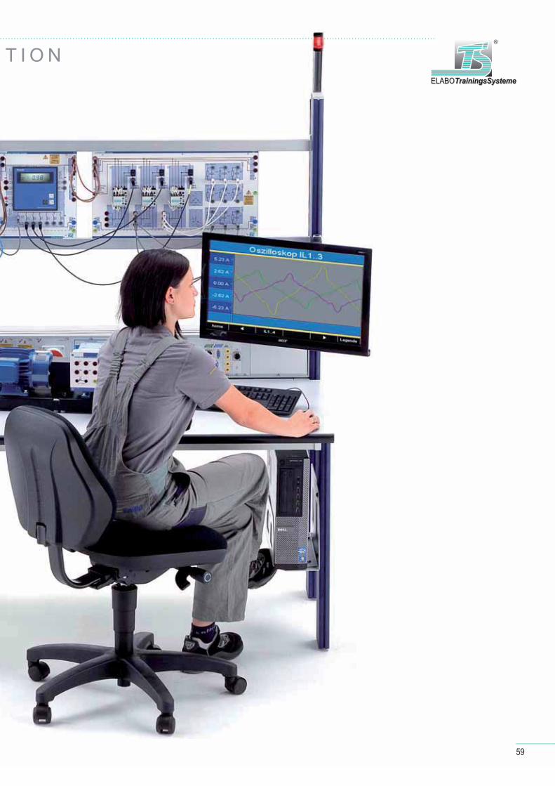
59
ELABOTrainingsSystemeELABOTrainingsSysteme
®
T I O N
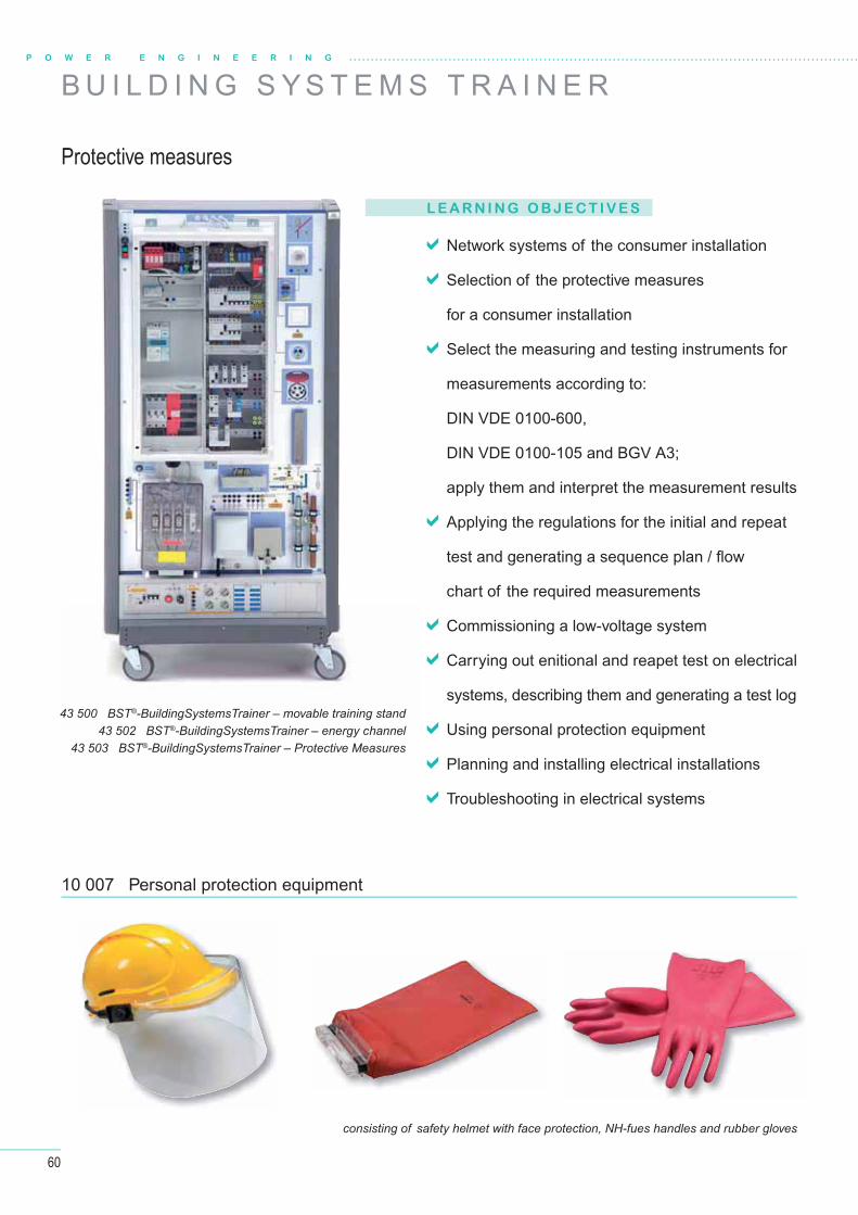
60
P O W E R E N G I N E E R I N G
L E A R N I N G O B J E C T I V E S
Network systems of the consumer installation
Selection of the protective measures
for a consumer installation
Select the measuring and testing instruments for
measurements according to:
DIN VDE 0100-600,
DIN VDE 0100-105 and BGV A3;
apply them and interpret the measurement results
Applying the regulations for the initial and repeat
test and generating a sequence plan / fl ow
chart of the required measurements
Commissioning a low-voltage system
Carrying out enitional and reapet test on electrical
systems, describing them and generating a test log
Using personal protection equipment
Planning and installing electrical installations
Troubleshooting in electrical systems
Protective measures
B U I L D I N G S Y S T E M S T R A I N E R
10 007 Personal protection equipment
consisting of safety helmet with face protection, NH-fues handles and rubber gloves
43 500 BST®-BuildingSystemsTrainer – movable training stand43 502 BST®-BuildingSystemsTrainer – energy channel
43 503 BST®-BuildingSystemsTrainer – Protective Measures
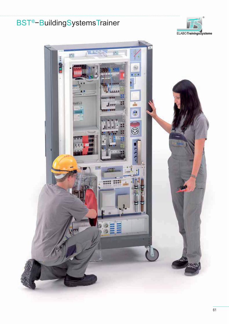
61
BST®−BuildingSystemsTrainerELABOTrainingsSystemeELABOTrainingsSysteme
®
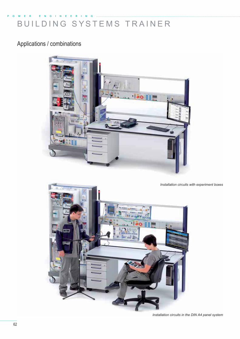
62
B U I L D I N G S Y S T E M S T R A I N E RP O W E R E N G I N E E R I N G
Applications / combinations
Installation circuits with experiment boxes
Installation circuits in the DIN A4 panel system
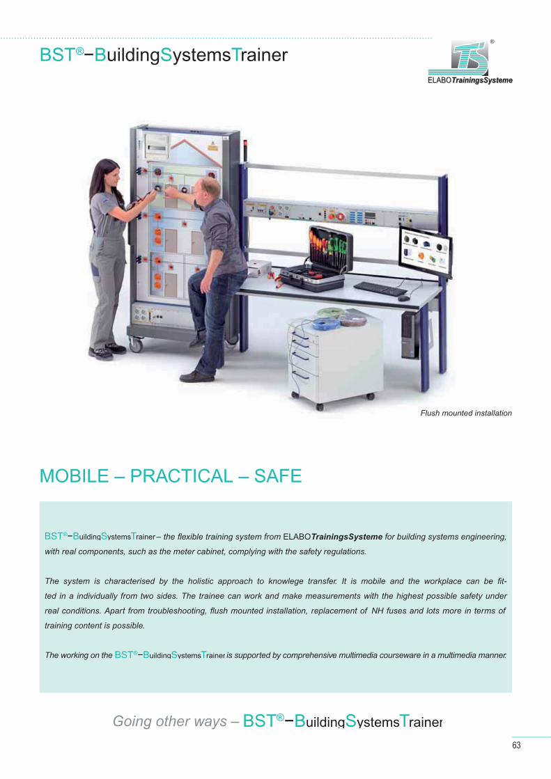
63
ELABOTrainingsSystemeELABOTrainingsSysteme
®
Flush mounted installation
MOBILE – PRACTICAL – SAFE
– the fl exible training system from ELABOTrainingsSysteme for building systems engineering,
with real components, such as the meter cabinet, complying with the safety regulations.
The system is characterised by the holistic approach to knowlege transfer. It is mobile and the workplace can be fi t-
ted in a individually from two sides. The trainee can work and make measurements with the highest possible safety under
real conditions. Apart from troubleshooting, fl ush mounted installation, replacement of NH fuses and lots more in terms of
training content is possible.
The working on the is supported by comprehensive multimedia courseware in a multimedia manner.
BST®−BuildingSystemsTrainer
BST®−BuildingSystemsTrainer
Going other ways – BST®−BuildingSystemsTrainer
BST®−BuildingSystemsTrainer
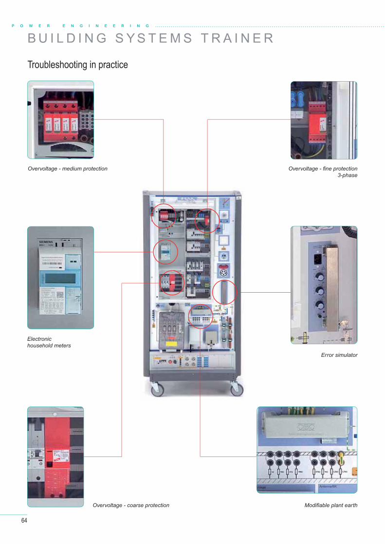
64
B U I L D I N G S Y S T E M S T R A I N E R
Troubleshooting in practice
P O W E R E N G I N E E R I N G
Overvoltage - coarse protection
Electronic household meters
Overvoltage - medium protection Overvoltage - fi ne protection 3-phase
Error simulator
Modifi able plant earth
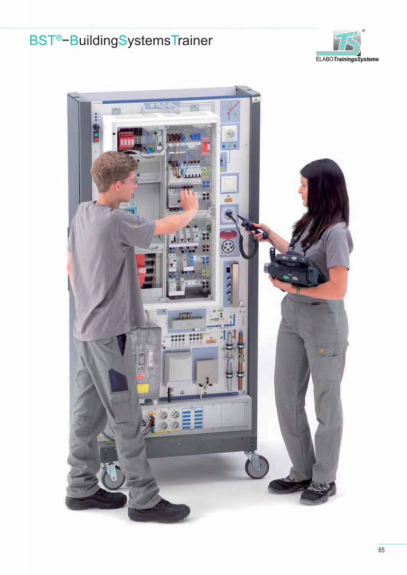
65
ELABOTrainingsSystemeELABOTrainingsSysteme
®
BST®−BuildingSystemsTrainer
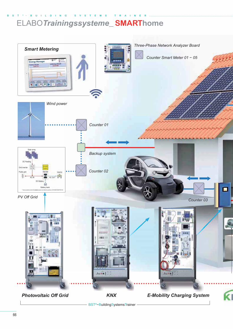
Counter 01
Backup system
Counter 02
Photovoltaic Off Grid
Counter 03PV Off Grid
Wind power
Smart Metering
KNX E-Mobility Charging System
Three-Phase Network Analyzer Board
Counter Smart Meter 01 − 05
Solar array
Grid inverter
Public grid
Battery bank
Xtender User(s)
DC Feeding
DC Battery
AC IN AC OUT
SCADASystem
BST®−BuildingSystemsTrainer
66
ELABOTrainingssysteme_ SMARThome
B S T ® − B U I L D I N G S Y S T E M S T R A I N E R
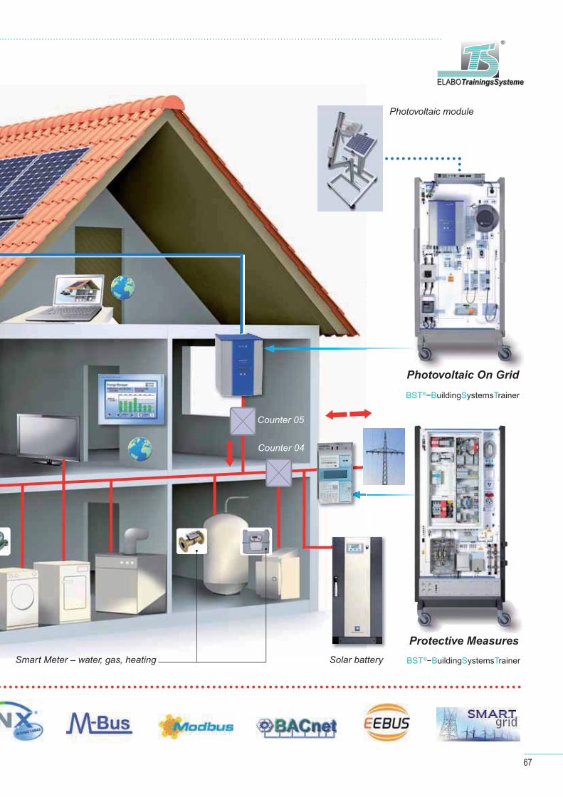
Counter 04
Counter 05
Photovoltaic On Grid
Protective Measures
Photovoltaic module
Smart Meter – water, gas, heating Solar battery BST®−BuildingSystemsTrainer
BST®−BuildingSystemsTrainer
67
ELABOTrainingsSystemeELABOTrainingsSysteme
®
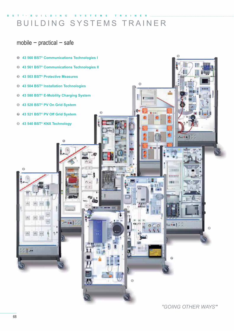
68
B S T ® − B U I L D I N G S Y S T E M S T R A I N E R
43 560 BST® Communications Technologies I
43 561 BST® Communications Technologies II
43 503 BST® Protective Measures
43 504 BST® Installation Technologies
43 580 BST® E-Mobility Charging System
43 520 BST® PV On Grid System
43 521 BST® PV Off Grid System
43 540 BST® KNX Technology
B U I L D I N G S Y S T E M S T R A I N E R
mobile − practical − safe
"GOING OTHER WAYS"
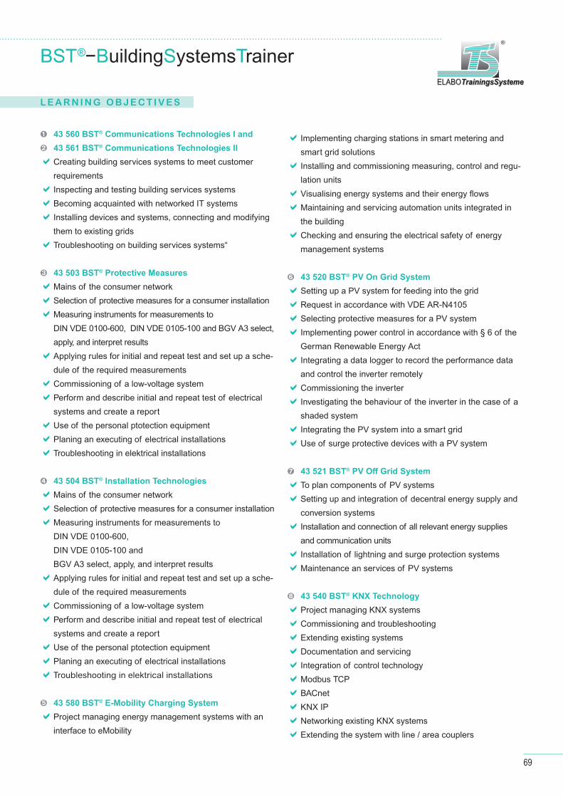
69
ELABOTrainingsSystemeELABOTrainingsSysteme
®
43 560 BST® Communications Technologies I and
43 561 BST® Communications Technologies II
Creating building services systems to meet customer
requirements
Inspecting and testing building services systems
Becoming acquainted with networked IT systems
Installing devices and systems, connecting and modifying
them to existing grids
Troubleshooting on building services systems“
43 503 BST® Protective Measures
Mains of the consumer network
Selection of protective measures for a consumer installation
Measuring instruments for measurements to
DIN VDE 0100-600, DIN VDE 0105-100 and BGV A3 select,
apply, and interpret results
Applying rules for initial and repeat test and set up a sche-
dule of the required measurements
Commissioning of a low-voltage system
Perform and describe initial and repeat test of electrical
systems and create a report
Use of the personal ptotection equipment
Planing an executing of electrical installations
Troubleshooting in elektrical installations
43 504 BST® Installation Technologies
Mains of the consumer network
Selection of protective measures for a consumer installation
Measuring instruments for measurements to
DIN VDE 0100-600,
DIN VDE 0105-100 and
BGV A3 select, apply, and interpret results
Applying rules for initial and repeat test and set up a sche-
dule of the required measurements
Commissioning of a low-voltage system
Perform and describe initial and repeat test of electrical
systems and create a report
Use of the personal ptotection equipment
Planing an executing of electrical installations
Troubleshooting in elektrical installations
43 580 BST® E-Mobility Charging System
Project managing energy management systems with an
interface to eMobility
Implementing charging stations in smart metering and
smart grid solutions
Installing and commissioning measuring, control and regu-
lation units
Visualising energy systems and their energy fl ows
Maintaining and servicing automation units integrated in
the building
Checking and ensuring the electrical safety of energy
management systems
43 520 BST® PV On Grid System
Setting up a PV system for feeding into the grid
Request in accordance with VDE AR-N4105
Selecting protective measures for a PV system
Implementing power control in accordance with § 6 of the
German Renewable Energy Act
Integrating a data logger to record the performance data
and control the inverter remotely
Commissioning the inverter
Investigating the behaviour of the inverter in the case of a
shaded system
Integrating the PV system into a smart grid
Use of surge protective devices with a PV system
43 521 BST® PV Off Grid System
To plan components of PV systems
Setting up and integration of decentral energy supply and
conversion systems
Installation and connection of all relevant energy supplies
and communication units
Installation of lightning and surge protection systems
Maintenance an services of PV systems
43 540 BST® KNX Technology
Project managing KNX systems
Commissioning and troubleshooting
Extending existing systems
Documentation and servicing
Integration of control technology
Modbus TCP
BACnet
KNX IP
Networking existing KNX systems
Extending the system with line / area couplers
BST®−BuildingSystemsTrainer
L E A R N I N G O B J E C T I V E S
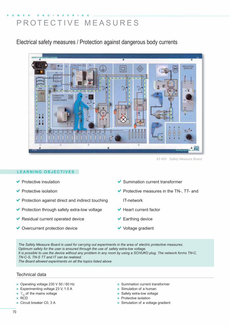
70
P O W E R E N G I N E E R I N G
Technical data
Protective insulation
Protective isolation
Protection against direct and indirect touching
Protection through safety extra-low voltage
Residual current operated device
Overcurrent protection device
Summation current transformer
Protective measures in the TN-, TT- and
IT-network
Heart current factor
Earthing device
Voltage gradient
Operating voltage 230 V 50 / 60 Hz Experimenting voltage 23 V, 1.5 A 1/10 of the mains voltage RCD Circuit breaker C0, 3 A
Summation current transformer Simulation of a human Safety extra-low voltage Protective isolation Simulation of a voltage gradient
43 400 Safety Measure Board
P R O T E C T I V E M E A S U R E S
Electrical safety measures / Protection against dangerous body currents
L E A R N I N G O B J E C T I V E S
The Safety Measure Board is used for carrying out experiments in the area of electric protective measures.Optimum safety for the user is ensured through the use of safety extra-low voltage. It is possible to use the device without any problem in any room by using a SCHUKO plug. The network forms TN-C, TN-C-S, TN-S TT and IT can be realised. The Board allowed experiments on all the topics listed above
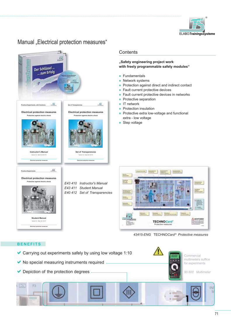
71
ELABOTrainingsSystemeELABOTrainingsSysteme
®
Carrying out experiments safely by using low voltage 1:10
No special measuring instruments required
Depiction of the protection degrees
B E N E F I T S
Commercialmultimeters suffi ce for experiments
90 600 Multimeter
Manual „Electrical protection measures“Contents
„Safety engineering project work
with freely programmable safety modules“
Fundamentals Network systems Protection against direct and indirect contact Fault current protective devices Fault current protective devices in networks Protective separation IT network Protection insulation Protective extra low-voltage and functional
extra - low voltage Step voltage
43415-ENG TECHNOCard® Protective measures
E43 410 Instructor's ManualE43 411 Student ManualE40 412 Set of Transparencies
Protective measures
Electrical protection measures
Protection against electric shock
Student Manual
Version 4.2 - Best.-Nr. 43 411
Practical Experiments
Electrical protection measures
Electrical protection measures
Protection against electric shock
Instructor's Manual
Version 4.2 - Best.-Nr. E43 410
Practical Experiments, with Solutions
Electrical protection measures
Electrical protection measures
Protection against electric shock
Set of Transparencies
Version 4.2 - Best.-Nr. 40 412
Set of Transparencies
Electrical protection measures
ELABOTrainingsSystemeELABOTrainingsSysteme
®
ELABOTrainingsSystemeELABOTrainingsSysteme
®
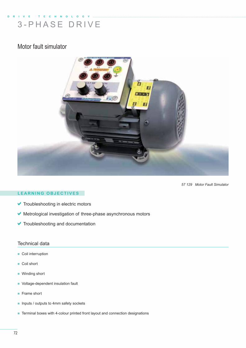
72
L E A R N I N G O B J E C T I V E S
Troubleshooting in electric motors
Metrological investigation of three-phase asynchronous motors
Troubleshooting and documentation
Coil interruption
Coil short
Winding short
Voltage-dependent insulation fault
Frame short
Inputs / outputs to 4mm safety sockets
Terminal boxes with 4-colour printed front layout and connection designations
Technical data
D R I V E T E C H N O L O G Y
57 129 Motor Fault Simulator
Motor fault simulator
3 - P H A S E D R I V E

73
ELABOTrainingsSystemeELABOTrainingsSysteme
®
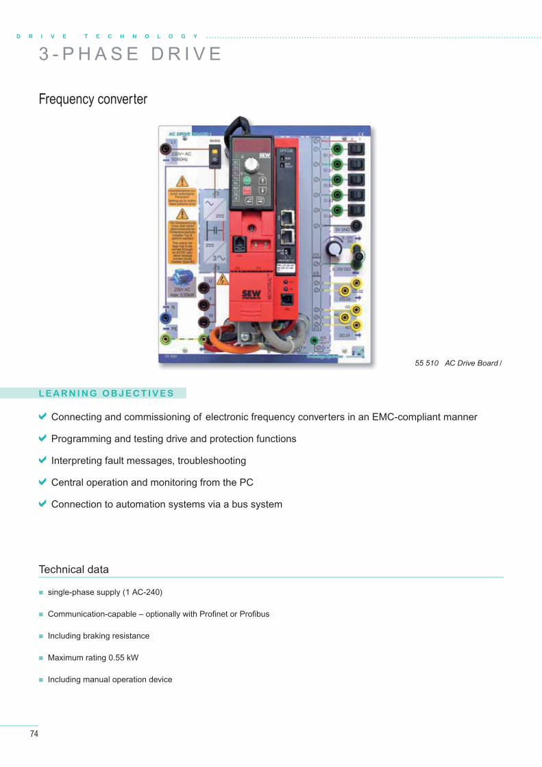
74
L E A R N I N G O B J E C T I V E S
Connecting and commissioning of electronic frequency converters in an EMC-compliant manner
Programming and testing drive and protection functions
Interpreting fault messages, troubleshooting
Central operation and monitoring from the PC
Connection to automation systems via a bus system
single-phase supply (1 AC-240)
Communication-capable – optionally with Profi net or Profi bus
Including braking resistance
Maximum rating 0.55 kW
Including manual operation device
Technical data
D R I V E T E C H N O L O G Y
Frequency converter
55 510 AC Drive Board /
3 - P H A S E D R I V E
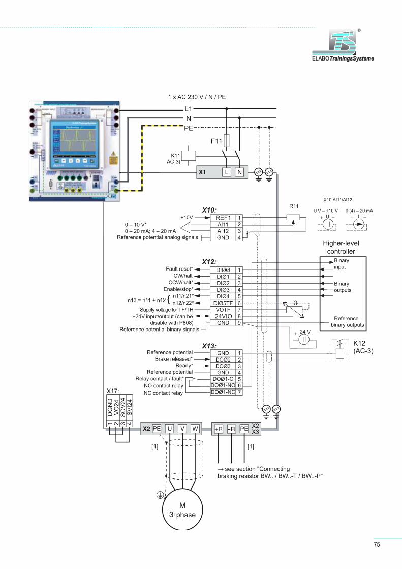
75
ELABOTrainingsSystemeELABOTrainingsSysteme
®
}
n13 = n11 + n12
REF1
24VIO
→ see section "Connectingbraking resistor BW.. / BW..-T / BW..-P"
PE X2X3
DG
ND
VO
24S
OV
24S
VI2
4
1 2 3 4
X17:
Enable/stop*
PE
1 x AC 230 V / N / PE
[1][1]
+24V input/output (can bedisable with P808)
L1N
PE
0 V – +10 V 0 (4) – 20 mA
Higher-levelcontroller
Binaryinput
Binaryoutputs
Referencebinary outputs
0 – 10 V*0 – 20 mA; 4 – 20 mA
Reference potential analog signals
Fault reset*CW/halt
CCW/halt*
n11/n21*n12/n22*
Supply voltage for TF/TH
Reference potential binary signals
Reference potentialBrake released*
Ready*Reference potential
Relay contact / fault*NO contact relayNC contact relay
phase

76
L E A R N I N G O B J E C T I V E S
Technical data
D R I V E T E C H N O L O G Y
Selection of motor starting techniques
Soft starters instead of devices
star-delta combinations
Use of soft-start devices in combination with PLC
Investigation of startup behaviour with and
without soft-start device
Maximum load 1.5 kW
Supply, load 400 V AC
Operating voltage 24 V DC
56 130 Soft Starter Board
3 - P H A S E D R I V E
Soft starter

77
ELABOTrainingsSystemeELABOTrainingsSysteme
®
56 130 Soft Starter Board
Optional: 40 312 Three-Phase Network Analyzer Board
40 023 Control Board V
Contactors
57 104 3-phase motor
Confi guration example – soft starter
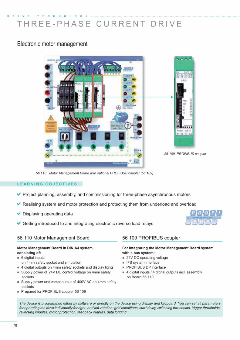
78
D R I V E T E C H N O L O G Y
T H R E E - P H A S E C U R R E N T D R I V E
Electronic motor management
56 110 Motor Management Board with optional PROFIBUS coupler (56 109)
56 109 PROFIBUS coupler
L E A R N I N G O B J E C T I V E S
Project planning, assembly, and commissioning for three-phase asynchronous motors
Realising system and motor protection and protecting them from underload and overload
Displaying operating data
Getting introduced to and integrating electronic reverse load relays
56 110 Motor Management Board
Motor Management Board in DIN A4 system,
consisting of:
6 digital inputson 4mm safety socket and simulation
4 digital outputs on 4mm safety sockets and display lights Supply power of 24V DC control voltage on 4mm safety
sockets Supply power and motor output of 400V AC on 4mm safety
sockets Prepared for PROFIBUS coupler 56 109
56 109 PROFIBUS coupler
For integrating the Motor Management Board system
with a bus system:
24V DC operating voltage IFS system interface PROFIBUS DP interface 4 digital inputs / 4 digital outputs incl. assembly
on Board 56 110
P R O F I
B U S
PROCESS FIELD BUS
The device is programmed either by software or directly on the device using display and keyboard. You can set all parameters for operating the drive individually for right- and left-rotation: grid conditions, start delay, switching thresholds, trigger thresholds, reversing impulse, motor protection, feedback outputs, data logging
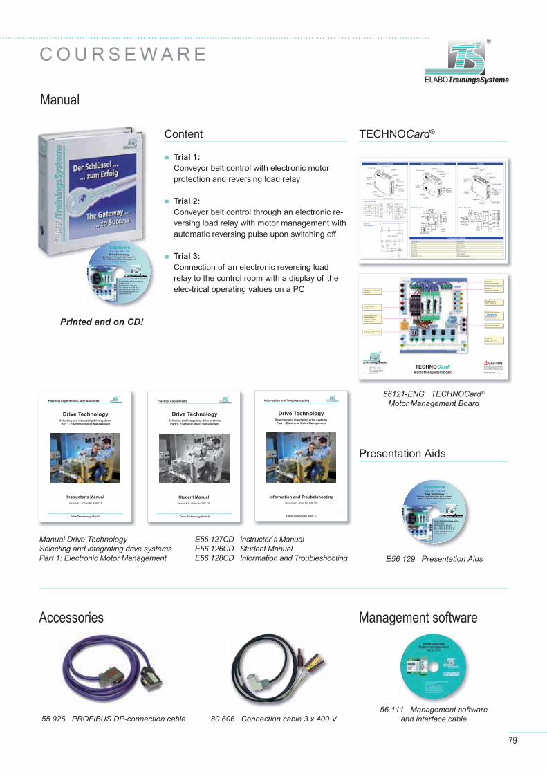
79
ELABOTrainingsSystemeELABOTrainingsSysteme
®
C O U R S E W A R E
Manual
56 111 Management software and interface cable
Accessories
80 606 Connection cable 3 x 400 V55 926 PROFIBUS DP-connection cable
Management software
Printed and on CD!
Content
Trial 1:
Conveyor belt control with electronic motor protection and reversing load relay
Trial 2:
Conveyor belt control through an electronic re-versing load relay with motor management with automatic reversing pulse upon switching off
Trial 3:
Connection of an electronic reversing load relay to the control room with a display of the elec-trical operating values on a PC
TECHNOCard®
56121-ENG TECHNOCard® Motor Management Board
Presentation Aids
E56 129 Presentation Aids
Engine management Electronic reversing load relay
Configuration / Settings
Gateway
0102
0304
EMM3 - 24DC/500AC-16-IFS
Ord.-No.: 22 975 23
Err
PWR
L
R
Reset
1/L13/L2
5/L3
2/T14/T2
6/T3
O1O2
O3
IN1
IN2
IN3
IN4
UO
O
US
O4
EM
M3-
24D
C/5
00A
C-1
6-IF
S
S-PORT
Us
0U
s0
T
T
IN1 IN
2 IN3 IN
4
Th1Th2
DAT
S
Metal lock for fixing to DIN rail
3-phaseinput voltage
Input:Control supply voltage
Reply output supply
3-phaseoutput voltage
Digital outputsO1 … O4
Digital inputsIN1 … IN4
Reset button
“S-PORT”:For connection of the programming adapter
LEDs:PWR Control supply
voltageDATErr message/errorL reverse runningR forward running
Thermistor input
EMM 3-.../500AC-16-IFS
Connection for T-BUS DIN rail connector
US
N
IN1
O1
IN2
O2
IN3
O3
IN4
O4
11
230 VAC
Digital
IN
230 VAC
US
USO
O
IN1
O1
IN2
O2
IN3
O3
IN4
O4
24 VDC
24 VDC
Digital
IN
Digital
OUT
Thermistor
Logic
μP
T-BUS
Th1
Th2
DA
T
ER
R
L R
IFS-
PortReset
V1
I11
I12
V2
I21
I22
V3
I31
I32
P
1/L1
2/T1
3/L2
4/T2
5/L3
6/T3
P
EMM 3.../500AC-16-IFS
EMM 3.../500AC-IFS
EMM 3-230AC/... EMM 3- 24DC/...
Block diagramm
Block diagrammBlock diagramm
System
configuration
1/L1 3/L2 5/L3
2/T1 4/T2 6/T3GND
EMM 3-.../500AC-16-IFS
O U OS O1 O2 O3 O4 Th
1
Th
2
2/T
1
4/T
2
6/T
3
US IN1 IN2 IN3 IN4
3/L
2
5/L
3
1/L
1
M
Mo
du
le
po
we
rs
up
ply
Dig
ita
l
inp
uts
Dig
ita
l
ou
tpu
ts
Po
we
rs
up
ply
Dig
ita
l
ou
tpu
ts
Current measurement
Current measurement
Reverse running
Separate
switching moduleForward running
Thermistor
input
MFigure 4
L1
L2
L3
9796
95
MANRES
AUTE
Us
RL
T
T
Err
PWR
L
R
Reset
max. 2,4A
1/L13/L2
5/L3
2/T14/T2
6/T3
MANRES
AUT
9796
95
R
L
US
E
ELR
H5-
ES
-SC
-24D
C/5
00A
C-2
ELRH5-ES-SC-24DC/500AC-2
Ord.-No.: 29 005 59
Solid-state reversing contactor / Halbleiter - Wendeschütz
www.phoenixcontact.com
32825 Blomberg, Germany
for fastening
3-phase input
Input: Forward / reverse running
3-phase
Forward / reverse running
T
PWR
ERR Message/errorLR Forward running
Reset
Reset
Autoreset
Reset 2MAN
AUT
RES
Logic
μP
24
VDC
sU
97
96
95
9796/98
95
& Error
24VDC
L
R
E
1/L1
3/L2
5/L3
2/T1
4/T2
6/T3
ELR H5-ES-24DC/...
Status
PB
US
USO
GND
24VDC
3
4
5
6
8
B-Line
RTSGND PB
5V PB
A-Line
EPROM
μController
O4O3O2O1
OUT
TBUSIFS
IN
IN1IN2IN3IN4IN5IN6IN7IN8
TO
IFS-
PortReset
In- / Output Description
Input IN1 Clockwise
Input IN2 anti-clockwise
Input IN3 Spot-Control
Input IN4 Reset
Output O1 Right-contractor
Output O2 Left-contractor
Output O3 ... O4 free parameterisable
TECHNOCard ®
Motor Management Board4.2
Aus- und Weiterbildung GmbH ELABOTrainingsSystemeELABOTrainingsSysteme
®
Im Hüttental 11 85125 Kinding - GermanyTel.: + 49 (0) 84 67 / 84 04 - 0 Fax: + 49 (0) 84 67 / 84 04 44E-Mail: [email protected]
Voltage supply for load400 V AC
Control voltage 24 V DC
Electrothermic and electromagnetic protective curcuitbreaker 2,5 A
Rotation reversing switchCCW / W / CW
Additional digital inputs for PROFIBUS-Gateway
Connection engine
Signal outputs Out 1 bis Out 4
Electronic reversing load relay
Electronicengine management
PROFIBUS-GatewayP R O F I
B U S
PROCESS FIELD BUS
56121-ENG
Please observe all the necessary safety regulations, laboratory rules and take the necessary safety precautions when setting up and testing the systems!
CAUTION!
E56 127CD Instructor`s ManualE56 126CD Student ManualE56 128CD Information and Troubleshooting
Information and Troubelshooting
Version 4.2 - Order No. E56 128
Information and Troubleshooting ELABOTrainingsSystemeELABOTrainingsSysteme
®
Drive Technology (Part 1)
Drive TechnologySelecting and integrating drive systems
Part 1: Electronic Motor Management
Student Manual
Version 4.2 - Order No. E56 126
Practical Experiments ELABOTrainingsSystemeELABOTrainingsSysteme
®
Drive Technology (Part 1)
Instructor's Manual
Version 4.2 - Order No. E56 127
Practical Experiments, with Solutions ELABOTrainingsSystemeELABOTrainingsSysteme
®
Drive Technology (Part 1)
Drive TechnologySelecting and integrating drive systems
Part 1: Electronic Motor Management
Drive TechnologySelecting and integrating drive systems
Part 1: Electronic Motor Management
Manual Drive TechnologySelecting and integrating drive systemsPart 1: Electronic Motor Management
TeachwareOrder-No. E56 129
Drive TechnologySelecting and integrating drive systems
Part 1: Electronic Motor Management
Presentation AidsVersion 4.2
Aus- und Weiterbildung GmbH ELABOTrainingsSystemeELABOOELABOELABOTrainingsSystemeTrainingsSystemeTrainingsSysteme
®
ELABOTrainingsSysteme GmbH Im Hüttental 11 85125 Kinding - GermanyTel.: + 49 (0) 84 67/ 84 04 - 0 Fax: + 49 (0) 84 67/ 84 04 44E-Mail: [email protected]
TeachwareOrder-No. E56 126
Drive TechnologySelecting and integrating drive systems
Part 1: Electronic Motor Management
Student ManualVersion 4.2
Aus- und Weiterbildung GmbH ELABOTrainingsSystemeELABOOELABOELABOTrainingsSystemeTrainingsSystemeTrainingsSysteme
®
ELABOTrainingsSysteme GmbH Im Hüttental 11 85125 Kinding - GermanyTel.: + 49 (0) 84 67/ 84 04 - 0 Fax: + 49 (0) 84 67/ 84 04 44E-mail: [email protected]
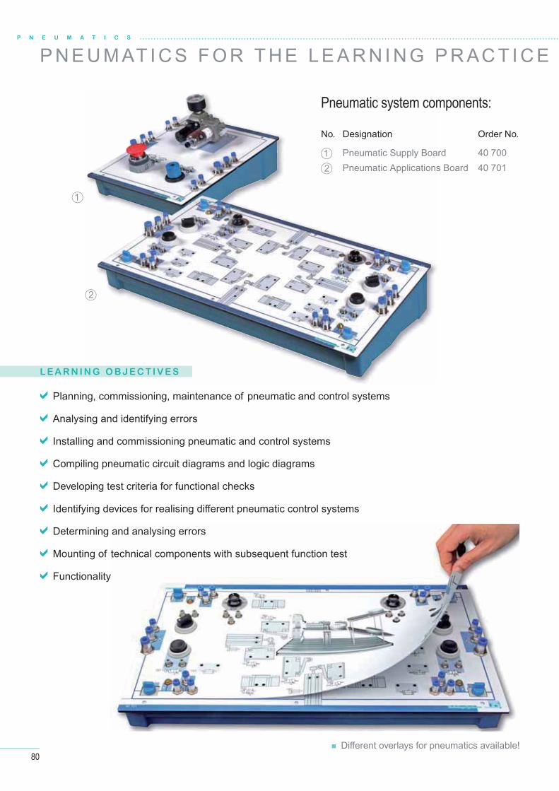
80
P N E U M A T I C S
P N E U M AT I C S F O R T H E L E A R N I N G P R AC T I C E
L E A R N I N G O B J E C T I V E S
Planning, commissioning, maintenance of pneumatic and control systems
Analysing and identifying errors
Installing and commissioning pneumatic and control systems
Compiling pneumatic circuit diagrams and logic diagrams
Developing test criteria for functional checks
Identifying devices for realising diff erent pneumatic control systems
Determining and analysing errors
Mounting of technical components with subsequent function test
Functionality
Pneumatic system components:
No. Designation Order No.
1 Pneumatic Supply Board 40 700
2 Pneumatic Applications Board 40 701
1
2
Diff erent overlays for pneumatics available!
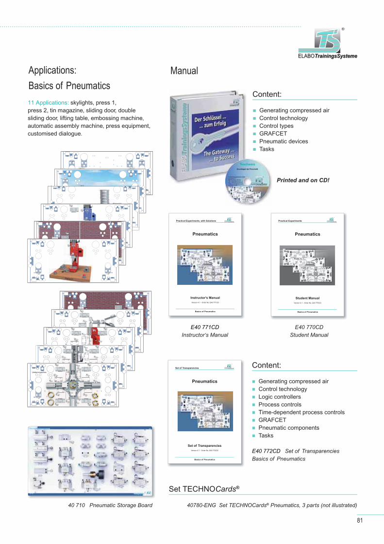
81
ELABOTrainingsSystemeELABOTrainingsSysteme
®
Applications: Basics of Pneumatics
40 710 Pneumatic Storage Board
11 Applications: skylights, press 1, press 2, tin magazine, sliding door, doublesliding door, lifting table, embossing machine,automatic assembly machine, press equipment, customised dialogue.
Content:
Generating compressed air Control technology Control types GRAFCET Pneumatic devices Tasks
Printed and on CD!
Manual
E40 771CD Instructor‘s Manual
Pneumatics
Instructor's Manual
Version 4.1 - Order No. E40 771CD
Practical Experiments, with Solutions ELABOTrainingsSystemeELABOTrainingsSysteme
®
Basics of Pneumatics
Pneumatics
Student Manual
Version 4.1 - Order No. E40 770CD
Practical Experiments ELABOTrainingsSystemeELABOTrainingsSysteme
®
Basics of Pneumatics
Pneumatics
Set of Transparencies
Version 4.1 - Order No. E40 772CD
Set of Transparencies ELABOTrainingsSystemeELABOTrainingsSysteme
®
Basics of Pneumatics
E40 770CD Student Manual
E40 772CD Set of Transparencies Basics of Pneumatics
Content:
Generating compressed air Control technology Logic controllers Process controls Time-dependent process controls GRAFCET Pneumatic components Tasks
40780-ENG Set TECHNOCards® Pneumatics, 3 parts (not illustrated)
Set TECHNOCards®
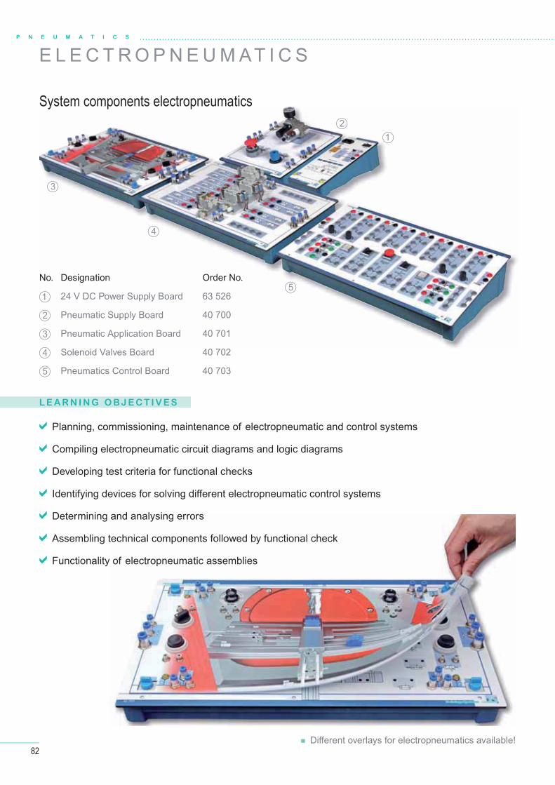
82
L E A R N I N G O B J E C T I V E S
Planning, commissioning, maintenance of electropneumatic and control systems
Compiling electropneumatic circuit diagrams and logic diagrams
Developing test criteria for functional checks
Identifying devices for solving diff erent electropneumatic control systems
Determining and analysing errors
Assembling technical components followed by functional check
Functionality of electropneumatic assemblies
System components electropneumatics
E L E C T R O P N E U M AT I C S
No. Designation Order No.
1 24 V DC Power Supply Board 63 526
2 Pneumatic Supply Board 40 700
3 Pneumatic Application Board 40 701
4 Solenoid Valves Board 40 702
5 Pneumatics Control Board 40 703
12
3
4
5
P N E U M A T I C S
Diff erent overlays for electropneumatics available!
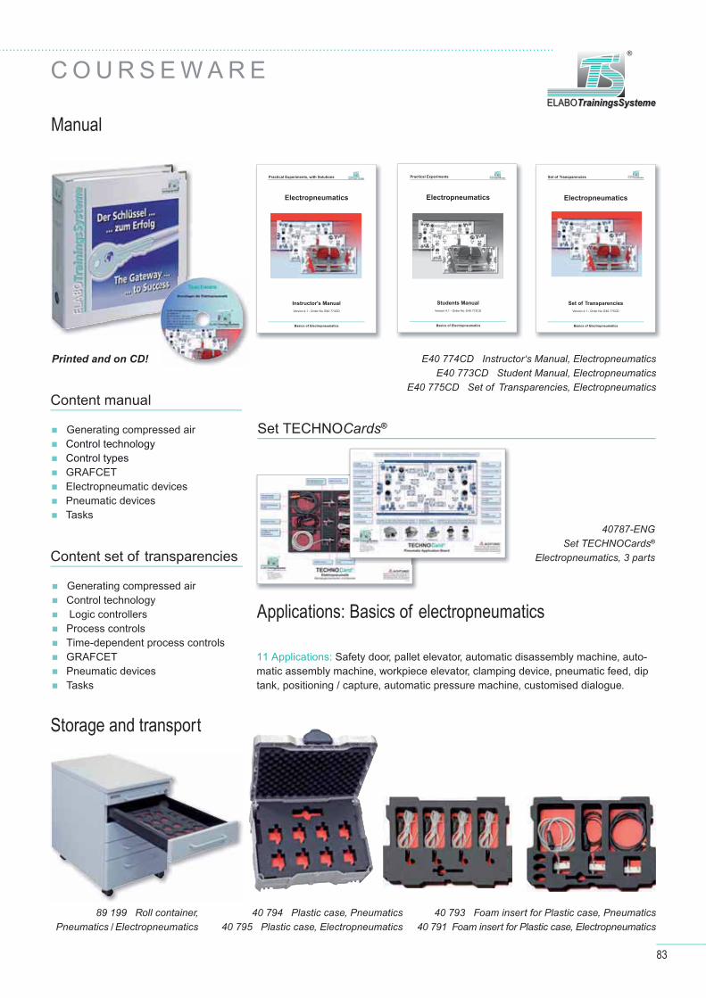
83
Manual
C O U R S E W A R E
Storage and transport
ELABOTrainingsSystemeELABOTrainingsSysteme
®
89 199 Roll container,Pneumatics / Electropneumatics 40 791 Foam insert for Plastic case, Electropneumatics
40 793 Foam insert for Plastic case, Pneumatics40 794 Plastic case, Pneumatics40 795 Plastic case, Electropneumatics
40787-ENG Set TECHNOCards®
Electropneumatics, 3 parts
Electropneumatics
Set of Transparencies
Version 4.1 - Order No. E40 775CD
Set of Transparencies ELABOTrainingsSystemeELABOTrainingsSysteme
®
Basics of Electropneumatics
Electropneumatics
Students Manual
Version 4.1 - Order No. E40 773CD
Practical Experiments ELABOTrainingsSystemeELABOTrainingsSysteme
®
Basics of Electropneumatics
Electropneumatics
Instructor's Manual
Version 4.1 - Order No. E40 774CD
Practical Experiments, with Solutions ELABOTrainingsSystemeELABOTrainingsSysteme
®
Basics of Electropneumatics
Content manual
Generating compressed air Control technologyControl typesGRAFCETElectropneumatic devicesPneumatic devicesTasks
Content set of transparencies
Generating compressed airControl technology Logic controllersProcess controlsTime-dependent process controlsGRAFCETPneumatic devicesTasks
E40 774CD Instructor‘s Manual, ElectropneumaticsE40 773CD Student Manual, Electropneumatics
E40 775CD Set of Transparencies, Electropneumatics
Set TECHNOCards®
Printed and on CD!
Applications: Basics of electropneumatics
11 Applications: Safety door, pallet elevator, automatic disassembly machine, auto-matic assembly machine, workpiece elevator, clamping device, pneumatic feed, dip tank, positioning / capture, automatic pressure machine, customised dialogue.

84
Y E S T E R D AY

85
T O D AY
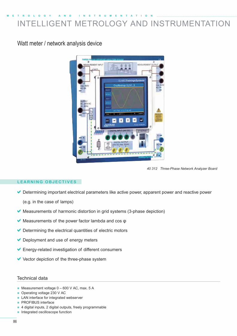
86
M E T R O L O G Y A N D I N S T R U M E N T A T I O N
INTELLIGENT METROLOGY AND INSTRUMENTATION
L E A R N I N G O B J E C T I V E S
Determining important electrical parameters like active power, apparent power and reactive power
(e.g. in the case of lamps)
Measurements of harmonic distortion in grid systems (3-phase depiction)
Measurements of the power factor lambda and cos
Determining the electrical quantities of electric motors
Deployment and use of energy meters
Energy-related investigation of diff erent consumers
Vector depiction of the three-phase system
Measurement voltage 0 – 600 V AC, max. 5 A Operating voltage 230 V AC LAN interface for integrated webserver PROFIBUS interface 4 digital inputs, 2 digital outputs, freely programmable Integrated oscilloscope function
Technical data
40 312 Three-Phase Network Analyzer Board
Watt meter / network analysis device
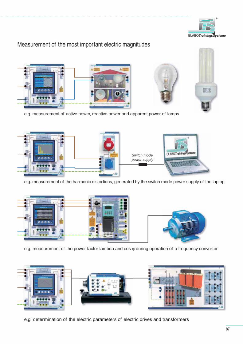
87
e.g. determination of the electric parameters of electric drives and transformers
Measurement of the most important electric magnitudes
Switch mode power supply
e.g. measurement of active power, reactive power and apparent power of lamps
e.g. measurement of the power factor lambda and cos during operation of a frequency converter
e.g. measurement of the harmonic distortions, generated by the switch mode power supply of the laptop
ELABOTrainingsSystemeELABOTrainingsSysteme
®
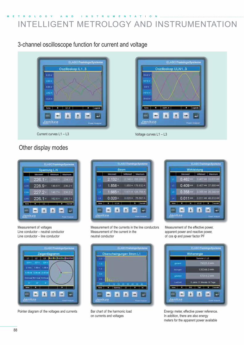
88
3-channel oscilloscope function for current and voltage
Other display modes
Current curves L1 – L3 Voltage curves L1 – L3
Measurement of voltagesLine conductor – neutral conductorLine conductor – line conductor
Pointer diagram of the voltages and currents
Measurement of the currents in the line conductorsMeasurement of the current in the neutral conductor
Bar chart of the harmonic loadon currents and voltages
Measurement of the eff ective power, apparent power and reactive power, of cos and power factor PF
Energy meter, eff ective power reference.In addition, there are also energy meters for the apparent power available
M E T R O L O G Y A N D I N S T R U M E N T A T I O N
INTELLIGENT METROLOGY AND INSTRUMENTATION
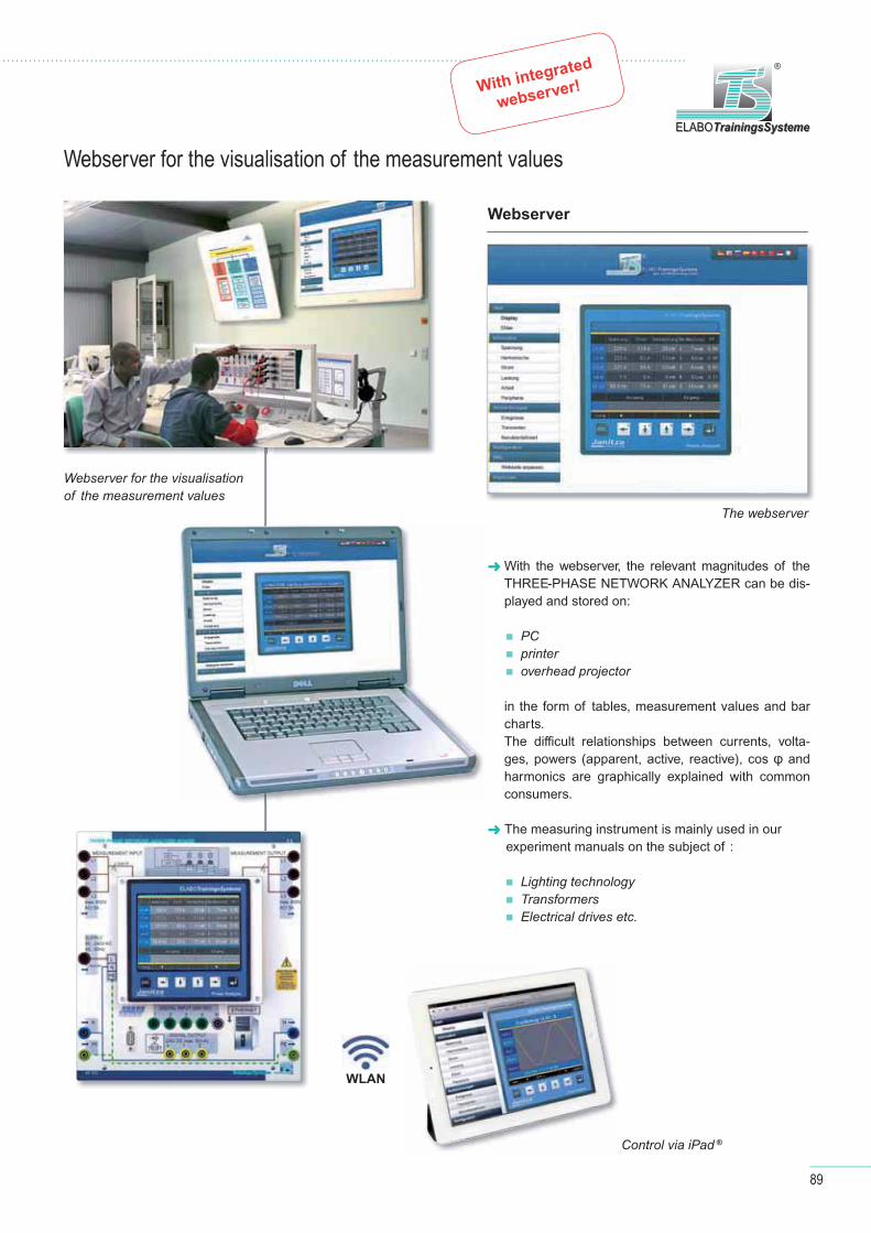
89
Webserver for the visualisation of the measurement valuesELABOTrainingsSystemeELABOTrainingsSysteme
®
Webserver for the visualisation of the measurement values
Control via iPad ®
Webserver
With the webserver, the relevant magnitudes of the THREE-PHASE NETWORK ANALYZER can be dis-played and stored on:
PC printer overhead projector
in the form of tables, measurement values and bar charts.The diffi cult relationships between currents, volta-ges, powers (apparent, active, reactive), cos and harmonics are graphically explained with common consumers.
The measuring instrument is mainly used in our experiment manuals on the subject of :
Lighting technology Transformers Electrical drives etc.
The webserver
With integrated
webserver!
WLAN

90
D I G I TA L M U LT I M E T E R
Professional digital multimeter up to AC/DC 1000 V and safety CAT IV
M E T R O L O G Y A N D I N S T R U M E N T A T I O N
The professional multimeter was developed to safely measure DC and AC voltages up to 1000 V in the overvoltage category CAT IV 600 V or CAT III 1000 V meeting the requirements of IEC/EN61010-1. The multimeter, fi tted with a mechanical safeguard against faulty operation, has a large, 3100 pixel resolution display with a bar graph and an AutoPowerOff function for saving battery life. Furthermore, the measuring instrument provides a large number of multimeter measurement functions with a broad measurement range.
Mechanical safeguard against faulty operation
AC and DC voltage up to 1000 V AC and DC current up to 10 A Resistance measurement with 30 MΩ
and continuity test
Frequency and capacitance Temperature with PT-10000 sensor Diode test and duty cycle Automatic range selection MIN / MAX und Data HOLD AutoPowerOFF
Scope of supplied kit
Measuring cable pair with 4mm tip Battery 9 V Protective holster Operating manual
Digits
600 VCAT IV
30MΩ
MIN/MAX
TC
BAR GRAPH
AUTO/MAN
RANGE
VAC / DC
AAC / DC
Functions
High safety
in training
90 600 Digital multimeter

91
ELABOTrainingsSystemeELABOTrainingsSysteme
®
The mechanical safeguard against faulty operationFaulty operation and in appropriate measurement settings often result in the distruc-tion of the fuses of the measurement instrument. The in-built mechanical safegu-ard against faulty operation, prevent such operation errors, which happen most frequently to untrained user. Avoiding annoyance and expensive spare fuses.
F u n c t i o n o f t h e m e ch a n i c a l s a feg u a rd
aga i n s t fa u l t y o p e rat i o n :
Depending on the measuring method and the relevant switch position selected, the "mechanical safeguard against faulty ope-ration" ensures that only the correct input
socket can be used.The two other sockets are mechanically closed by a screen to avoid faulty connection.At the same time, the switch is locked, to prevent andy accidental adjustment.
closed
open
Selected setting
"Voltage"
closed
open
Selected setting
"Milli-Ampere"
closed
open
Selected setting
"Ampere"
After selecting the measurement type and connecting the
measurement cables, the adjusting wheel
is arrested automatically.
No unnecessary
fuse wear from
faulty operation

92
M E T R O L O G Y A N D I N S T R U M E N T A T I O N
4-channel measurement interface with diff erential inputs
90 272 PC Measurement Interface
The PC Measurement Interface is a four-channel measuring instrument with differential inputs that allows safe measure- ment of voltages and quantities deriving from them up to 600 V AC.The depiction and evaluation of the measurement results is done by software via a connected PC.
4 analogue input channels with diff erential input
5 MHz bandwidth (5,000,000 samples/s)
Sampling rate of up to 5 MHz per channel
- 16 bits up to 195 kHz
- 14 bits up to 3.125 MHz
- 12 bits up to 5 MHz
Input 1:1
- Measurement ranges from ± 200 mV to ± 80 V (peak value)
- maximum input voltage ≤ 200 V AC
- 2mm-safety sockets
Input 10:1
- Measurement ranges from ± 2 V to ± 800 V (peak value)
- maximum input voltage ≤ 600 V AC
- 4mm safety sockets
All inputs contact-safe 600 V, CATII
All inputs clearly confi gurable through 19mm bridge connectors
4 measuring instruments in one device
12 … 16 bit 4-channel oscilloscope
- Spectrum analyser
- Transient recorder
- Voltmeter (average value, true RMS value, …)
Spectrum analyser with distortion factor calculation
Extensive trigger function
Fast transient recorder from 0.01 s to 500 s sampling time
USB 2.0 high speed (480 MBit/s)
Optional operating voltage: 8 …30 V DC
Dimensions 266 x 297 x 85 mm
Device shape: desktop housing
Technical data
P C M E A S U R E M E N T I N T E R FA C E
Microcontroller technology – Data analysis of serial interfaces
Application example
Your advantage:
600 V AC / directly
measurable / 4 channels
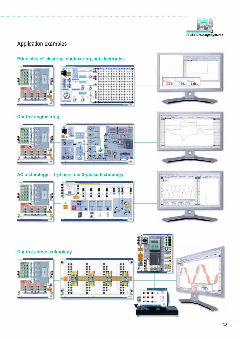
93
ELABOTrainingsSystemeELABOTrainingsSysteme
®
Principles of electrical engineering and electronics
Control engineering
AC technology – 1-phase- and 3-phase technology
Control / drive technology
Application examples
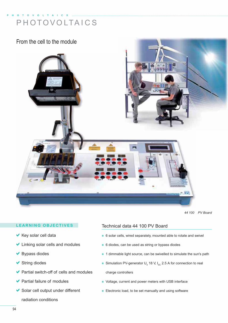
94
L E A R N I N G O B J E C T I V E S
P H O T O V O L T A I C S
P H O T O V O LTA I C S
From the cell to the module
44 100 PV Board
Key solar cell data
Linking solar cells and modules
Bypass diodes
String diodes
Partial switch-off of cells and modules
Partial failure of modules
Solar cell output under diff erent
radiation conditions
6 solar cells, wired separately, mounted able to rotate and swivel
6 diodes, can be used as string or bypass diodes
1 dimmable light source, can be swivelled to simulate the sun's path
Simulation PV-generator U0 18 V, ISC 2.5 A for connection to real
charge controllers
Voltage, current and power meters with USB interface
Electronic load, to be set manually and using software
Technical data 44 100 PV Board
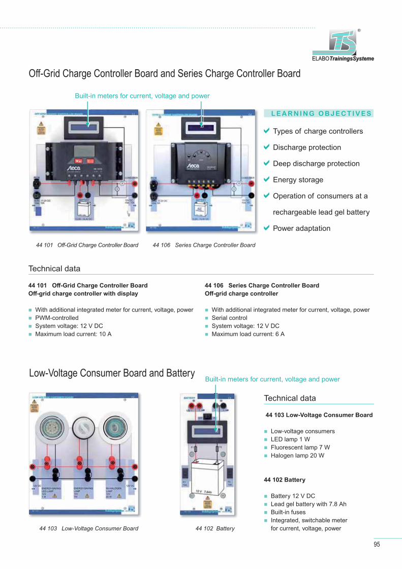
95
ELABOTrainingsSystemeELABOTrainingsSysteme
®
L E A R N I N G O B J E C T I V E S
Off -Grid Charge Controller Board and Series Charge Controller Board
Low-Voltage Consumer Board and Battery
Types of charge controllers
Discharge protection
Deep discharge protection
Energy storage
Operation of consumers at a
rechargeable lead gel battery
Power adaptation
44 101 Off -Grid Charge Controller Board
Off -grid charge controller with display
With additional integrated meter for current, voltage, power PWM-controlled System voltage: 12 V DC Maximum load current: 10 A
44 106 Series Charge Controller Board
Off -grid charge controller
With additional integrated meter for current, voltage, power Serial control System voltage: 12 V DC Maximum load current: 6 A
Technical data
44 103 Low-Voltage Consumer Board
Low-voltage consumers LED lamp 1 W Fluorescent lamp 7 W Halogen lamp 20 W
Battery 12 V DC Lead gel battery with 7.8 Ah Built-in fuses Integrated, switchable meter
for current, voltage, power
Technical data
44 102 Battery
44 101 Off -Grid Charge Controller Board 44 106 Series Charge Controller Board
44 103 Low-Voltage Consumer Board 44 102 Battery
Built-in meters for current, voltage and power
Built-in meters for current, voltage and power

96
H A R D W A R E
Off -Grid Inverter Board and Bulb Socket Board
P H O T O V O L T A I C S
Stand-by losses
Effi ciency of inverters
Start-up behaviour of inverters
Voltage shape and harmonics
Load behaviour
L E A R N I N G O B J E C T I V E S
44 104 Off -Grid Inverter Board
Off -grid inverter Input voltage: 12 V DC Output voltage: 230 V AC / 50 Hz, 275 VA,
sinus-shape Integrated metering device for current, voltage, eff ective,
apparent and blind power, power factor, energy
43 115 Bulb Socket Board
Lighting technology board with sockets for 4 bulbs (E27)
Technical data44 104 Off -Grid Inverter Board
43 115 Bulb Socket Board
Extensions
Mobile frame for carrying out technical measurements on solar modules
Light source with dimmer, can be rotated and swivelled, for simulating the position of the sun during the day and during the year
Operating voltage 230 V Module holder for the 10 W and 50 W solar modules from module sets 44 121 and 44 122, adjustable, for simulating diff erent roof angles, adjustment using a degree scale
The frame is also suitable for the use of 50 W modules outdoors The modules are attached using genuine roof attachment material, making the frame suitable for installation practice
44 120 PV sun position simulation
Comprising 6 lamps 230 V
43 122 Set of Bulbs

97
ELABOTrainingsSystemeELABOTrainingsSysteme
®
The set contains one polycrystalline (10 W) and one amorphous (6 W) solar module
The modules are equipped with an installation frame and Sunclix connectors ready for connection
The set contains one monocrystalline (50 W) and one polycrystalline (45 W) solar module
The modules are equipped with an installation frame and Sunclix connec-tors ready for connection
44 121 Solar Modules Set 10 W 44 122 Solar Modules Set 50 W
D C O F F - G R I D S Y S T E M S
Set-up variant – DC off -grid systems with off -grid inverter and AC load
DC
DC
DC AC
44 120 PV Cells simulation of the sun's position
44 100 PV Board solar cells
44 106 Series Charge Controller Board
44 101 Off -Grid Charge Controller Board
44 104 Off -Grid Inverter Board
43 115 Bulb Socket E27 Board
44 102 Battery Board 12 V DC

98
Technical data
M E C H A T R O N I C S
Assembling, setting up, operating and programming of robot handling systems
Analysing movement sequences, determining reference and starting points, optimising track curves
Installing, programming and testing task-specifi c control and safety concepts
Movement sequences with linear interpolation, hinge interpolation and circle interpolation
Programming true-to-track movements
Use of diff erent eff ectors (grippers, suction pads) and tools
89 991 Robot cell SafetyCUBE®
Operating voltage 230 V 50 / 60 Hz
Number of axes 6
Maximum lifting force 3 kg (4 kg)
Maximum speed 6200 mm/s
Repeat accuracy ± 0.01 mm
Color Teach Panel with Touch Screen
Control device with RS 232 and Ethernet
32 digital inputs and outputs
EMERGENCY STOP and light curtain
SafetyCUBE ®
R O B O T C E L L
L E A R N I N G O B J E C T I V E S
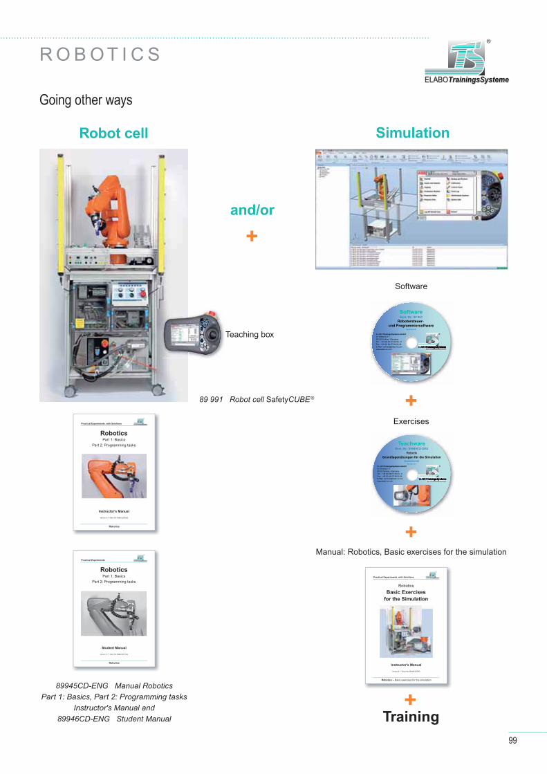
99
ELABOTrainingsSystemeELABOTrainingsSysteme
®
R O B O T I C S
89 991 Robot cell SafetyCUBE®
Going other ways
Robot cell Simulation
and/or
Training
Teaching box
Software
Exercises
Manual: Robotics, Basic exercises for the simulation
TeachwareBest.-Nr.: 89949CD-DEU
RobotikGrundlagenübungen für die Simulation
AusbilderteilVersion 4.1
Aus- und Weiterbildung GmbH ELABOTrainingsSystemeELABOOELABOELABOTrainingsSystemeTrainingsSystemeTrainingsSysteme
®ELABOTrainingsSysteme GmbH Im Hüttental 11 85125 Kinding - GermanyTel.: + 49 (0) 84 67/ 84 04 - 0 Fax: + 49 (0) 84 67/ 84 04 44E-Mail: [email protected]
+
+
+
+
SoftwareBest.-Nr.: 89 961
Robotersteuer-
und ProgrammiersoftwareVersion 4.0
Aus- und Weiterbildung GmbH ELABOTrainingsSystemeELABOOELABOELABOTrainingsSystemeTrainingsSystemeTrainingsSysteme
®ELABOTrainingsSysteme GmbH Im Hüttental 11 85125 Kinding - GermanyTel.: + 49 (0) 84 67/ 84 04 - 0 Fax: + 49 (0) 84 67/ 84 04 44E-Mail: [email protected]
89945CD-ENG Manual RoboticsPart 1: Basics, Part 2: Programming tasks
Instructor's Manual and89946CD-ENG Student Manual
Instructor's ManualInstructor's Manual
Version 4.1 – Best.-Nr. 89949CD-ENGVersion 4.1 – Best.-Nr. 89949CD-ENG
RoboticsRobotics
Basic ExercisesBasic Exercises
for the Simulationfor the Simulation
Robotics – Robotics – Basic exercises for the simulationBasic exercises for the simulation
Practical Experiments, with Solutions
Instructor's ManualInstructor's Manual
Version 4.1 – Best.-Nr. 89945CD-ENGVersion 4.1 – Best.-Nr. 89945CD-ENG
RoboticsRoboticsPart 1: BasicsPart 1: Basics
Part 2: Programming tasksPart 2: Programming tasks
RoboticsRobotics
Practical Experiments, with Solutions
Student ManualStudent Manual
Version 4.1 – Best.-Nr. 89946CD-ENGVersion 4.1 – Best.-Nr. 89946CD-ENG
RoboticsRoboticsPart 1: BasicsPart 1: Basics
Part 2: Programming tasksPart 2: Programming tasks
RoboticsRobotics
Practical Experiments

100
M E C H A T R O N I C S
F L E X I B L E P R O D U C T I O N S YS T E M
Modular production system with the robot cell SafetyCUBE®
"PERFECT INTERPLAY"
Team spirit in the automation system
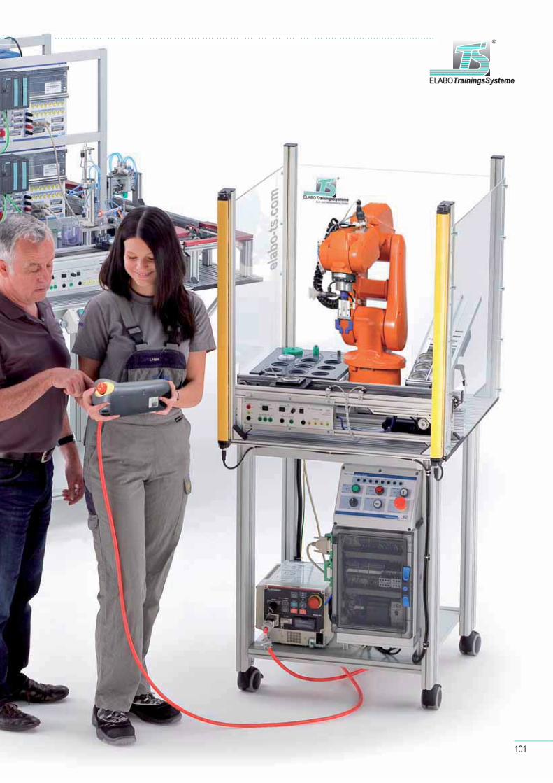
101
ELABOTrainingsSystemeELABOTrainingsSysteme
®
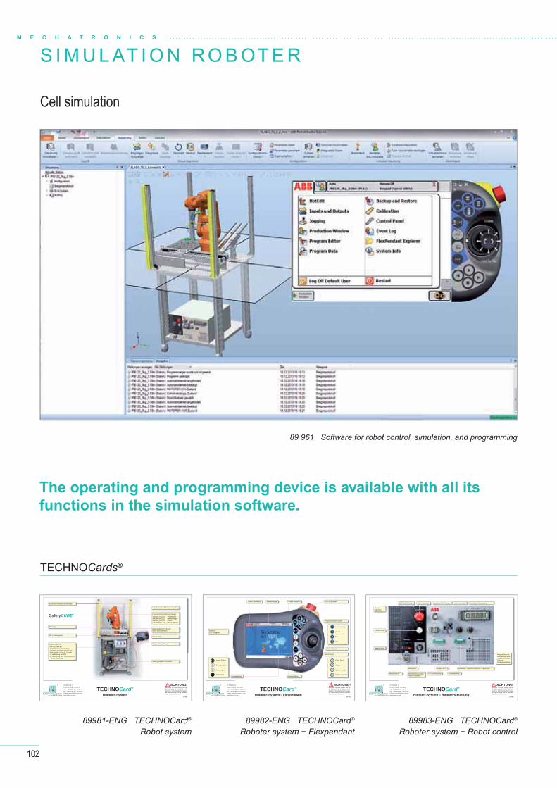
102
M E C H A T R O N I C S
S I M U L AT I O N R O B OT E R
Cell simulation
89 961 Software for robot control, simulation, and programming
TECHNOCards®
The operating and programming device is available with all its
functions in the simulation software.
4.0
TECHNOCard®
Roboter-SystemAus- und Weiterbildung GmbH ELABOTrainingsSystemeELABOTrainingsSysteme
® Im Hüttental 11 85125 Kinding - GermanyTel.: + 49 (0) 84 67 / 84 04 - 0 Fax: + 49 (0) 84 67 / 84 04 44E-Mail: [email protected]
Beachten Sie beim Aufbau und bei der Erprobung der Anlage alle erfor-derlichen Sicherheitsbestimmungen, die Laborordnung und die erforderli-chen Schutzmaßnahmen!
ACHTUNG!
89 981
Pneumatischer Greifer und Sauger:user_do_ext11_12: Teil abblasenuser_do_ext11_13: Vakuumsaugeruser_do_ext11_14: Greiferuser_di_ext11_13: Sensor Vakuum
Flexpendant
Roboter Control Panel
Steuergerät IRC 5 Compact
Schaltschrank mit:- E/A-Verdrahtung- Sicherheitskreis Verdrahtung- externem I/O-Modul Device Net- Schnittstelle 2x Sub D, 25-polig 1x Verbindung zur SPS 1x Verbindung zum Transfersystem (beide rückseitig)
Industrieroboter 6 Achsen, max. 3 kg
Materialrutsche für Dosen Ober- und Unterseite
DC-Transfersystem
Flachlager
Schutzeinrichtung Lichtvorhänge
SafetyCUBE®
4.0
TECHNOCard®
Roboter-System – FlexpendantAus- und Weiterbildung GmbH ELABOTrainingsSystemeELABOTrainingsSysteme
® Im Hüttental 11 85125 Kinding - GermanyTel.: + 49 (0) 84 67 / 84 04 - 0 Fax: + 49 (0) 84 67 / 84 04 44E-Mail: [email protected]
Beachten Sie beim Aufbau und bei der Erprobung der Anlage alle erfor-derlichen Sicherheitsbestimmungen, die Laborordnung und die erforderli-chen Schutzmaßnahmen!
ACHTUNG!
89 982
: Vakuumsauger
: Greifer
: frei
: frei
: Play / Start
: Stopp
: Schritt vorwärts
: Schritt rückwärts
: mech. Einheit
: Bewegungsart
: Achsgruppe
: Inkremente
Steuertasten
Steuerknüppel
Quickset Menü
NOT-AUS-Taster
BedienerEin- / Ausgabe
Öffnen des Menüs Statusanzeige Fenster schließen
Programmierbare Tasten
Auswahltasten
4.0
TECHNOCard®
Roboter-System – RobotersteuerungAus- und Weiterbildung GmbH ELABOTrainingsSystemeELABOTrainingsSysteme
® Im Hüttental 11 85125 Kinding - GermanyTel.: + 49 (0) 84 67 / 84 04 - 0 Fax: + 49 (0) 84 67 / 84 04 44E-Mail: [email protected]
Beachten Sie beim Aufbau und bei der Erprobung der Anlage alle erfor-derlichen Sicherheitsbestimmungen, die Laborordnung und die erforderli-chen Schutzmaßnahmen!
ACHTUNG!
89 983
Anschluss FlexPendant Anschlüsse Manipulator
Hauptrechner mit Netzwerkanschluss, RS232 Anschluss.Optional:Feldbusanschluss
DeviceNet™Lean für externe E / A-EinheitenDigitale E / ABedienfeld
Hauptschalter
Bremsen lösen
24 V für AnwenderBetriebsartenschalterHand / Automatik
Sicherheitskreis
nicht verwendetNOT-AUS-Schalter nicht verwendet
MotorenEIN / AUS
Netzanschluss
89981-ENG TECHNOCard®
Robot system89982-ENG TECHNOCard®
Roboter system − Flexpendant89983-ENG TECHNOCard®
Roboter system − Robot control

103
ELABOTrainingsSystemeELABOTrainingsSysteme
®
C O U R S E W A R E
89945CD-ENG Manual RoboticsPart 1: Basics, Part 2: Programming tasksInstructor‘s Manual
89949CD-ENG Manual RoboticsBasic exercises for simualtion − Instructor's Manual
89948CD-ENG Manual RoboticsBasic exercises for simualtion − Student Manual
89946CD-ENG Manual RoboticsPart 1: Basics, Part 2: Programming tasksStudent Manual
89947CD-ENG Manual RoboticsSet of transparencies (without picture)
Content: Basic exercises for simulation
Content: Robotics, basic information and programming exercises
Introduction Coordinate systems, movement types, tool data Programming Activating inputs and outputs If-then statements, branches,
multiple branches For loops, repeating programming sequences While loop, repeating programming sequences depend-
ent on a condition Object coordinate system, user coordinate system, work
object Modifying points, off set commands Programming a trajectory-controlled movement Linear movement and circular interpolation Circular interpolation, drawing a circle Palletising workpieces
Part 1: Basics
Basic safety instructions Getting started Categories of handling systems Robot design Coordinate systems and operating modes Programming industrial robots Key programming commands
Part 2: Programming tasks
Moving robots manually Teaching points Creating a movement program Transfer system control If-then-else loop
Printed and on CD!
Printed and on CD!
Manual
Manual
TeachwareBest.-Nr.: 89949CD-DEU
RobotikGrundlagenübungen für die Simulation
AusbilderteilVersion 4.1
Aus- und Weiterbildung GmbH ELABOTrainingsSystemeELABOOELABOELABOTrainingsSystemeTrainingsSystemeTrainingsSysteme
®ELABOTrainingsSysteme GmbH Im Hüttental 11 85125 Kinding - GermanyTel.: + 49 (0) 84 67/ 84 04 - 0 Fax: + 49 (0) 84 67/ 84 04 44E-Mail: [email protected]
TeachwareBest.-Nr.: 89 945
RobotikTeil 1: Grundlagen / Teil 2: Programmieraufgaben
AusbilderteilVersion 4.1
Aus- und Weiterbildung GmbH ELABOTrainingsSystemeELABOTrainingsSysteme
®
ELABOTrainingsSysteme GmbH Im Hüttental 11 85125 Kinding - GermanyTel.: + 49 (0) 84 67/ 84 04 - 0 Fax: + 49 (0) 84 67/ 84 04 44E-Mail: [email protected]
Instructor's ManualInstructor's Manual
Version 4.1 – Best.-Nr. 89945CD-ENGVersion 4.1 – Best.-Nr. 89945CD-ENG
RoboticsRoboticsPart 1: BasicsPart 1: Basics
Part 2: Programming tasksPart 2: Programming tasks
RoboticsRobotics
Practical Experiments, with Solutions
Student ManualStudent Manual
Version 4.1 – Best.-Nr. 89946CD-ENGVersion 4.1 – Best.-Nr. 89946CD-ENG
RoboticsRoboticsPart 1: BasicsPart 1: Basics
Part 2: Programming tasksPart 2: Programming tasks
RoboticsRobotics
Practical Experiments
Instructor's ManualInstructor's Manual
Version 4.1 – Best.-Nr. 89949CD-ENGVersion 4.1 – Best.-Nr. 89949CD-ENG
RoboticsRobotics
Basic ExercisesBasic Exercises
for the Simulationfor the Simulation
Robotics – Robotics – Basic exercises for the simulationBasic exercises for the simulation
Practical Experiments, with Solutions
Student ManualStudent Manual
Version 4.1 – Best.-Nr. 89948CD-ENGVersion 4.1 – Best.-Nr. 89948CD-ENG
RoboticsRobotics
Basic ExercisesBasic Exercises
for the Simulationfor the Simulation
Robotics – Robotics – Basic exercises for the simulationBasic exercises for the simulation
Practical Experiments
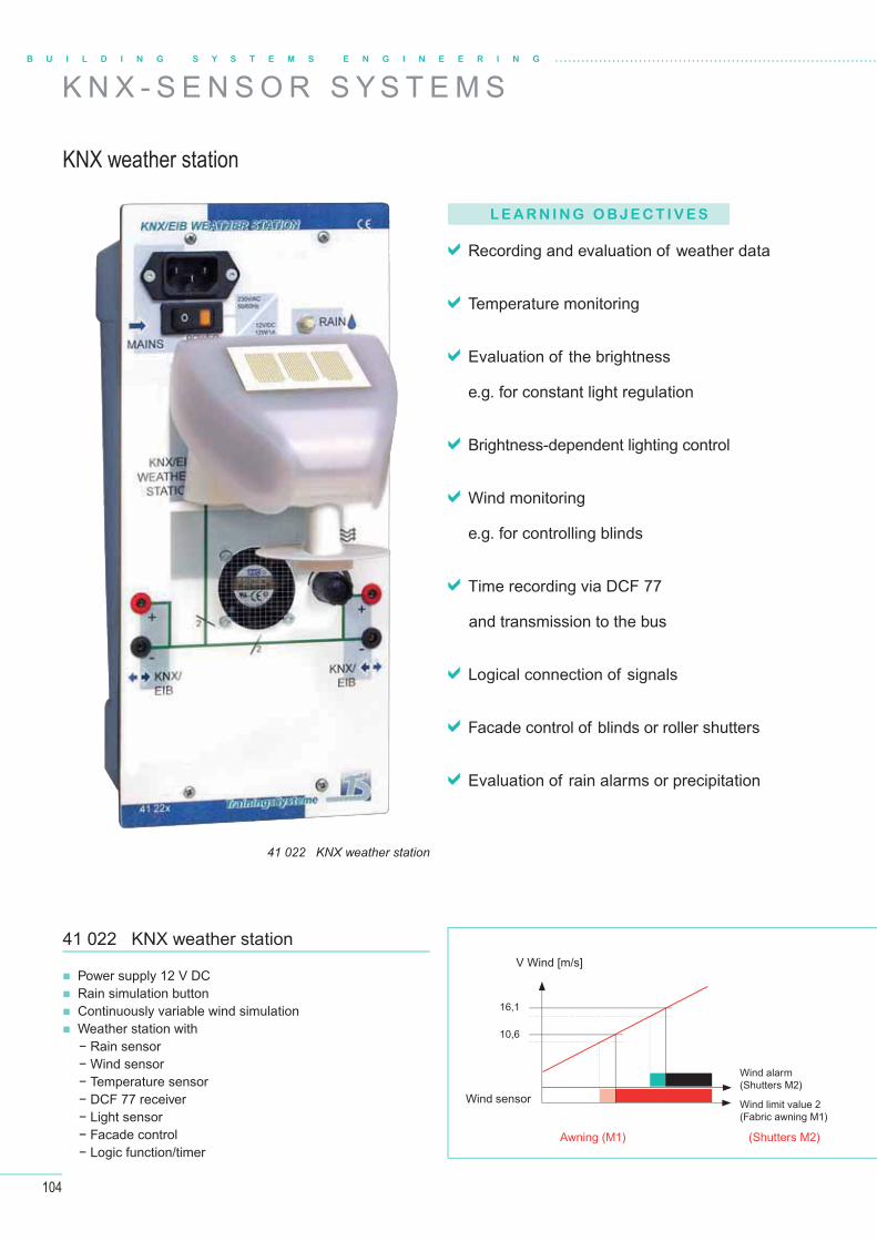
104
B U I L D I N G S Y S T E M S E N G I N E E R I N G
K N X - S E N S O R S Y S T E M S
KNX weather station
41 022 KNX weather station
L E A R N I N G O B J E C T I V E S
Recording and evaluation of weather data
Temperature monitoring
Evaluation of the brightness
e.g. for constant light regulation
Brightness-dependent lighting control
Wind monitoring
e.g. for controlling blinds
Time recording via DCF 77
and transmission to the bus
Logical connection of signals
Facade control of blinds or roller shutters
Evaluation of rain alarms or precipitation
Power supply 12 V DC Rain simulation button Continuously variable wind simulation Weather station with
− Rain sensor − Wind sensor − Temperature sensor − DCF 77 receiver − Light sensor − Facade control − Logic function/timer
41 022 KNX weather stationV Wind [m/s]
Wind sensor
Awning (M1) (Shutters M2)
Wind alarm(Shutters M2)
Wind limit value 2(Fabric awning M1)
16,1
10,6
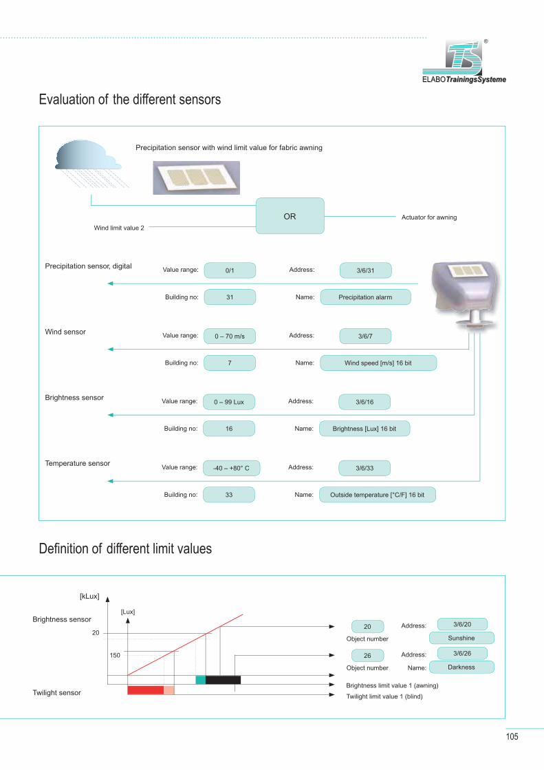
105
ELABOTrainingsSystemeELABOTrainingsSysteme
®
Evaluation of the diff erent sensors
Defi nition of diff erent limit values
Precipitation sensor with wind limit value for fabric awning
Wind limit value 2
Actuator for awningOR
Value range:
Value range:
Value range:
Value range:
Address:
Address:
Address:
Address:
Building no:
Building no:
Building no:
Building no:
Name:
Name:
Name:
Name:
0/1
0 – 70 m/s
0 – 99 Lux
-40 – +80° C
3/6/31
3/6/7
3/6/16
3/6/33
31
7
16
33
Precipitation alarm
Wind speed [m/s] 16 bit
Brightness [Lux] 16 bit
Outside temperature [°C/F] 16 bit
Precipitation sensor, digital
Wind sensor
Brightness sensor
Temperature sensor
Object number
Object number Name:
[kLux]
[Lux]Brightness sensor
Brightness limit value 1 (awning)
Twilight limit value 1 (blind)
20
150
Twilight sensor
Address:
Address:20 3/6/20
3/6/26
Sunshine
Darkness
26
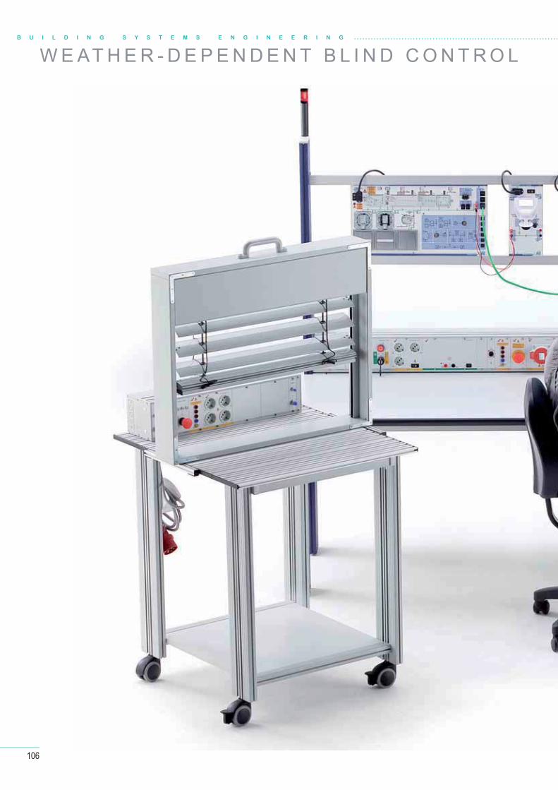
106
B U I L D I N G S Y S T E M S E N G I N E E R I N G
W E AT H E R - D E P E N D E N T B L I N D C O N T R O L
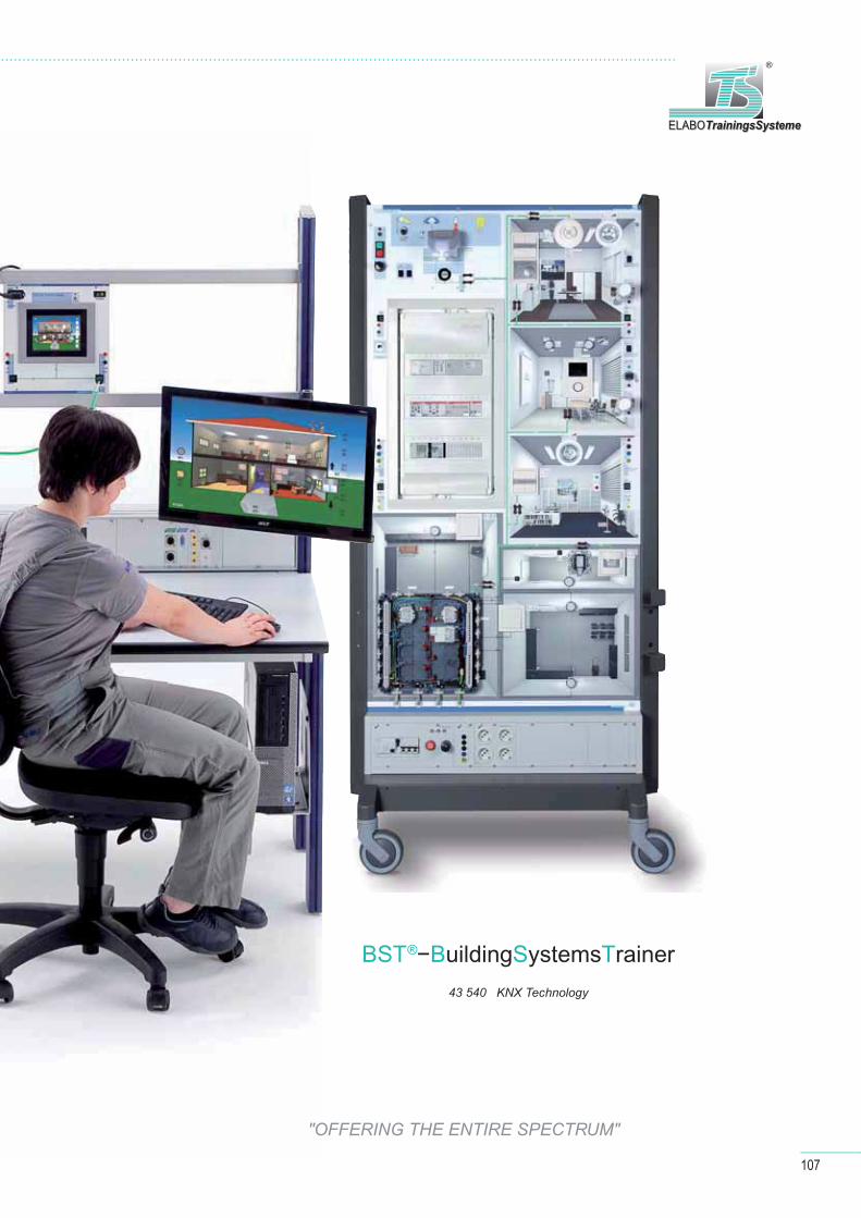
107
ELABOTrainingsSystemeELABOTrainingsSysteme
®
BST®−BuildingSystemsTrainer 43 540 KNX Technology
"OFFERING THE ENTIRE SPECTRUM"
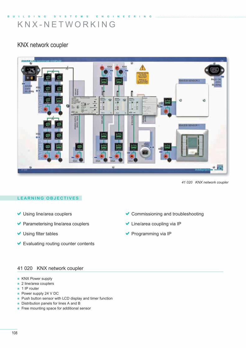
108
B U I L D I N G S Y S T E M S E N G I N E E R I N G
K N X - N E T W O R K I N G
KNX network coupler
41 020 KNX network coupler
L E A R N I N G O B J E C T I V E S
Using line/area couplers
Parameterising line/area couplers
Using fi lter tables
Evaluating routing counter contents
Commissioning and troubleshooting
Line/area coupling via IP
Programming via IP
KNX Power supply 2 line/area couplers 1 IP router Power supply 24 V DC Push button sensor with LCD display and timer function Distribution panels for lines A and B Free mounting space for additional sensor
41 020 KNX network coupler
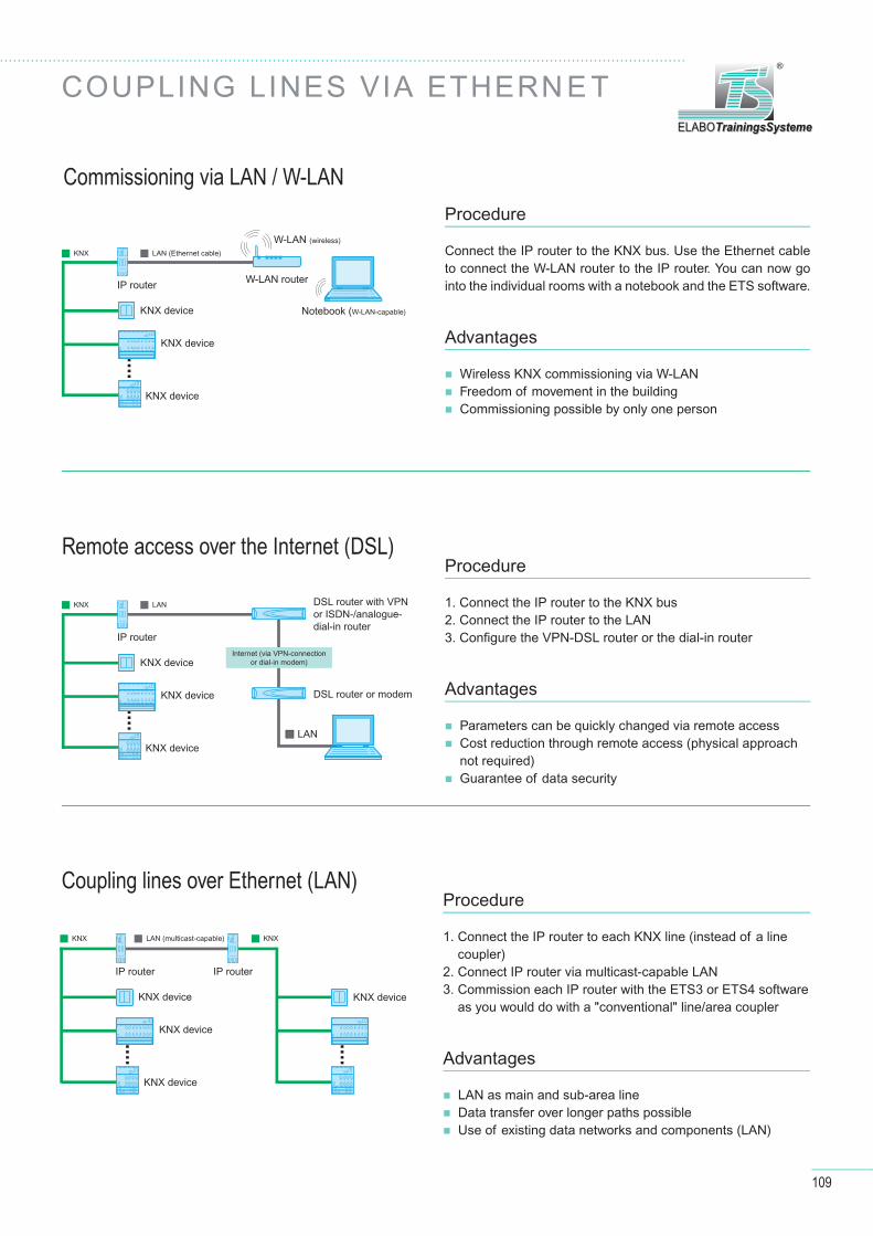
109
ELABOTrainingsSystemeELABOTrainingsSysteme
®
COUPLING LINES VIA ETHERN E T
Remote access over the Internet (DSL)
Commissioning via LAN / W-LAN
Coupling lines over Ethernet (LAN)
Procedure
Connect the IP router to the KNX bus. Use the Ethernet cable to connect the W-LAN router to the IP router. You can now go into the individual rooms with a notebook and the ETS software.
Advantages
Wireless KNX commissioning via W-LAN Freedom of movement in the building Commissioning possible by only one person
Procedure
1. Connect the IP router to the KNX bus2. Connect the IP router to the LAN3. Confi gure the VPN-DSL router or the dial-in router
Advantages
Parameters can be quickly changed via remote access Cost reduction through remote access (physical approach not required)
Guarantee of data security
Procedure
1. Connect the IP router to each KNX line (instead of a line coupler)
2. Connect IP router via multicast-capable LAN3. Commission each IP router with the ETS3 or ETS4 software
as you would do with a "conventional" line/area coupler
Advantages
LAN as main and sub-area line Data transfer over longer paths possible Use of existing data networks and components (LAN)
IP router IP router
KNX device KNX device
KNX device
KNX device
KNX KNXLAN (multicast-capable)
IP router
KNX device
KNX device
KNX device
W-LAN router
Notebook (W-LAN-capable)
W-LAN (wireless)
KNX LAN (Ethernet cable)
IP router
KNX device
KNX device
KNX device
DSL router with VPNor ISDN-/analogue-dial-in router
DSL router or modem
KNX LAN
LAN
Internet (via VPN-connectionor dial-in modem)
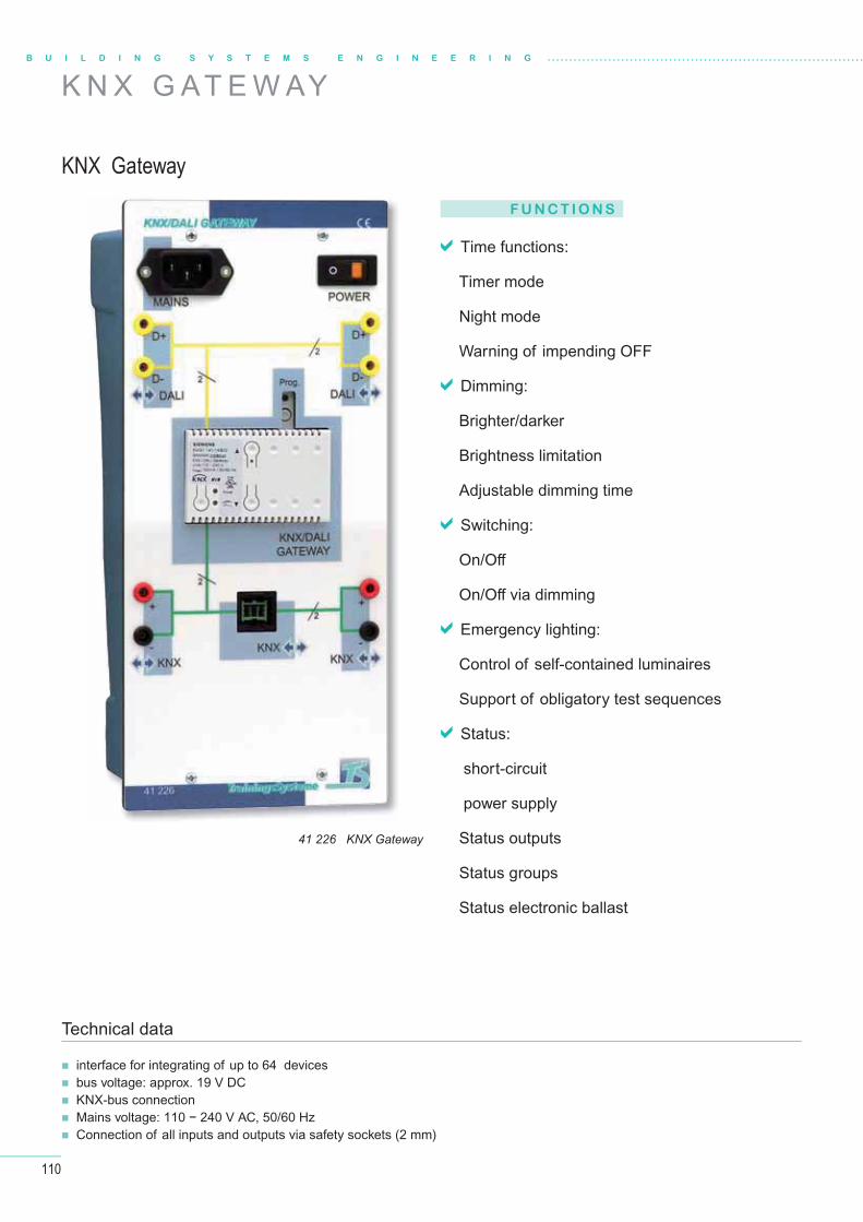
110
B U I L D I N G S Y S T E M S E N G I N E E R I N G
K N X G AT E W AY
KNX Gateway
41 226 KNX Gateway
F U N C T I O N S
Time functions:
Timer mode
Night mode
Warning of impending OFF
Dimming:
Brighter/darker
Brightness limitation
Adjustable dimming time
Switching:
On/Off
On/Off via dimming
Emergency lighting:
Control of self-contained luminaires
Support of obligatory test sequences
Status:
short-circuit
power supply
Status outputs
Status groups
Status electronic ballast
interface for integrating of up to 64 devices bus voltage: approx. 19 V DC KNX-bus connection Mains voltage: 110 − 240 V AC, 50/60 Hz Connection of all inputs and outputs via safety sockets (2 mm)
Technical data
111
ELABOTrainingsSystemeELABOTrainingsSysteme
®
W H AT I S D A L I ?
Digital Addressable Lighting Interface
Innovation in lighting technology
The confi guration of situation-dependent light settings requires lighting systems allowing to group luminaires and to save the light values of individual groups as light scenes.There are further requirements for the integration of lighting systems in building management with centralized switch control and status reporting.
Benefi t for installers
Changing the use of a room does not require rewiring as in 1…10 V systems. The complete lighting can be software-cont-rolled over a single gateway.
DALI is bus-capable
Light switching and dimming is only one function of DALI. It can also be used to control colourful light scenes, fl uorescent lamps or metal halide lamps.DALI furthermore allows complex programming for setting up constant light control circuits.
DALI was jointly created by the leading manufacturers of control units and electronic control gears as a non-proprietary standard to satisfy all the demands that are placed on a modern light management.
Innovation in lighting technology
F E AT U R E S
Simple installation
DALI and power supply wires can be handled in a sin-gle, common cable. Any wiring topology can be used, such as line, star or mixed.
Stable dimming function
Precise dimming values are achieved from digital sig-nals which are insensitive to interferences.
Flexibility
The assignment of the luminaires to the light groups and the operating buttons are defi ned after the installa-tion, thus off ering easy planning even after start-up.
Polarity of wiring irrelevant
Wiring errors can almost be excluded.
Approved by almost all luminaire and control equipment manu-facturers, DALI has become the new standard in lighting industry.DALI was designed mainly for room lighting control. Ease of use of the lighting systems and their components has
always been in the focus. As an interface standard, DALI pro-vides the means to confi gure complete light management sys-tems for rooms such as DALI room controllers or KNX-DALI gateways.
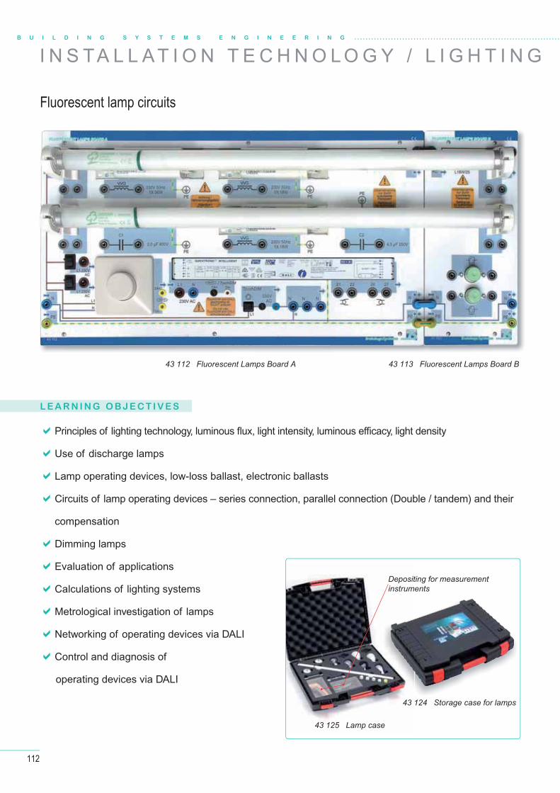
112
B U I L D I N G S Y S T E M S E N G I N E E R I N G
L E A R N I N G O B J E C T I V E S
I N S TA L L A T I O N T E C H N O L O G Y / L I G H T I N G
Principles of lighting technology, luminous fl ux, light intensity, luminous effi cacy, light density
Use of discharge lamps
Lamp operating devices, low-loss ballast, electronic ballasts
Circuits of lamp operating devices – series connection, parallel connection (Double / tandem) and their
compensation
Dimming lamps
Evaluation of applications
Calculations of lighting systems
Metrological investigation of lamps
Networking of operating devices via DALI
Control and diagnosis of
operating devices via DALI
43 112 Fluorescent Lamps Board A 43 113 Fluorescent Lamps Board B
43 124 Storage case for lamps
Depositing for measurementinstruments
43 125 Lamp case
Fluorescent lamp circuits

113
ELABOTrainingsSystemeELABOTrainingsSysteme
®
T E C H N O L O G Y
43 114 Energy Saving Lamps Board
43 116 LED Lamps Board43 117 LED Eff ect Lighting Board
43 121 LED Control Board
43 118 High Pressure Sodium Lamp Board 43 119 Metal Halide Lamp Board
43 120 Room Controller DALI 41 226 KNX /DALI Gateway
An overview of the system
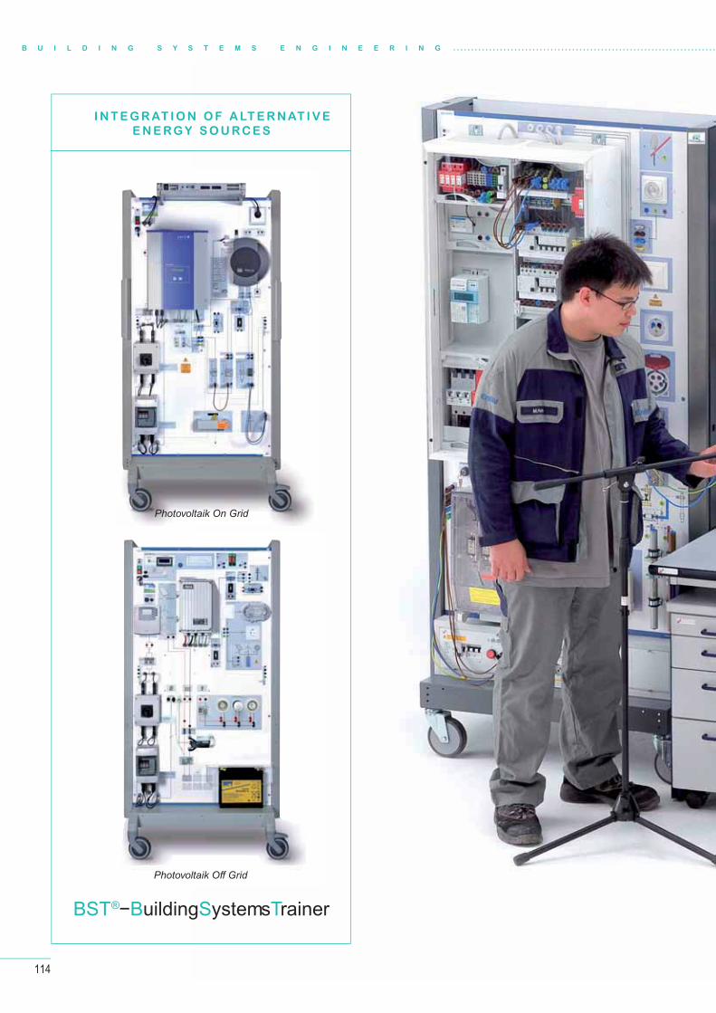
114
B U I L D I N G S Y S T E M S E N G I N E E R I N G
I N T E G R AT I O N O F A LT E R NAT I V E
E N E RG Y S O U RC E S
Photovoltaik On Grid
Photovoltaik Off Grid
BST®−BuildingSystemsTrainer

115
ELABOTrainingsSystemeELABOTrainingsSysteme
®
ELABOTrainingsSystemeELABOTrainingsSysteme
®

116
B U I L D I N G S Y S T E M S E N G I N E E R I N G
L E A R N I N G O B J E C T I V E S
Technical data
A L A R M M A N A G E M E N T S Y S T E M
Alarm control centre
45 000 Alarm Control Board
Construction and commissioning of an alarm management system
Taking into consideration the applicable VDE- and VdS-regulations
Selection of suitable detectors and sensors
Programming the danger detecting system via an LCD or via a PC
Carrying out maintenance work
Inspecting the detectors used
Use of diff erent activating devices, selection according to the VdS classes
Putting into operation an access control system
10 detector groups 2 relay outputs, programmable 1 relay output for continuous alarm 1 internal safety bus 1 external safety bus 1 transistor output for a strobe light 2 transistor outputs for sirens
8 transistor outputs for e.g. a dialling device 1 input for an emergency power supply 1 input for telephone dialer Fault 1 input for telephone dialer Alarm VdS approval: Class A, B, C
in accordance with DIN VDE 0833 parts 1&3
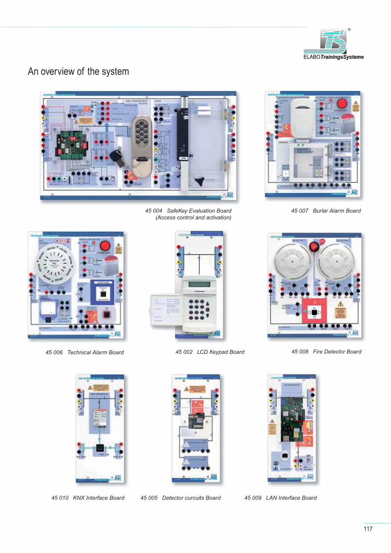
117
ELABOTrainingsSystemeELABOTrainingsSysteme
®
An overview of the system
45 004 SafeKey Evaluation Board(Access control and activation)
45 002 LCD Keypad Board
45 005 Detector curcuits Board
45 006 Technical Alarm Board
45 007 Burlar Alarm Board
45 008 Fire Detector Board
45 009 LAN Interface Board45 010 KNX Interface Board
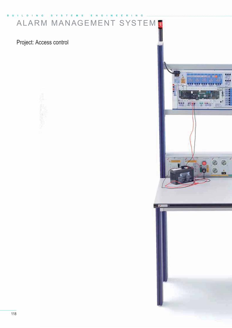
118
ALARM MANAGEMENT SYSTEMB U I L D I N G S Y S T E M S E N G I N E E R I N G
Project: Access control
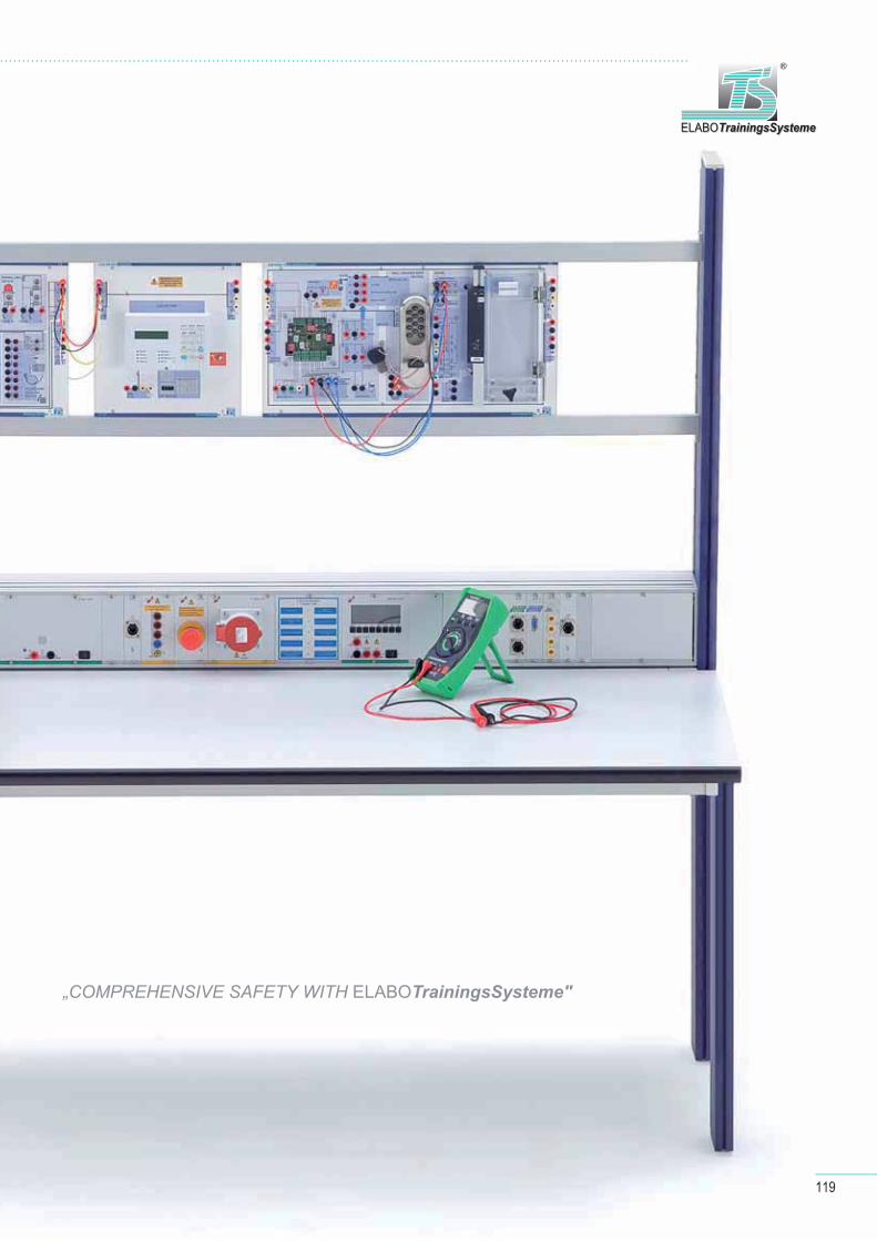
119
ELABOTrainingsSystemeELABOTrainingsSysteme
®
„COMPREHENSIVE SAFETY WITH ELABOTrainingsSysteme"
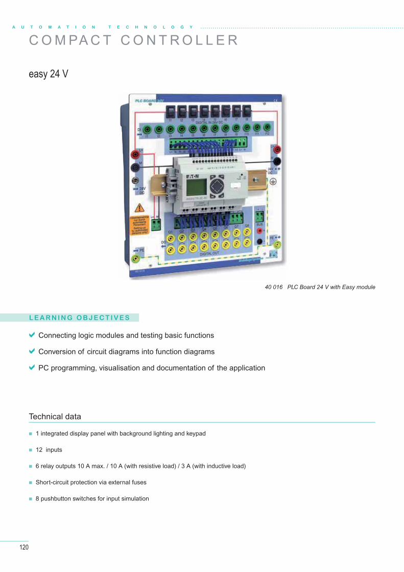
120
C O M PA C T C O N T R O L L E R
easy 24 V
40 016 PLC Board 24 V with Easy module
L E A R N I N G O B J E C T I V E S
Connecting logic modules and testing basic functions
Conversion of circuit diagrams into function diagrams
PC programming, visualisation and documentation of the application
1 integrated display panel with background lighting and keypad
12 inputs
6 relay outputs 10 A max. / 10 A (with resistive load) / 3 A (with inductive load)
Short-circuit protection via external fuses
8 pushbutton switches for input simulation
Technical data
A U T O M A T I O N T E C H N O L O G Y

121
S E L E C T YO U R F I T T I N G SELABOTrainingsSystemeELABOTrainingsSysteme
®
for self-assembly of compact controllers
40 020 PLC Professional Board
40 016 PLC Board 24 V with LOGO! 12 / 24RC
40 016 PLC Board 24 V with Easy module
40 015 PLC Board 230 V40 014 PLC Board 24 V
40 035 PLC Professional Board "Basic"
40 035 PLC Professional Board "Advanced"(Fully fi tted)
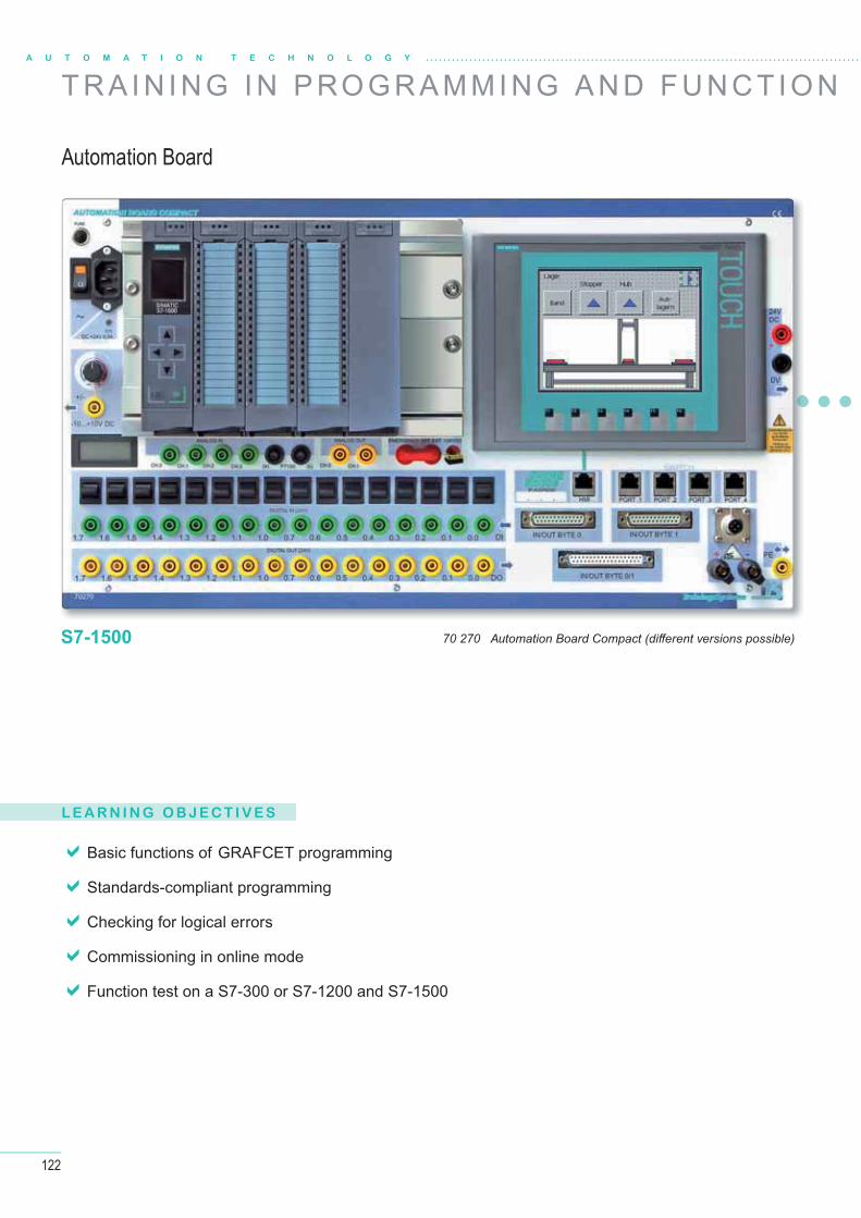
122
A U T O M A T I O N T E C H N O L O G Y
T R A I N I N G I N P RO G R A M M I N G A N D F U N C T I O N
Basic functions of GRAFCET programming
Standards-compliant programming
Checking for logical errors
Commissioning in online mode
Function test on a S7-300 or S7-1200 and S7-1500
L E A R N I N G O B J E C T I V E S
Automation Board
70 270 Automation Board Compact (diff erent versions possible)S7-1500
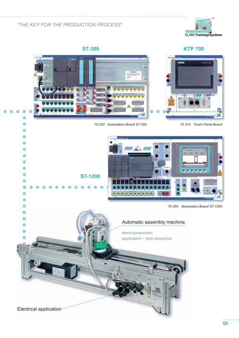
123
ELABOTrainingsSystemeELABOTrainingsSysteme
®
"THE KEY FOR THE PRODUCTION PROCESS"
70 020 Automation Board S7-300
70 260 Automation Board S7-1200
70 314 Touch Panel Board
S7-1200
KTP 700S7-300
Automatic assembly machine
Electrical application
electropneumatic application – step sequence
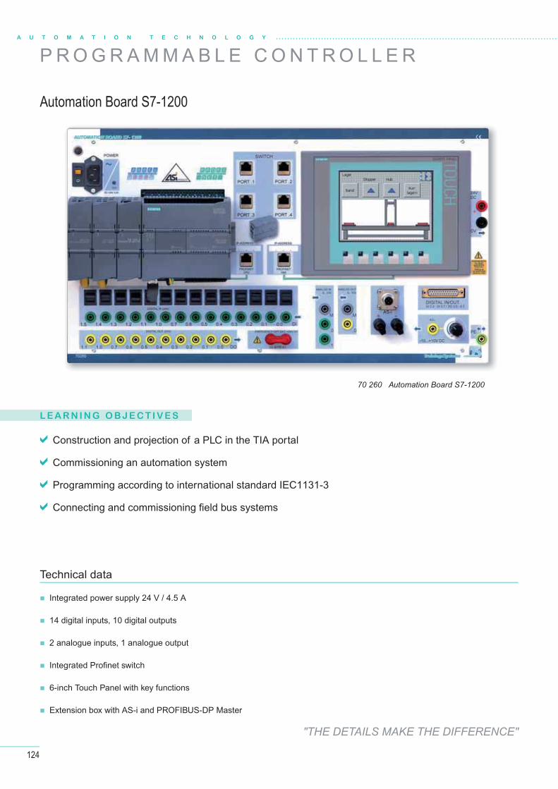
124
A U T O M A T I O N T E C H N O L O G Y
Technical data
Integrated power supply 24 V / 4.5 A
14 digital inputs, 10 digital outputs
2 analogue inputs, 1 analogue output
Integrated Profi net switch
6-inch Touch Panel with key functions
Extension box with AS-i and PROFIBUS-DP Master
Automation Board S7-1200
P R O G R A M M A B L E C O N T R O L L E R
Construction and projection of a PLC in the TIA portal
Commissioning an automation system
Programming according to international standard IEC1131-3
Connecting and commissioning fi eld bus systems
L E A R N I N G O B J E C T I V E S
70 260 Automation Board S7-1200
"THE DETAILS MAKE THE DIFFERENCE"
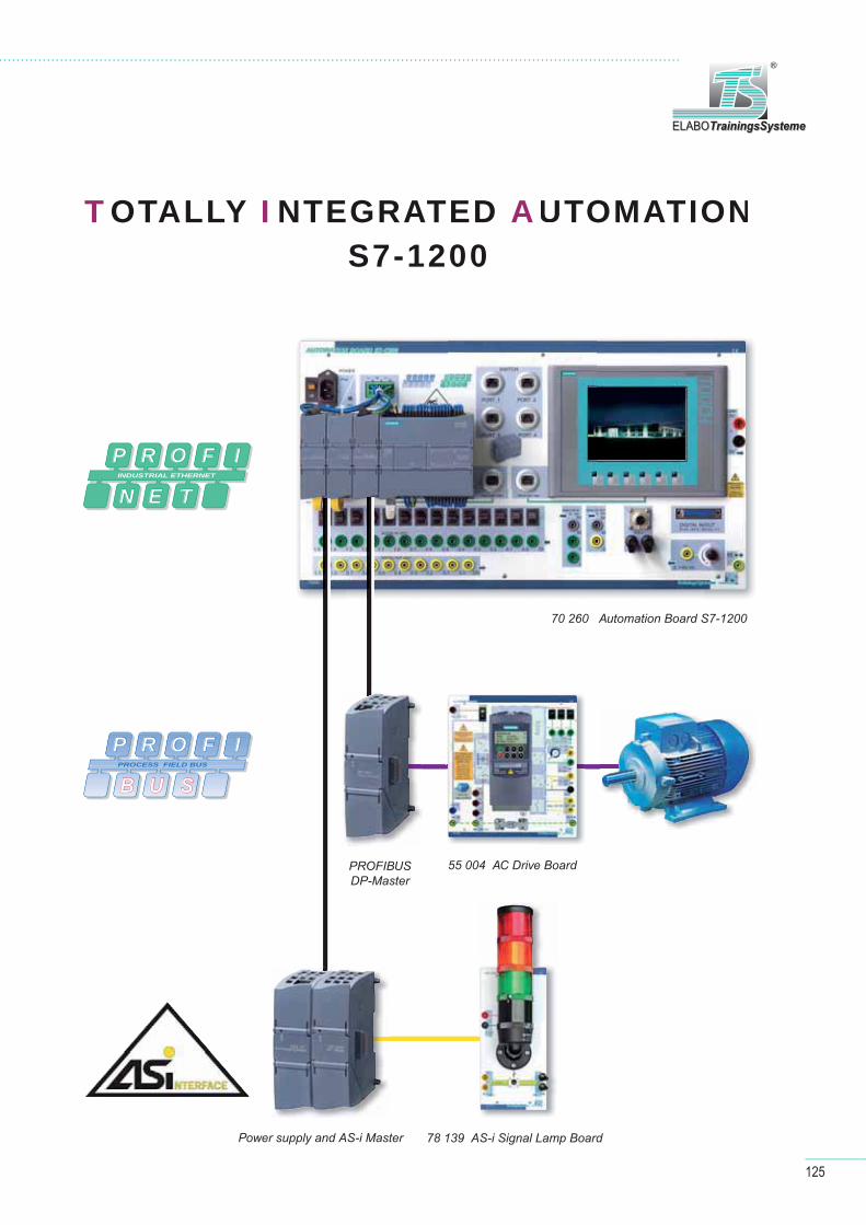
125
ELABOTrainingsSystemeELABOTrainingsSysteme
®
TOTALLY I NTEGRATED AUTOMATIONS7-1200
P R O F I
B U SPROCESS FIELD BUS
P R O F I
N E TINDUSTRIAL ETHERNET
70 260 Automation Board S7-1200
Profibus DP-Master
Netzteil und AS-i Master 78 139 AS-i Signal Lamp Board
55 004 AC Drive Board
70 260 Automation Board S7-1200
55 004 AC Drive Board
78 139 AS-i Signal Lamp Board
PROFIBUSDP-Master
Power supply and AS-i Master

126
A U T O M A T I O N T E C H N O L O G Y
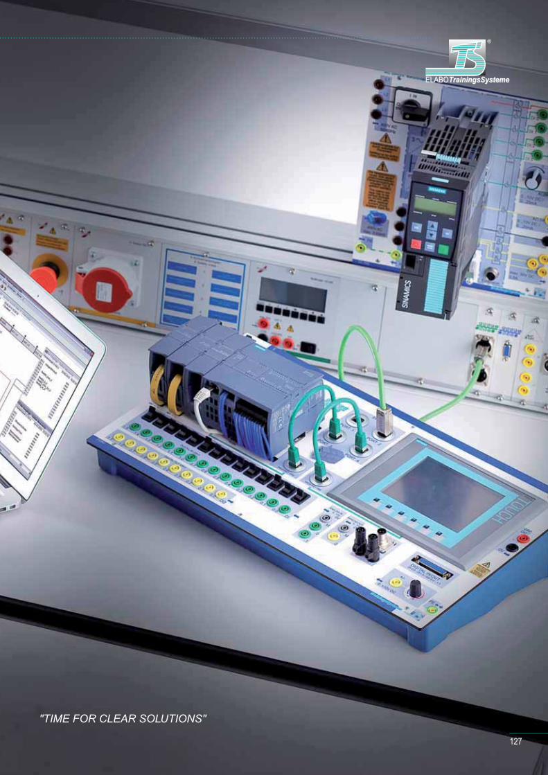
127
TrainingsSystemeELABOELABOTrainingsSysteme
®
"TIME FOR CLEAR SOLUTIONS"

128
L E A R N I N G O B J E C T I V E S
Function principle, system components and
integration in the automation structure
Special connection techniques for the AS-i modules
Using sensors, actuators and switchgear
Connecting and addressing bus subscribers and
checking their functions
M12 system plugs for AS-i
4mm safety sockets and pole terminals for AS-i
70mm continuous light elements in the colours green, yellow and red
Separate operating voltage 24 V DC
Technical data
78 139 AS-i Signal Lamp Board
AS-i Signal Lamp
F I E L D B U S S Y S T E M A S - I N T E R FA C E
NNT E R FAC E
A U T O M A T I O N T E C H N O L O G Y
"MODULAR AND FLEXIBLE"
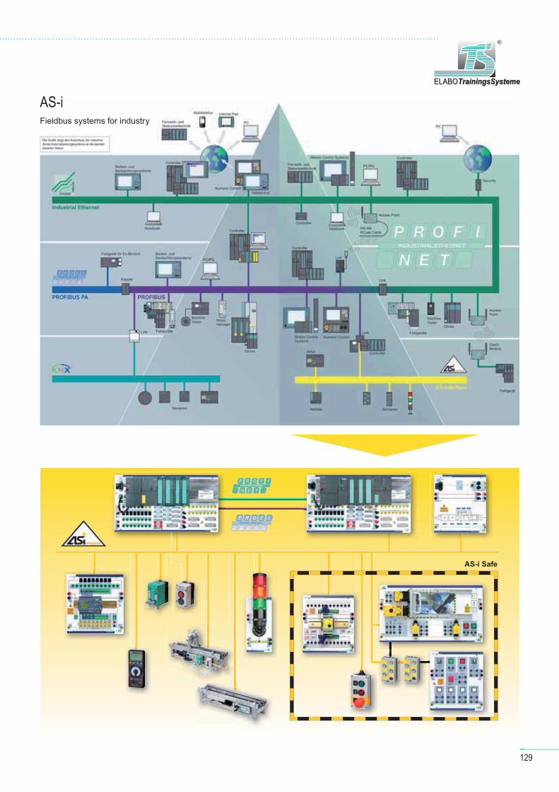
Fieldbus systems for industry
129
ELABOTrainingsSystemeELABOTrainingsSysteme
®
AS-i
P R O F I
B U S
PROCESS FIELD BUS
AS-i Safe
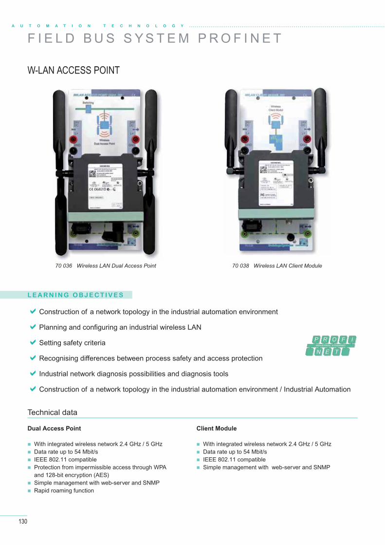
130
A U T O M A T I O N T E C H N O L O G Y
70 038 Wireless LAN Client Module70 036 Wireless LAN Dual Access Point
L E A R N I N G O B J E C T I V E S
Construction of a network topology in the industrial automation environment
Planning and confi guring an industrial wireless LAN
Setting safety criteria
Recognising diff erences between process safety and access protection
Industrial network diagnosis possibilities and diagnosis tools
Construction of a network topology in the industrial automation environment / Industrial Automation
Dual Access Point
With integrated wireless network 2.4 GHz / 5 GHz Data rate up to 54 Mbit/s IEEE 802.11 compatible Protection from impermissible access through WPA
and 128-bit encryption (AES) Simple management with web-server and SNMP Rapid roaming function
Client Module
With integrated wireless network 2.4 GHz / 5 GHz Data rate up to 54 Mbit/s IEEE 802.11 compatible Simple management with web-server and SNMP
Technical data
W-LAN ACCESS POINT
F I E L D B U S S Y S T E M P R O F I N E T
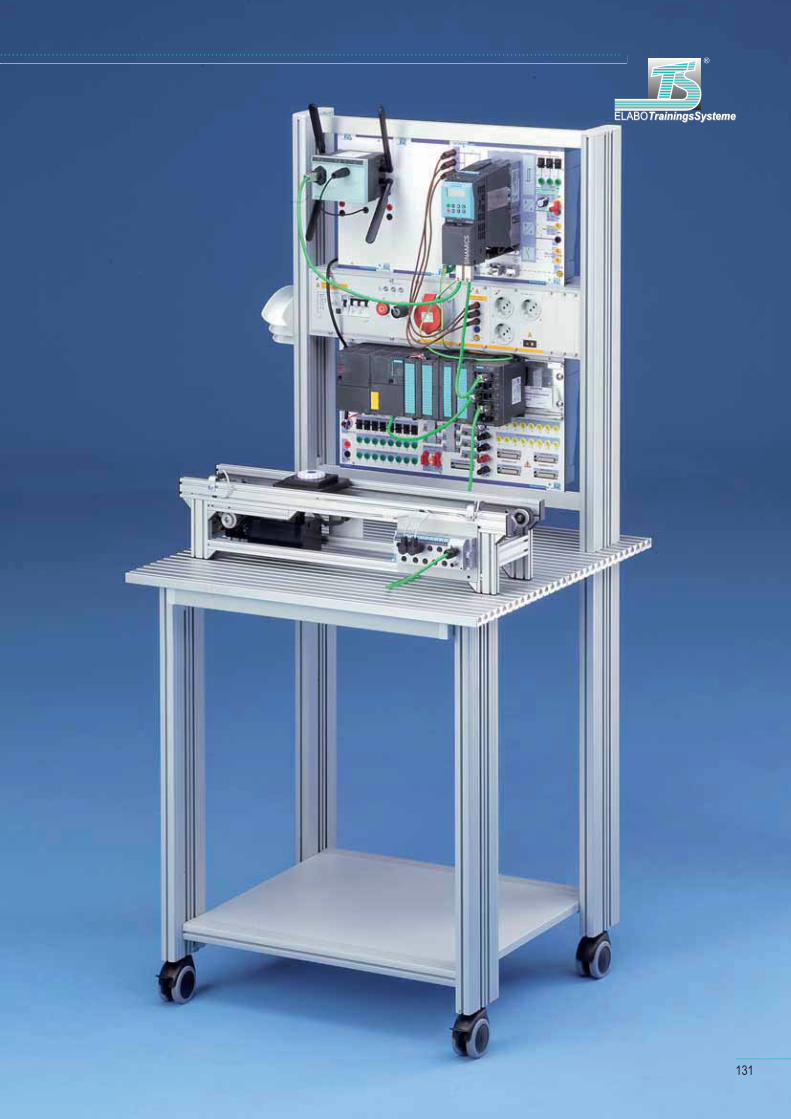
ELABOTrainingsSystemeELABOTrainingsSysteme
®
131
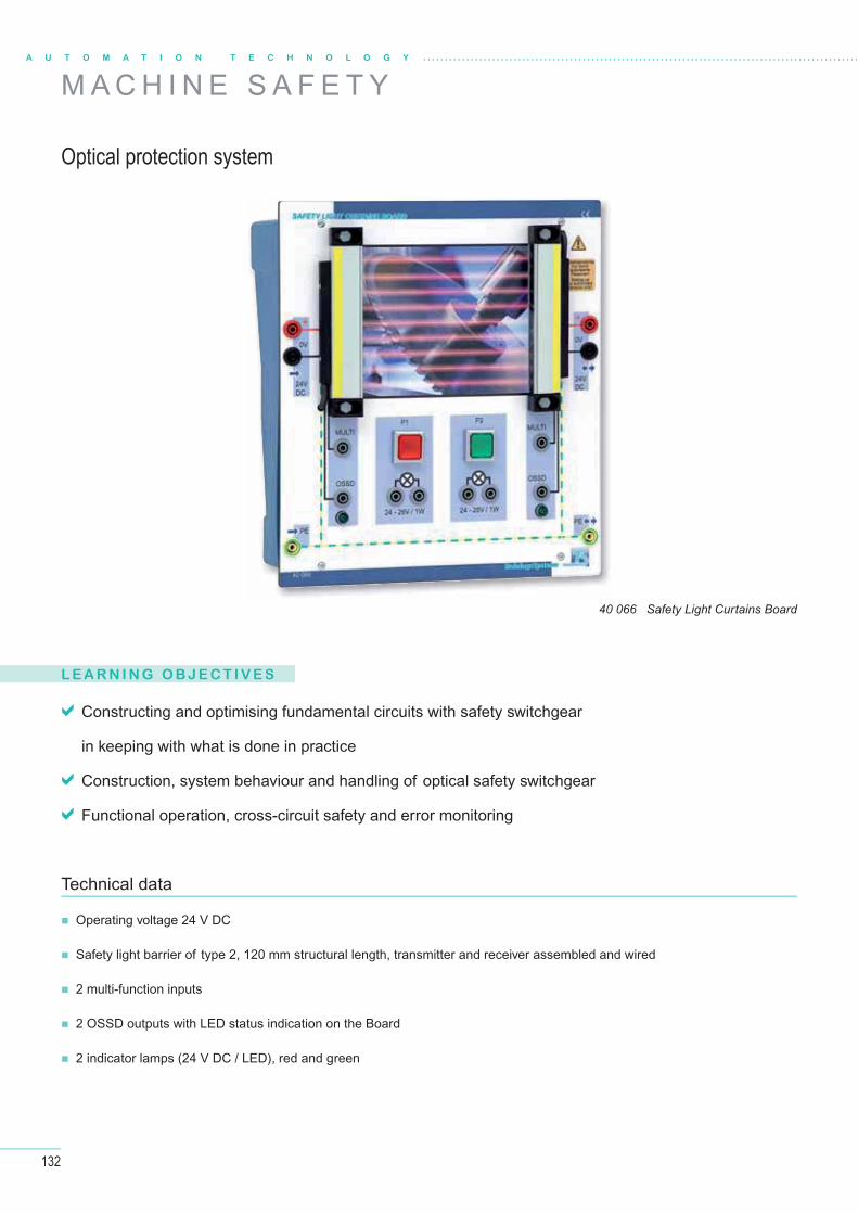
132
A U T O M A T I O N T E C H N O L O G Y
L E A R N I N G O B J E C T I V E S
Constructing and optimising fundamental circuits with safety switchgear
in keeping with what is done in practice
Construction, system behaviour and handling of optical safety switchgear
Functional operation, cross-circuit safety and error monitoring
Operating voltage 24 V DC
Safety light barrier of type 2, 120 mm structural length, transmitter and receiver assembled and wired
2 multi-function inputs
2 OSSD outputs with LED status indication on the Board
2 indicator lamps (24 V DC / LED), red and green
Technical data
Optical protection system
M A C H I N E S A F E T Y
40 066 Safety Light Curtains Board
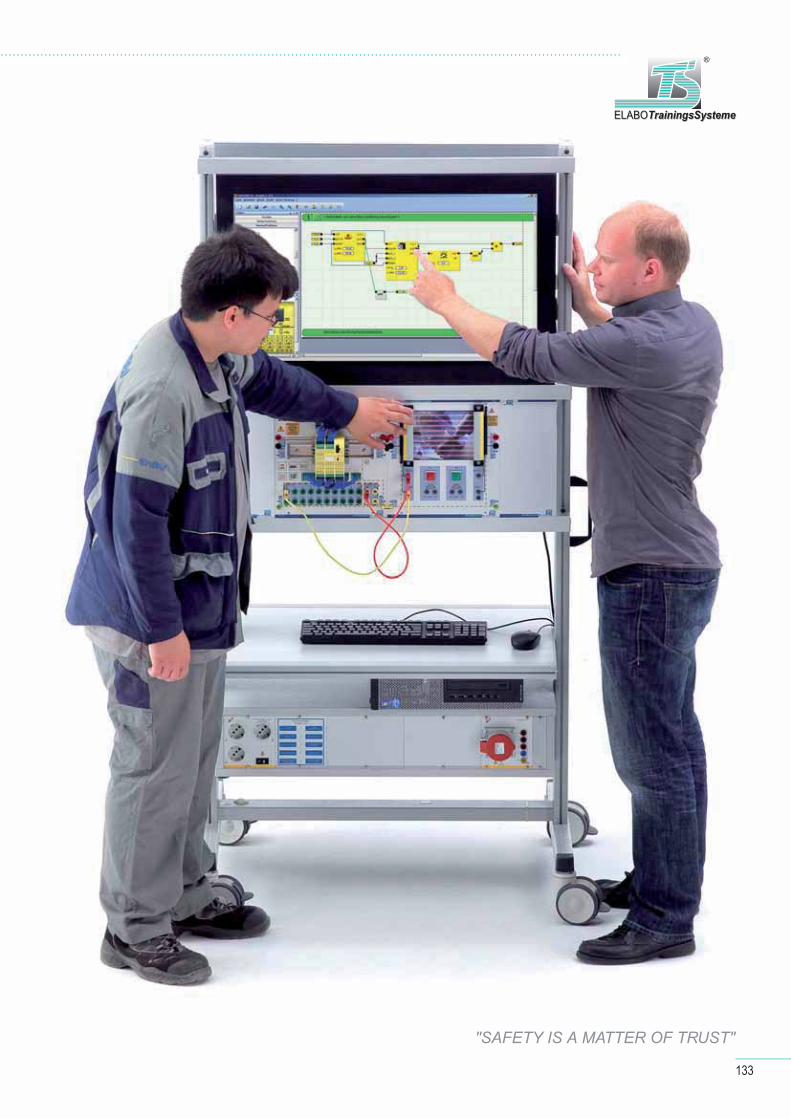
133
ELABOTrainingsSystemeELABOTrainingsSysteme
®
"SAFETY IS A MATTER OF TRUST"
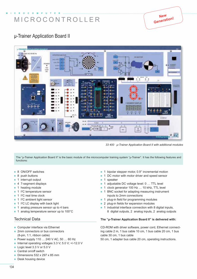
134
M I C R O C O M P U T E R
M I C R O C O N T R O L L E R New
Generation!
μ-Trainer Application Board II
33 400 μ-Trainer Application Board II with additional modules
8 ON/OFF switches 8 push buttons 1 interrupt output 4 7-segment displays 1 heating module 1 I2C temperature sensor 1 I2C real time clock 1 I2C ambient light sensor 1 I2C LC display with back light 1 analog pressure sensor up to 4 bars 1 analog temperature sensor up to 100°C
1 bipolar stepper motor, 0.9° incremental motion 1 DC motor with motor driver and speed sensor 1 speaker 1 adjustable DC voltage level: 0 … TTL level 1 clock generator 100 Hz … 10 kHz, TTL level 1 BNC socket for adapting measuring instrument
inputs to 2mm connections 1 plug-in fi eld for programming modules 2 plug-in fi elds for expansion modules 1 industrial interface connection with 8 digital inputs,
8 digital outputs, 2 analog inputs, 2 analog outputs
The “μ-Trainer Application Board II” is the basic module of the microcomputer training system “μ-Trainer”. It has the following features and functions:
Technical Data
Computer interface via Ethernet 2mm connectors or bus connectors
(8-pin, 1:1, ribbon cable) Power supply 110 … 240 V AC, 50 … 60 Hz Internal operating voltages 3.3 V; 5.0 V; +/-12.0 V Logic level 3.3 V or 5.0 V Central on/off switch Dimensions 532 x 297 x 85 mm Desk housing device
The “μ-Trainer Application Board II” is delivered with:
CD-ROM with driver software, power cord, Ethernet connect-ing cable 2 m, 1 bus cable 10 cm, 1 bus cable 20 cm, 1 bus cable 30 cm, 1 bus cable 50 cm, 1 adapter bus cable 20 cm, operating instructions.
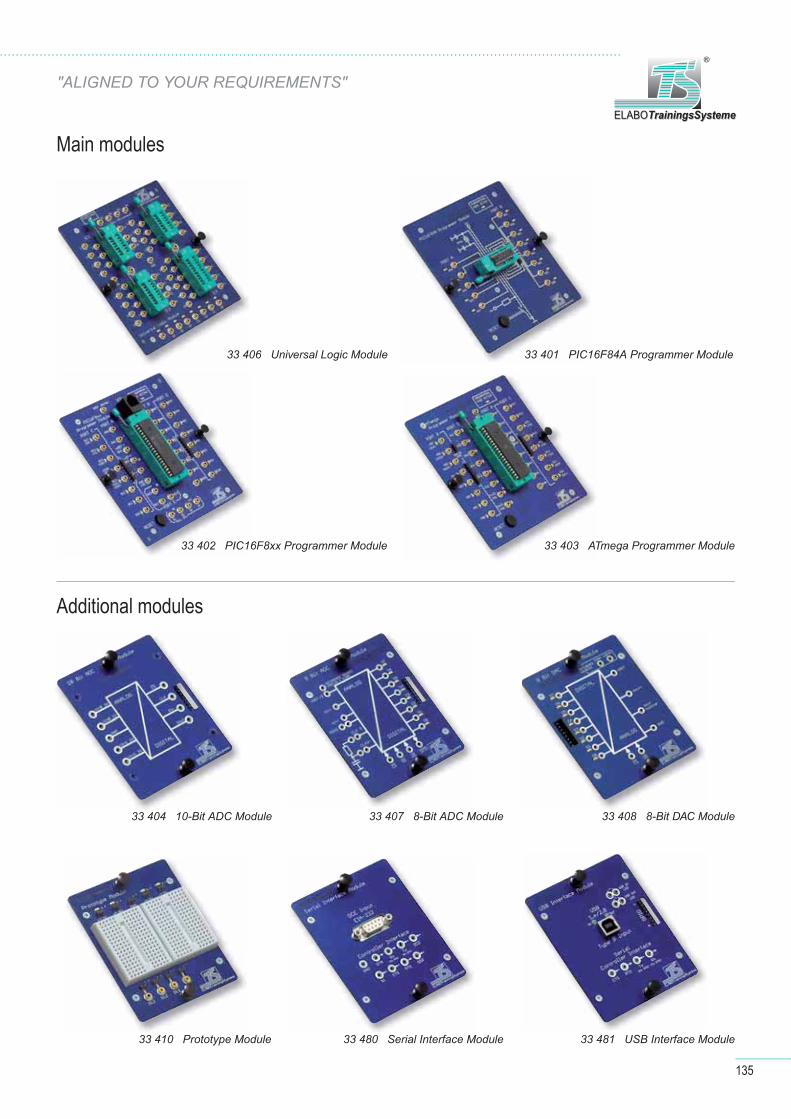
135
ELABOTrainingsSystemeELABOTrainingsSysteme
®
Main modules
Additional modules
33 406 Universal Logic Module 33 401 PIC16F84A Programmer Module
33 402 PIC16F8xx Programmer Module 33 403 ATmega Programmer Module
33 404 10-Bit ADC Module 33 407 8-Bit ADC Module 33 408 8-Bit DAC Module
33 410 Prototype Module 33 480 Serial Interface Module 33 481 USB Interface Module
"ALIGNED TO YOUR REQUIREMENTS"
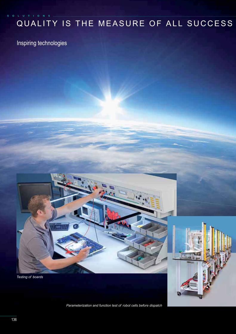
136
Q UA L I T Y I S T H E M E A S U R E O F A L L S U C C E S S
Inspiring technologies
Parameterization and function test of robot cells before dispatch
Testing of boards
S O L U T I O N S
137
ELABOTrainingsSysteme stands for high quality and
outstanding fl exibility. This means that the didactic systems from
ELABOTrainingsSysteme are convertible, they can – thanks to
the modular conception and the versatile range of accessories
– be quickly and effi ciently matched to changed requirements and extended almost without limits.
Our high quality standards not only refere to our products from ELABOTrainingsSysteme, but
also to the quality of the training that customers achieve using ELABOTrainingsSysteme products. To en-
sure trouble-free training processes was one of the main concern in the conception of our training systems.
The system solutions from ELABOTrainingsSysteme can be matched to individual customer requirements.
Customers of ELABOTrainingsSysteme are furthermore supported and accompanied in the successful
implementation of their training objectives by a comprehensive range of services.
TrainingsSystemeELABOELABOTrainingsSysteme
®

138
I N T E R N AT I O N A L A C T I V I T I E S
References
S O L U T I O N S
THE TECHNICAL TRAINERS COLLEGE (TTC) RIYADH, KINGDOM OF SAUDI ARABIA
AMERICAN UNIVERSITY, KUWAIT ABU DHABI
ELABO TrainingsSysteme GmbH
Im Hüttental 1185125 Kinding / Germanyelabo-ts.com

139
ELABOTrainingsSystemeELABOTrainingsSysteme
®
GERMAN-MALAYSIAN INSTITUTE,KUALA LUMPUR
RENEWABLE ENERGY LAB, MOZAMBIQUE

140
I N F O R M AT I O N A N D C O N S U LT I N GS O L U T I O N S
CONSULTANCY
Design of customer oriented solutions
Presentation, product demonstration
and on-site consultation
Assistance in the choice of products complying
with syllabuses
Customized products according to requirements
Development of room concepts
Design of ergonomic workplaces
Turnkey projects
CONTACT
ELABOTrainingsSysteme GmbH
Service-CenterIm Hüttental 1185125 Kinding / Germany
Tel.: + 49 (0) 84 67 / 84 04 - 0Fax: + 49 (0) 84 67 / 84 04 44
www.elabo-ts.com
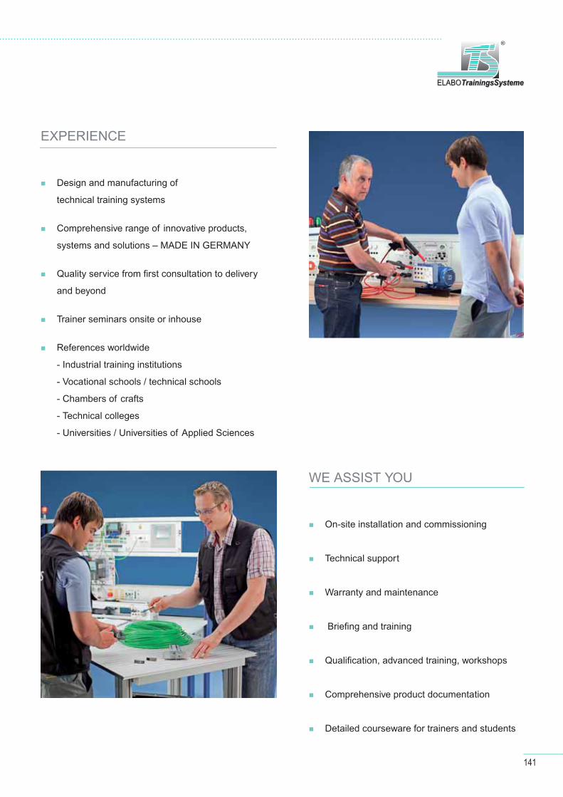
141
ELABOTrainingsSystemeELABOTrainingsSysteme
®
WE ASSIST YOU
On-site installation and commissioning
Technical support
Warranty and maintenance
Briefi ng and training
Qualifi cation, advanced training, workshops
Comprehensive product documentation
Detailed courseware for trainers and students
EXPERIENCE
Design and manufacturing of
technical training systems
Comprehensive range of innovative products,
systems and solutions – MADE IN GERMANY
Quality service from fi rst consultation to delivery
and beyond
Trainer seminars onsite or inhouse
References worldwide
- Industrial training institutions
- Vocational schools / technical schools
- Chambers of crafts
- Technical colleges
- Universities / Universities of Applied Sciences

S O L U T I O N S
142
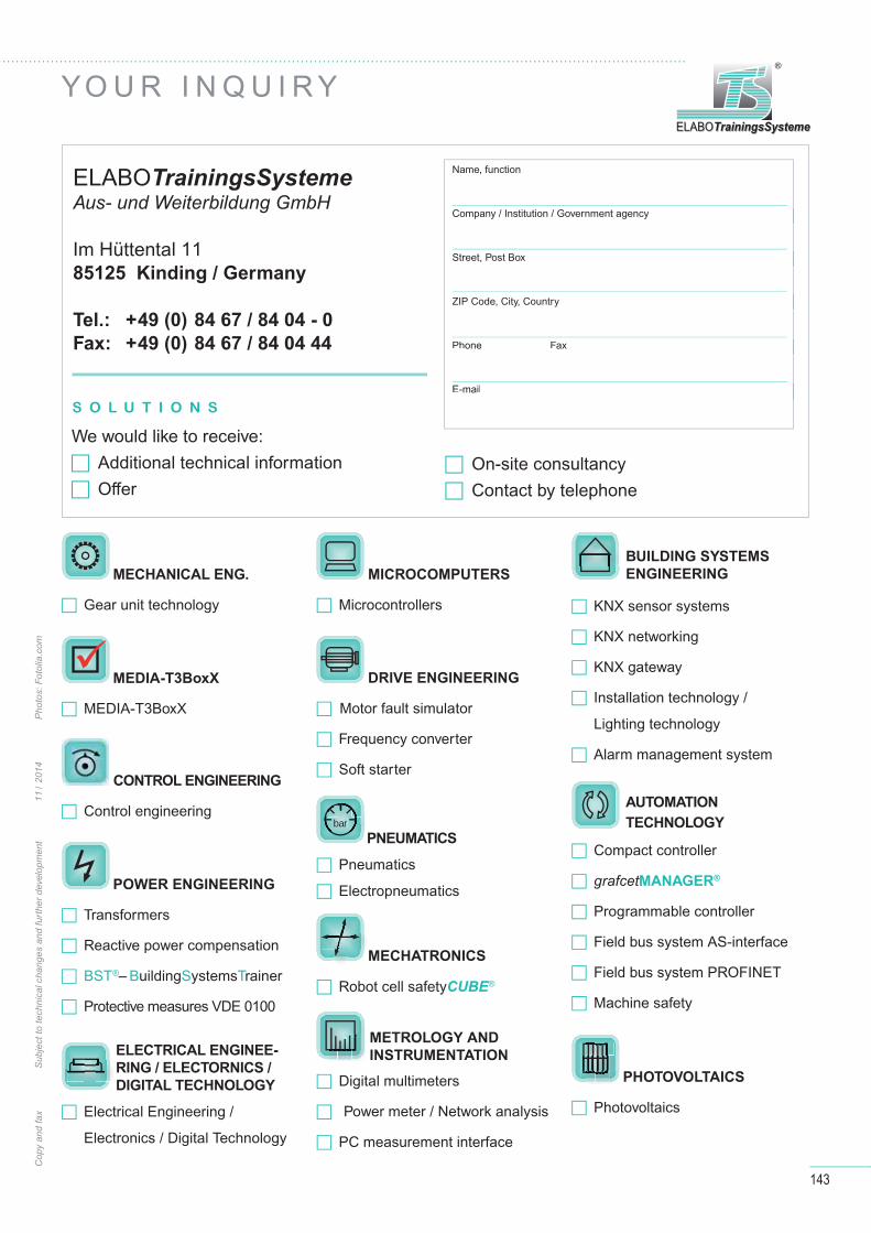
143
ELABOTrainingsSystemeELABOTrainingsSysteme
®
YO U R I N Q U I R Y
Cop
y an
d fa
x
Sub
ject
to te
chni
cal c
hang
es a
nd fu
rthe
r dev
elop
men
t
1
1 / 2
014
P
hoto
s: F
otol
ia.c
om
Name, function
Company / Institution / Government agency
Street, Post Box
ZIP Code, City, Country
Phone Fax
Phone Fax
Company / Institution / Government agency
Street, Post Box
ZIP Code, City, Country
We would like to receive:Additional technical informationOff er
On-site consultancy Contact by telephone
ELABOTrainingsSystemeAus- und Weiterbildung GmbH
Im Hüttental 1185125 Kinding / Germany
Tel.: +49 (0) 84 67 / 84 04 - 0
Fax: +49 (0) 84 67 / 84 04 44
S O L U T I O N S
MECHANICAL ENG.
Gear unit technology
� MEDIA-T3BoxX
MEDIA-T3BoxX
CONTROL ENGINEERING
Control engineering
POWER ENGINEERING
Transformers
Reactive power compensation
BST®– BuildingSystemsTrainer
Protective measures VDE 0100
ELECTRICAL ENGINEE-
RING / ELECTORNICS /
DIGITAL TECHNOLOGY
Electrical Engineering /
Electronics / Digital Technology
MICROCOMPUTERS
Microcontrollers
DRIVE ENGINEERING
Motor fault simulator
Frequency converter
Soft starter
bar
PNEUMATICS
Pneumatics
Electropneumatics
MECHATRONICS
Robot cell safetyCUBE®
Digital multimeters
Power meter / Network analysis
PC measurement interface
KNX sensor systems
KNX networking
KNX gateway
Installation technology /
Lighting technology
Alarm management system
Compact controller
grafcetMANAGER®
Programmable controller
Field bus system AS-interface
Field bus system PROFINET
Machine safety
PHOTOVOLTAICS
Photovoltaics
AUTOMATION
TECHNOLOGY
METROLOGY AND
INSTRUMENTATION
BUILDING SYSTEMS
ENGINEERING

ELABOTrainingsSysteme GmbH
Im Hüttental 11
85125 Kinding / Germany
Tel.: +49 (0) 84 67 / 84 04 - 0
Fax: +49 (0) 84 67 / 84 04 44
E-mail: [email protected]
Internet: elabo-ts.com
ELABOTrainingsSystemeELABOTrainingsSysteme
®S O L U T I O N S
Made
in
Germany