Embed Size (px)
Citation preview
1
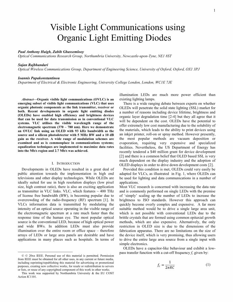
Abstract—Organic visible light communications (OVLC) is an
emerging subset of visible light communications (VLC) that uses
organic photonic components as the link transmitter, receiver or
both. Recent developments in organic light emitting diodes
(OLEDs) have enabled high efficiency and brightness devices
that can be used for data transmission as in conventional VLC
systems. VLC utilises the visible wavelength range of the
electromagnetic spectrum (370 – 780 nm). Here we demonstrate
an OVLC link using an OLED with 93 kHz bandwidth as the
source and a silicon photodetector with 5 MHz BW and a 10 dB
gain as the receiver. A wide range of modulation schemes are
examined and as is commonplace in communications systems;
equalization techniques are implemented to maximize data rates
into the Mb/s region and 2.7 Mb/s was achieved.
I. INTRODUCTION
Developments in OLEDs have resulted in a great deal of
public attention towards the implementation in high end
televisions and other display technologies. While OLEDs are
ideally suited for use in high resolution displays (low pixel
size, high contrast ratio), there is also an exciting application
as transmitter in VLC links. VLC, which features ~ 400 THz
of license free bandwidth (BW), is becoming popular due to
overcrowding of the radio-frequency (RF) spectrum [1]. In
VLCs information data is transmitted by modulating the
intensity of an optical source operating in the visible range of
the electromagnetic spectrum at a rate much faster than the
response time of the human eye. The most popular optical
source is the conventional LED, because of high optical power
and wide BWs. In addition LEDs must also provide
illumination over the entire room or office space – therefore
arrays of LEDs or large area panels are desirable and have
applications in many places such as hospitals. In terms of
© © 20xx IEEE. Personal use of this material is permitted. Permission
from IEEE must be obtained for all other uses, in any current or future media,
including reprinting/republishing this material for advertising or promotional
purposes, creating new collective works, for resale or redistribution to servers or lists, or reuse of any copyrighted component of this work in other works.
This work was supported by Northumbria University & the EU COST
Action IC1101.
illumination LEDs are much more power efficient than
existing lighting lamps.
There is a wide ranging debate between experts on whether
OLEDs will penetrate the solid state lighting (SSL) market for
a number of reasons including device lifetime, brightness and
organic layer degradation time [2-4] but they all agree that it
will be dependent on the cost. OLEDs have the potential to
offer extremely low cost manufacturing due to the solubility of
the materials, which leads to the ability to print devices using
an inkjet printer, roll-on or spray method. However presently,
the most popular methods are vacuum deposition or
evaporation, requiring very expensive and specialized
facilities. Nevertheless, the US Department of Energy has
recently tendered a $40 million grant for device development
[2] and there is a common belief that OLED based SSL is very
much dependent on the display industry and the adoption of
OLED displays in order to drive down development costs [2].
Provided this condition is met, OLEDs could very easily be
adapted for VLCs, as illustrated in Fig. 1, where OLEDs can
be used for lighting and data communications in a number of
applications.
Most VLC research is concerned with increasing the data rate
and is commonly performed on single LEDs with the premise
of ‘simply’ scaling up the number of LEDs to increase the
brightness to ISO standards. However this approach can
quickly become overly complex and expensive. A far more
suitable method would be to drive a single large area unit,
which is not possible with conventional LEDs due to the
brittle crystals that are formed using common epitaxial growth
methods, which are also expensive. Alternatively, the only
restriction in OLED size is due to the dimensions of the
fabrication apparatus. There are no limitations on the size of
the device itself, which is very promising, thus allowing users
to drive the entire large area source from a single input with
simple electronics.
OLEDs have a capacitor-like behaviour and exhibit a low-
pass transfer function with a cut-off frequency fc given by:
(1)
Visible Light Communications using
Organic Light Emitting Diodes
Paul Anthony Haigh, Zabih Ghassemlooy
Optical Communications Research Group, Northumbria University, Newcastle-upon-Tyne, NE1 8ST
Sujan Rajbhandari
Optical Wireless Communications Group, Department of Engineering Science, University of Oxford, Oxford, OX1 3PJ
Ioannis Papakonstantinou
Department of Electrical & Electronic Engineering, University College London, London, WC1E 7JE
2
where R (Ω) is the effective resistance of the OLED and C (F)
is the plate capacitance, given by [5]:
(2)
where A (m2) and d (m) are OLED photoactive area and
thickness, respectively, ϵ0 (F/m) and ϵr (unit-less ratio) are the
permittivity of free space and relative dielectric constant of the
organic layer, respectively. It is clear from (1) and (2) that the
device area is inversely proportional to fc. It is desirable to
have a large photoactive area and BW simultaneously, but this
represents a significant problem for OLED-VLC. OLEDs with
BW > 60 MHz have been produced [6] with A = 0.018 mm2 –
clearly too small for illumination of a typical room. Thus there
is a need for a solution if OLED-VLC is to be adopted as an
emerging technology for both illumination and data
communications. Perhaps future high brightness/BW OLEDs
will move away from thin films towards nanofabrication as in
LEDs [7].
FTTx
FSO
OLEDs
Future House/
Office
OLED
Display
Anode
Hole injection
Cathode
Electron injection
Electron transport
Organic emission
Substrate
Hole injection
OLED Structure
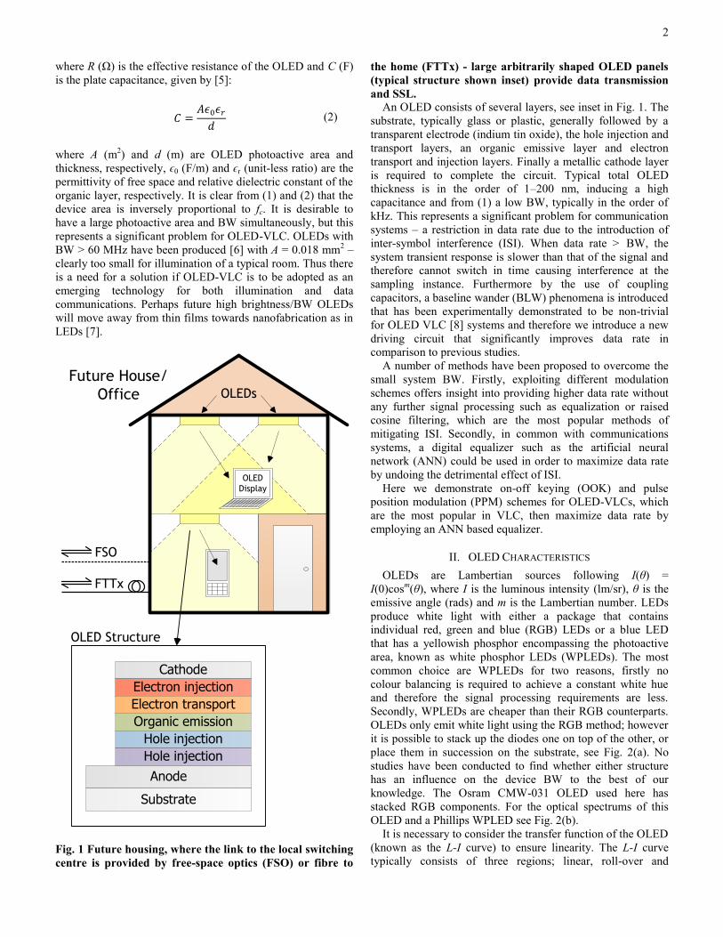
Fig. 1 Future housing, where the link to the local switching
centre is provided by free-space optics (FSO) or fibre to
the home (FTTx) - large arbitrarily shaped OLED panels
(typical structure shown inset) provide data transmission
and SSL.
An OLED consists of several layers, see inset in Fig. 1. The
substrate, typically glass or plastic, generally followed by a
transparent electrode (indium tin oxide), the hole injection and
transport layers, an organic emissive layer and electron
transport and injection layers. Finally a metallic cathode layer
is required to complete the circuit. Typical total OLED
thickness is in the order of 1–200 nm, inducing a high
capacitance and from (1) a low BW, typically in the order of
kHz. This represents a significant problem for communication
systems – a restriction in data rate due to the introduction of
inter-symbol interference (ISI). When data rate > BW, the
system transient response is slower than that of the signal and
therefore cannot switch in time causing interference at the
sampling instance. Furthermore by the use of coupling
capacitors, a baseline wander (BLW) phenomena is introduced
that has been experimentally demonstrated to be non-trivial
for OLED VLC [8] systems and therefore we introduce a new
driving circuit that significantly improves data rate in
comparison to previous studies.
A number of methods have been proposed to overcome the
small system BW. Firstly, exploiting different modulation
schemes offers insight into providing higher data rate without
any further signal processing such as equalization or raised
cosine filtering, which are the most popular methods of
mitigating ISI. Secondly, in common with communications
systems, a digital equalizer such as the artificial neural
network (ANN) could be used in order to maximize data rate
by undoing the detrimental effect of ISI.
Here we demonstrate on-off keying (OOK) and pulse
position modulation (PPM) schemes for OLED-VLCs, which
are the most popular in VLC, then maximize data rate by
employing an ANN based equalizer.
II. OLED CHARACTERISTICS
OLEDs are Lambertian sources following I(θ) =
I(0)cosm(θ), where I is the luminous intensity (lm/sr), θ is the
emissive angle (rads) and m is the Lambertian number. LEDs
produce white light with either a package that contains
individual red, green and blue (RGB) LEDs or a blue LED
that has a yellowish phosphor encompassing the photoactive
area, known as white phosphor LEDs (WPLEDs). The most
common choice are WPLEDs for two reasons, firstly no
colour balancing is required to achieve a constant white hue
and therefore the signal processing requirements are less.
Secondly, WPLEDs are cheaper than their RGB counterparts.
OLEDs only emit white light using the RGB method; however
it is possible to stack up the diodes one on top of the other, or
place them in succession on the substrate, see Fig. 2(a). No
studies have been conducted to find whether either structure
has an influence on the device BW to the best of our
knowledge. The Osram CMW-031 OLED used here has
stacked RGB components. For the optical spectrums of this
OLED and a Phillips WPLED see Fig. 2(b).
It is necessary to consider the transfer function of the OLED
(known as the L-I curve) to ensure linearity. The L-I curve
typically consists of three regions; linear, roll-over and
3
declining as divided by solid vertical lines labelled ‘1’ and ‘2’
in Fig. 2(c). An intensity modulated sine wave is also shown
within the linear region of the L-I curve.
WPLED RGBLED
RGB Pixel RGB StackOLEDs
LEDs
(a)
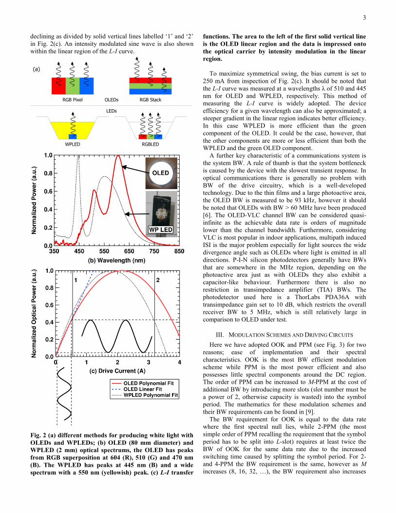
Fig. 2 (a) different methods for producing white light with
OLEDs and WPLEDs; (b) OLED (80 mm diameter) and
WPLED (2 mm) optical spectrums, the OLED has peaks
from RGB superposition at 604 (R), 510 (G) and 470 nm
(B). The WPLED has peaks at 445 nm (B) and a wide
spectrum with a 550 nm (yellowish) peak. (c) L-I transfer
functions. The area to the left of the first solid vertical line
is the OLED linear region and the data is impressed onto
the optical carrier by intensity modulation in the linear
region.
To maximize symmetrical swing, the bias current is set to
250 mA from inspection of Fig. 2(c). It should be noted that
the L-I curve was measured at a wavelengths λ of 510 and 445
nm for OLED and WPLED, respectively. This method of
measuring the L-I curve is widely adopted. The device
efficiency for a given wavelength can also be approximated; a
steeper gradient in the linear region indicates better efficiency.
In this case WPLED is more efficient than the green
component of the OLED. It could be the case, however, that
the other components are more or less efficient than both the
WPLED and the green OLED component.
A further key characteristic of a communications system is
the system BW. A rule of thumb is that the system bottleneck
is caused by the device with the slowest transient response. In
optical communications there is generally no problem with
BW of the drive circuitry, which is a well-developed
technology. Due to the thin films and a large photoactive area,
the OLED BW is measured to be 93 kHz, however it should
be noted that OLEDs with BW > 60 MHz have been produced
[6]. The OLED-VLC channel BW can be considered quasi-
infinite as the achievable data rate is orders of magnitude
lower than the channel bandwidth. Furthermore, considering
VLC is most popular in indoor applications, multipath induced
ISI is the major problem especially for light sources the wide
divergence angle such as OLEDs where light is emitted in all
directions. P-I-N silicon photodetectors generally have BWs
that are somewhere in the MHz region, depending on the
photoactive area just as with OLEDs they also exhibit a
capacitor-like behaviour. Furthermore there is also no
restriction in transimpedance amplifier (TIA) BWs. The
photodetector used here is a ThorLabs PDA36A with
transimpedance gain set to 10 dB, which restricts the overall
receiver BW to 5 MHz, which is still relatively large in
comparison to OLED under test.
III. MODULATION SCHEMES AND DRIVING CIRCUITS
Here we have adopted OOK and PPM (see Fig. 3) for two
reasons; ease of implementation and their spectral
characteristics. OOK is the most BW efficient modulation
scheme while PPM is the most power efficient and also
possesses little spectral components around the DC region.
The order of PPM can be increased to M-PPM at the cost of
additional BW by introducing more slots (slot number must be
a power of 2, otherwise capacity is wasted) into the symbol
period. The mathematics for these modulation schemes and
their BW requirements can be found in [9].
The BW requirement for OOK is equal to the data rate
where the first spectral null lies, while 2-PPM (the most
simple order of PPM recalling the requirement that the symbol
period has to be split into L-slot) requires at least twice the
BW of OOK for the same data rate due to the increased
switching time caused by splitting the symbol period. For 2-
and 4-PPM the BW requirement is the same, however as M
increases (8, 16, 32, …), the BW requirement also increases
4
linearly as can be seen mathematically in [9]. For this reason
high orders of PPM are rarely considered in band limited
systems and here we only demonstrate 2- and 4-PPM as well
as OOK. It should be noted that while OOK and M-PPM can
both be demodulated using the simple threshold-detection
scheme, the so-called ‘soft demodulation’ where the incoming
data stream is reshaped into an M-column matrix can be used
for M-PPM. Since each slot only contains a single 1-level
pulse then the highest valued matrix element is assigned a 1-
level and the remaining elements are assigned the 0-level.
Using this method over threshold-detection offers an electrical
signal-to-noise ratio (SNR) gain of 1.5 dB [10].
The driving circuit for the optical source has a large impact
on the performance of any modulation scheme adopted. For
instance, using the circuit in Fig. 4(a) in conjunction with
OOK a significantly lower data rate can be achieved compared
to the circuit in Fig. 4(b). The link performance is measured in
terms of the bit error rate (BER). This can be calculated or
estimated in a number of ways, including measuring the Q-
factor using the eye-diagram or comparing transmitted and
received bits. Q-factor analysis is only valid for systems that
are perturbed exclusively by additive white Gaussian noise
(AWGN). VLC systems experience AWGN; however this
system is also influenced by BW limitation, which is not a
random effect, so to measure the performance in this way
would be unfair and thus transmitted and received bits are
compared.
Fig. 3 OOK and 4-PPM modulation schemes, Ts and TM
denote symbol and slot periods, respectively. Here there
are two bits/symbol (P = 2) and hence the number of PPM
slots M = 2P = 2
2 = 4 slots. The pulse is positioned
according to the data.
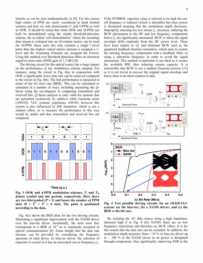
Fig. 4(c) shows the BER plots for the two driving circuits,
illustrating a significant improvement with the NAND driver
over the bias-tee driver. Incidentally, the term error free
corresponds to a BER of 10-6
as is commonly accepted in
optical communications [8]. Some insight into the data rate
increase can be provided by considering the frequency
spectrum of each driver. In bias-tee driver, the selection of
capacitor is crucial as it has an associated cut-on frequency fco.
If the SYMBOL capacitor value is selected to be high the cut-
off frequency is reduced (which is desirable) but more power
is dissipated meaning that the modulation depth decreases.
Improperly selecting too low means fco increases, inducing the
BLW phenomena as the DC and low frequency components
below fco are significantly attenuated. BLW is where the signal
envelope drifts randomly from the DC power level. There
have been studies to try and eliminate BLW such as the
quantized feedback baseline restoration, which aims to restore
the missing frequency components with a feedback filter, or
using a subcarrier frequency in order to avoid the signal
attenuation. This method in particular is not ideal as it wastes
the available BW, thus reducing system capacity. It is
noteworthy that BLW is not a random Gaussian process [11]
so it is not trivial to recover the original signal envelope and
hence there is no ideal solution to date.
(a)
PC
IOLED
VPDOLED
PD
TIA
Data
Received Data
PC
VOLED
VPD
High Z
OLED
PD
TIA
Data
Received Data
(b)
Fig. 4 Two possible driving circuits for an OLED-VLC
system: (a) the bias-tee; (b) a NAND driver; and (c) the
BER vs the bit rate.
By isolating the AC data source using a high impedance
(denoted high Z in Fig. 4 (b)) NAND, there are no low
frequency restrictions and therefore no BLW effect. It is for
this reason that the data rate can be extended. In addition, the
modulation depth increases from < 10 % in bias-tee driver up
to ~ 100 % in the NAND driver as no power is dissipated
through components, thus significantly improving SNR at the
5
receiver, which is also a major factor in the improvement. The
advantage of bias-tee driver is that it is not restricted to digital
pulse modulations; analogue formats and multi-level digital
formats such as pulse amplitude modulation could be adopted,
which is not possible with the NAND driver. Since we are not
demonstrating analogue or multi-level modulations we have
used the NAND driver.
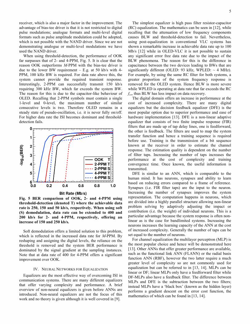
When using threshold-detection, the performance of OOK
far surpasses that of 2- and 4-PPM, Fig. 5. It is clear that the
reason OOK outperforms M-PPM with the bias-tee driver is
due to the lower BW requirement – E.g. at 50 kb/s with 4-
PPM, 100 kHz BW is required. For data rate above this, the
system cannot provide the required transient response.
Interestingly, 2-PPM can successfully transmit 150 kb/s
requiring 300 kHz BW, which far exceeds the system BW.
The reason for this is due to the capacitor-like behaviour of
OLED. Recalling that 2-PPM symbols must contain a single
1-level and 0-level, the maximum number of similar
consecutive levels is two. Therefore OLED remains in a
steady state of pseudo-oscillation, i.e. it is never fully on/off.
For higher data rate the ISI becomes dominant and threshold-
detection fails.
Fig. 5 BER comparison of OOK, 2- and 4-PPM using
threshold-detection (denoted T) where the achievable data
rate is 250, 150 and 50 kb/s, respectively. When using soft
(S) demodulation, data rate can be extended to 400 and
200 kb/s for 2- and 4-PPM, respectively, offering an
increase of 150 and 250 kb/s.
Soft demodulation offers a limited solution to this problem,
which is reflected in the increased data rate for M-PPM. By
reshaping and assigning the digital levels, the reliance on the
threshold is removed and the system BER performance is
dominated by the signal gradient at the sampling instances.
Note that at data rate of 400 for 4-PPM offers a significant
improvement over OOK.
IV. NEURAL NETWORKS FOR EQUALIZATION
Equalizers are the most effective way of overcoming ISI in
communication systems. There are many different equalizers
that offer varying complexity and performance. A brief
overview of non-neural equalizers is given before ANNs are
introduced. Non-neural equalizers are not the focus of this
work and no theory is given although it is well covered in [9].
The simplest equalizer is high pass filter resistor-capacitor
(RC) equalization. The mathematics can be seen in [12], while
recalling that the attenuation of low frequency components
causes BLW and threshold-detection to fail. Nevertheless,
using post-equalization in conventional VLC systems has
shown a remarkable increase in achievable data rate up to 100
Mb/s [12] while in OLED-VLC it is not possible to sustain
any significant error free data rate due to the impact of the
BLW phenomena. The reason for this is the difference in
capacitance between the two devices leading to BWs that are
significantly different (OLED: 93 kHz, WPLED: ~ 4 MHz).
For example, by using the same RC filter for both systems, a
greater proportion of the system frequency response is
removed for the OLED system. Hence BLW is more severe
while WPLED is operating at data rate that far exceeds the RC
fco, thus BLW has less impact on data recovery.
The digital domain offers an increase in performance at the
cost of increased complexity. There are many digital
equalizers but the decision feedback equalizer (DFE) is the
most popular option due to superior performance and ease of
hardware implementation [13]. DFE is a non-linear adaptive
equalizer that consists of two finite impulse response (FIR)
filters that are made up of tap delay lines, one is feedforward,
the other is feedback. The filters are used to map the system
transfer function and hence a training sequence is required
before use. Training is the transmission of a bit sequence
known at the receiver in order to estimate the channel
response. The estimation quality is dependent on the number
of filter taps. Increasing the number of taps increases the
performance at the cost of complexity and training
convergence time. Once known, the useful information is
transmitted.
DFE is similar to an ANN, which is comparable to the
human mind. It has neurons, synapses and ability to learn
based on reducing errors compared to a frame of reference.
Synapses (i.e. FIR filter taps) are the input to the neuron.
Increasing the number of synapses improves the system
representation. The computation happens in neurons, which
are divided into a highly parallel structure allowing non-linear
problem solving by adaptively adjusting the impact or
contribution (i.e. the weight) of individual neurons. This is a
particular advantage because the system response is often non-
linear as is the case for bandlimited systems. Increasing the
neurons increases the learning capacity of the ANN at the cost
of increased complexity. Generally the number of taps can be
set equal to the number of neurons.
For channel equalization the multilayer perceptron (MLP) is
the most popular choice and hence will be demonstrated here
[13]. Other ANNs that offer greater performance are available,
such as the functional link ANN (FLANN) or the radial basis
function ANN (RBF), however the two latter require a much
greater level of complexity so are not commonly used for
equalization but can be referred to in [13, 14]. MLPs can be
linear or DF; linear MLPs only have a feedforward filter while
DF-MLPs also have a feedback filter. The difference between
MLPs and DFE is the subtraction between the two filters;
instead MLPs have a ‘black box’ (known as the hidden layer)
performs a gradient descent on the error cost function, the
mathematics of which can be found in [13, 14].
6
In order to learn the input-output sequence the ANN
requires training just like DFE, where supervised or
unsupervised training can be adopted. This can be likened to
learning from a book (unsupervised) or being taught by a
teacher (supervised). The most popular choice is the
Levenberg-Marquardt back-propagation algorithm, which is
supervised training because it is simple and easy to implement
in hardware [13]. It works by taking the training set and the
input vector then updating the neuron weights iteratively until
the error between the equalized data and the target data does
not exceed an objective error separation. The rate at which the
ANN learns is selected adaptively [15]. ANNs have a
significant advantage over DFE – the capability to generalize.
This is a key advantage because it means that if an error
occurs that was not in the training sequence, ANN will not fail
when DFE will, thus increasing the BER in comparison [13,
14].
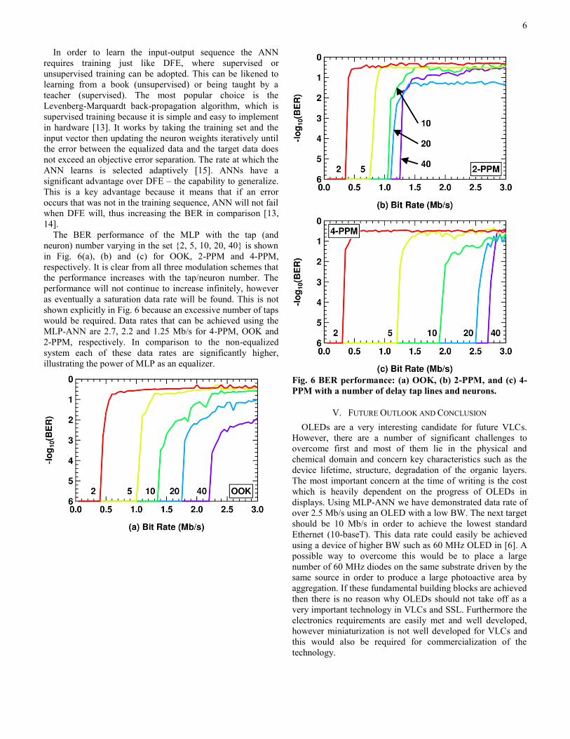
The BER performance of the MLP with the tap (and
neuron) number varying in the set {2, 5, 10, 20, 40} is shown
in Fig. 6(a), (b) and (c) for OOK, 2-PPM and 4-PPM,
respectively. It is clear from all three modulation schemes that
the performance increases with the tap/neuron number. The
performance will not continue to increase infinitely, however
as eventually a saturation data rate will be found. This is not
shown explicitly in Fig. 6 because an excessive number of taps
would be required. Data rates that can be achieved using the
MLP-ANN are 2.7, 2.2 and 1.25 Mb/s for 4-PPM, OOK and
2-PPM, respectively. In comparison to the non-equalized
system each of these data rates are significantly higher,
illustrating the power of MLP as an equalizer.
Fig. 6 BER performance: (a) OOK, (b) 2-PPM, and (c) 4-
PPM with a number of delay tap lines and neurons.
V. FUTURE OUTLOOK AND CONCLUSION
OLEDs are a very interesting candidate for future VLCs.
However, there are a number of significant challenges to
overcome first and most of them lie in the physical and
chemical domain and concern key characteristics such as the
device lifetime, structure, degradation of the organic layers.
The most important concern at the time of writing is the cost
which is heavily dependent on the progress of OLEDs in
displays. Using MLP-ANN we have demonstrated data rate of
over 2.5 Mb/s using an OLED with a low BW. The next target
should be 10 Mb/s in order to achieve the lowest standard
Ethernet (10-baseT). This data rate could easily be achieved
using a device of higher BW such as 60 MHz OLED in [6]. A
possible way to overcome this would be to place a large
number of 60 MHz diodes on the same substrate driven by the
same source in order to produce a large photoactive area by
aggregation. If these fundamental building blocks are achieved
then there is no reason why OLEDs should not take off as a
very important technology in VLCs and SSL. Furthermore the
electronics requirements are easily met and well developed,
however miniaturization is not well developed for VLCs and
this would also be required for commercialization of the
technology.
7
REFERENCES
[1] IEEE Standard for Local and Metropolitan Area Networks--Part
15.7: Short-Range Wireless Optical Communication Using Visible Light," ed: IEEE, 2012.
[2] R. S. King, "Expectations dim for OLED lighting," Spectrum,
IEEE, vol. 48, pp. 14-16, 2011. [3] J. Boyd, "Let there be (a new kind of) light [NEWS]," Spectrum,
IEEE, vol. 44, pp. 12-14, 2007.
[4] P. R. Savage, "Betting on a new idea [organic LEDs]," Spectrum, IEEE, vol. 39, pp. 63-64, 2002.
[5] R. Shinar and J. Shinar, Organic Electronics in Sensors and
Biotechnology: McGraw-Hill, 2009. [6] I. A. Barlow, T. Kreouzis, and D. G. Lidzey, "High-speed
electroluminescence modulation of a conjugated-polymer light
emitting diode," Applied Physics Letters, vol. 94, pp. 243301-3, 2009.
[7] J. J. D. McKendry, D. Massoubre, et. al., "Visible-Light
Communications Using a CMOS-Controlled Micro-Light- Emitting-Diode Array," Lightwave Technology, Journal of, vol.
30, pp. 61-67, 2012.
[8] P. A. Haigh, Z. Ghassemlooy, et. al., "Exploiting Equalization Techniques for Improving Data rates in Organic Optoelectronic
Devices for Visible Light Communications," Journal of Lightwave
Technology, vol. 30, pp. 3081-3088, Oct 1 2012. [9] Z. Ghassemlooy, W. Popoola, and S. Rajbhandari, Optical
Wireless Communications: System and Channel Modelling: CRC
PressINC, 2012. [10] S. Rajbhandari, Z. Ghassemlooy, and M. Angelova, "Bit error
performance of diffuse indoor optical wireless channel pulse
position modulation system employing artificial neural networks for channel equalisation," IET Optoelectronics, vol. 3, pp. 169-
179, 2009.
[11] A. M. Street, K. Samaras, D. C. Obrien, and D. J. Edwards,
"Closed form expressions for baseline wander effects in wireless
IR applications," Electronics Letters, vol. 33, pp. 1060-1062, 1997.
[12] M. Hoa Le, D. O'Brien, G. Faulkner, Z. Lubin, L. Kyungwoo, J. Daekwang, O. YunJe, and W. Eun Tae, "100-Mb/s NRZ Visible
Light Communications Using a Postequalized White LED," IEEE
Photonics Technology Letters, vol. 21, pp. 1063-1065, 2009. [13] K. Burse, R. N. Yadav, and S. C. Shrivastava, "Channel
Equalization Using Neural Networks: A Review," IEEE
Transactions on Systems Man and Cybernetics Part C-Applications and Reviews, vol. 40, pp. 352-357, May 2010.
[14] S. Haykin, Neural networks: A comprehensive foundation, 2nd ed.
New Jersey, USA: Prentice Hall, 1998. [15] L. Behera, S. Kumar, and A. Patnaik, "On adaptive learning rate
that guarantees convergence in feedforward networks," IEEE
Transactions on Neural Networks, vol. 17, pp. 1116-1125, 2006.


