Embed Size (px)
Citation preview

Author Queries
AQ1 Please provide details of Eppes et al. (2010) in the reference list.AQ2 Please provide details of Haff (2014) in the reference list.
0004165697.INDD 1 8/14/2018 4:32:22 PM

61
Aeolian Geomorphology: A New Introduction, First Edition. Edited by Ian Livingstone and Andrew Warren. © 2019 John Wiley & Sons Ltd. Published 2019 by John Wiley & Sons Ltd.
3.1 Introduction
‘Wind erosion’ is something of a misnomer, because the formation of wind‐eroded land‑forms is not the work of the wind itself, but of the mineral grains (and in some cases ice crystals) that the wind carries. Nevertheless, this chapter uses the term ‘wind erosion’ to describe how landforms are shaped by wind‐blown particles. The wind can erode both hard bedrock or loose surface materi‑als, although the preservation, beyond a few days or months of wind‐eroded features developed in loose materials as on dunes, is low (Chapter 6). Here, we discuss the effects of wind erosion on bedrock or loose boulder‐covered surfaces. Discussion of these wind‐eroded landforms is grounded in the historical context of research by such workers as Charles Keyes (Goudie 2012). Definitions of terms used in this chapter are provided in Table 3.1.
The capacity of wind‐blown sand to erode the surface of coherent materials depends on the properties of the wind, the grains it trans‑ports, and of the substrate. The most sig‑nificant properties to consider are listed in Table 3.2. The relevant properties of the wind include its speed, its turbulence, the fric‑tional force that it exerts on the land surface, and the nature of wind interactions with the surface macro‐ and micro‐topography. Many of these properties and interactions are
site‐specific, are difficult to downscale effec‑tively from regional climate or boundary layer models, and are subject to high spatial and temporal variability. There are also important feedbacks between the atmos‑pheric boundary layer and a variety of land surface processes, which are challenges to wind erosion modelling, and which wind tunnel models cannot capture well (e.g. Burri et al. 2011; Tong and Huang 2012; McKenna Neuman et al. 2013).
3.2 The Processes of Wind Abrasion
Sand‐sized particles are the most commonly observed and the most geomorphologically effective abraders, as shown both by field and experimental studies (Kuenen 1960; Suzuki and Takahashi 1981; Anderson 1986; Bridges et al. 2004). Silt particles or ice crys‑tals may also be important in some environ‑mental settings, but are generally considered to be less effective abraders, because of their smaller size and lower impact energy. The processes that result in the entrainment and transport of sand particles, and the different ways of calculating sediment threshold velocity, are described in Chapter 2. Here, we focus on those elements of particle trans‑port that are of direct relevance to wind erosion. The impact threshold, which is the
3
Wind ErosionJasper Knight
School of Geography, Archaeology, and Environmental Studies, University of the Witwatersrand, Johannesburg, South Africa
0004165697.INDD 61 8/14/2018 4:32:22 PM

3 Wind Erosion62
minimum velocity required to lift a grain, is lower on bedrock or other hard land surfaces than on loose or unconsolidated surfaces where kinetic energy absorption/diffusion is higher. In this instance, instead of kinetic energy being transferred to the impacted grain, the energy is absorbed into the substrate. The higher wind speeds com‑monly found above bedrock surfaces and desert stone pavements can lead to higher‐energy erosive environments, greater lift of saltating particles, and higher potential sedi‑ment fluxes. It is no surprise, therefore, that evidence for wind abrasion is most common under such environmental conditions.
High wind speeds and sediment fluxes increase the height of the saltation curtain and the height at which maximum abrasion occurs. This is measured indirectly as the height of the peak kinetic energy flux, which is around 40–50 cm above the land surface
(Anderson 1986). The precise height depends on wind speed and turbulence (which affects the size distribution of transported grains, and the nature of grain–grain interactions), land surface roughness, sediment supply, and the protrusion of obstacles into the wind‐stream. The highest density of abraders, at the height of the peak kinetic energy flux, may undercut rock protrusions. Sediment transport, and thus the potential for wind abrasion, do occur above the height of the peak kinetic energy flux, but is generally restricted to <2 m above the surface.
3.2.1 Environmental Controls on the Wind Transport of Particles
The likelihood of particle transport by wind, and the erosional effects of such transport, are strongly related to a range of site‐specific land surface factors which exhibit spatial and
Table 3.1 Definition of commonly used terms related to wind processes.
Term Definition
Deflation The process by which wind removes dry, unconsolidated materials from regional‐scale land surfaces, resulting in land surface down‐wearing and the formation of broad, low‐relief, bowl‐like depressions (deflation hollows)
Entrainment The process by which loose sediments are incorporated within the wind‐streamWind abrasion The microscale process of mechanical down‐wearing of hard rock surfaces by a wind‐
blown abrader (i.e. a sand grain). Wind abrasion takes place through the interaction of boundary layer winds with microtopography of the rock surface
Wind erosion The net effect of wind abrasion and deflation, thus wind erosion reflects net sediment removal from the land surface by wind
Source: Adapted after Whittow (2000).
Table 3.2 Key environmental properties that can influence the likelihood of wind erosion taking place, and the impacts of such erosion.
Properties of the wind Properties of the substrate
Wind speed, direction, durationWind turbulenceWind temperature (air density)Saltation and suspension load
Sediment availabilityGrain size/shapeBoundary layer (micro) topographyVegetation coverSurface moistureSurface roughness
0004165697.INDD 62 8/14/2018 4:32:22 PM

3.3 Ventifacts 63
temporal variability at a number of scales (see Table 3.2). Apart from wind speed, air density is another significant control on the capacity for wind transport of sediment par‑ticles. Air density varies as a function of air temperature, colder air being denser than warmer air (Figure 3.1). This means that, for any given wind speed, colder and denser air can transport higher volumes of sediment and coarser grain sizes. As a consequence, wind transport and thus the effects of wind erosion are most clearly seen in cold, extra‐glacial areas (Figure 3.2), many of which also experience strong, unidirectional katabatic winds (Box 3.1). Wind‐eroded features can, nonetheless, form under warm climates and
may attain the sizes of those found in extra‐glacial areas, but most low‐latitude, warm climate locations have experienced many episodes of aridity and deflation at relatively slow rates throughout the Quaternary, thus retaining as much evidence of abrasion as many colder locations (Fujioka and Chappell 2011).
This chapter describes the major land‑forms developed as a consequence of wind erosion. These landforms are best manifested on bedrock or boulder‐covered land sur‑faces, which retain more evidence for wind erosion. Different types of wind‐eroded landforms are also more commonly found in these locations, being formed by similar suites of processes (Goudie 2008). The gen‑erally high preservation of these landforms has a high potential to reconstruct the boundary‐layer climates and geomorpholog‑ical processes of the past. The most common wind erosion landforms are now described in ascending order of size.
3.3 Ventifacts
Ventifacts are loose surface clasts (pebbles, cobbles or boulders) or upstanding bedrock protrusions that have been shaped by the
1.4
1.3
1.2
1.1–10 10 20 30
Air temperature (°C)
Air
dens
ity (
kg m
–3)
0
Figure 3.1 Illustration of the relationship between air density and temperature.
(a) (b)
Figure 3.2 Wind‐eroded features in Antarctica. (a) Polished and pitted boulder surfaces, Victoria Valley. (b) A wind‐abraded boulder, Antarctic coast. Source: Photos: C. Bristow. See insert for colour representation of this figure.
0004165697.INDD 63 8/14/2018 4:32:23 PM

3 Wind Erosion64
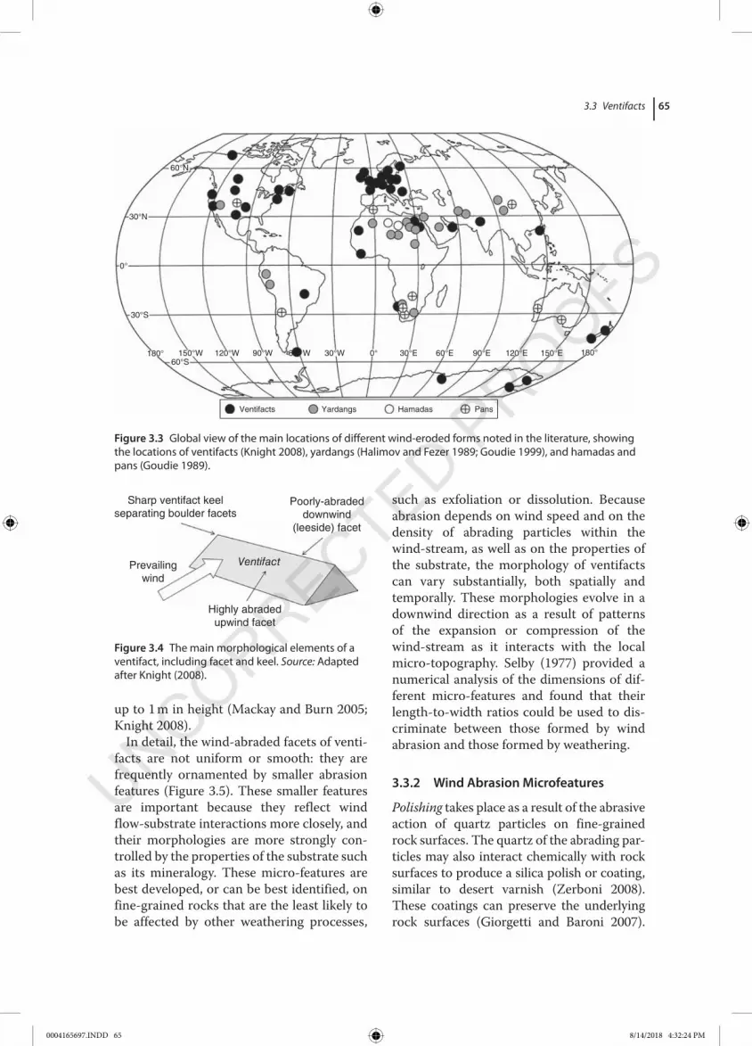
bombardment by wind‐blown particles. Ventifacts have been described from a range of mountain, desert, periglacial, and coastal environments worldwide (e.g. Wade 1910; Tremblay 1961; Sugden 1964; Selby 1977; Laity 1987, 1992; Bishop and Mildenhall 1994; Knight and Burningham 2001, 2003; Knight 2005, 2008; Mackay and Burn 2005) (Figure 3.3).
3.3.1 Morphology
The term ventifact was first used by Evans (1911, p. 335) to describe ‘any wind‐shaped stone’. His term was a replacement for the more specific German‐language terms Einkanter (a rock or boulder surface with one abraded and one non‐abraded face) and Dreikanter (a rock or boulder with three
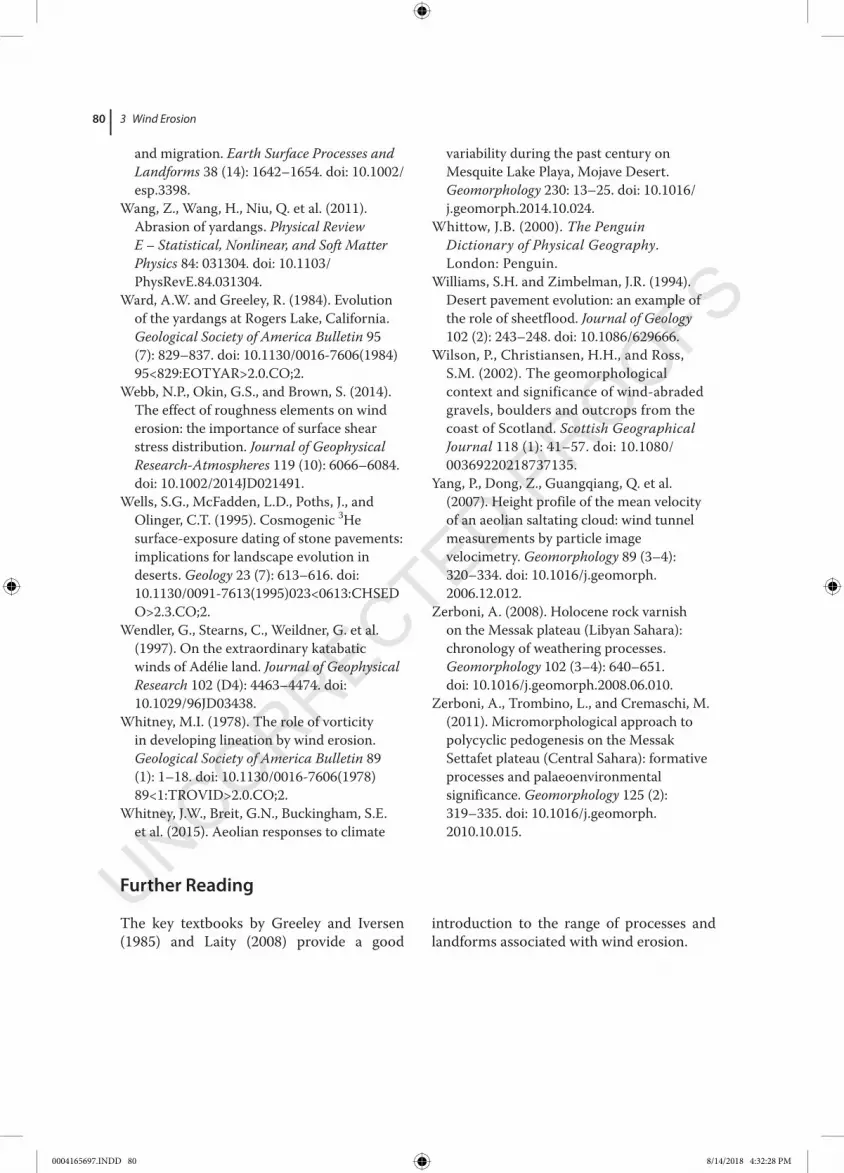
opposing, pyramidal sides, all of which have been abraded) (Wade 1910; Delo 1930). The most common morphological elements of a ventifact are one or more abraded faces, termed facets, which are sometimes sepa‑rated by a sharp ridge‐like keel that, where present, can usually be traced across the upper surface of the ventifact (Figure 3.4). Some ventifacts have only one dominant facet which therefore reflects very clearly the direction of the most geomorphologically‐effective wind. In other cases, ventifacts with multiple facets have been interpreted as evidence for the clast having been moved by rotation or undercutting by the wind, rather than as evidence of changes in wind direction during the development of the ven‑tifact (Kuenen 1928). The largest ventifacts reported are several metres horizontally and
Box 3.1 Katabatic Winds and Wind Erosion
Katabatic winds are generated by air flow down a thermal or topographic gradient as a result of seasonal or diurnal patterns of land surface heating and cooling. Typical examples include föhn or mistral winds, found in coastal settings where winds are generated by strong orographic relief. Katabatic winds flow at their strongest where there are significant atmos-pheric pressure gradients, and are thus best experienced in the unglaciated parts of east Antarctica where cold and arid air formed above the Antarctic ice sheet surface causes descending air masses and outward flow of this air towards and then away from ice sheet margins (Wendler et al. 1997; Parish and Cassano 2003; Nylen et al. 2004). The katabatic winds of east Antarctica are strong and unidi-rectional but the highest velocities occur in short gusts (Wendler et al. 1997; French and Guglielmin 1999). These winds are also strong-est in the austral summer months and are largely directed by land surface topography.
Based on data from experimental abrasion sites, calculated free‐stream wind speeds of katabatic winds can reach <70 m s−1 (250 km h−1) (Malin 1986) and are associated
with very high rates of windblown snow trans-port (Scarchilli et al. 2010). Erosion by strong katabatic winds of snow or ice fields can form wind‐parallel erosional features termed zas-trugi or sastrugi (Mather 1962). The flux density and ice crystal size of windblown snow and ice decrease upwards in the windstream, similar to that of sediment particles. These snow and ice crystals are also important because they are potentially hard abraders that can shape rock surfaces. Under these conditions, venti-facts are commonly developed over short (decadal) timescales (Miotke 1982) and wind abrasion is considered to be the most effective geomorphic process in the region (French and Guglielmin 1999; Gillies et al. 2009). Larger‐scale features such as honeycomb and cavern-ous (tafoni) weathering can reach <30 cm in length, may form over 1000–4000 years, and may have had a polygenic origin, including by salt and thermal weathering as well as by wind abrasion (French and Guglielmin 1999) (Figure 3.2). A significant limitation on wind abrasion, however, is the availability of sedi-ment grains or snow/ice crystals, thus regional aridity (Matsuoka et al. 1996).
0004165697.INDD 64 8/14/2018 4:32:23 PM
3.3 Ventifacts 65
up to 1 m in height (Mackay and Burn 2005; Knight 2008).
In detail, the wind‐abraded facets of venti‑facts are not uniform or smooth: they are frequently ornamented by smaller abrasion features (Figure 3.5). These smaller features are important because they reflect wind flow‐substrate interactions more closely, and their morphologies are more strongly con‑trolled by the properties of the substrate such as its mineralogy. These micro‐features are best developed, or can be best identified, on fine‐grained rocks that are the least likely to be affected by other weathering processes,
such as exfoliation or dissolution. Because abrasion depends on wind speed and on the density of abrading particles within the wind‑stream, as well as on the properties of the substrate, the morphology of ventifacts can vary substantially, both spatially and temporally. These morphologies evolve in a downwind direction as a result of patterns of the expansion or compression of the wind‑stream as it interacts with the local micro‐topography. Selby (1977) provided a numerical analysis of the dimensions of dif‑ferent micro‐features and found that their length‐to‐width ratios could be used to dis‑criminate between those formed by wind abrasion and those formed by weathering.
3.3.2 Wind Abrasion Microfeatures
Polishing takes place as a result of the abrasive action of quartz particles on fine‐grained rock surfaces. The quartz of the abrading par‑ticles may also interact chemically with rock surfaces to produce a silica polish or coating, similar to desert varnish (Zerboni 2008). These coatings can preserve the underlying rock surfaces (Giorgetti and Baroni 2007).
60°N
30°N
0°
30°S
180° 150°W 120°W 90°W 30°W 30°E 60°E 90°E 120°E 150°E 180°
PansHamadasYardangsVentifacts
0°660°S
W
Figure 3.3 Global view of the main locations of different wind‐eroded forms noted in the literature, showing the locations of ventifacts (Knight 2008), yardangs (Halimov and Fezer 1989; Goudie 1999), and hamadas and pans (Goudie 1989).
Prevailingwind
Highly abradedupwind facet
Poorly-abradeddownwind
(leeside) facet
Sharp ventifact keelseparating boulder facets
Ventifact
Figure 3.4 The main morphological elements of a ventifact, including facet and keel. Source: Adapted after Knight (2008).
0004165697.INDD 65 8/14/2018 4:32:24 PM

3 Wind Erosion66
Cosmogenic analysis of the polish can be used to date the formation of underlying wind‐eroded surfaces (Ruszkiczay‐Rudiger et al. 2011). Around 60% of the rocks in east Antarctica (Gillies et al. 2009) and north‐west Ireland (Knight 2005) show polish.
Pits are enclosed, circular to elongated micro‐depressions on the rock surface that are formed directly by the impact of an abrader (Várkonyi and Laity 2012). Pits pick out grain‐scale variations in mineralogy, especially softer minerals, such as feldspar, or may exploit microscale variations in rock surface roughness, such as vesicles within basalt. The shape and size of pits vary from a few mm in diameter and depth, to 6 mm diameter and up to 0.5 cm in depth (Knight and Burningham 2003). Pits generally develop at a steep angle to the rock surface
and are elongated into the rock face, parallel to the direction of wind‐flow. Steeper wind‑ward rock surfaces generally develop smaller and deeper pits, whereas on less steeply inclined surfaces, pits are more elongated and wider. They are therefore transitional to flutes and grooves.
Flutes and grooves are elongate depres‑sions in the rock surface with scoop‐like or scalloped edges, and smooth internal sides (Box 3.2). Many flutes and grooves have undu‑lating or highly variable long profiles that are aligned in the direction of the wind (Selby 1977). The morphological distinction between flutes and grooves is unclear, and the terms have been used quite loosely. In both, small depressions developed on the upwind edge of the rock surface become shallower and broaden in a downwind direction, and have
(a) (b)
(c) (d)
Figure 3.5 Examples of ventifact microfeatures from north‐west Ireland: (a) facets and keel, (b) pits developed on facets, (c, d) grooves. Source: Photos: J. Knight. See insert for colour representation of this figure.
0004165697.INDD 66 8/14/2018 4:32:25 PM

3.3 Ventifacts 67
clear to diffuse lateral margins. In general, neither flutes nor grooves have pits within them, but pits are common on the rock sur‑faces outside of these features. Flutes and grooves may also develop on oblique facets or downwind of pitted facets (Knight 2005).
3.3.3 Ventifact Evolution
Ventifacts form where loose sediments are present and where surface boulders or bedrock protrusions penetrate into the wind‐stream, where vegetation is absent, and where the velocity of the prevailing wind is above the sediment threshold velocity. The processes and rates of the evolution of venti‑facts have been examined both in field and laboratory studies in which blocks of differ‑ent natural and synthetic materials have been exposed to abrasion (e.g. Schoewe 1932; Sharp 1964, 1980; Suzuki and Takahashi 1981; Bridges et al. 2004; Mackay and Burn 2005). These experiments show that time‐averaged rates of wind abrasion are highly variable, both within and between materials of different types, but that all materials show similar patterns of down‐wearing, whereby the height of the ventifact decreases, the angle of the windward facet decreases, and the keel migrates downwind (Schoewe 1932).
Laboratory studies have assumed, however, that only a 6% loss of mass from wind‐abraded facets is required in order to form a ventifact (Kuenen 1960), but this value is somewhat arbitrary, because loss of mass can take place on any rock surface (Figure 3.6). Indeed, facets that have a very low value of
Box 3.2 Formation and Significance of Helicoidal Vortices
Helicoidal (corkscrew‐like) vortices are a likely candidate for the formation of wind‐parallel erosional ridges and grooves across rock sur-faces. Knight and Burningham (2003) described a series of wind‐parallel grooves (3 m deep, 10–40 cm apart) developed up the face of a diabase boulder on the coast of Oregon, USA.
In Oregon, the grooves widen and deepen up the face, in a down‐wind direction. These landforms are ascribed to wind flow within helicoidal vortices moving up the boulder face (Laity and Bridges 2009). In this example, airflow compression up the windward face of a rock surface results in increased windspeed and higher impact velocity of any transported
particles, and thus higher rates of abrasion. Furthermore, interactions between wind dynamics and surface microtopography results in high flow vorticity. This can be man-ifested either parallel or perpendicular to wind direction, and result in lines of higher abrasion, forming pits or grooves (Whitney 1978). The repeated development and then shedding of wind vortices over rock surfaces represent a dynamic response of air pressure to microtopography (Tanner 1960; McKenna Neuman et al. 2013). This means that varia-tions in microtopography and properties of the boundary‐layer windflow are key controls on the development of such vortices.
Windflow
Windflow
(a)
(b)
Downwindmigration ofventifact apex
12 3
321
Figure 3.6 Diagram illustrating ventifact evolution over time. (a) Cross‐sectional view showing changes in rock surface morphology from time periods 1–3, with development of the planar windward facet which decreases in angle and migrates downwind over time as abrasion takes place and the ventifact develops a more distinctive morphology and decreases in total volume. Abrasion moves the ventifact apex downwind over time and lowers the apex. (b) Plan view of the ventifact basal outline (solid line) and keel (dotted line), showing its development in time periods 1–3.
0004165697.INDD 67 8/14/2018 4:32:25 PM

3 Wind Erosion68
Table 3.3 Calculated averaged ventifact abrasion rates of ‘natural’ rock surfaces under field conditions.
Abrasion rate (mm yr−1) Source Comments
0.01–0.05 Knight (2003) Basalt boulders on a jetty of known age, Northern Ireland0.05–3.70 Malin (1986) Various lithologies, Victoria Land, Antarctica0.24–1.63 Knight and Burningham (2003) Diabase boulders on a jetty of known age, Oregon, USA10.40 Miotke (1982) Dolerite, Victoria Land, Antarctica
overall mass loss may still show a range of well‐developed micro‐features.
Thus, there are problems in interpreting the attributes of ventifacts (including their age, the depth of abrasion, the loss of rock mass, ambient wind speed, and sediment flux). This means that there are few good estimates of the timescales over which ventifacts form, or their abrasion rate, and estimates of timescales of formation vary considerably (Kuenen 1960), in part because the calculations of the timescale and abra‑sion rate are based on present‐day climatic conditions (e.g. wind speed, sediment availa‑bility). This assumes that ventifacts are being actively formed today under contemporary conditions. However, ventifacts covered by lichens have also been observed (Knight 2005, 2008), and lichens can only colonise the rock surface if abrasion is virtually zero. In these cases, it is evident that the ventifacts are not being actively formed and thus obser‑vations of contemporary climate cannot be used to calculate their age or the rate of their abrasion.
In the light of these problems with the age of ventifacts and the role of climate in their formation, it is important to determine whether ventifacts form episodically (by individual storm events, say, of 10−4 years duration), cyclically (seasonally, of 10−2–10−1 years duration) or during past cooler climate episodes (e.g. the Younger Dryas, Little Ice Age, of 102–103 years duration) when winds were known to be stronger and thus more abrasive. Based on ventifact mor‑phology, estimates of the ages of ventifacts observed in the field can be made. Some
ventifacts have been considered to be formed entirely under contemporary conditions (e.g. in Northern Ireland; Knight 2003), or reactivated episodically under these condi‑tions (e.g. in north‐west Ireland, northern Scotland, north‐east England; Braley and Wilson 1997; Knight and Burningham 2001; Wilson et al. 2002), or are entirely relic fea‑tures and not forming at present (e.g. in Denmark and central Scotland; Schlyter 1995; Christiansen 2004). Assumptions of ventifact age and depth of abrasion are required in order to calculate averaged abra‑sion rates (Table 3.3), but there are many uncertainties in both these measures ( discussed by Greeley and Iversen 1985, pp. 131–133). Several experimental studies have examined the abrasion rates of differ‑ent materials, but the results cannot be taken as representative of real rock surfaces under natural conditions. For example, using a lucite rod under field conditions, Sharp (1980) showed that abrasion was highly vari‑able: in a 15‐year experiment, 87% of the total abrasion took place during only 18% of the total time period, and inter‐annual aver‑aged abrasion rates varied by a factor of 15. This suggests that any short‐term measure‑ments of abrasion rates are not representa‑tive of the longer‐term rates that are required to shape ventifacts.
3.4 Yardangs
The term yardang is a transliteration of a Turkic (central Asian) word to describe streamlined ridges, and was originally used
0004165697.INDD 68 8/14/2018 4:32:25 PM

3.4 Yardangs 69
to refer to landforms identified in the cold‐desert Taklamakan region of north‐west China (Blackwelder 1934; Goudie 1999). Yardangs are elongate, wind‐parallel ridges that are developed in bedrock, particularly in sandstones, siltstones, and mudstones, where both physical and chemical weathering weaken rock surfaces and facilitate granular disintegration and exfoliation.
Yardangs can be distinguished from venti‑facts on the basis of their size and relation‑ship to wind direction: yardangs are much bigger and are aligned parallel rather than perpendicular to wind direction. Since the early twentieth century, yardangs have been identified in many arid and semi‐arid loca‑tions worldwide (see Figure 3.3). Their com‑mon features include a continental (not coastal) setting; dry climatic conditions; sed‑imentary bedrock, particularly of softer rock types or of relatively young (Neogene) age; a mixture of exposed bedrock and loose sur‑face sediments; and strong winds. Although fossil yardangs are known from the geologic record, the environment of their formation is very speculative, and Goudie (1999) has argued that many contemporary yardangs developed as a consequence of increased aridity from the mid‐Holocene onwards, exposing soft dried lake or river bed sedi‑ments to wind erosion (e.g. Gutiérrez‐Elorza et al. 2002; Whitney et al. 2015).
Actively‐forming yardangs have been described from China, Iran, and parts of the Sahara. In all these locations, strong, unidi‑rectional winds and high sediment supply result in high rates of abrasion (Brookes 2001; Vincent and Kattan 2006; Al‐Dousari et al. 2009). The formation of yardangs in these areas is probably also enhanced by strong thermal weathering, a freeze–thaw action and salt crystal growth, which can detach sediment grains from the bedrock surface (Lancaster 1984; Goudie 1989). In the western Qaidam region of central China, Wang et al. (2011) showed that the rate of yardang abrasion was in the range 0.011–0.398 mm yr−1 between 1986 and 2010, but that there was high inter‐annual variability,
probably related to the frequency of high winds. This rate of yardang abrasion is very similar to the rates of bedrock incision by wind across the same region, calculated using the cosmogenic 10Be method (Rohrmann et al. 2013). Yardangs at Rogers Lake (Mojave Desert, USA) experience abrasion at the windward tip of 20 mm yr−1and on the lateral flanks of 0.5 mm yr−1 (Laity 1994).
Although most studies have been con‑cerned with yardangs that are undergoing active contemporary abrasion, examples of fossil yardangs have also been described (Tewes and Loope 1992; Inbar and Risso 2001; Vincent and Kattan 2006; Al‐Dousari et al. 2009; Sebé et al. 2011). These relict (non‐active) forms can be identified on the basis of their stratigraphic position and ori‑entation relative to contemporary forms and wind regimes (Whitney et al. 2015).
3.4.1 Yardang Morphology and Evolution
Most yardangs are found in large fields where up to several hundred individuals, aligned parallel to one another, may be present (Brookes 2001). Individual yardangs are usu‑ally separated by a flat, sand‐covered valley through which strong and unidirectional winds are funnelled. Over time, these valleys are widened by the abrasion of the flanks of the yardangs on either side (Al‐Dousari et al. 2009; Sebé et al. 2011; Perkins et al. 2015) (Figure 3.7).
The processes of yardang development include wind abrasion by saltating particles, and deflation of loosened sediment grains from yardang slopes, which exposes the rock surface to further abrasion. In addition, yar‑dangs can be affected by non‐wind processes such as: mass movement; episodic fluvial erosion around their margins; and subaerial thermal, freeze–thaw and salt weathering. Under strong, unidirectional winds, upstand‑ing bedrock ridges and mesas are abraded on the upwind side and undercut by abrasion on the flanks. This results over time in a more streamlined and aerodynamic form. A length:
0004165697.INDD 69 8/14/2018 4:32:25 PM

3 Wind Erosion70
width ratio of 4 : 1 is considered optimal with respect to the balance between skin‐friction drag and pressure drag. In this abrasion pro‑cess, the summit location migrates down‑wind. More complex forms, including cones and pyramids, can also develop (Halimov and Fezer 1989).
Most yardangs typically attain dimensions of around 30 m in height, >50 m in width and <5 km. in length. Mega‐yardangs up to 20 km long have also been identified (Goudie 2008). The outline morphology of individ‑ual yardangs is generally quite consistent, irrespective of their size, location, likely age or bedrock type. Yardangs are elongate in the direction of the most geomorphologi‑cally effective wind; the outline morphology of individual yardangs usually tapers
downwind; morphology is axially symmet‑ric; and the yardang summit is usually located near the upwind end with elevations decreasing downwind (Halimov and Fezer 1989). The slope of the windward end of the yardang decreases over time as a result of abrasion, whereas the downwind prow of the yardang becomes steeper over time or may become undercut at its base (forming a ‘re‐entrant’; Wang et al. 2011), with an over‑hanging upper part caused by turbulence within the lowermost part of the saltation curtain (e.g. Lancaster 1984).
The reported dimensions of yardangs vary but, irrespective of substrate type, they gen‑erally attain similar length : width : height ratios of 10 : 2 : 1 (Halimov and Fezer 1989), which suggests that yardangs evolve as a
(a) (b)
(c) (d)
Figure 3.7 Examples of yardangs. (a) A field of yardangs from the Bodélé Depression, Chad, (b) a close‐up of a single yardang from that field. Source: Photos: C. Bristow. (c) An individual 15 m‐high yardang, from the Dunhuang Yardang National Geopark, China, (d) a group of parallel yardangs from the same field. Source: Photos: J. Bullard. See insert for colour representation of this figure.
0004165697.INDD 70 8/14/2018 4:32:26 PM

3.5 Hamadas and Stone Pavements 71
function of wind interaction with bedrock and are less strongly controlled by environ‑mental setting or bedrock type/structure. Ward and Greeley (1984) found a strong rela‑tionship (r2 = 0.89) between yardang length and width. Wang et al. (2011) modelled the evolutions of yardangs from the Qaidam basin, China. They showed that, although annually‐averaged abrasion rates were gen‑erally high, there may be only 19–49 effective abrasion days per year, so that yardang evolution is highly episodic.
3.5 Hamadas and Stone Pavements
Hamadas are rocky, wind‐eroded land sur‑faces that may be composed of bare bedrock that is covered by loose, angular and, in places often large, debris (pebbles to boulders) which has the same lithology as the underly‑ing bedrock. Hamadas are common in the northern Sahara (Libya, Algeria) where they cover large areas and are thought to have developed by progressive deflation during arid phases of the Quaternary (Perego et al. 2011; Zerboni et al. 2011). Hamada surfaces have not been well described, but their mac‑roscale morphology is commonly controlled by bedrock lithology and geologic struc‑tures. The angular boulders that commonly
cover hamada surfaces may have been formed as a result of different weathering processes, in particular, thermal and salt weathering under arid, hot conditions, which shatter and loosen angular fragments from the underlying bedrock (Eppes et al. 2010). Alternatively, hamadas can develop through the deflation of fine sediments, allowing angular boulders to settle directly on to bedrock (Perego et al. 2011).
Stone pavements, also termed desert pave‑ments, reg or gobi, are similar morphologi‑cally to hamadas in that their surfaces are covered by debris, but here the debris is of smaller size (pebbles), the clasts are often sub‐rounded and form an interlocking sur‑face cover of one clast thickness (Cooke 1970). These clasts shield the land surface and protect the underlying sediments from deflation or erosion by flashfloods (Williams and Zimbelman 1994; Dietze and Kleber 2012) (Figure 3.8). Below the surface cover there are usually unconsolidated sediments, not bedrock. Formation of stone pavements probably results from strong thermal, freeze–thaw and salt weathering, and strong winds that are able to carry small particles away.
Models of stone pavement evolution show that clasts comprising the pavements become clustered over time by erosion, thereby clos‑ing gaps between clasts and reducing the ability of finer sediments to be blown away
AQ1
(a) (b)
Figure 3.8 Stone pavement (erg) surfaces from (a) Jordan. Source: Photo: J. Bullard, and (b) Simpson Desert, Australia. Source: Photo: C. Bristow. See insert for colour representation of this figure.
0004165697.INDD 71 8/14/2018 4:32:26 PM

3 Wind Erosion72
(Haff and Werner 1996). The net effect is to stabilise the land surface. Dating of these sur‑faces has shown that stone pavements and the micro‐features developed thereon (rock varnish, polish, pits) can be in the range 103–107 years old (Wells et al. 1995; Quade 2001; Matmon et al. 2009). Stone pavements and desert landscapes can therefore develop and remain stable over very long time periods (McFadden et al. 1987; Fujioka and Chappell 2011). The ways in which stone pavements evolve, however, are not well understood. Apart from wind transport of fine sediments, other processes may also be significant in stone pavement formation, including rains‑plash (Wainwright et al. 1995), sheetflow during episodic rainfall events (Williams and Zimbelman 1994; Dietz and Kleber 2012; Dietze et al. 2013), bioturbation by small desert animals (Haff and Werner 1996; Haff 2014), and burial through wind‐blown sedi‑ment deposition and pedogenesis (Pelletier et al. 2007). Dong et al. (2002), using wind tunnel experiments, have shown that bound‑ary layer roughness (and thus aerodynamic turbulence) are best developed when surface clast coverage is around 15% by area. As boundary layer turbulence is important in particle entrainment, this may mean that development of stone pavements by wind
erosion is most effective at around this value of 15% surface clast coverage. At values higher or lower than this, other processes may be more dominant.
3.6 Deflation Basins and Pans
Deflation basins are shallow and sometimes very large land surface depressions that, although they are ultimately polygenetic in origin, are likely to have experienced periods of wind erosion (Goudie 1989) (Figure 3.9a). Deflation basins are particularly common on sedimentary bedrock types where physical and chemical weathering processes can generate loose surface materials. The larg‑est deflation basins include those in the Western Desert of Egypt, such as the Qattara Depression, which is around 300 km long, 145 km wide and attains a maximum depth of 134 m below sea level (Albritton et al. 1990). In the Western Desert, these basins are commonly deflated to the level of the water table, but their origin is more com‑plex, with strong geologic control by the presence of suitable sedimentary strata (Aref et al. 2002).As such, there is a macro‐scale geologic control on deflation basin geome‑try and location (Laity 2008), including lines
AQ2
(a) (b)
Figure 3.9 Photos of (a) a deflation basin developed on a wind‐eroded diatomite surface, Bodélé Depression, Chad. Source: Photo: C. Bristow., and (b) a pan in the linear dunefield between William Creek and Coober Pedy, South Australia. Note the linear dune in the background. Source: Photo: D. Nash. See insert for colour representation of this figure.
0004165697.INDD 72 8/14/2018 4:32:26 PM

3.7 Discussion 73
of bedrock weakness and former river drain‑age systems (Goudie 1999). The main factors contributing to the evolution of such systems are described in Figure 3.10.
Climate change is also a significant control on the formation of deflation basins. For example, during wetter climate periods of the Quaternary, fine sediments and biogenic materials can be deposited in these depres‑sions when they become water‐filled (e.g. Telfer et al. 2009). During arid phases when the basins dry up, the loose sediments may become susceptible to deflation (Gutiérrez‐Elorza et al. 2005). The resulting deflation may then be sediment‐limited, ceasing when fine sediments are no longer available or when the groundwater table is reached. Such a polyphase history is likely for basins such as the Qattara Depression.
Pans are common in some semi‐arid areas such as southern Africa, central USA, and southern and western Australia (see Figure 3.9b). They are shallow and generally small depressions that may contain water seasonally or ephemerally. Pans are also geomorphologically associated with sand dunes, sand sheets, and other features indicative of active wind transport (Goudie and Wells 1995). Pans can be distinguished from deflation basins based on their smaller
size and the much more common presence of water. In geometry, pans are circular to elongate with smooth shorelines created by wind‐driven waves. Winds can also form sand dune ridges and crescentic dunes (lunettes), in particular immediately down‑wind of pan margins when the pan is dry (Goudie 1989; Holmes et al. 2008).
3.7 Discussion
3.7.1 Wind Erosion and Boundary Layer Climates
Interactions between wind flow and land surface topography determine the volume and dynamics of wind‐blown sediment trans‑port and thus the wind erosion capacity (Raupach and Finnigan 1997; Jackson et al. 2011; Webb et al. 2014). The relationship between wind erosion and boundary layer climates, however, remains poorly under‑stood (Ping and Dong 2014). Wind tunnel experiments have been used to help inform this relationship, but these have focused mainly on the modes of sediment transport and rate fluxes rather than on the effects of wind abrasion (e.g. Li et al. 2008). Likewise, wind tunnel experiments using particle
Regional forcing factors Morphodynamic behaviour
Pans
Morphological controls
Climate Climate
Land surface instabilitySalinisation, desiccationDeflation
DunesLunette formation, migration
Human activityOvergrazingDeforestationAnimal tramplingWater extractionVehicles’ tracks
Periods of aridity/wetness
Geology
Hydrology
Vegetation patterns
Surface water flow (including rivers,endorheric basins)
Bedrock intrusions/topographySoils (including subsurface calcrete)
Precipitation patterns/seasonalityWind duration, direction, strength
GeologyRock typeWeathering patternsGrain size of weathering products
Figure 3.10 Model of pan evolution, illustrating the relationships between regional (geologic, climatic) processes and site‐scale geomorphological processes. Source: Adapted after Goudie (1999).
0004165697.INDD 73 8/14/2018 4:32:27 PM

3 Wind Erosion74
image velocimetry (PIV) have focused on grain–grain interactions in a free wind‐stream, but not on grain interactions with the substrate (e.g. Yang et al. 2007). As a con‑sequence, the detailed climatic conditions under which wind abrasion takes place at the micro‐scale have not been well studied under laboratory conditions, or in instrumented field experiments (e.g. Pease and Gares 2013; Walker and Shugar 2013). Computational fluid dynamics models (e.g. Jackson et al. 2011) have been shown to be a useful approach to the parameterization of the con‑ditions under which wind transport and abrasion can take place.
3.7.2 Reconstructing Past Wind Patterns from Wind‐Eroded Features
Wind‐eroded features, if they can be shown to be inactive, can be used to reconstruct the direction of the most geomorphologically‐effective winds of the past. Relic wind ero‑sion features are best identified in locations where past and present wind directions are very different, such as areas in North America and Europe that lay adjacent to the margins of the late Pleistocene ice sheets
(e.g. Rudberg 1968; Schlyter 1995; Christiansen and Svensson 1998; Christiansen 2004). For example, ventifacts are common across southern Sweden and Denmark (Schlyter 1995; Christiansen and Svensson 1998) and indicate regional easterly winds that were generated by a high‐pressure cell over the for‑mer Scandinavian ice sheet (Isarin et al. 1997) (Figure 3.11).
3.8 Conclusion
Understanding wind erosion processes and products requires an interdisciplinary approach that considers the properties of both boundary‐layer winds and of the substrate. The increasing availability and higher resolution of field equipment and remote sensing make it possible that such an interdisciplinary approach can be developed. These analytical tools can be used to monitor changes in sediment fluxes around, and geomorphic changes to, ventifacts and yardangs, and in evaluat‑ing spatial and temporal changes in the properties of hamadas and stone pave‑ments. The use of high‐resolution, multi‑spectral remote sensing to map large areas of difficult or remote terrain is now also being developed (e.g. Perego et al. 2011). Finally, different cosmogenic radioiso‑topes (e.g. 3He, 10Be, 26Al, 36Cl) can be used individually or in combination to evaluate the age and in some cases the denudation history of wind‐eroded land surfaces (e.g. Bierman and Caffee 2001).
There is great potential for developing future studies on the processes of and con‑trols on wind erosion and their associated landforms; and this research direction can be usefully informed by both field and laboratory/experimental approaches that consider the dynamics of the boundary layer. Improved computing power and data quality in the analysis of wind erosion features from Mars and other planets also suggest ways in which similar studies could be deployed on Earth.
Sweden
Palaeo-winddirection
Jutland
10°E
100 km
57°N
Figure 3.11 Spatial patterns of reconstructed palaeo‐wind direction derived from ventifacts in Denmark and southern Sweden. Source: Adapted from Schlyter (1995) and Christiansen and Svensson (1998).
0004165697.INDD 74 8/14/2018 4:32:27 PM

References 75
Acknowledgements
My field research on wind erosion is cur‑rently partly funded by the National Research Foundation (South Africa). I am particularly grateful to Charlie Bristow, Jo Bullard, and
Dave Nash for generously sharing their field photos and for permission to use some of them in this chapter.
References
Albritton, C.C., Brooks, J.E., Issawi, B., and Swedan, A. (1990). Origin of the Qattara depression, Egypt. Geological Society of America Bulletin 102 (7): 952–960. doi: 10.1130/0016‐7606(1990)102<0952: OOTQDE>2.3.CO;2.
Al‐Dousari, A.M., Al‐Elaj, M., Al‐Enezi, E., and Al‐Shareeda, A. (2009). Origin and characteristics of yardangs in the Um Al‐Rimam depressions (N Kuwait). Geomorphology 104 (3–4): 93–104. doi: 10.1016/j.geomorph.2008.05.010.
Anderson, R.S. (1986). Erosion profiles due to particles entrained by wind: application of an eolian sediment transport model. Geological Society of America Bulletin 97 (10): 1270–1278. doi: 10.1130/0016‐7606 (1986)97<1270:EPDTPE>2.0.CO;2.
Aref, M.A.M., El‐Khoriby, E., and Hamdan, M.A. (2002). The role of salt weathering in the origin of the Qattara depression, Western Desert, Egypt. Geomorphology 45 (3–4): 181–195. doi: 10.1016/S0169‐555X(01) 00152‐0.
Bierman, P.R. and Caffee, M. (2001). Slow rates of rock surface erosion and sediment production across the Namib Desert and escarpment, Southern Africa. The American Journal of Science 301 (4–5): 326–358. doi: 10.2475/ajs.301.4‐5.326.
Bishop, D.G. and Mildenhall, D.C. (1994). The geological setting of ventifacts and wind‐sculpted rocks at Mason Bay, Stewart Island, and their implications for late Quaternary paleoclimates. New Zealand Journal of Geology and Geophysics 37 (2): 169–180. doi: 10.1080/00288306.1994. 9514612.
Blackwelder, E. (1934). Yardangs. Bulletin of the Geological Society of America 45 (2): 159–166. doi: 10.1130/GSAB‐45‐159.
Braley, S.M. and Wilson, P. (1997). Ventifacts from the coast of Northumberland. Proceedings of the Geologists’ Association 108 (2): 141–147. doi: 10.1016/S0016‐ 7878(97)80036‐3.
Bridges, N.T., Laity, J.E., Greeley, R. et al. (2004). Insights on rock abrasion and ventifact formation from laboratory and field analog studies with applications to Mars. Planetary and Space Science 52 (1–3): 199–213. doi: 10.1016/j.pss.2003.08.026.
Brookes, I.A. (2001). Aeolian erosional lineations in the Libyan Desert, Dakhla region, Egypt. Geomorphology 39 (3–4): 189–209. doi: 10.1016/S0169‐555X(01) 00026‐5.
Burri, K., Gromke, C., Lehning, M., and Graf, F. (2011). Aeolian sediment transport over vegetation canopies: a wind tunnel study with live plants. Aeolian Research 3 (2): 205–213. doi: 10.1016/j.aeolia.2011.01.003.
Christiansen, H.H. (2004). Wind polished boulders and bedrock in the Scottish highlands: evidence and implications of late Devensian wind activity. Boreas 33 (1): 82–94. doi: 10.1080/03009480310006998.
Christiansen, H.H. and Svensson, H. (1998). Wind‐polished boulders as indicators of a late Weichselian wind regime in Denmark in relation to neighbouring areas. Permafrost and Periglacial Processes 9 (1): 1–21. doi: 10.1002/(SICI)1099‐1530(199801/03) 9:1<1::AID‐PPP271>3.0.CO;2‐X.
Cooke, R.U. (1970). Stone pavements in deserts. Annals of the Association of
0004165697.INDD 75 8/14/2018 4:32:27 PM

3 Wind Erosion76
American Geographers 60 (3): 560–577. doi: 10.1111/j.1467‐8306.1970.tb00741.x.
Delo, D.M. (1930). Dreikanter in Wyoming and Montana. Science 72 (1876): 604. doi: 10.1126/science.72.1876.604.
Dietze, M., Groth, J., and Kleber, A. (2013). Alignment of stone‐pavement clasts by unconcentrated overland flow: implications of numerical and physical modelling. Earth Surface Processes and Landforms 38 (11): 1234–1243. doi: 10.1002/esp.3365.
Dietze, M. and Kleber, A. (2012). Contribution of lateral processes to stone pavement formation in deserts inferred from clast orientation patterns. Geomorphology 139–140: 172–187. doi: 10.1016/ j.geomorph.2011.10.015.
Dong, Z., Xiaoping, L., and Wang, X. (2002). Aerodynamic roughness of gravel surfaces. Geomorphology 43 (1–2): 17–31. doi: 10.1016/S0169‐555X(01)00097‐6.
Evans, J.W. (1911). Dreikanter. The Geological Magazine, Decade V 8 (6): 334–335. doi: 10.1017/S0016756800111483.
French, H.M. and Guglielmin, M. (1999). Observations on the ice‐marginal, periglacial geomorphology of Terra Nova Bay, northern Victoria land, Antarctica. Permafrost and Periglacial Processes 10 (4): 331–347. doi: 10.1002/(SICI)1099‐1530 (199910/12)10:4<331::AID‐PPP328> 3.0.CO;2‐A.
Fujioka, T. and Chappell, J. (2011). Desert landscape processes on a timescale of millions of years, probed by cosmogenic nuclides. Aeolian Research 3 (2): 157–164. doi: 10.1016/j.aeolia.2011.03.003.
Gillies, J.A., Nickling, W.G., and Tilson, M. (2009). Ventifacts and wind‐abraded rock features in the Taylor Valley, Antarctica. Geomorphology 107 (3–4): 149–160. doi: 10.1016/j.geomorph.2008.12.007.
Giorgetti, G. and Baroni, C. (2007). High‐resolution analysis of silica and sulphate‐rich rock varnishes from Victoria Land (Antarctica). European Journal of Mineralogy 19 (3): 381–389. doi: 10.1127/0935‐1221/ 2007/0019‐1725.
Goudie, A.S. (1989). Wind erosion in deserts. Proceedings of the Geologists’ Association 100 (1): 83–92. doi: 10.1146/annurev.earth.36.031207.124353.
Goudie, A.S. (1999). Wind erosional landforms: yardangs and pans. In: Aeolian Environments, Sediments and Landforms (ed. A.S. Goudie, I. Livingstone and S. Stokes), 167–180. Chichester: Wiley.
Goudie, A.S. (2008). The history and nature of wind erosion in deserts. Annual Review of Earth and Planetary Sciences 36: 97–119. doi: 10.1146/annurev.earth.36.031207. 124353.
Goudie, A.S. (2012). Charles Rollin Keyes and extravagant aeolation. Aeolian Research 4 (1): 51–53. doi: 10.1016/j.aeolia.2012.01.001.
Goudie, A.S. and Wells, G.L. (1995). The nature, distribution and formation of pans in arid zones. Earth‐Science Reviews 38 (1): 1–69. doi: 10.1016/0012‐8252(94)00066‐6.
Greeley, R. and Iversen, J.D. (1985). Wind as a Geological Process on Earth, Mars, Venus and Titan. Cambridge: Cambridge University Press.
Gutiérrez‐Elorza, M., Desir, G., and Gutiérrez‐Santolalla, F. (2002). Yardangs in the semiarid central sector of the Ebro depression (NE Spain). Geomorphology 44 (1–2): 155–170. doi: 10.1016/S0169‐555X(01)00151‐9.
Gutiérrez‐Elorza, M., Desir, G., Gutiérrez‐Santolalla, F., and Marín, C. (2005). Origin and evolution of playas and blowouts in the semiarid zone of Tierra de Pinares (Duero Basin, Spain). Geomorphology 72 (1–4): 177–192. doi: 10.1016/S0169‐555X(01) 00151‐9.
Haff, P.K. and Werner, B.T. (1996). Dynamical processes on desert pavements and the healing of surficial disturbances. Quaternary Research 45 (1): 38–46. doi: 10.1006/qres.1996.0004.
Halimov, M. and Fezer, F. (1989). Eight yardang types in Central Asia. Zeitschrift für Geomorphologie 33 (2): 205–217.
Holmes, P.J., Bateman, M.D., Thomas, D.S.G. et al. (2008). A Holocene‐late Pleistocene aeolian record from lunette dunes of the
0004165697.INDD 76 8/14/2018 4:32:27 PM

References 77
western free state panfield, South Africa. The Holocene 18 (8): 1193–1206. doi: 10.1177/0959683608095577.
Inbar, M. and Risso, C. (2001). Holocene yardangs in volcanic terrains in the southern Andes, Argentina. Earth Surface Processes and Landforms 26 (6): 657–666. doi: 10.1002/esp.207.
Isarin, R.F.B., Renssen, H., and Koster, E.A. (1997). Surface wind climate during the younger Dryas in Europe as inferred from aeolian records and model simulations. Palaeogeography, Palaeoclimatology, Palaeoecology 134 (1–4): 127–148. doi: 10.1016/S0031‐0182(96)00155‐1.
Jackson, D.W.T., Beyers, J.H.M., Lynch, K. et al. (2011). Investigation of three‐dimensional wind flow behaviour over coastal dune morphology under offshore winds using computational fluid dynamics (CFD) and ultrasonic anemometry. Earth Surface Processes and Landforms 36 (8): 1113–1124. doi: 10.1002/esp.2139.
Knight, J. (2003). A note on the formation of ventifacts at Castlerock, Northern Ireland coast. Irish Journal of Earth Sciences 21: 39–45.
Knight, J. (2005). Controls on the formation of coastal ventifacts. Geomorphology 64 (3–4): 243–253. doi: 10.1016/j.geomorph. 2004.07.002.
Knight, J. (2008). The environmental significance of ventifacts: a critical review. Earth‐Science Reviews 86 (1–4): 89–105. doi: 10.1016/j.earscirev.2007.08.003.
Knight, J. and Burningham, H. (2001). Formation of bedrock‐cut ventifacts and late Holocene coastal zone evolution, County Donegal, Ireland. The Journal of Geology 109 (5): 647–660. doi: 10.1086/321959.
Knight, J. and Burningham, H. (2003). Recent ventifact development on the Central Oregon coast, Western USA. Earth Surface Processes and Landforms 28 (1): 87–98. doi: 10.1002/esp.432.
Kuenen, P.H. (1928). Experiments on the formation of wind‐worn pebbles. Leidsche Geologische Medellinger 3 (1): 17–28.
Kuenen, P.H. (1960). Experimental abrasion 4. Eolian action. The Journal of Geology 68 (4): 427–449. doi: 10.1086/626675.
Laity, J.E. (1987). Topographic effects on ventifact development, Mojave Desert, California. Physical Geography 8 (2): 113–132. doi: 10.1080/02723646.1987. 10642315.
Laity, J.E. (1992). Ventifact evidence for Holocene wind patterns in the east‐central Mojave Desert. Zeitschrift für Geomorphologie, N.F. Supplementband 84: 73–88.
Laity, J.E. (1994). Landforms of aeolian erosion. In: Geomorphology of Desert Environments (ed. A.D. Abrahams and A.J. Parsons), 506–535. London: Chapman & Hall.
Laity, J.E. (2008). Deserts and Desert Environments. Chichester: Wiley‐Blackwell.
Laity, J.E. and Bridges, N.T. (2009). Ventifacts on earth and Mars: analytical, field, and laboratory studies supporting sand abrasion and windward feature development. Geomorphology 105 (3–4): 202–217. doi: 10.1016/j.geomorph.2008.09.014.
Lancaster, N. (1984). Characteristics and occurrence of wind erosion features in the Namib Desert. Earth Surface Processes and Landforms 9 (5): 469–478. doi: 10.1002/esp.3290090507.
Li, Z., Feng, D., Wu, S. et al. (2008). Grain size and transport characteristics of non‐uniform sand in aeolian saltation. Geomorphology 100 (3–4): 484–493. doi: 10.1016/j.geomorph.2008.01.016.
Ping, L. and Dong, Z. (2014). The status of research on the development and characteristics of mass‐flux‐density profiles above wind‐eroded sediments: a literature review. Environmental Earth Sciences 71 (12): 5183–5194. doi: 10.1007/s12665‐013‐ 2921‐y.
Mackay, J.R. and Burn, C.R. (2005). A long‐term field study (1951–2003) of ventifacts formed by katabatic winds at Paulatuk, western Arctic coast, Canada. Canadian Journal of Earth Sciences 42 (9): 1615–1635. doi: 10.1139/e05‐061.
0004165697.INDD 77 8/14/2018 4:32:27 PM

3 Wind Erosion78
Malin, M.C. (1986). Rates of geomorphic modification in ice‐free areas southern Victoria Land, Antarctica. Antarctic Journal of the United States 20 (5): 18–21.
Mather, K.B. (1962). Further observations on sastrugi, snow dunes and the pattern of surface winds in Antarctica. Polar Record 11 (71): 158–171. doi: 10.1017/S0032247400052888.
Matmon, A., Simhai, O., Amit, R. et al. (2009). Desert pavement‐coated surfaces in extreme deserts present the longest‐lived landforms on Earth. Geological Society of America Bulletin 121 (5–6): 688–697. doi: 10.1130/B26422.1.
Matsuoka, N., Moriwaki, I., and Hirakawa, K. (1996). Field experiments on physical weathering and wind erosion in an Antarctic cold desert. Earth Surface Processes and Landforms 21 (8): 687–699. doi: 10.1002/(SICI)1096‐9837(199608)21:8<687::AID‐ESP614>3.0.CO;2‐J.
McFadden, L.D., Wells, S.G., and Jercinovich, M.J. (1987). Influences of eolian and pedogenic processes on the origin and evolution of desert pavements. Geology 15 (6): 504–508. doi: 10.1130/0091‐7613(1987) 15<504:IOEAPP>2.0.CO;2.
McKenna Neuman, C., Sanderson, R.S., and Sutton, S. (2013). Vortex shedding and morphodynamic response of bed surfaces containing non‐erodible roughness elements. Geomorphology 198: 45–56. doi: 10.1016/j.geomorph.2013.05.011.
Miotke, F.‐D. (1982). Formation and rate of formation of ventifacts in Victoria land, Antarctica. Polar Geography and Geology 6 (2): 98–113. doi: 10.1080/ 10889378209377158.
Nylen, T.H., Fountain, A.G., and Doran, P.T. (2004). Climatology of katabatic winds in the McMurdo dry valleys, southern Victoria Land, Antarctica. Journal of Geophysical Research 109: D03114. doi: 10.1029/2003 JD003937.
Parish, T.R. and Cassano, J.J. (2003). The role of katabatic winds on the Antarctic surface wind regime. Monthly Weather Review
131 (2): 317–333. doi: 10.1175/1520‐0493 (2003)131<0317:TROKWO>2.0.CO;2.
Pease, P. and Gares, P. (2013). The influence of topography and approach angles on local deflections of airflow within a coastal blowout. Earth Surface Processes and Landforms 38 (10): 1160–1169. doi: 10.1002/esp.3407.
Pelletier, J.D., Cline, M., and DeLong, S.B. (2007). Desert pavement dynamics: numerical modeling and field‐based calibration. Earth Surface Processes and Landforms 32: 1913–1927. doi: 10.1002/esp.1500.
Perego, A., Zerboni, A., and Cremaschi, M. (2011). Geomorphological map of the Messak Settafet and Mellet (central Sahara, SW Libya). Journal of Maps 2011: 464–475. doi: 10.4113/jom.2011.1207.
Perkins, J.P., Finnegan, N.J., and de Silva, S.L. (2015). Amplification of bedrock canyon incision by wind. Nature Geoscience 8: 305–310. doi: 10.1038/NGEO2381.
Quade, J. (2001). Desert pavements and associated rock varnish in the Mojave Desert: how old can they be? Geology 29 (9): 855–858. doi: 10.1130/0091‐7613(2001)029 <0855:DPAARV>2.0.CO;2.
Raupach, M.R. and Finnigan, J.J. (1997). The influence of topography on meteorological variables and surface‐atmosphere interactions. Journal of Hydrology 190: 182–213. doi: 10.1016/S0022‐1694(96) 03127‐7.
Rohrmann, A., Heermance, R., Kapp, P., and Cai, F. (2013). Wind as the primary driver of erosion in the Qaidam Basin, China. Earth and Planetary Science Letters 374: 1–10. doi: 10.1016/j.epsl.2013.03.011.
Rudberg, S. (1968). Wind erosion – preparation of maps showing the direction of eroding winds. Biuletyn Peryglacjalny 17: 181–193.
Ruszkiczay‐Rudiger, Z., Braucher, R., Csillag, G. et al. (2011). Dating Pleistocene aeolian landforms in Hungary, Central Europe, using in situ produced cosmogenic10BE. Quaternary Geochronology 6 (6): 515–529. doi: 10.1016/j.quageo.2011.06.001.
0004165697.INDD 78 8/14/2018 4:32:27 PM

References 79
Scarchilli, C., Frezzotti, M., Grigioni, P. et al. (2010). Extraordinary blowing snow transport events in East Antarctica. Climate Dynamics 34 (7–8): 1195–1206. doi: 10.1007/s00382‐009‐0601‐0.
Schlyter, P. (1995). Ventifacts as palaeo‐wind indicators in southern Scandinavia. Permafrost and Periglacial Processes 6 (3): 207–219. doi: 10.1002/ppp.3430060302.
Schoewe, W.H. (1932). Experiments on the formation of wind‐faceted pebbles. American Journal of Science, 5th Series, Whole no. 224 24 (140): 111–134. doi: 10.2475/ajs.s5‐24.140.111.
Sebé, K., Csillag, G., Ruszkiczay‐Rüdiger, Z. et al. (2011). Wind erosion under cold climate: a Pleistocene periglacial mega‐yardang system in Central Europe (western Pannonian Basin, Hungary). Geomorphology 134 (3–4): 470–482. doi: 10.1016/j.geomorph.2011.08.003.
Selby, M.J. (1977). Transverse erosional marks on ventifacts from Antarctica. New Zealand Journal of Geology and Geophysics 20 (5): 949–969. doi: 10.1080/00288306. 1977.10420690.
Sharp, R.P. (1964). Wind‐driven sand in Coachella Valley, California. Geological Society of America Bulletin 75 (9): 785–804. doi: 10.1130/0016‐7606(1980)91<724:WSICVC>2.0.CO;2.
Sharp, R.P. (1980). Wind‐driven sand in Coachella Valley, California: further data. Geological Society of America Bulletin 91 (12): 724–730. doi: 10.1130/0016‐7606(1966) 77[1045:KDMDC]2.0.CO;2.
Sugden, W. (1964). Origin of faceted pebbles in some recent desert sediments of southern Iraq. Sedimentology 3 (1): 65–74. doi: 10.1111/j.1365‐3091.1964.tb00276.x.
Suzuki, T. and Takahashi, K. (1981). An experimental study of wind abrasion. Journal of Geology 89 (1): 23–36; and Journal of Geology 89 (4): 509–522, doi:10.1086/628562.
Tanner, W.F. (1960). Helicoidal flow, a possible cause of meandering. Journal of Geophysical Research 65 (3): 993–995. doi: 10.1029/JZ065i003p00993.
Telfer, M.W., Thomas, D.S.G., Parker, A.G. et al. (2009). Optically stimulated luminescence (OSL) dating and palaeoenvironmental studies of pan (playa) sediment from Witpan, South Africa. Palaeogeography, Palaeoclimatology, Palaeoecology 273 (1–2): 50–60. doi: 10.1016/j.palaeo.2008.11.012.
Tewes, D.W. and Loope, D.B. (1992). Palaeo‐yardangs: wind‐scoured desert landforms at the Permo‐Triassic unconformity. Sedimentology 39 (2): 251–261. doi: 10.1111/j.1365‐3091.1992.tb01037.x.
Tong, D. and Huang, N. (2012). Numerical simulation of saltating particles in atmospheric boundary layer over flat bed and sand ripples. Journal of Geophysical Research 117: D16205. doi: 10.1029/2011JD017424.
Tremblay, L.P. (1961). Wind striations in northern Alberta and Saskatchewan, Canada. Geological Society of America Bulletin 72 (10): 1561–1564. doi: 10.1130/0016‐7606(1961)72[1561: WSINAA]2.0.CO;2.
Várkonyi, P.L. and Laity, J.E. (2012). Formation of surface features on ventifacts: modeling the role of sand grains rebounding within cavities. Geomorphology 139/140: 220–229. doi: 10.1016/j.geomorph.2011.10.021.
Vincent, P. and Kattan, F. (2006). Yardangs on the Cambro‐Ordovician Saq sandstones, north‐West Saudi Arabia. Zeitschrift für Geomorphologie 50 (3): 305–320. doi: 10.1127/zfg/50/2006/305.
Wade, A. (1910). On the formation of dreikante in desert regions. Geological Magazine Decade V 7 (9): 394–398. doi: 10.1017/S0016756800135162.
Wainwright, J., Parsons, A.J., and Abrahams, A. (1995). A simulation study of the role of raindrop erosion in the formation of desert pavements. Earth Surface Processes and Landforms 20: 277–291. doi: 10.1002/esp.3290200308.
Walker, I.J. and Shugar, D.H. (2013). Secondary flow deflection in the lee of transverse dunes with implications for dune morphodynamics
0004165697.INDD 79 8/14/2018 4:32:27 PM
3 Wind Erosion80
and migration. Earth Surface Processes and Landforms 38 (14): 1642–1654. doi: 10.1002/esp.3398.
Wang, Z., Wang, H., Niu, Q. et al. (2011). Abrasion of yardangs. Physical Review E – Statistical, Nonlinear, and Soft Matter Physics 84: 031304. doi: 10.1103/PhysRevE.84.031304.
Ward, A.W. and Greeley, R. (1984). Evolution of the yardangs at Rogers Lake, California. Geological Society of America Bulletin 95 (7): 829–837. doi: 10.1130/0016‐7606(1984) 95<829:EOTYAR>2.0.CO;2.
Webb, N.P., Okin, G.S., and Brown, S. (2014). The effect of roughness elements on wind erosion: the importance of surface shear stress distribution. Journal of Geophysical Research‐Atmospheres 119 (10): 6066–6084. doi: 10.1002/2014JD021491.
Wells, S.G., McFadden, L.D., Poths, J., and Olinger, C.T. (1995). Cosmogenic 3He surface‐exposure dating of stone pavements: implications for landscape evolution in deserts. Geology 23 (7): 613–616. doi: 10.1130/0091‐7613(1995)023<0613:CHSEDO>2.3.CO;2.
Wendler, G., Stearns, C., Weildner, G. et al. (1997). On the extraordinary katabatic winds of Adélie land. Journal of Geophysical Research 102 (D4): 4463–4474. doi: 10.1029/96JD03438.
Whitney, M.I. (1978). The role of vorticity in developing lineation by wind erosion. Geological Society of America Bulletin 89 (1): 1–18. doi: 10.1130/0016‐7606(1978) 89<1:TROVID>2.0.CO;2.
Whitney, J.W., Breit, G.N., Buckingham, S.E. et al. (2015). Aeolian responses to climate
variability during the past century on Mesquite Lake Playa, Mojave Desert. Geomorphology 230: 13–25. doi: 10.1016/ j.geomorph.2014.10.024.
Whittow, J.B. (2000). The Penguin Dictionary of Physical Geography. London: Penguin.
Williams, S.H. and Zimbelman, J.R. (1994). Desert pavement evolution: an example of the role of sheetflood. Journal of Geology 102 (2): 243–248. doi: 10.1086/629666.
Wilson, P., Christiansen, H.H., and Ross, S.M. (2002). The geomorphological context and significance of wind‐abraded gravels, boulders and outcrops from the coast of Scotland. Scottish Geographical Journal 118 (1): 41–57. doi: 10.1080/ 00369220218737135.
Yang, P., Dong, Z., Guangqiang, Q. et al. (2007). Height profile of the mean velocity of an aeolian saltating cloud: wind tunnel measurements by particle image velocimetry. Geomorphology 89 (3–4): 320–334. doi: 10.1016/j.geomorph. 2006.12.012.
Zerboni, A. (2008). Holocene rock varnish on the Messak plateau (Libyan Sahara): chronology of weathering processes. Geomorphology 102 (3–4): 640–651. doi: 10.1016/j.geomorph.2008.06.010.
Zerboni, A., Trombino, L., and Cremaschi, M. (2011). Micromorphological approach to polycyclic pedogenesis on the Messak Settafet plateau (Central Sahara): formative processes and palaeoenvironmental significance. Geomorphology 125 (2): 319–335. doi: 10.1016/j.geomorph. 2010.10.015.
Further Reading
The key textbooks by Greeley and Iversen (1985) and Laity (2008) provide a good
introduction to the range of processes and landforms associated with wind erosion.
0004165697.INDD 80 8/14/2018 4:32:28 PM


