Embed Size (px)
Citation preview

Building a New Electric World
MV vacuum circuit breaker
2002Catalog
Evolis Merlin Gerin17.5 kV
<< Back

1Schneider Electric
General contents 0
Evolis presentationVersatility 4Performance 6Heavy duty and innovative 7Tailored to your requirements 8The commitment of a major manufacturer 10Simplicity and rapidity 12
Circuit breakerPanorama 16Full version 18Fixed version and separated accessories 24Fitted accessories 30Dimensions 36
Protection, monitoring controland meteringPresentation 40Sepam 1000+ 41Dimensions 54
Instrument transformersPresentation 58Dimensions 59
Earthing switchEarthing 62Indication and interlocking 63Dimensions 64
Switchboard componentsSwitchboard components 68Cubicle components 70


3Schneider Electric
Enlarged products offer 0
2012
06

4 Schneider Electric
Evolis: versatility 0
Where to use Evolis?
2004
63

5Schneider Electric
0
Evolis circuit breakers are used to protect and control public or industrial medium voltage electrical distribution networks.Evolis is indoor switchgear that is particularly suited to the production and renovation of HV/MV, MV/MV and MV/LV sub-stations.It is suitable for the protection of all types of application:cables, lines, motors, capacitors, transformers, bus sectioning of sources, etc.
2 versions adapt to your fixed or withdrawable installation:
2004
6120
0460
Full versionwithdrawable with cradle
Fixed versionbasic circuit breaker with kits deliveredin separate

6 Schneider Electric
Evolis: perfomance 0
What does Evolis offer you? Electrical characteristics
bbbb 3 rated voltages:
v 7.2 kV index 7,
v 12 kV index 12,
v 17.5 kV index 17.
bbbb 3 breaking capacities:
v 25 kA index P1,
v 31.5 kA index P2,
v 40 kA index P3.
bbbb 4 rated currents:
v 630, 1250, 1600, 2500.
Full version
Fixed version
2004
7420
0493
630 A
2500 A1250 A
2500 A1250 A
630 A
P3: 40 kA
1250 A
2500 A630 A
P2: 31.5 kA
Rated current
630 A
2500 A1250 A
630 A
2500 A1250 A
2500 A1250 A
630 A
2500 A1250 A
630 A
1250 A
2500 A630 A
1250 A
2500 A630 AP1: 25 kA
Rated voltage
Rated breaking current
7.2 kV
12 kV
17.5 kV
2004
94
Rated current
Rated voltage
7.2 kV
12 kV
17.5 kV
Rated breaking current
P3: 40 kA
630 A
2500 A
2500 A1250 A
630 A
2500 A1250 A
630 A
1250 A
630 A
1600 A1250 A2500 A
P2: 31.5 kA
630 A
2500 A
1250 A630 A
2500 A1250 A
1600 A
P1: 25 kA
630 A
2500 A1250 A
630 A
2500 A1250 A
630 A
2500 A1600 A
1250 A1600 A

7Schneider Electric
Evolis: heavy duty and innovative 0
How does Evolis eliminate faults? Electrical enduranceA magnetic field is applied along the axis of the vacuum interrupter contacts.This process maintains the arc in a diffuse mode even at high current values.It ensures optimum distribution of the energy over the contact surface thus avoiding localised hot spots.
b The advantages of this technique:
v a very compact vacuum interrupter,
v low dissipation of arcing energy in the vacuum interrupter.
Evolis is in conformity with highest electrical endurance class(IEC 60 056: class E2).
Mechanical endurance
b This magnetic field is generated by a patented external coil which surrounds the contact zone. This solution provides many advantages:
v a simplified and therefore reliable vacuum interrupter,
v heavy duty contacts which do not distort during repeated switching operations,
v considerable reduction in control mechanism energy.
b For the first time, a low voltage device control mechanism has been integrated in a medium voltage circuit breaker. The Masterpact control mechanism used on Evolis provides the benefits of a system that has proven itself for over 10 years on hundreds of thousands of installations.
Evolis is in conformity with most demanding mechanical endurance class(IEC 60 056: class M2).
Protection chainThe Sepam 1000+ protection unit combined with current sensors, provides a comprehensive measurement, protection and energy management chain.
bbbb A high performance and economical solutionSepam 1000+, due to its modular offer, provides a cost-effective solution adapted to every requirement.
bbbb Easy to order and install
v all components in the protection chain are referenced and deliverable very rapidly,
v the functioning of the protection chain integrated in the Evolis circuit breaker has been fully tested and certified.
bbbb The power of a multifunctional digital unitSepam 1000+ is not a simple protection relay, it is a multi-functional unit notably providing:
v circuit breaker diagnosis functions (number of switching operations, operating time, charging time, cumulative breaking current),
v direct circuit breaker control whatever type of release,
v remote operation of the equipment through the Modbus communication option.
The Sepam 1000+ is in compliance with the low power CTs as defined by standard IEC 60044-8 (draft version).
2002
0520
0110
2011
65

8 Schneider Electric
Evolis:tailored to your requirements 0
What does Evolis offer you?
Circuit breakers that combine simplicity of selection and richness of offer.2 versions are proposed:- full version comprising the withdrawable circuit breaker and its cradle- fixed version and separately delivered kits.“Universal” accessories can be addedto either version.E.g:coil, contact, motor, connection,inter-locking systems, etc...
Full version:a fully assembled and tested unit
b As standard, the circuit breaker is equiped with all the components required for “ready to use” withdrawable installation in metalclad cubicles.This unit is easy to integrate in a cubicle environment, all it needs is mechanically fixing in place. An installation guide explains the required operations in detail.
b This version provides the guarantees of a highly reliable unit, whose components function in perfect harmony. Critical points such as inter-locking systems, dielectric withstand and temperature rise have been checked thoroughly during design.It is a system that is fully integrated and tested by the manufacturer, in conformity with IEC standards 60298 and 60056.
2004
63

9Schneider Electric
0
Fixed version andhigh added value accessories:
b The circuit breaker is proposed in its most simple configuration. In this case it can be combined with additional functions, to satisfy various requirements.
b This version offers maximum flexibility to adapt to constraints in existing cubicles or to operating specifications:
v retrofit: fixed and withdrawable installation,
v block-type cubicle or fenced substation: fixed or removable installation,
v compartmented cubicle: fixed and withdrawable installation.
b The panel builder chooses the components he needs for a “customised” solution tailor made to his know-how.
Build your own version...
2004
90
1
2
6
3
5
2001
18
2001
17
2001
21
2001
20
2001
22
4
2001
19
2004
90

10 Schneider Electric
Evolis:the commitment of a major manufacturer 0
What guarantees does Evolis provide? Conformity with standards
b Conformity with standards is a guarantee of suitability for the required function,the very basis of the contract between the supplier and the customer:
v dependability,
v operator safety.It allows specifications to be fully satisfied whilst complying with local contraints. During its design phase, Evolis was subjected to a series of tests which confirmed excellent performance levels, beyond the standards requirements.
bbbb Type testing:
v dielectric tests,
v temperature rise,
v breaking capacity,
v thermal withstand,
v mechanical endurance,
v electrical endurance.
bbbb Specific testing:
v ageing,
v transport and storage.
N.B.:IEC 60 694: common specifications for high voltage switchgear and controlgear standardsIEC 60 056: high voltage alternating current circuit breakersIEC 60 298: A.C metal-enclosed switchgear between 1 kV and 52 kV.
Comment: for more information, consult the IEC organisation site: www.iec.ch.
Certification
b Certification of conformity provides guarantees that the product:
v has been subjected to type testing according to EN 45001 standards procedures in accredited laboratories by independent organisations,
v is in conformity with recognized international standards.
b Evolis is under process of certification by external EN 45011 accredited organisations, members of the STL (Short circuit Testing Liaison).
N.B.:EN45001: general requirements for the competence of testing and calibration laboratoriesEN45011: general requirements for bodies operating product certification systems.
2004
7720
0464

11Schneider Electric
0
Guaranteed qualitySchneider Electric integrates a functional organisation in each of its units with the main mission of checking quality and overseeing compliance with standards.
The quality system, for the design and manufacture of Evolis circuit breakers, is certified to be in conformity with the requirements of ISO 9001 and ISO 9002 quality assurance standards.
b ISO 9001: quality system for design/production and installationb ISO 9002: quality system for production and installationb IQNET: international certification network.
Systematic controlDuring manufacture, each circuit breaker is subjected to routine systematic testing, with the aim of checking both quality and conformity.
bbbb Control of vacuum interruptersEach vacuum interrupter, sealed and airtight, is checked for the quality of the vacuum obtained. This pressure measurement is based on the proven “magnetrondischarge” method. Using this sophisticated procedure, measurement is very precise and does not require access to the inside of the bulb, thus not affecting the airtight seal.
bbbb Control of the circuit breakerA rigorous set of tests and measurements is carried out on each circuit breaker.The results obtained are reported on and signed off by the quality control department on the test certificate for each device, thereby guaranteeing product traceability.
Respecting the environment bbbb Schneider Electric sets itself the goal of:v actively participating in environmental protection, from a circuit breaker's design right through to its end of life,v complying with the environmental requirements of both its customers and end users of its products.
bbbb For Evolis circuit breakersv development teams integrated the product’s end-of-life right from the design stage. The product is easy to dismantle, all the materials used are recyclable v and non-polluting,v plastic parts are marked to identify the material,v the circuit breakers are produced in factories which respect the environment.Our subsidiary at Aubenas, France has been awarded the ISO 14001 standard certification (environmental management system).
Comment: for more information, consult the ISO organisation site: www.ISO.CH
2004
65M
T25
003
MT
2500
220
0466

12 Schneider Electric
Presentation Evolis:simplicity and rapidity 0
How Evolis makes your life easier? ChoiceEvolis circuit breakers offer a comprehensive and rational range:b 3 operating voltages (7.2 kV - 12 kV - 17.5 kV)b 3 breaking capacities (25 kA - 31.5 kA - 40 kA)b 5 current ratings (630 - 1250 - 1600 - 2500 A)b 1 common range of accessories and auxiliariesb 2 versions: full and fixed with accessories.
Ordering and deliveryb You can order:v the cradle before the circuit breaker,v accessories, at the last moment, that you will easily be able to install yourself.
b Thanks to modular design and local customising, the delivery is faster.
InstallationEvolis is easy to incorporate in cubicles. b Optimisation of volumes: one single height and depth throughout the range.b Electrical auxiliaries are interchangeable throughout the range.b Adjustable device height in the cubicle.b Variable phase to phase connection points.
OperationIncreased safety Evolis has been designed and industrialised to provide maximum safety for operators whilst guaranteeing the simplicity and rapidity of operations.b Protective metal shutters.b Safety interlocking systems to avoid operator errors when racking in or out.b Racking in/out possible with the door closed.
Reduced maintenance b Contact wear diagnosis is possible through a measurement on the pole unitb Electrical auxiliairies are easily mounted on site (all you need is a screwdriver).b Common stock of replacement parts with the Masterpact circuit breaker.b Diagnosis of the circuit breaker's functional chain using Sepam 1000+.
2004
7920
0490
Evolis circuit breaker
0564
72
Masterpact circuit breaker

13Schneider Electric
0
From pre-engineering to switchboard manufacturing, a “toolkit” exists for panel builders to highlight theirknow-how and optimise their work around Evolis.
Tools to partner your know-how
Design guide This document provides you with all the technical recommendations you require for your calculations when designing cubicles and incorporating equipment in conformity with IEC standard 60 298.E.g.:b defining the switchgear,b dielectric strength,b busbar calculation,b temperature rise calculation,b definition of IP protection index.
Electronic catalogueThis “electronic” selection guide will rapidly become an everyday tool.Several access points are proposed to discover the offer. It automatically provides the price of the device and an order form once you have selected your Evolis version.
Installation guideThis document provides you with all the information and recommendations you need to incorporate the circuit breaker and its accessories in a cubicle.E.g.:b dimensions and space requirements,b mechanical interface,b power circuit connection,b auxiliary connection,b layout diagrams.
AUTOCAD libraryFor easier and more reliable integration of Evolis in a cubicle environment, an extensive library of dimensional drawings and electrical layout diagrams is available in AUTOCAD format (format DXF/DWg/WMF).
Internet siteMissing a certificate? Lost a technical manual? Connect up to our web site where you can download all of our technical documentation (http://www.mvproduct.merlin-gerin.com).Become club member and discover the information for designing and choosing the right product integrating it in the switchboard.
2004
67E
2004
6820
0475
2004
69M
T25
000


15Schneider Electric
Circuit breaker 0
This chapter provides useful information in selecting the performance levels of your Evolis circuit breaker.It also describes all the functions associated to each version.
Panorama 16
Full version 18Performance tables 18Power circuit 20Racking in 21Support frame 22
Fixed version and separated accessories 24Performance tables 24Connecting the power circuit 26Power circuit 27Racking in 28Support frame 29
Fitted accessories 30 Opening circuit 30Remote control 32Indication 34Locking / Interlocking 35
Dimensions 36Full version 36Fixed version 37

16 Schneider Electric
Panorama 0
2011
71
00399

17Schneider Electric
Panorama 0
2011
68

18 Schneider Electric
Full version Performance tables 0
7P1 630 to 17P3 2500
(1) for 145 & 185 mm phase distances(2) for 240 mm phase distance
Common characteristics according to IEC 60 056rated frequency fr (Hz) 50 & 60short-time withstand current Ik for tk = 3 s (kA) rms Ik = Iscrated peak withstand current Ip peak (kA) Ip = 2.5 & 2.6 Ikrated short circuit making current peak (kA) = 2.5 & 2.6 Iscoperating sequence O - 3 mn - CO - 3 mn - CO
O - 0.3 s - CO - 3 mn - COO - 0.3 s - CO - 15 s - CO
operating times opening ms < 50breaking ms < 60closing ms < 65
mechanical endurance class M2(1) M1(2)
number of operations 10000 2000electrical endurance class E2
number of operations 25 kA 10031.5 kA 5040 kA 30
capacitive current breaking C1 class
Electrical characteristics according to IEC 60 056circuit breaker 7P1 7P1 7P1 7P2 7P2 7P2 7P3 7P3 7P3 12P1
630 1250 2500 630 1250 2500 630 1250 2500 630
rated voltage Ur (kV) rms 7.2 7.2 7.2 7.2 7.2 7.2 7.2 7.2 7.2 12
rated insulation voltage Ud (kV) rms 20 20 20 20 20 20 20 20 20 28
rated insulation voltage Up (kV) peak 60 60 60 60 60 60 60 60 60 75
rated short-circuit breaking current Isc (kA) rms 25 25 25 31.5 31.5 31.5 40 40 40 25
rated normal current (-25° +40°C) Ir (A) rms 630 1250 2500 630 1250 2500 630 1250 2500 630
climatic version -25° +40°C b b b b b b b b b b
Installation and connections
phase distance:
between poles (mm) 145 & 185 145 & 185 240 185 185 240 240 240 240 145 & 185
dimensions CB and cradle (mm) width (W) 592 & 702 592 & 702 882 702 702 882 882 882 882 592 & 702
depth (D) 1140 1140 1140 1140 1140 1140 1140 1140 1140 1140
height (H) 960 960 960 960 960 960 960 960 960 960
mass CB and cradle (kg) 118 & 123 118 & 123 194 128 128 194 194 194 194 118 & 123

19Schneider Electric
Full version 0
2002
06
2002
07
2002
08
12P1 12P1 12P2 12P2 12P2 12P3 12P3 12P3 17P1 17P1 17P1 17P2 17P2 17P2 17P3 17P3 17P3
1250 2500 630 1250 2500 630 1250 2500 630 1250 2500 630 1250 2500 630 1250 2500
12 12 12 12 12 12 12 12 17.5 17.5 17.5 17.5 17.5 17.5 17.5 17.5 17.5
28 28 28 28 28 28 28 28 38 38 38 38 38 38 38 38 38
75 75 75 75 75 75 75 75 95 95 95 95 95 95 95 95 95
25 25 31.5 31.5 31.5 40 40 40 25 25 25 31.5 31.5 31.5 40 40 40
1250 2500 630 1250 2500 630 1250 2500 630 1250 2500 630 1250 2500 630 1250 2500
b b b b b b b b b b b b b b b b b
145 & 185 240 185 185 240 240 240 240 185 185 240 185 185 240 240 240 240
592 & 702 882 702 702 882 882 882 882 702 702 882 702 702 882 882 882 882
1140 1140 1140 1140 1140 1140 1140 1140 1140 1140 1140 1140 1140 1140 1140 1140 1140
960 960 960 960 960 960 960 960 960 960 960 960 960 960 960 960 960
118 & 123 194 128 128 194 194 194 194 128 128 194 128 128 194 194 194 194

20 Schneider Electric
Full version Power circuit 0
Compositionb The power circuit comprises:v mobile contacts made up of disconnecting clusters and arms mounted on the circuit breaker,v fixed fingers located on the cradle and insulated by bushings and metal shutters.
b This unit gives perfect control of dielectric, short time withstand current and temperature rise considerations.All of these characteristics have been valided by testing.
Connectionb Customer connection is easily achieved outside the cradle:v on vertical copper terminals integrated in the bushing,v through a set of connectors, also used on the basic circuit breaker unit.Connection variants described on page 26 are possible.
Comments:The dielectric withstand values shown in the performance tables are guaranteed excluding these connectors.
The panel builder should check the overall cubicle connection configuration; typical examples are given in the installation guide.
b The field deflectors increase dielectric withstand from 75 kV to 95 kVif Ur = 17.5 kV for 185 mm circuit breaker phase distance only (see installation guide for instructions).
2001
24
Power circuit
2001
59
3 sets of connectors
2012
52
Field deflectors

21Schneider Electric
Full version Racking in 0
CompositionThe “racking in” function is provided by: b The racking truck supporting the circuit breaker (mobile part).b The cradle including the bushings (fixed part).b The LV plug.
Operating procedureb The circuit breaker moves through 3 stable states:v service: circuit breaker racked in and locked in place; low voltage connected,v test: circuit breaker racked out and locked in place; low voltage connected,v extracted: the circuit breaker can be unlocked and extracted from the cubicle,with no interlocking.
3 stable states for manual operation
Comments:Arrows indicate the “lock-in-positions” for the circuit breaker and the low voltage connector.
Functionsb Interlocking between circuit breaker control and cradle position makes operation safer: racking in or out only when the circuit breaker is open.b Interlocking is also provided between the low voltage connector and the circuit breaker. Racking in is only possible when the low voltage connector is connected.b Earthing is automatically achieved throughout the whole racking in operation. b Protective shutters placed on the cradle, prevent access to the racking fingers when the device is extracted (protection index: IP2X).b For maintenance operations, it is possible to: v padlock the shutters in the closed position,v unlock the shutters mechanism to access the racking fingers.b A fool prof protection enables cradle and circuit breaker to be matched up. This system is mounted on the racking base. Part of it has to be assembled by the panel builder on the cubicle floor.
Accessoriesb A set of auxiliary contacts: v 4 racked in/racked out position contacts,v 1 contact indicating that the cradle is locked in the racked in or racked out positions.b A propulsive system combined with makes racking in and racking out easier. It allows the operation to be carried out with the door closed. Interlocking prevents to insert operating lever until the racking base selector has been positioned to the “racked out” position.b The earthing for the base is provided by a copper brush.b A key locking system (Ronis or Profalux) for the racked out position on the circuit breaker will provide increased safety when working downstream of the circuit breaker. This system is combined with an earthing switch (refer to page 62).
2001
9920
1255
LV plug
2001
25
Shutters
2002
26
Auxiliary contacts
2001
46
Propulsive system
Earthing device
2001
28
2001
49
2001
48
Service position Test position Extracted position

22 Schneider Electric
Full version Support frame 0
Functionb The support frame allows:v a “cassette” type circuit breaker to be transformed into a “roll on the floor” type circuit breaker by adding an intermediary structure,v this structure can be positioned at a variable height according to your cubicle.
Compositionb A roller kit will be provided with a drawing to allow the panel builder to adapt the height to its need inside his cubicle, by manufacturing the upper frame.
Note:In this case it is not possible to install an earthing switch in the Schneider Electric cubicle.
2001
31
Support frame20
0147

23Schneider Electric
0

24 Schneider Electric
Fixed version Performance tables 0
7P1 630 at 17P3 2500
(1) for 145 & 185 mm phase distances(2) for 240 mm phase distance
Common characteristics according to IEC 60 056rated frequency fr (Hz) 50 & 60short-time withstand current Ik for tk = 3 s (kA) rms Ik = Iscrated peak withstand current Ip peak (kA) Ip = 2.5 & 2.6 Ikrated short circuit making current peak (kA) = 2.5 & 2.6 Iscoperating sequence O - 3 mn - CO - 3 mn - CO
O - 0.3 s - CO - 3 mn - COO - 0.3 s - CO - 15 s - CO
operating times opening ms < 50breaking ms < 60closing ms < 65
mechanical endurance class M2(1) M1(2)
number of operations 10000 2000electrical endurance class E2
number of operations 25 kA 10031.5 kA 5040 kA 30
capacitive current breaking C1 class
Electrical characteristics according to IEC 60 056circuit breaker 7P1 7P1 7P1 7P2 7P2 7P2 7P3 7P3 7P3 12P1 12P1 12P1
630 1250 2500 630 1250 2500 630 1250 2500 630 1250 2500
rated voltage Ur (kV) rms 7.2 7.2 7.2 7.2 7.2 7.2 7.2 7.2 7.2 12 12 12
rated insulation voltage Ud (kV) rms 20 20 20 20 20 20 20 20 20 28 28 28
rated insulation voltage Up (kV) peak 60 60 60 60 60 60 60 60 60 75 75 75
rated short-circuit breaking current Isc (kA) rms 25 25 25 31.5 31.5 31.5 40 40 40 25 25 25
rated normal current (-25° +40°C) Ir (A) rms 630 1250 2500 630 1250 2500 630 1250 2500 630 1250 2500
climatic version -25° +40°C b b b b b b b b b b b b
Installation and connections
phase distance between poles:
without MV connections (mm) 145 & 185 145 & 185 240 185 185 240 240 240 240 145 & 185 145 & 185 240
dimensions CB (mm) width (W) 470 470 & 550 660 550 550 660 660 660 660 470 & 550 470 & 550 660
depth (D) 429 429 429 429 429 429 429 429 429 429 429 429
height (H) 530 530 530 530 530 530 530 530 530 530 530 530
mass CB (kg) 50 50 / 55 70 55 55 70 70 70 70 50 / 55 50 / 55 70

25Schneider Electric
Fixed version 0
2002
09
2002
10
2002
11
12P2 12P2 12P2 12P3 12P3 12P3 17P1 17P1 17P1 17P2 17P2 17P2 17P3 17P3 17P3
630 1250 2500 630 1250 2500 630 1250 2500 630 1250 2500 630 1250 2500
12 12 12 12 12 12 17.5 17.5 17.5 17.5 17.5 17.5 17.5 17.5 17.5
28 28 28 28 28 28 38 38 38 38 38 38 38 38 38
75 75 75 75 75 75 95 95 95 95 95 95 95 95 95
31.5 31.5 31.5 40 40 40 25 25 25 31.5 31.5 31.5 40 40 40
630 1250 2500 630 1250 2500 630 1250 2500 630 1250 2500 630 1250 2500
b b b b b b b b b b b b b b b
185 185 240 240 240 240 185 185 240 185 185 240 240 240 240
550 550 660 660 660 660 550 550 660 550 550 660 660 660 660
429 429 429 429 429 429 429 429 429 429 429 429 429 429 429
530 530 530 530 530 530 530 530 530 530 530 530 530 530 530
55 55 70 70 70 70 55 55 70 55 55 70 70 70 70

26 Schneider Electric
Fixed versionand separated accessories
Connecting the power circuit 0
Compositionb The basic circuit breaker unit is equipped with copper, drilled connection terminals, located at the top and bottom of the breaking poles.b Connectors are mounted on these terminals using the associated bolt work. They enable several connection variants.The same connectors can be also mounted on the bushing connection terminals (see page 20).
Fixed connectorshorizontal connectors (H) vertical connectors (V) mixed connectors
A horizontal connector becomes a vertical connector by a 90° rotation.
Variable distance connectorshorizontal spreading vertical spreadingconnectors (H) connectors (V)
The spreading connector enables the connecting distance to be increased by0 to 25 mm.
Combined solutionExample
Comments:The dielectric withstand values shown in the performance tables do not take into account these connectors.These connectors may be fitted with either bare copper, tin plated copper or tin plated aluminium conductors without any particular protection.The dimensions and shapes of these conductors should be determined by the panel builder according to the required dielectric and temperature rise characteristics of the full connection system; typical examples are given in the installation guide.
2001
32
Terminal
2001
41
3 sets of connectors
P00
0020
D
P00
0021
D
P00
0022
D
P00
0024
D
P00
0023
D
P00
0025
D

27Schneider Electric
Fixed versionand separated accessories
Power circuit 0
CompositionThe panel builder produces the power circuit himself. He has the possibility of integrating one of these two highly technical units.b Clusters and fingers.b Arms, clusters, fingers and bushings.
Cluster and fingerb The tulip type cluster has a shape which provides maximum contact surface whilst optimising heat dissipation. Moreover, in the case of short-circuit, it offers good compensation characteristics for electrodynamic forces.Its degrees of freedom avoid the use of an interchangeability testing tool; a simple adjustment guide is all that is required.
b The finger is a component designed specifically for the cluster, regarding its shape, tolerances and materials. Contact between the finger and the cluster is guaranteed by type testing: 1000 racking in-out operations.
Arm, cluster, finger and bushingb The choice of a cylindrical shape for the arm optimises the dielectric withstand and eliminates the need for additional insulation.b The cylindrical shape of the bushing provides excellent dielectric withstand.b It includes a connection terminal that can be fitted with the connectors described on page 20.
Comment:Performances of the overall unit shall be controlled by the panel builder.Conditions of installation for both units described above are given in the installation guide.
Field deflectorb The field deflectors increase dielectric withstand from 75 kV to 95 kVif Ur = 17.5 kV for 185 mm circuit breaker phase distance only (see installation guide for instructions).
2001
29
Cluster and finger
2001
30
Arm, cluster, finger and bushing
2012
54
Arm, cluster, finger, bushing, busbar and field deflectors

28 Schneider Electric
Fixed versionand separated accessories
Racking in 0
Low voltage plug and terminal blocksThe fixed circuit breaker can be delivered with the mounted low voltage plug or with the loose low voltage plug.
External tripping deviceThis CB opening kit allows the panel builders to install a mechanical tripping by any external action.
Example:b To trip the CB before to extract it from the MV compartment.b To maintain the CB in open position during draw-in and draw-out operations.
Note:
b This option is included if using of a standard manual or screw-shaft racking truck.b See installation guide for design and assembling.
Position indicatorThis part indicates the circuit breaker draw in and draw out positions and can be adapted in your application.
2012
55
LV plug and terminal blocks
2013
2120
0226
Position indicator

29Schneider Electric
Fixed versionand separated accessories
Support frame 0
FunctionFixed installationb The support frame enables:v a fixing support to be produced for the circuit breaker. Fixing to the ground is achieved using a roller kit. A drawing enables the interface to be produced between the rolling channel and the circuit breaker,v the “roller” function to be provided using the integrated rollers.
Withdrawable installationb The support frame allows: v a “cassette” type circuit beaker to be transformed into a “roller” type circuit breaker by adding an intermediary structure,v this structure to be positioned at a variable height according to the cubicle.
2001
31
Support frame20
0158
2011
56

30 Schneider Electric
Fitted accessories Opening circuit 0
CompositionThe basic circuit breaker equipment includes a shunt trip release unit (MX).
b It may also include the following options:v a second MX release,v or an undervoltage release (MN),v or an undervoltage release with time delay (MN + time delay unit),v and a low energy release (MITOP).
Opening mechanism circuit diagram
Low energy release (MITOP)This specific coil actuates the opening mechanism of the poles to trip the circuit breaker. It comprises a low energy consumption.
Any tripping caused by the Mitop release is indicated momentarily by an SDE type changeover contact. This Release Unit also includes a coil enabling the remote rearming of the SDE contact.
Comment:To use the MITOP release requires the adjustment of a time delay to be set by the protection relay in order to ensure a circuit breaker operating time of 45-50 ms.
2002
02
Circuit breaker equipped with an opening release
2002
68
MITOP low energy release
2004
76E
N
Characteristicssupply direct currentthreshold 0.6 A < I < 3 Aresponse time of the circuit breaker at Un 11 ms
openingorder
openingorder
delayed opening order
time delay unit
MN MNMX

31Schneider Electric
Fitted accessories Opening circuit 0
Undervoltage release (MN)An undervoltage release operates to open the circuit breaker when the voltage at the terminals of the release decreases below 35% of its rated voltage, even in case of slow and gradual decrease.It doesn’t operate the circuit breaker when the voltage at its terminals exceeds 70% of its rated apply voltage.The closing of the circuit breaker is possible when the values of the voltage at the terminals of the release are equal to, or higher than 85% of its rated voltage. Its closing is impossible when the voltage of the terminals is lower than 35% of its rated supply voltage.
Time delay unit for MNTo eliminate spurious tripping of the circuit breaker during momentary voltage drops MN's action is time-delayed. This function is achieved by adding an external time delay to the MN release circuit (delay is ajustable).This unit is placed outside of the circuit breaker and can be inhibited by an emergency stop button to obtain instant opening.
Shunt release (MX)This enables the instant opening of the circuit breaker when energised. The permanent energising of the MX locks the circuit breaker in the “open” position.
2002
13
MN undervoltage release
2002
14
Time delay unit for MN
2002
13
MX shunt trip release
Characteristicssupply V AC 50/60 Hz 24 48 100/130 200/250
V DC 24/30 48/60 100/130 200/250threshold opening 0.35 to 0.7 Un
closing 0.85 Unconsumption (VA or W) pick-up: 200 hold: 4.5
Characteristicssupply V AC 50/60 Hz 48/60 100/130 200/250
V DC 48/60 100/130 200/250threshold opening 0.35 to 0.7 Un
closing 0.85 Unconsumption (VA or W) pick-up: 200 hold: 4.5time delay 0.5 s - 0.9 s - 1.5 s - 3 s
Characteristicssupply V AC 50/60 Hz 24 48 100/130 200/250
V DC 24/30 48/60 100/130 200/250threshold 0.7 to 1.1 Un (DC) 0.85 to 1.1 Un (AC)consumption (VA or W) pick-up: 200 hold: 4.5

32 Schneider Electric
Fitted accessories Remote control 0
Functionb The remote control enables remote opening and closing of the circuit breaker.b In the case of continuous opening and closing orders, the remote control unit blocks the device in the open position as standard: the anti-pumping function.This function gives absolute priority to the opening order, but and also it stops closing and thus avoids the device being locked in an indefinite opening-closing cycle:v the opening and closing coils may be fed power on a constant basis to achieve an electrical type locking: there is no self-breaking contact inside the device,v the interlocking between the opening and closing orders, whatever their causes,is achieved as standard within the device's control mechanism.
Remote control circuit diagram
Compositionb The remote control comprises:v electrical motor and associated mechanism (MCH) equipped with a “spring-loaded” limit switch (CH),v two shunt trip releases:- a closing release (XF),- an opening release (MX).
b It can be added to by:v a “ready to close” contact PF,v a second block of 4 contacts for indication of the O/C position of the device.
2002
03
Circuit breaker equipped with remote control
2004
85E
N
closedopen
OF
readyto close
PF
closingorder
XF
openingorder
MX
chargedsprings
CH
MCHOF OF

33Schneider Electric
Fitted accessories Remote control 0
Electric motor (MCH)The MCH unit arms and rearms the energy storage springs as soon as the circuit breaker is closed. This enables instant reclosing of the device after opening. The arming lever is only used as back up control in the absence of an auxiliary voltage.The MCH is equipped as standard with a CH limit switch. This contact indicates the “armed” position of the mechanism (spring charged).
Shunt release (XF and MX)Closing release (XF)This enables the remote closing of the circuit breaker when the control mechanism is charged.
Opening release (MX)This enables the opening of the circuit breaker when energised and can be permanently energised or temporarily energised.
2002
1520
0213
Shunt trip release XF/MX
Characteristicssupply V AC 50/60 Hz 48/60 100/130 200/240
V DC 24/30 48/60 100/125 200/250threshold 0.85 to 1.1 Unconsumption (VA or W) 180motor overcurrent 2 to 3 In during 0.1 scharging time 6 s. max.switching rate 3 cycles per minute max.mechanical endurance 10000 remote controlled opening operations
for Evolis 145 & 185 phase distances5000 remote controlled opening operations for Evolis 240 mm phase distance
CH contact 10 A at 240 V
Characteristics XF/MXsupply V AC 50/60 Hz 24 48 100/130 200/250
V DC 24/30 48/60 100/130 200/250threshold 0.85 to 1.1 Un (DC/AC)consumption (VA or W) pick-up: 200 pick-up: 200
hold: 4.5 hold: 4.5
34 Schneider Electric
Fitted accessories Indication 0
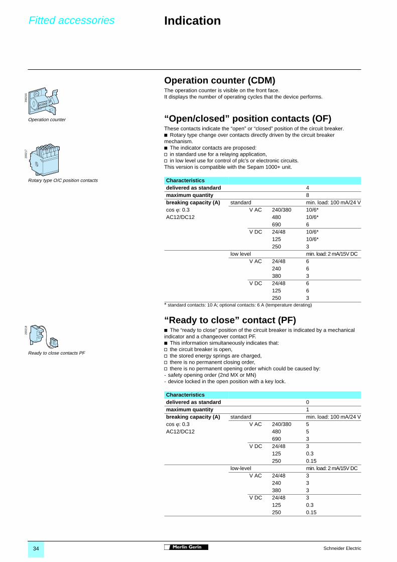
Operation counter (CDM)The operation counter is visible on the front face.It displays the number of operating cycles that the device performs.
“Open/closed” position contacts (OF)These contacts indicate the “open” or “closed” position of the circuit breaker.b Rotary type change over contacts directly driven by the circuit breaker mechanism.b The indicator contacts are proposed:v in standard use for a relaying application,v in low level use for control of plc’s or electronic circuits.This version is compatible with the Sepam 1000+ unit.
* standard contacts: 10 A; optional contacts: 6 A (temperature derating)
“Ready to close” contact (PF)b The “ready to close” position of the circuit breaker is indicated by a mechanical indicator and a changeover contact PF. b This information simultaneously indicates that:v the circuit breaker is open,v the stored energy springs are charged,v there is no permanent closing order,v there is no permanent opening order which could be caused by: - safety opening order (2nd MX or MN)- device locked in the open position with a key lock.
2002
16
Operation counter
2002
17
Rotary type O/C position contacts
2002
18
Ready to close contacts PF
Characteristicsdelivered as standard 4maximum quantity 8breaking capacity (A) standard min. load: 100 mA/24 Vcos ϕ: 0.3 V AC 240/380 10/6*AC12/DC12 480 10/6*
690 6V DC 24/48 10/6*
125 10/6*250 3
low level min. load: 2 mA/15V DCV AC 24/48 6
240 6380 3
V DC 24/48 6125 6250 3
Characteristicsdelivered as standard 0maximum quantity 1breaking capacity (A) standard min. load: 100 mA/24 Vcos ϕ: 0.3 V AC 240/380 5AC12/DC12 480 5
690 3V DC 24/48 3
125 0.3250 0.15
low-level min. load: 2 mA/15V DCV AC 24/48 3
240 3380 3
V DC 24/48 3125 0.3250 0.15

35Schneider Electric
Fitted accessories Locking / interlocking 0
Push button disablingThis transparent screen prevents access to the circuit breaker opening and closing push buttons.The device enables independent locking of the opening or closing button, it is often associated with an electrical motor (MCH).b Locking is achieved either by:v 2 screws,v 3 padlocks, not supplied,v sealing.
Locking of the circuit breaker in the “open” positionb The circuit breaker is locked in the “open” position by blocking the opening push button in the “pushed-in position”:v using padlocks: 1 to 3 padlocks not supplied,v using key locks: 1 or 2 different key locks supplied.b The key locks are of Profalux or Ronis type captive key, that becomes freeonce locked, and are offered according to the options, either:v 1 single key lock,v 1 single key lock mounted on the device + 1 identical one delivered, separately for interlocking with another device,v 2 different key locks for double locking.b Profalux and Ronis key locks are inter-compatible.
Cubicle door interlocking mechanismb The device allows CB operation only when the door is closed.
2002
19
Push button disabling
2002
00
Padlocking the circuit breaker in “open” position
2002
01
Key locking the circuit breaker in “open” position
2012
57
RONIS
2001
55E
2002
70
2002
69
Padlocking Sealing
Ics = 100% Icu
220/440
525
690
100
100
85
Icw 85kA/1s
DV2
cat.B
IEC 947-2
UTE VDE BS CEI UNE AS NEMA
EN 60947-2
50/60Hz
Ue
Icu
(V)
(kA)
Locking in the "open" position
Opening button
Closing button
Push button disabling
Main contact position indicator
Spring position indicator
Operation counter

36 Schneider Electric
Dimensions Full version 0
Phase distance between poles 145 mmcircuit breakers7P1-6307P1-125012P1-63012P1-1250
2001
06
2001
07
Phase distance between poles 185 mmcircuit breakers7P1-6307P1-12507P2-6307P2-125012P1-63012P1-125012P2-63012P2-125017P1-63017P1-125017P2-63017P2-1250
2001
11
2001
07
Phase distance between poles 240 mmcircuit breakers7P1-25007P2-25007P3-6307P3-12507P3-250012P1-250012P2-250012P3-63012P3-125012P3-250017P1-250017P2-250017P3-63017P3-125017P3-2500
2001
14
2001
15

37Schneider Electric
Dimensions Fixed version 0
Phase distance between poles 145 mmcircuit breakers7P1-6307P1-125012P1-63012P1-1250
2001
08
2001
09
Phase distance between poles 185 mmcircuit breakers7P1-6307P1-12507P2-6307P2-125012P1-63012P1-125012P2-63012P2-125017P1-63017P1-125017P2-63017P2-1250
2001
13
2001
09
Phase distance between poles 240 mmcircuit breakers7P1-25007P2-25007P3-6307P3-12507P3-250012P1-250012P2-250012P3-63012P3-125012P3-250017P1-250017P2-250017P3-63017P3-125017P3-2500
2001
16
2001
09


39Schneider Electric
Protection, monitoring control and metering
0
Presentation 40Protection chain 40Sepam 1000+ 41
Sepam 1000+ 43Base Unit 43Selection table 44Protection and metering 46Protection functions 48Sensors 50Monitoring and control 51Communication 52Software 53
Dimensions 54Sepam 1000+ 54
40 Schneider Electric
Presentation Protection chain 0
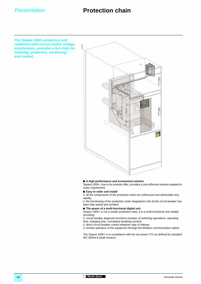
The Sepam 1000+ protection unit combined with current and/or voltage transformers, provides a full chain for metering, protection, monitoringand control.
bbbb A high performance and economical solutionSepam 1000+, due to its modular offer, provides a cost-effective solution adapted to every requirement.
bbbb Easy to order and installv all the components of the protection chain are referenced and deliverable very rapidly,v the functioning of the protection chain integrated in the Evolis circuit breaker has been fully tested and certified.
bbbb The power of a multi-functional digital unitSepam 1000+ is not a simple protection relay, it is a multi-functional unit notably providing:v circuit breaker diagnosis functions (number of switching operations, operating time, charging time, cumulative breaking current),v direct circuit breaker control whatever type of release,v remote operation of the equipment through the Modbus communication option.
The Sepam 1000+ is in compliance with the low power CTs as defined by standard IEC 60044-8 (draft version).
2011
65

41Schneider Electric
Presentation Sepam 1000+ 0
The Sepam 1000+ family of protection and metering units is designed for the operation of machines and electrical distribution networks of industrial installations and utility substations for all levels of voltage.It consists of complete, simple and reliable solutions, suited to the following applications:bbbb Protection of substations (incomers and feeders)bbbb Protection of transformersbbbb Protection of motorsbbbb Protection of generatorsbbbb Protection of busbars.
Sepam 1000+ series 20Suitable for common applications, Sepam 1000+ series 20 offers simplesolutions based on current or voltage metering.
The Sepam 1000+ series 20 S20, T20 and M20 current units cover applications such as the following:
b Protection of substation incomers and feeders against phase-to-phase and phase-to-earth short-circuits:v 16 IDMT tripping curves,v adjustable timer hold to detect recurrent faults,v switching of groups of setting to adapt to changes in the network configuration.b Protection of overhead lines with reclosers.b protection of transformers against overloads, with ambient temperature-compensated RMS thermal overload protection with 2 groups of settings for different ventilation operating rates.bbbb Protection of motorsv against overloads, with ambient temperature-compensated RMS thermal overload protection with a cold tripping curve that can be adjusted to fit motor characteristics,v against internal faults and load-related faults,v with motor starting condition monitoring and machine operation assistance.
The Sepam 1000+ series 20 B21 and B22 voltage units are suitable for the following situations:b Monitoring of network voltage and frequency.Loss of mains detection by rate of change of frequency protection for installations with local power generation.
Sepam 1000+ series 40Sepam 1000+ series 40, with its current and voltage metering capabilities, offershigh-performing solutions for more demanding applications.
Sepam 1000+ series 40 units perform the following functions in addition to those performed by Sepam 1000+ series 20:b Protection of networks with parallel incomers by directional protection.b Directional earth fault protection suitable for all earthing systems, impedant, isolated or compensated neutral.b All the necessary electrical measurements: phase and residual current, phase-to-neutral, phase-to-phase and residual voltage, frequency, power and energy, …b Comprehensive network diagnosis assistance: 20 seconds of disturbance recording, detailed history of the last 200 alarms, storage of contexts of the last 5 trips.b Adaptation of control functions by a logical equation editor.b Customization of alarm messages to fit each application, and/or in the user's language.
MT
1010
4M
T10
105
Sepam 1000+ selection guideSelectioncriteria
Series 20 Series 40
Measurements I U U I and U I and U I and USpecificprotectionfunctionsavailable
Loss of mains(ROCOF)
Directionalearth fault
Directionalearth fault and phaseovercurrent
Applications TypeSubstation S20 S40 S41 S42Transformer T20 T40 T42Motor M20 M41Generator G40Busbar B21 B22
Example: for motor protection and current and voltage measurements, your solution is the M41 type Sepam.

42 Schneider Electric
Presentation Sepam 1000+ 0
ModularityIn order to adapt to as many situations as possible and allow for subsequent upgrading of the installation, Sepam 1000+ may be functionally enhanced at any time by the addition of optional modules:b Logic input/output module with parameterizable program logic.b Communication module.b Temperature sensor module.b Analog output module.
SimplicitySimple to installb No constraints for integration in cubicles due to the compact size of the base units and remote installation of optional modules.b Universal auxiliary power supply.
Simple to commissionb All the functions are ready to use.b User-friendly, powerful PC setting software to utilize all the possibilities offered by Sepam 1000+.
Simple to operateWith the advanced UMI, all local operations are made easier by a clear, complete presentation of all the required information in your language.
Simple to maintainb Digital unit self-diagnosis and watchdog.b Switchgear diagnosis assistance functions to assess equipment condition and schedule preventive maintenance operations:v cumulative breaking current,v breaking device operating and charging time.
CommunicationModbus communication All the data needed for centralized management of your electrical network are available with the communication option based on the open, international Modbus protocol:b Measurement and diagnosis values.b Remote indication and time-tagging of events.b Remote control of the installation.b Remote setting of protection functions.b Reading of disturbance recording files.
Ethernet connection and WebserverSepam 1000+ can be connected to an Ethernet broadband network by Ethernet/Modbus communication gateways.With these gateways:b Sepam 1000+ can be integrated in any automation and supervisory system based on Modbus / TCP/IP multi-master protocol,b Web pages presenting information provided by Sepam may be consulted via an Internet/Intranet browser.
PowerLogic SystemSepam 1000+ is a component of PowerLogic System and may naturally be associated with SMS centralized industrial and commercial electrical network management software.
E57
754
Base unit, with various User/Machine Interface levels (UMI):b Basic UMIb Advanced UMI with graphic LCD screen.
Remote advanced UMI.
Logic input/output extension module (4l/4O or 10l/4O).
Connection module for Modbus communication network.
Temperature acquisition module for transformers or motors.
Analogue output module.
Software tools:b Sepam 1000+ parameters and protection settings, control logic customisationb Disturbance recording display.
14
5
6
7
2
3
1
2
3
4
5
6
7

43Schneider Electric
Sepam 1000+ Base unit 0
Sepam 1000+ is available with 2 different types of User-Machine Interface (UMI).
With the basic UMIb This unit offers a cost-effective response for: v installations not requiring local operation (control from a remote control and monitoring system) v replacement of electromechanical or analogic electronic protection devices.b Its UMI only includes:v 11 signal lamps,v 1 “reset” key to clear faults and to reset,v 1 connection port for the RS232 link with the PC.
Remote advanced UMI module (DSM303)b Thinner and offering the functional features of the advanced UMI, it allows convenient installation on the front panel of the cubicle in the most effective position for operation. b This module is connected to Sepam 1000+ with basic UMI using a prefabricated 2 m or 4 m cord (CCA772 or CCA774).b A mounting plate is available to mount Sepam 1000+ with basic UMI at the back of the cubicle control compartment (AMT840).
With the advanced UMIThis unit is an optimum response for local operation.b Its easy-to-read UMI includes: vvvv 11 signal lamps,v a “graphic” LCD display, enabling display of metering values, parameter settings and alarm and operation messages,vvvv a 9 key pad with 2 usage modes:- white keys for current operation:- displaying measurements, diagnosis information and alarms- blue keys for parameter and protection setting: access to device parameters and protection settings. Modification protected by passwordvvvv 1 connection port for the RS232 link with the PC.
(1) please consult us.
0591
20
Unit with basic UMI
0591
21
Unit with basic UMI and remote advanced UMI module
0591
22
Unit with advanced UMI
General characteristicsSupply voltage Sepam 1000+ series 20 Range
48 to 250 VDC and 110 to 240 VAC -20/+10%24 VDC -20/+50%
Supply voltage Sepam 1000+ series 4024 to 250 VDC and 110 to 240 VAC -20/+10%
Operating conditions according to IEC 60068from -25°C to +70°C
Operating languageEnglish/FrenchEnglish/SpanishEnglish/local language (1)

44 Schneider Electric
Sepam 1000+ Selection table 0
Sepam 1000+ series 20
Functions Type of SepamSubstation Transformer Motor Busbars
Protection ANSI code S20 T20 M20 B21 (5) B22Phase overcurrent 50/51 4 4 4Earth fault, sensitive earth fault 50N/51N 4 4 4Breaker failure 50BFNegative sequence / unbalance 46 1 1 1Directional phase overcurrent 67Directional earth fault 67N/67NCActive overpower 32PThermal overload 49RMS 2 2Phase undercurrent 37 1Locked rotor, excessive starting time 48/51LR 1Starts per hour 66 1Positive sequence undervoltage 27D/47 2 2Remanent undervoltage 27R 1 1Phase-to-phase undervoltage 27 2 2Phase-to-neutral undervoltage 27S 1 1Phase-to-phase overvoltage 59 2 2Neutral voltage displacement 59N 2 2Negative sequence overvoltage 47Overfrequency 81H 1 1Underfrequency 81L 2 2Rate of change of frequency 81R 1Recloser (4 cycles) 79 v
Thermostat / Buchholz v
Temperature monitoring (8 RDTs, 2 set points per RTD) 38/49T v v
MeteringPhase current I1, I2, I3 RMS, residual current Io b b b
Average current I1, I2, I3, Peak demand phase currents b b b
Voltage U21, U32, U13, V1, V2, V3, Residual voltage Vo b b
Positive sequence voltage Vd / rotation direction b b
Negative sequence voltage ViFrequency b b
Active and reactive power P and Q, Peak demand P and Q, Power factorActive and reactive energy (±Wh, ±VARh)Temperature measurement v v
Network and machine diagnosisTripping current I1, I2, I3, Io b b b
Tripping contextUnbalance ratio / negative sequence current li b b b
Phase angle ϕo, ϕ1, ϕ2, ϕ3Disturbance recording b b b b b
Thermal capacity used b b
Remaining operating time before overload tripping b b
Waiting time after overload tripping b b
Running hours counter / operating time b b
Starting current and time b
Start inhibit time delay, number of starts before inhibition b
Switchgear diagnosisCumulative breaking current b b b
Trip circuit supervision v v v
Number of operations, operating time, charging time v v v
CT / VT supervisionControl and monitoringCircuit breaker / contactor control (2) v v v v v
Logic discrimination v v v
Switching of setting groups b (3) b (3) b (3)
Logic equation editorAdditional modules8 temperature sensor outputs - MET148-2 module v v
1 low level analog output - MSA141 module v v v v v
Logic inputs and outputs - MES108 module (4l/4O) or MES114 (10l/4O) v v v v v
RS485 interface - ACE949-2 (2-wire) or ACE959 (4-wire) module v v v v v
b standard,v according to parameter setting and MES108, MES114 or MET148-2 input/output module options
(2) for shunt trip unit or undervoltage release coil(3) exclusive choice between logic discrimination and switching from one 2-relay group of settings to another 2-relay group(5) performs B20 type functions.

45Schneider Electric
Sepam 1000+ Selection table 0
Sepam 1000+ series 40
Functions Type of SepamSubstation Transformer Motor Generator
Protection ANSI code S40 S41 S42 T40 T42 M41 G40Phase overcurrent 50/51 4 4 4 4 4 4 4Voltage-restrained phase overcurrent 50V/51V 1Earth fault, sensitive earth fault 50N/51N 4 4 4 4 4 4 4Breaker failure 50BF 1 1 1 1 1 1 1Negative sequence / unbalance 46 2 2 2 2 2 2 2Directional phase overcurrent 67 2 2Directional earth fault 67N/67NC 2 2 2 2Directional active overpower 32P 1 1 1 1Directional reactive overpower 32Q/40 1 1Thermal overload 49RMS 2 2 2 2Phase undercurrent 37 1Locked rotor, excessive starting time 48/51LR 1Starts per hour 66 1Positive sequence undervoltage 27D/47 2Remanent undervoltage 27R 1Phase-to-phase undervoltage 27 (6) 2 2 2 2 2 2 2Phase-to-neutral undervoltage 27S (6) 2 2 2 2 2 2 2Overvoltage 59 (6) 2 2 2 2 2 2 2Neutral voltage displacement 59N 2 2 2 2 2 2 2Negative sequence overvoltage 47 1 1 1 1 1 1 1Overfrequency 81H 2 2 2 2 2 2 2Underfrequency 81L 4 4 4 4 4 4 4Rate of change of frequency 81RRecloser (4 cycles) 79 v v v
Thermostat / Buchholz v v
Temperature monitoring (8 RDTs, 2 set points per RTD) 38/49T v v v v
MeteringPhase current I1, I2, I3 RMS, residual current Io b b b b b b b
Average current I1, I2, I3, Peak demand phase currents b b b b b b b
Voltage U21, U32, U13, V1, V2, V3, Residual voltage Vo b b b b b b b
Positive sequence voltage Vd / rotation direction b b b b b b b
Negative sequence voltage Vi b b b b b b b
Frequency b b b b b b b
Active and reactive power P and Q, Peak demand P and Q, Power factor b b b b b b b
Active and reactive energy (±Wh, ±VARh) b b b b b b b
Temperature measurement v v v v
Network and machine diagnosisTripping current I1, I2, I3, Io b b b b b b b
Tripping context b b b b b b b
Unbalance ratio / negative sequence current li b b b b b b b
Phase angle ϕo, ϕ1, ϕ2, ϕ3 b b b b b b b
Disturbance recording b b b b b b b
Thermal capacity used b b b b b
Remaining operating time before overload tripping b b b b b
Waiting time after overload tripping b b b b b
Running hours counter / operating time b b b b b
Starting current and time b
Start inhibit time delay, number of starts before inhibition b
Switchgear diagnosisCumulative breaking current b b b b b b b
Trip circuit supervision v v v v v v v
Number of operations, operating time, charging time v v v v v v v
CT / VT supervision b b b b b b b
Control and monitoringCircuit breaker / contactor control (2) b b b b b b b
Logic discrimination v v v v v v v
Switching of setting groups b b b b b b b
Logic equation editor b b b b b b b
Additional modules8 temperature sensor outputs - MET148-2 module vvvv (4) vvvv (4) vvvv (4) vvvv (4)
1 low level analog output - MSA141 module v v v v v v v
Logic inputs and outputs - MES108 module (4l/4O) or MES114 (10l/4O) v v v v v v v
RS485 interface - ACE949-2 (2-wire) or ACE959 (4-wire) module v v v v v v v
b standard,v according to parameter setting and MES108, MES114 or MET148-2 input/output module options
(2) for shunt trip unit or undervoltage release coil(4) 2 modules possible(6) exclusive choice, phase-to-neutral or phase-to-phase voltage for each of the 2 relays

46 Schneider Electric
Sepam 1000+ Protection and metering 0
Current protection functionsPhase overcurrent (ANSI 50/51)4 three-phase protection functions against phase-to-phase short circuits,set independently.b Adjustable timer hold, for detection of restriking faults. b Switching function between 2 sets of settings.b Logic discrimination
Voltage-restrained phase overcurrent (ANSI 50V/51V)Three-phase protection against phase-to-phase short-circuits, suited to generator protection, for which the tripping set point is adjusted according to the voltage.b Adjustable timer hold, for detection of restriking faults. b Switching function between 2 sets of settings.
Earth fault (ANSI 50N/51N or 50G/51G)4 protection functions against earth faults, set independently.b Adjustable timer hold, for detection of restriking faults. b 2nd harmonic restraint, for stability on transformer energizing.b Switching function between 2 sets of settings.b Logic discrimination
Breaker failure (ANSI 50 BF)Backup protection that delivers a tripping order to the upstream or adjacent breakers should the breaker that is being commanded fail to trip, detected by measurement of the phase current after a tripping order.
Negative sequence / unbalance (ANSI 46)Protection against phase unbalance.
Directional current protection functionsDirectional phase overcurrent (ANSI 67)2 three-phase directional protection functions against phase-to-phase short circuits, set independently.b Adjustable timer hold, for detection of restriking faults.b Switching function between 2 sets of settings.b Active only for the chosen (line or busbar) short circuit current directionb Insensitive to the loss of measurement voltage.
Directional earth fault (ANSI 67N/67NC)2 directional protection functions against earth faults, set independently. Can operate on impedant, isolated or compensated neutral grounding systems.b 2 types of characteristics:v type 1, according to Io projection,v type 2, according to Io magnitude.b Switching function between 2 sets of setting.b Logic discrimination.
Directional power protection functionsDirectional active overpower (ANSI 32P)1 protection function activated if the active power flowing in one direction or the other according to the application (supplied or absorbed) is greater than the set point.
Directional reactive overpower (ANSI 32Q/40)1 protection function used to detect synchronous machine (generator or motor) field loss.
Machine protection functionsThermal overload (ANSI 49)b 2 protection functions against thermal damage due to an overload,to take account of:v changes in ventilation mode of transformers,v the thermal withstand of motors with locked rotor.b The calculation of equipment heat rise takes account of:v RMS value of currents,v negative sequence current,v ambient temperature,v heating and cooling curves. b Each function includes 2 thresholds:v 1 adjustable threshold for tripping,v 1 adjustable threshold for alarm.
Meteringb Display of operational measurements on the UMI display.b This information can be obtained remotely:v by adding the analog output MSA141together with the factory-built cords,v by adding the communication function.
0587
59
MSA141 analog output

47Schneider Electric
Sepam 1000+ Protection and metering 0
Phase undercurrent (ANSI 37)Protection of pump motors against working with no load, pump not primed.
Locked rotor / Excessive starting time (ANSI 48/51LR) b Control of the duration of motor starting.b Detection of locked rotor in steady state.
Start per hour (ANSI 66)Inhibition of motor starting in the case of too frequent starts, to avoid temperature rise.
Thermostat, BuchholzProtection of transformers against internal faults detected by integrated devices.
Temperature monitoring (ANSI 38/49T)Protection of transformers and motors equipped with temperature sensors. 1 alarm threshold and 1 tripping threshold on each temperature measured by sensors.b This protection requires the 8 temperature sensor inputs MET148-2 module:v Sepam 1000+ series 20: 1 module / 8 sensors max,v Sepam 1000+ series 40: 2 modules / 16 sensors max.b The module is connected to the Sepam unit by a cord of length 0.6 m, 2 m, or 4 m (CCA770 - CCA772 - CCA774).
Positive sequence undervoltage (ANSI 27D/47)b Protection of motors against incorrect operation due to insufficient or unbalanced voltage.b Detection of phase rotation.
Remanent undervoltage (ANSI 27R)Control of the disappearance of remanent voltage provided by rotating machine after circuit opening.
Voltage protection functionsOvervoltage (ANSI 59) 2 protection functions against overvoltage situations. Can be used for automatic functions (transfer, load shedding).Sepam 1000+ series 20: operates with phase-to-phase voltage,Sepam 1000+ series 40: operates with phase-to-phase or phase-to-neutral voltage.
Undervoltage (ANSI 27)2 protection functions against undervoltage situations. Can be used for automatic functions (transfer, load shedding). Operates with phase-to-phase or phase-to-neutral voltage.
Neutral voltage displacement (ANSI 59N)2 protection functions against earth faults on isolated network, by measurement of neutral voltage displacement.
Negative sequence overvoltage (ANSI 47)Protection against phase unbalance resulting from distant faults, a phase inversion or unbalanced power supply.
Frequency protection functionsOverfrequency (ANSI 81H) and underfrequency (ANSI 81L)Detection of variances with respect to the rated frequency, to monitor the quality of supply. May be used for overall tripping or for load shedding.
Rate of change of frequency (ANSI 81R)Detection of loss of mains by calculation of the frequency variation speed.Used in substations with generator that can be run in parallel with the mains.
Recloser (ANSI 79)Automatic control to reclose the circuit breaker after tripping on a spurious fault on a line (4 reclosing cycles can be set).
0587
60
MET148-2 temperature sensor inputs

48 Schneider Electric
Sepam 1000+ Protection functions 0
Setting ranges
(1) tripping as of 1.2 Is.(2) with ACE 990 interface for core balance CT with ratio n of 50 to 1500 turns.(3) table of In values in Amps: 25, 50, 100, 125, 133, 200, 250, 320, 400, 500, 630, 666, 1000, 1600, 2000, 3150.(4) on series 40 only.
General settings (set in the general settings menu)Frequency 50 Hz or 60 HzCurrent sensor CT 1 A or 5 A
rated current InNumber (I1, I2, I3) or (I1, I3)1 A to 6250 A
LPCTrated current In (3)
Number (I1, I2, I3)25 A to 3150 A
Residual current Io sensor CSH120/CSH200rated current Ino 2 A, 20 A or 5 A (4)
Core balance CT (2) + ACE990rated current Ino 1 A to 6250 ATC 1 A or 5 A + CSH30rated current Ino 1 A to 6250 A TC 1 A or 5 A + CSH30 sensitivity x10 (4)
rated current Ino 1 A to 6250 A (Ino = In/10)Voltage sensor Primary rated voltage Unp 220 V to 250 kV
VT : 100, 110, 115, 120 V V1, V2, V3(Uns) U21, U32
U21VT : 200, 230 V V1, V2, V3
Functions Settings Time delaysPhase overcurrent and voltage-restrained phase overcurrent
Tripping curve Reset timeDefinite time DTSIT, LTI, VIT, EIT, UIT (1) DTRI DTIEC: SIT/A, LTI/B, VIT/B, EIT/C DT or IDMTIEEE: MI (D), VI (E), EI (F) DT or IDMTIAC: I, VI, EI DT or IDMT
Is set point 0.1 to 24 In Definite time Inst.: 0.05 s to 300 s0.1 to 2,4 In IDMT 0.1 s à 12.5 s to 10 Is
Reset time Definite time (DT: timer hold) Inst.: 0.05 s to 300 sIDMT (IDMT: reset time) 0.5 s to 20 s
Earth faultTripping curve Reset time
Definite time DTSIT, LTI, VIT, EIT, UIT (1) DTRI DTIEC: SIT/A,LTI/B, VIT/B, EIT/C DT or IDMTIEEE: MI (D), VI (E), EI (F) DT or IDMTIAC: I, VI, EI DT or IDMT
Iso set point 0.1 to 15 Ino Definite time Inst.: 0.05 s to 300 s0.1 to 1 Ino IDMT 0.1 s to 12.5 s at 10 Iso
Reset time Definite time (DT: timer hold) Inst.: 0.05 s to 300 sIDMT (IDMT: reset time) 0.5 s to 20 s
Breaker failurePresence of current 0.2 to 2 InOperating time 0.05 s to 30 sNegative sequence / unbalance
Definite time 0.1 to 5 Ib 0.1 s to 300 sIDMT 0.1 to 0.5 Ib (Schneider Electric) 0.1 to 1Ib (IEC, IEEE) 0.1 s to 1 sTripping curve Schneider Electric
IEC: SIT/A, LTI/B, VIT/B, EIT/C (4)
IEEE: MI (D), VI (E), EI (F) (4)
Directional phase overcurrentTripping curve Reset time
Definite time DTSIT, LTI, VIT, EIT, UIT (1) DTRI DTIEC: SIT/A, LTI/B, VIT/B, EIT/C DT or IDMTIEEE: MI (D), VI (E), EI (F) DT or IDMTIA: I, VI, EI DT or IDMT
Is set point 0.1 to 24 In Definite time Inst.: 0.05 s to 300 s0.1 to 2.4 In IDMT 0.1 s to 12.5 s at 10 Is
Reset time Definite time (DT: timer hold) Inst.: 0.05 s to 300 sIDMT (IDMT: reset time) 0.5 s to 20 s
Characteristic angle 30°, 45°, 60°

49Schneider Electric
Sepam 1000+ Protection functions 0
Setting ranges
Reminder: In current, Unp rated voltage and Ino current are general settings that are made at the time of Sepam commissioning. They are given as the values on the measurement transformer primary windings.In is the current sensor rated current (CT rating) (adjustable from 1 A to 6250 A).Unp is the rated phase-to-phase voltage of the voltage sensor primary windings (adjustable from 220 V to 250 kV).Ino is the core balance CT current rating.Ib is the current which corresponds to the equipment power rating, adjustable from 0.4 to 1.3 In.The current, voltage and frequency values are set by direct entry of the values (resolution: 1 A, 1 V, 1 Hz, 1°C or F).
Functions Settings Time delayDirectional earth fault, according to Io projection (type 1)
Characteristic angle -45°, 0°, 15°, 30°, 45°, 60°, 90°Iso set point 0,1 to 15 Ino Definite time Inst.: 0.05 s to 300 sVso set point 2 to 80 % of UnMemory time Tomem duration 0; 0.05 s to 300 s
Vomem validity set point 0; 2 to 80 % of UnDirectional earth fault, according to Io magnitude (type 2)
Characteristic angle -45°, 0°, 15°, 30°, 45°, 60°, 90°Tripping curve Reset time
Definite time DTSIT, LTI, VIT, EIT, UIT (1) DTRI DTIEC, SIT/A,LTI/B, VIT/B, EIT/C DT or IDMTIEEE: MI (D), VI (E), EI (F) DT or IDMTIAC: I, VI, EI DT or IDMT
Iso set point 0.1 to 15 Ino Definite time Inst.: 0.05 s to 300 s0.1 to 1 Ino IDMT 0.1 s to 12.5 s at 10 Iso
Vso set point 2 to 80 % of UnReset time Definite time (DT: timer hold) Inst.: 0.05 s to 300 s
IDMT (IDMT: reset time) 0.5 s to 20 sDirectional active overpower
1 to 120 % of SnDirectional reactive overpower
5 to 120 % of SnThermal overload Rate 1 Rate 2
Negative sequence factor 0 - 2.25 - 4.5 - 9Time constant Heat rise T1: 5 to 120 mn T1: 5 to 120 mn
Cooling T2: 5 to 600 mn T2: 5 to 600 mnAlarm and trip set points 50 to 300 % of rated thermal capacity usedCold curve change factor 0 to 100 %Rate change condition by logic input
by Is setting from 0.25 to 8 IbMaximum equipment temperature 60 to 200 ˚CPhase undercurrent
0.15 to 1 Ib 0.05 s to 300 sExcessive starting time/locked rotor
0.5 Ib to 5 Ib ST start time 0.5 s to 300 sLT and LTS time delays 0.05 s to 300 s
Starts per hourStarts per period 1 to 60 Period 1 to 6 hConsecutive starts 1 to 60 time between starts 0 to 90 mnTemperature (RTDs)
Alarm and trip set points 0 to 180 °C (or 32 to 356 °F)Positive sequence undervoltage
15 to 60 % of Unp 0.05 s to 300 sRemanent undervoltage
5 to 100 % of Unp 0.05 s to 300 sPhase-to-phase undervoltage
5 to 100 % of Unp, 5 to 100 % of Vnp (4) 0.05 s to 300 sPhase-to-neutral undervoltage
5 to 100 % of Vnp 0.05 s to 300 sOvervoltage phase-to-phase phase-to-neutral (4)
50 to 150 % of Unp 50 to 150 % of Vnp 0.05 s to 300 sNeutral voltage displacement
2 to 80 % of Unp 0.05 s to 300 sNegative sequence overvoltage
1 to 50 % of Unp Inst.: 0.05 s to 300 sOverfrequency
50 to 53 Hz or 60 to 63 Hz 0.1 s to 300 sUnderfrequency
45 to 50 Hz or 55 to 60 Hz 0.1 s to 300 sRate of change of frequency
0.1 to 10 Hz/s Inst.: 0.15 s to 300 s
50 Schneider Electric
Sepam 1000+ Sensors 0
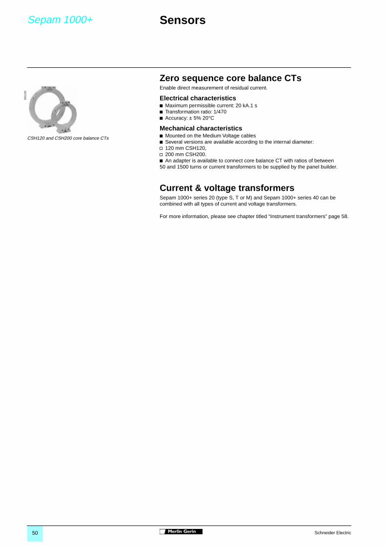
Zero sequence core balance CTsEnable direct measurement of residual current.
Electrical characteristicsb Maximum permissible current: 20 kA.1 sb Transformation ratio: 1/470b Accuracy: ± 5% 20°C
Mechanical characteristicsb Mounted on the Medium Voltage cablesb Several versions are available according to the internal diameter:v 120 mm CSH120,v 200 mm CSH200.b An adapter is available to connect core balance CT with ratios of between 50 and 1500 turns or current transformers to be supplied by the panel builder.
Current & voltage transformersSepam 1000+ series 20 (type S, T or M) and Sepam 1000+ series 40 can be combined with all types of current and voltage transformers.
For more information, please see chapter titled “Instrument transformers” page 58.
E61
192
CSH120 and CSH200 core balance CTs

51Schneider Electric
Sepam 1000+ Monitoring and control 0
Compositionb The Sepam 1000+ base unit has 4 relay outputs.b The extension of input/output resources for Sepam 1000+ uses an additional. module, available in 2 versions: v 4 logic inputs/4 relay outputs: MES108,v 10 logic inputs/4 relay outputs: MES114. This module is installed on the rear panel of the basic unit.
FunctionsThe availability of the following functions depends on the type of Sepam 1000+ unit and on its logic input/output resources.
Circuit breaker controlb Opening, closing and inhibit closing (ANSI 69) of circuit breaker equipped with undervoltage release coil or shunt trip coil according to information: v from the protection functions and the recloser,v from remote control system,v from switchgear diagnosis functions.
Trip circuit supervisionDetects trip circuit faults and circuit breaker position discrepancy.
Logic discrimination (SSL) (ANSI 68)Quick and selective tripping of phase overcurrent protection and earth fault protection by logical blocking of the upstream protection by the downstream protection.A safeguard device ensures the functioning of the protection device in the case of failure of the blocking link.
Latching / acknowledgement (ANSI 86)Latching of output relays can be set. The latched closing orders are stored in memory and must be acknowledged before the device is put back in service.
Annunciation (ANSI 30)b Alarms are detected and indicated:v by lights on the front panel,v by messages on the display,v by relay outputs according to parameter settings, v remotely by the communication interface.
Program logic parameter settingA boolean equation editor enables logical grouping of protection function outputs and logic inputs by the AND, OR, NO functions in order to supply new states that can activate a logic output, a signal lamp, an alarm message or a remote indication.
Watchdog
Output relay testing
CharacteristicsLogic inputsb Independent inputs, free of voltage.b DC input voltage: 24 to 250 Vdc.b Consumption: 3 mA typically.
Relay outputsb AC or DC voltage: 24 to 220 Vdc and 100 Vac to 240 Vac.b 3 control outputs: continuous rating 8 A.b 5 indication outputs: continuous rating 2 A.
0587
57
MES108, 4 inputs / 4 outputs
0587
56
MES114, 10 inputs / 4 outputs

52 Schneider Electric
Sepam 1000+ Communication 0
FunctionVia the remote control and monitoring system, this allows the remote operation of equipment, with a Modbus protocol.
Remote monitoring by reading datab Meteringb Value of protection settingsb Status of protections and Sepam 1000+ functions b Status of logic inputsb Time tagged eventsb Disturbance recordings.
Remote controlb Opening and closing of the switchgear from the supervisor workstation.b Activating of Sepam 1000+ functions.b Two modes are available: v “direct” or,v “select before operate”.
Remote setting of protections
Setting up the Modbus networkb Sepam 1000+ is connected to the communication network via a communication interface:v ACE949-2, for connection to a RS 485 2-wire network,v ACE959, for connection to a RS 485 4-wire network.A 3 m long prefabricated cord (CCA612) is necessary to connect the remote communication interface to the Sepam base unit.
A 12 Vdc or 24 Vdc power supply is required to supply the communication interfaces.
b RS 485 2-wire converters are available for signal conversion, line polarization and 12 Vdc supply of the Sepam communication interfaces:v ACE909-2, RS 485 / RS 232 converter,v ACE919, RS 485 / RS 485 converter.b Cabling between these elements must be provided with a shielded cable which is not supplied.
0587
61
ACE949-2, communication interface to RS485 2-wire network
2004
86E
N
Network example
interface
convertercommunication
Merlin Gerin Merlin GerinMerlin Gerin
CharacteristicsType of transmission asynchronous serialProtocol Modbus slaveRate 4800, 9600, 19200, 38400 baudsElectrical interface 2-wire or 4-wire differentiel, standard EIA RS 485Maximum distance 250 mNumber of bus suppliedSepam units on one line
25
Number of masters 1Response time less than 15 ms

53Schneider Electric
Sepam 1000+ Software 0
Expert User Machine Interface SoftwareThe SFT2841 software gives access to all Sepam 1000+ functions, with all the user friendliness and comfort offered by a Windows type environment.
Operationb 2 modes are available:v not connected to Sepam 1000+ for initial preparation of parameters and protection settings,v connected to Sepam 1000+, to get optimum use of its resources and have all the functions available in disconnected mode and additional local operation functions.
Parameter and protection settings The creation of files containing all parameters and protection settings forSepam 1000+ is possible without being connected to the unit.
b Amongst other things the software enables:v the full setting of Sepam 1000+ and adjustment of protection functions,v customising of the control logic,v customising of identification labels for signal lamps,v management of parameters and settings files: saving, comparison, printing.
Local operationb Connected to Sepam 1000+, the software enables access to the following information:v all metering and diagnosis values,v parameters and protection settings,v past history of alarms with time of occurrence,v logical states of inputs, outputs and signal lamps.
b And the following operations:v uploading and downloading of parameters and settings files,v recovery and saving of disturbance recordings,v acknowledgement of active alarms and resetting of Sepam 1000+ after tripping.
Disturbance records display softwareThe SFT2826 software allows display, analysis and printing of disturbance records made by Sepam units.
Implementationbbbb Required configurationv Microsoft Windows 95/98/NT4.0,v PC compatible computer with Pentium 133 MHz processor or more,v 32 Mb of RAM (64 Mb of RAM with Windows NT 4.0),v 32 Mb free on the hard disk.
bbbb Available in kit form comprisingv 1 CD-ROM including:- the SFT2841 expert UMI software,- the SFT2826 disturbance records display software.v 1 RS232 PC / Sepam 1000+ connection cord.
5051
EN
SFT2841: phase overcurrent protection setting screen
2004
78
SFT2826: display of a disturbance record

54 Schneider Electric
Dimensions Sepam 1000+
Sepam 1000+ base unit with connectorsand additional inputs/outputs module
Remote advanced UMI module
Remote additional modules
Communication interfaces
Zero sequence core balance CT
DE
5500
0
CSH120/CSH200dimensions (mm) A B D ECSH120 120 164 44 190CSH200 200 256 46 274
98.5
14425162
117
176
222
129
101 162
202
144
88
144
88
30
144
E
88
B
30
D
29
82
60
88
72
ø30
øA
MET148-2 MSA141
ACE949-2 ACE959
CSH30 CSH120 / CSH200

55Schneider Electric
0


57Schneider Electric
Instrumenttransformers
0
Instrument transformers 58
Presentation 58Dimensions 59

58 Schneider Electric
Instrumenttransformers
Presentation 0
Current transformers
Conventional 1 A or 5 A current transformers have primary current values from 50 A to 2500 A. Sepam can be combined with all types of current transformers.
Schneider has a standardized list of Cts available on order form.
Voltage transformers
They supply voltage for:b Measuring, metering and monitoring devices.b Relays or protective devices.b Auxiliary LV sources for various types of switchgear, all the devices are protected and isolated from MV.
They are installed in fixe or withdrawable position with or without fuse.
They are of the cast resin type.The core and windings are overcast in epoxy resin, providing electrical insulation and excellent mechanical strength.
They include the following models:b With on insulated MV terminal, for connection between neutral and phase conductors in 3-phase systems with MV plug-in-fuses.b With two insulated MV terminals, for connection to single-phase systems or between phase conductors in 3-phase systems.
Schneider has a standardized list of Vts available on order form.
0587
31N
0587
32N
0587
33N
ARJA1 ARJP2 ARJP3
0587
34N
0587
35N
VRQ3 VRS3without fuses with fuses

59Schneider Electric
Instrumenttransformers
Dimensions 0
Type ARJA1
MT
2502
5
MT
2502
6
MT
2502
7
Weight kg 30
308
148160
20 24
0
GROUPE SCHNEIDER
secondary and M6 screw type
earthing terminals 225
200
175
260
40
184
120
M 12 x 23
N°4 holes Ø 11
P2
P1
70
70
58
6060
45
Details of primary bars
Ipn
1800 ÷ 2500 A1300 ÷ 1600 A
IpnIpn
800 ÷ 1250 A
Type ARJP3
MT
2502
2
MT
2502
3
MT
2502
4
Weight kg 22
322
137185
5
20 240
270
72
NUOVA MAGRINI GALILEO
secondary and earthing terminalsM6 screw type
100
148
120
175
295
184120
M 12 x 23
N°4 slotØ 11
P1
P2
Type VRS3
MT
2502
8
MT
2502
9
MT
2503
0
Weight kg 17
141.5 116.5
232.5
374
233
230
260
Ø 2
0.6
option:secondary plastic box 60
49
M4 x 6
secondary and earthing terminals M6
100
100
125
82
M6 x 8


61Schneider Electric
Earthing switch 0
Earthing switch 62
Earthing 62Indication and interlocking 63Dimensions 64

62 Schneider Electric
Earthing switch Earthing 0
FunctionThis device is used to earth and short circuit the cable ends before work is performed on the cable compartment.
Compositionb The earthing switch includes:v an operating mechanism box to be mounted on the front face of the cubicle,v a power circuit unit with a fast acting closing mechanism independent of the operator.
b The link between the 2 devices will have a length depending of the depth of the cubicle. A drawing will define the installation conditions which allow the panel builder to design the rods.
Note: If the 95 kV dielectric withstand is required for 200 mm earthing switch phase distance,it is necessary to add field deflectors on the connections (see installation guide for instructions).
b Mechanical interlock with the circuit breaker to prevent:v to draw in the circuit breaker if the earthing switch is closed,v to close the earthing switch if the circuit breaker is not opened and drawn out,v this interlock is realised with Profalux or Ronis key,v a drawing is showing the mechanical link to be manufactured and installed by the panel builder.
Note: If mechanical interlock with the front and/or rear plate of the cable compartment to prevent access to the cables under voltage are required ; the design is under the responsability of the panel builder, according to the needs.
2001
71
Operating mechanism
2001
73
Power circuit unit
2011
99
Power circuit unit with field deflectors
2004
89
Electrical characteristics according to IEC 60 129phase distance mm 160 200 240rated voltage (kV) 7.2 12 7.2 12 17.5 7.2 12 17.5rated short time withstand current 1s
Ik (kA) 31.5 50 40 31.5 50 50 40
rated short time withstand current 4s
Ik (kA) 31.5 31.5 31.5
rated short circuit making current
Ip (kA) 2.5 Ik 2.5 Ik 2.5 Ik

63Schneider Electric
Earthing switch IndicationInterlocking 0
Voltage Presence Indicator Systemb This system combined with the capacitive divider insulator integrated as standard in the earthing system provides an indication of the voltage in the phases of the main circuit. b It is mounted on the front of the earthing operating mechanism.b It is available for two voltage ranges, in conformity with standard IEC 61958:v 3.2 to 7.2 kV,v 7.2 to 17.5 kV.
Open/closed position contactsA series of 6 auxiliary contacts indicates the open/closed position of the earthing switch.
Mechanical earthing switch lockingThis function enables the earthing switch to be locked in its open or closed position by adding 1 or 2 key locks.
b Several configurations are available:v locked closed by 1 key lock + locked open by 1 key lock,v locked closed by 2 key locks,v locked open by 2 key locks.
A mechanical adaptation kit is delivered to fit the various key locks which are not supplied.
Electromechanical interlockingof the earthing switchThis function is achieved using a coil which blocks switching operation when it is not supplied power. When energised it releases the earthing switch which can then be closed.The system is available in several versions according to the supply voltage: 24 VDC - 48 VDC - 110 VDC - 220 VDC.
Earthing switch operating leverThis is identical to the one supplied for the circuit breaker racking truck. It allows the earthing switch to be operated.
2002
23
Voltage presence indicator unit
2011
8520
1186
Key locking
2011
8420
0160
Operating lever
Characteristicsdelivered as option 6maximum quantity 11breaking capacity V AC 240 15 Acos ϕ: 0.3 380 10 A
480 10 A600 6 A
V DC 48125250 3 A500 0.5 A

64 Schneider Electric
Earthing switch Dimensions 0
Power circuit unit
Operating mechanism
2013
2820
1329
2013
2620
1327
ES phase distances 160 200 240dimensions (mm)A 530 660 860B 270 335 435C 506 636 836
356,5
90
291
217
A64
B
C
177
75
36
202
3
19
83
182207,5
79,5
338,5
13
394,5
6275
121,5
206.5
299

65Schneider Electric
0


67Schneider Electric
Switchboardcomponents
0
Switchboard components 68Operation 68
Cubicle components 70Indication, support, heating 70

68 Schneider Electric
Switchboardcomponents
Operation 0
Fixed coupling linkAllows a standard incomer/feeder cubicle to be transformed into a busbar riser cubicle by short circuiting the top and bottom terminals of the cradle.b This offer is exclusively available in the form of drawings proposed in the installation manual.b This unit comprises 1 bridge/phase and is easily installable by the operator on the cradle bushing fingers.
Withdrawable coupling linkEnables bridging in an existing cubicle of the upstream and downstream circuit in the cubicle. It is installed in place of the withdrawable circuit breaker in the cradle.b It includes:v a device to lock in the racked-in position using padlocks,v an auxiliary PAF contact delivered separately for installation on the cradle:it indicates that the truck is well mechanically racked in.
Busbar earthing truckThis device is a safety accessory used in place of the withdrawable breaker in order to earth the busbars.b Possibility of locking by padlocks in the draw-in position.
2001
44
Fixed coupling link
2001
45
Withdrawable coupling link
2001
43
Busbar earthing truck
Electrical characteristicsIr A 1250 2500Ik kA 31.5 40tk s 3 3
Electrical characteristicsIk kA 25 31.5 40tk s 3 3 3Ir A 1250 1250 2500phase distance mm 145 185 240
Electrical characteristicsUr kV 17.5 17.5 12 17.5Ik kA 25 31.5 40 40tk s 3 3 3 3phase distance mm 145 185 240 240

69Schneider Electric
Switchboardcomponents
Operation 0
Extraction tableEnables the circuit breaker to be taken out of the cubicle and to handle it during maintenance operations or during cubicle manufacturing.b A height adjustment device using screw/bolts allows the height to be adjusted to- 20 mm/ + 200 mm.b A latching device is provided between the extraction table and the cradle.
Operating leverThis enables all operations to be carried out on the circuit breaker racking truck as well as on the earthing switch.
Busbar connection coverThis set of 3 insulating covers enables improved dielectric withstand at the busbar connections in the cubicle.
2001
77
Extraction table
2001
60
Operating lever
2001
83
Busbar connection cover

70 Schneider Electric
Cubiclecomponents
IndicationSupportHeating 0
Capacitive divider insulator setb This Voltage Presence Indicator System (VPIS) includes:v the insulators themselves providing mechanical support and insulation up to v 17.5 kV; these insulators also integrate capacitors capable of supplying a voltage potential signal,v a voltage indication unit with light to indicate the voltage presence on the front panel covering 2 voltage ranges:- 3.2 to 7.2 kV,- 7.2 to 17.5 kV.
Support insulatorb This enables mechanical support and voltage insulation at 12 and 17.5 kV.b Application for busbar and cable fixing and support.
Door handleb Enables the front panel door of the cubicle to be closed. Several versions are available:v with triangular key lock,v with Ronis or Profalux type key lock.
Handle for panel removalb Two handles are needed to remove each panel fitted on a MV cubicle.
Sight windowsb The hight resistance plastic windows situated on the panel or the door, allows you to see inside a cubicle.
Heating elementb This can be used for 2 reasons:v heating the cubicle when the ambient temperature is too low,v avoiding the formation of condensation.b Delivered with its support and without a thermostat.
2011
6420
0136
2001
8220
1180
2012
5820
0244
Heating element

71Schneider Electric
Personal notes

72 Schneider Electric
Personal notes

AM
TE
D30
0015
EN
/3
©
200
2 S
chne
ider
Ele
ctric
- A
ll rig
hts
rese
rved
Schneider Electric Industries SAS
Postal address:MV DepartmentF-38050 Grenoble Cedex 9Tel.: +33 (0)4 76 57 60 60htt:/www.schneiderelectric.com
RCS Nanterre B 954 503 439
As standards, specifications and designs change from time to time, please ask for confirmation of the information given in this publication.
This document has been printed on ecological paper
Publishing: Schneider ElectricProduction: Headlines, GraphèmePrinting: Imprimerie des Deux-Ponts
ART.86213 10-2002