Embed Size (px)
Citation preview
1
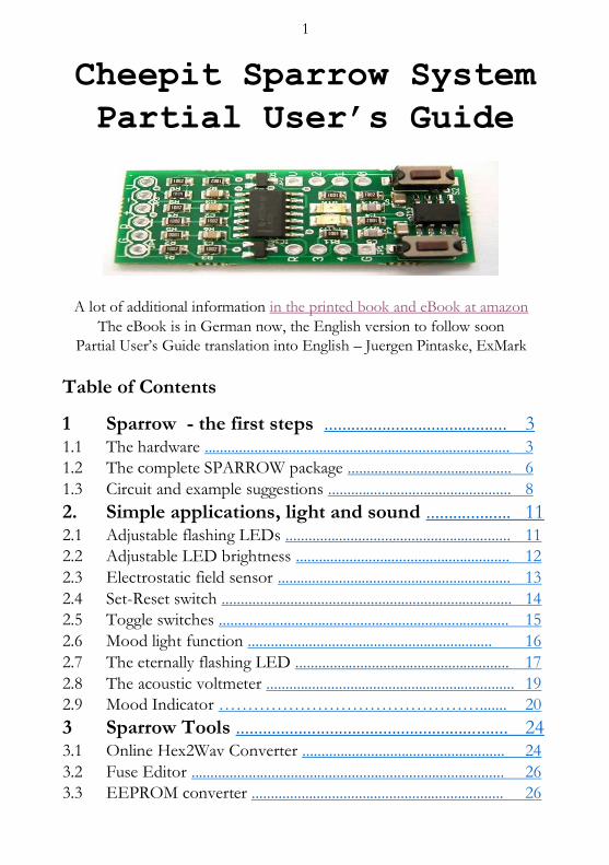
Cheepit Sparrow System
Partial User’s Guide
A lot of additional information in the printed book and eBook at amazon
The eBook is in German now, the English version to follow soon
Partial User’s Guide translation into English – Juergen Pintaske, ExMark
Table of Contents
1 Sparrow - the first steps ......................................... 3 1.1 The hardware ................................................................................ 3
1.2 The complete SPARROW package ........................................... 6
1.3 Circuit and example suggestions ................................................ 8
2. Simple applications, light and sound ................... 11 2.1 Adjustable flashing LEDs ........................................................... 11
2.2 Adjustable LED brightness ........................................................ 12
2.3 Electrostatic field sensor ............................................................. 13
2.4 Set-Reset switch ............................................................................ 14
2.5 Toggle switches ............................................................................ 15
2.6 Mood light function ................................................................ 16
2.7 The eternally flashing LED ........................................................ 17
2.8 The acoustic voltmeter ................................................................. 19
2.9 Mood Indicator ………………………………………....... 20
3 Sparrow Tools ............................................................. 24 3.1 Online Hex2Wav Converter ..................................................... 24
3.2 Fuse Editor .................................................................................. 26
3.3 EEPROM converter .................................................................. 26
2
3.4 Sound UART ............................................................................... 27
3.5 The Sound of Reset ..................................................................... 29
+++++ Translated up to this point ++++++++++++++++++
4 Morse Code and Binary Telegraphy 4.1 Sparrow_TeleBin
4.2 A code lock
4.3 Sparrow memory support
4.4 Sparrow reaction test
4.5 The Sparrow Sputnik
4.6 The Sparrow Morse code Sputnik
4.7 Sparrow Morse code Memory
5 micro-TPS for Sparrow 5.1 Sparrow_TPS1
5.2 Sparrow_TPS2
5.3 The Sparrow Bot
6 Sparrow apps with four-bit displays 6.1 Up / Down Counter 0 ... 15
6.2 Sparrow timer - up to four hours
6.3 The Sparrow LED Voltmeter
6.4 Measuring range switching
7 Sparrow peripherals and sensors 7.1 Sparrow_TouchB4
7.2 Sparrow Light Alarm
7.3 LED light with IR remote control
7.4 The Sparrow Sleep Radio
Some Links and further information ( mostly in German for now )
http://tiny.systems/categorie/cheepit
http://www.elektronik-labor.de/AVR/Sparrow/Cheepit.html
http://www.elexs.de/Sparrow1.html www.ak-modul-bus.de/stat/entwicklungssystem_sparrow.html
http://www.elektronik-labor.de/Lernpakete/TPS/TPS0.html
Burkhard Kainka, Basiskurs BASCOM-AVR , Elektor 2011
AVR Basic Software download – the free limited version
https://www.mcselec.com/index.php?option=com_docman&task=doc_download&gid=139 v5_partial_A5
3
1 Sparrow - the first steps
Cheepit is a system for programming microcontrollers via the sound output of mobile Terminals. The left and right channels on the headphone output are used as a data and clock lines for ISP programming. Using this technique allows for programming microcontrollers without a PC.
This is particularly interesting for beginners and for education, because the familiar hardware like a Smartphones and a tablet can be used. Small programs (apps) are loaded directly ( or saved locally ) from the network location at http://tiny.systems/category/cheepit/ into the controller. Additionally, any software programs developed by a user can be easily shared with others.
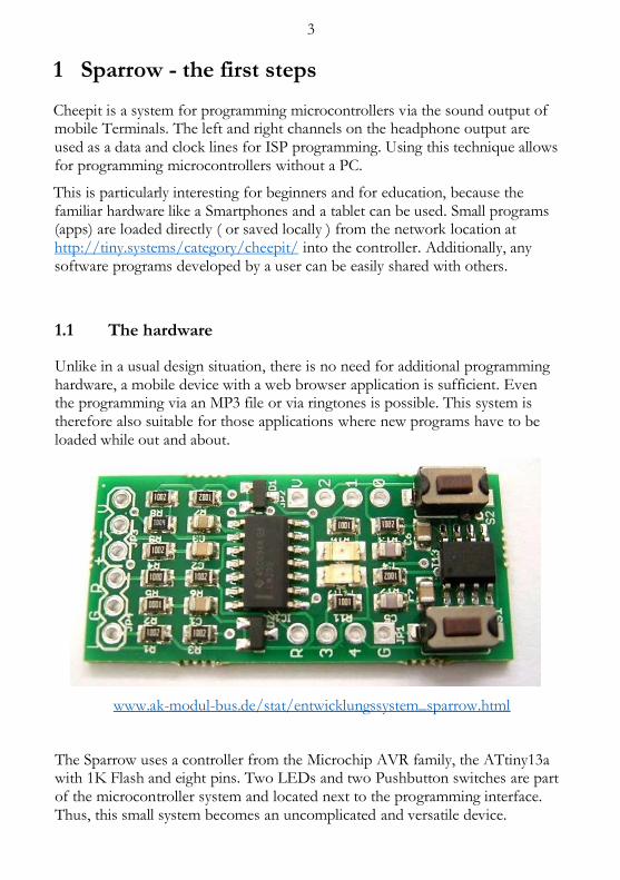
1.1 The hardware
Unlike in a usual design situation, there is no need for additional programming hardware, a mobile device with a web browser application is sufficient. Even the programming via an MP3 file or via ringtones is possible. This system is therefore also suitable for those applications where new programs have to be loaded while out and about.
www.ak-modul-bus.de/stat/entwicklungssystem_sparrow.html
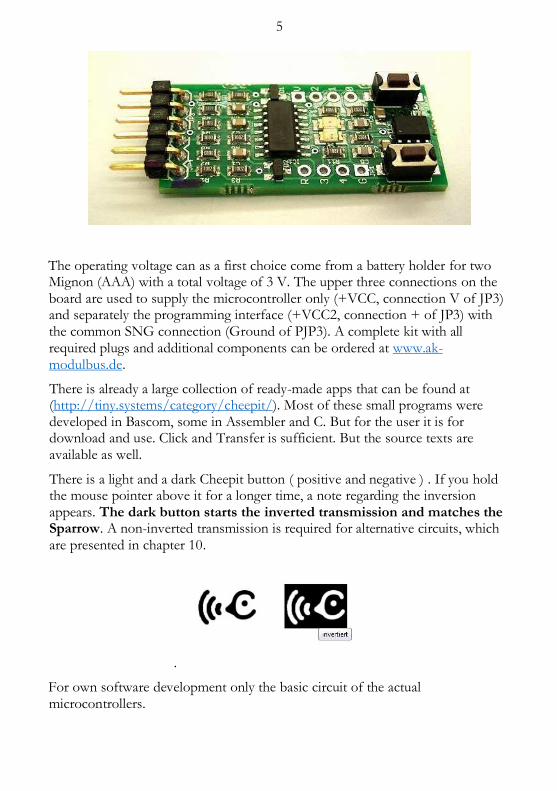
The Sparrow uses a controller from the Microchip AVR family, the ATtiny13a with 1K Flash and eight pins. Two LEDs and two Pushbutton switches are part of the microcontroller system and located next to the programming interface. Thus, this small system becomes an uncomplicated and versatile device.
4
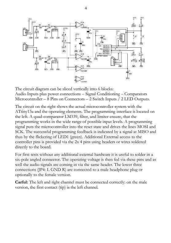
The circuit diagram can be sliced vertically into 6 blocks: Audio Inputs plus power connections – Signal Conditioning – Comparators Microcontroller – 8 Pins on Connectors – 2 Switch Inputs / 2 LED Outputs.
The circuit on the right shows the actual microcontroller system with the ATtiny13a and the operating elements. The programming interface is located on the left. A quad-comparator LM339, filter, and limiter ensure, that the programming works in the wide range of possible input levels. A programming signal puts the microcontroller into the reset state and drives the lines MOSI and SCK. The successful programming feedback is indicated by a signal at MISO and thus by the flickering of LED1 (green). Additional External access to the controller pins is provided via the 2x 4 pins using headers or wires soldered directly to the board.
For first tests without any additional external hardware it is useful to solder in a six-pole angled connector. The operating voltage is then fed via these pins and as well the audio signals are coming in via the same header. The lower three connections (JP4: L GND R) are connected to a male headphone plug or optionally to the female version.
Carful: The left and right channel must be connected correctly: on the male version, the first contact (tip) is the left channel.
5
The operating voltage can as a first choice come from a battery holder for two Mignon (AAA) with a total voltage of 3 V. The upper three connections on the board are used to supply the microcontroller only (+VCC, connection V of JP3) and separately the programming interface (+VCC2, connection + of JP3) with the common SNG connection (Ground of PJP3). A complete kit with all required plugs and additional components can be ordered at www.ak-modulbus.de.
There is already a large collection of ready-made apps that can be found at (http://tiny.systems/category/cheepit/). Most of these small programs were developed in Bascom, some in Assembler and C. But for the user it is for download and use. Click and Transfer is sufficient. But the source texts are available as well.
There is a light and a dark Cheepit button ( positive and negative ) . If you hold the mouse pointer above it for a longer time, a note regarding the inversion appears. The dark button starts the inverted transmission and matches the Sparrow. A non-inverted transmission is required for alternative circuits, which are presented in chapter 10.
.
For own software development only the basic circuit of the actual microcontrollers.
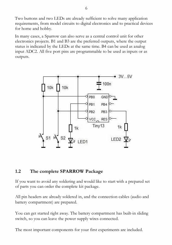
6 Two buttons and two LEDs are already sufficient to solve many application requirements, from model circuits to digital electronics and to practical devices for home and hobby.
In many cases, a Sparrow can also serve as a central control unit for other electronics projects. B1 and B3 are the preferred outputs, where the output status is indicated by the LEDs at the same time. B4 can be used as analog input ADC2. All five port pins are programmable to be used as inputs or as outputs.
1.2 The complete SPARROW Package
If you want to avoid any soldering and would like to start with a prepared set of parts you can order the complete kit package. All pin headers are already soldered in, and the connection cables (audio and
battery compartment) are prepared.
You can get started right away. The battery compartment has built-in sliding
switch, so you can leave the power supply wires connected.
The most important components for your first experiments are included.
7
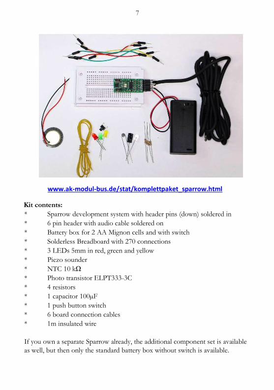
www.ak-modul-bus.de/stat/komplettpaket_sparrow.html
Kit contents:
* Sparrow development system with header pins (down) soldered in
* 6 pin header with audio cable soldered on
* Battery box for 2 AA Mignon cells and with switch
* Solderless Breadboard with 270 connections
* 3 LEDs 5mm in red, green and yellow
* Piezo sounder
* NTC 10 kΩ
* Photo transistor ELPT333-3C
* 4 resistors
* 1 capacitor 100µF
* 1 push button switch
* 6 board connection cables
* 1m insulated wire
If you own a separate Sparrow already, the additional component set is available
as well, but then only the standard battery box without switch is available.

8 The additional components of this kit have been selected to cover most of the
examples described here.
www.ak-modul-bus.de/stat/bauteileset_fuer_den_sparrow.html
1.3 Circuits and example suggestions
This chapter suggests, how this material can be connected. A very popular and
easy to understand exercise at school is the development of a basic traffic light
control. The three traffic light LEDs are connected to the ports via a series
resistors, and the red and green LEDs on the Sparrow board will light up as
well.
9
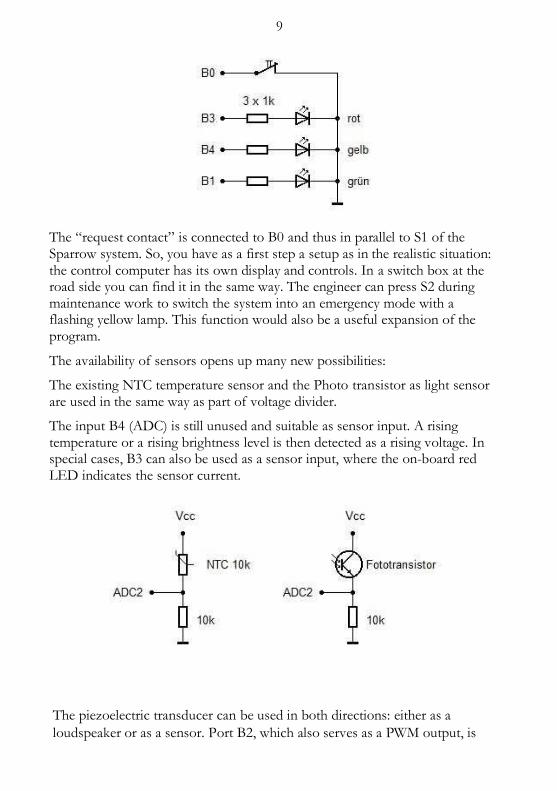
The “request contact” is connected to B0 and thus in parallel to S1 of the Sparrow system. So, you have as a first step a setup as in the realistic situation: the control computer has its own display and controls. In a switch box at the road side you can find it in the same way. The engineer can press S2 during maintenance work to switch the system into an emergency mode with a flashing yellow lamp. This function would also be a useful expansion of the program.
The availability of sensors opens up many new possibilities:
The existing NTC temperature sensor and the Photo transistor as light sensor are used in the same way as part of voltage divider.
The input B4 (ADC) is still unused and suitable as sensor input. A rising temperature or a rising brightness level is then detected as a rising voltage. In special cases, B3 can also be used as a sensor input, where the on-board red LED indicates the sensor current.
The piezoelectric transducer can be used in both directions: either as a
loudspeaker or as a sensor. Port B2, which also serves as a PWM output, is
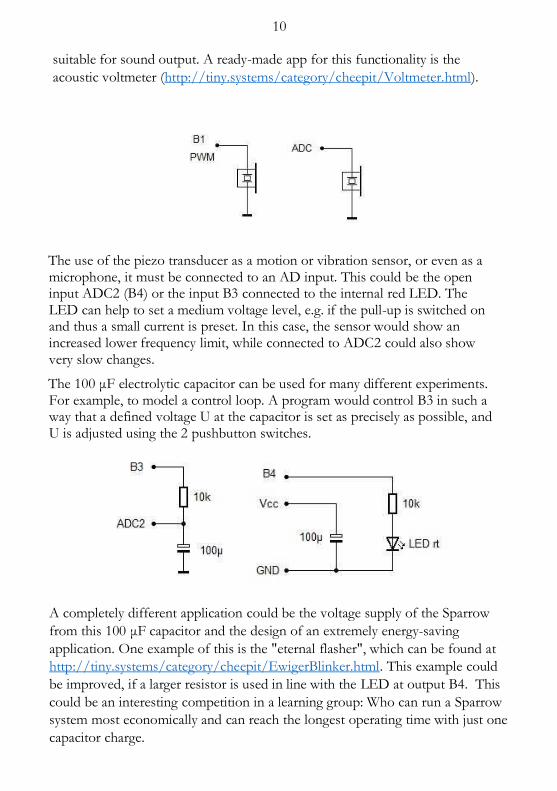
10 suitable for sound output. A ready-made app for this functionality is the
acoustic voltmeter (http://tiny.systems/category/cheepit/Voltmeter.html).
The use of the piezo transducer as a motion or vibration sensor, or even as a microphone, it must be connected to an AD input. This could be the open input ADC2 (B4) or the input B3 connected to the internal red LED. The LED can help to set a medium voltage level, e.g. if the pull-up is switched on and thus a small current is preset. In this case, the sensor would show an increased lower frequency limit, while connected to ADC2 could also show very slow changes.
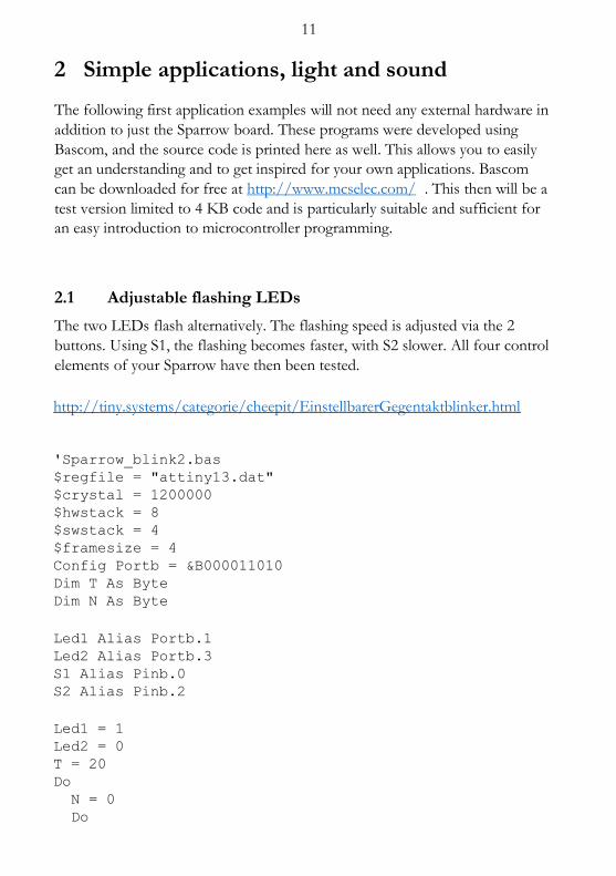
The 100 μF electrolytic capacitor can be used for many different experiments. For example, to model a control loop. A program would control B3 in such a way that a defined voltage U at the capacitor is set as precisely as possible, and U is adjusted using the 2 pushbutton switches.
A completely different application could be the voltage supply of the Sparrow
from this 100 μF capacitor and the design of an extremely energy-saving
application. One example of this is the "eternal flasher", which can be found at
http://tiny.systems/category/cheepit/EwigerBlinker.html. This example could
be improved, if a larger resistor is used in line with the LED at output B4. This
could be an interesting competition in a learning group: Who can run a Sparrow
system most economically and can reach the longest operating time with just one
capacitor charge.
11
2 Simple applications, light and sound
The following first application examples will not need any external hardware in
addition to just the Sparrow board. These programs were developed using
Bascom, and the source code is printed here as well. This allows you to easily
get an understanding and to get inspired for your own applications. Bascom
can be downloaded for free at http://www.mcselec.com/ . This then will be a
test version limited to 4 KB code and is particularly suitable and sufficient for
an easy introduction to microcontroller programming.
2.1 Adjustable flashing LEDs
The two LEDs flash alternatively. The flashing speed is adjusted via the 2
buttons. Using S1, the flashing becomes faster, with S2 slower. All four control
elements of your Sparrow have then been tested.
http://tiny.systems/categorie/cheepit/EinstellbarerGegentaktblinker.html
'Sparrow_blink2.bas $regfile = "attiny13.dat" $crystal = 1200000 $hwstack = 8 $swstack = 4 $framesize = 4 Config Portb = &B000011010 Dim T As Byte Dim N As Byte
Led1 Alias Portb.1 Led2 Alias Portb.3 S1 Alias Pinb.0 S2 Alias Pinb.2
Led1 = 1 Led2 = 0 T = 20 Do N = 0 Do
12 If S1 = 0 Then T = T + 1
If T > 250 Then T = 250 If S2 = 0 Then T = T - 1 If T < 1 Then T = 1 Waitms 10
N = N + 10 Loop Until N >= T Toggle Led1 Toggle Led2 Loop
End
2.2 Adjustable LED brightness
The green LED1 can be controlled via the PWM output PWM0B of the
Tiny13a. The following test program allows you to adjust the LED brightness
via the 2 buttons.
http://tiny.systems/categorie/cheepit/EinstellbareLEDHelligkeit.html
'Sparrow_PWM.bas $regfile = "attiny13.dat" $crystal = 1200000 $hwstack = 8 $swstack = 4 $framesize = 4 Config Portb.1 = 1 Dim D As Byte
Led1 Alias Portb.1 Led2 Alias Portb.3 S1 Alias Pinb.0 S2 Alias Pinb.2
Config Timer0 = Pwm , Prescale = 8 , Compare B Pwm =
Clear Up
D = 50 Do
13 If S1 = 0 Then D = D + 1 If D > 254 Then D = 254 If S2 = 0 Then D = D - 1 If D < 1 Then D = 1 Waitms 10
Pwm0b = D Loop End
2.3 Electrostatic field sensor
If the red LED2 is not used and ports B3 and B4 are set to high impedance, one
then ADC3 is an extremely sensitive analog input. A piece of wire, 5 cm long, is
sufficient for B3 to function as an antenna, to measure the electric field and to
display it via the PWM output.
With the Sparrow in your the hand, you can for example walk over a carpet and
look directly at the electric charge at each step showing the brightness on the
green LED.
http://tiny.systems/categorie/cheepit/ElektrofeldSensor.html
'Sparrow_ADC.bas
$regfile = "attiny13.dat" $crystal = 1200000 $hwstack = 8 $swstack = 4 $framesize = 4
Dim D As Integer Ddrb = 2
Config Adc = Single , Prescaler = Auto Start Adc Config Timer0 = Pwm , Prescale = 8 , Compare B Pwm =
Clear Up
Do
D = Getadc(3) D = D / 4 Pwm0b = D
14 Waitms 18 Loop End
The program contains a delay of 18 milliseconds, so very close to the period of
20 ms of a 50 Hz power line. All 50 Hz signals are therefore slowed down and
are clearly displayed on the green LED. If the antenna is approached with a
land, then the amplitude of the AC voltage rises clearly.
Even power cables in the wall can be tracked using the Sparrow!
This program is almost as useful as a small oscilloscope. As well it can be used
for voltage measurements, as long as the measuring voltage is not greater than
the Sparrow operating voltage.
For safety, a 10 kΩ protective series resistor should be placed in the measuring
cable to the measurement point. Most measuring instruments show the DC
value only and thus suppress any superposed alternating voltages. But our
sparrow shows these AC voltages.
2.4 RS Switch
An RS flip-flop has two inputs, one for switching on (Set) and one for
switching off (Reset). This example works just like this. S2 turns both LEDs on
and S1 turns them off.
http://tiny.systems/categorie/cheepit/RSSchalter.html
'Sparrow_RS.bas on/off LEDs $regfile = "attiny13.dat" $crystal = 1200000 $hwstack = 8 $swstack = 4 $framesize = 4 Config Portb = &B000011010 Dim T As Byte Dim N As Byte
Led1 Alias Portb.1 Led2 Alias Portb.3 S1 Alias Pinb.0 S2 Alias Pinb.2
15 Led1 = 1 Led2 = 1 T = 20 Do If S1 = 0 Then Led1 = 0 Led2 = 0 End If If S2 = 0 Then Led1 = 1 Led2 = 1 End If Loop End
2.5 Toggle switches
The function of this app corresponds to two separately implemented toggle
flipflops. Press switch once => On, press the same switch again => Off.
And this works in the same way for both buttons, and each switch with its own
LED.
http://tiny.systems/categorie/cheepit/ToggleSchalter.html
'Sparrow_Toggle.bas on/off LEDs $regfile = "attiny13.dat" $crystal = 1200000 $hwstack = 8 $swstack = 4 $framesize = 4 Config Portb = &B000011010 Dim T As Byte Dim N As Byte
Led1 Alias Portb.1 Led2 Alias Portb.3 S1 Alias Pinb.0 S2 Alias Pinb.2
Led1 = 1 Led2 = 1 T = 20 Do If S1 = 0 Then
16 Toggle Led1 Waitms 50 Do Loop Until S1 = 1 Waitms 50 End If If S2 = 0 Then Toggle Led2 Waitms 50 Do Waitms 50 Loop Until S2 = 1 End If Loop End
2.6 Mood light function
The green LED is dimmed slowly via the PWM output and then blown again.
The speed is adjustable via the buttons. Since the eye does not have a linear
feeling for the brightness, a parabola function is implemented here by squaring
a run variable.
http://tiny.systems/categorie/cheepit/Entspannungslicht.html
'Sparrow_Fade.bas $regfile = "attiny13.dat" $crystal = 1200000 $hwstack = 8 $swstack = 4 $framesize = 4 Config Portb.1 = 1 Config Portb.3 = 1 Config Portb.4 = 1 Dim T As Byte Dim I As Byte Dim J As Byte Dim N As Byte Dim D As Word
Led1 Alias Portb.1 Led2 Alias Portb.3
17 S1 Alias Pinb.0 S2 Alias Pinb.2
Config Timer0 = Pwm , Prescale = 8 , Compare B Pwm =
Clear Up
N = 50 T = 5 J = 0 Do Waitms 10 I = I + 1 If I >= T Then 'Toggle Led2 If S1 = 0 Then T = T + 1 If T > 20 Then T = 20 If S2 = 0 Then T = T - 1 If T < 1 Then T = 1 I = 0 If J = 0 Then N = N + 1 If N > 250 Then J = 1 If J = 1 Then N = N - 1 If N < 50 Then J = 0 D = N * N D = High(d) Pwm0b = D End If Loop End
2.7 The eternally flashing LED
The eternal light beacon has been around forever. Sometimes as pure electronic circuit and sometimes using a microcontroller-Application "The ELO-Flasher". Now it has come to the Sparrow. The main goal is extreme power saving.
The Sparrow produces a repeating flash on the green LED, but switches itself during the off cycle into sleep mode and then needs hardly any current. The watchdog timer function of the Tiny13 triggers the wake up. The Sparrow board was operated here via a storage Supercapacitor of 0.1 F, 5.5 V.
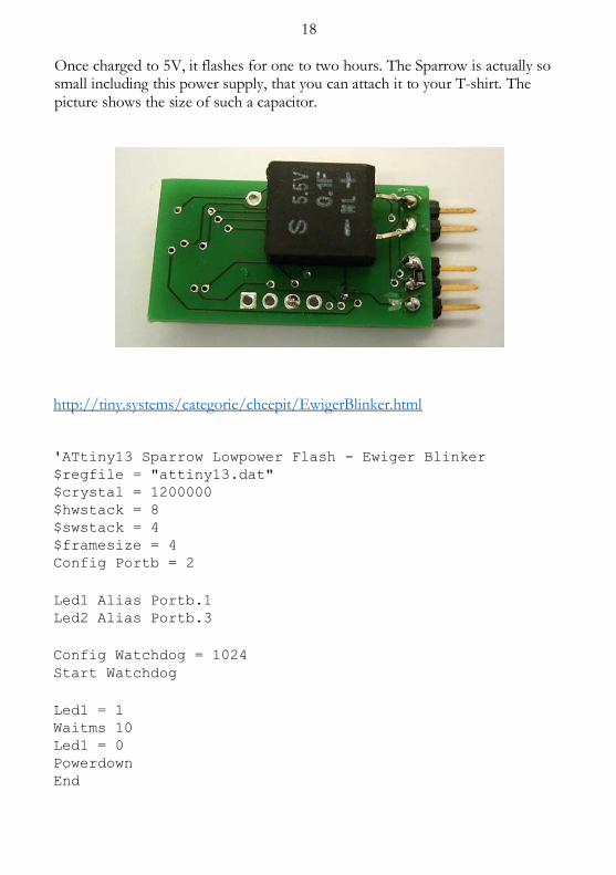
18 Once charged to 5V, it flashes for one to two hours. The Sparrow is actually so small including this power supply, that you can attach it to your T-shirt. The picture shows the size of such a capacitor.
http://tiny.systems/categorie/cheepit/EwigerBlinker.html
'ATtiny13 Sparrow Lowpower Flash - Ewiger Blinker $regfile = "attiny13.dat" $crystal = 1200000 $hwstack = 8 $swstack = 4 $framesize = 4 Config Portb = 2
Led1 Alias Portb.1 Led2 Alias Portb.3
Config Watchdog = 1024 Start Watchdog
Led1 = 1 Waitms 10 Led1 = 0 Powerdown End
19
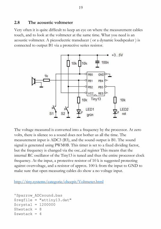
2.8 The acoustic voltmeter
Very often it is quite difficult to keep an eye on where the measurement cables
touch, and to look at the voltmeter at the same time. What you need is an
acoustic voltmeter. A piezoelectric transducer ( or a dynamic loudspeaker ) is
connected to output B1 via a protective series resistor.
The voltage measured is converted into a frequency by the processor. At zero
volts, there is silence so a sound does not bother us all the time. The
measurement input is ADC3 (B3), and the sound output is B1. The sound
signal is generated using PWM0B. This timer is set to a fixed dividing factor,
but the frequency is changed via the osc_cal register This means that the
internal RC oscillator of the Tiny13 is tuned and thus the entire processor clock
frequency. At the input, a protective resistor of 10 k is suggested protecting
against overvoltage, and a resistor of approx. 100 k from the input to GND to
make sure that open measuring cables do show a no voltage input.
http://tiny.systems/categorie/cheepit/Voltmeter.html
'Sparrow_ADCsound.bas $regfile = "attiny13.dat" $crystal = 1200000 $hwstack = 8 $swstack = 4
20 $framesize = 4
Dim D As Integer Ddrb = 2 'Sound Output B1
Config Adc = Single , Prescaler = Auto Start Adc Config Timer0 = Pwm , Prescale = 8 , Compare B Pwm =
Clear Up
Do D = Getadc(3) 'Voltage Input B3 D = D / 10 Osccal = D If D < 1 Then Pwm0b = 0 Else Pwm0b = 40 Waitms 18 Loop End
2.9 Mood Indicator
Interpersonal relationships are based on clear communication signals. But it is
not always easy to find the right words. Sparrow can help here. It acts as a kind
of mood traffic light and makes phrases such as "Leave me alone" unnecessary
to be said.
After starting, the Sparrow just flashes slowly and signals it is ready. The user then selects the current stress or relaxation level using the two buttons (up / down). What exactly such a frequency means in each case, has to be agreed obviously.
For example, it could look as follows:
Mode 1: Double flashes red / green: Maximum stress, best not talk to
Mode 2: Single flashes red / green: Strongly loaded, head not clear yet
Mode 3: Double flash red: Trying to relax
Mode 4: Single flashes red: Rather relaxed, everything easy
Mode 5: Single flashes green: Ready for new actions
Mode 6: Double flashes green: Under full power - Let's go!
http://tiny.systems/categorie/cheepit/Stimmungsindikator.html
21 'ATtiny13 Sparrow Blink3.bas $regfile = "attiny13.dat" $crystal = 1200000 $hwstack = 8 $swstack = 4 $framesize = 4 Config Portb = &B000011010 Dim T As Byte Dim N As Byte Dim M As Byte Led1 Alias Portb.1 Led2 Alias Portb.3 S1 Alias Pinb.0 S2 Alias Pinb.2
Do If S2 = 0 Then Waitms 50 If M < 6 Then M = M + 1 Do Loop Until S2 = 1 Waitms 50 End If If S1 = 0 Then Waitms 50 If M > 1 Then M = M - 1 Do Loop Until S1 = 1 Waitms 50 End If
If M = 0 Then 'Standby Led1 = 1 Waitms 10 Led1 = 0 Waitms 500 End If
If M = 1 Then 'very busy Led1 = 1 : Led2 = 1 Waitms 30 Led1 = 0 : Led2 = 0 Waitms 100 Led1 = 1 : Led2 = 1 Waitms 30
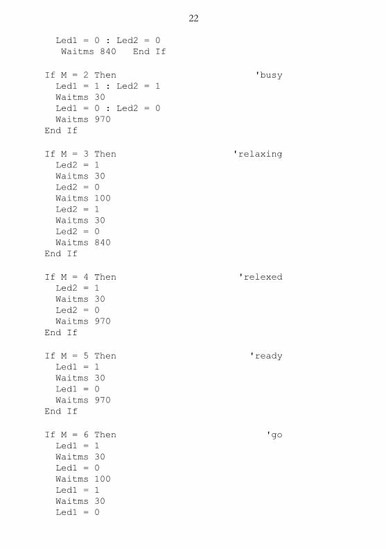
22 Led1 = 0 : Led2 = 0 Waitms 840 End If
If M = 2 Then 'busy Led1 = 1 : Led2 = 1 Waitms 30 Led1 = 0 : Led2 = 0 Waitms 970 End If
If M = 3 Then 'relaxing Led2 = 1 Waitms 30 Led2 = 0 Waitms 100 Led2 = 1 Waitms 30 Led2 = 0 Waitms 840 End If
If M = 4 Then 'relexed Led2 = 1 Waitms 30 Led2 = 0 Waitms 970 End If
If M = 5 Then 'ready Led1 = 1 Waitms 30 Led1 = 0 Waitms 970 End If
If M = 6 Then 'go Led1 = 1 Waitms 30 Led1 = 0 Waitms 100 Led1 = 1 Waitms 30 Led1 = 0

23 Waitms 840 End If Loop End
24
3 Sparrow tools
If you write code for microcontrollers on a PC, you usually have a compiler
running on the PC and a programming device connected via USB. Often you use
a bootloader on the controller, where the target system can program itself using
downloaded data. In either case, however, a PC with a suitable interface
connection is needed, e.g. an RS232 serial interface or a USB port.
Sparrow works differently. You do not need a programming device because the
necessary hardware is already available on the Sparrow board. USB or RS232
connection is also not necessary either, as the programming data is transmitted
by the sound card – or more precisely via the headphone output. A special
programming software is also not necessary, as an Internet browser is sufficient
to download the data from a remote location on the Internet. One click is
enough, and then the selected sound file is transferred.
So easy it is really, if prepared apps are downloaded. But what, if you want to
develop your own code? Then you will need an assembler Program or a compiler
that creates the required Hex File for programming the chip. This Hex File can
be converted online by uploading there converted into the relevant sound file
and transferred back immediately for programming.
3.1 Online Hex2Wav Converter
Finished apps are great and quick to use. But how does it help if you could only
use ready-made apps? This will get boring quickly. For this reason, the code
generator for the ATtiny13a was opened up and converted into a small
WebApp. With this application, you can now load any program onto the
controller, regardless of the compiler used.
25
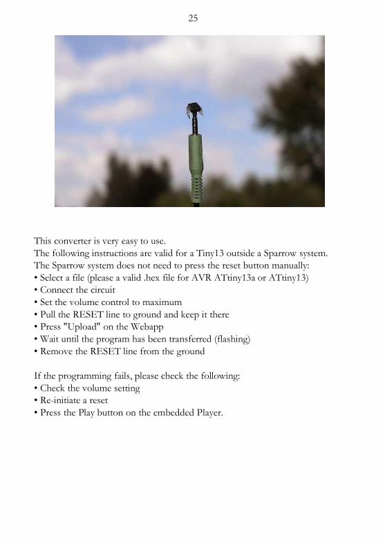
This converter is very easy to use.
The following instructions are valid for a Tiny13 outside a Sparrow system.
The Sparrow system does not need to press the reset button manually:
• Select a file (please a valid .hex file for AVR ATtiny13a or ATtiny13)
• Connect the circuit
• Set the volume control to maximum
• Pull the RESET line to ground and keep it there
• Press "Upload" on the Webapp
• Wait until the program has been transferred (flashing)
• Remove the RESET line from the ground
If the programming fails, please check the following:
• Check the volume setting
• Re-initiate a reset
• Press the Play button on the embedded Player.

26
SoundProgrammer
Select Hex File ( search ) Sparrow_TPS4.hex
(ticked) invert signal
Upload
Our Sparrow expects the setting "Invert Signal". Non-inverted signals can be
used to program a Tiny13 with just two resistors and a reset button (see chapter
10.2 in the eBook).
If you listen carefully, you can hear a kind of preamble in this sound file. It is
used to put the Sparrow into the reset state. The Sparrow system has a matching
reset circuit. This is the real reason why you can program the chip by just using
two lines. If you use the well-known ISP interface for AVR controllers, then you
know the six-wire connection: MOSI, MISO, SCK, Reset, GND and VCC.
27 MISO is omitted here, while MOSI (left channel) generates the at the same time
the reset signal and the right channel provides the SCK signal.
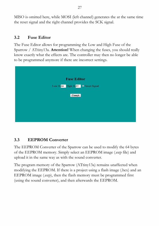
3.2 Fuse Editor
The Fuse Editor allows for programming the Low and High Fuse of the
Sparrow / ATtiny13a. Attention! When changing the fuses, you should really
know exactly what the effects are. The controller may then no longer be able
to be programmed anymore if there are incorrect settings.
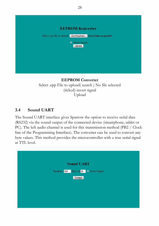
3.3 EEPROM Converter
The EEPROM Converter of the Sparrow can be used to modify the 64 bytes
of the EEPROM memory. Simply select an EEPROM image (.eep file) and
upload it in the same way as with the sound converter.
The program memory of the Sparrow (ATtiny13a) remains unaffected when
modifying the EEPROM. If there is a project using a flash image (.hex) and an
EEPROM image (.eep), then the flash memory must be programmed first
(using the sound converter), and then afterwards the EEPROM.
28
EEPROM Converter
Select .epp File to upload( search ) No file selected
(ticked) invert signal Upload
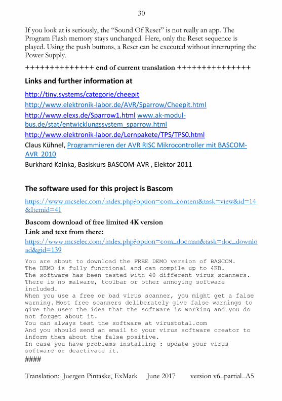
3.4 Sound UART
The Sound UART interface gives Sparrow the option to receive serial data
(RS232) via the sound output of the connected device (smartphone, tablet or
PC). The left audio channel is used for this transmission method (PB2 / Clock
line of the Programming Interface). The converter can be used to convert any
byte values. This method provides the microcontroller with a true serial signal
at TTL level.

29
Sound UART Baud Rate 300 Byte: 0x 55 (tick) Invert Signal
Cheepit
Only the left channel is used during transmission. The right channel (reset / data line) remains unchanged.
This allows data transfer to PB2 during operation.
The preset transfer rate is 300 Baud with 8 data bits, no parity and one stop bit.
The sound data are generated using a sampling rate of 44100 Hz. Based on this
fact, a theoretically possible Baud rate of max. of 22050 could be achieved.
During the conversion process however, rounding errors occur due to the
fixed sampling rate. This error can be calculated. If the sampling rate is directly
divisible by the set baud rate, there is no deviation.
3.5 The Sound of Reset
The trick is to address only the MOSI line, but not the SCK line. Then a reset
is executed without transmitting a new program.
http://tiny.systems/categorie/cheepit/Reset.html
TINY SYSTEMS article apps search window - tiny systems The Sound of Reset. by Thomas Baum
30 If you look at is seriously, the “Sound Of Reset” is not really an app. The Program Flash memory stays unchanged. Here, only the Reset sequence is played. Using the push buttons, a Reset can be executed without interrupting the Power Supply.
++++++++++++++ end of current translation +++++++++++++++
Links and further information at
http://tiny.systems/categorie/cheepit
http://www.elektronik-labor.de/AVR/Sparrow/Cheepit.html
http://www.elexs.de/Sparrow1.html www.ak-modul-bus.de/stat/entwicklungssystem_sparrow.html
http://www.elektronik-labor.de/Lernpakete/TPS/TPS0.html
Claus Kühnel, Programmieren der AVR RISC Mikrocontroller mit BASCOM-AVR 2010
Burkhard Kainka, Basiskurs BASCOM-AVR , Elektor 2011
The software used for this project is Bascom
https://www.mcselec.com/index.php?option=com_content&task=view&id=14&Itemid=41
Bascom download of free limited 4K version
Link and text from there:
https://www.mcselec.com/index.php?option=com_docman&task=doc_download&gid=139
You are about to download the FREE DEMO version of BASCOM. The DEMO is fully functional and can compile up to 4KB. The software has been tested with 40 different virus scanners. There is no malware, toolbar or other annoying software
included. When you use a free or bad virus scanner, you might get a false
warning. Most free scanners deliberately give false warnings to give the user the idea that the software is working and you do
not forget about it. You can always test the software at virustotal.com And you should send an email to your virus software creator to
inform them about the false positive. In case you have problems installing : update your virus
software or deactivate it.
####
Translation: Juergen Pintaske, ExMark June 2017 version v6_partial_A5


![m] · The field sparrow (Spizella pusilla) and grasshopper sparrow (Ammodramus savan-na-urn) are both similar to the Bachrnan’s sparrow. However, the field sparrow is smaller in](https://img.pdfslide.net/doc/110x75/6088ea8b235a2727543a9647/m-the-field-sparrow-spizella-pusilla-and-grasshopper-sparrow-ammodramus-savan-na-urn.jpg)