Embed Size (px)
Citation preview

Computer Organization and Architecture Chapter 1 : Introduction
Compiled By: Er. Hari Aryal [[email protected]] Reference: W. Stallings | 1
Chapter – 1
Introduction
1.1 Computer Organization and Architecture
Computer Architecture refers to those attributes of a system that have a direct impact on
the logical execution of a program. Examples:
o the instruction set
o the number of bits used to represent various data types
o I/O mechanisms
o memory addressing techniques
Computer Organization refers to the operational units and their interconnections that
realize the architectural specifications. Examples are things that are transparent to the
programmer:
o control signals
o interfaces between computer and peripherals
o the memory technology being used
So, for example, the fact that a multiply instruction is available is a computer architecture
issue. How that multiply is implemented is a computer organization issue.
• Architecture is those attributes visible to the programmer
o Instruction set, number of bits used for data representation, I/O mechanisms,
addressing techniques.
o e.g. Is there a multiply instruction?
• Organization is how features are implemented
o Control signals, interfaces, memory technology.
o e.g. Is there a hardware multiply unit or is it done by repeated addition?
• All Intel x86 family share the same basic architecture
• The IBM System/370 family share the same basic architecture
• This gives code compatibility
o At least backwards
• Organization differs between different versions
1.2 Structure and Function
• Structure is the way in which components relate to each other
• Function is the operation of individual components as part of the structure
• All computer functions are:
o Data processing: Computer must be able to process data which may take a wide
variety of forms and the range of processing.
o Data storage: Computer stores data either temporarily or permanently.
o Data movement: Computer must be able to move data between itself and the
outside world.
o Control: There must be a control of the above three functions.

Computer Organization and Architecture Chapter 1 : Introduction
Compiled By: Er. Hari Aryal [[email protected]] Reference: W. Stallings | 2
Fig: Functional view of a computer
Fig: Data movement operation Fig: Storage Operation

Computer Organization and Architecture Chapter 1 : Introduction
Compiled By: Er. Hari Aryal [[email protected]] Reference: W. Stallings | 3
Fig: Processing from / to storage Fig: Processing from storage to i/o
• Four main structural components:
o Central processing unit (CPU)
o Main memory
o I / O
o System interconnections
• CPU structural components:
o Control unit
o Arithmetic and logic unit (ALU)
o Registers
o CPU interconnections
Fig: Computer: Top level structure
Computer
Main
Memory
Input
Output
Systems
Interconnection
Peripherals
Communication lines
Central
Processing
Unit
Computer
Computer Organization and Architecture Chapter 1 : Introduction
Compiled By: Er. Hari Aryal [[email protected]] Reference: W. Stallings | 4
Fig: The central processing unit
Fig: The control unit
1.3 Designing for performance
Some of the driving factors behind the need to design for performance:
• Microprocessor Speed
Pipelining
On board cache, on board L1 & L2 cache
Branch prediction: The processor looks ahead in the instruction code fetched from
memory and predicts which branches, or group of instructions are likely to be
processed next.
Data flow analysis: The processor analyzes which instructions are dependent on
each other’s results, or data, to create an optimized schedule of instructions to
prevent delay.
Computer Arithmetic
and
Login Unit
Control
Unit
Internal CPU
Interconnection
Registers
CPU
I/O
Memory
System
Bus
CPU
CPU
Control
Memory
Control Unit
Registers and
Decoders
Sequencing
Login Control
Unit
ALU
Registers
Internal
Bus
Interconn
ection
Bus
Control Unit

Computer Organization and Architecture Chapter 1 : Introduction
Compiled By: Er. Hari Aryal [[email protected]] Reference: W. Stallings | 5
Speculative execution: Using branch prediction and data flow analysis, some
processors speculatively execute instructions ahead of their actual appearance in
the program execution, holding the results in temporary locations.
• Performance Mismatch
Processor speed increased
Memory capacity increased
Memory speed lags behind processor speed
Below figure depicts the history; while processor speed and memory capacity have grown
rapidly, the speed with which data can be transferred between main memory and the processor
has lagged badly.
Fig: Evolution of DRAM and processor Characteristics
The effects of these trends are shown vividly in figure below. The amount of main memory
needed is going up, but DRAM density is going up faster (number of DRAM per system is going
down).
Fig: Trends in DRAM use

Computer Organization and Architecture Chapter 1 : Introduction
Compiled By: Er. Hari Aryal [[email protected]] Reference: W. Stallings | 6
Solutions
Increase number of bits retrieved at one time
o Make DRAM “wider” rather than “deeper” to use wide bus data paths.
Change DRAM interface
o Cache
Reduce frequency of memory access
o More complex cache and cache on chip
Increase interconnection bandwidth
o High speed buses
o Hierarchy of buses
1.4 Computer Components
• The Control Unit (CU) and the Arithmetic and Logic Unit (ALU) constitute the Central
Processing Unit (CPU)
• Data and instructions need to get into the system and results need to get out
o Input/output (I/O module)
• Temporary storage of code and results is needed
o Main memory (RAM)
• Program Concept
o Hardwired systems are inflexible
o General purpose hardware can do different tasks, given correct control signals
o Instead of re-wiring, supply a new set of control signals
Fig: Hardware and Software Approaches

Computer Organization and Architecture Chapter 1 : Introduction
Compiled By: Er. Hari Aryal [[email protected]] Reference: W. Stallings | 7
Fig: Computer Components; Top-Level View
1.5 Computer Function
The basic function performed by a computer is execution of a program, which consists of a set of
instructions stored in memory.
• Two steps of Instructions Cycle:
o Fetch
o Execute
Fig: Basic Instruction Cycle
• Fetch Cycle
o Program Counter (PC) holds address of next instruction to fetch
o Processor fetches instruction from memory location pointed to by PC
o Increment PC
Unless told otherwise
o Instruction loaded into Instruction Register (IR)

Computer Organization and Architecture Chapter 1 : Introduction
Compiled By: Er. Hari Aryal [[email protected]] Reference: W. Stallings | 8
• Execute Cycle
o Processor interprets instruction and performs required actions, such as:
Processor - memory
o data transfer between CPU and main memory
Processor - I/O
o Data transfer between CPU and I/O module
Data processing
o Some arithmetic or logical operation on data
Control
o Alteration of sequence of operations
o e.g. jump
Combination of above
Example of program execution.
Fig: Example of program execution (consists of memory and registers in hexadecimal)
• The PC contains 300, the address of the first instruction. The instruction (the value 1940
in hex) is loaded into IR and PC is incremented. This process involves the use of MAR
and MBR.
• The first hexadecimal digit in IR indicates that the AC is to be loaded. The remaining
three hexadecimal digits specify the address (940) from which data are to be loaded.
• The next instruction (5941) is fetched from location 301 and PC is incremented.

Computer Organization and Architecture Chapter 1 : Introduction
Compiled By: Er. Hari Aryal [[email protected]] Reference: W. Stallings | 9
• The old contents of AC and the contents of location 941 are added and the result is stored
in the AC.
• The next instruction (2941) is fetched from location 302 and the PC is incremented.
• The contents of the AC are stored in location 941.
Fig: Instruction cycle state diagram
Interrupts:
• Mechanism by which other modules (e.g. I/O) may interrupt normal sequence of
processing
• Program
o e.g. overflow, division by zero
• Timer
o Generated by internal processor timer
o Used in pre-emptive multi-tasking
• I/O
o from I/O controller
• Hardware failure
o e.g. memory parity error

Computer Organization and Architecture Chapter 1 : Introduction
Compiled By: Er. Hari Aryal [[email protected]] Reference: W. Stallings | 10
Figure: Program flow of control without and with interrupts
• Instruction Cycle
o Added to instruction cycle
o Processor checks for interrupt
Indicated by an interrupt signal
o If no interrupt, fetch next instruction
o If interrupt pending:
Suspend execution of current program
Save context
Set PC to start address of interrupt handler routine
Process interrupt
Restore context and continue interrupted program
Fig: Transfer of control via interrupts

Computer Organization and Architecture Chapter 1 : Introduction
Compiled By: Er. Hari Aryal [[email protected]] Reference: W. Stallings | 11
Fig: Instruction Cycle with Interrupts
Fig: Instruction cycle state diagram, with interrupts
• Multiple Interrupts
o Disable interrupts (approach #1)
Processor will ignore further interrupts whilst processing one interrupt
Interrupts remain pending and are checked after first interrupt has been
processed
Interrupts handled in sequence as they occur
o Define priorities (approach #2)
Low priority interrupts can be interrupted by higher priority interrupts
When higher priority interrupt has been processed, processor returns to
previous interrupt
1.6 Interconnection structures
The collection of paths connecting the various modules is called the interconnecting structure.
• All the units must be connected
• Different type of connection for different type of unit
o Memory
o Input/Output
o CPU

Computer Organization and Architecture Chapter 1 : Introduction
Compiled By: Er. Hari Aryal [[email protected]] Reference: W. Stallings | 12
• Memory Connection
o Receives and sends data
o Receives addresses (of locations)
o Receives control signals
Read
Write
Timing
Fig: Memory Module
• I/O Connection
o Similar to memory from computer’s viewpoint
o Output
Receive data from computer
Send data to peripheral
o Input
Receive data from peripheral
Send data to computer
o Receive control signals from computer
o Send control signals to peripherals
e.g. spin disk
o Receive addresses from computer
e.g. port number to identify peripheral
o Send interrupt signals (control)
Fig: I/O Module
Computer Organization and Architecture Chapter 1 : Introduction
Compiled By: Er. Hari Aryal [[email protected]] Reference: W. Stallings | 13
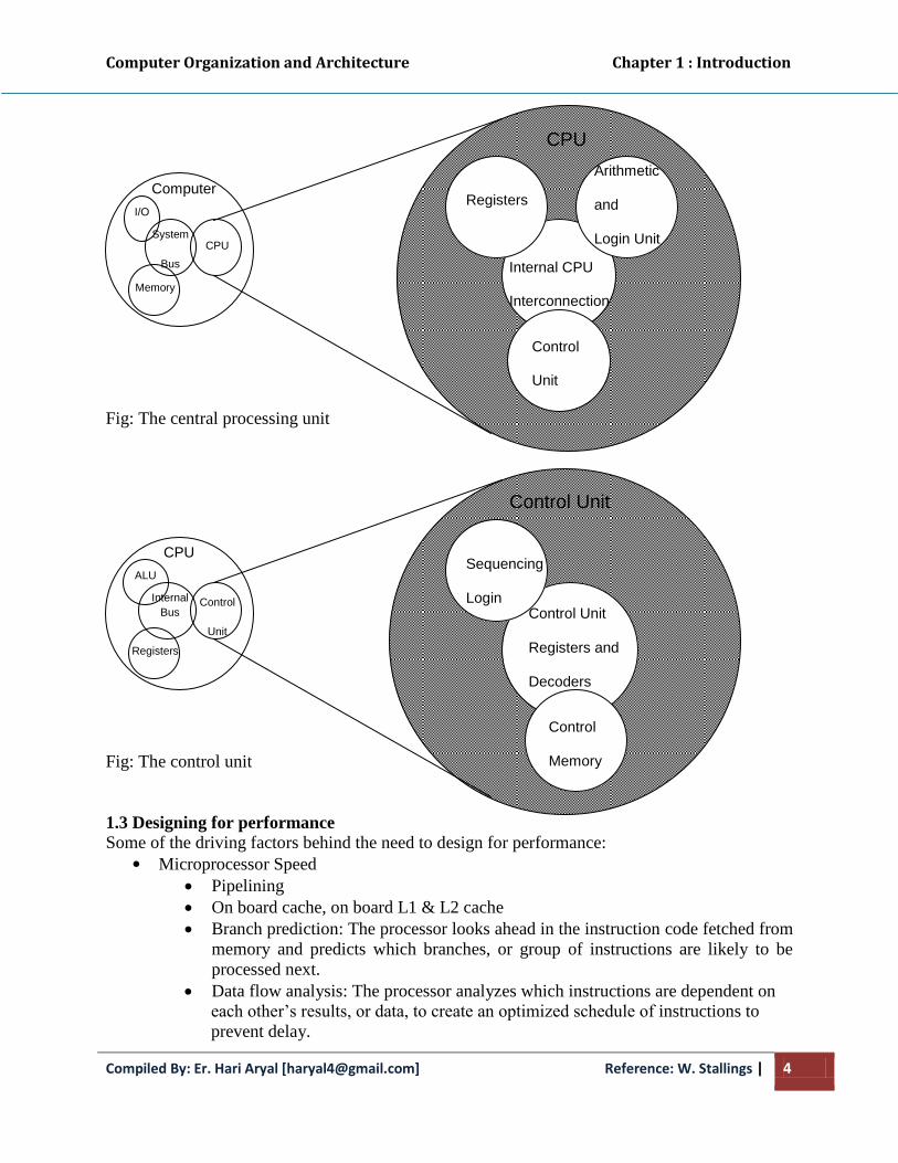
• CPU Connection
o Reads instruction and data
o Writes out data (after processing)
o Sends control signals to other units
o Receives (& acts on) interrupts
Fig: CPU Module
1.7 Bus interconnection
• A bus is a communication pathway connecting two or more devices
• Usually broadcast (all components see signal)
• Often grouped
o A number of channels in one bus
o e.g. 32 bit data bus is 32 separate single bit channels
• Power lines may not be shown
• There are a number of possible interconnection systems
• Single and multiple BUS structures are most common
• e.g. Control/Address/Data bus (PC)
• e.g. Unibus (DEC-PDP)
• Lots of devices on one bus leads to:
o Propagation delays
o Long data paths mean that co-ordination of bus use can adversely affect
performance
o If aggregate data transfer approaches bus capacity
• Most systems use multiple buses to overcome these problems
Fig: Bus Interconnection Scheme

Computer Organization and Architecture Chapter 1 : Introduction
Compiled By: Er. Hari Aryal [[email protected]] Reference: W. Stallings | 14
• Data Bus
o Carries data
Remember that there is no difference between “data” and “instruction” at
this level
o Width is a key determinant of performance
8, 16, 32, 64 bit
• Address Bus
o Identify the source or destination of data
o e.g. CPU needs to read an instruction (data) from a given location in memory
o Bus width determines maximum memory capacity of system
e.g. 8080 has 16 bit address bus giving 64k address space
• Control Bus
o Control and timing information
Memory read
Memory write
I/O read
I/O write
Transfer ACK
Bus request
Bus grant
Interrupt request
Interrupt ACK
Clock
Reset
Multiple Bus Hierarchies
A great number of devices on a bus will cause performance to suffer
o Propagation delay - the time it takes for devices to coordinate the use of the bus
o The bus may become a bottleneck as the aggregate data transfer demand approaches
the capacity of the bus (in available transfer cycles/second)
Traditional Hierarchical Bus Architecture
o Use of a cache structure insulates CPU from frequent accesses to main memory
o Main memory can be moved off local bus to a system bus
o Expansion bus interface
buffers data transfers between system bus and I/O controllers on expansion bus
insulates memory-to-processor traffic from I/O traffic

Computer Organization and Architecture Chapter 1 : Introduction
Compiled By: Er. Hari Aryal [[email protected]] Reference: W. Stallings | 15
Traditional Hierarchical Bus Architecture Example
High-performance Hierarchical Bus Architecture
o Traditional hierarchical bus breaks down as higher and higher performance is
seen in the I/O devices
o Incorporates a high-speed bus
specifically designed to support high-capacity I/O devices
brings high-demand devices into closer integration with the processor and at
the same time is independent of the processor
Changes in processor architecture do not affect the high-speed bus, and vice
versa
o Sometimes known as a mezzanine architecture

Computer Organization and Architecture Chapter 1 : Introduction
Compiled By: Er. Hari Aryal [[email protected]] Reference: W. Stallings | 16
High-performance Hierarchical Bus Architecture Example
Elements of Bus Design
• Bus Types
o Dedicated
Separate data & address lines
o Multiplexed
Shared lines
Address valid or data valid control line
Advantage - fewer lines
Disadvantages
o More complex control
o Ultimate performance
• Bus Arbitration
o More than one module controlling the bus
e.g. CPU and DMA controller
o Only one module may control bus at one time
o Arbitration may be centralised or distributed
• Centralised Arbitration
o Single hardware device controlling bus access
Bus Controller
Arbiter
o May be part of CPU or separate
• Distributed Arbitration

Computer Organization and Architecture Chapter 1 : Introduction
Compiled By: Er. Hari Aryal [[email protected]] Reference: W. Stallings | 17
o Each module may claim the bus
o Control logic on all modules
• Timing
o Co-ordination of events on bus
o Synchronous
Events determined by clock signals
Control Bus includes clock line
A single 1-0 is a bus cycle
All devices can read clock line
Usually sync on leading edge
Usually a single cycle for an event
• Bus Width
o Address: Width of address bus has an impact on system capacity i.e. wider bus
means greater the range of locations that can be transferred.
o Data: width of data bus has an impact on system performance i.e. wider bus
means number of bits transferred at one time.
• Data Transfer Type
o Read
o Write
o Read-modify-write
o Read-after-write
o Block
1.8 PCI
PCI is a popular high bandwidth, processor independent bus that can function as mezzanine
or peripheral bus.
PCI delivers better system performance for high speed I/O subsystems (graphic display
adapters, network interface controllers, disk controllers etc.)
PCI is designed to support a variety of microprocessor based configurations including both
single and multiple processor system.
It makes use of synchronous timing and centralised arbitration scheme.
PCI may be configured as a 32 or 64-bit bus.
Current Standard
o up to 64 data lines at 33Mhz
o requires few chips to implement
o supports other buses attached to PCI bus
o public domain, initially developed by Intel to support Pentium-based systems
o supports a variety of microprocessor-based configurations, including multiple
processors
o uses synchronous timing and centralized arbitration

Computer Organization and Architecture Chapter 1 : Introduction
Compiled By: Er. Hari Aryal [[email protected]] Reference: W. Stallings | 18
Typical Desktop System
Note: Bridge acts as a data buffer so that the speed of the PCI bus may differ from that of the
processor’s I/O capability.
Typical Server System
Note: In a multiprocessor system, one or more PCI configurations may be connected by bridges
to the processor’s system bus.
PCI Bus Lines
• Systems lines
o Including clock and reset
• Address & Data
o 32 time mux lines for address/data
o Interrupt & validate lines
• Interface Control
• Arbitration
o Not shared
o Direct connection to PCI bus arbiter

Computer Organization and Architecture Chapter 1 : Introduction
Compiled By: Er. Hari Aryal [[email protected]] Reference: W. Stallings | 19
• Error lines
• Interrupt lines
o Not shared
• Cache support
• 64-bit Bus Extension
o Additional 32 lines
o Time multiplexed
o 2 lines to enable devices to agree to use 64-bit transfer
• JTAG/Boundary Scan
o For testing procedures
PCI Commands
• Transaction between initiator (master) and target
• Master claims bus
• Determine type of transaction
o e.g. I/O read/write
• Address phase
• One or more data phases
PCI Enhancements: AGP
AGP – Advanced Graphics Port
o Called a port, not a bus because it only connects 2 devices