Embed Size (px)
Citation preview

Lawrence Berkeley National Laboratory - University of California Cat. Code Serial # Page
ENGINEERING NOTE FE3312 M8106 1 of 3 Author Department Date Allan DeMello Mechanical Engineering 5/13/02 _______________________________________________________________________________________ Program - Project - Job: SNS-FES MEBT
Beam Transport Systems Title: Chopper Target Vacuum Chamber Design Package
1. Scope This Engineering Note describes the mechanical design for the Chopper Target Vacuum Chamber Assembly. The Chopper Target itself is detailed in a separate SNS – FES Technote (FE-ME-031). Included are: part and assembly drawing, discussion of the mechanical design background, outside vendor component information and fiducialization data for the chamber as fabricated and miscellaneous data.
2. Drawings
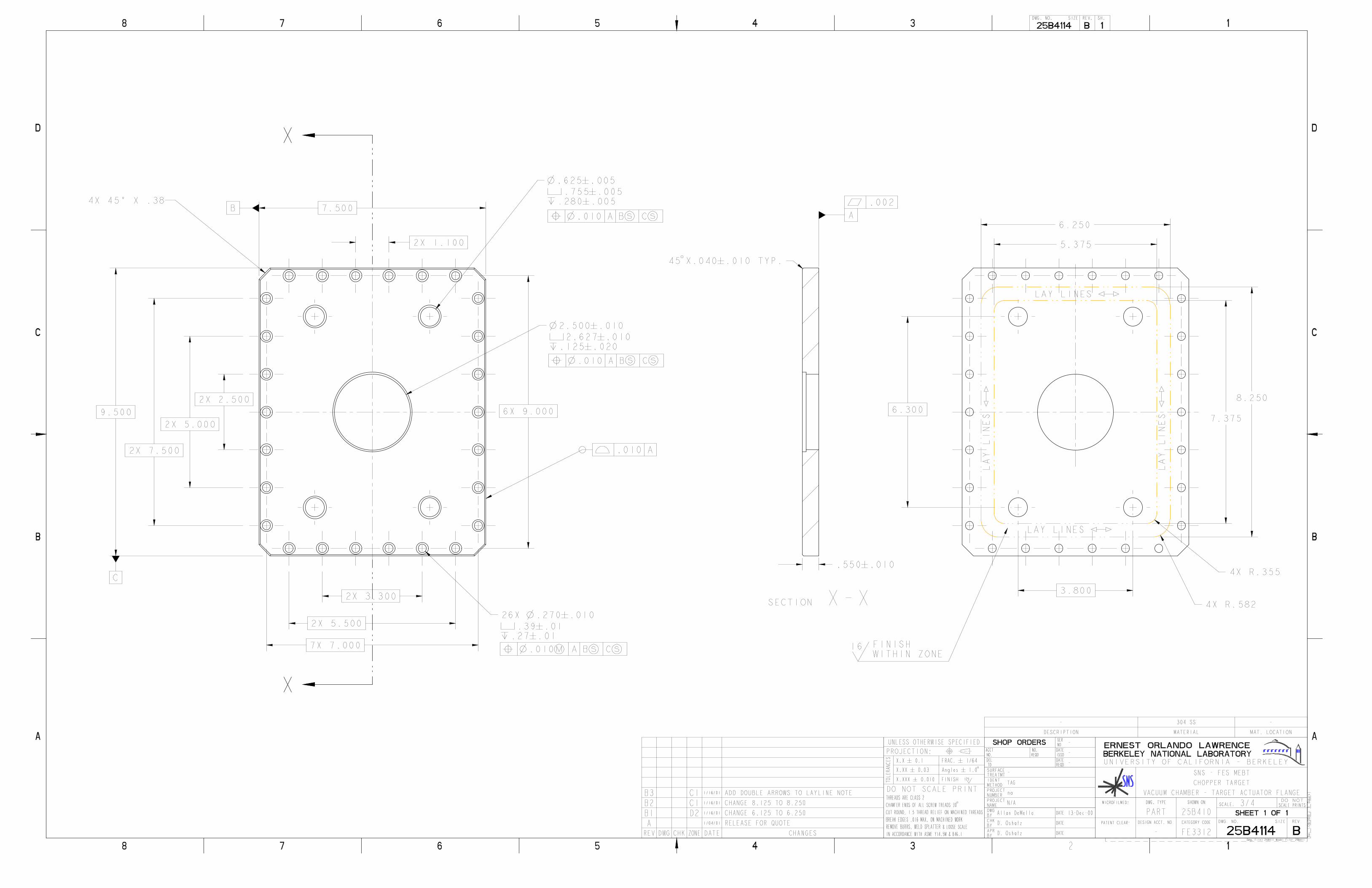
25B100 Modified Actuator, EMT-2.5-2/ Block Up 25B190 Stainless Steel Forging 25B400 Chopper Target Complete Assembly 25B401 Vacuum Chamber - Initial Machining 25B402 Bottom Plate Assembly 25B403 Vacuum Chamber - Bottom Plate 25B404 Viewport, 4.5" Conflat Flange 25B405 Vacuum Chamber Weldment 25B406 Vacuum Chamber - Mounting Plate 25B407 Vacuum Chamber Lower Assembly 25B408 Vacuum Chamber - View Port Flange Weldment 25B409 Vacuum Chamber - View Port Flange 25B410 Vacuum Chamber - Target Actuator Flange Weldment 25B411 Vacuum Chamber - Target Actuator Flange 25B412 Target Feedthru Port - Conflat Flange 25B413 Water Manifold 25B414 Water Manifold Conflat Flange 25B415 Water Manifold Inlet/Outlet Tube 25B416 Right Angle Tube, 1/2" O.D. x .035 Wall 25B417 Right Angle Cooling Tube
Copies of all drawings are included in the Appendix A.
Lawrence Berkeley National Laboratory - University of California Cat. Code Serial # Page
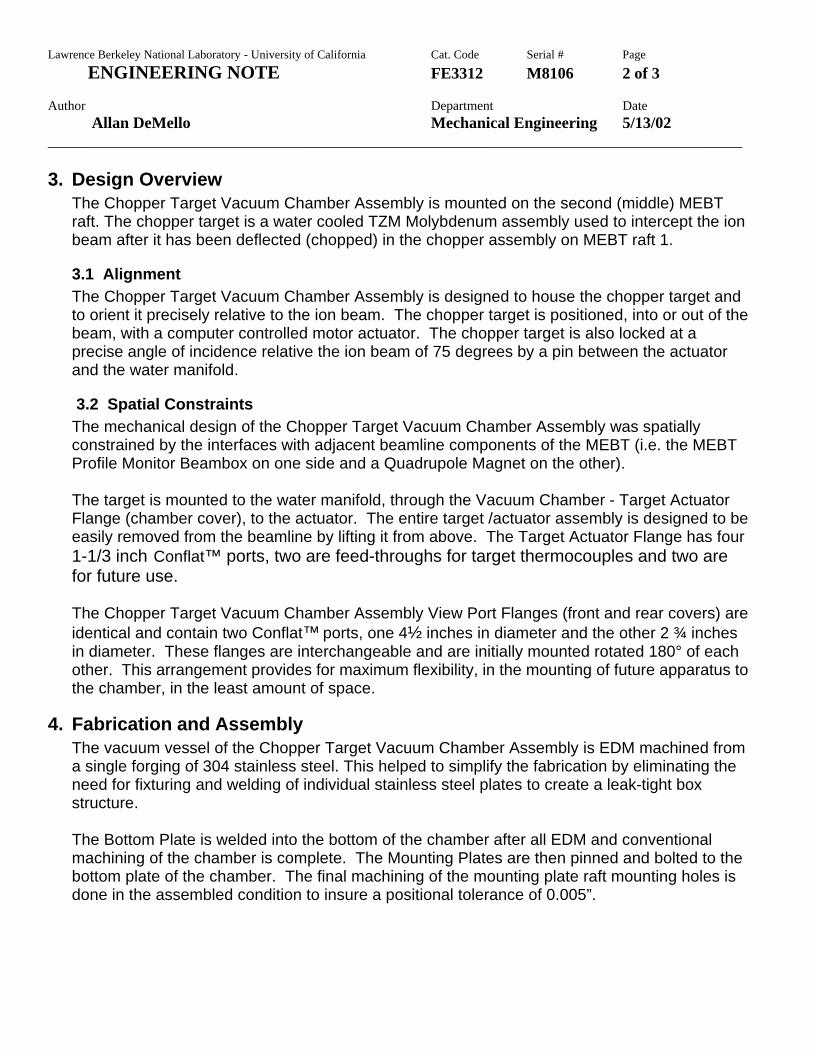
ENGINEERING NOTE FE3312 M8106 2 of 3 Author Department Date Allan DeMello Mechanical Engineering 5/13/02 _______________________________________________________________________________________ 3. Design Overview
The Chopper Target Vacuum Chamber Assembly is mounted on the second (middle) MEBT raft. The chopper target is a water cooled TZM Molybdenum assembly used to intercept the ion beam after it has been deflected (chopped) in the chopper assembly on MEBT raft 1.
3.1 Alignment The Chopper Target Vacuum Chamber Assembly is designed to house the chopper target and to orient it precisely relative to the ion beam. The chopper target is positioned, into or out of the beam, with a computer controlled motor actuator. The chopper target is also locked at a precise angle of incidence relative the ion beam of 75 degrees by a pin between the actuator and the water manifold.
3.2 Spatial Constraints The mechanical design of the Chopper Target Vacuum Chamber Assembly was spatially constrained by the interfaces with adjacent beamline components of the MEBT (i.e. the MEBT Profile Monitor Beambox on one side and a Quadrupole Magnet on the other). The target is mounted to the water manifold, through the Vacuum Chamber - Target Actuator Flange (chamber cover), to the actuator. The entire target /actuator assembly is designed to be easily removed from the beamline by lifting it from above. The Target Actuator Flange has four 1-1/3 inch Conflat™ ports, two are feed-throughs for target thermocouples and two are for future use. The Chopper Target Vacuum Chamber Assembly View Port Flanges (front and rear covers) are identical and contain two Conflat™ ports, one 4½ inches in diameter and the other 2 ¾ inches in diameter. These flanges are interchangeable and are initially mounted rotated 180° of each other. This arrangement provides for maximum flexibility, in the mounting of future apparatus to the chamber, in the least amount of space.
4. Fabrication and Assembly The vacuum vessel of the Chopper Target Vacuum Chamber Assembly is EDM machined from a single forging of 304 stainless steel. This helped to simplify the fabrication by eliminating the need for fixturing and welding of individual stainless steel plates to create a leak-tight box structure. The Bottom Plate is welded into the bottom of the chamber after all EDM and conventional machining of the chamber is complete. The Mounting Plates are then pinned and bolted to the bottom plate of the chamber. The final machining of the mounting plate raft mounting holes is done in the assembled condition to insure a positional tolerance of 0.005”.

Lawrence Berkeley National Laboratory - University of California Cat. Code Serial # Page
ENGINEERING NOTE FE3312 M8106 3 of 3 Author Department Date Allan DeMello Mechanical Engineering 5/13/02 _______________________________________________________________________________________
The finished chamber was fiducializied on the coordinate measuring machine (CMM) to verify its position, relative to the beamline, after being mounted to the raft #2 assembly.
5. Reference
5.1 T.Saleh, D. Oshatz, Y. Minamihara, “MEBT Chopper Target Final Design”, SNS-FES Technote FE-ME-031, June 2000
5.2 D. Oshatz, A DeMello, L. Doolittle, P. Luft, J. Staples, A. Zachoszcz, “Mechanical Design Of The SNS MEBT, PAC ’01, Chicago, June 2001 URL: http://accelconf.web.cern.ch/AccelConf/p01/HTML/A02277.HTM
5.3 D. Oshatz, T.Saleh, Y. Minamihara, R. DiGennaro, “MEBT Chopper Target Final Design Review”, SNS-FES Technote FE-ME-032, June 2000
6. SNS-FE Personnel Daryl Oshatz, MEBT Lead Mechanical Engineer Allan J. DeMello, Mechanical Engineer Yoshi Minimahara, Mechanical Design Technician Don Syversrud, Lead Mechanical Technician
7. Appendices Appendix A: Component and Assembly Drawings Appendix B: CAD Renderings and Photographs Appendix C: Outside Vendor Component Information Appendix D: Chamber Fiducialization Data Appendix E: Miscellaneous Information and Purchases

Lawrence Berkeley National Laboratory - University of California Cat. Code Serial # Page
ENGINEERING NOTE FE3312 M8106 Author Department Date Allan DeMello Mechanical Engineering 5/13/02 _______________________________________________________________________________________
Appendix A
Component and Assembly Drawings


Lawrence Berkeley National Laboratory - University of California Cat. Code Serial # Page
ENGINEERING NOTE FE3312 M8106 Author Department Date Allan DeMello Mechanical Engineering 5/13/02 _______________________________________________________________________________________
Appendix B
CAD Renderings and Photographs

Lawrence Berkeley National Laboratory - University of California Cat. Code Serial # Page
ENGINEERING NOTE FE3312 M8106 Author Department Date Allan DeMello Mechanical Engineering 5/13/02 _______________________________________________________________________________________
CAD Rendering
Chopper Target Complete Assembly
CAD Rendering Chopper Target Complete Assembly
Exploded View

Lawrence Berkeley National Laboratory - University of California Cat. Code Serial # Page
ENGINEERING NOTE FE3312 M8106 Author Department Date Allan DeMello Mechanical Engineering 5/13/02 _______________________________________________________________________________________
Chopper Target Complete Assembly
Chopper Target Complete Assembly
(one viewport flange removed)

Lawrence Berkeley National Laboratory - University of California Cat. Code Serial # Page
ENGINEERING NOTE FE3312 M8106 Author Department Date Allan DeMello Mechanical Engineering 5/13/02 _______________________________________________________________________________________
Close-up of Chopper Target in Vacuum Chamber
Chopper Target with Actuator Flange
and Actuator (target is shown not in its final form)
Close-up of the Chopper Target with Actuator Flange and Actuator
(target is shown not in its final form)

Lawrence Berkeley National Laboratory - University of California Cat. Code Serial # Page
ENGINEERING NOTE FE3312 M8106 Author Department Date Allan DeMello Mechanical Engineering 5/13/02 _______________________________________________________________________________________
Appendix C
Outside Vendor Component Information

Parker O-RingHandbook
Catalog ORD 5700A/US
Seals
ISO 9001 / QS9000 Certified


MS-01-28
VCO® O-ringFace Seal Fittings
www.swagelok.com

ZERO CLEARANCE CONNECTORS
Test ports attwo locations
for easyleak testing
Female nutthreads
silver platedfor easy
assembly
Male threadsrolled forstrength O-ring
containedcompletely
for maximumefficiency
Smooth finish on gland face
assures positive seal
Swagelok® VCO® O-ring face seal fittings are designed for rapidmake-up in pipe, tube and welded systems. Because of theirunique design, no axial clearance is required, allowing easyinstallation where space is limited. Sealing is accomplishedwith a captive O-ring in the body component. Assembliescan be used from high pressure to critical vacuum, within awide range of temperatures.
MATERIALSBodies, Glands and Nuts — 316 stainless steel.Automatic Tube Weld Fittings — 316L stainless steel.O-rings — 70 durometer fluorocarbon (Viton, Fluorel) is stan-dard on VCO bodies. 90 durometer fluorocarbon is used withSAE/MS threads. Perfluoroelastomer (Kalrez), Buna N, TFE,and ethylene-propylene available on special order.
TECHNICAL DATAPressure RatingsPressure ratings published in this catalog are calculated inaccordance with Power Piping Code ANSI B31.3.To determine pressure ratings in accordance with ANSIB31.1, multiply rating by 0.94.
Temperature RatingsMaximum temperature ratings for VCO Fittings are based onthe O-ring material used:
fluorocarbon: 400°F (200°C)Buna N: 250°F (120°C)TFE: 450°F (230°C)perfluoroelastomer: 550°F (280°C)ethylene-propylene: 300°F (140°C)
TestingVCO assemblies have been consistently helium leak testedto a rate of 4 x 10⁻⁹ std cm3/s. without leakage.
DimensionsFor reference only, subject to change.
PRODUCT LOCATOR
TYPICAL ASSEMBLY
Typical Assemblies . . . . . . . . . . . . . . . . . . . . . . . . . . Page 2Components
Nuts . . . . . . . . . . . . . . . . . . . . . . . . . . . . . . . . . . Page 3Glands . . . . . . . . . . . . . . . . . . . . . . . . . . . . . . Pages 3,4Bodies . . . . . . . . . . . . . . . . . . . . . . . . . . . . . Pages 4,5,6
WVCO® O-ringFace Seal Connectors . . . . . . . . . . . . . . . . . . . . . . . Page 7Installation Instructions . . . . . . . . . . . . . . . . . . . . . . Page 8VCO Fittings Used As Integral End Connections . . . . . . . . . . . . . Page 8
VCO assemblies are made up of three basic components
Female Nut Gland BodyGland
Female NutBody
The size of each component is designated by the first numeral in the Ordering Number. Each mated component will have the same numeral, except for the following: -2-VCObodies and glands use -4-VCO-4 nuts; -6-VCO bodies andglands use -8-VCO-4 nuts.
2
O-ring Uniform Size NumberUse chart below to find O-ring uniform size number of componentslisted in this catalog.
VCO ComponentSize
O-ring UniformSize Number
-2-VCO-4-VCO
010
-6-VCO-8-VCO
111
-12-VCO 116
-16-VCO 215
CAUTIONDo not mix or interchange parts with those of othermanufacturers.

Socket Weld Reducing Gland
Tx E
H
T
D
OrderingNumber Tx
WorkingPressure
12 600
TTube
Socket
1/8
E
0.09
H
0.77SS-4-VCO-3-2TSW 0.29
10 700
860
1/4
psig bar
0.18 0.81SS-8-VCO-3-4TSW 0.48 730
D
0.10
0.28
Blind Gland
Tx
H
OrderingNumber TxH
0.44SS-4-VCO-3-BL 0.38
0.44SS-8-VCO-3-BL 0.60
0.50SS-12-VCO-3-BL 0.92
0.50SS-16-VCO-3-BL 1.19
BODIES
Socket Weld ConnectorAdapts tubing to O-ring face seal.
TxT
F
E
BH
OrderingNumber Tx
WorkingPressure
12 600
TTube
Socket
1/8
E
0.09
H
0.88SS-2-VCO-1 0.29 860psig barD
0.10
B
0.10
FHexFlat
5/8
68001/4 5/80.18 1.09SS-4-VCO-1 0.38 4600.31 0.28
82003/8 15/160.28 1.28SS-6-VCO-1 0.60 5600.38 0.31
30001/2 15/160.40 1.34SS-8-VCO-1 0.60 2000.44 0.38
37003/4 1 5/160.62 1.50SS-12-VCO-1 0.92 2500.50 0.44
30001 1 5/80.87 1.72SS-16-VCO-1 1.19 2000.69 0.62
Automatic Tube Weld ConnectorAdapts tubing to O-ring face seal.
TxT
F
E
D
BH
OrderingNumber Tx
WorkingPressure
FHexFlat
TTubeSize E➀ HB
5100psig bar
1/4 5/80.18 1.59316L-4-VCO-1A 0.29 3500.75 0.02
D
NominalWall
Thickness0.035
33003/8 15/160.31 1.74316L-8-VCO-1A6 0.41 2200.75 0.03 0.035
35001/2 15/160.40 1.75316L-8-VCO-1A 0.55 2400.75 0.04 0.049
24003/4 1 5/160.65 1.78316L-12-VCO-1A 0.80 1600.75 0.04 0.049
24001 1 5/80.87 2.03316L-16-VCO-1A 1.06 1600.96 0.04 0.065
Male ConnectorConverts female NPT threadto O-ring face seal. F
E
P
CH
OrderingNumber
WorkingPressure
10 000
FHexFlat
PMaleNPTSize1/8 5/8
E➀
0.18
H1.16SS-4-VCO-1-2
C6800.38
13 400
psig bar
1/4 5/80.18 1.34SS-4-VCO-1-4 9200.56
78003/8 15/160.38 1.46SS-8-VCO-1-6 5300.56
10 0001/2 15/160.40 1.65SS-8-VCO-1-8 6800.75
73003/4 1 5/160.62 1.75SS-12-VCO-1-12 5000.75
53001 1 5/80.87 1.97SS-16-VCO-1-16 3600.94
SAE/MS ConnectorConverts SAE/MS straight threadboss to O-ring face seal.
F
E
S
CH
OrderingNumber
WorkingPressure
4500
FHexFlat
SStraightThread
Size7/16-20 11/16
E➀
0.18
H1.24SS-4-VCO-1-4ST
C3100.36
psig bar
ST O-ringUniform
SizeNumber ➁
-904
45009/16-18 11/160.18 1.17SS-4-VCO-1-6ST -906 3100.39
45007/16-20 15/160.20 1.36SS-8-VCO-1-4ST -904 3100.36
45009/16-18 15/160.28 1.39SS-8-VCO-1-6ST -906 3100.39
45003/4-16 1 0.40 1.47SS-8-VCO-1-8ST -908 3100.44
36001-1/16-12 1 3/80.62 1.73SS-12-VCO-1-12ST -912 2400.59
29001-5/16-12 1 5/80.87 1.79SS-16-VCO-1-16ST -916 1900.59
4
➀ Some configurations have more than one bore size. This dimension always references thesmallest nominal ID of the part.
➁ O-rings used with SAE/MS threads are fluorocarbon (90 durometer).
D


All dimensions are in inches. *With plug disconnected. Operable to 200ºC with plug engaged. + Not ANSI symbol. Products in this catalog are vacuum-rated 10-10 torr unless otherwise noted. For pressure rating, see each table. See Technical Reference section for cable attachment. **Uses compensating wire; maximum jun ction temperature 250ºC
ANSI TYPE
Thermocouple Materials
Plug Color
External Pressure PSIG @ 20ºC
Int. Pressure PSIG @ 20ºC
Figure Number
Part Number
K Chromel®/Alumel® Yellow 250 250 80 10583-01-CF J Iron/Constantan® Black 250 250 80 10583-02-CF
C+ Tungsten 5% Re**/Tungsten 26% Re**
Red 250 250 80 10583-03-CF
E Chromel®/Constantan® Violet 250 250 80 10583-04-CF Nt Nicrosil/Nisil Orange 250 250 80 10583-05-CF K Chromel®/Alumel® Yellow 250 250 79 8118-01-CF N+ Nicrosil/Nisil Orange 250 250 79 8118-02-CF
C+ Tungsten 5% Re**/Tungsten 26% Re**
Red 250 250 79 8118-04-CF
E Chromel®/Constantan® Violet 250 250 79 8118-05-CF J Iron/Constantan® Black 250 250 79 8370-01-CF

EMT Series Precision Translators
[Home] [Company] [Products] [Catalog] [Shows] [Employment] [Prev] [Next]
SEE BELOW FOR NEW PRICING.
EMT series translators provide single axis (Z only) motion. Thesetranslators are based on the EM-200 series manipulator Z drive. They arecalibrated in 0.001" increments with 0.100" travel per turn with a coarseside scale. They are available with four different bellows I.D.s. Thestandard base (stationary) flange is 2.75" O.D., with large O.D.s optional(required on longer travel units). The traveling flange is 2.75" O.D. BothFlanges are supplied tapped as standard, but we can supply clearanceholes with appropriate neck assemblies to accommodate thoseapplications which require it.
Assemblies are available with or without axis tube probe/bearingassembly.
The 2.75" and 4.5" O.D. flanges are rigidly attached to the traveling andbase structure in a special way. The "Super Grip System" holds the flange
about its perimeter by means of a tongue and groove, providing positive, rigid attachment with thegreatest lever arm possible. The flange (and thus the bolt pattern) is adjustable to any orientation.
The EMTX Series translator is available for applications where longer strokes and/or larger payloadsare required.
EMT Series Specifications
1.04", 1.39", 1.87", 2.25" or 2.5" I.D.bellows 2" to 36"+ Z travel, gearbox Acmedrive, 0.100"/turn, 10 turns/inch,0.001" divisions, position lock
Base Flange
2.75" (standard), 4.5", 6" or 8" O.D.base flange, tapped (except 2.5" IDbellows which have 4.5" O.D. Flangesstandard)
Traveling Flange
2.75" (standard), 3.3" or 4.5" O.D.traveling flange, tapped
Features
Hardened stainless steel Z guide rods All linear bearings hardened stainless steel Bakeable to 200°C fully assembled Stainless steel only material exposed tovacuum Includes 2" Z travel (additional Z travelavailable in 2" increments)
Motion Specifications
Z axisresolution <0.0005"(0.013mm) repeatability <0.0005"(0.013mm) backlash <0.0007"(0.018mm)
Ordering Information
Single-Axis Ultra High Vacuum Precision Translatorswith 2" of Z travel
1 of 3 5/15/2002 12:17 PM
EMT Series Precision Translators (UHV Manipulator) - Thermionics Vacuum Products http://www.thermionics.com/emt.htm

ZID
DIMENSIONS
Model No.NewPrice
Addl.Z Travel
per Inch**A C min*
1.04" 9.5" 2.83" EMT-1.04-2 $1,520. $195.
1.39"**** 9.5" 2.83" EMT-1.39-2 $1,575. $224.
1.87" 9.5" 2.83" EMT-1.87-2 $1,975. $248.
2.25" 10.5" 2.83" EMT-2.25-2 $2,740. $272.***
2.5" 10.5" 2.83" EMT-2.5-2 $2,910. $280.***
*NOTE: This equipment has the shortest possible minimumflange-to-flange "C min" dimension. This distance can be changed by alarge number of possible options. The C min dimension shown isonly for the exact model listed (both flanges tapped). Please consultthe factory for further information.
**Additional Z travel is available in 2" increments.
***With 4.5" O.D. Base and traveling flange, and up to 6" stroke,maximum.
****When Z stroke exceeds 12" this model is changed to a 1.53" IDbellows at no additional charge.
EMTX Extended Stroke Series
For longer strokes or increasedpayload
OPN linear bearings ontraveling stage Intermittent support for guiderods Longer bearing spacing ontraveling stage Double Acme nutarrangement
Ordering Information
EMTX Single-Axis Ultra High Vacuum PrecisionTranslatorswith 2" of Z travel
ZID
DIMENSIONS
Model No.NewPrice
Addl.Z Travelper Inch*A C min
1.04" Consult Factory EMTX-1.04-2 $2,010. $220.
1.39" Consult Factory EMTX-1.39-2 $2085. $260.
1.87" Consult Factory EMTX-1.87-2 $2,600. $280.
2.25" Consult Factory EMTX-2.25-2 $3,625. $315.
2.5" Consult Factory EMTX-2.5-2 $3,855. $330.
*NOTE: Additional Z travel is available in 2" increments.
Base Flange
O.D.
DIMENSIONS
"B" "E" "F"
2.75" 3.50" 1.73" 5.00"
4.50" 3.50" 2.76" 7.18"
6.00" 3.50" 3.00" 6.78"
8.00" 5.00" 4.00" 8.78"
/PL Probe Support OptionAdds linear all stainless steel bearing at base of Z stage
TubeO.D.
Add to"C"
Dimension
ModelNo.
SSBasePrice
0.75" 2.50" /PL-.75 $740.
1.00" 2.65" /PL-1 $745.
1.50" 2.25" /PL-1.5* $1,000.
2.00" 2.50" /PL-2 $1,215.
*NOTE: 1.5" probe requires 1.87" bellows.
2 of 3 5/15/2002 12:17 PM
EMT Series Precision Translators (UHV Manipulator) - Thermionics Vacuum Products http://www.thermionics.com/emt.htm

Options
Option Name Description Price
MicrometerZ Drive /MZD
Available on2" Z travel,1.39" IDbellows only
2" diameterdrum dial
0.0001"divisions
$75.
ExtendedBackframe /EB
Allowsgreaterspaceabouttravelingflange
Add 1.5" to"B"dimension
$235.
BaseFlangeChange
from 2.75"O.D. to:
/B-3.3 3.3" O.D. $135.
/B-3.3/EB
3.3" O.D.Withextendedbackframe
$370.
/B-4.54.5" O.D.includes/EB option
$400.
/B-66" O.D.Includes/EB option
$460.
/B-88" O.D.Includes/EB option
$465.
TravelingFlangeChange
from 2.75"O.D. To:
/T-3.33.3" O.D.Includes/EB option
$380.
/T-4.54.5" O.D.Includes/EB option
$400.
/MS Stepping or /MY Synchronous MotorDrive
/PLR or /PTF Probe Support OptionAdds linear all stainless steel bearing at base of Z stage
TubeO.D.
Add to"C"
Dimension
ModelNo.
SSBasePrice
Teflon®
ModelNo.
Teflon®
BasePrice
0.75" 2.25" /PLR-.75 $995. /PTF-.75 $500.
1.00" 3.30" /PLR-1 $1,150. /PTF-1 $550.
1.50" 2.63" /PLR-1.5* $1,775. /PTF-1.5* $770.
2.00" 2.50" /PLR-2 $1,840. /PTF-2 $885.
*NOTE: 1.5" probe requires 1.87" bellows
[Home] [Company] [Products] [Catalog] [Shows] [Employment] [Prev] [Next]
Thermionics Vacuum ProductsPhone: 800-962-2310
Last updated June 16, 2000.
3 of 3 5/15/2002 12:17 PM
EMT Series Precision Translators (UHV Manipulator) - Thermionics Vacuum Products http://www.thermionics.com/emt.htm
Lawrence Berkeley National Laboratory - University of California Cat. Code Serial # Page
ENGINEERING NOTE FE3312 M8106 Author Department Date Allan DeMello Mechanical Engineering 5/13/02 _______________________________________________________________________________________
Appendix D
Chamber Fiducialization Data


Lawrence Berkeley National Lab Precision Measurement Services Robert Connors Building 77/158 (510) 486-7611 DESCRIPTION : PART : SNS FES MEBT CHOPPER TARGET ------------------------------------------------------------------------------ MEAS NOM DEV UPTOL LWTOL O/T ------------------------------------------------------------------------------ **** FIRST RUN **** LEFT SIDE POINT POINT LFT_PNT CART CS7 INCH ANGDEC 10:15 May 10,2001 X -8.7240 -8.7250 0.0010 0.0000 0.0000 0.0010 Y -2.2022 -2.2000 -0.0022 0.0000 0.0000 -0.0022 Z 8.5007 8.5000 0.0007 0.0000 0.0000 0.0007 I -0.0002 0.0000 -0.0002 J -1.0000 -1.0000 0.0000 K -0.0000 0.0000 -0.0000 ________________________________________________________________________________ RIGHT SIDE POINT POINT RGHT_PNT CART CS7 INCH ANGDEC 10:15 May 10,2001 X 8.7241 8.7250 -0.0009 0.0000 0.0000 -0.0009 Y -2.1957 -2.2000 0.0043 0.0000 0.0000 0.0043 Z 8.5007 8.5000 0.0007 0.0000 0.0000 0.0007 I 0.0004 0.0000 0.0004 J -1.0000 -1.0000 0.0000 K -0.0000 0.0000 -0.0000 ________________________________________________________________________________ LEFT END POINT POINT LEFT_END CART CS7 INCH ANGDEC 10:16 May 10,2001 X -9.1980 -9.2000 0.0020 0.0000 0.0000 0.0020 Y 0.0000 -0.0000 0.0000 0.0000 0.0000 0.0000 Z 8.3503 8.3500 0.0003 0.0000 0.0000 0.0003 I -1.0000 -1.0000 0.0000 J -0.0005 0.0000 -0.0005 K 0.0001 -0.0000 0.0001 ________________________________________________________________________________ RIGHT END POINT POINT RGHT_END CART CS7 INCH ANGDEC 10:16 May 10,2001 X 9.1988 9.2000 -0.0012 0.0000 0.0000 -0.0012 Y -0.0007 0.0000 -0.0007 0.0000 0.0000 -0.0007 Z 8.3503 8.3500 0.0003 0.0000 0.0000 0.0003 I 1.0000 1.0000 -0.0000 J 0.0004 -0.0000 0.0004 K 0.0000 0.0000 0.0000 ________________________________________________________________________________ PARALLEL OF WINGS PARLEL PARA FA(WING_PLN) FA(DAT_A) INCH Parlel 0.0045 0.0045 0.0100 |+*++ ________________________________________________________________________________ DISTANCE OF BORES TO WING PLANE DISTB DIST_Z1 FEAT(WING_PLN) FEAT(FRNT_CIRC) INCH

Distb 4.1404 4.1400 0.0004 0.0050 -0.0050 ----|*+++ ________________________________________________________________________________ DISTB DIST_Z1 FEAT(WING_PLN) FEAT(BACK_CIRC) INCH Distb 4.1401 4.1400 0.0001 0.0050 -0.0050 ----|*+++ ________________________________________________________________________________ WING HOLE LOCATIONS DIAM DIA_1 FEAT(CIRC1) INCH Diam 0.4386 0.4380 0.0006 0.0100 -0.0100 ----|*+++ ________________________________________________________________________________ 2D POS_1 FA(CIRC1),MMC FA(DAT_A)RFS FA(DAT_B)RFS FA(DAT_C) RFS INCH Tpos2d 0.0000 0.0000 0.0156 *++++ ________________________________________________________________________________ CIRCLE CIRC1 CART CS7 INCH ANGDEC 10:20 May 10,2001 X -8.7269 -8.7250 -0.0019 0.0000 0.0000 -0.0019 Y 1.6928 1.7000 -0.0072 0.0000 0.0000 -0.0072 Z 8.3899 8.3893 0.0006 0.0000 0.0000 0.0006 I 0.0000 0.0000 0.0000 J 0.0000 0.0000 0.0000 K 1.0000 1.0000 0.0000 Dia 0.4386 0.4380 0.0006 0.0100 -0.0100 ----|*+++ Cirlty 0.0002 0.0004 |++*+ ________________________________________________________________________________ DIAM DIA_1 FEAT(CIRC2) INCH Diam 0.4387 0.4380 0.0007 0.0100 -0.0100 ----|*+++ ________________________________________________________________________________ 2D POS_1 FA(CIRC2),MMC FA(DAT_A)RFS FA(DAT_B)RFS FA(DAT_C) RFS INCH Tpos2d 0.0000 0.0000 0.0157 *++++ ________________________________________________________________________________ CIRCLE CIRC2 CART CS7 INCH ANGDEC 10:20 May 10,2001 X -8.7237 -8.7250 0.0013 0.0000 0.0000 0.0013 Y -1.7046 -1.7000 -0.0046 0.0000 0.0000 -0.0046 Z 8.3899 8.3893 0.0006 0.0000 0.0000 0.0006 I 0.0000 0.0000 0.0000 J 0.0000 0.0000 0.0000 K 1.0000 1.0000 0.0000 Dia 0.4387 0.4380 0.0007 0.0100 -0.0100 ----|*+++ Cirlty 0.0005 0.0004 0.0001 ________________________________________________________________________________ DIAM DIA_1 FEAT(CIRC3) INCH Diam 0.4388 0.4380 0.0008 0.0100 -0.0100 ----|*+++ ________________________________________________________________________________ 2D POS_1 FA(CIRC3),MMC FA(DAT_A)RFS FA(DAT_B)RFS FA(DAT_C) RFS INCH Tpos2d 0.0000 0.0000 0.0158 *++++ ________________________________________________________________________________ CIRCLE CIRC3 CART CS7 INCH ANGDEC 10:20 May 10,2001 X 8.7241 8.7250 -0.0009 0.0000 0.0000 -0.0009 Y -1.6952 -1.7000 0.0048 0.0000 0.0000 0.0048 Z 8.3899 8.3893 0.0006 0.0000 0.0000 0.0006 I 0.0000 0.0000 0.0000 J 0.0000 0.0000 0.0000 K 1.0000 1.0000 0.0000 Dia 0.4388 0.4380 0.0008 0.0100 -0.0100 ----|*+++ Cirlty 0.0005 0.0004 0.0001 ________________________________________________________________________________ DIAM DIA_1 FEAT(CIRC4) INCH Diam 0.4400 0.4380 0.0020 0.0100 -0.0100 ----|*+++ ________________________________________________________________________________ 2D POS_1 FA(CIRC4),MMC FA(DAT_A)RFS FA(DAT_B)RFS FA(DAT_C) RFS INCH Tpos2d 0.0000 0.0000 0.0170 *++++ ________________________________________________________________________________

CIRCLE CIRC4 CART CS7 INCH ANGDEC 10:20 May 10,2001 X 8.7236 8.7250 -0.0014 0.0000 0.0000 -0.0014 Y 1.7045 1.7000 0.0045 0.0000 0.0000 0.0045 Z 8.3898 8.3893 0.0005 0.0000 0.0000 0.0005 I 0.0000 0.0000 0.0000 J 0.0000 0.0000 0.0000 K 1.0000 1.0000 0.0000 Dia 0.4400 0.4380 0.0020 0.0100 -0.0100 ----|*+++ Cirlty 0.0002 0.0004 |++*+ ________________________________________________________________________________ **** SECOND RUN **** LEFT SIDE POINT POINT LFT_PNT CART CS7 INCH ANGDEC 10:26 May 10,2001 X -8.7241 -8.7250 0.0009 0.0000 0.0000 0.0009 Y -2.2024 -2.2000 -0.0024 0.0000 0.0000 -0.0024 Z 8.5008 8.5000 0.0008 0.0000 0.0000 0.0008 I -0.0062 0.0000 -0.0062 J -1.0000 -1.0000 0.0000 K -0.0000 0.0000 -0.0000 ________________________________________________________________________________ RIGHT SIDE POINT POINT RGHT_PNT CART CS7 INCH ANGDEC 10:26 May 10,2001 X 8.7242 8.7250 -0.0008 0.0000 0.0000 -0.0008 Y -2.1956 -2.2000 0.0044 0.0000 0.0000 0.0044 Z 8.5008 8.5000 0.0008 0.0000 0.0000 0.0008 I -0.0003 0.0000 -0.0003 J -1.0000 -1.0000 0.0000 K -0.0000 0.0000 -0.0000 ________________________________________________________________________________ LEFT END POINT POINT LEFT_END CART CS7 INCH ANGDEC 10:27 May 10,2001 X -9.1981 -9.2000 0.0019 0.0000 0.0000 0.0019 Y 0.0003 -0.0000 0.0003 0.0000 0.0000 0.0003 Z 8.3503 8.3500 0.0003 0.0000 0.0000 0.0003 I -1.0000 -1.0000 0.0000 J -0.0004 0.0000 -0.0004 K 0.0001 -0.0000 0.0001 ________________________________________________________________________________ RIGHT END POINT POINT RGHT_END CART CS7 INCH ANGDEC 10:27 May 10,2001 X 9.1987 9.2000 -0.0013 0.0000 0.0000 -0.0013 Y -0.0007 0.0000 -0.0007 0.0000 0.0000 -0.0007 Z 8.3503 8.3500 0.0003 0.0000 0.0000 0.0003 I 1.0000 1.0000 -0.0000 J 0.0015 -0.0000 0.0015 K -0.0001 0.0000 -0.0001 ________________________________________________________________________________ PARALLEL OF WINGS PARLEL PARA FA(WING_PLN) FA(DAT_A) INCH Parlel 0.0045 0.0045 0.0100 |+*++ ________________________________________________________________________________ DISTANCE OF BORES TO WING PLANE DISTB DIST_Z1 FEAT(WING_PLN) FEAT(FRNT_CIRC) INCH Distb 4.1406 4.1400 0.0006 0.0050 -0.0050 ----|*+++ ________________________________________________________________________________ DISTB DIST_Z1 FEAT(WING_PLN) FEAT(BACK_CIRC) INCH

Distb 4.1402 4.1400 0.0002 0.0050 -0.0050 ----|*+++ ________________________________________________________________________________ WING HOLE LOCATIONS DIAM DIA_1 FEAT(CIRC1) INCH Diam 0.4386 0.4380 0.0006 0.0100 -0.0100 ----|*+++ ________________________________________________________________________________ 2D POS_1 FA(CIRC1),MMC FA(DAT_A)RFS FA(DAT_B)RFS FA(DAT_C) RFS INCH Tpos2d 0.0000 0.0000 0.0156 *++++ ________________________________________________________________________________ CIRCLE CIRC1 CART CS7 INCH ANGDEC 10:30 May 10,2001 X -8.7271 -8.7250 -0.0021 0.0000 0.0000 -0.0021 Y 1.6927 1.7000 -0.0073 0.0000 0.0000 -0.0073 Z 8.3897 8.3893 0.0004 0.0000 0.0000 0.0004 I 0.0000 0.0000 0.0000 J 0.0000 0.0000 0.0000 K 1.0000 1.0000 0.0000 Dia 0.4386 0.4380 0.0006 0.0100 -0.0100 ----|*+++ Cirlty 0.0003 0.0004 |++*+ ________________________________________________________________________________ DIAM DIA_1 FEAT(CIRC2) INCH Diam 0.4387 0.4380 0.0007 0.0100 -0.0100 ----|*+++ ________________________________________________________________________________ 2D POS_1 FA(CIRC2),MMC FA(DAT_A)RFS FA(DAT_B)RFS FA(DAT_C) RFS INCH Tpos2d 0.0000 0.0000 0.0157 *++++ ________________________________________________________________________________ CIRCLE CIRC2 CART CS7 INCH ANGDEC 10:30 May 10,2001 X -8.7239 -8.7250 0.0011 0.0000 0.0000 0.0011 Y -1.7047 -1.7000 -0.0047 0.0000 0.0000 -0.0047 Z 8.3897 8.3893 0.0004 0.0000 0.0000 0.0004 I 0.0000 0.0000 0.0000 J 0.0000 0.0000 0.0000 K 1.0000 1.0000 0.0000 Dia 0.4387 0.4380 0.0007 0.0100 -0.0100 ----|*+++ Cirlty 0.0005 0.0004 0.0001 ________________________________________________________________________________ DIAM DIA_1 FEAT(CIRC3) INCH Diam 0.4388 0.4380 0.0008 0.0100 -0.0100 ----|*+++ ________________________________________________________________________________ 2D POS_1 FA(CIRC3),MMC FA(DAT_A)RFS FA(DAT_B)RFS FA(DAT_C) RFS INCH Tpos2d 0.0000 0.0000 0.0158 *++++ ________________________________________________________________________________ CIRCLE CIRC3 CART CS7 INCH ANGDEC 10:30 May 10,2001 X 8.7240 8.7250 -0.0010 0.0000 0.0000 -0.0010 Y -1.6953 -1.7000 0.0047 0.0000 0.0000 0.0047 Z 8.3897 8.3893 0.0004 0.0000 0.0000 0.0004 I 0.0000 0.0000 0.0000 J 0.0000 0.0000 0.0000 K 1.0000 1.0000 0.0000 Dia 0.4388 0.4380 0.0008 0.0100 -0.0100 ----|*+++ Cirlty 0.0006 0.0004 0.0002 ________________________________________________________________________________ DIAM DIA_1 FEAT(CIRC4) INCH Diam 0.4401 0.4380 0.0021 0.0100 -0.0100 ----|*+++ ________________________________________________________________________________ 2D POS_1 FA(CIRC4),MMC FA(DAT_A)RFS FA(DAT_B)RFS FA(DAT_C) RFS INCH Tpos2d 0.0000 0.0000 0.0171 *++++ ________________________________________________________________________________ CIRCLE CIRC4 CART CS7 INCH ANGDEC 10:30 May 10,2001 X 8.7234 8.7250 -0.0016 0.0000 0.0000 -0.0016 Y 1.7044 1.7000 0.0044 0.0000 0.0000 0.0044

Z 8.3897 8.3893 0.0004 0.0000 0.0000 0.0004 I 0.0000 0.0000 0.0000 J 0.0000 0.0000 0.0000 K 1.0000 1.0000 0.0000 Dia 0.4401 0.4380 0.0021 0.0100 -0.0100 ----|*+++ Cirlty 0.0001 0.0004 |+*++ ________________________________________________________________________________ CIRCLE BACK_CIRC CART CS7 INCH ANGDEC 15:00 May 11,2001 X -0.0003 0.0000 -0.0003 0.0000 0.0000 -0.0003 Y 2.8874 2.8875 -0.0001 0.0000 0.0000 -0.0001 Z 4.4247 4.4250 -0.0003 0.0000 0.0000 -0.0003 I -0.0000 -0.0000 0.0000 J 1.0000 1.0000 0.0000 K 0.0000 0.0000 0.0000 Dia 1.7633 1.7600 0.0033 0.0050 -0.0050 ----|++*+ Cirlty 0.0002 0.0004 |+*++ ________________________________________________________________________________ CIRCLE FRNT_CIRC CART CS7 INCH ANGDEC 15:00 May 11,2001 X 0.0003 -0.0000 0.0003 0.0000 0.0000 0.0003 Y -2.8251 -2.8250 -0.0001 0.0000 0.0000 -0.0001 Z 4.4227 4.4250 -0.0023 0.0000 0.0000 -0.0023 I 0.0000 0.0000 0.0000 J -1.0000 -1.0000 0.0000 K 0.0000 0.0000 0.0000 Dia 1.6267 1.6250 0.0017 0.0050 -0.0050 ----|+*++ Cirlty 0.0002 0.0004 |+*++ ________________________________________________________________________________

Lawrence Berkeley National Laboratory - University of California Cat. Code Serial # Page
ENGINEERING NOTE FE3312 M8106 Author Department Date Allan DeMello Mechanical Engineering 5/13/02 _______________________________________________________________________________________
Appendix E
Miscellaneous Information and Purchases