Embed Size (px)
Citation preview
10. SATELLITE COMMUNICATION & RADAR SENSORS
Applied EM by Ulaby, Michielssen and Ravaioli
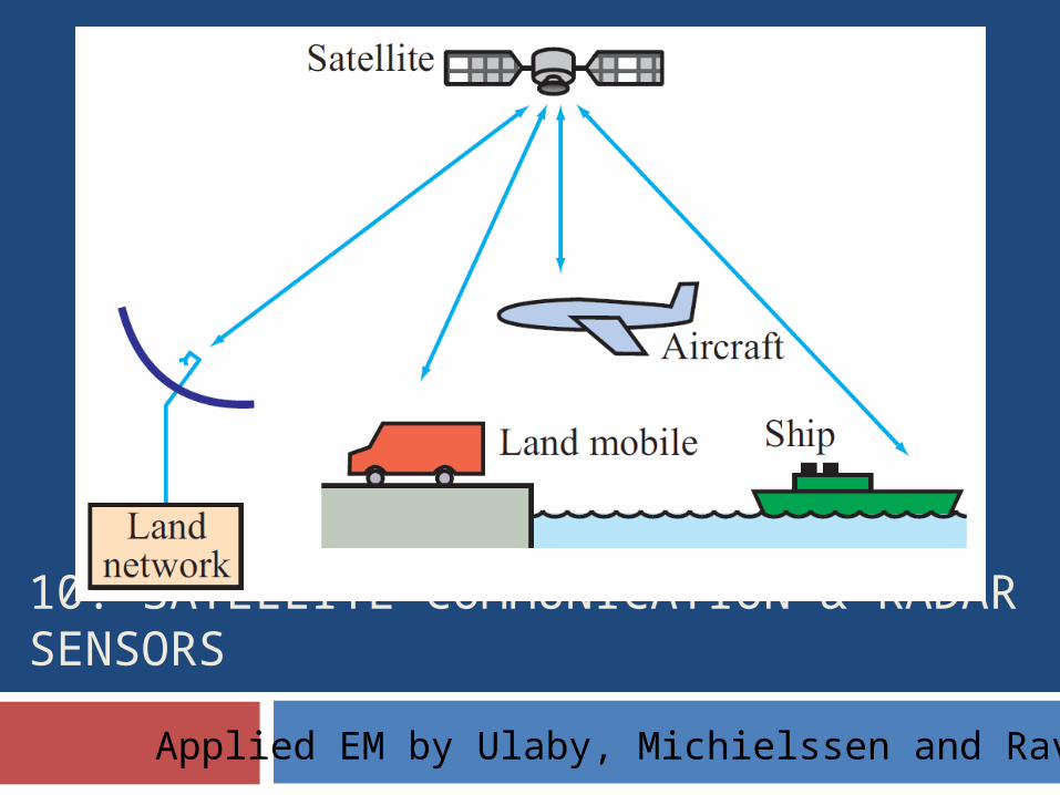
Overview
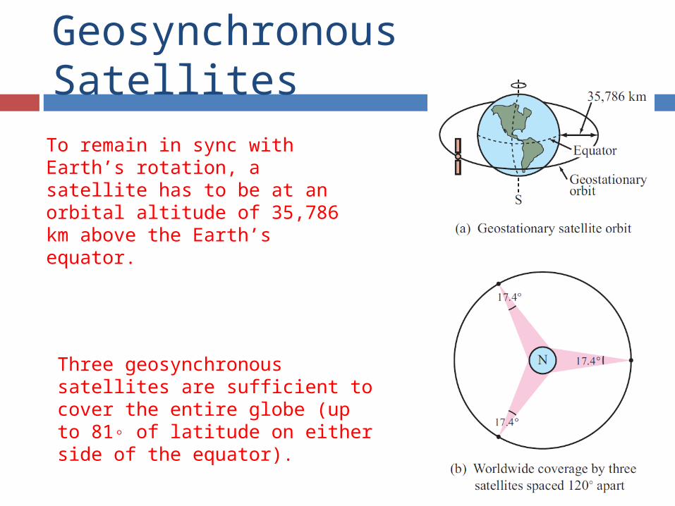
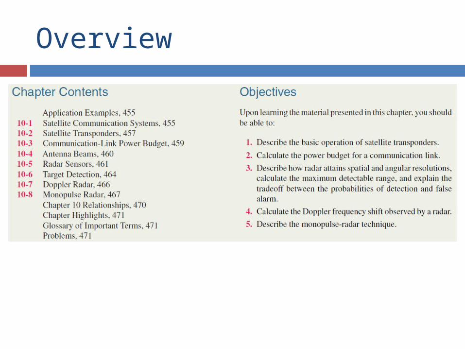
Geosynchronous Satellites
To remain in sync with Earth’s rotation, a satellite has to be at an orbital altitude of 35,786 km above the Earth’s equator.
Three geosynchronous satellites are sufficient to cover the entire globe (up to 81◦ of latitude on either side of the equator).
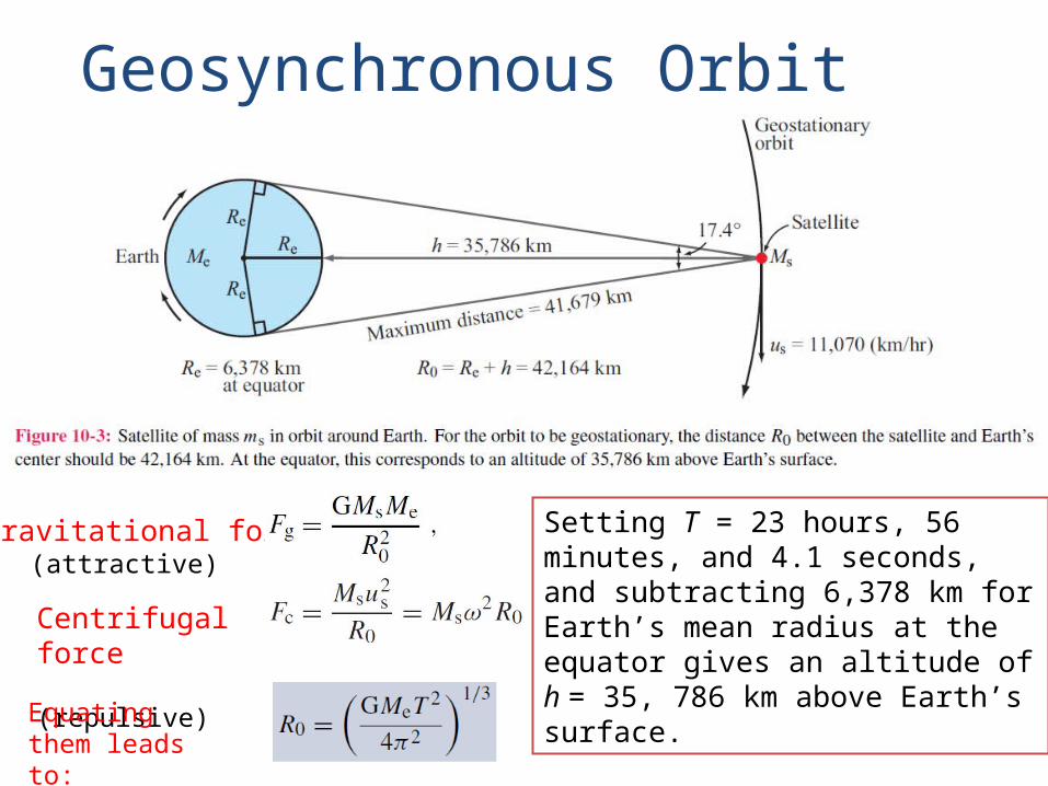
Geosynchronous Orbit
Gravitational force (attractive)
Centrifugal force (repulsive)
Equating them leads to:
Setting T = 23 hours, 56 minutes, and 4.1 seconds, and subtracting 6,378 km for Earth’s mean radius at the equator gives an altitude of h = 35, 786 km above Earth’s surface.
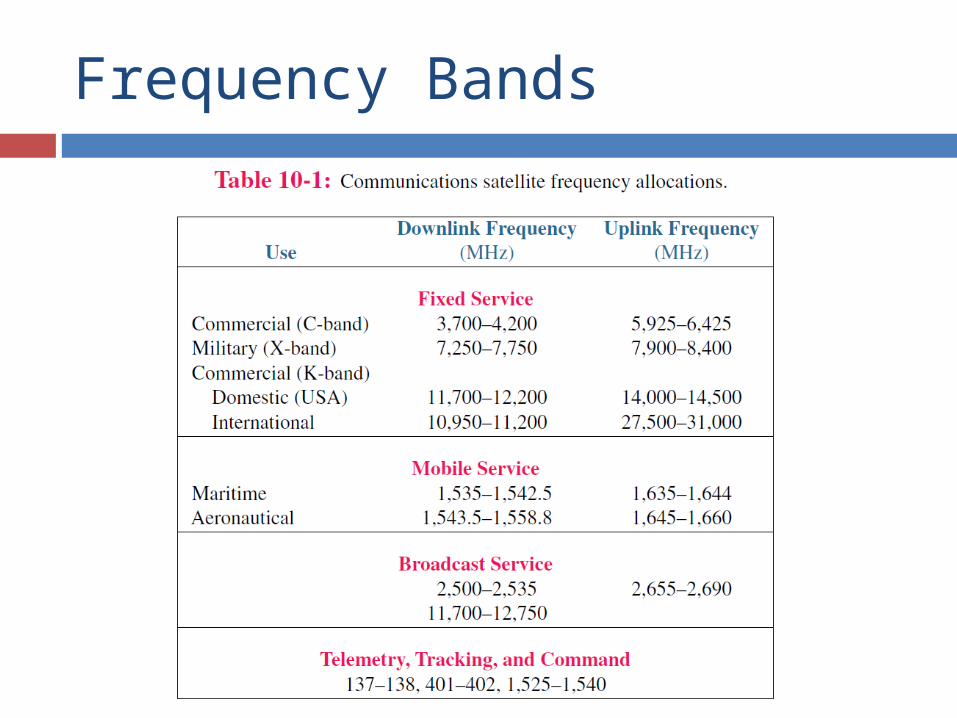
Frequency Bands
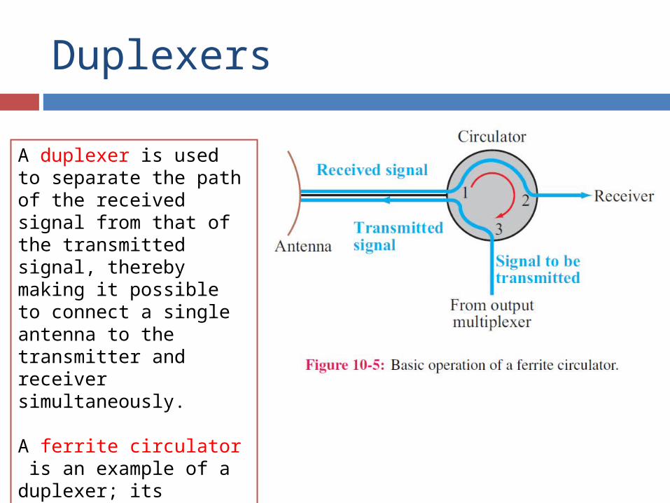
Duplexers
A duplexer is used to separate the path of the received signal from that of the transmitted signal, thereby making it possible to connect a single antenna to the transmitter and receiver simultaneously.
A ferrite circulator is an example of a duplexer; its ferrite material allows waves to travel in only the clockwise direction.
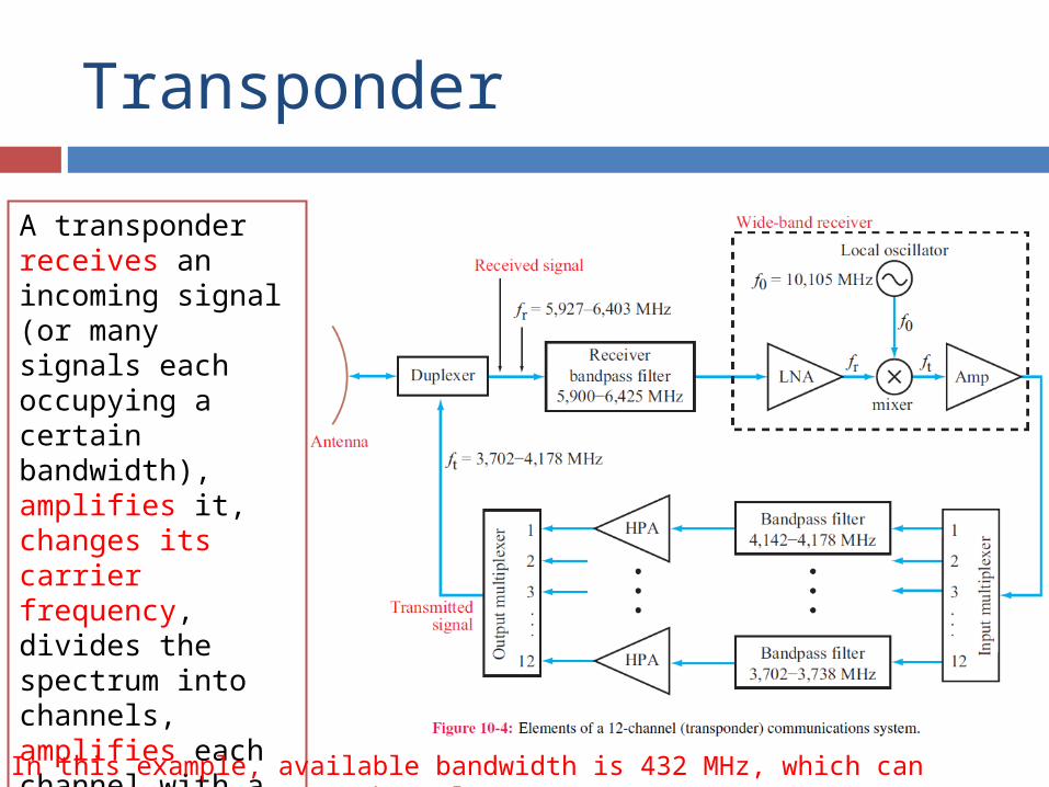
Transponder
A transponder receives an incoming signal (or many signals each occupying a certain bandwidth), amplifies it, changes its carrier frequency, divides the spectrum into channels, amplifies each channel with a high power amplifier, combines all channels and then transmits the full spectrum to the intended destination.
In this example, available bandwidth is 432 MHz, which can accommodate 75-100 TV Channels
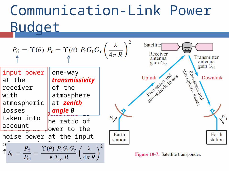
Communication-Link Power Budget
The signal-to-noise ratio is defined as the ratio of the signal power to the noise power at the input of an equivalent noise-free receiver
input power at the receiver with atmospheric losses taken into account
one-way transmissivity of the atmosphere at zenith angle θ
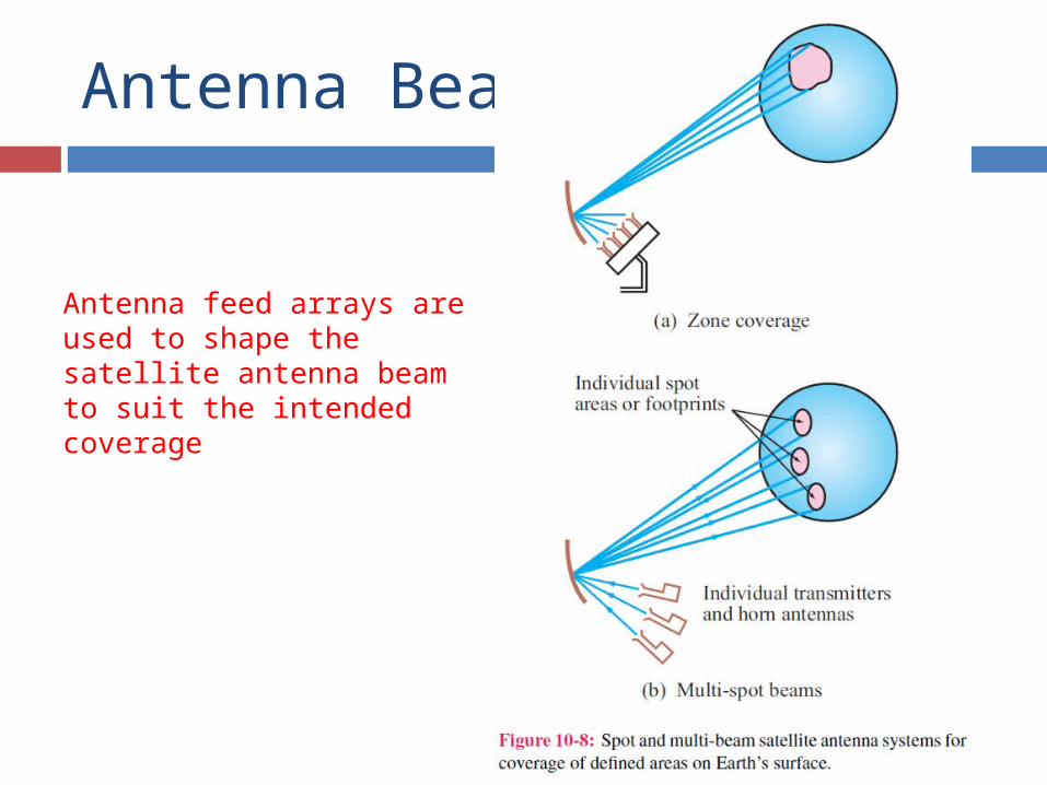
Antenna Beams
Antenna feed arrays are used to shape the satellite antenna beam to suit the intended coverage
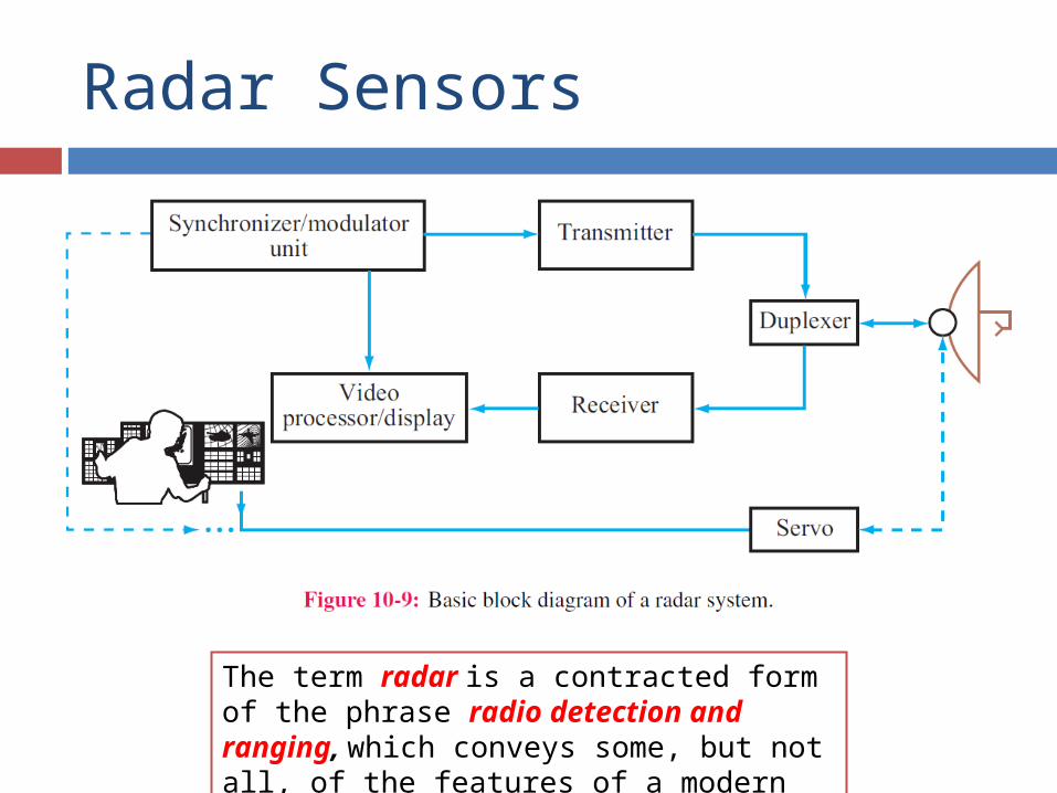
Radar Sensors
The term radar is a contracted form of the phrase radio detection and ranging, which conveys some, but not all, of the features of a modern radar system
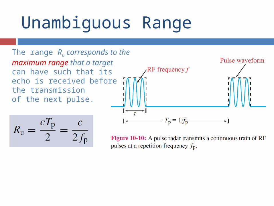
Unambiguous Range
The range Ru corresponds to the maximum range that a targetcan have such that its echo is received before the transmissionof the next pulse.
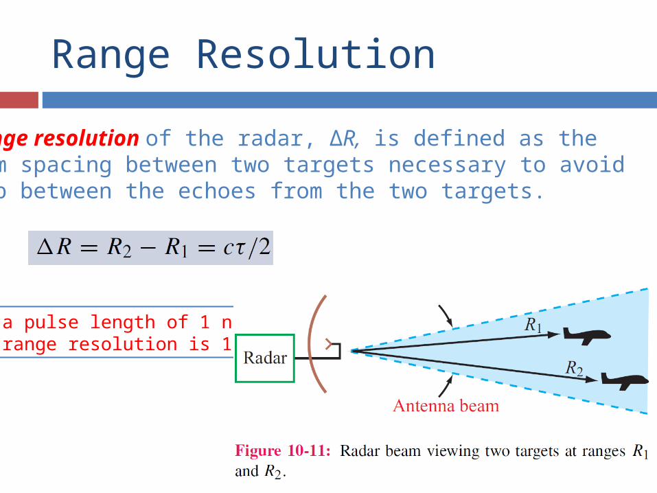
Range Resolution
The range resolution of the radar, ∆R, is defined as theminimum spacing between two targets necessary to avoidoverlap between the echoes from the two targets.
For a pulse length of 1 ns,the range resolution is 15 cm
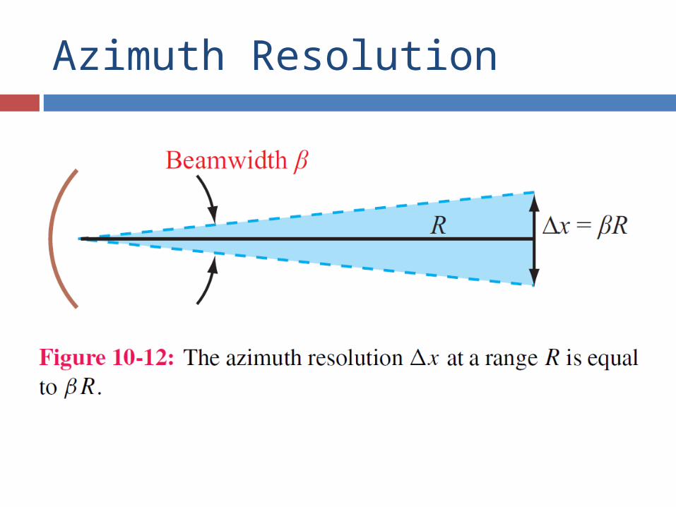
Azimuth Resolution
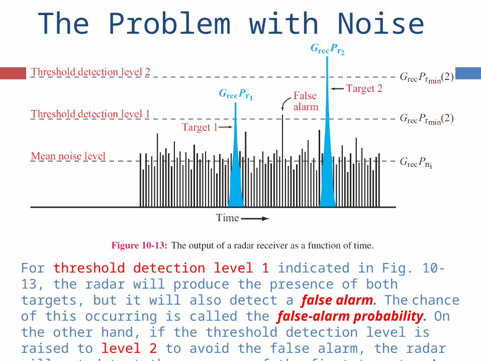
The Problem with Noise
For threshold detection level 1 indicated in Fig. 10-13, the radar will produce the presence of both targets, but it will also detect a false alarm. The chance of this occurring is called the false-alarm probability. On the other hand, if the threshold detection level is raised to level 2 to avoid the false alarm, the radar will not detect the presence of the first target. A radar’s ability to detect the presence of a target is characterized by a detection probability.
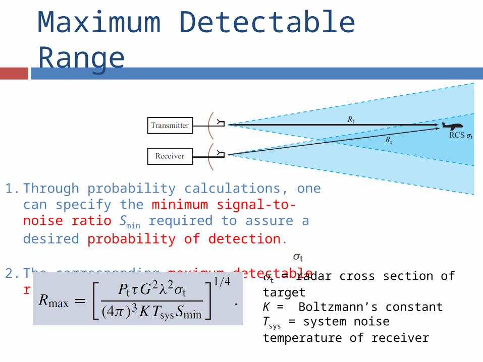
Maximum Detectable Range
1. Through probability calculations, one can specify the minimum signal-to-noise ratio Smin required to assure a desired probability of detection.
2. The corresponding maximum detectable range is:
t = radar cross section of targetK = Boltzmann’s constantTsys = system noise temperature of receiver
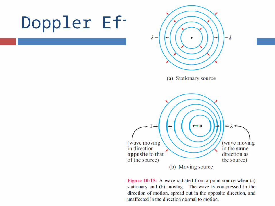
Doppler Effect
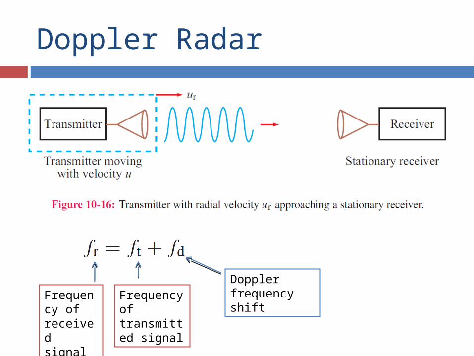
Doppler Radar
Frequency of received signal
Frequency of transmitted signal
Doppler frequency shift
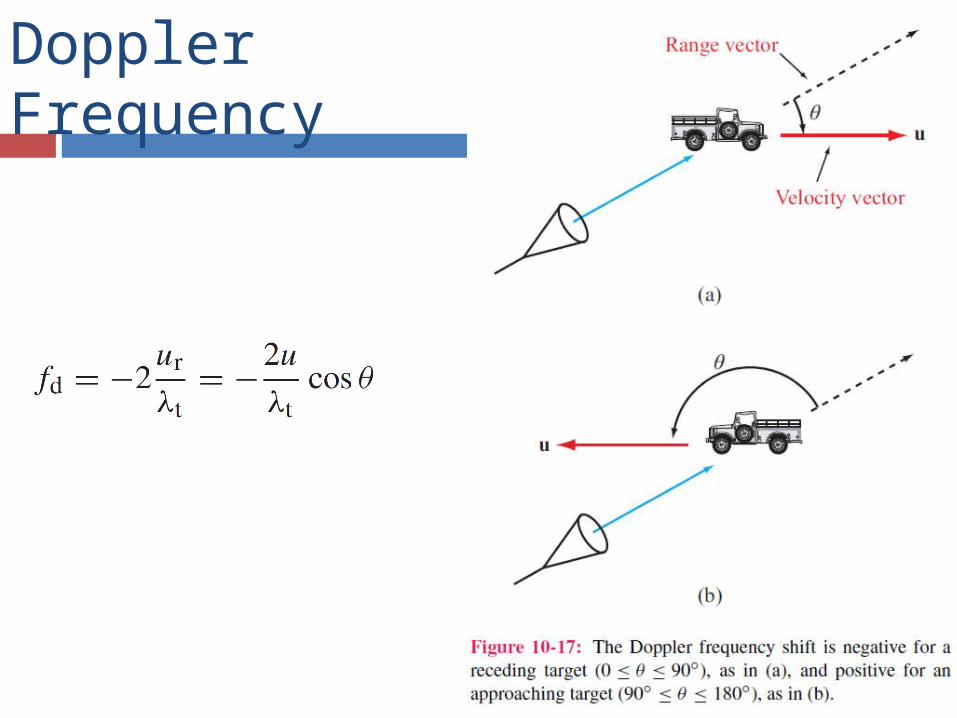
Doppler Frequency
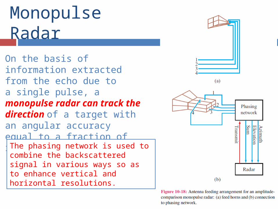
Monopulse Radar
On the basis of information extracted from the echo due toa single pulse, a monopulse radar can track the direction of a target with an angular accuracy equal to a fraction of its antenna beamwidth.The phasing network is used to combine the backscattered signal in various ways so as to enhance vertical and horizontal resolutions.
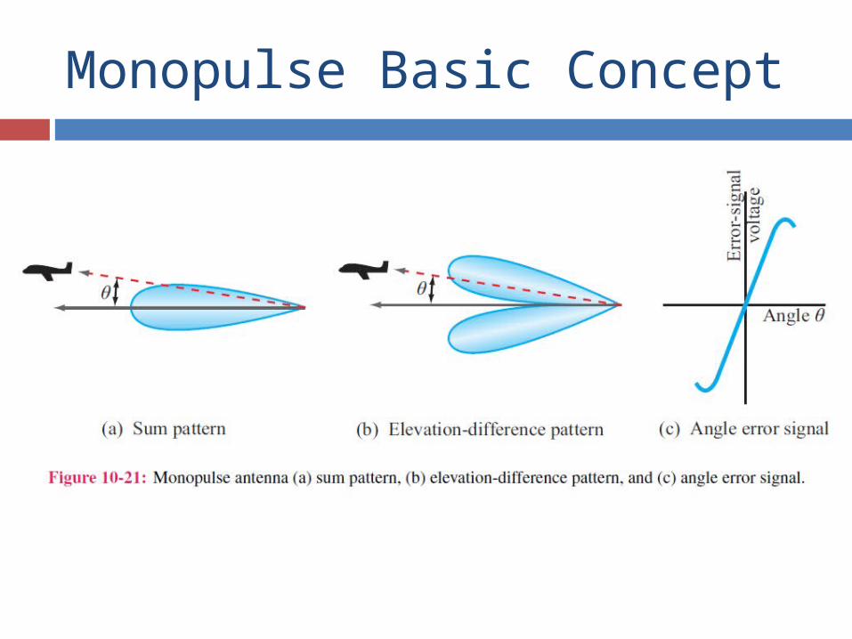
Monopulse Basic Concept
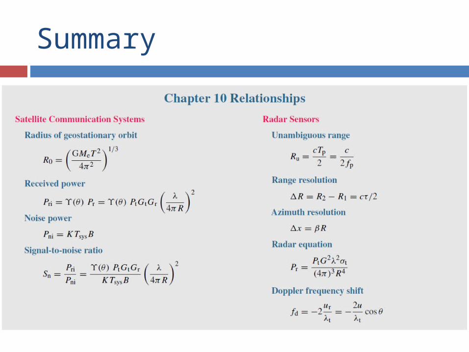
Summary