Embed Size (px)
Citation preview
Naval Research Laboratory - Washington, DC 20375-5320
NRL/MR/6180-97-7909
1995 Class B Firefighting Doctrine and Tactics: Final Report F.W. WILLIAMS
J.P. FARLEY
M.J. PEATROSS
Navy Technology for Safety and Survivability Chemistry Division
D.T. GOTTUK
Hughes Associates, Inc. Baltimore, MD
SWBBBMHWHfflBM
January 13,1997
Approved for public release; distribution unlimited.
WTCQt?Alrnri2fs^G2^

THIS DOCUMENT IS BEST
QUALITY AVAILABLE. THE
COPY FURNISHED TO DTIC
CONTAINED A SIGNIFICANT
NUMBER OF PAGES WHICH DO
NOT REPRODUCE LEGIBLY.
REPORT DOCUMENTATION PAGE Form Approved OMB No. 0704-0188
Public reporting burden for this collection of information is estimated to average 1 hour per response, including the time for reviewing instructions, searching existing data sources, gathering and maintaining the data needed, and completing and reviewing the collection of information. Send comments regarding this burden estimate or any other aspect of this collection of information, including suggestions for reducing this burden, to Washington Headquarters Services, Directorate for Information Operations and Reports, 1215 Jefferson Davis Highway, Suite 1204, Arlington, VA 22202-4302, and to the Office of Management and Budget. Paperwork Reduction Project (0704-01881, Washington, DC 20503.
1. AGENCY USE ONLY {Leave Blank) 2. REPORT DATE
January 13, 1997
3. REPORT TYPE AND DATES COVERED
Final Report 1995 Class B Fire Tests
4. TITLE AND SUBTITLE
1995 Class B Firefighting Doctrine and Tactics: Final Report
5. FUNDING NUMBERS
PE - 64516N PS - 2054
6. AUTHOR(S)
F.W. Williams, J.P. Farley, D.T. Gottuk,* and MJ. Peatross
7. PERFORMING ORGANIZATION NAME(S) AND ADDRESS(ES)
Naval Research Laboratory Washington, DC 20375-5320
8. PERFORMING ORGANIZATION REPORT NUMBER
NRL/MR/6180--97-7909
9. SPONSORING/MONITORING AGENCY NAME(S) AND ADDRESS(ES)
Chief of Naval Operations (N86D) Washington, DC 20350
Naval Sea Systems Command (Code 03R2) 2531 Jefferson Davis HW Arlington, VA 22242-5160
10. SPONSORING/MONITORING AGENCY REPORT NUMBER
11. SUPPLEMENTARY NOTES
*Hughes Associates, Inc., Baltimore, MD
12a. DISTRIBUTION/AVAILABILITY STATEMENT
Approved for public release; distribution unlimited.
12b. DISTRIBUTION CODE
13. ABSTRACT (Maximum 200 words)
These tests show development and mitigation of Class B explosions aboard Naval ships. This consisted of three main points: 1) determining the conditions needed for developing a Class B explosion, 2) determining the effect of ship board conditions (e.g. buffer zone size and ventilation) on the development of Class B explosions, and 3) determining the effectiveness of using water spray as a mitigating tactic. Results that address all three points are discussed in detail.
14. SUBJECT TERMS
ex-USS SHADWELL Class B explosions Ventilation Boundary zone Class B fuels Water spray
15. NUMBER OF PAGES
97
16. PRICE CODE
17. SECURITY CLASSIFICATION OF REPORT
UNCLASSIFIED
18. SECURITY CLASSIFICATION OF THIS PAGE
UNCLASSIFIED
19. SECURITY CLASSIFICATION OF ABSTRACT
UNCLASSIFIED
20. LIMITATION OF ABSTRACT
SAR
NSN 7540-01-280-5500 Standard Form 298 (Rev. 2-89)
Prescribed by ANSI Std 239-18
298-102
CONTENTS
1.0 INTRODUCTION 1 1.1 Current Navy Doctrine 1 1.2 Series 1 Testing 2
2.0 OBJECTIVE 3
3.0 APPROACH 3
4.0 EXPERIMENTAL SETUP AND PROCEDURE FOR SERIES 2 6
5.0 EXPERIMENTAL SETUP AND PROCEDURE FOR SERIES 3-5 9
6.0 RESULTS 23 6.1 Series 2A 23 6.2 Series 2B 37 6.3 Series 3, 4 and 5 52
6.3.1 General Results 52 6.3.2 Effect of Buffer Zone and Ventilation Conditions .66
7.0 DISCUSSION 68 7.1 Fuel Mass Fraction 73 7.2 Buffer Zone and Ventilation Conditions 81 7.3 Water Spray 82
8.0 SUMMARY AND CONCLUSIONS 87
9.0 RECOMMENDATIONS 88
10.0 REFERENCES 89
in
FIGURES
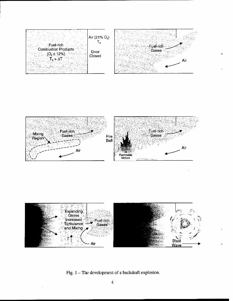
Fig. 1 The development of a backdraft explosion 4
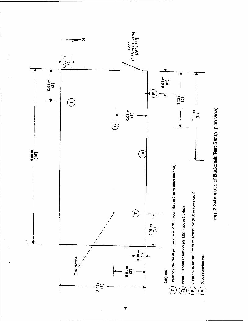
Fig. 2 Schematic of Backdraft Test Setup (plan view) 7
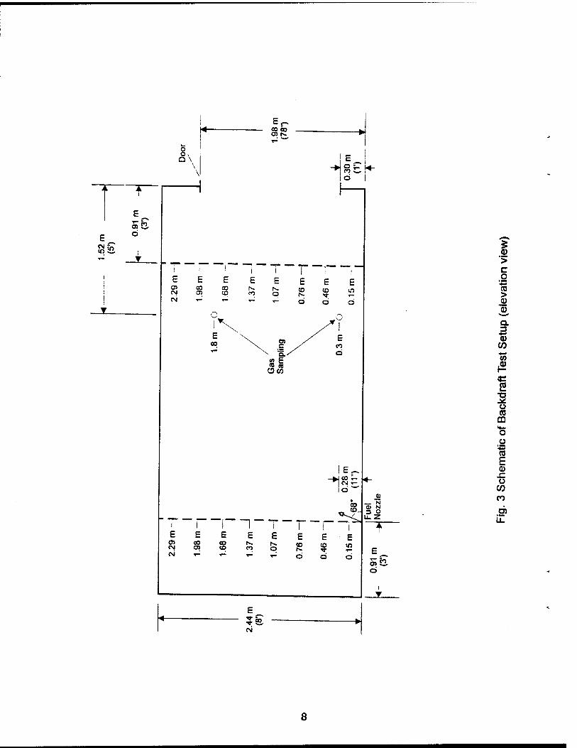
Fig. 3 Schematic of Backdraft Test Setup (elevation view) 8
Fig. 4 Third deck plan view showing test closure for buffer zone EGR 10
Fig. 5 Third deck plan view showing test closure for buffer zone 1 11
Fig. 6 Third deck plan view showing test closure for buffer zone 2 12
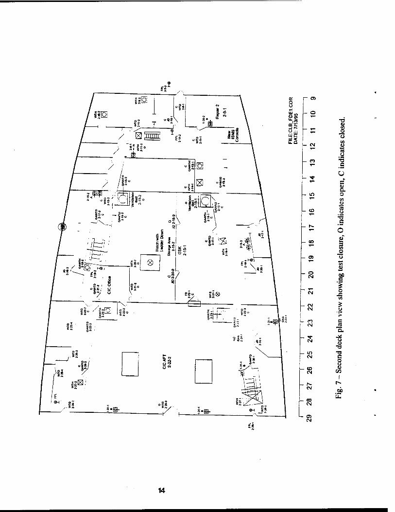
Fig. 7 Second deck plan view showing test closure 14
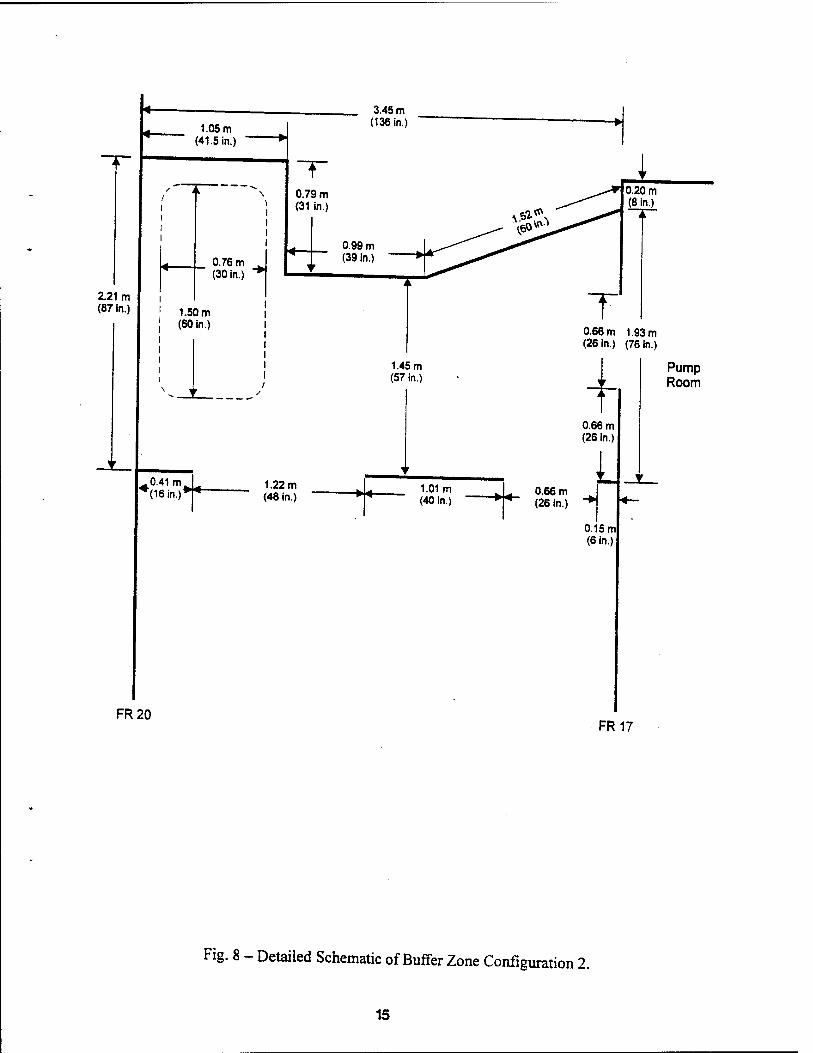
Fig. 8 Detailed Schematic of Buffer Zone Configuration 2 15
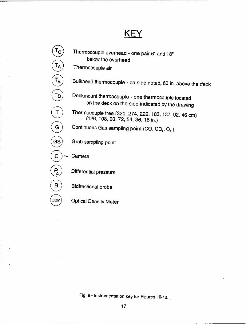
Fig. 9 Instrumentation key for Figures 10-12 17
Fig. 10 Third deck instrumentation for Series 3 Buffer Zone EGR tests 18
Fig. 11 Third deck instrumentation for Series 4 and 5 Buffer Zone 1 tests 19
Fig. 12 Third deck instrumentation for Series 4 Buffer Zone 2 20
Fig. 13 Second deck instrumentation for Series 3-5 tests 21
Fig. 14 A photograph of a smoke ball forming outside the fire door for test BD09 24
Fig. 15 A photograph of the formation of a fire ball during test BD21 25
Fig. 16 A side view photograph of a fire ball extending from the fire compartment door (leftmost edge) for test BD75 27
Fig. 17 Bar graph of nominal fuel mass fractions for series 2A tests 32
Fig. 18 Bar graph of nominal fuel mass fractions for series 2A tests 43
Fig. 19 A typical pressure time history for a Series 2B backdraft test resulting a fire ball (test BD86) 53
Fig. 20 Typical C01t C02 and 02 concentrations measured 0.3 m above deck in the fire compartment and the fuel supply rate for a backdraft test aboard the ex-USS SHADWELL (TEST SBD27) 60
Fig. 21 Typical CO.,, C02 and 02 concentrations measured 2.8 m above the deck in the fire compartment and the fuel supply rate for a backdraft test aboard the ex-USS SHADWELL (test SBD27) 61
IV
Fig. 22 Typical, vertically averaged gas temperatures in the fire space (upper plots) and in the buffer zone (lower plots) for a backdraft test aboard the ex-USS SHADWELL (test SBD27) 62
Fig. 23 Typical surface temperatures within the fire space for a backdraft test aboard the ex-USS SHADWELL (test SBD27) 63
Fig. 24 A typical time history of the differential blast pressure between the fire space and the Buffer Zone for a Series 3 backdraft test resulting in an explosion (test BD86) 65
Fig. 25 Average temperature ri.se due to Class B explosions in buffer zones with full ventilation and boundaries open 69
Fig. 26 Average temperature rise due to Class B explosion in buffer zones with no ventilation and boundaries secured 70
Fig. 27 Average temperature rise due to Class B explosions in Buffer Zone EGR with different ventilation schemes 71
Fig. 28 Average temperature rise due to Class B explosions in Buffer Zone 1 with different ventilation schemes 72
Fig. 29 The frequency of occurrence of backdraft explosions with respect to the monomial fuel mass fraction 74
Fig. 30 Lower and upper flammabiiity limits in air of various hydrocarbons expressed as a volume percent and on a mass basis (figure taken from Drysdale [6], data is from Zabetakis [7]) 75
Fig. 31 A typical flammabiiity diagram showing the possible mixture compositions that can result from mixing air with one of three initial mixtures (B,C and D) of methane and nitrogen with zero percent oxygen (for illustration only) 77
Fig. 32 A typical flammabiiity diagram showing the possible mixture compositions that can result from mixing air with one of three initial mixtures (B,C and D) of methane and nitrogen with ten percent oxygen (for illustration only) 79
Fig. 33 Comparison of averaged temperature profiles for backdraft tests with And without water injection (SBD47) and SBD46, respectively) 86
TABLES
Table 1 Buffer Zone Configurations Studied in Series 3 to 5 13
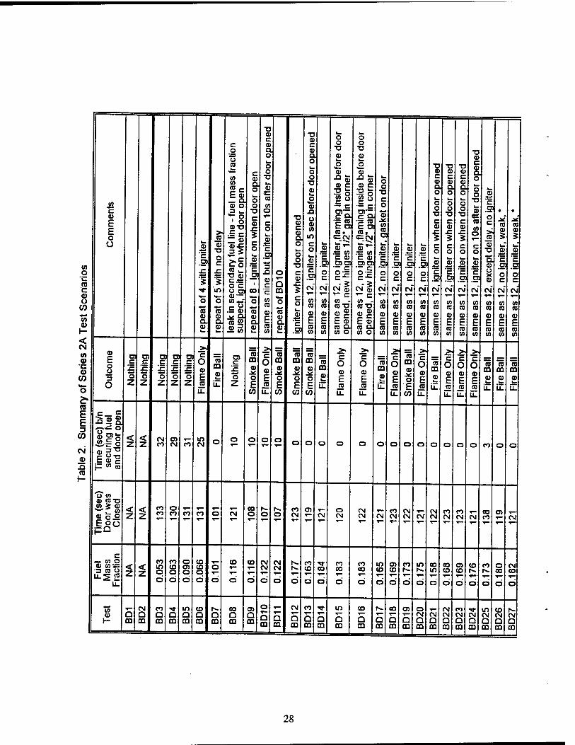
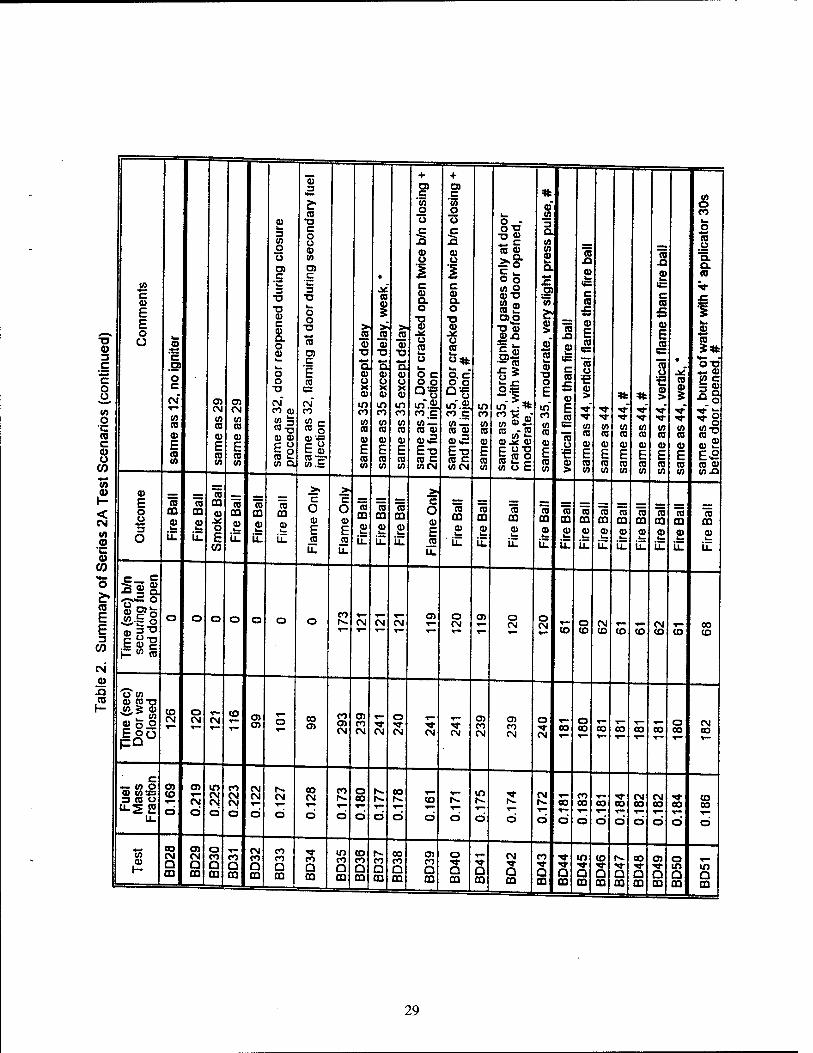
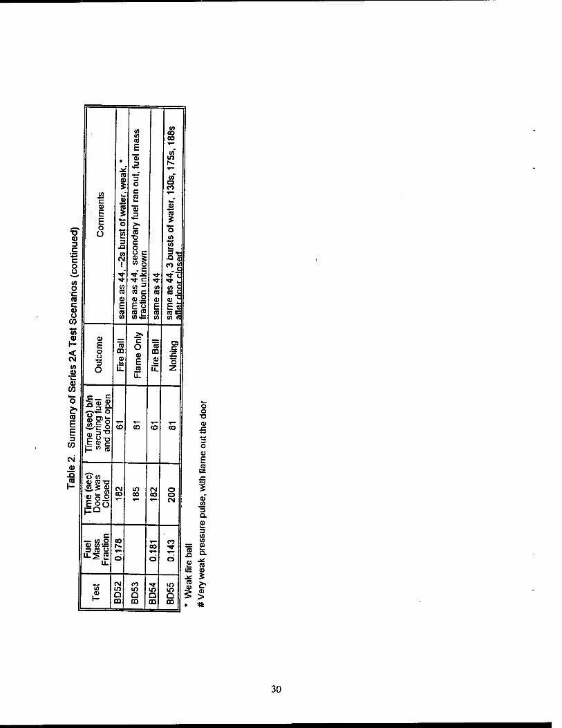
Table 2 Summary of Series 2A Test Scenarios 28
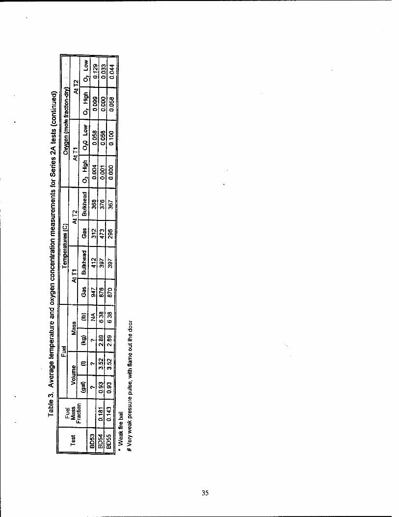
Table 3 Average temperature and oxygen concentration measurements for Section 2A tests 33
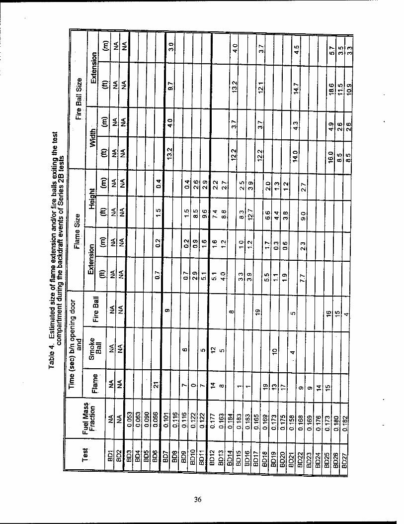
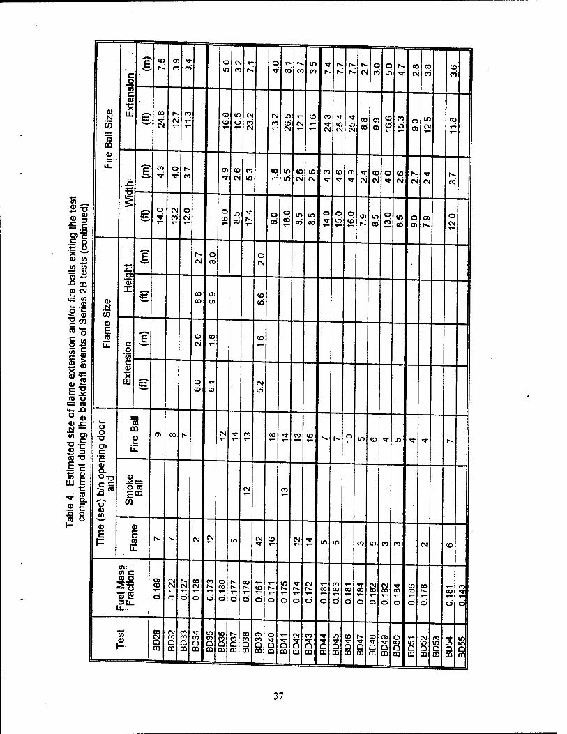
Table 4 Estimated size of flame extension and/or fire balls exiting the test compartment during the backdraft events of Series 2B tests 36
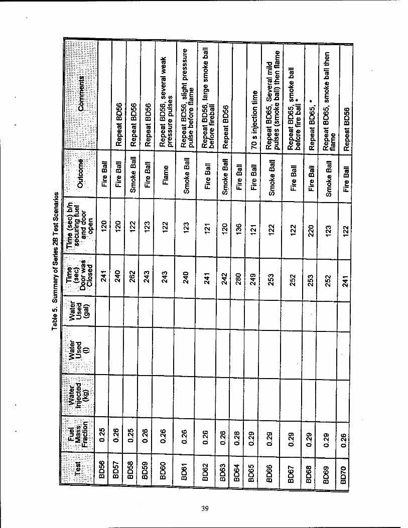
Table 5 Summary of Series 2B Test Scenarios 39
Table 6 Average temperature and oxygen concentration measurements for Series 2B tests 45
Table 7 Estimated size of flame extension and/or fire balls exiting the test compartment during the backdraft events of Series 2B tests 49
Table 8 Summary of Series 3,4 and 5 Test scenarios Conducted Aboard the ex-USS SHADWELL
Table 9 Forced air flow rates for the buffer zone configurations studied 59
Table 10 Comparison of Tenability Conditions within the EGR Buffer Zone for Different Ventilation Scenarios Prior to Opening Fire Door 66
Table 11 Comparison of Tenability Conditions within Buffer Zone 1 for Different Variation Scenarios Prior to Opening Fire Door 67
Table 12 Comparison of Tenability Conditions with Buffer Zone 2 for Different Ventilation Scenarios Prior to Opening Fire Door 67
Table 13 Average Gas Temperature in Buffer Zone at 3-19-2 for Tests with Closed Boundaries and No Ventilation (Smoke Curtains, Fan Secured) Presented for Different Buffer Zone Sizes 67
Table 14 Selected results from Fleischman [4] for methane backdraft experiments in a reduced-scale enclosure 80
Table 15 Comparison of Series 2B Backdraft Tests with Water Spray Injection for Tests with 4.93 kg of Secondary Fuel Injection 83
Table 16 Comparison of Water Spray Injection Backdraft Tests with Respect to Fuel Mass Fraction 84
Table 17 Comparison of Average Fire Compartment Gas Temperatures for Similar Tests with and without Water Injection for Tests in which Water Prevented a Backdraft 87
VI
1995 Class B Firefighting Doctrine and Tactics: Final Report
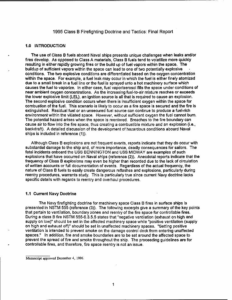
1.0 INTRODUCTION
The use of Class B fuels aboard Naval ships presents unique challenges when leaks and/or fires develop. As opposed to Class A materials, Class B fuels tend to volatilize more quickly resulting in either rapidly growing fires or the build up of fuel vapors within the space. The buildup of sufficient vapors within the space can lead to one of two potentially explosive conditions. The two explosive conditions are differentiated based on the oxygen concentration within the space. For example, a fuel leak may occur in which the fuel is either finely atomized due to a small break in a fuel line or the fuel is sprayed unto a hot machinery surface which causes the fuel to vaporize. In either case, fuel vapor/aerosol fills the space under conditions of near ambient oxygen concentrations. As the increasing fuel-to-air mixture reaches or exceeds the lower explosive limit (LEL), an ignition source is all that is required to cause an explosion. The second explosive condition occurs when there is insufficient oxygen within the space for combustion of the fuel. This scenario is likely to occur as a fire space is secured and the fire is extinguished. Residual fuel or an unsecured fuel source can continue to produce a fuel-rich environment within the vitiated space. However, without sufficient oxygen the fuel cannot bum. The potential hazard arises when the space is reentered. Breaches to the fire boundary can cause air to flow into the fire space, thus creating a combustible mixture and an explosion (i.e., backdraft). A detailed discussion of the development of hazardous conditions aboard Naval ships is included in reference (1)).
Although Class B explosions are not frequent events, reports indicate that they do occur with substantial damage to the ship and, of more importance, deadly consequences for sailors. The fatal incidents onboard the USS BENNINGTON and USS MIDWAY are examples of such explosions that have occurred on Naval ships (reference (2)). Anecdotal reports indicate that the frequency of Class B explosions may even be higher than recorded due to the lack of circulation of written accounts or full documentation of events. Regardless of the actual frequency, the nature of Class B fuels to easily create dangerous reflashes and explosions, particularly during reentry procedures, warrants study. This is particularly true since current Navy doctrine lacks specific details with regards to reentry and overhaul procedures.
1.1 Current Navy Doctrine
The Navy firefighting doctrine for machinery space Class B fires in surface ships is presented in NSTM 555 (reference (3)). The following excerpts give a summary of the key points that pertain to ventilation, boundary zones and reentry of the fire space for controllable fires. During a class B fire NSTM 555-6.3.5.5 states that "negative ventilation (exhaust on high and supply on low)" should be set in the affected machinery space while "positive ventilation (supply on high and exhaust off)" should be set in unaffected machinery spaces. "Setting positive ventilation is intended to prevent smoke on the damage control deck from entering unaffected spaces." In addition, fire and smoke boundaries are to be set around the affected space to prevent the spread of fire and smoke throughout the ship. The proceeding guidelines are for controllable fires, and therefore, fire space reentry is not an issue.
Manuscript approved December 4, 1996.
mJPJUS? 3n out-°f-contro1 fire-the sPace «• evacuated and ventilation in the fire space ÜJÄ? 1 spaces ,s secured (Section 6.3.6). Section 6.3.7.2 states that »inner and outer smoke boundaries shall be set quickly around accesses to the affected space . The area between the inner and outer smoke boundaries is designated the buffer zone and shall be a bonnH^nf* ,f lm?kiboundwy near«st the fire is designated as the inner smoke ooundary and normally coincides with the primary fire boundary" (Section 5 3 2 6 2) The outer
ZSStiS^ iSJ0Ca!fd, fa?her 3Way fr0m the fire- "These *>o«nd«iet are generally the watertight bulkheads and decks immediately adjacent to the affected space (Section 6 3 8 3) - Sufi? numerous existing ship designs, buffer zones can range in size from a vertical trunk
zoneZleht
0hf-Ha^ Regard,eSS °f theSize' VentHation ist0besecured «" the^er zone to establish a "dead-air space" (Section 6.3.7.2). "Establishing the buffer zone is iKfh" !t0 thiP°M,bll,ty of fire or explosion if hot combustion gases from a Class B fire m« with fresh air. Consequently, active desmoking (paragraph 555-5.3.4C) shall not be used for machinery space Class B fires." '
thJ^S^^^t0 ref,ntefthe sPace as ^ulcWy as P°ssible, to attack and extinguish the fire and ensure the source of fuel is secured (Section 6.3.10). Guidance is given to the time a which reentry should be attempted based on the extinguishing system usedfart". «£2? ^me^system in «anguishing the fire. However, there is little guidance with regards to the act.cs to be used dunng the reentry procedure even though "reentry...is the most critical part of
the firefighting evolution and potentially the most dangerous (6.3.10)." This lack of specific guidance was one of the motivating elements for this work. In addition, questions wereraLd
P=g«
1.2 Series 1 Testing
The 1995 Class B Firefighting Doctrine and Tactics Test Series 1 (reference (4)) was to
2SneZe,ClaS,S B fife COnditi0nS Which Could lead t0 ,he ventin9 <* flammable gases to SirrZt!n K a£d ?mpartr]ents from a below d*<*s Class B fire. These conditions were ™"zed by
4 tne fuel SUPP'V rate and the ventilation provided to the fire compartment. The
oltl^nfThfr n°n wasKexamined as a P°ssjb'e means to monitor the explosion/refiash
tS^ k6y ParameterS Within the fire c-Pa*-nt, such as
The results from these small compartment tests highlight the conditions and hazards assoaated with Class B fires. Under burning conditions, The fires can produce■ htahtovi. of toxic gases, high temperatures, and even the transport of flammable gLes However
fh«!V'n9^ery fUeJ:rich buming colons proved to be difficult. In order to'sustain bu'minq at täSSZ^'?? f fl°W I"*0 the comPartment had t0 ^ ducted to the base ö?thele
9
am2J7iJH UPper layer combus«°n gases would descend to the base of the fire 2'1 TT StarV6d- '* iS n0t dear whether the Phenomenon would occur in fuS size machinery space before surfaces become hot. As expected, this result indicates that Class B spray fires are easily extinguished under poor ventilation conditions. Several fires did self! extinguish even with the inlet duct in place. The fires that self-extinguished resXd in the onr.at.on of wh. e mists of fuel aerosol forming outside of the fire compartment For Iwo of
Suirshinom^ hnPh°,?nS """I1"1 ,th„e fire comPartment occu™d within a minute of the fire exungu.sh.ng. In both cases, jets of flame and/or fire balls shot out of the vents in the fire
™°I,!eStS 'IWhidl high fue|-t0"air rat'°s were obtained, several modes of external burning ZZö tQTA °UtSJde °ilhe f,re ComPartment. For these tests, the ignition index S c,^ ♦hi? f ?°°? pred,ct,on t001 for indicating when significantly fuel-rich conditions exist such that sustained external burning can result.
n,J!LSerieS 1 reSUJtS h'9hlight the conditi°ns and hazards associated with Class B fires Of greatest concern .s the susceptibility of Class B fires to extinguish and quickly create an '
SSS^^^TT1 3fer Seri6S 1' 90a,S °f the pr09ram ^'adjusted to investigate JSSSSKT?- ?rSS B exP|os,ons and possible tactics that could be used to mitigate the exptos.on potential of fire compartments that have been secured. This report present! the work
KST m thr0U9h 5 °fthe 1"5 Cl3SS B Rrefi9hting D0Ctrine and ™« te* 2.0 OBJECTIVE
dev'Sonm^'JoH ^f?* *£?* ^^ 2 {° 5 Was t0 obtain a scientific understanding of the ^^(TäSS^1i^ln^'ionM ab°ard Naval Ships- This consisted °'three 5? HJ£2 '( }* T nmg the condlt,ons needed for developing a Class B explosion
SÄSZ'S SL^ ■ShiPb0ard C°nditi0nS (eg' buffer Z0"e size and ve"tilati°n> 0" the £S£?t2? °nS' ^ determinin9 the effeCtiveness of usi"9 "*« spray
3.0 APPROACH
ta c^^Ä^fh^f^ phenomenon and assess th« effectiveness of preventive Ir?^!!?P ° ad t0ube Safely created in a rePeatable test. As described above there mTxt^e in a noSnwnf ** ^ laadt0 an eXp,0Si0n: (1) formation of a combustible Ar ^)^S^J^1S!^^ °r (2) f°rmati0n °f 3 fue,'riCh enviro™ent (insufficient °Ei ' h
a - • P Jfu ln SCenano 1' an ignition source is needed to produce an explos.on, where as in scenano 2 both an ignition source and sufficient oxygen are needed In both instances, hot surfaces from a preceding fire can be sufficient for gnTon Therefore
^ b^^S^? daHn9er0US " 3 t6St SCenari° -cerLlSg'actor 7nri,,Tn , y controlled- The dosed space presented an additional hazard of potentially ™dH ~9 P S'0n !?dUCed preSSUres above the ^P^V of the structure. Such explos ons could cause senous damage to the ship/test compartment and injury to test personnel
It was determined that a scenario 2 type explosion could be created in a safe test-oriented ESTE- KP°n♦bUtt°ning UP a fire Space'the fire extinguishes as it *^^^S£? Ä!^^ th
rfe space wi"vapori2e due to the hot ÄHST4
2TE!S??i • I10"9?,the hot surfaces are sufficient ignition sources, the gases within the fire space will not ignite until additional air enters the space From a testina standooint hilic a
very controllable parameter. For example, a door can be opened remofefaSoTno a qrav^ current of colder air to flow into the fuel-rich, hot compartment whi.eThe hotSch ga^s flow
too flow°sPtreamsn £ ^1)' ^ * and fue|-riCh gases mix along ÄKTÄ TWO now streams Ignition occurs once a flammable mixture is formed and it comes in contact
r,„flnHSU^,erlKy r0t SUrfaCe- The reSU,ting de«agration will cause the gasesTheat a^d expand within the fire space, thus forcing unbumed gases out of the open ven ahead of the flame front. These gases will mix with additional air outside of the fire soace AsThJA™ penetrates the doorway, it ignites the gases outside the ££ «^"bÄ^
Fuel-rich Combustion Products
(02<12%) T0 + AT
Air(21%02) To
Door Closed
Fuel-rich Gases
Air
Mixing Region'
Fuel-rich Gases
i A - '
3gion\. __ :-T
Air
Fire Ball
Ignlflon of
Flammabte Mixture
Fuel-rich Gases
Air
Ixpähdihg: ^■iGäses'Ji
Increased Turbulance and Mixing
Fuel-nch ;*iGasei5;
T I Air
v3
Blast Wave'
Fig. 1 - The development of a backdraft explosion.
4
hSfn J?IS explosion Phenomenon from the gravity current to the blast wave is termed a backdraft.
«rJ^L? explosion phenomenon is not a restrictive case study. The two explosion
22?. i USS6d are Simi,ar in natUre °nce ignition occurs- 0ne difference is that in scenano 1 he space is more l.kely to be sealed when the explosion occurs than in scenario 2
%*!??""* S*"" intenSity b,aStS- The fo,lowing *"W°" of a scenario even" explains how the two scenanos are related.
fit«Sf?nfi.fLthat 3 fUel;Üne mptures causing fuel t0 sPpayin a sPace- As fuel vapor/aerosol starts to fill the space, there will exist a fuel-rich region near the fuel source such that it is too
SÄ,HTvefl
r'a distance away from the fuel source-the tüei to^£Z^£Z* ^n.!n? ♦ Create a flammable mixture. At even a greater distance from the source ?he fuel SÄSS^T; and the ~ncentration of °W« is 21 percent. Ignition S^Sy^S? within the intermediate zone where the flammable mixture exists. Depending on the size* the E£J? the.t,me d"ration'tne sPace WH continue to fill with fuel to form an ?nc eLlrSy Lrger anmThQv« \Tn- After f SUffi<:ient,y ,0ng time'tne space can become exceeding^ Sril ZH£, *UPPer eXp,0S,0n l,mit (UEL)- ln this «»• (which is the same as scenario 2) Z Z H n0t °CCUr "nt" additional air is intr°duced into the space. In both scenario once IxolcLtn h'r m,X ° flarTmab,e Pr°Portions
1 the ensuing deflagration and explosion are
expected to be similar. The main difference will be that in scenario 1 the deflagration wHI occur
^SZSTSSsystem w!Teas in scenari0 2 the deflagration is more *E^ bz££a«?~L a Prom,Xed SyStem Wi" tend t0 produce hiQher intensity explosions, backdraft testing (scenano 2) represented a lower bounding case
MC^SS^SS!^ f°r HerieS K t0 5 W3S t0 develop safe' ^Producible backdraft rSl^w. .T* aV b.aS'S 1° StUdy the development and mitigation of Class B nÄT d NaVa'Ships- Factors that were studied included (1) the amount of fuel needed for an explosion, (2) the effect of buffer zone size on the development <fbackdraft exp osion, (3) the effect of creating a dead-air buffer zone on the deveEent of a bafkdraft explosion, and (4) the amount of water needed to mitigate a toaO^^^^ safety reasons, the first tests (Series 2) were conducted outside in a compartment that vented
^XEES ,Up0n C°mpleti0n °f these tests- experiments were «JSÄS1 ex-USS SHADWELL.
Initial tests (Senes 2A) were conducted at the Naval Research Laboratory Chesaoeake Beach Detachment (CBD) during the period of March 22-28, 1995. The^itoW^MM in creating safe backdraft scenarios. However, the ability to create a suftabTe^ reprodudbTe lH ^Jt? Wf S,S0t aChieved- Tnerefore' a seco"d set of tests at CBD (Series 2B) was conducted May 8-12,1995. The main purpose of the CBD series was to. chmStefe. Z necessary conditions for creating a safe backdraft explosion test The effSess o usino vanous amounts of water spray injection was also studied during these tests! 9
♦o Jhe leSt !ffunari0S developed at CBD during Series 2 were used to develop similar backdraft ests onboard the ex-USS SHADWELL. The first tests on the ship (Serie3?were conduotd
from June 19-30, 1995. Development of backdraft conditions onboard a shb ^med an
'S^^Z^'Z^ Ph6rf0rmed in the °pen at CBD.%t^Sna.dc:nnfines
theTh^dZZ^S Produce higher maximum pressures within the main fire space as tne backdraft deflagration occurred. Therefore, the primary objective of Sen** * «,»« ♦« incrementally change the fuel loading in the fire space untilsafe^SSÄ hS&l test scenano was developed. This test scenario was then used as a tJSSS^SSS^üM buffer zone ventilation schemes, such as the establishment of a deadXone
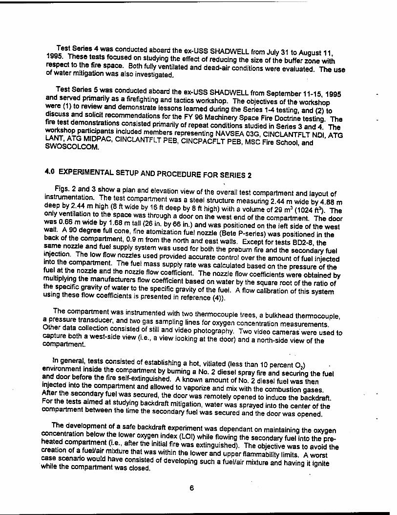
IQQI I?6"6? ,W!S conelucled aDoard the «-USS SHADWELL from July 31 to August 11 ™£ J. T r focuselon studvin9the effect of reducing the size of the buffer zone with respect to the fire space. Both fully ventilated and dead-air conditions were evaluated. The use of water mitigatjon was also investigated.
Test Series 5 was conducted aboard the ex-USS SHADWELL from September 11-15 1995 !2,™fm ? Pnm y ?? firef,9ntin9 and tactics workshop. The objectives of the workshop were (1) to review and demonstrate lessons learned during the Series 1-4 testing, and (2) to discuss and solicit recommendations for the FY 96 Machinery Space Fire Doctrine testing The fire test demonstrations consisted primarily of repeat conditions studied in Series 3 and 4 The rrU? AX^SSS?^.?.?60 members representing NAVSEA 03G, CINCLANTFLT NDI ATG S^SsCOLCoS C,NCLANTFLT PEB' CINCPACFLT PEB, MSC Fire School, and
4.0 EXPERIMENTAL SETUP AND PROCEDURE FOR SERIES 2
in^tmmon*!^ 3 T!°W, 3 flan and elevation view of the overa"test compartment and layout of ripln M 11 '„f,o« compartment was a steel structure measuring 2.44 m wide by 4.88 m
«S^irf "\ fi? ( W 6 by 16 ft d6ep by 8 ft ni9h> with a volume of 29 m3 (1024 ft3). The only ventnation to the space was through a door on the west end of the compartment The door
wa«! °?*££XM m r"^ in-by 66 in) and Was positioned on the W» side of the west bait nf Z rTnJ" 7en fne ft0m'Zati0n fuel n02zle <Bete P-Series)was Positioned in the SSL . cornP;rtn™ent- °9 m from ^e north and east walls. Except for tests BD2-8, the fnTrLn TL3?,? "f SUPply,SyStem was used for both the Prebum *• «* the secondary fuel 3^J^SÜTÄ^eS,U,ed Pr°Vided aCCUrate contro1 overthe amount of fuel inJe*ed Art Tt^TZ^J* fUe m«aSS SUPP'y rate WaS Calculated based on the Pressure i the ZI . ^ nd,the n0Zzle flow coefficie^. The nozzle flow coefficients were obtained by multiplying the manufacturers flow coefficient based on water by the square root of the ra^o of
uLniH^t fnZZ frWate[t0 the SpeCifiC 9ravity of the fueL A flow ^^Oan °< this system using these flow coefficients is presented in reference (4)).
. nrl^nlT^H 6nt W3S!n«trumented with two thermocouple trees, a bulkhead thermocouple, othfr S ! SUCer' and ^° 9aS samplin9 lines for 0XV9en concentration measurements ^SSt^,T",ted/-0f Sti" and Vide° phot09raPhy- Tw° video cameras were used to Mmpartment eSt"S'de V'ew (Le- a view ,00kin9 at tne door) and a north-side view of the
In general, tests consisted of establishing a hot, vitiated (less than 10 percent O,) !nn SITf VnS,?Ke !5e comDartment by burning a No. 2 diesel spray fire and securing the fuel fr?l w b,ef°.re the fire self-extinguished. A known amount of No. 2 diesel fuel was Then injected into the compartment and allowed to vaporize and mix with the combustion gases
££ hL .? ? f'."?S S6CUred'the door was remote|y opened to induce the backdraft. cZ™Z£l ^ A"9 backdraft miti9ation, water was sprayed into the center of the compartment between the t.me the secondary fuel was secured and the door was opened.
r^nfS0^6"1,? 3 Safe baCkdraft exPeriment was dependant on maintaining the oxygen concentrat.cn below the lower oxygen index (LOI) while flowing the secondary fuel into the pre-
2ST (£- after the initial fire was extinguished). The objective was to avoid^e ^ ™LnIUe a',H K,XtUre ,hat W3S Within the lower and uPPer flammability limits. A worst
■ssss^^of deve,opin9 such a fuei/air mi*ure a"d haVin9 « *-
8hP*-
O X X QE!o
(O CM to *" d
5 a
© -■©
©
£21
8*
E
c\i
E^ 00 CO
0
J-i. 8b
d c CO o (1)
o IB
■o O s CO > Ü CO
E IT)
O CO D> ■a C CO
■c > o
(0 J£ -Q O <0
■c a>
■o E IS o
10 s. CO
E cs > o
0_
o CD CO XI o ra 3
1 E CM CM
T3 in c 2
a ^ l- O o a 3
JS 3 O
10
Ü CO o a. 0. co c ^m*
co CO x:
ra CO
o h- a. »■ ■o o o> cs in m c
CO JZ
m
a. O 8
IS a.
a E eg 0)
b a
CO n ra JZ <a CO
5 CD
> c
a 3 a
C/5
2
o 08
CQ »*~ O o
CO
E o
il
c\i ©©©©
a.' <o E
Er- GO ~T- CM i- 1§£
n E E E E E 05 CO oo r*. r^ (N 03 (O CO o CM t™ ▼- T" ^-
r~r E
_ N
U. Z
i
0)5^.
5 cu '> c o (0 >
0)
a 15 CO +*■ (0
|2 2
"O o Co
CD i*- o o '^ CO E 0
-C o
CO CO
o> u.
8
thl^iS re deveJ°Ped on the Prem*e of burning a stoichiometric fire so that h!!«n«Ia^ eXCfSS Tim fuel ln the «»"P^ent at the time the door was closed. Using d^Zii Z paTete:-Ah <A is area of opening and h the height of the opening), to determine the air flow rate into the compartment and a stoichiometric fuel-to-air ratio of 0 068
Inn „Z* "" f\ MW (36 lpm (096 9Pm)>" UP°n aching steady-state temperatures SlST COnce"trat,ons of about 3 Percent or less in the upper layer, the door was secured
2Ü5TÄH EHK?..T aw°Ut 15 minutes- The fuel flow was secured 5 s after ^e door was aturinnThS Z? de,ay al owed the fire t0 ^er consume the remaining oxygen while 2? excessive fuel was not sprayed into the compartment. The door was closed and
don?A? 9,ng 8 P°,6 b6tWeen the d°0r and a Stop- As the test series Progressed, the fihf r ÄÄ Creatmg Saps between the door and tne oompartment. A gasket of ceramic T™LJ3 ♦? (F,berfrax>was used t0 *eal the door. As a result, the space was not air tight
SÄTr^1:1?°ke ,eakage around the door durin9 the secondary fuel injection and the subsequent hold time before the door was opened.
flo Jwaf^rf 7 ^ fl.°W '"I0 the comPartment was injected 60 seconds after the initial fuel Sr^lho r ^ ^P'03',njeCtion time was 60 seconds- The 60 second delay was to imefn the «,",!! T °Ut "I** a,l0W the comPartment Qases to mix. Due to ^transport
wTre DeTow9th6S^T**' *♦V™ W3S alS0 needed t0 insure that °' concentrations ™'°W th,e L011 (typically about 12 percent). Measured concentrations were below 10 percent by volume before secondary fuel was injected.
b^2hiSeCOnda,y fuel injection was complete, the door was opened to induce the ISS^TT™? Th,f ?°°r Was opened remote|y usin9 two ropes, one to dislodge the tafflowand fhl°nne t0 rM?.?ewd00r °Pen- Several delay times Detween the end of secondary fuel flow and the opening of the door were studied (0, 10, 30, 120, and 240 s). The majority of
^17J.Tmetd Witi a 12° S delay- For the water mitiaat'on tests, this delay pSed
«Lnl^f 1? Watert0 bewsPrayed int0 the center of the compartment between the time the
SSKÄ^^Tthe H°0r W!,S °Pened- Typically- water was • W* using a TMOFC nozzle (Bete) for a 60 second penod starting 30 seconds after the secondary fuel was
ue*HreH-, Th£ Water injeCti0n SyStem provided an accurate means for quantifying ttew^T used while obtaining good dispersion within the space.
withF?hpeiCahnH!rHS; the,firSt t6StS Performed consisted of burning the initial fire and proceeding
to check ftrSlKC7,U? .eXCeP!th3t n° S6C0ndary fuel was in'ected- These tests were used L to ntducJ thf A ^nSa ? ?ndUC:,n9 the tSStS and t0 verifythe success of ^e initial design IrinnÜ?, Jhe°2oo^entranon and achieve steady-state conditions. The volume of th^nlnf VnJfCt6d W.af systematica''y 'creased for subsequent tests. For Series 2 tests the amount of fuel ranged from 1 to 7 liters (0.25 to 1.9 gal). «»*«»»,
5.0 EXPERIMENTAL SETUP AND PROCEDURE FOR SERIES 3-5
fdelinnS« r p Ct6d ob°ard thf fX-USS SHADWELL were conducted in spaces 3-16-1 EGmuna * S^T 3nd t1 M1L <desianated as an Emergency Generator Room
we*, JL HSH'I^« I C0UrJ^f these test series- three different buffer zone configurations were studied. (1) Buffer Zone EGR , (2) Buffer Zone 1, and (3) Buffer Zone 2 These three
ÄSX^ ST",?1 %«' resPectively- Buffer Zoies 1 «dTJ^SÄSnB
^I^^S^SJ^inch p,ywood and half inch gypsum wa" board- A» i°in* ££ K^S£3£The spaces were we"sea,ed-Table 1 shows the volume of
9
10.4 m
FILE: SERIES3.CDR DATE: 11/02/95
25 20 15 10
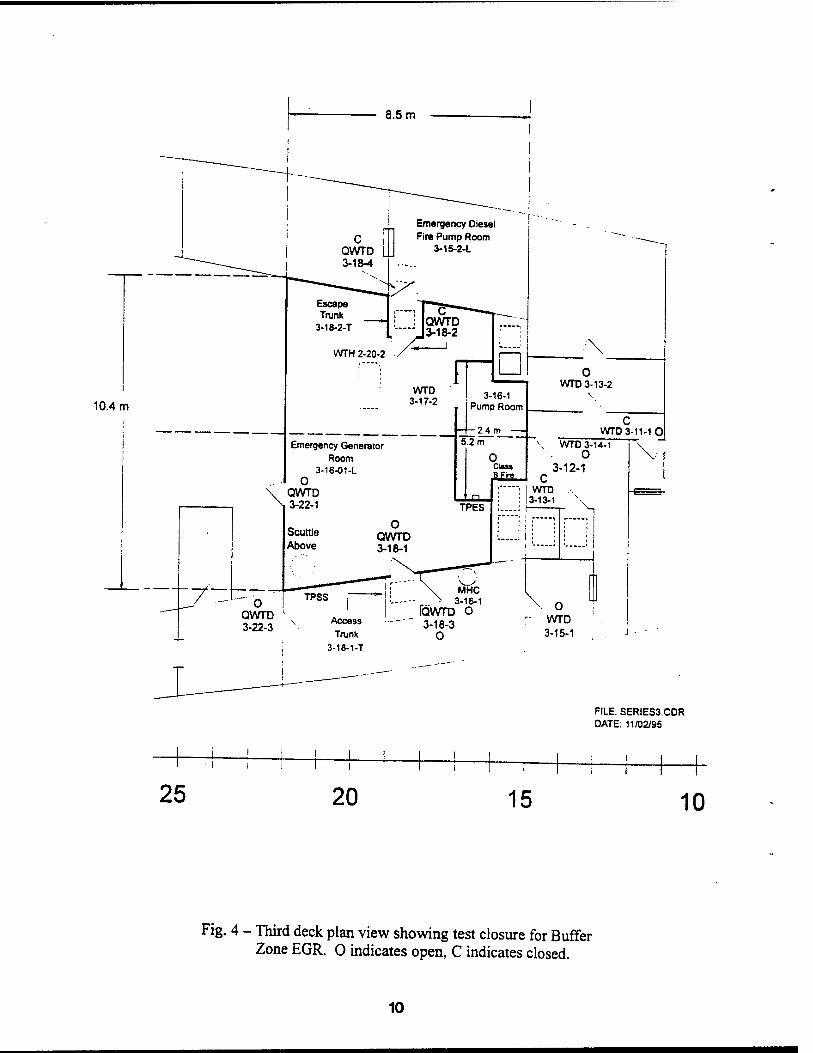
Fig. 4 - Third deck plan view showing test closure for Buffer Zone EGR. 0 indicates open, C indicates closed.
10
10.4 m
25 20 15 10
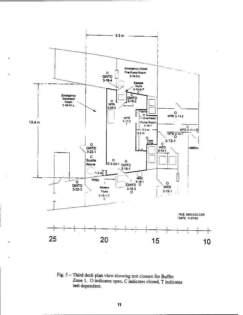
Fig. 5 - Third deck plan view showing test closure for Buffer Zone 1. O indicates open, C indicates closed, T indicates test dependent.
11
8.5 m
10.4 m
FILE: SERIES3.CDR DATE: 11/27/95
25 20 15 i i
10
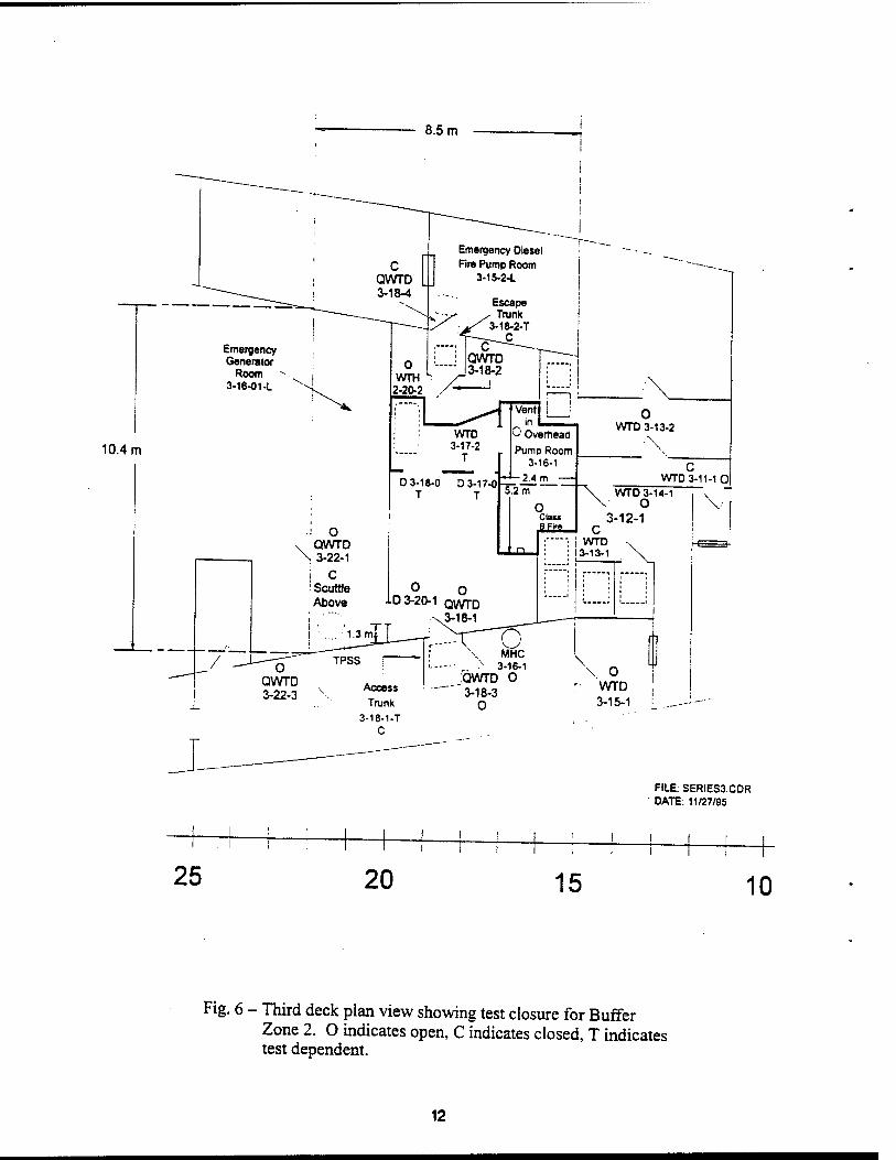
Fig. 6 - Third deck plan view showing test closure for Buffer Zone 2. O indicates open, C indicates closed, T indicates test dependent.
12
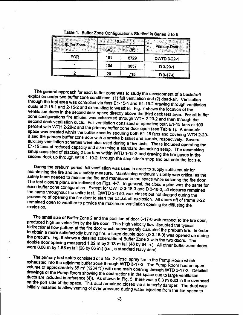
Table 1. Buffer Zone Configurations Studied in Series 3 to 5
Suffer Zone Size
Primary Door ; W:^: (ft3)
EGR 191 6729 QWTD 3-22-1
1 104 3657 D 3-20-1
CM 20 715 D 3-17-0
«yJ^nfn!!?1 ? Pr?a« f°r each buffer zone was t0 stucJythe development of a backdraft explosion under two buffer zone conditions: (1) full ventilation and (2) dead-air Ventilation
ducte at 2-15-1 and 2-15-2 and exhausting to weather. Fig. 7 shows the location of the ventilation ducts «n the second deck space directly above the third deck test area For all buffer
ZZSTTT?* fU6nt W3S 6XhaUSted thr0U9h WTH 2-20"2 and then ^ough' te second deck ventilation ducts. Full ventilation consisted of operating both E1-15 fans at 100 percent with WTH 2-20-2 and the primary buffer zone door open (see TaL ) A dead-air JÜSTJÜI" created w'thin the buffer 2°™ by securing both E1-15 fans and covering WTH 2-20- 2 and the pnmary buffer zone door with a smoke blanket and curtain, respectively Several STSS^T S?emes were also used duri"9 • *" tests. These i^ opSSJth. E1-15 fans at reduced capaaty and also using a standard desmoking setup The desmokina setup consisted of stacking 2 box fans within WTD 1-15-2 and drawing the fire oases ^°he second deck up through WTS 1-19-2, through the ship fitter's shop and out ontothe foe's*
During the prebum period, full ventilation was used in order to supply sufficient air for maintaining the fire and as a safety measure. Maintaining optimum visibility was cri ical as the Äre^t0 "**? the fire and maneuver in the space while .Ä^ToS I«rh h? « e Planf are ,nd,Cated °n Figs- ^ ln 9eneral-the cl0^re plan was the same for each buffer zone configuration. Except for QWTD 3-18-3 and D 3-18-0 an closures remaned the same throughout the entire test. QWTD 3-18-3 was closed but not dogged during Se procedure of opening the fire door to start the backdraft explosion. All doors aft of frame 3-22
explosion °Pen "t0 PrWidethe maXimUm Vent,,ation openin9for d^"ing thT
The small size of Buffer Zone 2 and the position of door 3-17-0 with resDect to the fire door
SÄ?1hffair ve'ocities by the fire door-This hj9h ve,ocity *°w *££££$$£ ' bidirectional flow pattern at the fire door which subsequently disrupted the preburn firf In order o obtain a more satisfactorily burning fire, a large double door (D 3-18-0) was openeducPurina
SÄST" R9' 8 Sh0WS 8 detaHed SChematic of Buffer Zon. 2 with the ^o doo« The we"e 0 66°m°bvT6nI ZTJ^VM™ ft2"18 m *"(48 by 84 ^ A" 0ther ^ zone doors were 0.66 m by 1.68 m tall (26 by 66 in.) (i.e., a standard Navy door).
exhIu!t«HTnÄStaH
etUf? C°üS«ted °f 3 u°- 2 diesel spray fire in tne Pump Room which exhausted into the adjoining buffer zone through WTD 3-17-2 The Pumn Rnnm h»H =„ ««o„ vo«ume of approximately 35 m* (1234 ft*) with one main Ä^v5Klw"a drawings of the Pump Room showing the obstructions in the space duetoiara^ventilation ducts are included in reference (4)). As shown in Fig. 5, there was a 0Z mduSISeoverhead on the port side of the space. This duct remained closed via a butterfly damper Thedurt waT ■nitia.ly installed to al.ow venting of over pressure during water injecti?n\rom'he file spaS to
13
£ r ^ a o w„. - o P« "-,5s •o CD'JT u
— J^ CO O
asp o Co CO
— C>J u
u - CO T3
f™
- "* s (U Q.
- ID O ^ CO
- co -a c
- f>»
- CO
- O)
o CM
CM
CM CM
co CM
CM
CM
CO CM
CM
00 CM
as CM
2> 3 CO O
CO U
00 c
o CO
> c CO
u u •o 13 c o
CJ u
c/3
.2P iZ
£*
14
0.15 m (6 in.)
FR 20 FR 17
Fig. 8 - Detailed Schematic of Buffer Zone Configuration 2.
15
ln!^™ !£drfCiSpaCe ab°Ve jt •H0Wever"there was sufficient ieaka9e in the compartment that opening the duct was never required. All possible efforts were made to maintain the «ThPoaH^e near air tight, however the thermal stress of testing made this a continuous task
riSÄÄK-r T !°Td- !" 9enera''leaka9e was minimized= and in cases where a substantial leak did occur the test results indicated it.
~ JK.6 ?me ^ procedure was used for Series 3-5 as used in Series 2B. Tests consisted of fnlSl ♦9 3 hot; v,t,ated Measured 02 concentrations less than 10 percent) environment h«f drV^?>mpa|?mint by. buming a No- 2 diesel sPray fire and ^curing the fuel and door ämDartmen?anH ^'Tf^' * """"T ""»^ °f N<X 2 dieSe' fuel WaS «"" inJ*ected Wo the "eTwas^ecuid ^°V° ^^ 7* miX *?*the combusti°" 9«es. After the secondary of slni 5 f«fc 'I 00f wa!rt
remote,y °Pened to induce the backdraft. Similar to the majority cI2f H 2,tes
1ts'.there was a 60 second delay between closing the door and starting the
secondary fuel mjection and a 120 second time delay between the end of secondary fuel flow and the openmg o the door. For the tests in which water was injected into the space this delay
EmrdHedr°U9Hh ""I* ?r W3ter t0 be Sprayed int0 the cente' of the compartmenTbeteen the TFSFr nn!rd« 7 w' ""Zt?^ and the d00r W3S opened- Water was sprayed using a Zf« "?rfJ
e £ete) f?r a 3° t0 6° S6C0nd period startin9 30 second* after the secondary fuel !«H M „ S Water ,Pjectlon system provided an aerate means for quantifying the water used while obtaining good dispersion within the space.
on SJ1?? li16'f0r Xre PrebUm fire and the secondary fuel injection were sprayed using a 90 degree full cone, fine atom.zation nozzle (Bete P66). The nozzle was oriented straioht uo and was located 0.3 m above the deck in the starboard side of the fire compartm^rThe ?^°!?Ur! °I measurin9 tne flow rate of fuel is the same as that discussed for Series 2 tests l%^yjrrT™ ?ttei°! 3 4° 9rams/sec flow rate (1 -7 MW) for 7 minutes followed by dimpS ?W ratS (1 ? MW) f°r a t0tal prebum time of 15 minutes. Since the fire door dimensions were the same for these tests as in the CBD tests, the stoichiometric design fire
o^rh^'?? *L* 2VMW- H0Wever' due t0 the configuration of the fire s^an^ the ZlrT 0bst
truct,ons:.tn,s s,ze fire was difficult to maintain. Even with the leaner fires used
S1ST** md,C?ted 3 fairly hi9h degree of '"complete combustion. Carbon monoxide SES2! neT hlgh 3S 3510 4 Percent by volume- The »wo step fueling procedure prov.ded a good start up fire under cold conditions. After the space heated the fuel flow was
on?haeSFeR VSSS? *™ "T ?"»** ^^ ™e to-ationo^Ted h^one IIJ2 lLb huad W,aS a 9°0d ind,Cat0r 0f when tne space was sufficiently hot. As discussed below, the fuel mass fraction is dependant on the average temperature of the space.
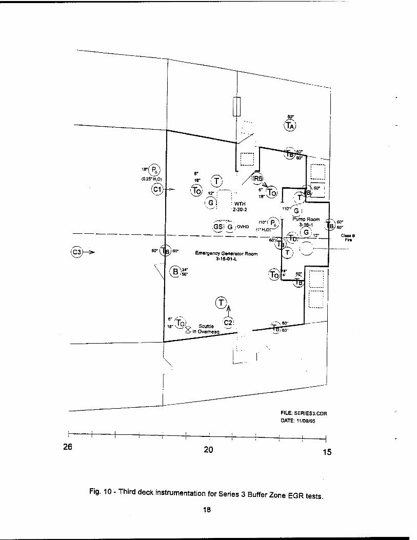
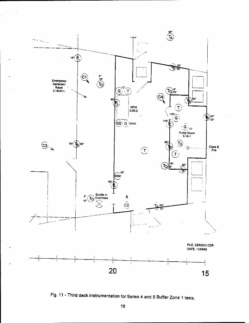
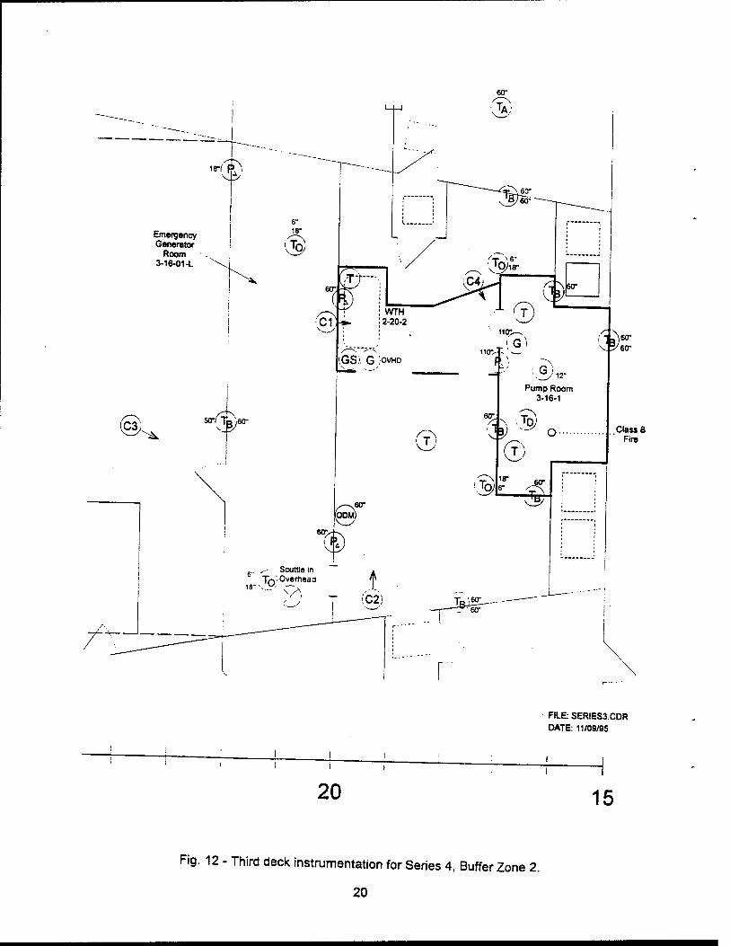
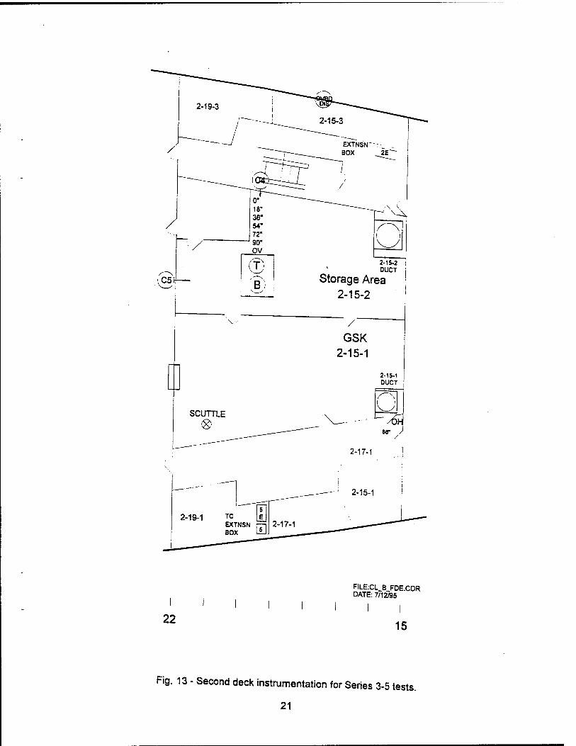
th*^9rL9K13f Sh°W the '"strumentation used in the third and second deck test areas, for each of he three buffer zone configurations. Measurements consisted of air and bulkhead
temperatures, pressures between spaces and ventilation openings, fuel supply pressure and gas concentrations high and low in both the Pump Room and the buffer zone O her
shoTtn F^s" iTi?t£0f Vide° photograpny- The ^ra locations and view angles are also snown in Figs. 10-12. Key measurements are discussed below.
mnSfvl."3'^'8 Were,USed t0 continuous|y monitor the gas concentrations of carbon £Lm?«* X'de and ^en in the fire compartment and in the Emergency Generator Room. Analyzers consisted of Beckman model 865 for carbon monoxide and carbon dioxide
locatedrear
3n m°del 755f°r0Xy9en measurements. Gas .am^wyS
(1) low in the fire space at 3-16-2, 0.3 m above the deck,
16
® T
KEY
Thermocouple overhead - one pair 6" and 18" below the overhead
Thermocouple air
Bulkhead thermocouple - on side noted, 60 in. above the deck
(TQ) Deckmount thermocouple - one thermocouple located on the deck on the side indicated by the drawing
Thermocouple tree (320, 274, 229,183,137, 92, 46 cm) (126,108,90,72,54,36, 18 in.)
(G) Continuous Gas sampling point (CO, C02, 02)
(GS) Grab sampling point
( C Y^ Camera
PA ) Differential pressure
\BJ Bidirectional probe
(°°y Optical Density Meter
Fig. 9 - Instrumentation key for Figures 10-12.
17
(C3H>
26
i
"H;
(C1
' 4
(0.25" H,0)
60-
WTH 2-20-2
IIR6)
110<,
-^■■"^. no- C p„ !.GS'G;OVHD (rHi0r^
60" ( ,^~V QB)
G) T Pump Room ^i ■*. „.
^-. i G ' /h-_" -■ / 12" Ciu« B
60- Emergency Generator Room 3-16-01-1
(B): 34" 56- 39
T;
V ä 7ft
© 6- AT-,
18" v!_5i-> Scuttle
1 C2:
FILE: SERIES3.CDR
DATE: 11/09/95
20 15
Fig. 10 - Third deck instrumentation for Series 3 Buffer Zone EGR tests.
18
Emergency Generator
Room 3-16-01-L
C3- ^
J—--
20
FILE: SERIES3.CDR DATE: 11/09/95
15
Fig. 11 - Third deck instrumentation for Series 4 and 5 Buffer Zone 1 tests.
19
Emergency Generator
Room 3-16-01-L
FILE: SERIES3.CDR DATE: 11/09/95
20 15
Fig. 12 - Third deck instrumentation for Series 4, Buffer Zone 2.
20
22
RLE:CL B FDE.CDR DATE: 7/12/95
15
Fig. 13 - Second deck instrumentation for Series 3-5 tests.
21
(2) high in the fire space at 3-16-2,2.8 m above the deck,
(3) low in the buffer zone at 3-20-2, 0.3 m above the deck, and
(4) high in the buffer zone at 3-20-2, in the overhead centered on the starboard side of WTH 2-20-2.
$H i3LS.!TPleS Wefe mf^ and passed throu9h an impingement-type water trap. In addition Z£SS£5 ST;?60 thr°Uf C0,d trapS t0 remove a"y remaining water. The90 percent response time of the four sampling systems ranged from 60 to 92 seconds.
«^mnlf ?ed B"? SamJ*eS °f the buffer zone were taken and ana|yzed by gas chromatography
ä^MST same ,ocation be,ow the hatch as Ä c°~ ■- «■
A vertical string located inside the fire space at FR 3-16-2 with thermocouples at 46 cm, 92 cm, 137 cm, 183 cm, 229 cm, 274 cm, and
deck In" 36 '"" 54 ln" 72 in" 9°'"" 108 in" and 126 in) above the
A vertical string located in the fire space at FR 3-17-1 with thermocouples at 46 cm, 92 cm, 137 cm, 183 cm, 229 cm, 274 cm, and 320 cm (18 in., 36 in., 54 in., 72 in., 90 in., 108 in., and 126 in.) above the deck.
^u^n8^"9 •I?cated in a" buffer zones at FR 3-19-2 to the port side of WTH 2-20-22 with thermocouples at 46 cm, 92 cm, 137 cm, 183 cm, 229 cm 274 cm, and 320 cm (18 in., 36 in., 54 in., 72 in., 90 in., 108 in., and 126 in.) above the deck.
(1)
(2)
(3)
(4) For Buffer Zone EGR, a vertical string located at FR 3-19-1 with thermocouples at 46 cm, 92 cm, 137 cm, 183 cm, 229 cm, 274 cm, and 320 cm (18 in 36 in., 54 in., 72 in., 90 in., 108 in., and 126 in.) above the aecK. For Buffer Zone 1 and 2 this string was located at FR 3-18-1 inward toward centertine.
(5) Bulkhead thermocouples were placed on all six boundaries of the fire compartment. Bulkhead thermocouples were located near the center of each side of the space at 1.52 m (60 in.) above deck. A deck thermocouple was located in the center of the space and above this the overhead metal surface temperature was made on the underside of the deflection plate shielding the overhead duct work from the fire.
Pressure differentials were measured at various locations for the purpose of quantifying the
th! h£he?SUre °?e eXpl2Si0n aCr0SS the fire boundarV and the buffer zone boundaries Due to E« £ eTeratures and sooty environment the pressure transducers needed to be remote from the test space The transducers were connected to the pressure ports using 0 6 cm
XnTth^K tUbI*" °Ue!°thehi9h,ytransient natureof ** blas"wave and?hedating 111 nrlc n9; A Wa-t r?'i2ed that the pressure measurements would be less thanThe actual pressure pulse. The leading transducer manufacturers were unable to give even an
22
eSld thl^hT 9 ' de °f th'S type °f measurement error. Despite this limitation, it was S^cJ^-^^Km!SUrBment8 W°Uld provide useful mfennatlon to the relative SSlÄi !Sos,ons for the d,fferent conditions studied. However, as discussed below a lack of reproducer and the overranging of some instruments precludes any condus^rends
6.0 RESULTS
6.1 Series 2A
tho ™6 ,*, T* a surnmarV of tne tes* scenarios conducted. This table lists the test name ,1 h^ Ue'maSS fraCti°n (defmed below>-the total time ^e door was dosed the deTy aTnP^ " Se?unn9the secondafy ft»l a"d opening the door, the resulting outcome and
tlfe Lme s^nario' ^ ^ F*-0" ** 9r°UP teStS WhiCh Were essentia,'y repeaUests of lonl^J ^ The reSU,t,n9 outcome descnbes what happened outside of the door In some cases, there was a deflagration in the compartment (noted by a peak %e n temoe atl
S^^l^T ! fire ba" °UtSide of the apartment. These *es*we ^characS bv 2JT £ I? °f 3 ,arge ba" °f smoke (2 t0 5 m in diameter) or a roll out of flame undethe ThfseS;lVh0WS 3 Phot°9raPh of a smoke ball forming outside the fire doo ortest BD09
2LS^ L wPartme,li8een in the Ph0t°9raph was an extraneous stmc u^ as t waS barfrS« o to? comPartment bel°w. The formation of a smoke ball was very similar to a
SS?d£S 2?6Pt With,°Ut flame °UtSide the comPartment) in that there waaHuSibfy the b^of SÄ Thf S- PUlSe,Wh;ch Üad thmSt the 9ases out of the compartment to fonn ine Daii of smoke The format.on of a fire ball can be seen in Figs. 15 and 16 Fia 15 showsan
BO™ TT™ ^ 2) °f thft6St comPartme"t with a fire ball Lning outside the door (test BD21) The maximum see of this fire ball was about 4 3 m (14 ft) in diameter Fir, i« .•!!!L ,
iTlu^ H7 °f \fire ba" eXtendin9 from the fire comXen do" whrCh ison the eft smokfanH/o t09^Ph t6St BD75)- ,n SOme cases-the fi« ba» was preceded by a ball of smoke and/or an extension of flame out of the door.
thisTreoonrtmT^ nl^f? 'T*™ '? an imP°rtant Parameter which will be referred to throughout no IS f mmal fuel mass fraction- Y'-is defined as ratio of the mass of fuel injected mtethe fire compartment to the total mass in the compartment. An overty ^SSÄon
y, = -^ (i) mtX
where
mix comp "V eomp 'air «.
23
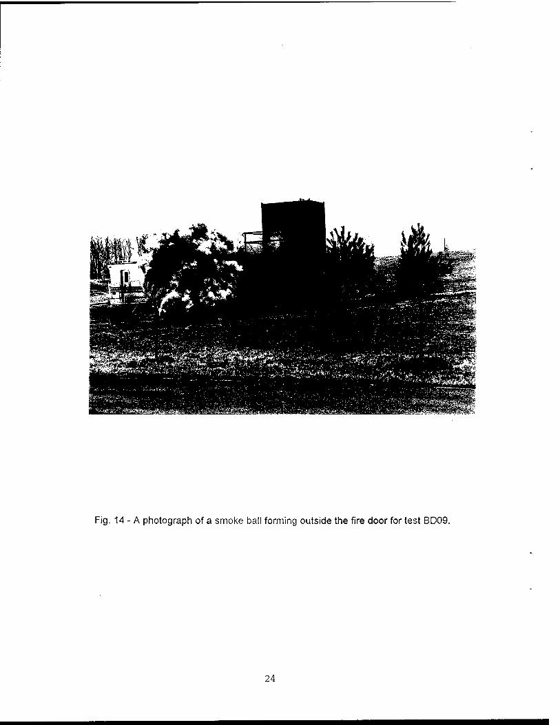
Fig. 14 - A photograph of a smoke ball forming outside the fire door for test BD09.
24
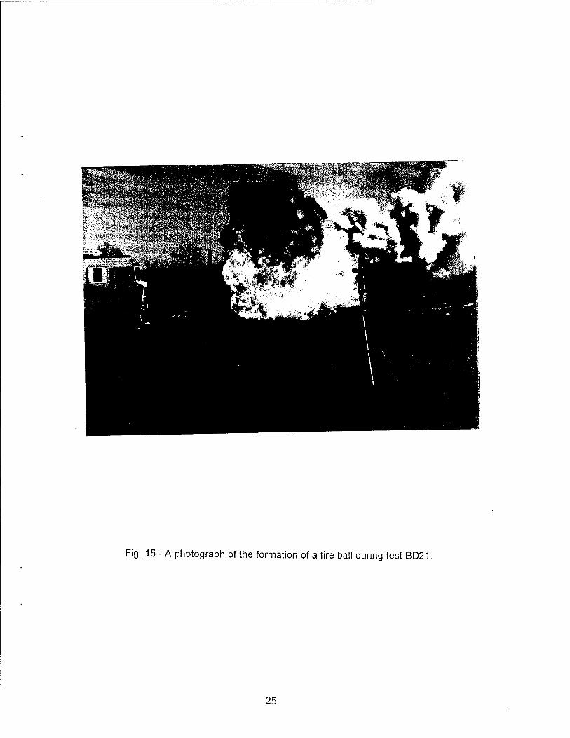
Fig. 15 - A photograph of the formation of a fire ball during test BD21.
25
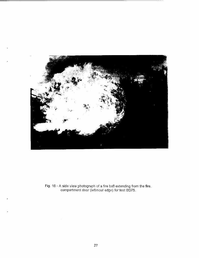
Fig. 16 - A side view photograph of a fire ball extending from the fire, compartment door (leftmost edge) for test BD75.
27
c o
■o V c CD a
73 CD C CD
to. o o
to. o o
■D ■o CD c m
■S3 a a CD CD u CO
to. o
o to.
to. ,o ■a T3 ■D
•fc- c CD a o
o o CD CD CD CD CD Q.
CO
E cu — a CD O
•a to. CD
o •a CD to.
-° CD- CD c
So
^CD CD C
I« O o
C C C o CD CD CD " a a a £ o o o 2
to. CD
J2 o o
CO
CO .2 CD
<2 o — c
c o
to. o o
"D c CD £ 5
to. o o
TJ c CD
JZ
to. o o •o c CD .c 5
■a to. c
.s o c
co
c CD
E E. o
> CD
3 ._
C0"O .Sc — CD
•a c cu sz 5
o r- C O to. CD
T3 CD C CD a
A
U CD CO
m
c Q •= CO E a CO*
CCCN
c Q •= to E a C0x
CC£N co ro
CD
co CO o
*
CO
*
CO CD 5
W o c en c
O ** 'c .S> g 1 •*•
CD ■o
o c
I m
11 4S «- TJ CD CSS O C O m
c o to. CO ** 'E
1
en
C ra
3
■Q CD C
c
o
a m
o to. o o
•D c CD
.C
c o to. CD *s c ro
CN
to. to. _ CD CD^
SS SS CO C C CD ro ro ro
o'5|
CN CN CD
SS CO c a) roro
II CN i
CDCDCDCOSSES
c 'E c 'E ^ to. i_ i. .21 .3 .S .ro £ « aj » o o o o '='='= '= c c c c.raarara
CN CN CN CN CN CN CN CN
CD ■_■ •_" T3 CD CD
a c -I CD ro a x o o CD C C
CN CN CN a> (^ «to- CD — c
o ' * ■^ c ^~ c ■»— ■*— T— ^ ^ ^ T- T" T" ^ ^to
o o CS w+s o (A o (0 V) CO - CO - CO CO CO CO CO CO (0 (0 cy> *■* ** r fei *«* .** cu CO C0T3 C0T3 CO CO CO CO CO CO CO CO CO en m
a> h-
< CN
CD Q.
CO CO a.
_^ a CO CD a
CD
1 CO CD a
0)
'E .5?
CD
E CD
E E CD CD
E CD
E CD
F CD
F CD
F CD
F CD
F CD
F CD
E CD
E CO CO
CD
E CO CO
a» Q) «^ (U CO
CD to. CO CO
CO CO
CO Cto CO o
co Q. CO o
CO CO
CO 10
CO CO
CO (0
CO CO
CO CO
CO 10
CO CO
CO CO
0) E o o
o
>. = > ss = — >» >. > > >. >> ■>. CO CD •c CU (0
o
a c ig o Z
c ic o Z
a c iE *- o Z
c
o Z
a c ig o Z
E JO
"5 CD 0) to.
LL
c g o Z
CD CD
O
E
c O CD
E CO
co CO CD
o E
CO CD CD
o E
CO CD CD
o E
"55 CD CD to. il
o CD
E CO
c O CD
E CO
15 CD CD to. il
o CD
E CO
CO CD CD
o 'F
c o CD
E CO
15 CD CD to. i~
o CD
E CO
c o CD
E CO
c o CD
E CO
15 00 CD to. il
15 CO CD to. ill
75 CD CD to.
LL w LL CO CO CO u. u. LL CO LL LL LL LL
ID E E 3
1*8 CO < < (M O) T— in o o o O o Z Z co CN co CM T"- o o o o o o o o o o o o o CO a o
CN <u 3"° a> ES? as
p w ra
"o «
Z. w
g o o < z
< z
CO co
O CO CO CO o CN
co o O o
CO CN
ro CN
o CN
CN CM CN
CO CN
CN CN CO CO 00 ro
E 50 pa
c — co o OJ we 3 CO o <
z < z
CO in o
co co o
o ro o
CO CO p
o CO CO CM
CN CN CN
CO CO co
CO CO
CO CO
m CO
ro CO
CO in co m
to CO
ro CO
CO
1"
CO l>to.
o co
CN co
ö G> ö Ö d Ö o O o O o o o o O o o o o o o o o° Ö d
^ CN CO •* in CO h- GO en O ,_ CN CO * in CO r» CO ro o CN CO ■<»■ in en |v» V a Q| n n n n n Q n a
m a CD
a D "»- T— ▼— T- ^ ^ CN CN CN CN CN CN CN CN
H m ml CD CD CD en m CD m O Q a o o u u G a a Q n n n 1 1 CD ill LU CD CD CD CD CD CD CD CD CD CD CO CD ml
28
■o 0) 3 c c o
w o 'C re c <D O
CO
J2 e a> E E o O
k» a»
.** c .a o c
w"
10 «
E CD 10
O) CN «0 CO
E ra en
CN tfl CO
co E ra CO
co k_ 3 10 o u ra c 'C 3
■a ■o CO c a> a o a k. k. o o -o CN CO <u to ^ «-D co co E8 to a
CO 3
CO •D c o u CO 10
ra c •c 3
k_ o o
T3 •** CO
ra c E ra
5=
CM" CO
«>o CO '^
t CO
to.S
> CO
CO ■a ** a CO o X CO
in CO 10 CO
CD
E ra CO
«
ra £
JS CO
TJ
a a> ü X CO
m CO
CO co CO
E CO CO
>< ra CO
■a
a. CO u X CO
m co to ra CO
E CO CO
+ ra c
'55 o ü
c A CO u
1 c CO a o
.2 o ra k. u k- O C 5 o Q'-§ in.® CO c co- co CO
<o .2 E-o CO c IOCN
+ ra c
'co o u c XI CO o
i c CO a. o
■o CO
U CO
k_ O, C o o
LO.® co c to- co 0) co«2 E-o CO c «CM
in CO CO ra CO
E CO (O sa
me
as 3
5, t
orch
igni
ted
gase
s on
ly a
t doo
r cr
acks
, ex
t. w
ith w
ater
bef
ore
door
ope
ned,
m
oder
ate,
#
co" JO 3 a 8 CO k. a
m
co" CO k» CO
T3 O E
in" CO
(0 CO
CD
E CO to
CO XI
CO k.
c ra
CD
E ra
e= 75 o "€ co >
ra XI « k_ IB C a x: ♦* CD
E CO
s=
15 o ■e (0 >
■^:
■V <o to a> E ra 10
to CO
CO
E ra to
^r to CO
CO
E ra to
ir to CO
CO
E ra to
ra XI
£ IB c CQ x: CD
E CO
C—
15 o ••e
to CO
Q>
E ra 10
*
CO
1 '♦"
to CO
CO
E ra to sa
me
as 4
4, b
urst
of w
ater
with
4' a
pplic
ator
30s
be
fore
doo
r op
ened
. #
W 0) I- < CN w .2 *cz <u
CO H— o 2» re E e
CO
CN
co E o o a O
"5 m £
LL
CO m CD
iZ
"5 m CO
o E (0
"5 CO a> W
LL
CO CO
£ LL
15 CD (0
LL
2J» c O a> E CO
LL
c o CO
E CO
LL
"co m CO
LL
ra m CO L.
LL
75 m CO k.
LL
> c o CO
E ra
LL
15 m 0)
LL
15 CO CO k_
LL
CO CO co k.
LL
"ra CQ a> k.
LL
To CD CO 1—
LL
"re CQ
CO k.
LL
15 CQ
CO k.
LL
15 CQ
CO k.
LL
15 m CD k.
LL
15 co CO k_
LL
15 CQ
CO k_
LL
CO CQ
CO k-
LL
ill ® rao
0) 3"° E <u £
o o o o o a O co N. CN CM CN
O) o CM
o> o CM
o CM CO
o CO
CM CO co CO
CM CO CO
eo CO
CO
XJ re r- CO § 0)
Eo0
CD CN
o CN (N
CO en en o co
O) co en CN
en CO CN CN
O
CN 5- CM CM
o> CO CM
O) CO CM
o CN
CO o co co co CO CO
o co
CM CO
c — to o o> W.B 3 ra o
u.
CO
Ö
O)
<N Ö
m CM CN d
co <N CN d
CN CN r- Ö
CM
d
CO CM
d
co
d
o eo
d d
co
d CO
d r-
d
in
d
(M
O
co
a
co co
o
CO
o
CO
o
CN co
O
CN CO
o
00
o
CO CO
o
1-
eo CN Q m
OJ CN a CO
a CO Q CQ
co a CN CO D m
CO CO a CO
N- CO a CD
to CO a m
CO CO a CO
r- co Q m
CO CO Q m
O) en Q 00
o *»■ a Q
CQ
CM "»• Q CD
co if a CQ
Q CO
m
a CO
CO *«■
Q CQ
Q CQ
co
O CQ
O)
D CQ
o m Q CQ
In
29
CO
w oo oo
E ^" CO
cu m * •2 N-
.* »- CO
I "3 o
w* o CO
JS a> CD
c CO c
E "05 3
k^1
5
TJ
: E o ü
O
CO CO
3 o
4) 3 3
13 C o
CO
£2 CO o c 3-c
c o
CN 1 "6
. c Tf
o if io «/) = (O
'C CU
CO CO c CO CO c 0) cu.2 V «f c E ES E Ea
O CO
CO CO f CO CO C <o w«c (/> to a
** (A _>> 0) l-
a> E "5 c
o "5 < o 00
<U 03 £ CN
3 a) E CD o
V)
■c o iZ CO a. Z
a» CO w— c c O ^ £ o
o (0 E E
«PS 5 CO 5 00
■o
© 3"° CD?
3 CO
3 O
«N E fl> CO
cs XI 'C<o JZ CO a> to"o f— CN in CN o %
oo oo oo o CN o
a. 0) w 3
c (0 — wo oo *— co (0 a> OT« r^ oo ««f — a) 3 CO O u-2 5 u_ ci o Ö
■ *- CM CO ^t m (A Q
in Q
m Q
m a m m CO 03 « %
30
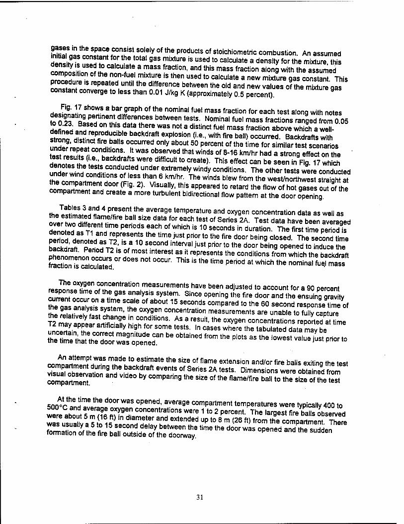
fS^SJSSST^ theproducts of stoichiometric combustion. An assumed riinS£ u ?f ° the t0tal gas m,xture ,s used t0 calculate a de"sity for the mixture this cation 2* MlCU ate,3 mJSS fraCti0n' and tnis mass fraction a,0"9 with the assumed compos.t.on of the non-fuel mixture is then used to calculate a new mixture gas constant This procedure is repeated until the difference between the old and new values of the mS gas constant converge to less than 0.01 J/kg K (approximately 0.5 percent). °
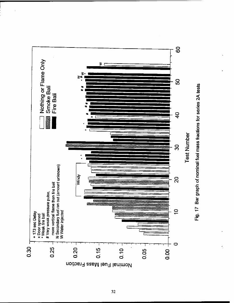
Fig. 17 shows a bar graph of the nominal fuel mass fraction for each test along with notes
KET2EEXISTS" b6tWeen t6StS- NOmina'fue' masS fractions Ä?Ä05 to 0.23. Based on this data there was not a distinct fuel mass fraction above which a welt-
strnnf ^1dn
r:Prr0dKCi?e baCkd"lft eXP'°Sion (Le- with fire ba"> occurred BactdraftsS Äet^r °,f Urred.0nly ab°Ut 50 percent of tne time for simila^ test scenarios tesfreS! r r"? J*W3S °bSerVed that Winds of 8"16 km/hr had a strong effect on the test mutts (i.e., backdrafts were difficult to create). This effect can be seen in Fig 17 wh ch denotes the tests conducted under extremely windy conditions. The othertesfc were conducted under wind conditions of less than 6 km/hr. The winds blew from the west/northwest sTraiqht at
^SSTVl00riF[9- 2)" ViSUally'thiS appeared t0 retard the flow orhorgase ouTof he compartment and create a more turbulent bidirectional flow pattern at the door opening
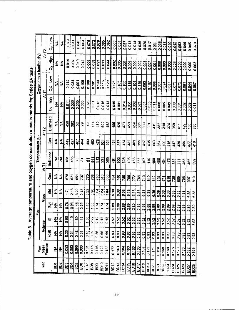
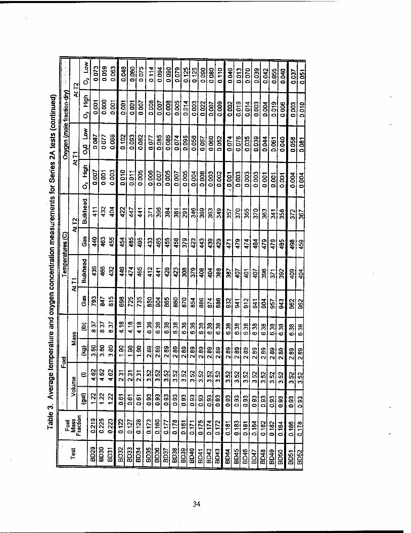
Tables 3 and 4 present the average temperature and oxygen concentration data as well as
^SXS^ bal,Hi2e d?a/0r 6aCh t6St °f Seri" 2A- Test SÄ!av aged dllTraT\ \ me Pen°dS eaCh °f Which is 10 seconds in dura«on. The first time period is SrinH H ! nand lepresents tne time i"st Prior to the fire door being closed. The second time
E£*T^£i?« 1 ° f eT6 interVa'jUSt Pri0r t0 the door bein9 °Pened to induce the LnnLnl S ? m°St ,ntereSt as !t rePrese"ts the conditions from which the backdraft
fraction"iZSSS " *" "* "^ ™* " *" *" ^ 3t WhiCh the n°minal »* ~
r««!!^**96" f"060^"0" measurements have been adjusted to account for a 90 percent c!,r?ent Z^nnT? 9** ■"*?. «y»tem. SinCe 0penin9 *e f,re door and *^ensuing graJty current occur on a time scale of about 15 seconds compared to the 60 second response time of
he ^SSZ'ST'the °Z9r COncentration measurements are unab.e to fu^ptuTe the relatively fast change in cond.tions. As a result, the oxygen concentrations reported at time
ulTay aPPh6ar artifiCia,,y hi9h for some tests- ln oases where the tabuSted data may be "^
SmÄ^ be °blained fr°m *» "" as »• -st value iustphor to
mmnna?lem?7aS "TV0 eStimate the size of flame extension and/or fire balls exiting the test
compartment dunng the backdraft events of Series 2A tests. Dimensions werVobtaS from
"mpatir °n 3nd Vide° by COmparinQ the Si2e °f the flame/fire ^^*25SS 500^Ch
aendT!^nfO,Or W3S °Penedl aVerage comPartment temperatures were typically 400 to
were about 5 S S^? CTntraii0nS Were 110 2 percent The largest fire balls observed wausuaiv a 5 £ «LllÄTT***™0? Up t0 8 m (26 ft) from the oompartment. There was usually a 5 to 15 second delay between the time the door was opened and the sudden formation of the fire ball outside of the doorway.
31
CO *■» CO
CO .0) 'C ID 0)
a CO c o ts
CO CO (0 E <u a 03 c E o
x: Q.
CQ
O)
IT)
ö d
UO!PBJJ SSB|/\| |snj IBUILUON
32
«A
< CN (A 0) •c Q)
CO
c/> ** c a> E 0) i_ 3 (A CO a) E c o
2 c o c o o c a> CD
o ■o c CO
9>
2 Q. E aj <u CO
2 a> > < CO
o .a CO
c o ■8 CO
a> o E c a>
1 O
CM
5
1 O
< z < z O) r- O O 0 0
CO
0 0
CO 0 d
in
0 0
CN
O O
at s. 0 0
m 00 0 0
CN at 0 d
to m 0 O
in 0 0
t». to 0 d
CO
0 d
0 0
in CO 0 0
0 CN O O 0 0
CO 0 Q
to CO 0 0
CO CO 0 0
0 0 0
CN
O O
CO in 0 0
CO
O O
m 0 0
0 0 d
x: at if < z < z 0
ö 0 0 d
0
0 0
CO
O d
at a 0 0
at m 0 0
CO CN 0 0 0 0 a d
CN O O d
m 0 0 d 0 0 d 0 0 d
0 0 0 d
CN O O d
00 O O d
O O d O O O
0 0 0 0
a 0 0 d
0 0 0 d
CO 0 0 0
0 0 0 d
O O O d
0 0 0 d
CO 0 0 0
i a O
< z < z Ö
00 0 d
O d
at 0
d
05 0
d
O
Q
at 0 T~
O
to
d
0 CN
d
m CN
d
in 0 *~ 0
0 0
d
00
d 0
d
m
d
CO 00 0 d 0
d
00 00 0 d
00 0 d
at 0 d
00 0 d
CO
0 d
m 0 d
to O d 0 d
00 O d
X < z < z O d
0 0 0 d
0 0 0 d
m CO 0 d
co CN 0 d
CO 0 d
00
O d
CO
0 d
CO
0 d
m O d 0 0 d 0 d
CO 0 d
CN 0 0 d
CN O d O O d
m CO 0 d
O d
00 0 0 d
m 0 0 d
00 0 0 d
0 0 0 d 0 0 d
CN 0 0 d
at 0 0 d 0 a
O CO a> 3
to a E 2
CM r-
<
■0 (0 0) JC
3 m
< z < z 0 in
CN 00 CN
CM m
CO co 0 00 0 0 m
CN 00
in m in CN
CO at m in CO CO
0 CO CO
at CO
CO CO CO
00
CO c«. CO
00 in CO
T- (N CN 0 CO XT
0 00 CO
CO (0 0
< z < z 0
CM 0 IT CO
CO o>
CN m CO CN m CN m m 03
CO 00
CN 00 00
m at CO
m CO
CO to CO
o> 0 1J-
co T-
to CO
to to
co
1"
3
■0
a>
3 m
< z < z 00 m CO 0 00 (O TT m
CO 1— m CO m
m 0 m at
tn 0 in
CO 0 in
m en
03 00
in m CO
0 OJ
TT
03 m m to CO m m
CO
CO in m to
CD CD CO
CO CO < z < z
00
CO CN CO m co
CO N.
0 N. 1^
CO CO 0 00
00 Y— 03
0 0 00
00 0 at
00 at at
CN CO to
at at 00
at 00
03 CO to
o>
CO
CO CO CO
CO CO
en CN
at to 03
to at 0
CD
O
00
■3
(0 2
JQ < z < z CO
CN
CN CN CO
CO
CN
CN (N CO
CO O) CO
00 CO
00 CO
CO CO
00 CO to
00 CO CO
CO CO CO
00 CO CO
00 CO CO
CO CO CD
CO CO CO
CO CO CO
00 CO to
00 CO CO
00 CO CO
00 CO CD
00 CO to
CO CO CO
CO CO CO
"3 < z < z 00
ö
to Öl O
CO CO O) O
CO 0 00
at 00 CN
05 03 CN
CO CN
at 00 CN
at 03 CN
at CO CN
t» 00 CN
at 03 CN
05 CO CN
03
CN
at 00 CN
at GO CN
01 00 CN
CD CO cvi
at 00 CN
o> 00 CN
0) 00 CN
a> E 3
s < z < z co cn d
o> 0 00
at O 00
CN CN c\i
CN r-
CN
CN
CN
CN
CN
CN m CO
CN m CO
CN m CO
CN m CO
CN m CO
CN m CO
CN m CO
CN m CO
CN in CO
CN m CO
CN m CO
CN m CO
CN m CO
CN m CO
CN m CO
CN in CO
CN m CO
5 3 < z < z
in CM d
CO d
00
d CO d
00
d 0> m d
CO m d
to m d
CO m d
CO at 0
CO en 0
CO at d
CO o> d
CO Ol Ö
CO 0> d
CO at d
CO at d
CO o> 0
CO at d
CO at d
CO CO d
CO at d
CO en d
CO at d
CO at d
CO CD d
Fuel
M
ass
Fra
ctio
n
< z < z CO in 0 d
CO co 0 d
0 at 0 d
co CO 0 d
O
a
co T-
d
co T-
d
CN CN
d
CN CN
d d
CO to
d CO
d
CO CO
d
CO 00 r-
d
in CO
0
at CO
d
CO
0
m
0
00 in
O
00 CO
0
en to
0
to
0
CO
0
0 CO
0
fN CO ■»—
0
05 to
0
0) to Q
CD
CM 0 m
CO O CO O CD
m Q m
co Q m
1^ G
00 Q CO
05 Q 00
0
D CO 5 a.
CN
5 CO
CO
Q m Q m
in
a CO
CO
a a. r- Q m
00
a CO
05 T— Q CO
0 CN a m
CN O CD
CN CN a m
CO CN Q CD
'S- CN Q CO
m CN Q m
CO CN a m
1^. CN Q m
00 (N a CO
33
•a CU 3 C
c o u
0>
< CM
10
•c 0)
CO
£ tfl c V E 2> CO (0 eu E c o ffl c 0) u c o o c a> a>
o TJ C (0 0) 3
5 Q. E a> CD C3>
2 a> > <
CO
Q) XJ CD
'S i c o
(0
OS o E c tu
I
CN
5
5 o
O
en d 0 0.
059
0.06
3 co 0 0
0 CO a 0
m 0 d
*■■
0
0 c 0
0 a 0
a 0 0
in CN
O
m CN
O
0 O) Q O
O CO 0 0
0
d
0
0 0
CO
a 0
a 0 0
OJ CO 0 0
CN
O d
m in 0 d
a 0 d
r-» CO 0 d m 0 d
os I
IX
O
r- O O O
O T- O O O O d d
0 0 d
1^
0 0 d
0 0 d
CO 0 0 0
0 0 0
CO 0 0 d
m 0 0 0 O d
CO 0 0 d
CN C\ O d
N. O O d
OS 0 0 d
CN O O d
OJ
0 d
■<T
O O
CO 0 0 d 0 0 d
OJ
0 d
CO 0 0 0
CO 0 0 0
0 0 d
P 5
$ o _i
o «»4
O
CO O d
1^ CD 0 0 d d
CN O
O
CO OS 0 d
CN (O O O
r- N. O d
m CO 0 d
CO CO 0 d 0 d
in o> 0 d
co m 0 0
1^- co 0 d
0 co 0 d
CN in 0 d
O O
CO
0 a
in CO 0 d
OS CO 0 d O O
CD 0 a
0 •^>
0 d
00 m 0 d
00 0 d
O) if
0
O O d
*- CO a 0 0 0 d d
O
O d
r- T— O d
m 0 0 d
CO O O d 0 0 d
m 0 0 d
0 0 d
in 0 0 d
T O O d
CO 0 0 0
CO 0 0
d
CN O O d
O O d
CO 0 0 d
CO 0 0
d
CO 0 0 d
O O d
O O d 0 0 d
0 0 0
0 0 d
O
8 1 0) a E <u
CM 1- •** <
T3 (0 V £
CO
CM T CO O
CN CN
CO
CO 01 CO
CO CO
CO CO CN
co CO
OJ CO CO
CO CO CO
o> CO
in CO
0 co
in CO CO
0 co
CO CO CO CO
00 in CO
CN N. CO
CO CO
OJ in
0> (0
O co in to m in
in CO
in OS
CO CO
in co m m CO
in OJ
CO
CO CN
CO ir
OJ CO
OJ CN
as CO
OS OJ m CO
CO as •or
3
■o (0
3 CO
CO CO
CO CN CO CO
CO
■"»■
in CO
CN r-
Y— CO CN ■V
CO CN
CO 0 CO
o> CO
CO 0 0
CO 03 CO
CO CO O O 0
CO OS CO CO
CN OS CO
OS 0 0
w rs co
OS TI- T- 00 CO
CO as CO
m CN m CO
O in CO
O in CO CO
0 CO 00
0
00 m CO
co CO CO CO
co CO 00
CN CO OJ OS
(N T- as OJ
0 OJ m OS
CO
OS
CN CO as
CN CO OS
■5 u.
in in
5
H 1-- CO ad
CO CO 00 CO
CO CO
■«r
CO 00 CO cb
CO CO CO
CO CO CO
CO CO CO
CO CO cd
CO CO CO
CO CO CD
CO CO cb
CO CO cd
CO CO CO
CO CO cb
CO CO CO
CO CO cb
00 CO cb
CO CO cb
CO CO CO
CO CO cb
CO CO CO
o> 0 CO co
0 0 CO CO CO CO
O as T—
0 as
O as
OS CO CN
OJ CO c\i
00 CN
CO CN
01 CO CN
O) 00 CN
o> CO
CN
OJ CO CN
CD CO CN
OJ CO CN
OJ CO CN
OS CO CN
OJ 00 CN
OJ CO CN
OJ CO CN
OJ CO CN
OJ CO CN
OS CO CN
0) E
o >
~ CM CD
CN CN co co CO
CN
r— CO CN
CO CN
CN m CO
CN in CO
CN in CO
CN m CO
CN m CO
CN in CO
CN m CO
CN in CO
CN m ei
CN in CO
CN m CO
CN 10 CO
CN in CO
CN in CO
CN m CO
CN in CO
CN m CO
CN in CO
'S CM CN
CN CN CN CN CO
d CO d
CD O
CO o> d
CO
0
CO O) d
CO O) d
CO o> 0
CO O) d
CO OJ d
CO OJ d
CO OJ d
CO OJ d
CO OS d
CO OS 0
CO as d
CO OJ d
CO OS d
CO OS d
CO OS d
CO as d
Fuel
M
ass
Frac
tion
OS
CN d
m co CN CN CN CN d d
CN CN
d CN
d
CO CN
O
CO
1—
d
0 CO
d d
00
d CD T-
d d
in
d d
CN
d CO
0
CO CO
0
OS
d
00
d
CN CO
d
CN CO
d
CO
d
co 00
d
CO
d
in 0) 1-
a> CM Q m
0 1- CO CO O Q|
CN CO a 00
CO CO a m
CO Q CO
m CO O m
co CO a *
CO a m
CO CO Q CO
05 CO a CO
0 T Q CO Q
CN
a m
CO
a a.
a m
in
Q CO
co T Q m Q
CO
00 'S- Q a
o> ■<f a CO
0 m Q 00
5J Q
CN m a CO
34
S o O) en v -i en
a o
«N O o o d (-
■o 0) 3 ,c c o
f
5 JC a O) o 00 c
o
a *: CD
X
o
05 o o
o o o
in o d
u O 5 o in E
CO 00 a (A c in m o <U a] o o T-
5 9. d ö d < s? O CM o P «A 5 © JZ •c O) •v T~ o CD I o o o
CO o o o L. O o Q d d
«*-. w
■o c <o V « 00 CO r-~ E <0
CO CO CO en
V rg 3 v. 3
>_ <•-#
m
(0 < 4) E
o » CM cn CO
8 CD
cn en CN c W
o 2 a "J5 S & CO c E a>
a
3 CO
f\ r^ N- 0) u
« ■»»• en
CD cn
c o u K
5 c CD in
co O
r» co o O) T r^- t-»
o o> 00 03
•o c —H <
2
00 CO CO n en cn <D (0
*«-<■ co CO o L_ (0 o 3
S a>
2 ra (N- oo
o> CO
•a co
Q. CN CN 3
E O
a» CO
CN CN E 4)
5? a> E
^■■» O in
en m CO
CO 5=
u. 1 (1) > <
CO
S o
en o> ö
en c» d
cu to 3 Q. CU
Hi c 3 J3 ■m «> O ^. en CO CU 0J«3 00 Tf — CO h- 3 <D U
d d 5 S. 2 IS IB CU
to cn in in
m w S £•
Q CO
Q m m
35
10 ©
4) £
C W S 0)
d)0Q v>™ — c/j ra a>
■Q'C
2<8 o°
c a> .2a= SS Xo ® ra a) A E«> ra£
o c CD §
"§§ ra = .§ ra w n ^1
■ u ^r JD .Q ra
0) N w 15
9>
e o
'55 c a> ■R
0) N
(55 a> E ra
a
o o ■D
O) _c 'c a> Q.
c c 2>ra
tr a>
« E
< 2
< <
ra OQ
4)
o ra Em
CO
Q)
E ra
<n c rao
"ATS
(A a>
m
05
CM
CN N- <N (Si
CO
CD
CO
•v CO |< CO
CO CN
CN
m CN If)
N. CO r*- co
o o
CN CO
a>
re CM
a>
co in 00 T^
o> d
o CN CM D Q CO CO
OS 05
CO
CO CN Q _ CO CO
36
<A
«s £ .E o>c .E o .ts o x w
0) JA
CD —" -Q CQ (D CN
IS <A a>
o c a)
c CO CD o c o V)
(A C
•s 4)
c > a>
CD 4) k.
E CO u (S CO w- .a
c ■c
_ 3 CD T3
S c E
■c CO a. E o o
<t>
<A w
«0 n CO
r
«*** I m 05
CO co a CN
CO
T- o eo CO
in CO
1 CN
O
CO O
m N. oo
CN
00 CO
CO CO
o '5! c fl>
■R a> N
CO ill s 00
CN CM
co r- T-
CO
CO
If) O
CN
CO CN
CN
CO
in CO CN
CN cp CO
in CN
m CN
oo oo
O) oS
CO
CO in O
ai in CN
oo
CO m
u_ E co O
co cn CO CO oo in CO co CO CO O) v CO o CO t^ TT 1»»
r v""' ■«r CN lO T- m CN CN ^- v ^r CN CN V CN CN CN CO
•o §
§? o CN
co o CN
o cb
m od
o CO
o cd
in 00
m oo
o o in
o CO
in CO
o co
in CO
o d
o CN
E, i^ o O
•*■* CN CO CN
a> I
« oo 05 CO a> CO G) <n N
CO (0
E CO £ o oo CO u_ c CN T- ,-
o CA c a>
5 S CO
CO CD CN
in
u CO o o m 2
O) ao r» CN T—
CO oo T CO CO l-~ r^- o m CD *r in w 'T r^ c c
iZ
0)
O-o a> •SS O CD CN CO -Q Em T~
O CO 0) (A
©
E E. CO
Ll_
r» h- CN CN in CN CO CN in in co in CO CO CN CO
«A «AC
■ CO O to ^- ö
CM CM
d CN T—
d
00 CN
d
CO
r—
d
o oo
d
r--
d
CO
d CO
d
T—
d
m
d d
CN
d
T- 00
d
CO CO
d ao
d
CO
d
CN ao
d
CN oo
d
00
d
CO oo
d
00
d 00
d
CO
d
(A 0)
oo CM O m
CN CO Q CD
CO CO a m
ro Q m
in CO a CD
CO CO a CD
co Q CD
ao CO Q CD
O) CO Q CO
o Q co
a co
CN
Q m
CO T Q a m
m Q m
CO
Q m
Q CD
CO
Q CD
O)
Q CO
o in Q CD
in Q CD
CN in O m
CO in Q m
in Q CD
in in a CD
37
The Series 2A tests were successful in (1) developing a safe method for producing Dackdrafts while avoiding dangerously explosive mixtures in the compartment (2) f !T™StratinSthat comPartment temperatures were sufficient for igniting dies'el vapor/aerosol backdrafT "9 preliminarv resu,ts that water injection is a feasible method for mitigating '
6.2 Series 2B
Table 5 shows a summary of the test scenarios conducted. Series 2B tests focused on emending the Series 2A work to develop a well-defined, reproducible backdraft test. In addition tne effectiveness of water spray injection as a mitigating tactic was studied. It was believed that the creation of conditions with higher nominal fuel mass fractions (i.e., greater than 0 18 which was typical for most of Series 2A tests) would lead to a reproducible test. At higher fuel concentrations, the effect of the difficult to control variables, such as wind and leakage around the warping door frame, would be minimized. «"*-»* arouna
Table 3 shows a summary of the Series 2B test scenarios conducted. This Table lists the test number, the nominal fuel mass fraction, the amount of water injected (if any), the total time he door was closed, the delay time between securing the secondary fuel and opening the door
the resulting outcome, and general comments. The bold division lines group tests which were ' essent.ally repeat tests of the same scenario. The resulting outcome describes what happened outs.de of the door. In some cases, there was a deflagration in the compartment (noted by a peak nse in temperature and pressure) without a fire ball outside of the compartment These
smokrre Characterized by a ro" out of flame under the soffit or the formation of a large ball of
Fig. 18 shows a bar graph of the nominal fuel mass fraction for each test along with notes Sf?X S pert,nent di!ferences between tests. Nominal fuel mass fractions ranged from 0 13 r A a I /4nlajonty °f tests were oo^^ed with nominal fuel mass fractions of about 0 25 p'm«? 9 ( 5al) °f secondarvfuel>- As can be seen in Table 3 and Fig. 18 (tests BD74 to BD115), a reproducible test scenario that resulted in a strong backdraft explosion was developed. This was achieved after it was found that a build up of soot on the walls of the compartment had a dramatic effect on creating a backdraft explosion. As can be seen in Fig
fi« SI 6Si J>t leSS than 60 percent of the tests resulted in well-defined explosions with fire balls outside of the compartment. This occured despite fuel mass fractions as high as 0.29. Tr. J!! w? the comPartmer|t walls were covered with soot, up to 1.9 cm thick It is believed that the soot (carbon) buildup on the interior surfaces absorbed some of the fuel injected into the compartment. Therefore, there was a reduction in the amount of vaporized fuel m the space such that the fuel mass fraction (which assumes all chemical species in the gas
w«SSriaHdUally '0Wer than ca,cu,ated- Dependent on the mass of soot buildup, enough fuel was adsorbed in some cases to prevent a bakdraft from occurring. By cleaning the soot from
uZ.^SLTPartre;! Wa"S 6Very 1°teStS the effect of the soot was minimized (soot layers were plntcinn« ,T ♦ }- ?? a reSUlt'the Same test conditions resulted in reproducible backdraft 2S?7. Kth St,ron9,1'51'"01 fire bal,S for 22 out of 22 tests- The effect of the soot buildup tnZ!tV° ♦ A'3'96; faCt°r than the Wind ^«^s of Series 2A; however, this can not be cnnH^niaf 'c aSo=e Same hi9h ^ conditions did not occur during this series. Weather conditions for Senes 2B were very still with wind speeds typically less than 4.8 km/hr (3 mph).
The data presented in Fig. 18 shows that fuel mass fractions of 0.17 or greater are
tTs^mos tnmdurRmf,kd?ft eXPl0Sr ThiS iS partiCU,ariy dem°n*trated * the results of tests BD103 through BD113. For example, tests BD 106, 109, and 110 had fuel mass fractions
38
:::':v.::::':-:■-■:'■* -:'' '■.•'■:'\ £ CO © c .* 3 SI E © CO «A
in © 2«g £ £ o
E «0
E c CO 15 2
-.:'.&<'' 5 a. _ © COf
JQ
© J3
© .©:>:';: © ■C .» © ©*-s JC J£ >
0) (A (A - ©
^E w5j Si ©
E ©re
CO-Q
o E (A« «
o E «A
<3 CD If)
CO lO
CD «0 if) "5
CD"51
w © io S
CO Q)
©oJ ££.G
CO m O CQ
© a ©
c £ * m" in CO
CO
n ©
Q CQ ^-* (D ©
Q CQ
©
Q a. CO ©
CQ 3 © «2
Qo «'S © ©
o
©
go CQ «A
as «A
to A
5 ®
8 8 00
in Q 03
to Q. ©
Q. a>
a. © © £
Q.OT ©3
<A © © CLIA
© © © °-E ©
a a: rr KÖ. o © 3 CCo. « © ©
a: ©
M o •c (0
;■■■■ E ■ 8 o
(Q CQ
£ iZ
15 CO
£ iZ
"5 CO
V
o E w
15 CQ
£ iZ
© E CO
15 03 ©
o E w
15 CD
£
ra CQ
©
o E.
CO
CO CQ
£ iZ
15 CQ
£ iZ
15 CQ
©
o E
CO
15 CQ
£ iZ
15 CQ
£ LI
15 OQ
©
O
E CO
15 00
£ E
".C_ c 23 3* u ^.«2 o
(0
o »- m
ÄTTT3 a. <D 3 C O Is«
o CM
o CM
CM CN
CO CM
CM CM
CO CM CM
o CM
CO CO CM
CM CM
CM CM
o CM CM
CO CM
CM CM T-
CM P'«.-' 1 © (0 »- o
a E
E ©»_ « C « o,2
o CM
CM to CM
CO
CM
CO
CM
o CM CM
CM
CM
o CO CM
o> CM
CO m CM
CM m CM
CO m CM
CM m CM CM
E 3 W
<U*0>«» in © .a
■a ® co
r—
'S °~ 5=>
»-"5 © <g >-* -
Ill :- .::,'C,:;-
— wo © ms 3 RJ O
lO CM
CO CM
lO CM
CD CM
CO CM
CO CM
CO CM
d
CO CM
d
to CM
d
o> o> CO CO CO CO "-2 e
■.■,,;! lt.y O o O O Ö d
CM
d CM
d CM
d CM
d CM
d CM
d
CD to Q CO
ID Q CO
CO lO a CQ
CO IO Q CQ
O
s CQ
8 CQ
CM
s CQ
CO
8 CQ
8 CQ
8 CQ
to
8 CQ
8 CQ
00
8 CO
O)
8 CQ
o 1^ Q 00
39
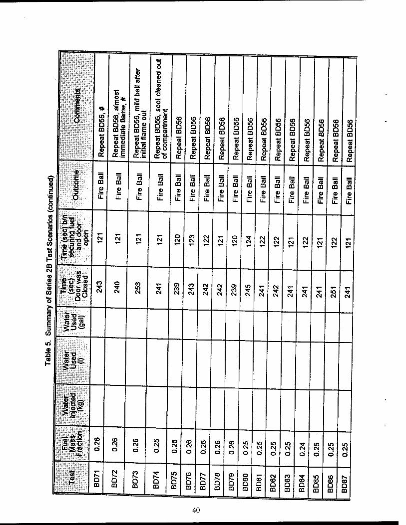
3 u. O ffi ■o C © to c m to
[:W--^itim^. «* to © f ;■:■:•:■:■:. - .•.*++■■.■■■-■-' ™VS:ä«S:C:;S::.::.
E *
in
I*. -.1
ja •a
E_
8"! Q © mi _^ to
o o o "'S o
Q ffi **
<o ra lO«B Q m *ra
to « to E
ffi to — Q.
(0 io Q ffi
to IO Q ffl
to
8 to in a m
to w Q ffl
to io Q ffi
to to a cQ
to io Q ffl
to io Q m
CO m a m
to IO a ffl
CO IO a m
to
s ffl
0) Q. 0) a:
1CD d> ffi °-E © c 0C.E
ra E So
ra © a © a.
© © a. © a:
*-* © © Q. ©
OH
to © a. © a:
to © a © a:
ra a> a. a>
to © a. a> a:
ra © Q. ©
0C
ra © Q. ©
DC
"io © o. © a:
ra © a. © a:
to © a ©
cc
ra © c ©
DC
15'>::-:-:«^.:::'
© 3
::-r,i:E:::;. ■■ a m £ iZ
(0 CQ
2 iZ
"to m £ iZ
«5 ffi
ra ffi
To ffi
"to ffl m, 75
ffl "to CO
15 ffi
ra ffi
TO ffi
ra ffl
15 ffl
ra ffi
ffi ffl
c c 8
' v..3\ o £ iZ
£ iZ
£ iZ
£ u.
£ iZ
£ iZ
£ iZ
£ iZ
£ iZ
£ iZ
£ u.
£ iZ
£ iZ
£ iZ
CO "•C-'i.'.. o •c ^■'S fe (0 :;>y.«tf-0 c 8
CO
«5
lilt CM CM CM CM o CM
CO CM
CM CM CM
o CN eg
CM CM
CM CM T"
T— eg
CM CM CM
eg CM CM
©
0Q
1= w
CM : m ■■■■ 1 ^—
(0 !0"n © •c to
CO
■s
£© C_ « C « oJ2
CO
CM
O
eg
CO IT) CM
T- ■*
CM
O) CO CM
CO
CM
CM "«* CM
CM
CM
0) CO CM
in •M- CM
5 CM
CM
CM CM CM CM to CM CM
CO
E III E 3
CO
in
«5'S .2
•a ©>-. •
^-"5
If* c
-j «> o © «ASS ,3 <BO u.S2
to eg Ö
to tN ö
to CM
Ö
IO CM Ö
lO CM
Ö to CM
O
to CM
O
to CM
d
to CM Ö
If) eg d
m eg d
IO CM
d
IO CM
d CM
d
IO CM
d
IO CM
O
to CM
d
,
■•••#
^•■;:?::-:-;«»vö'-'
«2
r-
Q m
Q
m
CO N. a O
ffl
to
o m
to
Q ffl
Q ffl
CO
Q ffl
O)
D ffl
o to Q ffi
CO Q
CM CO Q ffi
co CO a ffl
to Q ffl
to CO a m
to CO a ffl
CO Q ffl
40
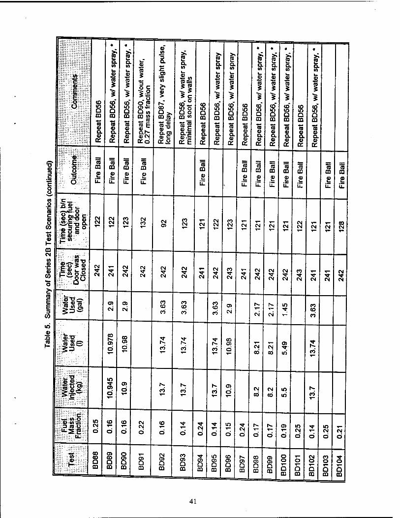
l;l?":-4»::*:'::-?" '&?' -TE.:-:;;::'
;> £:-'- :-0^:;. :;::::: <> -
<o to Q m ra © CL ©
DC
«
S Q. «0 I- ©
i CO* U) Q CQ
CO © a. ©
cc
* >". 5 Q. «A
© To
co- in a m
© a. ©
Q: Rep
eat
BD
90,
w/o
ut w
ater
, 0.
27 m
ass
frac
tion
Rep
eat
BD
87,
very
slig
ht p
ulse
, lo
ng d
elay
Rep
eat
BD
56,
w/ w
ater
spr
ay,
min
imal
soo
t on
wal
ls
CO to Q CQ
CO « Q. «
ct:
2 ex (0
© ra
CO" to Q CQ
To © Q. ©
DC
2 Q. «o
©
1 co" to O CQ ** ra © o. ©
cc
co to Q CQ
CO © a CO
cc
«
£ a. to
©
s co" to Q OQ *-* CO CO a ©
DC
«
£ Q. to L. © 75
co" to a OQ
© o. ©
DC
«
2 Q. «0
©
i co" to O CQ
To © a ©
DC
8 a OQ
© © a. ©
cc:
«
2 Q. «0
©
i CO* to Q CQ
To © a. ©
CC
© 3 C
c 8
?■:•■' ':;:0-:::v: --;:;-- -.Es:..-:-.
- ff 3 o
75 m £
75 03
£ iZ
75 m £ iZ
CO m ©
il
75 CQ
£ iZ
75 CQ
£ LL
75 OQ
£ iZ
75 OQ
£ iZ
75 OQ
£ iZ
75
£ iZ
© m £ iZ
© OQ
£ iZ
«0 O •c (0 c 8 (0 w
■2 m
't"_
1^ I' ACT» g. g 3 § ° C ©
CM CM
CM CM
CO CM
CM co CM
o> CO CM Y~
CM Y-
CM CM Y-
CO CM T—
CM Y- eg Y—
CM CM CM CM
T— CN CM
CO CM T-
CM w 0)
"C 4) (0 w- o
CO
E E 3
GO
'• en - CO TJ
CM
CM CM
CM "M- CM
CM
CM
CM •M- CM
CM T CM
Y™ "M" CM
CM ■*■ CM
CO
CM CM
CM
CM
CM ■M- CM
CM •«r CM
CO ■M- CM CM CM
CM ■«cf CM
'J5S O) CM
O) CM'
CO CO CO
CO co CO
CO CO CO
OJ
CM CM CM
to ■M;
CO CO CO
to CD
fl> *o CO <OCV
CO
cn Ö
CO OJ
Ö Y—
CO CO co
00 o> d cg
CO CM CO
O)
to CO
:T.^-o-'-''.'" © «>^-*
IP »o
o> Ö
o> O CO
N.
CO Y~
CO O) d Y—
CM CO
CM CO
to to CO
c *::-«—--:«».':0 •
© «OS 3 JO O
to CM
O
CO
Ö
co Y"*
Ö
CM CM
O
CO
O
Y—
Ö CM b d
lO
d CM d
1^.
d d O)
d
to CM O d
to CM
d CM
d
:::■>.-:■■ «0 CO CO O OQ
OJ CO Q CD
o O) Q CQ
CB Q CQ
CM o> Q CQ
CO o> Q CQ
o> Q CQ
to cn D m
CO O) Q
O) Q CQ
oo a> Q CQ
o> O) Q CQ
o o
5 OQ
O
Q OQ
CM o a OQ
CO o
Q CQ
o a CQ
41
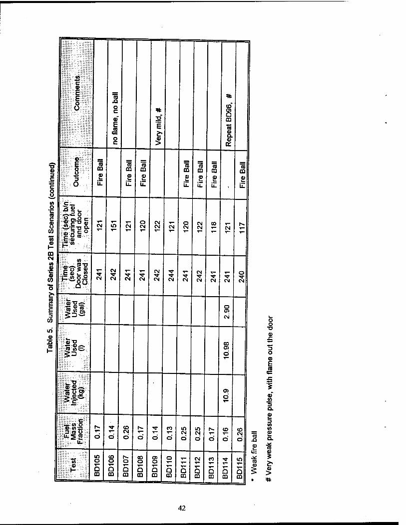
■sc C.-':. ."■"•• »: ■©"■■;;■:;
ra JQ o c ©' E ©
o c
E
co* O) Q CQ
ra © Q. © a:
13 © 3 C
C
8
©*:■•:■'
■^ ■.,£:■-. o o ~3 ' o
© ffl
£ LZ
n m £ iZ
© CD ©
iZ
© m £ il
© m £ iZ
© CO
£ il
© CQ
£ iZ
M O •c © c s
CO *■»
m CM w © •c © (0 o
StTJ O. HI 3 C O Sow C ©
CM CN o CN
CN CM CM
0 CM
CM » T— h-
CN
CN
CM CM CN
CM
CM CM CN
CM N- CM CM CN
0
CM
c CO
E E 3
CO
T5 © © 0 O) c\i
© x»
.5 fl) O
<5 «S3,
$3
00 0 d T-
o> 0
_ ih O © «n:c 3 «J o
•"■5 2 r— Ö
■>sf
Ö
CO CM CD Ö Ö
CO v-
Ö
lO CM Ö
m CM d
r—
O
CO
0
CO CM d
■■■ </>
S: . ©
in o "^ O m
co o
Q CD
O
Q m
00 o
Q CO
05 O
Q co
O
Q CD
D m
CM T"
5 m
CO
Q m O CD
Q CQ
ra
£
© ©
O o
© x:
"3 o © E ra es x:
©
3 a. £ 3 M «A
£ Q.
ra
I © >
42
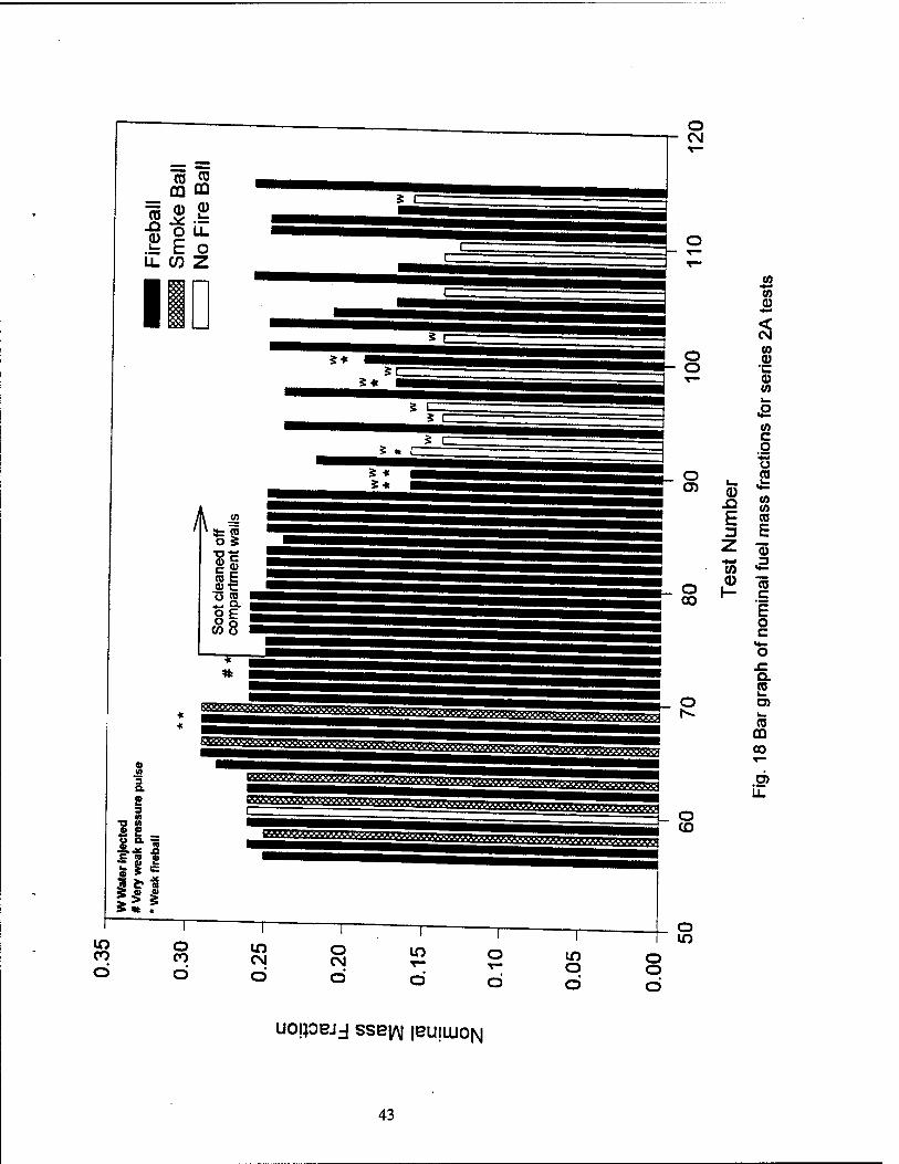
en CO CD cu
ro o E
Si L o
U.WZ
CO ö
o CM
co CO 0) ** < CM
o CO (1) o 'C
T— CD CO
CO c g
*«* u o P O) (1) i=
.O CO CO
H CO
3 b z CD *rf 71 (0 »♦2
o CO
0) f-
CTJ C
E o c
<*- o
JZ a S o O)
r». L. CO
03 CO
O)
o CO
o CO CM
o CM
o o
o in
UOIPBJJ SSBfll jBUILUON
43
of 0.13 or 0.14 with no fire ball; tests BD 103-104, 107, 108, 111-113, and 115 had fuel mass fractions of 0.17 or higher, and all resulted in backdraft explosions with large fire balls. Procedurally, the tests were identical except for the amount of secondary fuel injected into the fire compartment. The tests that did not result in fire balls had average gas temperatures equal to or greater than the tests that did and oxygen concentrations were similar as well Therefore these results indicate that the fuel mass fraction was the determining factor for creating the explosion.
Fig. 18 also shows the effect of water injection into the fire space using the same backdraft test scenario. The fuel mass fractions are decreased due to the water vapor in the space. If water was not injected the fuel mass fraction would be the same (0.25) as in tests without water Depending on the amount of water used, the tests with water injection resulted in either the elimination of the explosion (i.e., the fire ball) or in backdraft explosions of reduced intensity. This subject is addressed in more detail in the Discussion section.
Tables 6 and 7 present the average temperature and oxygen concentration data as well as the estimated flame/fire ball size data for each test of Series 2B. Test data have been averaged over two different time periods each of which is 10 seconds in duration. The first time period is denoted as T1 and represents the time just prior to the fire door being closed. The second time penod, denoted as T2, is a 10 second interval just prior to the door being opened to induce the backdraft. Period T2 is of most interest as it represents the conditions from which the backdraft phenomenon occurs or does not occur. This is the time period at which the nominal fuel mass fraction is calculated.
The oxygen concentration measurements have been adjusted to account for a 90 percent response time of the gas analysis system. Since opening the fire door and the ensuing gravity current occur on a time scale of about 15 seconds compared to the 60 second response time of the gas analysis system, the oxygen concentration measurements are unable to fully capture the relatively fast change in conditions. As a result, the oxygen concentrations reported at time T2 may appear artificially high for some tests.
An attempt was made to estimate the size of flame extension and/or fire balls exiting the test compartment during the backdraft events of Series 2B tests. Dimensions were obtained from visual observation and video by comparing the size of the flame/fire ball to the size of the test compartment. For Series 2B, markers were positioned within the view of the video camera to assist in the measurement of how far the fire extended away from the fire door Markers were placed every 5 ft from 5 to 30 ft away from the door.
At the time the door was opened, average compartment temperatures were typically 340 to 400°C, and average oxygen concentrations were 0.5 to 1.5 percent. These gas temperatures are 50 to 100°C lower than observed for Series 2A tests. The difference is attributed to the removal of the soot from inside the comparment. It is believed that in Series 2A tests the excessive buildup of soot in the compartment was absorbing some of the secondary fuel injected into the space. As a result there was a reduction in the amount of fuel vaporized and thus, a reduction in the amount of heat absorbed from the compartment gases due to the heat of the vaponzation of the fuel. In the Series 2B tests in which the compartment was clean of soot, gas temperatures would be lower since more fuel is vaporized, and consequently, more heat is extracted from the compartment gases. This trend is also supported by the temperature data of the Series 2B tests before and after soot was being cleaned from the compartment walls (i.e., before and after test BD74). The largest fire balls observed were about 7 m in diameter and extended over 9 m from the compartment. Similar to the Series 2A tests, there was usually a 15 to 20 second delay between the time the door was opened and the sudden formation of the
44
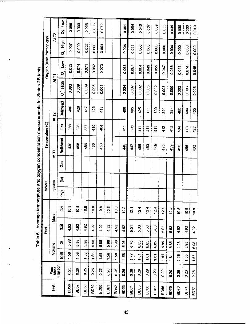
«A 0)
m eg (A u •c 9)
CO
w c 0)
E 8> 3 W CO 0)
E c o
I c a> ü c o u c 0)
! ■o c n Si 3
a) a. E «
O)
2 ID > < (O
J2 n CO
7 c o
■o u CO
w o E
»■^
c <0 O)
1
CN 1-
<
§ in 00 o ci
o o o d
CO o> o d
o o o d
CN IV. o d
CO o d
CO o d
O
o d
|v. CD o d
O) If) o d
IO If) o d
O)
o d
o o o d
o o o d
o
o d
O)
X o o d
o o o d
CN o o d
o o o d
o o d
8 o d
o d
o o o d
o o o d
o o o d
o o o d
o o o d
o o o d
o o o d
o o o d
5
■i
o
O)
if
CM in o ö
'S-
o d
o d
CN CO o d
CO tv. o d
CO CO o d
CO o d
CO o d
o d
in m o d
(v.
o d
00 in o d
o d
|v. o d
m Ti- ro
d
co o o Ö
O) o o d
O) o o d
in o o d
o o d
o o d
o o d
CN o o d
CO o o d
CN o o d
CO o o d
o o o d
CN o o d
CO o o d
n o o d
O
V w 3 13 a> a. E ai (-
5
s x:
3 03
CO o CM
t-- in (N
CO CO o
m o
in CN
r— en en CO
O) CO
|v. cn CO
o o O
in o
(0 10 o
CO CO CO
to O) CO
iv. 00 CO
o o CO
O) CO •«»■ T
CN
T
If) CO
CN O
CO CN CN
5
TJ (0 0) f
3 CO
8 CO If) TJ-
co If) TT
If) CO
CO in
CO m co
CO If)
If) O) m *3-
CO in
CO m
CN CO
(0 n
CD •
ai (0
5 O
3"
"3 4£
3 u.
%
£ CO
d CO d
CO
d 00
d co o
CO
d 00 d
CO
d CN CN CN CN CN c\i 00 o
CO
d CO
d
s 'S CN CM
O)
TT
CM o> «ST
CN 0)
CN 0)
TT
CN 0)
(N 0) TT
CN CD TT
If) iri
CO CO
iri
CO CO
iri
CO CO
iri
CO CO
iri
CO CO
iri
CN en -or
CN 0)
CN en
0) E
o >
s so
iri
CO
iri
00 O)
If)
CO 0) iri
00 CD If)
00 0> in
00 O) iri
00 O) iri
o
cb
if> CO
co
If) CO
CD
in 00
d
m 00
d
m 00
d CO en iri
CO O) iri
00 at
iri
To 00 in
CO If)
CO If)
00 If)
CO If)
CO if>
CO if)
CO in
iv. |v. 00 CO CO CO CO
00 CO 00
Fuel
M
ass
Frac
tion
if> CN d
CO CN d
If) CN d
CO CN
d
CO CN
d
CD (N d
CO CN
d
CO CN
d
CO CN
d
o> CN
d
en CN
d
CO CN
d
en CN
d
en CN
d
d CN
d
CO CN
d
CO CN d
1 (O m D m
rv. m Q ffi
CO If) Q m
en in Q m
o CO
Q m
V— CO
Q ffl
CN CO
Q CO
CO CO
Q m
T CO
D CD
If) CO Q m
CO CD Q DO
|v. CO
Q m
00 CO Q m
en CO
Q m
o fv. Q m
Q
CN |v- Q m
45
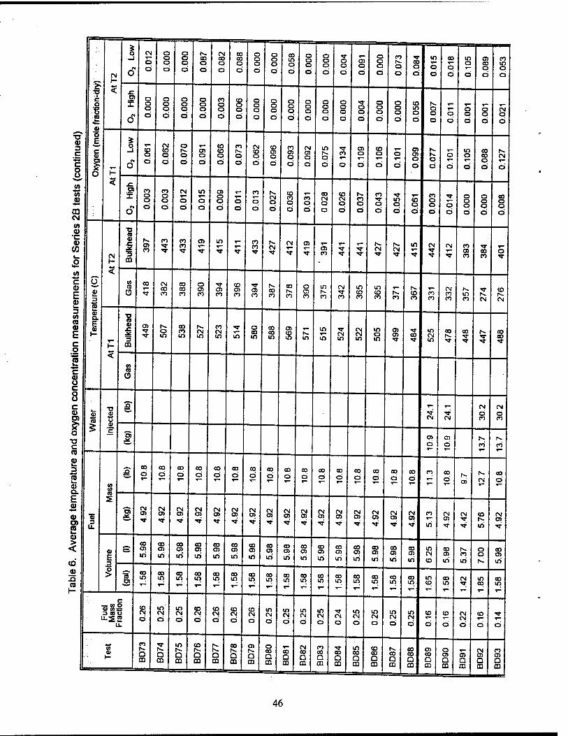
CM
—i CM
o d
o O a d
o o o d
N. CO o d
CM CO O
d
CO CO o d
O O O d
o o a d
CO in o d
o o o d
o o o d
o o d
1— 05 O
d
o Q O
d
CO
o d
CO o d
m co o o d d
m o
d
O) CO o d
CO m o d
(- 3 £
c o €
Q
F
Ol
X
O
o o o d
o o o d
o o o d
o o o d
CO o o d
CO o o d
o o o d
o o a d
a o o d
o o o d
o o o d
o o o d
o o d
o o o d
o o o d
to m o d
o o d
o d
o o d
o o d
CM o d
■o CD 3 c c o o
5
c
T"
o
O
o d
CM CO a d
o fs. O d
en o d
CO CO o d
CO
o d
CM CO o d
CO Q5 O
d
CO o> o d
CM O) o d
in o d
CO
d
a> o
d
CO o
d
o
d
O) OS o d
o d
o T-
d
m o
d
CO CO o d
(s. CM
d O
5 (A .e
(A 0)
03
a if
O
CO o o d
CO o o d
CM
o d
in o d
05 o o d
o d
CO
o d
is. CM O
d
CO CO o d
CO o d
CO CM O
d
CO CM a d
co o d
CO
o d
in o d
CO o d
CO o o d
o d
o o o d
o o o d
CO o o d
CM
a> •c ©
CO f\
TJ « 41 c
3
05 CO
CO ■st
CO CO
a> m r
CO CO TT
fs. CM
CM 05 05 CO
CM CM CM CM CO
O) CO
co CO
o
fi
o
3
n
5 CQ •
t/1
c a> E
co CD
CO CM CO CO
CO CO CO
o os CO
05 CO
co 05 CO
05 CO
Is. a> CO
CO fs. CO
o 05 CO
in
CO
CM
CO
m CO CO
in CO CO
N. CO
co CO
CO CO
CM CO CO
m CO
"3-
CM
co is. CM
3 Q. TJ
CO 0)
J=
3
to
E E
>- ^ ts. o m
CO CO m
|s- CM m
CO CM m m
O CO m
CO CO m
a> CO m
N. m
m m
CM in
CM CM in
m o in
05 05 CO
in CM in
00
■<»■
CO is. CO CO TJ- c o 5
m
«9 u. (0 C 4) CD U C o o c CD a)
■a <u
A CM
d CM
d
1 o c CO
«5 u A)
c?
CM CM CO CO
*->* O) 05
d 05 d
rs. CO
|s- co ,_ ^* T~
CD 3
E a> (0
(0
£ CO
d CO
d CO
d CO
d CO
d T—
co d
CO
d CO
d 00 d
CO
d CO
d CO
d CO
d T—
CO
d CO d
CO
d CO co
d 05
fs.
CM
00 d
a. fc s
fl)
5 a) > <
CO
«5 3
"3 CM CM O)
CM a>
CN a>
CM O)
CM 05
CM Ol
CM o>
CM o>
CM 05
CM 05
CM 05
CM OS
CM OS
CM OS
CM 05
CO
in
CN 05
CM CO
iri
CM as
0) E
s CO o> iri
CO 03
iri
CO
LO
CO CJJ
in
CO 03
in
CO O) in
CO O)
in'
00 OS
in
CO 05 iri
CO 05 in'
CO 05
in
CO 05
in
00 en in
CO 05
iri
CO 05
CO 05
iri
m CM
CO
CO 05 in
(s. CO
iri
o o
CO 05 iri
CO o > to 3 CO in
CO in
CO in
CO in
CO in
CO in
CO in
CO in
CO in
CO in
CO in
CO in
CO in
CO in
CO in
CO in
m CO
CO in
CM m CO
CO in
c
' v8£ 3 (BO u-22
Ü.
co CM
d
in CM d
m CM
d
to CM
d
CO CM
d
CO CM
d
CO CM
d
in CM
d
in CM
d
in CM
d
m CM
d
'S- CM
d
in CM
d
m CM
d
m CM
d
m CM
d
CO
o
co
d
CM CM
d
CO
d d
4-* Ifl CO t-
to
& m a CD
in ts. D m
CO fs. Q 00
ts.
a m
CO Is. Q CD
o> |s. a CD
o 03 a m
00 a CO
CM CO
Q «
CO CO
Q m
TT CO a CD
m CO
Q CD
CO CO
Q m
00 Q m
CO CO
a CD
O) CO
D CO
o OS
D m
r— 05 a CO
CM O) a m
CO 05 Q m
46
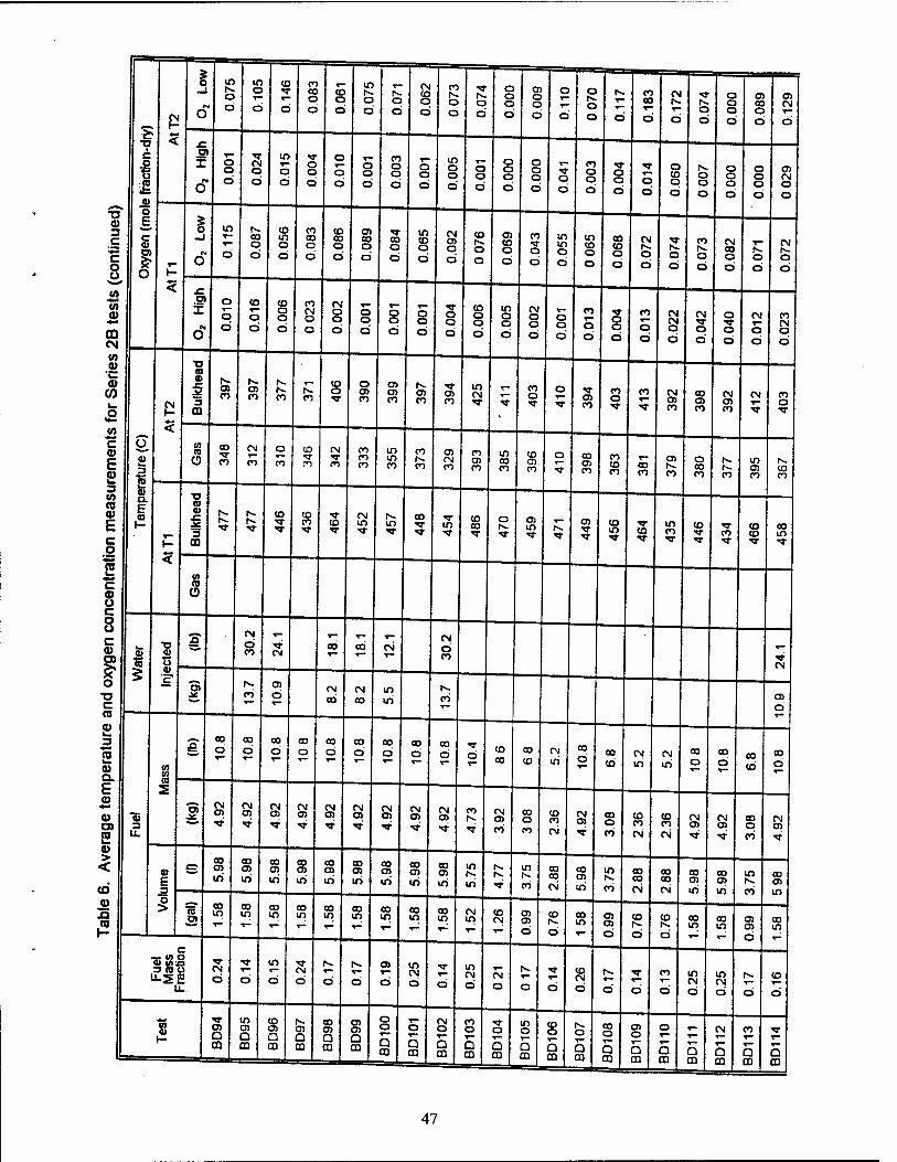
'S «
C o
£ «> o E. c V
O
CM 1-
<
1 O
w o
' o
if) o 1—
Ö
co
d
CO CO o d
CO o d
in
o d
O d
CM CO o d
CO
o d
o d
o Q O
d
O) o o d
o r-
d
o o d d
CO CO
d
CN
T—
d o d
o o o d
o> CO o d
en CM T—
d
x: a X
ft O
1- o o Ö
CN O
ti
in
O d
O a d
o ©
d
o o d
CO o o d
o a d
in o o d
a o d
o o a d
o o o d
a d
CO o o d
o o d
r- O
d
o CO o d
o o d
o o o d
a o o d
ffl CN O
d
T3 <B 3 ,C •** c o u
5
I o
m
Ö
00 o Ö
in o d
CO CO o d
co 00 o d
O) CO o d
00 o d
m co o d
CM O) o d
co
o d
O) co o d
CO "3- o d
m m o d
m CO o o
m o d
00 co o d
CN
o d
O
d
CO
o d
CM CO o d
o d
CM
O
d
(0 •«Hi
a>
ffl CM
O)
I o
o Ö
CO
o Ö
CO o o d
CO CM a d
CN o a d
o o a
T— O o d
o o d
o o d
co o o d
in o o d
CM o o d
o o d
o o d
CO
o d
CM CM O
d
CN T a d
o •^,
o d
CN
o d
CO CM a d
(0 a> •c a>
CO
,o
C «I)
e £ 3
(0 a> E c o
2 at a. E 01
<
a ai c
a m
co O) co CO CO
CO o
o CO
O) a> CO
o CO
O) CO
m CM
CO a
o
5 O) CO
CO o
CO CM o> CO
CO en CO
CM ffl CO
CN CO o XT
CO «0
Ü CO
co
CN
co
a CO
CO T CO
CM
CO
CO CO CO
m m CO
CO
CO
O) CM CO
CO a) CO
m CO CO
CD CD CO
o CO O) CO
CO CO CO
00 CO
CD
CO
o CO CO CO
m en CO
CO CO
1-
T3 (D 0)
3 m
N. co '3'
CO CO CO
CM in m
CO m
CO CO
o O) m o> CO
in CO m CO
CO CO
co to
00 in
2 c a> u c o o c a)
i o
■o c (0
*>
O
i ■a <u u a>
3" CM
d CO CN
00 00 CM CM
d CO
CM
E" CO
ffl d
CM
CO
CM
CO
in ir>
N.
CO T-
ffl d
3 •** 2 a> Q. E
a> a> 2 a>
■35
U.
0) (0 co ■
3" 00 Ö
CO
ö 00
d CO
d CO
d CO
d T—
CO
d CO
d 00 d d
CO
00 03
CO
CN
in
CO
d CO
cb CM
in CM
iri
00 d
00
d CO
CO
00 d
i
O) CM ffl it
CM ffl tN ffl CM O)
CN O)
CM 0)
CM CN CN O)
CO CN 0) CO
CO o CO
CO CO
CM
CM O)
CO o CO
CO CO
CM
CO CO
CM
CN o>
CM O)
CO o CO
CM ffl ■«r
> <
(Ö E
» 00 O) in
CO ffl If)
CO O) If)
CO 0) in
CO 0) in
00
in
00 m »ri
00 O) iri
00 o> in
m r-. iri
in
CO
CO CO
CM
co O) iri
m tv.
CO
00 CO
CM
00 CO
CM
00 0) iri
CO ffl iri
m
CO
00 ffl iri
jQ CO 1- ■
o > To s
00 in
00 in T-
CO If)
CO m
00 in
CO in
00 in
00 in
00 in
CM in
CO CM
O) O) d
co 1".
d
CO in
O) a> d
co
d
co
d
CO in
CO in
a o> d
CO in
«8-1 u.s2
■<*■
CN
Ö Ö
in
d CM
d d d
a>
d
m CM
d d
m CM
d CM
d d d
co CM
d d d
CO
d
m CN d
m CN d d
co
d
8 K
ffl D 00
If) 0) Q a
CO O) Q ffl
0) Q ffl
00 O) Q ffl
O) O) a ffl
o o ^» a m
o
Q CD
CM o T" a m
CO o
o ffl
«3- o
Q ffl
m o
Q ffl
CO o
O ffl
o
a m
CO o
D m
0) o
Q m
o ^- o m
5 m
CM
a m
CO
^— a m
5 CD
47
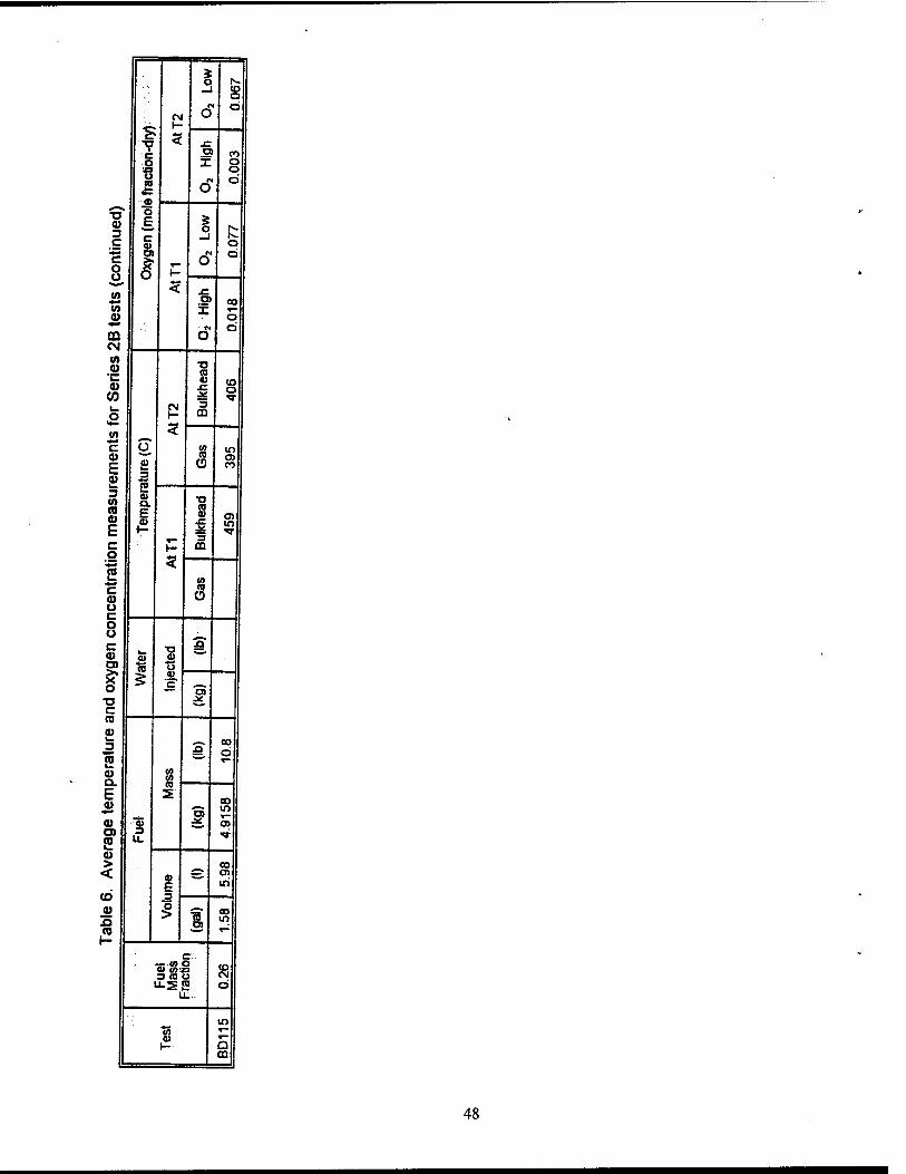
% a r*- -i (O o
CN O o
5 XT o
o T o
2 6 o Ö
o E <u % r-» 3
C « _i o
o> ^ o C o u (A
5? O H
u
^ .£ a> CO </> T T-
0> o M o
OQ Ü CM CO
•c •a
XL CO o (0 S£ 3 o
CM t- m
££ 3 (/> C u <0 lO 0) *~* to a> E
15 0J o. E
(i) CO
3 (0 (D 0>
n CO 0) a>
b c
»- "5 CO
•«r
o 5 ♦* re c 0) o c o u ^-» c 0> 0)
5
o ra u
0) 'c? — o
"O J£ c CO
a> 3
^.^ 00 .Q o re <w
T~ i_
Q.
E CO 0)
s CO
« ■« j>t a>
re 3 u. -»
0) > CO < 9)
A. a>
CO E m .^
0) o > 'S D)
00 m re T—
1— C7.
■B5 ■» O 0) UJ'ja CO 3 (0 ü CM ULSS O
ti-
m tS <1) I— a
. m
48
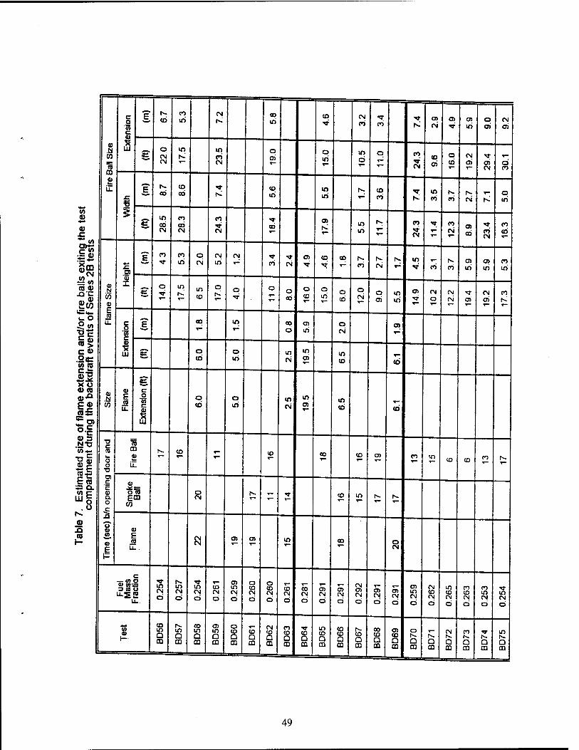
c o
'55
If t".
cd CO iri
CN CO
in CO CN
CO "3-
CO
■v K
O)
CM
at o iri
o o>
CM
d
V .61 CO
15 ffl
i g o CM CM
in in
CO CN
o 0) T-
o in
m d
O CO
CN
co ai
O
cb CN O) ai
CN d CO
«J
il E N.
00 co 00
*»; co in
in N. CO ««• in f^ N- T— o XT ^ CO K CO CO CN h* m
•«-* •a CO
g m ad CN
CO 00 CN
CO
CN CO
en m in
CO
CM
CO
CM a> ob CO
CM
CO
cd
"§ca
ffi N
CO
Ol 0) I
E CO CO
in o CN
CN iri
CN
CO CN co 00
CO CN in r—
CO co OJ iri
a> iri
CO
iri
= <0 (0 <D
i_ o
g o in N.'
in
co
o o o o CO
a CD
o in
o CO
o CN
O m iri
Ol CN d
CN
CN cri CM
ai CO
ffi E
*— T™ '" ^ T" »■»
o w u. c F 00 m CO o> o O)
1 = m 0>
(0 c
*- T~ o m CN T"
(0> 3 c« «£ o o m m in
.ye «A ra
Is CO m CM ai co CO
£■ X o a> ra » c 0»-° .a E
CO
^ o a m in m
of fl
am
ing t
he
CO c ffi
co iri CN O) CD co
s V 3 .an C (0
CD ffi iZ
CO.-
H to
o o
N- co T— (O CO CO O) CO m CO CD CO
•r-
■o
c bra ffi 3= Q. c J£r=
"Jo . u
0) a o
.Q
O (0 ECU
CO
o CN
1^ T-
*r- CO m
0) XI « ffi
£ ffi E
E ra CN
CN a» o> m oo o
CN
c -wo ffi «'«3 3(0 O
u-S'S m CN ö
m CM
ö m CN d
CO CN Ö
05 in CN ö
o CO CN d
o CD CN d
r- CO CN
d
00 CN d
o> CN d
CN d
CN O) CN d
s CN d
CN d
OJ in CN d
CN CO CN d
in CO CM
d
CO CO CN
d
CO in CM
d
m CM
d
«5 « (-
CO m O
m a m
00 m Q ffl
in a ffl
o CO D CO
CO
a m
CN CO
a a
CO CO
Q m
*3- CO
D m
in CO a m
co CO
Q ffl
CO
Q ffl
oo CO a ffl
o> CO
a m
o I-- a ffl Q
ffl
CM
a m
CO
D m
T
a m
m
Q ffl
49
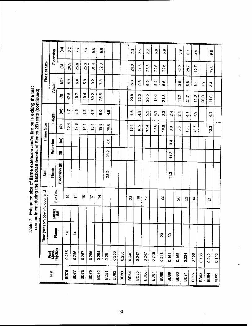
CD
.a CO
w CD
s il
c 2 to c
1 ill
? CN CO CO (O OJ
CO d
CO in tv
CM o> to CO CO 00
OJ CO
CO d
g m ö CN
co iri
<o in CN CO
o CM CO
o •*T CN
in
CM
m CO CM
CO CM CM
to CN CN
fv CM T—
IV
00 CM
IV
CM o CM CO
M f E CO
iri o CO
a> iri
CN O)
CO fv
CO
CO CO d
CM
cb iri CO (6
<o co"
to cb CO
O) IV CO
g th
e te
nt
inue
d
g rv CN
d CO
m iri CN
co d CM
o CM CO
m d CM
CO iv
00 ^- CN
rv N.
CM
o o d CM
q
fire
balls
exi
tin
es 2
B t
ests
(co
.a w 4> E CO
x:
'35 I
? rv W
iri co o
CO co O) CO
in ^r CO
CO CM CM CO
CO
g iri iri
03
d o CO iri
CM CO
T |v
CO CO
CO
d O
00 Q ad
CO CO
IV
CM •r—
CO
CO
and/
or
of S
eri
c o w c
1
¥
CO to
CO
e of
flam
e ex
tens
ion
he b
ackd
raft
even
ts
g CN CO CN
CO
T"
0) .a E
u.
g c o 55 c
It m
CN CO CN
CO
Tab
le 7
. E
stim
ated
siz
co
mpa
rtm
ent
durin
g t
c CO
o o
T3 O) c 'c 0) Q. O c
CD CO N- to T-
CO CN
CO iv CM CM
CO CM
CN CM
*T CO CM
J£as O (0 ECO
u
4) F
4)
E" to
■v V o CM
o CO
*\ C-.'
3&Ü m m CM Ö
CO m (N d
fv ir> <N
ö
CD m CN d
m CN d
m CN d
m m CN d
o m
d
o
CM d
tv T CM
d
rv
CM
d
c» CM
d
00 T CM d
co
d
in in
d
CM CM d
CO m
d
CO CO
d
CM
CM
d
o
d
1 i-
CO IV Q CD
iv |v Q CO
CO IV a CQ
O) rv Q CQ
o CO D CO
CO Q CQ
CM CO a CO
CO 00 a CQ
CO D CD
m CO Q CO
CO CO a CQ
IV 00 Q m
CO 00 o CO
CO Q CQ
o O) a CO
O) Q CO
CM O) Q CO
CO O) a CQ
03 a CQ
in 05 Q CQ
50
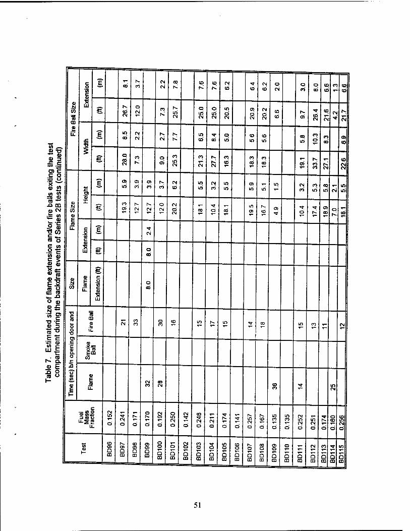
2^ • 3 o> c c o S 3,
t/> « = a> ra -* A m 0) CN
£ «»- CO o
5 w
2-E go, o> 53 "Sec g-o « ^ O a) 0) JC N **
'3> g> "O -c
ra"° E c IE <u
"1 Is- Q. a E 3 o ra o
LU
CD .a to
CD 0) I—
iZ
c o
'en c
1 at
£ 00 co
CN
CN
co
00 co CO CN
CO cb CN
co a CN
O CO
o ad
CO
co CO CO
cb
g CN
O CN iri
CN
o iri CN
o in CN
m d CN
c» d CN
CN
d CN
co CO O) CD
CN
co
CN
CN
CN
JC
*
|f CO
CM
CN CN in
cb ad o in
CO iri
co in
CO in
co d
CO
00 a> cd
*? o eb CN
co o a>
CO
in CN
CO
CN CN
CO
cd CO
00 CO
ad o> co CO CN
CO CN CN
CO .fc) CO <u E (0
0) X
% iri co
(3)
CO c>~ CO
CM
CD in in
CN CO
m iri
O)
in iri in CM
CO CO
in 00
in CN in in
g co
CN 1^ (N
o CN
CN d CN
00 d ad in
•9 d a> ad
O CO
c o 'S c
* Ul
1 CN
g o 00
CO
0) E <o
u.
g C o
'to c 0)
■R
o 00
•a c ro o o •D o c 'c 0) a. o c XI
t? tt W,
C) E F
TO co
iZ CN
co co
a CO
CO T—
N. in T 00 in CO CN
O ID Etn w
a> E co
LL
CN CO
oo CN co
CO m CN
-ssl CN m
Ö CM
d d
O
d
CN
d
o ID CN d
CN
d
CO "S- CN d
CN d d d
m CN d
co
d
m CO
d
m CO
d
CN m CN d
m CN d d
O CO
d
CO m CN d
CO 0) (-
CO o> Q CD
Q m
00 o> Q *
O)
D m
o o
a m
o T— a m
CN o
Q CD
CO o
Q m
o
Q CD
m o ^- Q CO
(0 o
Q CD
o
D m
CO o
Q m
o
Q m
o
5 CD
T— ^— Q CO
CN T"
a m|
CO
Q CO
Q CO
in
5 CD
51
fire ball outside of the doorway. In most instances, dense smoke obscured any view of the deflagration unt.l .t suddenly penetrated the doorway. However, in some testth^deflagration could be seen originating in the upper back (south-east) corner of the coÄ^£d ravel.ng as a flame across the overhead of the compartment. Contradictorily for a few tests
the flame/fire ball appeared to originate low in the doorway. '
The relative pressure across the compartment bulkhead was measured for Series 2B tests
InemHataMere?KUalitatiVe,y SimilarbetWeentests: however- theVw^e not qSÄtfy
reproducible with respect to the peak pressure during the backdraft. Fig. 19 shows a ypical
(p<1SusT TLT*Tr ■■ Tresulting in a fire ba"(test BD86)-Durin' *»S SS (<336 s), there »s a marginally negative pressure differential as measured on the 250 Pa pressure transducer (capable of overranging to 280 Pa). This negative pressure differential indicates the .nward flow of air low in the fire compartment. At 336 seconds the doortofta fire compartment was closed resulting in a large fluctuation in pressure due tothlast pullltonl* the fire plume before it was extinguished. As the door was quickly closed, the compartm^ expenences a rap.d positive pressure rise due to the hot expanding combusfion gTses TWs
E.rsaSon ;0rediate,r f^,owed by a sharp negative spjke « %™Äi last pu sation to draw air ,nto the compartment before extinguishing. The negative pressure
40?Ä::cSonOds US? andHaUd?'y, °bSerVed 3S the fire d00r Was suckeddoseS Between 406 o 466 seconds, the secondary fuel was in ected. During this time period there was an
fuel3' SSSÄ^ t0 the injeCti°n and vaporiL2doHhTsecondary *ZLI #S r 1 ? ( re °f 0ng,nal combustion Products and fuel vapor) leaked from around the fire door dunng the initial injection. This leakage stopped about half waVthrouah the
A seS^LPtr0CeSf
S 3S ?" be S6en '" Rg- 19 When the Pressure differentiaflpproaches'o Pa was stcured r e con^LTT T *"" 93Sket W°U'd °CCUr '"mediately asThe fuel flow 2SL !1( V C0^esP°nd,n9 t0 Ö» Pressure pulse which started at 466 s). During several £1 '♦,? pr°Panttorch was used as a pilot flame to determine if the fuel-rich gas mixture leakina from the compartment could be ignited. The gases could be ignited only a"the d™gasket A? a d,stance of only 0.15 m, the gases were to dilute to be flammable. For fhe test in Fiq 19 the
MiK1? ^ H87 STK°"0Wed by a def,aQrati0n in the compartment and the orSation'of a fire ball at 604 seconds. The compartment pressure increase during this backdraft excision
The' LZLlT* ^ ?°? ha,f °f the PreSSUre rise that occuwdBJKiÄ? Xas opened IverTS P.„^!?„Sr t6StS ,"whjch
Ia backdraft exP'osion occurred ranged from 100 to
over 280 Pa. In some instances, ident.cal tests produced pressure results that spanned this range One possible reason for the deviation in the data is the occurrence of varying degrees of sootdoggmg ,n the pressure port. However, this hypothesis is not fully consistentw'i th the
6.3 Series 3, 4 and 5
6.3.1 General Results
Sr^DwImn°0UrSMnrieS 5 teS* (SB„D01 to SBD65) were conducted aboard the ex-USS
SHADWELL in order to examine the effects of the additional confines of a shiD on the
%fiEEf£ZB "TT Tab'e 8 Sh0WS a SummarV °f tiÜÄS^corK.uctad. This table lists the test number, the nominal fuel mass fraction, the resulting outcome the ventilation setup, and general comments. The resulting outcome describewhat happened outside of the door. In some cases, there was a deflagration in the compartmen (noted by a peak nse «n temperature and pressure) without a fire ball outside of the comSient These tests were characterized by a roll out of flame under the soffit. compartment, i nese
52
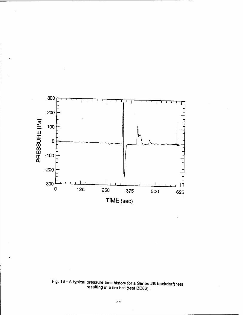
300 1 ' i i I i i i i i i i ~ i i i—I—i—i—r
200 h
t 100 UJ
D CO CO 111 cc -loo Q.
-200 h
0
-300 -J—I L —I—I—I—I I I i | i i I
125 250 375
TIME (sec)
J—i L_J_ J—I L
500 625
Fig. 19 - A typical pressure time history for a Series 2B backdraft test resulting in a fire ball (test BD86).
53
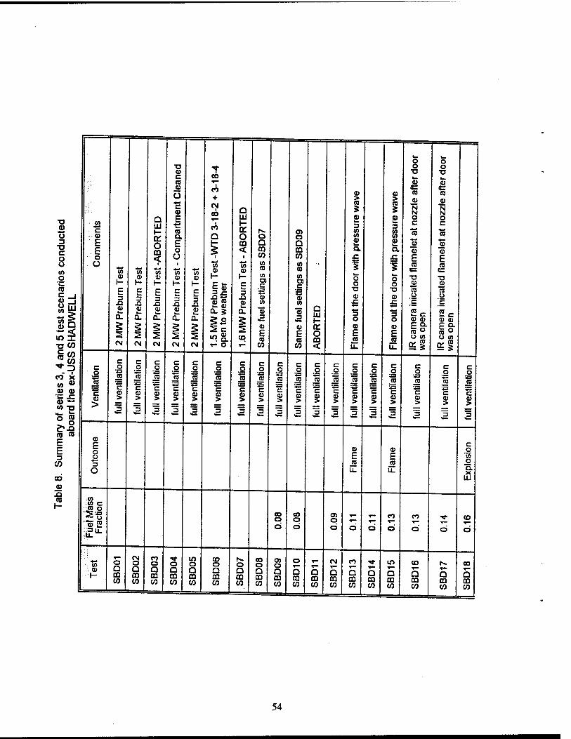
k_
—
O 0 ■a a> t O
TJ 0
TJ c 00 k» CO ^~ CO CO «Ö CO
+
CO
1 CO
Q
c SB
O c 0) a
CO > CO
CO >
i CD
CO
N M
CO
CO
N N
TJ a> o
w *•* ■ c
CO
G til H- o. o co <
E ■e CO a
in
Q. o 1^ o
o> O
£ 3 (0 w
CO
3 W </>
O C
*-» CO
O c CO
3 b F m Q Q CO u
CO CO CO TJ C o
: E o < < m m Q. a cu CO o U 1 i CO 1/3
1 o
x: E E CO
"O
Ü
O
O
a) (A
i
cu
i
w cu
*4
cu
■85 cu 1-
IS CO
1-
(A CO
<o
V) CO
to
5 W O O
CO
TJ 'C 1- H- t- 1- h- C w c c
E cu to
"cu 2
o cu CO
5t s
cena
•W
ELL
c k_ 3 X) co k. a.
c I. 3 X) CO k_
Q.
c k. 3 XI co k. a.
c k. 3 XI
CO k. a.
c L- 3 XI CU k. a.
.5 M
W P
rebu
r se
n to
wea
the k-
3 XI CU k- a.
CO
23 cu
« 3
a Ui i—
■D
CO
3 O
TJ
CU £
3 O
CO 0 [c Sc CU CO
CO 0
CO CO
2% m X
5 2
§ 2
§ 2
§ 2 2
a E CO
CO
E CO
a. o CD
CO
E CO
CO
E CO
IRca
m
was
op
IR c
am
was
op
of s
erie
s 3, 4
and
sa
rd t
he e
x-U
SS S
CM CM CM CM CM T- O T— CO CO < u_ u.
c .2 '•£5 jo ss c
>
C o
'43 co
S3 c to >
I
C o »
JE ss c >
1
C o
S3 jo
c cu >
2
C o
J2 c cu >
3
C o
■a JO S3 c cu >
I
c o
SB CO
ss c cu >
I
c o
S3 CO
S3 c
I ä
c o
JO
c cu >
I
c o
S3 CO
S3 c cu >
"5
c o
S3 CO
S3 c CO >
I
c o
S3 JO S3 c
I
c .2 jo S3 c CO >
"5
c o jo
"c CO >
2
c o
S3 JO
c CO >
"3
c 0
S3 JO
"c CO >
"3
e 0
S3 JO ♦3 c CO >
c 0
JO S3 c >
"3
c 0
S3 JO
c CO >
I r*.o cu n» E cu
E o ü
c E 3
CO
E CO
F 0
'55 CO 2
o CO
u. CO
u_ 0
Q.
CO LU CU
XJ CO <0
h- S3 c jo o
■a£--g
.3 0.
to o
CO o o T™
co CO CO
o o o o 0 0 o O 0 U.
«S a CM O
co o o
in o CO o O
CO o
O) o T" CM co ^r lO CO t^. 00
1 cu 1-
U m co
u GO CO
U m co
Q CQ CO
a m CO
a CO CO
Q CD CO
D CD CO
a CD CO
Q CQ CO
Q CD CO
Q CQ CO
Q CQ CO
Q CQ CO
Q CD CO
a CQ CO
Q CQ CO
5 CQ CO
54
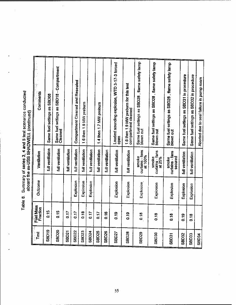
•D Q. Q. Q.
===
<_ CJ Ü E E E c CO CO CD
0) o E
■E (0
CO 1
CO CO & CO
£ 3
CD
3 F a. ■o T- CO w en "O ■c o
XJ
CD ::.E.
E o Ü
E o ü
i
(0 CD (0 0)
CO
a .52
E CO
CD
E CO
5=
0) E CO cc
CO u o fa. D.
CO o o k_ Q.
S a E
cond
ucte
)
00 o Q 00 CO V) CO
ao
5 m CO CO 03
•o c CO
T3 0) c
c 3 .a a>
c k. 3 XI 0)
c o
'55 o a. X
fa. ,o
c
|"g
oo CM Q m CO co CO
OO CM Q m CO co
CO
s m CO
CO
.c
CO Q CD CO CO
c CM CO Q 00 CO CO
3 a ,c
CD k.
_3
is U) "O </) V) (0 k. a
h. 03 CO CO CO CO O 0) OS D5 0) a.
OJ a. co co V) CO CO
c s
CD CO
a
CO
nd 5
test
sce
nari
DW
ELL
(co
ntin
u c 2 0)
"55 ,3
CD
c 2 tu CO
"35 «2-g 0) c
Ü c CD
E r CO a
o>
c CD
CO
c CO
C
c 3 O 0)
W
§3 O) (])
-E c-C a> to
C
2 CD (A
Ä o
CO c 2 CD CO
11
O) c
'*= a> CO
aE
c 2 0) CO
"S ,3
CD CO
o CD 3
■o
T5
E CO
CO
C CO
COO E o ü
JC
3 CD o a.
—1 O
.c a.
T- O
» c E5 CO o co.o
« c Eg co o
CO .a
a> c
ca.2 CO .a
11) E CO
CO
CD
E CO
CO
CD ■c O
<
of s
erie
s 3, 4
a
he e
x-U
SS S
HA
c o
'«3 CO
'■a c
5
C o
S3 (D
ss c CD >
I
c o
S3 CO
'«3 c >
2
c o «3 CO
S3 c CD >
I
c o
S3 (0
1 > ]5
c o flj
1 1 3
c o
*<s J2 S3 c a> >
c o
S3 CO
S3 c 0) >
"5 <•—
c o
S3 «2
S3 c 0) >
I
c o
S3 CO
S3 c 0) >
I
c o
S3 CO
S3 c 0) >
I
smok
e cu
rtain
s - f
ans
at 1
00%
smok
e cu
rtain
s - f
ans
at 2
5%
smok
e cu
rtain
s - f
ans
secu
red
c o To S3 c <u >
j5
c o
S3
c CO >
j5
tr- co "O
le 8
. S
umm
ab
oar CD
E o o 3 o
c o
'55 o Q. X
Hi
c o w o a X
UJ
c o
'55 o a X
LU
c o
■<7> o a. X
LU
c o
'35 o a X
LU
c o
o Q. X
LU
c o
'55 o a X
LU
c o
'55 o Q. X
LU
c o 'w o Q. X
LU
c o
'co o Q. X
LU
jQ CO 52 r- 15 c
<2.2 -2-g 00 N. r* CO o> O) oo OO OO O) oo x3) 2
S3U. o o O o o O a o Ö ci ci Ö d d d
■to O)
5 m CO
o CM a CO
CM a m
CM CM Q ffl
CM Q en
CM Q en
m CM O m
CO CM a CO
1^ CM a m CO
oo CM a CD CO
CM Q ffi CO
o CO a co
Q
CM CO D
co CO Q
"XT co n CO CO CO CO CO w CO QQ
CO m CO
00 CO
oo CO
00 CO
55
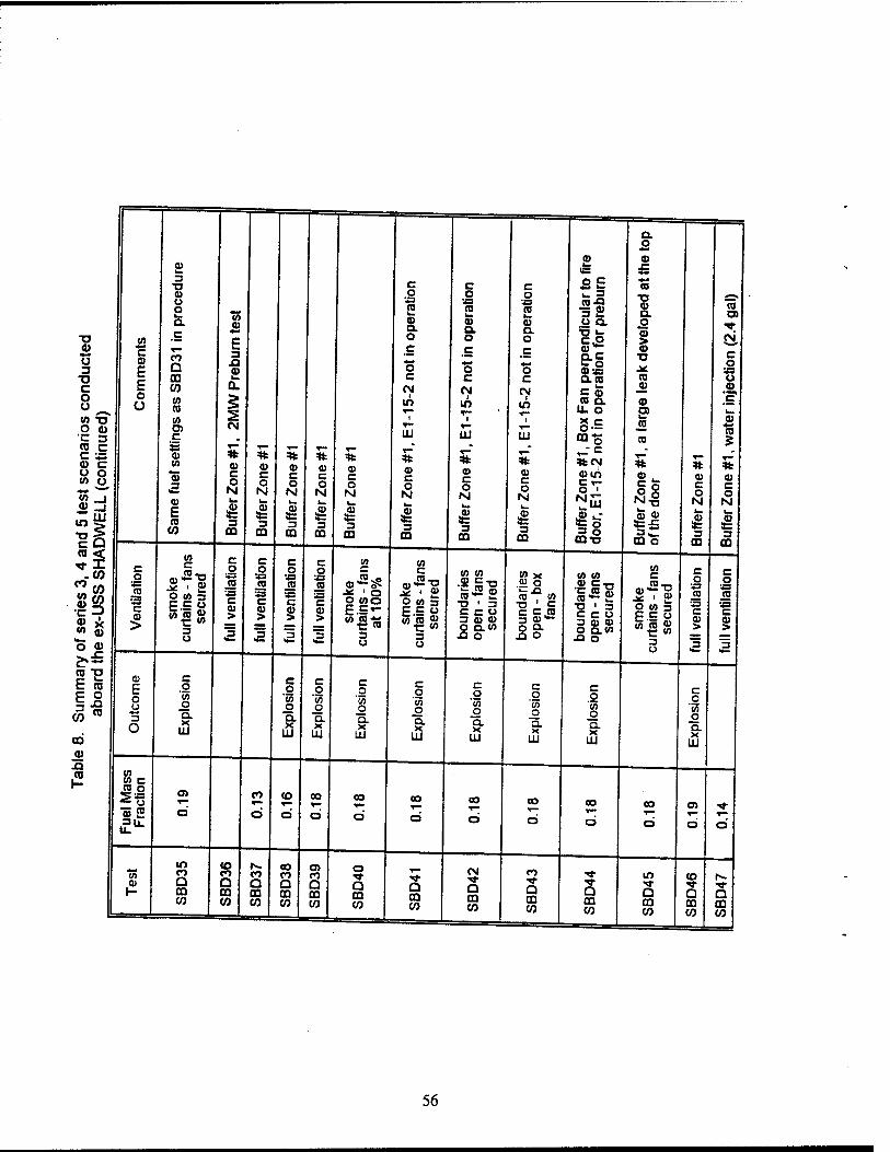
1 a.
■ o I a> CD
2> IB x:
3 TJ c c c BE "5 ffi U s 1A
<u
c
o 23 (0
o •JS CO
o ■JS (0 11 TJ
CD a. CO CD
-o (A
Q.
C
CD Q. O
a> a. o
CD Q. o
u a.
c.2
o JN,
0>
u TJ
C ffi E E o ü
CO a CD
3 XI £
c
o c
c
"5 c
c *-• O c
*- o CD» a. co
CD TJ
CO
c o
'■8 C CO QL CN CN CN c5 JO CD o o (A
CO
CN
m m £& CD
EP ,C k»
W TJ O CD
"C 3
(0
C uj i
UJ
i
UJ 8-S mo
JO
CO
CD
1 T—
TO C C S3
(0 =tfc CD 0) a>
T" T— % ffi c o M
1 3 m
% ffi c o N
1 3
CO
% ,_- c %CN %
nd 5
test
sc
DW
ELL
(co
a> a a> E CO
CO
c o
1 3 m
c o N
3 CO
c o N
1 3
CO
c o N
1 3
CO
CD c o N
I 3 m
ffi c o N
1 3
CO Buf
fer Z
one
door
, E
1-15
II ifc-e
CQ O
c o N
>ffi 3= 3 ffi
ffi c o
1 3
OQ
' of
series
3, 4
a
he e
x-U
SS S
HA
c o 2= CD
23 C a) >
smok
e cu
rtai
ns -
fans
se
cure
d
c o »3 CO
23 c > I
C o
23 cs
c a> > I
c o
23 CO
a c | 3_
c o
23 iS » c
1 a
smok
e cu
rtai
ns -
fans
at
100
%
smok
e cu
rtai
ns -
fans
se
cure
d
boun
darie
s op
en - fa
ns
secu
red
boun
darie
s op
en - b
ox
fans
boun
darie
s op
en -
fans
se
cure
d
smok
e cu
rtai
ns -
fans
se
cure
d
C o 23 (0
23 C ffi >
I
c o 23 (O
23 c
1 3
ff- ra TJ
8.
Sum
m
aboar ffi
E o u *■*
3 O
c o
'55 o Q. X
LU
c o
"55 o a X
LU
c o
'55 o Q. X
LU
c o
'55 o Q. X
LU
c o
'55 o a X
LU
c o
'55 o Q. X
LU
c o
'co o Q. X
LU
c o
'55 o a. X
LU
c o
'55 o Q. X
LU a>
(0 V) CO c « g
"5 5 3U. u.
CO
Ö
CO
Ö
CO
d
CO
d oo
d
oo
d oo
d
CO
d oo
d
oo
d
CO v-
d d
CO
t-
m co a m
CO co Q m
CO Q CD
co co Q m
CD co Q m
o
Q CQ
O CO CO
CM ^- Q m CO
CO ■«r a a
in
Q
CO
n D co CO CO 00 CO CO
CQ co
03 CO
CQ CO
m CO
CQ CO
56
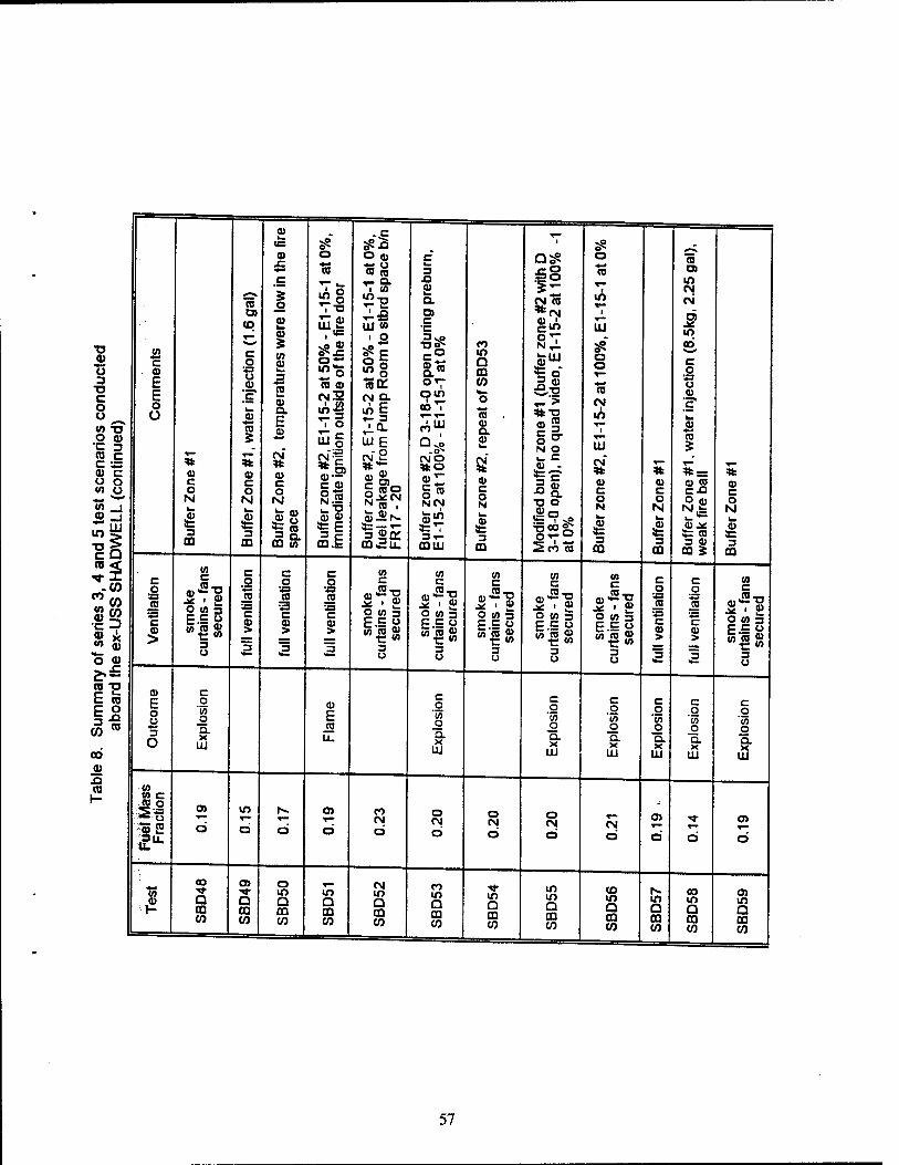
•o CD U 3
■o c o o ^ <0 ^ O Q) C 3 co c c = <u c o o OT U
a> m ■o c CO s Sw '= -?
o o ££
CO p E to E o
CO ra
CO
aj n CO
c o £ E o O
a> c o N
I 3
CO
CO a
CO
c o
S3 u V
is"
"ra
OJ c o N
i 3 m B
uffe
r Zon
e #2
, te
mpe
ratu
res
wer
e lo
w in
the
fire
spac
e
Buf
fer
zone
#2,
E1-
15-2
at 5
0% -
E1-
15-1 a
t 0%
, im
med
iate
igni
tion
outs
ide
of t
he f
ire d
oor
Buf
fer
zone
#2,
E1
-15-
2 at
50%
- E
1 -1
5-1
at 0
%,
fuel
leak
age
from
Pum
p R
oom
to
stbr
d sp
ace
b/n
FR
17-2
0
I
c h_ 3 O £ Q. ra c •c 3 vp
&*
om eoT
o4 .a*
CMO
«I §» NCN
fflUJ Buf
fer
zone
#2,
rep
eat o
f SB
D53
Mod
ified
buf
fer
zone
#1
(buf
fer
zone
#2
with
D
3-18
-0 o
pen)
, no
qua
d vi
deo,
E1-
15-2
at
100%
-1
at
0%
0
ra
1 m *■-
1
UJ
»s a a *■* ra
CM 1
m
S3 8 0 c 0 N
i 3
CD
5 CD C O N
i 3
CO
CO ra m CN CN
ra j£ m CO *•* c 0
S3 O CO
"c"
a m 5
aj co c-o
CD je 3= to 3 co
CO 5 Buf
fer
Zon
e #1
c o
S3 JO 'S c
5
CO
ah 1.83
3 U
c o
c
3
c o
S3 CO «3 c
1
c o
'43 co
S3 C OJ >
V)
• ■*■§
3 U
(A C
■2-n
o in 3 EC O
ȣ$ 3 U
in c
2 «2 3 P C O
3 u
en
.* i 0) O 10 3 E.S °
3 u
in
O W 3 P C 0
3 u
c 0
S3 CO
S3 c CO >
^5
c .0
ra
c CO > [5
(A
3 U
E o u 3 o
c o in o a X
UJ
E (0
U_
c o in o a X
UJ
c 0
'35 0 a. X
UJ
c 0 in 0 a. X
UJ
c 0
■55 0 a. X
UJ
c 0 in 0 Q. X
UJ
c 0
■« 0 a. X
UJ
<fl
jo o --■« o
^5 2 •3|i
O) *-> ci
in
d Ö ci
co CN
Q
o CM d
o CN
O
O CM
ci CN Ct d d d
■S3
■1=
eo ^t Q m CO
Q CD W
o m Q CQ CO
io Q m CO
CM m Q CQ CO
ro in a m CO
in Q £0 CO
in in a CO CO
CO m Q m CO
m a OQ CO
00 m Q CO co
m a m CO
57
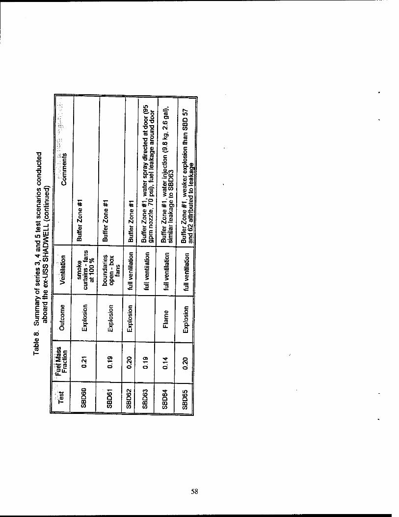
m O) i_ 5^* N. wo CO m
8* CO a OQ
21 CM CO n 2 O) c T3Ü 9> « oo
CO x: 4««
o a> o> C ■o CD " c
£ CO c o
O '55 o
Ü CD ><£ S3 Q.CD x ra 3 E
E CO JJ o
ceo T3 C
0) .
CO CO
o o
o O "9 C0 0Q
<0 CO .* CO
W T3 ■jgco 10 — CD Q
O CD 'C 3
5 o *-• >*- ST3 (0 c C \S * T— r- CO
* 2> % 3 0) c u o w o
c o
CO c o
CD c O
CO CO
p N o t3-2 »» *~^ N N N Nm
and
5 te
s A
DW
ELL
3 OQ
3 0Q
i 3
OQ 0Q O)
O) CO
*=c 3 C OQ'w
i_CM CO CO
OQ ca
-co o c
JO *P CO o
C o
c o
S3
c o
'43
c o
'J3 l'Jrn ■-■13
CO CO , w i2 JO CO CO
f ser
ies
ex-U
S
■::C
5 1=5 w£?o
3 O
T3 ' C C C CD 3 a — ° 9- u o
*-* c CO > I
'■S c 8
S3 c CO > ]3
•J3 c
1 o V
E'- en T3
. S
umm
ab
oar
E o o 3 o
c o
"55 o Q. X
UJ
c o
'55 o a. X IU
c o
■</J o a X
111
CO
E CO
c o
"S3 o a. X
UJ 0O « J3 ro 1 = CO o
*> E CM d
o>
ö
o CM o d d
o CM d
a ,_ CM CO ■«■ to In CO a CO CO CO CO CO £ a G a Q Q t- OQ 03 CO OQ OQ OQ CO CO w w CO CO
58
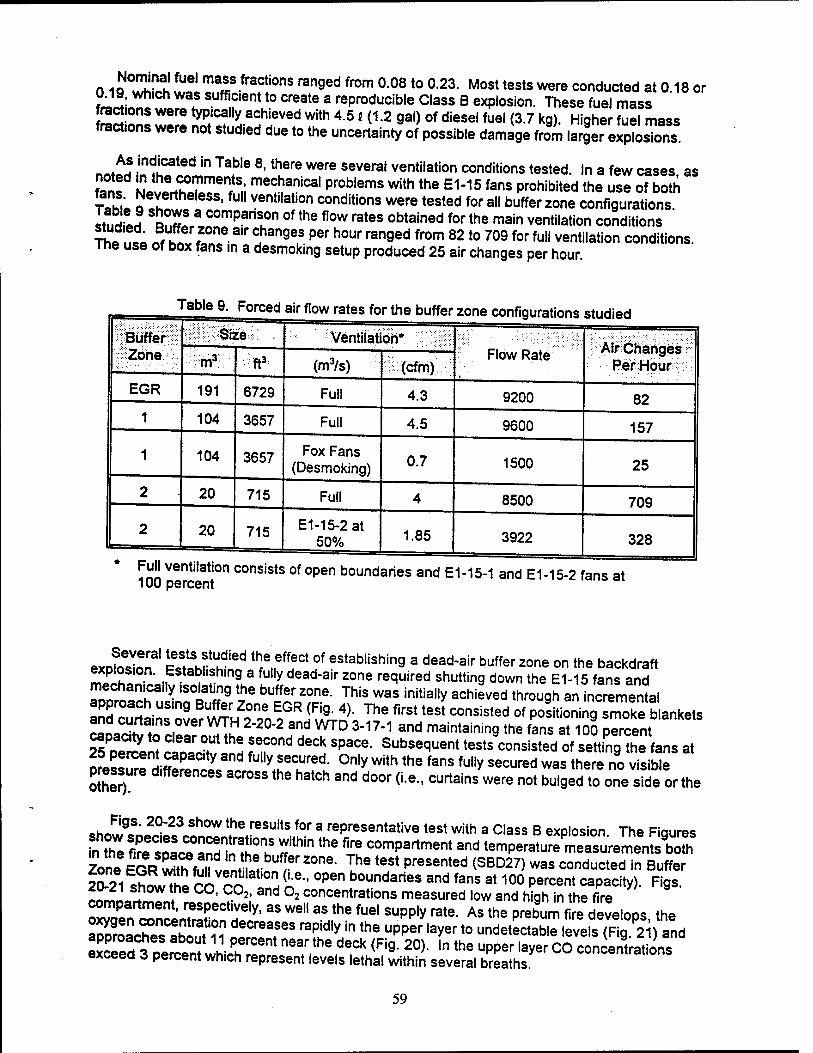
0 19 *32 leiTMffiofraf!i0nS ranged fr0m °08 t0 °23- Most tests were inducted at 0.18 or 0J9, which was sufficient to create a reproducible Class B explosion. These fuel mass
£££ü! ZtZ tyP*'C!"i a^eved With 45 '<12 9al> of diesel fuel <3-7 kg). Higher fuel mass fract.ons were not studied due to the uncertainty of possible damage from larger explosions
n^M .indicated in Table 8-tnere were several ventilation conditions tested. In a few cases as ?d U thei°mmen
rts,; mechanical problems with the E1-15 fans prohibited the use of both
fans Nevertheless, full ventilation conditions were tested for all buffer zone configurations
studiJ SSnfffra,nrPan'l0n °f the flow rates °btained for the main ventilation conditions " ?h1 nf K« f a'r ?anges per hour ranged from 8210 709 for ful1 ventilation conditions. The use of box fans in a desmoking setup produced 25 air changes per hour
1 rable 9. Forced air flow rates for the buffer zone configurations studied
Büffer Zone
Size Ventilation* Flow Rate Air Changes
Per Hour m3 ft3 (m3/s) (cfm)
EGR 191 6729 Full 4.3 9200 82 1 104 3657 Full 4.5 9600 157
1 104 3657 Fox Fans (Desmoking) 0.7 1500 25
2 20 715 Full 4 8500 709
2 20 715 E1-15-2 at 50% 1.85 3922 328
Full ventilation consists of open boundaries and E1-15-1 and E1-15-2 fans at 100 percent
exofo^on S?Wkh^ <f^? establishin9 a dead'air buffer zone on the backdraft mT'htn n
Estab''f hmg a fully dead-air zone required shutting down the E1-15 fans and mechanically isotatmg the buffer zone. This was initially achieved through an incremental approach using Buffer Zone EGR (Fig. 4). The first test consisted of posLning smoke bankets
SL^ZZ"^ 2-2°'2 and mD 3"17-1 and maintainin9 the fans at 1S0 pTrcent Ts oer^nt t^LT ^ VT* *** SpaCe' Subse^ent tests consisted of setting the fans at ofe^rf HiS™ y and fU"y !eCUred- °nly with the fans fu"y secured was there no visible pressure d.fferences across the hatch and door (i.e., curtains were not bulged to one side or the
ch^9S' 2°~23 Sh°W the reSults for a representative test with a Class B explosion The Fiqures
nt°hWefirs'o^aSdSH T***r*.COmpartment and t«np««iur.,!lSL^K3r ^BS^^J^SJ^2^' lhe t6St PreSented (SBD27) was conducted in Buffer SSiS^uSS>^2^H(A•■, °Pen boundaries and fans at 10° Percent capacity). Figs. eomLrTmon,«' ? 2; and °2 concentrations measured low and high in the fire
SSJSSLSfJT^ 3S We"3S the fUe' SUpply rate- As the prebum fire develops, the 2" °2S? u o!CreafeS raPIdly'",he Upper ,aver t0 ""detectable levels (Fig.2 ) and SSJ^^VIIA^neT, ^,*?k<Rg- 20)- ln the upperlaverC0 concentrations exceea t percent which represent levels lethal within several breaths.
59
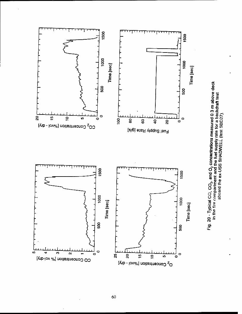
•' ' ' ' 1 ' ' ' ' I i i i i | i i i i i i r-
I: Z2
o o in
8 CO
©
E
o
[&p - |OA%] uoiiBJjueouoo 200
1 ' ' ' I ' ' ' ' ! ' ' ■ I I I ■ ■ i I . ! |~) o co o
CO o o
CM
[s/ß] ajey A|ddns isnj
[Ajp-|OA %] uoijeijueouoo 00
a •o
> « o « m c E S
«? -g^ o « rs. T3-OIM « HJ Q 3 i- CD 5> £ CO co _ © a> w E joi»
O Q.-J J5 O.UJ CO 3 >
S s< ü3i § a>W
S.i: ü 5E
- CL CO
O E ° O c -S C (L-
>» (t
Ö.E CN
iZ
[Ajp - |0A%] UOIJBJJU80UO0 20
60
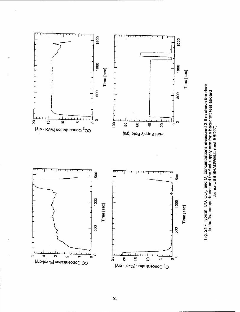
1 ' I I I I I I I I I I I I I I I I I o
-J o in
8 2 ™
CD (/) o E
o o w
[Ajp - |OA%] uoijej}uaouoo 200
•'''' | 'I i i | i i i i | i i i i | i i i r o
o o o —. T- u
CO JO <u E
o o m
1 ' ' ' ' ' ' ' ■ ' ' ' ' i I ■ ■ i ■ I ■ . i i f ■* CO CM
[Ajp-IOA %] uoaejiuaouoo oo
J ' i ' i I i i ' i i ■ i i i i ■ ■ i I S 2 ° o o o o co «o Tf cd
[s/ßj eiBfci Ä|ddns pry
:| ' ' ' I ' ' ' ' i i ) i i i i i i i i i i
<
in
lilt if" i ■ i i i i i i i ■ ■ ■ . | ,
8 3 5 ° [Ajp - |OA%] uoijBJ^uaouoo 20
o o o ,—, ^- o CO w
Q)
o o in
.* o <0 •a ■D o CO n o ■** n CD CO > ^- o V) A u n E CO
CO T7 CM n ■o CO fv 0) Si CM 3 CO Q (/) I- m n 0) £ CO E CD V) (A p CO r ^■■^
o J>. -J ^ Q.-J P auj c
-> £ o «_ n Ü r < o k- -L u a> co
0 £ CO T3 CO
"O C -) c CO ■ CO , . X _ c CD
fN
0 o
a E
■c
a)
0 (0 a
ü e o
(0 u u '5. I» 1-
1 sz ^" «_ CM Ol
61
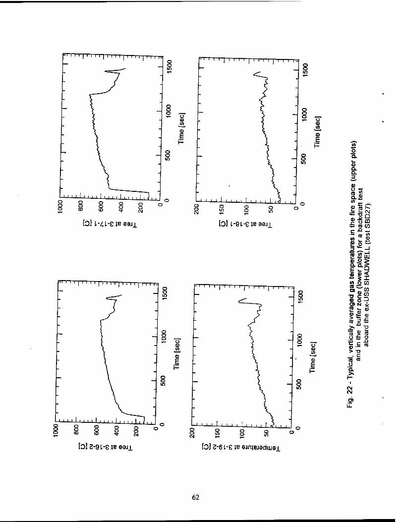
-'"'" ' I' I I I I I I I I I I I I o o
I I I I
o o CM
) I I I 1_
2 -Ü a>
a) E
o o to
o m
1 ■ '■" ' ' ' o o
bJ l-Zt-S is eaji b] l-Ql-evBeei±
=ri ' ' I ' ' ' ' I' ' '' I'''' I ' ' ' '■
s ° S o o oo o o CO
8
_ § ° Ü
CD w CD
E
o o m
1 ' ' ' ■ ■ ■ ' ' '' ■ ' i i i iIi j| i o o o
o CM
<A
o o l_ <a a a 3
0) () ** (0 a
1/1 d)
in
S5 01 N- u. f\J
.c o CD re CO
c 13 .w
in re en
0)
2 -t £ _1
1 ? tft HI a a. E
o a. D
(0 4) < ** 41 <n o co 08 »— CO
a> tu c o
CO
a> N X 1H <u 0) 11 > re 2
n £
>» T3
re CD sz re
o r a>
c re > Ü _ c CO re u Q. >» I-
CN <N
O) U.
b]2-9l.-8JBeaJl b] 2-6 l-e ve airuaiadiuai
62
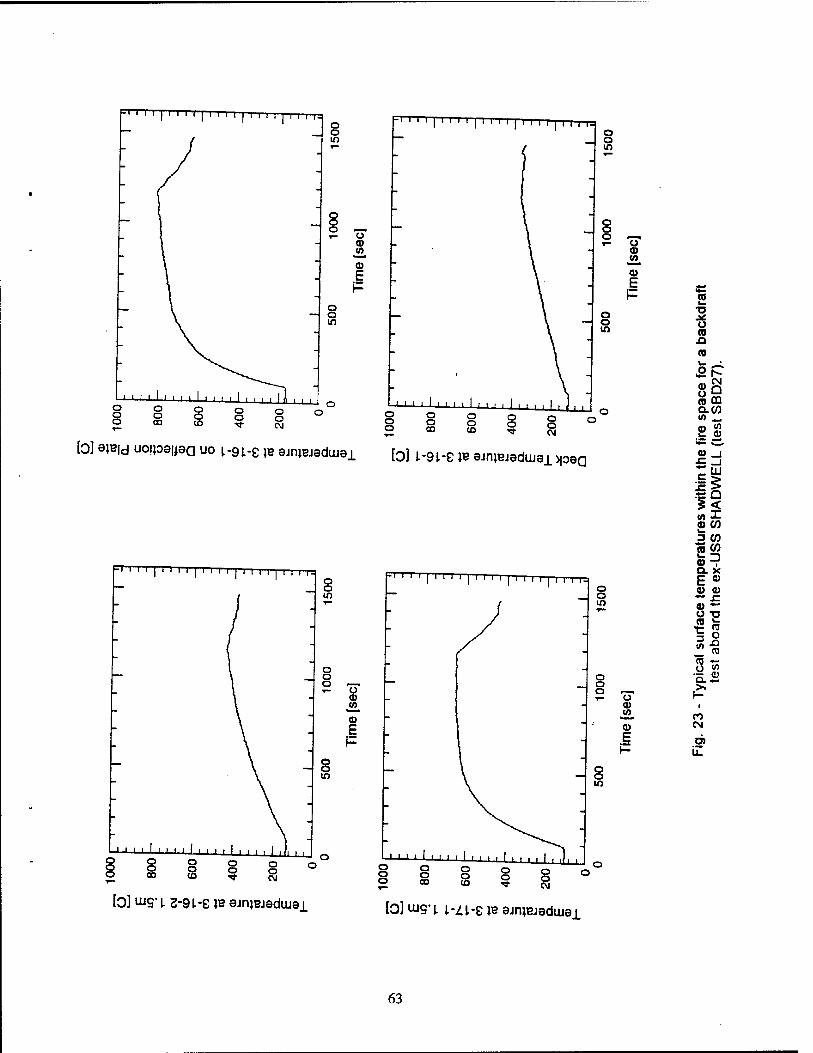
hl I IT I ' I' I I I I I I | I I I I I I I O
w
8 ° o
0)
E
o o in
-"' ' ' I I ' ' I ' I M ' I j I I I I I I | O
^ in
1 ' ' ■ i ' ' ■ ' ' ' ' ' i I i i Ä i i m i i i i 0
© ° 9 o O 9 9 o o co to .<»• eg o o o o o
I I I I 1 I ' ■ ■ 1 ■ ■ . . I I ■ ■ , I , o o CO
o o CO
o o
CD .CO
CD E
o o in
o o o o CM
[0] eiBid uoRoeuea uo l-9t-e }B ejnwueduiai [0] L-9L-e ,B wnnueduiBi»oaa
-' ',1 | ' ' I ' | I I I I I l I I I I I I IT O o w
■■'■■'■■ o o o
o o CO
' ■ ' ' ' ' ' ' ' ■ ' ■(! | o O O 52 ° o «O T CM
o o ° o-
flj « Co E
m
i i i i I i ii i i ii 1 i I ' i i i I i ii i. o
—J o m
o o O i—. 1- Ü
CD tfl
a>
fo] ujg-1 2-g i-e IB ejruBjeduiei [Q] Uig-i i-^i-e JB ajnjBjadLusi
CO ^ ■D .* U CO 13 n ^ & r*-
CN o Q m tu aw w ^-
£ 0) ys **.» a> . i £ . i "i~' III
'(7 £ Q
S< en I ID (0 I»
3 CO re W a D a. X
E 0)
0) 0J ♦* x: 0) ••-• o -n re re
o n CO
en +■«
o (A 01 u. *-*
>» 1-
n CN
CO u_
63
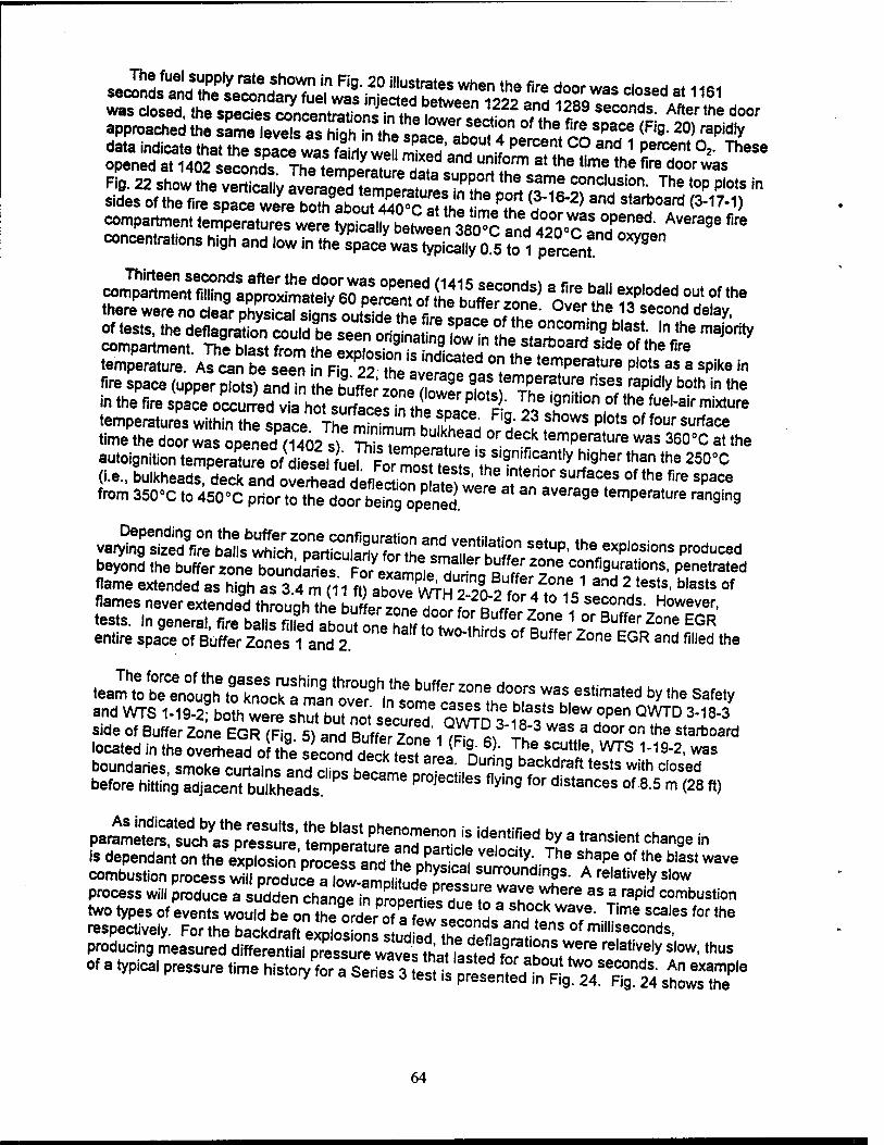
data indicate that the space was fairiv well mi^'ann .,nl~ !?! ? V percent °* These
opened at 1402 seconds ThTiV™™!! Tf d unl,orm at *• time the fire door was
Fig. 22 shol4?he"TcSy ÄSCÄ^ÄSSir^ The '0P P,0,S in
sides of the fire space were bothi abouBS P,„ <3~16"2) and s,ad=oard (3-17-1) compartment temperat^were JSÄS&SS and«n-T T""1 Avera9a fire
concentrations high and low in the^was^lca3,^ £ Ä"- 0Xy9en
in the fire space oceunVdvia^^hotsurf^nl( ' Pi°tSi" The ignition of the fue|-ai<- mixture temperatures with^h7sDaL Thfmfnt K A?08- RB'23 Shows P|ots of four Sl"*«* time the door wao^eneUU02«) SLT ^ °f d6Ck temPerat^ was 360'C at the autoignition tempedof J^sel"LI FJÄM 7 '? *9nificant|y higher than the 250°C (i.e., bulkheads, decken^ove^earJeflectiZLS 'the Tterior SUrfaCeS 0f the fire sPace
from 350°C to A50^C pncVTtÄ " an aVerage temPerature «"0*9
va^gÄ «'"P. ^e exp.osions produced beyond the buffer zJ^^SSn^^iT?^ fff 2°ne confi9urati°n*. penetrated
•JXSÄ£3!^,^h*lb,*r Z°ne dMrS was as,i™,ad "V •» safety
and WTS 1-19-2; bom were sh™o< secure/ 0^3 ^ f "*"?*" QWD 3"18"3
P^ÄSÄEi temoeSture an?6T != "r"" by a *"""' cha^ - is dependant en the eS"0™'pre«ss SÄ ? Vel0C"y' The shape °'tha blasl "«• combustion process wiS praducTa fow Tmn^^ surroundi"S=- A relatively slow process will Ww.JSÄSTÄlTT T where as a ra?id combustion two types of events JKÄK ° " S1°Ck Wave' Time scales '°r «» respectively. For the bäckdreft eJptoSls s udM ?Ä" r ^ "'""'"""»"os, producing measured MereZ^sMeZt^^fZT*^ ^7" S'°W'""" of a typical pressure time histor/for a Series"^£^^"£3, *^T
64
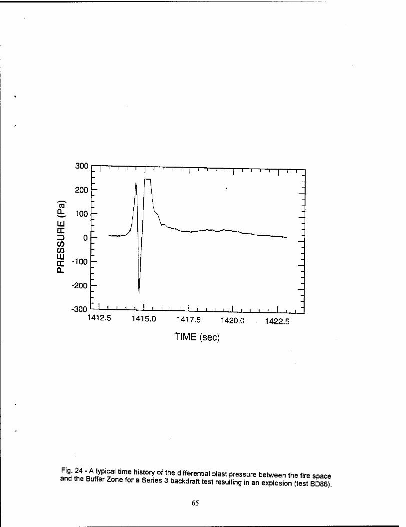
300
200
CO CL 100 UJ CE D 0 CO CO III □c -100 Q.
-200
-300
"i i i i | i—i—i—i—|—i—i—r i—i—i—r
J 1 L J 1 1 L J L 1412.5
J ' ' 1415.0 1417.5 1420.0
TIME (sec)
1422.5
S tht"ftJtor^niT hiSi0ry °f ?! differential blast Pressure between the fire space and the Buffer Zone for a Senes 3 backdraft test resulting in an explosion (test BD86).
65
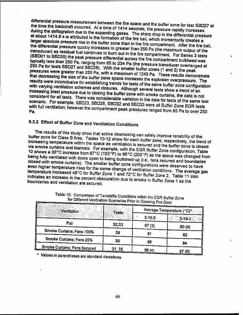
typically less than 250 Pa raS fram 85?o 5Si ^* compartment bulkhead was 250 p/for.ests SBD27 SlÄ ^ *
scenario. For exampte ?B53 sBD28 S?rS? Ä,"" dala for ,ests °'<•» 3«ne test
6.3.2 Effect of Buffer Zone and Ventilation Conditions
increasing tempere Sn IhTspVcels lÄT-ÄS'££T*'*? *«* °f
via smoke curtains and blankets. For exam e ^^ ESRufJr 71 "*/ Z°nS 'S C'°Sed
10 shows a 30°C increase from 67°C CI53°R icTQB'CV^ lZ°m confi9uration. Table being fully ventilated with doorTope,to being buUoned lo a J ft ** ^^ Changed from
closed with smoke curtains) ThesmaHertX™ tÄ( M.-ans Se°Ured and boundaries
Tab'e 1f°V SE wlll!nAbi,fty Conditions within the EGR Buffer Zone for Different Ventilation Scenarios Prior to Opening Fire Doör
Ventilation
Full
Smoke Curtains; Fans 100%
Smoke Curtains; Fans 25%
Smoke Curtains: Fans Secured
Tests
32,33
39
30
31,35
Values in parentheses are standard deviations
Average Temperature (°C)
3-19-2
67(3)
81
86
96 W
3-19-1
60(4)
82
84
97(6)
66
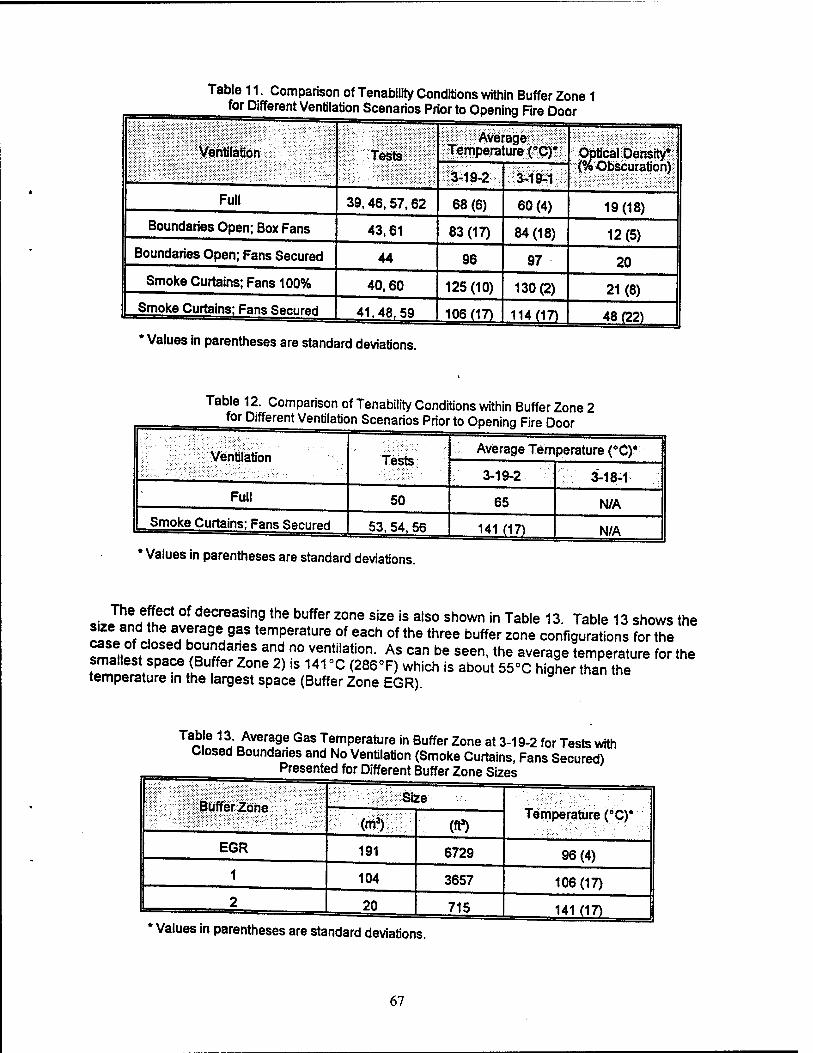
Table 11. Comparison of Tenability Conditions within Buffer Zone 1 for Different Ventilation Scenarios Prior to Opening Fire Door
Ventilation Tests Average
Temperature ("C)* Optical Density* (% Obscuration)
3-19-2 3-19^1
Full 39,46,57,62 68(6) 60(4) 19(18) Boundaries Open; Box Fans 43,61 83(17) 84(18) 12(5)
Boundaries Open; Fans Secured 44 96 97 20 Smoke Curtains; Fans 100% 40,60 125(10) 130(2) 21(8)
Smoke Curtains; Fans Secured 41,48.59 106(17) 114(17) 48(22)
* Values in parentheses are standard deviations.
Table 12. Comparison of Tenability Conditions within Buffer Zone 2 for Different Ventilation Scenarios Prior to Opening Fire Door
Ventilation Tests Average Temperature (*C)*
3-19-2 '!'■/ '■ 3-18-1
Full 50 65 N/A
Smoke Curtains: Fans Secured 53.54. 56 141 (17) N/A
' Values in parentheses are standard deviations.
The effect of decreasing the buffer zone size is also shown in Table 13. Table 13 shows the size and he average gas temperature of each of the three buffer zone configurations for the case of closed boundanes and no ventilation. As can be seen, the average temperature for the smallest space (Buffer Zone 2) is 141 »C (286T) which is about 55°C higher than the temperature in the largest space (Buffer Zone EGR).
Ü8 J rAvera9e Gas Temperature in Buffer Zone at 3-19-2 for Tests with
Closed Boundaries and No Ventilation (Smoke Curtains, Fans Secured) Presented for Different Buffer Zone Sizes
Buffer Zone v.:;::,:v::Size
Temperature (°C)* (m*) (ft3)
EGR 191 6729 96(4) 1 104 3657 106 (17) 2 20 715 141 (17)
* Values in parentheses are standard deviations.
67
kJX ?.rSÜ£ t° dlemonstrated that decreasing the size of the buffer zone increased the
22?2 ? explosion ong.nating from within the fire space. Fig 25 illustrates the
buffe^onUIeJ,nCreaSeS ? 17?°C (338°F)- R9- 26 shows «"""ar results for tests in which the
Äf^B^lSSf ?* ""?*. C"rtainS and b,ankets and ventilation was seeded Ihe toSSM tr5 !!n ?c demonstrate that decreasing the size of the buffer zone space increases the explosion overpressure between the fire space and the buffer zone.
intens[tao9^aec.S
aceSlfe';20ne, the reSUltS Sh0Wed that securin9the boundaries increased the
«Ilnl r0ff).?e Same trend in Peak temperature rises due to Class B explosions is seen in Fig. 28 for the tests with Buffer Zone 1.
tou^ä^uZZ^ll^fTthe d,fferenCe between the effect of ventila«°n and
rÄfM^ vaned from 4.5 m'/s (9600 cfm) for Full VentaSork7mXSSMÄ Box Fans
SÄl"? C3SeS' ihe.B0X Fan scenari° re"uired «conc^Tdaries
s~ries^ ventilation flow rateS 9 the eXpl°S'°n Intensity comP^d to changes in
7.0 DISCUSSION
*JZZS2£Z£2f^^^»#?Tne 5Tis ,he correla"on behrean *• zone and «nJ^SS^Ä '£££, n SflTÄSSS, "'VT*^ ^ K use of water spray as a firefighting tactic for explosion mSgatLn P ' *" ** '°PIC 'S 'he
68
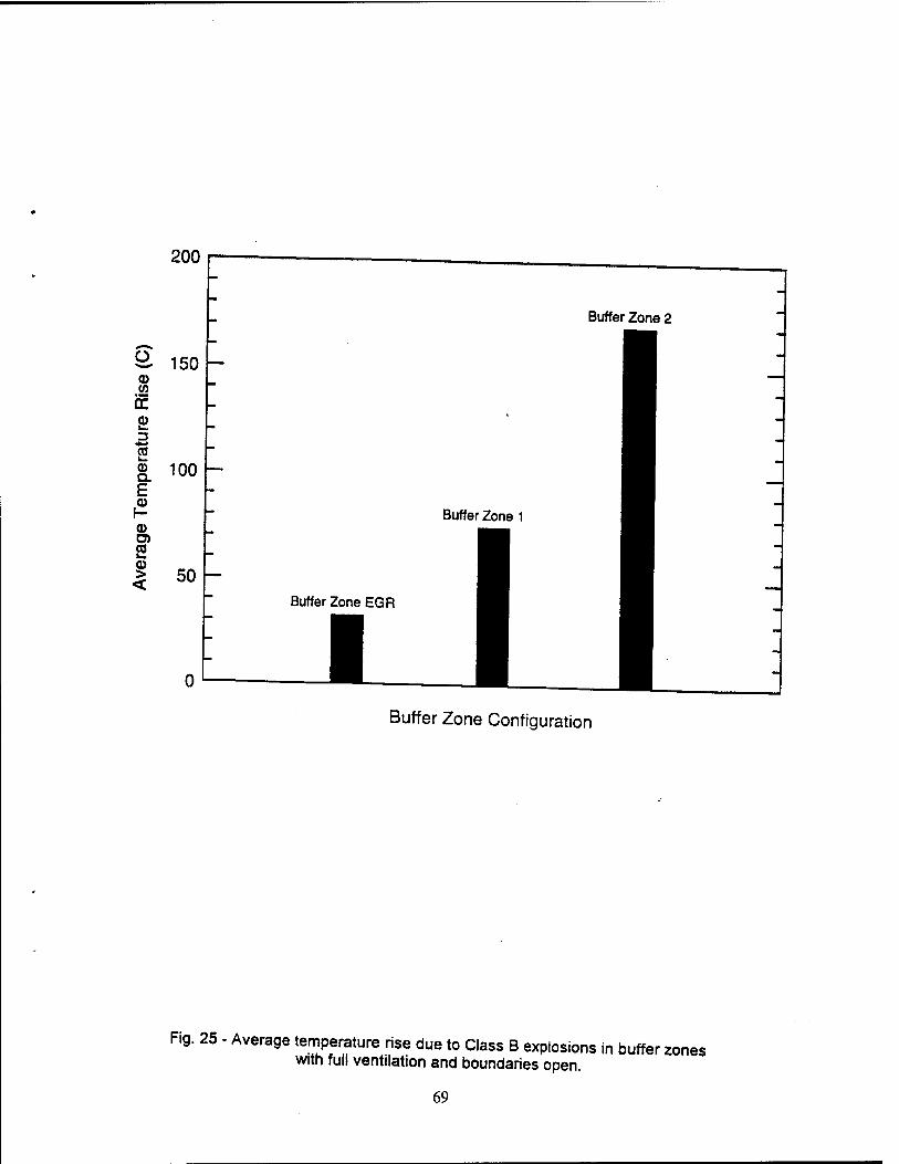
200
ö. 150 o V) if S> rj
2 ® 100 E |2 a> D) 2 > 50
Buffer Zone 2
Buffer Zone 1
Buffer Zone EGR
1 Buffer Zone Configuration
Fig. 25 - Average temperature rise due to Class B explosions in buffer zones with full ventilation and boundaries open.
69
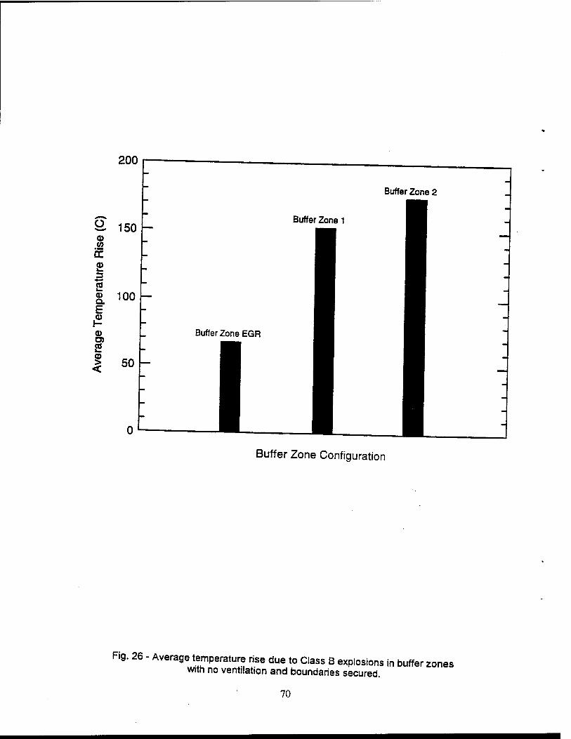
200
Buffer Zone 2
Ö. 150 o (0
>—
o Q. E
©
2
<
100
Buffer Zone 1
"
50
Buffer Zone EGR
Buffer Zone Configuration
Fig. 26 - Average temperature rise due to Class B explosions in buffer zones with no ventilation and boundaries secured.
70
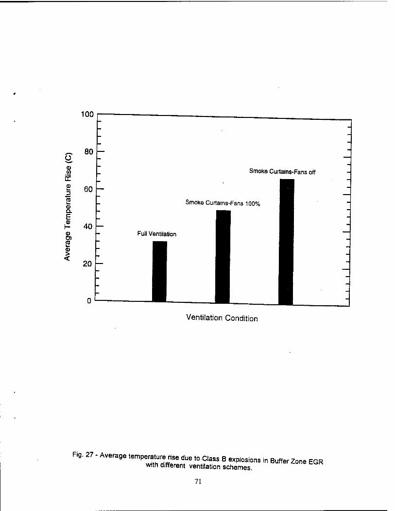
100
~ 80 o o CO
if o 3 ffl i— a> Q. E H 40 ©
S > <
60
20
Smoke Curtains-Fans off
Smoke Curtains-Fans 100%
Full Ventilation
Ventilation Condition
Fig. 27 - Average temperature rise due toClass B explosions in Buffer Zone EGR with different ventilation schemes.
71
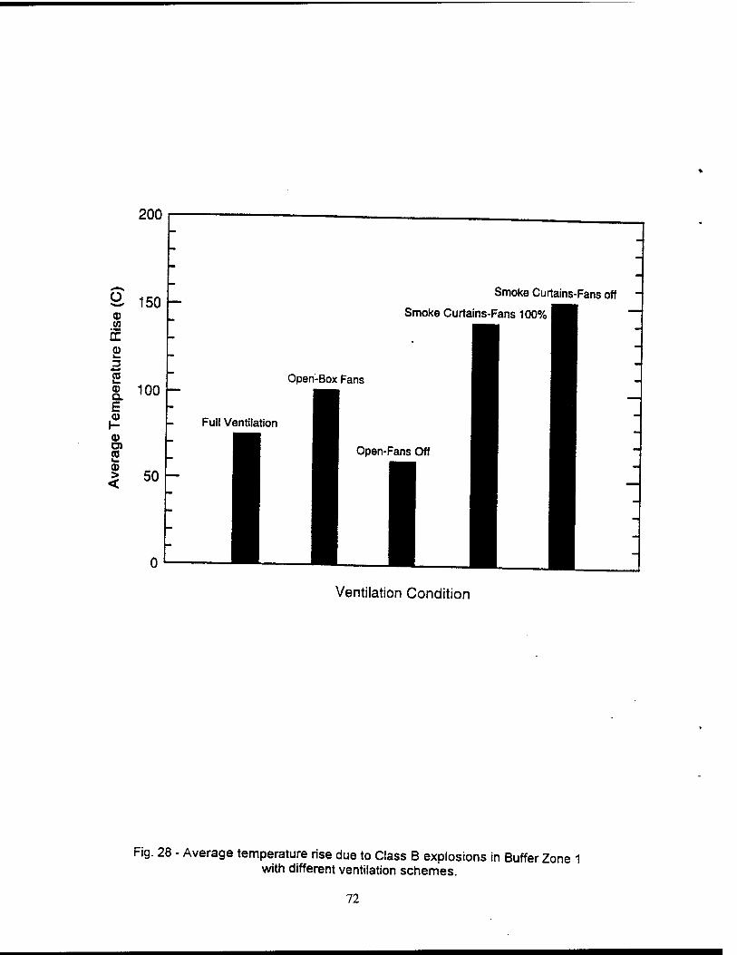
200
9, 150 (0 if
Smoke Curtains-Fans off
Smoke Curtains-Fans 100%
3 (0 u.
Q. 100 —
£ -
|2 - FullV 0) O) CO 0) > < 50
n ,
Open-Box Fans
Ventilation Condition
Fig. 28 - Average temperature rise due to Class B explosions in Buffer Zone 1 with different ventilation schemes.
72
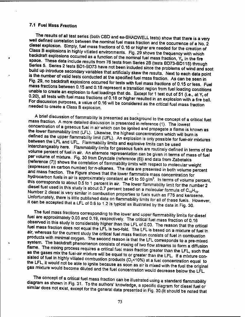
7.1 Fuel Mass Fraction
welMefined'ä-Sion5!,^88 ^ °BD a"d ex'SHADW^L tests) show that there is a very So, il"1 ^o ,on,between the nominal ^el mass fraction and the occurrence of a No 2
C ass ÄELfT'^TT! fraCti0nS °f °16 °r hi9her are needed for the nation of backdraffiS. ,5? * ^^environments. Fig. 29 shows the frequency with which lltl ?hi?i IT ^ned 3S a function of tne nominal fuel mass action. Y,, in the fire Sri« 7 I dala;nc,ude results from 76 tests from Series 2B (tests BD73-BD115) through h,Tn f n • f T* 2 t6StS BD1-BD73 have not been included since the problems of wind and soot bu Id up mtroduce secondary variables that artificially skew the results Next to each data oolnt
tZtST? °JnVa«d t6StS C°nduCted at tne sPedf,ed fuel mass fraction As can be AT mLlL^ backdraft explosions occurred for tests with fuel mass fractions of 0.15 or (ess Fuel
ÄEÄ *l"'6n, °-15 and °-18 represent a transition reai°n from fuel loading conditions TiS^Zfl^eTSi0nl°fUel '0adingS that da *"»*for 1 test out of 51 (i.e., at Yf of O20), all tests w.th fuel mass fract.ons of 0.18 or higher resulted in an explosion with a fire ball
fZSS^SSZS* 1 ^ °f 0"1e Wi" be COnsidered as the «««"W mas fracl on needed to create a Class B explosion.
ma^fraiforfmnrffHflaTwabJ'ity iS PreSented aS backaround to the concept of a critical fuel £n£S f deta"ed d,scuss,on is Presented in reference (1). The lowest
SS^^lh«?fT-w^Min f.'WhiCh C3n be iQnited and proDa9ate a flame is known as defile acZ
tyJim,t (LuFL)- Likewise'the n,'9nest concentrations which will bum is
S^^j^fSTT* ""U.^: An eXpl0S,0n iS °nly p0SSib,e for fue,"air mixtures .vJUST M u UFL Flammablllty limits and explosive limits can be used 2^^ie£., inFlamnTbi,i!y 'imi!S f°r gaS60US fue,s are routine,y defined in terms of the volume percent of fuel in air. An alternate representation can be given in terms of mass of fuel
oSÄmÄ^ Z°lT D7*Sdale (referenCe (6)) and data fromTabetaSs *" /2™SL?.) 1 correlation of flammability limits with respect to molecular weight 2*Ä£M fH "^STi The d3ta are Presented in both volume *~* hS^H ft gUre Sh0WS that the 'ower flammable mass concentration for hydrocarbon fuels in air is approximately constant at 45 to 50 g/m3. In terms of volume percent
SiSKÄ^d0510 h TnTinair The'0Werflammabi,itylim"forTh'rnumber2 ' diesel fuel used in this study is about 0.7 percent based on a molecular formula of C H
unf^er 2,d|eSfKiS Very Similar in combustion properties to fuels such as F™andkerosene
it ca?benltoteed^ To °" "^^ 'imitS for a» of these ?ue^ However, it can be accepted that a LFL of 0.6 to 1.2 is typical as illustrated by the data in Fig. 30.
fue|Tahre aoeö^ t0 the '°Wer and upper flammability limits for diesel LbirLJ inS* ? !V and °-19, resPectively. The critical fuel mass fraction of 0 16 observed in this study is considerably higher than the LFL of 0.03 The reason that the critical fuel mass fraction does not equal the LFL is two-fold. The LFL is based on a m xTurl of fueMn
nl^Hefa,nf°r the T601 StUdy the Critical fuel mass fraction consists erf fiir^r^Sstoi t^^SZSXST ^ SeCOnd reaS°n iS that the LFL corresponds Jo aT-mixed flame ThT^SS^K!"0'"-n°n °° v'8? °f mixing 0f two flow streams t0 form a diffusion asThe Ja^T2lT^JtreqTS * T^1 fuel mass fraction 9reater than the LFL, such that stated of f!S ST hilh! 6f,miXtZe W"1 be equal t0 or 9reater than the LFL. If a mixture con- fheLFL Su.^'9h'y vitiated combustion products (O2<10o/o) at a fuel concentration equal to aas mLurelluilh? aWü f 'gnrts because as soon as air is mixed with the fuel the original gas rmxture would become diluted and the fuel concentration would decrease below the LFL
diag^amTshown ?n RIT^T T* ^T™ Can be il,UStrated usin9 a standard flammability similato noTex** Sini fT? aUth0r? knowled9e. a specific diagram for diesel fuel o? similar does not exist, except for the general data presented in Fig. 30.(lt should be noted that
73
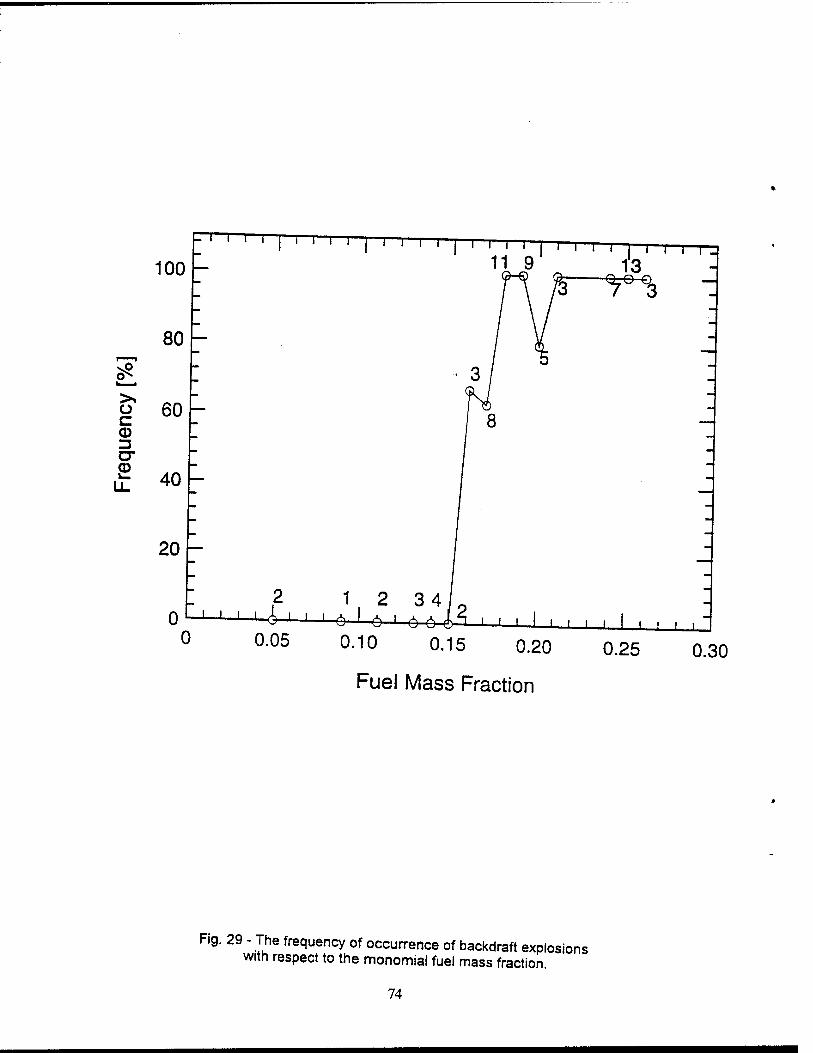
L I I I I- i i i—I—r—r
100
80 -
60 o c CD 3 o-
■T 40
20
0 0
2
0.05
1 -6-
2 -6-
i i i i
11 9 i—i—r i i i T^_
13
J I I I I I
0.10 0.15 0.20
Fuel Mass Fraction
0.25 0.30
Fig. 29 - The frequency of occurrence of backdraft explosions with respect to the monomial fuel mass fraction.
74
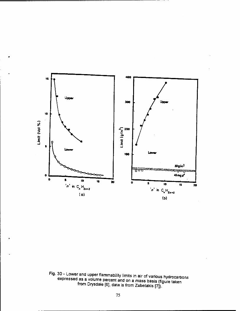
'"' nCH, ,
(a) V in CH, ,
» 2i»*2
(b)
Fig. 30 - Lower and upper flammability limits in air of various hydrocarbons expressed as a volume percent and on a mass basis ÄK°""
from Drysdale [6], data is from Zabetakis [7])
75
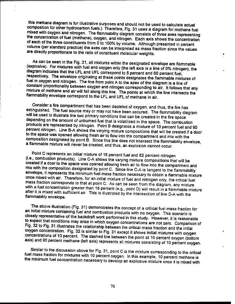
this methane diagram is for illustrative purposes and should not be used to calculate actual composition for other hydrocarbon fuels.) Therefore, Fig. 31 uses a diagram for methane fuel mixed with oxygen and nitrogen. The flammability diagram consists of three axes representing the concentration of fuel (methane), oxygen, and nitrogen. Each axis shows the concentration of each of the three constituents from 0 to 100% by volume. Although presented in percent volume (per standard practice) the axes can be interpreted as mass fraction since the values are directly proportionate to the ratio of constituent molecular weights.
As can be seen in the Fig. 31, all mixtures within the designated envelope are flammable (explosive). For mixtures with fuel and oxygen only (the left axis is a line of 0% nitrogen) the diagram indicates that the LFL and UFL correspond to 5 percent and 60 percent fuel respectively. The envelope originating at these points designates the flammable mixtures of fuel in oxygen and nitrogen. The line from point A to the apex of the diagram is a line of constant proportionality between oxygen and nitrogen corresponding to air. It follows that any mixture of methane and air will fall along this line. The points at which the line intersects the flammability envelope correspond to the LFL and UFL of methane in air.
Consider a fire compartment that has been depleted of oxygen, and thus, the fire has extinguished The fuel source may or may not have been secured. The flammability diagram will be used to illustrate the two primary conditions that can be created in the fire space depending on the amount of unburned fuel that is volatilized in the space. The combustion produces are represented by nitrogen. Point B designates a mixture of 10 percent fuel and 90 percent nitrogen. Une B-A shows the varying mixture compositions that will be created if a door to the space was opened allowing fresh air to flow into the compartment and mix with the ?<!!! £" deÜ9nated
u bV P°int B- Since this line does not intersect the flammability envelope,
a flammable mixture will never be created, and thus, an explosion cannot occur.
Point C represents an initial mixture of 18 percent fuel and 82 percent nitrogen (i.e. combustion products). Line C-A shows the varying mixture compositions that will be created if a door to the space was opened allowing fresh air to flow into the compartment and mix with the composition designated by point C. Since line C-A is tangent to the flammability envelope, it represents the minimum fuel mass fraction necessary to obtain a flammable mixture once mixed with air. Therefore, for an initial mixture of fuel and nitrogen only, the critical fuel mass fracton corresponds to that at point C. As can be seen from the diagram, any mixture
^p'rViU
ceiCOr!fen!!;at,0i]-9reaterthan 18 percent (e-9" P°int D> wili result in a flammable mixture
after it is mixed with sufficient air. This is illustrated by the intersection of line D-A with the flammability envelope.
The above illustration (Fig. 31) demonstrates the concept of a critical fuel mass fraction for an initial mixture containing fuel and combustion products with no oxygen. This scenario is
SüÜr?CBJen!^Ü? °f the baCkdraft WOrk Performed in this study. However, it is reasonable PL £ ? c condition» may arise in which oxygen concentrations are not zero. Comparison of Pig. 32 to Fig. 31 illustrates the relationship between the critical mass fraction and the initial
rZlTtCTe TUT- Fig- 32 iS Similar t0 Fi9' 31 exceP*jt shows initial mixtures with oxygen
concentrations of 10 percent. The dashed line between the point at 10 percent oxygen (bottom axis) and 90 percent methane (left axis) represents all mixtures consisting of 10 percent oxygen.
hJHHm^ dlSCUSSion above for F|9- 31- Point C is the mixture corresponding to the critical fl£ Z?m. mTJ!l°r mXlUT With 1° Percent 0xygen- ,n this examP|e- 10 Percent methane is the minimum fuel concentration necessary to develop an explosive mixture once it is mixed with
76
80 70 60 50 40 30 Ä
OXYGEN (VOLUME PERCENT)
100
Fig. 31 - A typical flamrnabihty diagram showing the possible mixture compositions that can result from mixing air with one of three initial mixtures (B C and D) oi methane and nitrogen with zero percent oxygen (for illustration only)
77
air Initial mixtures with fuel concentrations less than 10 percent (e g Point B) will never
SS^Sf^, T ThiS iS illUStrated bythe fact that the'^ B A doe" nountersect S^SZSSHT'y- lnit a' miXtUreS With fuel concentrations greater than 10 percent in SSSSrSlT ^reS SmCe the additi0n 0f air is reP"*ented by the line D-A which intersects the flammabihty envelope.
Mnr^r?ia"d I1 illU?rfte how the critical fuel mass action will decrease as the oxygen
S^E^toJ^ miXlUre inCreaSeS- ,n thSSe examp,es-the critical fuel concentration o^fopn P?hJ:tt5 "^ °f 2er0 percent oxy9en and 10 Percent for*he case often percent 31 , ^^e of zero percent oxygen is a bounding case as it represents the maximum
SuSssS Iheref0re' aCC°rding t0 the resu,ts of these S a ^c^ toÄ r0t)
max,mum possib,e va,ue since the oxysen
This^ waVotrff^d^'nre' K "* iS ,0nly °ne °ther kn0Wn study of backdraft explosions. (Serened PTnT?R XSmaT f°r 6XCeSS methane in a reduced scale enc'os^e (reference (8)). The 3.6 m3 (128 ft3) enclosure measured 1.2 m by 2.4 m by 1 2 m hiqh (A bv 8
woiAte^^V0 about,10 Percent **• *. (volume) of the spaces sTudifd Sn fh s work. A methane burner was ignited within the closed enclosure. The fire would extinquish as
?•^.<iS!^;deCT',? fd the fire b6Came 0Xy9en StarVed" TS£Ä£Sd to flow for a set penod after extinguishment at which time a hatch was opened at one end of the enclosure. An electnc spark positioned near the burner was used as anSion soC?ce The
SMS sLeiroathd6
the ra9ratiT
0n Within the «W*™* were visible tSrrgragLhses window in one s de of the enclosure. Two vent configurations were studied- (1) a horizontal opening,0.4 m h.gh by 1.1 m wide and (2) a window-style opening 0 4 m by 0 4 m both centered on the short wall of the compartment at the opposite end from t£ burner
"showSThennHcThvH^dr^ Wlth fUe' maSS fraCti0nS Up t0 °29 and states that *• ^sults to oc£uvihe^the HCr^0n COncentratn must be >10% & masslin •*•' for a backdraft io occur. When the HC concentration is <10% the flame travel is slow and the comoartment
E? and thTb? l°HWeft
rKAS ^ HC ^^ creases the^^IZSSl™ owe'^Ä m^^^l1"0™ SeVere" The reSUltS of Fleiscnmann indicaTe a Ssurefi^^Tl^'n han th3t °bSerVed in thiS Studyfor backdrafts in ^"-»«le ?S«ZrtZi ^PL ?ntl,atl0n °Penina (j-e-. a door instead of a raised horizontal slot) The d,fference is attnbuted to the oxygen concentrations within the compartments Avenue compartment oxygen concentrations for this study were approximately 1 perS where as the
SS!?? rf"^?"^1'008 in Fleischmanns tests were estimated to be about 10 percent or higher. As .ilustrated above with Figs. 31 and 32 gas mixtures with higher oxygen concentrates require lower levels of fuel to create an explosive condition
h«ihÜ14 Sh0WS SeleCted data from F,eischmann's experiments (reference (8)) for tests of nf w=f H H Pen'l9 confi9urations- Presented in the Table is the fue flow ra?e the mass action EÄ*r0Jaib0nS m the Upper ,ayer (UL)"the mass fracticn of oxygen, the ignitSn detaT ho^onta.Ps.ao f SS!' *",? the efmated *re ba» "»• «" compar^g the datafor the " SS to creafe w th thTalle; ^^^ °penin9'il can be seen that drafts were more difficult to create with the wmdow opening. Despite relatively high fuel mass fractions of 0 15 to
, .. lThe res,u,ts of pleischmann are estimated since he presented all species data as mass
ÄL&^ lT:«he rpper ,ayer were °-11 *ith ^wSüPJüT Soof 0 11 aL 1L v°,umftnc concentration has been calculated based on a mass fraction of 0.11 and an assumed molecular weight of the gas composition of 26 g/mole.
78
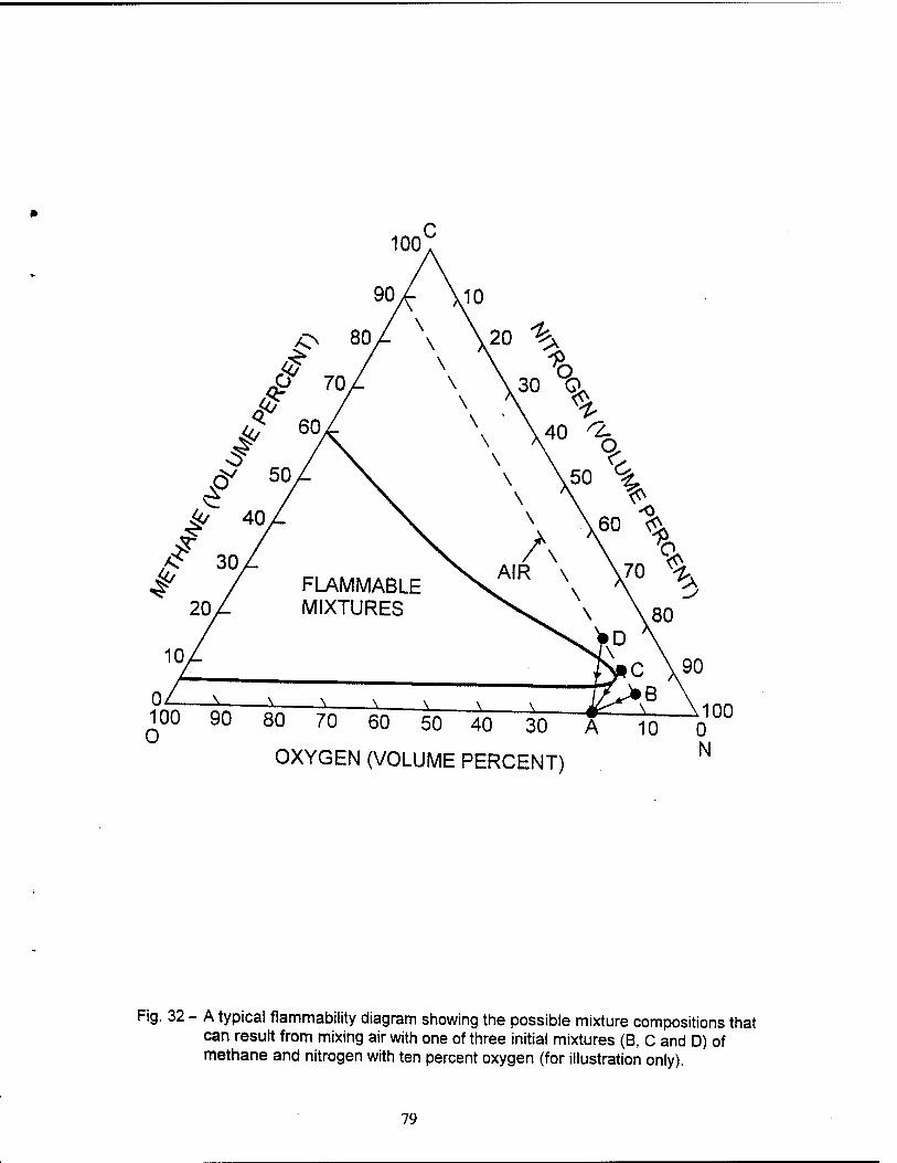
jo 40
/£ 30 ^ / FLAMMABLE
20/ MIXTURES
WO 90 80 70 60 50 40 30 A 10 0
OXYGEN (VOLUME PERCENT) N
Fig. 32 - A typical flammability diagram showing the possible mixture compositions that can result from mixing air with one of three initial mixtures (B, C and D) of methane and nitrogen with ten percent oxygen (for illustration only).
79
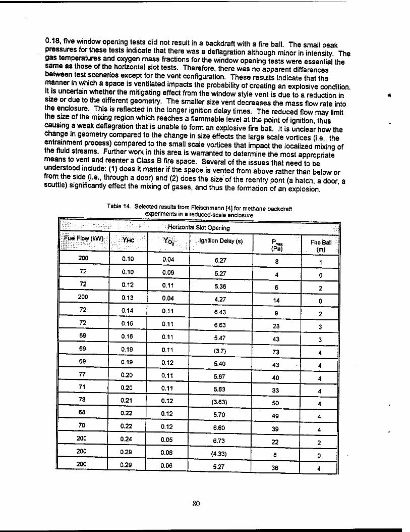
0.18, five window opening tests did not result in a backdraft with a fire ball. The small peak pressures for these tests indicate that there was a deflagration although minor in intensity The gas temperatures and oxygen mass fractions for the window opening tests were essential the same as those of the horizontal slot tests. Therefore, there was no apparent differences between test scenarios except for the vent configuration. These results indicate that the manner in which a space is ventilated impacts the probability of creating an explosive condition it is uncertain whether the mitigating effect from the window style vent is due to a reduction in size or due to the different geometry. The smaller size vent decreases the mass flow rate into the enclosure. This is reflected in the longer ignition delay times. The reduced flow may limit the size of the mixing region which reaches a flammable level at the point of ignition thus causing a weak deflagration that is unable to form an explosive fire ball. It is unclear how the change in geometry compared to the change in size effects the large scale vortices (i e the entrapment process) compared to the small scale vortices that impact the localized mixing of the fluid streams. Further work in this area is warranted to determine the most appropriate means to vent and reenter a Class B fire space. Several of the issues that need to be understood include: (1) does it matter if the space is vented from above rather than below or from the side (i.e., through a door) and (2) does the size of the reentry pont (a hatch, a door a scuttle) significantly effect the mixing of gases, and thus the formation of an explosion
Table 14. Selected results from Fleischmann [4] for methane backdraft experiments in a reduced-scale enclosure
■■■■'"'Horizontal Slot Opening
Fuel Flow (kW) YHC ■ :m^ Ignition Delay (s) (Pa)
Fire Ball i (m)
200 0.10 0.04 6.27 8 1 72 0.10 0.09 5.27 4 0 72 0.12 0.11 5.36 6 2
200 0.13 0.04 4.27 14 0 72 0.14 0.11 6.43 9 2 72 0.16 0.11 6.63 28 3 69 0.16 0.11 5.47 43 3 69 0.19 0.11 (3.7) 73 4 69 0.19 0.12 5.40 43 4 77 0.20 0.11 5.67 40 4 71 0.20 0.11 5.63 33 4 73 0.21 0.12 (3.63) 50 4 68 0.22 0.12 5.70 49 4 70 0.22 0.12 6.60 39 4
200 0.24 0.05 6.73 22 2 200 0.29 0.06 (4.33) 8 0 200 0.29 0.06 5.27 36 4
80
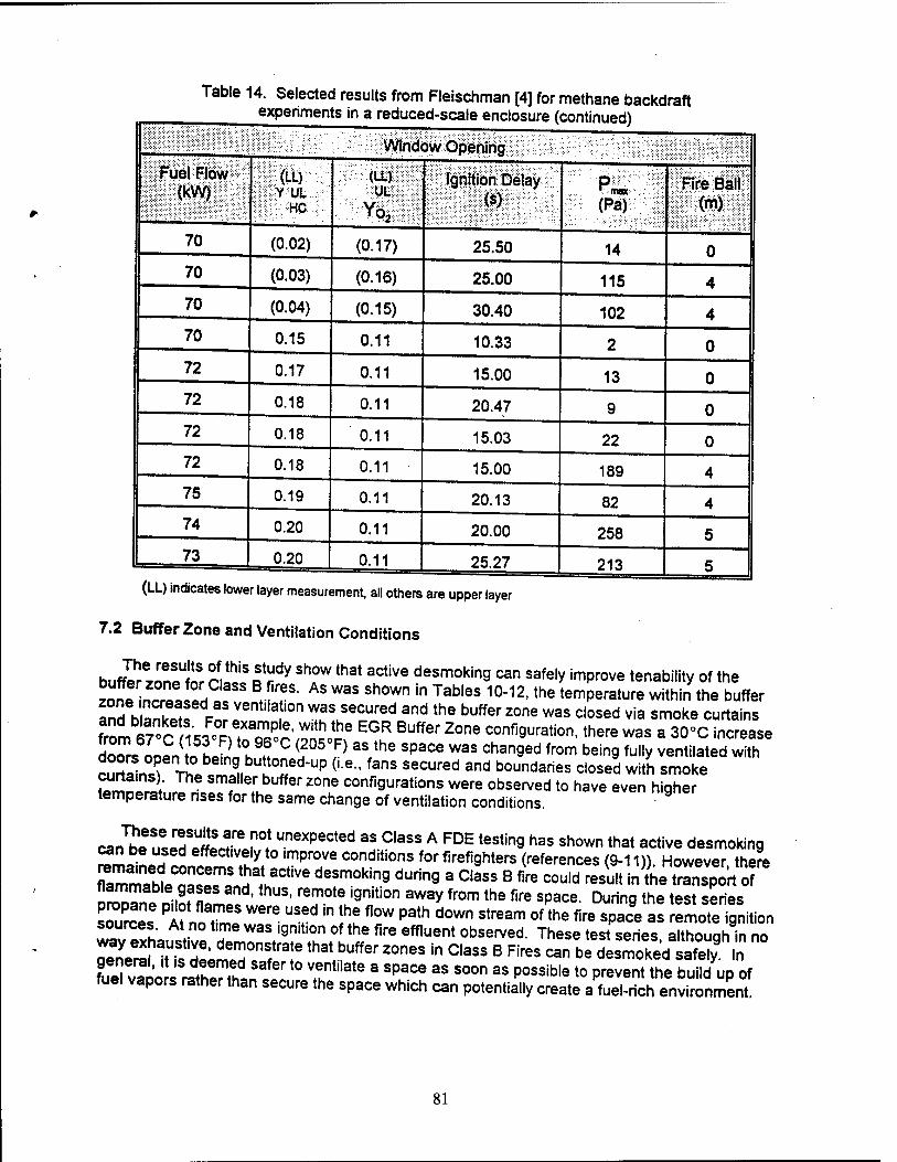
Table 14. Selected results from Fleischman [4] for methane backdraft experiments in a reduced-scale enclosure (continued)
Window Opening
Fuel Flow (kW)
(LL). Y UL UL
. : YC1I ignition Delay
(s) ■max
(Pä) 1 fRrelBlii:"
70 (0.02) (0.17) 25.50 14 0 70 (0.03) (0.16) 25.00 115 4 70 (0.04) (0.15) 30.40 102 4 70 0.15 0.11 10.33 2 0 72 0.17 0.11 15.00 13 0 72 0.18 0.11 20.47 9 0 72 0.18 0.11 15.03 22 0 72 0.18 0.11 15.00 189 4 75 0.19 0.11 20.13 82 4 74 0.20 0.11 20.00 258 5 73 0.20 0.11 25.27 213 5
(LL) indicates lower layer measurement, all others are upper layer
7.2 Buffer Zone and Ventilation Conditions
buff?rzonSet
Sr SSf ^ 8hfW th3t lCtiVe desmokin9 ™ safely improve tenability of the lanl n™I°H ' rf?S- AS W3S Sh°Wn in Tables 10"12-the temperature within the buffer and blanks Mr £™M °" TJ^l* and the buffer 20ne was closed via smoke ^ains from 67°Cu^^TSS^'^o^ EGR BUffer Z°ne confi9uration- there was a 30°C increase doo^ ID1;( to LL h fC ?°5 ,F> 3S the SpaCe WaS Chan9ed from bein9 ful|y ventilated with £S2i2T Tr° c!Ln9„butt°"ed-uP (•■•-. fans secured and boundaries closed with smoke SmnLri" smf"er buffer zone configurations were observed to have even higher temperature nses for the same change of ventilation conditions. -
ca^V^ln!?0! unexpected as Class A ™ testing has shown that active desmoking can be used effectively to improve conditions for firefighters (references (9-11)) However there
Zral^TaSnHhlaCtiVe deSm0kinS dUrin9 a C'aSS B «re COU,d ™«*toÄrtSP flammable gases and, thus, remote ignition away from the fire space. During the test series
Xn! PA? fl?eS W6re US6d in the flow Path down stream of Pthe fire space as remote ignition wayExhaustive Tj^f^f^ *• 6fflUent °bServed' These «"■seri^ although"in no S^TiS dLmlT f ?that buffer zones in Class B Fires can be desmoked safely In ?ueU?oo rathPMhln
Safer t0 ?"t,late a Space as soon as P°ssib|e to prevent the build up of fuel vapors rather than secure the space which can potentially create a fuel-rich environment
81
Decreasing the buffer zone size did not prevent backdraft explosions from occurring On the contrary, the test results demonstrated that decreasing the size of the buffer zone increased the intensity of a Class B explosion originating from within the fire space. As was shown in Fig 25 the peak temperature rise in Buffer Zone EGR was about 30°C (86°F). Tests with the smallest S^«oi2, ^fe observed t0 nave substantially higher peak temperature increases of yo c (338 F). The Senes 3 to 5 results also demonstrate that decreasing the size of the buffer zone space increases the explosion overpressure between the fire space and the buffer zone.
For a given size buffer zone, the results show that securing the boundaries (i e creating a dead-air space) also increased the intensity of a Class B explosion originating from within the fire space. This was illustrated in Fig. 31 which showed the effect of securing buffer zone boundanes on the development of Class B explosions in tests with Buffer Zone EGR The SSS??' Peak temPeratures '"creased by about 32°C (90°F) for fully ventilated tests to 68°C (154 F) for tests with closed boundaries and no ventilation (i.e., dead-air space). The results of Buffer Zone 1 tests also show the same distinct increase in the thermal blast to the buffer zone when it is made a dead-air space rather than keeping boundaries open. This study suggests that the underlying premise in NSTM 555 for creating a "dead-air space" in the buffer zone is not valid. Recall that Section 6.3.7.2 of NSTM 555 (reference (3)) states that establishing the dead-air space buffer zone is important due to the possibility of fire or explosion if hot combustion gases from a Class B fire mix with fresh air." It is clear from this work that creating a dead-air space does not necessarily prevent or even mitigate an explosion or reflash from occurnng. The mixing of air in the buffer zone and fuel gases in the fire space is driven by the thermally induced pressure gradient between the hot fire space and the cooler buffer zone The crea ion of a dead-air space did not significantly impact this mixing process which occurred and resulted in a backdraft within only 30 seconds of opening the fire boundary. Such a short delay time precludes any feasible tactics, such as using a smoke curtain at the fire boundary reentry point, to prevent sufficient air from mixing with fuel to form a flammable mixture.
It may be rationalized that a sufficiently small buffer zone would not contain enough air even if mixed entirely into the fire space, to form an explosive mixture. However, there are practical problems with this idea as explained further in this paragraph. Experimental limitations prevented the study of extremely small buffer zones relative to the fire space The ratio of the volume of the buffer zone to the volume of the fire space ranged from 0 57 to 5 5 for the experiments conducted. A study of machinery spaces on LPD17 and DDG-51 ships shows that vestibules or trunks would be used as the immediate buffer zone for attacking a fire in the machinery space. If the buffer zone were limited to just these spaces, the volume ratio of the
frrÜ02e t0 fire SpaCe COuld be as sma" as 006 t0 °006- Due to the relatively small size of the buffer zone, as the fire space is entered, the buffer zone and fire space atmosphere would become essentially the same. Therefore, opening the fire space to the buffer zone would just marginaiiy extend the fire zone boundaries. As a result, the potential for explosion would not be averted; the boundary that separates the fuel-rich atmosphere and fresh air has just
S!"a^hf,h?h'lh,er f[°?the ^ !°«Ce- '* iS Undear whether there is an OP«™' buffer zone size at which the limited air in the buffer zone could prevent a potential explosion from occurnng during reentry. It can be argued that any amount of air introduced into a Class B fire space could locally mix near the door or hatch to form an explosive mixture. This may be especially S3 VÜ" nI °Penin9 int0 machinery spaces, since this is typically the location of fuel storage and, thus, a likely area to have high fuel concentrations from a break in the fuel system.
7.3 Water Spray
Both test series with the fire compartment venting directly to atmosphere (CBD tests) and the senes ventmg to confined spaces (ex-USS SHADWELL tests) were successful in demonstrating
82
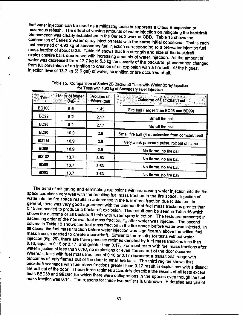
ho, J ,njSCt'!n ^" be USed as a mitiaatin9 tactic to suppress a Class B explosion or hazardous reflash. The effect of varying amounts of water injection on mitigating the backdraft phenomenon was clearly established in the Series 2 work at CBD. Table 15 shows the
t?«T^n!Ti %*£ I Wa,ter lprüf injeCti0n tests with the same initial conditions. That is each test consisted of 4.92 kg of secondary fuel injection corresponding to a pre-water injection fuel mass fraction of about 0.25. Table 15 shows that the strength and size of the bacK explosions/fire balls decreased with increasing amounts of water injection. As the amount of
^mfZrfeCr?aSed/r0m 1?:7 k910 55k9the severityof the bac*draft PhenomenonRanged
rorn full prevention of an ignition to creation of an explosion with a fire ball. At the highest injectron level of 13.7 kg (3.6 gal) of water, no ignition or fire occurred at all.
Table 15. Comparison of Series 2B Backdraft Tests with Water Spray Injection for Tests with 4.92 kg of Secondary Fuel Injection
l|VTest Mass of Water (kg)
VoJume of Water (gal) Outcome of Backdraft Test
BD100 5.5 1.45 Fire bail (larger than BD98 and BD99) BD99 8.2 2.17 Small fire ball BD98 8.2 2.17 Small fire ball BD90 10.9 2.9 Small fire ball (4 m extension from compartment)
BD114 10.9 2.9 Very weak pressure pulse, roll out of flame BD96 10.9 2.9 No flame, no fire ball
BD102 13.7 3.63 No flame, no fire ball BD95 13.7 3.63 No flame, no fire ball BD93 13.7 3.63 No flame, no fire ball
The trend of mitigating and eliminating explosions with increasing water injection into the fire
wat^irTf !V6S V6ry We" Wit,h the reSUUin9 fuel mass fraction in the «re sPace ln"ect on of Tl TV ite SpaCe reSUltS ,n a decrease in the fuel mass frac*°n due to dilution In general, there was very good agreement with the criterion that fuel mass fractions greater than
«hQtffh2eed
ted t0 P?d^e a baCkdraft exp,osion- This result <*n be seen in Table 16wh ch
shows he outcome of all backdraft tests with water spray injection. The tests are presented in
SnTn9T°tr °Ith! nom_!nalfuel mass fraction, Y„ after water was injected. The second column .n Tab e 6 shows the fuel mass fraction in the fire space before water was injected In all cases, the fuel mass fraction before water injection was significantly above t"^cSfuel
Si n ?Ron 2Ttndei°a
C"aie 3 baCkdrf "• SimNar t0 the reSUltS for £*»Ä^£ o«fZ I*L n«n t? XhT pnnC,ple regimes denoted bvfuel mas* fractions less than wateVS^ WhfrJ« S Sff > -1?' n° exP|os,ons or even flames out of the door occurred. Si ***£«% fuel mafs racti°ns of 0.16 or 0.17 represent a transitional range with outcomes of only flames out of the door to small fire balls. The third regime shows that
E^ZSZ^}^ fraCti0nS 9reater than °17 reSU,t in ^P'osion^h a distinct iests SBD5^an|£°4/fnr se
h h^re9imes accurately describe the results of all tests except
«? ,ZT « for which there were deflagrations in the spaces even thouah the fuel mass fract,on was 0.14. The reasons for these two outliers is unknown. Af deSanalysil ol
83
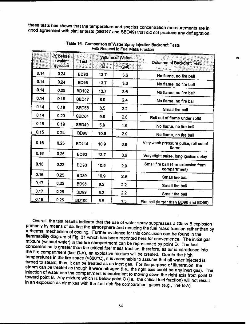
Ulf?teStS h3S Sh°lTthat the temPerature and species concentration measurements are in good agreement with s.milar tests (SBD47 and SBD49) that did not produce any deflagration.
Il
Table 16. Comparison of Water Spray Injection Backdraft Tests with Respect to Fuel Mass Fraction
h Y, before
^■■watervr Injection
^TSstv! JVölwne of Water . |
(U ISSo^' Outcome of Backdraft Test
I 0.14 0.24 BD93 13.7 3.6 No flame, no fire ball 0.14 0.24 BD95 13.7 3.6 No flame, no fire ball 0.14 0.25 BD102 13.7 3.6 No flame, no fire ball 0.14 0.19 SBD47 8.9 2.4 No flame, no fire ball 0.14 0.19 SBD58 8.5 2.2 Small fire ball 0.14 0.20 SBD64 9.8 2.6 Roll out of flame under soffit 0.15 0.19 SBD49 5.9 1.6 No flame, no fire ball 0.15 0.24 BD96 10.9 2.9 No flame, no fire ball
0.16 0.25 BD114 10.9 2.9 Very weak pressure pulse, roll out of flame
0.16 025 BD92 13.7 3.6 Very slight pulse, long ignition delay
0.16 022 BD90 10.9 2.9 Small fire ball (4 m extension from compartment)
0.16 025 BD89 10.9 2.9 Small fire ball 0.17 025 BD98 8.2 2.2 Small fire ball 0.17 0.25 BD99 8.2 22 Small fire ball 0.19 0.25 I BD100 5.5 1.5 Fire ball (larger than BD98 and BD99)
Overall, the test results indicate that the use of water spray suppresses a Class B explosion
r«ÜÜ3Y m!fnS °f diiUtin9 th6 atmosPhere and reducing the fuel mass fraction rather than by I.™S-r!?,aniSm ?ft.
coolin9- Furtner eviden<* for this conclusion can be found in the mIZfr ^h ,9raT ° F,Q- 31 Which haS been rePrinted here «* convenience. The initial gas m.xture (without water) in the fire compartment can be represented by point D The fuel
^"SliS.'iS^*!?^ CritiCa'fUe'maSS fracti0n: therefore, as air is introduced into the fire compartment (l.ne D-A), an explosive mixture will be created. Due to the hioh
S'ST^.^ ^V^! (>30°°C)'!t iS reasonable to assume that all water ir?jected is s^am can beTriltl8, * T bV?atod 3S ™ '"** 9aS" For the PurP0Se of "'^ration, the JES^Ü 1 fuS th0U9h rt Were nitr0gen (ie- the n9ht axis could be any inert gas). The l?lr A1"'0 *S comPart
ument iS equiva,ent t0 movin9 down ^e right axis from point D
n^n iTin A y m,XtUre "S*iS bel°W P0int C (ie- tne critical fuel fraction) will not result in an explosion as a.r mixes with the fuel-rich fire compartment gases (e g line B-A)
84
ninPnf SSX?V °f waterJ^ Section «n be seen in Fig. 33. This Figure shows two plots of the vertically averaged temperatures within the fire space for a test with and a test without water injection. The upper and lower plots represent the temperatures measured at locations 3-16-2 and 3-17-1, respectively, for tests SBD46 and SBD47. There is very good
2ZTS& ^IV!**}*"!^™ Pr0files °f b0th tests- The raPid rise in the temperature at about 1250 s for the test without water is a result of the backdraft explosion. As noted on the Figure, this thermal spike occurs after the door is opened. The test with water injection did not result in a backdraft explosion as evidenced by the absence of a temperature rise after the door was opened. The data illustrate the minor thermal affect water injection had on the fire space •I™ ll £". f a J°°C temPerature difference before the door was opened between the test
Tpin^lt^Z I™UX waterinJe??J. (••••.the temperature at the times denoted with arrows %2L H!L1? ^ S6f",n F,!?' ? f°r the test with water injection-the temperature in the fire space decreased relatively quickly dunng the time of water injection from 1205s to 1265s However, within the 60s between securing the water injection and opening the fire door the average temperature increased about 40°C, such that it was equivalent to the average' temperature in the fire space for the similar test without water injection. Therefore, these tests r* *??* th®re was a minimal 9as cooling effect due to the water injection. As a matter of fact the bulkhead temperature measurements for the tests shown in Fig. 33 indicate equivalent or ' even slightly higher temperatures for the test with water addition.
IT Ttle ueSuU tha!water injection caused a minimal thermal effect is further illustrated in Table 17 which shows the average fire compartment temperature for similar tests with and without water injection for tests in which water prevented a backdraft explosion. The temperatures presented represent a 10 second average of both thermocouple trees within the fire space prior
!J,v ^?0r be,nQ °pened- ln 9eneral'the temperature decreased about 35°C due to water addition Of more importance is the fact that even with water injection, the fire space temperatures were typically greater than 300°C. The autoignition temperature for diesel fuel
™orf!Jaaf ™ !o«o??OOC Since the temPerat"re for similar fuels, JP5 and kerosene, are
Z22S f If ?. C' resPect,ve|y- Therefore, all the tests with water injection had ETX S^PJ?n!nlte!flperature8 9reater than the autoj9nition temperature (AIT) for the fuel. The fact that alt teste had temperatures greater than the AIT and only tests with fuel mass fractions of 0.15 or less resulted in no explosion, indicate that the use of water injection
hS^^^^^^ Prim,arily by meanS °f diluting the atmosPh*re and reducing the fmTnl IS !r ?an *? C0°"ng the SpaCe- This conclusion may seem counter-intuitive
to many fire fighters who have been taught to fight a fire by knocking down the overhead
SÄT Z fllTr^l "T"'the discussion Plains to preventing explosions, not fire fighting. In fighbng a fire, it is advantageous to reduce the overhead gas temperature in order to reduce radiant feedback to the fuel source. This tactic will aid in controlling and
™SS2 r,e ln •9eneral' a greater reduction in the gas temperature will lead to greater «s lDl*u^r^,niT,Z,n9 i{S, T- WAh reSpeCt t0 exp,0sion Prevention in th^ tests, the Ef^i P K P e!entS an 0n/off sw,tch which eitner allows a backdraft to occur if the gas temperature is above the AIT or inhibits the backdraft if the gas temperature is below the AIT
85
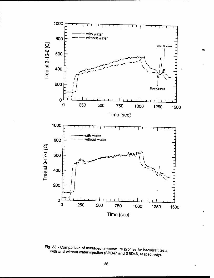
IUUU
_
~r-r ' 1 ' ' ' ' | ' ' ' ' | ' ' T ' | ' ' ' ' | ' ' '
with water
T-
800 — — without water -
o - Door Opened
-
CM - i
CO 600 — — Y— ^^~^A A 1
CO .
to CO CD
400 ' —
1- //
1 ■■ V- - ""
200 -
0
// Door Opened
,'Z ZJ
J i i 1 1 ' ' M 1 1 1 I 1 I'I . . . 1 , . , , . -L_i
0 250 500 750 1000 1250 1500
Time [sec]
1000
800
Ü
I I I 1 I I I I" ' I ' ' ■ ' I ' ' ' ' I I I I I I I 1 I I
with water — without water
r^. 600 - i
CO
CTJ CD CD
400
200
0 0
1 ' ' ' ■ ' ' ' ■ ' ' ' ' ' ' ■ ■ ■ i 1 ■ ■ ■ ■ | ,
250 500 750 1000 1250 1500
Time [sec]
Fig. 33 - Comparison of averaged temperature profiles for backdraft t»«e with and wrthout water injection (SBD47 andSBD46 reSpfc«vely)
86
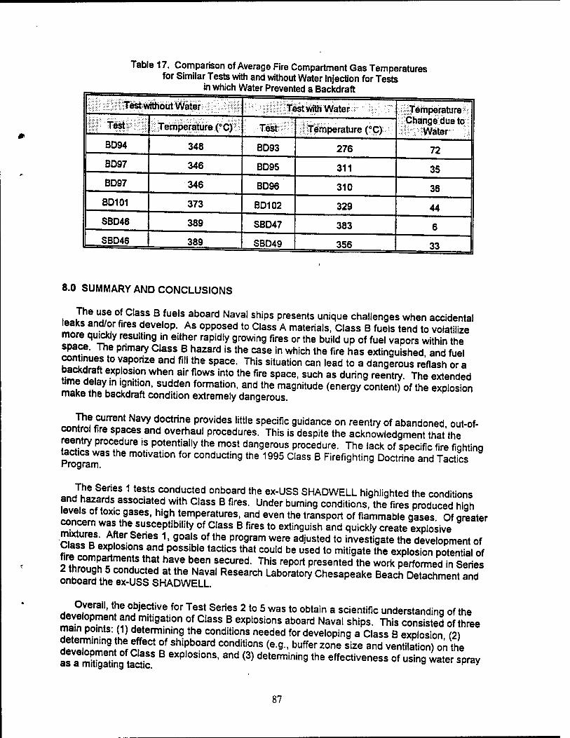
Table 17. Comparison of Average Fire Compartment Gas Temperatures for Similar Tests with and without Water Injection for Tests
in which Water Prevented a Backdraft
Test without Water Test with Water Temperature Change due to
Water III TeSt:-;::;:::: Temperature (°CJ Test Temperature (aC)
BD94 348 BD93 276 72 BD97 346 BD95 311 35 BD97 346 BD96 310 36
BD101 373 BO102 329 44 SBD46 389 SBD47 383 6 SBD46 389 SBD49 356 33
8.0 SUMMARY AND CONCLUSIONS
The use of Class B fuels aboard Naval ships presents unique challenges when accidental teaks and/or fires develop. As opposed to Class A materials, Class B fuels tend to volatilize more quickly resulting in either rapidly growing fires or the build up of fuel vapors within the space. The pnmary Class B hazard is the case in which the fire has extinguished and fuel continues to vaporize and fill the space. This situation can lead to a dangerous reflash or a «!r?f exp.,os,on when air flows int0 the f|re space, such as during reentry. The extended time delay in ignition, sudden formation, and the magnitude (energy content) of the explosion make the backdraft condition extremely dangerous.
The current Navy doctrine provides little specific guidance on reentry of abandoned out-of- control fire spaces and overhaul procedures. This is despite the acknowledgment that'the reentry procedure is potentially the most dangerous procedure. The lack of specific fire fighting tactics was the motivation for conducting the 1995 Class B Firefighting Doctrine and Tactics rrogram.
o« J?6 SeTeS 1 teStS conducted onboard the ex-USS SHADWELL highlighted the conditions and hazards associated with Class B fires. Under burning conditions, the fires produced high levels of toxic gases, high temperatures, and even the transport of flammable gases. Of greater concern was the susceptibility of Class B fires to extinguish and quickly create explosive
Sf?" i 6r J' 9°alS 0f the pr09ram were adJusted t0 investigate the development of Sf^L^monT^3"^053?'6 taCtiCS that COuld be used t0 miti9ate the exP'°*ion potential of 2ThST^nnH ♦ al hfI6 bMen ?tCured- This report Presen*d the work performed in Series
oÄ^ÄiSS^Research Laborato*Chesapeake Beach Detachment and
Hnv2.?ral1' \he °bjec!ive for Test Series 2 to 5 was to obtain a scientific understanding of the development and mitigation of Class B explosions aboard Naval ships. This consisted of three main points: (1) determining the conditions needed for developing a Class B explosion (2)
deSri M rfeCt °f shipboard conditions (e9- buffer zone size and ventilation) on the
tUTSSSSSS! 6XP °nS' 3nd <3) determinin9 the effeCtiveness of usi"9 water spray
87
In general, the test series were successful in
2.
3.
4.
^oZ%t:^TPTOdu^e Class B fire test scenario which resu,ted in
zoTfofSasI BhfireasCtiVe deSm°kin9 ^ "'* ^^ ^^ °f the buffer
Showing that securing ventilation and closing boundaries had no mitigating effect on the Class B explosions for buffer zone to fire space volume rat^s ofu I7 o"
Showing that decreasing the size of the buffer zone increased the intensity of a Class B explosion originating from within the fire space, *
5" BheSilnai SeCU ♦n9 ^Uff6r 20ne boundaries 'creased the intensity of a Class B explosion ongmating from within the fire space,
6. Showing that explosion intensity is more dependant on buffer zone boundary conditions rather than buffer zone ventilation, oounaary
?" C.rsaBnfNo a2 di'Lrfuir30^"5 °f °-16 °r hi9her are needed for the nation of
Srcem oxygen? exp,os,ons ,n ni9h|y v^ated environments (less than 2
8- ssrssrs: ras a miti9ating tactic * -«- 9.
?rimoH, L 9 th3t th!,USe 0f water sPrav suppresses a Class B explosion pnmanly by means of diluting the atmosphere and reducing the fuel mass fract.on rather than by a thermal mechanism of cooling
9.0 RECOMMENDATIONS
This study of Class B fires aboard Naval ships has identified several k«*v naramo^r«,
instrumentation that can accu^ m^ & cS 7"^^^^ deVe'°Pin9
concentration. These measurements would prov'del'efigh e^s ?he nfo^^n^ TST „ a pivotal assessment of the potential hazard of reemSÄ
The program has also shown that buffer zones of Cla« R fir« M„ ^ * , ... . ^
Sne^l??hL rng n0t JUSt thu buffer 20ne but the fire sPace- Particularly for main ^^SSHTl ZOne °an be Vented directly t0 weathen This Procedure should be combined with water spray injection into the fire space. The water spray will serve two purposes. As demonstrated in this test program, water spray can be used to mitiqate the
ÜMEÜSL £ ^ ^K^0" °f St6am ^ be used as -SÄXÄn to ZTJS^S 9 °4
w^ther. Otherwise, to successfully ventilate a fire space, make-up air is
bXoSed ' CinQ 3irint°the Space iSthe ha2ardous Procedure*»** isWo
«h,^nin!COn2menda!i0n!° Ventilate the f,re space is not intended t0 Preclude the current
iSE*S*E^ B fires-However-U is "»*»«t0 be a more 555 Towf i?S 1 IT *» «entonng and overhauling the fire space than that stated in NSTM ™LI^a L f ' SpeC,fic reentry tactics need t0 be defined and tested. Based on the success of the water spray injection technique, it is recommended that the effectiveness of an
of estabhshing a sheet of water across a hatch or door via fixed flat spray nozzles It is
pSteSontef fiefiaS^h COmbination with sP.rayin9 water into the space will provide adequate SS^aSll^ fighters by suppress.ng or m.tigating explosions and dangerous reflashes Alternate tactics may .nclude the use of smoke curtains at the access to the fire space However, this may not always be practical due to geometry and space JmteSls
As part of the study to investigate appropriate ventilation and reentry tactics the size and
*wZz?^zzzfire sKprshou,d be considered-The back*aft -"" 5FSSL e«tosive Lndftf™ T W?Ch 3 !PaCe iS VentHated impacts the Probability * creating an *Z^7%lSL irnCe,rta,n Whelher the miti9ating effect observed by Fleischmann with S^tiZ^^JT*compared t0 a ,ong slot is due t0 a reduction in size or due t0 the
fuekn^ oases Ind IPXHT ,SSU6S Vthe entrainment and the mixing processes of the
10.0 REFERENCES
1 GafD^^L^lf' DiT-,,!VI,,if"!?' FW- 3nd Scheffey' JL- "Evaluation of Flammable Gas Detection Systems for Use to Determine the Reignition Potential in a Ship Machinery Space," NRL Ltr Rpt Ser 6180/0513.2, 21 August 1995.
2' uS?A"v^w ^I?m Report Summafy of Fadings, Informal Fire Investigation, USS MIDWAY (CV 41)," NAVSEA Ltr Rpt 56Y5/142, 1 May 1991.
^ihÄTf^"-03'^3""31, NAVSEA S9086-S3-STM-010 Chapter 555, »Shipboard SJ 2ht,n?' Rev,s,on 1. w'th Change A dated 1 August 1994, ACN 1/B dated 25 October 1994, and ACN2/B dated 17 May 1995. "ouaiea^o
rSSL^Li ^!I;arnSoRW- Peatr0SS' MJ" and Farley- JP- "1995 Class B Firefighting Doctnne and Tactics: Series 1 Report," NRL Ltr Rpt Ser 6180/0060.1, 18 March 1996
Williams, F.W, Beyler, C.L., and Gottuk, D.T., "1993 Fleet Doctrine Evaluation
23 Ma^chP1994aSe "' ^^ B "" Dynamics Test Series-" NRL Ltr RP» Ser 6180/148.1,
Drysdale, D., An Introduction to Fire Dynamics, John Wiley and Sons, NY, 1985.
3.
4.
89
8. Fleischmann, CM., "Backdraft Phenomena," NIST-GCR-94-646, National Institute of Standards and Technology, Gaithersburg, MD, 1994.
9. Scheffey, J.L., Williams, F.W., Farley, J., Wong, J.T., and Toomey, T., "1993 Fleet Doctrine Evaluation (FDE) Workshop: Phase I - Class A fire/Vertical Attack," NRL Ltr Rpt Ser 6180/400.1, 27 October 1993.
10. Williams, F.W., Wong, J.T., Farley, J., Scheffey, J.L, and Toomey, T.A., "Results of Smoke and Heat Management Fuel/AFFF Mixtures," NRL Ltr (draft - December 1992).
11. Wong, J.T., Scheffey, J.L., Toomey, T.A., Havlovick, B.J., and Williams, F.W., "Findings of Portable Air Mover Tests on the ex-USS SHADWELL," NRL Memorandum Report 6180-02-7145, September 30, 1992.
90