Embed Size (px)
Citation preview
2017 Biomedical Engineering Summer Undergraduate Research Symposium
August 2, 2017
Scott Hall 4N200
8:30 AM to 1:00 PM
2
Biomedical Engineering at Carnegie Mellon University Biomedical engineering education at Carnegie Mellon reflects the belief that a top biomedical engineer must be deeply trained in both a traditional engineering practice and biomedical sciences. The unique additional major program leverages extensive collaborations with sister departments in the College of Engineering and with major medical institutions in Pittsburgh. This collaborative approach, combined with a rigorous engineering education, confers unique depth and breadth to the education of Biomedical Engineering graduates. Biomedical Engineering Summer Undergraduate Research Program (BME SURP) This program allows students to spend a ten-week period on a project that combines translational research and clinical exposure at a local medical center. Hundreds of students have participated in BME-SURP since its introduction in 1980. The experience have played a major role in helping students choose their career paths and obtain positions in industrial or academia. This program is supported by grants from the CMU College of Engineering and Merck & Co., Inc. Carnegie Heart Program The Carnegie Heart Program is a collaborative effort between the Biomedical Engineering Department at Carnegie Mellon University and the Allegheny Health Network. The purpose of this program is to develop biomedical engineers who can apply their education toward new technologies for clinical cardiovascular medicine. In addition to students' experience in a laboratory setting, students will shadow cardiovascular clinicians at Allegheny General Hospital one day every two weeks. This program is supported through a grant from the American Heart Association.

3
Presentation Schedule
8:30 AM: Continental Breakfast 9:00 AM: Shridhar Singh (BME SURP) 9:20 AM: Alexander Noring (BME SURP) 9:40 AM: Madeleine Anderson and Chanel Jhin (BME SURP) 10:00 AM: Eileen Ge (Carnegie Heart) 10:20 AM to 10:40 AM BREAK 10:40 AM: Kitty (Yilin) Yang (Carnegie Heart) 11:00 AM: Natsuha Omori (Carnegie Heart) 11:20 AM: Berk Sahin (Carnegie Heart) 11:40 AM: Matt Kubala (Carnegie Heart) 12:00 PM to 1:00 PM: Lunch and cake!

Shridhar Singh
Introduction Skin cancers including melanoma account for nearly as many annual cases as all other cancers combined. An estimated 87,100 new cases of skin cancer will be diagnosed in 2017. Initial diagnosis of melanoma utilizes a dermatoscope to produce a magnified image of a suspicious mole growth, allowing the doctor to visually evaluate the growth based on color and shape. Definitive diagnosis entails an invasive tissue biopsy of the suspicious mole growth in addition to surrounding skin. Pathologists then analyze the excised samples to make a diagnosis. The current framework for melanoma diagnosis is invasive and time consuming. However, with an appropriate technique for imaging directly on a patient’s skin, a machine learning algorithm can be trained to make a noninvasive diagnosis of skin cancer. Such technology would guide surgeons in excising smaller regions of skin and eventually eliminate the need for excision altogether, reducing healthcare costs and enabling more rapid diagnoses. Dark-field imaging is a technique that enhances contrast in unstained samples by excluding unscattered light from the image, allowing skin to be visualized directly on patients. The Braedius CytoCam is a commercially available imaging device that utilizes dark-field technology and green LEDs to visualize subsurface vascular structure. In this study, we seek to extend the capabilities of the CytoCam to imaging melanoma sites.
Materials and Methods In this study, we use the CytoCam to image melanoma sites at 80x magnification. We modified the CytoCam by adding a ring of near-infrared LEDs (NIR) to image structures different from those visible using green LEDs. We imaged melanoma sites directly on patients’ skin in the operating room prior to surgery using both NIR and green LEDs. To evaluate the clinical potential of these images, we will image excised skin samples using the CytoCam then produce 3D images of the same sites. A procedure for constructing 3D images was developed using serial histology sections of excised skin. The sections are cut from extracted skin samples at 5 microns using a Leica microtome. While histology sections are conventionally taken as the vertical cross section of tissue, in this study we section transversely along the surface of the skin, mimicking the top-down point of view of the CytoCam. The sections are stained using a standard H&E staining protocol which requires xylene, 95% and 100% ethanol, clearing reagent, bluing reagent, and the hematoxylin and eosin stains, all procured from ThermoFisher. Microscopy images of the H&E stained-slides are aligned using the StackReg plugin in ImageJ, and the resulting image stacks are used to construct 3D images using 3D Slicer 4.1.1 (Harvard SPL, Boston, MA, USA).
Results While green LEDs image subsurface vascular structure, we find that NIR produces images of surface topography. The CytoCam images reveal fundamentally different skin structures and patterns than those revealed by dermatoscope and histology, which impacts the CytoCam’s potential clinical application in two key ways. First, the Cytocam images cannot support the standard method for identifying suspicious mole growths from dermatoscope images because this method requires color images with the entire mole site in the field of view. Second, the CytoCam images do not provide any information about the depth of melanoma growth that histology provides. A machine learning algorithm trained on CytoCam images would need to recognize novel features that distinguish melanomas from normal skin. We find that the CytoCam images (especially NIR) reveal surface patterns that differ between normal and pathological skin sites, potentially revealing cancer margins. The skin is rougher and darker on melanoma sites. These surface patterns will need to be verified using 3D reconstructions of transverse sections of the same regions. The 3D images produced thus far allow us to view the surface of skin with high resolution like the CytoCam in addition to providing information about the depth of surface features. A comparison of CytoCam and 3D images will help to identify the structures revealed by the Cytocam and indicate the feasibility of developing machine learning algorithms to classify these images.
Conclusions NIR LEDs allow the CytoCam to image skin surface topography. The CytoCam images reveal surface patterns that differ between normal and pathological skin. These differences are not currently used to diagnose melanoma using traditional methods, so the nature of these differences is not understood in anatomical terms. A comparison with 3D histology images will allow us correspond features in CytoCam images with features recognizable to physicians. Identification of melanoma features will inform the development of machine learning algorithms that can diagnose melanoma.
Figure 1: Interface between melanoma (right) and normal skin (left) imaged using NIR.

AlexNoring ANovelApproachtoLongTermSampling
Introduction: A Lab-on-a-chip (LOC) is a device that integrates various laboratory functions into a single automated circuit. They are particularly useful for performing chemical assays, and have many advantages over traditional laboratory procedures. LOCs are typically contained on chips that are no more than a few square centimeters. As such, they only use microliters of fluid resulting in lower reagent costs, less exposure to hazards, smaller sample sizes and less waste. Additionally, they can be mass produced to drive lab costs down. They have the potential to revolutionize diagnostic chemistry, but have yet to experience widespread use in hospitals. Chips have already been developed that can assay different biomarkers such as endosomes, neurotransmitters, and proteins.
We have developed a microfluidic device that is designed to promote the clinical use of LOC assays. The device automatically collects and stores 85 microliter samples of urine when connected to a patient’s catheter, providing an easy way to obtain samples for testing various biomarkers. Furthermore, the system collects samples for 24 hours allowing doctors to observe trends in biomarker levels. These trends will be studied in relation to the patients’ ailments and eventually be used to improve diagnosis. One important aspect of this device is its surface chemistry. The samples are separated by a short segment of fluorocarbon to prevent mixing. The effectiveness of the fluorocarbon barrier is crucial to ensuring trends can be seen. The interactions between the tubing wall, the samples, and the fluorocarbon need to satisfy three conditions. First, the fluorocarbon phase needs to stay together. Second, there needs to be minimal cross contamination between samples. Third, there needs to be minimal protein adsorption from the urine onto the tube.
Materials and Methods: A pump moves urine from a patient’s Foley catheter line toward a Y-connector. The samples enter a 6m length of Teflon (FEP) tubing where they will be stored. When a sample has reached the desired size of 85 microliters a fluorocarbon “plug” is injected through the other side of the Y-connector. Neither aqueous nor lipid soluble molecules are soluble in fluorocarbon, so the plug acts as a barrier between samples. Then the FEP tubing enters a custom refrigerator where samples sit until ready to be tested.
A variety of coatings (FEP, albumin (BSA), polyvinyl alcohol (PVOH), polydopamine (PDA), PDA-sulfobetain (SB), PVOH - polySB), fluorocarbons (FC-43, FC-770, FC-84, FC-75), and surfactants (FS-3100, FS-65) were tested for their amount of cross contamination between samples. To determine the amount of contamination sets of positive and negative samples, separated by a plug, were pumped through a tube. The positive samples contained a known concentration of fluorescein (yellow) while the negative samples only contained phosphate buffered saline (colorless). The negative samples were collected and analyzed with UV-VIS to determine the concentration of fluorescein and volume of contamination.
Results and Discussion: The worst coating was the untreated FEP tubing. After a few samples, the plugs broke up allowing for large amounts of mixing between adjacent samples. Coating the walls with BSA fixed the problem of the plugs falling apart. However, it introduced leak back contamination. Small droplets of water from a leading sample would stick to the wall of the tubing as the plug passed over them and contaminate the following sample. After 6 meters, samples leaked an average of 0.54 microliters. The PVOH coating had an average leak back of 0.46 microliters. The PDA coating had a leak back of 8.4 microliters. All three of these coatings adsorb to the FEP due to the hydrophobic effect. Since fluorocarbons are hydrophobic, repeated use can cause the coatings to wash off. This problem was solved by using a smaller fluorocarbon FC-770 that is less hydrophobic. Leak back was found to increase when using smaller fluorocarbons. Using surfactants on BSA, PVOH, and PDA coatings did not affect leak back.
Conclusion: The PDA is very hydrophilic and will result is less protein fouling than the BSA or PVOH. However, it has significant leak back and we do not want to use a coating with that much contamination. The PVOH coating is preferred over the BSA coating because BSA can interfere with some assays if it washes off the wall. PVOH and FC-770 is currently the best choice.

The Use of Clinical Immersion for BME Design Project Ideas: A Pilot Study Carnegie Mellon Department of Biomedical Engineering
Chanel Jhin (Civil and Environmental Engineering) and Madeleine Anderson (Mechanical Engineering) Introduction: This pilot BME SURP (Summer Undergraduate Research Program) project focused on the identification of opportunities for ideas for BME Design projects through the method of clinical immersion. Doing research directly in the setting where medical devices are used connects the problems seen on the clinical side with the tools and innovation on the research and development side. The needs statements created with these clinical observations will be used by the Biomedical Engineering Design class to design and prototype new medical devices. Materials and Methods: Clinical immersion was used to identify problems in the clinical setting that could be solved with the design of new medical devices. Clinical immersion provides students a unique opportunity beyond the classroom to observe and learn first-hand from currently practicing physicians. Students will focus on developing needs statements while gaining a deeper understanding of the clinical setting. Researchers focused on problems or gaps in care that caused loss of time, excessive spending, or negative patient outcome. The observations and feedback from clinicians were analyzed, and background research was done to identify the needs statements that would make the most impact in a clinical setting. Each needs statement incorporated the problem, population, and outcome involved with that design solution. The clinical immersion and needs statement process was modeled after the Stanford textbook “BIODESIGN the Process of Innovating Medical Technologies.” For each needs statement a summary of the clinical need, background information, existing products, and recommended skills is compiled to give engineers and designers the information they need to choose the problem that fits their skills and interests. Results and Discussion: For the clinical immersion experience, three hospitals were visited—Allegheny General Hospital, West Penn Hospital, and the Children’s Institute. At Allegheny General Hospital, the Catheterization Lab, Cardiac MRI Dept., and the Nuclear Cardiology Dept. were visited. At West Penn Hospital, the Emergency Dept., the Anesthesiology Dept., and the General Surgery Dept. were visited. At the Children’s Institute, the Physical Therapy Dept., Occupational Therapy Dept., and the Speech Therapy Dept. were visited. Sample need statements included:
Needs Statements A way to access dry or small veins in difficult patients in order to speed up
procedures and improve patient outcomes
A way to protect doctors and nurses from radiation without having to wear poorly constructed or extremely heavy
lead vests
A method for diagnosing if and what type of stroke a person is having before they reach the hospital in order to give them
faster and more successful care A haptic feedback massaging device for physical therapists to protect their
hands from fatigue while still delivering the same results for patients
A way to improve the transition from a wheelchair to different surfaces to give
physically impaired patients more comfort and independence
A way to protect the teeth of patients during intubation procedures in order to
prevent tooth loss and breakage
Conclusions: In the clinical setting, cost efficiency and time are very important factors in the adoption and use of any medical technology for both the hospital system and for the patients residing in them. Solutions may already exist for a certain problem, but if they are too expensive or difficult to incorporate into the preexisting system then these technologies will be overlooked. In many cases. clinicians will overlook the shortcomings of a pre-existing procedure, because they have grown accustomed to the issues they deal with on a daily basis. Coming in with a fresh perspective and questioning the status quo can help identify underlying issues in any medical procedure or treatment. Acknowledgements: Dr. Conrad Zapanta and the Carnegie Mellon University, Department of Biomedical Engineering Dr. Cook and Dr. Edington, and all of the Doctors, Nurses, Technicians, and Hospital staff at Allegheny General Hospital, West Penn Hospital, and the Children’s Institute. References: Denend, Lyn. BIODESIGN The Process of Innovating Medical Technologies. Ed. Paul G. Yock, Stefanos Zenios,
Josh Makower, Todd J. Brinton, Uday N. Kumar, and F. T. Jay Watkins. Second ed. Cambridge: Cambridge UP, 2015. Print.
Eileen Ge Introduction: Laminin (LAM) 111 is a basement membrane protein vital to embryonic muscle development [1]. It has also been found to be key in treating dystrophic adult muscle tissue. When laminin-111 was added to myoblasts in vitro, it was observed that the myotubes were longer and had a greater myotube fusion index compared to fibronectin, a commonly used substrate for myoblasts. However, when the brand of laminin used in myotube generation was changed from Invitrogen to Beckton Dickinson (BD), it was observed that myotube formation decreased substantially [2]. This was unexpected, as both LAMs were >90% pure and were sourced from EHS mouse sarcoma, so the products were seemingly identical. BD Ultra Pure (>95% Pure) LAM and BD Laminin+Entactin (LAM+ENT) were also used to determine if laminin purity and entactin-1 presence, respectively, affected myotube formation. Mass spectrometry analysis revealed that the presence of perlecan in Invitrogen LAM and BD LAM+ENT, but not BD and BD UltraPure LAM, may be responsible for the difference in myotube formation. Discovering the differences between Invitrogen and BD LAM is key for engineering tissues in vitro, as understanding the exact effects of interactions between proteins is essential for creating engineered tissue. Materials and Methods: To confirm the presence of perlecan in LAM, sets of BD LAM lines (BD >90% pure, BD >95% Pure, BD LAM+ENT) were microcontact printed onto PDMS coated coverslips. A second set of INV LAM lines were also microcontact printed onto each coverslip perpendicular to the BD LAM lines. Coverslips were stained with an anti-laminin or anti-perlecan antibody, and BD LAMs were quantified for perlecan and laminin immunofluorescence relative to Invitrogen laminin. Sets of LAM lines were microcontact printed onto PDMS coverslips and seeded with C2C12 cells. After reaching confluence on LAM lines, cells were differentiated for six days before being stained for nuclei and myosin heavy chain. Myosin heavy chain area was used to quantify myotube formation. All samples were imaged for fluorescence using the Zeiss LSM 700 Confocal Microscope. Image processing and quantification was performed in ImageJ. One way ANOVAs were performed using SigmaPlot 11.0.
Results and Discussion: The perlecan immunofluorescence staining trials confirmed previous mass spectrometry results, demonstrating that both INV LAM and BD LAM+ENT have perlecan content while BD LAM >90% pure and >95% pure do not. BD LAM+ENT had a mean perlecan fluorescence relative to INV LAM of 0.27. Based on previous mass spectrometry data, this value was expected to be 0.27. The perlecan immunofluorescence data confirms the mass spectrometry results. Interestingly, when BD LAM+ENT’s LAM immunofluorescence was compared to that of INV LAM, BD LAM+ENT had a relative LAM fluorescence of 0.32. However, these two LAM types were microcontact printed at identical concentrations and found to have similar levels of LAM when analyzed via mass spectrometry. This difference in fluorescence could be caused by other trace proteins interfering with the binding between the LAM antibody and the LAM domains in BD LAM+ENT. BD LAM >90% pure and >95% pure were also quantified for relative LAM fluorescence and found to have similar fluorescence levels to INV LAM. It is possible that BD LAM+ENT’s low LAM fluorescence could be caused by difference processing compared to other BD LAMs. When C2C12 mouse myoblasts were seeded onto lines of LAM, it was observed that INV LAM best supported myotube formation, BD LAM+ENT and BD LAM >90% pure had some myotube formation, and BD LAM >95% pure least supported myotube formation. This confirms previous observations of the effect of LAM type on myotube formation, demonstrating that this trend is robust against lot-to-lot variations in manufacturing.
Conclusions: Perlecan immunofluorescence staining trials confirmed the presence and relative concentrations of perlecan in INV LAM and BD LAM+ENT in previous mass spectrometry results. In addition, the LAM immunofluorescence and myotube formation trials illustrate how processing differences in similar and even supposedly identical products can cause unpredictable inconsistencies in experiment results. Because most tissue engineering relies on commercially sourced proteins, an increase in transparency in manufacturer processing methods is desirable.In future studies, perlecan will be added into BD LAM >95% pure at INV LAM levels. C2C12s will be seeded onto perlecan enhanced LAM lines to demonstrate the effect of perlecan on myotube development in vitro. References: [1] Kühl, U. et al., Developmental Biology (1986) 117.2 628-635. [2] Duffy, R.M., Carnegie Mellon University Dissertations. (2016) Paper 689.

Non-invasive, Cuff-less Blood Pressure Estimation Using Near-Infrared Spectroscopy Yilin (Kitty) Yang
Department of Biomedical Engineering, Carnegie Mellon University Introduction:
Current blood pressure (BP) monitors mainly employ arm cuffs that occlude the arm and give a non-continuous, one-time reading of the systolic and diastolic BP. Although such technology is a conventional way to measure BP, it presents two major disadvantages: the discomfort due to cuff inflation and the inability to measure BP continuously. These disadvantages limit its clinical use where continuous BP measurements may be crucial.
This study proposed a non-invasive, cuff-less BP measurement method using near-infrared spectroscopy (NIRS), which related BP with total hemoglobin (HbT) concentration in tissue. A change in blood pressure is caused by a change in local blood volume following a heartbeat, which also leads to a change in total hemoglobin concentration (Δ[HbT]) in tissue. How quickly the vasculature reacts to pressure changes can be described by a time lag between the onset of blood pressure change and when Δ[HbT] is seen in vasculature. Therefore, by studying the time lag in terms of phase difference between BP and Δ[HbT], a fundamental relationship between the two measurements can be established and can be used in the development of a non-invasive, continuous BP measurement method. This study is trying to establish such a relationship between blood pressure and vascular blood volume changes at the frequency of respiration, as a function of body location, and posture (lying or sitting) changes.
In this study, near-infrared spectroscopy (NIRS), an optical method sensitive to hemodynamic changes in tissue, was used to measure the change in oxygenated hemoglobin (Δ[HbO2]) and deoxygenated hemoglobin concentration (Δ[Hb]) in arterioles, venules and capillaries. Due to HbO2 and Hb’s difference in absorptivity in the near-infrared range, Δ[HbO2] and Δ[Hb] can be obtained by measuring the absorbance of near-infrared light at 690nm and 830 nm in tissue and by applying the modified Beer-Lambert Law, which relates concentration to light absorbance and accounts for the scattering of light in tissue. Materials and Methods:
Δ[HbT] and BP were measured from 5 consenting volunteers. Oxiplex TS system (ISS Medical) was a NIRS system used to measure the absorbance of light at 630 nm and 890 nm by HbO2 and Hb. Four optical fiber probes were each placed on the subject’s forehead, upper left arm, lower left arm and left leg. CNAP blood pressure monitor (CNSystems) was attached to the subject’s right arm and right hand fingers for continuous BP measurements. A respiration belt was wrapped around the subject’s chest and a pulse oximeter was clipped onto the subject’s left hand finger. The subject was asked to perform 3 sets of 3-min paced breathing, each at 0.083 Hz, 0.1Hz and 0.125 Hz, followed by normal breathing. The protocol was first performed in supine position and then repeated while sitting upright. Results and Discussion:
This study showed that the phase difference between BP and Δ[HbT] measured at the same location on the body varied significantly among the five volunteers when all five were breathing at the same frequency and in the same posture. That is, the magnitude of time lag was dependent on the subjects being measured. However, for each individual subject, posture was found to affect the phase difference between BP and Δ[HbT]. When a subject breathed at a constant frequency, the time lag between BP and Δ[HbT] measured at a certain location differed depending on whether the subject was seated or in supine position. On the other hand, no decisive results were found regarding how the location where Δ[HbT] is measured and how the respiration frequency could affect the phase difference between BP and Δ[HbT]. Conclusions:
This study showed promising results that Δ[HbT] could reflect the change in BP and that the phase difference between Δ[HbT] and BP can be used in the development of a non-invasive, cuff-less method for BP measurement. It also suggested that the posture of the subject when BP was measured could influence the phase difference between Δ[HbT] and BP. However, more information is needed to reach conclusion on how the different postures affect the phase difference and whether the location where BP is measured and the respiration frequency also have impact on the phase difference. Acknowledgements:
This summer research is funded by the American Heart Association. The author would like to thank Dr. Jana Kainerstorfer and Alexander Ruesch for their help during the research.
Micro Scale Modeling of Blood Flow through Artificial Lung Natsuha Omori
Introduction: Currently 16 million patients are diagnosed with Chronic Obstructive Pulmonary Disease (COPD) in the United States1.This is the third leading cause of death in the US1, while only 2000 lung transplants are performed each year2. Artificial lungs can be utilized to bridge a patient a few weeks to months until a donor lung is available, but clot formation in these lungs prevent permanent support. Clot formation, generally occurring at the interface between blood and the fiber bundle, causes flow occlusion and reduced gas exchange. The motivation of this project, therefore, was to create a microfluidic device to model blood flow through a fiber bundle. Micro scale modeling allows the study of correlations between bundle geometry, flow velocity, and anticoagulation levels and clot formation for the fibers, and can then be developed to enable modeling of clot formation in full-scale artificial lungs.
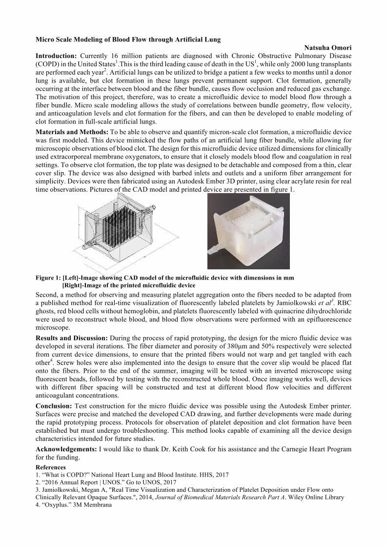
Materials and Methods: To be able to observe and quantify micron-scale clot formation, a microfluidic device was first modeled. This device mimicked the flow paths of an artificial lung fiber bundle, while allowing for microscopic observations of blood clot. The design for this microfluidic device utilized dimensions for clinically used extracorporeal membrane oxygenators, to ensure that it closely models blood flow and coagulation in real settings. To observe clot formation, the top plate was designed to be detachable and composed from a thin, clear cover slip. The device was also designed with barbed inlets and outlets and a uniform fiber arrangement for simplicity. Devices were then fabricated using an Autodesk Ember 3D printer, using clear acrylate resin for real time observations. Pictures of the CAD model and printed device are presented in figure 1.
Figure 1: [Left]-Image showing CAD model of the microfluidic device with dimensions in mm
[Right]-Image of the printed microfluidic device
Second, a method for observing and measuring platelet aggregation onto the fibers needed to be adapted from a published method for real-time visualization of fluorescently labeled platelets by Jamiolkowski et al3. RBC ghosts, red blood cells without hemoglobin, and platelets fluorescently labeled with quinacrine dihydrochloride were used to reconstruct whole blood, and blood flow observations were performed with an epifluorescence microscope.
Results and Discussion: During the process of rapid prototyping, the design for the micro fluidic device was developed in several iterations. The fiber diameter and porosity of 380µm and 50% respectively were selected from current device dimensions, to ensure that the printed fibers would not warp and get tangled with each other4. Screw holes were also implemented into the design to ensure that the cover slip would be placed flat onto the fibers. Prior to the end of the summer, imaging will be tested with an inverted microscope using fluorescent beads, followed by testing with the reconstructed whole blood. Once imaging works well, devices with different fiber spacing will be constructed and test at different blood flow velocities and different anticoagulant concentrations.
Conclusion: Test construction for the micro fluidic device was possible using the Autodesk Ember printer. Surfaces were precise and matched the developed CAD drawing, and further developments were made during the rapid prototyping process. Protocols for observation of platelet deposition and clot formation have been established but must undergo troubleshooting. This method looks capable of examining all the device design characteristics intended for future studies.
Acknowledgements: I would like to thank Dr. Keith Cook for his assistance and the Carnegie Heart Program for the funding.
References 1. “What is COPD?” National Heart Lung and Blood Institute. HHS, 2017 2. “2016 Annual Report | UNOS.” Go to UNOS, 2017 3. Jamiolkowski, Megan A, "Real Time Visualization and Characterization of Platelet Deposition under Flow onto Clinically Relevant Opaque Surfaces.", 2014, Journal of Biomedical Materials Research Part A. Wiley Online Library 4. “Oxyplus.” 3M Membrana

A Modeling Tool for the Design of Mechanically Stiff Periodic Cardiac Nanosensors
Rebecca E. Taylor, Berk Sahin
Introduction
DNA origami is the folding of a single-stranded DNA into 2D and 3D double stranded nanostructures.3,4
This is
achieved by taking advantage of the specific complementary base pairs between the strands. Using single-
stranded tiles (SSTs), it is possible to create micron-scale period structures like nanoribbons and nanotubes with
programmed circumferences. 5 These nanostructures formed by DNA origami have various applications in drug
delivery, biosensing and biomimetics.1,2
The Taylor Lab at Carnegie Mellon University is investigating DNA
origami nanosensors for the measurement of strains in cardiac cell cultures, and needs to develop new designs for
creating helical nanotubes with tunable stiffness.
The aim of this project is to assist in that effort by developing strategies to make periodic nanosensors with
tunable bending stiffness. To do this, I am creating a physical modeling system that enables easy prototyping of
these periodic DNA nanostructures, and using this system to investigate alternate cross-section designs for stiff
nanotubes. First, this study aims to answer the question of how to model periodic structures such as DNA origami
using 3D printed models. Secondly, this study involves the theoretical calculation bending modulus in DNA
origami nanotubes, a necessary calculation for validating designs for mechanically stiff origami structures.
Materials and Methods
A CubePro Duo 3D printer was used to print the individual parts of the physical model while the parts were
designed through Solidworks 2016 software and converted into a printable format using the CubePro software.
The approach to modeling was creating and representing smaller sections of the DNA that can be attachable to
build up the whole staple and scaffold strands. The smaller sections corresponded to a part of DNA, and using an
iterative design methodology I investigated approaches for enabling the "polymerization" of small nucleotide
segments into long single- and double- stranded DNA. The constraints in the design process were the specifics of
DNA such as its length, curvature and base pairing while the others were limitations due to the printer.
Results and Discussion
An early prototype of the smaller section corresponding to a single base pair was obtained. The small sections
were about 20 mm in length and 12.5 mm in diameter and can be attached together to form a single stranded
oligonucleotide. Future work will be needed to base decoration and more bio-mimetic curvative. The limitations
of the CubePro 3D printer provided significant challenges, because an important output of this project is a design
that is easy to print on any 3D printer. Therefore, the design had to be robust for low-resolution printing and
optimized to require minimum supporting material. These manufacturing constraints and the inherent stiffness of
the printing material, polylactic acid (PLA), made this project much more challenging than initially anticipated.
Conclusions
The purpose of the study was to design a 3D printable physical model of a nanotube sensor for studying cardiac
strain. The result of this work is a prototype of a 3D-printable nucleotide system. This modeling system needs
further development to enable hybridization and construction of more complex geometries. A promising alternate
future direction would be to physically model DNA origami from parts that represent larger sections of a DNA,
possibly 21 or 42 base pairs. Also alternate printing materials could better mimic the elastic properties of DNA.
Acknowledgements
Many thanks to the Microsystems and Mechanobiology Lab (Paula Arambel, Mitchell Harmatz, Sriram Kumar,
Ying Liu, Mitchell Riek, and Rachel Sneeringer) for the wonderful conversations and guidance this summer.
References
[1] R.F. Hariadi, R.F. Sommese, A.S. Adhikari, R.E. Taylor, S. Sutton, J.A. Spudich, and S. Sivaramakrishnan.
Nature Nanotechnology, 10(8):696–700, 2015.
[2] Cathal J. Kearney, Christopher R. Lucas, Fergal J. O’Brien, and Carlos E. Castro. Advanced Materials,
28(27):5509–5524, 2016.
[3] P.W. K. Rothemund. Nature, 440(7082):297– 302, 2006.
[4] N. C. Seeman. Journal of Theoretical Biology,99(2):237–247, 1982.
[5] P. Yin, R. F. Hariadi, S. Sahu, H. M. T. Choi, S. H. Park, T. H. LaBean, and J. H. Reif. Science,
321(5890):824–826, 2008.
Matthew Kubala
Introduction According to the Centers for Disease Control and Prevention, approximately 610,000 people die from some form of heart disease in the United States every year. Heart disease is the leading cause of death in both men and women1. The estimated cost of heart disease over fifteen years (2015-2030) is over 8.5 billion dollars2. It is difficult to argue that heart disease isn’t a particularly pressing issue. There are some solutions and aids created, but they tend to have similar problems. Firstly, transplants are in limited supply. Approximately 3000 people in the United States are on the heart transplant list on any day while there are only 2000 donors available each year. Receiving a heart transplant can take numerous months3. Another option is a ventricular assist device. These devices tend to have two major problems: blood contacting surfaces and percutaneous drivelines. The blood contacting surfaces create possibly deadly blood clots that reduce the lifetime of the device, and the percutaneous driveline can lead to dangerous infections. To solve these problems, we are creating an extra-ventricular balloon pump (EVBP) that applies compressive forces around the surface of the heart to displace the blood and is powered by a hydraulic Muscle Energy Converter developed by Dr. Dennis Trumble. We are currently exploring various configurations of the EVBP to optimize the device and test various features effects. Materials and Methods: To answer these questions, various CAD programs are utilized to model and simulate these configurations. Firstly the devices are modeled using SolidWorks 2016 x64 according to starting specifications. Then, they are imported to ANSYS Workbench R17. Here materials are defined for each section based off of the current materials being explored: silicone rubber, NinjaTek NinjaFlex, Stratasys Tango Plus, and Stratasys Agilu30. Once materials are defined a static structural simulation is run to receive data on the stresses, displacement, and general motion of deformation of the device. For this simulation, a pressure is applied to the interior surfaces of the tubes of the device and a resisting pressure to simulate the heart is sometimes placed on the interior surfaces of the device. A methodology for volume analysis using Autodesk Simulation Mechanical is also being developed. These devices are then built using a Lulzbot 3D printer for bench testing. Other manufacturing methods are also being explored. Results and Discussion: Multiple variables were tested for effects and optimization. Most notably inflating pressure, number of tubes, material, degree of twist of the tubes, tapering, starting level of inflation, and type of seal were explored. Through these simulations, it was found that increased pressure, an increased starting level of inflation, and a tapered seal were positively related to inward displacement. Tapering, stiffer material, and a higher degree of twist were negatively related to inward displacement. Though, degree of twist and inward displacement were negatively related, it was also found that an increased degree of twist of tubes and torsion of the device were positively related. This would aid in volume displacement as well. These simulations are ongoing and more configurations and variables are being tested to create an optimized device. Conclusion: Through these simulations, it was found that features such as a degree of twist, higher numbers of tubes, tapered seals, and some starting level of inflation had a positive impact on displacing volume while large tapering of the tubes had a noticeable negative impact. These results will be used to better optimize the EVBP models physically created for bench testing so as to improve efficiency and will help optimize the device so that it can compress the heart with a minimum hydraulic volume. In the future, these features should be more specifically simulated and other types of manufacturing should be taken into account such as printing with multiple materials. Acknowledgments: I would like to acknowledge the tremendous assistance of Prof. Christopher D’Eramos, Dr. Dennis Trumble, Dr. Keith Cook, and Jooli Han. References: 1 “Heart Disease Facts.” Center for Disease Control and Prevention, August 10, 2015 https://www.cdc.gov/heartdisease/facts.htm 2 Mozaffarian D, Heart disease and stroke statistics— 2016 update: a report from the American Heart Association [published online ahead of print December 16, 2015]. Circulation. doi: 10.1161/CIR.0000000000000350 3 National Heart, Lung, and Blood Institute, “Heart Transplant.” NCBI, June11,2014.https://www.ncbi.nlm.nih.gov/pubmedhealth/PMH0063038/