Embed Size (px)
Citation preview

PAR
TS /
OPE
RAT
OR
'S M
AN
UA
L
MA
N 7
2072
0
MODELS:8223-00-01
22HP KOHLER TRUCKLOADER
8272-00-0127HP KOHLER TRUCKLOADER
REV
A 0
8-20
12
Shown with optional trailer.
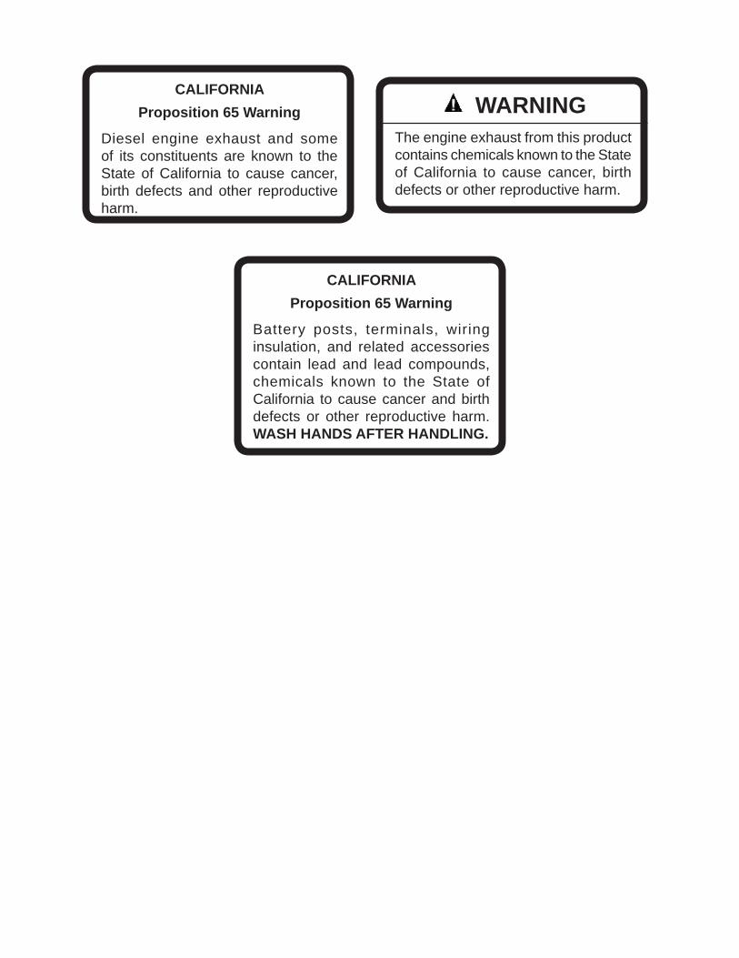
CALIFORNIAProposition 65 Warning
Diesel engine exhaust and some of its constituents are known to the State of California to cause cancer, birth defects and other reproductive harm.
WARNINGThe engine exhaust from this product contains chemicals known to the State of California to cause cancer, birth defects or other reproductive harm.
CALIFORNIAProposition 65 Warning
Battery posts, terminals, wiring insulation, and related accessories contain lead and lead compounds, chemicals known to the State of California to cause cancer and birth defects or other reproductive harm. WASH HANDS AFTER HANDLING.
1
TruckloaderIMPORTANT MESSAGE
On behalf of everyone at Little Wonder, we would like to thank you for your purchase of a Little Wonder Truckloader. This professional truckloader was designed to the highest standards to ensure many hours of uninterrupted service.
This machine comes with an Operators / Parts Manual. The useful life and good service you receive from this machine depends to a large extent on how well you read and understand this manual. Treat your machine properly, lubricate and adjust it as instructed, and it will give you many years of reliable service.
Your safe use of this Little Wonder product is one of our prime design objectives. Many safety features are built in, but we also rely on your good sense and care to achieve accident-free operation. For best protection, study the manual thoroughly. Learn the proper operation of all controls. Observe all safety precautions. Follow all instructions and warnings. Do not remove or defeat any safety features. Make sure those who operate this machine are as well informed and careful in its use as you are.
See a Little Wonder dealer for any service or parts needed. Little Wonder service ensures that you continue to receive the best results possible from Little Wonder products. You can trust Little Wonder replacement parts because they are manufactured with the same high precision and quality as the original parts.
Little Wonder designs and builds its equipment to serve many years in a safe and productive manner. For longest life, use this machine only as directed in the manuals, keep it in good repair and follow safety warnings and instructions. You'll always be glad you did.
Little Wonder1028 Street Rd.
Southampton, PA 18966-4217
08-2012
TABLE OF CONTENTS FIGURES PAGESAFETY .........................................................................................................................................................2-6LABELS .........................................................................................................................................................7-8SET-UP INSTRUCTIONS ............................................................................................................................9-15CONTROLS ....................................................................................................................................................16OPERATION ..............................................................................................................................................17-18TORQUE CHART / MAINTENANCE CHART ................................................................................................19MAINTENANCE / SERVICE ......................................................................................................................20-24PARTS SECTION ...........................................................................................................................................25HOSE ASSEMBLY .............................................. FIGURE 1 ...................................................................26, 27UNIT ASSEMBLY ................................................ FIGURE 2 ...................................................................28, 29WARRANTY ................................................................................................................................ BACKCOVER
2
TruckloaderSAFETY
NOTICE !!!Unauthorized modifications may present extreme safety hazards to operators and bystanders and could also result in product damage.
Little Wonder strongly warns against, rejects and disclaims any modifications, add-on accessories or product alterations that are not designed, developed, tested and approved by Little Wonder Engineering Department. Any Little Wonder product that is altered, modified or changed in any manner not specifically authorized after original manufacture–including the addition of “aftermarket” accessories or component parts not specifically approved by Little Wonder–will result in the Little Wonder warranty being voided.
Any and all liability for personal injury and/or property damage caused by any unauthorized modifications, add-on accessories or products not approved by Little Wonder will be considered the responsibility of the individual(s) or company designing and/or making such changes. Little Wonder will vigorously pursue full indemnification and costs from any party responsible for such unauthorized post-manufacture modifications and/or accessories should personal injury and/or property damage result.
MODEL NUMBER: This number appears on sales literature, technical manuals and price lists.
SERIAL NUMBER: This number appears only on your machine. It contains the model number followed consecutively by the serial number. Use this number when ordering parts or seeking warranty information.
This symbol means: ATTENTION! BECOME ALERT!
Your safety and the safety of others is involved.
Signal word definitions:The signal words below are used to identify levels of hazard seriousness. These words appear in this manual and on the safety labels attached to Little Wonder machines. For your safety and the safety of others, read and follow the information given with these signal words and/or the symbol shown above.
DANGER indicates an imminently hazardous situation which, if not avoided, WILL result in death or serious injury.
WARNING indicates a potentially hazardous situation which, if not avoided, COULD result in death or serious injury.
CAUTION indicates a potentially hazardous situation which, if not avoided, MAY result in minor or moderate injury. It may also be used to alert against unsafe practices or property damage.
CAUTION used without the safety alert symbol indicates a potentially hazardous situation which, if not avoided, MAY result in property damage
Schiller Grounds Care, Inc. 1028 Street RoadSouthampton, PA 18966 U.S.APhone: 215-357-5110Fax: 215-357-8045
MODEL NUMBER
SE
RIA
L N
UM
BE
R
3
TruckloaderSAFETY
Site preparation and circumstances - If Truckoader is mounted on a trailer, make
sure that the driver of the towing vehicle has the operator of the Truckloader in full view at all times.
- Check the area to be cleared of objects such as rocks, toys, wire or other debris that may be picked up or thrown by the machine.
- Be sure the area is clear of pets and people, especially young children. Never assume they will remain where you last saw them. Stop the machine if any enter the area.
- Use machine only in daylight or in good artificial light.
- Evaluate the terrain to determine how to safely perform the job. Only use accessories and at-tachments approved by the manufacturer.
PREPARING FOR SAFE OPERATION Operator preparation and trainingRead the Operation & SafetyManual- If an operator or mechanic
cannot read English, it is the owner's responsibility to explain this material to them. If any portion of this material is unclear, contact your factory representative for clarification.
- Decals regarding safety and/or unit operations have been placed on parts of the machine. Adhere to the warnings and instructions depicted in these decals. Replace any missing or damaged labels.
- Become familiar with the safe operation of the equipment, operator controls and safety signs. Know how to stop the engine and attachments quickly in an emergency. Do not operate or allow another person to operate this machine if there are any questions about safety.
- All operators and mechanics should be trained. The owner is responsible for training the users. Never attempt to use a machine that is damaged or has unauthorized modifications.
- Wear appropriate clothing, including gloves, Do not operate barefoot or wearing open sandals. Long hair, loose clothing or jewelry may get tangled in moving parts.
- Wear hearing protection. - Wear safety glasses.- Wear a dust mask to avoid breathing dust.- Never allow underage children, unskilled
or improperly trained people operate this equipment. Local regulations can restrict the age of the operator.
- Keep warning labels and this operator's manual legible and intact. Replacement labels and manuals are available from the factory.
- Do not operate machine while under the influence of drugs or alcohol.
- The owner/user can prevent and is responsible for accidents or injuries occurring to themselves, other people or property.
Machine preparation- Do not tamper with or defeat safety devices.
Keep guards, shields and interlock safety devices in place and in proper working condition. They are for your protection.
- Keep all fasteners such as nuts, bolts and pins well secured.
- Verify that machine and attachments, if any, are in good operating condition.
- Do not start machine until ready to use.
4
Truckloader
Interrupting operation- Before leaving the operator's position: - Move throttle to the SLOW position. - Shut off the engine and remove the key.- Move the throttle to the SLOW position, turn key
to the OFF position and wait till all moving parts have come to a complete stop.
- before refueling;- Move the throttle to the SLOW position, turn key
to the OFF position, wait till all moving parts have come to a complete stop and disconnect the spark plug wire(s) or remove the key:
- before clearing blockages or unclogging chute; - before checking, cleaning or working on the
machine; - after striking a foreign object. Inspect the
machine for damage and make repairs before restarting;
- if the machine begins to vibrate abnormally: shut off machine immediately. Inspect and make repairs as needed before restarting;
- except for repairs or adjustments as specifically noted, such as for carburetor adjustment, where the engine must be running. Keep hands and feet clear of moving parts in these circumstances.
- Allow the fan to come to a complete stop when stopping operation to clear blockages, unclog, inspect the machine, do maintenance or repair.
- Reduce the throttle setting to SLOW during engine shut-down. Turn the key to the OFF position.
SAFETY
OPERATION SAFETYIn general- Use extra care when loading or unloading the
Truckloader into a trailer or truck.- Slow down and use caution when making turns
and crossing roads and sidewalks. - Do not run the engine in an enclosed area where
dangerous carbon monoxide fumes can collect.- While operating the machine, maintain a safe
operating position, secure footing, and good balance at all times.
- Before operating, lower the discharge chute.- Keep a safe distance between two or more
operators when working together simultaneously.- Keep clear of the discharge opening at all times.
Never direct the discharge toward a bystander. Stop operation if someone approaches.
- Never leave a machine unattended. Always turn off engine, set throttle to SLOW, key is in OFF position, and fan has come to a complete stop.- Maintain machine according to manufacturer's schedule and instructions for maximum safety and best mowing results.
Starting- Start only according to instructions in this manual
or on the machine.- When starting the engine, make sure hands and
feet are clear of the chute.- Do not start the machine while standing in front
of the discharge chute or with the chute directed at someone.
- Do not change engine governor settings or overspeed the engine. Operating the engine at excessive speed can increase the hazard of personal injury.
5
TruckloaderSAFETY
MAINTENANCE SAFETYIn general
- Maintain machine according to manufacturer's schedule and instructions for maximum safety and best mowing results.
- Park supporting vehicle on level ground.- Maintain machine according to manufacturer's
schedule and instructions for maximum safety and best mowing results.
- Rotating Fan: Do not attempt to remove materi-als from intake or discharge when Shredding Truckloader is running or fan is still rotating.
- Never allow untrained personnel to service ma-chine.
- Adjust or repair only after the engine has been stopped and the fan has quit rotating.
- Inspect Truckloader components regularly. If worn, damaged or deteriorated, they may expose moving parts or allow objects to be thrown.
- Replace parts if worn, damaged or faulty. have repairs make by a qualified Little Wonder dealer or repairman. For best results, always replace with parts recommended by the manufacturer(s).
- Turn off engine, set throttle to SLOW position, turn ignition key to OFF position. Disconnect remove spark plug wire(s) before making any repairs. Disconnect the negative terminal first and the positive last. Reconnect positive first and negative last.
- Do not dismantle the machine without releasing or restraining forces which may cause parts to move suddenly.
- Provide adequate support, e.g. jack stands for lifted machine or parts if working beneath.
- Do not put hands or feet near or under rotating parts.
- Clean up spilled oil or fuel thoroughly.- Replace faulty mufflers.- To reduce fire hazards, keep the engine, muffler,
battery compartment and fuel storage area free of grass, leaves, debris buildup or grease.
Rotating Fan- Don't attempt to remove materi-
als from intake or discharge when unit is running or fan is rotating.
- Fan coasts after the engine is turned off.
- Only replace fan. Never straighten or weld them. - Keep other persons away from fan.- Caution should be used when clearing debris
from inside the housing. Gloves should be worn as sharp edges on the, talon ring, or in the debris may be present.
Fuel- Gasoline and diesel fuels
are flammable; gasoline vapors are explosive. Use extra care when handling.
- Store only in containers specifically designed for fuel.
- When refueling or checking fuel level: - Stop the engine and allow to cool; - Do not smoke; - Refuel outdoors only; - Use a funnel; - Do not overfill; - If fuel is spilled, do not attempt to start the
engine until the spill is cleaned up and vapors have cleared.
Sparks from static electricity can start fires or causeexplosions. Flowing fuel can generate static electricity. To prevent static electricity sparks:- Keep containers electrically grounded. Do not fill
containers in a vehicle or on a truck or trailer bed with a plastic liner. Fill containers on the ground away from the vehicle.
- When practical, remove gas powered equip-ment from the truck or trailer and refuel it on the ground. If equipment must be refueled on the truck or trailer, refuel from a portable container rather than a dispenser nozzle.
- Keep the dispenser nozzle in contact with the rim of the fuel tank or container opening until fueling is complete. Do not use a nozzle lock-open device.
- Replace caps on fuel cans and tanks securely.- If fuel is spilled on clothing change it immediately.
WARNING
WARNING
6
TruckloaderSAFETY
BATTERYBattery acid is caustic and fumes are explosive and can cause serious injury or death.To reduce the risk of personal injury when working near a bat-tery:- When working with battery
acid, use protective equipment such as, but not limited to, goggles, face shield, rubber gloves and apron.
- Avoid leaning over a battery.- Do not expose a battery to open flames or
sparks.- Be sure batteries with filler caps are properly
filled with fluid.- Do not allow battery acid to contact eyes or skin.
Flush any contacted area with water immediately and get medical help.
- Do not check for spark with spark plug or plug wire removed and grounded. Use and approved tester. Sparks can ignite fumes.
- Charge batteries in an open, well ventilated area, away from sparks and flames. Unplug charger before connecting or disconnecting from battery.
ENGINE- Don't run engine if there is an accumulation of
debris around the muffler, and cooling fins.- don't run engine while electrical system causes
spark outside the cylinder. - Don 't touch hot mufflers, cylinders or cooling fins
as contact ay cause serious burns.
STORAGE AND TRANSPORTATION- Stop the engine and allow to cool before storing.- Drain the fuel tank outdoors only. - Store fuel in an approved container in a cool, dry
place.- Keep the machine and fuel containers in a locked
storage place to prevent tampering and to keep children from playing with them.
- Do not store the machine or fuel container near heating appliances with an open flame such as a water heater or an appliance with a pilot light.
- Keep gasoline storage area free of grass, leaves and excessive grease to reduce fire hazard.
- Clean grass and debris from cutting units, drives, mufflers and engine to help prevent fires.
- When not in use store indoors in a sheltered area (a dry place) where it is not accessible to chil-dren. DO NOT store in a house. Keep throttle in SLOW position and ignition key in the OFF posi-tion.
JUMP STARTING1. Be sure the jumper cables are in good condition.
Turn off the ignition and all electrical accessories on both machines.
2. Position the machine with a good (charged) bat-tery next to but not touching the machine with the dead battery so jumper cables will reach.
3. When making cable connections: - make sure the clamps do not touch anywhere
except to intended metal parts, - Never connect a positive ("+" or red) terminal
to a negative ("–" or black) terminal. - Make sure the cables won't get caught in any
parts after the engines are started.4. Connect one end of the first jumper cable to the
positive terminal on one battery. Connect the other end to the positive terminal on the other battery.
5. Connect one end of the other cable to the negative terminal of the machine with a good (charged) battery. Make the final connection on the engine of the machine to be started, away from the battery.
6. Start the vehicle with the good battery, then the machine with the discharged battery.
7. Remove the cables in the exact reverse order of installation. When removing each clamp, take care it does not touch any other metal parts while the other end remains attached.
WARNING
7
Truckloader
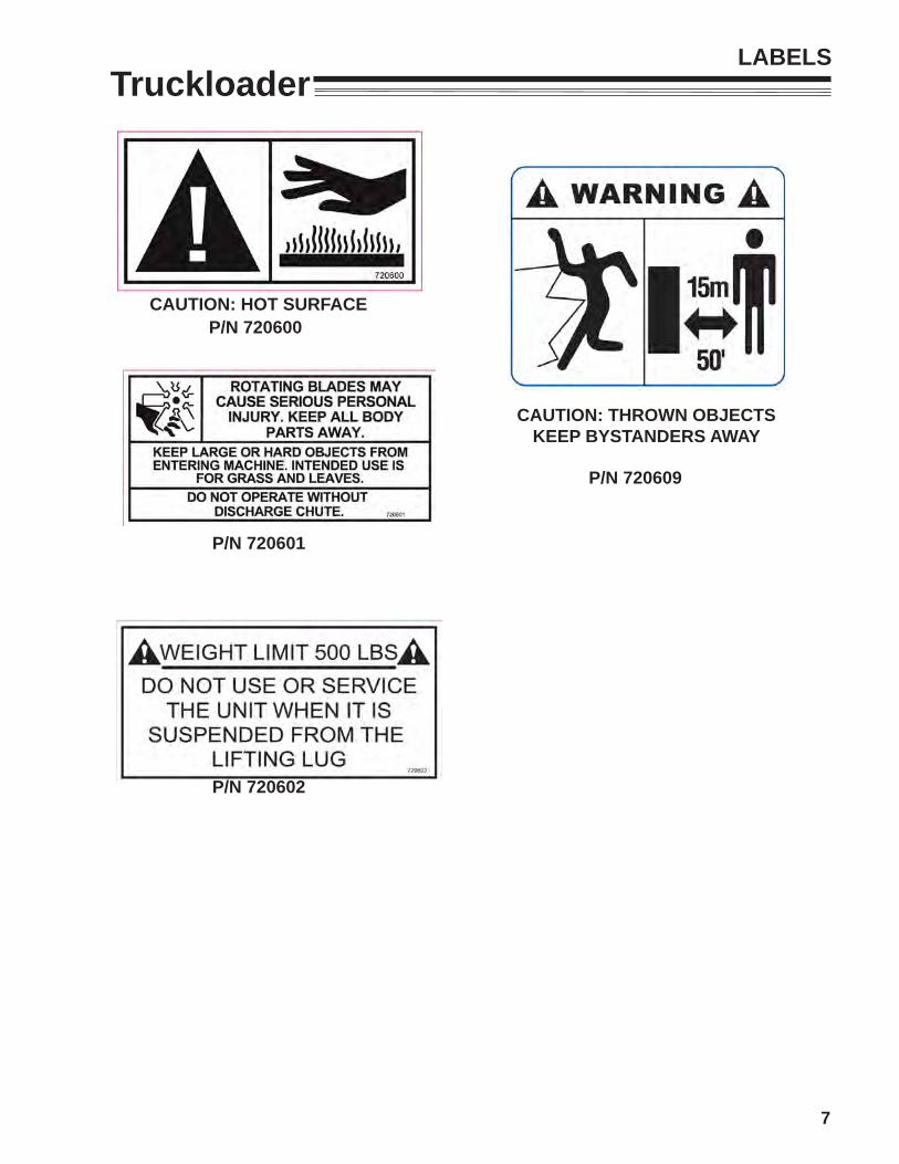
CAUTION: HOT SURFACEP/N 720600
P/N 720601
P/N 720602
CAUTION: THROWN OBJECTSKEEP BYSTANDERS AWAY
P/N 720609
LABELS
8
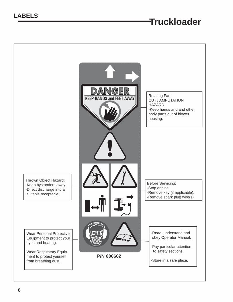
TruckloaderLABELS
Thrown Object Hazard:-Keep bystanders away.-Direct discharge into a suitable receptacle.
Wear Personal Protective Equipment to protect your eyes and hearing.
Wear Respiratory Equip-ment to protect yourself from breathing dust.
Rotating Fan:CUT / AMPUTATION HAZARD-Keep hands and and other body parts out of blower housing.
Before Servicing:-Stop engine.-Remove key (if applicable).-Remove spark plug wire(s).
-Read, understand and obey Operator Manual.
-Pay particular attention to safety sections.
-Store in a safe place.P/N 600602
9
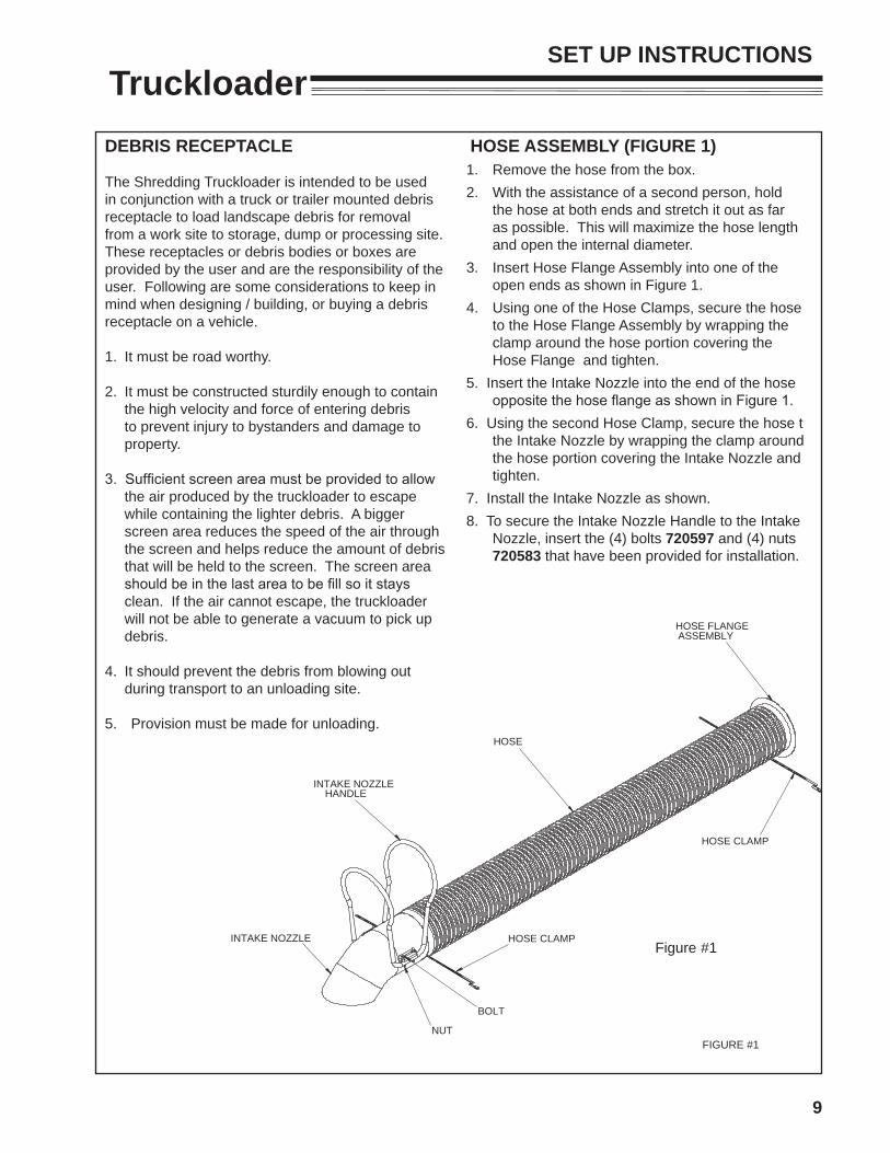
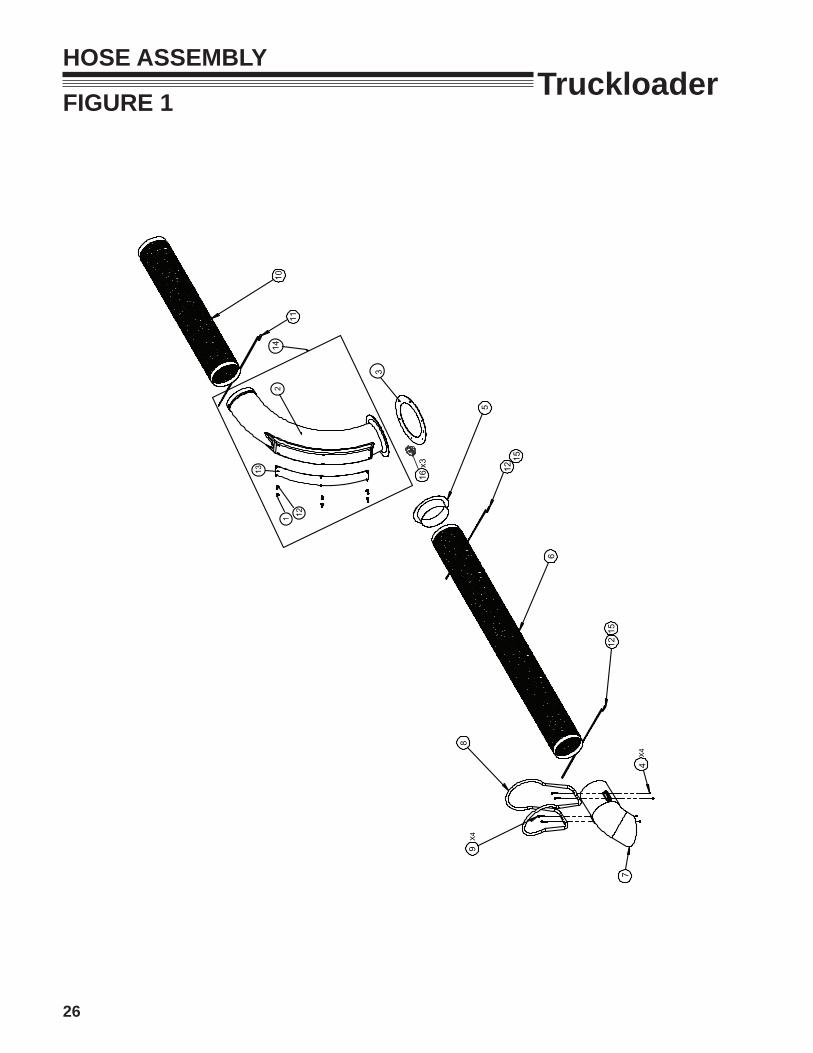
TruckloaderSET UP INSTRUCTIONS
HOSE FLANGE
HOSE
ASSEMBLY
HOSE CLAMP
NUT
HANDLE
INTAKE NOZZLE
BOLT
INTAKE NOZZLE
HOSE CLAMP
FIGURE #1
Figure #1
DEBRIS RECEPTACLE
The Shredding Truckloader is intended to be used in conjunction with a truck or trailer mounted debris receptacle to load landscape debris for removal from a work site to storage, dump or processing site. These receptacles or debris bodies or boxes are provided by the user and are the responsibility of the user. Following are some considerations to keep in mind when designing / building, or buying a debris receptacle on a vehicle.
1. It must be road worthy.
2. It must be constructed sturdily enough to contain the high velocity and force of entering debris to prevent injury to bystanders and damage to property.
3. Sufficient screen area must be provided to allow the air produced by the truckloader to escape while containing the lighter debris. A bigger screen area reduces the speed of the air through the screen and helps reduce the amount of debris that will be held to the screen. The screen area should be in the last area to be fill so it stays clean. If the air cannot escape, the truckloader will not be able to generate a vacuum to pick up debris.
4. It should prevent the debris from blowing out during transport to an unloading site.
5. Provision must be made for unloading.
HOSE ASSEMBLY (FIGURE 1)1. Remove the hose from the box.2. With the assistance of a second person, hold
the hose at both ends and stretch it out as far as possible. This will maximize the hose length and open the internal diameter.
3. Insert Hose Flange Assembly into one of the open ends as shown in Figure 1.
4. Using one of the Hose Clamps, secure the hose to the Hose Flange Assembly by wrapping the clamp around the hose portion covering the Hose Flange and tighten.
5. Insert the Intake Nozzle into the end of the hose opposite the hose flange as shown in Figure 1.
6. Using the second Hose Clamp, secure the hose t the Intake Nozzle by wrapping the clamp around the hose portion covering the Intake Nozzle and tighten.
7. Install the Intake Nozzle as shown.8. To secure the Intake Nozzle Handle to the Intake
Nozzle, insert the (4) bolts 720597 and (4) nuts 720583 that have been provided for installation.
10
TruckloaderSETUP INSTRUCTIONS
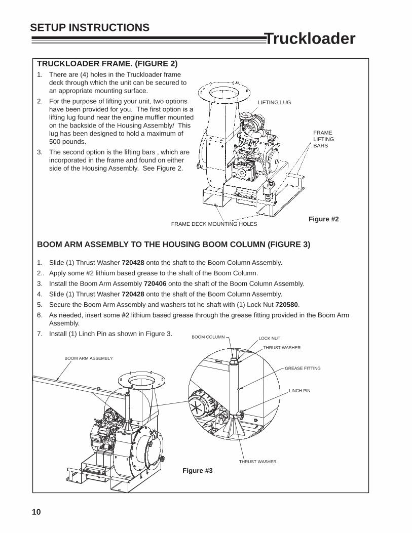
Figure #2FRAME DECK MOUNTING HOLES
LIFTING LUG
FRAME LIFTING BARS
BOOM ARM ASSEMBLY
FIGURE #3
LINCH PIN
GREASE FITTING
BOOM COLUMN LOCK NUT
THRUST WASHER
THRUST WASHER
Figure #3
BOOM ARM ASSEMBLY TO THE HOUSING BOOM COLUMN (FIGURE 3)
1. Slide (1) Thrust Washer 720428 onto the shaft to the Boom Column Assembly.2.. Apply some #2 lithium based grease to the shaft of the Boom Column.3. Install the Boom Arm Assembly 720406 onto the shaft of the Boom Column Assembly.4. Slide (1) Thrust Washer 720428 onto the shaft of the Boom Column Assembly.5. Secure the Boom Arm Assembly and washers tot he shaft with (1) Lock Nut 720580.6. As needed, insert some #2 lithium based grease through the grease fitting provided in the Boom Arm
Assembly.7. Install (1) Linch Pin as shown in Figure 3.
TRUCKLOADER FRAME. (FIGURE 2)1. There are (4) holes in the Truckloader frame
deck through which the unit can be secured to an appropriate mounting surface.
2. For the purpose of lifting your unit, two options have been provided for you. The first option is a lifting lug found near the engine muffler mounted on the backside of the Housing Assembly/ This lug has been designed to hold a maximum of 500 pounds.
3. The second option is the lifting bars , which are incorporated in the frame and found on either side of the Housing Assembly. See Figure 2.
11
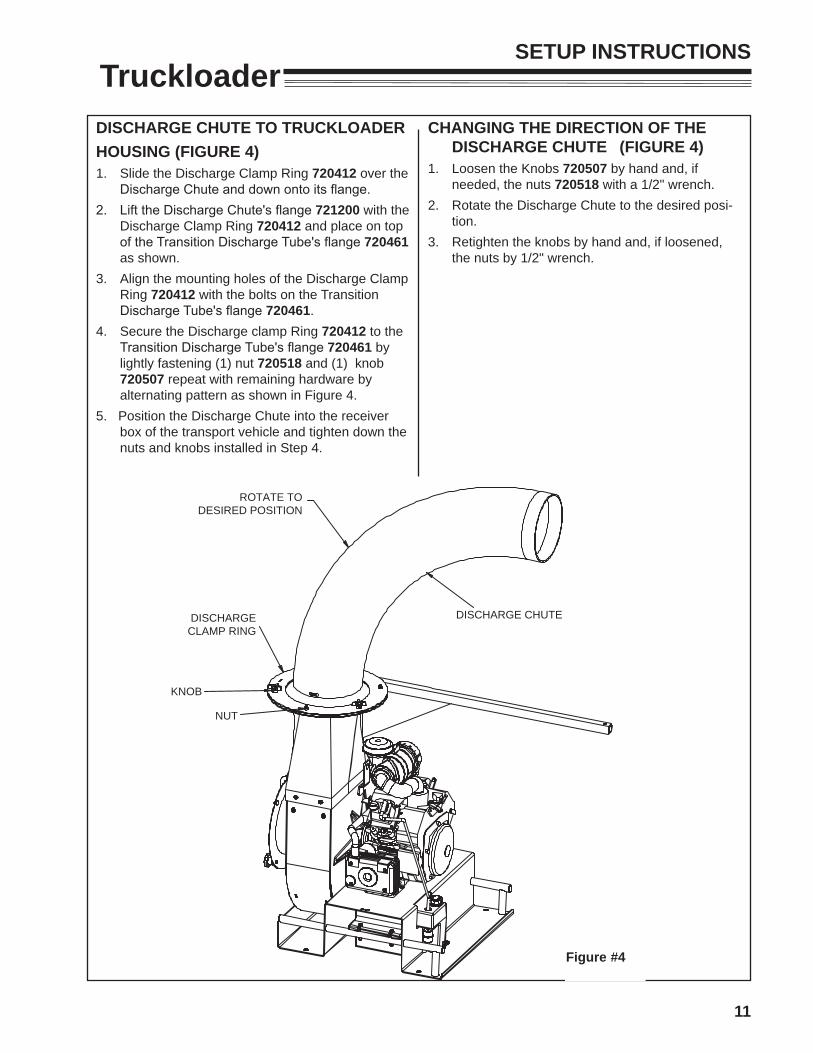
TruckloaderDISCHARGE CHUTE TO TRUCKLOADERHOUSING (FIGURE 4)1. Slide the Discharge Clamp Ring 720412 over the
Discharge Chute and down onto its flange.2. Lift the Discharge Chute's flange 721200 with the
Discharge Clamp Ring 720412 and place on top of the Transition Discharge Tube's flange 720461 as shown.
3. Align the mounting holes of the Discharge Clamp Ring 720412 with the bolts on the Transition Discharge Tube's flange 720461.
4. Secure the Discharge clamp Ring 720412 to the Transition Discharge Tube's flange 720461 by lightly fastening (1) nut 720518 and (1) knob 720507 repeat with remaining hardware by alternating pattern as shown in Figure 4.
5. Position the Discharge Chute into the receiver box of the transport vehicle and tighten down the nuts and knobs installed in Step 4.
DISCHARGE CHUTE
ROTATE TODESIRED POSITION
FIGURE #4
KNOB
DISCHARGECLAMP RING
NUT
Figure #4
CHANGING THE DIRECTION OF THE DISCHARGE CHUTE (FIGURE 4)
1. Loosen the Knobs 720507 by hand and, if needed, the nuts 720518 with a 1/2" wrench.
2. Rotate the Discharge Chute to the desired posi-tion.
3. Retighten the knobs by hand and, if loosened, the nuts by 1/2" wrench.
SETUP INSTRUCTIONS
12
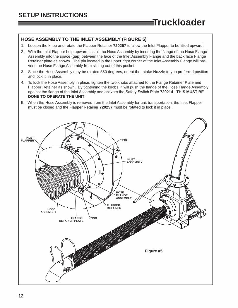
TruckloaderHOSE ASSEMBLY TO THE INLET ASSEMBLY (FIGURE 5)1. Loosen the knob and rotate the Flapper Retainer 720257 to allow the Inlet Flapper to be lifted upward.2. With the Inlet Flapper help upward, install the Hose Assembly by inserting the flange of the Hose Flange
Assembly into the space (gap) between the face of the Inlet Assembly Flange and the back face Flange Retainer plate as shown. The pin located in the upper right corner of the Inlet Assembly Flange will pre-vent the Hose Flange Assembly from sliding out of this pocket.
3. Since the Hose Assembly may be rotated 360 degrees, orient the Intake Nozzle to you preferred position and lock it in place.
4. To lock the Hose Assembly in place, tighten the two knobs attached to the Flange Retainer Plate and Flapper Retainer as shown. By tightening the knobs, it will push the flange of the Hose Flange Assembly against the flange of the Inlet Assembly and activate the Safety Switch Plate 720214. THIS MUST BE DONE TO OPERATE THE UNIT.
5. When the Hose Assembly is removed from the Inlet Assembly for unit transportation, the Inlet Flapper must be closed and the Flapper Retainer 720257 must be rotated to lock it in place.
FIGURE #5
INLETFLAPPER
INLETASSEMBLY
PIN
KNOB
FLAPPERRETAINER
HOSE FLANGEASSEMBLY
HOSE ASSEMBLY
FLANGE RETAINER PLATE
Figure #5
SETUP INSTRUCTIONS
13
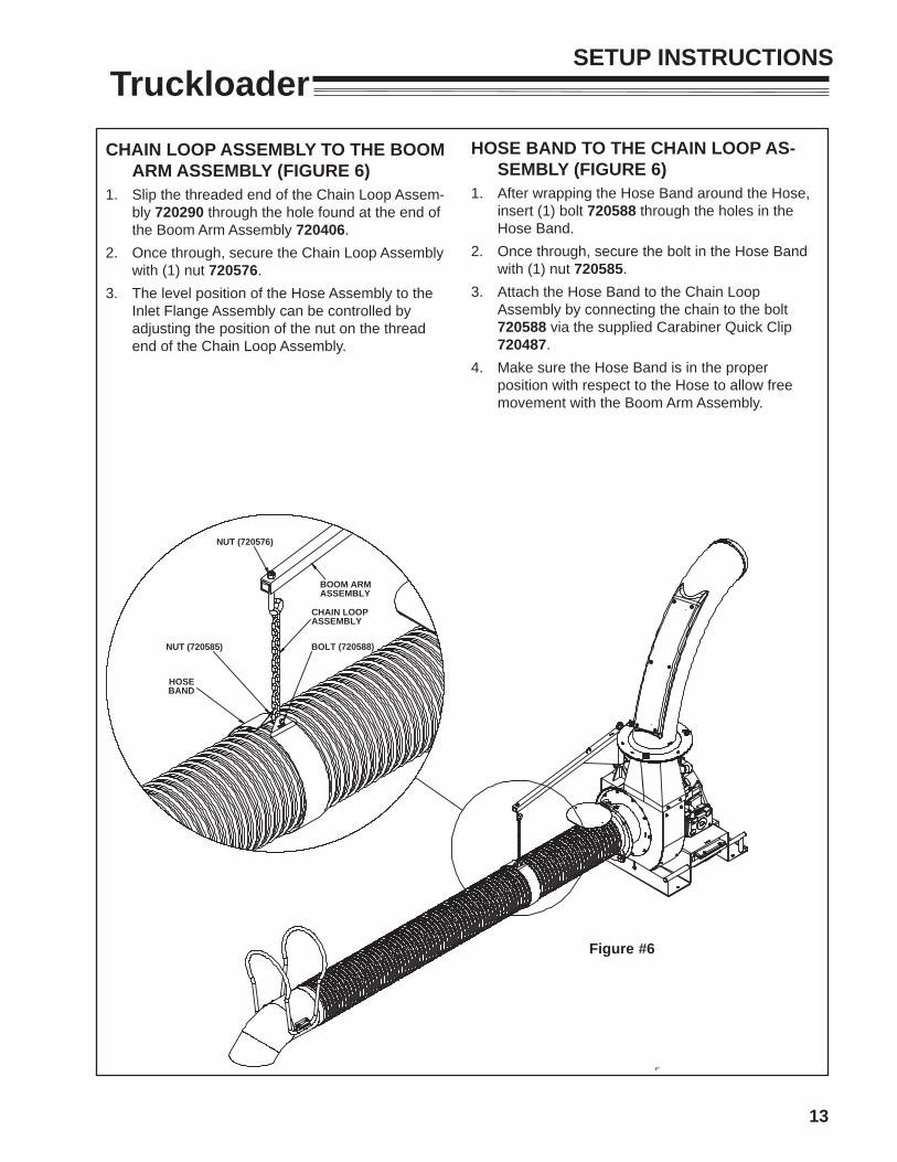
TruckloaderCHAIN LOOP ASSEMBLY TO THE BOOM
ARM ASSEMBLY (FIGURE 6)1. Slip the threaded end of the Chain Loop Assem-
bly 720290 through the hole found at the end of the Boom Arm Assembly 720406.
2. Once through, secure the Chain Loop Assembly with (1) nut 720576.
3. The level position of the Hose Assembly to the Inlet Flange Assembly can be controlled by adjusting the position of the nut on the thread end of the Chain Loop Assembly.
FIGURE #6
NUT (720585)
HOSEBAND
CHAIN LOOPASSEMBLY
NUT (720576)
BOOM ARMASSEMBLY
BOLT (720588)
Figure #6
HOSE BAND TO THE CHAIN LOOP AS-SEMBLY (FIGURE 6)
1. After wrapping the Hose Band around the Hose, insert (1) bolt 720588 through the holes in the Hose Band.
2. Once through, secure the bolt in the Hose Band with (1) nut 720585.
3. Attach the Hose Band to the Chain Loop Assembly by connecting the chain to the bolt 720588 via the supplied Carabiner Quick Clip 720487.
4. Make sure the Hose Band is in the proper position with respect to the Hose to allow free movement with the Boom Arm Assembly.
SETUP INSTRUCTIONS
14
Truckloader
DISCHARGE EXTENSION KIT ASSEMBLY1. Turn off the Truckloader and disconnect both of
the spark plug wires from the engine.2. Disassemble the Truckloader Discharge Flapper
by removing the knob, (2) nuts, (2) washers, and (3) bolts.
3. Remove the Discharge Flapper from the Discharge Nozzle.
4. Slide the Discharge Extension Hose 720436 over the end of the Discharge Extension Nozzle where the Flapper has been removed. Make sure the Hose has overlapped the Discharge Nozzle by at least 6 inches.
5. Secure the attachment of the Discharge Extension Hose 720436 to the Discharge Nozzle with the supplied Hose Clamp 720388. When installing the Hose Clamp, make sure it is positioned between the 1st and 2nd coil of the Discharge Extension Hose. Once in position, tighten the clamp to ensure a firm connection of the two parts.
6. Insert the opposite end of the Discharge Extension Hose into the receiver box on your truck. In the event the Hose is too long for your application, you can choose to cut it to a shorter length. If you shorten the length of this hose, make sure enough hose is left to properly install and secure it into the truck.
7. Once the hose is properly fir into your truck, secure it in place with a rope, bungee cord, etc. as required to secure it in place.
8. Make sure the Discharge Nozzle and Discharge Extension Hose is positioned to ensure a strait flow from the Truckloader into your receiver box.
9. Once everything has been properly positioned and secured, reconnect both spark plug wires on your engine.
10. Be sure to check the positioning and all connections of your Truckloader before starting.
11. To increase the life of your Discharge Extension Hose, periodically rotate the position of this hose. This can be accomplished by repeating the assembly instructions 1-9.
SETUP INSTRUCTIONS
15
Truckloader
ADDING OIL TO THE ENGINE 1. Fill the crankcase with the proper oil to the "F"
mark found on the dipstick. 2. Using the proper type and weight of oil in the
crankcase is extremely important. It is also im-portant to check oil before every use and change oil regularly. Failure to use the correct oil, or using dirty oil, causes premature engine wear and failure.
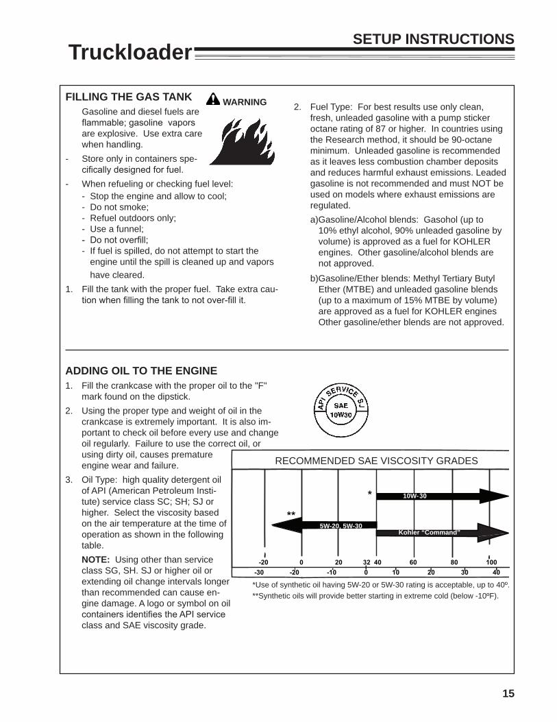
3. Oil Type: high quality detergent oil of API (American Petroleum Insti-tute) service class SC; SH; SJ or higher. Select the viscosity based on the air temperature at the time of operation as shown in the following table.
NOTE: Using other than service class SG, SH. SJ or higher oil or extending oil change intervals longer than recommended can cause en-gine damage. A logo or symbol on oil containers identifies the API service class and SAE viscosity grade.
10W-
5W-20, 5W-30Kohler “Command”
RECOMMENDED SAE VISCOSITY GRADES
*Use of synthetic oil having 5W-20 or 5W-30 rating is acceptable, up to 40º.**Synthetic oils will provide better starting in extreme cold (below -10ºF).
FILLING THE GAS TANK Gasoline and diesel fuels are
flammable; gasoline vapors are explosive. Use extra care when handling.
- Store only in containers spe-cifically designed for fuel.
- When refueling or checking fuel level: - Stop the engine and allow to cool; - Do not smoke; - Refuel outdoors only; - Use a funnel; - Do not overfill; - If fuel is spilled, do not attempt to start the
engine until the spill is cleaned up and vapors have cleared.
1. Fill the tank with the proper fuel. Take extra cau-tion when filling the tank to not over-fill it.
2. Fuel Type: For best results use only clean, fresh, unleaded gasoline with a pump sticker octane rating of 87 or higher. In countries using the Research method, it should be 90-octane minimum. Unleaded gasoline is recommended as it leaves less combustion chamber deposits and reduces harmful exhaust emissions. Leaded gasoline is not recommended and must NOT be used on models where exhaust emissions are regulated.
a)Gasoline/Alcohol blends: Gasohol (up to 10% ethyl alcohol, 90% unleaded gasoline by volume) is approved as a fuel for KOHLER engines. Other gasoline/alcohol blends are not approved.
b)Gasoline/Ether blends: Methyl Tertiary Butyl Ether (MTBE) and unleaded gasoline blends (up to a maximum of 15% MTBE by volume) are approved as a fuel for KOHLER engines Other gasoline/ether blends are not approved.
WARNING
SETUP INSTRUCTIONS
16
Truckloader
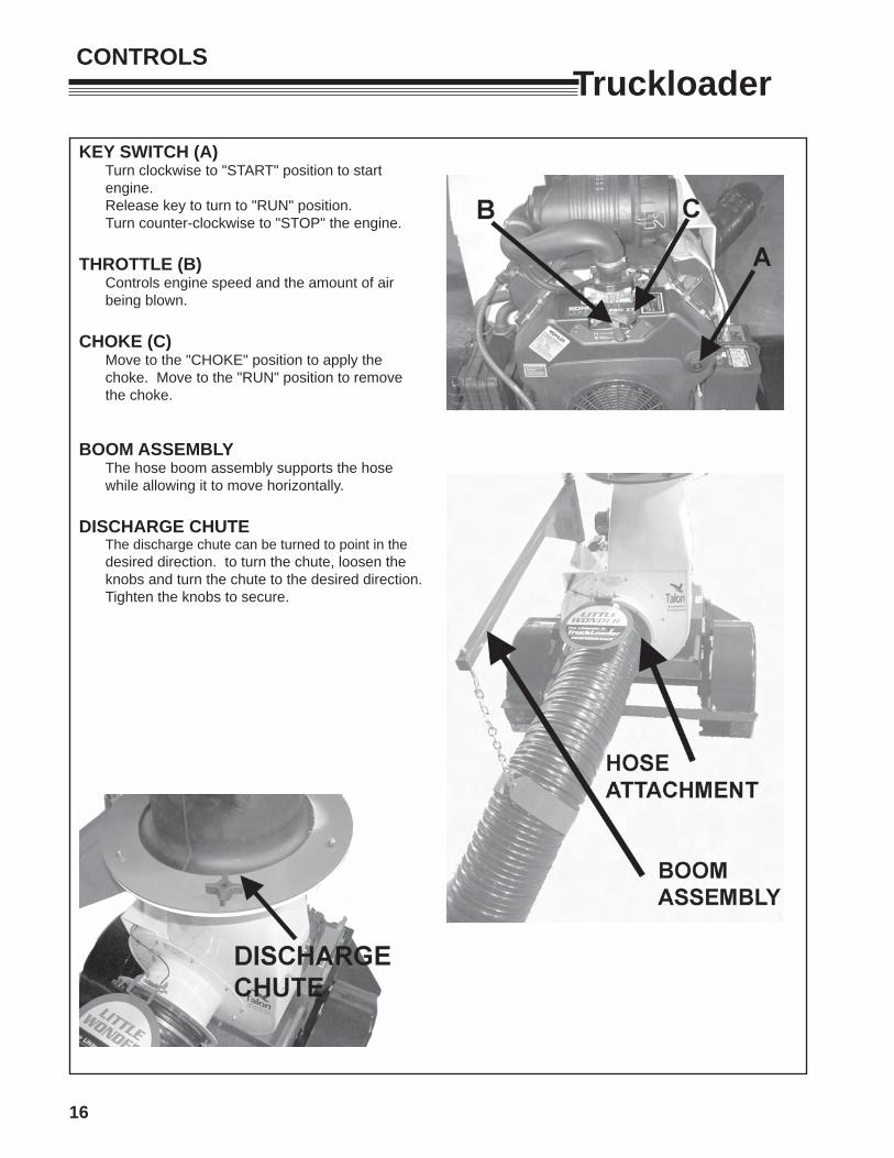
KEY SWITCH (A) Turn clockwise to "START" position to start
engine. Release key to turn to "RUN" position. Turn counter-clockwise to "STOP" the engine.
THROTTLE (B) Controls engine speed and the amount of air
being blown.
CHOKE (C) Move to the "CHOKE" position to apply the
choke. Move to the "RUN" position to remove the choke.
BOOM ASSEMBLY The hose boom assembly supports the hose
while allowing it to move horizontally. DISCHARGE CHUTE The discharge chute can be turned to point in the
desired direction. to turn the chute, loosen the knobs and turn the chute to the desired direction. Tighten the knobs to secure.
CONTROLS
17
TruckloaderOPERATION
Gasoline is extremely flammable and highly explosive under certain conditions. BE SURE to install fuel cap after refueling.
Fill fuel tank with good quality, clean, unleaded regular gasoline to the level recommended by the engine manufacturer.
TO CHECK OR ADD FUEL:
- Use a funnel to avoid spilling.- Do it outdoors.- Do not smoke.- Stop the engine; allow to cool.- Do not overfill.- Clean up spilled fuel.
BEFORE STARTING THE ENGINE
1. Be familiar with the controls, how each functions, and what each operates.
2.. Check engine oil level. Add oil if necessary, following the engine manufacturer's recommendations. Refer to engine manual included with literature packet.
3. Check the air cleaner for dirty, loose, or damaged parts. Clean or replace if necessary.
4. Check the air intake and cooling area for dirt or debris and clean as necessary.
OPERATOR PRESENCE INTERLOCK SYSTEM
The suction hose must be in place or the flapper door closed to start the engine and keep it running.
INTENDED USE
This unit is intended for vacuuming leaves, clippings and other similar sized organic material from the ground into a truck or trailer. Large sized or long stringy material will tend to clog.
Vacuuming sand, rocks, and hard litter will shorten the life of this machine and may damage the machine or parts of it.
PRE-OPERATION CHECK LIST(OPERATOR'S RESPONSIBILITY)
- Review and follow all safety rules and safety decal instructions.
- Check that all safety decals are installed and in good condition. Replace if damaged.
- Check to make sure all shields and guards are properly installed and in good condition.
- Make sure the discharge chute and hose are installed.
- Check the hose, discharge chute, liners, and housing for wear. Do not operate if these parts are worn through. Replace or repair before operating.
- Check that all hardware is properly installed and secured.
- Check to be sure engine is free of dirt and debris. Pay particular attention to the cooling fins, governor parts and muffler. Clean air intake screen. Check air cleaner; service if necessary.
- Clean area around the oil fill dipstick. Remove dipstick and check to be sure oil is in operating range (between marks on dipstick). Add oil if necessary but Do Not Overfill. See engine manual for oil specifications. Install dipstick assembly firmly until cap bottoms out on tube. Dipstick assembly must always be secured into fill tube when engine is running.
- Inspect material to be vacuumed and remove stones, branches or other hard objects that might damage the machine or cause it to clog.
- Perform a functional check of the safety interlock system each time you operate the unit.
STARTING THE ENGINE
1. Move the choke control lever to the CHOKE position.
2. Move the throttle control lever to the middle position.
3. Turn the key switch clockwise to the start position.
When the engine starts, release the key and gradually back off the choke until the engine runs with no choke.
4. After letting the engine warm up, slowly move the choke lever to the OPEN position.
5. See engine manual for additional information on starting.
18
TruckloaderOPERATING This machine has been designed for two methods of vacuuming debris:- With the handles of the Intake Nozzle in the
operator's hands, move the nozzle back and forth in a sweeping motion over the debris
- Rotate the hose assembly 90 degrees at the Inlet to allow the Intake Nozzle to lay sideways on the ground. By placing the Nozzle in this position, debris can be raked into the nozzle by an operator.
While large amounts of debris can be vacuumed quickly with this machine, caution must be taken to avoid blocking the airflow into the Nozzle.
Tip: Hose life may be increased by periodically loosening the hose clamps and rotating the hose, and retightening hose clamps. This will allow the hose to wear more evenly.
EXCESSIVE VIBRATION
Shut off the engine immediately if abnormal/excessive vibration occurs. Remove spark plug wire. Find the cause of vibration and repair it. Some possible causes for excessive vibration are:- Damaged impeller or talon ring.- Loose impeller bolt- Loose impeller key- Lodged objects
STOPPING THE ENGINE
When operation is complete or the unit needs to be checked or a clog needs to be cleared:1. Move the throttle to SLOW.2. Turn the key switch to the OFF position.
CLOGS
To prevent clogs, do not overfeed, especially with heavy wet material.
Pay attention to how full the debris receptacle is. Overfilled debris receptacles cause material to back up and get tightly packed in the discharge cute.
Removing Clogs
If a decrease in suction is experienced, there may be a debris blockage in the hose. Often a clogged hose can be cleared by stretching the hose out straight with the engine running. If the hose does not clear, . Before removing the hose or attempting to clear a clog manually:- Stop the engine. Turn the key switch to the OFF
position.- Wait for the fan to come to a complete stop.- Disconnect the spark plug wire so fan movement
cannot accidentally start the engine.
Removing Clogs ( continued)CAUTION SHOULD BE USED WHEN CLEARING DEBRIS FROM INSIDE THE HOUSING. GLOVES SHOULD BE WORN AS SHARP EDGES ON THE FAN, THE TALON RING, OR IN THE DEBRIS MAY BE PRESENT..
Remove the Hose assembly from the Inlet Flange Assembly. With this removed, open the Inlet Flapper and remove any debris that is clogging housing.
Remove the Discharge Chute from the Transition Discharge tube's flange. With the Chute removed, inspect the Transition Discharge part of the housing and remove any debris clogging this area.
Reassemble removed parts reconnect the spark plug wire and resume operation.
TRANSPORT
1. Make sure the engine is off.
2. Disconnect the Carabiner 720487 from the hose band.
3. Attach the Carabiner to the chain link closest to the Boom Arm Assembly.
4. Rotate the Boom Arm Assembly toward the vehicle to allow the locking bosses on the Arm and Column to line up. Once the bosses are aligned, insert Linch Pin 720437 through the hole and snap the ring over the boss to secure.
5. Make sure the Chain Loop Assembly cannot make contact with anything other than the Boom Arm Assembly. If necessary, use a bungee cord to secure it.
6. Remove the Hose Assembly from the Inlet Flange Assembly.
7. Close the Inlet Flapper and rotate the Flapper Retainer 720257 to allow the Flapper to be secured by tightening the knob.
8. Remove the Discharge Nozzle from the Truckloader Housing.
6. Secure the removed parts in the transport vehicle.
7. Before moving a trailer mounted truckloader, be sure everything is properly secured for road travel, the trailer is properly connected physically and electrically to tow vehicle, and the safety chains are properly attached.
OPERATION
19
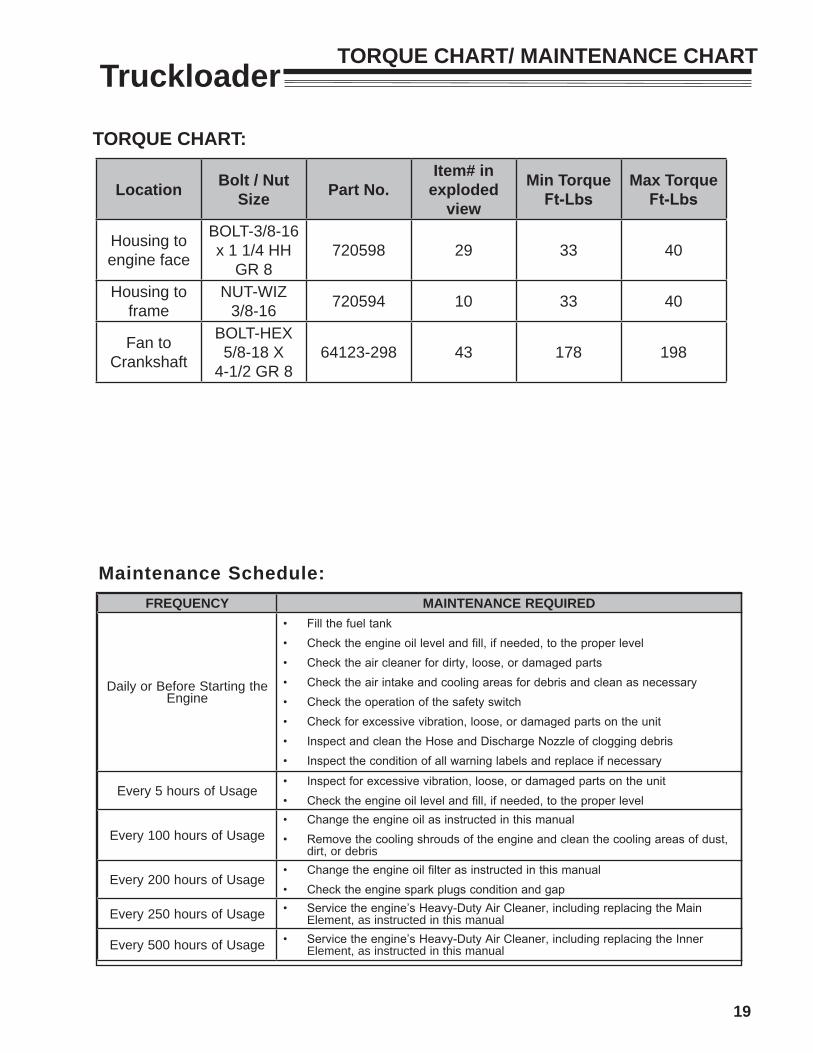
TruckloaderTORQUE CHART/ MAINTENANCE CHART
FREQUENCY MAINTENANCE REQUIRED
Daily or Before Starting the Engine
• Fill the fuel tank• Check the engine oil level and fill, if needed, to the proper level• Check the air cleaner for dirty, loose, or damaged parts• Check the air intake and cooling areas for debris and clean as necessary• Check the operation of the safety switch• Check for excessive vibration, loose, or damaged parts on the unit• Inspect and clean the Hose and Discharge Nozzle of clogging debris• Inspect the condition of all warning labels and replace if necessary
Every 5 hours of Usage• Inspect for excessive vibration, loose, or damaged parts on the unit• Check the engine oil level and fill, if needed, to the proper level
Every 100 hours of Usage• Change the engine oil as instructed in this manual• Remove the cooling shrouds of the engine and clean the cooling areas of dust,
dirt, or debris
Every 200 hours of Usage• Change the engine oil filter as instructed in this manual• Check the engine spark plugs condition and gap
Every 250 hours of Usage • Service the engine’s Heavy-Duty Air Cleaner, including replacing the Main Element, as instructed in this manual
Every 500 hours of Usage • Service the engine’s Heavy-Duty Air Cleaner, including replacing the Inner Element, as instructed in this manual
Maintenance Schedule:
TORQUE CHART:
Location Bolt / Nut Size Part No.
Item# in exploded
view
Min Torque Ft-Lbs
Max TorqueFt-Lbs
Housing to engine face
BOLT-3/8-16 x 1 1/4 HH
GR 8720598 29 33 40
Housing to frame
NUT-WIZ 3/8-16 720594 10 33 40
Fan to Crankshaft
BOLT-HEX 5/8-18 X
4-1/2 GR 864123-298 43 178 198
20
Truckloader
Removing and Replacing the Fan and Talon Ring (Figure #7 Page 21)1. Disconnect the spark plug wires from the spark plugs
on the engine.
2. Disconnect safety switch wire from engine.
3. Unbolt and Remove the Inlet Assembly from the face of the Housing.
4. Remove the bolt (64123-298) securing the Fan and Talon Ring to the crankshaft of the engine.
5. Pull the Talon Ring and talon ring driver off the face of the Fan hub.
6. Rotate the Fan to allow the blades to align with the notches provided in the Housing face.
7. Using a flywheel puller, remove the fan from the crankshaft. **Take note of the orientation of the fan with respect to the keyway upon removal. This is important when reinstalling the Fan.**
8. Upon removal of the Fan and Talon Ring, inspect for damaged or worn blades. If the Fan or Talon Ring is found to be damaged or excessively worn, it should be replaced with a new part. I
9. Reinstall the Fan onto the crankshaft and orient it to the same position as removed in Step #6. Align the keyway of the fan hub with the keyway on the crankshaft. Once aligned, inset key.
10. Place the talon ring driver into the end of fan hub. Align the keyway on the driver with the key. Place the talon ring over the talon ring driver.
11. Apply a few drops of Loctite 263 on a 5/8-18 x 4-1/2" GR8 bolt and tighten to 188 ft./lbs.
12. Install the Inlet Assembly to the face of the Housing and secure with the previously removed hardware.
13. Connect the spark plug wires to the spark plugs on the engine.
MAINTENANCE / SERVICE
DAILY MAINTENANCE- Check operation of hose interlock switch. 1. Start engine with hose properly installed.
2. Loosen the knobs, start to remove it. 3. The engine should stop running.
4. Reinstall hose and tighten knobs.If the switch does not stop the engine, repair before attempting to use the machine.
- Inspect the hose, chute, chute liner, and blower housing liner for wear. Replace worn parts or have them repaired.
- Tighten any loose fasteners.
ENGINE OIL- Check the oil level daily. - Change after the first day of operation and then
according to the engine manual.- See the engine manual for oil specifications and
checking procedure.
ENGINE AIR CLEANER
- Check and clean according to the engine manuals.
- Little Wonder recommends daily inspection and cleaning due to the extreme environment of debris handling.
CLEANINGKeep the area around the muffler and engine recoil cover /cooling air intake free of debris accumulation to prevent fires and keep the engine from overheating. These areas need to be monitored throughout the work day and may need to be cleaned several times daily depending on circumstances.
21
Truckloader
Figure #7
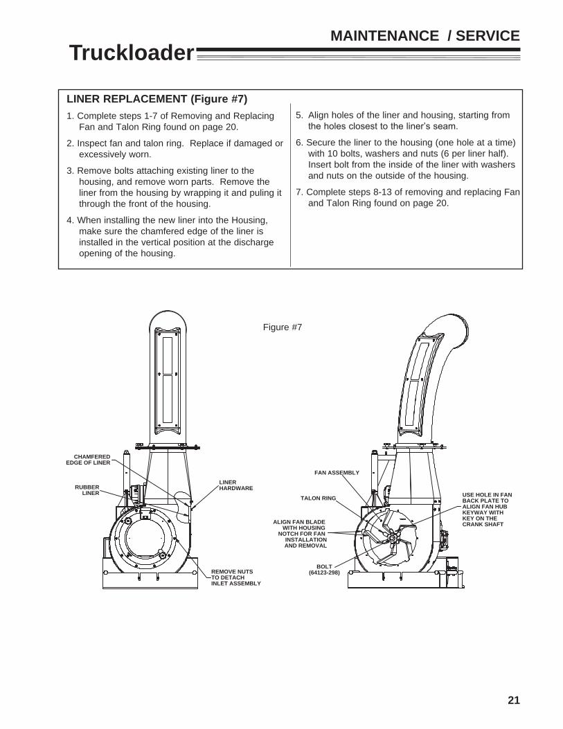
LINER REPLACEMENT (Figure #7) 1. Complete steps 1-7 of Removing and Replacing
Fan and Talon Ring found on page 20.
2. Inspect fan and talon ring. Replace if damaged or excessively worn.
3. Remove bolts attaching existing liner to the housing, and remove worn parts. Remove the liner from the housing by wrapping it and puling it through the front of the housing.
4. When installing the new liner into the Housing, make sure the chamfered edge of the liner is installed in the vertical position at the discharge opening of the housing.
MAINTENANCE / SERVICE
RUBBERLINER
REMOVE NUTS TO DETACHINLET ASSEMBLY
CHAMFEREDEDGE OF LINER
LINERHARDWARE
TALON RING USE HOLE IN FAN BACK PLATE TO ALIGN FAN HUB KEYWAY WITH KEY ON THE CRANK SHAFTALIGN FAN BLADE
WITH HOUSING NOTCH FOR FAN
INSTALLATIONAND REMOVAL
BOLT(64123-298)
FAN ASSEMBLY
5. Align holes of the liner and housing, starting from the holes closest to the liner’s seam.
6. Secure the liner to the housing (one hole at a time) with 10 bolts, washers and nuts (6 per liner half). Insert bolt from the inside of the liner with washers and nuts on the outside of the housing.
7. Complete steps 8-13 of removing and replacing Fan and Talon Ring found on page 20.
22
TruckloaderOIL CHANGE1. Oil Change: Change oil after every 100 hours of
operation (more frequently under severe conditions). Refill with service class SG, SH, SJ or higher oil as specified in the “Viscosity Grades” above. Change the oil while the engine is still warm. The oil will flow more freely and carry away more impurities. Make sure the engine is level when filling, checking, and changing the oil. Change the oil as follows:
2. To keep dirt, debris, etc., out of the engine, clean the area around the oil fill cap/dipstick and drain valve before moving to the next step.
3. Attach a 1/2” I.D. hose to the fitting on the oil drain valve. Place the other end of the hose in an oil pan. Remove the oil fill cap/dipstick, then open the oil drain valve (counter-clockwise) to begin drainage. Be sure to allow ample time for complete drainage.
4. Once all the oil has drained, close the valve (clockwise) and remove the hose.
5. Fill the crankcase, with new oil of the proper type, to the “F” mark on the dipstick. Refer to “Oil Type” on page 14. Always check the level with the dipstick before adding more oil.
6. Reinstall the oil fill cap and tighten securely. Reinstall the dipstick. NOTE: To prevent extensive engine wear or damage, always maintain the proper oil level in the crankcase. Never operate the engine with the oil level below the “L” mark or over the “F” mark on the dipstick.
OIL FILTER CHANGE1. Replace the oil filter at least every other oil change
(every 200 hours of operation). Always use a genuine Kohler oil filter, Part No. 12 050 OI-S. Replace the oil filter as follows:
a) Follow steps A to C from the above “Change Oil” section.
b) Allow the oil filter to drain.
c) Before removing the oil filter, clean the area around the oil filter to keep dirt and debris out of the engine. Remove the old filter. Wipe off the surface where the oil filter mounts.
d) Place a new replacement filter in a shallow pan with the open end up. Pour new oil, of the proper type, in through the threaded center hole. Stop pouring when the oil reaches the bottom of the threads. Allow a minute or two for the oil to be absorbed by the filter material.
e) Put a drop of oil on your fingertip and wipe it on the rubber gasket.
f) Install the replacement oil filter to the filter adapter or oil cooler. Turn the oil filter clockwise until the rubber gasket contacts the filter adapter or oil cooler, then tighten the filter an additional 2/3 to 1 turn.
g) Follow steps d-e from above “Change Oil” section. Start the engine and check for oil leaks. Correct any leaks before placing the engine into service. Check oil level to be sure it is up to but not over the “F” mark.
MAINTENANCE / SERVICE
23
TruckloaderHEAVY DUTY AIR CLEANER1. Every 250 hours of operation (more often under
extremely dusty or dirty conditions), replace the main paper element and check inner element. Follow these steps.
2. Unhook the two retaining clips and remove the end cap from the air cleaner housing.
3. Pull the air cleaner element out of the housing. Figure 9.
4. After the main element is removed, check the condition of the inner element. It should be replaced whenever it appears dirty, typically every other time the main element is replaced. Clean the area around the base of the inner element before removing it, so dirt does not get into the engine.
5. Do not wash the paper element and inner element or
Figure #9
Figure #10
use pressurized air, this will damage the elements. Replace dirty, bent or damaged elements with new genuine Kohler elements as required. Handle new elements carefully; do not use if the sealing surfaces are bent or damaged.
6. Check all parts for wear, cracks or damage. Replace any damaged components.
6. Install the new inner element, Kohler Part No. 25 083 04-S followed by the outer element, Kohler Part No. 25 083 01-S. Slide each fully into place in the air cleaner housing.
7. Reinstall the end cap so the dust ejector valve is down and secure with the two retaining clips. See Assembly Figure 10.
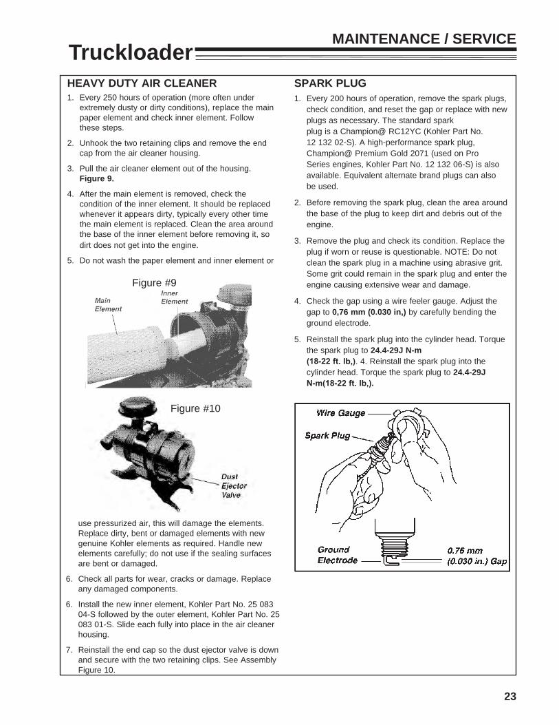
SPARK PLUG1. Every 200 hours of operation, remove the spark plugs,
check condition, and reset the gap or replace with new plugs as necessary. The standard spark plug is a Champion@ RC12YC (Kohler Part No. 12 132 02-S). A high-performance spark plug, Champion@ Premium Gold 2071 (used on Pro Series engines, Kohler Part No. 12 132 06-S) is also available. Equivalent alternate brand plugs can also be used.
2. Before removing the spark plug, clean the area around the base of the plug to keep dirt and debris out of the engine.
3. Remove the plug and check its condition. Replace the plug if worn or reuse is questionable. NOTE: Do not clean the spark plug in a machine using abrasive grit. Some grit could remain in the spark plug and enter the engine causing extensive wear and damage.
4. Check the gap using a wire feeler gauge. Adjust the gap to 0,76 mm (0.030 in,) by carefully bending the ground electrode.
5. Reinstall the spark plug into the cylinder head. Torque the spark plug to 24.4-29J N-m (18-22 ft. lb,). 4. Reinstall the spark plug into the cylinder head. Torque the spark plug to 24.4-29J N-m(18-22 ft. lb,).
MAINTENANCE / SERVICE
24
Truckloader
STORAGE To prevent possible explosion or ignition of vaporized fuel, do not store equipment with fuel in tank or carburetor in an enclosure or enclosed area with an open flame (for example, a furnace or water heater pilot light.)
Before the equipment is put into storage for any period exceeding 30 days, the following steps should be completed.
1. Drain all fuel from the fuel tank and the fuel lines. Drained fuel may only be stored for 30 days. If a stabilizer is chosen, follow the manufacturer's recommendation by adding the correct amount of additive for the amount of fuel to be stored. Fill the tank with this clean, fresh gasoline and run the engine for 2 to 3 minutes to get the stabilized fuel into the carburetor.
2. Start the engine and run until all the fuel is used from the carburetor float bowl and the engine stops.
3. While the engine is still warm, drain the crankcase oil and replace with the proper weight oil corresponding to the season the equipment will be used next.
4. Remove the spark plug and squirt a small amount of engine oil into the cylinder. Reinstall the plugs and ground spark plug leads- DO NOT connect the leads to the plugs. Crank the engine two or three revolutions.
5. Store the unit and all of it's components in a clean, dry, well ventilated, non-child accessible, sheltered area that is out of sun light and high ambient temperatures.
To put the equipment into service after an extended period of storage.
1. Check for loose parts and tighten if necessary.
2. Fill the fuel tank and then check the engine oil level. Top off if necessary. See engine manual for details.
3. Start the engine and check for fuel leaks. Repair any leaks before operating the unit.
STORAGE

25
PARTSSECTION
26
TruckloaderHOSE ASSEMBLY
FIGURE 1
7
4
98
15
6
5
15
10
11
13
1212
3
14
12
12
16 x
3
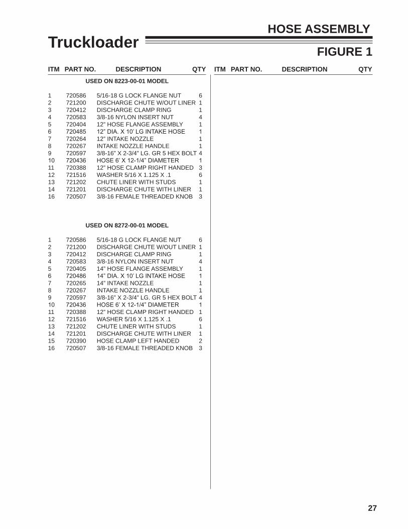
ITM PART NO. DESCRIPTION QTY
27
ITM PART NO. DESCRIPTION QTY
TruckloaderHOSE ASSEMBLY
FIGURE 1
USED ON 8223-00-01 MODEL
1 720586 5/16-18 G LOCK FLANGE NUT 62 721200 DISCHARGE CHUTE W/OUT LINER 13 720412 DISCHARGE CLAMP RING 14 720583 3/8-16 NYLON INSERT NUT 45 720404 12” HOSE FLANGE ASSEMBLY 16 720485 12” DIA. X 10’ LG INTAKE HOSE 17 720264 12” INTAKE NOZZLE 18 720267 INTAKE NOZZLE HANDLE 19 720597 3/8-16” X 2-3/4” LG. GR 5 HEX BOLT 410 720436 HOSE 6’ X 12-1/4” DIAMETER 111 720388 12” HOSE CLAMP RIGHT HANDED 312 721516 WASHER 5/16 X 1.125 X .1 613 721202 CHUTE LINER WITH STUDS 114 721201 DISCHARGE CHUTE WITH LINER 116 720507 3/8-16 FEMALE THREADED KNOB 3
USED ON 8272-00-01 MODEL
1 720586 5/16-18 G LOCK FLANGE NUT 62 721200 DISCHARGE CHUTE W/OUT LINER 13 720412 DISCHARGE CLAMP RING 14 720583 3/8-16 NYLON INSERT NUT 45 720405 14” HOSE FLANGE ASSEMBLY 16 720486 14” DIA. X 10’ LG INTAKE HOSE 17 720265 14” INTAKE NOZZLE 18 720267 INTAKE NOZZLE HANDLE 19 720597 3/8-16” X 2-3/4” LG. GR 5 HEX BOLT 410 720436 HOSE 6’ X 12-1/4” DIAMETER 111 720388 12” HOSE CLAMP RIGHT HANDED 112 721516 WASHER 5/16 X 1.125 X .1 613 721202 CHUTE LINER WITH STUDS 114 721201 DISCHARGE CHUTE WITH LINER 115 720390 HOSE CLAMP LEFT HANDED 216 720507 3/8-16 FEMALE THREADED KNOB 3
28
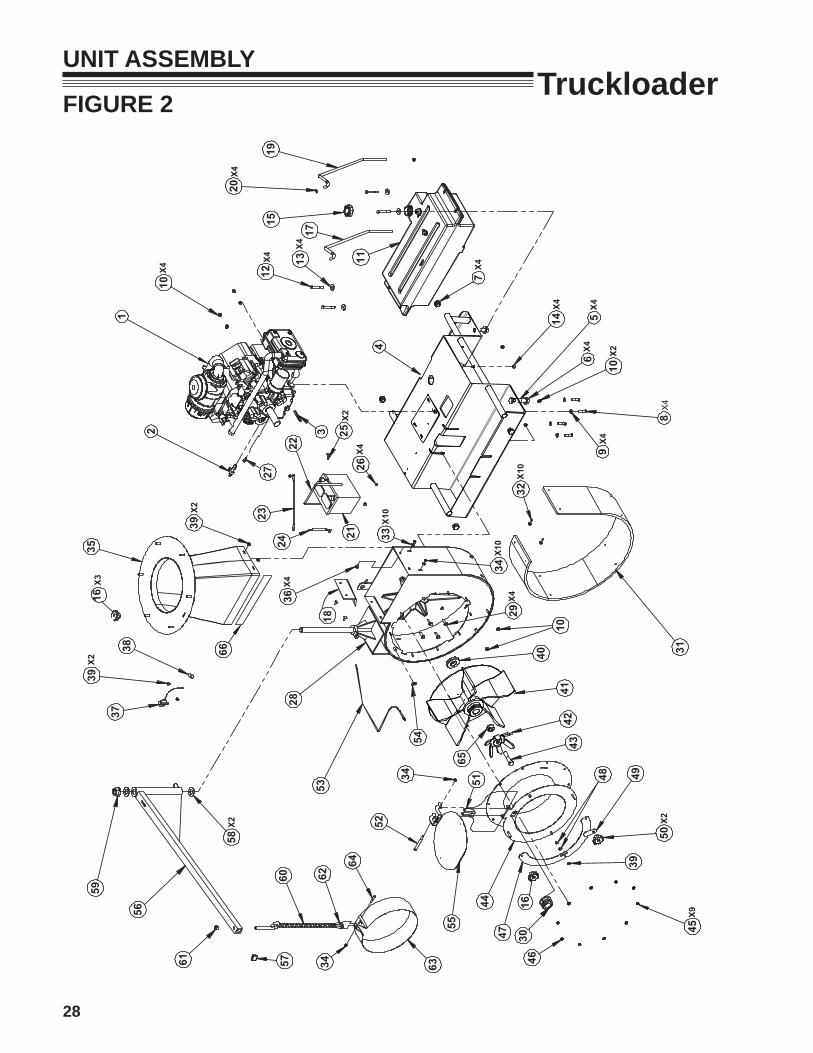
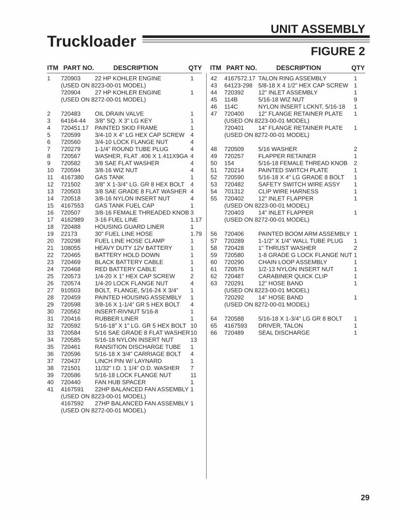
TruckloaderUNIT ASSEMBLY
FIGURE 2
53
58
56
29
59
3837
2836
33
39
35 24
2
2723
21
1
25
22
10
3
13
1519
1817
11
7
4
109
831
32
50
49
45
48
43
46
4744
42
51
55
34
52
63
64
62
41
5760
61
40
54
20
39
39
34
12
X2
X2
X2
X10
X9
X2X2
X10
X10
X4
X4
X4
10
X2
X426
X4
X4
X4
X4
14X4
X4
65
X4X4
X4
16
34
66
30
65
16X3
ITM PART NO. DESCRIPTION QTY
29
ITM PART NO. DESCRIPTION QTY
TruckloaderUNIT ASSEMBLY
FIGURE 2
1 720903 22 HP KOHLER ENGINE 1 (USED ON 8223-00-01 MODEL) 720904 27 HP KOHLER ENGINE 1 (USED ON 8272-00-01 MODEL)
2 720483 OIL DRAIN VALVE 13 64164-44 3/8” SQ. X 3” LG KEY 14 720451.17 PAINTED SKID FRAME 15 720599 3/4-10 X 4” LG HEX CAP SCREW 46 720560 3/4-10 LOCK FLANGE NUT 47 720279 1-1/4” ROUND TUBE PLUG 48 720567 WASHER, FLAT .406 X 1.411X9GA 49 720582 3/8 SAE FLAT WASHER 410 720594 3/8-16 WIZ NUT 411 4167380 GAS TANK 112 721502 3/8” X 1-3/4” LG. GR 8 HEX BOLT 413 720503 3/8 SAE GRADE 8 FLAT WASHER 414 720518 3/8-16 NYLON INSERT NUT 415 4167553 GAS TANK FUEL CAP 116 720507 3/8-16 FEMALE THREADED KNOB 317 4162989 3-16 FUEL LINE 1.1718 720488 HOUSING GUARD LINER 119 22173 30” FUEL LINE HOSE 1.7920 720298 FUEL LINE HOSE CLAMP 121 108055 HEAVY DUTY 12V BATTERY 122 720465 BATTERY HOLD DOWN 123 720469 BLACK BATTERY CABLE 124 720468 RED BATTERY CABLE 125 720573 1/4-20 X 1” HEX CAP SCREW 226 720574 1/4-20 LOCK FLANGE NUT 427 910503 BOLT, FLANGE, 5/16-24 X 3/4” 128 720459 PAINTED HOUSING ASSEMBLY 129 720598 3/8-16 X 1-1/4” GR 5 HEX BOLT 430 720562 INSERT-RIVNUT 5/16-8 131 720416 RUBBER LINER 132 720592 5/16-18” X 1” LG. GR 5 HEX BOLT 1033 720584 5/16 SAE GRADE 8 FLAT WASHER 1034 720585 5/16-18 NYLON INSERT NUT 1335 720461 RANSITION DISCHARGE TUBE 136 720596 5/16-18 X 3/4” CARRIAGE BOLT 437 720437 LINCH PIN W/ LAYNARD 138 721501 11/32” I.D. 1 1/4” O.D. WASHER 739 720586 5/16-18 LOCK FLANGE NUT 1140 720440 FAN HUB SPACER 141 4167591 22HP BALANCED FAN ASSEMBLY 1 (USED ON 8223-00-01 MODEL) 4167592 27HP BALANCED FAN ASSEMBLY 1 (USED ON 8272-00-01 MODEL)
42 4167572.17 TALON RING ASSEMBLY 143 64123-298 5/8-18 X 4 1/2” HEX CAP SCREW 144 720392 12” INLET ASSEMBLY 145 114B 5/16-18 WIZ NUT 946 114C NYLON INSERT LCKNT, 5/16-18 147 720400 12” FLANGE RETAINER PLATE 1 (USED ON 8223-00-01 MODEL) 720401 14” FLANGE RETAINER PLATE 1 (USED ON 8272-00-01 MODEL)
48 720509 5/16 WASHER 249 720257 FLAPPER RETAINER 150 154 5/16-18 FEMALE THREAD KNOB 251 720214 PAINTED SWITCH PLATE 152 720590 5/16-18 X 4” LG GRADE 8 BOLT 153 720482 SAFETY SWITCH WIRE ASSY 154 701312 CLIP WIRE HARNESS 155 720402 12” INLET FLAPPER 1 (USED ON 8223-00-01 MODEL) 720403 14” INLET FLAPPER 1 (USED ON 8272-00-01 MODEL)
56 720406 PAINTED BOOM ARM ASSEMBLY 157 720289 1-1/2” X 1/4” WALL TUBE PLUG 158 720428 1” THRUST WASHER 259 720580 1-8 GRADE G LOCK FLANGE NUT 160 720290 CHAIN LOOP ASSEMBLY 161 720576 1/2-13 NYLON INSERT NUT 162 720487 CARABINER QUICK CLIP 163 720291 12” HOSE BAND 1 (USED ON 8223-00-01 MODEL) 720292 14” HOSE BAND 1 (USED ON 8272-00-01 MODEL)
64 720588 5/16-18 X 1-3/4” LG GR 8 BOLT 165 4167593 DRIVER, TALON 166 720489 SEAL DISCHARGE 1

30
All LITTLE WONDER TRUCKLOADERS are warranted against defects in material and workmanship for a period of two (2) years from the date of purchase, under the following terms and conditions.
LITTLE WONDER will repair or replace, at its option, any part or parts of the product found to be defective in ma-terial or workmanship during the warranty period. Warranty repairs and replacements will be made without charge for parts or labor. All parts replaced under warranty will be considered as part of the original product, and any warranty on the replaced parts will expire coincident with the original product warranty. If you think your LITTLE WONDER TRUCKLOADER is defective in material or workmanship, you must return it to a registered dealer with a valid sales receipt or to our factory at 1028 Street Rd., Southampton, PA 18966. Transportation charges to ship your product to us or a registered dealer must be borne by you.
Engines for all gasoline powered products are warranted separately by the engine manufacturer. Therefore, there are no warranties made, expressed or implied, for engines for gasoline powered products by LITTLE WONDER.
LITTLE WONDER assumes no responsibility in the event that the product was not assembled or used in compli-ance with any assembly, care, safety or operating instructions contained in the Owner’s Manual or information accompanying the product. This limited warranty does not cover damages or defects due to normal wear and tear, lack of reasonable and proper maintenance, failure to follow operating instructions or Owner’s Manual, misuse, lack of proper storage or accidents, nor does it cover routine maintenance parts and service. This limited warranty does not cover any defects due to repairs or alterations made to the product made by anyone other than LITTLE WONDER or its registered dealers.
You must maintain your LITTLE WONDER TRUCKLOADER by following the maintenance procedures described in the owner’s manual. Such routine maintenance, whether performed by you or a registered dealer, is at your expense.
LITTLE WONDER MAKES NO EXPRESS OR IMPLIED WARRANTIES REPRESENTATIONS OR PROMISES EXCEPT THOSE CONTAINED HEREIN. THERE ARE NO OTHER WARRANTIES, INCLUDING WARRANTIES OF MERCHANTABILITY AND FITNESS FOR A PARTICULAR PURPOSE. ALL WARRANTIES OTHER THAN THE EXPRESS WARRANTY SET FORTH ABOVE ARE SPECIFICALLY DISCLAIMED. THE DURATION OF ANY IMPLIED WARRANTY, INCLUDING MERCHANTABILITY AND FITNESS FOR A PARTICULAR PURPOSE, IS LIMITED TO THE DURATION OF THIS WRITTEN LIMITED WARRANTY. LITTLE WONDER DISCLAIMS ALL LIABILITY FOR INDIRECT, INCIDENTAL AND/OR CONSEQUENTIAL DAMAGES IN CONNECTION WITH THE USE OF THE LITTLE WONDER TRUCKLOADER PRODUCTS COVERED BY THIS WARRANTY. SOME STATES DO NOT ALLOW LIMITATIONS ON HOW LONG AN IMPLIED WARRANTY LASTS AND/OR DO NOT ALLOW THE EXCLUSION OR LIMITATION OF INCIDEN-TAL OR CONSEQUENTIAL DAMAGES, SO THAT ABOVE LIMITATIONS AND EXCLUSIONS MAY NOT APPLY TO YOU. THIS WARRANTY GIVES YOU SPECIFIC LEGAL RIGHTS, AND YOU MAY ALSO HAVE OTHER RIGHTS WHICH VARY FROM STATE TO STATE
©2012 Schiller Grounds Care, Inc. All Rights Reserved.
2 YEAR LIMITED SERVICE AND WARRANTY POLICY
FOR LITTLE WONDER TRUCKLOADERS
LITTLE WONDER®
SCHILLER GROUNDS CARE, INC.1028 STREET ROAD, P.O. BOX 38
SOUTHAMPTON, PA 18966PHONE 877-596-6337 • FAX 215-357-8045
www.littlewonder.com