Embed Size (px)
Citation preview

belfuse.com/power-solutions
BCD.00803 Rev AC1, 19-Jun-2018
RCM500/1000 Series 500/1000 W DC-DC Converters
The RCM500 and RCM1000 Series converters are reliable power supplies for railway and transportation systems. They are optimized for 72 or 110 V railway batteries. The output delivers 24 V with 500 or 1000 W. The converters are designed for chassis mounting and exhibit a closed housing with cooling openings.Many options are available, such as an output ORing FET for redundant operation, output voltage adjustment, interruption time of 10 ms, shutdown input, and a monitoring relay (change-over contact).
Features• Optimized for 72 V or 110 V railway batteries• Output voltage 24 V• Closed housing for chassis mounting• Extremelyhighefficiencyandhighpowerdensity• Low inrush current• 3 connectors: Input, output, auxiliary (option)• Overtemperature, overvoltage, overcurrent, and
short-circuit protection• Many options available• Compliant to EN 50155, EN 50121-3-2, AREMA• RoHS-compatible for all 6 substances• Fire and smoke: compliant to EN 45545 and NFPA 130• 5 year warranty
Safety-approved to the latest edition of IEC/EN 60950-1and UL/CSA 60950-1
Table of ContentsDescription........................................................................................1Model Selection ................................................................................2Functional Description ......................................................................3Electrical Input Data .........................................................................4Electrical Output Data.......................................................................6Description of Options ......................................................................9
Electromagnetic Compatibility (EMC) ............................................. 11Immunity to Environmental Conditions ...........................................13Mechanical Data .............................................................................14Safety and Installation Instructions .................................................15Accessories ....................................................................................17
1
1 pending
1
[email protected] belfuse.com/power-solutions
BCD.00803 Rev AC1, 19-Jun-2018
Page 2 of 17
RCM Series 500 / 1000 W DC-DC Converters
© 2018 Bel Power Solutions & Protection
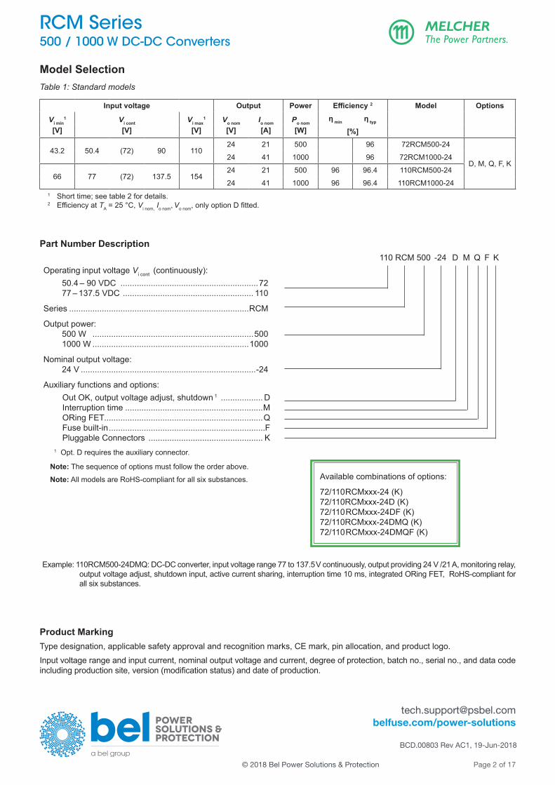
Model SelectionTable 1: Standard models
Input voltage Output Power Efficiency 2 Model Options
Vi min1
[V]Vi cont
[V]Vi max
1
[V]Vo nom
[V]Io nom
[A]Po nom
[W]η min η typ
[%]
43.2 50.4 (72) 90 11024 21 500 96 72RCM500-24
D, M, Q, F, K24 41 1000 96 72RCM1000-24
66 77 (72) 137.5 15424 21 500 96 96.4 110RCM500-24
24 41 1000 96 96.4 110RCM1000-241 Short time; see table 2 for details.2 EfficiencyatTA = 25 °C, Vi nom, Io nom, Vo nom,onlyoptionDfitted.
Part Number Description
Operating input voltage Vi cont (continuously): 50.4 – 90 VDC ...........................................................72 77 – 137.5 VDC ........................................................ 110
Series .............................................................................RCM
Output power: 500 W .....................................................................500 1000 W ...................................................................1000
Nominal output voltage: 24 V ...........................................................................-24
Auxiliary functions and options: Out OK, output voltage adjust, shutdown 1 .................. D Interruption time ...........................................................M ORing FET....................................................................Q Fuse built-in ...................................................................F Pluggable Connectors ................................................. K
1 Opt. D requires the auxiliary connector.
Note: The sequence of options must follow the order above.
Note: All models are RoHS-compliant for all six substances.
110 RCM 500 -24 D M Q F K
Available combinations of options:
72/110RCMxxx-24 (K) 72/110RCMxxx-24D (K) 72/110RCMxxx-24DF (K) 72/110RCMxxx-24DMQ (K) 72/110RCMxxx-24DMQF (K)
Example: 110RCM500-24DMQ: DC-DC converter, input voltage range 77 to 137.5 V continuously, output providing 24 V /21 A, monitoring relay, output vol tage adjust, shutdown input, active current sharing, interruption time 10 ms, integrated ORing FET, RoHS-compliant for all six sub stances.
Product MarkingType designation, applicable safety approval and recognition marks, CE mark, pin allocation, and product logo.Input voltage range and input current, nominal output voltage and current, degree of protection, batch no., serial no., and data code includingproductionsite,version(modificationstatus)anddateofproduction.

[email protected] belfuse.com/power-solutions
BCD.00803 Rev AC1, 19-Jun-2018
Page 3 of 17
RCM Series 500 / 1000 W DC-DC Converters
© 2018 Bel Power Solutions & Protection
Functional DescriptionTheinputvoltageisfedviaanefficientinputfilterandastep-upconverter(switchingwith2×110kHz)tothehigh-efficientDC-DCconverter operating at a switching frequency of ap prox i mately 90 kHz. The built-in over voltage limiter protects against input voltage surges.The inrush current is limited by an electronic circuitry. A VDR resistor protects against external surges.If there is no external circuit breaker, the converter can be ordered with built-in fuse (opt. F). This fuse is not accessible.Thecircuitrytoprovidetheinterruptiontime(opt.M)islocatedaftertheinputfiltertogetherwiththereversepolarityprotectionformed by a FET.Therectificationonthesecondarysideisprovidedbysynchronousrectifiers,inordertokeepthelossesaslowaspossible.Theoutput voltage control logic is located on the secondary side and controls the FETs of the DC-DC converter via insulated drivers.An auxiliary converter supplies all circuits with a stable bias voltage. An output ORing FET is available (opt. Q) and allows for a redundant power supply system. Opt. D encompasses an additional signal connector to allow for output voltage adjustment, active current sharing, primary shutdown, and an output voltage monitor activating a relay with change-over contact.The converter is mounted onto a base plate which acts as cooling plate. An additional heatsink for natural convection cooling is available as accessory. A thermal protection on the input and output side prevents from overheating.
Vi–
Vi+ Isol
atio
n
Vo–
Auxiliary connector (only with option D)
Vo+
AuxiliaryconverterCy PE
Opt. Q
Fuse
(opt
ion
F)
Opt. M
Inputfilter
1 Reverse polarity protection (FET) , only fitted with opt. F or M2
Bipolar suppressor diode with opt. F or M
Outputfilter
VDR
JM201e
Secondarycontrol logic
T T R– R R R+
NTC
++Chu
Primarycontrol logicSD0
SD
Inputfilter
Cy
1
OK0
OK2OK1
Insulateddriver
Ci
Insulateddriver
2
Fig. 1Block diagram

[email protected] belfuse.com/power-solutions
BCD.00803 Rev AC1, 19-Jun-2018
Page 4 of 17
RCM Series 500 / 1000 W DC-DC Converters
© 2018 Bel Power Solutions & Protection
Electrical Input DataGeneral conditions:
- TA=25°C,unlessspecified.
Table 2a: Input data of RCM500 models
Model 72RCM500-24 110RCM500-24 Unit
Characteristics Conditions min typ max min typ max
Vi Operating input voltage Io = 0 – Io maxTA min – TA max
50.4 (72) 90 77 (110) 137.5
VVi 2s for≤2s without shutdown 43.2 100.8 66 154
Vi nom Nominal input voltage 72 110
Vi abs Input voltage limits 3 s without damage 0 108 0 165
Ii Typical input current Vi nom, Io nom 7.3 4.8 A
P i 0 No-load input power Vi min – Vi max, Io = 0 2.5 4 2.5 4W
P i SD Idle input power Vi min – Vi max, VSD = 0 V 2 3 2 3
Ci Input capacitance 1 7 7 µF
Ri Input resistance 14 14 mΩ
Iinr p Peak inrush currentVi = Vi max, Po nom
20 20 A
tinr d Duration of inrush current 0.5 0.5
mston
Duration of inrush current 0→Vi min, Po nom 300 500 300 500
Start-up time after removal of shutdownVi min, Po nom
VSD=0→5V300 500 300 500
Table 2b: Input data of RCM1000 models
Model 72RCM1000-24 110RCM1000-24 Unit
Characteristics Conditions min typ max min typ max
Vi Operating input voltage Io = 0 – Io maxTA min – TA max
50.4 (72) 90 77 (110) 137.5
VVi 2s for≤2s without shutdown 43.2 100.8 66 154
Vi nom Nominal input voltage 72 110
Vi abs Input voltage limits 3 s without damage 0 108 0 165
Ii Typical input current Vi nom, Io nom 15 9.5 A
P i 0 No-load input power Vi min – Vi max, Io = 0 3 4 3 4W
P i SD Idle input power Vi min – Vi max, VSD = 0 V 2.5 3 2.5 3
Ci Input capacitance 1 7 7 µF
Ri Input resistance 14 14 mΩ
Iinr p Peak inrush currentVi = Vi max, Po nom
40 40 A
tinr d Duration of inrush current 0.5 0.5
mston
Duration of inrush current 0→Vi min, Po nom 300 500 300 500
Start-up time after removal of shutdownVi min, Po nom
VSD=0→5V300 500 300 500
1 Not smoothed by the inrush current limiter at start-up (for inrush current calculation)

[email protected] belfuse.com/power-solutions
BCD.00803 Rev AC1, 19-Jun-2018
Page 5 of 17
RCM Series 500 / 1000 W DC-DC Converters
© 2018 Bel Power Solutions & Protection
Input Transient and Reverse Polarity Protection AVDRresistorandasymmetricalinputfilterformaneffectiveprotectionagainstinputtransients,whichtypicallyoccurinmanyinstallations, but especially in battery-driven mobile applications. If the input voltage has the wrong polarity, the incorporated reverse diode will cause the external input circuit breaker or fuse to trip. With option M or F (incorporated fuse), an active reverse-polarity protection circuit prevents from any damage.
Input Under- /Overvoltage LockoutIf the input voltage is out of range, an internally generated signal dis ables the converter to avoid any damage.
EfficiencySeefig.2.
60
70
80
90
0.4 0.8 Po / Po nom0
JM216100
η [%]
0.60.2
110RCM500-24DMQ
Vi = 137 V
Vi = 77 V
60
70
80
90
0.4 0.8 Po / Po nom0
JM215100
η [%]
0.60.2
110RCM1000-24DMQ
Vi = 110 V
Vi = 137 V Vi = 77 V
Fig. 2aEfficiency versus Vi and Po (110RCM500-24DMQ)
Fig. 2bEfficiency versus Vi and Po (110RCM1000-24DMQ)

[email protected] belfuse.com/power-solutions
BCD.00803 Rev AC1, 19-Jun-2018
Page 6 of 17
RCM Series 500 / 1000 W DC-DC Converters
© 2018 Bel Power Solutions & Protection
Electrical Output DataGeneral conditions:
- TA = 25 °C, unless TCisspecified- R input not connected
Table 3: Output data
Model 72/110RCM500-24 72/110RCM1000-24 Unit
Characteristics Conditions min typ max min typ max
Vo Output voltage 1 V i nom, 0.5 Io nom 23.76 24 24.24 23.76 24 24.24V
Vow Worst case output voltageVi min – Vi max TC min – TC max, 0 - Io nom
23.28 24.72 23.28 24.72
Vo droop Output voltage droop - 10 - 5 mV/A
Vo L Overvoltage shutdown 6 28 28V
Vo P Overvoltage protection 2 28.5 30 31.5 28.5 30 31.5
Io nom Nominal output currentTC min – TC max
21 42A
Io L Output current limit 23 45
vo Output noise 3Switching frequency V i nom, Io nom
BW = 20 MHz240 240
mVppTotal incl. spikes 480 480
vod Dynamic load regulation
Voltage deviation 5 Vi nom ,
0.1 ↔ 0.9 Io nom
1000 1000
t d 4 Recovery time 5 5 ms
α vo Temperaturecoefficientofvo (NTC) 0 - Io nom, TC min – TC max - 0.02 0 - 0.02 0 %/K
1 If the output voltage is increased above Vo nom through R-input control, the output power should be reduced accordingly, so that Po max and TC max are not exceeded.
2 Breakdown voltage of the incorporated suppressor diode at 1 mA . Exceeding this value might damage the suppressor diode.3 Measured according to IEC/EN 61204 with a probe described in annex A4 Recovery time until Vo returns to ±1% of Vo;seefig.3.5 No overshoot at switch on. 6 Output overvoltage shutdown by an electronic circuitry, with automatic recovery.
Output Voltage Regulation
Vod
Vodtd td
Vo ±1% Vo ±1%
t
t ≥ 10 µs ≥ 10 µs
Vo
0
0.5
1
Io/Io nom
05102c
Fig. 3Typical dynamic load regulation of output voltage
[email protected] belfuse.com/power-solutions
BCD.00803 Rev AC1, 19-Jun-2018
Page 7 of 17
RCM Series 500 / 1000 W DC-DC Converters
© 2018 Bel Power Solutions & Protection
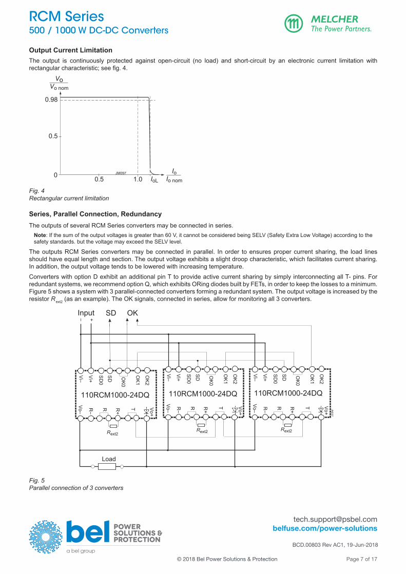
Output Current LimitationThe output is continuously protected against open-circuit (no load) and short-circuit by an electronic current limitation with rectangularcharacteristic;seefig.4.
VoVo nom
0.98
0.5
00.5 1.0 IoL
Io
Io nom
JM097
Fig. 4Rectangular current limitation
Series, Parallel Connection, RedundancyThe outputs of several RCM Series converters may be con nected in series.
Note: If the sum of the output voltages is greater than 60 V, it cannot be considered being SELV (Safety Extra Low Voltage) according to the safety standards. but the voltage may exceed the SELV level.
The outputs RCM Series converters may be con nected in parallel. In order to ensures proper current sharing, the load lines should have equal length and section. The output voltage exhibits a slight droop characteristic, which facilitates current sharing. In addition, the output voltage tends to be lowered with increasing temperature.Converters with option D exhibit an additional pin T to provide active current sharing by simply interconnecting all T- pins. For redundant systems, we recommend option Q, which exhibits ORing diodes built by FETs, in order to keep the losses to a minimum. Figure 5 shows a system with 3 parallel-connected converters forming a redundant system. The output voltage is increased by the resistor Rext2 (as an example). The OK signals, connected in series, allow for monitoring all 3 converters.
Vo–
Vo+
T
Vi–
Vi+
SD0
OK1
OK2
R+
R–
OK0
110RCM1000-24DQ
SD
R
Load
Vo–
Vo+
T
Vi–
Vi+
SD0
OK1
OK2
+
JM237
R+
R–
OK0
110RCM1000-24DQ
SD
RVo–
Vo+
T
Vi–
Vi+
SD0
OK1
OK2
R+
R–
Rext2
OK0
110RCM1000-24DQ
SD
R
–Input OKSD
Rext2 Rext2
Fig. 5Parallel connection of 3 converters

[email protected] belfuse.com/power-solutions
BCD.00803 Rev AC1, 19-Jun-2018
Page 8 of 17
RCM Series 500 / 1000 W DC-DC Converters
© 2018 Bel Power Solutions & Protection
Thermal Considerations and ProtectionA temperature protection is incorporated in the primary and secondary control logic each. It generates an internal inhibit signal, which disables the converter in case of over tem per a ture. The converter automatically recovers, when the temper a ture drops below thelimit;seefig.6.TherelationshipbetweenTA and TC depends heavily upon the conditions of operation and the integration into a system.
Caution: The installer must ensure that under all operating con ditions TC remains within the limits stated in table 7.
0
200
400
600
800
50 60 70 80 90 100
Po [W]
TA [°C]
1000 RCM1000
JM252
TC max
convection cooling
RCM500
40
with heatsink(dotted lines)
Fig. 6Typical output power derating versus temperature; vertical mounting position, free convection cooling.
LED IndicatorEachconverterexhibitsagreenLED“OutOK”,signalingthattheoutputvoltageisinsidethespecifiedrange.
[email protected] belfuse.com/power-solutions
BCD.00803 Rev AC1, 19-Jun-2018
Page 9 of 17
RCM Series 500 / 1000 W DC-DC Converters
© 2018 Bel Power Solutions & Protection
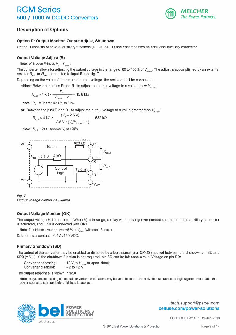
Description of Options
Option D: Output Monitor, Output Adjust, ShutdownOption D consists of several auxiliary functions (R, OK, SD, T) and en compasses an additional auxiliary connector.
Output Voltage Adjust (R)Note: With open R-input, Vo = Vo nom.
The converter allows for adjusting the output voltage in the range of 80 to 105% of Vo nom. The adjust is accomplished by an external resistor Rext1 or Rext2,connectedtoinputR;seefig.7.Depending on the value of the required output voltage, the resistor shall be connected: either: Between the pins R and R– to adjust the output voltage to a value below Vo nom: Vo Rext1 ≈ 4 kΩ • __________ – 15.8 kΩ Vo nom – Vo
Note: Rext1 = 0 Ω reduces Vo to 80%.
or: Between the pins R and R+ to adjust the output voltage to a value greater than Vo nom: (Vo – 2.5 V)Rext2 ≈ 4 kΩ • __________________ – 682 kΩ
2.5 V • (Vo/Vo nom – 1)
Note: Rext2 = 0 Ω increases Vo to 105%.
R–
R+
Vo–
4 kΩVref = 2.5 V
Rext1
Rext2
JM191
Vi–
Vi+
+Control
logic
Bias628 kΩ
15.8 kΩ
R
Fig. 7Output voltage control via R-input
Output Voltage Monitor (OK)The output voltage Vo is monitored. When Vo is in range, a relay with a changeover contact connected to the auxiliary connector is activated, and OK0 is connected with OK1.
Note: The trigger levels are typ. ±5 % of Vonom (with open R-input).
Data of relay contacts: 0.4 A /150 VDC.
Primary Shutdown (SD)The output of the converter may be enabled or disabled by a logic signal (e.g. CMOS) applied between the shutdown pin SD and SD0 (= Vi–). If the shutdown function is not re quired, pin SD can be left open-circuit. Voltage on pin SD:
Converter operating: 12 V to Vi max or open-circuitConverter disabled: –2 to +2 V
Theoutputresponseisshowninfig.8Note: In systems consisting of several converters, this feature may be used to control the activation sequence by logic signals or to enable the power source to start up, before full load is applied.

[email protected] belfuse.com/power-solutions
BCD.00803 Rev AC1, 19-Jun-2018
Page 10 of 17
RCM Series 500 / 1000 W DC-DC Converters
© 2018 Bel Power Solutions & Protection
Current Share Function in Parallel Operation (T)Just interconnect the T-pins of all converters to balance their output currents. Only a single-wire connection is needed.
0
t0
SD1
0.1
1Vo/Vo nom
ton
tf
JM193a
t off
tr thu
td on
Fig. 8Typical output response to the SD-signal. If option M is not fitted, thu = 0 ms.
Option Q: ORing FET for Redundant Systems Two parallel connected converters are separated with ORing diodes (built by FETs). If one converter fails, the remaining one still delivers the full power to the loads. If more power is needed, the system may be extended to more parallel converters (n+1 re-dundancy).Current sharing must be ensured by load lines of equal section and length. In addition, a slight droop characteristic of the outputs andanegativetemperaturecoefficientarehelpfulaswell.To keep the losses as small as possible, the ORing diode is replaced by a FET.
Note: In the case of a failing converter, the output voltage is maintained by the redundant converters. However, the failing item should be identifiedandreplaced.WerecommendtheOutOKfunction(optionD).
Option M: Interruption TimeThe interruption time thuisspecifiedintherailwaystandardEN50155:2017clause5.1.1.4:ClassS2is10ms.ItismeasuredatVB nom (nominal battery voltage) for interruption and short-circuit of the input. After such an event, the system is ready for the next event after 10 s. Fig. 6 shows the output voltage Vo,ifoptionMisfitted.OptionMencompassesabackrushprotectionformedbya FET device. Forlesscriticalapplications,optionMisnotrequired(classS1).Suchunitshaveaslightlybetterefficiency.
Option F: Incorporated FuseThe railway standard EN 50155 does not recommend fuses in converters. Consequently, the installer should preview an external fuse or circuit breaker. However,whenthisisnotpossible,weofferanincorporatedfuse(optionF)withactivereversepolarityprotectionformedbyaFET device. The fuse is not accessible and will not trip, unless the converter is really defect. The type of the incorporated fuses is specifiedintable4.Suchfusesarealsorecommendedforexternalfuses. Table 4: Recommended external fuses (same as with option F)
Converter Specification Ordering number72RCM500-24 15 A fast acting Littlefuse 0505015.MX52 LEP
110RCM500-24 15 A fast acting Littlefuse 0505015.MX52 LEP
72RCM1000-24
110RCM1000-24 25 A fast acting Littlefuse 0505025.MX52 LEP
Option K: Pluggable ConnectorsThis option allows the use of preassembled pluggabale con nectors; for details see Accessories.
Note: Female connectors must be ordered separately.

[email protected] belfuse.com/power-solutions
BCD.00803 Rev AC1, 19-Jun-2018
Page 11 of 17
RCM Series 500 / 1000 W DC-DC Converters
© 2018 Bel Power Solutions & Protection
Electromagnetic Compatibility (EMC)
Electromagnetic Immunity
Table 5: Electromagnetic immunity (type tests). Corresponds or Exceeds EN50121-3-2:2016 and AREMA.
Phenomenon Standard Level Coupling mode 1 Value applied
Waveform Source imped.
Test procedure In oper.
Perf. crit. 2
Electrostatic discharge (to case)
IEC/EN 61000-4-2 4
contact discharge 6000 Vp 1/50 ns 330Ω150 pF
10 pos. & 10 neg. discharges yes A
air discharge 8000 Vp
Electromagnetic field
IEC/EN 61000-4-3
x antenna 20 V/m AM 80% / 1 kHz N/A 80 – 800 MHz yes A
antenna
20 V/m
AM 80% / 1 kHz N/A
800 – 1000 MHz
yes A20 V/m 1400 – 2000 MHz
5 V/m 2000 – 2700 MHz
3 V/m 5100 – 6000 MHz
Electrical fast transients/burst
IEC/EN 61000-4-4 3 capacitive, o/c
±2000 Vp
bursts of 5/50 ns; 2.5/5 kHz over 15 ms; burst period: 300 ms
50Ω
60 s positive 60 s negative transients per coupling mode
yes A3 i/c, +i/–i
direct
Surges IEC/EN 61000-4-5
3
i/c ±2000 Vp
1.2 / 50 µs
42Ω0.5μF 5 pos. & 5 neg.
surges per coupling mode
yesA
+i/– i ±1000 Vp
i/c, +i/–i ±2000 Vp12Ω9μF B
Conducted disturbances
IEC/EN 61000-4-6 3 i, o, signal wires 10 VAC
(140 dBµV) AM 80% / 1 kHz 150Ω 0.15 – 80 MHz yes A
Power frequency magneticfield
IEC/EN 61000-4-8 3 300 A/m 60 s in all 3 axis yes A
1 i = input, o = output, c = case2 A = normal operation, no deviation from specs.; B = normal operation, temporary loss of function or deviation from specs possible

[email protected] belfuse.com/power-solutions
BCD.00803 Rev AC1, 19-Jun-2018
Page 12 of 17
RCM Series 500 / 1000 W DC-DC Converters
© 2018 Bel Power Solutions & Protection
Electromagnetic EmissionsTheconductedemissions(fig.9)havebeentestedaccordingtoEN55011,group1,classA(similartoEN55032),muchbettervaluesthanrequestedbyEN50121-3-2:2016,table2.1.Thelimitsinfig.9applytoquasipeakvalues,whicharealwayslowerthen peak values. Radiated emissions have been tested as per EN 55011, group 1, class A, similar to EN 61000-6-4+A1:2011, table 1. The test was executedwithhorizontalandverticalpolarization;theworseresultisshowninfig.10.
0
dBµV
20
40
60
80
110RCM500-24DMQF; Vi = 110 V, Vo = 24 V; Io = 21 AClass A, 25-May-2017
JM225
EN 55011 A av
EN 55011 A qp
0.2 0.5 1 2 5 10 20 MHz 0
dBµV
20
40
60
80
110RCM500-24DMQF; Vi = 110 V, Vo = 24 V; Io = 21 AClass A, 25-May-2017
JM225
EN 55011 A av
EN 55011 A qp
0.2 0.5 1 2 5 10 20 MHz 0
dBµV
20
40
60
80
110RCM1000-24DMQF; Vi = 110 V, Vo = 24 V; Io = 42 AClass A, 25-May-2017
JM227
EN 55011 A av
EN 55011 A qp
0.2 0.5 1 2 5 10 20 MHz
Fig. 9a110RCM500-24: Typ. conducted disturbances at the input (Vi =110 V, Ii nom, resistive load, quasi peak and average).
Fig. 9b110RCM1000-24: Typ. conducted disturbances at the input (Vi =110 V, I i nom, resistive load, quasi peak and average).
30 50 100 200 500 1000 MHz
dBµV/m
10
20
30
40
0
60EMC Labatory, 110RCM500-24DMQF; Vi = 110 VDC, Vo = 24 V / 21 AETS-3143B Testdistance 3 m, Class A, 25-May-2017 JM226
50QP Limit EN 55011, Group 1, Class A, 3 m
30 50 100 200 500 1000 MHz
dBµV/m
10
20
30
40
0
60EMC Labatory, 110RCM500-24DMQF; Vi = 110 VDC, Vo = 24 V / 42 AETS-3143B Testdistance 3 m, Class A, 25-May-2017 JM228
50QP Limit EN 55011, Group 1, Class A, 3 m
Fig. 10a110RCM500-24: Typ. radiated disturbances in 3 m distance (Vi = 110 V, I i nom, resistive load, quasi peak).
Fig. 10b110RCM1000-24: Typ. radiated disturbances in 3 m distance (Vi = 110 V, I i nom, resistive load, quasi peak).

[email protected] belfuse.com/power-solutions
BCD.00803 Rev AC1, 19-Jun-2018
Page 13 of 17
RCM Series 500 / 1000 W DC-DC Converters
© 2018 Bel Power Solutions & Protection
Immunity to Environmental ConditionsTable 6: Mechanical and climatic stress. Air pressure 800 – 1200 hPa
Test method Standard Test Conditions StatusAd Low temperature
start-up testEN 50155:2017, clause 13.4.4IEC/EN 60068-2-1
Temperature, duration: - 40 °C, 2 hNot operating
Performance test: +25 °C
Be Dry heat test, cycle A
EN 50155:2017, clause 13.4.5 IEC/EN 60068-2-2
Temperature: 70 °C Operating perf. crit. ADuration: 6 h
Db 2 Cyclic damp heat test
EN 50155:2017, clause 13.4.7 IEC/EN 60068-2-30
Temperature: 55 °C and 25 °C
Not operating Cycles(respirationeffect): 2
Duration: 2x 24 h
Ka Salt mist test sodium chloride (NaCl) solution
EN 50155:2017, clause 13.4.10IEC/EN 60068-2-11
Temperature: 35 ±2 °C Converter not operatingDuration: 48 h
Functional random vibration test
EN 50155:2017 clause 13.4.11.4 EN 61373:2010 clause 8, class B, body mounted 1
Acceleration amplitude: 0.1 gn = 1.01 m/s2
Operating perf. crit. A
Frequency band: 5 – 150 Hz
Test duration: 30 min (10 min in each axis)
Simulated long life testing
EN 50155:2017 clause 13.4.11.2
EN 61373:2010 clause 9, class B, body mounted 1
Acceleration amplitude: 0.58 gn = 5.72 m/s2
Not operating Frequency band: 5 – 150 Hz
Test duration: 15 h (5 h in each axis)
Shock test EN 50155:2017 clause 13.4.11.3 EN 61373:2010 clause 10, class B, body mounted 1
Acceleration amplitude: 5.1 gnOperating perf. crit. A Bump duration: 30 ms
Number of bumps: 18 (3 in each direction)
Vibration sinusoidal AREMA Part. 11.5.1 class C, D, E, I, J
Acceleration amplitude: 0.3” (5 – 20 Hz) 1.5 gn = 14.7 m/s2
Operating perf. crit. A Frequency: 10 – 200 Hz
Test duration: 12 h (4 h in each axis)
Mechanical shock AREMA Part. 11.5.1 class C, D, E, I, J
Acceleration amplitude: 10 gn = 98 m/s2
Operating perf. crit. A Bump duration: 11 ms
Number of bumps: 18 (3 in each direction)
1 Body mounted = chassis of a railway coach
TemperaturesTable 7: Temperature specifications, valid for an air pressure of 800 – 1200 hPa (800 – 1200 mbar)
Model RCM500 RCM1000 UnitEN 50155:2017 Class OT4 EN 50155:2017 Class OT2
Characteristics Conditions min max 10 min min max 10 minTA Ambient temperature Converter operating - 40 70 85 - 40 55 2 70
° CTC Case temperature 1 - 40 90 90
TS Storage temperature Not operational - 55 85 - 55 85
1 Measured at the measurement point TC ; see Mechanical Data.2 RCM1000 can be operated at higher temperature with reduced output power.
ReliabilityTable 8: MTBF and device hours
Ratings at specified case temperature between failures Model MTBFAccord. to IEC 62380 110RCM500-24DMQF 1 120 000 h
110RCM1000-24DMQF 1 110 000 h

[email protected] belfuse.com/power-solutions
BCD.00803 Rev AC1, 19-Jun-2018
Page 14 of 17
RCM Series 500 / 1000 W DC-DC Converters
© 2018 Bel Power Solutions & Protection
Mechanical DataDimensions in mm.
4 .5 (4x)
Vo+ Vo– Vi– Vi+ PE
Measuringpoint of case
temperatureTC
JM206d
10.9553.65
99.65
7
92.7570.5
209
197
147.
05
123141
9.0
6
4071
.566 Heatsink fixation
2x M36
13.953.7
99.4
7
Vo+ Vo– Vi– Vi+ PE
JM204e
Measuringpoint of case
temperatureTC
92.75
147
.05
197
209
123
6
9.0
Heatsink fixation2x M3
6
70.5
71.5
66
Vo+ Vo– Vi– Vi+ PE
10.9553.65
99.65
46
141
13.953.7
99.4
7
Vo+ Vo– Vi– Vi+ PE
RCM500/1000standard
RCM500/1000with option K
Fig. 11Case for RCM500 (RCM03), Aluminum, EP powder-coated; 1160 g.
Fig. 12Case for RCM1000 (RCM04), Aluminum, EP powder-coated; 1250 g.
6
17.7
pluggableconnector
JM246
EuropeanProjection
Fig. 13Case detail for RCM500/1000 with option K

[email protected] belfuse.com/power-solutions
BCD.00803 Rev AC1, 19-Jun-2018
Page 15 of 17
RCM Series 500 / 1000 W DC-DC Converters
© 2018 Bel Power Solutions & Protection
Safety and Installation Instruction
Connectors and Pin Allocation - Input connector, 3 pins: Wago 745-353: Vi+, Vi–, PE;
wire sections: RCM500/1000: 0.2 – 6 mm2, 24 – 10 AWG; with option K: Weidmüller 1048500000
- Output connector, 2 pins: Wago 745-652/006-000: Vo+, Vo; wire sections: RCM500/1000: 0.2 – 16 mm2, 24 – 06 AWG with option K: Weidmüller 1048390000
- Auxiliaryconnector:PhoenixContact1874043,pinallocationseefig.14.
RR+
RR–
TT
n.c.
n.c
.O
K0
OK1
OK
0O
K2n.
c. n
.c.
SD0
SD
Fig. 14Auxiliary connector pin allocation
Installation InstructionThese converters are components, intended exclusively for inclusion by an industrial assembly process or by a pro fessionally competent person. Installation must strictly follow the national safety regulations in respect of the enclosure, mounting, creepage distances, clearances, markings and segregation requirements of the end-use application.Connectiontothesystemshallonlybeeffectedwithcableswithsuitablesection(primaryandsecondaryconnectorincageclamptechnique). The auxiliary connector shall be connected via the suitable female connector; see Accessories. Other installation methods may not meet the safety requirements. Check that PE is safely connected to protective earth.No fuse is incorporated in the converter (except for option F). An external circuit breaker or a fuse in the wiring to one or both input pins.Donotopentheconverters,orthewarrantywillbeinvalidated.Makesurethatthereissufficientairflowavailableforconvectioncoolingandthatthetemperatureofthebottomplateiswithinthespecifiedrange.Thisshouldbeverifiedbymeasuringthecasetemperatureat thespecifiedmeasuringpoint,whentheconverter isoperated in theend-useapplication.TC max should not be exceeded. Ensure that a failure of the converter does not result in a hazardous condition.
Standards and ApprovalsThe RCM Series converters are approved according to the last edition of IEC/EN 60950-1 and UL/CSA 60950-1.They have been evaluated for: • Class I equipment • Building in • Double or reinforced insulation based on 250 VAC or 240 VDC between input and output, and between input and OK signals
(relay contacts) • Pollution degree 2 environment
The converters are subject to manufacturing surveillance in accordance with the above mentioned UL standards and with ISO 9001:2015.
Cleaning Liquids and Protection DegreeThe converters are not hermetically sealed. In order to avoid possible damage, any penetration of liquids shall be avoided. The converters correspond to protection degree IP 30.

[email protected] belfuse.com/power-solutions
BCD.00803 Rev AC1, 19-Jun-2018
Page 16 of 17
RCM Series 500 / 1000 W DC-DC Converters
© 2018 Bel Power Solutions & Protection
Railway ApplicationsThe RCM Series converters have been designed observing the railway standards EN 50155:2017, EN 50121-3-2:2016, and AREMA. Allboardsarecoatedwithaprotectivelacquer.Theconverterscomplywiththefire&smokestandardEN45545-2,HL1toHL3.
Insulation TestThe electric strength test is performed in the factory as routine test in accordance with EN 50514 and IEC/EN 60950 and AREMA. Itshouldnotberepeatedinthefield.TheCompanywillnothonorwarrantyclaimsresultingfromincorrectlyexecutedelectricstrength tests.
Table 9: Isolation
Characteristics Input to Output to Case OK contacts to UnitOutput 1 Case + Output Input Case Outputs
Electric strength test Factory test 10 s 4.2 2.86 2.86 2.86 2.86 2.86 kVDC
AC test voltage equivalent to factory test 3.0 2.0 2.0 2.0 2.0 2.0 kVAC
Insulation resistance >300 2 >300 2 >300 >300 >300 >300 MΩ
Creepage distances 5.0 3.5 3.5 3.5 3.5 3.5 mm
1 Pretest of subassemblies in accordance with IEC/EN 60950 2 Tested at 500 VDC
[email protected] belfuse.com/power-solutions
BCD.00803 Rev AC1, 19-Jun-2018
Page 17 of 17
RCM Series 500 / 1000 W DC-DC Converters
© 2018 Bel Power Solutions & Protection
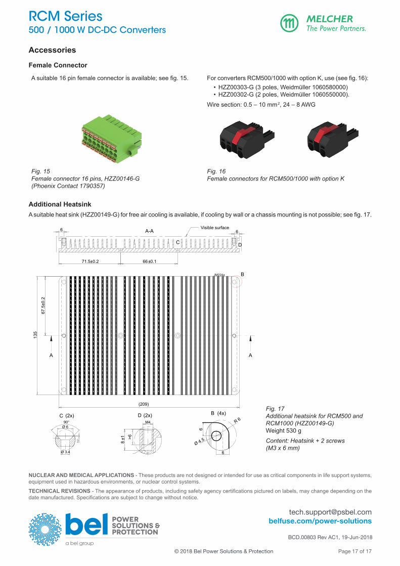
Accessories
Female Connector
Asuitable16pinfemaleconnectorisavailable;seefig.15. ForconvertersRCM500/1000withoptionK,use(seefig.16): • HZZ00303-G (3 poles, Weidmüller 1060580000)
• HZZ00302-G (2 poles, Weidmüller 1060550000).Wire section: 0.5 – 10 mm2, 24 – 8 AWG
Fig. 15Female connector 16 pins, HZZ00146-G (Phoenix Contact 1790357)
Fig. 16Female connectors for RCM500/1000 with option K
Additional HeatsinkAsuitableheatsink(HZZ00149-G)forfreeaircoolingisavailable,ifcoolingbywallorachassismountingisnotpossible;seefig.17.
Visible surface
A A
A-A
B
67.5
±0.2
71.5±0.2 66±0.1
C
135
(209)
6 6
D
C (2x)
0.2
90°
Ø 3.4
D (2x)M4
>68
±1
B (4x)
6
6
R 6
Ø 4.5
JM224a
Ø 6
Fig. 17Additional heatsink for RCM500 and RCM1000 (HZZ00149-G)Weight 530 gContent: Heatsink + 2 screws (M3 x 6 mm)
NUCLEAR AND MEDICAL APPLICATIONS - These products are not designed or intended for use as critical components in life support systems, equipment used in hazardous environments, or nuclear control systems.
TECHNICAL REVISIONS-Theappearanceofproducts,includingsafetyagencycertificationspicturedonlabels,maychangedependingonthedatemanufactured.Specificationsaresubjecttochangewithoutnotice.