Embed Size (px)
Citation preview

High-Voltage, High-Current DC-
DC Converters
Applications and Topologies
Converters Theme
Underpinning Research

DC Power Networks
Underpinning Research
• DC power can reduce losses and allow better
utilisation of conductor ratings.
• Power Networks must accommodate growing levels of
power electronic connected generation and loads:
• Most power electronic converters operate from DC.
• Elimination of intermediate AC interconnection
appears to reduce the number of conversion stages required.
Advantages of DC Power
Networks
Underpinning Research
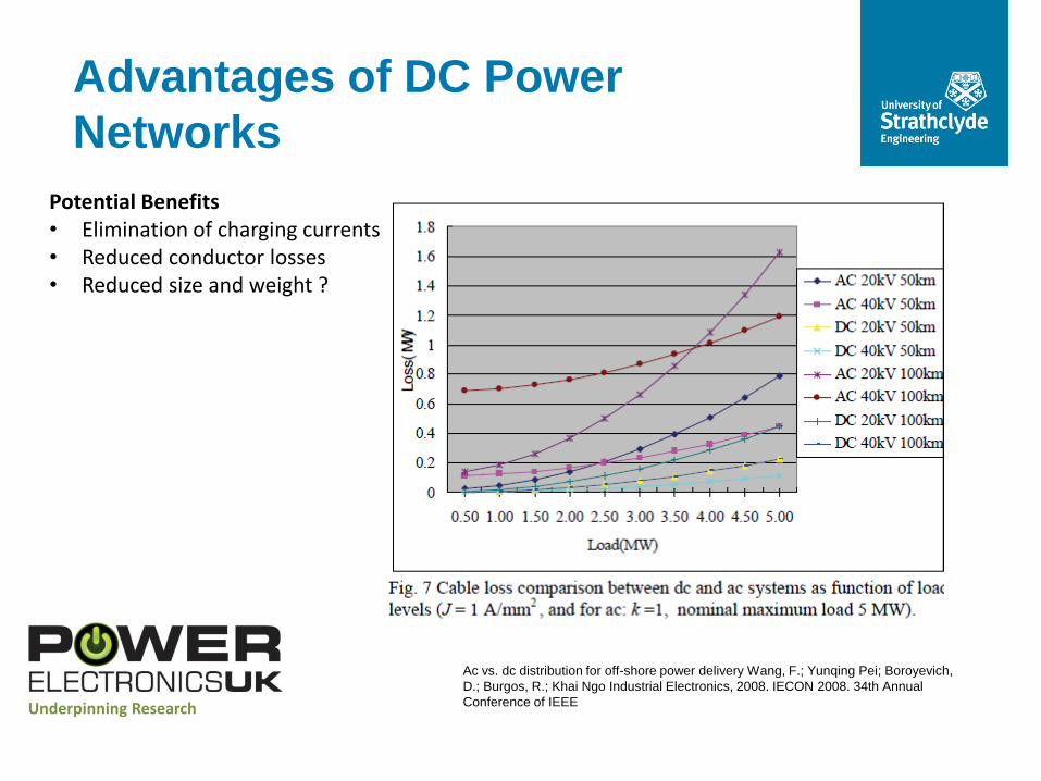
Potential Benefits • Elimination of charging currents and • Reduced conductor losses • Reduced size and weight ?
Ac vs. dc distribution for off-shore power delivery Wang, F.; Yunqing Pei; Boroyevich,
D.; Burgos, R.; Khai Ngo Industrial Electronics, 2008. IECON 2008. 34th Annual
Conference of IEEE

Reduced Conversion Stages
Underpinning Research
G ac/dc dc/AC
G ac/dc dc/AC
AC/dc
Lo
ad
s
dc/ac
dc/dc
G ac/DC
G ac/DC
Lo
ad
s
DC/ac
DC/dc
Underpinning Research
MVAC/
HVDC
MVDC/
HVDC
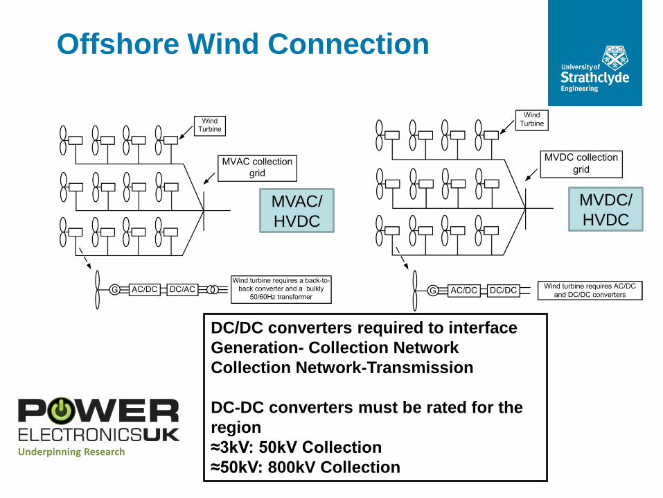
Offshore Wind Connection
DC/DC converters required to interface
Generation- Collection Network
Collection Network-Transmission
DC-DC converters must be rated for the
region
≈3kV: 50kV Collection
≈50kV: 800kV Collection
Underpinning Research
DC/DC Converters
• Different DC voltages may be preferable at generation,
collection/distribution and transmission stages.
• DC/DC converters will be required to interface these stages.
• HVDC networks may require DC/DC interface to connect different
transmission (legacy) voltages.
• Meshed DC networks may require DC/DC converters to provide
auxiliary functions.
• Balancing power flows in meshed DC networks • Controlling DC fault currents stages required.
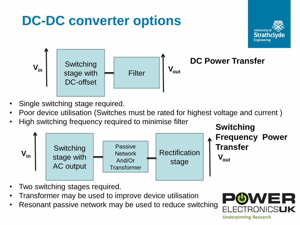
DC-DC converter options
Vin Switching
stage with
DC-offset
Filter Vout
Switching
stage with
AC output
Passive
Network
And/Or
Transformer
Vout Vin
Rectification
stage
• Single switching stage required.
• Poor device utilisation (Switches must be rated for highest voltage and current )
• High switching frequency required to minimise filter
• Two switching stages required.
• Transformer may be used to improve device utilisation
• Resonant passive network may be used to reduce switching loss
DC Power Transfer
Switching
Frequency Power
Transfer
Underpinning Research
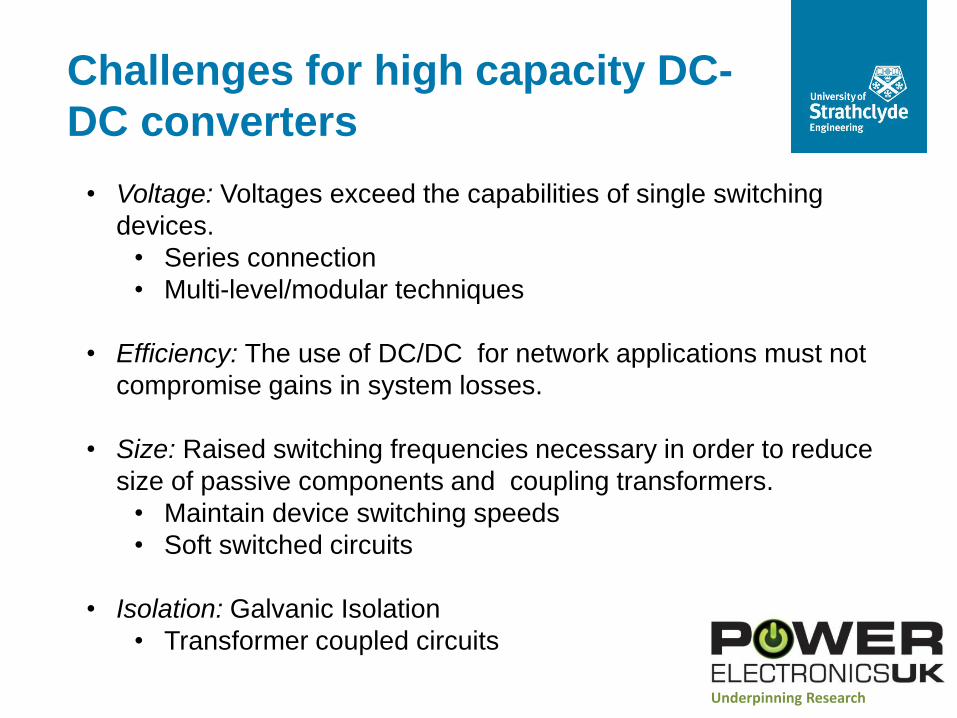
• Voltage: Voltages exceed the capabilities of single switching
devices.
• Series connection
• Multi-level/modular techniques
• Efficiency: The use of DC/DC for network applications must not
compromise gains in system losses.
• Size: Raised switching frequencies necessary in order to reduce
size of passive components and coupling transformers.
• Maintain device switching speeds
• Soft switched circuits
• Isolation: Galvanic Isolation
• Transformer coupled circuits
Challenges for high capacity DC-
DC converters
Underpinning Research
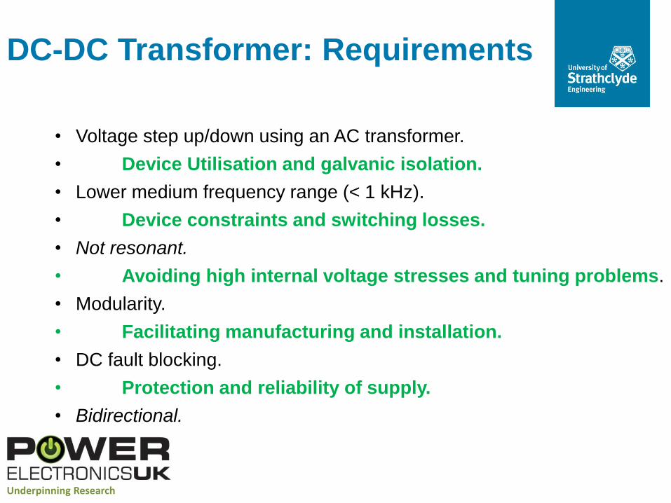
• Voltage step up/down using an AC transformer.
• Device Utilisation and galvanic isolation.
• Lower medium frequency range (< 1 kHz).
• Device constraints and switching losses.
• Not resonant.
• Avoiding high internal voltage stresses and tuning problems.
• Modularity.
• Facilitating manufacturing and installation.
• DC fault blocking.
• Protection and reliability of supply.
• Bidirectional.
DC-DC Transformer: Requirements
Underpinning Research
Underpinning Research
• Dynamic voltage sharing may limit the achievable switching speed of individual
devices.
• HVDC links have shown that the use of series connection of IGBTs is feasible
to the region of ±200kV
• Power frequencies up to 1-2kHz may be achievable to reduce the size and
weight of magnetic components. This will result in overall semiconductor
losses of a similar level to that of a3 two-level HVDC converter.
• Switching large voltage steps, such as 400kV or higher, at 1 or 2kHz impresses
extremely high dv/dt upon passive components and interfacing transformers.
Series Connection
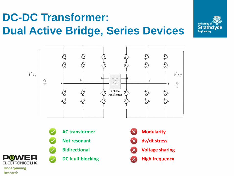
AC transformer
Not resonant
Bidirectional
DC fault blocking
Modularity
dv/dt stress
Voltage sharing
High frequency
DC-DC Transformer:
Dual Active Bridge, Series Devices
Underpinning Research
Underpinning Research
Multi-Level Techniques
• A number of multilevel DC/AC topologies exist which could be applied
to transformer coupled DC-DC converters
• Multi-level can decouple switching frequency from output power quality
in DC-AC converters working at power frequencies of 50-60Hz resulting
in significant efficiency improvements.. However:
• Advantages for DC-DC conversion are not clear since efficiency will
reduce if raised power frequency employed to reduce transformer size.
• Capacitor energy storage requirement and resulting volume can be
high. (Reduction in capacitor requirement with raised power frequency.)
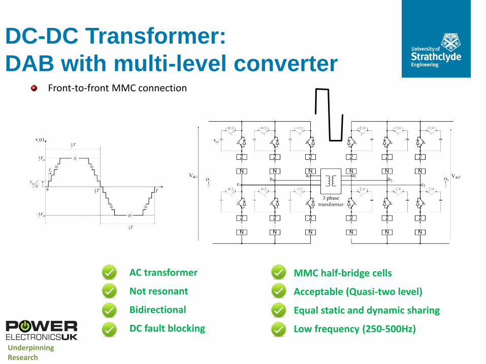
MMC half-bridge cells
Acceptable (Quasi-two level)
Equal static and dynamic sharing
Low frequency (250-500Hz)
DC-DC Transformer:
DAB with multi-level converter Front-to-front MMC connection
AC transformer
Not resonant
Bidirectional
DC fault blocking
Underpinning Research
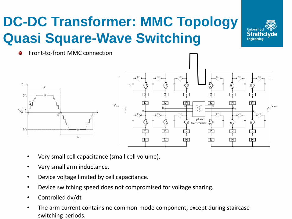
• Very small cell capacitance (small cell volume).
• Very small arm inductance.
• Device voltage limited by cell capacitance.
• Device switching speed does not compromised for voltage sharing.
• Controlled dv/dt
• The arm current contains no common-mode component, except during staircase switching periods.
DC-DC Transformer: MMC Topology
Quasi Square-Wave Switching Front-to-front MMC connection
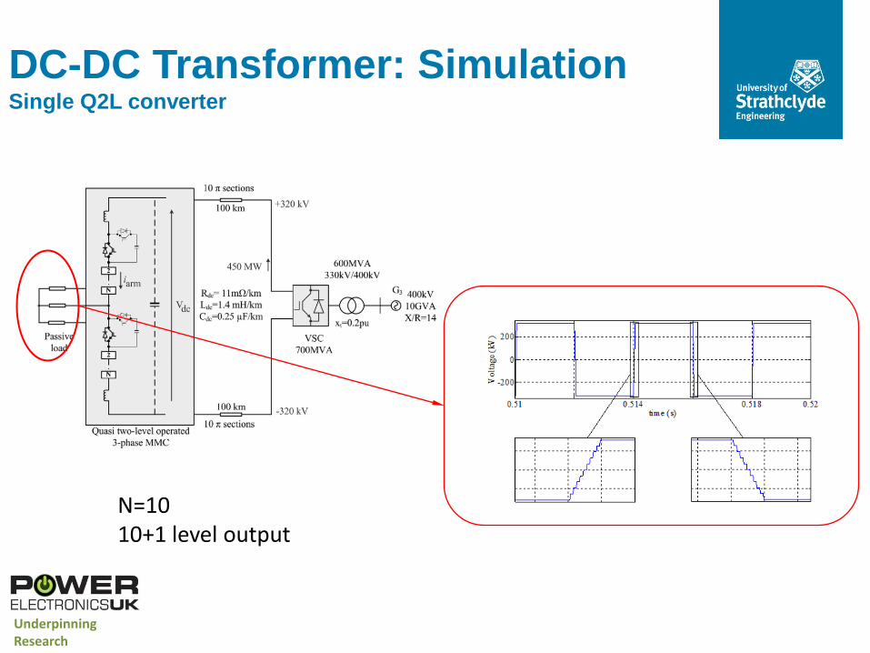
N=10 10+1 level output
DC-DC Transformer: Simulation Single Q2L converter
Underpinning Research
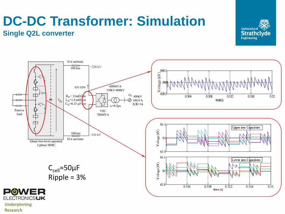
Ccell=50μF Ripple = 3%
DC-DC Transformer: Simulation Single Q2L converter
Underpinning Research
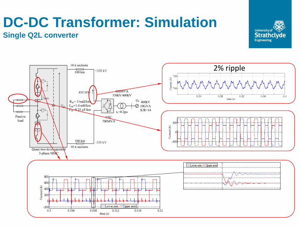
2% ripple
DC-DC Transformer: Simulation Single Q2L converter
Modular Transformer Coupled
DC-DC
Inp
ut
Co
nvert
er
Arr
ay
i0u
tpu
t C
on
vert
er
Arr
ay
Transformer
Array
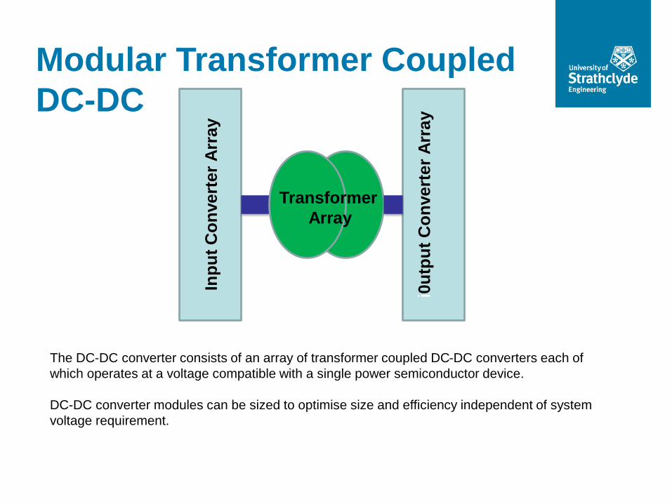
The DC-DC converter consists of an array of transformer coupled DC-DC converters each of
which operates at a voltage compatible with a single power semiconductor device.
DC-DC converter modules can be sized to optimise size and efficiency independent of system
voltage requirement.
Modular Transformer Coupled
DC-DC
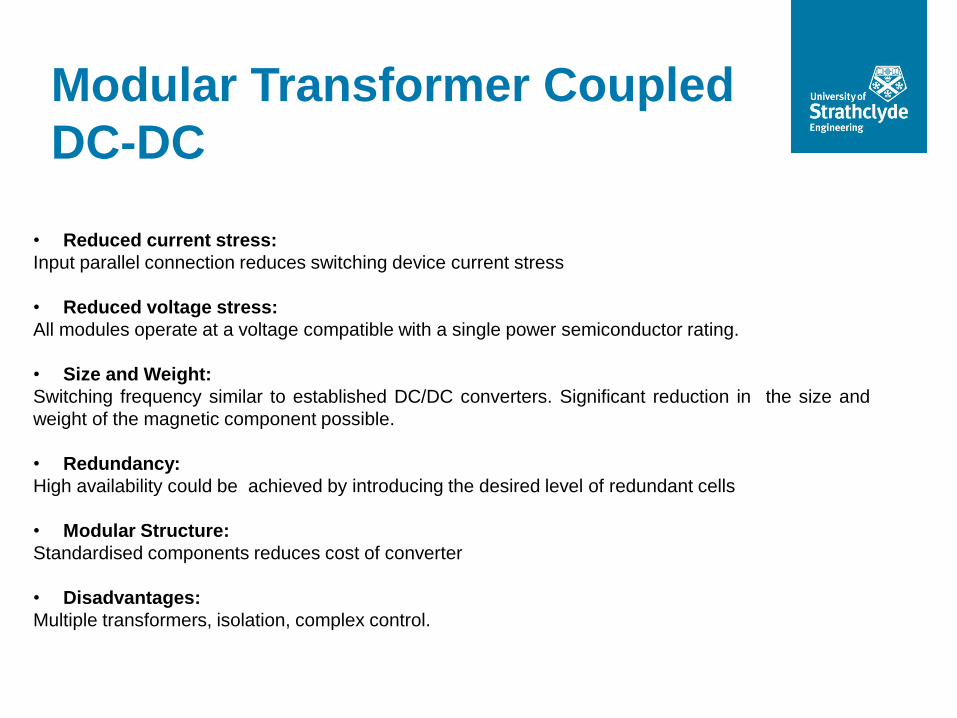
• Reduced current stress:
Input parallel connection reduces switching device current stress
• Reduced voltage stress:
All modules operate at a voltage compatible with a single power semiconductor rating.
• Size and Weight:
Switching frequency similar to established DC/DC converters. Significant reduction in the size and
weight of the magnetic component possible.
• Redundancy:
High availability could be achieved by introducing the desired level of redundant cells
• Modular Structure:
Standardised components reduces cost of converter
• Disadvantages:
Multiple transformers, isolation, complex control.
Modular Transformer Coupled
DC-DC Building Blocks
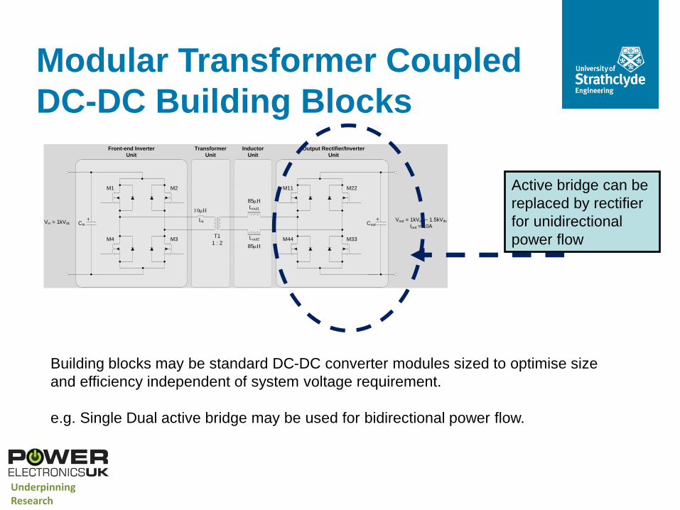
Building blocks may be standard DC-DC converter modules sized to optimise size
and efficiency independent of system voltage requirement.
e.g. Single Dual active bridge may be used for bidirectional power flow.
M1
M4
M2
M3
CinVin = 1kVdc
T1
M22
M33
M11
M44
Lout1
Cout
Vout = 1kVdc – 1.5kVdc
Iout = 10A
Front-end Inverter
Unit
Transformer
Unit
Output Rectifier/Inverter
Unit
Lk
Inductor
Unit
1 : 2Lout2
85mH
85mH
10mH
Active bridge can be
replaced by rectifier
for unidirectional
power flow
Underpinning Research
Modular Transformer Coupled
DC-DC
Tr2
Trn
2oV
onV
Module 1
Module 2
Module n
oV
inV
2ini
inni
Tr11ini
Tr(n+2)
Tr2n
(2 )o nV
Module n+1
Module n+2
Module 2n
Tr(n+1)( 1)in ni
( 2)in ni
(2n)ini
( 1)o nV
( 2)o nV
1oV
1cdV
2cdV
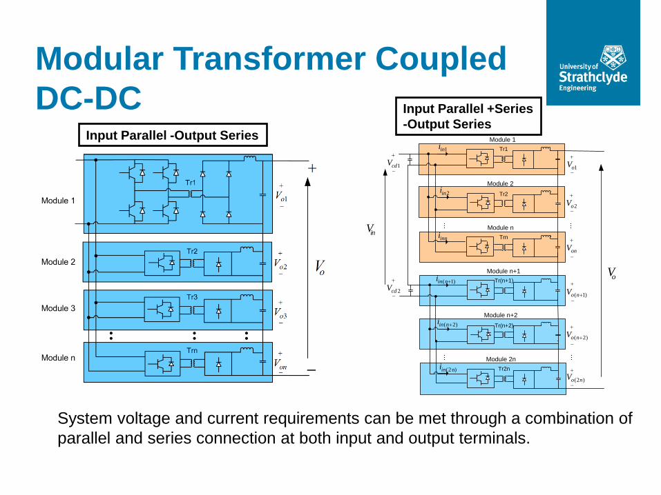
System voltage and current requirements can be met through a combination of
parallel and series connection at both input and output terminals.
Input Parallel +Series
-Output Series Input Parallel -Output Series
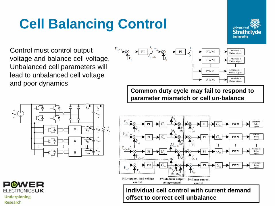
Cell Balancing Control
Common duty cycle may fail to respond to
parameter mismatch or cell un-balance
Individual cell control with current demand
offset to correct cell unbalance Underpinning Research
Control must control output
voltage and balance cell voltage.
Unbalanced cell parameters will
lead to unbalanced cell voltage
and poor dynamics
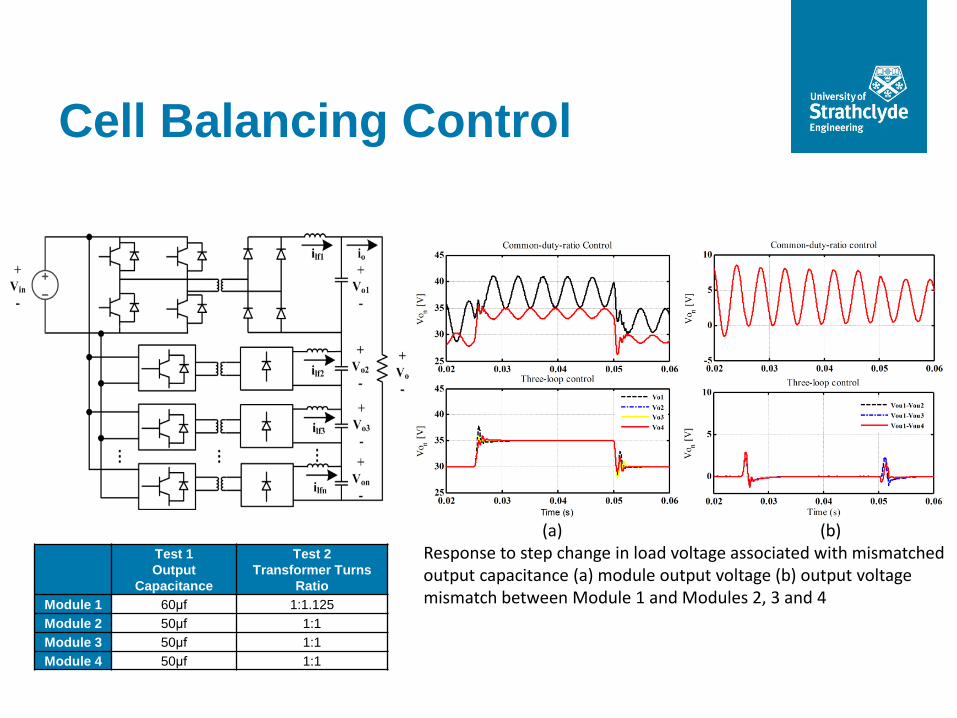
Test 1
Output
Capacitance
Test 2
Transformer Turns
Ratio
Module 1 60μf 1:1.125
Module 2 50μf 1:1
Module 3 50μf 1:1
Module 4 50μf 1:1
(a) (b) Response to step change in load voltage associated with mismatched output capacitance (a) module output voltage (b) output voltage mismatch between Module 1 and Modules 2, 3 and 4
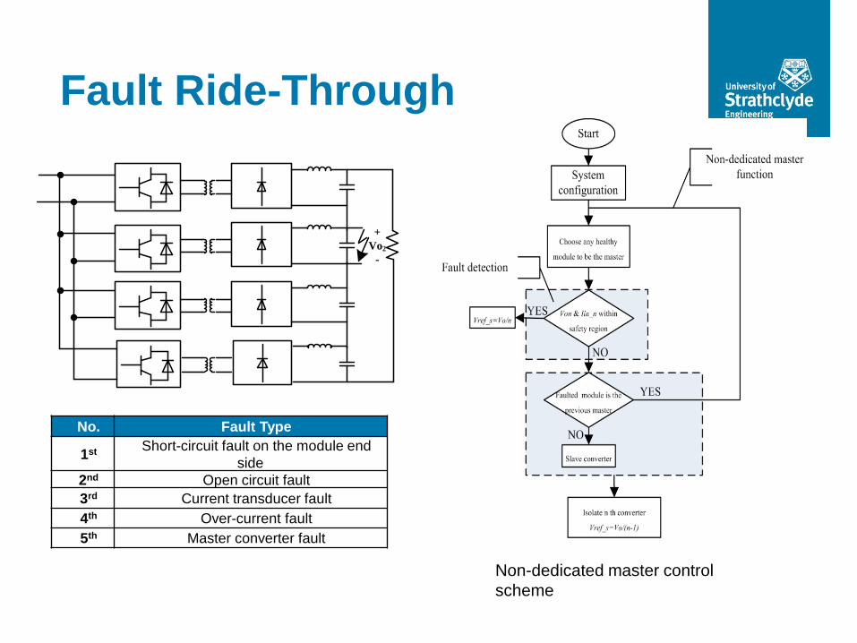
Cell Balancing Control
+
Vo2
-
No. Fault Type
1st Short-circuit fault on the module end
side
2nd Open circuit fault
3rd Current transducer fault
4th Over-current fault
5th Master converter fault Short circuit fault
Non-dedicated master control
scheme
Fault Ride-Through
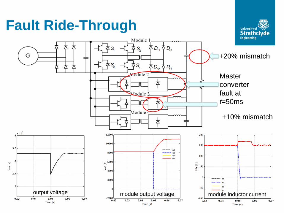
Fault Ride-Through
System Specifications
+10% mismatch
+20% mismatch
output voltage module output voltage module inductor current
Master
converter
fault at
t=50ms
Conclusions
Underpinning Research
The lack effective DC/DC converters remains one of the barriers to expansion of DC power networks. High capacity DC/DC converters are feasible. A wide range of topologies are under investigation but it is unclear if any deliver the advances in efficiency and power density necessary for utility scale DC applications.