Embed Size (px)
Citation preview

2005 Pearson Education South Asia Pte Ltd
6. Bending
1
CHAPTER OBJECTIVES
• Determine stress in members
caused by bending
• Discuss how to establish shear
and moment diagrams for a
beam or shaft
• Determine largest shear and moment in a member,
and specify where they occur
• Consider members that are straight, symmetric x-
section and homogeneous linear-elastic material

2005 Pearson Education South Asia Pte Ltd
6. Bending
2
CHAPTER OBJECTIVES
• Consider special cases of
unsymmetrical bending and
members made of composite
materials
• Consider curved members, stress
concentrations, inelastic bending,
and residual stresses

2005 Pearson Education South Asia Pte Ltd
6. Bending
3
CHAPTER OUTLINE
1. Shear and Moment Diagrams
2. Graphical Method for Constructing Shear and Moment Diagrams
3. Bending Deformation of a Straight Member
4. The Flexure Formula
5. Unsymmetrical Bending
6. *Composite Beams
7. *Reinforced Concrete Beams
8. *Curved Beams
9. Stress Concentrations
10. *Inelastic Bending
11. *Residual Stress

2005 Pearson Education South Asia Pte Ltd
6. Bending
4
• Members that are slender and support loadings
applied perpendicular to their longitudinal axis are
called beams
6.1 SHEAR AND MOMENT DIAGRAMS

2005 Pearson Education South Asia Pte Ltd
6. Bending
5
6.1 SHEAR AND MOMENT DIAGRAMS
• In order to design a beam, it is necessary to
determine the maximum shear and moment in the
beam
• Express V and M as functions of arbitrary position
x along axis.
• These functions can be represented by graphs
called shear and moment diagrams
• Engineers need to know the variation of shear and
moment along the beam to know where to
reinforce it

2005 Pearson Education South Asia Pte Ltd
6. Bending
6
6.1 SHEAR AND MOMENT DIAGRAMS
• Shear and bending-moment functions must be
determined for each region of the beam between
any two discontinuities of loading

2005 Pearson Education South Asia Pte Ltd
6. Bending
7
6.1 SHEAR AND MOMENT DIAGRAMS
Beam sign convention
• Although choice of sign convention is arbitrary, in
this course, we adopt the one often used by
engineers:
2005 Pearson Education South Asia Pte Ltd
6. Bending
8
6.1 SHEAR AND MOMENT DIAGRAMS
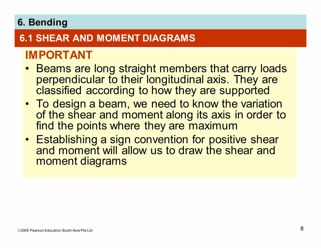
IMPORTANT
• Beams are long straight members that carry loads perpendicular to their longitudinal axis. They are classified according to how they are supported
• To design a beam, we need to know the variation of the shear and moment along its axis in order to find the points where they are maximum
• Establishing a sign convention for positive shear and moment will allow us to draw the shear and moment diagrams

2005 Pearson Education South Asia Pte Ltd
6. Bending
9
6.1 SHEAR AND MOMENT DIAGRAMS
Procedure for analysis
Support reactions
• Determine all reactive forces and couple moments acting on beam
• Resolve all forces into components acting perpendicular and parallel to beam’s axis
Shear and moment functions
• Specify separate coordinates x having an origin at beam’s left end, and extending to regions of beam between concentrated forces and/or couple moments, or where there is no discontinuity of distributed loading

2005 Pearson Education South Asia Pte Ltd
6. Bending
10
6.1 SHEAR AND MOMENT DIAGRAMS
Procedure for analysis
Shear and moment functions
• Section beam perpendicular to its axis at each distance x
• Draw free-body diagram of one segment
• Make sure V and M are shown acting in positive sense, according to sign convention
• Sum forces perpendicular to beam’s axis to get shear
• Sum moments about the sectioned end of segment to get moment

2005 Pearson Education South Asia Pte Ltd
6. Bending
11
6.1 SHEAR AND MOMENT DIAGRAMS
Procedure for analysis
Shear and moment diagrams
• Plot shear diagram (V vs. x) and moment diagram (M vs. x)
• If numerical values are positive, values are plotted above axis, otherwise, negative values are plotted below axis
• It is convenient to show the shear and moment diagrams directly below the free-body diagram

2005 Pearson Education South Asia Pte Ltd
6. Bending
12
EXAMPLE 6.6
Draw the shear and moment diagrams for beam
shown below.

2005 Pearson Education South Asia Pte Ltd
6. Bending
13
EXAMPLE 6.6 (SOLN)
Support reactions: Shown in free-body diagram.
Shear and moment functions
Since there is a discontinuity of distributed load
and a concentrated load at beam’s center, two
regions of x must be considered.
0 ≤ x1 ≤ 5 m,
+↑ Σ Fy = 0; ... V = 5.75 N
+ Σ M = 0; ... M = (5.75x1 + 80) kN·m

2005 Pearson Education South Asia Pte Ltd
6. Bending
14
EXAMPLE 6.6 (SOLN)
Shear and moment functions
5 m ≤ x2 ≤ 10 m,
+↑ Σ Fy = 0; ... V = (15.75 − 5x2) kN
+ Σ M = 0; ... M = (−5.75x22 + 15.75x2 +92.5) kN·m
Check results by applying w = dV/dx and V = dM/dx.

2005 Pearson Education South Asia Pte Ltd
6. Bending
15
EXAMPLE 6.6 (SOLN)
Shear and moment diagrams

2005 Pearson Education South Asia Pte Ltd
6. Bending
16
6.2 GRAPHICAL METHOD FOR CONSTRUCTING SHEAR AND MOMENT DIAGRAMS
• A simpler method to construct shear and moment
diagram, one that is based on two differential
equations that exist among distributed load, shear
and moment

2005 Pearson Education South Asia Pte Ltd
6. Bending
17
6.2 GRAPHICAL METHOD FOR CONSTRUCTING SHEAR AND MOMENT DIAGRAMS
Regions of distributed load
dV
dx= −w(x)
dM
dx= V
Slope of
shear
diagram
at each
point
Slope of
moment
diagram
at each
point
= −distributed
load
intensity at
each point
= shear at
each point

2005 Pearson Education South Asia Pte Ltd
6. Bending
18
6.2 GRAPHICAL METHOD FOR CONSTRUCTING SHEAR AND MOMENT DIAGRAMS
Regions of distributed load
∆V = −∫ w(x) dx ∆M = ∫ V(x) dx
Change in
shearChange in
moment
= −area under
distributed
loading
= area
under
shear
diagram

2005 Pearson Education South Asia Pte Ltd
6. Bending
19
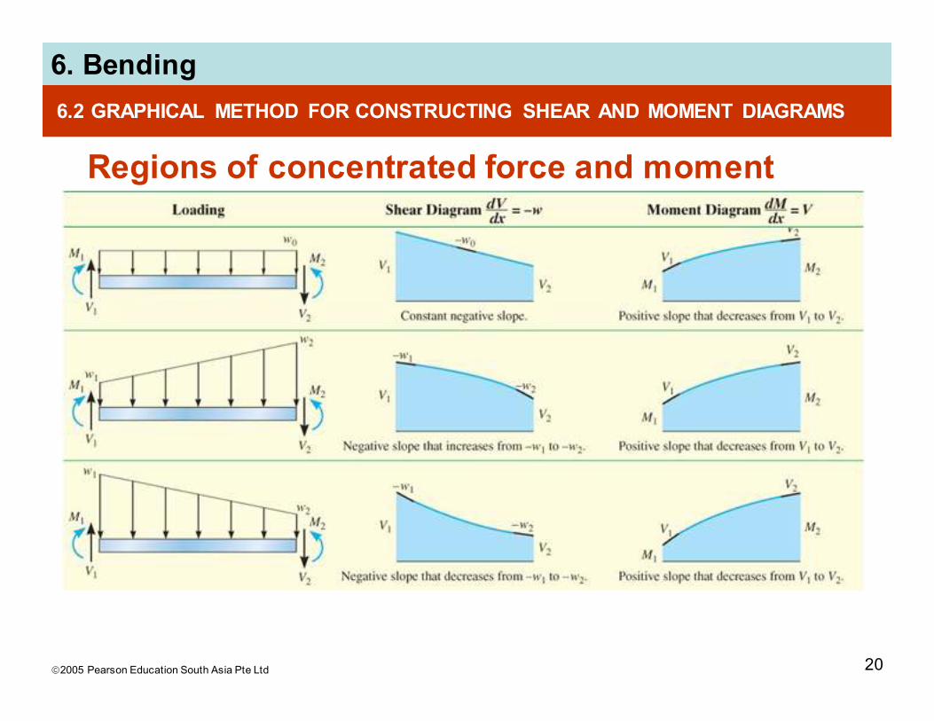
6.2 GRAPHICAL METHOD FOR CONSTRUCTING SHEAR AND MOMENT DIAGRAMS
Regions of concentrated force and moment
2005 Pearson Education South Asia Pte Ltd
6. Bending
20
6.2 GRAPHICAL METHOD FOR CONSTRUCTING SHEAR AND MOMENT DIAGRAMS
Regions of concentrated force and moment

2005 Pearson Education South Asia Pte Ltd
6. Bending
21
6.2 GRAPHICAL METHOD FOR CONSTRUCTING SHEAR AND MOMENT DIAGRAMS
Procedure for analysis
Support reactions
• Determine support reactions and resolve forces
acting on the beam into components that are
perpendicular and parallel to beam’s axis
Shear diagram
• Establish V and x axes
• Plot known values of shear at two ends of the
beam

2005 Pearson Education South Asia Pte Ltd
6. Bending
22
6.2 GRAPHICAL METHOD FOR CONSTRUCTING SHEAR AND MOMENT DIAGRAMS
Procedure for analysis
Shear diagram
• Since dV/dx = −w, slope of the shear diagram at
any point is equal to the (-ve) intensity of the
distributed loading at that point
• To find numerical value of shear at a point, use
method of sections and equation of equilibrium or
by using ∆V = −∫ w(x) dx, i.e., change in the shear
between any two points is equal to (-ve) area
under the load diagram between the two points

2005 Pearson Education South Asia Pte Ltd
6. Bending
23
6.2 GRAPHICAL METHOD FOR CONSTRUCTING SHEAR AND MOMENT DIAGRAMS
Procedure for analysis
Shear diagram
• Since w(x) must be integrated to obtain ∆V, then if w(x) is a curve of degree n, V(x) will be a curve of
degree n+1
Moment diagram
• Establish M and x axes and plot known values of
the moment at the ends of the beam
• Since dM/dx = V, slope of the moment diagram at
any point is equal to the shear at the point

2005 Pearson Education South Asia Pte Ltd
6. Bending
24
6.2 GRAPHICAL METHOD FOR CONSTRUCTING SHEAR AND MOMENT DIAGRAMS
Procedure for analysis
Moment diagram
• At point where shear is zero, dM/dx = 0 and
therefore this will be a point of maximum or
minimum moment
• If numerical value of moment is to be determined
at the point, use method of sections and equation
of equilibrium, or by using ∆M = ∫ V(x) dx, i.e.,
change in moment between any two pts is equal
to area under shear diagram between the two pts

2005 Pearson Education South Asia Pte Ltd
6. Bending
25
6.2 GRAPHICAL METHOD FOR CONSTRUCTING SHEAR AND MOMENT DIAGRAMS
Procedure for analysis
Moment diagram
• Since V(x) must be integrated to obtain ∆M, then if V(x) is a curve of degree n, M(x) will be a curve of degree n+1

2005 Pearson Education South Asia Pte Ltd
6. Bending
26
EXAMPLE 6.11
Draw the shear and moment diagrams for beam
shown below.

2005 Pearson Education South Asia Pte Ltd
6. Bending
27
EXAMPLE 6.11 (SOLN)
Support reactions:
See free-body diagram.
Shear diagram
From behavior of distributed load, slope of shear diagram varies from zero at x = 0 to −2 at x = 4.5. Thus, its parabolic shape.
Use method of sections to find point of zero shear:
+↑ Σ Fy = 0; ... x = 2.6 m

2005 Pearson Education South Asia Pte Ltd
6. Bending
28
EXAMPLE 6.11 (SOLN)
Moment diagram
From shear diagram, slope of
moment diagram begin at +1.5,
then decreases positively till it
reaches zero at 2.6 m. Then it
increases negatively and
reaches −3 at x = 4.5 m.
Moment diagram is a cubic
function of x.
M = 2.6 kN·m
+ Σ M = 0; . . .
2005 Pearson Education South Asia Pte Ltd
6. Bending
29
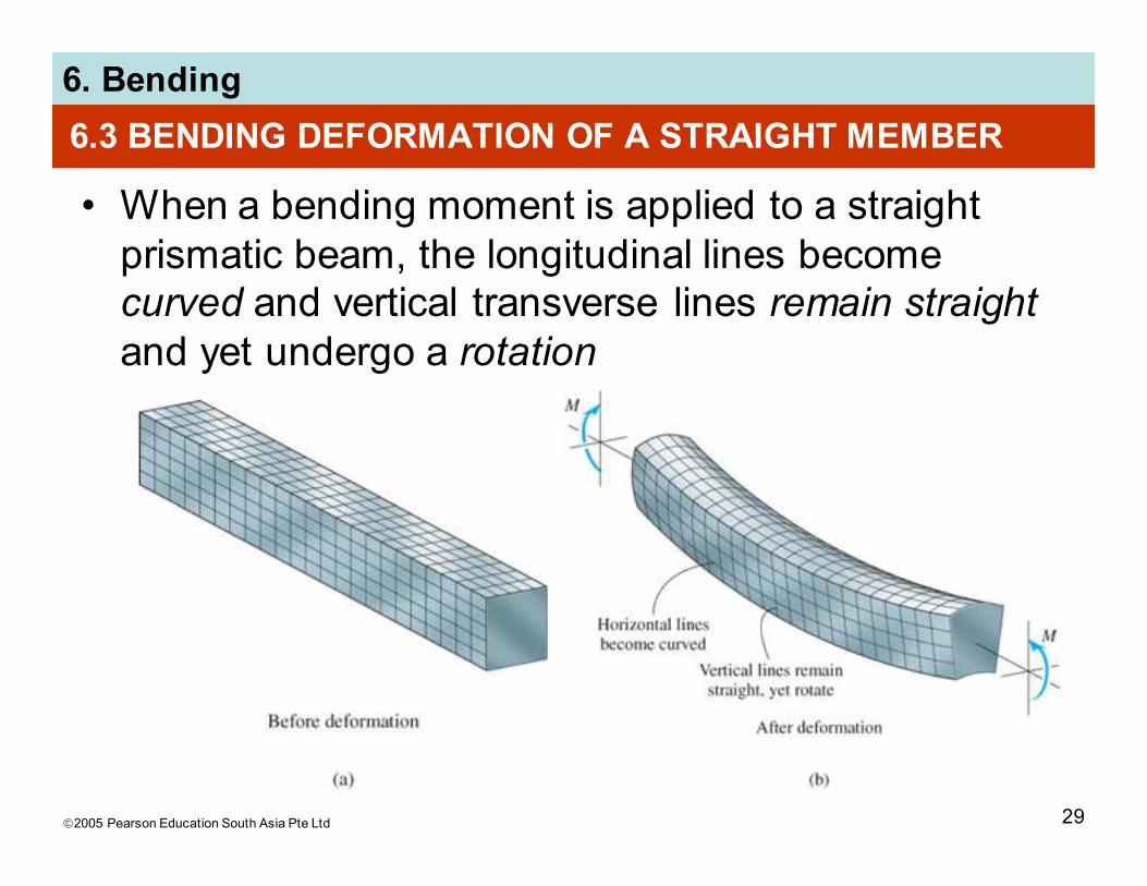
6.3 BENDING DEFORMATION OF A STRAIGHT MEMBER
• When a bending moment is applied to a straight
prismatic beam, the longitudinal lines become
curved and vertical transverse lines remain straight
and yet undergo a rotation
2005 Pearson Education South Asia Pte Ltd
6. Bending
30
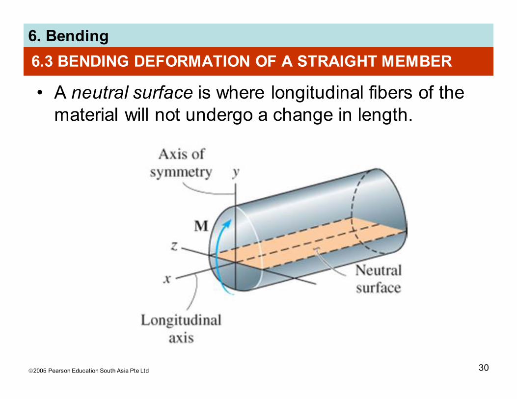
6.3 BENDING DEFORMATION OF A STRAIGHT MEMBER
• A neutral surface is where longitudinal fibers of the
material will not undergo a change in length.

2005 Pearson Education South Asia Pte Ltd
6. Bending
31
6.3 BENDING DEFORMATION OF A STRAIGHT MEMBER
• Thus, we make the following assumptions:
1. Longitudinal axis x (within neutral surface)
does not experience any change in length
2. All cross sections of the beam remain plane
and perpendicular to longitudinal axis during
the deformation
3. Any deformation of the cross-section within its
own plane will be neglected
• In particular, the z axis, in plane of x-section and
about which the x-section rotates, is called the
neutral axis
2005 Pearson Education South Asia Pte Ltd
6. Bending
32
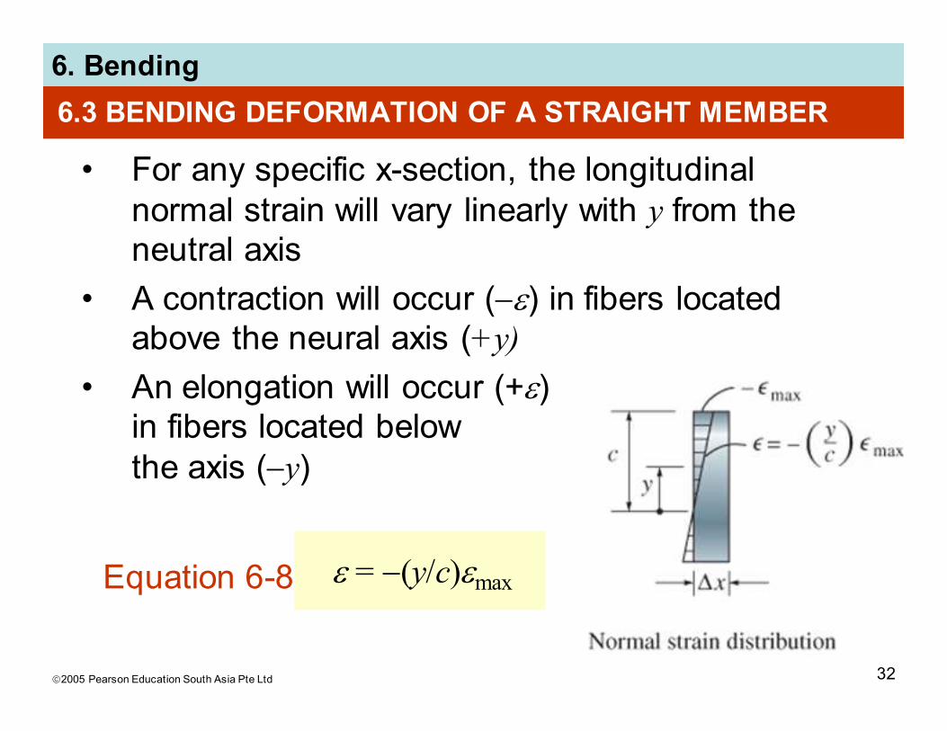
6.3 BENDING DEFORMATION OF A STRAIGHT MEMBER
• For any specific x-section, the longitudinal
normal strain will vary linearly with y from the
neutral axis
• A contraction will occur (−ε) in fibers located
above the neural axis (+y)
• An elongation will occur (+ε)
in fibers located below
the axis (−y)
ε = −(y/c)εmaxEquation 6-8

2005 Pearson Education South Asia Pte Ltd
6. Bending
33
6.4 THE FLEXURE FORMULA
• Assume that material behaves in a linear-elastic
manner so that Hooke’s law applies.
• A linear variation of normal strain
must then be the consequence of
a linear variation in normal stress
• Applying Hooke’s law to Eqn 6-8,
σ = −(y/c)σmaxEquation 6-9

2005 Pearson Education South Asia Pte Ltd
6. Bending
34
6.4 THE FLEXURE FORMULA
• By mathematical expression,
equilibrium equations of
moment and forces, we get
Equation 6-11
∫A y dA = 0Equation 6-10
σmax
cM = ∫A y2 dA
• The integral represents the moment of inertia of x-
sectional area, computed about the neutral axis.
We symbolize its value as I.

2005 Pearson Education South Asia Pte Ltd
6. Bending
35
6.4 THE FLEXURE FORMULA
• Hence, Eqn 6-11 can be solved and written as
Equation 6-12Mc
Iσmax =
σmax = maximum normal stress in member, at a pt on
x-sectional area farthest away from neutral axis
M = resultant internal moment, computed about
neutral axis of x-section
I = moment of inertia of x-sectional area computed
about neutral axis
c = perpendicular distance from neutral axis to a pt
farthest away from neutral axis, where σmax acts

2005 Pearson Education South Asia Pte Ltd
6. Bending
36
6.4 THE FLEXURE FORMULA
• Normal stress at intermediate distance y can be
determined from
Equation 6-13My
Iσ = −
• σ is -ve as it acts in the -ve direction (compression)
• Equations 6-12 and 6-13 are often referred to as
the flexure formula.

2005 Pearson Education South Asia Pte Ltd
6. Bending
37
6.4 THE FLEXURE FORMULA
IMPORTANT
• X-section of straight beam remains plane when
beam deforms due to bending.
• The neutral axis is subjected to zero stress
• Due to deformation, longitudinal strain varies
linearly from zero at neutral axis to maximum at
outer fibers of beam
• Provided material is homogeneous and Hooke’s
law applies, stress also varies linearly over the x-
section

2005 Pearson Education South Asia Pte Ltd
6. Bending
38
6.4 THE FLEXURE FORMULA
IMPORTANT
• For linear-elastic material, neutral axis passes
through centroid of x-sectional area. This is based
on the fact that resultant normal force acting on x-
section must be zero
• Flexure formula is based on requirement that
resultant moment on the x-section is equal to
moment produced by linear normal stress
distribution about neutral axis

2005 Pearson Education South Asia Pte Ltd
6. Bending
39
6.4 THE FLEXURE FORMULA
Procedure for analysis
Internal moment
• Section member at pt where bending or normal
stress is to be determined and obtain internal
moment M at the section
• Centroidal or neutral axis for x-section must be
known since M is computed about this axis
• If absolute maximum bending stress is to be
determined, then draw moment diagram in order
to determine the maximum moment in the diagram

2005 Pearson Education South Asia Pte Ltd
6. Bending
40
6.4 THE FLEXURE FORMULA
Procedure for analysis
Section property
• Determine moment of inertia I, of x-sectional area
about the neutral axis
• Methods used are discussed in Textbook Appendix
A
• Refer to the course book’s inside front cover for
the values of I for several common shapes

2005 Pearson Education South Asia Pte Ltd
6. Bending
41
6.4 THE FLEXURE FORMULA
Procedure for analysis
Normal stress
• Specify distance y, measured perpendicular to
neutral axis to pt where normal stress is to be
determined
• Apply equation σ = My/I, or if maximum bending
stress is needed, use σmax = Mc/I
• Ensure units are consistent when substituting
values into the equations

2005 Pearson Education South Asia Pte Ltd
6. Bending
42
EXAMPLE 6.16
Beam shown has x-sectional area in the shape of a
channel. Determine the maximum bending stress
that occurs in the beam at section a-a.

2005 Pearson Education South Asia Pte Ltd
6. Bending
43
EXAMPLE 6.16 (SOLN)
Internal moment
Beam support reactions need not be determined.
Instead, use method of sections, the segment to the
left of a-a. Note that resultant internal axial force N
passes through centroid of x-section.
The resultant internal moment must be computed
about the beam’s neutral axis a section a-a.

2005 Pearson Education South Asia Pte Ltd
6. Bending
44
EXAMPLE 6.16 (SOLN)
Internal moment
To find location of neutral axis, x-sectional area
divided into 3 composite parts as shown. Then using
Eqn. A-2 of Appendix A:
y = = ... = 59.09 mmΣ y A
Σ A
2005 Pearson Education South Asia Pte Ltd
6. Bending
45
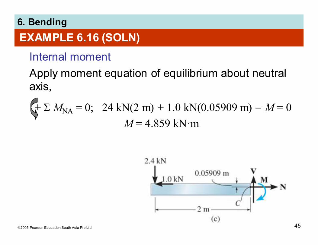
EXAMPLE 6.16 (SOLN)
Internal moment
Apply moment equation of equilibrium about neutral
axis,
+ Σ MNA = 0; 24 kN(2 m) + 1.0 kN(0.05909 m) − M = 0
M = 4.859 kN·m
2005 Pearson Education South Asia Pte Ltd
6. Bending
46
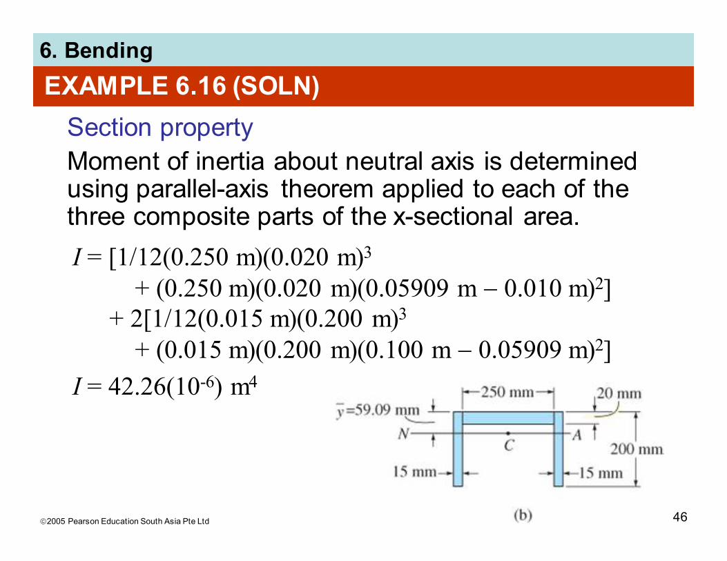
EXAMPLE 6.16 (SOLN)
Section property
Moment of inertia about neutral axis is determined using parallel-axis theorem applied to each of the three composite parts of the x-sectional area.
I = [1/12(0.250 m)(0.020 m)3
+ (0.250 m)(0.020 m)(0.05909 m − 0.010 m)2]+ 2[1/12(0.015 m)(0.200 m)3
+ (0.015 m)(0.200 m)(0.100 m − 0.05909 m)2]
I = 42.26(10-6) m4

2005 Pearson Education South Asia Pte Ltd
6. Bending
47
EXAMPLE 6.16 (SOLN)
Maximum bending stress
It occurs at points farthest away from neutral axis. At bottom of beam, c = 0.200 m − 0.05909 m = 0.1409 m. Thus,
At top of beam, σ’ = 6.79
MPa. In addition, normal
force of N = 1 kN and
shear force V = 2.4 kN will
also contribute additional
stress on x-section.
Mc
Iσmax = = = 16.2 MPa
4.859 kN·m(0.1409 m)
42.26(10-6) m4

2005 Pearson Education South Asia Pte Ltd
6. Bending
48
6.5 UNSYMMETRICAL BENDING
• A condition for flexure formula is the symmetric x-
sectional area of beam about an axis perpendicular
to neutral axis
• However, the flexure formula can also be applied
either to a beam having x-sectional area of any
shape OR to a beam having a resultant moment
that acts in any direction
2005 Pearson Education South Asia Pte Ltd
6. Bending
49
6.5 UNSYMMETRICAL BENDING
Moment applied along principal axis
• Consider a beam with unsymmetrical shape
• Establish coordinate system as per usual and that
resultant moment M acts along +z axis
• Conditions:
1. Stress distribution acting over entire x-sectional
area to be a zero force resultant,
2. Resultant internal moment about y axis to be
zero
3. Resultant internal moment about z axis to be
equal to M

2005 Pearson Education South Asia Pte Ltd
6. Bending
50
6.5 UNSYMMETRICAL BENDING
Moment applied along principal axis
• Express the 3 conditions mathematically by
considering force acting on differential element dAlocated at (0, y, z). Force is dF = σ dA, therefore
FR = Fy; 0 = ∫A σ dA
(MR)y = Σ My; 0 = ∫A z σ dA
(MR)z = Σ Mz; 0 = ∫A −y σ dA
Equation 6-14
Equation 6-15
Equation 6-16

2005 Pearson Education South Asia Pte Ltd
6. Bending
51
6.5 UNSYMMETRIC BENDING
Moment applied along principal axis
• Eqn 6.14 is satisfied since z axis passes through centroid of x-sectional area
• If material has linear-elastic behavior, then we can substitute σ = −(y/c)σmax into Eqn 6-16 and after integration, we get
∫A yz dA = 0

2005 Pearson Education South Asia Pte Ltd
6. Bending
52
6.5 UNSYMMETRIC BENDING
Moment applied along principal axis
∫A yz dA = 0
• This integral is the product of inertia for the area.
It will be zero if y and z axes are chosen as
principal axes of inertia for the area.
• Thus, Eqns 6-14 to 6-16 will always be satisfied
regardless of the direction of applied moment M
2005 Pearson Education South Asia Pte Ltd
6. Bending
53
6.5 UNSYMMETRIC BENDING
Moment arbitrarily applied
• If a member is loaded such that resultant internal
moment does not act about one of the principal
axes of x-section, resolve the moment into
components directed along the principal axes
• Use flexure formula to determine normal stress
caused by each moment component
• Use principle of superposition to determine
resultant normal stress at the pt
2005 Pearson Education South Asia Pte Ltd
6. Bending
54
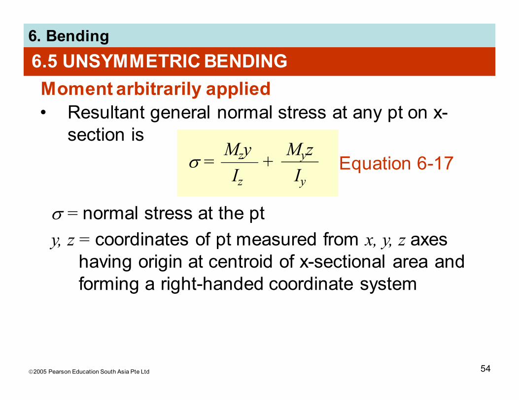
6.5 UNSYMMETRIC BENDING
Moment arbitrarily applied
• Resultant general normal stress at any pt on x-
section isMzy
Iz
σ = +Myz
Iy
σ = normal stress at the pt
y, z = coordinates of pt measured from x, y, z axes
having origin at centroid of x-sectional area and
forming a right-handed coordinate system
Equation 6-17
2005 Pearson Education South Asia Pte Ltd
6. Bending
55
6.5 UNSYMMETRIC BENDING
Moment arbitrarily applied
• Resultant general normal stress at any pt on x-
section isMzy
Iz
σ = +Myz
Iy
My, Mz = resultant internal moment components
along principal y and z axes. Positive if directed
along +y and +z axes. Can also be stated as
My = M sin θ and Mz = M cos θ , where θ is
measured positive from +z axis toward +y axis
Iy, Iz = principal moments of inertia computed
about the y and z axes, respectively
Equation 6-17

2005 Pearson Education South Asia Pte Ltd
6. Bending
56
6.5 UNSYMMETRIC BENDING
Moment arbitrarily applied
+

2005 Pearson Education South Asia Pte Ltd
6. Bending
57
6.5 UNSYMMETRIC BENDING
Orientation of neutral axis
• Angle α of neutral axis can be determined by
applying Eqn 6-17 with σ = 0, since no normal
stress acts on neutral axis. Finally, we get
Iz
Iytan α = tan θ
• For unsymmetrical bending, angle θ defining
direction of moment M is not equal to angle α,
angle defining inclination of neutral axis unless
Iz = Iy.
• Thus, θ ≤ α ≤ 90o
Equation 6-19

2005 Pearson Education South Asia Pte Ltd
6. Bending
58
6.5 UNSYMMETRIC BENDING
IMPORTANT
• Flexure formula applied only when bending
occurs about axes that represent the principal
axes of inertia for x-section
• These axes have their origin at centroid and are
orientated along an axis of symmetry and
perpendicular to it
• If moment applied about arbitrary axis, then
resolve moment into components along each of
the principal axes, and stress at a pt is
determined by superposition of stress caused by
each moment component.

2005 Pearson Education South Asia Pte Ltd
6. Bending
59
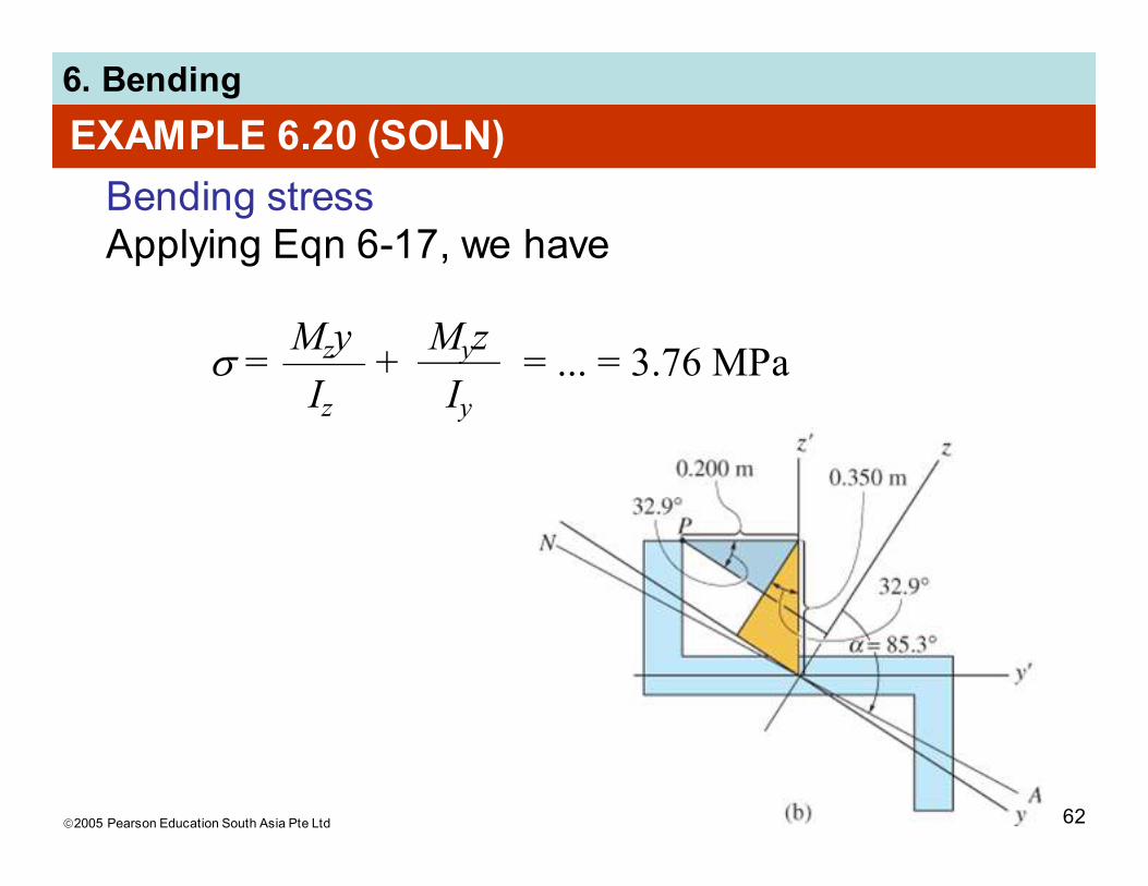
EXAMPLE 6.20
Z-section shown is subjected to bending moment of M = 20 kN·m. Using methods from Appendix A, the principal axes y and z are oriented as shown such that they represent the maximum and minimum principal moments of inertia, Iy = 0.960(10-3) m4 and Iz = 7.54(10-3) m4 respectively.
Determine normal stress at point P and orientation of neutral axis.

2005 Pearson Education South Asia Pte Ltd
6. Bending
60
EXAMPLE 6.20 (SOLN)
Internal moment components
To use Eqn 6-19, z axis needs to be principal axis for the maximum moment of inertia, as most of the area if located furthest away from this axis
My = 20 kN·m sin 57.1o = 16.79 kN�m
Mz = 20 kN�m cos 57.1o = 10.86 kN�m

2005 Pearson Education South Asia Pte Ltd
6. Bending
61
EXAMPLE 6.20 (SOLN)
Bending stress
The y and z coordinates of P must be determined first. Note that y’, z’ coordinates of P are (−0.2 m, 0.35 m). Using colored and shaded triangles from construction shown below,
yP = −0.35 sin 32.9o− 0.2 cos 32.9o = 0.3580 m
zP = 0.35 cos 32.9o− 0.2 sin 32.9o = 0.1852 m
2005 Pearson Education South Asia Pte Ltd
6. Bending
62
EXAMPLE 6.20 (SOLN)
Bending stress
Applying Eqn 6-17, we have
Mzy
Iz
σ = + = ... = 3.76 MPaMyz
Iy

2005 Pearson Education South Asia Pte Ltd
6. Bending
63
EXAMPLE 6.20 (SOLN)
Orientation of neutral axis
Angle =57.1o
is shown, Thus,
Iz
Iy
tan α = tan θ
α = 85.3o
. . .
Neutral Axis