Embed Size (px)
Citation preview

Simandou SEIA Volume I Mine Annex 7C
7C-1
7C Noise Design Assumptions and Source Data 7C.1 Mine Construction Predicted noise levels at the nearest noise sensitive receptors from construction activities have been modelled and presented as noise contours and these are used to identify settlements that have potential to be significantly affected by noise during the construction of the mine. Construction activity is focussed on the processing and infrastructure area (pre-production development in the pits is treated as part of mine operations) and has been separated into two main phases – Earthworks and General Construction and comprising the following activities. Earthworks:
clearing and site preparation for all areas including the rail loop; heavy earthworks, levelling, battering; and pre-loading and ground treatment.
General Construction:
assembly and erection of the crushing and screening plant; assembly of stackers and reclaimers; conveyor assembly and commissioning; construction of facilities, services, and infrastructure; and track laying on the rail loop.
As detailed construction teams and methods are not known, a simplified approach has been adopted of applying an overall sound power level for typical construction teams for the Earthworks and General Construction scenarios. A Sound Power Level (SWL) of 121 dBA for Earthworks and 114 dBA for General Construction has been applied throughout the site in the construction noise calculation. 7C.2 Mine Operations 7C.2.1.1 Overview The mine at Simandou will comprise two open pits using conventional drill, blast, load and haul methods. Each of the Ouéléba and Pic de Fon pits will have primary crushers located within the active mining area and a secondary crusher at the head of the conveyors connecting the pits to the mine plant area. Ore will be transported from each pit via an overland conveyor to the mine plant area where it will be processed by tertiary crushing and screening, before being transported to the stockyard by conveyor and then loaded onto trains. The locations of the principal noise sources for the mining, processing, materials handling and rail loading areas are shown in Figure 7C.1 and described below. 7C.2.1.2 Mining Area Before ore extraction can commence a hard cap over the ore bodies will be removed by drilling and blasting to expose the more friable ore material. Ore will then be extracted from the working face and hauled to crushers located within the pits. After crushing the ore will be transported via overland conveyors to the mine plant area. The following equipment and processes are modelled: pre stripping and clearing - dozers, excavator / shovels, haul trucks; overburden removal, haulage to and deposit in waste emplacements – excavator / shovels, haul trucks
dozers; drilling and blasting of ore and haul to primary crusher;
Simandou SEIA Volume I Mine Annex 7C
7C-2
in-pit processing and transport - crushers and in pit conveyors (up to approximately 3 km); and transport to mine plant area by overland conveyor including transfer stations en route. 7C.2.1.3 Mine Plant Area Further processing will be carried out in the mine plant area and the ore transported to the mine stockyard by overland conveyor. The following equipment and processes are included: crushing plant; transfer stations; transfer conveyors; conveyor drives; and overland conveyors to stockyard. 7C.2.1.4 Stockyard and Rail Loading Facility The mine stockyard and rail loading area will include the following significant noise sources: 2 reclaimers and 3 stackers; stacking and reclaim conveyors; load out and transfer conveyors; transfer shuttles; transfer stations enclosed / open; and train loadout facility. 7C.2.2 Fixed and Mobile Equipment Design Expectations The following specifications have been adopted in calculating noise emissions from the operational phase of the Mine, for both the daytime and night-time periods: mobile equipment will be of relatively new technology:
AC electric drive diesel powered haul trucks;
incorporating noise suppression typical of modern mining equipment in shovels, excavators, drills,
graders, front end loaders and dozers; and
all equipment achieves the design sound power levels used in the noise model, presented in Table 7C.1.
fixed plant includes reasonable noise mitigation / design commensurate with the project scope and aligned with Rio Tinto’s Company Standards; and
items such as conveyors and conveyor drives are designed such that they do not emit tonal noise or induce harmonics.
7C.2.3 Power Station The power station will operate continuously for 365 days per year and will include the following significant noise sources: the power plant will have a 100 MW capacity with an additional 20 MW reserve; diesel fuelled and will be situated near the rail spur before the rail loop to the North of the stockyard; and all units are 5 MW units.20 units running at any one time.

Foma
Touréla
Kankoro
Banko
CangaEast
Camp
Mandou
Orono
LamandouMoribadou
Mamouroudou
Korèla
Wataférédou II
Wataférédou ITraoréla Siatouro
505000
505000
510000
510000
515000
515000
520000
520000
9400
00
9400
00
9450
00
9450
00
9500
00
9500
00
9550
00
9550
00
9600
00
9600
00
Client: Taille: Titre:
Date: 07/06/2012
Dessiné par: WB
Vérifié par: RL
Approuvé par: KR
Projet: 0131299
Echelle: Barre d’echelle
Légende:
Figure 7C.1Vue d'ensemble des source de bruit /Noise Sources Overview
Usine et infrastructures minières /Mine Plant & Infrastructure
Contour de mine / Mine OutlineTerril de stériles /Waste EmplacementProjet de route de la mine /Proposed Mine RoadZone de stockage d'explosifs /Explosives Storage AreaZone d'exclusion autour de lazone de stockage d'explosifs /Explosives Area Clearance Zone
Dépôt de carburant / Fuel Farm
Localisation de la base de vie / Camp Location
Centrale électrique / Power StationTracé indicatif de la voie ferrée / Indicative Rail AlignmentAgglomération / Settlement
Route principale / Primary Road
Route secondaire / Secondary Road
Route tertiaire / Tertiary Route
Cours d'eau / Watercourse
Forêt classée / Classified Forest
Projection: WGS 1984 UTM Zone 29N
File:
0131
299S
iman
douG
IS_IG
_CK\M
aps\E
RM\N
oise\M
ine\M
ay20
12_re
vision
s\Ann
ex_C
\mi_N
oise_
Noise
Sourc
es.m
xd
A4
0 2
kilomètres
Activités dans les fosses de mines / In-Pit Activities:- Forage / Drilling- Travail à l'explosif / Blasting- Excavateur, camions de chargement pelle / Excavator, Shovel Loading Trucks- Camions de transport / Haul Trucks- Broyage principale / Primary Crushing- Convoyeurs / Conveyors- OB, flotte de démembrement / OB, Stripping Fleet- Déblaiement par bulldozer / Clearing by Dozer- Transport aux terrils / Haul to DumpsRoutes de transport / Haul Roads:- Camions de transport déplaçant OB vers des terrils / Haul Trucks Moving OB to Dumps- Route de transport du minerai vers les broyeurs en fosse / Haul Roads Moving Ore to In Pit Crushers- Calibreur/Camion citerne pour la maintenance des routes / Graders/Water Cart for Road Maintenance- Equipement de soutien; camion citerne (carburant et lubrifiant), véhicules de service / Support Equipment; Fuel Trucks, Lube Trucks and Service Vehicles
Convoyeur / Conveyor
PIC de FON
OUÉLÉBA
Décharge surchargée / Overburden Dumps:- Déchargement des camions de transport / Unloading of Haul Trucks- Façonnage du sol au bulldozer (profilage) / Dozer Shaping Ground (Profiling)- Camion citerne / Water Cart
Centrale électrique / Power Station
- Chargement du chemin de fer / Rail Loading- Train / Train
Activités de stockage / Stockpile Activities:- Empilement / Stacking- Recupération / Reclaiming- Convoyeurs / Conveyors- Embase vibrante / Conveyor Drives
Infrastructure minière / Mine Infrastructure- Bureaux / Offices- Maintenance / Maintenance- Ateliers / Workshops
Activités de broyage et de filtrage/ Crushing and Screening activities:- Broyage secondaire / Secondary Crushing- Broyage tertiaire / Tertiary Crushing- Convoyeur / Conveyor Belt Transfer- Sac filtrant de dépoussièrage / Dedusting Baghouse- Embase vibrante / Conveyor Drives
Zone HME / HME Area:- Assemblage, maintenance et révision des équipements / Equipment Assembly, Maintenance and Overhaul
Décharge surchargée / Overburden Dumps:- Déchargement des camions de transport / Unloading of Haul Trucks- Façonnage du sol au bulldozer (profilage) / Dozer Shaping Ground (profiling)- Camion citerne / Water Cart
Phase mine / Mine StagesPhase 1 / Stage 1Phase 2 / Stage 2Phase 3 / Stage 3Phase 4 / Stage 4Phase 5 / Stage 5Phase 6 / Stage 6Phase 7 / Stage 7Phase 8 / Stage 8
G u i n e aG u i n e a
M a l iM a l i
S i e r r aS i e r r aL e o n eL e o n e
G u i n e a - B i s s a uG u i n e a - B i s s a uS e n e g a lS e n e g a l
C o t eC o t ed ' I v o i r ed ' I v o i r eL i b e r i aL i b e r i a

Simandou SEIA Volume I Mine Annex 7C
7C-4
7C.2.4 Ancillary Facilities Other non-mining infrastructure at the mine will include: a workshop, hard stand and heavy equipment assembly and maintenance area; pit workshops, stores and offices; and new internal and external site access roads. 7C.2.5 Noise Source Terms Source terms used in the noise model are shown in Table 7C.1. Table 7C.1 Modelled Design Sound Power Levels
Mine area Item Description Rated
Capacity Quantity
Unmitigated SWL dBA re 10-12 Watts
Mitigation Applied
Mitigated SWL dBA re 10-12 Watts
Ouéléba Pit & Pic de Fon Pit
Crushers 7700 tph 7000 tph
120
situated into bench and directed
towards pit
110
In pit Conveyor 90 dBA/ m -- 90 dBA/ m
In pit Conveyor Drive 600 kW 101 -- 101
Komatsu PC1250 Excavator
485 hp 6 116 -- 116
Komatsu PC8000 Excavator
2 900 hp 7 122 -- 122
LeTourneau L1850 FEL 2 000 hp 2 115 -- 115
CAT 777 Haul Truck 100 t 15 117 -- 117
Komatsu 830 E Haul Truck
220 t 6 116 -- 116
Komatsu 930 E Haul Truck
290 t 58 119 -- 119
Atlas Copco Pit Viper 8 120 120
ROC L8-25 Drill 2 117 -- 117
CAT 992G FEL 900 hp 115 -- 115
Dozer D11T (average reversing and pushing)
4 119 -- 119
Dozer D10T (average reversing and pushing)
4 114 -- 114
CAT 844H RTD 2 114 -- 114
CAT 329 rockbreaker 2 118 118
CAT 777 Lube Truck 100 t 4 116 -- 116
CAT 24M Grader 2 112 -- 112
CAT 16M Grader 3 106 -- 106
CAT 777F Water Cart 4 117 -- 117

Simandou SEIA Volume I Mine Annex 7C
7C-5
Mine area Item Description Rated
Capacity Quantity
Unmitigated SWL dBA re 10-12 Watts
Mitigation Applied
Mitigated SWL dBA re 10-12 Watts
Mine plant area
Crushing plant 2 000 tph 115 115
Crushing plant 3 000 tph 112 112
Scalping screening plant
4 800 tph 4 112 112
Transfer conveyors 88 dBA/m 88 dBA/m
Transfer station 100 100
Stockyard Stacker 9 300 tph 3 (2
operating) 110 -- 110
Reclaimer 6 600 tph 2 111 -- 111
Reclaim conveyor 1 800 kw 89 dBA/m -- 89 dBA/m
Stacking conveyors 300 89 dBA/m -- 89 dBA/m
Transfer conveyor 400 89 dBA/m -- 89 dBA/m
Transfer station 100 100
Train loading (material) 103 -- 103
Loco during loading cycle
Lw calculated based on Locomotive achieving RT locomotive specification at various notch settings
89 dB(A) at 100ft (33m)
Power station
Engine generator -- Enclosed/
design to meet 70 dBA at 95m
--
Other Workshop 103 -- 103
HME 103 103
Belt shop 103 -- 103
All Areas Conveyors Capacity Idler Roll
Type Belt speed
SWL dBA re 10-12
Watts
Standard Stockyard Conveyor (open sided or covered)
7 700 tph Steel 4.4 m/s 89 dBA/m
Standard Coarse Ore Conveyor (open sided or covered)
7 700 tph Steel 3.5 m/s 88 dBA/m
All Areas Conveyor Drives Capacity
Standard Conveyor Drives
≤450 kW -- 100
630 kW -- 101
800 kW -- 103
1 000 kW -- 104

Simandou SEIA Volume I Mine Annex 7C
7C-6
Mine area Item Description Rated
Capacity Quantity
Unmitigated SWL dBA re 10-12 Watts
Mitigation Applied
Mitigated SWL dBA re 10-12 Watts
1 200 kW 105
Sources: AMC Phase 2 PEA LOM Schedule Revision 2E Mechanical Equipment List Module: Ore Handling Plant (Fluor Document A4RG-PL2000-55LI-001/ RT Doc SIM-2000-M-LST-00018 Fluor doc A4RG / SIM-9000-F-DC-00053 – Process Design Criteria RT Doc RTIO-SIM-9000-F-DC-00053
7C.2.6 Conformance Levels and Specifications Some items of plant consist of many components, and for the complete item to “conform” with a design emission level (sound power level), the component items will need to meet “specific” sound power levels. Hence the source terms for these items are referred to a “conformance specification” which is reliant upon the individual “item specifications”. Conformance specifications will be developed for conveyor drives, conveyors, reclaimers and stackers including conveyor idlers, belts, frames and frame spacing and stacker / reclaimer belts, idlers, long travel drives, boom drives, luffing and slewing mechanisms. Some further details are provided below. 7C.2.6.1 Idler Rolls Idlers will meet the following specifications so that the conveyor can achieve the conformance specification. The specified idler-roll surface profile upper limiting criteria for the idler-roll surface profile parameters are shown in Table 7C.2. Table 7C.2 Idler-Roll Surface Profile Upper Limiting Criteria
Criterion Surface Profile Parameter Upper Limit
TIR Total indicator runout 600 m (pk-pk)
MIS Maximum Indicated Slope (per 6o of idler rotation) 60 m
Notes: Total Indicator Runout - The Total Indicator Runout (TIR) is the peak to peak variation in roll eccentricity and out of round, measured in micrometers. Maximum Indicated Slope - The Maximum Indicated Slope (MIS) is defined for the purpose of this Specification as the maximum indicated runout per 6° of idler-roll rotation. Note that manual measurements of the MIS may be conducted using a similar test rig to that traditionally used to measure the TIR. The indicated runout displacements shall be determined from a continuous measurement around the idler-roll circumference. The largest difference in the indicated runout for any 6° of idler roll rotation yields the MIS measured in micrometers.
7C.2.6.2 Idler-Roll Self Noise The total sound power emission level of each idler-roll will not exceed the levels shown in Table 7C.3 at the design idler-roll rotational speed. This sound power level relates to the noise emission of each idler-roll operating in isolation from other conveyor components. Table 7C.3 Idler- Roll Self Noise Sound Power Level
Idler-Roll Length Range Overall Sound Power Level (dBA re 1 W)
500 mm - 800 mm 68 dBA
801 mm – 1 100 mm 69 dBA
1 101 mm – 1 500 mm 70 dBA

Simandou SEIA Volume I Mine Annex 7C
7C-7
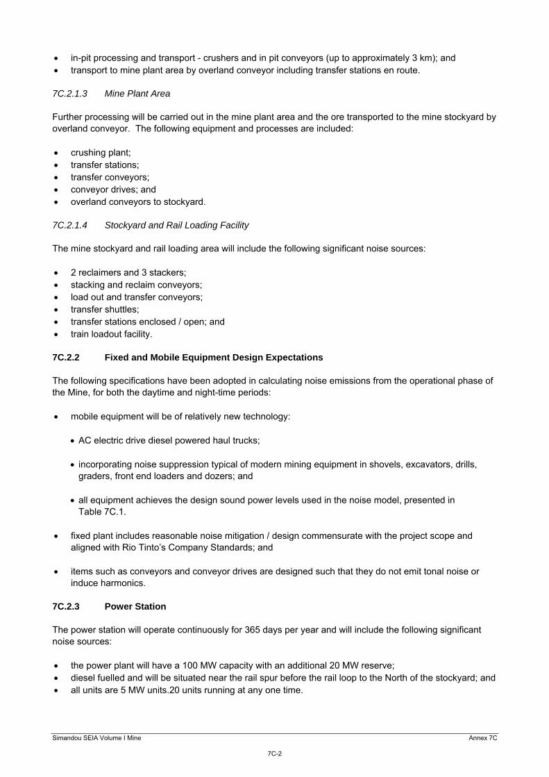
7C.2.6.3 Idler Frame Spacing Idler frames are built in standard modules illustrated in Figure 7C.2, consisting of variable spacing to minimise the occurrence of harmonics throughout the conveyor’s length. Figure 7C.2 Idler Frame Spacing
7C.3 Blasting Emissions The blast design information contained in Table 7C.4, developed during the Preliminary Engineering Assessment, has been used to inform the blasting assessment. Table 7C.4 Blasting Data
Design Parameter Production Development
Number of holes per blast 200 200
Number of rows per blast 10 10
Average volume per blast 169 213 16 696
Average tonnage per blast 507 509 50 074
MIC (> 8 milliseconds) 515 60
Normal blast management practices will be applied to reduce overpressure and are taken into account in the assessment.

Simandou SEIA Volume I Mine Annex 7C
7C-8
7C.3.1.1 Blast Design All blastholes will be stemmed with an appropriate packing material in order to contain the explosive
gases, achieve an efficient blast and better fragmentation of the rock.
The Maximum Instantaneous Charge (MIC) (ie the maximum mass of explosive detonated in any 8 ms period throughout the blast) will be selected to ensure the relevant criteria are net for example by reducing the number of holes fired at any one time.
Halving the MIC will reduce the airblast level by 1 dB to 3 dBZ. All blasts at the site will be monitored.
Blast designs will be recorded for all individual blast events and the data used with the monitoring results
to assist in the design and optimisation of future blasting and to provide information in case of incident or complaint.
For the purposes of blast emission monitoring, the mine will follow the requirements of AS 2187.2-2006, “Explosive Storage, Transport and Use - Appendix J”. The Blast Emissions Summary Record will record for each blast. Blast Number. Block or Area ID. Date and Time of blast. Shot Type. Centroid of Blast (X,Y,Z coordinates in a referenced mapping system). Distance from the blast to the monitoring locations. MIC (kg). Peak Airblast Level, dB (Lin). Vibration Level, mm/s.