Embed Size (px)
Citation preview
P a g e | 1
EXPERIMENT NO. 9
AIM: To Study the speed control of D.C. Shunt motor by-(i) Field control method. (ii) Armature control Method.
APPARATUS USED:
Sl. No. Equipment Type Specification Quantity1. DC Shunt motor DC 5-HP, 1500 rpm,
16.7 amp, 220 V 1
2. Tachometer Digital (0-10000) r. p. m. 13. Voltmeter MC (0-300) volts 14. Ammeter MC (0-1/2) A(0-5/10) A 1 each5. Rehostat Single Tube 260Ω, 1.2 A 16. Rehostat Single Tube (0-2000) rpm 1
THEORY:
DC Motor: A machine that converts DC electrical power into mechanical power is known as DC Motor. It has been seen that a.c. Motors are invariably used in the the industry for the conversion of electrical power into mechanical power, but at the places where wide range of speed and good speed regulation is required such as in ELETRIC TRACTION, DC motor has to be applied.
Working Principle: Its working depends upon the basic principle that when a current carrying conductor is placed in the magnetic field, a force is exerted on it and torque develops. Types of DC Motor: On the basis of their field excitation , the DC Motors can be classified as:
1. Seprately excited DC Motor.2. Self excited DC Motor:
(i) DC Shunt Motor(ii) DC Series Motor
Now, the back emf of a dc motor is given by =>Where,
P a g e | 2
Kp is constant for the given motor because a machine once designed will have constant no. Of armature conductors Z no. Of poles P and number of parrallel paths, Ø is the flux per pole and Wm is the rotational velocity(mechanical).
Wm=2πn(rad/sec)
Where, (r.p.s)
(r.p.m)
Hence, speed can be controlled by:1. By controlling Eb through variation of Vt(terminal voltage) or Ra(Armature
circuit resistance) called Armature control.2. By controlling through variation of field voltage or field resistance called field
control.
1. FIELD CONTROL METHOD: The flux produced by the shunt winding depends upon the current flowing through it. (i.e.,, is directly proportional to Ish & Ish= V/Rsh). When a variable resistance R is connected in series with the shunt field winding as shown in fig. (1), the shunt field current (Ish = V/(Rsh+R)) is reduced & hence the flux Ø. Consequently, the motor runs at a speed higher than the normal speed (since N is directly prop. to 1/Ø). The amount of increase in speed depends upon the value of varible resistance R.
2. ARMATURE CONTROL METHOD:-In a shunt motor flux is constant when appied terminal voltage & shunt field resistance are constant. Therefore, speed of the motor is directly proportional to the induced emf (i.e., N is directly prop. Eb & Eb= V-Ia* Ra). The value of Eb depends upon the drop in the armture circuit. When a variable resistance is inserted in series with tyhe armature as shown in the figure(2), the induced emf[Eb=V-Ia(Ra+R)] is reduced & hence the speed. Thus the motor runs at speed lesser than the normal speed. This method is neither economical nor efficient as a large power (Ia2*R) is wasted in control resistance R since it carries full armature current Ia.
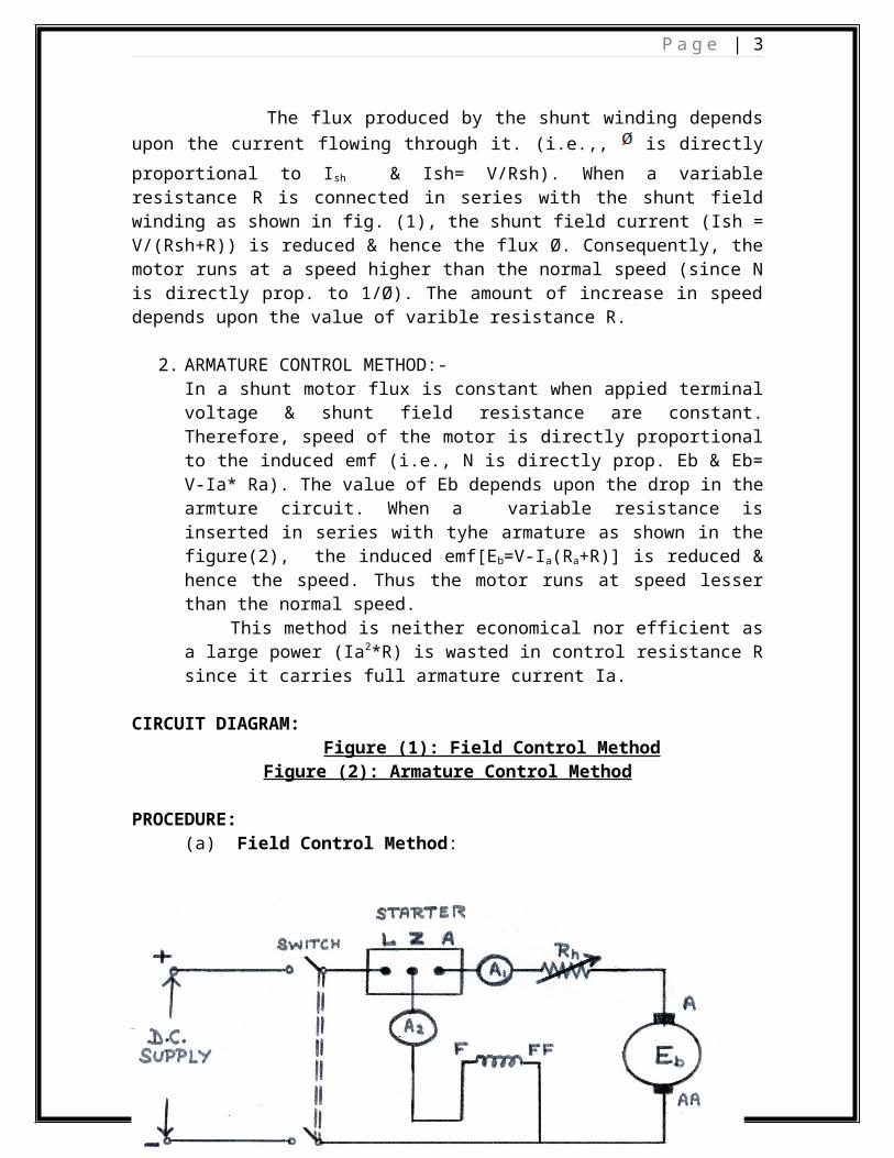
CIRCUIT DIAGRAM:
P a g e | 3
Figure (1): Field Control Method
Figure (2): Armature Control Method
PROCEDURE:(a) Field Control Method:
1. Make a proper connection as per the circuit diagram.2. Switch on he supply and start the motor with the help of starter. 3. Now, insert the resistance in the resistancein the field winding slowly.4. Tabulate the readings of field current, voltage and the speed by tachometer
in the observation table.5. Take some more readings by varying the field resistance.6. Plot the graph between If and N on the graph paper.
(b) Armature Control Method:1. Make a proper connection according to the circuit diagram given in the
Figure (2).2. Start the motor.3. For the diffrent values of resistance, note the values from ammeter,
voltmeter and tachometer and note down in the observation table.4. Plot the graph between Ia and N on the graph paper
P a g e | 4
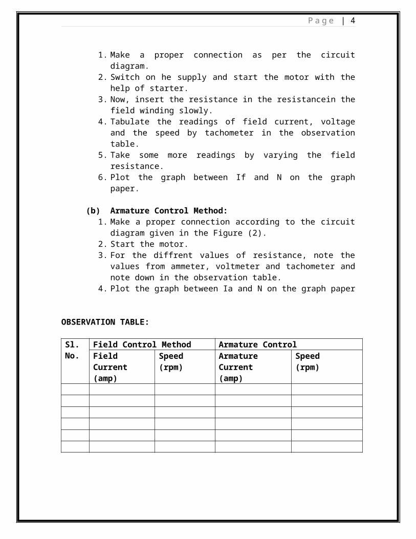
OBSERVATION TABLE:
Sl. No.
Field Control Method Armature ControlField Current(amp)
Speed(rpm)
Armature Current(amp)
Speed (rpm)
PRECAUTIONS:
1. All the connections should be tight. 2. Never touch the live terminal during the experiment.3. Before changing the connection, switch off the supply properly.4. Increase the load carefully. 5. Always use the starter of proper rating.6. Always wear shoes when working in the lab. Avoid wearing loose clothes,
hanging chains etc.7. Make proper contact when measuring the speed with Tachometer.
RESULT:1. The variation in speed of shunt motor, w.r.t., If and Ia, is shown in the observation
table and plotted on the Graph.2. From the graph we obseveved that speed falls down slowly as the D. C. Shunt motor
is loaded from no load to full load.