Embed Size (px)
Citation preview

A ma!! purposeof the Techni-cal Information Center is to providethe broadest dissemination po&i-ble of information contained inDOE’s Research and DevelopmentReports to business, industry, theacademic community, and federal,state and local governments,
~~Although a small portion of thisreport is not reproducible, it isbeing made available to expeditethe availability of information on theresearch discussed herein.
1
.
TITLE TWO-FIELD AND DRIFT-FLUX MODELS WITH APPLICATIONS TO
l\ UCLEAR REACTO,I SAFETY
LA-uR--I34-165O
DIZ84 012456
ALJTM~(Sl J. R. Travis
BWMITTEDTo IAEA Technical Counnittee/Workshop on the Uses of Computer Codesfor N~lear Reactor Safety Analy~is, Varna, Bulgaria, 2H Mav -1 June 19FJ4.
DWC’LAIMER
T’hlI rqorl wasprqmrdasan swounlof wc+knp+rtod bynnagunc-ydthc UnltalSlmt~Oovwrmnt Noih Ihc Unltd SImeI GowmnunI nor ●ny wcy therd, na nny of Mram~~, m~a any wmmnly, ox- or impkd, or ●uurnu -ny I@ Iisblllly or reJpmll-bility fm (h r.mmcy, complelerw4, m umfulnuu of nny Marnwon, ●~mtun, pra!uot, aP dtdcd, IX m~ntl thnl III um would w Mrinm privmlnly OWA ~ht~ Refer.m Irmwinto ●ny wWlc armrneIclnl pmduot, P, or _ by tmdm nmo, Irndcmmrk,m~nuftiumr, or oIhorwlm doa M ~rlly oomtkulr a4 Imply KS andurmrnan 1, ,~.
mmddon, or rm?rins by the [Jnhd StMleI Ocwmnrrmnt m wry qwIcy Ihard, T’hc vlewd o@dcmI d wdhcws ex~ hamln do ma ~rlly IIme or mflecl thm d tlw
Unltul Smla GOvernrrmnlW ●ny qancy Iharmofl
ILwwmilm l%l:R$&Y&%&’%
.
“. /f
TW)-FIELD #N!l DRIFT-FLUX MODELSWITH APPLICATIONS TO NUC%EARREACTORSAFETY
J. R. Travis
Theoretic.el Division, Croup T-3University of California
Loo Alam(,a ?Jational LaboratoryLo- Alamos, New Mexico 87545
ABSTRACT
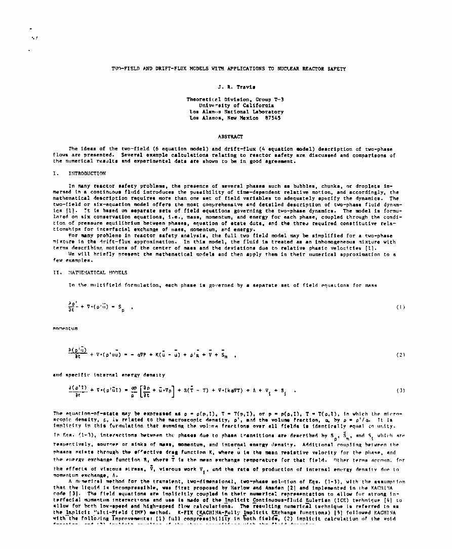
The ideas of the two-field (6 equation model) and drift-flux (4 equation model) description of two-phaseflows are presented. Several example calculation relating to reactor safety are discunsed and comparisons ofthe numerical rea~lts and experimental data are shown to be in good agreement.
I. INTRODUCTION
In many reactor safety problems, the presence of several phases such as bubbles, chunks, or droplets im-mersed in a continuous fluid introduces the possibility of time-dependent relative motion, and accordingly, themathematical description requires more than one set of field variables to adequately specify the dynamics. Thetwo-field or six-equation model offers the most comprehensive and detailed description of two-phase fluid dynam-ics [1]. ?t is based on separate setti of field equations governing the two-phame dynamics. The model is formu-lated on ~ix conservation equations, i.e., maas, momentum, and energy for each phase, coupled through the condi-tion of pressure equilibrium between phases, equation of state data, ●nd the three required constitutivc rela-tionship for fnterfacial exchange of mass, momentum, and energy.
For many prohlemn in reactor safety analyais, tile full two field model mny be simplified for a two-phasemixture In the drift-flux approximation. In this model, the fluid is treated as an inhornogeneous mixture withterms describing, motions of the center of mass and the deviations due to relative phamic velocities [11.
Me will briefly present the mathematical models and then ●pply them in their Iwmerlcal approximation to .sfew examples.
11. :lAITEMATICAL MnDELS
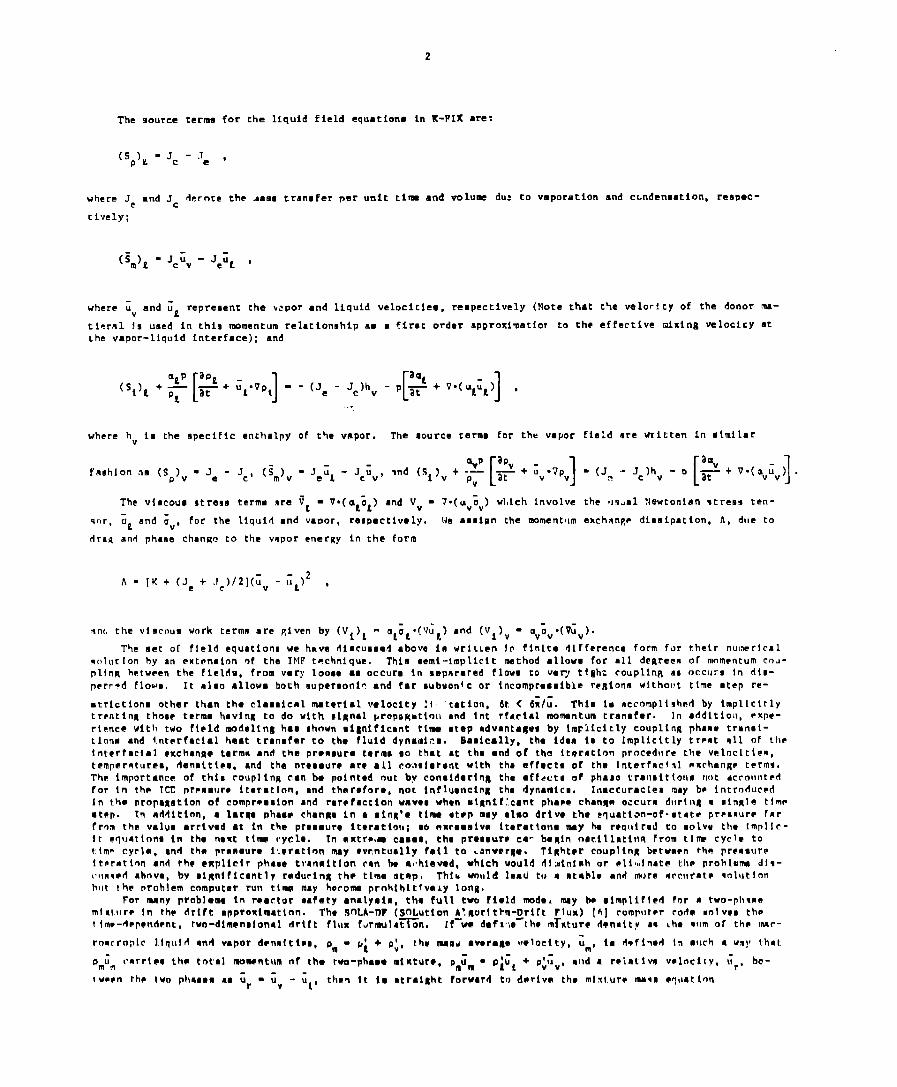
~n the m!llttfielrl formulation, asch phase is governed hy a separate set of field equnLions for mass
?&+ V.(p,;;) - so ,
mncwntufn
ILe# ---+V*(p’u;) - - aVP +I((; - u) + p’g +V+ Sm ,
(1)
(’))
snd apec~fiv internal en~rRy density
I)(D’I) + V.(pl;l) - 52
[ap + ;.vp + R(i
at 1- T) + V*(kaVT) + A + Vi + S, .
E(1)
P
The equntion-of-state may be @xpr@ssed as p - p(p,I), T - T(P,I), or p - P(P,I), T - T(P,I), in which lh~ mlrro-ncrrpic d?nsity, L, in rtlatad to the macroscopic Apnnity, p!, ●,wl the volume fraction, x by p = p’/u, Tt laimnlicity in this furmulatton thst surnmink the volIvr4 fractfona ov~r ●ll flaltis 1S !dent(eallv eqilsl co ur,ity.
Tm l?qn. (1-3), intetsctlnns bwtwnen thu phanes due to phss~ I,ranaitlons are dencriheri hy Sn, ?m, nnd S, whl(h tre
remp~ctlvelyo sowrfinr or ninka of mass, momentum, and intarn~l ansrRy density. Additlonnl enupl!nR between the
phaa~rn @xlnts thrmiRh th- ●froctive drat functirm K,.
Wharc u la tha wan resisttvw vslorify for thp PI]H*-, anti.the eneruy exchanno function R, whors T 1s the man ?xrhcnRa t~mperatur~ for that ficltl.Other terms Arrnllni for
the efferlm of viscous #trass, ~, vlsrous work V,, ml the rate of prodwctton of int~rmal tvwrgy Aonntfv ciIIe LOmom@ntum @?tchnnRe, A.
A n!n~rlcal met.hnd for th@ transient, two-dlmenaional, two-phaa~ sollltion of t!,qs. (1-3), with th aoaumptlnnthnt, thw l~quid in incompr~soible, wss first proposad by Narlow ●nd Amsrlan [21 and tmplemmnt~d in I}IQ KAC!14’IAcoda [3]. Tho fis.ld equations are implicitly coupled in th?tr numerical rapr~sentation to allaw fur strong ln-t?rfacfal numenturn inttrraet!ons ●nd us. 1s medo of th~ &mpliclt ~ontinuous-fluld 11.ul?rlan (ICE) twhnfqup [4] tuA11OW for bct,h low-spo~d ●nd high-sp~ad flow calculations. l%. rosultina numaric,;l tochniqua in rcfarrsd to nstho Implicit “tilti-Fi@ld (IMP) method. K-FIX (KACllINA-Fully Implicit MJchanna fwnctiona) [51 followed KACIIINAwith-tho follh,tinu Tmprnvcmal:tmt (1) full compr~asihill~y in Foth fialds, (2) implicit calculation of the votd----- *-- --A , . . 4——● 4. . - —,, ..—-..,- ,.. –... ––. . 4–. -.. ..L. L-.4..4A..—. –.–-
2
The eource terme for the liquid field ●quatiens in K-FIX are:
(Sp)g - J - Jc ● ’
where J and J c dernte the .nasa cranofer per unit time and wlume dus to vaporation and condensation, reoc+ec-e
cively;
where u and ;E
repreoent the vcpor ●nd liquid velocities, respectively (Note thatv
ti?ral jg used in this momentum relatiortrnhip am ● firmt order approximation to th~Lhe vapor-liquid interface); and
where hv in the specific ●nthalpy of the vapor. The source termo for the vapor
t>e velority of the donor mm-
●ffective mixing velocicy at
field are written in etmilar
The viscous rntreue termm Ire ~t - V*(at~L) and Vv - 7.(uV;V) wl,lch involve
qnr, i Land SV, for the liquid and vapor, reepectlvely. We ae~lgn the moment,]m
drag and phase chanRe to the vapor ●nergy in the form
A = [K + (Je + Jc)/2](; - ;L)2 ,v
nnt, the virncnum wnrk termn are given by (Vi)L - Ot;tO(V~t) ●nd (Vi)v - av~v-(V~v
the u?dml Newtonian mcr.ern~ ten-
exchnnR_ diemipation, h, due to
).The met of field ●quation- we hmve diecusmed shove in wrllLen !P finite dlff~rence form for th?ir num~riral
●t)luclon by an extension of the IMF technique. Thle .emi-implicit method allow- for all deRreem of mnmentum cou-pltnR h~tween the fielrlm, from vary 1000O as occurn in mepnrared F1OWOto ve~ tight coupllnR MS OCCU:S tn dlo-perr-d flowm. It al-o allovm both suptreoni? and far subuon~c or tncomprmcnibie reBionm wjthol?t time step re-
■trictlonm other than the clasmical mmtcrial velocity !1 ‘tation, 4t C 6;I;. This 10 ~ccompli shed by implicitlytrentln~ thos? tarmm havlnR to do with signal propegmttoll ●nd tnt rfaeial mownt.um trannfer. in ●ddltioll, eKpe-ri?nce with two fl~ld modelinE ha- ohown ●lgniflcant time step advantage by lmFilcitly coupling phane trnnol-tlonn and fnt~rfacial heat trmnnfar to the fluid dynamir.n. Bamically, the idea 1s to implicitly tr~mt all of theinterracial exchmnna termn and the pramsure termm eo that at thm ●nd of tha it~ratlon proc~d~lrw the velocltieH,temp~rmturen, denmitles, and tha or~nsur~ ara ●ll cw,tm~etant with tha eff~ctt of the lnterfac!al mxchang~ termrn.The lmportanc~ of this roupllng ran bm point~d out by conoiderlng the ●ffecte of phaso tra!lsit{oun not dcrnllntedfor in the ICE pr~rnmure iteration, and ther~fore, not influencing tha dynamics. Ifiaccuracles may b~ lntroduc~dIn th? propaxatlon of compr-amion and rtir~faction waves when uiRnif:,cant phape chan~m occurm dllring a minnle t!mr●trip. In addition, ● lmr~ phaam chanRo in a ●inR’@ tirw nt~p may al-o drlw th~ cquattan-af- state pr?rnnur- farfrnm the valua arrived at in the proemure it~ration; w exraDmivQ itermtiona My he rcg~lirad to EOIVU the [mpllc-it ~quatinne in the next ttmm vycle, in nmtr?,m cameo, the prencure cm” beRln norillmtinn from tlm cycle tottm~ Cyrle, and the pranaura lL@ration MY cvrntuclly fatl to .anwer~a. TiRhter coup!lnR ~cwn?n thn prenaureIt?rarinn ●nd the ●xplicfr phaue trannltlon ran be mi.hieved, which would di~lnjnh or eliwfnnte thp prohl~mn dls-(.IIn~FA abnva, by siRnlflcantly raduelng thr time otmp, Thim WOuld lead to ● ntmhle and nwre ~rcuratp ~nlutlrmhut rhe problem computer run tlm may herow prnhihitfvely lonR,
For mmny problem- in r?artor oafety ●natyain, ttm full two field modm. mey ba ●impliffed for @ two-plmnemlml~lr~ in the drift appromlmat{nn, The !WLA-DF (SOLutton ~’.Rarltkm-Qrift Flux) [6] rornput?r rotla molvet the! fm~-d~p~nd~nt, two-dlm~nslonal drift flux fortmli~n. ~f we defim [h- m~xturc d?noity -n ~hm ~um of the lmar-
rnncroplc liqutII and vapor d~nn!tirm, om - b; + P;, thv N!Jti awrmse Wlocity, -Um, in dmfi~o.i la ●lich a wy that,
Om:m rarrl~g the tntil mo~ntum nf thm two-phaso ❑luturo, p ;m m ● o’;1;+ PJGV, ●nd ● r~lative vmlnciIY, {r, ba-
!wmon th? two plinsem ma ~ = ~.
r - UL, than it im mtrcight forward to dative th~ m!xtur~ mesa ●q,mtionv

>
(h)
the
the
and
vapor masa equation
apt
(
P;P; -$+v. p$m+ -—. u
)=J-J
Pm r e c’
mixture momentum equation
a( Dmlm) -. c;P~ - -—— + V.(pmumum + ~
at Urur) - -Vp+pmi+(vv+vt) ,In
the mixture internal energy density equation
+ V.(kvavVTv +kLaLVTt) + (Vi)v + (Vi)t ,
(5)
(6)
(7)
where I = (P:IV + pjIt)/pm.
The equationa-of-ntate and the drift convection of the specific internal energy equation req,tire theknowledge ~f Iv and IL. Several posaibiltties are available:
(1) Aamume thnt the liquid and vapor phasea are at the same temperature, or(~) ~~hen the heat condllction between phaaea is small, aaaume that the vapor phaae la at maturation with the
local preaaure.
Ariother independent relationship is needed for closure. An expreaaion for the relative velocity ~r, can be de-
rived [71 from the momentum equationa. Baaically, one neRlecta the phase tranaltion and vidcous stress terms,and rewrites the reduced momentum cqumtiona in nonconrnervativc form by aubtractinft from eAch the proper contin~i-ty equ~tion, neglecting phaae tranaltion termn. Thee? remulting
ing tranaport equationa for ;r.
Ue can eatlmate the drag function K from the drag on an indhuhblea (droplets) per unit volurna, !1, by
where
a, ● a, v - vt(l - a)-2.5
for a< 0.5 ,
al m(l- a), v - vva ‘7”5for a> 0.5 .
equatlona are atl~tracted from each other yield-
vldual huhble (or droplet) times the number of
(!3)
fld irn n draR cn~fffc{ent (gener~lly of ord?r !Inlty), S la the croaa-aoctional nrea par unit volume of buhhl~rn
(Aropletrn) with raditiq ro,
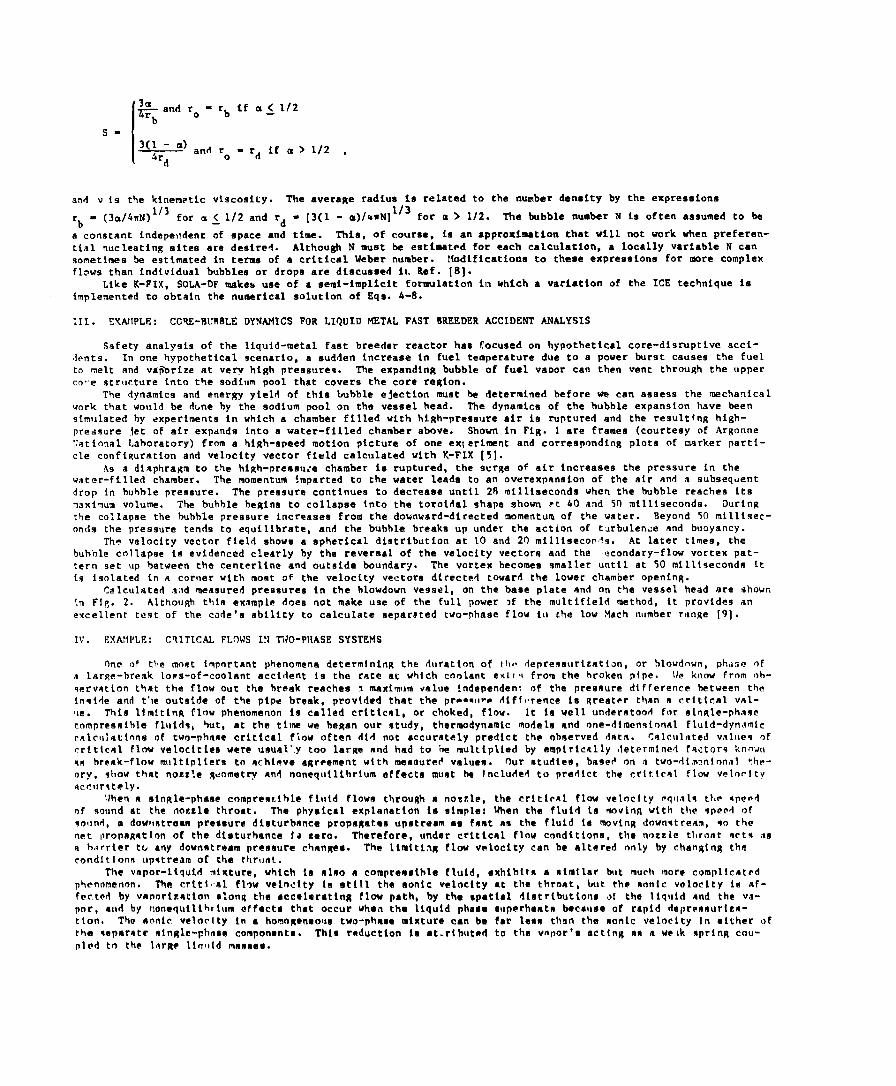
I and r~.=rbifa~ l/2
s= 13(1 - a) and ~ -rdifa> l/2 ,$r
do
an4 v is the kinenwtic viscosity. The average radius is related to the number density by the expreaeiona
- (3a/4rN)1’3 for a~l/2 and rd = [3(1 - a)/QwNl113
‘bfor a> 1/2. The bubble number N ie often aasumed to be
a constant indepe~xlent of epace and time. This, of course, is an approximation that will not work when preferen-tial nucleating eitea are desired. Although N muet be estimated for each calculation, a locally variable N cansometimes be estimated in terms of a critical Weber number. Modification to these expreeaiona for more complexflows than individual bubbles or drops are diecueeed it. Ref. [81.
Like K-FIX, SOLA-DF makes use of a semi-implicit formulation in which a variation of the ICE technique iaimplemented to obtain the numerical solutlon of Eqe. .4-8.
111. E!tAflPLE: CCIV-FNJRBLEDYNAMICSFOR LIQUID METALFAST BREEDER ACCIDENT ANALYSIS
Safety analysia of the liquid-metal fast breeder reactor has focused on hypothetical core-disruptive acci-tent9. In one hypothetical scenario, a eudden increase in fuel temperature due to a power burst cauaea the fuelto melt and vdp%rize at very high presaure9. The expanding bubble of fuel vapor can then vent through the upperco,.e structure into the sodium pool that covers the core region.
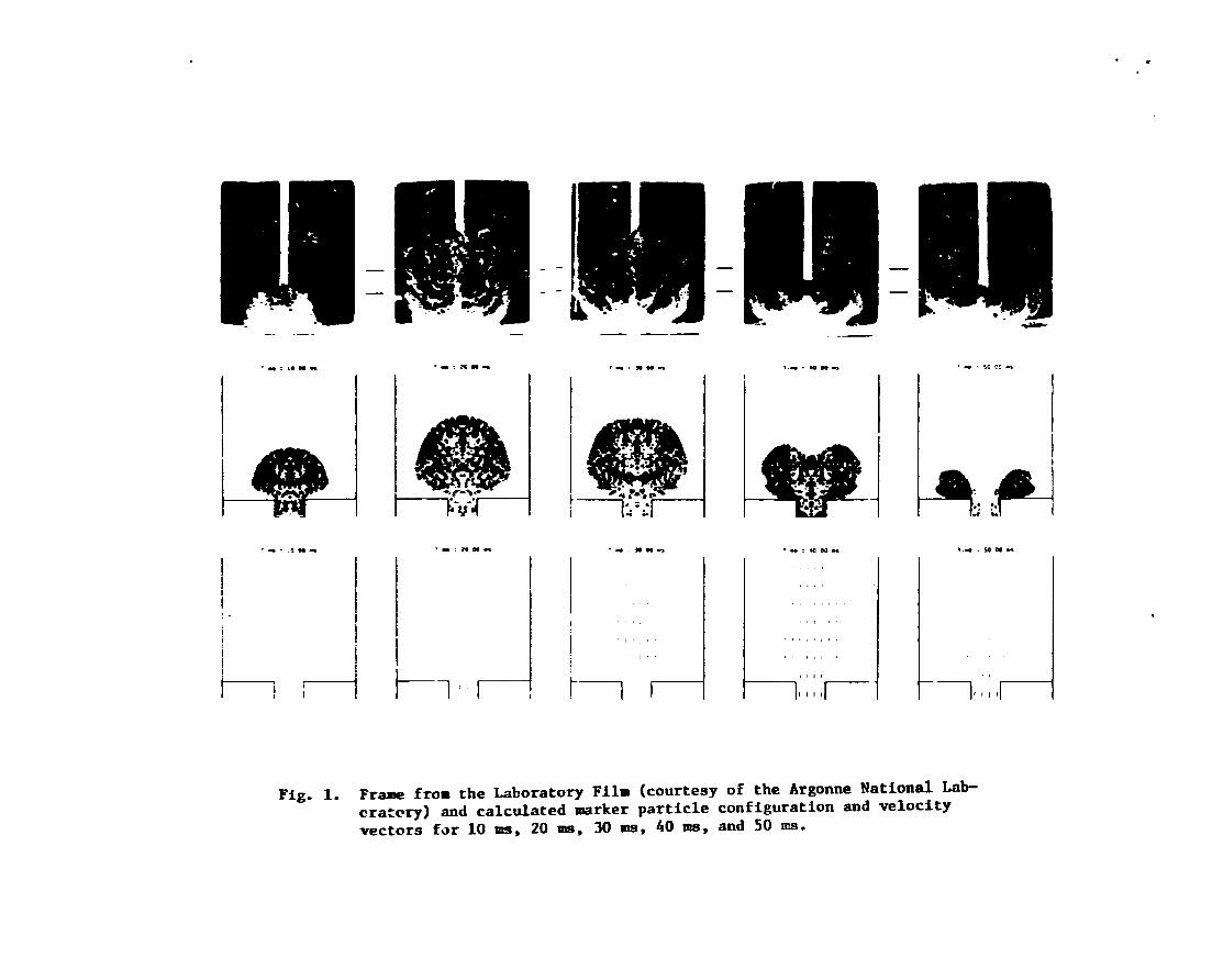
The dynamics and energy yield of this bubble ejection must be determined hefore we can assess the mechanicalwork that would be dme by the sodium pool on the vessel head. The dynamica of the bubble expansion have beensimulated by experiments in which a chamber filled with high-preaaure air ie ruptured and the resultfng high--pressure let of air expanda into a water-filled chamber above. Shown in Fig. 1 are frames (courtesy of ArgonneNational Laboratory) from a high-speed motion picture of one ex~eriment and corresponding plots of marker partf-cle conft~uration and velocity vector field calculated with K-FIX [51.
As a diaphragm to the high-preasu:e chamber is ruptured, the surge of air increasea the pressure in thewater-filled chamber. The momentum !mparted to the watar leade to an overexpansion of the air anti a subsequentdrop in bubble preaaure. The preaaure continues to decreaee until 28 milliseconds when the bubble reachen ltsmaximum volume. The bubble he~ins to collapee tnto the toroidal shape shown ?t 40 and 5(I mil~iseconds. i)urinutbe collapae the bulrhle pressure increaaea from the downward-directed momentum of the vater. Beyond 50 millisec-onds the pressure tends to equilibrate, and the bubble breaks up under the action of t’JrbUlenJe and buoyancy.
The velocity vector field showe a spherical diatributlon at 10 and 20 millisecon~s. At later times, thebuhr)le collapse is evidenced clearly by the reversal of the velocity vectors and the econdary-flow vortex pat-tern aet up batween the centerline and outside boundary. The vortex becomes smaller until at 50 milliseconds itia isolated in a corner wtth most of the velocity vectors dtrecttvf toward the lower chamber opening.
Calculated a,’zd measured preasurea in the hlowdovn vessel, on the base plate and on the vessel head are shown{n Fig. 2. AlthouRh thin example doea not make uae of the full power >f the multifield method, it provides anexcellent test of the code’s ability to calculate aepar$ted two-phase flow ill the low Mach number range [91.
IV. EXAMPLE: CTITICAL FLOWS I!J TWO-PNASE SYSTEMS
One of the most important phenomena determining the Auratton of th~ Iepressurizatian, or hlowd{~wn, phase Ofa lar~e-break lora-of-coolant accident is the rate at which cnolant •xl!~ from the broken pipe. I/e know from rrh-wrvntton that the flow out the break reachee I maximum value independent of the pressure difference between thein~ide and t’~e outside of the pipe break, provtded that the preamtr- ~iff,,rence is Rreat~r than a crittcal val-IIe. This limitinR flow phenomenon la called critical, or choked, flow. It is Veil Understood for einRle-phasecompresrnihle fluid?, but, at the time we began our otudy, thermodynamic models and one-dimensional fluid-dynsmicrnlculmttnne of two-phaae critical flow often did not accurately predict th~ observed datm. ~al~tlll,tedv~l,,~qofrritlcal flnw velociciea were unual”.y too larRe and had to ‘be multiplied by emptrle~lly ,Ietermined factorq knownRR break-flow multipliers to achieve agreement w{th meaaurd valuas. Our mtudieo, base+ on II two-dimonional ?hr-ory, ellow that nozzle Rtiometry awl nonequllibrlum effects must he tncluded to predict the crtt(cml flow velnrltyQccllrfitely.
‘then a ainRle-phase compren%ihle fluid flows through e noczle, the critirnl flow velnclty @q~laln tile ~peedof sound at the fiottcle throat. The physical ●xplanation is almple: When the fluid La moving with the qped of~m]nd, a dowttntream pressure disturbance propaRatea upstream ae frost as the fluid la movinR 4own~tream, ~o thenet lpropaRation of the disturbance f~ z~ro. Therefore, under critical flow conditions, the nozzle throat acts Ma h,~rr{er to any downstream pressure chmnges. The limiting flov vnlocity can be altered only by changing theronditionn upstre~rn of the throat.
The vnpor-ltquitf mixture, which is also a compremaihle fluid, exhibltn n similar but much more complicatedphenomenon. The critf,al flow velocity ie still the conic veLoclty at the throat, but the nonlc velocity in af-fee.twf by vanorizatton rnlonR the accelerating flow path, by the spatial diatributione ot the liquid and the v.l-por, and by uonequilihtlwm @ffecta that occur when the liquid phaae swperheatn because of rapid dapreaaurtzm-tion. The nnnlr veloclty in a homoRmeoua two-phaae mitttura can be far leae than the sonic velocity In either ofthe wparate rnlngle-phnae componante. This reduction in ●t.rlbutsd to the vnpor’s actinR an m wn~k nprinR cou-pled to the lnrRe llqlt(d maasee.
5
Equilibrium Tffo-Dimensional Calculation of Criticcl Flow ReteaUsing a homogeneous equilib rium model [R -_, K=_,and $e = C(T
r. - Ts), where C is efficiently large to
maintain T - T = TlV
~aturationl, we calculated the critical flw rate for a blowdown experi~nt at the Semiscale
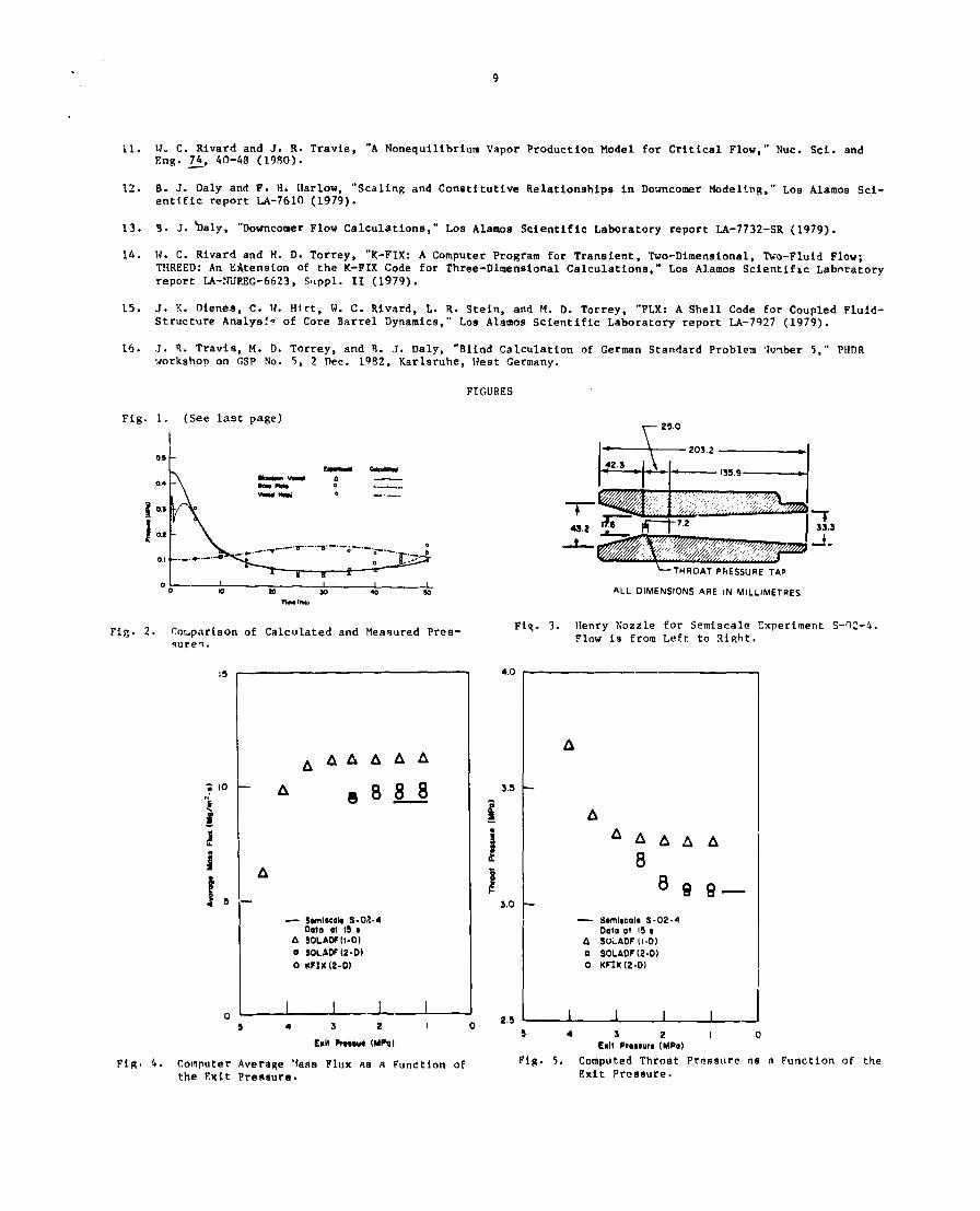
test facility flO]. Semiscale is a small-scale version of a pressurized-water reactor prhory system for study-ing loss-of-coolant accidents resulring from the break of a large cooling pipe. In the experiment that we ana-lyzed, the pipe break waa simulated by a nozzle knowm as the Henw nozzle (Fig. 3). We used the conditions meas-ured a short distance upstream from the nozzle entrance as boundary conditions for our calculation and solvedthe fluid equations in the fmmediate neighborhood of the nozzle.
Our initial calculations involved determining the critical flow rate 15 seconds after blowdown began. At 15seconds, the vapor volume fraction ie fairly large and the flow rate is likely to be independent of the vaporproduc ion rate, so we aamtmed an equilibrium phase-change model. In other worda, Je was chosen large enough to
maintain the vapor and the liquid at the satl~rmtion temperature for each value of the local pressure. The bound-ary conditions upstream oi the Henry nozzle entrance were 48 bara for the pressure, 534 kelvin for the tempera-ture, and 56 kilograms per cubic meter for the mixture density.
Ne varied the pressure at the nozzle exit between 45 and 10 bars. For selected pressures in this interval,the computation were carried nut until the flow reached a steady state, typically at 8 milliseconds after atart-fng the flow from rest. The computed average mass flv% and throat pressure are shown In Figs. 4 and 5. Figure 4indicates that the flow reaches a limiting value as the exit pressure la reduced. The computed critical flowvalue ia in good agreeuent with the measurements without the use of a break-flow multiplier or any other adjust-ment. The corresponding one-dimensional calculations also exhibit a critical flow aa the exit pressure is re-duced, but the computed maea flux must be multiplied by 0.9333 to agree with the data.
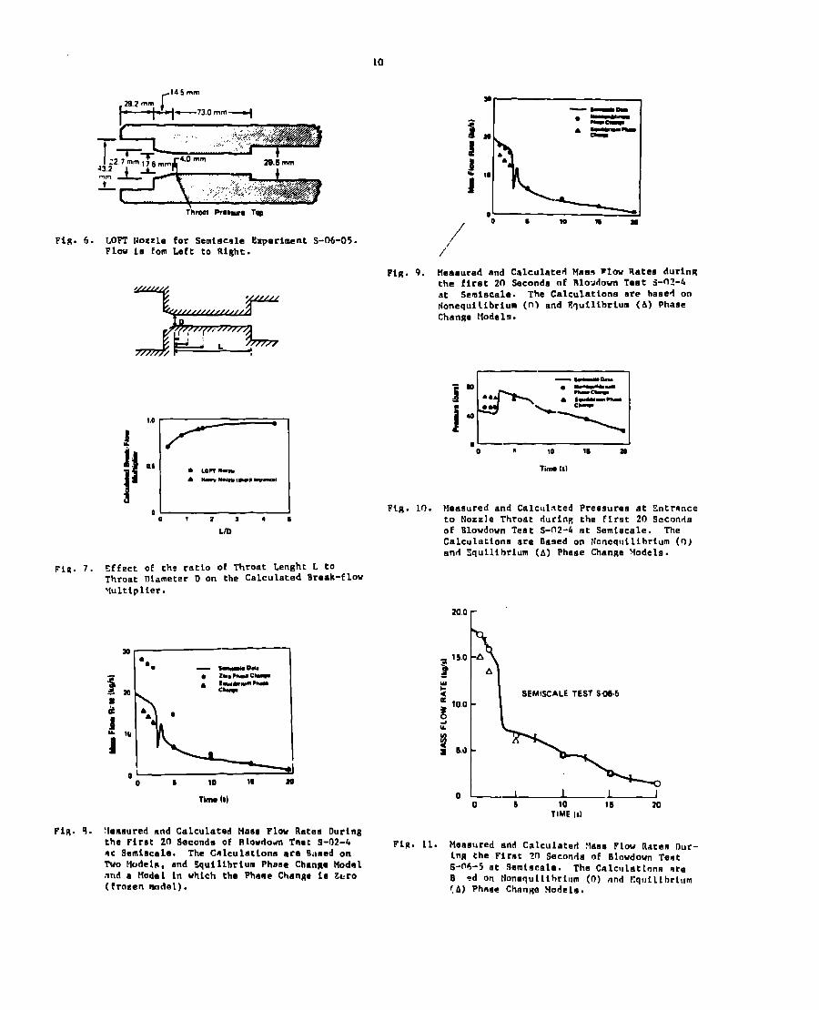
To understand the nature of the two-dimenalonal calculation for a similar experiment in which the ilenrynozzle was replaced by the nozzle design used at the LOFT (loaa-of-fluld test) facility. Although the abrupt en-trance to the throat of the LOFT nozzle (Fig. 6) would seew more likely to exhibit two-dimensional effects thant},e tapered entrance to the Henry nozzle throat, our one-dimensional results for the LOFT nozzle need only asmall correction to agree with tke two-dimensional calculation.
We studied the effect of entrance geometry further with a two-dimensional calculation for a henry nozzlemodified so that the entrance to the throat was abrupt rather than tapered. This change in geometry producedonly a small change in the mass flow rate and the throat pressure.
!Jext we investigated the effect of varying the ratio of throat length to throat diameter for the generalgeometric configuration of the LOFT nozzle. Figure 7 showa the break-fl~w multipliers required to reach agree-ment between one- and two-dimensional calc~la’ ions for vartou!i ratioa. If the throat length is s40rt relative toit diameter, two-dimensional effects are large. But for ratios greater than about 5, two-dimensional effects areno longer important and the exit flow can he described by a one-dimensional calculation.
A detailed look at the velocity profiles ●xplains this effect. At the throat entrance the radial velocitycomponents are negative and , accordingly, accelerate the central axial velocities. Therefore, a strong radialvelocity gradient develops in the entrance region. At a short distance downstream, the radial velocity compon-ents become positive and tranafer momentum rapidly outward from the center. Ilere,velocity distribution develop.
aPPrOXlmate on~-dimensionalHowever, if the throat length is too short for the flow to develop a one-dimen-
sional velocity profile, the one-dimensional models will require a braak-flow multiplier to agree with observeddata.
Effects of Nonequilibrium Phase ChangeThe calculations presented ao far have corresponded to homogeneous equilt,brium phase change. To assess the
relative importance of nonequilibrium phaae change, we calculated the mass flow rates at the nozzle exit dur,nxthe first 20 sec~mda of blowdown using two phaae-change models, the equilibrium model described above mnd a mode’in which the phase change ia zero. FiRure 8 shows the calculated values and experimental data for the :Icnry noz-zle. The values were obtalnad by multiplying the results of A onc-dimenatonal calculation by the calculatedbreak flow multiplier for the Wenry nozzle.
During tha first 3 oeconds of hlowdown the fluld snterlng the nozzle is singie-phaae liquid. Its tempero-t~ire ia initially 28 kelvin Iral)w the aattiration temperktv,fa, but, aa the preaaure decreanes, the fluid rapidlyrenchaa the saturation point and becomes superheated. The fact that the data lie between the calculated extremesin,llcatea that nonequillh,ium phase change occurs during these first few aecondm.
After 3 aeconda, when n tuc-phaae mixture enters the nozzle, the calculation with equilibrium phase chmnge@Rr@ee with the data. Finally, after 10 oeconda vhen the mixture entering the nozzle is mostly 8team, the cmlru-Iated msna flow rntea for both vaporization models coincide with each other and agree with the datn. The flowrate in ~ndependent of the vapor production and im oalely rlet.armined by the upstream condtttons.
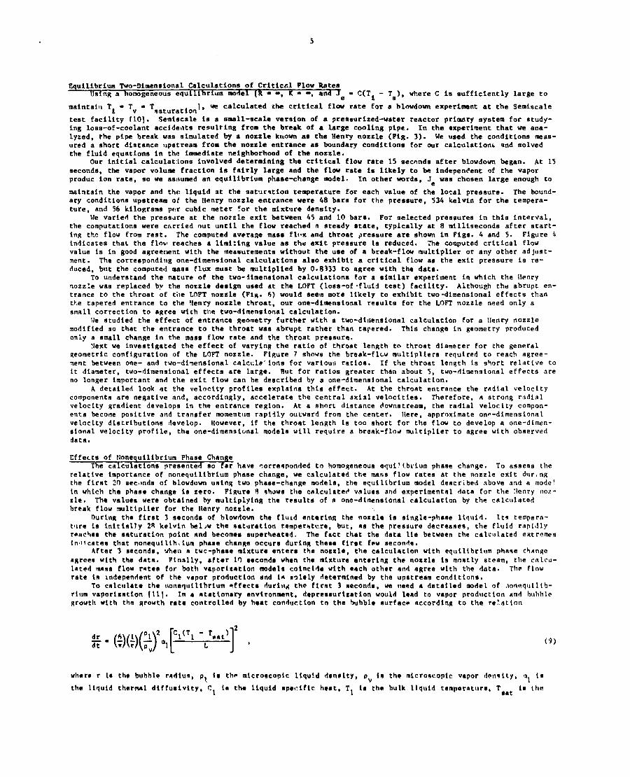
To calculate the oonequiltbrium affects duriilg the flrnt 3 neconda, we need a detailed model of .mmwqutlil)-rium vaporization [111. In a atattonary anvtronment, depraasurization would lead to vapor production and buhblc~rowth with the ~rowth rate controlled by heat conduction to the bubble nurface accordinR to the re!.atlon
where r la tha bubble radiun ) P, fs the microscopic Llqu!d denmlty, pv irn the mlcroncopic vapor d~n~ity, ml l!I
(9)
the liquld thermsl diffustvity, Cl la the liquid ape(:lfic heat, T, ia th~ bulk liquid temparatura, Taat is tha
6
saturation temperature. and L is the heat nf vaporization. During t,he depresaurization and acceleration of thefluid through a converging nozzle, the bubble growth rate varies becauae T*at and pv depend on the pressure and
T1 decreases aE heat is used to vaporize the liqui4. The Instantaneous bubble radiua thus depends on the entire
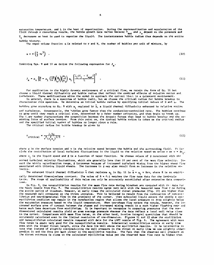
bubble history.The vapor volume fraction a is related to r and N, the number of butibles per unit of mixture, by
()43LX-N -nr.
3
Combining Eqs. 9 and 10 we derive the following expression for Je.
Je=pv+-pl
For appllcatton
($[3(3al[1(”~‘sat)]’“
to the highly dynamic environment of a critical flow, we retain the form of Eq. 11 but
(lo)
(11)
chooqe a liquid thermal diffueivity and bubble radius that reflect the combt~ed effects of reltttiv.? motion andturbulence. These modifications allow the model to approach the correct limit in a quiescent environment.
In general, there is a spectrum of bubble radii, but we choose the critical radiua for bubble breakup tocharacterize this spectrum. lfe determine an initial bubble radius by specifying initial values of N and G. The
huhbles grow according to Eq. 9 with al replaced by ~, a liquid thermal diffusivity enhanced hy relative m?tton
and turbulence. Consequently, the ~ubbles grow faster than the conduction-controlled rate. The bubbles continueto grow until they reach a critical size, determined by a Weber number criteriou, and then begin to break up.The ::..ner number characterizes the competition between the dynamic forces that lead to bubble breakup and the re-storing force of surface tension. From this point on, the typical bubble radius is taken as the critical radiusnnd the specified initial number of bubbles no longer plays a role.
The critical radiua for bubble breakup is given by
2.3arcritical - 2 2 1/3 ~
v (Plov)(12)
where CJ is the surface tension and v is the relntive speed between the bubble and the surrounding fluid, To in-clude the contribution of local turbulent fluctuations in the liquid to the relatlve speed we write v as v - 13v
1’where VI is the ltquid speed and 8 is a function of vapor fraction. We choose values of B consistent
s~rved turbulent velocity fluctuations, which are generally leqs than 19 per cent of the wan flow veward the miridlc vaporfraction range, 1? lncreasee becauee of increased turbulent mixing from the hl~lleaedoclateri with thinning liquid eheets. The increase in (1 may aleo reoult from an increaae in the relocity.
Tho enhanced liquid thermal dtffusivity ; that replaces al in Eq. 11 is ~ ● al + Brv, where B 1s
with oh-
Oclty. To-shemr Flow
ative ve-
an empiri-
call~ determined rlimenslonless conqtant. The value of B - fl.l-matches the flow ra~e data for the Semtqcalet,eflts. The range of applicability of this value can only be accurately established after extensive data compari-r.on~,.
In FLjI. 9, the nonequilibrium reeults for the mesa flow rate durin~ blowdown are compared with th’ data forthe !lenrv nozzle from Ftg. S. The nonequilibriurn results agree very well with the measured mass flow r.te duringthe entire period of blowdown. Nowever, at early timeo the calculated throat preasurea (FIR. 10) are higher thnnthe measured wall pKeSSIJKe# at the throet entrance. Thie in believed to reeult from the combination of non(qui-Iibrium and two-dimensional flow in the proximity of the cornar. hhen subcooled liquid enters the nozzle IJ oon-eqllilibrium condition may result in the rarefaction ragion that allows the local preseure to drop slightly belowthe saturation pressure beeed on the liquid temperature. When two-phaae flow enters the nozzle, however, the ln-creaned surface area cf contact between the phaees and increaced mixing r?sult in a much hiRher flaehirg rate indhence much leen departure from equilibrium. It lC important to recognize in comparing pressureo that the one-dimennional calculated reoulte yield an area avera8e preesure whereas the data reflect a local wall value closeto the corner. Comparteons with maes flow rates, on the other hand, involve integral quantities that should beaccurately calculated even in the limited resolution of one-dimension. F14uree 11 and 12 show the equilibriumnnfl nonequlitbrium calculated results compared with data for the LOFT nozzle of Fig. 6. The ngreement with masqflow rates is aRain vary good for the nonequilibrium resulte. !lubstantiel lM)IIeqUiLibriUfO existn at t?~rly timeeven with the lonRer tllro~t lenfith, Mince the data lie well above the equ:libriurn results. It is intareating tooote that Ln#teAd of s~iRhtly overpredictin~ the wall preseure in the throat at early tlm we now slightly under-predict it and the datn ar~ tmch cloeer tn the equiltbriutn ruaulte, The fact that the obeerved wall preeeure at:he thrnnt ●ntrance 1S closa to the calculated ●quilibrlw value yet the obnerved maern flow rate io higher than
7
.
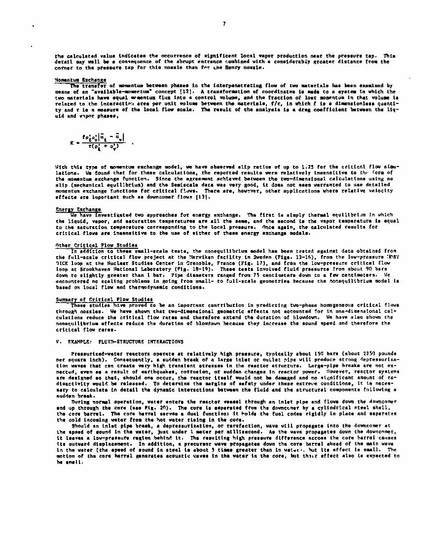
the calculated value indicatea the occurrence of mignifiwnt local vapor production near the preaeura tap. Thiodetail may well be ● con~equence of the abrupt ● ntrance combined with a conaidarably Rrcater distance from thecorner to tha preeaure tap for thie IIOZZ1Othan fw cne EMnry nozzle.
>fo~ntum ExchangeTha tranafer of mm?ntum bmtwaen phaaea in the interpanatrating flow of two mztarialm haa ken ●xamined by
meana of ●n ‘availablezmer.tum- concept [12]. A traneformetion of coordinate ie made to a ■ystam in which thetwo -tariale have aqual =mmntum flux into ● control volume, ●nd tha fraction of lost mmentum in that volum inrelated to the lnteractim area per unit volum between the materiala, f/r, in which f ia a dimenaionloas quanti-ty and r ia a -aaurm of the local flow ecale. The result of thm ●elyeis la ● drag coefficient btween the liq-uid and vlpmr phaaes,
With thio ty~ of rnmentum ●xchange model, w have obeerved slip rattoa of up to 1.25 for the criticcl flow eimu-lationa. We found that for thmae calculation, the raportmd reoulta were relatively insensitive to thu form oftha momentum exchanga function. Since the a~reamnt achieved between the two-di~nsionei calculation using noslip (mechanical aquil!brium) and the Semlacale data waa very good, it doam not amem warranted to uae detailedmomentum ●xchange ‘functions for critical E!.wa. Them am, however, other application whera relative velocityeffecte are important such as downcomer flown [131.
Energy ExchanfieWa have invaatigated tvo approached for energy exehanga. Thm first ia ahply thermal equilibri~m in which
tha liquid, vapor, and aaturatlon tomperaturee are all the same, and tha second ia the vapor temperature is equalto the saturation temperature corresponding to the local preeoura. once again, the calculated results Eorcritical flow are Inaaneitiva to the uem of eith~r of theaa ●nergy ●xchange models.
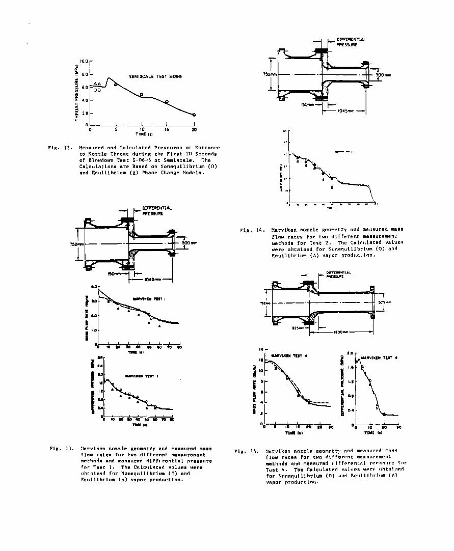
Other Critical Flow StudiesIn addition to theee emall-ecala teato. the noneautlibrium mdel haa been tested auainet data obteined from
the full-eeale critical flow project at the-!farvikenVICK loop at the Nuclear Studiaa Center in Grenoble,loop at Brookhaven National Laboratory (Fig. 113-19).down to elightly greater than 1 bar. Pipe diameteraencountered no acalinfi problmma in Roing from emell-based on local flow and thermodynamic condition.
Cacility in Sweden (Fige. 13-16), Crom the low-preaaure ~KIBYFrance (Fig. 17), and from the Low-preeeura critical flw
Theee taata Involvad fluid preasuree from about 90 barsranged from 75 centimatera down to a few centi~tera. !feto Cull-scale geomatriea Emcaume the nonequilibrium miel ts
Sumary of Criticnl Flow StudiesTheme atudlea have proved to be an importmnt contribution in predicting tvo-phaaa homogenaoue Critical flws
throuRh nozzlaa. We have ahwn that two-dimanaional gaomatrlc ●ffecta not accountmd ?or in one-dimenatonal cal-culation reduce tha crikical flw ratea and therafore extend the duration of hlowdon. We have aleo shown thenonequilibrlum affecta raduce the duration of blowdown hecauae thay intreaee the sound speed and therefore thecritical flow rarae.
v. EXAMPLE: FLUID-STRUCTURE INTERACTIONS
Presaurtzed-water reactora opernte at relatively high preoaura, typically about 150 bare (about 2250 poundsper aqware inch). Consequently, ● nurlden break of m lnr~e inlet or ouLlet pipe will produce ntrong deprennurlza-tlon wavea thet can craatm vaty him tranalmnt ●tremeam in tha raactor ntructura. LnrSe-pipe hroaka are not Qx-nectud, ●ven ●e m result of earthquake, corrosion , or ●uddan changea in reactor power. llwever, reactor eyatemsam designed ao that, should one occur, the raactor itself would not be damaged and no ~i~;niftcant amount of ra-dioactivity would be raleaeed. To detamine the wrginc of aafaty under these extrelte condltiona, it ia necee-●ary to calculato in detail tha dynamic interaction batwean tha fluid and tha structural component following anudden break.
lMrl~ normal operation, water ●nters the reactor vessel throu@ an inlet pipe and flwe down the downcomerand up throunh the core (ace PiR. 20). The com ia ●eperatad from the downccmar by ● cylindrical nteel ohell,tha core barrel. Tha cora barrel aarvoa a dual functiont it bolda the fual codee rigidly in place and aeparntentha cold incominR vatar from tha hot watar rising in the core.
Should an inlmt pipe braak, a dapremauritatlon, or rarafactionthe speed of sound in the watar,
, wave will propagate into the downcomer atJuet under 1 mater per millisecond. Ae the wavo propagate down the downcnmer,
it leaven a low-preaaure reRion hahintl it. The reoulting high pressure difference acroam the cora harrol cauaaaite outward dieplacamant. In addition, a pr~curaor wave propagate down the core barrel ahead of tha main wavein thm water (the speed of sound in steel la ●bout 5 timma Breater than in wat-r’,. hut its ●ffect is mrM1l. Themtinn of tha core barrel ,qaneratee ●coustic uavea in the water In the core, ht th!~r effect aleo la expected toh ●men.
8
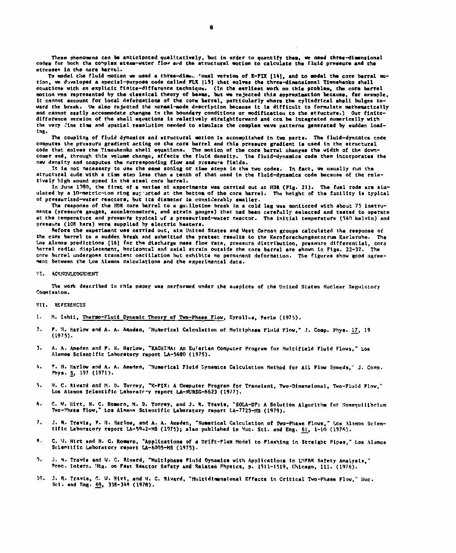
These pheno=na can be anticipated qualttatimly, but in order to quantify thin, w mead three+ imenoionalcodes fmr both the co~plex ●teem-water flw sl*d the structural mtion to calculate the fluid preeaure and thastrenee~ in the core barrel.
To mdel the fluid motion vz ueed e three-dirn..’ooal vareion of K-FIX [14], and to -dml the core barrel mo-tion, we d~veloped a special-purpoee code call-d FIX [15] that eolvms the threo+limensiomal Thoehenko shellequatione with ~n explicit Eintce-difference technique. (In the earlieet work on thte problem, the core barrelmotion wne represented by the clameical theory of baama, but we rejected this ●pproximation because, for erample,it cmnnot account for local defo;mztiona of the core barrel, particularly where the cylindrical @hell bulgee to-ward the break. Ue aleo rejected the normal-mode description becauee it ie difficult to formulate rnthematicallyand cannot ●aefly accomtwdate changes in the boundary condition or mdificatiou to the ●tructura.) Our finite-difference eereion of the ehell equatione I- relatively atraightfomard and ccn be Integrated nu~rtcally withthe very ~ine tim and spatial resolution needed to eimulace the complex wave patterne generated by eudden load-ing.
The coupling of fluid dynamica and structural motion ie accomplished in tw parta. The Eluid-dyrmmica codecomputes the preeourc gradient acting on the core barrel and this preaaure gradient la used in the structuralcode that solves the Tim~henko shell equetiona. The motion of the core barrel changas the width of thn down-comer and, through this volume chmnae, ●ffecta the fluid denoity. The fluid-dynamite code then Incorporate thenew denoity and computua the corresponding flti and pteeeura fielda.
It ie not neceeoary to uae the aaw zoning or time atepa in the two codeo. In fact, we usually run thestructural cude with a time step less than a tenth of that used in the Eluid-dynamica code because of the rela-tively high Mound apeed in the steal core barrel.
In June 1980, the firet of a ●arieo of axperimente was carried out at llDR (Fig. 21). The fuel roda are sim-ulated by a If)-metric-ton ring eu~ “~rted at the lmttom of the core barrel. The height of the faciLity is typicalof preaourized-water reactora, but ita diameter la conei(!arably emellar.
The reeponne of the HDR core barrel to a guillotine braak in a cold leg waa monitored with about 75 inatru-mentm (preenure gauges, accelerometer, and otrain gaugaa) that had been carafully aeleccad and teatad to operateat the temperature and preneure typical uf a preaaurized+ater reactor. The initial temperature (5411 kelvin)” andpre~aure (108 tara) were euppliad by ●lectric heatere.
Sefora the experiment waa carried out, aix United Statea and Waet Ccrman groups calculated the reaponoe ofthe cora barrel to a euddan break and submittad the pretaat raeulte to the Kernforechungezcntrum Karlsruha. ThaLne Alamoa predlctione [16] for the diech.irga meao flow ratebarrel radial. dieplacaunt,
, preeeura distribution, preaaure differential, corehorizontal and axial etrain outside the cora barrel are ehown In Flge. 22-32. The
core barrel undergoen trannient oscillation hut exhibits no permanent deformation. The figures chow good agree-
ment betwean the LoE Alamon calculation and the experimental data.
!’1. .4CYNOWLEOCEMEN’T
Tha work deecribed in rhie paper wae Derformed under the auapicee of the United Statea Nuclear RegulatoryCo~isaion.
V1l. REFERENCES
1.
7-,
3.
4.
5.
6.
7.
n,
0,
10.
M. Ishii, Thercm-Fluid Dynamic Theory of Two-Phaea Flow, Eyroll~e, Parie (1975).
F. !I. Haricw and A. A. Amnden, ‘“Numerical Calculation of Multiphaae Fluid Flow,” J. Comp. Phye. LJ, 19(1975).
A. A. Ametien and F. H. IIarlow, “lCACHINA: An Eu!arian Computer Program for Multifteld Fluid Flows,” LoeAlamoa Scientific Laboratory report LA-3680 (1975).
?. H. llarlow and A. A. Ammlen, “Numerical Pluid Lynamice Calculation Method for All FIw Speeds,’” J. Comp.Phya. ~, 197 (1971).
W. C. Rivard and M. D. Torrey, “K-FIX: A Computer Program for Tranaient, Two-Dlmaneional, Two-Fluid Flow,”Loo Alamoe Scientific Laboratc-y report LA-NUREC-6623 (1977).
C, 1{. Ilirt, N. C. Romero, ~. D. Torray, and J. R. Travis, “SOLA-DP: A Solution Algorithm for XonetlutlibriumlVo-?haee Flow,” Loa Alnmn~ Scientific Laboratory r-port LA-7725-MS (1979).
J. R. Travis, F. Il. !iarlw, and A. A. Amaden, “Numerical Calculation of Two-Phaae Flowe,” Loo ilamon Scien-tific Laboratory report LA-5%2-tIS (1975); alao publlahad in WC. Sci. and Eng. Q, 1-10 (L976).
C. W. Hirt and N. C. RoMro, “Appltcatlone of a Drift-Flux Model to Flanhing in 9traiRht Plpee,” Loo .tl~moeScientific Lehoratory report LA-60f15-PIS (1975).
J. K. Trmvi,e and W. C. Rivnrd, “Ftultiphaao Fluid 13ynamica with Applicntiono in L’lFllR Safety AnaLyel~,”Proc. Intern. !ltR. on Fact Reactor Safety ~nd Related Phyoicm, p. 1511-1319, Chicago, 111. (1976).
J. R. Trnvia, C, \J, Nirt, and 1/. C. Rivard, “Ilultidlmnelonal Effecte in Critical Two-Phaae Flw,” NUC.Sci. and Eng, 69, 3M3-34R (197 R).
9
11. W. C. Rivard and J. R. Travis, “A Nonequilibrium Vapor Production Model for Critical Flow,” NUC. SCi. andEng. fi, 40-48 (1980).
1’?. B. J. Daly anrl F. H. Ilarlow, ‘“Scaling and Conatitutlve RelatlonahlDs in Do-wncomer Model?.ne.” Los Alamoa Sci-entificreportLA-761O (1979).
-.—
13. B. J. baly, “Downcomer Flow Calculations,” Los Alamos Scientific Laboratory report LA-7732-sR (1979
14. W. C. Rivard and M. D. Torrey, “K-FIX: A Computer Program for Transient, Two-Dimensional, Tvo-FluidT!{REED: An E~tension of the K-FIX Code for Three-Dimensional Calculations,” Los Alamos Scientific L/report LA-NiiP.EG-6623, Suppl. II (1979).
.
Flow ;boratory
15. J. K. Dienes, C. W. Hirt, W. C. Rivarci, L. R. Stein, and M. D. Torrey, “FLX: A Shell Code for Coupled Fluid-Structure Analys!s of Core Barrel Dynamics,” Los Alamos Scientific Laborato~ report LA-7927 (1979).
16. J. R. Travis, M. b. Torrey, and B. J, Daly, “’Blind Calculation of German Standard Problem ‘Junber 5,’” PHDRworkshop on GSP No. 5, 2 Dec. 1982, Karlsruhe, West Germany.
FIGURES
Fig. 1. (See last page)
0.5-
0.4-
-,-. -.-w-.-’~’ - ‘=’-’ -s-’- ..-. s.01 -._. *----
01 ! 1 I 10
Lm m 30 * sO-
l’hmhll,
FiE. 2. Cor,lparison of Calculated and Measured Prea-
Fig. 4. Computerthe Exit
A
A AAA A A
A eO~
— SUnlual, S-OZ-4Dote at 159
A 90LAOF[I-D)0 SOLSOF(2.D)O K?XX(Z-D)
~-l——~
8 4 3 2 I o
ltslt Pmswo (MPa~
Average ‘tasn Flux as a Function ofPressure.
,-4=032—,P-P-t--’”+
-T33.3
d.
THROAT PRESSURE TAP
ALLDIMENSIONS ARE IN MI LLIMETREs
Firz. 3. ilenrv Nozzle for 5emiscale Exnerifnent
4.0
3.s
3.0
,–Flow is from Left. to Right.
A
A
‘AAAA
8QQ—
S-02-4 .
— Stmlscalo S-02.4Data 0! 15 B
A SW-ADF(I-D)O SOLADF(2-D)o KFIX(2-D)
I
2.59 4 3 2 I 0
Ed! Pfowure {MPa)Fig. 5. Computed Throat Pressure AS a Function of the
Exit Prc88ure.
10
~145mm
I%-J-i-’’’””--+I
—
I
FIu. 6. LOFT Nozzle for Semtecale Experiment S-06-05.Flow ie fom Left to Right.
Jt@a-
/ -o 6 10 m m
//
QiR. 9. Ueasurad and Calculated Mae~ Plow Nateo durinRthe firet 20 Seconde of II1O-MIOWMTest s-02-4at Semlacale. The Calculation are baaed onNonequiLibrium (n) and Equilibrium (A) PhaaeChanRe llodele.
o~ I0 m 10 lM 20
Ftg. 10. Mea9ured and Calculated Preaauraa at Sntrance
to Nozz]a Throat durinR tha first 20 Sccondaof Blowdnwn Teet S-02-4 at Samtacale. ThaCalculation are Daaed on Ncncquilihriurn (o)and ?,qullibrium (A) Phaee ChanRe Yodels.
FiR, ~. Effect of the ratio of Throat Lenght L toThroat lliamatar D on the Calculated Break-flowMultiplier.
20.0 r
FiR. q. Hen.wred nnd Calculated Ftaoo Flow Ratea Duringthe First 20 Seconde of Rlowdovn Tnot s-02-4at Semlocale. The Calculatlonn are Bi~aed onTwo Modeln, and Squilihrium Phnee Change Modelmid a Model in which the Phame Change ia Ztiro(frozen modal).
FIR. 11. Meooured and Calculated !Iasa Flow Raten llur-inR the Firmt ?0 Seconds of Dlowdow Teat5-nq-5 at Semiscale. Tha Calculatlnna nreB ~d on Nonaqullihriurn (0) nnd Cquillhriurn~.A) Phnae ChanHe ?lodela.
10.0r
OL ~... ~~o 5 10 16 20
TIME (s)
FtR. 12. Measured and ?~lculaterl Pressurfia at Entranceco Nozzle Throat during the Flret 20 Secondsof Blowdoun Test S-M-5 at %mincale. TheCalculatlona are Baned on Nonequilibrium (0)and Eq~lilibrium (A) Phaae Change Models.
TF-%c2..1-“l- Ioasm —
a.or
L I00 10
1 1 1 1 1 1 Iw m ti m w m m
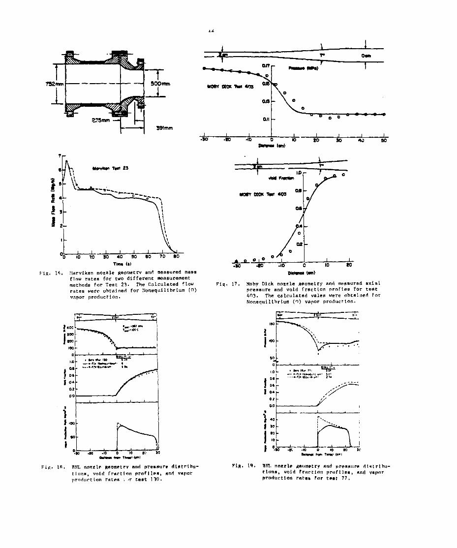
FIR. 11. :l~rviknn nnznl~ Ronmatry nnd mnanurnrl mamaflow rRtOE for two rtlffcront meanurnmontmnthnin nnd m~nmurarl dlfftrontlnl praun!lre~or Tant 1. The Cnlculntod vnlueo wereohtnlnqd Fnr tlnnequlllhriurn (fl) nndF.qullihrlum (A) vnpnr production,
mE5smE
T nmm —.—--
115cwm 1-l-- lo45mnl —
-*I
FIR. 14. !larviken nozzle geometry nnd rneusured mass
Flnw ratee for two different meaauremen~r,wthoda for Te~t 2. The Calculated valucq
were obtained for Nunequtllbrtum (0) antiEqulllbrium (A) vapor prnduc:lnn.
mi.1–-.—-—~—-” + 5c’+-
‘k-%ikr+’“’”-p-l-+
1,0
\
Manvluw TUT 4
I ,#
I. I
0.0
0.6 b
Flu, 15. Hnrvlkon nozzle uoometr~’ nnd Mcnnllrcfl mnn~.,flow rntnn For tun (llFfErrnt mamf+uremrllt
methndn nnti rnonnurmd dlffrrmntnl nr~-nllr~ rl~r
Tuat h. TIIrI Cmlculntrd vnl.IIoe werv t]htnlilmrl
for !Innnqul llhr~um (o) IIIId I?qIII llhrlum (A)vnpnr prorluctlnu.
Lb I #
2mmm*
H “’mm
‘~L-_L10 ?0 so 40 50 80 70 00
The (8)
Fig. 14. :Itirviken nozzle geometrv and measured massflnw rates for two different measurementmethods for Test 23. The calculated flowrntea i.fer~ obtained for !Ionequilihrlum (0)vnpor production.
00 f, I , 1
/
i i !
“:L*.m .10 0 so 80
Dletma tan}
FiR. 17. !lohy Dick nozzle geometry and measured axialprenmure and void fraction profien for tent4n3. The calculated vales were ohtninetl forNonequilfbriurn (n) vapor production.
.-
.
—=--4
EAJIII
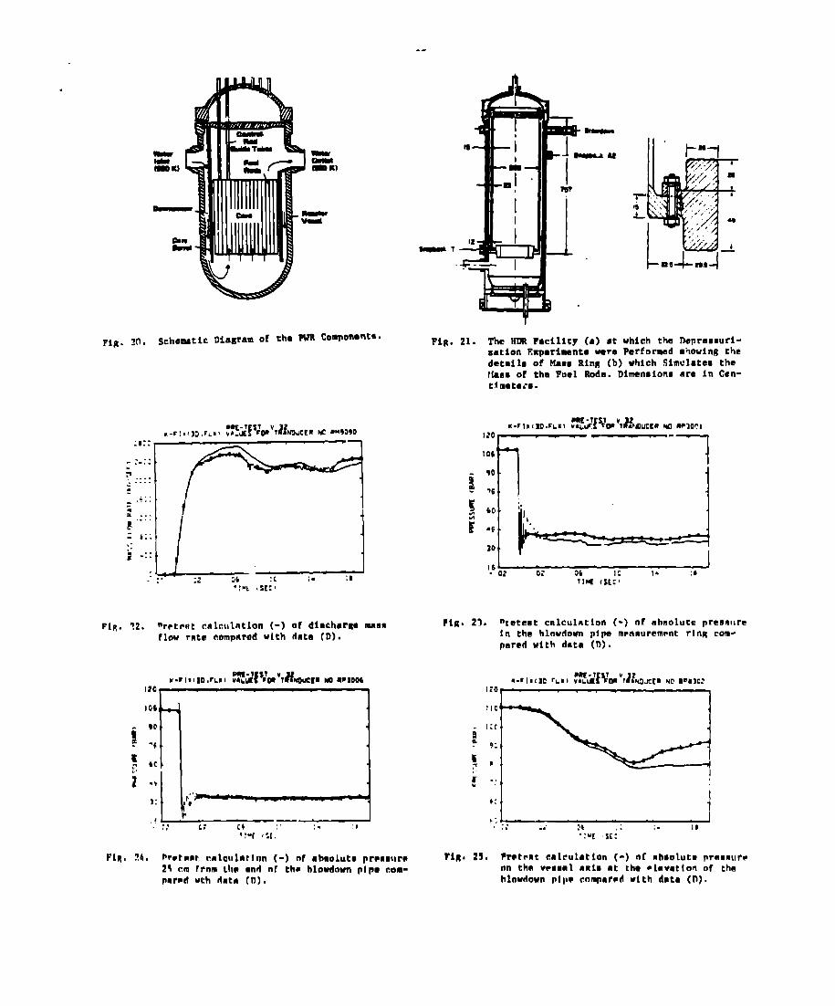
Fig. m. Schematic Diagram of tha PUR Components.
FIR. ?2. nr~tent calculation (-) of dinchar~ mmnnflow rate corntmrod with data (D).
T
Fig. 21. The n Facility (a) ●t which the DePreneuri-zation Experiments were Performed ●tiouing thedetaile of Mace Ring (b) which Simulatea theMaea of the Fuel Roda. Dimaneionm are in Cen-timetete.
m-r 1,, So.r.,) 3wb?’v&lucmr Mu Wloc,I20r .—-106
1
%:1
Pig. 23. nretent calculation (-) nf ahnolute preonllrein the Mnwdourr pipe mmnuremmt ring com-pared with data (n).
110
1:(9*
9:
~p,-! . .
I
FIR# 25. Pretont calrulatlon (-) nf nhsolute praanur~on thn v~eeml anin at the ●levatlon d thahlowrlnwn ptpc tmepar~d with data (D).
14
:: I I-.. ti:: i? :.. . :E
1:#~ <sE:!
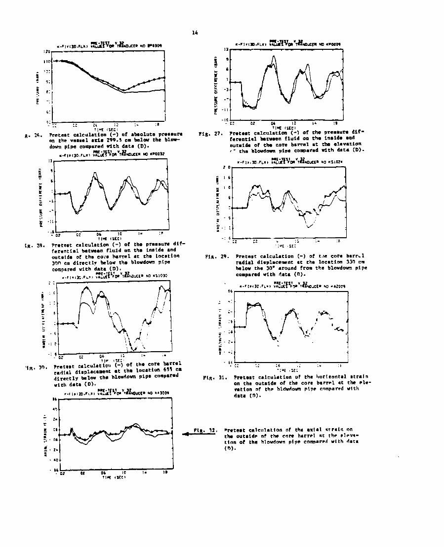
8. ~~. ?retaot calculation (-) of abaoluta prommuraon the veomal ●xis 299.5 cm below the blow-
i -“t. ,y~-
lIW (SEC I
lR. 28. Preteot cmkuhtion (-)of the ve~~ure dif-ferential between fluid on the lnotde ●nd
outside of the coi.a barrel at the locationllln cm directly blow tha blowd~ pipe
compared with dmta (D)I,.,,.,,: ,,L. , fls#&’7&IucE~ NO KSI030
~: I
~“ 0
JFj::
5r} \/
h‘!/\:-.
L:.b \:
=
.!
a i !’ ;$-: c. NJ,
i..: 6
- 0: Ci W 12 :. :.
Ilv, {X:,
Pretest calculation(-)of tho core barrelradial dinplacamnt ●t tha locati~ fi~~ cm
directly balow the hlowdon pipa comparedwith data (D).
a-r , “,socrL”, R5iwm”nmoucsmEm ●mow
‘3~—~
71-E {SE: IFig. 27. Pretest calculati~ (-) of the Pre~ru~ dif-
ferential btwaen fluid mm the insida ●ndoutafde of th core barrel ●t cha alevation,- the blovdowa pipe compared with data (D).
FIR. 29. preteet calculation (-) of t.le core barrklradial displacement ●t the locatiom 33fI cmbelow the 30° ●round from the blowdown pipe
compared with data (n).
.:
p-l,,..-.\ a ,*.:*Jr
,+\,,:8 f’i.’ ‘-%
.-:. .
. J
-: ;
. .. :: :: :6 .: ;. ,k
“:% !;[:
FIR. 31. Pretent calculation of the hortcontal ntralnon the outmide of the core barr-1 At the ●le-vation of th~ hldwdown pipr cnmpar~d wtth
data (0).
cm, 1
~1 ~ piR. 32. nretemt calculation of the ●xlml otrmln on::- . 0, the out~id?
ttnn of theof the cnre harr~l at the PIov.t-hlowdown PIPP cnmnared with data
(n).
. MI
- 01 Ot 06 Ic 1. 19?Iw (See)
—
—
—..—.
--,,,--
---:*,c -
a● ..*-*.-“
. >-<>
——
1-= *M”
——
11“
‘ ‘J[ .’, ;
in—l
$!!!!!2-...I 8’b.
r.o:wooe
,,,
.,
,,,
!, !,,.
,$, ,,,
,!, !
_“l,,,,r
+
“.SC CC-,
,.- ,5000”
Fig. 1. Frame from the Laboratory Film (courtesy of the Argonne National Lab-era:cry) and calculated winker particle configuration and velocity
vectors for 10 ma, 20 ma, 30 ma, 40 ma, and 50 ma.