Embed Size (px)
Citation preview

Loughborough UniversityInstitutional Repository
A review and comparativestudy of release coatings foroptimised abhesion in resin
transfer mouldingapplications
This item was submitted to Loughborough University's Institutional Repositoryby the/an author.
Citation: CRITCHLOW, G.W. ... et al, 2006. A review and comparativestudy of release coatings for optimised abhesion in resin transfer moulding ap-plications. International Journal of Adhesion and Adhesives, 26 (8), p.577-599.
Additional Information:
• This article has been published in the journal, International Jour-nal of Adhesion and Adhesives [ c© Elsevier]. The definitive ver-sion: CRITCHLOW, G.W., LITCHFIELD, R.E., SUTHERLAND, I.,GRANDY, D.B. and WILSON, S., 2005. A review and comparative studyof release coatings for optimised abhesion in resin transfer moulding ap-plications. International Journal of Adhesion and Adhesives is availableat: www.elsevier.com/locate/ijadhadh
Metadata Record: https://dspace.lboro.ac.uk/2134/808
Publisher: c© Elsevier
Please cite the published version.

1
A REVIEW AND COMPARATIVE STUDY OF RELEASE COATINGS FOR
OPTIMISED ABHESION
IN RESIN TRANSFER MOULDING APPLICATIONS
G.W.Critchlow1*, R.E.Litchfield1, I.Sutherland1, D.B.Grandy1 and S.Wilson2
1IPTME, Loughborough University, Loughborough, Leicestershire, LE11 3TU, UK.
2Short Bros./Bombardier Aerospace, Airport Road, Belfast, BT3 9DZ, Northern Ireland, UK.
*Corresponding author, [email protected]
ABSTRACT
In this study, a number of abhesion promoting coatings were considered in terms of their
physicochemical and release properties. The techniques used to further this study include;
FEGSEM, AFM, profilometry, AFM, XPS, AES, SSIMS, FTIR and contact angle analysis for
coating physical and chemical characterisation along with PF-AFM and other adhesion and
mechanical tests to determine surface release properties. These coatings were applied to metal
substrates and were based upon silicone, fluoropolymer or metal-PTFE composite chemistry, all
being potentially useful as release films for resin transfer moulding (RTM) applications. The
semi-permanent Frekote B15/710 NC mould release coating system, which is based on PDMS,
proved extremely effective in terms of release against a cured epoxide applied under pressure.
Although fluoroalkylsilane coatings offer a number of technological advantages for release
applications they generally produce very thin coatings which conform any existing surface
topography and adhesion through mechanical interlocking occurs. The commercial PTFE-based
coatings were found to provide poor release properties due to the presence of surface
microcracks which allowed epoxide penetration when cured under elevated pressure and
temperature. Electroless Ni/PTFE composite coatings comprise hard nickel-phosphorus matrix
containing a very fine dispersion of PTFE particles. The matrix proved sufficiently robust for

2
industrial applications and the low friction and surface energy provided by the embedded PTFE
combined with macroscopic scale surface roughness provided efficient mould release.
1. INTRODUCTION “Abhesion”, a term first used by Zisman[1], is the very antithesis of adhesion. Whilst the
majority of reported studies focus on the science and technology used in achieving optimum
adhesion, an understanding of abhesion is fundamental to a number of areas. Examples include;
pressure sensitive adhesive (PSA) tapes where a silicone backing paper allows easy use of the
tape[2]; antifouling paints for immersed marine structures; ice-repellent surfaces for aircraft
wings; biomedical implants, and; non-stick bakeware[3,4]. A particularly demanding application,
of interest in the present study, are the semi-permanent and permanent externally-applied release
coatings used in resin transfer moulding (RTM) applications. In this instance, epoxides are
cured, under pressure, in contact with the release coating on the inner surface of the mould tool.
The role of the release coating is therefore to facilitate removal of the moulded part. Although
this is a very specific example of abhesion many of the conclusions drawn from this study can be
applied to other systems.
It is important in the context of the present study to emphasise the fact that RTM processes in the
aerospace industry almost exclusively use externally-applied, semi-permanent mould release
coatings which allow multiple moulding cycles to be performed before the release agent has to
be re-applied. These will be the focus of the present study. Permanent coatings have also been
studied because of their potential advantages. This distinction is necessary because much of the
published literature concerning moulding focuses on internal release agents. Internal mould
release agents are those added to a polymer formulation that is intended to be injection or
compression moulded. Proprietary release agents are used which may be fatty acid esters, metal
stearates (often zinc or calcium) and waxes and which are believed to migrate to the surface
during the moulding process presenting a weak boundary layer between the moulding and the
tool which allows ejection of the part with minimal force [5,6]. Other internal mould release
agents operate by forming microcrystals, which increase interfacial stresses[7].

3
Clearly, the abhesion promoting properties of release coating need to be understood in order to
develop optimised systems. It is important to note at this stage that there are relatively few
reported studies relating mould release coating functional chemistry, mechanical properties and
performance[8]. However, an understanding of the factors which help to achieve good adhesion
is clearly essential in understanding the phenomenom of abhesion. From any review of the
literature, it is apparent that for optimum adhesion, surfaces should be: high energy;
mechanically and hydrolytically stable, and; micro-or nano-rough. Intuitively, the corollary is
that for minimum adhesion, ie. abhesion, the surface should be: low energy; possibly able to
form a cohesively weak boundary layer; of dissimilar solubility parameter to that of the
contacting media, to prevent interdiffusion; thermally stable, for some applications; of low
molecular mobility, associated with low glass transition temperature, and; free from major
surface asperities. A consideration of these critical factors follows. Also of importance to the
present study are frictional forces acting between the mould and the moulded part. The force
required for demoulding must overcome the summation of adhesion and frictional forces. This
assumes no distortion of the moulding on ejection.
1.1 The importance of low energy surfaces
It is well known that low energy surfaces reduce intermolecular attractive forces. Consequently,
the spreading of a contacting medium over a low energy surface is reduced along with any
physical or chemical bonds, resulting in low practical adhesion levels. Packham[9] describes the
practical adhesion or fracture energy, G, in terms of a surface energy term Go and a separate term
describing the sum of other energy absorbing processes, ϕ, where:
G = Go + ϕ
With an ideal release coating applied the Go term can be regarded as the thermodynamic work of
adhesion, Wa, which can be derived from the surface energies in the system, via Young’s
equation. In practical terms, when there is some mechanical interlocking occurring, there is some
cohesive failure of the contacting media and the Go term contains a contribution due to the work
of cohesion, Wc. G is now a complex function of these three interdependent terms. Importantly,
for good abhesion, the Wa term should be minimised, this is achieved by having a low surface

4
energy coating. The contribution from Wc is minimised by reducing the surface roughness, as
will be discussed later.
Contact angle measurements have been the principal method of calculating surface free energies
for many years and their use in comparing different PSAs was pioneered by Gordon and
Colquhoun [10], amongst others. Contact angle analysis has been used throughout the present
study. The usefulness of the surface force apparatus, in this context, and the analysis by
Johnson, Kendall and Roberts [11] is also acknowledged.
Fluoropolymer-based systems are well known for their ability to produce low energy surfaces.
PTFE is possibly the best known abhesion promoting coating. The closely packed fluorine
atoms on the outside of the molecule contribute to the exceptional physical properties of PTFE,
which include a very low surface energy, and one of the lowest coefficients of friction of any
known material (0.04 – 0.09) [12]. Unfortunately, PTFE is insoluble in almost all solvents and is
difficult to mould or extrude since it has a very high melt viscosity (1011-1013 Pa sec). It is most
frequently encountered in non-stick coating formulations as a dispersed solid phase or emulsion
or can be processed in granular form by sintering. Melt processing is possible by modifying
PTFE with the introduction of hexafluoropropylene and perfluoroalkylvinyl ether into the
polymer chain to give Teflon FEP and Teflon PFA respectively, both possessing relatively low
crystallinity and molecular weight[13].
There are other fluoropolymers that have lower surface free energies than PTFE and these are
frequently characterised by possession of CF3 functional groups rather than the CF2 groups of
PTFE. Zisman[1] found that the surface free energy depends on the constituent groups in
polymers, as follows:
CH2 (36mN.m-1) > CH3 (30 mN.m-1) > CF2 (23 mN.m-1) > CF3 (15 mN.m-1).
Considering abhesion, the surface of a coating dominates its interaction with other materials and
this interaction occurs at a molecular level so that the properties of coatings depend not only on
the degree of coverage of a substrate but also on the polymer orientation. Examples of
fluorinated polymers possessing low-surface-energy have been reported in the literature and
include perfluoroacrylates[14,15], which are used to increase stain and soil resistance of textiles,
perfluoromethacrylates[16,17] and perfluorosiloxanes[7]. Perfluorosiloxanes are used as mould
release agents for casting poly(methylmethacrylate) (PMMA) and fluorochemical elastomer

5
additives are used as release agents for ethylene-propylene, nitrile and fluoroelastomers. They
also prevent melt fracturing in film blowing of linear low density polyethylene[7]. Fluorinated
groups in such coatings preferentially migrate to the outer surface since this is favoured
thermodynamically because it minimises the surface free energy of the system.
DuPont have recently introduced a range of completely amorphous fluoropolymers based on
copolymers of 2,2-bistrifluoromethyl-4,5-difluoro-1,3-dioxole (PDD) and market the products
under the trade name Teflon AF [13]. These materials possess many of the desirable properties of
PTFE and additionally can be melt processed and are soluble in fluorinated solvents. Processing
can be performed from solution, casting, spraying, painting, vacuum pyrolysis and laser
ablation[18]. This versatility makes Teflon AF potentially attractive for release applications and it
is being used as a low energy non-stick coating for photomasks in contact lithography in the
semiconductor industry [19,20]. This application requires a release coating that is optically
transparent and Teflon AF satisfies this since it is completely amorphous. Scheirs[2] gives full
details of the properties of these fluoropolymers.
Werner[21] proposed the use of perfluorinated polyethers as mould release agents for high
temperature thermosetting resins. These satisfy the properties that good release agents should
possess but are only soluble in highly fluorinated solvents.
Fluoroalkylsiloxane (FAS) molecules possesses a duality of behaviour where one end reacts with
a surface and the other end possesses non-wetting functionality. The fluoroalkylsilane molecule
is bifunctional with a silane termination which will bond to many different types of substrates
whilst a highly fluorinated chain is terminated with a CF3 group at the other end. After molecular
bonding with the substrate, the fluorinated chain, with its tendency to orient itself away from the
surface, forms a tightly packed, low energy release surface. Such molecules are reported to form
self assembled monolayers (SAMs) on substrates [22,23].
Fluoroalkylsilanes are relatively new materials that have been used for hydrophobic[24] and ice
phobic coatings[25]. In addition, several recent publications have suggested the potential of
fluoroalkylsilanes for adhesion control in micro-electromechanical systems (MEMS)[26]. Burns et
al [27] discuss their application as model lubricants in studies of nano-scale friction investigated
using the latest scanning probe technologies.

6
Fluoroalkysilanes have many interesting tribological properties as non-stick coatings and have
been investigated and reported by several authors such as Shanahan et al[28,29]. It was envisaged
that, in the present study, these compounds might be used singly or in combination with similar
bisfunctional chemistries to engineer a suitable barrier between a metal moulding tool substrate
and a resin rich moulded part.
One particular commercially available fluoroalkylsilane is tridecafluoro-1,1,2,2-tetrahydrooctyl
triethoxysilane C14H19F13O3Si (Dynasylan® F8261 hereafter referred to as Dynasylan F8261);
see Figure 1. This was used in the present study.
CH3CH2O CH3CH2O SiCH2CH2CF2CF2CF2CF2CF2CF3 CH3CH2O
Figure 1 – To show the molecular structure of Dynasylan F8261.
Dynasylan F8261, reportedly, bonds covalently to the substrate via a hydrolysis and
condensation reaction. The application of heat and humidity cures the coating allowing
crosslinking to occur with the elimination of water, see Figure 2.
Figure 2 - Reaction and cure of Dynasylan (After Shanahan [29] )
Many antifouling marine paints are based on polyurethane coatings. Research has shown[30] that,
for fluorinated urethanes, the adhesion of marine organisms is a minimum for coatings with
7
surface energies ~25mJ.m-2 and actually increases gradually for surfaces with lower energies.
The smoothness of antifouling coatings is also known to influence their ability to resist fouling.
1.2 Weak boundary layers
The first external mould release agents used were mineral or ester oils and waxes, such as
paraffin, which provided a cohesively weak boundary layer between the moulded part and the
moulding tool. Multiple coatings of waxes had to be used and these were buffed to a high
gloss[31]. Once a moulding was removed, the mould release had to be reapplied; these were thus
termed sacrificial release agents. However, it was found that moulded rubber parts could absorb
the oils and waxes during curing processes and this was undesirable. Also it was difficult to
obtain a uniform thickness of mould release agent and this lead to the use of release agents
dissolved in organic solvents that allowed conformal coatings to be applied. Such sacrificial
release agents are unsuitable for RTM applications and as such are not considered further.
1.3 Surface mobility
Andrade[32] reports that increasing the polymer surface mobility of the molecules comprising a
coating reduces the possibility for permanent adhesive bonding and consequently increased
abhesion. Brady[33] describes such a molecularly mobile surface as providing “a moving target”,
making it difficult for a compatible adsorbate functional group to latch onto and bind to a
specific site on the mobile molecule bound to the surface. Bonafede and Brady[34] in studying
fluorinated urethanes with different levels of PTFE fillers concluded that supple, soft polymers
with low glass transition temperatures may be more effective as antifouling materials. The
suggestion is that surface roughness and molecular mobility play an important part in the success
of a non-stick coating. According to Comyn[7], the viscoelastic properties of a non-stick coating
are more important than the surface chemistry .
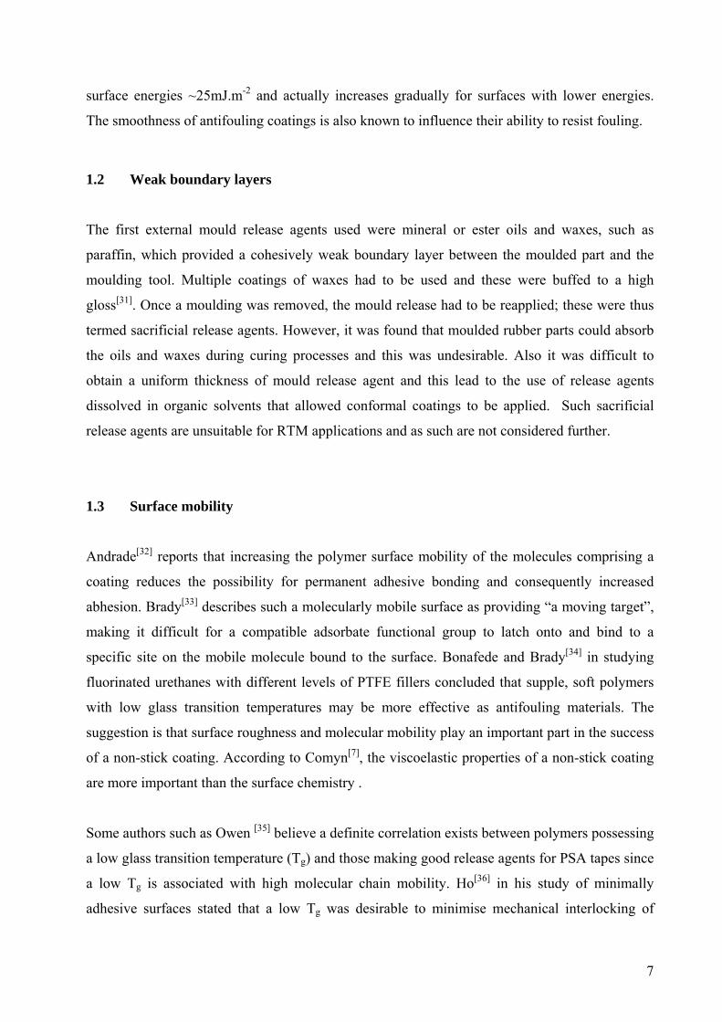
Some authors such as Owen [35] believe a definite correlation exists between polymers possessing
a low glass transition temperature (Tg) and those making good release agents for PSA tapes since
a low Tg is associated with high molecular chain mobility. Ho[36] in his study of minimally
adhesive surfaces stated that a low Tg was desirable to minimise mechanical interlocking of
8
adherents. It is perhaps not surprising then that many good release coatings essentially comprise
a lightly cured rubbery silicone.
In contrast, electroless nickel/PTFE composite films have excellent tribological properties and a
number of studies have evaluated their application as permanent, external mould release coatings [37,38]. In this case there is little or no surface mobility due to the presence of the hard matrix
material. An early electroless nickel/PTFE composite coating system suitable for abhesion
promotion was developed by Ebdon[39].
Considering electroless nickel/PTFE composite coatings for mould release applications,
dispersions of very fine particles of PTFE are thought necessary. These particles can be in the
range of 0.4 to 1.0 micrometres in diameter and it is proposed that the low frictional properties of
this fluoropolymer are transferred to the coating. The nickel-phosphorus matrix provides
hardness and durability to the coating and this is influenced by the volume percentage of
phosphorus in the alloy, typically between 4% and 12%. The PTFE particle loading also affects
the hardness and volume percentages in the range 15% to 25% are typical for permanent release
coatings. A compromise in final properties of the coating has to be established between
lubricity, hardness and wear resistance. Once deposited the coating can be heat-treated to
promote the development of a hard nickel-phosphorus phase (Ni3P) and to sinter the PTFE to
enhance its adhesion to the substrate. The performance of the material at elevated temperatures is
limited by the thermal stability of PTFE and this limits its use in practice to 400°C.
Poeton claim that their Apticote 450 coating has low wear properties at low loading and a bulk
hardness of about 250VPN although this can be increased after heat treatment at 300°C to
400VPN. The exceptional properties of the Apticote coating are believed to originate from the
high concentration of the PTFE dispersed phase comprising very tiny beads of PTFE with
approximate diameter ~ 200 nanometres. Stevens[40] discusses the application of Apticote
coatings in the moulding of thermoplastic trays and extols their properties as replacements for
conventional mould release agents.
1.4 Chemical and temperature stability
The demands of RTM are, however, such that semi-permanent systems are currently favoured.
The silicones, or polysiloxanes, mentioned previously have many desirable properties, including

9
good chemical and thermal stability. Possibly the most commonly-used polysilaxane in release
applications is polydimethylsiloxane (PDMS); see Figure 3.
Figure 3 - Structure of PDMS (After Arkles [41])
The PDMS structure comprises a long, very flexible inorganic backbone terminated by methyl
groups. As a consequence of the long silicon-oxygen bond and flatter bond angles of the
backbone, there is no barrier to the rotation of the methyl groups about the backbone. Thus the
backbone is very efficient in presenting the methyl groups to an air interface and adopts this
molecular conformation since it minimises its surface energy. PDMS can be modified by varying
the terminal end groups. Figure 3 shows termination by a trimethylsiloxy (Me3SiO) group. These
pendant groups effectively shield the strongly polar backbone and since the carbon atoms are
fully saturated by hydrogen atoms, intermolecular forces between adjacent polymer chains are
very low. This means that they slide over one another easily without any steric hindrance.
Measurements of surface free energies for polysiloxanes generally report values in the range 20
to 23 mJ. m-2.
Also of note, Boeing is developing organically modified ceramic coatings called “ormocers” for
the high temperature processing of advanced composite materials where conventional release
agents are thermally unstable. These combine the thermochemical stability of a glass with the
surface chemistry of a fluoropolymer[42].
1.5 Influence of surface roughness

10
Packham has reviewed the influence of surface topography on adhesion[9]. The complex
interactions between the chemistry and structure, invoking both the adsorption and mechanical
interlocking theories of adhesion, are used to explain the generally improved adhesion resulting
from micro-or nano-rough surfaces. In the case of the RTM process, assuming little chemical
interaction between an epoxide matrix and a low energy mould surface it is highly likely that
mechanical adhesion will limit the abhesion performance of the system and it therefore follows
then that for good abhesion the specific surface area should be minimised.
Packham[43] argues that the degree of penetration of a liquid into a capillary (considered here as a
pore) can be derived by equating the spreading pressure of the liquid to the resisting back
pressure due to trapped air. At equilibrium, the distance, x, penetrated is given by:
x = L ( 1 – {Pa r /2 [2γ2 cos θ + Pa r]})
Where L is the pore depth, Pa is the capillary pressure, r is the radius of the pore, θ is the contact
angle and γ2 is the surface tension of the resin. Clearly, the above equation shows that very small
pores are more easily filled by the contacting liquid, which in the case of RTM will be an
epoxide at elevated temperature, just prior to curing. It is particularly relevant that in RTM the
mould will be under pressure so the Pa term is an underestimate. Consequently, a fine scale
morphology will be detrimental for abhesion and we would need to ensure that any fine surface
morphology should be filled by a mould release compound. Note that, good adhesion is required,
however, between the release agent and the metal to which it is applied in order to achieve a
durable coating. The proposed condensation bonds which are thought to occur at the metal
(oxide)/FAS interface are clearly important; see Figure 2.
Clarke[44] used atomic force microscopy (AFM) to show that application of a semi-permanent
release fills grooves and holes in a metal mould surface and levels the surface topography but
does not create a perfectly smooth surface. The single coating thickness was estimated to be
approximately 300nm. The point was made that if the release coating is too thick and the surface
too smooth, it becomes unstable due to the high shear forces encountered in moulding and
demoulding operations. An optimum coating thickness worked best, which reduces frictional
contact with the mould substrate and provides a lubricating effect. AFM, scanning electron

11
microscopy (SEM) and profilometry have been used in the present study to determine the degree
of surface roughness following the application of a number of abhesion promoting coatings.
In a separate, but not completely unrelated field, Bonafede and Brady[34] suggest that the
adhesive from marine organisms initially penetrates surface cavities and surface porosities in
PTFE and then after chemical bonding has occurred, mechanical interlocking of the crosslinked
adhesive contributes to the tenacious attachment of the organism to the surface.
1.6 Summary
In the previous sections, a summary of the critical factors which affect abhesion have been
presented along with details of some of the coating technologies which might be used to optimise
abhesion. In the present study, we aim to compare the physicochemical properties introduced to
metal surfaces by a number of semi-permanent and permanent coatings which are potentially
suitable for RTM applications, along with limited adhesion/abhesion data. A number of metal
substrates were used in the present study, the results presented herein focus on nickel, a common
tooling material. In terms of coatings, fluoropolymer and polysiloxane-based materials offer the
combination of properties required for ideal abhesion and so a number of these were evaluated.
In addition, an electroless Ni/PTFE coating has been studied which shows promise as a
permanent external mould release coating.

12
2. EXPERIMENTAL
2.1 Substrates
Three types of nickel substrate were used. For some experiments, clean, smooth, model
substrates were produced by magnetron sputtering 1.1 micrometres of nickel onto glass slides.
These substrates were used in the XPS studies. For tapping mode AFM, highly polished nickel
was used. Various grades of diamond paste were used with the final particle size being 1
micrometre. For most studies, industrially-relevant, rough, abraded nickel substrates were cut
from nickel mould tools. Also, where mentioned in the text, a limited number of mechanical tests
were carried out using stainless steel substrates. These had similar surface texture and surface
free energy to the abraded nickel substrates.
With the exception of the sputter coated nickel samples, all surfaces were thoroughly cleaned
prior to release coat application using proprietary chemicals (Isoprep 44, Lea Manufacturing,
UK) to remove organic contamination.
2.2 Release coatings
This section provides details of the deposition processes used for the various abhesion promoting
coatings studied, these are listed in Table 1.
13
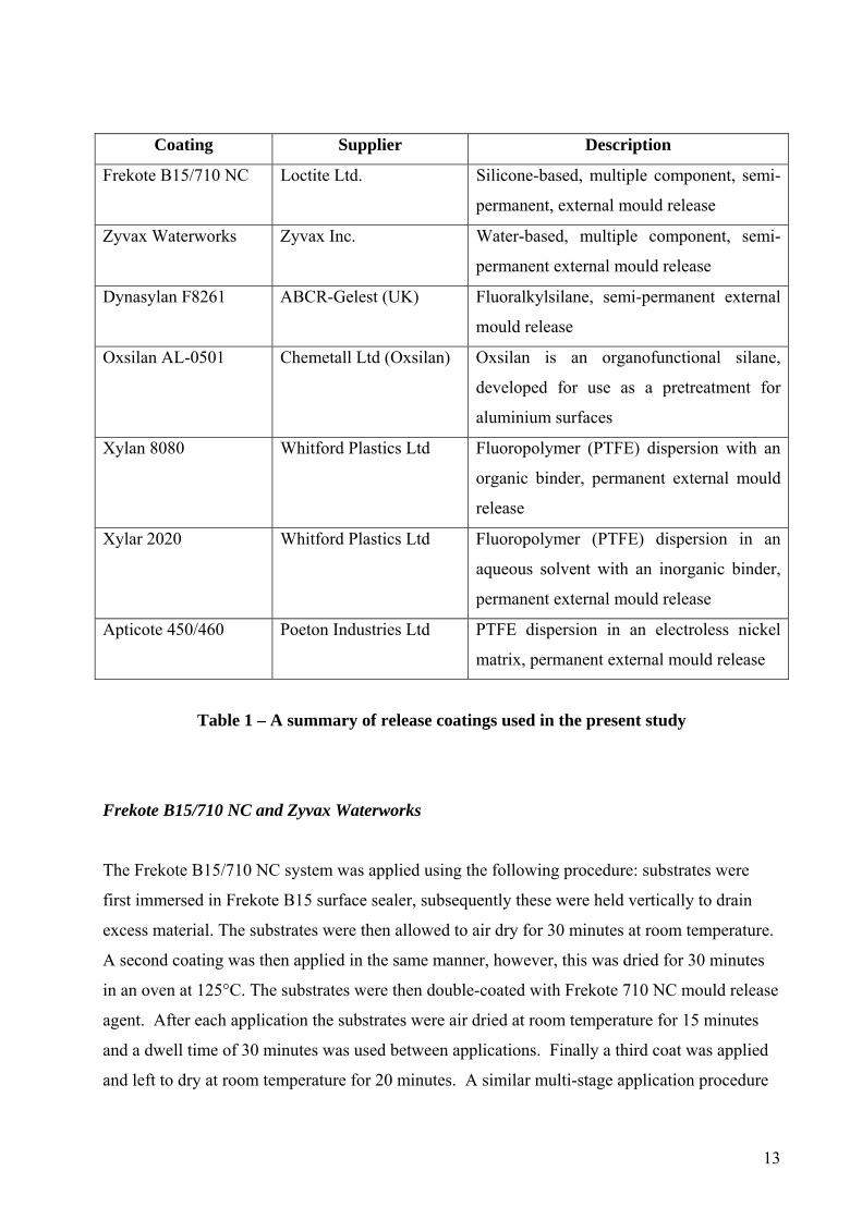
Coating Supplier Description
Frekote B15/710 NC Loctite Ltd. Silicone-based, multiple component, semi-
permanent, external mould release
Zyvax Waterworks Zyvax Inc. Water-based, multiple component, semi-
permanent external mould release
Dynasylan F8261 ABCR-Gelest (UK)
Fluoralkylsilane, semi-permanent external
mould release
Oxsilan AL-0501 Chemetall Ltd (Oxsilan)
Oxsilan is an organofunctional silane,
developed for use as a pretreatment for
aluminium surfaces
Xylan 8080 Whitford Plastics Ltd Fluoropolymer (PTFE) dispersion with an
organic binder, permanent external mould
release
Xylar 2020 Whitford Plastics Ltd Fluoropolymer (PTFE) dispersion in an
aqueous solvent with an inorganic binder,
permanent external mould release
Apticote 450/460 Poeton Industries Ltd PTFE dispersion in an electroless nickel
matrix, permanent external mould release
Table 1 – A summary of release coatings used in the present study
Frekote B15/710 NC and Zyvax Waterworks
The Frekote B15/710 NC system was applied using the following procedure: substrates were
first immersed in Frekote B15 surface sealer, subsequently these were held vertically to drain
excess material. The substrates were then allowed to air dry for 30 minutes at room temperature.
A second coating was then applied in the same manner, however, this was dried for 30 minutes
in an oven at 125°C. The substrates were then double-coated with Frekote 710 NC mould release
agent. After each application the substrates were air dried at room temperature for 15 minutes
and a dwell time of 30 minutes was used between applications. Finally a third coat was applied
and left to dry at room temperature for 20 minutes. A similar multi-stage application procedure

14
was employed for the Zyvax Waterworks. Manufacturers recommended application conditions
were employed for the sealer and the mould release coats.
Dynasylan F8261 FAS
Different concentrations, in the range 0.1% to 5%, of Dynasylan F8261 solution were prepared
and used to coat samples of metal for time periods of 0.5 to 60 minutes. The manufacturers
recommend preparing a working solution by first mixing absolute ethanol and water in the ratio
95:5. Then by adding 1 part of Dynasylan F8261 to 119 parts of the working solution, a final
concentration of 0.5% Dynasylan F8261 is obtained. Stirring then produces a dispersion that has
a shelf life of up to 24 hours. Acidification was recommended to accelerate polymerisation and it
was recommended that acetic acid be used to adjust the solution to a pH between 4.5 and 5.5.
Dipping of samples in this solution for periods of at least 1 minute allows sufficient material to
react with a high surface energy substrate and produce a uniform coating. Heating in an oven at
110°C for 10 minutes subsequently cures the coating. Varying these mixing proportions and
acidifying each to a pH of 5.0 produced metal samples coated with 0.1%, 0.5%, 1.0%, 2,0% and
5.0% Dynasylan F8261. Although different immersion times were tried ranging from 1 to 60
minutes it was subsequently found reaction times in excess of 10 minutes did not result in higher
water contact angles implying that once the substrate surface had fully reacted with the
fluoroalkylsilane, further treatment time did not produce a thicker coating or decrease the surface
free energy of the coating.
Oxsilan AL-0501 only and Oxsilan AL-0501 plus Dynasylan F8261 FAS
The theory associated with such coatings has been described by Van Ooij[45] who described their
application as replacements for chromate pretreatment of metals. The active silane component in
Oxsilan AL-0501 is unknown but is believed to possess a similar chemistry to bis-
[triethoxysilyl]ethane (BTSE) as described by Van Ooij and is dispersed in a water\ethanol
solution at a few percent concentration.
The substrates used in these studies were stainless steel foil. All substrates were dip coated with
undiluted Oxsilan AL-0501 as received from the manufacturers, the coatings were then blow-

15
dried and cured at 80°C for 30 minutes. cured. Some of these coated samples were then
immersed in a solution of 1% Dynasylan F8261 fluoroalkylsilane and left to react for 15
minutes. These samples were then removed and cured according to the procedure previously
mentioned. It was thought that a weak boundary layer would be created at the interface between
the two cured coatings that would enhance the ease of mould release.
The Oxsilan treated samples displayed pronounced interference colours in reflected light
implying the thickness of the coating was less than the average wavelength for visible light.
Xylan 8080 & Xylar 2020
Although spray coating was recommended for these coatings the particle size in the coating was
too large for the spray coater available and it was decided to apply coatings using a brush. The
Xylan coatings were flash evaporated for 10 minutes in an oven set at 150°C and then removed.
For the Xylan 8080, the oven was subsequently reset to 400°C and the coated samples replaced
when the oven had reached this temperature these were left in the oven for a further 5 minutes.
In contrast, the water-based Xylar 2020 was heated in an oven set at 200°C for 15 minutes to
effect full cure.
The results of these preparations were quite variable. Sometimes boiling of the solvent during
flashing or cure generated a rough surface and these samples were discarded. Only samples
where the cured coating was smooth and blemish free were retained for testing and analysis.
Apticote 450 and 460
The Apticote 450 and 460 Ni/PTFE composite coatings were applied to samples of nickel
tooling by Poeton Industries Ltd., Gloucester. This is a self-lubricating nickel alloy composite
coating comprising a micro dispersion of PTFE particles. The coating thickness was estimated to
be ~20 micrometres.

16
2.3 Surface characterisation and mechanical testing
A range of techniques was used to determine the physicochemical characteristics of the uncoated
and coated surfaces. Further to this an attempt was made to determine the adhesion/abhesion
response to these coatings. Brief details of the instrumentation and procedures used follow:
2.3.1 Scanning electron microscopy (SEM)
The instrument used was a Leo Gemini 1530 field emission gun SEM (FEGSEM) operated using
either a 10x103 V or 20x103 V primary electron beam energy. This instrument also incorporated
an energy dispersive X-ray analyser (EDXA).
2.3.2 Atomic force microscopy (AFM and PFM-AFM)
A TA instruments 2990 Micro-Thermal Analyser was used to provide both topographical data
and pull-off force information. In the latter case an attempt was made to quantify differences in
adhesion between coatings and the instrument was used in the pulsed force mode of operation.
2.3.3 Auger electron spectroscopy (AES)
A JEOL 7100Auger Spectrometer was used with a primary electron beam energy of 10x103 V
and a current close to 1x10⁻⁶ A. Depth profiling was carried out using argon ion bombardment
with a primary beam energy of 3x10³ eV and a current density of 50x10-6 A.cm-2. Empirically-
derived relative sensitivity factors and etch rates were used for quantification purposes.
2.3.4 X-ray photoelectron spectroscopy (XPS)
XPS spectra were recorded on a VG Scientific Escalab Mk I instrument operating with an with
unmonochromatised Al Kα X-ray source (1486.6 eV) and operated in the constant analyser
energy (CAE) mode. Spectra were calibrated by assuming a 285 eV binding energy for aromatic
and aliphatic carbons. Quantification was achieved by measurement of peak area following
subtraction of a Shirley type background.

17
2.3.5 Static secondary ion mass spectrometry(SSIMS)
A Cameca 3F SIMS instrument was used to analyse the chemistry of Frekote mould using
positive secondary ion detection.
2.3.6 Contact angle analysis
A Data Physics SCA20 Contact Angle Analyser was used to obtain experimental measurements
of contact angles using the recently-advanced sessile drop method. Using two liquids with
known surface tensions allows the calculation of surface free energies (SFE). Triply distilled
water and diiodomethane (DIM) were used, these being polar and non-polar liquids of known
surface tensions[46]. The approach of Owens-Wendt-Rabel and Kaelble was followed. The SFE
values quoted are the mean of at least ten measurements.
2.3.7 Fourier transform infra-red analysis (FTIR)
Spectra were collected using a Mattson 3000 FTIR spectrometer. The majority of samples
examined were liquids and these were prepared by preparing a film of the liquid onto a KBr disc
and allowing to dry in air at ambient temperature. This disc was then placed in the spectrometer
and spectra collected over the range 300 to 4000 wavenumbers using 64 scans. The same
numbers of scans were used to record the background.
2.3.8 Differential scanning calorimetry (DSC) and Thermogravimetric analysis (TGA)
These techniques were used to determine the thermal properties of the Frekote 710 NC. Frekote
710 NC mould release agent is a resin dissolved in dibutyl ether. A volume of 250ml of this
liquid in a glass beaker was placed in an empty fume cupboard and the solvent allowed to
evaporate completely over a 48 hour period with the fume cupboard extraction left on for this
period. After this period a rubbery solid remained at the bottom of the beaker. This material was
used for subsequent thermal analysis experiments.
For DSC analysis a mass of 11.05mg of solid Frekote was placed in an aluminium DSC sample
pan, which was hermetically sealed, and then the lid of the pan was pricked to allow volatiles to
escape. This was then subjected to a three stage controlled heating ramp in the furnace of a TA
Instruments 2920 modulated DSC. A heating rate of 20°C per minute was used which is a
standard heating rate for the determination of glass transition temperatures. The heating cycle

18
consisted of a ramp from 30°C to 120°C using nitrogen purge gas to drive off excess solvent and
the sample was held isothermally at the latter temperature for 5 minutes. The second segment of
the heating program caused the sample to be cooled to -100°C using liquid nitrogen cooling. In
the final segment the sample was heated from -80°C to 300°C.
To achieve the stated degree of cooling required the use of a whole Dewar of liquid nitrogen and
it was impractical to try to reduce the starting temperature further. At such low temperatures the
heat flow signal in the DSC takes some time before it settles down and becomes steady, after
about 20°C into the run. Thus the recorded data shows heat flow from -80°C to allow for this
settling period.
The thermal stability of Frekote was determined using a TA Instruments TGA 2950HR. A mass
of 10.011mg of solid Frekote was weighed into a platinum crucible, which was then positioned
inside the TGA furnace. The furnace was purged with dry air at a suitable flow rate (typically
10ml per second). The sample was heated from 30°C to 300°C at a heating rate of approximately
3.5°C per minute. A slow heating rate was chosen to allow excess solvent to be released from the
sample. This particular TGA allowed high resolution data to be obtained whereby the heating
rate is reduced automatically when a significant mass change occurs.
2.3.9 Stylus profilometry
Surface roughness measurements to determine Ra and Rt parameters were made using a Talysurf
instrument. Ra is defined as the arithmetic mean of the absolute departures of the roughness
profile from the mean line. Rt is the maximum peak to valley height of the profile in a given
assessment length.

19
2.3.10 Mechanical tests
Initially, axial butt testing was carried out using 60 mm diameter stainless steel platens treated
with the various release coatings. These were then bonded together using an epoxide-based
prepreg laminate. The results obtained were generally unsatisfactory. In some instances, for
example with the Frekote B15/710 NC system applied, no repeatable release force could be
measured as this force was so small. It was found that a single full application of Frekote
B15/710 NC to the steel discs allowed easy release for twenty separate cure cycles for the
prepreg laminate. Only slight sticking was noticeable after 20 cure cycles at the periphery of the
discs due to bleed out of the resin onto uncoated edges. It was concluded that this rather simple
adhesion test method could not provide meaningful data for very small release forces and a new
testing methodology was required.
The blister test was then used, using apparatus which was constructed in-house on which the
pressure could be varied up to 608KPa. In this test a 65 mm stainless steel disc was machined
and cleaned then treated with release coating prior to application of Cytec Fiberite FM300
epoxide resin sheet. The epoxide was then cured, under pressure, according to the manufactures
recommended procedures for 3 hours at 180°C. The pressure required to delaminate the FM300
or for blister formation was recorded.
Friction coefficient and wear test comparisons were also made on selected coated surfaces using
a bi-directional wear test rig manufactured by Teer Coatings Ltd. Each sample was tested at a
load of 5N and 10N for 200 cycles against a 5mm tungsten carbide-cobalt (WC-Co) ball. The
following conditions were used for each bi-directional wear test: 150mm min.-1 table speed, 2mm
displacement, 200 cycles.
3 RESULTS
One of the major aims of this research was to evaluate surface coatings that offered potential as
mould release agents. A number of candidate systems were selected using the criteria previously
detailed in Section 1. For comparative purposes, initial characterisation was carried out on the
substrate materials prior to coating application.

20
3.1 Uncoated substrate characterisation
The following metal substrates were initially studied: sputter coated nickel on glass; polished
nickel, and; industrially-sourced abraded nickel.
3.1.1 Sputter coated nickel on glass
The SFE of the sputter coated nickel on glass was not determined as this was assumed to be
clean as care was taken to minimise atmospheric contamination post nickel deposition and prior
to release coating deposition. High resolution SEM and AFM showed no significant features on
this sample indicating a very smooth surface topography.
3.1.2 Polished nickel
The polished then cleaned nickel was examined by SEM and AFM and was shown, as expected,
to be relatively smooth over the majority of its surface area; see Figures 4a and 4b.
Figure 4a - SEM image of hand polished nickel tooling

21
Figure 4b - AFM image of hand polished nickel tooling (5 x 5 micrometres area). Vertical
scale 60 nm.
The roughness, Ra, value was determined to be 0.0240 micrometres. The polished surface
hardness was calculated as 471HV/150. An average water contact angle of 35° was measured
indicating a reasonably clean surface.
3.1.3 Industrially sourced substrates
Figures 5a and 5b show the surface topography of the industrially sourced nickel substrate using
SEM and AFM. Mechanical abrasion had clearly resulted in scouring of the surface with many
scratches visible, as shown in Figure 5a. Stylus profilometry results showed an Ra value of 0.405
micrometres on this surface. An average water contact angle of 32° was obtained from the
abraded and cleaned industrially-sourced substrate surface, again, demonstrating that a
reasonably clean surface was prepared prior to coating application.

22
Figure 5a - SEM image of abraded nickel tooling.
Figure 5b - AFM image of abraded nickel tooling. Vertical scale approx. 0.3 micrometres.
3.2 Frekote B15/710 NC release coating
Initial studies focussed on the characterisation of the Frekote B15/710 NC coating system.
Using FTIR the transmittance spectra for Frekote 710 NC mould release agent (Figure 6a) and
Frekote B15 sealer (Figure 6b) were obtained. The most intense peaks occur at similar positions
between 1500 and 500 wavenumbers (cm -1) in both spectra. These figures also show a number
of subtle differences in the minor peaks and broadening of the absorption bands. Other peaks
common to both samples are clustered in the range ~2700 to ~3000 cm-1.
Considering the spectrum for Frekote 710 NC, the principal peaks occur at 2931,
2878,1261,1095,1020 and 807 cm-1. Strong absorption peaks assigned to dimethyl- and
trimethyl-substituted silicon atoms are reported to occur near 800 cm–1[47]. Also a strong band at
1263 cm-1 is assigned to the bending mode for a silicon bonded methyl group[48]. Absorptions
correlated with CH2 and CH3 stretching are observed at higher wavenumbers and overall the
spectrum resembles that obtained for PDMS. There appears to be a reasonable qualitative
similarity between the spectrum for Frekote 710 NC and the Frekote B15 sealing agent and since
these are chemically compatible, it is reasonable to assume this may also be based on PDMS.

23
4000 3500 3000 2500 2000 1500 1000 500
0
20
40
60
80
100
Rel005
Figure 6a - FTIR transmittance vs wavenumber (cm-1) spectrum of Frekote 710NC mould
release agent.
4000 3500 3000 2500 2000 1500 1000 500
0
20
40
60
80
100
Rel012
Figure 6b - FTIR transmittance vs wavenumber (cm-1) spectrum of Frekote B15 sealer.
In addition, Blanchard[49] used static secondary ion mass spectrometry (SSIMS) to determine that
Frekote 710 NC was based on polydimethylsiloxane (PDMS). The positive ion SIMS spectrum
of PDMS[50] shows peaks at 73, 147, and 221 atomic mass units (amu) in order of intensity
attributed to (CH3)3Si, (CH3)3SiOSi(CH3)2 and (CH3)3Si(OSi(CH3)2)2 clusters. Minor peaks also
occur at 207 and 295 amu. SSIMS spectra from Frekote 710 NC cured onto nickel foil were
acquired in this study and are shown in Figures 7a to 7c.
SIMS spectrum Frekote on nickel foil
010002000300040005000
0 20 40 60 80
Atomic Mass Units
Seco
ndar
y io
n c.
p.s

24
Figure 7a - SIMS positive ion spectrum for Frekote on nickel foil.
Range 0 – 100 amu.
SIMS spectrum Frekote on nickel foil
0100200300400
100
120
140
160
180
Atomic Mass Units
Seco
ndar
y io
n c.
p.s.
Figure 7b - SIMS positive ion spectrum for Frekote on nickel foil.
Range 100 – 200 amu.
SIMS spectrum Frekote on nickel foil
0
20
40
60
200
220
240
260
280
300
Atomic Mass Units
Seco
ndar
y io
n c.
p.s.
Figure 7c - SIMS positive ion spectrum for Frekote on nickel foil.
Range 200 – 300 amu.
The main peaks at 73 and 147 amu are seen in the above spectra confirming the presence of
PDMS although there are many other peaks which cannot be as easily assigned and are likely to
be associated with the formulation of Frekote which is a complex product and not a single
compound such as PDMS. These results are very similar to those reported by Blanchard.
From simple evaporation experiments it was apparent that the Frekote 710 NC mould release
agent would precipitate out as a transparent, rubbery film once the dibutyl ether solvent had been
driven off. This again was consistent with the physical properties of PDMS and an experiment
was performed using differential scanning calorimetry (DSC) to determine its glass transition
temperature. In this experiment the calorimeter was cooled using liquid nitrogen to an initial

25
temperature of –100°C, however, no Tg was measured and it was concluded that the Tg must be
very low. This is consistent with the known Tg for PDMS that has been measured as
-127°C. Thermogravimetric analysis of the sample also showed that it is thermally stable with a
weight loss of only 2.18% measured from ambient to 300°C.
The significance of these measurements mean that films of the mould release agent will be
viscoelastic at the temperatures experienced by mould tooling during a typical heating cycle.
Consequently, the molecular mobility of these molecules will tend to lubricate the moulding and
the mechanical properties of the film will resist the pressures applied to the tool surface during
the cure cycle. The desirability of these properties to obtain good release was previously
discussed. These are very different properties to those of fluoroalkylsilanes that cure to form a
very thin film on a surface that conforms to the surface topography without sealing porosities or
irregularities on the surface.
SEM showed the thickness of the fully applied Frekote B15/710 NC coating to be ~5
micrometres. The surface roughness for the untreated substrate is significantly less than this.
Consequently a typical application of the Frekote products would be expected to largely fill and
mask most surface irregularities. This was confirmed by SEM. It is also conjectured that under
conditions of elevated temperature and applied pressure commensurate with moulding processes,
the Frekote smears and flows over a surface filling in many microscopic substrate irregularities.
The role of the sealing component in such mould release products is clearly important.
The SFE of the Frekote 710 NC surface was measured a number of times. Values in the range
10.7 to 20.4 mJ.m-2 were calculated. The lower value being recorded on abraded nickel.
3.2 Zyvax Waterworks
The surface energy of this coating was measured as 24.4 mJ.m-2. However, in a tapping mode
AFM test the result for the Zyvax treated surface was interesting in that the AFM tip apparently
remained attached to the surface during testing. This was interpreted as implying that this release
coating was unstable by virtue of it being hygroscopic. This aspect was further studied by
monitoring the water contact angle as a function of time. Results are shown in Figure 8. The
initial water contact angle was 110° but reduced so rapidly that data collection could only be
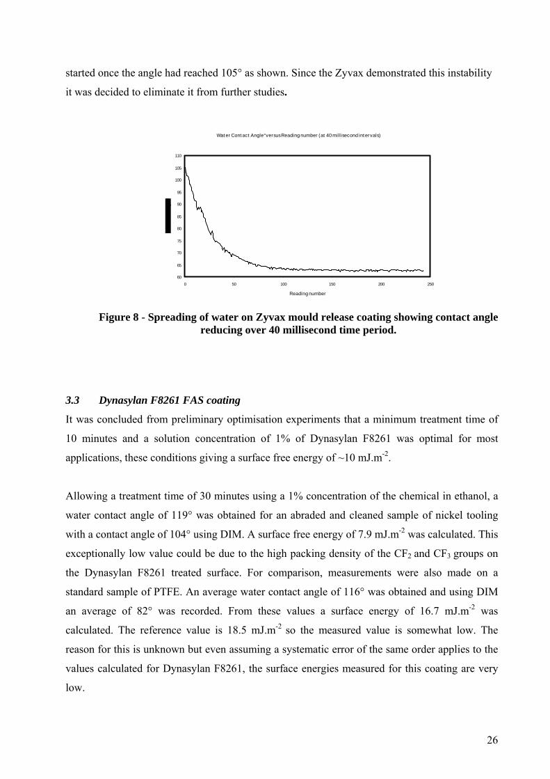
26
started once the angle had reached 105° as shown. Since the Zyvax demonstrated this instability
it was decided to eliminate it from further studies.
Wat er Cont act Angle° versus Reading number (at 40 millisecond int ervals)
60
65
70
75
80
85
90
95
100
105
110
0 50 100 150 200 250
Reading number
Figure 8 - Spreading of water on Zyvax mould release coating showing contact angle
reducing over 40 millisecond time period.
3.3 Dynasylan F8261 FAS coating
It was concluded from preliminary optimisation experiments that a minimum treatment time of
10 minutes and a solution concentration of 1% of Dynasylan F8261 was optimal for most
applications, these conditions giving a surface free energy of ~10 mJ.m-2.
Allowing a treatment time of 30 minutes using a 1% concentration of the chemical in ethanol, a
water contact angle of 119° was obtained for an abraded and cleaned sample of nickel tooling
with a contact angle of 104° using DIM. A surface free energy of 7.9 mJ.m-2 was calculated. This
exceptionally low value could be due to the high packing density of the CF2 and CF3 groups on
the Dynasylan F8261 treated surface. For comparison, measurements were also made on a
standard sample of PTFE. An average water contact angle of 116° was obtained and using DIM
an average of 82° was recorded. From these values a surface energy of 16.7 mJ.m-2 was
calculated. The reference value is 18.5 mJ.m-2 so the measured value is somewhat low. The
reason for this is unknown but even assuming a systematic error of the same order applies to the
values calculated for Dynasylan F8261, the surface energies measured for this coating are very
low.

27
The cured Dynasylan F8261 fluoroalkylsilane film was colourless and stable. It did not appear to
be susceptible to moisture absorption even after exposure for several weeks to laboratory air.
From published work on fluoroalkylsilanes[22,26,28,29] and other silane metal treatments[45] it was
believed that the cured coatings were very thin extending to a few nanometres and to investigate
the surface morphology of the coating it was apparent that high resolution microscopy would be
required. XPS was used to confirm the estimated coating thickness.
Samples of nickel sputtered onto glass slides were prepared to be utilized for such investigations
since the surface roughness values of real tooling were too high to allow clear resolution of the
coating. Initially, one of the sputtered nickel slides was treated in a 1% solution of Dynasylan
F8261 for 30 minutes and the coating cured. The sample was then examined using high
resolution SEM without any additional preparation and the images shown in Figures 9a and 9b
were recorded. These images appear to show the coating comprises discrete islands of the cured
chemical with features up to about 40 nanometres in diameter.
Figure 9a – Low resolution FEGSEM image of fluoroalkylsilane coating on nickel

28
Figure 9b – High resolution FEGSEM image of fluoroalkylsilane coating on nickel
Published literature[27,51] suggests that AFM can also provide useful topographic and functional
images relating to the tribological properties of fluoroalkylsilanes. AFM images were collected
from nickel sputtered coated glass slides following treatment with Dynasylan with varying
concentrations and treatment times, referenced against an untreated control sample; see Figures
9c and 9d. These images show the pull off force of the surfaces represented in three-dimensional
plots, these images suggest that there is not a great deal of difference in the surface “stickiness”
between the treated and control surface. The patterning developing on the treated sample
comprising circular patches is difficult to interpret. The features are ~180 nm in diameter and do
not correlate with the islands shown in the high resolution SEM images which were only ~40 nm
in diameter. Similar structures attributed to phase separation effects have been reported in the
literature. A further consideration of such data is given in Section 3.7.2.
Figure 9c - AFM image of untreated nickel sputter coated onto glass (2500 nmx2500nm)

29
Figure 9d - AFM image of surface in figure 9c following treatment with fluoroalkylsilane
(2500x2500 nm)
In a subsequent study a sample was treated with 5% Dynasylan F8261 for 60 minutes to fully
react with the metal substrate. XPS was then carried out to determine the resultant surface
chemistry and obtain information about the coating thickness.
The surface survey spectrum showed peaks for oxygen (531 eV) and fluorine (698 eV). Smaller
peaks for carbon were also seen (285 eV and 291 eV). Other elements detected were Si, Mn, Cr
and Fe associated with the stainless steel substrate used in this case. The fact that these elements
are detected is evidence that at least part of the fluoroalkylsilane coating is less than 10
nanometres in thickness.
A high energy resolution scan was performed for carbon to obtain more accurate information
about its binding energy. The binding energy shift between the two carbon peaks was 6.0±0.1
eV. From XPS reference data the chemical shift in binding energy associated with a CF2
functional group should be 5.9 eV and for a CF3 functional group the shift should be 7.69 eV.
The molecular structure of the Dynasylan F8261 molecule is shown in Figure 1 and has five CF2
functional groups terminated by a single CF3 functional group and it is suggested that the 6.0 eV
shift seen in the high resolution scan for the carbon peak implies that the shift due to the CF2
functional groups dominates and effectively masks the presence of the terminal CF3 group.

30
Angle resolved XPS experiments were carried out on Dynasylan F8261 deposited onto the
sputter coated nickel on glass substrate. The purpose of the proposed experiment was to obtain
information about how the fluoroalkylsilane molecules might be oriented on the nickel substrate.
In this experiment it was appropriate to attempt to produce a coating thickness of only a few
monolayers and a low concentration solution of 0.1% Dynasylan F8261 was used to treat a
nickel sputtered slide for a reaction time of one minute. Data was collected using take off angles
of 20°, 50°, 70° and 90°.
Figure 10 shows the atomic percentages for carbon, fluorine and nickel plotted as a function of take-off angle.
XPS AT% concentration for different take-off angles
05
1015202530354045
20 50 70 90
Take-off angle °
AT%
con
c
CarbonFluorineNickel
Figure 10 - Carbon, Fluorine and Nickel concentrations for different XPS take-off angles.
These data can be interpreted either as suggesting an enrichment of fluorine at the surface
consistent with the known molecular structure as depicted and comprising a CF2 tail terminated
by a CF3 group in which the tail orients itself perpendicular to the surface or the data may simply
show that defluorination is occurring over the timescale taken to collect the data in each case.
Fluorine present on surface coatings examined using XPS can be sensitive to the X-ray
irradiation experienced during analysis leading to defluorination. The fact that the fluorine-to-
carbon ratio does not exceed unity is suggestive that defluorination is occurring since if CF3 were
present at the surface, one would expect the ratio to be greater than unity. The possibility of
defluorination at the sample surfaces by irradiation over the duration of these experiments
severely limits the interpretation of the data albeit a relatively low fluence was used.

31
It was suspected that to obtain good release properties it was necessary to fill in the asperities
and porosities on a rough surface such that mechanical interlocking was denied as a mechanism
for adhesion. The thin, conformal coverage provided by Dynasylan F8261 does not achieve this
effect. Many widely used commercial mould releases use a sealing agent which is compatible
with a mould release coating applied afterwards. In other words it is usually necessary to use a
primer or sealer to treat the surface before producing a low energy surface. Hence, a
combination of Oxsilan AL-0501 plus a Dynasylan F8261 topcoat was studied.
3.4 Oxsilan AL-0501 only and Oxsilan AL-0501 plus Dynasylan F8261 topcoat
The potential use of use of Oxsilan AL-0501 silane alone or as a sealer followed by the
application of a Dynasylan F8261 topcoat was studied. It was thought this combination might
provide a bifunctional coating where a smooth, low energy outer surface would be produced and,
in addition, a weak boundary layer would exist between the Oxsilan AL-0501 and the Dynasylan
F8261 coatings to engineer good release properties by a combination of these two mechanisms.
Evidence from both ellipsometry and SEM suggested the Oxsilan AL-0501 forms a sufficiently
thick coating to fill in many micro-cavities in a substrate surface.
However, blister tests carried out using both Oxsilan AL-0501 only and Oxsilan AL-0501 plus
Dynasylan F8261 coated discs gave essentially the same result with no disbonding of the applied
FM300 resin apparent at reasonable applied loads.
It was concluded that Oxsilan AL-0501 alone was not successful at release as this coating is not
intended as a release agent and is not optimised for that application. For the combination coating
it was thought that the Dynasylan F8261 coating failed to react sufficiently with an already
existing silane treated surface. In addition, it is possible that an interpenetrating network could
form which would reduce the effectiveness of these coatings for release applications. Due to
their lack of release properties these systems were not studied further.
3.5 Xylar 2020 and Xylan 8080 sintered fluoropolymer coatings
32
Whitford Xylar 2020 and Xylan 8080 PTFE-based coatings were sintered onto different
substrates. The contact angles and surface free energies of the prepared coatings were measured,
these are given in Table 2 along with selected SFE values for other coating systems for
comparative purposes.
Coating Water contact
angle (°)
DIM contact
angle (°)
SFE (mJ.m-2)
Xylar 2020 118 96 10.8
Xylan 8080 126 99 9.0
Frekote B15/710 NC - - 10.0 to 20.4
Zyvax Waterworks - - 24.4
Dynasylan F8261 - - 7.9 to 16.7
Table 2 – A summary of contact angle data for Xylan 8080 and Xylar 2020 coatings
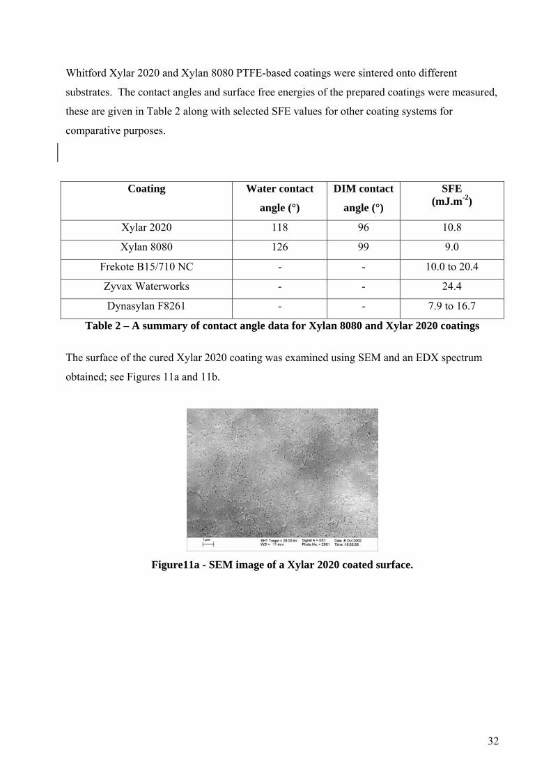
The surface of the cured Xylar 2020 coating was examined using SEM and an EDX spectrum
obtained; see Figures 11a and 11b.
Figure11a - SEM image of a Xylar 2020 coated surface.

33
Figure 11b - EDXA spectrum of Xylar 2020. C,O,F,Si and were Fe detected
Blister testing was carried out using Xylar 8020 against Cytec Fiberite FM300 epoxide resin
It was found that the FM300 tenaciously adhered to the Xylar 8020 coating despite the fact that
the Xylar coating possessed a relatively low surface energy of 10.8 mJ .m-2. Figures 11c and 11d
show areas of the blister test sample in cross-section. In Figure 11c the white area on the right
hand side of the image originates from the substrate. A polyethylene terephthalate membrane is
present in the FM300 resin sheet as a supporting binder and this is seen as the oval and round,
darkened areas on the left hand side of this image. The Xylar 8020 coating is sandwiched
between the two and has sufficient atomic number contrast to be discernable. It is seen to be
approximately 50 micrometres thick.
Figure 11c - SEM cross section of Xylar 2020/FM300/steel structure.

34
Figure 11d - SEM cross-section of the Xylar 2020/FM300 interface.
Note from Figure 11d there is visible surface roughness which seems to be well wetted out by
the FM300 resin.
When the surface of the Xylan 8080 is examined by SEM, see Figure 12a, a different highly
textured morphology is observed. When examined at higher magnification the porous structure
of PTFE is clearly resolved; see Figure 12b. It is this porosity combined with the pressure and
temperature applied to the resin system that causes mechanical interlocking and adhesion despite
the low surface energy of the PTFE surface. Again, it is seen that a low energy surface does not
by itself prevent sticking.
The significant factor in this application is the combination of applied pressure and high
temperature (180°C) applied during FM300 cure. Other non-stick applications of the Whitford
coatings are unlikely to have to contend with relatively high-pressure conditions and therefore
these coatings satisfy their intended function.

35
Figure 12a - Low magnification FEGSEM image showing the Xylan 8080 surface
topography.
Figure12b - High magnification FEGSEM image showing the Xylan 8080 surface
topography.
Figure 12c shows an EDXA spectrum for the Xylan 8080 coating from which it is seen that the
coating composition is different to that of the previously studied Xylar 2020 coating with the
possibility of barium sulphate and copper chromate present as additives. The role of these
additives is unknown, although they could possibly be applied to increase the passivity of the
substrate. This again emphasises the difficulty in understanding the observed abhesion
performance of a particular system when the chemistry of proprietary coatings is not fully
known.

36
Figure 12c – EDXA spectrum of Xylan 8080 coating. C,
O, F, S, Ba, Cr and Cu were detected
Further tests were made on the Xylan 8080 coating. In this case the PTFE coating was sintered
onto a piece of stainless steel foil and Cytec FM300 epoxide resin sheets were laid up and cured
onto the coated surface under weighted loading and cured. It was found that the resin could be
peeled away from the metal foil substrate with only slight difficulty. It was thus possible to
remove the epoxide resin from an area where it had been in contact with the Xylan 8080 coating
to examine the failure surfaces using SEM; see Figures 12d and 12e.
Figure 12d - SEM image of Xylan 8080 coating following removal of FM 300 resin.

37
Figure 12e - SEM image of underside surface of FM300 resin following delamination.
Figure 12e shows an image of the underside on the resin where it had been in contact with the
Xylan 8080 coating. It is suggested that the asperities seen on this surface may be points where
mechanical interlocking has occurred with the Xylan coating giving rise to a level of adhesion
making it difficult to separate the two surfaces in tension. The virgin Xylan coating surface
possesses fine porosity typical of PTFE. It is suggested that both the Xylar and Xylan coatings
resist wetting from the resin in its liquid phase, but that the pressure applied overcomes the
surface tension forcing the resin into the porosities in the soft PTFE structure opening them up at
the elevated cure temperatures. When the liquid resin crosslinks and cools, a mechanical
interlock has occurred and the surfaces become difficult to separate in tension.
3.6 Apticote 450/460 coating
Roughness measurements were made on an Apticote 450 coated surface which was deposited
onto a piece of nickel tooling plate. The measured surface roughness parameter, Ra, was 1.498
micrometres. It should be noted that this roughness was of an undulating nature rather than there
being deep grooves and scratches present on the surface. Indentation was used to measure the
surface hardness. The indentation hardness measurements, measured from the area of the
indentation of a stylus or ball bearing under a specific loading, really measures the yield stress of
the material, which is dependent on the plastic properties of the material[51]. Hardness
measurements were made on the Apicote 450 surface using the Rockwell C scale and measured
using an Indentec 8150 ACD tester, which applied a load of 150kg to a pyramidal shaped
indenter for a dwell time of approximately 8 seconds. A conversion chart was used to convert the
average of three separate readings into the Vickers hardness scale. A hardness of 345Hv/150 was

38
measured on this surface. Note that some difficulty was encountered in obtaining consistent
results for the Apticote 450 sample because the indentations were poorly defined and due to the
presence of the softer PTFE phase in the material. As the load is reduced further, the indentation
becomes smaller and backlash errors associated with the curtain micrometer in the eyepiece
reduce accuracy of measurement of the dimensions of the indentation. Using a 25 g force, the
average of three readings gave a hardness of 222HV/0.025. The manufacturers quote a bulk
hardness of 250HV though no loading is specified.
Physically, the Apticote 450 coating has a brown colouration thought to be due to heating which
hardens the coating. Figure 13a shows an SEM image of the coating and it is seen to possess a
shallow dimpled or undulating appearance, as described. Higher magnification reveals the
dispersed PTFE phase that contributes to the enhanced release properties of the coating. The
coating thickness, measured from a cross section, was found to be approximately 20
micrometres; see Figures 13b to 13d.
Figure 13a - Low resolution SEM plan view image of the Apticote 450 coating.

39
Figure 13b - High resolution SEM plan view image of the Apticote 450 coating.
Figure 13c - High resolution backscatter plan view image of the Apticote 450 coating.
Figure 13d - High resolution SEM cross-section image of the Apticote 450 coating.
Elemental analysis using EDXA identified Ni, P and F as the major peaks. The size of the
PTFE particles is below the resolution limit for X-ray mapping and so it was not possible

40
to produce a map to show the fluorine rich sites but it is reasonable to assume that the
dark, roughly circular features in Figure 13c are the PTFE phase. These particles have a
diameter of approximately 200nm. The surface free energy of the Apticote 450 treated
sample was measured as 16.5 mJ .m-2, reflecting the presence of this PTFE.
Additional images from the Apicote 450 surface were acquired by AFM; see Figures 13e
and 13f. No characterisation was carried out on the Apticote 460 surface; this is also a
Ni/PTFE composite coating.
Figure 13e - AFM topographic 3D image for Apticote 450 (area 100x100
micrometres).
Figure 13f - AFM topographic 2D image for Apticote 450 (area 3x3 micrometres).

41
3.7 Release performance studies
Studies carried out using either the axial butt or blister geometries indicated that the Frekote
B15/710 NC and Apticote 450/460 systems facilitated easy release when FM300 resin was
pressed against these surfaces during cure. All other release coatings performed unsatisfactorily
to one degree or another. Additional testing was carried out to study the release properties of
these surfaces using conventional wear testing and tapping mode AFM.
3.7.1 Friction coefficient and wear test comparisons
Friction coefficient and wear test measurements were made on the Apticote 450 and 460
coatings applied to nickel tooling substrates. Both Apticote coatings were compared against
cleaned but otherwise untreated nickel tooling and the same tooling that had been treated with
Frekote B15/710 NC. Figures 14a and 14b show the friction coefficients for 5N and 10N
loadings.
Figure 14a - Friction coefficients for selected surfaces using a 5N loading. Sample legend as
follows: Sample 1 = Frekote on nickel; Sample 2 = Apticote 460; Sample 3 = Apticote 450;
Sample 4 = untreated nickel.
5N Load
0 50 100 150 200 0
0.1
0.2
0.3
0.4
0.5
No. of cycles
Friction coefficient
1
2
3
4

42
Figure 14b - Friction coefficients for selected surfaces using 10N loading. Same legends as
for Figure 14a.
From Figures 14a and 14b it is clear that both Apticote coatings clearly have exceptionally low
friction coefficients which was also reflected in their wear test performance; see Figure 14c. The
latter observation is significant if these coatings are to be regarded as permanent release coatings.
Sample 1 Sample 2 Sample 3 Sample 4
Wear depth - ~ 3.3μm
Wear depth - ~ 4.8μm
Wear depth - ~ 1.0μm
Wear depth - ~ 3.7μm
Figure 14c - Wear test images for sample surfaces using 5N and 10N loadings.Sample legend as follows: Sample 1= Frekote on nickel, Sample 2= Apticote 460,
Sample 3 = Apticote 450, Sample 4 = untreated nickel.
10N Load
0 50 100 150 200 0
0.1
0.2
0.3
0.4
0.5
No. of cycles
Friction coefficient
1
2
3
4

43
An approximate wear depth was measured for the 10N load tests, as indicated in Figure 14c.
This depth would also include any deformation of the sample. The wear is greatest for the softer
Apticote 460 coating. The Apticote 450 coating was heat treated to enhance its hardness. The
Frekote system, however, makes little difference to the wear of the untreated tooling so would be
considered suitable only for semi-permanent applications.
3.7.2 Pulsed force mode AFM study of adhesion differences.
Pulsed force mode AFM (PFM-AFM) is a mechanical property-based AFM imaging method in
which a relatively low frequency (200-2000 Hz) sinusoidal modulation is applied to the z-piezo
crystal and hence the probe cantilever. The ultra-sharp silicon tip is therefore pushed onto and
pulled off the sample surface at this frequency. The amplitude of modulation is typically a few
hundred nanometres. The signals acquired are topography and cantilever deflection (in common
with most AFM imaging modes), together with pull-off force (related to tip-to-sample adhesion)
and indentation (related to local modulus). Pull-off force is that force imparted by the cantilever
required to cause disengagement of the tip from the sample surface. Indentation is the mean
gradient of the indenting portion of the probe-sample force distance curve.
The pull-off force results presented in this paper have been left expressed in volts. These
voltages can be converted readily into units of force, in this case nN, by using the nominal spring
constant of the cantilever. It has been found, however, that the spring constant can vary
substantially even within the same batch of probes, so that a careful calibration must be carried
out to determine its real value. In any case, it is the relative, not absolute, values of pull-off force
that are important in this study.
Initially, four nickel mould tooling substrates were hand polished and characterised as previously
described, three of these were then release coated prior to AFM analysis. These were identified
as follows: Sample 1 - Untreated clean surface, control; Sample 2. - Zyvax Waterworks; Sample
3 – Frekote B15/710 NC; Sample 4. Dynasylan F8261 (5% solution). Water contact angles were
determined to ensure surface cleanliness on the polished nickel substrates prior to coating and, as
mentioned, it was found that a drop of water produced an average contact angle of ~35° in this

44
case. For samples 2, 3 and 4 water contact angles of 110°,107° and 116° were measured
respectively.
For all samples, pull-off force images were obtained from areas measuring 100x100
micrometres. As previously mentioned, with the Zyvax sample the signal was saturated due to
the AFM tip being stuck to the surface. These AFM images indicated that the fluoroalkylsilane
coating produces the lowest pull-off force followed by the Frekote treated surface.
The pull-off force images were then converted into data point distributions that reflect the
adhesion of the tip as it is retracted from the sample. As has been discussed, it is difficult to
quantify this force since it depends upon many AFM instrumental parameters such as the
stiffness and spring constant of the probe. However, presenting the data in this form more clearly
illustrates the differences between the samples. It is clear from Figure 15a that there exists a
distinction between the fluoroalkylsilane coating and the Frekote and the untreated control.
Figure 15a – To show the pull-off force distributions for clean nickel, Dynasylan F8261,
Frekote B15/710 NC and Zyvax Waterworks treated release coatings
This technique was then used to rank the performance of Apticote 450 coating in relation to
Frekote B15/710 NC. Figures 15b and 15c show AFM topographic and pull-off force images for
the same area on the Apticote 450 surface.

45
Figure 15b. AFM Topographic 3D image (left) and 15c. pull-off force image (right) for
Apticote 450 (area 3x3 micrometres).
The pull-off force, as discussed previously, is a mixture of the elastic, frictional and adhesive
properties of the surface [53]. The adhesion component can be separated using the AFM software
and allows images showing differences in adhesion to be displayed. The dark areas in these
images represent points where the adhesion is low and conversely the bright areas are those
where the adhesion is greatest. The scale of the bright areas in these figures suggest a correlation
exists between these and the dispersed PTFE particles in the Apticote 450 coating as shown
using SEM. Note that the pull-off forces are, however, low in these bright areas compared with
other surfaces.
Figure 15d - AFM pull-off force image for Apticote 450 (area 1.5x1.5 micrometres).
46
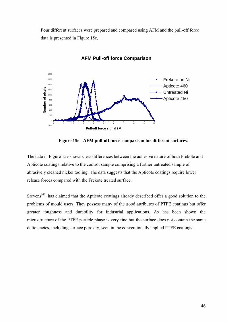
Four different surfaces were prepared and compared using AFM and the pull-off force
data is presented in Figure 15e.
AFM Pull-off force Comparison
-200
0
200
400
600
800
1000
1200
1400
1600
1800
0 1 2 3 4 5 6 7 8 9 10
Pull-off force signal / V
Num
ber o
f pix
els
Frekote on NiApticote 460Untreated NiApticote 450
Figure 15e - AFM pull-off force comparison for different surfaces.
The data in Figure 15e shows clear differences between the adhesive nature of both Frekote and
Apticote coatings relative to the control sample comprising a further untreated sample of
abrasively cleaned nickel tooling. The data suggests that the Apticote coatings require lower
release forces compared with the Frekote treated surface.
Stevens[40] has claimed that the Apticote coatings already described offer a good solution to the
problems of mould users. They possess many of the good attributes of PTFE coatings but offer
greater toughness and durability for industrial applications. As has been shown the
microstructure of the PTFE particle phase is very fine but the surface does not contain the same
deficiencies, including surface porosity, seen in the conventionally applied PTFE coatings.

47
4 DISCUSSION
The premise initially adopted was that the release properties of an abhesion promoting coating
for RTM applications were dominated largely by its surface chemistry and the requirement to
engineer an exceptionally low energy surface which would resist the adhesion of any liquid
resin. As has been mentioned, the chemistry of mould release formulations is only ever discussed
in general terms in the literature. Noteworthy exceptions are publications by Clarke et al[44] and
Utz, Hensel and Sprenger[54]. However, the surface chemistry provided by fluoroalkylsilanes
(FAS), such as Dynasylan F8261, suggests that these materials satisfy this requirement; the
surface energy of this FAS coating can be lower than that of PTFE.
The FAS compound investigated in this research has been successfully applied to enamelled
surfaces to prevent the sticking of food and has also been used successfully as a water repellent
coating for textiles. In both these applications there is no high applied pressure against the coated
substrate. It is also claimed that FAS compounds are effective in mould release for
semiconductor fabrications but in such applications only moderate moulding pressures are used.
The molecular structure of FAS compounds makes it difficult to develop thick coatings; the
coating thicknesses are usually only a few monolayers and these are assumed to conform to any
substrate topography.
If a water droplet is applied, under pressure, to a FAS coated surface it will clearly not intimately
wet the surface because the low surface energy resists this but it may well fill some of the
irregularities on the surface. Once the pressure is released the water droplet will return to a
roughly spherical bead on the surface because this shape is thermodynamically favoured. If
instead of water, a drop of liquid thermosetting resin is applied to the coated surface and
deformed by pressure, this will behave similarly to the water droplet. However, if the system is
now heated so that the deformed resin crosslinks and hardens, then it will mechanically adhere
once the pressure is released. The above scenario is presented as a plausible explanation of the
observed facts that, despite engineering a low energy surface, liquid resin pressed against a FAS
coated surface and cured results in poor abhesion.
Mechanical interlocking has been observed in the case of fluoropolymer (PTFE) coatings but the
extreme thinness of the FAS coating makes this difficult to study by SEM. The fact that marine

48
organisms can stick with apparent impunity to such low energy fluoropolymer surfaces is
evidence that abhesion, like its counterpart adhesion, is not a simple phenomenon.
Sintered fluoropolymer coatings based on PTFE perform well in food industry applications but
the two systems used in this study did not perform well.
Considering the Frekote B15/710 NC system, the commercially successful PDMS-based mould
release agent, evidence has been presented to show this Frekote system largely satisfies the
criteria required for ideal abhesion promoting coatings. Frekote provides: a low surface free
energy; thermal and chemical stability; durability, lasting typically for at least twenty releases;
mobility at a molecular level, associated with low glass transition temperature, and; a coating
that will cover and fill major surface irregularities resulting from abrasive finishing. Bey[55],
amongst others confirmed the usefulness of silicones for release applications. In common with
many other semi-permanent mould release agents, the Frekote product comprises two resin-
based reactive polymers. The manufacturers suggest a thoroughly cleaned moulding is first
primed with two light coats of a sealing formulation. These are followed by the application of
further coats of the mould-releasing agent. It is believed that the first sealing component
polymerises on contact with air, when applied to a clean metal mould surface, and seals surface
pits and porosities in the mould. Heating can accelerate the crosslinking reaction and an open
sponge-like structure is created. The second chemically compatible mould release polymer is
now applied and it is this polymer that reduces friction between the moulding and the mould
Frekote release coatings may not form smooth coatings on rough surfaces, such as industrial
moulds and these do not necessarily fill in all the rough contours and irregularities on the
surface. Grit-blasted metal surfaces for example, that have been treated with Frekote B15/710
NC can still feel slightly rough and it may be that a degree of roughness assists separation of a
moulding since this will trap air pockets. Also, thin layers of Frekote are easily parted and SEM
shows the presence of irregularly shaped platelets overlying surface asperities arising from the
grit blasting treatment; these act are weak boundary layers and assist in mould release. For this
reason PDMS-based release coatings are regarded as only semi-permanent.
Apticote coatings also offered good release properties and are durable enough to withstand the
aggressive moulding conditions prevalent in the aerospace industry; these are regarded as
permanent coatings. In the case of the Apticote 450 release coatings, PTFE particles are

49
uniformly dispersed in a hard nickel matrix that resists the application of pressure applied to a
curing resin system. The porosities present in a continuous PTFE coating are not manifest in the
Apticote 450 coating. The roughness observed on the Apticote 450 surface is on the macroscopic
rather than the microscopic scale. Micro-rough surfaces are known to promote good adhesion
with epoxides, but it is possible that macro-roughness could lead to regions where high shear
forces are experienced leading to easy release. Thus, the coating combines a low surface energy,
derived from the PTFE, with the toughness of a nickel matrix and it is conjectured that these
qualities account for its apparent success as a release coating as demonstrated in the present
work. This release behaviour is not perhaps surprising in view of the very low friction coefficient
measured for the Apticote 450 coating. This surface was characterised in section 5.1.4.3 for 5N
and 10N loadings. The Apticote 450 coating was used in preference to the Apticote 460 coating,
despite its slightly lower friction coefficient, because 450 is temperature hardened.
The desirable properties of mould releases have been discussed previously. Two of these were
that the release coating should possess molecular mobility and cohesively weak boundary layers.
Clearly the Apticote coating does not meet these particular properties and yet it appears to be
successful at ensuring easy release of parts moulded against it. In discussing the non-stick
properties of these coatings it is necessary to distinguish between “release” and “low friction”.
Friction results from two surfaces sliding across each other and is measured by the drag force
between the sliding parts. Release is different because the separating force is normal to the two
surfaces involved and relates to the material properties of the surfaces such as, though not
exclusively, surface energy. A release coating for RTM applications requires both low release
and low friction forces. The FM300 resin system used for these tests is an aerospace grade
material and therefore the results are very relevant to RTM application.
It should be noted that although established and well-documented testing methods clearly exist
for the testing of adhesive bond performance. These generally proved unsatisfactory in the
evaluation of mould release performance and alternative approaches have been adopted. For
example, Percell[56] measured the ejection force required for mould emptying by mounting a
piezo-electric device to the ejector rod. Another approach first adopted by Wilkomm et al[57] was
to use a modified rheometer to measure the shear force required to separate a moulded part from
a substrate coated with a release agent. A more conventional method for adhesion measurement
is the blister test[58] used in the present study. Parry and Wronski[59] and Kinloch[60] developed
this method and a body of literature and results accumulated over the last twenty years testify to

50
its usefulness in quantifying adhesive fracture energies. In these tests it was regarded as a useful
screening test but not suitable for measuring fundamental adhesion forces. Briscoe and
Panesar[61] proposed a method of measuring the release force using the blister test originally
developed for measuring low adhesion interfaces. Although this method proved very successful
for Briscoe it was used to study the effects of external releasants on the adhesion of elastomeric
materials such as polyurethane[62], whereas this research is concerned with thermosetting
composites possessing a much higher elastic modulus when cured. Blanchard [49] appraised the
blister test and concluded that it was unsuitable for thermosetting compounds. Even in relatively
recent publications[42], quantitative measurements of release force seem to be avoided because of
the experimental difficulties and qualitative assessments of performance are given instead. New
methods of evaluating mould releases continue to be developed[63] which testify to the fact that
no single method has yet been accepted as being universally applicable. For this reason indirect
measurements to determine friction forces and PFM-AFM to determine comparative pull-off
forces were considered valid in the present study. PFM-AFM did, prove itself to be very useful
in providing qualitative comparisons of the “stickiness” of surfaces treated with different mould
release agents. In PFM-AFM the tip is attracted to the surface it is tracking, the oscillating
cantilever experiences a damping force if the surface is adhesive which tries to keep the tip in
contact with the surface. The amplitude of oscillation is such that it will be sufficient to
overcome this and then carries information about the pull-off force required. Effectively the
sinusoidal response of the cantilever will lag behind that of the oscillation impressed upon it and
this phase lag can be extracted by operating software and the resulting signal used to modulate
an image contrast.
Such phase images can provide information concerning the viscoelastic properties of the sample
and adhesion forces. Since the resonant frequency of the cantilever is very high several thousand
pull-off force measurements may be made for a very small area scanned. To use this technique
effectively to qualitatively compare the stickiness of different surfaces, resulting from
application of different mould release agents, it is necessary to largely eliminate large differences
in surface height on a microscopic scale and hence substrates need to be polished to a mirror
finish. Quantitative data by this means is very difficult to obtain, relying on precise knowledge of
the spring constant of the cantilever used, a means of calibrating a microscope and a thorough
understanding of the complex interactions between tip and surface within the size domain of the
technique. Adhesive force measurements can be related to the AFM pull-off force via the
Johnson, Kendall and Roberts (JKR) theory of adhesion mechanics[64]. This theory provides a

51
means of calculating the surface energy of a solid directly in terms of the interactions between
solid surfaces rather than through the use of contact angle measurements [65-67]. The theory can
be used to derive the following equation:
Fad = 3/2π RWSMT
where WSMT = γSM + γTM - γST (after Dupré)
WSMT is the thermodynamic work of adhesion for separating the sample and tip with associated
surface free energies of the sample (S) and tip (T) in contact with the medium (M) and where γ is
the interfacial surface free energy of the two interacting solid surfaces ; Fad is the pull-off force
required to separate an AFM tip of radius R from a planar surface. If the two materials in contact
are the same then the work of adhesion is equal to the work of cohesion. This is rather limited
since it is only possible to directly measure the surface free energy for a material which is the
same composition as that which the AFM tip is made from but the principle is valid.
It should also be noted that contact angle behaviour can be exceedingly complex and subject to
many variables such as surface roughness, chemical heterogeneity of the surface and surface
sorption layers to mention but a few. The approach used by Owen,Wendt, Kaelble & Uy [66,67]
has been used extensively in the present study to calculate the surface energies of treated samples
by measuring contact angles using two liquids. The popularity of this analytical approach belies
the fact that there is much controversy about whether the geometric mean approximation, used
by Owen,Wendt, Kaelble & Uy, is the best approach for finding the polar interactions at an
interface. Zettelmoyer[68] and Wu [69] separately discuss this approximation in detail. In general,
Wu asserts that the geometric approximation gives rather poor results for many organic liquids
on organic polymers and that a harmonic mean approximation is preferable. Despite these
objections, the Owen, Wendt, Kaelble & Uy, approach allows simple and quick measurements of
surface free energy to be made. Such is the importance of surface energy values for solids that
numerous approximate models[70-72] have been developed and different approaches used to
enable their calculation.
The very low surface energy (7.9 mJ m-2) obtained for the Dysalan F8261 FAS coating on a
sample of nickel tooling is clearly physically unrealistic. The surface energy of the same coating
on an optically flat surface was found to be 12.6 mJ .m-2 . The value obtained is clearly being

52
affected by surface roughness. Surface roughness can affect contact angle by increasing the
effective area of the surface[72] and may also give rise to hysteresis[73]. In this case a third factor
needs to be considered. As a drop advances over a hydrophobic surface trapped air and porosity
means that the surface must be treated as composite[74]. If the fraction of the solid/liquid
interface comprising air is (1-f) then Young’s equation may be rewritten as
fγs = fγsl +(1-f)γl + γlcos φ
where γs is the surface free energy of the solid, γsl the interfacial free energy and γl the surface
energy of the liquid. φ is the observed macroscopic contact angle. The effect of trapped air and
porosity is to increase the observed contact angles of both water and diiodomethane over that
observed for a flat homogeneous surface, and this will contribute to the lower that accepted value
for surface energy calculated using the Owens and Wendt method. A value of about 0.1 for 1-f
would be sufficient to have a significant effect on the apparent surface energy obtained for the
Dysalan F8261 FAS coated nickel tooling.
5 CONCLUSIONS
The semi-permanent Frekote B15/710 NC mould release coating system, which is based on
PDMS, proved extremely effective in terms of release against a cured epoxide applied under
pressure. This system was applied to clean abraded metal tooling and allowed many release
cycles to be performed before any fouling problems were experienced. It has proved difficult to
find an alternative release that is as effective and offers the same versatility as Frekote B15/710
NC for such an application. The physicochemical properties previously described can be used to
explain this result..
Fluoroalkylsilane coatings offer a number of technological advantages for release applications.
However, they generally produce very thin coatings which conform any existing surface
topography. As such, whilst they provide a low energy surface, they do not seal any surface
porosities present on a substrate and adhesion through mechanical interlocking can occur without
impediment. Mechanical interlocking with fine surface features is considered particularly
detrimental to abhesion. Whilst there are undoubtedly some specialised applications of these
53
materials, especially in the microelectronics industry, it is considered that they are not suitable
for RTM application given the roughness of mould tooling.
The commercial fluoropolymer coating formulations investigated were PTFE based. These were
demonstrated to provide low energy surfaces on metal substrates. With both examples of these
coatings evaluated for use with metal tooling materials it was found that when adhesives were
cured under elevated pressure and temperature whilst in contact with the coatings, subsequent
release was poor or impossible. It is proposed that the porosities present in PTFE surfaces allow
penetration of the resin and, after curing, these bond by mechanical interlocking. The
formulations were considered not to be suitable for RTM mould release coatings.
Electroless Ni/PTFE composite coatings comprise hard nickel-phosphorus matrix containing a
very fine dispersion of PTFE particles. The matrix is sufficiently robust for industrial
applications and the low friction and surface energy provided by the embedded PTFE combined
with macroscopic scale surface roughness provided efficient mould release.

54
6 REFERENCES
1. W.A.Zisman in Adhesion and Cohesion, Ed.P.Weiss, Elsevier, 1962. p176.
2. Modern Fluoropolymers, Ed.J.Scheirs, Wiley, 1997.
3. P.Thomas, Surface Coatings International, 1998, 12.
4. J.Herber and K.J.Reucker, Surface Coatings International Part B:Coatings Transactions, 2001,
84(B1),1.
5. R.K.Champaneria, M.Lotfipour, D.E.Packham, D.Brister and D.M.Turner, Proc.25th Annual
Conference on Adhesion and Adhesives, London, 1987.
6. L.A.Reeves, D.Kiroski and D.E.Packham, Proc.Adhesion ’93.Sept 1993,York, 277.
7. J.Comyn, High Performance Plastics, 1988, 5(6), 7.
8. D.E.Packham, Mould Sticking, Fouling and Cleaning, RAPRA Report 150, 13(6), 2002.
9. D.E.Packham, Int.J.Adhesion and Adhesives, 1996, 16, 121
10. D.J.Gordon and J.A.Colquhoun., Adhesives Age, June 1976.
11. K.L.Johnson, K.Kendall and A.D.Roberts, Proc.Roy.Soc., 1971, A324,301.
12. J.Bradrup and E.H.Immergut, Physical Constants of Fluoropolymers:Polymer Handbook.3rd
Edn., 1989.
13. J.G.Drobny, Technology of Fluoropolymers, CRC Press, 2000.
14. J.M.Desimone, Z.Guan and C.S.Elsberned, Science, 1992, 257, 945.
15. M.Morita, H.Ogisu and M.Kubo, J.App.Polym.Sci., 1999, 73, 1741.
16. D.L.Schmidt, C.E.Coburn, B.M.DeKoven, G.E.Potter, G.F.Meyers and D.A.Fisher, Nature,
1994, 368, 39.
17. S.Takahashi, T.Kasemura and K.Asano, Polymer, 1997, 38, 2107.
18. G.B.Blanchet, Appl.Phys.Lett., 1993, 62(5).
19. T.Bailey, J.Vac.Sci.Technol.B., 18(6), 3572.
20. J.Douglas et al, Semiconductor International, 2002.
21. J.J.Werner, Proc.43rd Annual Conference, Composites Institute, The Society of the Plastics
Industry, February 1-5,1988.
22. K.Kojio, A.Takahara and T.Kajiyama T, Proc.ACS Symposium Series 787, Eds.D.B.Castner
and D.W.Grainger, American Chemical Society, 2002.
23. H.Sugimura, K.Ushivama, A.Hozumi and O.Takai, J.Vac.Sci.Technol.B.Microelectronic
Nanometer Struct., 2002, 20(1), 393.
24. A.G.Pittman, W.L.Wasley and J.N.Roitman, Textile Chemist and Colourist, 1972, 4(12),
278.

55
25. M.Narita, T.Kasuga and A.Kivotani, J.Japan Institute of Light Metals, 2000, 50(11), 594.
26. T.M.Mayer, M.P.deBoer, N.D.Shin, P.J.Clewis and T.A.Michalske,
J.Vac.Sci.Technology.B., 2000, 18(5).
27. A.R.Burns et al, Langmuir, 1999, 15, 2922.
28. M.E.R.Shanahan et al., Int.J.Adhesion and Adhesives, 1998, 18, 273.
29. M.E.R.Shanahan et al., Int.J.Adhesion and Adhesives, 2000, 20, 257.
30. R.E.Beier, A.E.Meyer and R.W.King, Canadian J.Chem.Eng., 1988, 66,55.
31. Anon., Reinforced Plastics October 1996.
32. J.D.Andrade, V.Hlady and S.I.Jeon, Hydrophillic in Polymers in Advances in Chemistry
Series 248, Ed.J.E.Glass, American Chemical Society, 1996, 51.
33. R.F.Brady.Jr., Chemistry and Industry, March 1997, 219.
34. S.F.Bonafede and R.F.Brady.Jr., Surface Coatings International, 1998, 4, 181.
35. M.J.Owen, Surface Coatings International, 1996, 9, 400.
36. T.Ho, K.J.Wynne and R.A.Nissan, Macromolecules, 1993, 26, 7029.
37. K.Ikeda, M.Okuno, A.Yukawa, K.Kakuda and K.Yamaguchi, Int.J.Polymer Science and
Technology, 1993, 20(6).
38. M.D.Feldstein, Plating And Surface Finishing, 1998, 85(11), 248.
39. P.R.Ebdon, Int.J.Vehicle Design, 1985, 6(4/5), 466.
40. K.Stevens, British Plastics and Rubber, 2002, 38.
41. B.Arkles, Chemtech, 1983, 13, 542.
42. P.F.Fleig, S.T.Schwab, W.A.Beauchamp and J.Brown, Proc.31st Int.SAMPE Technical
Conf., Oct.26-30,1999.
43. D.E.Packham in Adhesion Aspects of Polymeric Coatings, Ed.K.L.Mittal, Plenum Press,
New York, 1983.
44. C.Clarke, T.Mergenhagen and B.Just, Proc.Rubberchem 2001, Brussels 3-4th April 2001,
RAPRA Technology Ltd., Paper 15, 2001.
45. W.J.Van Ooij, Proc.SINTEF Seminar on Chromium free Pretreatments, Holmenkollen,
Norway, March 18-19,2002.
46. F.M.Fowkes, Ind.Eng.Chem., 1964, 56(12), 40.
47. H.Kriegsmann, Proc.IVth Int.Meeting on Molecular Spectroscopy, Bologna and Rome,
Italy,1962, 1000.
48. L.J.Belamy, The Infrared Spectra of Complex Molecules, 2nd ed., John Wiley.1958.
49. P.J.Blanchard, High Speed Resin Moulding of Composite Structures, PhD Thesis,
Nottingham University, 1995.

56
50. D.Briggs, Surface and Interface Anal., 1983, 5,113.
51. P.Eaton, J.R.Smith., P.Graham, J.D.Smart, T.G.Nevell and J.Tsibouklis, Langmuir, 2002,18,
3387.
52. D.Tabor, The Hardness of Metals, Oxford University Press, 1951, 112.
53. S.Sheiko in New Developments in Polymer Analytics II, Ed. M.Schmidt, Springer-Verlag,
2000.
54. R.Utz. M.Hensel and S.Sprenger, Kautschuk Gummi Kunststoffe, 48, Jahrgang, 2/95.
55. A.E.Bey, Adhesives Age, October 1972.
56. K.S.Percell, H.H.Tomlinson and L.E.Walp, Proc.ANTEC’87, 45th Annual Conference,
Soc.Plastic Engineers, Los Angeles, USA,4th-7th May 1987,1289.
57. W.R.Wilkomm, R.M.Jennings and C.W.Macosko, Rubber and Composites Processing and
Applications, 1993, 19, 69.
58. H.Dannenburg, J.Appl.Polym.Sci., 1961, 5, 125.
59. T.V.Parry and A.S.Wronski, J.Adhesion, 1992, 37, 251.
60. A.J.Kinloch and M.Fernando, Int.J.Adhesion and Adhesives, 1990, 10(2).
61. B.J.Briscoe and S.S.Panesar, Proc.Royal Soc.London Ser.A, 1991, 433, 23.
62. B.J.Briscoe and S.S.Panesar, J.Adhesion Sci.Technol., 1994, 8(12), 1485.
63. K.S.Shields, R.Beck, M.Scott and A.Shook A, Proc.151st ACS Rubber Division Meeting,
Anaheim, CA, 6th-9th May 1997, Paper 91.
64. K.L.Johnson, K.Kendall K and A.D.Roberts, Proc.R.Soc.London, Ser A, 1971, 324, 301.
65. D.G.Rance in Industrial Adhesion Problems, Eds.D.M.Brewis and D.Briggs, Orbital Press,
1985.
66. D.K.Owens and R.C.Wendt., J.App.Polym.Sci., 1969, 13.
67. D.H.Kaelble, J.Adhesion, 1970, 2, 50.
68. A.C.Zettlemoyer, J.of Colloid and Interface Science, 1968, 3/4, 343.
69. S.Wu, J.of Macromolecular Science.Part C, 1974, 10, 1.
70. D.Y.Kwok and A.W.Neumann, Adv.Colloid Interface Sci., 1999, 81,176.
71. S.Wu in Polymer Interface and Adhesion, Marcel Dekker, New York,1982.
72. R.J.Good and C.J.van Oss in Modern Approaches to Wettability, Eds.M.E.Schrader and
G.I.Loeb, Plenum Press, 1992.
73. R.N.Wenzel, Ind.Eng.Chem., 28, 1936, 988.
74. R.E.Johnson and R.H.Dettre, ACS Advances Chem.Ser., 1964, 43, 112.
75. A.B.D.Cassie and S.Baxter, Trans.Faraday Soc., 1944, 40, 546.

57