Embed Size (px)
Citation preview
A STANDARDIZED EPA PROTOCOL FOR CHARACTERIZING INDOOR AIR QUALITY IN LARGE OFFICE BUILDINGS
Indoor Environments Division Office of Radiation and Indoor Air
U.S. Environmental Protection Agency Washington, DC 20460
and
Atmospheric Research and Exposure Assessment Laboratory Office of Modeling, Monitoring Systems, and Quality Assurance
U.S. Environmental Protection Agency Research Triangle Park, NC 27711
EFFECTIVE DATE: FEBRUARY 2003
Supercedes Protocol Effective September 2001, August 1, 1999, and June 1, 1994
TABLE OF CONTENTS
1.0 INTRODUCTION.........................................................................................................1
1.1 BACKGROUND.....................................................................................................1
1.2 OVERVIEW...........................................................................................................4
1.3 SUMMARY OF CHANGES TO MARCH 1993 DRAFT PROTOCOL....................6
1.3.1 Changes to Section 4.0, Selection of Study Area(s) and Monitoring
Locations ......................................................................................................7
1.3.2 Changes to Section 5.0, Building Characterization and Monitoring .............9
2.0 STUDY TEAM ORGANIZATION AND RESPONSIBILITIES ....................................14
3.0 INITIAL BUILDING VISIT ..........................................................................................19
4.0 SELECTION OF STUDY AREA(S) AND MONITORING LOCATIONS ....................22
4.1 STUDY AREA(S).................................................................................................22
4.2 MONITORING LOCATIONS ...............................................................................23
4.2.1 Selecting Monitoring Locations...................................................................23
4.2.2 General Guidelines for Siting Indoor Monitoring Locations Within a Tile ...27
4.2.3 General Guidelines for Siting Outdoor Monitoring Locations .....................28
4.2.4 Deviation From Siting Guidelines ...............................................................29
5.0 BUILDING CHARACTERIZATION AND MONITORING...........................................30
5.1 COLLECTION OF INFORMATION ON THE BUILDING AND STUDY AREA(S)31
5.2 ENVIRONMENTAL MEASUREMENTS ..............................................................33
5.3 MEASUREMENT METHODS AND MONITORING REGIME .............................36
5.3.1 Real-Time Measurements—Mobile Cart ....................................................37
5.3.2 Real-Time Measurements—Indoor and Outdoor Fixed Sites.....................38
5.3.3 Integrated Samplers ...................................................................................41
5.3.4 Radon Sampling.........................................................................................42
5.3.5 Sound Level Measurements.......................................................................42
5.3.6 Illuminance Measurements.........................................................................42
5.3.7 Monitoring Period Observations Checklist..................................................42
5.3.8 Number of Measurements to Be Made.......................................................43
5.4 HVAC MEASUREMENTS...................................................................................46
5.5 SCHEDULE OF ACTIVITIES FOR EACH BUILDING.........................................49
6.0 ADMINISTRATION OF OCCUPANT QUESTIONNAIRE..........................................54
6.1 PARTICIPANT RECRUITMENT .........................................................................54
TABLE OF CONTENTS (Continued)
6.2 SURVEY ADMINISTRATION..............................................................................55
6.3 DATA ENTRY......................................................................................................57
6.4 DATA CONFIDENTIALITY..................................................................................57
7.0 SAMPLE AND DATA MANAGEMENT......................................................................58
7.1 SAMPLE MANAGEMENT...................................................................................58
7.1.1 Integrated Sample Management ................................................................58
7.1.2 Management of Real-Time Monitoring Data...............................................63
7.1.3 HVAC Measurement Data ..........................................................................64
7.1.4 Building, Study Area(s), and HVAC Description Checklists .......................64
7.1.5 Occupant Questionnaire.............................................................................65
7.2 DATA REDUCTION ............................................................................................65
7.3 DATA VALIDATION ............................................................................................67
7.3.1 Validation Required Before Leaving a Building ..........................................67
7.3.2 Validation Required By the Supporting Laboratories..................................72
7.3.3 Validation Required by the Research Organization Quality Assurance
Officer and Study Team Leader .................................................................73
7.3.4 Submitting Data to the EPA Project Officer ................................................74
7.3.5 Validation by the EPA Project Officer .........................................................74
LIST OF APPENDICES Appendix A Checklists for Characterization of the Whole Building, the Study Area(s),
and the Study Area(s) HVAC System Appendix B Augmentation Parameters Appendix C Protocols for Core Environmental Parameters Appendix D Checklist for Subjective Observations Appendix E Protocols and Forms for the Study Area(s) HVAC System Measurements Appendix F Indoor Environmental Quality Questionnaire Appendix G Steering Committee Members Appendix H The Indoor Air Data Collection System (IADCS) (Software/Documentation
provided separately)
TABLE OF CONTENTS (Continued)
LIST OF TABLES Table 1-1 Overview of Field Data Collection Activities Table 2-1 Responsibilities and Qualifications for Study Team Members Table 4-1 Criteria for Designating a Building Space as a Study Area(s) Table 4-2 Monitoring Performed at Specific Indoor Monitoring Locations Table 5-1 Core Parameters and Sample Collection Methods Table 5-2 Checklists for Collecting Information on the Building and Study Area(s) Table 5-3 Core Environmental Measurement Parameters Table 5-4 Number of Measurements to be Performed for Comfort and
Environmental Characterization Table 5-5 Number of Integrated Samples to be Analyzed from Each Building Table 5-6 Samples Required for Initial Demonstration of Laboratory Capability Table 5-7 HVAC Measurement Parameters Table 5-8 General Schedule for Data Collection Activities Table 5-9 Schedule of Day-By-Day Activities Table 7-1 Data Reduction Procedures Table 7-2 Reasonableness Checks and Criteria for Validating Data Table 7-3 Format for Submission of Particle Samples Table 7-4 Format for Submission of Radon Samples Table 7-5 Format for Submission of Aldehyde Samples Table 7-6 Format for Submission of Volatile Organic Compound Samples Table 7-7 Format for Submission of Airborne Fungi Samples Table 7-8 Format for Submission of Airborne Bacteria Samples Table 7-9 Format for Submission of Bulk Fungi Samples Table 7-10 Format for Submission of Bulk Bacteria Samples Table 7-11 Format for Submission of Antigen Samples Table 7-12 Format for Submission of Airborne Spore Samples LIST OF FIGURES Figure 1-1 Basic Activities for Implementing EPA Building Investigations Figure 2-1 Study Team Organization Figure 3-1 Activities for Initial Building Visit Figure 4-1 Basic Activities for Selection of a Study Area(s) in a Building Figure 4-2 Procedure for Siting Monitoring Equipment Figure 5-1 Diagram of the Measurements to be Made at the Mobile Cart and Fixed
Site Location Indoors and the Outdoor Fixed Site Location Figure 6-1 Questionnaire Administration Activities Figure 7-1 Management of Data for Integrated Samples Figure 7-2 Management Of Building, Study Area(s) And HVAC Descriptions and
HVAC Measurements Figure 7-3 Sample Management for Real-Time Monitoring Figure 7-4 Management of Occupant Questionnaire Data
TABLE OF CONTENTS (Continued)
LIST OF ABBREVIATIONS AND ACRONYMS AHU air handling unit BASE Building Assessment Survey and Evaluation CO carbon monoxide CO2 carbon dioxide DNPH dinitrophenyl hydrazine EH&E Environmental Health & Engineering, Inc. EPA U.S. Environmental Protection Agency FL field team leader HCHO formaldehyde HVAC heating, ventilating, and air-conditioning IADCS Indoor Air Data Collection System IAQ indoor air quality m meters ORD Office of Research and Development ORIA Office of Radiation and Indoor Air PM2.5 inhalable particles with an aerodynamic diameter less than or equal to 2.5 micronsPM10 inhalable particles with an aerodynamic diameter less than or equal to 10 microns ppm parts of vapor or gas per million parts of air by volume QA quality assurance QA/QC quality assurance and quality control QC quality control SA survey administrator TIME Temporal Indoor Monitoring Evaluation Study
A Standardized EPA Protocol for Characterizing IAQ in Large Office Buildings February 2003 Environmental Health & Engineering, Inc., 12796 Page 1 of 86
1.0 INTRODUCTION
1.1 BACKGROUND
A significant data gap exists regarding baseline indoor air quality (IAQ) in public and
commercial buildings. The U.S. Environmental Protection Agency (EPA) has attempted
to fill in this gap by conducting a major study of IAQ in those buildings. The Office of
Radiation and Indoor Air (ORIA) and the Office of Research and Development (ORD)
funded complementary large building studies to collect this information. The primary goal
of the studies is to define the status of existing building stock with respect to
determinants of IAQ and occupant perceptions. The studies will also provide basic
support for indoor air researchers and the data will form the basis for future building
studies, as well as provide guidance on design, construction, operation, and
maintenance of buildings.
A steering committee of federal and non-federal experts met to provide opinions on the
design, planning, and implementation of this major program. Program activities and
research needs were evaluated in the following areas: study design; building and
heating, ventilating, and air conditioning (HVAC) characteristics; human response and
questionnaires; environmental measurements; diagnostics and mitigation; and program
integration. The experts were asked to identify key parameters that should be measured
at a minimum in each building.
This integrated protocol was developed based upon these discussions and incorporates
three major areas of investigation: comfort and environmental measurements; building
and HVAC characterization; and an occupant questionnaire. Certain aspects of the
entire building and its HVAC system(s) will be characterized. Due to cost and time
limitations, one or more representative sampling spaces in each building will be more
intensively characterized (including sampling space HVAC characterization,
environmental monitoring, and occupant response) rather than the entire building. The
sampling space(s) will be selected based upon a targeted minimum occupancy of 50 full-
time employees in a space served by no more than two air handling units (AHUs). The
protocol specifies the schedule of measurements, the specifications of the measurement
equipment, how to select the representative space(s), and how to select the sampling
A Standardized EPA Protocol for Characterizing IAQ in Large Office Buildings February 2003 Environmental Health & Engineering, Inc., 12796 Page 2 of 86
sites in that space. The protocol is very specific so that data collected among all of the
buildings in the ORIA and ORD studies will be comparable. Automated data collection
programs have been developed to allow entry of the majority of the data into a portable
computer and entry of the findings in a readily accessible database. The details specified
in the protocol provide researchers the opportunity to collect and compare the results of
non-EPA sponsored large building studies.
After being quality assured, the data will reside in a publicly accessible database. It is
expected that the data will be used by any interested party for a number of applications.
EPA will initially monitor access to the database and ensure that users are aware of the
limitations and appropriate use of the data. Applications might include developing
distributions of IAQ/building/HVAC characteristics, developing new hypotheses,
establishing standardized protocols, examining the relationship of symptoms to building
characteristics, and developing guidance on building design, construction, operation,
and maintenance. Until the data are analyzed, the strength of these correlations cannot
be predicted.
ORIA's Building Assessment Survey and Evaluation (BASE) study is a cross-sectional
study that collected information on the core parameters in each building over a one-
week period in either the summer or winter. Transition seasons are not included in the
BASE Study. The ORD longitudinal study, the Temporal Indoor Monitoring Evaluation
(TIME) Study, followed the same week-long regime but returned to the same buildings at
randomly selected intervals covering each of the four seasons over a three-year period.
Buildings included in the sample were not intended to be complaint buildings, although
some complaint buildings may have been included. However, complaint buildings that
had been highly publicized by the media were excluded. The sampling strategy
randomized the sample to the extent possible, based upon the success in gaining
access to buildings. Regional variation was included in the sample, as well as seasonal
variation from winter and summer. Over the five-year period from 1994 to 1998, 100
buildings were studied in the BASE program. The TIME Study includes 56 buildings
studied from 1995 to 1998. All of the TIME Study buildings were U.S. Government-
owned, and were a statistically selected sample, stratified by region and based upon the
occupancy rate. The decision to use Government buildings was made because of the
A Standardized EPA Protocol for Characterizing IAQ in Large Office Buildings February 2003 Environmental Health & Engineering, Inc., 12796 Page 3 of 86
potential difficulties in gaining repeated access to commercial buildings over a three-year
period.
A strategy for gaining access to buildings was developed using focus groups consisting
of building owners and managers, tenants, and occupants. The strategy appoints a
building-level study coordinator who acts as a single point of contact for all of the
building participants. The study coordinator oversees all activities associated with the
study in a particular building. He or she makes all recruitment contacts and conducts the
face-to-face recruiting. The coordinator answers any questions or complaints about the
measurements and may distribute and collect the occupant questionnaires.
After permission was obtained to conduct the study from the building owner, permission
was obtained from any tenant(s) whose space(s) might be evaluated. Results of the
building level data were made available only to building managers. Focus-group findings
indicating non-compliance with this procedure would have frequently resulted in denial of
permission to conduct the study in the building. ORIA and ORD realize that the tenants
will be interested in the study data, but the focus groups agreed that the occupants
would probably agree to participate even if they were not provided specific information.
The following protocol contains the specific details of the procedures that were employed
in the EPA BASE Study. While conducting the study, specific changes were made to the
original draft protocol.1 The following protocol documents those changes. This document
reflects the procedures that were used over the life of the BASE Study. Other EPA large
building studies (such as the TIME Study) were implemented using procedures outlined
in the 1993 draft protocol. To retain the information contained in the original March, 1993
draft protocol, footnotes are used within the text of this document to indicate the specific
changes and the period when those changes occurred. An overall summary of the
changes made to the 1993 draft protocol is documented in Section 1.3.
1 L. Sheldon, R. Fortman, Research Triangle Institute, EPA Large Building Studies Integrated
Protocol, dated March 3, 1993.
A Standardized EPA Protocol for Characterizing IAQ in Large Office Buildings February 2003 Environmental Health & Engineering, Inc., 12796 Page 4 of 86
1.2 OVERVIEW
This protocol describes the procedures that were used to implement EPA's large building
investigations. The six basic activities that were performed are summarized and further
described below.
Figure 1-1 Basic Activities for Implementing EPA Building Investigations
1 Select and Recruit Buildings 2 Physically Characterize Buildings 3 Select Study Area(s) and Monitoring Locations within the Area(s) 4 Monitor Study Area(s) 5 Survey Occupants of Study Area(s) 6 Validate data by Field and Research Organization and Combine Data in EPA
Database
1. Buildings selected and recruited for monitoring represent both public and commercial
office buildings in the United States. Both complaint and non-complaint buildings
were included in the study.
2. Each selected building was physically characterized in terms of location, physical
structure, ventilation, occupant activities, and potential indoor pollutant sources.
3. Study areas within each building were defined, then one or more study area(s) were
randomly selected for more extensive evaluation. Within the selected study area(s),
locations for taking physical and chemical measurements were selected based upon
a set procedure.
4. Monitoring was performed in the study area(s) during a one-week period to generate
data on HVAC operation, environmental pollutants, and comfort factors. All building
characterization and monitoring was performed using standard procedures. Standard
measurement and strict quality assurance and quality control (QA/QC) procedures
were used to ensure the collection of high quality and comparable data.
5. Occupants in the study area(s) were surveyed on perceived IAQ and health
symptoms using a self-administered questionnaire on Thursday of the week of field
monitoring.
A Standardized EPA Protocol for Characterizing IAQ in Large Office Buildings February 2003 Environmental Health & Engineering, Inc., 12796 Page 5 of 86
6. Data were validated and combined in a user-friendly database containing all of the
ORIA and ORD building studies data.
This document provides a detailed protocol for conducting the building investigations
and occupant surveys as described directly above. Activities described in this protocol
are initiated after the building has been selected for study and consent to study the
building has been given by the appropriate parties. This protocol covers data flow
through data collection, reduction, validation, and quality assurance (QA) review. The
software developed to collect information in the field defines and ensures that the data
entry format is compatible with the EPA database. Information regarding this software,
the Indoor Air Data Collection System (IADCS), is contained in Appendix H.
The activities and time schedule described in the protocol are outlined in Table 1-1.
Table 1-1 Overview of Field Data Collection Activities Activity Time Initial Visit As soon as possible after
building is selected Study Area(s) Selection During initial visit Selection of Monitoring Locations within Study Area(s) Monday Study area(s) verification Monday Field Monitoring
Equipment preparation, setup, and calibration Monday and Tuesday Supply air and diffuser flow measurements Tuesday Building and study area(s) characterization Tuesday to Thursday Measurement of environmental pollutants and comfort parameters
Tuesday to Thursday
HVAC measurements Monday to Thursday Questionnaire administration Thursday Field data check for completeness and validation Thursday and Friday Equipment take down, packing, and shipment Thursday and Friday
As indicated in the table, pre-monitoring coordination with the building owner(s), building
manager(s), and tenant(s) should be performed as soon as possible after a building is
selected. It is important that the suitability of a building be established well ahead of
monitoring so that a field monitoring schedule can be developed. Study area(s) selection
is made at the building during the initial visit. Activities associated with the building and
HVAC characterization, as well as the comfort and environmental monitoring, are
performed during a one-week period. These activities begin with a building walkthrough
A Standardized EPA Protocol for Characterizing IAQ in Large Office Buildings February 2003 Environmental Health & Engineering, Inc., 12796 Page 6 of 86
and equipment preparation on Monday and conclude with packing and shipment of
equipment on Friday. On the Monday when field monitoring is initiated, the field team
leader meets with the building manager(s), tenant(s), and occupants, as appropriate, in
the selected study area(s) to explain the objectives and conduct of the study and
monitoring activities. The occupant questionnaire will be administered to the study
area(s) participants on Thursday of the monitoring week. The protocol assumes that the
buildings will be sequentially monitored on a weekly basis.
This protocol has been divided into seven sections as follows:
• Section 1—Introduction
• Section 2—Study Team Organization and Responsibility
• Section 3—Initial Building Visit
• Section 4—Selection of Study Area(s) and Monitoring Locations
• Section 5—Building Characterization and Monitoring
• Section 6—Administration of the Occupant Questionnaire
• Section 7—Sample and Data Management
Each section will provide information on the procedures that are to be used. Supporting
information and a sample questionnaire are provided in the Appendices.
1.3 SUMMARY OF CHANGES TO MARCH 1993 DRAFT PROTOCOL
The original protocol for EPA’s large building studies was dated March 1993. In February
1994, specific changes were made to the protocol that were documented in an updated
protocol with an effective date of June 1, 1994. The changes presented in the
June 1, 1994 protocol were documented in a section at the front of the protocol entitled
“Summary of Changes – Feb 1 94.” Over the course of the field-monitoring portion of
ORIA’s large building study (BASE), specific changes and procedural variations were
made to the June 1, 1994 protocol and were presented in an updated protocol with an
effective date of August 1, 1999. The changes presented in the August 1, 1999 protocol
were documented in a section at the front of the protocol entitled “Summary of
Changes – Aug 1 99.”
A Standardized EPA Protocol for Characterizing IAQ in Large Office Buildings February 2003 Environmental Health & Engineering, Inc., 12796 Page 7 of 86
In the June 1, 1994 and August 1, 1999 protocols, the summary of changes were
documented only in the protocol section entitled “Summary of Changes,” while the body
of these protocol versions remained unchanged. For this protocol, changes and
procedural variations made throughout the course of the study are included directly
within the text of this document. It is possible that other previously implemented EPA-
sponsored building studies (such as the TIME Study) may have conducted studies
following the activities documented in the March 1993 and June 1994 protocols.
Therefore, for informational purposes, a summary of these changes is presented for
each section of the protocol listed below:
• Section 4.0, Selection of Study Area(s) and Monitoring Locations
• Section 5.0, Building Characterization and Monitoring
Note that there were no changes made to the study team organization and
responsibilities (Section 2.0), to procedures to follow when implementing the initial
building visit (Section 3.0), to the administration of the occupant questionnaire (Section
6.0) or to the sample data and management (Section 7.0).
1.3.1 Changes to Section 4.0, Selection of Study Area(s) and Monitoring Locations
• Section 4.2.1 of the 1993, 1994, and 1999 protocols specified that the selection of
monitoring sites within the study area would be conducted after the building
preliminary visit but prior to the field monitoring week. However, this protocol has
been updated to specify that the site selection (fixed and mobile) will occur as early
as possible on the Monday morning of the field monitoring week.
• The 1994 and 1999 protocols specified procedures for establishing the siting of
mobile monitoring locations within the test space. Section 4.2.1, Selection of
Monitoring Locations, specifies that three to ten indoor locations will be selected for
monitoring based on the number of occupants and/or the overall area of the space.
The selection procedure also specifies that mobile indoor monitoring locations be
established for every increase of ten occupants over the minimal 25, or for every
increase of 1,500 square feet over an estimated base of 10,000 square feet.
A Standardized EPA Protocol for Characterizing IAQ in Large Office Buildings February 2003 Environmental Health & Engineering, Inc., 12796 Page 8 of 86
This protocol has been updated to specify that the number of mobile monitoring sites
will be independent of the number of occupants in the test space. Five mobile sites
will be selected, which encompass three indoor fixed sites and an augmented fourth
site, designated as Fixed Site 2.
• The 1993, 1994, and 1999 protocols specified procedures for establishing the siting
of outdoor monitoring locations. Section 4.2.3, General Guidelines for Citing Outdoor
Monitoring Locations, specified that if the outdoor monitoring location at the air intake
site cannot be secured, then real-time measurements were to be made in the
morning and afternoon of the monitoring day using the mobile monitoring cart. In this
case, the monitoring location for integrated samples was to be moved to a secured
site, such as a rooftop location.
This protocol has been updated to specify that the monitors and sensors placed
outdoors must be secured to prevent tampering or loss; however, if the outdoor
location at the air intake site cannot be secured, an appropriate location as close to
the outdoor air intake as possible should be chosen. Deviations from the siting
guidelines should be appropriately documented.
• In the 1993 and 1994 protocols, Table 4-2 specified monitoring location 2 as only a
mobile monitoring location designated as M2. In June 1997 this site was added as an
augmented site where continuous monitoring of selected comfort parameters is
specified. Table 4-2 of this protocol has been updated to specify Fixed Site 2 (F2) as
an augmented site.
• In the 1993 and 1994 protocols, Table 4-2 specified that all of the duplicate samples
should be collected at site F5. This protocol specifies that duplicate samples be
collected at a single indoor fixed site (F1, F3, or F5) and shall be placed based on
physical site restrictions.
• In the 1994 and 1999 protocols, Table 4-2 specified that all duplicate samples should
be collected at site F1. Further, it was specified that if physical restrictions or other
limitations preclude this collocation of sampling devices, then the duplicates may be
collected across all of the fixed indoor sites. For example, volatile organic compound
A Standardized EPA Protocol for Characterizing IAQ in Large Office Buildings February 2003 Environmental Health & Engineering, Inc., 12796 Page 9 of 86
(VOC) duplicates may be collected at F1, particles at F3, and other duplicate
samplers at F5. This protocol specifies that duplicate samples be collected at a
single indoor fixed site (F1, F3, or F5) and shall be placed based on site physical
restrictions.
1.3.2 Changes to Section 5.0, Building Characterization and Monitoring
• Section 5.2 of the 1993, 1994, and 1999 protocols, Environmental Measurements,
did not specify the measurement of viable and non-viable fungal spores as an
augmented parameter for integrated sampling. This protocol has been modified to
include the measurement of viable and non-viable fungal spores as an augmented
parameter. Starting in June 1997, viable and non-viable fungal spores were collected
using a Burkard spore trap sampler. Sampling locations are identical to those for air
biological sampling, as described in Section 5.3.3.
• Table 5-3 of the 1993, 1994, and 1999 protocols specified that sound level
measurements were to be taken at selected workstations in the study space.
Section 5.3.5 of the 1993 protocol specified that sound level measurements be made
at the five indoor locations on Tuesdays of the study week at 10:00 a.m. and
3:00 p.m. Section 5.3.5 of the 1994 and 1999 protocols specified that real-time
sound level measurements were to be made during the mobile cart monitoring
rounds at each indoor site. It was further stated that the sound level measurements
were to be recorded at the center of a workstation adjacent to the monitoring
location. This protocol has been updated to specify that sound level measurements
are to be performed only at indoor fixed sites (F1, F3, and F5) using continuous
monitoring methods.
• Table 5-3 of the 1993 protocol did not specify a sampling strategy for radon.
Table 5-3 of the 1994 and 1999 protocols specified that radon samples be collected
at selected ground floor locations, elevator shafts, and stairwells on the floor(s) of the
test space and at the fixed site sampling locations. The radon sampling strategy was
altered in the Winter of 1998. The current protocol specifies that radon samples now
be collected only at the fixed indoor sites (F1, F3, and F5) and study floor areas
A Standardized EPA Protocol for Characterizing IAQ in Large Office Buildings February 2003 Environmental Health & Engineering, Inc., 12796 Page 10 of 86
designated as potential pathways of soil gas from lower levels (stairwells, elevators,
exits, etc.).
• Section 5.3.1 of the 1993 protocol, Real-Time Measurements- Mobile Cart, specified
that Luminance measurements are made during the mobile monitoring rounds.
Section 5.3.6 of the 1994 and 1999 protocols, Luminance Measurements, specified
that real-time luminance measurements be made during the mobile cart monitoring
rounds at each indoor site. The 1994 and 1999 protocols further stated that the
luminance level measurements were to be recorded at the center of a workstation
adjacent to the monitoring location. This protocol has been updated to specify that
luminance level measurements are to be performed only at indoor fixed sites (F1, F3,
and F5) using continuous monitoring methods.
• The 1994 and 1999 protocols specified procedures for conducting mobile monitoring
at sampling sites within the test space. Section 5.3.1 of the 1994 and 1999 protocols,
Real Time measurements- Mobile Cart, specified the following procedures for mobile
monitoring.
When more than three indoor monitoring sites are being characterized in a test
space, one or more mobile carts will be configured with battery powered, real-
time monitors for CO, CO2, temperature, relative humidity, noise, and
illuminance. The cart(s) will be configured so that measurements are conducted
at a height of 1.1 m (43.3 inches) above the floor. The monitors will be
interfaced with a datalogger for recording minute-by-minute instrument output on
a continuous basis. The dataloggers must be compatible with a portable
computer so all the data can be easily downloaded in the field.
The mobile cart(s) will be used for making measurements at all the indoor
locations. The cart will be moved to the first site no later than 9:30 a.m. and will
remain there for approximately ten minutes, after which it will be moved to the
second location, etc. The first five-to-seven minutes of each ten-minute period
are for movement between locations and instrument stability. Averaged
measurement values for the last 3 minutes will be stored in the datalogger
A Standardized EPA Protocol for Characterizing IAQ in Large Office Buildings February 2003 Environmental Health & Engineering, Inc., 12796 Page 11 of 86
The sequence will be repeated in the afternoon, starting no later than 2:30 p.m.,
with the sites visited in the identical sequence. The measurements will initiate
immediately upon arrival at the location and will be recorded directly into the
portable computer. When not used for mobile monitors, the cart will be
collocated with the fixed-site continuous monitors to collect data on
measurement precision.
The current protocol specifies that mobile monitoring be conducted at each of the five
mobile sites located within the test space. Measurements will be made with real-time
monitors measuring carbon dioxide (CO2), temperature, relative humidity and air diffuser
volume flow rates. All measurements will be made at the supply air diffuser closest to the
given mobile site as described in Section 5.3.1.
• Section 5.3.2 of the 1993 protocol specified that continuous monitoring of selected
parameters be conducted at a single indoor fixed site. This protocol specifies that
continuous monitors be placed at each indoor fixed site.
• Section 5.3.2 of the 1994 and 1999 protocols specified that real-time monitors for
carbon monoxide (CO), CO2, temperature, relative humidity, noise, and light will be
placed at the three indoor fixed sites (F1, F3, and F5). Section 5.3.1 of the 1993,
1994, and 1999 protocols, Real Time measurements- Mobile Cart, specified
duplicate continuous monitoring be implemented. In June 1997, continuous
monitoring at the duplicate site was discontinued as it was deemed redundant given
calibration frequencies. As a result, the duplicate sensors were moved to Mobile Site
2 (M2) (creating Fixed Site 2 [F2]), allowing for a better understanding of interspatial
variability within the study space. Continuous monitoring parameters at Fixed Site 2
included: CO2, CO, relative humidity, and temperature (at four elevations). These
changes are reflected in the current protocol.
• Figure 5-1 of the 1994 and 1999 protocols specified measurements to be made at
the indoor mobile cart locations. The 1994 and 1999 protocols specified that CO,
CO2, temperature, relative humidity, luminance, and noise were to be measured at
each of the mobile monitoring locations. The current protocol specifies that CO2,
temperature, relative humidity, and diffuser airflow be measured at the supply air
A Standardized EPA Protocol for Characterizing IAQ in Large Office Buildings February 2003 Environmental Health & Engineering, Inc., 12796 Page 12 of 86
diffuser closest to the mobile monitoring site. The parameters of CO, luminance, and
sound have been excluded.
• Figure 5-1 of the 1993, 1994, and 1999 protocols specified measurements to be
made at the indoor fixed site locations. The 1994 and 1999 protocols specified that
PM2.5 sampling be conducted at one indoor and one outdoor site. The 1993 protocol
did not include PM2.5 sampling. The current protocol specifies that PM2.5 sampling be
conducted at each fixed indoor site (F1, F3, and F5) and at the outdoor site.
• Section 5.3.3 of the 1994 and 1999 protocols, Integrated Samplers, specified that
microbiological source samples will be collected from the air handler drip pans, from
the carpet near the indoor fixed sites, and from other obviously biologically
contaminated areas. The samples were to be pooled by sample type and analyzed
for fungi and bacteria. Table 5-4 of the 1993 protocol specified that microbiological
source samples be collected as needed. The current protocol also specifies that
biological samples be collected from these sources; however, samples will be
analyzed individually as opposed to pooled to create a single sample. Further, the
current protocol specifies that samples be analyzed for fungal and bacterial content.
Bacteria samples will be cultured at incubation temperatures that target mesophilic
and thermophilic bacteria.
• Section 5.3.3 of the 1994 and 1999 protocols, Integrated Samplers, specified that
integrated air bioaerosol samples be collected and characterized for fungi and
bacteria. Table 5-5 of the 1993 protocol specified that air bioaerosol samples be
collected and characterized for fungi and bacteria. The current protocol clarifies that
bacteria samples will be cultured at incubation temperatures that target mesophilic
and thermophilic bacteria.
• The 1993, 1994, and 1999 protocols did not include antigen characterization as an
augmented parameter in samples of dust collected from floors or carpeting at each of
the three indoor fixed sites (F1, F3, and F5). The current protocol reflects the
addition of antigen analysis from dust samples as an augmented parameter.
A Standardized EPA Protocol for Characterizing IAQ in Large Office Buildings February 2003 Environmental Health & Engineering, Inc., 12796 Page 13 of 86
• The 1993, 1994, and 1999 protocols specify volatile organic compounds (VOCs) as a
core measurement parameter using the SUMMA® canister sampling method. These
protocol versions did not include the Multisorbent tube sampling method as an
additional method to use for the collection of VOC samples. VOC results from these
samples may be used to supplement those from the SUMMA® canister sampling
method. The current protocol reflects the addition of the Multisorbent tube sampling
method as an additional method of collecting VOC samples. The current protocol
specifies that VOCs will be collected as a core measurement parameter collected
using both the SUMMA® canister and Multisorbent tube sampling method.
• The 1993, 1994, and 1999 protocols did not include the continuous measurement of
CO2 concentrations in the supply and return air streams of the AHU serving the test
space as an augmented parameter. Section 5.4, of the current protocol, HVAC
Measurements, reflects these changes.
A Standardized EPA Protocol for Characterizing IAQ in Large Office Buildings February 2003 Environmental Health & Engineering, Inc., 12796 Page 14 of 86
2.0 STUDY TEAM ORGANIZATION AND RESPONSIBILITIES
The activities described in this protocol may be performed by a potentially large number
of study teams. Each study team will be responsible for all data collection, data
reduction, and data entry activities associated with individual buildings or a group of
buildings monitored as part of EPA's large building studies. A conceptual study team’s
internal organization and its relationship to EPA's program management are illustrated in
Figure 2-1. Each study team must designate a study team leader, field team leader,
analysis team leader, sample custodian, survey administrator, data management
specialist, and QA officer prior to field monitoring activities. In small organizations the
same individual can be designated to perform several of these functions. However, the
QA officer must be independent of the study team technical staff and routine sampling
and analysis activities to avoid the potential for conflict of interest.
Program management of EPA’s large building studies was performed by an EPA project
manager with support, as required, from a designated EPA contractor. Responsibilities
for members of a study team's organization are listed in Table 2-1. The experience
requirements for each team member necessary to ensure program success are also
provided. EPA recognizes that differences in research organizations and individuals may
require changes to this proposed organization and alignment of responsibilities.
Figure 2-1 merely identifies those qualifications determined to be essential for
successfully conducting EPA’s large building studies. Implementing the field portion of
the study suggests that an ideal field team would be comprised of four people: a field
team leader, a field technician, a sample custodian, and a ventilation or mechanical
systems measurement specialist. Qualifications and responsibilities of a four-person field
team may often overlap.
A Standardized EPA Protocol for Characterizing IAQ in Large Office Buildings February 2003 Environmental Health & Engineering, Inc., 12796 Page 15 of 86
Figure 2-1 Study Team Organization
EPA Program
Manager
EPA QA Officer
EPA Contractor (as required)
Study Team Leader
Study Team QA
Officer
Field Team Leader
Analysis Team
Leader
Sample
Custodian
Survey
Administrator
Data Management
Specialist
Senior Field Technician
Analysis Technicians
Field
Technicians
A Standardized EPA Protocol for Characterizing IAQ in Large Office Buildings February 2003 Environmental Health & Engineering, Inc., 12796 Page 16 of 86
Table 2-1 Responsibilities And Qualifications For Study Team Members
Member Responsibility Qualifications Study Team Leader
Project management Fiscal and technical management experience for indoor air quality projects
Indoor air quality field monitoring expertise for large buildings
Data processing and analysis expertise
Quality assurance/quality control expertise
Field Team Leader
Manage field measurement activities
Fiscal and technical management experience for indoor air quality projects
Experience in coordination of field monitoring programs for indoor air quality studies
Experience in characterization of HVAC systems in large buildings and performance of core HVAC measurements
Experience in field measurement of core parameters in large buildings
Experience with field monitoring instrumentation
Experience in data collection, documentation, and field data processing
Senior Field Technician
Sample collection and field monitoring; collection of information on HVAC system(s) and performance of core HVAC measurements
Experience in field measurement of core parameters in occupied buildings Experience with field monitoring instrumentation Experience in characterization of HVAC systems in large buildings and performance of core HVAC measurements Experience in the implementation of study protocols and quality control procedures
A Standardized EPA Protocol for Characterizing IAQ in Large Office Buildings February 2003 Environmental Health & Engineering, Inc., 12796 Page 17 of 86
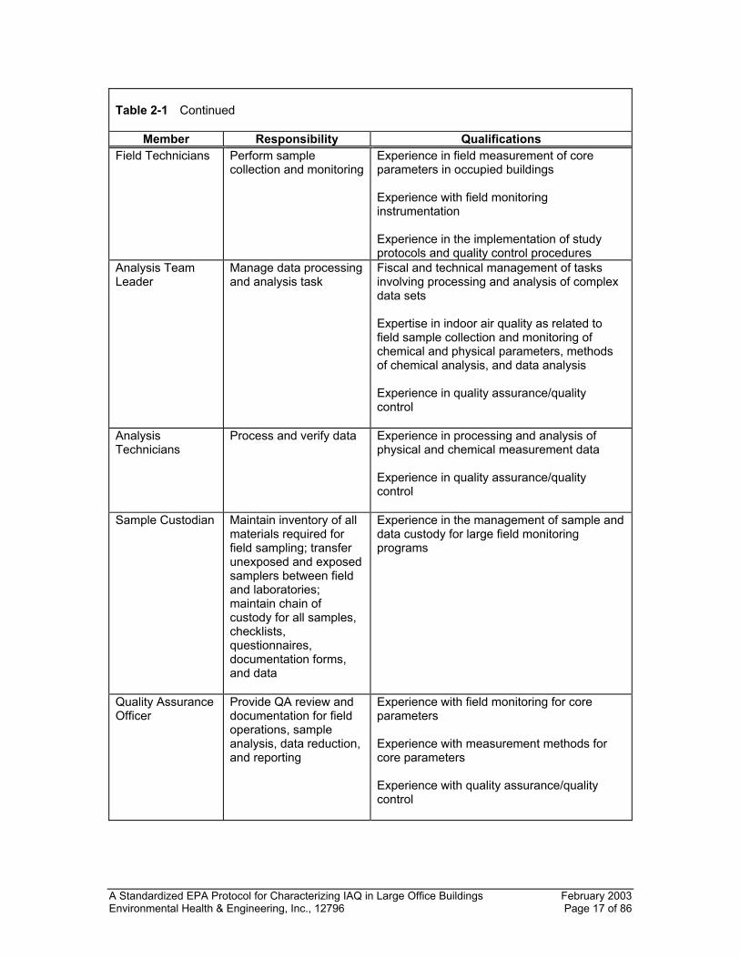
Table 2-1 Continued
Member Responsibility Qualifications Field Technicians Perform sample
collection and monitoringExperience in field measurement of core parameters in occupied buildings Experience with field monitoring instrumentation Experience in the implementation of study protocols and quality control procedures
Analysis Team Leader
Manage data processing and analysis task
Fiscal and technical management of tasks involving processing and analysis of complex data sets Expertise in indoor air quality as related to field sample collection and monitoring of chemical and physical parameters, methods of chemical analysis, and data analysis Experience in quality assurance/quality control
Analysis Technicians
Process and verify data Experience in processing and analysis of physical and chemical measurement data Experience in quality assurance/quality control
Sample Custodian Maintain inventory of all materials required for field sampling; transfer unexposed and exposed samplers between field and laboratories; maintain chain of custody for all samples, checklists, questionnaires, documentation forms, and data
Experience in the management of sample and data custody for large field monitoring programs
Quality Assurance Officer
Provide QA review and documentation for field operations, sample analysis, data reduction, and reporting
Experience with field monitoring for core parameters Experience with measurement methods for core parameters Experience with quality assurance/quality control
A Standardized EPA Protocol for Characterizing IAQ in Large Office Buildings February 2003 Environmental Health & Engineering, Inc., 12796 Page 18 of 86
Table 2-1 Continued
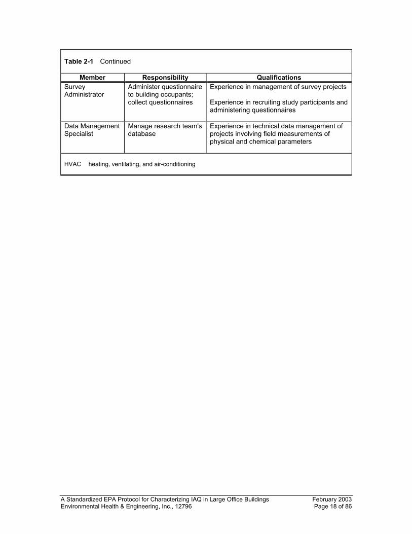
Member Responsibility Qualifications Survey Administrator
Administer questionnaire to building occupants; collect questionnaires
Experience in management of survey projects Experience in recruiting study participants and administering questionnaires
Data Management Specialist
Manage research team's database
Experience in technical data management of projects involving field measurements of physical and chemical parameters
HVAC heating, ventilating, and air-conditioning
A Standardized EPA Protocol for Characterizing IAQ in Large Office Buildings February 2003 Environmental Health & Engineering, Inc., 12796 Page 19 of 86
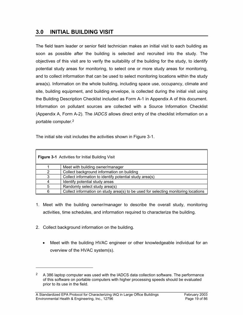
3.0 INITIAL BUILDING VISIT
The field team leader or senior field technician makes an initial visit to each building as
soon as possible after the building is selected and recruited into the study. The
objectives of this visit are to verify the suitability of the building for the study, to identify
potential study areas for monitoring, to select one or more study areas for monitoring,
and to collect information that can be used to select monitoring locations within the study
area(s). Information on the whole building, including space use, occupancy, climate and
site, building equipment, and building envelope, is collected during the initial visit using
the Building Description Checklist included as Form A-1 in Appendix A of this document.
Information on pollutant sources are collected with a Source Information Checklist
(Appendix A, Form A-2). The IADCS allows direct entry of the checklist information on a
portable computer.2
The initial site visit includes the activities shown in Figure 3-1.
Figure 3-1 Activities for Initial Building Visit
1 Meet with building owner/manager 2 Collect background information on building 3 Collect information to identify potential study area(s) 4 Identify potential study areas 5 Randomly select study area(s) 6 Collect information on study area(s) to be used for selecting monitoring locations
1. Meet with the building owner/manager to describe the overall study, monitoring
activities, time schedules, and information required to characterize the building.
2. Collect background information on the building.
• Meet with the building HVAC engineer or other knowledgeable individual for an
overview of the HVAC system(s).
2 A 386 laptop computer was used with the IADCS data collection software. The performance
of this software on portable computers with higher processing speeds should be evaluated prior to its use in the field.
A Standardized EPA Protocol for Characterizing IAQ in Large Office Buildings February 2003 Environmental Health & Engineering, Inc., 12796 Page 20 of 86
• Collect available documentation, such as updated floor plans and HVAC plans
(may be obtained prior to initial visit, if possible).
• Identify on floor plans the HVAC systems and air handlers serving each floor
and/or major area.
• Perform a walkthrough to include the following activities:
− Complete Building Description Checklist (Form A-1)
− Complete Building Source Information Checklist (Form A-2)
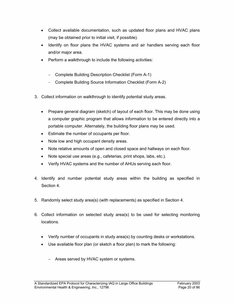
3. Collect information on walkthrough to identify potential study areas.
• Prepare general diagram (sketch) of layout of each floor. This may be done using
a computer graphic program that allows information to be entered directly into a
portable computer. Alternately, the building floor plans may be used.
• Estimate the number of occupants per floor.
• Note low and high occupant density areas.
• Note relative amounts of open and closed space and hallways on each floor.
• Note special use areas (e.g., cafeterias, print shops, labs, etc.).
• Verify HVAC systems and the number of AHUs serving each floor.
4. Identify and number potential study areas within the building as specified in
Section 4.
5. Randomly select study area(s) (with replacements) as specified in Section 4.
6. Collect information on selected study area(s) to be used for selecting monitoring
locations.
• Verify number of occupants in study area(s) by counting desks or workstations.
• Use available floor plan (or sketch a floor plan) to mark the following:
− Areas served by HVAC system or systems.
A Standardized EPA Protocol for Characterizing IAQ in Large Office Buildings February 2003 Environmental Health & Engineering, Inc., 12796 Page 21 of 86
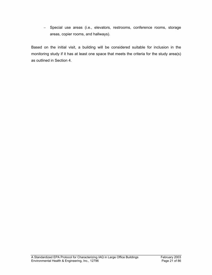
− Special use areas (i.e., elevators, restrooms, conference rooms, storage
areas, copier rooms, and hallways).
Based on the initial visit, a building will be considered suitable for inclusion in the
monitoring study if it has at least one space that meets the criteria for the study area(s)
as outlined in Section 4.
A Standardized EPA Protocol for Characterizing IAQ in Large Office Buildings February 2003 Environmental Health & Engineering, Inc., 12796 Page 22 of 86
4.0 SELECTION OF STUDY AREA(S) AND MONITORING LOCATIONS
4.1 STUDY AREA(S)
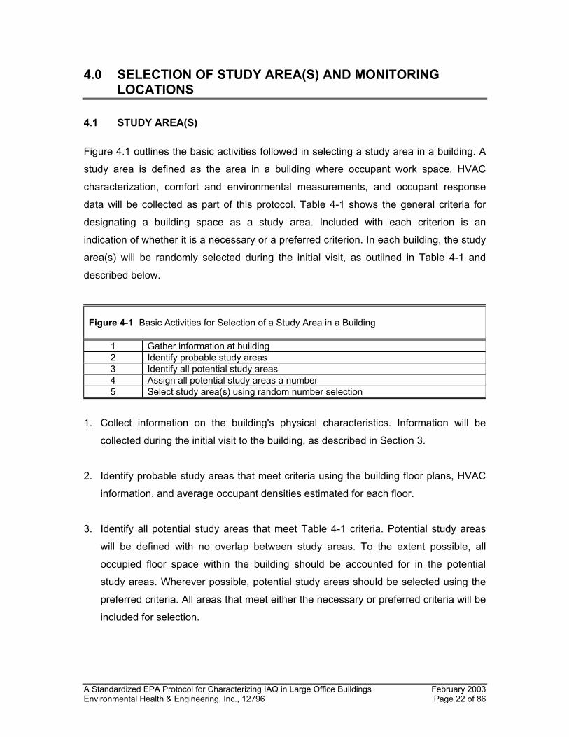
Figure 4.1 outlines the basic activities followed in selecting a study area in a building. A
study area is defined as the area in a building where occupant work space, HVAC
characterization, comfort and environmental measurements, and occupant response
data will be collected as part of this protocol. Table 4-1 shows the general criteria for
designating a building space as a study area. Included with each criterion is an
indication of whether it is a necessary or a preferred criterion. In each building, the study
area(s) will be randomly selected during the initial visit, as outlined in Table 4-1 and
described below.
Figure 4-1 Basic Activities for Selection of a Study Area in a Building
1 Gather information at building 2 Identify probable study areas 3 Identify all potential study areas 4 Assign all potential study areas a number 5 Select study area(s) using random number selection
1. Collect information on the building's physical characteristics. Information will be
collected during the initial visit to the building, as described in Section 3.
2. Identify probable study areas that meet criteria using the building floor plans, HVAC
information, and average occupant densities estimated for each floor.
3. Identify all potential study areas that meet Table 4-1 criteria. Potential study areas
will be defined with no overlap between study areas. To the extent possible, all
occupied floor space within the building should be accounted for in the potential
study areas. Wherever possible, potential study areas should be selected using the
preferred criteria. All areas that meet either the necessary or preferred criteria will be
included for selection.
A Standardized EPA Protocol for Characterizing IAQ in Large Office Buildings February 2003 Environmental Health & Engineering, Inc., 12796 Page 23 of 86
4. Assign each potential study area a number. Number assignments will be sequential.
Number one will be assigned to the space in the northernmost section of the lowest
floor. Numbers will then be assigned in a clockwise fashion on each floor. After all
numbers are assigned to potential study areas on one floor, the next number will be
given to an area on the next highest floor, again starting in the northernmost corner.
Remaining numbers will be assigned in a clockwise fashion. This procedure is
repeated on all floors until all potential study areas have been assigned numbers.
5. Select the study area for monitoring from the potential study areas using a random
number generator. Two backup study areas will also be selected. These areas may
be used if conditions within the building have changed since the initial visit or if it
appears that a potential study area does not meet all criteria after more detailed
information is obtained.
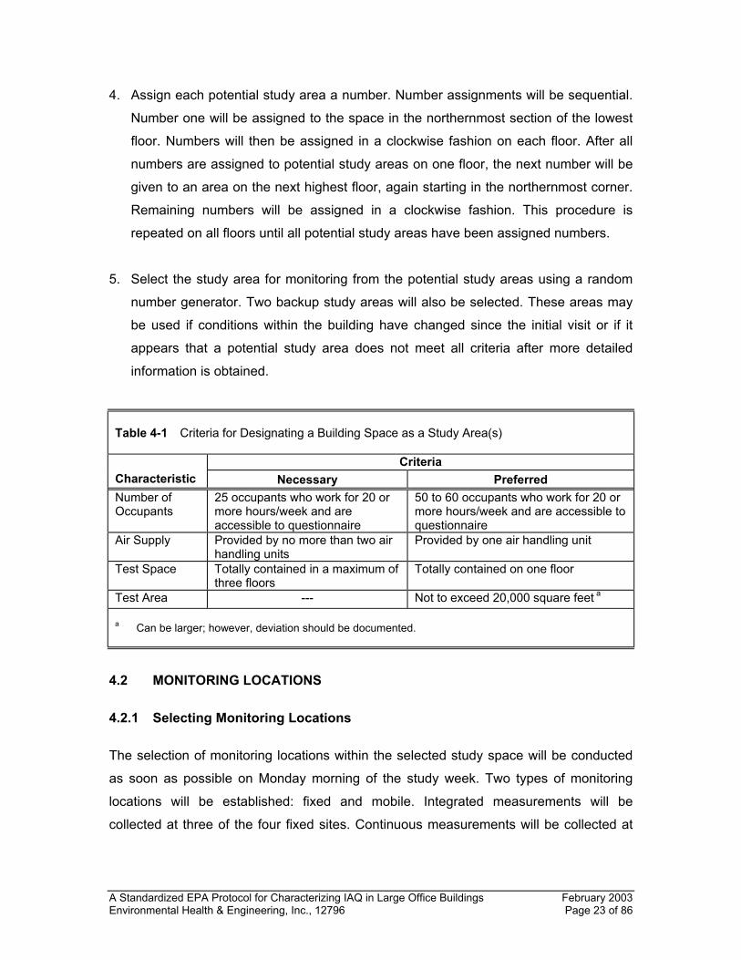
Table 4-1 Criteria for Designating a Building Space as a Study Area(s)
Criteria Characteristic Necessary Preferred Number of Occupants
25 occupants who work for 20 or more hours/week and are accessible to questionnaire
50 to 60 occupants who work for 20 or more hours/week and are accessible to questionnaire
Air Supply Provided by no more than two air handling units
Provided by one air handling unit
Test Space Totally contained in a maximum of three floors
Totally contained on one floor
Test Area --- Not to exceed 20,000 square feet a a Can be larger; however, deviation should be documented.
4.2 MONITORING LOCATIONS
4.2.1 Selecting Monitoring Locations
The selection of monitoring locations within the selected study space will be conducted
as soon as possible on Monday morning of the study week. Two types of monitoring
locations will be established: fixed and mobile. Integrated measurements will be
collected at three of the four fixed sites. Continuous measurements will be collected at
A Standardized EPA Protocol for Characterizing IAQ in Large Office Buildings February 2003 Environmental Health & Engineering, Inc., 12796 Page 24 of 86
the four fixed sites. Real-time measurements will be collected at the five mobile sites.
Four of the mobile sites will be co-located with the fixed indoor sites.3
Four fixed indoor monitoring locations will be established in each building. For three of
these fixed sites, integrated, continuous, and real-time monitoring will be conducted. At
the fourth fixed site, only continuous monitoring will be conducted. A fixed outdoor
monitoring location will also be selected during the initial field visit and should be as
close as possible to the fresh air intake of the primary AHU serving the test space.
Equivalent sample sets are collected at the three fixed indoor and fixed outdoor
locations.
Five mobile indoor monitoring locations will be established and will be co-located with
the fixed indoor monitoring locations.4 The selection of monitoring locations will be
conducted on the Monday morning of the field monitoring week.
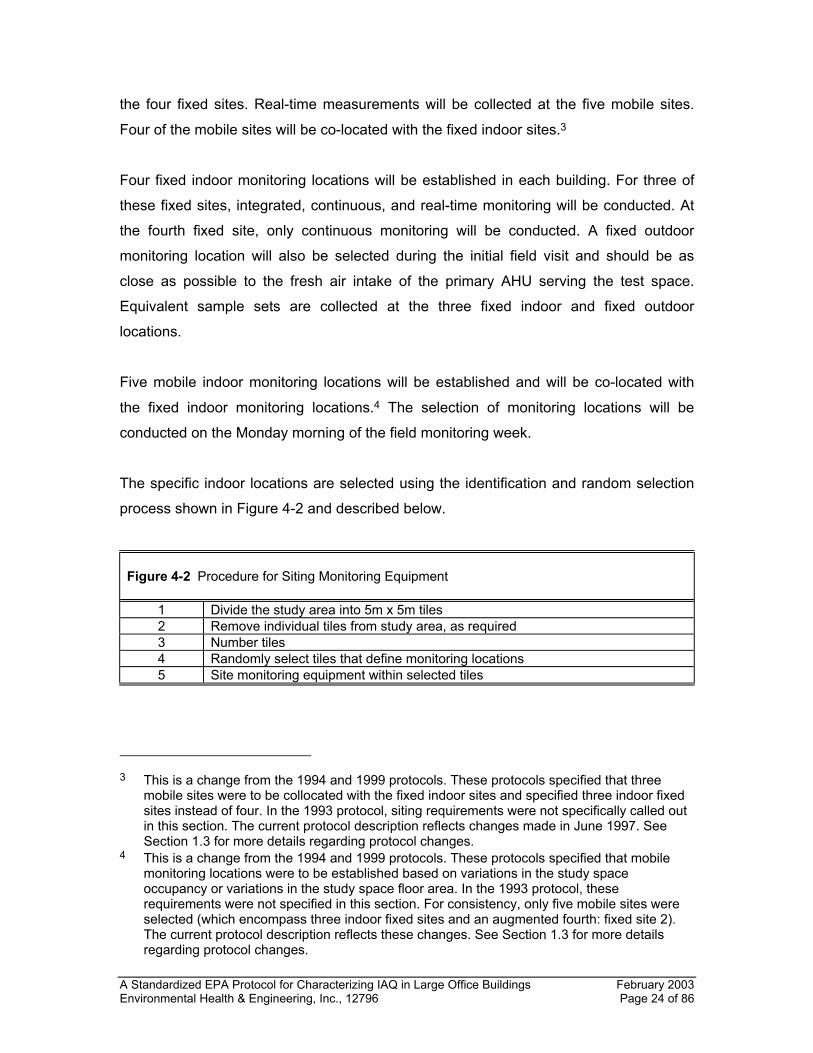
The specific indoor locations are selected using the identification and random selection
process shown in Figure 4-2 and described below.
Figure 4-2 Procedure for Siting Monitoring Equipment
1 Divide the study area into 5m x 5m tiles 2 Remove individual tiles from study area, as required 3 Number tiles 4 Randomly select tiles that define monitoring locations 5 Site monitoring equipment within selected tiles
3 This is a change from the 1994 and 1999 protocols. These protocols specified that three
mobile sites were to be collocated with the fixed indoor sites and specified three indoor fixed sites instead of four. In the 1993 protocol, siting requirements were not specifically called out in this section. The current protocol description reflects changes made in June 1997. See Section 1.3 for more details regarding protocol changes.
4 This is a change from the 1994 and 1999 protocols. These protocols specified that mobile monitoring locations were to be established based on variations in the study space occupancy or variations in the study space floor area. In the 1993 protocol, these requirements were not specified in this section. For consistency, only five mobile sites were selected (which encompass three indoor fixed sites and an augmented fourth: fixed site 2). The current protocol description reflects these changes. See Section 1.3 for more details regarding protocol changes.
A Standardized EPA Protocol for Characterizing IAQ in Large Office Buildings February 2003 Environmental Health & Engineering, Inc., 12796 Page 25 of 86
1. Divide the study area into 5 meter (m) × 5 m tiles. Each tile represents a potential
monitoring location. Tiles will be defined so that there is no overlap between tiles and
all the space in the study area is defined within the tiles.
Although most of the study area should be defined in this manner, the size of some
tiles may require slight adjustment to accommodate the actual dimensions and
shape(s) of the study area.
2. Remove tiles from consideration as monitoring locations, as specified by the
following criteria. In general, for a tile to be considered valid for potential selection,
more than 50% of the tile must include areas where full-time occupants are assigned
and conduct their normal work activities. Tiles that are comprised solely of
bathrooms, hallways, stairs, elevators, laboratories, cafeterias, conference rooms,
and other special use areas where full-time occupants are not assigned should be
removed from the tile selection process. This may require some minor modification to
the actual tile size as noted in step 1 above.
3. Assign each valid tile a unique number in a sequential order. Number one will be
assigned to the tile in the northernmost section of the lowest floor in the study area.
Numbers will be assigned using a clockwise inward spiral on each floor. After all
numbers are assigned to tiles on one floor, the next number will be given to the area
on the next higher floor. Remaining numbers on the floor will be assigned using the
same clockwise inward spiral procedure.
4. Select tiles that define the indoor monitoring locations using the following systematic
random sampling scheme. The potential number of tiles for monitoring (x) is divided
by the total number of indoor monitoring sites (y) to establish the interval between
monitoring sites (i). For example, for a study area with 100 tiles (x) and five indoor
monitoring sites (y), every 20th tile (i) will be selected (100 ÷ 5 = 20). Use a randomly
generated start number to establish the base tile number. Using the calculated
interval number, establish the location for the remaining monitoring sites in a
sequential fashion. For example, using the 100-tile scenario above, the randomly
generated base number was 47; therefore, tile 47 is the base monitoring site.
Monitoring sites two, three, four, and five will then be located at tiles 67, 87, 7, and
A Standardized EPA Protocol for Characterizing IAQ in Large Office Buildings February 2003 Environmental Health & Engineering, Inc., 12796 Page 26 of 86
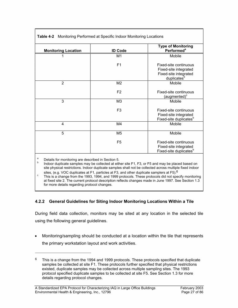
27, in that order. The first, second, third, and fifth randomly selected tiles will be
designated fixed indoor monitoring sites F1, F2, F3, and F5, respectively.5 All five
sites will be designated as mobile monitoring sites (M1, M2, M3, M4, and M5) with
M1, M2, M3, and M5 being co-located with F1, F2, F3, and F5, respectively.
5. If one or more of the randomly selected tiles are determined to be unusable, then
replacement tiles will be selected. Replacement tiles will be selected and assigned
as monitoring locations by using tile x – 1, then x + 1, etc. until a suitable tile is
found. Table 4-2 shows the type of monitoring that will be performed at the
monitoring locations 1 to 5 for this example.
5 This is a change from the 1994 and 1999 protocols. These protocols specified three fixed
sites where both integrated and continuous sampling were to be performed (F1, F3, and F5). The 1993 protocol specified three fixed sites for integrated sampling of which one site was used for continuous monitoring. The current protocol adds an augmented sampling site, F2, reflecting changes made in June 1997. See Section 1.3 for more details regarding protocol changes.
A Standardized EPA Protocol for Characterizing IAQ in Large Office Buildings February 2003 Environmental Health & Engineering, Inc., 12796 Page 27 of 86
Table 4-2 Monitoring Performed at Specific Indoor Monitoring Locations
Monitoring Location
ID Code
Type of Monitoring Performeda
1 M1 Mobile
F1 Fixed-site continuous Fixed-site integrated Fixed-site integrated
duplicatesb 2 M2 Mobile
F2
Fixed-site continuous
(augmented)c 3 M3 Mobile
F3 Fixed-site continuous Fixed-site integrated Fixed-site duplicatesb
4 M4
Mobile
5 M5
Mobile
F5 Fixed-site continuous Fixed-site integrated Fixed-site duplicatesb
a Details for monitoring are described in Section 5. b Indoor duplicate samples may be collected at either site F1, F3, or F5 and may be placed based on
site physical restrictions. Indoor duplicate samples shall not be collected across multiple fixed indoor sites, (e.g. VOC duplicates at F1, particles at F3, and other duplicate samplers at F5).6
c This is a change from the 1993, 1994, and 1999 protocols. These protocols did not specify monitoring at fixed site 2. The current protocol description reflects changes made in June 1997. See Section 1.3 for more details regarding protocol changes.
4.2.2 General Guidelines for Siting Indoor Monitoring Locations Within a Tile
During field data collection, monitors may be sited at any location in the selected tile
using the following general guidelines.
• Monitoring/sampling should be conducted at a location within the tile that represents
the primary workstation layout and work activities.
6 This is a change from the 1994 and 1999 protocols. These protocols specified that duplicate
samples be collected at site F1. These protocols further specified that physical restrictions existed, duplicate samples may be collected across multiple sampling sites. The 1993 protocol specified duplicate samples to be collected at site F5. See Section 1.3 for more details regarding protocol changes.
A Standardized EPA Protocol for Characterizing IAQ in Large Office Buildings February 2003 Environmental Health & Engineering, Inc., 12796 Page 28 of 86
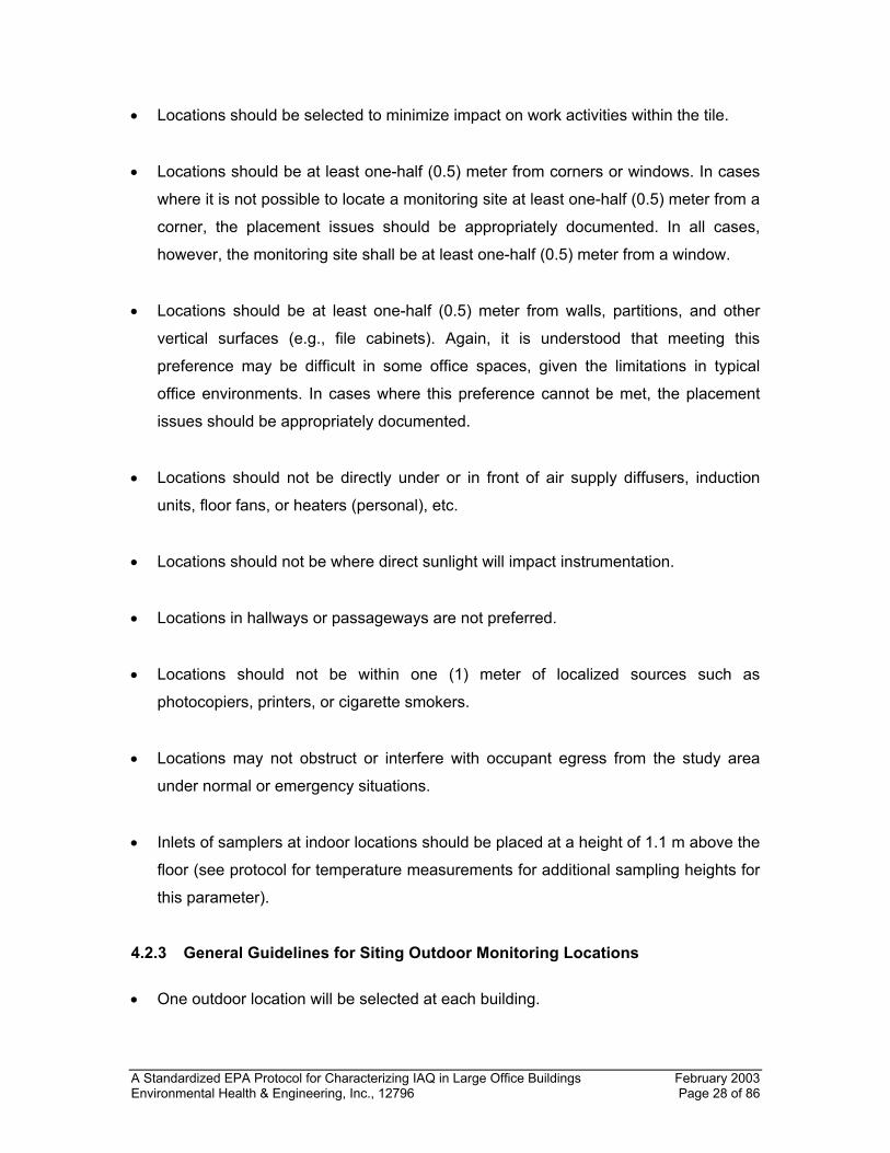
• Locations should be selected to minimize impact on work activities within the tile.
• Locations should be at least one-half (0.5) meter from corners or windows. In cases
where it is not possible to locate a monitoring site at least one-half (0.5) meter from a
corner, the placement issues should be appropriately documented. In all cases,
however, the monitoring site shall be at least one-half (0.5) meter from a window.
• Locations should be at least one-half (0.5) meter from walls, partitions, and other
vertical surfaces (e.g., file cabinets). Again, it is understood that meeting this
preference may be difficult in some office spaces, given the limitations in typical
office environments. In cases where this preference cannot be met, the placement
issues should be appropriately documented.
• Locations should not be directly under or in front of air supply diffusers, induction
units, floor fans, or heaters (personal), etc.
• Locations should not be where direct sunlight will impact instrumentation.
• Locations in hallways or passageways are not preferred.
• Locations should not be within one (1) meter of localized sources such as
photocopiers, printers, or cigarette smokers.
• Locations may not obstruct or interfere with occupant egress from the study area
under normal or emergency situations.
• Inlets of samplers at indoor locations should be placed at a height of 1.1 m above the
floor (see protocol for temperature measurements for additional sampling heights for
this parameter).
4.2.3 General Guidelines for Siting Outdoor Monitoring Locations
• One outdoor location will be selected at each building.
A Standardized EPA Protocol for Characterizing IAQ in Large Office Buildings February 2003 Environmental Health & Engineering, Inc., 12796 Page 29 of 86
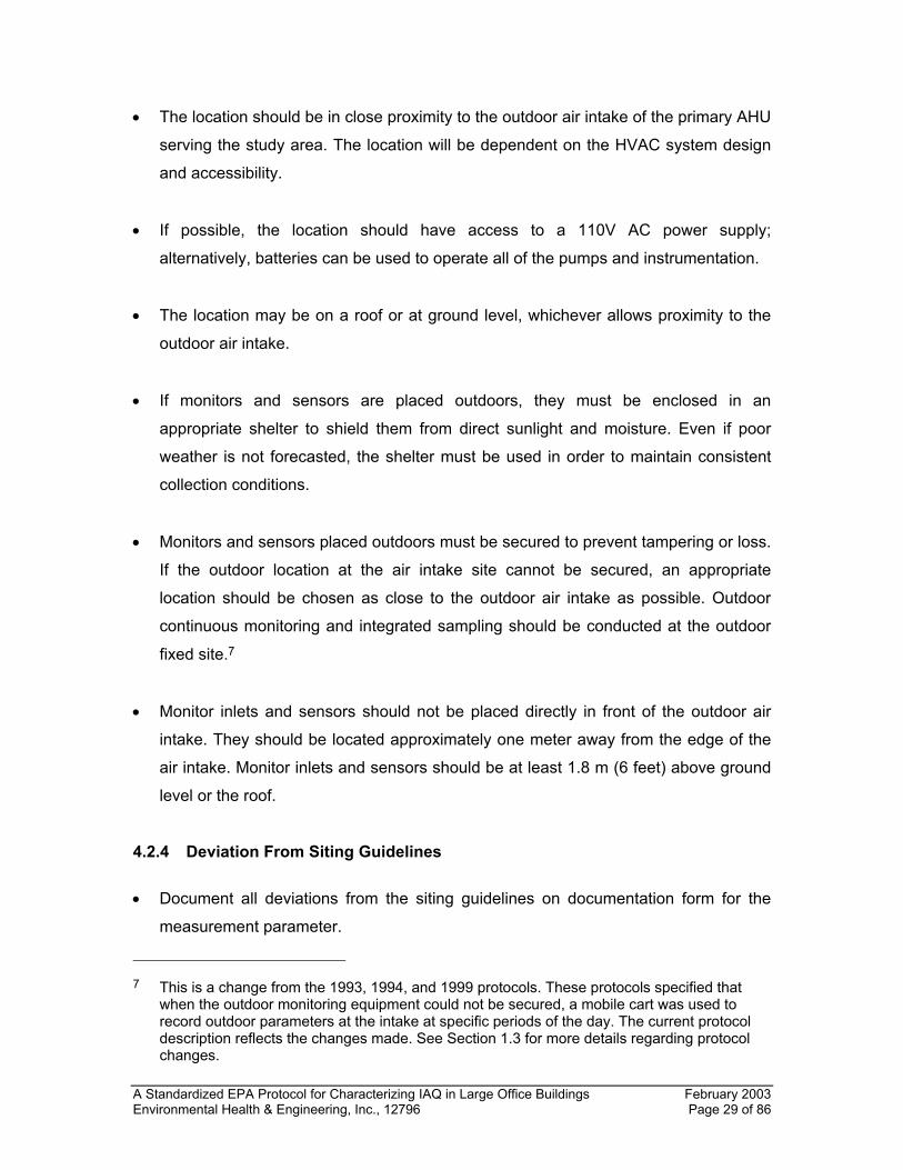
• The location should be in close proximity to the outdoor air intake of the primary AHU
serving the study area. The location will be dependent on the HVAC system design
and accessibility.
• If possible, the location should have access to a 110V AC power supply;
alternatively, batteries can be used to operate all of the pumps and instrumentation.
• The location may be on a roof or at ground level, whichever allows proximity to the
outdoor air intake.
• If monitors and sensors are placed outdoors, they must be enclosed in an
appropriate shelter to shield them from direct sunlight and moisture. Even if poor
weather is not forecasted, the shelter must be used in order to maintain consistent
collection conditions.
• Monitors and sensors placed outdoors must be secured to prevent tampering or loss.
If the outdoor location at the air intake site cannot be secured, an appropriate
location should be chosen as close to the outdoor air intake as possible. Outdoor
continuous monitoring and integrated sampling should be conducted at the outdoor
fixed site.7
• Monitor inlets and sensors should not be placed directly in front of the outdoor air
intake. They should be located approximately one meter away from the edge of the
air intake. Monitor inlets and sensors should be at least 1.8 m (6 feet) above ground
level or the roof.
4.2.4 Deviation From Siting Guidelines
• Document all deviations from the siting guidelines on documentation form for the
measurement parameter.
7 This is a change from the 1993, 1994, and 1999 protocols. These protocols specified that
when the outdoor monitoring equipment could not be secured, a mobile cart was used to record outdoor parameters at the intake at specific periods of the day. The current protocol description reflects the changes made. See Section 1.3 for more details regarding protocol changes.
A Standardized EPA Protocol for Characterizing IAQ in Large Office Buildings February 2003 Environmental Health & Engineering, Inc., 12796 Page 30 of 86
5.0 BUILDING CHARACTERIZATION AND MONITORING
The measurement of various physical, comfort, and environmental parameters in the
study area(s) is an important component of EPA's large building studies. This section
describes the core parameters to be measured, the measurement protocols, and the
schedule of activities at each building.
Measurement parameters have been categorized as core or augmentation parameters.
Core parameters are those parameters for which measurements were required for all
EPA-sponsored building studies and met the following general criteria. First, they should
provide physical, comfort, or environmental information pertaining to the study area(s)
that is considered necessary for characterizing the overall quality of the indoor
environment. Second, standard methods should be employed that provide measurement
data with sufficient sensitivity, selectivity, precision, and accuracy to adequately
characterize the indoor environment as it exists in a range of large buildings. Third,
measurement methods for core parameters should be easy to implement in the field and
create minimal burden on the building space and occupants during monitoring. Finally,
methods for core parameters should be relatively inexpensive to perform. Augmentation
parameters are additional parameters that were measured at some of the buildings in
the program. Measurements of augmentation parameters were considered for inclusion
at selected buildings based on considerations of the research objectives, historical data,
potential for integration of the measurement results with other studies, and other factors,
as deemed appropriate by the EPA Program Manager. Table 5-1 summarizes the core
parameters and sample collection methods that were measured during EPA's large
building studies. Information on augmentation parameters is given in Appendix B.
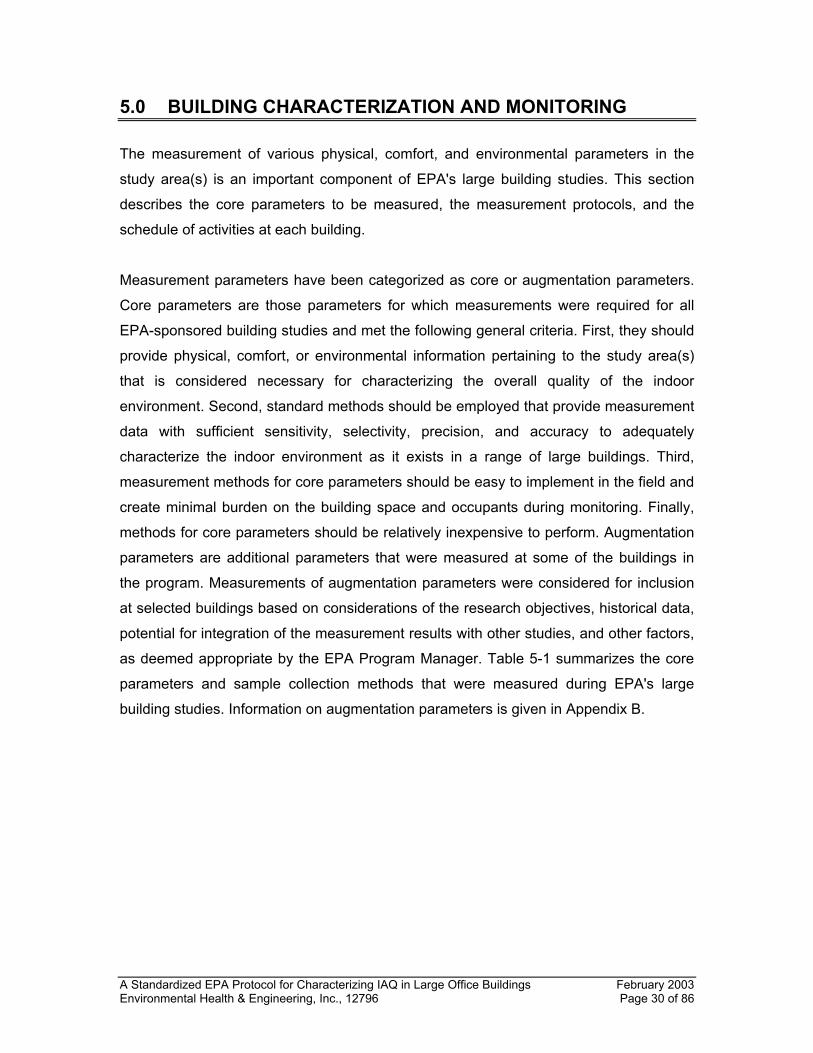
A Standardized EPA Protocol for Characterizing IAQ in Large Office Buildings February 2003 Environmental Health & Engineering, Inc., 12796 Page 31 of 86
Table 5-1 Core Parameters and Sample Collection Methods Parameter Sampling Method/Device Real-Time Monitors Air Temperature (Dry Bulb) Sensor Relative Humidity Sensor CO2 Monitor/Pump CO Monitor/passive diffusion or pump Sound Level Sensor (microphone) Illuminance Sensor (light) Integrated Samples Inhalable Particles (PM2.5) Pump/size selective impactor, filter Inhalable Particles (PM10) Pump/size selective impactor, filter Volatile Organic Compounds Pump, Multisorbent cartridge and SUMMA®
canister Formaldehyde Pump, DNPH cartridge Bioaerosols Pump/size selective impactor, agar media Radon Passive diffusion charcoal canister Other Samples Bulk Biologicals a Sterile disposable pipettes, sterile sampling
bottles, sample collection bags HVAC Measurements Supply/Return Airflow Rate Duct traverse/pitot tubeb Supply/Return Air Temperature Sensor Supply/Return Air Relative Humidity Sensor Percent Outdoor Air Intake—Outdoor, Supply, Return Air
CO2 monitor
Outdoor Air Intake Rate Duct traverse/pitot tubeb Exhaust Fan Airflow Rate Flow capture hood, duct traverse/pitot tubeb Supply Diffuser Airflow Rate Flow capture hood Supply Diffuser Temperature Sensor Supply Diffuser Relative Humidity Sensor Supply Diffuser Carbon Dioxide Sensor CO2 carbon dioxide CO carbon monoxide PM2.5 inhalable particles with an aerodynamic diameter less than or equal to 2.5 microns PM10 inhalable particles with an aerodynamic diameter less than or equal to 10 microns DNPH dinitrophenyl hydrazine a Bulk samples from obviously contaminated sources (i.e., drip pans, ducts) are also collected for
determination of bacteria and fungi. b May be performed with pitot tube, hot-wire anemometer, or comparable sensor.
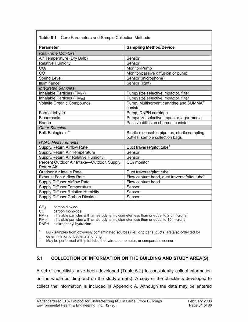
5.1 COLLECTION OF INFORMATION ON THE BUILDING AND STUDY AREA(S)
A set of checklists have been developed (Table 5-2) to consistently collect information
on the whole building and on the study area(s). A copy of the checklists developed to
collect the information is included in Appendix A. Although the data may be entered
A Standardized EPA Protocol for Characterizing IAQ in Large Office Buildings February 2003 Environmental Health & Engineering, Inc., 12796 Page 32 of 86
directly into the IADCS on a portable computer (see Appendix H), it is generally
advisable to also document this information in a hard copy format to ensure that a
backup is maintained. Information can readily be entered into the IADCS software
shortly after the initial visit.
Information on the whole building is collected using the Building Description portion of
the Building Survey section of the IADCS. This information is completed during the initial
visit to the building, as described previously in Section 3. When the field team returns to
the building to perform the monitoring, the field team leader reviews the entries to these
checklists to verify the previous information collected and to record any changes that
may have occurred since the previous site visit.
Table 5-2 Checklists for Collecting Information on the Building and Study Area
Data Collection Instrument Form Number Building Description Checklist A-1 Building Source Information Checklist A-2 Test Space Description Checklist B-1 Test Space Source Information Checklist B-2 Test Space HVAC System Description Checklists • Central Air Handling and Distribution System C-1 • Perimeter Zone Units C-2 • Unitary Systems C-3 • Evaporative Cooling Systems C-4 • Outdoor Air Intake Control C-5 • Natural Ventilation Systems C-6 • Air Handler Specifications C-7A • Exhaust Fan Specifications C-7B • Filtration and Air Cleaning Systems C-8 • Air Washers C-9 • Humidification Systems C-10 • Maintenance C-11 • Inspection C-12 * Checklists are adapted for collection and storage using the IADCS on a portable computer.
Information on the study area(s) (sometimes referred to as the test space) and specific
sources will be collected during the week of measurements at the building using the
appropriate sections of the IADCS Building Survey. It is preferred that these checklists
are initiated early in the week to allow time for completion while still in the building. The
A Standardized EPA Protocol for Characterizing IAQ in Large Office Buildings February 2003 Environmental Health & Engineering, Inc., 12796 Page 33 of 86
data should be completed at all buildings by the same team member, preferably either
the field team leader or senior field technician, to ensure consistency.
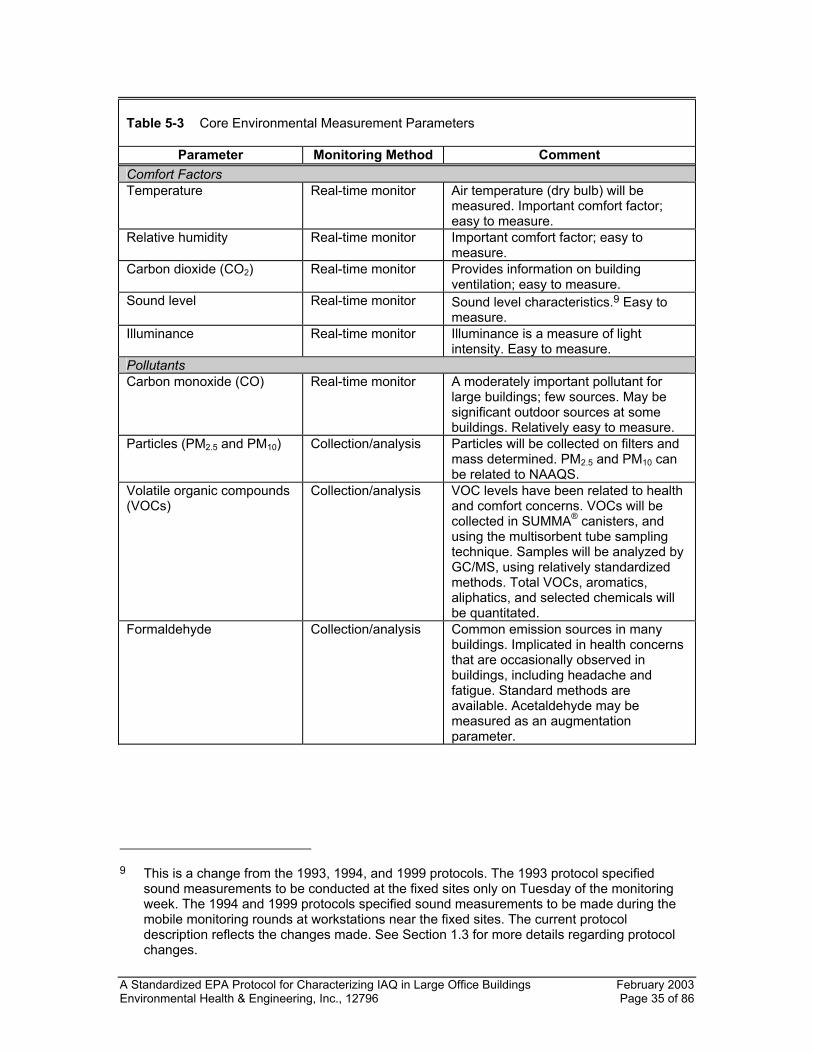
5.2 ENVIRONMENTAL MEASUREMENTS
Environmental monitoring includes measurements for both comfort factors and
environmental pollutants. Table 5-3 summarizes information on the environmental
measurements included in EPA's large building studies. The type of monitoring to be
performed and general considerations for inclusion as a core parameter are also given.
Monitoring will be performed with both real-time and integrated measurement methods,
as described below.
Abbreviated protocols for each parameter are included in Appendix C of this document.
Each protocol describes the measurement method, performance requirements,
instrument requirements, calibration requirements, and QA/QC requirements.
Core comfort parameters include temperature, relative humidity, CO2, sound level, and
illuminance. All of these parameters can be measured with portable, "real-time"
monitors. Quality of light (luminance and color) is considered to be an augmentation
parameter. Although measurements of lighting quality parameters may be useful, their
measurement and interpretation are complex, and standardized protocols that are
applicable to large building studies have not been developed and validated. Although
standard procedures are not available to quantitatively measure odor and odor
perception, qualitative information related to odors will be collected by the research team
during the monitoring period using the standardized checklist described in Section 5.3.7.
CO, particles (PM2.5 and PM10), VOCs, formaldehyde (HCHO), bioaerosols (fungi,
mesophilic bacteria, and thermophilic bacteria) and radon are included as core
parameters in the pollutant category. For VOCs, measurements are conducted using the
SUMMA® canister and Multisorbent tube sampling method. The measurement of fungi
and bacteria in bulk source samples collected from areas with noticeable biological
growth is also a core parameter. Although there continues to be controversy with regard
to the appropriate measurement protocols and the utility of the microbiologicals data, it is
important that a database of bioaerosol measurements be developed. This study
A Standardized EPA Protocol for Characterizing IAQ in Large Office Buildings February 2003 Environmental Health & Engineering, Inc., 12796 Page 34 of 86
provides an opportunity for developing such a database. The measurement of viable and
non-viable fungal spores is included as an augmented parameter.8 Nicotine and
acetaldehyde may be included as augmented parameters (Appendix B). Several
pollutants, including ozone and oxides of nitrogen, were considered but not
recommended for inclusion in the program.
8 This is an addition to the 1993, 1994, and 1999 protocols. This change was made in June
1997. See Section 1.3 for more details regarding protocol additions.
A Standardized EPA Protocol for Characterizing IAQ in Large Office Buildings February 2003 Environmental Health & Engineering, Inc., 12796 Page 35 of 86
Table 5-3 Core Environmental Measurement Parameters
Parameter Monitoring Method Comment Comfort Factors Temperature Real-time monitor Air temperature (dry bulb) will be
measured. Important comfort factor; easy to measure.
Relative humidity Real-time monitor Important comfort factor; easy to measure.
Carbon dioxide (CO2) Real-time monitor Provides information on building ventilation; easy to measure.
Sound level Real-time monitor Sound level characteristics.9 Easy to measure.
Illuminance Real-time monitor Illuminance is a measure of light intensity. Easy to measure.
Pollutants Carbon monoxide (CO) Real-time monitor A moderately important pollutant for
large buildings; few sources. May be significant outdoor sources at some buildings. Relatively easy to measure.
Particles (PM2.5 and PM10) Collection/analysis Particles will be collected on filters and mass determined. PM2.5 and PM10 can be related to NAAQS.
Volatile organic compounds (VOCs)
Collection/analysis VOC levels have been related to health and comfort concerns. VOCs will be collected in SUMMA® canisters, and using the multisorbent tube sampling technique. Samples will be analyzed by GC/MS, using relatively standardized methods. Total VOCs, aromatics, aliphatics, and selected chemicals will be quantitated.
Formaldehyde Collection/analysis Common emission sources in many buildings. Implicated in health concerns that are occasionally observed in buildings, including headache and fatigue. Standard methods are available. Acetaldehyde may be measured as an augmentation parameter.
9 This is a change from the 1993, 1994, and 1999 protocols. The 1993 protocol specified
sound measurements to be conducted at the fixed sites only on Tuesday of the monitoring week. The 1994 and 1999 protocols specified sound measurements to be made during the mobile monitoring rounds at workstations near the fixed sites. The current protocol description reflects the changes made. See Section 1.3 for more details regarding protocol changes.
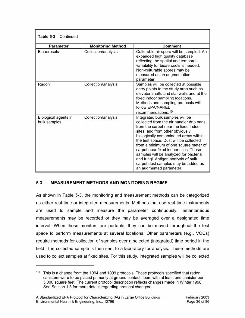
A Standardized EPA Protocol for Characterizing IAQ in Large Office Buildings February 2003 Environmental Health & Engineering, Inc., 12796 Page 36 of 86
Table 5-3 Continued
Parameter Monitoring Method Comment Bioaerosols Collection/analysis Culturable air spora will be sampled. An
expanded high quality database reflecting the spatial and temporal variability for bioaerosols is needed. Non-culturable spores may be measured as an augmentation parameter.
Radon Collection/analysis Samples will be collected at possible entry points to the study area such as elevator shafts and stairwells and at the fixed indoor sampling locations. Methods and sampling protocols will follow EPA/NAREL recommendations.10
Biological agents in bulk samples
Collection/analysis Integrated bulk samples will be collected from the air handler drip pans, from the carpet near the fixed indoor sites, and from other obviously biologically contaminated areas within the test space. Dust will be collected from a minimum of one square meter of carpet near fixed indoor sites. These samples will be analyzed for bacteria and fungi. Antigen analysis of bulk carpet dust samples may be added as an augmented parameter.
5.3 MEASUREMENT METHODS AND MONITORING REGIME
As shown in Table 5-3, the monitoring and measurement methods can be categorized
as either real-time or integrated measurements. Methods that use real-time instruments
are used to sample and measure the parameter continuously. Instantaneous
measurements may be recorded or they may be averaged over a designated time
interval. When these monitors are portable, they can be moved throughout the test
space to perform measurements at several locations. Other parameters (e.g., VOCs)
require methods for collection of samples over a selected (integrated) time period in the
field. The collected sample is then sent to a laboratory for analysis. These methods are
used to collect samples at fixed sites. For this study, integrated samples will be collected
10 This is a change from the 1994 and 1999 protocols. These protocols specified that radon
canisters were to be placed primarily at ground contact floors with at least one canister per 5,000 square feet. The current protocol description reflects changes made in Winter 1998. See Section 1.3 for more details regarding protocol changes.
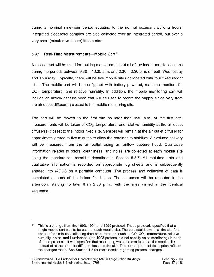
A Standardized EPA Protocol for Characterizing IAQ in Large Office Buildings February 2003 Environmental Health & Engineering, Inc., 12796 Page 37 of 86
during a nominal nine-hour period equating to the normal occupant working hours.
Integrated bioaerosol samples are also collected over an integrated period, but over a
very short (minutes vs. hours) time period.
5.3.1 Real-Time Measurements—Mobile Cart11
A mobile cart will be used for making measurements at all of the indoor mobile locations
during the periods between 9:30 – 10:30 a.m. and 2:30 – 3:30 p.m. on both Wednesday
and Thursday. Typically, there will be five mobile sites collocated with four fixed indoor
sites. The mobile cart will be configured with battery powered, real-time monitors for
CO2, temperature, and relative humidity. In addition, the mobile monitoring cart will
include an airflow capture hood that will be used to record the supply air delivery from
the air outlet diffuser(s) closest to the mobile monitoring site.
The cart will be moved to the first site no later than 9:30 a.m. At the first site,
measurements will be taken of CO2, temperature, and relative humidity at the air outlet
diffuser(s) closest to the indoor fixed site. Sensors will remain at the air outlet diffuser for
approximately three to five minutes to allow the readings to stabilize. Air volume delivery
will be measured from the air outlet using an airflow capture hood. Qualitative
information related to odors, cleanliness, and noise are collected at each mobile site
using the standardized checklist described in Section 5.3.7. All real-time data and
qualitative information is recorded on appropriate log sheets and is subsequently
entered into IADCS on a portable computer. The process and collection of data is
completed at each of the indoor fixed sites. The sequence will be repeated in the
afternoon, starting no later than 2:30 p.m., with the sites visited in the identical
sequence.
11 This is a change from the 1993, 1994 and 1999 protocol. These protocols specified that a
single mobile cart was to be used at each mobile site. The cart would remain at the site for a period of ten minutes collecting data on parameters such as CO, CO2, temperature, relative humidity, noise, and illuminance. (the 1993 protocol did not specify noise monitoring) In each of these protocols, it was specified that monitoring would be conducted at the mobile site instead of at the air outlet diffuser closest to the site. The current protocol description reflects the changes made. See Section 1.3 for more details regarding protocol changes.
A Standardized EPA Protocol for Characterizing IAQ in Large Office Buildings February 2003 Environmental Health & Engineering, Inc., 12796 Page 38 of 86
A typical layout of measurement locations and comfort/environmental parameters for
four fixed indoor, five mobile indoor (four being at the identical locations of the four fixed
indoor sites), and one outdoor monitoring location are diagrammed in Figure 5-1.
5.3.2 Real-Time Measurements—Indoor and Outdoor Fixed Sites
Real-time monitors for CO, CO2, relative humidity, noise, and light will be placed at the
height of 1.1 m above the floor at three fixed indoor sites (F1, F3, and F5) as shown in
Figure 5-1.12 Real-time monitors for CO, CO2, temperature, and relative humidity will be
placed at fixed site 2. Temperature measurements will be recorded at heights of 0.1, 0.6,
1.1, and 1.7 m above the floor. Each parameter will be continuously recorded over an
approximate three-day period at the building (Tuesday, a.m., to Thursday, p.m.). The
real-time data will be output to a datalogger, with five-minute averages collected for
future processing. Data will be downloaded each day using a portable computer.
At the outdoor location, which should be near the outside air intake for the study area(s)
(see Section 4 for details on siting), a fixed-site monitoring station will be established
with CO, CO2, temperature, and relative humidity or dew point monitors. Data will be
recorded continuously with a datalogger using a five-minute average as a collection
frequency. At the end of each day, the data will be downloaded into the portable
computer. In situations where the fixed-site monitoring equipment cannot be secured at
the outdoor site and meet the requirement for being near the outdoor air intake (e.g.,
ground level intakes), the fixed site monitoring equipment shall be located in a secure
outdoor location as close as possible to the AHU outdoor air intake.13 Deviations from
the siting requirements shall be appropriately documented.
12 This is a change from the 1994 and 1999 protocols. These protocols specified that light
measurements were considered an augmented parameter to be implemented when possible. Also, real time monitoring was specified to occur at three indoor fixed sites instead of four. The 1993 protocol specified that continuous monitoring be implemented at only one fixed site. The current protocol reflects the changes made. See Section 1.3 for more details regarding protocol changes.
13 This is a change from the 1994 and 1999 protocols. These protocols specified that when the outdoor monitoring equipment could not be secured, a mobile cart was used to record outdoor parameters at the intake at specific periods of the day. The current protocol description reflects changes made. See Section 1.3 for more details regarding protocol changes.
A Standardized EPA Protocol for Characterizing IAQ in Large Office Buildings February 2003 Environmental Health & Engineering, Inc., 12796 Page 39 of 86
Routine hourly meteorological parameter data (wind direction, wind speed, ambient
temperature, ambient relative humidity, precipitation, and solar radiation) will be
collected from the local National Weather Service activity and reported for inclusion in
the EPA database.
A Standardized EPA Protocol for Characterizing IAQ in Large Office Buildings February 2003 Environmental Health & Engineering, Inc., 12796 Page 40 of 86
Figure 5-1 Diagram of the Measurements to be Made at the Indoor Mobile Cart and Fixed Site Locations and Outdoorsb
Study Area Outdoors
OUTDOOR
M2
CO2 T
RH DIFF
F2
CO CO2
T RH
CO CO2
T RH
VOC HCHO PM10 PM2.5 BIO
OUTDOOR-DUP VOC
HCHO PM10 PM2.5 BIO
M1 CO2
T RH
DIFF
F1 CO CO2
T RH LUX
NOISE VOC
HCHO PM10 PM2.5 BIO
F1-DUPa VOC
HCHO PM10 PM2.5 BIO
M3 CO2
T RH
DIFF
F3 CO CO2
T RH LUX
NOISE VOC
HCHO PM10 PM2.5 BIO
M4
CO2 T
RH DIFF
M5 CO2
T RH
DIFF
F5 CO CO2
T RH LUX
NOISE VOC
HCHO PM10 PM2.5 BIO
ABBREVIATIONS
Monitoring Sites
M=Mobile F=Fixed
BIO = Bioaerosols LUX = Illuminance
DIFF = Diffuser airflow
a Indoor duplicate samples may be collected at either site F1, F3, or F5 and may be placed based on site physical restrictions. Indoor duplicate samples shall not be collected across multiple fixed indoor sites (e.g., VOC duplicates at F1, particles at F3, and other duplicate samplers at F5).
b Changes were made to the 1993, 1994, and 1999 protocols regarding measurements to be made at the indoor fixed and mobile sites. For mobile monitoring sites, the measurement of CO, Illuminance, and noise was excluded while site diffuser measurements were added. At the fixed sites, PM2.5 sampling was added for all sites. See Section 1.3 for more details regarding protocol changes.
A Standardized EPA Protocol for Characterizing IAQ in Large Office Buildings February 2003 Environmental Health & Engineering, Inc., 12796 Page 41 of 86
5.3.3 Integrated Samplers
As described in Section 4, integrated air samples for VOCs, formaldehyde, and particles
(PM10 and PM2.5) will be collected on one day (Wednesday) at a height of 1.1 m above
the floor at the three fixed sites (F1, F3, and F5) within each building study area and the
outdoor fixed-site location. Figure 5-1 shows that duplicate samples will be collected at
one fixed indoor site and the outdoor site. The integrated samples will be collected over
a nominal nine-hour period from approximately 8:00 a.m. to 5:00 p.m., ±30 minutes,
equating to the anticipated normal daytime working hours. The start and end time may
require adjustment based on the normal working hours within the test space.
At the outdoor location, integrated samples for VOCs, formaldehyde (and acetaldehyde
if applicable), PM10, and PM2.5 will be collected in duplicate from approximately 7:30 a.m.
to 5:30 p.m. on Wednesday. Outdoor sampling should always be initiated before the
indoor monitoring starts and should end after the completion of the indoor integrated
samplers. The collection of duplicate outdoor samples should substantially improve data
completeness.
Bioaerosol samples (fungi, mesophilic bacteria, and thermophilic bacteria) will be paired
as two and five minute samples and will be collected at the three indoor fixed-site
locations and at the outdoor location. The samples will be collected on Wednesday
(only) at approximately 10:30 a.m. and 3:30 p.m. (±30 minutes) following completion of
the mobile cart monitoring. As shown in Figure 5-1, samples will be collected in duplicate
at one indoor and the outdoor location.
The measurement of viable and non viable spores may be collected as an augmented
parameter. Samples will be collected on Wednesday (only) at approximately 10:30 a.m.
and 3:30 p.m. in coincidence with bioaerosol samples described above.
Integrated source samples for microbiological contamination will also be collected from:
AHU drip pans, interior AHU sections or coils, and areas with obvious water damage and
biological contamination. Samples will be analyzed individually for fungi, mesophilic
bacteria, and thermophilic bacteria. These source samples can be collected at any time
during the Tuesday to Friday period, but preferably on Thursday, as no other integrated
A Standardized EPA Protocol for Characterizing IAQ in Large Office Buildings February 2003 Environmental Health & Engineering, Inc., 12796 Page 42 of 86
sampling is conducted on that day. Dust samples within a 1 square meter area will be
collected in close proximity to each of the three indoor fixed sites where integrated
sampling is conducted. Samples will be analyzed individually for bacteria, fungi, and
thermophilic bacteria. Dust samples will be collected on Thursday. As an augmented
parameter, a portion of the dust collected at each fixed site may be split from the sample
and sent out for antigen analysis.
5.3.4 Radon Sampling
Radon will be sampled using diffusion-barrier charcoal canisters. The canisters will be
deployed on Monday soon after arrival of the field team. They will be retrieved 72 hours
after being deployed and shipped to the laboratory on Thursday for analysis on Friday.
The canisters will be deployed at each of the three indoor fixed sites and at entry
locations to the study space, such as stairwells, elevator lobbies, etc.14
5.3.5 Sound Level Measurements
Sound level measurements will be made continuously at the three fixed indoor locations
designated as F1, F3, and F5. Measurements will be made at a height of 1.1 m.
5.3.6 Illuminance Measurements
Illuminance measurements will be made continuously at the three fixed indoor locations
designated as F1, F3, and F5.15 Measurements will be made at a height of 1.1 m.
5.3.7 Monitoring Period Observations Checklist
During the two daily mobile cart monitoring periods, the researcher will record
observations made at each location related to odors, noise, housekeeping, and pollutant
14 This is a change from the 1994 and 1999s protocol. The 1994 and 1999 protocol specified
that radon samples be collected at selected ground floor locations, elevator shafts, stairwells on the floor(s) of the test space and at the fixed site sampling locations. See Section 1.3 for more details regarding protocol changes.
15 This is a change from the 1993, 1994, and 1999s protocol. The 1993 protocol specified that illuminance measurements were to be made at all mobile sites during the mobile monitoring rounds. The 1994 and 1999 protocols specified that illuminance measurements were to be made during the mobile cart monitoring round at a workstation adjacent to the site. See Section 1.3 for more details regarding protocol changes.
A Standardized EPA Protocol for Characterizing IAQ in Large Office Buildings February 2003 Environmental Health & Engineering, Inc., 12796 Page 43 of 86
sources using a standardized checklist (see Appendix D). These observations, although
subjective, may aid in the interpretation of the measurement data. The observations will
be entered into a checklist in the portable computer.
5.3.8 Number of Measurements to Be Made
The number of measurements to be made at each building is presented in Table 5-4.
Two mobile cart measurements are made each day at the indoor locations. At the fixed-
site indoor and outdoor locations, data will be collected continuously for various
parameters during the two to three day monitoring period. Five-minute averages will be
downloaded from the datalogger. In naturally ventilated buildings, CO2 measurements
will also be calculated as 15-minute averages (see Section 5.4).
Integrated samples will be collected on only one day at the three fixed indoor locations
(F1, F3, and F5) and one fixed outdoor location. Bioaerosol samples will be collected at
all three fixed indoor locations and at the outdoor location, twice on one day
(Wednesday morning and afternoon). Grab samples of biologically contaminated bulk
samples will be collected on Thursday from the HVAC drip pans, the carpeting or
flooring at the three fixed indoor sites, and at other locations where noticeable biological
contamination is observed. The number of radon samplers to be deployed will be a
function of the study area size and the number of possible entry points to the study area.
In addition to the field samples, various quality control (QC) samples will be analyzed.
These will include the QC samples provided by the research organization and those
provided by EPA. The minimum number of field and QC samples to be analyzed per
building are listed in Table 5-5. At each building, one field blank and one duplicate
sample are required for each type of integrated sample. As described previously, PM2.5,
PM10, HCHO, and VOC samples will be collected and analyzed in duplicate at the
outdoor location to maximize data completeness. Table 5-6 shows the samples that
must be analyzed before the program is initiated as an initial demonstration of laboratory
capability.
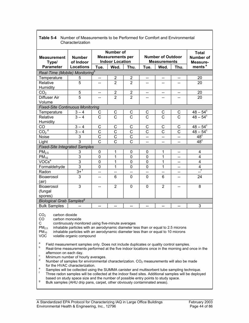
A Standardized EPA Protocol for Characterizing IAQ in Large Office Buildings February 2003 Environmental Health & Engineering, Inc., 12796 Page 44 of 86
Table 5-4 Number of Measurements to be Performed for Comfort and Environmental
Characterization
Number of Measurements per
Indoor Location
Number of Outdoor
Measurements Measurement
Type/ Parameter
Number of Indoor Locations Tue. Wed. Thu. Tue. Wed. Thu.
Total Number of Measure-ments a
Real-Time (Mobile) Monitoringb Temperature 5 -- 2 2 -- -- -- 20 Relative Humidity
5 -- 2 2 -- -- -- 20
CO2 5 -- 2 2 -- -- -- 20 Diffuser Air Volume
5 -- 2 2 -- -- -- 20
Fixed-Site Continuous Monitoring Temperature 3 – 4 C C C C C C 48 – 54c Relative Humidity
3 – 4 C C C C C C 48 – 54c
CO 3 – 4 C C C C C C 48 – 54c CO2
d 3 – 4 C C C C C C 48 – 54c Noise 3 C C C -- -- -- 48c Light 3 C C C -- -- -- 48c Fixed-Site Integrated Samples PM2.5 3 0 1 0 0 1 -- 4 PM10 3 0 1 0 0 1 -- 4 VOCse 3 0 1 0 0 1 -- 4 Formaldehyde 3 0 1 0 0 1 -- 4 Radon 3+ f -- -- -- -- -- -- --f Bioaerosol (air)
3 -- 6 0 0 6 -- 24
Bioaerosol (fungal spores)
3 -- 2 0 0 2 -- 8
Biological Grab Samplesg Bulk Samples -- -- -- -- -- -- -- 3 CO2 carbon dioxide CO carbon monoxide C continuously monitored using five-minute averages PM2.5 inhalable particles with an aerodynamic diameter less than or equal to 2.5 microns PM10 inhalable particles with an aerodynamic diameter less than or equal to 10 microns VOC volatile organic compound a Field measurement samples only. Does not include duplicates or quality control samples. b Real-time measurements performed at the five indoor locations once in the morning and once in the
afternoon on each day. c Minimum number of hourly averages. d Number of samples for environmental characterization. CO2 measurements will also be made
for the HVAC characterization. e Samples will be collected using the SUMMA canister and multisorbent tube sampling technique. f Three radon samples will be collected at the indoor fixed sites. Additional samples will be deployed
based on study space size and the number of possible entry points to study space. g Bulk samples (AHU drip pans, carpet, other obviously contaminated areas).
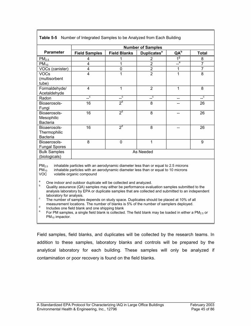
A Standardized EPA Protocol for Characterizing IAQ in Large Office Buildings February 2003 Environmental Health & Engineering, Inc., 12796 Page 45 of 86
Table 5-5 Number of Integrated Samples to be Analyzed from Each Building
Number of Samples Parameter Field Samples Field Blanks Duplicatesa QAb Total
PM2.5 4 1 2 1g 8 PM10 4 1 2 --e 7 VOCs (canister) 4 0 2 1 7 VOCs (multisorbent tube)
4 1 2 1 8
Formaldehyde/ Acetaldehyde
4 1 2 1 8
Radon --c --c --c -- --c Bioaerosols-Fungi
16 2d 8 -- 26
Bioaerosols-Mesophilic Bacteria
16 2d 8 -- 26
Bioaerosols-Thermophilic Bacteria
16 2d 8 -- 26
Bioaerosols-Fungal Spores
8 0 1 9
Bulk Samples (biologicals)
As Needed
PM2.5 inhalable particles with an aerodynamic diameter less than or equal to 2.5 microns PM10 inhalable particles with an aerodynamic diameter less than or equal to 10 microns VOC volatile organic compound a One indoor and outdoor duplicate will be collected and analyzed. b Quality assurance (QA) samples may either be performance evaluation samples submitted to the
analysis laboratory by EPA or duplicate samples that are collected and submitted to an independent laboratory for analysis.
c The number of samples depends on study space. Duplicates should be placed at 10% of all measurement locations. The number of blanks is 5% of the number of samplers deployed.
d Includes one field blank and one shipping blank e For PM samples, a single field blank is collected. The field blank may be loaded in either a PM2.5 or
PM10 impactor.
Field samples, field blanks, and duplicates will be collected by the research teams. In
addition to these samples, laboratory blanks and controls will be prepared by the
analytical laboratory for each building. These samples will only be analyzed if
contamination or poor recovery is found on the field blanks.
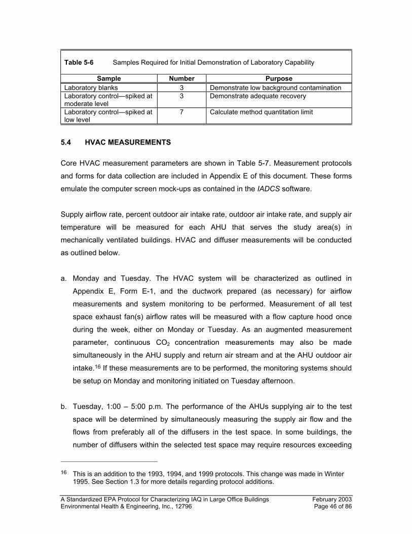
A Standardized EPA Protocol for Characterizing IAQ in Large Office Buildings February 2003 Environmental Health & Engineering, Inc., 12796 Page 46 of 86
Table 5-6 Samples Required for Initial Demonstration of Laboratory Capability
Sample Number Purpose Laboratory blanks 3 Demonstrate low background contamination Laboratory control—spiked at moderate level
3 Demonstrate adequate recovery
Laboratory control—spiked at low level
7 Calculate method quantitation limit
5.4 HVAC MEASUREMENTS
Core HVAC measurement parameters are shown in Table 5-7. Measurement protocols
and forms for data collection are included in Appendix E of this document. These forms
emulate the computer screen mock-ups as contained in the IADCS software.
Supply airflow rate, percent outdoor air intake rate, outdoor air intake rate, and supply air
temperature will be measured for each AHU that serves the study area(s) in
mechanically ventilated buildings. HVAC and diffuser measurements will be conducted
as outlined below.
a. Monday and Tuesday. The HVAC system will be characterized as outlined in
Appendix E, Form E-1, and the ductwork prepared (as necessary) for airflow
measurements and system monitoring to be performed. Measurement of all test
space exhaust fan(s) airflow rates will be measured with a flow capture hood once
during the week, either on Monday or Tuesday. As an augmented measurement
parameter, continuous CO2 concentration measurements may also be made
simultaneously in the AHU supply and return air stream and at the AHU outdoor air
intake.16 If these measurements are to be performed, the monitoring systems should
be setup on Monday and monitoring initiated on Tuesday afternoon.
b. Tuesday, 1:00 – 5:00 p.m. The performance of the AHUs supplying air to the test
space will be determined by simultaneously measuring the supply air flow and the
flows from preferably all of the diffusers in the test space. In some buildings, the
number of diffusers within the selected test space may require resources exceeding
16 This is an addition to the 1993, 1994, and 1999 protocols. This change was made in Winter
1995. See Section 1.3 for more details regarding protocol additions.
A Standardized EPA Protocol for Characterizing IAQ in Large Office Buildings February 2003 Environmental Health & Engineering, Inc., 12796 Page 47 of 86
those available. When this occurs, a random sample consisting of a minimum of 50%
of the diffusers in the test space will be monitored, including the diffusers nearest to
each of the indoor monitoring locations. This activity should be appropriately
scheduled and completed within this four-hour period to minimize the potential
influence by a variable air flow system.
c. Wednesday and Thursday. HVAC system performance measurements will be made
at the same time that environmental measurements are made with the mobile cart,
i.e., 9:30 a.m. and 2:30 p.m. on Wednesday and Thursday. Each measurement is
briefly described in Table 5-7 and is described in detail in Appendix E. Outdoor,
return, and supply air flow stream temperatures, relative humidity levels, CO2 levels,
and flows will be measured. During this same period, the temperature, relative
humidity, CO2, and flow from the diffuser closest to each mobile site will also be
measured. The technician performing the mobile monitoring will also check to see if
the exhaust fans are operating at approximately 10:30 a.m. and 3:30 p.m.
d. Thursday and Friday. Additional information pertaining to the AHU(s) may be
collected during this period to complete the Appendix E, E-form narratives.
In naturally ventilated buildings, the core parameters to be measured include:
(1) continuous carbon dioxide measurements, (2) measurements of exhaust fan airflow
rate, and (3) the twice-daily check of exhaust fan operation. The continuous CO2
measurements, described in Form E-5 of Appendix E, consist of measurements of CO2
at three indoor locations throughout the day on both days of monitoring. CO2 monitors
will be available for measurements at fixed sites F1, F2, F3, and F5 (See Figure 5-1).
Data will be recorded continuously with the datalogger.
Research teams may propose protocols for air infiltration rate measurements (such as
using sulfur hexaflouride as a tracer gas) at specific buildings. These measurements,
described in Form E-6 of Appendix E, will be considered augmented parameters
(Appendix B) and will not be performed at all of the buildings in the study.
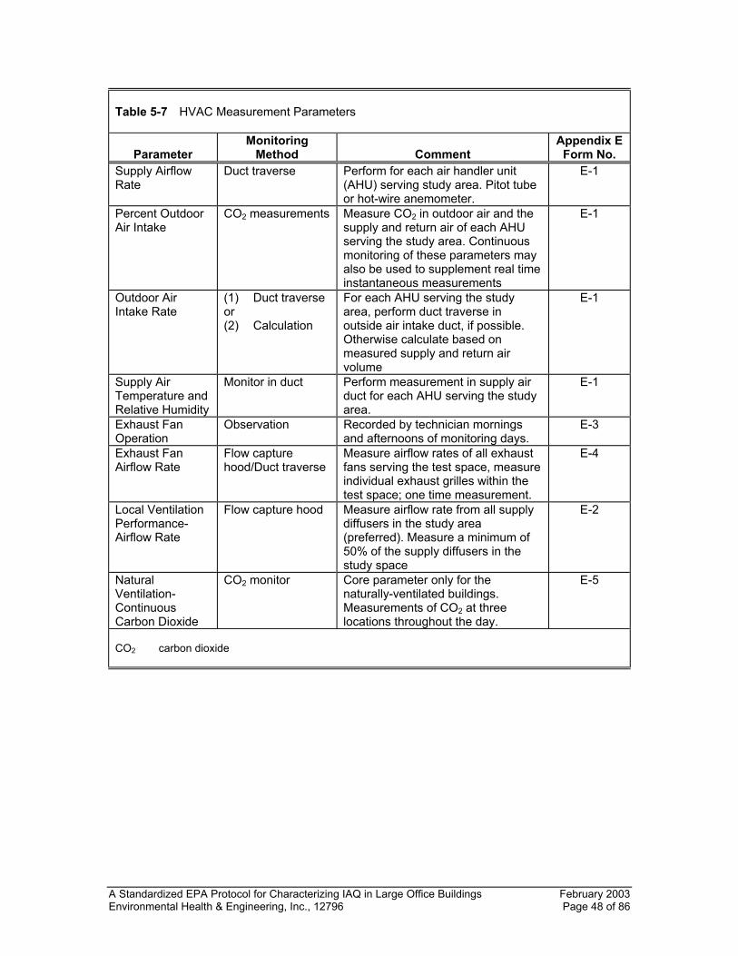
A Standardized EPA Protocol for Characterizing IAQ in Large Office Buildings February 2003 Environmental Health & Engineering, Inc., 12796 Page 48 of 86
Table 5-7 HVAC Measurement Parameters
Parameter
Monitoring Method
Comment
Appendix E Form No.
Supply Airflow Rate
Duct traverse Perform for each air handler unit (AHU) serving study area. Pitot tube or hot-wire anemometer.
E-1
Percent Outdoor Air Intake
CO2 measurements Measure CO2 in outdoor air and the supply and return air of each AHU serving the study area. Continuous monitoring of these parameters may also be used to supplement real time instantaneous measurements
E-1
Outdoor Air Intake Rate
(1) Duct traverse or (2) Calculation
For each AHU serving the study area, perform duct traverse in outside air intake duct, if possible. Otherwise calculate based on measured supply and return air volume
E-1
Supply Air Temperature and Relative Humidity
Monitor in duct Perform measurement in supply air duct for each AHU serving the study area.
E-1
Exhaust Fan Operation
Observation Recorded by technician mornings and afternoons of monitoring days.
E-3
Exhaust Fan Airflow Rate
Flow capture hood/Duct traverse
Measure airflow rates of all exhaust fans serving the test space, measure individual exhaust grilles within the test space; one time measurement.
E-4
Local Ventilation Performance- Airflow Rate
Flow capture hood Measure airflow rate from all supply diffusers in the study area (preferred). Measure a minimum of 50% of the supply diffusers in the study space
E-2
Natural Ventilation- Continuous Carbon Dioxide
CO2 monitor Core parameter only for the naturally-ventilated buildings. Measurements of CO2 at three locations throughout the day.
E-5
CO2 carbon dioxide
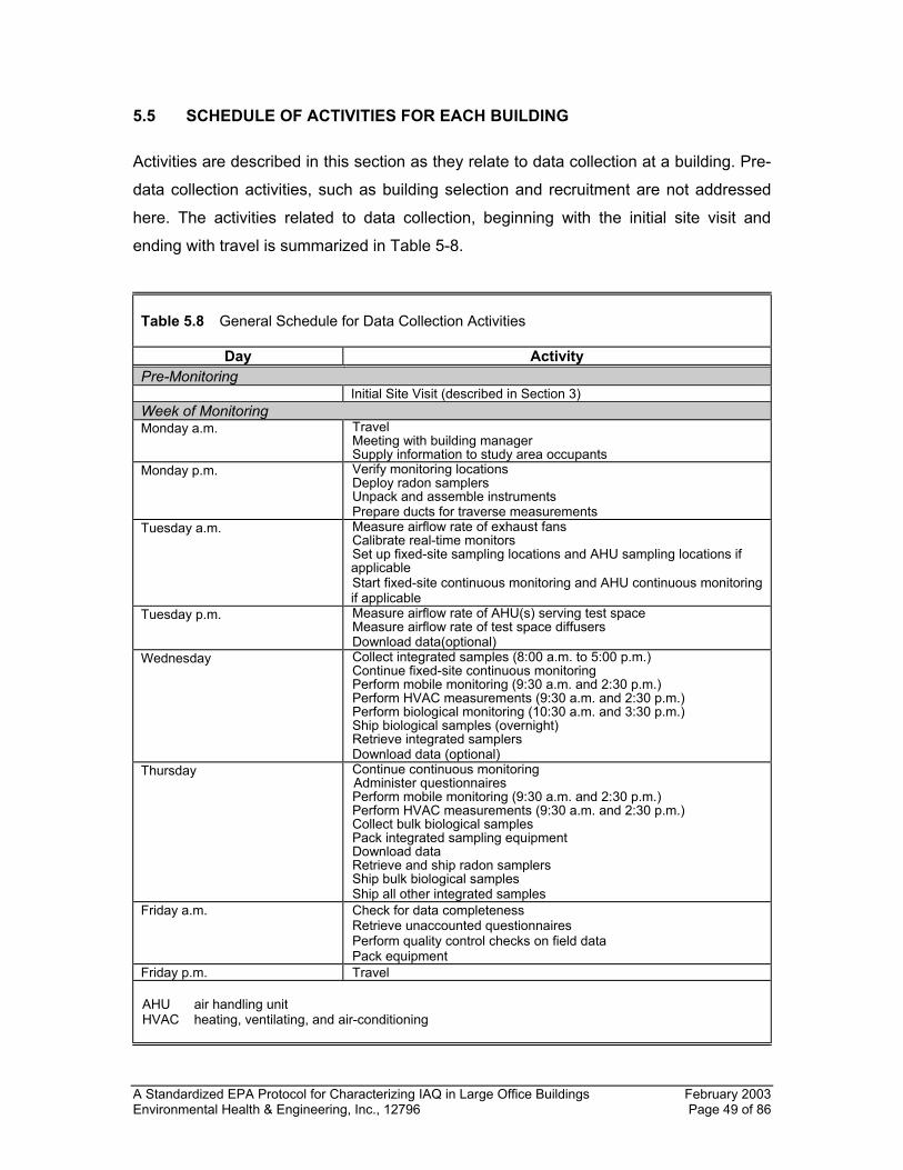
A Standardized EPA Protocol for Characterizing IAQ in Large Office Buildings February 2003 Environmental Health & Engineering, Inc., 12796 Page 49 of 86
5.5 SCHEDULE OF ACTIVITIES FOR EACH BUILDING
Activities are described in this section as they relate to data collection at a building. Pre-
data collection activities, such as building selection and recruitment are not addressed
here. The activities related to data collection, beginning with the initial site visit and
ending with travel is summarized in Table 5-8.
Table 5.8 General Schedule for Data Collection Activities
Day Activity Pre-Monitoring Initial Site Visit (described in Section 3) Week of Monitoring Monday a.m. Travel
Meeting with building manager Supply information to study area occupants
Monday p.m. Verify monitoring locations Deploy radon samplers Unpack and assemble instruments Prepare ducts for traverse measurements
Tuesday a.m. Measure airflow rate of exhaust fans Calibrate real-time monitors Set up fixed-site sampling locations and AHU sampling locations if applicable Start fixed-site continuous monitoring and AHU continuous monitoring if applicable
Tuesday p.m. Measure airflow rate of AHU(s) serving test space Measure airflow rate of test space diffusers Download data(optional)
Wednesday Collect integrated samples (8:00 a.m. to 5:00 p.m.) Continue fixed-site continuous monitoring Perform mobile monitoring (9:30 a.m. and 2:30 p.m.) Perform HVAC measurements (9:30 a.m. and 2:30 p.m.) Perform biological monitoring (10:30 a.m. and 3:30 p.m.) Ship biological samples (overnight) Retrieve integrated samplers Download data (optional)
Thursday Continue continuous monitoring Administer questionnaires Perform mobile monitoring (9:30 a.m. and 2:30 p.m.) Perform HVAC measurements (9:30 a.m. and 2:30 p.m.) Collect bulk biological samples Pack integrated sampling equipment Download data Retrieve and ship radon samplers Ship bulk biological samples Ship all other integrated samples
Friday a.m. Check for data completeness Retrieve unaccounted questionnaires Perform quality control checks on field data Pack equipment
Friday p.m. Travel AHU air handling unit HVAC heating, ventilating, and air-conditioning
A Standardized EPA Protocol for Characterizing IAQ in Large Office Buildings February 2003 Environmental Health & Engineering, Inc., 12796 Page 50 of 86
The field team will arrive at the building by 9:00 a.m. on Monday morning. The field team
leader will meet the building manager, verify the appropriateness of the study area(s)
selected, and make preparations for meeting with the occupants of the study area(s) late
Monday morning. The field team leader will then meet with the occupants of the study
area(s) to briefly explain the study and the monitoring regime. Information pamphlets on
the study will also be distributed at this time. The field technicians will devote Monday
morning to equipment unpacking and preliminary equipment setup.
For the technicians, Monday afternoon and Tuesday will be devoted to: (1) preparation
and calibration of monitoring equipment, (2) preparations for the required HVAC
measurements, (3) measurements of airflow rates of diffusers and exhaust fans in the
study area(s), and (4) set up and flow check of the instrumentation at the fixed outdoor
and indoor sites. The flow of the AHU(s) and diffusers serving the test space will be
measured on Tuesday afternoon. Environmental and comfort monitoring will be
performed on Tuesday afternoon, Wednesday, and Thursday, with the integrated
samples being collected only on Wednesday. Monitoring with the mobile cart at the
indoor mobile sites and HVAC performance measurements will be performed on both
Wednesday and Thursday. Continuous monitoring at the four indoor fixed sites and at
the outdoor site will be initiated on Tuesday afternoon and will continue through late
Thursday afternoon. If continuous CO2 concentrations are monitored in the AHU air
streams, this monitoring will also be initiated on Tuesday afternoon and continue through
late Thursday afternoon.
Radon samplers will be deployed on Monday afternoon, retrieved 72 hours after
deployment, and shipped to the laboratory for Friday analysis. Friday will be devoted to
data validation, checks for data completeness, instrument packing, shipping, and team
travel.
A more detailed day-by-day schedule of activities is presented in Table 5-9. Activities are
listed for the field team leader (FL), two technicians (T-1 and T-2), and a survey
administrator (SA). A team of four should be able to complete all activities at a building
during the five-day week. Initially, during the pre-test or during monitoring at the first one
or two buildings, a fifth team member might be included to ensure that there is no data
loss due to time constraints. However, after gaining experience at some buildings, the
A Standardized EPA Protocol for Characterizing IAQ in Large Office Buildings February 2003 Environmental Health & Engineering, Inc., 12796 Page 51 of 86
four-person team can probably complete all the activities identified in this protocol.
Because of the requirements for a nine-hour monitoring period, the team should expect
to be at the building site at least 11 hours on the two monitoring days (Wednesday and
Thursday).
The field team leader's primary responsibilities relate to supervisory, coordination, quality
control, data processing, sample handling, and documentation activities. It is anticipated
that the field team leader will complete most of the building and study area(s) (test
space) description checklists and the HVAC checklists. In the allocation of activities, the
field leader's time has not been delineated on an hour-by-hour basis. The field team
leader will be available to provide support and assistance to the technicians on an as-
needed basis.
Table 5-9 Schedule of Day-by-Day Activities
Day/Time Activity Team Memberb
MONDAY a.m. Travel
Meet with building manager Review and verify building characteristics and study area Meet with study space occupants
FL, T-1, T-2 FL FL
p.m. Deploy radon samplers Verify monitoring locations Unpack and prepare instrumentation Prepare HVAC ducts for traverses
T-1, T-2 FL FL T-1, T-2
TUESDAY a.m. Finish preparation of ducts
Finish preparation of instrumentation T-2 T-2
p.m. AHU(s) and diffuser flow measurements Exhaust fan airflow rate measurements Calibrate all real-time monitors Set up outdoor sampling site (and shelter) Set up indoor mobile and fixed sites Start fixed site, real-time monitoring Download (optional)
T-2 T-2 T-1, FL T-2, FL T-1, FL T-1, T-2, FL T-1
WEDNESDAY 7:00 – 8:00 a.m. Zero and span outdoor monitors; set-up integrated
outdoor samplers T-2
8:00 – 8:30 a.m. Set up indoor fixed-site integrated sampling locations T-1 8:30 – 9:30 a.m. Zero and span instruments on mobile cart; misc.
activities T-1
9:00 – 9:30 a.m. Prepare for HVAC measurements; misc. activities T-2 9:30 – 10:20 a.m. Perform mobile monitoring at 5 locations; perform
diffuser measurements T-1, FL
A Standardized EPA Protocol for Characterizing IAQ in Large Office Buildings February 2003 Environmental Health & Engineering, Inc., 12796 Page 52 of 86
Table 5-9 Continued
Day/Time Activity Team Memberb
9:30 – 11:00 a.m. Perform HVAC measurements T-2 10:20 a.m. Check exhaust fan operation; move cart to fixed site T-1 10:30 a.m. – 12:00 p.m.
Perform bioaerosol sampling T-1
11:30 a.m. – 12:00 p.m.
Verify all pumps and monitors operating at indoor and outdoor fixed sites
T-2
12:00 – 2:30 p.m. Lunch; misc. activities T-1, T-2 2:30 – 3:20 p.m. Mobile monitoring; diffuser measurements T-1, FL 2:30 – 4:00 p.m. HVAC measurements T-2 3:20 p.m. Check exhaust fan operation; move cart to work area T-1 3:30 – 4:30 p.m. Perform bioaerosol sampling T-1 4:30 – 5:00 p.m. Ship bioaerosol samples to laboratory for delivery on
Thursday morning T-1
4:30 – 5:30 p.m. Retrieve indoor integrated samplers; retrieve outdoor integrated samplers; zero and span outdoor monitors; download datalogger
T-2, FL
5:00 – 6:00 p.m. Zero and span fixed-site indoor monitors; download data loggers
T-1
5:00 – 6:30 p.m. Pack and store samples; complete documentation; misc. activities
FL, T-1, T-2
THURSDAY 7:00 – 8:00 a.m. Zero and span indoor fixed-site monitors T-1 8:30 – 9:00 a.m. Zero and span outdoor fixed-site monitors T-2 9:00 – 9:30 a.m. Zero and span mobile cart monitors; prepare for
measurements T-1, T-2
9:30 – 10:20 a.m. Perform mobile monitoring; diffuser measurements T-1, FL 9:30 – 11:00 a.m. Perform HVAC measurements T-2 10:00 a.m. Distribute questionnaires SA 10:20 a.m. Check exhaust fan operation; move cart to fixed site T-1 10:30 a.m. – 2:30 p.m.
Pack integrated sampling instrumentation; lunch; and misc. activities
T-1, T-2
2:30 – 3:20 p.m. Mobile monitoring; diffuser measurements T-1, FL 2:30 – 4:00 p.m. HVAC measurements T-2 3:00 – 4:00 p.m. Retrieve questionnaires SA p.m. Retrieve radon samplers (72 hours after deployment);
ship to laboratory for Friday analysis T-1, T-2
3:20 p.m. Check exhaust fan operation T-1 3:30 – 4:30 p.m. Zero and span mobile cart monitors T-1 4:30 – 5:00 p.m. Retrieve outdoor monitors; zero and span T-2 5:00 – 6:00 p.m. Download dataloggers T-1 6:00 p.m. – Computer data completeness and quality control check FL 6:00 p.m. Ship other samples to laboratories T-2
A Standardized EPA Protocol for Characterizing IAQ in Large Office Buildings February 2003 Environmental Health & Engineering, Inc., 12796 Page 53 of 86
Table 5-9 Continued
Day/Time Activity Team Memberb
FRIDAY Data Quality Check
Retrieve remaining questionnaires Pack and ship instrumentation Travel
FL SA FL, T-1, T-2
a Activities are generally not delineated for the field team leader (FL). The FL may complete the Test
Space Description checklists (Forms B-1 and B-2, Appendix A) and the Test Space HVAC Description Checklists (Forms C-1 through C-12, Appendix A) on Wednesday or Thursday. The FL will assist in set-up and retrieval of instrumentation, as required. The FL will devote a substantial amount of time to supervisory, quality control, data processing, sample handling, and documentation activities at the building. Note that team responsibilities may often overlap.
b Team members designated as: FL field team leader T1 technician 1 T2 technician 2 SA survey administrator
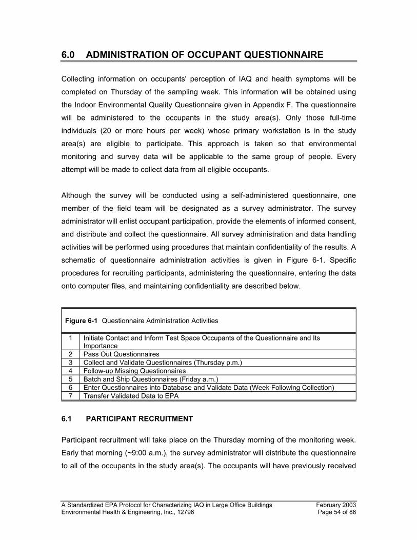
A Standardized EPA Protocol for Characterizing IAQ in Large Office Buildings February 2003 Environmental Health & Engineering, Inc., 12796 Page 54 of 86
6.0 ADMINISTRATION OF OCCUPANT QUESTIONNAIRE
Collecting information on occupants' perception of IAQ and health symptoms will be
completed on Thursday of the sampling week. This information will be obtained using
the Indoor Environmental Quality Questionnaire given in Appendix F. The questionnaire
will be administered to the occupants in the study area(s). Only those full-time
individuals (20 or more hours per week) whose primary workstation is in the study
area(s) are eligible to participate. This approach is taken so that environmental
monitoring and survey data will be applicable to the same group of people. Every
attempt will be made to collect data from all eligible occupants.
Although the survey will be conducted using a self-administered questionnaire, one
member of the field team will be designated as a survey administrator. The survey
administrator will enlist occupant participation, provide the elements of informed consent,
and distribute and collect the questionnaire. All survey administration and data handling
activities will be performed using procedures that maintain confidentiality of the results. A
schematic of questionnaire administration activities is given in Figure 6-1. Specific
procedures for recruiting participants, administering the questionnaire, entering the data
onto computer files, and maintaining confidentiality are described below.
Figure 6-1 Questionnaire Administration Activities 1 Initiate Contact and Inform Test Space Occupants of the Questionnaire and Its
Importance 2 Pass Out Questionnaires 3 Collect and Validate Questionnaires (Thursday p.m.) 4 Follow-up Missing Questionnaires 5 Batch and Ship Questionnaires (Friday a.m.) 6 Enter Questionnaires into Database and Validate Data (Week Following Collection) 7 Transfer Validated Data to EPA
6.1 PARTICIPANT RECRUITMENT
Participant recruitment will take place on the Thursday morning of the monitoring week.
Early that morning (~9:00 a.m.), the survey administrator will distribute the questionnaire
to all of the occupants in the study area(s). The occupants will have previously received
A Standardized EPA Protocol for Characterizing IAQ in Large Office Buildings February 2003 Environmental Health & Engineering, Inc., 12796 Page 55 of 86
an informational brochure that explains the study objectives and the need for their
participation.
The questionnaire will have a tear-off sheet that will be returned to the survey
administrator to assist the administrator in accounting for the return of the
questionnaires. As the survey administrator distributes the questionnaire, they will
provide the following information.
• Reiterate the purpose of the study and describe background information
• Describe the components of the questionnaire and its relationship to the study
• Cover areas of informed consent
− Voluntary
− Can refuse any questions
− Can stop at any time in the survey
− No negative impact of non-participation
− Review benefits/risks
− Data confidentiality
• Explain logistics of survey data collection
6.2 SURVEY ADMINISTRATION
The survey administrator will distribute questionnaires by no later than 10:00 a.m. on
Thursday morning. The cover page of the questionnaire will be numbered prior to
distribution. The survey administrator will have a cross-reference sheet between those
numbers and where the questionnaire is distributed. The questionnaire will be distributed
by going to each work area and individually distributing the questionnaires. All of the
occupants in the study area(s) who are at work must be contacted prior to Thursday to
make them aware of the questionnaire, the purpose of the BASE Study in general, and
what will be done with the responses. Participant recruitment activities may continue
until 2:00 p.m. on Thursday.
A Standardized EPA Protocol for Characterizing IAQ in Large Office Buildings February 2003 Environmental Health & Engineering, Inc., 12796 Page 56 of 86
At the time that the questionnaires are handed out, the survey administrator should
briefly discuss the contents of the questionnaire's four major sections:
• The work place in general—questions about the physical setting of the work area.
• General health and well being—questions about health symptoms experienced over
the last four weeks at work and what happens to those symptoms when away from
work.
• Work place conditions regarding thermal comfort and noise.
• Characteristics of the respondent’s job—questions regarding stress and other
factors. Inform the participants that these questions are asked because many factors
can combine in the office environment to affect how you feel.
The survey administrator will answer any questions about the study or participation,
make sure the participants are aware that they are available for questions throughout the
day, emphasize that any responses will be completely confidential and will not be
discussed with management or union representatives, and indicate that when the
respondent is finished he/she should return the questionnaire by no later than 4:00 p.m.
at a pre-determined drop-off point.
The questionnaire drop-off point will have two separate secured boxes. At the drop-off
point, the respondent will detach the numbered cover page from the remainder of the
questionnaire. The cover page will be placed in the first box, the questionnaire in the
second box. This approach completely separates any identification of the respondent
from the questionnaire and, as a result, ensures confidentiality of the participant's
responses.
At 4:00 p.m. on Thursday, the survey administrator will collect the cover page sheets
from the drop-off point and determine which occupants still have not returned the
questionnaires. The survey administrator will then contact these individuals and prompt
them to complete and return their questionnaires.
A Standardized EPA Protocol for Characterizing IAQ in Large Office Buildings February 2003 Environmental Health & Engineering, Inc., 12796 Page 57 of 86
Individuals absent on Thursday, but who were present on Monday, Tuesday,
Wednesday, and Friday may complete the questionnaire on Friday morning before noon.
Questionnaires distributed or returned on Friday must be flagged to note when they were
returned.
Once the questionnaires are retrieved, the survey administrator will verify that the
questionnaires and cover pages have been separated and there is nothing that can link
a participant with a questionnaire. Questionnaires will then be assigned an ID number. A
chain-of-custody list with all questionnaire ID numbers will then be generated.
The questionnaires and original chain-of-custody list will be returned to the study team's
data processing center using a commercial overnight delivery service.
6.3 DATA ENTRY
All data returned from the field will be logged in; all questionnaires must be accounted
for. Each questionnaire will be reviewed to assure the consistent handling of responses.
Responses on the questionnaires will then be transferred to a file using EPA-provided
software. The transferred data must be checked for completeness. Once all the data has
been checked, the data file will be directly downloaded for entry into the EPA database.
6.4 DATA CONFIDENTIALITY
All data collected as part of the occupant questionnaire must be treated as confidential
data. The following procedures will be used to ensure confidentiality.
• Survey administrators who administer questionnaires must sign a pledge of
confidentiality. As specified in the Privacy Act of 1974, breaches in confidentiality will
result in fines and/or imprisonment.
• All identifiers such as the respondent's name must be removed from the
questionnaire.
• All hard-copy data must be stored in a locked area.
• Data can only be provided in composite form, so that individual identifiers are hidden.
• Individual data files will not be turned over to the government unless subpoenaed.
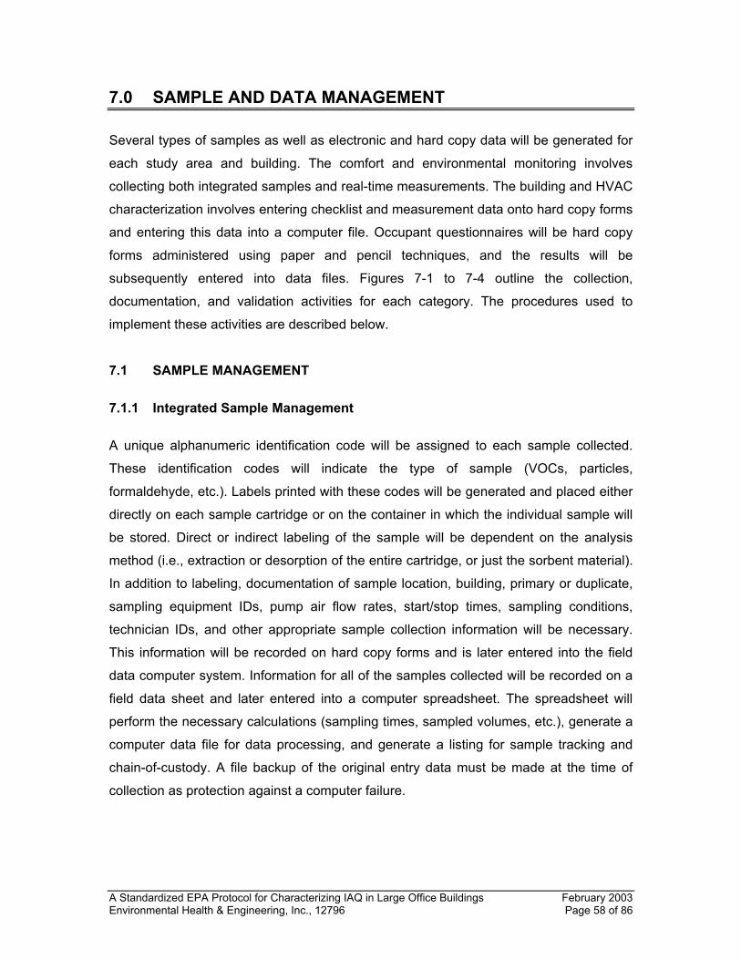
A Standardized EPA Protocol for Characterizing IAQ in Large Office Buildings February 2003 Environmental Health & Engineering, Inc., 12796 Page 58 of 86
7.0 SAMPLE AND DATA MANAGEMENT
Several types of samples as well as electronic and hard copy data will be generated for
each study area and building. The comfort and environmental monitoring involves
collecting both integrated samples and real-time measurements. The building and HVAC
characterization involves entering checklist and measurement data onto hard copy forms
and entering this data into a computer file. Occupant questionnaires will be hard copy
forms administered using paper and pencil techniques, and the results will be
subsequently entered into data files. Figures 7-1 to 7-4 outline the collection,
documentation, and validation activities for each category. The procedures used to
implement these activities are described below.
7.1 SAMPLE MANAGEMENT
7.1.1 Integrated Sample Management
A unique alphanumeric identification code will be assigned to each sample collected.
These identification codes will indicate the type of sample (VOCs, particles,
formaldehyde, etc.). Labels printed with these codes will be generated and placed either
directly on each sample cartridge or on the container in which the individual sample will
be stored. Direct or indirect labeling of the sample will be dependent on the analysis
method (i.e., extraction or desorption of the entire cartridge, or just the sorbent material).
In addition to labeling, documentation of sample location, building, primary or duplicate,
sampling equipment IDs, pump air flow rates, start/stop times, sampling conditions,
technician IDs, and other appropriate sample collection information will be necessary.
This information will be recorded on hard copy forms and is later entered into the field
data computer system. Information for all of the samples collected will be recorded on a
field data sheet and later entered into a computer spreadsheet. The spreadsheet will
perform the necessary calculations (sampling times, sampled volumes, etc.), generate a
computer data file for data processing, and generate a listing for sample tracking and
chain-of-custody. A file backup of the original entry data must be made at the time of
collection as protection against a computer failure.
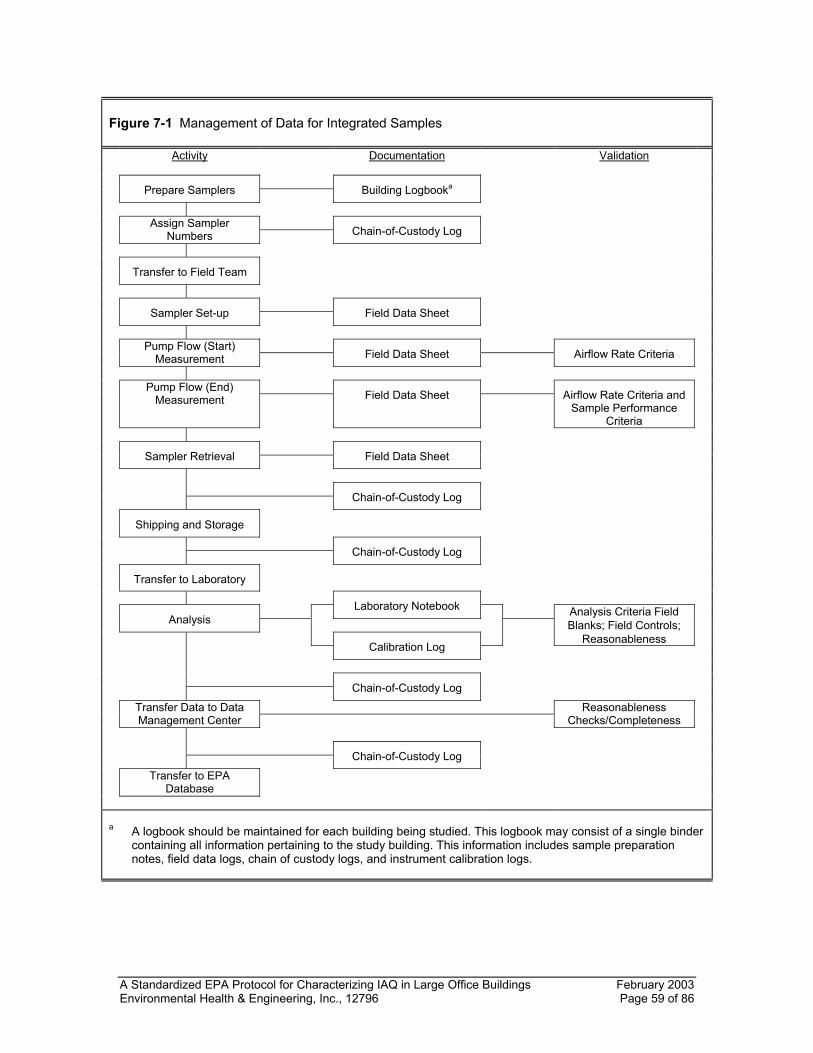
A Standardized EPA Protocol for Characterizing IAQ in Large Office Buildings February 2003 Environmental Health & Engineering, Inc., 12796 Page 59 of 86
Figure 7-1 Management of Data for Integrated Samples Activity Documentation Validation Prepare Samplers Building Logbooka
Assign Sampler Numbers Chain-of-Custody Log
Transfer to Field Team Sampler Set-up Field Data Sheet
Pump Flow (Start) Measurement Field Data Sheet Airflow Rate Criteria
Pump Flow (End) Measurement Field Data Sheet Airflow Rate Criteria and
Sample Performance Criteria
Sampler Retrieval Field Data Sheet Chain-of-Custody Log Shipping and Storage Chain-of-Custody Log Transfer to Laboratory Laboratory Notebook Analysis Criteria Field Analysis Blanks; Field Controls; Reasonableness Calibration Log Chain-of-Custody Log
Transfer Data to Data Management Center
Reasonableness Checks/Completeness
Chain-of-Custody Log
Transfer to EPA Database
a A logbook should be maintained for each building being studied. This logbook may consist of a single binder
containing all information pertaining to the study building. This information includes sample preparation notes, field data logs, chain of custody logs, and instrument calibration logs.
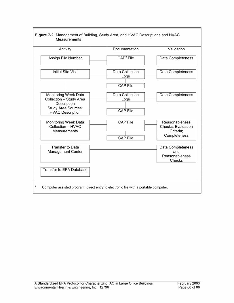
A Standardized EPA Protocol for Characterizing IAQ in Large Office Buildings February 2003 Environmental Health & Engineering, Inc., 12796 Page 60 of 86
Figure 7-2 Management of Building, Study Area, and HVAC Descriptions and HVAC
Measurements Activity Documentation Validation
Assign File Number
CAPa File Data Completeness
Initial Site Visit
Data Collection Logs
Data Completeness
CAP File
Data Collection Logs
Data Completeness
Monitoring Week Data Collection – Study Area
Description Study Area Sources; HVAC Description
CAP File
CAP File
Monitoring Week Data Collection – HVAC
Measurements
CAP File
Reasonableness
Checks; Evaluation Criteria;
Completeness
Transfer to Data
Management Center Data Completeness
and Reasonableness
Checks
Transfer to EPA Database
a Computer assisted program; direct entry to electronic file with a portable computer.
A Standardized EPA Protocol for Characterizing IAQ in Large Office Buildings February 2003 Environmental Health & Engineering, Inc., 12796 Page 61 of 86
Figure 7-3 Sample Management for Real-Time Monitoring Data Activity Documentation Validation
Monitor Validation (Accuracy Precision Resolution, Limit of
Detection)
Instrumentation Log
Performance Criteria
Building Start Multipoint
Calibration Calibration Log
Calibration/
Performance Criteria
Zero and Span, Day 1, a.m.
Zero and Span Log
Performance Criteria
Data Collection
Fixed-Site Monitoring Log or Portable Monitoring Log
Reasonableness
Checks
Zero and Span, Day 1
Zero and Span Log
Performance Criteria
End of Day Download
File Name
Data Completeness/ Reasonableness
Evaluation
Zero and Span, Day 2
Zero and Span Log
Performance Criteria
Data Collection
Fixed-Site Monitoring Log or Portable Monitoring Log
Reasonableness
Checks
Building End Multipoint
Calibration Calibration Log
Calibration/
Performance Criteria
Data Download
File Name
Data Completeness/ Reasonableness
Evaluation
Chain-of-Custody Log
Data Processing
Processing Checks/Manual
Calculations/ Reasonableness
Checks
Chain-of-Custody Log
Transfer to Data Management
Center Data Completeness/
Validation
Chain-of-Custody Log
Transfer to EPA Database
A Standardized EPA Protocol for Characterizing IAQ in Large Office Buildings February 2003 Environmental Health & Engineering, Inc., 12796 Page 62 of 86
Figure 7-4 Management of Occupant Questionnaire Data Activity Documentation Validation
Distribute Occupant Questionnaire
Confidential ID Number and Location
Completeness
Collect Occupant
Questionnaire, Separate Cover Page
Confidential ID
Number and Location Completeness
Assign Sample ID Number to
Each Questionnaire Chain of Custody Log
Transfer Occupant
Questionnaire to Data Transfer Center
Chain of Custody Log
Completeness
Enter Data Manually or
Using an Optical Scanner Computer Log
Completeness
Transfer to EPA database
All sampling materials and supplies will be transported to and from the field under the
direction of the field team leader. The field team leader or designated sample custodian
will be responsible for the proper storage and shipment of samples while in the field.
Samples will be stored and shipped according to the procedures outlined in the specific
sampling protocols. These procedures include:
• For inhalable particles, hand-carry the filters, if possible; overnight shipment
otherwise. Filters are stored in a temperature- and humidity-controlled environment
and allowed to condition for at least 24 hours before tare and gross weighing.
• For formaldehyde and acetaldehyde, exposed cartridges are resealed in culture
tubes, placed inside sealed, uncoated paint cans, then shipped overnight to the
laboratory in cushioned, hard-sided shipping containers. The cartridges are stored in
a "clean" freezer at 4 degrees Celsius for no more than four weeks before analysis.
• For VOCs, SUMMA® canisters are separated from their flow controllers, inlets are
capped, and the cans are re-packed in their shipping box. For multisorbent tubes,
exposed cartridges are capped with swage locks and placed in glass vials. Upon
A Standardized EPA Protocol for Characterizing IAQ in Large Office Buildings February 2003 Environmental Health & Engineering, Inc., 12796 Page 63 of 86
packing with bubble wrap, samplers are packaged with ice packs and secured in
hard-sided shipment coolers.
• For bioaerosols, the samples are stored in well-insulated boxes. They must be
received at the laboratory within 24 hours following collection. Sample incubation
begins as soon as possible after receipt at the laboratory. Slides used for collecting
fungal spores are secured in slide containers prior to overnight delivery.
• For radon, overnight Thursday shipment is required.
Samples will be sent directly to the analyzing laboratory from the field. A Chain-of-
Custody/Sample Tracking List will be included with each shipment. Receipt of the
samples will require visual inspection of each sample for damage and appropriate
notations made on the Chain-of-Custody/Sample Tracking List followed by proper
storage.
7.1.2 Management of Real-Time Monitoring Data
Real-time sample data will consist of electronic computer files generated by downloading
recorded data from dataloggers. Real-time samples will be collected at fixed-site
locations with stationary monitors. A unique alphanumeric identification code will be
assigned to each sample collected. These identification codes will indicate the type of
sample (CO, CO2, etc.), the building being sampled, the sampling location, and sample
type (mobile, fixed, duplicate, and monitoring time). A Fixed Site Monitoring Log and a
Portable Monitoring Log will be used to record pertinent information. The Fixed Site
Monitoring Log will document sampling locations, start and stop times, monitor IDs, and
data filenames for stored data. The Portable Monitoring Log will document the locations
sampled and the time of sampling at each location. This information will be used in
conjunction with the datalogger information to assign location identifications to the
concentrations recorded by the datalogger. This log will also document the monitor IDs
and data filenames.
At the end of the monitoring period, the dataloggers will be downloaded to a portable
computer using the appropriate interfacing hardware and program software. The
A Standardized EPA Protocol for Characterizing IAQ in Large Office Buildings February 2003 Environmental Health & Engineering, Inc., 12796 Page 64 of 86
datalogger software will prompt the necessary entry information. In general, the
datalogger start time, monitor ID, input channel, monitoring location, sample ID, and
operator ID will be entered. The data will be viewed on the computer screen to verify
successful downloading. Once verified, a unique filename will be assigned and the data
saved under that filename. The filename will be recorded on the appropriate monitoring
log. Verification of the file's existence will be checked by viewing the file listing. Backup
files will be copied to diskettes to protect against loss of data due to computer failure.
The dataloggers will not be turned off until all data have been successfully retrieved,
saved, backed up, and reviewed by the field team leader to check for completeness and
reasonableness. Diskettes will be labeled and delivered to the field team leader. Data
that does not appear reasonable will be flagged by the field team leader using the Fixed
Site Monitoring Log so that further review can be conducted during the data validation
process (Section 7.3). No data will be deleted from the downloaded file during the
sampling week.
7.1.3 HVAC Measurement Data
HVAC measurement data will be entered onto appropriate logsheets and subsequently
entered to an electronic file using a portable computer. All logsheets will be maintained
in the building logbook. Within each file, the date of the test, the time of day, and the
measurement location (e.g., air handler number, exhaust fan, diffuser) will be entered
into the file. Each data file will be assigned a unique alphanumeric identification code.
The identification code will indicate the measurement parameters (e.g., supply airflow
rate), the building being sampled, and the sampling date and time (e.g., a.m. or p.m. for
supply airflow rate). At the end of the day, the field team leader will review the files for
reasonableness of the entries and for completeness. A backup file will be copied to a
diskette to protect against the loss of data due to computer failure. Back-up diskettes will
be labeled, as appropriate, and stored separately from the computer.
7.1.4 Building, Study Area(s), and HVAC Description Checklists
The information collected on the building and study area description and source
information checklists and the HVAC system description checklists will be entered onto
appropriate logsheets and subsequently entered into an electronic file using a portable
computer. All logsheets will be maintained in the building logbook. Each data file will be
A Standardized EPA Protocol for Characterizing IAQ in Large Office Buildings February 2003 Environmental Health & Engineering, Inc., 12796 Page 65 of 86
assigned a unique alphanumeric identification code. The identification code will indicate
the building, date and time, and the checklist. Prior to completion of activities at the
building, the field team leader will review the file to check for reasonableness of entries
and completeness. A backup file will be copied to a diskette.
7.1.5 Occupant Questionnaire
The on-site survey administrator will retrieve and process all occupant questionnaires on
Thursday or Friday morning. Questionnaires will be turned in and compared to the
distribution list. The survey administrator will attempt to retrieve all the questionnaires
that were distributed, consistent with the rights of participants to refuse to complete the
document.
Once questionnaires are retrieved, the survey administrator will verify that the
questionnaires and informed consent documents have been separated and there is
nothing that can link a participant's name with a questionnaire. Questionnaires will then
be assigned an ID number. A chain-of-custody list with all questionnaire ID numbers will
then be generated.
The questionnaires and original chain-of-custody list will be returned to the study team's
data processing center using a commercial overnight delivery service. A copy of the
chain-of-custody list should be sent separately. Documentation of chain-of-custody will
be maintained throughout the shipping and processing of the questionnaires.
7.2 DATA REDUCTION
Data reduction procedures for each of the measurement parameters are given in
Table 7-1. For real-time measurements, instrumental output is used directly. For
integrated samples, results are generated from the calibration curve for the analytical
instrument used to make the measurement. Measurement corrections are not made for
zero offset, calibration drift, contamination of field blanks, or recovery on field controls.
For real-time measurements, data output will be reduced to five-minute averages for
fixed site monitors. Integrated sample concentrations will be calculated by dividing
measured mass by sample air volume. Quantitative results will be reported for
A Standardized EPA Protocol for Characterizing IAQ in Large Office Buildings February 2003 Environmental Health & Engineering, Inc., 12796 Page 66 of 86
measurements below the minimum quantitation level with a designation of -98.
Measurements detected below the limit of detection will be designated as -97. Other
coding designations shall be -99 (exceeding calibration standard), -96 (not applicable or
incalculable), and -95 (sample voided by field team or analytical laboratory).
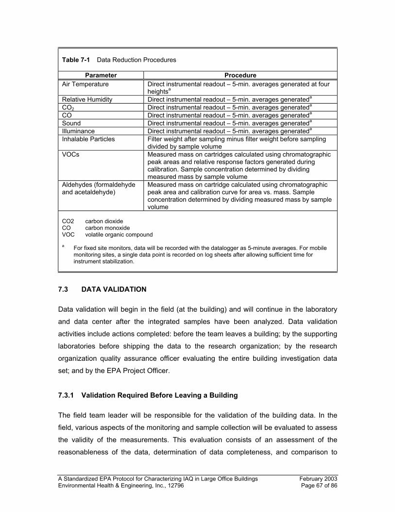
A Standardized EPA Protocol for Characterizing IAQ in Large Office Buildings February 2003 Environmental Health & Engineering, Inc., 12796 Page 67 of 86
Table 7-1 Data Reduction Procedures
Parameter Procedure Air Temperature Direct instrumental readout – 5-min. averages generated at four
heightsa Relative Humidity Direct instrumental readout – 5-min. averages generateda CO2 Direct instrumental readout – 5-min. averages generateda CO Direct instrumental readout – 5-min. averages generateda Sound Direct instrumental readout – 5-min. averages generateda Illuminance Direct instrumental readout – 5-min. averages generateda Inhalable Particles Filter weight after sampling minus filter weight before sampling
divided by sample volume VOCs Measured mass on cartridges calculated using chromatographic
peak areas and relative response factors generated during calibration. Sample concentration determined by dividing measured mass by sample volume
Aldehydes (formaldehyde and acetaldehyde)
Measured mass on cartridge calculated using chromatographic peak area and calibration curve for area vs. mass. Sample concentration determined by dividing measured mass by sample volume
CO2 carbon dioxide CO carbon monoxide VOC volatile organic compound a For fixed site monitors, data will be recorded with the datalogger as 5-minute averages. For mobile
monitoring sites, a single data point is recorded on log sheets after allowing sufficient time for instrument stabilization.
7.3 DATA VALIDATION
Data validation will begin in the field (at the building) and will continue in the laboratory
and data center after the integrated samples have been analyzed. Data validation
activities include actions completed: before the team leaves a building; by the supporting
laboratories before shipping the data to the research organization; by the research
organization quality assurance officer evaluating the entire building investigation data
set; and by the EPA Project Officer.
7.3.1 Validation Required Before Leaving a Building
The field team leader will be responsible for the validation of the building data. In the
field, various aspects of the monitoring and sample collection will be evaluated to assess
the validity of the measurements. This evaluation consists of an assessment of the
reasonableness of the data, determination of data completeness, and comparison to
A Standardized EPA Protocol for Characterizing IAQ in Large Office Buildings February 2003 Environmental Health & Engineering, Inc., 12796 Page 68 of 86
criteria defined for specific parameters, such as pump flow rates and real-time monitor
calibrations. If data do not appear to be valid or do not meet validation criteria, they will
be flagged and verified. Information and data completeness will be verified by the field
team leader by reviewing the documentation collected and stored in the building
logbook. Any information not collected should be collected prior to leaving the building.
Reasonableness checks and evaluation criteria are summarized in Table 7-2. Note that
some reasonableness criteria cannot be verified until results are received from the
analytical laboratories.
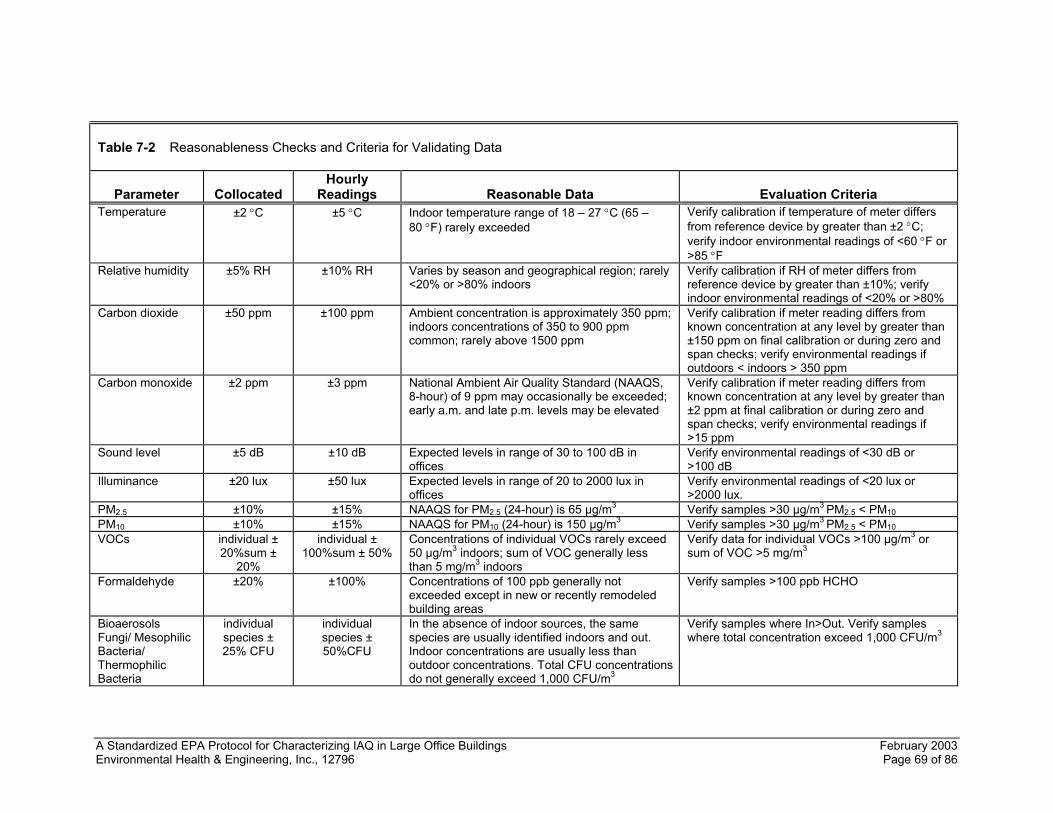
A Standardized EPA Protocol for Characterizing IAQ in Large Office Buildings February 2003 Environmental Health & Engineering, Inc., 12796 Page 69 of 86
Table 7-2 Reasonableness Checks and Criteria for Validating Data
Parameter
Collocated
Hourly Readings
Reasonable Data
Evaluation Criteria
Temperature ±2 °C ±5 °C Indoor temperature range of 18 – 27 °C (65 – 80 °F) rarely exceeded
Verify calibration if temperature of meter differs from reference device by greater than ±2 °C; verify indoor environmental readings of <60 °F or >85 °F
Relative humidity ±5% RH ±10% RH Varies by season and geographical region; rarely <20% or >80% indoors
Verify calibration if RH of meter differs from reference device by greater than ±10%; verify indoor environmental readings of <20% or >80%
Carbon dioxide ±50 ppm ±100 ppm Ambient concentration is approximately 350 ppm; indoors concentrations of 350 to 900 ppm common; rarely above 1500 ppm
Verify calibration if meter reading differs from known concentration at any level by greater than ±150 ppm on final calibration or during zero and span checks; verify environmental readings if outdoors < indoors > 350 ppm
Carbon monoxide ±2 ppm ±3 ppm National Ambient Air Quality Standard (NAAQS, 8-hour) of 9 ppm may occasionally be exceeded; early a.m. and late p.m. levels may be elevated
Verify calibration if meter reading differs from known concentration at any level by greater than ±2 ppm at final calibration or during zero and span checks; verify environmental readings if >15 ppm
Sound level ±5 dB ±10 dB Expected levels in range of 30 to 100 dB in offices
Verify environmental readings of <30 dB or >100 dB
Illuminance ±20 lux ±50 lux Expected levels in range of 20 to 2000 lux in offices
Verify environmental readings of <20 lux or >2000 lux.
PM2.5 ±10% ±15% NAAQS for PM2.5 (24-hour) is 65 µg/m3 Verify samples >30 µg/m3 PM2.5 < PM10 PM10 ±10% ±15% NAAQS for PM10 (24-hour) is 150 µg/m3 Verify samples >30 µg/m3 PM2.5 < PM10 VOCs individual ±
20%sum ± 20%
individual ± 100%sum ± 50%
Concentrations of individual VOCs rarely exceed 50 µg/m3 indoors; sum of VOC generally less than 5 mg/m3 indoors
Verify data for individual VOCs >100 µg/m3 or sum of VOC >5 mg/m3
Formaldehyde ±20% ±100% Concentrations of 100 ppb generally not exceeded except in new or recently remodeled building areas
Verify samples >100 ppb HCHO
Bioaerosols Fungi/ Mesophilic Bacteria/ Thermophilic Bacteria
individual species ± 25% CFU
individual species ± 50%CFU
In the absence of indoor sources, the same species are usually identified indoors and out. Indoor concentrations are usually less than outdoor concentrations. Total CFU concentrations do not generally exceed 1,000 CFU/m3
Verify samples where In>Out. Verify samples where total concentration exceed 1,000 CFU/m3
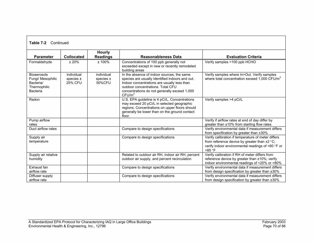
A Standardized EPA Protocol for Characterizing IAQ in Large Office Buildings February 2003 Environmental Health & Engineering, Inc., 12796 Page 70 of 86
Table 7-2 Continued
Parameter
Collocated
Hourly Readings
Reasonableness Data
Evaluation Criteria
Formaldehyde ± 20% ± 100% Concentrations of 100 ppb generally not exceeded except in new or recently remodeled building areas
Verify samples >100 ppb HCHO
Bioaerosols Fungi/ Mesophilic Bacteria/ Thermophilic Bacteria
individual species ± 25% CFU
individual species ± 50%CFU
In the absence of indoor sources, the same species are usually identified indoors and out. Indoor concentrations are usually less than outdoor concentrations. Total CFU concentrations do not generally exceed 1,000 CFU/m3
Verify samples where In>Out. Verify samples where total concentration exceed 1,000 CFU/m3
Radon U.S. EPA guideline is 4 pCi/L. Concentrations may exceed 20 pCi/L in selected geographic regions. Concentrations on upper floors should generally be lower than on the ground contact floor.
Verify samples >4 pCi/L
Pump airflow rates
Verify if airflow rates at end of day differ by greater than ±10% from starting flow rates
Duct airflow rates Compare to design specifications Verify environmental data if measurement differs from specification by greater than ±30%
Supply air temperature
Compare to design specifications Verify calibration if temperature of meter differs from reference device by greater than ±2 °C; verify indoor environmental readings of <60 °F or >85 °F
Supply air relative humidity
Related to outdoor air RH, indoor air RH, percent outdoor air supply, and percent recirculation
Verify calibration if RH of meter differs from reference device by greater than ±10%; verify indoor environmental readings of <20% or >80%
Exhaust fan airflow rate
Compare to design specifications Verify environmental data if measurement differs from design specification by greater than ±30%
Diffuser supply airflow rate
Compare to design specifications Verify environmental data if measurement differs from design specification by greater than ±30%
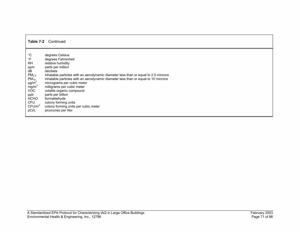
A Standardized EPA Protocol for Characterizing IAQ in Large Office Buildings February 2003 Environmental Health & Engineering, Inc., 12796 Page 71 of 86
Table 7-2 Continued °C degrees Celsius °F degrees Fahrenheit RH relative humidity ppm parts per million dB decibels PM2.5 inhalable particles with an aerodynamic diameter less than or equal to 2.5 microns PM10 inhalable particles with an aerodynamic diameter less than or equal to 10 microns µg/m3 micrograms per cubic meter mg/m3 milligrams per cubic meter VOC volatile organic compound ppb parts per billion HCHO formaldehyde CFU colony forming units CFU/m3 colony forming units per cubic meter pCi/L picocuries per liter

A Standardized EPA Protocol for Characterizing IAQ in Large Office Buildings February 2003 Environmental Health & Engineering, Inc., 12796 Page 72 of 86
On Thursday, the Field Team Leader will conduct an inventory of the building study data
to ensure completeness of data collection. The continuous monitor data will also be
reviewed to ensure that the data fall within the reasonableness checks reflected in
Table 7-2. Data completeness and data review should be conducted on Thursday night
so that any questionable or missing data can be reviewed and updated as appropriate to
include narrative statements supporting the out-of-expected-range values.
In-field data validation for integrated samples will also include the following checks on
data quality:
• Within-control analytical conditions will be verified and data generated under
conditions judged to be out-of-control will be noted.
• The mechanism used to transmit raw data from the analyst to the individual
responsible for their quantitation, compilation, and batching will be reviewed.
• The concentration calculations of a random subset (10%) of the raw data will be re-
calculated. This will consist of re-entering the input data on computer programs used
originally for this purpose.
Prior to transmitting data to the research organization study team leader, the field team
leader shall review all of the entered field and analytical data to assess the
reasonableness of the data being reported. The cause for missing data will be
investigated and reported quantitation limits will be verified. After data entry, all of the
keyed material will be summarized on a control file printout. This will provide information
regarding the completeness of the file and will indicate samples that were scheduled for
collection, but for which there are no data.
7.3.2 Validation Required By the Supporting Laboratories
The analysis team leader will be responsible for the validation of the results of
environmental analysis. These checks include ensuring appropriate chain-of-custody
documentation, acceptable calibration and control sample analysis, and other
procedures employed by the research organization to ensure high quality data are
A Standardized EPA Protocol for Characterizing IAQ in Large Office Buildings February 2003 Environmental Health & Engineering, Inc., 12796 Page 73 of 86
reported. The analysis team leader will also ensure that the results of analysis are
submitted to the study team leader in the appropriate electronic and hardcopy formats.
The required templates for each type of sample are provided in Tables 7-3 through 7-12.
7.3.3 Validation Required by the Research Organization Quality Assurance Officer and Study Team Leader
The research organization quality assurance officer and study team leader will review all
of the building study data following the field and laboratory validation steps. They will
ensure the validity, completeness, reasonableness, and appropriate formatting of the
entire data set. This validation process should ensure that all of the data fall within the
expected ranges reflected in Table 7-2 or that explanations are provided when the data
fall outside these expected ranges.
As shown in Table 7-2, the reasonableness of measurements with real-time monitors for
temperature, relative humidity, CO, and CO2 can be evaluated on a continuing basis by
comparison to expected readings. For example, the National Ambient Air Quality
Standard (eight-hour) for CO of 9 parts per million (ppm) may be exceeded in some
areas of the country, but both indoor and outdoor concentrations are usually below
9 ppm. Data for CO can also be evaluated by comparing indoor and outdoor levels,
which are usually similar unless there is a significant source (e.g., an attached parking
garage) contributing to indoor levels. For CO2, guidelines for reasonableness of data are
also presented in Table 7-2. If elevated levels of CO or CO2 are detected indoors, the
reasonableness of the readings can be verified by comparison to other monitors indoors
and/or outdoors.
For temperature, relative humidity, CO, CO2, light, and sound level, Table 7-2 also
presents evaluation criteria for monitor performance that will be used to verify data. The
criteria apply to both daily zero and span checks for CO and CO2 and to the calibration
checks performed at the end of the two days of monitoring. If the criteria for CO and CO2
are not met during a zero and span check, the meter reading should be checked at
different concentration levels to determine if the problem is related to the monitor or the
calibration gas.
A Standardized EPA Protocol for Characterizing IAQ in Large Office Buildings February 2003 Environmental Health & Engineering, Inc., 12796 Page 74 of 86
Concentrations of VOCs, formaldehyde, PM2.5, PM10, and radon should be compared to
reasonable levels expected in office building environments. As indicated in Table 7-2,
when extremely high values that may be outliers are measured, acceptable performance
for the measurement system should be verified immediately and documented. The
reason for the elevated levels should be investigated.
7.3.4 Submitting Data to the EPA Project Officer
Data will be delivered to the EPA Project Officer after it has been fully evaluated and
verified by the research group. The validated data (including field data, results data,
building characteristic data, questionnaire responses, etc.) will be processed and saved
in the database system specifically developed for the study. The data set should not
include voided data, unvalidated data, flow checks or spans, or other unexplained data
variables. Results of data that have been voided shall be removed and replaced with the
appropriate code used for this purpose. The submittal of data to EPA will be based on
the submittal requirements of the EPA Project Officer. This may be on a building-by-
building basis, or on a study season basis if multiple building are studied consecutively.
7.3.5 Validation by the EPA Project Officer
One the dataset is received by EPA, the EPA Project Officer conduct a final validation
and verification check on the data. The EPA Project Officer will validate the acceptability
of the electronically transferred data and report findings to the research group.
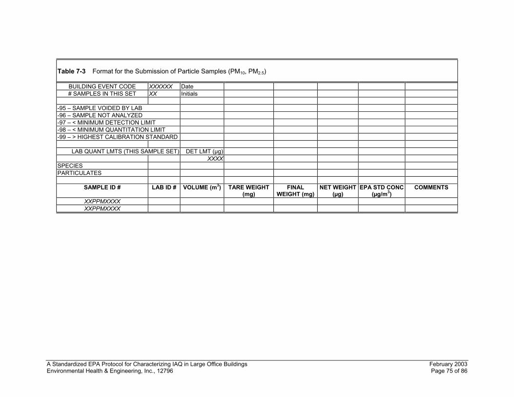
A Standardized EPA Protocol for Characterizing IAQ in Large Office Buildings February 2003 Environmental Health & Engineering, Inc., 12796 Page 75 of 86
Table 7-3 Format for the Submission of Particle Samples (PM10, PM2.5)
BUILDING EVENT CODE XXXXXX Date # SAMPLES IN THIS SET XX Initials
-95 – SAMPLE VOIDED BY LAB -96 – SAMPLE NOT ANALYZED -97 – < MINIMUM DETECTION LIMIT -98 – < MINIMUM QUANTITATION LIMIT -99 – > HIGHEST CALIBRATION STANDARD
LAB QUANT LMTS (THIS SAMPLE SET) DET LMT (µg)
XXXX SPECIES PARTICULATES
SAMPLE ID # LAB ID # VOLUME (m3) TARE WEIGHT
(mg) FINAL
WEIGHT (mg) NET WEIGHT
(µg) EPA STD CONC
(µg/m3) COMMENTS
XXPPMXXXX XXPPMXXXX
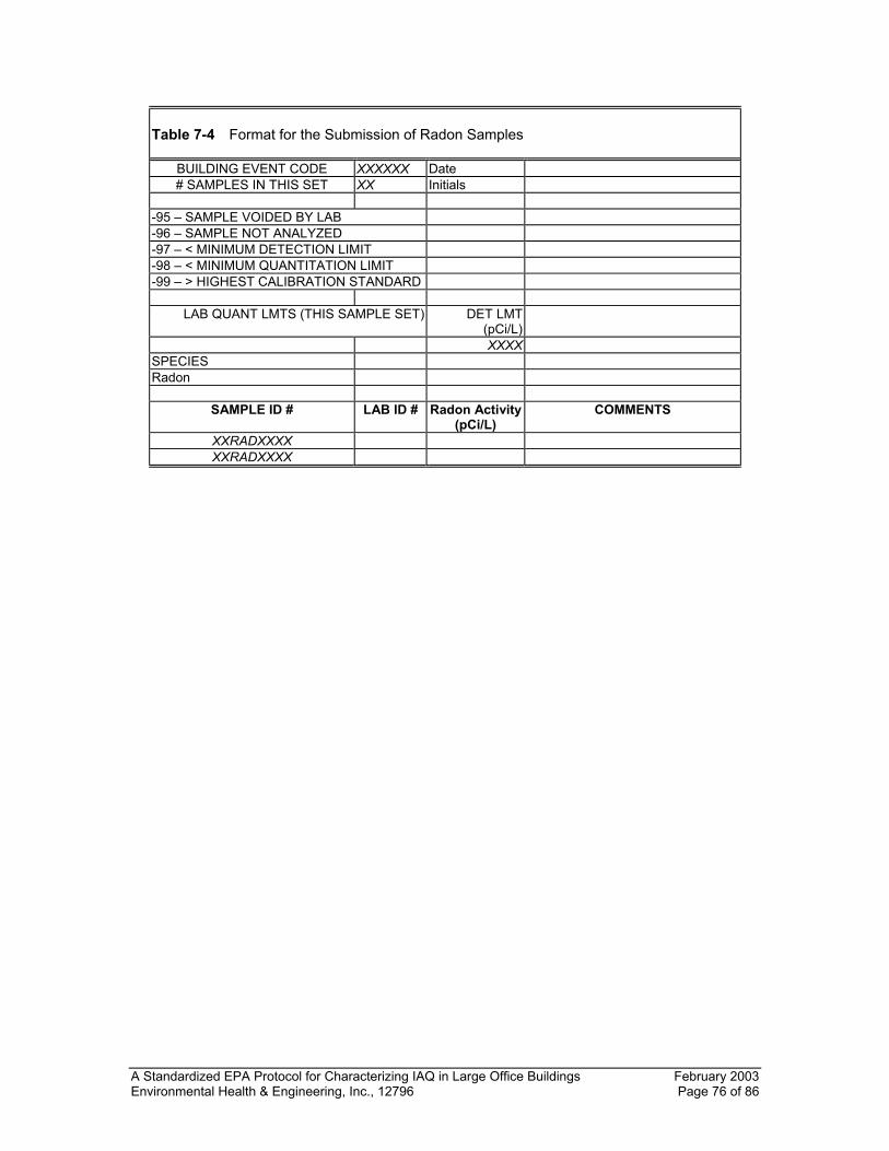
A Standardized EPA Protocol for Characterizing IAQ in Large Office Buildings February 2003 Environmental Health & Engineering, Inc., 12796 Page 76 of 86
Table 7-4 Format for the Submission of Radon Samples
BUILDING EVENT CODE XXXXXX Date # SAMPLES IN THIS SET XX Initials
-95 – SAMPLE VOIDED BY LAB -96 – SAMPLE NOT ANALYZED -97 – < MINIMUM DETECTION LIMIT -98 – < MINIMUM QUANTITATION LIMIT -99 – > HIGHEST CALIBRATION STANDARD
LAB QUANT LMTS (THIS SAMPLE SET) DET LMT
(pCi/L) XXXX
SPECIES Radon
SAMPLE ID # LAB ID # Radon Activity
(pCi/L) COMMENTS
XXRADXXXX XXRADXXXX
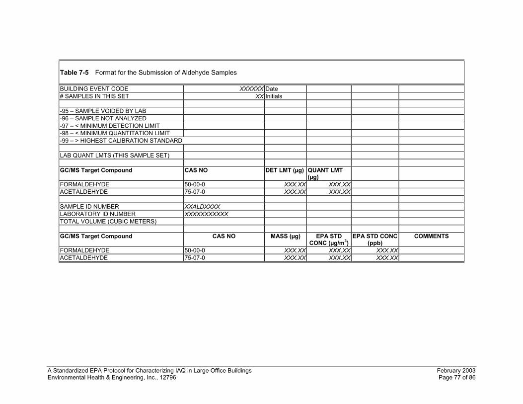
A Standardized EPA Protocol for Characterizing IAQ in Large Office Buildings February 2003 Environmental Health & Engineering, Inc., 12796 Page 77 of 86
Table 7-5 Format for the Submission of Aldehyde Samples BUILDING EVENT CODE XXXXXX Date # SAMPLES IN THIS SET XX Initials
-95 – SAMPLE VOIDED BY LAB -96 – SAMPLE NOT ANALYZED -97 – < MINIMUM DETECTION LIMIT -98 – < MINIMUM QUANTITATION LIMIT -99 – > HIGHEST CALIBRATION STANDARD
LAB QUANT LMTS (THIS SAMPLE SET)
GC/MS Target Compound CAS NO DET LMT (µg) QUANT LMT
(µg)
FORMALDEHYDE 50-00-0 XXX.XX XXX.XXACETALDEHYDE 75-07-0 XXX.XX XXX.XX SAMPLE ID NUMBER XXALDXXXX LABORATORY ID NUMBER XXXXXXXXXXX TOTAL VOLUME (CUBIC METERS) GC/MS Target Compound CAS NO MASS (µg) EPA STD
CONC (µg/m3)EPA STD CONC
(ppb) COMMENTS
FORMALDEHYDE 50-00-0 XXX.XX XXX.XX XXX.XXACETALDEHYDE 75-07-0 XXX.XX XXX.XX XXX.XX
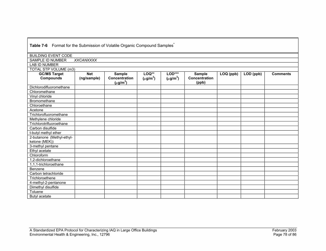
A Standardized EPA Protocol for Characterizing IAQ in Large Office Buildings February 2003 Environmental Health & Engineering, Inc., 12796 Page 78 of 86
Table 7-6 Format for the Submission of Volatile Organic Compound Samples* BUILDING EVENT CODE SAMPLE ID NUMBER XXCANXXXX LAB ID NUMBER TOTAL STP VOLUME (m3)
GC/MS Target Compounds
Net (ng/sample)
Sample Concentration
(µg/m3)
LOQ** (µg/m3)
LOD*** (µg/m3)
Sample Concentration
(ppb)
LOQ (ppb) LOD (ppb) Comments
Dichlorodifluoromethane Chloromethane Vinyl chloride Bromomethane Chloroethane Acetone Trichlorofluoromethane Methylene chloride Trichlorotrifluoroethane Carbon disulfide t-butyl methyl ether 2-butanone (Methyl-ethyl-ketone (MEK))
3-methyl pentane Ethyl acetate Chloroform 1,2-dichloroethane 1,1,1-trichloroethane Benzene Carbon tetrachloride Trichloroethene 4-methyl-2-pentanone Dimethyl disulfide Toluene Butyl acetate
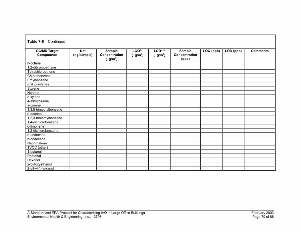
A Standardized EPA Protocol for Characterizing IAQ in Large Office Buildings February 2003 Environmental Health & Engineering, Inc., 12796 Page 79 of 86
Table 7-6 Continued
GC/MS Target Compounds
Net (ng/sample)
Sample Concentration
(µg/m3)
LOQ** (µg/m3)
LOD*** (µg/m3)
Sample Concentration
(ppb)
LOQ (ppb) LOD (ppb) Comments
n-octane 1,2-dibromoethane Tetrachloroethene Chlorobenzene Ethylbenzene m & p-xylenes Styrene Nonane o-xylene 4-ethyltoluene a-pinene 1,3,5-trimethylbenzene n-decane 1,2,4-trimethylbenzene 1,4-dichlorobenzene d-limonene 1,2-dichlorobenzene n-undecane n-dodecane Naphthalene TVOC (other) 1-butanol Pentanal Hexanal 2-butoxyethanol 2-ethyl-1-hexanol
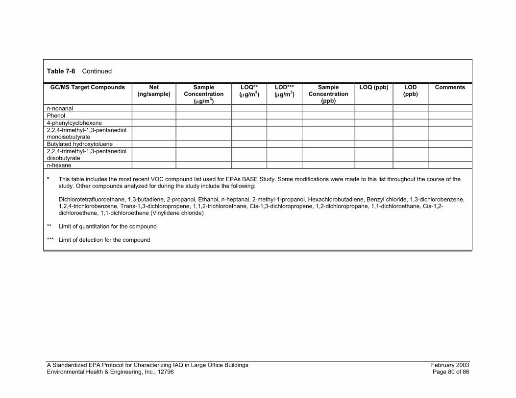
A Standardized EPA Protocol for Characterizing IAQ in Large Office Buildings February 2003 Environmental Health & Engineering, Inc., 12796 Page 80 of 86
Table 7-6 Continued
GC/MS Target Compounds Net (ng/sample)
Sample Concentration
(µg/m3)
LOQ** (µg/m3)
LOD*** (µg/m3)
Sample Concentration
(ppb)
LOQ (ppb) LOD (ppb)
Comments
n-nonanal Phenol 4-phenylcyclohexene 2,2,4-trimethyl-1,3-pentanediol monoisobutyrate
Butylated hydroxytoluene 2,2,4-trimethyl-1,3-pentanediol diisobutyrate
n-hexane * This table includes the most recent VOC compound list used for EPAs BASE Study. Some modifications were made to this list throughout the course of the
study. Other compounds analyzed for during the study include the following:
Dichlorotetrafluoroethane, 1,3-butadiene, 2-propanol, Ethanol, n-heptanal, 2-methyl-1-propanol, Hexachlorobutadiene, Benzyl chloride, 1,3-dichlorobenzene, 1,2,4-trichlorobenzene, Trans-1,3-dichloropropene, 1,1,2-trichloroethane, Cis-1,3-dichloropropene, 1,2-dichloropropane, 1,1-dichloroethane, Cis-1,2-dichloroethene, 1,1-dichloroethene (Vinylidene chloride)
** Limit of quantitation for the compound *** Limit of detection for the compound
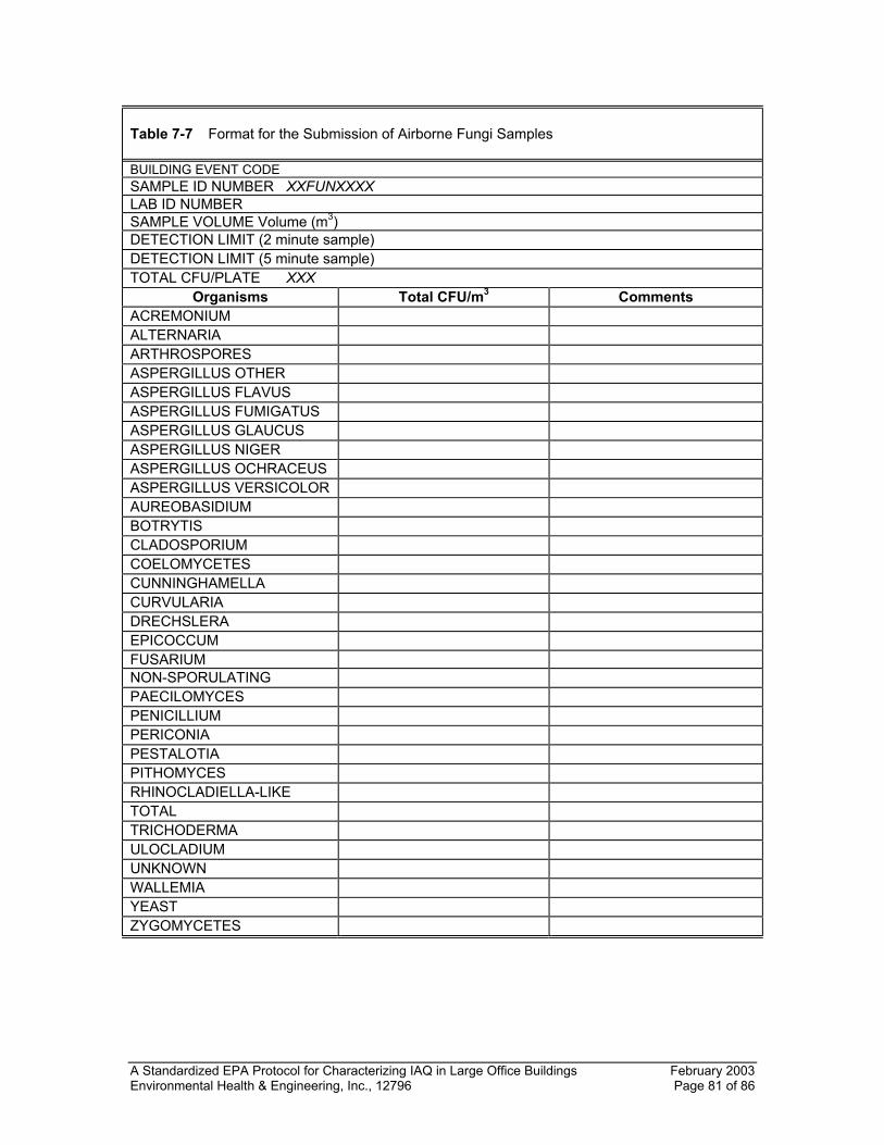
A Standardized EPA Protocol for Characterizing IAQ in Large Office Buildings February 2003 Environmental Health & Engineering, Inc., 12796 Page 81 of 86
Table 7-7 Format for the Submission of Airborne Fungi Samples BUILDING EVENT CODE SAMPLE ID NUMBER XXFUNXXXX LAB ID NUMBER SAMPLE VOLUME Volume (m3) DETECTION LIMIT (2 minute sample) DETECTION LIMIT (5 minute sample) TOTAL CFU/PLATE XXX
Organisms Total CFU/m3 Comments ACREMONIUM ALTERNARIA ARTHROSPORES ASPERGILLUS OTHER ASPERGILLUS FLAVUS ASPERGILLUS FUMIGATUS ASPERGILLUS GLAUCUS ASPERGILLUS NIGER ASPERGILLUS OCHRACEUS ASPERGILLUS VERSICOLOR AUREOBASIDIUM BOTRYTIS CLADOSPORIUM COELOMYCETES CUNNINGHAMELLA CURVULARIA DRECHSLERA EPICOCCUM FUSARIUM NON-SPORULATING PAECILOMYCES PENICILLIUM PERICONIA PESTALOTIA PITHOMYCES RHINOCLADIELLA-LIKE TOTAL TRICHODERMA ULOCLADIUM UNKNOWN WALLEMIA YEAST ZYGOMYCETES
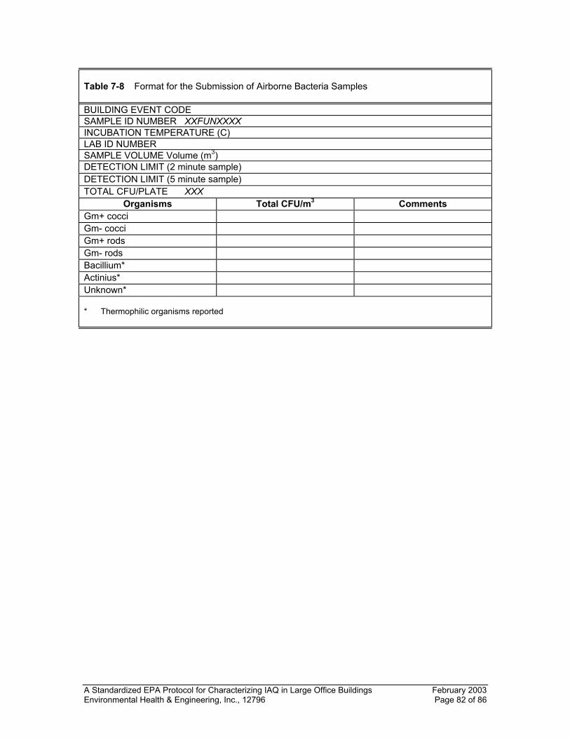
A Standardized EPA Protocol for Characterizing IAQ in Large Office Buildings February 2003 Environmental Health & Engineering, Inc., 12796 Page 82 of 86
Table 7-8 Format for the Submission of Airborne Bacteria Samples BUILDING EVENT CODE SAMPLE ID NUMBER XXFUNXXXX INCUBATION TEMPERATURE (C) LAB ID NUMBER SAMPLE VOLUME Volume (m3) DETECTION LIMIT (2 minute sample) DETECTION LIMIT (5 minute sample) TOTAL CFU/PLATE XXX
Organisms Total CFU/m3 Comments Gm+ cocci Gm- cocci Gm+ rods Gm- rods Bacillium* Actinius* Unknown* * Thermophilic organisms reported
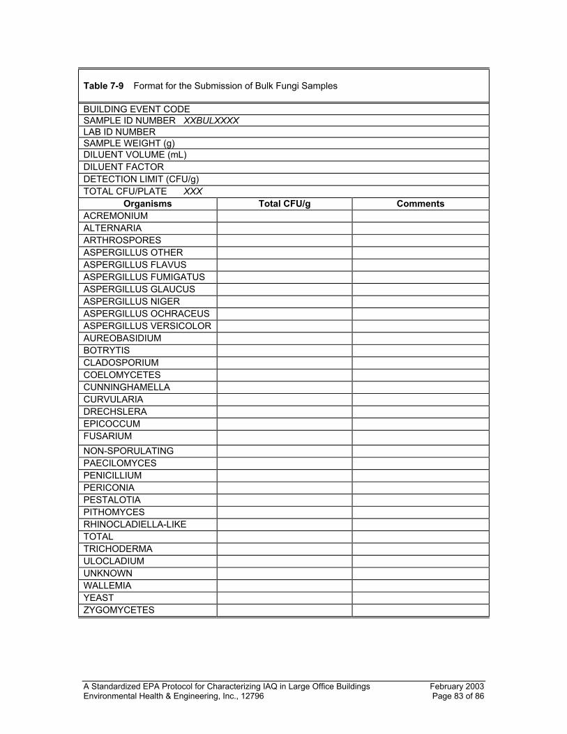
A Standardized EPA Protocol for Characterizing IAQ in Large Office Buildings February 2003 Environmental Health & Engineering, Inc., 12796 Page 83 of 86
Table 7-9 Format for the Submission of Bulk Fungi Samples BUILDING EVENT CODE SAMPLE ID NUMBER XXBULXXXX LAB ID NUMBER SAMPLE WEIGHT (g) DILUENT VOLUME (mL) DILUENT FACTOR DETECTION LIMIT (CFU/g) TOTAL CFU/PLATE XXX
Organisms Total CFU/g Comments ACREMONIUM ALTERNARIA ARTHROSPORES ASPERGILLUS OTHER ASPERGILLUS FLAVUS ASPERGILLUS FUMIGATUS ASPERGILLUS GLAUCUS ASPERGILLUS NIGER ASPERGILLUS OCHRACEUS ASPERGILLUS VERSICOLOR AUREOBASIDIUM BOTRYTIS CLADOSPORIUM COELOMYCETES CUNNINGHAMELLA CURVULARIA DRECHSLERA EPICOCCUM FUSARIUM NON-SPORULATING PAECILOMYCES PENICILLIUM PERICONIA PESTALOTIA PITHOMYCES RHINOCLADIELLA-LIKE TOTAL TRICHODERMA ULOCLADIUM UNKNOWN WALLEMIA YEAST ZYGOMYCETES
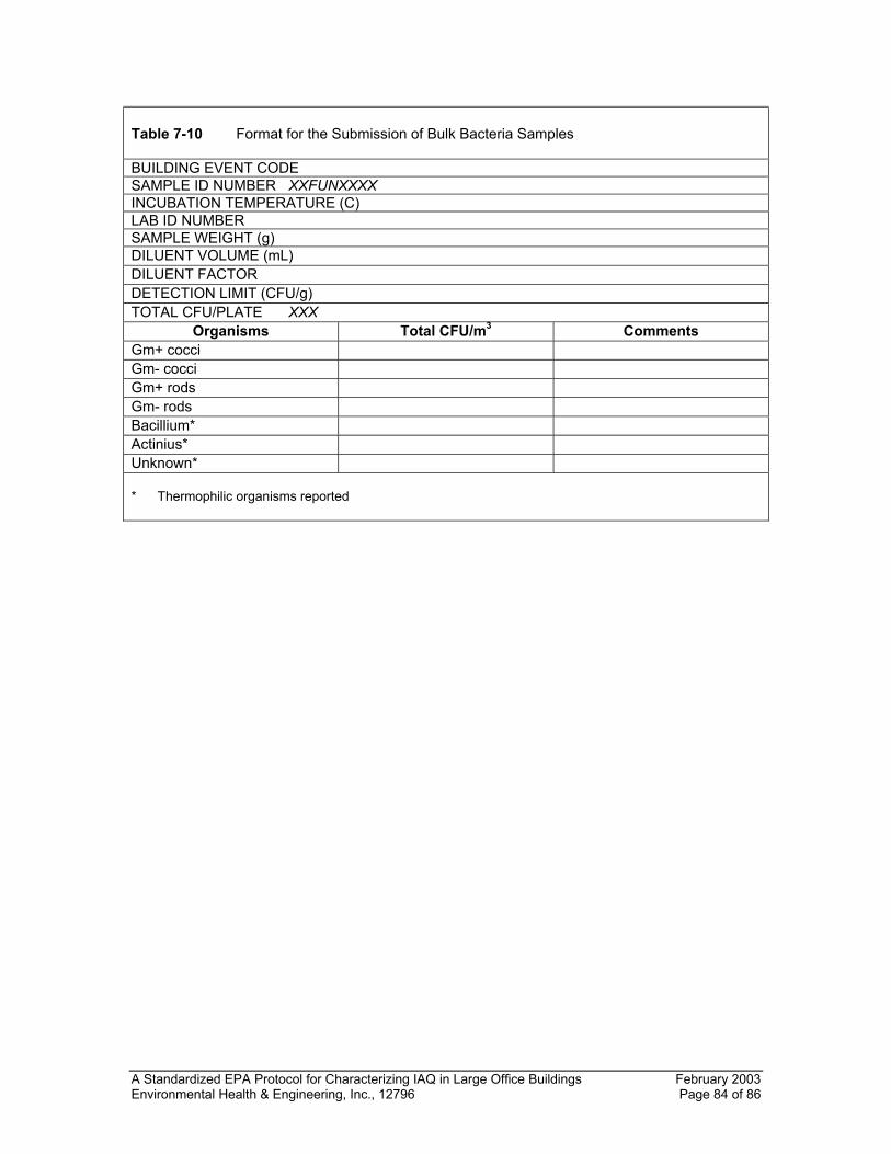
A Standardized EPA Protocol for Characterizing IAQ in Large Office Buildings February 2003 Environmental Health & Engineering, Inc., 12796 Page 84 of 86
Table 7-10 Format for the Submission of Bulk Bacteria Samples BUILDING EVENT CODE SAMPLE ID NUMBER XXFUNXXXX INCUBATION TEMPERATURE (C) LAB ID NUMBER SAMPLE WEIGHT (g) DILUENT VOLUME (mL) DILUENT FACTOR DETECTION LIMIT (CFU/g) TOTAL CFU/PLATE XXX
Organisms Total CFU/m3 Comments Gm+ cocci Gm- cocci Gm+ rods Gm- rods Bacillium* Actinius* Unknown* * Thermophilic organisms reported
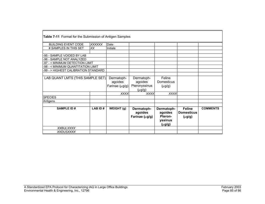
A Standardized EPA Protocol for Characterizing IAQ in Large Office Buildings February 2003 Environmental Health & Engineering, Inc., 12796 Page 85 of 86
Table 7-11 Format for the Submission of Antigen Samples
BUILDING EVENT CODE XXXXXX Date # SAMPLES IN THIS SET XX Initials
-95 - SAMPLE VOIDED BY LAB -96 - SAMPLE NOT ANALYZED -97 - < MINIMUM DETECTION LIMIT -98 - < MINIMUM QUANTITATION LIMIT -99 - > HIGHEST CALIBRATION STANDARD
LAB QUANT LMTS (THIS SAMPLE SET) Dermatoph-
agoides Farinae (µg/g)
Dermatoph-agoides
Pteronyssinus (µg/g)
Feline Domesticus
(µg/g)
XXXX XXXX XXXXSPECIES Antigens
SAMPLE ID # LAB ID # WEIGHT (g) Dermatoph-
agoides Farinae (µg/g)
Dermatoph-agoides Pteron-yssinus (µg/g)
Feline Domesticus
(µg/g)
COMMENTS
XXBULXXXX XXDUSXXXX
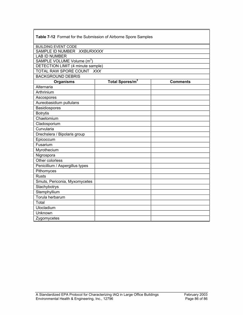
A Standardized EPA Protocol for Characterizing IAQ in Large Office Buildings February 2003 Environmental Health & Engineering, Inc., 12796 Page 86 of 86
Table 7-12 Format for the Submission of Airborne Spore Samples BUILDING EVENT CODE SAMPLE ID NUMBER XXBURXXXX LAB ID NUMBER SAMPLE VOLUME Volume (m3) DETECTION LIMIT (4 minute sample) TOTAL RAW SPORE COUNT XXX BACKGROUND DEBRIS
Organisms Total Spores/m3 Comments Alternaria Arthrinium Ascospores Aureobasidium pullulans Basidiospores Botrytis Chaetomium Cladosporium Curvularia Drechslera / Bipolaris group Epicoccum Fusarium Myrothecium Nigrospora Other colorless Penicillium / Aspergillus types Pithomyces Rusts Smuts, Periconia, Myxomycetes Stachybotrys Stemphyllium Torula herbarum Total Ulocladium Unknown Zygomycetes
APPENDIX A
CHECKLISTS FOR CHARACTERIZATION OF THE WHOLE BUILDING, THE STUDY AREA(S),
AND THE STUDY AREAS(S) HVAC SYSTEM
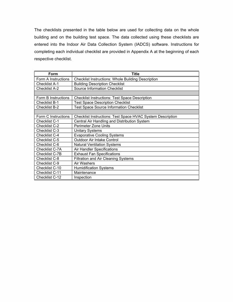
The checklists presented in the table below are used for collecting data on the whole
building and on the building test space. The data collected using these checklists are
entered into the Indoor Air Data Collection System (IADCS) software. Instructions for
completing each individual checklist are provided in Appendix A at the beginning of each
respective checklist.
Form Title Form A Instructions Checklist Instructions: Whole Building Description Checklist A-1 Building Description Checklist Checklist A-2 Source Information Checklist Form B Instructions Checklist Instructions: Test Space Description Checklist B-1 Test Space Description Checklist Checklist B-2 Test Space Source Information Checklist Form C Instructions Checklist Instructions: Test Space HVAC System Description Checklist C-1 Central Air Handling and Distribution System Checklist C-2 Perimeter Zone Units Checklist C-3 Unitary Systems Checklist C-4 Evaporative Cooling Systems Checklist C-5 Outdoor Air Intake Control Checklist C-6 Natural Ventilation Systems Checklist C-7A Air Handler Specifications Checklist C-7B Exhaust Fan Specifications Checklist C-8 Filtration and Air Cleaning Systems Checklist C-9 Air Washers Checklist C-10 Humidification Systems Checklist C-11 Maintenance Checklist C-12 Inspection
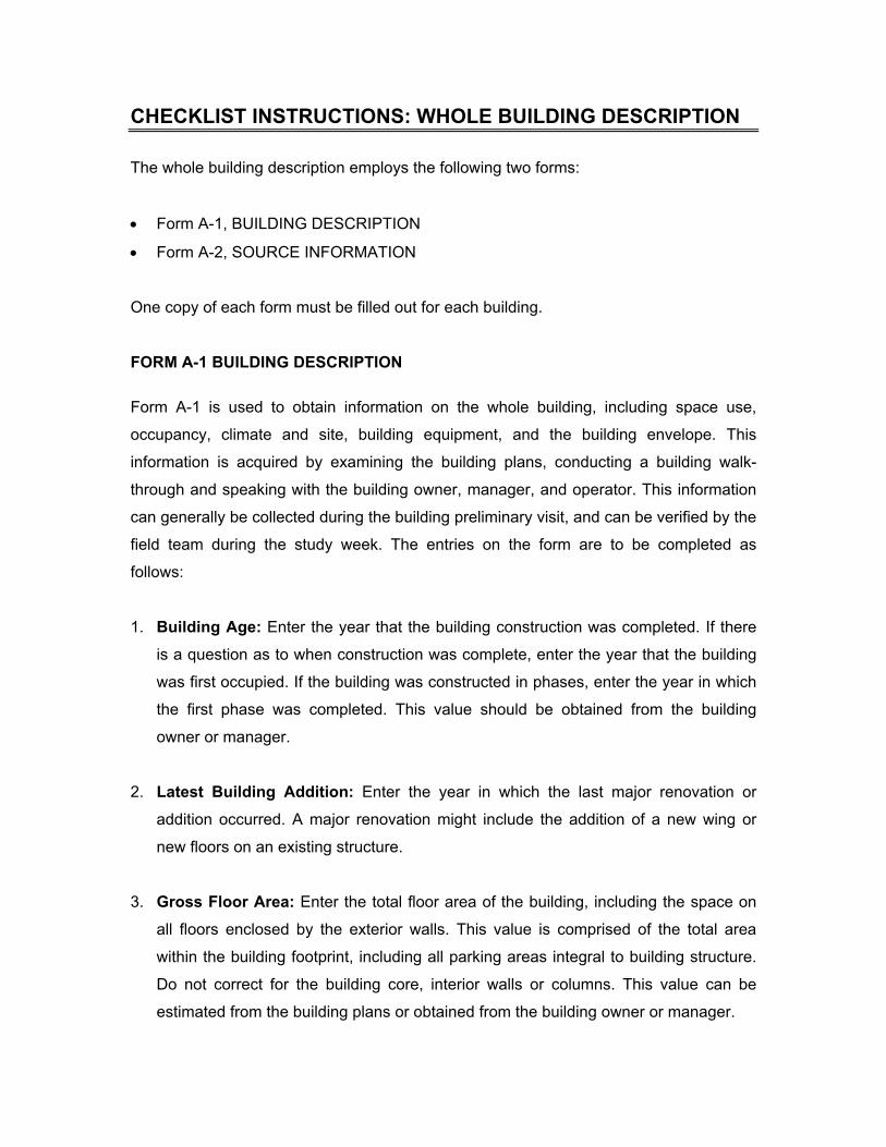
CHECKLIST INSTRUCTIONS: WHOLE BUILDING DESCRIPTION
The whole building description employs the following two forms:
• Form A-1, BUILDING DESCRIPTION
• Form A-2, SOURCE INFORMATION
One copy of each form must be filled out for each building.
FORM A-1 BUILDING DESCRIPTION
Form A-1 is used to obtain information on the whole building, including space use,
occupancy, climate and site, building equipment, and the building envelope. This
information is acquired by examining the building plans, conducting a building walk-
through and speaking with the building owner, manager, and operator. This information
can generally be collected during the building preliminary visit, and can be verified by the
field team during the study week. The entries on the form are to be completed as
follows:
1. Building Age: Enter the year that the building construction was completed. If there
is a question as to when construction was complete, enter the year that the building
was first occupied. If the building was constructed in phases, enter the year in which
the first phase was completed. This value should be obtained from the building
owner or manager.
2. Latest Building Addition: Enter the year in which the last major renovation or
addition occurred. A major renovation might include the addition of a new wing or
new floors on an existing structure.
3. Gross Floor Area: Enter the total floor area of the building, including the space on
all floors enclosed by the exterior walls. This value is comprised of the total area
within the building footprint, including all parking areas integral to building structure.
Do not correct for the building core, interior walls or columns. This value can be
estimated from the building plans or obtained from the building owner or manager.
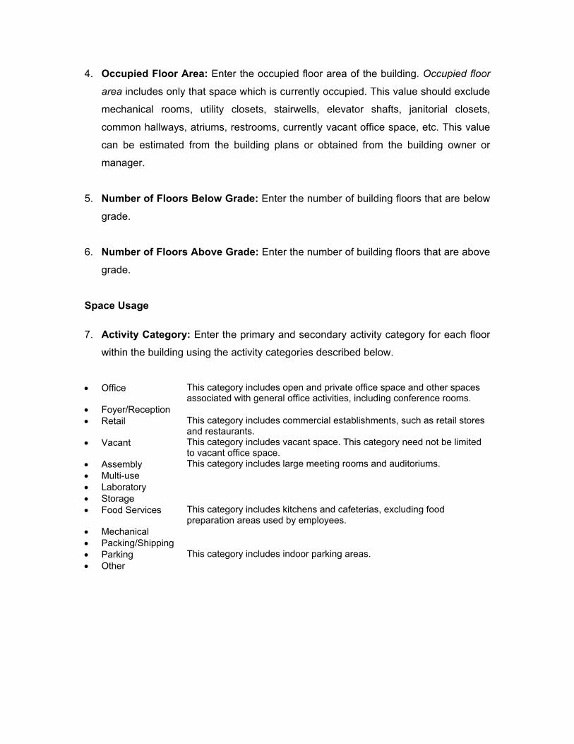
4. Occupied Floor Area: Enter the occupied floor area of the building. Occupied floor
area includes only that space which is currently occupied. This value should exclude
mechanical rooms, utility closets, stairwells, elevator shafts, janitorial closets,
common hallways, atriums, restrooms, currently vacant office space, etc. This value
can be estimated from the building plans or obtained from the building owner or
manager.
5. Number of Floors Below Grade: Enter the number of building floors that are below
grade.
6. Number of Floors Above Grade: Enter the number of building floors that are above
grade.
Space Usage
7. Activity Category: Enter the primary and secondary activity category for each floor
within the building using the activity categories described below.
• Office This category includes open and private office space and other spaces
associated with general office activities, including conference rooms. • Foyer/Reception • Retail This category includes commercial establishments, such as retail stores
and restaurants. • Vacant This category includes vacant space. This category need not be limited
to vacant office space. • Assembly This category includes large meeting rooms and auditoriums. • Multi-use • Laboratory • Storage • Food Services This category includes kitchens and cafeterias, excluding food
preparation areas used by employees. • Mechanical • Packing/Shipping • Parking This category includes indoor parking areas. • Other
Building Occupancy
8. Number of Occupants: Enter the number of people (including visitors) that normally
occupy the building. This value should be obtained from the building owner or
manager.
9. Days per Week Building is Occupied: Enter the number of days per week that the
building is substantially occupied. This value should not include days that the
building has only minimal (less than 25%) occupancy and should be obtained from
the building owner or manager.
10. Hours per Day Building is Occupied (WEEKDAYS): Enter the number of hours
that the building is at 25% or more of full occupancy on weekdays. This value should
be obtained from the building owner or manager.
11. Hours per Day Building is Occupied (WEEKEND DAYS): Enter the number of
hours that the building is at 25% or more of full occupancy on weekends. This value
should be obtained from the building owner or manager.
Climate and Site
12. Heating Degree Days: Enter the average number of heating degree days for the
building location. This value can be obtained from the nearest station of the National
Weather Service and a variety of references including meteorological manuals.
Designate the units, either C-Days or F-Days.
13. Cooling Degree Days: Enter the average number of cooling degree days for the
building location. This value can be obtained from the nearest station of the National
Weather Service and a variety of references including meteorological manuals.
Designate the units, either C-Days or F-Days.
14. Winter Design Dry-bulb Temperature (99%): Enter the 99% value of the winter
design dry-bulb temperature for the building location. This value can be obtained
from the American Society of Heating, Refrigerating, and Air-Conditioning Engineers,
Inc. (ASHRAE) Handbook of Fundamentals (Chapter on Weather Data). Designate
the units, either C or F.
15. Summer Design Dry-bulb Temperature (1%): Enter the 1% value of the summer
design dry-bulb temperature for the building location. This value can be obtained
from the ASHRAE Handbook of Fundamentals (Chapter on Weather Data).
Designate the units, either C or F.
16. Summer Design Wet-bulb Temperature (1%): Enter the 1% value of the summer
design wet-bulb temperature for the building location. This value can be obtained
from the ASHRAE Handbook of Fundamentals (Chapter on Weather Data).
Designate the units, either C or F.
17. Site Characterization: Check the category that best characterizes the building site.
The distinction between urban, suburban, and rural is straightforward, with urban
referring to the core of the city, not simply to the incorporated area. Within the
categories of urban and suburban, the three subcategories describe the dominant
influence within a 1 kilometer (km) radius of the site and are defined as follows:
• Industrial: Product-oriented establishments, such as manufacturing and utilities.
• Commercial: Service-oriented establishments, such as retail establishments,
restaurants, and shopping centers.
• Residential: Because most areas include some residential use, this category is
used in the absence of a dominating industrial or commercial influence.
Within the category of rural, the four subcategories describe the dominant influence
within a 1 km radius of the site and are defined as follows:
• Near Urban: Essentially a rural area that is close enough to a major urban center
as to be affected by the urban area.
• Agricultural: Including orchards, crop raising, and livestock grazing.
• Industrial: Product-oriented establishments, such as manufacturing and utilities.
• Commercial: Service-oriented establishments, such as retail establishments,
restaurants, and shopping centers.
Building Equipment
18. Building Ventilation (Natural or Mechanical): Enter whether the building is
ventilated naturally or mechanically. Natural ventilation includes any un-powered
ventilation system including operable windows, ventilation shafts, intentional
ventilation openings in walls and envelope leakage. The existence of isolated
mechanical exhaust fans does not disqualify such a building from the natural
ventilation category. A mechanically ventilated building employs a powered system
to bring outdoor air into the building, even if it also contains some natural ventilation
elements as well.
19. Cooling Systems: Enter “yes” if the building is air-conditioned and “no” if it is not.
For each equipment type listed, enter whether this system is primary, secondary, or
other. Note that more than one of the equipment categories may exist in the building.
20. Heating System: Enter “yes” if the building is equipped with heating systems and
“no” if it is not. For each equipment type listed, enter whether this system is primary,
secondary, or other. Note that more than one of the equipment categories may exist
in the building.
Operating Schedule
21. Space Conditioning Days per WEEKDAY: Enter the number of days per week (on
weekdays) that the building space-conditioning equipment is operated. This value
should be obtained from the building owner, manager, or operator.
22. Space Conditioning Hours per WEEKDAY: Enter the number of hours per day (on
weekdays) that the building space-conditioning equipment is operated. This value
should be obtained from the building owner, manager, or operator.
23. Space Conditioning Days per WEEKEND DAY: Enter the number of days per
week (on weekend days) that the building space-conditioning equipment is operated.
This value should be obtained from the building owner, manager, or operator.
24. Space Conditioning Hours per WEEKEND DAY: Enter the number of hours per
week (on weekend days) that the building space-conditioning equipment is operated.
This value should be obtained from the building owner, manager, or operator.
25. Ventilation System Operation Days per WEEKDAY: Enter the number of days per
week (on weekdays) that the building ventilation equipment is operated. This value
should be obtained from the building owner, manager, or operator.
26. Ventilation System Operation Hours per WEEKDAY: Enter the number of hours
per day (on weekdays) that the building ventilation equipment is operated. This value
should be obtained from the building owner, manager, or operator.
27. Ventilation System Operation Days per WEEKEND DAY: Enter the number of
days per week (on weekend days) that the building ventilation equipment is
operated. This value should be obtained from the building owner, manager, or
operator.
28. Ventilation System Operation Hours per WEEKDAY: Enter the number of hours
per week (on weekend days) that the building ventilation equipment is operated. This
value should be obtained from the building owner, manager, or operator.
Building Envelope
29. Exterior Wall Construction: Enter the construction of the exterior walls of the
building, selecting from the following options:
• Glass and metal curtain wall
• Masonry
• Precast concrete panels
• Stone panels
• Exterior insulation finish system
• Siding on frame construction
• Metal building system
• Other
Indicate whether the construction selected is primary, secondary, or other. More than
one of the wall construction categories may apply in the building. If the wall
construction is not listed, it can be described in the constriction category named
“OTHER."
30. Roof Construction: Enter the construction of the roof of the building, selecting from
the following options:
• Built-up roof
• Single ply membrane
• Inverted membrane
• Shingles
• Metal
• Other
Indicate whether the construction selected is primary, secondary, or other. More than
one of the roof construction category may apply in the building. If the roof
construction is not listed, it can be described in the construction category named
“OTHER."
31. Glazing Elements: Enter whether the windows are single, double, or triple pane.
32. Operable Windows: Enter “yes” or “no,” as to whether the building has operable
windows.
33. Percentage of Operable Windows: Enter the percentage of operable windows.
34. Shading Elements: Enter “yes” or “no,” to whether the windows are equipped with
shading elements.
35. Percentage of Windows with Shading Elements: Enter the percentage of
windows equipped with shading elements, such as overhangs, window treatments,
or shades.
HVAC Control Systems
36. HVAC Control Implementation: For heating, ventilating, and air-conditioning
(HVAC) controls, select the control system types that best describe the building
control system, pneumatic, low-voltage analog electric, or direct-digital. Select
whether these systems are Primary (P), Secondary (S), or Other (O).
37. HVAC Control Response Strategy: Enter the response strategy for the building
control system, two-position, proportional, floating point, proportional-integral, and
proportional-integral derivative. Select whether these strategies are Primary (P),
Secondary (S), or Other (O).
FORM A-2 BUILDING SOURCE INFORMATION
This form is used to obtain information related to sources of indoor and outdoor
pollutants that may impact the building. This information is acquired through a
combination of a building walk-through and discussions with the building owner,
manager and operator. This information can generally be collected during the building
preliminary visit, and can be verified by the field team during the study week. The entries
on the form are to be completed as follows:
Outdoor Contaminant Sources
Note whether each of the following sources exist in the immediate vicinity of the building.
The source need not be proximate to the outdoor air intake.
1. Garbage Dumpsters
2. Power Plants: A positive response indicates the existence of a power plant including
electricity or steam generation.
3. Heavy Motor Vehicle Traffic: A positive response indicates the existence of heavy
traffic during at least part of the day. It need not be heavy all day long.
4. Construction Activities: A positive response indicates the existence of building
construction on nearby building sites, including new construction, renovation, and
demolition.
5. Emergency Generators: A positive response indicates the existence of emergency
electricity generators, even if they are generally inactive.
6. Industrial Stacks: A positive response indicates the existence of industrial stacks
from industrial facilities.
Smoking Policies
Information on smoking policies can be obtained by the building owner or manager.
7. Smoking Permitted in Building: Enter “yes” if smoking is permitted anywhere in the
building and “no” if smoking is not allowed.
8. Smoking permitted in entire building: Enter “yes” if smoking is permitted
throughout the entire building and “no” if smoking is permitted only in specific
locations.
9. Restricted to Private Offices: Enter “yes” if smoking is restricted within the building
except for private offices and “no” if smoking is not allowed in private offices.
10. Restricted to Indoor Smoking Areas: Enter “yes” if smoking is restricted within the
building except for designated smoking areas (including designated restrooms).
Enter “no” if indoor smoking areas do not exist.
11. Restricted to Outdoor Smoking Areas: Enter “yes” if smoking is allowed outside
the building.
Water Damage
Information on water damage can be obtained from the building owner or manager.
12. Past Occurrences: Enter “yes” if there has been past water damage in the building.
13. Location of Past Water Damage: If water damage occurred in the past, enter the
location from the list where water damage has occurred, i.e., basement, roof,
mechanical, or occupied space. If the water damage occurred in the occupied space,
enter the floor where damage occurred.
14. Current Water Damage: Enter “yes” if there is currently water leakage or visible
water damage within the building.
15. Location of Current Water Damage: If current water damage or water leaks are
present, enter the location from the list where this is occurring, i.e., basement, roof,
mechanical, or occupied space. If it is occurring in the occupied space, enter the
floor where it is occurring.
Fire Damage
Information on fire damage can be obtained from the building owner or manager.
16. Past Occurrences: Enter “yes” if there has been fire damage within the building.
17. Date of Fire Damage: If “yes,” enter the date that the damage occurred.
18. Extent of Damage: Enter whether the fire damage was building wide or whether the
damage occurred in limited areas or floors of the building.
Building Renovations
This section describes the renovations, if any, that have occurred in the building during
the past year. This information can be obtained from a building walk-through and from
the building owner or manager.
Painting
19. Painting: Enter “yes” if there has been painting within the building within the last
year.
20. Continuous: If the building has a continuous painting cycle (i.e., some part of the
building is always undergoing painting), enter “continuous.” If painting is not
implemented continuously, enter the both the location and date of each painting
renovation.
Carpeting
21. Carpeting: Enter “yes” if there has been carpeting installed within the building within
the last year.
22. Continuous: If the building has a continuous re-carpeting cycle (i.e., some part of
the building is always undergoing re-carpeting), enter “continuous.” If re-carpeting is
not implemented continuously, enter the both the location and date of each carpeting
renovation.
Roofing
23. Roofing: Enter “yes” if there has been re-roofing implemented within the building
within the last year.
24. Continuous: If the building has a continuous re-roofing cycle (i.e., some part of the
building is always undergoing re-roofing), select “continuous.” If re-roofing is not
implemented continuously, enter the both the location and date of each re-roofing
renovation.
Furniture
25. Furniture: Enter “yes” if there has been new furniture installed within the building
within the last year.
26. Continuous: If the building has a continuous new furniture installation cycle select
“continuous.” If new furniture is not installed continuously, enter the both the location
and date of each new furniture installation.
Partition and Interior Wall Systems
27. Enter “yes” if there has been movement of partitions or interior walls within the
building within the last year.
28. Continuous: If the building has a continuous partition or interior wall movement
cycle, select “continuous.” If partition or interior wall movement projects are not
implemented continuously, enter the both the location and date of each project.
Cleaning Schedules
Information pertaining to cleaning schedules can be obtained from the building owner,
manager, or operator.
29. Office Cleaning: Enter the frequency at which office cleaning is done. Note whether
this cleaning is done during occupied hours, evenings, or weekends.
30. Dry Mopping: Enter the frequency at which dry mopping is done. Note whether dry
mopping is done during occupied hours, evenings, or weekends.
31. Wet Mopping: Enter the frequency at which wet mopping is done. Note whether wet
mopping is done during occupied hours, evenings, or weekends.
32. Vacuuming: Enter the frequency at which vacuuming is done. Note whether
vacuuming is done during occupied hours, evenings, or weekends.
33. Type of Vacuum Used: If vacuuming is conducted, enter the type of vacuum used.
These include standard vacuums and vacuums equipped with high efficiency particle
air (HEPA) filtration.
Indoor Trash Storage
34. Trash Storage: Enter the locations within the building where trash is stored, other
than temporarily during collection. Collect information of building floor and the
location on each floor (i.e., occupied space, stairwell, freight elevator lobby, or
loading dock).
Cleaning Materials
35. Materials Used: Select each cleaning material used in the building from the list.
General descriptors include window cleaner, furniture cleaner, floor wax, bathroom
cleaners, bleach, soap, and carpet cleaners.
36. Inventory of Cleaning Materials: Collect an inventory of all cleaning materials used
in the building. This information should be collected by taking an inventory of each
storage room within the building.
37. Storage Location: Enter the locations within the building where cleaning materials
are stored. Appropriate information includes the building floor and where on the
building floor cleaning materials are located, such as janitors closet or storage room.
Pest Control
Pest control information should be obtained from the building owner, manager, or
facilities engineer.
38. Exterior Application: Enter the frequency of exterior pesticide application.
Appropriate frequencies include weekly, monthly, semi-annually, etc.
39. Date of Last Exterior Application Frequency: Enter the date of the last exterior
pesticide application.
40. Interior Application: Enter the frequency of interior pesticide application.
Appropriate frequencies include weekly, monthly, semi-annually, etc.
41. Date of Last Interior Application Frequency: Enter the date of the last interior
pesticide application.
42. Interior Pesticide Application Location: Enter the floors and locations within the
building where pesticides are applied. Appropriate information includes the building
floor and location such as occupied space, storage areas, and mechanical spaces.
43. Pesticides Used: Enter the name of the pesticides used both for interior and exterior
applications.
44. Pesticide Storage: Enter whether pesticides are stored on-site within the building or
whether pesticides are stored off-site.
45. Storage Locations: If pesticides are stored on-site, enter the floors and locations
where pesticides are stored. Appropriate information includes the building floor and
location such as occupied space, janitorial closet, or storage room.
Special Use Spaces (46 through 57)
Information regarding special use spaces should be obtained from the building owner,
manager, or facilities engineer. For each of the categories, (smoking lounges through
conference rooms) provide the following information:
Existence: Enter “yes” if the space use category exists in the building.
Floor and Space Ventilation: Enter the floor within the building where this space exists.
Enter whether this special use space is equipped with its own dedicated ventilation
system and dedicated exhaust system.
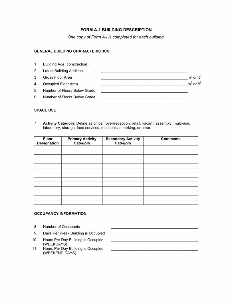
FORM A-1 BUILDING DESCRIPTION One copy of Form A-l is completed for each building.
GENERAL BUILDING CHARACTERISTICS
1 Building Age (construction) _________________________________________
2 Latest Building Addition _________________________________________
3 Gross Floor Area _________________________________________m2 or ft2
4 Occupied Floor Area _________________________________________m2 or ft2
5 Number of Floors Below Grade _________________________________________
6 Number of Floors Below Grade _________________________________________
SPACE USE
7 Activity Category: Define as office, foyer/reception, retail, vacant, assembly, multi-use, laboratory, storage, food services, mechanical, parking, or other.
Floor
Designation Primary Activity
Category Secondary Activity
Category Comments
OCCUPANCY INFORMATION
8 Number of Occupants _________________________________________
9 Days Per Week Building is Occupied _________________________________________
10 Hours Per Day Building is Occupied (WEEKDAYS)
_________________________________________
11 Hours Per Day Building is Occupied (WEEKEND DAYS)
_________________________________________
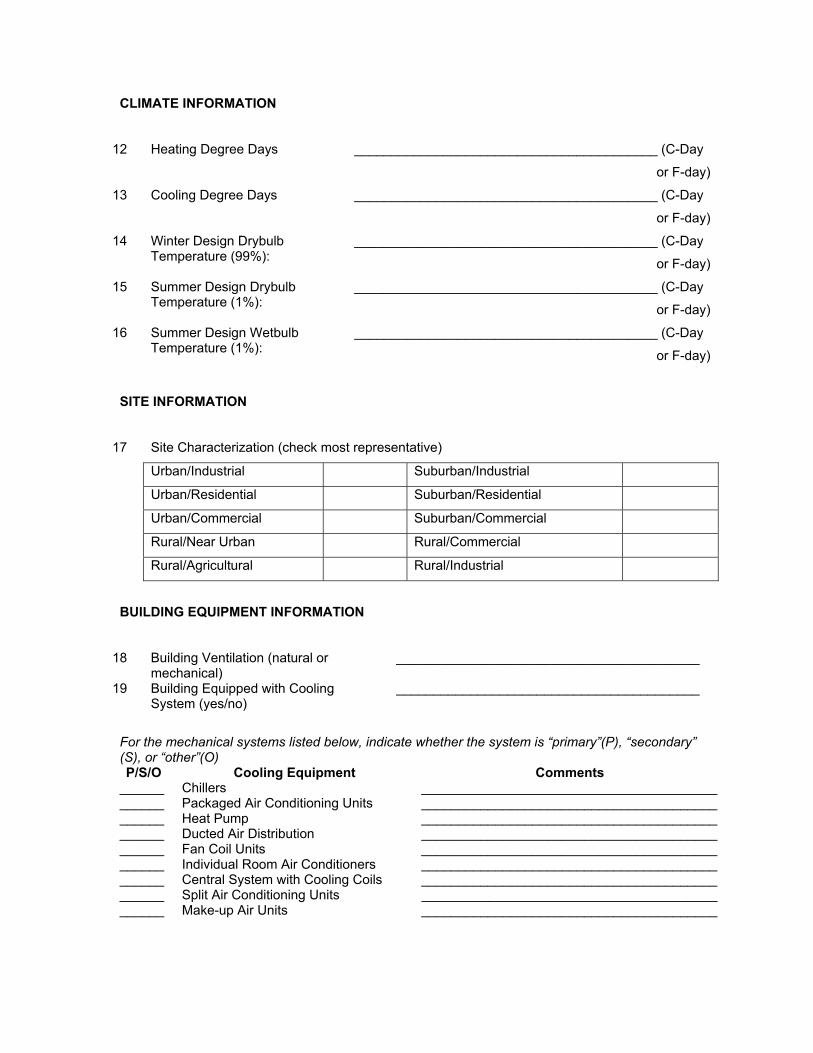
CLIMATE INFORMATION
12 Heating Degree Days _________________________________________ (C-Day
or F-day)
13 Cooling Degree Days _________________________________________ (C-Day
or F-day)
14 Winter Design Drybulb Temperature (99%):
_________________________________________ (C-Day
or F-day)
15 Summer Design Drybulb Temperature (1%):
_________________________________________ (C-Day
or F-day)
16 Summer Design Wetbulb Temperature (1%):
_________________________________________ (C-Day
or F-day)
SITE INFORMATION
17 Site Characterization (check most representative)
Urban/Industrial Suburban/Industrial
Urban/Residential Suburban/Residential
Urban/Commercial Suburban/Commercial
Rural/Near Urban Rural/Commercial
Rural/Agricultural Rural/Industrial
BUILDING EQUIPMENT INFORMATION
18 Building Ventilation (natural or mechanical)
_________________________________________
19 Building Equipped with Cooling System (yes/no)
_________________________________________
For the mechanical systems listed below, indicate whether the system is “primary”(P), “secondary” (S), or “other”(O) P/S/O Cooling Equipment Comments
______ Chillers ________________________________________ ______ Packaged Air Conditioning Units ________________________________________ ______ Heat Pump ________________________________________ ______ Ducted Air Distribution ________________________________________ ______ Fan Coil Units ________________________________________ ______ Individual Room Air Conditioners ________________________________________ ______ Central System with Cooling Coils ________________________________________ ______ Split Air Conditioning Units ________________________________________ ______ Make-up Air Units ________________________________________
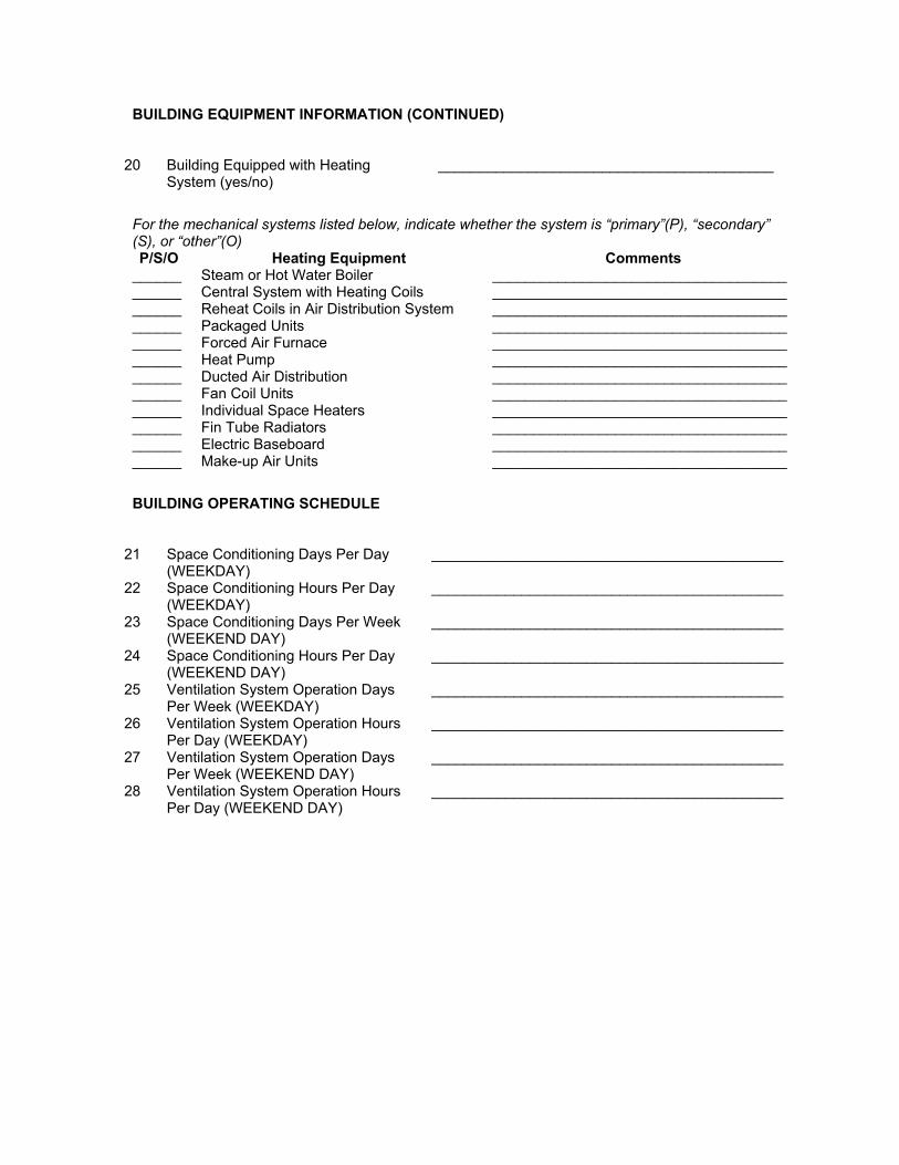
BUILDING EQUIPMENT INFORMATION (CONTINUED)
20 Building Equipped with Heating System (yes/no)
_________________________________________
For the mechanical systems listed below, indicate whether the system is “primary”(P), “secondary” (S), or “other”(O) P/S/O Heating Equipment Comments
______ Steam or Hot Water Boiler ____________________________________ ______ Central System with Heating Coils ____________________________________ ______ Reheat Coils in Air Distribution System ____________________________________ ______ Packaged Units ____________________________________ ______ Forced Air Furnace ____________________________________ ______ Heat Pump ____________________________________ ______ Ducted Air Distribution ____________________________________ ______ Fan Coil Units ____________________________________ ______ Individual Space Heaters ____________________________________ ______ Fin Tube Radiators ____________________________________ ______ Electric Baseboard ____________________________________ ______ Make-up Air Units ____________________________________
BUILDING OPERATING SCHEDULE
21 Space Conditioning Days Per Day (WEEKDAY)
___________________________________________
22 Space Conditioning Hours Per Day (WEEKDAY)
___________________________________________
23 Space Conditioning Days Per Week (WEEKEND DAY)
___________________________________________
24 Space Conditioning Hours Per Day (WEEKEND DAY)
___________________________________________
25 Ventilation System Operation Days Per Week (WEEKDAY)
___________________________________________
26 Ventilation System Operation Hours Per Day (WEEKDAY)
___________________________________________
27 Ventilation System Operation Days Per Week (WEEKEND DAY)
___________________________________________
28 Ventilation System Operation Hours Per Day (WEEKEND DAY)
___________________________________________
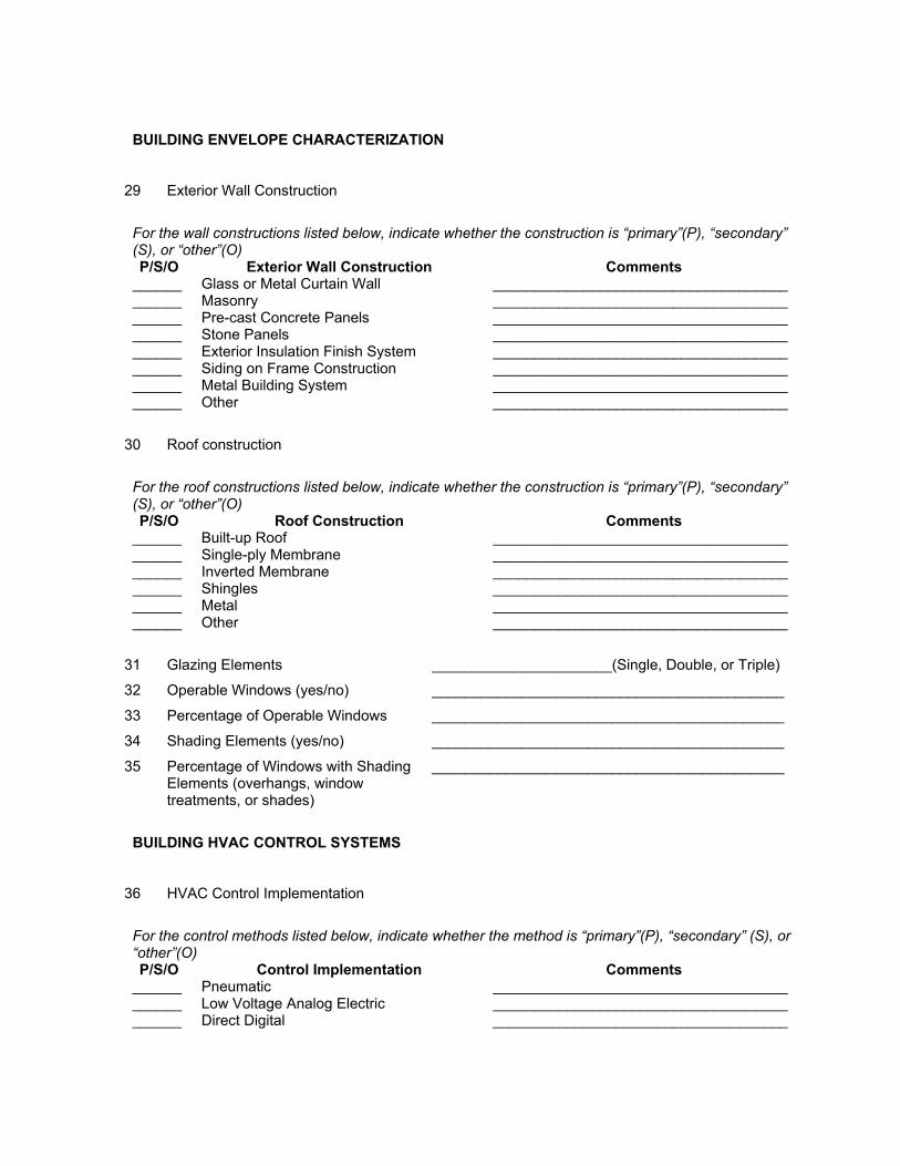
BUILDING ENVELOPE CHARACTERIZATION
29 Exterior Wall Construction
For the wall constructions listed below, indicate whether the construction is “primary”(P), “secondary” (S), or “other”(O) P/S/O Exterior Wall Construction Comments
______ Glass or Metal Curtain Wall ____________________________________ ______ Masonry ____________________________________ ______ Pre-cast Concrete Panels ____________________________________ ______ Stone Panels ____________________________________ ______ Exterior Insulation Finish System ____________________________________ ______ Siding on Frame Construction ____________________________________ ______ Metal Building System ____________________________________ ______ Other ____________________________________
30 Roof construction
For the roof constructions listed below, indicate whether the construction is “primary”(P), “secondary” (S), or “other”(O) P/S/O Roof Construction Comments
______ Built-up Roof ____________________________________ ______ Single-ply Membrane ____________________________________ ______ Inverted Membrane ____________________________________ ______ Shingles ____________________________________ ______ Metal ____________________________________ ______ Other ____________________________________
31 Glazing Elements ______________________(Single, Double, or Triple)
32 Operable Windows (yes/no) ___________________________________________
33 Percentage of Operable Windows ___________________________________________
34 Shading Elements (yes/no) ___________________________________________
35 Percentage of Windows with Shading Elements (overhangs, window treatments, or shades)
___________________________________________
BUILDING HVAC CONTROL SYSTEMS
36 HVAC Control Implementation
For the control methods listed below, indicate whether the method is “primary”(P), “secondary” (S), or “other”(O) P/S/O Control Implementation Comments
______ Pneumatic ____________________________________ ______ Low Voltage Analog Electric ____________________________________ ______ Direct Digital ____________________________________
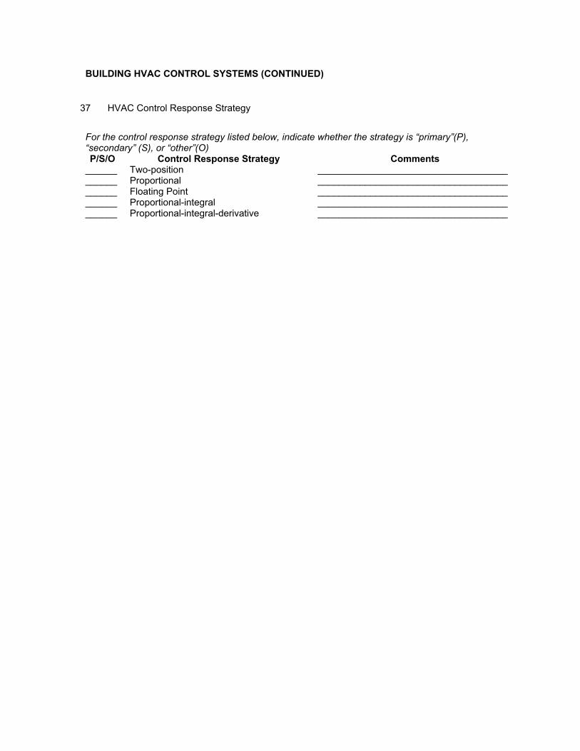
BUILDING HVAC CONTROL SYSTEMS (CONTINUED)
37 HVAC Control Response Strategy For the control response strategy listed below, indicate whether the strategy is “primary”(P), “secondary” (S), or “other”(O) P/S/O Control Response Strategy Comments
______ Two-position ____________________________________ ______ Proportional ____________________________________ ______ Floating Point ____________________________________ ______ Proportional-integral ____________________________________ ______ Proportional-integral-derivative ____________________________________
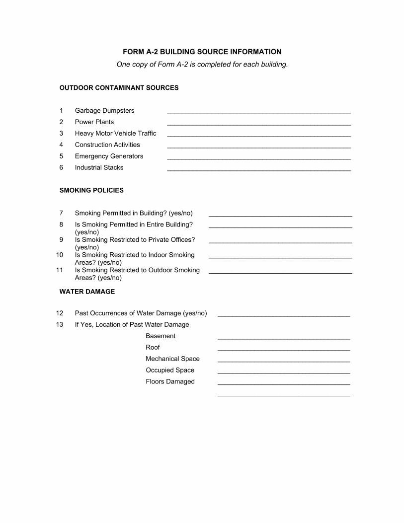
FORM A-2 BUILDING SOURCE INFORMATION One copy of Form A-2 is completed for each building.
OUTDOOR CONTAMINANT SOURCES
1 Garbage Dumpsters __________________________________________________
2 Power Plants __________________________________________________
3 Heavy Motor Vehicle Traffic __________________________________________________
4 Construction Activities __________________________________________________
5 Emergency Generators __________________________________________________
6 Industrial Stacks __________________________________________________
SMOKING POLICIES
7 Smoking Permitted in Building? (yes/no) _______________________________________
8 Is Smoking Permitted in Entire Building? (yes/no)
_______________________________________
9 Is Smoking Restricted to Private Offices? (yes/no)
_______________________________________
10 Is Smoking Restricted to Indoor Smoking Areas? (yes/no)
_______________________________________
11 Is Smoking Restricted to Outdoor Smoking Areas? (yes/no)
_______________________________________
WATER DAMAGE
12 Past Occurrences of Water Damage (yes/no) ____________________________________
13 If Yes, Location of Past Water Damage
Basement ____________________________________
Roof ____________________________________
Mechanical Space ____________________________________
Occupied Space ____________________________________
Floors Damaged ____________________________________
____________________________________
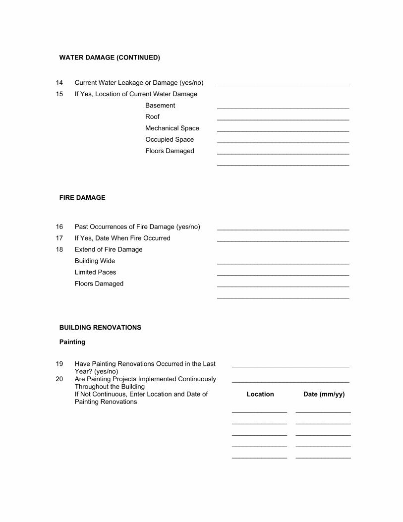
WATER DAMAGE (CONTINUED)
14 Current Water Leakage or Damage (yes/no) ____________________________________
15 If Yes, Location of Current Water Damage
Basement ____________________________________
Roof ____________________________________
Mechanical Space ____________________________________
Occupied Space ____________________________________
Floors Damaged ____________________________________
____________________________________
FIRE DAMAGE
16 Past Occurrences of Fire Damage (yes/no) ____________________________________
17 If Yes, Date When Fire Occurred ____________________________________
18 Extend of Fire Damage
Building Wide ____________________________________
Limited Paces ____________________________________
Floors Damaged ____________________________________
____________________________________
BUILDING RENOVATIONS
Painting
19 Have Painting Renovations Occurred in the Last
Year? (yes/no) ________________________________
20 Are Painting Projects Implemented Continuously Throughout the Building
________________________________
If Not Continuous, Enter Location and Date of Painting Renovations
Location Date (mm/yy)
_______________ _______________
_______________ _______________
_______________ _______________
_______________ _______________
_______________ _______________
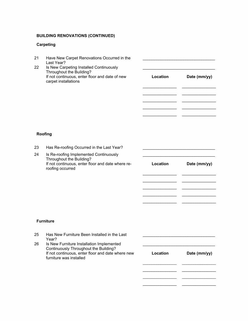
BUILDING RENOVATIONS (CONTINUED)
Carpeting
21 Have New Carpet Renovations Occurred in the
Last Year? ________________________________
22 Is New Carpeting Installed Continuously Throughout the Building?
________________________________
If not continuous, enter floor and date of new carpet installations
Location Date (mm/yy)
_______________ _______________
_______________ _______________
_______________ _______________
_______________ _______________
_______________ _______________
Roofing
23 Has Re-roofing Occurred in the Last Year? ________________________________
24 Is Re-roofing Implemented Continuously Throughout the Building?
________________________________
If not continuous, enter floor and date where re-roofing occurred
Location Date (mm/yy)
_______________ _______________
_______________ _______________
_______________ _______________
_______________ _______________
_______________ _______________
Furniture
25 Has New Furniture Been Installed in the Last
Year? ________________________________
26 Is New Furniture Installation Implemented Continuously Throughout the Building?
________________________________
If not continuous, enter floor and date where new furniture was installed
Location Date (mm/yy)
_______________ _______________
_______________ _______________
_______________ _______________
_______________ _______________
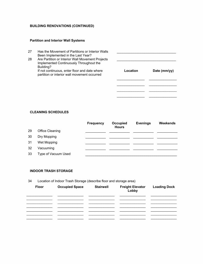
BUILDING RENOVATIONS (CONTINUED)
Partition and Interior Wall Systems
27 Has the Movement of Partitions or Interior Walls
Been Implemented in the Last Year? ________________________________
28 Are Partition or Interior Wall Movement Projects Implemented Continuously Throughout the Building?
________________________________
If not continuous, enter floor and date where partition or interior wall movement occurred
Location Date (mm/yy)
_______________ _______________
_______________ _______________
_______________ _______________
_______________ _______________
CLEANING SCHEDULES
Frequency Occupied
Hours Evenings Weekends
29 Office Cleaning ___________ ___________ ___________ ___________
30 Dry Mopping ___________ ___________ ___________ ___________
31 Wet Mopping ___________ ___________ ___________ ___________
32 Vacuuming ___________ ___________ ___________ ___________
33 Type of Vacuum Used _____________________________________________
INDOOR TRASH STORAGE
34 Location of Indoor Trash Storage (describe floor and storage area)
Floor Occupied Space Stairwell Freight Elevator Lobby
Loading Dock
______________ ______________ ______________ ______________ ______________ ______________ ______________ ______________ ______________ ______________ ______________ ______________ ______________ ______________ ______________ ______________ ______________ ______________ ______________ ______________ ______________ ______________ ______________ ______________ ______________ ______________ ______________ ______________ ______________ ______________ ______________ ______________ ______________ ______________ ______________
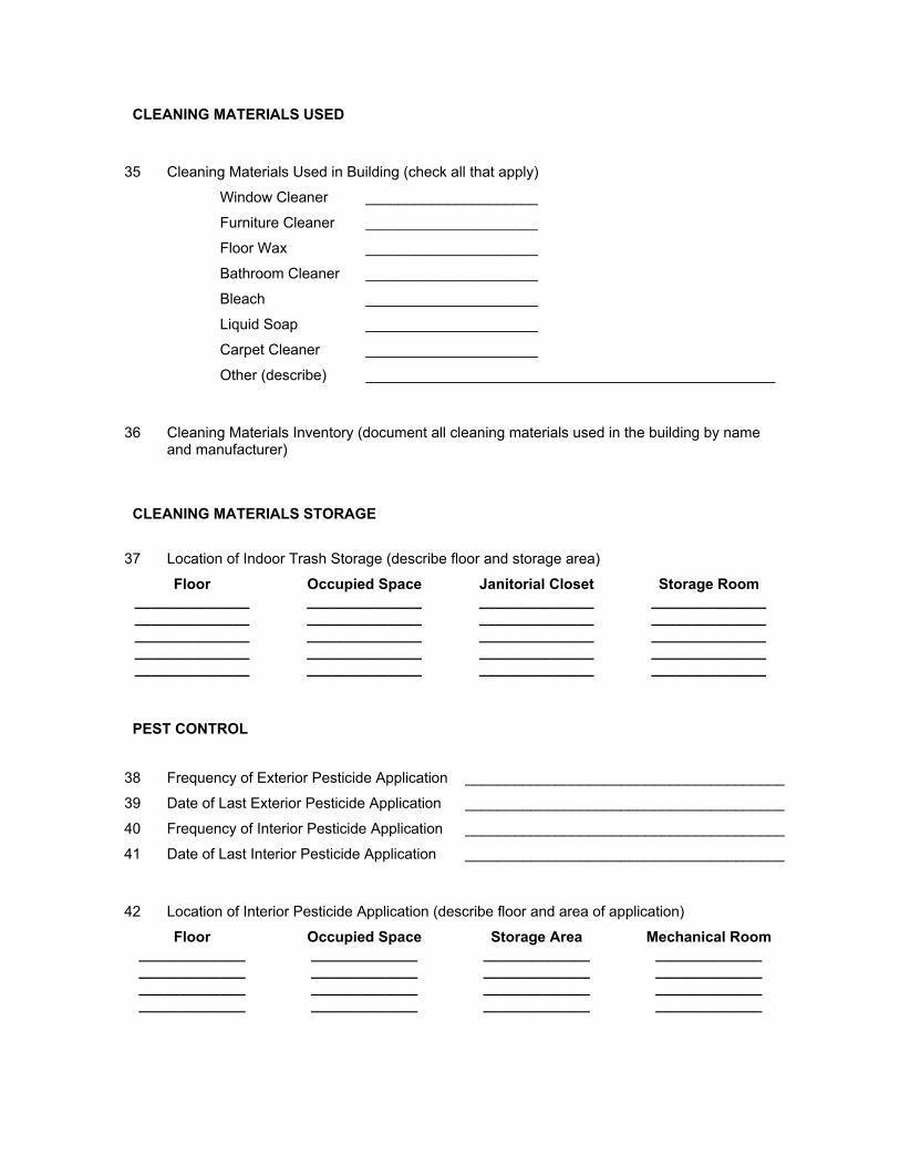
CLEANING MATERIALS USED
35 Cleaning Materials Used in Building (check all that apply)
Window Cleaner _____________________
Furniture Cleaner _____________________
Floor Wax _____________________
Bathroom Cleaner _____________________
Bleach _____________________
Liquid Soap _____________________
Carpet Cleaner _____________________
Other (describe) __________________________________________________
36 Cleaning Materials Inventory (document all cleaning materials used in the building by name
and manufacturer)
CLEANING MATERIALS STORAGE
37 Location of Indoor Trash Storage (describe floor and storage area)
Floor Occupied Space Janitorial Closet Storage Room ______________ ______________ ______________ ______________ ______________ ______________ ______________ ______________ ______________ ______________ ______________ ______________ ______________ ______________ ______________ ______________ ______________ ______________ ______________ ______________
PEST CONTROL
38 Frequency of Exterior Pesticide Application _______________________________________
39 Date of Last Exterior Pesticide Application _______________________________________
40 Frequency of Interior Pesticide Application _______________________________________
41 Date of Last Interior Pesticide Application _______________________________________
42 Location of Interior Pesticide Application (describe floor and area of application)
Floor Occupied Space Storage Area Mechanical Room _____________ _____________ _____________ _____________ _____________ _____________ _____________ _____________ _____________ _____________ _____________ _____________ _____________ _____________ _____________ _____________
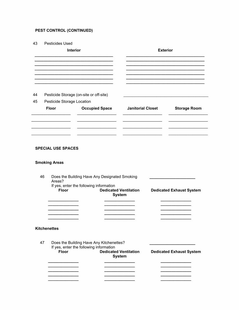
PEST CONTROL (CONTINUED)
43 Pesticides Used
Interior Exterior ____________________________________ ____________________________________ ____________________________________ ____________________________________ ____________________________________ ____________________________________ ____________________________________ ____________________________________ ____________________________________ ____________________________________ ____________________________________ ____________________________________ ____________________________________ ____________________________________
44 Pesticide Storage (on-site or off-site) _______________________________________
45 Pesticide Storage Location
Floor Occupied Space Janitorial Closet Storage Room __________________ __________________ __________________ __________________
__________________ __________________ __________________ __________________
__________________ __________________ __________________ __________________
__________________ __________________ __________________ __________________
SPECIAL USE SPACES
Smoking Areas
46 Does the Building Have Any Designated Smoking
Areas? _____________________
If yes, enter the following information Floor Dedicated Ventilation
System Dedicated Exhaust System
______________ ______________ ______________ ______________ ______________ ______________ ______________ ______________ ______________ ______________ ______________ ______________ ______________ ______________ ______________
Kitchenettes
47 Does the Building Have Any Kitchenettes? _____________________
If yes, enter the following information Floor Dedicated Ventilation
System Dedicated Exhaust System
______________ ______________ ______________ ______________ ______________ ______________ ______________ ______________ ______________ ______________ ______________ ______________ ______________ ______________ ______________
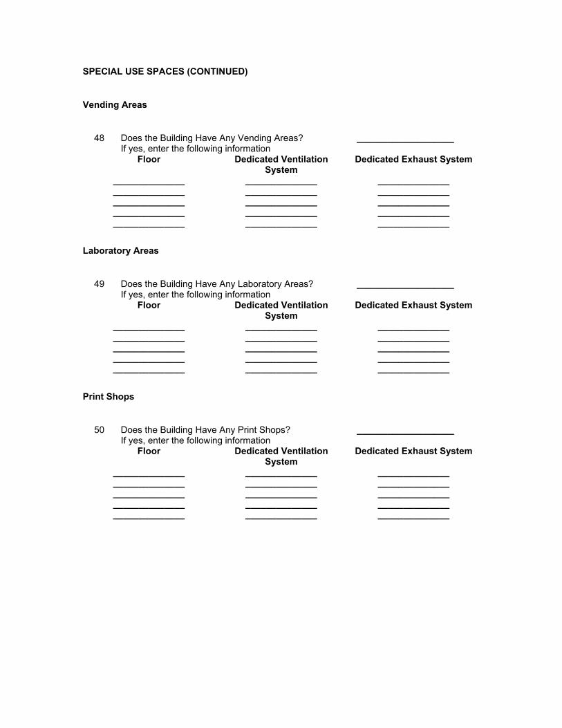
SPECIAL USE SPACES (CONTINUED)
Vending Areas
48 Does the Building Have Any Vending Areas? ___________________
If yes, enter the following information Floor Dedicated Ventilation
System Dedicated Exhaust System
______________ ______________ ______________ ______________ ______________ ______________ ______________ ______________ ______________ ______________ ______________ ______________ ______________ ______________ ______________
Laboratory Areas
49 Does the Building Have Any Laboratory Areas? ___________________
If yes, enter the following information Floor Dedicated Ventilation
System Dedicated Exhaust System
______________ ______________ ______________ ______________ ______________ ______________ ______________ ______________ ______________ ______________ ______________ ______________ ______________ ______________ ______________
Print Shops
50 Does the Building Have Any Print Shops? ___________________
If yes, enter the following information Floor Dedicated Ventilation
System Dedicated Exhaust System
______________ ______________ ______________ ______________ ______________ ______________ ______________ ______________ ______________ ______________ ______________ ______________ ______________ ______________ ______________
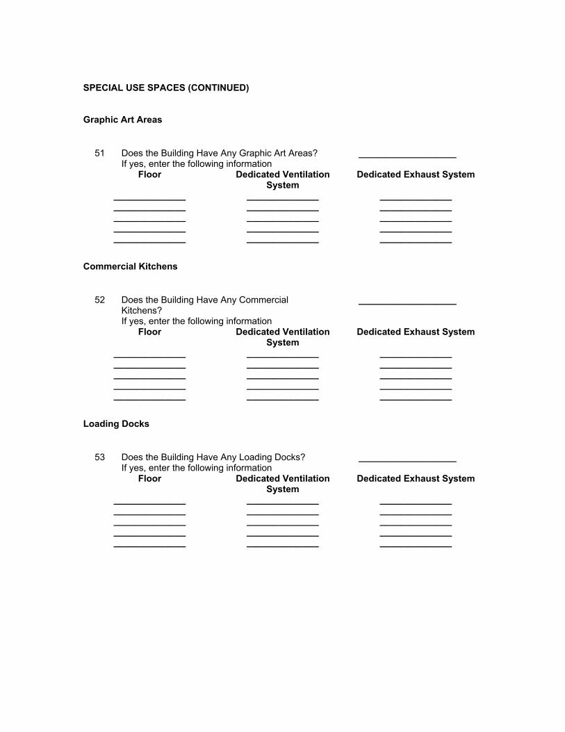
SPECIAL USE SPACES (CONTINUED) Graphic Art Areas
51 Does the Building Have Any Graphic Art Areas? ___________________
If yes, enter the following information Floor Dedicated Ventilation
System Dedicated Exhaust System
______________ ______________ ______________ ______________ ______________ ______________ ______________ ______________ ______________ ______________ ______________ ______________ ______________ ______________ ______________
Commercial Kitchens
52 Does the Building Have Any Commercial
Kitchens? ___________________
If yes, enter the following information Floor Dedicated Ventilation
System Dedicated Exhaust System
______________ ______________ ______________ ______________ ______________ ______________ ______________ ______________ ______________ ______________ ______________ ______________ ______________ ______________ ______________
Loading Docks
53 Does the Building Have Any Loading Docks? ___________________
If yes, enter the following information Floor Dedicated Ventilation
System Dedicated Exhaust System
______________ ______________ ______________ ______________ ______________ ______________ ______________ ______________ ______________ ______________ ______________ ______________ ______________ ______________ ______________
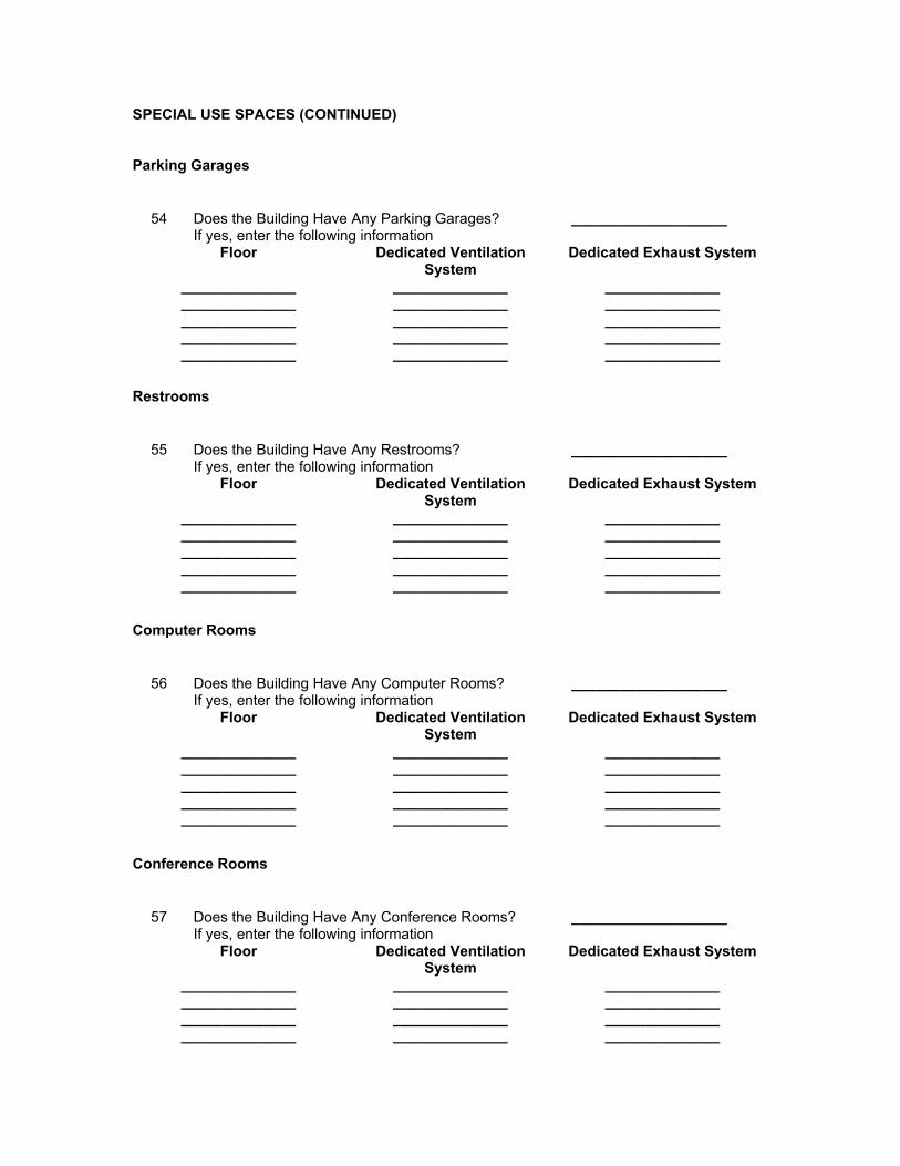
SPECIAL USE SPACES (CONTINUED)
Parking Garages
54 Does the Building Have Any Parking Garages? ___________________
If yes, enter the following information Floor Dedicated Ventilation
System Dedicated Exhaust System
______________ ______________ ______________ ______________ ______________ ______________ ______________ ______________ ______________ ______________ ______________ ______________ ______________ ______________ ______________
Restrooms
55 Does the Building Have Any Restrooms? ___________________
If yes, enter the following information Floor Dedicated Ventilation
System Dedicated Exhaust System
______________ ______________ ______________ ______________ ______________ ______________ ______________ ______________ ______________ ______________ ______________ ______________ ______________ ______________ ______________
Computer Rooms
56 Does the Building Have Any Computer Rooms? ___________________
If yes, enter the following information Floor Dedicated Ventilation
System Dedicated Exhaust System
______________ ______________ ______________ ______________ ______________ ______________ ______________ ______________ ______________ ______________ ______________ ______________ ______________ ______________ ______________
Conference Rooms
57 Does the Building Have Any Conference Rooms? ___________________
If yes, enter the following information Floor Dedicated Ventilation
System Dedicated Exhaust System
______________ ______________ ______________ ______________ ______________ ______________ ______________ ______________ ______________ ______________ ______________ ______________
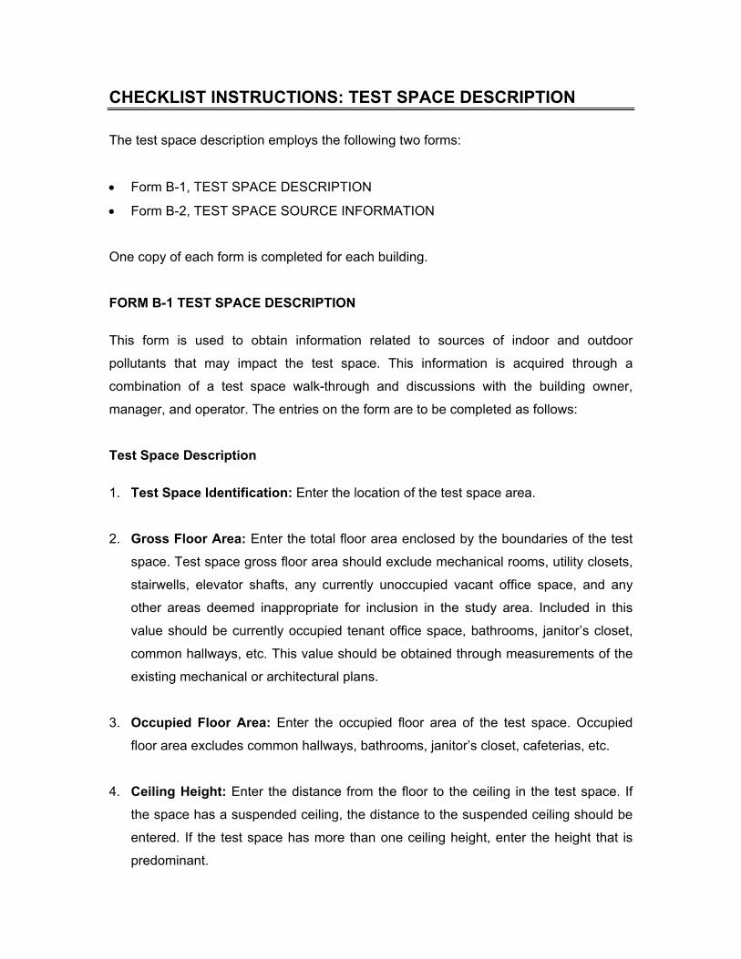
CHECKLIST INSTRUCTIONS: TEST SPACE DESCRIPTION
The test space description employs the following two forms:
• Form B-1, TEST SPACE DESCRIPTION
• Form B-2, TEST SPACE SOURCE INFORMATION
One copy of each form is completed for each building.
FORM B-1 TEST SPACE DESCRIPTION
This form is used to obtain information related to sources of indoor and outdoor
pollutants that may impact the test space. This information is acquired through a
combination of a test space walk-through and discussions with the building owner,
manager, and operator. The entries on the form are to be completed as follows:
Test Space Description
1. Test Space Identification: Enter the location of the test space area.
2. Gross Floor Area: Enter the total floor area enclosed by the boundaries of the test
space. Test space gross floor area should exclude mechanical rooms, utility closets,
stairwells, elevator shafts, any currently unoccupied vacant office space, and any
other areas deemed inappropriate for inclusion in the study area. Included in this
value should be currently occupied tenant office space, bathrooms, janitor’s closet,
common hallways, etc. This value should be obtained through measurements of the
existing mechanical or architectural plans.
3. Occupied Floor Area: Enter the occupied floor area of the test space. Occupied
floor area excludes common hallways, bathrooms, janitor’s closet, cafeterias, etc.
4. Ceiling Height: Enter the distance from the floor to the ceiling in the test space. If
the space has a suspended ceiling, the distance to the suspended ceiling should be
entered. If the test space has more than one ceiling height, enter the height that is
predominant.
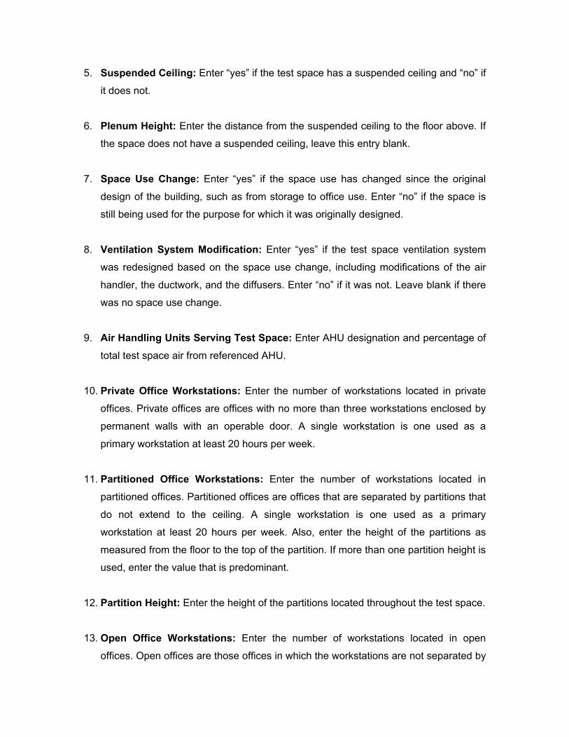
5. Suspended Ceiling: Enter “yes” if the test space has a suspended ceiling and “no” if
it does not.
6. Plenum Height: Enter the distance from the suspended ceiling to the floor above. If
the space does not have a suspended ceiling, leave this entry blank.
7. Space Use Change: Enter “yes” if the space use has changed since the original
design of the building, such as from storage to office use. Enter “no” if the space is
still being used for the purpose for which it was originally designed.
8. Ventilation System Modification: Enter “yes” if the test space ventilation system
was redesigned based on the space use change, including modifications of the air
handler, the ductwork, and the diffusers. Enter “no” if it was not. Leave blank if there
was no space use change.
9. Air Handling Units Serving Test Space: Enter AHU designation and percentage of
total test space air from referenced AHU.
10. Private Office Workstations: Enter the number of workstations located in private
offices. Private offices are offices with no more than three workstations enclosed by
permanent walls with an operable door. A single workstation is one used as a
primary workstation at least 20 hours per week.
11. Partitioned Office Workstations: Enter the number of workstations located in
partitioned offices. Partitioned offices are offices that are separated by partitions that
do not extend to the ceiling. A single workstation is one used as a primary
workstation at least 20 hours per week. Also, enter the height of the partitions as
measured from the floor to the top of the partition. If more than one partition height is
used, enter the value that is predominant.
12. Partition Height: Enter the height of the partitions located throughout the test space.
13. Open Office Workstations: Enter the number of workstations located in open
offices. Open offices are those offices in which the workstations are not separated by
any walls or partitions. A single workstation is one used as a primary workstation at
least 20 hours per week.
14. Windows in Test Space: Enter the total number of windows in the test space.
15. Operable Windows in Test Space: Of the total number of windows, enter the
number of windows that are operable.
16. Design Floor Area per Workstation: Enter the design floor area per workstation.
Note that this value does not indicate the floor area at the time of building design.
Rather, this value represents the floor area per occupant calculated during the study
week. Design floor area per occupant is calculated by taking the test space occupied
floor area (2), divided by the total number of test space workstations (9 + 10 + 11).
Test Space Furniture
17. Systems Furniture: Enter the number of workstations comprised of systems
furniture. Systems furniture is fixed to the floor or wall and cannot be moved without
detaching the furniture from its installation hardware. Also, enter the systems
furniture materials used within the test space. These include wood, wood veneer,
textiles, metal, formica, or other. For each material used in systems furniture in the
test space, select primary, secondary, or other.
18. Movable Furniture: Enter the number of workstations comprised of movable
furniture. Movable furniture is not attached to the floor or wall and can be moved
without requiring detachment from installation hardware. Also, enter the movable
furniture materials used within the test space. These include wood, wood veneer,
textiles, metal, formica, or other. For each material used in movable furniture in the
test space, select primary, secondary, or other.
Test Space Interior Finishes
19. Wall Finish: Enter the types of wall finish in the test space. These include painted
wallboard, fabric, metal, wallpaper, wood paneling, or other. For each material used,
select primary, secondary, or other.
20. Partition Finish: Enter the types of partition finish in the test space. These include
cloth, wood veneer, metal, plastic, wood, or other. For each material used, select
primary, secondary, or other.
21. Ceiling Finish: Enter the types of ceiling finish in the test space. These include
suspended, fabric, metal, painted wallboard, wood paneling, or other. For each
material used, select primary, secondary, or other.
22. Floor Finish: Enter the types of floor finish in the test space. These include carpet,
wood, tile, concrete, or other. For each material used, select primary, secondary, or
other.
Test Space Lighting
23. Incandescent Lamps: Enter the number of incandescent lamps permanently fixed
to walls or ceilings in the test space.
24. Incandescent Lamps Wattage: Enter the typical wattage of these lamps.
25. Fluorescent Lamps: Enter the number of fluorescent lamps permanently fixed to
walls or ceilings in the test space.
26. Fluorescent Lamp Type: Enter the lamp type. When describing the lamp type,
include the typical bulb wattage.
27. Fluorescent Lamp Luminaire: Enter the typical luminaire type of the lamps.
Luminaire types include parabolic, lensed, troffer, indirect/direct, indirect, and bare.
An example of each type is shown below. Note that a single fixture may contain
multiple lamps.
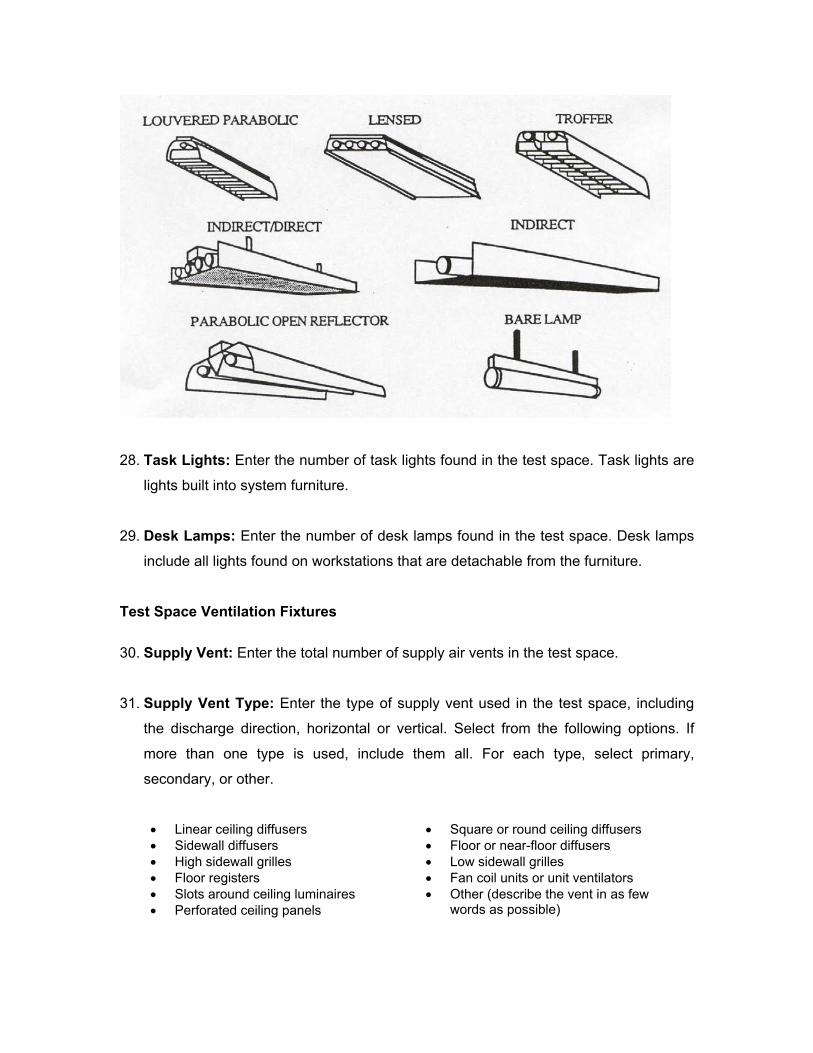
28. Task Lights: Enter the number of task lights found in the test space. Task lights are
lights built into system furniture.
29. Desk Lamps: Enter the number of desk lamps found in the test space. Desk lamps
include all lights found on workstations that are detachable from the furniture.
Test Space Ventilation Fixtures
30. Supply Vent: Enter the total number of supply air vents in the test space.
31. Supply Vent Type: Enter the type of supply vent used in the test space, including
the discharge direction, horizontal or vertical. Select from the following options. If
more than one type is used, include them all. For each type, select primary,
secondary, or other.
• Linear ceiling diffusers • Square or round ceiling diffusers • Sidewall diffusers • Floor or near-floor diffusers • High sidewall grilles • Low sidewall grilles • Floor registers • Fan coil units or unit ventilators • Slots around ceiling luminaires • Perforated ceiling panels
• Other (describe the vent in as few words as possible)
32. Return Vents: Enter the total number of return vents in the test space.
33. Return Vent Type: Enter the type of return vents used in the test space. Select from
the following options. If more than one type is used, include them all. For each type,
select primary, secondary, or other. Also, enter the total number of return air vents in
the test space.
• Ceiling grilles • Slots around ceiling luminaires • Ceiling slots • High sidewall grilles • Low sidewall or floor grilles • Other (describe the vent in as few
words as possible)
34. Additional Space Equipment: Enter the types of additional space conditioning
equipment found in the test space. Select from the following list. For each equipment
type, enter the total number found and the number found operating
• Air cleaners • Space heaters • Humidifiers • Dehumidifiers • Desk fans
FORM B-2 TEST SPACE SOURCE INFORMATION
This form is used to obtain information related to sources of indoor and outdoor
pollutants that may impact the test space. This information is acquired through a
combination of a test space walk-through and discussions with the building owner,
manager, and operator. The entries on the form are to be completed as follows:
Test Space Smoking
1. Smoking Permitted: Enter “yes” if smoking is permitted anywhere in the test space
and “no” if smoking is not allowed.
2. Smoking Permitted in Entire Test Space: Enter “yes” if smoking is permitted
throughout the entire test space and “no” if smoking is permitted only in specific
locations.
3. Restricted to Private Offices: Enter “yes” if smoking is restricted within the test
space except for private offices and “no” if smoking is not allowed in private offices.
4. Restricted to Indoor Smoking Areas: Enter “yes” if smoking is restricted within the
test space except for designated smoking areas (including designated restrooms).
Enter “no” if indoor smoking areas do not exist.
5. Restricted to Outdoor Smoking Areas: Enter “yes” if smoking is allowed outside
the test space.
Test Space Water Damage
6. Past Occurrences: Enter “yes” if there has been past water damage in the test
space.
7. Location of Past Water Damage: If water damage occurred in the past, enter the
location from the list where water damage has occurred, basement, roof, mechanical
space, or occupied space. If the water damage occurred in the occupied space,
enter the floor where damage occurred.
8. Current Water Damage: Enter “yes” if there is currently water leakage or visible
water damage within the test space.
9. Location of Current Water Damage: If current water damage or water leaks are
present, enter the location from the list where this is occurring, basement, roof,
mechanical space, or occupied space. If it is occurring in the occupied space, enter
the floor where it is occurring.
Test Space Fire Damage
10. Test Space Damage: Enter “yes” if there has been fire damage within the test
space.
11. Month/Year: If “yes,” enter the month and year that the damage occurred.
Test Space Renovations
This section describes the renovations that have occurred in the test space during the
past year. This information can be obtained from a building walk-through and from the
building owner or manager.
Painting
12. Painting: Enter “yes” if there has been painting within the test space within the last
year.
13. Month: If “yes,” enter the month and year that painting occurred.
Carpeting
14. Carpet: Enter “yes” if there has been new carpeting installed within the test space
within the building within the last year.
15. Month: If “yes,” enter the month and year that carpeting was installed.
Furniture
16. Furniture: Enter “yes” if there has been new furniture installed within the test space
within the building within the last year.
17. Month: If “yes,” enter the month and year that new furniture was installed.
Partition and Interior Wall Systems
18. Partitions: Enter “yes” if there has been partition replacement or interior wall
movement within the test space within the building within the last year.
19. Month: If “yes,” enter the month and year that partition replacement or interior wall
movement occurred.
Test Space Cleaning
This section describes cleaning that may occur in the test space. Information recorded
on this form may differ from that for whole building cleaning such as cleaning schedules,
when cleaning is performed and materials used. This information can be obtained from a
building walk-through and from the building owner or manager.
Cleaning Schedules
20. Office Cleaning: Enter the frequency at which test spaced office cleaning is done.
Note whether this cleaning is done during occupied hours, evenings, or weekends.
21. Dry Mopping: Enter the frequency at which test space dry mopping is done. Note
whether dry mopping is done during occupied hours, evenings, or weekends.
22. Wet Mopping: Enter the frequency at which test space wet mopping is done. Note
whether wet mopping is done during occupied hours, evenings, or weekends.
23. Vacuuming: Enter the frequency at which test space vacuuming is done. Note
whether vacuuming is done during occupied hours, evenings, or weekends.
24. Vacuum Type: If vacuuming is conducted, enter the type of vacuum used. These
include standard vacuums, and vacuums equipped with HEPA filtration.
Cleaning Materials
25. Storage Location: Enter “yes” if cleaning materials are stored in the test space and
“no” if they are not.
26. Materials Used: Select from the list each cleaning material used in the test space.
General descriptors include window cleaner, furniture cleaner, floor wax, bathroom
cleaners, bleach, soap, and carpet cleaners.
27. Inventory of Cleaning Materials: Collect an inventory of all cleaning materials used
in the test space. This information should be collected by taking an inventory of each
storage room within the test space.
Test Space Trash Storage
28. Trash Storage: Enter “yes” if trash is stored in the test space and no if it is not. Enter
“no” if trash is stored only temporarily during trash collection.
Special Use Spaces (29 through 61)
Information regarding special use spaces should be obtained from the building owner,
manager, or facilities engineer and verified by a walkthrough. For each of the categories,
(smoking lounges through conference rooms) provide the following information:
Existence: Enter “yes” if the space use category exists in the building. Also, enter
whether this special use space is equipped with its own dedicated ventilation system and
dedicated exhaust system.
FORM B-1 TEST SPACE DESCRIPTION One copy of Form B-l is completed for each building.
GENERAL TEST SPACE CHARACTERISTICS
1 Test Space Identification _________________________________________
2 Gross Floor Area (see description for exclusions)
_________________________________________m2 or ft2
3 Occupied Floor Area (see description for exclusions)
_________________________________________m2 or ft2
4 Ceiling Height (see description for exclusions)
_________________________________________m or ft
5 Suspended Ceiling _________________________________________
6 Plenum Height _________________________________________m or ft
7 Space Use Change _________________________________________
8 Ventilation System Modification _________________________________________
9 Test Space Air Handling Units
AHU Designation Percentage of Total Test Space Air From Referenced AHU
____________________ ____________________ ____________________ ____________________ ____________________ ____________________ ____________________ ____________________
Enter Number of Each 10 Workstations in Private Offices _________________________________________
11 Workstations in Partitioned Offices (see description)
_________________________________________
12 Partition Height _________________________________________
13 Workstations in Open Office Space (see description)
_________________________________________
14 Windows in Test Space _________________________________________
15 Operable Windows in Test Space
_________________________________________
16 Design Floor Area Per Work Station
_________________________________________
Furniture
17 Systems Furniture: Number of Workstations
_________________________________________
Systems Furniture Materials: Indicate whether material is “primary”, “secondary”, or “other
P/S/O Materials Comments ______ Wood ____________________________________ ______ Wood Veneer ____________________________________ ______ Textiles ____________________________________ ______ Metal ____________________________________ ______ Plastic Laminate or Composite
Wood (formica) ____________________________________
______ Other ____________________________________
18 Movable Furniture: Number of Workstations
_________________________________________
Movable Furniture Materials: Indicate whether material is “primary”, “secondary”, or “other
P/S/O Materials Comments ______ Wood ____________________________________ ______ Wood Veneer ____________________________________ ______ Textiles ____________________________________ ______ Metal ____________________________________ ______ Plastic Laminate or Composite
Wood (formica) ____________________________________
______ Other ____________________________________
Interior Finishes
19 Wall Finish: Indicate whether finish is “primary”, “secondary”, or “other
P/S/O Wall Finish Comments ______ Painted Wallboard ____________________________________ ______ Fabric Wall Covering ____________________________________ ______ Metal ____________________________________ ______ Wallpaper ____________________________________ ______ Wood Paneling ____________________________________ ______ Other ____________________________________
20 Partition Finish: Indicate whether finish is “primary”, “secondary”, or “other
P/S/O Partition Finish Comments ______ Cloth ____________________________________ ______ Wood Veneer ____________________________________ ______ Metal ____________________________________ ______ Plastic ____________________________________ ______ Wood ____________________________________ ______ Other ____________________________________
21 Ceiling Finish: Indicate whether finish is “primary”, “secondary”, or “other
P/S/O Ceiling Finish Comments ______ Suspended Ceiling ____________________________________ ______ Fabric ____________________________________ ______ Metal ____________________________________ ______ Painted Wallboard ____________________________________ ______ Wood Paneling ____________________________________ ______ Other ____________________________________
22 Floor finish: Indicate whether finish is “primary”, “secondary”, or “other
P/S/O Floor Finish Comments ______ Carpet ____________________________________ ______ Wood ____________________________________ ______ Plastic Tile or Sheet ____________________________________ ______ Concrete ____________________________________ ______ Other ____________________________________
Lighting
23 Number of Fixed Incandescent Lamps
_________________________________________
24 Typical Wattage of Fixed Incandescent Lamps
_________________________________________
25 Number of Fluorescent Lamps _________________________________________
26 Fluorescent Lamp Type _________________________________________
27 Fluorescent Luminaire Type _________________________________________
28 Number of Task Lights _________________________________________
29 Number of Desk Lamps _________________________________________
Ventilation Fixtures
30 Total Number of Supply Vents ______________________________________
31 Supply Air Vent Type: Indicate whether type is “primary”, “secondary”, or “other
P/S/O Materials Comments ______ Linear Ceiling Diffusers ____________________________________ ______ Sidewall Diffusers ____________________________________ ______ High Sidewall Grilles ____________________________________ ______ Floor Registers ____________________________________ ______ Perforated Ceiling Panels ____________________________________ ______ Square or Round Ceiling
Diffusers ____________________________________
______ Floor or Near-floor Diffusers ____________________________________ ______ Low Sidewall Grilles ____________________________________ ______ Fan Coil Units or Unit Ventilators ____________________________________ ______ Slots Around Ceiling Luminaires ____________________________________ ______ Other ____________________________________
32 Total Number of Return Vents ______________________________________
33 Return Air Vent Type: Indicate whether type is “primary”, “secondary”, or “other
P/S/O Materials Comments ______ Ceiling Grilles ____________________________________ ______ Ceiling Slots ____________________________________ ______ Low Sidewall or Floor Grilles ____________________________________ ______ Slots Around Ceiling Luminaires ____________________________________ ______ High Sidewall Grilles ____________________________________ ______ Other ____________________________________
Additional Space Conditioning Equipment
34 Number of Air Cleaners Observed in Test Space
______________________________________________
Number of Operating Air Cleaners
______________________________________________
Number of Space Heaters Observed in Test Space
______________________________________________
Number of Operating Space Heaters
______________________________________________
Number of Humidifiers Observed in Test Space
______________________________________________
Number of Operating Humidifiers
______________________________________________
Number of Dehumidifiers Observed in Test Space
______________________________________________
Number of Operating Dehumidifiers
______________________________________________
Number of Desk Fans Observed in Test Space
______________________________________________
Number of Operating Desk Fans
______________________________________________
FORM B-2 TEST SPACE DESCRIPTION One copy of Form B-2 is completed for each building.
SMOKING POLICIES
1 Smoking Permitted in Test Space? (yes/no)
_______________________________________
2 Is Smoking Permitted in Entire Test Space?
_______________________________________
3 Is Smoking Restricted to Private Offices? _______________________________________
4 Is Smoking Restricted to Indoor Smoking Areas?
_______________________________________
5 Is Smoking Restricted to Outdoor Smoking Areas?
_______________________________________
WATER DAMAGE
6 Past Occurrences of Water Damage (yes/no) ____________________________________ 7 If Yes, Location of Past Water Damage Basement ____________________________________ Roof ____________________________________ Mechanical Space ____________________________________ Occupied Space ____________________________________
8 Current Water Leakage or Damage
____________________________________
9 If Yes, Location of Current Water Leakage or Damage
Basement Roof Mechanical Space Occupied Space
FIRE DAMAGE 10 Past Occurrences of Test Space Fire Damage
(yes/no) ____________________________________
11 If Yes, Month/Year When Fire Occurred ____________________________________
TEST SPACE RENOVATIONS
Painting
12 Have Painting Renovations Occurred in the Last
Year? (yes/no) ________________________________
13 If Yes, Enter Month and Year ________________________________
New Carpet
14 Has New Carpet Been Installed in the Last Year?
(yes/no) ________________________________
15 If Yes, Enter Month and Year ________________________________
New Furniture
16 Has New Furniture Been Installed in the Last
Year? (yes/no) ________________________________
17 If Yes, Enter Month and Year ________________________________
Partition Replacement
18 Has Partition Replacement or Interior Wall
Movement Occurred in the Last Year? (yes/no) ________________________________
19 If Yes, Enter Month and Year ________________________________
TEST SPACE CLEANING
Frequency Occupied
Hours Evenings Weekends
20 Office Cleaning ___________ ___________ ___________ ___________
21 Dry Mopping ___________ ___________ ___________ ___________
22 Wet Mopping ___________ ___________ ___________ ___________
23 Vacuuming ___________ ___________ ___________ ___________
24 Type of Vacuum Used _____________________________________________
25 Are Cleaning Materials Stored in Test Space? ________________________________
26 Cleaning Materials Used in Building (check all that apply)
Window Cleaner _____________________ Furniture Cleaner _____________________ Floor Wax _____________________ Bathroom Cleaner _____________________ Bleach _____________________ Liquid Soap _____________________ Carpet Cleaner _____________________ Other (describe) __________________________________________________
27 Cleaning Materials Inventory (document all cleaning materials used in the test space by name
and manufacturer)
Test Space Trash Storage
28 Is Trash Stored in the Test Space? _______________________________ SPECIAL USE SPACES Smoking Areas 29 Does the Test Space Have Any Smoking Areas? _________________________ 30 If Yes, is the Space Served by a Dedicated
Ventilation System? _________________________
31 If Yes, is the Space Served by a Dedicated Exhaust System?
_________________________
Kitchenettes 32 Does the Test Space Have Any Kitchenettes? _________________________ 33 If Yes, is the Space Served by a Dedicated
Ventilation System? _________________________
34 If Yes, is the Space Served by a Dedicated Exhaust System?
_________________________
Vending Areas 35 Does the Test Space Have Any Vending Areas? _________________________
36 If Yes, is the Space Served by a Dedicated Ventilation System?
_________________________
37 If Yes, is the Space Served by a Dedicated Exhaust System?
_________________________
Laboratory Areas 38 Does the Test Space Have Any Laboratory
Areas? _________________________
39 If Yes, is the Space Served by a Dedicated Ventilation System?
_________________________
40 If Yes, is the Space Served by a Dedicated Exhaust System?
_________________________
Print Shop 41 Does the Test Space Have a Print Shop? _________________________ 42 If Yes, is the Space Served by a Dedicated
Ventilation System? _________________________
43 If Yes, is the Space Served by a Dedicated Exhaust System?
_________________________
Graphic Arts 44 Does the Test Space Have a Graphic Arts Area? _________________________ 45 If Yes, is the Space Served by a Dedicated
Ventilation System? _________________________
46 If Yes, is the Space Served by a Dedicated Exhaust System?
_________________________
Commercial Kitchen 47 Does the Test Space Have a Commercial
Kitchen? _________________________
48 If Yes, is the Space Served by a Dedicated Ventilation System?
_________________________
49 If Yes, is the Space Served by a Dedicated Exhaust System?
_________________________
Loading Dock 50 Does the Test Space Have a Loading Dock? _________________________ 51 If Yes, is the Space Served by a Dedicated
Ventilation System? _________________________
52 If Yes, is the Space Served by a Dedicated Exhaust System?
_________________________
Parking Garage 53 Does the Test Space Have a Parking Garage? _________________________ 54 If Yes, is the Space Served by a Dedicated
Ventilation System? _________________________
55 If Yes, is the Space Served by a Dedicated Exhaust System?
_________________________
Computer Room 56 Does the Test Space Have a Computer Room? _________________________ 57 If Yes, is the Space Served by a Dedicated
Ventilation System? _________________________
58 If Yes, is the Space Served by a Dedicated Exhaust System?
_________________________
Conference Room 59 Does the Test Space Have a Conference Room? _________________________ 60 If Yes, is the Space Served by a Dedicated
Ventilation System? _________________________
61 If Yes, is the Space Served by a Dedicated Exhaust System?
_________________________

CHECKLIST INSTRUCTIONS: TEST SPACE HVAC SYSTEM DESCRIPTION
The description of the HVAC system serving the test space employs a series of forms,
with the specific forms used and their number depending on the system. The use of
Forms C-1 through C-10 depends on the components of the HVAC system. Forms C-11
and C-12 will be used in all buildings. The forms for HVAC descriptions and inspections
are as follows:
C1 AIR HANDLING AND DISTRIBUTION SYSTEM
C2 PERIMETER ZONE UNITS
C3 UNITARY SYSTEMS
C4 EVAPORATIVE COOLING SYSTEMS
C5 OUTDOOR AIR INTAKE CONTROL
C6 NATURAL VENTILATION SYSTEMS
C7A AIR HANDLER SPECIFICATIONS
C7B EXHAUST FAN SPECIFICATIONS
C8 FILTRATION AND AIR CLEANING SYSTEMS
C9 AIR WASHERS
C10 HUMIDIFICATION SYSTEMS
C11 MAINTENANCE
C12 INSPECTION
FORM C-1 AIR HANDLING AND DISTRIBUTION SYSTEMS
Central air handling systems, sometimes also referred to as "all-air," provide space
conditioning by supplying conditioned air and ventilation by supplying outdoor air. A test
space air handling unit may be defined as an air handling unit that supplies outdoor air to
the test space. This form is used to describe the air handling and distribution systems
serving the test space. One form should be completed for each system serving the test
space.
Air Handling Unit Description
1. Identification: Enter the air handler identification using floor numbers and either
room numbers or a description of the location on that floor.
2. System Type Code: Select the system type from one of the following options. The
system type should be determined by review of equipment specifications and
documentation, and system inspection. Additional information should be obtained
from the building operator.
A Single Duct, Constant Volume, Single Zone
The air handler supplies a constant volume of supply air to a single zone with minimum
heating and cooling load variations. The load within the space is controlled by varying
the temperature of the supply air. The supply air temperature is controlled by varying the
quantity and/or temperature of the heating or cooling source, by varying the relative
proportions of outdoor air intake and recirculation air, by modulating the position of face
and bypass dampers within the air handler, or a combination of these approaches.
B Single Duct, Constant Volume, Multiple Zone Reheat
The air handler supplies a constant volume of supply air to multiple zones with unequal
loads. The load within each zone is controlled by varying the temperature of the supply
air delivered to the zone. The supply air temperature is controlled by varying the amount
of heating or cooling at the air handler, the relative proportions of outdoor air intake and
recirculation, the position of face and bypass dampers within the air handler, or a
combination of these approaches. Further temperature control in individual zones is
provided by reheat coils in the ducts in each individual zone.
C Single Duct, Constant Volume, Multiple Zone Bypass
The air handler supplies a constant volume of supply air to multiple zones with unequal
loads. The load within each zone is controlled by varying the temperature of the supply
air delivered to the zone and the amount of supply air that is actually delivered to the
zone. The supply air temperature is controlled by varying the amount of heating or
cooling at the air handler, the relative proportions of outdoor air intake and recirculation,
the position of face and bypass dampers within the air handler, or a combination of these
approaches. Further temperature control in individual zones is provided through the use
of a bypass box in the zone which dumps some of the supply air into the return air
plenum or duct.
D Single Duct, Variable Air Volume
The air handler supplies air at a constant temperature of approximately 13 degrees
Celsius (55 degrees Fahrenheit) through a duct system to variable air volume (VAV)
units located in the ceiling plenum. In each zone, the VAV unit controls the quantity of
supply air delivered to meet the cooling load requirements within that zone. The total
quantity of supply air delivered by the air handler therefore varies in response to
variations in the building space load. A true VAV system provides cooling only, with
perimeter zones heated by some other system.
E Single Duct, Variable Air Volume, Reheat
This system is a modification of a true VAV system capable of providing both heating
and cooling. Heat is provided in or near the terminal units after the supply airflow rate
has been reduced to a predetermined minimum.
F Single Duct, Variable Air Volume, Induction
A VAV air handler provides primary air to unpowered VAV terminal units that induce
plenum or room air into the supply airstream. The combination of primary and induced
air provides a constant airflow. Variations in space load are met by varying the relative
proportions of the primary and induced air. Reheat coils or some other form of auxiliary
heat are required when heat gain in the room and ceiling is less than the sum of the
transmission losses and the cooling loads associated with the primary air.
G Single Duct, Variable Air Volume, Fan Powered, Constant Fan
A VAV air handler supplies primary air to fan-powered VAV induction units that are
installed in series with the primary supply airflow. The fan-powered units run
continuously and operate at a relatively constant volume. In each zone, the unit mixes
primary supply air with induced return air from the plenum to meet the space loads.
Terminal units in exterior zones have heating coils for winter heating requirements. The
heating coil is not activated until the primary air volume is sensed.
H Single Duct, Variable Air Volume, Fan Powered, Intermittent Fan
A VAV air handler supplies primary air to fan-powered VAV induction units that are
installed in parallel with the primary supply airflow. The unit modulates the primary
supply air in response to the cooling loads of the zone and operates the fan-powered
unit when induced air is needed to meet the heating requirements. The primary air and
the induced air mix within a common plenum within the fan-powered unit.
I Single Duct, Variable Air Volume, Dual Conduit
This system has two airstreams, one system used to meet year round cooling loads and
a second system to offset transmission losses. The first system is a conventional central
VAV system that provides year-round cooling to meet space cooling loads. The second
system operates at constant volume, with the air temperature varied to meet
transmission losses, and conditions return air from the ceiling plenum or the room. In
some systems, this second system operates only during peak loads.
J Dual Duct, Constant Volume
The air handler supplies a constant volume of supply air to multiple zones; with the
supply fan blowing through cooling coil and bypass sections connected to cold and hot
decks respectively. These two decks run through the building to unpowered mixing
boxes in the ceiling plenum, which mix the warm and cold air to meet the loads in the
zone.
K Dual Duct, Constant Volume, Reheat
The air handler supplies a constant volume of supply air to multiple zones, with the
supply airstream being split into two flows, one blowing through cooling coils and the
other blowing through heating coils. The hot and cold air decks run through the building
to unpowered mixing boxes in the ceiling plenum, which mix the hot and cold air to meet
the loads in the zone. Interior zones mixing boxes may only be connected to the cold
deck.
L Dual Duct, Variable Air Volume, Single Fan
A single VAV air handler supplies air to multiple zones, with the supply fan blowing
through cooling and heating coil sections connected to cold and hot decks respectively.
These two decks run through the building to VAV mixing boxes in the ceiling plenum,
which mix the hot and cold air to meet the loads in the zone. The dampers in the mixing
boxes are controlled by zone thermostats. Interior zone boxes may be connected to only
the cold duct, while exterior zones will be connected to both the hot and cold decks.
M Dual Duct, Variable Air Volume, Dual Fan
In this system, separate supply fans serve the cold and hot decks. The two decks run
through the building to VAV mixing boxes in the ceiling plenum, which mix the hot and
cold air to meet the loads in the zone. Interior zone boxes may be connected to only the
cold duct while exterior zones will be connected to both the hot and cold ducts.
N Multizone, Constant Volume
A constant volume air handler serves multiple zones, with the supply fan blowing
through a cooling or heating coil, or both. Each zone's space load is met with a mixture
of the hot and cold airstreams carried by a single duct to the zone. The mixing of the two
airstreams for each zone takes place at the unit, with dampers in the hot and cold decks.
The airflow rate to each zone is fairly constant depending on the pressure drop through
each coil and the position of the mixing dampers.
O Constant Volume, Blow-through Bypass
A constant volume air handler serves multiple zones, with the supply fan blowing air
through the cooling coil section or through a bypass section around the cooling coil. The
two supply ducts, cold and bypass, split off such that there is a cold duct and bypass air
duct for each zone. These two supply airflows are brought together within the
mechanical room, with the damper in the bypass air duct and a heating coil downstream
of where the two flows merge. A constant quantity of air is supplied to each zone through
this single duct and the supply air temperature to each zone is varied to meet space load
by modulating the bypass damper and the use of the heating coil. The heating coil is
activated only when all of the zone's supply air is bypass air. Interior zones may not have
the heating coil in their ducts.
P Texas Multizone, or Three-deck Multizone
The air handler supplies a constant volume of supply air to multiple zones, with the
supply fan blowing through a cooling coil, a bypass section or a heating coil. The space
load of each zone is met through a mixture of the cold, bypass, and hot airstreams that
is carried by a single duct to the zone. The mixing of the three airstreams for each zone
takes place at the unit, employing dampers in the three decks. Interior zones are
generally not connected to the hot deck. The heating coils are activated only if the
bypass air can not meet the loads. The total air quantity to each zone is more or less
constant depending on the pressure drop through each coil and the position of the
mixing dampers.
3. Zones Served: Enter the thermostatically controlled zones served by the air
handling unit. This value can be obtained by a review of building design drawings.
Note that this count should include both zones inside and outside of the test space.
4. Return Air Fan: Enter “yes” if the air handling unit is equipped with a return air fan
and “no” if it is not.
5. Variable Temperature Setpoint: If the system is VAV and the supply air
temperature is varied by the control system in response to conditions, choose “Yes”
in response to variable supply air temperature setpoint. Choose “No” if the system is
VAV, but does have a variable supply air temperature. If the system is not VAV,
leave this question blank.
6. Test Space Served by Air Handler: For each test space served by this air handler,
enter the two digit code used to identify the test space and the approximate
percentage of total air handler capacity going to that test space.
Air Handling Unit Ductwork
7. Supply Ducting: Enter the type of supply ductwork used by the air handling unit,
galvanized, flexible fiber board, no ducting used, or other. When multiple types of
ducting are used, select each type as primary, secondary, or other.
8. Return Ducting: Enter the type of return ductwork used by the air handling unit,
galvanized, flexible fiber board, no ducting used, or other. When multiple types of
ducting are used, select each type as primary, secondary, or other.
FORM C-2 PERIMETER ZONE UNITS
This form is used to describe systems that provide space conditioning to perimeter
zones. In many cases, the systems within the section on central systems will also serve
perimeter zones, but the systems described on this form are intended solely for
perimeter applications. Only one form is required for the test space. One copy of
Form C-2 should be completed for each test space.
1. Air Water Induction Units: Enter “yes” if air water induction units are used in the
test space and “no” if they are not. Also, if “yes,” enter whether these systems are
equipped with condensate drain pans and air filters.
2. Fan Coil Units: Enter “yes” if fan coil units are used in the test space and “no” if they
are not. Also, if “yes,” enter whether these systems are equipped with condensate
drain pans and air filters.
3. Unit Ventilators: Enter “yes” if unit ventilators are used in the test space and “no” if
they are not. Also, if “yes,” enter whether these systems are equipped with
condensate drain pans and air filters and whether the units are provided with
ventilation air.
4. Fin-tube Radiation: Enter “yes” if fin-tube radiation is used in the test space and
“no” if they are not.
5. Electric Baseboard: Enter “yes” if electric baseboard is used in the test space and
“no” if they are not.
FORM C-3 UNITARY SYSTEMS
This form is used to describe unitary air-conditioning equipment, which includes a range
of systems consisting of factory-assembled components providing heating, cooling, and
outdoor air. Generally, each zone is served by a separate unit, unless the zone is very
large. One copy of Form C-3 should be completed for each test space.
1. Rooftop Units: Enter “yes” if the test space is conditioned by rooftop units. These
units are single package units consisting of unitary equipment, a ducted air
distribution system, and a temperature control system. They may serve single or
multiple zones, and may be constant and variable air volume. Also, enter the number
of rooftop systems serving the test space, the type of zoning, and whether the
systems are constant air volume (CAV) or VAV.
2. Packaged Room AC Systems: Enter “yes” if the test space is conditioned by
individual room packaged air-conditioning (AC) units. Individual room packaged AC
units are small capacity direct expansion (DX) refrigeration cycle air-conditioning
package units that do not introduce outside air. Also, if “yes,” enter whether these
systems are equipped with condensate drain pans and air filters.
3. Heat Pump Systems: Enter “yes” if the test space is conditioned by heat pump
systems. Heat pump systems are factory-assembled units with the capacity to heat
and cool. A single system can be used to condition an entire building or individual
zones. Heat pump types include air-to-air, water-to-air, air-to-water, and water-to-
water. Ventilation air may be supplied by a central system to the individual units
through a system of ductwork or the individual units may provide ventilation. If the
test space is served by these systems, enter the number of systems serving the
space and whether ventilation air is provided.
4. Other: If some other type of unitary system is being used, enter “yes” and describe
the system.
FORM C-4 EVAPORATIVE COOLING SYSTEMS
Evaporative cooling systems are non-refrigerant systems that cool air by exchanging
sensible heat for latent heat, thereby reducing temperatures, but raising humidity levels.
This form is used to describe evaporative cooling systems that may be used to condition
the test space. One copy of Form C-4 should be completed for each test space.
1. Direct Evaporative Air Coolers: Enter “yes” if the test space is served by a direct
evaporative cooling system. If “yes,” also enter the type of system being used. These
include the following:
Wetted-media: A fan pulls air through wetted pads and delivers the cooled air to the
space. A pump lifts water from a reservoir allowing it to flow down the media back to
the sump.
Rigid-media: A fan moves air horizontally through wet sheets of rigid corrugated
material. A pump lifts water from a reservoir allowing it to flow down the media back
to the sump.
Slinger packaged: A fan draws outdoor air through a water spray, an evaporative
filter pad, and an entrained-moisture eliminator pad. The spray is created by a motor-
driven disk that is partially emersed in a water reservoir.
Packaged rotary: A fan pulls air through a pad that rotates through a water reservoir.
2. Indirect Evaporative Air Coolers: Enter “yes” if the test space is served by an
indirect evaporative cooling system. In an indirect evaporative air cooler, a fan forces
an air stream across one side of a heat exchanger. On the other side of the heat
exchanger, the conditioned air being supplied to the space is sensibly cooled by
contact with the heat exchanger surfaces. An indirect evaporative cooler may either
be self-contained or a part of a packaged air handling system.
FORM C-5 OUTDOOR AIR INTAKE CONTROL
This form is used to describe the means of outdoor air intake control employed in the
mechanical ventilation system serving the test space. The information on this form can
be determined from the mechanical equipment specifications and verified by inspection
and discussion with the building operator. One copy of Form C-5 should be completed
for each test space.
1. Intake Strategy: Enter the intake strategy for the air handling units serving the test
space from the list provided below:
Conditioned positive: A separate fan is used to bring in the required amount of
outdoor air. This air is filtered and possibly dehumidified and heated or cooled prior
to being delivered to the air handler
Unconditioned positive: A separate fan is used to bring in the required amount of
outdoor air, but this air is not treated prior to being delivered to the air handler.
Unconditioned suction: Outdoor air is brought into the building through a separate
duct by the suction induced by the supply fan. This air is not treated prior to being
delivered to the air handler.
Unconditioned suction with no duct: Untreated outdoor air intake is induced by the
supply fan suction, directly into the air handling unit.
2. Control Strategy: Enter the outdoor air control strategy for the air handling units
serving the test space from the list provided below.
100% outdoor air intake: The air handler provides 100 percent outdoor air at all
times, with no recirculation of return air.
Fixed minimum outdoor air intake: The rate of outdoor air intake is constant
whenever the air handler is operating. The supply air consists of constant proportions
of outdoor air and recirculated return air.
Economizer cycle: If the outdoor air temperature is above a low temperature
setpoint, the return, relief, and outdoor air intake dampers modulate to maintain the
mixed air temperature at its setpoint. When the outdoor air temperature is below this
setpoint, the outdoor air intake is at a minimum. When the outdoor air temperature is
above a high temperature limit, the outdoor air intake is reduced to a minimum level.
Enthalpy economizer cycle: If the outdoor air enthalpy is above a low enthalpy
setpoint, the return, relief, and outdoor air intake dampers modulate to maintain the
mixed air temperature at its setpoint. When the outdoor air enthalpy is below this
setpoint, the outdoor air intake is at a minimum. When the outdoor air enthalpy is
above a high enthalpy limit, the outdoor air intake is reduced to a minimum level.
3. Means of Maintaining Minimum: From the list provided, enter the method used by
the air handling unit in maintaining a minimum outdoor air setpoint.
Fixed damper position: The intake and recirculation dampers are fixed and the
pressure in the mixed air plenum determines the outdoor air intake rate.
Supply/return fan tracking: Based on the difference between the supply and return
fan airflow rates, the outdoor air intake dampers position is modulated to provide a
constant outdoor air intake rate.
Intake airflow monitoring: The outdoor air intake rate is monitored with an airflow
station and the control system modulates the outdoor air intake dampers based on
the measured airflow rate as compared to a set point.
Additional Outdoor Air Control
4. Morning Warm-up Cycle: Enter “yes” if the air handling units operate with a
morning warm-up cycle and “no” if they do not. With morning warm-up, the system
operates with no outdoor air to warm up the building prior to occupancy. This mode
is used during unoccupied hours.
5. Morning Purge Cycle: Enter “yes” if the air handling units operate with a morning
purge cycle and “no” if they do not. With morning purge, the system operates at a
high level of outdoor air to purge the building of any contaminants that may have built
up over the night. This mode occurs prior to occupancy.
6. Night Cool-down Cycle: Enter “yes” if the air handling units operate with a night
cool-down cycle and “no” if they do not. With night cool-down, the system is run at
100% outdoor air intake in order to cool the building prior to occupancy. This mode is
operated under certain outdoor air temperature and humidity conditions.
FORM C-6 NATURAL VENTILATION SYSTEMS
This form is used to describe the ventilation strategy employed in naturally ventilated
buildings. Natural ventilation systems operate without external power, employing
pressure differences caused by wind and temperature differences to induce airflow
through the building. A building with a natural ventilation system may still have powered
exhaust systems serving toilets and other areas. Information on the natural ventilation
system can be determined from the mechanical equipment specifications, and verified
by inspection and discussion with the building operator. One copy of Form C-6 should be
completed for each building.
1. Through-the-exterior Wall Vents: Enter “yes” if the building is ventilated by airflow
through openings in the exterior wall and “no” if it is not. If “yes,” enter the number
and size of the vents. Note that if the building is not naturally ventilated this question
is left blank.
2. Central Shaft: For naturally ventilated buildings, enter “yes” if the building is
ventilated through central shaft that connects to the floors and carries air to the roof
of the building. Note that if the building is not naturally ventilated this question is left
blank.
3. Mechanical Exhaust System: For naturally ventilated buildings, enter “yes” if the
building is ventilated only by a mechanical exhaust system. The exhaust system
should not include those used for bathrooms and/or special use spaces. Note that if
the building is not naturally ventilated this question is left blank.
FORM C-7A AIR HANDLING UNIT SPECIFICATIONS
This form is used to record the design specifications of the air handler(s) serving the test
space. Information on the air handler is generally found in the mechanical equipment
specifications. The accuracy of these specifications should be verified by discussions
with the building operator. One copy of Form C-7A should be completed for each air
handling unit serving the test space.
1. Supply Capacity: Enter the design supply airflow rate capacity for the air handling
unit. Also, enter the source where this value was obtained.
2. Minimum Outdoor Air Rate: Enter the design minimum outdoor air intake rate for
the air handling unit. Also, enter the source where this value was obtained.
3. Space Served by Supply Air: Enter the space served by the air handling unit
supply air system. Include the floor number and description of the space.
4. Floor Area Served by Supply: Enter the floor area served by the air handling unit
supply air system. Also, enter the source where this value was obtained.
5. Occupants Served: Enter the total number of occupants served by the air handling
unit supply air system. This information can be obtained through the building
operator or through a walkthrough of the air handling unit zones. Also, enter the
source where this value was obtained.
6. Design Cooling Load: Enter the design-cooling load for the air handling unit. This
value is obtained from the schedule page of the buildings mechanical design
drawings and is calculated by dividing the cooling coil capacity by the floor area
served by the air handling unit. Also, enter the source where this value was obtained.
7. Return Fan: Enter “yes” if the air handling unit is equipped with a dedicated return
fan and “no” if it is not.
8. Return Capacity: Enter the design return airflow rate capacity for the air handling
unit. Also, enter the source where this value was obtained.
9. Space Served by Return Air: Enter the space served by the air handling unit return
air system. Include the floor number and description of the space. Note that this
question is still valid even if the air handling unit is not equipped with a dedicated
return air fan.
10. Floor Area Served by Return: Enter the floor area served by the air handling unit
return air system. Also, enter the source where this value was obtained. Note that
this question is still valid even if the air handling unit is not equipped with a dedicated
return air fan.
FORM C-7B EXHAUST FAN SPECIFICATIONS
This form is used to record the design specifications for the exhaust fan(s) serving the
test space. Information on the exhaust fans is generally found in the mechanical
equipment specifications. The accuracy of these specifications should be verified by
discussions with the building operator. One copy of Form C-7B should be completed for
each exhaust fan serving the test space.
1. Identification: Enter the exhaust fan identification using floor numbers and either
room numbers or a description of the location on that floor.
2. Exhaust Capacity: Enter the design exhaust airflow rate capacity for the exhaust
fan. Also, enter the source where this value was obtained.
3. Space Served by Exhaust Fan: Enter the space served by the exhaust fan. Include
the floor number and description of the space.
4. Floor Area Served by Exhaust Fan: Enter the floor area served by the exhaust fan.
Also, enter the source where this value was obtained.
5. Fan Controls: Enter, from the list below, the type of control used to operate the
exhaust fan.
• Manual: Enter “yes” if the exhaust fan operation is controlled manually with an
on/off switch.
• Time of Day: Enter “yes” if the exhaust fan operation is controlled automatically
based on the time of day.
• Temperature: Enter “yes” if the exhaust fan operation is controlled automatically
based on temperature.
• Equipment Operation: Enter “yes” if the exhaust fan operation is controlled
automatically based on the operation of a piece of equipment.
• Pressure: Enter “yes” if the exhaust fan operation is controlled by means of a
building pressure.
FORM C-8 FILTRATION AND AIR CLEANING SYSTEMS
This form is used to record information regarding filtration and air cleaning systems used
in the air handling units serving the test space. Information on these systems is generally
found in the mechanical equipment specifications. The accuracy of these specifications
should be verified by inspection of the systems and discussion with the building
operator. One copy of Form C-8 should be completed for each filtration and air cleaning
system. Therefore, more than one copy of the form may be needed for a given air
handler, for example if the air handler has a pre-filter and a HEPA filter.
1. Air Handler Number: Enter the air handling unit number where the filtration or air-
cleaning device is installed. This number should correspond to an air handling
number defined in Form C-1.
2. Location within Air Handler: Enter the location within the air handling unit where
the filtration or air-cleaning device is installed. Appropriate terms include recirculation
air, outdoor air, mixed air upstream of coils, mixed air downstream of coils, and
supply air downstream of fan.
3. Air Cleaner Type: Enter the type of filtration or air cleaning device installed in the air
handling unit. These include filter, electronic, or gaseous.
For an air cleaner type designated as an “air filter” complete the following questions
4. Manufacturer: Enter the filtration system or air cleaning device manufacturer, Also
enter the manufacturer’s model number.
5. Filter system type: Enter whether the filter is a panel filter of a roll filter.
6. Panel filter type: If the filter is a panel filter type, enter whether the filter is a dry filter
or a viscous impingement filter. Viscous filters consist of a coarse media of high
porosity that is treated with a viscous substance such as oil to which particles adhere
when they impinge on the filter. Dry filters are made of random filter mats or
blankets. If the system employs a dry filter, enter the dry filter type: flat panel,
pleated, bag or HEPA.
7. Roll Filter Type: Enter whether the roll filter is a viscous impingement filter or a dry
filter. Also, enter whether the mechanism to introduce new media into the airstream
is manual or automatic.
8. Size: Enter the total face area of the filter bank.
9. Media: Enter the type of filter media employed in the filter.
10. Rating: Enter the rating of the filter as determined from the manufacturer's
specifications. Specify the rating as the synthetic dust weight arrestance, the
atmospheric dust spot efficiency or the dust holding capacity as determined
according to ASHRAE Standard 52-76, or the DOP efficiency of HEPA filters as
determined according to U.S. Military Standard, MJL-STD-282.
For an air cleaner type designated as an “electronic” filter, complete the following
questions:
11. Size: Enter the total face area of the filter bank.
12. Auto Wash System: Enter “yes” if the air cleaner has an automatic wash system
and no if it does not.
For an air cleaner type designated as a “gaseous” filter, complete the following
questions:
13. Size: Enter the total face area of the filter bank.
14. Depth: Enter the depth of the media bed.
15. Absorbent Media: Enter the media utilized in the air cleaning.
FORM C-9 AIR WASHERS
This form is used to record information on air washer systems used in the air handling
units serving the test space. Information on these systems is generally found in the
mechanical equipment specifications. The accuracy of these specifications should be
verified by inspection of the systems and discussion with the building operator. One copy
of Form C-9 should be completed for each air handler serving the test space.
1. Air Washer System: Enter “yes” if the air handling unit is equipped with an air
washer system and “no” if it is not. For systems so equipped, enter the type of air
washer system from the list provided. These include:
High-velocity spray: In a high-velocity spray, water is pumped to a series of spray
nozzles that discharge a finely atomized spray of water into the airstream
Cell Type: In cell type systems, air is passed through a tiered arrangement of cells
packed with glass, metal or fiber screens. Water is pumped to the top of this tier and
flows down over the cells, providing contact between the water and air.
FORM C-10 HUMIDIFICATION SYSTEMS
This form is used to record information on humidification systems used in the air
handlers serving the test space. Information on these systems is generally found in the
mechanical equipment specifications. The accuracy of these specifications should be
verified by inspection of the systems and discussion with the building operator. One copy
of Form C-10 should be completed each air handler serving the test space.
1. Humidification System: Enter “yes” if the air handling unit is equipped with a
humidification system. If “yes,” enter the system type from those provided below.
A Heated Pan: A heated pan of water is exposed to the air duct, and water
evaporates directly into the airstream.
B Steam Type. Enclosed Steam Grid: A steam pipe passes through an enclosure
within the air duct and releases steam into this enclosure. Condensate is drained
from the enclosure, and dry steam is released into the airstream.
C Steam Type. Cup or Pot-Type: Steam is led into a cup attached under an air
duct. Condensate drains from the cup and steam is released into the airstream.
D Steam Type. Jacketed Dry-steam: Steam is supplied to a perforated tube after
passing through a condensate separator This perforated discharge tube is
located within a jacket fed by the steam before it passes through thc separator.
The perforations face into the airstream.
E Steam Type. Self-contained. Tap water is converted into steam by electrical
energy, and the steam is injected directly into the airstream.
F Wetted element: Air is circulated over or through a wetted element, and water
evaporates into the airstream.
G Atomizing: A high-speed disk slings water through a fine comb to create a mist
that is introduced directly into the airstream, where it evaporates.
2. Water Softening: Enter “yes” if a water softening system is used to reduce scaling
of system components and “no” if it is not.
3. Demineralizer: Enter “yes” if a water demineralizing system is used to reduce
hardness and remove dissolved solids from the makeup water and “no” if it is not.
FORM C-11 MAINTENANCE
This form is used to record information regarding HVAC system maintenance
procedures and schedules. This information should be obtained through discussion with
the building manager and operator. One copy of Form C-11 is required for the building.
Air Handler Inspections
1. Regularly Scheduled: Enter “yes” if there are regularly scheduled inspections of the
air handling systems, including the air intakes, dampers, damper controls, filters,
fans, fan belts, and fan housings. Enter “no” if this equipment is not regularly
inspected.
2. Frequency: Enter the frequency of these inspections. The frequency should be
entered in times per year or months between inspections. If there are no regularly
scheduled inspections, leave this entry blank.
Particulate Filtration Systems
PANEL FILTER REPLACEMENT
3. Regularly Scheduled: Enter “yes” if there is a regular schedule for filter
replacement, and enter “no” if not.
4. Frequency: Enter the frequency of panel filter replacement. The frequency should
be entered in times per year or months between replacement. If there is no regular
schedule for filter replacement, leave this entry blank.
Manual Roll Filter Advancement
5. Regularly Scheduled: Enter “yes” if there is a regular schedule for roll filter
advancement, and enter “no” if not.
6. Frequency: Enter the frequency of filter advancement. The frequency should be
entered in times per year of months between advancements. If there is no regular
schedule for filter advancement, leave this entry blank.
Automatic Roll Filter Inspection
7. Regularly Scheduled: Enter “yes” if there is a regular schedule for inspection of the
advancement mechanism for automatic roll filters, and enter “no” if not.
8. Frequency: Enter the frequency of advancement mechanism inspection. The
frequency should be entered in times per year or months between inspections. If
there is no regular schedule for inspection, leave this entry blank.
Electronic Air Cleaners
INSPECTION
9. Regularly Scheduled: Enter “yes” if there is a regular schedule for inspection of the
electronic air cleaners, and enter “no” if not.
10. Frequency: Enter the frequency of air cleaner inspection. The frequency should be
entered in times per year or months between inspections. If there is no regular
schedule for inspection, leave this entry blank.
CLEANING
11. Regularly Scheduled: Enter “yes” if there is a regular schedule for cleaning the
electronic air cleaners, and enter “no” if not.
12. Frequency: Enter the frequency of air cleaner cleaning. The frequency should be
entered in times per year or months between cleanings. If there is no regular
schedule for cleaning, leave this entry blank.
Heating and Cooling Coils
INSPECTION
13. Regularly Scheduled: Enter “yes” if there is a regular schedule for inspection of the
heating and cooling coils, and enter “no” if not.
14. Frequency: Enter the frequency of coil inspection. The frequency should be entered
in times per year or months between inspections. If there is no regular schedule for
inspection, leave this entry blank.
CLEANING
15. Regularly Scheduled: Enter “yes” if there is regular schedule for cleaning the
heating and cooling coils, and enter “no” if not.
16. Frequency: Enter the frequency of coil cleaning. The frequency should be entered in
times per year or months between cleanings. If there is no regular schedule for
cleaning, leave this entry blank.
Drain Pans
INSPECTION
17. Regularly Scheduled: Enter “yes” if there is a regular schedule for inspection of the
drain pans in the air handlers, and enter “no” if not.
18. Frequency: Enter the frequency of drain pan inspection. The frequency should be
entered in times per year or months between inspections. If there is no regular
schedule for inspection, leave this entry blank.
CLEANING
19. Regularly Scheduled: Enter “yes” if there is a regular schedule for cleaning the
drain pans in the air handlers, and enter “no” if not.
20. Frequency: Enter the frequency of drain pan cleaning. The frequency should be
entered in times per year or months between cleanings. If there is no regular
schedule for cleaning, leave this entry blank.
Air Distribution Ductwork
INSPECTION
21. Regularly Scheduled: Enter “yes” if there is a regular schedule for inspection of the
air distribution ductwork, and enter “no” if not.
22. Frequency: Enter the frequency of ductwork inspection. The frequency should be
entered in times per year or months between inspections. If there is no regular
schedule for inspection, leave this entry blank.
CLEANING
23. Regularly Scheduled: Enter “yes” if there is a regular schedule for cleaning the air
distribution ductwork, and enter “no” if not.
24. Frequency: Enter the frequency of ductwork cleaning. The frequency should be
entered in times per year or months between cleanings. If there is no regular
schedule for cleaning, leave this entry blank.
Humidifiers
INSPECTION
25. Regularly Scheduled: Enter “yes” if there is a regular schedule for inspection of
humidifier in the air handlers, and enter “no” if not.
26. Frequency: Enter the frequency of humidifier inspection. The frequency should be
entered in times per year or months between inspections. If there is no regular
schedule for inspection, leave this entry blank.
CLEANING
27. Regularly Scheduled: Enter “yes” if there is a regular schedule for cleaning the
humidifiers in the air handlers, and enter “no” if not.
28. Frequency: Enter the frequency of humidifier cleaning. The frequency should be
entered in times per year or months between cleanings. If there is no regular
schedule for cleaning, leave this entry blank.
29. Purge or Blowdown: Enter “yes” if there is a regular schedule for purging or blowing
down the humidifiers. Enter “no” if not.
30. Purge Frequency: Enter the frequency of purging the humidifiers. The frequency
should be entered in times per year or months between purgings. If there is no
regularly scheduled purging, leave this entry blank.
31. Purge Duration: Enter the length of time of the purge cycle in hours.
32. Purge Control: Enter automatic if the purge cycle is done automatically or manual if
it is initiated manually.
Evaporative Coolers
INSPECTION
33. Regularly Scheduled: Enter “yes” if there is a regular schedule for inspection of
evaporative coolers, and enter “no” if not.
34. Frequency: Enter the frequency of evaporative cooler inspection. The frequency
should be entered in times per year or months between inspections. If there is no
regular schedule for inspection, leave this entry blank.
CLEANING
35. Regularly Scheduled: Enter “yes” if there is a regular schedule for cleaning the
evaporative coolers, and enter “no” if not.
36. Frequency: Enter the frequency of evaporative cooler cleaning. The frequency
should be entered in times per year or months between cleanings. If there is no
regular schedule for cleaning, leave this entry blank.
37. System Bleeding Frequency: Enter the frequency of bleeding of the system to
minimize scale accumulation. The frequency should be entered in times per year or
months between bleedings. If there are no regularly system bleeding, leave this entry
blank.
38. Water Treatment: Enter “yes” if the water in the system is treated to keep dissolved
solids in suspension. Enter “no” if not.
39. Water Treatment Frequency: Enter the frequency of application of water treatment
to the system. The frequency should be entered in times per year or months between
treatments. If there is no regular water treatment, leave this entry blank.
40. Water Treatment Compound: Enter the compound used in the water treatment.
41. Biocide Treatment: Enter “yes” if the water in the system is treated to control
biological growth. Enter “no” if not.
42. Biocide Treatment Frequency: Enter the frequency of application of biocide to the
system. The frequency should be entered in times per year or months between
treatments. If there is no biocide treatment, leave this entry blank.
43. Biocide Treatment Compound: Enter the compound used in the biocide treatment.
Air Washers
INSPECTION
44. Regularly Scheduled: Enter “yes” if there is a regular schedule for inspection of air
washers, and enter “no” if not.
45. Frequency: Enter the frequency of air washer inspection. The frequency should be
entered in times per year or months between inspections. If there is no regular
schedule for inspection, leave this entry blank.
CLEANING
46. Regularly Scheduled: Enter “yes” if there is a regular schedule for cleaning the air
washers, and enter “no” if not.
47. Frequency: Enter the frequency of air washer cleaning. The frequency should be
entered in times per year or months between cleaning. If there is no regular schedule
for cleaning, leave this entry blank.
48. Tank Maintenance Frequency: Enter the frequency of draining and cleaning the air
washer tanks. The frequency should be entered in times per year or months between
drainings and cleanings. If there are no regularly scheduled cleaning, leave this entry
blank.
49. Eliminator Repainting Frequency: Enter the frequency of repainting of the
eliminators and baffles to prevent corrosion. The frequency should be entered in
times per year or months between painting. If there is no regularly scheduled
repainting, leave this entry blank.
50. Glass Media Cleaning Frequency: Enter the frequency of cleaning of the glass
media. The frequency should be entered in times per year or months between
cleanings. If there is no regularly scheduled cleaning, leave this entry blank.
51. System Bleeding Frequency: Enter the frequency of bleeding of the system to
minimize scale accumulation. The frequency should be entered in times per year or
months between bleedings. If there is no regularly scheduled system bleeding, leave
this entry blank.
52. Water Treatment: Enter “yes” if the water in the air washer system is treated to keep
dissolved solids in suspension. Enter “no” if not.
53. Water Treatment Frequency: Enter the frequency of application of water treatment
to the system. The frequency should be entered in times per year or months between
treatments. If there is no regular water treatment, leave this entry blank.
54. Water Treatment Compound: Enter the compound used in the water treatment.
55. Biocide Treatment: Enter “yes” if the water in the air washer system is treated to
control biological growth. Enter “no” if not.
56. Biocide Treatment Frequency: Enter the frequency of application of biocide to the
system. The frequency should be entered in times per year or months between
treatments. If there is no biocide treatment, leave this entry blank.
57. Biocide Treatment Compound: Enter the compound used in the biocide treatment.
Control System
INSPECTION
58. Regularly Scheduled: Enter “yes” if there is a regular schedule for inspection of the
control system components, and enter “no” if not.
59. Frequency: Enter the frequency of control system inspection. The frequency should
be entered in times per year or months between inspections. If there is no regular
schedule for inspection, leave this entry blank.
SENSOR RECALIBRATION
60. Regularly Scheduled: Enter “yes” if there is a regular schedule for recalibrating the
control system sensors, and enter “no” if not.
61. Frequency: Enter the frequency of recalibration. The frequency should be entered in
times per year or months between cleanings. If there is no regular schedule for
recalibration, leave this entry blank.
Testing and Balancing
62. Regularly Scheduled: Enter “yes” if there is a regular schedule for testing and
balancing the HVAC system, and enter “no” if not.
63. Frequency: Enter the frequency of testing and balancing. The frequency should be
entered in times per year or months between testing and balancing efforts. If there is
no regular schedule, leave this entry blank.
Cooling towers
INSPECTION
64. Regularly Scheduled: Enter “yes” if there is a regular schedule for inspection of the
cooling towers, and enter “no” if not.
65. Frequency: Enter the frequency of cooling tower inspection. The frequency should
be entered in times per year or months between inspections. If there is no regular
schedule for inspection, leave this entry blank.
66. Surface Cleaning Frequency: Enter the frequency at which the system is drained
and the wetted surface cleaned. The frequency should be entered in times per year
or months between cleanings. If there is no regularly scheduled cleaning, leave this
entry blank.
67. Scale Control Treatment: Enter “yes” if the scale control treatment is used in the
cooling tower system, either blowdown or chemical treatment. Enter “no” if not.
68. Blowdown or Chemical Treatment: Enter blowdown if blowdown is used to control
scaling or chemical if a chemical treatment is used.
69. Blowdown Frequency: Enter the frequency of system blowdown or chemical
treatment. The frequency should be entered in times per year or months between
blowdowns. If there is no regular schedule, leave this entry blank.
70. Scale Control Treatment Compound: Enter the compound used in the scale
control treatment.
71. Corrosion Treatment: Enter “yes” if the water in the cooling tower system is treated
to control corrosion. Enter “no” if not.
72. Corrosion Treatment Frequency: Enter the frequency of application of the
corrosion treatment to the system. The frequency should be entered in times per
year or months between treatments. If there is no corrosion treatment, leave this
entry blank.
73. Corrosion Treatment Compound: Enter the compound used in the corrosion
treatment.
74. Biocide Treatment: Enter “yes” if the water in the cooling tower system is treated to
control biological growth. Enter “no” if not.
75. Biocide Treatment Frequency: Enter the frequency of application of biocide to the
system. The frequency should be entered in times per year or months between
treatments. If there is no biocide treatment, leave this entry blank.
76. Biocide Treatment Compound: Enter the compound used in the biocide treatment.
77. Silt Treatment: Enter “yes” if the water in the cooling tower system is treated to
control silt. Enter “no” if not.
78. Silt Treatment Frequency: Enter the frequency of application of biocide to the
system. The frequency should be entered in times per year of months between
treatments. If there is no silt treatment, leave this entry blank.
79. Silt Treatment Compound: Enter the compound used in the silt treatment.
Fan coil units
INSPECTION
80. Regularly Scheduled: Enter “yes” if there is a regular schedule for inspection of the
fan coil units in the building, including the condensate drainage, valves, fans and
coils. Enter “no” if not.
81. Frequency: Enter the frequency of fan coil unit inspection. The frequency should be
entered in times per year or months between inspections. If there is no regular
schedule for inspection, leave this entry blank.
Filter Replacement
82. Regularly Scheduled: Enter “yes” if there is a regular schedule for replacing the
filters in the fan coil units, and enter “no” if not.
83. Frequency: Enter the frequency of filter replacement. The frequency should be
entered in times per year or months between replacement. If there is no regular
schedule for replacement, leave this entry blank.
Terminal units
INSPECTION
84. Regularly Scheduled: Enter “yes” if there is a regular schedule for inspection of the
terminal units in the building, and enter “no” if not.
85. Frequency: Enter the frequency of terminal unit inspection. The frequency should be
entered in times per year or months between inspections. If there is no regular
schedule for inspection, leave this entry blank.
FORM C-12 INSPECTION
This form is used to record information obtained during the inspection of the HVAC
system and its major components. Some of this information will be dependent on when
the inspection is conducted and how the system is being operated at this time. One copy
of Form C-12 is required for the building.
Mechanical Room: These entries are intended to provide information on the state of the
mechanical room containing the air handling equipment.
1. General condition: Enter 1, 2, or 3 based on the following descriptions.
1 Clean, no sign of water leakage
2 Fairly dusty, some evidence of water on floor
3 Very dirty, standing water on floor
2. Part of Return System: Enter “yes” if unducted return airflows through the
mechanical room before being recirculated through the air handler. Enter “no” if not.
3. Used for Storage: Enter “yes” if the mechanical room is used for storage of
chemicals or refuse. Enter “no” if not.
System Check-Out: These entries are intended to provide information on the operation
of the air handling system.
Supply Fans
4. Operating: Enter “yes” if the supply fans serving the test space were operating at
the time of the inspection. Enter “no” if not, and identify the fans that were not
operating.
5. Correct Direction of Fan Rotation: Enter “yes” if the supply fans were rotating in
the correct direction at the time of the inspection. Enter “no” if not, and identify the
fans that were not rotating the correct direction.
6. Correct Airflow Direction: Enter “yes” if air was flowing through the supply fans in
the correct direction at the time of the inspection. Enter “no” if not, and identify the
fans through which air was flowing in the wrong direction.
Return Fans
7. Operating: Enter “yes” if the return fans serving the test space were operating at the
time of the inspection. Enter “no” if not, and identify the fans that were not operating.
8. Correct Direction of Fan Rotation: Enter “yes” if the return fan was rotating in the
correct direction at the time of the inspection. Enter “no” if not, and identify the fans
that were not rotating in the correct direction.
9. Correct Airflow Direction: Enter “yes” if air was flowing through the return fans in
the correct direction at the time of the inspection. Enter “no” if not, and identify the
fans through which air was flowing in the wrong direction.
Exhaust Fans
10. Operating: Enter “yes” if the exhaust fans serving the test space were operating at
the time of the inspection. Enter “no” if not, and identify the fans that were not
operating.
11. Correct Direction of Fan Rotation: Enter “yes” if the exhaust fans were rotating in
the correct direction at the time of the inspection. Enter “no” if not, and identify the
fans that were not rotating in the correct direction.
12. Correct Airflow Direction: Enter “yes” if air was flowing through the exhaust fans in
the correct direction at the time of the inspection. Enter “no” if not, and identify the
fans through which air was flowing in the wrong direction.
13. Correct Airflow Direction: Enter “yes” if outdoor air was flowing into the building
through the air intake at the time of the inspection. Enter “no” if air was flowing out of
the building through the intake.
14. Height: Enter the height above the ground of the outdoor air intake serving the test
space. If the intake is on the roof, enter the height of the intake above the roof.
Proximity to Pollutant Sources: For the following entries, enter “yes” if the source is
located within 7.5 m (25ft) of the outdoor air intake serving the test space.
15. Standing Water
16. Exhaust Vents
17. Sanitary Vents
18. Cooling Tower
19. Loading Dock
20. Parking Garage
21. Vehicle Traffic
22. Trash Dumpster
Air Handler Housing
23. General condition: Enter 1, 2, or 3 based on the following descriptions.
1 Clean, metal panels securely in place
2 Fairly dusty, some gaps at seams
3 Very dirty, many gaps at seams, metal panels loose
24. Sound liner: Enter 1, 2, or 3 based on the following descriptions.
1 Clean, dry, securely in place
2 Moist in places, loose in some spots
3 Very dirty, moist and separating from panels at many locations
Air Handler Components
25. General condition: Enter 1, 2, or 3 based on the following descriptions.
1 Clean and dry, components in place and operational
2 Some dust and moisture, some components not securely in place
3 Very dirty, significant moisture, some components out of position or not
operational
26. Intakes: Enter 1, 2, or 3 based on the following descriptions.
1 Clean insect screen, no debris inside plenum, linkages in good condition,
minimum dampers open
2 Insect screen needs cleaning, some debris inside plenum, linkages need
maintenance
3 Insect screen partially blocked, much debris inside plenum, linkages broken or in
very bad condition, minimum dampers closed
27. Dampers: Enter 1, 2, or 3 based on the following descriptions.
1 Linkages in good condition, dampers in correct positions, closed dampers fully
closed and not excessively leaky, open dampers properly positioned
2 Linkages need maintenance, small deviations from correct positions, closed
dampers leaking
3 Linkages broken or in very bad condition, dampers not in correct positions
28. Coils: Enter 1, 2, or 3 based on the following descriptions.
1 Coils clean
2 Coils dirty
3 Coils very dirty
29. Drain pans: Enter 1, 2, or 3 based on the following descriptions.
1 Drain pans clean and draining well
2 Some residue in pans but still draining
3 Drain pans very dirty, poor drainage from pans
30. Fan belts: Enter 1, 2, or 3 based on the following descriptions.
1 Belts in good condition
2 Belts somewhat worn, will need replacement soon
3 Belts fraying or broken, need immediate replacement
Air Distribution Ductwork: The inspection should include examination of the exterior of
the ductwork within the mechanical room as well as of the interior ductwork that is
accessible from all access panels.
31. Enter 1, 2, or 3 based on the following descriptions.
1 Clean and dry, securely in place, well labeled
2 Some dust and moisture, some ducts not securely in place
3 Very dirty, significant moisture, some ducts poorly secured
32. Leakage at seams: Enter 1, 2, or 3 based on the following descriptions.
1 No or only minimal leakage
2 Small leaks at only some of the locations
3 Large leaks at many locations
33. Liners: Enter 1, 2, or 3 based on the following descriptions.
1 Clean, dry, securely in place
2 Moist in places, loose in some spots
3 Very dirty, moist and very loose at many locations
Exhaust Fans: The following items concern the condition of all the exhaust fans serving
the test space. These fans may be located in the mechanical room and elsewhere.
34. General condition: Enter 1, 2, or 3 based on the following descriptions.
1 Clean and dry, operational
2 Some dust and moisture, some ducts not securely in place
3 Very dirty, significant moisture, some ducts poorly secured
35. Fan belts: Enter 1, 2, or 3 based on the following descriptions.
1 Belts in good condition
2 Belts somewhat worn, will need replacement soon
3 Belts fraying or broken, need immediate replacement
Particulate Filtration Systems: The following items concern the particulate filtration
systems within the air handler, as opposed to desktop air cleaners within the occupied
space.
36. General condition: Enter 1, 2, or 3 based on the following descriptions.
1 Filters and frames in good physical condition, securely in position
2 Filters somewhat old, some filters not securely in place
3 Filters very old and deteriorating, some filters out of position, frames in very bad
shape
37. Accessibility: Enter 1, 2, or 3 based on the following descriptions.
1 Large access doors providing access to both sides of filters, adequate space for
inspecting and changing filters
2 Small access doors, very limited space for inspecting and changing filters
3 No access doors, no means of inspecting or changing filters
38. Filter Fit into Frames: Enter 1, 2, or 3 based on the following descriptions.
1 Filters fit very well into frames, minimal leakage around filters
2 Filters fit marginally well into frames, some bypass around filters
3 Filters fit poorly into frames, large amounts of bypass around filters
39. Condition: Enter 1, 2, or 3 based on the following descriptions.
1 Filters in very good physical condition, recently changed or no need to change
anytime soon
2 Filters somewhat old, will need to be changed soon
3 Filters very dirty, need to be changed immediately
40. Evenness of Loading: Enter 1, 2, or 3 based on the following descriptions.
1 Filter loading very even across the face
2 Some unevenness in loading
3 Filter loading very uneven, some areas heavily loaded while others are like new
41. Indicator of Resistance: Enter “yes” if the system contains an indicator for the
resistance across the filter bank, generally a differential pressure gauge.
42. Time to Change Label: Enter “yes” if the resistance indicator shows when the filter
should be changed.
43. Pressure Indicator Reading: If the system contains a differential pressure indicator
across the filter bank, enter the reading of the pressure gauge.
Humidifiers: The following items concern any humidification systems within the air
handler, as opposed to any local devices within the occupied space.
44. General Condition: Enter 1, 2, or 3 based on the following descriptions. Inspect
water lines and any pumps, pump filters and fans.
1 Components clean and in good physical condition, no corrosion
2 Components somewhat dirty, some corrosion, some water leakage
3 Components very dirty, heavily corrosion, large water leaks, some components
not held securely in position
45. Drain Pans: Enter 1, 2, or 3 based on the following descriptions.
1 Drain pans clean and draining well
2 Some residue in pans but still draining
3 Drain pans very dirty, poor drainage from pans
Evaporative Coolers
46. General Condition: Enter 1, 2, or 3 based on the following descriptions. Inspect
water lines, pumps, pump filters and fans.
1 Components clean and in good physical condition
2 Components somewhat dirty, some water leakage
3 Components very dirty, large water leaks, some components not held securely in
position
47. Water Pans: Enter 1, 2, or 3 based on the following descriptions.
1 Pans very clean
2 Some residue in pans
3 Drain pans very dirty, no evidence of ever having been cleaned
48. Water Clarity: Enter 1, 2, or 3 based on the following descriptions.
1 Water very clear
2 Water somewhat dirty, can see bottom of pan
3 Water very dirty, can’t see bottom of pan
Air Washers
49. General Condition: Enter 1, 2, or 3 based on the following descriptions. Inspect
water lines, pumps, nozzles, pump filters and fans.
1 Components clean and in good physical condition, all nozzles working, uniform
coil coverage
2 Components somewhat dirty, some water leakage, moderately uniform coil
coverage
3 Components very dirty, large water leaks, some components not held securely in
position, many nozzles clogged, coil coverage very nonuniform
50. Water Pans: Enter 1, 2, or 3 based on the following descriptions.
1 Pans very clean
2 Some residue in pans
3 Drain pans very dirty, no evidence of ever having been cleaned
51. Water Clarity: Enter 1, 2, or 3 based on the following descriptions.
1 Water very clear
2 Water somewhat dirty, can see bottom of pan
3 Water very dirty, can’t see bottom of pan
52. Eliminators and Baffles: Enter 1, 2, or 3 based on the following descriptions.
1 Very clean, no corrosion
2 Somewhat dirty, some corrosion
3 Very dirty, heavily corroded, some out of position or loose
Control System
53. General Condition: Enter 1, 2, or 3 based on the following descriptions.
1 Components clean and in good physical condition
2 Components somewhat dirty, some electrical and/or pneumatic connections
loose
3 Components very dirty, some electrical and/or pneumatic connections
disconnected.
54. Sensors: Enter 1, 2, or 3 based on the following descriptions.
1 Sensors clean and securely in place
2 Sensors somewhat dirty, some sensor connections loose
3 Sensors very dirty, some sensors out of position
Cooling Tower
55. General condition: Enter 1, 2, or 3 based on the following descriptions.
1 Components clean and in good physical condition
2 Components somewhat dirty, some deterioration evident
3 Components very dirty, some components seriously deteriorated
56. Surfaces: Enter 1, 2, or 3 based on the following descriptions.
1 Surfaces clean and in good physical condition, free of scaling
2 Surfaces somewhat dirty, some deterioration evident
3 Surfaces very dirty, heavy scaling, serious deterioration evident
57. Water Condition: Enter 1, 2, or 3 based on the following descriptions.
1 Water very clear
2 Water somewhat dirty
3 Water very dirty
Fan Coil Units: The following items concern fan coil units located within the occupied
space. All of the fan coil units within the test space should be inspected.
58. General condition: Enter 1, 2, or 3 based on the following descriptions.
1 Components clean and in good physical condition
2 Components somewhat dirty, some deterioration evident
3 Components very dirty, some components seriously deteriorated
59. Valves: Enter 1, 2, or 3 based on the following descriptions.
1 Valves clean and in good working order
2 Valves somewhat dirty, some deterioration evident
3 Valves very dirty, seriously deterioration evident
60. Fans: Enter 1, 2, or 3 based on the following descriptions.
1 Fans clean and in good working order
2 Fans somewhat dirty, some rust or other deterioration evident
3 Fans very dirty, rust and other serious deterioration evident
61. Coils: Enter 1, 2, or 3 based on the following descriptions.
1 Coils clean and in good physical condition
2 Coils somewhat dirty, some deterioration evident
3 Coils very dirty, serious deterioration evident
62. Drain Pans: Enter 1, 2, or 3 based on the following descriptions.
1 Drain pans clean and draining well
2 Some residue in pans but still draining
3 Drain pans very dirty, poor or no drainage from pans
63. Air Filters: Enter 1, 2, or 3 based on the following descriptions.
1 Filters clean or recently changed, securely in position
2 Filters somewhat dirty, will need changing soon
3 Filters very dirty, need to be changed immediately, some filters out of position
Terminal Units: The following items concern terminal boxes located within the occupied
space. All of the terminal boxes within the test space should be inspected.
64. General Condition: Enter 1, 2, or 3 based on the following descriptions.
1 Components clean and in good physical condition
2 Components somewhat dirty, some deterioration evident
3 Components very dirty, some components seriously deteriorated
65. Dampers: Enter 1, 2, or 3 based on the following descriptions.
1 Dampers clean, linkages in good condition
2 Dampers somewhat dirty, some deterioration of linkages evident
3 Dampers very dirty, linkages seriously deteriorated, dampers unable to modulate
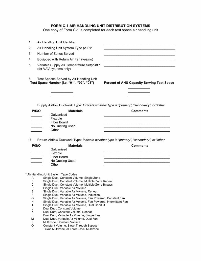
FORM C-1 AIR HANDLING UNIT DISTRIBUTION SYSTEMS One copy of Form C-1 is completed for each test space air handling unit
1 Air Handling Unit Identifier _______________________________________
2 Air Handling Unit System Type (A-P)* _______________________________________
3 Number of Zones Served _______________________________________
4 Equipped with Return Air Fan (yes/no) _______________________________________
5 Variable Supply Air Temperature Setpoint? (for VAV systems only)
_______________________________________
6 Test Spaces Served by Air Handling Unit Test Space Number (i.e. “01”, “02”, “03”) Percent of AHU Capacity Serving Test Space
___________ ___________ ___________ ___________ ___________ ___________
Supply Airflow Ductwork Type: Indicate whether type is “primary”, “secondary”, or “other
P/S/O Materials Comments ______ Galvanized ____________________________________ ______ Flexible ____________________________________ ______ Fiber Board ____________________________________ ______ No Ducting Used ____________________________________ ______ Other ____________________________________
17 Return Airflow Ductwork Type: Indicate whether type is “primary”, “secondary”, or “other
P/S/O Materials Comments ______ Galvanized ____________________________________ ______ Flexible ____________________________________ ______ Fiber Board ____________________________________ ______ No Ducting Used ____________________________________ ______ Other ____________________________________
* Air Handling Unit System Type Codes
A Single Duct, Constant Volume, Single Zone B Single Duct, Constant Volume, Multiple Zone Reheat C Single Duct, Constant Volume, Multiple Zone Bypass D Single Duct, Variable Air Volume E Single Duct, Variable Air Volume, Reheat F Single Duct, Variable Air Volume, Induction G Single Duct, Variable Air Volume, Fan Powered, Constant Fan H Single Duct, Variable Air Volume, Fan Powered, Intermittent Fan I Single Duct, Variable Air Volume, Dual Conduit J Dual Duct, Constant Volume K Dual Duct, Constant Volume, Reheat L Dual Duct, Variable Air Volume, Single Fan M Dual Duct, Variable Air Volume, Dual Fan N Multizone, Constant Volume O Constant Volume, Blow- Through Bypass P Texas Multizone, or Three-Deck Multizone
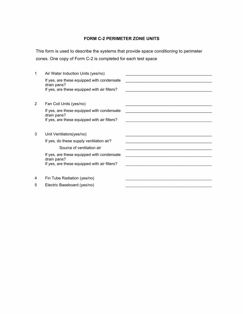
FORM C-2 PERIMETER ZONE UNITS
This form is used to describe the systems that provide space conditioning to perimeter
zones. One copy of Form C-2 is completed for each test space
1 Air Water Induction Units (yes/no) _______________________________________
If yes, are these equipped with condensate drain pans?
_______________________________________
If yes, are these equipped with air filters? _______________________________________
2 Fan Coil Units (yes/no) _______________________________________
If yes, are these equipped with condensate drain pans?
_______________________________________
If yes, are these equipped with air filters? _______________________________________
3 Unit Ventilators(yes/no) _______________________________________
If yes, do these supply ventilation air? _______________________________________
Source of ventilation air _______________________________________
If yes, are these equipped with condensate drain pans?
_______________________________________
If yes, are these equipped with air filters? _______________________________________
4 Fin Tube Radiation (yes/no) _______________________________________
5 Electric Baseboard (yes/no) _______________________________________
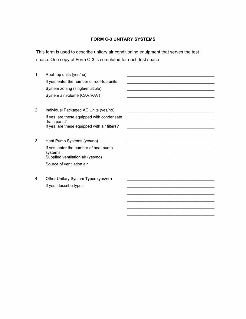
FORM C-3 UNITARY SYSTEMS
This form is used to describe unitary air conditioning equipment that serves the test
space. One copy of Form C-3 is completed for each test space
1 Roof-top units (yes/no) _______________________________________
If yes, enter the number of roof-top units _______________________________________
System zoning (single/multiple) _______________________________________
System air volume (CAV/VAV) _______________________________________
2 Individual Packaged AC Units (yes/no) _______________________________________
If yes, are these equipped with condensate drain pans?
_______________________________________
If yes, are these equipped with air filters? _______________________________________
3 Heat Pump Systems (yes/no) _______________________________________
If yes, enter the number of heat pump systems
_______________________________________
Supplied ventilation air (yes/no) _______________________________________
Source of ventilation air _______________________________________
4 Other Unitary System Types (yes/no) _______________________________________
If yes, describe types _______________________________________
_______________________________________
_______________________________________
_______________________________________
_______________________________________
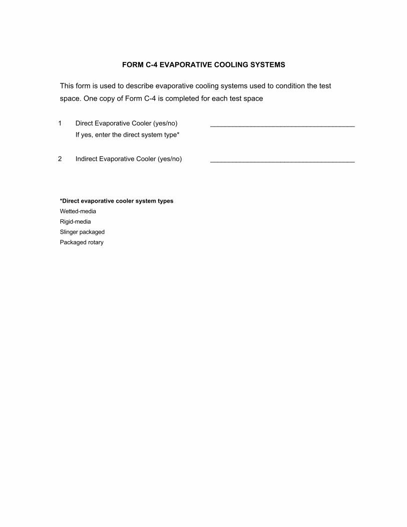
FORM C-4 EVAPORATIVE COOLING SYSTEMS
This form is used to describe evaporative cooling systems used to condition the test
space. One copy of Form C-4 is completed for each test space
1 Direct Evaporative Cooler (yes/no) _______________________________________
If yes, enter the direct system type*
2 Indirect Evaporative Cooler (yes/no) _______________________________________ *Direct evaporative cooler system types Wetted-media Rigid-media Slinger packaged Packaged rotary
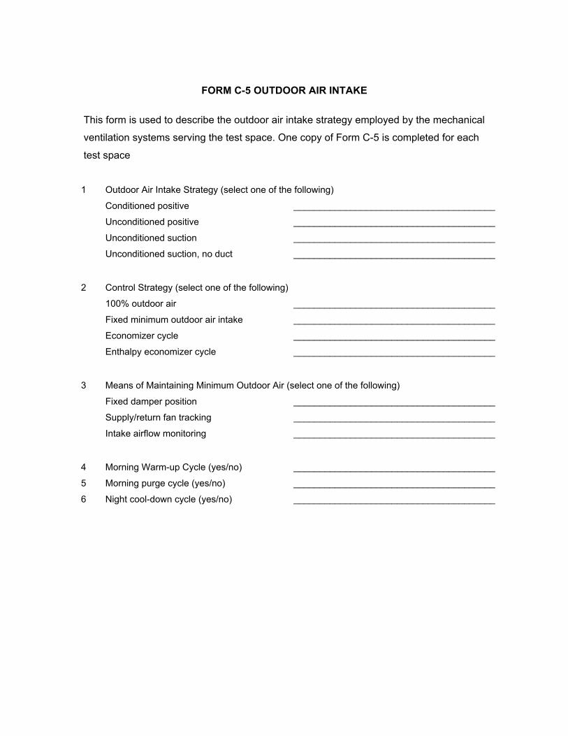
FORM C-5 OUTDOOR AIR INTAKE
This form is used to describe the outdoor air intake strategy employed by the mechanical
ventilation systems serving the test space. One copy of Form C-5 is completed for each
test space
1 Outdoor Air Intake Strategy (select one of the following)
Conditioned positive _______________________________________
Unconditioned positive _______________________________________
Unconditioned suction _______________________________________
Unconditioned suction, no duct _______________________________________
2 Control Strategy (select one of the following)
100% outdoor air _______________________________________
Fixed minimum outdoor air intake _______________________________________
Economizer cycle _______________________________________
Enthalpy economizer cycle _______________________________________
3 Means of Maintaining Minimum Outdoor Air (select one of the following)
Fixed damper position _______________________________________
Supply/return fan tracking _______________________________________
Intake airflow monitoring _______________________________________
4 Morning Warm-up Cycle (yes/no) _______________________________________
5 Morning purge cycle (yes/no) _______________________________________
6 Night cool-down cycle (yes/no) _______________________________________
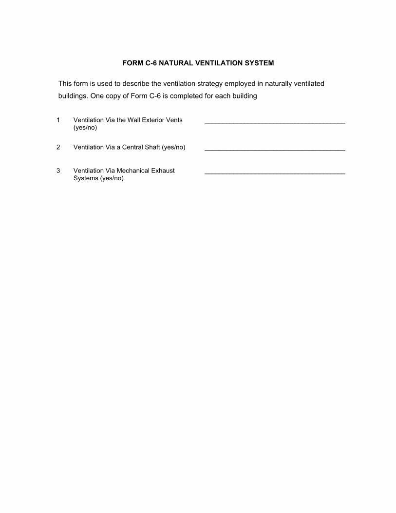
FORM C-6 NATURAL VENTILATION SYSTEM
This form is used to describe the ventilation strategy employed in naturally ventilated
buildings. One copy of Form C-6 is completed for each building
1 Ventilation Via the Wall Exterior Vents
(yes/no) _______________________________________
2 Ventilation Via a Central Shaft (yes/no) _______________________________________
3 Ventilation Via Mechanical Exhaust
Systems (yes/no) _______________________________________
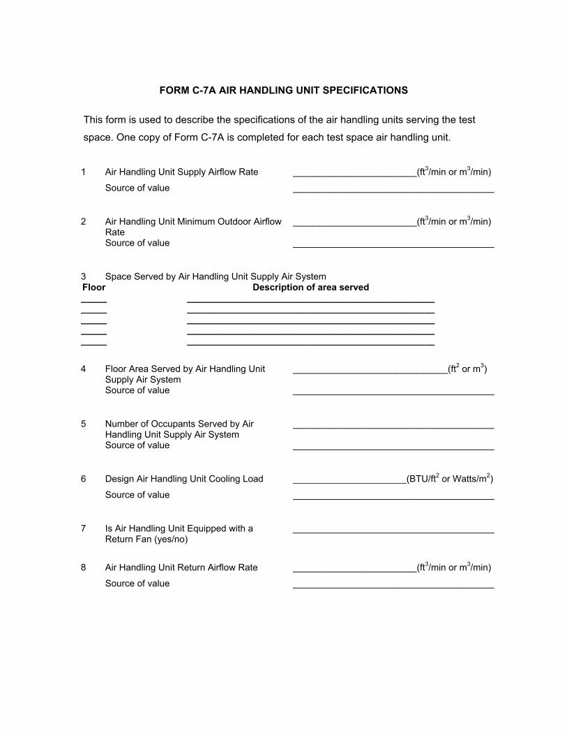
FORM C-7A AIR HANDLING UNIT SPECIFICATIONS
This form is used to describe the specifications of the air handling units serving the test
space. One copy of Form C-7A is completed for each test space air handling unit.
1 Air Handling Unit Supply Airflow Rate ________________________(ft3/min or m3/min)
Source of value _______________________________________
2 Air Handling Unit Minimum Outdoor Airflow
Rate ________________________(ft3/min or m3/min)
Source of value _______________________________________
3 Space Served by Air Handling Unit Supply Air System Floor Description of area served _____ ________________________________________________ _____ ________________________________________________ _____ ________________________________________________ _____ ________________________________________________ _____ ________________________________________________
4 Floor Area Served by Air Handling Unit Supply Air System
______________________________(ft2 or m3)
Source of value _______________________________________
5 Number of Occupants Served by Air
Handling Unit Supply Air System _______________________________________
Source of value _______________________________________
6 Design Air Handling Unit Cooling Load ______________________(BTU/ft2 or Watts/m2)
Source of value _______________________________________
7 Is Air Handling Unit Equipped with a
Return Fan (yes/no) _______________________________________
8 Air Handling Unit Return Airflow Rate ________________________(ft3/min or m3/min)
Source of value _______________________________________
9 Space Served by Air Handling Unit Return Air System Floor Description of area served _____ ________________________________________________ _____ ________________________________________________ _____ ________________________________________________ _____ ________________________________________________ _____ ________________________________________________
10 Floor Area Served by Air Handling Unit Return Air System
______________________________(ft2 or m3)
Source of value _______________________________________
FORM C-7B EXHAUST FAN SPECIFICATIONS
This form is used to describe the specifications of the exhaust fans serving the test
space. One copy of Form C-7B is completed for each test space exhaust fan.
1 Exhaust Fan Identifier _______________________________________
2 Exhaust Fan Airflow Rate ________________________(ft3/min or m3/min)
Source of value _______________________________________
3 Space Served by Exhaust Fan Floor Description of Area Served _____ ________________________________________________ _____ ________________________________________________ _____ ________________________________________________ _____ ________________________________________________ _____ ________________________________________________
4 Floor Area Served by Exhaust Fan ______________________________(ft2 or m3)
Source of value _______________________________________
5 Exhaust Fan Operated through Manual Control (yes/no)
_______________________________________
6 Exhaust Fan Operated through Time of Day Control (yes/no)
_______________________________________
7 Exhaust Fan Operated through Temperature Control (yes/no)
_______________________________________
8 Exhaust Fan Operated Based on Other Equipment Operation (yes/no)
_______________________________________
9 Exhaust Fan Operated Based on Building Pressure (yes/no)
_______________________________________
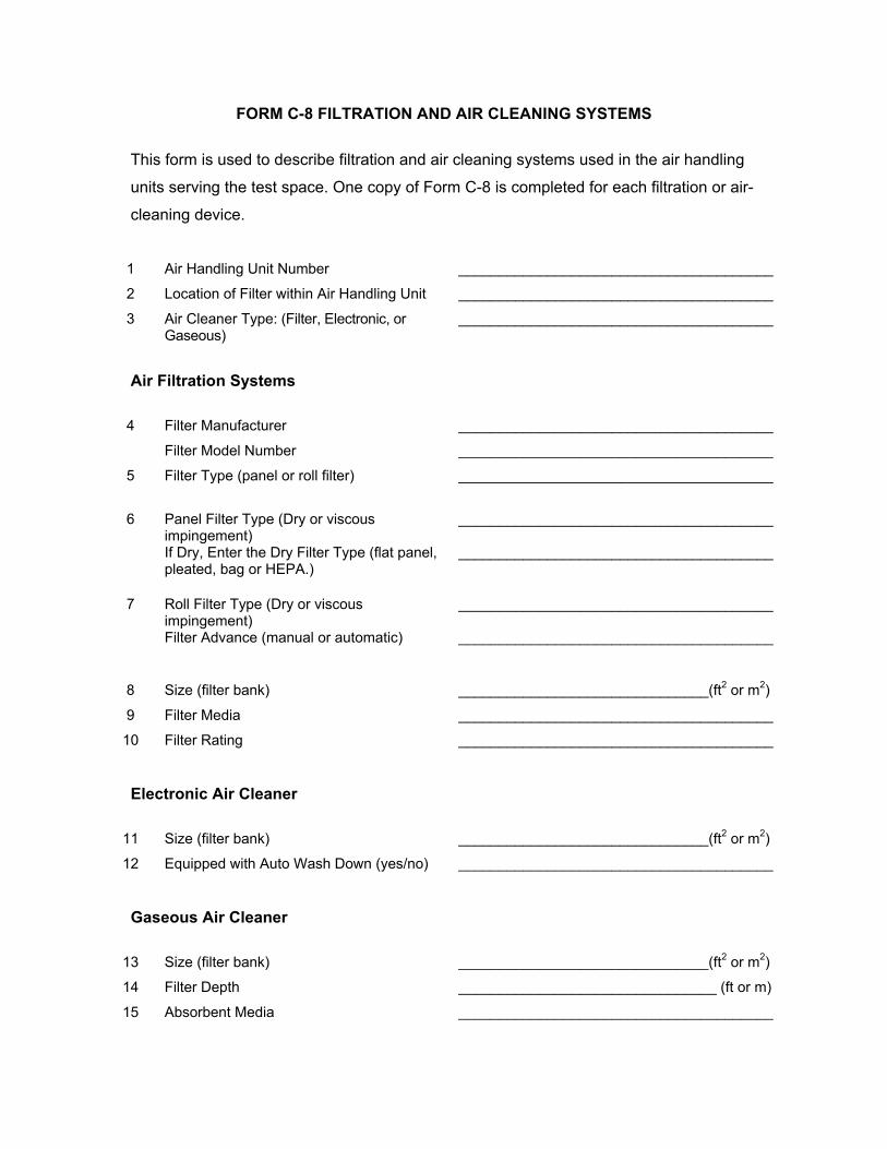
FORM C-8 FILTRATION AND AIR CLEANING SYSTEMS
This form is used to describe filtration and air cleaning systems used in the air handling
units serving the test space. One copy of Form C-8 is completed for each filtration or air-
cleaning device.
1 Air Handling Unit Number _______________________________________
2 Location of Filter within Air Handling Unit _______________________________________
3 Air Cleaner Type: (Filter, Electronic, or Gaseous)
_______________________________________
Air Filtration Systems
4 Filter Manufacturer _______________________________________
Filter Model Number _______________________________________
5 Filter Type (panel or roll filter) _______________________________________
6 Panel Filter Type (Dry or viscous
impingement) _______________________________________
If Dry, Enter the Dry Filter Type (flat panel, pleated, bag or HEPA.)
_______________________________________
7 Roll Filter Type (Dry or viscous
impingement) _______________________________________
Filter Advance (manual or automatic) _______________________________________
8 Size (filter bank) _______________________________(ft2 or m2)
9 Filter Media _______________________________________
10 Filter Rating _______________________________________
Electronic Air Cleaner
11 Size (filter bank) _______________________________(ft2 or m2)
12 Equipped with Auto Wash Down (yes/no) _______________________________________
Gaseous Air Cleaner
13 Size (filter bank) _______________________________(ft2 or m2)
14 Filter Depth ________________________________ (ft or m)
15 Absorbent Media _______________________________________
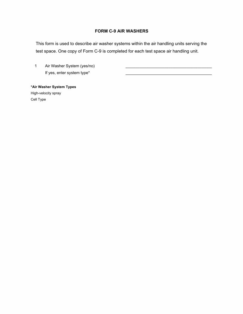
FORM C-9 AIR WASHERS
This form is used to describe air washer systems within the air handling units serving the
test space. One copy of Form C-9 is completed for each test space air handling unit.
1 Air Washer System (yes/no) _______________________________________
If yes, enter system type* _______________________________________
*Air Washer System Types High-velocity spray
Cell Type
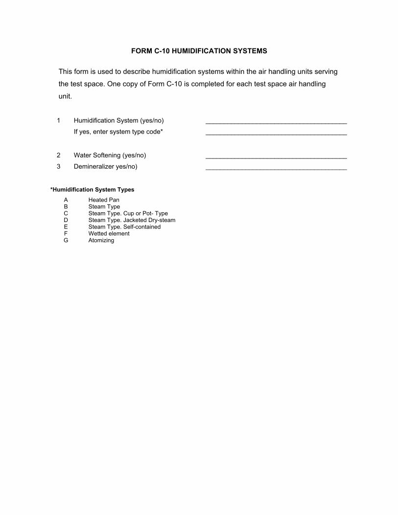
FORM C-10 HUMIDIFICATION SYSTEMS
This form is used to describe humidification systems within the air handling units serving
the test space. One copy of Form C-10 is completed for each test space air handling
unit.
1 Humidification System (yes/no) _______________________________________
If yes, enter system type code* _______________________________________
2 Water Softening (yes/no) _______________________________________
3 Demineralizer yes/no) _______________________________________
*Humidification System Types
A Heated Pan B Steam Type C Steam Type. Cup or Pot- Type D Steam Type. Jacketed Dry-steam E Steam Type. Self-contained F Wetted element G Atomizing

FORM C-11 MAINTENANCE
This form is used to describe the HVAC system maintenance procedures and schedules.
One copy of Form C-11 is completed for the building
Air Handling Unit Inspections
1 Scheduled Inspections (yes/no) _______________________________________
2 Inspection Frequency* _______________________________________
Particulate Filtration Systems
3 Scheduled Filter Replacements (yes/no) _______________________________________
4 Frequency of Panel Filters Replacement _______________________________________
5 Scheduled Manual Roll Filter Advancement (yes/no)
_______________________________________
6 Frequency of Manual Roll Filters Advancement
_______________________________________
7 Scheduled Automatic Roll Filter Inspection (yes/no)
_______________________________________
8 Frequency of Automatic Roll Filters Inspection
_______________________________________
Electronic Air Cleaners
9 Scheduled Inspections (yes/no) _______________________________________
10 Frequency of Inspection _______________________________________
11 Scheduled Cleaning (yes/no) _______________________________________
12 Frequency of Cleaning _______________________________________
Heating and Cooling Coils
13 Scheduled Inspections (yes/no) _______________________________________
14 Frequency of Inspection _______________________________________
15 Scheduled Cleaning (yes/no) _______________________________________
16 Frequency of Cleaning _______________________________________
Condensate Drain Pans
17 Scheduled Inspections (yes/no) _______________________________________
18 Frequency of Inspection _______________________________________
19 Scheduled Cleanings (yes/no) _______________________________________
20 Frequency of Cleaning _______________________________________
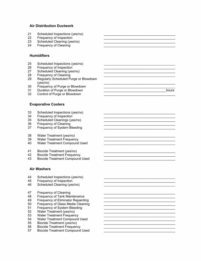
Air Distribution Ductwork
21 Scheduled Inspections (yes/no) _______________________________________ 22 Frequency of Inspection _______________________________________ 23 Scheduled Cleaning (yes/no) _______________________________________ 24 Frequency of Cleaning _______________________________________
Humidifiers
25 Scheduled Inspections (yes/no) _______________________________________ 26 Frequency of Inspection _______________________________________ 27 Scheduled Cleaning (yes/no) _______________________________________ 28 Frequency of Cleaning _______________________________________ 29 Regularly Scheduled Purge or Blowdown
(yes/no) _______________________________________
30 Frequency of Purge or Blowdown _______________________________________ 31 Duration of Purge or Blowdown __________________________________hours 32 Control of Purge or Blowdown _______________________________________
Evaporative Coolers
33 Scheduled Inspections (yes/no) _______________________________________ 34 Frequency of Inspection _______________________________________ 35 Scheduled Cleanings (yes/no) _______________________________________ 36 Frequency of Cleaning _______________________________________ 37 Frequency of System Bleeding _______________________________________
38 Water Treatment (yes/no) _______________________________________ 39 Water Treatment Frequency _______________________________________ 40 Water Treatment Compound Used _______________________________________
41 Biocide Treatment (yes/no) _______________________________________ 42 Biocide Treatment Frequency _______________________________________ 43 Biocide Treatment Compound Used _______________________________________
Air Washers
44 Scheduled Inspections (yes/no) _______________________________________ 45 Frequency of Inspection _______________________________________ 46 Scheduled Cleaning (yes/no) _______________________________________
47 Frequency of Cleaning _______________________________________ 48 Frequency of Tank Maintenance _______________________________________ 49 Frequency of Eliminator Repainting _______________________________________ 50 Frequency of Glass Media Cleaning _______________________________________ 51 Frequency of System Bleeding _______________________________________ 52 Water Treatment (yes/no) _______________________________________ 53 Water Treatment Frequency _______________________________________ 54 Water Treatment Compound Used _______________________________________ 55 Biocide Treatment (yes/no) _______________________________________ 56 Biocide Treatment Frequency _______________________________________ 57 Biocide Treatment Compound Used _______________________________________
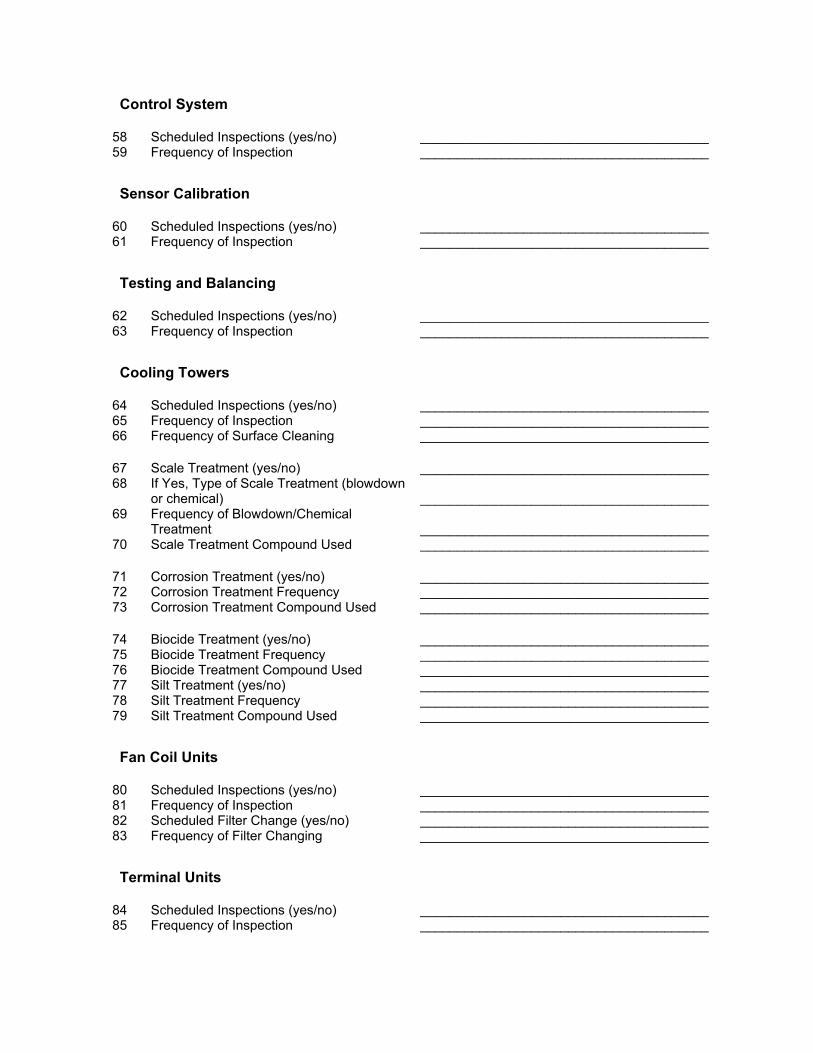
Control System
58 Scheduled Inspections (yes/no) _______________________________________ 59 Frequency of Inspection _______________________________________
Sensor Calibration
60 Scheduled Inspections (yes/no) _______________________________________ 61 Frequency of Inspection _______________________________________
Testing and Balancing
62 Scheduled Inspections (yes/no) _______________________________________ 63 Frequency of Inspection _______________________________________
Cooling Towers
64 Scheduled Inspections (yes/no) _______________________________________ 65 Frequency of Inspection _______________________________________ 66 Frequency of Surface Cleaning _______________________________________
67 Scale Treatment (yes/no) _______________________________________ 68 If Yes, Type of Scale Treatment (blowdown
or chemical) _______________________________________
69 Frequency of Blowdown/Chemical Treatment
_______________________________________
70 Scale Treatment Compound Used _______________________________________
71 Corrosion Treatment (yes/no) _______________________________________ 72 Corrosion Treatment Frequency _______________________________________ 73 Corrosion Treatment Compound Used _______________________________________
74 Biocide Treatment (yes/no) _______________________________________ 75 Biocide Treatment Frequency _______________________________________ 76 Biocide Treatment Compound Used _______________________________________ 77 Silt Treatment (yes/no) _______________________________________ 78 Silt Treatment Frequency _______________________________________ 79 Silt Treatment Compound Used _______________________________________
Fan Coil Units
80 Scheduled Inspections (yes/no) _______________________________________ 81 Frequency of Inspection _______________________________________ 82 Scheduled Filter Change (yes/no) _______________________________________ 83 Frequency of Filter Changing _______________________________________
Terminal Units
84 Scheduled Inspections (yes/no) _______________________________________ 85 Frequency of Inspection _______________________________________
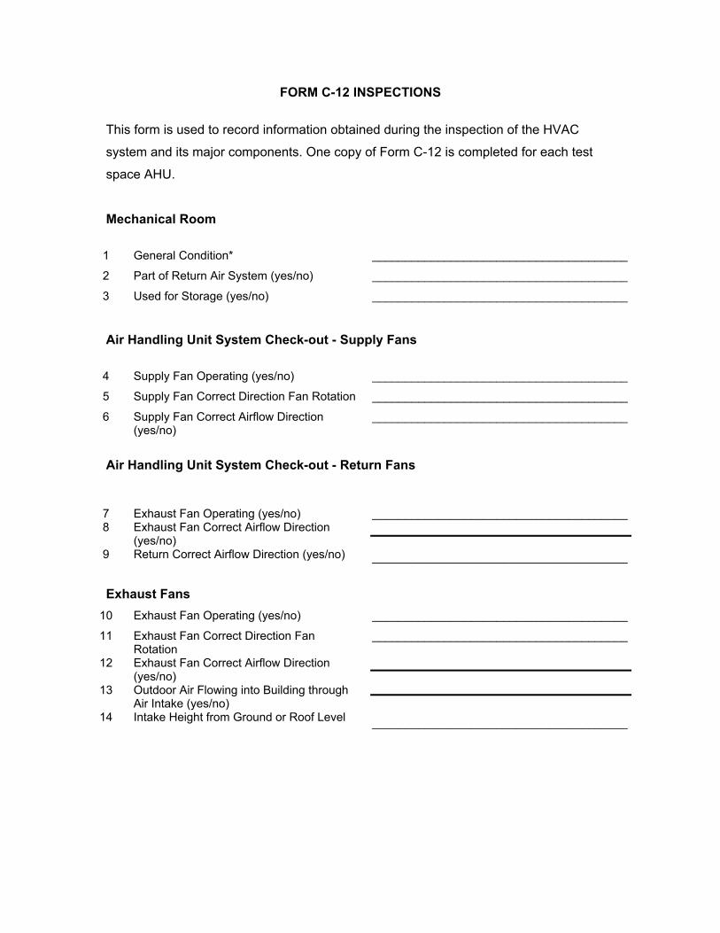
FORM C-12 INSPECTIONS
This form is used to record information obtained during the inspection of the HVAC
system and its major components. One copy of Form C-12 is completed for each test
space AHU.
Mechanical Room
1 General Condition* _______________________________________
2 Part of Return Air System (yes/no) _______________________________________
3 Used for Storage (yes/no) _______________________________________
Air Handling Unit System Check-out - Supply Fans
4 Supply Fan Operating (yes/no) _______________________________________
5 Supply Fan Correct Direction Fan Rotation _______________________________________
6 Supply Fan Correct Airflow Direction (yes/no)
_______________________________________
Air Handling Unit System Check-out - Return Fans
7 Exhaust Fan Operating (yes/no)
_______________________________________
8
9
Exhaust Fan Correct Airflow Direction (yes/no) Return Correct Airflow Direction (yes/no)
_______________________________________
Exhaust Fans 10 Exhaust Fan Operating (yes/no) _______________________________________
11
12
13
14
Exhaust Fan Correct Direction Fan Rotation Exhaust Fan Correct Airflow Direction (yes/no) Outdoor Air Flowing into Building through Air Intake (yes/no) Intake Height from Ground or Roof Level
_______________________________________
_______________________________________
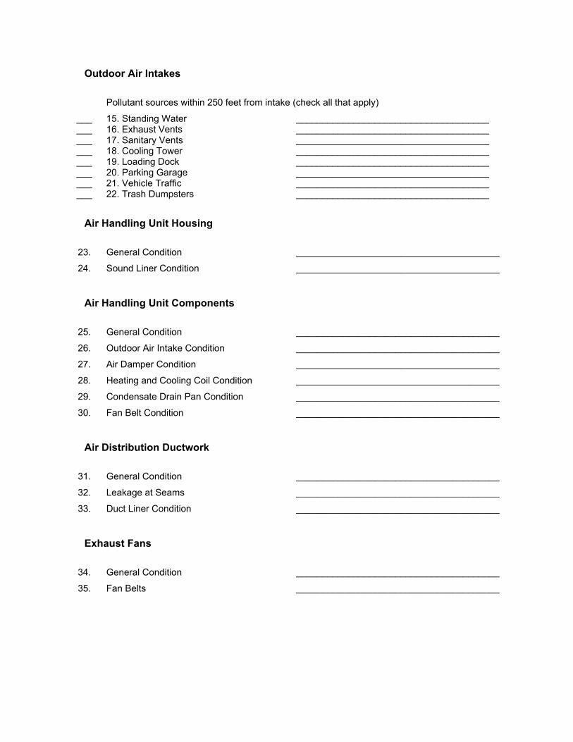
Outdoor Air Intakes Pollutant sources within 250 feet from intake (check all that apply)
___ 15. Standing Water _____________________________________ ___ 16. Exhaust Vents _____________________________________ ___ 17. Sanitary Vents _____________________________________ ___ 18. Cooling Tower _____________________________________ ___ 19. Loading Dock _____________________________________ ___ 20. Parking Garage _____________________________________ ___ 21. Vehicle Traffic _____________________________________ ___ 22. Trash Dumpsters _____________________________________
Air Handling Unit Housing
23. General Condition _______________________________________
24. Sound Liner Condition _______________________________________
Air Handling Unit Components
25. General Condition _______________________________________
26. Outdoor Air Intake Condition _______________________________________
27. Air Damper Condition _______________________________________
28. Heating and Cooling Coil Condition _______________________________________
29. Condensate Drain Pan Condition _______________________________________
30. Fan Belt Condition _______________________________________
Air Distribution Ductwork
31. General Condition _______________________________________
32. Leakage at Seams _______________________________________
33. Duct Liner Condition _______________________________________
Exhaust Fans
34.
35.
General Condition
Fan Belts
_______________________________________
_______________________________________
Particulate Filtration Systems
36. General Condition _______________________________________
37. Accessibility _______________________________________
38. Filter Fit into Frames _______________________________________
39. Filter Condition _______________________________________
40. Evenness of Filter Loading _______________________________________
41. Indicator of Resistance (yes/no) _______________________________________
42. Filter Change Label (yes/no) _______________________________________
43. Pressure Indicator Reading ________________________________(in H2O)
Humidifiers
44. General Condition _______________________________________
45. Drain Pans _______________________________________
Evaporate Coolers
46. General Condition _______________________________________
47. Water Pans _______________________________________
48. Water Clarity _______________________________________
Air Washers
49. General Condition _______________________________________
50. Water Clarity _______________________________________
51. Water Pans _______________________________________
52. Eliminators and Baffles _______________________________________
Control Systems
53. General Condition _______________________________________
54. Sensors _______________________________________
Cooling Towers
55. General Condition _______________________________________
56. Water Condition _______________________________________
57. Surface Condition _______________________________________
Fan Coil Units
58. General Condition _______________________________________
59. Valve Condition _______________________________________
60. Fan Condition _______________________________________
61. Coil Condition _______________________________________
62. Drain Pan Condition _______________________________________
63. Air Filter Condition _______________________________________
Terminal Units
64. General Condition _______________________________________
65. Damper Condition _______________________________________
* Condition Ratings
1 System or component is in good condition
2 System or component is in fair condition
3 System or component is in poor condition
APPENDIX B
AUGMENTATION PARAMETERS
AUGMENTATION PARAMETERS
This appendix describes augmentation parameters that may be considered for some
buildings. Augmentation parameters are additional parameters that were measured at
some of the buildings in the program. Measurements of augmentation parameters were
considered for inclusion at selected buildings based on considerations of the research
objectives, historical data, potential for integration of the measurement results with other
studies, and other factors as deemed appropriate by the EPA Program Manager. Table
B.1 lists potential augmentation parameters and methods that may be considered for
inclusion.
Table B.1 Potential Augmentation Parameters and Methods
Parameter
Method Description
Suggested Protocol
Nicotine Ambient air passes through XAD-4 sorbent tube. Nicotine extract with solvent. Extract analyzed by gas chromatography with nitrogen specific detector
Table B2, Appendix B
Air Handling Unit Continuous Airstream CO2 Monitoring
Continuous CO2 concentration measurements may also be made simultaneously in the AHU supply and return air stream and at the AHU outdoor air intake.
Table B3, Appendix B
Acetaldehyde Ambient air passes through DNPH coated silica gel cartridge. DNPA-aldehyde deviate eluded. Eluant analyzed by reverse phase HPLC with UV detection (360 nm)
Table C10, Appendix C
Biologicals in Dust
Dust samples will be collected from exposed surfaces. Sample analyzed for microbiological organism (bacteria and fungi).
Table C12, Appendix C
Air Infiltration Rate
The building envelope infiltration rate in mechanically ventilated buildings may be estimated by post-occupancy carbon dioxide decay tests or other tracer gas methods.
Appendix B, Section B.1
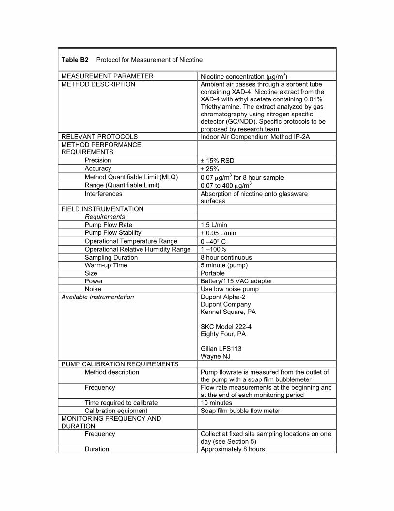
Table B2 Protocol for Measurement of Nicotine MEASUREMENT PARAMETER Nicotine concentration (µg/m3) METHOD DESCRIPTION Ambient air passes through a sorbent tube
containing XAD-4. Nicotine extract from the XAD-4 with ethyl acetate containing 0.01% Triethylamine. The extract analyzed by gas chromatography using nitrogen specific detector (GC/NDD). Specific protocols to be proposed by research team
RELEVANT PROTOCOLS Indoor Air Compendium Method IP-2A METHOD PERFORMANCE REQUIREMENTS
Precision ± 15% RSD Accuracy ± 25% Method Quantifiable Limit (MLQ) 0.07 µg/m3 for 8 hour sample Range (Quantifiable Limit) 0.07 to 400 µg/m3 Interferences Absorption of nicotine onto glassware
surfaces FIELD INSTRUMENTATION
Requirements Pump Flow Rate 1.5 L/min Pump Flow Stability ± 0.05 L/min Operational Temperature Range 0 –40° C Operational Relative Humidity Range 1 –100% Sampling Duration 8 hour continuous Warm-up Time 5 minute (pump) Size Portable Power Battery/115 VAC adapter Noise Use low noise pump
Available Instrumentation Dupont Alpha-2 Dupont Company Kennet Square, PA SKC Model 222-4 Eighty Four, PA Gilian LFS113 Wayne NJ
PUMP CALIBRATION REQUIREMENTS Method description Pump flowrate is measured from the outlet of
the pump with a soap film bubblemeter Frequency Flow rate measurements at the beginning and
at the end of each monitoring period Time required to calibrate 10 minutes Calibration equipment Soap film bubble flow meter
MONITORING FREQUENCY AND DURATION
Frequency Collect at fixed site sampling locations on one day (see Section 5)
Duration Approximately 8 hours
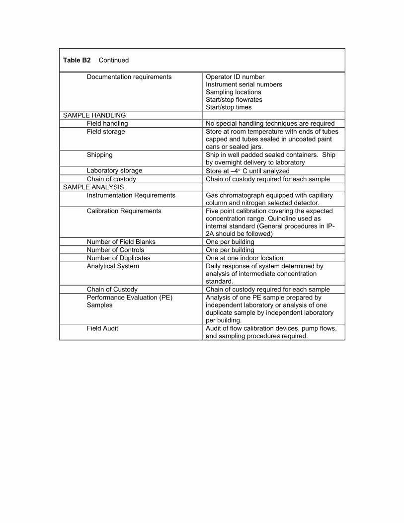
Table B2 Continued
Documentation requirements Operator ID number Instrument serial numbers Sampling locations Start/stop flowrates Start/stop times
SAMPLE HANDLING Field handling No special handling techniques are required Field storage Store at room temperature with ends of tubes
capped and tubes sealed in uncoated paint cans or sealed jars.
Shipping Ship in well padded sealed containers. Ship by overnight delivery to laboratory
Laboratory storage Store at –4° C until analyzed Chain of custody Chain of custody required for each sample
SAMPLE ANALYSIS Instrumentation Requirements Gas chromatograph equipped with capillary
column and nitrogen selected detector. Calibration Requirements Five point calibration covering the expected
concentration range. Quinoline used as internal standard (General procedures in IP-2A should be followed)
Number of Field Blanks One per building Number of Controls One per building Number of Duplicates One at one indoor location Analytical System Daily response of system determined by
analysis of intermediate concentration standard.
Chain of Custody Chain of custody required for each sample Performance Evaluation (PE) Samples
Analysis of one PE sample prepared by independent laboratory or analysis of one duplicate sample by independent laboratory per building.
Field Audit Audit of flow calibration devices, pump flows, and sampling procedures required.
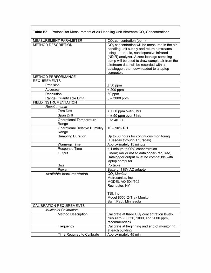
Table B3 Protocol for Measurement of Air Handling Unit Airstream CO2 Concentrations MEASUREMENT PARAMETER CO2 concentration (ppm) METHOD DESCRIPTION CO2 concentration will be measured in the air
handling unit supply and return airstreams using a portable, nondispersive infrared (NDIR) analyzer. A zero leakage sampling pump will be used to draw sample air from the airstream data will be recorded with a datalogger, then downloaded to a laptop computer.
METHOD PERFORMANCE REQUIREMENTS
Precision ± 50 ppm Accuracy ± 200 ppm Resolution 50 ppm Range (Quantifiable Limit) 0 – 3000 ppm
FIELD INSTRUMENTATION Requirements
Zero Drift < ± 50 ppm over 8 hrs Span Drift < ± 50 ppm over 8 hrs Operational Temperature Range
0 to 40° C
Operational Relative Humidity Range
10 – 90% RH
Sampling Duration Up to 56 hours for continuous monitoring (Tuesday through Thursday)
Warm-up Time Approximately 15 minute Response Time ≤ 1 minute to 90% concentration Output Linear; mV or mA to datalogger (required).
Datalogger output must be compatible with laptop computer.
Size Portable Power Battery: 115V AC adapter
Available Instrumentation CO2 Monitor Metrosonics, Inc. MODEL AQ-501/502 Rochester, NY TSI, Inc. Model 8550 Q-Trak Monitor Saint Paul, Minnesota
CALIBRATION REQUIREMENTS Multipoint Calibration
Method Description Calibrate at three CO2 concentration levels plus zero. (0, 350, 1000, and 2000 ppm, recommended)
Frequency Calibrate at beginning and end of monitoring at each building.
Time Required to Calibrate Approximately 45 min
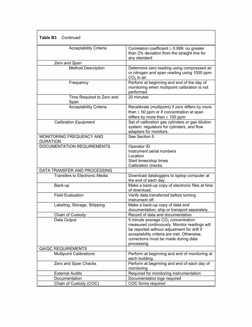
Table B3 Continued
Acceptability Criteria Correlation coefficient ≥ 0.999; no greater than 2% deviation from the straight line for any standard
Zero and Span Method Description Determine zero reading using compressed air
or nitrogen and span reading using 1000 ppm CO2 in air
Frequency Perform at beginning and end of the day of monitoring when multipoint calibration is not performed
Time Required to Zero and Span
20 minutes
Acceptability Criteria Recalibrate (multipoint) if zero differs by more than ± 50 ppm or if concentration at span differs by more than ± 100 ppm
Calibration Equipment Set of calibration gas cylinders or gas dilution system, regulators for cylinders, and flow adapters for monitors.
MONITORING FREQUENCY AND DURATION
See Section 5
DOCUMENTATION REQUIREMENTS Operator ID Instrument serial numbers Location Start times/stop times Calibration checks
DATA TRANSFER AND PROCESSING Transfers to Electronic Media Download dataloggers to laptop computer at
the end of each day Back-up Make a back-up copy of electronic files at time
of download. Field Evaluation Verify data transferred before turning
instrument off. Labeling, Storage, Shipping Make a back-up copy of data and
documentation; ship or transport separately. Chain of Custody Record of data and documentation Data Output 5 minute average CO2 concentration
measured continuously. Monitor readings will be reported without adjustment for drift if acceptability criteria are met. Otherwise, corrections must be made during data processing
QA/QC REQUIREMENTS Multipoint Calibrations Perform at beginning and end of monitoring at
each building. Zero and Span Checks Perform at beginning and end of each day of
monitoring External Audits Required for monitoring instrumentation Documentation Documentation logs required Chain of Custody (COC) COC forms required
B-1 AIR INFILTRATION RATE IN MECHANICALLY VENTILATED BUILDINGS
Forms 1 through 6 are used to estimate the envelope infiltration rate in mechanically
ventilated buildings. This is done by conducting a tracer gas decay test with the air
handlers operating to determine the whole building air change rate. The outdoor air
intake rate is then measured at the air handlers and subtracted from the whole building
air change rate to determine the building infiltration rate. Only one such test is required
in each building.
Form 1 Air Infiltration Rate: Test Description
This form is used to describe the sample locations used in the tracer gas decay test.
1. Date of Test: Enter the date on which the measurement is conducted.
The tracer gas concentration must be monitored during the decay test at one outdoor
location, ten locations within the occupied space, and locations within the air handlers.
The outdoor air concentration is monitored at an outdoor air intake. The ten interior
locations must be distributed throughout the building in order to verify that the tracer gas
concentration is uniform throughout the building prior to and during the decay. The
specific locations that are selected will depend on the layout of the building including
such factors as number of stories and floor area per story. The tracer gas concentration
must also be monitored within the return airstreams of the building air handlers. The
forms allow for ten return air locations, although a smaller number may be used
depending on the number of air handlers in the building. If there are more than ten major
air handlers, additional copies of Form 1 will be required.
2. Tracer Gas: Enter the tracer gas employed in the test.
3. Measurement Location, Outdoor Air: Describe the location at which the outdoor
air tracer gas concentration is measured. Providing the distance from the outdoor air
intake grille, designated as upstream or downstream, is preferred.
4. Measurement Location, Occupied Space # 1: Describe the first location within the
occupied space of the building at which the tracer gas concentration is measured.
Use column numbers if available, and note the building floor.
For entries #5 through #13, describe the second through tenth interior sampling location
as described in entry #4 above.
14. Measurement Location, Air Handling Unit: Describe the first air handler sampling
location at which the tracer gas concentration is measured. Enter the air handler
number used in the building mechanical plans. Enter the location of the air handler,
using a room number from the building plans if available. If no room number is
available, enter the floor and location on the floor.
For entries #15 through #23, describe the second through tenth air handler sampling
location as described in entry #14 above.
Form 2 Air Infiltration Rate: Supply Airflow Rate
This form is used to measure the supply airflow rate in each air handler serving the
entire building. The airflow rate measurement is performed with a pitot tube traverse
according to standard procedures contained in the ACGIH Industrial Ventilation Manual,
AMCA Publication 203-90 and the ASHRAE Standard III. A traverse with a calibrated
hot-wire anemometer is acceptable, using the same procedures as recommended for a
pitot traverse. One form is required for each air handler serving the building. The entries
on the form are to be completed as follows:
1. Date of Test: Enter the date on which the measurement is conducted.
2. Time: Enter the time at which the measurement is conducted.
3. Air Handler Number: Enter the air handler number used in the building mechanical
plans.
4. Air Handler Location: Enter the location of the air handler, using a room number
from the building plans, if available. If no room number is available, enter the floor
and location on the floor.
5. Location of Duct Traverse: Describe the point within the supply ductwork at which
the traverse is conducted. Provide the distance from the fan, designated as upstream
or downstream.
6. Measurement Device Type: Describe the device used in the traverse, i.e., a pitot-
static tube and differential pressure gauge or a calibrated hot-wire anemometer.
7. Manufacturer: In the case of a pitot traverse, enter the manufacturer of the pressure
gauge. In the case of a hot-wire anemometer, enter the manufacturer of the
anemometer.
8. Model Number: Enter the model number of the device.
9. Serial Number: Enter the serial number of the device.
10. Rectangular or Round: Note whether the duct is rectangular or round.
11. Duct Area: Enter the cross-sectional area of the duct at the point of the traverse.
Designate the units, either m2 or ft2.
12. Start of Traverse: Enter the time at which the collection of traverse data began.
13. End of Traverse: Enter the time at which the collection of traverse data was
completed.
14. Root Mean Square Velocity Pressure: In the case of a pitot traverse, calculate the
root mean square velocity pressure using the formula contained on the form. In the
case of a hot-wire traverse, leave this space blank. Designate the correct units,
either (Pa)1/2 or (in.w.g.)1/2.
15. Average Air Speed: In the case of a hot-wire traverse, calculate the average value
of the air speed. In the case of a pitot traverse, calculate the average air speed from
the root mean square velocity pressure using the appropriate formula contained on
the form. Designate the units, either mps or fpm.
16. Airflow Rate: Calculate the supply airflow rate by multiplying the duct area at entry
# 11 by the average air speed at entry # 15. Designate the units, either m3/s or cfm.
Form 3 Air Infiltration Rate: Percent Outdoor Air Intake
This form is used to measure the percent outdoor air intake in each air handler serving
the entire building. The percent outdoor air intake is determined using a mass balance of
air and carbon dioxide based on carbon dioxide concentration measurements in the
outdoor air, the return air and the supply air. One form is required for each air handler
serving the building. The entries on the form are to be completed as follows:
1. Date of Test: Enter the date on which the measurement is conducted.
2. Time: Enter the time at which the measurement is conducted.
3. Air Handler Number: Enter the air handler number used in the building mechanical
plans.
4. Air Handler Location: Enter the location of the air handler, using a room number
from the building plans if available. If no room number is available, enter the floor
and location on the floor.
5. Air Sample Location, Outdoor Air Intake: Describe the location at which the
outdoor air intake carbon dioxide concentration is measured. Provide the distance
from the outdoor air intake grille, designated as upstream or downstream.
6. Air Sample Location, Supply Air: Describe the location at which the supply air
carbon dioxide concentration is measured. Provide the distance from the supply fan,
designated as upstream or downstream.
7. Air Sample Location, Return Air: Describe the location at which the return air
carbon dioxide concentration is measured. Provide the distance upstream from the
point at which the return and outdoor airstreams mix.
8. Manufacturer: Enter the manufacturer of the carbon dioxide concentration
measurement device.
9. Model Number: Enter the model number of the device
10. Serial Number: Enter the serial number of the device.
The span and zero of the carbon dioxide monitor will be checked immediately before
each determination of the percent outdoor air intake.
11. Span Concentration: Enter the carbon dioxide concentration of the span gas used
to check the monitor.
12. Reading: Enter the response of the carbon dioxide monitor to the span gas.
13. Reading: Enter the response of the carbon dioxide monitor to the zero gas.
The concentration measurements are to consist of five successive readings at each of
the three locations. At each location, record the concentration reading every 10 seconds.
After the five readings, move immediately to the next location in order to complete all the
measurements in the minimum amount of time.
14. Start of Measurement: Enter the time at which the concentration measurements
began.
15. Outdoor Air: Enter the five concentration readings from the outdoor airstream.
16. Return Air: Enter the five concentration readings from the return airstream.
17. Supply Air: Enter the five concentration readings from the supply airstream.
18. End of Measurement: Enter the time at which the concentration measurements
were completed.
19. Enter the mean of the outdoor air concentration readings.
20. Enter the standard deviation of the outdoor air concentration readings.
21. Enter the mean of the return air concentration readings.
22. Enter the standard deviation of the return air concentration readings.
23. Enter the mean of the supply air concentration readings
24. Enter the standard deviation of the supply air concentration readings.
25. Percent Outdoor Air: Calculate the percent outdoor air intake using the formula
provided on the form.
26. Error Estimate: Calculate the estimated error in the percent outdoor air intake using
the formula provided on the form.
Form 4 Air Infiltration Rate: Outdoor Air Intake
This form is used to determine the outdoor air intake rate in each air handler serving the
entire building. Two methods are available to make this determination, the first being a
pitot-tube traverse of the outdoor air intake duct according to standard procedures
contained in the ACGIH Industrial Ventilation Manual, M1CA Publication 203-90 and the
ASHRAE Standard III. A traverse with a calibrated hot-wire anemometer is acceptable,
using the same procedures as recommended for a hot-wire traverse. The second
method involves the multiplication of the supply airflow rate (Form 2) by the percent
outdoor air intake (Form 3). Method #1 can only be used if the outdoor air intake is
configured such that a traverse is possible (see the referenced documents for the
ductwork configurations required for conducting a traverse). One form is required for
each air handler serving the building. The entries on the form are to be completed as
follows:
1. Date of Test: Enter the date on which the measurement is conducted.
2. Time: Enter the time at which the measurement is conducted.
3. Air Handler Number: Enter the air handler number used in the building mechanical
plans.
4. Air Handler Location: Enter the location of the air handler, using a room number
from the building plans if available. If no room number is available, enter the floor
and location on the floor.
5. Location of Duct Traverse: Describe the point within the outdoor air intake
ductwork at which the traverse is conducted. Provide the distance downstream from
the outdoor air intake grille.
6. Measurement Device Type: Describe the device used in the traverse, such as pitot-
static tube and differential pressure gauge or calibrated hot-wire anemometer.
7. Manufacturer: In the case of a pitot traverse, enter the name of the manufacturer of
the pressure gauge. In the case of a hot-wire anemometer, enter the manufacturer of
the anemometer.
8. Model Number: Enter the model number of the device.
9. Serial Number: Enter the serial number of the device.
10. Rectangular or Round: Note whether the duct is rectangular or round.
11. Duct Area: Enter the cross-sectional area of the duct at the point of the traverse.
Designate the units, either m2 or ft2.
12. Start of Traverse: Enter the time at which the collection of traverse data began.
13. End of Traverse: Enter the time at which the collection of traverse data was
completed.
14. Root Mean Square Velocity Pressure: In the case of a pitot traverse, calculate the
root mean square velocity pressure using the formula contained on the form. In the
case of a hot-wire traverse, leave this space blank. Designate the correct units,
either (Pa)1/2 or (in.w.g.)1/2.
15. Average Air Speed: In the case of a hot-wire traverse, calculate the average value
of the air speed. In the case of a pitot traverse, calculate the average air speed from
the root mean square velocity pressure using the appropriate formula contained on
the form. Designate the units, either mps or fpm.
16. Airflow Rate: Calculate the outdoor air intake rate by multiplying the duct area at
entry # 10 by the average air speed at entry # 14. Designate the units, either m3/s or
cfm.
17. Supply Airflow Rate: Enter the supply airflow rate for the air handler from Form 2,
entry # 16. Designate the units, either m3/s or cfm.
18. Percent Outdoor Air Intake: Enter the percent outdoor air intake for the air handler
from Form 3, entry #26.
19. Outdoor Air Intake Rate: Calculate the outdoor air intake rate by multiplying the
supply airflow rate in entry # 17 by the percent outdoor air intake in entry # 18 and
dividing the result by 100. Designate the units, either m'/s or cfm.
Form 5 Air Infiltration Rate: Tracer Gas Decay
This form is used to record the results of a tracer gas decay test in the building
conducted to estimate the whole building air change rate. This test is to be conducted in
accordance with ASTM E741. Based on the requirements contained in ASTM E741, this
test must be conducted to determine the whole building air change rate. Tracer gas must
be released into the entire building such that the concentration is uniform throughout the
building. This test cannot be performed by releasing tracer gas into the test space alone.
Only a single tracer gas decay test is required, and therefore only one form is needed.
However, one can repeat the test if the initial attempt does not provide satisfactory
results. This measurement can be conducted using occupant generated carbon dioxide
as the tracer gas after the occupants have left the building. The entries on the form are
to be completed as follows:
1. Date of Test: Enter the date on which the measurement is conducted.
2. Manufacturer: Enter the manufacturer of the tracer gas concentration measurement
device.
3. Model Number: Enter the model number of the device.
4. Serial Number: Enter the serial number of the device.
5. Concentration Units: Enter the tracer gas concentration units provided by the tracer
gas concentration monitor.
The tracer gas concentration must be monitored during the decay test at one outdoor
location, ten locations within the occupied space, and locations within the air handlers.
The concentration at each location should be measured once every 30 minutes, though
the exact time interval is not critical as long as the sample times are recorded accurately.
These sampling locations are described in Form 1. If one employs occupant generated
carbon dioxide as the tracer gas, then the concentrations at these locations must be
monitored after the occupants have left the building, while the interior carbon dioxide
concentration is still significantly above the outdoor concentration. The concentration
monitoring should begin very soon after the occupants have left the building, before the
interior concentrations decays significantly. The tracer gas decay test requires that the
interior concentration is significantly above the outdoor concentration and the interior
concentration is uniform (within 10%) throughout the building. If either of these
conditions is not satisfied, the test will not provide acceptable estimates of the building
air change rate.
6. Initial Reading:
• Outdoor, Time: Enter the time at which the outdoor conditions are measured.
• Outdoor, Concentration: Enter the outdoor tracer gas concentration.
• Outdoor, Temperature: Enter the outdoor air temperature.
• Outdoor, Wind Speed: Enter the wind speed. Designate the units, either m/s or mph.
• Location #1, Time: Enter the time at which the tracer gas concentration at location #1
is recorded.
• Location # 1, Concentration: Enter the tracer gas concentration at location # 1.
For occupied space locations #2 through #10 and air handlers #1 through #10, enter the
time and concentration as described for location # 1.
7. Second Reading: Record the information as described above for the initial reading.
8. Third Reading: Record the information as described above for the initial reading.
9. Fourth Reading: Record the information as described above for the initial reading.
10. Fifth Reading: Record the information as described above for the initial reading.
The data analysis involves determining the tracer gas decay rate in air changes per hour
at each of the 10 occupied space locations and the air handler locations. This is done by
performing a least squares linear regression of the natural logarithm of concentration
against time. Based on the assumption of a uniform tracer gas concentration within the
building, the tracer gas concentration at each location decays according to the following
expression:
C(t) = C0exp(–It) where
C(t) = the tracer gas concentration at a location at time t minus the outdoor concentration
recorded at the same time
C0 = the tracer gas concentration at a location time t = 0 minus the outdoor concentration
recorded at the same time
I = the tracer gas decay rate at that location
In order to determine I, one rewrites the above equation in log form:
lnC = lnC0 – It
This equation can be used to solve for I at each location by regressing the log of the
difference between the tracer gas concentration at the location and the outdoor
concentration against time. Linear regression techniques are described in many
handbooks and are contained in many computer spreadsheet programs, as are
procedures for determining the error associated with the estimate of the slope I.
11. Decay Rates: Enter the calculated decay rate in air changes per hour for each of the
locations and the standard error of this decay rate.
12. Building Average Decay Rate: Enter the average of the decay rates at all of the
sampling locations.
13. Standard Deviation: Enter the standard deviation of the decay rates at all of the
sampling locations.
14. Average Exterior Temperature: Enter the average of the exterior temperatures
measured during the decay.
15. Average Wind Speed: Enter the average of the wind speeds measured during the
decay. Designate the units, either mps or mph.
Form 6 Air Infiltration Rate: Data Analysis
This form is used to conduct the data analysis necessary to determine the building air
infiltration rate. Only one form is required for the building. If there are more than ten air
handlers in the building, then additional copies of Form 6 will be required. The entries on
the form are to be completed as follows:
1. Date of Test: Enter the date on which the measurement is conducted.
2. Outdoor Air Intake Method: Enter the method used to determine the outdoor air
intake rate using Form 4.
3. Outdoor Air Intake Rate, Air Handler #1: Enter the outdoor air intake rate
determined for air handler #1 from the Form 4 corresponding to that air handler.
Designate the units, either mps or cfm.
For entries #4 through #12, enter the outdoor air intake rate for air handlers #2 through
#10 from the Form 4 corresponding to each air handler. If there are more than ten air
handlers in the building, then the outdoor air intake rate for the additional air handlers
are entered on additional copies of Form 6. Designate the correct units, either mps or
cfm.
13. Total Outdoor Air Intake Rate: Enter the sum of the outdoor air intake rates for all
of the air handlers in the building, contained in entries #3 through #12. If there are
more than ten air handlers in the building, then the outdoor air intake rates for the
additional air handlers must be included in this sum. Designate the units, either m3/s
or cfm.
14. Outdoor Air Intake Rate in ACH: Enter the whole building outdoor air intake rate in
units of air changes per hour by dividing entry #13 by the building volume and
converting the result to units of air changes per hour.
15. Total Building Air Change Rate: Enter the whole building air change rate in units of
air changes per hour from entry #12 on Form 5.
16. Building Infiltration Rate: Enter the building infiltration rate, equal to entry #15
minus entry #14.
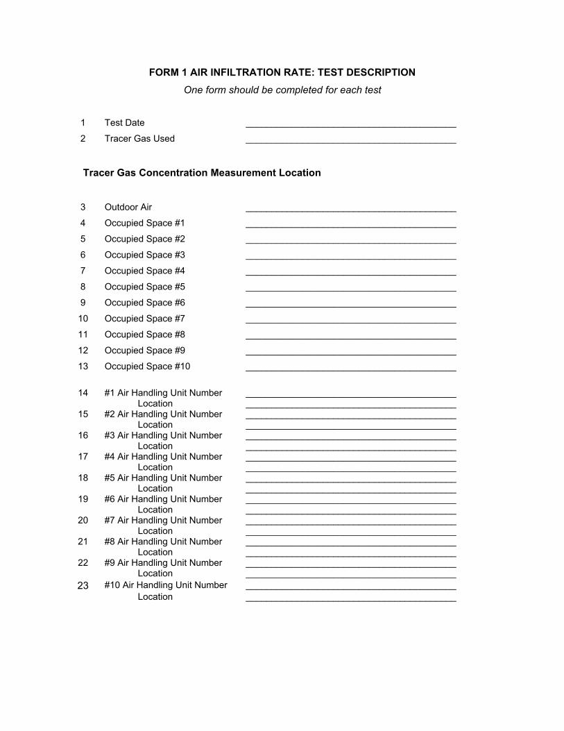
FORM 1 AIR INFILTRATION RATE: TEST DESCRIPTION One form should be completed for each test
1 Test Date _________________________________________
2 Tracer Gas Used _________________________________________
Tracer Gas Concentration Measurement Location
3 Outdoor Air _________________________________________
4 Occupied Space #1 _________________________________________
5 Occupied Space #2 _________________________________________
6 Occupied Space #3 _________________________________________
7 Occupied Space #4 _________________________________________
8 Occupied Space #5 _________________________________________
9 Occupied Space #6 _________________________________________
10 Occupied Space #7 _________________________________________
11 Occupied Space #8 _________________________________________
12 Occupied Space #9 _________________________________________
13 Occupied Space #10 _________________________________________
14 #1 Air Handling Unit Number _________________________________________
Location _________________________________________ 15 #2 Air Handling Unit Number _________________________________________
Location _________________________________________ 16 #3 Air Handling Unit Number _________________________________________
Location _________________________________________ 17 #4 Air Handling Unit Number _________________________________________
Location _________________________________________ 18 #5 Air Handling Unit Number _________________________________________
Location _________________________________________ 19 #6 Air Handling Unit Number _________________________________________
Location _________________________________________ 20 #7 Air Handling Unit Number _________________________________________
Location _________________________________________ 21 #8 Air Handling Unit Number _________________________________________
Location _________________________________________ 22 #9 Air Handling Unit Number _________________________________________ Location _________________________________________
23 #10 Air Handling Unit Number _________________________________________ Location _________________________________________
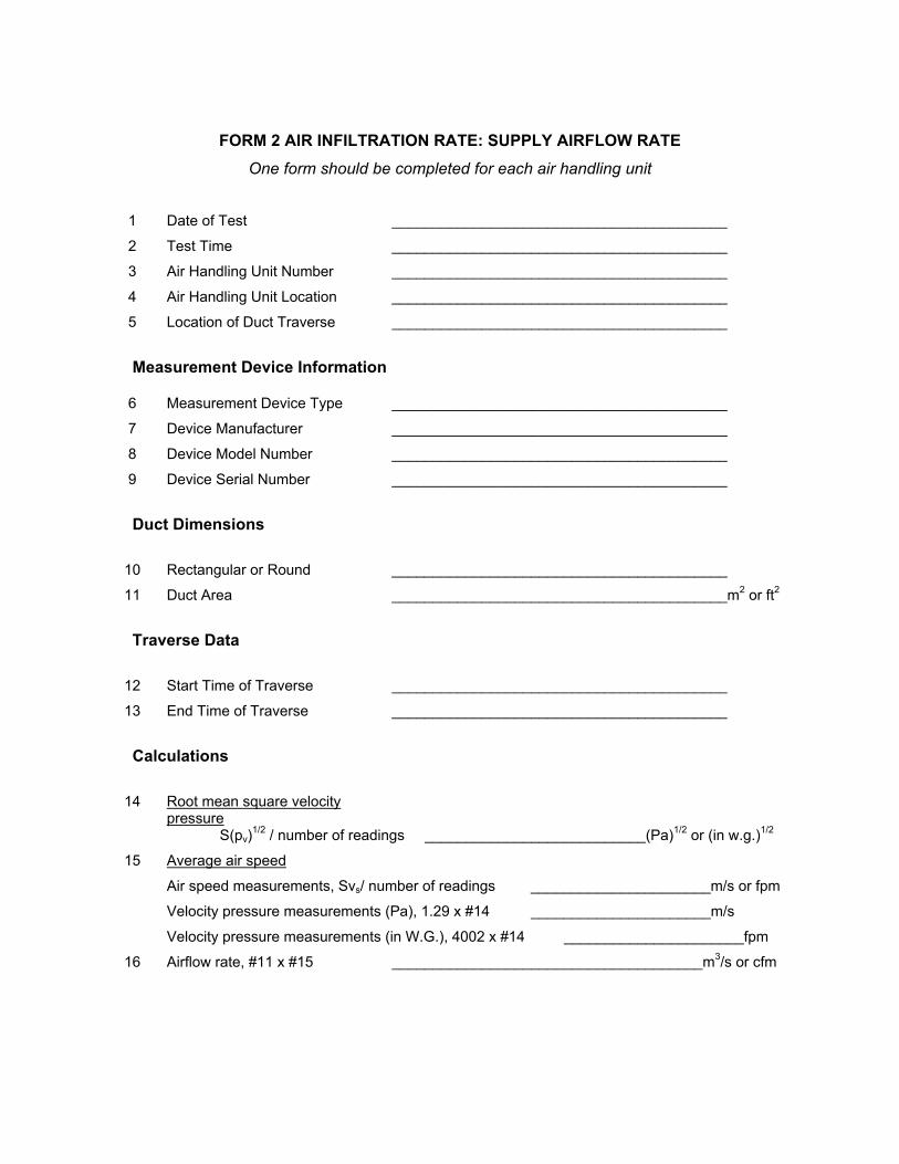
FORM 2 AIR INFILTRATION RATE: SUPPLY AIRFLOW RATE One form should be completed for each air handling unit
1 Date of Test _________________________________________
2 Test Time _________________________________________
3 Air Handling Unit Number _________________________________________
4 Air Handling Unit Location _________________________________________
5 Location of Duct Traverse _________________________________________
Measurement Device Information
6 Measurement Device Type _________________________________________
7 Device Manufacturer _________________________________________
8 Device Model Number _________________________________________
9 Device Serial Number _________________________________________
Duct Dimensions
10 Rectangular or Round _________________________________________
11 Duct Area _________________________________________m2 or ft2
Traverse Data
12 Start Time of Traverse _________________________________________
13 End Time of Traverse _________________________________________
Calculations
14 Root mean square velocity pressure
S(pv)1/2 / number of readings ___________________________(Pa)1/2 or (in w.g.)1/2
15 Average air speed
Air speed measurements, Svs/ number of readings ______________________m/s or fpm
Velocity pressure measurements (Pa), 1.29 x #14 ______________________m/s
Velocity pressure measurements (in W.G.), 4002 x #14 ______________________fpm
16 Airflow rate, #11 x #15 ______________________________________m3/s or cfm
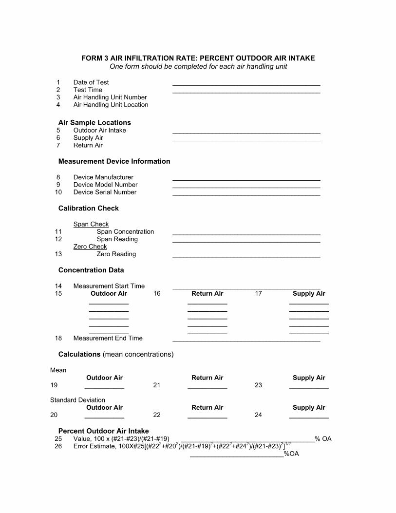
FORM 3 AIR INFILTRATION RATE: PERCENT OUTDOOR AIR INTAKE
One form should be completed for each air handling unit
1 Date of Test _________________________________________ 2 Test Time _________________________________________ 3 Air Handling Unit Number 4 Air Handling Unit Location
Air Sample Locations 5 Outdoor Air Intake _________________________________________ 6 Supply Air _________________________________________ 7 Return Air Measurement Device Information
8 Device Manufacturer _________________________________________ 9 Device Model Number _________________________________________ 10 Device Serial Number _________________________________________ Calibration Check Span Check
11 Span Concentration _________________________________________ 12 Span Reading _________________________________________
Zero Check 13 Zero Reading _________________________________________ Concentration Data
14 Measurement Start Time _________________________________________ 15 Outdoor Air 16 Return Air 17 Supply Air
___________ ___________ ___________ ___________ ___________ ___________ ___________ ___________ ___________ ___________ ___________ ___________ ___________ ___________ ___________
18 Measurement End Time _________________________________________ Calculations (mean concentrations)
Mean Outdoor Air Return Air Supply Air
19 ___________ 21 ___________ 23 ___________
Standard Deviation Outdoor Air Return Air Supply Air
20 ___________ 22 ___________ 24 ___________ Percent Outdoor Air Intake
25 Value, 100 x (#21-#23)/(#21-#19) _____________________________________% OA 26 Error Estimate, 100X#25[(#222+#202)/(#21-#19)2+(#222+#242)/(#21-#23)2]1/2
__________________________%OA
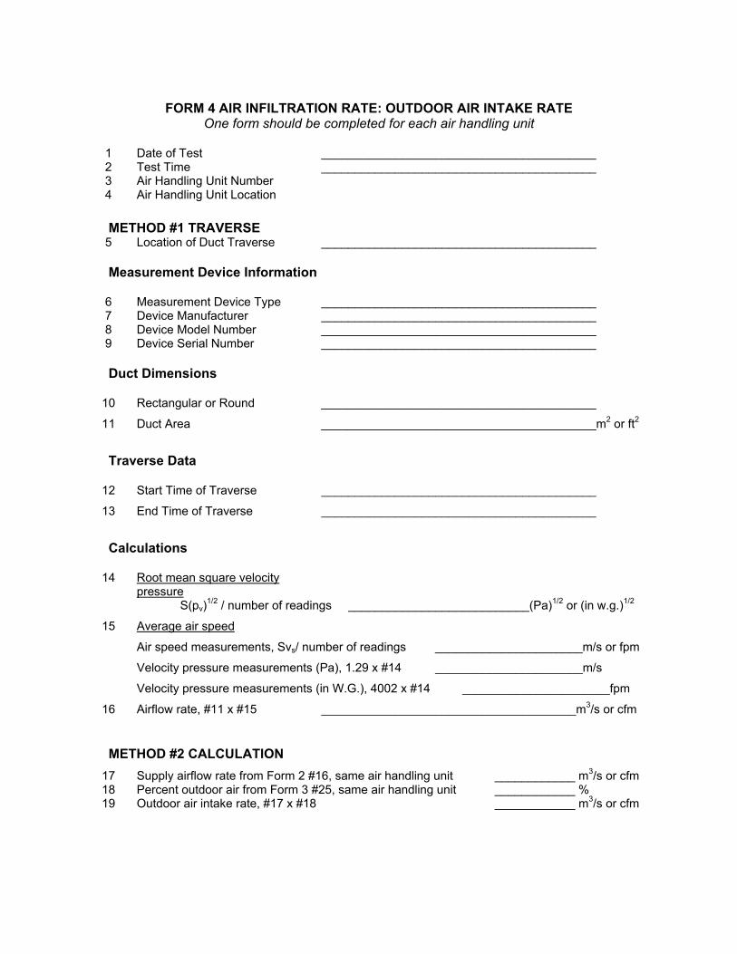
FORM 4 AIR INFILTRATION RATE: OUTDOOR AIR INTAKE RATE
One form should be completed for each air handling unit
1 Date of Test _________________________________________ 2 Test Time _________________________________________ 3 Air Handling Unit Number 4 Air Handling Unit Location
METHOD #1 TRAVERSE 5 Location of Duct Traverse _________________________________________ Measurement Device Information
6 Measurement Device Type _________________________________________ 7 Device Manufacturer _________________________________________ 8 Device Model Number _________________________________________ 9 Device Serial Number _________________________________________ Duct Dimensions
10 Rectangular or Round _________________________________________
11 Duct Area _________________________________________m2 or ft2
Traverse Data
12 Start Time of Traverse _________________________________________
13 End Time of Traverse _________________________________________
Calculations
14 Root mean square velocity pressure
S(pv)1/2 / number of readings ___________________________(Pa)1/2 or (in w.g.)1/2
15 Average air speed
Air speed measurements, Svs/ number of readings ______________________m/s or fpm
Velocity pressure measurements (Pa), 1.29 x #14 ______________________m/s
Velocity pressure measurements (in W.G.), 4002 x #14 ______________________fpm
16 Airflow rate, #11 x #15 ______________________________________m3/s or cfm
METHOD #2 CALCULATION 17 Supply airflow rate from Form 2 #16, same air handling unit ____________ m3/s or cfm 18 Percent outdoor air from Form 3 #25, same air handling unit ____________ % 19 Outdoor air intake rate, #17 x #18 ____________ m3/s or cfm
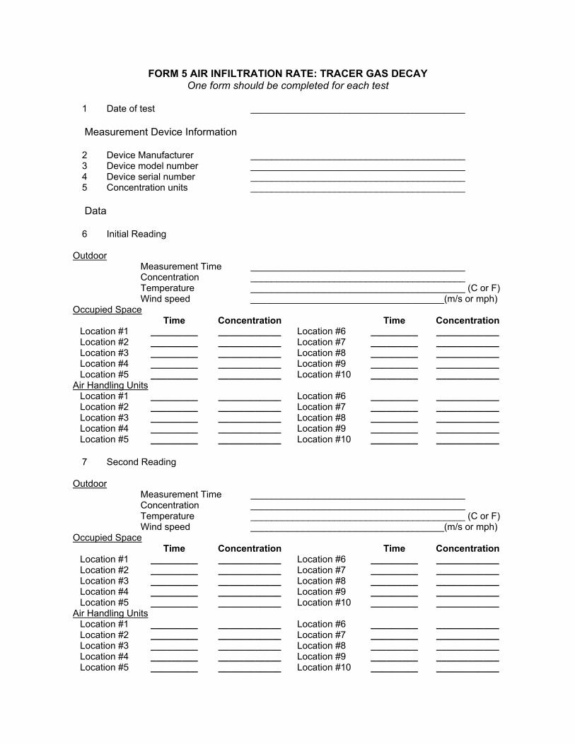
FORM 5 AIR INFILTRATION RATE: TRACER GAS DECAY One form should be completed for each test
1 Date of test _________________________________________ Measurement Device Information
2 Device Manufacturer _________________________________________ 3 Device model number _________________________________________ 4 Device serial number _________________________________________ 5 Concentration units _________________________________________ Data
6 Initial Reading Outdoor
Measurement Time _________________________________________ Concentration _________________________________________ Temperature _________________________________________ (C or F) Wind speed _____________________________________(m/s or mph)
Occupied Space Time Concentration Time Concentration
Location #1 _________ ____________ Location #6 _________ ____________ Location #2 _________ ____________ Location #7 _________ ____________ Location #3 _________ ____________ Location #8 _________ ____________ Location #4 _________ ____________ Location #9 _________ ____________ Location #5 _________ ____________ Location #10 _________ ____________
Air Handling Units Location #1 _________ ____________ Location #6 _________ ____________ Location #2 _________ ____________ Location #7 _________ ____________ Location #3 _________ ____________ Location #8 _________ ____________ Location #4 _________ ____________ Location #9 _________ ____________ Location #5 _________ ____________ Location #10 _________ ____________
7 Second Reading Outdoor
Measurement Time _________________________________________ Concentration _________________________________________ Temperature _________________________________________ (C or F) Wind speed _____________________________________(m/s or mph)
Occupied Space Time Concentration Time Concentration
Location #1 _________ ____________ Location #6 _________ ____________ Location #2 _________ ____________ Location #7 _________ ____________ Location #3 _________ ____________ Location #8 _________ ____________ Location #4 _________ ____________ Location #9 _________ ____________ Location #5 _________ ____________ Location #10 _________ ____________
Air Handling Units Location #1 _________ ____________ Location #6 _________ ____________ Location #2 _________ ____________ Location #7 _________ ____________ Location #3 _________ ____________ Location #8 _________ ____________ Location #4 _________ ____________ Location #9 _________ ____________ Location #5 _________ ____________ Location #10 _________ ____________
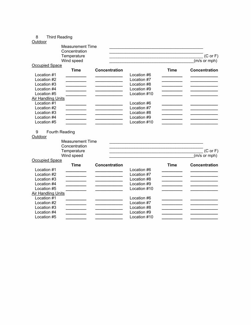
8 Third Reading
Outdoor Measurement Time _________________________________________ Concentration _________________________________________ Temperature _________________________________________ (C or F) Wind speed _____________________________________(m/s or mph)
Occupied Space Time Concentration Time Concentration
Location #1 _________ ____________ Location #6 _________ ____________ Location #2 _________ ____________ Location #7 _________ ____________ Location #3 _________ ____________ Location #8 _________ ____________ Location #4 _________ ____________ Location #9 _________ ____________ Location #5 _________ ____________ Location #10 _________ ____________
Air Handling Units Location #1 _________ ____________ Location #6 _________ ____________ Location #2 _________ ____________ Location #7 _________ ____________ Location #3 _________ ____________ Location #8 _________ ____________ Location #4 _________ ____________ Location #9 _________ ____________ Location #5 _________ ____________ Location #10 _________ ____________
9 Fourth Reading Outdoor
Measurement Time _________________________________________ Concentration _________________________________________ Temperature _________________________________________ (C or F) Wind speed _____________________________________(m/s or mph)
Occupied Space Time Concentration Time Concentration
Location #1 _________ ____________ Location #6 _________ ____________ Location #2 _________ ____________ Location #7 _________ ____________ Location #3 _________ ____________ Location #8 _________ ____________ Location #4 _________ ____________ Location #9 _________ ____________ Location #5 _________ ____________ Location #10 _________ ____________
Air Handling Units Location #1 _________ ____________ Location #6 _________ ____________ Location #2 _________ ____________ Location #7 _________ ____________ Location #3 _________ ____________ Location #8 _________ ____________ Location #4 _________ ____________ Location #9 _________ ____________ Location #5 _________ ____________ Location #10 _________ ____________
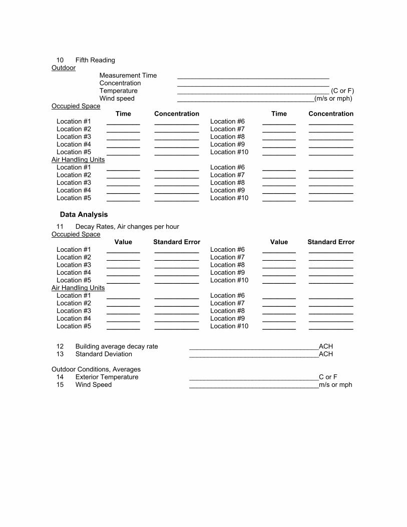
10 Fifth Reading
Outdoor Measurement Time _________________________________________ Concentration _________________________________________ Temperature _________________________________________ (C or F) Wind speed _____________________________________(m/s or mph)
Occupied Space Time Concentration Time Concentration
Location #1 _________ ____________ Location #6 _________ ____________ Location #2 _________ ____________ Location #7 _________ ____________ Location #3 _________ ____________ Location #8 _________ ____________ Location #4 _________ ____________ Location #9 _________ ____________ Location #5 _________ ____________ Location #10 _________ ____________
Air Handling Units Location #1 _________ ____________ Location #6 _________ ____________ Location #2 _________ ____________ Location #7 _________ ____________ Location #3 _________ ____________ Location #8 _________ ____________ Location #4 _________ ____________ Location #9 _________ ____________ Location #5 _________ ____________ Location #10 _________ ____________ Data Analysis
11 Decay Rates, Air changes per hour Occupied Space
Value Standard Error Value Standard Error Location #1 _________ ____________ Location #6 _________ ____________ Location #2 _________ ____________ Location #7 _________ ____________ Location #3 _________ ____________ Location #8 _________ ____________ Location #4 _________ ____________ Location #9 _________ ____________ Location #5 _________ ____________ Location #10 _________ ____________
Air Handling Units Location #1 _________ ____________ Location #6 _________ ____________ Location #2 _________ ____________ Location #7 _________ ____________ Location #3 _________ ____________ Location #8 _________ ____________ Location #4 _________ ____________ Location #9 _________ ____________ Location #5 _________ ____________ Location #10 _________ ____________
12 Building average decay rate ___________________________________ACH 13 Standard Deviation ___________________________________ACH
Outdoor Conditions, Averages
14 Exterior Temperature ___________________________________C or F 15 Wind Speed ___________________________________m/s or mph
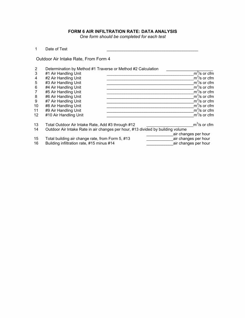
FORM 6 AIR INFILTRATION RATE: DATA ANALYSIS One form should be completed for each test
1 Date of Test _________________________________________ Outdoor Air Intake Rate, From Form 4
2 Determination by Method #1 Traverse or Method #2 Calculation _____________________ 3 #1 Air Handling Unit _______________________________________m3/s or cfm 4 #2 Air Handling Unit _______________________________________m3/s or cfm 5 #3 Air Handling Unit _______________________________________m3/s or cfm 6 #4 Air Handling Unit _______________________________________m3/s or cfm 7 #5 Air Handling Unit _______________________________________m3/s or cfm 8 #6 Air Handling Unit _______________________________________m3/s or cfm 9 #7 Air Handling Unit _______________________________________m3/s or cfm 10 #8 Air Handling Unit _______________________________________m3/s or cfm 11 #9 Air Handling Unit _______________________________________m3/s or cfm 12 #10 Air Handling Unit _______________________________________m3/s or cfm
13 Total Outdoor Air Intake Rate, Add #3 through #12 _____________________m3/s or cfm 14 Outdoor Air Intake Rate in air changes per hour, #13 divided by building volume
____________air changes per hour 15 Total building air change rate, from Form 5, #13 ____________air changes per hour 16 Building infiltration rate, #15 minus #14 ____________air changes per hour
APPENDIX C
PROTOCOLS FOR CORE ENVIRONMENTAL PARAMETERS
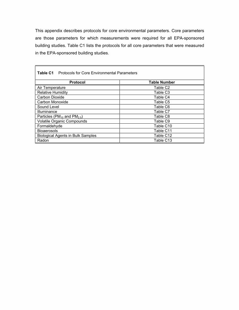
This appendix describes protocols for core environmental parameters. Core parameters
are those parameters for which measurements were required for all EPA-sponsored
building studies. Table C1 lists the protocols for all core parameters that were measured
in the EPA-sponsored building studies.
Table C1 Protocols for Core Environmental Parameters
Protocol Table Number Air Temperature Table C2 Relative Humidity Table C3 Carbon Dioxide Table C4 Carbon Monoxide Table C5 Sound Level Table C6 Illuminance Table C7 Particles (PM10 and PM2.5) Table C8 Volatile Organic Compounds Table C9 Formaldehyde Table C10 Bioaerosols Table C11 Biological Agents in Bulk Samples Table C12 Radon Table C13
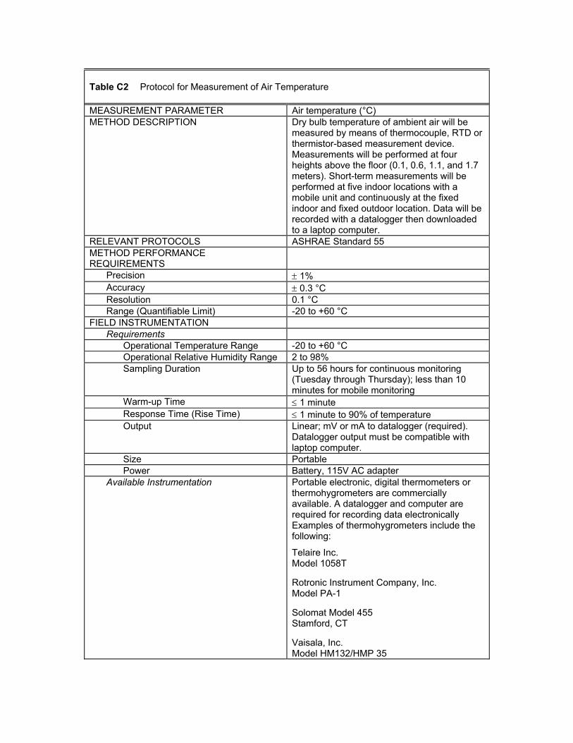
Table C2 Protocol for Measurement of Air Temperature MEASUREMENT PARAMETER Air temperature (°C) METHOD DESCRIPTION Dry bulb temperature of ambient air will be
measured by means of thermocouple, RTD or thermistor-based measurement device. Measurements will be performed at four heights above the floor (0.1, 0.6, 1.1, and 1.7 meters). Short-term measurements will be performed at five indoor locations with a mobile unit and continuously at the fixed indoor and fixed outdoor location. Data will be recorded with a datalogger then downloaded to a laptop computer.
RELEVANT PROTOCOLS ASHRAE Standard 55 METHOD PERFORMANCE REQUIREMENTS
Precision ± 1% Accuracy ± 0.3 °C Resolution 0.1 °C Range (Quantifiable Limit) -20 to +60 °C
FIELD INSTRUMENTATION Requirements
Operational Temperature Range -20 to +60 °C Operational Relative Humidity Range 2 to 98% Sampling Duration Up to 56 hours for continuous monitoring
(Tuesday through Thursday); less than 10 minutes for mobile monitoring
Warm-up Time ≤ 1 minute Response Time (Rise Time) ≤ 1 minute to 90% of temperature Output Linear; mV or mA to datalogger (required).
Datalogger output must be compatible with laptop computer.
Size Portable Power Battery, 115V AC adapter
Available Instrumentation Portable electronic, digital thermometers or thermohygrometers are commercially available. A datalogger and computer are required for recording data electronically Examples of thermohygrometers include the following:
Telaire Inc. Model 1058T
Rotronic Instrument Company, Inc. Model PA-1
Solomat Model 455 Stamford, CT
Vaisala, Inc. Model HM132/HMP 35
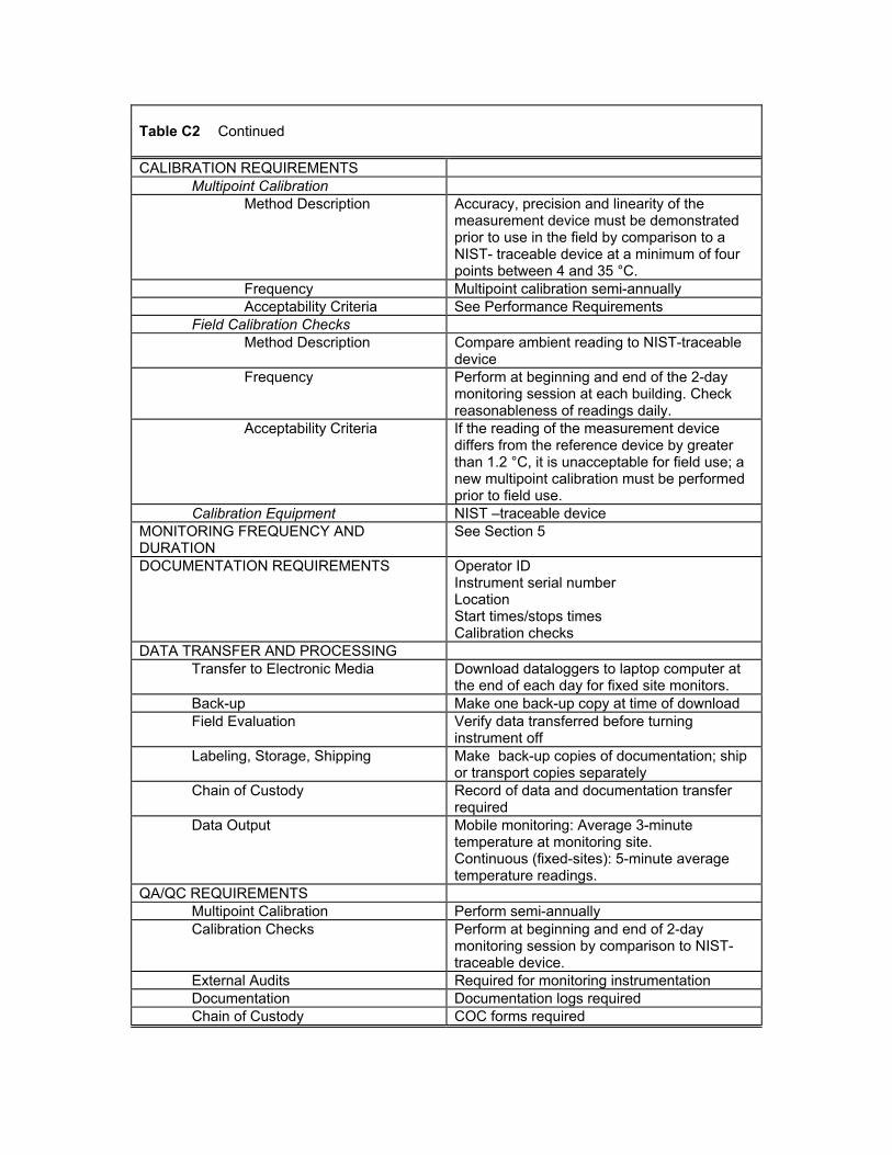
Table C2 Continued CALIBRATION REQUIREMENTS
Multipoint Calibration Method Description Accuracy, precision and linearity of the
measurement device must be demonstrated prior to use in the field by comparison to a NIST- traceable device at a minimum of four points between 4 and 35 °C.
Frequency Multipoint calibration semi-annually Acceptability Criteria See Performance Requirements
Field Calibration Checks Method Description Compare ambient reading to NIST-traceable
device Frequency Perform at beginning and end of the 2-day
monitoring session at each building. Check reasonableness of readings daily.
Acceptability Criteria If the reading of the measurement device differs from the reference device by greater than 1.2 °C, it is unacceptable for field use; a new multipoint calibration must be performed prior to field use.
Calibration Equipment NIST –traceable device MONITORING FREQUENCY AND DURATION
See Section 5
DOCUMENTATION REQUIREMENTS Operator ID Instrument serial number Location Start times/stops times Calibration checks
DATA TRANSFER AND PROCESSING Transfer to Electronic Media Download dataloggers to laptop computer at
the end of each day for fixed site monitors. Back-up Make one back-up copy at time of download Field Evaluation Verify data transferred before turning
instrument off Labeling, Storage, Shipping Make back-up copies of documentation; ship
or transport copies separately Chain of Custody Record of data and documentation transfer
required Data Output Mobile monitoring: Average 3-minute
temperature at monitoring site. Continuous (fixed-sites): 5-minute average temperature readings.
QA/QC REQUIREMENTS Multipoint Calibration Perform semi-annually Calibration Checks Perform at beginning and end of 2-day
monitoring session by comparison to NIST- traceable device.
External Audits Required for monitoring instrumentation Documentation Documentation logs required Chain of Custody COC forms required
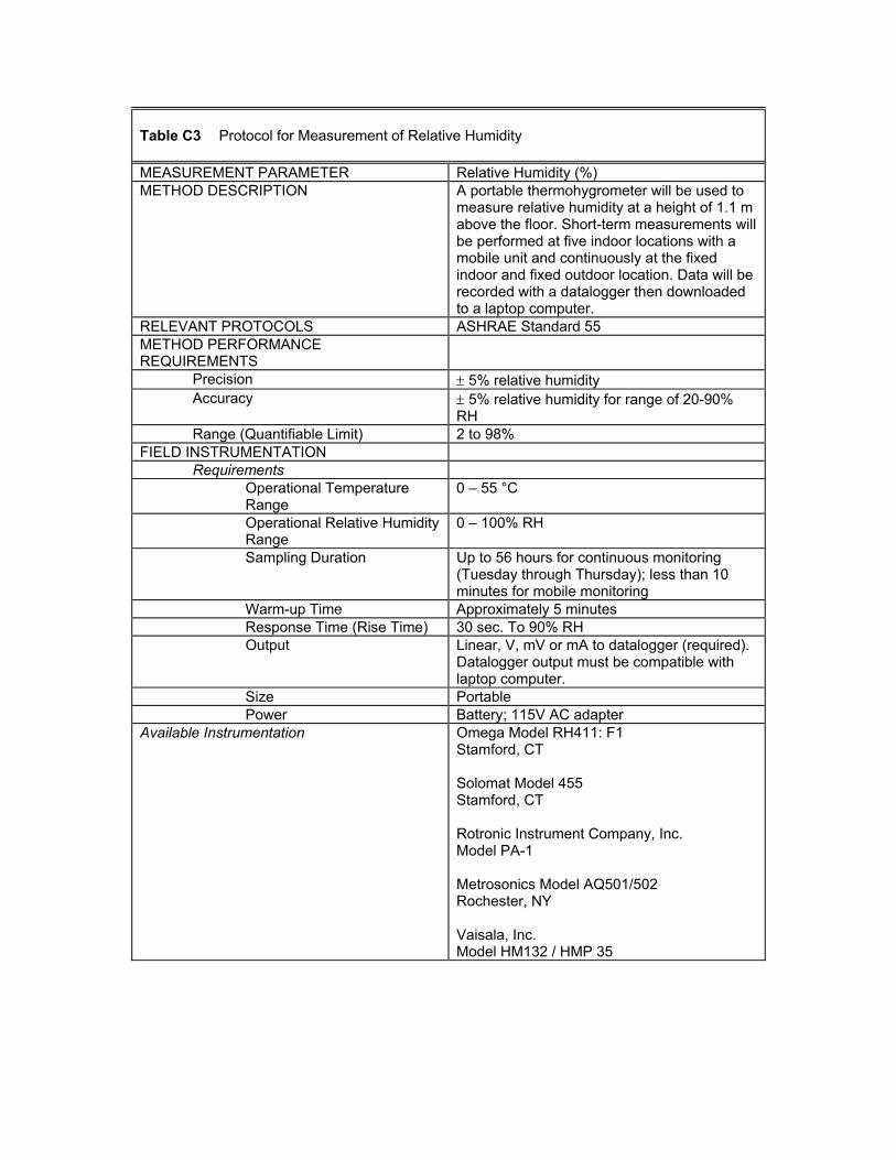
Table C3 Protocol for Measurement of Relative Humidity MEASUREMENT PARAMETER Relative Humidity (%) METHOD DESCRIPTION A portable thermohygrometer will be used to
measure relative humidity at a height of 1.1 m above the floor. Short-term measurements will be performed at five indoor locations with a mobile unit and continuously at the fixed indoor and fixed outdoor location. Data will be recorded with a datalogger then downloaded to a laptop computer.
RELEVANT PROTOCOLS ASHRAE Standard 55 METHOD PERFORMANCE REQUIREMENTS
Precision ± 5% relative humidity Accuracy ± 5% relative humidity for range of 20-90%
RH Range (Quantifiable Limit) 2 to 98%
FIELD INSTRUMENTATION Requirements
Operational Temperature Range
0 – 55 °C
Operational Relative Humidity Range
0 – 100% RH
Sampling Duration Up to 56 hours for continuous monitoring (Tuesday through Thursday); less than 10 minutes for mobile monitoring
Warm-up Time Approximately 5 minutes Response Time (Rise Time) 30 sec. To 90% RH Output Linear, V, mV or mA to datalogger (required).
Datalogger output must be compatible with laptop computer.
Size Portable Power Battery; 115V AC adapter
Available Instrumentation Omega Model RH411: F1 Stamford, CT Solomat Model 455 Stamford, CT Rotronic Instrument Company, Inc. Model PA-1 Metrosonics Model AQ501/502 Rochester, NY Vaisala, Inc. Model HM132 / HMP 35
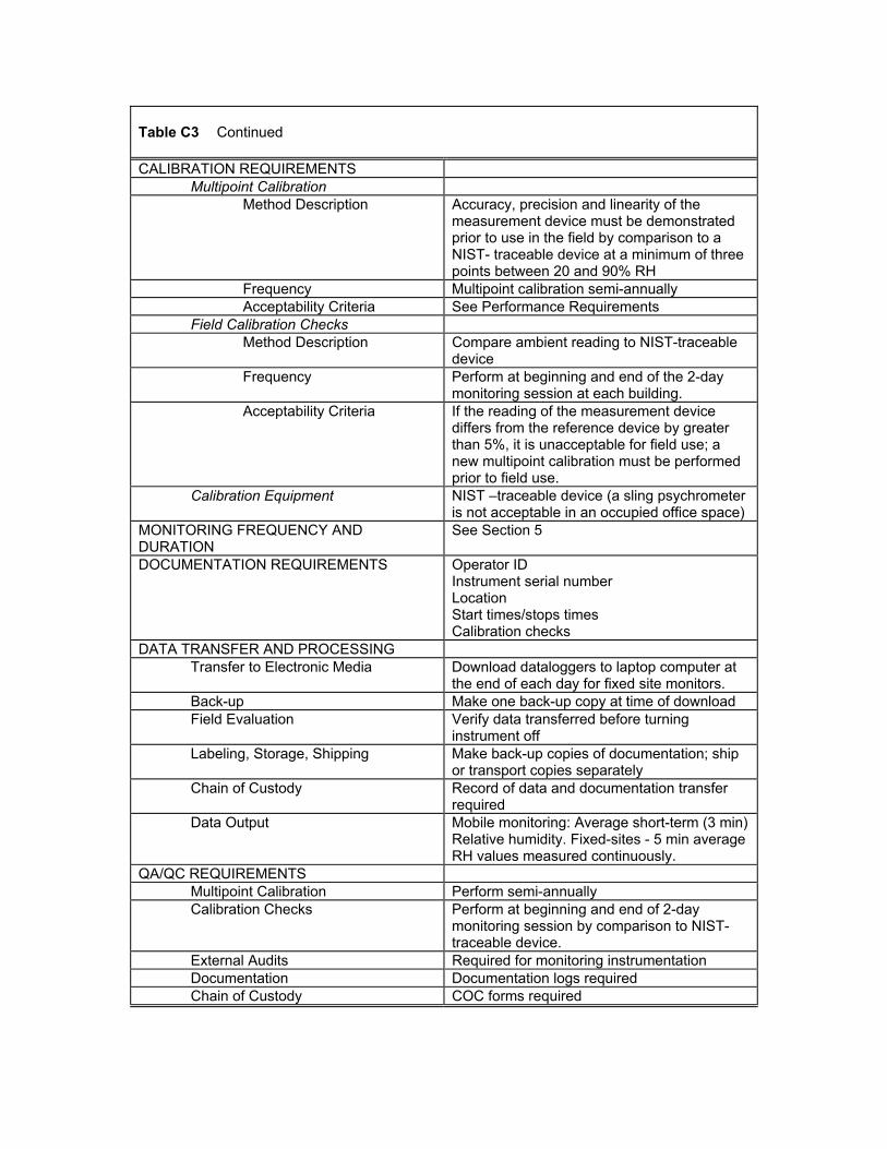
Table C3 Continued CALIBRATION REQUIREMENTS
Multipoint Calibration Method Description Accuracy, precision and linearity of the
measurement device must be demonstrated prior to use in the field by comparison to a NIST- traceable device at a minimum of three points between 20 and 90% RH
Frequency Multipoint calibration semi-annually Acceptability Criteria See Performance Requirements
Field Calibration Checks Method Description Compare ambient reading to NIST-traceable
device Frequency Perform at beginning and end of the 2-day
monitoring session at each building. Acceptability Criteria If the reading of the measurement device
differs from the reference device by greater than 5%, it is unacceptable for field use; a new multipoint calibration must be performed prior to field use.
Calibration Equipment NIST –traceable device (a sling psychrometer is not acceptable in an occupied office space)
MONITORING FREQUENCY AND DURATION
See Section 5
DOCUMENTATION REQUIREMENTS Operator ID Instrument serial number Location Start times/stops times Calibration checks
DATA TRANSFER AND PROCESSING Transfer to Electronic Media Download dataloggers to laptop computer at
the end of each day for fixed site monitors. Back-up Make one back-up copy at time of download Field Evaluation Verify data transferred before turning
instrument off Labeling, Storage, Shipping Make back-up copies of documentation; ship
or transport copies separately Chain of Custody Record of data and documentation transfer
required Data Output Mobile monitoring: Average short-term (3 min)
Relative humidity. Fixed-sites - 5 min average RH values measured continuously.
QA/QC REQUIREMENTS Multipoint Calibration Perform semi-annually Calibration Checks Perform at beginning and end of 2-day
monitoring session by comparison to NIST- traceable device.
External Audits Required for monitoring instrumentation Documentation Documentation logs required Chain of Custody COC forms required
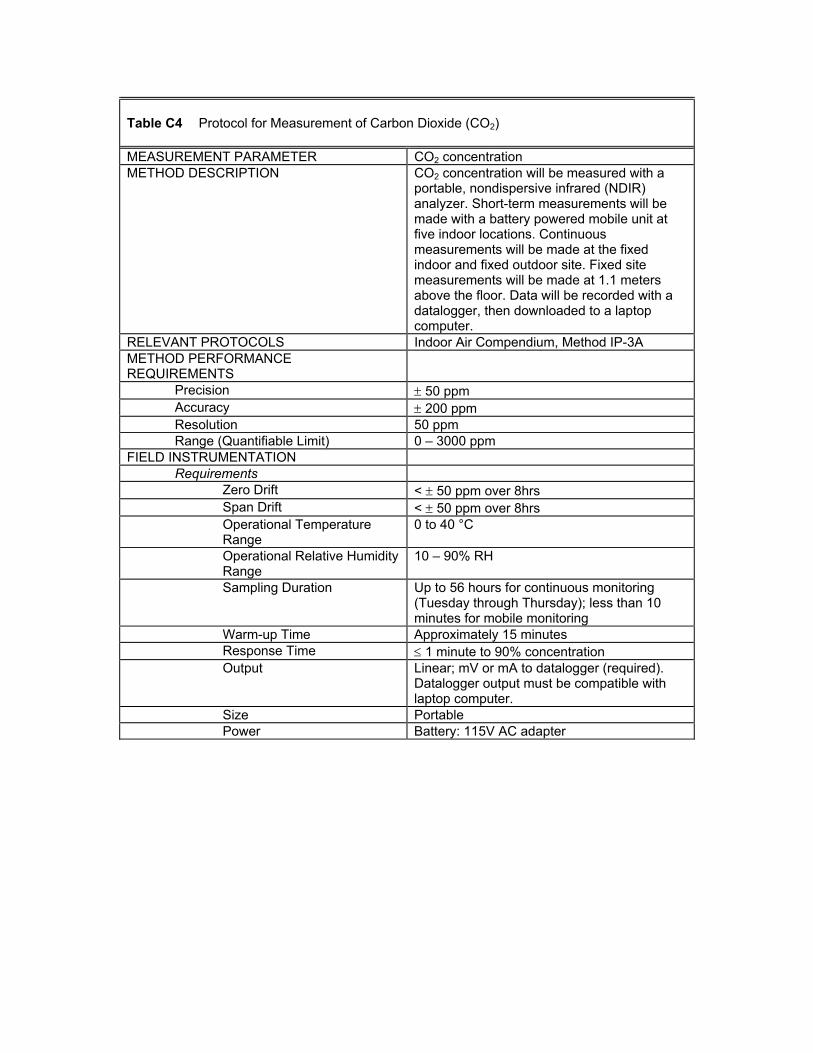
Table C4 Protocol for Measurement of Carbon Dioxide (CO2) MEASUREMENT PARAMETER CO2 concentration METHOD DESCRIPTION CO2 concentration will be measured with a
portable, nondispersive infrared (NDIR) analyzer. Short-term measurements will be made with a battery powered mobile unit at five indoor locations. Continuous measurements will be made at the fixed indoor and fixed outdoor site. Fixed site measurements will be made at 1.1 meters above the floor. Data will be recorded with a datalogger, then downloaded to a laptop computer.
RELEVANT PROTOCOLS Indoor Air Compendium, Method IP-3A METHOD PERFORMANCE REQUIREMENTS
Precision ± 50 ppm Accuracy ± 200 ppm Resolution 50 ppm Range (Quantifiable Limit) 0 – 3000 ppm
FIELD INSTRUMENTATION Requirements
Zero Drift < ± 50 ppm over 8hrs Span Drift < ± 50 ppm over 8hrs Operational Temperature Range
0 to 40 °C
Operational Relative Humidity Range
10 – 90% RH
Sampling Duration Up to 56 hours for continuous monitoring (Tuesday through Thursday); less than 10 minutes for mobile monitoring
Warm-up Time Approximately 15 minutes Response Time ≤ 1 minute to 90% concentration Output Linear; mV or mA to datalogger (required).
Datalogger output must be compatible with laptop computer.
Size Portable Power Battery: 115V AC adapter
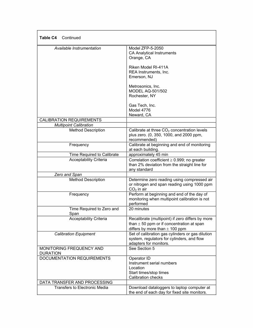
Table C4 Continued
Available Instrumentation Model ZFP-5-2050 CA Analytical Instruments Orange, CA Riken Model RI-411A REA Instruments, Inc. Emerson, NJ Metrosonics, Inc. MODEL AQ-501/502 Rochester, NY Gas Tech, Inc. Model 4776 Neward, CA
CALIBRATION REQUIREMENTS Multipoint Calibration
Method Description Calibrate at three CO2 concentration levels plus zero. (0, 350, 1000, and 2000 ppm, recommended)
Frequency Calibrate at beginning and end of monitoring at each building.
Time Required to Calibrate approximately 45 min Acceptability Criteria Correlation coefficient ≥ 0.999; no greater
than 2% deviation from the straight line for any standard
Zero and Span Method Description Determine zero reading using compressed air
or nitrogen and span reading using 1000 ppm CO2 in air
Frequency Perform at beginning and end of the day of monitoring when multipoint calibration is not performed
Time Required to Zero and Span
20 minutes
Acceptability Criteria Recalibrate (multipoint) if zero differs by more than ± 50 ppm or if concentration at span differs by more than ± 100 ppm
Calibration Equipment Set of calibration gas cylinders or gas dilution system, regulators for cylinders, and flow adapters for monitors.
MONITORING FREQUENCY AND DURATION
See Section 5
DOCUMENTATION REQUIREMENTS Operator ID Instrument serial numbers Location Start times/stop times Calibration checks
DATA TRANSFER AND PROCESSING Transfers to Electronic Media Download dataloggers to laptop computer at
the end of each day for fixed site monitors.
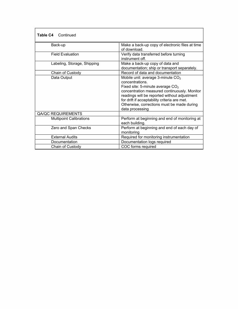
Table C4 Continued
Back-up Make a back-up copy of electronic files at time of download.
Field Evaluation Verify data transferred before turning instrument off.
Labeling, Storage, Shipping Make a back-up copy of data and documentation; ship or transport separately.
Chain of Custody Record of data and documentation Data Output Mobile unit: average 3-minute CO2
concentrations. Fixed site: 5-minute average CO2 concentration measured continuously. Monitor readings will be reported without adjustment for drift if acceptability criteria are met. Otherwise, corrections must be made during data processing
QA/QC REQUIREMENTS Multipoint Calibrations Perform at beginning and end of monitoring at
each building. Zero and Span Checks Perform at beginning and end of each day of
monitoring External Audits Required for monitoring instrumentation Documentation Documentation logs required Chain of Custody COC forms required
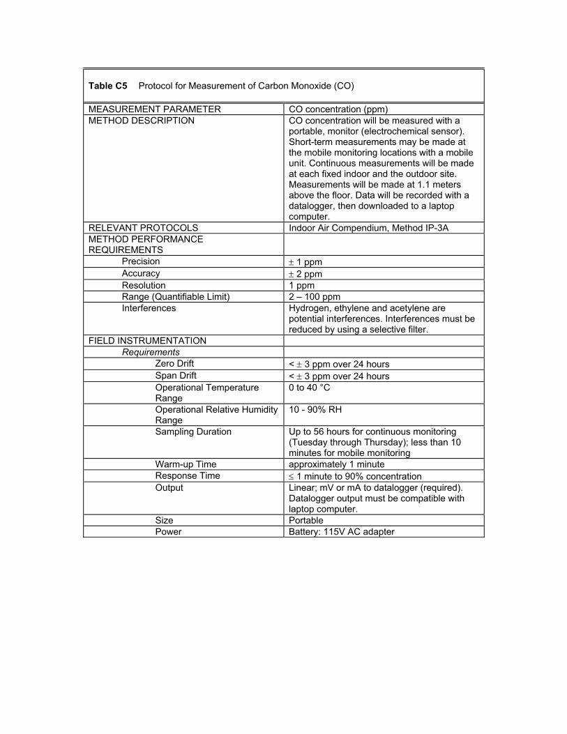
Table C5 Protocol for Measurement of Carbon Monoxide (CO) MEASUREMENT PARAMETER CO concentration (ppm) METHOD DESCRIPTION CO concentration will be measured with a
portable, monitor (electrochemical sensor). Short-term measurements may be made at the mobile monitoring locations with a mobile unit. Continuous measurements will be made at each fixed indoor and the outdoor site. Measurements will be made at 1.1 meters above the floor. Data will be recorded with a datalogger, then downloaded to a laptop computer.
RELEVANT PROTOCOLS Indoor Air Compendium, Method IP-3A METHOD PERFORMANCE REQUIREMENTS
Precision ± 1 ppm Accuracy ± 2 ppm Resolution 1 ppm Range (Quantifiable Limit) 2 – 100 ppm Interferences Hydrogen, ethylene and acetylene are
potential interferences. Interferences must be reduced by using a selective filter.
FIELD INSTRUMENTATION Requirements
Zero Drift < ± 3 ppm over 24 hours Span Drift < ± 3 ppm over 24 hours Operational Temperature Range
0 to 40 °C
Operational Relative Humidity Range
10 - 90% RH
Sampling Duration Up to 56 hours for continuous monitoring (Tuesday through Thursday); less than 10 minutes for mobile monitoring
Warm-up Time approximately 1 minute Response Time ≤ 1 minute to 90% concentration Output Linear; mV or mA to datalogger (required).
Datalogger output must be compatible with laptop computer.
Size Portable Power Battery: 115V AC adapter
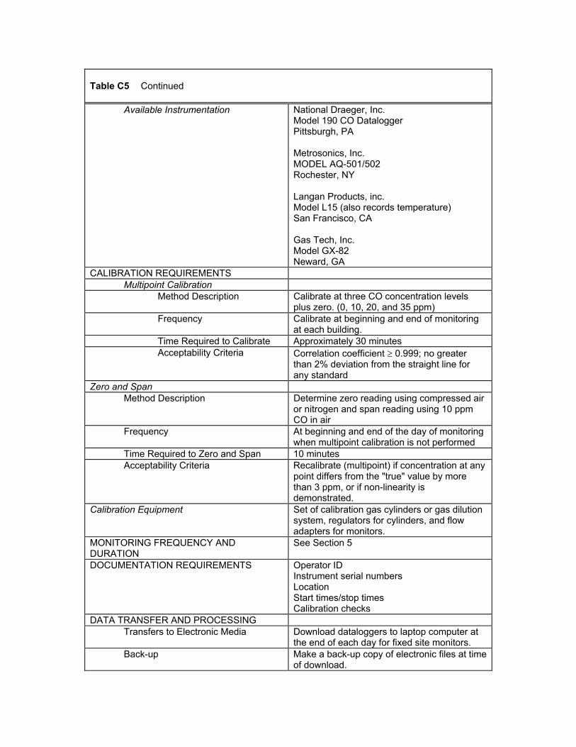
Table C5 Continued
Available Instrumentation National Draeger, Inc. Model 190 CO Datalogger Pittsburgh, PA Metrosonics, Inc. MODEL AQ-501/502 Rochester, NY Langan Products, inc. Model L15 (also records temperature) San Francisco, CA Gas Tech, Inc. Model GX-82 Neward, GA
CALIBRATION REQUIREMENTS Multipoint Calibration
Method Description Calibrate at three CO concentration levels plus zero. (0, 10, 20, and 35 ppm)
Frequency Calibrate at beginning and end of monitoring at each building.
Time Required to Calibrate Approximately 30 minutes Acceptability Criteria Correlation coefficient ≥ 0.999; no greater
than 2% deviation from the straight line for any standard
Zero and Span Method Description Determine zero reading using compressed air
or nitrogen and span reading using 10 ppm CO in air
Frequency At beginning and end of the day of monitoring when multipoint calibration is not performed
Time Required to Zero and Span 10 minutes Acceptability Criteria Recalibrate (multipoint) if concentration at any
point differs from the "true" value by more than 3 ppm, or if non-linearity is demonstrated.
Calibration Equipment Set of calibration gas cylinders or gas dilution system, regulators for cylinders, and flow adapters for monitors.
MONITORING FREQUENCY AND DURATION
See Section 5
DOCUMENTATION REQUIREMENTS Operator ID Instrument serial numbers Location Start times/stop times Calibration checks
DATA TRANSFER AND PROCESSING Transfers to Electronic Media Download dataloggers to laptop computer at
the end of each day for fixed site monitors. Back-up Make a back-up copy of electronic files at time
of download.
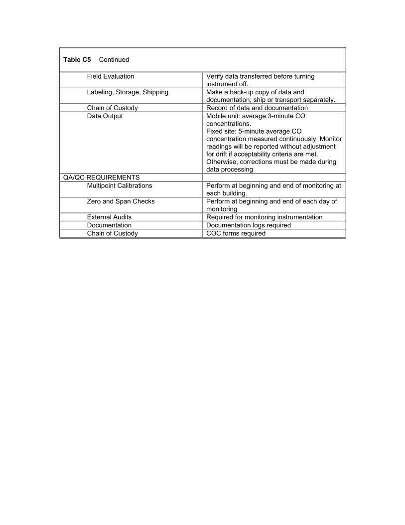
Table C5 Continued
Field Evaluation Verify data transferred before turning instrument off.
Labeling, Storage, Shipping Make a back-up copy of data and documentation; ship or transport separately.
Chain of Custody Record of data and documentation Data Output Mobile unit: average 3-minute CO
concentrations. Fixed site: 5-minute average CO concentration measured continuously. Monitor readings will be reported without adjustment for drift if acceptability criteria are met. Otherwise, corrections must be made during data processing
QA/QC REQUIREMENTS Multipoint Calibrations Perform at beginning and end of monitoring at
each building. Zero and Span Checks Perform at beginning and end of each day of
monitoring External Audits Required for monitoring instrumentation Documentation Documentation logs required Chain of Custody COC forms required
Table C6 Protocol for Measurement of Sound Level MEASUREMENT PARAMETER Sound Level (dB) METHOD DESCRIPTION Sound level will be measured with a
commercial Type 2 sound meter. Continuous measurements will be made at each fixed indoor site. Measurements will be made at 1.1 meters above the floor. Data will be recorded with a datalogger, then downloaded to a laptop computer.
RELEVANT PROTOCOLS None for office spaces METHOD PERFORMANCE REQUIREMENTS
Precision ± 2 dB Accuracy ± 2 dB Resolution 0.1 dB Range (Quantifiable Limit) 30 to 130 dB
FIELD INSTRUMENTATION Requirements
Operational Temperature Range
-10 to +50 °C
Operational Relative Humidity Range
5 to 95%
Sampling Duration Up to 56 hours for continuous monitoring (Tuesday through Thursday); less than 10 minutes for mobile monitoring
Output Linear; mV or mA to datalogger, or instrument equipped with internal datalogging capabilities. Datalogger output must be compatible with laptop computer
Size Portable Power Battery, 115V AC adapter
Available Instrumentation Quest Electronics Model 2400 Kit contains meter and calibrator Oconomowoc, WI Metrosonics, Inc. MODEL AQ-501/502 Rochester, NY CEL 231 Kit includes meter and calibrator Available from Vallen Safety Supply
CALIBRATION REQUIREMENTS Multipoint Calibration
Method Description Laboratory or manufacturer multi-point calibration should be performed annually
Field Calibration Checks Method Description Portable field calibrator should be used. Frequency Verify meter performance prior to each use.
Table C6 Continued
Acceptability Criteria If the meter reading differs from the reference device by greater than 4 dB, it is unacceptable for field use and should be recalibrated.
Calibration Equipment Portable field calibrator. MONITORING FREQUENCY, DURATION, AND LOCATIONS Frequency See Section 5 DOCUMENTATION REQUIREMENTS Operator ID
Instrument serial numbers Location Start times/stop times Calibration checks
DATA TRANSFER AND PROCESSING Transfers to Electronic Media Download dataloggers to laptop computer at
the end of each day for fixed site monitors. Back-up Make a back-up copy of electronic files at time
of download. Labeling, Storage, Shipping Make a back-up copy of data and
documentation; ship or transport separately. Chain of Custody Record of data and documentation Data Output Fixed sites: 5 minute average sound levels
measured continuously QA/QC REQUIREMENTS
Multipoint Calibrations Perform annually Calibration Checks Perform prior to each use with field calibrator. External Audits Required for monitoring instrumentation Documentation Documentation logs required Chain of Custody COC forms required
Table C7 Protocol for Measurement of Illuminance MEASUREMENT PARAMETERS Illuminance (lux) METHOD DESCRIPTION Illuminance will be measured with a
commercial meter. Continuous measurements will be made at each fixed indoor site. Measurements will be made at 1.1 meters above the floor. Data will be recorded with a datalogger, then downloaded to a laptop computer.
RELEVANT PROTOCOLS CIE Guide on interior Lighting METHOD PERFORMANCE REQUIREMENTS
Precision and Accuracy ± 2% of recording FIELD INSTRUMENTATION
Requirements Metering Range 1 to 2000 lux Operational Temperature Range
0 to 40 °C
Operational Relative Humidity Range
5 to 95%
Output Linear; mV or mA to datalogger, or instrument equipped with internal datalogging capabilities. Datalogger output must be compatible with laptop computer
Size Portable hand held units Power Battery, 115 VAC adapter
Available Instrumentation Minolta T-1 Illuminance Meter ($625) Minolta Corporation Ramsey, NJ 07446-129 Metrosonics, Inc. MODEL AQ-501/502 Rochester, NY
CALIBRATION REQUIREMENTS Multipoint Calibration
Method Description Laboratory calibration against known standard annually
Field Calibration Checks Method Description Zero calibration
MONITORING FREQUENCY AND DURATION
Frequency See Section 5 DOCUMENTATION REQUIREMENTS Operator ID
Instrument serial numbers Location Start times/stop times Calibration checks
DATA TRANSFER AND HANDLING Transfer to Electronic Media Download dataloggers to laptop computer at
the end of each day for fixed site monitors. Back-up Back-up copy electronic media. Chain of custody Required
Table C7 Continued
Data Output Fixed sites: 5 minute average lux levels measured continuously
QA/ QC REQUIREMENTS Multipoint Calibration Perform annually Calibration Checks Follow manufacturer's instructions External Audits Required for monitoring instrumentation Documentation Documentation logs required Chain of Custody COC forms required
MEASUREMENT PARAMETER Particles (PM10 and PM2.5) METHOD DESCRIPTION Ambient air will be passed through a particle
size selective device (impactor) at a constant and specified flowrate. For PM10, particles greater than 10 microns are removed from the airstream by impaction and discarded. Particles equal to or smaller than 10 microns are collected on a pre-weighed filter. For PM2.5, particles greater than 2.5 microns are removed from the airstream by impaction and discarded. Particles equal to or smaller than 2.5 microns are collected on a pre-weighed filter. The mass of the collected particulate will be determined gravimetrically using an analytical balance. Integrated samples will be collected over an 8-hour period at three indoor and one outdoor location.
RELEVANT PROTOCOLS Indoor Air Compendium Method IP-10A METHOD PERFORMANCE REQUIREMENTS
Precision ± 25% Accuracy ± 25% Method Quantifiable Limit (MQL) 10 µg/m3 for 8 hour sample Range (Qualifiable Limit) 10 – 120 µg/m3 for 8 hour sample Interferences Static electricity and humidity during filter
weighing FIELD INSTRUMENTATION
Pump Flow Rate 10 L/min Pump Flow Stability ± 5% Operational Temperature Range 0 – 40 °C Operational Relative Humidity Range 0 – 100%
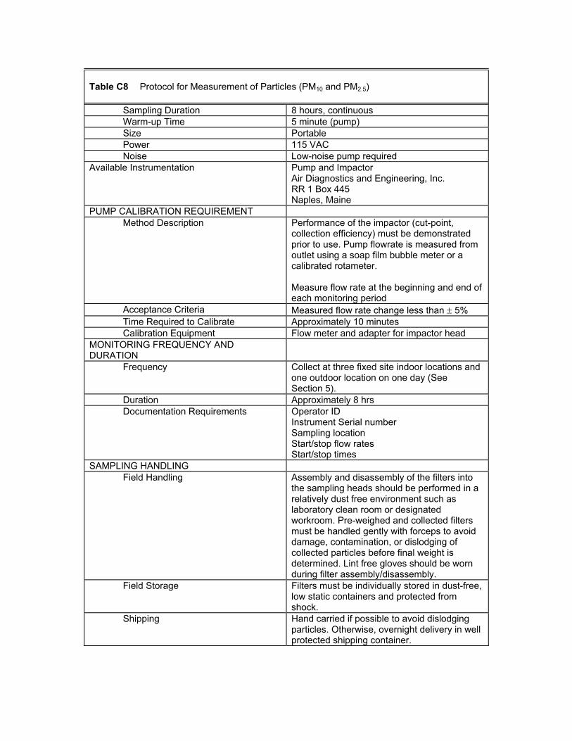
Table C8 Protocol for Measurement of Particles (PM10 and PM2.5)
Sampling Duration 8 hours, continuous Warm-up Time 5 minute (pump) Size Portable Power 115 VAC Noise Low-noise pump required
Available Instrumentation Pump and Impactor Air Diagnostics and Engineering, Inc. RR 1 Box 445 Naples, Maine
PUMP CALIBRATION REQUIREMENT Method Description Performance of the impactor (cut-point,
collection efficiency) must be demonstrated prior to use. Pump flowrate is measured from outlet using a soap film bubble meter or a calibrated rotameter. Measure flow rate at the beginning and end of each monitoring period
Acceptance Criteria Measured flow rate change less than ± 5% Time Required to Calibrate Approximately 10 minutes Calibration Equipment Flow meter and adapter for impactor head
MONITORING FREQUENCY AND DURATION
Frequency Collect at three fixed site indoor locations and one outdoor location on one day (See Section 5).
Duration Approximately 8 hrs Documentation Requirements Operator ID
Instrument Serial number Sampling location Start/stop flow rates Start/stop times
SAMPLING HANDLING Field Handling Assembly and disassembly of the filters into
the sampling heads should be performed in a relatively dust free environment such as laboratory clean room or designated workroom. Pre-weighed and collected filters must be handled gently with forceps to avoid damage, contamination, or dislodging of collected particles before final weight is determined. Lint free gloves should be worn during filter assembly/disassembly.
Field Storage Filters must be individually stored in dust-free, low static containers and protected from shock.
Shipping Hand carried if possible to avoid dislodging particles. Otherwise, overnight delivery in well protected shipping container.
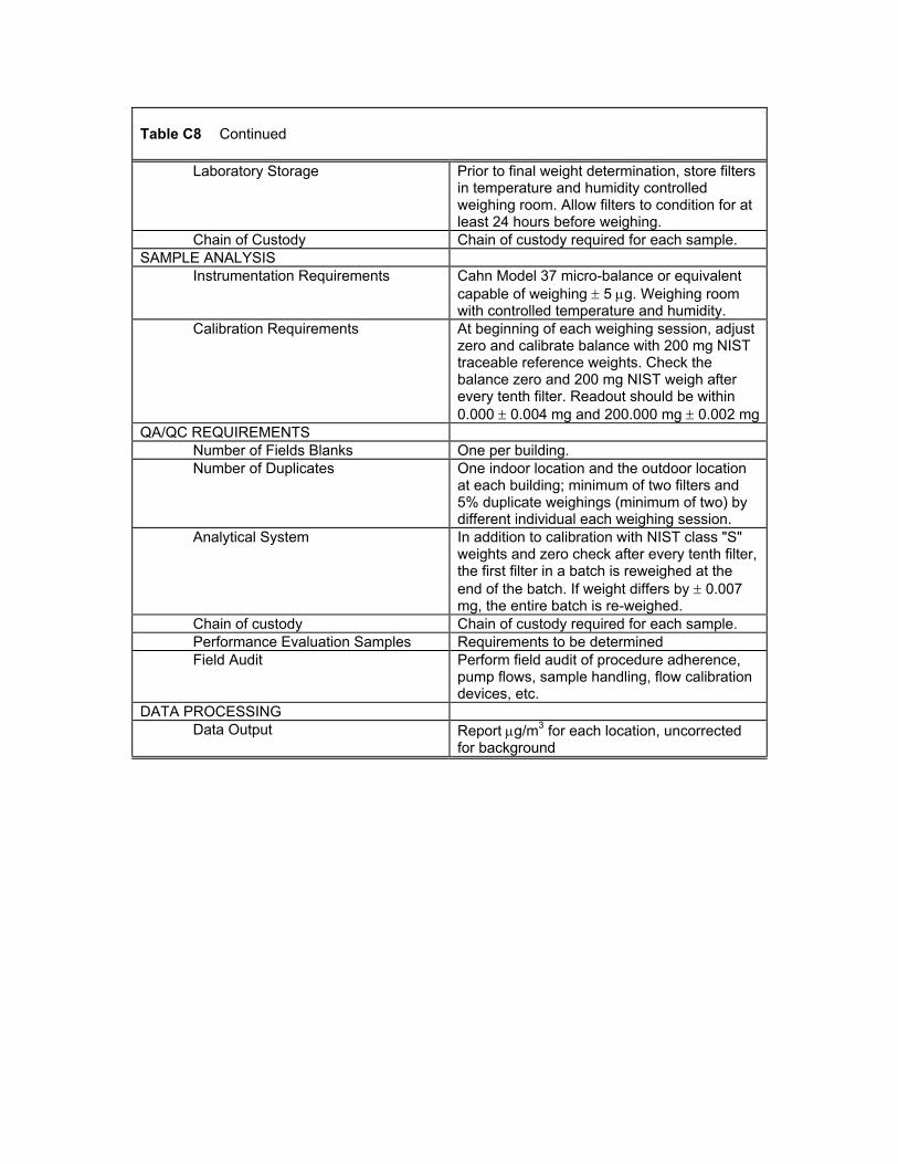
Table C8 Continued
Laboratory Storage Prior to final weight determination, store filters in temperature and humidity controlled weighing room. Allow filters to condition for at least 24 hours before weighing.
Chain of Custody Chain of custody required for each sample. SAMPLE ANALYSIS
Instrumentation Requirements Cahn Model 37 micro-balance or equivalent capable of weighing ± 5 µg. Weighing room with controlled temperature and humidity.
Calibration Requirements At beginning of each weighing session, adjust zero and calibrate balance with 200 mg NIST traceable reference weights. Check the balance zero and 200 mg NIST weigh after every tenth filter. Readout should be within 0.000 ± 0.004 mg and 200.000 mg ± 0.002 mg
QA/QC REQUIREMENTS Number of Fields Blanks One per building. Number of Duplicates One indoor location and the outdoor location
at each building; minimum of two filters and 5% duplicate weighings (minimum of two) by different individual each weighing session.
Analytical System In addition to calibration with NIST class "S" weights and zero check after every tenth filter, the first filter in a batch is reweighed at the end of the batch. If weight differs by ± 0.007 mg, the entire batch is re-weighed.
Chain of custody Chain of custody required for each sample. Performance Evaluation Samples Requirements to be determined Field Audit Perform field audit of procedure adherence,
pump flows, sample handling, flow calibration devices, etc.
DATA PROCESSING Data Output Report µg/m3 for each location, uncorrected
for background
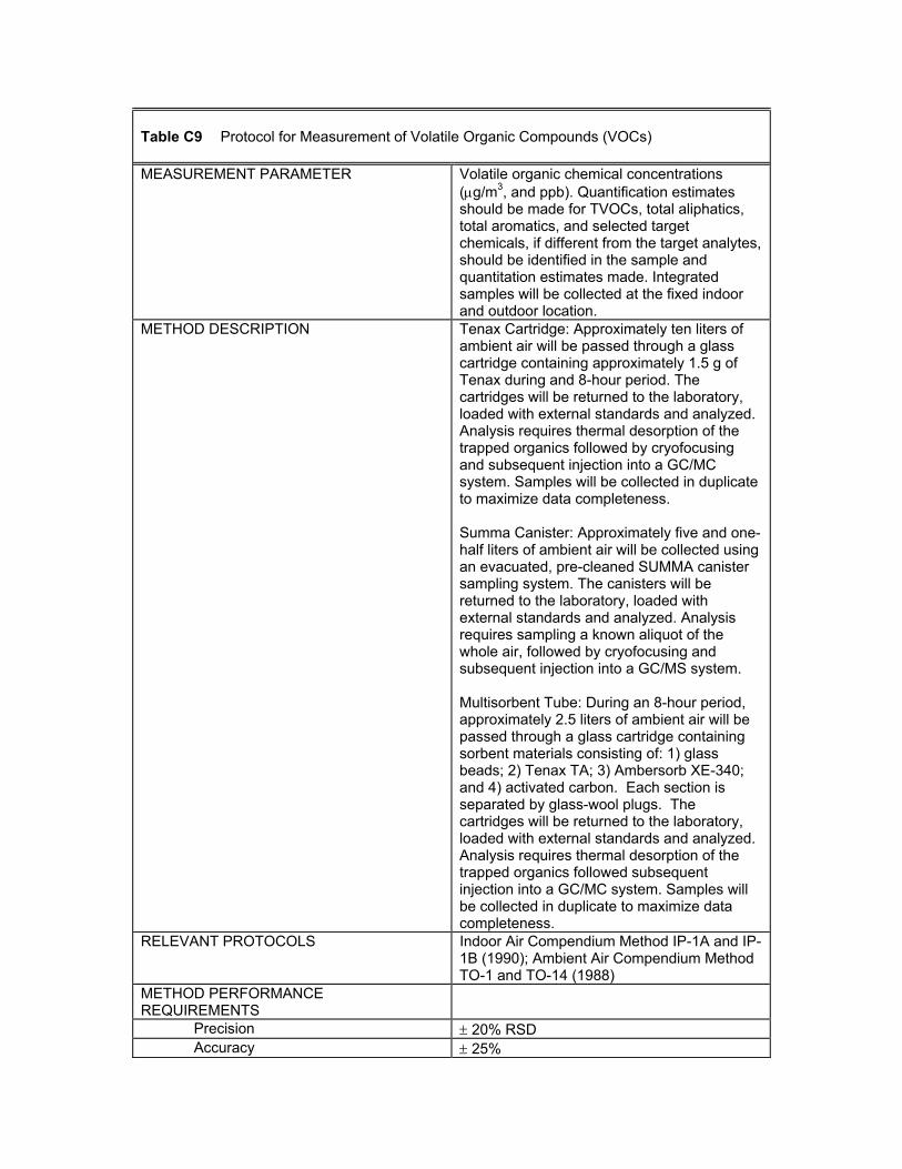
Table C9 Protocol for Measurement of Volatile Organic Compounds (VOCs) MEASUREMENT PARAMETER Volatile organic chemical concentrations
(µg/m3, and ppb). Quantification estimates should be made for TVOCs, total aliphatics, total aromatics, and selected target chemicals, if different from the target analytes, should be identified in the sample and quantitation estimates made. Integrated samples will be collected at the fixed indoor and outdoor location.
METHOD DESCRIPTION Tenax Cartridge: Approximately ten liters of ambient air will be passed through a glass cartridge containing approximately 1.5 g of Tenax during and 8-hour period. The cartridges will be returned to the laboratory, loaded with external standards and analyzed. Analysis requires thermal desorption of the trapped organics followed by cryofocusing and subsequent injection into a GC/MC system. Samples will be collected in duplicate to maximize data completeness. Summa Canister: Approximately five and one-half liters of ambient air will be collected using an evacuated, pre-cleaned SUMMA canister sampling system. The canisters will be returned to the laboratory, loaded with external standards and analyzed. Analysis requires sampling a known aliquot of the whole air, followed by cryofocusing and subsequent injection into a GC/MS system. Multisorbent Tube: During an 8-hour period, approximately 2.5 liters of ambient air will be passed through a glass cartridge containing sorbent materials consisting of: 1) glass beads; 2) Tenax TA; 3) Ambersorb XE-340; and 4) activated carbon. Each section is separated by glass-wool plugs. The cartridges will be returned to the laboratory, loaded with external standards and analyzed. Analysis requires thermal desorption of the trapped organics followed subsequent injection into a GC/MC system. Samples will be collected in duplicate to maximize data completeness.
RELEVANT PROTOCOLS Indoor Air Compendium Method IP-1A and IP-1B (1990); Ambient Air Compendium Method TO-1 and TO-14 (1988)
METHOD PERFORMANCE REQUIREMENTS
Precision ± 20% RSD Accuracy ± 25%
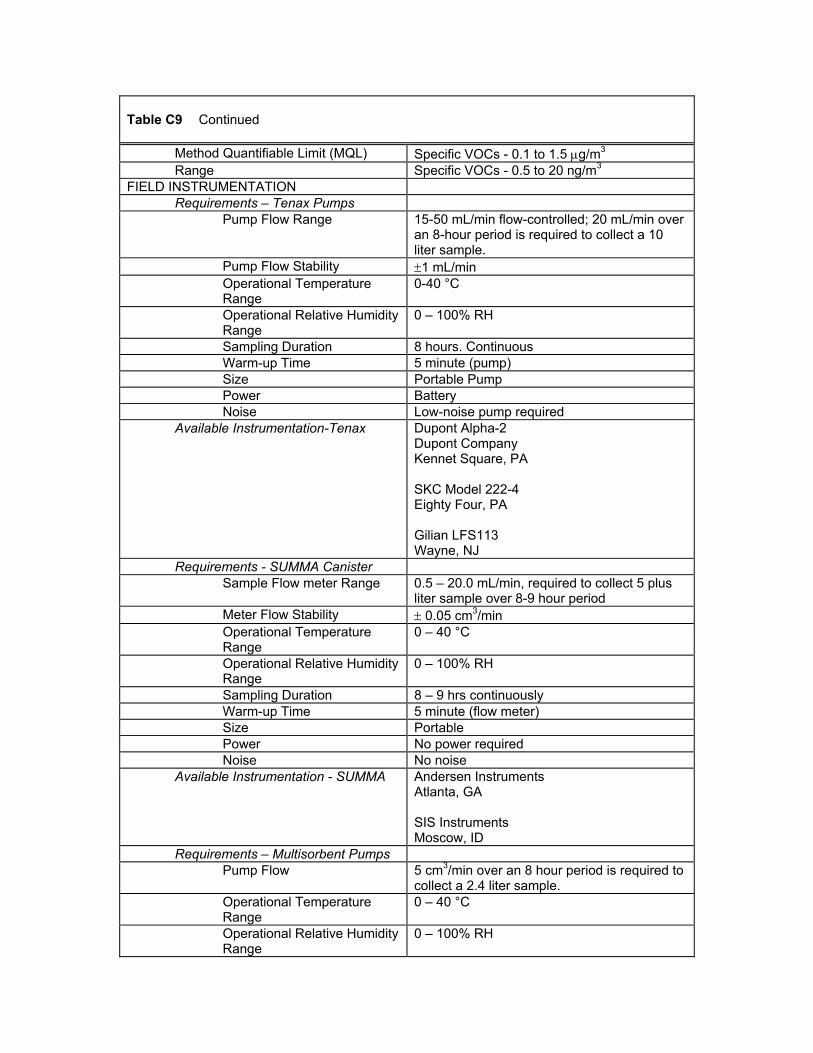
Table C9 Continued
Method Quantifiable Limit (MQL) Specific VOCs - 0.1 to 1.5 µg/m3 Range Specific VOCs - 0.5 to 20 ng/m3
FIELD INSTRUMENTATION Requirements – Tenax Pumps
Pump Flow Range 15-50 mL/min flow-controlled; 20 mL/min over an 8-hour period is required to collect a 10 liter sample.
Pump Flow Stability ±1 mL/min Operational Temperature Range
0-40 °C
Operational Relative Humidity Range
0 – 100% RH
Sampling Duration 8 hours. Continuous Warm-up Time 5 minute (pump) Size Portable Pump Power Battery Noise Low-noise pump required
Available Instrumentation-Tenax Dupont Alpha-2 Dupont Company Kennet Square, PA SKC Model 222-4 Eighty Four, PA Gilian LFS113 Wayne, NJ
Requirements - SUMMA Canister Sample Flow meter Range 0.5 – 20.0 mL/min, required to collect 5 plus
liter sample over 8-9 hour period Meter Flow Stability ± 0.05 cm3/min Operational Temperature Range
0 – 40 °C
Operational Relative Humidity Range
0 – 100% RH
Sampling Duration 8 – 9 hrs continuously Warm-up Time 5 minute (flow meter) Size Portable Power No power required Noise No noise
Available Instrumentation - SUMMA Andersen Instruments Atlanta, GA SIS Instruments Moscow, ID
Requirements – Multisorbent Pumps Pump Flow 5 cm3/min over an 8 hour period is required to
collect a 2.4 liter sample. Operational Temperature Range
0 – 40 °C
Operational Relative Humidity Range
0 – 100% RH
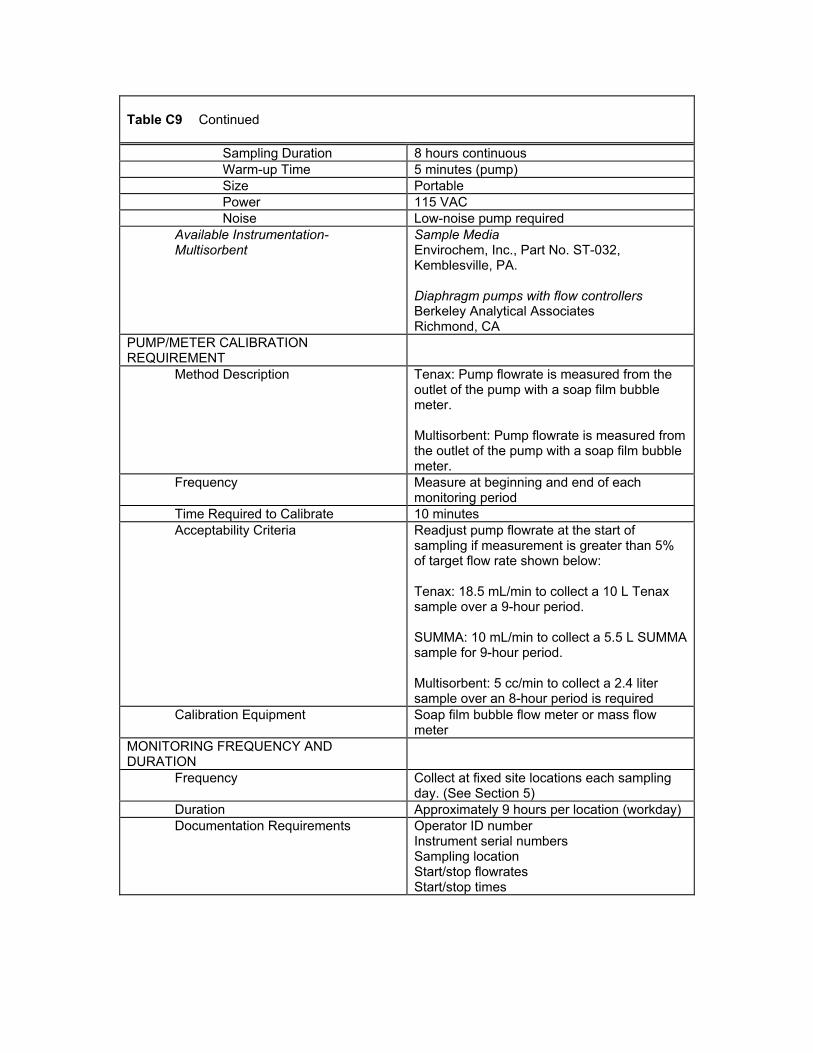
Table C9 Continued
Sampling Duration 8 hours continuous Warm-up Time 5 minutes (pump) Size Portable Power 115 VAC Noise Low-noise pump required
Available Instrumentation-Multisorbent
Sample Media Envirochem, Inc., Part No. ST-032, Kemblesville, PA. Diaphragm pumps with flow controllers Berkeley Analytical Associates Richmond, CA
PUMP/METER CALIBRATION REQUIREMENT
Method Description Tenax: Pump flowrate is measured from the outlet of the pump with a soap film bubble meter. Multisorbent: Pump flowrate is measured from the outlet of the pump with a soap film bubble meter.
Frequency Measure at beginning and end of each monitoring period
Time Required to Calibrate 10 minutes Acceptability Criteria Readjust pump flowrate at the start of
sampling if measurement is greater than 5% of target flow rate shown below: Tenax: 18.5 mL/min to collect a 10 L Tenax sample over a 9-hour period. SUMMA: 10 mL/min to collect a 5.5 L SUMMA sample for 9-hour period. Multisorbent: 5 cc/min to collect a 2.4 liter sample over an 8-hour period is required
Calibration Equipment Soap film bubble flow meter or mass flow meter
MONITORING FREQUENCY AND DURATION
Frequency Collect at fixed site locations each sampling day. (See Section 5)
Duration Approximately 9 hours per location (workday) Documentation Requirements Operator ID number
Instrument serial numbers Sampling location Start/stop flowrates Start/stop times
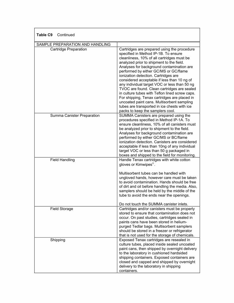
Table C9 Continued SAMPLE PREPARATION AND HANDLING
Cartridge Preparation Cartridges are prepared using the procedure specified in Method IP-1B. To ensure cleanliness, 10% of all cartridges must be analyzed prior to shipment to the field. Analyses for background contamination are performed by either GC/MS or GC/flame ionization detection. Cartridges are considered acceptable if less than 10 ng of any individual target VOC or less than 50 ng TVOC are found. Clean cartridges are sealed in culture tubes with Teflon lined screw caps. For shipping, Tenax cartridges are placed in uncoated paint cans. Multisorbent sampling tubes are transported in ice chests with ice packs to keep the samplers cool.
Summa Canister Preparation SUMMA Canisters are prepared using the procedures specified in Method IP-1A. To ensure cleanliness, 10% of all canisters must be analyzed prior to shipment to the field. Analyses for background contamination are performed by either GC/MS or BC/flame ionization detection. Canisters are considered acceptable if less than 10ng of any individual target VOC or less than 50 g packaged in boxes and shipped to the field for monitoring.
Field Handling Handle Tenax cartridges with white cotton gloves or Kimwipes. Multisorbent tubes can be handled with ungloved hands, however care must be taken to avoid contamination. Hands should be free of dirt and oil before handling the media. Also, samplers should be held by the middle of the tube to avoid the ends near the openings. Do not touch the SUMMA canister inlets.
Field Storage Cartridges and/or canisters must be properly stored to ensure that contamination does not occur. On past studies, cartridges sealed in paints cans have been stored in helium-purged Tedlar bags. Multisorbent samplers should be stored in a freezer or refrigerator that is not used for the storage of chemicals.
Shipping Exposed Tenax cartridges are resealed in culture tubes, placed inside sealed uncoated paint cans, then shipped by overnight delivery to the laboratory in cushioned hardsided shipping containers. Exposed containers are closed and capped and shipped by overnight delivery to the laboratory in shipping containers.
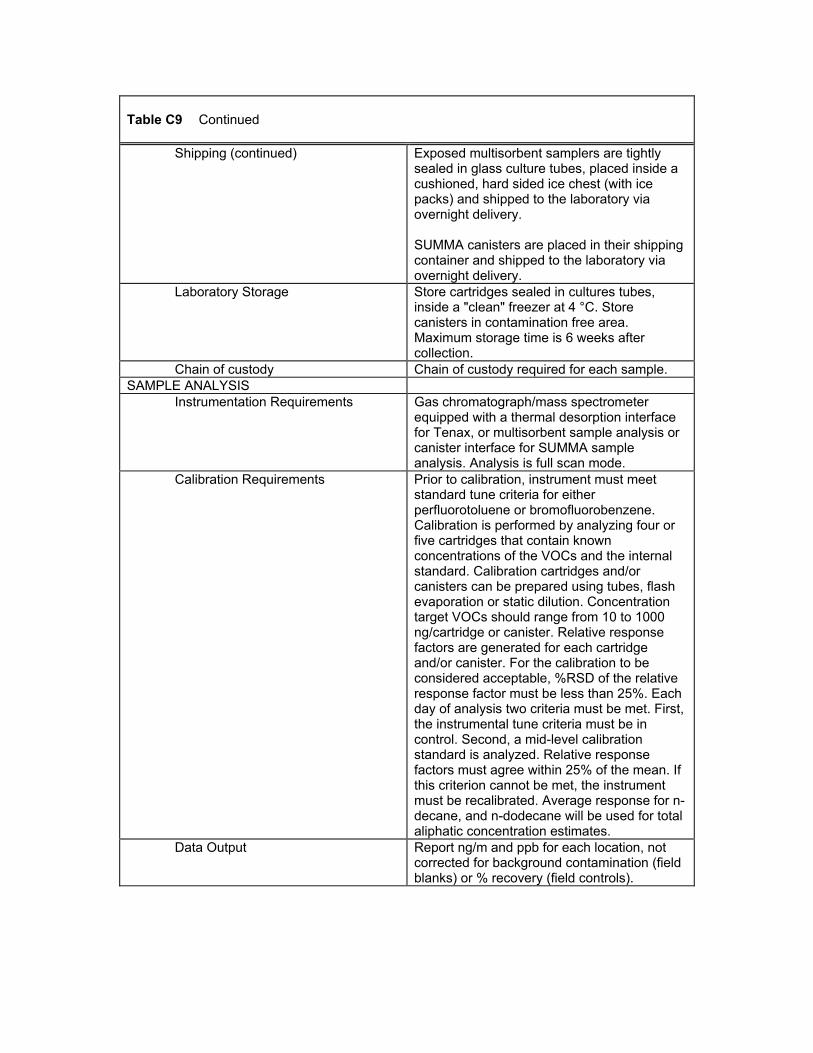
Table C9 Continued
Shipping (continued) Exposed multisorbent samplers are tightly sealed in glass culture tubes, placed inside a cushioned, hard sided ice chest (with ice packs) and shipped to the laboratory via overnight delivery. SUMMA canisters are placed in their shipping container and shipped to the laboratory via overnight delivery.
Laboratory Storage Store cartridges sealed in cultures tubes, inside a "clean" freezer at 4 °C. Store canisters in contamination free area. Maximum storage time is 6 weeks after collection.
Chain of custody Chain of custody required for each sample. SAMPLE ANALYSIS
Instrumentation Requirements Gas chromatograph/mass spectrometer equipped with a thermal desorption interface for Tenax, or multisorbent sample analysis or canister interface for SUMMA sample analysis. Analysis is full scan mode.
Calibration Requirements Prior to calibration, instrument must meet standard tune criteria for either perfluorotoluene or bromofluorobenzene. Calibration is performed by analyzing four or five cartridges that contain known concentrations of the VOCs and the internal standard. Calibration cartridges and/or canisters can be prepared using tubes, flash evaporation or static dilution. Concentration target VOCs should range from 10 to 1000 ng/cartridge or canister. Relative response factors are generated for each cartridge and/or canister. For the calibration to be considered acceptable, %RSD of the relative response factor must be less than 25%. Each day of analysis two criteria must be met. First, the instrumental tune criteria must be in control. Second, a mid-level calibration standard is analyzed. Relative response factors must agree within 25% of the mean. If this criterion cannot be met, the instrument must be recalibrated. Average response for n-decane, and n-dodecane will be used for total aliphatic concentration estimates.
Data Output Report ng/m and ppb for each location, not corrected for background contamination (field blanks) or % recovery (field controls).
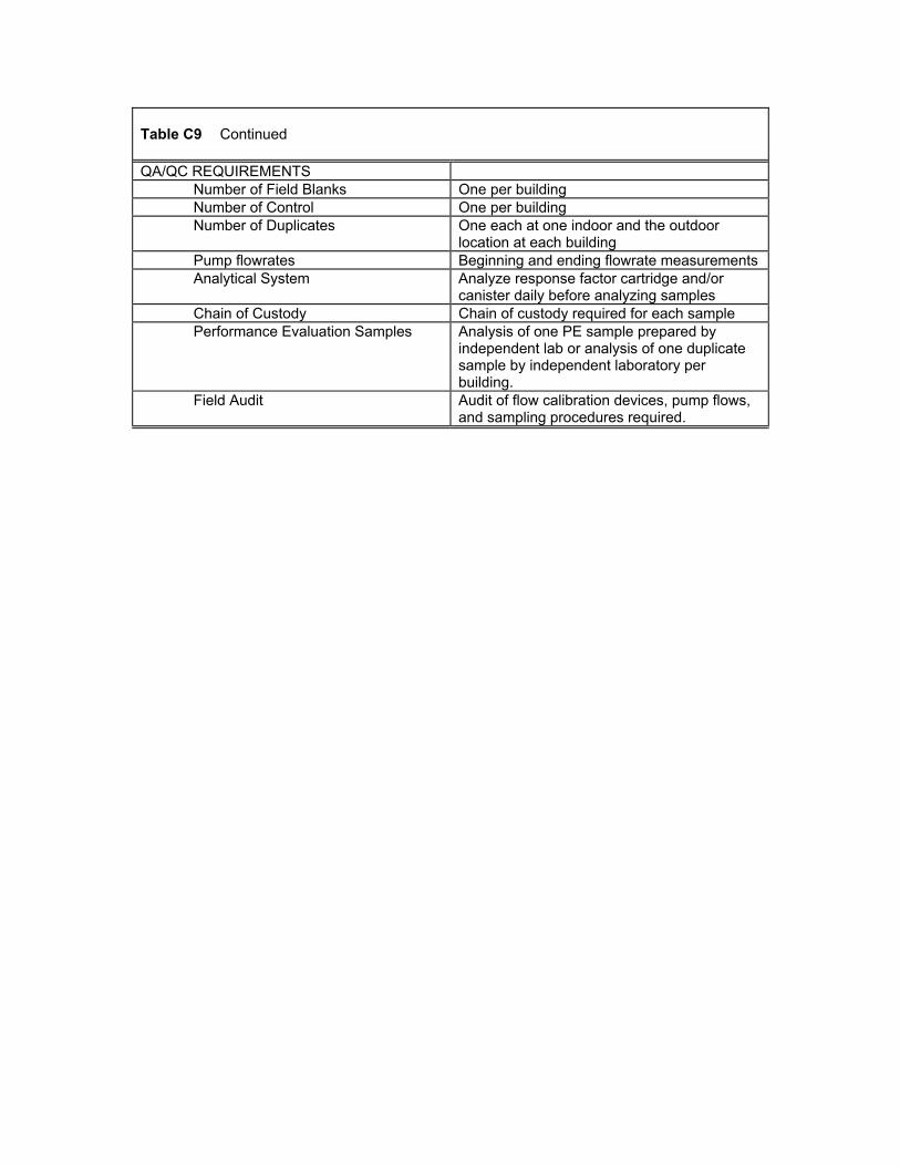
Table C9 Continued QA/QC REQUIREMENTS
Number of Field Blanks One per building Number of Control One per building Number of Duplicates One each at one indoor and the outdoor
location at each building Pump flowrates Beginning and ending flowrate measurements Analytical System Analyze response factor cartridge and/or
canister daily before analyzing samples Chain of Custody Chain of custody required for each sample Performance Evaluation Samples Analysis of one PE sample prepared by
independent lab or analysis of one duplicate sample by independent laboratory per building.
Field Audit Audit of flow calibration devices, pump flows, and sampling procedures required.
Table C10 Protocol for Measurement of Formaldehyde MEASUREMENT PARAMETER Formaldehyde concentration (µg/m3) METHOD DESCRIPTION Ambient air samples will be collected with
2,4-dinitrophenylhydrazine (DNPH) coated silica gel cartridges. Samples are analyzed by reverse phase HPLC using a UV detector operated at 360 nm. Integrated samples will be collected over an 8-hour period at the fixed indoor and outdoor locations.
RELEVANT PROTOCOLS Indoor Air Compendium Method IP-6A; Ambient Air Compendium Method TO-11
METHOD PERFORMANCE REQUIREMENTSPrecision ± 25% RSD (for duplicate samples) Accuracy ± 20% Method Quantifiable Limit (MQL) 0 5 µg/m3 (for 100 L sampling volume) Range 0 5 to 1000 µg/m3 Interferences Unresolved organic compounds having same
retention time and significant absorbance at 360 nm may interfere. Ozone is a known interference that can be removed with a potassium iodide-coated tubular denuder placed upstream of the sampling cartridge. NOTE: Acetonitrile is released from the cartridge during sampling. It must be collected from the pump outlet with a trap containing charcoal to minimize interferences with VOC measurements.
FIELD INSTRUMENTATION Requirements Pump Flow Range 50 – 1500 mL/min (200 mL recommended for
96 liter sampling volume) Pump Flow Stability 5% Operational Temperature Range 0 – 40 °C Operational Relative Humidity Range 0 – 100% Sampling Duration 8 hour continuous Warm-up Time 5 minute (pump) Size Portable Power Battery,115V AC Adapter Noise Low noise pump required Special Requirements Outlet of the pump must be fitted with a trap
containing charcoal to collect acetonitrile released from Sep-Pak cartridge during sampling
Table C10 Continued Available Instrumentation and Media Prepared Sep-Pak cartridges are available
from Waters Associates, Milford, WA Dupont Alpha-2 Pump Dupont Company Kennet Square, PA SKC Model 222-4 Pump Eighty Four, PA Gilian LFS113 Pump Gilian Instrument Corp. West Caldwell, NJ
PUMP CALIBRATION REQUIREMENT Method Description Pump flow rate is measured from the outlet of
the pump with a soap film bubble meter. Frequency Flow rate measurements at the beginning and
end of each monitoring period Time Required to Calibrate 10 minutes Calibration Equipment Soap film bubble flow meter.
MONITORING FREQUENCY AND DURATION
Frequency Collect at fixed-site locations on one day (See Section 5)
Duration Approximately 8 hours Documentation Requirements Operator ID number
Instrument serial numbers Sampling locations Start/stop flow rates Start/stop times
SAMPLE HANDLING Field Handling Sampler preparation and handling procedures
must minimize background contamination Field Storage Sampling cartridges are capped with Luer end
plugs and placed in sealed glass culture tubes inside sealed uncoated paint can. Paint cans should contain 1 – 2 inches of granular charcoal.
Shipping Cartridges are shipped sealed in culture tubes, inside sealed uncoated paint cans containing granular charcoal. Paint cans are placed inside cushioned hard-sided shipping containers. Ship by overnight delivery to laboratory.
Laboratory Storage Store cartridges sealed in culture tubes, inside paint cans, in a "clean" freezer at 4 °C
Chain of Custody Chain of custody required for each sample SAMPLE ANALYSIS
Instrumentation Requirements HPLC Systems with a variable wavelength UV Detector (360 nm wavelength)
Table C10 Continued
Calibration Requirements Five point calibration with calibration standards prepared in acetonitrile from DNPH-formaldehyde derivative. (General procedures in IP-6A should be followed)
DATA PROCESSING Data Output Report µg/m3for each location; not corrected
for background contamination (field blanks) or % recovery (field controls).
QA/QC REQUIREMENTS Number of Field Blanks One per Building Number of Field Controls One per Building Number of Duplicates One each at one indoor location and at the
outdoor location Analytical Systems Daily response of system determined by
analysis of intermediate concentration standard.
Chain of Custody Chain of custody required for each sample Performance Evaluation Samples Analysis of one PE sample prepared by
independent laboratory or analysis of one duplicate sample by independent laboratory per building.
Field Audit Audit of flow calibration devices, pump flows and sampling procedures required.
Table C11 Protocol for Measurement of Bioaerosols MEASUREMENT PARAMETER Mesophilic Bacteria, thermophilic bacteria and
fungi METHOD DESCRIPTION Culturable air spora are collected onto agar by
impaction using an Anderson N6 sampler. Media are cultured. Analysis by light microscopy.
RELEVANT PROTOCOLS Guidelines for the Assessment of Bioaerosols in the Indoor Environment (ACGIH, 1989)
METHOD PERFORMANCE REQUIREMENTS
Precision Objectives have not been established Accuracy Objectives for the method have not been
established FIELD INSTRUMENTATION
Requirements Pump Flow Rate 28.3 LPM Pump Flow Stability ± 5% Sampling Duration 2-minute and 5-minute – two samples of
different air volumes for each culture media collected at each location each time period.
Power AC required for pump Noise Use low noise vacuum pump
Required Instrumentation and Materials
Sampler Andersen N6 Microbiological Sampler and vacuum pump capable of sampling at 28 LPM
Culture media (20 1 mL per plate) Bacteria: Trypticase soy agar (TSA) Fungi: Malt extract agar (MEA) Sterility and ability to support growth must be documented
PUMP CALIBRATION REQUIREMENTS Method Description Pump flowrate is measured in the field with a
calibrated rotameter in-line between the sampler and pump.
Frequency Record pump flowrate for each sample collected.
Acceptability Criteria Adjust pump if flowrate differs by more than ±5% from 28.3 LPM
Field Calibration Equipment Calibrated rotameter MONITORING FREQUENCY AND LOCATIONS
Frequency Collection at approximately 10:30 a.m. and 3:30 p.m. on Wednesday
Locations Three fixed-site integrated sampling locations indoors and the one outdoor fixed-site location
Duration For each culture media, collect samples of 2-minute and 5-minute duration.
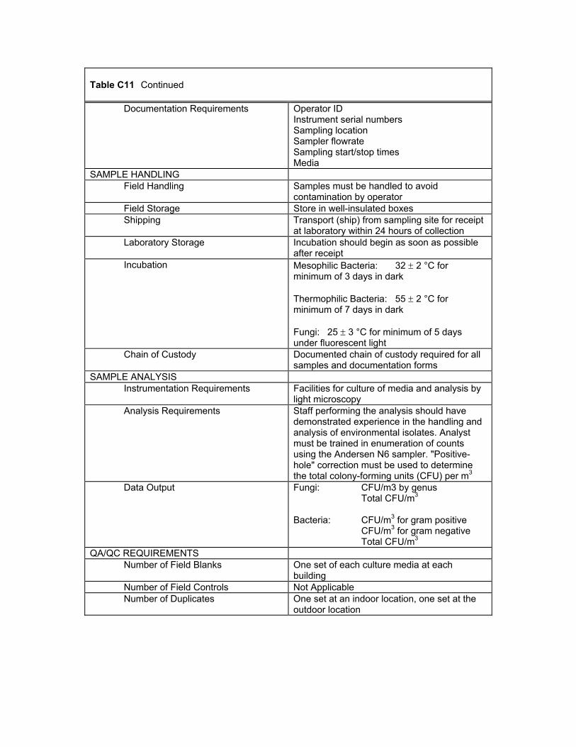
Table C11 Continued
Documentation Requirements Operator ID Instrument serial numbers Sampling location Sampler flowrate Sampling start/stop times Media
SAMPLE HANDLING Field Handling Samples must be handled to avoid
contamination by operator Field Storage Store in well-insulated boxes Shipping Transport (ship) from sampling site for receipt
at laboratory within 24 hours of collection Laboratory Storage Incubation should begin as soon as possible
after receipt Incubation Mesophilic Bacteria: 32 ± 2 °C for
minimum of 3 days in dark Thermophilic Bacteria: 55 ± 2 °C for minimum of 7 days in dark Fungi: 25 ± 3 °C for minimum of 5 days under fluorescent light
Chain of Custody Documented chain of custody required for all samples and documentation forms
SAMPLE ANALYSIS Instrumentation Requirements Facilities for culture of media and analysis by
light microscopy Analysis Requirements Staff performing the analysis should have
demonstrated experience in the handling and analysis of environmental isolates. Analyst must be trained in enumeration of counts using the Andersen N6 sampler. "Positive-hole" correction must be used to determine the total colony-forming units (CFU) per m3
Data Output Fungi: CFU/m3 by genus Total CFU/m3 Bacteria: CFU/m3 for gram positive CFU/m3 for gram negative Total CFU/m3
QA/QC REQUIREMENTS Number of Field Blanks One set of each culture media at each
building Number of Field Controls Not Applicable Number of Duplicates One set at an indoor location, one set at the
outdoor location
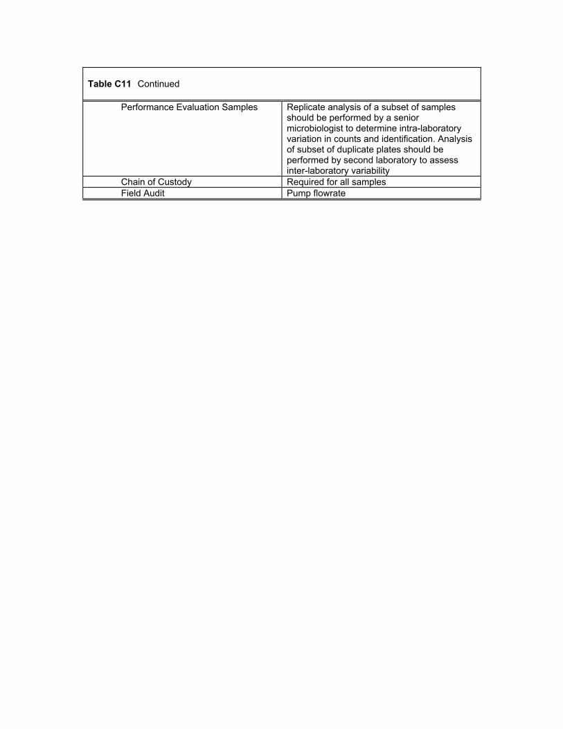
Table C11 Continued
Performance Evaluation Samples Replicate analysis of a subset of samples should be performed by a senior microbiologist to determine intra-laboratory variation in counts and identification. Analysis of subset of duplicate plates should be performed by second laboratory to assess inter-laboratory variability
Chain of Custody Required for all samples Field Audit Pump flowrate
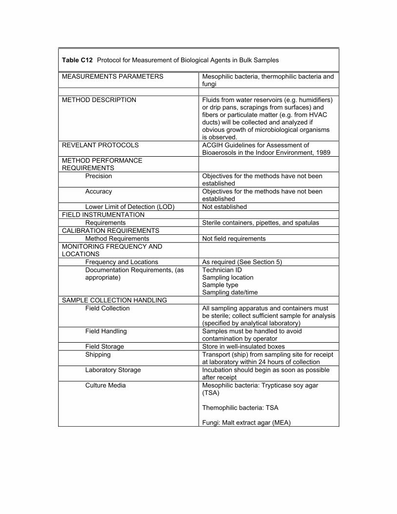
Table C12 Protocol for Measurement of Biological Agents in Bulk Samples MEASUREMENTS PARAMETERS Mesophilic bacteria, thermophilic bacteria and
fungi
METHOD DESCRIPTION Fluids from water reservoirs (e.g. humidifiers) or drip pans, scrapings from surfaces) and fibers or particulate matter (e.g. from HVAC ducts) will be collected and analyzed if obvious growth of microbiological organisms is observed.
REVELANT PROTOCOLS ACGIH Guidelines for Assessment of Bioaerosols in the Indoor Environment, 1989
METHOD PERFORMANCE REQUIREMENTS
Precision Objectives for the methods have not been established
Accuracy Objectives for the methods have not been established
Lower Limit of Detection (LOD) Not established FIELD INSTRUMENTATION
Requirements Sterile containers, pipettes, and spatulas CALIBRATION REQUIREMENTS
Method Requirements Not field requirements MONITORING FREQUENCY AND LOCATIONS
Frequency and Locations As required (See Section 5) Documentation Requirements, (as appropriate)
Technician ID Sampling location Sample type Sampling date/time
SAMPLE COLLECTION HANDLING Field Collection All sampling apparatus and containers must
be sterile; collect sufficient sample for analysis (specified by analytical laboratory)
Field Handling Samples must be handled to avoid contamination by operator
Field Storage Store in well-insulated boxes Shipping Transport (ship) from sampling site for receipt
at laboratory within 24 hours of collection Laboratory Storage Incubation should begin as soon as possible
after receipt Culture Media Mesophilic bacteria: Trypticase soy agar
(TSA) Themophilic bacteria: TSA Fungi: Malt extract agar (MEA)
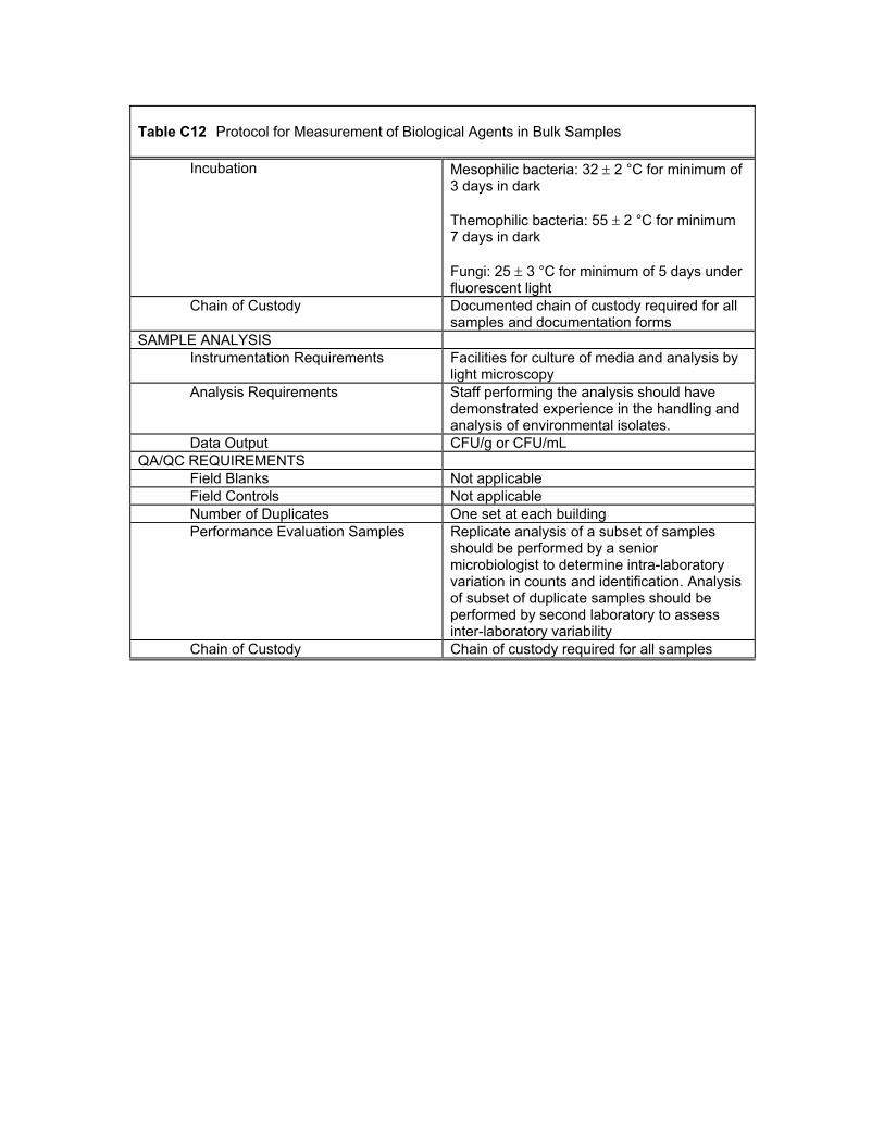
Table C12 Protocol for Measurement of Biological Agents in Bulk Samples
Incubation Mesophilic bacteria: 32 ± 2 °C for minimum of 3 days in dark Themophilic bacteria: 55 ± 2 °C for minimum 7 days in dark Fungi: 25 ± 3 °C for minimum of 5 days under fluorescent light
Chain of Custody Documented chain of custody required for all samples and documentation forms
SAMPLE ANALYSIS Instrumentation Requirements Facilities for culture of media and analysis by
light microscopy Analysis Requirements Staff performing the analysis should have
demonstrated experience in the handling and analysis of environmental isolates.
Data Output CFU/g or CFU/mL QA/QC REQUIREMENTS
Field Blanks Not applicable Field Controls Not applicable Number of Duplicates One set at each building Performance Evaluation Samples Replicate analysis of a subset of samples
should be performed by a senior microbiologist to determine intra-laboratory variation in counts and identification. Analysis of subset of duplicate samples should be performed by second laboratory to assess inter-laboratory variability
Chain of Custody Chain of custody required for all samples
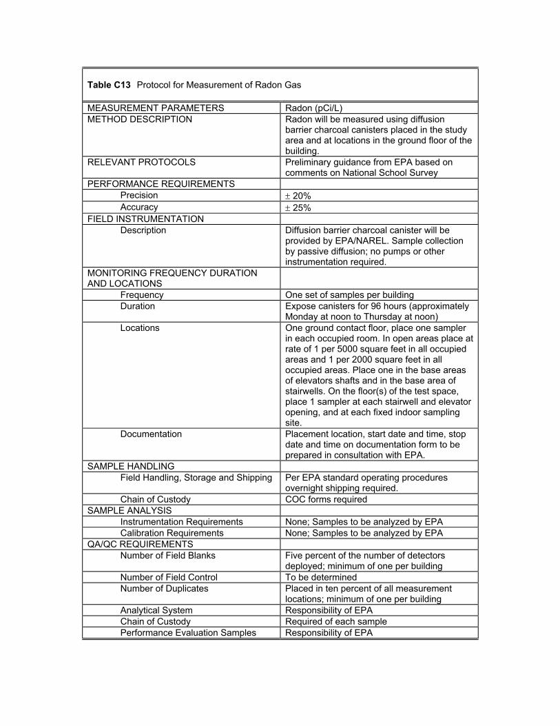
Table C13 Protocol for Measurement of Radon Gas MEASUREMENT PARAMETERS Radon (pCi/L) METHOD DESCRIPTION Radon will be measured using diffusion
barrier charcoal canisters placed in the study area and at locations in the ground floor of the building.
RELEVANT PROTOCOLS Preliminary guidance from EPA based on comments on National School Survey
PERFORMANCE REQUIREMENTS Precision ± 20% Accuracy ± 25%
FIELD INSTRUMENTATION Description Diffusion barrier charcoal canister will be
provided by EPA/NAREL. Sample collection by passive diffusion; no pumps or other instrumentation required.
MONITORING FREQUENCY DURATION AND LOCATIONS
Frequency One set of samples per building Duration Expose canisters for 96 hours (approximately
Monday at noon to Thursday at noon) Locations One ground contact floor, place one sampler
in each occupied room. In open areas place at rate of 1 per 5000 square feet in all occupied areas and 1 per 2000 square feet in all occupied areas. Place one in the base areas of elevators shafts and in the base area of stairwells. On the floor(s) of the test space, place 1 sampler at each stairwell and elevator opening, and at each fixed indoor sampling site.
Documentation Placement location, start date and time, stop date and time on documentation form to be prepared in consultation with EPA.
SAMPLE HANDLING Field Handling, Storage and Shipping Per EPA standard operating procedures
overnight shipping required. Chain of Custody COC forms required
SAMPLE ANALYSIS Instrumentation Requirements None; Samples to be analyzed by EPA Calibration Requirements None; Samples to be analyzed by EPA
QA/QC REQUIREMENTS Number of Field Blanks Five percent of the number of detectors
deployed; minimum of one per building Number of Field Control To be determined Number of Duplicates Placed in ten percent of all measurement
locations; minimum of one per building Analytical System Responsibility of EPA Chain of Custody Required of each sample Performance Evaluation Samples Responsibility of EPA
APPENDIX D
CHECKLISTS FOR SUBJECTIVE OBSERVATIONS
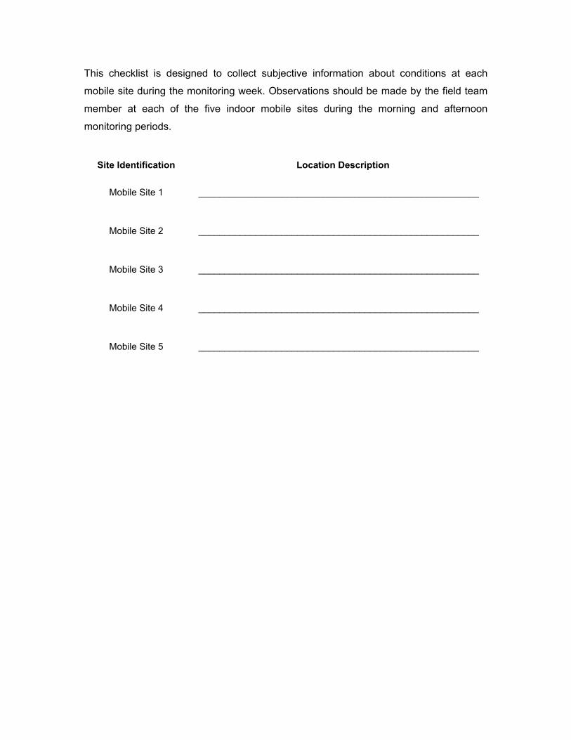
This checklist is designed to collect subjective information about conditions at each
mobile site during the monitoring week. Observations should be made by the field team
member at each of the five indoor mobile sites during the morning and afternoon
monitoring periods.
Site Identification Location Description
Mobile Site 1 ______________________________________________________
Mobile Site 2 ______________________________________________________
Mobile Site 3 ______________________________________________________
Mobile Site 4 ______________________________________________________
Mobile Site 5 ______________________________________________________
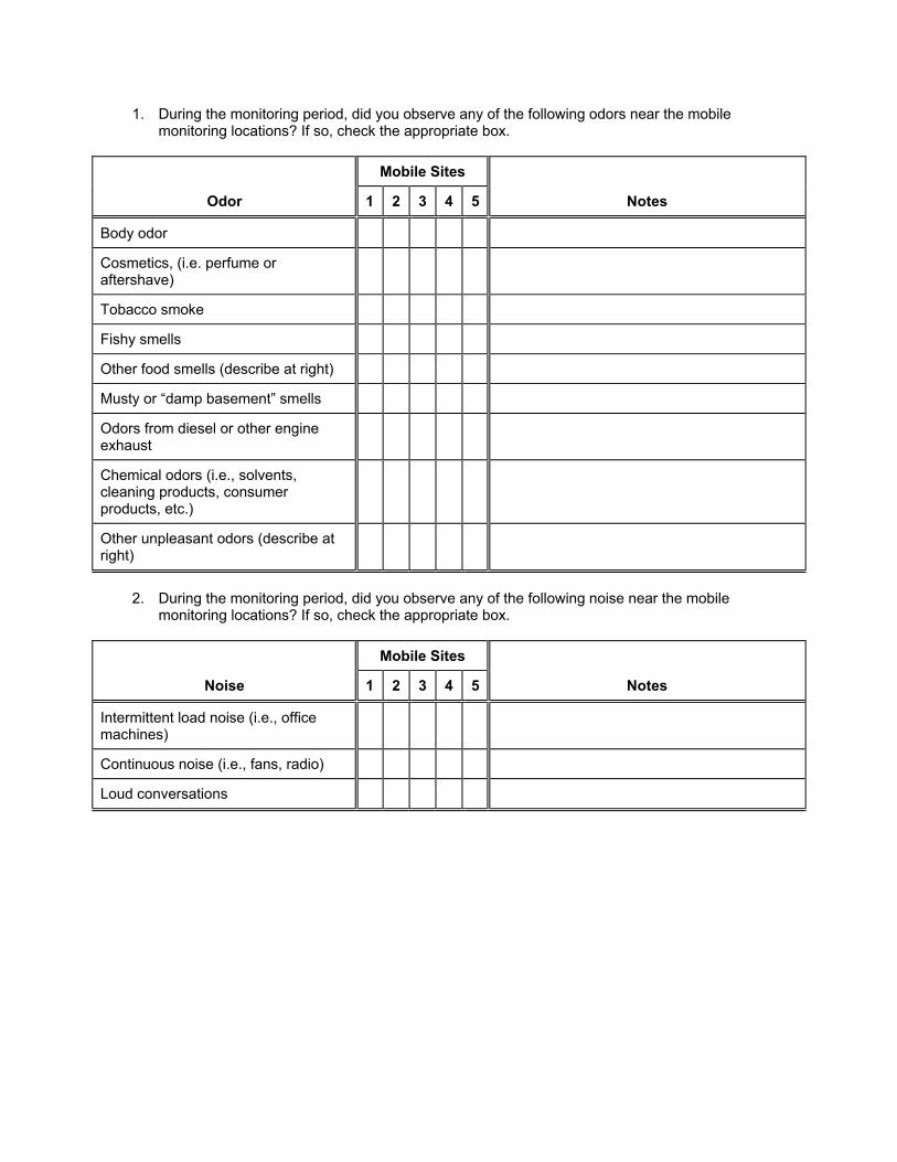
1. During the monitoring period, did you observe any of the following odors near the mobile monitoring locations? If so, check the appropriate box.
Mobile Sites
Odor 1 2 3 4 5 Notes
Body odor
Cosmetics, (i.e. perfume or aftershave)
Tobacco smoke
Fishy smells
Other food smells (describe at right)
Musty or “damp basement” smells
Odors from diesel or other engine exhaust
Chemical odors (i.e., solvents, cleaning products, consumer products, etc.)
Other unpleasant odors (describe at right)
2. During the monitoring period, did you observe any of the following noise near the mobile
monitoring locations? If so, check the appropriate box.
Mobile Sites
Noise 1 2 3 4 5 Notes
Intermittent load noise (i.e., office machines)
Continuous noise (i.e., fans, radio)
Loud conversations
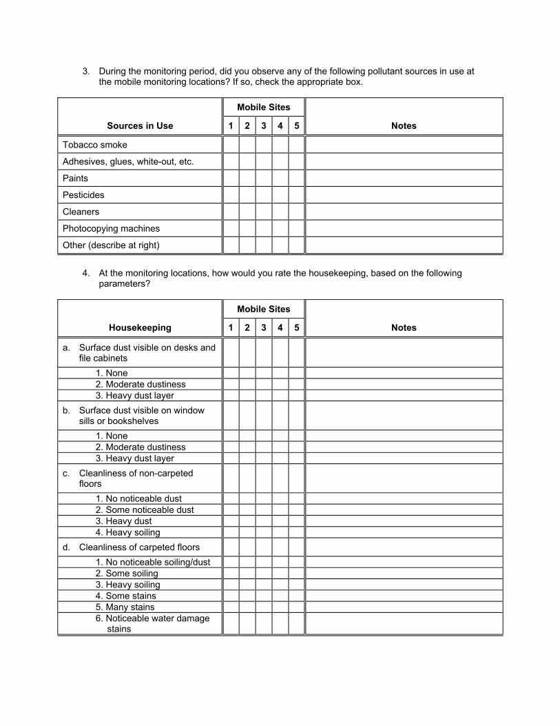
3. During the monitoring period, did you observe any of the following pollutant sources in use at the mobile monitoring locations? If so, check the appropriate box.
Mobile Sites
Sources in Use 1 2 3 4 5 Notes
Tobacco smoke
Adhesives, glues, white-out, etc.
Paints
Pesticides
Cleaners
Photocopying machines
Other (describe at right)
4. At the monitoring locations, how would you rate the housekeeping, based on the following
parameters?
Mobile Sites
Housekeeping 1 2 3 4 5 Notes
a. Surface dust visible on desks and file cabinets
1. None 2. Moderate dustiness 3. Heavy dust layer
b. Surface dust visible on window sills or bookshelves
1. None 2. Moderate dustiness 3. Heavy dust layer
c. Cleanliness of non-carpeted floors
1. No noticeable dust 2. Some noticeable dust 3. Heavy dust 4. Heavy soiling
d. Cleanliness of carpeted floors 1. No noticeable soiling/dust 2. Some soiling 3. Heavy soiling 4. Some stains 5. Many stains 6. Noticeable water damage
stains
APPENDIX E
PROTOCOLS AND FORMS FOR THE STUDY AREA(S) HVAC SYSTEM MEASUREMENTS
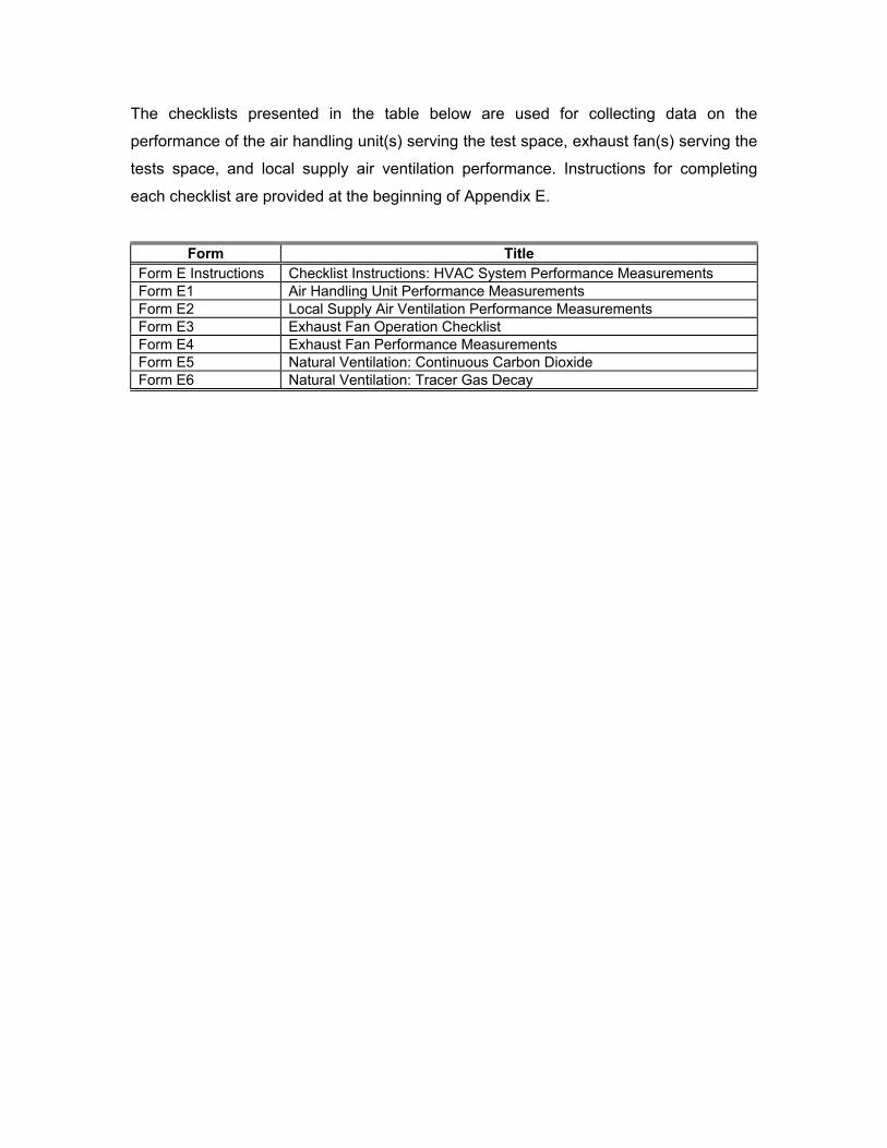
The checklists presented in the table below are used for collecting data on the
performance of the air handling unit(s) serving the test space, exhaust fan(s) serving the
tests space, and local supply air ventilation performance. Instructions for completing
each checklist are provided at the beginning of Appendix E.
Form Title Form E Instructions Checklist Instructions: HVAC System Performance Measurements Form E1 Air Handling Unit Performance Measurements Form E2 Local Supply Air Ventilation Performance Measurements Form E3 Exhaust Fan Operation Checklist Form E4 Exhaust Fan Performance Measurements Form E5 Natural Ventilation: Continuous Carbon Dioxide Form E6 Natural Ventilation: Tracer Gas Decay
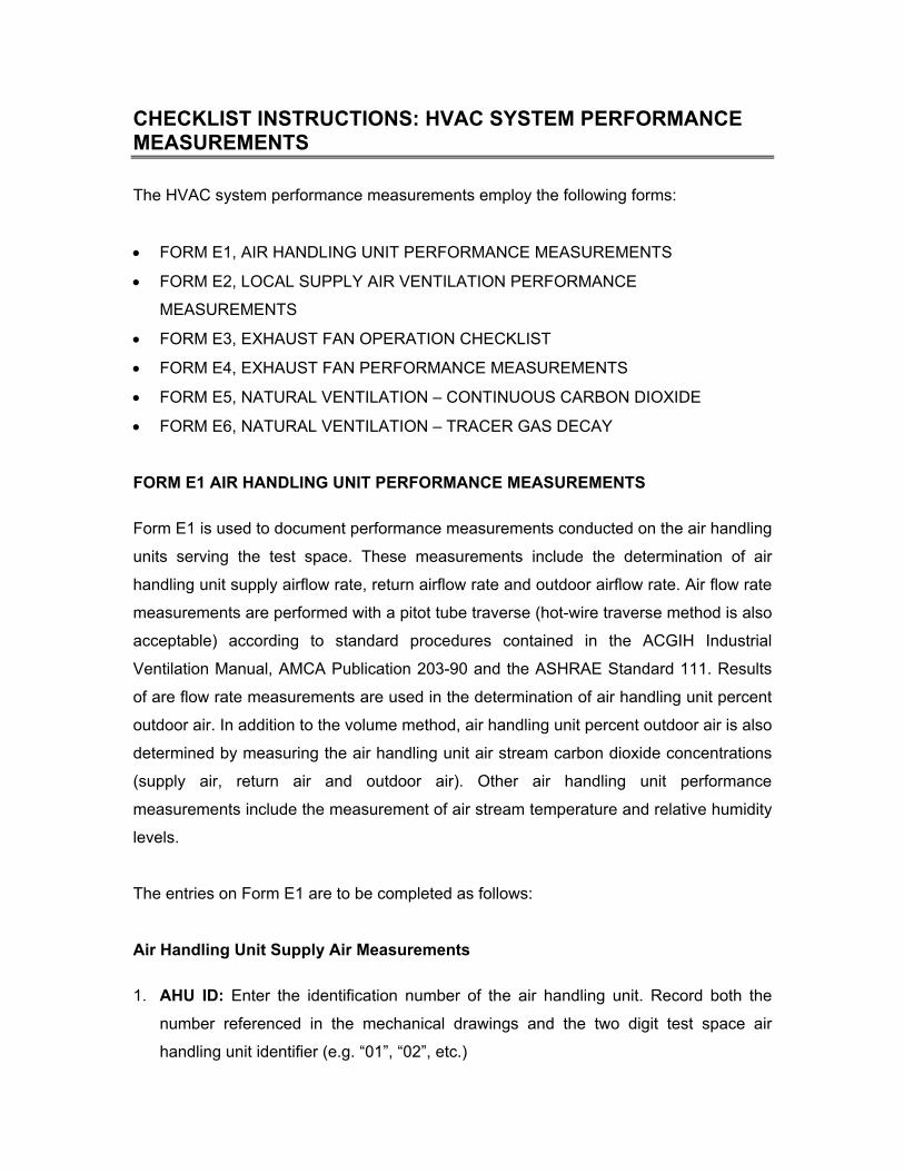
CHECKLIST INSTRUCTIONS: HVAC SYSTEM PERFORMANCE MEASUREMENTS
The HVAC system performance measurements employ the following forms:
• FORM E1, AIR HANDLING UNIT PERFORMANCE MEASUREMENTS
• FORM E2, LOCAL SUPPLY AIR VENTILATION PERFORMANCE
MEASUREMENTS
• FORM E3, EXHAUST FAN OPERATION CHECKLIST
• FORM E4, EXHAUST FAN PERFORMANCE MEASUREMENTS
• FORM E5, NATURAL VENTILATION – CONTINUOUS CARBON DIOXIDE
• FORM E6, NATURAL VENTILATION – TRACER GAS DECAY
FORM E1 AIR HANDLING UNIT PERFORMANCE MEASUREMENTS
Form E1 is used to document performance measurements conducted on the air handling
units serving the test space. These measurements include the determination of air
handling unit supply airflow rate, return airflow rate and outdoor airflow rate. Air flow rate
measurements are performed with a pitot tube traverse (hot-wire traverse method is also
acceptable) according to standard procedures contained in the ACGIH Industrial
Ventilation Manual, AMCA Publication 203-90 and the ASHRAE Standard 111. Results
of are flow rate measurements are used in the determination of air handling unit percent
outdoor air. In addition to the volume method, air handling unit percent outdoor air is also
determined by measuring the air handling unit air stream carbon dioxide concentrations
(supply air, return air and outdoor air). Other air handling unit performance
measurements include the measurement of air stream temperature and relative humidity
levels.
The entries on Form E1 are to be completed as follows:
Air Handling Unit Supply Air Measurements
1. AHU ID: Enter the identification number of the air handling unit. Record both the
number referenced in the mechanical drawings and the two digit test space air
handling unit identifier (e.g. “01”, “02”, etc.)
2. Measurement Location: Enter the measurement location of the air handling unit
supply air traverse.
3. Instrument Used: Enter the test instrument used for the air handling unit supply air
traverse. Information should include instrument type, model, serial number and any
other appropriate identification numbers.
4. Duct Dimensions: Enter the dimensions of the duct at the location of the air
handling unit supply air traverse. Record duct dimensions as inches x inches for
rectangular ducts or inches in diameter for round ducts.
5. Duct Area: Enter the area of the duct at the location of the air handling unit supply
air traverse. Record duct area as square feet. Note to account for internal duct
insulation if duct systems are so equipped.
6. Measurement Results: Enter the results of the air handling unit supply air
measurement. Record measurement start and stop times, average air velocity and
calculated air volume flow rate. Measurements are conducted Tuesday afternoon,
Wednesday morning, Wednesday afternoon, Thursday morning, and Thursday
afternoon.
Air Handling Unit Outdoor or Return Air Measurements
Ideally, direct measurement should be conducted at the outdoor air intake. However, if
conditions at the intake, such as excessive turbulence or limited access, prohibited
taking measurements, then measurements should instead be taken of the return
airstream. The difference in the measured supply airflow rate and the measured return
airflow rate can be used to calculate outdoor airflow rate. The entries required for
outdoor air or return air flow rate measurements are as follows:
7. Measurement Type: Enter whether a direct measurement is being conducted of air
handling unit outdoor air or of air handling unit return air.
8. Measurement Location: Enter the measurement location of the air handling unit
outdoor air or return air traverse.
9. Instrument Used: Enter the test instrument used for the air handling unit outdoor air
or return air traverse. Information should include instrument type, model, serial
number and any other appropriate identification numbers.
10. Duct Dimensions: Enter the dimensions of the duct at the location of the air
handling unit outdoor air or return air traverse. Record duct dimensions as inches x
inches for rectangular ducts or inches in diameter for round ducts.
11. Duct Area: Enter the area of the duct at the location of the air handling unit outdoor
air or return air traverse. Record duct area as square feet. Note to account for
internal duct insulation if duct systems are so equipped.
12. Measurement Results: Enter the results of the air handling unit outdoor air or return
air measurement. Record measurement start and stop times, average air velocity
and calculated air volume flow rate. Measurements are conducted Wednesday
morning, Wednesday afternoon, Thursday morning, and Thursday afternoon.
AHU CO2, Temperature and Relative Humidity Measurements
13. Supply Air Measurement Location: Enter the measurement location of the air
handling unit supply air CO2, temperature and relative humidity measurements.
14. Return Air Measurement Location: Enter the measurement location of the air
handling unit return air CO2, temperature and relative humidity measurements.
15. Outdoor Air Measurement Location: Enter the measurement location of the air
handling unit outdoor air CO2, temperature and relative humidity measurements.
16. CO2 Instrument Used: Enter the test instrument used for the air handling unit CO2
measurements. Information should include instrument type, model, serial number
and any other appropriate identification numbers.
17. Temperature Instrument Used: Enter the test instrument used for the air handling
unit temperature measurements. Information should include instrument type, model,
serial number and any other appropriate identification numbers.
18. Relative Humidity Instrument Used: Enter the test instrument used for the air
handling unit relative humidity measurements. Information should include instrument
type, model, serial number and any other appropriate identification numbers.
19. Measurement Results: Record the results of the air handling unit supply, return and
outdoor air measurements of CO2, temperature and relative humidity. Record start
and stop times for each parameter and the measured CO2, temperature and relative
humidity. To ensure measurement stabilization, a total of five measurements are
recorded for each parameter at one-minute intervals. Measurements are conducted
Wednesday morning, Wednesday afternoon, Thursday morning, and Thursday
afternoon.
20. Percent outdoor air by volume method: Using the measurement results obtained
in #6 and #12, calculate the air handling unit percent outdoor air by the volume
method as follows;
Measurement of outdoor air (CFMOA) and supply air flow.
Measurement of supply air (CFMSA), and return air (CFMRA) flow.
21. Percent Outdoor Air by CO2 Method: Using the measurement results obtained in
#19, calculate the air handling unit percent outdoor air by the volume method as
follows;
100CFMCFM%OA
SA
OA ×=
100CFM
CFMCFM%OASA
RASA ×−
=
100)CO (CO)CO (CO%OA
RA2OA2
RA2SA 2×
−−
=
The CO2, temperature, and relative humidity measurements performed in #19 are
repeated on Wednesday afternoon, Thursday morning and Thursday afternoon.
Checklists for these measurements are documented in Form E1, #22 through #27.
FORM E2 LOCAL SUPPLY AIR VENTILATION PERFORMANCE MEASUREMENTS
Form E2 is used to document local supply air ventilation performance in the test space.
For these measurements, air flow is measured from the supply air diffusers in the test
space using an air for capture hood. Ideally, the goal is to conduct measurements on
100% of the supply air diffusers in the test space. However, for test spaces equipped
with a large number of diffusers, measurement logistics problems, (i.e., ceiling height or
diffuser dimension issues) the minimum number of measurements should capture no
less than 50% of the test space supply diffusers. The entries on the form are to be
completed as follows:
1. Measurement Date: Enter the date that the measurements are made. As described
in Section 5, supply air diffuser measurements are conducted on Tuesday afternoon
of the study week.
2. Instrument Used #1: Enter the test instrument used for the test space supply
diffuser measurements. Information should include instrument type, model, serial
number, hood size and any other appropriate identification numbers.
3. Instrument Used #2: If more than one instrument is used for the measurements,
enter the test instrument information here. Again, information should include
instrument type, model, serial number, hood size and any other appropriate
identification numbers.
4. Number of Supply Air Diffusers: Enter the number of supply air diffusers located in
the test space. This information is obtained through the building mechanical design
drawings and verified through a walkthrough of the test space. Locations of supply
air diffusers should be mapped out on a test space floor plan.
5. Number of Return Air Diffusers: Enter the number of return air diffusers located in
the test space. This information is obtained using the mechanical design drawings
and verified through a walkthrough of the test space. Locations of return air diffusers
should be mapped out on a test space floor plan.
6. Measurement Start Time: Enter the time that the supply air diffuser measurement
round was started.
7. Measurement Results: Record the results of the test space supply air diffuser
measurements. Record the diffuser number (from the diffuser map created in #5),
the time of each measurement, the floor number, the diffuser air volume (units of
cfm) and the instrument number used for the measurement. For the diffuser(s)
located closest to each mobile monitoring site (see Section 5), record the monitoring
site in the appropriate row in Form E2.
8. Measurement End Time: Enter the time that the supply air diffuser measurement
round was completed.
9. Number Measured: Enter the number of supply air diffusers measured during the
measurement round.
FORM E3 EXHAUST FAN OPERATION CHECKLIST
Form E3 is used to record the operation of each exhaust fan serving the test space. The
operation of the fan is to be checked twice a day, once in the morning and once in the
afternoon, on five consecutive working days. One form is required for each exhaust fan
serving the test space.
1. Exhaust Fan Number: Enter the identification number of the exhaust fan. Record
both the number referenced in the mechanical drawings and the two digit test space
exhaust fan identifier (e.g. “01”, “02”, etc.).
2. Exhaust Fan Location: Enter the location of the exhaust fan using a room number
or area from the building plans.
The exhaust fan is checked twice a day to determine whether it is operating or not. The
morning and afternoon checks need not occur at any particular time, but they should be
conducted when the building is fully occupied, The times on all five days should be
reasonably consistent.
Day 1 A.M. Observation
3. Observation Time: Enter the time at which the morning operation is checked on
Day #1.
4. Fan Operating: Enter yes if the fan is operating and no if not.
For entries #5 through #22, enter the time and operating status for days 2 through 5 as
described for day 1.
FORM E4 EXHAUST FAN PERFORMANCE MEASUREMENTS
This form is used to measure the air flow rate of each exhaust fan serving the test
space. Measurements are made of the total exhaust fan flow rate as well as the local
exhaust flow rates within the test space. Total flow rate measurements are generally
performed with a pitot tube traverse (hot-wire traverse method is also acceptable)
according to standard procedures contained in the ACGIH Industrial Ventilation Manual,
AMCA Publication 203-90 and the ASHRAE Standard 111. Local exhaust flow rates
from test space exhaust grilles can generally be measured using an air flow capture
hood. The entries on the form are to be completed as follows:
Total Exhaust Fan Flow Rate
1. Exhaust Fan Number: Enter the identification number of the exhaust fan. Record
both the number referenced in the mechanical drawings and the two digit test space
exhaust fan identifier (e.g., “01,” “02,” etc.).
2. Exhaust Fan Location: Enter the location of the exhaust fan using a room number
or area from the building plans.
3. Measurement Location: Enter the measurement location of the exhaust fan
traverse.
4. Instrument Used: Enter the test instrument used for the exhaust fan traverse.
Information should include instrument type, model, serial number and any other
appropriate identification numbers.
5. Duct Dimensions: Enter the dimensions of the duct at the location of the exhaust
fan traverse. Record duct dimensions as inches x inches for rectangular ducts or
inches in diameter for round ducts.
6. Duct Area: Enter the area of the duct at the location of the air handling unit outdoor
air or return air traverse. Record duct area as square feet. Note to account for
internal duct insulation if duct systems are so equipped.
7. Start Time: Enter the measurement start time.
8. End Time: Enter the measurement end time.
9. Air Velocity: Enter the Enter the average air speed calculated from the traverse
results. Record value in units of fpm.
10. Air Volume: Enter the exhaust fan air volume by multiplying the velocity (#9) by the
duct area (#6).
Test Space Exhaust Flow Rate
11. Measurement Location: Enter the measurement location of the local exhaust
measurement.
12. Instrument Used: Enter the test instrument used for the local exhaust
measurement. Information should include instrument type, model, serial number and
any other appropriate identification numbers.
13. Duct dimensions: If a traverse is being made in the exhaust duct, enter the
dimensions of the duct at the location of the traverse. Record duct dimensions as
inches × inches for rectangular ducts or inches in diameter for round ducts.
14. Duct area: For a traverse measurement, enter the area of the duct at the location of
the traverse. Record duct area as square feet. Note to account for internal duct
insulation if duct systems are so equipped.
15. Start Time: Enter the measurement start time.
16. End Time: Enter the measurement end time.
17. Air Velocity: For a traverse measurement, enter the average air speed calculated
from the traverse results. Record value in units of fpm.
18. Air Volume: Enter the exhaust fan air volume. If a traverse was used, calculate
volume by multiplying the velocity (#17) by the duct area (#14). If an air flow capture
hood was used, enter the result here.
If additional exhaust grilles are located in the test space for complete #11 through #18
for each additional exhaust grille.
FORM E5 NATURAL VENTILATION – CONTINUOUS CARBON DIOXIDE
This form is used to record the results of continuous carbon dioxide monitoring at three
locations within the test space. This monitoring is to take place for two full days. Two E5
Forms are required for this test. The entries on the form are to be completed as follows:
1. Date of Test: Enter the date on which the measurement is conducted.
2. Manufacturer: Enter the manufacturer of the carbon dioxide concentration
measurement device.
3. Model Number: Enter the model number of the device.
4. Serial Number: Enter the serial number of the device.
5. Measurement Location, Outdoor Air: Describe the location at which the outdoor
air carbon dioxide concentration is measured. A sample location on the roof of the
building, at least 20 meters from any exhaust vents, is preferred.
6. Measurement Location, Occupied Space #1: Describe the first location within the
occupied space at which the carbon dioxide concentration is measured. Use column
numbers if available, and note the location on the test space floor plan.
For entries #7 and #8, describe occupied space locations #2 and #3 as was done for
occupied space location #1 in entry #6.
The carbon dioxide concentrations at these four locations are to be monitored
continuously, with a reading at each location taken every 15 minutes or less. After this
data has been recorded, it must be analyzed and the following information extracted.
9. Outdoor Reading, 6 a.m.: Enter the outdoor concentration recorded at 6 a.m.
10. Outdoor Reading, 10 a.m.: Enter the outdoor concentration recorded at 10 a.m.
11. Outdoor Reading, 2 p.m.: Enter the outdoor concentration recorded at 2 p.m.
12. Outdoor Reading, 6 p.m.: Enter the outdoor concentration recorded at 6 p.m.
13. Occupied Space Reading #1, 6 a.m.: Enter the concentration at occupied space
location #1 recorded at 6 a.m.
14. Occupied Space #1, Morning Maximum Concentration: Enter the maximum
carbon dioxide concentration recorded at occupied space location #1 during the
morning.
15. Occupied Space #1, Morning Maximum Time: Enter the time at which the morning
maximum carbon dioxide concentration occurred at occupied space location #1.
16. Occupied Space #1, Morning Maximum, Outdoor Concentration: Enter the
outdoor concentration recorded at the same time as the morning maximum carbon
dioxide concentration as occupied space location #1.
17. Occupied Space #1, Afternoon Maximum Concentration: Enter the maximum
carbon dioxide concentration recorded at occupied space location #1 during the
afternoon.
18. Occupied Space #1, Afternoon Maximum Time: Enter the time at which the
afternoon maximum carbon dioxide concentration occurred at occupied space
location #1.
19. Occupied Space #1, Afternoon Maximum, Outdoor Concentration: Enter the
outdoor concentration recorded at the same time as the afternoon maximum carbon
dioxide concentration as occupied space location #1.
For entries #20 through #33, record the information on the morning and afternoon
maxima at occupied space locations #2 and #3 as described above for location #1.
FORM E6 NATURAL VENTILATION – TRACER GAS DECAY
This form is used to record the results of a tracer gas decay test in the building
conducted to estimate the whole building air change rate. This test is to be conducted in
accordance with ASTM E741. Based on the requirements contained in ASTM E741, this
test must be conducted to determine the whole building air change rate. Tracer gas must
be released into the entire building such that the concentration is uniform throughout the
building. This test cannot be performed by releasing tracer gas into the test space alone.
Only a single tracer gas decay test is required, and therefore only one form is needed.
However, one can repeat the test if the initial attempt does not provide satisfactory
results. This measurement can also be conducted using occupant generated carbon
dioxide as the tracer gas after the occupants have left the building. The entries on the
form are to be completed as follows:
1. Date of Test: Enter the date on which the measurement is conducted.
2. Tracer Gas: Enter the tracer gas employed in the test.
3. Manufacturer: Enter the manufacturer of the tracer gas concentration measurement
device.
4. Model Number: Enter the model number of the device.
5. Serial Number: Enter the serial number of the device.
6. Concentration Units: Enter the tracer gas concentration units provided by the
device.
The tracer gas concentration must be monitored at one outdoor location and ten
locations within the occupied space during the decay test. The ten interior locations must
be distributed throughout the entire building in order to be able to verify that the tracer
gas concentration is uniform throughout the building prior to and during the decay. The
specific locations that are selected will depend on the layout of the building including
such factors as the number of stories and the floor area per story.
7. Measurement Location, Outdoor Air: Describe the location at which the outdoor
air tracer gas concentration is measured. A sample location on the roof of the
building, at least 20 meters from any exhaust vents, is preferred.
8. Measurement Location, Occupied Space #1: Describe the first location within the
occupied space of the building at which the tracer gas concentration is measured.
Use column numbers if available, and note the building floor.
For entries #9 through #17, describe the second through tenth occupied space sampling
location as described in entry #8 above.
The concentration at each location should be measured once every 30 minutes, though
the exact time interval is not critical as long as the sample times are recorded accurately.
If one employs occupant generated carbon dioxide as the tracer gas, then the carbon
dioxide concentrations must be monitored after the occupants have left the building,
while the interior carbon dioxide concentration is still significantly above the outdoor
concentration. The concentration monitoring should begin very soon after the occupants
have left the building, before the interior concentrations decay significantly. The tracer
gas decay test requires that the interior concentration is significantly above the outdoor
concentration and the interior concentration is uniform (within 10%) throughout the
building. If either of these conditions is not satisfied, the test will not provide acceptable
estimates of the building air change rate.
18. Initial Reading
• Outdoor, Time: Enter the time at which the outdoor conditions are measured.
• Outdoor, Concentration: Enter the outdoor tracer gas concentration.
• Outdoor Temperature: Enter the outdoor air temperature. Designate the units,
either °C or °F.
• Outdoor, Wind Speed: Enter the wind speed. Designate the units, either mps or mph.
• Location #1, Time: Enter the time at which the tracer gas concentration at location #1
is recorded.
• Location #1, Concentration: Enter the tracer gas concentration at location #1.
For locations #2 through #10, enter the time and concentration as described for
location #1.
19. Second Reading: Record the information as described above for the initial reading.
20. Third Reading: Record the information as described above for the initial reading.
21. Fourth Reading: Record the information as described above for the initial reading.
22. Fifth Reading: Record the information as described above for the initial reading.
The data analysis involves determining the tracer gas decay rate in air changes per hour
at each of the 10 interior locations. This is done by performing a least squares linear
regression of the natural logarithm of concentration against time. Based on the
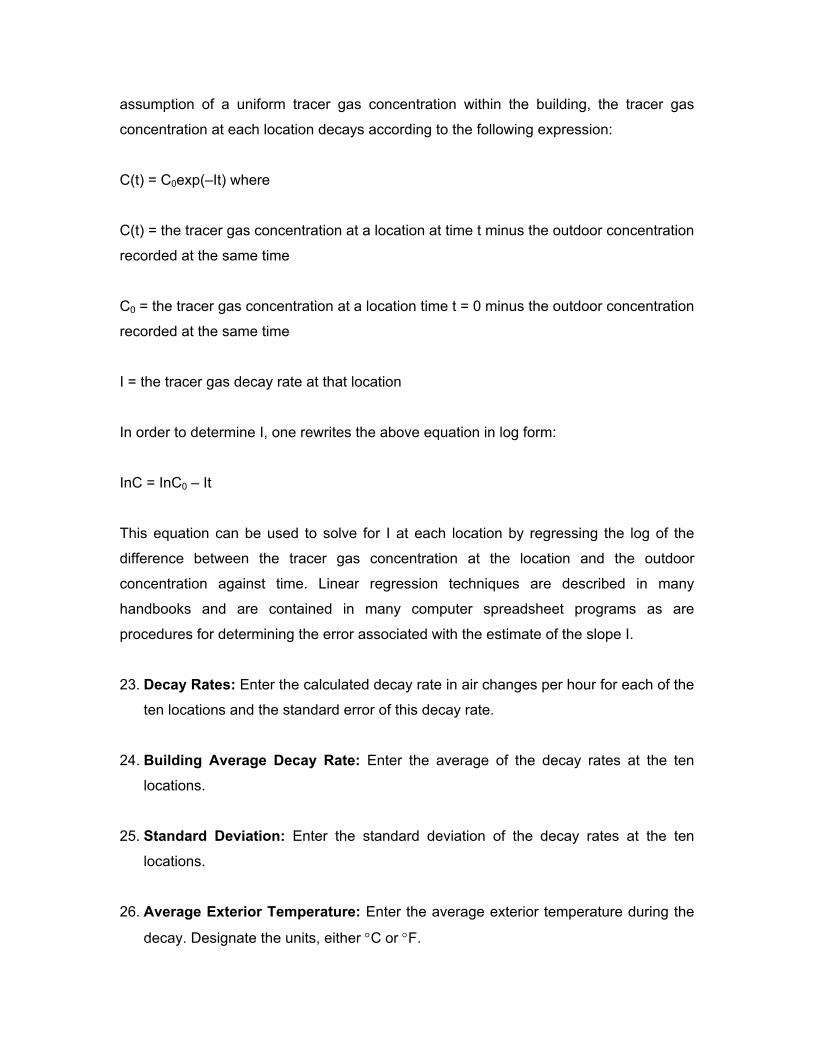
assumption of a uniform tracer gas concentration within the building, the tracer gas
concentration at each location decays according to the following expression:
C(t) = C0exp(–It) where
C(t) = the tracer gas concentration at a location at time t minus the outdoor concentration
recorded at the same time
C0 = the tracer gas concentration at a location time t = 0 minus the outdoor concentration
recorded at the same time
I = the tracer gas decay rate at that location
In order to determine I, one rewrites the above equation in log form:
InC = InC0 – It
This equation can be used to solve for I at each location by regressing the log of the
difference between the tracer gas concentration at the location and the outdoor
concentration against time. Linear regression techniques are described in many
handbooks and are contained in many computer spreadsheet programs as are
procedures for determining the error associated with the estimate of the slope I.
23. Decay Rates: Enter the calculated decay rate in air changes per hour for each of the
ten locations and the standard error of this decay rate.
24. Building Average Decay Rate: Enter the average of the decay rates at the ten
locations.
25. Standard Deviation: Enter the standard deviation of the decay rates at the ten
locations.
26. Average Exterior Temperature: Enter the average exterior temperature during the
decay. Designate the units, either °C or °F.

27. Average Wind Speed: Enter the average of the wind speeds during the decay.
Designate the units, either mps or mph.
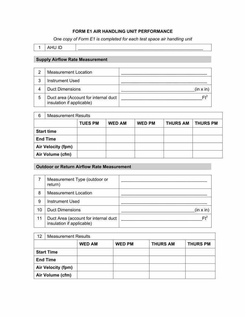
FORM E1 AIR HANDLING UNIT PERFORMANCE One copy of Form E1 is completed for each test space air handling unit
1 AHU ID ___________________________________________________ Supply Airflow Rate Measurement 2 Measurement Location ___________________________________
3 Instrument Used ___________________________________
4 Duct Dimensions ______________________________(in x in)
5 Duct area (Account for internal duct insulation if applicable)
_________________________________Ft2
6 Measurement Results
TUES PM WED AM WED PM THURS AM THURS PM
Start time
End Time
Air Velocity (fpm)
Air Volume (cfm) Outdoor or Return Airflow Rate Measurement 7 Measurement Type (outdoor or
return) ___________________________________
8 Measurement Location ___________________________________
9 Instrument Used ___________________________________
10 Duct Dimensions ______________________________(in x in)
11 Duct Area (account for internal duct insulation if applicable)
_________________________________Ft2
12 Measurement Results
WED AM WED PM THURS AM THURS PM
Start Time
End Time
Air Velocity (fpm)
Air Volume (cfm)
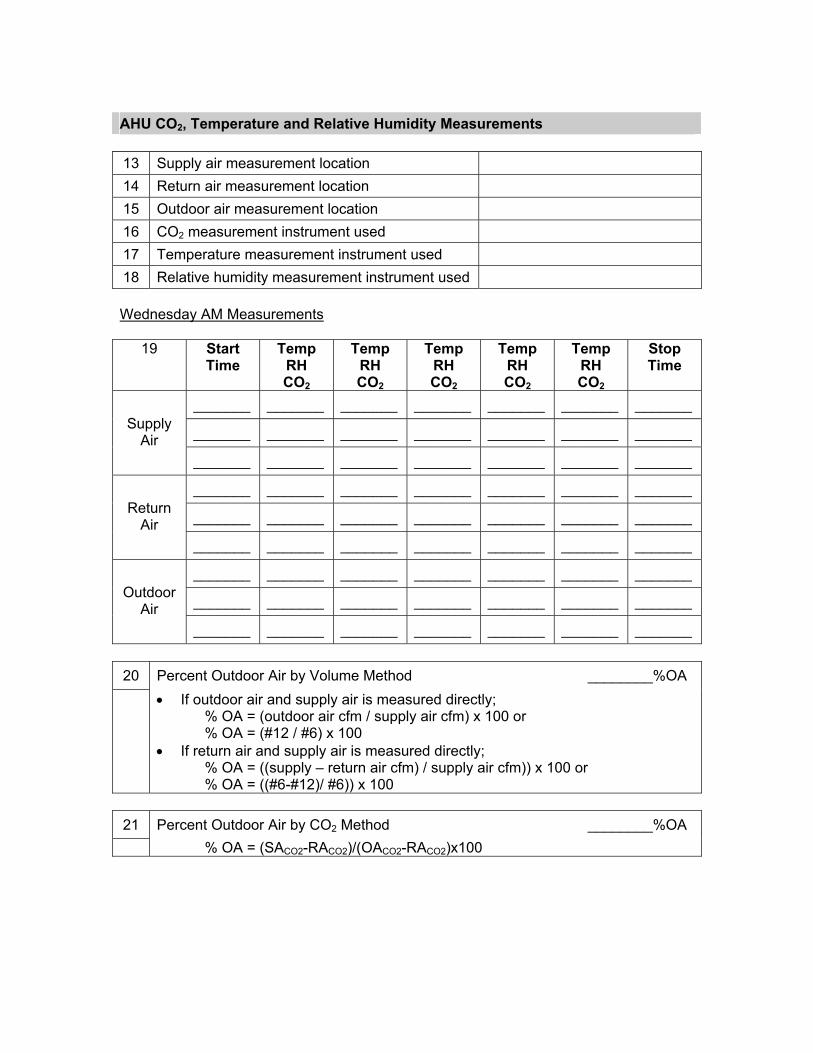
AHU CO2, Temperature and Relative Humidity Measurements 13 Supply air measurement location 14 Return air measurement location 15 Outdoor air measurement location 16 CO2 measurement instrument used 17 Temperature measurement instrument used 18 Relative humidity measurement instrument used Wednesday AM Measurements
19 Start Time
Temp RH CO2
Temp RH CO2
Temp RH CO2
Temp RH CO2
Temp RH CO2
Stop Time
_______ _______ _______ _______ _______ _______ _______
_______ _______ _______ _______ _______ _______ _______ Supply Air
_______ _______ _______ _______ _______ _______ _______
_______ _______ _______ _______ _______ _______ _______
_______ _______ _______ _______ _______ _______ _______ Return Air
_______ _______ _______ _______ _______ _______ _______
_______ _______ _______ _______ _______ _______ _______
_______ _______ _______ _______ _______ _______ _______ Outdoor Air
_______ _______ _______ _______ _______ _______ _______ 20 Percent Outdoor Air by Volume Method ________%OA
• If outdoor air and supply air is measured directly; % OA = (outdoor air cfm / supply air cfm) x 100 or % OA = (#12 / #6) x 100
• If return air and supply air is measured directly; % OA = ((supply – return air cfm) / supply air cfm)) x 100 or % OA = ((#6-#12)/ #6)) x 100
21 Percent Outdoor Air by CO2 Method ________%OA
% OA = (SACO2-RACO2)/(OACO2-RACO2)x100
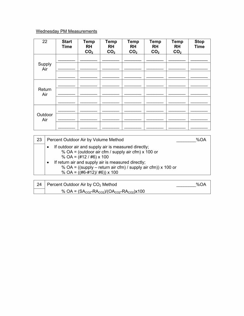
Wednesday PM Measurements
22 Start Time
Temp RH CO2
Temp RH CO2
Temp RH CO2
Temp RH CO2
Temp RH CO2
Stop Time
_______ _______ _______ _______ _______ _______ _______
_______ _______ _______ _______ _______ _______ _______ Supply Air
_______ _______ _______ _______ _______ _______ _______
_______ _______ _______ _______ _______ _______ _______
_______ _______ _______ _______ _______ _______ _______ Return Air
_______ _______ _______ _______ _______ _______ _______
_______ _______ _______ _______ _______ _______ _______
_______ _______ _______ _______ _______ _______ _______ Outdoor Air
_______ _______ _______ _______ _______ _______ _______ 23 Percent Outdoor Air by Volume Method ________%OA
• If outdoor air and supply air is measured directly; % OA = (outdoor air cfm / supply air cfm) x 100 or % OA = (#12 / #6) x 100
• If return air and supply air is measured directly; % OA = ((supply – return air cfm) / supply air cfm)) x 100 or % OA = ((#6-#12)/ #6)) x 100
24 Percent Outdoor Air by CO2 Method ________%OA
% OA = (SACO2-RACO2)/(OACO2-RACO2)x100

Thursday AM Measurements
25 Start Time
Temp RH CO2
Temp RH CO2
Temp RH CO2
Temp RH CO2
Temp RH CO2
Stop Time
_______ _______ _______ _______ _______ _______ _______
_______ _______ _______ _______ _______ _______ _______ Supply Air
_______ _______ _______ _______ _______ _______ _______
_______ _______ _______ _______ _______ _______ _______
_______ _______ _______ _______ _______ _______ _______ Return Air
_______ _______ _______ _______ _______ _______ _______
_______ _______ _______ _______ _______ _______ _______
_______ _______ _______ _______ _______ _______ _______ Outdoor Air
_______ _______ _______ _______ _______ _______ _______ 26 Percent Outdoor Air by Volume Method ________%OA
• If outdoor air and supply air is measured directly; % OA = (outdoor air cfm / supply air cfm) x 100 or % OA = (#12 / #6) x 100
• If return air and supply air is measured directly; % OA = ((supply – return air cfm) / supply air cfm)) x 100 or % OA = ((#6-#12)/ #6)) x 100
27 Percent Outdoor Air by CO2 Method ________%OA
% OA = (SACO2-RACO2)/(OACO2-RACO2)x100
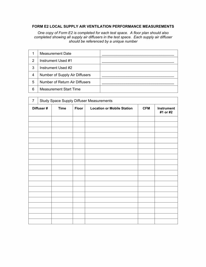
FORM E2 LOCAL SUPPLY AIR VENTILATION PERFORMANCE MEASUREMENTS One copy of Form E2 is completed for each test space. A floor plan should also
completed showing all supply air diffusers in the test space. Each supply air diffuser should be referenced by a unique number
1 Measurement Date ___________________________________
2 Instrument Used #1 ___________________________________
3 Instrument Used #2
4 Number of Supply Air Diffusers ___________________________________
5 Number of Return Air Diffusers ___________________________________
6 Measurement Start Time 7 Study Space Supply Diffuser Measurements
Diffuser # Time Floor Location or Mobile Station CFM Instrument #1 or #2
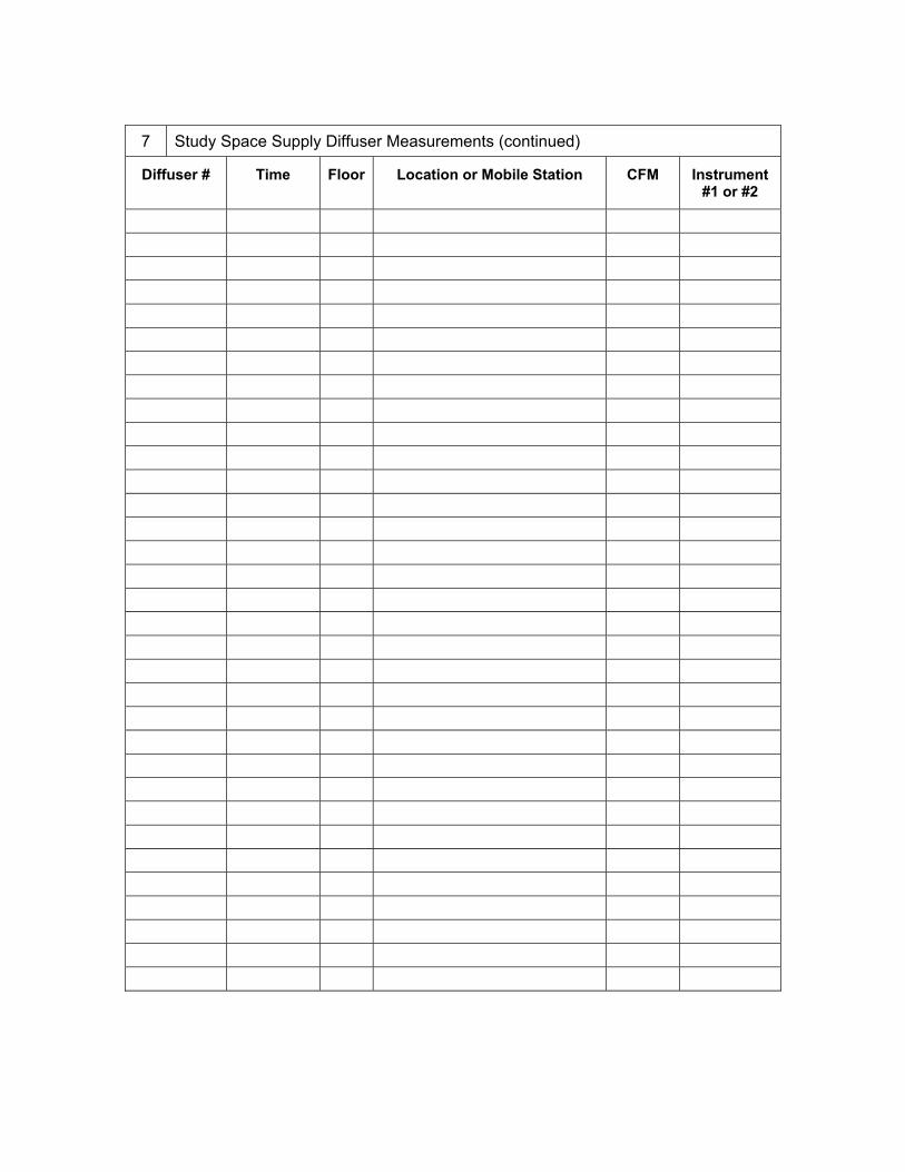
7 Study Space Supply Diffuser Measurements (continued)
Diffuser # Time Floor Location or Mobile Station CFM Instrument #1 or #2
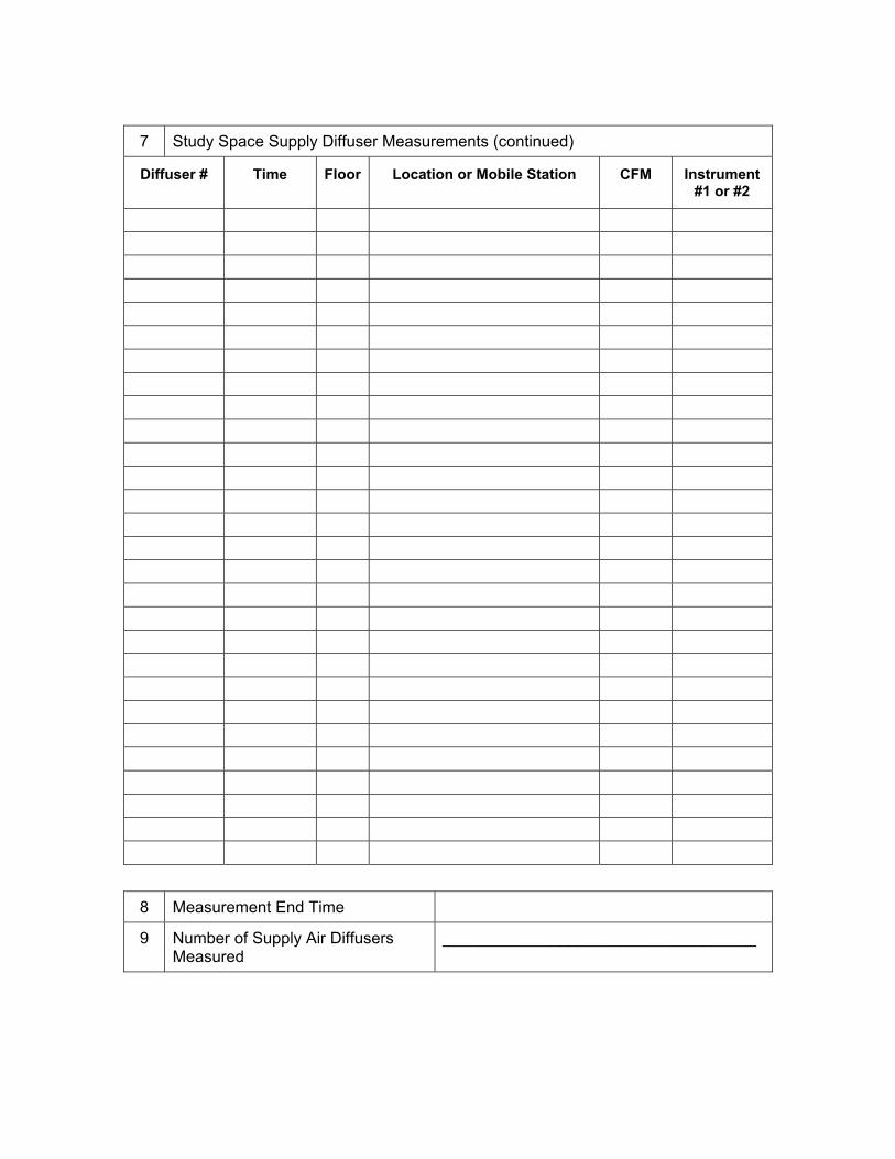
7 Study Space Supply Diffuser Measurements (continued)
Diffuser # Time Floor Location or Mobile Station CFM Instrument #1 or #2
8 Measurement End Time
9 Number of Supply Air Diffusers Measured
___________________________________
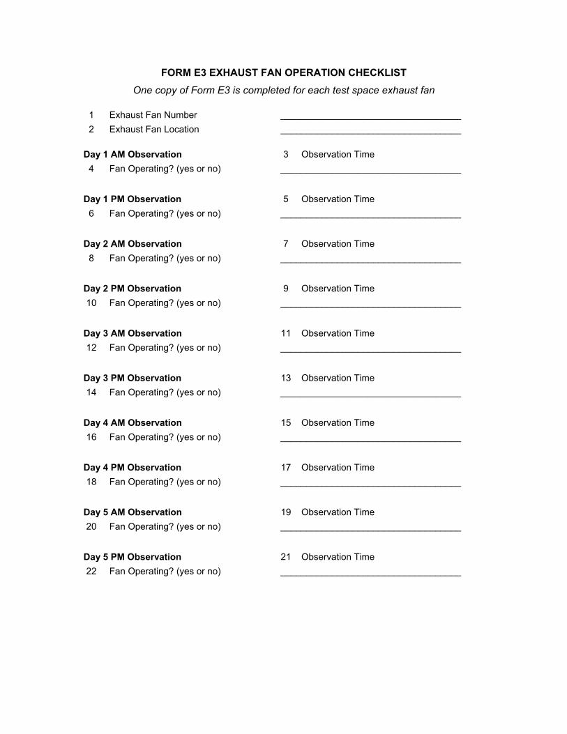
FORM E3 EXHAUST FAN OPERATION CHECKLIST One copy of Form E3 is completed for each test space exhaust fan
1 Exhaust Fan Number ___________________________________ 2 Exhaust Fan Location ___________________________________
Day 1 AM Observation 3 Observation Time
4 Fan Operating? (yes or no) ___________________________________
Day 1 PM Observation 5 Observation Time 6 Fan Operating? (yes or no) ___________________________________
Day 2 AM Observation 7 Observation Time 8 Fan Operating? (yes or no) ___________________________________
Day 2 PM Observation 9 Observation Time 10 Fan Operating? (yes or no) ___________________________________
Day 3 AM Observation 11 Observation Time 12 Fan Operating? (yes or no) ___________________________________
Day 3 PM Observation 13 Observation Time 14 Fan Operating? (yes or no) ___________________________________
Day 4 AM Observation 15 Observation Time 16 Fan Operating? (yes or no) ___________________________________
Day 4 PM Observation 17 Observation Time 18 Fan Operating? (yes or no) ___________________________________
Day 5 AM Observation 19 Observation Time 20 Fan Operating? (yes or no) ___________________________________
Day 5 PM Observation 21 Observation Time 22 Fan Operating? (yes or no) ___________________________________
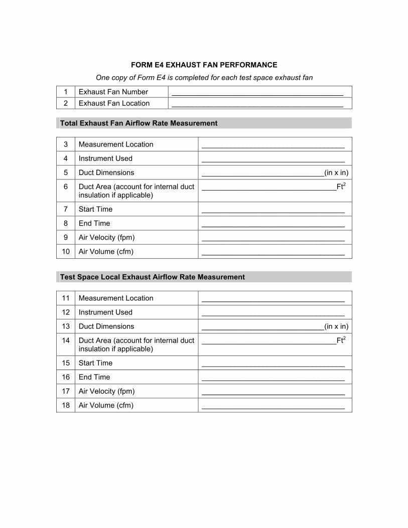
FORM E4 EXHAUST FAN PERFORMANCE One copy of Form E4 is completed for each test space exhaust fan
1 Exhaust Fan Number __________________________________________ 2 Exhaust Fan Location __________________________________________
Total Exhaust Fan Airflow Rate Measurement 3 Measurement Location ___________________________________
4 Instrument Used ___________________________________
5 Duct Dimensions ______________________________(in x in)
6 Duct Area (account for internal duct insulation if applicable)
_________________________________Ft2
7 Start Time ___________________________________
8 End Time ___________________________________
9 Air Velocity (fpm) ___________________________________
10 Air Volume (cfm) ___________________________________
Test Space Local Exhaust Airflow Rate Measurement 11 Measurement Location ___________________________________
12 Instrument Used ___________________________________
13 Duct Dimensions ______________________________(in x in)
14 Duct Area (account for internal duct insulation if applicable)
_________________________________Ft2
15 Start Time ___________________________________
16 End Time ___________________________________
17 Air Velocity (fpm) ___________________________________
18 Air Volume (cfm) ___________________________________
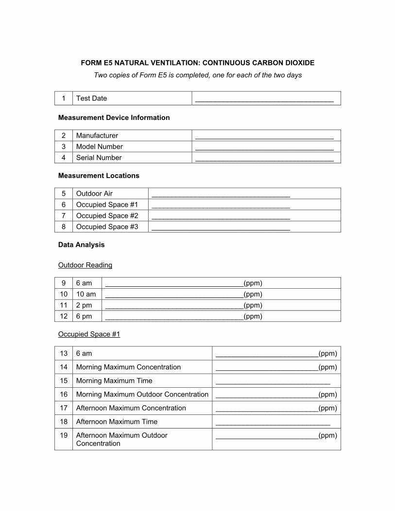
FORM E5 NATURAL VENTILATION: CONTINUOUS CARBON DIOXIDE Two copies of Form E5 is completed, one for each of the two days
1 Test Date ___________________________________
Measurement Device Information 2 Manufacturer ___________________________________ 3 Model Number ___________________________________ 4 Serial Number ___________________________________
Measurement Locations 5 Outdoor Air ___________________________________ 6 Occupied Space #1 ___________________________________ 7 Occupied Space #2 ___________________________________ 8 Occupied Space #3 ___________________________________
Data Analysis
Outdoor Reading
9 6 am ___________________________________(ppm) 10 10 am ___________________________________(ppm) 11 2 pm ___________________________________(ppm) 12 6 pm ___________________________________(ppm) Occupied Space #1 13 6 am __________________________(ppm)
14 Morning Maximum Concentration __________________________(ppm)
15 Morning Maximum Time _____________________________
16 Morning Maximum Outdoor Concentration __________________________(ppm)
17 Afternoon Maximum Concentration __________________________(ppm)
18 Afternoon Maximum Time _____________________________
19 Afternoon Maximum Outdoor Concentration
__________________________(ppm)
Occupied Space #2 20 6 am __________________________(ppm)
21 Morning Maximum Concentration __________________________(ppm)
22 Morning Maximum Time _____________________________
23 Morning Maximum Outdoor Concentration __________________________(ppm)
24 Afternoon Maximum Concentration __________________________(ppm)
25 Afternoon Maximum Time _____________________________
26 Afternoon Maximum Outdoor Concentration
__________________________(ppm)
Occupied Space #3
27 6 am __________________________(ppm)
28 Morning Maximum Concentration __________________________(ppm)
29 Morning Maximum Time _____________________________
30 Morning Maximum Outdoor Concentration __________________________(ppm)
31 Afternoon Maximum Concentration __________________________(ppm)
32 Afternoon Maximum Time _____________________________
33 Afternoon Maximum Outdoor Concentration
__________________________(ppm)
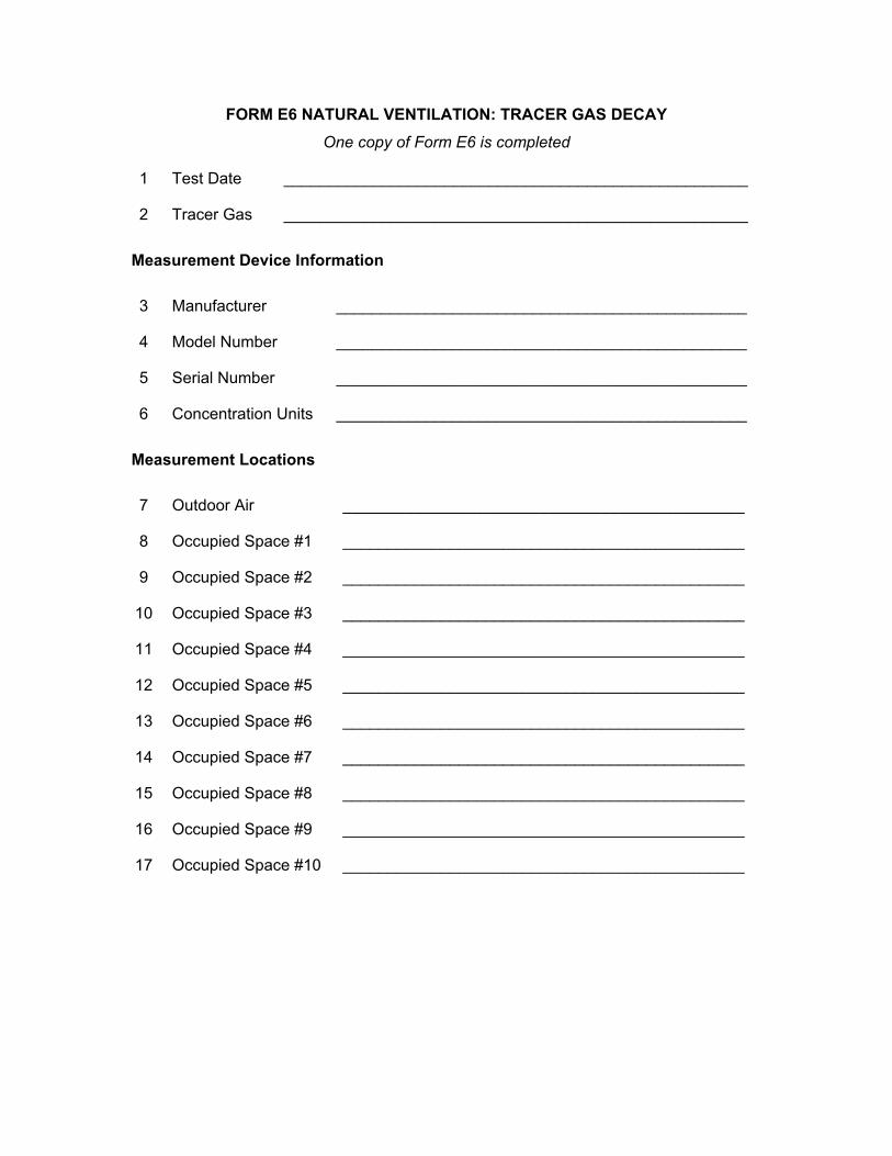
FORM E6 NATURAL VENTILATION: TRACER GAS DECAY One copy of Form E6 is completed
1 Test Date ____________________________________________________
2 Tracer Gas ____________________________________________________ Measurement Device Information 3 Manufacturer ______________________________________________
4 Model Number ______________________________________________
5 Serial Number ______________________________________________
6 Concentration Units ______________________________________________ Measurement Locations 7 Outdoor Air _____________________________________________
8 Occupied Space #1 _____________________________________________
9 Occupied Space #2 _____________________________________________
10 Occupied Space #3 _____________________________________________
11 Occupied Space #4 _____________________________________________
12 Occupied Space #5 _____________________________________________
13 Occupied Space #6 _____________________________________________
14 Occupied Space #7 _____________________________________________
15 Occupied Space #8 _____________________________________________
16 Occupied Space #9 _____________________________________________
17 Occupied Space #10 _____________________________________________
Data 18 Initial Reading Outdoor Time _____________________________________________ Temperature _____________________________________(°C or °F) Concentration ___________________________________________ Wind Speed ___________________________________(m/s or mph) Time Concentration Location #1 _______________ _______________ Location #2 _______________ _______________ Location #3 _______________ _______________ Location #4 _______________ _______________ Location #5 _______________ _______________ Location #6 _______________ _______________ Location #7 _______________ _______________ Location #8 _______________ _______________ Location #9 _______________ _______________ Location #10 _______________ _______________ 19 Second Reading Outdoor Time _____________________________________________ Temperature _____________________________________(°C or °F) Concentration ___________________________________________ Wind Speed ___________________________________(m/s or mph) Time Concentration Location #1 _______________ _______________ Location #2 _______________ _______________ Location #3 _______________ _______________ Location #4 _______________ _______________ Location #5 _______________ _______________ Location #6 _______________ _______________ Location #7 _______________ _______________ Location #8 _______________ _______________ Location #9 _______________ _______________ Location #10 _______________ _______________
20 Third Reading Outdoor Time _____________________________________________ Temperature _____________________________________(°C or °F) Concentration ___________________________________________ Wind Speed ___________________________________(m/s or mph) Time Concentration Location #1 _______________ _______________ Location #2 _______________ _______________ Location #3 _______________ _______________ Location #4 _______________ _______________ Location #5 _______________ _______________ Location #6 _______________ _______________ Location #7 _______________ _______________ Location #8 _______________ _______________ Location #9 _______________ _______________ Location #10 _______________ _______________ 21 Fourth Reading Outdoor Time _____________________________________________ Temperature _____________________________________(°C or °F) Concentration ___________________________________________ Wind Speed ___________________________________(m/s or mph) Time Concentration Location #1 _______________ _______________ Location #2 _______________ _______________ Location #3 _______________ _______________ Location #4 _______________ _______________ Location #5 _______________ _______________ Location #6 _______________ _______________ Location #7 _______________ _______________ Location #8 _______________ _______________ Location #9 _______________ _______________ Location #10 _______________ _______________
22 Fifth Reading Outdoor Time _____________________________________________ Temperature _____________________________________(°C or °F) Concentration ___________________________________________ Wind Speed ___________________________________(m/s or mph) Time Concentration Location #1 _______________ _______________ Location #2 _______________ _______________ Location #3 _______________ _______________ Location #4 _______________ _______________ Location #5 _______________ _______________ Location #6 _______________ _______________ Location #7 _______________ _______________ Location #8 _______________ _______________ Location #9 _______________ _______________ Location #10 _______________ _______________ Data Analysis 23 Decay Rates, air changes per hour Value Standard Error Location #1 _______________ _______________ Location #2 _______________ _______________ Location #3 _______________ _______________ Location #4 _______________ _______________ Location #5 _______________ _______________ Location #6 _______________ _______________ Location #7 _______________ _______________ Location #8 _______________ _______________ Location #9 _______________ _______________ Location #10 _______________ _______________ 24 Building average decay rate ____ach 25 Standard Deviation ____ach Outdoor Conditions, Averages 26 Exterior Temperature _________________________________(°C or °F) 27 Wind Speed _______________________________(m/s or mph)
APPENDIX F
INDOOR ENVIRONMENTAL QUALITY QUESTIONNAIRE
U.S. ENVIRONMENTAL PROTECTION AGENCY
INDOOR ENVIRONMENTAL QUALITY SURVEY
The U.S. Environmental Protection Agency (EPA) is conducting this survey as part of an
information gathering effort to establish baseline information regarding indoor air quality in
your building. Measurements of a variety of environmental conditions are being taken in
your building throughout the week.
To help determine how these measurements relate to your comfort and health, please
complete the attached questionnaire. Your participation in this part of the evaluation of this
building is voluntary, but very important. Your completed questionnaire will be collected and
analyzed by EPA and your responses WILL NOT BE SEEN BY MANAGEMENT OR UNION
REPRESENTATIVES.
"BY COMPLETING THIS QUESTIONNAIRE, I INDICATE MY CONSENT TO
PARTICIPATE IN THIS STUDY. I UNDERSTAND CONFIDENTIALITY WILL BE
MAINTAINED."
THANK YOU FOR YOUR PARTICIPATION IN THIS STUDY.
U. S. ENVIRONMENTAL PROTECTION AGENCY'S
INDOOR ENVIRONMENTAL QUALITY SURVEY
1
EPA INDOOR ENVIRONMENTAL QUALITY SURVEY (OMB NO. 2060-0244)
This survey is being conducted to determine the environmental quality of your building. This questionnaire asks about how you think your building environment and your work affect you. Please answer the questions as accurately and completely as you can, regardless of how satisfied or dissatisfied you are with conditions in the building. ALL OF YOUR ANSWERS WILL BE TREATED IN THE STRICTEST CONFIDENCE. I. WORKPLACE INFORMATION
1. How long have you worked in this
building, to the nearest year?
years
If less than one year, how many months have you worked in this building?
months
4. Which best describes the space in which
your current workstation* is located?
*For this questionnaire, your "workstation" is the place (desk, cubicle, office, etc.) where you do the majority of your work
Single person private office (1) Shared private office (2) Open space with partitions (3) Open space without partitions (4) Other (specify) (5)
4a. How many people work in the room in
which your workstation is located (including yourself)?
1 2-3 4-7 8 or more
2. On average, how many hours a week
do you work in this building?
hours per week
5. Is there carpet on most or all of the floor
at your workstation?
Yes(1) No(2)
3. During THIS WEEK, including today,
how many days did you work in this building?
days
6. In general, how clean is your workspace*
area? *For this questionnaire, your "workspace" is the immediate area surrounding your workstation Very clean (1) Reasonably clean (2) Somewhat dusty or dirty (3) Very dusty or dirty (4)
2
7. Please rate the lighting at your
workstation.
Much too dim (1) A little too dim (2) Just right (3) A little too bright (4) Much too bright (5)
10. How comfortable is the current set-up
of your desk or work table (i.e., height and general arrangement of the table, chair, and equipment you work with)?
Very comfortable (1) Reasonably comfortable (2) Somewhat uncomfortable (3) Very uncomfortable (4) Don't have one specific desk or
work table (5)
8. Do you experience a reflection or
"glare" in your field of vision when at your workstation?
Rarely (1) Occasionally (2) Sometimes (3) Fairly often (4) Very often (5)
11. Do you work with a computer or word
processor? ____ yes(1) ____ no(2)(skip to #12)
11a. About how many hours a day do you work with a computer or word processor, to the nearest hour? hours per day
11b. If you use a computer or word processor, do you usually wear glasses when you use these machines?
Yes (1) No (2)
11c. Do you use a glare screen on your computer?
Yes (1) No (2) 9. How comfortable is the chair at your
workstation?
Very comfortable (1) Reasonably comfortable (2) Somewhat uncomfortable (3) Very uncomfortable (4) Don't have one specific chair (5)
12. Which one of the following statements
best describes the windows in your work area?
There are no windows in my personal
workspace and none in the general area visible from my workspace (when I am either standing or seated). (1)
There are no windows in my personal
workspace, but I can see one or more windows in the general area. (2)
There are one or more windows in my
personal workspace. (3)
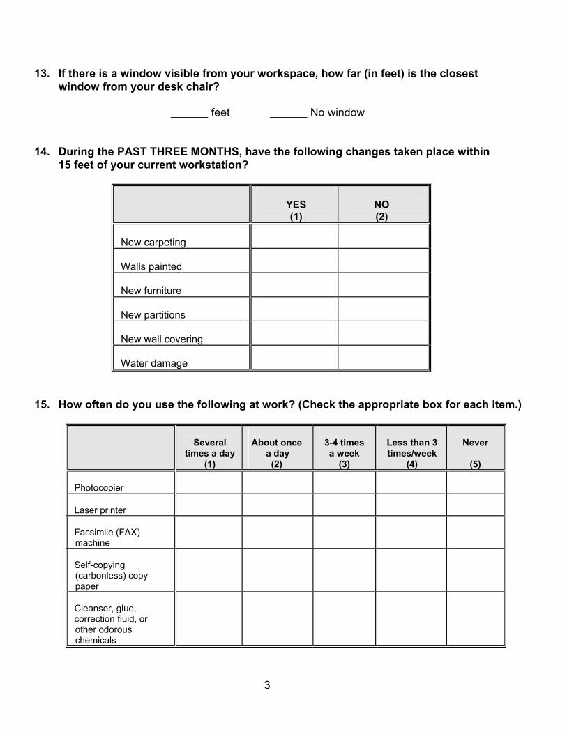
3
13. If there is a window visible from your workspace, how far (in feet) is the closest window from your desk chair?
feet No window
14. During the PAST THREE MONTHS, have the following changes taken place within
15 feet of your current workstation?
YES (1)
NO (2)
New carpeting
Walls painted
New furniture
New partitions
New wall covering
Water damage
15. How often do you use the following at work? (Check the appropriate box for each item.)
Several
times a day (1)
About once
a day (2)
3-4 times a week
(3)
Less than 3 times/week
(4)
Never
(5)
Photocopier
Laser printer
Facsimile (FAX) machine
Self-copying (carbonless) copy paper
Cleanser, glue, correction fluid, or other odorous chemicals
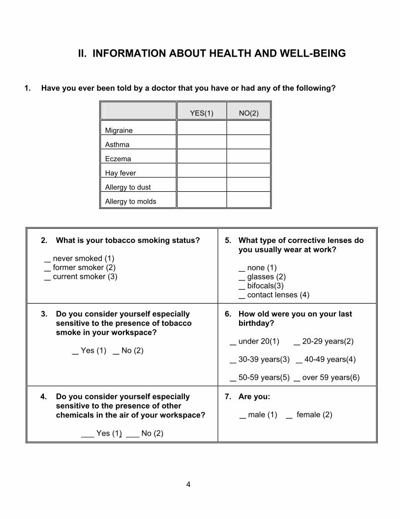
4
II. INFORMATION ABOUT HEALTH AND WELL-BEING
1. Have you ever been told by a doctor that you have or had any of the following?
YES(1)
NO(2)
Migraine
Asthma
Eczema
Hay fever
Allergy to dust
Allergy to molds
2. What is your tobacco smoking status?
never smoked (1) former smoker (2) current smoker (3)
5. What type of corrective lenses do
you usually wear at work? none (1) glasses (2) bifocals(3) contact lenses (4)
3. Do you consider yourself especially
sensitive to the presence of tobacco smoke in your workspace?
Yes (1) No (2)
6. How old were you on your last
birthday?
under 20(1) 20-29 years(2) 30-39 years(3) 40-49 years(4) 50-59 years(5) over 59 years(6)
4. Do you consider yourself especially
sensitive to the presence of other chemicals in the air of your workspace?
___ Yes (1) ___ No (2)
7. Are you:
male (1) female (2)
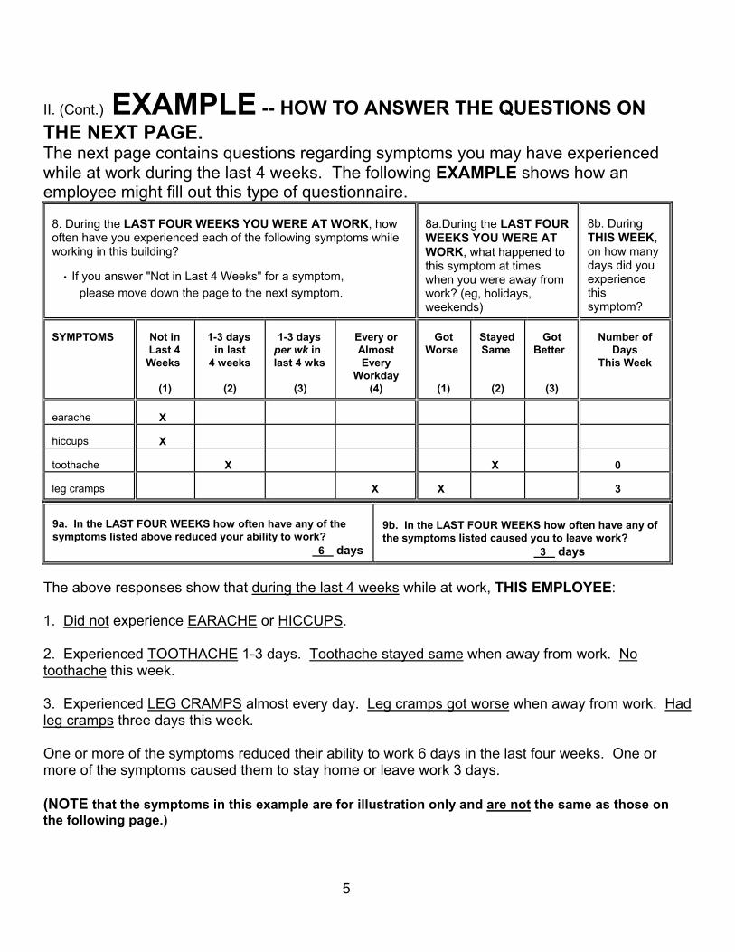
5
II. (Cont.) EXAMPLE -- HOW TO ANSWER THE QUESTIONS ON THE NEXT PAGE. The next page contains questions regarding symptoms you may have experienced while at work during the last 4 weeks. The following EXAMPLE shows how an employee might fill out this type of questionnaire.
8. During the LAST FOUR WEEKS YOU WERE AT WORK, how often have you experienced each of the following symptoms while working in this building? ∙ If you answer "Not in Last 4 Weeks" for a symptom,
please move down the page to the next symptom.
8a.During the LAST FOUR WEEKS YOU WERE AT WORK, what happened to this symptom at times when you were away from work? (eg, holidays, weekends)
8b. During THIS WEEK, on how many days did you experience this symptom?
SYMPTOMS
Not in Last 4 Weeks (1)
1-3 days in last 4 weeks (2)
1-3 days per wk in last 4 wks (3)
Every or Almost Every Workday (4)
Got Worse (1)
Stayed Same (2)
Got Better (3)
Number of Days This Week
earache
X
hiccups
X
toothache
X
X
0
leg cramps
X
X
3
9a. In the LAST FOUR WEEKS how often have any of the symptoms listed above reduced your ability to work?
6 days
9b. In the LAST FOUR WEEKS how often have any of the symptoms listed caused you to leave work?
3 days The above responses show that during the last 4 weeks while at work, THIS EMPLOYEE: 1. Did not experience EARACHE or HICCUPS. 2. Experienced TOOTHACHE 1-3 days. Toothache stayed same when away from work. No toothache this week. 3. Experienced LEG CRAMPS almost every day. Leg cramps got worse when away from work. Had leg cramps three days this week. One or more of the symptoms reduced their ability to work 6 days in the last four weeks. One or more of the symptoms caused them to stay home or leave work 3 days. (NOTE that the symptoms in this example are for illustration only and are not the same as those on the following page.)
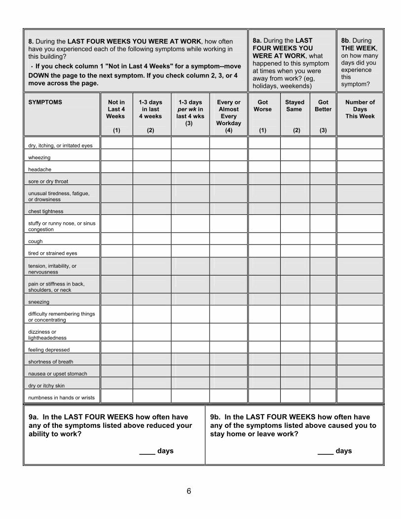
6
8. During the LAST FOUR WEEKS YOU WERE AT WORK, how often have you experienced each of the following symptoms while working in this building? ∙ If you check column 1 "Not in Last 4 Weeks" for a symptom--move DOWN the page to the next symptom. If you check column 2, 3, or 4 move across the page.
8a. During the LAST FOUR WEEKS YOU WERE AT WORK, what happened to this symptom at times when you were away from work? (eg, holidays, weekends)
8b. During THE WEEK, on how many days did you experience this symptom?
SYMPTOMS
Not in Last 4 Weeks (1)
1-3 days in last 4 weeks (2)
1-3 days per wk in last 4 wks (3)
Every or Almost Every
Workday (4)
Got Worse (1)
Stayed Same (2)
Got
Better
(3)
Number of
Days This Week
dry, itching, or irritated eyes
wheezing
headache
sore or dry throat
unusual tiredness, fatigue, or drowsiness
chest tightness
stuffy or runny nose, or sinus congestion
cough
tired or strained eyes
tension, irritability, or nervousness
pain or stiffness in back, shoulders, or neck
sneezing
difficulty remembering things or concentrating
dizziness or lightheadedness
feeling depressed
shortness of breath
nausea or upset stomach
dry or itchy skin
numbness in hands or wrists
9a. In the LAST FOUR WEEKS how often have any of the symptoms listed above reduced your ability to work?
days
9b. In the LAST FOUR WEEKS how often have any of the symptoms listed above caused you to stay home or leave work?
days
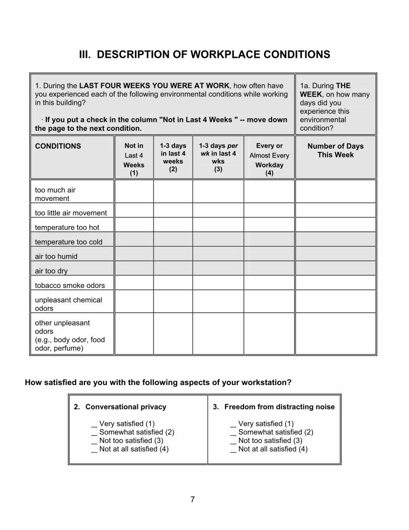
7
III. DESCRIPTION OF WORKPLACE CONDITIONS
1. During the LAST FOUR WEEKS YOU WERE AT WORK, how often have you experienced each of the following environmental conditions while working in this building? · If you put a check in the column "Not in Last 4 Weeks " -- move down the page to the next condition.
1a. During THE WEEK, on how many days did you experience this environmental condition?
CONDITIONS
Not in Last 4 Weeks
(1)
1-3 days in last 4 weeks
(2)
1-3 days per wk in last 4
wks (3)
Every or
Almost Every Workday
(4)
Number of Days
This Week
too much air movement
too little air movement
temperature too hot
temperature too cold
air too humid
air too dry
tobacco smoke odors
unpleasant chemical odors
other unpleasant odors (e.g., body odor, food odor, perfume)
How satisfied are you with the following aspects of your workstation?
2. Conversational privacy
Very satisfied (1) Somewhat satisfied (2) Not too satisfied (3) Not at all satisfied (4)
3. Freedom from distracting noise
Very satisfied (1) Somewhat satisfied (2) Not too satisfied (3) Not at all satisfied (4)
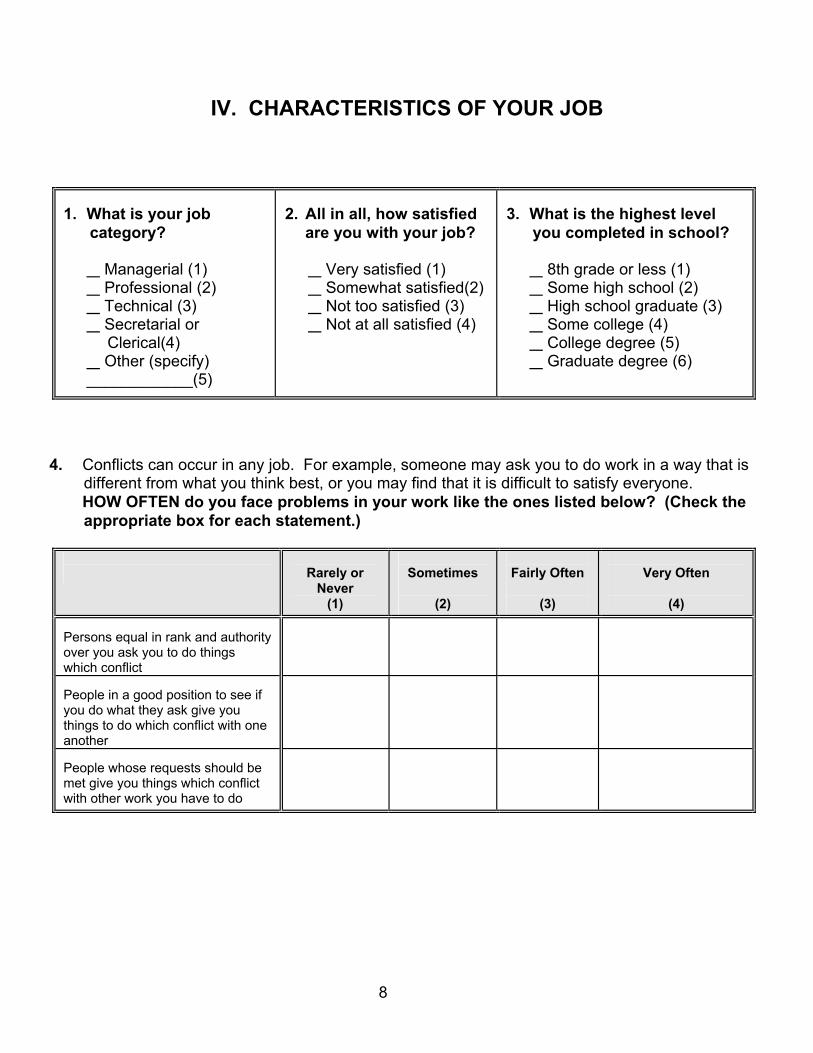
8
IV. CHARACTERISTICS OF YOUR JOB
1. What is your job
category?
Managerial (1) Professional (2) Technical (3) Secretarial or
Clerical(4) Other (specify)
____________(5)
2. All in all, how satisfied
are you with your job?
Very satisfied (1) Somewhat satisfied(2) Not too satisfied (3) Not at all satisfied (4)
3. What is the highest level
you completed in school?
8th grade or less (1) Some high school (2) High school graduate (3) Some college (4) College degree (5) Graduate degree (6)
4. Conflicts can occur in any job. For example, someone may ask you to do work in a way that is
different from what you think best, or you may find that it is difficult to satisfy everyone. HOW OFTEN do you face problems in your work like the ones listed below? (Check the
appropriate box for each statement.)
Rarely or
Never (1)
Sometimes
(2)
Fairly Often
(3)
Very Often
(4)
Persons equal in rank and authority over you ask you to do things which conflict
People in a good position to see if you do what they ask give you things to do which conflict with one another
People whose requests should be met give you things which conflict with other work you have to do
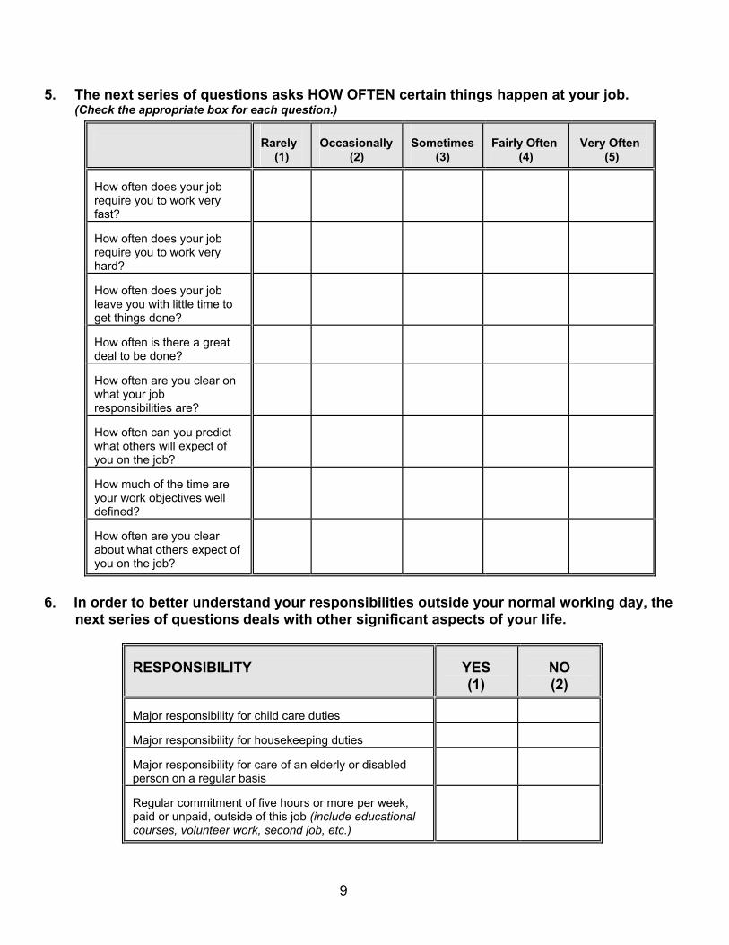
9
5. The next series of questions asks HOW OFTEN certain things happen at your job. (Check the appropriate box for each question.)
Rarely (1)
Occasionally (2)
Sometimes (3)
Fairly Often (4)
Very Often (5)
How often does your job require you to work very fast?
How often does your job require you to work very hard?
How often does your job leave you with little time to get things done?
How often is there a great deal to be done?
How often are you clear on what your job responsibilities are?
How often can you predict what others will expect of you on the job?
How much of the time are your work objectives well defined?
How often are you clear about what others expect of you on the job?
6. In order to better understand your responsibilities outside your normal working day, the
next series of questions deals with other significant aspects of your life.
RESPONSIBILITY
YES (1)
NO (2)
Major responsibility for child care duties
Major responsibility for housekeeping duties
Major responsibility for care of an elderly or disabled person on a regular basis
Regular commitment of five hours or more per week, paid or unpaid, outside of this job (include educational courses, volunteer work, second job, etc.)
10
PLEASE USE THE REMAINING SPACE TO DISCUSS ANY ASPECTS OF THE BUILDING ENVIRONMENT OR EMPLOYEE HEALTH THAT YOU FEEL APPROPRIATE
/ / / / / / /

APPENDIX G
STEERING COMMITTEE MEMBERS
STEERING COMMITTEE MEMBERS
Mr. Robert Axelrad U.S. Environmental Protection Agency Dr. Larry G. Berglund J.B. Pierce Foundation Mr. Terry Brennan Camroden Associates Mr. Jack Buckley I.A. Naman & Associates, Inc. Dr. Harriet Burge Harvard School of Public Health Prof. William S. Cain J.B. Pierce Foundation Ms. Lillie Clark Occupational Safety and Health Association Dr. Belinda Collins National Institute of Standards and Technology Mr. Michael Crandall National Institute for Occupational Safety and Health Dr. Ann Fidler National Institute for Occupational Safety and Health Mr. Bill Fisk Lawrence Berkeley Laboratory Mr. John R. Girman U.S. Environmental Protection Agency Dr. David Grimsrud Minnesota Building Research Center Dr. Allen Hedge Cornell University Mr. Jeff Hicks Radian Corporation Mr. Ross Highsmith U.S. Environmental Protection Agency Dr. Michael Hodgson University of Connecticut Dr. Joe Hurrel National Institute for Occupational Safety and Health Dr. Kay Kreiss National Jewish Center for Immunology and Respiratory
Medicine Mr. Andy Lindstrom U.S. Environmental Protection Agency Dr. Brian Leaderer J.B. Pierce Foundation Mr. Hal Levin Levin & Associates Mr. Ed Light Pathway Diagnostics, Inc. Dr. Jack McCarthy Environmental Health & Engineering, Inc. Dr. Mark Mendell National Institute for Occupational Safety and Health Dr. Vivian Mills General Services Administration Dr. Philip E. Morey Clayton Environmental Consultants Dr. Niren Nagda ICF, Inc. Mr. C. J. Nelson U.S. Environmental Protection Agency Mr. J. Francis Offerman Indoor Environmental Engineering Dr. Andrew Persily National Institute of Standards and Technology Dr. Linda Sheldon Research Triangle Institute Mr. Scott Sylvester Occupational Safety and Health Administration Mr. John Talbot U.S. Department of Energy Dr. Kevin Teichman U.S. Environmental Protection Agency Mr. Robert Thompson U.S. Environmental Protection Agency Mr. William A. Turner H. L. Turner Group, Inc. Dr. Lance Wallace U.S. Environmental Protection Agency Mr. Kenneth M. Wallingford
National Institute for Occupational Safety and Health
Dr. Roy Whitmore Research Triangle Institute Dr. Tom Wilcox National Institute for Occupational Safety and Health Dr. Deborah Winn National Center for Health Statistics Dr. James Wood Virginia Polytechnic Institute
APPENDIX H
THE INDOOR AIR DATA COLLECTION SYSTEM (IADCS)

The IADCS Software and Documentation is available upon request by contacting
Indoor Environments Division (6609J) U.S. Environmental Protection Agency 1200 Pennsylvania Ave., NW Washington, DC 20460