Embed Size (px)
Citation preview
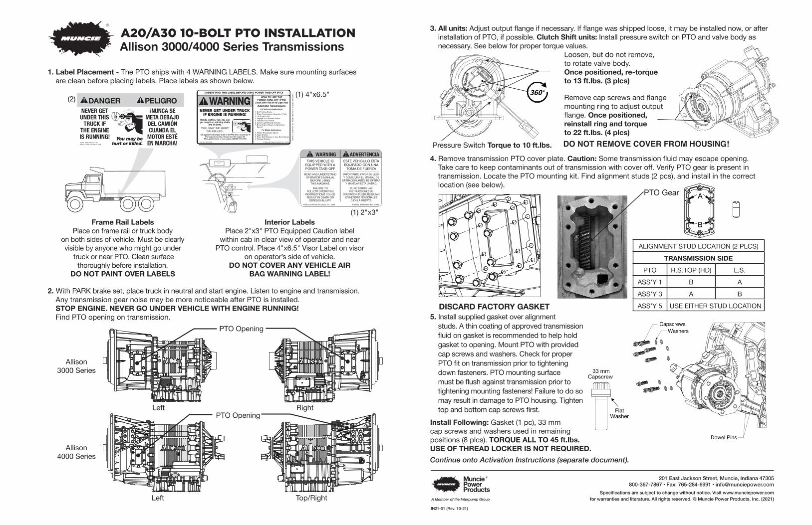
3. All units: Adjust output flange if necessary. If flange was shipped loose, it may be installed now, or after installation of PTO, if possible. Clutch Shift units: Install pressure switch on PTO and valve body as necessary. See below for proper torque values.
Loosen, but do not remove, to rotate valve body. Once positioned, re-torque to 13 ft.lbs. (3 plcs)
Remove cap screws and flange mounting ring to adjust output flange. Once positioned, reinstall ring and torque to 22 ft.lbs. (4 plcs)
4. Remove transmission PTO cover plate. Caution: Some transmission fluid may escape opening. Take care to keep contaminants out of transmission with cover off. Verify PTO gear is present in transmission. Locate the PTO mounting kit. Find alignment studs (2 pcs), and install in the correct location (see below).
5. Install supplied gasket over alignment studs. A thin coating of approved transmission fluid on gasket is recommended to help hold gasket to opening. Mount PTO with provided cap screws and washers. Check for proper PTO fit on transmission prior to tightening down fasteners. PTO mounting surface must be flush against transmission prior to tightening mounting fasteners! Failure to do so may result in damage to PTO housing. Tighten top and bottom cap screws first.
Install Following: Gasket (1 pc), 33 mm cap screws and washers used in remaining positions (8 plcs). TORQUE ALL TO 45 ft.lbs. USE OF THREAD LOCKER IS NOT REQUIRED.Continue onto Activation Instructions (separate document).
REVISIONS
REV. ZONE DESCRIPTION ECN/ERN DATE BY
D
C
B
AA
B
C
D
12345678
8 7 6 5 4 3 2 1
-
THIRD ANGLEPROJECTION
THE INFORMATION CONTAINED IN THIS DRAWING IS THE SOLE PROPERTY OF MUNCIE POWER PRODUCTS, INC. ANY REPRODUCTION IN PART OR AS A WHOLE WITHOUT THE WRITTEN PERMISSION OF MUNCIE POWER PRODUCTS, INC. IS PROHIBITED.
INTERPRET GEOMETRICTOLERANCING PER: ASME Y14.5MATERIAL
FINISH
-
DRAWN
CHECKED
ENG APPR.
COMMENTS:
DATENAME
Muncie Power Products, Inc.
TITLE:
SIZE
BDWG. NO. REV
UNLESS OTHERWISE SPECIFIED:
00
-
SHEET 1 OF 2
IN16-07_UPDATEDVIEWS
--
--
-
SIMILAR TO:
125
-
-
PROPRIETARY AND CONFIDENTIAL
WEIGHT:
DIMENSIONS ARE IN INCHESTOLERANCES:FRACTIONAL 1/16ANGULAR: MACH 1 BEND 1TWO PLACE DECIMAL 0.030THREE PLACE DECIMAL 0.010BREAK ALL SHARP CORNERSALL FILLETS AND RADII 0.12 R.
Pressure Switch Torque to 10 ft.lbs.
B
APTO Gear
DISCARD FACTORY GASKET
ALIGNMENT STUD LOCATION (2 PLCS)
TRANSMISSION SIDE
PTO R.S.TOP (HD) L.S.
ASS’Y 1 B A
ASS’Y 3 A B
ASS’Y 5 USE EITHER STUD LOCATION
360
360
A20/A30 10-BOLT PTO INSTALLATIONAllison 3000/4000 Series Transmissions
1. Label Placement - The PTO ships with 4 WARNING LABELS. Make sure mounting surfaces are clean before placing labels. Place labels as shown below.
THIS VEHICLE ISEQUIPPED WITH APOWER TAKE-OFF
READ AND UNDERSTAND OPERATOR'S MANUAL
BEFORE USING THIS MACHINE.
FAILURE TO FOLLOW OPERATING
INSTRUCTIONS COULD RESULT IN DEATH OR
SERIOUS INJURY.
ESTE VEHICULO ESTAEQUIPADO CON UNA
TOMA DE FUERZA
IMPORTANTE. FAVOR DE LEER Y CONSULTAR EL MANUAL DE
OPERACION ANTES DE OPERAR Y MANEJAR ESTA UNIDAD.
EL NO SEGUIR LAS INSTRUCCIONES DE
OPERACION PUEDA RESULTAR EN HERIDAS PERSONALES
O EN LA MUERTE.© Muncie Power Products, Inc. 2006 Part No. 36M35652 (Rev. 9-06)
You may behurt or killed.
NEVER GET UNDER THIS TRUCK IF
THE ENGINE IS RUNNING!
¡NUNCA SE META DEBAJO DEL CAMIÓN CUANDA EL MOTOR ESTÉ EN MARCHA! Part No. 36M35644 (Rev. 9-06)
© Muncie Power Products, Inc. 2006
WARNINGUNDERSTAND THIS LABEL BEFORE USING POWER TAKE-OFF (PTO) LOCATE
ONVISOR
SOIT
ISVISIBLE
WHEN
THESUN
VISORIS
RAISED
NEVER GET UNDER TRUCKIF ENGINE IS RUNNING!
Part No. 36T37507 © Muncie Power Products, Inc. 2009
Hands, clothes, hair, etc. canget caught on spinning shafts
and U-joints.
YOU MAY BE HURTOR KILLED.
It is against Federal Law to try to fix PTO driven machinery ifthe engine is running. Always turn the engine off.
Then, put the keys in your pocket. (OSHA 1910.147)
HOW TO USE THEPOWER TAKE-OFF (PTO)
Clutch Shift PTOs for the Light TruckAutomatic Transmissions
For Stationary Applications:
1. Set Parking Brake.2. Place Transmission Selector in Park.3. Let Engine Idle.4. Engage PTO Rocker Switch.5. Release PTO Switch.6. Green Light Should Activate.7. Bring Engine Slowly to Operating
Speed.
For Mobile Applications:
1. Follow Procedures Above.2. Apply Brakes.3. Place Shift Selector in Any Drive Range.4. Release Brakes.
Frame Rail LabelsPlace on frame rail or truck body
on both sides of vehicle. Must be clearly visible by anyone who might go under
truck or near PTO. Clean surface thoroughly before installation.
DO NOT PAINT OVER LABELS
Interior LabelsPlace 2"x3" PTO Equipped Caution label
within cab in clear view of operator and near PTO control. Place 4"x6.5" Visor Label on visor
on operator’s side of vehicle.DO NOT COVER ANY VEHICLE AIR
BAG WARNING LABEL!
(2) (1) 4"x6.5"
(1) 2"x3"
2. With PARK brake set, place truck in neutral and start engine. Listen to engine and transmission.Any transmission gear noise may be more noticeable after PTO is installed.STOP ENGINE. NEVER GO UNDER VEHICLE WITH ENGINE RUNNING!Find PTO opening on transmission.
PTO Opening
Allison3000 Series
Allison4000 Series
PTO Opening
Left
Left
Top/Right
Right
DO NOT REMOVE COVER FROM HOUSING!
33 mmCapscrew
FlatWasher
Dowel Pins
CapscrewsWashers
Capscrews
Washers
33 mmCapscrew
FlatWasher
Dowel Pins
201 East Jackson Street, Muncie, Indiana 47305800-367-7867 • Fax: 765-284-6991 • [email protected]
Specifications are subject to change without notice. Visit www.munciepower.com for warranties and literature. All rights reserved. © Muncie Power Products, Inc. (2021)
IN21-01 (Rev. 10-21)
A Member of the Interpump Group
REVISIONS
REV. ZONE DESCRIPTION ECN/ERN DATE BY
D
C
B
AA
B
C
D
12345678
8 7 6 5 4 3 2 1
-
THIRD ANGLEPROJECTION
THE INFORMATION CONTAINED IN THIS DRAWING IS THE SOLE PROPERTY OF MUNCIE POWER PRODUCTS, INC. ANY REPRODUCTION IN PART OR AS A WHOLE WITHOUT THE WRITTEN PERMISSION OF MUNCIE POWER PRODUCTS, INC. IS PROHIBITED.
INTERPRET GEOMETRICTOLERANCING PER: ASME Y14.5MATERIAL
FINISH
-
DRAWN
CHECKED
ENG APPR.
COMMENTS:
DATENAME
Muncie Power Products, Inc.
TITLE:
SIZE
BDWG. NO. REV
UNLESS OTHERWISE SPECIFIED:
00
-
SHEET 1 OF 2
IN16-07_UPDATEDVIEWS
--
--
-
SIMILAR TO:
125
-
-
PROPRIETARY AND CONFIDENTIAL
WEIGHT:
DIMENSIONS ARE IN INCHESTOLERANCES:FRACTIONAL 1/16ANGULAR: MACH 1 BEND 1TWO PLACE DECIMAL 0.030THREE PLACE DECIMAL 0.010BREAK ALL SHARP CORNERSALL FILLETS AND RADII 0.12 R.
D
C
B
AA
B
C
D
12345678
8 7 6 5 4 3 2 1
-
THIRD ANGLEPROJECTION
THE INFORMATION CONTAINED IN THIS DRAWING IS THE SOLE PROPERTY OF MUNCIE POWER PRODUCTS, INC. ANY REPRODUCTION IN PART OR AS A WHOLE WITHOUT THE WRITTEN PERMISSION OF MUNCIE POWER PRODUCTS, INC. IS PROHIBITED.
INTERPRET GEOMETRICTOLERANCING PER: ASME Y14.5MATERIAL
FINISH
-
DRAWN
CHECKED
ENG APPR.
COMMENTS:
DATENAME
Muncie Power Products, Inc.
TITLE:
SIZE
BDWG. NO. REV
UNLESS OTHERWISE SPECIFIED:
00
-
SHEET 2 OF 2
IN16-07_UPDATEDVIEWS
--
--
-
SIMILAR TO:
125
-
-
PROPRIETARY AND CONFIDENTIAL
WEIGHT:
DIMENSIONS ARE IN INCHESTOLERANCES:FRACTIONAL 1/16ANGULAR: MACH 1 BEND 1TWO PLACE DECIMAL 0.030THREE PLACE DECIMAL 0.010BREAK ALL SHARP CORNERSALL FILLETS AND RADII 0.12 R.
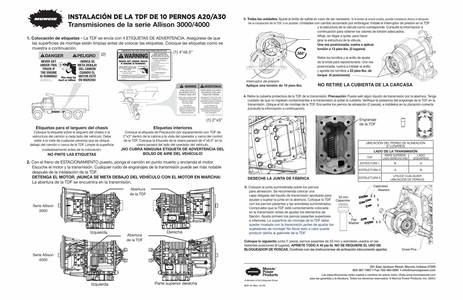
INSTALACIÓN DE LA TDF DE 10 PERNOS A20/A30 Transmisiones de la serie Allison 3000/4000
1. Colocación de etiquetas - La TDF se envía con 4 ETIQUETAS DE ADVERTENCIA. Asegúrese de que las superficies de montaje estén limpias antes de colocar las etiquetas. Coloque las etiquetas como se muestra a continuación.
THIS VEHICLE ISEQUIPPED WITH APOWER TAKE-OFF
READ AND UNDERSTAND OPERATOR'S MANUAL
BEFORE USING THIS MACHINE.
FAILURE TO FOLLOW OPERATING
INSTRUCTIONS COULD RESULT IN DEATH OR
SERIOUS INJURY.
ESTE VEHICULO ESTAEQUIPADO CON UNA
TOMA DE FUERZA
IMPORTANTE. FAVOR DE LEER Y CONSULTAR EL MANUAL DE
OPERACION ANTES DE OPERAR Y MANEJAR ESTA UNIDAD.
EL NO SEGUIR LAS INSTRUCCIONES DE
OPERACION PUEDA RESULTAR EN HERIDAS PERSONALES
O EN LA MUERTE.© Muncie Power Products, Inc. 2006 Part No. 36M35652 (Rev. 9-06)
Etiquetas para el larguero del chasisColoque la etiqueta sobre el larguero del chasis o la
estructura del camión a cada lado del vehículo. Debe estar a la vista de cualquier persona que se ubique
debajo del camión o cerca de la TDF. Limpie la superficie cuidadosamente antes de la colocación.
NO PINTE LAS ETIQUETAS
Etiquetas interioresColoque la etiqueta de Precaución por equipamiento con TDF de
2”x3” dentro de la cabina a la vista del operador y cerca del control de la TDF. Coloque la Etiqueta de la visera parasol de 4”x6.5” en la
visera parasol del lado del operador del vehículo.¡NO CUBRA NINGUNA ETIQUETA DE ADVERTENCIA DEL
BOLSO DE AIRE DEL VEHÍCULO!
(2) (1) 4"x6.5"
(1) 2"x3"
2. Con el freno de ESTACIONAMIENTO puesto, ponga el camión en punto muerto y encienda el motor. Escuche el motor y la transmisión. Cualquier ruido de engranajes de la transmisión puede ser más notable después de la instalación de la TDF.DETENGA EL MOTOR. ¡NUNCA SE META DEBAJO DEL VEHÍCULO CON EL MOTOR EN MARCHA! La abertura de la TDF se encuentra en la transmisión.
Aberturade la TDF
Aberturade la TDF
Serie Allison 3000
Serie Allison 4000
You may behurt or killed.
NEVER GET UNDER THIS TRUCK IF
THE ENGINE IS RUNNING!
¡NUNCA SE META DEBAJO DEL CAMIÓN CUANDA EL MOTOR ESTÉ EN MARCHA! Part No. 36M35644 (Rev. 9-06)
© Muncie Power Products, Inc. 2006
You may behurt or killed.
NEVER GET UNDER THIS TRUCK IF
THE ENGINE IS RUNNING!
¡NUNCA SE META DEBAJO DEL CAMIÓN CUANDA EL MOTOR ESTÉ EN MARCHA! Part No. 36M35644 (Rev. 9-06)
© Muncie Power Products, Inc. 2006
WARNINGUNDERSTAND THIS LABEL BEFORE USING POWER TAKE-OFF (PTO) LOCATE
ONVISOR
SOIT
ISVISIBLE
WHEN
THESUN
VISORIS
RAISED
NEVER GET UNDER TRUCKIF ENGINE IS RUNNING!
Part No. 36T37507 © Muncie Power Products, Inc. 2009
Hands, clothes, hair, etc. canget caught on spinning shafts
and U-joints.
YOU MAY BE HURTOR KILLED.
It is against Federal Law to try to fix PTO driven machinery ifthe engine is running. Always turn the engine off.
Then, put the keys in your pocket. (OSHA 1910.147)
HOW TO USE THEPOWER TAKE-OFF (PTO)
Clutch Shift PTOs for the Light TruckAutomatic Transmissions
For Stationary Applications:
1. Set Parking Brake.2. Place Transmission Selector in Park.3. Let Engine Idle.4. Engage PTO Rocker Switch.5. Release PTO Switch.6. Green Light Should Activate.7. Bring Engine Slowly to Operating
Speed.
For Mobile Applications:
1. Follow Procedures Above.2. Apply Brakes.3. Place Shift Selector in Any Drive Range.4. Release Brakes.
3. Todas las unidades: Ajuste la brida de salida en caso de ser necesario. Si la brida se envió suelta, puede instalarse ahora o después de la instalación de la TDF, si es posible. Unidades con cambio accionado por embrague: Instale el interruptor de presión en la TDF
y la estructura de la válvula como corresponde. Consulte la información a continuación para obtener los valores de torsión adecuados.Afloje, sin llegar a quitar, para hacergirar la estructura de la válvula. Una vez posicionada, vuelva a aplicar torsión a 13 pies-lbs. (3 lugares)
Retire los tornillos y el anillo de ajuste de la brida para reposicionarla. Una ves posicionada, vuelva a instalar el anillo y apriete los tornillos a 22 pies-lbs. de torque (4 posiciones)
4. Retire la cubierta protectora de la TDF de la transmisión. Precaución: Puede salir algún líquido de transmisión por la abertura. Tenga cuidado de que no ingresen contaminantes a la transmisión al quitar la cubierta. Verifique la presencia del engranaje de la TDF en la transmisión. Ubique el kit de montaje de la TDF. Encuentre los pernos de alineación (2 piezas), e instálelos en la ubicación correcta (consulte la información a continuación).
Interruptor de presión Aplique una torsión de 10 pies-lbs.
B
AEngranajede la TDF
DESECHE LA JUNTA DE FÁBRICA
UBICACIÓN DEL PERNO DE ALINEACIÓN(2 LUGARES)
LADO DE LA TRANSMISIÓNTDF PARTE SUPERIOR
LADO DERECHO (HD)LADO
IZQUIERDOESTRUCTURA 1 B A
ESTRUCTURA 3 A B
ESTRUCTURA 5 UTILICE CUALQUIER UBICACIÓN DE PERNOS
360
360
Izquierda Derecha
Izquierda Parte superior derecha
5. Coloque la junta suministrada sobre los pernos para alineación. Se recomienda colocar una capa delgada del líquido de transmisión aprobado para ayudar a sujetar la junta en la abertura. Coloque la TDF con los pernos pasantes y las arandelas suministrados. Compruebe que la TDF esté correctamente colocada en la transmisión antes de ajustar los elementos de fijación. Ajuste primero los pernos pasantes superiores e inferiores. La superficie de montaje de la TDF debe quedar nivelada con la transmisión ¡antes de ajustar los sujetadores de montaje! No llevar esto a cabo puede producir daños al gabinete de la TDF.
Coloque lo siguiente: junta (1 pieza), pernos pasantes de 33 mm y arandelas usados en las restantes posiciones (8 lugares). APRIETE TODO A 45 pie-lb. NO SE REQUIERE EL USO DE BLOQUEADOR DE ROSCAS. Continúe con las instrucciones de activación (documento aparte).
NO RETIRE LA CUBIERTA DE LA CARCASA
Capscrews
Washers
33 mmCapscrew
FlatWasher
Dowel Pins33 mm
Capscrew
FlatWasher
Dowel Pins
CapscrewsWashers
201 East Jackson Street, Muncie, Indiana 47305800-367-7867 • Fax 765-284-6991 • [email protected]
Las especificaciones están sujetas a cambios sin previo aviso. Visita www.munciepower.com para las garantías y la literatura. Todos los derechos reservados. © Muncie Power Products, Inc. (2021)
IN21-01 (Rev. 10-21)
A Member of the Interpump Group